US9532697B2 - Dishwasher with unitary wash module - Google Patents
Dishwasher with unitary wash moduleDownload PDFInfo
- Publication number
- US9532697B2 US9532697B2US14/827,339US201514827339AUS9532697B2US 9532697 B2US9532697 B2US 9532697B2US 201514827339 AUS201514827339 AUS 201514827339AUS 9532697 B2US9532697 B2US 9532697B2
- Authority
- US
- United States
- Prior art keywords
- dishwasher
- high voltage
- liquid
- pump
- housing
- Prior art date
- Legal status (The legal status is an assumption and is not a legal conclusion. Google has not performed a legal analysis and makes no representation as to the accuracy of the status listed.)
- Active
Links
Images


Classifications
- A—HUMAN NECESSITIES
- A47—FURNITURE; DOMESTIC ARTICLES OR APPLIANCES; COFFEE MILLS; SPICE MILLS; SUCTION CLEANERS IN GENERAL
- A47L—DOMESTIC WASHING OR CLEANING; SUCTION CLEANERS IN GENERAL
- A47L15/00—Washing or rinsing machines for crockery or tableware
- A47L15/0018—Controlling processes, i.e. processes to control the operation of the machine characterised by the purpose or target of the control
- A47L15/0021—Regulation of operational steps within the washing processes, e.g. optimisation or improvement of operational steps depending from the detergent nature or from the condition of the crockery
- A—HUMAN NECESSITIES
- A47—FURNITURE; DOMESTIC ARTICLES OR APPLIANCES; COFFEE MILLS; SPICE MILLS; SUCTION CLEANERS IN GENERAL
- A47L—DOMESTIC WASHING OR CLEANING; SUCTION CLEANERS IN GENERAL
- A47L15/00—Washing or rinsing machines for crockery or tableware
- A47L15/0084—Washing or rinsing machines for crockery or tableware of drawer-type
- A—HUMAN NECESSITIES
- A47—FURNITURE; DOMESTIC ARTICLES OR APPLIANCES; COFFEE MILLS; SPICE MILLS; SUCTION CLEANERS IN GENERAL
- A47L—DOMESTIC WASHING OR CLEANING; SUCTION CLEANERS IN GENERAL
- A47L15/00—Washing or rinsing machines for crockery or tableware
- A47L15/42—Details
- A47L15/4202—Water filter means or strainers
- A—HUMAN NECESSITIES
- A47—FURNITURE; DOMESTIC ARTICLES OR APPLIANCES; COFFEE MILLS; SPICE MILLS; SUCTION CLEANERS IN GENERAL
- A47L—DOMESTIC WASHING OR CLEANING; SUCTION CLEANERS IN GENERAL
- A47L15/00—Washing or rinsing machines for crockery or tableware
- A47L15/42—Details
- A47L15/4214—Water supply, recirculation or discharge arrangements; Devices therefor
- A47L15/4219—Water recirculation
- A—HUMAN NECESSITIES
- A47—FURNITURE; DOMESTIC ARTICLES OR APPLIANCES; COFFEE MILLS; SPICE MILLS; SUCTION CLEANERS IN GENERAL
- A47L—DOMESTIC WASHING OR CLEANING; SUCTION CLEANERS IN GENERAL
- A47L15/00—Washing or rinsing machines for crockery or tableware
- A47L15/42—Details
- A47L15/4214—Water supply, recirculation or discharge arrangements; Devices therefor
- A47L15/4225—Arrangements or adaption of recirculation or discharge pumps
- A—HUMAN NECESSITIES
- A47—FURNITURE; DOMESTIC ARTICLES OR APPLIANCES; COFFEE MILLS; SPICE MILLS; SUCTION CLEANERS IN GENERAL
- A47L—DOMESTIC WASHING OR CLEANING; SUCTION CLEANERS IN GENERAL
- A47L15/00—Washing or rinsing machines for crockery or tableware
- A47L15/42—Details
- A47L15/4293—Arrangements for programme selection, e.g. control panels; Indication of the selected programme, programme progress or other parameters of the programme, e.g. by using display panels
- B—PERFORMING OPERATIONS; TRANSPORTING
- B08—CLEANING
- B08B—CLEANING IN GENERAL; PREVENTION OF FOULING IN GENERAL
- B08B3/00—Cleaning by methods involving the use or presence of liquid or steam
- B08B3/02—Cleaning by the force of jets or sprays
- A—HUMAN NECESSITIES
- A47—FURNITURE; DOMESTIC ARTICLES OR APPLIANCES; COFFEE MILLS; SPICE MILLS; SUCTION CLEANERS IN GENERAL
- A47L—DOMESTIC WASHING OR CLEANING; SUCTION CLEANERS IN GENERAL
- A47L2301/00—Manual input in controlling methods of washing or rinsing machines for crockery or tableware, i.e. information entered by a user
- A47L2301/08—Other manual input
- A—HUMAN NECESSITIES
- A47—FURNITURE; DOMESTIC ARTICLES OR APPLIANCES; COFFEE MILLS; SPICE MILLS; SUCTION CLEANERS IN GENERAL
- A47L—DOMESTIC WASHING OR CLEANING; SUCTION CLEANERS IN GENERAL
- A47L2401/00—Automatic detection in controlling methods of washing or rinsing machines for crockery or tableware, e.g. information provided by sensors entered into controlling devices
- A47L2401/02—Consumable products information, e.g. information on detergent, rinsing aid or salt; Dispensing device information, e.g. information on the type, e.g. detachable, or status of the device
- A—HUMAN NECESSITIES
- A47—FURNITURE; DOMESTIC ARTICLES OR APPLIANCES; COFFEE MILLS; SPICE MILLS; SUCTION CLEANERS IN GENERAL
- A47L—DOMESTIC WASHING OR CLEANING; SUCTION CLEANERS IN GENERAL
- A47L2401/00—Automatic detection in controlling methods of washing or rinsing machines for crockery or tableware, e.g. information provided by sensors entered into controlling devices
- A47L2401/18—Air temperature
- A—HUMAN NECESSITIES
- A47—FURNITURE; DOMESTIC ARTICLES OR APPLIANCES; COFFEE MILLS; SPICE MILLS; SUCTION CLEANERS IN GENERAL
- A47L—DOMESTIC WASHING OR CLEANING; SUCTION CLEANERS IN GENERAL
- A47L2401/00—Automatic detection in controlling methods of washing or rinsing machines for crockery or tableware, e.g. information provided by sensors entered into controlling devices
- A47L2401/19—Air humidity
- A—HUMAN NECESSITIES
- A47—FURNITURE; DOMESTIC ARTICLES OR APPLIANCES; COFFEE MILLS; SPICE MILLS; SUCTION CLEANERS IN GENERAL
- A47L—DOMESTIC WASHING OR CLEANING; SUCTION CLEANERS IN GENERAL
- A47L2401/00—Automatic detection in controlling methods of washing or rinsing machines for crockery or tableware, e.g. information provided by sensors entered into controlling devices
- A47L2401/26—Loading door status, e.g. door latch opened or closed state
- A—HUMAN NECESSITIES
- A47—FURNITURE; DOMESTIC ARTICLES OR APPLIANCES; COFFEE MILLS; SPICE MILLS; SUCTION CLEANERS IN GENERAL
- A47L—DOMESTIC WASHING OR CLEANING; SUCTION CLEANERS IN GENERAL
- A47L2501/00—Output in controlling method of washing or rinsing machines for crockery or tableware, i.e. quantities or components controlled, or actions performed by the controlling device executing the controlling method
- A47L2501/07—Consumable products, e.g. detergent, rinse aids or salt
- A—HUMAN NECESSITIES
- A47—FURNITURE; DOMESTIC ARTICLES OR APPLIANCES; COFFEE MILLS; SPICE MILLS; SUCTION CLEANERS IN GENERAL
- A47L—DOMESTIC WASHING OR CLEANING; SUCTION CLEANERS IN GENERAL
- A47L2501/00—Output in controlling method of washing or rinsing machines for crockery or tableware, i.e. quantities or components controlled, or actions performed by the controlling device executing the controlling method
- A47L2501/20—Spray nozzles or spray arms
- A—HUMAN NECESSITIES
- A47—FURNITURE; DOMESTIC ARTICLES OR APPLIANCES; COFFEE MILLS; SPICE MILLS; SUCTION CLEANERS IN GENERAL
- A47L—DOMESTIC WASHING OR CLEANING; SUCTION CLEANERS IN GENERAL
- A47L2501/00—Output in controlling method of washing or rinsing machines for crockery or tableware, i.e. quantities or components controlled, or actions performed by the controlling device executing the controlling method
- A47L2501/30—Regulation of machine operational steps within the washing process, e.g. performing an additional rinsing phase, shortening or stopping of the drying phase, washing at decreased noise operation conditions
Definitions
- Contemporary automatic dishwashers for use in a typical householdinclude a tub for receiving soiled utensils to be cleaned.
- a spray system and a recirculation systemmay be provided for re-circulating liquid throughout the tub to remove soils from the utensils.
- An air supply systemmay be included to provide air to the tub for drying the utensils.
- the dishwashermay have a controller that implements a number of pre-programmed cycles of operation to wash utensils contained in the tub.
- the inventionrelates to an automatic dishwasher with a tub defining a treating chamber, a sprayer located in the treating chamber and spraying liquid into the treating chamber and, a housing physically separate from the tub and defining a sump to receive liquid sprayed into the tub, the housing having an inlet fluidly connected to a liquid outlet of the tub and an outlet fluidly coupled to the sprayer located within the tub to define a recirculation path for the sprayed liquid.
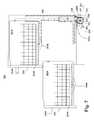
- FIG. 1is a perspective view of a dishwasher in accordance with a first embodiment of the invention.
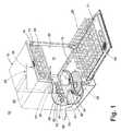
- FIG. 2is a partial schematic cross-sectional view of the dishwasher shown in FIG. 1 and illustrating a recirculation system and air supply system.
- FIG. 3is a schematic view of a control system of the dishwasher of FIG. 1 .
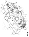
- FIG. 4is a perspective view of one embodiment of the shared wash unit and its couplings to the recirculation system and air supply system illustrated in FIG. 2 .
- FIG. 5is a cross-sectional view of the shared wash unit and illustrating a heater that is shared by the recirculation system and air supply system illustrated in FIG. 4 .
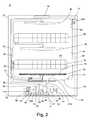
- FIG. 6is a cross-sectional view of a portion of a dishwasher in accordance with a second embodiment of the invention.
- FIG. 7is a cross-sectional view of a dishwasher in accordance with a third embodiment of the invention.
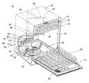
- a first embodiment of the inventionis illustrated as an automatic dishwasher 10 having a cabinet 12 defining an interior.
- the cabinet 12may be a chassis/frame with or without panels attached, respectively.
- the dishwasher 10shares many features of a conventional automatic dishwasher, which will not be described in detail herein except as necessary for a complete understanding of the invention.
- the cabinet 12encloses a wash tub 14 , which at least partially defines a treating chamber 24 for holding utensils for washing according to a cycle of operation. While typically made from a single piece, the wash tub 14 has spaced top and bottom walls 16 and 18 , spaced sidewalls 20 , a front wall 21 , and a rear wall 22 . In this configuration, the walls 16 , 18 , 20 , 21 , and 22 collectively define the treating chamber 24 for washing utensils.
- the front wall 21may be a moveable element or door of the dishwasher 10 , which may be moveably mounted to the cabinet 12 to provide selective access to the wash tub 14 for loading and unloading utensils or other washable items.
- Utensil holders in the form of upper and lower utensil racks 26 , 28are located within the treating chamber 24 and receive utensils for washing.
- the upper and lower racks 26 , 28may be mounted for slidable movement in and out of the treating chamber 24 for ease of loading and unloading.
- the term “utensil(s)”is intended to be generic to any item, single or plural, that may be treated in the dishwasher 10 , including, without limitation; dishes, plates, pots, bowls, pans, glassware, and silverware. While the present invention is described in terms of a conventional dishwashing unit as illustrated in FIG. 1 , it could also be implemented in other types of dishwashing units such as in-sink dishwashers or drawer dishwashers including drawer dishwashers having multiple compartments.
- a recirculation system 30is provided for spraying liquid within the treating chamber 24 to treat any utensils located therein.
- An air supply system 60is provided for supplying air to the treating chamber 24 for aiding in the drying of the utensils.
- the recirculation systemfurther comprises a wash unit 31 that is operably coupled to the recirculation system 30 and the air supply system 60 , such that it provides pumping for the recirculation system 30 , and heating for both the recirculation system 30 and the air supply system 60 , along with a draining function.
- the recirculation system 30comprises one or more sprayers for spraying liquid within the treating chamber 24 .
- One or more valvesmay be provided with the supply tube 42 to control the flow of liquid to the various sprayers. In this way, liquid may be selectively supplied to a subset of all of the sprayers and/or simultaneously to all of the sprayers.
- the first lower spray assembly 34is positioned above the bottom wall 18 and beneath the lower utensil rack 28 .
- the first lower spray assembly 34is an arm configured to rotate in the wash tub 14 and spray a flow of liquid from a plurality of spray nozzles or outlets 43 , in a primarily upward direction, over a portion of the interior of the wash tub 14 .
- a first wash zonemay be defined by the spray field emitted by the first lower spray assembly 34 into the treating chamber 24 .
- the spray from the first lower spray assembly 34is sprayed into the wash tub 14 in typically upward fashion to wash utensils located in the lower utensil rack 28 . None of the outlets 43 spray directly onto a liquid outlet 29 in the bottom wall 18 as the lower spray assembly 34 rotates.
- the second lower spray assembly 36is illustrated as being located adjacent the lower rack 28 toward the rear of the treating chamber 24 .
- the second lower spray assembly 36is illustrated as including a horizontally oriented distribution header or spray manifold 44 having a plurality of nozzles 50 , each with a plurality of apertures 52 .
- the spray manifold 44may not be limited to this position; rather, the spray manifold 44 could be located in virtually any part of the treating chamber 24 .
- the manifold 44could be positioned underneath the lower rack 28 , adjacent or beneath the first lower spray assembly 34 .
- Such a spray manifoldis set forth in detail in U.S. Pat. No. 7,594,513, issued Sep. 29, 2009, and titled “Multiple Wash Zone Dishwasher,” which is incorporated herein by reference in its entirety.
- the second lower spray assembly 36may be configured to spray a flow of treating liquid from the apertures 52 , in a generally lateral direction, over a portion of the interior of the treating chamber 24 .
- the spray from the apertures 52may be typically directed to treat utensils located in the lower rack 28 .
- a second wash zonemay be defined by the spray field emitted by the second lower spray assembly 36 into the treating chamber 24 .
- the mid-level spray arm assembly 38is positioned between the upper utensil rack 26 and the lower utensil rack 28 . Like the first lower spray assembly 34 , the mid-level spray assembly 38 may also be configured to rotate in the dishwasher 10 and spray a flow of liquid from at least one outlet 43 , in a generally upward direction, over a portion of the interior of the wash tub 14 . In this case, the spray from the mid-level spray arm assembly 38 is directed to utensils in the upper utensil rack 26 to define a third spray zone.
- the upper spray arm assembly 40is positioned above the upper utensil rack 26 and generally directs a spray of liquid in a generally downward direction to define a fourth spray zone that helps wash utensils on both upper and lower utensil racks 26 , 28 .
- the wash unit 31comprises a wash or recirculation pump 32 and a drain pump 41 , which are fluidly coupled to a housing 57 defining a sump 58 , where liquid sprayed into the wash tub 14 will collect due to gravity.
- the housing 57is physically separate from the wash tub 14 and provides a mounting structure for the recirculation pump 32 and drain pump 41 .
- An inlet conduit 31 Afluidly couples the wash tub 14 to the housing 57 and provides a path for the liquid in the treating chamber 24 to travel to the sump 58 .
- a filter element 61shown in phantom, has been illustrated in FIG. 2 as being located within the housing 57 between the inlet conduit 31 A and the recirculation pump 32 .
- the recirculation pump 32fluidly couples the sump 58 to the supply tube 42 to effect a supplying of the liquid from the sump 58 to the sprayers.
- the drain pump 41fluidly couples to a drain pump outlet 46 to effect a supplying of liquid from the sump to a household drain 47 .
- the inlet conduit 31 A, sump 58 , recirculation pump 32 , spray assemblies 34 - 40 , and supply tube 42collectively form a liquid flow path in the recirculation system 30 .
- the recirculation pump 32is fluidly coupled to the recirculation path such that it draws liquid in through the inlet conduit 31 A and sump 58 and delivers it to one or more of the spray assemblies 34 - 40 through the supply tube 42 .
- One or more valves or divertersmay also be included in the dishwasher 10 to control the flow of liquid to the spray assemblies 34 - 40 from the recirculation pump 32 .
- the liquidis sprayed back into the treating chamber 24 through the spray assemblies 34 - 40 and drains back to the sump 58 where the process may be repeated.
- a liquid flow pathfluidly couples the treating chamber 24 to the spray assemblies 34 - 40 .
- the drain pump 41may also be fluidly coupled to the housing 57 .
- the drain pump 41may be adapted to draw liquid from the housing 57 and to pump the liquid through a drain pump outlet 46 to a household drain 47 .
- the dishwasher 10includes a recirculation pump 32 and a drain pump 41 .
- the two pumpsmay be replaced by a single pump, which may be operated to supply to either the household drain or to the recirculation system.
- the air supply system 60comprises an inlet duct 68 coupled to the wash tub 14 , with an inlet 64 located below the bottom wall 18 such that air exterior to the tub 14 , i.e., “ambient air”, may be provided to the treating chamber 24 .
- a fan or blower 62is fluidly coupled to the inlet duct 68 through an air supply conduit 66 to draw in the ambient air through the inlet 64 and supply it to the treating chamber 24 through the air supply conduit 66 and air inlet duct 68 .
- An air outlet, such as a vent 69is provided for exhausting the supplied air from the treating chamber 24 .
- the vent 69is fluidly coupled to an outlet duct 69 A, which vents into the interior of the door 21 and will escape through the various openings in the door 21 .
- the outlet duct 69 Amay extend completely through the door 21 .
- a flap or other meansmay be used to close off the fluid connection between the outlet duct 68 and the wash tub 14 during certain portions of the cycle of operation so that liquid does not enter the outlet duct 68 .
- the pump assembly 32 of the recirculation system 30 , the blower 62 of the air supply system 60 , and the drain pump 41are all high voltage components that are physically arranged as a unit or module. These components may be thought of as forming a high voltage module 81 .
- the term “high voltage”is intended to be generic to any household AC voltage, such as a single-phase supply having a voltage between about 110 and 120 volts, and a three-phase supply having a voltage of between 208 and 240 volts. While the household AC voltage varies from country to country, typically it is greater the 100 volts. High voltage is not intended to include traditional DC voltage with a voltage of 0-24 volts, which is typically used as control signals.
- the term “low voltage”is intended to be generic to a DC voltage typically less than about 24 volts. The voltages and voltage ranges described above are not meant to be limiting and may vary depending upon location.
- a high voltage inlet 82provides power to the high voltage module 81 .
- a power block 83may extend from the high voltage inlet 82 and may have a high voltage wiring harness 84 extending from it to the components of the high voltage module 81 .
- the standard house line voltagemay be between about 110 and 120 volts.
- the power block 83 and high voltage wiring harness 84are illustrated as being the only high voltage electrical supply in the cabinet 12 . Notably, the high voltage wiring harness 84 bypasses the door 21 .
- a low voltage control panel or user interface 56may be provided on the cabinet 12 or on the outer panel of the door of the dishwasher 10 .
- the user interfaceis the only low voltage component.
- a low voltage wiring harness 85provides electrical power to the user interface.
- the user interface 56may be operably coupled to a controller 55 such that the user interface 56 may be used to select a cycle of operation.
- the user interface 56may include operational controls such as dials, lights, switches, and displays enabling a user to input commands.
- the dishwasher 10may further include other conventional components such as additional valves, a dispensing system for dispensing treating chemistries or rinse aids, spray arms or nozzles, etc.; however, these components are not germane to the present invention and will not be described further herein.
- Separation of the high voltage components from the low voltage componentsprovides freedom to locate the high voltage components within the dishwasher 10 .
- the high voltage componentsare located within the dishwasher 10 such that they are remote from the location where a user interacts with the dishwasher.
- a controller 55is provided for controlling the components of the dishwasher according to a cycle of operation. As illustrated, the controller 55 forms part of the high voltage module ( FIG. 2 ) and couples to the user interface via the low voltage wiring harness 85 .
- the controller 55may be provided with a memory 74 and a central processing unit (CPU) 76 .
- the memory 74may be used for storing control software that may be executed by the CPU 76 in completing a cycle of operation using the dishwasher 10 and any additional software.
- the memory 74may store one or more pre-programmed cycles of operation that may be selected by a user and completed by the dishwasher 10 .
- a cycle of operation for the dishwasher 10may include one or more of the following steps: a wash step, a rinse step, and a drying step.
- the wash stepmay further include a pre-wash step and a main wash step.
- the rinse stepmay also include multiple steps such as one or more additional rinsing steps performed in addition to a first rinsing.
- the amounts of water and/or rinse aid used during each of the multiple rinse stepsmay be varied.
- the drying stepmay have a non-heated drying step (so called “air only”), a heated drying step or a combination thereof. These multiple steps may also be performed by the dishwasher 10 in any desired combination.
- the controller 55may be operably coupled with one or more components of the dishwasher 10 for communicating with and controlling the operation of the components to complete a cycle of operation.
- the controller 55may be coupled with the recirculation pump 32 for circulation of liquid in the wash tub 14 and the drain pump 41 for drainage of liquid in the wash tub 14 .
- the controller 55may also be operably coupled with the blower 62 to provide air into the wash tub 14 .
- the controller 55may also be coupled with a variety of sensors 77 such that the controller 55 may control the duration of the steps of the cycle of operation based upon information provided by the sensors.
- sensors 77that may be communicably coupled with the controller 55 include a temperature sensor, a moisture sensor, a door sensor, a detergent and rinse aid presence/type sensor(s).
- the controller 55may also be coupled to a dispenser 78 , which may dispense a detergent during the wash step of the cycle of operation or a rinse aid during the rinse step of the cycle of operation.
- the recirculation system 30may be employed to provide liquid to one or more of the spray assemblies 34 - 40 .
- Liquid in the wash tub 14passes into the housing 57 where it may collect in the sump 58 .
- the controller 55signals the recirculation pump 32 to supply liquid to one or more of the spray assemblies 34 - 40 .
- the recirculation pump 32draws liquid from the sump 58 through the filter element 61 and the recirculation pump 32 where it may then be delivered to one or more of the spray assemblies 34 - 40 through the supply tube 42 and any associated valving.
- FIG. 4illustrates a perspective view of one embodiment of the wash unit 31 integrated with the air supply system 60 .
- the wash unit 31has a drain pump 41 and recirculation pump 32 mounted to the housing 57 .
- the air supply conduit 66 of the air supply system 60wraps around the housing 57 , with the blower 62 located within the air supply conduit 66 just inside the inlet 64 .
- the controller 55may also be mounted to the wash unit 31 .
- the housing 57may have a housing inlet 57 A, which leads to the sump 58 , and a housing outlet 57 B.
- a filter element 61located in the housing 57 and fluidly disposed between the housing inlet 57 A and housing outlet 57 B to filter liquid passing through the sump 58 . Because the housing 57 is located within the cabinet 12 but physically remote from the wash tub 14 , the filter element 61 is not directly exposed to the wash tub 14 . In this manner, the housing 57 and filter element 61 may be thought of as defining a filter unit, which is separate and remote from the wash tub 14 .
- the filter element 61may be a fine filter, which may be utilized to remove smaller particles from the liquid.
- the filter element 61may be a rotating filter and such a rotating filter is set forth in detail in U.S. patent application Ser. No. 12/643,394, filed Dec. 21, 2009, and titled “Rotating Drum Filter for a Dishwashing Machine,” which is incorporated herein by reference in its entirety.
- the rotating filter according to U.S. patent application Ser. No. 12/643,394may be operably coupled to an impeller 32 C of the recirculation pump 32 such that when the impeller 32 C rotates the filter element 61 is also rotated.
- the recirculation pump 32may be adapted to draw liquid from the housing outlet 57 B in through an inlet 32 A and to pump the liquid out through an outlet 32 B to the sprayers.
- the directional arrows in FIG. 5illustrate the liquid flowing into the housing 57 and the sump 58 where it may then be drawn through the filter element 61 and the recirculation pump 32 when the recirculation pump 32 is operated. In this manner, the filter element 61 fluidly separates the housing 57 from the inlet 32 A of the recirculation pump 32 .
- the drain pump 41may also be fluidly coupled to the housing 57 .
- the drain pump 41includes an impeller 41 C which may draw liquid from the housing 57 and pump it through a drain pump outlet 46 to a household drain 47 ( FIG. 2 ).
- the filter element 61is not fluidly disposed between the housing inlet 57 A and the drain pump outlet 46 such that unfiltered liquid may be removed from the sump 58 .
- a heater 70may be operably coupled to the controller 55 and may be positioned such that it is mounted to the housing 57 and shared by the recirculation system 30 and the air supply system 60 . More specifically, it has been illustrated that the heater 70 is mounted to an exterior of the housing 57 where the air supply conduit 66 wraps around the cylindrical housing 57 . In this location, the heater 70 may provide heated air and heated liquid into the wash tub 14 at the same time or may provide heated air and heated liquid into the wash tub 14 separately. Alternatively, it has been contemplated that the heater 70 may be mounted to an interior of the housing 57 or that portions of the heater 70 could be mounted on both the interior and the exterior of the housing 57 .
- the heater 70is a variable thermal energy heater, which may be accomplished by altering the duty cycle (ratio of on/off states per unit time) of a fixed wattage heater, a variable wattage heater, or a combination of both.
- the heater 70has three rings encircling the housing.
- the three ringsmay be an integral unit or independent.
- the ringscould be part of a heating coil that uses a variable duty cycle to vary the thermal energy output by the heater 70 .
- the desired numbers of ringscould be selectively actuated to obtain the desired thermal energy output. For example, if the heater is to run at 1 ⁇ 3 thermal energy output, then only one of the three rings could be continuously actuated.
- a combination of both approachescould be used such as continuously running a subset of all of the rings, while operating another one or more of the rings according to a duty cycle.
- the heater 70may be a thin-film heater mounted on the housing 57 .
- the thin film heatermay comprise one film or multiple films in much the same manner that the rings may be a coil or individual elements.
- the heater 70may be mounted to the housing 57 and positioned such that it abuts a portion of the air supply conduit 66 . In this manner, the air supply conduit 66 need not wrap fully around the housing 57 . Instead the air supply conduit 66 may abut or partially envelope the housing 57 . In such an instance, the heater 70 may be mounted to the housing 57 where the air supply conduit 66 abuts or partially envelops the housing 57 such that the heater 70 may heat the liquid in the housing 57 and the air in the air supply conduit 66 .
- blower 62has been illustrated as being fluidly coupled with the air supply conduit 66 upstream from the heater 70 such that heated air does not pass through the blower 62 , the blower 62 may also be located downstream from the heater 70 such that heated air is passed through the blower 62 .
- controller 55may be coupled with a heater 70 such that it may be used to heat the liquid or heat the air depending on the step being performed in the cycle of operation. If the heater 70 is capable of supplying different wattages, then the controller 55 may also control that aspect of the heater 70 .
- the impeller 32 C of the recirculation pumphas a first rotational axis 73 while the impeller 41 C of the drain pump 41 has a second rotational axis 75 .
- the first and second rotational axes 73 , 75may be parallel, which they are in FIG. 5 .
- the filter element 61may also have a third rotational axis, which may be parallel to at least one of the first and second rotational axes 73 , 75 .
- the third rotational axisis collinear with the first rotational axis 73 , and as such has not been separately labeled, and is thus also parallel to the second rotational axis 75 . It has been contemplated that the first, second, and third axes of rotation 73 , 75 , may all be parallel to each other or may all be collinear.
- the housing 57may also have a longitudinal axis. As illustrated, the longitudinal axis of the housing 57 is also collinear with the first rotational axis 73 , and as such has not been separately labeled. It may be understood that the recirculation pump 32 , drain pump 41 , and housing 57 are arranged such that the first and second axes of rotation 73 , 75 are generally parallel with the longitudinal axis to form an overall elongated configuration of the wash unit 31 . Further, it should be noted that a longitudinal axis for the remote wash unit 31 may also be considered to be the same as the first axis of rotation.
- the longitudinal axis of the housing 57may be collinear with the first, second, and third axes of rotation to define a longitudinal axis for the remote wash unit 31 .
- the wash unit 31has been located centrally below the bottom wall 18 it has been contemplated that the wash unit 30 may be located in a lower-rear portion of the interior of the cabinet 12 such that the longitudinal axis of the wash unit 31 is generally parallel to the rear wall of the cabinet 12 .
- FIG. 6illustrates a dishwasher 100 according to a second embodiment of the invention.
- the second embodiment 100is similar to the first embodiment 10 . Therefore, like parts will be identified with like numerals increased by 100 , with it being understood that the description of the like parts of the first embodiment applies to the second embodiment, unless otherwise noted.
- FIG. 6is identical to the embodiment shown in FIG. 2 except that the wash unit 131 , sump 158 , and air supply system 160 are located in a lower-rear portion of the interior of the cabinet 12 such that the longitudinal axis of the wash unit 131 is generally parallel to a rear wall of the cabinet 12 . In all other ways the embodiment of FIG. 6 is structured and operates in the same manner as the first embodiment illustrated in FIG. 2 .
- FIG. 7illustrates a third embodiment wherein a wash unit 231 is illustrated as being located in a multi-compartment dishwasher 200 having a lower compartment 290 and an upper compartment 291 .
- the compartments 290 , 291each partially define a treating chamber 290 A, 291 A.
- the lower and upper compartments 290 , 291are moveable elements and take the form of slide-out drawer units of similar size, each having a handle 292 A, 292 B, respectively, for facilitating movement of the drawer units between an open and closed position.
- the compartmentsare slidably mounted to the chassis 212 through a pair of extendible support guides (not shown).
- the upper compartment 291is illustrated in the closed position and the lower compartment 290 is illustrated in the open position.
- the lower and upper compartments 290 , 291may carry the treating chamber 290 A, 291 A between the open and closed positions.
- the remote wash unit 231is not carried by either drawer and is illustrated as being positioned in the lower-rear portion of the chassis 212 .
- the high voltage wiring harness 283is illustrated as being the only high voltage electrical supply in the cabinet 212 and it bypasses both drawers.
- each of the compartments 290 , 291have separate liquid inlets 293 A and 293 B and separate liquid outlets 294 A and 294 B and that these liquid inlets 293 A, 293 B and outlets 294 A, 294 B are fluidly coupled to the wash unit 231 through a fluid distribution system 295 of various conduits and valves.
- the wash unit 231includes a housing 257 defining a sump 258 that is physically separate from both of the compartments 290 , 291 .
- the sump 258may receive liquid sprayed into the treating chamber 290 A, 291 A.
- the housing 259has an inlet 259 A fluidly connected to the liquid outlets 294 A, 294 B when the compartments 290 , 291 are in the closed position and an outlet 257 B fluidly coupled to the rotating spray arms or liquid inlets 293 A, 293 B when the compartments 290 , 291 are in the closed position to define a recirculation path for the sprayed liquid.
- the wash unit 231may include a recirculation pump 232 , housing 257 , drain pump (not shown), and controller 255 as well as an air supply system 260 and filter unit (not shown).
- the embodiments of the invention described aboveallow for a simple construction, which requires fewer parts to manufacture the dishwasher. Further, the embodiments of the invention described above remove the heater from the tub. This results in a heater which is not exposed to the user and prevents plastic items on the bottom rack from being melted.
- the embodiments of the invention described abovealso allow for a compact assembly of the recirculation system and air supply system.
- One benefit that may be realized from the compact assemblyis that a larger wash tub may be put in the housing.
- a larger wash tubmay result in a larger capacity for utensils, which allows for more utensils to be washed at one time. This results in a saving of both time and energy as the dishwasher needs to be run fewer times to wash the same amount of utensils.
- a benefit, which may be recognized from the modularity of the assembly,is that it only requires one high voltage wiring harness. Further, the modularity of the assembly allows it to be more efficiently shielded. As the unitary module is the only assembly or component to which high voltage wiring is supplied, less wiring is required and high voltage lines may be kept out of the moveable elements of the dishwasher. Because the high voltage wiring harness bypasses the moveable element in the dishwasher, the high voltage wiring harness does not fatigue due to movement of the door or drawer. Further, as the controller is a part of the unitary module this also allows for less wiring from the controller to each of the components.
Landscapes
- Engineering & Computer Science (AREA)
- Water Supply & Treatment (AREA)
- Washing And Drying Of Tableware (AREA)
Abstract
Description
The present application represents a divisional application of U.S. patent application Ser. No. 12/959,507 entitled “DISHWASHER WITH UNITARY WASH MODULE” filed Dec. 3, 2010, currently allowed.
Contemporary automatic dishwashers for use in a typical household include a tub for receiving soiled utensils to be cleaned. A spray system and a recirculation system may be provided for re-circulating liquid throughout the tub to remove soils from the utensils. An air supply system may be included to provide air to the tub for drying the utensils. The dishwasher may have a controller that implements a number of pre-programmed cycles of operation to wash utensils contained in the tub.
The invention relates to an automatic dishwasher with a tub defining a treating chamber, a sprayer located in the treating chamber and spraying liquid into the treating chamber and, a housing physically separate from the tub and defining a sump to receive liquid sprayed into the tub, the housing having an inlet fluidly connected to a liquid outlet of the tub and an outlet fluidly coupled to the sprayer located within the tub to define a recirculation path for the sprayed liquid.
In the drawings:
Referring toFIG. 1 , a first embodiment of the invention is illustrated as anautomatic dishwasher 10 having acabinet 12 defining an interior. Depending on whether thedishwasher 10 is a stand-alone or built-in, thecabinet 12 may be a chassis/frame with or without panels attached, respectively. Thedishwasher 10 shares many features of a conventional automatic dishwasher, which will not be described in detail herein except as necessary for a complete understanding of the invention.
Thecabinet 12 encloses awash tub 14, which at least partially defines a treatingchamber 24 for holding utensils for washing according to a cycle of operation. While typically made from a single piece, thewash tub 14 has spaced top andbottom walls sidewalls 20, afront wall 21, and arear wall 22. In this configuration, thewalls chamber 24 for washing utensils. Thefront wall 21 may be a moveable element or door of thedishwasher 10, which may be moveably mounted to thecabinet 12 to provide selective access to thewash tub 14 for loading and unloading utensils or other washable items.
Utensil holders in the form of upper andlower utensil racks chamber 24 and receive utensils for washing. The upper andlower racks chamber 24 for ease of loading and unloading. As used in this description, the term “utensil(s)” is intended to be generic to any item, single or plural, that may be treated in thedishwasher 10, including, without limitation; dishes, plates, pots, bowls, pans, glassware, and silverware. While the present invention is described in terms of a conventional dishwashing unit as illustrated inFIG. 1 , it could also be implemented in other types of dishwashing units such as in-sink dishwashers or drawer dishwashers including drawer dishwashers having multiple compartments.
Referring toFIG. 2 , the major systems of thedishwasher 10 and their interrelationship may be seen. Arecirculation system 30 is provided for spraying liquid within the treatingchamber 24 to treat any utensils located therein. Anair supply system 60 is provided for supplying air to the treatingchamber 24 for aiding in the drying of the utensils. The recirculation system further comprises awash unit 31 that is operably coupled to therecirculation system 30 and theair supply system 60, such that it provides pumping for therecirculation system 30, and heating for both therecirculation system 30 and theair supply system 60, along with a draining function.
Therecirculation system 30 comprises one or more sprayers for spraying liquid within the treatingchamber 24. As illustrated, there are four sprayers: a firstlower spray assembly 34, a secondlower spray assembly 36, amid-level spray assembly 38, and anupper spray assembly 40, which are supplied liquid from asupply tube 42. One or more valves may be provided with thesupply tube 42 to control the flow of liquid to the various sprayers. In this way, liquid may be selectively supplied to a subset of all of the sprayers and/or simultaneously to all of the sprayers.
The firstlower spray assembly 34 is positioned above thebottom wall 18 and beneath thelower utensil rack 28. The firstlower spray assembly 34 is an arm configured to rotate in thewash tub 14 and spray a flow of liquid from a plurality of spray nozzles oroutlets 43, in a primarily upward direction, over a portion of the interior of thewash tub 14. A first wash zone may be defined by the spray field emitted by the firstlower spray assembly 34 into the treatingchamber 24. The spray from the firstlower spray assembly 34 is sprayed into thewash tub 14 in typically upward fashion to wash utensils located in thelower utensil rack 28. None of theoutlets 43 spray directly onto aliquid outlet 29 in thebottom wall 18 as thelower spray assembly 34 rotates.
The secondlower spray assembly 36 is illustrated as being located adjacent thelower rack 28 toward the rear of the treatingchamber 24. The secondlower spray assembly 36 is illustrated as including a horizontally oriented distribution header orspray manifold 44 having a plurality ofnozzles 50, each with a plurality ofapertures 52. Thespray manifold 44 may not be limited to this position; rather, thespray manifold 44 could be located in virtually any part of the treatingchamber 24. Alternatively, themanifold 44 could be positioned underneath thelower rack 28, adjacent or beneath the firstlower spray assembly 34. Such a spray manifold is set forth in detail in U.S. Pat. No. 7,594,513, issued Sep. 29, 2009, and titled “Multiple Wash Zone Dishwasher,” which is incorporated herein by reference in its entirety.
The secondlower spray assembly 36 may be configured to spray a flow of treating liquid from theapertures 52, in a generally lateral direction, over a portion of the interior of the treatingchamber 24. The spray from theapertures 52 may be typically directed to treat utensils located in thelower rack 28. A second wash zone may be defined by the spray field emitted by the secondlower spray assembly 36 into the treatingchamber 24. When both the firstlower spray assembly 34 and the secondlower spray assembly 36 emit spray fields the first and second zones may intersect.
The mid-levelspray arm assembly 38 is positioned between theupper utensil rack 26 and thelower utensil rack 28. Like the firstlower spray assembly 34, themid-level spray assembly 38 may also be configured to rotate in thedishwasher 10 and spray a flow of liquid from at least oneoutlet 43, in a generally upward direction, over a portion of the interior of thewash tub 14. In this case, the spray from the mid-levelspray arm assembly 38 is directed to utensils in theupper utensil rack 26 to define a third spray zone. In contrast, the upperspray arm assembly 40 is positioned above theupper utensil rack 26 and generally directs a spray of liquid in a generally downward direction to define a fourth spray zone that helps wash utensils on both upper andlower utensil racks
Thewash unit 31 comprises a wash orrecirculation pump 32 and adrain pump 41, which are fluidly coupled to ahousing 57 defining asump 58, where liquid sprayed into thewash tub 14 will collect due to gravity. As illustrated, thehousing 57 is physically separate from thewash tub 14 and provides a mounting structure for therecirculation pump 32 anddrain pump 41. Aninlet conduit 31A fluidly couples thewash tub 14 to thehousing 57 and provides a path for the liquid in the treatingchamber 24 to travel to thesump 58. Afilter element 61, shown in phantom, has been illustrated inFIG. 2 as being located within thehousing 57 between theinlet conduit 31A and therecirculation pump 32. As illustrated, therecirculation pump 32 fluidly couples thesump 58 to thesupply tube 42 to effect a supplying of the liquid from thesump 58 to the sprayers. As illustrated, thedrain pump 41 fluidly couples to adrain pump outlet 46 to effect a supplying of liquid from the sump to ahousehold drain 47.
Theinlet conduit 31A,sump 58,recirculation pump 32, spray assemblies34-40, andsupply tube 42 collectively form a liquid flow path in therecirculation system 30. Therecirculation pump 32 is fluidly coupled to the recirculation path such that it draws liquid in through theinlet conduit 31A andsump 58 and delivers it to one or more of the spray assemblies34-40 through thesupply tube 42. One or more valves or diverters (not shown) may also be included in thedishwasher 10 to control the flow of liquid to the spray assemblies34-40 from therecirculation pump 32. The liquid is sprayed back into the treatingchamber 24 through the spray assemblies34-40 and drains back to thesump 58 where the process may be repeated. Thus, a liquid flow path fluidly couples the treatingchamber 24 to the spray assemblies34-40.
Thedrain pump 41 may also be fluidly coupled to thehousing 57. Thedrain pump 41 may be adapted to draw liquid from thehousing 57 and to pump the liquid through adrain pump outlet 46 to ahousehold drain 47. As illustrated, thedishwasher 10 includes arecirculation pump 32 and adrain pump 41. Alternatively, it is possible for the two pumps to be replaced by a single pump, which may be operated to supply to either the household drain or to the recirculation system.
Theair supply system 60 comprises aninlet duct 68 coupled to thewash tub 14, with aninlet 64 located below thebottom wall 18 such that air exterior to thetub 14, i.e., “ambient air”, may be provided to the treatingchamber 24. A fan orblower 62 is fluidly coupled to theinlet duct 68 through anair supply conduit 66 to draw in the ambient air through theinlet 64 and supply it to the treatingchamber 24 through theair supply conduit 66 andair inlet duct 68. An air outlet, such as avent 69, is provided for exhausting the supplied air from the treatingchamber 24. As illustrated, thevent 69 is fluidly coupled to anoutlet duct 69A, which vents into the interior of thedoor 21 and will escape through the various openings in thedoor 21. However, theoutlet duct 69A may extend completely through thedoor 21. It should be noted that a flap or other means (not shown) may be used to close off the fluid connection between theoutlet duct 68 and thewash tub 14 during certain portions of the cycle of operation so that liquid does not enter theoutlet duct 68.
Thepump assembly 32 of therecirculation system 30, theblower 62 of theair supply system 60, and thedrain pump 41, are all high voltage components that are physically arranged as a unit or module. These components may be thought of as forming ahigh voltage module 81. As used in this description, the term “high voltage” is intended to be generic to any household AC voltage, such as a single-phase supply having a voltage between about 110 and 120 volts, and a three-phase supply having a voltage of between 208 and 240 volts. While the household AC voltage varies from country to country, typically it is greater the 100 volts. High voltage is not intended to include traditional DC voltage with a voltage of 0-24 volts, which is typically used as control signals. As used in this description the term “low voltage” is intended to be generic to a DC voltage typically less than about 24 volts. The voltages and voltage ranges described above are not meant to be limiting and may vary depending upon location.
Ahigh voltage inlet 82 provides power to thehigh voltage module 81. More specifically, apower block 83 may extend from thehigh voltage inlet 82 and may have a highvoltage wiring harness 84 extending from it to the components of thehigh voltage module 81. The standard house line voltage may be between about 110 and 120 volts. Thepower block 83 and highvoltage wiring harness 84 are illustrated as being the only high voltage electrical supply in thecabinet 12. Notably, the highvoltage wiring harness 84 bypasses thedoor 21.
A low voltage control panel oruser interface 56 may be provided on thecabinet 12 or on the outer panel of the door of thedishwasher 10. In the illustrateddishwasher 10, the user interface is the only low voltage component. A lowvoltage wiring harness 85 provides electrical power to the user interface. Theuser interface 56 may be operably coupled to acontroller 55 such that theuser interface 56 may be used to select a cycle of operation. Theuser interface 56 may include operational controls such as dials, lights, switches, and displays enabling a user to input commands. Thedishwasher 10 may further include other conventional components such as additional valves, a dispensing system for dispensing treating chemistries or rinse aids, spray arms or nozzles, etc.; however, these components are not germane to the present invention and will not be described further herein.
Separation of the high voltage components from the low voltage components provides freedom to locate the high voltage components within thedishwasher 10. As illustrated, the high voltage components are located within thedishwasher 10 such that they are remote from the location where a user interacts with the dishwasher.
As illustrated inFIG. 3 , acontroller 55 is provided for controlling the components of the dishwasher according to a cycle of operation. As illustrated, thecontroller 55 forms part of the high voltage module (FIG. 2 ) and couples to the user interface via the lowvoltage wiring harness 85.
Thecontroller 55 may be provided with a memory74 and a central processing unit (CPU)76. The memory74 may be used for storing control software that may be executed by the CPU76 in completing a cycle of operation using thedishwasher 10 and any additional software. For example, the memory74 may store one or more pre-programmed cycles of operation that may be selected by a user and completed by thedishwasher 10. A cycle of operation for thedishwasher 10 may include one or more of the following steps: a wash step, a rinse step, and a drying step. The wash step may further include a pre-wash step and a main wash step. The rinse step may also include multiple steps such as one or more additional rinsing steps performed in addition to a first rinsing. The amounts of water and/or rinse aid used during each of the multiple rinse steps may be varied. The drying step may have a non-heated drying step (so called “air only”), a heated drying step or a combination thereof. These multiple steps may also be performed by thedishwasher 10 in any desired combination.
Thecontroller 55 may be operably coupled with one or more components of thedishwasher 10 for communicating with and controlling the operation of the components to complete a cycle of operation. For example, thecontroller 55 may be coupled with therecirculation pump 32 for circulation of liquid in thewash tub 14 and thedrain pump 41 for drainage of liquid in thewash tub 14. Thecontroller 55 may also be operably coupled with theblower 62 to provide air into thewash tub 14.
Further, thecontroller 55 may also be coupled with a variety of sensors77 such that thecontroller 55 may control the duration of the steps of the cycle of operation based upon information provided by the sensors. Non-limiting examples of sensors77 that may be communicably coupled with thecontroller 55 include a temperature sensor, a moisture sensor, a door sensor, a detergent and rinse aid presence/type sensor(s). Thecontroller 55 may also be coupled to a dispenser78, which may dispense a detergent during the wash step of the cycle of operation or a rinse aid during the rinse step of the cycle of operation.
During operation of thedishwasher 10, therecirculation system 30 may be employed to provide liquid to one or more of the spray assemblies34-40. Liquid in thewash tub 14 passes into thehousing 57 where it may collect in thesump 58. At an appropriate time during the cycle of operation to spray liquid into the treatingchamber 24, thecontroller 55 signals therecirculation pump 32 to supply liquid to one or more of the spray assemblies34-40. Therecirculation pump 32 draws liquid from thesump 58 through thefilter element 61 and therecirculation pump 32 where it may then be delivered to one or more of the spray assemblies34-40 through thesupply tube 42 and any associated valving.
Referring toFIG. 5 , thehousing 57 may have ahousing inlet 57A, which leads to thesump 58, and a housing outlet57B. Afilter element 61 located in thehousing 57 and fluidly disposed between thehousing inlet 57A and housing outlet57B to filter liquid passing through thesump 58. Because thehousing 57 is located within thecabinet 12 but physically remote from thewash tub 14, thefilter element 61 is not directly exposed to thewash tub 14. In this manner, thehousing 57 andfilter element 61 may be thought of as defining a filter unit, which is separate and remote from thewash tub 14.
Thefilter element 61 may be a fine filter, which may be utilized to remove smaller particles from the liquid. Thefilter element 61 may be a rotating filter and such a rotating filter is set forth in detail in U.S. patent application Ser. No. 12/643,394, filed Dec. 21, 2009, and titled “Rotating Drum Filter for a Dishwashing Machine,” which is incorporated herein by reference in its entirety. The rotating filter according to U.S. patent application Ser. No. 12/643,394 may be operably coupled to animpeller 32C of therecirculation pump 32 such that when theimpeller 32C rotates thefilter element 61 is also rotated.
Therecirculation pump 32 may be adapted to draw liquid from the housing outlet57B in through aninlet 32A and to pump the liquid out through anoutlet 32B to the sprayers. The directional arrows inFIG. 5 illustrate the liquid flowing into thehousing 57 and thesump 58 where it may then be drawn through thefilter element 61 and therecirculation pump 32 when therecirculation pump 32 is operated. In this manner, thefilter element 61 fluidly separates thehousing 57 from theinlet 32A of therecirculation pump 32. Thedrain pump 41 may also be fluidly coupled to thehousing 57. Thedrain pump 41 includes animpeller 41C which may draw liquid from thehousing 57 and pump it through adrain pump outlet 46 to a household drain47 (FIG. 2 ). Thefilter element 61 is not fluidly disposed between thehousing inlet 57A and thedrain pump outlet 46 such that unfiltered liquid may be removed from thesump 58.
InFIG. 5 , it may also more clearly be seen that aheater 70 may be operably coupled to thecontroller 55 and may be positioned such that it is mounted to thehousing 57 and shared by therecirculation system 30 and theair supply system 60. More specifically, it has been illustrated that theheater 70 is mounted to an exterior of thehousing 57 where theair supply conduit 66 wraps around thecylindrical housing 57. In this location, theheater 70 may provide heated air and heated liquid into thewash tub 14 at the same time or may provide heated air and heated liquid into thewash tub 14 separately. Alternatively, it has been contemplated that theheater 70 may be mounted to an interior of thehousing 57 or that portions of theheater 70 could be mounted on both the interior and the exterior of thehousing 57.
Theheater 70 is a variable thermal energy heater, which may be accomplished by altering the duty cycle (ratio of on/off states per unit time) of a fixed wattage heater, a variable wattage heater, or a combination of both. As illustrated, theheater 70 has three rings encircling the housing. The three rings may be an integral unit or independent. As an integral unit, the rings could be part of a heating coil that uses a variable duty cycle to vary the thermal energy output by theheater 70. As independent rings, the desired numbers of rings could be selectively actuated to obtain the desired thermal energy output. For example, if the heater is to run at ⅓ thermal energy output, then only one of the three rings could be continuously actuated. A combination of both approaches could be used such as continuously running a subset of all of the rings, while operating another one or more of the rings according to a duty cycle.
In addition to a coiled heater or multiple ring heater, other heater configurations may be used. For example, it has been contemplated that theheater 70 may be a thin-film heater mounted on thehousing 57. The thin film heater may comprise one film or multiple films in much the same manner that the rings may be a coil or individual elements.
It has also been contemplated that theheater 70 may be mounted to thehousing 57 and positioned such that it abuts a portion of theair supply conduit 66. In this manner, theair supply conduit 66 need not wrap fully around thehousing 57. Instead theair supply conduit 66 may abut or partially envelope thehousing 57. In such an instance, theheater 70 may be mounted to thehousing 57 where theair supply conduit 66 abuts or partially envelops thehousing 57 such that theheater 70 may heat the liquid in thehousing 57 and the air in theair supply conduit 66. It should be noted that while theblower 62 has been illustrated as being fluidly coupled with theair supply conduit 66 upstream from theheater 70 such that heated air does not pass through theblower 62, theblower 62 may also be located downstream from theheater 70 such that heated air is passed through theblower 62.
Further, thecontroller 55 may be coupled with aheater 70 such that it may be used to heat the liquid or heat the air depending on the step being performed in the cycle of operation. If theheater 70 is capable of supplying different wattages, then thecontroller 55 may also control that aspect of theheater 70.
Theimpeller 32C of the recirculation pump has a firstrotational axis 73 while theimpeller 41C of thedrain pump 41 has a secondrotational axis 75. It has been contemplated that to keep thewash unit 31 low profile, the first and secondrotational axes FIG. 5 . Further, in an effort to keep thewash unit 31 low profile, thefilter element 61 may also have a third rotational axis, which may be parallel to at least one of the first and secondrotational axes rotational axis 73, and as such has not been separately labeled, and is thus also parallel to the secondrotational axis 75. It has been contemplated that the first, second, and third axes ofrotation
Further, thehousing 57 may also have a longitudinal axis. As illustrated, the longitudinal axis of thehousing 57 is also collinear with the firstrotational axis 73, and as such has not been separately labeled. It may be understood that therecirculation pump 32,drain pump 41, andhousing 57 are arranged such that the first and second axes ofrotation wash unit 31. Further, it should be noted that a longitudinal axis for theremote wash unit 31 may also be considered to be the same as the first axis of rotation. Although not illustrated as such, it has been contemplated that the longitudinal axis of thehousing 57 may be collinear with the first, second, and third axes of rotation to define a longitudinal axis for theremote wash unit 31. Further, although thewash unit 31 has been located centrally below thebottom wall 18 it has been contemplated that thewash unit 30 may be located in a lower-rear portion of the interior of thecabinet 12 such that the longitudinal axis of thewash unit 31 is generally parallel to the rear wall of thecabinet 12.
It should be noted that each of thecompartments liquid inlets liquid outlets liquid inlets outlets wash unit 231 through afluid distribution system 295 of various conduits and valves. Thewash unit 231 includes ahousing 257 defining asump 258 that is physically separate from both of thecompartments sump 258 may receive liquid sprayed into the treatingchamber liquid outlets compartments outlet 257B fluidly coupled to the rotating spray arms orliquid inlets compartments wash unit 231 may include arecirculation pump 232,housing 257, drain pump (not shown), andcontroller 255 as well as anair supply system 260 and filter unit (not shown).
The embodiments of the invention described above allow for a simple construction, which requires fewer parts to manufacture the dishwasher. Further, the embodiments of the invention described above remove the heater from the tub. This results in a heater which is not exposed to the user and prevents plastic items on the bottom rack from being melted.
The embodiments of the invention described above also allow for a compact assembly of the recirculation system and air supply system. One benefit that may be realized from the compact assembly is that a larger wash tub may be put in the housing. A larger wash tub may result in a larger capacity for utensils, which allows for more utensils to be washed at one time. This results in a saving of both time and energy as the dishwasher needs to be run fewer times to wash the same amount of utensils.
A benefit, which may be recognized from the modularity of the assembly, is that it only requires one high voltage wiring harness. Further, the modularity of the assembly allows it to be more efficiently shielded. As the unitary module is the only assembly or component to which high voltage wiring is supplied, less wiring is required and high voltage lines may be kept out of the moveable elements of the dishwasher. Because the high voltage wiring harness bypasses the moveable element in the dishwasher, the high voltage wiring harness does not fatigue due to movement of the door or drawer. Further, as the controller is a part of the unitary module this also allows for less wiring from the controller to each of the components.
While the invention has been specifically described in connection with certain specific embodiments thereof, it is to be understood that this is by way of illustration and not of limitation, and the scope of the appended claims should be construed as broadly as the prior art will permit. For example, it has been contemplated that the invention may differ from the configurations shown inFIGS. 1-7 , such as by inclusion of other conduits, utensil racks, valves, spray assemblies, seals, and the like, to control the flow of liquid and the supply of air.
Claims (15)
1. A dishwasher comprising:
a cabinet;
a low voltage user interface;
a tub located within the cabinet and at least partially defining a treating chamber having a liquid outlet;
a sprayer located in the treating chamber and spraying liquid into the treating chamber; and
a high voltage module located within the cabinet and exteriorly of the tub and comprising:
a housing defining a sump having an inlet fluidly coupled to the tub liquid outlet to collect liquid sprayed in the treating chamber;
a wash pump having an inlet fluidly coupled to the sump and an outlet fluidly coupled to the sprayer to recirculate liquid from the sump back to the sprayer;
a drain pump having an inlet fluidly coupled to the sump and an outlet configured to fluidly couple to a household drain; and
a controller operably coupled to the user interface, wash pump, and drain pump to control the actuation of the wash pump and drain pump in accordance with a cycle of operation residing in memory of the controller as initiated by a user via the user interface; and
wherein low voltage wiring couples the user interface to the controller and high voltage wiring couples components of the high voltage module including the wash pump, drain pump, and controller.
2. The dishwasher ofclaim 1 , further comprising a high voltage inlet on the cabinet and a high voltage wiring harness extending from the high voltage inlet to the high voltage module.
3. The dishwasher ofclaim 2 wherein the high voltage wiring harness is the only high voltage electrical supply in the cabinet.
4. The dishwasher ofclaim 2 wherein the cabinet further comprises a moveable element for providing access to the tub and the high voltage wiring harness bypasses the moveable element.
5. The dishwasher ofclaim 4 wherein the moveable element is one of a door and drawer.
6. The dishwasher ofclaim 2 wherein the high voltage inlet is a standard high voltage plug.
7. The dishwasher ofclaim 1 wherein the wash pump, drain pump, and controller are mounted to the housing.
8. The dishwasher ofclaim 7 , further comprising a filter located in the housing and fluidly separating the housing inlet from the wash pump inlet to filter liquid being recirculated from the sump to the sprayer.
9. The dishwasher ofclaim 8 wherein the wash pump comprises an impeller having a first rotational axis, the drain pump comprises an impeller having a second rotational axis, and the first and second rotational axes are parallel.
10. The dishwasher ofclaim 9 wherein the filter is a rotating filter having a third rotational axis, which is parallel to the at least one of the first and second rotational axes.
11. The dishwasher ofclaim 10 wherein the first, second, and third rotational axes are parallel.
12. The dishwasher ofclaim 11 wherein the first, second, and third rotational axes are co-linear.
13. The dishwasher ofclaim 12 wherein the housing further comprises opposing ends and the wash pump is mounted to one of the opposing ends and the drain pump is mounted to the other of the opposing ends.
14. The dishwasher ofclaim 12 wherein the filter is mounted to the impeller of the wash pump to effect the rotation of the filter.
15. A dishwasher comprising:
a cabinet;
a low voltage user interface;
a tub located within the cabinet and at least partially defining a treating chamber having a liquid outlet;
a sprayer located in the treating chamber and spraying liquid into the treating chamber; and
a high voltage module located within the cabinet and exteriorly of the tub and comprising:
a housing defining a sump having an inlet fluidly coupled to the tub liquid outlet to collect liquid sprayed in the treating chamber;
a wash pump having an impeller, an inlet fluidly coupled to the sump, and an outlet fluidly coupled to the sprayer to recirculate liquid from the sump back to the sprayer;
a rotating filter located in the housing and mounted to the impeller of the wash pump to effect the rotation of the rotating filter and where the rotating filter fluidly separates the housing inlet from the wash pump inlet to filter liquid being recirculated from the sump to the sprayer;
a drain pump having an inlet fluidly coupled to the sump and an outlet configured to fluidly couple to a household drain; and
a controller operably coupled to the user interface, wash pump, and drain pump to control the actuation of the wash pump and drain pump in accordance with a cycle of operation residing in memory of the controller as initiated by a user via the user interface;
wherein low voltage wiring couples the user interface to the controller and high voltage wiring couples components of the high voltage module including the wash pump, drain pump, and controller.
Priority Applications (1)
| Application Number | Priority Date | Filing Date | Title |
|---|---|---|---|
| US14/827,339US9532697B2 (en) | 2010-12-03 | 2015-08-17 | Dishwasher with unitary wash module |
Applications Claiming Priority (2)
| Application Number | Priority Date | Filing Date | Title |
|---|---|---|---|
| US12/959,507US9119515B2 (en) | 2010-12-03 | 2010-12-03 | Dishwasher with unitary wash module |
| US14/827,339US9532697B2 (en) | 2010-12-03 | 2015-08-17 | Dishwasher with unitary wash module |
Related Parent Applications (1)
| Application Number | Title | Priority Date | Filing Date |
|---|---|---|---|
| US12/959,507ContinuationUS9119515B2 (en) | 2009-12-21 | 2010-12-03 | Dishwasher with unitary wash module |
Publications (2)
| Publication Number | Publication Date |
|---|---|
| US20150342438A1 US20150342438A1 (en) | 2015-12-03 |
| US9532697B2true US9532697B2 (en) | 2017-01-03 |
Family
ID=46161074
Family Applications (4)
| Application Number | Title | Priority Date | Filing Date |
|---|---|---|---|
| US12/959,507Active2033-12-15US9119515B2 (en) | 2009-12-21 | 2010-12-03 | Dishwasher with unitary wash module |
| US14/669,498ActiveUS9572473B2 (en) | 2010-12-03 | 2015-03-26 | Dishwasher with unitary wash module |
| US14/687,151ActiveUS9532696B2 (en) | 2010-12-03 | 2015-04-15 | Dishwasher with unitary wash module |
| US14/827,339ActiveUS9532697B2 (en) | 2010-12-03 | 2015-08-17 | Dishwasher with unitary wash module |
Family Applications Before (3)
| Application Number | Title | Priority Date | Filing Date |
|---|---|---|---|
| US12/959,507Active2033-12-15US9119515B2 (en) | 2009-12-21 | 2010-12-03 | Dishwasher with unitary wash module |
| US14/669,498ActiveUS9572473B2 (en) | 2010-12-03 | 2015-03-26 | Dishwasher with unitary wash module |
| US14/687,151ActiveUS9532696B2 (en) | 2010-12-03 | 2015-04-15 | Dishwasher with unitary wash module |
Country Status (1)
| Country | Link |
|---|---|
| US (4) | US9119515B2 (en) |
Families Citing this family (7)
| Publication number | Priority date | Publication date | Assignee | Title |
|---|---|---|---|---|
| US9693672B2 (en) | 2011-09-22 | 2017-07-04 | Whirlpool Corporation | Dishwasher with sprayer |
| CN203430799U (en)* | 2012-06-28 | 2014-02-12 | 德昌电机(深圳)有限公司 | Water draining pump and washing device |
| US20140000665A1 (en)* | 2012-06-29 | 2014-01-02 | General Electric Company | Dishwasher appliance with low voltage electrical components |
| US9532701B2 (en) | 2013-03-01 | 2017-01-03 | Whirlpool Corporation | Dishwasher with sprayer |
| US9713413B2 (en) | 2013-07-01 | 2017-07-25 | Whirlpool Corporation | Dishwasher for treating dishes |
| US9532699B2 (en) | 2013-07-15 | 2017-01-03 | Whirlpool Corporation | Dishwasher with sprayer |
| CN107518849B (en)* | 2016-06-20 | 2020-04-28 | 青岛海尔洗碗机有限公司 | Clamping structure of dish washing machine filter |
Citations (259)
| Publication number | Priority date | Publication date | Assignee | Title |
|---|---|---|---|---|
| US1617021A (en) | 1921-10-08 | 1927-02-08 | Robert B Mitchell | Dishwashing machine |
| CH169630A (en) | 1933-04-18 | 1934-06-15 | Baumgaertel Otto | Device in the rinse water circulation system of dishwashers for cleaning the circulating rinse water. |
| US2154559A (en) | 1933-10-23 | 1939-04-18 | Bolinders Fabriks Ab | Dishwashing machine |
| US2422022A (en) | 1942-01-15 | 1947-06-10 | Hotpoint Inc | Dishwashing and drying apparatus |
| US2734122A (en) | 1956-02-07 | Dishwashers | ||
| US3016147A (en) | 1957-03-13 | 1962-01-09 | Whirlpool Co | Self-cleaning filter for laundry machine |
| US3026628A (en) | 1956-08-07 | 1962-03-27 | Whirlpool Co | Drying system for dishwashers |
| DE1134489B (en) | 1958-10-22 | 1962-08-09 | Boelkow Entwicklungen Kg | Sieve and filter device for a liquid cleaning machine |
| US3068877A (en) | 1958-09-12 | 1962-12-18 | Gen Motors Corp | Dishwasher |
| US3103227A (en) | 1961-04-18 | 1963-09-10 | Westinghouse Electric Corp | Dishwasher apparatus |
| US3122148A (en) | 1960-01-13 | 1964-02-25 | Colston Ltd C | Dishwasher with multiple filter means |
| FR1370521A (en) | 1963-10-08 | 1964-08-21 | Kloeckner Humboldt Deutz Ag | Device for removing a partial layer of cake forming on rotary drum filters |
| GB973859A (en) | 1960-09-02 | 1964-10-28 | Wilhelm Lepper Ing | Improvements in or relating to dish washing machines |
| US3186417A (en) | 1962-11-27 | 1965-06-01 | Waste King Corp | Dishwasher heating system with dual electrical heating means |
| GB1047948A (en) | 1962-11-30 | 1966-11-09 | Siemens Elektrogeraete Gmbh | Improvements in or relating to dish washing machines |
| US3288154A (en) | 1964-11-02 | 1966-11-29 | Gen Motors Corp | Plural compartment dishwasher with unitary pump |
| US3378933A (en) | 1966-01-13 | 1968-04-23 | Gen Electric | Drying system for dishwasher |
| GB1123789A (en) | 1966-06-20 | 1968-08-14 | Colston Ltd C | Improvements in dishwashing and other washing machines |
| DE1428358A1 (en) | 1964-12-16 | 1968-11-14 | Braun Ag | Dishwasher with circulating rinsing water |
| US3542594A (en) | 1968-06-19 | 1970-11-24 | Maytag Co | Fluid control system |
| US3575185A (en) | 1968-10-23 | 1971-04-20 | Gen Motors Corp | Self-cleaning dishwasher strainer |
| DE1453070C (en) | 1971-05-06 | Siemens Electrogerate GmbH, 1000 Ber hnu 8000 München | Dishwasher for table and cake dishes | |
| US3586011A (en) | 1969-08-04 | 1971-06-22 | Zanussi A Spa Industrie | Dish washer |
| DE7105474U (en) | 1971-08-19 | Brueggemann H | Automatic dishwashing device, especially for household purposes | |
| US3739145A (en) | 1971-11-08 | 1973-06-12 | Fedders Corp | Dishwasher water air heater |
| DE7237309U (en) | 1973-09-13 | Frank G | Automatic control device for reducing the room temperature at night in central heating systems | |
| US3801280A (en) | 1971-11-11 | 1974-04-02 | Upjohn Co | Solubility-dissolution test apparatus and method |
| US3846321A (en) | 1973-05-30 | 1974-11-05 | Mine Safety Appliances Co | Centrifugal filtering apparatus |
| US3906967A (en) | 1974-05-08 | 1975-09-23 | Maytag Co | Dishwasher |
| US3989054A (en) | 1975-10-28 | 1976-11-02 | General Motors Corporation | Dishwasher system |
| GB1515095A (en) | 1976-03-12 | 1978-06-21 | Bosch Siemens Hausgeraete | Dish-washing machine |
| FR2372363A1 (en) | 1976-11-24 | 1978-06-23 | Bosch Siemens Hausgeraete | CHECK VALVE FOR APPLIANCES SUPPLIED WITH WATER, ESPECIALLY FOR LAUNDRY OR DISHWASHING MACHINES |
| DE2825242A1 (en) | 1977-06-16 | 1979-01-11 | Zanussi A Spa Industrie | DEVICE FOR CONTROLLING THE LIQUID LEVEL IN THE SINK OF A WASHING MACHINE |
| US4179307A (en) | 1977-05-13 | 1979-12-18 | Montedison S.P.A. | Dish-washer consisting of an assembly of functional units made of thermoplastic material |
| US4180095A (en) | 1977-11-21 | 1979-12-25 | White Consolidated Industries, Inc. | Dishwasher float switch control assembly |
| JPS5539215A (en) | 1978-09-09 | 1980-03-19 | Osaka Gas Co Ltd | Method and apparatus for filtration |
| US4228962A (en) | 1979-06-14 | 1980-10-21 | Whirlpool Corporation | Comminuting liquid swirler |
| FR2491321A1 (en) | 1980-10-08 | 1982-04-09 | Bosch Siemens Hausgeraete | Instant heater for dishwashing machine - uses tubular heating element wound round rinse water pipe with air duct around both directing heated air into dishwasher |
| FR2491320A1 (en) | 1980-10-08 | 1982-04-09 | Bosch Siemens Hausgeraete | DISHWASHER PROVIDED WITH A FRESH AIR SUPPLY FAN |
| US4326552A (en) | 1979-01-23 | 1982-04-27 | Ingo Bleckmann | Heater for heating flows of fluid and dishwashing machine provided therewith |
| EP0068974A1 (en) | 1981-06-30 | 1983-01-05 | Esswein S.A. | Dish washer with automatically cleaning filter |
| JPS6069375A (en) | 1983-09-27 | 1985-04-20 | Hazama Gumi Ltd | Flow rate adjustment valve opening control device |
| DE3337369A1 (en) | 1983-10-14 | 1985-04-25 | Jakobus Janhsen | Dishwasher |
| EP0178202A1 (en) | 1984-09-11 | 1986-04-16 | Esswein S.A. | Dish washer with a microfilter for the liquid |
| JPS6185991A (en) | 1984-10-03 | 1986-05-01 | 株式会社日立製作所 | Air trap attachment device |
| JPS61200824A (en) | 1985-03-01 | 1986-09-05 | Arai Tekkosho:Kk | Filter apparatus |
| EP0198496A1 (en) | 1985-04-18 | 1986-10-22 | Zanussi Elettrodomestici S.p.A. | Washing machine, particularly dishwashing machine, provided with a self-cleaning filter |
| EP0208900A2 (en) | 1985-07-09 | 1987-01-21 | Elpag Ag Chur | Electric instantaneous heater |
| DE3723721A1 (en) | 1986-11-13 | 1988-05-26 | Candy Elettrodomestici | Method for operating a washing machine, especially a dishwasher, and washing machine working according to such a method |
| US4754770A (en) | 1985-06-21 | 1988-07-05 | Eltek S.P.A. | Dishwasher equipped with a single, unidirectional electric motor for washing and drain cycles |
| EP0370552A1 (en) | 1988-11-22 | 1990-05-30 | Dall'Oglio, Erminio | Improved dishwasher |
| EP0374616A1 (en) | 1988-12-21 | 1990-06-27 | Licentia Patent-Verwaltungs-GmbH | Dish-washing machine |
| EP0383028A2 (en) | 1989-02-14 | 1990-08-22 | Licentia Patent-Verwaltungs-GmbH | Dishwashing machine compromising an electro-mechanic reversing device |
| EP0405627A1 (en) | 1989-06-27 | 1991-01-02 | CABASSA S.a.s. di E. Dall'Oglio & C. | Improved dishwashing machine |
| US5002890A (en) | 1988-11-29 | 1991-03-26 | The United States Of America As Represented By The Administrator Of The National Aeronautics And Space Administration | Spiral vane bioreactor |
| US5030357A (en) | 1990-09-11 | 1991-07-09 | Lowe Engineering Company | Oil/grease recovery method and apparatus |
| EP0437189A1 (en) | 1989-12-22 | 1991-07-17 | Aktiebolaget Electrolux | Level control arrangement for dishwashers |
| DE4011834A1 (en) | 1990-04-12 | 1991-10-17 | Donat Johannes | Electric dishwasher with storage facility - has central rinsing system used in alternation for two adjacent chambers |
| EP0454640A1 (en) | 1990-04-26 | 1991-10-30 | Aktiebolaget Electrolux | Waste disintegrating device for a dishwater |
| DE4016915A1 (en) | 1990-05-25 | 1991-11-28 | Nordenskjoeld Reinhart Von | METHOD AND DEVICE FOR MECHANICALLY SEPARATING SOLIDS FROM A FLUID |
| US5133863A (en) | 1988-11-19 | 1992-07-28 | Bayer Aktiengesellschaft | Stripping device for rotary filters |
| EP0521815A1 (en) | 1991-07-02 | 1993-01-07 | Miele & Cie. GmbH & Co. | Dishwasher with an opening or similar connecting the washing compartment with the ambient air |
| DE4131914A1 (en) | 1991-09-25 | 1993-04-01 | Licentia Gmbh | Sieve combination for domestic dishwasher - has inside fine sieve cylinder provided with cover and centrally around coarse sieve axially rotatable conical micro-sieve |
| EP0585905A2 (en) | 1992-09-04 | 1994-03-09 | Daewoo Electronics Co., Ltd | Dishwashing machine |
| GB2274772A (en) | 1993-02-09 | 1994-08-10 | Bitron A Spa | A device for the controlled evacuation of steam from the washing chamber of a dishwasher machine |
| DE9415486U1 (en) | 1994-09-24 | 1994-11-17 | Bauknecht Hausgeräte GmbH, 70563 Stuttgart | Dishwasher with a rinse water circuit and a filter device with a cleaning device |
| DE9416710U1 (en) | 1994-10-18 | 1994-12-01 | Röser, Karlo, 74074 Heilbronn | Device for cleaning dishes |
| JPH07178030A (en) | 1993-12-22 | 1995-07-18 | Matsushita Electric Ind Co Ltd | dishwasher |
| DE4413432C1 (en) | 1994-04-18 | 1995-08-31 | Bauknecht Hausgeraete | Programme-controlled dishwashing machine |
| US5454298A (en) | 1995-01-31 | 1995-10-03 | Lu; Tsai-Chuan | Apparatus for meshing dehydrating and desiccating food products |
| US5470472A (en) | 1994-05-16 | 1995-11-28 | Dorr-Oliver Incorporated | Rotary drum filter with reciprocating nozzle means |
| US5470142A (en) | 1991-12-20 | 1995-11-28 | Fisher & Paykel Limited | Dishwasher |
| DE4418523A1 (en) | 1994-05-27 | 1995-11-30 | Licentia Gmbh | Domestic dishwashing machine float-controlled filter combination |
| EP0597907B1 (en) | 1991-07-25 | 1995-12-27 | ELOMA GmbH BEDARFSARTIKEL ZUR GEMEINSCHAFTSVERPFLEGUNG | Cooking device for food in piece form |
| DE69111365T2 (en) | 1990-10-15 | 1996-03-21 | Aerospatiale | Self-heating aerosol filter for pyrolysis. |
| DE4433842C1 (en) | 1994-09-22 | 1996-03-21 | Bauknecht Hausgeraete | Device for washing dishes in a dishwasher |
| EP0725182A1 (en) | 1995-02-03 | 1996-08-07 | Bosch-Siemens HausgerÀ¤te GmbH | Water supply device for household appliance with water flow |
| US5557704A (en) | 1990-11-09 | 1996-09-17 | Pifco Limited | Heating vessel with chromium-enriched stainless steel substrate promoting adherence of thin film heater thereon |
| US5569383A (en) | 1994-12-15 | 1996-10-29 | Delaware Capital Formation, Inc. | Filter with axially and rotatably movable wiper |
| EP0748607A2 (en) | 1995-06-14 | 1996-12-18 | SMEG S.p.A. | Device for controlling the washing of the filter of a dishwasher |
| EP0752231A1 (en) | 1995-07-06 | 1997-01-08 | Merloni Elettrodomestici S.p.A. | Dishwashing machine with improved filtering system, and filtering method thereof |
| US5618424A (en) | 1995-04-21 | 1997-04-08 | Nagaoka International Corp. | Rotary drum type device for separating solid particles from a liquid |
| US5630437A (en) | 1995-04-12 | 1997-05-20 | White Consolidated Industries, Inc. | Dishwasher with downward opening pump inlet mouth for improved operation |
| DE19546965A1 (en) | 1995-12-15 | 1997-06-19 | Bosch Siemens Hausgeraete | Programme-controlled domestic dishwasher or washing machine |
| DE69403957T2 (en) | 1993-03-15 | 1998-01-29 | Notox A S | SMOKE GAS FILTER WITH A HEATING ELEMENT IN AN AXIAL SPACE OF TWO FILTER SEGMENTS |
| JPH10109007A (en) | 1996-10-02 | 1998-04-28 | Takada:Kk | Filter device |
| US5782112A (en) | 1996-11-07 | 1998-07-21 | White; Wm Wallace | Auto-injection siphon break for washers |
| EP0854311A2 (en) | 1997-01-20 | 1998-07-22 | Premark International Holdings B.V. | Fluid check valve |
| EP0855165A2 (en) | 1997-01-22 | 1998-07-29 | SMEG S.p.A. | Improved filtering device for dishwashers |
| US5803100A (en) | 1995-08-25 | 1998-09-08 | Whirlpool Corporation | Soil separation channel for dishwasher pump system |
| DE19652235C2 (en) | 1996-12-16 | 1998-11-26 | Whirlpool Co | Dishwasher with lower spray arm and circulation pump for the rinse water |
| US5865997A (en) | 1996-04-17 | 1999-02-02 | Ashbrook Corporation | Scraper blade assembly |
| US5868937A (en) | 1996-02-13 | 1999-02-09 | Mainstream Engineering Corporation | Process and system for recycling and reusing gray water |
| EP0898928A1 (en) | 1997-08-23 | 1999-03-03 | Whirlpool Corporation | Dishwashing machine with lower and upper spray arm and a circulating pump with liquid heating means |
| US5904163A (en) | 1996-07-26 | 1999-05-18 | Sharp Kabushiki Kaisha | Dishwasher for washing dishes by rotating a dish washing basket and dish washing basket therefor |
| US5924432A (en) | 1995-10-17 | 1999-07-20 | Whirlpool Corporation | Dishwasher having a wash liquid recirculation system |
| JP2000107114A (en) | 1998-10-09 | 2000-04-18 | Matsushita Electric Ind Co Ltd | Dishwasher |
| DE10000772A1 (en) | 1999-01-11 | 2000-07-13 | Elbi Int Spa | Hydraulic distributor for electric domestic appliances has valve devices with specific component parts |
| EP1029965A1 (en) | 1999-02-18 | 2000-08-23 | Invensys Appliance Controls S.A. | Water dispenser for washing machine |
| DE19951838A1 (en) | 1999-10-28 | 2001-05-10 | Aeg Hausgeraete Gmbh | Dish washer includes flow basin, at bottom of washing tank, containing a funnel or cylindrical shaped filter and heater surrounding the filter |
| JP2001190479A (en) | 2000-01-13 | 2001-07-17 | Osaka Gas Co Ltd | Dishwasher |
| JP2001190480A (en) | 2000-01-17 | 2001-07-17 | Matsushita Electric Ind Co Ltd | Dishwasher |
| KR20010077128A (en) | 2000-01-31 | 2001-08-17 | 구자홍 | pump system of dish washer |
| US6289908B1 (en) | 1999-12-01 | 2001-09-18 | Marjorie K. Kelsey | Double dishwasher |
| US20020017483A1 (en) | 2000-03-21 | 2002-02-14 | Chesner Warren Howard | Mobile floating water treatment vessel |
| US6389908B1 (en) | 1997-05-30 | 2002-05-21 | Schlumberger Technology Corporation | Method and device for characterizing oil borehole effluents |
| DE10065571A1 (en) | 2000-12-28 | 2002-07-04 | Bsh Bosch Siemens Hausgeraete | Dishwasher has rotary slide valve first brought to reference position from unknown position without reference to controller, then moved for defined period to desired position per displacement |
| EP1224902A2 (en) | 2001-01-18 | 2002-07-24 | CANDY S.p.A. | Heating unit for dishwasher machine |
| DE10106514A1 (en) | 2001-02-13 | 2002-08-29 | Miele & Cie | Drying blower for a dishwasher |
| US6443091B1 (en) | 1999-11-18 | 2002-09-03 | Marco F. Matte | Drain alert device |
| US6460555B1 (en)* | 1998-09-21 | 2002-10-08 | Maytag Corporation | Dual dishwasher construction |
| EP1256308A2 (en) | 2001-05-08 | 2002-11-13 | Electrolux Home Products Corporation N.V. | Dishwashing machine with garbage shredding apparatus |
| US6491049B1 (en) | 1998-09-21 | 2002-12-10 | Maytag Corporation | Lid construction for drawer dishwasher |
| US20030037809A1 (en) | 2000-02-15 | 2003-02-27 | Daniele Favaro | Diswashing machine provided with an electric-hydraulic functional unit |
| EP1319360A1 (en) | 2001-12-06 | 2003-06-18 | CANDY S.p.A. | Domestic dishwasher with a front loading door having a recessed panel and a detergent measurer/dispenser supported by the upper rack |
| US6601593B2 (en) | 1998-12-10 | 2003-08-05 | BSH Bosch und Siemens Hausgeräte GmbH | Household dishwasher |
| CN2571812Y (en) | 2002-08-01 | 2003-09-10 | 杭州松下家用电器有限公司 | Water supply switching mechainsm for double-tub washing machine |
| US20030168087A1 (en) | 2000-02-14 | 2003-09-11 | Hiroaki Inui | Washing machine |
| US20030205248A1 (en) | 2002-05-03 | 2003-11-06 | Christman Ralph E. | In-sink dishwasher with self-aligning liquid feed system |
| JP2003336909A (en) | 2002-05-15 | 2003-11-28 | Yozo Oko | Static type light condensing system |
| JP2003339607A (en) | 2002-05-23 | 2003-12-02 | Matsushita Electric Ind Co Ltd | dishwasher |
| US6666976B2 (en) | 1998-01-28 | 2003-12-23 | James Benenson, Jr. | Self cleaning water filter |
| US20040007253A1 (en) | 2002-07-09 | 2004-01-15 | Samsung Electronics Co., Ltd. | Dishwasher |
| EP1386575A1 (en)* | 2002-07-31 | 2004-02-04 | CANDY S.p.A. | Dishwashing machine with macerator filter caused to rotate by the wash liquid flow |
| US20040103926A1 (en) | 2002-11-28 | 2004-06-03 | Lg Electronics Inc. | Dishwasher |
| JP2004267507A (en) | 2003-03-10 | 2004-09-30 | Matsushita Electric Ind Co Ltd | dishwasher |
| US6800197B1 (en) | 2000-10-12 | 2004-10-05 | Genencor International, Inc. | Continuously operable rotating drum pressure differential filter, method and systems |
| US20040254654A1 (en)* | 2003-06-13 | 2004-12-16 | Donnelly Matthew K. | Electrical appliance energy consumption control methods and electrical energy consumption systems |
| EP1498065A1 (en) | 2003-07-16 | 2005-01-19 | Bonferraro S.p.A. | Dishwasher with means for reducing the water and power consumption |
| US20050022849A1 (en) | 2003-07-31 | 2005-02-03 | Lg Electronic Inc. | Apparatus for controlling washing flow of dishwasher |
| JP2005124979A (en) | 2003-10-27 | 2005-05-19 | Hitachi Home & Life Solutions Inc | dishwasher |
| US20050133070A1 (en) | 2003-06-17 | 2005-06-23 | Vanderroest Chad T. | Dishwasher having valved third-level sprayer |
| EP1415587A3 (en) | 2002-11-01 | 2005-06-29 | Samsung Electronics Co., Ltd. | Dishwasher |
| WO2005058124A1 (en) | 2003-12-18 | 2005-06-30 | BSH Bosch und Siemens Hausgeräte GmbH | Device and method for filtering particles from a liquid in a dishwasher |
| EP1583455A1 (en) | 2002-12-31 | 2005-10-12 | Arcel K A. . | Dishwasher |
| WO2005115216A1 (en) | 2004-05-25 | 2005-12-08 | Arcelik Anonim Sirketi | A washing machine with a flood-preventing mechanism |
| US20060005863A1 (en) | 2004-07-06 | 2006-01-12 | Gurubatham Vincent P | Dishwasher filter system |
| US6997195B2 (en) | 2000-06-07 | 2006-02-14 | Electrolux Zanussi S.P.A. | Ergonomic dishwashing machine |
| CN2761660Y (en) | 2005-01-10 | 2006-03-01 | 叶鹏 | Double-washing full automatic laundry machine |
| US20060054549A1 (en) | 2002-05-30 | 2006-03-16 | Schoendorfer Donald W | Vortex enhanced filtration device and methods |
| JP2006075635A (en) | 2005-12-01 | 2006-03-23 | Matsushita Electric Ind Co Ltd | Dishwasher |
| US7047986B2 (en) | 2001-12-21 | 2006-05-23 | Bsh Bosch Und Siemens Hausgeraete Gmbh | Movement reversal device, particularly for a dishwasher |
| US20060123563A1 (en) | 2001-01-18 | 2006-06-15 | Raney Kirk H | Method for economically viable and environmentally friendly central processing of home laundry |
| US7069181B2 (en) | 2001-12-21 | 2006-06-27 | BSH Bosch und Siemens Hausgeräte | Method of determining the energy and water consumption of dishwashers, and dishwashers |
| US20060162744A1 (en) | 2005-01-25 | 2006-07-27 | Johnson Electric S.A. | Dishwasher with high voltage DC motor |
| US20060174915A1 (en) | 2005-02-09 | 2006-08-10 | Maytag Corp. | Rapid heat system for a multi-tub dishwasher |
| US20060237049A1 (en) | 2005-04-25 | 2006-10-26 | Viking Range Corporation | Primary filter cleaning system for a dishwasher |
| US20060237052A1 (en)* | 2005-04-25 | 2006-10-26 | Viking Range Corporation | Computer-controlled system for dishwashers |
| US20060236556A1 (en) | 2005-04-25 | 2006-10-26 | Viking Range Corporation | Dishwasher drying system |
| DE102005023428A1 (en) | 2005-05-20 | 2006-11-23 | Premark Feg L.L.C. (N.D.Ges.D. Staates Delaware), Wilmington | Commercial dishwasher |
| US7153817B2 (en) | 2000-02-23 | 2006-12-26 | The Procter & Gamble Company | Detergent tablet |
| US20070006898A1 (en) | 2005-07-11 | 2007-01-11 | Lee Jhe H | Dishwasher and method of controlling the same |
| EP1743871A1 (en) | 2005-07-14 | 2007-01-17 | MEIKO Maschinenbau GmbH & Co. KG | Waste water treatment in automatic multi-tank cleaning devices |
| DE102005038433A1 (en) | 2005-08-12 | 2007-02-15 | Premark Feg L.L.C. (N.D.Ges.D. Staates Delaware), Wilmington | Transport dishwasher |
| WO2007024491A2 (en) | 2005-08-20 | 2007-03-01 | Premark Feg L.L.C. | Conveyor ware washer |
| JP2007068601A (en) | 2005-09-05 | 2007-03-22 | Matsushita Electric Ind Co Ltd | dishwasher |
| US7198054B2 (en) | 2003-12-17 | 2007-04-03 | Maytag Corporation | Dishwasher having a side-by-side rack system |
| US7208080B2 (en) | 2004-09-16 | 2007-04-24 | Thermaco, Inc. | Low cost oil/grease separator |
| US20070107753A1 (en) | 2003-10-08 | 2007-05-17 | Bsh Bosch Und Siemens Hausgerate, Gnbh | Dishwasher with comminution device |
| CN1966129A (en) | 2005-11-15 | 2007-05-23 | 张民良 | Flexible tube type solid-liquid processing machine with filtering, heat-exchange and hot compression function |
| US20070124004A1 (en)* | 2005-11-29 | 2007-05-31 | Maytag Corp. | Control system for a multi-compartment dishwasher |
| US20070119478A1 (en)* | 2005-11-29 | 2007-05-31 | Maytag Corp. | Dishwasher control system |
| CN2907830Y (en) | 2006-05-25 | 2007-06-06 | 宝山钢铁股份有限公司 | Fiter of automatic cleaning filtering net |
| US7232494B2 (en) | 2002-09-06 | 2007-06-19 | Whirlpool Corporation | Stop start wash cycle for dishwashers |
| WO2007074024A1 (en) | 2005-12-27 | 2007-07-05 | BSH Bosch und Siemens Hausgeräte GmbH | Dishwasher |
| US20070163626A1 (en) | 2004-01-23 | 2007-07-19 | BSH Bosch und Siemens Hausgeräte GmbH | Liquid-conducting electrical household appliance |
| US7250174B2 (en) | 1999-12-07 | 2007-07-31 | Schott Ag | Cosmetic, personal care, cleaning agent, and nutritional supplement compositions and methods of making and using same |
| US20070186964A1 (en) | 2006-02-10 | 2007-08-16 | Wayne Andrew Mason | Extra Width Dishwasher |
| US20070246078A1 (en) | 2006-04-20 | 2007-10-25 | Maytag Corp. | Wash/rinse system for a drawer-type dishwasher |
| US20070266587A1 (en) | 2006-05-17 | 2007-11-22 | Herbert Kannegiesser Gmbh | Method and apparatus for treating, preferably washing, spinning and/or drying, laundry |
| EP1862104A1 (en) | 2006-05-30 | 2007-12-05 | Electrolux Home Products Corporation N.V. | Method for cleaning the filter of a dishwasher and dishwasher for carrying out the same |
| US20070295360A1 (en) | 2004-12-09 | 2007-12-27 | BSH Bosch und Siemens Hausgeräte GmbH | Dishwashing Machine |
| US7319841B2 (en) | 2005-09-22 | 2008-01-15 | Infoprint Solutions Company, Llc | Apparatus and method for cleaning residual toner with a scraper blade periodically held in contact with a toner transfer surface |
| EP1882436A1 (en) | 2006-07-25 | 2008-01-30 | Electrolux Home Products Corporation N.V. | Dishwasher with a hydraulic circuit having a switch valve |
| US7347212B2 (en) | 2002-08-28 | 2008-03-25 | Bsh Bosch Und Siemens Hausgeraete Gmbh | Filter device |
| EP1342827B1 (en) | 2002-03-07 | 2008-04-09 | BSH Bosch und Siemens Hausgeräte GmbH | Electrically heatable household appliance |
| JP2008093196A (en) | 2006-10-12 | 2008-04-24 | Matsushita Electric Ind Co Ltd | dishwasher |
| US20080116135A1 (en) | 2004-12-17 | 2008-05-22 | Bsh Bosch Und Siemens Hausgerate Gmbh | Dishwasher With A Low-Maintenance Filter System |
| WO2008067898A1 (en) | 2006-12-06 | 2008-06-12 | Electrolux Home Products Corporation N.V. | Dishwasher |
| US7406843B2 (en) | 2002-05-08 | 2008-08-05 | Whirlpool Corporation | Remote sump with film heater and auto purge |
| DE102007007133A1 (en) | 2007-02-13 | 2008-08-14 | Meiko Maschinenbau Gmbh & Co. Kg | Front-loading dishwasher with heat recovery |
| JP2008253543A (en) | 2007-04-05 | 2008-10-23 | Matsushita Electric Ind Co Ltd | Dishwasher |
| WO2008125482A2 (en) | 2007-04-12 | 2008-10-23 | BSH Bosch und Siemens Hausgeräte GmbH | Method for detecting the position of a closure element in a water distribution mechanism |
| US7445013B2 (en) | 2003-06-17 | 2008-11-04 | Whirlpool Corporation | Multiple wash zone dishwasher |
| JP2008264018A (en) | 2007-04-16 | 2008-11-06 | Matsushita Electric Ind Co Ltd | Dishwasher |
| JP2008264724A (en) | 2007-04-24 | 2008-11-06 | Chugoku Electric Power Co Inc:The | Strainer apparatus |
| US20080289664A1 (en) | 2007-05-24 | 2008-11-27 | Rockwell Anthony L | Modular drip pan and component mounting assembly for a dishwasher |
| US20080289654A1 (en) | 2007-03-31 | 2008-11-27 | Lg. Electronics, Inc. | Dish washing machine and control method of the same |
| KR20090006659A (en) | 2007-07-12 | 2009-01-15 | 삼성전자주식회사 | washer |
| WO2009018903A1 (en) | 2007-08-08 | 2009-02-12 | Electrolux Home Products Corporation N.V. | Dishwasher |
| US7497222B2 (en) | 2004-07-02 | 2009-03-03 | Bsh Bosch Und Siemens Hausgeraete | Comminution device and method for comminuting residue in a dishwasher |
| CN101406379A (en) | 2008-10-01 | 2009-04-15 | 南京乐金熊猫电器有限公司 | Dish washer |
| US20090095330A1 (en) | 2007-10-11 | 2009-04-16 | Matsushita Electric Industrial Co., Ltd. | Dish washer/dryer |
| US7523758B2 (en) | 2003-06-17 | 2009-04-28 | Whirlpool Corporation | Dishwasher having rotating zone wash sprayer |
| WO2009065696A1 (en) | 2007-11-23 | 2009-05-28 | BSH Bosch und Siemens Hausgeräte GmbH | Aquiferous household appliance with safety mechanism |
| KR20090061479A (en) | 2007-12-11 | 2009-06-16 | 엘지전자 주식회사 | dish washer |
| DE102007060195A1 (en) | 2007-12-14 | 2009-06-18 | BSH Bosch und Siemens Hausgeräte GmbH | Water-conducting household appliance |
| WO2009077286A1 (en) | 2007-12-14 | 2009-06-25 | BSH Bosch und Siemens Hausgeräte GmbH | Dishwasher |
| WO2009077283A1 (en) | 2007-12-18 | 2009-06-25 | BSH Bosch und Siemens Hausgeräte GmbH | Water-bearing domestic appliance |
| WO2009077279A2 (en) | 2007-12-14 | 2009-06-25 | BSH Bosch und Siemens Hausgeräte GmbH | Water-bearing domestic appliance |
| WO2009077290A1 (en) | 2007-12-18 | 2009-06-25 | BSH Bosch und Siemens Hausgeräte GmbH | Water conducting household appliance having self-cleaning filter system |
| WO2009077266A1 (en) | 2007-12-14 | 2009-06-25 | BSH Bosch und Siemens Hausgeräte GmbH | Water conducting household appliance |
| EP2075366A1 (en) | 2007-12-24 | 2009-07-01 | ELBI International S.p.A. | A fluid-heating device for a washing machine, in particular a dishwasher |
| CN201276653Y (en) | 2008-08-19 | 2009-07-22 | 合肥荣事达洗衣设备制造有限公司 | Feed water switch valve of double-cylinder washing machine |
| WO2009118308A1 (en) | 2008-03-28 | 2009-10-01 | BSH Bosch und Siemens Hausgeräte GmbH | Water-bearing domestic appliance |
| US20090283111A1 (en) | 2005-08-10 | 2009-11-19 | Bsh Bosch Und Siemens Hausgerate Gmbh | Dishwasher, In Particular Domestic Dishwasher, and Method for Operating Said Dishwasher |
| EP2127587A1 (en) | 2008-05-31 | 2009-12-02 | Electrolux Home Products Corporation N.V. | Water outlet system for a dishwasher |
| CN201361486Y (en) | 2009-01-08 | 2009-12-16 | 刘琪 | Special water filter for water source heat pump system |
| EP2138087A1 (en) | 2008-06-27 | 2009-12-30 | Electrolux Home Products Corporation N.V. | Dishwasher and method for letting water into a dishwasher |
| US20100012159A1 (en) | 2008-07-15 | 2010-01-21 | Electrolux Home Products, Inc. | Sump assembly for a dishwasher, and associated method |
| JP2010035745A (en) | 2008-08-04 | 2010-02-18 | Toshiba Corp | Laundry machine |
| CN201410325Y (en) | 2009-06-09 | 2010-02-24 | 青岛威特水煤浆技术开发有限公司 | Power-type filter |
| US20100043828A1 (en) | 2008-08-21 | 2010-02-25 | Yong Jin Choi | Diswasher and controlling method of the same |
| US20100043847A1 (en) | 2008-08-21 | 2010-02-25 | Sang Heon Yoon | Dishwasher |
| US20100043826A1 (en) | 2008-08-19 | 2010-02-25 | Whirlpool Corporation | Sequencing spray arm assembly for a dishwasher |
| CN201473770U (en) | 2009-06-12 | 2010-05-19 | 冉伊虹 | double chamber washing machine |
| US20100147339A1 (en) | 2008-12-16 | 2010-06-17 | Whirlpool Corporation | Dishwasher with driven spray arm for upper rack |
| US20100154830A1 (en) | 2008-12-19 | 2010-06-24 | Whirlpool Corporation | Dishwasher final steam rinse method |
| US20100154841A1 (en) | 2008-12-22 | 2010-06-24 | Whirlpool Corporation | Dishwasher with soil removal |
| US20100175762A1 (en) | 2009-01-12 | 2010-07-15 | Anacrelico Carl G | Washing machine flood prevention system |
| DE202010006739U1 (en) | 2010-05-12 | 2010-08-19 | Türk & Hillinger GmbH | Heater |
| JP2010187796A (en) | 2009-02-17 | 2010-09-02 | Panasonic Corp | Dishwasher |
| US20100224223A1 (en) | 2009-03-05 | 2010-09-09 | Whirlpool Corporation | Dishwasher with a drive motor for filter or spray arm |
| US7819983B2 (en) | 2008-08-21 | 2010-10-26 | Lg Electronics Inc. | Dishwasher and controlling method thereof |
| US20100300499A1 (en) | 2009-04-14 | 2010-12-02 | Lg Electronics Inc. | Dish washer |
| DE102009027910A1 (en) | 2009-07-22 | 2011-01-27 | BSH Bosch und Siemens Hausgeräte GmbH | Dishwasher with an optimized sieve system |
| DE102009028278A1 (en) | 2009-08-06 | 2011-02-10 | BSH Bosch und Siemens Hausgeräte GmbH | Water-conducting household appliance |
| US7896977B2 (en) | 2007-12-19 | 2011-03-01 | Whirlpool Corporation | Dishwasher with sequencing corner nozzles |
| US20110061682A1 (en) | 2009-09-17 | 2011-03-17 | Whirlpool Corporation | Rotary drum filter for a dishwashing machine |
| US20110120508A1 (en) | 2009-11-25 | 2011-05-26 | Sangheon Yoon | Dishwasher |
| US20110126865A1 (en) | 2009-12-02 | 2011-06-02 | Sangheon Yoon | Dishwasher |
| EP2332457A1 (en) | 2005-05-10 | 2011-06-15 | Electrolux Home Products Corporation N.V. | Dishwashing-machine |
| DE102010061215A1 (en) | 2009-12-21 | 2011-06-22 | Whirlpool Corp. (a Delaware Corp.), Mich. | Dishwasher for cleaning e.g. plate in household, has filter arranged in sump that separates inlet from outlet of cabinet housing, and flushing pump attached to circulating path in order to pump liquid from sump to spraying device |
| EP2335547A1 (en) | 2009-12-21 | 2011-06-22 | Whirlpool Corporation | Rotating drum filter for a dishwashing machine |
| US20110146714A1 (en) | 2009-12-21 | 2011-06-23 | Whirlpool Corporation | Rotating filter for a dishwashing machine |
| US20110146731A1 (en) | 2009-12-21 | 2011-06-23 | Whirlpool Corporation | Rotating drum filter for a dishwashing machine |
| US20110197933A1 (en) | 2009-12-02 | 2011-08-18 | Lg Electronics Inc. | Dishwasher |
| US8043437B1 (en) | 2010-12-03 | 2011-10-25 | Whirlpool Corporation | Dishwasher with multiple treating chambers |
| CN101654855B (en) | 2009-09-09 | 2012-01-04 | 温清武 | Multi-barrel washing machine |
| US20120097200A1 (en) | 2010-10-21 | 2012-04-26 | Whirlpool Corporation | Dishwasher with controlled rotation of lower spray arm |
| US20120118330A1 (en) | 2010-11-16 | 2012-05-17 | Whirlpool Corporation | Method and apparatus for dishwasher with common heating element for multiple treating chambers |
| US20120118336A1 (en) | 2010-11-16 | 2012-05-17 | Whirlpool Corporation | Dishwasher with filter cleaning assembly |
| US20120138096A1 (en) | 2010-12-03 | 2012-06-07 | Whirlpool Corporation | Dishwasher with shared heater |
| US20120138106A1 (en) | 2010-12-03 | 2012-06-07 | Whirlpool Corporation | Dishwasher with single valve to fill multiple compartments |
| US20120138107A1 (en) | 2010-12-03 | 2012-06-07 | Whirlpool Corporation | Dishwasher with single pump and filter unit for multiple compartments |
| US20120167928A1 (en) | 2010-12-13 | 2012-07-05 | Whirlpool Corporation | Rotating filter for a dishwashing machine |
| US20120291822A1 (en) | 2011-05-16 | 2012-11-22 | Whirlpool Corporation | Dishwasher with filter assembly |
| US20120291805A1 (en) | 2011-05-16 | 2012-11-22 | Whirlpool Corporation | Dishwasher with filter assembly |
| DE102012103435A1 (en) | 2011-06-20 | 2012-12-20 | Whirlpool Corp. (A Delaware Corp.) | Filter arrangement for a dishwasher |
| US20120318309A1 (en) | 2011-06-20 | 2012-12-20 | Whirlpool Corporation | Rotating filter for a dishwashing machine |
| US20120318308A1 (en) | 2011-06-20 | 2012-12-20 | Whirlpool Corporation | Rotating filter for a dishwashing machine |
| US20120318296A1 (en) | 2011-06-20 | 2012-12-20 | Whirlpool Corporation | Ultra micron filter for a dishwasher |
| US20130186437A1 (en) | 2010-11-16 | 2013-07-25 | Whirlpool Corporation | Method and apparatus for dishwasher with common heating element for multiple treating chambers |
| US20130319485A1 (en) | 2012-05-30 | 2013-12-05 | Whirlpool Corporation | Rotating filter for a dishwasher |
| US20130319482A1 (en) | 2012-06-01 | 2013-12-05 | Whirlpool Corporation | Heating air for drying dishes in a dishwasher using an in-line wash liquid heater |
| US20130319483A1 (en) | 2012-06-01 | 2013-12-05 | Whirlpool Corporation | Dishwasher with overflow conduit |
| US20130319481A1 (en) | 2012-06-01 | 2013-12-05 | Whirlpool Corporation | Dishwasher with unitary wash module |
| US20140109938A1 (en) | 2012-10-23 | 2014-04-24 | Whirlpool Corporation | Rotating filter for a dishwasher and methods of cleaning a rotating filter |
| US20140332040A1 (en) | 2012-05-30 | 2014-11-13 | Whirlpool Corporation | Reduced sound with a rotating filter for a dishwasher |
- 2010
- 2010-12-03USUS12/959,507patent/US9119515B2/enactiveActive
- 2015
- 2015-03-26USUS14/669,498patent/US9572473B2/enactiveActive
- 2015-04-15USUS14/687,151patent/US9532696B2/enactiveActive
- 2015-08-17USUS14/827,339patent/US9532697B2/enactiveActive
Patent Citations (297)
| Publication number | Priority date | Publication date | Assignee | Title |
|---|---|---|---|---|
| DE1453070C (en) | 1971-05-06 | Siemens Electrogerate GmbH, 1000 Ber hnu 8000 München | Dishwasher for table and cake dishes | |
| DE7105474U (en) | 1971-08-19 | Brueggemann H | Automatic dishwashing device, especially for household purposes | |
| US2734122A (en) | 1956-02-07 | Dishwashers | ||
| DE7237309U (en) | 1973-09-13 | Frank G | Automatic control device for reducing the room temperature at night in central heating systems | |
| US1617021A (en) | 1921-10-08 | 1927-02-08 | Robert B Mitchell | Dishwashing machine |
| CH169630A (en) | 1933-04-18 | 1934-06-15 | Baumgaertel Otto | Device in the rinse water circulation system of dishwashers for cleaning the circulating rinse water. |
| US2154559A (en) | 1933-10-23 | 1939-04-18 | Bolinders Fabriks Ab | Dishwashing machine |
| US2422022A (en) | 1942-01-15 | 1947-06-10 | Hotpoint Inc | Dishwashing and drying apparatus |
| US3026628A (en) | 1956-08-07 | 1962-03-27 | Whirlpool Co | Drying system for dishwashers |
| US3016147A (en) | 1957-03-13 | 1962-01-09 | Whirlpool Co | Self-cleaning filter for laundry machine |
| US3068877A (en) | 1958-09-12 | 1962-12-18 | Gen Motors Corp | Dishwasher |
| DE1134489B (en) | 1958-10-22 | 1962-08-09 | Boelkow Entwicklungen Kg | Sieve and filter device for a liquid cleaning machine |
| US3122148A (en) | 1960-01-13 | 1964-02-25 | Colston Ltd C | Dishwasher with multiple filter means |
| GB973859A (en) | 1960-09-02 | 1964-10-28 | Wilhelm Lepper Ing | Improvements in or relating to dish washing machines |
| US3103227A (en) | 1961-04-18 | 1963-09-10 | Westinghouse Electric Corp | Dishwasher apparatus |
| US3186417A (en) | 1962-11-27 | 1965-06-01 | Waste King Corp | Dishwasher heating system with dual electrical heating means |
| GB1047948A (en) | 1962-11-30 | 1966-11-09 | Siemens Elektrogeraete Gmbh | Improvements in or relating to dish washing machines |
| FR1370521A (en) | 1963-10-08 | 1964-08-21 | Kloeckner Humboldt Deutz Ag | Device for removing a partial layer of cake forming on rotary drum filters |
| US3288154A (en) | 1964-11-02 | 1966-11-29 | Gen Motors Corp | Plural compartment dishwasher with unitary pump |
| DE1428358A1 (en) | 1964-12-16 | 1968-11-14 | Braun Ag | Dishwasher with circulating rinsing water |
| US3378933A (en) | 1966-01-13 | 1968-04-23 | Gen Electric | Drying system for dishwasher |
| GB1123789A (en) | 1966-06-20 | 1968-08-14 | Colston Ltd C | Improvements in dishwashing and other washing machines |
| US3542594A (en) | 1968-06-19 | 1970-11-24 | Maytag Co | Fluid control system |
| US3575185A (en) | 1968-10-23 | 1971-04-20 | Gen Motors Corp | Self-cleaning dishwasher strainer |
| US3586011A (en) | 1969-08-04 | 1971-06-22 | Zanussi A Spa Industrie | Dish washer |
| US3739145A (en) | 1971-11-08 | 1973-06-12 | Fedders Corp | Dishwasher water air heater |
| US3801280A (en) | 1971-11-11 | 1974-04-02 | Upjohn Co | Solubility-dissolution test apparatus and method |
| US3846321A (en) | 1973-05-30 | 1974-11-05 | Mine Safety Appliances Co | Centrifugal filtering apparatus |
| US3906967A (en) | 1974-05-08 | 1975-09-23 | Maytag Co | Dishwasher |
| US3989054A (en) | 1975-10-28 | 1976-11-02 | General Motors Corporation | Dishwasher system |
| GB1515095A (en) | 1976-03-12 | 1978-06-21 | Bosch Siemens Hausgeraete | Dish-washing machine |
| FR2372363A1 (en) | 1976-11-24 | 1978-06-23 | Bosch Siemens Hausgeraete | CHECK VALVE FOR APPLIANCES SUPPLIED WITH WATER, ESPECIALLY FOR LAUNDRY OR DISHWASHING MACHINES |
| US4179307A (en) | 1977-05-13 | 1979-12-18 | Montedison S.P.A. | Dish-washer consisting of an assembly of functional units made of thermoplastic material |
| DE2825242A1 (en) | 1977-06-16 | 1979-01-11 | Zanussi A Spa Industrie | DEVICE FOR CONTROLLING THE LIQUID LEVEL IN THE SINK OF A WASHING MACHINE |
| US4180095A (en) | 1977-11-21 | 1979-12-25 | White Consolidated Industries, Inc. | Dishwasher float switch control assembly |
| JPS5539215A (en) | 1978-09-09 | 1980-03-19 | Osaka Gas Co Ltd | Method and apparatus for filtration |
| US4326552A (en) | 1979-01-23 | 1982-04-27 | Ingo Bleckmann | Heater for heating flows of fluid and dishwashing machine provided therewith |
| US4228962A (en) | 1979-06-14 | 1980-10-21 | Whirlpool Corporation | Comminuting liquid swirler |
| FR2491321A1 (en) | 1980-10-08 | 1982-04-09 | Bosch Siemens Hausgeraete | Instant heater for dishwashing machine - uses tubular heating element wound round rinse water pipe with air duct around both directing heated air into dishwasher |
| FR2491320A1 (en) | 1980-10-08 | 1982-04-09 | Bosch Siemens Hausgeraete | DISHWASHER PROVIDED WITH A FRESH AIR SUPPLY FAN |
| EP0068974A1 (en) | 1981-06-30 | 1983-01-05 | Esswein S.A. | Dish washer with automatically cleaning filter |
| JPS6069375A (en) | 1983-09-27 | 1985-04-20 | Hazama Gumi Ltd | Flow rate adjustment valve opening control device |
| DE3337369A1 (en) | 1983-10-14 | 1985-04-25 | Jakobus Janhsen | Dishwasher |
| EP0178202A1 (en) | 1984-09-11 | 1986-04-16 | Esswein S.A. | Dish washer with a microfilter for the liquid |
| JPS6185991A (en) | 1984-10-03 | 1986-05-01 | 株式会社日立製作所 | Air trap attachment device |
| JPS61200824A (en) | 1985-03-01 | 1986-09-05 | Arai Tekkosho:Kk | Filter apparatus |
| EP0198496A1 (en) | 1985-04-18 | 1986-10-22 | Zanussi Elettrodomestici S.p.A. | Washing machine, particularly dishwashing machine, provided with a self-cleaning filter |
| US4754770A (en) | 1985-06-21 | 1988-07-05 | Eltek S.P.A. | Dishwasher equipped with a single, unidirectional electric motor for washing and drain cycles |
| EP0208900A2 (en) | 1985-07-09 | 1987-01-21 | Elpag Ag Chur | Electric instantaneous heater |
| DE3723721A1 (en) | 1986-11-13 | 1988-05-26 | Candy Elettrodomestici | Method for operating a washing machine, especially a dishwasher, and washing machine working according to such a method |
| US5133863A (en) | 1988-11-19 | 1992-07-28 | Bayer Aktiengesellschaft | Stripping device for rotary filters |
| EP0370552A1 (en) | 1988-11-22 | 1990-05-30 | Dall'Oglio, Erminio | Improved dishwasher |
| US5002890A (en) | 1988-11-29 | 1991-03-26 | The United States Of America As Represented By The Administrator Of The National Aeronautics And Space Administration | Spiral vane bioreactor |
| DE3842997A1 (en) | 1988-12-21 | 1990-07-05 | Licentia Gmbh | DISHWASHER |
| EP0374616A1 (en) | 1988-12-21 | 1990-06-27 | Licentia Patent-Verwaltungs-GmbH | Dish-washing machine |
| EP0383028A2 (en) | 1989-02-14 | 1990-08-22 | Licentia Patent-Verwaltungs-GmbH | Dishwashing machine compromising an electro-mechanic reversing device |
| EP0405627A1 (en) | 1989-06-27 | 1991-01-02 | CABASSA S.a.s. di E. Dall'Oglio & C. | Improved dishwashing machine |
| EP0437189A1 (en) | 1989-12-22 | 1991-07-17 | Aktiebolaget Electrolux | Level control arrangement for dishwashers |
| DE4011834A1 (en) | 1990-04-12 | 1991-10-17 | Donat Johannes | Electric dishwasher with storage facility - has central rinsing system used in alternation for two adjacent chambers |
| EP0454640A1 (en) | 1990-04-26 | 1991-10-30 | Aktiebolaget Electrolux | Waste disintegrating device for a dishwater |
| DE4016915A1 (en) | 1990-05-25 | 1991-11-28 | Nordenskjoeld Reinhart Von | METHOD AND DEVICE FOR MECHANICALLY SEPARATING SOLIDS FROM A FLUID |
| US5030357A (en) | 1990-09-11 | 1991-07-09 | Lowe Engineering Company | Oil/grease recovery method and apparatus |
| DE69111365T2 (en) | 1990-10-15 | 1996-03-21 | Aerospatiale | Self-heating aerosol filter for pyrolysis. |
| US5557704A (en) | 1990-11-09 | 1996-09-17 | Pifco Limited | Heating vessel with chromium-enriched stainless steel substrate promoting adherence of thin film heater thereon |
| EP0521815A1 (en) | 1991-07-02 | 1993-01-07 | Miele & Cie. GmbH & Co. | Dishwasher with an opening or similar connecting the washing compartment with the ambient air |
| EP0597907B1 (en) | 1991-07-25 | 1995-12-27 | ELOMA GmbH BEDARFSARTIKEL ZUR GEMEINSCHAFTSVERPFLEGUNG | Cooking device for food in piece form |
| DE4131914A1 (en) | 1991-09-25 | 1993-04-01 | Licentia Gmbh | Sieve combination for domestic dishwasher - has inside fine sieve cylinder provided with cover and centrally around coarse sieve axially rotatable conical micro-sieve |
| US5470142A (en) | 1991-12-20 | 1995-11-28 | Fisher & Paykel Limited | Dishwasher |
| US5755244A (en) | 1991-12-20 | 1998-05-26 | Fisher & Paykel Limited | Dishwasher |
| EP1346680A2 (en) | 1991-12-20 | 2003-09-24 | Fisher & Paykel Appliances Ltd. | Dishwasher |
| EP0585905A2 (en) | 1992-09-04 | 1994-03-09 | Daewoo Electronics Co., Ltd | Dishwashing machine |
| US5331986A (en) | 1992-09-04 | 1994-07-26 | Daewoo Eelctronics Company, Ltd. | Dishwashing machine |
| GB2274772A (en) | 1993-02-09 | 1994-08-10 | Bitron A Spa | A device for the controlled evacuation of steam from the washing chamber of a dishwasher machine |
| DE69403957T2 (en) | 1993-03-15 | 1998-01-29 | Notox A S | SMOKE GAS FILTER WITH A HEATING ELEMENT IN AN AXIAL SPACE OF TWO FILTER SEGMENTS |
| JPH07178030A (en) | 1993-12-22 | 1995-07-18 | Matsushita Electric Ind Co Ltd | dishwasher |
| DE4413432C1 (en) | 1994-04-18 | 1995-08-31 | Bauknecht Hausgeraete | Programme-controlled dishwashing machine |
| US5470472A (en) | 1994-05-16 | 1995-11-28 | Dorr-Oliver Incorporated | Rotary drum filter with reciprocating nozzle means |
| DE4418523A1 (en) | 1994-05-27 | 1995-11-30 | Licentia Gmbh | Domestic dishwashing machine float-controlled filter combination |
| DE4433842C1 (en) | 1994-09-22 | 1996-03-21 | Bauknecht Hausgeraete | Device for washing dishes in a dishwasher |
| EP0702928A1 (en) | 1994-09-22 | 1996-03-27 | Whirlpool Europe B.V. | Method of rinsing in a dishwasher and device for carrying out the method |
| US5711325A (en) | 1994-09-22 | 1998-01-27 | Whirlpool Europe B.V. | Method of rinsing in a dishwasher and device for carrying out the method |
| DE9415486U1 (en) | 1994-09-24 | 1994-11-17 | Bauknecht Hausgeräte GmbH, 70563 Stuttgart | Dishwasher with a rinse water circuit and a filter device with a cleaning device |
| DE9416710U1 (en) | 1994-10-18 | 1994-12-01 | Röser, Karlo, 74074 Heilbronn | Device for cleaning dishes |
| US5569383A (en) | 1994-12-15 | 1996-10-29 | Delaware Capital Formation, Inc. | Filter with axially and rotatably movable wiper |
| US5454298A (en) | 1995-01-31 | 1995-10-03 | Lu; Tsai-Chuan | Apparatus for meshing dehydrating and desiccating food products |
| EP0725182A1 (en) | 1995-02-03 | 1996-08-07 | Bosch-Siemens HausgerÀ¤te GmbH | Water supply device for household appliance with water flow |
| US5630437A (en) | 1995-04-12 | 1997-05-20 | White Consolidated Industries, Inc. | Dishwasher with downward opening pump inlet mouth for improved operation |
| US5618424A (en) | 1995-04-21 | 1997-04-08 | Nagaoka International Corp. | Rotary drum type device for separating solid particles from a liquid |
| DE69605965T2 (en) | 1995-04-21 | 2000-08-17 | Nagaoka International Corp., Osaka | Rotary drum device for separating solid particles from a liquid and manufacturing method and device therefor |
| EP0748607A2 (en) | 1995-06-14 | 1996-12-18 | SMEG S.p.A. | Device for controlling the washing of the filter of a dishwasher |
| EP0752231A1 (en) | 1995-07-06 | 1997-01-08 | Merloni Elettrodomestici S.p.A. | Dishwashing machine with improved filtering system, and filtering method thereof |
| US5803100A (en) | 1995-08-25 | 1998-09-08 | Whirlpool Corporation | Soil separation channel for dishwasher pump system |
| US5924432A (en) | 1995-10-17 | 1999-07-20 | Whirlpool Corporation | Dishwasher having a wash liquid recirculation system |
| DE19546965A1 (en) | 1995-12-15 | 1997-06-19 | Bosch Siemens Hausgeraete | Programme-controlled domestic dishwasher or washing machine |
| US5868937A (en) | 1996-02-13 | 1999-02-09 | Mainstream Engineering Corporation | Process and system for recycling and reusing gray water |
| US5865997A (en) | 1996-04-17 | 1999-02-02 | Ashbrook Corporation | Scraper blade assembly |
| US5904163A (en) | 1996-07-26 | 1999-05-18 | Sharp Kabushiki Kaisha | Dishwasher for washing dishes by rotating a dish washing basket and dish washing basket therefor |
| JPH10109007A (en) | 1996-10-02 | 1998-04-28 | Takada:Kk | Filter device |
| US5782112A (en) | 1996-11-07 | 1998-07-21 | White; Wm Wallace | Auto-injection siphon break for washers |
| DE19652235C2 (en) | 1996-12-16 | 1998-11-26 | Whirlpool Co | Dishwasher with lower spray arm and circulation pump for the rinse water |
| EP0854311A2 (en) | 1997-01-20 | 1998-07-22 | Premark International Holdings B.V. | Fluid check valve |
| EP0855165A2 (en) | 1997-01-22 | 1998-07-29 | SMEG S.p.A. | Improved filtering device for dishwashers |
| US6389908B1 (en) | 1997-05-30 | 2002-05-21 | Schlumberger Technology Corporation | Method and device for characterizing oil borehole effluents |
| EP0898928A1 (en) | 1997-08-23 | 1999-03-03 | Whirlpool Corporation | Dishwashing machine with lower and upper spray arm and a circulating pump with liquid heating means |
| US6666976B2 (en) | 1998-01-28 | 2003-12-23 | James Benenson, Jr. | Self cleaning water filter |
| US6491049B1 (en) | 1998-09-21 | 2002-12-10 | Maytag Corporation | Lid construction for drawer dishwasher |
| US6460555B1 (en)* | 1998-09-21 | 2002-10-08 | Maytag Corporation | Dual dishwasher construction |
| JP2000107114A (en) | 1998-10-09 | 2000-04-18 | Matsushita Electric Ind Co Ltd | Dishwasher |
| US6601593B2 (en) | 1998-12-10 | 2003-08-05 | BSH Bosch und Siemens Hausgeräte GmbH | Household dishwasher |
| DE10000772A1 (en) | 1999-01-11 | 2000-07-13 | Elbi Int Spa | Hydraulic distributor for electric domestic appliances has valve devices with specific component parts |
| FR2790013A1 (en) | 1999-02-18 | 2000-08-25 | Siebe Appliance Controls Sa | WATER DISPENSER FOR WASHING MACHINE |
| EP1029965A1 (en) | 1999-02-18 | 2000-08-23 | Invensys Appliance Controls S.A. | Water dispenser for washing machine |
| DE19951838A1 (en) | 1999-10-28 | 2001-05-10 | Aeg Hausgeraete Gmbh | Dish washer includes flow basin, at bottom of washing tank, containing a funnel or cylindrical shaped filter and heater surrounding the filter |
| US6443091B1 (en) | 1999-11-18 | 2002-09-03 | Marco F. Matte | Drain alert device |
| US6289908B1 (en) | 1999-12-01 | 2001-09-18 | Marjorie K. Kelsey | Double dishwasher |
| US7250174B2 (en) | 1999-12-07 | 2007-07-31 | Schott Ag | Cosmetic, personal care, cleaning agent, and nutritional supplement compositions and methods of making and using same |
| JP2001190479A (en) | 2000-01-13 | 2001-07-17 | Osaka Gas Co Ltd | Dishwasher |
| JP2001190480A (en) | 2000-01-17 | 2001-07-17 | Matsushita Electric Ind Co Ltd | Dishwasher |
| KR20010077128A (en) | 2000-01-31 | 2001-08-17 | 구자홍 | pump system of dish washer |
| EP1264570B1 (en) | 2000-02-14 | 2010-01-20 | Panasonic Corporation | Washing machine |
| US20030168087A1 (en) | 2000-02-14 | 2003-09-11 | Hiroaki Inui | Washing machine |
| US7270132B2 (en) | 2000-02-14 | 2007-09-18 | Matsushita Electric Industrial Co., Ltd. | Washer |
| US20030037809A1 (en) | 2000-02-15 | 2003-02-27 | Daniele Favaro | Diswashing machine provided with an electric-hydraulic functional unit |
| US7153817B2 (en) | 2000-02-23 | 2006-12-26 | The Procter & Gamble Company | Detergent tablet |
| US20020017483A1 (en) | 2000-03-21 | 2002-02-14 | Chesner Warren Howard | Mobile floating water treatment vessel |
| US6997195B2 (en) | 2000-06-07 | 2006-02-14 | Electrolux Zanussi S.P.A. | Ergonomic dishwashing machine |
| US6800197B1 (en) | 2000-10-12 | 2004-10-05 | Genencor International, Inc. | Continuously operable rotating drum pressure differential filter, method and systems |
| DE10065571A1 (en) | 2000-12-28 | 2002-07-04 | Bsh Bosch Siemens Hausgeraete | Dishwasher has rotary slide valve first brought to reference position from unknown position without reference to controller, then moved for defined period to desired position per displacement |
| EP1224902A2 (en) | 2001-01-18 | 2002-07-24 | CANDY S.p.A. | Heating unit for dishwasher machine |
| US20060123563A1 (en) | 2001-01-18 | 2006-06-15 | Raney Kirk H | Method for economically viable and environmentally friendly central processing of home laundry |
| DE10106514A1 (en) | 2001-02-13 | 2002-08-29 | Miele & Cie | Drying blower for a dishwasher |
| EP1256308A2 (en) | 2001-05-08 | 2002-11-13 | Electrolux Home Products Corporation N.V. | Dishwashing machine with garbage shredding apparatus |
| EP1319360A1 (en) | 2001-12-06 | 2003-06-18 | CANDY S.p.A. | Domestic dishwasher with a front loading door having a recessed panel and a detergent measurer/dispenser supported by the upper rack |
| US7069181B2 (en) | 2001-12-21 | 2006-06-27 | BSH Bosch und Siemens Hausgeräte | Method of determining the energy and water consumption of dishwashers, and dishwashers |
| US7047986B2 (en) | 2001-12-21 | 2006-05-23 | Bsh Bosch Und Siemens Hausgeraete Gmbh | Movement reversal device, particularly for a dishwasher |
| EP1342827B1 (en) | 2002-03-07 | 2008-04-09 | BSH Bosch und Siemens Hausgeräte GmbH | Electrically heatable household appliance |
| US20030205248A1 (en) | 2002-05-03 | 2003-11-06 | Christman Ralph E. | In-sink dishwasher with self-aligning liquid feed system |
| US7406843B2 (en) | 2002-05-08 | 2008-08-05 | Whirlpool Corporation | Remote sump with film heater and auto purge |
| JP2003336909A (en) | 2002-05-15 | 2003-11-28 | Yozo Oko | Static type light condensing system |
| JP2003339607A (en) | 2002-05-23 | 2003-12-02 | Matsushita Electric Ind Co Ltd | dishwasher |
| US20060054549A1 (en) | 2002-05-30 | 2006-03-16 | Schoendorfer Donald W | Vortex enhanced filtration device and methods |
| US20040007253A1 (en) | 2002-07-09 | 2004-01-15 | Samsung Electronics Co., Ltd. | Dishwasher |
| DE60206490T2 (en) | 2002-07-31 | 2006-05-18 | Candy S.P.A., Monza | Dishwasher with rotatable by the Spülwasserstrom filter and crushing device |
| EP1386575A1 (en)* | 2002-07-31 | 2004-02-04 | CANDY S.p.A. | Dishwashing machine with macerator filter caused to rotate by the wash liquid flow |
| CN2571812Y (en) | 2002-08-01 | 2003-09-10 | 杭州松下家用电器有限公司 | Water supply switching mechainsm for double-tub washing machine |
| US7347212B2 (en) | 2002-08-28 | 2008-03-25 | Bsh Bosch Und Siemens Hausgeraete Gmbh | Filter device |
| US7232494B2 (en) | 2002-09-06 | 2007-06-19 | Whirlpool Corporation | Stop start wash cycle for dishwashers |
| EP1415587A3 (en) | 2002-11-01 | 2005-06-29 | Samsung Electronics Co., Ltd. | Dishwasher |
| US7093604B2 (en) | 2002-11-01 | 2006-08-22 | Samsung Electronics Co., Ltd. | Dishwasher with heater and method of controlling the same |
| US20040103926A1 (en) | 2002-11-28 | 2004-06-03 | Lg Electronics Inc. | Dishwasher |
| EP1583455A1 (en) | 2002-12-31 | 2005-10-12 | Arcel K A. . | Dishwasher |
| JP2004267507A (en) | 2003-03-10 | 2004-09-30 | Matsushita Electric Ind Co Ltd | dishwasher |
| US20040254654A1 (en)* | 2003-06-13 | 2004-12-16 | Donnelly Matthew K. | Electrical appliance energy consumption control methods and electrical energy consumption systems |
| US20050133070A1 (en) | 2003-06-17 | 2005-06-23 | Vanderroest Chad T. | Dishwasher having valved third-level sprayer |
| US7594513B2 (en) | 2003-06-17 | 2009-09-29 | Whirlpool Corporation | Multiple wash zone dishwasher |
| US7523758B2 (en) | 2003-06-17 | 2009-04-28 | Whirlpool Corporation | Dishwasher having rotating zone wash sprayer |
| US7445013B2 (en) | 2003-06-17 | 2008-11-04 | Whirlpool Corporation | Multiple wash zone dishwasher |
| DE60302143T2 (en) | 2003-07-16 | 2006-08-03 | Bonferraro S.P.A. | Dishwasher with means for reducing energy and water consumption |
| EP1498065A1 (en) | 2003-07-16 | 2005-01-19 | Bonferraro S.p.A. | Dishwasher with means for reducing the water and power consumption |
| US20050022849A1 (en) | 2003-07-31 | 2005-02-03 | Lg Electronic Inc. | Apparatus for controlling washing flow of dishwasher |
| US20070107753A1 (en) | 2003-10-08 | 2007-05-17 | Bsh Bosch Und Siemens Hausgerate, Gnbh | Dishwasher with comminution device |
| JP2005124979A (en) | 2003-10-27 | 2005-05-19 | Hitachi Home & Life Solutions Inc | dishwasher |
| US7198054B2 (en) | 2003-12-17 | 2007-04-03 | Maytag Corporation | Dishwasher having a side-by-side rack system |
| WO2005058124A1 (en) | 2003-12-18 | 2005-06-30 | BSH Bosch und Siemens Hausgeräte GmbH | Device and method for filtering particles from a liquid in a dishwasher |
| EP1703834A1 (en) | 2003-12-18 | 2006-09-27 | BSH Bosch und Siemens Hausgeräte GmbH | Device and method for filtering particles from a liquid in a dishwasher |
| US20070163626A1 (en) | 2004-01-23 | 2007-07-19 | BSH Bosch und Siemens Hausgeräte GmbH | Liquid-conducting electrical household appliance |
| WO2005115216A1 (en) | 2004-05-25 | 2005-12-08 | Arcelik Anonim Sirketi | A washing machine with a flood-preventing mechanism |
| US7497222B2 (en) | 2004-07-02 | 2009-03-03 | Bsh Bosch Und Siemens Hausgeraete | Comminution device and method for comminuting residue in a dishwasher |
| US7350527B2 (en) | 2004-07-06 | 2008-04-01 | Whirlpool Corporation | Dishwasher filter system |
| US20060005863A1 (en) | 2004-07-06 | 2006-01-12 | Gurubatham Vincent P | Dishwasher filter system |
| US7208080B2 (en) | 2004-09-16 | 2007-04-24 | Thermaco, Inc. | Low cost oil/grease separator |
| US7326338B2 (en) | 2004-09-16 | 2008-02-05 | Thermaco, Inc. | Low cost oil/grease separator |
| US20070295360A1 (en) | 2004-12-09 | 2007-12-27 | BSH Bosch und Siemens Hausgeräte GmbH | Dishwashing Machine |
| US20080116135A1 (en) | 2004-12-17 | 2008-05-22 | Bsh Bosch Und Siemens Hausgerate Gmbh | Dishwasher With A Low-Maintenance Filter System |
| CN2761660Y (en) | 2005-01-10 | 2006-03-01 | 叶鹏 | Double-washing full automatic laundry machine |
| US20060162744A1 (en) | 2005-01-25 | 2006-07-27 | Johnson Electric S.A. | Dishwasher with high voltage DC motor |
| US20060174915A1 (en) | 2005-02-09 | 2006-08-10 | Maytag Corp. | Rapid heat system for a multi-tub dishwasher |
| US20060236556A1 (en) | 2005-04-25 | 2006-10-26 | Viking Range Corporation | Dishwasher drying system |
| US20060237049A1 (en) | 2005-04-25 | 2006-10-26 | Viking Range Corporation | Primary filter cleaning system for a dishwasher |
| US20060237052A1 (en)* | 2005-04-25 | 2006-10-26 | Viking Range Corporation | Computer-controlled system for dishwashers |
| EP2332457A1 (en) | 2005-05-10 | 2011-06-15 | Electrolux Home Products Corporation N.V. | Dishwashing-machine |
| US8161986B2 (en) | 2005-05-10 | 2012-04-24 | Roberto Alessandrelli | Dish-washing machine |
| DE102005023428A1 (en) | 2005-05-20 | 2006-11-23 | Premark Feg L.L.C. (N.D.Ges.D. Staates Delaware), Wilmington | Commercial dishwasher |
| US20070006898A1 (en) | 2005-07-11 | 2007-01-11 | Lee Jhe H | Dishwasher and method of controlling the same |
| EP1743871A1 (en) | 2005-07-14 | 2007-01-17 | MEIKO Maschinenbau GmbH & Co. KG | Waste water treatment in automatic multi-tank cleaning devices |
| US20090283111A1 (en) | 2005-08-10 | 2009-11-19 | Bsh Bosch Und Siemens Hausgerate Gmbh | Dishwasher, In Particular Domestic Dishwasher, and Method for Operating Said Dishwasher |
| DE102005038433A1 (en) | 2005-08-12 | 2007-02-15 | Premark Feg L.L.C. (N.D.Ges.D. Staates Delaware), Wilmington | Transport dishwasher |
| WO2007024491A2 (en) | 2005-08-20 | 2007-03-01 | Premark Feg L.L.C. | Conveyor ware washer |
| JP2007068601A (en) | 2005-09-05 | 2007-03-22 | Matsushita Electric Ind Co Ltd | dishwasher |
| US7319841B2 (en) | 2005-09-22 | 2008-01-15 | Infoprint Solutions Company, Llc | Apparatus and method for cleaning residual toner with a scraper blade periodically held in contact with a toner transfer surface |
| CN1966129A (en) | 2005-11-15 | 2007-05-23 | 张民良 | Flexible tube type solid-liquid processing machine with filtering, heat-exchange and hot compression function |
| US20070119478A1 (en)* | 2005-11-29 | 2007-05-31 | Maytag Corp. | Dishwasher control system |
| US7363093B2 (en) | 2005-11-29 | 2008-04-22 | Whirlpool Corporation | Control system for a multi-compartment dishwasher |
| US20070124004A1 (en)* | 2005-11-29 | 2007-05-31 | Maytag Corp. | Control system for a multi-compartment dishwasher |
| JP2006075635A (en) | 2005-12-01 | 2006-03-23 | Matsushita Electric Ind Co Ltd | Dishwasher |
| WO2007074024A1 (en) | 2005-12-27 | 2007-07-05 | BSH Bosch und Siemens Hausgeräte GmbH | Dishwasher |
| US20070186964A1 (en) | 2006-02-10 | 2007-08-16 | Wayne Andrew Mason | Extra Width Dishwasher |
| US20070246078A1 (en) | 2006-04-20 | 2007-10-25 | Maytag Corp. | Wash/rinse system for a drawer-type dishwasher |
| US20070266587A1 (en) | 2006-05-17 | 2007-11-22 | Herbert Kannegiesser Gmbh | Method and apparatus for treating, preferably washing, spinning and/or drying, laundry |
| CN2907830Y (en) | 2006-05-25 | 2007-06-06 | 宝山钢铁股份有限公司 | Fiter of automatic cleaning filtering net |
| EP1980193A1 (en) | 2006-05-30 | 2008-10-15 | Electrolux Home Products Corporation N.V. | Method for cleaning the filter of a dishwasher and dishwasher for carrying out the same |
| EP1862104A1 (en) | 2006-05-30 | 2007-12-05 | Electrolux Home Products Corporation N.V. | Method for cleaning the filter of a dishwasher and dishwasher for carrying out the same |
| EP1882436A1 (en) | 2006-07-25 | 2008-01-30 | Electrolux Home Products Corporation N.V. | Dishwasher with a hydraulic circuit having a switch valve |
| JP2008093196A (en) | 2006-10-12 | 2008-04-24 | Matsushita Electric Ind Co Ltd | dishwasher |
| WO2008067898A1 (en) | 2006-12-06 | 2008-06-12 | Electrolux Home Products Corporation N.V. | Dishwasher |
| DE102007007133A1 (en) | 2007-02-13 | 2008-08-14 | Meiko Maschinenbau Gmbh & Co. Kg | Front-loading dishwasher with heat recovery |
| US20080289654A1 (en) | 2007-03-31 | 2008-11-27 | Lg. Electronics, Inc. | Dish washing machine and control method of the same |
| JP2008253543A (en) | 2007-04-05 | 2008-10-23 | Matsushita Electric Ind Co Ltd | Dishwasher |
| WO2008125482A2 (en) | 2007-04-12 | 2008-10-23 | BSH Bosch und Siemens Hausgeräte GmbH | Method for detecting the position of a closure element in a water distribution mechanism |
| US20100121497A1 (en) | 2007-04-12 | 2010-05-13 | BSH Bosch und Siemens Hausgeräte GmbH | Method for detecting the position of a closure element in a water distribution mechanism |
| JP2008264018A (en) | 2007-04-16 | 2008-11-06 | Matsushita Electric Ind Co Ltd | Dishwasher |
| JP2008264724A (en) | 2007-04-24 | 2008-11-06 | Chugoku Electric Power Co Inc:The | Strainer apparatus |
| US20080289664A1 (en) | 2007-05-24 | 2008-11-27 | Rockwell Anthony L | Modular drip pan and component mounting assembly for a dishwasher |
| KR20090006659A (en) | 2007-07-12 | 2009-01-15 | 삼성전자주식회사 | washer |
| WO2009018903A1 (en) | 2007-08-08 | 2009-02-12 | Electrolux Home Products Corporation N.V. | Dishwasher |
| US20090095330A1 (en) | 2007-10-11 | 2009-04-16 | Matsushita Electric Industrial Co., Ltd. | Dish washer/dryer |
| WO2009065696A1 (en) | 2007-11-23 | 2009-05-28 | BSH Bosch und Siemens Hausgeräte GmbH | Aquiferous household appliance with safety mechanism |
| KR20090061479A (en) | 2007-12-11 | 2009-06-16 | 엘지전자 주식회사 | dish washer |
| WO2009077280A1 (en) | 2007-12-14 | 2009-06-25 | BSH Bosch und Siemens Hausgeräte GmbH | Water-bearing domestic appliance |
| DE102007060195A1 (en) | 2007-12-14 | 2009-06-18 | BSH Bosch und Siemens Hausgeräte GmbH | Water-conducting household appliance |
| WO2009077266A1 (en) | 2007-12-14 | 2009-06-25 | BSH Bosch und Siemens Hausgeräte GmbH | Water conducting household appliance |
| WO2009077279A2 (en) | 2007-12-14 | 2009-06-25 | BSH Bosch und Siemens Hausgeräte GmbH | Water-bearing domestic appliance |
| US20100252081A1 (en) | 2007-12-14 | 2010-10-07 | BSH Bosch und Siemens Hausgeräte GmbH | Water conducting household appliance |
| WO2009077286A1 (en) | 2007-12-14 | 2009-06-25 | BSH Bosch und Siemens Hausgeräte GmbH | Dishwasher |
| WO2009077290A1 (en) | 2007-12-18 | 2009-06-25 | BSH Bosch und Siemens Hausgeräte GmbH | Water conducting household appliance having self-cleaning filter system |
| WO2009077283A1 (en) | 2007-12-18 | 2009-06-25 | BSH Bosch und Siemens Hausgeräte GmbH | Water-bearing domestic appliance |
| US7896977B2 (en) | 2007-12-19 | 2011-03-01 | Whirlpool Corporation | Dishwasher with sequencing corner nozzles |
| EP2075366A1 (en) | 2007-12-24 | 2009-07-01 | ELBI International S.p.A. | A fluid-heating device for a washing machine, in particular a dishwasher |
| WO2009118308A1 (en) | 2008-03-28 | 2009-10-01 | BSH Bosch und Siemens Hausgeräte GmbH | Water-bearing domestic appliance |
| EP2127587A1 (en) | 2008-05-31 | 2009-12-02 | Electrolux Home Products Corporation N.V. | Water outlet system for a dishwasher |
| EP2138087A1 (en) | 2008-06-27 | 2009-12-30 | Electrolux Home Products Corporation N.V. | Dishwasher and method for letting water into a dishwasher |
| US20100012159A1 (en) | 2008-07-15 | 2010-01-21 | Electrolux Home Products, Inc. | Sump assembly for a dishwasher, and associated method |
| JP2010035745A (en) | 2008-08-04 | 2010-02-18 | Toshiba Corp | Laundry machine |
| US20100043826A1 (en) | 2008-08-19 | 2010-02-25 | Whirlpool Corporation | Sequencing spray arm assembly for a dishwasher |
| CN201276653Y (en) | 2008-08-19 | 2009-07-22 | 合肥荣事达洗衣设备制造有限公司 | Feed water switch valve of double-cylinder washing machine |
| US20100043828A1 (en) | 2008-08-21 | 2010-02-25 | Yong Jin Choi | Diswasher and controlling method of the same |
| US20100043847A1 (en) | 2008-08-21 | 2010-02-25 | Sang Heon Yoon | Dishwasher |
| US7819983B2 (en) | 2008-08-21 | 2010-10-26 | Lg Electronics Inc. | Dishwasher and controlling method thereof |
| CN101406379A (en) | 2008-10-01 | 2009-04-15 | 南京乐金熊猫电器有限公司 | Dish washer |
| US20100147339A1 (en) | 2008-12-16 | 2010-06-17 | Whirlpool Corporation | Dishwasher with driven spray arm for upper rack |
| US20100154830A1 (en) | 2008-12-19 | 2010-06-24 | Whirlpool Corporation | Dishwasher final steam rinse method |
| US8215322B2 (en) | 2008-12-22 | 2012-07-10 | Whirlpool Corporation | Dishwasher with soil removal |
| US20100154841A1 (en) | 2008-12-22 | 2010-06-24 | Whirlpool Corporation | Dishwasher with soil removal |
| CN201361486Y (en) | 2009-01-08 | 2009-12-16 | 刘琪 | Special water filter for water source heat pump system |
| US20100175762A1 (en) | 2009-01-12 | 2010-07-15 | Anacrelico Carl G | Washing machine flood prevention system |
| JP2010187796A (en) | 2009-02-17 | 2010-09-02 | Panasonic Corp | Dishwasher |
| US20100224223A1 (en) | 2009-03-05 | 2010-09-09 | Whirlpool Corporation | Dishwasher with a drive motor for filter or spray arm |
| US20100300499A1 (en) | 2009-04-14 | 2010-12-02 | Lg Electronics Inc. | Dish washer |
| CN201410325Y (en) | 2009-06-09 | 2010-02-24 | 青岛威特水煤浆技术开发有限公司 | Power-type filter |
| CN201473770U (en) | 2009-06-12 | 2010-05-19 | 冉伊虹 | double chamber washing machine |
| DE102009027910A1 (en) | 2009-07-22 | 2011-01-27 | BSH Bosch und Siemens Hausgeräte GmbH | Dishwasher with an optimized sieve system |
| DE102009028278A1 (en) | 2009-08-06 | 2011-02-10 | BSH Bosch und Siemens Hausgeräte GmbH | Water-conducting household appliance |
| CN101654855B (en) | 2009-09-09 | 2012-01-04 | 温清武 | Multi-barrel washing machine |
| US20110061682A1 (en) | 2009-09-17 | 2011-03-17 | Whirlpool Corporation | Rotary drum filter for a dishwashing machine |
| US20110120508A1 (en) | 2009-11-25 | 2011-05-26 | Sangheon Yoon | Dishwasher |
| US20110126865A1 (en) | 2009-12-02 | 2011-06-02 | Sangheon Yoon | Dishwasher |
| US20110197933A1 (en) | 2009-12-02 | 2011-08-18 | Lg Electronics Inc. | Dishwasher |
| US20110146730A1 (en) | 2009-12-21 | 2011-06-23 | Whirlpool Corporation | Rotating drum filter for a dishwashing machine |
| US20110146731A1 (en) | 2009-12-21 | 2011-06-23 | Whirlpool Corporation | Rotating drum filter for a dishwashing machine |
| EP2338400A1 (en) | 2009-12-21 | 2011-06-29 | Whirlpool Corporation | Rotating drum filter for a dishwashing machine |
| EP2351507A1 (en) | 2009-12-21 | 2011-08-03 | Whirlpool Corporation | Rotating filter for a dishwashing machine |
| US20110146714A1 (en) | 2009-12-21 | 2011-06-23 | Whirlpool Corporation | Rotating filter for a dishwashing machine |
| US8667974B2 (en) | 2009-12-21 | 2014-03-11 | Whirlpool Corporation | Rotating filter for a dishwashing machine |
| EP2335547A1 (en) | 2009-12-21 | 2011-06-22 | Whirlpool Corporation | Rotating drum filter for a dishwashing machine |
| DE102010061215A1 (en) | 2009-12-21 | 2011-06-22 | Whirlpool Corp. (a Delaware Corp.), Mich. | Dishwasher for cleaning e.g. plate in household, has filter arranged in sump that separates inlet from outlet of cabinet housing, and flushing pump attached to circulating path in order to pump liquid from sump to spraying device |
| US20140130829A1 (en) | 2009-12-21 | 2014-05-15 | Whirlpool Corporation | Rotating filter for a dishwashing machine |
| US8746261B2 (en) | 2009-12-21 | 2014-06-10 | Whirlpool Corporation | Rotating drum filter for a dishwashing machine |
| US20140238446A1 (en) | 2009-12-21 | 2014-08-28 | Whirlpool Corporation | Rotating filter for a dishwashing machine |
| DE202010006739U1 (en) | 2010-05-12 | 2010-08-19 | Türk & Hillinger GmbH | Heater |
| DE102011052846A1 (en) | 2010-10-21 | 2012-05-03 | Whirlpool Corp. (A Delaware Corp.) | Dishwasher with controlled circulation of the lower spray arm |
| US20120097200A1 (en) | 2010-10-21 | 2012-04-26 | Whirlpool Corporation | Dishwasher with controlled rotation of lower spray arm |
| US20120118336A1 (en) | 2010-11-16 | 2012-05-17 | Whirlpool Corporation | Dishwasher with filter cleaning assembly |
| US20130186437A1 (en) | 2010-11-16 | 2013-07-25 | Whirlpool Corporation | Method and apparatus for dishwasher with common heating element for multiple treating chambers |
| US20120118330A1 (en) | 2010-11-16 | 2012-05-17 | Whirlpool Corporation | Method and apparatus for dishwasher with common heating element for multiple treating chambers |
| US20120138096A1 (en) | 2010-12-03 | 2012-06-07 | Whirlpool Corporation | Dishwasher with shared heater |
| US20120138106A1 (en) | 2010-12-03 | 2012-06-07 | Whirlpool Corporation | Dishwasher with single valve to fill multiple compartments |
| US20120138107A1 (en) | 2010-12-03 | 2012-06-07 | Whirlpool Corporation | Dishwasher with single pump and filter unit for multiple compartments |
| US8043437B1 (en) | 2010-12-03 | 2011-10-25 | Whirlpool Corporation | Dishwasher with multiple treating chambers |
| US9034112B2 (en) | 2010-12-03 | 2015-05-19 | Whirlpool Corporation | Dishwasher with shared heater |
| US20120167928A1 (en) | 2010-12-13 | 2012-07-05 | Whirlpool Corporation | Rotating filter for a dishwashing machine |
| US8627832B2 (en) | 2010-12-13 | 2014-01-14 | Whirlpool Corporation | Rotating filter for a dishwashing machine |
| US20130186438A1 (en) | 2010-12-13 | 2013-07-25 | Whirlpool Corporation | Rotating filter for a dishwashing machine |
| US20140230852A1 (en) | 2011-05-16 | 2014-08-21 | Whirlpool Corporation | Dishwasher with filter assembly |
| US20120291805A1 (en) | 2011-05-16 | 2012-11-22 | Whirlpool Corporation | Dishwasher with filter assembly |
| US20120291822A1 (en) | 2011-05-16 | 2012-11-22 | Whirlpool Corporation | Dishwasher with filter assembly |
| DE102012103435A1 (en) | 2011-06-20 | 2012-12-20 | Whirlpool Corp. (A Delaware Corp.) | Filter arrangement for a dishwasher |
| US20120318296A1 (en) | 2011-06-20 | 2012-12-20 | Whirlpool Corporation | Ultra micron filter for a dishwasher |
| US20120318308A1 (en) | 2011-06-20 | 2012-12-20 | Whirlpool Corporation | Rotating filter for a dishwashing machine |
| US20120318295A1 (en) | 2011-06-20 | 2012-12-20 | Whirlpool Corporation | Filter assembly for a dishwasher |
| US9005369B2 (en) | 2011-06-20 | 2015-04-14 | Whirlpool Corporation | Filter assembly for a dishwasher |
| US20120318309A1 (en) | 2011-06-20 | 2012-12-20 | Whirlpool Corporation | Rotating filter for a dishwashing machine |
| US20130319485A1 (en) | 2012-05-30 | 2013-12-05 | Whirlpool Corporation | Rotating filter for a dishwasher |
| US20140332040A1 (en) | 2012-05-30 | 2014-11-13 | Whirlpool Corporation | Reduced sound with a rotating filter for a dishwasher |
| US20130319481A1 (en) | 2012-06-01 | 2013-12-05 | Whirlpool Corporation | Dishwasher with unitary wash module |
| US20130319483A1 (en) | 2012-06-01 | 2013-12-05 | Whirlpool Corporation | Dishwasher with overflow conduit |
| US20130319482A1 (en) | 2012-06-01 | 2013-12-05 | Whirlpool Corporation | Heating air for drying dishes in a dishwasher using an in-line wash liquid heater |
| US20140109938A1 (en) | 2012-10-23 | 2014-04-24 | Whirlpool Corporation | Rotating filter for a dishwasher and methods of cleaning a rotating filter |
Non-Patent Citations (14)
| Title |
|---|
| European Search Report for EP101952380, May 19, 2011. |
| European Search Report for EP11188106, Mar. 29, 2012. |
| European Search Report for EP12188007, Aug. 6, 2013. |
| German Search Report for Counterpart DE102013109125, Dec. 9, 2013. |
| German Search Report for Counterpart DE102014101260.7, Sep. 18, 2014. |
| German Search Report for DE102010061215, Feb. 7, 2013. |
| German Search Report for DE102010061342, Aug. 19, 2011. |
| German Search Report for DE102010061343, Jul. 7, 2011. |
| German Search Report for DE102010061346, Sep. 30, 2011. |
| German Search Report for DE102010061347, Jan. 23, 2013. |
| German Search Report for DE102011053666, Oct. 21, 2011. |
| German Search Report for DE102013103264, Jul. 12, 2013. |
| German Search Report for DE102013103625, Jul. 19, 2013. |
| Ishihara et al., JP 11155792 A, English Machine Translation, 1999, pp. 1-14. |
Also Published As
| Publication number | Publication date |
|---|---|
| US9572473B2 (en) | 2017-02-21 |
| US20150196187A1 (en) | 2015-07-16 |
| US20150342438A1 (en) | 2015-12-03 |
| US20150216389A1 (en) | 2015-08-06 |
| US20120138111A1 (en) | 2012-06-07 |
| US9119515B2 (en) | 2015-09-01 |
| US9532696B2 (en) | 2017-01-03 |
Similar Documents
| Publication | Publication Date | Title |
|---|---|---|
| US9034112B2 (en) | Dishwasher with shared heater | |
| US9113766B2 (en) | Method and apparatus for dishwasher with common heating element for multiple treating chambers | |
| US9532697B2 (en) | Dishwasher with unitary wash module | |
| US9668636B2 (en) | Method and apparatus for dishwasher with common heating element for multiple treating chambers | |
| US20120138107A1 (en) | Dishwasher with single pump and filter unit for multiple compartments | |
| US20120138106A1 (en) | Dishwasher with single valve to fill multiple compartments | |
| US9655496B2 (en) | Dishwasher with sprayer | |
| US9451862B2 (en) | Dishwasher with unitary wash module | |
| US9833120B2 (en) | Heating air for drying dishes in a dishwasher using an in-line wash liquid heater | |
| US9532700B2 (en) | Dishwasher with overflow conduit | |
| US10512388B2 (en) | Dishwasher with condensing drying system | |
| US10076225B2 (en) | Dishwasher with sprayer | |
| US20140137909A1 (en) | Dishwasher with sprayer | |
| US9713414B2 (en) | Dishwasher having a conduit framework | |
| US11330958B2 (en) | Dishwasher with a sprayer | |
| US9167951B2 (en) | Dishwasher appliance having energy recovery features | |
| US9986885B2 (en) | Dish treating appliance with self-draining feedtube | |
| US11399696B2 (en) | Dishwashing appliances having a hot plate heater for drying | |
| US10314460B2 (en) | Diverter valve and dishwasher with diverter valve |
Legal Events
| Date | Code | Title | Description |
|---|---|---|---|
| AS | Assignment | Owner name:WHIRLPOOL CORPORATION, MICHIGAN Free format text:ASSIGNMENT OF ASSIGNORS INTEREST;ASSIGNORS:TULLER, BARRY E.;WELCH, RODNEY M.;SIGNING DATES FROM 20150722 TO 20150814;REEL/FRAME:036335/0266 | |
| STCF | Information on status: patent grant | Free format text:PATENTED CASE | |
| MAFP | Maintenance fee payment | Free format text:PAYMENT OF MAINTENANCE FEE, 4TH YEAR, LARGE ENTITY (ORIGINAL EVENT CODE: M1551); ENTITY STATUS OF PATENT OWNER: LARGE ENTITY Year of fee payment:4 | |
| MAFP | Maintenance fee payment | Free format text:PAYMENT OF MAINTENANCE FEE, 8TH YEAR, LARGE ENTITY (ORIGINAL EVENT CODE: M1552); ENTITY STATUS OF PATENT OWNER: LARGE ENTITY Year of fee payment:8 |