US9531879B1 - Networked contact center user interface approach - Google Patents
Networked contact center user interface approachDownload PDFInfo
- Publication number
- US9531879B1 US9531879B1US14/974,759US201514974759AUS9531879B1US 9531879 B1US9531879 B1US 9531879B1US 201514974759 AUS201514974759 AUS 201514974759AUS 9531879 B1US9531879 B1US 9531879B1
- Authority
- US
- United States
- Prior art keywords
- communication
- contact center
- selectable
- frame
- information
- Prior art date
- Legal status (The legal status is an assumption and is not a legal conclusion. Google has not performed a legal analysis and makes no representation as to the accuracy of the status listed.)
- Active
Links
Images


Classifications
- H—ELECTRICITY
- H04—ELECTRIC COMMUNICATION TECHNIQUE
- H04M—TELEPHONIC COMMUNICATION
- H04M3/00—Automatic or semi-automatic exchanges
- H04M3/42—Systems providing special services or facilities to subscribers
- H04M3/50—Centralised arrangements for answering calls; Centralised arrangements for recording messages for absent or busy subscribers ; Centralised arrangements for recording messages
- H04M3/51—Centralised call answering arrangements requiring operator intervention, e.g. call or contact centers for telemarketing
- H04M3/523—Centralised call answering arrangements requiring operator intervention, e.g. call or contact centers for telemarketing with call distribution or queueing
- H04M3/5237—Interconnection arrangements between ACD systems
- H—ELECTRICITY
- H04—ELECTRIC COMMUNICATION TECHNIQUE
- H04M—TELEPHONIC COMMUNICATION
- H04M3/00—Automatic or semi-automatic exchanges
- H04M3/42—Systems providing special services or facilities to subscribers
- H04M3/50—Centralised arrangements for answering calls; Centralised arrangements for recording messages for absent or busy subscribers ; Centralised arrangements for recording messages
- H04M3/51—Centralised call answering arrangements requiring operator intervention, e.g. call or contact centers for telemarketing
- H04M3/5183—Call or contact centers with computer-telephony arrangements
- H04M3/5191—Call or contact centers with computer-telephony arrangements interacting with the Internet
- H—ELECTRICITY
- H04—ELECTRIC COMMUNICATION TECHNIQUE
- H04M—TELEPHONIC COMMUNICATION
- H04M3/00—Automatic or semi-automatic exchanges
- H04M3/42—Systems providing special services or facilities to subscribers
- H04M3/42136—Administration or customisation of services
- H04M3/42153—Administration or customisation of services by subscriber
- H04M3/42161—Administration or customisation of services by subscriber via computer interface
- G—PHYSICS
- G06—COMPUTING OR CALCULATING; COUNTING
- G06F—ELECTRIC DIGITAL DATA PROCESSING
- G06F3/00—Input arrangements for transferring data to be processed into a form capable of being handled by the computer; Output arrangements for transferring data from processing unit to output unit, e.g. interface arrangements
- G06F3/01—Input arrangements or combined input and output arrangements for interaction between user and computer
- G06F3/048—Interaction techniques based on graphical user interfaces [GUI]
- G06F3/0481—Interaction techniques based on graphical user interfaces [GUI] based on specific properties of the displayed interaction object or a metaphor-based environment, e.g. interaction with desktop elements like windows or icons, or assisted by a cursor's changing behaviour or appearance
- G—PHYSICS
- G06—COMPUTING OR CALCULATING; COUNTING
- G06F—ELECTRIC DIGITAL DATA PROCESSING
- G06F3/00—Input arrangements for transferring data to be processed into a form capable of being handled by the computer; Output arrangements for transferring data from processing unit to output unit, e.g. interface arrangements
- G06F3/01—Input arrangements or combined input and output arrangements for interaction between user and computer
- G06F3/048—Interaction techniques based on graphical user interfaces [GUI]
- G06F3/0484—Interaction techniques based on graphical user interfaces [GUI] for the control of specific functions or operations, e.g. selecting or manipulating an object, an image or a displayed text element, setting a parameter value or selecting a range
- H—ELECTRICITY
- H04—ELECTRIC COMMUNICATION TECHNIQUE
- H04L—TRANSMISSION OF DIGITAL INFORMATION, e.g. TELEGRAPHIC COMMUNICATION
- H04L51/00—User-to-user messaging in packet-switching networks, transmitted according to store-and-forward or real-time protocols, e.g. e-mail
- H04L51/04—Real-time or near real-time messaging, e.g. instant messaging [IM]
- H—ELECTRICITY
- H04—ELECTRIC COMMUNICATION TECHNIQUE
- H04M—TELEPHONIC COMMUNICATION
- H04M3/00—Automatic or semi-automatic exchanges
- H04M3/42—Systems providing special services or facilities to subscribers
- H04M3/50—Centralised arrangements for answering calls; Centralised arrangements for recording messages for absent or busy subscribers ; Centralised arrangements for recording messages
- H04M3/51—Centralised call answering arrangements requiring operator intervention, e.g. call or contact centers for telemarketing
- H04M3/5133—Operator terminal details
- H—ELECTRICITY
- H04—ELECTRIC COMMUNICATION TECHNIQUE
- H04M—TELEPHONIC COMMUNICATION
- H04M3/00—Automatic or semi-automatic exchanges
- H04M3/42—Systems providing special services or facilities to subscribers
- H04M3/50—Centralised arrangements for answering calls; Centralised arrangements for recording messages for absent or busy subscribers ; Centralised arrangements for recording messages
- H04M3/51—Centralised call answering arrangements requiring operator intervention, e.g. call or contact centers for telemarketing
- H04M3/5183—Call or contact centers with computer-telephony arrangements
- H—ELECTRICITY
- H04—ELECTRIC COMMUNICATION TECHNIQUE
- H04M—TELEPHONIC COMMUNICATION
- H04M3/00—Automatic or semi-automatic exchanges
- H04M3/42—Systems providing special services or facilities to subscribers
- H04M3/50—Centralised arrangements for answering calls; Centralised arrangements for recording messages for absent or busy subscribers ; Centralised arrangements for recording messages
- H04M3/51—Centralised call answering arrangements requiring operator intervention, e.g. call or contact centers for telemarketing
- H04M3/523—Centralised call answering arrangements requiring operator intervention, e.g. call or contact centers for telemarketing with call distribution or queueing
- H04M3/5232—Call distribution algorithms
- H—ELECTRICITY
- H04—ELECTRIC COMMUNICATION TECHNIQUE
- H04M—TELEPHONIC COMMUNICATION
- H04M2201/00—Electronic components, circuits, software, systems or apparatus used in telephone systems
- H04M2201/42—Graphical user interfaces
- H—ELECTRICITY
- H04—ELECTRIC COMMUNICATION TECHNIQUE
- H04M—TELEPHONIC COMMUNICATION
- H04M2203/00—Aspects of automatic or semi-automatic exchanges
- H04M2203/05—Aspects of automatic or semi-automatic exchanges related to OAM&P
- H04M2203/053—Aspects of automatic or semi-automatic exchanges related to OAM&P remote terminal provisioning, e.g. of applets
- H—ELECTRICITY
- H04—ELECTRIC COMMUNICATION TECHNIQUE
- H04M—TELEPHONIC COMMUNICATION
- H04M2203/00—Aspects of automatic or semi-automatic exchanges
- H04M2203/25—Aspects of automatic or semi-automatic exchanges related to user interface aspects of the telephonic communication service
- H04M2203/256—Aspects of automatic or semi-automatic exchanges related to user interface aspects of the telephonic communication service comprising a service specific user interface
- H—ELECTRICITY
- H04—ELECTRIC COMMUNICATION TECHNIQUE
- H04M—TELEPHONIC COMMUNICATION
- H04M3/00—Automatic or semi-automatic exchanges
- H04M3/42—Systems providing special services or facilities to subscribers
- H04M3/42136—Administration or customisation of services
- H04M3/42178—Administration or customisation of services by downloading data to substation equipment
Definitions
- This patent documentpertains generally to communication systems involving networked contact center interfaces.
- call centersTraditional, contact centers are referred to as call centers, which are designed to enable a company to handle calls from their clients.
- the calls received from clientsmay be distributed to multiple call agents according to certain call distribution and handling methodologies.
- a call centeris designed to handle calls with minimal client waiting time, minimal dropped calls, even call distribution to agents, and minimal downtime. Any drastic fluctuations in one or more of these criteria may result in loss of business and/or customer satisfaction.
- FIG. 1is a high level diagrammatic representation of an on-demand contact center, according to an example embodiment.
- FIG. 2is a further diagrammatic representation of an on-demand contact center, according to an example embodiment.
- FIG. 3is a block diagram illustrating a further network including a networked contact center 302 organized into layers, in accordance with an example embodiment.
- FIG. 4is a flow diagram illustrating example actions performed by various on-demand contact center components in response to agent or customer contact, according to an example embodiment.
- FIG. 5is a mock-up web interface, in accordance with an example embodiment
- FIG. 6is a graphical diagram showing example windows for a shared area of the mock-up web interface, in accordance with an example embodiment
- FIG. 7shows an example transaction panel, in accordance with an example embodiment
- FIG. 8is a block diagram showing an example web interface module communicatively coupled to one or more web browsers, in accordance with an example embodiment
- FIG. 9is a flow diagram illustrating an example method for presenting a frame on a user interface, in accordance with an example embodiment
- FIG. 10is a graphical state diagram illustrating user placement of an outgoing call using a transaction panel, in accordance with an example embodiment
- FIG. 11is a flow diagram illustrating a further example method for presenting a frame on a user interface, in accordance with an example embodiment
- FIG. 12is a further graphical state diagram illustrating state transitions out of the talking state, in accordance with example embodiments.
- FIG. 13is a block diagram illustrating an example machine, in accordance with an example embodiment.
- An example web based user interface for a networked contact centerdisplays information related to voice calls, chats and emails.
- a web based user interfacemay be provided to allow a tenant's agent or an agent's supervisor to communicate and to access information about the contact managed by the networked contact center. Some relevant information may include a list of calls waiting in a queue, subject matter of a customer's question, an agent's average time to resolve an issue, the names of all the agents currently available to help customers and other contact center related information of the sort.
- An example transaction panel of the user interfacemay be constructed to allow an agent to manipulate a particular set of frames for a particular channel of communication.
- the user interfacemay include one or more sections. Each of the sections may be used to display related information. Merely for simplicity, each section may be referred to as a frame which may or may not be associated with visible boundaries.
- frames in the user interfaceare used to initiate (e.g., dialing) and respond to (e.g., finding in a queue and responding) customer contact.
- a frame used for these purposespresents information in a format that makes the frame selectable. Based on the frame being selected, the frame may display further information in an un-selectable format.
- the first informationmay be associated with a function that is to be initiated by selecting the frame (e.g., a button to dial a call).
- the second informationmay be associated with a status existing subsequent to the initiation of the function (e.g., displaying a dialing status).
- FIG. 1is a block diagram showing an example networked contact center 100 , in accordance with an example embodiment.
- FIG. 1is shown to include a contact center 102 that is communicatively coupled with networks 104 , via transmission media 114 .
- machines 106 - 109Also communicatively coupled with the networks 104 via the transmission media 114 are machines 106 - 109 .
- One or more of the machines 106 - 109may be used by call agents or call supervisors associated with a company (also referred to as a tenant).
- One or more of the machines 106 - 109may be used by customers or potential customers of the company.
- the networks 104may be used to communicatively couple the contact center 102 with the machines 106 - 109 .
- networks 104include the Internet and a public switched telephone network (PSTN).
- PSTNpublic switched telephone network
- Other types of networksmay be included within the networks 104 without departing from the claimed subject matter.
- the transmission media 114may include any transmission media appropriate for supporting the networks 104 .
- the transmission medial 14may include one or more of optical fiber, twisted pairs and wireless media. Other transmission media not described may also be used.
- Contact made between the contact center 102 and the various machines 106 - 109may include various modes of communications (e.g., electronic communications) that may be digitally encoded, composed of analog signals and/or include a combination of digital and analog communication.
- Some example types of contactmay include communications made via Voice Over Internet Protocol (VOIP), analog telephone, online chat, audio/visual links (e.g., web cams and video phones), text messaging, electronic mail (email), video conferencing, screen sharing, web conferencing, file sharing and/or radio broadcast, etc.
- VOIPVoice Over Internet Protocol
- analog telephoneanalog telephone
- online chate.g., online chat
- audio/visual linkse.g., web cams and video phones
- text messaginge.g., electronic mail (email), video conferencing, screen sharing, web conferencing, file sharing and/or radio broadcast, etc.
- VOIPVoice Over Internet Protocol
- example forms of communicationare provided herein to illustrate types of contact and not to limit the meaning of contact to certain forms of communication.
- the contact center 102may perform various contact-related tasks (described in more detail below), on behalf of one or more tenants.
- the contact center 102may be implemented in software, hardware or a combination of both software and hardware.
- the contact center 102may comprise contact center machines (not shown) that execute instructions to perform the various contact related tasks (e.g., call distribution, call routing, call prioritizing, call transferring, etc.).
- One or more of the contact center machinesmay include interface hardware to communicate with the machines 106 - 109 via the transmission media 114 and the networks 104 .
- the number of customers, agents or supervisors (and e.g., machines used by the customers, agent and supervisors) that communicate with the contact center 102may be significantly increased when the number of tenants supported by the contact center 102 also increases.
- One or more of the contact center machines 106 - 109may access data associated with the one or more tenants.
- the datamay include, for example, tenant-specific call configuration, agents' identification, supervisors' identification, call recordings, call statistics, etc.
- a tenantis an entity (e.g., a company, an employer, team, division, department, or any other entity having agents and customers. etc.) that seeks to address contact made by other entities (e.g., customers, employees, associates, etc.) with which the tenant has a relationship.
- an example tenantmay use the contact center 102 to receive the contact, organize the contact, allocate the contact, transmit the contact and to perform other contact center related services for the benefit of the tenant.
- a tenantmay look to yet further entities (e.g., agents, consultants, business partners, etc.) to help address the various contact referred to above (e.g., contact from the customers, associates, etc.).
- Entitiessuch as, for example, agents and customers may transmit and/or receive communications using the machines 106 - 109 .
- the machines 106 - 109may include interface hardware (not shown) and software to transmit and/or receive communications via the transmission media 114 to and/or from the networks 104 and the contact center 102 .
- the machines 106 - 109may represent different types of machines (e.g., personal computers (PCs), mobile devices, telephones or any other network device).
- an entity associated with the machine 106is a tenant's agent and a different entity associated with the machine 108 is the tenant's customer.
- the agent using the machine 106may communicate via the networks 104 and the contact center 102 with the customer that is using the machine 108 .
- FIG. 2is a block diagram illustrating a network 200 , in accordance with an example embodiment.
- the network 200is shown to include an example networked contact center 202 communicatively coupled with agent machines 206 and 207 and customer machines 208 - 211 via the transmission media 214 of the Internet 204 .
- the example networked contact center 202is further communicatively coupled with customer machines 212 and 213 via the transmission media 215 of the PSTN 205 .
- the networked contact center 202may be configured to support or host multiple tenants (and therefore may also be referred to as a hosted networked contact center or just a hosted contact center).
- the tenantsmay not need to install any call-distribution system on-premise.
- the networked contact center 202may include multiple platforms and databases to store configurations specific to each tenant.
- the networked contact center 202may also implement redundancy and recovery schemes to reduce system down time.
- FIG. 3is a block diagram illustrating a further network 300 including networked contact center 302 organized into layers, in accordance with an example embodiment.
- the networked contact center 302may be substantially similar to the networked contact center 202 of FIG. 2 .
- the networked contact centers 202 , 302may be organized into multiple logical groups or layers.
- the telephony layer 308may be responsible for receiving calls that come into the networked contact centers 202 , 302 .
- the telephony layer 308distributes the call to an appropriate platform in the platform layer 306 .
- each platform in the platform layer 306may be associated with one or more machines (also referred to as platform machines).
- Each platform machinee.g., server
- Each tenantmay support one or more tenants.
- each tenantmay be associated with two or more platforms.
- a first platformmay be used for a tenant as an active platform, and one or more other platforms may be used for the tenant as an inactive platform that is available in the event the active platform becomes unavailable.
- a tenantmay use multiple platforms as inactive platforms available to provide resources to the tenant in the case of a software failure, hardware failure or platform unavailability due to administrator activities, etc.
- Incoming calls distributed to a tenantmay always be directed to the active platform unless the tenant is reconfigured to direct the incoming calls to an inactive platform.
- the inactive platformis operational and the primary platform is operational, even when all calls are being processed by the active platform. This can be advantageous when there are problems with the active platform since switching the operations to the inactive platform may not cause too much delay in the call handlings associated with the tenant.
- the inactive platformmay be re-classified as an active platform at the time operations are switched.
- the multiple platforms in the platform layer 306may share the same data in the storage layer 304 .
- the storage layer 304may be associated with databases and associated database machines.
- the storage layer 304may itself be partitioned into multiple images for redundancy and recovery and for efficient access.
- mappingsmay be used to relate a tenant on a particular platform to the tenant's data in the storage layer 304 .
- the contact centers 102 , 202 , 302may include logic to receive calls, to determine to which of the multiple supported tenants the calls belong, to distribute the calls to the appropriate platform, and to determine where the data associated with the tenant may be found.
- the contact centers 102 , 202 , 302may be easily upgraded and maintained with little or minimal impact to the tenant.
- a tenantmay be operating with a inactive platform while the primary platform is upgraded from one software level to another software level. Once the upgrade is completed, operations may be switched back to the primary platform.
- both the primary platform and the inactive platformshare the same data in the storage layer 304 , switching from the inactive platform to the primary platform can be accomplished with minimal impact to the tenant and system availability. It may be noted that some calls may be affected during the switch; however, as is typical with telephone calls, the customers may re-dial or call the tenant again. It may be likely that the re-dialed calls may be received by the example contact center 102 after the switch is complete.
- platform machines 224 - 226may be communicatively coupled with an extraction module 232 via communication channels 227 - 229 , respectively, and communication channel 230 .
- Platform machines 224 - 226are further communicatively coupled to contact machine(s) 258 .
- the contact machine(s) 258are communicatively coupled with the routing databases 268 via the communication channel 266 .
- Platform management machine(s) 244are shown to be communicatively coupled with configuration data location databases 252 via communication channel 250 , the tenant location database 247 via communication channel 249 and with the contact machine(s) 258 and platform machines 224 - 226 , respectively, via the communication channels 256 and 264 .
- the platform management machine(s) 244are further shown to be communicatively coupled with the configuration module 236 via communication channel 242 , while the configuration module 236 is communicatively coupled with the extraction module 232 and the configuration data databases 240 via communication channels 234 and 238 , respectively.
- the machines and modules of FIG. 2are to be described in further detail with respect to FIG. 4 , which follows.
- FIG. 4is a flow diagram 400 showing example actions performed by various components of a contact center for responding to agent or customer contact, in accordance with an example embodiment.
- each columnrepresents a lane in which action(s) are carried out.
- Actions in lanes 404 , 406 , 408 and 410may be performed by certain machines and/or modules shown in FIG. 2 .
- a modulemay represent software, hardware and/or a combination of software and hardware used to implement logical constructions and/or to process instructions. Although shown in separate lanes, one module may be included in, or composed of, one or more of the other modules.
- the flow diagram 400may begin at block 412 with an agent or customer submitting an indicator associated with a tenant along with an initiation of communication.
- the customer machine 212is shown to include a telephonic interface 219 (e.g., a telephone with a handset).
- a customer seeking customer support from a tenantdials a tenant's phone number on a telephone to place a call (e.g., initiation of communication) to the contact center over the PSTN.
- the telephone numberitself serves as an indicator of the tenant whose attention is sought by the customer.
- the customer machine 208is shown to include a network interface 203 (e.g., a web browser) with which a customer may, for example, submit a chat request to the networked contact center 202 over the Internet to receive, for example, technical support from a tenant.
- An agent of the tenant or a contact supervisormay also contact the tenant.
- an agent using the agent machine 206uses the network interface 201 to log on to an agent network server hosted by the networked contact center 202 to notify the networked contact center 202 that the agent is available to be contacted by customers.
- the agentmay use the voice interface 217 to speak with a customer or another agent.
- the indicator submitted at block 412is received by the contact machines(s) 258 .
- the contact machine(s) 258are shown to include a routing module 262 and a contact limiting module 260 .
- the routing module 262may route contacts to a certain platform depending on the tenant indicated by the indicator (e.g., a phone number, username/password or any other indicator designating a tenant).
- the example contact limiting module 260may regulate incoming contact with the networked contact center 202 .
- the routing module 262 within the contact machines 258 of FIG. 2may determine a platform upon which the tenant is supported based on the indicator received from the agent or customer at block 412 .
- the routing module 262accesses the routing databases 268 via communication channel 266 to associate an indicator with a tenant and a platform.
- the contact machine(s) 258submit a request, via the communication channel 256 to the platform management machine(s) 244 to determine a platform associated with the indicator (e.g., and a tenant corresponding to the indicator).
- the example flow diagram 400includes the example contact limiting module 260 within the contact machines 258 of FIG. 2 determining whether to allow the initiation of communication (e.g., a telephone call from a customer) to be routed to a platform (e.g., the platform machine(s) 224 ).
- a platforme.g., the platform machine(s) 224
- the contact limiting module's 260 determination of whether to allow the initiation of communicationmay include referencing a current allowance of contact or communication (e.g., a bucket value, described in more detail below) to be received by a particular communication layer or platform (e.g., within the platform machines 224 ) in a fixed period of time.
- each platformmay vary a maximum allowance of contact for a period of time or vary the period of time based on an availability of platform resources.
- the contact limiting module 260may reject initiation of the communication as shown in block 417 of FIG. 4 .
- the contact limiting module 260may allow the initiation of communication to be routed to the platform as shown between blocks 416 and 418 of FIG. 4 .
- determination of whether to allow the initiation of communicationmay be made by a platform at block 418 after the contact limiting module has allowed the initiation of communication to be routed to the platform at block 416 .
- a platformmay reject the initiation of communication based on availability of platform resources or other conditions warranting a rejection. Such a rejection is represented by block 417 .
- a platformmay allow the initiation of communication from the contact machines(s) 258 .
- Example resource module(s) 270 located on the platform machine 224 and located on the other platform machines 225 - 226may include various modules that provide services for multiple tenants.
- Example resource module(s) 270may include interaction routers, interactive voice recordings, scripting, agent network server, media control and other contact center related services, etc.
- the initiation of communicationis a voice call from a customer seeking help with installing a water heater; the tenant is in the business of providing technical support for refrigerator installations and water heater installations.
- the tenantemploys some agents who address questions about refrigerator installations while the tenant's other agents address questions about water heater installations.
- the flow diagram 400includes the resource module(s) 270 of FIG. 2 allowing the initiation of communication and generating a request for data associated with a tenant, based on the initiation of communication.
- the resource module(s) 270request tenant data to be used to teleprompt the customer, prompting the customer to press 1 on their telephone dial for refrigerator installation support or to press 2 for water heater installation support.
- Example platform machine(s) 224 , 225 and 226may initially request the data associated with the tenant from the extraction module 232 and the configuration module 236 .
- the resource module(s) 270may use a different addressing system than the configuration module 236 uses to locate and access the same data.
- the extraction module 232translates requests from the platform machine(s) 224 , 225 , 226 to allow the configuration module 236 to understand the request.
- the configuration module 236may access the requested data in the configuration data databases 240 and relay the requested data to the resource module(s) 270 on a set of platform machine(s) (e.g., platform machine(s) 224 ) via the extraction module 232 .
- the configuration module 236may not initially locate the requested data in the configuration data databases 240 .
- the configuration module 236may request the location of the requested data from the data location module 246 that may be located within the platform management machine(s) 244 .
- the flow 400may include the data location module 246 providing the location of the requested data (e.g., the location within the configuration data databases 240 ) to the configuration module 236 .
- the configuration module 236may then access the requested data to provide it to the resource module(s) 270 via the extraction module 232 .
- the example resource module(s) 270receive access to the requested data (e.g. tenant data). With access to the particular tenant data, an example resource module 270 may generate a particular response to the initiation of communication received from the agent or customer.
- the requested datae.g. tenant data
- an example resource module 270may generate a particular response to the initiation of communication received from the agent or customer.
- the resource module(s) 270respond to the initiation of the communication based on the data (e.g., the tenant data).
- the agent or customer that initiated communicationmay receive the response where the flow ends at terminal 426 .
- the response to the initiation at terminal 426may be the tenant's teleprompter asking the customer to indicate the nature of the call.
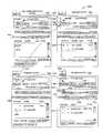
- FIG. 5is a mock-up web interface 500 , in accordance with an example embodiment.
- the web interfacemay be generated by a web server that relates to the networked contact center and may be accessed over the Internet via a web browser.
- Example embodimentsmay be used by a supervisor or an agent to manage contacts.
- the contact centermay route contacts, such as voice, chat and email communications, to a particular agent, group and/or queue and display information associated with the contact via the example web interface 500 .
- a usersuch as an agent or supervisor, may log on to the example web interface to obtain access to information within the networked contact center.
- a usermay initiate and respond to contacts with the web interface 500 .
- Sub-window 502 of the web interface 500may be referred to as a transaction panel, and sub-window 504 may be referred to as a shared area.
- FIG. 6is a graphical diagram 600 showing example windows 601 - 605 that may be displayed in the shared area 504 of the mock-up web interface 500 , in accordance with an example embodiment.
- Some example shared windowsmay include a frequently asked questions (FAQs) window 602 and a help window 603 .
- a customer relationship management (CRM) and agent profile window 601may be used to access customer and agent information.
- a supervision window 604may be accessed by an agent supervisor to view agent or group performance information or any other information useful to a supervisor.
- a reports window 605is to display generated contact center related reports,
- FIG. 7shows an example transaction panel 700 , in accordance with an example embodiment.
- An agent or contact supervisormay employ the transaction panel 700 to manage contact relating to a network contact center.
- the transaction panel 700may include one or more frames.
- a frame or framesoccupy space (e.g., a footprint) on the transaction panel 700 , and may be used to convey information (e.g., visual information) and/or to provide functionality associated with a networked contact center.
- a framemay include sub-frames that may be associated with the frame in different manners. It may be noted that a frame as used herein is not limited to being used or being generated with any particular programming language(s); a frame as used herein may be generated using various programming languages and the concept of a frame may be extended to various programming environments.
- a frameis a selectable toggle button and a user may interact with the toggle button by selecting it.
- the toggle buttonmay display text that indicates a function that will be initiated when a user toggles the button.
- the words “frame” and “indicator”may be used interchangeably.
- One or more web serversmay generate output and receive input via the frames of the example web interface 500 .
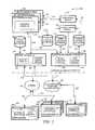
- FIG. 8is a block diagram 800 showing an example web interface module 802 (e.g., a web server) that is communicatively coupled with one or more web browsers 812 , in accordance with an example embodiment.
- the example web interface module 802is shown to include an output module 804 that is communicatively coupled with an input module 806 and a status module 810 .
- the input module 806is further communicatively coupled to a function module 808 .
- the example web interface module 802 and its components 804 , 806 , 808 and 810may provide certain functionality that may be implemented with hardware, software or a combination of hardware and software.
- all or part of the web interface module 802is implemented using HyperText markup language (HTML).
- Other software languagese.g., Java, etc.
- the output module 804may present a frame on an example web interface such as a web page served to a web browser 812 .
- the output module 804may present frames with different formats and capabilities.
- the output module 804presents an example frame that includes text (e.g., “Dial”) and is initially a selectable toggle button or switch to initiate a function.
- the toggle buttonmay initially be un-selectable and display text indicating a status (e.g., dialing).
- the output module 804may output other information related to a capability of a frame.
- the input module 806is to detect user interaction with a frame.
- a user interaction with a frameincludes input provided to a web browser by the user.
- inputmay include a keystroke, a mouse click, a voice command, a computer generated input, or any other input to a machine interface.
- the input module 806may transmit a signal to the output module 804 and/or the function module 808 upon detecting the user interaction.
- the input module 806may register a selection of the selectable toggle button and notify the function module 808 .
- the function module 808is to initiate a function associated with a frame presented by the output module 804 .
- a functionmay be initiated in response to a frame being selected, as detected by the input module.
- the function module 808may signal the output module 804 regarding initiation of the function.
- the status module 810is to detect a state associated with a networked contact center and report a status and/or status change to the output module 804 and/or the function module 808 .
- the status moduledetects that communication between an agent and a customer has been temporarily suspended (e.g., on hold) and may notify the output and function modules 804 , 808 .
- the transaction panel 700is shown to include a drop down menu 702 (e.g., a frame) that allows for user selection of various sub-windows to cause windows 601 - 605 to be displayed by a user interface (e.g., a screen).
- a current user indicator 704(e.g., a further frame, etc.) indicates a name of a current user logged on to the contact center web interface module 800 .
- the status panel 706is a frame that includes sub-frames to display and/or allow control over a user's current status and the elapsed time since the start of a current status.
- the example status panel 706allows the user to change his or her status (e.g., by pushing a button to take a break or to log out).
- a group and queue status indicator 708may be an interface that gives a user an overview of the current status of a group of users and/or a contact queue. In some example embodiments, the status indicator 708 shows an amount of contact with the group and/or in the queue relative to a maximum capacity of contact that may be received.
- a tab selector bar 710may include multiple tabs that are selectable to switch between channels of communication. For example, one tab may be selected to display information about a telephone call while another tab may be selected to display different information about a simultaneously connected telephone call, chat session or email. Other forms of communication not described may be represented by tabs in the tab selector bar 710 .
- the transaction panel 700may display a different interaction control panel 712 .
- the communication channelis analog voice and the interaction control panel 712 shows a telephone number 713 of a customer interacting with an agent.
- the interaction control panel 712may include buttons 714 that may be selectable or un-selectable by an agent to affect current communication (e.g., mute button, hold button, and hang up button).
- the window selector 716may be used to select (e.g., via sub-frames CRM, frequently asked questions (FAQ), collaboration, close, etc.) different windows and corresponding content to be displayed in the shared area 504 . Toggling of an example sub-frame within the frame 716 may show and hide the frame 504 , for example, by changing the width of the window 500 to display frame 502 alone or with frame 504 .
- Each channel selected under the tab selector bar 710may correspond to its own set of windows, which are selectable by the window selector 716 .
- Each interaction occurring over a particular channelmay be timed.
- An example time display 715may display an elapsed time for each channel of communication.
- Each particular channelmay include a tabbed set of sub-panels 718 .
- An example sub-panel 719includes a phone sub-panel 720 that may display a current status (e.g., talking, dialing, ringing, etc.) of a call, the participants of the call and any other call information that may be appropriate for a responding agent to access.
- Other sub-panelssuch as a transaction sub-panel 721 , an agents sub-panel 722 and a queues sub-panel 723 may be selectable to display corresponding contact center information.
- Further status control buttons 724may be included to allow a user to influence state of communication.
- FIG. 9is a flow diagram illustrating an example method 900 for presenting a frame on a user interface, in accordance with an example embodiment.
- the example method 900may be performed by the web interface module 802 of FIG. 8 .
- the example method 900may be performed with respect to the user interface of FIGS. 5-7 and 10 .
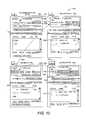
- FIG. 10is a graphical state diagram illustrating user placement of an outgoing call using a transaction panel 700 , in accordance with an example embodiment.
- the example method 900may be illustrated in state transitions 1003 , 1023 and 1043 included in the state diagram 1000 of FIG. 10 .
- the example method 900includes presenting first information in a selectable format.
- the first information presentedmay include the word “Dial” on the button 1004 .
- Information presented with a frame(e.g., “Dial” on the frame 1004 ) may represent a function, and selection of the frame may activate the function.
- the output module 804provides a selectable frame 1004 in response to the input module 806 indicating that all or part of a phone number is entered into the frame 1006 as shown.
- the output module 804may generate a selectable frame 1004 when the status module 810 detects that the voice channel is in a state of no communication 1002 .
- the output module 804may present the selectable button 1004 in response to the input module 806 indicating that a particular agent listed (not shown) under the agent tab 1012 has been highlighted by a user.
- Other framessuch as the frame 1010 that includes the word “Mute,” may be presented by the output module 804 as being un-selectable as there may not yet a be a call in-progress to mute.
- the output module 804may present the button 1008 including the words “End Call” (e.g., a function to be provided by the function module 808 ) as being selectable to remove any input to the frame 1006 , which may in turn cause the output module 804 to present the dial button 1004 as being un-selectable.
- End Calle.g., a function to be provided by the function module 808
- the method 900may include presenting second information in an un-selectable format, responsive to a selection associated with the first information.
- a usermay select the frame 1004 to dial a call by interacting with (e.g., clicking on) the frame 1004 .
- the input module 806is to register selection of the frame 1004 and transmit a signal to notify the output module 804 and the function module 808 of the selection.
- the example function module 808may initiate a function, such as a dial function, to place a call to the phone number entered into the frame 1006 .
- the status module 810may detect a transition 1003 if the state of the call has transitioned from a no communication state to a dialing state.
- Information presented with frames(e.g., “Dialing” on the frame 1024 ) may represent a status associated with a function.
- the status of communicationshows “D” 1036 indicating dialing when a number has been dialed.
- the phone tab 1034is also shown to include a name (e.g., “John Doe”) 1038 indicating that dialing relates to the caller by that name 1038 .
- the output module 804may provide the frame 1024 with second information, such as “Dialing,” and may provide the frame 1024 as being un-selectable.
- a transaction panelmay be used as an interface for chat and/or email communications.
- the transaction panel 700serves as an interface for voice, chat and email communications.
- the communicationis between a tenant's agent and the tenant's customer.
- Two of the tenant's agentsmay also communicate with each other using one or more transaction panel.
- Some example embodimentsrelate to communication between the agent and the networked contact center.
- the transaction panelmay be configured to facilitate communication between various different entities without departing from the spirit of the claimed subject matter.
- a toggle buttonmay be provided, that when selected, initiates ending a chat session between an agent and a customer or any other entities participating in a communication.
- the method 900includes presenting third information in the un-selectable format, responsive to a detection of a further status of communication.
- the third informationmay represent a further status (e.g., relative to the dialing state).
- the status module 810may detect that the status of a call has transitioned 1023 from a dialing state 1022 to a ringing state 1042 .
- the voice channel in the ringing state 1042is shown to include a frame 1044 , which is provided by the output module 804 to include the word “Ringing” and to be un-selectable.
- the status of communicationshows “R” 1056 indicating that the status of the call is ringing at the call recipient's receiver.
- the status module 810may detect that the status of the call has transitioned 1043 from a ringing state 1042 to a talking state 1062 .
- the status module 810may notify the output module 804 , which may responsively display certain frames on the transaction panel 1062 .
- a transaction panel 1062is shown in the talking state, which is indicated by the frame 1064 that includes the word “Talking” and the “T” 1076 in the status column of the phone tab 1074 . It may be noted that the “T” is included in the same rows 1078 as the name of the caller and the name of the user being called, indicating that talking relates to each user.
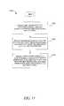
- FIG. 11is a flow diagram illustrating a further example method 1100 for presenting a frame on a user interface, in accordance with an example embodiment.
- Blocks 1102 and 1104may be substantially similar to blocks 902 and 904 of FIG. 9 .
- the method 1100may include presenting further information with a second frame (e.g., frame 1068 ) in a selectable format in response to the initial selection (e.g., the selection of the frame 1004 to “Dial”).
- the further informatione.g., “Mute” on the frame 1068
- a further functione.g., a mute function
- the status module 810may notify the output module 804 that the call status has transitioned from the ringing state 1042 to a talking state 1062 . Responsive to the initial selection of the frame 1004 and the subsequent talking status 1062 , the output module 804 may display a further selectable frame such as the frame 1068 including the word “Mute.” In an example embodiment, the mute button on frame 1068 becomes available when in the talking state 1062 and may be selected to temporarily suspend an in-progress call. Other frames that may become available include the frame 1082 , which represents an available channel, the frame 1070 to transfer a call and the frames 1072 , 1073 that are to be discussed in more detail below. As disclosed above, a time display frame 1080 may display the time elapsed in minutes and seconds since the call was first connected.
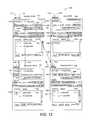
- FIG. 12is a further graphical state diagram 1200 illustrating state transitions out of the talking state 1202 , in accordance with example embodiments.
- the figureillustrates further example embodiments illustrating the claimed subject matter.
- the voice channelmay transition 1203 from the talking state 1202 to the muted state 1242 .
- the input module 806may register the selection and notify the function module 808 and the output module 804 of the selection.
- the function module 808may initiate a mute function in response to the selection of the frame 1208 .
- the output module 804may display the frame 1248 with the word “Muted” on an un-selectable button.
- the information on the selectable frame(e.g., frame 1208 , the “Mute” button) is associated with one status (e.g., the frame 1204 , the talking status of communication), while the un-selectable frame (e.g., the frame 1248 , the “Muted” button) is associated with another status of communication (e.g., the frame 1248 , the muted status of communication).
- the mute functionis initiated, “Talking,” the status that was indicated on the un-selectable frame 1204 in the talking state 1202 , is replaced with “Talk,” a function on the selectable frame 1244 .
- the status under the phone tabmay show “M” 1250 to indicate that John Doe is muted.
- the transaction panelmay transition 1243 from the muted state 1242 back to the talking state 1202 .
- Other framesmay become selectable or un-selectable in response to the mute function being initiated.
- additional framesmay be affected by an initial selection of the frame 1004 (e.g., “Dial”) and the subsequent transition to talking status of communication.
- the output module 804may generate the additional frames in response to signals from the input module 806 , indicating user input, and/or the status module 810 , indicating change of state.
- frames providing tabs 1215 and 1216may become selectable to access information that is specific to the particular call that has been connected (e.g., frame 1215 , “Transaction”) and/or to access information related to queues associated with the call (e.g., frame 1216 , “Queues”).
- connection of a callmay cause a frame providing a tab selector bar 1214 to become selectable.
- the tab selector bar 1214allows access to voice channel information relating to a telephone connection (or e.g., potential connection) other than the telephone connection associated with selector tab 1212 of the transaction panel in the talking state 1202 .
- Selection of the frame 1206may result in an active connection being temporarily suspended.
- the function module 808may initiate a state transition 1205 from the talking state 1202 to the on hold state 1282 .
- the output module 804may change the display on the frame 1206 from “Hold” to “On Hold” as displayed on frame 1286 .
- the frame 1292displays a hand icon on the tab that represents a telephone line, to indicate that the telephone line is on hold.
- An “H” 1290 , 1291may also be displayed to indicate that call participants are on hold.
- a usermay transition 1283 back to the talking state by selecting the frame 1284 , initiating the talk function as in the transition from the muted state 1242 to the talking state 1202
- Selection of the frame 1210may result in an active connection being terminated.
- Frames in the transaction panelmay indicate a transition 1207 from the talking state 1202 to the idle state 1222 .
- the frames located in the interaction control panel 1223become un-selectable when the transaction panel is in the idle state 1222 .
- the available channel of communication 1234may no longer be shown as selectable since the first channel represented by the frame 1232 is no longer occupied.
- the status 1224may be labeled as “none” and the frames 1235 and 1236 may no longer remain selectable to view call related transaction or queue information.
- a frame that may display different information under different circumstances and that may vary selectability under different circumstancesmay be used for other contact center activity.
- a transaction panelmay be used to answer a call that has been directly dialed, transferred from another entity and/or taken from a queue of calls. Chats and emails may be initiated, answered and/or transferred.
- the claimed subject mattermay be practiced with respect to numerous other applications that include the presentation of varying information by a frame where the information presented relates to whether or not the frame is selected by a user.
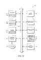
- FIG. 13shows a diagrammatic representation of a machine in the example form of a computer system 1300 within which a set of instructions, for causing the machine to perform any one or more of the methodologies discussed herein, may be executed.
- the machineoperates as a standalone device or may be connected (e.g., networked) to other machines.
- the machinemay operate in the capacity of a server or a client machine in a server-client network environment, or as a peer machine in a peer-to-peer (or distributed) network environment.
- the machinemay be a server computer, a client computer, a PC, a tablet PC, a set-top box (STB), a Personal Digital Assistant (PDA), a cellular telephone, a web appliance, a network router, switch or bridge, or any machine capable of executing a set of instructions (sequential or otherwise) that specify actions to be taken by that machine.
- PDAPersonal Digital Assistant
- STBset-top box
- machineshall also be taken to include any collection of machines that individually or jointly execute a set (or multiple sets) of instructions to perform any one or more of the methodologies discussed herein.
- the example computer system 1300includes a processor 1304 (e.g., a central processing unit (CPU), a graphics processing unit (GPU) or both), a main memory 1310 and a static memory 1314 which communicate with each other via a bus 1308 .
- the computer system 1300may further include a video display unit 1302 (e.g., a liquid crystal display (LCD) or a cathode ray tube (CRT)).
- the computer system 1300also includes an alphanumeric input device 1312 (e.g., a keyboard), a cursor control device 1316 (e.g., a mouse), a disk drive unit 1320 a signal generation device 1340 (e.g., a speaker) and a network interface device 1318
- the disk drive unit 1320includes a machine-readable medium 1322 on which is stored one or more sets of instructions (e.g., software 1324 ) embodying any one or more of the methodologies or functions described herein.
- the instructions 1324may also reside, completely or at least partially, within the main memory 1310 and/or within the processor 1304 during execution thereof by the computer system 1300 , the main memory 1310 and the processor 1304 also constituting machine-readable media.
- the instructions 1324may further be transmitted or received over a network 1330 via the network interface device 1318 .
- machine-readable medium 1322is shown in an example embodiment to be a single medium, the term “machine-readable medium” should be taken to include a single medium or multiple media (e.g., a centralized or distributed database, and/or associated caches and servers) that store the one or more sets of instructions.
- the term “machine-readable medium”shall also be taken to include any medium that is capable of storing, encoding or carrying a set of instructions for execution by the machine and that cause the machine to perform any one or more of the methodologies of the present subject matter.
- the term “machine-readable medium”shall accordingly be taken to include, but not be limited to, solid-state memories, optical and magnetic media, and carrier wave signals.
Landscapes
- Engineering & Computer Science (AREA)
- Signal Processing (AREA)
- Business, Economics & Management (AREA)
- Marketing (AREA)
- General Engineering & Computer Science (AREA)
- Theoretical Computer Science (AREA)
- Human Computer Interaction (AREA)
- Physics & Mathematics (AREA)
- General Physics & Mathematics (AREA)
- Computer Networks & Wireless Communication (AREA)
- Telephonic Communication Services (AREA)
Abstract
Description
Claims (15)
Priority Applications (4)
| Application Number | Priority Date | Filing Date | Title |
|---|---|---|---|
| US14/974,759US9531879B1 (en) | 2008-08-29 | 2015-12-18 | Networked contact center user interface approach |
| US15/384,072US10298767B1 (en) | 2008-08-29 | 2016-12-19 | Networked contact center user interface approach |
| US16/394,623US10863031B1 (en) | 2008-08-29 | 2019-04-25 | Networked contact center user interface approach |
| US17/115,147US11736618B1 (en) | 2008-08-29 | 2020-12-08 | Networked contact center user interface approach |
Applications Claiming Priority (3)
| Application Number | Priority Date | Filing Date | Title |
|---|---|---|---|
| US12/201,573US8972885B2 (en) | 2008-08-29 | 2008-08-29 | Networked contact center user interface |
| US14/629,577US9225832B1 (en) | 2008-08-29 | 2015-02-24 | Networked contact center user interface |
| US14/974,759US9531879B1 (en) | 2008-08-29 | 2015-12-18 | Networked contact center user interface approach |
Related Parent Applications (1)
| Application Number | Title | Priority Date | Filing Date |
|---|---|---|---|
| US14/629,577ContinuationUS9225832B1 (en) | 2008-08-29 | 2015-02-24 | Networked contact center user interface |
Related Child Applications (1)
| Application Number | Title | Priority Date | Filing Date |
|---|---|---|---|
| US15/384,072ContinuationUS10298767B1 (en) | 2008-08-29 | 2016-12-19 | Networked contact center user interface approach |
Publications (1)
| Publication Number | Publication Date |
|---|---|
| US9531879B1true US9531879B1 (en) | 2016-12-27 |
Family
ID=41727147
Family Applications (6)
| Application Number | Title | Priority Date | Filing Date |
|---|---|---|---|
| US12/201,573Active2032-09-14US8972885B2 (en) | 2008-08-29 | 2008-08-29 | Networked contact center user interface |
| US14/629,577ActiveUS9225832B1 (en) | 2008-08-29 | 2015-02-24 | Networked contact center user interface |
| US14/974,759ActiveUS9531879B1 (en) | 2008-08-29 | 2015-12-18 | Networked contact center user interface approach |
| US15/384,072Active2029-02-03US10298767B1 (en) | 2008-08-29 | 2016-12-19 | Networked contact center user interface approach |
| US16/394,623ActiveUS10863031B1 (en) | 2008-08-29 | 2019-04-25 | Networked contact center user interface approach |
| US17/115,147ActiveUS11736618B1 (en) | 2008-08-29 | 2020-12-08 | Networked contact center user interface approach |
Family Applications Before (2)
| Application Number | Title | Priority Date | Filing Date |
|---|---|---|---|
| US12/201,573Active2032-09-14US8972885B2 (en) | 2008-08-29 | 2008-08-29 | Networked contact center user interface |
| US14/629,577ActiveUS9225832B1 (en) | 2008-08-29 | 2015-02-24 | Networked contact center user interface |
Family Applications After (3)
| Application Number | Title | Priority Date | Filing Date |
|---|---|---|---|
| US15/384,072Active2029-02-03US10298767B1 (en) | 2008-08-29 | 2016-12-19 | Networked contact center user interface approach |
| US16/394,623ActiveUS10863031B1 (en) | 2008-08-29 | 2019-04-25 | Networked contact center user interface approach |
| US17/115,147ActiveUS11736618B1 (en) | 2008-08-29 | 2020-12-08 | Networked contact center user interface approach |
Country Status (1)
| Country | Link |
|---|---|
| US (6) | US8972885B2 (en) |
Families Citing this family (24)
| Publication number | Priority date | Publication date | Assignee | Title |
|---|---|---|---|---|
| US10033869B2 (en)* | 2008-08-29 | 2018-07-24 | 8X8, Inc. | Methods and systems for information streaming to user interface |
| US8275116B2 (en) | 2008-08-29 | 2012-09-25 | 8X8, Inc. | Networked contact center |
| US8204206B2 (en)* | 2008-08-29 | 2012-06-19 | 8X8, Inc. | Systems and methods for selection of a communication path |
| US8243913B2 (en)* | 2008-08-29 | 2012-08-14 | 8×8, Inc. | Limiting contact in a networked contact center environment |
| US8972885B2 (en) | 2008-08-29 | 2015-03-03 | 8X8, Inc. | Networked contact center user interface |
| US8515833B2 (en)* | 2008-08-29 | 2013-08-20 | 8X8, Inc. | Methods and systems for multilayer provisioning of networked contact centers |
| US8355691B2 (en)* | 2009-03-09 | 2013-01-15 | E.F. Johnson Company | Land mobile radio dispatch console |
| US20110150194A1 (en)* | 2009-12-23 | 2011-06-23 | Ramprakash Narayanaswamy | Web-Enabled Conferencing and Meeting Implementations with Flexible User Calling Features |
| US8468545B2 (en) | 2010-08-18 | 2013-06-18 | 8X8, Inc. | Interaction management |
| US8817801B1 (en) | 2011-07-08 | 2014-08-26 | 8X8, Inc. | Conferencing and meeting implementations with advanced features |
| CN102891939B (en)* | 2011-07-20 | 2017-05-10 | 中兴通讯股份有限公司 | Method and system for call forwarding and webpage server |
| WO2013016432A1 (en) | 2011-07-25 | 2013-01-31 | Talkto, Inc. | System and method for abstract communication |
| US10460290B2 (en)* | 2011-09-12 | 2019-10-29 | Path Mobile Inc Pte. Ltd. | System and method for establishing presence in a brokered chat system |
| WO2013040037A1 (en) | 2011-09-12 | 2013-03-21 | Talkto, Inc. | Multi-user communication system and method |
| US8468121B1 (en) | 2011-09-29 | 2013-06-18 | Shoretel, Inc. | Resolving resource time intervals in a distributed system |
| US11057339B1 (en)* | 2014-01-27 | 2021-07-06 | Phone2Action, Inc. | Systems and methods for providing an online platform for facilitating a communication connection between an individual and an elected official |
| US9401078B2 (en)* | 2014-02-26 | 2016-07-26 | Dell Products L.P. | Systems and methods for muting visual indicators in an information handling system |
| US10616345B1 (en)* | 2016-08-26 | 2020-04-07 | Noble Systems Corporation | Communication management system for supporting multiple agent communication sessions in a contact center |
| US10284723B1 (en) | 2016-12-23 | 2019-05-07 | Noble Systems Corporation | Managing multiple agent communication sessions in a contact center |
| EP3361706A1 (en)* | 2017-02-14 | 2018-08-15 | Webtext Holdings Limited | A redirection bridge device and system, a method of redirection bridging, method of use of a user interface and a software product |
| US10033870B1 (en) | 2017-04-12 | 2018-07-24 | Noble Systems Corporation | Agent interaction with a party using multiple channels of communication |
| US10523816B1 (en) | 2017-10-24 | 2019-12-31 | Noble Systems Corporation | Transferring an interaction between an agent at a contact center and a party from a first channel of communication to a second channel of communication |
| USD874493S1 (en)* | 2018-03-23 | 2020-02-04 | Martell Broadcasting Systems, Inc. | Display screen with channel page user interface |
| US11463587B1 (en) | 2019-03-04 | 2022-10-04 | United Services Automobile Association (Usaa) | Predictive mapping for routing telephone calls |
Citations (75)
| Publication number | Priority date | Publication date | Assignee | Title |
|---|---|---|---|---|
| US4723238A (en) | 1986-03-24 | 1988-02-02 | American Telephone And Telegraph Company | Interface circuit for interconnecting circuit switched and packet switched systems |
| US4809272A (en)* | 1986-09-22 | 1989-02-28 | Rockwell International Corporation | Telephone switching system with voice detection and answer supervision |
| US5117452A (en)* | 1989-09-29 | 1992-05-26 | David Callele | Telephone interface for a computer for receiving and transmitting information during the silent interval between ringing |
| US5210789A (en)* | 1991-06-28 | 1993-05-11 | International Telecharge, Inc. | Interactive telephone operator terminal |
| US5754636A (en)* | 1994-11-01 | 1998-05-19 | Answersoft, Inc. | Computer telephone system |
| US5799061A (en) | 1994-04-26 | 1998-08-25 | Greater Harris County 9-1-1 Emergency Network | Computer integrated telephony system for the processing of 9-1-1 calls for service |
| US5887139A (en)* | 1996-08-19 | 1999-03-23 | 3Com Corporation | Configurable graphical user interface useful in managing devices connected to a network |
| US6005931A (en) | 1997-02-10 | 1999-12-21 | Genesys Telecommunications Laboratories, Inc. | Negotiated routing in telephony systems |
| US6154465A (en) | 1998-10-06 | 2000-11-28 | Vertical Networks, Inc. | Systems and methods for multiple mode voice and data communications using intelligenty bridged TDM and packet buses and methods for performing telephony and data functions using the same |
| US6201863B1 (en) | 1997-02-10 | 2001-03-13 | Genesys Telecommunications Laboratories, Inc. | Personal desktop router |
| US6278777B1 (en) | 1998-03-12 | 2001-08-21 | Ser Solutions, Inc. | System for managing agent assignments background of the invention |
| US6295551B1 (en) | 1996-05-07 | 2001-09-25 | Cisco Technology, Inc. | Call center system where users and representatives conduct simultaneous voice and joint browsing sessions |
| US6317727B1 (en) | 1997-10-14 | 2001-11-13 | Blackbird Holdings, Inc. | Systems, methods and computer program products for monitoring credit risks in electronic trading systems |
| US6330005B1 (en) | 1996-02-23 | 2001-12-11 | Visionael Corporation | Communication protocol binding in a computer system for designing networks |
| US6393467B1 (en) | 1998-08-31 | 2002-05-21 | Nortel Networks Limited | Network interconnected computing device, server and notification method |
| US6392666B1 (en) | 1999-07-21 | 2002-05-21 | Avaya Technology Corp. | Telephone call center monitoring system allowing real-time display of summary views and interactively defined detailed views |
| US6493447B1 (en) | 1997-11-21 | 2002-12-10 | Mci Communications Corporation | Contact server for call center for syncronizing simultaneous telephone calls and TCP/IP communications |
| US20020198943A1 (en) | 2001-06-20 | 2002-12-26 | David Zhuang | Web-enabled two-way remote messaging facility |
| US6553115B1 (en) | 1995-01-06 | 2003-04-22 | Anip, Inc. | Automated access telephone system |
| US20030123640A1 (en) | 2001-12-31 | 2003-07-03 | William Roelle | Call center monitoring system |
| US20030172131A1 (en) | 2000-03-24 | 2003-09-11 | Yonghui Ao | Method and system for subject video streaming |
| US20030195934A1 (en) | 2002-04-15 | 2003-10-16 | Peterson Neil J. | Web services-based communications for use with process control systems |
| US20030195943A1 (en) | 2002-04-16 | 2003-10-16 | Elliott Bradshaw | System and method for managing memory |
| US20030208754A1 (en) | 2002-05-01 | 2003-11-06 | G. Sridhar | System and method for selective transmission of multimedia based on subscriber behavioral model |
| US20030236907A1 (en) | 2002-06-24 | 2003-12-25 | Stewart James C. | Communicating via a connection between a streaming server and a client without breaking the connection |
| US20040073508A1 (en) | 2000-11-20 | 2004-04-15 | Paul Foster | Method and system for property valuation in an on-line computing environment |
| US20040083292A1 (en) | 2002-10-25 | 2004-04-29 | Hermann Lueckhoff | Session coupling |
| US20040088300A1 (en) | 2001-01-08 | 2004-05-06 | Avery Brett Andrew | Management system for a contact centre |
| US6741698B1 (en) | 2000-01-27 | 2004-05-25 | Avaya Technology Corp. | Call management system using dynamic threshold adjustment |
| US6760429B1 (en) | 1999-12-23 | 2004-07-06 | Nortel Networks Limited | Web based agent backed system that provides streaming multimedia support |
| US6804345B1 (en) | 1997-09-18 | 2004-10-12 | At&T Corp | Virtual contact center with flexible staffing control |
| US20050041647A1 (en) | 2003-08-05 | 2005-02-24 | Stinnie Desmond L. | Internet voice & data messaging (IVDM) portal |
| US20050047579A1 (en) | 2003-08-29 | 2005-03-03 | Salame Mansour A. | Telecommunication call distribution system |
| US20050132298A1 (en) | 2003-12-16 | 2005-06-16 | Hermann Lueckhoff | Displaying interactive chat sessions |
| US20050135600A1 (en) | 2003-12-19 | 2005-06-23 | Whitman Raymond Jr. | Generation of automated recommended parameter changes based on force management system (FMS) data analysis |
| US20050193055A1 (en) | 2004-02-26 | 2005-09-01 | Mark Angel | Context sensitive dynamic user interface for customer service agent |
| US20060026304A1 (en) | 2004-05-04 | 2006-02-02 | Price Robert M | System and method for updating software in electronic devices |
| US6999990B1 (en) | 1998-12-18 | 2006-02-14 | Motive, Inc. | Technical support chain automation with guided self-help capability, escalation to live help, and active journaling |
| US7028091B1 (en) | 2000-08-31 | 2006-04-11 | Sun Microsystems, Inc. | Web server in-kernel interface to data transport system and cache manager |
| US7028331B2 (en) | 2001-02-28 | 2006-04-11 | Sharp Laboratories, Inc. | Content proxy method and apparatus for digital television environment |
| US7124171B1 (en) | 2002-05-23 | 2006-10-17 | Emc Corporation | In a networked computing cluster storage system and plurality of servers sharing files, in the event of server unavailability, transferring a floating IP network address from first server to second server to access area of data |
| US20060239440A1 (en) | 2005-04-25 | 2006-10-26 | Cisco Technology, Inc. | Method and system for handling calls at an automatic call distribution system |
| US20060256953A1 (en) | 2005-05-12 | 2006-11-16 | Knowlagent, Inc. | Method and system for improving workforce performance in a contact center |
| US7224783B2 (en) | 2003-12-19 | 2007-05-29 | International Business Machines Corporation | Subscriber service management |
| US20070127665A1 (en) | 2001-07-31 | 2007-06-07 | At&T Labs, Inc. | System and method for creating and accessing outgoing telephone call log |
| US20070162908A1 (en) | 2006-01-06 | 2007-07-12 | International Business Machines Corporation | Behavior-based resource capacity adjustment method for business processes |
| US20070192415A1 (en) | 2001-03-31 | 2007-08-16 | Pak Wai H | Extensible interface for inter-module communication |
| US20070192414A1 (en) | 2001-03-31 | 2007-08-16 | Mingte Chen | User interface for multi-channel communication |
| US20070211881A1 (en)* | 2006-03-09 | 2007-09-13 | Rachel Parker-Stephen | Call center user interface and methods of using same |
| US20080010084A1 (en) | 2002-10-03 | 2008-01-10 | Castro D A | Method and system for displaying customer information |
| US7328001B2 (en) | 2004-08-05 | 2008-02-05 | International Business Machines Corporation | Traffic shaping of cellular service consumption through modification of consumer behavior encouraged by cell-based pricing advantages |
| US20080037760A1 (en) | 2006-06-28 | 2008-02-14 | Boughton James N | Call flow staffing estimation tool |
| US20080072264A1 (en) | 2006-08-02 | 2008-03-20 | Aaron Crayford | Distribution of content on a network |
| US7403995B2 (en) | 2003-01-08 | 2008-07-22 | Outhink, Inc. | Symmetrical bi-directional communication |
| US20080178278A1 (en) | 2007-01-22 | 2008-07-24 | Doron Grinstein | Providing A Generic Gateway For Accessing Protected Resources |
| US20080177994A1 (en) | 2003-01-12 | 2008-07-24 | Yaron Mayer | System and method for improving the efficiency, comfort, and/or reliability in Operating Systems, such as for example Windows |
| US7480719B2 (en) | 2003-10-29 | 2009-01-20 | International Business Machines Corporation | Information system, load control method, load control program and recording medium |
| US20090055195A1 (en) | 2007-08-20 | 2009-02-26 | Karlsgodt Stephen | Internet radio player |
| US20090061850A1 (en) | 2007-08-31 | 2009-03-05 | Cct Tech Advanced Products Limited | Cordless phone system with data retrieving capability using wireless technology |
| US20090064148A1 (en) | 2007-08-31 | 2009-03-05 | Volker Jaeck | Linking Transactions with Separate Systems |
| US20090066788A1 (en) | 2005-03-16 | 2009-03-12 | Marc Baum | System for Data Routing in Networks |
| US20090067586A1 (en) | 2003-09-15 | 2009-03-12 | Accenture Global Services Gmbh | Remote media call center |
| US20090190728A1 (en) | 2008-01-24 | 2009-07-30 | Lucent Technologies Inc. | System and Method for Providing Audible Spoken Name Pronunciations |
| US20090216683A1 (en) | 2008-02-21 | 2009-08-27 | Mypowerpad, Llc | Interactive Media Content Display System |
| US7610388B2 (en) | 2003-04-03 | 2009-10-27 | International Business Machines Corporation | System, method and program for coordinating timeouts for distributed servers |
| US7627658B2 (en) | 2001-02-12 | 2009-12-01 | Integra Sp Limited | Presentation service which enables client device to run a network based application |
| US20090307001A1 (en) | 2008-06-10 | 2009-12-10 | Oracle International Corporation | Crm client architecture conducive to interaction with other applications executing in the same client system |
| WO2010025113A1 (en) | 2008-08-29 | 2010-03-04 | Contactual, Inc. | Multilayer provisioning of networked contact centers |
| US20100054448A1 (en) | 2008-08-29 | 2010-03-04 | Contactual, Inc. | Systems and methods for selection of a communicatoin path |
| US20100054451A1 (en) | 2008-08-29 | 2010-03-04 | Contactual, Inc. | Limiting contact in a networked contact center environment |
| US20100057927A1 (en) | 2008-08-29 | 2010-03-04 | Contactual, Inc. | Methods and systems for information streaming to user interface |
| WO2010025110A1 (en) | 2008-08-29 | 2010-03-04 | Contactual, Inc. | Networked contact center |
| US7784021B2 (en) | 2006-05-02 | 2010-08-24 | International Business Machines Corporation | Method for specifying, deploying and dynamically updating work flows |
| US20100232583A1 (en) | 2004-06-30 | 2010-09-16 | Bettis Sonny R | System and Method for Message Storage Assurance in a Geographically Distributed Voice Messaging System |
| US8065618B2 (en) | 2003-08-18 | 2011-11-22 | Sap Ag | Customization of an interaction center manager's graphical dashboard |
Family Cites Families (12)
| Publication number | Priority date | Publication date | Assignee | Title |
|---|---|---|---|---|
| US5625676A (en)* | 1993-09-13 | 1997-04-29 | Active Voice Corporation | Method and apparatus for monitoring a caller's name while using a telephone |
| US5901214A (en)* | 1996-06-10 | 1999-05-04 | Murex Securities, Ltd. | One number intelligent call processing system |
| US6285364B1 (en)* | 1997-06-03 | 2001-09-04 | Cisco Technology, Inc. | Method and apparatus for organizing and displaying internet and telephone information |
| US6466663B1 (en)* | 1997-09-30 | 2002-10-15 | Don Ravenscroft | Monitoring system client for a call center |
| US6823384B1 (en)* | 1999-10-15 | 2004-11-23 | James Wilson | Methods and apparatus for securely collecting customer service agent data in a multi-tenant environment |
| US6697858B1 (en)* | 2000-08-14 | 2004-02-24 | Telephony@Work | Call center |
| US20040088208A1 (en)* | 2002-10-30 | 2004-05-06 | H. Runge Bernhard M. | Creating and monitoring automated interaction sequences using a graphical user interface |
| JP3724492B2 (en)* | 2004-02-24 | 2005-12-07 | 株式会社カナック | Problem solving support device and program |
| US7779363B2 (en)* | 2006-12-05 | 2010-08-17 | International Business Machines Corporation | Enabling user control over selectable functions of a running existing application |
| US8365097B2 (en)* | 2007-11-08 | 2013-01-29 | Hewlett-Packard Development Company, L.P. | Interface for selection of items |
| US8490020B2 (en)* | 2008-02-21 | 2013-07-16 | Shoretel, Inc. | Programmable buttons for telephone user interface |
| US8972885B2 (en) | 2008-08-29 | 2015-03-03 | 8X8, Inc. | Networked contact center user interface |
- 2008
- 2008-08-29USUS12/201,573patent/US8972885B2/enactiveActive
- 2015
- 2015-02-24USUS14/629,577patent/US9225832B1/enactiveActive
- 2015-12-18USUS14/974,759patent/US9531879B1/enactiveActive
- 2016
- 2016-12-19USUS15/384,072patent/US10298767B1/enactiveActive
- 2019
- 2019-04-25USUS16/394,623patent/US10863031B1/enactiveActive
- 2020
- 2020-12-08USUS17/115,147patent/US11736618B1/enactiveActive
Patent Citations (82)
| Publication number | Priority date | Publication date | Assignee | Title |
|---|---|---|---|---|
| US4723238A (en) | 1986-03-24 | 1988-02-02 | American Telephone And Telegraph Company | Interface circuit for interconnecting circuit switched and packet switched systems |
| US4809272A (en)* | 1986-09-22 | 1989-02-28 | Rockwell International Corporation | Telephone switching system with voice detection and answer supervision |
| US5117452A (en)* | 1989-09-29 | 1992-05-26 | David Callele | Telephone interface for a computer for receiving and transmitting information during the silent interval between ringing |
| US5210789A (en)* | 1991-06-28 | 1993-05-11 | International Telecharge, Inc. | Interactive telephone operator terminal |
| US5799061A (en) | 1994-04-26 | 1998-08-25 | Greater Harris County 9-1-1 Emergency Network | Computer integrated telephony system for the processing of 9-1-1 calls for service |
| US5754636A (en)* | 1994-11-01 | 1998-05-19 | Answersoft, Inc. | Computer telephone system |
| US6553115B1 (en) | 1995-01-06 | 2003-04-22 | Anip, Inc. | Automated access telephone system |
| US6330005B1 (en) | 1996-02-23 | 2001-12-11 | Visionael Corporation | Communication protocol binding in a computer system for designing networks |
| US6295551B1 (en) | 1996-05-07 | 2001-09-25 | Cisco Technology, Inc. | Call center system where users and representatives conduct simultaneous voice and joint browsing sessions |
| US5887139A (en)* | 1996-08-19 | 1999-03-23 | 3Com Corporation | Configurable graphical user interface useful in managing devices connected to a network |
| US6005931A (en) | 1997-02-10 | 1999-12-21 | Genesys Telecommunications Laboratories, Inc. | Negotiated routing in telephony systems |
| US6201863B1 (en) | 1997-02-10 | 2001-03-13 | Genesys Telecommunications Laboratories, Inc. | Personal desktop router |
| US6804345B1 (en) | 1997-09-18 | 2004-10-12 | At&T Corp | Virtual contact center with flexible staffing control |
| US6317727B1 (en) | 1997-10-14 | 2001-11-13 | Blackbird Holdings, Inc. | Systems, methods and computer program products for monitoring credit risks in electronic trading systems |
| US6687241B1 (en) | 1997-11-21 | 2004-02-03 | Worldcom, Inc. | Enterprise contact server with enhanced routing features |
| US6493447B1 (en) | 1997-11-21 | 2002-12-10 | Mci Communications Corporation | Contact server for call center for syncronizing simultaneous telephone calls and TCP/IP communications |
| US6278777B1 (en) | 1998-03-12 | 2001-08-21 | Ser Solutions, Inc. | System for managing agent assignments background of the invention |
| US6393467B1 (en) | 1998-08-31 | 2002-05-21 | Nortel Networks Limited | Network interconnected computing device, server and notification method |
| US6154465A (en) | 1998-10-06 | 2000-11-28 | Vertical Networks, Inc. | Systems and methods for multiple mode voice and data communications using intelligenty bridged TDM and packet buses and methods for performing telephony and data functions using the same |
| US6999990B1 (en) | 1998-12-18 | 2006-02-14 | Motive, Inc. | Technical support chain automation with guided self-help capability, escalation to live help, and active journaling |
| US6392666B1 (en) | 1999-07-21 | 2002-05-21 | Avaya Technology Corp. | Telephone call center monitoring system allowing real-time display of summary views and interactively defined detailed views |
| US6760429B1 (en) | 1999-12-23 | 2004-07-06 | Nortel Networks Limited | Web based agent backed system that provides streaming multimedia support |
| US6741698B1 (en) | 2000-01-27 | 2004-05-25 | Avaya Technology Corp. | Call management system using dynamic threshold adjustment |
| US20030172131A1 (en) | 2000-03-24 | 2003-09-11 | Yonghui Ao | Method and system for subject video streaming |
| US7028091B1 (en) | 2000-08-31 | 2006-04-11 | Sun Microsystems, Inc. | Web server in-kernel interface to data transport system and cache manager |
| US20040073508A1 (en) | 2000-11-20 | 2004-04-15 | Paul Foster | Method and system for property valuation in an on-line computing environment |
| US20040088300A1 (en) | 2001-01-08 | 2004-05-06 | Avery Brett Andrew | Management system for a contact centre |
| US7627658B2 (en) | 2001-02-12 | 2009-12-01 | Integra Sp Limited | Presentation service which enables client device to run a network based application |
| US7028331B2 (en) | 2001-02-28 | 2006-04-11 | Sharp Laboratories, Inc. | Content proxy method and apparatus for digital television environment |
| US20070192415A1 (en) | 2001-03-31 | 2007-08-16 | Pak Wai H | Extensible interface for inter-module communication |
| US20070192414A1 (en) | 2001-03-31 | 2007-08-16 | Mingte Chen | User interface for multi-channel communication |
| US7730204B2 (en) | 2001-03-31 | 2010-06-01 | Siebel Systems, Inc. | Extensible interface for inter-module communication |
| US20020198943A1 (en) | 2001-06-20 | 2002-12-26 | David Zhuang | Web-enabled two-way remote messaging facility |
| US20070127665A1 (en) | 2001-07-31 | 2007-06-07 | At&T Labs, Inc. | System and method for creating and accessing outgoing telephone call log |
| US20030123640A1 (en) | 2001-12-31 | 2003-07-03 | William Roelle | Call center monitoring system |
| US20030195934A1 (en) | 2002-04-15 | 2003-10-16 | Peterson Neil J. | Web services-based communications for use with process control systems |
| US20030195943A1 (en) | 2002-04-16 | 2003-10-16 | Elliott Bradshaw | System and method for managing memory |
| US20030208754A1 (en) | 2002-05-01 | 2003-11-06 | G. Sridhar | System and method for selective transmission of multimedia based on subscriber behavioral model |
| US7124171B1 (en) | 2002-05-23 | 2006-10-17 | Emc Corporation | In a networked computing cluster storage system and plurality of servers sharing files, in the event of server unavailability, transferring a floating IP network address from first server to second server to access area of data |
| US20030236907A1 (en) | 2002-06-24 | 2003-12-25 | Stewart James C. | Communicating via a connection between a streaming server and a client without breaking the connection |
| US7644172B2 (en) | 2002-06-24 | 2010-01-05 | Microsoft Corporation | Communicating via a connection between a streaming server and a client without breaking the connection |
| US20080010084A1 (en) | 2002-10-03 | 2008-01-10 | Castro D A | Method and system for displaying customer information |
| US20040083292A1 (en) | 2002-10-25 | 2004-04-29 | Hermann Lueckhoff | Session coupling |
| US7403995B2 (en) | 2003-01-08 | 2008-07-22 | Outhink, Inc. | Symmetrical bi-directional communication |
| US20080177994A1 (en) | 2003-01-12 | 2008-07-24 | Yaron Mayer | System and method for improving the efficiency, comfort, and/or reliability in Operating Systems, such as for example Windows |
| US7610388B2 (en) | 2003-04-03 | 2009-10-27 | International Business Machines Corporation | System, method and program for coordinating timeouts for distributed servers |
| US20050041647A1 (en) | 2003-08-05 | 2005-02-24 | Stinnie Desmond L. | Internet voice & data messaging (IVDM) portal |
| US8065618B2 (en) | 2003-08-18 | 2011-11-22 | Sap Ag | Customization of an interaction center manager's graphical dashboard |
| US20050047579A1 (en) | 2003-08-29 | 2005-03-03 | Salame Mansour A. | Telecommunication call distribution system |
| US20090067586A1 (en) | 2003-09-15 | 2009-03-12 | Accenture Global Services Gmbh | Remote media call center |
| US20090133031A1 (en) | 2003-10-29 | 2009-05-21 | Masashi Inoue | Information system, load control method, load control program and recording medium |
| US7480719B2 (en) | 2003-10-29 | 2009-01-20 | International Business Machines Corporation | Information system, load control method, load control program and recording medium |
| US20050132298A1 (en) | 2003-12-16 | 2005-06-16 | Hermann Lueckhoff | Displaying interactive chat sessions |
| US7224783B2 (en) | 2003-12-19 | 2007-05-29 | International Business Machines Corporation | Subscriber service management |
| US20050135600A1 (en) | 2003-12-19 | 2005-06-23 | Whitman Raymond Jr. | Generation of automated recommended parameter changes based on force management system (FMS) data analysis |
| US20050193055A1 (en) | 2004-02-26 | 2005-09-01 | Mark Angel | Context sensitive dynamic user interface for customer service agent |
| US20060026304A1 (en) | 2004-05-04 | 2006-02-02 | Price Robert M | System and method for updating software in electronic devices |
| US20100232583A1 (en) | 2004-06-30 | 2010-09-16 | Bettis Sonny R | System and Method for Message Storage Assurance in a Geographically Distributed Voice Messaging System |
| US7328001B2 (en) | 2004-08-05 | 2008-02-05 | International Business Machines Corporation | Traffic shaping of cellular service consumption through modification of consumer behavior encouraged by cell-based pricing advantages |
| US20090066788A1 (en) | 2005-03-16 | 2009-03-12 | Marc Baum | System for Data Routing in Networks |
| US20060239440A1 (en) | 2005-04-25 | 2006-10-26 | Cisco Technology, Inc. | Method and system for handling calls at an automatic call distribution system |
| US20060256953A1 (en) | 2005-05-12 | 2006-11-16 | Knowlagent, Inc. | Method and system for improving workforce performance in a contact center |
| US20070162908A1 (en) | 2006-01-06 | 2007-07-12 | International Business Machines Corporation | Behavior-based resource capacity adjustment method for business processes |
| US20070211881A1 (en)* | 2006-03-09 | 2007-09-13 | Rachel Parker-Stephen | Call center user interface and methods of using same |
| US7784021B2 (en) | 2006-05-02 | 2010-08-24 | International Business Machines Corporation | Method for specifying, deploying and dynamically updating work flows |
| US20080037760A1 (en) | 2006-06-28 | 2008-02-14 | Boughton James N | Call flow staffing estimation tool |
| US20080072264A1 (en) | 2006-08-02 | 2008-03-20 | Aaron Crayford | Distribution of content on a network |
| US20080178278A1 (en) | 2007-01-22 | 2008-07-24 | Doron Grinstein | Providing A Generic Gateway For Accessing Protected Resources |
| US20090055195A1 (en) | 2007-08-20 | 2009-02-26 | Karlsgodt Stephen | Internet radio player |
| US20090061850A1 (en) | 2007-08-31 | 2009-03-05 | Cct Tech Advanced Products Limited | Cordless phone system with data retrieving capability using wireless technology |
| US20090064148A1 (en) | 2007-08-31 | 2009-03-05 | Volker Jaeck | Linking Transactions with Separate Systems |
| US20090190728A1 (en) | 2008-01-24 | 2009-07-30 | Lucent Technologies Inc. | System and Method for Providing Audible Spoken Name Pronunciations |
| US20090216683A1 (en) | 2008-02-21 | 2009-08-27 | Mypowerpad, Llc | Interactive Media Content Display System |
| US20090307001A1 (en) | 2008-06-10 | 2009-12-10 | Oracle International Corporation | Crm client architecture conducive to interaction with other applications executing in the same client system |
| US20100054448A1 (en) | 2008-08-29 | 2010-03-04 | Contactual, Inc. | Systems and methods for selection of a communicatoin path |
| US20100057927A1 (en) | 2008-08-29 | 2010-03-04 | Contactual, Inc. | Methods and systems for information streaming to user interface |
| WO2010025110A1 (en) | 2008-08-29 | 2010-03-04 | Contactual, Inc. | Networked contact center |
| US20100054450A1 (en) | 2008-08-29 | 2010-03-04 | Contactual, Inc. | Networked contact center |
| WO2010025112A1 (en) | 2008-08-29 | 2010-03-04 | Contactual, Inc. | Limiting contact in a networked contact center environment |
| US20100054451A1 (en) | 2008-08-29 | 2010-03-04 | Contactual, Inc. | Limiting contact in a networked contact center environment |
| US20100054439A1 (en) | 2008-08-29 | 2010-03-04 | Contactual, Inc. | Methods and systems for multilayer provisioning of networked contact centers |
| WO2010025113A1 (en) | 2008-08-29 | 2010-03-04 | Contactual, Inc. | Multilayer provisioning of networked contact centers |
Non-Patent Citations (23)
| Title |
|---|
| "International Application Serial No. PCT/US2009/054787, Search Report mailed Oct. 13, 2009". |
| "U.S. Appl. No. 12/201,726, Final Office Action mailed Apr. 18, 2011", 16 pgs. |
| Brown, Donald E, "The Interaction Center Platform", Interactive Intelligence, Inc., (2005), 35 pgs. |
| Fielding, et al., "HTTP/1.1: Connections, 8 Connections", Part of Hypertext Transfer Protocol-HTTP/1.1, RFC 2616, [Online]. Retrieved from the Internet Jan. 12, 2011: , 6 pgs. |
| Fielding, et al., "HTTP/1.1: Connections, 8 Connections", Part of Hypertext Transfer Protocol-HTTP/1.1, RFC 2616, [Online]. Retrieved from the Internet Jan. 12, 2011: <URL: http://www.w3.org/Protocols/rfc2616/rfc2616-sec8.html>, 6 pgs. |
| Fielding, R., et al., "Hypertext Transfer Protocol-HTTP/1.1, Chapters 1-9.1.2", (Jun. 1999), 22 pgs. |
| Infrequently Noted, "Comet: Low Latency Data for the Browser", [Online]. Retrieved from the Internet: , (Mar. 3, 2006), 5 pgs. |
| Infrequently Noted, "Comet: Low Latency Data for the Browser", [Online]. Retrieved from the Internet: <URL:http://infrequently.org/2006/03/comet-low-latency-data-for-thebrowser>, (Mar. 3, 2006), 5 pgs. |
| International Application Serial No. PCT/US2009/054780, Search Report and Written Opinion mailed Oct. 8, 2009. |
| International Application Serial No. PCT/US2009/054787, Written Opinion mailed Oct. 13, 2009. |
| International Application Serial No. PCT/US2009/054788, Search Report mailed Oct. 13, 2009. |
| International Application Serial No. PCT/US2009/054788, Written Opinion mailed Oct. 13, 2009. |
| McCarthy, Philip, "Ajax for Java developers: Write scalable Comet applications with Jetty and Direct Web Remoting", [Online]. Retrieved from the Internet: , (Jul. 17, 2007), 16 pgs. |
| McCarthy, Philip, "Ajax for Java developers: Write scalable Comet applications with Jetty and Direct Web Remoting", [Online]. Retrieved from the Internet: <URL: http://www.ibm.com/developerworks/java/library/j-jettydwr/index.html>, (Jul. 17, 2007), 16 pgs. |
| U.S. Appl. No. 12/201,599, Preliminary Amendment mailed Dec. 8, 2009, 10 pgs. |
| U.S. Appl. No. 12/201,639, Preliminary Amendment mailed Jul. 1, 2010, 11 pgs. |
| U.S. Appl. No. 12/201,671 Non-Final Office Action mailed Jun. 28, 2010, 21 pgs. |
| U.S. Appl. No. 12/201,671, Final Office Action mailed Dec. 14, 2010,24 pgs. |
| U.S. Appl. No. 12/201,671, Response Filed Jun. 14, 2011 to Final Office Action Received Dec. 14, 2010, 14 pgs. |
| U.S. Appl. No. 12/201,671, Response filed Sep. 28, 2010 to Non Final Office Action mailed Jun. 28, 2010, 11 pgs. |
| U.S. Appl. No. 12/201,726, Non-Final Office Action mailed Oct. 12, 2010, 17 pgs. |
| U.S. Appl. No. 12/201,726, Response filed Jan. 12, 2011 to Non-Final Office Action mailed Oct. 12, 2010, 13 pgs. |
| U.S. Appl. No. 12/201,726, Response filed Jun. 20, 2011 to Final Office Action mailed Apr. 18, 2011, 14 pgs. |
Also Published As
| Publication number | Publication date |
|---|---|
| US9225832B1 (en) | 2015-12-29 |
| US20100058234A1 (en) | 2010-03-04 |
| US11736618B1 (en) | 2023-08-22 |
| US8972885B2 (en) | 2015-03-03 |
| US10863031B1 (en) | 2020-12-08 |
| US10298767B1 (en) | 2019-05-21 |
Similar Documents
| Publication | Publication Date | Title |
|---|---|---|
| US11736618B1 (en) | Networked contact center user interface approach | |
| US12022028B1 (en) | Methods and systems for information streaming to user interface | |
| US8468545B2 (en) | Interaction management | |
| US11831809B2 (en) | Limiting contact in a networked contact center environment | |
| EP4246948A2 (en) | System and method for omni-channel notification and selection | |
| US9307088B1 (en) | Networked contact center | |
| US10616345B1 (en) | Communication management system for supporting multiple agent communication sessions in a contact center | |
| US8515833B2 (en) | Methods and systems for multilayer provisioning of networked contact centers |
Legal Events
| Date | Code | Title | Description |
|---|---|---|---|
| AS | Assignment | Owner name:CONTACTUAL, INC., CALIFORNIA Free format text:ASSIGNMENT OF ASSIGNORS INTEREST;ASSIGNORS:SALAME, MANSOUR;SOUTHWICK, RICHARD;FERNANDEZ, WILLIAM JAMES;AND OTHERS;SIGNING DATES FROM 20080905 TO 20100115;REEL/FRAME:039485/0271 Owner name:8X8, INC., CALIFORNIA Free format text:ASSIGNMENT OF ASSIGNORS INTEREST;ASSIGNOR:CONTACTUAL, INC.;REEL/FRAME:039485/0382 Effective date:20111101 | |
| STCF | Information on status: patent grant | Free format text:PATENTED CASE | |
| MAFP | Maintenance fee payment | Free format text:PAYMENT OF MAINTENANCE FEE, 4TH YEAR, LARGE ENTITY (ORIGINAL EVENT CODE: M1551); ENTITY STATUS OF PATENT OWNER: LARGE ENTITY Year of fee payment:4 | |
| AS | Assignment | Owner name:WILMINGTON SAVINGS FUND SOCIETY, FSB, DELAWARE Free format text:INTELLECTUAL PROPERTY SECURITY AGREEMENT;ASSIGNORS:8X8, INC.;FUZE, INC.;REEL/FRAME:061085/0861 Effective date:20220803 | |
| AS | Assignment | Owner name:WILMINGTON SAVINGS FUND SOCIETY, FSB, DELAWARE Free format text:CORRECTIVE ASSIGNMENT TO CORRECT THE PROPERTY NUMBERS SECTION TO REMOVE APPLICATION NUMBERS 11265423, 11252205, 11240370, 11252276, AND 11297182 PREVIOUSLY RECORDED ON REEL 061085 FRAME 0861. ASSIGNOR(S) HEREBY CONFIRMS THE INTELLECTUAL PROPERTY SECURITY AGREEMENT;ASSIGNORS:8X8, INC.;FUZE, INC.;REEL/FRAME:066383/0936 Effective date:20220803 | |
| MAFP | Maintenance fee payment | Free format text:PAYMENT OF MAINTENANCE FEE, 8TH YEAR, LARGE ENTITY (ORIGINAL EVENT CODE: M1552); ENTITY STATUS OF PATENT OWNER: LARGE ENTITY Year of fee payment:8 | |
| AS | Assignment | Owner name:FUZE, INC., MASSACHUSETTS Free format text:RELEASE BY SECURED PARTY;ASSIGNOR:WILMINGTON SAVINGS FUND SOCIETY, FSB;REEL/FRAME:068328/0569 Effective date:20240805 Owner name:8X8, INC., CALIFORNIA Free format text:RELEASE BY SECURED PARTY;ASSIGNOR:WILMINGTON SAVINGS FUND SOCIETY, FSB;REEL/FRAME:068328/0569 Effective date:20240805 Owner name:WELLS FARGO BANK, NATIONAL ASSOCIATION, AS ADMINISTRATIVE AGENT, TEXAS Free format text:SECURITY INTEREST;ASSIGNOR:8X8, INC.;REEL/FRAME:068327/0819 Effective date:20240805 |