US9531363B2 - Methods and apparatuses including command latency control circuit - Google Patents
Methods and apparatuses including command latency control circuitDownload PDFInfo
- Publication number
- US9531363B2 US9531363B2US14/698,550US201514698550AUS9531363B2US 9531363 B2US9531363 B2US 9531363B2US 201514698550 AUS201514698550 AUS 201514698550AUS 9531363 B2US9531363 B2US 9531363B2
- Authority
- US
- United States
- Prior art keywords
- signals
- signal
- counter
- delay
- circuit
- Prior art date
- Legal status (The legal status is an assumption and is not a legal conclusion. Google has not performed a legal analysis and makes no representation as to the accuracy of the status listed.)
- Active
Links
- 230000003111delayed effectEffects0.000claimsabstractdescription38
- 230000001902propagating effectEffects0.000claimsdescription2
- VUKDZGAUWUDQRZ-XKLVTHTNSA-N[[(2r,3s,4r,5r)-5-(6-aminopurin-9-yl)-3,4-dihydroxyoxolan-2-yl]methoxy-hydroxyphosphoryl] 2-phenylacetateChemical compoundC([C@H]1O[C@H]([C@@H]([C@@H]1O)O)N1C=2N=CN=C(C=2N=C1)N)OP(O)(=O)OC(=O)CC1=CC=CC=C1VUKDZGAUWUDQRZ-XKLVTHTNSA-N0.000description37
- 230000015654memoryEffects0.000description35
- 238000010586diagramMethods0.000description11
- 230000000630rising effectEffects0.000description8
- 230000001360synchronised effectEffects0.000description8
- 230000008859changeEffects0.000description3
- 230000001934delayEffects0.000description3
- 230000006399behaviorEffects0.000description2
- 230000007704transitionEffects0.000description2
- 241001522296Erithacus rubeculaSpecies0.000description1
- 238000004519manufacturing processMethods0.000description1
- 230000004048modificationEffects0.000description1
- 238000012986modificationMethods0.000description1
- 230000000644propagated effectEffects0.000description1
- 230000004044responseEffects0.000description1
- 230000003068static effectEffects0.000description1
Images


Classifications
- G—PHYSICS
- G11—INFORMATION STORAGE
- G11C—STATIC STORES
- G11C7/00—Arrangements for writing information into, or reading information out from, a digital store
- G11C7/10—Input/output [I/O] data interface arrangements, e.g. I/O data control circuits, I/O data buffers
- G11C7/1051—Data output circuits, e.g. read-out amplifiers, data output buffers, data output registers, data output level conversion circuits
- G11C7/106—Data output latches
- H—ELECTRICITY
- H03—ELECTRONIC CIRCUITRY
- H03K—PULSE TECHNIQUE
- H03K5/00—Manipulating of pulses not covered by one of the other main groups of this subclass
- H03K5/13—Arrangements having a single output and transforming input signals into pulses delivered at desired time intervals
- H03K5/135—Arrangements having a single output and transforming input signals into pulses delivered at desired time intervals by the use of time reference signals, e.g. clock signals
- H—ELECTRICITY
- H03—ELECTRONIC CIRCUITRY
- H03K—PULSE TECHNIQUE
- H03K3/00—Circuits for generating electric pulses; Monostable, bistable or multistable circuits
- H03K3/02—Generators characterised by the type of circuit or by the means used for producing pulses
- H03K3/027—Generators characterised by the type of circuit or by the means used for producing pulses by the use of logic circuits, with internal or external positive feedback
- H03K3/037—Bistable circuits
- H—ELECTRICITY
- H03—ELECTRONIC CIRCUITRY
- H03K—PULSE TECHNIQUE
- H03K5/00—Manipulating of pulses not covered by one of the other main groups of this subclass
- H03K5/13—Arrangements having a single output and transforming input signals into pulses delivered at desired time intervals
- H03K5/14—Arrangements having a single output and transforming input signals into pulses delivered at desired time intervals by the use of delay lines
- G—PHYSICS
- G11—INFORMATION STORAGE
- G11C—STATIC STORES
- G11C2207/00—Indexing scheme relating to arrangements for writing information into, or reading information out from, a digital store
- G11C2207/22—Control and timing of internal memory operations
- G11C2207/2272—Latency related aspects
- G—PHYSICS
- G11—INFORMATION STORAGE
- G11C—STATIC STORES
- G11C7/00—Arrangements for writing information into, or reading information out from, a digital store
- G11C7/10—Input/output [I/O] data interface arrangements, e.g. I/O data control circuits, I/O data buffers
- G11C7/1051—Data output circuits, e.g. read-out amplifiers, data output buffers, data output registers, data output level conversion circuits
- G11C7/1066—Output synchronization
- H—ELECTRICITY
- H03—ELECTRONIC CIRCUITRY
- H03L—AUTOMATIC CONTROL, STARTING, SYNCHRONISATION OR STABILISATION OF GENERATORS OF ELECTRONIC OSCILLATIONS OR PULSES
- H03L7/00—Automatic control of frequency or phase; Synchronisation
- H03L7/06—Automatic control of frequency or phase; Synchronisation using a reference signal applied to a frequency- or phase-locked loop
- H03L7/08—Details of the phase-locked loop
- H03L7/081—Details of the phase-locked loop provided with an additional controlled phase shifter
- H03L7/0812—Details of the phase-locked loop provided with an additional controlled phase shifter and where no voltage or current controlled oscillator is used
Definitions
- synchronous integrated circuitsmay be clocked by an external clock signal and perform operations at predetermined times relative to the rising and falling edges of the external clock signal.
- DRAMsdynamic random access memories
- the timing of external signalsis determined by the external clock signal, and the memory device must latch these signals at the proper times to successfully capture the signals.
- an internal clock signalmay be developed based on the external clock signal, and may be conventionally applied to latches contained in the memory to clock the external signals into the latches.
- the internal clock signal and external clock signalmust be synchronized to ensure the latches are clocked at the proper times to successfully capture the external signals.
- the memoryWhen a read request is received at a memory, the memory must provide the associated data to a data bus at a time according to defined read latency, which is usually a predetermined number of external tCK after the read request is made by the memory controller.
- the memorymay have its own internal clock system, which converts the external clock signal into one or more internal clock signals using internal clock generation circuits such as a clock buffer and a delay locked loop (“DLL”).
- DLLdelay locked loop
- the memory deviceIn order to meet a specified read latency the memory device must be able to count clock signals upon receiving a read command, and activate an output latch to provide the requested data to an output bus relative to the read clock signal.
- the read commandmay be latched responsive to an internal clock signal which has a different phase relationship to the external system clock signal from the read clock. Therefore, the timing control must be required between the read clock signal and the internal clock signal when the memory device counts the latency.
- FIG. 1is a block diagram of an apparatus that includes a latency control circuit according to an embodiment of the disclosure.
- FIG. 2is a block diagram of an apparatus that includes a latency control circuit according to an embodiment of the disclosure.
- FIG. 3is a timing diagram of various signals during operation of the latency control circuit according to an embodiment of the disclosure.
- FIG. 4is a block diagram of an apparatus that includes a latency control circuit according to an embodiment of the disclosure.
- FIG. 5is a block diagram of an apparatus that includes a latency control circuit according to an embodiment of the disclosure.
- FIG. 6is a block diagram of an apparatus that includes a latency control circuit according to an embodiment of the disclosure.
- FIG. 7is a block diagram of a memory including a latency control circuit according to an embodiment of the disclosure.
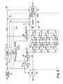
- an apparatus including a latency control circuit 112is disclosed and generally designated 100 .
- apparatusesmay include an integrated circuit, a memory device, a memory system, an electronic device or system, a smart phone, a tablet, a computer, a server, etc.
- the apparatus 100may include an input buffer 104 coupled to a delay-locked loop DLL 110 .
- the input buffer 104may be configured to receive an external clock signal CLK and to provide a buffered clock signal PCLK to the DLL 110 , to the latency control circuit 112 , and a command decoder 150 .
- the DLL 110may be configured to provide an internal clock signal LCLK, a delay control signal DCTL, and a counter signal N to the latency control circuit 112 .
- the apparatus 100may further include a command decoder 150 and an output driver 190 .
- the command decoder 150may be configured to decode a command signal CMD to provide a decoded command RP, and the output driver 190 may be configured to provide the data DQ at an output based on the internal clock signal and output enable rising/falling signals OER/F from the latency control circuit 112 .
- the DLL 110may provide the LCLK signal based on the PCLK signal.
- the DLL 110may adjust a delay of the PCLK signal to provide the LCLK such that timing of the DQ output from the output driver 190 matches the phase of the CLK signal.
- the DLL 110may include an adjustable delay line, circuitry that models delays of circuitry of the apparatus 100 , and a phase detector that detects a phase difference between the LCLK signal fed through the model delays and the PCLK signal.
- the DLL 110may adjust a delay of the adjustable delay line via the DCTL signal.
- the DCLT signalmay also be provided to the latency control circuit 112 to control propagation of the RP signal.
- the command decoder 150may be configured to decode the CMD signal respective to the PCLK signal to provide a pulse on the RP signal to the latency control circuit 112 .
- the CMD signalmay be a memory access command, such as a read, write, or on die termination (ODT) command.
- the latency control circuit 112may include a latch control circuit 120 coupled to a latch circuit 160 .
- the latch control circuit 120may receive the PCLK signal, the DCTL signal, and the LCLK signal.
- the latch control circuit 120may provide control signals RSELI and RSELO to the latch circuit 160 responsive to the PCLK, DCTL, and LCLK signals.
- the latch control circuit 120may include one or more adjustable delay lines that mirror the delay line of the DLL 110 , with the delay of the one or more adjustable delay lines controlled by the DCTL signals.
- the relative timing of the RSELI control signals to the timing of the RSELO control signalsmay be related to the relative timing between the PCLK and LCLK signals.
- the latch circuit 160may include latches configured to propagate the RP signal pulse to the RL signal.
- the latch circuit 160may include a set of input latches configured to propagate the RP signal to a set of output latches responsive to the RSELI control signals and the set of output latches may be configured to propagate the RP signal to an output as the RL signal responsive to the RSELO control signals.
- the latency control circuit 112may further include a shifter 180 configured to receive the RL signal pulse from the latch circuit 160 and a count signal N and the LCLK signal from the DLL 110 .
- the N signalmay be provided to shifter 180 after the CLK and LCLK signals are synchronized through a series of delay elements of the adjustable delay line of the DLL 110 .
- the N signalmay be a count of the number of tCK calculated by the DLL 110 to achieve the locking condition (e.g., a tCK count indicating a latency between the CLK signal and the LCLK signal).
- the shifter 180is further configured to receive latency information which indicates a specified latency CL.
- the shifter 180may assert the OER/F signals based on the CL, the N signal, and the LCLK signal.
- the output driver 190may receive the OER/F signals, the LCLK signal, and input data IDATA, and may propagate the IDATA to data DQ responsive to the OER/F signals and the LCLK signal.
- the apparatus 100may receive a CLK signal at the input buffer 104 and the CMD signal the command decoder 150 , which may be received based on timing of the PCLK signal.
- the apparatus 100may operate according to the read latency CL.
- the read latency CLmay specify a timing of output of the IDATA to the data DQ responsive to the read command based on the CLK signal, which includes time for data to be accessed and provided on an output bus (e.g., via a DQ pad).
- the read latency CLmay be from 6-10 tCK.
- the read latency CLmay be fixed in the apparatus 100 at a time of manufacture or may be set by a memory controller, such as via the CMD signal.
- the DLL 110 and the latency control circuit 112may apply the read latency the IDATA and synchronize the IDATA with the CLK signal.
- the DLL 110may receive the PCLK signal from the input buffer 104 , and may provide the LCLK signal, which may be used by the output driver 190 to latch the IDATA data to the DQ of the apparatus 100 .
- the LCLKmay have a timing relationship relative to the PCLK signal, which may be determined by the DLL 110 , and provided at an output as the N signal.
- the N signalmay be a count of the number of tCK to achieve the locking condition (e.g., a tCK latency between receipt of the CLK signal and the LCLK signal).
- the locking conditionmay be achieved such that the LCLK signal at an output of the apparatus 100 matches a phase of the CLK signal.
- the N signalmay be provided to the shifter 180 after the locking condition is achieved.
- the DLL 110may also generate the DCTL signal, which may be used to select the delay of the adjustable delay line of the DLL 110 .
- the command decoder 150may decode the CMD signal and provide the decoded CMD signal to the latency control circuit 112 as the RP signal.
- the latency control circuit 112may use the PCLK and LCLK signals to change timings of internal read command pulses from being relative to the PCLK signal to being relative to the LCLK signal during a memory read operation.
- the latch control circuit 120may include a counter configured to count the PCLK signals, and the RSELI control signals may be asserted based on the count of the counter.
- the latch control circuit 120may include a decoder that is configured to assert a single one of the RSELI control signals with every clock cycle based on the count provided by the counter.
- the counter valuemay also be used to provide the RSELO signals.
- the latch control circuit 120may include one or more adjustable delay lines having delays selected by the DCTL signal that are configured to delay the counter signal values by the same delay as the delay applied to the PCLK signal to provide the LCLK signal.
- the RSELO control signalsmay be provided based on the delayed counter signal values.
- the latch control circuit 120may include a second decoder that is configured to assert a single one of the RSELO signals with every clock cycle based on the delayed counter signal values.
- the RESLI signalsmay be directly delayed via the one or more adjustable delay lines to provide the RSELO signals.
- the RSELI and RSELO signalsmay be received by the latch circuit 160 , and may control propagation of the RP signal to the shifter 180 as the RL signal pulse.
- the RP signal pulsemay be initially received and latched by the latch circuit 160 responsive to an asserted one of the RSELI signals. Subsequently, the latched RP signal may be propagated to the shifter 180 as the RL signal responsive to a corresponding asserted one of the RSELO signals.
- the shifter 180may assert the OER/F signals based on the read latency CL and the N signal.
- the output driver 190may provide the IDATA as data DQ relative to the timing of the LCLK, and as required by the specified latency CL.
- the latch control circuit 120that times the RSELI and RSELO relative to a single counter may save complexity and improve reliability as compared with coordinating timing of the RSELI and RSELO signals between two different counters. Additional delay models that unnecessarily consume extra chip space are thereby reduced by utilizing the RSELI and RSELO signals that can be provided directly to the latch circuit 160 . High speed operations may be better achieved by utilizing a clock-based control system such as the latency control circuit 112 .
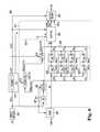
- the apparatus 200may include an input buffer 204 and a DLL 210 configured to receive an external clock signal CLK and to provide an internal clock signal LCLK.
- the apparatus 200may further include a command decoder 250 and a latency control circuit 212 configured to receive a command signal CMD and to provide output enable rising OER and output enable falling OEF signals based on timing of receipt of the CMD signal.
- the 200may further include an output driver 290 configured to provide the IDATA to a data DQ responsive to the LCLK signal and the OER and OEF signals.
- the input buffer 204 and the DLL 210may be implemented in the input buffer 104 and the DLL 110 , respectively, of FIG. 1 .
- the command decoder 250 and the latency control circuit 212may be implemented in the command decoder 150 and the latency control circuit 112 , respectively, of FIG. 1 .
- the DLL 210may include a delay line DLINED 211 configured to delay the PCLK signal received from the input buffer 204 .
- the DLL 210may set a delay of the delay line DLINED 211 based on a phase relationship between the PCLK signal and the LCLK signal after passing through circuitry configured to model a propagation path of the CLK signal through the apparatus 200 , such as a model of the input buffer 204 , the output driver 290 , etc.
- the LCLK signalmay be eventually passed on to the output driver 290 after locking is achieved at the DLL 210 .
- the DLL 210may generate a delay control signal DCTL that adjusts a delay of the delay line DLINED 211 to adjust the timing of the PCLK signal such that the phase of the LCLK will match the phase of the CLK signal at an output of the apparatus 200 (e.g., via the output driver 290 ).
- the DLL 210may also provide a count signal N representing a count of the number of tCK used to adjust the PCLK signal in order to achieve the locked condition (e.g., a tCK latency the CLK signal and the LCLK signal.
- the command decoder 250may be configured to decode the CMD signal respective to the PCLK signal to provide a pulse on the RP signal to the latency control circuit 212 .
- the CMD signalmay be a memory access command, such as a read, write, or ODT command.
- the latency control circuit 212may include a latch control circuit 220 coupled to a latch circuit 260 .
- the latch control circuit 220may receive the PCLK signal, the DCTL signal, and the LCLK signal.
- the latch control circuit 220may provide control signals RSELI ⁇ 7 : 0 > and RSELO ⁇ 7 : 0 > to the latch circuit 260 responsive to the PCLK, DCTL, and LCLK signals.
- the latch control circuit 220may include a counter/decoder circuit 224 configured to provide the RESELI ⁇ 7 : 0 > signals.
- the counter/decoder circuit 224may include a counter 225 coupled to a decoder 226 .
- the counter 225may perform a count operation responsive to the PCLK signal to provide the B ⁇ 2 : 0 > signals, with each of the B ⁇ 2 : 0 > signal representing a binary bit of the counter. That is, the counter 225 may increment the B ⁇ 2 : 0 > signals responsive to the PCLK signal.
- the B ⁇ 2 : 0 > signalsmay indicate a count value ranging from ‘000’ to ‘111’ before wrapping back to ‘000’.
- the decoder 226may decode the B ⁇ 2 : 0 > signal to assert a corresponding one of the RSELI ⁇ 7 : 0 > signals responsive to the PCLK signal. That is, each of the RSELI ⁇ 7 : 0 > signals may correspond to a particular count value indicated by the B ⁇ 2 : 0 > signals. Responsive to the PCLK signal, may assert the one of the RSELI ⁇ 7 : 0 > signals corresponding to the decoded count value.
- the latch control circuit 220may further include delay lines DLINE ⁇ 2 : 0 > 222 ( 2 - 0 ) coupled between the counter/decoder circuit 224 and a decoder 228 .
- the DLINE ⁇ 2 : 0 > delay lines 222 ( 2 - 0 )may be configured to delay the B ⁇ 2 : 0 > signals to provide delayed B ⁇ 2 : 0 > signals BD ⁇ 2 : 0 >.
- the delay of each of the DLINE ⁇ 2 : 0 > delay lines 222 ( 2 - 0 )may be controlled by the DCTL signal received from the DLL 210 .
- the delay applied to the B ⁇ 2 : 0 > signalsmay be a same delay that is applied to the PCLK signal to generate the LCLK signal.
- the decoder 228may receive the BD ⁇ 2 : 0 > signals and, similar to the decoder 226 , may decode the BD ⁇ 2 : 0 > signals to assert a corresponding one of the RSELO ⁇ 7 : 0 > signals responsive to the LCLK signal. That is, each of the RSELO ⁇ 7 : 0 > signals may correspond to a count value of the BD ⁇ 2 : 0 > signals. Responsive to the LCLK signal, the decoder 228 may assert the one of the RSELO ⁇ 7 : 0 > signals corresponding to the decoded count value.
- the latch circuit 260may include input latches 262 ( 0 - 7 ) and output latches 264 ( 0 - 7 ). Each of the input latches 262 ( 0 - 7 ) may be coupled in series with a respective one of the output latches 264 ( 0 - 7 ) to form input/output latch pairs (e.g., holding circuits HC 0 -HC 7 ). For example, the input latch 262 ( 0 ) may be coupled to the output latch 264 ( 0 ) in series.
- the input latches 262 ( 0 - 7 )may be clocked by the RSELI ⁇ 7 : 0 > signals, and the output latches 264 ( 0 - 7 ) may be clocked by the RSELO ⁇ 7 : 0 > signals.
- the input latches 262 ( 0 - 7 )may be configured to receive the RP signal from the command decoder 250 and one of the input latches 262 ( 0 - 7 ) may latch the RP signal pulse responsive to the corresponding RSELI ⁇ 7 : 0 > signal.
- the output latches 264 ( 0 - 7 ) associated with the input latch 262 ( 0 - 7 ) that has latched the RP signal pulsemay latch the latched RP signal pulse as the RL signal responsive to the corresponding RSELO ⁇ 7 : 0 > signal.
- the latency control circuit 212may further include a shifter 280 configured to receive the RL signal pulse from the latch circuit 260 and a count signal N and the LCLK signal from the DLL 210 .
- the shifter 280may assert the OER and OEF signals responsive to receipt of the RL signal pulse and based on subtracting the N signal from the read latency CL.
- the output driver 290may receive the asserted OER and OEF signals, the LCLK signal, and input data IDATA, and may propagate the IDATA to DQ responsive to the asserted OER and OEF signals and the LCLK signal.
- the apparatus 200may receive (e.g., from a memory controller) the external CLK signal at the input buffer 204 and the CMD signal at the command decoder 250 based on timing of the PCLK signal.
- the apparatus 200may operate according to the read latency CL.
- the DLL 210 and the latency control circuit 212may be configured to apply the latency CL to the IDATA and synchronize the IDATA with the CLK signal.
- the DLL 210may receive the PCLK signal from the input buffer 204 .
- the delay line DLINED 211may delay the PCLK signal to provide the LCLK signal based on the DCTL signal.
- the delay selected by the DCTL signalmay be based on a phase relationship between the PCLK signal and the LCLK signal passed through a model delay.
- the DLL 210may determine a tCK latency between the CLK signal and the LCLK signal, and may provide the N signal having a value indicating the tCK latency.
- the N signalmay be used by the shifter 280 to determine when to assert the OER and OEF signals.
- the command decoder 250may decode the CMD signal responsive to the PCLK signal and provide a pulse on the RP signal to the latch circuit 260 .
- the PCLK and LCLK signalsmay be received by the latch control circuit 220 and used to change timings of read command pulses from being relative to the PCLK to being relative to the LCLK clock during a memory read operation.
- the counter 225may receive the PCLK signal, and may increment a count with every clock cycle of the PCLK signal to provide the B ⁇ 2 : 0 > signals, where each of the B ⁇ 2 : 0 > represents a bit of the counter.
- the decoder 226may decode the B ⁇ 2 : 0 > signals to assert a respective one of the RSELI ⁇ 7 : 0 > signals responsive to the PCLK signal. As the collective value of the B ⁇ 2 : 0 > signals change with each clock cycle of the PCLK, a different one of the RSELI ⁇ 7 : 0 > signals may be asserted with each clock cycle of the PCLK signal.
- the RSELI ⁇ 0 > signalmay be asserted
- the B ⁇ 2 : 0 > signalshave logical values of ‘001’
- the RSELI ⁇ l> signalmay be asserted, etc.
- the B ⁇ 2 : 0 >may also be provided to the delay lines DLINE ⁇ 2 : 0 > 222 ( 2 - 0 ).
- the delay lines DLINE ⁇ 2 : 0 > 222 ( 2 - 0 )may delay the B ⁇ 2 : 0 > signals to provide the BD ⁇ 2 : 0 > signals.
- the decoder 228may decode the BD ⁇ 2 : 0 > signals to assert a respective one of the RSELO ⁇ 7 : 0 > signals responsive to the LCLK signal.
- the delay of the delay lines DLINE ⁇ 2 : 0 > 222 ( 2 - 0 )may be selected based on the DCTL signal.
- the delay lines DLINE ⁇ 2 : 0 > 222 ( 2 - 0 )may be identical to the delay line DLINED 211 , and thus the DCTL signal may select the same delay for the B ⁇ 2 : 0 > signals as the delay applied to the PCLK signal. Based on having the same applied delay, the latency between the B ⁇ 2 : 0 > signals and the BD ⁇ 2 : 0 > signals may be the same as the latency between the PCLK and LCLK signals.
- the latency between the one of the RSELI ⁇ 7 : 0 > signals asserted based on the B ⁇ 2 : 0 > signals and the corresponding one of the RSELO ⁇ 7 : 0 > signals asserted based on the BD ⁇ 2 : 0 > signalsmay be the same as the latency between the PCLK and LCLK signals.
- a single counter 225as a basis to assert the RSELI ⁇ 7 : 0 > and RSELO ⁇ 7 : 0 > signals (e.g., rather than separate counters for each)
- a synchronous relationship between the RSELI ⁇ 7 : 0 > and RSELO ⁇ 7 : 0 > signalsmay be inherently maintained. For example, if controlled by separate counters, the counters for each may become asynchronous relative to one another, and would thus require a reset to be re-synchronized.
- the RSELI ⁇ 7 : 0 > and RSELO ⁇ 7 : 0 > signalsmay be received by the latch circuit 260 , and may control propagation of the RP signal pulse to the shifter 280 via the RL signal.
- the RP signal pulsemay be received at an input of each of the input latches 262 ( 0 - 7 ).
- a first one of the RSELI ⁇ 7 : 0 > to be assertedmay clock a corresponding input latch 262 ( 0 - 7 ) to latch the RP signal pulse therein.
- the RSELI ⁇ 7 : 0 > signalsmay be sequentially asserted based on timing of the PCLK signal and the B ⁇ 2 : 0 > signals.
- each of the input latches 262 ( 0 - 7 )may be asserted once every 8 tCK of the PCLK signal in a round robin fashion.
- the latched RP signal pulsemay be held in the one input latch 262 ( 0 - 7 ) and provided to an output of the one input latch 262 ( 0 - 7 ).
- an output latch of the output latches 264 ( 0 - 7 ) corresponding to the input latch that latched the RP signal pulsemay latch the latched RP signal pulse and provide the latched RP signal pulse to an output as the RL signal responsive to a corresponding RSELO ⁇ 7 : 0 > signal. Because the timing relationship between corresponding RSELI ⁇ 7 : 0 > signals and RSELO ⁇ 7 : 0 > signals is equal to the timing relationship between the PCLK and LCLK signals, the timing relationship between the RP and RL signals is also equal to the latency between the PCLK and LCLK signals.
- the shifter 280may assert the OER and OEF signals based on the read latency CL.
- the shifter 280may subtract the N signal value (e.g., elapsed time from receipt of the CMD signal to latching of the RL signal) plus 1 tCK (e.g., to allow 1 tCK for the output driver 290 to latch the IDATA) from the read latency CL, and may delay assertion of the OER and OEF signals responsive to the LCLK signal based on the calculation. After the delay, the shifter 280 may assert the OER and OEF signals.
- the output driver 290may provide the IDATA data to the data DQ responsive to the LCLK signal.
- the data DQmay provide the IDATA data to a data bus having timing synchronized with the CLK signal.
- FIG. 2depicts the latch circuit 260 having 8 pairs of input 262 ( 0 - 7 )/output latches 264 ( 0 - 7 ), the latch circuit 260 may have more or less than 8 pairs of latches. Accordingly, the number of bits in the counter 225 and the size of the decoder 226 and decoder 228 may vary based on the number of pairs of input/output latches of the latch circuit 260 . For example, with 16 input/output latch pairs, the counter 225 may be a 4-bit decoder, and the decoder 226 and decoder 228 may be 16 bit decoders. The number of delay lines of the delay lines DLINE ⁇ 2 : 0 > 222 ( 2 - 0 ) may be based on the number of bits in the counter 225 .
- FIG. 3is an exemplary timing diagram depicting various signals propagating through circuitry of the apparatus 200 of FIG. 2 .
- the CLK signalmay represent a CLK signal received at the input buffer 204 of FIG. 2 .
- the CMD signalmay represent the CMD signal received at the command decoder 250 of FIG. 2 .
- the PCLK signalmay represent a PCLK signal provided by the input buffer 204 of FIG. 2 .
- the B ⁇ 2 : 0 > signalsmay represent the B ⁇ 2 : 0 > signals provided by the counter 225 of FIG. 2 .
- the RSELI ⁇ i> signalmay represent the RSELI ⁇ 7 : 0 > signals provided by the decoder 226 of FIG. 2 .
- the RP signalmay represent the RP signal provided by the command decoder 250 of FIG.
- the LCLK signalmay represent a LCLK signal provided by the DLL 210 of FIG. 2 .
- the BD ⁇ 2 : 0 > signalsmay represent the BD ⁇ 2 : 0 > signals received by the decoder 228 of FIG. 2 .
- the RSELO ⁇ i> signalmay represent the RSELO ⁇ 7 : 0 > signals provided by the decoder 228 of FIG. 2 .
- the RL signalmay represent the RL signal provided by the latch circuit 260 of FIG. 2 .
- the OER/F signalsmay represent the OER and OEF signals provided by the shifter 280 of FIG. 2 .
- the DQmay represent the data DQ providing from the output driver 290 of FIG. 2 .
- a READ commandmay be received at the apparatus 200 via the CMD signal coincident with a rising edge of the CLK signal received at the input buffer 204 .
- the PCLK signalmay be provided at an output of the input buffer 204 .
- the counter 225may begin counting, thus toggling the B ⁇ 2 : 0 > signals starting from time t 1 .
- the decoder 226may assert one of the RSELI ⁇ 7 : 0 > signals based on a value of the B ⁇ 2 : 0 > signals.
- the RSELI ⁇ 0 > signalmay be asserted when the B ⁇ 2 : 0 > has values of ‘000’ between time t 1 and time t 2 .
- the RP signalmay be asserted from the command decoder 250 starting between time between time t 1 and t 2 , and may be de-asserted after time t 2 (e.g., a pulse). Responsive to the RSELI ⁇ 0 > signal being asserted in this example between times t 1 and t 2 , the RP signal may be latched at the input latch 262 ( 0 ).
- the LCLK signalmay start.
- the tCK count of the N signalmay be equal to 3 tCK (e.g., time from receipt of read command to start of the LCLK signal).
- the decoder 228may begin receiving and decoding the BD ⁇ 2 : 0 > signals to assert the RSELO ⁇ 7 : 0 > signals.
- the RSELO ⁇ 0 > signalmay be asserted when the BD ⁇ 2 : 0 > has values of ‘000’ between time t 3 and time t 4 .
- the latched RP signal pulsemay be latched as the RL signal at the output latch 264 ( 0 ).
- the latency between of the RP and RL signalsmay match the latency between the PCLK and LCLK signals.
- the shifter 280may receive the RL signal pulse, along with the N signal, and begin counting a delay based on the read latency.
- the shiftermay apply a delay that equal to the read latency CL minus the N value (e.g., 3tCK) minus 1.
- the OER/F signalsmay be asserted.
- the output drivermay begin providing data at an output responsive to the LCLK signal at time t 9 .
- the read latency CLis equal to 9 tCK.
- Other read latencies CLmay be used in other apparatuses.
- the timing diagram 300is exemplary, and actual relative timing relationships between signals may vary from the relationships depicted. Further, the length of pulses of signals of the timing diagram 300 may vary from depicted.
- the apparatus 400may include an input buffer 204 and a DLL 210 configured to receive an external clock signal CLK and to provide an internal clock signal LCLK.
- the apparatus 400may further include a command decoder 250 and a latency control circuit 412 configured to receive a command signal CMD and to provide output enable rising OER and output enable falling OEF signals based on timing of receipt of the CMD signal.
- the 400may further include an output driver 290 configured to provide the IDATA as DQ data responsive to the LCLK signal and the OER and OEF signals.
- the latency control circuit 212may be implemented in the latency control circuit 112 of FIG. 1 .
- the apparatus 400may include elements that have been previously described with respect to the apparatus 200 of FIG. 2 . Those elements have been identified in FIG. 4 using the same reference numbers used in FIG. 2 and operation of the common elements is as previously described. Consequently, a detailed description of the operation of these particular elements will not be repeated in the interest of brevity.
- the command decoder 250may be configured to decode the CMD signal to provide a decoded command signal RP to the latency control circuit 412 .
- the latency control circuit 412may include a latch control circuit 420 coupled to the latch circuit 260 .
- the latch control circuit 420may receive the PCLK signal, the DCTL signal, and the LCLK signal.
- the latch control circuit 420may provide control signals RSELI ⁇ 7 : 0 > and RSELO ⁇ 7 : 0 > to the latch circuit 260 responsive to the PCLK, DCTL, and LCLK signals.
- the latch control circuit 420may include the counter/decoder circuit 224 configured to provide the RSELI ⁇ 7 : 0 > signals.
- the latch control circuit 420may further include delay lines DLINE ⁇ 1 : 0 > 422 ( 1 - 0 ) coupled between the counter/decoder circuit 224 and the decoder 228 .
- the DLINE ⁇ 1 : 0 > delay lines 422 ( 1 - 0 )may be configured to delay the B ⁇ 1 : 0 > signals to provide delayed B ⁇ 1 : 0 > signals BD ⁇ 1 : 0 >.
- the delay of each of the DLINE ⁇ 1 : 0 > delay lines 422 ( 1 - 0 )may be controlled by the DCTL signal received from the DLL 210 .
- the delay applied to the B ⁇ 1 : 0 > signalsmay be a same delay that is applied to the PCLK signal to generate the LCLK signal.
- the latch control circuit 420may further include delay 423 coupled between the counter/decoder circuit 224 and the decoder 228 .
- the delay 423may be configured to delay the B ⁇ 2 > signal to provide delayed B ⁇ 2 > signals BD ⁇ 2 >.
- the delay the delay 423may be fixed. Because the B ⁇ 2 > signal is associated with the most significant bit of the counter 225 and only transitions 4 tCK, and because the RSELO ⁇ 0 : 7 > signals transition responsive to the LCLK signal, using the delay 423 in place of an adjustable delay line may reduce complexity and layout size while retaining the benefits of timing control using the latch circuit 260 .
- the counter 225may provide the B ⁇ 2 : 0 > signals and the decoder 226 may decode the B ⁇ 2 : 0 > signals to assert a respective one of the RSELI ⁇ 7 : 0 > signals responsive to the PCLK signal.
- the B ⁇ 1 : 0 > signalsmay also be provided to the delay lines DLINE ⁇ 1 : 0 > 422 ( 1 - 0 ) and the B ⁇ 2 > signal may be provided through the delay 423 .
- the delay lines DLINE ⁇ 1 : 0 > 422 ( 1 - 0 )may delay the B ⁇ 1 : 0 > signals to provide the BD ⁇ 1 : 0 > signals based on the DCTL signal.
- the delay lines DLINE ⁇ 1 : 0 > 422may be identical to the delay line DLINED 211 , and thus the DCTL signal may select the same delay for the B ⁇ 1 : 0 > signals as the delay applied to the PCLK signal.
- the delay 423may apply a fixed delay to the B ⁇ 2 > signal to provide the BD ⁇ 2 > signal. Based on having the same applied delay, the latency between the B ⁇ 1 : 0 > signals and the BD ⁇ 1 : 0 > signals may be the same as the latency between the PCLK and LCLK signals, and latency between the B ⁇ 2 > signal and the BD ⁇ 2 > signal may have a different latency.
- the exact timing of receipt of the BD ⁇ 2 > signal relative to timing of receipt of the BD ⁇ 1 : 0 > signalsmay vary slightly (e.g., within one tCK) with no noticeable difference in the behavior of the RSELO ⁇ 7 : 0 > signals.
- the BD ⁇ 2 > signalis the most significant bit of the count, so the signal may only toggles once every 4 tCK, thereby reducing an opportunity for error.
- the RSELI ⁇ 7 : 0 > and RSELO ⁇ 7 : 0 > signalsmay be received by the latch circuit 260 , and may control propagation of the RP signal to the shifter 280 as the RL signal. Responsive to receipt of the RL signal, the shifter 280 may assert the OER and OEF signals based on the read latency CL. Responsive to receiving the asserted OER and OEF signals, the output driver 290 may provide the IDATA data to the DQ responsive to the LCLK signal. The DQ may provide the IDATA data to a data bus having timing synchronized with the CLK signal.
- the number of bits in the counter 225may be based on the number of input/output latch pairs of the latch circuit 260 .
- the number of delay lines of the delay lines DLINE ⁇ 1 : 0 > 422 ( 1 - 0 )may be based on the number of bits in the counter 225 (e.g., count of bits in the counter 225 ⁇ 1).
- the apparatus 500may include an input buffer 204 and a DLL 210 configured to receive an external clock signal CLK and to provide an internal clock signal LCLK.
- the apparatus 500may further include a command decoder 250 and a latency control circuit 512 configured to receive a command signal CMD and to provide output enable rising OER and output enable falling OEF signals based on timing of receipt of the CMD signal.
- the 500may further include an output driver 290 configured to provide the IDATA as DQ data responsive to the LCLK signal and the OER and OEF signals.
- the latency control circuit 512may be implemented in the latency control circuit 112 of FIG. 1 .
- the apparatus 500may include elements that have been previously described with respect to the apparatus 200 of FIG. 2 and the apparatus 400 of FIG. 4 . Those elements have been identified in FIG. 5 using the same reference numbers used in FIG. 2 and/or in FIG. 4 , and operation of the common elements is as previously described. Consequently, a detailed description of the operation of these particular elements will not be repeated in the interest of brevity.
- the command decoder 250may be configured to decode the CMD signal to provide a decoded command signal RP to the latency control circuit 512 .
- the latency control circuit 512may include a latch control circuit 520 coupled to the latch circuit 260 .
- the latch control circuit 520may receive the PCLK signal, the DCTL signal, and the LCLK signal.
- the latch control circuit 520may provide control signals RSELI ⁇ 7 : 0 > and RSELO ⁇ 7 : 0 > to the latch circuit 260 responsive to the PCLK, DCTL, and LCLK signals.
- the latch control circuit 520may include the counter/decoder circuit 224 configured to provide the RESELI ⁇ 7 : 0 > signals.
- the latch control circuit 520may further include delay lines DLINE ⁇ 1 : 0 > 422 ( 1 - 0 ) coupled between the counter/decoder circuit 224 and a latch 529 .
- the DLINE ⁇ 1 : 0 > delay lines 422 ( 1 - 0 )may be configured to delay the B ⁇ 1 : 0 > signals to provide delayed B ⁇ 1 : 0 > signals BD ⁇ 1 : 0 >.
- the latch control circuit 520may not apply any delay to the B ⁇ 2 > signal.
- the latch control circuit 520may further include a latch 529 that is configured to receive the BD ⁇ 1 : 0 > signals from the delay lines DLINE ⁇ 1 : 0 > 422 ( 1 - 0 ) and the B ⁇ 2 > signal directly from the counter/decoder circuit 224 .
- the latch 529may be clocked by the LCLK to latch the BD ⁇ 1 : 0 > and B ⁇ 2 > signals at an output as the BD ⁇ 2 : 0 > signals. That is, the latch 529 may recombine the B ⁇ 2 : 0 > signals at an output as the BD ⁇ 2 : 0 > signals.
- the 528may receive the BD ⁇ 2 : 0 > signals and may decode the BD ⁇ 2 : 0 > signals to assert a corresponding one of the RSELO ⁇ 7 : 0 > signals.
- each of the RSELO ⁇ 7 : 0 > signalsmay correspond to a count value of the BD ⁇ 2 : 0 > signals.
- the 528may assert the one of the RSELO ⁇ 7 : 0 > signals corresponding to the decoded count value.
- the counter 225may provide the B ⁇ 2 : 0 > signals and the decoder 226 may decode the B ⁇ 2 : 0 > signals to assert a respective one of the RSELI ⁇ 7 : 0 > signals responsive to the PCLK signal.
- the B ⁇ 1 : 0 > signalsmay also be provided to the delay lines DLINE ⁇ 1 : 0 > 422 ( 1 - 0 ) to provide the BD ⁇ 2 : 0 > signals to the latch 529 .
- the latch 529may also receive the B ⁇ 2 > signal directly from the counter/decoder circuit 224 .
- the latch 529may latch the BD ⁇ 1 : 0 > and the B ⁇ 2 > signals at an output as the BD ⁇ 2 : 0 > signals.
- the 528may decode the BD ⁇ 2 : 0 > signals to assert a respective one of the RSELO ⁇ 7 : 0 > signals responsive to the LCLK signal. Because the BD ⁇ 2 : 0 > signals are collectively provided to the 528 responsive to the LCLK signal, the exact timing of receipt of the B ⁇ 2 > signal at the latch 529 relative to timing of receipt of the BD ⁇ 1 : 0 > signals may vary slightly (e.g., within one tCK) with no noticeable difference in the behavior of the RSELO ⁇ 7 : 0 > signals provided from the 528 . Further, the BD ⁇ 2 > signal is the most significant bit of the count, so the signal may only toggles once every 4 tCK, thereby reducing an opportunity for error. By replacing an adjustable delay line with latch, the layout size and complexity may be reduced.
- the RSELI ⁇ 7 : 0 > and RSELO ⁇ 7 : 0 > signalsmay be received by the latch circuit 260 , and may control propagation of the RP signal to the shifter 280 as the RL signal. Responsive to receipt of the RL signal, the shifter 280 may assert the OER and OEF signals based on the read latency CL. Responsive to receiving the asserted OER and OEF signals, the output driver 290 may provide the IDATA data to the DQ responsive to the LCLK signal. The DQ may provide the IDATA data to a data bus having timing synchronized with the CLK signal.
- the number of bits in the counter 225may be based on the number of input/output latch pairs of the latch circuit 260 .
- the size of the latch 529may be based on the number of bits in the counter 225 (e.g., count of bits in the counter 225 ).
- the apparatus 600may include an input buffer 204 and a DLL 210 configured to receive an external clock signal CLK and to provide an internal clock signal LCLK.
- the apparatus 600may further include a command decoder 250 and a latency control circuit 612 configured to receive a command signal CMD and to provide output enable rising OER and output enable falling OEF signals based on timing of receipt of the CMD signal.
- the 600may further include an output driver 290 configured to provide the IDATA as DQ data responsive to the LCLK signal and the OER and OEF signals.
- the latency control circuit 612may be implemented in the latency control circuit 112 of FIG. 1 .
- the apparatus 600may include elements that have been previously described with respect to the apparatus 200 of FIG. 2 . Those elements have been identified in FIG. 6 using the same reference numbers used in FIG. 2 , and operation of the common elements is as previously described. Consequently, a detailed description of the operation of these particular elements will not be repeated in the interest of brevity.
- the command decoder 250may be configured to decode the CMD signal to provide a decoded command signal RP to the latency control circuit 612 .
- the latency control circuit 612may include a latch control circuit 620 coupled to the latch circuit 260 .
- the latch control circuit 620may receive the PCLK signal, the DCTL signal, and the LCLK signal.
- the latch control circuit 620may provide control signals RSELI ⁇ 7 : 0 > and RSELO ⁇ 7 : 0 > to the latch circuit 260 responsive to the PCLK, DCTL, and LCLK signals.
- the latch control circuit 620may include the counter/decoder circuit 224 configured to provide the RESELI ⁇ 7 : 0 > signals.
- the latch control circuit 620may further include delay lines DLINE ⁇ 7 : 0 > 622 ( 7 - 0 ) coupled between the counter/decoder circuit 224 and a latch 629 .
- the DLINE ⁇ 7 : 0 > delay lines 622 ( 7 - 0 )may be configured to delay the RSELI ⁇ 7 : 0 > signals to provide delayed RSELI ⁇ 7 : 0 > signals RSELID ⁇ 7 : 0 >.
- the delay of each of the DLINE ⁇ 7 : 0 > delay lines 622 ( 7 - 0 )may be controlled by the DCTL signal received from the DLL 210 .
- the delay applied to the RSELI ⁇ 7 : 0 > signalsmay be a same delay that is applied to the PCLK signal to generate the LCLK signal.
- the latch control circuit 620may further include the latch 629 that is configured to receive the RSELID ⁇ 7 : 0 > signals from the delay lines DLINE ⁇ 7 : 0 > 622 ( 7 - 0 ).
- the latch 629may be clocked by the LCLK to latch the RSELID ⁇ 7 : 0 > at an output as the RSELO ⁇ 7 : 0 > signals.
- the delaymay be applied directly to the RSELI ⁇ 7 : 0 > signals, via the delay lines DLINE ⁇ 7 : 0 > 622 ( 7 - 0 ), and the decoder may be replaced with a simple latch 629 to provide the RSELO ⁇ 7 : 0 > signals responsive to the LCLK signal.
- the counter 225may provide the B ⁇ 2 : 0 > signals and the decoder 226 may decode the B ⁇ 2 : 0 > signals to assert a respective one of the RSELI ⁇ 7 : 0 > signals responsive to the PCLK signal.
- the RSELI ⁇ 7 : 0 > signalsmay also be provided to the delay lines DLINE ⁇ 7 : 0 > 622 ( 7 - 0 ).
- the delay lines DLINE ⁇ 7 : 0 > 622 ( 7 - 0 )may delay the RSELI ⁇ 1 : 0 > signals to provide the RSELID ⁇ 7 : 0 > signals based on the DCTL signal.
- the delay lines DLINE ⁇ 7 : 0 > 622may be identical to the delay line DLINED 211 , and thus the DCTL signal may select the same delay for the RSELI ⁇ 7 : 0 > signals as the delay applied to the PCLK signal. Based on having the same applied delay, the latency between the RSELI ⁇ 7 : 0 > signals and the RSELID ⁇ 7 : 0 > signals may be the same as the latency between the PCLK and LCLK signals.
- the RSELID ⁇ 7 : 0 > signalsmay be provided to the latch 629 .
- the latch 629may latch the RSELID ⁇ 7 : 0 > signals at an output as the RSELO ⁇ 7 : 0 > signals.
- the delaymay be applied directly to the RSELI ⁇ 7 : 0 > signals, via the delay lines DLINE ⁇ 7 : 0 > 622 ( 7 - 0 ), and the decoder may be replaced with a simple latch 629 to provide the RSELO ⁇ 7 : 0 > signals responsive to the LCLK signal.
- the RSELI ⁇ 7 : 0 > and RSELO ⁇ 7 : 0 > signalsmay be received by the latch circuit 260 , and may control propagation of the RP signal to the shifter 280 as the RL signal. Responsive to receipt of the RL signal, the shifter 280 may assert the OER and OEF signals based on the read latency CL. Responsive to receiving the asserted OER and OEF signals, the output driver 290 may provide the IDATA data to the DQ responsive to the LCLK signal. The DQ may provide the IDATA data to a data bus having timing synchronized with the CLK signal.
- the latch circuit 260may have more or less than 8 pairs of input/output latches. Accordingly, the size of the latch 629 may vary based on the number of pairs of input/output latches of the latch circuit 260 . For example, with 16 input/output latch pairs, the latch 629 may be a 16 bit latch. Further, the number of delay lines of the delay lines DLINE ⁇ 7 : 0 > 622 ( 7 - 0 ) may also be based on the number of pairs of input/output latches.
- the memory 700may include an array 702 of memory cells, which may be, for example, dynamic random-access memory (DRAM) memory cells, static random-access memory (SRAM) memory cells, flash memory cells, or some other types of memory cells.
- the memory 700may include clock generator 713 that is configured to generate receive the CLK signal, and to generate internal clock signals PCLK and LCLK.
- the clock generatormay include a DLL circuit that includes an adjustable delay circuit configured to generate the LCLK signal based on the PCLK signal. The delay of the adjustable delay circuit may be selected by the DCTL signal.
- the clock generator 713may include the input buffer 104 and/or the DLL 110 of FIG. 1 , the input buffer 204 and/or the DLL 210 of FIGS. 2, 4, 5 , and/or 6 , or combinations thereof.
- the memory 700includes a command decoder 706 that may receive memory commands through a command bus 708 and provide (e.g., generate) corresponding control signals within the memory 700 to carry out various memory operations.
- the command decoder 706may include a command path 714 configured to control timing of the received CMD signal.
- the command path 714may receive the PCLK, LCLK, and DCTL signals from the clock generator 713 , and may generate the output enable rising OER and output enable falling OEF signals responsive to the PCLK, LCLK, DCTL, and CMD signals.
- the command path 714may include the latency control circuit 112 of FIG. 1 , the latency control circuit 212 of FIG. 2 , the latency control circuit 412 of FIG. 4 , the latency control circuit 512 of FIG. 5 , and/or the latency control circuit 612 of FIG. 6 .
- Row and column address signalsmay be provided (e.g., applied) to an address latch 710 in the memory 700 through an address bus 720 .
- the address latch 710may then provide (e.g., output) a separate column address and a separate row address.
- the address latch 710may provide row and column addresses to a row address decoder 722 and a column address decoder 728 , respectively.
- the column address decoder 728may select bit lines extending through the array 702 corresponding to respective column addresses.
- the row address decoder 722may be connected to a word line driver 724 that activates respective rows of memory cells in the array 702 corresponding to received row addresses.
- the selected data line(e.g., a bit line or bit lines) corresponding to a received column address may be coupled to a read/write circuitry 730 to provide read data to an output data buffer 734 via an input-output data bus 740 .
- the output data buffer 734may provide the read data to the DQ responsive to the OER, OEF, and LCLK signals.
- Write datamay be provided to the memory array 702 through an input data buffer 744 and the memory array read/write circuitry 730 .
- the command decoder 706may respond to memory commands provided to the command bus 708 to perform various operations on the memory array 702 . In particular, the command decoder 706 may be used to provide internal control signals to read data from and write data to the memory array 702 .
Landscapes
- Physics & Mathematics (AREA)
- Nonlinear Science (AREA)
- Dram (AREA)
Abstract
Description
Claims (25)
Priority Applications (1)
| Application Number | Priority Date | Filing Date | Title |
|---|---|---|---|
| US14/698,550US9531363B2 (en) | 2015-04-28 | 2015-04-28 | Methods and apparatuses including command latency control circuit |
Applications Claiming Priority (1)
| Application Number | Priority Date | Filing Date | Title |
|---|---|---|---|
| US14/698,550US9531363B2 (en) | 2015-04-28 | 2015-04-28 | Methods and apparatuses including command latency control circuit |
Publications (2)
| Publication Number | Publication Date |
|---|---|
| US20160322964A1 US20160322964A1 (en) | 2016-11-03 |
| US9531363B2true US9531363B2 (en) | 2016-12-27 |
Family
ID=57205816
Family Applications (1)
| Application Number | Title | Priority Date | Filing Date |
|---|---|---|---|
| US14/698,550ActiveUS9531363B2 (en) | 2015-04-28 | 2015-04-28 | Methods and apparatuses including command latency control circuit |
Country Status (1)
| Country | Link |
|---|---|
| US (1) | US9531363B2 (en) |
Cited By (12)
| Publication number | Priority date | Publication date | Assignee | Title |
|---|---|---|---|---|
| US9813067B2 (en) | 2015-06-10 | 2017-11-07 | Micron Technology, Inc. | Clock signal and supply voltage variation tracking |
| US9997220B2 (en) | 2016-08-22 | 2018-06-12 | Micron Technology, Inc. | Apparatuses and methods for adjusting delay of command signal path |
| US10090026B2 (en) | 2017-02-28 | 2018-10-02 | Micron Technology, Inc. | Apparatuses and methods for providing internal memory commands and control signals in semiconductor memories |
| US20180314437A1 (en)* | 2015-11-17 | 2018-11-01 | Hewlett Packard Enterprise Development Lp | Iterative write sequence interrupt |
| US10210918B2 (en)* | 2017-02-28 | 2019-02-19 | Micron Technology, Inc. | Apparatuses and methods for determining a phase relationship between an input clock signal and a multiphase clock signal |
| US10224938B2 (en) | 2017-07-26 | 2019-03-05 | Micron Technology, Inc. | Apparatuses and methods for indirectly detecting phase variations |
| US10269397B2 (en) | 2017-08-31 | 2019-04-23 | Micron Technology, Inc. | Apparatuses and methods for providing active and inactive clock signals |
| US10290336B2 (en) | 2016-04-26 | 2019-05-14 | Micron Technology, Inc. | Methods and apparatuses including command delay adjustment circuit |
| US10608620B2 (en) | 2018-06-19 | 2020-03-31 | Micron Technology, Inc. | Shifter circuits having registers arranged in a folded topology |
| US10658019B2 (en) | 2007-03-15 | 2020-05-19 | Micron Technology, Inc. | Circuit, system and method for controlling read latency |
| US10796737B1 (en)* | 2019-07-05 | 2020-10-06 | SK Hynix Inc. | Semiconductor apparatus capable of synchronizing command signal and clock signal, and operation method thereof |
| US11171654B1 (en)* | 2021-05-13 | 2021-11-09 | Qualcomm Incorporated | Delay locked loop with segmented delay circuit |
Families Citing this family (3)
| Publication number | Priority date | Publication date | Assignee | Title |
|---|---|---|---|---|
| US11658668B2 (en) | 2018-06-14 | 2023-05-23 | SK Hynix Inc. | Semiconductor device |
| KR102608910B1 (en)* | 2018-06-14 | 2023-12-04 | 에스케이하이닉스 주식회사 | Semiconductor device |
| JP6734962B1 (en)* | 2019-04-17 | 2020-08-05 | ウィンボンド エレクトロニクス コーポレーション | Semiconductor device |
Citations (154)
| Publication number | Priority date | Publication date | Assignee | Title |
|---|---|---|---|---|
| US5004933A (en) | 1986-06-02 | 1991-04-02 | Tektronix, Inc. | Phase-selectable flip-flop |
| US6111810A (en) | 1998-09-30 | 2000-08-29 | Nec Corporation | Synchronous semiconductor memory device having burst access mode and multi-bit pre-fetch operation |
| US6219384B1 (en) | 1995-06-26 | 2001-04-17 | Phillip S. Kliza | Circuit for determining clock propagation delay in a transmission line |
| US6260128B1 (en) | 1997-08-13 | 2001-07-10 | Kabushiki Kaisha Toshiba | Semiconductor memory device which operates in synchronism with a clock signal |
| US6275077B1 (en) | 1999-08-31 | 2001-08-14 | Sun Microsystems, Inc. | Method and apparatus for programmable adjustment of bus driver propagation times |
| US20010015924A1 (en) | 1999-12-24 | 2001-08-23 | Kazutami Arimoto | Test interface circuit and semiconductor integrated circuit device including the same |
| US6327318B1 (en)* | 1998-06-30 | 2001-12-04 | Mosaid Technologies Incorporated | Process, voltage, temperature independent switched delay compensation scheme |
| US20020057624A1 (en) | 1997-03-05 | 2002-05-16 | Manning Troy A. | Delay-locked loop with binary-coupled capacitor |
| US6424592B1 (en) | 2000-11-30 | 2002-07-23 | Mitsubishi Denki Kabushiki Kaisha | Semiconductor integrated circuit having circuit for correcting data output timing |
| US6438055B1 (en) | 1999-10-20 | 2002-08-20 | Fujitsu Limited | Dynamic memory circuit with automatic refresh function |
| US6459313B1 (en) | 1998-09-18 | 2002-10-01 | Lsi Logic Corporation | IO power management: synchronously regulated output skew |
| US6489823B2 (en)* | 2000-10-18 | 2002-12-03 | Mitsubishi Denki Kabushiki Kaisha | Semiconductor device capable of generating highly precise internal clock |
| US6510095B1 (en) | 2001-09-28 | 2003-01-21 | Fujitsu Limited | Semiconductor memory device for operating in synchronization with edge of clock signal |
| US20030117864A1 (en) | 2001-10-22 | 2003-06-26 | Hampel Craig E. | Phase adjustment apparatus and method for a memory device signaling system |
| US20030147299A1 (en) | 2002-02-05 | 2003-08-07 | Mitsubishi Denki Kabushiki Kaisha | Semiconductor memory device capable of making switch between synchronizing signals for operation on data generated by different circuit configurations |
| US20030161210A1 (en) | 2002-02-28 | 2003-08-28 | Pramod Acharya | Control circuit for an S-DRAM |
| US6636110B1 (en) | 1998-05-01 | 2003-10-21 | Mitsubishi Denki Kabushiki Kaisha | Internal clock generating circuit for clock synchronous semiconductor memory device |
| US6687185B1 (en) | 2002-08-29 | 2004-02-03 | Micron Technology, Inc. | Method and apparatus for setting and compensating read latency in a high speed DRAM |
| US6710726B2 (en) | 2002-04-03 | 2004-03-23 | Samsung Electronics Co., Ltd. | Serializer-deserializer circuit having increased margins for setup and hold time |
| US6744285B2 (en)* | 2002-08-08 | 2004-06-01 | Agilent Technologies, Inc. | Method and apparatus for synchronously transferring data across multiple clock domains |
| US6781861B2 (en) | 2001-08-06 | 2004-08-24 | Micron Technology, Inc. | Method and apparatus for determining digital delay line entry point |
| US6839288B1 (en) | 2003-11-12 | 2005-01-04 | Infineon Technologies Ag | Latch scheme with invalid command detector |
| US20050024107A1 (en) | 2003-07-31 | 2005-02-03 | Elpida Memory, Inc | Delay circuit and delay sysnchronization loop device |
| US6861901B2 (en) | 2002-07-01 | 2005-03-01 | Texas Instruments Deutschland, Gmbh | Voltage follower circuit |
| US20050047222A1 (en) | 2003-08-27 | 2005-03-03 | Rentschler Eric Mccutcheon | Data signal reception latch control using clock aligned relative to strobe signal |
| US20050132043A1 (en) | 2003-12-12 | 2005-06-16 | Hon Hai Precision Industry Co., Ltd. | System and method for command line interface command processing |
| US6914798B2 (en) | 2001-06-30 | 2005-07-05 | Hynix Semiconductor Inc. | Register controlled DLL for reducing current consumption |
| US6930955B2 (en) | 2003-03-18 | 2005-08-16 | Micron Technology, Inc. | Method and apparatus for establishing and maintaining desired read latency in high-speed DRAM |
| US6973008B2 (en) | 2003-04-29 | 2005-12-06 | Infineon Technologies Ag | Apparatus for flexible deactivation of word lines of dynamic memory modules and method therefor |
| US20050270852A1 (en) | 2004-05-27 | 2005-12-08 | Infineon Technologies Ag | Read latency control circuit |
| US6980479B2 (en) | 2003-04-29 | 2005-12-27 | Hynix Semiconductor Inc. | Semiconductor device for domain crossing |
| US6988218B2 (en) | 2002-02-11 | 2006-01-17 | Micron Technology, Inc. | System and method for power saving delay locked loop control by selectively locking delay interval |
| US20060062341A1 (en) | 2004-09-20 | 2006-03-23 | Edmondson John H | Fast-lock clock-data recovery system |
| US20060064620A1 (en)* | 2004-09-15 | 2006-03-23 | Justus Kuhn | Self test for the phase angle of the data read clock signal DQS |
| US7042799B2 (en) | 2003-12-30 | 2006-05-09 | Hynix Semiconductor Inc. | Write circuit of double data rate synchronous DRAM |
| US7046060B1 (en) | 2004-10-27 | 2006-05-16 | Infineon Technologies, Ag | Method and apparatus compensating for frequency drift in a delay locked loop |
| US7058799B2 (en) | 2001-06-19 | 2006-06-06 | Micron Technology, Inc. | Apparatus and method for clock domain crossing with integrated decode |
| US7061941B1 (en) | 2000-11-28 | 2006-06-13 | Winbond Electronics Corporation America | Data input and output circuits for multi-data rate operation |
| US7065001B2 (en) | 2004-08-04 | 2006-06-20 | Micron Technology, Inc. | Method and apparatus for initialization of read latency tracking circuit in high-speed DRAM |
| US20060155948A1 (en) | 2004-10-27 | 2006-07-13 | Hermann Ruckerbauer | Semiconductor memory system and method for data transmission |
| US20060182212A1 (en) | 2005-02-11 | 2006-08-17 | International Business Machines Corporation | Method and apparatus for generating synchronization signals for synchronizing multiple chips in a system |
| US20060193194A1 (en) | 2005-02-28 | 2006-08-31 | Josef Schnell | Data strobe synchronization for DRAM devices |
| US7111185B2 (en) | 2003-12-23 | 2006-09-19 | Micron Technology, Inc. | Synchronization device with delay line control circuit to control amount of delay added to input signal and tuning elements to receive signal form delay circuit |
| US7119591B1 (en) | 2004-01-05 | 2006-10-10 | Integrated Device Technology, Inc. | Delay-locked loop (DLL) integrated circuits having binary-weighted delay chain units with built-in phase comparators that support efficient phase locking |
| US7170819B2 (en) | 2005-05-04 | 2007-01-30 | Infineon Technologies Ag | Integrated semiconductor memory device for synchronizing a signal with a clock signal |
| US20070033427A1 (en) | 2005-07-19 | 2007-02-08 | International Business Machines Corporation | Power efficient cycle stealing |
| US20070046346A1 (en) | 2005-08-30 | 2007-03-01 | Alessandro Minzoni | Clock controller with integrated DLL and DCC |
| US7187599B2 (en) | 2005-05-25 | 2007-03-06 | Infineon Technologies North America Corp. | Integrated circuit chip having a first delay circuit trimmed via a second delay circuit |
| US20070088903A1 (en) | 2005-10-17 | 2007-04-19 | Samsung Electronics Co., Ltd. | Memory module, memory system and method for controlling the memory system |
| US7248512B2 (en) | 2004-11-08 | 2007-07-24 | Hynix Semiconductor Inc. | Semiconductor memory device having controller with improved current consumption |
| US20070192651A1 (en) | 2002-08-12 | 2007-08-16 | Broadcom Corporation | Low-Speed DLL Employing a Digital Phase Interpolator based upon a High-Speed Clock |
| US7268605B2 (en) | 2004-06-14 | 2007-09-11 | Rambus, Inc. | Technique for operating a delay circuit |
| US7269754B2 (en) | 2002-12-30 | 2007-09-11 | Intel Corporation | Method and apparatus for flexible and programmable clock crossing control with dynamic compensation |
| US7280430B2 (en) | 2005-04-30 | 2007-10-09 | Hynix Semiconductor Inc. | Semiconductor memory device |
| US20070291558A1 (en) | 2006-06-15 | 2007-12-20 | Hynix Semiconductor Inc. | Data strobe signal generator for generating data strobe signal based on adjustable preamble value and semiconductor memory device with the same |
| US7336752B2 (en) | 2002-12-31 | 2008-02-26 | Mosaid Technologies Inc. | Wide frequency range delay locked loop |
| US7340632B2 (en) | 2004-01-10 | 2008-03-04 | Hynix Semiconductor Inc. | Domain crossing device |
| US20080082707A1 (en) | 2006-09-29 | 2008-04-03 | Synfora, Inc. | Non-blocking bus controller for a pipelined, variable latency, hierarchical bus with point-to-point first-in first-out ordering |
| US20080080267A1 (en) | 2006-09-29 | 2008-04-03 | Lee Hyeng Ouk | Data output control circuit and data output control method |
| US20080080271A1 (en) | 2006-09-29 | 2008-04-03 | Hynix Semiconductor Inc. | Delay selecting circuit for semiconductor memory device |
| US7375560B2 (en) | 2004-08-31 | 2008-05-20 | Micron Technology, Inc. | Method and apparatus for timing domain crossing |
| US20080126822A1 (en) | 2006-11-28 | 2008-05-29 | Kyoung-Ho Kim | Apparatus for aligning input data in semiconductor memory device |
| US20080137471A1 (en) | 2006-12-07 | 2008-06-12 | Josef Schnell | Memory with clock distribution options |
| US20080144423A1 (en) | 2006-12-19 | 2008-06-19 | Jongtae Kwak | Timing synchronization circuit with loop counter |
| US7411852B2 (en) | 2005-10-27 | 2008-08-12 | Elpida Memory, Inc. | Semiconductor memory device and method of adjusting same |
| US20080232180A1 (en) | 2006-10-31 | 2008-09-25 | Hynix Semiconductor Inc. | Semiconductor memory device and method for driving the same |
| US20080232179A1 (en)* | 2007-03-15 | 2008-09-25 | Micron Technology, Inc. | Circuit, system and method for controlling read latency |
| US20080253205A1 (en) | 2007-04-11 | 2008-10-16 | Hynix Semiconductor Inc. | Write control signal generation circuit, semiconductor ic having the same and method of driving semicounductor ic |
| US7443216B2 (en) | 2007-02-20 | 2008-10-28 | Micron Technology, Inc. | Trimmable delay locked loop circuitry with improved initialization characteristics |
| US7451338B2 (en) | 2005-09-30 | 2008-11-11 | Intel Corporation | Clock domain crossing |
| US7463534B2 (en) | 2006-04-18 | 2008-12-09 | Hynix Semiconductor Inc. | Write apparatus for DDR SDRAM semiconductor memory device |
| US7489172B2 (en) | 2005-09-29 | 2009-02-10 | Hynix Semiconductor Inc. | DLL driver control circuit |
| US20090041104A1 (en)* | 2006-06-27 | 2009-02-12 | Bogdan John W | Phase and Frequency Recovery Techniques |
| US7509517B2 (en) | 2003-07-31 | 2009-03-24 | Advantest Corporation | Clock transferring apparatus for synchronizing input data with internal clock and test apparatus having the same |
| US7580321B2 (en) | 2005-10-20 | 2009-08-25 | Elpida Memory, Inc. | Synchronous semiconductor memory device |
| US7590013B2 (en) | 2006-07-07 | 2009-09-15 | Samsung Electronics Co., Ltd. | Semiconductor memory devices having variable additive latency |
| US20090232250A1 (en) | 2008-03-12 | 2009-09-17 | Takaaki Yamada | Communication system, receiver and reception method |
| US7593273B2 (en) | 2006-11-06 | 2009-09-22 | Altera Corporation | Read-leveling implementations for DDR3 applications on an FPGA |
| US7609584B2 (en) | 2005-11-19 | 2009-10-27 | Samsung Electronics Co., Ltd. | Latency control circuit and method thereof and an auto-precharge control circuit and method thereof |
| US7616040B2 (en) | 2006-12-08 | 2009-11-10 | Sony Corporation | Flip-flop and semiconductor integrated circuit |
| US7631248B2 (en) | 2004-09-29 | 2009-12-08 | Intel Corporation | Cycle-stealing decoding apparatus, systems, and methods |
| US20090315600A1 (en) | 2008-06-18 | 2009-12-24 | Micron Technologies, Inc. | Locked-loop quiescence apparatus, systems, and methods |
| US7643334B1 (en) | 2007-04-26 | 2010-01-05 | Super Talent Electronics, Inc. | High-speed controller for phase-change memory peripheral device |
| US20100001762A1 (en) | 2008-07-03 | 2010-01-07 | Hynix Semiconductor, Inc. | Domain crossing circuit and method |
| US7660187B2 (en) | 2004-08-04 | 2010-02-09 | Micron Technology, Inc. | Method and apparatus for initialization of read latency tracking circuit in high-speed DRAM |
| US7663946B2 (en) | 2007-07-12 | 2010-02-16 | Hynix Semiconductor Inc. | Semiconductor memory device having on-die-termination device and operation method thereof |
| US7671648B2 (en) | 2006-10-27 | 2010-03-02 | Micron Technology, Inc. | System and method for an accuracy-enhanced DLL during a measure initialization mode |
| US7675439B2 (en) | 2007-12-26 | 2010-03-09 | Altek Corporation | Serial/parallel data conversion apparatus and method thereof |
| US20100066422A1 (en) | 2008-09-16 | 2010-03-18 | Jen-Che Tsai | Clock timing calibration circuit and clock timing calibration method for calibrating phase difference between different clock signals and related analog-to-digital conversion system using the same |
| US7698589B2 (en) | 2006-03-21 | 2010-04-13 | Mediatek Inc. | Memory controller and device with data strobe calibration |
| US7715260B1 (en) | 2008-12-01 | 2010-05-11 | United Microelectronics Corp. | Operating voltage tuning method for static random access memory |
| US20100124090A1 (en) | 2008-11-18 | 2010-05-20 | Elpida Memory, Inc. | Semiconductor memory device and control method thereof |
| US20100124102A1 (en) | 2008-11-17 | 2010-05-20 | Kwang-Jin Lee | Phase-Change and Resistance-Change Random Access Memory Devices and Related Methods of Performing Burst Mode Operations in Such Memory Devices |
| CN101752009A (en) | 2008-12-16 | 2010-06-23 | 联华电子股份有限公司 | Method for adjusting operation voltage of static random access memory |
| US20100165780A1 (en) | 2008-12-27 | 2010-07-01 | Bains Kuljit S | Dynamic random access memory with shadow writes |
| US20100165769A1 (en) | 2008-12-25 | 2010-07-01 | Elpida Memory. Inc. | Semiconductor memory device having auto-precharge function |
| US7751261B2 (en) | 2007-02-08 | 2010-07-06 | Samsung Electronics Co., Ltd. | Method and apparatus for controlling read latency of high-speed DRAM |
| US20100195429A1 (en) | 2009-02-03 | 2010-08-05 | Nec Electronics Corporation | Semiconductor memory device |
| US7773435B2 (en) | 2008-01-03 | 2010-08-10 | Samsung Electronics Co., Ltd. | Semiconductor memory devices for controlling latency |
| US20100208534A1 (en)* | 2009-02-17 | 2010-08-19 | Elpida Memory, Inc. | Semiconductor memory device, memory module including the same, and data processing system |
| US20100208535A1 (en)* | 2009-02-17 | 2010-08-19 | Elpida Memory, Inc. | Semiconductor memory device, memory module including the same, and data processing system |
| US20100232213A1 (en) | 2009-03-12 | 2010-09-16 | Hyong-Ryol Hwang | Control signal transmitting system of a semiconductor device |
| US20100254198A1 (en) | 2009-04-01 | 2010-10-07 | Venkatraghavan Bringivijayaraghavan | Write command and write data timing circuit and methods for timing the same |
| US7822904B2 (en) | 1999-07-29 | 2010-10-26 | Micron Technology, Inc. | Capturing read data |
| US7826583B2 (en) | 2006-10-31 | 2010-11-02 | Hynix Semiconductor Inc. | Clock data recovery apparatus |
| US7826305B2 (en) | 2007-07-10 | 2010-11-02 | Elpida Memory, Inc. | Latency counter, semiconductor memory device including the same, and data processing system |
| US20100327926A1 (en) | 2009-06-24 | 2010-12-30 | Elpida Memory, Inc. | DLL circuit and semiconductor device having the DLL circuit |
| US7872924B2 (en) | 2008-10-28 | 2011-01-18 | Micron Technology, Inc. | Multi-phase duty-cycle corrected clock signal generator and memory having same |
| US7885365B2 (en) | 2007-08-31 | 2011-02-08 | International Business Machines Corporation | Low-power, low-area high-speed receiver architecture |
| US20110047319A1 (en) | 2009-08-18 | 2011-02-24 | Samsung Electronics Co., Ltd. | Memory devices and systems including write leveling operations and methods of performing write leveling operations in memory devices and systems |
| US20110055671A1 (en) | 2009-09-03 | 2011-03-03 | International Business Machines Corporation | Advanced memory device having improved performance, reduced power and increased reliability |
| US20110057697A1 (en)* | 2009-09-08 | 2011-03-10 | Elpida Memory, Inc. | Clock generating circuit, semiconductor device including the same, and data processing system |
| US7913103B2 (en) | 2007-08-31 | 2011-03-22 | Globalfoundries Inc. | Method and apparatus for clock cycle stealing |
| US20110102039A1 (en) | 2009-10-30 | 2011-05-05 | Seok-Bo Shin | Apparatus and method for correcting duty cycle of clock signal |
| US7948817B2 (en) | 2009-02-27 | 2011-05-24 | International Business Machines Corporation | Advanced memory device having reduced power and improved performance |
| US7983094B1 (en) | 2006-11-06 | 2011-07-19 | Altera Corporation | PVT compensated auto-calibration scheme for DDR3 |
| US8004884B2 (en) | 2009-07-31 | 2011-08-23 | International Business Machines Corporation | Iterative write pausing techniques to improve read latency of memory systems |
| US20110238866A1 (en) | 2010-03-23 | 2011-09-29 | Spansion Llc | Variable read latency on a serial memory bus |
| US20110238941A1 (en) | 2010-03-29 | 2011-09-29 | Freescale Semiconductor, Inc. | Scheduling memory access requests using predicted memory timing and state information |
| US8030981B2 (en) | 2008-12-30 | 2011-10-04 | Hynix Semiconductor Inc. | Latency signal generating circuit and semconductor device having the same |
| US20110314324A1 (en) | 2010-06-17 | 2011-12-22 | Stmicroelectronics, Inc. | Variable latency interface for read/write channels |
| US8115529B2 (en) | 2008-08-28 | 2012-02-14 | Elpida Memory, Inc. | Device and control method of device |
| US8116415B2 (en) | 2007-10-02 | 2012-02-14 | Panasonic Corporation | Semiconductor integrated circuit, communication apparatus, information playback apparatus, image display apparatus, electronic apparatus, electronic control apparatus and mobile apparatus |
| US8144529B2 (en) | 2009-03-31 | 2012-03-27 | Intel Corporation | System and method for delay locked loop relock mode |
| US20120084575A1 (en) | 2010-09-30 | 2012-04-05 | Jose Luis Flores | Synchronized Voltage Scaling and Device Calibration |
| US20120124317A1 (en) | 2010-11-16 | 2012-05-17 | Micron Technology, Inc. | Concurrent read and write memory operations in a serial interface memory |
| US20120147692A1 (en)* | 2010-12-13 | 2012-06-14 | Elpida Memory, Inc. | Semiconductor device outputting read data in synchronization with clock signal |
| US20120212268A1 (en)* | 2011-02-22 | 2012-08-23 | Hynix Semiconductor Inc. | Phase control circuit |
| US20120254873A1 (en) | 2011-03-29 | 2012-10-04 | Micron Technology, Inc. | Command paths, apparatuses and methods for providing a command to a data block |
| US20120269015A1 (en) | 2011-04-25 | 2012-10-25 | Micron Technology, Inc. | Command paths, apparatuses, memories, and methods for providing internal commands to a data path |
| US20120274376A1 (en) | 2005-05-19 | 2012-11-01 | Micron Technology, Inc. | Duty cycle corrector circuits |
| US8321714B2 (en) | 2010-07-16 | 2012-11-27 | Macroblock, Inc. | Serial controller and bi-directional serial controller |
| US20130002320A1 (en)* | 2011-07-01 | 2013-01-03 | Faraday Technology Corp. | Delay-locked loop |
| US8358546B2 (en) | 2009-11-13 | 2013-01-22 | Samsung Electronics Co., Ltd. | Semiconductor device having additive latency |
| US8392741B2 (en) | 2010-02-04 | 2013-03-05 | Hynix Semiconductor Inc. | Latency control circuit and semiconductor memory device including the same |
| US20130141994A1 (en) | 2011-12-05 | 2013-06-06 | Elpida Memory, Inc. | Semiconductor device having skew detection circuit measuring skew between clock signal and data strobe signal |
| US20130194013A1 (en) | 2012-02-01 | 2013-08-01 | Micron Technology, Inc. | Apparatuses and methods for altering a forward path delay of a signal path |
| JP2013222997A (en) | 2012-04-13 | 2013-10-28 | Ps4 Luxco S A R L | Semiconductor device |
| US20140010025A1 (en) | 2012-07-06 | 2014-01-09 | Micron Technology, Inc. | Apparatuses and methods for adjusting a path delay of a command path |
| US20140055184A1 (en)* | 2012-08-22 | 2014-02-27 | Micron Technology, Inc | Apparatuses, integrated circuits, and methods for synchronizing data signals with a command signal |
| US20140119141A1 (en) | 2012-10-25 | 2014-05-01 | Micron Technology, Inc. | Apparatuses and methods for capturing data in a memory |
| US8717078B2 (en) | 2012-06-13 | 2014-05-06 | Arm Limited | Sequential latching device with elements to increase hold times on the diagnostic data path |
| US20140177359A1 (en) | 2012-12-24 | 2014-06-26 | Arm Limited | Method and apparatus for aligning a clock signal and a data strobe signal in a memory system |
| US20140176213A1 (en) | 2011-06-10 | 2014-06-26 | International Business Machines Corporation | Programmable delay generator and cascaded interpolator |
| US8788896B2 (en) | 2012-01-11 | 2014-07-22 | Lsi Corporation | Scan chain lockup latch with data input control responsive to scan enable signal |
| US20140293719A1 (en)* | 2013-03-29 | 2014-10-02 | Hangi Jung | Semiconductor memory device with a delay locked loop circuit and a method for controlling an operation thereof |
| US9001955B2 (en) | 2008-03-31 | 2015-04-07 | Cambridge Silicon Radio Limited | Phase-locked loop modulation |
| US20150156009A1 (en)* | 2005-06-27 | 2015-06-04 | John W. Bogdan | Direct Synchronization of Synthesized Clock |
| US9053815B2 (en) | 2013-05-28 | 2015-06-09 | Nanya Technology Corporation | Circuit in dynamic random access memory devices |
| US9054675B2 (en) | 2012-06-22 | 2015-06-09 | Micron Technology, Inc. | Apparatuses and methods for adjusting a minimum forward path delay of a signal path |
| US20150235691A1 (en) | 2014-02-20 | 2015-08-20 | Micron Technology, Inc. | Methods and apparatuses for controlling timing paths and latency based on a loop delay |
| US9166579B2 (en) | 2012-06-01 | 2015-10-20 | Micron Technology, Inc. | Methods and apparatuses for shifting data signals to match command signal delay |
| US20150340072A1 (en) | 2014-05-22 | 2015-11-26 | Micron Technology, Inc. | Apparatuses and methods for timing provision of a command to input circuitry |
| US20160056807A1 (en)* | 2011-12-15 | 2016-02-25 | Intel Corporation | Apparatus, system, and method for re-synthesizing a clock signal |
- 2015
- 2015-04-28USUS14/698,550patent/US9531363B2/enactiveActive
Patent Citations (174)
| Publication number | Priority date | Publication date | Assignee | Title |
|---|---|---|---|---|
| US5004933A (en) | 1986-06-02 | 1991-04-02 | Tektronix, Inc. | Phase-selectable flip-flop |
| US6219384B1 (en) | 1995-06-26 | 2001-04-17 | Phillip S. Kliza | Circuit for determining clock propagation delay in a transmission line |
| US20020057624A1 (en) | 1997-03-05 | 2002-05-16 | Manning Troy A. | Delay-locked loop with binary-coupled capacitor |
| US6260128B1 (en) | 1997-08-13 | 2001-07-10 | Kabushiki Kaisha Toshiba | Semiconductor memory device which operates in synchronism with a clock signal |
| US6636110B1 (en) | 1998-05-01 | 2003-10-21 | Mitsubishi Denki Kabushiki Kaisha | Internal clock generating circuit for clock synchronous semiconductor memory device |
| US6327318B1 (en)* | 1998-06-30 | 2001-12-04 | Mosaid Technologies Incorporated | Process, voltage, temperature independent switched delay compensation scheme |
| US6459313B1 (en) | 1998-09-18 | 2002-10-01 | Lsi Logic Corporation | IO power management: synchronously regulated output skew |
| US6111810A (en) | 1998-09-30 | 2000-08-29 | Nec Corporation | Synchronous semiconductor memory device having burst access mode and multi-bit pre-fetch operation |
| US7822904B2 (en) | 1999-07-29 | 2010-10-26 | Micron Technology, Inc. | Capturing read data |
| US6275077B1 (en) | 1999-08-31 | 2001-08-14 | Sun Microsystems, Inc. | Method and apparatus for programmable adjustment of bus driver propagation times |
| US6438055B1 (en) | 1999-10-20 | 2002-08-20 | Fujitsu Limited | Dynamic memory circuit with automatic refresh function |
| US20010015924A1 (en) | 1999-12-24 | 2001-08-23 | Kazutami Arimoto | Test interface circuit and semiconductor integrated circuit device including the same |
| US6489823B2 (en)* | 2000-10-18 | 2002-12-03 | Mitsubishi Denki Kabushiki Kaisha | Semiconductor device capable of generating highly precise internal clock |
| US7061941B1 (en) | 2000-11-28 | 2006-06-13 | Winbond Electronics Corporation America | Data input and output circuits for multi-data rate operation |
| US6424592B1 (en) | 2000-11-30 | 2002-07-23 | Mitsubishi Denki Kabushiki Kaisha | Semiconductor integrated circuit having circuit for correcting data output timing |
| US7058799B2 (en) | 2001-06-19 | 2006-06-06 | Micron Technology, Inc. | Apparatus and method for clock domain crossing with integrated decode |
| US6914798B2 (en) | 2001-06-30 | 2005-07-05 | Hynix Semiconductor Inc. | Register controlled DLL for reducing current consumption |
| US6781861B2 (en) | 2001-08-06 | 2004-08-24 | Micron Technology, Inc. | Method and apparatus for determining digital delay line entry point |
| US6510095B1 (en) | 2001-09-28 | 2003-01-21 | Fujitsu Limited | Semiconductor memory device for operating in synchronization with edge of clock signal |
| US20030117864A1 (en) | 2001-10-22 | 2003-06-26 | Hampel Craig E. | Phase adjustment apparatus and method for a memory device signaling system |
| US20030147299A1 (en) | 2002-02-05 | 2003-08-07 | Mitsubishi Denki Kabushiki Kaisha | Semiconductor memory device capable of making switch between synchronizing signals for operation on data generated by different circuit configurations |
| US6988218B2 (en) | 2002-02-11 | 2006-01-17 | Micron Technology, Inc. | System and method for power saving delay locked loop control by selectively locking delay interval |
| US20030161210A1 (en) | 2002-02-28 | 2003-08-28 | Pramod Acharya | Control circuit for an S-DRAM |
| US6710726B2 (en) | 2002-04-03 | 2004-03-23 | Samsung Electronics Co., Ltd. | Serializer-deserializer circuit having increased margins for setup and hold time |
| US6861901B2 (en) | 2002-07-01 | 2005-03-01 | Texas Instruments Deutschland, Gmbh | Voltage follower circuit |
| US6744285B2 (en)* | 2002-08-08 | 2004-06-01 | Agilent Technologies, Inc. | Method and apparatus for synchronously transferring data across multiple clock domains |
| US20070192651A1 (en) | 2002-08-12 | 2007-08-16 | Broadcom Corporation | Low-Speed DLL Employing a Digital Phase Interpolator based upon a High-Speed Clock |
| US6687185B1 (en) | 2002-08-29 | 2004-02-03 | Micron Technology, Inc. | Method and apparatus for setting and compensating read latency in a high speed DRAM |
| US7269754B2 (en) | 2002-12-30 | 2007-09-11 | Intel Corporation | Method and apparatus for flexible and programmable clock crossing control with dynamic compensation |
| US7336752B2 (en) | 2002-12-31 | 2008-02-26 | Mosaid Technologies Inc. | Wide frequency range delay locked loop |
| US6930955B2 (en) | 2003-03-18 | 2005-08-16 | Micron Technology, Inc. | Method and apparatus for establishing and maintaining desired read latency in high-speed DRAM |
| US6980479B2 (en) | 2003-04-29 | 2005-12-27 | Hynix Semiconductor Inc. | Semiconductor device for domain crossing |
| US6973008B2 (en) | 2003-04-29 | 2005-12-06 | Infineon Technologies Ag | Apparatus for flexible deactivation of word lines of dynamic memory modules and method therefor |
| US7509517B2 (en) | 2003-07-31 | 2009-03-24 | Advantest Corporation | Clock transferring apparatus for synchronizing input data with internal clock and test apparatus having the same |
| US20050024107A1 (en) | 2003-07-31 | 2005-02-03 | Elpida Memory, Inc | Delay circuit and delay sysnchronization loop device |
| US20050047222A1 (en) | 2003-08-27 | 2005-03-03 | Rentschler Eric Mccutcheon | Data signal reception latch control using clock aligned relative to strobe signal |
| US6839288B1 (en) | 2003-11-12 | 2005-01-04 | Infineon Technologies Ag | Latch scheme with invalid command detector |
| US20050132043A1 (en) | 2003-12-12 | 2005-06-16 | Hon Hai Precision Industry Co., Ltd. | System and method for command line interface command processing |
| US7945800B2 (en) | 2003-12-23 | 2011-05-17 | Round Rock Research, Llc | Synchronization devices having input/output delay model tuning elements in signal paths to provide tuning capabilities to offset signal mismatch |
| US7111185B2 (en) | 2003-12-23 | 2006-09-19 | Micron Technology, Inc. | Synchronization device with delay line control circuit to control amount of delay added to input signal and tuning elements to receive signal form delay circuit |
| US7042799B2 (en) | 2003-12-30 | 2006-05-09 | Hynix Semiconductor Inc. | Write circuit of double data rate synchronous DRAM |
| US7119591B1 (en) | 2004-01-05 | 2006-10-10 | Integrated Device Technology, Inc. | Delay-locked loop (DLL) integrated circuits having binary-weighted delay chain units with built-in phase comparators that support efficient phase locking |
| US7340632B2 (en) | 2004-01-10 | 2008-03-04 | Hynix Semiconductor Inc. | Domain crossing device |
| US20050270852A1 (en) | 2004-05-27 | 2005-12-08 | Infineon Technologies Ag | Read latency control circuit |
| US7268605B2 (en) | 2004-06-14 | 2007-09-11 | Rambus, Inc. | Technique for operating a delay circuit |
| US7660187B2 (en) | 2004-08-04 | 2010-02-09 | Micron Technology, Inc. | Method and apparatus for initialization of read latency tracking circuit in high-speed DRAM |
| US7065001B2 (en) | 2004-08-04 | 2006-06-20 | Micron Technology, Inc. | Method and apparatus for initialization of read latency tracking circuit in high-speed DRAM |
| US7375560B2 (en) | 2004-08-31 | 2008-05-20 | Micron Technology, Inc. | Method and apparatus for timing domain crossing |
| US20060064620A1 (en)* | 2004-09-15 | 2006-03-23 | Justus Kuhn | Self test for the phase angle of the data read clock signal DQS |
| US20060062341A1 (en) | 2004-09-20 | 2006-03-23 | Edmondson John H | Fast-lock clock-data recovery system |
| US7631248B2 (en) | 2004-09-29 | 2009-12-08 | Intel Corporation | Cycle-stealing decoding apparatus, systems, and methods |
| US7046060B1 (en) | 2004-10-27 | 2006-05-16 | Infineon Technologies, Ag | Method and apparatus compensating for frequency drift in a delay locked loop |
| US20060155948A1 (en) | 2004-10-27 | 2006-07-13 | Hermann Ruckerbauer | Semiconductor memory system and method for data transmission |
| US7248512B2 (en) | 2004-11-08 | 2007-07-24 | Hynix Semiconductor Inc. | Semiconductor memory device having controller with improved current consumption |
| US20060182212A1 (en) | 2005-02-11 | 2006-08-17 | International Business Machines Corporation | Method and apparatus for generating synchronization signals for synchronizing multiple chips in a system |
| US7209396B2 (en) | 2005-02-28 | 2007-04-24 | Infineon Technologies Ag | Data strobe synchronization for DRAM devices |
| US20060193194A1 (en) | 2005-02-28 | 2006-08-31 | Josef Schnell | Data strobe synchronization for DRAM devices |
| US7280430B2 (en) | 2005-04-30 | 2007-10-09 | Hynix Semiconductor Inc. | Semiconductor memory device |
| US7170819B2 (en) | 2005-05-04 | 2007-01-30 | Infineon Technologies Ag | Integrated semiconductor memory device for synchronizing a signal with a clock signal |
| US20120274376A1 (en) | 2005-05-19 | 2012-11-01 | Micron Technology, Inc. | Duty cycle corrector circuits |
| US7187599B2 (en) | 2005-05-25 | 2007-03-06 | Infineon Technologies North America Corp. | Integrated circuit chip having a first delay circuit trimmed via a second delay circuit |
| US20150156009A1 (en)* | 2005-06-27 | 2015-06-04 | John W. Bogdan | Direct Synchronization of Synthesized Clock |
| US20070033427A1 (en) | 2005-07-19 | 2007-02-08 | International Business Machines Corporation | Power efficient cycle stealing |
| US20070046346A1 (en) | 2005-08-30 | 2007-03-01 | Alessandro Minzoni | Clock controller with integrated DLL and DCC |
| US7489172B2 (en) | 2005-09-29 | 2009-02-10 | Hynix Semiconductor Inc. | DLL driver control circuit |
| US7451338B2 (en) | 2005-09-30 | 2008-11-11 | Intel Corporation | Clock domain crossing |
| US20070088903A1 (en) | 2005-10-17 | 2007-04-19 | Samsung Electronics Co., Ltd. | Memory module, memory system and method for controlling the memory system |
| US7580321B2 (en) | 2005-10-20 | 2009-08-25 | Elpida Memory, Inc. | Synchronous semiconductor memory device |
| US7411852B2 (en) | 2005-10-27 | 2008-08-12 | Elpida Memory, Inc. | Semiconductor memory device and method of adjusting same |
| US7609584B2 (en) | 2005-11-19 | 2009-10-27 | Samsung Electronics Co., Ltd. | Latency control circuit and method thereof and an auto-precharge control circuit and method thereof |
| US7698589B2 (en) | 2006-03-21 | 2010-04-13 | Mediatek Inc. | Memory controller and device with data strobe calibration |
| US7463534B2 (en) | 2006-04-18 | 2008-12-09 | Hynix Semiconductor Inc. | Write apparatus for DDR SDRAM semiconductor memory device |
| US20070291558A1 (en) | 2006-06-15 | 2007-12-20 | Hynix Semiconductor Inc. | Data strobe signal generator for generating data strobe signal based on adjustable preamble value and semiconductor memory device with the same |
| US20090041104A1 (en)* | 2006-06-27 | 2009-02-12 | Bogdan John W | Phase and Frequency Recovery Techniques |
| US7590013B2 (en) | 2006-07-07 | 2009-09-15 | Samsung Electronics Co., Ltd. | Semiconductor memory devices having variable additive latency |
| US20080080267A1 (en) | 2006-09-29 | 2008-04-03 | Lee Hyeng Ouk | Data output control circuit and data output control method |
| US20080080271A1 (en) | 2006-09-29 | 2008-04-03 | Hynix Semiconductor Inc. | Delay selecting circuit for semiconductor memory device |
| US20080082707A1 (en) | 2006-09-29 | 2008-04-03 | Synfora, Inc. | Non-blocking bus controller for a pipelined, variable latency, hierarchical bus with point-to-point first-in first-out ordering |
| US7671648B2 (en) | 2006-10-27 | 2010-03-02 | Micron Technology, Inc. | System and method for an accuracy-enhanced DLL during a measure initialization mode |
| US7826583B2 (en) | 2006-10-31 | 2010-11-02 | Hynix Semiconductor Inc. | Clock data recovery apparatus |
| US20080232180A1 (en) | 2006-10-31 | 2008-09-25 | Hynix Semiconductor Inc. | Semiconductor memory device and method for driving the same |
| US7593273B2 (en) | 2006-11-06 | 2009-09-22 | Altera Corporation | Read-leveling implementations for DDR3 applications on an FPGA |
| US7983094B1 (en) | 2006-11-06 | 2011-07-19 | Altera Corporation | PVT compensated auto-calibration scheme for DDR3 |
| US20080126822A1 (en) | 2006-11-28 | 2008-05-29 | Kyoung-Ho Kim | Apparatus for aligning input data in semiconductor memory device |
| US20080137471A1 (en) | 2006-12-07 | 2008-06-12 | Josef Schnell | Memory with clock distribution options |
| US7616040B2 (en) | 2006-12-08 | 2009-11-10 | Sony Corporation | Flip-flop and semiconductor integrated circuit |
| US20140258764A1 (en) | 2006-12-19 | 2014-09-11 | Micron Technology, Inc. | Timing synchronization circuit with loop counter |
| US8732509B2 (en) | 2006-12-19 | 2014-05-20 | Micron Technology, Inc. | Timing synchronization circuit with loop counter |
| US20100199117A1 (en) | 2006-12-19 | 2010-08-05 | Micron Technology, Inc. | Timing synchronization circuit with loop counter |
| US20080144423A1 (en) | 2006-12-19 | 2008-06-19 | Jongtae Kwak | Timing synchronization circuit with loop counter |
| US7716510B2 (en) | 2006-12-19 | 2010-05-11 | Micron Technology, Inc. | Timing synchronization circuit with loop counter |
| US7751261B2 (en) | 2007-02-08 | 2010-07-06 | Samsung Electronics Co., Ltd. | Method and apparatus for controlling read latency of high-speed DRAM |
| US7443216B2 (en) | 2007-02-20 | 2008-10-28 | Micron Technology, Inc. | Trimmable delay locked loop circuitry with improved initialization characteristics |
| US7656745B2 (en) | 2007-03-15 | 2010-02-02 | Micron Technology, Inc. | Circuit, system and method for controlling read latency |
| US8018791B2 (en) | 2007-03-15 | 2011-09-13 | Micron Technology, Inc. | Circuit, system and method for controlling read latency |
| US20110298512A1 (en) | 2007-03-15 | 2011-12-08 | Micron Technology, Inc. | Circuit, system and method for controlling read latency |
| US20150170725A1 (en) | 2007-03-15 | 2015-06-18 | Micron Technology, Inc. | Circuit, system and method for controlling read latency |
| US20080232179A1 (en)* | 2007-03-15 | 2008-09-25 | Micron Technology, Inc. | Circuit, system and method for controlling read latency |
| US20080253205A1 (en) | 2007-04-11 | 2008-10-16 | Hynix Semiconductor Inc. | Write control signal generation circuit, semiconductor ic having the same and method of driving semicounductor ic |
| US7643334B1 (en) | 2007-04-26 | 2010-01-05 | Super Talent Electronics, Inc. | High-speed controller for phase-change memory peripheral device |
| US7826305B2 (en) | 2007-07-10 | 2010-11-02 | Elpida Memory, Inc. | Latency counter, semiconductor memory device including the same, and data processing system |
| US7663946B2 (en) | 2007-07-12 | 2010-02-16 | Hynix Semiconductor Inc. | Semiconductor memory device having on-die-termination device and operation method thereof |
| US7885365B2 (en) | 2007-08-31 | 2011-02-08 | International Business Machines Corporation | Low-power, low-area high-speed receiver architecture |
| US7913103B2 (en) | 2007-08-31 | 2011-03-22 | Globalfoundries Inc. | Method and apparatus for clock cycle stealing |
| US8116415B2 (en) | 2007-10-02 | 2012-02-14 | Panasonic Corporation | Semiconductor integrated circuit, communication apparatus, information playback apparatus, image display apparatus, electronic apparatus, electronic control apparatus and mobile apparatus |
| US7675439B2 (en) | 2007-12-26 | 2010-03-09 | Altek Corporation | Serial/parallel data conversion apparatus and method thereof |
| US7773435B2 (en) | 2008-01-03 | 2010-08-10 | Samsung Electronics Co., Ltd. | Semiconductor memory devices for controlling latency |
| US20090232250A1 (en) | 2008-03-12 | 2009-09-17 | Takaaki Yamada | Communication system, receiver and reception method |
| US9001955B2 (en) | 2008-03-31 | 2015-04-07 | Cambridge Silicon Radio Limited | Phase-locked loop modulation |
| US20090315600A1 (en) | 2008-06-18 | 2009-12-24 | Micron Technologies, Inc. | Locked-loop quiescence apparatus, systems, and methods |
| US20100001762A1 (en) | 2008-07-03 | 2010-01-07 | Hynix Semiconductor, Inc. | Domain crossing circuit and method |
| US8115529B2 (en) | 2008-08-28 | 2012-02-14 | Elpida Memory, Inc. | Device and control method of device |
| US20100066422A1 (en) | 2008-09-16 | 2010-03-18 | Jen-Che Tsai | Clock timing calibration circuit and clock timing calibration method for calibrating phase difference between different clock signals and related analog-to-digital conversion system using the same |
| US7872924B2 (en) | 2008-10-28 | 2011-01-18 | Micron Technology, Inc. | Multi-phase duty-cycle corrected clock signal generator and memory having same |
| US20100124102A1 (en) | 2008-11-17 | 2010-05-20 | Kwang-Jin Lee | Phase-Change and Resistance-Change Random Access Memory Devices and Related Methods of Performing Burst Mode Operations in Such Memory Devices |
| US20100124090A1 (en) | 2008-11-18 | 2010-05-20 | Elpida Memory, Inc. | Semiconductor memory device and control method thereof |
| US7715260B1 (en) | 2008-12-01 | 2010-05-11 | United Microelectronics Corp. | Operating voltage tuning method for static random access memory |
| CN101752009A (en) | 2008-12-16 | 2010-06-23 | 联华电子股份有限公司 | Method for adjusting operation voltage of static random access memory |
| US20100165769A1 (en) | 2008-12-25 | 2010-07-01 | Elpida Memory. Inc. | Semiconductor memory device having auto-precharge function |
| US20100165780A1 (en) | 2008-12-27 | 2010-07-01 | Bains Kuljit S | Dynamic random access memory with shadow writes |
| US8030981B2 (en) | 2008-12-30 | 2011-10-04 | Hynix Semiconductor Inc. | Latency signal generating circuit and semconductor device having the same |
| US20100195429A1 (en) | 2009-02-03 | 2010-08-05 | Nec Electronics Corporation | Semiconductor memory device |
| US20100208535A1 (en)* | 2009-02-17 | 2010-08-19 | Elpida Memory, Inc. | Semiconductor memory device, memory module including the same, and data processing system |
| US20100208534A1 (en)* | 2009-02-17 | 2010-08-19 | Elpida Memory, Inc. | Semiconductor memory device, memory module including the same, and data processing system |
| US7948817B2 (en) | 2009-02-27 | 2011-05-24 | International Business Machines Corporation | Advanced memory device having reduced power and improved performance |
| US20100232213A1 (en) | 2009-03-12 | 2010-09-16 | Hyong-Ryol Hwang | Control signal transmitting system of a semiconductor device |
| US8144529B2 (en) | 2009-03-31 | 2012-03-27 | Intel Corporation | System and method for delay locked loop relock mode |
| US20130250701A1 (en) | 2009-04-01 | 2013-09-26 | Micron Technology, Inc. | Write command and write data timing circuit and methods for timing the same |
| US20110228625A1 (en) | 2009-04-01 | 2011-09-22 | Venkatraghavan Bringivijayaraghavan | Write command and write data timing circuit and methods for timing the same |
| US7969813B2 (en) | 2009-04-01 | 2011-06-28 | Micron Technology, Inc. | Write command and write data timing circuit and methods for timing the same |
| US8441888B2 (en) | 2009-04-01 | 2013-05-14 | Micron Technology, Inc. | Write command and write data timing circuit and methods for timing the same |
| US20100254198A1 (en) | 2009-04-01 | 2010-10-07 | Venkatraghavan Bringivijayaraghavan | Write command and write data timing circuit and methods for timing the same |
| US20100327926A1 (en) | 2009-06-24 | 2010-12-30 | Elpida Memory, Inc. | DLL circuit and semiconductor device having the DLL circuit |
| US8004884B2 (en) | 2009-07-31 | 2011-08-23 | International Business Machines Corporation | Iterative write pausing techniques to improve read latency of memory systems |
| US20110047319A1 (en) | 2009-08-18 | 2011-02-24 | Samsung Electronics Co., Ltd. | Memory devices and systems including write leveling operations and methods of performing write leveling operations in memory devices and systems |
| US20110055671A1 (en) | 2009-09-03 | 2011-03-03 | International Business Machines Corporation | Advanced memory device having improved performance, reduced power and increased reliability |
| US20110057697A1 (en)* | 2009-09-08 | 2011-03-10 | Elpida Memory, Inc. | Clock generating circuit, semiconductor device including the same, and data processing system |
| US20110102039A1 (en) | 2009-10-30 | 2011-05-05 | Seok-Bo Shin | Apparatus and method for correcting duty cycle of clock signal |
| US8358546B2 (en) | 2009-11-13 | 2013-01-22 | Samsung Electronics Co., Ltd. | Semiconductor device having additive latency |
| US8392741B2 (en) | 2010-02-04 | 2013-03-05 | Hynix Semiconductor Inc. | Latency control circuit and semiconductor memory device including the same |
| US20110238866A1 (en) | 2010-03-23 | 2011-09-29 | Spansion Llc | Variable read latency on a serial memory bus |
| US20110238941A1 (en) | 2010-03-29 | 2011-09-29 | Freescale Semiconductor, Inc. | Scheduling memory access requests using predicted memory timing and state information |
| US20110314324A1 (en) | 2010-06-17 | 2011-12-22 | Stmicroelectronics, Inc. | Variable latency interface for read/write channels |
| US8321714B2 (en) | 2010-07-16 | 2012-11-27 | Macroblock, Inc. | Serial controller and bi-directional serial controller |
| US20120084575A1 (en) | 2010-09-30 | 2012-04-05 | Jose Luis Flores | Synchronized Voltage Scaling and Device Calibration |
| US20120124317A1 (en) | 2010-11-16 | 2012-05-17 | Micron Technology, Inc. | Concurrent read and write memory operations in a serial interface memory |
| US20120147692A1 (en)* | 2010-12-13 | 2012-06-14 | Elpida Memory, Inc. | Semiconductor device outputting read data in synchronization with clock signal |
| US20120212268A1 (en)* | 2011-02-22 | 2012-08-23 | Hynix Semiconductor Inc. | Phase control circuit |
| TW201303735A (en) | 2011-03-29 | 2013-01-16 | Micron Technology Inc | Command paths, apparatuses and methods for providing a command to a data block |
| US20120254873A1 (en) | 2011-03-29 | 2012-10-04 | Micron Technology, Inc. | Command paths, apparatuses and methods for providing a command to a data block |
| US20120269015A1 (en) | 2011-04-25 | 2012-10-25 | Micron Technology, Inc. | Command paths, apparatuses, memories, and methods for providing internal commands to a data path |
| US8509011B2 (en) | 2011-04-25 | 2013-08-13 | Micron Technology, Inc. | Command paths, apparatuses, memories, and methods for providing internal commands to a data path |
| US20130329503A1 (en) | 2011-04-25 | 2013-12-12 | Micron Technology, Inc. | Command paths, apparatuses, memories, and methods for providing internal commands to a data path |
| US8644096B2 (en) | 2011-04-25 | 2014-02-04 | Micron Technology, Inc. | Command paths, apparatuses, memories, and methods for providing internal commands to a data path |
| US20140176213A1 (en) | 2011-06-10 | 2014-06-26 | International Business Machines Corporation | Programmable delay generator and cascaded interpolator |
| US20130002320A1 (en)* | 2011-07-01 | 2013-01-03 | Faraday Technology Corp. | Delay-locked loop |
| US20130141994A1 (en) | 2011-12-05 | 2013-06-06 | Elpida Memory, Inc. | Semiconductor device having skew detection circuit measuring skew between clock signal and data strobe signal |
| US20160056807A1 (en)* | 2011-12-15 | 2016-02-25 | Intel Corporation | Apparatus, system, and method for re-synthesizing a clock signal |
| US8788896B2 (en) | 2012-01-11 | 2014-07-22 | Lsi Corporation | Scan chain lockup latch with data input control responsive to scan enable signal |
| US20140035640A1 (en) | 2012-02-01 | 2014-02-06 | Micron Technology, Inc. | Apparatuses and methods for altering a forward path delay of a signal path |
| US20130194013A1 (en) | 2012-02-01 | 2013-08-01 | Micron Technology, Inc. | Apparatuses and methods for altering a forward path delay of a signal path |
| JP2013222997A (en) | 2012-04-13 | 2013-10-28 | Ps4 Luxco S A R L | Semiconductor device |
| US9166579B2 (en) | 2012-06-01 | 2015-10-20 | Micron Technology, Inc. | Methods and apparatuses for shifting data signals to match command signal delay |
| US8717078B2 (en) | 2012-06-13 | 2014-05-06 | Arm Limited | Sequential latching device with elements to increase hold times on the diagnostic data path |
| US9054675B2 (en) | 2012-06-22 | 2015-06-09 | Micron Technology, Inc. | Apparatuses and methods for adjusting a minimum forward path delay of a signal path |
| US20140010025A1 (en) | 2012-07-06 | 2014-01-09 | Micron Technology, Inc. | Apparatuses and methods for adjusting a path delay of a command path |
| US20140055184A1 (en)* | 2012-08-22 | 2014-02-27 | Micron Technology, Inc | Apparatuses, integrated circuits, and methods for synchronizing data signals with a command signal |
| US9329623B2 (en) | 2012-08-22 | 2016-05-03 | Micron Technology, Inc. | Apparatuses, integrated circuits, and methods for synchronizing data signals with a command signal |
| US20140119141A1 (en) | 2012-10-25 | 2014-05-01 | Micron Technology, Inc. | Apparatuses and methods for capturing data in a memory |
| US20140177359A1 (en) | 2012-12-24 | 2014-06-26 | Arm Limited | Method and apparatus for aligning a clock signal and a data strobe signal in a memory system |
| US20140293719A1 (en)* | 2013-03-29 | 2014-10-02 | Hangi Jung | Semiconductor memory device with a delay locked loop circuit and a method for controlling an operation thereof |
| US9053815B2 (en) | 2013-05-28 | 2015-06-09 | Nanya Technology Corporation | Circuit in dynamic random access memory devices |
| US20150235691A1 (en) | 2014-02-20 | 2015-08-20 | Micron Technology, Inc. | Methods and apparatuses for controlling timing paths and latency based on a loop delay |
| US20150340072A1 (en) | 2014-05-22 | 2015-11-26 | Micron Technology, Inc. | Apparatuses and methods for timing provision of a command to input circuitry |
Non-Patent Citations (5)
| Title |
|---|
| "Interfacing DDR SDRAM with Stratix II Devices", Version 3.2, Altera Corp, Sep. 2008. |
| Lee, "How to Implement DDR SGRAM in Graphic System", Samsung Electric, 4Q1998. |
| U.S. Appl. No, 15/139,120, entitled "Apparatuses and Methods for Adjusting a Delay of a Command Signal Path", filed Apr. 26, 2016 (no copy provided in accordance with the 1287 O.G. 163 waiver published Oct. 19, 2004). |
| U.S. Appl. No. 15/139,102, entitled "Methods and Apparatuses Including Command Delay Adjustment Circuit", filed Apr. 26, 2016 (no copy provided in accordance with the 1287 O.G. 163 waiver published Oct. 19, 2004). |
| U.S. Appl. No. 15/243,651, entitled "Apparatuses and Methods for Adjusting Delay of Command Signal Path", filed. Aug. 22, 2016 (no copy provided in accordance with the 1287 O.G. 163 waiver published Oct. 19, 2004). |
Cited By (24)
| Publication number | Priority date | Publication date | Assignee | Title |
|---|---|---|---|---|
| US10658019B2 (en) | 2007-03-15 | 2020-05-19 | Micron Technology, Inc. | Circuit, system and method for controlling read latency |
| US10193558B2 (en) | 2015-06-10 | 2019-01-29 | Micron Technology, Inc. | Clock signal and supply voltage variation tracking |
| US9813067B2 (en) | 2015-06-10 | 2017-11-07 | Micron Technology, Inc. | Clock signal and supply voltage variation tracking |
| US20180314437A1 (en)* | 2015-11-17 | 2018-11-01 | Hewlett Packard Enterprise Development Lp | Iterative write sequence interrupt |
| US10671291B2 (en)* | 2015-11-17 | 2020-06-02 | Hewlett Packard Enterprise Development Lp | Iterative write sequence interrupt |
| US10755758B2 (en) | 2016-04-26 | 2020-08-25 | Micron Technology, Inc. | Methods and apparatuses including command delay adjustment circuit |
| US10290336B2 (en) | 2016-04-26 | 2019-05-14 | Micron Technology, Inc. | Methods and apparatuses including command delay adjustment circuit |
| US9997220B2 (en) | 2016-08-22 | 2018-06-12 | Micron Technology, Inc. | Apparatuses and methods for adjusting delay of command signal path |
| US11087806B2 (en) | 2016-08-22 | 2021-08-10 | Micron Technology, Inc. | Apparatuses and methods for adjusting delay of command signal path |
| US10860469B2 (en) | 2017-02-28 | 2020-12-08 | Micron Technology, Inc. | Apparatuses and methods for providing internal memory commands and control signals in semiconductor memories |
| US10210918B2 (en)* | 2017-02-28 | 2019-02-19 | Micron Technology, Inc. | Apparatuses and methods for determining a phase relationship between an input clock signal and a multiphase clock signal |
| US10090026B2 (en) | 2017-02-28 | 2018-10-02 | Micron Technology, Inc. | Apparatuses and methods for providing internal memory commands and control signals in semiconductor memories |
| US10515676B2 (en) | 2017-02-28 | 2019-12-24 | Micron Technology, Inc. | Apparatuses and methods for determining a phase relationship between an input clock signal and a multiphase clock signal |
| US10534394B2 (en) | 2017-02-28 | 2020-01-14 | Micron Technology, Inc. | Apparatuses and methods for providing internal memory commands and control signals in semiconductor memories |
| US10984844B2 (en) | 2017-02-28 | 2021-04-20 | Micron Technology, Inc. | Apparatuses and methods for determining a phase relationship between an input clock signal and a multiphase clock signal |
| US10825495B2 (en) | 2017-02-28 | 2020-11-03 | Micron Technology, Inc. | Apparatuses and methods for determining a phase relationship between an input clock signal and a multiphase clock signal |
| US10224938B2 (en) | 2017-07-26 | 2019-03-05 | Micron Technology, Inc. | Apparatuses and methods for indirectly detecting phase variations |
| US10797708B2 (en) | 2017-07-26 | 2020-10-06 | Micron Technology, Inc. | Apparatuses and methods for indirectly detecting phase variations |
| US10269397B2 (en) | 2017-08-31 | 2019-04-23 | Micron Technology, Inc. | Apparatuses and methods for providing active and inactive clock signals |
| US10872646B2 (en) | 2017-08-31 | 2020-12-22 | Micron Technology, Inc. | Apparatuses and methods for providing active and inactive clock signals |
| US10924097B2 (en) | 2018-06-19 | 2021-02-16 | Micron Technology, Inc. | Shifter circuits having registers arranged in a folded topology |
| US10608620B2 (en) | 2018-06-19 | 2020-03-31 | Micron Technology, Inc. | Shifter circuits having registers arranged in a folded topology |
| US10796737B1 (en)* | 2019-07-05 | 2020-10-06 | SK Hynix Inc. | Semiconductor apparatus capable of synchronizing command signal and clock signal, and operation method thereof |
| US11171654B1 (en)* | 2021-05-13 | 2021-11-09 | Qualcomm Incorporated | Delay locked loop with segmented delay circuit |
Also Published As
| Publication number | Publication date |
|---|---|
| US20160322964A1 (en) | 2016-11-03 |
Similar Documents
| Publication | Publication Date | Title |
|---|---|---|
| US9531363B2 (en) | Methods and apparatuses including command latency control circuit | |
| US9530473B2 (en) | Apparatuses and methods for timing provision of a command to input circuitry | |
| US10658019B2 (en) | Circuit, system and method for controlling read latency | |
| US10332575B2 (en) | Signal training for prevention of metastability due to clocking indeterminacy | |
| US9001594B2 (en) | Apparatuses and methods for adjusting a path delay of a command path | |
| US8913448B2 (en) | Apparatuses and methods for capturing data in a memory | |
| US9851744B2 (en) | Address and control signal training | |
| CN110827875B (en) | Electronic device with time sequence adjusting mechanism | |
| US7610503B2 (en) | Methods for generating a delayed clock signal | |
| US8902693B2 (en) | System and method for per-bit de-skew for datamask in a double data-rate memory device interface | |
| US9601170B1 (en) | Apparatuses and methods for adjusting a delay of a command signal path | |
| US20070230266A1 (en) | Methods of DDR receiver read re-synchronization | |
| US11348633B2 (en) | Selectively controlling clock transmission to a data (DQ) system | |
| US7181638B2 (en) | Method and apparatus for skewing data with respect to command on a DDR interface | |
| US9570135B2 (en) | Apparatuses and methods to delay memory commands and clock signals | |
| US8947956B2 (en) | Delay circuit and latency control circuit of memory, and signal delay method thereof | |
| US9466396B2 (en) | Semiconductor devices and semiconductor systems including the same | |
| US20150380070A1 (en) | Latch circuit and input/output device including the same | |
| US9129705B2 (en) | Semiconductor devices |
Legal Events
| Date | Code | Title | Description |
|---|---|---|---|
| AS | Assignment | Owner name:MICRON TECHNOLOGY, INC., IDAHO Free format text:ASSIGNMENT OF ASSIGNORS INTEREST;ASSIGNOR:MIYANO, KAZUTAKA;REEL/FRAME:035519/0453 Effective date:20150428 | |
| FEPP | Fee payment procedure | Free format text:PAYOR NUMBER ASSIGNED (ORIGINAL EVENT CODE: ASPN); ENTITY STATUS OF PATENT OWNER: LARGE ENTITY | |
| AS | Assignment | Owner name:U.S. BANK NATIONAL ASSOCIATION, AS COLLATERAL AGENT, CALIFORNIA Free format text:SECURITY INTEREST;ASSIGNOR:MICRON TECHNOLOGY, INC.;REEL/FRAME:038669/0001 Effective date:20160426 Owner name:U.S. BANK NATIONAL ASSOCIATION, AS COLLATERAL AGEN Free format text:SECURITY INTEREST;ASSIGNOR:MICRON TECHNOLOGY, INC.;REEL/FRAME:038669/0001 Effective date:20160426 | |
| AS | Assignment | Owner name:MORGAN STANLEY SENIOR FUNDING, INC., AS COLLATERAL AGENT, MARYLAND Free format text:PATENT SECURITY AGREEMENT;ASSIGNOR:MICRON TECHNOLOGY, INC.;REEL/FRAME:038954/0001 Effective date:20160426 Owner name:MORGAN STANLEY SENIOR FUNDING, INC., AS COLLATERAL Free format text:PATENT SECURITY AGREEMENT;ASSIGNOR:MICRON TECHNOLOGY, INC.;REEL/FRAME:038954/0001 Effective date:20160426 | |
| STCF | Information on status: patent grant | Free format text:PATENTED CASE | |
| AS | Assignment | Owner name:U.S. BANK NATIONAL ASSOCIATION, AS COLLATERAL AGENT, CALIFORNIA Free format text:CORRECTIVE ASSIGNMENT TO CORRECT THE REPLACE ERRONEOUSLY FILED PATENT #7358718 WITH THE CORRECT PATENT #7358178 PREVIOUSLY RECORDED ON REEL 038669 FRAME 0001. ASSIGNOR(S) HEREBY CONFIRMS THE SECURITY INTEREST;ASSIGNOR:MICRON TECHNOLOGY, INC.;REEL/FRAME:043079/0001 Effective date:20160426 Owner name:U.S. BANK NATIONAL ASSOCIATION, AS COLLATERAL AGEN Free format text:CORRECTIVE ASSIGNMENT TO CORRECT THE REPLACE ERRONEOUSLY FILED PATENT #7358718 WITH THE CORRECT PATENT #7358178 PREVIOUSLY RECORDED ON REEL 038669 FRAME 0001. ASSIGNOR(S) HEREBY CONFIRMS THE SECURITY INTEREST;ASSIGNOR:MICRON TECHNOLOGY, INC.;REEL/FRAME:043079/0001 Effective date:20160426 | |
| AS | Assignment | Owner name:JPMORGAN CHASE BANK, N.A., AS COLLATERAL AGENT, ILLINOIS Free format text:SECURITY INTEREST;ASSIGNORS:MICRON TECHNOLOGY, INC.;MICRON SEMICONDUCTOR PRODUCTS, INC.;REEL/FRAME:047540/0001 Effective date:20180703 Owner name:JPMORGAN CHASE BANK, N.A., AS COLLATERAL AGENT, IL Free format text:SECURITY INTEREST;ASSIGNORS:MICRON TECHNOLOGY, INC.;MICRON SEMICONDUCTOR PRODUCTS, INC.;REEL/FRAME:047540/0001 Effective date:20180703 | |
| AS | Assignment | Owner name:MICRON TECHNOLOGY, INC., IDAHO Free format text:RELEASE BY SECURED PARTY;ASSIGNOR:U.S. BANK NATIONAL ASSOCIATION, AS COLLATERAL AGENT;REEL/FRAME:047243/0001 Effective date:20180629 | |
| AS | Assignment | Owner name:MICRON TECHNOLOGY, INC., IDAHO Free format text:RELEASE BY SECURED PARTY;ASSIGNOR:MORGAN STANLEY SENIOR FUNDING, INC., AS COLLATERAL AGENT;REEL/FRAME:050937/0001 Effective date:20190731 | |
| AS | Assignment | Owner name:MICRON SEMICONDUCTOR PRODUCTS, INC., IDAHO Free format text:RELEASE BY SECURED PARTY;ASSIGNOR:JPMORGAN CHASE BANK, N.A., AS COLLATERAL AGENT;REEL/FRAME:051028/0001 Effective date:20190731 Owner name:MICRON TECHNOLOGY, INC., IDAHO Free format text:RELEASE BY SECURED PARTY;ASSIGNOR:JPMORGAN CHASE BANK, N.A., AS COLLATERAL AGENT;REEL/FRAME:051028/0001 Effective date:20190731 | |
| MAFP | Maintenance fee payment | Free format text:PAYMENT OF MAINTENANCE FEE, 4TH YEAR, LARGE ENTITY (ORIGINAL EVENT CODE: M1551); ENTITY STATUS OF PATENT OWNER: LARGE ENTITY Year of fee payment:4 | |
| MAFP | Maintenance fee payment | Free format text:PAYMENT OF MAINTENANCE FEE, 8TH YEAR, LARGE ENTITY (ORIGINAL EVENT CODE: M1552); ENTITY STATUS OF PATENT OWNER: LARGE ENTITY Year of fee payment:8 |