US9529344B1 - Device-type handlers for remote control and monitoring of devices through a data network - Google Patents
Device-type handlers for remote control and monitoring of devices through a data networkDownload PDFInfo
- Publication number
- US9529344B1 US9529344B1US13/838,687US201313838687AUS9529344B1US 9529344 B1US9529344 B1US 9529344B1US 201313838687 AUS201313838687 AUS 201313838687AUS 9529344 B1US9529344 B1US 9529344B1
- Authority
- US
- United States
- Prior art keywords
- hub
- central server
- devices
- event
- type
- Prior art date
- Legal status (The legal status is an assumption and is not a legal conclusion. Google has not performed a legal analysis and makes no representation as to the accuracy of the status listed.)
- Active, expires
Links
Images


Classifications
- G—PHYSICS
- G05—CONTROLLING; REGULATING
- G05B—CONTROL OR REGULATING SYSTEMS IN GENERAL; FUNCTIONAL ELEMENTS OF SUCH SYSTEMS; MONITORING OR TESTING ARRANGEMENTS FOR SUCH SYSTEMS OR ELEMENTS
- G05B15/00—Systems controlled by a computer
- G05B15/02—Systems controlled by a computer electric
- G—PHYSICS
- G05—CONTROLLING; REGULATING
- G05B—CONTROL OR REGULATING SYSTEMS IN GENERAL; FUNCTIONAL ELEMENTS OF SUCH SYSTEMS; MONITORING OR TESTING ARRANGEMENTS FOR SUCH SYSTEMS OR ELEMENTS
- G05B19/00—Programme-control systems
- G05B19/02—Programme-control systems electric
- G05B19/04—Programme control other than numerical control, i.e. in sequence controllers or logic controllers
- G05B19/042—Programme control other than numerical control, i.e. in sequence controllers or logic controllers using digital processors
- G05B19/0423—Input/output
- H—ELECTRICITY
- H04—ELECTRIC COMMUNICATION TECHNIQUE
- H04L—TRANSMISSION OF DIGITAL INFORMATION, e.g. TELEGRAPHIC COMMUNICATION
- H04L12/00—Data switching networks
- H04L12/28—Data switching networks characterised by path configuration, e.g. LAN [Local Area Networks] or WAN [Wide Area Networks]
- H04L12/46—Interconnection of networks
- H04L12/4604—LAN interconnection over a backbone network, e.g. Internet, Frame Relay
- H04L12/462—LAN interconnection over a bridge based backbone
- H04L12/4625—Single bridge functionality, e.g. connection of two networks over a single bridge
- H—ELECTRICITY
- H04—ELECTRIC COMMUNICATION TECHNIQUE
- H04L—TRANSMISSION OF DIGITAL INFORMATION, e.g. TELEGRAPHIC COMMUNICATION
- H04L41/00—Arrangements for maintenance, administration or management of data switching networks, e.g. of packet switching networks
- H—ELECTRICITY
- H04—ELECTRIC COMMUNICATION TECHNIQUE
- H04L—TRANSMISSION OF DIGITAL INFORMATION, e.g. TELEGRAPHIC COMMUNICATION
- H04L41/00—Arrangements for maintenance, administration or management of data switching networks, e.g. of packet switching networks
- H04L41/02—Standardisation; Integration
- H04L41/0226—Mapping or translating multiple network management protocols
- G—PHYSICS
- G05—CONTROLLING; REGULATING
- G05B—CONTROL OR REGULATING SYSTEMS IN GENERAL; FUNCTIONAL ELEMENTS OF SUCH SYSTEMS; MONITORING OR TESTING ARRANGEMENTS FOR SUCH SYSTEMS OR ELEMENTS
- G05B2219/00—Program-control systems
- G05B2219/20—Pc systems
- G05B2219/26—Pc applications
- G05B2219/2642—Domotique, domestic, home control, automation, smart house
Definitions
- FIG. 1is a block diagram illustrating a web-based device automation system in embodiments of the present invention.
- FIG. 2which includes FIGS. 2A and 2B , illustrates an example of a hub.
- FIG. 3illustrates an example of a device which may be installed in an environment to be monitored and controlled by the web-based device automation system.
- FIG. 4which includes FIGS. 4A and 4B , illustrate examples of an event handler and an event handler generating event wiring.
- FIG. 5is a flow chart illustrating the process for configuring and installing an automation application in the web-based device automation system in embodiments of the present invention.
- FIG. 6is a flow chart illustrating the process for automatically determining application deployment strategy in the web-based device automation system in one embodiment of the present invention.
- FIG. 7is a flow chart illustrating the application execution process at a hub in the web-based device automation system in one embodiment of the present invention.
- FIG. 8is a block diagram illustrating a web-based device automation system in alternate embodiments of the present invention.
- FIG. 9is a logical block diagram illustrating the operation of the device-type handler in the execution of an automation application in examples of the present invention.
- FIG. 10which includes FIGS. 10( a ) and 10( b ) , illustrates an example of a hub incorporating device-type handlers.
- FIG. 11which includes FIG. 11( a ) and FIG. 11( b ) , contains flow charts illustrating device-type handler methods in the central server or the hub of the automation system in embodiments of the present invention.
- the inventioncan be implemented in numerous ways, including as a process; an apparatus; a system; a composition of matter; a computer program product embodied on a computer readable storage medium; and/or a processor, such as a processor configured to execute instructions stored on and/or provided by a memory coupled to the processor.
- these implementations, or any other form that the invention may take,may be referred to as techniques.
- the order of the steps of disclosed processesmay be altered within the scope of the invention.
- a componentsuch as a processor or a memory described as being configured to perform a task may be implemented as a general component that is temporarily configured to perform the task at a given time or a specific component that is manufactured to perform the task.
- the term ‘processor’refers to one or more devices, circuits, and/or processing cores configured to process data, such as computer program instructions.
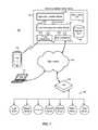
- FIG. 1is a block diagram illustrating a web-based device automation system in embodiments of the present invention.
- a web-based device automation system 100(“system 100 ”) includes a web-based device automation central server 102 (“central server 102 ”) communicating with a hub 104 over a data network 106 , such as the Internet or an intranet.
- Central server 102implements the processing and control for remotely monitoring and controlling one or more devices 108 over the data network 106 .
- web-based device automation system 100enables everyday objects to respond to digital controls.
- central server 102is a server connected to and communicating with hub 104 over the data network 106 .
- Hub 104is a module installed in an environment, which can be a home or an office or an outdoor location, for connecting one or more devices or appliances 108 in that environment to the data network 106 .
- hub 104functions as a bridge between the data network 106 and devices 108 to enable devices 108 to be connected to the data network.
- devices 108can be monitored and controlled through hub 104 and web services provided by central server 102 without requiring each device 108 to implement full network communication capability.
- hub 104is connected to a group of devices 108 including sensing devices that generate data and actuating devices that control a function.
- the group of devices 108can include everyday devices and appliances found in a home or an office.
- the group of devices 108includes a contact sensor, a temperature sensor, a motion sensor, and a presence sensor as sensing devices.
- the group of devices 108includes a thermostat, a garage door opener, and a light switch as actuating devices.
- Devices 108 shown in FIG. 1are illustrative only and not intended to be limiting.
- the web-based device automation central server of the present inventioncan be applied to monitor and control many types of devices applied in any environment.
- Each of the devices 108communicates with hub 104 to receive commands for actions to be performed or to report status or data.
- Devices 108may communicate with hub 104 through a wired or a wireless connection.
- devices 108communicate with hub 104 using a low-power wireless protocol, such as Zigbee and Z-wave.
- Hub 104in turn is connected to the data network 106 , typically through a wired connection.
- hub 104maintains a persistent connection to the data network 106 to enable continuous monitoring and control of devices 108 by central server 102 .
- Central server 102also supports communication with network-enabled computing devices, such as laptop computers, tablet computers, or smartphones.
- a usermay access the services provided by central server 102 using a smartphone 110 and a wireless or cellular connection to the data network 106 .
- a usermay access the services provided by central server 102 using a laptop computer 112 running a web user interface on a web browser.
- the laptop computer 112may connect to the data network through a wired or wireless connection.
- system 100includes a single hub 104 communicating with a set of devices 108 .
- the configuration shown in FIG. 1is illustrative only and not intended to be limiting.
- system 100may include two or more hubs 104 , each hub communicating with its own set of devices 108 .
- Central server 102is informed of the configuration of the hubs and the associated devices to enable remote control and monitoring of the devices through their respective hubs.
- the configuration of devices and hubs and their interconnection in a user's environmentis sometimes referred to as a physical graph. More specifically, a physical graph describes the devices that are in a user's environment and the interconnection of the devices and one or more hubs in the environment.
- the physical graphbeing a virtual representation of the physical devices in the user's environment, enables visibility into the status of devices and the events the devices are generating within the user's environment.
- the physical graphalso enables control over the state of the devices and the events generated by the devices.
- FIG. 1further illustrates an embodiment of central server 102 .
- central server 102includes a hub connectivity interface 114 configured to communicate with hub 104 over the data network 106 and a phone connectivity interface 116 configured to communicate with mobile devices, such as smartphone 110 , over a cellular network.
- Hub connectivity interface 114implements the necessary communication protocols to communicate with the hub 104 over the data network 106 and phone connectivity interface 116 implements the necessary communication protocols to communicate with mobile devices over a cellular network.
- hub connectivity interface 114 and phone connectivity interface 116maintain a persistent connection to the data network 106 and to one or more cellular network to enable continuous connection to the hubs in the system and to one or more mobile devices accessing the system.
- Central server 102includes an event processing and routing module 118 configured to process and route events within system 100 . More specifically, the functions of the event processing and routing module 118 includes receiving and processing event data received from the hub connectivity interface 114 and determining how events should be routed in the system. Central server 102 further includes an application execution module 120 configured to handle execution of automation applications, also referred to as “Apps” on the central server, as will be explained in more detail below.
- the central server 102includes a web interface 122 supporting communication with web services, APIs and mobile applications.
- central server 102includes a database 124 of automation applications, and data, such as user login information, event data and other data. In physical implementations, the central server 102 may include one or more processors performing the functions of the logical blocks shown in FIG. 1 .
- Automation applications or Appsare software components of the web-based device automation system 100 used to monitor, control and automate devices 108 that are installed in an environment or at a location.
- an automation application or an Appis a collection of event handlers or a collection of event handlers and controls that operates to respond to various types of events that occur within system 100 .
- an event handleris the software component for servicing an event to which an App is subscribed.
- an Appdefines event handlers, subscribes to events and the App is invoked when a specified event occurs.
- an eventincludes activities occurring at devices 108 , or controls or queries received from web applications from mobile devices or from web services.
- an eventcan be the detection of an opened door, the detection of the presence of a certain person at a certain location, the detection of a certain temperature reading, or the detection of motion at a certain location.
- An eventcan also be a control command from a web application on a mobile device, for example, to turn up the temperature on a thermostat or to turn on a light.
- the control commandcan also be received from web interfaces, such as from a laptop computer, or from other web services.
- an eventcan be a timer where an event is generated when the predetermined time set on the timer expires.
- an Appincludes a list of subscriptions to events, typically associated with devices, and a definition of event handlers to process those events, typically by taking action such as issuing commands.
- an Appmay include a definition of preferences or user settings to allow a user to configure the App to operate on certain devices desired by the user.
- An Appmay further include event handlers for performing installation and update of the App.
- an Appmay subscribe to one or more events and generate responses based on the subscribed events where the responses may be an action or another event.
- an Appreceives an event as an input and generates an action or raises other events as an output.
- an event handleris the software code that describes the input event and the action to be taken or the output event to be raised.
- an automation applicationimplements one or more of the following functions.
- An Appcan subscribe to and receive events from devices, events from mobile devices, events from web services, or events from timers.
- An Appcan handle and process events.
- An Appcan define actions to be taken.
- an Appcan raise events.
- An Appcan issue commands and set attributes on devices. For example, an App can make a web service call to an external data network.
- An Appcan access presence information, location, group and device information.
- An Appcan persist information in the database that is available across instantiations of the application. It is instructive to note that automation applications in system 100 are event driven, that is, they are not always running but are only invoked when a specified event occurs.
- an Appis merely a collection of event handlers or a container of event handlers and that an App is installed in system 100 by installing the event handlers defined in the App. Once the App is installed, it is the individual event handlers that are executed in response to events and the App itself becomes a shell for identifying event handlers that belong to the same App.
- references to “execution of the App”refers to the execution of (or invoking) the event handlers defined in the App.
- execution of an Apprefers to execution of the event handers associated with the App.
- system 100realizes a distributed control scheme where some event handlers are executed on central server 102 while other event handlers are executed on hub 104 .
- system 100can be made more responsive to events in the system.
- better resource utilizationis achieved by distributing the processing load over different processors in system 100 .
- central server 102for handling execution of Apps (or its associated event handlers) on the central server, includes the application execution module 120 .
- the application execution module 120receives events and an application identifier (App ID) of an automation application to be executed from the event processing and routing module 118 .
- the application execution module 120loads the App from the database 124 , or from a cache memory, and determines which event handler needs to be invoked and invokes the event handler.
- the application execution module 120also collects all of the information required by the event handler associated with the App and provides the information to the event handler.
- the application execution module 120may further monitor the execution of the App and report execution information in the data base.
- the application execution module 120may further send out-bound events generated by the event handler back to the event processing and routing module 118 .
- execution of Appsresults in generation of commands for devices which are sent to the event processing and routing module 118 to be transmitted to the hub 104 to cause actions to be taken on one or more devices 108 .
- the commandsmay be in the form of “event wirings,” as will be explained in more detail below.
- system 100has stored there on one or more automation applications (Apps) and the automation applications are made available to users through the mobile application or web interface.
- the usersmaking use of one or more automation applications, operate one or more of devices 108 remotely based on specified events.
- a usermay select an automation application (e.g. Light.On) which detects motion at a motion sensor device and as a result of the detected motion, actuates a light switch to turn on a light.
- the detected motionconstitutes an event while the actuation of the light switch constitutes an action.
- an automation applicatione.g.
- Arrive.Homewhich detects the opening of a door through a contact sensor and as a result of the detected state of the door, generates a web service call to check the weather or send a SMS message to a given mobile telephone number.
- the detected opening of the doorconstitutes an event while the web service call or SMS message constitutes another event raised by the App.
- a usermay configure one or more devices or appliances in his environment to respond to specified events.
- system 100realizes a distributed control scheme where some events are serviced by Apps (or the associated event handlers) being executed on central server 102 while other events are serviced by Apps (or the associated event handlers) being executed on hub 104 .
- the distributed control schemeensures optimal configuration of an automation application at run-time where event handlers are executed efficiently, either on central server 102 or on hub 104 .
- central server 102applies control policies to determine the best deployment strategy for executing the App.
- Various control policescan be applied to distribute the event handlers.
- an event handleris configured to run on a hub that is located in closest proximity to the device.
- an event handlerwhen an event handler includes actions to raise events involving web service calls, the event handler is run at the central server. Other scenarios will be described in more detail below.
- determination of distributing event handlers to the central server or to the hubis made when the App is installed by the user, as will be explained in more detail below.
- an automation application or an Appreceives an event as an input and generates an action or raise other events as an output.
- An Appis a collection of event handlers where an event handler is the software code that describes the input event and the action to be taken or an output event to be raised.
- an event handleris compiled into Java bytecode and sits on the Java runtime environment (JRE). Such an event handler can be executed by the central server 102 or by a hub supporting the Java runtime environment.
- a hubmay be configured without the ability to execute applications locally (such as executing applications using the Java Runtime environment).
- central server 102generates “event wiring” from an event handler and forwards the event wiring to the hub, or installs the event wiring at the hub, for execution.
- an event handleris compiled into machine code as the “event wiring” to run on the hub.
- the event wiringconsists of JSON or xml data.
- an event wiringdefines the direct connection (or “wiring”) of an event on a first device to a specific action on a second device, which can be the same device or a different device).
- event wiringdoes not involve any logical operations.
- event wiringthere is no programmable logic between the event and the action and the event directly causes the action.
- an event wiringis used when a specific event on a specific device, such as a motion detected event on a motion detector, always results in the same response, such as turn on a light.
- Event wiringsare commands send down to be stored on the hub for execution and do not have to rely on further communication with the central server 102 for execution.
- an automation applicationmay include preferences to allow users to select a specific device or a group of devices to use with the application.
- the Appmay specify the device type and capabilities of the device required for the App. For example, the App may require a motion detector (device type) with night-vision capability. In another example, an App may require a switch that can provide an on-off function.
- the central serveridentifies all of the devices meeting the requirements of the App and provides a user interface to the user to select the preferred device as user configuration preferences.
- FIG. 2illustrates an example of a hub.
- a hub 104includes a processor 150 , a network interface 152 and a device interface 154 which implements one or more communication protocols for communicating with the data network and with one or more devices respectively.
- the device interfacemay be implemented as radio frequency radios for communicating wirelessly with one or more devices in the environment.
- Hub 104further includes one or more memories for storing event handlers and/or event wiring.
- hub 104includes an event handler table 158 for storing a listing of event handlers installed on the hub to be executed on the hub.
- the hub 104further includes an event handler storage for storing the software codes associated with each event handler listed in the event handler table.
- the hub 104also includes an event wiring table 156 for storing event wiring data. Event wirings and event handlers are stored onto the memories in hub 104 when an App is installed by the user and the central server determines that the App or its associated event handlers should be deployed to the hub for execution at run-time.
- the hub 104includes both the event handler table and the event wiring table. Hub 104 can therefore support commands sent as event wirings and can support execution of event handlers. In other embodiments, the hub 104 can be configured to include either an event handler table or an event wiring table. In the case where the hub is provided with the capability to execute event handers, then the event wiring table is not needed and the hub may be configured to include only the event handler table 158 and the event handler storage 159 . In the case where the hub does not support the programming language of event handlers, the hub 10 may be configured to include only the event wiring table 156 . FIG. 2 is illustrative only and is not intended to be limiting.
- Event wiring table 156is shown in FIG. 2A .
- the event wiring table 156is implemented as a look-up table.
- Event wiring table 156associates an event identifier (event ID) to a source device ID, a target device ID and an action.
- event IDevent identifier
- the hub 104detects the occurrence of an event with a certain event ID from the associated source device ID, the hub 104 will take the associated action to the associated target device.
- an eventmay be mapped to multiple entries in table 156 . In that case, hub 104 executes the action defined for each event entry to each specified target device.
- an event handler table 158is shown in FIG. 2B .
- the event handler table 158is implemented as a look-up table.
- the event handlercan be installed on the hub to be executed on the hub.
- the event handler table 158associates an event identifier (event ID) and a source device identifier (ID) with an event handler identifier (ID).
- event IDevent identifier
- IDsource device identifier
- IDevent handler identifier
- the hub 104will retrieve the associated event handler ID.
- the event hander IDcan then be used to retrieve the codes associated with the event hander ID.
- the processor 150invokes the event handler, or executes the codes of the event handler to generate the action required.
- the processor 150functions as the execution module of the event handlers that are stored in the hub to be executed in the hub.
- an eventmay be mapped to multiple entries in table 158 . In that case, hub 104 executes the event handler defined for each event entry.
- FIG. 3illustrates an example of a device which may be installed in an environment to be monitored and controlled by the web-based device automation system.
- a device 108includes a controller 160 communicating with a communication interface 162 .
- the communication interface 162may include a command interface and an event interface as logical components of the interface.
- the command interfacereceives commands for actions to be taken on the device from the hub.
- the event interfacereports status or event data to the hub.
- the communication interface 162implements wired or wireless communication protocols for communicating with the hub.
- Device 108may include a local memory 164 for storing status and event data. Memory 164 is optional and may be omitted in other embodiments of the device.
- Controller 160may include embedded memory sufficient to store the status and event data for the device.
- Device 108may be applied in many applications in an environment.
- Device 108may be configured as a sensing device for sensing certain environmental data or status condition data, such as temperature, humidity, pressure and open and close conditions.
- Device 108may also be configured as an actuating device for controlling an object.
- device 108may be an actuator for activating a door lock, or a light switch, or a thermostat.
- device 108may be both a sensing device and an actuating device.
- device 108includes a sensor 166 or an interface to a sensor and further includes an actuator 168 or an interface to an actuator. Sensor 166 provides data to controller 160 while actuator 168 receives control signals from the controller 160 .
- the configuration for device 108 shown in FIG. 3is illustrative only. In embodiments of the present invention, a device 108 may include only the sensor or only the actuator or both depending on the application of device 108 .
- a deviceis associated with a device type and is defined by its capabilities, its attributes and the events it can generate.
- an on-off switch devicehas the capabilities of turning on and turning off, has an attribute of a current state being on or off, and has an On event and an Off event.
- the controller 160 in device 108accepts commands that may change the attributes or doing something physically in device 108 .
- the devicemay further report events, such as the current state of the device or the current state of the attributes of the device.
- a devicemay be a door and the attributes may be the position and the current state of the attribute may be open, close or locked.
- a composite device typecan be formed by aggregating multiple physical devices into one logical device.
- An automation applicationcan be written using the composite device type so that the device is treated as a single logical device, without regard to how many separate physical devices there may be.
- a virtual device typecan be a garage door opener which consists of an accelerometer and a relay as the separate physical devices.
- An automation applicationmay be created to respond to events from the garage door opener and issues actions and commands to the garage door opener. With the use of the composite device type, the fact that the garage door opener includes separate lower level devices is irrelevant to the user.
- the central server 102 of system 100takes care of the installation and execution of the automation application for interacting with a device having the composite device type.
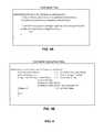
- FIG. 4which includes FIGS. 4A and 4B , illustrate examples of an event handler and an event handler generating event wiring.
- an Appdefines the device types that are called out and the capabilities that are required for the App.
- an event handler “onDoorOpen”receives as input an Event and Preferences specifying one or more source devices. If the Event occurred on a source device defined in the Preferences, then the event handler generates an action to turn on a light or multiple lights as the target devices. The target devices are selected based on user preferences.
- an event handler “onMotionDetected”receives as input an Event and Preferences specifying one or more source devices. Specifically, the event handler onMotionDetected generates event wiring that may be stored in a hub for execution. The event handler first determines if the hard wiring has already taken place. For example, if the action is to turn on a light, the event handler first checks if the light is already turned on. If not, a new wiring is created where in response to the event, the light specified by user preference is to be turned on.
- FIG. 5is a flow chart illustrating the process for configuring and installing an automation application in the web-based device automation system in embodiments of the present invention.
- the App configuration and installation process 200 in FIG. 5can be used in conjunction with system 100 in FIG. 1 .
- a user having a hub 104 and one or more devices 108 installed in an environment and wishing to access services provided by the web-based device automation system 100initiates an login to the central server 102 .
- Central server 102receives the login information for the user ( 202 ).
- Central server 102retrieves the physical graph associated with the user's environment ( 204 ). For example, the physical graph for the user's environment may be established when the user sets up the hub 104 and one or more devices 108 are joined or paired with the hub.
- the central server 102receives an App selection ( 206 ). For example, the user may select the onDoorOpen App in FIG. 4A .
- the central server 102presents a selection of automation applications to the user and the user may select an App to handle certain desirable events. From the selected App, the central server 102 retrieves the App configuration information required for that App ( 208 ). In some cases, the App does not involve any user experience and the process 200 may proceed to 214 . In other cases, the App requires further user input and presents a user interface to the user to select preferences for configuring the App for installation.
- the user interfacemay be presented through a mobile application on a mobile device or through a web browser in a computer device, such as a laptop.
- the onDoorOpen Appis configured to operate in response to an event on a source device (contact sensor) and turn on a target device (light) where the specific source device and target device can be specified by user preferences.
- a source devicecontact sensor
- a target devicelight
- the onDoorOpen Apptherefore collects the configuration information needed to execute the App, including the device types that are called out by the App and the required capabilities for the devices called out by the App.
- Central server 102filters the devices in the user's physical graph based on the requirements or specification of the App ( 210 ). Of all the devices in the user's physical graph, central server 102 selects those that meet the device type and the capabilities called out by the App. The list of possible source devices and target devices is then provided to the user through a user interface where the user may make selections. The central server 102 then receives user configuration preferences ( 212 ). The central server 102 then determines the optimal deployment strategy for the App ( 214 ). In some cases, the App is more efficiently executed at the central server. In that case, the App (or the associated event hander) is installed at the central server 102 ( 218 ) and the central server 102 issues commands to the hub to execute the actions described in the App.
- the Appis more efficiently executed at the hub 104 in the user's environment.
- the central server 102installs the App (or its associated event handler) at the hub ( 216 ).
- the central server 102generates event wiring from the event handler and sends the event wiring down to the hub to be installed at the hub.
- the hubstores the event wiring in its local memory and executes the actions described in the event wiring in response to the subscribed event.
- the central server 102may send the event handler associated with the App down to the hub when the hub is capable of executing software codes and the event handlers are stored in the hub and executed by the hub.
- Central server 102applies various policies to determine the optimal deployment strategy for an App.
- the deployment of the Appis determined when the App is installed so that the deployment strategy is made pertaining to each user's specific configuration of devices and hubs.
- the central servermay install an App to be executed on one of the hubs if all the devices called out by that App is associated with that one hub. However, if the devices are connected to different hubs, then the App will be executed from the central server.
- the central servermay install an App to be executed on the hub.
- the central serverexamines actions called out by the App. When the action called out by the App results in actions taken at the central server, such as a web service call, then the App should be executed from the central server rather than at the hub.
- automation applicationsare written without knowledge or without taking in consideration how the automation applications or the associated event handlers will be distributed at deployment.
- an automation applicationmay be deployed differently in different environments.
- the deployment characteristics of an automation applicationis a function of the configuration of hubs (if any) and devices in a user's environment, as described by the physical graph associated with the user.
- FIG. 6is a flow chart illustrating the process for automatically determining application deployment strategy in the web-based device automation system in one embodiment of the present invention.
- process 250starts when central server 102 receives the configuration information for an App ( 252 ) and further receives user preferences and the configuration information (or the physical graph) for devices and hubs associated with the user's environment ( 254 ). Based on this information, central server 102 determines if the App should be installed on the central server or on a hub in the user's environment. In the present embodiment, for each event handler in the App ( 255 ), the process 250 first determines if the App includes any web services call ( 256 ).
- process 250determines if an event handler generates event wiring. If the hub supports event wiring, then the App is sent down to the hub to be installed on the hub as event wiring.
- the event handleris the boundary for the automatic deployment analysis. That is, an event handler is the boundary where the central server will analyze the actions in the event handler and makes an automatic determination where the event handler can run. The determination is made at the App installation time when the specific user configuration information can be obtained to determine how the event handler should be executed.
- an Appcan be structured so that execution of the event handlers is distributed optimally between the central server or the hub. For example, an App may be created to detect a door opening event and turn on a light and make a web service call to check the weather. When the App is structured as such, the App will be installed to run from the central server as the App requires making a web service call.
- the Appmay be structured with separate event handlers so that some of the actions can take place on the hub instead of the central server.
- the Appcan be structure to include a first event handler to detect a door opening event and turn on a light and then raise a second event handler.
- the second event handlermakes a web service call to check the weather.
- the central serverwill determine that the first event handler can be installed at the hub while the second event handler is installed at the central server. In this manner, optimal deployment of event handlers is realized.
- FIG. 7is a flow chart illustrating the application execution process at a hub in the web-based device automation system in one embodiment of the present invention.
- process 300operates on a hub installed in a user's environment.
- the hubreceives deployment of event handlers or event wirings from the central server ( 302 ).
- the event handlers or event wiringsare stored in memories, such as look-up tables, in the hub ( 304 ).
- an event generated by a source deviceis detected by the hub ( 306 ), such as when a device reports an event to the hub or when the central server reports an event to the hub.
- the hublook up the event ID and the source device identifier in the event wiring table or look up the event ID in the event handler table ( 308 ).
- the hubissues the action to the target device ( 310 ).
- the hubexecutes the codes and takes the action specified by the codes ( 310 ). In some embodiments, the hub may then report the event to the central server with the actions that were taken (312).
- events received at the hubare sent up to the central server to the event processing and routing module.
- the event processing and routing moduleprocesses the events to determine if event handlers that are installed on the central server may subscribe to the event.
- An event handlermay be invoked and executed at the Application Execution module when a subscribed event is received. The execution of App or event handlers at the central server is described above with reference to FIG. 1 .
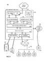
- FIG. 8is a block diagram illustrating a web-based device automation system in alternate embodiments of the present invention.
- a web-based device automation system 500(“system 500 ”) includes a web-based device automation central server 502 (“central server 502 ”) communicating with a hub 504 over a data network (not shown), such as the Internet or an intranet.
- the hub 504is installed in an environment and is in communication with one or more devices 508 .
- central server 502implements the processing and control for remotely monitoring and controlling devices 508 over the data network.
- central server 502further supports direct communication with devices, such as device 509 . That is, central server 502 may communicate with devices directly without going through a hub.
- a device 509may communicate with central server 502 through a cellular network (not shown) and using the phone connectivity interface 516 .
- the device 509is a sensor module installed in a car for monitoring the traveling speed of the car.
- Device 509supports cellular communication and generates status data (car speed) which are reported back to the central server 502 as events.
- device 509can be a location determination device or an outdoor temperature sensor.
- central server 502further supports network-to-network, or cloud-to-cloud, communication.
- a device 562 installed in the same environment as other devices 508may be configured to communicate only with a third party private data network, such as a data network 560 associated with the manufacturer of the device 562 .
- a third party private data networksuch as a data network 560 associated with the manufacturer of the device 562 .
- manufacturers of remote control door lockstypically required the lock to communicate only with the manufacturers' own data network in order to ensure security.
- central sever 502supports communication with third party private data networks, such as network 560 , to enable a user to control and operate device 562 seamlessly through central server 502 and using the automation applications that are part of system 500 .
- FIG. 8further illustrates an embodiment of central server 502 .
- the example shownis a representation of logical components that may be included in central server 502 , in some embodiments.
- central server 502includes a hub connectivity interface 514 configured to communicate with hub 504 over a data network (not shown) and a phone connectivity interface 516 configured to communicate with mobile devices, such as smartphone 510 , over a cellular network (not shown).
- Hub connectivity interface 514implements the necessary communication protocols to communicate with the hub 504 over the data network
- phone connectivity interface 516implements the necessary communication protocols to communicate with mobile devices and devices 509 over a cellular network.
- hub connectivity interface 514 and phone connectivity interface 516maintain a persistent connection to the data network and to one or more cellular network to enable continuous connection to the hubs in the system and to one or more devices and mobile devices accessing the system.
- Central server 502includes a device-type handler module 517 and an event processing and routing module 518 .
- Device-type handler module 517implements device-type handlers that are an abstraction of devices from their distinct capabilities. More specifically, device-type handlers enable automation applications to be written using generic or normalized language for commands and status with respect to devices and the device-type handlers in module 517 perform the translation of the normalized language to device-specific language required to communicate with the physical devices. The operation of the device-type handler module 517 in central server 502 will be explained in more detail below. In brief, the device-type handler module 517 receives device-specific events and status and generates normalized events and status for the event processing and routing module 518 . The device-type handler module 517 also receives normalized commands from the event processing and routing module 518 and generates device-specific commands to be sent to the devices 508 or 509 .
- Event processing and routing module 518operates in the same manner as described above to process and route events within system 500 .
- the functions of the event processing and routing module 518includes receiving and processing event data received from the hub connectivity interface 514 and phone connectivity interface 516 and determining how events should be routed in the system 500 .
- Central server 502further includes an application execution module 520 configured to handle execution of automation applications or Apps on the central server.
- the central server 502includes an App and Data management module 530 for supporting data transfer with a web interface 522 and an API 523 .
- web interface 522supports communication with external web services.
- API 523can be used to communicate with external services 550 , such as external web services.
- API 523can also be used to communicate with third party private data network 560 .
- central server 502includes a database 524 for storing automation applications, user physical graphs, event store and other data. In physical implementations, the central server 502 may include one or more processors performing the functions of the logical blocks shown in FIG. 8 .
- device-type handlersare virtual representations of devices in the environment that enable the separation of devices with their capabilities from automation applications that are used to control or monitor the devices. In this manner, an automation application is not necessarily tightly coupled to a specific device but rather can be used on a class of devices meeting the requirements specified in the App.
- a deviceis associated with a device type and a device type is defined by its capabilities, its attributes and the events it can generate.
- a device type “switch”describes devices that have the On and Off capabilities. Switches many different physical configuration and may employ different wireless communication protocols.
- a simple light switch or a multi-sensorcan both belong to the device type “switch.”
- a multi-sensorcan belong to the device type “switch” or the device type “sensor” describing sensing capabilities.
- the exact physical configuration of the deviceis not critical to the App but rather all the App looks for is a device that can perform certain functions or a device that has certain attributes. With the use of device types and device-type handlers, an App can be used on any devices belonging to the device type (e.g. “switch”) without knowing the exact nature of the device.
- a device typecan be defined by its capabilities and attributes.
- a device type “ACME wireless door lock version 4”describes a fourth generation door lock device from the manufacturer ACME that has a locking and unlocking capabilities and wireless communication ability.
- device-type handlersare software components that act as a translator between a device and an automation application that makes use of the device.
- device-type handlersare the bridge between generic capabilities at the automation application level and the device-specific (or protocol-specific) interface actually used to communicate with the device.
- Device-type handlersenable automation applications to be developed without knowing the specific details of the physical devices.
- Device-type handlersenable automation applications to be written using generic or normalized commands so that an automation application can be applied to any devices having the capabilities of a specific device type, including devices to be developed in the future.
- device-type handlersare installed at the central server 502 in device-type handler module 517 .
- device-type handlersmay also be installed at the hub 504 when the hub is used to execute event handlers.
- Device-type handlerscan be installed at the hub in one of several ways. In some embodiments, when a user sets up a hub in his or her environment, the hub, as part of the set up procedure, is placed in the “join” mode to join or pair with devices that are within its communication range.
- the hubdiscovers the device type of the device using identifying information associated with the device, referred to as “device fingerprints.”
- Device fingerprintscan include information such as the manufacturer identification, the product identification, the device identification and other unique identifier for the device.
- the hubmay further discover the capabilities of the device, including the communication protocol used by the device.
- the central serverdetermines the device-type handler to be used with the device. If a specific device-type handler cannot be find, then a generic device-type handler can be used.
- the central serverdeploys to the hub all device-type handlers for devices that have paired with the hub.
- the hubstores the device-type handlers for future use.
- the central servermay also dynamically download updates of the device-type handlers that have been deployed to the hub.
- the central serverdeploys device-type handlers to the hub only when an App is to be installed on the hub to be executed on the hub. In that case, device-type handlers are deployed to the hub in an on-demand basis. In either case, the hub is provided with the device-type handlers that it needs to execute Apps or device handlers on the hub.
- FIG. 9is a logical block diagram illustrating the operation of the device-type handler in the execution of an automation application in examples of the present invention.
- a device-type handler 660is provided for a device 608 implementing a switch capability.
- a device with a switch capabilityhas the ability to turn on or off.
- the main function of the device-type handler 660is to parse incoming protocol-specific status messages from the device 608 , received through the connectivity layer 614 , and turn these protocol-specific status messages into normalized events or status.
- protocol-specific status messagesrefer to messages that are transmitted in the format of the communication protocol used by the device.
- the devicemay employ protocols such as Zigbee or Z-Wave.
- the device-type handler 660is also responsible for accepting normalized commands (such as ‘on’ and ‘off’) and turning those into the protocol-specific commands that can be sent to the device to effect the desired action.
- the device 608may report a status to the central server or the hub.
- the connectivity layer 614(of the central server or the hub) receives the protocol-specific status message from the device 608 and forwards the message to the device-type handler 660 .
- the device-type handler 660implements a parse method 662 to parse the incoming protocol-specific status message and to generate a normalized event (e.g. “On” event or “Off” event).
- the normalized eventcan then be sent to the event processing and routing module 630 to be processed.
- the event processing and routing module 630determines the event handler that subscribes to the event and forwards the event with the event handler to the application execution module 620 .
- the normalized eventmay also be made available to external services, such as through an API 623 .
- device 608is a Z-Wave compatible on-off switch.
- the protocol-specific status messages to report an “on” state or an “off” stateare as follows.
- the normalized event generated by the device-type handleris simply an “On” or “Off” event.
- the event handlerWhen the execution of the event handler at the application execution module 620 results in generation of commands for actions to be taken on the device 608 (or another device), the event handler generates a normalized command which is sent to the event processing and routing module 630 . Normalized commands may also be received from the API 623 .
- the event processing and routing module 630forwards the normalized command intended for device 608 to device-type handler 660 .
- the device-type handler 660implements device capability methods 664 to translate the normalized command (On or Off) to a protocol-specific command. The protocol-specific command is then forwarded to device 608 through the connectivity layer 614 .
- FIG. 9is provided to illustrate the operation of the device-type handler 660 in generating normalized event and generating device-specific (or protocol-specific) commands.
- FIG. 9illustrates events being received from device 608 and commands being generated for the same device 608 .
- FIG. 9is illustrative only and does not necessarily illustrate the actual operation of the device automation system in the present invention. For example, in normal operation of the device automation system, status messages are received from a source device and commands are generated for a target device and the source device and the target device may not be the same device.
- the use of device 608 in FIG. 9is symbolic only.
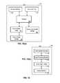
- FIG. 10which includes FIGS. 10( a ) and 10( b ) , illustrates an example of a hub incorporating device-type handlers.
- a hub 704includes a processor 750 , a network interface 152 and a device interface 154 which implements one or more communication protocols for communicating with the data network and with one or more devices respectively.
- Hub 704further includes an event handler table 158 for storing a listing of event handlers installed on the hub to be executed on the hub.
- the hub 704further includes an event handler storage for storing the software codes associated with each event handler listed in the event handler table.
- the hub 704further includes a device-type handler storage 760 for storing one or more device-type handlers for use by processor 750 in processing incoming status messages and generating outgoing commands.
- FIG. 10( b )illustrates the logical block diagram of the hub 704 .
- the logical blocks of hub processor 704is similar to the logical blocks of the central server.
- the hub 704includes a device interface 772 for communicating with devices. Messages received from devices are sent to the device-type handler 774 to be translated. The normalized messages or events are then sent to the event processing and routing module 776 to be processed.
- the event processing and routing module 776looks for subscription of the event and invokes the event handler that subscribes to the event.
- the event handler execution module 778supports the execution of event handlers in response to the received event.
- Normalized commands generated by the event handler execution module 778flows down the logical blocks to the event processing and routing module 776 and then to the device-type handler 774 to be translated into protocol-specific commands.
- the protocol-specific commandsare then provided to the device interface 772 to be forwarded to the device.
- status messages generated by devices and received at the hubare normalized by the local device-type handler into normalized events and these events can be operated on at the hub but are also sent up to the central server. Because the event has already been normalized, the central server does not need to apply the device-type handler to the received event again and may process and route the event and store the events in the event store database. In other embodiments, the central server may receive status messages directly from devices. In that case, the protocol-specific status messages are provided to the device-type handler module in the central server to be translated into normalized events.
- the application execution module at the central serverwhen the application execution module at the central server generates commands for a device, the commands will be translated into protocol-specific commands by the device-type handler at the central server before the commands are sent down to the hub or directly to the device.
- the hubupon receiving the protocol-specific commands, forwards the commands to the device and does not need to invoke the device-type handler again.
- FIG. 11which includes FIG. 11( a ) and FIG. 11( b ) , contains flow charts illustrating device-type handler methods in the central server or the hub of the automation system in embodiments of the present invention.
- a method 800illustrates the processing of incoming status messages.
- a status messageis received from a source device, from user control, or from a timer.
- method 800parses the protocol-specific status message.
- method 800generates normalized event.
- method 800forwards the normalized event to the event processing and routing module.
- a method 820illustrates the processing of incoming normalized commands.
- method 820receives normalized commands from the application execution module.
- method 820parses the normalized commands.
- method 820generates protocol-specific commands.
- the method 820forwards the protocol-specific commands to the target device.
- an event handlerin response to an event, may issue an action to a target device or the event handler may raise another event.
- the event being raisedreferred to as a custom event—can be subscribed by other event handlers.
- the automation system of the present inventionmay use custom events as a means for event handler communications. When one event handler raises a custom event, that custom event can be treated as a message from one event handler to another event handler. In this manner, custom events become a convenient method in the automation system to relay messages from one event handler to another event handler.
Landscapes
- Engineering & Computer Science (AREA)
- Physics & Mathematics (AREA)
- General Physics & Mathematics (AREA)
- Automation & Control Theory (AREA)
- Computer Networks & Wireless Communication (AREA)
- Signal Processing (AREA)
- General Engineering & Computer Science (AREA)
- Computer And Data Communications (AREA)
Abstract
Description
| Device | Protocol-specific | Normalized |
| Status | Status Message | Event |
| On | command: 2003, payload: FF | On |
| Off | command: 2003, payload: 00 | Off |
| Device | Protocol-specific | ||
| Command | Command Message | ||
| On | 2001FF | ||
| Off | 200100 | ||
Claims (18)
Priority Applications (3)
| Application Number | Priority Date | Filing Date | Title |
|---|---|---|---|
| US13/838,687US9529344B1 (en) | 2013-03-15 | 2013-03-15 | Device-type handlers for remote control and monitoring of devices through a data network |
| US15/357,433US10386807B2 (en) | 2013-03-15 | 2016-11-21 | Device-type handlers for remote control and monitoring of devices through a data network |
| US16/839,822USRE50100E1 (en) | 2013-03-15 | 2020-04-03 | Device-type handlers for remote control and monitoring of devices through a data network |
Applications Claiming Priority (1)
| Application Number | Priority Date | Filing Date | Title |
|---|---|---|---|
| US13/838,687US9529344B1 (en) | 2013-03-15 | 2013-03-15 | Device-type handlers for remote control and monitoring of devices through a data network |
Related Child Applications (2)
| Application Number | Title | Priority Date | Filing Date |
|---|---|---|---|
| US15/357,433ContinuationUS10386807B2 (en) | 2013-03-15 | 2016-11-21 | Device-type handlers for remote control and monitoring of devices through a data network |
| US16/839,822ContinuationUSRE50100E1 (en) | 2013-03-15 | 2020-04-03 | Device-type handlers for remote control and monitoring of devices through a data network |
Publications (1)
| Publication Number | Publication Date |
|---|---|
| US9529344B1true US9529344B1 (en) | 2016-12-27 |
Family
ID=57590102
Family Applications (3)
| Application Number | Title | Priority Date | Filing Date |
|---|---|---|---|
| US13/838,687Active2035-07-14US9529344B1 (en) | 2013-03-15 | 2013-03-15 | Device-type handlers for remote control and monitoring of devices through a data network |
| US15/357,433CeasedUS10386807B2 (en) | 2013-03-15 | 2016-11-21 | Device-type handlers for remote control and monitoring of devices through a data network |
| US16/839,822Active2034-06-24USRE50100E1 (en) | 2013-03-15 | 2020-04-03 | Device-type handlers for remote control and monitoring of devices through a data network |
Family Applications After (2)
| Application Number | Title | Priority Date | Filing Date |
|---|---|---|---|
| US15/357,433CeasedUS10386807B2 (en) | 2013-03-15 | 2016-11-21 | Device-type handlers for remote control and monitoring of devices through a data network |
| US16/839,822Active2034-06-24USRE50100E1 (en) | 2013-03-15 | 2020-04-03 | Device-type handlers for remote control and monitoring of devices through a data network |
Country Status (1)
| Country | Link |
|---|---|
| US (3) | US9529344B1 (en) |
Cited By (91)
| Publication number | Priority date | Publication date | Assignee | Title |
|---|---|---|---|---|
| US20160274759A1 (en) | 2008-08-25 | 2016-09-22 | Paul J. Dawes | Security system with networked touchscreen and gateway |
| US20170054571A1 (en)* | 2008-08-11 | 2017-02-23 | Jim KITCHEN | Integrated cloud system for premises automation |
| US9838244B1 (en) | 2013-12-11 | 2017-12-05 | Ca, Inc. | Compound alarms |
| US20180224811A1 (en)* | 2015-07-03 | 2018-08-09 | Overkiz | Method for recording a central control unit belonging to a home-automation facility, method for controlling and method for configuring a home-automation facility |
| US10051078B2 (en) | 2007-06-12 | 2018-08-14 | Icontrol Networks, Inc. | WiFi-to-serial encapsulation in systems |
| US10062245B2 (en) | 2005-03-16 | 2018-08-28 | Icontrol Networks, Inc. | Cross-client sensor user interface in an integrated security network |
| US10062273B2 (en) | 2010-09-28 | 2018-08-28 | Icontrol Networks, Inc. | Integrated security system with parallel processing architecture |
| US10078958B2 (en) | 2010-12-17 | 2018-09-18 | Icontrol Networks, Inc. | Method and system for logging security event data |
| US10079839B1 (en) | 2007-06-12 | 2018-09-18 | Icontrol Networks, Inc. | Activation of gateway device |
| US10091014B2 (en) | 2005-03-16 | 2018-10-02 | Icontrol Networks, Inc. | Integrated security network with security alarm signaling system |
| US10127801B2 (en) | 2005-03-16 | 2018-11-13 | Icontrol Networks, Inc. | Integrated security system with parallel processing architecture |
| US10142392B2 (en) | 2007-01-24 | 2018-11-27 | Icontrol Networks, Inc. | Methods and systems for improved system performance |
| US10142166B2 (en) | 2004-03-16 | 2018-11-27 | Icontrol Networks, Inc. | Takeover of security network |
| US10142394B2 (en) | 2007-06-12 | 2018-11-27 | Icontrol Networks, Inc. | Generating risk profile using data of home monitoring and security system |
| US10140840B2 (en) | 2007-04-23 | 2018-11-27 | Icontrol Networks, Inc. | Method and system for providing alternate network access |
| US10156959B2 (en) | 2005-03-16 | 2018-12-18 | Icontrol Networks, Inc. | Cross-client sensor user interface in an integrated security network |
| US10156831B2 (en) | 2004-03-16 | 2018-12-18 | Icontrol Networks, Inc. | Automation system with mobile interface |
| US10200504B2 (en) | 2007-06-12 | 2019-02-05 | Icontrol Networks, Inc. | Communication protocols over internet protocol (IP) networks |
| US10237806B2 (en) | 2009-04-30 | 2019-03-19 | Icontrol Networks, Inc. | Activation of a home automation controller |
| US10237237B2 (en) | 2007-06-12 | 2019-03-19 | Icontrol Networks, Inc. | Communication protocols in integrated systems |
| US10313303B2 (en) | 2007-06-12 | 2019-06-04 | Icontrol Networks, Inc. | Forming a security network including integrated security system components and network devices |
| US10339791B2 (en) | 2007-06-12 | 2019-07-02 | Icontrol Networks, Inc. | Security network integrated with premise security system |
| US10348575B2 (en) | 2013-06-27 | 2019-07-09 | Icontrol Networks, Inc. | Control system user interface |
| US10365810B2 (en) | 2007-06-12 | 2019-07-30 | Icontrol Networks, Inc. | Control system user interface |
| US10380871B2 (en) | 2005-03-16 | 2019-08-13 | Icontrol Networks, Inc. | Control system user interface |
| US10382452B1 (en) | 2007-06-12 | 2019-08-13 | Icontrol Networks, Inc. | Communication protocols in integrated systems |
| US10386807B2 (en) | 2013-03-15 | 2019-08-20 | SmartThings, Inc. | Device-type handlers for remote control and monitoring of devices through a data network |
| US10389736B2 (en) | 2007-06-12 | 2019-08-20 | Icontrol Networks, Inc. | Communication protocols in integrated systems |
| US10423309B2 (en) | 2007-06-12 | 2019-09-24 | Icontrol Networks, Inc. | Device integration framework |
| US10425312B1 (en)* | 2013-12-11 | 2019-09-24 | Ca, Inc. | One-click monitoring |
| US10498830B2 (en) | 2007-06-12 | 2019-12-03 | Icontrol Networks, Inc. | Wi-Fi-to-serial encapsulation in systems |
| US10522026B2 (en) | 2008-08-11 | 2019-12-31 | Icontrol Networks, Inc. | Automation system user interface with three-dimensional display |
| US10523689B2 (en) | 2007-06-12 | 2019-12-31 | Icontrol Networks, Inc. | Communication protocols over internet protocol (IP) networks |
| US10530839B2 (en) | 2008-08-11 | 2020-01-07 | Icontrol Networks, Inc. | Integrated cloud system with lightweight gateway for premises automation |
| US10559193B2 (en) | 2002-02-01 | 2020-02-11 | Comcast Cable Communications, Llc | Premises management systems |
| US10616075B2 (en) | 2007-06-12 | 2020-04-07 | Icontrol Networks, Inc. | Communication protocols in integrated systems |
| US10666523B2 (en) | 2007-06-12 | 2020-05-26 | Icontrol Networks, Inc. | Communication protocols in integrated systems |
| US10721087B2 (en) | 2005-03-16 | 2020-07-21 | Icontrol Networks, Inc. | Method for networked touchscreen with integrated interfaces |
| US10747216B2 (en) | 2007-02-28 | 2020-08-18 | Icontrol Networks, Inc. | Method and system for communicating with and controlling an alarm system from a remote server |
| US10785319B2 (en) | 2006-06-12 | 2020-09-22 | Icontrol Networks, Inc. | IP device discovery systems and methods |
| US10841381B2 (en) | 2005-03-16 | 2020-11-17 | Icontrol Networks, Inc. | Security system with networked touchscreen |
| US10908772B2 (en)* | 2014-11-27 | 2021-02-02 | Xiaomi Inc. | Method and apparatus for adjusting running state of smart housing device |
| US10979389B2 (en) | 2004-03-16 | 2021-04-13 | Icontrol Networks, Inc. | Premises management configuration and control |
| US10999254B2 (en) | 2005-03-16 | 2021-05-04 | Icontrol Networks, Inc. | System for data routing in networks |
| US11089122B2 (en) | 2007-06-12 | 2021-08-10 | Icontrol Networks, Inc. | Controlling data routing among networks |
| US11113950B2 (en) | 2005-03-16 | 2021-09-07 | Icontrol Networks, Inc. | Gateway integrated with premises security system |
| US11146637B2 (en) | 2014-03-03 | 2021-10-12 | Icontrol Networks, Inc. | Media content management |
| US11153266B2 (en) | 2004-03-16 | 2021-10-19 | Icontrol Networks, Inc. | Gateway registry methods and systems |
| US11182060B2 (en) | 2004-03-16 | 2021-11-23 | Icontrol Networks, Inc. | Networked touchscreen with integrated interfaces |
| US11201755B2 (en) | 2004-03-16 | 2021-12-14 | Icontrol Networks, Inc. | Premises system management using status signal |
| US11212192B2 (en) | 2007-06-12 | 2021-12-28 | Icontrol Networks, Inc. | Communication protocols in integrated systems |
| US11218878B2 (en) | 2007-06-12 | 2022-01-04 | Icontrol Networks, Inc. | Communication protocols in integrated systems |
| US11237714B2 (en) | 2007-06-12 | 2022-02-01 | Control Networks, Inc. | Control system user interface |
| US11240059B2 (en) | 2010-12-20 | 2022-02-01 | Icontrol Networks, Inc. | Defining and implementing sensor triggered response rules |
| US11244545B2 (en) | 2004-03-16 | 2022-02-08 | Icontrol Networks, Inc. | Cross-client sensor user interface in an integrated security network |
| US11258625B2 (en) | 2008-08-11 | 2022-02-22 | Icontrol Networks, Inc. | Mobile premises automation platform |
| US11277465B2 (en) | 2004-03-16 | 2022-03-15 | Icontrol Networks, Inc. | Generating risk profile using data of home monitoring and security system |
| US11310199B2 (en) | 2004-03-16 | 2022-04-19 | Icontrol Networks, Inc. | Premises management configuration and control |
| US11316753B2 (en) | 2007-06-12 | 2022-04-26 | Icontrol Networks, Inc. | Communication protocols in integrated systems |
| US11316958B2 (en) | 2008-08-11 | 2022-04-26 | Icontrol Networks, Inc. | Virtual device systems and methods |
| US11343380B2 (en) | 2004-03-16 | 2022-05-24 | Icontrol Networks, Inc. | Premises system automation |
| US11398147B2 (en) | 2010-09-28 | 2022-07-26 | Icontrol Networks, Inc. | Method, system and apparatus for automated reporting of account and sensor zone information to a central station |
| US11405463B2 (en) | 2014-03-03 | 2022-08-02 | Icontrol Networks, Inc. | Media content management |
| US11423756B2 (en) | 2007-06-12 | 2022-08-23 | Icontrol Networks, Inc. | Communication protocols in integrated systems |
| US11424980B2 (en) | 2005-03-16 | 2022-08-23 | Icontrol Networks, Inc. | Forming a security network including integrated security system components |
| US11451409B2 (en) | 2005-03-16 | 2022-09-20 | Icontrol Networks, Inc. | Security network integrating security system and network devices |
| US11489812B2 (en) | 2004-03-16 | 2022-11-01 | Icontrol Networks, Inc. | Forming a security network including integrated security system components and network devices |
| US11496568B2 (en) | 2005-03-16 | 2022-11-08 | Icontrol Networks, Inc. | Security system with networked touchscreen |
| US11582065B2 (en) | 2007-06-12 | 2023-02-14 | Icontrol Networks, Inc. | Systems and methods for device communication |
| US11601810B2 (en) | 2007-06-12 | 2023-03-07 | Icontrol Networks, Inc. | Communication protocols in integrated systems |
| US11615697B2 (en) | 2005-03-16 | 2023-03-28 | Icontrol Networks, Inc. | Premise management systems and methods |
| US11646907B2 (en) | 2007-06-12 | 2023-05-09 | Icontrol Networks, Inc. | Communication protocols in integrated systems |
| US11677577B2 (en) | 2004-03-16 | 2023-06-13 | Icontrol Networks, Inc. | Premises system management using status signal |
| US11700142B2 (en) | 2005-03-16 | 2023-07-11 | Icontrol Networks, Inc. | Security network integrating security system and network devices |
| US11706279B2 (en) | 2007-01-24 | 2023-07-18 | Icontrol Networks, Inc. | Methods and systems for data communication |
| US11706045B2 (en) | 2005-03-16 | 2023-07-18 | Icontrol Networks, Inc. | Modular electronic display platform |
| US11729255B2 (en) | 2008-08-11 | 2023-08-15 | Icontrol Networks, Inc. | Integrated cloud system with lightweight gateway for premises automation |
| US11750414B2 (en) | 2010-12-16 | 2023-09-05 | Icontrol Networks, Inc. | Bidirectional security sensor communication for a premises security system |
| US11758026B2 (en) | 2008-08-11 | 2023-09-12 | Icontrol Networks, Inc. | Virtual device systems and methods |
| US11792036B2 (en) | 2008-08-11 | 2023-10-17 | Icontrol Networks, Inc. | Mobile premises automation platform |
| US11792330B2 (en) | 2005-03-16 | 2023-10-17 | Icontrol Networks, Inc. | Communication and automation in a premises management system |
| US11811845B2 (en) | 2004-03-16 | 2023-11-07 | Icontrol Networks, Inc. | Communication protocols over internet protocol (IP) networks |
| US11816323B2 (en) | 2008-06-25 | 2023-11-14 | Icontrol Networks, Inc. | Automation system user interface |
| US11831462B2 (en) | 2007-08-24 | 2023-11-28 | Icontrol Networks, Inc. | Controlling data routing in premises management systems |
| US11916870B2 (en) | 2004-03-16 | 2024-02-27 | Icontrol Networks, Inc. | Gateway registry methods and systems |
| US11916928B2 (en) | 2008-01-24 | 2024-02-27 | Icontrol Networks, Inc. | Communication protocols over internet protocol (IP) networks |
| US12003387B2 (en) | 2012-06-27 | 2024-06-04 | Comcast Cable Communications, Llc | Control system user interface |
| US12063220B2 (en) | 2004-03-16 | 2024-08-13 | Icontrol Networks, Inc. | Communication protocols in integrated systems |
| US12063221B2 (en) | 2006-06-12 | 2024-08-13 | Icontrol Networks, Inc. | Activation of gateway device |
| US12184443B2 (en) | 2007-06-12 | 2024-12-31 | Icontrol Networks, Inc. | Controlling data routing among networks |
| US12283172B2 (en) | 2007-06-12 | 2025-04-22 | Icontrol Networks, Inc. | Communication protocols in integrated systems |
Families Citing this family (3)
| Publication number | Priority date | Publication date | Assignee | Title |
|---|---|---|---|---|
| DE102014117589A1 (en)* | 2014-12-01 | 2016-06-02 | Deutsche Telekom Ag | Migration of control elements in a building control |
| CN104615456B (en)* | 2014-12-30 | 2019-02-05 | 联想(北京)有限公司 | A kind of information processing method and control device |
| RU2651142C1 (en)* | 2017-08-18 | 2018-04-18 | Валентин Львович Ким | Method and system of automated programming using the expert system, intellectual management systems based on program-logic controllers (plcs) and on microcontrollers |
Citations (21)
| Publication number | Priority date | Publication date | Assignee | Title |
|---|---|---|---|---|
| US5905442A (en) | 1996-02-07 | 1999-05-18 | Lutron Electronics Co., Inc. | Method and apparatus for controlling and determining the status of electrical devices from remote locations |
| US6131118A (en) | 1998-07-07 | 2000-10-10 | Compaq Computer Corporation | Flexible display of management data in a programmable event driven processing system |
| US6356949B1 (en)* | 1999-01-29 | 2002-03-12 | Intermec Ip Corp. | Automatic data collection device that receives data output instruction from data consumer |
| US20020062338A1 (en)* | 1998-09-30 | 2002-05-23 | Mccurley Kevin Snow | Extensible thin server for computer networks |
| US6421719B1 (en) | 1995-05-25 | 2002-07-16 | Aprisma Management Technologies, Inc. | Method and apparatus for reactive and deliberative configuration management |
| US20030187920A1 (en) | 2002-04-01 | 2003-10-02 | Tejaswi Redkar | Communication management system |
| US20050022210A1 (en) | 1999-06-11 | 2005-01-27 | Microsoft Corporation | Synchronization of controlled device state using state table and eventing in data-driven remote device control model |
| US20070143162A1 (en)* | 2005-11-15 | 2007-06-21 | Ils Technology Llc | RFID with two tier connectivity, RFID in the PLC rack, secure RFID tags and RFID multiplexer system |
| US7551071B2 (en)* | 1997-12-29 | 2009-06-23 | At&T Intellectual Property I, L.P. | System and method for home automation and security |
| US20100083356A1 (en)* | 2008-09-29 | 2010-04-01 | Andrew Steckley | System and method for intelligent automated remote management of electromechanical devices |
| US20100217837A1 (en)* | 2006-12-29 | 2010-08-26 | Prodea Systems , Inc. | Multi-services application gateway and system employing the same |
| US20110026436A1 (en) | 2004-04-16 | 2011-02-03 | Jeyhan Karaoguz | Remote configuration and control of local devices via a broadband access gateway |
| US20110314163A1 (en) | 2010-06-16 | 2011-12-22 | Mmb Research Inc. | Wireless communication network for smart appliances |
| US8121973B2 (en)* | 2001-04-30 | 2012-02-21 | The Commonwealth Of Australia | Event handling system |
| US8135796B1 (en) | 2000-05-09 | 2012-03-13 | Oracle America, Inc. | Mechanism and apparatus for accessing and addressing services in a distributed computing environment |
| US8271629B1 (en) | 2008-12-02 | 2012-09-18 | ioBridge, Inc. | Module-based device interaction system |
| US20130223279A1 (en) | 2012-02-24 | 2013-08-29 | Peerapol Tinnakornsrisuphap | Sensor based configuration and control of network devices |
| US20130273855A1 (en)* | 2012-04-16 | 2013-10-17 | Qualcomm Incorporated | Systems, methods, and apparatus for machine to machine device triggering |
| US20140157224A1 (en) | 2012-11-30 | 2014-06-05 | Accenture Global Services Limited | Communications network, computer architecture, computer-implemented method and computer program product for development and management of femtocell-based applications |
| US20140181521A1 (en) | 2012-12-22 | 2014-06-26 | Wigwag, Llc | Provisioning of electronic devices |
| US20150150097A1 (en) | 2012-10-31 | 2015-05-28 | Rockwell Automation Technologies, Inc. | Automation system access control system and method |
Family Cites Families (23)
| Publication number | Priority date | Publication date | Assignee | Title |
|---|---|---|---|---|
| US6711624B1 (en)* | 1999-01-13 | 2004-03-23 | Prodex Technologies | Process of dynamically loading driver interface modules for exchanging data between disparate data hosts |
| CA2453037A1 (en)* | 2000-07-06 | 2002-01-17 | Home-Portal, Inc. | Method and system for controlling and coordinating devices and appliances, such as from a central portal and via a wide/area communications network |
| US8122114B1 (en)* | 2000-10-06 | 2012-02-21 | Hewlett-Packard Development Company, L.P. | Modular, dynamically extensible, and integrated storage area network management system |
| US20040039459A1 (en)* | 2002-08-06 | 2004-02-26 | Daugherty Paul R. | Universal device control |
| US7444401B1 (en)* | 2002-11-18 | 2008-10-28 | Arkion Systems Llc | Method and apparatus for inexpensively monitoring and controlling remotely distributed appliances |
| WO2004097643A2 (en)* | 2003-04-29 | 2004-11-11 | University Of Strathclyde | Monitoring software |
| US20040230655A1 (en)* | 2003-05-16 | 2004-11-18 | Chia-Hsin Li | Method and system for media playback architecture |
| JP2005051473A (en) | 2003-07-28 | 2005-02-24 | Sony Corp | Network interconnection apparatus, network interconnection method, name resolution apparatus, and computer program |
| US7321983B2 (en)* | 2003-12-09 | 2008-01-22 | Traverse Systems Llc | Event sensing and meta-routing process automation |
| GB0413334D0 (en)* | 2004-06-15 | 2004-07-21 | Koninkl Philips Electronics Nv | Gateway for a local networking system |
| JP4534719B2 (en) | 2004-10-29 | 2010-09-01 | 株式会社富士通ゼネラル | Gateway device |
| US8149849B2 (en)* | 2006-08-31 | 2012-04-03 | Sony Ericsson Mobile Communications Ab | Zigbee/IP gateway |
| JP5014040B2 (en) | 2007-09-21 | 2012-08-29 | 三菱電機株式会社 | Gateway device, gateway method of gateway device, and gateway program |
| US20100121968A1 (en)* | 2008-11-11 | 2010-05-13 | Qwebl, Inc. | System and method for automating operations of household systems from remote applications |
| FR2947407B1 (en)* | 2009-06-25 | 2011-11-11 | Philippe Couillabin | INTERNET DOMOTIC SYSTEM. |
| US8498749B2 (en)* | 2009-08-21 | 2013-07-30 | Allure Energy, Inc. | Method for zone based energy management system with scalable map interface |
| US8761361B2 (en)* | 2011-01-18 | 2014-06-24 | Sears Brands, L.L.C. | Management unit with microphone |
| JP5209096B2 (en)* | 2011-09-07 | 2013-06-12 | 株式会社東芝 | Remote access system, electronic device, and remote access processing method |
| US8443071B2 (en)* | 2011-10-04 | 2013-05-14 | Advanergy, Inc. | Data server system and method |
| US9246757B2 (en)* | 2012-01-23 | 2016-01-26 | Zonoff, Inc. | Commissioning devices for automation systems |
| US9237524B2 (en)* | 2012-08-09 | 2016-01-12 | Computime, Ltd. | Sleep mode operation for networked end devices |
| US20140156281A1 (en)* | 2012-12-03 | 2014-06-05 | Qualcomm Incorporated | Voice-controlled configuration of an automation system |
| US9529344B1 (en) | 2013-03-15 | 2016-12-27 | SmartThings, Inc. | Device-type handlers for remote control and monitoring of devices through a data network |
- 2013
- 2013-03-15USUS13/838,687patent/US9529344B1/enactiveActive
- 2016
- 2016-11-21USUS15/357,433patent/US10386807B2/ennot_activeCeased
- 2020
- 2020-04-03USUS16/839,822patent/USRE50100E1/enactiveActive
Patent Citations (21)
| Publication number | Priority date | Publication date | Assignee | Title |
|---|---|---|---|---|
| US6421719B1 (en) | 1995-05-25 | 2002-07-16 | Aprisma Management Technologies, Inc. | Method and apparatus for reactive and deliberative configuration management |
| US5905442A (en) | 1996-02-07 | 1999-05-18 | Lutron Electronics Co., Inc. | Method and apparatus for controlling and determining the status of electrical devices from remote locations |
| US7551071B2 (en)* | 1997-12-29 | 2009-06-23 | At&T Intellectual Property I, L.P. | System and method for home automation and security |
| US6131118A (en) | 1998-07-07 | 2000-10-10 | Compaq Computer Corporation | Flexible display of management data in a programmable event driven processing system |
| US20020062338A1 (en)* | 1998-09-30 | 2002-05-23 | Mccurley Kevin Snow | Extensible thin server for computer networks |
| US6356949B1 (en)* | 1999-01-29 | 2002-03-12 | Intermec Ip Corp. | Automatic data collection device that receives data output instruction from data consumer |
| US20050022210A1 (en) | 1999-06-11 | 2005-01-27 | Microsoft Corporation | Synchronization of controlled device state using state table and eventing in data-driven remote device control model |
| US8135796B1 (en) | 2000-05-09 | 2012-03-13 | Oracle America, Inc. | Mechanism and apparatus for accessing and addressing services in a distributed computing environment |
| US8121973B2 (en)* | 2001-04-30 | 2012-02-21 | The Commonwealth Of Australia | Event handling system |
| US20030187920A1 (en) | 2002-04-01 | 2003-10-02 | Tejaswi Redkar | Communication management system |
| US20110026436A1 (en) | 2004-04-16 | 2011-02-03 | Jeyhan Karaoguz | Remote configuration and control of local devices via a broadband access gateway |
| US20070143162A1 (en)* | 2005-11-15 | 2007-06-21 | Ils Technology Llc | RFID with two tier connectivity, RFID in the PLC rack, secure RFID tags and RFID multiplexer system |
| US20100217837A1 (en)* | 2006-12-29 | 2010-08-26 | Prodea Systems , Inc. | Multi-services application gateway and system employing the same |
| US20100083356A1 (en)* | 2008-09-29 | 2010-04-01 | Andrew Steckley | System and method for intelligent automated remote management of electromechanical devices |
| US8271629B1 (en) | 2008-12-02 | 2012-09-18 | ioBridge, Inc. | Module-based device interaction system |
| US20110314163A1 (en) | 2010-06-16 | 2011-12-22 | Mmb Research Inc. | Wireless communication network for smart appliances |
| US20130223279A1 (en) | 2012-02-24 | 2013-08-29 | Peerapol Tinnakornsrisuphap | Sensor based configuration and control of network devices |
| US20130273855A1 (en)* | 2012-04-16 | 2013-10-17 | Qualcomm Incorporated | Systems, methods, and apparatus for machine to machine device triggering |
| US20150150097A1 (en) | 2012-10-31 | 2015-05-28 | Rockwell Automation Technologies, Inc. | Automation system access control system and method |
| US20140157224A1 (en) | 2012-11-30 | 2014-06-05 | Accenture Global Services Limited | Communications network, computer architecture, computer-implemented method and computer program product for development and management of femtocell-based applications |
| US20140181521A1 (en) | 2012-12-22 | 2014-06-26 | Wigwag, Llc | Provisioning of electronic devices |
Cited By (186)
| Publication number | Priority date | Publication date | Assignee | Title |
|---|---|---|---|---|
| US10559193B2 (en) | 2002-02-01 | 2020-02-11 | Comcast Cable Communications, Llc | Premises management systems |
| US11489812B2 (en) | 2004-03-16 | 2022-11-01 | Icontrol Networks, Inc. | Forming a security network including integrated security system components and network devices |
| US11449012B2 (en) | 2004-03-16 | 2022-09-20 | Icontrol Networks, Inc. | Premises management networking |
| US11277465B2 (en) | 2004-03-16 | 2022-03-15 | Icontrol Networks, Inc. | Generating risk profile using data of home monitoring and security system |
| US11310199B2 (en) | 2004-03-16 | 2022-04-19 | Icontrol Networks, Inc. | Premises management configuration and control |
| US11201755B2 (en) | 2004-03-16 | 2021-12-14 | Icontrol Networks, Inc. | Premises system management using status signal |
| US12063220B2 (en) | 2004-03-16 | 2024-08-13 | Icontrol Networks, Inc. | Communication protocols in integrated systems |
| US11991306B2 (en) | 2004-03-16 | 2024-05-21 | Icontrol Networks, Inc. | Premises system automation |
| US11916870B2 (en) | 2004-03-16 | 2024-02-27 | Icontrol Networks, Inc. | Gateway registry methods and systems |
| US11343380B2 (en) | 2004-03-16 | 2022-05-24 | Icontrol Networks, Inc. | Premises system automation |
| US11893874B2 (en) | 2004-03-16 | 2024-02-06 | Icontrol Networks, Inc. | Networked touchscreen with integrated interfaces |
| US11184322B2 (en) | 2004-03-16 | 2021-11-23 | Icontrol Networks, Inc. | Communication protocols in integrated systems |
| US11182060B2 (en) | 2004-03-16 | 2021-11-23 | Icontrol Networks, Inc. | Networked touchscreen with integrated interfaces |
| US10142166B2 (en) | 2004-03-16 | 2018-11-27 | Icontrol Networks, Inc. | Takeover of security network |
| US11175793B2 (en) | 2004-03-16 | 2021-11-16 | Icontrol Networks, Inc. | User interface in a premises network |
| US11159484B2 (en) | 2004-03-16 | 2021-10-26 | Icontrol Networks, Inc. | Forming a security network including integrated security system components and network devices |
| US11153266B2 (en) | 2004-03-16 | 2021-10-19 | Icontrol Networks, Inc. | Gateway registry methods and systems |
| US10156831B2 (en) | 2004-03-16 | 2018-12-18 | Icontrol Networks, Inc. | Automation system with mobile interface |
| US11368429B2 (en) | 2004-03-16 | 2022-06-21 | Icontrol Networks, Inc. | Premises management configuration and control |
| US11378922B2 (en) | 2004-03-16 | 2022-07-05 | Icontrol Networks, Inc. | Automation system with mobile interface |
| US11811845B2 (en) | 2004-03-16 | 2023-11-07 | Icontrol Networks, Inc. | Communication protocols over internet protocol (IP) networks |
| US11810445B2 (en) | 2004-03-16 | 2023-11-07 | Icontrol Networks, Inc. | Cross-client sensor user interface in an integrated security network |
| US11043112B2 (en) | 2004-03-16 | 2021-06-22 | Icontrol Networks, Inc. | Integrated security system with parallel processing architecture |
| US11782394B2 (en) | 2004-03-16 | 2023-10-10 | Icontrol Networks, Inc. | Automation system with mobile interface |
| US11757834B2 (en) | 2004-03-16 | 2023-09-12 | Icontrol Networks, Inc. | Communication protocols in integrated systems |
| US10992784B2 (en) | 2004-03-16 | 2021-04-27 | Control Networks, Inc. | Communication protocols over internet protocol (IP) networks |
| US10979389B2 (en) | 2004-03-16 | 2021-04-13 | Icontrol Networks, Inc. | Premises management configuration and control |
| US11410531B2 (en) | 2004-03-16 | 2022-08-09 | Icontrol Networks, Inc. | Automation system user interface with three-dimensional display |
| US11677577B2 (en) | 2004-03-16 | 2023-06-13 | Icontrol Networks, Inc. | Premises system management using status signal |
| US10890881B2 (en) | 2004-03-16 | 2021-01-12 | Icontrol Networks, Inc. | Premises management networking |
| US10796557B2 (en) | 2004-03-16 | 2020-10-06 | Icontrol Networks, Inc. | Automation system user interface with three-dimensional display |
| US11656667B2 (en) | 2004-03-16 | 2023-05-23 | Icontrol Networks, Inc. | Integrated security system with parallel processing architecture |
| US11626006B2 (en) | 2004-03-16 | 2023-04-11 | Icontrol Networks, Inc. | Management of a security system at a premises |
| US11625008B2 (en) | 2004-03-16 | 2023-04-11 | Icontrol Networks, Inc. | Premises management networking |
| US10754304B2 (en) | 2004-03-16 | 2020-08-25 | Icontrol Networks, Inc. | Automation system with mobile interface |
| US11601397B2 (en) | 2004-03-16 | 2023-03-07 | Icontrol Networks, Inc. | Premises management configuration and control |
| US10735249B2 (en) | 2004-03-16 | 2020-08-04 | Icontrol Networks, Inc. | Management of a security system at a premises |
| US10447491B2 (en) | 2004-03-16 | 2019-10-15 | Icontrol Networks, Inc. | Premises system management using status signal |
| US11588787B2 (en) | 2004-03-16 | 2023-02-21 | Icontrol Networks, Inc. | Premises management configuration and control |
| US11537186B2 (en) | 2004-03-16 | 2022-12-27 | Icontrol Networks, Inc. | Integrated security system with parallel processing architecture |
| US10691295B2 (en) | 2004-03-16 | 2020-06-23 | Icontrol Networks, Inc. | User interface in a premises network |
| US12253833B2 (en) | 2004-03-16 | 2025-03-18 | Icontrol Networks, Inc. | Automation system with mobile interface |
| US11244545B2 (en) | 2004-03-16 | 2022-02-08 | Icontrol Networks, Inc. | Cross-client sensor user interface in an integrated security network |
| US11082395B2 (en) | 2004-03-16 | 2021-08-03 | Icontrol Networks, Inc. | Premises management configuration and control |
| US10692356B2 (en) | 2004-03-16 | 2020-06-23 | Icontrol Networks, Inc. | Control system user interface |
| US10841381B2 (en) | 2005-03-16 | 2020-11-17 | Icontrol Networks, Inc. | Security system with networked touchscreen |
| US10930136B2 (en) | 2005-03-16 | 2021-02-23 | Icontrol Networks, Inc. | Premise management systems and methods |
| US11424980B2 (en) | 2005-03-16 | 2022-08-23 | Icontrol Networks, Inc. | Forming a security network including integrated security system components |
| US10156959B2 (en) | 2005-03-16 | 2018-12-18 | Icontrol Networks, Inc. | Cross-client sensor user interface in an integrated security network |
| US11367340B2 (en) | 2005-03-16 | 2022-06-21 | Icontrol Networks, Inc. | Premise management systems and methods |
| US11496568B2 (en) | 2005-03-16 | 2022-11-08 | Icontrol Networks, Inc. | Security system with networked touchscreen |
| US10721087B2 (en) | 2005-03-16 | 2020-07-21 | Icontrol Networks, Inc. | Method for networked touchscreen with integrated interfaces |
| US11595364B2 (en) | 2005-03-16 | 2023-02-28 | Icontrol Networks, Inc. | System for data routing in networks |
| US11824675B2 (en) | 2005-03-16 | 2023-11-21 | Icontrol Networks, Inc. | Networked touchscreen with integrated interfaces |
| US11700142B2 (en) | 2005-03-16 | 2023-07-11 | Icontrol Networks, Inc. | Security network integrating security system and network devices |
| US11615697B2 (en) | 2005-03-16 | 2023-03-28 | Icontrol Networks, Inc. | Premise management systems and methods |
| US12277853B2 (en) | 2005-03-16 | 2025-04-15 | Icontrol Networks, Inc. | Gateway integrated with premises security system |
| US10380871B2 (en) | 2005-03-16 | 2019-08-13 | Icontrol Networks, Inc. | Control system user interface |
| US11113950B2 (en) | 2005-03-16 | 2021-09-07 | Icontrol Networks, Inc. | Gateway integrated with premises security system |
| US11451409B2 (en) | 2005-03-16 | 2022-09-20 | Icontrol Networks, Inc. | Security network integrating security system and network devices |
| US10127801B2 (en) | 2005-03-16 | 2018-11-13 | Icontrol Networks, Inc. | Integrated security system with parallel processing architecture |
| US11792330B2 (en) | 2005-03-16 | 2023-10-17 | Icontrol Networks, Inc. | Communication and automation in a premises management system |
| US10062245B2 (en) | 2005-03-16 | 2018-08-28 | Icontrol Networks, Inc. | Cross-client sensor user interface in an integrated security network |
| US10999254B2 (en) | 2005-03-16 | 2021-05-04 | Icontrol Networks, Inc. | System for data routing in networks |
| US10091014B2 (en) | 2005-03-16 | 2018-10-02 | Icontrol Networks, Inc. | Integrated security network with security alarm signaling system |
| US11706045B2 (en) | 2005-03-16 | 2023-07-18 | Icontrol Networks, Inc. | Modular electronic display platform |
| US12063221B2 (en) | 2006-06-12 | 2024-08-13 | Icontrol Networks, Inc. | Activation of gateway device |
| US11418518B2 (en) | 2006-06-12 | 2022-08-16 | Icontrol Networks, Inc. | Activation of gateway device |
| US10785319B2 (en) | 2006-06-12 | 2020-09-22 | Icontrol Networks, Inc. | IP device discovery systems and methods |
| US10616244B2 (en) | 2006-06-12 | 2020-04-07 | Icontrol Networks, Inc. | Activation of gateway device |
| US11418572B2 (en) | 2007-01-24 | 2022-08-16 | Icontrol Networks, Inc. | Methods and systems for improved system performance |
| US11706279B2 (en) | 2007-01-24 | 2023-07-18 | Icontrol Networks, Inc. | Methods and systems for data communication |
| US10225314B2 (en) | 2007-01-24 | 2019-03-05 | Icontrol Networks, Inc. | Methods and systems for improved system performance |
| US11412027B2 (en) | 2007-01-24 | 2022-08-09 | Icontrol Networks, Inc. | Methods and systems for data communication |
| US12120171B2 (en) | 2007-01-24 | 2024-10-15 | Icontrol Networks, Inc. | Methods and systems for data communication |
| US10142392B2 (en) | 2007-01-24 | 2018-11-27 | Icontrol Networks, Inc. | Methods and systems for improved system performance |
| US10747216B2 (en) | 2007-02-28 | 2020-08-18 | Icontrol Networks, Inc. | Method and system for communicating with and controlling an alarm system from a remote server |
| US11809174B2 (en) | 2007-02-28 | 2023-11-07 | Icontrol Networks, Inc. | Method and system for managing communication connectivity |
| US11194320B2 (en) | 2007-02-28 | 2021-12-07 | Icontrol Networks, Inc. | Method and system for managing communication connectivity |
| US10657794B1 (en) | 2007-02-28 | 2020-05-19 | Icontrol Networks, Inc. | Security, monitoring and automation controller access and use of legacy security control panel information |
| US10140840B2 (en) | 2007-04-23 | 2018-11-27 | Icontrol Networks, Inc. | Method and system for providing alternate network access |
| US11132888B2 (en) | 2007-04-23 | 2021-09-28 | Icontrol Networks, Inc. | Method and system for providing alternate network access |
| US11663902B2 (en) | 2007-04-23 | 2023-05-30 | Icontrol Networks, Inc. | Method and system for providing alternate network access |
| US10672254B2 (en) | 2007-04-23 | 2020-06-02 | Icontrol Networks, Inc. | Method and system for providing alternate network access |
| US10666523B2 (en) | 2007-06-12 | 2020-05-26 | Icontrol Networks, Inc. | Communication protocols in integrated systems |
| US10051078B2 (en) | 2007-06-12 | 2018-08-14 | Icontrol Networks, Inc. | WiFi-to-serial encapsulation in systems |
| US11722896B2 (en) | 2007-06-12 | 2023-08-08 | Icontrol Networks, Inc. | Communication protocols in integrated systems |
| US11601810B2 (en) | 2007-06-12 | 2023-03-07 | Icontrol Networks, Inc. | Communication protocols in integrated systems |
| US10339791B2 (en) | 2007-06-12 | 2019-07-02 | Icontrol Networks, Inc. | Security network integrated with premise security system |
| US11218878B2 (en) | 2007-06-12 | 2022-01-04 | Icontrol Networks, Inc. | Communication protocols in integrated systems |
| US12283172B2 (en) | 2007-06-12 | 2025-04-22 | Icontrol Networks, Inc. | Communication protocols in integrated systems |
| US12284057B2 (en) | 2007-06-12 | 2025-04-22 | Icontrol Networks, Inc. | Systems and methods for device communication |
| US11212192B2 (en) | 2007-06-12 | 2021-12-28 | Icontrol Networks, Inc. | Communication protocols in integrated systems |
| US11316753B2 (en) | 2007-06-12 | 2022-04-26 | Icontrol Networks, Inc. | Communication protocols in integrated systems |
| US10313303B2 (en) | 2007-06-12 | 2019-06-04 | Icontrol Networks, Inc. | Forming a security network including integrated security system components and network devices |
| US10365810B2 (en) | 2007-06-12 | 2019-07-30 | Icontrol Networks, Inc. | Control system user interface |
| US10237237B2 (en) | 2007-06-12 | 2019-03-19 | Icontrol Networks, Inc. | Communication protocols in integrated systems |
| US10382452B1 (en) | 2007-06-12 | 2019-08-13 | Icontrol Networks, Inc. | Communication protocols in integrated systems |
| US11646907B2 (en) | 2007-06-12 | 2023-05-09 | Icontrol Networks, Inc. | Communication protocols in integrated systems |
| US12250547B2 (en) | 2007-06-12 | 2025-03-11 | Icontrol Networks, Inc. | Communication protocols in integrated systems |
| US11632308B2 (en) | 2007-06-12 | 2023-04-18 | Icontrol Networks, Inc. | Communication protocols in integrated systems |
| US11089122B2 (en) | 2007-06-12 | 2021-08-10 | Icontrol Networks, Inc. | Controlling data routing among networks |
| US12184443B2 (en) | 2007-06-12 | 2024-12-31 | Icontrol Networks, Inc. | Controlling data routing among networks |
| US11611568B2 (en) | 2007-06-12 | 2023-03-21 | Icontrol Networks, Inc. | Communication protocols over internet protocol (IP) networks |
| US10200504B2 (en) | 2007-06-12 | 2019-02-05 | Icontrol Networks, Inc. | Communication protocols over internet protocol (IP) networks |
| US10444964B2 (en) | 2007-06-12 | 2019-10-15 | Icontrol Networks, Inc. | Control system user interface |
| US10079839B1 (en) | 2007-06-12 | 2018-09-18 | Icontrol Networks, Inc. | Activation of gateway device |
| US11894986B2 (en) | 2007-06-12 | 2024-02-06 | Icontrol Networks, Inc. | Communication protocols in integrated systems |
| US11423756B2 (en) | 2007-06-12 | 2022-08-23 | Icontrol Networks, Inc. | Communication protocols in integrated systems |
| US10498830B2 (en) | 2007-06-12 | 2019-12-03 | Icontrol Networks, Inc. | Wi-Fi-to-serial encapsulation in systems |
| US11237714B2 (en) | 2007-06-12 | 2022-02-01 | Control Networks, Inc. | Control system user interface |
| US10616075B2 (en) | 2007-06-12 | 2020-04-07 | Icontrol Networks, Inc. | Communication protocols in integrated systems |
| US10389736B2 (en) | 2007-06-12 | 2019-08-20 | Icontrol Networks, Inc. | Communication protocols in integrated systems |
| US10523689B2 (en) | 2007-06-12 | 2019-12-31 | Icontrol Networks, Inc. | Communication protocols over internet protocol (IP) networks |
| US11625161B2 (en) | 2007-06-12 | 2023-04-11 | Icontrol Networks, Inc. | Control system user interface |
| US10423309B2 (en) | 2007-06-12 | 2019-09-24 | Icontrol Networks, Inc. | Device integration framework |
| US10142394B2 (en) | 2007-06-12 | 2018-11-27 | Icontrol Networks, Inc. | Generating risk profile using data of home monitoring and security system |
| US11582065B2 (en) | 2007-06-12 | 2023-02-14 | Icontrol Networks, Inc. | Systems and methods for device communication |
| US11815969B2 (en) | 2007-08-10 | 2023-11-14 | Icontrol Networks, Inc. | Integrated security system with parallel processing architecture |
| US11831462B2 (en) | 2007-08-24 | 2023-11-28 | Icontrol Networks, Inc. | Controlling data routing in premises management systems |
| US12301379B2 (en) | 2007-08-24 | 2025-05-13 | Icontrol Networks, Inc. | Controlling data routing in premises management systems |
| US11916928B2 (en) | 2008-01-24 | 2024-02-27 | Icontrol Networks, Inc. | Communication protocols over internet protocol (IP) networks |
| US11816323B2 (en) | 2008-06-25 | 2023-11-14 | Icontrol Networks, Inc. | Automation system user interface |
| US11368327B2 (en)* | 2008-08-11 | 2022-06-21 | Icontrol Networks, Inc. | Integrated cloud system for premises automation |
| US10522026B2 (en) | 2008-08-11 | 2019-12-31 | Icontrol Networks, Inc. | Automation system user interface with three-dimensional display |
| US11616659B2 (en) | 2008-08-11 | 2023-03-28 | Icontrol Networks, Inc. | Integrated cloud system for premises automation |
| US20220376943A1 (en)* | 2008-08-11 | 2022-11-24 | Icontrol Networks, Inc. | Integrated cloud system for premises automation |
| US10530839B2 (en) | 2008-08-11 | 2020-01-07 | Icontrol Networks, Inc. | Integrated cloud system with lightweight gateway for premises automation |
| US11962672B2 (en) | 2008-08-11 | 2024-04-16 | Icontrol Networks, Inc. | Virtual device systems and methods |
| US12244663B2 (en) | 2008-08-11 | 2025-03-04 | Icontrol Networks, Inc. | Integrated cloud system with lightweight gateway for premises automation |
| US11641391B2 (en) | 2008-08-11 | 2023-05-02 | Icontrol Networks Inc. | Integrated cloud system with lightweight gateway for premises automation |
| US11729255B2 (en) | 2008-08-11 | 2023-08-15 | Icontrol Networks, Inc. | Integrated cloud system with lightweight gateway for premises automation |
| US12267385B2 (en) | 2008-08-11 | 2025-04-01 | Icontrol Networks, Inc. | Integrated cloud system with lightweight gateway for premises automation |
| US11190578B2 (en) | 2008-08-11 | 2021-11-30 | Icontrol Networks, Inc. | Integrated cloud system with lightweight gateway for premises automation |
| US11792036B2 (en) | 2008-08-11 | 2023-10-17 | Icontrol Networks, Inc. | Mobile premises automation platform |
| US20170054571A1 (en)* | 2008-08-11 | 2017-02-23 | Jim KITCHEN | Integrated cloud system for premises automation |
| US11316958B2 (en) | 2008-08-11 | 2022-04-26 | Icontrol Networks, Inc. | Virtual device systems and methods |
| US11258625B2 (en) | 2008-08-11 | 2022-02-22 | Icontrol Networks, Inc. | Mobile premises automation platform |
| US11758026B2 (en) | 2008-08-11 | 2023-09-12 | Icontrol Networks, Inc. | Virtual device systems and methods |
| US11711234B2 (en)* | 2008-08-11 | 2023-07-25 | Icontrol Networks, Inc. | Integrated cloud system for premises automation |
| US12341865B2 (en) | 2008-08-11 | 2025-06-24 | Icontrol Networks, Inc. | Virtual device systems and methods |
| US20160274759A1 (en) | 2008-08-25 | 2016-09-22 | Paul J. Dawes | Security system with networked touchscreen and gateway |
| US10375253B2 (en) | 2008-08-25 | 2019-08-06 | Icontrol Networks, Inc. | Security system with networked touchscreen and gateway |
| US11553399B2 (en) | 2009-04-30 | 2023-01-10 | Icontrol Networks, Inc. | Custom content for premises management |
| US10674428B2 (en) | 2009-04-30 | 2020-06-02 | Icontrol Networks, Inc. | Hardware configurable security, monitoring and automation controller having modular communication protocol interfaces |
| US11778534B2 (en) | 2009-04-30 | 2023-10-03 | Icontrol Networks, Inc. | Hardware configurable security, monitoring and automation controller having modular communication protocol interfaces |
| US10275999B2 (en) | 2009-04-30 | 2019-04-30 | Icontrol Networks, Inc. | Server-based notification of alarm event subsequent to communication failure with armed security system |
| US11665617B2 (en) | 2009-04-30 | 2023-05-30 | Icontrol Networks, Inc. | Server-based notification of alarm event subsequent to communication failure with armed security system |
| US10332363B2 (en) | 2009-04-30 | 2019-06-25 | Icontrol Networks, Inc. | Controller and interface for home security, monitoring and automation having customizable audio alerts for SMA events |
| US11997584B2 (en) | 2009-04-30 | 2024-05-28 | Icontrol Networks, Inc. | Activation of a home automation controller |
| US12127095B2 (en) | 2009-04-30 | 2024-10-22 | Icontrol Networks, Inc. | Custom content for premises management |
| US11284331B2 (en) | 2009-04-30 | 2022-03-22 | Icontrol Networks, Inc. | Server-based notification of alarm event subsequent to communication failure with armed security system |
| US11601865B2 (en) | 2009-04-30 | 2023-03-07 | Icontrol Networks, Inc. | Server-based notification of alarm event subsequent to communication failure with armed security system |
| US11223998B2 (en) | 2009-04-30 | 2022-01-11 | Icontrol Networks, Inc. | Security, monitoring and automation controller access and use of legacy security control panel information |
| US10237806B2 (en) | 2009-04-30 | 2019-03-19 | Icontrol Networks, Inc. | Activation of a home automation controller |
| US12245131B2 (en) | 2009-04-30 | 2025-03-04 | Icontrol Networks, Inc. | Security, monitoring and automation controller access and use of legacy security control panel information |
| US11856502B2 (en) | 2009-04-30 | 2023-12-26 | Icontrol Networks, Inc. | Method, system and apparatus for automated inventory reporting of security, monitoring and automation hardware and software at customer premises |
| US11129084B2 (en) | 2009-04-30 | 2021-09-21 | Icontrol Networks, Inc. | Notification of event subsequent to communication failure with security system |
| US10813034B2 (en) | 2009-04-30 | 2020-10-20 | Icontrol Networks, Inc. | Method, system and apparatus for management of applications for an SMA controller |
| US11356926B2 (en) | 2009-04-30 | 2022-06-07 | Icontrol Networks, Inc. | Hardware configurable security, monitoring and automation controller having modular communication protocol interfaces |
| US10127802B2 (en) | 2010-09-28 | 2018-11-13 | Icontrol Networks, Inc. | Integrated security system with parallel processing architecture |
| US11900790B2 (en) | 2010-09-28 | 2024-02-13 | Icontrol Networks, Inc. | Method, system and apparatus for automated reporting of account and sensor zone information to a central station |
| US11398147B2 (en) | 2010-09-28 | 2022-07-26 | Icontrol Networks, Inc. | Method, system and apparatus for automated reporting of account and sensor zone information to a central station |
| US10223903B2 (en) | 2010-09-28 | 2019-03-05 | Icontrol Networks, Inc. | Integrated security system with parallel processing architecture |
| US10062273B2 (en) | 2010-09-28 | 2018-08-28 | Icontrol Networks, Inc. | Integrated security system with parallel processing architecture |
| US11750414B2 (en) | 2010-12-16 | 2023-09-05 | Icontrol Networks, Inc. | Bidirectional security sensor communication for a premises security system |
| US12088425B2 (en) | 2010-12-16 | 2024-09-10 | Icontrol Networks, Inc. | Bidirectional security sensor communication for a premises security system |
| US10078958B2 (en) | 2010-12-17 | 2018-09-18 | Icontrol Networks, Inc. | Method and system for logging security event data |
| US12100287B2 (en) | 2010-12-17 | 2024-09-24 | Icontrol Networks, Inc. | Method and system for processing security event data |
| US11341840B2 (en) | 2010-12-17 | 2022-05-24 | Icontrol Networks, Inc. | Method and system for processing security event data |
| US10741057B2 (en) | 2010-12-17 | 2020-08-11 | Icontrol Networks, Inc. | Method and system for processing security event data |
| US12021649B2 (en) | 2010-12-20 | 2024-06-25 | Icontrol Networks, Inc. | Defining and implementing sensor triggered response rules |
| US11240059B2 (en) | 2010-12-20 | 2022-02-01 | Icontrol Networks, Inc. | Defining and implementing sensor triggered response rules |
| US12003387B2 (en) | 2012-06-27 | 2024-06-04 | Comcast Cable Communications, Llc | Control system user interface |
| USRE50100E1 (en) | 2013-03-15 | 2024-08-27 | Samsung Electronics Co., Ltd. | Device-type handlers for remote control and monitoring of devices through a data network |
| US10386807B2 (en) | 2013-03-15 | 2019-08-20 | SmartThings, Inc. | Device-type handlers for remote control and monitoring of devices through a data network |
| US10348575B2 (en) | 2013-06-27 | 2019-07-09 | Icontrol Networks, Inc. | Control system user interface |
| US11296950B2 (en) | 2013-06-27 | 2022-04-05 | Icontrol Networks, Inc. | Control system user interface |
| US10425312B1 (en)* | 2013-12-11 | 2019-09-24 | Ca, Inc. | One-click monitoring |
| US9838244B1 (en) | 2013-12-11 | 2017-12-05 | Ca, Inc. | Compound alarms |
| US11146637B2 (en) | 2014-03-03 | 2021-10-12 | Icontrol Networks, Inc. | Media content management |
| US11943301B2 (en) | 2014-03-03 | 2024-03-26 | Icontrol Networks, Inc. | Media content management |
| US11405463B2 (en) | 2014-03-03 | 2022-08-02 | Icontrol Networks, Inc. | Media content management |
| US10908772B2 (en)* | 2014-11-27 | 2021-02-02 | Xiaomi Inc. | Method and apparatus for adjusting running state of smart housing device |
| US10908567B2 (en)* | 2015-07-03 | 2021-02-02 | Overkiz | Method for registering a central control unit belonging to a home automation installation, method of control and configuration of a home automation installation |
| US20180224811A1 (en)* | 2015-07-03 | 2018-08-09 | Overkiz | Method for recording a central control unit belonging to a home-automation facility, method for controlling and method for configuring a home-automation facility |
Also Published As
| Publication number | Publication date |
|---|---|
| US20170068230A1 (en) | 2017-03-09 |
| US10386807B2 (en) | 2019-08-20 |
| USRE50100E1 (en) | 2024-08-27 |
Similar Documents
| Publication | Publication Date | Title |
|---|---|---|
| USRE50100E1 (en) | Device-type handlers for remote control and monitoring of devices through a data network | |
| US9673991B2 (en) | Distributed control scheme for remote control and monitoring of devices through a data network | |
| US9674199B2 (en) | Secured device access in a device automation system | |
| US12149424B2 (en) | Internet of things event management systems and methods | |
| US12375369B2 (en) | Service enabler function | |
| CN108702389B (en) | Architecture for remotely controlling IOT (Internet of things) devices | |
| KR101605968B1 (en) | Method and system for supportin dynamic instance hosting service of virtual object | |
| US20150006296A1 (en) | NOTIFICATION DISMISSAL IN AN INTERNET OF THINGS (IoT) ENVIRONMENT | |
| US20050289229A1 (en) | Device management method for device management system | |
| WO2017040534A1 (en) | Management of gateway device using virtual gateway device | |
| JP6564327B2 (en) | Configuring interaction control in a multi-controller network | |
| WO2021164872A1 (en) | Devices and methods for managing entities in a communication network | |
| KR20170100638A (en) | Managing resource links in the service layer | |
| Wall et al. | Decentralized configuration of embedded web services for smart home applications | |
| Jerabandi et al. | Internet of Things Based Technology for Smart Home System: A Generic Framework | |
| CN119014043A (en) | Method and device for transmitting control information | |
| Nikolov | Autonomous management issues in Future Internet. |
Legal Events
| Date | Code | Title | Description |
|---|---|---|---|
| AS | Assignment | Owner name:VENTURE LENDING & LEASING VI, INC., CALIFORNIA Free format text:SECURITY AGREEMENT;ASSIGNOR:PHYSICAL GRAPH CORPORATION;REEL/FRAME:030370/0305 Effective date:20130503 Owner name:VENTURE LENDING & LEASING VII, INC., CALIFORNIA Free format text:SECURITY AGREEMENT;ASSIGNOR:PHYSICAL GRAPH CORPORATION;REEL/FRAME:030370/0305 Effective date:20130503 | |
| AS | Assignment | Owner name:PHYSICAL GRAPH CORPORATION, VIRGINIA Free format text:ASSIGNMENT OF ASSIGNORS INTEREST;ASSIGNORS:HAGINS, JEFFREY;HAWKINSON, ALEXANDER;REEL/FRAME:030876/0147 Effective date:20130711 | |
| AS | Assignment | Owner name:SMARTTHINGS, INC., DISTRICT OF COLUMBIA Free format text:CHANGE OF NAME;ASSIGNOR:PHYSICAL GRAPH CORPORATION;REEL/FRAME:034783/0383 Effective date:20140818 | |
| STCF | Information on status: patent grant | Free format text:PATENTED CASE | |
| AS | Assignment | Owner name:SAMSUNG ELECTRONICS CO., LTD., KOREA, REPUBLIC OF Free format text:ASSIGNMENT OF ASSIGNORS INTEREST;ASSIGNOR:SMARTTHINGS, INC.;REEL/FRAME:051520/0895 Effective date:20200113 | |
| MAFP | Maintenance fee payment | Free format text:PAYMENT OF MAINTENANCE FEE, 4TH YEAR, LARGE ENTITY (ORIGINAL EVENT CODE: M1551); ENTITY STATUS OF PATENT OWNER: LARGE ENTITY Year of fee payment:4 | |
| MAFP | Maintenance fee payment | Free format text:PAYMENT OF MAINTENANCE FEE, 8TH YEAR, LARGE ENTITY (ORIGINAL EVENT CODE: M1552); ENTITY STATUS OF PATENT OWNER: LARGE ENTITY Year of fee payment:8 |