US9528850B1 - Suggesting a route based on desired amount of driver interaction - Google Patents
Suggesting a route based on desired amount of driver interactionDownload PDFInfo
- Publication number
- US9528850B1 US9528850B1US14/878,525US201514878525AUS9528850B1US 9528850 B1US9528850 B1US 9528850B1US 201514878525 AUS201514878525 AUS 201514878525AUS 9528850 B1US9528850 B1US 9528850B1
- Authority
- US
- United States
- Prior art keywords
- route
- proposed route
- vehicle
- proposed
- driving mode
- Prior art date
- Legal status (The legal status is an assumption and is not a legal conclusion. Google has not performed a legal analysis and makes no representation as to the accuracy of the status listed.)
- Active
Links
- 230000003993interactionEffects0.000titledescription3
- 238000000034methodMethods0.000claimsdescription28
- 230000000694effectsEffects0.000claimsdescription17
- 230000015654memoryEffects0.000claimsdescription16
- 230000007704transitionEffects0.000claims22
- 230000000007visual effectEffects0.000claims19
- 230000004044responseEffects0.000abstractdescription6
- 239000000446fuelSubstances0.000abstractdescription5
- 230000000875corresponding effectEffects0.000description59
- 230000001133accelerationEffects0.000description10
- 238000012545processingMethods0.000description7
- 238000001514detection methodMethods0.000description6
- 238000010586diagramMethods0.000description6
- 238000004891communicationMethods0.000description5
- 230000006870functionEffects0.000description4
- 230000008859changeEffects0.000description2
- 230000001276controlling effectEffects0.000description2
- 238000013461designMethods0.000description2
- 230000007613environmental effectEffects0.000description2
- 230000004807localizationEffects0.000description2
- 238000001556precipitationMethods0.000description2
- 238000013515scriptMethods0.000description2
- 230000003213activating effectEffects0.000description1
- 230000003044adaptive effectEffects0.000description1
- 238000013459approachMethods0.000description1
- 238000004364calculation methodMethods0.000description1
- 239000003086colorantSubstances0.000description1
- 238000010276constructionMethods0.000description1
- 230000002596correlated effectEffects0.000description1
- 230000001186cumulative effectEffects0.000description1
- 230000007423decreaseEffects0.000description1
- 230000003247decreasing effectEffects0.000description1
- 230000005484gravityEffects0.000description1
- 238000010801machine learningMethods0.000description1
- 230000003287optical effectEffects0.000description1
- 230000008569processEffects0.000description1
- 230000035484reaction timeEffects0.000description1
- 238000002310reflectometryMethods0.000description1
- 230000011664signalingEffects0.000description1
- 238000009987spinningMethods0.000description1
- 238000012546transferMethods0.000description1
Images


Classifications
- B—PERFORMING OPERATIONS; TRANSPORTING
- B60—VEHICLES IN GENERAL
- B60W—CONJOINT CONTROL OF VEHICLE SUB-UNITS OF DIFFERENT TYPE OR DIFFERENT FUNCTION; CONTROL SYSTEMS SPECIALLY ADAPTED FOR HYBRID VEHICLES; ROAD VEHICLE DRIVE CONTROL SYSTEMS FOR PURPOSES NOT RELATED TO THE CONTROL OF A PARTICULAR SUB-UNIT
- B60W60/00—Drive control systems specially adapted for autonomous road vehicles
- B60W60/001—Planning or execution of driving tasks
- G—PHYSICS
- G01—MEASURING; TESTING
- G01C—MEASURING DISTANCES, LEVELS OR BEARINGS; SURVEYING; NAVIGATION; GYROSCOPIC INSTRUMENTS; PHOTOGRAMMETRY OR VIDEOGRAMMETRY
- G01C21/00—Navigation; Navigational instruments not provided for in groups G01C1/00 - G01C19/00
- G01C21/26—Navigation; Navigational instruments not provided for in groups G01C1/00 - G01C19/00 specially adapted for navigation in a road network
- G01C21/34—Route searching; Route guidance
- G01C21/36—Input/output arrangements for on-board computers
- G01C21/3626—Details of the output of route guidance instructions
- G—PHYSICS
- G01—MEASURING; TESTING
- G01C—MEASURING DISTANCES, LEVELS OR BEARINGS; SURVEYING; NAVIGATION; GYROSCOPIC INSTRUMENTS; PHOTOGRAMMETRY OR VIDEOGRAMMETRY
- G01C21/00—Navigation; Navigational instruments not provided for in groups G01C1/00 - G01C19/00
- G01C21/26—Navigation; Navigational instruments not provided for in groups G01C1/00 - G01C19/00 specially adapted for navigation in a road network
- G01C21/34—Route searching; Route guidance
- G01C21/3407—Route searching; Route guidance specially adapted for specific applications
- G—PHYSICS
- G01—MEASURING; TESTING
- G01C—MEASURING DISTANCES, LEVELS OR BEARINGS; SURVEYING; NAVIGATION; GYROSCOPIC INSTRUMENTS; PHOTOGRAMMETRY OR VIDEOGRAMMETRY
- G01C21/00—Navigation; Navigational instruments not provided for in groups G01C1/00 - G01C19/00
- G01C21/26—Navigation; Navigational instruments not provided for in groups G01C1/00 - G01C19/00 specially adapted for navigation in a road network
- G01C21/34—Route searching; Route guidance
- G01C21/3453—Special cost functions, i.e. other than distance or default speed limit of road segments
- G—PHYSICS
- G01—MEASURING; TESTING
- G01C—MEASURING DISTANCES, LEVELS OR BEARINGS; SURVEYING; NAVIGATION; GYROSCOPIC INSTRUMENTS; PHOTOGRAMMETRY OR VIDEOGRAMMETRY
- G01C21/00—Navigation; Navigational instruments not provided for in groups G01C1/00 - G01C19/00
- G01C21/26—Navigation; Navigational instruments not provided for in groups G01C1/00 - G01C19/00 specially adapted for navigation in a road network
- G01C21/34—Route searching; Route guidance
- G01C21/36—Input/output arrangements for on-board computers
- G01C21/3605—Destination input or retrieval
- G01C21/3614—Destination input or retrieval through interaction with a road map, e.g. selecting a POI icon on a road map
- G—PHYSICS
- G01—MEASURING; TESTING
- G01C—MEASURING DISTANCES, LEVELS OR BEARINGS; SURVEYING; NAVIGATION; GYROSCOPIC INSTRUMENTS; PHOTOGRAMMETRY OR VIDEOGRAMMETRY
- G01C21/00—Navigation; Navigational instruments not provided for in groups G01C1/00 - G01C19/00
- G01C21/26—Navigation; Navigational instruments not provided for in groups G01C1/00 - G01C19/00 specially adapted for navigation in a road network
- G01C21/34—Route searching; Route guidance
- G01C21/36—Input/output arrangements for on-board computers
- G01C21/3667—Display of a road map
- G01C21/367—Details, e.g. road map scale, orientation, zooming, illumination, level of detail, scrolling of road map or positioning of current position marker
- G—PHYSICS
- G01—MEASURING; TESTING
- G01C—MEASURING DISTANCES, LEVELS OR BEARINGS; SURVEYING; NAVIGATION; GYROSCOPIC INSTRUMENTS; PHOTOGRAMMETRY OR VIDEOGRAMMETRY
- G01C21/00—Navigation; Navigational instruments not provided for in groups G01C1/00 - G01C19/00
- G01C21/26—Navigation; Navigational instruments not provided for in groups G01C1/00 - G01C19/00 specially adapted for navigation in a road network
- G01C21/34—Route searching; Route guidance
- G01C21/36—Input/output arrangements for on-board computers
- G01C21/3667—Display of a road map
- G01C21/3673—Labelling using text of road map data items, e.g. road names, POI names
- G—PHYSICS
- G01—MEASURING; TESTING
- G01C—MEASURING DISTANCES, LEVELS OR BEARINGS; SURVEYING; NAVIGATION; GYROSCOPIC INSTRUMENTS; PHOTOGRAMMETRY OR VIDEOGRAMMETRY
- G01C21/00—Navigation; Navigational instruments not provided for in groups G01C1/00 - G01C19/00
- G01C21/26—Navigation; Navigational instruments not provided for in groups G01C1/00 - G01C19/00 specially adapted for navigation in a road network
- G01C21/34—Route searching; Route guidance
- G01C21/36—Input/output arrangements for on-board computers
- G01C21/3667—Display of a road map
- G01C21/3676—Overview of the route on the road map
- G—PHYSICS
- G01—MEASURING; TESTING
- G01C—MEASURING DISTANCES, LEVELS OR BEARINGS; SURVEYING; NAVIGATION; GYROSCOPIC INSTRUMENTS; PHOTOGRAMMETRY OR VIDEOGRAMMETRY
- G01C21/00—Navigation; Navigational instruments not provided for in groups G01C1/00 - G01C19/00
- G01C21/26—Navigation; Navigational instruments not provided for in groups G01C1/00 - G01C19/00 specially adapted for navigation in a road network
- G01C21/34—Route searching; Route guidance
- G01C21/36—Input/output arrangements for on-board computers
- G01C21/3679—Retrieval, searching and output of POI information, e.g. hotels, restaurants, shops, filling stations, parking facilities
- G01C21/3682—Retrieval, searching and output of POI information, e.g. hotels, restaurants, shops, filling stations, parking facilities output of POI information on a road map
- G—PHYSICS
- G01—MEASURING; TESTING
- G01C—MEASURING DISTANCES, LEVELS OR BEARINGS; SURVEYING; NAVIGATION; GYROSCOPIC INSTRUMENTS; PHOTOGRAMMETRY OR VIDEOGRAMMETRY
- G01C21/00—Navigation; Navigational instruments not provided for in groups G01C1/00 - G01C19/00
- G01C21/26—Navigation; Navigational instruments not provided for in groups G01C1/00 - G01C19/00 specially adapted for navigation in a road network
- G01C21/34—Route searching; Route guidance
- G01C21/36—Input/output arrangements for on-board computers
- G01C21/3697—Output of additional, non-guidance related information, e.g. low fuel level
- G—PHYSICS
- G05—CONTROLLING; REGULATING
- G05D—SYSTEMS FOR CONTROLLING OR REGULATING NON-ELECTRIC VARIABLES
- G05D1/00—Control of position, course, altitude or attitude of land, water, air or space vehicles, e.g. using automatic pilots
- G05D1/0055—Control of position, course, altitude or attitude of land, water, air or space vehicles, e.g. using automatic pilots with safety arrangements
- G05D1/0061—Control of position, course, altitude or attitude of land, water, air or space vehicles, e.g. using automatic pilots with safety arrangements for transition from automatic pilot to manual pilot and vice versa
- G—PHYSICS
- G05—CONTROLLING; REGULATING
- G05D—SYSTEMS FOR CONTROLLING OR REGULATING NON-ELECTRIC VARIABLES
- G05D1/00—Control of position, course, altitude or attitude of land, water, air or space vehicles, e.g. using automatic pilots
- G05D1/02—Control of position or course in two dimensions
- G05D1/021—Control of position or course in two dimensions specially adapted to land vehicles
- G05D1/0255—Control of position or course in two dimensions specially adapted to land vehicles using acoustic signals, e.g. ultra-sonic singals
- G—PHYSICS
- G05—CONTROLLING; REGULATING
- G05D—SYSTEMS FOR CONTROLLING OR REGULATING NON-ELECTRIC VARIABLES
- G05D1/00—Control of position, course, altitude or attitude of land, water, air or space vehicles, e.g. using automatic pilots
- G05D1/02—Control of position or course in two dimensions
- G05D1/021—Control of position or course in two dimensions specially adapted to land vehicles
- G05D1/0268—Control of position or course in two dimensions specially adapted to land vehicles using internal positioning means
- G05D1/0272—Control of position or course in two dimensions specially adapted to land vehicles using internal positioning means comprising means for registering the travel distance, e.g. revolutions of wheels
- G—PHYSICS
- G05—CONTROLLING; REGULATING
- G05D—SYSTEMS FOR CONTROLLING OR REGULATING NON-ELECTRIC VARIABLES
- G05D1/00—Control of position, course, altitude or attitude of land, water, air or space vehicles, e.g. using automatic pilots
- G05D1/02—Control of position or course in two dimensions
- G05D1/021—Control of position or course in two dimensions specially adapted to land vehicles
- G05D1/0268—Control of position or course in two dimensions specially adapted to land vehicles using internal positioning means
- G05D1/0274—Control of position or course in two dimensions specially adapted to land vehicles using internal positioning means using mapping information stored in a memory device
- H—ELECTRICITY
- H04—ELECTRIC COMMUNICATION TECHNIQUE
- H04L—TRANSMISSION OF DIGITAL INFORMATION, e.g. TELEGRAPHIC COMMUNICATION
- H04L67/00—Network arrangements or protocols for supporting network services or applications
- H04L67/01—Protocols
- H04L67/12—Protocols specially adapted for proprietary or special-purpose networking environments, e.g. medical networks, sensor networks, networks in vehicles or remote metering networks
Definitions
- Autonomous vehiclesuse various computing systems to aid in the transport of passengers from one location to another. Some autonomous vehicles may require an initial input or continuous input from an operator, such as a pilot, driver, or passenger. Other autonomous systems, for example autopilot systems, may be used only when the system has been engaged, which permits the operator to switch from a manual mode (where the operator exercises a high degree of control over the movement of the vehicle) to an autonomous mode (where the vehicle essentially drives itself) to modes that lie somewhere in between.
- a manual modewhere the operator exercises a high degree of control over the movement of the vehicle
- autonomous modewhere the vehicle essentially drives itself
- an autonomous vehiclecannot or should not drive an entire route in fully autonomous mode due to road conditions or other environmental factors. Thus, some routes may require some amount driver control or interaction at some point during the trip. Generally, the driver is not informed of the need to take control of the vehicle until immediately before such a change is necessary.
- the methodincludes receiving input including a destination; generating a set of proposed routes between a current location of a vehicle and the destination based on detailed map information; for each route of the set of proposed routes, generating by a processor, corresponding control information, the control information defining which portions of a particular route may be maneuvered in a manual driving mode where a driver controls one or more of the steering, acceleration, and braking, and where the control information also defines which portions of the particular route may be maneuvered in an autonomous mode where the processor controls the steering, braking, and acceleration; providing a set of routing options, wherein each routing option includes a particular proposed route of the set of proposed routes and the corresponding control information for the proposed route; receiving input indicating one of the proposed routes of the set of proposed routes; and after receiving the input indicating the one proposed route, maneuvering the vehicle according to the corresponding control information for the indicated proposed routes.
- generating the corresponding control information for each route of the set of proposed routesincludes: inputting control factors into a probabilistic estimation of failure for a plurality of different types of failures along the given route to generate a set of probabilistic estimations, wherein the different types of failures indicate whether the vehicle can be driven by the processor in the autonomous mode; combining the set of probabilistic estimations into an overall probability of failure along the given proposed route; and determining the corresponding control information for the given proposed route based on the overall probability of failure.
- determining the corresponding control information for each route of the set of proposed routes based on the overall probability of failureincludes: comparing the overall probability of failure to a threshold value; associating portions of that route where the overall probability of failure is above the threshold value with the autonomous mode; and associating portions of that route where the overall probability of failure is above the threshold value with the manual mode.
- the methodalso includes, for each route of the set of proposed routes, determining a corresponding activity suggestion based on the corresponding control information for that route, and each provided routing option of the set of routing options further includes the corresponding activity suggestion for the proposed route of the given provided routing option.
- the methodalso includes, for each route of the set of proposed routes, determining a corresponding longest portion of autonomous mode based on the corresponding control information for the given proposed route, and each provided routing option further includes the corresponding longest portion of autonomous mode.
- the methodalso includes, for a particular route of the set of proposed routes, determining a corresponding activity which will be unavailable during the particular proposed route, and providing a notification with the set of routing options, indicating the corresponding activity which will be unavailable during the particular proposed route.
- the methodalso includes displaying a map including each proposed route of the set of routing options, and each proposed route of the map includes information indicating which portions of the route are associated with the manual mode and each proposed route of the map includes information indicating which portions of the route are associated with the autonomous mode.
- the systemincludes memory storing detailed map information and a processor.
- the processoris configured to: receive input including a destination; generate a set of proposed routes between a current location of a vehicle and the destination based on the detailed map information; for each route of the set of proposed routes, generate corresponding control information, the control information defining which portions of a particular route may be maneuvered in a manual driving mode where a driver controls one or more of the steering, acceleration, and braking, and where the control information also defines which portions of the particular route may be maneuvered in an autonomous mode where the processor controls the steering, braking, and acceleration; provide a set of routing options, wherein each routing option includes a particular proposed route of the set of proposed routes and the corresponding control information for the proposed route; receive input indicating one of the proposed routes of the set of proposed routes; and after receiving the input indicating the one proposed route, maneuver the vehicle according to the corresponding control information for the indicated proposed routes.
- the processoris configured to generate the corresponding control information for each route of the set of proposed routes by: inputting control factors into a probabilistic estimation of failure for a plurality of different types of failures along the given route to generate a set of probabilistic estimations, wherein the different types of failures indicate whether the vehicle can be driven by the processor in the autonomous mode; combining the set of probabilistic estimations into an overall probability of failure along the given proposed route; and determining the corresponding control information for the given proposed route based on the overall probability of failure.
- the processoris configured to determine the corresponding control information for each route of the set of proposed routes based on the overall probability of failure by: comparing the overall probability of failure to a threshold value; associating portions of that route where the overall probability of failure is above the threshold value with the autonomous mode; and associating portions of that route where the overall probability of failure is above the threshold value with the manual mode.
- the processoris also configured to for each route of the set of proposed routes, determine a corresponding activity suggestion based on the corresponding control information for that route, and each provided routing option of the set of routing options further includes the corresponding activity suggestion for the proposed route of the given provided routing option.
- the processoris also configured to, for each route of the set of proposed routes, determine a corresponding longest portion of autonomous mode based on the corresponding control information for the given proposed route, and each provided routing option further includes the corresponding longest portion of autonomous mode.
- the processoris also configured to, for a particular route of the set of proposed routes, determine a corresponding activity which will be unavailable during the particular proposed route, and provide a notification with the set of routing options, indicating the corresponding activity which will be unavailable during the particular proposed route.
- the processoris also configured to display a map including each proposed route of the set of routing options, and where each proposed route of the map includes information indicating which portions of the route are associated with the manual mode and each proposed route of the map includes information indicating which portions of the route are associated with the autonomous mode.
- a further aspect of the disclosureprovides a non-transitory, tangible computer-readable storage medium on which computer readable instructions of a program are stored.
- the instructionswhen executed by a processor, cause the processor to perform a method.
- the methodincludes receiving input including a destination; generating a set of proposed routes between a current location of a vehicle and the destination based on detailed map information; for each route of the set of proposed routes, generating corresponding control information, the control information defining which portions of a particular route may be maneuvered in a manual driving mode where a driver controls one or more of the steering, acceleration, and braking, and where the control information also defines which portions of the particular route may be maneuvered in an autonomous mode where the processor controls the steering, braking, and acceleration; providing a set of routing options, wherein each routing option includes a particular proposed route of the set of proposed routes and the corresponding control information for the proposed route; receiving input indicating one of the proposed routes of the set of proposed routes; and after receiving the input indicating the one proposed route, maneuvering the vehicle
- generating the corresponding control information for each route of the set of proposed routesincludes: inputting control factors into a probabilistic estimation of failure for a plurality of different types of failures along the given route to generate a set of probabilistic estimations, wherein the different types of failures indicate whether the vehicle can be driven by the processor in the autonomous mode; combining the set of probabilistic estimations into an overall probability of failure along the given proposed route; and determining the corresponding control information for the given proposed route based on the overall probability of failure.
- determining the corresponding control information for each route of the set of proposed routes based on the overall probability of failureincludes: comparing the overall probability of failure to a threshold value; associating portions of that route where the overall probability of failure is above the threshold value with the autonomous mode; and associating portions of that route where the overall probability of failure is above the threshold value with the manual mode.
- the methodalso includes, for each route of the set of proposed routes, determining a corresponding activity suggestion based on the corresponding control information for that route, and each provided routing option of the set of routing options further includes the corresponding activity suggestion for the proposed route of the given provided routing option.
- the methodalso includes, for each route of the set of proposed routes, determining a corresponding longest portion of autonomous mode based on the corresponding control information for the given proposed route, and each provided routing option further includes the corresponding longest portion of autonomous mode.
- the methodalso includes, for a particular route of the set of proposed routes, determining a corresponding activity which will be unavailable during the particular proposed route, and providing a notification with the set of routing options, indicating the corresponding activity which will be unavailable during the particular proposed route.
- the methodalso includes displaying a map including each proposed route of the set of routing options, and each proposed route of the map includes information indicating which portions of the route are associated with the manual mode and each proposed route of the map includes information indicating which portions of the route are associated with the autonomous mode.
- FIG. 1is a functional diagram of a system in accordance with aspects of the disclosure.
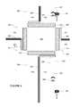
- FIG. 2is an interior of an autonomous vehicle in accordance with aspects of the disclosure.
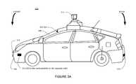
- FIG. 3Ais an exterior of an autonomous vehicle in accordance with aspects of the disclosure.
- FIG. 3Bis a pictorial diagram of a system in accordance with aspects of the disclosure.
- FIG. 3Cis a functional diagram of a system in accordance with aspects of the disclosure.
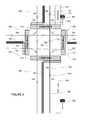
- FIG. 4is a diagram of an intersection and a portion of roadway in accordance with aspects of the disclosure.
- FIG. 5is an example of detailed map information for the intersection and portion of roadway of FIG. 4 in accordance with aspects of the disclosure.
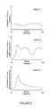
- FIG. 6is an example of graph data in accordance with aspects of the disclosure.
- FIG. 7is another example of graph data in accordance with aspects of the disclosure.
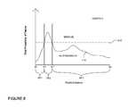
- FIG. 8is a further example of graph data in accordance with aspects of the disclosure.
- FIG. 9is yet another example of graph data in accordance with aspects of the disclosure.
- FIG. 10is an example display device and screen shot in accordance with aspects of the disclosure.
- FIG. 11is a flow diagram in accordance with aspects of the disclosure.
- a computer associated with a vehiclemay receive user information including a destination.
- the computermay generate a set of proposed routes between the vehicle's current location and the destination. For each proposed route, the computer may generate corresponding control information.
- the control informationincludes which portions of a particular route may be maneuvered in a manual mode (where the driver generally has control of the vehicle) or an autonomous mode (where the computer maneuvers the vehicle without continuous input form the driver).
- the control informationmay also include whether a semiautonomous mode (where the computer controls some aspects of the vehicle while the driver controls others) is applicable.
- control factorsmay be input into a set of probabilistic estimations for a plurality of different types of failures along a particular route. These failures refer to times when the vehicle is unable (for safety or other reasons) to maneuver in the autonomous mode.
- the set of probabilistic estimations for the different failure typesmay then be combined into an overall probability of failure along the particular route. The overall probability of failure may be compared to a threshold value of acceptable risk to determine corresponding control information for the particular route.
- the computermay also generate a corresponding activity suggestion for each proposed route based on the corresponding control information for that proposed route.
- the set of proposed routes, the corresponding control information, and the corresponding activity suggestionmay be provided to the driver as a set of routing options.
- the computermay then user input indicating one of the routing options of the set of routing options.
- the computermaneuvers the vehicle according to the proposed route and corresponding control information for the indicated one of the routing options.
- an autonomous driving system 100in accordance with one aspect of the disclosure includes a vehicle 101 with various components. While certain aspects of the disclosure are particularly useful in connection with specific types of vehicles, the vehicle may be any type of vehicle including, but not limited to, cars, trucks, motorcycles, busses, boats, airplanes, helicopters, lawnmowers, recreational vehicles, amusement park vehicles, trams, golf carts, trains, and trolleys.
- the vehiclemay have one or more computers, such as computer 110 containing a processor 120 , memory 130 and other components typically present in general purpose computers.
- the memory 130stores information accessible by processor 120 , including instructions 132 and data 134 that may be executed or otherwise used by the processor 120 .
- the memory 130may be of any type capable of storing information accessible by the processor, including a computer-readable medium, or other medium that stores data that may be read with the aid of an electronic device, such as a hard-drive, memory card, ROM, RAM, DVD or other optical disks, remote servers accessed via the internet, as well as other write-capable and read-only memories.
- Systems and methodsmay include different combinations of the foregoing, whereby different portions of the instructions and data are stored on different types of media.
- the instructions 132may be any set of instructions to be executed directly (such as machine code) or indirectly (such as scripts) by the processor.
- the instructionsmay be stored as computer code on the computer-readable medium.
- the terms “instructions” and “programs”may be used interchangeably herein.
- the instructionsmay be stored in object code format for direct processing by the processor, or in any other computer language including scripts or collections of independent source code modules that are interpreted on demand or compiled in advance. Functions, methods and routines of the instructions are explained in more detail below.
- the data 134may be retrieved, stored or modified by processor 120 in accordance with the instructions 132 .
- the datamay be stored in computer registers, in a relational database as a table having a plurality of different fields and records, XML documents or flat files.
- the datamay also be formatted in any computer-readable format.
- image datamay be stored as bitmaps comprised of grids of pixels that are stored in accordance with formats that are compressed or uncompressed, lossless (e.g., BMP) or lossy (e.g., JPEG), and bitmap or vector-based (e.g., SVG), as well as computer instructions for drawing graphics.
- the datamay comprise any information sufficient to identify the relevant information, such as numbers, descriptive text, proprietary codes, references to data stored in other areas of the same memory or different memories (including other network locations) or information that is used by a function to calculate the relevant data.
- the processor 120may be any conventional processor, such as commercially available CPUs. Alternatively, the processor may be a dedicated device such as an ASIC.
- FIG. 1functionally illustrates the processor, memory, and other elements of computer 110 as being within the same block, it will be understood that the processor and memory may actually comprise multiple processors and memories that may or may not be stored within the same physical housing.
- memorymay be a hard drive or other storage media located in a housing different from that of computer 110 .
- references to a processor or computerwill be understood to include references to a collection of processors or computers or memories that may or may not operate in parallel. Rather than using a single processor to perform the steps described herein some of the components, such as steering components and deceleration components, may each have their own processor that only performs calculations related to the component's specific function.
- the processormay be located remotely from the vehicle and communicate with the vehicle wirelessly. In other aspects, some of the processes described herein are executed on a processor disposed within the vehicle while others are executed by a remote processor, including taking the steps necessary to execute a single maneuver.
- Computer 110may include all of the components normally used in connection with a computer such as a central processing unit (CPU), memory (e.g., RAM and internal hard drives) storing data 134 and instructions such as a web browser, an electronic display 142 (e.g., a monitor having a screen, a small LCD touch-screen or any other electrical device that is operable to display information), user input 140 (e.g., a mouse, keyboard, touch screen and/or microphone), as well as various sensors (e.g., a video camera) for gathering the explicit (e.g., a gesture) or implicit (e.g., “the person is asleep”) information about the states and desires of a person.
- CPUcentral processing unit
- memorye.g., RAM and internal hard drives
- data 134 and instructionssuch as a web browser
- an electronic display 142e.g., a monitor having a screen, a small LCD touch-screen or any other electrical device that is operable to display information
- user input 140e.g.,
- computer 110may be an autonomous driving computing system incorporated into vehicle 101 .
- FIG. 2depicts an exemplary design of the interior of an autonomous vehicle.
- the autonomous vehiclemay include all of the features of a non-autonomous vehicle, for example: a steering apparatus, such as steering wheel 210 ; a navigation display apparatus, such as navigation display 215 ; and a gear selector apparatus, such as gear shifter 220 .
- the vehiclemay also have various user input devices, such as gear shifter 220 , touch screen 217 , or button inputs 219 , for activating or deactivating one or more autonomous driving modes and for enabling a driver or passenger 290 to provide information, such as a navigation destination, to the autonomous driving computer 110 .
- Vehicle 101may also include one or more additional displays.
- the vehiclemay include a display 225 for displaying information regarding the status of the autonomous vehicle or its computer.
- the vehiclemay include a status indicating apparatus such as status bar 230 , to indicate the current status of vehicle 101 .
- status bar 230displays “D” and “2 mph” indicating that the vehicle is presently in drive mode and is moving at 2 miles per hour.
- the vehiclemay display text on an electronic display, illuminate portions of vehicle 101 , such as steering wheel 210 , or provide various other types of indications.
- the autonomous driving computing systemmay capable of communicating with various components of the vehicle.
- computer 110may be in communication with the vehicle's conventional central processor 160 and may send and receive information from the various systems of vehicle 101 , for example the braking 180 , acceleration 182 , steering 184 , and navigation 186 systems in order to control the movement, speed, etc., of vehicle 101 .
- computer 110may control some or all of these functions of vehicle 101 and thus be fully or merely partially autonomous. It will be understood that although various systems and computer 110 are shown within vehicle 101 , these elements may be external to vehicle 101 or physically separated by large distances.
- the vehiclemay also include a geographic position component 144 in communication with computer 110 for determining the geographic location of the device.
- the position componentmay include a GPS receiver to determine the device's latitude, longitude and/or altitude position.
- Other location systemssuch as laser-based localization systems, inertial-aided GPS, or camera-based localization may also be used to identify the location of the vehicle.
- the location of the vehiclemay include an absolute geographical location, such as latitude, longitude, and altitude as well as relative location information, such as location relative to other cars, geographic landmarks, or road markings immediately around it which can often be determined with less noise that absolute geographical location.
- the vehiclemay also include other features in communication with computer 110 , such as an accelerometer, gyroscope or another direction/speed detection device 146 to determine the direction and speed of the vehicle or changes thereto.
- device 146may determine its pitch, yaw or roll (or changes thereto) relative to the direction of gravity or a plane perpendicular thereto.
- the devicemay also track increases or decreases in speed and the direction of such changes.
- the device's provision of location and orientation data as set forth hereinmay be provided automatically to the user, computer 110 , other computers and combinations of the foregoing.
- the computermay control the direction and speed of the vehicle by controlling various components.
- computer 110may cause the vehicle to accelerate (e.g., by increasing fuel or other energy provided to the engine), decelerate (e.g., by decreasing the fuel supplied to the engine or by applying brakes) and change direction (e.g., by turning the front two wheels).
- the vehiclemay also include components 148 for detecting objects and conditions external to the vehicle such as other vehicles, obstacles in the roadway, traffic signals, signs, trees, etc.
- the detection systemmay include lasers, sonar, radar detection units (such as those used for adaptive cruise control), cameras, or any other detection devices which record data which may be processed by computer 110 .
- the vehicleis a small passenger vehicle, the car may include a laser mounted on the roof or other convenient location.
- vehicle 101may comprise a small passenger vehicle.
- vehicle 300may include 2 cameras 320 - 321 mounted under a windshield 330 near the rear view mirror (not shown) as well as radar detection units 320 - 323 located on the side (only one side being shown), front and rear of the vehicle.
- Vehicle 101 sensorsmay also include lasers 310 and 311 , mounted on the front and top of the vehicle, respectively.
- the lasersmay include commercially available lasers such as the Velodyne HDL-64 or other models.
- the lasersmay provide the vehicle with range and intensity information which the computer may use to identify the location, distance, and reflectivity of various objects in the vehicles environment.
- the lasermay measure the distance between the vehicle and the object surfaces facing the vehicle by spinning on its axis and changing its pitch.
- the aforementioned sensorsmay allow the vehicle to understand and potentially respond to its environment in order to maximize safety for passengers as well as objects or people in the environment. It will be understood that the vehicle types, number and type of sensors, the sensor locations, the sensor fields of view, and the sensors' sensor fields are merely exemplary. Various other configurations may also be utilized.
- the computermay also use input from sensors typical non-autonomous vehicles.
- these sensorsmay include tire pressure sensors, engine temperature sensors, brake heat sensors, brake pad status sensors, tire tread sensors, fuel sensors, oil level and quality sensors, air quality sensors (for detecting temperature, humidity, or particulates in the air), precipitation sensors for automatic windshield wipers, etc.
- sensorsprovide data that is processed by the computer in real-time, that is, the sensors may continuously update their output to reflect the environment being sensed at or over a range of time, and continuously or as-demanded provide that updated output to the computer so that the computer can determine whether the vehicle's then-current direction or speed should be modified in response to the sensed environment.
- Computer 110may also receive or transfer information to and from other computers.
- the map information stored by computer 110may be received or transferred from other computers and/or the sensor data collected from the sensors of vehicle 101 may be transferred to another computer for processing as described herein.
- data from computer 110may be transmitted via a network to computer 320 for further processing.
- the network, and intervening nodesmay comprise various configurations and protocols including the Internet, World Wide Web, intranets, virtual private networks, wide area networks, local networks, private networks using communication protocols proprietary to one or more companies, Ethernet, WiFi and HTTP, and various combinations of the foregoing.
- Such communicationmay be facilitated by any device capable of transmitting data to and from other computers, such as modems and wireless interfaces.
- datamay be transferred by storing it on memory which may be accessed by or connected to computers 110 and 320 .
- computer 320may comprise a server having a plurality of computers, e.g., a load balanced server farm, that exchange information with different nodes of a network for the purpose of receiving, processing and transmitting the data from computer 110 .
- the servermay be configured similarly to the computer 110 , with a processor 330 , memory 350 , instructions 360 , and data 370 .
- data 134may include detailed map information 136 , e.g., highly detailed maps identifying the shape and elevation of roadways, intersections, crosswalks, speed limits, traffic signals, buildings, signs, real time traffic information, or other such objects and information.
- the detailed map informationmay include predetermined virtual rails along which computer 110 may maneuver vehicle 101 . These rails may therefore be associated with direction information indicative of the direction of a lane (or direction traffic should move in that lane) in which the rail appears. By following the rails, vehicle 101 's future locations along a route may be predicted with a high degree of accuracy.
- FIG. 4depicts a birds-eye view of an exemplary intersection 400 .
- the intersectionmay include a number of different features such as crosswalks 410 - 13 , bicycle lanes 420 - 21 , lanes 430 - 37 , lane lines 440 - 43 , and roadway boundaries 450 - 459 (such as fog lines, curbs, etc.).
- Intersection 400may also include indicators such as signs 450 - 51 and 460 - 61 identifying specific areas such as bicycle lanes 420 - 21 . Other features such as traffic signals or stop signs may also be present, but are not shown.
- intersection 400includes four roadways meeting perpendicular to one another, various other intersection configurations, may also be employed. It will be further understood that aspects described herein are not limited to intersections, but may be utilized in conjunction with various other traffic or roadway designs which may or may not include additional features or all of the features described with respect to intersection 400 .
- Data about the intersectionmay be collected, for example, by driving a vehicle equipped various object detection components.
- the datamay be processed in order to generate roadgraph information describing the roadway. For example, as shown in FIG. 5 , based on laser, geographic location, and other information collected while driving a vehicle through intersection 400 , a roadgraph 500 of the intersection may be generated. Similar to intersection 400 , roadgraph 500 may include various features such as lanes 530 - 37 , lane lines 540 - 43 , and roadway boundaries 550 - 59 (such as fog lines, curbs, etc.). Each of these features may be associated with geographic location information identifying where these objects may be located in the real world (for example in intersection 400 ). Again, although roadgraph 500 is depicted as an image-based map, it will be understood that this information may be stored as a graph network or grid of data or other information describing the various features and their relationships.
- the detailed map informationis depicted herein as an image-based map, the map information need not be entirely image based (for example, raster).
- the detailed map informationmay include one or more roadgraphs or graph networks of information such as roads, lanes, intersections, and the connections between these features.
- Each featuremay be stored as graph data and may be associated with information such as a geographic location and whether or not it is linked to other related features, for example, a stop sign may be linked to a road and an intersection, etc.
- the associated datamay include grid-based indices of a roadgraph to allow for efficient lookup of certain roadgraph features.
- data 134 of computer 110may store various control factor data 138 .
- the control factorsmay include the availability of detailed map information (e.g. a road map vs. a highly detailed map of the location of lane lines, curbs, etc.) along the route, input from current data feeds (including, for example, traffic, construction, accident information, and weather data), data from other autonomous vehicles reporting problem areas, and historical data (including past traffic data, dangerous areas or areas of high accident rates, weather conditions such as fog, bright sunlight, etc.).
- Data 134may also store task and activity suggestions 139 .
- Thismay include, for example, a database or table may associate various lengths of time with corresponding tasks or activities. For example, time periods between 5 and 10 minutes may be associated with relatively short tasks such as text messaging or reading emails. Slightly longer periods may be associated with more involved tasks such as writing emails, web surfing, video games, etc. Even longer periods may be associated with activities such as watching a television show or movie.
- the task and activity suggestions datamay also store information regarding which tasks a particular driver has typically engaged in during similar periods of time.
- a driver of an autonomous vehiclemay begin a trip by indicating a destination.
- a drivermay initially input a destination, such as location coordinates (latitude and longitude), an address, an intersection, a point of interest, etc. using user input 140 .
- the vehicle's computermay generate a set of proposed routes between the vehicle's current location and the destination based on the detailed map 136 .
- Each routemay be based on typical navigational considerations such as the total travel time, travel distance, fuel economy, etc.
- Each route of the set of proposed routsmay also be associated with control information generated by computer 110 .
- the control informationmay include whether and which portions of the proposed route may be controlled by the vehicle alone (fully autonomous mode), by both the vehicle and the driver (semiautonomous mode), or the driver alone (manual mode).
- vehicle 101when vehicle 101 is operating in an autonomous mode, features such as the braking system 180 , acceleration system 182 , signaling system 184 , and navigation system 186 are being controlled by computer without continuous input from a driver.
- the drivermay have primary control over some control features while computer 110 has control over other features.
- the drivermay control the steering by adjusting the steering wheel while computer 110 may control the braking and acceleration systems.
- the computermay have primary control over all features, but the driver may be required to monitor the operation of the vehicle. For example, the driver may be required to confirm various information such as the state (red, yellow, green, etc.) of a traffic signal, whether a blind spot adjacent to the vehicle is clear, the posted speed limit, the number of lanes, etc.
- computer 110 or another of the vehicle's processing systemsmay control the vehicle based on input received from the driver at the steering wheel, brake pedal, and/or acceleration pedal.
- the control information for the proposed routesmay be based on one or more of the control factors of control factor data 138 . These factors may be used to estimate the likelihood of different types of failures would be expected by computer 110 .
- Such conditionsmay include situations in which a driver may not feel comfortable without full control of the vehicle or where computer 110 would not be able to safely maneuver the vehicle.
- Examples of unsafe or dangerous driving conditionsmay include areas lacking specific map information, areas where lots of pedestrians would be expected (such as around a mall), weather conditions that may affect the vehicle's sensor or the computer's control capabilities (such as precipitation, snow or ice covered roadways, bright sunlight etc.), high traffic areas, areas associated with high occurrences of accidents, or any such conditions which may be estimated or determined from the factors listed above.
- One or more of the control factors of control factor data 138may be input into a probabilistic estimation of how confident the computer is that a particular type of failure would not occur over a certain portion of the route.
- the computer 110may use a machine learning classifier to compare correlated data such as past history of this or other vehicles and the number of times where there was a failure.
- the classifiermay be trained across a number of different factors such as traffic feeds, weather, speeds of other autonomous vehicles, live or historic data from other autonomous vehicles, etc.
- the resultmay be a confidence value indicative of how likely the driver is going to be asked to take control.
- computer 110may use a heuristic approach. In this example, when a set of factors are known to cause any type of failure these factors may be considered together. In one example, if the type of failure is related to traffic congestion, the factors considered may include speed, number of vehicles, distance between vehicles, weather conditions, or any other factors known to affect traffic conditions. Each factor may be associated with some cost value. The costs of different factors may accumulate until a threshold is met, and the computer determines that a failure is likely. In yet another example, the computer 110 may examine historic data from this or other vehicles to determine the probability of failure at the same times and locations along a route.
- FIG. 6is an example of 3 different probabilistic estimations for a route.
- each of the graphs 1-3is plotted for the distance traveled along the route between an initial starting location Xi for the route and a destination location Xd. Similar plots may also be generated for the time of the route (as opposed to distance traveled).
- Each of the three graphsincludes a probabilistic estimation for a particular type of failure. For example, graph 1 is plotted for a failure associated with weather predictions, graph 2 is plotted for a failure associated with traffic congestion, and graph 3 is plotted for a failure associated with dangerous intersections.
- Each probabilistic estimation for the different types of failuresmay be considered together to determine an overall probability of failure along each part of the route. For example, if one of the probabilistic estimations indicates a possible failure, the computer 110 may determine from a single probabilistic estimation that a particular location along a route would surpass an acceptable level or threshold of risk. In this regard, the computer to determine that there would be a failure at some point along the route. In another example, the different probabilistic estimations may be added together, such as by using a weighted sum, to determine if some threshold of acceptable risk has been met. Thus, the factors may be used by computer 110 to determine the best driving mode for various portions of the route. For example, FIG. 7 is an example of a graph 4 plotted for a total probability of failure 710 along a route between the initial starting location Xi for the route and the destination location Xd.
- the overall probability of failuremay then be compared to one or more acceptable threshold values. For example, any portion of the route where the overall probability of failure is estimated to be at or below an acceptable threshold for autonomous driving may be determined to be appropriate for the autonomous mode. In one example, portions of the route where the overall probability of failure is below the acceptable threshold may be associated with the autonomous mode while portions of the route where the overall probability of failure is above the acceptable threshold may be associated with the manual mode.
- graph 5 of FIG. 8depicts the overall probability of failure 710 as compared to an acceptable threshold 810 .
- the overall probability of failurecrosses threshold 810 at two locations, X1 and X2, along the route between Xi and Xd.
- the probability of failure 710is below threshold 810 between Xi and location X1 (along dX1) as well as between X2 and Xd (along dX3).
- the probability of failure 710is above threshold 810 between X1 and X2 (along dX3).
- portions above threshold 810may be associated with the manual mode while portions below the threshold may be associated with the autonomous mode.
- dX1 and dX3may be associated with the autonomous mode as the overall probability of failure 710 is below the threshold 810
- dX2may be associated with the manual mode as the overall probability of failure 710 is above threshold 810 .
- Areas of a route which may be above an acceptable threshold and associated with the manual modemay include, for example, those where only a street map is available.
- a particular portion along a route which is projected to have a high volume of traffic during the time which the vehicle would travelmay be associated probability of failure that is above the acceptable threshold for autonomous driving, requiring a manual mode.
- the given portionmay be associated with the autonomous mode.
- computer 110may also be capable of operating in the semiautonomous mode.
- the overall probability of failuremay be compared to two different thresholds, for example, one for autonomous driving and another for semiautonomous driving. Any portion of the route associated with an overall probability of failure is above the acceptable threshold for autonomous driving, but below an acceptable threshold for semiautonomous driving may be determined to be portion of the route appropriate for the semiautonomous mode.
- graph 6 of FIG. 9depicts the total probability of failure 710 with an acceptable autonomous threshold 910 and an acceptable semiautonomous threshold 920 .
- portions of the route where the overall probability of failure 710 is below the autonomous threshold 910may be associated with the autonomous mode
- portions of the route where the overall probability of failure 710 is above the autonomous threshold 910 but below the semiautonomous threshold 920may be associated with the semiautonomous mode
- portions of the route where the overall probability of failure 710 is above the semiautonomous threshold 920may be associated with the manual mode.
- thresholds 910 and 920may include when a street map as well as speed limit information is available for a given portion, the given portion may be associated with either the manual mode or a semiautonomous mode (as described above.
- the semiautonomous modemay be appropriate where the probability of failure is close to, but has not actually surpassed the acceptable level of risk.
- the drivermay have a greater level of concentration on the road such that he or she is able to take over at a moment's notice.
- the vehiclecan safely drive in the semiautonomous mode with sufficient time to provide any necessary warning to the driver of the need to take immediate control.
- the computermay consider the type of failure and the amount of time associated with those types of failures.
- the probabilistic estimations determined based on the various control factors of factor data 138 , the overall probability of failure, and the one or more thresholdsmay be used by computer 110 to generate the control information for each proposed route.
- the computermay then provide the proposed routes and control information as routing options to the driver. For example, a given proposed route may be displayed to a user with information such as a total time for the route and a map depicting the given proposed route as with typical navigational systems.
- the computermay also provide details such as the time of the longest stretch of driving associated with the autonomous mode as well as map information highlighting the location of the route including information indicating which portions of the routes are associated with the type of control.
- computer 110may provide information regarding not only the total time of the route but also the total time in the various driving modes.
- FIG. 10is one example of how computer 110 may provide the proposed routing options to the driver, though various other methods may also be used.
- FIG. 10may thus include an example screen shot of touch screen 217 and/or display 225 .
- Routing option 1010includes Route 1 between initial and destination locations A and B depicted on map 1030 via River Road, while routing option 1020 includes Route 2 between initial and destination locations A and B via First Avenue.
- the routing options in this exampleinclude a total estimated travel time for each route as well as a time for the longest autonomous portion of each route.
- computer 110may also provide the control information determined for the routing options to the driver.
- computer 110may designate the portions of the route associated with different modes of driving (as determined from the probability of failure and thresholds described above).
- key 1040distinguishes between the different operating modes based on the type of line displayed on map 1030 , this information may be displayed in other ways, such as by different colors, line widths, etc.
- Route 1begins at location A in the autonomous mode, switches to a manual mode, and then concludes in an autonomous mode at location B.
- Route 2begins at location A in the manual mode and subsequently switches to an autonomous mode until reaching location B.
- the drivermay select that option and select button 1050 to begin the selected routing option in the predetermined driving mode.
- computer 110may also provide the driver with task and activity suggestions for each of the routes.
- the task and activity suggestion data 139may associate specific suggestions with different periods of time.
- Computermay search this data and identify a suggestion based on how long the driver may have to perform different tasks or activities during a particular proposed route.
- suggestionsmay be selected based on an estimated period of time for a portion of the route where vehicle 101 may operate in the autonomous mode, or rather, the amount of time computer 110 determines that it may control vehicle 101 without input from the driver.
- routing options 1010 and 1020each include a recommendation for the driver. Routing option 1 suggests reading emails as the longest stretch of autonomous mode is only 7 minutes. Routing option 2 suggests a more time consuming activity of watching a television show as the longest stretch of autonomous mode is 25 minutes. In another example, route 2 might be associated with a suggestion that the driver could finish a movie started previously, while route 1 may be associated with a suggestion that the driver could complete only one or 2 levels of a popular game.
- the example suggestions provided in FIG. 10are based on the longest period of time of the routes associated with the autonomous mode. However, the suggestions may also be based on the amount (time or distance) of any portion of a route associated with the autonomous mode. In another example, the suggestions may be based on the driver's previous reaction times. For example, it may be important in certain areas associated with higher probabilities of failure, which have not quite met the threshold for acceptable risk, that the driver be prepared to take control of the vehicle quickly. Thus, the computer 110 may suggest activities which the driver is easily and quickly taken away from for such areas along the route. In this regard, it may be easier to draw the driver from texting than from reading a book, etc.
- the recommended activitiesmay be based on past actions by the driver (e.g. he or she prefers games or emailing). This may assist the user in selecting which route option to chose. These recommendations may also be provided while the vehicle is being driven (either by the computer, the user, or both) to the destination.
- the computermay warn or enforce which activities a user may perform during the drive.
- the computermay note with the routing options that a certain routing option does not have a large enough portion or cumulative total time associated with the autonomous mode to perform some task show so that a particular task or activity may be disabled during the proposed route.
- certain featuresmay be disabled by the computer during portions which may require some oversight, semiautonomous driving, or control by the user. This information may be provided to the driver as a notification with the routing options.
- the drivermay then select one of the routing options.
- computer 110may begin to navigate the route according to the control information. Referring to FIG. 10 , if the driver selects routing option 1010 , computer 110 may begin maneuvering vehicle 101 the autonomous mode along Route 1. In the driver selects routing option 1020 (as actually shown in the example of FIG. 10 ), computer 110 may indicate to the driver that he or she must begin driving in the manual mode along Route 2.
- Flow diagram 1100 of FIG. 11is an example of some of the features described above as performed by computer 110 .
- the computerreceives user information including a destination at block 1102 .
- the computerthen generates a set of proposed routes between a vehicle's current location and the destination at block 1104 .
- the computerFor each proposed route, the computer generates corresponding control information at block 1106 .
- the control informationincludes which portions of a particular route may be maneuvered in a manual mode or an autonomous mode. In some examples, this may also include a semiautonomous mode.
- generating the corresponding control information at block 1106desirably includes the steps of blocks 1108 through 1112 .
- control factorsare input into a set of probabilistic estimations for a plurality of different types of failures along a particular route at block 1108 . Again, these failures refer to times when the vehicle is unable (for safety or other reasons) to maneuver in the autonomous mode.
- the set of probabilistic estimationsare then combined into an overall probability of failure along the particular proposed route at block 1110 .
- the overall probability of failureis compared to a threshold value to determine corresponding control information for the particular route at block 1112 .
- These stepsmay be repeated sequentially or simultaneously for each proposed route of the set of proposed routes.
- the computergenerates a corresponding activity suggestion for each proposed route based on the corresponding control information for that proposed route at block 1114 .
- the set of proposed routes, the corresponding control information, and the corresponding activity suggestionas a set of routing options at block 1116 .
- the computerreceives user input indicating one of the routing options of the set of routing options at block 1118 .
- the computermaneuvers the vehicle according to the proposed route and corresponding control information for the indicated one of the routing options at block 1120 .
- a routemay be selected accordingly.
Landscapes
- Engineering & Computer Science (AREA)
- Radar, Positioning & Navigation (AREA)
- Remote Sensing (AREA)
- Automation & Control Theory (AREA)
- Physics & Mathematics (AREA)
- General Physics & Mathematics (AREA)
- Aviation & Aerospace Engineering (AREA)
- Acoustics & Sound (AREA)
- Mechanical Engineering (AREA)
- Transportation (AREA)
- Human Computer Interaction (AREA)
- Navigation (AREA)
- Traffic Control Systems (AREA)
- Control Of Driving Devices And Active Controlling Of Vehicle (AREA)
Abstract
Description
Claims (20)
Priority Applications (6)
| Application Number | Priority Date | Filing Date | Title |
|---|---|---|---|
| US14/878,525US9528850B1 (en) | 2012-09-28 | 2015-10-08 | Suggesting a route based on desired amount of driver interaction |
| US15/351,880US10036648B1 (en) | 2012-09-28 | 2016-11-15 | Suggesting a route based on desired amount of driver interaction |
| US16/020,028US10451433B1 (en) | 2012-09-28 | 2018-06-27 | Suggesting a route based on desired amount of driver interaction |
| US16/553,603US11231292B1 (en) | 2012-09-28 | 2019-08-28 | Suggesting a route based on desired amount of driver interaction |
| US17/540,306US11692841B1 (en) | 2012-09-28 | 2021-12-02 | Suggesting a route based on desired amount of driver interaction |
| US18/202,088US12123735B1 (en) | 2012-09-28 | 2023-05-25 | Suggesting a route based on desired amount of driver interaction |
Applications Claiming Priority (2)
| Application Number | Priority Date | Filing Date | Title |
|---|---|---|---|
| US13/629,799US9188985B1 (en) | 2012-09-28 | 2012-09-28 | Suggesting a route based on desired amount of driver interaction |
| US14/878,525US9528850B1 (en) | 2012-09-28 | 2015-10-08 | Suggesting a route based on desired amount of driver interaction |
Related Parent Applications (1)
| Application Number | Title | Priority Date | Filing Date |
|---|---|---|---|
| US13/629,799ContinuationUS9188985B1 (en) | 2012-09-28 | 2012-09-28 | Suggesting a route based on desired amount of driver interaction |
Related Child Applications (1)
| Application Number | Title | Priority Date | Filing Date |
|---|---|---|---|
| US15/351,880ContinuationUS10036648B1 (en) | 2012-09-28 | 2016-11-15 | Suggesting a route based on desired amount of driver interaction |
Publications (1)
| Publication Number | Publication Date |
|---|---|
| US9528850B1true US9528850B1 (en) | 2016-12-27 |
Family
ID=54434570
Family Applications (7)
| Application Number | Title | Priority Date | Filing Date |
|---|---|---|---|
| US13/629,799Active2033-01-02US9188985B1 (en) | 2012-09-28 | 2012-09-28 | Suggesting a route based on desired amount of driver interaction |
| US14/878,525ActiveUS9528850B1 (en) | 2012-09-28 | 2015-10-08 | Suggesting a route based on desired amount of driver interaction |
| US15/351,880ActiveUS10036648B1 (en) | 2012-09-28 | 2016-11-15 | Suggesting a route based on desired amount of driver interaction |
| US16/020,028ActiveUS10451433B1 (en) | 2012-09-28 | 2018-06-27 | Suggesting a route based on desired amount of driver interaction |
| US16/553,603Active2033-05-29US11231292B1 (en) | 2012-09-28 | 2019-08-28 | Suggesting a route based on desired amount of driver interaction |
| US17/540,306ActiveUS11692841B1 (en) | 2012-09-28 | 2021-12-02 | Suggesting a route based on desired amount of driver interaction |
| US18/202,088ActiveUS12123735B1 (en) | 2012-09-28 | 2023-05-25 | Suggesting a route based on desired amount of driver interaction |
Family Applications Before (1)
| Application Number | Title | Priority Date | Filing Date |
|---|---|---|---|
| US13/629,799Active2033-01-02US9188985B1 (en) | 2012-09-28 | 2012-09-28 | Suggesting a route based on desired amount of driver interaction |
Family Applications After (5)
| Application Number | Title | Priority Date | Filing Date |
|---|---|---|---|
| US15/351,880ActiveUS10036648B1 (en) | 2012-09-28 | 2016-11-15 | Suggesting a route based on desired amount of driver interaction |
| US16/020,028ActiveUS10451433B1 (en) | 2012-09-28 | 2018-06-27 | Suggesting a route based on desired amount of driver interaction |
| US16/553,603Active2033-05-29US11231292B1 (en) | 2012-09-28 | 2019-08-28 | Suggesting a route based on desired amount of driver interaction |
| US17/540,306ActiveUS11692841B1 (en) | 2012-09-28 | 2021-12-02 | Suggesting a route based on desired amount of driver interaction |
| US18/202,088ActiveUS12123735B1 (en) | 2012-09-28 | 2023-05-25 | Suggesting a route based on desired amount of driver interaction |
Country Status (1)
| Country | Link |
|---|---|
| US (7) | US9188985B1 (en) |
Cited By (15)
| Publication number | Priority date | Publication date | Assignee | Title |
|---|---|---|---|---|
| US20160356623A1 (en)* | 2015-06-05 | 2016-12-08 | Denso Corporation | Automated driving control apparatus and automated driving control method |
| US20170236210A1 (en)* | 2016-02-15 | 2017-08-17 | Allstate Insurance Company | Early Notification of Non-Autonomous Area |
| US20170352267A1 (en)* | 2016-06-02 | 2017-12-07 | GM Global Technology Operations LLC | Systems for providing proactive infotainment at autonomous-driving vehicles |
| US20180206391A1 (en)* | 2017-01-20 | 2018-07-26 | Kubota Corporation | Travel control apparatus and travel control method |
| US10036648B1 (en)* | 2012-09-28 | 2018-07-31 | Waymo Llc | Suggesting a route based on desired amount of driver interaction |
| WO2018156108A1 (en)* | 2017-02-22 | 2018-08-30 | Rovi Guides, Inc. | Systems and methods for altering navigation instructions based on the consumption time of media content |
| US20180348758A1 (en)* | 2017-06-02 | 2018-12-06 | Honda Motor Co., Ltd. | Vehicle control system, vehicle control method, and storage medium |
| US10168707B2 (en)* | 2015-11-27 | 2019-01-01 | Subaru Corporation | Information processing device, vehicle information processing device, information processing method, and vehicle information processing method |
| CN109204325A (en)* | 2017-07-07 | 2019-01-15 | Lg电子株式会社 | The method of the controller of vehicle and control vehicle that are installed on vehicle |
| US10331139B2 (en)* | 2015-07-28 | 2019-06-25 | Toyota Jidosha Kabushiki Kaisha | Navigation device for autonomously driving vehicle |
| US10351139B2 (en)* | 2015-07-10 | 2019-07-16 | Volvo Car Corporation | Method and system for smart use of in-car time with advanced pilot assist and autonomous drive |
| US20200200558A1 (en)* | 2018-12-20 | 2020-06-25 | Here Global B.V. | Autonomous driving instructions |
| US10942038B2 (en) | 2016-02-15 | 2021-03-09 | Allstate Insurance Company | Real time risk assessment and operational changes with semi-autonomous vehicles |
| US20220034679A1 (en)* | 2020-07-29 | 2022-02-03 | Kawasaki Jukogyo Kabushiki Kaisha | Travel route generation system, travel route generation program, and travel route generation method |
| US20220252412A1 (en)* | 2019-08-30 | 2022-08-11 | Rovi Guides, Inc. | Systems and methods for providing uninterrupted media content during vehicle navigation |
Families Citing this family (129)
| Publication number | Priority date | Publication date | Assignee | Title |
|---|---|---|---|---|
| US10096038B2 (en) | 2007-05-10 | 2018-10-09 | Allstate Insurance Company | Road segment safety rating system |
| US8606512B1 (en) | 2007-05-10 | 2013-12-10 | Allstate Insurance Company | Route risk mitigation |
| US9932033B2 (en) | 2007-05-10 | 2018-04-03 | Allstate Insurance Company | Route risk mitigation |
| US10157422B2 (en) | 2007-05-10 | 2018-12-18 | Allstate Insurance Company | Road segment safety rating |
| DE102012212065A1 (en)* | 2012-07-11 | 2014-01-16 | Robert Bosch Gmbh | Method for operating a driver assistance system for a vehicle and driver assistance system for a vehicle |
| EP2972096B1 (en)* | 2013-03-15 | 2019-01-09 | Volkswagen Aktiengesellschaft | Automatic driving route planning application |
| DE102013206212A1 (en)* | 2013-04-09 | 2014-10-09 | Ford Global Technologies, Llc | Method for controlling a vehicle with temporarily autonomous vehicle guidance and control device |
| DE102013008605A1 (en)* | 2013-05-16 | 2014-11-20 | Audi Ag | Navigation aid for a motor vehicle with autopilot |
| US9390451B1 (en) | 2014-01-24 | 2016-07-12 | Allstate Insurance Company | Insurance system related to a vehicle-to-vehicle communication system |
| US9355423B1 (en) | 2014-01-24 | 2016-05-31 | Allstate Insurance Company | Reward system related to a vehicle-to-vehicle communication system |
| US10096067B1 (en) | 2014-01-24 | 2018-10-09 | Allstate Insurance Company | Reward system related to a vehicle-to-vehicle communication system |
| JP6369028B2 (en)* | 2014-01-27 | 2018-08-08 | アイシン・エィ・ダブリュ株式会社 | Route search system, route search method and computer program |
| JP6287264B2 (en)* | 2014-01-27 | 2018-03-07 | アイシン・エィ・ダブリュ株式会社 | Route guidance system, route guidance method and computer program |
| US10783587B1 (en) | 2014-02-19 | 2020-09-22 | Allstate Insurance Company | Determining a driver score based on the driver's response to autonomous features of a vehicle |
| US10803525B1 (en) | 2014-02-19 | 2020-10-13 | Allstate Insurance Company | Determining a property of an insurance policy based on the autonomous features of a vehicle |
| US10796369B1 (en) | 2014-02-19 | 2020-10-06 | Allstate Insurance Company | Determining a property of an insurance policy based on the level of autonomy of a vehicle |
| US10783586B1 (en) | 2014-02-19 | 2020-09-22 | Allstate Insurance Company | Determining a property of an insurance policy based on the density of vehicles |
| US9940676B1 (en) | 2014-02-19 | 2018-04-10 | Allstate Insurance Company | Insurance system for analysis of autonomous driving |
| US11669090B2 (en) | 2014-05-20 | 2023-06-06 | State Farm Mutual Automobile Insurance Company | Autonomous vehicle operation feature monitoring and evaluation of effectiveness |
| US20210133871A1 (en) | 2014-05-20 | 2021-05-06 | State Farm Mutual Automobile Insurance Company | Autonomous vehicle operation feature usage recommendations |
| US9972054B1 (en) | 2014-05-20 | 2018-05-15 | State Farm Mutual Automobile Insurance Company | Accident fault determination for autonomous vehicles |
| US10599155B1 (en) | 2014-05-20 | 2020-03-24 | State Farm Mutual Automobile Insurance Company | Autonomous vehicle operation feature monitoring and evaluation of effectiveness |
| US10373259B1 (en) | 2014-05-20 | 2019-08-06 | State Farm Mutual Automobile Insurance Company | Fully autonomous vehicle insurance pricing |
| US10759442B2 (en)* | 2014-05-30 | 2020-09-01 | Here Global B.V. | Dangerous driving event reporting |
| US10387962B1 (en) | 2014-07-21 | 2019-08-20 | State Farm Mutual Automobile Insurance Company | Methods of reconstructing an accident scene using telematics data |
| KR20160013713A (en)* | 2014-07-28 | 2016-02-05 | 현대자동차주식회사 | Global path generation apparatus for autonomous vehicle and method thereof |
| JP6591737B2 (en)* | 2014-08-25 | 2019-10-16 | クラリオン株式会社 | Automatic operation control device |
| US10157423B1 (en) | 2014-11-13 | 2018-12-18 | State Farm Mutual Automobile Insurance Company | Autonomous vehicle operating style and mode monitoring |
| JP6413841B2 (en)* | 2015-02-27 | 2018-10-31 | 株式会社デンソー | Driving assistance device |
| JP6598019B2 (en)* | 2015-04-21 | 2019-10-30 | パナソニックIpマネジメント株式会社 | Driving support method, driving support device, driving control device, vehicle, and driving support program using the same |
| DE102015211562A1 (en)* | 2015-06-23 | 2016-12-29 | Bayerische Motoren Werke Aktiengesellschaft | Method for determining a time course of a motor vehicle and motor vehicle |
| US9805601B1 (en) | 2015-08-28 | 2017-10-31 | State Farm Mutual Automobile Insurance Company | Vehicular traffic alerts for avoidance of abnormal traffic conditions |
| JP2017072440A (en)* | 2015-10-06 | 2017-04-13 | クラリオン株式会社 | Driving comfort level calculation device, driving comfort level calculation method, and driving comfort level calculation system |
| US10607293B2 (en)* | 2015-10-30 | 2020-03-31 | International Business Machines Corporation | Automated insurance toggling for self-driving vehicles |
| US9720415B2 (en)* | 2015-11-04 | 2017-08-01 | Zoox, Inc. | Sensor-based object-detection optimization for autonomous vehicles |
| JP6552952B2 (en)* | 2015-12-07 | 2019-07-31 | 株式会社ゼンリンデータコム | Navigation device and navigation method |
| US9796388B2 (en)* | 2015-12-17 | 2017-10-24 | Ford Global Technologies, Llc | Vehicle mode determination |
| US10134278B1 (en) | 2016-01-22 | 2018-11-20 | State Farm Mutual Automobile Insurance Company | Autonomous vehicle application |
| US10395332B1 (en) | 2016-01-22 | 2019-08-27 | State Farm Mutual Automobile Insurance Company | Coordinated autonomous vehicle automatic area scanning |
| US11242051B1 (en) | 2016-01-22 | 2022-02-08 | State Farm Mutual Automobile Insurance Company | Autonomous vehicle action communications |
| US11719545B2 (en) | 2016-01-22 | 2023-08-08 | Hyundai Motor Company | Autonomous vehicle component damage and salvage assessment |
| US10493936B1 (en) | 2016-01-22 | 2019-12-03 | State Farm Mutual Automobile Insurance Company | Detecting and responding to autonomous vehicle collisions |
| US11441916B1 (en) | 2016-01-22 | 2022-09-13 | State Farm Mutual Automobile Insurance Company | Autonomous vehicle trip routing |
| US10324463B1 (en) | 2016-01-22 | 2019-06-18 | State Farm Mutual Automobile Insurance Company | Autonomous vehicle operation adjustment based upon route |
| US10269075B2 (en) | 2016-02-02 | 2019-04-23 | Allstate Insurance Company | Subjective route risk mapping and mitigation |
| JP6354776B2 (en) | 2016-03-10 | 2018-07-11 | トヨタ自動車株式会社 | Vehicle control device |
| US9581460B1 (en)* | 2016-03-29 | 2017-02-28 | Toyota Motor Engineering & Manufacturing North America, Inc. | Apparatus and method transitioning between driving states during navigation for highly automated vechicle |
| JP6294905B2 (en)* | 2016-03-31 | 2018-03-14 | 株式会社Subaru | Display device |
| US10054454B2 (en)* | 2016-05-06 | 2018-08-21 | Ford Global Technologies, Llc | Network based storage of vehicle and infrastructure data for optimizing vehicle routing |
| US9851212B2 (en)* | 2016-05-06 | 2017-12-26 | Ford Global Technologies, Llc | Route generation using road lane line quality |
| US10309792B2 (en) | 2016-06-14 | 2019-06-04 | nuTonomy Inc. | Route planning for an autonomous vehicle |
| WO2017218563A1 (en) | 2016-06-14 | 2017-12-21 | nuTonomy Inc. | Route planning for an autonomous vehicle |
| US11092446B2 (en) | 2016-06-14 | 2021-08-17 | Motional Ad Llc | Route planning for an autonomous vehicle |
| US10260898B2 (en)* | 2016-07-12 | 2019-04-16 | Toyota Motor Engineering & Manufacturing North America, Inc. | Apparatus and method of determining an optimized route for a highly automated vehicle |
| US10921810B2 (en) | 2016-08-02 | 2021-02-16 | Pcms Holdings, Inc. | System and method for optimizing autonomous vehicle capabilities in route planning |
| US10746559B2 (en)* | 2016-08-15 | 2020-08-18 | International Business Machines Corporation | Dynamic route guidance based on real-time data |
| JP6723884B2 (en)* | 2016-09-14 | 2020-07-15 | 日産自動車株式会社 | Route search method and device for automatic driving support |
| US10710603B2 (en)* | 2016-10-19 | 2020-07-14 | Here Global B.V. | Segment activity planning based on route characteristics |
| FR3058214B1 (en)* | 2016-11-02 | 2020-06-12 | Safran Electronics & Defense | METHOD FOR DEVELOPING A SELF-NAVIGATION MAP FOR A VEHICLE |
| US10042362B2 (en) | 2016-11-18 | 2018-08-07 | Waymo Llc | Dynamic routing for autonomous vehicles |
| US10515390B2 (en) | 2016-11-21 | 2019-12-24 | Nio Usa, Inc. | Method and system for data optimization |
| US11293765B2 (en) | 2016-12-08 | 2022-04-05 | Pcms Holdings, Inc. | System and method for routing and reorganization of a vehicle platoon in a smart city |
| DE102016225429A1 (en)* | 2016-12-19 | 2018-06-21 | Continental Automotive Gmbh | Control device and electronic wheel unit for a wheel monitoring system of a vehicle, wheel monitoring system of a vehicle and method for wheel monitoring in a vehicle |
| KR102513185B1 (en)* | 2017-01-12 | 2023-03-23 | 모빌아이 비젼 테크놀로지스 엘티디. | rules-based navigation |
| DE102017200432B4 (en) | 2017-01-12 | 2022-08-18 | Audi Ag | Method for operating a security system for a motor vehicle and security system |
| US10471829B2 (en) | 2017-01-16 | 2019-11-12 | Nio Usa, Inc. | Self-destruct zone and autonomous vehicle navigation |
| JP6702217B2 (en)* | 2017-02-06 | 2020-05-27 | 株式会社デンソー | Automatic driving device |
| JP6575543B2 (en) | 2017-02-07 | 2019-09-18 | トヨタ自動車株式会社 | Automatic driving device and automatic driving method |
| US10126137B2 (en)* | 2017-02-09 | 2018-11-13 | GM Global Technology Operations LLC | Methods and systems to convey autonomous/semi-autonomous feature available roadways |
| US10338594B2 (en)* | 2017-03-13 | 2019-07-02 | Nio Usa, Inc. | Navigation of autonomous vehicles to enhance safety under one or more fault conditions |
| US10423162B2 (en) | 2017-05-08 | 2019-09-24 | Nio Usa, Inc. | Autonomous vehicle logic to identify permissioned parking relative to multiple classes of restricted parking |
| US11282016B2 (en) | 2017-05-23 | 2022-03-22 | Uatc, Llc | Individualized risk vehicle matching for an on-demand transportation service |
| US11080806B2 (en)* | 2017-05-23 | 2021-08-03 | Uber Technologies, Inc. | Non-trip risk matching and routing for on-demand transportation services |
| US11282009B2 (en) | 2017-05-23 | 2022-03-22 | Uatc, Llc | Fleet utilization efficiency for on-demand transportation services |
| US11288612B2 (en) | 2017-05-23 | 2022-03-29 | Uatc, Llc | Generalized risk routing for human drivers |
| WO2018217526A1 (en)* | 2017-05-23 | 2018-11-29 | Uber Technologies, Inc. | Path segment risk regression system for on-demand transportation services |
| US10710633B2 (en) | 2017-07-14 | 2020-07-14 | Nio Usa, Inc. | Control of complex parking maneuvers and autonomous fuel replenishment of driverless vehicles |
| US10369974B2 (en) | 2017-07-14 | 2019-08-06 | Nio Usa, Inc. | Control and coordination of driverless fuel replenishment for autonomous vehicles |
| US10571919B2 (en) | 2017-07-26 | 2020-02-25 | Lenovo (Singapore) Pte. Ltd. | Systems and methods to identify directions based on use of autonomous vehicle function |
| US10837790B2 (en)* | 2017-08-01 | 2020-11-17 | Nio Usa, Inc. | Productive and accident-free driving modes for a vehicle |
| US20190041859A1 (en)* | 2017-08-04 | 2019-02-07 | Aptiv Technologies Limited | Sensor failure compensation system for an automated vehicle |
| US11460842B2 (en) | 2017-08-28 | 2022-10-04 | Motional Ad Llc | Mixed-mode driving of a vehicle having autonomous driving capabilities |
| WO2019046204A1 (en)* | 2017-08-28 | 2019-03-07 | nuTonomy Inc. | Mixed-mode driving of a vehicle having autonomous driving capabilities |
| US11112793B2 (en)* | 2017-08-28 | 2021-09-07 | Motional Ad Llc | Mixed-mode driving of a vehicle having autonomous driving capabilities |
| US10872533B1 (en) | 2017-09-29 | 2020-12-22 | DroneUp, LLC | Multiplexed communications of telemetry data, video stream data and voice data among piloted aerial drones via a common software application |
| US10895465B2 (en)* | 2017-10-12 | 2021-01-19 | Toyota Jidosha Kabushiki Kaisha | Optimizing a route selection for a highly autonomous vehicle |
| US10635109B2 (en) | 2017-10-17 | 2020-04-28 | Nio Usa, Inc. | Vehicle path-planner monitor and controller |
| US10606274B2 (en) | 2017-10-30 | 2020-03-31 | Nio Usa, Inc. | Visual place recognition based self-localization for autonomous vehicles |
| US10935978B2 (en) | 2017-10-30 | 2021-03-02 | Nio Usa, Inc. | Vehicle self-localization using particle filters and visual odometry |
| US10684134B2 (en)* | 2017-12-15 | 2020-06-16 | Waymo Llc | Using prediction models for scene difficulty in vehicle routing |
| US11022971B2 (en) | 2018-01-16 | 2021-06-01 | Nio Usa, Inc. | Event data recordation to identify and resolve anomalies associated with control of driverless vehicles |
| JP7004245B2 (en)* | 2018-01-22 | 2022-02-04 | トヨタ自動車株式会社 | Driving support device and driving support method |
| US10710607B2 (en)* | 2018-02-12 | 2020-07-14 | Lenovo (Singapore) Pte. Ltd. | Systems and methods for identifying first route to destination as involving less human driving of vehicle than second route to destination |
| DE102018202334A1 (en)* | 2018-02-15 | 2019-08-22 | Bayerische Motoren Werke Aktiengesellschaft | Consider driving time periods for automated driving in a digital diary |
| DE102018203426A1 (en)* | 2018-03-07 | 2019-09-12 | Audi Ag | Method for operating a motor vehicle with an autopilot system and motor vehicle |
| GB2572555A (en)* | 2018-03-29 | 2019-10-09 | Arm Ip Ltd | Systems, Methods and Devices For Navigation |
| US10442443B1 (en)* | 2018-05-09 | 2019-10-15 | GM Global Technology Operations LLC | Providing driver feedback |
| DE102018209980A1 (en) | 2018-06-20 | 2019-12-24 | Robert Bosch Gmbh | Procedure for choosing a route for a vehicle |
| CN110163405B (en)* | 2018-07-23 | 2022-03-25 | 腾讯大地通途(北京)科技有限公司 | Method, device, terminal and storage medium for determining transit time |
| EP3611471B1 (en)* | 2018-08-14 | 2021-03-10 | Bayerische Motoren Werke Aktiengesellschaft | Methods and devices arranged for routing autonomous driving |
| JP7251394B2 (en)* | 2018-08-31 | 2023-04-04 | 株式会社デンソー | VEHICLE-SIDE DEVICE, METHOD AND STORAGE MEDIUM |
| EP3647728B1 (en) | 2018-11-05 | 2023-06-21 | Toyota Jidosha Kabushiki Kaisha | Map information system |
| JP7163729B2 (en)* | 2018-11-08 | 2022-11-01 | トヨタ自動車株式会社 | vehicle controller |
| US10969235B2 (en) | 2018-11-14 | 2021-04-06 | International Business Machines Corporation | Secure data navigation |
| US10962372B1 (en)* | 2018-12-31 | 2021-03-30 | Accelerate Labs, Llc | Navigational routes for autonomous vehicles |
| US11112794B2 (en) | 2019-02-20 | 2021-09-07 | Gm Cruise Holdings Llc | Autonomous vehicle routing based upon risk of autonomous vehicle takeover |
| KR102727116B1 (en)* | 2019-03-20 | 2024-11-06 | 현대자동차주식회사 | Navigation system and route search method thereof |
| US12111170B1 (en) | 2019-06-10 | 2024-10-08 | Waymo Llc | Model-based routing for autonomous vehicles |
| US11307590B2 (en) | 2019-06-29 | 2022-04-19 | Gm Cruise Holdings Llc | Systems and methods for overlap-aware ranking of navigation avoidance areas for autonomous vehicles |
| CN110341787B (en)* | 2019-07-16 | 2021-08-03 | 上海高爱特汽车电子股份有限公司 | EPS-based automobile driving mode switching method |
| DE102019211137A1 (en)* | 2019-07-26 | 2021-01-28 | Robert Bosch Gmbh | Method and device for creating a map and for operating a vehicle |
| US11142214B2 (en) | 2019-08-06 | 2021-10-12 | Bendix Commercial Vehicle Systems Llc | System, controller and method for maintaining an advanced driver assistance system as active |
| JP7234872B2 (en)* | 2019-09-12 | 2023-03-08 | トヨタ自動車株式会社 | Vehicle remote indication system |
| US10969232B1 (en) | 2019-12-06 | 2021-04-06 | Ushr Inc. | Alignment of standard-definition and High-Definition maps |
| US11802774B2 (en)* | 2019-12-20 | 2023-10-31 | Robert Bosch Gmbh | Determining vehicle actions based upon astronomical data |
| US20210258751A1 (en) | 2020-02-18 | 2021-08-19 | Lenovo (Singapore) Pte. Ltd. | Responding to a signal indicating that an autonomous driving feature has been overridden by alerting plural vehicles |
| JP7469167B2 (en)* | 2020-07-07 | 2024-04-16 | 本田技研工業株式会社 | Control device, control method, and vehicle |
| US11884291B2 (en) | 2020-08-03 | 2024-01-30 | Waymo Llc | Assigning vehicles for transportation services |
| DE102020214969A1 (en) | 2020-11-27 | 2022-06-02 | Volkswagen Aktiengesellschaft | Method and device for operating a vehicle with an automatic driving function |
| US20220185338A1 (en)* | 2020-12-11 | 2022-06-16 | Here Global B.V. | Mixed mode vehicle |
| US11365980B1 (en)* | 2020-12-18 | 2022-06-21 | Samsara Inc. | Vehicle gateway device and interactive map graphical user interfaces associated therewith |
| FR3119016A1 (en)* | 2021-01-20 | 2022-07-22 | Psa Automobiles Sa | Selection of a route to a destination based on a secondary task to be performed by the user of a vehicle |
| US11958499B2 (en) | 2021-05-17 | 2024-04-16 | Ford Global Technologies, Llc | Systems and methods to classify a road based on a level of suppport offered by the road for autonomous driving operations |
| CN117940741A (en)* | 2021-09-24 | 2024-04-26 | 华为技术有限公司 | Navigation method and related device |
| DE102021212158A1 (en) | 2021-10-27 | 2023-04-27 | Psa Automobiles Sa | Route planning for automated vehicles with minimal manual intervention |
| US20230311898A1 (en)* | 2022-03-30 | 2023-10-05 | Rivian Ip Holdings, Llc | Recommending activities for occupants during vehicle servicing |
| US12024172B2 (en) | 2022-05-10 | 2024-07-02 | Lenovo (Singapore) Pte. Ltd. | Lane assist for deviating from preexisting traffic lane |
| US12286132B2 (en)* | 2022-12-08 | 2025-04-29 | GM Global Technology Operations LLC | Vehicle systems and methods for autonomous route following |
| DE102024201963A1 (en)* | 2024-03-01 | 2025-09-04 | Volkswagen Aktiengesellschaft | Method and device for displaying information and/or entertainment content to vehicle occupants |
Citations (10)
| Publication number | Priority date | Publication date | Assignee | Title |
|---|---|---|---|---|
| US5689252A (en)* | 1994-11-04 | 1997-11-18 | Lucent Technologies Inc. | Navigation system for an automotive vehicle |
| US5774069A (en)* | 1995-12-05 | 1998-06-30 | Toyota Jidosha Kabushiki Kaisha | Auto-drive control unit for vehicles |
| US6014081A (en)* | 1995-07-28 | 2000-01-11 | Honda Giken Kogyo Kabushiki Kaisha | Driving condition-monitoring apparatus for automotive vehicles |
| US6591172B2 (en)* | 2001-11-02 | 2003-07-08 | Pioneer Corporation | Automatic vehicle guidance system, control apparatus in automatic vehicle guidance system, automatic vehicle guidance method, and computer-readable data recorded medium in which automatic vehicle guidance system program is recorded |
| US20030158651A1 (en)* | 2002-02-19 | 2003-08-21 | Hitachi, Ltd. | Navigation system |
| US7598889B2 (en)* | 2005-11-14 | 2009-10-06 | Fujitsu Ten Limited | Driving information analysis apparatus and driving information analysis system |
| US20100292916A1 (en)* | 2009-05-13 | 2010-11-18 | Honda Motor Co., Ltd. | Navigation System For a Motor Vehicle |
| US7982620B2 (en)* | 2007-05-23 | 2011-07-19 | Toyota Motor Engineering & Manufacturing North America, Inc. | System and method for reducing boredom while driving |
| US8509982B2 (en)* | 2010-10-05 | 2013-08-13 | Google Inc. | Zone driving |
| US9188985B1 (en)* | 2012-09-28 | 2015-11-17 | Google Inc. | Suggesting a route based on desired amount of driver interaction |
Family Cites Families (4)
| Publication number | Priority date | Publication date | Assignee | Title |
|---|---|---|---|---|
| US8554463B2 (en)* | 2006-03-31 | 2013-10-08 | Volkswagen Ag | Navigation system for a motor vehicle |
| DE102009048954A1 (en)* | 2009-10-10 | 2011-04-14 | Daimler Ag | Method and apparatus for automatically operating a vehicle in autonomous driving requiring no user action |
| US9688288B1 (en)* | 2016-03-08 | 2017-06-27 | VOLKSWAGEN AG et al. | Geofencing for auto drive route planning |
| US10438493B2 (en) | 2016-08-24 | 2019-10-08 | Uber Technologies, Inc. | Hybrid trip planning for autonomous vehicles |
- 2012
- 2012-09-28USUS13/629,799patent/US9188985B1/enactiveActive
- 2015
- 2015-10-08USUS14/878,525patent/US9528850B1/enactiveActive
- 2016
- 2016-11-15USUS15/351,880patent/US10036648B1/enactiveActive
- 2018
- 2018-06-27USUS16/020,028patent/US10451433B1/enactiveActive
- 2019
- 2019-08-28USUS16/553,603patent/US11231292B1/enactiveActive
- 2021
- 2021-12-02USUS17/540,306patent/US11692841B1/enactiveActive
- 2023
- 2023-05-25USUS18/202,088patent/US12123735B1/enactiveActive
Patent Citations (10)
| Publication number | Priority date | Publication date | Assignee | Title |
|---|---|---|---|---|
| US5689252A (en)* | 1994-11-04 | 1997-11-18 | Lucent Technologies Inc. | Navigation system for an automotive vehicle |
| US6014081A (en)* | 1995-07-28 | 2000-01-11 | Honda Giken Kogyo Kabushiki Kaisha | Driving condition-monitoring apparatus for automotive vehicles |
| US5774069A (en)* | 1995-12-05 | 1998-06-30 | Toyota Jidosha Kabushiki Kaisha | Auto-drive control unit for vehicles |
| US6591172B2 (en)* | 2001-11-02 | 2003-07-08 | Pioneer Corporation | Automatic vehicle guidance system, control apparatus in automatic vehicle guidance system, automatic vehicle guidance method, and computer-readable data recorded medium in which automatic vehicle guidance system program is recorded |
| US20030158651A1 (en)* | 2002-02-19 | 2003-08-21 | Hitachi, Ltd. | Navigation system |
| US7598889B2 (en)* | 2005-11-14 | 2009-10-06 | Fujitsu Ten Limited | Driving information analysis apparatus and driving information analysis system |
| US7982620B2 (en)* | 2007-05-23 | 2011-07-19 | Toyota Motor Engineering & Manufacturing North America, Inc. | System and method for reducing boredom while driving |
| US20100292916A1 (en)* | 2009-05-13 | 2010-11-18 | Honda Motor Co., Ltd. | Navigation System For a Motor Vehicle |
| US8509982B2 (en)* | 2010-10-05 | 2013-08-13 | Google Inc. | Zone driving |
| US9188985B1 (en)* | 2012-09-28 | 2015-11-17 | Google Inc. | Suggesting a route based on desired amount of driver interaction |
Non-Patent Citations (2)
| Title |
|---|
| H. Krishnan, The Connected Vehicle and Continuous Safety, GM R&D Center, WiVEC Panel @ Baltimore, Oct. 1, 2007, 23 pages. |
| Michael Chapman, Connected Vehicles and Weather-The Vehicle Data Translator (VDT) Version 3.0, National Center for Atmospheric Research (NCAR) Research Applications Lab (RAL), Boulder, CO, U.S. Department of Transportation, Federal Highway Administration, Sep. 19, 2011, 23 pages. |
Cited By (35)
| Publication number | Priority date | Publication date | Assignee | Title |
|---|---|---|---|---|
| US11692841B1 (en)* | 2012-09-28 | 2023-07-04 | Waymo Llc | Suggesting a route based on desired amount of driver interaction |
| US11231292B1 (en)* | 2012-09-28 | 2022-01-25 | Waymo Llc | Suggesting a route based on desired amount of driver interaction |
| US12123735B1 (en)* | 2012-09-28 | 2024-10-22 | Waymo Llc | Suggesting a route based on desired amount of driver interaction |
| US10036648B1 (en)* | 2012-09-28 | 2018-07-31 | Waymo Llc | Suggesting a route based on desired amount of driver interaction |
| US10451433B1 (en)* | 2012-09-28 | 2019-10-22 | Waymo Llc | Suggesting a route based on desired amount of driver interaction |
| US10126430B2 (en)* | 2015-06-05 | 2018-11-13 | Denso Corporation | Automated driving control apparatus and automated driving control method |
| US20160356623A1 (en)* | 2015-06-05 | 2016-12-08 | Denso Corporation | Automated driving control apparatus and automated driving control method |
| US10351139B2 (en)* | 2015-07-10 | 2019-07-16 | Volvo Car Corporation | Method and system for smart use of in-car time with advanced pilot assist and autonomous drive |
| US10331139B2 (en)* | 2015-07-28 | 2019-06-25 | Toyota Jidosha Kabushiki Kaisha | Navigation device for autonomously driving vehicle |
| US10168707B2 (en)* | 2015-11-27 | 2019-01-01 | Subaru Corporation | Information processing device, vehicle information processing device, information processing method, and vehicle information processing method |
| US12146756B2 (en) | 2016-02-15 | 2024-11-19 | Allstate Insurance Company | Real time risk assessment and operational changes with semi-autonomous vehicles |
| US12175538B2 (en) | 2016-02-15 | 2024-12-24 | Allstate Insurance Company | Early notification of non-autonomous area |
| US10942038B2 (en) | 2016-02-15 | 2021-03-09 | Allstate Insurance Company | Real time risk assessment and operational changes with semi-autonomous vehicles |
| US11692838B1 (en) | 2016-02-15 | 2023-07-04 | Allstate Insurance Company | Real time risk assessment and operational changes with semi-autonomous vehicles |
| US20170236210A1 (en)* | 2016-02-15 | 2017-08-17 | Allstate Insurance Company | Early Notification of Non-Autonomous Area |
| US11250514B2 (en)* | 2016-02-15 | 2022-02-15 | Allstate Insurance Company | Early notification of non-autonomous area |
| US20170352267A1 (en)* | 2016-06-02 | 2017-12-07 | GM Global Technology Operations LLC | Systems for providing proactive infotainment at autonomous-driving vehicles |
| US10660255B2 (en)* | 2017-01-20 | 2020-05-26 | Kubota Corporation | Travel control apparatus and travel control method |
| US20180206391A1 (en)* | 2017-01-20 | 2018-07-26 | Kubota Corporation | Travel control apparatus and travel control method |
| US11680805B2 (en) | 2017-02-22 | 2023-06-20 | Rovi Guides, Inc. | Systems and methods for altering navigation instructions based on the consumption time of media content |
| WO2018156108A1 (en)* | 2017-02-22 | 2018-08-30 | Rovi Guides, Inc. | Systems and methods for altering navigation instructions based on the consumption time of media content |
| US12111164B2 (en)* | 2017-02-22 | 2024-10-08 | Rovi Guides, Inc. | Systems and methods for altering navigation instructions based on the consumption time of media content |
| US20230273030A1 (en)* | 2017-02-22 | 2023-08-31 | Rovi Guides, Inc. | Systems and methods for altering navigation instructions based on the consumption time of media content |
| CN109032124A (en)* | 2017-06-02 | 2018-12-18 | 本田技研工业株式会社 | Vehicle control system, control method for vehicle and storage medium |
| US11194326B2 (en)* | 2017-06-02 | 2021-12-07 | Honda Motor Co., Ltd. | Vehicle control system, vehicle control method, and storage medium storing vehicle control program |
| CN109032124B (en)* | 2017-06-02 | 2021-11-16 | 本田技研工业株式会社 | Vehicle control system, vehicle control method, and storage medium |
| US20180348758A1 (en)* | 2017-06-02 | 2018-12-06 | Honda Motor Co., Ltd. | Vehicle control system, vehicle control method, and storage medium |
| CN109204325B (en)* | 2017-07-07 | 2021-08-17 | Lg电子株式会社 | Vehicle control device mounted on vehicle and method of controlling vehicle |
| CN109204325A (en)* | 2017-07-07 | 2019-01-15 | Lg电子株式会社 | The method of the controller of vehicle and control vehicle that are installed on vehicle |
| US11578986B2 (en)* | 2018-12-20 | 2023-02-14 | Here Global B.V. | Autonomous driving instructions |
| US20200200558A1 (en)* | 2018-12-20 | 2020-06-25 | Here Global B.V. | Autonomous driving instructions |
| US20220252412A1 (en)* | 2019-08-30 | 2022-08-11 | Rovi Guides, Inc. | Systems and methods for providing uninterrupted media content during vehicle navigation |
| US12196564B2 (en)* | 2019-08-30 | 2025-01-14 | Adeia Guides Inc. | Systems and methods for providing uninterrupted media content during vehicle navigation |
| US20220034679A1 (en)* | 2020-07-29 | 2022-02-03 | Kawasaki Jukogyo Kabushiki Kaisha | Travel route generation system, travel route generation program, and travel route generation method |
| US12332075B2 (en)* | 2020-07-29 | 2025-06-17 | Kawasaki Motors, Ltd. | Travel route generation system, travel route generation program, and travel route generation method |
Also Published As
| Publication number | Publication date |
|---|---|
| US10451433B1 (en) | 2019-10-22 |
| US10036648B1 (en) | 2018-07-31 |
| US12123735B1 (en) | 2024-10-22 |
| US11692841B1 (en) | 2023-07-04 |
| US9188985B1 (en) | 2015-11-17 |
| US11231292B1 (en) | 2022-01-25 |
Similar Documents
| Publication | Publication Date | Title |
|---|---|---|
| US12123735B1 (en) | Suggesting a route based on desired amount of driver interaction | |
| US11624628B2 (en) | Determining and displaying auto drive lanes in an autonomous vehicle | |
| USRE49649E1 (en) | System and method for automatically detecting key behaviors by vehicles | |
| US11868133B1 (en) | Avoiding blind spots of other vehicles | |
| US10591924B1 (en) | Detecting sensor degradation by actively controlling an autonomous vehicle | |
| US10300926B2 (en) | Engaging and disengaging for autonomous driving | |
| US8954252B1 (en) | Pedestrian notifications | |
| US8825264B2 (en) | Zone driving | |
| US20130197736A1 (en) | Vehicle control based on perception uncertainty |
Legal Events
| Date | Code | Title | Description |
|---|---|---|---|
| AS | Assignment | Owner name:GOOGLE INC., CALIFORNIA Free format text:ASSIGNMENT OF ASSIGNORS INTEREST;ASSIGNORS:HOBBS, NICHOLAS KENNETH;BURNS, LAWRENCE;CULLINANE, BRIAN;SIGNING DATES FROM 20121029 TO 20121126;REEL/FRAME:036766/0694 | |
| STCF | Information on status: patent grant | Free format text:PATENTED CASE | |
| AS | Assignment | Owner name:WAYMO HOLDING INC., CALIFORNIA Free format text:ASSIGNMENT OF ASSIGNORS INTEREST;ASSIGNOR:GOOGLE INC.;REEL/FRAME:042099/0935 Effective date:20170321 | |
| AS | Assignment | Owner name:WAYMO LLC, CALIFORNIA Free format text:ASSIGNMENT OF ASSIGNORS INTEREST;ASSIGNOR:WAYMO HOLDING INC.;REEL/FRAME:042108/0021 Effective date:20170322 | |
| AS | Assignment | Owner name:GOOGLE LLC, CALIFORNIA Free format text:CHANGE OF NAME;ASSIGNOR:GOOGLE INC.;REEL/FRAME:044144/0001 Effective date:20170929 | |
| AS | Assignment | Owner name:GOOGLE LLC, CALIFORNIA Free format text:CORRECTIVE ASSIGNMENT TO CORRECT THE CORRECTIVE BY NULLIFICATION TO CORRECT INCORRECTLY RECORDED APPLICATION NUMBERS PREVIOUSLY RECORDED ON REEL 044144 FRAME 0001. ASSIGNOR(S) HEREBY CONFIRMS THE CHANGE OF NAME;ASSIGNOR:GOOGLE INC.;REEL/FRAME:047894/0508 Effective date:20170929 | |
| AS | Assignment | Owner name:WAYMO LLC, CALIFORNIA Free format text:SUBMISSION TO CORRECT AN ERROR MADE IN A PREVIOUSLY RECORDED DOCUMENT THAT ERRONEOUSLY AFFECTS THE IDENTIFIED APPLICATIONS;ASSIGNOR:WAYMO LLC;REEL/FRAME:050978/0359 Effective date:20191001 | |
| MAFP | Maintenance fee payment | Free format text:PAYMENT OF MAINTENANCE FEE, 4TH YEAR, LARGE ENTITY (ORIGINAL EVENT CODE: M1551); ENTITY STATUS OF PATENT OWNER: LARGE ENTITY Year of fee payment:4 | |
| AS | Assignment | Owner name:GOOGLE LLC, CALIFORNIA Free format text:CORRECTIVE ASSIGNMENT TO CORRECT THE THE REMOVAL OF THE INCORRECTLY RECORDED APPLICATION NUMBERS 14/149802 AND 15/419313 PREVIOUSLY RECORDED AT REEL: 44144 FRAME: 1. ASSIGNOR(S) HEREBY CONFIRMS THE CHANGE OF NAME;ASSIGNOR:GOOGLE INC.;REEL/FRAME:068092/0502 Effective date:20170929 | |
| MAFP | Maintenance fee payment | Free format text:PAYMENT OF MAINTENANCE FEE, 8TH YEAR, LARGE ENTITY (ORIGINAL EVENT CODE: M1552); ENTITY STATUS OF PATENT OWNER: LARGE ENTITY Year of fee payment:8 |