US9527392B2 - Aerial system and vehicle for continuous operation - Google Patents
Aerial system and vehicle for continuous operationDownload PDFInfo
- Publication number
- US9527392B2 US9527392B2US14/213,450US201414213450AUS9527392B2US 9527392 B2US9527392 B2US 9527392B2US 201414213450 AUS201414213450 AUS 201414213450AUS 9527392 B2US9527392 B2US 9527392B2
- Authority
- US
- United States
- Prior art keywords
- aerial vehicle
- uav
- cable
- control station
- ground control
- Prior art date
- Legal status (The legal status is an assumption and is not a legal conclusion. Google has not performed a legal analysis and makes no representation as to the accuracy of the status listed.)
- Active, expires
Links
Images


Classifications
- B—PERFORMING OPERATIONS; TRANSPORTING
- B60—VEHICLES IN GENERAL
- B60L—PROPULSION OF ELECTRICALLY-PROPELLED VEHICLES; SUPPLYING ELECTRIC POWER FOR AUXILIARY EQUIPMENT OF ELECTRICALLY-PROPELLED VEHICLES; ELECTRODYNAMIC BRAKE SYSTEMS FOR VEHICLES IN GENERAL; MAGNETIC SUSPENSION OR LEVITATION FOR VEHICLES; MONITORING OPERATING VARIABLES OF ELECTRICALLY-PROPELLED VEHICLES; ELECTRIC SAFETY DEVICES FOR ELECTRICALLY-PROPELLED VEHICLES
- B60L53/00—Methods of charging batteries, specially adapted for electric vehicles; Charging stations or on-board charging equipment therefor; Exchange of energy storage elements in electric vehicles
- B60L53/60—Monitoring or controlling charging stations
- B60L53/68—Off-site monitoring or control, e.g. remote control
- B60L11/1816—
- B—PERFORMING OPERATIONS; TRANSPORTING
- B60—VEHICLES IN GENERAL
- B60L—PROPULSION OF ELECTRICALLY-PROPELLED VEHICLES; SUPPLYING ELECTRIC POWER FOR AUXILIARY EQUIPMENT OF ELECTRICALLY-PROPELLED VEHICLES; ELECTRODYNAMIC BRAKE SYSTEMS FOR VEHICLES IN GENERAL; MAGNETIC SUSPENSION OR LEVITATION FOR VEHICLES; MONITORING OPERATING VARIABLES OF ELECTRICALLY-PROPELLED VEHICLES; ELECTRIC SAFETY DEVICES FOR ELECTRICALLY-PROPELLED VEHICLES
- B60L53/00—Methods of charging batteries, specially adapted for electric vehicles; Charging stations or on-board charging equipment therefor; Exchange of energy storage elements in electric vehicles
- B60L53/10—Methods of charging batteries, specially adapted for electric vehicles; Charging stations or on-board charging equipment therefor; Exchange of energy storage elements in electric vehicles characterised by the energy transfer between the charging station and the vehicle
- B60L53/14—Conductive energy transfer
- B—PERFORMING OPERATIONS; TRANSPORTING
- B64—AIRCRAFT; AVIATION; COSMONAUTICS
- B64C—AEROPLANES; HELICOPTERS
- B64C25/00—Alighting gear
- B64C25/68—Arrester hooks
- B—PERFORMING OPERATIONS; TRANSPORTING
- B64—AIRCRAFT; AVIATION; COSMONAUTICS
- B64C—AEROPLANES; HELICOPTERS
- B64C39/00—Aircraft not otherwise provided for
- B64C39/02—Aircraft not otherwise provided for characterised by special use
- B64C39/024—Aircraft not otherwise provided for characterised by special use of the remote controlled vehicle type, i.e. RPV
- B—PERFORMING OPERATIONS; TRANSPORTING
- B64—AIRCRAFT; AVIATION; COSMONAUTICS
- B64D—EQUIPMENT FOR FITTING IN OR TO AIRCRAFT; FLIGHT SUITS; PARACHUTES; ARRANGEMENT OR MOUNTING OF POWER PLANTS OR PROPULSION TRANSMISSIONS IN AIRCRAFT
- B64D47/00—Equipment not otherwise provided for
- B64D47/02—Arrangements or adaptations of signal or lighting devices
- B64D47/04—Arrangements or adaptations of signal or lighting devices the lighting devices being primarily intended to illuminate the way ahead
- B—PERFORMING OPERATIONS; TRANSPORTING
- B64—AIRCRAFT; AVIATION; COSMONAUTICS
- B64F—GROUND OR AIRCRAFT-CARRIER-DECK INSTALLATIONS SPECIALLY ADAPTED FOR USE IN CONNECTION WITH AIRCRAFT; DESIGNING, MANUFACTURING, ASSEMBLING, CLEANING, MAINTAINING OR REPAIRING AIRCRAFT, NOT OTHERWISE PROVIDED FOR; HANDLING, TRANSPORTING, TESTING OR INSPECTING AIRCRAFT COMPONENTS, NOT OTHERWISE PROVIDED FOR
- B64F1/00—Ground or aircraft-carrier-deck installations
- B64F1/02—Ground or aircraft-carrier-deck installations for arresting aircraft, e.g. nets or cables
- B64F1/029—Ground or aircraft-carrier-deck installations for arresting aircraft, e.g. nets or cables using a cable or tether
- B—PERFORMING OPERATIONS; TRANSPORTING
- B64—AIRCRAFT; AVIATION; COSMONAUTICS
- B64U—UNMANNED AERIAL VEHICLES [UAV]; EQUIPMENT THEREFOR
- B64U10/00—Type of UAV
- B64U10/25—Fixed-wing aircraft
- B—PERFORMING OPERATIONS; TRANSPORTING
- B64—AIRCRAFT; AVIATION; COSMONAUTICS
- B64U—UNMANNED AERIAL VEHICLES [UAV]; EQUIPMENT THEREFOR
- B64U50/00—Propulsion; Power supply
- B64U50/10—Propulsion
- B64U50/19—Propulsion using electrically powered motors
- B—PERFORMING OPERATIONS; TRANSPORTING
- B64—AIRCRAFT; AVIATION; COSMONAUTICS
- B64U—UNMANNED AERIAL VEHICLES [UAV]; EQUIPMENT THEREFOR
- B64U50/00—Propulsion; Power supply
- B64U50/30—Supply or distribution of electrical power
- B64U50/34—In-flight charging
- B—PERFORMING OPERATIONS; TRANSPORTING
- B64—AIRCRAFT; AVIATION; COSMONAUTICS
- B64U—UNMANNED AERIAL VEHICLES [UAV]; EQUIPMENT THEREFOR
- B64U70/00—Launching, take-off or landing arrangements
- B64U70/30—Launching, take-off or landing arrangements for capturing UAVs in flight by ground or sea-based arresting gear, e.g. by a cable or a net
- G—PHYSICS
- G05—CONTROLLING; REGULATING
- G05D—SYSTEMS FOR CONTROLLING OR REGULATING NON-ELECTRIC VARIABLES
- G05D1/00—Control of position, course, altitude or attitude of land, water, air or space vehicles, e.g. using automatic pilots
- G05D1/10—Simultaneous control of position or course in three dimensions
- G05D1/101—Simultaneous control of position or course in three dimensions specially adapted for aircraft
- B—PERFORMING OPERATIONS; TRANSPORTING
- B60—VEHICLES IN GENERAL
- B60L—PROPULSION OF ELECTRICALLY-PROPELLED VEHICLES; SUPPLYING ELECTRIC POWER FOR AUXILIARY EQUIPMENT OF ELECTRICALLY-PROPELLED VEHICLES; ELECTRODYNAMIC BRAKE SYSTEMS FOR VEHICLES IN GENERAL; MAGNETIC SUSPENSION OR LEVITATION FOR VEHICLES; MONITORING OPERATING VARIABLES OF ELECTRICALLY-PROPELLED VEHICLES; ELECTRIC SAFETY DEVICES FOR ELECTRICALLY-PROPELLED VEHICLES
- B60L2200/00—Type of vehicles
- B60L2200/10—Air crafts
- B64C2201/028—
- B64C2201/042—
- B64C2201/06—
- B64C2201/123—
- B64C2201/141—
- B64C2201/182—
- B—PERFORMING OPERATIONS; TRANSPORTING
- B64—AIRCRAFT; AVIATION; COSMONAUTICS
- B64U—UNMANNED AERIAL VEHICLES [UAV]; EQUIPMENT THEREFOR
- B64U2101/00—UAVs specially adapted for particular uses or applications
- B64U2101/30—UAVs specially adapted for particular uses or applications for imaging, photography or videography
- B—PERFORMING OPERATIONS; TRANSPORTING
- B64—AIRCRAFT; AVIATION; COSMONAUTICS
- B64U—UNMANNED AERIAL VEHICLES [UAV]; EQUIPMENT THEREFOR
- B64U2201/00—UAVs characterised by their flight controls
- B64U2201/10—UAVs characterised by their flight controls autonomous, i.e. by navigating independently from ground or air stations, e.g. by using inertial navigation systems [INS]
- Y—GENERAL TAGGING OF NEW TECHNOLOGICAL DEVELOPMENTS; GENERAL TAGGING OF CROSS-SECTIONAL TECHNOLOGIES SPANNING OVER SEVERAL SECTIONS OF THE IPC; TECHNICAL SUBJECTS COVERED BY FORMER USPC CROSS-REFERENCE ART COLLECTIONS [XRACs] AND DIGESTS
- Y02—TECHNOLOGIES OR APPLICATIONS FOR MITIGATION OR ADAPTATION AGAINST CLIMATE CHANGE
- Y02T—CLIMATE CHANGE MITIGATION TECHNOLOGIES RELATED TO TRANSPORTATION
- Y02T10/00—Road transport of goods or passengers
- Y02T10/60—Other road transportation technologies with climate change mitigation effect
- Y02T10/70—Energy storage systems for electromobility, e.g. batteries
- Y—GENERAL TAGGING OF NEW TECHNOLOGICAL DEVELOPMENTS; GENERAL TAGGING OF CROSS-SECTIONAL TECHNOLOGIES SPANNING OVER SEVERAL SECTIONS OF THE IPC; TECHNICAL SUBJECTS COVERED BY FORMER USPC CROSS-REFERENCE ART COLLECTIONS [XRACs] AND DIGESTS
- Y02—TECHNOLOGIES OR APPLICATIONS FOR MITIGATION OR ADAPTATION AGAINST CLIMATE CHANGE
- Y02T—CLIMATE CHANGE MITIGATION TECHNOLOGIES RELATED TO TRANSPORTATION
- Y02T10/00—Road transport of goods or passengers
- Y02T10/60—Other road transportation technologies with climate change mitigation effect
- Y02T10/7072—Electromobility specific charging systems or methods for batteries, ultracapacitors, supercapacitors or double-layer capacitors
- Y—GENERAL TAGGING OF NEW TECHNOLOGICAL DEVELOPMENTS; GENERAL TAGGING OF CROSS-SECTIONAL TECHNOLOGIES SPANNING OVER SEVERAL SECTIONS OF THE IPC; TECHNICAL SUBJECTS COVERED BY FORMER USPC CROSS-REFERENCE ART COLLECTIONS [XRACs] AND DIGESTS
- Y02—TECHNOLOGIES OR APPLICATIONS FOR MITIGATION OR ADAPTATION AGAINST CLIMATE CHANGE
- Y02T—CLIMATE CHANGE MITIGATION TECHNOLOGIES RELATED TO TRANSPORTATION
- Y02T90/00—Enabling technologies or technologies with a potential or indirect contribution to GHG emissions mitigation
- Y02T90/10—Technologies relating to charging of electric vehicles
- Y02T90/12—Electric charging stations
- Y—GENERAL TAGGING OF NEW TECHNOLOGICAL DEVELOPMENTS; GENERAL TAGGING OF CROSS-SECTIONAL TECHNOLOGIES SPANNING OVER SEVERAL SECTIONS OF THE IPC; TECHNICAL SUBJECTS COVERED BY FORMER USPC CROSS-REFERENCE ART COLLECTIONS [XRACs] AND DIGESTS
- Y02—TECHNOLOGIES OR APPLICATIONS FOR MITIGATION OR ADAPTATION AGAINST CLIMATE CHANGE
- Y02T—CLIMATE CHANGE MITIGATION TECHNOLOGIES RELATED TO TRANSPORTATION
- Y02T90/00—Enabling technologies or technologies with a potential or indirect contribution to GHG emissions mitigation
- Y02T90/10—Technologies relating to charging of electric vehicles
- Y02T90/14—Plug-in electric vehicles
- Y—GENERAL TAGGING OF NEW TECHNOLOGICAL DEVELOPMENTS; GENERAL TAGGING OF CROSS-SECTIONAL TECHNOLOGIES SPANNING OVER SEVERAL SECTIONS OF THE IPC; TECHNICAL SUBJECTS COVERED BY FORMER USPC CROSS-REFERENCE ART COLLECTIONS [XRACs] AND DIGESTS
- Y02—TECHNOLOGIES OR APPLICATIONS FOR MITIGATION OR ADAPTATION AGAINST CLIMATE CHANGE
- Y02T—CLIMATE CHANGE MITIGATION TECHNOLOGIES RELATED TO TRANSPORTATION
- Y02T90/00—Enabling technologies or technologies with a potential or indirect contribution to GHG emissions mitigation
- Y02T90/10—Technologies relating to charging of electric vehicles
- Y02T90/16—Information or communication technologies improving the operation of electric vehicles
Definitions
- the present inventionrelates to systems and methods for use with Unmanned Aerial Vehicles (“UAVs”) and Unmanned Aerial Systems (“UASs”). More specifically, the present invention relates to systems and methods for enabling the operation of an autonomous, self-charging aerial vehicle surveillance system.
- UAVsUnmanned Aerial Vehicles
- UASsUnmanned Aerial Systems
- UAVsUnmanned Aerial vehicles
- SUASsSmall Unmanned Aerial Systems
- UAVs and SUASsare employed in a wide variety of applications, including both military and civilian uses.
- a UAV or SUASmay be required to maneuver quickly, or in tight spaces, over a wide range of speeds. Accordingly, several efforts have been made to improve UAV and SUAS performance to yield a fully autonomous UAV system.
- U.S. Pat. No. 6,960,750discusses an optical system and method for positioning a first object with respect to a second object, such as a refueling aircraft and an unmanned air vehicle, including a pattern of reflectors, an optical receiver, an optical transmitter, and a processor.
- U.S. Pat. No. 7,318,564, to Marshalldiscusses a surveillance aircraft recharging system based on energy collection by magnetic induction from the current flowing in a randomly selected alternating current transmission line conductor.
- U.S. Pat. No. 7,714,536, to Silbergdiscusses a method and apparatus for charging energy supplies in a UAV.
- MAVmicro air vehicle
- U.S. Pat. No. 8,172,177, to Lovelldiscusses a stabilized UAV recovery system.
- United States Patent Publication No. 2003/0222173, to McGeerdiscusses a method and an apparatus for capturing a flying object.
- UAVs and UAV systemsare deficient in at least two respects.
- existing UAVsare not entirely self-sufficient and require routine upkeep, such as charging and/or refueling.
- existing UAVsare generally concerned only with the cable capture (e.g., landing), but do not consider both the autonomous capture and release of the vehicle. Accordingly, the present application provides systems and methods for providing a self-charging UAV and UAV system capable of autonomous capture and release.
- the present disclosureendeavors to provide systems and methods for enabling the operation of an autonomous self-charging aerial vehicle surveillance system.
- an aerial vehicle system for gathering datacomprises: a waypoint location, wherein the Waypoint Location comprises an arresting cable; a ground control station, wherein the ground control station comprises a charging cable; an aerial vehicle, wherein the aerial vehicle comprises an onboard battery, a capturing hook and a sensor payload for generating surveillance data; wherein the aerial vehicle is configured to autonomously travel between the Waypoint Location and the ground control station; wherein the aerial vehicle is configured to couple and decouple with the arresting cable via the capturing hook; wherein the aerial vehicle is configured to perch from the charging cable via the capturing hook; wherein the aerial vehicle is configured to electronically couple and decouple with the charging cable via the capturing hook to facilitate charging the aerial vehicle's onboard battery.
- a capturing hook for engaging a cable during capture and release of an aerial vehiclecomprises: a first gate pivotally supported at a first end by a base portion and movable between (i) a closed position and (ii) an open position; a first return spring biasing the first gate to the closed position; a second gate pivotally supported at a first end by the base portion and movable between (i) a closed position and (ii) an open position; a second return spring biasing the second gate to the closed position; and a latch device comprising a movable locking part biased by a return spring to a locked position for locking of the second gate in the closed position.
- a vision-based aerial vehicle navigation system for capturing an arresting cablecomprises: a camera; an infrared illuminator positioned on an aerial vehicle; two or more infrared reflectors positioned on an arresting cable; and an onboard vision processor configured to calculate the centers of each of said two or more infrared reflectors.
- FIG. 1illustrates an example Continuous Operation System
- FIG. 2illustrates a block diagram of a UAV communicatively coupled with a Ground Control Station
- FIGS. 3 a and 3 billustrate an example UAV for use with a System
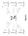
- FIGS. 4 a through 4 dillustrate example cable capture and release maneuvers
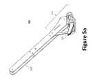
- FIGS. 5 a and 5 bprovide an enlarged view of an example arresting device
- FIGS. 6 a through 6 eprovide enlarged views of the arresting device's capturing hook during the cable capture and release maneuver of FIGS. 4 a through 4 d;
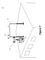
- FIG. 7illustrates a Ground Control Station 102 positioned on a rooftop
- FIG. 8illustrates a schematic diagram of a Ground Control Station 102 ;
- FIG. 9 aillustrates a block diagram of an example vision-based navigation system
- FIG. 9 billustrates an example process of analyzing an image using a vision-based navigation system
- FIG. 10 aillustrates a cross-sectional view of a charging cable electrically coupling with a conductive contacts
- FIG. 10 billustrates an example configuration for positioning conductive contacts on an arresting device capturing hook.
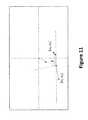
- FIG. 11illustrates the geometry of the guidance elements in the camera frame.
- communicateand “communicating,” as used herein, refer to both transmitting, or otherwise conveying, data from a source to a destination and delivering data to a communications medium, system, channel, network, device, wire, cable, fiber, circuit, and/or link to be conveyed to a destination.
- ⁇refers to a programmable device designed to sequentially and automatically carry out a sequence of arithmetic or logical operations, including without limitation, personal computers (e.g., those available from Gateway, Hewlett-Packard, IBM, Sony, Toshiba, Dell, Apple, Cisco, Sun, etc.), handheld, processor-based devices, and any other electronic device equipped with a processor or microprocessor.
- personal computerse.g., those available from Gateway, Hewlett-Packard, IBM, Sony, Toshiba, Dell, Apple, Cisco, Sun, etc.
- handheld, processor-based devicese.g., and any other electronic device equipped with a processor or microprocessor.
- processorrefers to processing devices, apparatus, programs, circuits, components, systems and subsystems, whether implemented in hardware, tangibly embodied software or both, and whether or not programmable.
- processorincludes, but is not limited to, one or more computers, hardwired circuits, signal modifying devices and systems, devices and machines for controlling systems, central processing units, programmable devices and systems, field-programmable gate arrays, application-specific integrated circuits, systems on a chip, systems comprising discrete elements and/or circuits, state machines, virtual machines and data processors.
- the present disclosureendeavors to provide systems and methods for enabling the operation of an autonomous self-charging aerial vehicle surveillance system. More specifically, the present disclosure endeavors to provide systems and methods for providing a self-charging UAV and UAV system capable of autonomous capture and release for use in a Continuous Operation System.
- a UAV system of the present inventionpreferably utilizes off-site charging through direct current lines (e.g., via a charging cable 804 ).
- direct current linese.g., via a charging cable 804 .
- An advantage of this approachis that the charging mechanisms on the UAV may be simplified, thus reducing the cost and weight of the UAV.
- UAVsare not forced to rely on ideal conditions of the power line to facilitate charging (e.g., current, voltage, diameter, etc.), thus expanding the scope of suitable Waypoint Locations.
- a Continuous Operation System 100may permit continuous, fully autonomous operation of one or more UAVs 106 for surveillance purposes.
- Each UAV 106may employ one or more sensors to facilitate autonomous flight, including, but not limited to, ultrasonic sensors, infrared sensors, radar and the like.
- the UAV 106may be equipped with a traditional ISR surveillance payload.
- the UAV 106may be equipped with a payload pod comprising one or more cameras, audio devices and other sensors.
- Any video, image, audio, telemetry and/or other sensor data (“Surveillance Data”), collected by the UAV 106may be locally stored or wirelessly communicated from the UAV 106 (e.g., at the Waypoint Location 104 or during flight) to a Ground Control Station 102 in real time using an antenna coupled with an onboard wireless communication device, such as a transmitter/receiver.
- Surveillance Datamay be communicated, or otherwise transferred, to the Ground Control Station 102 or another party via a wired connection.
- a UAV 106may alternate between a Waypoint Location 104 and a charging location, such as a Ground Control Station 102 .
- the UAV 106should be capable of autonomous landing and takeoff using, for example, an optical sensing system with an onboard precision vision-processing computer.
- the UAV 106may capture an arresting cable 310 to arrest itself and perch.
- the two general types of arresting cables 310include perching cables and charging cables 804 .
- Each of the perching cable and the charging cable 804are capable of capturing and supporting a UAV 106 while it perches, however, as will be discussed in greater detail below, a charging cable 804 provides the additional function of charging the UAV 106 's batteries.
- a utility power transmission linemay function as a perching cable.
- a predetermined perching point on the perching cablemay be marked using markers, such as IR reflectors.
- a UAV 106may be further configured to autonomously charge itself upon return to the Ground Control Station 102 , or other charging stations, through an electrified charging cable 804 on which the UAV 106 may perch and recharge.
- a charging cable 804may comprise two direct current wires carrying power and ground transmission.
- a predetermined perching pointmay be marked on the charging cable 804 using markers.
- the Ground Control Station 102may be permanently installed or portable to facilitate on-the-move operations.
- a Continuous Operation System 100continuous fully autonomous surveillance is enabled, thus enabling continuous surveillance by providing a real time Surveillance Data feed to the Ground Control Station 102 and/or another monitoring facility.
- FIG. 2provides a block diagram for a UAV 106 communicatively coupled with a Ground Control Station 102 via a wireless data link.
- Each UAV 106typically includes an onboard processor 108 that controls the various UAV components and functions.
- the processor 108may be communicatively coupled with an Inertial Navigation System (“INS”) 114 (e.g., Vector Nav VN-100) that is communicatively coupled with an inertial measurement unit 116 and GPS receiver, an onboard data storage device 112 (e.g., hard drive, flash memory, or the like), a surveillance payload 118 , one or more batteries 142 , a battery system 130 , a wireless communication device 120 , or virtually any other desired services 110 .
- INSInertial Navigation System
- 114e.g., Vector Nav VN-100
- an onboard data storage device 112e.g., hard drive, flash memory, or the like
- surveillance payload 118e.g., one or more batteries 142
- the UAV 106may be equipped with a traditional ISR surveillance payload 118 .
- the UAV 106may be equipped with one or more cameras 118 a , audio devices, and/or other sensors 118 b .
- Any Surveillance Data collected by the UAV 106may be wirelessly communicated to the Ground Control Station 700 in real time via the wireless communication device 120 .
- the UAV 106may be further equipped to store said Surveillance Data to an onboard data storage device 112 .
- the UAV 106may be programmed to erase, or otherwise destroy, the onboard data storage device 112 if the UAV 106 determines that it may have fallen into an enemy's possession.
- the UAV 106 onboard data storage devicemay be erased automatically when communication between the Ground Control Station 102 and UAV 106 is lost or upon touching down in a location outside of a predefined radius from the Ground Control Station 102 and/or Waypoint Location 104 , based on GPS calculations, or, if a crash is detected, e.g., based on detection of a sudden impact.
- the UAV 106may further comprise an air communication link 120 enabled to transmit (“TX”) and receive (“RX”) data using one or more antennas (e.g., top and bottom) via a circulator 126 , LNE 122 and RFE 124 .
- the antennamay be controlled via the processor 108 that is operatively coupled to an RF switch 128 .
- the UAVmay be equipped with coded orthogonal frequency division multiplexing (“CoFDM”) radios.
- CoFDMis a modulation format that is highly resistant to multipath interference. Since an operation may call for the UAV 106 to communicate Surveillance Data from a stationary Waypoint Location 104 below a roofline, a multipath resistant radio may be useful by eliminating the need to launch and re-land to improve radio reception from a perching point.
- the Ground Control Station 102typically includes a processor 132 that controls the various Ground Control Station 102 components and functions.
- the processor 132may be communicatively coupled with a communication transceiver 136 , an I/O device 140 , a power supply 138 and a charging cable 804 .
- the UAV 106 's battery system 130is electrically coupled with the Ground Control Station 102 's Power Supply 138 , thereby charging the UAV 106 's one or more onboard batteries 142 .
- other methodsare possible, such as inductance charging.
- the Ground Control Station 102 's communication transceiver 136may be used to wirelessly communicate data signals with the UAV 106 and/or an end user. Specifically, Surveillance Data collected by the UAV 106 may be transmitted in real time to the end user for live viewing, or to an apparatus (e.g., a computer) where it may be stored and/or displayed. Similarly, flight control data (i.e., flight commands from the end user or a flight computer) may be communicated between the Ground Control Station 102 and UAV 106 using the communication transceiver 136 . Alternatively, the Ground Control Station 102 may employ separate communication transceivers for communicating with the UAV 106 and with an end user.
- Surveillance Data collected by the UAV 106may be transmitted in real time to the end user for live viewing, or to an apparatus (e.g., a computer) where it may be stored and/or displayed.
- flight control datai.e., flight commands from the end user or a flight computer
- the Ground Control Station 102may communicate with an end user through a pre-configured high bandwidth directional data link and/or a satellite-based tactical data link. As illustrated, the Ground Control Station 102 may be electronically coupled to a power supply 138 .
- the power supply 138may be, for example, a battery, a generator, line current (e.g., from a power grid), a solar cell, etc.
- the I/O Device 140may be coupled with one or more sensors, such as a wind gauge 706 .
- the Ground Control Station 102may be equipped with an enhanced data receiving system.
- the Ground Control Station 102may be provided with a mechanically steered antenna system, or a multi-antenna diversity system that can allow much higher gain antennas to be used, thereby greatly extending the range of the UAV's data link without increasing the power consumption of the UAV 106 's transmitting radios. With each additional antenna added to the system, a higher gain antenna can be utilized.
- the Ground Control Station 102may employ a smart antenna (e.g., an adaptive array antenna, multiple-antenna and multiple-input and multiple-output) combined with smart signal processing algorithms for (i) identifying spatial signal signatures such as the direction of arrival (DOA) of the signal, and (ii) calculating beam-forming vectors to track and locate the antenna beam on the mobile/target.
- a smart antennae.g., an adaptive array antenna, multiple-antenna and multiple-input and multiple-output
- smart signal processing algorithmsfor (i) identifying spatial signal signatures such as the direction of arrival (DOA) of the signal, and (ii) calculating beam-forming vectors to track and locate the antenna beam on the mobile/target.
- DOAdirection of arrival
- a Continuous Operation System 100may employ a plurality of UAVs 106 of different types and sizes. Indeed, specially equipped UAVs 106 may be deployed to a particular Waypoint Location 104 to meet a specific need. However, compact lightweight UAVs are generally advantageous as they yield minimal detection and reduce weight imposed on the arresting cable 310 . Indeed, as will be shown below, a suitable UAV 106 that may be modified to facilitate Continuous Operation System operations includes the back-packable SkateTM UAS, available from Aurora Flight Sciences.
- the SkateTM systemis able to fly with its ISR payload,
- the SkateTM systemcan carry out autonomous missions from takeoff to landing without pilot intervention, but it is not able to land and take off again without assistance.
- the SkateTM systemuses independently articulating thrust vectoring motor pods to allow rapid transition between vertical and horizontal flight. Transitioning from VTOL to wing-borne flight increases the endurance and range of the system to levels characteristic of a fixed-wing platform and far beyond those of a traditional VTOL asset.
- the thrust vectoring provided by the motor podsallows the SkateTM UAV to fly both vertically and horizontally indoors and out, enabling rapid navigation of cluttered environments such as city streets or building interiors.
- While the present inventionillustrates a modified SkateTM UAV in the Continuous Operation System 100 , one of skill in the art would appreciate that the present invention should not be limited to use with the SkateTM-type UAVs. On the contrary, virtually any small UAV or SUAS may be modified to meet the objectives of a Continuous Operation System 100 . Such features including, for example, unattended recharging, autonomous cable capture and launch, and video-based flight controls that permit accurate perching point targeting, as well as the extended endurance to a one hour mission with a half-pound payload. However, a modified SkateTM UAV is illustrated in the following examples because of its advantageous airframe characteristics.
- the SkateTM UAVmay be equipped with an autopilot capable of flying to waypoints (e.g., a Waypoint Location 104 ) and performing many fully autonomous missions through a full suite of sensors including, for example, GPS, barometric pressure for altitude, differential pressure (e.g., a Pitot tube) for airspeed, and a full 9-DOF inertial measurement unit.
- an autopilotcapable of flying to waypoints (e.g., a Waypoint Location 104 ) and performing many fully autonomous missions through a full suite of sensors including, for example, GPS, barometric pressure for altitude, differential pressure (e.g., a Pitot tube) for airspeed, and a full 9-DOF inertial measurement unit.
- the existing SkateTM UAS configurationrepresents a balance of the need for vertical launch/recovery, with the desire for persistent presence, and the physical constraints imposed by back packability (e.g., the ability to carry the UAV in a backpack). Therefore, the resulting SkateTM planform compromises by providing an aspect ratio selection driven by maneuvering and payload constraints, as opposed to an optimized cruise case, and wingspan limited by packaging requirements.
- This low aspect ratio planformprovides a wide angle of attack envelope, facilitating inbound perch transition and controlled steep glide slopes for landing/maneuvering in confined spaces, but increasing induced drag at cruise.
- relaxing the aspect ratio constraint, by incrementally increasing wingspancan improve cruise performance with minimal impact on maneuvering and storage capabilities. Therefore, because back packability is not necessarily required in a Continuous Operation System 100 , lengthening the wingspan of the UAV 106 can both increase the aspect ratio and reduce the wing loading, translating directly to lower cruise power requirements.
- a SkateTM UAVmay be modified using, for example, 3-inch wingtip extension 302 on each wing.
- wingtip extensions 302changes to the SkateTM UAV's mechanical/propulsion systems are not required.
- the vertical stabilizers 304may also be enlarged, or raked, to meet new tail volume requirements.
- any sub finsmay be eliminated from the underside of the UAV 106 thereby avoiding interference with any landing/capture devices, including arresting devices 306 .
- the UAV 106should also be configured to capture onto, or otherwise engage, an arresting cable 310 using one or more arresting devices 306 located on the underside of the UAV 106 .
- the UAV 106may be configured to swing down and hang inverted from the arresting cable 310 to execute its surveillance objectives as illustrated in FIG. 3 b .
- Providing the arresting devices 306 on the underside of the UAV 106allows for increased clearance between the oncoming arresting cable 310 and the propellers 312 , but also allows for excellent ground visibility from the surveillance payload pod 308 .
- a UAV 106 's ISR payload pod 308may be preferably located on the top of the UAV 106 (e.g., opposite the arresting device 306 ). Therefore, when the UAV 106 is hanging inverted, the payload pod 308 faces downward, and provides the opportunity to mount a gimbaled camera, or other sensors, with a full 360-degree view of the ground. This orientation also maximizes exposure of the payload pod 308 with the ground where, from this position, the UAV 106 will be able to observe any ground location below the arresting cable 310 .
- the UAVmay wirelessly transmit Surveillance Data back to the Ground Control Station 102 . From there, the data may be relayed to end users (e.g., remote operators) either through a pre-configured high bandwidth directional data link or through a satellite-based tactical data link. Alternatively, the UAV may wirelessly transmit any data directly to the remote operators.
- end userse.g., remote operators
- the UAVmay wirelessly transmit any data directly to the remote operators.
- the cable-arresting mechanical systemwhich may comprise one or more arresting devices 306 , may be designed to release the UAV 106 either on command (i.e., actively) or when the UAV 106 generates enough thrust to lift off the arresting cable 310 (i.e., passively).
- the UAV 106may power its motors to reaches a stable condition wherein the vehicle is pointed nearly vertically (e.g., perpendicular to the ground) and is pulling against the arresting cable 310 .
- the autopilotsimultaneously applies increased power to the motors and actuates the servo releasing the one or more arresting devices 306 's hook from the arresting cable 310 .
- the UAV 106releases from the arresting cable 310 and launches vertically to a predetermined altitude before resuming level flight and navigation to a waypoint location (e.g., Ground Control Station 102 and/or Waypoint Location 104 ). Before the takeoff sequence, the UAV 106 hangs inverted, but since the propellers 312 are offset from the arresting devices, rotating back to vertical is not a difficult operation.
- a waypoint locatione.g., Ground Control Station 102 and/or Waypoint Location 104 .
- the UAV's flight control systemmay be provided with camera-derived estimates of the target arresting cable 310 's relative azimuth, elevation, and range. Together with the state estimate of the vehicle itself, this information is sufficient to determine line-of-sight rate and range rate to the target, which in turn can be used to implement a homing algorithm such as pure pursuit, proportional navigation (PN), or variations on PN that reduce the reliance on range rate information (which may be of lower accuracy in windy situations).
- PNproportional navigation
- range rate informationwhich may be of lower accuracy in windy situations.
- the UAVmay guide itself to the desired landing site using GPS, along the approach heading designated by the installation crew.
- the UAVcan activate the sensing system.
- the UAVmay detect the cable markers (e.g., IR illuminators and/or IR reflectors) and may utilize a terminal guidance algorithm to impact the arresting cable 310 at a slower cruise.
- the sensing systemdoes not detect the markers, or the UAV encounters a wind gust and misses the arresting cable 310 , the UAV can perform an abort operation.
- An abort operationmay comprise, for example, climbing rapidly above obstructions. Since the UAV may be capable of a vertical takeoff, the UAV can rapidly ascend to a safe altitude and fly around for another attempt.
- the UAV 106may employ an onboard vision processing system capable of performing real time centroiding on the incoming video and calculating relative altitude estimates. This may be done at a conservative minimum of 30 frames per second (fps), although 60 fps may be preferable.
- an OMAPTM 3-based cellular phone processormay be used to provide a vision processing system because it is highly miniaturized and designed for low power operation.
- the perch point cable markersmay be placed on an arresting cable 310 and may be detected using, for example, IR beacons, coupled with the onboard vision processing system. This method is advantageous because IR light can be effectively utilized in both day and night with proper selection of IR frequency (e.g., 940 nm).
- a suitable cameramay be a miniature camera based on an Aptina monochrome image sensor. Testing of the marker performance is analyzed through an RGB intensity graph.
- arresting cables 310may be marked with a marker 812 , such as active IR illuminator (e.g., Phoenix Jr. Infrared Beacons) and/or IR reflectors (e.g., retro-reflective tape), which functions in IR (e.g., “Glint Tape”, available from U.S. Tactical Supply at http://ustacticalsupply.com/irglintsquares.aspx; Emdom retro-reflective ID Marker; 3M 3000X or 3M 7610 Reflective Tape; or another all-purpose adhesive light strips).
- active IR illuminatore.g., Phoenix Jr. Infrared Beacons
- IR reflectorse.g., retro-reflective tape
- functions in IRe.g., “Glint Tape”, available from U.S. Tactical Supply at http://ustacticalsupply.com/irglintsquares.aspx; Em
- the IR illuminatorhas the advantage of not requiring an IR light source on the UAV, but would require power of some kind (e.g., onboard batteries.) Conversely, the IR reflectors, which are passive, would require an illuminator on the UAV.
- two markersmay be attached to the arresting cable 310 to enable the vehicle to easily detect relative bank angle compared to the cable, relative pitch and heading as well as to estimate a rough distance to target.
- the onboard vision processingcan centroid the incoming images, and determines the centers of the IR beacons in the field of view. To identify a perching point, the vision processing system can input these centroid coordinates and calculate the relative altitude estimates to feed into the landing control system.
- FIGS. 4 a through 4 dillustrate an example cable capture and release maneuver.
- the UAV 106approaches the arresting cable 310 , whether a perching cable or charging cable 804 , at cruise speed with the arresting devices 306 lowered.
- the UAV 106may be equipped with one or more retractable arresting devices 306 on the underside of the UAV 106 .
- the distal end of each arresting device 306may be provided with a capturing hook 314 (e.g., a capture and release mechanism), such as the passively locking jaw illustrated in FIGS. 5 a and 5 b .
- a capturing hook 314e.g., a capture and release mechanism
- the arresting device 306may strike the arresting cable 310 and capture it via the one or more capturing hooks 314 .
- the arresting device 306may be configured such that an arresting cable 310 may strike at any point along the shank 510 and result in a capture. Once locked, the UAV 106 swings forward and/or down to hang below the arresting cable 310 .
- the arresting device 306may be secured to the UAV's main structure (e.g., the payload pod 308 's attachment brackets) thus transferring arresting loads (e.g., energy) into the main structure of the airframe.
- arresting loadse.g., energy
- the UAV 106After charging, or surveying an area of interest, the UAV 106 is ready to re-launch. By throttling up the motors to a thrust-weight setting, as illustrated in FIG. 4 c , the UAV 106 will rotate around the arresting cable 310 and be pulled into a vertical launch position. At this point, the arresting device 306 will release. By omitting sub-fins, the portion of the airframe behind the arresting device 306 is obstruction free. As illustrated in FIG. 4 d , the UAV 106 climbs up and away from the arresting cable 310 , transitioning back to a cruise altitude. The arresting device 306 may then retract into the fuselage of the UAV 106 to reduce drag.
- FIGS. 5 a and 5 bprovide an enlarged view of an example arresting device 306 while FIGS. 6 a through 6 d provide enlarged views of the arresting device 306 's capturing hook 314 during the cable capture and release maneuver of FIGS. 4 a through 4 d .
- the capturing hook 314 for engaging an arresting cable 310 during capture and release of an aerial vehiclegenerally comprises a first gate 502 pivotally supported at a first end by a base portion of the shank 510 and movable between (i) a closed position (e.g., FIGS. 6 a and 6 c -6 e ) and (ii) an open position (e.g., FIG.
- a second gate 504pivotally supported at a first end by the base portion of the shank 510 and movable between (i) a closed position and (e.g., FIGS. 6 a -6 d ) (ii) an open position (e.g., FIG. 6 e ).
- a first return spring 516biases the first gate 502 in the closed position.
- a latch device 514comprising a movable locking part 506 biased by a return spring 518 to a locked position for locking of the second gate 504 in the closed position.
- the first gate 502may be configured such that the first gate 502 's second end 520 slips within a recess 522 at the second end of the second gate 504 , thereby preventing the arresting cable 310 from inadvertently slipping out of the hook recess 512 .
- FIG. 6 aillustrates the arresting device 306 's capturing hook 314 , which is a passively locking jaw resembling a clevis type hook, in a lowered position as the UAV 106 approaches an arresting cable 310 (e.g., a charging cable 804 comprising a wire pair) at cruise speed.
- FIG. 6 billustrates the capturing hook 314 in the course of catching the arresting cable 310 .
- the arresting cable 310may either (i) make direct contact with the capturing hook 314 's first gate 502 , or (ii) pass along the arresting device 306 's shank 510 until it reaches the capturing hook 314 's first gate 502 .
- the force of the arresting cable 310can cause the first gate 502 to push backward in direction C about pivot point Y, thus providing access to the capturing hook 314 's hook recess 512 .
- a forcee.g., an extension spring
- the first gate 502may snap back in direction C, as illustrated in FIG. 6 c , thereby securing the arresting cable 310 in the hook recess 512 .
- FIG. 6 dillustrates the capturing hook 314 prior to releasing the arresting cable 310 .
- the arresting cable 310While perched and during the takeoff maneuver, the arresting cable 310 generates a force against the second gate 504 in direction A.
- a servo-controlled release wiremay be configured related to the latch device 514 by pulling the a movable locking part 506 in direction B about pivot point Z, thus enabling the second gate 504 to open by pivoting about pivot point X as illustrated in FIG. 6 d .
- FIG. 6 dillustrates the capturing hook 314 prior to releasing the arresting cable 310 .
- the lift and thrust of the UAV 106applies a tension to the arresting cable 310 during takeoff that pulls the second gate 504 open thereby releasing the UAV 106 to facilitate free flight, as shown in FIGS. 4 c and 4 d .
- the force from the arresting cable 310 pulling on the second gate 504is gone and an extension spring pulls the second gate 504 back into its closed position and allows the latch device 514 to lock it in place, ready for the next capture.
- the arresting device 306 's designeliminates the need for a controls/sensing intensive dynamic perch maneuver.
- the UAV 310By approaching the arresting cable 310 at or near cruise speed, the UAV 310 can be much less susceptible to gusts, and the controls approach can be greatly simplified (i.e. not in the post-stall regime).
- the arresting device 306 's designenables the Continuous Operation System 100 .
- a Ground Control Station 102may be positioned on a rooftop, or other substantially clear area (e.g., clear from landing/takeoff obstruction) near the area of surveillance.
- a Waypoint Location 104having an arresting cable 310 (e.g., power, telephone or specially-installed cable) for the UAV 106 may be identified or created. Since the arresting cable 310 may be pre-surveyed, an operator can designate an approach direction; the GPS coordinate location and/or altitude of the perching zone (e.g., the area immediately surrounding the arresting cable 310 ).
- the arresting cable 310may also be marked or equipped with markers, such as IR beacons, that allow the UAV 106 to locate the arresting cable 310 using its onboard sensory system. After surveying and marking an arresting cable 310 within a perching zone, the UAV may approach and land on the arresting cable 310 .
- markerssuch as IR beacons
- the UAV 106may be configured to launch from a Ground Control Station 102 , fly a mission (e.g., perch at a Waypoint Location 104 ), then return to the Ground Control Station 102 to charge itself in preparation for the next autonomous launch.
- a Ground Control Station 102may provide a charging cable 804 for electrically connecting to the UAV 106 to facilitate charging after the UAV 106 has perched on the charging cable 804 .
- a diagram of an example Ground Control Station 102is illustrated in FIG. 7 .
- a Ground Control Station 102may comprise a charging cable 804 , a communications transceiver 136 and wind gauge 704 .
- the charging cable 804may be supported by one or more dedicated posts 708 . Accordingly, the Ground Control Station 102 may be configured to be self-supporting so that it may stand on its own in an open field. Alternatively, the charging cable 804 may be coupled with independent structures, such as buildings, telephone poles, etc. In fact, the entire Ground Control Station 102 may be coupled with, or integrated with, a vehicle to provide a mobile Ground Control Station 102 where the UAV 106 can locate the Ground Control Station 102 via the wireless antenna and/or GPS tracking.
- the wind gauge 704may be integrated with the Ground Control Station 102 via an I/O device 140 to provide wind data (e.g., speed and direction) or remotely located wherein the wind data is communicated to the Ground Control Station 102 via communications transceiver 136 .
- the charging cable 804should be designed and positioned sufficiently off the ground to provide an adequate amount of landing length for the UAV.
- the charging cable 804 lengthmay be 15 feet and positioned substantially parallel to the ground at a height of 15 feet.
- the charging cable 804may directly electrically interface with the capturing hook 314 to facilitate charging the UAV 106 's battery while perched on (e.g., hanging from) the charging cable 804 .
- the charging cable 804preferably comprises conductive wires (e.g., ground and power) that interface with the UAV 106 's battery system via the capturing hook 314 .
- the conductive wiresshould be configured to minimize the risk of shorting (e.g., making contact with each other) directly, or through some part of the UAV 106 's hook, once the UAV has perched and is hanging in steady state.
- a cable management system for use in Ground Control Station 102may be illustrated by the following example. This example is provided to aid in the understanding of the invention and is not to be construed as a limitation thereof.
- two extendable (e.g., telescoping) poles 802may be spaced apart and extended into the air.
- the poles 802may be spaced 15 feet apart and extend 15 feet into the air.
- a first end of two or more guy-lines 804may be coupled to the top of each pole 802 via one or more mounts while a second end may be coupled to one or more ground attachment points 806 (e.g., ground stakes).
- guy-lines 804may be constructed from rope, cable may be employed to reduce any displacement resulting from guy-line stretching.
- the mount for the guy-linesmay be configured such that each guy-line may attach to its own mount with some distance between them, thus adding moment resistance to the setup, thereby reducing twisting of the poles 802 .
- ratcheting tensioning devicesmay be provided in line with the guy-line to facilitate larger adjustments while turnbuckles may be provided to facilitate fine adjustments.
- a charging cable 804may be stretched between the poles 808 to capture and charge a UAV 106 .
- the charging cable 804may be further threaded through one or more pulleys 808 and coupled to one or more cable management devices 810 .
- Each cable management device 810may be configured to provide a constant charging cable 804 tension augmented by a shock absorber to absorb energy during UAV capture. Indeed, the charging cable 804 should be configured as to provide a soft catch to the UAV 106 , thereby minimizing the risk of damage after repeated use.
- Example cable management devices 810may include, for example, a winch coupled with one or more shock absorbers, springs (linear or torsional), elastic cables, or hydraulics. To increase reliability, the cables may be kept on the pulleys with cable guards or routed through cable housings.
- the charging cable 804may be marked with two or more markers 812 , such as active IR beacon and/or retro-reflective tape.
- the markers 812may be attached to the charging cable 804 to enable the UAV 106 to detect relative bank angle compared to the charging cable 804 , relative pitch and heading as well as to estimate a rough distance to target.
- the UAV 106 's onboard vision based navigation systemcan centroid the incoming images to determine the centers of the IR beacons in the field of view, thereby identifying the charging cable 804 .
- the vision navigation algorithmis continually trying to identify a target.
- an internal counterverifies that it has been continually identified for several frames.
- a signalis sent to the outer-loop controller and the vehicle guidance is switched into a vision-based tracking routine.
- heading and altitude commandsmay track the location of the target to the center of the field of view.
- the targetwas set as the central markers, detected by the vision based navigation system algorithms where offsets in the lateral direction commands heading, and vertical offset commands altitude. Accordingly, a low level altitude and heading tracker was implemented in the autopilot.
- the general objective of a vision based navigation systemis to determine the estimation and control approach for a UAV 106 flying towards an identified visual source and using the information of the observed location of two or more known markers 812 in the camera frame to reach a specific location (e.g., a Ground Control Station 102 or Waypoint Location 104 ).
- Measurements available to the vision based navigation systemmay include, for example, position data from a GPS device, attitude with respect to a global reference frame (e.g., using VectorNav) and the location of predetermined points in the camera frame (e.g., using Sanford image processing).
- Markers 812 or other beacon pointsmay be located in the environment and the MAV may be provided with data regarding the markers 812 's location with respect to the charging cable 804 .
- the specific locationshould be visually accessible to the camera at least up to a point where the UAV 300 may achieve a final approach with increased certainly. That is, as the UAV 300 gets closer to the specific location, the markers 812 should fall within the field of view of the camera up to a very short distance to the target location.
- the markers 812are known, or assumed, to be located at some predetermined points on the cable.
- FIG. 9 aillustrates a block diagram of an example vision based navigation system 900 .
- the vision based navigation system 900may comprise one or more image capture devices 902 , a point correlation device 904 , a thresholding device 906 , a feature tracking device 908 , a likelihood filter 910 , and a Kalman estimate device 912 .
- the one or more image capture devices 902may be configured to receive, or generate, an image of an area.
- the one or more image capture devices 902may include, for example, an onboard camera.
- the image of the areamay be a still photo or a video, which generally comprises a series of still photos known as frames.
- the thresholding device 906may be configured to determine the location of features within the image.
- markers 812may be used to provide image points with high intensity levels that can be extracted from the image by thresholding.
- the information from the image capture devices 902e.g., camera
- a detected light that exceeds a predetermined threshold intensity valuemay be represented as a coordinate within the image.
- the feature tracking device 908may employ a feature tracking algorithm, such as Lukas-Kanade, to calculate the motion of the image locally using the coordinates by tracking the motion of a feature (e.g., a coordinate) from frame to frame. This process allows for filtering out coordinates that do not correspond to the markers 812 as they are tracked. However, additional calculations may further be employed to track of the markers, or other features. Specifically, an algorithm may track features over different frames but may not identify which ones are the markers.
- a feature tracking algorithmsuch as Lukas-Kanade
- the point correlation device 904 and likelihood filter 908may be used to reduce the coordinates by eliminating outlier coordinates based on, for example, a linear correlation. Since the locations of the markers is typically known (e.g., on a power line), the markers should meet a known geometric constraint. Accordingly, a first approach may be to assume that a valid set of points should lie on a line (or close to it) as shown in FIG. 9 b . Therefore for vision based navigation system 900 selected n-sets of points, the likelihood filter 908 can determine whether the points are within a threshold of being in a line by checking the error from a linear fit.
- the Kalman estimate device 912comprises a Kalman filter, which uses input from GPS, the IMU and the Camera to produce the best estimate of the position and/or attitude with respect to the markers.
- a Kalman filteris an algorithm that uses a series of measurements observed over time, containing noise (random variations) and other inaccuracies, and produces estimates of unknown variables.
- the routinemay identify features that are consistent over time in spite of the time-varying brightness threshold to eliminate noise and reflections that are less consistent in brightness over time.
- a closed-loop thresholding algorithmmay be used to alters the brightness threshold in real-time to select a subset of points (e.g., 5 or so).
- the closed-loop thresholding algorithmmay work in conjunction with the likelihood filter that may have more time-varying brightness levels than the beacons themselves.
- FIG. 9 billustrates an example process of analyzing an image using a vision based navigation system 900 .
- the vision based navigation system 900generates, or otherwise receives, an image of a given area.
- the areamay be the view of the UAV 300 during flight (e.g., akin to the view from a manned aircraft's cockpit).
- the camera parametersmay be assumed, such as focal length and camera configuration.
- a series of coordinatesare identified based on the image using thresholding techniques.
- the various light sources detected in the imageare represented using one or more coordinates on a coordinate plane.
- the light sourcesare represented on the plane when they exceed a predetermined threshold intensity value.
- the various street lampsalso exceed the threshold intensity and thus are similarly represented on the coordinate plane.
- Using intense beaconswill provide image points with high intensity levels that can be extracted from the image by thresholding.
- the information from the camerawill provide the (u,v) coordinates for points within a corresponding threshold.
- the measurement model usedis the standard pinhole model:
- ⁇ , ⁇ , o x , o yare parameters of the camera describing distortion and offset. As mentioned in the assumptions, ⁇ , ⁇ , will be considered 0, 1 (no shear or compression distortion).
- Xis the coordinates of the camera with respect to the target location
- x Ais the location of the beacon with respect to the target location.
- the gradient of the measurement equation Hcan be calculated by implicit differentiation of equations (1) and (2) to be:
- a RANdom SAmple Consensus (RANSAC) algorithmmay sample different combinations of n-points.
- the coordinatesare reduced by eliminating outlier coordinates based on a known geometric constraint, for example, a linear correlation. That is, outliers that correspond to 3D points reflecting or emitting IR that may not be discerned from the correct beacons to be tracked.
- a preliminary filter that can reduce the data points by rejecting outliersis based on a linear correlation. Since the beacons are known to be located on a power line, they should meet a specific geometric constraint. As a first approach we will assume that a valid set of points should lie on a line (or close to it).
- the markersare identified using likelihood filtering and/or Kalman filter.
- a standard Extended Kalman Filter approachmay be used to predict the state and update the covariance: ⁇ circumflex over (x) ⁇ k
- k-1f ( ⁇ circumflex over (x) ⁇ + k-1
- k-1F k-1 P k-1
- k-1 F k-1 TQ′ k
- Each point z kindicates a combinatorial of feature points, which indicate mutually exclusive events. Therefore, we are interested in selecting one of the possible events as the correct one. This may be accomplished by selecting the one with the largest likelihood as measured by the innovation vector and its covariance. After performing the state prediction, we can look for the event z k n that maximizes the likelihood by projecting the innovation of each event (variation from predicted state) in its probability space, and finding distance to the origin (maximum likelihood).
- K kP k
- k⁇ circumflex over (x) ⁇ k
- k( I ⁇ K k H k ) P k
- the UAV 300may navigate to the arresting cable 310 's perch point using an onboard autopilot. For example, a terminal guidance control approach may be employed. Using this approach, assumptions may be used to reduce the complexity of an approach. Specifically, one assumption may be that the UAV 300 can initially identify the beacons on the camera plane, that is, the points in the image that correspond to the beacons are known. Additionally, given the ambiguity of the measurements we have to make some assumptions of states that will be controlled through internal loops.
- Ris the covariance matrix of the measurements. Using that information, a line in the image may be defined by two points.
- the information from the camera in FIG. 11may be used, which illustrates the geometry of the guidance elements in the camera frame.
- the guidance elementsare:
- control transfer functions K(s)can be a set of static gains or a dynamic transfer functions set to compensate the dynamics of the non-linear input to output system.
- a first approachmay be a constant pitch angle approach.
- an internal looptries to maintain a constant pitch angle, the altitude variations are small, and the altitude is regulated using thrust.
- Pitch angleis constant. Small variations with respect to the level direction. (Defining level direction as vector from camera to target point is aligned). Under the constant pitch angle assumption we can define an input-output system:
- Control approachwill then be based on trying to regulate the altitude, heading and roll based on the observed line (defined by the extreme points) in the image.
- [ h . ⁇ . ][ K h ⁇ ⁇ ⁇ ⁇ ( s ) 0 0 0 K ⁇ ⁇ ( S ) K ⁇ ⁇ ( S ) ] ⁇ [ e ⁇ e ⁇ ⁇ ]
- ⁇ , ⁇ , ⁇are pitch yaw and roll angles respectively.
- a second approachmay be control of velocity vector.
- An objective of the control lawis to maintain the camera vector aligned with the final target point, given the assumption that the camera vector is aligned with the velocity direction, the trajectory converges to the target.
- the velocity of the vehicleis aligned with the camera vector. This can be performed by providing inner control loops that regulate the thrust to achieve such behavior.
- [ ⁇ . ⁇ . ⁇ . ][ K ⁇ ⁇ ⁇ 1 ⁇ ( s ) K ⁇ ⁇ ⁇ 2 ⁇ ( s ) 0 K ⁇ ⁇ ⁇ 1 ⁇ ( s ) K ⁇ ⁇ ⁇ 1 ⁇ ( s ) 0 K ⁇ 1 ⁇ ( s ) 0 K ⁇ ⁇ ⁇ 2 ⁇ ( s ) ] ⁇ [ e ⁇ e ⁇ ⁇ ]
- ⁇ , 104 , ⁇are pitch yaw and roll angles respectively.
- a third approachmay be glideslope. This approach considers a glideslope defined by an estimated distance to the target from the size of the line in the camera plane and assumes that the pitch angle is held constant.
- Inner loopsmay be employed to achieve the glideslope.
- FIG. 10 aillustrates a cross sectional diagram of an example charging cable 804 comprising two conductive wires 1002 separated by an non-conductive insulator 1004 , which resembles a twin lead RF cable.
- the arresting device 306 and capturing hook 314may be fabricated from a non-conductive material equipped with conductive contacts 1006 positioned in the hook recess 510 of the capturing hook 314 to facilitate an effective electrical contact between the UAV 106 's battery charging system and the wire conductors 1002 .
- An example non-conductive materialincludes synthetic polymers, such as plastic.
- the conductive contacts 1006may be fabricated from a non-corrosive conductor, such as gold. Providing wider conductive contacts 1006 allows for a large amount of angular movement of the UAV 106 on the cable while maintaining electrical contact.
- FIG. 10 billustrates an example configuration for positioning conductive contacts 1006 on the arresting device 306 's capturing hook 314 of FIGS. 6 a through 6 e .
- a first conductive contact 1006may be placed on the second gate 504
- a second conductive contact 1006may be placed on the base portion of the shank 510 .
- the first and second conductive contacts 1006should be placed at or near the point where the second gate 504 meets the base portion of the shank 510 , such that each of the arresting cable 310 's conductive wires 1002 may be electronically coupled with its respective conductive contact 1006 .
- the non-conductive insulator 1004 's widthmay be increased or decreased to ensure sufficient contact between each conductive wire 1002 and an associated conductive contact 1006 .
Landscapes
- Engineering & Computer Science (AREA)
- Aviation & Aerospace Engineering (AREA)
- Mechanical Engineering (AREA)
- Remote Sensing (AREA)
- Chemical & Material Sciences (AREA)
- Combustion & Propulsion (AREA)
- Transportation (AREA)
- Power Engineering (AREA)
- Radar, Positioning & Navigation (AREA)
- Physics & Mathematics (AREA)
- General Physics & Mathematics (AREA)
- Automation & Control Theory (AREA)
- Control Of Position, Course, Altitude, Or Attitude Of Moving Bodies (AREA)
- Traffic Control Systems (AREA)
Abstract
Description
{circumflex over (x)}k|k-1=f({circumflex over (x)}+k-1|k-1,uk-1)
Pk|k-1=Fk-1Pk-1|k-1Fk-1T+Qk
λpA=KR(−X+xA) (1)
with:
λ=R3(|X+xA) (2)
is the rotation matrix from the absolute frame to the camera frame:
R=Rcam/bodyRbody/x
Pk:{pk1,pk2,pk3,pk4,pk5. . . }
Zk:{zk
{circumflex over (x)}k|k-1=f({circumflex over (x)}+k-1|k-1,uk-1)
Pk|k-1=Fk-1Pk-1|k-1Fk-1T=Q′k
ek
With:
{tilde over (y)}k
Sk=HkPk|k-1HkT+Rk
Kk=Pk|k-1HkTSk−1
{circumflex over (x)}k|k={circumflex over (x)}k|k+Kk{tilde over (y)}k
Pk|k=(I−KkHk)Pk|k-1
e=dpTR−1dp
Claims (7)
Priority Applications (4)
| Application Number | Priority Date | Filing Date | Title |
|---|---|---|---|
| US14/213,450US9527392B2 (en) | 2013-03-14 | 2014-03-14 | Aerial system and vehicle for continuous operation |
| US15/291,870US10308375B2 (en) | 2013-03-14 | 2016-10-12 | Capturing hook for aerial system |
| US15/291,878US9926084B2 (en) | 2013-03-14 | 2016-10-12 | Aerial system and vehicle for continuous operation |
| US15/291,874US10220963B2 (en) | 2013-03-14 | 2016-10-12 | Aerial system and vehicle for continuous operation |
Applications Claiming Priority (2)
| Application Number | Priority Date | Filing Date | Title |
|---|---|---|---|
| US201361851866P | 2013-03-14 | 2013-03-14 | |
| US14/213,450US9527392B2 (en) | 2013-03-14 | 2014-03-14 | Aerial system and vehicle for continuous operation |
Related Child Applications (3)
| Application Number | Title | Priority Date | Filing Date |
|---|---|---|---|
| US15/291,874DivisionUS10220963B2 (en) | 2013-03-14 | 2016-10-12 | Aerial system and vehicle for continuous operation |
| US15/291,878ContinuationUS9926084B2 (en) | 2013-03-14 | 2016-10-12 | Aerial system and vehicle for continuous operation |
| US15/291,870DivisionUS10308375B2 (en) | 2013-03-14 | 2016-10-12 | Capturing hook for aerial system |
Publications (2)
| Publication Number | Publication Date |
|---|---|
| US20160137311A1 US20160137311A1 (en) | 2016-05-19 |
| US9527392B2true US9527392B2 (en) | 2016-12-27 |
Family
ID=55961011
Family Applications (4)
| Application Number | Title | Priority Date | Filing Date |
|---|---|---|---|
| US14/213,450Active2035-09-29US9527392B2 (en) | 2013-03-14 | 2014-03-14 | Aerial system and vehicle for continuous operation |
| US15/291,874Active2034-08-31US10220963B2 (en) | 2013-03-14 | 2016-10-12 | Aerial system and vehicle for continuous operation |
| US15/291,870Active2035-04-25US10308375B2 (en) | 2013-03-14 | 2016-10-12 | Capturing hook for aerial system |
| US15/291,878ActiveUS9926084B2 (en) | 2013-03-14 | 2016-10-12 | Aerial system and vehicle for continuous operation |
Family Applications After (3)
| Application Number | Title | Priority Date | Filing Date |
|---|---|---|---|
| US15/291,874Active2034-08-31US10220963B2 (en) | 2013-03-14 | 2016-10-12 | Aerial system and vehicle for continuous operation |
| US15/291,870Active2035-04-25US10308375B2 (en) | 2013-03-14 | 2016-10-12 | Capturing hook for aerial system |
| US15/291,878ActiveUS9926084B2 (en) | 2013-03-14 | 2016-10-12 | Aerial system and vehicle for continuous operation |
Country Status (1)
| Country | Link |
|---|---|
| US (4) | US9527392B2 (en) |
Cited By (8)
| Publication number | Priority date | Publication date | Assignee | Title |
|---|---|---|---|---|
| US20170015415A1 (en)* | 2015-07-15 | 2017-01-19 | Elwha Llc | System and method for operating unmanned aircraft |
| US20170036762A1 (en)* | 2015-08-03 | 2017-02-09 | Dustin Gamble | Release and Capture of a Fixed-Wing Aircraft |
| US9937808B2 (en)* | 2016-09-09 | 2018-04-10 | Michael Steward Evans | Drone charging stations |
| CN107908197A (en)* | 2017-11-23 | 2018-04-13 | 深圳市智璟科技有限公司 | The accurate landing system of unmanned plane and method based on infrared beacon and vision |
| US10112728B2 (en)* | 2016-09-09 | 2018-10-30 | Michael Steward Evans | Drone charging stations |
| US10336202B2 (en)* | 2013-08-05 | 2019-07-02 | Peter J. Panopoulos | Drone assistance apparatus with charging system and method |
| US20230294552A1 (en)* | 2020-10-29 | 2023-09-21 | Wing Aviation Llc | Systems and Methods for Battery Capacity Management in a Fleet of UAVs |
| US12333923B2 (en) | 2020-03-16 | 2025-06-17 | Asylon, Inc. | Automated alert system using unmanned aerial vehicles |
Families Citing this family (231)
| Publication number | Priority date | Publication date | Assignee | Title |
|---|---|---|---|---|
| EP2421757B1 (en) | 2009-04-24 | 2013-10-23 | Insitu, Inc. | Systems and methods for recovering and controlling post-recovery motion of unmanned aircraft |
| US8944373B2 (en) | 2010-09-27 | 2015-02-03 | Insitu, Inc. | Line capture devices for unmanned aircraft, and associated systems and methods |
| US10009065B2 (en) | 2012-12-05 | 2018-06-26 | At&T Intellectual Property I, L.P. | Backhaul link for distributed antenna system |
| US9113347B2 (en) | 2012-12-05 | 2015-08-18 | At&T Intellectual Property I, Lp | Backhaul link for distributed antenna system |
| US9290269B2 (en) | 2013-03-15 | 2016-03-22 | CyPhy Works, Inc. | Spooler for unmanned aerial vehicle system |
| US20150014475A1 (en) | 2013-05-03 | 2015-01-15 | Aerovironment, Inc. | Vertical Takeoff and Landing (VTOL) Air Vehicle |
| US9999038B2 (en) | 2013-05-31 | 2018-06-12 | At&T Intellectual Property I, L.P. | Remote distributed antenna system |
| US9525524B2 (en) | 2013-05-31 | 2016-12-20 | At&T Intellectual Property I, L.P. | Remote distributed antenna system |
| EP2853494B1 (en)* | 2013-09-26 | 2018-08-01 | The Boeing Company | Power management method and system for an unmanned air vehicle |
| US8897697B1 (en) | 2013-11-06 | 2014-11-25 | At&T Intellectual Property I, Lp | Millimeter-wave surface-wave communications |
| US9209902B2 (en) | 2013-12-10 | 2015-12-08 | At&T Intellectual Property I, L.P. | Quasi-optical coupler |
| US10399674B2 (en) | 2014-07-28 | 2019-09-03 | Insitu, Inc. | Systems and methods countering an unmanned air vehicle |
| US9692101B2 (en) | 2014-08-26 | 2017-06-27 | At&T Intellectual Property I, L.P. | Guided wave couplers for coupling electromagnetic waves between a waveguide surface and a surface of a wire |
| US9768833B2 (en) | 2014-09-15 | 2017-09-19 | At&T Intellectual Property I, L.P. | Method and apparatus for sensing a condition in a transmission medium of electromagnetic waves |
| US10063280B2 (en) | 2014-09-17 | 2018-08-28 | At&T Intellectual Property I, L.P. | Monitoring and mitigating conditions in a communication network |
| US9615269B2 (en) | 2014-10-02 | 2017-04-04 | At&T Intellectual Property I, L.P. | Method and apparatus that provides fault tolerance in a communication network |
| US9685992B2 (en) | 2014-10-03 | 2017-06-20 | At&T Intellectual Property I, L.P. | Circuit panel network and methods thereof |
| US9503189B2 (en) | 2014-10-10 | 2016-11-22 | At&T Intellectual Property I, L.P. | Method and apparatus for arranging communication sessions in a communication system |
| US9762289B2 (en) | 2014-10-14 | 2017-09-12 | At&T Intellectual Property I, L.P. | Method and apparatus for transmitting or receiving signals in a transportation system |
| US9973299B2 (en) | 2014-10-14 | 2018-05-15 | At&T Intellectual Property I, L.P. | Method and apparatus for adjusting a mode of communication in a communication network |
| US9520945B2 (en) | 2014-10-21 | 2016-12-13 | At&T Intellectual Property I, L.P. | Apparatus for providing communication services and methods thereof |
| US9769020B2 (en) | 2014-10-21 | 2017-09-19 | At&T Intellectual Property I, L.P. | Method and apparatus for responding to events affecting communications in a communication network |
| US9312919B1 (en) | 2014-10-21 | 2016-04-12 | At&T Intellectual Property I, Lp | Transmission device with impairment compensation and methods for use therewith |
| US9780834B2 (en) | 2014-10-21 | 2017-10-03 | At&T Intellectual Property I, L.P. | Method and apparatus for transmitting electromagnetic waves |
| US9627768B2 (en) | 2014-10-21 | 2017-04-18 | At&T Intellectual Property I, L.P. | Guided-wave transmission device with non-fundamental mode propagation and methods for use therewith |
| US9653770B2 (en) | 2014-10-21 | 2017-05-16 | At&T Intellectual Property I, L.P. | Guided wave coupler, coupling module and methods for use therewith |
| US9577306B2 (en) | 2014-10-21 | 2017-02-21 | At&T Intellectual Property I, L.P. | Guided-wave transmission device and methods for use therewith |
| US10243784B2 (en) | 2014-11-20 | 2019-03-26 | At&T Intellectual Property I, L.P. | System for generating topology information and methods thereof |
| US10340573B2 (en) | 2016-10-26 | 2019-07-02 | At&T Intellectual Property I, L.P. | Launcher with cylindrical coupling device and methods for use therewith |
| US9742462B2 (en) | 2014-12-04 | 2017-08-22 | At&T Intellectual Property I, L.P. | Transmission medium and communication interfaces and methods for use therewith |
| US9997819B2 (en) | 2015-06-09 | 2018-06-12 | At&T Intellectual Property I, L.P. | Transmission medium and method for facilitating propagation of electromagnetic waves via a core |
| US9896222B2 (en) | 2014-11-20 | 2018-02-20 | Insitu, Inc. | Capture devices for unmanned aerial vehicles, including track-borne capture lines, and associated systems and methods |
| US10009067B2 (en) | 2014-12-04 | 2018-06-26 | At&T Intellectual Property I, L.P. | Method and apparatus for configuring a communication interface |
| US9800327B2 (en) | 2014-11-20 | 2017-10-24 | At&T Intellectual Property I, L.P. | Apparatus for controlling operations of a communication device and methods thereof |
| US9680670B2 (en) | 2014-11-20 | 2017-06-13 | At&T Intellectual Property I, L.P. | Transmission device with channel equalization and control and methods for use therewith |
| US9654173B2 (en) | 2014-11-20 | 2017-05-16 | At&T Intellectual Property I, L.P. | Apparatus for powering a communication device and methods thereof |
| US9544006B2 (en) | 2014-11-20 | 2017-01-10 | At&T Intellectual Property I, L.P. | Transmission device with mode division multiplexing and methods for use therewith |
| US9461706B1 (en) | 2015-07-31 | 2016-10-04 | At&T Intellectual Property I, Lp | Method and apparatus for exchanging communication signals |
| US9954287B2 (en) | 2014-11-20 | 2018-04-24 | At&T Intellectual Property I, L.P. | Apparatus for converting wireless signals and electromagnetic waves and methods thereof |
| US10144036B2 (en) | 2015-01-30 | 2018-12-04 | At&T Intellectual Property I, L.P. | Method and apparatus for mitigating interference affecting a propagation of electromagnetic waves guided by a transmission medium |
| WO2016130847A1 (en) | 2015-02-11 | 2016-08-18 | Aerovironment, Inc. | Pod launch and landing system for vertical take-off and landing (vtol) unmanned aerial vehicles (uavs) |
| WO2016130711A1 (en) | 2015-02-11 | 2016-08-18 | Aerovironment, Inc. | Pod operating system for a vertical take-off and landing (vtol) unmanned aerial vehicle (uav) |
| WO2016130797A1 (en)* | 2015-02-11 | 2016-08-18 | Aerovironment, Inc. | Pod cover system for a vertical take-off and landing (vtol) unmanned aerial vehicle (uav) |
| US9977435B2 (en)* | 2015-02-11 | 2018-05-22 | Aeroviroment, Inc. | Survey migration system for vertical take-off and landing (VTOL) unmanned aerial vehicles (UAVS) |
| WO2016130716A2 (en) | 2015-02-11 | 2016-08-18 | Aerovironment, Inc. | Geographic survey system for vertical take-off and landing (vtol) unmanned aerial vehicles (uavs) |
| US9876570B2 (en) | 2015-02-20 | 2018-01-23 | At&T Intellectual Property I, Lp | Guided-wave transmission device with non-fundamental mode propagation and methods for use therewith |
| US9749013B2 (en) | 2015-03-17 | 2017-08-29 | At&T Intellectual Property I, L.P. | Method and apparatus for reducing attenuation of electromagnetic waves guided by a transmission medium |
| US9705561B2 (en) | 2015-04-24 | 2017-07-11 | At&T Intellectual Property I, L.P. | Directional coupling device and methods for use therewith |
| US10224981B2 (en) | 2015-04-24 | 2019-03-05 | At&T Intellectual Property I, Lp | Passive electrical coupling device and methods for use therewith |
| US9793954B2 (en) | 2015-04-28 | 2017-10-17 | At&T Intellectual Property I, L.P. | Magnetic coupling device and methods for use therewith |
| US9948354B2 (en) | 2015-04-28 | 2018-04-17 | At&T Intellectual Property I, L.P. | Magnetic coupling device with reflective plate and methods for use therewith |
| US9871282B2 (en) | 2015-05-14 | 2018-01-16 | At&T Intellectual Property I, L.P. | At least one transmission medium having a dielectric surface that is covered at least in part by a second dielectric |
| US9490869B1 (en) | 2015-05-14 | 2016-11-08 | At&T Intellectual Property I, L.P. | Transmission medium having multiple cores and methods for use therewith |
| US9748626B2 (en) | 2015-05-14 | 2017-08-29 | At&T Intellectual Property I, L.P. | Plurality of cables having different cross-sectional shapes which are bundled together to form a transmission medium |
| US10650940B2 (en) | 2015-05-15 | 2020-05-12 | At&T Intellectual Property I, L.P. | Transmission medium having a conductive material and methods for use therewith |
| US9917341B2 (en) | 2015-05-27 | 2018-03-13 | At&T Intellectual Property I, L.P. | Apparatus and method for launching electromagnetic waves and for modifying radial dimensions of the propagating electromagnetic waves |
| US9828093B2 (en)* | 2015-05-27 | 2017-11-28 | First Principles, Inc. | System for recharging remotely controlled aerial vehicle, charging station and rechargeable remotely controlled aerial vehicle, and method of use thereof |
| US9912381B2 (en) | 2015-06-03 | 2018-03-06 | At&T Intellectual Property I, Lp | Network termination and methods for use therewith |
| US10812174B2 (en) | 2015-06-03 | 2020-10-20 | At&T Intellectual Property I, L.P. | Client node device and methods for use therewith |
| US10103801B2 (en) | 2015-06-03 | 2018-10-16 | At&T Intellectual Property I, L.P. | Host node device and methods for use therewith |
| US9866309B2 (en) | 2015-06-03 | 2018-01-09 | At&T Intellectual Property I, Lp | Host node device and methods for use therewith |
| US9913139B2 (en) | 2015-06-09 | 2018-03-06 | At&T Intellectual Property I, L.P. | Signal fingerprinting for authentication of communicating devices |
| US10142086B2 (en) | 2015-06-11 | 2018-11-27 | At&T Intellectual Property I, L.P. | Repeater and methods for use therewith |
| US9608692B2 (en) | 2015-06-11 | 2017-03-28 | At&T Intellectual Property I, L.P. | Repeater and methods for use therewith |
| US9820146B2 (en) | 2015-06-12 | 2017-11-14 | At&T Intellectual Property I, L.P. | Method and apparatus for authentication and identity management of communicating devices |
| US9667317B2 (en) | 2015-06-15 | 2017-05-30 | At&T Intellectual Property I, L.P. | Method and apparatus for providing security using network traffic adjustments |
| US9640850B2 (en) | 2015-06-25 | 2017-05-02 | At&T Intellectual Property I, L.P. | Methods and apparatus for inducing a non-fundamental wave mode on a transmission medium |
| US9509415B1 (en) | 2015-06-25 | 2016-11-29 | At&T Intellectual Property I, L.P. | Methods and apparatus for inducing a fundamental wave mode on a transmission medium |
| US9865911B2 (en) | 2015-06-25 | 2018-01-09 | At&T Intellectual Property I, L.P. | Waveguide system for slot radiating first electromagnetic waves that are combined into a non-fundamental wave mode second electromagnetic wave on a transmission medium |
| US10170840B2 (en) | 2015-07-14 | 2019-01-01 | At&T Intellectual Property I, L.P. | Apparatus and methods for sending or receiving electromagnetic signals |
| US9882257B2 (en) | 2015-07-14 | 2018-01-30 | At&T Intellectual Property I, L.P. | Method and apparatus for launching a wave mode that mitigates interference |
| US9847566B2 (en) | 2015-07-14 | 2017-12-19 | At&T Intellectual Property I, L.P. | Method and apparatus for adjusting a field of a signal to mitigate interference |
| US10205655B2 (en) | 2015-07-14 | 2019-02-12 | At&T Intellectual Property I, L.P. | Apparatus and methods for communicating utilizing an antenna array and multiple communication paths |
| US10341142B2 (en) | 2015-07-14 | 2019-07-02 | At&T Intellectual Property I, L.P. | Apparatus and methods for generating non-interfering electromagnetic waves on an uninsulated conductor |
| US10033108B2 (en) | 2015-07-14 | 2018-07-24 | At&T Intellectual Property I, L.P. | Apparatus and methods for generating an electromagnetic wave having a wave mode that mitigates interference |
| US10033107B2 (en) | 2015-07-14 | 2018-07-24 | At&T Intellectual Property I, L.P. | Method and apparatus for coupling an antenna to a device |
| US9853342B2 (en) | 2015-07-14 | 2017-12-26 | At&T Intellectual Property I, L.P. | Dielectric transmission medium connector and methods for use therewith |
| US9722318B2 (en) | 2015-07-14 | 2017-08-01 | At&T Intellectual Property I, L.P. | Method and apparatus for coupling an antenna to a device |
| US9628116B2 (en) | 2015-07-14 | 2017-04-18 | At&T Intellectual Property I, L.P. | Apparatus and methods for transmitting wireless signals |
| US10320586B2 (en) | 2015-07-14 | 2019-06-11 | At&T Intellectual Property I, L.P. | Apparatus and methods for generating non-interfering electromagnetic waves on an insulated transmission medium |
| US10044409B2 (en) | 2015-07-14 | 2018-08-07 | At&T Intellectual Property I, L.P. | Transmission medium and methods for use therewith |
| US10148016B2 (en) | 2015-07-14 | 2018-12-04 | At&T Intellectual Property I, L.P. | Apparatus and methods for communicating utilizing an antenna array |
| US9793951B2 (en) | 2015-07-15 | 2017-10-17 | At&T Intellectual Property I, L.P. | Method and apparatus for launching a wave mode that mitigates interference |
| US10090606B2 (en) | 2015-07-15 | 2018-10-02 | At&T Intellectual Property I, L.P. | Antenna system with dielectric array and methods for use therewith |
| US9608740B2 (en) | 2015-07-15 | 2017-03-28 | At&T Intellectual Property I, L.P. | Method and apparatus for launching a wave mode that mitigates interference |
| US9912027B2 (en) | 2015-07-23 | 2018-03-06 | At&T Intellectual Property I, L.P. | Method and apparatus for exchanging communication signals |
| US9948333B2 (en) | 2015-07-23 | 2018-04-17 | At&T Intellectual Property I, L.P. | Method and apparatus for wireless communications to mitigate interference |
| US9749053B2 (en) | 2015-07-23 | 2017-08-29 | At&T Intellectual Property I, L.P. | Node device, repeater and methods for use therewith |
| US9871283B2 (en) | 2015-07-23 | 2018-01-16 | At&T Intellectual Property I, Lp | Transmission medium having a dielectric core comprised of plural members connected by a ball and socket configuration |
| US9967173B2 (en) | 2015-07-31 | 2018-05-08 | At&T Intellectual Property I, L.P. | Method and apparatus for authentication and identity management of communicating devices |
| US9735833B2 (en) | 2015-07-31 | 2017-08-15 | At&T Intellectual Property I, L.P. | Method and apparatus for communications management in a neighborhood network |
| US9904535B2 (en) | 2015-09-14 | 2018-02-27 | At&T Intellectual Property I, L.P. | Method and apparatus for distributing software |
| US10009901B2 (en) | 2015-09-16 | 2018-06-26 | At&T Intellectual Property I, L.P. | Method, apparatus, and computer-readable storage medium for managing utilization of wireless resources between base stations |
| US10079661B2 (en) | 2015-09-16 | 2018-09-18 | At&T Intellectual Property I, L.P. | Method and apparatus for use with a radio distributed antenna system having a clock reference |
| US10009063B2 (en) | 2015-09-16 | 2018-06-26 | At&T Intellectual Property I, L.P. | Method and apparatus for use with a radio distributed antenna system having an out-of-band reference signal |
| US10136434B2 (en) | 2015-09-16 | 2018-11-20 | At&T Intellectual Property I, L.P. | Method and apparatus for use with a radio distributed antenna system having an ultra-wideband control channel |
| US9769128B2 (en) | 2015-09-28 | 2017-09-19 | At&T Intellectual Property I, L.P. | Method and apparatus for encryption of communications over a network |
| US9729197B2 (en) | 2015-10-01 | 2017-08-08 | At&T Intellectual Property I, L.P. | Method and apparatus for communicating network management traffic over a network |
| US10933997B2 (en) | 2015-10-02 | 2021-03-02 | Insitu, Inc. | Aerial launch and/or recovery for unmanned aircraft, and associated systems and methods |
| US9882277B2 (en) | 2015-10-02 | 2018-01-30 | At&T Intellectual Property I, Lp | Communication device and antenna assembly with actuated gimbal mount |
| US9876264B2 (en) | 2015-10-02 | 2018-01-23 | At&T Intellectual Property I, Lp | Communication system, guided wave switch and methods for use therewith |
| US10665942B2 (en) | 2015-10-16 | 2020-05-26 | At&T Intellectual Property I, L.P. | Method and apparatus for adjusting wireless communications |
| US10355367B2 (en) | 2015-10-16 | 2019-07-16 | At&T Intellectual Property I, L.P. | Antenna structure for exchanging wireless signals |
| US9788260B2 (en)* | 2016-02-16 | 2017-10-10 | At&T Intellectual Property I, L.P. | Methods and apparatus to network unmanned aerial vehicles (UAVs) |
| US10726381B2 (en) | 2016-04-29 | 2020-07-28 | United Parcel Service Of America, Inc. | Methods for dispatching unmanned aerial delivery vehicles |
| US10730626B2 (en) | 2016-04-29 | 2020-08-04 | United Parcel Service Of America, Inc. | Methods of photo matching and photo confirmation for parcel pickup and delivery |
| JP6143311B1 (en)* | 2016-06-02 | 2017-06-07 | 有限会社エム・エイ・シー | Drone safety flight system |
| US10212346B2 (en)* | 2016-06-08 | 2019-02-19 | Amazon Technologies, Inc. | Multi-sensor image stabilization techniques |
| CN109789794A (en)* | 2016-06-15 | 2019-05-21 | 弗拉里斯电力有限公司 | Systems, methods and apparatus for induction-based power harvesting for battery powered vehicles |
| US10407181B2 (en)* | 2016-06-27 | 2019-09-10 | Insitu, Inc. | Locking line capture devices for unmanned aircraft, and associated systems and methods |
| US9975634B2 (en)* | 2016-07-06 | 2018-05-22 | Qualcomm Incorporated | Magnetic field navigation of unmanned autonomous vehicles |
| FR3054324A1 (en)* | 2016-07-20 | 2018-01-26 | Universite de Bordeaux | GUIDING SYSTEM FOR GUIDING AN AIRCRAFT ALONG AT LEAST ONE AIR ROAD PORTION |
| US9912419B1 (en) | 2016-08-24 | 2018-03-06 | At&T Intellectual Property I, L.P. | Method and apparatus for managing a fault in a distributed antenna system |
| US9860075B1 (en) | 2016-08-26 | 2018-01-02 | At&T Intellectual Property I, L.P. | Method and communication node for broadband distribution |
| US11164149B1 (en)* | 2016-08-31 | 2021-11-02 | Corvus Robotics, Inc. | Method and system for warehouse inventory management using drones |
| US10291311B2 (en) | 2016-09-09 | 2019-05-14 | At&T Intellectual Property I, L.P. | Method and apparatus for mitigating a fault in a distributed antenna system |
| US11032819B2 (en) | 2016-09-15 | 2021-06-08 | At&T Intellectual Property I, L.P. | Method and apparatus for use with a radio distributed antenna system having a control channel reference signal |
| WO2018057821A1 (en)* | 2016-09-21 | 2018-03-29 | Zipline International Inc. | Automated recovery system for unmanned aircraft |
| CN107223219B (en)* | 2016-09-26 | 2020-06-23 | 深圳市大疆创新科技有限公司 | Control method, control device and carrying system |
| CN112109914B (en)* | 2016-10-18 | 2022-06-14 | 深圳市大疆灵眸科技有限公司 | Connecting device and unmanned aerial vehicle with same |
| US10135146B2 (en) | 2016-10-18 | 2018-11-20 | At&T Intellectual Property I, L.P. | Apparatus and methods for launching guided waves via circuits |
| US10135147B2 (en) | 2016-10-18 | 2018-11-20 | At&T Intellectual Property I, L.P. | Apparatus and methods for launching guided waves via an antenna |
| US10340600B2 (en) | 2016-10-18 | 2019-07-02 | At&T Intellectual Property I, L.P. | Apparatus and methods for launching guided waves via plural waveguide systems |
| US10811767B2 (en) | 2016-10-21 | 2020-10-20 | At&T Intellectual Property I, L.P. | System and dielectric antenna with convex dielectric radome |
| US9876605B1 (en) | 2016-10-21 | 2018-01-23 | At&T Intellectual Property I, L.P. | Launcher and coupling system to support desired guided wave mode |
| US9991580B2 (en) | 2016-10-21 | 2018-06-05 | At&T Intellectual Property I, L.P. | Launcher and coupling system for guided wave mode cancellation |
| US10374316B2 (en) | 2016-10-21 | 2019-08-06 | At&T Intellectual Property I, L.P. | System and dielectric antenna with non-uniform dielectric |
| US10312567B2 (en) | 2016-10-26 | 2019-06-04 | At&T Intellectual Property I, L.P. | Launcher with planar strip antenna and methods for use therewith |
| US10498044B2 (en) | 2016-11-03 | 2019-12-03 | At&T Intellectual Property I, L.P. | Apparatus for configuring a surface of an antenna |
| US10291334B2 (en) | 2016-11-03 | 2019-05-14 | At&T Intellectual Property I, L.P. | System for detecting a fault in a communication system |
| US10224634B2 (en) | 2016-11-03 | 2019-03-05 | At&T Intellectual Property I, L.P. | Methods and apparatus for adjusting an operational characteristic of an antenna |
| US10225025B2 (en) | 2016-11-03 | 2019-03-05 | At&T Intellectual Property I, L.P. | Method and apparatus for detecting a fault in a communication system |
| US10178445B2 (en) | 2016-11-23 | 2019-01-08 | At&T Intellectual Property I, L.P. | Methods, devices, and systems for load balancing between a plurality of waveguides |
| US10340603B2 (en) | 2016-11-23 | 2019-07-02 | At&T Intellectual Property I, L.P. | Antenna system having shielded structural configurations for assembly |
| US10535928B2 (en) | 2016-11-23 | 2020-01-14 | At&T Intellectual Property I, L.P. | Antenna system and methods for use therewith |
| US10090594B2 (en) | 2016-11-23 | 2018-10-02 | At&T Intellectual Property I, L.P. | Antenna system having structural configurations for assembly |
| US10340601B2 (en) | 2016-11-23 | 2019-07-02 | At&T Intellectual Property I, L.P. | Multi-antenna system and methods for use therewith |
| CN106532828A (en)* | 2016-11-28 | 2017-03-22 | 车以能 | Active multi-rotor unmanned aerial vehicle power supply system |
| US10361489B2 (en) | 2016-12-01 | 2019-07-23 | At&T Intellectual Property I, L.P. | Dielectric dish antenna system and methods for use therewith |
| US10305190B2 (en) | 2016-12-01 | 2019-05-28 | At&T Intellectual Property I, L.P. | Reflecting dielectric antenna system and methods for use therewith |
| CN106774386B (en)* | 2016-12-06 | 2019-08-13 | 杭州灵目科技有限公司 | Unmanned plane vision guided navigation landing system based on multiple dimensioned marker |
| US10819035B2 (en) | 2016-12-06 | 2020-10-27 | At&T Intellectual Property I, L.P. | Launcher with helical antenna and methods for use therewith |
| US10727599B2 (en) | 2016-12-06 | 2020-07-28 | At&T Intellectual Property I, L.P. | Launcher with slot antenna and methods for use therewith |
| US10382976B2 (en) | 2016-12-06 | 2019-08-13 | At&T Intellectual Property I, L.P. | Method and apparatus for managing wireless communications based on communication paths and network device positions |
| US10694379B2 (en) | 2016-12-06 | 2020-06-23 | At&T Intellectual Property I, L.P. | Waveguide system with device-based authentication and methods for use therewith |
| US10439675B2 (en) | 2016-12-06 | 2019-10-08 | At&T Intellectual Property I, L.P. | Method and apparatus for repeating guided wave communication signals |
| US10135145B2 (en) | 2016-12-06 | 2018-11-20 | At&T Intellectual Property I, L.P. | Apparatus and methods for generating an electromagnetic wave along a transmission medium |
| US10326494B2 (en) | 2016-12-06 | 2019-06-18 | At&T Intellectual Property I, L.P. | Apparatus for measurement de-embedding and methods for use therewith |
| US10637149B2 (en) | 2016-12-06 | 2020-04-28 | At&T Intellectual Property I, L.P. | Injection molded dielectric antenna and methods for use therewith |
| US10020844B2 (en) | 2016-12-06 | 2018-07-10 | T&T Intellectual Property I, L.P. | Method and apparatus for broadcast communication via guided waves |
| US9927517B1 (en) | 2016-12-06 | 2018-03-27 | At&T Intellectual Property I, L.P. | Apparatus and methods for sensing rainfall |
| US10755542B2 (en) | 2016-12-06 | 2020-08-25 | At&T Intellectual Property I, L.P. | Method and apparatus for surveillance via guided wave communication |
| US10027397B2 (en) | 2016-12-07 | 2018-07-17 | At&T Intellectual Property I, L.P. | Distributed antenna system and methods for use therewith |
| US10547348B2 (en) | 2016-12-07 | 2020-01-28 | At&T Intellectual Property I, L.P. | Method and apparatus for switching transmission mediums in a communication system |
| US10168695B2 (en) | 2016-12-07 | 2019-01-01 | At&T Intellectual Property I, L.P. | Method and apparatus for controlling an unmanned aircraft |
| US10139820B2 (en) | 2016-12-07 | 2018-11-27 | At&T Intellectual Property I, L.P. | Method and apparatus for deploying equipment of a communication system |
| US10389029B2 (en) | 2016-12-07 | 2019-08-20 | At&T Intellectual Property I, L.P. | Multi-feed dielectric antenna system with core selection and methods for use therewith |
| US9893795B1 (en) | 2016-12-07 | 2018-02-13 | At&T Intellectual Property I, Lp | Method and repeater for broadband distribution |
| US10359749B2 (en) | 2016-12-07 | 2019-07-23 | At&T Intellectual Property I, L.P. | Method and apparatus for utilities management via guided wave communication |
| US10446936B2 (en) | 2016-12-07 | 2019-10-15 | At&T Intellectual Property I, L.P. | Multi-feed dielectric antenna system and methods for use therewith |
| US10243270B2 (en) | 2016-12-07 | 2019-03-26 | At&T Intellectual Property I, L.P. | Beam adaptive multi-feed dielectric antenna system and methods for use therewith |
| US10103422B2 (en) | 2016-12-08 | 2018-10-16 | At&T Intellectual Property I, L.P. | Method and apparatus for mounting network devices |
| US10601494B2 (en) | 2016-12-08 | 2020-03-24 | At&T Intellectual Property I, L.P. | Dual-band communication device and method for use therewith |
| US9911020B1 (en) | 2016-12-08 | 2018-03-06 | At&T Intellectual Property I, L.P. | Method and apparatus for tracking via a radio frequency identification device |
| US10916969B2 (en) | 2016-12-08 | 2021-02-09 | At&T Intellectual Property I, L.P. | Method and apparatus for providing power using an inductive coupling |
| US10938108B2 (en) | 2016-12-08 | 2021-03-02 | At&T Intellectual Property I, L.P. | Frequency selective multi-feed dielectric antenna system and methods for use therewith |
| US9998870B1 (en) | 2016-12-08 | 2018-06-12 | At&T Intellectual Property I, L.P. | Method and apparatus for proximity sensing |
| US10326689B2 (en) | 2016-12-08 | 2019-06-18 | At&T Intellectual Property I, L.P. | Method and system for providing alternative communication paths |
| US10069535B2 (en) | 2016-12-08 | 2018-09-04 | At&T Intellectual Property I, L.P. | Apparatus and methods for launching electromagnetic waves having a certain electric field structure |
| US10777873B2 (en) | 2016-12-08 | 2020-09-15 | At&T Intellectual Property I, L.P. | Method and apparatus for mounting network devices |
| US10530505B2 (en) | 2016-12-08 | 2020-01-07 | At&T Intellectual Property I, L.P. | Apparatus and methods for launching electromagnetic waves along a transmission medium |
| US10411356B2 (en) | 2016-12-08 | 2019-09-10 | At&T Intellectual Property I, L.P. | Apparatus and methods for selectively targeting communication devices with an antenna array |
| US10389037B2 (en) | 2016-12-08 | 2019-08-20 | At&T Intellectual Property I, L.P. | Apparatus and methods for selecting sections of an antenna array and use therewith |
| US10340983B2 (en) | 2016-12-09 | 2019-07-02 | At&T Intellectual Property I, L.P. | Method and apparatus for surveying remote sites via guided wave communications |
| US10264586B2 (en) | 2016-12-09 | 2019-04-16 | At&T Mobility Ii Llc | Cloud-based packet controller and methods for use therewith |
| US9838896B1 (en) | 2016-12-09 | 2017-12-05 | At&T Intellectual Property I, L.P. | Method and apparatus for assessing network coverage |
| US10586465B2 (en)* | 2016-12-14 | 2020-03-10 | International Business Machines Corporation | Determination of a change in atmospheric pressure based on radio frequency return signal |
| US10733880B2 (en)* | 2016-12-21 | 2020-08-04 | Intel Corporation | Unmanned aerial vehicle traffic signals and related methods |
| US9973940B1 (en) | 2017-02-27 | 2018-05-15 | At&T Intellectual Property I, L.P. | Apparatus and methods for dynamic impedance matching of a guided wave launcher |
| US10298293B2 (en) | 2017-03-13 | 2019-05-21 | At&T Intellectual Property I, L.P. | Apparatus of communication utilizing wireless network devices |
| CN108622389A (en)* | 2017-03-25 | 2018-10-09 | 周良勇 | A kind of multi-rotor unmanned aerial vehicle |
| US11629975B2 (en)* | 2017-04-18 | 2023-04-18 | Ruben Leon | Independently operable low-visibility aid device |
| US10775792B2 (en) | 2017-06-13 | 2020-09-15 | United Parcel Service Of America, Inc. | Autonomously delivering items to corresponding delivery locations proximate a delivery route |
| US10767682B2 (en) | 2017-06-29 | 2020-09-08 | Insitu, Inc. | Frangible fasteners with flexible connectors for unmanned aircraft, and associated systems and methods |
| CN107571988B (en)* | 2017-09-06 | 2020-11-10 | 哈尔滨工业大学 | Double-hook device for recovering collision line of unmanned aerial vehicle |
| EP3688684B1 (en) | 2017-09-29 | 2025-02-26 | United Parcel Service Of America, Inc. | Predictive parcel damage identification, analysis, and mitigation |
| CN107856873A (en)* | 2017-11-02 | 2018-03-30 | 大连理工大学 | Carrier-based aircraft landing device with hook vertical bar at the tail end and portal frame arresting cable |
| US11027843B2 (en)* | 2017-12-19 | 2021-06-08 | Wing Aviation Llc | System and methods for automatic payload pickup by UAV |
| US10670709B2 (en)* | 2018-01-08 | 2020-06-02 | Intel Corporation | Drone localization |
| FR3078316B1 (en)* | 2018-02-27 | 2022-04-01 | Commissariat Energie Atomique | FLYING DEVICE WITH ELECTRIC PROPULSION |
| FR3078317B1 (en)* | 2018-02-27 | 2022-04-01 | Commissariat Energie Atomique | FLYING DEVICE |
| CN108710381A (en)* | 2018-04-01 | 2018-10-26 | 成都远致科技有限公司 | A kind of servo-actuated landing method of unmanned plane |
| US11148805B2 (en)* | 2018-04-10 | 2021-10-19 | Government Of The United States, As Represented By The Secretary Of The Army | Enclosure for an unmanned aerial system |
| US11142339B2 (en) | 2018-05-04 | 2021-10-12 | Insitu, Inc. | Launch and/or recovery for unmanned aircraft and/or other payloads, including via parachute-assist, and associated systems and methods |
| US11066185B2 (en) | 2018-05-04 | 2021-07-20 | Insitu, Inc. | Launch and/or recovery for unmanned aircraft and/or other payloads, including via parachute-assist, and associated systems and methods |
| CN108860657B (en)* | 2018-05-18 | 2021-10-29 | 西北工业大学 | Aircraft arresting test device and aircraft arresting load transfer simulation equipment |
| US11315811B2 (en) | 2018-09-06 | 2022-04-26 | Kla Corporation | Process temperature measurement device fabrication techniques and methods of calibration and data interpolation of the same |
| US11370538B2 (en)* | 2018-09-10 | 2022-06-28 | Skyeton USA Inc. | Fully automated launch and recovery platform for unmanned aerial vehicle |
| CN109445455B (en)* | 2018-09-21 | 2022-09-30 | 深圳供电局有限公司 | Unmanned aerial vehicle autonomous landing method and control system thereof |
| US20200262554A1 (en)* | 2018-09-24 | 2020-08-20 | Global Energy Transmission, Co. | Methods and systems for wireless power transfer for electrically powered aerial vehicles |
| CN109398684B (en)* | 2018-11-21 | 2024-03-22 | 西安爱生无人机技术有限公司 | Unmanned aerial vehicle arresting hook mechanism |
| US11498440B2 (en)* | 2018-12-26 | 2022-11-15 | Michael Steward Evans | Vehicle traffic and charge management system using autonomous cluster networks of vehicle charging stations |
| CN109936405B (en)* | 2019-01-30 | 2022-03-22 | 合肥学院 | A tethered UAV emergency communication system based on optical fiber remote |
| US11295141B1 (en)* | 2019-03-15 | 2022-04-05 | Alarm.Com Incorporated | Security camera drone station detection |
| US11691761B2 (en)* | 2019-05-17 | 2023-07-04 | FlyFocus Sp. z.o.o. | Detachable power cable for unmanned aerial vehicle |
| CN110224784A (en)* | 2019-05-23 | 2019-09-10 | 北京航空航天大学 | A kind of positioning of unmanned plane signal source and control system |
| US11273911B2 (en) | 2019-08-20 | 2022-03-15 | Textron Innovations Inc. | Detachable power tethering systems for aircraft |
| US10951247B1 (en)* | 2019-10-10 | 2021-03-16 | Viasat, Inc. | Channelizing a wideband waveform for transmission on a spectral band comprising unavailable channel segments |
| US11082101B2 (en) | 2019-10-10 | 2021-08-03 | Viasat, Inc. | Channelizing and beamforming a wideband waveform |
| CN110657808B (en)* | 2019-10-16 | 2021-01-29 | 中国人民解放军火箭军工程大学 | Active target positioning method and system for airborne photoelectric pod |
| CN110744546B (en)* | 2019-11-01 | 2022-06-07 | 云南电网有限责任公司电力科学研究院 | Method and system for grabbing non-stationary lead by defect repairing robot |
| CN114901556A (en) | 2019-11-15 | 2022-08-12 | Bmic有限责任公司 | Integrated roof accessories for unmanned vehicle navigation and methods and systems incorporating same |
| US11595934B2 (en)* | 2019-12-11 | 2023-02-28 | Nec Corporation | Infrastructure-free tracking and response |
| CN111077903B (en)* | 2019-12-12 | 2021-11-16 | 南京航空航天大学 | High-fault-tolerance skyhook recovery method based on window decision |
| CN110879617A (en)* | 2019-12-30 | 2020-03-13 | 湖南星空机器人技术有限公司 | Infrared-guided unmanned aerial vehicle landing method and device |
| CA3125400A1 (en)* | 2020-04-06 | 2021-10-06 | Workhorse Group Inc. | Flying vehicle systems and methods |
| US11988742B2 (en) | 2020-04-07 | 2024-05-21 | MightyFly Inc. | Detect and avoid system and method for aerial vehicles |
| US11679875B2 (en)* | 2020-12-03 | 2023-06-20 | Saudi Arabian Oil Company | Mechanism for docking a magnetic crawler into a UAV |
| US11787562B2 (en)* | 2021-01-28 | 2023-10-17 | Raytheon Company | System and method for net-capture of unmanned aerial vehicle |
| UA125842C2 (en)* | 2021-02-17 | 2022-06-15 | Олександр Володимирович Степура | Device for catching and launching an unmanned aircraft |
| IL283070B2 (en) | 2021-05-10 | 2025-06-01 | Gadfin Ltd | Linkage system and method for VTOL aircraft |
| US11993161B2 (en) | 2021-06-01 | 2024-05-28 | Textron Innovations Inc. | External power assist systems for charging batteries onboard eVTOL aircraft |
| US11899471B2 (en)* | 2021-07-06 | 2024-02-13 | Insitu, Inc. (A Subsidiary Of The Boeing Company) | Methods and apparatus to guide an unmanned aerial vehicle for recovery thereof |
| CN114625164B (en)* | 2022-02-22 | 2025-03-21 | 赫千汽车科技(深圳)有限公司 | Intelligent return method of UAV based on UAV mother vehicle |
| DE102022116329A1 (en)* | 2022-06-30 | 2024-01-04 | Bayerische Motoren Werke Aktiengesellschaft | Flying drone, flying drone safety system and method for operating a flying drone |
| US11987351B2 (en) | 2022-08-10 | 2024-05-21 | Textron Innovations Inc. | Tow line tension management systems for aircraft |
| US12079383B2 (en)* | 2022-08-16 | 2024-09-03 | Lenovo (Singapore) Pte. Ltd. | Headset wire tracking and notification |
| US12263941B2 (en)* | 2023-02-10 | 2025-04-01 | The Boeing Company | Arresting hook systems for aircraft |
| US12116115B2 (en) | 2023-02-10 | 2024-10-15 | The Boeing Company | Arresting hook systems for aircraft |
| US12116116B2 (en) | 2023-02-10 | 2024-10-15 | The Boeing Company | Arresting hook systems for aircraft |
| CN116353878B (en)* | 2023-03-21 | 2024-04-23 | 山东智航智能装备有限公司 | Unmanned aerial vehicle charging system and charging method |
Citations (9)
| Publication number | Priority date | Publication date | Assignee | Title |
|---|---|---|---|---|
| US20030222173A1 (en)* | 1999-06-08 | 2003-12-04 | Mcgeer Brian T. | Method and apparatus for retrieving a flying object |
| US6960750B2 (en) | 2003-01-08 | 2005-11-01 | The Boeing Company | Optical positioning system and method, transceiver, and reflector |
| US7059564B2 (en)* | 2003-01-17 | 2006-06-13 | The Insitu Group, Inc. | Methods and apparatuses for capturing and recovering unmanned aircraft, including a cleat for capturing aircraft on a line |
| US7318564B1 (en)* | 2004-10-04 | 2008-01-15 | The United States Of America As Represented By The Secretary Of The Air Force | Power line sentry charging |
| US7714536B1 (en)* | 2007-04-05 | 2010-05-11 | The United States Of America As Represented By The Secretary Of The Navy | Battery charging arrangement for unmanned aerial vehicle utilizing the electromagnetic field associated with utility power lines to generate power to inductively charge energy supplies |
| US20110057074A1 (en) | 2009-09-09 | 2011-03-10 | Aurora Flight Sciences Corporation | Modular miniature unmanned aircraft with vectored thrust control |
| US8167234B1 (en)* | 2010-03-21 | 2012-05-01 | Michael Moore | Insect-like micro air vehicle having perching, energy scavenging, crawling, and offensive payload capabilities |
| US8172177B2 (en)* | 2008-06-02 | 2012-05-08 | Advanced Technology & Research Corp. | Stabilized UAV recovery system |
| US20130175390A1 (en)* | 2009-09-09 | 2013-07-11 | Aurora Flight Sciences Corporation | Modular miniature unmanned aircraft with vectored-thrust control |
Family Cites Families (17)
| Publication number | Priority date | Publication date | Assignee | Title |
|---|---|---|---|---|
| US7398946B1 (en)* | 2004-10-04 | 2008-07-15 | United States Of America As Represented By The Secretary Of The Air Force | Power line sentry charging |
| US7219856B2 (en)* | 2005-02-04 | 2007-05-22 | Lockheed Martin Corporation | UAV recovery system |
| US7954758B2 (en)* | 2006-08-24 | 2011-06-07 | Aerovel Corporation | Method and apparatus for retrieving a hovering aircraft |
| US8511606B1 (en)* | 2009-12-09 | 2013-08-20 | The Boeing Company | Unmanned aerial vehicle base station |
| US9384668B2 (en)* | 2012-05-09 | 2016-07-05 | Singularity University | Transportation using network of unmanned aerial vehicles |
| US8880241B2 (en)* | 2013-02-20 | 2014-11-04 | Farrokh Mohamadi | Vertical takeoff and landing (VTOL) small unmanned aerial system for monitoring oil and gas pipelines |
| US9382003B2 (en)* | 2013-03-24 | 2016-07-05 | Bee Robotics Corporation | Aerial farm robot system for crop dusting, planting, fertilizing and other field jobs |
| US20150158599A1 (en)* | 2013-12-10 | 2015-06-11 | Michael Sisko | Robotic aerial vehicle delivery system and method |
| KR101842031B1 (en)* | 2013-12-11 | 2018-03-26 | 한화테크윈 주식회사 | Surveillance system |
| US20150175276A1 (en)* | 2013-12-19 | 2015-06-25 | Kenneth Lee Koster | Delivery platform for unmanned aerial vehicles |
| WO2015180180A1 (en)* | 2014-05-30 | 2015-12-03 | SZ DJI Technology Co., Ltd. | Systems and methods for uav docking |
| US9321531B1 (en)* | 2014-07-08 | 2016-04-26 | Google Inc. | Bystander interaction during delivery from aerial vehicle |
| US9704409B2 (en)* | 2014-08-05 | 2017-07-11 | Qualcomm Incorporated | Piggybacking unmanned aerial vehicle |
| EP3177531B1 (en)* | 2014-08-08 | 2019-05-01 | SZ DJI Technology Co., Ltd. | Multi-zone battery exchange system for uav |
| EP3167535B1 (en)* | 2014-08-08 | 2020-09-23 | SZ DJI Technology Co., Ltd. | Systems and methods for uav battery exchange |
| US9244147B1 (en)* | 2014-10-22 | 2016-01-26 | Google Inc. | Automated package delivery to a delivery receptacle |
| US9387928B1 (en)* | 2014-12-18 | 2016-07-12 | Amazon Technologies, Inc. | Multi-use UAV docking station systems and methods |
- 2014
- 2014-03-14USUS14/213,450patent/US9527392B2/enactiveActive
- 2016
- 2016-10-12USUS15/291,874patent/US10220963B2/enactiveActive
- 2016-10-12USUS15/291,870patent/US10308375B2/enactiveActive
- 2016-10-12USUS15/291,878patent/US9926084B2/enactiveActive
Patent Citations (9)
| Publication number | Priority date | Publication date | Assignee | Title |
|---|---|---|---|---|
| US20030222173A1 (en)* | 1999-06-08 | 2003-12-04 | Mcgeer Brian T. | Method and apparatus for retrieving a flying object |
| US6960750B2 (en) | 2003-01-08 | 2005-11-01 | The Boeing Company | Optical positioning system and method, transceiver, and reflector |
| US7059564B2 (en)* | 2003-01-17 | 2006-06-13 | The Insitu Group, Inc. | Methods and apparatuses for capturing and recovering unmanned aircraft, including a cleat for capturing aircraft on a line |
| US7318564B1 (en)* | 2004-10-04 | 2008-01-15 | The United States Of America As Represented By The Secretary Of The Air Force | Power line sentry charging |
| US7714536B1 (en)* | 2007-04-05 | 2010-05-11 | The United States Of America As Represented By The Secretary Of The Navy | Battery charging arrangement for unmanned aerial vehicle utilizing the electromagnetic field associated with utility power lines to generate power to inductively charge energy supplies |
| US8172177B2 (en)* | 2008-06-02 | 2012-05-08 | Advanced Technology & Research Corp. | Stabilized UAV recovery system |
| US20110057074A1 (en) | 2009-09-09 | 2011-03-10 | Aurora Flight Sciences Corporation | Modular miniature unmanned aircraft with vectored thrust control |
| US20130175390A1 (en)* | 2009-09-09 | 2013-07-11 | Aurora Flight Sciences Corporation | Modular miniature unmanned aircraft with vectored-thrust control |
| US8167234B1 (en)* | 2010-03-21 | 2012-05-01 | Michael Moore | Insect-like micro air vehicle having perching, energy scavenging, crawling, and offensive payload capabilities |
Non-Patent Citations (2)
| Title |
|---|
| Aurora Flight Sciences-Skate, retrieved from <www.aurora.aero/Products/skate.aspx> on Jan. 14, 2013. |
| Aurora Flight Sciences-Skate, retrieved from on Jan. 14, 2013. |
Cited By (11)
| Publication number | Priority date | Publication date | Assignee | Title |
|---|---|---|---|---|
| US10336202B2 (en)* | 2013-08-05 | 2019-07-02 | Peter J. Panopoulos | Drone assistance apparatus with charging system and method |
| US20170015415A1 (en)* | 2015-07-15 | 2017-01-19 | Elwha Llc | System and method for operating unmanned aircraft |
| US9878787B2 (en)* | 2015-07-15 | 2018-01-30 | Elwha Llc | System and method for operating unmanned aircraft |
| US20170036762A1 (en)* | 2015-08-03 | 2017-02-09 | Dustin Gamble | Release and Capture of a Fixed-Wing Aircraft |
| US10933996B2 (en)* | 2015-08-03 | 2021-03-02 | Lockheed Martin Corporation | Release and capture of a fixed-wing aircraft |
| US9937808B2 (en)* | 2016-09-09 | 2018-04-10 | Michael Steward Evans | Drone charging stations |
| US10112728B2 (en)* | 2016-09-09 | 2018-10-30 | Michael Steward Evans | Drone charging stations |
| CN107908197A (en)* | 2017-11-23 | 2018-04-13 | 深圳市智璟科技有限公司 | The accurate landing system of unmanned plane and method based on infrared beacon and vision |
| US12333923B2 (en) | 2020-03-16 | 2025-06-17 | Asylon, Inc. | Automated alert system using unmanned aerial vehicles |
| US20230294552A1 (en)* | 2020-10-29 | 2023-09-21 | Wing Aviation Llc | Systems and Methods for Battery Capacity Management in a Fleet of UAVs |
| US11840158B2 (en)* | 2020-10-29 | 2023-12-12 | Wing Aviation Llc | Systems and methods for battery capacity management in a fleet of UAVs |
Also Published As
| Publication number | Publication date |
|---|---|
| US20170023948A1 (en) | 2017-01-26 |
| US20160137311A1 (en) | 2016-05-19 |
| US20170021944A1 (en) | 2017-01-26 |
| US20170021943A1 (en) | 2017-01-26 |
| US10308375B2 (en) | 2019-06-04 |
| US10220963B2 (en) | 2019-03-05 |
| US9926084B2 (en) | 2018-03-27 |
Similar Documents
| Publication | Publication Date | Title |
|---|---|---|
| US10308375B2 (en) | Capturing hook for aerial system | |
| US11834173B2 (en) | Anchored aerial countermeasures for rapid deployment and neutralizing of target aerial vehicles | |
| US11465741B2 (en) | Deployable aerial countermeasures for neutralizing and capturing target aerial vehicles | |
| US20240400225A1 (en) | System and method for drone tethering | |
| US11697497B2 (en) | Aerial vehicles having countermeasures deployed from a platform for neutralizing target aerial vehicles | |
| US11407526B2 (en) | Systems and methods for UAV docking | |
| US11312490B2 (en) | Landing and payload loading structures | |
| EP3586212B1 (en) | Control systems for unmanned aerial vehicles | |
| US10564651B2 (en) | Control system, terminal and airborne flight control system of multi-rotor craft | |
| AU2017345067A1 (en) | Drop-off location planning for delivery vehicle |
Legal Events
| Date | Code | Title | Description |
|---|---|---|---|
| AS | Assignment | Owner name:ENLIGHTENMENT CAPITAL SOLUTIONS FUND II, L.P., AS AGENT, MARYLAND Free format text:NOTICE OF GRANT OF SECURITY INTEREST IN PATENTS;ASSIGNOR:AURORA FLIGHT SCIENCES CORPORATION;REEL/FRAME:038090/0092 Effective date:20160311 Owner name:PNC BANK, NATIONAL ASSOCIATION, PENNSYLVANIA Free format text:SECURITY INTEREST;ASSIGNORS:AURORA FLIGHT SCIENCES CORPORATION;AURORA FLIGHT SCIENCES OF WEST VIRGINIA, INC.;REEL/FRAME:038089/0074 Effective date:20160311 Owner name:ENLIGHTENMENT CAPITAL SOLUTIONS FUND II, L.P., AS Free format text:NOTICE OF GRANT OF SECURITY INTEREST IN PATENTS;ASSIGNOR:AURORA FLIGHT SCIENCES CORPORATION;REEL/FRAME:038090/0092 Effective date:20160311 | |
| AS | Assignment | Owner name:PNC BANK, NATIONAL ASSOCIATION, PENNSYLVANIA Free format text:CORRECTIVE ASSIGNMENT TO CORRECT THE INDICATION THAT THE DOCUMENT SERVES AS AN OATH/DECLARATION (37 CFR 1.63) PREVIOUSLY RECORDED ON REEL 038089 FRAME 0074. ASSIGNOR(S) HEREBY CONFIRMS THE DOCUMENT DOES NOT SERVE AS AN OATH/DECLARATION (37 CFR 1.63);ASSIGNORS:AURORA FLIGHT SCIENCES CORPORATION;AURORA FLIGHT SCIENCES OF WEST VIRGINIA, INC.;REEL/FRAME:038357/0631 Effective date:20160311 | |
| AS | Assignment | Owner name:AURORA FLIGHT SCIENCES CORPORATION, VIRGINIA Free format text:ASSIGNMENT OF ASSIGNORS INTEREST;ASSIGNORS:PEVERILL, JAMES;WOODWORTH, ADAM;FREUDBERG, BENJAMIN;AND OTHERS;SIGNING DATES FROM 20160922 TO 20161109;REEL/FRAME:040278/0101 | |
| FEPP | Fee payment procedure | Free format text:PAT HOLDER NO LONGER CLAIMS SMALL ENTITY STATUS, ENTITY STATUS SET TO UNDISCOUNTED (ORIGINAL EVENT CODE: STOL); ENTITY STATUS OF PATENT OWNER: LARGE ENTITY | |
| STCF | Information on status: patent grant | Free format text:PATENTED CASE | |
| AS | Assignment | Owner name:AURORA FLIGHT SCIENCES CORPORATION, VIRGINIA Free format text:RELEASE BY SECURED PARTY;ASSIGNOR:ENLIGHTENMENT CAPITAL SOLUTIONS FUND II, L.P., AS AGENT;REEL/FRAME:044573/0926 Effective date:20171103 | |
| MAFP | Maintenance fee payment | Free format text:PAYMENT OF MAINTENANCE FEE, 4TH YEAR, LARGE ENTITY (ORIGINAL EVENT CODE: M1551); ENTITY STATUS OF PATENT OWNER: LARGE ENTITY Year of fee payment:4 |