US9526638B2 - Implantable medical devices constructed of shape memory material - Google Patents
Implantable medical devices constructed of shape memory materialDownload PDFInfo
- Publication number
- US9526638B2 US9526638B2US13/807,880US201213807880AUS9526638B2US 9526638 B2US9526638 B2US 9526638B2US 201213807880 AUS201213807880 AUS 201213807880AUS 9526638 B2US9526638 B2US 9526638B2
- Authority
- US
- United States
- Prior art keywords
- band
- engagement members
- radially
- applications
- latch member
- Prior art date
- Legal status (The legal status is an assumption and is not a legal conclusion. Google has not performed a legal analysis and makes no representation as to the accuracy of the status listed.)
- Expired - Fee Related
Links
Images


Classifications
- A—HUMAN NECESSITIES
- A61—MEDICAL OR VETERINARY SCIENCE; HYGIENE
- A61F—FILTERS IMPLANTABLE INTO BLOOD VESSELS; PROSTHESES; DEVICES PROVIDING PATENCY TO, OR PREVENTING COLLAPSING OF, TUBULAR STRUCTURES OF THE BODY, e.g. STENTS; ORTHOPAEDIC, NURSING OR CONTRACEPTIVE DEVICES; FOMENTATION; TREATMENT OR PROTECTION OF EYES OR EARS; BANDAGES, DRESSINGS OR ABSORBENT PADS; FIRST-AID KITS
- A61F2/00—Filters implantable into blood vessels; Prostheses, i.e. artificial substitutes or replacements for parts of the body; Appliances for connecting them with the body; Devices providing patency to, or preventing collapsing of, tubular structures of the body, e.g. stents
- A61F2/82—Devices providing patency to, or preventing collapsing of, tubular structures of the body, e.g. stents
- A—HUMAN NECESSITIES
- A61—MEDICAL OR VETERINARY SCIENCE; HYGIENE
- A61F—FILTERS IMPLANTABLE INTO BLOOD VESSELS; PROSTHESES; DEVICES PROVIDING PATENCY TO, OR PREVENTING COLLAPSING OF, TUBULAR STRUCTURES OF THE BODY, e.g. STENTS; ORTHOPAEDIC, NURSING OR CONTRACEPTIVE DEVICES; FOMENTATION; TREATMENT OR PROTECTION OF EYES OR EARS; BANDAGES, DRESSINGS OR ABSORBENT PADS; FIRST-AID KITS
- A61F2/00—Filters implantable into blood vessels; Prostheses, i.e. artificial substitutes or replacements for parts of the body; Appliances for connecting them with the body; Devices providing patency to, or preventing collapsing of, tubular structures of the body, e.g. stents
- A61F2/95—Instruments specially adapted for placement or removal of stents or stent-grafts
- A61F2/962—Instruments specially adapted for placement or removal of stents or stent-grafts having an outer sleeve
- A61F2/97—Instruments specially adapted for placement or removal of stents or stent-grafts having an outer sleeve the outer sleeve being splittable
- A—HUMAN NECESSITIES
- A61—MEDICAL OR VETERINARY SCIENCE; HYGIENE
- A61F—FILTERS IMPLANTABLE INTO BLOOD VESSELS; PROSTHESES; DEVICES PROVIDING PATENCY TO, OR PREVENTING COLLAPSING OF, TUBULAR STRUCTURES OF THE BODY, e.g. STENTS; ORTHOPAEDIC, NURSING OR CONTRACEPTIVE DEVICES; FOMENTATION; TREATMENT OR PROTECTION OF EYES OR EARS; BANDAGES, DRESSINGS OR ABSORBENT PADS; FIRST-AID KITS
- A61F2/00—Filters implantable into blood vessels; Prostheses, i.e. artificial substitutes or replacements for parts of the body; Appliances for connecting them with the body; Devices providing patency to, or preventing collapsing of, tubular structures of the body, e.g. stents
- A61F2/02—Prostheses implantable into the body
- A61F2/04—Hollow or tubular parts of organs, e.g. bladders, tracheae, bronchi or bile ducts
- A61F2/06—Blood vessels
- A61F2/07—Stent-grafts
- A—HUMAN NECESSITIES
- A61—MEDICAL OR VETERINARY SCIENCE; HYGIENE
- A61F—FILTERS IMPLANTABLE INTO BLOOD VESSELS; PROSTHESES; DEVICES PROVIDING PATENCY TO, OR PREVENTING COLLAPSING OF, TUBULAR STRUCTURES OF THE BODY, e.g. STENTS; ORTHOPAEDIC, NURSING OR CONTRACEPTIVE DEVICES; FOMENTATION; TREATMENT OR PROTECTION OF EYES OR EARS; BANDAGES, DRESSINGS OR ABSORBENT PADS; FIRST-AID KITS
- A61F2/00—Filters implantable into blood vessels; Prostheses, i.e. artificial substitutes or replacements for parts of the body; Appliances for connecting them with the body; Devices providing patency to, or preventing collapsing of, tubular structures of the body, e.g. stents
- A61F2/95—Instruments specially adapted for placement or removal of stents or stent-grafts
- A61F2002/9505—Instruments specially adapted for placement or removal of stents or stent-grafts having retaining means other than an outer sleeve, e.g. male-female connector between stent and instrument
- A61F2002/9511—Instruments specially adapted for placement or removal of stents or stent-grafts having retaining means other than an outer sleeve, e.g. male-female connector between stent and instrument the retaining means being filaments or wires
Definitions
- the present inventionrelates generally to implantable medical devices, and specifically to delivery tools and implantable medical devices comprising a shape memory material.
- NiTi shape memory alloyshave two different temperature-dependent crystal structures (phases) called “martensite” (lower temperature) and austenite (higher temperature or parent phase). Several properties of austenite NiTi and martensite NiTi are notably different.
- martensite NiTiWhen heated, martensite NiTi begins to transform into austenite at a temperature called the austenite start temperature (A s ), and completes the transformation at a temperature called the austenite finish temperature (A f ). When cooled, austenite NiTi begins to transform into martensite at a temperature that is called the martensite start temperature (M s ), and is again completely reverted at a temperature called the martensite finish temperature (M f ).
- NiTican have three different forms: martensite, stress-induced martensite (superelastic), and austenite. When the material is in its martensite form, it is soft and ductile and can be easily deformed (somewhat like soft pewter). Superelastic NiTi is highly elastic (rubber-like), while austenitic NiTi is quite strong and hard (similar to titanium).
- NiTihas all of these properties, and their specific expression depends on the temperature in which the NiTi is used.
- the temperature range for the martensite-to-austenite transformation, i.e., soft-to-hard transition, that takes place upon heatingis somewhat higher than that for the reverse transformation upon cooling.
- the difference between the transition temperatures upon heating and coolingis called hysteresis (denoted as H).
- Hysteresisis generally defined as the difference between the temperatures at which the material is 50% transformed to austenite upon heating and 50% transformed to martensite upon cooling. This difference can be up to 20-30 degrees C. In practice, this means that an alloy designed to be completely transformed by body temperature upon heating (A f ⁇ 37 degrees C.) would require cooling to about +5 degrees C. to fully retransform into martensite (M f ).
- shape memory alloyexploits the pseudo-elastic properties of the metal during the high-temperature (austenitic) phase. This is the result of pseudoelasticity; the martensitic phase is generated by stressing the metal in the austenitic state and this martensite phase is capable of large strains. With the removal of the load, the martensite transforms back into the austenite phase and resumes its original shape. This allows the metal to be bent, twisted and pulled, before reforming its shape when released. This means the frames of shape memory alloy glasses are claimed to be “nearly indestructible” because it appears no amount of bending results in permanent plastic deformation.
- the martensite temperature of shape memory alloysis dependent on a number of factors including alloy chemistry. Shape memory alloys with transformation temperatures in the range of 60-1450 K have been made.
- SMAsshape memory alloys
- SIMstress-induced martensite
- the stress-induced martensiteis stable; but if the temperature is above A s , the martensite is unstable and transforms back to austenite, with the sample returning (or attempting to return) to its original shape.
- the effectis seen in almost all alloys which exhibit a thermoelastic martensitic transformation, along with the shape memory effect.
- the extent of the temperature range over which SIM is seen and the stress and strain ranges for the effectvary greatly with the alloy.
- Some applications of the present inventionprovide medical apparatus comprising a hollow placement device and a stent body restrained therein.
- the placement devicecomprises a restraining member, which is configured to rotatively release the stent body therefrom.
- an outer tubeneed not be axially withdrawn in order to release the stent body. Therefore, in some applications of the present invention a proximal stopper is not needed to prevent the stent body from being withdrawn proximally as the outer tube is withdrawn. The stent body thus is less likely to fold or otherwise become distorted during deployment.
- the medical apparatuscomprises structural stent elements, at least a portion of which define the stent body.
- the stent bodyis configured to assume radially-compressed and radially-expanded states.
- the medical apparatusfurther comprises an implantable-grade fabric securely attached to and at least partially covering the stent body.
- At least a portion of stent bodyis initially disposed, while in the radially-compressed state, in the restraining member.
- the restraining memberis configured to assume at least (a) a first rotational state, in which the restraining member restrains the at least a portion of the stent body in the radially-compressed state, and (b) a second rotational state, in which the restraining member releases the at least a portion of the stent body, thereby allowing the at least a portion of the stent body to transition to the radially-expanded state.
- the restraining membercomprises at least two generally arcuate sections, which together define at least a circumferential portion of a generally tubular structure.
- the restraining memberis configured such that (a) when the restraining member is in the first rotational state, the arcuate sections are rotationally disposed with respect to each other around a central longitudinal axis of the restraining member so as to restrain the at least a portion of the stent body in the radially-compressed state; and (b) when the restraining member is in the second rotational state, the arcuate sections are rotationally disposed with respect to each other around the axis so as to not restrain the stent body within the restraining member, thereby releasing the stent body from the restraining member and allowing the at least a portion of the stent body to transition to the radially-expanded state.
- Some applications of the present inventionprovide another medical apparatus comprising structural stent elements, at least a portion of which are shaped so as to define (a) one or more generally circumferential bands, and (b) a plurality of engagement members that are joined to and extend radially inwardly from each of the bands.
- the structural stent elementsincluding the at least a portion that defines the one or more bands, are shaped so as to define a generally tubular structure.
- the medical apparatusfurther comprises an implantable-grade fabric securely attached to and at least partially covering the generally tubular structure.
- the medical apparatusfurther comprises an elongated latch member which is threaded through the engagement members, thereby physically latching engagement members.
- the elongated latch membercomprises a wire or a hollow tube.
- the engagement members and each of the one or more bandsare configured such that (a) when the latch member is threaded through and thus physically latching the engagement members, the engagement members retain the band in a radially-compressed state; and (b) when the latch member is removed from the engagement members, the band assumes a radially-expanded state.
- the engagement membershave (a) respective first ends, which are joined to and extend from one of one or more bands, (b) respective second ends, which are joined to and extend from the band at respective junctions, and (c) respective curved portions between the respective first and the respective second ends.
- the curved portionspass around the latch member.
- the latch memberholds the curved portions near a central longitudinal axis of the band. The engagement members thus prevent the band from expanding radially.
- the structural stent elementscomprise a shape memory alloy.
- the shape memory alloymay comprise a nickel and titanium, and, optionally, additionally cobalt.
- the shape memory elementmay comprise any shape memory alloy known in the art that is characterized by a stress-induced martensitic state and an unstressed austenitic state.
- suitable alloysare those that display stress-induced martensite at temperatures near mammalian (e.g., human) body temperature (35-40 degrees C.).
- medical apparatus for insertion into a mammalian bodyincluding:
- structural stent elementsat least a portion of which are shaped so as to define:
- band and the engagement membersare configured such that:
- the elongated latch memberincludes an element selected from the group consisting of: a wire and a hollow tube.
- the engagement membershave (a) respective first ends, which are joined to and extend from the band, (b) respective second ends, which are joined to and extend from the band at respective junctions, and (c) respective curved portions between the respective first and the respective second ends.
- the circumferential bandhas distal and proximal ends, and all of the engagement members are shaped such that the curved portions are disposed more proximally than the junctions, when the latch member physically latches the engagement members.
- the circumferential bandhas distal and proximal ends, and wherein, when the latch member physically latches the engagement members: a first subset of the engagement members are shaped such that the curved portions thereof are disposed more distally than the junctions thereof, a second subset of the engagement members are shaped such that the curved portions thereof are disposed more proximally than the junctions thereof, and the first and the second subsets do not include any common engagement members.
- the at least a portion of the structural stent elementsmay be shaped so as to define a plurality of generally circumferential bands, and respective subsets of the engagement members are joined to and extend radially inwardly from the bands.
- At least a portion of the structural stent elements of the bandmay be arranged as a plurality of pairs of two respective generally straight, adjacently disposed structural stent elements joined by respective peaks, and each of the engagement members may have (a) a first end, which is joined to and extends from one of the generally straight structural stent elements of one of the pairs, (b) a second end, which is joined to and extends from the other of the generally straight structural stent elements of the one of the pairs, and (c) a curved portion between the first and the second ends of the engagement member.
- the latch memberwhen physically latching the engagement members, rests against an inner surface of the curved portion.
- the structural stent elementsincluding the at least a portion that defines the at least one band, may be shaped so as to define a generally tubular structure, and the medical apparatus further includes an implantable-grade fabric securely attached to and at least partially covering the generally tubular structure.
- the apparatusmay further include a hollow, elongated delivery shaft, in which the at least one band is initially positioned, with the latch member threaded through the engagement members.
- the delivery shaft and the at least one bandare configured such that the at least one band, when retained by the latch member in the radially-compressed state, is slidably positioned in the delivery shaft.
- the radially-compressed stateis a first radially-compressed state
- the delivery shaft and the at least one bandare configured such that the delivery shaft holds the at least one band in a second radially-compressed state that is more radially compressed than the first radially-compressed state.
- the structural stent elementsmay include a shape memory alloy.
- the shape memory alloyincludes nickel and titanium, and, optionally, further includes cobalt.
- the shape memory alloyincludes a pseudoelastic shape-memory alloy, the alloy displaying reversible stress-induced martensite at between 35 and 40 degrees C. such that it has a stress-induced martensitic state and an austenitic state; (b) when the alloy is in the stress-induced martensitic state, the band has a deformed shape that provides the radially-compressed state; and (c) when the alloy is in the austenitic state, the band has a different unstressed shape that provides the radially-expanded state.
- the band and the engagement membersare configured such that:
- the latch memberwhen the latch member physically latches the engagement members and the shape memory alloy is at a temperature greater than an austenite start temperature of the shape memory alloy, the latch member retains the shape memory alloy of the band so that at least a portion of the alloy is in at least a partially stress-induced martensitic state and the band is in the deformed shape, and
- the shape memory alloywhen the latch member is removed from the plurality of engagement members and the shape memory alloy is at a temperature greater than the austenite start temperature, at least a portion of the shape memory alloy at least partially transitions to an austenitic state from the stress-induced martensitic state, thereby causing a transformation of the band from the deformed shape to the unstressed shape.
- the shape memory alloyis realized such that the transformation occurs without any change in temperature of the latch member or the shape memory alloy.
- the shape memory alloyis realized such that the transformation occurs with a change in temperature of at least one element selected from group consisting of: the latch member and the shape memory alloy.
- the latch memberis configured to function as a heat dissipation element, which is in physical contact with the shape memory alloy at least when the latch member physically latches the engagement members.
- the latch memberwhen physically latching the engagement members, is disposed adjacent to at least a portion of the shape memory alloy.
- the latch member, when physically latching the engagement membersis in direct physical contact with at least a portion of the shape memory alloy.
- the apparatusfurther includes a heat dissipation element, which is in thermal contact with the shape memory alloy at least when the band is in the radially-compressed state.
- the apparatusfurther includes a hollow, elongated delivery shaft, in which the at least one band is initially positioned, retained by the latch member in the radially-compressed state, and the elongated delivery shaft includes the heat dissipation element.
- the heat dissipation elementis disposed adjacent to at least part of the shape memory alloy while the shape memory alloy is in the stress-induced martensitic state.
- the heat dissipation elementincludes a plurality of heat dissipation elements.
- the heat dissipation elementis adapted to lose thermal energy at a rate faster than the rate of change of thermal energy caused by the change in temperature.
- providing the latch memberincludes providing a latch member that includes an element selected from the group consisting of: a wire and a hollow tube.
- providing the engagement membersincludes providing engagement members that have (a) respective first ends, which are joined to and extend from the band, (b) respective second ends, which are joined to and extend from the band at respective junctions, and (c) respective curved portions between the respective first and the respective second ends.
- the structural stent elementsincluding the at least a portion that defines the at least one band, are shaped so as to define a generally tubular structure, and further including providing an implantable-grade fabric securely attached to and at least partially covering the generally tubular structure.
- transvascularly introducingincludes transvascularly introducing the at least one band while the at least one band is positioned in a hollow, elongated delivery shaft, with the latch member threaded through the engagement members.
- transvascularly introducingincludes advancing the delivery shaft to a target site in the blood vessel, and thereafter sliding the at least one band through at least a portion of the delivery shaft while the at least one band is retained by the latch member in the radially-compressed state.
- the radially-compressed stateis a first radially-compressed state
- transvascularly introducingincludes:
- providing the structural stent elementsincludes providing structural stent elements that include a shape memory alloy.
- medical apparatus for insertion into a mammalian bodyincluding:
- structural stent elementsat least a portion of which define a stent body that is configured to assume radially-compressed and radially-expanded states;
- a restraining memberin which at least a portion of the stent body is disposed in the radially-compressed state, and which restraining member is configured to assume at least:
- the restraining memberincludes at least two generally arcuate sections, which together define at least a circumferential portion of a generally tubular structure, and wherein:
- the arcuate sectionsare rotationally disposed with respect to each other around a central longitudinal axis of the restraining member so as to restrain the at least a portion of the stent body in the radially-compressed state, and
- the arcuate sectionsare rotationally disposed with respect to each other around the axis so as to not restrain the stent body within the restraining member, thereby releasing the stent body from the restraining member and allowing the at least a portion of the stent body to transition to the radially-expanded state.
- circumferentially-adjacent ones of the arcuate sectionswhen the restraining member is in the first rotational state, partially circumferentially overlap one another along at least portions of respective axial lengths of the arcuate sections.
- the circumferentially-adjacent ones of the arcuate sectionswhen the restraining member is in the first rotational state, circumferentially-adjacent ones of the arcuate sections circumferentially overlap one another along less than respective entire axial lengths of portions of the arcuate sections that restrain the at least a portion of the stent body.
- the arcuate sectionswhen the restraining member is in the second rotational state, circumferentially overlap one another to a greater extent than when in the first rotational state. For some applications, when the restraining member is in the first rotational state, the arcuate sections do not circumferentially overlap one another.
- a greatest arc between circumferentially-adjacent ones of the arcuate sections, along respective entire axial lengths of portions of the arcuate sections that restrain the at least a portion of the stent bodyis no more than 150 degrees.
- the greatest arc between circumferentially-adjacent ones of the arcuate sectionsis no more than 120 degrees.
- the restraining memberincludes exactly three generally arcuate sections.
- the restraining memberincludes between two and six generally arcuate sections.
- the arcuate sectionswhen the restraining member is in the second rotational state, collectively circumscribe one or more arcs having an angular sum of no more than 150 degrees, such as no more than 90 degrees.
- the arcuate sectionsare shaped so as to define (a) respective longitudinal base strips, and (b) respective pluralities of circumferential tabs that extend circumferentially from the respective longitudinal base strips, and wherein, when the restraining member is in the first rotational state, the longitudinal base strips of circumferentially-adjacent ones of the arcuate sections do not circumferentially overlap one another, and the circumferential tabs overlap the longitudinal base strips of circumferentially-adjacent ones of the arcuate sections.
- the longitudinal base strips of at least some of the arcuate sectionsat least partially overlap one another.
- the longitudinal base strips of all of the arcuate sectionsat least partially overlap one another.
- portions of the arcuate sections that restrain the at least a portion of the stent body in the radially-compressed statehave respective lengths along the axis, and an average of the lengths is at least 30% of an average length of the at least a portion of the stent body when in the radially-compressed state.
- a portion of the restraining element that restrains the at least a portion of stent body 20 in the radially-compressed statemay have a length along the axis of at least 30% of an average length of the at least a portion of the stent body when in the radially-compressed state.
- the apparatusmay further include an implantable-grade fabric securely attached to and at least partially covering the stent body.
- the structural stent elementsmay include a shape memory alloy.
- the shape memory alloyincludes nickel and titanium, and, optionally further includes cobalt.
- the shape memory alloyincludes a pseudoelastic shape-memory alloy, the alloy displaying reversible stress-induced martensite at between 35 and 40 degrees C. such that it has a stress-induced martensitic state and an austenitic state, (b) when the alloy is in the stress-induced martensitic state, the stent body has a deformed shape that provides the radially-compressed state, and (c) when the alloy is in the austenitic state, the stent body has a different unstressed shape that provides the radially-expanded state.
- the restraining memberwhen the restraining member is in the first rotational state and the shape memory alloy is at a temperature greater than an austenite start temperature of the shape memory alloy, the restraining member confines and stresses the memory alloy element so that the at least a portion of the stent body is retained in a stress-induced martensite state.
- the transformation of the stent bodyoccurs with a change in the temperature of at least one element from the group consisting of: the restraining member, the structural stent elements including the shape memory alloy, and the mammalian body.
- the apparatusfurther includes a heat dissipation element in thermal contact with at least one element selected from the group consisting of: the restraining member and the structural stent elements.
- providing the restraining memberincludes providing a restraining member that includes at least two generally arcuate sections, which together define at least a circumferential portion of a generally tubular structure, and (a) when the restraining member is in the first rotational state, the arcuate sections are rotationally disposed with respect to each other around a central longitudinal axis of the restraining member so as to restrain the at least a portion of the stent body in the radially-compressed state, and (b) when the restraining member is in the second rotational state, the arcuate sections are rotationally disposed with respect to each other around the axis so as to not restrain the stent body within the restraining member, thereby releasing the stent body from the restraining member and allowing the at least a portion of the stent body to transition to the radially-expanded state.
- circumferentially-adjacent ones of the arcuate sectionswhen the restraining member is in the first rotational state, partially circumferentially overlap one another along at least portions of respective axial lengths of the arcuate sections.
- the circumferentially-adjacent ones of the arcuate sectionswhen the restraining member is in the first rotational state, circumferentially-adjacent ones of the arcuate sections circumferentially overlap one another along less than respective entire axial lengths of portions of the arcuate sections that restrain the at least a portion of the stent body.
- the arcuate sectionswhen the restraining member is in the second rotational state, circumferentially overlap one another to a greater extent than when in the first rotational state. For some applications, when the restraining member is in the first rotational state, the arcuate sections do not circumferentially overlap one another.
- the methodfurther includes providing an implantable-grade fabric securely attached to and at least partially covering the stent body.
- providing the structural stent elementsincludes providing structural stent elements that include a shape memory alloy.
- FIG. 1Ais a schematic illustrations of medical apparatus comprising a hollow placement device and a stent body restrained therein, in accordance with an application of the present invention
- FIG. 1Bshows the hollow placement device of FIG. 1A without the stent body restrained therein, in accordance with an application of the present invention
- FIGS. 1C and 1Dare schematic illustrations of the restraining member of FIGS. 1A and 1B viewed from one end of the restraining member, in accordance with an application of the present invention
- FIGS. 2A-Care schematic illustrations of the medical apparatus of FIGS. 1A and 1B in several respective rotational states, in accordance with an application of the present invention
- FIGS. 3A and 3Bare schematic illustrations of another medical apparatus, in accordance with respective applications of the present invention.
- FIG. 4is a schematic illustration of the medical apparatus of FIGS. 3A and 3B in a partially radially-expanded state, in accordance with an application of the present invention.
- FIGS. 5A and 5Bare schematic illustrations of yet another medical apparatus, in accordance with respective applications of the present invention.
- FIG. 1Ais a schematic illustrations of medical apparatus 10 comprising a hollow placement device 12 and a stent body 20 restrained therein, in accordance with an application of the present invention.
- FIG. 1Bshows hollow placement device 12 without stent body 20 restrained therein, in accordance with an application of the present invention.
- Medical apparatus 10is configured for insertion into a mammalian body, such as a human body.
- Placement device 12comprises a restraining member 30 , which is configured to rotatively release stent body 20 therefrom, as described hereinbelow.
- medical apparatus 10comprises structural stent elements 32 , at least a portion of which define stent body 20 .
- Stent body 20is configured to assume radially-compressed and radially-expanded states.
- Stent body 20is shown in the radially-compressed state in FIG. 1A (as well as in FIGS. 2A-B , described hereinbelow).
- medical apparatus 10further comprises an implantable-grade fabric 34 securely attached to and at least partially covering stent body 20 (an inner and/or an outer surface of the stent body). The fabric typically defines a fluid flow guide through the body of the stent.
- the fabricis biologically-compatible and substantially blood-impervious, and may comprise, for example, a polyester, a polyethylene (e.g., a poly-ethylene-terephthalate), a polymeric film material (e.g., polytetrafluoroethylene), a polymeric textile material (e.g., woven polyethylene terephthalate (PET)), natural tissue graft (e.g., saphenous vein or collagen), or a combination thereof.
- PETwoven polyethylene terephthalate
- natural tissue grafte.g., saphenous vein or collagen
- stent body 20is initially disposed, while in the radially-compressed state, in restraining member 30 .
- Restraining member 30is configured to assume at least:
- Restraining member 30typically can assume many additional rotational states, some of which restrain the stent body, some of which do not, and, optionally, some of which partially restrain the stent body.
- restraining member 30is shown in one first rotational state in FIGS. 1A and 1B , and two other first rotational states in FIGS. 2A and 2B .
- restraining member 30is shown in one second rotational state in FIG. 2C .
- restraining member 30comprises at least two generally arcuate sections 34 , which together define at least a circumferential portion of a generally tubular structure 36 .
- restraining member 30comprises between two and six generally arcuate sections 34 , such as exactly three generally arcuate sections 34 A, 34 B, and 34 C, as shown.
- Restraining member 30is configured such that:
- tubularmeans having the form of an elongated hollow object that defines a conduit therethrough.
- a “tubular” structuremay have varied cross-sections therealong, and the cross-sections are not necessarily circular.
- one or more of the cross-sectionsmay be generally circular, or generally elliptical but not circular, or circular.
- FIGS. 1C and 1Dare schematic illustrations of restraining member 30 viewed from one end of the restraining member, in accordance with an application of the present invention.
- FIG. 1Cshows the restraining member in one first rotational state
- FIG. 1Dshows the restraining member in one second rotational state.
- circumferentially-adjacent ones of arcuate sections 34when restraining member 30 is in the first rotational state, circumferentially-adjacent ones of arcuate sections 34 partially circumferentially overlap one another along at least portions of respective axial lengths of the arcuate sections, such as shown in FIGS. 1A and 1B (and in FIG. 1D , except that the axial lengths are not shown).
- the circumferentially adjacent ones of the arcuate sectionscircumferentially overlap one another along less than respective entire axial lengths of portions of the arcuate sections that restrain the at least a portion of stent body 20 , as shown in FIG. 1A .
- circumferentially-adjacent arcuate sections 34 A and 34 Ccircumferentially overlap one another at points A and B along the axial lengths of arcuate sections 34 A and 34 C, but not at point C along these axial lengths.
- arcuate sections 34do not circumferentially overlap one another (configuration not shown); in this configuration, the arcuate sections are nevertheless distributed around axis 40 so as to restrain the at least a portion of stent body 20 in the radially-compressed state.
- a greatest arc between circumferentially-adjacent ones of the arcuate sections, along respective entire axial lengths of portions of the arcuate sections that restrain the at least a portion of the stent bodyis no more than 150 degrees, such as no more than 120 degrees, in order to restrain the at least a portion of stent body 20 in the radially-compressed state.
- arcuate sections 34when restraining member 30 is in the second rotational state, such as shown in FIGS. 1D and 2C , arcuate sections 34 circumferentially overlap one another to a greater extent than when in the first rotational state, such as shown in FIGS. 1A, 1B, and 1D .
- arcuate sections 34when restraining member 30 is in the second rotational state, arcuate sections 34 may be arranged to have maximal overlap with one another, as shown in FIG. 1D .
- arcuate sections 34when restraining member 30 is in the first rotational state, arcuate sections 34 collectively circumscribe (i.e., without double-counting the arcs of any circumferentially-overlapping portions) a complete circle, i.e., exactly one 360-degree arc, as shown in FIGS. 1A, 1B, and 1C .
- arcuate sections 34when restraining member 30 is in the first rotational state, arcuate sections 34 collectively circumscribe one or more arcs having an angular sum of at least 220 degrees (the configuration in which the sum is less than 360 degrees is not shown).
- arcuate sections 34collectively circumscribe (i.e., without double-counting the arcs of any circumferentially-overlapping portions) one or more arcs having an angular sum of no more than 150 degrees, as is approximately shown in FIG. 1D , e.g., no more than 90 degrees.
- arcuate sections 34are shaped so as to define (a) respective longitudinal base strips 42 , and (b) respective pluralities of circumferential tabs 44 that extend circumferentially from respective longitudinal base strips 42 .
- a first subset of circumferential tabs 44extend circumferentially clockwise from each of longitudinal base strips 42
- a second subset of circumferential tabs 44extend circumferentially counterclockwise from the longitudinal base strip.
- circumferential tabs 44overlap longitudinal base strips 42 of circumferentially-adjacent ones of arcuate sections 34 .
- the circumferential tabs 44 Athat extend circumferentially counterclockwise (as viewed from the top of the figure) from longitudinal base strip 42 A of arcuate section 34 A circumferentially overlap longitudinal base strip 42 C of circumferentially-adjacent arcuate section 34 C, and longitudinal base strips 42 A and 42 C of circumferentially-adjacent arcuate sections 34 A and 34 C do not circumferentially overlap one another.
- longitudinal base strips 42extend along an entire axial length of their respective arcuate sections 34 , as shown in FIG. 1B .
- at least one of arcuate sections 34is shaped such that longitudinal base strip 42 thereof extends axially beyond the end-most circumferential tab(s) 44 thereof, such as shown in FIG. 1B for arcuate sections 34 A and 34 B (but not arcuate section 34 C).
- longitudinal base strips 42 of at least some of (e.g., all of) arcuate sections 34at least partially overlap one another.
- portions of arcuate sections 34 that restrain the at least a portion of stent body 20 in the radially-compressed statehave respective lengths along the axis 40 , and an average of the lengths is at least 30% of an average length of the at least a portion of stent body 20 when in the radially-compressed state.
- a portion of restraining element 30 that restrains the at least a portion of stent body 20 in the radially-compressed statehas a length along the axis of at least 30% of an average length of the at least a portion of stent body 20 when in the radially-compressed state.
- structural stent elements 32comprise a shape memory alloy.
- the shape memory alloymay comprise a nickel and titanium, and, optionally, additionally cobalt.
- the shape memory elementmay comprise any shape memory alloy known in the art that is characterized by a stress-induced martensitic state and an unstressed austenitic state.
- suitable alloysare those that display stress-induced martensite at temperatures near mammalian (e.g., human) body temperature (35-40 degrees C.).
- one such alloyis the nickel/titanium/vanadium alloy described in U.S. Pat. No. 4,505,767 to Quin, which is incorporated herein by reference.
- the shape memory alloyis typically configured such that stent body 20 is self-expanding when not radially restrained.
- the shape memory alloycomprises a pseudoelastic shape-memory alloy, the alloy displaying reversible stress-induced martensite at between 35 and 40 degrees C. such that it has a stress-induced martensitic state and an austenitic state.
- stent body 20When the alloy is in the stress-induced martensitic state, stent body 20 has a deformed shape that provides the radially-compressed state.
- the stent bodyWhen the alloy is in the austenitic state, the stent body has a different unstressed shape that provides the radially-expanded state.
- restraining member 30when restraining member 30 is in the first rotational state and the shape memory alloy is at a temperature greater than an austenite start temperature of the shape memory alloy, restraining member 30 confines and stresses the memory alloy element so that the at least a portion of stent body 20 is retained in a stress-induced martensite state.
- the transformation of stent body 20occurs with a change in the temperature of at least one element from the group consisting of: restraining member 30 (typically, arcuate sections 34 thereof), structural stent elements 32 comprising the shape memory alloy, and the mammalian body.
- restraining member 30typically, arcuate sections 34 thereof
- structural stent elements 32comprising the shape memory alloy
- medical apparatus 10further comprises a heat dissipation element in thermal contact with at least one element selected from the group consisting of: restraining member 30 and structural stent elements 32 .
- the heat dissipation elementdissipates at least a portion of any heat that may be released by the stent body as it radially expands.
- FIGS. 1A, 2A, 2B, and 2Cshow restraining member 30 in successively more open, i.e., less restraining, rotational states.
- FIG. 1Ashows restraining member 30 in a first rotational state, in which restraining member 30 restrains the at least a portion of stent body 20 in the radially-compressed state.
- this rotational stateis the rotational state in which restraining member 30 is initially disposed, and may, for example, be delivered to a surgeon in this state.
- FIGS. 2A and 2Bshow restraining member 30 in a subsequent, different first rotational states that are successively less restraining, as arcuate members 34 are rotated toward one another into a more circumferentially dense disposition.
- FIG. 2Cshows restraining member 30 in the second rotational state, releasing the at least a portion of stent body 20 .
- the stent bodyas it is released, transitions to the radially-expanded state, because of the memory properties of the shape memory alloy, as discussed above.
- the rotational state of restraining member 30is typically controlled using a handle located external to the patient's body.
- the surgeonmanually actuates (e.g., by rotating a handle, pressing on a knob, advancing a lever, etc.) one or more knobs that transmit the rotation to the arcuate sections, such as via one or more wires, shafts, and/or another gearing mechanism.
- the handlecomprises one or more motors that are actuated to rotate the arcuate sections.
- FIGS. 3A and 3Bare schematic illustrations of medical apparatus 100 , in accordance with respective applications of the present invention.
- Medical apparatus 100is configured for insertion into a mammalian body, such as a human body.
- Medical apparatus 100comprises structural stent elements 110 , at least a portion of which are shaped so as to define (a) one or more generally circumferential bands 112 , such as a plurality of generally circumferential bands 112 , and (b) a plurality of engagement members 114 that are joined to and extend radially inwardly from each of bands 112 .
- structural stent elements 110including the at least a portion that defines the one or more bands 112 , are shaped so as to define a generally tubular structure.
- medical apparatus 100further comprises an implantable-grade fabric 116 securely attached to and at least partially covering the generally tubular structure (an inner and/or an outer surface of the structure).
- Fabric 116may have the properties of fabric 34 , described hereinabove with reference to FIG. 1A .
- Medical apparatus 100further comprises an elongated latch member 118 which is threaded through engagement members 114 , thereby physically latching engagement members 114 .
- elongated latch member 118comprises a wire (typically comprising a metal, such as a metal alloy, e.g., any of the alloys described herein) or a hollow tube (which may comprise a metal, such as a metal alloy, e.g., any of the alloys described herein, or plastic).
- Engagement members 114 and each of one or more bands 112are configured such that:
- engagement members 114have (a) respective first ends 130 , which are joined to and extend from one of one or more bands 112 , (b) respective second ends 132 , which are joined to and extend from the band at respective junctions 134 , and (c) respective curved portions 136 between respective first and respective second ends 130 and 132 .
- latch member 118is threaded through engagement members 114 , curved portions 136 pass around latch member 118 .
- latch member 118holds the curved portions near a central longitudinal axis of band 112 .
- the engagement membersthus prevent the band from expanding radially.
- each of the one or more bands 118has distal and proximal ends 140 and 142 .
- All of engagement members 114 of a given circumferential bandare shaped such that curved portions 136 thereof are disposed more proximally than junctions 134 , when latch member 118 physically latches the engagement members. In other words, all of these curved portions generally extend in the same, proximal direction.
- At least a portion of the structural stent elements of each of one or more bands 112are arranged as a plurality of pairs 150 of two respective generally straight, adjacently disposed structural stent elements 152 A and 152 B joined by respective peaks 154 .
- First end 130 of each of engagement members 114is joined to and extends from one of the generally straight structural stent elements 152 A of one of pairs 150 .
- Second end 132 of the engagement memberis joined to and extends from the other 152 B of the generally straight structural stent elements of the one of pairs 150 .
- latch member 118when physically latching engagement members 114 , rests against an inner surface of curved portion 136 of each of engagement member 114 .
- circumferentially-adjacent pairs 150are connected by secondary peaks 156 at an end of the band opposite to the end at which peaks 154 are disposed.
- medical apparatus 100further comprises a hollow, elongated delivery shaft 160 , in which one or more bands 112 are initially positioned, retained by latch member 118 in the radially-compressed state.
- delivery shaft 160 and one or more bands 112are configured such that the bands, when retained by latch member 118 in the radially-compressed state, are slidably positioned in the delivery shaft.
- a rapid exchange techniquecan be performed in which the delivery shaft can be advanced to a target site in a body lumen (typically a blood vessel), and thereafter bands 112 (typically as part of a medical device, such as a stent-graft) are advanced through the delivery shaft. Because latch member 118 holds the bands in a radially-compressed state, the bands do not apply outward force again the inner wall of the delivery shaft, and thus the bands can slide through the delivery shaft. After the desired site is reached, the delivery shaft is withdrawn, leaving the bands in place. The bands are then allowed to radially expand by removal of the latch member 118 , as described herein.
- delivery shaft 160 and one or more bands 112are configured such that the shaft snugly (non-slidably) holds the bands in a second radially-compressed state that is more radially compressed than the radially-compressed state in which latch member 118 restrains the bands. Proximal withdrawal of the delivery shaft with respect to the bands releases the bands to a partial deployment state, in which the bands are in the radially-compressed state in which latch member 118 restrains the bands. When the latch member is removed from the engagement members, the bands assume the radially-expanded state, thereby completing deployment.
- This two-stage deployment approachmay be useful in cases where deployment accuracy—axial and/or orientational—is of high importance, such as when deploying a main stent-graft module that has side-branch fenestrations, which fenestrations should be positioned as accurately as possible relative to the anatomical side branches.
- structural stent elements 110comprise a shape memory alloy.
- the shape memory alloymay comprise a nickel and titanium, and, optionally, additionally cobalt.
- the shape memory elementmay comprise any shape memory alloy known in the art that is characterized by a stress-induced martensitic state and an unstressed austenitic state.
- suitable alloysare those that display stress-induced martensite at temperatures near mammalian (e.g., human) body temperature (35-40 degrees C.).
- one such alloyis the nickel/titanium/vanadium alloy described in U.S. Pat. No. 4,505,767 to Quin, which is incorporated herein by reference.
- the shape memory alloyis typically configured such that bands 112 are self-expanding when not radially restrained.
- the shape memory alloycomprises a pseudoelastic shape-memory alloy, the alloy displaying reversible stress-induced martensite at between 35 and 40 degrees C. such that it has a stress-induced martensitic state and an austenitic state.
- each of one or more bands 112When the alloy is in the stress-induced martensitic state, each of one or more bands 112 has a deformed shape that provides the radially-compressed state.
- each of the bandshas a different unstressed shape that provides the radially-expanded state.
- one or more bands 112 and engagement members 114are configured such that:
- the shape memory alloyis realized such that the transformation occurs without any change in temperature of the latch member or the shape memory alloy.
- the shape memory alloyis realized such that the transformation occurs with a change in temperature of at least one element selected from group consisting of: the latch member and the shape memory alloy.
- latch member 118is configured to function as a heat dissipation element, which is in physical contact with the shape memory alloy at least when the latch member physically latches engagement members 114 .
- latch member 118when physically latching engagement members 114 , is disposed adjacent to at least a portion of the shape memory alloy.
- latch member 118when physically latching engagement members 114 , is in direct physical contact with at least a portion of the shape memory alloy.
- the latch memberfunctioning as the heat dissipation element, dissipates at least a portion of any heat that may be released by bands 112 as they radially expand.
- latch member 118is configured to function as a heat application element, which is in thermal contact with the shape memory alloy at least when the latch member physically latches engagement members 114 .
- latch member 118when physically latching engagement members 114 , is disposed adjacent to at least a portion of the shape memory alloy.
- latch member 118when physically latching engagement members 114 , is in direct physical contact with at least a portion of the shape memory alloy.
- the latch memberfunctioning as the heat application element, applies at least a portion of any heat that may be absorbed by bands 112 as they radially expand.
- medical apparatus 100further comprises a heat dissipation element, which is in thermal contact with the shape memory alloy at least when one or more bands 112 are in the radially-compressed state.
- a heat dissipation elementwhich is in thermal contact with the shape memory alloy at least when one or more bands 112 are in the radially-compressed state.
- the elongated delivery shaft 160comprises the heat dissipation element.
- the heat dissipation elementdissipates at least a portion of any heat that may be released by bands 112 as they radially expand.
- the heat dissipation elementis disposed adjacent to at least part of the shape memory alloy while the shape memory alloy is in the stress-induced martensitic state.
- the heat dissipation elementcomprises a plurality of heat dissipation elements.
- the heat dissipation elementis adapted to lose thermal energy at a rate faster than the rate of change of thermal energy caused by the change in temperature.
- medical apparatus 100further comprises a heat application element, which is in thermal contact with the shape memory alloy at least when one or more bands 112 are in the radially-compressed state.
- a heat application elementwhich is in thermal contact with the shape memory alloy at least when one or more bands 112 are in the radially-compressed state.
- the elongated delivery shaft 160comprises the heat dissipation element.
- the heat application elementapplies at least a portion of any heat that may be absorbed by bands 112 as they radially expand.
- the heat application elementis disposed adjacent to at least part of the shape memory alloy while the shape memory alloy is in the stress-induced martensitic state.
- the heat application elementcomprises a plurality of heat application elements.
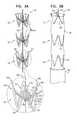
- FIG. 4is a schematic illustration of medical apparatus 100 in a partially radially-expanded state, in accordance with an application of the present invention.
- medical apparatus 100comprises fabric 116 , as described hereinabove with reference to FIG. 3B , and a plurality of bands 112 .
- Latch member 118has been partially withdrawn.
- latch member 118has been withdrawn from engagement members 114 of the uppermost band 112 in the figure, but is still threaded through and physically latching engagement members 114 of the middle and lowermost bands 112 .
- uppermost band 112has assumed the radially-expanded state, while middle and lowermost bands 112 are still restrained by latch member 118 in the radially-compressed state.
- FIGS. 5A and 5Bare schematic illustrations of medical apparatus 200 , in accordance with respective applications of the present invention.
- Medical apparatus 200is configured for insertion into a mammalian body, such as a human body.
- Medical apparatus 200is similar in some respects to medical apparatus 100 , described hereinabove with reference to FIGS. 3A-4 , and may implement any of the configurations in the applications described hereinabove for medical apparatus 100 .
- Medical apparatuscomprises structural stent elements 210 , at least a portion of which are shaped so as to define (a) one or more generally circumferential bands 212 , such as a plurality of generally circumferential bands 112 , and (b) a plurality of engagement members 214 that are joined to and extend radially inwardly from each of bands 212 .
- structural stent elements 210are shaped so as to define a generally tubular structure.
- medical apparatus 200further comprises an implantable-grade fabric 216 securely attached to and at least partially covering the generally tubular structure (an inner and/or an outer surface of the structure). Fabric 216 may have the properties of fabric 34 , described hereinabove with reference to FIG. 1A .
- Medical apparatus 200further comprises an elongated latch member 218 which is threaded through engagement members 214 , thereby physically latching engagement members 214 .
- elongated latch member 218comprises a wire or a hollow tube.
- Engagement members 214 and each of one or more bands 212are configured such that:
- engagement members 214have (a) respective first ends 230 , which are joined to and extend from one of one or more bands 212 , (b) respective second ends 232 , which are joined to and extend from the band at respective junctions 234 , and (c) respective curved portions 236 between respective first and respective second ends 230 and 232 .
- latch member 218is threaded through engagement members 214 , curved portions 236 pass around latch member 218 .
- latch member 218holds the curved portions near a central longitudinal axis of band 212 .
- the engagement membersthus prevent the band from expanding radially.
- each of the one or more bands 218has distal and proximal ends 240 and 242 .
- a first subset 244 of engagement members 214are shaped such that curved portions 236 thereof are disposed more distally than junctions 234 thereof, and a second subset 246 of engagement members 214 are shaped such that curved portions 236 thereof are disposed more proximally than junctions 234 thereof.
- the curved portions of first subset 244generally extend in the opposite direction as the curved portions of second subset 246 .
- First and second subsets 244 and 246do not include any common engagement members 214 , i.e., are non-overlapping sets. This configuration may prevent engagement members 214 from giving band 218 a biased shape.
- structural stent elements 210comprise a shape memory alloy, such as described regarding structural stent elements 110 hereinabove with reference to FIGS. 3A-4 .
- FIG. 5Bshows medical apparatus 200 in a partially radially-expanded state.
- Latch member 218has been partially withdrawn.
- latch member 218has been withdrawn from engagement members 214 of the uppermost band 212 in the figure, but is still threaded through and physically latching engagement members 214 of the middle and lowermost bands 212 .
- uppermost band 212has assumed the radially-expanded state, while middle and lowermost bands 212 are still restrained by latch member 218 in the radially-compressed state.
- Implantable medical devicesinclude stents, coil stents and filters, catheters, cannulas, intrauterine contraceptive devices (IUDs), bone plates, marrow nails, dental arch wires, filters, bone staples, heart valves, and clips.
- IUDsintrauterine contraceptive devices
Landscapes
- Health & Medical Sciences (AREA)
- Engineering & Computer Science (AREA)
- Biomedical Technology (AREA)
- Cardiology (AREA)
- Oral & Maxillofacial Surgery (AREA)
- Transplantation (AREA)
- Heart & Thoracic Surgery (AREA)
- Vascular Medicine (AREA)
- Life Sciences & Earth Sciences (AREA)
- Animal Behavior & Ethology (AREA)
- General Health & Medical Sciences (AREA)
- Public Health (AREA)
- Veterinary Medicine (AREA)
- Media Introduction/Drainage Providing Device (AREA)
- Prostheses (AREA)
Abstract
Description
- at least one generally circumferential band, and
- a plurality of engagement members that are joined to and extend radially inwardly from the band; and
- when the latch member is threaded through and thus physically latches the engagement members, the engagement members retain the band in a radially-compressed state, and
- when the latch member is removed from the engagement members, the band assumes a radially-expanded state.
- a first rotational state, in which the restraining member restrains the at least a portion of the stent body in the radially-compressed state, and
- a second rotational state, in which the restraining member releases the at least a portion of the stent body, thereby allowing the at least a portion of the stent body to transition to the radially-expanded state.
- a first rotational state, in which restraining
member 30 restrains the at least a portion ofstent body 20 in the radially-compressed state, and - a second rotational state, in which restraining
member 30 releases the at least a portion ofstent body 20, thereby allowing the at least a portion ofstent body 20 to transition to the radially-expanded state.
- a first rotational state, in which restraining
- when restraining
member 30 is in the first rotational state,arcuate sections 34 are rotationally disposed with respect to each other around a centrallongitudinal axis 40 of restrainingmember 30 so as to restrain the at least a portion ofstent body 20 in the radially-compressed state, such as shown inFIG. 1A ; and - when restraining
member 30 is in the second rotational state,arcuate sections 34 are rotationally disposed with respect to each other aroundaxis 40 so as to not restrainstent body 20 within restrainingmember 30, thereby releasingstent body 20 from restrainingmember 30 and allowing the at least a portion ofstent body 20 to transition to the radially-expanded state, such as shown inFIG. 2C , described hereinbelow.
- when restraining
- when
latch member 118 is threaded through and thus physically latchesengagement members 114,engagement members 114 retain the band in a radially-compressed state, as shown inFIGS. 3A and 3B ; and - when
latch member 118 is removed fromengagement members 114, the band assumes a radially-expanded state, as described hereinbelow with reference toFIG. 4 .
- when
- when
latch member 118 physically latchesengagement members 114 and the shape memory alloy is at a temperature greater than an austenite start temperature of the shape memory alloy, the latch member retains the shape memory alloy of the one or more bands so that at least a portion of the alloy is in at least a partially stress-induced martensitic state and the one or more bands are in the deformed shape, and - when
latch member 118 is removed from the plurality ofengagement members 114 and the shape memory alloy is at a temperature greater than the austenite start temperature, at least a portion of the shape memory alloy at least partially transitions to an austenitic state from the stress-induced martensitic state, thereby causing a transformation of the one or more bands from the deformed shape to the unstressed shape.
- when
- when
latch member 218 is threaded through and thus physically latchesengagement members 214,engagement members 214 retain the band in a radially-compressed state, as shown inFIG. 5A , and for the lower twobands 218 shown inFIG. 5B ; and - when
latch member 218 is removed fromengagement members 214, the band assumes a radially-expanded state, as shown in theuppermost band 218 shown inFIG. 5B .
- when
- PCT Application PCT/IL2008/000287, filed Mar. 5, 2008, which published as PCT Publication WO 2008/107885 to Shalev et al., and U.S. application Ser. No. 12/529,936 in the national stage thereof, which published as US Patent Application Publication 2010/0063575 to Shalev et al.
- U.S. Provisional Application 60/892,885, filed Mar. 5, 2007
- U.S. Provisional Application 60/991,726, filed Dec. 2, 2007
- PCT Application PCT/IL2008/001621, filed Dec. 15, 2008, which published as PCT Publication WO 2009/078010
- U.S. Provisional Application 61/219,758, filed Jun. 23, 2009
- U.S. Provisional Application 61/221,074, filed Jun. 28, 2009
- PCT Application PCT/IB2010/052861, filed Jun. 23, 2010, which published as PCT Publication WO 2010/150208
- PCT Application PCT/IL2010/000549, filed Jul. 8, 2010, which published as PCT Publication WO 2011/004374
- PCT Application PCT/IL2010/000564, filed Jul. 14, 2010, which published as PCT Publication WO 2011/007354
- PCT Application PCT/IL2010/000917, filed Nov. 4, 2010, which published as PCT Publication WO 2011/055364
- PCT Application PCT/IL2010/000999, filed Nov. 30, 2010, which published as PCT Publication WO 2011/064782
- PCT Application PCT/IL2010/001018, filed Dec. 2, 2010, which published as PCT Publication WO 2011/067764
- PCT Application PCT/IL2010/001037, filed Dec. 8, 2010, which published as PCT Publication WO 2011/070576
- PCT Application PCT/IL2011/000135, filed Feb. 8, 2011, which published as PCT Publication WO 2011/095979
- U.S. application Ser. No. 13/031,871, filed Feb. 22, 2011, which published as US Patent Application Publication 2011/0208289
Claims (5)
Priority Applications (1)
| Application Number | Priority Date | Filing Date | Title |
|---|---|---|---|
| US13/807,880US9526638B2 (en) | 2011-02-03 | 2012-02-02 | Implantable medical devices constructed of shape memory material |
Applications Claiming Priority (3)
| Application Number | Priority Date | Filing Date | Title |
|---|---|---|---|
| US201161438977P | 2011-02-03 | 2011-02-03 | |
| PCT/IL2012/000060WO2012104842A2 (en) | 2011-02-03 | 2012-02-02 | Implantable medical devices constructed of shape memory material |
| US13/807,880US9526638B2 (en) | 2011-02-03 | 2012-02-02 | Implantable medical devices constructed of shape memory material |
Publications (2)
| Publication Number | Publication Date |
|---|---|
| US20130131783A1 US20130131783A1 (en) | 2013-05-23 |
| US9526638B2true US9526638B2 (en) | 2016-12-27 |
Family
ID=46603167
Family Applications (1)
| Application Number | Title | Priority Date | Filing Date |
|---|---|---|---|
| US13/807,880Expired - Fee RelatedUS9526638B2 (en) | 2011-02-03 | 2012-02-02 | Implantable medical devices constructed of shape memory material |
Country Status (4)
| Country | Link |
|---|---|
| US (1) | US9526638B2 (en) |
| EP (1) | EP2579810A4 (en) |
| CA (1) | CA2826022A1 (en) |
| WO (1) | WO2012104842A2 (en) |
Cited By (2)
| Publication number | Priority date | Publication date | Assignee | Title |
|---|---|---|---|---|
| US10603197B2 (en) | 2013-11-19 | 2020-03-31 | Endospan Ltd. | Stent system with radial-expansion locking |
| US11406540B2 (en)* | 2018-09-05 | 2022-08-09 | Acclarent, Inc. | Linked assembly with isthmus anchor for treating patulous eustachian tube |
Families Citing this family (26)
| Publication number | Priority date | Publication date | Assignee | Title |
|---|---|---|---|---|
| CA3009244C (en) | 2009-06-23 | 2020-04-28 | Endospan Ltd. | Vascular prostheses for treating aneurysms |
| US9468517B2 (en) | 2010-02-08 | 2016-10-18 | Endospan Ltd. | Thermal energy application for prevention and management of endoleaks in stent-grafts |
| CA2826022A1 (en) | 2011-02-03 | 2012-08-09 | Endospan Ltd. | Implantable medical devices constructed of shape memory material |
| WO2012111006A1 (en) | 2011-02-17 | 2012-08-23 | Endospan Ltd. | Vascular bands and delivery systems therefor |
| WO2012117395A1 (en) | 2011-03-02 | 2012-09-07 | Endospan Ltd. | Reduced-strain extra- vascular ring for treating aortic aneurysm |
| US8574287B2 (en) | 2011-06-14 | 2013-11-05 | Endospan Ltd. | Stents incorporating a plurality of strain-distribution locations |
| US8951298B2 (en) | 2011-06-21 | 2015-02-10 | Endospan Ltd. | Endovascular system with circumferentially-overlapping stent-grafts |
| US9254209B2 (en) | 2011-07-07 | 2016-02-09 | Endospan Ltd. | Stent fixation with reduced plastic deformation |
| US9839510B2 (en) | 2011-08-28 | 2017-12-12 | Endospan Ltd. | Stent-grafts with post-deployment variable radial displacement |
| US9427339B2 (en) | 2011-10-30 | 2016-08-30 | Endospan Ltd. | Triple-collar stent-graft |
| US9597204B2 (en) | 2011-12-04 | 2017-03-21 | Endospan Ltd. | Branched stent-graft system |
| WO2013171730A1 (en) | 2012-05-15 | 2013-11-21 | Endospan Ltd. | Stent-graft with fixation elements that are radially confined for delivery |
| US9993360B2 (en) | 2013-01-08 | 2018-06-12 | Endospan Ltd. | Minimization of stent-graft migration during implantation |
| US9668892B2 (en) | 2013-03-11 | 2017-06-06 | Endospan Ltd. | Multi-component stent-graft system for aortic dissections |
| CN106029005B (en) | 2014-12-18 | 2018-01-19 | 恩都思潘有限公司 | The Endovascular stent-graft of horizontal conduit with tired resistance |
| WO2016113731A1 (en) | 2015-01-12 | 2016-07-21 | Endospan Ltd. | Self-curving stent-graft |
| WO2016125137A1 (en) | 2015-02-02 | 2016-08-11 | Endospan Ltd. | Self-orienting endovascular delivery system |
| WO2017081679A1 (en) | 2015-11-12 | 2017-05-18 | Endospan Ltd. | Stent-grafts systems with skirt |
| JP2020512914A (en) | 2017-03-21 | 2020-04-30 | エンドスパン リミテッド | Stent graft for sealing around external disturbances |
| US10641427B2 (en) | 2018-04-03 | 2020-05-05 | Mueller International, Llc | Stents and methods for repairing pipes |
| EP4509097A3 (en)* | 2019-02-19 | 2025-08-20 | Mueller International, LLC | Stent springs and stents for repairing pipes |
| US11187366B2 (en) | 2019-03-15 | 2021-11-30 | Mueller International, Llc | Stent for repairing a pipe |
| US11079058B2 (en) | 2019-03-15 | 2021-08-03 | Mueller International , LLC | Stent with coiled spring |
| US11326731B2 (en) | 2019-04-24 | 2022-05-10 | Mueller International, Llc | Pipe repair assembly |
| US11391405B2 (en) | 2019-08-09 | 2022-07-19 | Mueller International, Llc | Deployment probe for pipe repair device |
| US11802646B2 (en) | 2019-08-09 | 2023-10-31 | Mueller International, Llc | Pipe repair device |
Citations (409)
| Publication number | Priority date | Publication date | Assignee | Title |
|---|---|---|---|---|
| US4355426A (en) | 1975-05-09 | 1982-10-26 | Macgregor David C | Porous flexible vascular graft |
| US4505767A (en) | 1983-10-14 | 1985-03-19 | Raychem Corporation | Nickel/titanium/vanadium shape memory alloy |
| US4562596A (en) | 1984-04-25 | 1986-01-07 | Elliot Kornberg | Aortic graft, device and method for performing an intraluminal abdominal aortic aneurysm repair |
| US4577631A (en) | 1984-11-16 | 1986-03-25 | Kreamer Jeffry W | Aneurysm repair apparatus and method |
| US4617932A (en) | 1984-04-25 | 1986-10-21 | Elliot Kornberg | Device and method for performing an intraluminal abdominal aortic aneurysm repair |
| US4665906A (en) | 1983-10-14 | 1987-05-19 | Raychem Corporation | Medical devices incorporating sim alloy elements |
| US4739762A (en) | 1985-11-07 | 1988-04-26 | Expandable Grafts Partnership | Expandable intraluminal graft, and method and apparatus for implanting an expandable intraluminal graft |
| US4787899A (en) | 1983-12-09 | 1988-11-29 | Lazarus Harrison M | Intraluminal graft device, system and method |
| US4878906A (en) | 1986-03-25 | 1989-11-07 | Servetus Partnership | Endoprosthesis for repairing a damaged vessel |
| US4886062A (en) | 1987-10-19 | 1989-12-12 | Medtronic, Inc. | Intravascular radially expandable stent and method of implant |
| US4938740A (en) | 1988-05-25 | 1990-07-03 | Trustees Of The University Of Pennsylvania | Reducing stress at vascular graft anastomoses |
| US4969458A (en) | 1987-07-06 | 1990-11-13 | Medtronic, Inc. | Intracoronary stent and method of simultaneous angioplasty and stent implant |
| US5042707A (en) | 1990-10-16 | 1991-08-27 | Taheri Syde A | Intravascular stapler, and method of operating same |
| US5064435A (en) | 1990-06-28 | 1991-11-12 | Schneider (Usa) Inc. | Self-expanding prosthesis having stable axial length |
| US5104404A (en) | 1989-10-02 | 1992-04-14 | Medtronic, Inc. | Articulated stent |
| US5122136A (en) | 1990-03-13 | 1992-06-16 | The Regents Of The University Of California | Endovascular electrolytically detachable guidewire tip for the electroformation of thrombus in arteries, veins, aneurysms, vascular malformations and arteriovenous fistulas |
| US5133732A (en) | 1987-10-19 | 1992-07-28 | Medtronic, Inc. | Intravascular stent |
| US5192286A (en) | 1991-07-26 | 1993-03-09 | Regents Of The University Of California | Method and device for retrieving materials from body lumens |
| US5234448A (en) | 1992-02-28 | 1993-08-10 | Shadyside Hospital | Method and apparatus for connecting and closing severed blood vessels |
| US5425739A (en) | 1989-03-09 | 1995-06-20 | Avatar Design And Development, Inc. | Anastomosis stent and stent selection system |
| US5439446A (en) | 1994-06-30 | 1995-08-08 | Boston Scientific Corporation | Stent and therapeutic delivery system |
| US5456694A (en)* | 1994-05-13 | 1995-10-10 | Stentco, Inc. | Device for delivering and deploying intraluminal devices |
| US5486183A (en) | 1990-10-09 | 1996-01-23 | Raychem Corporation | Device or apparatus for manipulating matter |
| US5507769A (en) | 1994-10-18 | 1996-04-16 | Stentco, Inc. | Method and apparatus for forming an endoluminal bifurcated graft |
| US5509923A (en) | 1989-08-16 | 1996-04-23 | Raychem Corporation | Device for dissecting, grasping, or cutting an object |
| US5522880A (en) | 1990-06-11 | 1996-06-04 | Barone; Hector D. | Method for repairing an abdominal aortic aneurysm |
| US5527322A (en) | 1993-11-08 | 1996-06-18 | Perclose, Inc. | Device and method for suturing of internal puncture sites |
| US5549662A (en) | 1994-11-07 | 1996-08-27 | Scimed Life Systems, Inc. | Expandable stent using sliding members |
| US5554181A (en) | 1994-05-04 | 1996-09-10 | Regents Of The University Of Minnesota | Stent |
| US5556413A (en) | 1994-03-11 | 1996-09-17 | Advanced Cardiovascular Systems, Inc. | Coiled stent with locking ends |
| US5562724A (en) | 1993-12-15 | 1996-10-08 | William Cook Europe A/S | Endovascular graft prosthesis and an implantation method for such a prosthesis |
| US5575818A (en) | 1995-02-14 | 1996-11-19 | Corvita Corporation | Endovascular stent with locking ring |
| WO1996039104A1 (en) | 1995-06-06 | 1996-12-12 | Endotex Interventional Systems, Inc. | Prosthetic graft and method for aneurysm repair |
| US5607445A (en) | 1992-06-18 | 1997-03-04 | American Biomed, Inc. | Stent for supporting a blood vessel |
| US5613974A (en) | 1992-12-10 | 1997-03-25 | Perclose, Inc. | Apparatus and method for vascular closure |
| US5632746A (en) | 1989-08-16 | 1997-05-27 | Medtronic, Inc. | Device or apparatus for manipulating matter |
| US5632763A (en) | 1995-01-19 | 1997-05-27 | Cordis Corporation | Bifurcated stent and method for implanting same |
| US5632772A (en) | 1993-10-21 | 1997-05-27 | Corvita Corporation | Expandable supportive branched endoluminal grafts |
| US5639278A (en) | 1993-10-21 | 1997-06-17 | Corvita Corporation | Expandable supportive bifurcated endoluminal grafts |
| US5643340A (en) | 1994-10-27 | 1997-07-01 | Nunokawa; Mioko | Synthetic vascular prosthesis |
| US5653743A (en) | 1994-09-09 | 1997-08-05 | Martin; Eric C. | Hypogastric artery bifurcation graft and method of implantation |
| US5676696A (en) | 1995-02-24 | 1997-10-14 | Intervascular, Inc. | Modular bifurcated intraluminal grafts and methods for delivering and assembling same |
| US5676697A (en) | 1996-07-29 | 1997-10-14 | Cardiovascular Dynamics, Inc. | Two-piece, bifurcated intraluminal graft for repair of aneurysm |
| US5693084A (en) | 1991-10-25 | 1997-12-02 | Cook Incorporated | Expandable transluminal graft prosthesis for repair of aneurysm |
| US5728134A (en) | 1996-09-17 | 1998-03-17 | Barak; Shlomo | Method and apparatus for hemostasis |
| US5749879A (en) | 1989-08-16 | 1998-05-12 | Medtronic, Inc. | Device or apparatus for manipulating matter |
| US5755770A (en) | 1995-01-31 | 1998-05-26 | Boston Scientific Corporatiion | Endovascular aortic graft |
| US5755771A (en) | 1994-11-03 | 1998-05-26 | Divysio Solutions Ulc | Expandable stent and method of delivery of same |
| US5755777A (en) | 1991-10-25 | 1998-05-26 | Cook Incorporated | Expandable transluminal graft prosthesis for repair of aneurysm |
| US5755774A (en) | 1994-06-27 | 1998-05-26 | Corvita Corporation | Bistable luminal graft endoprosthesis |
| US5755781A (en) | 1996-08-06 | 1998-05-26 | Iowa-India Investments Company Limited | Embodiments of multiple interconnected stents |
| US5769884A (en) | 1996-06-27 | 1998-06-23 | Cordis Corporation | Controlled porosity endovascular implant |
| US5769882A (en) | 1995-09-08 | 1998-06-23 | Medtronic, Inc. | Methods and apparatus for conformably sealing prostheses within body lumens |
| US5782906A (en) | 1994-08-25 | 1998-07-21 | Ethicon, Inc. | Combination arterial stent |
| US5782903A (en) | 1987-10-19 | 1998-07-21 | Medtronic, Inc. | Intravascular stent and method |
| US5792172A (en) | 1996-12-23 | 1998-08-11 | Isostent, Inc. | Multifold balloon for stent deployment |
| US5824040A (en) | 1995-12-01 | 1998-10-20 | Medtronic, Inc. | Endoluminal prostheses and therapies for highly variable body lumens |
| US5827321A (en) | 1997-02-07 | 1998-10-27 | Cornerstone Devices, Inc. | Non-Foreshortening intraluminal prosthesis |
| US5843170A (en) | 1994-09-02 | 1998-12-01 | Ahn; Sam Seunghae | Apparatus and method for performing aneurysm repair |
| US5855600A (en) | 1997-08-01 | 1999-01-05 | Inflow Dynamics Inc. | Flexible implantable stent with composite design |
| US5876432A (en) | 1994-04-01 | 1999-03-02 | Gore Enterprise Holdings, Inc. | Self-expandable helical intravascular stent and stent-graft |
| US5906641A (en) | 1997-05-27 | 1999-05-25 | Schneider (Usa) Inc | Bifurcated stent graft |
| WO1999025273A1 (en) | 1997-11-14 | 1999-05-27 | Transvascular, Inc. | Devices for forming and/or maintaining connections between adjacent anatomical conduits |
| US5921994A (en) | 1995-06-15 | 1999-07-13 | Perclose, Inc. | Low profile intraluminal suturing device and method |
| US5925076A (en) | 1995-05-19 | 1999-07-20 | Inoue; Kanji | Appliance to be implanted, method of collapsing the appliance to be implanted and method of using the appliance to be implanted |
| US5944750A (en) | 1997-06-30 | 1999-08-31 | Eva Corporation | Method and apparatus for the surgical repair of aneurysms |
| WO1999051165A1 (en) | 1998-04-02 | 1999-10-14 | Salviac Limited | An implant comprising a support structure and a transition material made of porous plastics material |
| US5976178A (en) | 1996-11-07 | 1999-11-02 | Vascular Science Inc. | Medical grafting methods |
| US5980552A (en) | 1994-03-17 | 1999-11-09 | Medinol Ltd. | Articulated stent |
| US6015431A (en) | 1996-12-23 | 2000-01-18 | Prograft Medical, Inc. | Endolumenal stent-graft with leak-resistant seal |
| US6030414A (en) | 1997-11-13 | 2000-02-29 | Taheri; Syde A. | Variable stent and method for treatment of arterial disease |
| US6033435A (en) | 1997-11-03 | 2000-03-07 | Divysio Solutions Ulc | Bifurcated stent and method for the manufacture and delivery of same |
| US6036725A (en) | 1998-06-10 | 2000-03-14 | General Science And Technology | Expandable endovascular support device |
| US6059824A (en) | 1998-12-23 | 2000-05-09 | Taheri; Syde A. | Mated main and collateral stent and method for treatment of arterial disease |
| US6077298A (en) | 1999-02-20 | 2000-06-20 | Tu; Lily Chen | Expandable/retractable stent and methods thereof |
| US6099497A (en) | 1998-03-05 | 2000-08-08 | Scimed Life Systems, Inc. | Dilatation and stent delivery system for bifurcation lesions |
| US6117145A (en) | 1994-06-01 | 2000-09-12 | Perclose, Inc. | Method and device for providing hemostasis at vascular penetration sites |
| JP2000279533A (en) | 1999-03-31 | 2000-10-10 | Terumo Corp | Stent for blood vessel knob shaping blood vessel and apparatus for treating blood vessel knob shaping blood vessel |
| US6156064A (en) | 1998-08-14 | 2000-12-05 | Schneider (Usa) Inc | Stent-graft-membrane and method of making the same |
| US6168615B1 (en) | 1998-05-04 | 2001-01-02 | Micrus Corporation | Method and apparatus for occlusion and reinforcement of aneurysms |
| US6200339B1 (en) | 1999-02-23 | 2001-03-13 | Datascope Investment Corp. | Endovascular split-tube bifurcated graft prosthesis and an implantation method for such a prosthesis |
| US20010000188A1 (en) | 1996-01-05 | 2001-04-05 | Lenker Jay A. | Limited expansion endoluminal prostheses and methods for their use |
| US20010004705A1 (en) | 1998-03-04 | 2001-06-21 | Killion Douglas P. | Stent having variable properties and method of its use |
| US20010010006A1 (en) | 1997-04-23 | 2001-07-26 | St. Jude Medical Cardiovascular Goup Inc. | Medical grafting connectors and fasteners |
| US6270524B1 (en) | 1996-11-12 | 2001-08-07 | Medtronic, Inc. | Flexible, radially expansible luminal prostheses |
| US20010014823A1 (en) | 1998-03-16 | 2001-08-16 | Teramed, Inc. | Bifurcated prosthetic graft |
| US6290720B1 (en) | 1998-11-16 | 2001-09-18 | Endotex Interventional Systems, Inc. | Stretchable anti-buckling coiled-sheet stent |
| US20010034550A1 (en) | 1994-04-29 | 2001-10-25 | Jonathan Grad | Stent with collagen |
| US6312458B1 (en) | 2000-01-19 | 2001-11-06 | Scimed Life Systems, Inc. | Tubular structure/stent/stent securement member |
| US6319287B1 (en) | 1999-04-09 | 2001-11-20 | B. Braun Melsungen Ag | Stent assembly |
| US20010044652A1 (en) | 1999-10-14 | 2001-11-22 | Moore Brian Edward | Stents with multi-layered struts |
| US20010044651A1 (en) | 1998-02-17 | 2001-11-22 | Steinke Thomas A. | Expandable stent with sliding and locking radial elements |
| US20010047198A1 (en) | 1999-04-26 | 2001-11-29 | Drasler William J. | Intravascular folded tubular endoprosthesis |
| US6325823B1 (en) | 1999-10-29 | 2001-12-04 | Revasc Corporation | Endovascular prosthesis accommodating torsional and longitudinal displacements and methods of use |
| US20010049550A1 (en) | 1995-12-14 | 2001-12-06 | Gerald Ray Martin | Method of making a kink resistant stent-graft |
| US20010053930A1 (en) | 1999-12-03 | 2001-12-20 | Teramed, Inc. | Endovascular graft system |
| US6344056B1 (en) | 1999-12-29 | 2002-02-05 | Edwards Lifesciences Corp. | Vascular grafts for bridging a vessel side branch |
| EP1177780A2 (en) | 2000-08-02 | 2002-02-06 | Hector Daniel Barone | Multi-component endoluminal graft assembly, use thereof and method of implanting |
| US20020040236A1 (en) | 1994-09-08 | 2002-04-04 | Gore Enterprise Holdings, Inc. | Procedures for introducing stents and stent-grafts |
| US20020099441A1 (en) | 1999-12-29 | 2002-07-25 | Edwards Lifesciences, Llc | Towel graft means for enhancing tissue ingrowth in vascular grafts |
| US20020099438A1 (en) | 1998-04-15 | 2002-07-25 | Furst Joseph G. | Irradiated stent coating |
| US6428565B1 (en) | 1997-09-11 | 2002-08-06 | Medtronic Ave, Inc. | System and method for edoluminal grafting of bifurcated or branched vessels |
| US20020107564A1 (en) | 1999-04-22 | 2002-08-08 | Cox Daniel L. | Variable strength stent |
| US20020111667A1 (en)* | 2000-11-02 | 2002-08-15 | Scimed Life Systems, Inc. | Non-expanded porous polytetrafluoroethylene (PTFE) products and methods of manufacture |
| US20020123791A1 (en) | 2000-12-28 | 2002-09-05 | Harrison William J. | Stent design with increased vessel coverage |
| JP2002253682A (en) | 2001-02-27 | 2002-09-10 | Inprest Co Ltd | Stent and stent member |
| US6451048B1 (en) | 1997-10-09 | 2002-09-17 | St. Jude Medical Atg, Inc. | Wire connector structures for tubular grafts |
| US20020156495A1 (en) | 1995-09-15 | 2002-10-24 | Rodney Brenneman | Apparatus and method for percutaneous sealing of blood vessel punctures |
| US20020173809A1 (en) | 1999-09-01 | 2002-11-21 | Fleischman Sidney D. | Sutureless anastomosis system deployment concepts |
| US20020183783A1 (en) | 2001-06-04 | 2002-12-05 | Shadduck John H. | Guidewire for capturing emboli in endovascular interventions |
| US20020193864A1 (en) | 1998-03-25 | 2002-12-19 | Endotex Interventional Systems, Inc. | Coiled sheet graft for single and bifurcated lumens and methods of making and use |
| US6506211B1 (en) | 2000-11-13 | 2003-01-14 | Scimed Life Systems, Inc. | Stent designs |
| US6520988B1 (en) | 1997-09-24 | 2003-02-18 | Medtronic Ave, Inc. | Endolumenal prosthesis and method of use in bifurcation regions of body lumens |
| US20030040791A1 (en) | 2001-08-22 | 2003-02-27 | Oktay Hasan Semih | Flexible MEMS actuated controlled expansion stent |
| US20030057156A1 (en) | 2001-03-08 | 2003-03-27 | Dean Peterson | Atrial filter implants |
| US6544279B1 (en) | 2000-08-09 | 2003-04-08 | Incept, Llc | Vascular device for emboli, thrombus and foreign body removal and methods of use |
| US20030074055A1 (en) | 2001-10-17 | 2003-04-17 | Haverkost Patrick A. | Method and system for fixation of endoluminal devices |
| WO2002083038A3 (en) | 2001-04-11 | 2003-04-17 | Trivascular Inc | Delivery system and method for bifurcated graft |
| WO2003034948A1 (en) | 2001-10-26 | 2003-05-01 | Cook Incorporated | Prostheses for curved lumens |
| US20030093145A1 (en) | 2001-10-26 | 2003-05-15 | Cook Incorporated | Endoluminal graft |
| US6565597B1 (en) | 1999-07-16 | 2003-05-20 | Med Institute, Inc. | Stent adapted for tangle-free deployment |
| EP1325716A1 (en) | 2002-01-08 | 2003-07-09 | Cordis Corporation | Thoracic aneurysm repair prosthesis and system |
| US20030130720A1 (en) | 2002-01-08 | 2003-07-10 | Depalma Donald F. | Modular aneurysm repair system |
| US20030144725A1 (en) | 2000-02-14 | 2003-07-31 | Sylvie Lombardi | Stent matrix |
| US20030153968A1 (en) | 2002-02-14 | 2003-08-14 | Geis John S. | Vessel support, delivery system for vessel support and method for preventive treatment of aorta diseases |
| US20030163187A1 (en) | 2002-02-25 | 2003-08-28 | Jan Weber | Non-invasive heating of implanted vascular treatment device |
| US6613075B1 (en) | 1999-10-27 | 2003-09-02 | Cordis Corporation | Rapid exchange self-expanding stent delivery catheter system |
| US20030171771A1 (en) | 2002-03-08 | 2003-09-11 | Anderson Kent D. | Vascular protection devices and methods of use |
| US20030191523A1 (en) | 1997-03-10 | 2003-10-09 | Hikmat Hojeibane | Articulated expandable intraluminal stent |
| US6635083B1 (en) | 2001-06-25 | 2003-10-21 | Advanced Cardiovascular Systems, Inc. | Stent with non-linear links and method of use |
| US20030199968A1 (en) | 2000-05-03 | 2003-10-23 | Ainsworth Stephen D. | Intravascular stent |
| US20030199967A1 (en) | 2002-03-25 | 2003-10-23 | Cook Incorporated | Bifurcated/branch vessel prosthesis |
| US20030208192A1 (en) | 2000-11-24 | 2003-11-06 | Csaba Truckai | Polymer matrix devices for treatment of vascular malformations |
| US20030212449A1 (en) | 2001-12-28 | 2003-11-13 | Cox Daniel L. | Hybrid stent |
| US6648901B2 (en) | 1998-06-10 | 2003-11-18 | Converge Medical, Inc. | Anastomosis systems |
| US6652567B1 (en) | 1999-11-18 | 2003-11-25 | David H. Deaton | Fenestrated endovascular graft |
| US6652571B1 (en) | 2000-01-31 | 2003-11-25 | Scimed Life Systems, Inc. | Braided, branched, implantable device and processes for manufacture thereof |
| US20030233117A1 (en) | 2002-06-14 | 2003-12-18 | Adams Daniel O. | Rapid exchange catheters usable with embolic protection devices |
| US20030236567A1 (en) | 2002-06-25 | 2003-12-25 | Scimed Life Systems, Inc. | Implantable prosthesis with displaceabe skirt |
| US20040015227A1 (en) | 1996-11-04 | 2004-01-22 | Gil Vardi | Extendible stent apparatus |
| US20040015229A1 (en) | 2002-07-22 | 2004-01-22 | Syntheon, Llc | Vascular stent with radiopaque markers |
| US6692520B1 (en) | 1998-12-15 | 2004-02-17 | C. R. Bard, Inc. | Systems and methods for imbedded intramuscular implants |
| US6695833B1 (en) | 2000-09-27 | 2004-02-24 | Nellix, Inc. | Vascular stent-graft apparatus and forming method |
| US6695875B2 (en) | 2000-03-14 | 2004-02-24 | Cook Incorporated | Endovascular stent graft |
| WO2004017868A1 (en) | 2002-08-23 | 2004-03-04 | William A. Cook Australia Pty. Ltd. | Asymmetric stent graft attachment |
| CA2497704A1 (en) | 2002-09-03 | 2004-03-18 | Boston Scientific Limited | Elephant trunk thoracic endograft and delivery system |
| US6730117B1 (en) | 1998-03-05 | 2004-05-04 | Scimed Life Systems, Inc. | Intraluminal stent |
| US20040098091A1 (en) | 2000-11-17 | 2004-05-20 | Raimund Erbel | Endovascular prosthesis |
| US6743195B2 (en) | 2001-03-14 | 2004-06-01 | Cardiodex | Balloon method and apparatus for vascular closure following arterial catheterization |
| US20040106978A1 (en) | 2002-06-28 | 2004-06-03 | Cook Incorporated | Thoracic aortic aneurysm stent graft |
| US20040106972A1 (en) | 2000-11-20 | 2004-06-03 | Deaton David H. | Fenestrated endovascular graft |
| US6748953B2 (en) | 2002-06-11 | 2004-06-15 | Scimed Life Systems, Inc. | Method for thermal treatment of type II endoleaks in arterial aneurysms |
| US20040117003A1 (en) | 2002-05-28 | 2004-06-17 | The Cleveland Clinic Foundation | Minimally invasive treatment system for aortic aneurysms |
| US6752826B2 (en) | 2001-12-14 | 2004-06-22 | Thoratec Corporation | Layered stent-graft and methods of making the same |
| US20040133266A1 (en) | 1997-05-27 | 2004-07-08 | Clerc Claude O. | Stent and stent-graft for treating branched vessels |
| US6776794B1 (en) | 2001-11-28 | 2004-08-17 | Advanced Cardiovascular Systems, Inc. | Stent pattern with mirror image |
| US20040162606A1 (en) | 1995-10-11 | 2004-08-19 | Thompson Paul J. | Braided composite prosthesis |
| US20040171978A1 (en) | 2002-12-16 | 2004-09-02 | Shalaby Shalaby W. | Composite vascular constructs with selectively controlled properties |
| US20040176832A1 (en) | 2002-12-04 | 2004-09-09 | Cook Incorporated | Method and device for treating aortic dissection |
| US20040181149A1 (en) | 2001-02-07 | 2004-09-16 | Ulrich Langlotz | Device and method for intraoperative navigation |
| US6808534B1 (en) | 2000-02-16 | 2004-10-26 | Endovascular Technologies, Inc. | Collapsible jacket guard |
| US20040215327A1 (en) | 2003-04-25 | 2004-10-28 | Medtronic Ave, Inc. | Universal modular stent graft assembly to accommodate flow to collateral branches |
| US20040215320A1 (en) | 2003-04-25 | 2004-10-28 | James Machek | Integral stent graft |
| US6814752B1 (en) | 2000-03-03 | 2004-11-09 | Endovascular Technologies, Inc. | Modular grafting system and method |
| US6814749B2 (en) | 1999-12-30 | 2004-11-09 | Advanced Cardiovascular Systems, Inc. | Stent designs for use in peripheral vessels |
| US6824560B2 (en) | 2001-06-13 | 2004-11-30 | Advanced Cardiovascular Systems, Inc. | Double-butted superelastic nitinol tubing |
| US20050010246A1 (en) | 2000-06-30 | 2005-01-13 | Streeter Richard B. | Intravascular filter with debris entrapment mechanism |
| US6846321B2 (en) | 2000-06-21 | 2005-01-25 | Cardiodex, Ltd. | Mechanical method and apparatus for enhancing hemostatis following arterial catheterization |
| US20050033406A1 (en) | 2003-07-15 | 2005-02-10 | Barnhart William H. | Branch vessel stent and graft |
| WO2005002466A3 (en) | 2003-07-08 | 2005-03-03 | Ventor Technologies Ltd | Implantable prosthetic devices particularly for transarterial delivery in the treatment of aortic stenosis, and methods of implanting such devices |
| US20050049678A1 (en) | 2001-09-04 | 2005-03-03 | Graeme Cocks | Stent |
| US20050065545A1 (en) | 2003-09-23 | 2005-03-24 | Scimed Life Systems, Inc. | External activation of vaso-occlusive implants |
| US20050070995A1 (en) | 2003-04-28 | 2005-03-31 | Zilla Peter Paul | Compliant venous graft |
| US20050085900A1 (en) | 2003-07-31 | 2005-04-21 | Case Brian C. | Prosthetic valve for implantation in a body vessel |
| US20050102018A1 (en) | 2003-11-06 | 2005-05-12 | Carpenter Judith T. | Endovascular prosthesis, system and method |
| US20050102021A1 (en) | 2003-10-10 | 2005-05-12 | Cook Incorporated | Stretchable prosthesis fenestration |
| WO2005041781A1 (en) | 2003-10-30 | 2005-05-12 | Sunshine Heart Company Pty Ltd | Methods and devices for tensioning a wrap around a blood vessel |
| US6907285B2 (en) | 2001-01-16 | 2005-06-14 | Kenergy, Inc. | Implantable defibrillartor with wireless vascular stent electrodes |
| US20050131512A1 (en) | 2003-12-12 | 2005-06-16 | Design & Performance-Cyprus Ltd | Stent delivery catheter |
| US20050131517A1 (en) | 2003-10-10 | 2005-06-16 | William A. Cook Australia Pty. Ltd. | Stent graft fenestration |
| US6908477B2 (en) | 2000-10-13 | 2005-06-21 | Rex Medical, L.P. | Methods of implanting covered stents with side branch |
| US20050143802A1 (en) | 1998-04-30 | 2005-06-30 | Medtronic, Inc. | Implantable system with drug-eluting cells for on-demand local drug delivery |
| US20050149166A1 (en) | 2003-11-08 | 2005-07-07 | Schaeffer Darin G. | Branch vessel prosthesis with anchoring device and method |
| US20050154448A1 (en) | 1999-01-22 | 2005-07-14 | Gore Enterprise Holdings, Inc. | Biliary stent-graft |
| WO2005041783A8 (en) | 2003-10-30 | 2005-07-21 | Sunshine Heart Co Pty Ltd | A wrap |
| WO2005037138A3 (en) | 2003-10-14 | 2005-08-04 | James C Peacock Iii | Aneurysm treatment system and method |
| US6929660B1 (en) | 2000-12-22 | 2005-08-16 | Advanced Cardiovascular Systems, Inc. | Intravascular stent |
| US6942691B1 (en) | 2000-04-27 | 2005-09-13 | Timothy A. M. Chuter | Modular bifurcated graft for endovascular aneurysm repair |
| US20050203606A1 (en) | 2004-03-09 | 2005-09-15 | Vancamp Daniel H. | Stent system for preventing restenosis |
| US20050222669A1 (en) | 2004-03-31 | 2005-10-06 | Purdy James D | Fenestrated intraluminal stent system |
| US20050222649A1 (en) | 2001-09-26 | 2005-10-06 | Leonilda Capuano | Method for treatment of aneurysms |
| US20050222667A1 (en) | 2004-03-31 | 2005-10-06 | Hunt James B | Stent-graft with graft to graft attachment |
| US6953469B2 (en) | 2001-08-30 | 2005-10-11 | Ethicon, Inc, | Device and method for treating intraluminal tissue |
| US20050266042A1 (en) | 2004-05-27 | 2005-12-01 | Medtronic Vascular, Inc. | Methods and apparatus for treatment of aneurysmal tissue |
| US20050283188A1 (en) | 1998-05-29 | 2005-12-22 | By-Pass, Inc. | Vascular closure device |
| US6986774B2 (en) | 1989-08-16 | 2006-01-17 | Medtronic, Inc. | Method of manipulating matter in a mammalian body |
| WO2006007389A1 (en) | 2004-06-16 | 2006-01-19 | Cook Incorprated | Thoracic deployment device and stent graft |
| US20060015170A1 (en) | 2004-07-16 | 2006-01-19 | Jones Ryan A | Contrast coated stent and method of fabrication |
| US20060030911A1 (en) | 2004-08-03 | 2006-02-09 | Medtronic Vascular, Inc. | Stabilization of aortic iliac neck diameter by use of radio frequency |
| WO2006028925A1 (en) | 2004-09-02 | 2006-03-16 | Med Institute, Inc. | Modular prosthesis and method for branch vessels |
| US20060069426A1 (en) | 2004-09-27 | 2006-03-30 | Weinberger Judah Z | Methods and devices for extravascular intervention |
| US20060095104A1 (en) | 1999-02-09 | 2006-05-04 | Michael Magers | System and method for patient temperature control employing temperature projection algorithm |
| US20060100684A1 (en) | 2003-02-26 | 2006-05-11 | Elliott Christopher J | Endoluminal device having enhanced affixation characteristics |
| US20060106406A1 (en) | 2004-09-27 | 2006-05-18 | Judah Weinberger | Methods and devices for extravascular intervention |
| US20060149360A1 (en) | 2003-07-08 | 2006-07-06 | Ventor Technologies Ltd. | Fluid flow prosthetic device |
| US20060155366A1 (en) | 2005-01-10 | 2006-07-13 | Laduca Robert | Apparatus and method for deploying an implantable device within the body |
| US20060155358A1 (en) | 2005-01-10 | 2006-07-13 | Laduca Robert | Methods for placing a stent in a branched vessel |
| US20060167476A1 (en) | 2000-11-06 | 2006-07-27 | Perclose, Inc | Systems, devices and methods for suturing patient tissue |
| US20060173530A1 (en) | 2005-01-28 | 2006-08-03 | Das Gladwin S | Flexible cells for interconnecting stent components |
| US20060190070A1 (en)* | 2005-02-23 | 2006-08-24 | Dieck Martin S | Rail stent and methods of use |
| WO2006088905A1 (en) | 2005-02-17 | 2006-08-24 | Khoury Michael D | Vascular endograft |
| US20060193892A1 (en) | 2001-10-26 | 2006-08-31 | Icon Medical Corp. | Polymer biodegradable medical device |
| US7105020B2 (en) | 2003-01-14 | 2006-09-12 | The Cleveland Clinic Foundation | Branched vessel endoluminal device |
| US20060212113A1 (en) | 2005-02-24 | 2006-09-21 | Shaolian Samuel M | Externally adjustable endovascular graft implant |
| US7112217B1 (en) | 1998-03-16 | 2006-09-26 | Cordis Corporation | Biluminal endovascular graft system |
| US7115127B2 (en) | 2003-02-04 | 2006-10-03 | Cardiodex, Ltd. | Methods and apparatus for hemostasis following arterial catheterization |
| US20060229709A1 (en) | 2005-03-30 | 2006-10-12 | Morris Liam G | Vascular graft |
| US20070016281A1 (en)* | 2005-07-13 | 2007-01-18 | Cook Incorporated | Introducer for self-expandable medical device |
| US20070021822A1 (en) | 2005-07-25 | 2007-01-25 | Cook Incorporated | Fenestrated endoluminal stent system |
| US20070027526A1 (en) | 2005-07-27 | 2007-02-01 | Cook Critical Care Incorporated | Stent/graft device and method for open surgical placement |
| WO2006130755A3 (en) | 2005-06-01 | 2007-02-15 | Cook William A Australia | Side branch stent graft |
| US20070043425A1 (en) | 2005-08-18 | 2007-02-22 | William A. Cook Australia Pty Ltd. | Assembly of stent grafts |
| US20070050011A1 (en) | 2005-08-26 | 2007-03-01 | Medlogics Device Corporation | Lumen-supporting stents and methods for creating lumen-supporting stents with various open/closed designs |
| US20070055358A1 (en) | 2005-08-22 | 2007-03-08 | Krolik Jeffrey A | Axially compressible flared stents and apparatus and methods for delivering them |
| US20070055326A1 (en)* | 2005-07-21 | 2007-03-08 | Farley Brian E | Method of treating a hollow anatomical structure with a thermal catheter |
| US20070055350A1 (en) | 2005-09-02 | 2007-03-08 | Medtronic Vascular, Inc. | Modular branch vessel stent-graft assembly |
| US20070060989A1 (en) | 2005-09-07 | 2007-03-15 | Deem Mark E | Apparatus and method for disrupting subcutaneous structures |
| US20070061002A1 (en) | 2005-09-01 | 2007-03-15 | Cook Incorporated | Attachment of material to an implantable frame by cross-linking |
| US20070073373A1 (en) | 2005-09-28 | 2007-03-29 | Craig Bonsignore | Intraluminal medical device with nested interlocking segments |
| US7198638B2 (en) | 2001-07-03 | 2007-04-03 | Scimed Life System, Inc. | Low profile, high stretch, low dilation knit prosthetic device |
| US20070088425A1 (en) | 2005-10-13 | 2007-04-19 | Cook Incorporated | Endoluminal prosthesis |
| US20070112344A1 (en) | 1997-10-14 | 2007-05-17 | Cardiometrix, Inc. | Endoluminal implant with therapeutic and diagnostic capability |
| US7223266B2 (en) | 2003-02-04 | 2007-05-29 | Cardiodex Ltd. | Methods and apparatus for hemostasis following arterial catheterization |
| US20070150051A1 (en) | 2005-01-10 | 2007-06-28 | Duke Fiduciary, Llc | Vascular implants and methods of fabricating the same |
| US20070156167A1 (en) | 2000-04-14 | 2007-07-05 | Connors Kevin G | Pressure attenuation device |
| US20070168018A1 (en) | 2006-01-13 | 2007-07-19 | Aga Medical Corporation | Intravascular deliverable stent for reinforcement of abdominal aortic aneurysm |
| US20070167955A1 (en) | 2005-01-10 | 2007-07-19 | Duke Fiduciary, Llc | Apparatus and method for deploying an implantable device within the body |
| WO2007084547A1 (en) | 2006-01-18 | 2007-07-26 | William A. Cook Australia Pty. Ltd. | Endoluminal delivery device |
| US20070179598A1 (en) | 2006-02-01 | 2007-08-02 | Duerig Thomas W | Method and system of attaching vessels to grafts |
| US7261733B1 (en) | 2002-06-07 | 2007-08-28 | Endovascular Technologies, Inc. | Endovascular graft with sensors design and attachment methods |
| US20070208410A1 (en) | 2005-09-02 | 2007-09-06 | Medtronic Vascular, Inc. | Methods and Apparatus for Treatment of Aneurysms Adjacent to Branch Arteries |
| US20070207186A1 (en) | 2006-03-04 | 2007-09-06 | Scanlon John J | Tear and abrasion resistant expanded material and reinforcement |
| US20070213805A1 (en) | 2006-03-09 | 2007-09-13 | Cook Incorporated | Expandable stent grafts and methods of use thereof |
| US20070219610A1 (en) | 2006-03-20 | 2007-09-20 | Israel Henry M | Stent with flap |
| US20070219627A1 (en) | 2006-03-17 | 2007-09-20 | Medtronic Vascular, Inc. | Prosthesis Fixation Apparatus and Methods |
| US20070233229A1 (en) | 2005-09-01 | 2007-10-04 | Medtronic Vascular, Inc. | Methods and Apparatus for Treatment of Thoracic Aortic Aneurysms |
| US7279003B2 (en) | 2003-04-24 | 2007-10-09 | Medtronic Vascular, Inc. | Stent graft tapered spring |
| US20070239256A1 (en) | 2006-03-22 | 2007-10-11 | Jan Weber | Medical devices having electrical circuits with multilayer regions |
| US20070237973A1 (en) | 2006-02-21 | 2007-10-11 | Purdy James D | Graft material, stent graft and method |
| WO2007115017A1 (en) | 2006-03-30 | 2007-10-11 | Medtronic Vascular, Inc. | Prosthesis with guide lumen |
| US20070244542A1 (en) | 2006-04-18 | 2007-10-18 | Medtronic Vascular, Inc. | Stent Graft Having a Flexible, Articulable, and Axially Compressible Branch Graft |
| US20070244543A1 (en) | 2006-04-18 | 2007-10-18 | Medtronic Vascular, Inc. A Delaware Corporation | Stent With Movable Crown |
| US20070244547A1 (en) | 2006-04-18 | 2007-10-18 | Medtronic Vascular, Inc., A Delaware Corporation | Device and Method for Controlling the Positioning of a Stent Graft Fenestration |
| US20070250154A1 (en) | 2006-04-19 | 2007-10-25 | William A. Cook Australia Pty Ltd. | Twin bifurcated stent graft |
| US20070255388A1 (en) | 2004-03-31 | 2007-11-01 | Merlin Md Pte Ltd | Endovascular device with membrane |
| US7294145B2 (en) | 2004-02-26 | 2007-11-13 | Boston Scientific Scimed, Inc. | Stent with differently coated inside and outside surfaces |
| US7306623B2 (en) | 2005-01-13 | 2007-12-11 | Medtronic Vascular, Inc. | Branch vessel graft design and deployment method |
| WO2007144782A2 (en) | 2006-04-28 | 2007-12-21 | Younes Boudjemline | Vascular stents, methods of use and methods of manufacture |
| US20080002871A1 (en) | 2006-05-23 | 2008-01-03 | Konstanze Gunzert-Marx | Procedure for detecting a deviation in a x-ray system from a target position |
| US20080015673A1 (en) | 2006-07-10 | 2008-01-17 | Chuter Timothy A | Conformable end sealing stent |
| WO2008008291A2 (en) | 2006-07-13 | 2008-01-17 | Icon Medical Corp. | Stent |
| US20080033527A1 (en) | 2006-07-07 | 2008-02-07 | Anthony Nunez | Methods and systems for monitoring an endoprosthetic implant |
| WO2008021557A1 (en) | 2006-08-18 | 2008-02-21 | William A. Cook Australia Pty. Ltd. | Stent graft |
| US7341598B2 (en) | 1999-01-13 | 2008-03-11 | Boston Scientific Scimed, Inc. | Stent with protruding branch portion for bifurcated vessels |
| US20080064957A1 (en) | 2006-09-07 | 2008-03-13 | Spence Paul A | Ultrasonic implant, systems and methods related to diverting material in blood flow away from the head |
| WO2008035337A2 (en) | 2006-09-19 | 2008-03-27 | Ventor Technologies, Ltd. | Fixation member for valve |
| US20080086193A1 (en) | 2002-08-19 | 2008-04-10 | Jeffery Thramann | Methods for placement of vascular stents and vascular stents |
| WO2008042266A2 (en) | 2006-09-28 | 2008-04-10 | Cook Incorporated | Thoracic aortic aneurysm repair apparatus and method |
| WO2008047092A1 (en) | 2006-10-16 | 2008-04-24 | Anson Medical Ltd | System and method for positioning a stent graft |
| US20080097578A1 (en) | 2006-10-20 | 2008-04-24 | Medtronic Vascular, Inc. | Extender Cuff for Branch Vessel |
| WO2008047354A2 (en) | 2006-10-16 | 2008-04-24 | Ventor Technologies Ltd. | Transapical delivery system with ventriculo-arterial overflow bypass |
| US20080109066A1 (en) | 2000-12-11 | 2008-05-08 | Quinn Stephen F | Bifurcated side-access intravascular stent graft |
| CN201058061Y (en) | 2007-06-12 | 2008-05-14 | 中国人民解放军第二军医大学 | Branched vascular endografts in the aortic arch |
| US20080114444A1 (en) | 2006-11-09 | 2008-05-15 | Chun Ho Yu | Modular stent graft and delivery system |
| US20080114445A1 (en) | 2006-10-24 | 2008-05-15 | Cook Incorporated | Thoracic arch stent graft and method of delivery |
| WO2008066923A1 (en) | 2006-11-30 | 2008-06-05 | William Cook Europe Aps | Implant release mechanism |
| US20080147173A1 (en) | 2006-12-18 | 2008-06-19 | Medtronic Vascular, Inc. | Prosthesis Deployment Apparatus and Methods |
| US20080167704A1 (en) | 2007-01-05 | 2008-07-10 | Medtronic Vascular, Inc. | Branch Vessel Graft Method and Delivery System |
| US7399313B2 (en) | 2002-06-07 | 2008-07-15 | Brown Peter S | Endovascular graft with separable sensors |
| US20080176271A1 (en) | 2000-05-15 | 2008-07-24 | Silver James H | Sensors for detecting substances indicative of stroke, ischemia, infection or inflammation |
| US7407509B2 (en) | 2003-01-14 | 2008-08-05 | The Cleveland Clinic Foundation | Branched vessel endoluminal device with fenestration |
| US20080195191A1 (en) | 2005-05-24 | 2008-08-14 | Qiyi Luo | Flexible Stent-Graft |
| US20080195190A1 (en) | 2004-07-30 | 2008-08-14 | Angiomed Gmbh & Co. Medizintechnik Kg | Flexible Intravascular Implant |
| US7413573B2 (en) | 2003-10-10 | 2008-08-19 | William A. Cook Australia Pty. Ltd. | Fenestrated stent grafts |
| US20080215134A1 (en) | 2007-03-02 | 2008-09-04 | William Cook Australia Pty. Ltd. | Vascular band |
| WO2008107885A2 (en) | 2007-03-05 | 2008-09-12 | Alon Shalev | Multi-component expandable supportive bifurcated endoluminal grafts and methods for using same |
| US20080249598A1 (en) | 2002-08-16 | 2008-10-09 | John Sherry | Covered stents with degradable barbs |
| US20080262595A1 (en) | 2007-04-19 | 2008-10-23 | Medtronic Vascular, Inc. | Methods and Apparatus for Treatment of Aneurysms Adjacent to Branch Arteries |
| US20080269789A1 (en) | 2007-04-27 | 2008-10-30 | Uri Eli | Implantable device with miniature rotating portion for the treatment of atherosclerosis, especially vulnerable plaques |
| US20080275540A1 (en) | 2005-11-09 | 2008-11-06 | Ning Wen | Artificial Heart Valve Stent and Weaving Method Thereof |
| US20080288044A1 (en) | 2005-10-31 | 2008-11-20 | Osborne Thomas A | Composite Stent Graft |
| WO2008140796A1 (en) | 2007-05-11 | 2008-11-20 | William A. Cook Australia Pty. Ltd. | Stent grafts for the thoracic aorta |
| US20080300665A1 (en) | 2007-06-02 | 2008-12-04 | Biotronik Vi Patent Ag | Medical implant, in particular stent |
| US20080319528A1 (en) | 2007-06-25 | 2008-12-25 | Abbott Laboratories | Modular endoprosthesis with flexible interconnectors between modules |
| US7473272B2 (en) | 2005-08-17 | 2009-01-06 | Medtronic Vascular, Inc. | Recapturable stent with minimum crossing profile |
| US20090012602A1 (en) | 2003-10-10 | 2009-01-08 | Cardiaq Valve Technologies, Inc. | System and method for endoluminal grafting of bifurcated and branched vessels |
| US20090030497A1 (en) | 2007-07-25 | 2009-01-29 | Metcalf Justin M | Retention Wire For Self-Expanding Stent |
| US20090030502A1 (en) | 2007-07-26 | 2009-01-29 | Jichao Sun | Socket For Fenestrated Tubular Prosthesis |
| US20090048663A1 (en) | 2007-08-08 | 2009-02-19 | Greenberg Roy K | Branched stent graft system |
| US20090054967A1 (en) | 2005-01-28 | 2009-02-26 | Das Gladwin S | Flexible Cells for Axially Interconnecting Stent Components |
| US20090062899A1 (en) | 2001-12-21 | 2009-03-05 | Nfocus Neuromedical, Inc. | Composite stent with polymeric covering and bioactive coating |
| US20090069882A1 (en) | 2006-02-17 | 2009-03-12 | Invatec S.R.L. | Endoluminal Prosthesis |
| US20090082841A1 (en) | 2007-09-26 | 2009-03-26 | Boston Scientific Corporation | Apparatus for securing stent barbs |
| US20090099647A1 (en) | 2007-10-12 | 2009-04-16 | Aga Medical Corporation | Multi-component vascular device |
| US20090099649A1 (en) | 2007-10-04 | 2009-04-16 | Chobotov Michael V | Modular vascular graft for low profile percutaneous delivery |
| US20090099650A1 (en) | 2001-11-28 | 2009-04-16 | Lee Bolduc | Devices, systems, and methods for endovascular staple and/or prosthesis delivery and implantation |
| US20090099640A1 (en) | 2006-03-30 | 2009-04-16 | Ning Weng | Axial Pullwire Tension Mechanism for Self-Expanding Stent |
| US20090099648A1 (en) | 2006-11-09 | 2009-04-16 | Chun Ho Yu | Modular stent graft and delivery system |
| US20090105809A1 (en) | 2007-10-19 | 2009-04-23 | Lee Michael J | Implantable and lumen-supporting stents and related methods of manufacture and use |
| US20090112233A1 (en) | 2007-10-30 | 2009-04-30 | Medtronic Vascular, Inc. | Prosthesis Fixation Apparatus and Methods |
| US20090125096A1 (en) | 2007-11-12 | 2009-05-14 | Medtronic Vascular, Inc. | Stent Graft With Pins |
| EP1177779B1 (en) | 2000-07-31 | 2009-05-20 | Mani, Inc. | Stent and method of manufacturing |
| US7537609B2 (en) | 1998-01-14 | 2009-05-26 | Boston Scientific Scimed, Inc. | Extendible stent apparatus |
| US7540881B2 (en) | 2005-12-22 | 2009-06-02 | Boston Scientific Scimed, Inc. | Bifurcation stent pattern |
| US7544160B2 (en) | 2005-02-10 | 2009-06-09 | Yossi Gross | Extracardiac blood flow amplification device |
| US20090149877A1 (en) | 2007-12-06 | 2009-06-11 | Cardiovascular Systems, Inc. | Rotational atherectomy device with pre-curved drive shaft |
| WO2009078010A2 (en) | 2007-12-15 | 2009-06-25 | Aneuwrap Ltd | Extra-vascular wrapping for treating aneurysmatic aorta in conjunction with endovascular stent-graft and methods thereof |
| WO2008053469A3 (en) | 2006-10-29 | 2009-09-03 | Alon Shalev | An extra-vascular wrapping for treating aneurysmatic aorta and methods thereof |
| US20090227997A1 (en) | 2006-01-19 | 2009-09-10 | The Regents Of The University Of Michigan | System and method for photoacoustic imaging and monitoring of laser therapy |
| WO2009116041A2 (en) | 2008-03-18 | 2009-09-24 | Ventor Technologies Ltd. | Valve suturing and implantation procedures |
| US20090240316A1 (en) | 2008-03-20 | 2009-09-24 | Medtronic Vascular, Inc. | Bloused Stent-Graft and Fenestration Method |
| WO2009118733A2 (en) | 2008-03-25 | 2009-10-01 | K.M.B.Y. Ltd. | Drill-aiming method and apparatus |
| US20090248134A1 (en) | 2007-12-26 | 2009-10-01 | Med Institute, Inc. | Stent with polished eyelet |
| US20090254170A1 (en) | 2003-04-03 | 2009-10-08 | William A. Cook Australia Pty. Ltd. | Branch stent graft deployment and method |
| US20090259290A1 (en) | 2008-04-14 | 2009-10-15 | Medtronic Vascular, Inc. | Fenestration Segment Stent-Graft and Fenestration Method |
| US7616997B2 (en) | 2000-09-27 | 2009-11-10 | Kieval Robert S | Devices and methods for cardiovascular reflex control via coupled electrodes |
| US20090287145A1 (en) | 2008-05-15 | 2009-11-19 | Altura Interventional, Inc. | Devices and methods for treatment of abdominal aortic aneurysms |
| US7637939B2 (en) | 2005-06-30 | 2009-12-29 | Boston Scientific Scimed, Inc. | Hybrid stent |
| US20100004728A1 (en) | 2008-02-13 | 2010-01-07 | Nellix, Inc. | Graft endoframe having axially variable characteristics |
| US20100029608A1 (en) | 2004-08-23 | 2010-02-04 | Don Richard Finley | Histamine H3 Receptor Agents, Preparation and Therapeutic Uses |
| US7662168B2 (en) | 1999-09-13 | 2010-02-16 | Rex Medical, L.P. | Vascular closure |
| US7662161B2 (en) | 1999-09-13 | 2010-02-16 | Rex Medical, L.P | Vascular hole closure device |
| WO2010024879A1 (en) | 2008-08-26 | 2010-03-04 | William A. Cook Australia Pty. Ltd. | Thoracic aorta stent graft with access region |
| WO2010024869A1 (en) | 2008-08-26 | 2010-03-04 | William A. Cook Australia Pty. Ltd. | Thoracic introducer |
| WO2009116042A3 (en) | 2008-03-18 | 2010-03-11 | Ventor Technologies Ltd. | Medical suturing device and method of use thereof |
| WO2010031060A1 (en) | 2008-09-15 | 2010-03-18 | Medtronic Ventor Technologies Ltd. | Prosthetic heart valve having identifiers for aiding in radiographic positioning |
| US20100082091A1 (en) | 2004-05-25 | 2010-04-01 | Chestnut Medical Technologies, Inc. | Vascular stenting and other procedures |
| WO2010042210A1 (en) | 2008-10-10 | 2010-04-15 | William Cook Europe Aps | Apparatus for curving an implantable medical device in a lumen |
| WO2010045238A2 (en) | 2008-10-13 | 2010-04-22 | Medtronic Ventor Technologies Ltd. | Prosthetic valve having tapered tip when compressed for delivery |
| WO2010062355A1 (en) | 2008-10-31 | 2010-06-03 | William Cook Europe Aps | Introducer for deploying a stent graft in a curved lumen and stent graft therefor |
| US7731732B2 (en) | 2007-08-31 | 2010-06-08 | Ken Christopher G M | Closure medical device |
| US20100161025A1 (en) | 2008-08-29 | 2010-06-24 | Cook, Incorporated | Variable weave graft with metal strand reinforcement for in situ fenestration |
| US20100161026A1 (en) | 2007-12-26 | 2010-06-24 | David Brocker | Low profile non-symmetrical stent |
| US20100168838A1 (en) | 2002-05-29 | 2010-07-01 | David Ernest Hartley | Trigger wire system |
| WO2010088776A1 (en) | 2009-02-09 | 2010-08-12 | Evysio Medical Devices Ulc | Stent |
| US20100211159A1 (en) | 2007-01-26 | 2010-08-19 | Reva Medical, Inc. | Circumferentially nested expandable device |
| US7803178B2 (en) | 2004-01-30 | 2010-09-28 | Trivascular, Inc. | Inflatable porous implants and methods for drug delivery |
| US20100256725A1 (en) | 2009-04-07 | 2010-10-07 | William Cook Europe Aps | Introducer assembly and implantable medical device |
| US7815673B2 (en) | 2008-04-01 | 2010-10-19 | Medtronic Vascular, Inc. | Double-walled stent system |
| US20100274187A1 (en) | 2009-04-23 | 2010-10-28 | Medtronic Vascular, Inc. | Centering for a TAA |
| US20100274345A1 (en) | 2009-04-24 | 2010-10-28 | Medtronic Vascular, Inc. | Self-Flaring Active Fixation Element for a Stent Graft |
| WO2010128162A1 (en) | 2009-05-08 | 2010-11-11 | National University Of Ireland, Galway | A flexible intraluminal stent |
| US20100318180A1 (en) | 2009-06-15 | 2010-12-16 | Boston Scientific Scimed, Inc. | Multi-layer stent assembly |
| WO2010150208A2 (en) | 2009-06-23 | 2010-12-29 | Endospan Ltd. | Vascular prostheses for treating aneurysms |
| EP2266509A1 (en) | 2009-06-23 | 2010-12-29 | Cordis Corporation | Stent - graft securement device |
| WO2011004374A1 (en) | 2009-07-09 | 2011-01-13 | Endospan Ltd. | Apparatus for closure of a lumen and methods of using the same |
| WO2011007354A1 (en) | 2009-07-14 | 2011-01-20 | Endospan Ltd. | Sideport engagement and sealing mechanism for endoluminal stent-grafts |
| US20110022149A1 (en) | 2007-06-04 | 2011-01-27 | Cox Brian J | Methods and devices for treatment of vascular defects |
| US20110022153A1 (en) | 2009-07-27 | 2011-01-27 | Endologix, Inc. | Stent graft |
| US7887575B2 (en) | 2002-05-22 | 2011-02-15 | Boston Scientific Scimed, Inc. | Stent with segmented graft |
| US20110040366A1 (en) | 2008-03-02 | 2011-02-17 | Transcatheter Technologies Gmbh | Stent which is reduceable again in its diameter from an expanded state in a controlled manner |
| EP2298248A1 (en) | 2008-05-21 | 2011-03-23 | Microport Medical (Shanghai) Co., Ltd. | Stent graft with opening and method for binding the stent graft |
| US20110093002A1 (en) | 2009-10-20 | 2011-04-21 | Wilson-Cook Medical Inc. | Stent-within-stent arrangements |
| WO2011055364A1 (en) | 2009-11-04 | 2011-05-12 | Endospan Ltd. | Treatment of a main body lumen in the vicinity of a branching body lumen |
| US20110125251A1 (en) | 2009-05-14 | 2011-05-26 | Orbusneich Medical, Inc. | Self-Expanding Stent with Polygon Transition Zone |
| WO2011064782A2 (en) | 2009-11-30 | 2011-06-03 | Endospan Ltd. | Multi-component stent-graft system for implantation in a blood vessel with multiple branches |
| US7955373B2 (en) | 2004-06-28 | 2011-06-07 | Boston Scientific Scimed, Inc. | Two-stage stent-graft and method of delivering same |
| WO2011067764A1 (en) | 2009-12-02 | 2011-06-09 | Endospan Ltd. | Endovascular fenestrated stent-grafting |
| WO2011070576A1 (en) | 2009-12-08 | 2011-06-16 | Endospan Ltd. | Endovascular stent-graft system with fenestrated and crossing stent-grafts |
| WO2011080738A1 (en) | 2009-12-31 | 2011-07-07 | Endospan Ltd. | Endovascular flow direction indicator |
| WO2011095979A1 (en) | 2010-02-08 | 2011-08-11 | Endospan Ltd. | Thermal energy application for prevention and management of endoleaks in stent-grafts |
| US7998186B2 (en) | 2003-10-14 | 2011-08-16 | William A. Cook Australia Pty. Ltd. | Introducer for a side branch device |
| US20110208297A1 (en) | 2010-02-24 | 2011-08-25 | Medtronic Ventor Technologies Ltd. | Mitral Prosthesis and Methods for Implantation |
| US20110208296A1 (en) | 2010-02-24 | 2011-08-25 | Medtronic Ventor Technologies Ltd. | Catheter Assembly with Valve Crimping Accessories |
| US20110208289A1 (en) | 2010-02-25 | 2011-08-25 | Endospan Ltd. | Flexible Stent-Grafts |
| US20110218609A1 (en) | 2010-02-10 | 2011-09-08 | Trivascular, Inc. | Fill tube manifold and delivery methods for endovascular graft |
| US20110218617A1 (en) | 2010-03-02 | 2011-09-08 | Endologix, Inc. | Endoluminal vascular prosthesis |
| US20110218607A1 (en) | 2003-09-03 | 2011-09-08 | Samuel Arbefeuille | Methods of Self-Aligning Stent Grafts |
| US8016853B2 (en) | 2002-06-26 | 2011-09-13 | Boston Scientific Scimed, Inc. | Sacrificial anode stent system |
| US20110257725A1 (en) | 2010-04-20 | 2011-10-20 | Medtronic Vascular, Inc. | Blood Inflating Prosthesis |
| US20110264184A1 (en) | 2010-04-26 | 2011-10-27 | Paul Heltai | Sleeve and tubing device for restricting and constricting aneurysms and a system and method for using such a device |
| US20110262684A1 (en) | 2010-04-23 | 2011-10-27 | Biotronik Ag | Implant and method for producing the same |
| US8048147B2 (en) | 2007-06-27 | 2011-11-01 | Aga Medical Corporation | Branched stent/graft and method of fabrication |
| WO2011136930A1 (en) | 2010-04-29 | 2011-11-03 | Medtronic Vasular Inc. | Mobile external coupling for branch vessel connection |
| US8052741B2 (en) | 2009-03-23 | 2011-11-08 | Medtronic Vascular, Inc. | Branch vessel prosthesis with a roll-up sealing assembly |
| US20110288622A1 (en) | 2010-05-18 | 2011-11-24 | Abbott Cardiovascular Systems, Inc. | Expandable endoprostheses, systems, and methods for treating a bifurcated lumen |
| US8066755B2 (en) | 2007-09-26 | 2011-11-29 | Trivascular, Inc. | System and method of pivoted stent deployment |
| US8080026B2 (en) | 2003-01-21 | 2011-12-20 | Angioscore, Inc. | Apparatus and methods for treating hardened vascular lesions |
| US8080053B2 (en) | 2006-08-01 | 2011-12-20 | Merit Medical Systems, Inc. | Stent, stent removal and repositioning device, and associated methods |
| US8133267B2 (en) | 1995-10-30 | 2012-03-13 | Medtronic Vascular, Inc. | Apparatus for engrafting a blood vessel |
| US8157852B2 (en) | 2008-01-24 | 2012-04-17 | Medtronic, Inc. | Delivery systems and methods of implantation for prosthetic heart valves |
| WO2012049679A2 (en) | 2010-10-12 | 2012-04-19 | Endospan Ltd. | Accelerated bench-testing of medical devices |
| US8167926B2 (en) | 2006-11-07 | 2012-05-01 | Cook Medical Technologies Llc | Fenestration for stent graft arrangements and stent graft including the same |
| US8172892B2 (en) | 2002-02-26 | 2012-05-08 | Endovascular Technologies, Inc. | Endovascular graft device and methods for attaching components thereof |
| US20120143317A1 (en) | 2010-12-06 | 2012-06-07 | Tyco Healthcare Group Lp | Vascular remodeling device |
| US20120158038A1 (en) | 2010-12-20 | 2012-06-21 | Empire Technology Development Llc | Implantable apparatus for facilitating imaging-based diagnoses |
| US8226706B2 (en) | 2004-09-22 | 2012-07-24 | Cook Medical Technologies Llc | Stent graft with integral side arm |
| US8236040B2 (en) | 2008-04-11 | 2012-08-07 | Endologix, Inc. | Bifurcated graft deployment systems and methods |
| WO2012111006A1 (en) | 2011-02-17 | 2012-08-23 | Endospan Ltd. | Vascular bands and delivery systems therefor |
| WO2012117395A1 (en) | 2011-03-02 | 2012-09-07 | Endospan Ltd. | Reduced-strain extra- vascular ring for treating aortic aneurysm |
| US8292951B2 (en) | 2010-04-29 | 2012-10-23 | Medtronic Vascular, Inc. | Tethered pop up branch structure stent graft and method |
| WO2012104842A3 (en) | 2011-02-03 | 2012-11-22 | Endospan Ltd. | Implantable medical devices constructed of shape memory material |
| US8333800B2 (en) | 2010-04-29 | 2012-12-18 | Medtronic Vascular, Inc. | Mobile external coupling with internal sealing cuff for branch vessel connection |
| US20130116773A1 (en) | 2011-11-09 | 2013-05-09 | Cook Medical Technologies Llc | Diameter reducing tie arrangement for endoluminal prosthesis |
| US20130158646A1 (en) | 2011-12-14 | 2013-06-20 | Cook Medical Technologies Llc | Circumferential trigger wire for deploying an endoluminal prosthesis |
| US8491646B2 (en) | 2009-07-15 | 2013-07-23 | Endologix, Inc. | Stent graft |
| US20130338753A1 (en) | 2012-06-15 | 2013-12-19 | Trivascular, Inc. | Endovascular delivery system with flexible and torqueable hypotube |
| US20140316510A1 (en) | 2003-09-03 | 2014-10-23 | Bolton Medical, Inc. | Dual capture device for stent graft delivery system and method for capturing a stent graft |
| US20140364930A1 (en) | 2011-11-04 | 2014-12-11 | Reverse Medical Corporation | Protuberant Aneurysm Bridging Device and Method of Use |
- 2012
- 2012-02-02CACA2826022Apatent/CA2826022A1/ennot_activeAbandoned
- 2012-02-02EPEP12741804.4Apatent/EP2579810A4/ennot_activeWithdrawn
- 2012-02-02WOPCT/IL2012/000060patent/WO2012104842A2/enactiveApplication Filing
- 2012-02-02USUS13/807,880patent/US9526638B2/ennot_activeExpired - Fee Related
Patent Citations (463)
| Publication number | Priority date | Publication date | Assignee | Title |
|---|---|---|---|---|
| US4355426A (en) | 1975-05-09 | 1982-10-26 | Macgregor David C | Porous flexible vascular graft |
| US4505767A (en) | 1983-10-14 | 1985-03-19 | Raychem Corporation | Nickel/titanium/vanadium shape memory alloy |
| US4665906A (en) | 1983-10-14 | 1987-05-19 | Raychem Corporation | Medical devices incorporating sim alloy elements |
| US4787899A (en) | 1983-12-09 | 1988-11-29 | Lazarus Harrison M | Intraluminal graft device, system and method |
| US4562596A (en) | 1984-04-25 | 1986-01-07 | Elliot Kornberg | Aortic graft, device and method for performing an intraluminal abdominal aortic aneurysm repair |
| US4617932A (en) | 1984-04-25 | 1986-10-21 | Elliot Kornberg | Device and method for performing an intraluminal abdominal aortic aneurysm repair |
| US4577631A (en) | 1984-11-16 | 1986-03-25 | Kreamer Jeffry W | Aneurysm repair apparatus and method |
| US4739762B1 (en) | 1985-11-07 | 1998-10-27 | Expandable Grafts Partnership | Expandable intraluminal graft and method and apparatus for implanting an expandable intraluminal graft |
| US4739762A (en) | 1985-11-07 | 1988-04-26 | Expandable Grafts Partnership | Expandable intraluminal graft, and method and apparatus for implanting an expandable intraluminal graft |
| US4878906A (en) | 1986-03-25 | 1989-11-07 | Servetus Partnership | Endoprosthesis for repairing a damaged vessel |
| US4969458A (en) | 1987-07-06 | 1990-11-13 | Medtronic, Inc. | Intracoronary stent and method of simultaneous angioplasty and stent implant |
| US5782903A (en) | 1987-10-19 | 1998-07-21 | Medtronic, Inc. | Intravascular stent and method |
| US4886062A (en) | 1987-10-19 | 1989-12-12 | Medtronic, Inc. | Intravascular radially expandable stent and method of implant |
| US5133732A (en) | 1987-10-19 | 1992-07-28 | Medtronic, Inc. | Intravascular stent |
| US4938740A (en) | 1988-05-25 | 1990-07-03 | Trustees Of The University Of Pennsylvania | Reducing stress at vascular graft anastomoses |
| US5425739A (en) | 1989-03-09 | 1995-06-20 | Avatar Design And Development, Inc. | Anastomosis stent and stent selection system |
| US6986774B2 (en) | 1989-08-16 | 2006-01-17 | Medtronic, Inc. | Method of manipulating matter in a mammalian body |
| US7722626B2 (en) | 1989-08-16 | 2010-05-25 | Medtronic, Inc. | Method of manipulating matter in a mammalian body |
| US5632746A (en) | 1989-08-16 | 1997-05-27 | Medtronic, Inc. | Device or apparatus for manipulating matter |
| US5749879A (en) | 1989-08-16 | 1998-05-12 | Medtronic, Inc. | Device or apparatus for manipulating matter |
| US20060052799A1 (en) | 1989-08-16 | 2006-03-09 | Medtronic Vascular, Inc. | Method of manipulating matter in a mammalian body |
| US5509923A (en) | 1989-08-16 | 1996-04-23 | Raychem Corporation | Device for dissecting, grasping, or cutting an object |
| US5104404A (en) | 1989-10-02 | 1992-04-14 | Medtronic, Inc. | Articulated stent |
| US5122136A (en) | 1990-03-13 | 1992-06-16 | The Regents Of The University Of California | Endovascular electrolytically detachable guidewire tip for the electroformation of thrombus in arteries, veins, aneurysms, vascular malformations and arteriovenous fistulas |
| US5522880A (en) | 1990-06-11 | 1996-06-04 | Barone; Hector D. | Method for repairing an abdominal aortic aneurysm |
| US5064435A (en) | 1990-06-28 | 1991-11-12 | Schneider (Usa) Inc. | Self-expanding prosthesis having stable axial length |
| US5486183A (en) | 1990-10-09 | 1996-01-23 | Raychem Corporation | Device or apparatus for manipulating matter |
| US5042707A (en) | 1990-10-16 | 1991-08-27 | Taheri Syde A | Intravascular stapler, and method of operating same |
| US5192286A (en) | 1991-07-26 | 1993-03-09 | Regents Of The University Of California | Method and device for retrieving materials from body lumens |
| US5755777A (en) | 1991-10-25 | 1998-05-26 | Cook Incorporated | Expandable transluminal graft prosthesis for repair of aneurysm |
| US5693084A (en) | 1991-10-25 | 1997-12-02 | Cook Incorporated | Expandable transluminal graft prosthesis for repair of aneurysm |
| US5234448A (en) | 1992-02-28 | 1993-08-10 | Shadyside Hospital | Method and apparatus for connecting and closing severed blood vessels |
| US5607445A (en) | 1992-06-18 | 1997-03-04 | American Biomed, Inc. | Stent for supporting a blood vessel |
| US5860991A (en) | 1992-12-10 | 1999-01-19 | Perclose, Inc. | Method for the percutaneous suturing of a vascular puncture site |
| US5613974A (en) | 1992-12-10 | 1997-03-25 | Perclose, Inc. | Apparatus and method for vascular closure |
| US20090138067A1 (en) | 1993-10-21 | 2009-05-28 | Leonard Pinchuk | Expandable supportive branched endoluminal grafts |
| US5632772A (en) | 1993-10-21 | 1997-05-27 | Corvita Corporation | Expandable supportive branched endoluminal grafts |
| US5639278A (en) | 1993-10-21 | 1997-06-17 | Corvita Corporation | Expandable supportive bifurcated endoluminal grafts |
| US5527322A (en) | 1993-11-08 | 1996-06-18 | Perclose, Inc. | Device and method for suturing of internal puncture sites |
| US6206893B1 (en) | 1993-11-08 | 2001-03-27 | Perclose, Inc. | Device and method for suturing of internal puncture sites |
| US5562724A (en) | 1993-12-15 | 1996-10-08 | William Cook Europe A/S | Endovascular graft prosthesis and an implantation method for such a prosthesis |
| US5556413A (en) | 1994-03-11 | 1996-09-17 | Advanced Cardiovascular Systems, Inc. | Coiled stent with locking ends |
| US5980552A (en) | 1994-03-17 | 1999-11-09 | Medinol Ltd. | Articulated stent |
| US5876432A (en) | 1994-04-01 | 1999-03-02 | Gore Enterprise Holdings, Inc. | Self-expandable helical intravascular stent and stent-graft |
| US20010034550A1 (en) | 1994-04-29 | 2001-10-25 | Jonathan Grad | Stent with collagen |
| US5554181A (en) | 1994-05-04 | 1996-09-10 | Regents Of The University Of Minnesota | Stent |
| US5456694A (en)* | 1994-05-13 | 1995-10-10 | Stentco, Inc. | Device for delivering and deploying intraluminal devices |
| US6117145A (en) | 1994-06-01 | 2000-09-12 | Perclose, Inc. | Method and device for providing hemostasis at vascular penetration sites |
| US5755774A (en) | 1994-06-27 | 1998-05-26 | Corvita Corporation | Bistable luminal graft endoprosthesis |
| US5439446A (en) | 1994-06-30 | 1995-08-08 | Boston Scientific Corporation | Stent and therapeutic delivery system |
| US5782906A (en) | 1994-08-25 | 1998-07-21 | Ethicon, Inc. | Combination arterial stent |
| US5843170A (en) | 1994-09-02 | 1998-12-01 | Ahn; Sam Seunghae | Apparatus and method for performing aneurysm repair |
| US20020040236A1 (en) | 1994-09-08 | 2002-04-04 | Gore Enterprise Holdings, Inc. | Procedures for introducing stents and stent-grafts |
| US5653743A (en) | 1994-09-09 | 1997-08-05 | Martin; Eric C. | Hypogastric artery bifurcation graft and method of implantation |
| US5507769A (en) | 1994-10-18 | 1996-04-16 | Stentco, Inc. | Method and apparatus for forming an endoluminal bifurcated graft |
| US5643340A (en) | 1994-10-27 | 1997-07-01 | Nunokawa; Mioko | Synthetic vascular prosthesis |
| US5755771A (en) | 1994-11-03 | 1998-05-26 | Divysio Solutions Ulc | Expandable stent and method of delivery of same |
| US5549662A (en) | 1994-11-07 | 1996-08-27 | Scimed Life Systems, Inc. | Expandable stent using sliding members |
| US5632763A (en) | 1995-01-19 | 1997-05-27 | Cordis Corporation | Bifurcated stent and method for implanting same |
| US5755770A (en) | 1995-01-31 | 1998-05-26 | Boston Scientific Corporatiion | Endovascular aortic graft |
| US6016810A (en) | 1995-01-31 | 2000-01-25 | Boston Scientific Corporation | Endovasular aortic graft |
| US5575818A (en) | 1995-02-14 | 1996-11-19 | Corvita Corporation | Endovascular stent with locking ring |
| US5676696A (en) | 1995-02-24 | 1997-10-14 | Intervascular, Inc. | Modular bifurcated intraluminal grafts and methods for delivering and assembling same |
| US6964679B1 (en) | 1995-02-24 | 2005-11-15 | Endovascular Technologies, Inc. | Bifurcated graft with a superior extension |
| US5925076A (en) | 1995-05-19 | 1999-07-20 | Inoue; Kanji | Appliance to be implanted, method of collapsing the appliance to be implanted and method of using the appliance to be implanted |
| WO1996039104A1 (en) | 1995-06-06 | 1996-12-12 | Endotex Interventional Systems, Inc. | Prosthetic graft and method for aneurysm repair |
| US5921994A (en) | 1995-06-15 | 1999-07-13 | Perclose, Inc. | Low profile intraluminal suturing device and method |
| US5769882A (en) | 1995-09-08 | 1998-06-23 | Medtronic, Inc. | Methods and apparatus for conformably sealing prostheses within body lumens |
| US6656214B1 (en) | 1995-09-08 | 2003-12-02 | Medtronic Ave, Inc. | Methods and apparatus for conformably sealing prostheses within body lumens |
| US20020156495A1 (en) | 1995-09-15 | 2002-10-24 | Rodney Brenneman | Apparatus and method for percutaneous sealing of blood vessel punctures |
| US20040162606A1 (en) | 1995-10-11 | 2004-08-19 | Thompson Paul J. | Braided composite prosthesis |
| US8133267B2 (en) | 1995-10-30 | 2012-03-13 | Medtronic Vascular, Inc. | Apparatus for engrafting a blood vessel |
| US5824040A (en) | 1995-12-01 | 1998-10-20 | Medtronic, Inc. | Endoluminal prostheses and therapies for highly variable body lumens |
| US6283991B1 (en) | 1995-12-01 | 2001-09-04 | Medtronics Inc. | Endoluminal prostheses and therapies for highly variable body lumens |
| US20010049550A1 (en) | 1995-12-14 | 2001-12-06 | Gerald Ray Martin | Method of making a kink resistant stent-graft |
| US20010000188A1 (en) | 1996-01-05 | 2001-04-05 | Lenker Jay A. | Limited expansion endoluminal prostheses and methods for their use |
| US5769884A (en) | 1996-06-27 | 1998-06-23 | Cordis Corporation | Controlled porosity endovascular implant |
| US5676697A (en) | 1996-07-29 | 1997-10-14 | Cardiovascular Dynamics, Inc. | Two-piece, bifurcated intraluminal graft for repair of aneurysm |
| US5755781A (en) | 1996-08-06 | 1998-05-26 | Iowa-India Investments Company Limited | Embodiments of multiple interconnected stents |
| US5728134A (en) | 1996-09-17 | 1998-03-17 | Barak; Shlomo | Method and apparatus for hemostasis |
| US20060241740A1 (en) | 1996-11-04 | 2006-10-26 | Advanced Stent Technologies, Inc. | Extendible stent apparatus |
| US20040015227A1 (en) | 1996-11-04 | 2004-01-22 | Gil Vardi | Extendible stent apparatus |
| US5976178A (en) | 1996-11-07 | 1999-11-02 | Vascular Science Inc. | Medical grafting methods |
| US6270524B1 (en) | 1996-11-12 | 2001-08-07 | Medtronic, Inc. | Flexible, radially expansible luminal prostheses |
| US6015431A (en) | 1996-12-23 | 2000-01-18 | Prograft Medical, Inc. | Endolumenal stent-graft with leak-resistant seal |
| US5792172A (en) | 1996-12-23 | 1998-08-11 | Isostent, Inc. | Multifold balloon for stent deployment |
| US20070213807A1 (en) | 1997-02-07 | 2007-09-13 | Endosystems Llc | Non-foreshortening intraluminal prosthesis |
| US5827321A (en) | 1997-02-07 | 1998-10-27 | Cornerstone Devices, Inc. | Non-Foreshortening intraluminal prosthesis |
| US20030191523A1 (en) | 1997-03-10 | 2003-10-09 | Hikmat Hojeibane | Articulated expandable intraluminal stent |
| US20010010006A1 (en) | 1997-04-23 | 2001-07-26 | St. Jude Medical Cardiovascular Goup Inc. | Medical grafting connectors and fasteners |
| US5906641A (en) | 1997-05-27 | 1999-05-25 | Schneider (Usa) Inc | Bifurcated stent graft |
| US20040133266A1 (en) | 1997-05-27 | 2004-07-08 | Clerc Claude O. | Stent and stent-graft for treating branched vessels |
| US5944750A (en) | 1997-06-30 | 1999-08-31 | Eva Corporation | Method and apparatus for the surgical repair of aneurysms |
| EP0893108B1 (en) | 1997-07-18 | 2007-01-03 | Gore Enterprise Holdings, Inc. | Process for making a kink-resistant stent-graft |
| US5855600A (en) | 1997-08-01 | 1999-01-05 | Inflow Dynamics Inc. | Flexible implantable stent with composite design |
| US6428565B1 (en) | 1997-09-11 | 2002-08-06 | Medtronic Ave, Inc. | System and method for edoluminal grafting of bifurcated or branched vessels |
| US6520988B1 (en) | 1997-09-24 | 2003-02-18 | Medtronic Ave, Inc. | Endolumenal prosthesis and method of use in bifurcation regions of body lumens |
| US6451048B1 (en) | 1997-10-09 | 2002-09-17 | St. Jude Medical Atg, Inc. | Wire connector structures for tubular grafts |
| US20070112344A1 (en) | 1997-10-14 | 2007-05-17 | Cardiometrix, Inc. | Endoluminal implant with therapeutic and diagnostic capability |
| US6033435A (en) | 1997-11-03 | 2000-03-07 | Divysio Solutions Ulc | Bifurcated stent and method for the manufacture and delivery of same |
| US6030414A (en) | 1997-11-13 | 2000-02-29 | Taheri; Syde A. | Variable stent and method for treatment of arterial disease |
| WO1999025273A1 (en) | 1997-11-14 | 1999-05-27 | Transvascular, Inc. | Devices for forming and/or maintaining connections between adjacent anatomical conduits |
| US7537609B2 (en) | 1998-01-14 | 2009-05-26 | Boston Scientific Scimed, Inc. | Extendible stent apparatus |
| US20010044651A1 (en) | 1998-02-17 | 2001-11-22 | Steinke Thomas A. | Expandable stent with sliding and locking radial elements |
| US20010004705A1 (en) | 1998-03-04 | 2001-06-21 | Killion Douglas P. | Stent having variable properties and method of its use |
| US6730117B1 (en) | 1998-03-05 | 2004-05-04 | Scimed Life Systems, Inc. | Intraluminal stent |
| US6099497A (en) | 1998-03-05 | 2000-08-08 | Scimed Life Systems, Inc. | Dilatation and stent delivery system for bifurcation lesions |
| US7112217B1 (en) | 1998-03-16 | 2006-09-26 | Cordis Corporation | Biluminal endovascular graft system |
| US20010014823A1 (en) | 1998-03-16 | 2001-08-16 | Teramed, Inc. | Bifurcated prosthetic graft |
| US20020193864A1 (en) | 1998-03-25 | 2002-12-19 | Endotex Interventional Systems, Inc. | Coiled sheet graft for single and bifurcated lumens and methods of making and use |
| WO1999051165A1 (en) | 1998-04-02 | 1999-10-14 | Salviac Limited | An implant comprising a support structure and a transition material made of porous plastics material |
| US20020099438A1 (en) | 1998-04-15 | 2002-07-25 | Furst Joseph G. | Irradiated stent coating |
| US20050143802A1 (en) | 1998-04-30 | 2005-06-30 | Medtronic, Inc. | Implantable system with drug-eluting cells for on-demand local drug delivery |
| US6168615B1 (en) | 1998-05-04 | 2001-01-02 | Micrus Corporation | Method and apparatus for occlusion and reinforcement of aneurysms |
| US20050283188A1 (en) | 1998-05-29 | 2005-12-22 | By-Pass, Inc. | Vascular closure device |
| US6648901B2 (en) | 1998-06-10 | 2003-11-18 | Converge Medical, Inc. | Anastomosis systems |
| US6036725A (en) | 1998-06-10 | 2000-03-14 | General Science And Technology | Expandable endovascular support device |
| US6156064A (en) | 1998-08-14 | 2000-12-05 | Schneider (Usa) Inc | Stent-graft-membrane and method of making the same |
| US6290720B1 (en) | 1998-11-16 | 2001-09-18 | Endotex Interventional Systems, Inc. | Stretchable anti-buckling coiled-sheet stent |
| US6692520B1 (en) | 1998-12-15 | 2004-02-17 | C. R. Bard, Inc. | Systems and methods for imbedded intramuscular implants |
| US6059824A (en) | 1998-12-23 | 2000-05-09 | Taheri; Syde A. | Mated main and collateral stent and method for treatment of arterial disease |
| US7341598B2 (en) | 1999-01-13 | 2008-03-11 | Boston Scientific Scimed, Inc. | Stent with protruding branch portion for bifurcated vessels |
| US20050154448A1 (en) | 1999-01-22 | 2005-07-14 | Gore Enterprise Holdings, Inc. | Biliary stent-graft |
| US20060095104A1 (en) | 1999-02-09 | 2006-05-04 | Michael Magers | System and method for patient temperature control employing temperature projection algorithm |
| US6077298A (en) | 1999-02-20 | 2000-06-20 | Tu; Lily Chen | Expandable/retractable stent and methods thereof |
| US6200339B1 (en) | 1999-02-23 | 2001-03-13 | Datascope Investment Corp. | Endovascular split-tube bifurcated graft prosthesis and an implantation method for such a prosthesis |
| JP2000279533A (en) | 1999-03-31 | 2000-10-10 | Terumo Corp | Stent for blood vessel knob shaping blood vessel and apparatus for treating blood vessel knob shaping blood vessel |
| US6319287B1 (en) | 1999-04-09 | 2001-11-20 | B. Braun Melsungen Ag | Stent assembly |
| US20020107564A1 (en) | 1999-04-22 | 2002-08-08 | Cox Daniel L. | Variable strength stent |
| US20010047198A1 (en) | 1999-04-26 | 2001-11-29 | Drasler William J. | Intravascular folded tubular endoprosthesis |
| US6565597B1 (en) | 1999-07-16 | 2003-05-20 | Med Institute, Inc. | Stent adapted for tangle-free deployment |
| US20020173809A1 (en) | 1999-09-01 | 2002-11-21 | Fleischman Sidney D. | Sutureless anastomosis system deployment concepts |
| US7662168B2 (en) | 1999-09-13 | 2010-02-16 | Rex Medical, L.P. | Vascular closure |
| US7662161B2 (en) | 1999-09-13 | 2010-02-16 | Rex Medical, L.P | Vascular hole closure device |
| US20010044652A1 (en) | 1999-10-14 | 2001-11-22 | Moore Brian Edward | Stents with multi-layered struts |
| US6613075B1 (en) | 1999-10-27 | 2003-09-02 | Cordis Corporation | Rapid exchange self-expanding stent delivery catheter system |
| US6325823B1 (en) | 1999-10-29 | 2001-12-04 | Revasc Corporation | Endovascular prosthesis accommodating torsional and longitudinal displacements and methods of use |
| US6652567B1 (en) | 1999-11-18 | 2003-11-25 | David H. Deaton | Fenestrated endovascular graft |
| US20010053930A1 (en) | 1999-12-03 | 2001-12-20 | Teramed, Inc. | Endovascular graft system |
| US20020099441A1 (en) | 1999-12-29 | 2002-07-25 | Edwards Lifesciences, Llc | Towel graft means for enhancing tissue ingrowth in vascular grafts |
| US6344056B1 (en) | 1999-12-29 | 2002-02-05 | Edwards Lifesciences Corp. | Vascular grafts for bridging a vessel side branch |
| US6814749B2 (en) | 1999-12-30 | 2004-11-09 | Advanced Cardiovascular Systems, Inc. | Stent designs for use in peripheral vessels |
| US6312458B1 (en) | 2000-01-19 | 2001-11-06 | Scimed Life Systems, Inc. | Tubular structure/stent/stent securement member |
| US6652571B1 (en) | 2000-01-31 | 2003-11-25 | Scimed Life Systems, Inc. | Braided, branched, implantable device and processes for manufacture thereof |
| US20030144725A1 (en) | 2000-02-14 | 2003-07-31 | Sylvie Lombardi | Stent matrix |
| US6808534B1 (en) | 2000-02-16 | 2004-10-26 | Endovascular Technologies, Inc. | Collapsible jacket guard |
| US6814752B1 (en) | 2000-03-03 | 2004-11-09 | Endovascular Technologies, Inc. | Modular grafting system and method |
| US6695875B2 (en) | 2000-03-14 | 2004-02-24 | Cook Incorporated | Endovascular stent graft |
| US7393357B2 (en) | 2000-03-14 | 2008-07-01 | Cook Incorporated | Endovascular stent graft |
| US20070156167A1 (en) | 2000-04-14 | 2007-07-05 | Connors Kevin G | Pressure attenuation device |
| US6942691B1 (en) | 2000-04-27 | 2005-09-13 | Timothy A. M. Chuter | Modular bifurcated graft for endovascular aneurysm repair |
| US20030199968A1 (en) | 2000-05-03 | 2003-10-23 | Ainsworth Stephen D. | Intravascular stent |
| US20080176271A1 (en) | 2000-05-15 | 2008-07-24 | Silver James H | Sensors for detecting substances indicative of stroke, ischemia, infection or inflammation |
| US6846321B2 (en) | 2000-06-21 | 2005-01-25 | Cardiodex, Ltd. | Mechanical method and apparatus for enhancing hemostatis following arterial catheterization |
| US20050010246A1 (en) | 2000-06-30 | 2005-01-13 | Streeter Richard B. | Intravascular filter with debris entrapment mechanism |
| EP1177779B1 (en) | 2000-07-31 | 2009-05-20 | Mani, Inc. | Stent and method of manufacturing |
| EP1177780A2 (en) | 2000-08-02 | 2002-02-06 | Hector Daniel Barone | Multi-component endoluminal graft assembly, use thereof and method of implanting |
| US6613078B1 (en) | 2000-08-02 | 2003-09-02 | Hector Daniel Barone | Multi-component endoluminal graft assembly, use thereof and method of implanting |
| US6544279B1 (en) | 2000-08-09 | 2003-04-08 | Incept, Llc | Vascular device for emboli, thrombus and foreign body removal and methods of use |
| US6695833B1 (en) | 2000-09-27 | 2004-02-24 | Nellix, Inc. | Vascular stent-graft apparatus and forming method |
| US7616997B2 (en) | 2000-09-27 | 2009-11-10 | Kieval Robert S | Devices and methods for cardiovascular reflex control via coupled electrodes |
| US6908477B2 (en) | 2000-10-13 | 2005-06-21 | Rex Medical, L.P. | Methods of implanting covered stents with side branch |
| US20020111667A1 (en)* | 2000-11-02 | 2002-08-15 | Scimed Life Systems, Inc. | Non-expanded porous polytetrafluoroethylene (PTFE) products and methods of manufacture |
| US20060167476A1 (en) | 2000-11-06 | 2006-07-27 | Perclose, Inc | Systems, devices and methods for suturing patient tissue |
| US6506211B1 (en) | 2000-11-13 | 2003-01-14 | Scimed Life Systems, Inc. | Stent designs |
| US7959662B2 (en) | 2000-11-17 | 2011-06-14 | Raimund Erbel | Endovascular prosthesis |
| US20040098091A1 (en) | 2000-11-17 | 2004-05-20 | Raimund Erbel | Endovascular prosthesis |
| US20040106972A1 (en) | 2000-11-20 | 2004-06-03 | Deaton David H. | Fenestrated endovascular graft |
| US20030208192A1 (en) | 2000-11-24 | 2003-11-06 | Csaba Truckai | Polymer matrix devices for treatment of vascular malformations |
| US20080109066A1 (en) | 2000-12-11 | 2008-05-08 | Quinn Stephen F | Bifurcated side-access intravascular stent graft |
| US6929660B1 (en) | 2000-12-22 | 2005-08-16 | Advanced Cardiovascular Systems, Inc. | Intravascular stent |
| US20020123791A1 (en) | 2000-12-28 | 2002-09-05 | Harrison William J. | Stent design with increased vessel coverage |
| US6907285B2 (en) | 2001-01-16 | 2005-06-14 | Kenergy, Inc. | Implantable defibrillartor with wireless vascular stent electrodes |
| US20040181149A1 (en) | 2001-02-07 | 2004-09-16 | Ulrich Langlotz | Device and method for intraoperative navigation |
| JP2002253682A (en) | 2001-02-27 | 2002-09-10 | Inprest Co Ltd | Stent and stent member |
| US20030057156A1 (en) | 2001-03-08 | 2003-03-27 | Dean Peterson | Atrial filter implants |
| US7008441B2 (en) | 2001-03-14 | 2006-03-07 | Cardiodex | Balloon method and apparatus for vascular closure following arterial catheterization |
| US6743195B2 (en) | 2001-03-14 | 2004-06-01 | Cardiodex | Balloon method and apparatus for vascular closure following arterial catheterization |
| WO2002083038A3 (en) | 2001-04-11 | 2003-04-17 | Trivascular Inc | Delivery system and method for bifurcated graft |
| US20020183783A1 (en) | 2001-06-04 | 2002-12-05 | Shadduck John H. | Guidewire for capturing emboli in endovascular interventions |
| US6824560B2 (en) | 2001-06-13 | 2004-11-30 | Advanced Cardiovascular Systems, Inc. | Double-butted superelastic nitinol tubing |
| US6635083B1 (en) | 2001-06-25 | 2003-10-21 | Advanced Cardiovascular Systems, Inc. | Stent with non-linear links and method of use |
| US7198638B2 (en) | 2001-07-03 | 2007-04-03 | Scimed Life System, Inc. | Low profile, high stretch, low dilation knit prosthetic device |
| US20030040791A1 (en) | 2001-08-22 | 2003-02-27 | Oktay Hasan Semih | Flexible MEMS actuated controlled expansion stent |
| US6953469B2 (en) | 2001-08-30 | 2005-10-11 | Ethicon, Inc, | Device and method for treating intraluminal tissue |
| US20050049678A1 (en) | 2001-09-04 | 2005-03-03 | Graeme Cocks | Stent |
| US20050222649A1 (en) | 2001-09-26 | 2005-10-06 | Leonilda Capuano | Method for treatment of aneurysms |
| US20030074055A1 (en) | 2001-10-17 | 2003-04-17 | Haverkost Patrick A. | Method and system for fixation of endoluminal devices |
| US20060193892A1 (en) | 2001-10-26 | 2006-08-31 | Icon Medical Corp. | Polymer biodegradable medical device |
| WO2003034948A1 (en) | 2001-10-26 | 2003-05-01 | Cook Incorporated | Prostheses for curved lumens |
| US20030093145A1 (en) | 2001-10-26 | 2003-05-15 | Cook Incorporated | Endoluminal graft |
| US20090099650A1 (en) | 2001-11-28 | 2009-04-16 | Lee Bolduc | Devices, systems, and methods for endovascular staple and/or prosthesis delivery and implantation |
| US6776794B1 (en) | 2001-11-28 | 2004-08-17 | Advanced Cardiovascular Systems, Inc. | Stent pattern with mirror image |
| US6752826B2 (en) | 2001-12-14 | 2004-06-22 | Thoratec Corporation | Layered stent-graft and methods of making the same |
| US20090062899A1 (en) | 2001-12-21 | 2009-03-05 | Nfocus Neuromedical, Inc. | Composite stent with polymeric covering and bioactive coating |
| US20030212449A1 (en) | 2001-12-28 | 2003-11-13 | Cox Daniel L. | Hybrid stent |
| EP1325716A1 (en) | 2002-01-08 | 2003-07-09 | Cordis Corporation | Thoracic aneurysm repair prosthesis and system |
| US20030130720A1 (en) | 2002-01-08 | 2003-07-10 | Depalma Donald F. | Modular aneurysm repair system |
| US20030153968A1 (en) | 2002-02-14 | 2003-08-14 | Geis John S. | Vessel support, delivery system for vessel support and method for preventive treatment of aorta diseases |
| US20030163187A1 (en) | 2002-02-25 | 2003-08-28 | Jan Weber | Non-invasive heating of implanted vascular treatment device |
| US8172892B2 (en) | 2002-02-26 | 2012-05-08 | Endovascular Technologies, Inc. | Endovascular graft device and methods for attaching components thereof |
| US20030171771A1 (en) | 2002-03-08 | 2003-09-11 | Anderson Kent D. | Vascular protection devices and methods of use |
| US20030199967A1 (en) | 2002-03-25 | 2003-10-23 | Cook Incorporated | Bifurcated/branch vessel prosthesis |
| US7887575B2 (en) | 2002-05-22 | 2011-02-15 | Boston Scientific Scimed, Inc. | Stent with segmented graft |
| US20040117003A1 (en) | 2002-05-28 | 2004-06-17 | The Cleveland Clinic Foundation | Minimally invasive treatment system for aortic aneurysms |
| US20100168838A1 (en) | 2002-05-29 | 2010-07-01 | David Ernest Hartley | Trigger wire system |
| US7261733B1 (en) | 2002-06-07 | 2007-08-28 | Endovascular Technologies, Inc. | Endovascular graft with sensors design and attachment methods |
| US7399313B2 (en) | 2002-06-07 | 2008-07-15 | Brown Peter S | Endovascular graft with separable sensors |
| US6748953B2 (en) | 2002-06-11 | 2004-06-15 | Scimed Life Systems, Inc. | Method for thermal treatment of type II endoleaks in arterial aneurysms |
| US20030233117A1 (en) | 2002-06-14 | 2003-12-18 | Adams Daniel O. | Rapid exchange catheters usable with embolic protection devices |
| US20030236567A1 (en) | 2002-06-25 | 2003-12-25 | Scimed Life Systems, Inc. | Implantable prosthesis with displaceabe skirt |
| US7044962B2 (en) | 2002-06-25 | 2006-05-16 | Scimed Life Systems, Inc. | Implantable prosthesis with displaceable skirt |
| US8016853B2 (en) | 2002-06-26 | 2011-09-13 | Boston Scientific Scimed, Inc. | Sacrificial anode stent system |
| US20040106978A1 (en) | 2002-06-28 | 2004-06-03 | Cook Incorporated | Thoracic aortic aneurysm stent graft |
| US20040015229A1 (en) | 2002-07-22 | 2004-01-22 | Syntheon, Llc | Vascular stent with radiopaque markers |
| US20080249598A1 (en) | 2002-08-16 | 2008-10-09 | John Sherry | Covered stents with degradable barbs |
| US20080086193A1 (en) | 2002-08-19 | 2008-04-10 | Jeffery Thramann | Methods for placement of vascular stents and vascular stents |
| WO2004017868A1 (en) | 2002-08-23 | 2004-03-04 | William A. Cook Australia Pty. Ltd. | Asymmetric stent graft attachment |
| CA2497704A1 (en) | 2002-09-03 | 2004-03-18 | Boston Scientific Limited | Elephant trunk thoracic endograft and delivery system |
| US20040176832A1 (en) | 2002-12-04 | 2004-09-09 | Cook Incorporated | Method and device for treating aortic dissection |
| US20040171978A1 (en) | 2002-12-16 | 2004-09-02 | Shalaby Shalaby W. | Composite vascular constructs with selectively controlled properties |
| US7105020B2 (en) | 2003-01-14 | 2006-09-12 | The Cleveland Clinic Foundation | Branched vessel endoluminal device |
| US7407509B2 (en) | 2003-01-14 | 2008-08-05 | The Cleveland Clinic Foundation | Branched vessel endoluminal device with fenestration |
| US8080026B2 (en) | 2003-01-21 | 2011-12-20 | Angioscore, Inc. | Apparatus and methods for treating hardened vascular lesions |
| US7115127B2 (en) | 2003-02-04 | 2006-10-03 | Cardiodex, Ltd. | Methods and apparatus for hemostasis following arterial catheterization |
| US7223266B2 (en) | 2003-02-04 | 2007-05-29 | Cardiodex Ltd. | Methods and apparatus for hemostasis following arterial catheterization |
| US20060100684A1 (en) | 2003-02-26 | 2006-05-11 | Elliott Christopher J | Endoluminal device having enhanced affixation characteristics |
| US20090254170A1 (en) | 2003-04-03 | 2009-10-08 | William A. Cook Australia Pty. Ltd. | Branch stent graft deployment and method |
| US7279003B2 (en) | 2003-04-24 | 2007-10-09 | Medtronic Vascular, Inc. | Stent graft tapered spring |
| US20040215327A1 (en) | 2003-04-25 | 2004-10-28 | Medtronic Ave, Inc. | Universal modular stent graft assembly to accommodate flow to collateral branches |
| US20040215320A1 (en) | 2003-04-25 | 2004-10-28 | James Machek | Integral stent graft |
| US20090012597A1 (en) | 2003-04-25 | 2009-01-08 | Medtronic Vascular, Inc. | Universal Modular Stent Graft Assembly to Accommodate Flow to Collateral Branches |
| US20050070995A1 (en) | 2003-04-28 | 2005-03-31 | Zilla Peter Paul | Compliant venous graft |
| US7429269B2 (en) | 2003-07-08 | 2008-09-30 | Ventor Technologies Ltd. | Aortic prosthetic devices |
| US20070185565A1 (en) | 2003-07-08 | 2007-08-09 | Ventor Technologies Ltd. | Fluid flow prosthetic device |
| US20060149360A1 (en) | 2003-07-08 | 2006-07-06 | Ventor Technologies Ltd. | Fluid flow prosthetic device |
| US7201772B2 (en) | 2003-07-08 | 2007-04-10 | Ventor Technologies, Ltd. | Fluid flow prosthetic device |
| US7442204B2 (en) | 2003-07-08 | 2008-10-28 | Ventor Technologies, Ltd. | Fluid flow prosthetic device |
| WO2005002466A3 (en) | 2003-07-08 | 2005-03-03 | Ventor Technologies Ltd | Implantable prosthetic devices particularly for transarterial delivery in the treatment of aortic stenosis, and methods of implanting such devices |
| US20050033406A1 (en) | 2003-07-15 | 2005-02-10 | Barnhart William H. | Branch vessel stent and graft |
| US20050085900A1 (en) | 2003-07-31 | 2005-04-21 | Case Brian C. | Prosthetic valve for implantation in a body vessel |
| US20140316510A1 (en) | 2003-09-03 | 2014-10-23 | Bolton Medical, Inc. | Dual capture device for stent graft delivery system and method for capturing a stent graft |
| US20110218607A1 (en) | 2003-09-03 | 2011-09-08 | Samuel Arbefeuille | Methods of Self-Aligning Stent Grafts |
| US20050065545A1 (en) | 2003-09-23 | 2005-03-24 | Scimed Life Systems, Inc. | External activation of vaso-occlusive implants |
| US20080312732A1 (en) | 2003-10-10 | 2008-12-18 | Cook Incorporated | Fenestrated stent grafts |
| US20050102021A1 (en) | 2003-10-10 | 2005-05-12 | Cook Incorporated | Stretchable prosthesis fenestration |
| US20090012602A1 (en) | 2003-10-10 | 2009-01-08 | Cardiaq Valve Technologies, Inc. | System and method for endoluminal grafting of bifurcated and branched vessels |
| US20050131517A1 (en) | 2003-10-10 | 2005-06-16 | William A. Cook Australia Pty. Ltd. | Stent graft fenestration |
| US7413573B2 (en) | 2003-10-10 | 2008-08-19 | William A. Cook Australia Pty. Ltd. | Fenestrated stent grafts |
| US7998186B2 (en) | 2003-10-14 | 2011-08-16 | William A. Cook Australia Pty. Ltd. | Introducer for a side branch device |
| WO2005037138A3 (en) | 2003-10-14 | 2005-08-04 | James C Peacock Iii | Aneurysm treatment system and method |
| US20060281966A1 (en) | 2003-10-14 | 2006-12-14 | Peacock James C Iii | Aneurysm treatment system and method |
| WO2005041781A1 (en) | 2003-10-30 | 2005-05-12 | Sunshine Heart Company Pty Ltd | Methods and devices for tensioning a wrap around a blood vessel |
| US20070135677A1 (en) | 2003-10-30 | 2007-06-14 | Sunshine Heart Company Pty Ltd | Wrap |
| WO2005041783A8 (en) | 2003-10-30 | 2005-07-21 | Sunshine Heart Co Pty Ltd | A wrap |
| US20070167898A1 (en) | 2003-10-30 | 2007-07-19 | Sunshine Heart Company Pty Ltd. | Methods and devices for tensioning a wrap around a blood vessel |
| US7144421B2 (en) | 2003-11-06 | 2006-12-05 | Carpenter Judith T | Endovascular prosthesis, system and method |
| US20050102018A1 (en) | 2003-11-06 | 2005-05-12 | Carpenter Judith T. | Endovascular prosthesis, system and method |
| WO2005046524A1 (en) | 2003-11-06 | 2005-05-26 | Carpenter Judith T | Endovascular prosthesis, system and method |
| US20050149166A1 (en) | 2003-11-08 | 2005-07-07 | Schaeffer Darin G. | Branch vessel prosthesis with anchoring device and method |
| US20050171598A1 (en) | 2003-11-08 | 2005-08-04 | Schaeffer Darin G. | Aorta and branch vessel stent grafts and method |
| US20050222668A1 (en) | 2003-11-08 | 2005-10-06 | Schaeffer Darin G | Flareable branch vessel prosthesis and method |
| US20050131512A1 (en) | 2003-12-12 | 2005-06-16 | Design & Performance-Cyprus Ltd | Stent delivery catheter |
| US7803178B2 (en) | 2004-01-30 | 2010-09-28 | Trivascular, Inc. | Inflatable porous implants and methods for drug delivery |
| US7294145B2 (en) | 2004-02-26 | 2007-11-13 | Boston Scientific Scimed, Inc. | Stent with differently coated inside and outside surfaces |
| US20050203606A1 (en) | 2004-03-09 | 2005-09-15 | Vancamp Daniel H. | Stent system for preventing restenosis |
| US20050222667A1 (en) | 2004-03-31 | 2005-10-06 | Hunt James B | Stent-graft with graft to graft attachment |
| US20050222669A1 (en) | 2004-03-31 | 2005-10-06 | Purdy James D | Fenestrated intraluminal stent system |
| US20070255388A1 (en) | 2004-03-31 | 2007-11-01 | Merlin Md Pte Ltd | Endovascular device with membrane |
| US20100082091A1 (en) | 2004-05-25 | 2010-04-01 | Chestnut Medical Technologies, Inc. | Vascular stenting and other procedures |
| US20050266042A1 (en) | 2004-05-27 | 2005-12-01 | Medtronic Vascular, Inc. | Methods and apparatus for treatment of aneurysmal tissue |
| WO2006007389A1 (en) | 2004-06-16 | 2006-01-19 | Cook Incorprated | Thoracic deployment device and stent graft |
| US7955373B2 (en) | 2004-06-28 | 2011-06-07 | Boston Scientific Scimed, Inc. | Two-stage stent-graft and method of delivering same |
| US20060015170A1 (en) | 2004-07-16 | 2006-01-19 | Jones Ryan A | Contrast coated stent and method of fabrication |
| US20080195190A1 (en) | 2004-07-30 | 2008-08-14 | Angiomed Gmbh & Co. Medizintechnik Kg | Flexible Intravascular Implant |
| US20060030911A1 (en) | 2004-08-03 | 2006-02-09 | Medtronic Vascular, Inc. | Stabilization of aortic iliac neck diameter by use of radio frequency |
| US20100029608A1 (en) | 2004-08-23 | 2010-02-04 | Don Richard Finley | Histamine H3 Receptor Agents, Preparation and Therapeutic Uses |
| WO2006028925A1 (en) | 2004-09-02 | 2006-03-16 | Med Institute, Inc. | Modular prosthesis and method for branch vessels |
| US8226706B2 (en) | 2004-09-22 | 2012-07-24 | Cook Medical Technologies Llc | Stent graft with integral side arm |
| US20060106406A1 (en) | 2004-09-27 | 2006-05-18 | Judah Weinberger | Methods and devices for extravascular intervention |
| US20060069426A1 (en) | 2004-09-27 | 2006-03-30 | Weinberger Judah Z | Methods and devices for extravascular intervention |
| WO2006070372A3 (en) | 2004-12-30 | 2006-11-16 | Ventor Technologies Ltd | Fluid flow prosthetic device |
| US20060155366A1 (en) | 2005-01-10 | 2006-07-13 | Laduca Robert | Apparatus and method for deploying an implantable device within the body |
| US20070167955A1 (en) | 2005-01-10 | 2007-07-19 | Duke Fiduciary, Llc | Apparatus and method for deploying an implantable device within the body |
| US20070150051A1 (en) | 2005-01-10 | 2007-06-28 | Duke Fiduciary, Llc | Vascular implants and methods of fabricating the same |
| US20060155358A1 (en) | 2005-01-10 | 2006-07-13 | Laduca Robert | Methods for placing a stent in a branched vessel |
| US20080275542A1 (en) | 2005-01-10 | 2008-11-06 | Duke Fiduciary, Llc | Implantable devices for the treatment of intersecting lumens |
| US7306623B2 (en) | 2005-01-13 | 2007-12-11 | Medtronic Vascular, Inc. | Branch vessel graft design and deployment method |
| US20080058918A1 (en) | 2005-01-13 | 2008-03-06 | Medtronic Vascular, Inc. | Branch Vessel Graft Design and Deployment Method |
| US20060173530A1 (en) | 2005-01-28 | 2006-08-03 | Das Gladwin S | Flexible cells for interconnecting stent components |
| US20090054967A1 (en) | 2005-01-28 | 2009-02-26 | Das Gladwin S | Flexible Cells for Axially Interconnecting Stent Components |
| US7544160B2 (en) | 2005-02-10 | 2009-06-09 | Yossi Gross | Extracardiac blood flow amplification device |
| WO2006088905A1 (en) | 2005-02-17 | 2006-08-24 | Khoury Michael D | Vascular endograft |
| US20060190070A1 (en)* | 2005-02-23 | 2006-08-24 | Dieck Martin S | Rail stent and methods of use |
| US20060212113A1 (en) | 2005-02-24 | 2006-09-21 | Shaolian Samuel M | Externally adjustable endovascular graft implant |
| US20060229709A1 (en) | 2005-03-30 | 2006-10-12 | Morris Liam G | Vascular graft |
| US20080195191A1 (en) | 2005-05-24 | 2008-08-14 | Qiyi Luo | Flexible Stent-Graft |
| WO2006130755A3 (en) | 2005-06-01 | 2007-02-15 | Cook William A Australia | Side branch stent graft |
| US7637939B2 (en) | 2005-06-30 | 2009-12-29 | Boston Scientific Scimed, Inc. | Hybrid stent |
| US20070016281A1 (en)* | 2005-07-13 | 2007-01-18 | Cook Incorporated | Introducer for self-expandable medical device |
| US20070055326A1 (en)* | 2005-07-21 | 2007-03-08 | Farley Brian E | Method of treating a hollow anatomical structure with a thermal catheter |
| US20070021822A1 (en) | 2005-07-25 | 2007-01-25 | Cook Incorporated | Fenestrated endoluminal stent system |
| US20070027526A1 (en) | 2005-07-27 | 2007-02-01 | Cook Critical Care Incorporated | Stent/graft device and method for open surgical placement |
| US7473272B2 (en) | 2005-08-17 | 2009-01-06 | Medtronic Vascular, Inc. | Recapturable stent with minimum crossing profile |
| US20070043425A1 (en) | 2005-08-18 | 2007-02-22 | William A. Cook Australia Pty Ltd. | Assembly of stent grafts |
| US20070142896A1 (en) | 2005-08-18 | 2007-06-21 | William A. Cook Australia Pty Ltd. | Design and assembly of fenestrated stent grafts |
| US8172895B2 (en) | 2005-08-18 | 2012-05-08 | Cook Medical Technologies Llc | Design and assembly of fenestrated stent grafts |
| US20070055358A1 (en) | 2005-08-22 | 2007-03-08 | Krolik Jeffrey A | Axially compressible flared stents and apparatus and methods for delivering them |
| US20070050011A1 (en) | 2005-08-26 | 2007-03-01 | Medlogics Device Corporation | Lumen-supporting stents and methods for creating lumen-supporting stents with various open/closed designs |
| US20070061002A1 (en) | 2005-09-01 | 2007-03-15 | Cook Incorporated | Attachment of material to an implantable frame by cross-linking |
| US20070233229A1 (en) | 2005-09-01 | 2007-10-04 | Medtronic Vascular, Inc. | Methods and Apparatus for Treatment of Thoracic Aortic Aneurysms |
| US20070208410A1 (en) | 2005-09-02 | 2007-09-06 | Medtronic Vascular, Inc. | Methods and Apparatus for Treatment of Aneurysms Adjacent to Branch Arteries |
| US20070055350A1 (en) | 2005-09-02 | 2007-03-08 | Medtronic Vascular, Inc. | Modular branch vessel stent-graft assembly |
| US20070060989A1 (en) | 2005-09-07 | 2007-03-15 | Deem Mark E | Apparatus and method for disrupting subcutaneous structures |
| US20070073373A1 (en) | 2005-09-28 | 2007-03-29 | Craig Bonsignore | Intraluminal medical device with nested interlocking segments |
| US20070088425A1 (en) | 2005-10-13 | 2007-04-19 | Cook Incorporated | Endoluminal prosthesis |
| US20080288044A1 (en) | 2005-10-31 | 2008-11-20 | Osborne Thomas A | Composite Stent Graft |
| US20080275540A1 (en) | 2005-11-09 | 2008-11-06 | Ning Wen | Artificial Heart Valve Stent and Weaving Method Thereof |
| US7540881B2 (en) | 2005-12-22 | 2009-06-02 | Boston Scientific Scimed, Inc. | Bifurcation stent pattern |
| US20070168018A1 (en) | 2006-01-13 | 2007-07-19 | Aga Medical Corporation | Intravascular deliverable stent for reinforcement of abdominal aortic aneurysm |
| WO2007084547A1 (en) | 2006-01-18 | 2007-07-26 | William A. Cook Australia Pty. Ltd. | Endoluminal delivery device |
| US20090227997A1 (en) | 2006-01-19 | 2009-09-10 | The Regents Of The University Of Michigan | System and method for photoacoustic imaging and monitoring of laser therapy |
| US20070179598A1 (en) | 2006-02-01 | 2007-08-02 | Duerig Thomas W | Method and system of attaching vessels to grafts |
| US20090069882A1 (en) | 2006-02-17 | 2009-03-12 | Invatec S.R.L. | Endoluminal Prosthesis |
| US20070237973A1 (en) | 2006-02-21 | 2007-10-11 | Purdy James D | Graft material, stent graft and method |
| US20070207186A1 (en) | 2006-03-04 | 2007-09-06 | Scanlon John J | Tear and abrasion resistant expanded material and reinforcement |
| US20070213805A1 (en) | 2006-03-09 | 2007-09-13 | Cook Incorporated | Expandable stent grafts and methods of use thereof |
| US20070219627A1 (en) | 2006-03-17 | 2007-09-20 | Medtronic Vascular, Inc. | Prosthesis Fixation Apparatus and Methods |
| US20070219610A1 (en) | 2006-03-20 | 2007-09-20 | Israel Henry M | Stent with flap |
| US20070239256A1 (en) | 2006-03-22 | 2007-10-11 | Jan Weber | Medical devices having electrical circuits with multilayer regions |
| WO2007115017A1 (en) | 2006-03-30 | 2007-10-11 | Medtronic Vascular, Inc. | Prosthesis with guide lumen |
| CN101045022B (en) | 2006-03-30 | 2010-08-25 | 温宁 | Self-expanding stent axial wire-drawing tensioning mechanism |
| US20090099640A1 (en) | 2006-03-30 | 2009-04-16 | Ning Weng | Axial Pullwire Tension Mechanism for Self-Expanding Stent |
| US20070244542A1 (en) | 2006-04-18 | 2007-10-18 | Medtronic Vascular, Inc. | Stent Graft Having a Flexible, Articulable, and Axially Compressible Branch Graft |
| US20070244547A1 (en) | 2006-04-18 | 2007-10-18 | Medtronic Vascular, Inc., A Delaware Corporation | Device and Method for Controlling the Positioning of a Stent Graft Fenestration |
| US7678141B2 (en) | 2006-04-18 | 2010-03-16 | Medtronic Vascular, Inc. | Stent graft having a flexible, articulable, and axially compressible branch graft |
| US20070244543A1 (en) | 2006-04-18 | 2007-10-18 | Medtronic Vascular, Inc. A Delaware Corporation | Stent With Movable Crown |
| US20070250154A1 (en) | 2006-04-19 | 2007-10-25 | William A. Cook Australia Pty Ltd. | Twin bifurcated stent graft |
| WO2007144782A2 (en) | 2006-04-28 | 2007-12-21 | Younes Boudjemline | Vascular stents, methods of use and methods of manufacture |
| US20080002871A1 (en) | 2006-05-23 | 2008-01-03 | Konstanze Gunzert-Marx | Procedure for detecting a deviation in a x-ray system from a target position |
| US20080033527A1 (en) | 2006-07-07 | 2008-02-07 | Anthony Nunez | Methods and systems for monitoring an endoprosthetic implant |
| US20080015673A1 (en) | 2006-07-10 | 2008-01-17 | Chuter Timothy A | Conformable end sealing stent |
| WO2008008291A2 (en) | 2006-07-13 | 2008-01-17 | Icon Medical Corp. | Stent |
| US8080053B2 (en) | 2006-08-01 | 2011-12-20 | Merit Medical Systems, Inc. | Stent, stent removal and repositioning device, and associated methods |
| WO2008021557A1 (en) | 2006-08-18 | 2008-02-21 | William A. Cook Australia Pty. Ltd. | Stent graft |
| US8021419B2 (en) | 2006-08-18 | 2011-09-20 | Cook Medical Technologies Llc | Stent graft |
| US20080064957A1 (en) | 2006-09-07 | 2008-03-13 | Spence Paul A | Ultrasonic implant, systems and methods related to diverting material in blood flow away from the head |
| WO2008035337A2 (en) | 2006-09-19 | 2008-03-27 | Ventor Technologies, Ltd. | Fixation member for valve |
| WO2008042266A2 (en) | 2006-09-28 | 2008-04-10 | Cook Incorporated | Thoracic aortic aneurysm repair apparatus and method |
| WO2008047092A1 (en) | 2006-10-16 | 2008-04-24 | Anson Medical Ltd | System and method for positioning a stent graft |
| WO2008047354A2 (en) | 2006-10-16 | 2008-04-24 | Ventor Technologies Ltd. | Transapical delivery system with ventriculo-arterial overflow bypass |
| US20080097578A1 (en) | 2006-10-20 | 2008-04-24 | Medtronic Vascular, Inc. | Extender Cuff for Branch Vessel |
| WO2008051704A1 (en) | 2006-10-20 | 2008-05-02 | Medtronic Vascular, Inc. | Extender cuff for branch vessel |
| US20080114445A1 (en) | 2006-10-24 | 2008-05-15 | Cook Incorporated | Thoracic arch stent graft and method of delivery |
| WO2008053469A3 (en) | 2006-10-29 | 2009-09-03 | Alon Shalev | An extra-vascular wrapping for treating aneurysmatic aorta and methods thereof |
| US20100070019A1 (en) | 2006-10-29 | 2010-03-18 | Aneuwrap Ltd. | extra-vascular wrapping for treating aneurysmatic aorta and methods thereof |
| US8470018B2 (en) | 2006-11-07 | 2013-06-25 | Cook Medical Technologies Llc | Fenestration for stent graft arrangements and stent graft including the same |
| US8167926B2 (en) | 2006-11-07 | 2012-05-01 | Cook Medical Technologies Llc | Fenestration for stent graft arrangements and stent graft including the same |
| US20080114444A1 (en) | 2006-11-09 | 2008-05-15 | Chun Ho Yu | Modular stent graft and delivery system |
| US20090099648A1 (en) | 2006-11-09 | 2009-04-16 | Chun Ho Yu | Modular stent graft and delivery system |
| WO2008066923A1 (en) | 2006-11-30 | 2008-06-05 | William Cook Europe Aps | Implant release mechanism |
| US20080140178A1 (en) | 2006-11-30 | 2008-06-12 | William Cook Europe Aps | Implant release mechanism |
| US20080147173A1 (en) | 2006-12-18 | 2008-06-19 | Medtronic Vascular, Inc. | Prosthesis Deployment Apparatus and Methods |
| US20080167704A1 (en) | 2007-01-05 | 2008-07-10 | Medtronic Vascular, Inc. | Branch Vessel Graft Method and Delivery System |
| US20100211159A1 (en) | 2007-01-26 | 2010-08-19 | Reva Medical, Inc. | Circumferentially nested expandable device |
| US20080215134A1 (en) | 2007-03-02 | 2008-09-04 | William Cook Australia Pty. Ltd. | Vascular band |
| WO2008107885A2 (en) | 2007-03-05 | 2008-09-12 | Alon Shalev | Multi-component expandable supportive bifurcated endoluminal grafts and methods for using same |
| US20100063575A1 (en) | 2007-03-05 | 2010-03-11 | Alon Shalev | Multi-component expandable supportive bifurcated endoluminal grafts and methods for using same |
| US20080262595A1 (en) | 2007-04-19 | 2008-10-23 | Medtronic Vascular, Inc. | Methods and Apparatus for Treatment of Aneurysms Adjacent to Branch Arteries |
| US20080269789A1 (en) | 2007-04-27 | 2008-10-30 | Uri Eli | Implantable device with miniature rotating portion for the treatment of atherosclerosis, especially vulnerable plaques |
| WO2008140796A1 (en) | 2007-05-11 | 2008-11-20 | William A. Cook Australia Pty. Ltd. | Stent grafts for the thoracic aorta |
| US20080300665A1 (en) | 2007-06-02 | 2008-12-04 | Biotronik Vi Patent Ag | Medical implant, in particular stent |
| US20130274866A1 (en) | 2007-06-04 | 2013-10-17 | Sequent Medical Inc. | Methods and devices for treatment of vascular defects |
| US20110022149A1 (en) | 2007-06-04 | 2011-01-27 | Cox Brian J | Methods and devices for treatment of vascular defects |
| CN201058061Y (en) | 2007-06-12 | 2008-05-14 | 中国人民解放军第二军医大学 | Branched vascular endografts in the aortic arch |
| US20080319528A1 (en) | 2007-06-25 | 2008-12-25 | Abbott Laboratories | Modular endoprosthesis with flexible interconnectors between modules |
| US8048147B2 (en) | 2007-06-27 | 2011-11-01 | Aga Medical Corporation | Branched stent/graft and method of fabrication |
| US20090030497A1 (en) | 2007-07-25 | 2009-01-29 | Metcalf Justin M | Retention Wire For Self-Expanding Stent |
| US20090030502A1 (en) | 2007-07-26 | 2009-01-29 | Jichao Sun | Socket For Fenestrated Tubular Prosthesis |
| US20090048663A1 (en) | 2007-08-08 | 2009-02-19 | Greenberg Roy K | Branched stent graft system |
| US7731732B2 (en) | 2007-08-31 | 2010-06-08 | Ken Christopher G M | Closure medical device |
| US8066755B2 (en) | 2007-09-26 | 2011-11-29 | Trivascular, Inc. | System and method of pivoted stent deployment |
| US20090082841A1 (en) | 2007-09-26 | 2009-03-26 | Boston Scientific Corporation | Apparatus for securing stent barbs |
| US20090099649A1 (en) | 2007-10-04 | 2009-04-16 | Chobotov Michael V | Modular vascular graft for low profile percutaneous delivery |
| US20090099647A1 (en) | 2007-10-12 | 2009-04-16 | Aga Medical Corporation | Multi-component vascular device |
| US20090105809A1 (en) | 2007-10-19 | 2009-04-23 | Lee Michael J | Implantable and lumen-supporting stents and related methods of manufacture and use |
| US20090112233A1 (en) | 2007-10-30 | 2009-04-30 | Medtronic Vascular, Inc. | Prosthesis Fixation Apparatus and Methods |
| US20090125096A1 (en) | 2007-11-12 | 2009-05-14 | Medtronic Vascular, Inc. | Stent Graft With Pins |
| US20090149877A1 (en) | 2007-12-06 | 2009-06-11 | Cardiovascular Systems, Inc. | Rotational atherectomy device with pre-curved drive shaft |
| WO2009078010A2 (en) | 2007-12-15 | 2009-06-25 | Aneuwrap Ltd | Extra-vascular wrapping for treating aneurysmatic aorta in conjunction with endovascular stent-graft and methods thereof |
| US20100292774A1 (en) | 2007-12-15 | 2010-11-18 | Endospan Ltd. | Extra-Vascular Wrapping for Treating Aneurysmatic Aorta in Conjunction with Endovascular Stent-Graft and Methods Thereof |
| US20090248134A1 (en) | 2007-12-26 | 2009-10-01 | Med Institute, Inc. | Stent with polished eyelet |
| US20100161026A1 (en) | 2007-12-26 | 2010-06-24 | David Brocker | Low profile non-symmetrical stent |
| US8157852B2 (en) | 2008-01-24 | 2012-04-17 | Medtronic, Inc. | Delivery systems and methods of implantation for prosthetic heart valves |
| CN101980670B (en) | 2008-01-24 | 2014-04-23 | 麦德托尼克公司 | Delivery systems and methods of implantation for prosthetic heart valves |
| US20100004728A1 (en) | 2008-02-13 | 2010-01-07 | Nellix, Inc. | Graft endoframe having axially variable characteristics |
| CN101998845A (en) | 2008-03-02 | 2011-03-30 | 导管技术股份有限公司 | Stent which is reducible again in its diameter from an expanded state in a controlled manner |
| US20110040366A1 (en) | 2008-03-02 | 2011-02-17 | Transcatheter Technologies Gmbh | Stent which is reduceable again in its diameter from an expanded state in a controlled manner |
| WO2009116042A3 (en) | 2008-03-18 | 2010-03-11 | Ventor Technologies Ltd. | Medical suturing device and method of use thereof |
| WO2009116041A2 (en) | 2008-03-18 | 2009-09-24 | Ventor Technologies Ltd. | Valve suturing and implantation procedures |
| US20090240316A1 (en) | 2008-03-20 | 2009-09-24 | Medtronic Vascular, Inc. | Bloused Stent-Graft and Fenestration Method |
| WO2009118733A2 (en) | 2008-03-25 | 2009-10-01 | K.M.B.Y. Ltd. | Drill-aiming method and apparatus |
| US7815673B2 (en) | 2008-04-01 | 2010-10-19 | Medtronic Vascular, Inc. | Double-walled stent system |
| US8236040B2 (en) | 2008-04-11 | 2012-08-07 | Endologix, Inc. | Bifurcated graft deployment systems and methods |
| US20090259290A1 (en) | 2008-04-14 | 2009-10-15 | Medtronic Vascular, Inc. | Fenestration Segment Stent-Graft and Fenestration Method |
| US20090287145A1 (en) | 2008-05-15 | 2009-11-19 | Altura Interventional, Inc. | Devices and methods for treatment of abdominal aortic aneurysms |
| EP2298248A1 (en) | 2008-05-21 | 2011-03-23 | Microport Medical (Shanghai) Co., Ltd. | Stent graft with opening and method for binding the stent graft |
| WO2010024879A1 (en) | 2008-08-26 | 2010-03-04 | William A. Cook Australia Pty. Ltd. | Thoracic aorta stent graft with access region |
| WO2010024869A1 (en) | 2008-08-26 | 2010-03-04 | William A. Cook Australia Pty. Ltd. | Thoracic introducer |
| US20100161025A1 (en) | 2008-08-29 | 2010-06-24 | Cook, Incorporated | Variable weave graft with metal strand reinforcement for in situ fenestration |
| WO2010031060A1 (en) | 2008-09-15 | 2010-03-18 | Medtronic Ventor Technologies Ltd. | Prosthetic heart valve having identifiers for aiding in radiographic positioning |
| WO2010042210A1 (en) | 2008-10-10 | 2010-04-15 | William Cook Europe Aps | Apparatus for curving an implantable medical device in a lumen |
| WO2010045238A2 (en) | 2008-10-13 | 2010-04-22 | Medtronic Ventor Technologies Ltd. | Prosthetic valve having tapered tip when compressed for delivery |
| WO2010062355A1 (en) | 2008-10-31 | 2010-06-03 | William Cook Europe Aps | Introducer for deploying a stent graft in a curved lumen and stent graft therefor |
| WO2010088776A1 (en) | 2009-02-09 | 2010-08-12 | Evysio Medical Devices Ulc | Stent |
| US8052741B2 (en) | 2009-03-23 | 2011-11-08 | Medtronic Vascular, Inc. | Branch vessel prosthesis with a roll-up sealing assembly |
| US20100256725A1 (en) | 2009-04-07 | 2010-10-07 | William Cook Europe Aps | Introducer assembly and implantable medical device |
| US20100274187A1 (en) | 2009-04-23 | 2010-10-28 | Medtronic Vascular, Inc. | Centering for a TAA |
| US20100274345A1 (en) | 2009-04-24 | 2010-10-28 | Medtronic Vascular, Inc. | Self-Flaring Active Fixation Element for a Stent Graft |
| WO2010128162A1 (en) | 2009-05-08 | 2010-11-11 | National University Of Ireland, Galway | A flexible intraluminal stent |
| US20110125251A1 (en) | 2009-05-14 | 2011-05-26 | Orbusneich Medical, Inc. | Self-Expanding Stent with Polygon Transition Zone |
| US20100318180A1 (en) | 2009-06-15 | 2010-12-16 | Boston Scientific Scimed, Inc. | Multi-layer stent assembly |
| US20100318171A1 (en) | 2009-06-15 | 2010-12-16 | Boston Scientific Scimed, Inc. | Multiple Stent Delivery System |
| WO2010150208A2 (en) | 2009-06-23 | 2010-12-29 | Endospan Ltd. | Vascular prostheses for treating aneurysms |
| EP2266509A1 (en) | 2009-06-23 | 2010-12-29 | Cordis Corporation | Stent - graft securement device |
| WO2011004374A1 (en) | 2009-07-09 | 2011-01-13 | Endospan Ltd. | Apparatus for closure of a lumen and methods of using the same |
| WO2011007354A1 (en) | 2009-07-14 | 2011-01-20 | Endospan Ltd. | Sideport engagement and sealing mechanism for endoluminal stent-grafts |
| US8491646B2 (en) | 2009-07-15 | 2013-07-23 | Endologix, Inc. | Stent graft |
| US20110022153A1 (en) | 2009-07-27 | 2011-01-27 | Endologix, Inc. | Stent graft |
| US20110093002A1 (en) | 2009-10-20 | 2011-04-21 | Wilson-Cook Medical Inc. | Stent-within-stent arrangements |
| WO2011055364A1 (en) | 2009-11-04 | 2011-05-12 | Endospan Ltd. | Treatment of a main body lumen in the vicinity of a branching body lumen |
| WO2011064782A2 (en) | 2009-11-30 | 2011-06-03 | Endospan Ltd. | Multi-component stent-graft system for implantation in a blood vessel with multiple branches |
| WO2011067764A1 (en) | 2009-12-02 | 2011-06-09 | Endospan Ltd. | Endovascular fenestrated stent-grafting |
| WO2011070576A1 (en) | 2009-12-08 | 2011-06-16 | Endospan Ltd. | Endovascular stent-graft system with fenestrated and crossing stent-grafts |
| WO2011080738A1 (en) | 2009-12-31 | 2011-07-07 | Endospan Ltd. | Endovascular flow direction indicator |
| WO2011095979A1 (en) | 2010-02-08 | 2011-08-11 | Endospan Ltd. | Thermal energy application for prevention and management of endoleaks in stent-grafts |
| US20110218609A1 (en) | 2010-02-10 | 2011-09-08 | Trivascular, Inc. | Fill tube manifold and delivery methods for endovascular graft |
| US20110208297A1 (en) | 2010-02-24 | 2011-08-25 | Medtronic Ventor Technologies Ltd. | Mitral Prosthesis and Methods for Implantation |
| US20110208298A1 (en) | 2010-02-24 | 2011-08-25 | Medtronic Ventor Technologies Ltd | Mitral Prosthesis and Methods for Implantation |
| WO2011106544A1 (en) | 2010-02-24 | 2011-09-01 | Medtronic Ventor Technologies Ltd | Mitral prosthesis |
| WO2011106532A1 (en) | 2010-02-24 | 2011-09-01 | Medtronic Ventor Technologies Ltd | Catheter assembly with valve crimping accessories |
| WO2011106533A9 (en) | 2010-02-24 | 2011-12-08 | Medtronic Ventor Technologies Ltd | Mitral prosthesis |
| US20110208296A1 (en) | 2010-02-24 | 2011-08-25 | Medtronic Ventor Technologies Ltd. | Catheter Assembly with Valve Crimping Accessories |
| US20110208289A1 (en) | 2010-02-25 | 2011-08-25 | Endospan Ltd. | Flexible Stent-Grafts |
| US20110218617A1 (en) | 2010-03-02 | 2011-09-08 | Endologix, Inc. | Endoluminal vascular prosthesis |
| US20110257725A1 (en) | 2010-04-20 | 2011-10-20 | Medtronic Vascular, Inc. | Blood Inflating Prosthesis |
| US20110262684A1 (en) | 2010-04-23 | 2011-10-27 | Biotronik Ag | Implant and method for producing the same |
| US20110264184A1 (en) | 2010-04-26 | 2011-10-27 | Paul Heltai | Sleeve and tubing device for restricting and constricting aneurysms and a system and method for using such a device |
| US8292951B2 (en) | 2010-04-29 | 2012-10-23 | Medtronic Vascular, Inc. | Tethered pop up branch structure stent graft and method |
| US8333800B2 (en) | 2010-04-29 | 2012-12-18 | Medtronic Vascular, Inc. | Mobile external coupling with internal sealing cuff for branch vessel connection |
| US8337546B2 (en) | 2010-04-29 | 2012-12-25 | Medtronic Vascular, Inc. | Mobile external coupling for branch vessel connection |
| WO2011136930A1 (en) | 2010-04-29 | 2011-11-03 | Medtronic Vasular Inc. | Mobile external coupling for branch vessel connection |
| US20110288622A1 (en) | 2010-05-18 | 2011-11-24 | Abbott Cardiovascular Systems, Inc. | Expandable endoprostheses, systems, and methods for treating a bifurcated lumen |
| WO2012049679A2 (en) | 2010-10-12 | 2012-04-19 | Endospan Ltd. | Accelerated bench-testing of medical devices |
| US20120143317A1 (en) | 2010-12-06 | 2012-06-07 | Tyco Healthcare Group Lp | Vascular remodeling device |
| US20120158038A1 (en) | 2010-12-20 | 2012-06-21 | Empire Technology Development Llc | Implantable apparatus for facilitating imaging-based diagnoses |
| WO2012104842A3 (en) | 2011-02-03 | 2012-11-22 | Endospan Ltd. | Implantable medical devices constructed of shape memory material |
| WO2012111006A1 (en) | 2011-02-17 | 2012-08-23 | Endospan Ltd. | Vascular bands and delivery systems therefor |
| WO2012117395A1 (en) | 2011-03-02 | 2012-09-07 | Endospan Ltd. | Reduced-strain extra- vascular ring for treating aortic aneurysm |
| US20140364930A1 (en) | 2011-11-04 | 2014-12-11 | Reverse Medical Corporation | Protuberant Aneurysm Bridging Device and Method of Use |
| US20130116773A1 (en) | 2011-11-09 | 2013-05-09 | Cook Medical Technologies Llc | Diameter reducing tie arrangement for endoluminal prosthesis |
| US20130158646A1 (en) | 2011-12-14 | 2013-06-20 | Cook Medical Technologies Llc | Circumferential trigger wire for deploying an endoluminal prosthesis |
| US20130338753A1 (en) | 2012-06-15 | 2013-12-19 | Trivascular, Inc. | Endovascular delivery system with flexible and torqueable hypotube |
Non-Patent Citations (58)
| Title |
|---|
| "E-vita® open plus" product brochure (JOTEC GmbH, Hechingen, Germany) (2010). |
| A non-final Office Action issued on Feb. 28, 2014 in U.S. Appl. No. 13/512,778. |
| An English Translation of an Office Action dated Aug. 25, 2011, which issued during the prosecution of Chinese Patent Application No. 200880014919.9. |
| An International Search Report and a Written Opinion both dated Apr. 18, 2011, which issued during the prosecution of Applicant's PCT/IL2010/001037. |
| An International Search Report and a Written Opinion both dated Aug. 31, 2012, which issued during the prosecution of Applicant's PCT/IL2012/000148. |
| An International Search Report and a Written Opinion both dated Aug. 4, 2011, which issued during the prosecution of Applicant's PCT/IL2010/000999. |
| An International Search Report and a Written Opinion both dated Dec. 3, 2010, which issued during the prosecution of Applicant's PCT/IL2010/000564. |
| An International Search Report and a Written Opinion both dated Feb. 17, 2016, which issued during the prosecution of Applicant's PCT/IL2015/051221. |
| An International Search Report and a Written Opinion both dated Feb. 4, 2011, which issued during the prosecution of Applicant's PCT/IB2010/052861. |
| An International Search Report and a Written Opinion both dated Jul. 13, 2012, which issued during the prosecution of Applicant's PCT/IL2012/000083. |
| An International Search Report and a Written Opinion both dated Jul. 17, 2012, which issued during the prosecution of Applicant's PCT/IL2012/000095. |
| An International Search Report and a Written Opinion both dated Jun. 19, 2012, which issued during the prosecution of Applicant's PCT/IL2012/000241. |
| An International Search Report and a Written Opinion both dated Jun. 21, 2016, which issued during the prosecution of Applicant's PCT/IL2016/050014. |
| An International Search Report and a Written Opinion both dated Jun. 28, 2011, which issued during the prosecution of Applicant's PCT/IL2011/000135. |
| An International Search Report and a Written Opinion both dated Jun. 30, 2009, which issued during the prosecution of Applicant's PCT/IL2008/001621. |
| An International Search Report and a Written Opinion both dated Mar. 10, 2011, which issued during the prosecution of Applicant's PCT/IL2010/000917. |
| An International Search Report and a Written Opinion both dated Mar. 11, 2009, which issued during the prosecution of Applicant's PCT/IL2007/001312. |
| An International Search Report and a Written Opinion both dated Mar. 18, 2015, which issued during the prosecution of Applicant's PCT/IL2014/050973. |
| An International Search Report and a Written Opinion both dated Mar. 30, 2011, which issued during the prosecution of Applicant's PCT/IL2010/001018. |
| An International Search Report and a Written Opinion both dated May 23, 2011, which issued during the prosecution of Applicant's PCT/IL2010/001087. |
| An International Search Report and a Written Opinion both dated Nov. 27, 2012, which issued during the prosecution of Applicant's PCT/IL2012/000300. |
| An International Search Report and a Written Opinion both dated Nov. 5, 2010, which issued during the prosecution of Applicant's PCTIL2010000549. |
| An International Search Report and a Written Opinion both dated Sep. 24, 2012, which issued during the prosecution of Applicant's PCT/IL2012/000060. |
| An International Search Report and a Written Opinion both dated Sep. 29, 2008, which issued during the prosecution of Applicant's PCT/IL08/000287. |
| An International Search Report and a Written Opinion both dated Sep. 6, 2012, which issued during the prosecution of Applicant's PCT/IL2012/000190. |
| An International Search Report and Written Opinion issued on Nov. 26, 2013 in PCT/IL2013/050656. |
| An International Search Report dated Oct. 4, 2012, which issued during the prosecution of Applicant's PCT/IL2012/000269. |
| An Invitation to pay additional fees dated Apr. 12, 2016, which issued during the prosecution of Applicant's PCT/IL2016/050014. |
| An Office Action dated Apr. 14, 2016, which issued during the prosecution of Canadian Patent Application No. 2,766,347. |
| An Office Action dated Apr. 27, 2011, which issued during the prosecution of U.S. Appl. No. 12/447,684. |
| An Office Action dated Aug. 3, 2016, which issued during the prosecution of U.S. Appl. No. 14/241,793. |
| An Office Action dated Dec. 9, 2015, which issued during the prosecution of U.S. Appl. No. 14/416,236. |
| An Office Action dated Feb. 1, 2016, which issued during the prosecution of U.S. Appl. No. 14/241,793. |
| An Office Action dated Feb. 23, 2016, which issued during the prosecution of U.S. Appl. No. 14/416,236. |
| An Office Action dated Jul. 22, 2016, which issued during the prosecution of Chinese Patent Application No. 201480012648.9. |
| An Office Action dated Jun. 19, 2012, which issued during the prosecution of U.S. Appl. No. 12/808,037. |
| An Office Action dated Mar. 24, 2011, which issued during the prosecution of U.S. Appl. No. 12/529,936. |
| An Office Action dated Mar. 28, 2016, which issued during the prosecution of U.S. Appl. No. 14/362,194. |
| An Office Action dated Mar. 7, 2016, which issued during the prosecution of U.S. Appl. No. 14/240,600. |
| An Office Action dated Nov. 12, 2010, which issued during the prosecution of U.S. Appl. No. 12/447,684. |
| An Office Action dated Oct. 11, 2012, which issued during the prosecution of U.S. Appl. No. 13/031,871. |
| An Office Action dated Oct. 28, 2011, which issued during the prosecution of U.S. Appl. No. 12/529,936. |
| Communication dated Sep. 4, 2014, from the U.S. Patent and Trademark Office in counterpart U.S. Appl. No. 13/519,971. |
| EP Search in Appl. No. 12855964.8, dated Jun. 12, 2014. |
| European Search Report dated Jan. 18, 2016 which issued during the prosecution of Applicant's European App No. 10799521.9. |
| European Search Report dated Mar. 11, 2016 which issued during the prosecution of Applicant's European App No. 11739497.3. |
| European Search Report dated Mar. 15, 2016 which issued during the prosecution of Applicant's European App No. 13825456.0. |
| European Search Report dated May 23, 2016 which issued during the prosecution of Applicant's European App No. 10832752.9. |
| European Search Report for European Patent Application No. 12741804.4 dated Jun. 30, 2014. |
| Final office action in U.S. Appl. No. 13/384,075, dated Sep. 23, 2015. |
| Fonseca A et al., "Intravascular ultrasound assessment of the novel AngioSculpt scoring balloon catheter for the treatment of complex coronary lesions," J Invasive Cardiol 20(1):21-7 (Jan. 2008). |
| International Search Report and Written Opinion dated Jun. 14, 2013 issued in PCT/IL2012/050506. |
| Khlif H et al., "Contribution to the Improvement of Textile Vascular Prostheses Crimping," Trends in Applied Sciences Research 6(9):1019-1027 (2011). |
| Non-final OA in U.S. Appl. No. 13/577,161, dated Oct. 2, 2015. |
| Non-final office action in U.S. Appl. No. 13/513,397, dated Aug. 12, 2015. |
| Non-final office action in U.S. Appl. No. 14/240,600, dated Jul. 30, 2014. |
| Ryhänen J., in "Biocompatibility evaluation of nickel-titanium shape memory metal alloy," Academic Dissertation, Faculty of Medicine, Department of Surgery, University of Oulu, Finland (May 1999). |
| Scurr et al., "Fenestrated Aortic Stent Grafts," Semin Intervent Radiol. Jun. 2007; 24(2): 211-220. |
Cited By (2)
| Publication number | Priority date | Publication date | Assignee | Title |
|---|---|---|---|---|
| US10603197B2 (en) | 2013-11-19 | 2020-03-31 | Endospan Ltd. | Stent system with radial-expansion locking |
| US11406540B2 (en)* | 2018-09-05 | 2022-08-09 | Acclarent, Inc. | Linked assembly with isthmus anchor for treating patulous eustachian tube |
Also Published As
| Publication number | Publication date |
|---|---|
| WO2012104842A8 (en) | 2013-02-21 |
| WO2012104842A3 (en) | 2012-11-22 |
| CA2826022A1 (en) | 2012-08-09 |
| EP2579810A4 (en) | 2014-07-30 |
| EP2579810A2 (en) | 2013-04-17 |
| US20130131783A1 (en) | 2013-05-23 |
| WO2012104842A2 (en) | 2012-08-09 |
Similar Documents
| Publication | Publication Date | Title |
|---|---|---|
| US9526638B2 (en) | Implantable medical devices constructed of shape memory material | |
| US20080274011A1 (en) | Shape memory alloy endoprosthesis delivery system | |
| US6837901B2 (en) | Methods for delivering, repositioning and/or retrieving self-expanding stents | |
| EP2421483B1 (en) | Expandable distension device for hollow organ growth | |
| Stoeckel | Nitinol medical devices and implants | |
| EP1465551B1 (en) | Temporary, repositionable or retrievable intraluminal devices | |
| Song | History and current situation of shape memory alloys devices for minimally invasive surgery | |
| US6306141B1 (en) | Medical devices incorporating SIM alloy elements | |
| CN101299975B (en) | Implant delivery technology with twisting and shrinking | |
| USRE39335E1 (en) | Surgical graft/stent system | |
| US20050043757A1 (en) | Medical devices formed from shape memory alloys displaying a stress-retained martensitic state and method for use thereof | |
| US20130204281A1 (en) | Total occlusion guidewire device | |
| JP2001526575A (en) | Self-expanding endoprostheses | |
| Frank et al. | Instruments based on shape-memory alloy properties for minimal access surgery, interventional radiology and flexible endoscopy | |
| Van Humbeeck et al. | Shape memory alloys | |
| Hannula et al. | Shape memory alloys for biomedical applications | |
| JP4798662B2 (en) | Stent | |
| JP4220585B2 (en) | Stent | |
| KR20230097621A (en) | Shape memory wire braided re- expansion stent |
Legal Events
| Date | Code | Title | Description |
|---|---|---|---|
| AS | Assignment | Owner name:ENDOSPAN LTD., ISRAEL Free format text:ASSIGNMENT OF ASSIGNORS INTEREST;ASSIGNORS:SHALEV, ALON;BENARY, RAPHAEL;REEL/FRAME:029784/0461 Effective date:20130207 | |
| STCF | Information on status: patent grant | Free format text:PATENTED CASE | |
| AS | Assignment | Owner name:JAPAN LIFELINE, CO., LTD., JAPAN Free format text:ASSIGNMENT OF ASSIGNORS INTEREST;ASSIGNOR:ENDOSPAN LTD.;REEL/FRAME:050811/0390 Effective date:20191010 | |
| FEPP | Fee payment procedure | Free format text:ENTITY STATUS SET TO UNDISCOUNTED (ORIGINAL EVENT CODE: BIG.); ENTITY STATUS OF PATENT OWNER: LARGE ENTITY | |
| MAFP | Maintenance fee payment | Free format text:PAYMENT OF MAINTENANCE FEE, 4TH YEAR, LARGE ENTITY (ORIGINAL EVENT CODE: M1551); ENTITY STATUS OF PATENT OWNER: LARGE ENTITY Year of fee payment:4 | |
| FEPP | Fee payment procedure | Free format text:MAINTENANCE FEE REMINDER MAILED (ORIGINAL EVENT CODE: REM.); ENTITY STATUS OF PATENT OWNER: LARGE ENTITY | |
| LAPS | Lapse for failure to pay maintenance fees | Free format text:PATENT EXPIRED FOR FAILURE TO PAY MAINTENANCE FEES (ORIGINAL EVENT CODE: EXP.); ENTITY STATUS OF PATENT OWNER: LARGE ENTITY | |
| STCH | Information on status: patent discontinuation | Free format text:PATENT EXPIRED DUE TO NONPAYMENT OF MAINTENANCE FEES UNDER 37 CFR 1.362 | |
| FP | Lapsed due to failure to pay maintenance fee | Effective date:20241227 |