US9526627B2 - Expandable interbody device system and method - Google Patents
Expandable interbody device system and methodDownload PDFInfo
- Publication number
- US9526627B2 US9526627B2US13/678,238US201213678238AUS9526627B2US 9526627 B2US9526627 B2US 9526627B2US 201213678238 AUS201213678238 AUS 201213678238AUS 9526627 B2US9526627 B2US 9526627B2
- Authority
- US
- United States
- Prior art keywords
- insert
- implant
- members
- guide
- during use
- Prior art date
- Legal status (The legal status is an assumption and is not a legal conclusion. Google has not performed a legal analysis and makes no representation as to the accuracy of the status listed.)
- Active
Links
- 238000000034methodMethods0.000titleclaimsdescription69
- 239000007943implantSubstances0.000claimsabstractdescription152
- 238000003780insertionMethods0.000claimsabstractdescription52
- 230000037431insertionEffects0.000claimsabstractdescription52
- 230000000295complement effectEffects0.000claimsdescription31
- 238000000926separation methodMethods0.000claimsdescription22
- 230000008878couplingEffects0.000claimsdescription10
- 238000010168coupling processMethods0.000claimsdescription10
- 238000005859coupling reactionMethods0.000claimsdescription10
- 210000000988bone and boneAnatomy0.000claimsdescription9
- 230000007246mechanismEffects0.000claimsdescription9
- 230000002401inhibitory effectEffects0.000claimsdescription6
- 230000012010growthEffects0.000claimsdescription2
- 230000014759maintenance of locationEffects0.000description33
- 210000001331noseAnatomy0.000description21
- 230000004927fusionEffects0.000description17
- 230000007480spreadingEffects0.000description15
- 125000006850spacer groupChemical group0.000description9
- 238000002513implantationMethods0.000description5
- 230000008569processEffects0.000description5
- 230000008468bone growthEffects0.000description4
- 239000000463materialSubstances0.000description4
- 230000008901benefitEffects0.000description3
- 238000012986modificationMethods0.000description3
- 230000004048modificationEffects0.000description3
- 230000035807sensationEffects0.000description3
- 206010016654FibrosisDiseases0.000description2
- 238000013461designMethods0.000description2
- 230000004761fibrosisEffects0.000description2
- 230000006870functionEffects0.000description2
- 238000007499fusion processingMethods0.000description2
- 208000014674injuryDiseases0.000description2
- 210000005036nerveAnatomy0.000description2
- 230000001537neural effectEffects0.000description2
- 230000002829reductive effectEffects0.000description2
- 230000008733traumaEffects0.000description2
- 208000008035Back PainDiseases0.000description1
- 208000003618Intervertebral Disc DisplacementDiseases0.000description1
- 206010050296Intervertebral disc protrusionDiseases0.000description1
- 208000002193PainDiseases0.000description1
- 238000013459approachMethods0.000description1
- 230000000712assemblyEffects0.000description1
- 238000000429assemblyMethods0.000description1
- 210000000845cartilageAnatomy0.000description1
- 230000037326chronic stressEffects0.000description1
- 230000006835compressionEffects0.000description1
- 238000007906compressionMethods0.000description1
- 230000008602contractionEffects0.000description1
- 230000001054cortical effectEffects0.000description1
- 230000003247decreasing effectEffects0.000description1
- 230000003412degenerative effectEffects0.000description1
- 238000009795derivationMethods0.000description1
- 230000000694effectsEffects0.000description1
- 230000002068genetic effectEffects0.000description1
- PCHJSUWPFVWCPO-UHFFFAOYSA-NgoldChemical compound[Au]PCHJSUWPFVWCPO-UHFFFAOYSA-N0.000description1
- 229910052737goldInorganic materials0.000description1
- 239000010931goldSubstances0.000description1
- 238000009434installationMethods0.000description1
- 210000003041ligamentAnatomy0.000description1
- 230000000670limiting effectEffects0.000description1
- 238000012423maintenanceMethods0.000description1
- 230000036961partial effectEffects0.000description1
- 230000007170pathologyEffects0.000description1
- 210000004197pelvisAnatomy0.000description1
- 230000035515penetrationEffects0.000description1
- 230000001737promoting effectEffects0.000description1
- 230000009467reductionEffects0.000description1
- 210000003625skullAnatomy0.000description1
- 230000000087stabilizing effectEffects0.000description1
- 239000000126substanceSubstances0.000description1
- 238000011477surgical interventionMethods0.000description1
- 229910052715tantalumInorganic materials0.000description1
- GUVRBAGPIYLISA-UHFFFAOYSA-Ntantalum atomChemical compound[Ta]GUVRBAGPIYLISA-UHFFFAOYSA-N0.000description1
- 210000001519tissueAnatomy0.000description1
Images


Classifications
- A—HUMAN NECESSITIES
- A61—MEDICAL OR VETERINARY SCIENCE; HYGIENE
- A61F—FILTERS IMPLANTABLE INTO BLOOD VESSELS; PROSTHESES; DEVICES PROVIDING PATENCY TO, OR PREVENTING COLLAPSING OF, TUBULAR STRUCTURES OF THE BODY, e.g. STENTS; ORTHOPAEDIC, NURSING OR CONTRACEPTIVE DEVICES; FOMENTATION; TREATMENT OR PROTECTION OF EYES OR EARS; BANDAGES, DRESSINGS OR ABSORBENT PADS; FIRST-AID KITS
- A61F2/00—Filters implantable into blood vessels; Prostheses, i.e. artificial substitutes or replacements for parts of the body; Appliances for connecting them with the body; Devices providing patency to, or preventing collapsing of, tubular structures of the body, e.g. stents
- A61F2/02—Prostheses implantable into the body
- A61F2/30—Joints
- A61F2/44—Joints for the spine, e.g. vertebrae, spinal discs
- A61F2/4455—Joints for the spine, e.g. vertebrae, spinal discs for the fusion of spinal bodies, e.g. intervertebral fusion of adjacent spinal bodies, e.g. fusion cages
- A—HUMAN NECESSITIES
- A61—MEDICAL OR VETERINARY SCIENCE; HYGIENE
- A61F—FILTERS IMPLANTABLE INTO BLOOD VESSELS; PROSTHESES; DEVICES PROVIDING PATENCY TO, OR PREVENTING COLLAPSING OF, TUBULAR STRUCTURES OF THE BODY, e.g. STENTS; ORTHOPAEDIC, NURSING OR CONTRACEPTIVE DEVICES; FOMENTATION; TREATMENT OR PROTECTION OF EYES OR EARS; BANDAGES, DRESSINGS OR ABSORBENT PADS; FIRST-AID KITS
- A61F2/00—Filters implantable into blood vessels; Prostheses, i.e. artificial substitutes or replacements for parts of the body; Appliances for connecting them with the body; Devices providing patency to, or preventing collapsing of, tubular structures of the body, e.g. stents
- A61F2/02—Prostheses implantable into the body
- A61F2/30—Joints
- A61F2/46—Special tools for implanting artificial joints
- A61F2/4603—Special tools for implanting artificial joints for insertion or extraction of endoprosthetic joints or of accessories thereof
- A61F2/4611—Special tools for implanting artificial joints for insertion or extraction of endoprosthetic joints or of accessories thereof of spinal prostheses
- A—HUMAN NECESSITIES
- A61—MEDICAL OR VETERINARY SCIENCE; HYGIENE
- A61F—FILTERS IMPLANTABLE INTO BLOOD VESSELS; PROSTHESES; DEVICES PROVIDING PATENCY TO, OR PREVENTING COLLAPSING OF, TUBULAR STRUCTURES OF THE BODY, e.g. STENTS; ORTHOPAEDIC, NURSING OR CONTRACEPTIVE DEVICES; FOMENTATION; TREATMENT OR PROTECTION OF EYES OR EARS; BANDAGES, DRESSINGS OR ABSORBENT PADS; FIRST-AID KITS
- A61F2/00—Filters implantable into blood vessels; Prostheses, i.e. artificial substitutes or replacements for parts of the body; Appliances for connecting them with the body; Devices providing patency to, or preventing collapsing of, tubular structures of the body, e.g. stents
- A61F2/02—Prostheses implantable into the body
- A61F2/30—Joints
- A61F2002/30001—Additional features of subject-matter classified in A61F2/28, A61F2/30 and subgroups thereof
- A61F2002/30316—The prosthesis having different structural features at different locations within the same prosthesis; Connections between prosthetic parts; Special structural features of bone or joint prostheses not otherwise provided for
- A61F2002/30329—Connections or couplings between prosthetic parts, e.g. between modular parts; Connecting elements
- A61F2002/30383—Connections or couplings between prosthetic parts, e.g. between modular parts; Connecting elements made by laterally inserting a protrusion, e.g. a rib into a complementarily-shaped groove
- A61F2002/30387—Dovetail connection
- A—HUMAN NECESSITIES
- A61—MEDICAL OR VETERINARY SCIENCE; HYGIENE
- A61F—FILTERS IMPLANTABLE INTO BLOOD VESSELS; PROSTHESES; DEVICES PROVIDING PATENCY TO, OR PREVENTING COLLAPSING OF, TUBULAR STRUCTURES OF THE BODY, e.g. STENTS; ORTHOPAEDIC, NURSING OR CONTRACEPTIVE DEVICES; FOMENTATION; TREATMENT OR PROTECTION OF EYES OR EARS; BANDAGES, DRESSINGS OR ABSORBENT PADS; FIRST-AID KITS
- A61F2/00—Filters implantable into blood vessels; Prostheses, i.e. artificial substitutes or replacements for parts of the body; Appliances for connecting them with the body; Devices providing patency to, or preventing collapsing of, tubular structures of the body, e.g. stents
- A61F2/02—Prostheses implantable into the body
- A61F2/30—Joints
- A61F2002/30001—Additional features of subject-matter classified in A61F2/28, A61F2/30 and subgroups thereof
- A61F2002/30316—The prosthesis having different structural features at different locations within the same prosthesis; Connections between prosthetic parts; Special structural features of bone or joint prostheses not otherwise provided for
- A61F2002/30329—Connections or couplings between prosthetic parts, e.g. between modular parts; Connecting elements
- A61F2002/30476—Connections or couplings between prosthetic parts, e.g. between modular parts; Connecting elements locked by an additional locking mechanism
- A61F2002/30482—Connections or couplings between prosthetic parts, e.g. between modular parts; Connecting elements locked by an additional locking mechanism using a locking cam
- A—HUMAN NECESSITIES
- A61—MEDICAL OR VETERINARY SCIENCE; HYGIENE
- A61F—FILTERS IMPLANTABLE INTO BLOOD VESSELS; PROSTHESES; DEVICES PROVIDING PATENCY TO, OR PREVENTING COLLAPSING OF, TUBULAR STRUCTURES OF THE BODY, e.g. STENTS; ORTHOPAEDIC, NURSING OR CONTRACEPTIVE DEVICES; FOMENTATION; TREATMENT OR PROTECTION OF EYES OR EARS; BANDAGES, DRESSINGS OR ABSORBENT PADS; FIRST-AID KITS
- A61F2/00—Filters implantable into blood vessels; Prostheses, i.e. artificial substitutes or replacements for parts of the body; Appliances for connecting them with the body; Devices providing patency to, or preventing collapsing of, tubular structures of the body, e.g. stents
- A61F2/02—Prostheses implantable into the body
- A61F2/30—Joints
- A61F2002/30001—Additional features of subject-matter classified in A61F2/28, A61F2/30 and subgroups thereof
- A61F2002/30316—The prosthesis having different structural features at different locations within the same prosthesis; Connections between prosthetic parts; Special structural features of bone or joint prostheses not otherwise provided for
- A61F2002/30329—Connections or couplings between prosthetic parts, e.g. between modular parts; Connecting elements
- A61F2002/30476—Connections or couplings between prosthetic parts, e.g. between modular parts; Connecting elements locked by an additional locking mechanism
- A61F2002/305—Snap connection
- A—HUMAN NECESSITIES
- A61—MEDICAL OR VETERINARY SCIENCE; HYGIENE
- A61F—FILTERS IMPLANTABLE INTO BLOOD VESSELS; PROSTHESES; DEVICES PROVIDING PATENCY TO, OR PREVENTING COLLAPSING OF, TUBULAR STRUCTURES OF THE BODY, e.g. STENTS; ORTHOPAEDIC, NURSING OR CONTRACEPTIVE DEVICES; FOMENTATION; TREATMENT OR PROTECTION OF EYES OR EARS; BANDAGES, DRESSINGS OR ABSORBENT PADS; FIRST-AID KITS
- A61F2/00—Filters implantable into blood vessels; Prostheses, i.e. artificial substitutes or replacements for parts of the body; Appliances for connecting them with the body; Devices providing patency to, or preventing collapsing of, tubular structures of the body, e.g. stents
- A61F2/02—Prostheses implantable into the body
- A61F2/30—Joints
- A61F2002/30001—Additional features of subject-matter classified in A61F2/28, A61F2/30 and subgroups thereof
- A61F2002/30316—The prosthesis having different structural features at different locations within the same prosthesis; Connections between prosthetic parts; Special structural features of bone or joint prostheses not otherwise provided for
- A61F2002/30535—Special structural features of bone or joint prostheses not otherwise provided for
- A61F2002/30537—Special structural features of bone or joint prostheses not otherwise provided for adjustable
- A61F2002/30556—Special structural features of bone or joint prostheses not otherwise provided for adjustable for adjusting thickness
- A—HUMAN NECESSITIES
- A61—MEDICAL OR VETERINARY SCIENCE; HYGIENE
- A61F—FILTERS IMPLANTABLE INTO BLOOD VESSELS; PROSTHESES; DEVICES PROVIDING PATENCY TO, OR PREVENTING COLLAPSING OF, TUBULAR STRUCTURES OF THE BODY, e.g. STENTS; ORTHOPAEDIC, NURSING OR CONTRACEPTIVE DEVICES; FOMENTATION; TREATMENT OR PROTECTION OF EYES OR EARS; BANDAGES, DRESSINGS OR ABSORBENT PADS; FIRST-AID KITS
- A61F2/00—Filters implantable into blood vessels; Prostheses, i.e. artificial substitutes or replacements for parts of the body; Appliances for connecting them with the body; Devices providing patency to, or preventing collapsing of, tubular structures of the body, e.g. stents
- A61F2/02—Prostheses implantable into the body
- A61F2/30—Joints
- A61F2002/30001—Additional features of subject-matter classified in A61F2/28, A61F2/30 and subgroups thereof
- A61F2002/30316—The prosthesis having different structural features at different locations within the same prosthesis; Connections between prosthetic parts; Special structural features of bone or joint prostheses not otherwise provided for
- A61F2002/30535—Special structural features of bone or joint prostheses not otherwise provided for
- A61F2002/30604—Special structural features of bone or joint prostheses not otherwise provided for modular
- A61F2002/30616—Sets comprising a plurality of prosthetic parts of different sizes or orientations
- A—HUMAN NECESSITIES
- A61—MEDICAL OR VETERINARY SCIENCE; HYGIENE
- A61F—FILTERS IMPLANTABLE INTO BLOOD VESSELS; PROSTHESES; DEVICES PROVIDING PATENCY TO, OR PREVENTING COLLAPSING OF, TUBULAR STRUCTURES OF THE BODY, e.g. STENTS; ORTHOPAEDIC, NURSING OR CONTRACEPTIVE DEVICES; FOMENTATION; TREATMENT OR PROTECTION OF EYES OR EARS; BANDAGES, DRESSINGS OR ABSORBENT PADS; FIRST-AID KITS
- A61F2/00—Filters implantable into blood vessels; Prostheses, i.e. artificial substitutes or replacements for parts of the body; Appliances for connecting them with the body; Devices providing patency to, or preventing collapsing of, tubular structures of the body, e.g. stents
- A61F2/02—Prostheses implantable into the body
- A61F2/30—Joints
- A61F2/30767—Special external or bone-contacting surface, e.g. coating for improving bone ingrowth
- A61F2/30771—Special external or bone-contacting surface, e.g. coating for improving bone ingrowth applied in original prostheses, e.g. holes or grooves
- A61F2002/30772—Apertures or holes, e.g. of circular cross section
- A—HUMAN NECESSITIES
- A61—MEDICAL OR VETERINARY SCIENCE; HYGIENE
- A61F—FILTERS IMPLANTABLE INTO BLOOD VESSELS; PROSTHESES; DEVICES PROVIDING PATENCY TO, OR PREVENTING COLLAPSING OF, TUBULAR STRUCTURES OF THE BODY, e.g. STENTS; ORTHOPAEDIC, NURSING OR CONTRACEPTIVE DEVICES; FOMENTATION; TREATMENT OR PROTECTION OF EYES OR EARS; BANDAGES, DRESSINGS OR ABSORBENT PADS; FIRST-AID KITS
- A61F2/00—Filters implantable into blood vessels; Prostheses, i.e. artificial substitutes or replacements for parts of the body; Appliances for connecting them with the body; Devices providing patency to, or preventing collapsing of, tubular structures of the body, e.g. stents
- A61F2/02—Prostheses implantable into the body
- A61F2/30—Joints
- A61F2/30767—Special external or bone-contacting surface, e.g. coating for improving bone ingrowth
- A61F2/30771—Special external or bone-contacting surface, e.g. coating for improving bone ingrowth applied in original prostheses, e.g. holes or grooves
- A61F2002/30904—Special external or bone-contacting surface, e.g. coating for improving bone ingrowth applied in original prostheses, e.g. holes or grooves serrated profile, i.e. saw-toothed
- A—HUMAN NECESSITIES
- A61—MEDICAL OR VETERINARY SCIENCE; HYGIENE
- A61F—FILTERS IMPLANTABLE INTO BLOOD VESSELS; PROSTHESES; DEVICES PROVIDING PATENCY TO, OR PREVENTING COLLAPSING OF, TUBULAR STRUCTURES OF THE BODY, e.g. STENTS; ORTHOPAEDIC, NURSING OR CONTRACEPTIVE DEVICES; FOMENTATION; TREATMENT OR PROTECTION OF EYES OR EARS; BANDAGES, DRESSINGS OR ABSORBENT PADS; FIRST-AID KITS
- A61F2/00—Filters implantable into blood vessels; Prostheses, i.e. artificial substitutes or replacements for parts of the body; Appliances for connecting them with the body; Devices providing patency to, or preventing collapsing of, tubular structures of the body, e.g. stents
- A61F2/02—Prostheses implantable into the body
- A61F2/30—Joints
- A61F2/44—Joints for the spine, e.g. vertebrae, spinal discs
- A61F2002/448—Joints for the spine, e.g. vertebrae, spinal discs comprising multiple adjacent spinal implants within the same intervertebral space or within the same vertebra, e.g. comprising two adjacent spinal implants
Definitions
- the present inventiongenerally relates to spinal implants. More specifically, embodiments of the invention relate to expandable intervertebral implants for insertion into an intervertebral space between adjacent vertebrae of a human spine.
- the human spineis a complex mechanical structure including alternating bony vertebrae and fibrocartilaginous discs that are connected by strong ligaments and supported by musculature that extends from the skull to the pelvis and provides axial support to the body.
- the intervertebral discsprovide mechanical cushion between adjacent vertebral segments of the spinal column and include three basic components: the nucleus pulposus, the annulus fibrosis, and two vertebral end plates.
- the end platesare made of thin cartilage overlying a thin layer of hard cortical bone that attaches to the spongy, cancellous bone of the vertebral body.
- the annulus fibrosisforms the disc's perimeter and is a tough outer ring that binds adjacent vertebrae together.
- the vertebraegenerally include a vertebral foramen bounded by the anterior vertebral body and the neural arch, which consists of two pedicles and two laminae that are united posteriorly.
- the spinous and transverse processesprotrude from the neural arch.
- the superior and inferior articular facetslie at the root of the transverse process.
- the human spineis highly flexible, capable of a high degree of curvature and twist in nearly every direction. Genetic or developmental irregularities, trauma, chronic stress, and degenerative wear, however, can result in spinal pathologies for which surgical intervention may be necessary.
- a discmay become damaged or diseased, reducing intervertebral separation. Reduction of the intervertebral separation may reduce a height of the disc nucleus, which may cause the annulus to buckle in areas where the laminated plies are loosely bonded. As the overlapping laminated plies of the annulus begin to buckle and separate, circumferential or radial annular tears may occur. Such disruption to the natural intervertebral separation may produce pain, which may be alleviated by removal of the disc and subsequently maintaining the natural separation of the vertebrae. In cases of chronic back pain resulting from a degenerated or herniated disc, removal of the disc becomes medically necessary.
- a damaged discmay be replaced with a disc prosthesis intended to duplicate the dynamic function of a natural spinal disc.
- Intervertebral fusionhas been accomplished with a variety of techniques and instruments.
- intervertebral fusionhas been accomplished by placing structural bone or interbody fusion cage implants filled with bone graft material (e.g., morselized bone) within an intervertebral space where the spinal disc once resided. Fusion cage implants have been generally successful in promoting fusion and maintaining suitable disc height.
- fusion cages inserted from a posterior approachare generally limited in size by the space between the nerve roots which the implant is moved through during insertion.
- the height of the intervertebral spaceis reduced, thereby limited the size of implants introduced into the space, and often requiring distraction (e.g., spreading of the vertebrae) to achieve a suitable separation of the vertebrae.
- some implant designsinclude expandable implants. Expandable implants may include an undeployed/contracted configuration during insertion into the intervertebral space and may be expanded once inserted into the intervertebral space.
- Expansionmay provide an expanded height to maintain a suitable separation of the vertebrae.
- such expandable implant assemblies that are expanded within the intervertebral spacemay reduce potential trauma to the nerve roots and yet still allow restoration of disc space height.
- the expandable implantsmay increase design complexity, may increase the complexity during implantation, may be unstable, or the like.
- an intervertebral implantto be implanted within an intervertebral space between endplates of adjacent vertebra during use.
- the implantincludes an upper member having an inferior surface including an upper guide track and a superior surface to contact an endplate of an upper one of the adjacent vertebra during use, a lower member having a superior surface including a lower guide track and an inferior surface to contact an endplate of a lower one of the adjacent vertebra during use, and an insert having a superior surface including an upper guide rail to engage the upper guide track during use and an inferior surface including a lower guide rail to engage the lower guide track during use.
- an intervertebral implantto be implanted within an intervertebral space between endplates of adjacent vertebra during use.
- the implantincludes a first member having an interior surface including a first guide track, and an exterior surface to contact an endplate of a first of the adjacent vertebra during use, a second member including an interior surface comprising a second guide track and an exterior surface to contact an endplate of a second of the adjacent vertebra during use, and an insert including a first exterior surface including a first guide rail to engage the first guide track during use and a second exterior surface including a second guide rail to engage the second guide track during use.
- an intervertebral implantin another embodiment, includes a first member to contact an endplate of a first vertebra during use, a second member to contact an endplate of a second vertebra during use, and an insert to be inserted between the first and second members to maintain the first and second members in an expanded position during use.
- the insertincludes a longitudinally oriented guide insertion of the insert between the first and second member.
- a method of implanting an intervertebral implant within an intervertebral space between endplates of adjacent vertebraincluding inserting an upper member into the intervertebral space such that a superior surface of the upper member contacts an endplate of an upper one of the adjacent vertebra, wherein the upper member includes an inferior surface including an upper guide track, inserting a lower member into the intervertebral space such that an inferior surface of the lower member contacts an endplate of a lower one of the adjacent vertebra, wherein the lower member includes a superior surface including a lower guide track, inserting, between the upper and lower members, an insert including a superior surface including an upper guide rail and an inferior surface including a lower guide rail, where the upper guide rail engages the upper guide track and the lower guide rail engages the lower guide track.
- a method of implanting an intervertebral implant within an intervertebral space between endplates of adjacent vertebraincludes inserting a first member into the intervertebral space such that an exterior surface of the first member contacts an endplate of a first of the adjacent vertebra, wherein the first member includes an interior surface including a first guide track, inserting a second member into the intervertebral space such that an exterior surface of the second member contacts an endplate of a second of the adjacent vertebra, wherein the second member includes an interior surface including a second guide track, inserting, between the first and second members, an insert including a first exterior surface including a first guide rail and a second exterior surface including a second guide rail, where the first guide rail engages the second guide track.
- a methodthat includes inserting a first member between adjacent vertebra, wherein the first member contacts an endplate of a first of the adjacent vertebra during use, inserting a second member between the adjacent vertebra, wherein the second member contacts an endplate of a second of the adjacent vertebra during use, and inserting an insert between the first and second members to maintain the first and second members in an expanded position during use.
- the insertincludes a longitudinally oriented guide insertion of the insert between the first and second member.
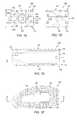
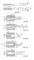
- FIG. 1Aillustrates a perspective view of an expandable implant system in accordance with one or more embodiments of the present technique.
- FIGS. 1B, 1C, 1D and 1Eillustrate a left-side view, a back/trailing-end view, a front/leading-end view, and a top view, respectively, of implant in accordance with one or more embodiments of the present technique.
- FIG. 1Fillustrates a cross-sectioned perspective view of implant taken across line 1 F- 1 F of FIG. 1E in accordance with one or more embodiments of the present technique.
- FIG. 1Hillustrates a cross-sectioned perspective view of implant taken across line 1 H- 1 H of FIG. 1B in accordance with one or more embodiments of the present technique.
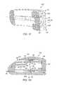
- FIGS. 2A and 2Bdepict perspective and side views, respectively, illustrating insertion of insert between upper and lower members in accordance with one or more embodiments of the present technique.
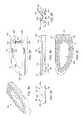
- FIGS. 3A, 3B, 3C, 3D, 3E, 3F and 3Gdepict a perspective view, a side view, a bottom view, a top view, a rear/trailing-end view, a nose/leading-end view, and a side view, respectively of an insert in accordance with one or more embodiments of the present technique.
- FIGS. 4A, 4B, 4C, 4D, 4E and 4Fdepict a perspective view, a side view, a bottom view, a top view, a nose/leading-end view and a rear/trailing-end view, respectively of upper member 102 in accordance with one or more embodiments of the present technique.
- FIGS. 5A, 5B, 5C, 5D, 5E and 5Fdepict a lower-perspective view, a side view, a bottom view, a top view, a nose/leading-end view, and a rear/trailing-end view, respectively of lower member 104 in accordance with one or more embodiments of the present technique.
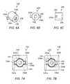
- FIGS. 6A, 6B and 6Cillustrate a perspective view, a rear-end view and a side view, respectively, of a rotating locking member, in accordance with one or more embodiments of the present technique.
- FIGS. 7A and 7Billustrate actuation of the locking member within the implant, in accordance with one or more embodiments of the present technique.
- FIGS. 8A, 8B, 8C and 8Dillustrate a perspective view, a side view, an end view, and a top view of a guide instrument, in accordance with one or more embodiments of the present technique.
- FIGS. 9A-9Fillustrate a sequence of implanting implant in accordance with one or more embodiments of the present technique.
- FIG. 10is a flowchart that illustrated a method for implanting implant in accordance with one or more embodiments of the present technique.
- FIG. 11illustrates installation of multiple implants in accordance with one or more embodiments of the present technique.
- FIGS. 12A-12Billustrates a perspective view of an expandable implant system in accordance with one or more embodiments of the present technique.
- connectiongenerally refers to pieces which may be joined or linked together.
- Coupledgenerally refers to pieces which may be used operatively with each other, or joined or linked together, with or without one or more intervening members.
- the intervertebral implantincludes an expandable device that is disposed within an intervertebral space located between adjacent vertebrae of a human spine.
- the implantincludes a spinal fusion implant that facilitates fusion of the adjacent vertebrae.
- the implantincludes several components, including an upper member, a lower member, and an insert. The components are provided in a sandwiched configuration, having the insert disposed between the upper and lower members.
- the upper and lower membersare disposed within an intervertebral space and, the insert is advanced/inserted between the upper and lower members to distract the members relative to one another, thereby expanding the implant.
- the upper and lower membersare disposed adjacent the upper and lower vertebrae, respectively, such that expansion of the implant causes the upper and lower members to engage and distract the adjacent vertebrae.
- advancement of the insertis facilitated by guide rails/tracks provided on the upper and lower members, the insert, and related instrumentation.
- guidese.g., rails/tracks
- complementary guidese.g., complementary tracks/rails
- the rails/tracksrun longitudinally (e.g., substantially parallel to the direction of insertion) along lengths of the members and the insert to guide longitudinal advancement of the insert between the interior surfaces of the upper and lower members.
- the rails/tracksmay include one or more locking features that facilitate retention of the insert between the upper and lower members, thereby inhibiting back-out of the insert from between the members.
- instrumentationfacilitates expansion/distraction of the upper and lower members and/or to guide advancement of the insert between the upper and lower members.
- instrument guide membersengage trailing ends of the upper and lower members.
- the instrument guide membersare used to insert the upper and lower members into the intervertebral space, and once the members have been inserted into the intervertebral space, the instrument guide members are spread apart to provide a distraction force that biases the upper and lower members away from one another into an expanded/distracted position.
- the distraction forceis provided simultaneously with the advancement of the insert.
- the distraction forceprovides for distraction of the upper and lower member of a sufficient amount to receive the insert between the members without any significant additional distraction.
- the distraction forceis combined with other distraction forces generated as the insert is advanced/wedged between the upper and lower members, thereby providing a resulting distraction force that distracts the upper and lower members and causes distraction of the upper and lower member of a sufficient amount to receive the insert between the members.
- all or substantially all the distraction forceis generated as the insert is advanced/wedged between the upper and lower members.
- FIG. 1Aillustrates a perspective view of an expandable implant system 100 in accordance with one or more embodiments of the present technique.
- FIGS. 1B, 1C, 1D and 1EFillustrate a left-side view, a back/trailing-end view, a front/leading-end view, and a top view, respectively, of implant 100 in accordance with one or more embodiments of the present technique.
- FIG. 1Fillustrates a cross-sectioned perspective view of implant 100 taken across line 1 F- 1 F of FIG. 1E in accordance with one or more embodiments of the present technique.
- FIG. 1Hillustrates a cross-sectioned perspective view of implant 100 taken across line 1 H- 1 H of FIG. 1B in accordance with one or more embodiments of the present technique.
- Implant 100may include a spinal fusion implant that is disposed between adjacent vertebrae of a human spine.
- Implant 100may be expandable such that it is inserted into an intervertebral space in a generally unexpanded configuration, and is subsequently expanded to distract or otherwise maintain the adjacent vertebra at a suitable separation distance.
- expansion of implant 100 and/or maintenance of an expanded height of implant 100may be provided via insertion of an insert between upper and lower members that engage endplates (or similar bony structures) of the adjacent vertebra.
- Such an insertmay act as a wedge that facilitates distraction and/or a spacer that inhibits contraction of the implant, thereby generating and/or maintaining an expanded height of implant 100 and suitable separation/distraction of the adjacent vertebrae.
- implant 100includes an upper member 102 , a lower member 104 and an insert 106 .
- FIG. 1Adepicts implant 100 in an assembled/expanded configuration wherein insert 106 is disposed between upper and lower members 102 and 104 .
- Implant 100includes a nose/leading-end 108 and a tail/trailing-end 110 .
- Implant 100may be inserted into an intervertebral space “nose first”. It will be appreciated that relative terms, such as “lower” and “upper” are provided for clarity of description to differentiate between various portions of implant 100 .
- implant 100 and/or insertion/implantation of implant 100may include components arranged in the described orientations (e.g., upper member 102 is located above lower member 104 ), other embodiments may include variations in their arrangement.
- implant 100may be inverted during insertion such that lower member 104 is located above upper member 102 during insertion/implantation of implant 100 .
- insert 106may be advanced linearly between upper and lower members 102 and 104 .
- upper and lower members 102 and 104may be disposed within an intervertebral space located between adjacent vertebrae, and insert 106 may be subsequently slid into position between the upper and lower members 102 and 104 to expand or otherwise maintain upper or lower members 102 and 104 in an expanded position to provide for distraction/separation of the adjacent vertebrae.
- advancement of insert 106may be provided by one or more instruments used to push insert 106 into a gap between upper and lower members 102 and 104 . The gap may already exist or may be created by insertion of insert 106 .
- FIGS. 2A and 2Bdepict perspective and side views, respectively, illustrating insertion of insert 106 between upper and lower members 104 and 106 in accordance with one or more embodiments of the present technique. It will be appreciated that, in FIG. 2A , the spacing between upper and lower members 102 and 104 has been increased to provide a clear view of upper and lower members 102 and 104 .
- FIGS. 3A, 3B, 3C, 3D, 3E, 3F and 3Gdepict a perspective view, a side view, a bottom view, a top view, a rear/trailing-end view, and a nose/leading-end view, and a side view, respectively of insert 106 in accordance with one or more embodiments of the present technique.
- 5A, 5B, 5C, 5D, 5E and 5Fdepict a lower-perspective view, a side view, a bottom view, a top view, a nose/leading-end view, and a rear/trailing-end view, respectively of lower member 104 in accordance with one or more embodiments of the present technique.
- upper and lower members 102 and 104may be separated by a lesser distance (see FIG. 2B ) such that portions of inset 106 (e.g., guides) may engage complementary portions (e.g., complementary guides) of upper and lower members 102 and 104 , as discussed in more detail below.
- insert 106may be advanced longitudinally, in a linear direction, as indicated by arrow 112 , such that a nose/leading end 114 of insert 106 is advanced into a gap 116 between upper and lower members 102 and 104 .
- Insert 106may be advanced until nose/leading end 114 and/or a rear/trailing-end 118 of insert 106 is about flush with nose/leading-ends 120 and 122 and/or tail/trailing ends 124 and 126 of upper and lower members 102 and 104 , respectively (see FIGS. 1A and 1B ).
- a superior surface of insert 106includes upper guide rails 130 a and 130 b (referred to collectively as upper guide rails 130 ) and an inferior surface of insert 106 includes lower guide rails 132 a and 132 b (referred to collectively as lower guide rails 132 ).
- Guide rails 130 and 132may engage complementary upper guide tracks 134 a and 134 b (referred to collectively as upper guide tracks 134 ) of upper member 102 and lower guide tracks 136 a and 136 b (referred to collectively as lower guide tracks 136 ) of lower member 104 .
- upper guide tracks 134complementary upper guide tracks 134 a and 134 b
- lower guide tracks 136referred to collectively as lower guide tracks 136
- the terms “rails” and “tracks”are used for clarity in distinguishing one from the other, it will be appreciated that the “rails” and “tracks” may include similar/complementary features (e.g., grooves/recess and/or protrusions/lips) that facilitate guiding relative movement and coupling of members 102 and 104 and insert 106 .
- guide rails 130 and 132 of insert 106run in a substantially longitudinal direction (e.g., extending substantially between tail 118 and nose 114 ) along superior and inferior surfaces 140 and 142 .
- guide tracks 134 and 136 of respective members 102 and 104run in a substantially longitudinal direction (e.g., extending between tails 124 and 126 and noses 120 and 122 ).
- Guide rails and tracksmay run along a portion, substantially all or all of a length of insert 106 .
- guides rails 130 and 132run along a length of insert 106 (e.g., from a leading edge portion to a trailing edge portion).
- guide rails 132 b and 134 bare shorter than guide rails 132 a and 132 a , as the outward curvature of members 102 and 104 creates a shorter effective length.
- Guides tracks 134 and 136 of members 102 and 104may extend at least to tail/trailing-ends 124 and 126
- guide rails 130 and 132 of insert 106may extend at least to nose/leading-end 114 insert 106 such that guide rails 130 and 132 can engage complementary portions of guide tracks 134 and 136 upon insertion of nose-end 114 of insert 106 into tail-ends 124 and 126 of upper and lower members 102 and 104 , as illustrated by arrow 112 .
- the guide rails and tracksinclude complementary shaped protrusions and recesses that engage one another to guide longitudinal/linear advancement of insert 106 .
- rails 130 and 132include inward-facing undercut grooves
- tracks 136 and 134include complementary-outward facing undercut grooves.
- Each of the undercut groovesmay define a longitudinally extending lip or dovetailed groove.
- each of the lips/grooves of rails 130 and 132 of insert 106include an “S” shaped profile that engages a complementary “S” shaped profile of tracks 136 and 134 of upper and lower members 102 and 104 .
- the respective grooves/lips of the rails and tracksmay dovetail with one another to guide longitudinal advancement of insert 106 relative to upper and lower members 102 and 104 .
- engagement of the guide rails and tracksmay inhibit lateral shifting and or vertical separation of insert 106 and upper and lower members 102 and 104 .
- the longitudinal orientation and a substantially low tolerance fit between rails 130 and tracks 134may inhibit lateral (e.g., side-to-side) movement of insert 106 relative to upper member 102
- a similar fit between rails 132 and tracks 136may inhibit substantial lateral (e.g., side-to-side) movement and rotation of insert 106 relative to lower member 104 .
- Such retentionmay help to prevent axial rotation of the adjacent vertebrae during the fusion process, thereby facilitating secure bone growth/fusion between the vertebrae.
- Engagement of the respective lips of the guide rails and tracksmay inhibit vertical separation as the overlap between the lips causes them to catch one another.
- Such retentionmay help to prevent vertical separation of the adjacent vertebrae during the fusion process, thereby facilitating secure bone growth/fusion between the vertebrae.
- an upper and lower substantially planar exterior surfaces (e.g., superior surface 137 a and inferior surface 137 b ) of a central body portion 138 of insert 106may abut complementary interior surfaces (e.g., inferior surface 139 a and superior surface 139 b ) of upper and lower members 102 and 104 . Abutment of the respective surfaces may resist vertical compression of implant 100 , thereby enabling implant 100 to provide for and maintain an expanded height.
- central body portion 138includes a height (h) such that, when inserted between upper and lower members 102 and 104 , the inferior and superior surfaces 139 a and 139 b of the upper and lower members are separated by a distance about equal to height (h) (see FIG. 3E ) and implant 100 has an overall expanded implant height (H) defined by the distance between superior surface 144 of upper member 102 and an inferior surface 146 of lower member 104 .
- Hoverall expanded implant height
- Hoverall expanded implant height
- Height (h) of spacer 106may include any height to provide any desired height (H).
- height (h)is about 0.1 millimeter (mm), 0.2 mm, 0.3 mm, 0.4 mm, 0.5 mm, 0.75 mm, 1 mm, 2 mm, 3 mm, 4 mm, 5 mm, 6 mm, 7 mm, 8 mm, 9 mm, 10 mm, 11 mm, 12, mm, 13 mm, 14 mm, 15 mm or more.
- the overall expanded implant height (H)is about 0.5 mm, 1 mm, 2 mm, 3 mm, 4 mm, 5 mm, 6 mm, 7 mm, 8 mm, 9 mm, 10 mm, 11 mm, 12 mm, 13 mm, 14 mm, 15 mm, 16, mm, 17 mm, 18 mm, 19 mm, 20 mm or more. In some embodiments, the overall expanded implant height (H) is about 13-17 mm or about 15 mm. As discussed in more detail below, one or a plurality of inserts of different heights may be selected and inserted to achieve a desired overall expanded implant height and resulting separation distance between adjacent vertebrae.
- an implant kitmay include an upper member, a lower member, and a plurality of inserts of differing heights such that an appropriately sized insert can be selected and inserted during a spinal fusion implant procedure.
- implant 100includes a retaining mechanism to provide for the retention of insert 106 between upper and lower members 102 and 104 .
- insert 106includes an upper retention feature 160 a that engages an upper retention peg 162 of upper member 102 and a lower retention feature 160 b that engages a lower retention peg 164 of lower member 104 .
- upper retention feature 160 ais located proximate an internal lateral side 166 of insert 106
- lower retention feature 160 bis located proximate an external lateral side 168 of insert 106
- upper retention peg 162is located proximate an internal lateral side 170 of upper member 102
- lower retention peg 164is located proximate an external lateral side 172 of lower member 102 .
- Retention features 160 a and 160 bmay be located within or otherwise coupled to central portion 138 of insert 106 .
- retention feature 160 aincludes a ramped shaped protrusion formed integrally with a cross member 180 of central portion 138 .
- the ramp shaped protrusionincludes a leading ramped surface 182 terminating into a substantially orthogonal trailing edge 184 extending substantially laterally with respect to a longitudinal axis (e.g., substantially parallel to the direction of insertion) of insert 106 (See FIG. 3D ).
- retention feature 160 bincludes a similar ramped shaped protrusion formed integrally with a cross member 190 of central portion 138 .
- the ramp shaped protrusionincludes a leading ramped surface 192 terminating into a substantially orthogonal trailing edge 194 (See FIG. 3C ).
- cross-members 180 and/or 190may be flexible such that the ramped shaped protrusion may translate inward in the direction of arrows 186 and 196 , respectively when ramped surfaces 182 or 192 are engaged by complementary upper and lower retention pegs 162 and 164 , respectively.
- cross members 180 and 190include relatively thin-elongated shaped members formed from adjacent cut-outs within central portion 138 . The thin elongate cross-section may enable lateral deflection of retention features 160 a and 160 b.
- retention features 160 a and 160 bare recessed within central body portion 138 such that they do not extend beyond superior and inferior surfaces 137 a and 137 b of central body portion 138 of insert 106 .
- Central body portion 138includes slots 200 and 202 that provide for longitudinal insertion/sliding of retention pegs 162 and 164 into engagement with the recessed retention features 160 a and 160 b .
- slot 200is formed in superior surface 137 a and extends from an area proximate retention feature 160 a to a leading edge of insert 106 to provide a channel that enables retention peg 162 to slide there through as insert 106 is advanced between upper and lower members 102 and 104 .
- Slot 202is formed in inferior surface 137 b and extends from an area proximate retention feature 160 b to a leading edge of insert 106 to provide a channel that enables retention peg 164 to slide there through as insert 106 is advanced between upper and lower members 102 and 104 .
- Retention peg 162includes a protrusion extending downward from inferior surface 139 a of upper member 102 .
- the protrusionincludes a ramped trailing surface 206 terminating into a substantially orthogonal leading edge 208 .
- retention peg 164includes a protrusion extending upward from superior surface 139 b of lower member 104 .
- the protrusionincludes a ramped trailing surface 210 terminating into a substantially orthogonal leading edge 212 .
- FIG. 1Hdepicts a cross-sectioned view of implant 100 having insert 106 installed therein.
- the figureillustrates retention pegs 162 and 164 in a locked position with respect to retaining features 160 a and 160 b .
- trailing edges 194 and 184 of insert 106abut leading edges 212 and 208 of the pegs 162 and 164 of upper and lower members 102 and 104 .
- insert 106may be advanced between upper and lower members 102 and 104 (as described below with respect to FIGS. 9A-9F ) such that pegs 162 and 164 are advanced into and through slots 200 and 202 , respectively, and leading ramped surfaces 192 and 182 of retaining features 160 a and 160 b engage the complementary ramped trailing surfaces 206 and 210 of pegs 162 and 164 , respectively.
- leading ramped surfaces 192 and 182 of retaining features 160 a and 160 bslidingly engage the complementary ramped trailing surfaces 206 and 210 of pegs 162 and 164 , thereby creating an inward biasing force that causes cross-members 180 and 190 and retaining features 160 a and 160 b to deflect inward in the direction of arrows 186 and 196 .
- trailing edges 184 and 194 of retaining features 160 a and 160 bmay be moved into a position at or just past leading edges 208 and 212 of pegs 162 and 164 such that retaining features 160 a and 160 b snap back into their undeflected/locked position with respect to retaining features 160 a and 160 b .
- trailing edges 194 and 184 of insert 106abut leading edges 212 and 208 of the pegs 162 and 164 of upper and lower members 102 and 104 .
- the snap of retaining features 160 a and 160 bmay provide cound or tactile sensation (e.g., audible and/or physical sensation) that alerts a user (e.g., a surgeon) that insert 106 has been fully engaged and is properly seated between upper and lower members 102 and 104 .
- a usere.g., a surgeon
- a forward peg 220 extending from lower member 102engages a complementary recess/slot 222 of insert 106 to limit additional forward movement of insert 106 , thereby inhibiting over insertion of insert 106 .
- a similar recess/slot 222may be provided on upper member 102 . The combination of the forward stopping mechanism along with the retaining mechanism may facilitate proper placement of insert 106 by inhibiting over insertion and back-out of insert 106 .
- an actuatable locking mechanismmay provide for at least partial retention of insert 106 between upper and lower members 102 and 104 .
- insert 106includes a locking member 230 .
- FIGS. 6A, 6B and 6Cillustrate a perspective view, a rear-end view and a side view, respectively, of rotating locking member 230 , in accordance with one or more embodiments of the present technique.
- FIGS. 7A and 7Billustrate actuation of locking member 230 within implant 100 , in accordance with one or more embodiments of the present technique.
- locking member 230includes a cylindrical body 232 , two protruding arms 234 a and 234 b , and a tool recess 236 .
- cylindrical body 232is inserted into a complementary cylindrical recess 240 within a trailing end of insert 106 .
- Recess 240may include two lateral recess 240 a and 240 b extending radially.
- Insert 106may be inserted such that its longitudinal axis 238 substantially aligns with a longitudinal axis of recess 240 and or a longitudinal axis 242 of insert 106 and/or implant 100 .
- arms 234 a and 234 b of locking member 230may be aligned and inserted into lateral recess 240 a and 240 b , respectively, such that locking member 230 is advanced longitudinal into recess 240 .
- locking member 230may be rotated such that arms 234 a and 234 b engage complementary recess of upper and/or lower members 102 and 104 . For example, as illustrated in FIGS.
- locking member 230may be rotated about longitudinal axis 238 from an unlocked position, in which arms 234 a and 234 b are not engaged with upper and lower members 102 and 104 , to a locked position in which arms 234 a and 234 b are rotated into engagement with recesses 244 a and 244 b of upper member 102 and lower member 104 , respectively, as depicted by arrow 246 .
- Rotationmay be provided via a tool engaging tool recess 236 and being rotated.
- Recesses 244 a and 244 bmay include notches that, when engaged by arms 234 a and 234 b , block/inhibit forward and/or backward movement of locking member 230 relative to upper and lower member 102 and 104 . Arms 234 a and 234 b may be rotated into and extend through slots within insert 106 such that insert is blocked/inhibited forward and/or backward movement relative to locking member 230 . Thus, upon actuation/rotation of locking member 230 , insert 106 may be locked to upper and lower members 102 and 104 , thereby further inhibiting back-out of insert 106 .
- locking member 230is rotated about forty-five degrees about axis 238 between the locked and unlocked positions.
- Other embodimentsmay include varying amounts of rotations.
- locking member 230may be rotated about five, ten, fifteen, twenty, twenty-five, thirty, thirty-five, forty, fifty, fifty-five, sixty, seventy, seventy-five, eighty, eighty-five, ninety degrees or more between the locked and unlocked positions.
- Outer surfaces of upper and/or lower members 102 and 104may include various features to facilitate engagement of their exterior surfaces with endplates of adjacent vertebrae.
- superior surface 144 of upper member 102 and inferior surface 146 of lower member 104may include protrusions (e.g., teeth) 250 extending there from.
- teeth 250may extend/penetrate into adjacent boney structure of the upper and lower adjacent vertebrae. Such penetration may help to fix a position of upper and lower members 102 and 104 , and, thus assembled implant 100 , relative to the vertebrae. Fixing or otherwise stabilizing the implant may reduce the likelihood of implant 100 being expelled from within the intervertebral space, and may promote bone attachment to and through implant 100 .
- protrusions 250may include unidirectional teeth that facilitate forward insertion of the members, but inhibit back-out of the members.
- teeth 250include a ramped leading surface 250 a and a substantially vertical trailing edge 250 b (see FIGS. 4B and 5B ).
- forward advancement of the membersmay be facilitated as boney structure of the vertebrae slides over ramped leading surface 250 a of teeth 250 and backward advancement may be inhibited by substantially vertical trailing edge 250 b hooking into or otherwise engaging the boney structure of the vertebrae.
- Protrusions 250may be provided in a variety of shapes and patterns.
- protrusions 250include six arched shaped rows of teeth arranged in a generally concentric pattern. The arched rows have a profile that is substantially similar to the curvature of lateral external edges 172 and 173 of upper and lower members 102 and 104 .
- implant 100includes one or more openings extending vertically between upper and lower surfaces of implant 100 .
- implant 100includes a vertical opening 260 defined openings 260 a , 260 b and 260 c extending vertically through upper member 102 , lower member 104 and insert 106 , respectively.
- Vertical opening 260may be provided when implant 100 is assembled to include insert 106 fully inserted/seated between upper and lower members 102 and 104 such that opening 260 a , 260 b and 260 c substantially aligned with one another.
- Vertical openingmay extend completely through implant 100 , from superior surface 144 of upper member 102 to inferior surface 146 of lower member 104 .
- vertical opening 260may be filled with a substance/material to facilitate bone growth/fusion. Once implant 100 is implanted, vertical opening may facilitate a column of bone growth between the adjacent vertebrae through vertical opening 260 .
- an openinge.g., opening 260
- insert 106may act as a wedge that provides for increasing a separation distance between upper and lower members 102 and 104 (e.g., such that the adjacent vertebra are distracted as insert 106 is installed) and/or a spacer that is advanced between upper and lower members 102 and 104 to maintain a separation distance there between (e.g., where upper an lower members 102 and 104 have already been separated/distracted an adequate amount prior to insertion of insert 106 ).
- insert 106includes a tapered/wedged shaped nose/leading-end that facilitates insertion of insert 106 .
- insert 106includes a tapered/ramped/wedge shaped nose portion 270 (see FIG. 3B ).
- Nose portion 270includes upper and lower ramped surfaces 270 a and 270 b that terminate into a substantially flat/planar portion of superior and inferior surfaces 137 a and 137 b of central body portion 138 .
- ramped surfaces 270 a and 270 bmay engage trailing end portions of inferior surface 139 a and superior surface 139 b .
- nose portion 270may facilitate spreading of the upper and lower members 102 and 104 to enable further distraction of members 102 and 104 and advancement of insert 106 .
- one or more tool/instrumentsmay be used to facilitate expansion of implant 100 .
- expansion instruments coupled to upper member and lower member 102 and 104may generate a distraction force that separates the members, thereby increasing a size of gap 116 to enable insert 106 to be provided therein.
- the distraction forcemay be sufficient to expand gap 116 to accept insert 106 without much or any additional distraction.
- the gap 116may have a height approximately equal to height (h) of insert 106 .
- the distraction forcemay help to expand gap 116 , however, advancement of insert 106 between upper and lower members 102 and 104 may provide for additional distraction to fully expand implant 100 .
- the distraction forcesmay partially distract upper and lower members 102 and 104 , and advancement of insert 106 may act as a wedge, providing additional distraction forces that, alone or combined with the distraction forces of the instruments, provides additional distraction to fully expand implant 100 .
- implant 100includes tool engagement features that enable coupling of one or more instruments to upper and lower members 102 and 104 .
- upper member 102includes recess 280 a and 280 b
- lower member 104includes tool recesses 282 a and 282 b (see FIGS. 4F, 5F and 1F ).
- Each of recesses 280 a , 280 b , 282 a and 282 bextend into rear/trailing ends of the respective upper and lower members 102 and 104 .
- a protrusion of a complementary instrumentmay be engaged into one or more of the recess.
- two protrusions of an upper instrument portionmay be inserted into recesses 280 a and 280 b and two protrusions of a lower instrument portion may be inserted into recesses 282 a and 282 b .
- Applying a spreading force to the upper and lower instrument portionsmay generate a corresponding distraction force that is transferred to the upper and lower members 102 and 104 , thereby aiding in generating and/or widening of gap 116 .
- the spreading forcemay be maintained as insert 106 is advanced between upper and lower members 102 and 104 .
- the upper and lower instrument portionsmay include or may be attached to elongate instrument extensions that can be used to guide insertion of upper and lower members 102 and 104 into the intervertebral space. Insertion, placement and/or aligning of implant 100 within the intervertebral space may be accomplished using the instruments.
- Some or all of recesses 280 a , 280 b , 282 a and 282 bmay include a retention feature that at least partially couples the instrument portions to the respective upper and lower member 102 and 104 .
- an interior of some or all of recesses 280 a , 280 b , 282 a and 282 bmay include a detent feature (e.g., recess) that engages a complementary detent feature (e.g., protrusion) of the instrument portions such that the protrusion and, thus, the instrument portion can be clipped to the recess.
- a detent featuree.g., recess
- a complementary detent featuree.g., protrusion
- the upper and lower instrument portionsmay include guide tracks that couple to guide rails of insert 106 to facilitate guiding of insert 106 into gap 116 .
- an inferior surface of on upper instrument portion and a superior surfaced of a lower instrument portionmay include guide track similar to guide tracks 134 and 136 of upper and lower members 102 and 104 .
- the guide tracks of the instrumentsmay align with guide tracks 134 and 136 of members 102 and 104 to provide an elongated track to guide insertion of insert 106 .
- insert 106may be advanced along a longitudinal path that extends across the guide tracks of the instruments and guide tracks 134 and 136 .
- FIGS. 8A, 8B, 8C and 8Dillustrate a perspective view, a side view, an end view, and a top view of a guide instrument 290 , in accordance with one or more embodiments of the present technique.
- Guide instrument 290includes an elongate body 292 having a guide surface 294 . Depending on the orientation of guide instrument, guide surface 294 may be located on an inferior surface or inferior surface of guide instrument 290 . In the illustrated embodiment, guide surface is located on a superior/top/upper surface of guide instrument 290 .
- Guide surface 294includes guide tracks 296 a and 296 b (referred to collectively as guide tracks 296 ).
- Guide tracks 296may have a profile that is the same or similar to guide tracks 134 and 136 of upper and lower members 102 and 104 .
- guide tracks 296include outward facing undercut grooves that are shaped complementary to guide rails 130 and/or 132 of insert 106 .
- Each of the undercut groovesmay define a longitudinally extending lip or dovetail.
- the lips/groovesinclude an “S” shaped profile that engages a complementary “S” shaped profile of insert 106 .
- the respective grooves/lips of guide rails 130 and/or 132 and guide tracks 294may dovetail with one another to guide longitudinal advancement of insert 106 relative to the guide instrument 290 and/or upper and lower members 102 and 104 .
- a front/leading end of guide instrument 290includes protrusions 298 a and 298 b (collectively referred to as guide protrusions 298 ).
- protrusions 298 a and 298 binclude elongate cylindrical shaped protrusions that, during use, engage recesses 280 a and 280 b of upper member 102 or 282 a and 282 b of lower member 104 .
- Protrusions 298may provide for aligning of guide tracks 294 with guide tracks 134 and 136 of upper and lower members 102 and 104 when instrument 290 is coupled to upper or lower member 102 or 104 .
- Protrusions 298may include detent features that engage complementary detent features of upper or lower members 102 or 104 to facilitate coupling of instrument 290 to upper or lower members 102 or 104 .
- protrusions 298 a and 298 binclude respective detent catches 300 a and 300 b .
- Detent catches 300 a and 300 bmay couple to complementary detent pockets 302 within recess 280 a , 280 b , 282 a , or 282 b . Coupling of detent may facilitate retention of instrument 290 to upper or lower members 102 or 104 during insertion.
- Detent featuresmay facilitate removal of instrument 290 from upper or lower members 102 or 104 via application of a longitudinal separation force pulling instrument 290 away from upper or lower members 102 or 104 . Detent features may enable instrument 290 to be snapped into and out of upper or lower members 102 or 104 .
- FIGS. 9A-9Fillustrate a sequence of implanting implant 100 in accordance with one or more embodiments of the present technique.
- implant 100is disposed within an intervertebral space 310 between adjacent vertebrae 312 and 314 .
- FIG. 10is a flowchart that illustrated a method 400 for implanting implant 100 in accordance with one or more embodiments of the present technique.
- Method 400generally includes coupling guide instruments to upper and lower members of an implant, positing the upper and lower members within an intervertebral space, applying a distraction force, attaching an insert to the guide instruments, advancing the insert into position between the upper and lower members, locking the insert between the upper and lower members, and removing the guide instruments.
- method 400includes installing another implant.
- Method 400may include coupling guide instruments to upper and lower members, as depicted at block 402 .
- coupling guide instruments to upper and lower membersincludes coupling an upper guide 290 a instrument to upper member 102 and a lower guide instrument 290 b to lower member 104 , as depicted in FIG. 9 a .
- instrument protrusions 298 of upper guide instrument 290 amay be inserted into recesses 280 of upper member 102 such that detents 300 engage pockets 302 of the recesses.
- Instrument protrusions 298 of lower guide instrument 290 bmay be inserted into recess 280 of lower member 104 such that detents 300 engage pockets 302 of the recesses.
- Method 400may include positioning the upper and lower members within an intervertebral space, as depicted at block 404 .
- positioning the upper and lower members within an intervertebral spacemay include disposing upper member 102 and/or lower member 104 within intervertebral space 310 between upper vertebra 312 and lower vertebra 314 , as depicted in FIG. 9B .
- superior surface 144 of upper member 102may abut an endplate, or other boney structure of, upper vertebra 312 and inferior surface 146 of lower member 104 may abut an endplate, or other boney structure, of lower vertebra 314 .
- teeth 250may engage the boney structure of vertebrae 312 and 314 .
- Insertion of upper and lower members 102 and 104may be accomplished by a practitioner handling trailing end portions of guide instruments 290 a and 290 b to move upper and lower members 102 and 104 into intervertebral space 310 as represented by arrows 316 .
- each of upper and lower members 102 and 104may be positioned individually.
- lower member 104may be positioned in intervertebral space 310 , followed by positioning of upper member 102 within intervertebral space 310 .
- upper and lower members 102 and 104may be positioned substantially simultaneously.
- upper and lower members 102 and 104may be coupled to one another and/or upper and lower guide instruments 290 a and 290 b may be rigidly coupled such that both of upper and lower members 102 and 104 are moved in unison into intervertebral space 310 .
- Method 400may include applying a distraction force, as depicted at block 406 .
- applying a distraction forceincludes applying a force to urge lower body and upper body away from one another.
- a spreading forcemay be applied to upper and lower guide instruments 290 a and 290 b , as depicted by arrow 318 .
- the spreading forceis generated by a practitioner simply spreading/pushing/pulling the upper and lower guide instruments 290 a and 290 b away from one another.
- the spreading forceis generated mechanically.
- lower guide instruments 290 a and 290 bmay be coupled to one another via spreading pliers, such that squeezing the pliers generates a spreading force that urges the lower guide instruments 290 a and 290 b away from one another.
- the pliersmay include a ratcheting mechanism such that incremental increases in separation distances can be achieved between guide instruments 290 a and 290 b .
- the spreading forcemay be transferred to upper and lower members 102 and 104 (e.g., via engagement of protrusions 298 with recesses 280 and 282 ) to generate a corresponding spreading force to upper and lower members 102 and 104 , as depicted by arrows 320 .
- the spreading forcemay cause actual separation/distraction of lower guide instruments 290 a and 290 b , upper and lower members 102 and 104 , and/or upper and lower vertebrae 312 and 314 .
- the spreading forcemay simply counteract some of the compressive forces between vertebrae 312 and 314 , however, the spreading force may not cause any substantial separation/distraction of lower guide instruments 290 a and 290 b , upper and lower members 102 and 104 , and/or upper and lower vertebrae 312 and 314
- Method 400may include attaching an insert to the guide instruments, as depicted at block 408 .
- attaching an insert to the guide instrumentsincludes attaching insert 106 to one or both of guide instruments 290 a and 290 b .
- guide rails 130 and 132are coupled to guide tracks 296 of the respective upper and lower guide instruments 290 a and 290 b .
- guide tracks 296may guide longitudinal sliding of insert 106 between guide instruments 290 a and 290 b such that insert 106 can be slid from at or near a trailing end of guide instruments 290 a and 290 b , past the leading end of guide instruments 290 a and 290 b and onto guide tracks 134 and 136 of upper and lower members 102 and 104 .
- an insert instrument 330engages insert 106 .
- Insert instrument 330may be used to push/pull insert along the guide tracks.
- insert instrument 330includes a keyed leading end that engages tool recess 236 of locking member 230 .
- Insert instrument 330may be used to advance insert 106 and/or actuate locking member 230 to lock insert 106 between upper and lower members 102 and 104 .
- Method 400may include advancing the insert into position between the upper and lower members, as depicted at block 410 .
- advancing the insert into position between the upper and lower membersmay include pushing insert 106 forward in the direction of arrow 322 , as depicted in FIGS. 9C and 9D .
- effective upper and lower unitary guide tracksmay be formed to enable sliding of insert 106 forward from a location between guide instruments 290 a and 290 b (see FIG. 9C ), into a location at least partially between upper and lower members 102 and 104 (see FIG. 9D ).
- Spacer 106may be advanced until completely inserted between upper and lower members 102 and 104 .
- spacer 106may be advanced until nose/leading end 114 and/or a rear/trailing-end 118 of insert 106 is about flush with nose/leading-ends 120 and 122 and/or tail/trailing ends 124 and 126 of upper and lower members 102 and 104 , respectively (see FIG. 9E ).
- advancementmaybe limited by forward peg 220 of lower member 102 engaging complementary recess/slot 222 of insert 106 , thereby inhibiting over insertion of insert 106 .
- back-out of insert 106may be inhibited by retention features 160 engaging complementary pegs 162 and 164 of upper and lower members 102 and 104 .
- complete insertionis signaled by engagement of peg 220 into slot/recess 222 and/or engagement of retention features 160 .
- an audible clickmay be heard and/or a tactile sensation may be felt as the retention features and/or the peg are engaged.
- Advancement of insert 106may provide additional distraction forces that combine with the distraction forces provided at block 406 to effectively distract vertebrae 312 and 314 .
- nose of 114 of insert 106may act as a wedge to distract upper and lower members 102 and 104 .
- insert 106may simply inserted to act as a spacer to maintain the distraction. Once inserted, insert 106 may be left in place to act as a spacer that maintains implant 100 at the distracted/expanded height.
- Method 400may include locking the insert between upper and lower members, as depicted at block 412 .
- locking the insert between upper and lower membersincludes actuating/rotating locking member 230 such that arms 234 a and/or 234 b engage recesses 244 a and 244 b of upper member 102 and lower member 104 , respectively.
- insert instrument 330may be rotated about longitudinal axis 238 , as indicated by arrow 332 , such that the keyed leading end engages tool recess 236 of locking member 230 , thereby transmitting a torque to rotate locking member into a locked position (see FIGS. 7A, 7B and 9E ).
- Method 400may include removing the instruments, as depicted at block 414 .
- removing the instrumentsincludes removing some or all of upper guide instrument 290 a , lower guide instrument 290 b and insert instrument 330 .
- a practitionermay simply pull each of the instruments backwards to de-couple them from the respective portions of implant 100 , as depicted by arrows 334 of FIG. 9F .
- Method 400may include installing other implants, as depicted at block 416 .
- installing other implantsmay include installing another implant with intervertebral space 310 and/or another intervertebral space between other adjacent vertebrae.
- a first implant 100 ′may be implanted on a first side of a saggital plane 340 of vertebrae 312 and 314
- a second implant 100 ′′may be implanted on a second/opposite side of saggital plane 340 , such that a pair of intervertebral implants are implanted within intervertebral space 310 .
- Each of implants 100 ′ and 100 ′′may be similar to implant 100 , and may be implanted a method that is the same or similar to method 400 .
- an implantmay be inserted at an oblique angle to saggital plane 340 .
- a single implante.g., implant 100
- multiple implantse.g., implants 100 ′ and 100 ′′
- method 400is an exemplary embodiment of a method employed in accordance with techniques described herein.
- Method 400may be may be modified to facilitate variations of its implementations and uses.
- the order of method 400may be changed, and various elements may be added, reordered, combined, omitted, modified, etc.
- FIGS. 12A-12Billustrates a perspective view of expandable implant system 100 in accordance with one or more embodiments of the present technique.
- one or more portions of expandable implant system 100may include markers 342 .
- Markersmay be used to assess a position of one or more portions of the expandable implant system during implantation in a subject.
- a portion of the expandable implant systemmay include none, one or multiple markers.
- Markersmay provide radiographic opacity. Markers may be biocompatible. Markers may be of any size or shape.
- a systemmay have multiple markers with different shapes in order to more easily identify different portions of the system and/or an orientation of one or more portions of the system.
- markers 342include spherical and rod shapes.
- one or more markersmay be formed from gold or tantalum.
Landscapes
- Health & Medical Sciences (AREA)
- Engineering & Computer Science (AREA)
- Biomedical Technology (AREA)
- Neurology (AREA)
- Orthopedic Medicine & Surgery (AREA)
- Cardiology (AREA)
- Oral & Maxillofacial Surgery (AREA)
- Transplantation (AREA)
- Heart & Thoracic Surgery (AREA)
- Vascular Medicine (AREA)
- Life Sciences & Earth Sciences (AREA)
- Animal Behavior & Ethology (AREA)
- General Health & Medical Sciences (AREA)
- Public Health (AREA)
- Veterinary Medicine (AREA)
- Prostheses (AREA)
Abstract
Description
Claims (19)
Priority Applications (1)
| Application Number | Priority Date | Filing Date | Title |
|---|---|---|---|
| US13/678,238US9526627B2 (en) | 2011-11-17 | 2012-11-15 | Expandable interbody device system and method |
Applications Claiming Priority (2)
| Application Number | Priority Date | Filing Date | Title |
|---|---|---|---|
| US201161561037P | 2011-11-17 | 2011-11-17 | |
| US13/678,238US9526627B2 (en) | 2011-11-17 | 2012-11-15 | Expandable interbody device system and method |
Publications (2)
| Publication Number | Publication Date |
|---|---|
| US20130158667A1 US20130158667A1 (en) | 2013-06-20 |
| US9526627B2true US9526627B2 (en) | 2016-12-27 |
Family
ID=48610924
Family Applications (1)
| Application Number | Title | Priority Date | Filing Date |
|---|---|---|---|
| US13/678,238ActiveUS9526627B2 (en) | 2011-11-17 | 2012-11-15 | Expandable interbody device system and method |
Country Status (1)
| Country | Link |
|---|---|
| US (1) | US9526627B2 (en) |
Cited By (10)
| Publication number | Priority date | Publication date | Assignee | Title |
|---|---|---|---|---|
| US9788971B1 (en) | 2013-05-22 | 2017-10-17 | Nuvasive, Inc. | Expandable fusion implant and related methods |
| US9801734B1 (en) | 2013-08-09 | 2017-10-31 | Nuvasive, Inc. | Lordotic expandable interbody implant |
| US10195053B2 (en) | 2009-09-18 | 2019-02-05 | Spinal Surgical Strategies, Llc | Bone graft delivery system and method for using same |
| US10245159B1 (en) | 2009-09-18 | 2019-04-02 | Spinal Surgical Strategies, Llc | Bone graft delivery system and method for using same |
| US10278830B1 (en) | 2018-02-07 | 2019-05-07 | Zavation, Llc | Expandable orthopedic implant |
| US10973656B2 (en) | 2009-09-18 | 2021-04-13 | Spinal Surgical Strategies, Inc. | Bone graft delivery system and method for using same |
| US11173044B1 (en) | 2021-04-20 | 2021-11-16 | Zavation Medical Products, Llc | Expanding orthopedic implant |
| US11389303B1 (en) | 2021-10-07 | 2022-07-19 | Zavation Medical Products, Llc | Externally threaded expandable orthopedic implant |
| US11547575B2 (en) | 2019-09-27 | 2023-01-10 | Degen Medical, Inc. | Expandable intervertebral spacers |
| US12161560B2 (en) | 2021-08-03 | 2024-12-10 | Warsaw Orthopedic, Inc. | Integral graft interbody devices |
Families Citing this family (76)
| Publication number | Priority date | Publication date | Assignee | Title |
|---|---|---|---|---|
| US6793678B2 (en) | 2002-06-27 | 2004-09-21 | Depuy Acromed, Inc. | Prosthetic intervertebral motion disc having dampening |
| AU2004212942A1 (en) | 2003-02-14 | 2004-09-02 | Depuy Spine, Inc. | In-situ formed intervertebral fusion device |
| US20040267367A1 (en) | 2003-06-30 | 2004-12-30 | Depuy Acromed, Inc | Intervertebral implant with conformable endplate |
| US7753958B2 (en) | 2003-08-05 | 2010-07-13 | Gordon Charles R | Expandable intervertebral implant |
| US8636802B2 (en) | 2004-03-06 | 2014-01-28 | DePuy Synthes Products, LLC | Dynamized interspinal implant |
| WO2008070863A2 (en) | 2006-12-07 | 2008-06-12 | Interventional Spine, Inc. | Intervertebral implant |
| US8900307B2 (en) | 2007-06-26 | 2014-12-02 | DePuy Synthes Products, LLC | Highly lordosed fusion cage |
| EP2237748B1 (en) | 2008-01-17 | 2012-09-05 | Synthes GmbH | An expandable intervertebral implant |
| US8936641B2 (en) | 2008-04-05 | 2015-01-20 | DePuy Synthes Products, LLC | Expandable intervertebral implant |
| US9526620B2 (en) | 2009-03-30 | 2016-12-27 | DePuy Synthes Products, Inc. | Zero profile spinal fusion cage |
| KR101687435B1 (en) | 2009-07-06 | 2016-12-19 | 신세스 게엠바하 | Expandable fixation assemblies |
| US9393129B2 (en) | 2009-12-10 | 2016-07-19 | DePuy Synthes Products, Inc. | Bellows-like expandable interbody fusion cage |
| EP2547292B1 (en) | 2010-03-16 | 2019-04-24 | Pinnacle Spine Group, LLC | Ntervertebral implants and graft delivery systems |
| WO2011150350A1 (en)* | 2010-05-28 | 2011-12-01 | Benvenue Medical, Inc. | Disc space sizing devices and methods of using the same |
| US9907560B2 (en) | 2010-06-24 | 2018-03-06 | DePuy Synthes Products, Inc. | Flexible vertebral body shavers |
| US8979860B2 (en) | 2010-06-24 | 2015-03-17 | DePuy Synthes Products. LLC | Enhanced cage insertion device |
| US8623091B2 (en) | 2010-06-29 | 2014-01-07 | DePuy Synthes Products, LLC | Distractible intervertebral implant |
| US20120078372A1 (en) | 2010-09-23 | 2012-03-29 | Thomas Gamache | Novel implant inserter having a laterally-extending dovetail engagement feature |
| US9402732B2 (en) | 2010-10-11 | 2016-08-02 | DePuy Synthes Products, Inc. | Expandable interspinous process spacer implant |
| EP2685921B1 (en) | 2011-03-18 | 2019-03-13 | Raed M. Ali, M.D., Inc. | Transpedicular access to intervertebral spaces and related spinal fusion systems and methods |
| US9265620B2 (en) | 2011-03-18 | 2016-02-23 | Raed M. Ali, M.D., Inc. | Devices and methods for transpedicular stabilization of the spine |
| US9248028B2 (en) | 2011-09-16 | 2016-02-02 | DePuy Synthes Products, Inc. | Removable, bone-securing cover plate for intervertebral fusion cage |
| US9380932B1 (en) | 2011-11-02 | 2016-07-05 | Pinnacle Spine Group, Llc | Retractor devices for minimally invasive access to the spine |
| US9526627B2 (en) | 2011-11-17 | 2016-12-27 | Exactech, Inc. | Expandable interbody device system and method |
| EP2877127B1 (en) | 2012-07-26 | 2019-08-21 | Synthes GmbH | Expandable implant |
| US9492288B2 (en) | 2013-02-20 | 2016-11-15 | Flexuspine, Inc. | Expandable fusion device for positioning between adjacent vertebral bodies |
| US9717601B2 (en) | 2013-02-28 | 2017-08-01 | DePuy Synthes Products, Inc. | Expandable intervertebral implant, system, kit and method |
| US9522070B2 (en) | 2013-03-07 | 2016-12-20 | Interventional Spine, Inc. | Intervertebral implant |
| WO2014159739A1 (en) | 2013-03-14 | 2014-10-02 | Pinnacle Spine Group, Llc | Interbody implants and graft delivery systems |
| US9861495B2 (en) | 2013-03-14 | 2018-01-09 | Raed M. Ali, M.D., Inc. | Lateral interbody fusion devices, systems and methods |
| US9480574B2 (en) | 2013-03-14 | 2016-11-01 | Benvenue Medical, Inc. | Spinal fusion implants and devices and methods for deploying such implants |
| US10687962B2 (en)* | 2013-03-14 | 2020-06-23 | Raed M. Ali, M.D., Inc. | Interbody fusion devices, systems and methods |
| US9987143B2 (en)* | 2013-03-15 | 2018-06-05 | Spectrum Spine Ip Holdings, Llc | Expandable inter-body fusion devices and methods |
| US10322006B2 (en)* | 2013-03-15 | 2019-06-18 | Globus Medical, Inc. | Interbody standalone intervertebral implant |
| US10603187B2 (en)* | 2013-07-17 | 2020-03-31 | Aesculap Implant Systems, Llc | Spinal interbody device, system and method |
| US9918848B2 (en)* | 2013-10-07 | 2018-03-20 | Warsaw Orthopedic, Inc. | Spinal implant system and method |
| US10398565B2 (en) | 2014-04-24 | 2019-09-03 | Choice Spine, Llc | Limited profile intervertebral implant with incorporated fastening and locking mechanism |
| US9517144B2 (en) | 2014-04-24 | 2016-12-13 | Exactech, Inc. | Limited profile intervertebral implant with incorporated fastening mechanism |
| US10314605B2 (en) | 2014-07-08 | 2019-06-11 | Benvenue Medical, Inc. | Apparatus and methods for disrupting intervertebral disc tissue |
| US10022243B2 (en) | 2015-02-06 | 2018-07-17 | Benvenue Medical, Inc. | Graft material injector system and method |
| US11426290B2 (en) | 2015-03-06 | 2022-08-30 | DePuy Synthes Products, Inc. | Expandable intervertebral implant, system, kit and method |
| US10624757B2 (en) | 2015-04-09 | 2020-04-21 | Centinel Spine, Llc | Spinal implants configured for tissue sparing angle of insertion and related methods |
| US9913727B2 (en) | 2015-07-02 | 2018-03-13 | Medos International Sarl | Expandable implant |
| KR101674491B1 (en)* | 2015-07-10 | 2016-11-09 | 주식회사 메드릭스 | Cage apparatus for minimal invasive surgery |
| WO2017147340A1 (en)* | 2016-02-23 | 2017-08-31 | Life Spine, Inc. (A Delaware Corporation) | Expandable lateral spine cage with reverse dovetail configuration |
| EP3474784A2 (en) | 2016-06-28 | 2019-05-01 | Eit Emerging Implant Technologies GmbH | Expandable and angularly adjustable intervertebral cages with articulating joint |
| US11510788B2 (en) | 2016-06-28 | 2022-11-29 | Eit Emerging Implant Technologies Gmbh | Expandable, angularly adjustable intervertebral cages |
| US10258483B2 (en) | 2016-08-19 | 2019-04-16 | Degen Medical, Inc. | Laminate implantable medical devices |
| US10537436B2 (en) | 2016-11-01 | 2020-01-21 | DePuy Synthes Products, Inc. | Curved expandable cage |
| US10888433B2 (en) | 2016-12-14 | 2021-01-12 | DePuy Synthes Products, Inc. | Intervertebral implant inserter and related methods |
| US10758286B2 (en) | 2017-03-22 | 2020-09-01 | Benvenue Medical, Inc. | Minimal impact access system to disc space |
| US10398563B2 (en) | 2017-05-08 | 2019-09-03 | Medos International Sarl | Expandable cage |
| US11344424B2 (en) | 2017-06-14 | 2022-05-31 | Medos International Sarl | Expandable intervertebral implant and related methods |
| US10940016B2 (en) | 2017-07-05 | 2021-03-09 | Medos International Sarl | Expandable intervertebral fusion cage |
| US11801144B2 (en) | 2017-09-14 | 2023-10-31 | Degen Medical, Inc. | Methods of making medical devices |
| WO2019079090A1 (en)* | 2017-10-18 | 2019-04-25 | Spine Wave, Inc. | Expandable anterior lumbar interbody fusion device |
| WO2019148083A1 (en) | 2018-01-29 | 2019-08-01 | Benvenue Medical, Inc. | Minimally invasive interbody fusion |
| WO2019178575A1 (en) | 2018-03-16 | 2019-09-19 | Benvenue Medical, Inc. | Articulated instrumentation and methods of using the same |
| AU2019342137A1 (en) | 2018-09-20 | 2021-03-25 | Spinal Elements, Inc. | Spinal implant device |
| US11446156B2 (en) | 2018-10-25 | 2022-09-20 | Medos International Sarl | Expandable intervertebral implant, inserter instrument, and related methods |
| US11123198B2 (en) | 2018-11-13 | 2021-09-21 | Degen Medical, Inc. | Expandable spacers |
| GB201818849D0 (en) | 2018-11-19 | 2019-01-02 | Axis Spine Tech Ltd | Intervertebral devices |
| GB201902002D0 (en) | 2019-02-13 | 2019-04-03 | Axis Spine Tech Ltd | Intervertebral devices |
| GB201818850D0 (en)* | 2018-11-19 | 2019-01-02 | Axis Spine Tech Ltd | Intervertebral devices |
| GB201818847D0 (en) | 2018-11-19 | 2019-01-02 | Axis Spine Tech Ltd | Intervertebral devices |
| US11234829B2 (en) | 2019-01-21 | 2022-02-01 | Degen Medical, Inc. | Expandable intervertebral spacers |
| GB201910668D0 (en) | 2019-07-25 | 2019-09-11 | Axis Spine Tech Ltd | Assemblies for and methods of determing height and angle of an intervertebral device |
| GB201910640D0 (en) | 2019-07-25 | 2019-09-11 | Axis Spine Tech Ltd | Insertions instruments |
| US11426286B2 (en) | 2020-03-06 | 2022-08-30 | Eit Emerging Implant Technologies Gmbh | Expandable intervertebral implant |
| US11185421B1 (en) | 2020-09-10 | 2021-11-30 | Warsaw Orthopedic, Inc. | Spinal implant with features facilitating independent expansion of portions thereof and method for use thereof |
| US11911284B2 (en) | 2020-11-19 | 2024-02-27 | Spinal Elements, Inc. | Curved expandable interbody devices and deployment tools |
| US20220241089A1 (en)* | 2020-11-19 | 2022-08-04 | Spinal Elements, Inc. | Curved expandable interbody devices and deployment tools |
| WO2022133456A1 (en) | 2020-12-17 | 2022-06-23 | Spinal Elements, Inc. | Spinal implant device |
| US11850160B2 (en) | 2021-03-26 | 2023-12-26 | Medos International Sarl | Expandable lordotic intervertebral fusion cage |
| US11752009B2 (en) | 2021-04-06 | 2023-09-12 | Medos International Sarl | Expandable intervertebral fusion cage |
| US12090064B2 (en) | 2022-03-01 | 2024-09-17 | Medos International Sarl | Stabilization members for expandable intervertebral implants, and related systems and methods |
Citations (495)
| Publication number | Priority date | Publication date | Assignee | Title |
|---|---|---|---|---|
| US3848601A (en) | 1972-06-14 | 1974-11-19 | G Ma | Method for interbody fusion of the spine |
| US3867728A (en) | 1971-12-30 | 1975-02-25 | Cutter Lab | Prosthesis for spinal repair |
| US4309777A (en) | 1980-11-13 | 1982-01-12 | Patil Arun A | Artificial intervertebral disc |
| US4349921A (en) | 1980-06-13 | 1982-09-21 | Kuntz J David | Intervertebral disc prosthesis |
| US4611581A (en) | 1983-12-16 | 1986-09-16 | Acromed Corporation | Apparatus for straightening spinal columns |
| US4657550A (en) | 1984-12-21 | 1987-04-14 | Daher Youssef H | Buttressing device usable in a vertebral prosthesis |
| US4696290A (en) | 1983-12-16 | 1987-09-29 | Acromed Corporation | Apparatus for straightening spinal columns |
| US4743260A (en) | 1985-06-10 | 1988-05-10 | Burton Charles V | Method for a flexible stabilization system for a vertebral column |
| US4759766A (en) | 1984-09-04 | 1988-07-26 | Humboldt-Universitaet Zu Berlin | Intervertebral disc endoprosthesis |
| US4759769A (en) | 1987-02-12 | 1988-07-26 | Health & Research Services Inc. | Artificial spinal disc |
| US4763644A (en) | 1984-02-28 | 1988-08-16 | Webb Peter J | Spinal fixation |
| US4772287A (en) | 1987-08-20 | 1988-09-20 | Cedar Surgical, Inc. | Prosthetic disc and method of implanting |
| US4790303A (en) | 1987-03-11 | 1988-12-13 | Acromed Corporation | Apparatus and method for securing bone graft |
| US4854311A (en) | 1986-01-09 | 1989-08-08 | Acro Med Corporation | Bone screw |
| US4863476A (en) | 1986-08-29 | 1989-09-05 | Shepperd John A N | Spinal implant |
| US4863477A (en) | 1987-05-12 | 1989-09-05 | Monson Gary L | Synthetic intervertebral disc prosthesis |
| US4907577A (en) | 1989-04-03 | 1990-03-13 | Wu Shing Sheng | Spinal transpedicle drill jig |
| US4911718A (en) | 1988-06-10 | 1990-03-27 | University Of Medicine & Dentistry Of N.J. | Functional and biocompatible intervertebral disc spacer |
| US4932975A (en) | 1989-10-16 | 1990-06-12 | Vanderbilt University | Vertebral prosthesis |
| US4946378A (en) | 1987-11-24 | 1990-08-07 | Asahi Kogaku Kogyo Kabushiki Kaisha | Artificial intervertebral disc |
| US4946458A (en) | 1986-04-25 | 1990-08-07 | Harms Juergen | Pedicle screw |
| US5042982A (en) | 1987-07-08 | 1991-08-27 | Harms Juergen | Positioning device |
| US5047055A (en) | 1990-12-21 | 1991-09-10 | Pfizer Hospital Products Group, Inc. | Hydrogel intervertebral disc nucleus |
| US5059194A (en) | 1990-02-12 | 1991-10-22 | Michelson Gary K | Cervical distractor |
| US5071437A (en) | 1989-02-15 | 1991-12-10 | Acromed Corporation | Artificial disc |
| US5092867A (en) | 1988-07-13 | 1992-03-03 | Harms Juergen | Correction and supporting apparatus, in particular for the spinal column |
| US5108438A (en) | 1989-03-02 | 1992-04-28 | Regen Corporation | Prosthetic intervertebral disc |
| US5123926A (en) | 1991-02-22 | 1992-06-23 | Madhavan Pisharodi | Artificial spinal prosthesis |
| US5171281A (en) | 1988-08-18 | 1992-12-15 | University Of Medicine & Dentistry Of New Jersey | Functional and biocompatible intervertebral disc spacer containing elastomeric material of varying hardness |
| US5171278A (en) | 1991-02-22 | 1992-12-15 | Madhavan Pisharodi | Middle expandable intervertebral disk implants |
| US5180393A (en) | 1990-09-21 | 1993-01-19 | Polyclinique De Bourgogne & Les Hortensiad | Artificial ligament for the spine |
| US5192326A (en) | 1990-12-21 | 1993-03-09 | Pfizer Hospital Products Group, Inc. | Hydrogel bead intervertebral disc nucleus |
| US5196013A (en) | 1989-11-03 | 1993-03-23 | Harms Juergen | Pedicel screw and correcting and supporting apparatus comprising such screw |
| US5207678A (en) | 1989-07-20 | 1993-05-04 | Prufer | Pedicle screw and receiver member therefore |
| US5217497A (en) | 1990-07-04 | 1993-06-08 | Mehdian Seyed M H | Apparatus for use in the treatment of spinal disorders |
| US5246458A (en) | 1992-10-07 | 1993-09-21 | Graham Donald V | Artificial disk |
| US5258031A (en) | 1992-01-06 | 1993-11-02 | Danek Medical | Intervertebral disk arthroplasty |
| US5261909A (en) | 1992-02-18 | 1993-11-16 | Danek Medical, Inc. | Variable angle screw for spinal implant system |
| US5306307A (en) | 1991-07-22 | 1994-04-26 | Calcitek, Inc. | Spinal disk implant |
| US5306309A (en) | 1992-05-04 | 1994-04-26 | Calcitek, Inc. | Spinal disk implant and implantation kit |
| US5314477A (en) | 1990-03-07 | 1994-05-24 | J.B.S. Limited Company | Prosthesis for intervertebral discs and instruments for implanting it |
| US5320644A (en) | 1991-08-30 | 1994-06-14 | Sulzer Brothers Limited | Intervertebral disk prosthesis |
| US5336223A (en) | 1993-02-04 | 1994-08-09 | Rogers Charles L | Telescoping spinal fixator |
| US5370697A (en) | 1992-04-21 | 1994-12-06 | Sulzer Medizinaltechnik Ag | Artificial intervertebral disk member |
| US5375823A (en) | 1992-06-25 | 1994-12-27 | Societe Psi | Application of an improved damper to an intervertebral stabilization device |
| US5397364A (en) | 1993-10-12 | 1995-03-14 | Danek Medical, Inc. | Anterior interbody fusion device |
| US5401269A (en) | 1992-03-13 | 1995-03-28 | Waldemar Link Gmbh & Co. | Intervertebral disc endoprosthesis |
| US5403315A (en) | 1992-04-29 | 1995-04-04 | Danek Medical, Inc. | Positionable spinal fixation device |
| US5415661A (en) | 1993-03-24 | 1995-05-16 | University Of Miami | Implantable spinal assist device |
| US5423816A (en) | 1993-07-29 | 1995-06-13 | Lin; Chih I. | Intervertebral locking device |
| US5425773A (en) | 1992-01-06 | 1995-06-20 | Danek Medical, Inc. | Intervertebral disk arthroplasty device |
| US5443467A (en) | 1993-03-10 | 1995-08-22 | Biedermann Motech Gmbh | Bone screw |
| US5458642A (en) | 1994-01-18 | 1995-10-17 | Beer; John C. | Synthetic intervertebral disc |
| US5458643A (en) | 1991-03-29 | 1995-10-17 | Kyocera Corporation | Artificial intervertebral disc |
| US5480401A (en) | 1993-02-17 | 1996-01-02 | Psi | Extra-discal inter-vertebral prosthesis for controlling the variations of the inter-vertebral distance by means of a double damper |
| US5496321A (en) | 1993-11-19 | 1996-03-05 | Cross Medical Products, Inc. | Rod anchor seat having a sliding interlocking rod connector |
| US5498263A (en) | 1994-06-28 | 1996-03-12 | Acromed Corporation | Transverse connector for spinal column corrective devices |
| US5507816A (en) | 1991-12-04 | 1996-04-16 | Customflex Limited | Spinal vertebrae implants |
| US5514180A (en) | 1994-01-14 | 1996-05-07 | Heggeness; Michael H. | Prosthetic intervertebral devices |
| US5514132A (en) | 1993-01-19 | 1996-05-07 | Jbs S.A. | Spinal osteosynthesis device |
| US5522899A (en) | 1988-06-28 | 1996-06-04 | Sofamor Danek Properties, Inc. | Artificial spinal fusion implants |
| US5527314A (en) | 1993-01-04 | 1996-06-18 | Danek Medical, Inc. | Spinal fixation system |
| US5534029A (en) | 1992-12-14 | 1996-07-09 | Yumiko Shima | Articulated vertebral body spacer |
| US5534030A (en) | 1993-02-09 | 1996-07-09 | Acromed Corporation | Spine disc |
| US5534028A (en) | 1993-04-20 | 1996-07-09 | Howmedica, Inc. | Hydrogel intervertebral disc nucleus with diminished lateral bulging |
| US5540688A (en) | 1991-05-30 | 1996-07-30 | Societe "Psi" | Intervertebral stabilization device incorporating dampers |
| US5545165A (en) | 1992-10-09 | 1996-08-13 | Biedermann Motech Gmbh | Anchoring member |
| US5554191A (en) | 1994-01-26 | 1996-09-10 | Biomat | Intersomatic vertebral cage |
| US5556431A (en) | 1992-03-13 | 1996-09-17 | B+E,Uml U+Ee Ttner-Janz; Karin | Intervertebral disc endoprosthesis |
| US5562737A (en) | 1993-11-18 | 1996-10-08 | Henry Graf | Extra-discal intervertebral prosthesis |
| US5562663A (en) | 1995-06-07 | 1996-10-08 | Danek Medical, Inc. | Implant interconnection mechanism |
| US5571109A (en) | 1993-08-26 | 1996-11-05 | Man Ceramics Gmbh | System for the immobilization of vertebrae |
| US5609635A (en) | 1988-06-28 | 1997-03-11 | Michelson; Gary K. | Lordotic interbody spinal fusion implants |
| US5624442A (en) | 1990-04-26 | 1997-04-29 | Cross Medical Products, Inc. | Transverse link for use with a spinal implant system |
| US5645599A (en) | 1994-07-26 | 1997-07-08 | Fixano | Interspinal vertebral implant |
| US5653763A (en) | 1996-03-29 | 1997-08-05 | Fastenetix, L.L.C. | Intervertebral space shape conforming cage device |
| US5658335A (en) | 1995-03-09 | 1997-08-19 | Cohort Medical Products Group, Inc. | Spinal fixator |
| US5665122A (en) | 1995-01-31 | 1997-09-09 | Kambin; Parviz | Expandable intervertebral cage and surgical method |
| US5672176A (en) | 1995-03-15 | 1997-09-30 | Biedermann; Lutz | Anchoring member |
| US5672175A (en) | 1993-08-27 | 1997-09-30 | Martin; Jean Raymond | Dynamic implanted spinal orthosis and operative procedure for fitting |
| US5674294A (en) | 1993-09-14 | 1997-10-07 | Commissariat A L'energie Atomique | Intervertebral disk prosthesis |
| US5674296A (en) | 1994-11-14 | 1997-10-07 | Spinal Dynamics Corporation | Human spinal disc prosthesis |
| US5676701A (en) | 1993-01-14 | 1997-10-14 | Smith & Nephew, Inc. | Low wear artificial spinal disc |
| US5676702A (en) | 1994-12-16 | 1997-10-14 | Tornier S.A. | Elastic disc prosthesis |
| US5683465A (en) | 1996-03-18 | 1997-11-04 | Shinn; Gary Lee | Artificial intervertebral disk prosthesis |
| US5683394A (en) | 1995-09-29 | 1997-11-04 | Advanced Spine Fixation Systems, Inc. | Fusion mass constrainer |
| US5683391A (en) | 1995-06-07 | 1997-11-04 | Danek Medical, Inc. | Anterior spinal instrumentation and method for implantation and revision |
| US5702450A (en) | 1993-06-28 | 1997-12-30 | Bisserie; Michel | Intervertebral disk prosthesis |
| US5733284A (en) | 1993-08-27 | 1998-03-31 | Paulette Fairant | Device for anchoring spinal instrumentation on a vertebra |
| US5741253A (en) | 1988-06-13 | 1998-04-21 | Michelson; Gary Karlin | Method for inserting spinal implants |
| US5755797A (en) | 1993-04-21 | 1998-05-26 | Sulzer Medizinaltechnik Ag | Intervertebral prosthesis and a process for implanting such a prosthesis |
| US5772661A (en) | 1988-06-13 | 1998-06-30 | Michelson; Gary Karlin | Methods and instrumentation for the surgical correction of human thoracic and lumbar spinal disease from the antero-lateral aspect of the spine |
| US5782832A (en) | 1996-10-01 | 1998-07-21 | Surgical Dynamics, Inc. | Spinal fusion implant and method of insertion thereof |
| US5785647A (en) | 1996-07-31 | 1998-07-28 | United States Surgical Corporation | Surgical instruments useful for spinal surgery |
| US5797909A (en) | 1988-06-13 | 1998-08-25 | Michelson; Gary Karlin | Apparatus for inserting spinal implants |
| US5800549A (en) | 1997-04-30 | 1998-09-01 | Howmedica Inc. | Method and apparatus for injecting an elastic spinal implant |
| US5800550A (en) | 1996-03-13 | 1998-09-01 | Sertich; Mario M. | Interbody fusion cage |
| US5800547A (en) | 1994-08-20 | 1998-09-01 | Schafer Micomed Gmbh | Ventral intervertebral implant |
| US5810820A (en) | 1994-05-20 | 1998-09-22 | Santori; Francesco Saverio | Endomedullar device for nailing long distance |
| US5810819A (en) | 1997-05-15 | 1998-09-22 | Spinal Concepts, Inc. | Polyaxial pedicle screw having a compression locking rod gripping mechanism |
| US5824094A (en) | 1997-10-17 | 1998-10-20 | Acromed Corporation | Spinal disc |
| US5824093A (en) | 1994-10-17 | 1998-10-20 | Raymedica, Inc. | Prosthetic spinal disc nucleus |
| US5827328A (en) | 1996-11-22 | 1998-10-27 | Buttermann; Glenn R. | Intervertebral prosthetic device |
| US5836960A (en) | 1994-09-23 | 1998-11-17 | United States Surgical Corporation | Endoscopic surgical apparatus with rotation lock |
| US5849004A (en) | 1996-07-17 | 1998-12-15 | Bramlet; Dale G. | Surgical anchor |
| US5861041A (en) | 1997-04-07 | 1999-01-19 | Arthit Sitiso | Intervertebral disk prosthesis and method of making the same |
| US5860973A (en) | 1995-02-27 | 1999-01-19 | Michelson; Gary Karlin | Translateral spinal implant |
| US5863293A (en) | 1996-10-18 | 1999-01-26 | Spinal Innovations | Spinal implant fixation assembly |
| US5865848A (en) | 1997-09-12 | 1999-02-02 | Artifex, Ltd. | Dynamic intervertebral spacer and method of use |
| US5888220A (en) | 1994-05-06 | 1999-03-30 | Advanced Bio Surfaces, Inc. | Articulating joint repair |
| US5888226A (en) | 1997-11-12 | 1999-03-30 | Rogozinski; Chaim | Intervertebral prosthetic disc |
| US5893889A (en) | 1997-06-20 | 1999-04-13 | Harrington; Michael | Artificial disc |
| US5895427A (en) | 1989-07-06 | 1999-04-20 | Sulzer Spine-Tech Inc. | Method for spinal fixation |
| US5895428A (en) | 1996-11-01 | 1999-04-20 | Berry; Don | Load bearing spinal joint implant |
| US5899941A (en) | 1997-12-09 | 1999-05-04 | Chubu Bearing Kabushiki Kaisha | Artificial intervertebral disk |
| US5928243A (en) | 1997-07-16 | 1999-07-27 | Spinal Concepts, Inc. | Pedicle probe and depth gage |
| US5935133A (en) | 1997-08-26 | 1999-08-10 | Spinal Concepts, Inc. | Surgical cable system and method |
| US5938663A (en) | 1995-03-06 | 1999-08-17 | Stryker France, S.A. | Spinal instruments, particularly for a rod |
| US5951555A (en) | 1996-03-27 | 1999-09-14 | Rehak; Lubos | Device for the correction of spinal deformities |
| US5961554A (en) | 1996-12-31 | 1999-10-05 | Janson; Frank S | Intervertebral spacer |
| US5961518A (en) | 1997-05-15 | 1999-10-05 | Spinal Concepts, Inc. | Polyaxial pedicle screw having a through bar clamp locking mechanism |
| US5976186A (en) | 1994-09-08 | 1999-11-02 | Stryker Technologies Corporation | Hydrogel intervertebral disc nucleus |
| US5980522A (en) | 1994-07-22 | 1999-11-09 | Koros; Tibor | Expandable spinal implants |
| US5984967A (en) | 1995-03-27 | 1999-11-16 | Sdgi Holdings, Inc. | Osteogenic fusion devices |
| US5989290A (en) | 1995-05-24 | 1999-11-23 | Biedermann; Lutz | Height-adjustable artificial vertebral body |
| US5989250A (en) | 1996-10-24 | 1999-11-23 | Spinal Concepts, Inc. | Method and apparatus for spinal fixation |
| US6019792A (en) | 1998-04-23 | 2000-02-01 | Cauthen Research Group, Inc. | Articulating spinal implant |
| US6022376A (en) | 1997-06-06 | 2000-02-08 | Raymedica, Inc. | Percutaneous prosthetic spinal disc nucleus and method of manufacture |
| US6030389A (en) | 1997-08-04 | 2000-02-29 | Spinal Concepts, Inc. | System and method for stabilizing the human spine with a bone plate |
| US6039763A (en) | 1998-10-27 | 2000-03-21 | Disc Replacement Technologies, Inc. | Articulating spinal disc prosthesis |
| US6045579A (en) | 1997-05-01 | 2000-04-04 | Spinal Concepts, Inc. | Adjustable height fusion device |
| US6045552A (en) | 1998-03-18 | 2000-04-04 | St. Francis Medical Technologies, Inc. | Spine fixation plate system |
| US6053921A (en) | 1997-08-26 | 2000-04-25 | Spinal Concepts, Inc. | Surgical cable system and method |
| US6063089A (en) | 1996-12-23 | 2000-05-16 | Spinal Concepts, Inc. | Side mounted polyaxial pedicle screw |
| USRE36758E (en) | 1995-03-16 | 2000-06-27 | Fitz; William R. | Artificial facet joint |
| US6093205A (en) | 1997-06-25 | 2000-07-25 | Bridport-Gundry Plc C/O Pearsalls Implants | Surgical implant |
| US6096038A (en) | 1988-06-13 | 2000-08-01 | Michelson; Gary Karlin | Apparatus for inserting spinal implants |
| US6099531A (en) | 1998-08-20 | 2000-08-08 | Bonutti; Peter M. | Changing relationship between bones |
| US6102950A (en)* | 1999-01-19 | 2000-08-15 | Vaccaro; Alex | Intervertebral body fusion device |
| US6106526A (en) | 1995-03-15 | 2000-08-22 | Harms; Juergen | Member for stabilizing cervical vertebrae |
| US6110210A (en) | 1999-04-08 | 2000-08-29 | Raymedica, Inc. | Prosthetic spinal disc nucleus having selectively coupled bodies |
| US6113638A (en) | 1999-02-26 | 2000-09-05 | Williams; Lytton A. | Method and apparatus for intervertebral implant anchorage |
| US6113637A (en) | 1998-10-22 | 2000-09-05 | Sofamor Danek Holdings, Inc. | Artificial intervertebral joint permitting translational and rotational motion |
| US6123707A (en) | 1999-01-13 | 2000-09-26 | Spinal Concepts, Inc. | Reduction instrument |
| US6126689A (en) | 1998-06-15 | 2000-10-03 | Expanding Concepts, L.L.C. | Collapsible and expandable interbody fusion device |
| US6132464A (en) | 1994-06-24 | 2000-10-17 | Paulette Fairant | Vertebral joint facets prostheses |
| US6132430A (en) | 1996-10-24 | 2000-10-17 | Spinal Concepts, Inc. | Spinal fixation system |
| US6132465A (en) | 1998-06-04 | 2000-10-17 | Raymedica, Inc. | Tapered prosthetic spinal disc nucleus |
| US6136031A (en) | 1998-06-17 | 2000-10-24 | Surgical Dynamics, Inc. | Artificial intervertebral disc |
| US6136001A (en) | 1994-03-28 | 2000-10-24 | Michelson; Gary Karlin | Apparatus and method for linking spinal implants |
| US6139579A (en) | 1997-10-31 | 2000-10-31 | Depuy Motech Acromed, Inc. | Spinal disc |
| US6146421A (en) | 1997-08-04 | 2000-11-14 | Gordon, Maya, Roberts And Thomas, Number 1, Llc | Multiple axis intervertebral prosthesis |
| US6146422A (en) | 1999-01-25 | 2000-11-14 | Lawson; Kevin Jon | Prosthetic nucleus replacement for surgical reconstruction of intervertebral discs and treatment method |
| US6159244A (en) | 1999-07-30 | 2000-12-12 | Suddaby; Loubert | Expandable variable angle intervertebral fusion implant |
| US6162252A (en) | 1997-12-12 | 2000-12-19 | Depuy Acromed, Inc. | Artificial spinal disc |
| US6165218A (en) | 1995-11-08 | 2000-12-26 | Sulzer Orthopaedie Ag | Intervertebral prosthesis |
| US6176882B1 (en) | 1998-02-20 | 2001-01-23 | Biedermann Motech Gmbh | Intervertebral implant |
| US6179873B1 (en) | 1995-08-11 | 2001-01-30 | Bernhard Zientek | Intervertebral implant, process for widening and instruments for implanting an intervertebral implant |
| US6179874B1 (en) | 1998-04-23 | 2001-01-30 | Cauthen Research Group, Inc. | Articulating spinal implant |
| US6186034B1 (en) | 1998-12-11 | 2001-02-13 | Dan E. Lamons | Flex handle adjustable wrench |
| US6187048B1 (en) | 1994-05-24 | 2001-02-13 | Surgical Dynamics, Inc. | Intervertebral disc implant |
| US6200348B1 (en) | 1998-02-06 | 2001-03-13 | Biedermann, Motech Gmbh | Spacer with adjustable axial length |
| US6206924B1 (en) | 1999-10-20 | 2001-03-27 | Interpore Cross Internat | Three-dimensional geometric bio-compatible porous engineered structure for use as a bone mass replacement or fusion augmentation device |
| US6214049B1 (en) | 1999-01-14 | 2001-04-10 | Comfort Biomedical, Inc. | Method and apparatus for augmentating osteointegration of prosthetic implant devices |
| US6214050B1 (en) | 1999-05-11 | 2001-04-10 | Donald R. Huene | Expandable implant for inter-bone stabilization and adapted to extrude osteogenic material, and a method of stabilizing bones while extruding osteogenic material |
| US6228118B1 (en) | 1997-08-04 | 2001-05-08 | Gordon, Maya, Roberts And Thomas, Number 1, Llc | Multiple axis intervertebral prosthesis |
| US6231609B1 (en) | 1998-07-09 | 2001-05-15 | Hamid M. Mehdizadeh | Disc replacement prosthesis |
| US6241730B1 (en) | 1997-11-26 | 2001-06-05 | Scient'x (Societe A Responsabilite Limitee) | Intervertebral link device capable of axial and angular displacement |
| US6264656B1 (en) | 1988-06-13 | 2001-07-24 | Gary Karlin Michelson | Threaded spinal implant |
| US20010020476A1 (en) | 1996-08-08 | 2001-09-13 | The Trustees Of The University Of Pennsylvania | Compositions and methods for intervertebral disc reformation |
| US6290724B1 (en) | 1998-05-27 | 2001-09-18 | Nuvasive, Inc. | Methods for separating and stabilizing adjacent vertebrae |
| US6296664B1 (en) | 1998-06-17 | 2001-10-02 | Surgical Dynamics, Inc. | Artificial intervertebral disc |
| US20010032020A1 (en) | 1999-07-02 | 2001-10-18 | Petrus Besselink | Reinforced expandable cage |
| US6331179B1 (en) | 2000-01-06 | 2001-12-18 | Spinal Concepts, Inc. | System and method for stabilizing the human spine with a bone plate |
| US20020040243A1 (en) | 1996-09-13 | 2002-04-04 | David Attali | Method and apparatus for providing proper vertebral spacing |
| US6368351B1 (en) | 2001-03-27 | 2002-04-09 | Bradley J. Glenn | Intervertebral space implant for use in spinal fusion procedures |
| US6368350B1 (en) | 1999-03-11 | 2002-04-09 | Sulzer Spine-Tech Inc. | Intervertebral disc prosthesis and method |
| US6371990B1 (en) | 1999-10-08 | 2002-04-16 | Bret A. Ferree | Annulus fibrosis augmentation methods and apparatus |
| USRE37665E1 (en) | 1995-04-13 | 2002-04-16 | Fastenetix, Llc | Polyaxial pedicle screw having a threaded and tapered compression locking mechanism |
| US20020045945A1 (en) | 1998-08-28 | 2002-04-18 | Mingyan Liu | Expandable interbody fusion cage |
| US6375683B1 (en) | 1997-05-02 | 2002-04-23 | Stryker France S.A. | Implant in particular for replacing a vertebral body in surgery of the spine |
| US6375682B1 (en) | 2001-08-06 | 2002-04-23 | Lewis W. Fleischmann | Collapsible, rotatable and expandable spinal hydraulic prosthetic device |
| US6391090B1 (en) | 2001-04-02 | 2002-05-21 | Aeronex, Inc. | Method for purification of lens gases used in photolithography |
| US6395032B1 (en) | 1998-12-11 | 2002-05-28 | Dimso (Distribution Medicale Du Sud-Ouest) | Intervertebral disc prosthesis with liquid chamber |
| US6395034B1 (en) | 1999-11-24 | 2002-05-28 | Loubert Suddaby | Intervertebral disc prosthesis |
| US20020065557A1 (en) | 2000-11-29 | 2002-05-30 | Goble E. Marlowe | Facet joint replacement |
| US20020068977A1 (en) | 2000-12-05 | 2002-06-06 | Jackson Roger P. | Anterior variable expandable fusion cage |
| US6402784B1 (en) | 1997-07-10 | 2002-06-11 | Aberdeen Orthopaedic Developments Limited | Intervertebral disc nucleus prosthesis |
| US6402785B1 (en) | 1999-06-04 | 2002-06-11 | Sdgi Holdings, Inc. | Artificial disc implant |
| US20020072801A1 (en) | 2000-02-04 | 2002-06-13 | Michelson Gary K. | Expandable threaded arcuate interbody spinal fusion implant with lordotic configuration during insertion |
| US6413259B1 (en) | 2000-12-14 | 2002-07-02 | Blackstone Medical, Inc | Bone plate assembly including a screw retaining member |
| US6419703B1 (en) | 2001-03-01 | 2002-07-16 | T. Wade Fallin | Prosthesis for the replacement of a posterior element of a vertebra |
| US6419704B1 (en) | 1999-10-08 | 2002-07-16 | Bret Ferree | Artificial intervertebral disc replacement methods and apparatus |
| US20020095154A1 (en) | 2000-04-04 | 2002-07-18 | Atkinson Robert E. | Devices and methods for the treatment of spinal disorders |
| US6443990B1 (en) | 1997-08-06 | 2002-09-03 | Synthes (U.S.A.) | Adjustable intervertebral implant |
| US6442814B1 (en) | 1999-04-23 | 2002-09-03 | Spinal Concepts, Inc. | Apparatus for manufacturing a bone dowel |
| US20020123806A1 (en) | 1999-10-22 | 2002-09-05 | Total Facet Technologies, Inc. | Facet arthroplasty devices and methods |
| US6447545B1 (en) | 2000-07-01 | 2002-09-10 | George W. Bagby | Self-aligning bone implant |
| US6447546B1 (en) | 2000-08-11 | 2002-09-10 | Dale G. Bramlet | Apparatus and method for fusing opposing spinal vertebrae |
| US6447512B1 (en) | 2000-01-06 | 2002-09-10 | Spinal Concepts, Inc. | Instrument and method for implanting an interbody fusion device |
| US20020128659A1 (en) | 2001-03-01 | 2002-09-12 | Michelson Gary K. | Dynamic lordotic guard with movable extensions for creating an implantation space posteriorly in the lumbar spine and method for use thereof |
| US20020128714A1 (en) | 1999-06-04 | 2002-09-12 | Mark Manasas | Orthopedic implant and method of making metal articles |
| US6451021B1 (en) | 2001-02-15 | 2002-09-17 | Third Millennium Engineering, Llc | Polyaxial pedicle screw having a rotating locking element |
| US20020130112A1 (en) | 2000-06-05 | 2002-09-19 | Mark Manasas | Orthopedic implant and method of making metal articles |
| US6454769B2 (en) | 1997-08-04 | 2002-09-24 | Spinal Concepts, Inc. | System and method for stabilizing the human spine with a bone plate |
| US6454806B1 (en) | 1999-07-26 | 2002-09-24 | Advanced Prosthetic Technologies, Inc. | Spinal surgical prosthesis |
| US6454807B1 (en) | 2000-11-30 | 2002-09-24 | Roger P. Jackson | Articulated expandable spinal fusion cage system |
| US20020138077A1 (en) | 2001-03-26 | 2002-09-26 | Ferree Bret A. | Spinal alignment apparatus and methods |
| US20020143401A1 (en) | 2001-03-27 | 2002-10-03 | Michelson Gary K. | Radially expanding interbody spinal fusion implants, instrumentation, and methods of insertion |
| US6475218B2 (en) | 2000-06-30 | 2002-11-05 | Sofamor, S.N.C. | Spinal implant for an osteosynthesis device |
| US6478822B1 (en) | 2001-03-20 | 2002-11-12 | Spineco, Inc. | Spherical spinal implant |
| US6482234B1 (en) | 2000-04-26 | 2002-11-19 | Pearl Technology Holdings, Llc | Prosthetic spinal disc |
| US6482207B1 (en) | 2000-07-13 | 2002-11-19 | Fastenetix, Llc | Efficient assembling modular locking pedicle screw |
| US6491724B1 (en) | 1999-08-13 | 2002-12-10 | Bret Ferree | Spinal fusion cage with lordosis correction |
| US6500206B1 (en) | 2000-09-15 | 2002-12-31 | Donald W. Bryan | Instruments for inserting spinal vertebral implant |
| US6500180B1 (en) | 1999-10-20 | 2002-12-31 | Sdgi Holdings, Inc. | Methods and instrumentation for distraction of a disc space |
| US6500205B1 (en) | 2000-04-19 | 2002-12-31 | Gary K. Michelson | Expandable threaded arcuate interbody spinal fusion implant with cylindrical configuration during insertion |
| US20030028250A1 (en) | 1999-10-22 | 2003-02-06 | Archus Orthopedics, Inc. | Prostheses, systems and methods for replacement of natural facet joints with artifical facet joint surfaces |
| US6520996B1 (en) | 1999-06-04 | 2003-02-18 | Depuy Acromed, Incorporated | Orthopedic implant |
| US20030040802A1 (en) | 2001-07-16 | 2003-02-27 | Errico Joseph P. | Artificial intervertebral disc having limited rotation using a captured ball and socket joint with a solid ball and compression locking post |
| US6527803B1 (en) | 1998-06-23 | 2003-03-04 | Dimso (Distribution Medicale Du Sud-Ouest) | Intersomatic spine implant having anchoring elements |
| US6533817B1 (en) | 2000-06-05 | 2003-03-18 | Raymedica, Inc. | Packaged, partially hydrated prosthetic disc nucleus |
| US20030055427A1 (en) | 1999-12-01 | 2003-03-20 | Henry Graf | Intervertebral stabilising device |
| US6537320B1 (en) | 1998-10-30 | 2003-03-25 | Gary K. Michelson | Self-broaching, rotatable, push-in interbody spinal fusion implant and method for deployment thereof |
| US6540748B2 (en) | 1999-09-27 | 2003-04-01 | Blackstone Medical, Inc. | Surgical screw system and method of use |
| US20030069643A1 (en) | 2001-07-16 | 2003-04-10 | Ralph James D. | Tension bearing artificial disc providing a centroid of motion centrally located within an intervertebral space |
| US20030074063A1 (en) | 2001-10-17 | 2003-04-17 | Medicinelodge, Inc. | Adjustable bone fusion implant and method |
| US20030074066A1 (en) | 2001-07-16 | 2003-04-17 | Errico Joseph P. | Artificial intervertebral disc having limited rotation using a captured ball and socket joint with a solid ball, a retaining cap, and an interference pin |
| US6558423B1 (en) | 1999-05-05 | 2003-05-06 | Gary K. Michelson | Interbody spinal fusion implants with multi-lock for locking opposed screws |
| US6558424B2 (en) | 2001-06-28 | 2003-05-06 | Depuy Acromed | Modular anatomic fusion device |
| US6565605B2 (en) | 2000-12-13 | 2003-05-20 | Medicinelodge, Inc. | Multiple facet joint replacement |
| US6565566B1 (en) | 2000-03-22 | 2003-05-20 | Spinal Concepts, Inc. | Sacral screw assembly and method |
| US6572653B1 (en) | 2001-12-07 | 2003-06-03 | Rush E. Simonson | Vertebral implant adapted for posterior insertion |
| US6579318B2 (en) | 2000-06-12 | 2003-06-17 | Ortho Development Corporation | Intervertebral spacer |
| US6582467B1 (en) | 2000-10-31 | 2003-06-24 | Vertelink Corporation | Expandable fusion cage |
| US6592624B1 (en) | 1999-11-24 | 2003-07-15 | Depuy Acromed, Inc. | Prosthetic implant element |
| US20030135277A1 (en) | 2001-11-26 | 2003-07-17 | Sdgi Holdings, Inc. | Implantable joint prosthesis and associated instrumentation |
| US20030135275A1 (en) | 2001-11-09 | 2003-07-17 | Javier Garcia | Instruments and methods for inserting a spinal implant |
| US6595998B2 (en) | 2001-03-08 | 2003-07-22 | Spinewave, Inc. | Tissue distraction device |
| US6607530B1 (en) | 1999-05-10 | 2003-08-19 | Highgate Orthopedics, Inc. | Systems and methods for spinal fixation |
| US6610091B1 (en) | 1999-10-22 | 2003-08-26 | Archus Orthopedics Inc. | Facet arthroplasty devices and methods |
| US20030176923A1 (en) | 2002-03-12 | 2003-09-18 | Waldemar Link Gmbh & Co. | Intervertebral prosthesis |
| US6626904B1 (en) | 1999-07-27 | 2003-09-30 | Societe Etudes Et Developpements - Sed | Implantable intervertebral connection device |
| US6626905B1 (en) | 2000-08-02 | 2003-09-30 | Sulzer Spine-Tech Inc. | Posterior oblique lumbar arthrodesis |
| US20030187436A1 (en) | 1999-07-01 | 2003-10-02 | Ciaran Bolger | Interbody spinal stabilization cage and spinal stabilization method |
| US20030191470A1 (en) | 2002-04-05 | 2003-10-09 | Stephen Ritland | Dynamic fixation device and method of use |
| US6635062B2 (en) | 1998-04-09 | 2003-10-21 | Sdgi Holdings, Inc. | Methods and instrumentation for vertebral interbody fusion |
| US20030204260A1 (en) | 2002-04-30 | 2003-10-30 | Ferree Bret A. | Methods and apparatus for preventing the migration of intradiscal devices |
| US6641614B1 (en) | 1997-05-01 | 2003-11-04 | Spinal Concepts, Inc. | Multi-variable-height fusion device |
| US6648915B2 (en) | 1999-12-23 | 2003-11-18 | John A. Sazy | Intervertebral cage and method of use |
| US6648893B2 (en) | 2000-10-27 | 2003-11-18 | Blackstone Medical, Inc. | Facet fixation devices |
| US20030220643A1 (en) | 2002-05-24 | 2003-11-27 | Ferree Bret A. | Devices to prevent spinal extension |
| US20030225409A1 (en) | 2002-02-01 | 2003-12-04 | Freid James M. | Spinal plate extender system and method |
| US20030233145A1 (en) | 2002-03-11 | 2003-12-18 | Landry Michael E. | Instrumentation and procedure for implanting spinal implant devices |
| US6666870B2 (en) | 2001-01-05 | 2003-12-23 | Robert A Dixon | Method utilizing chemical bonding to improve the bone screw fixation interface |
| US6666891B2 (en) | 2000-11-13 | 2003-12-23 | Frank H. Boehm, Jr. | Device and method for lumbar interbody fusion |
| US20040010312A1 (en) | 2002-07-09 | 2004-01-15 | Albert Enayati | Intervertebral prosthesis |
| US6679915B1 (en) | 1998-04-23 | 2004-01-20 | Sdgi Holdings, Inc. | Articulating spinal implant |
| US20040019353A1 (en) | 2002-02-01 | 2004-01-29 | Freid James M. | Spinal plate system for stabilizing a portion of a spine |
| US6685742B1 (en) | 2002-11-12 | 2004-02-03 | Roger P. Jackson | Articulated anterior expandable spinal fusion cage system |
| US20040030389A1 (en) | 2002-06-27 | 2004-02-12 | Ferree Bret A. | Artificial disc replacements with deployable fixation components |
| US6692495B1 (en) | 1999-10-14 | 2004-02-17 | Fred Zacouto | Vertebral fixator and articulation |
| US20040039448A1 (en) | 2000-07-28 | 2004-02-26 | Madhavan Pisharodi | Method and apparatus for stabilizing adjacent vertebrae |
| US20040044411A1 (en) | 2002-08-30 | 2004-03-04 | Loubert Suddaby | Lordotic fusion implant |
| US20040049190A1 (en) | 2002-08-09 | 2004-03-11 | Biedermann Motech Gmbh | Dynamic stabilization device for bones, in particular for vertebrae |
| US20040049271A1 (en) | 2001-08-03 | 2004-03-11 | Lutz Biedermann | Spacer having a variable axial length |
| US6712819B2 (en) | 1998-10-20 | 2004-03-30 | St. Francis Medical Technologies, Inc. | Mating insertion instruments for spinal implants and methods of use |
| US20040064136A1 (en) | 2002-09-30 | 2004-04-01 | Paula Papineau | Novel device for advancing a functional element through tissue |
| US6716247B2 (en) | 2000-02-04 | 2004-04-06 | Gary K. Michelson | Expandable push-in interbody spinal fusion implant |
| US6719796B2 (en) | 1999-07-26 | 2004-04-13 | Advanced Prosthetic Technologies, Inc. | Spinal surgical prosthesis |
| US20040087947A1 (en) | 2002-08-28 | 2004-05-06 | Roy Lim | Minimally invasive expanding spacer and method |
| US6733531B1 (en) | 2000-10-20 | 2004-05-11 | Sdgi Holdings, Inc. | Anchoring devices and implants for intervertebral disc augmentation |
| US20040093083A1 (en) | 1998-10-28 | 2004-05-13 | Branch Charles L. | Interbody fusion grafts and instrumentation |
| US6736850B2 (en) | 2001-12-28 | 2004-05-18 | Spinal Concepts, Inc. | Vertebral pseudo arthrosis device and method |
| US20040102774A1 (en) | 2002-11-21 | 2004-05-27 | Trieu Hai H. | Systems and techniques for intravertebral spinal stabilization with expandable devices |
| US6743257B2 (en) | 2000-12-19 | 2004-06-01 | Cortek, Inc. | Dynamic implanted intervertebral spacer |
| US20040106997A1 (en) | 2002-11-01 | 2004-06-03 | Lieberson Robert E. | Apparatus and method for creating a surgical channel |
| US20040117020A1 (en) | 1999-10-21 | 2004-06-17 | George Frey | Devices and techniques for a posterior lateral disc space approach |
| US20040127989A1 (en) | 2002-12-31 | 2004-07-01 | Andrew Dooris | Prosthetic facet joint ligament |
| US6758861B2 (en) | 2001-07-16 | 2004-07-06 | Spinecore, Inc. | Intervertebral spacer device having a wave washer force restoring element |
| US20040133278A1 (en) | 2002-10-31 | 2004-07-08 | Marino James F. | Spinal disc implant |
| US20040133281A1 (en) | 2002-12-17 | 2004-07-08 | Khandkar Ashok C. | Total disc implant |
| US20040138662A1 (en) | 2002-10-30 | 2004-07-15 | Landry Michael E. | Spinal stabilization systems and methods |
| US20040138749A1 (en) | 2002-10-29 | 2004-07-15 | St. Francis Medical Technologies, Inc. | Artificial vertebral disk replacement implant with translating pivot point and method |
| US20040143332A1 (en) | 2002-10-31 | 2004-07-22 | Krueger David J. | Movable disc implant |
| US6767367B1 (en) | 2002-02-02 | 2004-07-27 | Gary K. Michelson | Spinal fusion implant having deployable bone engaging projections |
| US20040147928A1 (en) | 2002-10-30 | 2004-07-29 | Landry Michael E. | Spinal stabilization system using flexible members |
| US20040153065A1 (en) | 2003-02-03 | 2004-08-05 | Lim Roy K. | Expanding interbody implant and articulating inserter and method |
| US20040167626A1 (en) | 2003-01-23 | 2004-08-26 | Geremakis Perry A. | Expandable artificial disc prosthesis |
| US20040181284A1 (en) | 2001-12-07 | 2004-09-16 | Simonson Rush E. | Vertebral implant with dampening matrix adapted for posterior insertion |
| US20040181223A1 (en) | 2001-09-28 | 2004-09-16 | Stephen Ritland | Adjustable rod and connector device and method of use |
| US20040220567A1 (en) | 2003-02-12 | 2004-11-04 | Sdgi Holdings, Inc. | Instruments and methods for aligning implants for insertion |
| US6821298B1 (en) | 2000-04-18 | 2004-11-23 | Roger P. Jackson | Anterior expandable spinal fusion cage system |
| US20040236327A1 (en) | 2003-05-23 | 2004-11-25 | Paul David C. | Spine stabilization system |
| US20040236329A1 (en) | 2003-05-02 | 2004-11-25 | Panjabi Manohar M. | Dynamic spine stabilizer |
| US20040243240A1 (en) | 2001-05-04 | 2004-12-02 | Jacques Beaurain | Intervertebral disc prosthesis and fitting tools |
| US20040254644A1 (en) | 2002-10-21 | 2004-12-16 | Taylor Brett Allison | Intervertebral disk prosthesis |
| US20040267364A1 (en) | 2003-06-26 | 2004-12-30 | Olivier Carli | Disk prosthesis for cervical vertebrae with controlled clearance |
| US20040267369A1 (en) | 2002-04-25 | 2004-12-30 | Matthew Lyons | Artificial intervertebral disc |
| US20050015146A1 (en) | 2001-11-15 | 2005-01-20 | Rene Louis | Posterior vertebral joint prosthesis |
| US20050015149A1 (en) | 2001-02-04 | 2005-01-20 | Michelson Gary K. | Instrumentation with inwardly moveable extensions for inserting an expandable interbody spinal fusion implant |
| US20050021144A1 (en) | 2003-07-23 | 2005-01-27 | Malberg Marc I. | Expandable spinal implant |
| US20050027361A1 (en) | 1999-10-22 | 2005-02-03 | Reiley Mark A. | Facet arthroplasty devices and methods |
| US20050033437A1 (en) | 2002-05-23 | 2005-02-10 | Pioneer Laboratories, Inc. | Artificial disc device |
| US20050033432A1 (en) | 2003-08-05 | 2005-02-10 | Charles Gordon | Artificial spinal unit assemblies |
| US20050033431A1 (en) | 2003-08-05 | 2005-02-10 | Charles Gordon | Artificial functional spinal unit assemblies |
| US20050033439A1 (en) | 2003-08-05 | 2005-02-10 | Charles Gordon | Artificial functional spinal unit assemblies |
| US20050043800A1 (en) | 2003-07-31 | 2005-02-24 | Paul David C. | Prosthetic spinal disc replacement |
| US20050060034A1 (en) | 2003-09-15 | 2005-03-17 | Sdgi Holdings, Inc. | Revisable prosthetic device |
| US20050085815A1 (en) | 2003-10-17 | 2005-04-21 | Biedermann Motech Gmbh | Rod-shaped implant element for application in spine surgery or trauma surgery, stabilization apparatus comprising said rod-shaped implant element, and production method for the rod-shaped implant element |
| US20050096745A1 (en) | 2003-10-29 | 2005-05-05 | Eurosurgical Sa | Intersomatic cage for lumbar fusion by transforaminal approach and its cage carrying device |
| US6893464B2 (en) | 2002-03-05 | 2005-05-17 | The Regents Of The University Of California | Method and apparatus for providing an expandable spinal fusion cage |
| US20050107881A1 (en) | 2003-05-02 | 2005-05-19 | Neville Alleyne | Artificial spinal disk |
| US20050113927A1 (en) | 2003-11-25 | 2005-05-26 | Malek Michel H. | Spinal stabilization systems |
| US20050124991A1 (en) | 2003-12-05 | 2005-06-09 | Tae-Ahn Jahng | Method and apparatus for flexible fixation of a spine |
| US20050125062A1 (en) | 2003-12-09 | 2005-06-09 | Lutz Biedermann | Height-adjustable intervertebrae implant |
| US20050125061A1 (en) | 2003-12-08 | 2005-06-09 | Zucherman James F. | System and method for replacing degenerated spinal disks |
| US20050131408A1 (en) | 2003-12-16 | 2005-06-16 | Sicvol Christopher W. | Percutaneous access devices and bone anchor assemblies |
| US20050131406A1 (en) | 2003-12-15 | 2005-06-16 | Archus Orthopedics, Inc. | Polyaxial adjustment of facet joint prostheses |
| US20050143818A1 (en) | 2003-05-14 | 2005-06-30 | Hansen Yuan | Prostheses, tools and methods for replacement of natural facet joints with artifical facet joint surfaces |
| US20050154465A1 (en) | 2004-01-09 | 2005-07-14 | Sdgi Holdings, Inc. | Split spinal device and method |
| US20050154461A1 (en) | 2004-01-09 | 2005-07-14 | Sdgi Holdings, Inc. | Dual articulating spinal device and method |
| US20050154466A1 (en) | 2004-01-09 | 2005-07-14 | Sdgi Holdings, Inc. | Posterior spinal device and method |
| US20050154462A1 (en) | 2003-12-02 | 2005-07-14 | St. Francis Medical Technologies, Inc. | Laterally insertable artificial vertebral disk replacement implant with translating pivot point |
| US20050159818A1 (en) | 2002-06-26 | 2005-07-21 | Jason Blain | Total disc replacement system and related methods |
| US20050171610A1 (en) | 2004-01-09 | 2005-08-04 | Sdgi Holdings, Inc. | Mobile bearing spinal device and method |
| US20050171608A1 (en) | 2004-01-09 | 2005-08-04 | Sdgi Holdings, Inc. | Centrally articulating spinal device and method |
| US20050171543A1 (en) | 2003-05-02 | 2005-08-04 | Timm Jens P. | Spine stabilization systems and associated devices, assemblies and methods |
| US6928284B2 (en) | 2000-02-22 | 2005-08-09 | Lucent Technologies Inc. | Inhibiting handover to a new serving GPRS support node during a real-time call in a telecommunication system |
| US20050177156A1 (en) | 2003-05-02 | 2005-08-11 | Timm Jens P. | Surgical implant devices and systems including a sheath member |
| US20050177166A1 (en) | 2003-05-02 | 2005-08-11 | Timm Jens P. | Mounting mechanisms for pedicle screws and related assemblies |
| US20050177164A1 (en) | 2003-05-02 | 2005-08-11 | Carmen Walters | Pedicle screw devices, systems and methods having a preloaded set screw |
| US20050177157A1 (en) | 2003-09-24 | 2005-08-11 | N Spine, Inc. | Method and apparatus for flexible fixation of a spine |
| US20050182409A1 (en) | 2003-05-02 | 2005-08-18 | Ronald Callahan | Systems and methods accommodating relative motion in spine stabilization |
| US20050182401A1 (en) | 2003-05-02 | 2005-08-18 | Timm Jens P. | Systems and methods for spine stabilization including a dynamic junction |
| US6936070B1 (en) | 2001-01-17 | 2005-08-30 | Nabil L. Muhanna | Intervertebral disc prosthesis and methods of implantation |
| US6936071B1 (en) | 1999-07-02 | 2005-08-30 | Spine Solutions, Inc. | Intervertebral implant |
| US20050203517A1 (en) | 2003-09-24 | 2005-09-15 | N Spine, Inc. | Spinal stabilization device |
| US20050209698A1 (en) | 2003-08-05 | 2005-09-22 | Gordon Charles R | Expandable intervertebral implant |
| US20050209697A1 (en) | 2000-12-05 | 2005-09-22 | Stryker Spine | Spinal intervertebral implant adjustable in situ comprising hard pass point |
| US6953477B2 (en) | 2002-11-01 | 2005-10-11 | Sdgi Holdings, Inc. | Laterally expandable cage |
| US20050228500A1 (en) | 2003-08-01 | 2005-10-13 | Spinal Kinetics, Inc. | Prosthetic intervertebral disc and methods for using same |
| US20050245930A1 (en) | 2003-05-02 | 2005-11-03 | Timm Jens P | Dynamic spine stabilizer |
| US6962606B2 (en) | 2000-02-04 | 2005-11-08 | Gary Karlin Michelson | Expandable push-in interbody spinal fusion implant |
| US20050251261A1 (en) | 2004-05-05 | 2005-11-10 | Sdgi Holdings, Inc. | Artificial intervertebral disc for lateral insertion |
| US20050256578A1 (en) | 2004-05-11 | 2005-11-17 | Geoffrey Blatt | Artificial spinal disc, insertion tool, and method of insertion |
| US6966930B2 (en) | 2003-10-20 | 2005-11-22 | Impliant Ltd. | Facet prosthesis |
| US6966929B2 (en) | 2002-10-29 | 2005-11-22 | St. Francis Medical Technologies, Inc. | Artificial vertebral disk replacement implant with a spacer |
| US20050261771A1 (en) | 1998-01-30 | 2005-11-24 | Synthes (Usa) | Intervertebral allograft spacer |
| US20050273167A1 (en) | 2004-06-02 | 2005-12-08 | Triplett Daniel J | Surgical measurement and resection framework |
| US20050288670A1 (en) | 2004-06-23 | 2005-12-29 | Panjabi Manohar M | Dynamic stabilization device including overhanging stabilizing member |
| US6981989B1 (en) | 2003-04-22 | 2006-01-03 | X-Pantu-Flex Drd Limited Liability Company | Rotatable and reversibly expandable spinal hydraulic prosthetic device |
| US20060009850A1 (en) | 2002-12-17 | 2006-01-12 | Mathys Medizinaltechnik Ag | Intervertebral implant |
| US6997929B2 (en) | 2003-05-16 | 2006-02-14 | Spine Wave, Inc. | Tissue distraction device |
| US20060036240A1 (en) | 2004-08-09 | 2006-02-16 | Innovative Spinal Technologies | System and method for dynamic skeletal stabilization |
| US20060036245A1 (en) | 2004-08-04 | 2006-02-16 | Leslie Stern | Surgical base unit and retractor support mechanism |
| US7011685B2 (en) | 2003-11-07 | 2006-03-14 | Impliant Ltd. | Spinal prostheses |
| US7018415B1 (en) | 2002-09-23 | 2006-03-28 | Sdgi Holdings, Inc. | Expandable spinal fusion device and methods of promoting spinal fusion |
| US20060084986A1 (en) | 2004-09-30 | 2006-04-20 | Depuy Spine, Inc. | Instrument and method for the insertion and alignment of an intervertebral implant |
| US20060084988A1 (en) | 2004-10-20 | 2006-04-20 | The Board Of Trustees Of The Leland Stanford Junior University | Systems and methods for posterior dynamic stabilization of the spine |
| US20060089717A1 (en) | 2004-10-15 | 2006-04-27 | Manoj Krishna | Spinal prosthesis and facet joint prosthesis |
| US20060095132A1 (en) | 2004-10-29 | 2006-05-04 | X-Spine Systems, Inc. | Prosthetic implant and method |
| US20060122701A1 (en) | 2004-11-23 | 2006-06-08 | Kiester P D | Posterior lumbar interbody fusion expandable cage with lordosis and method of deploying the same |
| US7060100B2 (en) | 1999-10-08 | 2006-06-13 | Ferree Bret A | Artificial disc and joint replacements with modular cushioning components |
| US7060073B2 (en) | 1999-10-21 | 2006-06-13 | Sdgi Holdings, Inc. | Devices and techniques for a posterior lateral disc space approach |
| US20060129244A1 (en) | 2004-10-25 | 2006-06-15 | Alphaspine, Inc. | Expandable intervertebral spacer method and apparatus |
| US20060142759A1 (en) | 2004-12-23 | 2006-06-29 | Impliant Ltd. | Adjustable spinal prosthesis |
| US20060149229A1 (en) | 2004-12-30 | 2006-07-06 | Kwak Seungkyu Daniel | Artificial facet joint |
| US20060149228A1 (en) | 2003-06-12 | 2006-07-06 | Stratec Medical | Device for dynamically stabilizing bones or bone fragments, especially thoracic vertebral bodies |
| US20060149278A1 (en) | 2004-11-24 | 2006-07-06 | Abdou Amy M | Devices and methods for inter-vertebral orthopedic device placement |
| US20060149372A1 (en) | 2004-12-17 | 2006-07-06 | Paxson Robert D | Artificial spinal disc |
| US20060155377A1 (en) | 2002-11-05 | 2006-07-13 | Jacques Beaurain | Intervertebral disk prosthesis |
| US20060167547A1 (en) | 2005-01-21 | 2006-07-27 | Loubert Suddaby | Expandable intervertebral fusion implants having hinged sidewalls |
| US7083622B2 (en) | 2003-11-10 | 2006-08-01 | Simonson Peter M | Artificial facet joint and method |
| US20060178746A1 (en) | 2005-02-10 | 2006-08-10 | Depuy Spine, Inc. | Intervertebral prosthetic disc and method for installing using a guidewire |
| US20060178745A1 (en) | 2005-02-10 | 2006-08-10 | Depuy Spine, Inc. | Intervertebral prosthetic disc |
| US7090698B2 (en) | 2001-03-02 | 2006-08-15 | Facet Solutions | Method and apparatus for spine joint replacement |
| US20060189983A1 (en) | 2005-02-22 | 2006-08-24 | Medicinelodge, Inc. | Apparatus and method for dynamic vertebral stabilization |
| US20060195191A1 (en) | 2005-01-08 | 2006-08-31 | Alphaspine Inc. | Modular disc device |
| US20060195114A1 (en) | 2003-07-21 | 2006-08-31 | Rudolf Bertagnoli | Method of using a vertebral retainer-distracter |
| US20060217712A1 (en) | 2003-03-24 | 2006-09-28 | Richard Mueller | Spinal implant adjustment device |
| US7118580B1 (en) | 1999-09-14 | 2006-10-10 | Spine Solutions Inc. | Instrument for inserting intervertebral implants |
| US20060229729A1 (en) | 2003-08-05 | 2006-10-12 | Gordon Charles R | Expandable intervertebral implant for use with instrument |
| US20060235426A1 (en) | 2005-04-15 | 2006-10-19 | Sdgi Holdings, Inc. | Instruments, implants and methods for positioning implants into a spinal disc space |
| US20060241642A1 (en) | 2005-04-11 | 2006-10-26 | Impliant Ltd. | Inserting anterior and posterior spinal prostheses |
| US20060241771A1 (en) | 2003-08-05 | 2006-10-26 | Southwest Research Institute | Artificial functional spinal unit system and method for use |
| US20060241770A1 (en) | 2005-04-21 | 2006-10-26 | Rhoda William S | Expandable vertebral prosthesis |
| US20060264937A1 (en) | 2005-05-04 | 2006-11-23 | White Patrick M | Mobile spine stabilization device |
| US20060260483A1 (en) | 2003-09-29 | 2006-11-23 | Stephan Hartmann | Device for elastically stabilizing vertebral bodies |
| US20060265074A1 (en) | 2004-10-21 | 2006-11-23 | Manoj Krishna | Posterior spinal arthroplasty-development of a new posteriorly inserted artificial disc, a new anteriorly inserted artifical disc and an artificial facet joint |
| US20060265068A1 (en) | 2005-05-17 | 2006-11-23 | Schwab Frank J | Intervertebral implant |
| US20060265077A1 (en) | 2005-02-23 | 2006-11-23 | Zwirkoski Paul A | Spinal repair |
| US7153310B2 (en) | 2001-07-16 | 2006-12-26 | Spinecore, Inc. | Vertebral bone distraction instruments |
| US20070010886A1 (en) | 2001-09-28 | 2007-01-11 | Zimmer Spine, Inc. | Skeletal Stabilization Implant |
| US20070073405A1 (en) | 2005-09-29 | 2007-03-29 | Dominique Verhulst | Motion segment repair system |
| WO2007035892A1 (en) | 2005-09-21 | 2007-03-29 | Children's Hospital Medical Center | Endoscopic instruments and method for the delivery of spinal implant |
| US7198644B2 (en) | 2003-07-08 | 2007-04-03 | Aesculap Ag & Co. Kg | Intervertebral implant |
| US7204852B2 (en) | 2002-12-13 | 2007-04-17 | Spine Solutions, Inc. | Intervertebral implant, insertion tool and method of inserting same |
| US20070093846A1 (en) | 2005-10-12 | 2007-04-26 | Robert Frigg | Apparatus and methods for vertebral augmentation |
| US20070093828A1 (en) | 2005-10-07 | 2007-04-26 | Abdou M S | Devices and methods for inter-vertebral orthopedic device placement |
| US20070162137A1 (en) | 2003-12-31 | 2007-07-12 | Henning Kloss | Intervertebral disk implant |
| US20070213737A1 (en) | 2006-03-08 | 2007-09-13 | Seaspine, Inc. | Insertion tool for an intervertebral spacer providing multiple angles of insertion |
| US20070213821A1 (en) | 2006-02-10 | 2007-09-13 | Depuy Spine, Inc. | Intervertebral disc prosthesis having multiple bearing surfaces |
| US20070213720A1 (en) | 2006-03-08 | 2007-09-13 | Southwest Research Institute | Dynamic interbody device |
| US7273496B2 (en) | 2002-10-29 | 2007-09-25 | St. Francis Medical Technologies, Inc. | Artificial vertebral disk replacement implant with crossbar spacer and method |
| US20070239279A1 (en) | 2006-04-06 | 2007-10-11 | Sdgi Holdings, Inc. | Intervertebral disc nucleus replacement implants and methods |
| US7291159B2 (en) | 2000-05-26 | 2007-11-06 | Roche Diagnostics Operations, Inc. | System for withdrawing body fluid |
| US7291173B2 (en) | 2003-05-06 | 2007-11-06 | Aesculap Ii, Inc. | Artificial intervertebral disc |
| US20070270814A1 (en) | 2006-04-20 | 2007-11-22 | Sdgi Holdings, Inc. | Vertebral stabilizer |
| US20070270838A1 (en) | 2006-05-08 | 2007-11-22 | Sdgi Holdings, Inc. | Dynamic spinal stabilization device with dampener |
| US20070288094A1 (en) | 2006-06-08 | 2007-12-13 | Manoj Krishna | System and method for lumbar arthroplasty |
| US20080015702A1 (en) | 2006-07-11 | 2008-01-17 | Ebi, L.P. | Intervertebral implantation apparatus |
| US7320707B2 (en) | 2003-11-05 | 2008-01-22 | St. Francis Medical Technologies, Inc. | Method of laterally inserting an artificial vertebral disk replacement implant with crossbar spacer |
| US20080021285A1 (en) | 2006-01-04 | 2008-01-24 | Anne Drzyzga | Surgical retractor for use with minimally invasive spinal stabilization systems and methods of minimally invasive surgery |
| US20080027547A1 (en) | 2006-07-27 | 2008-01-31 | Warsaw Orthopedic Inc. | Prosthetic device for spinal joint reconstruction |
| US20080065079A1 (en) | 2006-09-11 | 2008-03-13 | Aurelien Bruneau | Spinal Stabilization Devices and Methods of Use |
| US20080133013A1 (en) | 2004-06-30 | 2008-06-05 | Synergy Disc Replacement, Inc. | Artificial Spinal Disc |
| US20080161853A1 (en) | 2006-12-28 | 2008-07-03 | Depuy Spine, Inc. | Spine stabilization system with dynamic screw |
| US20080177310A1 (en) | 2000-10-20 | 2008-07-24 | Archus Orthopedics, Inc. | Facet arthroplasty devices and methods |
| US20080183204A1 (en) | 2005-07-14 | 2008-07-31 | Stout Medical Group, L.P. | Expandable support device and method of use |
| US20080234740A1 (en) | 2007-01-19 | 2008-09-25 | Landry Michael E | Artificial functional spinal unit system and method for use |
| US20080249628A1 (en) | 2007-04-09 | 2008-10-09 | Moti Altarac | Multi-component interbody device |
| US20080300685A1 (en) | 2007-06-20 | 2008-12-04 | Warsaw Orthopedic, Inc. | Posterior Total Joint Replacement |
| US20080306557A1 (en) | 2007-06-11 | 2008-12-11 | Moti Altarac | Inserter for a spinal implant |
| US20080306488A1 (en) | 2007-06-07 | 2008-12-11 | Moti Altarac | Inserter for a spinal implant |
| US20080306489A1 (en) | 2007-06-07 | 2008-12-11 | Moti Altarac | Inserter for a spinal implant |
| US20080312692A1 (en) | 2007-06-15 | 2008-12-18 | Terrence Brennan | Multi-level spinal stabilization system |
| US20090005817A1 (en) | 2007-04-30 | 2009-01-01 | Adam Friedrich | Flexible Spine Stabilization System |
| US7473276B2 (en) | 2002-12-17 | 2009-01-06 | Synthes (U.S.A.) | Intervertebral implant with joint parts mounted on roller bodies |
| US7485146B1 (en) | 2004-03-08 | 2009-02-03 | Nuvasive, Inc. | Total disc replacement system and related methods |
| US20090076616A1 (en)* | 2004-06-30 | 2009-03-19 | Synergy Disc | Systems and Methods for Vertebral Disc Replacement |
| US20090076549A1 (en) | 2007-09-17 | 2009-03-19 | Warsaw Orthopedic, Inc. | Orthopedic implant system |
| US20090093846A1 (en) | 2007-10-04 | 2009-04-09 | Zimmer Spine Inc. | Pre-Curved Flexible Member For Providing Dynamic Stability To A Spine |
| US7517359B2 (en) | 2005-12-20 | 2009-04-14 | Sdgi Holdings, Inc. | Vertebral rod assemblies and methods |
| US20090105828A1 (en) | 2007-10-22 | 2009-04-23 | Gimbel Jonathan A | Posterior stabilization system with isolated, dual dampener systems |
| US20090105820A1 (en) | 2007-10-23 | 2009-04-23 | Jackson Roger P | Dynamic stabilization member with fin support and cable core extension |
| US20090105759A1 (en) | 2007-10-22 | 2009-04-23 | Gimbel Jonathan A | Spinal stabilization systems with dynamic interbody devices |
| US20090105757A1 (en) | 2007-10-22 | 2009-04-23 | Gimbel Jonathan A | Posterior stabilization systems with shared, dual dampener systems |
| US20090105829A1 (en) | 2007-10-22 | 2009-04-23 | Gimbel Jonathan A | Dampener system for a posterior stabilization system with a variable length elongated member |
| US20090105758A1 (en) | 2007-10-22 | 2009-04-23 | Gimbel Jonathan A | Dampener system for a posterior stabilization system with a variable length elongated member |
| US20090105827A1 (en) | 2007-10-22 | 2009-04-23 | Gimbel Jonathan A | Dampener system for a posterior stabilization system with a fixed length elongated member |
| US20090105764A1 (en) | 2007-10-23 | 2009-04-23 | Jackson Roger P | Dynamic stabilization member with fin support and solid core extension |
| US20090143862A1 (en) | 2002-12-10 | 2009-06-04 | Warsaw Orthopedic, Inc. | System and method for blocking and/or retaining a prosthetic spinal implant |
| US7547309B2 (en) | 2004-09-23 | 2009-06-16 | Spine Solutions, Inc. | Distractor for lumbar insertion instrument |
| US7550009B2 (en) | 2004-03-08 | 2009-06-23 | Impliant Ltd. | Spinal prosthesis |
| US20090177196A1 (en) | 2008-01-09 | 2009-07-09 | Applied Spine Technologies, Inc. | Medical Instrument For Rod Positioning |
| US7594932B2 (en) | 2005-12-29 | 2009-09-29 | International Spinal Innovations, Llc | Apparatus for anterior intervertebral spinal fixation and fusion |
| US20090270870A1 (en) | 2008-04-24 | 2009-10-29 | Rafail Zubok | Dynamic distractor |
| US20100030336A1 (en) | 2005-04-28 | 2010-02-04 | Aiden Cope | Spinal disc prosthesis and instruments |
| US20100082109A1 (en) | 2008-09-22 | 2010-04-01 | Stout Medical Group, L.P. | Expandable intervertebral implant |
| US7699875B2 (en) | 2006-04-17 | 2010-04-20 | Applied Spine Technologies, Inc. | Spinal stabilization device with weld cap |
| US7713288B2 (en) | 2005-08-03 | 2010-05-11 | Applied Spine Technologies, Inc. | Spring junction and assembly methods for spinal device |
| US7727280B2 (en) | 2004-11-03 | 2010-06-01 | Mcluen Design, Inc. | Bone fusion device |
| US20100185289A1 (en) | 2009-01-20 | 2010-07-22 | Incite Innovation Llc | Interbody fusion device and method of operation |
| US20100191336A1 (en) | 2008-11-12 | 2010-07-29 | Stout Medical Group. L.P. | Fixation device and method |
| US20100204795A1 (en) | 2008-11-12 | 2010-08-12 | Stout Medical Group, L.P. | Fixation device and method |
| US20100211176A1 (en) | 2008-11-12 | 2010-08-19 | Stout Medical Group, L.P. | Fixation device and method |
| US7811309B2 (en) | 2005-07-26 | 2010-10-12 | Applied Spine Technologies, Inc. | Dynamic spine stabilization device with travel-limiting functionality |
| US7819801B2 (en) | 2003-02-27 | 2010-10-26 | Nuvasive, Inc. | Surgical access system and related methods |
| US20100292796A1 (en) | 2009-05-14 | 2010-11-18 | Stout Medical Group, L.P. | Expandable support device and method of use |
| US20100298941A1 (en) | 2009-05-19 | 2010-11-25 | Robert Hes | Dynamic trial implants |
| US7846188B2 (en) | 2005-04-12 | 2010-12-07 | Moskowitz Nathan C | Bi-directional fixating transvertebral body screws, zero-profile horizontal intervertebral miniplates, total intervertebral body fusion devices, and posterior motion-calibrating interarticulating joint stapling device for spinal fusion |
| US20110015742A1 (en) | 2009-07-20 | 2011-01-20 | Wei-Chen Hong | Spine fusion cage |
| US7896919B2 (en) | 2003-08-04 | 2011-03-01 | Zimmer Spine S.A.S. | Method of implanting intervertebral disk prosthesis |
| US7927374B2 (en) | 2004-06-30 | 2011-04-19 | Synergy Disc Replacement, Inc. | Artificial spinal disc |
| US7951170B2 (en) | 2007-05-31 | 2011-05-31 | Jackson Roger P | Dynamic stabilization connecting member with pre-tensioned solid core |
| US20110172774A1 (en)* | 2010-01-11 | 2011-07-14 | Armando Varela | Expandable intervertebral implant and associated surgical method |
| US20110178599A1 (en) | 2009-09-17 | 2011-07-21 | Brett Darrell C | Intervertebral implant having extendable bone fixation members |
| US20110184522A1 (en)* | 2010-01-27 | 2011-07-28 | Warsaw Orthopedic, Inc. | Modular interbody devices and methods of use |
| US20110208311A1 (en) | 2007-11-28 | 2011-08-25 | Janowski Brian P | Device For Securing An Impalnt To Tissue |
| US20110230971A1 (en) | 2009-04-15 | 2011-09-22 | Synthes Usa, Llc | Arcuate fixation member |
| US8043379B2 (en) | 2006-04-21 | 2011-10-25 | Depuy Spine, Inc. | Disc prosthesis having remote flexion/extension center of rotation |
| US8062375B2 (en) | 2009-10-15 | 2011-11-22 | Globus Medical, Inc. | Expandable fusion device and method of installation thereof |
| US8080062B2 (en) | 2008-12-02 | 2011-12-20 | Warsaw Orthopedic, Inc. | Intervertebral implant with fixation mechanism |
| US20110319997A1 (en) | 2010-06-25 | 2011-12-29 | Chad Glerum | Expandable Fusion Device and Method of Installation Thereof |
| US8105382B2 (en) | 2006-12-07 | 2012-01-31 | Interventional Spine, Inc. | Intervertebral implant |
| US8128700B2 (en) | 2006-09-13 | 2012-03-06 | Synthes Usa, Llc | Allograft intervertebral implant and method of manufacturing the same |
| US8257443B2 (en) | 2009-02-19 | 2012-09-04 | Aflatoon Kamran | Open body box form interbody fusion cage |
| US20120245689A1 (en) | 2011-03-25 | 2012-09-27 | Gimbel Jonathan A | Interbody device insertion systems and methods |
| US20120265309A1 (en) | 2010-06-25 | 2012-10-18 | Chad Glerum | Expandable Fusion Device and Method of Installation Thereof |
| US8303660B1 (en) | 2006-04-22 | 2012-11-06 | Samy Abdou | Inter-vertebral disc prosthesis with variable rotational stop and methods of use |
| US8313528B1 (en) | 2008-03-27 | 2012-11-20 | Spinelogik, Inc. | Intervertebral fusion device and method of use |
| US20130023994A1 (en) | 2009-10-15 | 2013-01-24 | Chad Glerum | Expandable Fusion Device and Method of Installation Thereof |
| US8398713B2 (en) | 2010-09-03 | 2013-03-19 | Globus Medical, Inc. | Expandable fusion device and method of installation thereof |
| US8435298B2 (en) | 2010-09-03 | 2013-05-07 | Globus Medical, Inc. | Expandable fusion device and method of installation thereof |
| US20130158667A1 (en) | 2011-11-17 | 2013-06-20 | Exactech, Inc. | Expandable interbody device system and method |
| US20130158669A1 (en) | 2012-02-13 | 2013-06-20 | Arno Sungarian | Expandable Self-Anchoring Interbody Cage for Orthopedic Applications |
| US8475461B2 (en) | 2009-06-10 | 2013-07-02 | Life Spine, Inc. | Instruments for installing multi-section intervertebral spinal implants |
| US8486148B2 (en) | 2008-01-16 | 2013-07-16 | Life Spine, Inc. | Hinged spinal fusion cages |
| US8491659B2 (en) | 2010-09-03 | 2013-07-23 | Globus Medical, Inc. | Expandable fusion device and method of installation thereof |
| US8512407B2 (en) | 2005-03-31 | 2013-08-20 | Life Spine, Inc. | Expandable spinal interbody and intravertebral body devices |
| US8545563B2 (en) | 2011-02-02 | 2013-10-01 | DePuy Synthes Product, LLC | Intervertebral implant having extendable bone fixation members |
| US8556979B2 (en) | 2009-10-15 | 2013-10-15 | Globus Medical, Inc. | Expandable fusion device and method of installation thereof |
| US8632595B2 (en) | 2010-09-03 | 2014-01-21 | Globus Medical, Inc. | Expandable fusion device and method of installation thereof |
| US20140067071A1 (en) | 2010-09-03 | 2014-03-06 | Mark Weiman | Expandable Fusion Device and Method of Installation Thereof |
- 2012
- 2012-11-15USUS13/678,238patent/US9526627B2/enactiveActive
Patent Citations (677)
| Publication number | Priority date | Publication date | Assignee | Title |
|---|---|---|---|---|
| US3867728A (en) | 1971-12-30 | 1975-02-25 | Cutter Lab | Prosthesis for spinal repair |
| US3848601A (en) | 1972-06-14 | 1974-11-19 | G Ma | Method for interbody fusion of the spine |
| US4349921A (en) | 1980-06-13 | 1982-09-21 | Kuntz J David | Intervertebral disc prosthesis |
| US4309777A (en) | 1980-11-13 | 1982-01-12 | Patil Arun A | Artificial intervertebral disc |
| US4611581A (en) | 1983-12-16 | 1986-09-16 | Acromed Corporation | Apparatus for straightening spinal columns |
| US4696290A (en) | 1983-12-16 | 1987-09-29 | Acromed Corporation | Apparatus for straightening spinal columns |
| US4763644A (en) | 1984-02-28 | 1988-08-16 | Webb Peter J | Spinal fixation |
| US4759766A (en) | 1984-09-04 | 1988-07-26 | Humboldt-Universitaet Zu Berlin | Intervertebral disc endoprosthesis |
| US4657550A (en) | 1984-12-21 | 1987-04-14 | Daher Youssef H | Buttressing device usable in a vertebral prosthesis |
| US4743260A (en) | 1985-06-10 | 1988-05-10 | Burton Charles V | Method for a flexible stabilization system for a vertebral column |
| US4854311A (en) | 1986-01-09 | 1989-08-08 | Acro Med Corporation | Bone screw |
| US4946458A (en) | 1986-04-25 | 1990-08-07 | Harms Juergen | Pedicle screw |
| US4863476A (en) | 1986-08-29 | 1989-09-05 | Shepperd John A N | Spinal implant |
| US4759769A (en) | 1987-02-12 | 1988-07-26 | Health & Research Services Inc. | Artificial spinal disc |
| US4790303A (en) | 1987-03-11 | 1988-12-13 | Acromed Corporation | Apparatus and method for securing bone graft |
| US4863477A (en) | 1987-05-12 | 1989-09-05 | Monson Gary L | Synthetic intervertebral disc prosthesis |
| US5042982A (en) | 1987-07-08 | 1991-08-27 | Harms Juergen | Positioning device |
| US4772287A (en) | 1987-08-20 | 1988-09-20 | Cedar Surgical, Inc. | Prosthetic disc and method of implanting |
| US4946378A (en) | 1987-11-24 | 1990-08-07 | Asahi Kogaku Kogyo Kabushiki Kaisha | Artificial intervertebral disc |
| US4911718A (en) | 1988-06-10 | 1990-03-27 | University Of Medicine & Dentistry Of N.J. | Functional and biocompatible intervertebral disc spacer |
| US5797909A (en) | 1988-06-13 | 1998-08-25 | Michelson; Gary Karlin | Apparatus for inserting spinal implants |
| US6096038A (en) | 1988-06-13 | 2000-08-01 | Michelson; Gary Karlin | Apparatus for inserting spinal implants |
| US6264656B1 (en) | 1988-06-13 | 2001-07-24 | Gary Karlin Michelson | Threaded spinal implant |
| US5772661A (en) | 1988-06-13 | 1998-06-30 | Michelson; Gary Karlin | Methods and instrumentation for the surgical correction of human thoracic and lumbar spinal disease from the antero-lateral aspect of the spine |
| US5741253A (en) | 1988-06-13 | 1998-04-21 | Michelson; Gary Karlin | Method for inserting spinal implants |
| US5609635A (en) | 1988-06-28 | 1997-03-11 | Michelson; Gary K. | Lordotic interbody spinal fusion implants |
| US6478823B1 (en) | 1988-06-28 | 2002-11-12 | Sofamor Danek Holdings, Inc. | Artificial spinal fusion implants |
| US5522899A (en) | 1988-06-28 | 1996-06-04 | Sofamor Danek Properties, Inc. | Artificial spinal fusion implants |
| US5776199A (en) | 1988-06-28 | 1998-07-07 | Sofamor Danek Properties | Artificial spinal fusion implants |
| US5092867A (en) | 1988-07-13 | 1992-03-03 | Harms Juergen | Correction and supporting apparatus, in particular for the spinal column |
| US5171281A (en) | 1988-08-18 | 1992-12-15 | University Of Medicine & Dentistry Of New Jersey | Functional and biocompatible intervertebral disc spacer containing elastomeric material of varying hardness |
| US5071437A (en) | 1989-02-15 | 1991-12-10 | Acromed Corporation | Artificial disc |
| US5108438A (en) | 1989-03-02 | 1992-04-28 | Regen Corporation | Prosthetic intervertebral disc |
| US4907577A (en) | 1989-04-03 | 1990-03-13 | Wu Shing Sheng | Spinal transpedicle drill jig |
| US5895427A (en) | 1989-07-06 | 1999-04-20 | Sulzer Spine-Tech Inc. | Method for spinal fixation |
| US5207678A (en) | 1989-07-20 | 1993-05-04 | Prufer | Pedicle screw and receiver member therefore |
| US4932975A (en) | 1989-10-16 | 1990-06-12 | Vanderbilt University | Vertebral prosthesis |
| US5196013A (en) | 1989-11-03 | 1993-03-23 | Harms Juergen | Pedicel screw and correcting and supporting apparatus comprising such screw |
| US5059194A (en) | 1990-02-12 | 1991-10-22 | Michelson Gary K | Cervical distractor |
| US5314477A (en) | 1990-03-07 | 1994-05-24 | J.B.S. Limited Company | Prosthesis for intervertebral discs and instruments for implanting it |
| US5624442A (en) | 1990-04-26 | 1997-04-29 | Cross Medical Products, Inc. | Transverse link for use with a spinal implant system |
| US5217497A (en) | 1990-07-04 | 1993-06-08 | Mehdian Seyed M H | Apparatus for use in the treatment of spinal disorders |
| US5180393A (en) | 1990-09-21 | 1993-01-19 | Polyclinique De Bourgogne & Les Hortensiad | Artificial ligament for the spine |
| US5192326A (en) | 1990-12-21 | 1993-03-09 | Pfizer Hospital Products Group, Inc. | Hydrogel bead intervertebral disc nucleus |
| US5047055A (en) | 1990-12-21 | 1991-09-10 | Pfizer Hospital Products Group, Inc. | Hydrogel intervertebral disc nucleus |
| US5123926A (en) | 1991-02-22 | 1992-06-23 | Madhavan Pisharodi | Artificial spinal prosthesis |
| US5171278A (en) | 1991-02-22 | 1992-12-15 | Madhavan Pisharodi | Middle expandable intervertebral disk implants |
| US5458643A (en) | 1991-03-29 | 1995-10-17 | Kyocera Corporation | Artificial intervertebral disc |
| US5540688A (en) | 1991-05-30 | 1996-07-30 | Societe "Psi" | Intervertebral stabilization device incorporating dampers |
| US5306307A (en) | 1991-07-22 | 1994-04-26 | Calcitek, Inc. | Spinal disk implant |
| US5320644A (en) | 1991-08-30 | 1994-06-14 | Sulzer Brothers Limited | Intervertebral disk prosthesis |
| US5507816A (en) | 1991-12-04 | 1996-04-16 | Customflex Limited | Spinal vertebrae implants |
| US5562738A (en) | 1992-01-06 | 1996-10-08 | Danek Medical, Inc. | Intervertebral disk arthroplasty device |
| US5425773A (en) | 1992-01-06 | 1995-06-20 | Danek Medical, Inc. | Intervertebral disk arthroplasty device |
| US5258031A (en) | 1992-01-06 | 1993-11-02 | Danek Medical | Intervertebral disk arthroplasty |
| US5261909A (en) | 1992-02-18 | 1993-11-16 | Danek Medical, Inc. | Variable angle screw for spinal implant system |
| US5556431A (en) | 1992-03-13 | 1996-09-17 | B+E,Uml U+Ee Ttner-Janz; Karin | Intervertebral disc endoprosthesis |
| US5401269A (en) | 1992-03-13 | 1995-03-28 | Waldemar Link Gmbh & Co. | Intervertebral disc endoprosthesis |
| US5370697A (en) | 1992-04-21 | 1994-12-06 | Sulzer Medizinaltechnik Ag | Artificial intervertebral disk member |
| US5403315A (en) | 1992-04-29 | 1995-04-04 | Danek Medical, Inc. | Positionable spinal fixation device |
| US5306309A (en) | 1992-05-04 | 1994-04-26 | Calcitek, Inc. | Spinal disk implant and implantation kit |
| US5683464A (en) | 1992-05-04 | 1997-11-04 | Sulzer Calcitek Inc. | Spinal disk implantation kit |
| US5375823A (en) | 1992-06-25 | 1994-12-27 | Societe Psi | Application of an improved damper to an intervertebral stabilization device |
| US5725527A (en) | 1992-09-10 | 1998-03-10 | Biedermann Motech Gmbh | Anchoring member |
| US5246458A (en) | 1992-10-07 | 1993-09-21 | Graham Donald V | Artificial disk |
| US5545165A (en) | 1992-10-09 | 1996-08-13 | Biedermann Motech Gmbh | Anchoring member |
| US5534029A (en) | 1992-12-14 | 1996-07-09 | Yumiko Shima | Articulated vertebral body spacer |
| US5527314A (en) | 1993-01-04 | 1996-06-18 | Danek Medical, Inc. | Spinal fixation system |
| US5676701A (en) | 1993-01-14 | 1997-10-14 | Smith & Nephew, Inc. | Low wear artificial spinal disc |
| US5514132A (en) | 1993-01-19 | 1996-05-07 | Jbs S.A. | Spinal osteosynthesis device |
| US5336223A (en) | 1993-02-04 | 1994-08-09 | Rogers Charles L | Telescoping spinal fixator |
| US5534030A (en) | 1993-02-09 | 1996-07-09 | Acromed Corporation | Spine disc |
| US5480401A (en) | 1993-02-17 | 1996-01-02 | Psi | Extra-discal inter-vertebral prosthesis for controlling the variations of the inter-vertebral distance by means of a double damper |
| US5443467A (en) | 1993-03-10 | 1995-08-22 | Biedermann Motech Gmbh | Bone screw |
| US5415661A (en) | 1993-03-24 | 1995-05-16 | University Of Miami | Implantable spinal assist device |
| US5534028A (en) | 1993-04-20 | 1996-07-09 | Howmedica, Inc. | Hydrogel intervertebral disc nucleus with diminished lateral bulging |
| US5755797A (en) | 1993-04-21 | 1998-05-26 | Sulzer Medizinaltechnik Ag | Intervertebral prosthesis and a process for implanting such a prosthesis |
| US5702450A (en) | 1993-06-28 | 1997-12-30 | Bisserie; Michel | Intervertebral disk prosthesis |
| US5423816A (en) | 1993-07-29 | 1995-06-13 | Lin; Chih I. | Intervertebral locking device |
| US5571109A (en) | 1993-08-26 | 1996-11-05 | Man Ceramics Gmbh | System for the immobilization of vertebrae |
| US5733284A (en) | 1993-08-27 | 1998-03-31 | Paulette Fairant | Device for anchoring spinal instrumentation on a vertebra |
| US5672175A (en) | 1993-08-27 | 1997-09-30 | Martin; Jean Raymond | Dynamic implanted spinal orthosis and operative procedure for fitting |
| US5674294A (en) | 1993-09-14 | 1997-10-07 | Commissariat A L'energie Atomique | Intervertebral disk prosthesis |
| US5397364A (en) | 1993-10-12 | 1995-03-14 | Danek Medical, Inc. | Anterior interbody fusion device |
| US5562737A (en) | 1993-11-18 | 1996-10-08 | Henry Graf | Extra-discal intervertebral prosthesis |
| US5496321A (en) | 1993-11-19 | 1996-03-05 | Cross Medical Products, Inc. | Rod anchor seat having a sliding interlocking rod connector |
| US5514180A (en) | 1994-01-14 | 1996-05-07 | Heggeness; Michael H. | Prosthetic intervertebral devices |
| US5458642A (en) | 1994-01-18 | 1995-10-17 | Beer; John C. | Synthetic intervertebral disc |
| US5554191A (en) | 1994-01-26 | 1996-09-10 | Biomat | Intersomatic vertebral cage |
| US6136001A (en) | 1994-03-28 | 2000-10-24 | Michelson; Gary Karlin | Apparatus and method for linking spinal implants |
| US5888220A (en) | 1994-05-06 | 1999-03-30 | Advanced Bio Surfaces, Inc. | Articulating joint repair |
| US5810820A (en) | 1994-05-20 | 1998-09-22 | Santori; Francesco Saverio | Endomedullar device for nailing long distance |
| US6187048B1 (en) | 1994-05-24 | 2001-02-13 | Surgical Dynamics, Inc. | Intervertebral disc implant |
| US6132464A (en) | 1994-06-24 | 2000-10-17 | Paulette Fairant | Vertebral joint facets prostheses |
| US5498263A (en) | 1994-06-28 | 1996-03-12 | Acromed Corporation | Transverse connector for spinal column corrective devices |
| US6217579B1 (en) | 1994-07-22 | 2001-04-17 | Tibor Koros | Expandable spinal implants |
| US5980522A (en) | 1994-07-22 | 1999-11-09 | Koros; Tibor | Expandable spinal implants |
| US5645599A (en) | 1994-07-26 | 1997-07-08 | Fixano | Interspinal vertebral implant |
| US5800547A (en) | 1994-08-20 | 1998-09-01 | Schafer Micomed Gmbh | Ventral intervertebral implant |
| US5976186A (en) | 1994-09-08 | 1999-11-02 | Stryker Technologies Corporation | Hydrogel intervertebral disc nucleus |
| US5836960A (en) | 1994-09-23 | 1998-11-17 | United States Surgical Corporation | Endoscopic surgical apparatus with rotation lock |
| US5824093A (en) | 1994-10-17 | 1998-10-20 | Raymedica, Inc. | Prosthetic spinal disc nucleus |
| US5674296A (en) | 1994-11-14 | 1997-10-07 | Spinal Dynamics Corporation | Human spinal disc prosthesis |
| US6156067A (en) | 1994-11-14 | 2000-12-05 | Spinal Dynamics Corporation | Human spinal disc prosthesis |
| US6001130A (en) | 1994-11-14 | 1999-12-14 | Bryan; Vincent | Human spinal disc prosthesis with hinges |
| US5865846A (en) | 1994-11-14 | 1999-02-02 | Bryan; Vincent | Human spinal disc prosthesis |
| US5676702A (en) | 1994-12-16 | 1997-10-14 | Tornier S.A. | Elastic disc prosthesis |
| US5665122A (en) | 1995-01-31 | 1997-09-09 | Kambin; Parviz | Expandable intervertebral cage and surgical method |
| US20020091390A1 (en) | 1995-02-27 | 2002-07-11 | Michelson Gary Karlin | Methods and instrumentation for the surgical correction of human thoracic and lumbar spinal disease from the lateral aspect of the spine |
| US5860973A (en) | 1995-02-27 | 1999-01-19 | Michelson; Gary Karlin | Translateral spinal implant |
| US5938663A (en) | 1995-03-06 | 1999-08-17 | Stryker France, S.A. | Spinal instruments, particularly for a rod |
| US5658335A (en) | 1995-03-09 | 1997-08-19 | Cohort Medical Products Group, Inc. | Spinal fixator |
| US5672176A (en) | 1995-03-15 | 1997-09-30 | Biedermann; Lutz | Anchoring member |
| US6106526A (en) | 1995-03-15 | 2000-08-22 | Harms; Juergen | Member for stabilizing cervical vertebrae |
| USRE36758E (en) | 1995-03-16 | 2000-06-27 | Fitz; William R. | Artificial facet joint |
| US5984967A (en) | 1995-03-27 | 1999-11-16 | Sdgi Holdings, Inc. | Osteogenic fusion devices |
| USRE37665E1 (en) | 1995-04-13 | 2002-04-16 | Fastenetix, Llc | Polyaxial pedicle screw having a threaded and tapered compression locking mechanism |
| US5989290A (en) | 1995-05-24 | 1999-11-23 | Biedermann; Lutz | Height-adjustable artificial vertebral body |
| US5683391A (en) | 1995-06-07 | 1997-11-04 | Danek Medical, Inc. | Anterior spinal instrumentation and method for implantation and revision |
| US6447544B1 (en) | 1995-06-07 | 2002-09-10 | Gary Karlin Michelson | Lordotic interbody spinal fusion implants |
| US5562663A (en) | 1995-06-07 | 1996-10-08 | Danek Medical, Inc. | Implant interconnection mechanism |
| US6179873B1 (en) | 1995-08-11 | 2001-01-30 | Bernhard Zientek | Intervertebral implant, process for widening and instruments for implanting an intervertebral implant |
| US5683394A (en) | 1995-09-29 | 1997-11-04 | Advanced Spine Fixation Systems, Inc. | Fusion mass constrainer |
| US6165218A (en) | 1995-11-08 | 2000-12-26 | Sulzer Orthopaedie Ag | Intervertebral prosthesis |
| US6610094B2 (en) | 1995-11-08 | 2003-08-26 | Sulzer Orthopaedie Ag | Intervertebral prosthesis |
| US5800550A (en) | 1996-03-13 | 1998-09-01 | Sertich; Mario M. | Interbody fusion cage |
| US5683465A (en) | 1996-03-18 | 1997-11-04 | Shinn; Gary Lee | Artificial intervertebral disk prosthesis |
| US5951555A (en) | 1996-03-27 | 1999-09-14 | Rehak; Lubos | Device for the correction of spinal deformities |
| US5653763A (en) | 1996-03-29 | 1997-08-05 | Fastenetix, L.L.C. | Intervertebral space shape conforming cage device |
| US5849004A (en) | 1996-07-17 | 1998-12-15 | Bramlet; Dale G. | Surgical anchor |
| US5785647A (en) | 1996-07-31 | 1998-07-28 | United States Surgical Corporation | Surgical instruments useful for spinal surgery |
| US6569442B2 (en) | 1996-08-08 | 2003-05-27 | The Trustees Of The University Of Pennsylvania | Preparation of polymer foam having gelled sol coating for intervertebral disc reformation |
| US20010020476A1 (en) | 1996-08-08 | 2001-09-13 | The Trustees Of The University Of Pennsylvania | Compositions and methods for intervertebral disc reformation |
| US20020040243A1 (en) | 1996-09-13 | 2002-04-04 | David Attali | Method and apparatus for providing proper vertebral spacing |
| US5782832A (en) | 1996-10-01 | 1998-07-21 | Surgical Dynamics, Inc. | Spinal fusion implant and method of insertion thereof |
| US5863293A (en) | 1996-10-18 | 1999-01-26 | Spinal Innovations | Spinal implant fixation assembly |
| US6613050B1 (en) | 1996-10-24 | 2003-09-02 | Spinal Concepts, Inc. | Method and apparatus for spinal fixation |
| US6562040B1 (en) | 1996-10-24 | 2003-05-13 | Spinal Concepts, Inc. | Spinal fixation system |
| US6416515B1 (en) | 1996-10-24 | 2002-07-09 | Spinal Concepts, Inc. | Spinal fixation system |
| US6595992B1 (en) | 1996-10-24 | 2003-07-22 | Spinal Concepts, Inc. | Method and apparatus for spinal fixation |
| US5989250A (en) | 1996-10-24 | 1999-11-23 | Spinal Concepts, Inc. | Method and apparatus for spinal fixation |
| US6132430A (en) | 1996-10-24 | 2000-10-17 | Spinal Concepts, Inc. | Spinal fixation system |
| US5895428A (en) | 1996-11-01 | 1999-04-20 | Berry; Don | Load bearing spinal joint implant |
| US5827328A (en) | 1996-11-22 | 1998-10-27 | Buttermann; Glenn R. | Intervertebral prosthetic device |
| US6063089A (en) | 1996-12-23 | 2000-05-16 | Spinal Concepts, Inc. | Side mounted polyaxial pedicle screw |
| US5961554A (en) | 1996-12-31 | 1999-10-05 | Janson; Frank S | Intervertebral spacer |
| US5861041A (en) | 1997-04-07 | 1999-01-19 | Arthit Sitiso | Intervertebral disk prosthesis and method of making the same |
| US5800549A (en) | 1997-04-30 | 1998-09-01 | Howmedica Inc. | Method and apparatus for injecting an elastic spinal implant |
| US6080193A (en) | 1997-05-01 | 2000-06-27 | Spinal Concepts, Inc. | Adjustable height fusion device |
| US6706070B1 (en) | 1997-05-01 | 2004-03-16 | Spinal Concepts, Inc. | Multi-variable-height fusion device |
| US6641614B1 (en) | 1997-05-01 | 2003-11-04 | Spinal Concepts, Inc. | Multi-variable-height fusion device |
| US6576016B1 (en) | 1997-05-01 | 2003-06-10 | Spinal Concepts, Inc. | Adjustable height fusion device |
| US6045579A (en) | 1997-05-01 | 2000-04-04 | Spinal Concepts, Inc. | Adjustable height fusion device |
| US6375683B1 (en) | 1997-05-02 | 2002-04-23 | Stryker France S.A. | Implant in particular for replacing a vertebral body in surgery of the spine |
| US5961518A (en) | 1997-05-15 | 1999-10-05 | Spinal Concepts, Inc. | Polyaxial pedicle screw having a through bar clamp locking mechanism |
| US5997539A (en) | 1997-05-15 | 1999-12-07 | Spinal Concepts, Inc. | Polyaxial pedicle screw having a compression locking rod gripping mechanism |
| US6017344A (en) | 1997-05-15 | 2000-01-25 | Spinal Concepts, Inc. | Polyaxial pedicle screw having a through bar clamp locking mechanism |
| US5810819A (en) | 1997-05-15 | 1998-09-22 | Spinal Concepts, Inc. | Polyaxial pedicle screw having a compression locking rod gripping mechanism |
| US6022376A (en) | 1997-06-06 | 2000-02-08 | Raymedica, Inc. | Percutaneous prosthetic spinal disc nucleus and method of manufacture |
| US5893889A (en) | 1997-06-20 | 1999-04-13 | Harrington; Michael | Artificial disc |
| US6093205A (en) | 1997-06-25 | 2000-07-25 | Bridport-Gundry Plc C/O Pearsalls Implants | Surgical implant |
| US6402784B1 (en) | 1997-07-10 | 2002-06-11 | Aberdeen Orthopaedic Developments Limited | Intervertebral disc nucleus prosthesis |
| US5928243A (en) | 1997-07-16 | 1999-07-27 | Spinal Concepts, Inc. | Pedicle probe and depth gage |
| US6454769B2 (en) | 1997-08-04 | 2002-09-24 | Spinal Concepts, Inc. | System and method for stabilizing the human spine with a bone plate |
| US6030389A (en) | 1997-08-04 | 2000-02-29 | Spinal Concepts, Inc. | System and method for stabilizing the human spine with a bone plate |
| US6228118B1 (en) | 1997-08-04 | 2001-05-08 | Gordon, Maya, Roberts And Thomas, Number 1, Llc | Multiple axis intervertebral prosthesis |
| US6146421A (en) | 1997-08-04 | 2000-11-14 | Gordon, Maya, Roberts And Thomas, Number 1, Llc | Multiple axis intervertebral prosthesis |
| US6443990B1 (en) | 1997-08-06 | 2002-09-03 | Synthes (U.S.A.) | Adjustable intervertebral implant |
| US6053921A (en) | 1997-08-26 | 2000-04-25 | Spinal Concepts, Inc. | Surgical cable system and method |
| US6682533B1 (en) | 1997-08-26 | 2004-01-27 | Spinal Concepts, Inc. | Surgical cable system and method |
| US5935133A (en) | 1997-08-26 | 1999-08-10 | Spinal Concepts, Inc. | Surgical cable system and method |
| US5964769A (en) | 1997-08-26 | 1999-10-12 | Spinal Concepts, Inc. | Surgical cable system and method |
| US5865848A (en) | 1997-09-12 | 1999-02-02 | Artifex, Ltd. | Dynamic intervertebral spacer and method of use |
| US5824094A (en) | 1997-10-17 | 1998-10-20 | Acromed Corporation | Spinal disc |
| US6348071B1 (en) | 1997-10-31 | 2002-02-19 | Depuy Acromed, Inc. | Spinal disc |
| US6139579A (en) | 1997-10-31 | 2000-10-31 | Depuy Motech Acromed, Inc. | Spinal disc |
| US5888226A (en) | 1997-11-12 | 1999-03-30 | Rogozinski; Chaim | Intervertebral prosthetic disc |
| US6241730B1 (en) | 1997-11-26 | 2001-06-05 | Scient'x (Societe A Responsabilite Limitee) | Intervertebral link device capable of axial and angular displacement |
| US5899941A (en) | 1997-12-09 | 1999-05-04 | Chubu Bearing Kabushiki Kaisha | Artificial intervertebral disk |
| US6162252A (en) | 1997-12-12 | 2000-12-19 | Depuy Acromed, Inc. | Artificial spinal disc |
| US20050261771A1 (en) | 1998-01-30 | 2005-11-24 | Synthes (Usa) | Intervertebral allograft spacer |
| US6200348B1 (en) | 1998-02-06 | 2001-03-13 | Biedermann, Motech Gmbh | Spacer with adjustable axial length |
| US6176882B1 (en) | 1998-02-20 | 2001-01-23 | Biedermann Motech Gmbh | Intervertebral implant |
| US6045552A (en) | 1998-03-18 | 2000-04-04 | St. Francis Medical Technologies, Inc. | Spine fixation plate system |
| US6635062B2 (en) | 1998-04-09 | 2003-10-21 | Sdgi Holdings, Inc. | Methods and instrumentation for vertebral interbody fusion |
| US6019792A (en) | 1998-04-23 | 2000-02-01 | Cauthen Research Group, Inc. | Articulating spinal implant |
| US6679915B1 (en) | 1998-04-23 | 2004-01-20 | Sdgi Holdings, Inc. | Articulating spinal implant |
| US7270681B2 (en) | 1998-04-23 | 2007-09-18 | Warsaw Orthopedic, Inc. | Articulating spinal implant |
| US6440168B1 (en) | 1998-04-23 | 2002-08-27 | Sdgi Holdings, Inc. | Articulating spinal implant |
| US20040049280A1 (en) | 1998-04-23 | 2004-03-11 | Cauthen Joseph C. | Articulating spinal implant |
| US6179874B1 (en) | 1998-04-23 | 2001-01-30 | Cauthen Research Group, Inc. | Articulating spinal implant |
| US6290724B1 (en) | 1998-05-27 | 2001-09-18 | Nuvasive, Inc. | Methods for separating and stabilizing adjacent vertebrae |
| US6132465A (en) | 1998-06-04 | 2000-10-17 | Raymedica, Inc. | Tapered prosthetic spinal disc nucleus |
| US6126689A (en) | 1998-06-15 | 2000-10-03 | Expanding Concepts, L.L.C. | Collapsible and expandable interbody fusion device |
| US6315797B1 (en) | 1998-06-17 | 2001-11-13 | Surgical Dynamics, Inc. | Artificial intervertebral disc |
| US6296664B1 (en) | 1998-06-17 | 2001-10-02 | Surgical Dynamics, Inc. | Artificial intervertebral disc |
| US6136031A (en) | 1998-06-17 | 2000-10-24 | Surgical Dynamics, Inc. | Artificial intervertebral disc |
| US6527803B1 (en) | 1998-06-23 | 2003-03-04 | Dimso (Distribution Medicale Du Sud-Ouest) | Intersomatic spine implant having anchoring elements |
| US6231609B1 (en) | 1998-07-09 | 2001-05-15 | Hamid M. Mehdizadeh | Disc replacement prosthesis |
| US6409766B1 (en) | 1998-07-30 | 2002-06-25 | Expanding Concepts, Llc | Collapsible and expandable interbody fusion device |
| US6099531A (en) | 1998-08-20 | 2000-08-08 | Bonutti; Peter M. | Changing relationship between bones |
| US6436140B1 (en) | 1998-08-28 | 2002-08-20 | Sofamor S.N.C. | Expandable interbody fusion cage and method for insertion |
| US20020045945A1 (en) | 1998-08-28 | 2002-04-18 | Mingyan Liu | Expandable interbody fusion cage |
| US6712819B2 (en) | 1998-10-20 | 2004-03-30 | St. Francis Medical Technologies, Inc. | Mating insertion instruments for spinal implants and methods of use |
| US6113637A (en) | 1998-10-22 | 2000-09-05 | Sofamor Danek Holdings, Inc. | Artificial intervertebral joint permitting translational and rotational motion |
| US6039763A (en) | 1998-10-27 | 2000-03-21 | Disc Replacement Technologies, Inc. | Articulating spinal disc prosthesis |
| US20040093083A1 (en) | 1998-10-28 | 2004-05-13 | Branch Charles L. | Interbody fusion grafts and instrumentation |
| US6537320B1 (en) | 1998-10-30 | 2003-03-25 | Gary K. Michelson | Self-broaching, rotatable, push-in interbody spinal fusion implant and method for deployment thereof |
| US20030149483A1 (en) | 1998-10-30 | 2003-08-07 | Michelson Gary K. | Self-broaching, rotatable, push-in interbody spinal fusion implant and method for deployment thereof |
| US6186034B1 (en) | 1998-12-11 | 2001-02-13 | Dan E. Lamons | Flex handle adjustable wrench |
| US6395032B1 (en) | 1998-12-11 | 2002-05-28 | Dimso (Distribution Medicale Du Sud-Ouest) | Intervertebral disc prosthesis with liquid chamber |
| US6123707A (en) | 1999-01-13 | 2000-09-26 | Spinal Concepts, Inc. | Reduction instrument |
| US6214049B1 (en) | 1999-01-14 | 2001-04-10 | Comfort Biomedical, Inc. | Method and apparatus for augmentating osteointegration of prosthetic implant devices |
| US6102950A (en)* | 1999-01-19 | 2000-08-15 | Vaccaro; Alex | Intervertebral body fusion device |
| US6146422A (en) | 1999-01-25 | 2000-11-14 | Lawson; Kevin Jon | Prosthetic nucleus replacement for surgical reconstruction of intervertebral discs and treatment method |
| US6113638A (en) | 1999-02-26 | 2000-09-05 | Williams; Lytton A. | Method and apparatus for intervertebral implant anchorage |
| US20050027362A1 (en) | 1999-02-26 | 2005-02-03 | Williams Lytton A. | Method and apparatus for intervertebral implant anchorage |
| US6800092B1 (en) | 1999-02-26 | 2004-10-05 | Lytton A. Williams | Method and apparatus for intervertebral implant anchorage |
| US6368350B1 (en) | 1999-03-11 | 2002-04-09 | Sulzer Spine-Tech Inc. | Intervertebral disc prosthesis and method |
| US6110210A (en) | 1999-04-08 | 2000-08-29 | Raymedica, Inc. | Prosthetic spinal disc nucleus having selectively coupled bodies |
| US6442814B1 (en) | 1999-04-23 | 2002-09-03 | Spinal Concepts, Inc. | Apparatus for manufacturing a bone dowel |
| US6558423B1 (en) | 1999-05-05 | 2003-05-06 | Gary K. Michelson | Interbody spinal fusion implants with multi-lock for locking opposed screws |
| US6607530B1 (en) | 1999-05-10 | 2003-08-19 | Highgate Orthopedics, Inc. | Systems and methods for spinal fixation |
| US6214050B1 (en) | 1999-05-11 | 2001-04-10 | Donald R. Huene | Expandable implant for inter-bone stabilization and adapted to extrude osteogenic material, and a method of stabilizing bones while extruding osteogenic material |
| US20020082701A1 (en) | 1999-06-04 | 2002-06-27 | Zdeblick Thomas A. | Artificial disc implant |
| US6402785B1 (en) | 1999-06-04 | 2002-06-11 | Sdgi Holdings, Inc. | Artificial disc implant |
| US6520996B1 (en) | 1999-06-04 | 2003-02-18 | Depuy Acromed, Incorporated | Orthopedic implant |
| US20020128714A1 (en) | 1999-06-04 | 2002-09-12 | Mark Manasas | Orthopedic implant and method of making metal articles |
| US20030187436A1 (en) | 1999-07-01 | 2003-10-02 | Ciaran Bolger | Interbody spinal stabilization cage and spinal stabilization method |
| US6770096B2 (en) | 1999-07-01 | 2004-08-03 | Spinevision S.A. | Interbody spinal stabilization cage and spinal stabilization method |
| US6936071B1 (en) | 1999-07-02 | 2005-08-30 | Spine Solutions, Inc. | Intervertebral implant |
| US20010032020A1 (en) | 1999-07-02 | 2001-10-18 | Petrus Besselink | Reinforced expandable cage |
| US6488710B2 (en) | 1999-07-02 | 2002-12-03 | Petrus Besselink | Reinforced expandable cage and method of deploying |
| US6719796B2 (en) | 1999-07-26 | 2004-04-13 | Advanced Prosthetic Technologies, Inc. | Spinal surgical prosthesis |
| US6454806B1 (en) | 1999-07-26 | 2002-09-24 | Advanced Prosthetic Technologies, Inc. | Spinal surgical prosthesis |
| US6626904B1 (en) | 1999-07-27 | 2003-09-30 | Societe Etudes Et Developpements - Sed | Implantable intervertebral connection device |
| US6159244A (en) | 1999-07-30 | 2000-12-12 | Suddaby; Loubert | Expandable variable angle intervertebral fusion implant |
| US6491724B1 (en) | 1999-08-13 | 2002-12-10 | Bret Ferree | Spinal fusion cage with lordosis correction |
| US7118580B1 (en) | 1999-09-14 | 2006-10-10 | Spine Solutions Inc. | Instrument for inserting intervertebral implants |
| US6540748B2 (en) | 1999-09-27 | 2003-04-01 | Blackstone Medical, Inc. | Surgical screw system and method of use |
| US6371990B1 (en) | 1999-10-08 | 2002-04-16 | Bret A. Ferree | Annulus fibrosis augmentation methods and apparatus |
| US6419704B1 (en) | 1999-10-08 | 2002-07-16 | Bret Ferree | Artificial intervertebral disc replacement methods and apparatus |
| US7060100B2 (en) | 1999-10-08 | 2006-06-13 | Ferree Bret A | Artificial disc and joint replacements with modular cushioning components |
| US6692495B1 (en) | 1999-10-14 | 2004-02-17 | Fred Zacouto | Vertebral fixator and articulation |
| US6206924B1 (en) | 1999-10-20 | 2001-03-27 | Interpore Cross Internat | Three-dimensional geometric bio-compatible porous engineered structure for use as a bone mass replacement or fusion augmentation device |
| US6500180B1 (en) | 1999-10-20 | 2002-12-31 | Sdgi Holdings, Inc. | Methods and instrumentation for distraction of a disc space |
| US20040117020A1 (en) | 1999-10-21 | 2004-06-17 | George Frey | Devices and techniques for a posterior lateral disc space approach |
| US7060073B2 (en) | 1999-10-21 | 2006-06-13 | Sdgi Holdings, Inc. | Devices and techniques for a posterior lateral disc space approach |
| US20020123806A1 (en) | 1999-10-22 | 2002-09-05 | Total Facet Technologies, Inc. | Facet arthroplasty devices and methods |
| US20040049281A1 (en) | 1999-10-22 | 2004-03-11 | Archus Orthopedics, Inc. | Facet arthroplasty devices and methods |
| US6811567B2 (en) | 1999-10-22 | 2004-11-02 | Archus Orthopedics Inc. | Facet arthroplasty devices and methods |
| US6974478B2 (en) | 1999-10-22 | 2005-12-13 | Archus Orthopedics, Inc. | Prostheses, systems and methods for replacement of natural facet joints with artificial facet joint surfaces |
| US20040049273A1 (en) | 1999-10-22 | 2004-03-11 | Archus Orthopedics, Inc. | Facet Arthroplasty devices and methods |
| US6610091B1 (en) | 1999-10-22 | 2003-08-26 | Archus Orthopedics Inc. | Facet arthroplasty devices and methods |
| US20040049276A1 (en) | 1999-10-22 | 2004-03-11 | Archus Orthopedics, Inc. | Facet arthroplasty devices and methods |
| US20040049274A1 (en) | 1999-10-22 | 2004-03-11 | Archus Orthopedics, Inc. | Facet arthroplasty devices and methods |
| US20040049277A1 (en) | 1999-10-22 | 2004-03-11 | Archus Orthopedics, Inc. | Facet arthroplasty devices and methods |
| US20050027361A1 (en) | 1999-10-22 | 2005-02-03 | Reiley Mark A. | Facet arthroplasty devices and methods |
| US20040049275A1 (en) | 1999-10-22 | 2004-03-11 | Archus Orthopedics, Inc. | Facet arthroplasty devices and methods |
| US20040006391A1 (en) | 1999-10-22 | 2004-01-08 | Archus Orthopedics Inc. | Facet arthroplasty devices and methods |
| US20030028250A1 (en) | 1999-10-22 | 2003-02-06 | Archus Orthopedics, Inc. | Prostheses, systems and methods for replacement of natural facet joints with artifical facet joint surfaces |
| US20040049278A1 (en) | 1999-10-22 | 2004-03-11 | Archus Orthopedics, Inc. | Facet arthroplasty devices and methods |
| US20040049272A1 (en) | 1999-10-22 | 2004-03-11 | Archus Orthopedics, Inc. | Facet arthroplasty devices and methods |
| US6592624B1 (en) | 1999-11-24 | 2003-07-15 | Depuy Acromed, Inc. | Prosthetic implant element |
| US6395034B1 (en) | 1999-11-24 | 2002-05-28 | Loubert Suddaby | Intervertebral disc prosthesis |
| US20030055427A1 (en) | 1999-12-01 | 2003-03-20 | Henry Graf | Intervertebral stabilising device |
| US7291150B2 (en) | 1999-12-01 | 2007-11-06 | Sdgi Holdings, Inc. | Intervertebral stabilising device |
| US6648915B2 (en) | 1999-12-23 | 2003-11-18 | John A. Sazy | Intervertebral cage and method of use |
| US6616671B2 (en) | 2000-01-06 | 2003-09-09 | Spinal Concepts, Inc. | Instrument and method for implanting an interbody fusion device |
| US6331179B1 (en) | 2000-01-06 | 2001-12-18 | Spinal Concepts, Inc. | System and method for stabilizing the human spine with a bone plate |
| US6964664B2 (en) | 2000-01-06 | 2005-11-15 | Spinal Concepts Inc. | System and method for stabilizing the human spine with a bone plate |
| US6524312B2 (en) | 2000-01-06 | 2003-02-25 | Spinal Concepts, Inc. | Instrument and method for implanting an interbody fusion device |
| US6447512B1 (en) | 2000-01-06 | 2002-09-10 | Spinal Concepts, Inc. | Instrument and method for implanting an interbody fusion device |
| US6962606B2 (en) | 2000-02-04 | 2005-11-08 | Gary Karlin Michelson | Expandable push-in interbody spinal fusion implant |
| US6716247B2 (en) | 2000-02-04 | 2004-04-06 | Gary K. Michelson | Expandable push-in interbody spinal fusion implant |
| US20020072801A1 (en) | 2000-02-04 | 2002-06-13 | Michelson Gary K. | Expandable threaded arcuate interbody spinal fusion implant with lordotic configuration during insertion |
| US20070032871A1 (en)* | 2000-02-04 | 2007-02-08 | Michelson Gary K | Expandable push-in arcuate orthopedic implant |
| US6928284B2 (en) | 2000-02-22 | 2005-08-09 | Lucent Technologies Inc. | Inhibiting handover to a new serving GPRS support node during a real-time call in a telecommunication system |
| US6565566B1 (en) | 2000-03-22 | 2003-05-20 | Spinal Concepts, Inc. | Sacral screw assembly and method |
| US20020095154A1 (en) | 2000-04-04 | 2002-07-18 | Atkinson Robert E. | Devices and methods for the treatment of spinal disorders |
| US20070225814A1 (en) | 2000-04-04 | 2007-09-27 | Anulex Technologies, Inc. | Devices and Methods for the Treatment of Spinal Disorders |
| US6821298B1 (en) | 2000-04-18 | 2004-11-23 | Roger P. Jackson | Anterior expandable spinal fusion cage system |
| US6500205B1 (en) | 2000-04-19 | 2002-12-31 | Gary K. Michelson | Expandable threaded arcuate interbody spinal fusion implant with cylindrical configuration during insertion |
| US6482234B1 (en) | 2000-04-26 | 2002-11-19 | Pearl Technology Holdings, Llc | Prosthetic spinal disc |
| US6533818B1 (en) | 2000-04-26 | 2003-03-18 | Pearl Technology Holdings, Llc | Artificial spinal disc |
| US7291159B2 (en) | 2000-05-26 | 2007-11-06 | Roche Diagnostics Operations, Inc. | System for withdrawing body fluid |
| US6533817B1 (en) | 2000-06-05 | 2003-03-18 | Raymedica, Inc. | Packaged, partially hydrated prosthetic disc nucleus |
| US20020130112A1 (en) | 2000-06-05 | 2002-09-19 | Mark Manasas | Orthopedic implant and method of making metal articles |
| US6579318B2 (en) | 2000-06-12 | 2003-06-17 | Ortho Development Corporation | Intervertebral spacer |
| US6475218B2 (en) | 2000-06-30 | 2002-11-05 | Sofamor, S.N.C. | Spinal implant for an osteosynthesis device |
| US6447545B1 (en) | 2000-07-01 | 2002-09-10 | George W. Bagby | Self-aligning bone implant |
| US6482207B1 (en) | 2000-07-13 | 2002-11-19 | Fastenetix, Llc | Efficient assembling modular locking pedicle screw |
| US20040039448A1 (en) | 2000-07-28 | 2004-02-26 | Madhavan Pisharodi | Method and apparatus for stabilizing adjacent vertebrae |
| US6626905B1 (en) | 2000-08-02 | 2003-09-30 | Sulzer Spine-Tech Inc. | Posterior oblique lumbar arthrodesis |
| US6447546B1 (en) | 2000-08-11 | 2002-09-10 | Dale G. Bramlet | Apparatus and method for fusing opposing spinal vertebrae |
| US6500206B1 (en) | 2000-09-15 | 2002-12-31 | Donald W. Bryan | Instruments for inserting spinal vertebral implant |
| US6733531B1 (en) | 2000-10-20 | 2004-05-11 | Sdgi Holdings, Inc. | Anchoring devices and implants for intervertebral disc augmentation |
| US20080177310A1 (en) | 2000-10-20 | 2008-07-24 | Archus Orthopedics, Inc. | Facet arthroplasty devices and methods |
| US6648893B2 (en) | 2000-10-27 | 2003-11-18 | Blackstone Medical, Inc. | Facet fixation devices |
| US6582467B1 (en) | 2000-10-31 | 2003-06-24 | Vertelink Corporation | Expandable fusion cage |
| US6666891B2 (en) | 2000-11-13 | 2003-12-23 | Frank H. Boehm, Jr. | Device and method for lumbar interbody fusion |
| US20020065557A1 (en) | 2000-11-29 | 2002-05-30 | Goble E. Marlowe | Facet joint replacement |
| US6579319B2 (en) | 2000-11-29 | 2003-06-17 | Medicinelodge, Inc. | Facet joint replacement |
| US6454807B1 (en) | 2000-11-30 | 2002-09-24 | Roger P. Jackson | Articulated expandable spinal fusion cage system |
| US20020068977A1 (en) | 2000-12-05 | 2002-06-06 | Jackson Roger P. | Anterior variable expandable fusion cage |
| US6773460B2 (en) | 2000-12-05 | 2004-08-10 | Roger P. Jackson | Anterior variable expandable fusion cage |
| US20050209697A1 (en) | 2000-12-05 | 2005-09-22 | Stryker Spine | Spinal intervertebral implant adjustable in situ comprising hard pass point |
| US6565605B2 (en) | 2000-12-13 | 2003-05-20 | Medicinelodge, Inc. | Multiple facet joint replacement |
| US20030204259A1 (en) | 2000-12-13 | 2003-10-30 | Goble E. Marlowe | Multiple facet joint replacement |
| US6413259B1 (en) | 2000-12-14 | 2002-07-02 | Blackstone Medical, Inc | Bone plate assembly including a screw retaining member |
| US6743257B2 (en) | 2000-12-19 | 2004-06-01 | Cortek, Inc. | Dynamic implanted intervertebral spacer |
| US6666870B2 (en) | 2001-01-05 | 2003-12-23 | Robert A Dixon | Method utilizing chemical bonding to improve the bone screw fixation interface |
| US6936070B1 (en) | 2001-01-17 | 2005-08-30 | Nabil L. Muhanna | Intervertebral disc prosthesis and methods of implantation |
| US20050015149A1 (en) | 2001-02-04 | 2005-01-20 | Michelson Gary K. | Instrumentation with inwardly moveable extensions for inserting an expandable interbody spinal fusion implant |
| US7118579B2 (en) | 2001-02-04 | 2006-10-10 | Sdgi Holdings, Inc. | Instrumentation for inserting an expandable interbody spinal fusion implant |
| US6451021B1 (en) | 2001-02-15 | 2002-09-17 | Third Millennium Engineering, Llc | Polyaxial pedicle screw having a rotating locking element |
| US6902580B2 (en) | 2001-03-01 | 2005-06-07 | Facet Solutions, Inc. | Prosthesis for the replacement of a posterior element of a vertebra |
| US6896680B2 (en) | 2001-03-01 | 2005-05-24 | Gary K. Michelson | Arcuate dynamic lordotic guard with movable extensions for creating an implantation space posteriorly in the lumbar spine |
| US6419703B1 (en) | 2001-03-01 | 2002-07-16 | T. Wade Fallin | Prosthesis for the replacement of a posterior element of a vertebra |
| US20020128659A1 (en) | 2001-03-01 | 2002-09-12 | Michelson Gary K. | Dynamic lordotic guard with movable extensions for creating an implantation space posteriorly in the lumbar spine and method for use thereof |
| US7090698B2 (en) | 2001-03-02 | 2006-08-15 | Facet Solutions | Method and apparatus for spine joint replacement |
| US7311713B2 (en) | 2001-03-08 | 2007-12-25 | Spine Wave, Inc. | Method of interbody fusion with stacked elements |
| US6595998B2 (en) | 2001-03-08 | 2003-07-22 | Spinewave, Inc. | Tissue distraction device |
| US6478822B1 (en) | 2001-03-20 | 2002-11-12 | Spineco, Inc. | Spherical spinal implant |
| US20020138077A1 (en) | 2001-03-26 | 2002-09-26 | Ferree Bret A. | Spinal alignment apparatus and methods |
| US6802844B2 (en) | 2001-03-26 | 2004-10-12 | Nuvasive, Inc | Spinal alignment apparatus and methods |
| US20020143401A1 (en) | 2001-03-27 | 2002-10-03 | Michelson Gary K. | Radially expanding interbody spinal fusion implants, instrumentation, and methods of insertion |
| US6368351B1 (en) | 2001-03-27 | 2002-04-09 | Bradley J. Glenn | Intervertebral space implant for use in spinal fusion procedures |
| US7128760B2 (en) | 2001-03-27 | 2006-10-31 | Warsaw Orthopedic, Inc. | Radially expanding interbody spinal fusion implants, instrumentation, and methods of insertion |
| US20050010295A1 (en) | 2001-03-27 | 2005-01-13 | Michelson Gary K. | Radially expanding interbody spinal fusion implants, instrumentation, and method of insertion |
| US6391090B1 (en) | 2001-04-02 | 2002-05-21 | Aeronex, Inc. | Method for purification of lens gases used in photolithography |
| US7326250B2 (en) | 2001-05-04 | 2008-02-05 | Ldr Medical | Intervertebral disc prosthesis and fitting tools |
| US20040243240A1 (en) | 2001-05-04 | 2004-12-02 | Jacques Beaurain | Intervertebral disc prosthesis and fitting tools |
| US6558424B2 (en) | 2001-06-28 | 2003-05-06 | Depuy Acromed | Modular anatomic fusion device |
| US20030074070A1 (en) | 2001-07-16 | 2003-04-17 | Errico Joseph P. | Artificial intervertebral disc having limited rotation using a captured ball and socket joint with a retaining cap and a solid ball having a protrusion |
| US7153310B2 (en) | 2001-07-16 | 2006-12-26 | Spinecore, Inc. | Vertebral bone distraction instruments |
| US20030074066A1 (en) | 2001-07-16 | 2003-04-17 | Errico Joseph P. | Artificial intervertebral disc having limited rotation using a captured ball and socket joint with a solid ball, a retaining cap, and an interference pin |
| US20030074067A1 (en) | 2001-07-16 | 2003-04-17 | Errico Joseph P. | Artificial intervertebral disc having a captured ball and socket joint with a solid ball and compression locking post |
| US6758861B2 (en) | 2001-07-16 | 2004-07-06 | Spinecore, Inc. | Intervertebral spacer device having a wave washer force restoring element |
| US20030074073A1 (en) | 2001-07-16 | 2003-04-17 | Errico Joseph P. | Artificial intervertebral disc having limited rotation using a captured ball and socket joint with a solid ball, a retaining cap, and an interference ball bearing |
| US20030074072A1 (en) | 2001-07-16 | 2003-04-17 | Errico Joseph P. | Artificial intervertebral disc having limited rotation using a captured ball and socket joint with a solid ball, a compression locking post, and an interference pin |
| US20030069643A1 (en) | 2001-07-16 | 2003-04-10 | Ralph James D. | Tension bearing artificial disc providing a centroid of motion centrally located within an intervertebral space |
| US20030040802A1 (en) | 2001-07-16 | 2003-02-27 | Errico Joseph P. | Artificial intervertebral disc having limited rotation using a captured ball and socket joint with a solid ball and compression locking post |
| US20030074074A1 (en) | 2001-07-16 | 2003-04-17 | Errico Joseph P. | Artificial intervertebral disc having limited rotation using a captured ball and socket joint with a solid ball, a compression locking post, and an interference ball bearing |
| US20030074069A1 (en) | 2001-07-16 | 2003-04-17 | Errico Joseph P. | Artificial intervertebral disc having a captured ball and socket joint with a solid ball and retaining cap |
| US20030074071A1 (en) | 2001-07-16 | 2003-04-17 | Errico Joseph P. | Artificial intervertebral disc having limited rotation using a captured ball and socket joint with a compression locking post and a solid ball having a protrusion |
| US20030074068A1 (en) | 2001-07-16 | 2003-04-17 | Errico Joseph P. | Artificial intervertebral disc having limited rotation using a captured ball and socket joint with a solid ball and retaining cap |
| US20040049271A1 (en) | 2001-08-03 | 2004-03-11 | Lutz Biedermann | Spacer having a variable axial length |
| US6375682B1 (en) | 2001-08-06 | 2002-04-23 | Lewis W. Fleischmann | Collapsible, rotatable and expandable spinal hydraulic prosthetic device |
| US20070010886A1 (en) | 2001-09-28 | 2007-01-11 | Zimmer Spine, Inc. | Skeletal Stabilization Implant |
| US20050149023A1 (en) | 2001-09-28 | 2005-07-07 | Stephen Ritland | Adjustable rod and connector device and method of use |
| US6991632B2 (en) | 2001-09-28 | 2006-01-31 | Stephen Ritland | Adjustable rod and connector device and method of use |
| US20040181223A1 (en) | 2001-09-28 | 2004-09-16 | Stephen Ritland | Adjustable rod and connector device and method of use |
| US6562074B2 (en) | 2001-10-17 | 2003-05-13 | Medicinelodge, Inc. | Adjustable bone fusion implant and method |
| US6863673B2 (en) | 2001-10-17 | 2005-03-08 | Movdice Holding, Inc. | Methods for adjustable bone fusion implants |
| US20030074063A1 (en) | 2001-10-17 | 2003-04-17 | Medicinelodge, Inc. | Adjustable bone fusion implant and method |
| US6852129B2 (en) | 2001-10-17 | 2005-02-08 | Movdice Holding, Inc. | Adjustable bone fusion implant and method |
| US6648917B2 (en) | 2001-10-17 | 2003-11-18 | Medicinelodge, Inc. | Adjustable bone fusion implant and method |
| US20030135275A1 (en) | 2001-11-09 | 2003-07-17 | Javier Garcia | Instruments and methods for inserting a spinal implant |
| US20030139812A1 (en) | 2001-11-09 | 2003-07-24 | Javier Garcia | Spinal implant |
| US20050015146A1 (en) | 2001-11-15 | 2005-01-20 | Rene Louis | Posterior vertebral joint prosthesis |
| US7147664B2 (en) | 2001-11-15 | 2006-12-12 | Louis Rene | Posterior vertebral joint prosthesis |
| US20030135277A1 (en) | 2001-11-26 | 2003-07-17 | Sdgi Holdings, Inc. | Implantable joint prosthesis and associated instrumentation |
| US6572653B1 (en) | 2001-12-07 | 2003-06-03 | Rush E. Simonson | Vertebral implant adapted for posterior insertion |
| US20040181284A1 (en) | 2001-12-07 | 2004-09-16 | Simonson Rush E. | Vertebral implant with dampening matrix adapted for posterior insertion |
| US6736850B2 (en) | 2001-12-28 | 2004-05-18 | Spinal Concepts, Inc. | Vertebral pseudo arthrosis device and method |
| US20040019353A1 (en) | 2002-02-01 | 2004-01-29 | Freid James M. | Spinal plate system for stabilizing a portion of a spine |
| US20030225409A1 (en) | 2002-02-01 | 2003-12-04 | Freid James M. | Spinal plate extender system and method |
| US6981975B2 (en) | 2002-02-02 | 2006-01-03 | Sdgi Holdings, Inc. | Method for inserting a spinal fusion implant having deployable bone engaging projections |
| US6767367B1 (en) | 2002-02-02 | 2004-07-27 | Gary K. Michelson | Spinal fusion implant having deployable bone engaging projections |
| US7112206B2 (en) | 2002-02-02 | 2006-09-26 | Warsaw Orthopedic, Inc. | Instrumentation for inserting a spinal fusion implant having deployable bone engaging projections |
| US6923830B2 (en) | 2002-02-02 | 2005-08-02 | Gary K. Michelson | Spinal fusion implant having deployable bone engaging projections |
| US6893464B2 (en) | 2002-03-05 | 2005-05-17 | The Regents Of The University Of California | Method and apparatus for providing an expandable spinal fusion cage |
| US20040030387A1 (en) | 2002-03-11 | 2004-02-12 | Landry Michael E. | Instrumentation and procedure for implanting spinal implant devices |
| US20030233145A1 (en) | 2002-03-11 | 2003-12-18 | Landry Michael E. | Instrumentation and procedure for implanting spinal implant devices |
| US20030176923A1 (en) | 2002-03-12 | 2003-09-18 | Waldemar Link Gmbh & Co. | Intervertebral prosthesis |
| US20060009768A1 (en) | 2002-04-05 | 2006-01-12 | Stephen Ritland | Dynamic fixation device and method of use |
| US20030191470A1 (en) | 2002-04-05 | 2003-10-09 | Stephen Ritland | Dynamic fixation device and method of use |
| US20040267369A1 (en) | 2002-04-25 | 2004-12-30 | Matthew Lyons | Artificial intervertebral disc |
| US7338525B2 (en) | 2002-04-30 | 2008-03-04 | Ferree Bret A | Methods and apparatus for preventing the migration of intradiscal devices |
| US20030204260A1 (en) | 2002-04-30 | 2003-10-30 | Ferree Bret A. | Methods and apparatus for preventing the migration of intradiscal devices |
| US20050033437A1 (en) | 2002-05-23 | 2005-02-10 | Pioneer Laboratories, Inc. | Artificial disc device |
| US20030220643A1 (en) | 2002-05-24 | 2003-11-27 | Ferree Bret A. | Devices to prevent spinal extension |
| US20050159818A1 (en) | 2002-06-26 | 2005-07-21 | Jason Blain | Total disc replacement system and related methods |
| US20040030389A1 (en) | 2002-06-27 | 2004-02-12 | Ferree Bret A. | Artificial disc replacements with deployable fixation components |
| US20040010312A1 (en) | 2002-07-09 | 2004-01-15 | Albert Enayati | Intervertebral prosthesis |
| US20040049190A1 (en) | 2002-08-09 | 2004-03-11 | Biedermann Motech Gmbh | Dynamic stabilization device for bones, in particular for vertebrae |
| US20040087947A1 (en) | 2002-08-28 | 2004-05-06 | Roy Lim | Minimally invasive expanding spacer and method |
| US20040044411A1 (en) | 2002-08-30 | 2004-03-04 | Loubert Suddaby | Lordotic fusion implant |
| US20060149385A1 (en) | 2002-09-23 | 2006-07-06 | Mckay William F | Expandable spinal fusion device and methods of promoting spinal fusion |
| US7018415B1 (en) | 2002-09-23 | 2006-03-28 | Sdgi Holdings, Inc. | Expandable spinal fusion device and methods of promoting spinal fusion |
| US20040064136A1 (en) | 2002-09-30 | 2004-04-01 | Paula Papineau | Novel device for advancing a functional element through tissue |
| US20040254644A1 (en) | 2002-10-21 | 2004-12-16 | Taylor Brett Allison | Intervertebral disk prosthesis |
| US6966929B2 (en) | 2002-10-29 | 2005-11-22 | St. Francis Medical Technologies, Inc. | Artificial vertebral disk replacement implant with a spacer |
| US20040138749A1 (en) | 2002-10-29 | 2004-07-15 | St. Francis Medical Technologies, Inc. | Artificial vertebral disk replacement implant with translating pivot point and method |
| US7083649B2 (en) | 2002-10-29 | 2006-08-01 | St. Francis Medical Technologies, Inc. | Artificial vertebral disk replacement implant with translating pivot point |
| US7273496B2 (en) | 2002-10-29 | 2007-09-25 | St. Francis Medical Technologies, Inc. | Artificial vertebral disk replacement implant with crossbar spacer and method |
| US20040143265A1 (en) | 2002-10-30 | 2004-07-22 | Landry Michael E. | Spinal stabilization systems and methods using minimally invasive surgical procedures |
| US20040147928A1 (en) | 2002-10-30 | 2004-07-29 | Landry Michael E. | Spinal stabilization system using flexible members |
| US20040138662A1 (en) | 2002-10-30 | 2004-07-15 | Landry Michael E. | Spinal stabilization systems and methods |
| US20040133278A1 (en) | 2002-10-31 | 2004-07-08 | Marino James F. | Spinal disc implant |
| US7909877B2 (en) | 2002-10-31 | 2011-03-22 | Zimmer Spine, Inc. | Spinal disc implant with complimentary members between vertebral engaging plates |
| US20040143332A1 (en) | 2002-10-31 | 2004-07-22 | Krueger David J. | Movable disc implant |
| US20040106997A1 (en) | 2002-11-01 | 2004-06-03 | Lieberson Robert E. | Apparatus and method for creating a surgical channel |
| US6953477B2 (en) | 2002-11-01 | 2005-10-11 | Sdgi Holdings, Inc. | Laterally expandable cage |
| US20060155377A1 (en) | 2002-11-05 | 2006-07-13 | Jacques Beaurain | Intervertebral disk prosthesis |
| US7682396B2 (en) | 2002-11-05 | 2010-03-23 | Ldr Medical | Intervertebral disc prosthesis |
| US6685742B1 (en) | 2002-11-12 | 2004-02-03 | Roger P. Jackson | Articulated anterior expandable spinal fusion cage system |
| US20040254643A1 (en) | 2002-11-12 | 2004-12-16 | Jackson Roger P. | Articulated anterior expandable spinal fusion cage system |
| US20040102774A1 (en) | 2002-11-21 | 2004-05-27 | Trieu Hai H. | Systems and techniques for intravertebral spinal stabilization with expandable devices |
| US20090143862A1 (en) | 2002-12-10 | 2009-06-04 | Warsaw Orthopedic, Inc. | System and method for blocking and/or retaining a prosthetic spinal implant |
| US7204852B2 (en) | 2002-12-13 | 2007-04-17 | Spine Solutions, Inc. | Intervertebral implant, insertion tool and method of inserting same |
| US20040133281A1 (en) | 2002-12-17 | 2004-07-08 | Khandkar Ashok C. | Total disc implant |
| US6994727B2 (en) | 2002-12-17 | 2006-02-07 | Amedica Corporation | Total disc implant |
| US20060009850A1 (en) | 2002-12-17 | 2006-01-12 | Mathys Medizinaltechnik Ag | Intervertebral implant |
| US7473276B2 (en) | 2002-12-17 | 2009-01-06 | Synthes (U.S.A.) | Intervertebral implant with joint parts mounted on roller bodies |
| US7101398B2 (en) | 2002-12-31 | 2006-09-05 | Depuy Acromed, Inc. | Prosthetic facet joint ligament |
| US20040127989A1 (en) | 2002-12-31 | 2004-07-01 | Andrew Dooris | Prosthetic facet joint ligament |
| US20040167626A1 (en) | 2003-01-23 | 2004-08-26 | Geremakis Perry A. | Expandable artificial disc prosthesis |
| US7828849B2 (en) | 2003-02-03 | 2010-11-09 | Warsaw Orthopedic, Inc. | Expanding interbody implant and articulating inserter and method |
| US20040153065A1 (en) | 2003-02-03 | 2004-08-05 | Lim Roy K. | Expanding interbody implant and articulating inserter and method |
| US20040220567A1 (en) | 2003-02-12 | 2004-11-04 | Sdgi Holdings, Inc. | Instruments and methods for aligning implants for insertion |
| US8591553B2 (en) | 2003-02-12 | 2013-11-26 | Warsaw Orthopedic, Inc. | Spinal disc prosthesis and associated methods |
| US7364589B2 (en) | 2003-02-12 | 2008-04-29 | Warsaw Orthopedic, Inc. | Mobile bearing articulating disc |
| US7819801B2 (en) | 2003-02-27 | 2010-10-26 | Nuvasive, Inc. | Surgical access system and related methods |
| US20060217712A1 (en) | 2003-03-24 | 2006-09-28 | Richard Mueller | Spinal implant adjustment device |
| US6981989B1 (en) | 2003-04-22 | 2006-01-03 | X-Pantu-Flex Drd Limited Liability Company | Rotatable and reversibly expandable spinal hydraulic prosthetic device |
| US20040236329A1 (en) | 2003-05-02 | 2004-11-25 | Panjabi Manohar M. | Dynamic spine stabilizer |
| US20050182401A1 (en) | 2003-05-02 | 2005-08-18 | Timm Jens P. | Systems and methods for spine stabilization including a dynamic junction |
| US20050171543A1 (en) | 2003-05-02 | 2005-08-04 | Timm Jens P. | Spine stabilization systems and associated devices, assemblies and methods |
| US7615068B2 (en) | 2003-05-02 | 2009-11-10 | Applied Spine Technologies, Inc. | Mounting mechanisms for pedicle screws and related assemblies |
| US7635379B2 (en) | 2003-05-02 | 2009-12-22 | Applied Spine Technologies, Inc. | Pedicle screw assembly with bearing surfaces |
| US20050177156A1 (en) | 2003-05-02 | 2005-08-11 | Timm Jens P. | Surgical implant devices and systems including a sheath member |
| US7713287B2 (en) | 2003-05-02 | 2010-05-11 | Applied Spine Technologies, Inc. | Dynamic spine stabilizer |
| US20100174317A1 (en) | 2003-05-02 | 2010-07-08 | Applied Spine Technologies, Inc. | Dynamic Spine Stabilizer |
| US20050177166A1 (en) | 2003-05-02 | 2005-08-11 | Timm Jens P. | Mounting mechanisms for pedicle screws and related assemblies |
| US20050177164A1 (en) | 2003-05-02 | 2005-08-11 | Carmen Walters | Pedicle screw devices, systems and methods having a preloaded set screw |
| US20050182409A1 (en) | 2003-05-02 | 2005-08-18 | Ronald Callahan | Systems and methods accommodating relative motion in spine stabilization |
| US20050107881A1 (en) | 2003-05-02 | 2005-05-19 | Neville Alleyne | Artificial spinal disk |
| US20050222569A1 (en) | 2003-05-02 | 2005-10-06 | Panjabi Manohar M | Dynamic spine stabilizer |
| US20050245930A1 (en) | 2003-05-02 | 2005-11-03 | Timm Jens P | Dynamic spine stabilizer |
| US7476238B2 (en) | 2003-05-02 | 2009-01-13 | Yale University | Dynamic spine stabilizer |
| US7029475B2 (en) | 2003-05-02 | 2006-04-18 | Yale University | Spinal stabilization method |
| US7291173B2 (en) | 2003-05-06 | 2007-11-06 | Aesculap Ii, Inc. | Artificial intervertebral disc |
| US20050143818A1 (en) | 2003-05-14 | 2005-06-30 | Hansen Yuan | Prostheses, tools and methods for replacement of natural facet joints with artifical facet joint surfaces |
| US6997929B2 (en) | 2003-05-16 | 2006-02-14 | Spine Wave, Inc. | Tissue distraction device |
| US20040236327A1 (en) | 2003-05-23 | 2004-11-25 | Paul David C. | Spine stabilization system |
| US20060149228A1 (en) | 2003-06-12 | 2006-07-06 | Stratec Medical | Device for dynamically stabilizing bones or bone fragments, especially thoracic vertebral bodies |
| US20040267364A1 (en) | 2003-06-26 | 2004-12-30 | Olivier Carli | Disk prosthesis for cervical vertebrae with controlled clearance |
| US7198644B2 (en) | 2003-07-08 | 2007-04-03 | Aesculap Ag & Co. Kg | Intervertebral implant |
| US20060195114A1 (en) | 2003-07-21 | 2006-08-31 | Rudolf Bertagnoli | Method of using a vertebral retainer-distracter |
| US20050021144A1 (en) | 2003-07-23 | 2005-01-27 | Malberg Marc I. | Expandable spinal implant |
| US7318839B2 (en) | 2003-07-23 | 2008-01-15 | Ebi, L.P. | Expandable spinal implant |
| US20050043800A1 (en) | 2003-07-31 | 2005-02-24 | Paul David C. | Prosthetic spinal disc replacement |
| US20050228500A1 (en) | 2003-08-01 | 2005-10-13 | Spinal Kinetics, Inc. | Prosthetic intervertebral disc and methods for using same |
| US7896919B2 (en) | 2003-08-04 | 2011-03-01 | Zimmer Spine S.A.S. | Method of implanting intervertebral disk prosthesis |
| US7316714B2 (en) | 2003-08-05 | 2008-01-08 | Flexuspine, Inc. | Artificial functional spinal unit assemblies |
| US8118871B2 (en) | 2003-08-05 | 2012-02-21 | Flexuspine, Inc. | Expandable articulating intervertebral implant |
| US20050273173A1 (en) | 2003-08-05 | 2005-12-08 | Gordon Charles R | Expandable articulating intervertebral implant with cam |
| US20050273175A1 (en) | 2003-08-05 | 2005-12-08 | Gordon Charles R | Expandable articulating intervertebral implant |
| US20050278026A1 (en) | 2003-08-05 | 2005-12-15 | Gordon Charles R | Expandable intervertebral implant with wedged expansion member |
| US7708778B2 (en) | 2003-08-05 | 2010-05-04 | Flexuspine, Inc. | Expandable articulating intervertebral implant with cam |
| US20050283244A1 (en) | 2003-08-05 | 2005-12-22 | Gordon Charles R | Method of insertion of an expandable intervertebral implant |
| US20050283247A1 (en) | 2003-08-05 | 2005-12-22 | Gordon Charles R | Expandable articulating intervertebral implant with limited articulation |
| US7753958B2 (en) | 2003-08-05 | 2010-07-13 | Gordon Charles R | Expandable intervertebral implant |
| US20050283248A1 (en) | 2003-08-05 | 2005-12-22 | Gordon Charles R | Expandable intervertebral implant with spacer |
| US7785351B2 (en) | 2003-08-05 | 2010-08-31 | Flexuspine, Inc. | Artificial functional spinal implant unit system and method for use |
| US20050283245A1 (en) | 2003-08-05 | 2005-12-22 | Gordon Charles R | Method of insertion of an expandable intervertebral implant using a tool |
| US7794480B2 (en) | 2003-08-05 | 2010-09-14 | Flexuspine, Inc. | Artificial functional spinal unit system and method for use |
| US7799082B2 (en) | 2003-08-05 | 2010-09-21 | Flexuspine, Inc. | Artificial functional spinal unit system and method for use |
| US20050273174A1 (en) | 2003-08-05 | 2005-12-08 | Gordon Charles R | Expandable articulating intervertebral implant with spacer |
| US8753398B2 (en) | 2003-08-05 | 2014-06-17 | Charles R. Gordon | Method of inserting an expandable intervertebral implant without overdistraction |
| US20100331985A1 (en) | 2003-08-05 | 2010-12-30 | Flexuspine, Inc. | Expandable intervertebral implant system and method |
| US8647386B2 (en) | 2003-08-05 | 2014-02-11 | Charles R. Gordon | Expandable intervertebral implant system and method |
| US20060195192A1 (en) | 2003-08-05 | 2006-08-31 | Flexuspine, Inc. | Artificial functional spinal unit assemblies |
| US20050273171A1 (en) | 2003-08-05 | 2005-12-08 | Gordon Charles R | Method of inserting an expandable intervertebral implant without overdistraction |
| US20070270972A1 (en) | 2003-08-05 | 2007-11-22 | Southwest Research Institute | Artificial functional spinal unit system and method for use |
| US20050209698A1 (en) | 2003-08-05 | 2005-09-22 | Gordon Charles R | Expandable intervertebral implant |
| US20050033439A1 (en) | 2003-08-05 | 2005-02-10 | Charles Gordon | Artificial functional spinal unit assemblies |
| US7909869B2 (en) | 2003-08-05 | 2011-03-22 | Flexuspine, Inc. | Artificial spinal unit assemblies |
| US20050033431A1 (en) | 2003-08-05 | 2005-02-10 | Charles Gordon | Artificial functional spinal unit assemblies |
| US20050033432A1 (en) | 2003-08-05 | 2005-02-10 | Charles Gordon | Artificial spinal unit assemblies |
| US20060229729A1 (en) | 2003-08-05 | 2006-10-12 | Gordon Charles R | Expandable intervertebral implant for use with instrument |
| US8603168B2 (en) | 2003-08-05 | 2013-12-10 | Flexuspine, Inc. | Artificial functional spinal unit system and method for use |
| US8052723B2 (en) | 2003-08-05 | 2011-11-08 | Flexuspine Inc. | Dynamic posterior stabilization systems and methods of use |
| US20060241771A1 (en) | 2003-08-05 | 2006-10-26 | Southwest Research Institute | Artificial functional spinal unit system and method for use |
| US20060241769A1 (en) | 2003-08-05 | 2006-10-26 | Southwest Research Institute | Artificial functional spinal implant unit system and method for use |
| US20120310349A1 (en) | 2003-08-05 | 2012-12-06 | Flexuspine, Inc. | Expandable articulating intervertebral implant with limited articulation |
| US7204853B2 (en) | 2003-08-05 | 2007-04-17 | Flexuspine, Inc. | Artificial functional spinal unit assemblies |
| US20060247635A1 (en) | 2003-08-05 | 2006-11-02 | Gordon Charles R | Dynamic posterior stabilization systems and methods of use |
| US20060247779A1 (en) | 2003-08-05 | 2006-11-02 | Gordon Charles R | Artificial functional spinal unit system and method for use |
| US8257440B2 (en) | 2003-08-05 | 2012-09-04 | Gordon Charles R | Method of insertion of an expandable intervertebral implant |
| US8118870B2 (en) | 2003-08-05 | 2012-02-21 | Flexuspine, Inc. | Expandable articulating intervertebral implant with spacer |
| US20070073406A1 (en) | 2003-08-05 | 2007-03-29 | Charles Gordon | Artificial functional spinal unit assemblies |
| US8172903B2 (en) | 2003-08-05 | 2012-05-08 | Gordon Charles R | Expandable intervertebral implant with spacer |
| US8147550B2 (en) | 2003-08-05 | 2012-04-03 | Flexuspine, Inc. | Expandable articulating intervertebral implant with limited articulation |
| US8123810B2 (en) | 2003-08-05 | 2012-02-28 | Gordon Charles R | Expandable intervertebral implant with wedged expansion member |
| US20050060034A1 (en) | 2003-09-15 | 2005-03-17 | Sdgi Holdings, Inc. | Revisable prosthetic device |
| US20050177157A1 (en) | 2003-09-24 | 2005-08-11 | N Spine, Inc. | Method and apparatus for flexible fixation of a spine |
| US20050203517A1 (en) | 2003-09-24 | 2005-09-15 | N Spine, Inc. | Spinal stabilization device |
| US20060260483A1 (en) | 2003-09-29 | 2006-11-23 | Stephan Hartmann | Device for elastically stabilizing vertebral bodies |
| US20050085815A1 (en) | 2003-10-17 | 2005-04-21 | Biedermann Motech Gmbh | Rod-shaped implant element for application in spine surgery or trauma surgery, stabilization apparatus comprising said rod-shaped implant element, and production method for the rod-shaped implant element |
| US6966930B2 (en) | 2003-10-20 | 2005-11-22 | Impliant Ltd. | Facet prosthesis |
| US20050096745A1 (en) | 2003-10-29 | 2005-05-05 | Eurosurgical Sa | Intersomatic cage for lumbar fusion by transforaminal approach and its cage carrying device |
| US7320707B2 (en) | 2003-11-05 | 2008-01-22 | St. Francis Medical Technologies, Inc. | Method of laterally inserting an artificial vertebral disk replacement implant with crossbar spacer |
| US20060149383A1 (en) | 2003-11-07 | 2006-07-06 | Impliant Ltd. | Spinal prostheses |
| US7011685B2 (en) | 2003-11-07 | 2006-03-14 | Impliant Ltd. | Spinal prostheses |
| US7083622B2 (en) | 2003-11-10 | 2006-08-01 | Simonson Peter M | Artificial facet joint and method |
| US20050113927A1 (en) | 2003-11-25 | 2005-05-26 | Malek Michel H. | Spinal stabilization systems |
| US20050154462A1 (en) | 2003-12-02 | 2005-07-14 | St. Francis Medical Technologies, Inc. | Laterally insertable artificial vertebral disk replacement implant with translating pivot point |
| US20050149020A1 (en) | 2003-12-05 | 2005-07-07 | Tae-Ahn Jahng | Method and apparatus for flexible fixation of a spine |
| US20050124991A1 (en) | 2003-12-05 | 2005-06-09 | Tae-Ahn Jahng | Method and apparatus for flexible fixation of a spine |
| US20050125061A1 (en) | 2003-12-08 | 2005-06-09 | Zucherman James F. | System and method for replacing degenerated spinal disks |
| US20050125062A1 (en) | 2003-12-09 | 2005-06-09 | Lutz Biedermann | Height-adjustable intervertebrae implant |
| US20050131406A1 (en) | 2003-12-15 | 2005-06-16 | Archus Orthopedics, Inc. | Polyaxial adjustment of facet joint prostheses |
| US20050131408A1 (en) | 2003-12-16 | 2005-06-16 | Sicvol Christopher W. | Percutaneous access devices and bone anchor assemblies |
| US20070162137A1 (en) | 2003-12-31 | 2007-07-12 | Henning Kloss | Intervertebral disk implant |
| US20050171608A1 (en) | 2004-01-09 | 2005-08-04 | Sdgi Holdings, Inc. | Centrally articulating spinal device and method |
| US7771479B2 (en) | 2004-01-09 | 2010-08-10 | Warsaw Orthopedic, Inc. | Dual articulating spinal device and method |
| US20050171610A1 (en) | 2004-01-09 | 2005-08-04 | Sdgi Holdings, Inc. | Mobile bearing spinal device and method |
| US20050154466A1 (en) | 2004-01-09 | 2005-07-14 | Sdgi Holdings, Inc. | Posterior spinal device and method |
| US7556651B2 (en) | 2004-01-09 | 2009-07-07 | Warsaw Orthopedic, Inc. | Posterior spinal device and method |
| US20050154461A1 (en) | 2004-01-09 | 2005-07-14 | Sdgi Holdings, Inc. | Dual articulating spinal device and method |
| US20050154465A1 (en) | 2004-01-09 | 2005-07-14 | Sdgi Holdings, Inc. | Split spinal device and method |
| US7485146B1 (en) | 2004-03-08 | 2009-02-03 | Nuvasive, Inc. | Total disc replacement system and related methods |
| US7550009B2 (en) | 2004-03-08 | 2009-06-23 | Impliant Ltd. | Spinal prosthesis |
| US20050251261A1 (en) | 2004-05-05 | 2005-11-10 | Sdgi Holdings, Inc. | Artificial intervertebral disc for lateral insertion |
| US20050256578A1 (en) | 2004-05-11 | 2005-11-17 | Geoffrey Blatt | Artificial spinal disc, insertion tool, and method of insertion |
| US7338527B2 (en) | 2004-05-11 | 2008-03-04 | Geoffrey Blatt | Artificial spinal disc, insertion tool, and method of insertion |
| US20050273167A1 (en) | 2004-06-02 | 2005-12-08 | Triplett Daniel J | Surgical measurement and resection framework |
| US20060015100A1 (en) | 2004-06-23 | 2006-01-19 | Panjabi Manohar M | Spinal stabilization devices coupled by torsional member |
| US20050288670A1 (en) | 2004-06-23 | 2005-12-29 | Panjabi Manohar M | Dynamic stabilization device including overhanging stabilizing member |
| US20110196428A1 (en) | 2004-06-23 | 2011-08-11 | Rachiotek Llc | Method for stabilizing a spine |
| US7931675B2 (en) | 2004-06-23 | 2011-04-26 | Yale University | Dynamic stabilization device including overhanging stabilizing member |
| US20080133013A1 (en) | 2004-06-30 | 2008-06-05 | Synergy Disc Replacement, Inc. | Artificial Spinal Disc |
| US20090076616A1 (en)* | 2004-06-30 | 2009-03-19 | Synergy Disc | Systems and Methods for Vertebral Disc Replacement |
| US7927374B2 (en) | 2004-06-30 | 2011-04-19 | Synergy Disc Replacement, Inc. | Artificial spinal disc |
| US20060036245A1 (en) | 2004-08-04 | 2006-02-16 | Leslie Stern | Surgical base unit and retractor support mechanism |
| US20060036240A1 (en) | 2004-08-09 | 2006-02-16 | Innovative Spinal Technologies | System and method for dynamic skeletal stabilization |
| US7547309B2 (en) | 2004-09-23 | 2009-06-16 | Spine Solutions, Inc. | Distractor for lumbar insertion instrument |
| US20060084986A1 (en) | 2004-09-30 | 2006-04-20 | Depuy Spine, Inc. | Instrument and method for the insertion and alignment of an intervertebral implant |
| US20080033562A1 (en) | 2004-10-15 | 2008-02-07 | Disc Motion Technologies, Inc. | Posteriorly inserted artificial disc and an artificial facet joint |
| US20060089717A1 (en) | 2004-10-15 | 2006-04-27 | Manoj Krishna | Spinal prosthesis and facet joint prosthesis |
| US20060084988A1 (en) | 2004-10-20 | 2006-04-20 | The Board Of Trustees Of The Leland Stanford Junior University | Systems and methods for posterior dynamic stabilization of the spine |
| US20060265074A1 (en) | 2004-10-21 | 2006-11-23 | Manoj Krishna | Posterior spinal arthroplasty-development of a new posteriorly inserted artificial disc, a new anteriorly inserted artifical disc and an artificial facet joint |
| US20060129244A1 (en) | 2004-10-25 | 2006-06-15 | Alphaspine, Inc. | Expandable intervertebral spacer method and apparatus |
| US20060095132A1 (en) | 2004-10-29 | 2006-05-04 | X-Spine Systems, Inc. | Prosthetic implant and method |
| US7727280B2 (en) | 2004-11-03 | 2010-06-01 | Mcluen Design, Inc. | Bone fusion device |
| US20060122701A1 (en) | 2004-11-23 | 2006-06-08 | Kiester P D | Posterior lumbar interbody fusion expandable cage with lordosis and method of deploying the same |
| US20060149278A1 (en) | 2004-11-24 | 2006-07-06 | Abdou Amy M | Devices and methods for inter-vertebral orthopedic device placement |
| US20060149372A1 (en) | 2004-12-17 | 2006-07-06 | Paxson Robert D | Artificial spinal disc |
| US20060142759A1 (en) | 2004-12-23 | 2006-06-29 | Impliant Ltd. | Adjustable spinal prosthesis |
| US20060149229A1 (en) | 2004-12-30 | 2006-07-06 | Kwak Seungkyu Daniel | Artificial facet joint |
| US20060195191A1 (en) | 2005-01-08 | 2006-08-31 | Alphaspine Inc. | Modular disc device |
| US20060167547A1 (en) | 2005-01-21 | 2006-07-27 | Loubert Suddaby | Expandable intervertebral fusion implants having hinged sidewalls |
| US20060178746A1 (en) | 2005-02-10 | 2006-08-10 | Depuy Spine, Inc. | Intervertebral prosthetic disc and method for installing using a guidewire |
| US20060178745A1 (en) | 2005-02-10 | 2006-08-10 | Depuy Spine, Inc. | Intervertebral prosthetic disc |
| US20060189983A1 (en) | 2005-02-22 | 2006-08-24 | Medicinelodge, Inc. | Apparatus and method for dynamic vertebral stabilization |
| US20060265077A1 (en) | 2005-02-23 | 2006-11-23 | Zwirkoski Paul A | Spinal repair |
| US8512407B2 (en) | 2005-03-31 | 2013-08-20 | Life Spine, Inc. | Expandable spinal interbody and intravertebral body devices |
| US20060241642A1 (en) | 2005-04-11 | 2006-10-26 | Impliant Ltd. | Inserting anterior and posterior spinal prostheses |
| US7846188B2 (en) | 2005-04-12 | 2010-12-07 | Moskowitz Nathan C | Bi-directional fixating transvertebral body screws, zero-profile horizontal intervertebral miniplates, total intervertebral body fusion devices, and posterior motion-calibrating interarticulating joint stapling device for spinal fusion |
| US7575580B2 (en) | 2005-04-15 | 2009-08-18 | Warsaw Orthopedic, Inc. | Instruments, implants and methods for positioning implants into a spinal disc space |
| US20060235426A1 (en) | 2005-04-15 | 2006-10-19 | Sdgi Holdings, Inc. | Instruments, implants and methods for positioning implants into a spinal disc space |
| US20060241770A1 (en) | 2005-04-21 | 2006-10-26 | Rhoda William S | Expandable vertebral prosthesis |
| US20100030336A1 (en) | 2005-04-28 | 2010-02-04 | Aiden Cope | Spinal disc prosthesis and instruments |
| US20060264937A1 (en) | 2005-05-04 | 2006-11-23 | White Patrick M | Mobile spine stabilization device |
| US20060265068A1 (en) | 2005-05-17 | 2006-11-23 | Schwab Frank J | Intervertebral implant |
| US20080183204A1 (en) | 2005-07-14 | 2008-07-31 | Stout Medical Group, L.P. | Expandable support device and method of use |
| US7811309B2 (en) | 2005-07-26 | 2010-10-12 | Applied Spine Technologies, Inc. | Dynamic spine stabilization device with travel-limiting functionality |
| US20100222819A1 (en) | 2005-08-03 | 2010-09-02 | Applied Spine Technologies, Inc. | Integral Spring Junction |
| US7713288B2 (en) | 2005-08-03 | 2010-05-11 | Applied Spine Technologies, Inc. | Spring junction and assembly methods for spinal device |
| WO2007035892A1 (en) | 2005-09-21 | 2007-03-29 | Children's Hospital Medical Center | Endoscopic instruments and method for the delivery of spinal implant |
| US20100100138A1 (en) | 2005-09-21 | 2010-04-22 | Reynolds Joseph E | Endoscopic Insturments and Mehod for Delivery of Spinal Implant |
| US20070073405A1 (en) | 2005-09-29 | 2007-03-29 | Dominique Verhulst | Motion segment repair system |
| US20070093828A1 (en) | 2005-10-07 | 2007-04-26 | Abdou M S | Devices and methods for inter-vertebral orthopedic device placement |
| US20070093846A1 (en) | 2005-10-12 | 2007-04-26 | Robert Frigg | Apparatus and methods for vertebral augmentation |
| US7517359B2 (en) | 2005-12-20 | 2009-04-14 | Sdgi Holdings, Inc. | Vertebral rod assemblies and methods |
| US7594932B2 (en) | 2005-12-29 | 2009-09-29 | International Spinal Innovations, Llc | Apparatus for anterior intervertebral spinal fixation and fusion |
| US20080021285A1 (en) | 2006-01-04 | 2008-01-24 | Anne Drzyzga | Surgical retractor for use with minimally invasive spinal stabilization systems and methods of minimally invasive surgery |
| US20070213821A1 (en) | 2006-02-10 | 2007-09-13 | Depuy Spine, Inc. | Intervertebral disc prosthesis having multiple bearing surfaces |
| US20070213720A1 (en) | 2006-03-08 | 2007-09-13 | Southwest Research Institute | Dynamic interbody device |
| US20070213737A1 (en) | 2006-03-08 | 2007-09-13 | Seaspine, Inc. | Insertion tool for an intervertebral spacer providing multiple angles of insertion |
| US8118869B2 (en) | 2006-03-08 | 2012-02-21 | Flexuspine, Inc. | Dynamic interbody device |
| US20070239279A1 (en) | 2006-04-06 | 2007-10-11 | Sdgi Holdings, Inc. | Intervertebral disc nucleus replacement implants and methods |
| US7699875B2 (en) | 2006-04-17 | 2010-04-20 | Applied Spine Technologies, Inc. | Spinal stabilization device with weld cap |
| US7942905B2 (en) | 2006-04-20 | 2011-05-17 | Warsaw Orthopedic, Inc. | Vertebral stabilizer |
| US20070270814A1 (en) | 2006-04-20 | 2007-11-22 | Sdgi Holdings, Inc. | Vertebral stabilizer |
| US8043379B2 (en) | 2006-04-21 | 2011-10-25 | Depuy Spine, Inc. | Disc prosthesis having remote flexion/extension center of rotation |
| US8414652B2 (en) | 2006-04-21 | 2013-04-09 | Depuy Spine, Inc. | Disc prosthesis having remote flexion/extension center of rotation |
| US8303660B1 (en) | 2006-04-22 | 2012-11-06 | Samy Abdou | Inter-vertebral disc prosthesis with variable rotational stop and methods of use |
| US20070270838A1 (en) | 2006-05-08 | 2007-11-22 | Sdgi Holdings, Inc. | Dynamic spinal stabilization device with dampener |
| US20070288094A1 (en) | 2006-06-08 | 2007-12-13 | Manoj Krishna | System and method for lumbar arthroplasty |
| US20080015702A1 (en) | 2006-07-11 | 2008-01-17 | Ebi, L.P. | Intervertebral implantation apparatus |
| US20080027547A1 (en) | 2006-07-27 | 2008-01-31 | Warsaw Orthopedic Inc. | Prosthetic device for spinal joint reconstruction |
| US20080065079A1 (en) | 2006-09-11 | 2008-03-13 | Aurelien Bruneau | Spinal Stabilization Devices and Methods of Use |
| US8128700B2 (en) | 2006-09-13 | 2012-03-06 | Synthes Usa, Llc | Allograft intervertebral implant and method of manufacturing the same |
| US8105382B2 (en) | 2006-12-07 | 2012-01-31 | Interventional Spine, Inc. | Intervertebral implant |
| US20080161853A1 (en) | 2006-12-28 | 2008-07-03 | Depuy Spine, Inc. | Spine stabilization system with dynamic screw |
| US20080234764A1 (en) | 2007-01-19 | 2008-09-25 | Landry Michael E | Artificial functional spinal unit system and method for use |
| US20080234732A1 (en) | 2007-01-19 | 2008-09-25 | Landry Michael E | Dynamic interbody devices |
| US8940022B2 (en) | 2007-01-19 | 2015-01-27 | Flexuspine, Inc. | Artificial functional spinal unit system and method for use |
| US8377098B2 (en) | 2007-01-19 | 2013-02-19 | Flexuspine, Inc. | Artificial functional spinal unit system and method for use |
| US8597358B2 (en) | 2007-01-19 | 2013-12-03 | Flexuspine, Inc. | Dynamic interbody devices |
| US7959677B2 (en) | 2007-01-19 | 2011-06-14 | Flexuspine, Inc. | Artificial functional spinal unit system and method for use |
| US20080234823A1 (en) | 2007-01-19 | 2008-09-25 | Landry Michael E | Artificial functional spinal unit system and method for use |
| US20080234740A1 (en) | 2007-01-19 | 2008-09-25 | Landry Michael E | Artificial functional spinal unit system and method for use |
| US20080234741A1 (en) | 2007-01-19 | 2008-09-25 | Landry Michael E | Artificial functional spinal unit system and method for use |
| US20080249628A1 (en) | 2007-04-09 | 2008-10-09 | Moti Altarac | Multi-component interbody device |
| US20090005817A1 (en) | 2007-04-30 | 2009-01-01 | Adam Friedrich | Flexible Spine Stabilization System |
| US7951170B2 (en) | 2007-05-31 | 2011-05-31 | Jackson Roger P | Dynamic stabilization connecting member with pre-tensioned solid core |
| US8114092B2 (en) | 2007-06-07 | 2012-02-14 | Exactech, Inc. | Inserter for a spinal implant |
| US20080306488A1 (en) | 2007-06-07 | 2008-12-11 | Moti Altarac | Inserter for a spinal implant |
| US20080306489A1 (en) | 2007-06-07 | 2008-12-11 | Moti Altarac | Inserter for a spinal implant |
| US20080306557A1 (en) | 2007-06-11 | 2008-12-11 | Moti Altarac | Inserter for a spinal implant |
| US20080312692A1 (en) | 2007-06-15 | 2008-12-18 | Terrence Brennan | Multi-level spinal stabilization system |
| US20080300685A1 (en) | 2007-06-20 | 2008-12-04 | Warsaw Orthopedic, Inc. | Posterior Total Joint Replacement |
| US20090076549A1 (en) | 2007-09-17 | 2009-03-19 | Warsaw Orthopedic, Inc. | Orthopedic implant system |
| US20090093846A1 (en) | 2007-10-04 | 2009-04-09 | Zimmer Spine Inc. | Pre-Curved Flexible Member For Providing Dynamic Stability To A Spine |
| US8523912B2 (en) | 2007-10-22 | 2013-09-03 | Flexuspine, Inc. | Posterior stabilization systems with shared, dual dampener systems |
| US20090105758A1 (en) | 2007-10-22 | 2009-04-23 | Gimbel Jonathan A | Dampener system for a posterior stabilization system with a variable length elongated member |
| US8187330B2 (en) | 2007-10-22 | 2012-05-29 | Flexuspine, Inc. | Dampener system for a posterior stabilization system with a variable length elongated member |
| US8182514B2 (en) | 2007-10-22 | 2012-05-22 | Flexuspine, Inc. | Dampener system for a posterior stabilization system with a fixed length elongated member |
| US20090105827A1 (en) | 2007-10-22 | 2009-04-23 | Gimbel Jonathan A | Dampener system for a posterior stabilization system with a fixed length elongated member |
| US8267965B2 (en) | 2007-10-22 | 2012-09-18 | Flexuspine, Inc. | Spinal stabilization systems with dynamic interbody devices |
| US20090105757A1 (en) | 2007-10-22 | 2009-04-23 | Gimbel Jonathan A | Posterior stabilization systems with shared, dual dampener systems |
| US20090105829A1 (en) | 2007-10-22 | 2009-04-23 | Gimbel Jonathan A | Dampener system for a posterior stabilization system with a variable length elongated member |
| US8162994B2 (en) | 2007-10-22 | 2012-04-24 | Flexuspine, Inc. | Posterior stabilization system with isolated, dual dampener systems |
| US20120143254A1 (en) | 2007-10-22 | 2012-06-07 | Flexuspine, Inc. | Posterior stabilization systems with shared, dual dampener systems |
| US20090105759A1 (en) | 2007-10-22 | 2009-04-23 | Gimbel Jonathan A | Spinal stabilization systems with dynamic interbody devices |
| US8157844B2 (en) | 2007-10-22 | 2012-04-17 | Flexuspine, Inc. | Dampener system for a posterior stabilization system with a variable length elongated member |
| US20090105828A1 (en) | 2007-10-22 | 2009-04-23 | Gimbel Jonathan A | Posterior stabilization system with isolated, dual dampener systems |
| US20090105820A1 (en) | 2007-10-23 | 2009-04-23 | Jackson Roger P | Dynamic stabilization member with fin support and cable core extension |
| US20090105764A1 (en) | 2007-10-23 | 2009-04-23 | Jackson Roger P | Dynamic stabilization member with fin support and solid core extension |
| US20110208311A1 (en) | 2007-11-28 | 2011-08-25 | Janowski Brian P | Device For Securing An Impalnt To Tissue |
| US20090177196A1 (en) | 2008-01-09 | 2009-07-09 | Applied Spine Technologies, Inc. | Medical Instrument For Rod Positioning |
| US8486148B2 (en) | 2008-01-16 | 2013-07-16 | Life Spine, Inc. | Hinged spinal fusion cages |
| US8313528B1 (en) | 2008-03-27 | 2012-11-20 | Spinelogik, Inc. | Intervertebral fusion device and method of use |
| US20090270870A1 (en) | 2008-04-24 | 2009-10-29 | Rafail Zubok | Dynamic distractor |
| US20100082109A1 (en) | 2008-09-22 | 2010-04-01 | Stout Medical Group, L.P. | Expandable intervertebral implant |
| US20100222884A1 (en) | 2008-11-12 | 2010-09-02 | Stout Medical Group, L.P. | Fixation device and method |
| US20100211176A1 (en) | 2008-11-12 | 2010-08-19 | Stout Medical Group, L.P. | Fixation device and method |
| US20100204795A1 (en) | 2008-11-12 | 2010-08-12 | Stout Medical Group, L.P. | Fixation device and method |
| US20100191336A1 (en) | 2008-11-12 | 2010-07-29 | Stout Medical Group. L.P. | Fixation device and method |
| US8080062B2 (en) | 2008-12-02 | 2011-12-20 | Warsaw Orthopedic, Inc. | Intervertebral implant with fixation mechanism |
| US20100185289A1 (en) | 2009-01-20 | 2010-07-22 | Incite Innovation Llc | Interbody fusion device and method of operation |
| US8257443B2 (en) | 2009-02-19 | 2012-09-04 | Aflatoon Kamran | Open body box form interbody fusion cage |
| US20110230971A1 (en) | 2009-04-15 | 2011-09-22 | Synthes Usa, Llc | Arcuate fixation member |
| US20100292796A1 (en) | 2009-05-14 | 2010-11-18 | Stout Medical Group, L.P. | Expandable support device and method of use |
| US20100298941A1 (en) | 2009-05-19 | 2010-11-25 | Robert Hes | Dynamic trial implants |
| US8475461B2 (en) | 2009-06-10 | 2013-07-02 | Life Spine, Inc. | Instruments for installing multi-section intervertebral spinal implants |
| US20110015742A1 (en) | 2009-07-20 | 2011-01-20 | Wei-Chen Hong | Spine fusion cage |
| US20110178599A1 (en) | 2009-09-17 | 2011-07-21 | Brett Darrell C | Intervertebral implant having extendable bone fixation members |
| US8518120B2 (en) | 2009-10-15 | 2013-08-27 | Globus Medical, Inc. | Expandable fusion device and method of installation thereof |
| US8709086B2 (en) | 2009-10-15 | 2014-04-29 | Globus Medical, Inc. | Expandable fusion device and method of installation thereof |
| US8062375B2 (en) | 2009-10-15 | 2011-11-22 | Globus Medical, Inc. | Expandable fusion device and method of installation thereof |
| US20130023994A1 (en) | 2009-10-15 | 2013-01-24 | Chad Glerum | Expandable Fusion Device and Method of Installation Thereof |
| US20120035729A1 (en) | 2009-10-15 | 2012-02-09 | Chad Glerum | Expandable Fusion Device and Method of Installation Thereof |
| US8556979B2 (en) | 2009-10-15 | 2013-10-15 | Globus Medical, Inc. | Expandable fusion device and method of installation thereof |
| US20110172774A1 (en)* | 2010-01-11 | 2011-07-14 | Armando Varela | Expandable intervertebral implant and associated surgical method |
| US20110184522A1 (en)* | 2010-01-27 | 2011-07-28 | Warsaw Orthopedic, Inc. | Modular interbody devices and methods of use |
| US8685098B2 (en) | 2010-06-25 | 2014-04-01 | Globus Medical, Inc. | Expandable fusion device and method of installation thereof |
| US20110319997A1 (en) | 2010-06-25 | 2011-12-29 | Chad Glerum | Expandable Fusion Device and Method of Installation Thereof |
| US8679183B2 (en) | 2010-06-25 | 2014-03-25 | Globus Medical | Expandable fusion device and method of installation thereof |
| US20120265309A1 (en) | 2010-06-25 | 2012-10-18 | Chad Glerum | Expandable Fusion Device and Method of Installation Thereof |
| US8491659B2 (en) | 2010-09-03 | 2013-07-23 | Globus Medical, Inc. | Expandable fusion device and method of installation thereof |
| US8435298B2 (en) | 2010-09-03 | 2013-05-07 | Globus Medical, Inc. | Expandable fusion device and method of installation thereof |
| US8632595B2 (en) | 2010-09-03 | 2014-01-21 | Globus Medical, Inc. | Expandable fusion device and method of installation thereof |
| US8398713B2 (en) | 2010-09-03 | 2013-03-19 | Globus Medical, Inc. | Expandable fusion device and method of installation thereof |
| US20140067071A1 (en) | 2010-09-03 | 2014-03-06 | Mark Weiman | Expandable Fusion Device and Method of Installation Thereof |
| US8545563B2 (en) | 2011-02-02 | 2013-10-01 | DePuy Synthes Product, LLC | Intervertebral implant having extendable bone fixation members |
| US20130245769A1 (en) | 2011-03-25 | 2013-09-19 | Flexuspine | Interbody device insertion systems and methods |
| US20120245689A1 (en) | 2011-03-25 | 2012-09-27 | Gimbel Jonathan A | Interbody device insertion systems and methods |
| US8388687B2 (en) | 2011-03-25 | 2013-03-05 | Flexuspine, Inc. | Interbody device insertion systems and methods |
| US8940051B2 (en) | 2011-03-25 | 2015-01-27 | Flexuspine, Inc. | Interbody device insertion systems and methods |
| US20130158667A1 (en) | 2011-11-17 | 2013-06-20 | Exactech, Inc. | Expandable interbody device system and method |
| US20130158669A1 (en) | 2012-02-13 | 2013-06-20 | Arno Sungarian | Expandable Self-Anchoring Interbody Cage for Orthopedic Applications |
Cited By (21)
| Publication number | Priority date | Publication date | Assignee | Title |
|---|---|---|---|---|
| US10195053B2 (en) | 2009-09-18 | 2019-02-05 | Spinal Surgical Strategies, Llc | Bone graft delivery system and method for using same |
| US10245159B1 (en) | 2009-09-18 | 2019-04-02 | Spinal Surgical Strategies, Llc | Bone graft delivery system and method for using same |
| US12053393B2 (en) | 2009-09-18 | 2024-08-06 | Spinal Surgical Strategies, Inc. | Bone graft delivery system and method for use |
| US10973656B2 (en) | 2009-09-18 | 2021-04-13 | Spinal Surgical Strategies, Inc. | Bone graft delivery system and method for using same |
| US9788971B1 (en) | 2013-05-22 | 2017-10-17 | Nuvasive, Inc. | Expandable fusion implant and related methods |
| US10219915B1 (en) | 2013-05-22 | 2019-03-05 | Nuvasive, Inc. | Expandable fusion implant and related methods |
| US9801734B1 (en) | 2013-08-09 | 2017-10-31 | Nuvasive, Inc. | Lordotic expandable interbody implant |
| US10492924B2 (en) | 2013-08-09 | 2019-12-03 | Nuvasive, Inc. | Lordotic expandable interbody implant |
| US12213893B2 (en) | 2013-08-09 | 2025-02-04 | Nuvasive, Inc. | Lordotic expandable interbody implant and method of using same |
| US11696836B2 (en) | 2013-08-09 | 2023-07-11 | Nuvasive, Inc. | Lordotic expandable interbody implant |
| US11051949B2 (en) | 2018-02-07 | 2021-07-06 | Zavation, Llc | Expandable orthopedic implant |
| US10278830B1 (en) | 2018-02-07 | 2019-05-07 | Zavation, Llc | Expandable orthopedic implant |
| US11547575B2 (en) | 2019-09-27 | 2023-01-10 | Degen Medical, Inc. | Expandable intervertebral spacers |
| US12329657B2 (en) | 2019-09-27 | 2025-06-17 | Degen Medical, Inc. | Expandable intervertebral spacers |
| US11963885B2 (en) | 2019-09-27 | 2024-04-23 | Degen Medical, Inc. | Expandable intervertebral spacers |
| US20220331122A1 (en)* | 2021-04-20 | 2022-10-20 | Zavation Medical Products, Llc | Expanding orthopedic implant |
| US11173044B1 (en) | 2021-04-20 | 2021-11-16 | Zavation Medical Products, Llc | Expanding orthopedic implant |
| US11737890B2 (en)* | 2021-04-20 | 2023-08-29 | Zavation Medical Products, Llc | Expanding orthopedic implant |
| US12161560B2 (en) | 2021-08-03 | 2024-12-10 | Warsaw Orthopedic, Inc. | Integral graft interbody devices |
| US11389303B1 (en) | 2021-10-07 | 2022-07-19 | Zavation Medical Products, Llc | Externally threaded expandable orthopedic implant |
| US11911289B2 (en) | 2021-10-07 | 2024-02-27 | Zavation Medical Products, Llc | Externally threaded expandable orthopedic implant |
Also Published As
| Publication number | Publication date |
|---|---|
| US20130158667A1 (en) | 2013-06-20 |
Similar Documents
| Publication | Publication Date | Title |
|---|---|---|
| US9526627B2 (en) | Expandable interbody device system and method | |
| US11013614B2 (en) | Expandable interbody fusion device | |
| US12083025B2 (en) | Intervertebral cages with integrated expansion and angular adjustment mechanism | |
| US11660206B2 (en) | Intervertebral implant | |
| US11633288B2 (en) | Vertebral implant, vertebral fastening device of the implant and implant instrumentation | |
| US11065129B2 (en) | Expandable intervertebral fusion device | |
| JP6643364B2 (en) | Interbody fusion device and system for implantation | |
| US8795366B2 (en) | Expandable intervertebral implant and associated surgical method | |
| US8828084B2 (en) | Dynamic interbody cage anchor system | |
| US9180017B2 (en) | Lumbar implant | |
| US20120197405A1 (en) | Intervertebral implant | |
| EP1937189A1 (en) | System and method for fusion cage implantation | |
| CN101198298A (en) | Expandable spinal implant and related placement procedure |
Legal Events
| Date | Code | Title | Description |
|---|---|---|---|
| AS | Assignment | Owner name:EXACTECH, INC., FLORIDA Free format text:ASSIGNMENT OF ASSIGNORS INTEREST;ASSIGNORS:TABOR, DEREK A.;HICKEY, LARRY G.;REEL/FRAME:029814/0015 Effective date:20130207 | |
| AS | Assignment | Owner name:JPMORGAN CHASE BANK, N.A., AS ADMINISTRATIVE AGENT, ILLINOIS Free format text:SECURITY INTEREST;ASSIGNORS:EXACTECH, INC.;ALTIVA, LLC;BRIGHTON PARTNERS, LLC;AND OTHERS;REEL/FRAME:037358/0571 Effective date:20151217 Owner name:JPMORGAN CHASE BANK, N.A., AS ADMINISTRATIVE AGENT Free format text:SECURITY INTEREST;ASSIGNORS:EXACTECH, INC.;ALTIVA, LLC;BRIGHTON PARTNERS, LLC;AND OTHERS;REEL/FRAME:037358/0571 Effective date:20151217 | |
| FEPP | Fee payment procedure | Free format text:PAT HOLDER CLAIMS SMALL ENTITY STATUS, ENTITY STATUS SET TO SMALL (ORIGINAL EVENT CODE: LTOS); ENTITY STATUS OF PATENT OWNER: SMALL ENTITY | |
| STCF | Information on status: patent grant | Free format text:PATENTED CASE | |
| AS | Assignment | Owner name:CHOICE SPINE, LP, TENNESSEE Free format text:ASSIGNMENT OF ASSIGNORS INTEREST;ASSIGNOR:EXACTECH, INC.;REEL/FRAME:041425/0932 Effective date:20170301 | |
| AS | Assignment | Owner name:EXACTECH, INC, FLORIDA Free format text:SECURITY RELEASE REEL/FRAME 037358/0571;ASSIGNOR:JPMORGAN CHASE BANK, N.A., AS ADMINISTRATIVE AGENT;REEL/FRAME:045345/0933 Effective date:20180214 Owner name:BRIGHTON PARTNERS, LLC, FLORIDA Free format text:SECURITY RELEASE REEL/FRAME 037358/0571;ASSIGNOR:JPMORGAN CHASE BANK, N.A., AS ADMINISTRATIVE AGENT;REEL/FRAME:045345/0933 Effective date:20180214 Owner name:EXACTECH U.S., INC., FLORIDA Free format text:SECURITY RELEASE REEL/FRAME 037358/0571;ASSIGNOR:JPMORGAN CHASE BANK, N.A., AS ADMINISTRATIVE AGENT;REEL/FRAME:045345/0933 Effective date:20180214 Owner name:EXACTECH INTERNATIONAL, LLC, FLORIDA Free format text:SECURITY RELEASE REEL/FRAME 037358/0571;ASSIGNOR:JPMORGAN CHASE BANK, N.A., AS ADMINISTRATIVE AGENT;REEL/FRAME:045345/0933 Effective date:20180214 Owner name:ALTIVA, LLC, FLORIDA Free format text:SECURITY RELEASE REEL/FRAME 037358/0571;ASSIGNOR:JPMORGAN CHASE BANK, N.A., AS ADMINISTRATIVE AGENT;REEL/FRAME:045345/0933 Effective date:20180214 | |
| AS | Assignment | Owner name:CHOICE SPINE, LLC, TENNESSEE Free format text:CONVERSION OF ENTITY;ASSIGNOR:CHOICE SPINE, LP;REEL/FRAME:048147/0243 Effective date:20181119 | |
| AS | Assignment | Owner name:ABACUS FINANCE GROUP, LLC, NEW YORK Free format text:SECURITY INTEREST;ASSIGNOR:CHOICE SPINE, LLC;REEL/FRAME:047618/0524 Effective date:20181119 | |
| MAFP | Maintenance fee payment | Free format text:PAYMENT OF MAINTENANCE FEE, 4TH YR, SMALL ENTITY (ORIGINAL EVENT CODE: M2551); ENTITY STATUS OF PATENT OWNER: SMALL ENTITY Year of fee payment:4 |