US9526587B2 - Fiducial marker design and detection for locating surgical instrument in images - Google Patents
Fiducial marker design and detection for locating surgical instrument in imagesDownload PDFInfo
- Publication number
- US9526587B2 US9526587B2US12/428,657US42865709AUS9526587B2US 9526587 B2US9526587 B2US 9526587B2US 42865709 AUS42865709 AUS 42865709AUS 9526587 B2US9526587 B2US 9526587B2
- Authority
- US
- United States
- Prior art keywords
- marker
- tool
- image
- features
- markers
- Prior art date
- Legal status (The legal status is an assumption and is not a legal conclusion. Google has not performed a legal analysis and makes no representation as to the accuracy of the status listed.)
- Active, expires
Links
- 239000003550markerSubstances0.000titleclaimsabstractdescription314
- 238000013461designMethods0.000titledescription22
- 238000001514detection methodMethods0.000titledescription20
- 238000000034methodMethods0.000claimsabstractdescription104
- 238000012545processingMethods0.000claimsabstractdescription54
- 238000003384imaging methodMethods0.000claimsdescription58
- 230000008569processEffects0.000claimsdescription23
- 230000004044responseEffects0.000claimsdescription7
- 230000007246mechanismEffects0.000claimsdescription5
- 238000013459approachMethods0.000description49
- 238000002432robotic surgeryMethods0.000description24
- 238000005286illuminationMethods0.000description20
- 238000001356surgical procedureMethods0.000description17
- 238000010586diagramMethods0.000description15
- 238000012937correctionMethods0.000description14
- 230000008901benefitEffects0.000description13
- 230000033001locomotionEffects0.000description12
- 239000012636effectorSubstances0.000description8
- 230000009466transformationEffects0.000description7
- 238000012360testing methodMethods0.000description6
- 238000002604ultrasonographyMethods0.000description6
- 230000003044adaptive effectEffects0.000description5
- 230000008859changeEffects0.000description5
- 239000003086colorantSubstances0.000description5
- 238000000605extractionMethods0.000description5
- 238000002324minimally invasive surgeryMethods0.000description5
- 238000004458analytical methodMethods0.000description4
- 239000008280bloodSubstances0.000description4
- 210000004369bloodAnatomy0.000description4
- 238000003780insertionMethods0.000description4
- 230000037431insertionEffects0.000description4
- 230000003287optical effectEffects0.000description4
- 238000012795verificationMethods0.000description4
- 230000002411adverseEffects0.000description3
- 238000002405diagnostic procedureMethods0.000description3
- 230000000694effectsEffects0.000description3
- 239000012530fluidSubstances0.000description3
- 230000006870functionEffects0.000description3
- 230000000007visual effectEffects0.000description3
- GXCLVBGFBYZDAG-UHFFFAOYSA-NN-[2-(1H-indol-3-yl)ethyl]-N-methylprop-2-en-1-amineChemical compoundCN(CCC1=CNC2=C1C=CC=C2)CC=CGXCLVBGFBYZDAG-UHFFFAOYSA-N0.000description2
- 210000001015abdomenAnatomy0.000description2
- 230000009286beneficial effectEffects0.000description2
- 210000001124body fluidAnatomy0.000description2
- 238000004891communicationMethods0.000description2
- 239000002131composite materialSubstances0.000description2
- 238000001839endoscopyMethods0.000description2
- 230000004927fusionEffects0.000description2
- 238000010191image analysisMethods0.000description2
- 238000002357laparoscopic surgeryMethods0.000description2
- 239000002184metalSubstances0.000description2
- 238000012986modificationMethods0.000description2
- 230000004048modificationEffects0.000description2
- 238000005457optimizationMethods0.000description2
- 230000008447perceptionEffects0.000description2
- 238000011084recoveryMethods0.000description2
- 238000000844transformationMethods0.000description2
- FKOQWAUFKGFWLH-UHFFFAOYSA-M3,6-bis[2-(1-methylpyridin-1-ium-4-yl)ethenyl]-9h-carbazole;diiodideChemical compound[I-].[I-].C1=C[N+](C)=CC=C1C=CC1=CC=C(NC=2C3=CC(C=CC=4C=C[N+](C)=CC=4)=CC=2)C3=C1FKOQWAUFKGFWLH-UHFFFAOYSA-M0.000description1
- 0CCCC(C)C1C(CC2)CC2CCC(C)(C)CC*1Chemical compoundCCCC(C)C1C(CC2)CC2CCC(C)(C)CC*10.000description1
- 210000000683abdominal cavityAnatomy0.000description1
- 230000001133accelerationEffects0.000description1
- 238000009825accumulationMethods0.000description1
- 230000004075alterationEffects0.000description1
- 210000003484anatomyAnatomy0.000description1
- 238000013476bayesian approachMethods0.000description1
- 230000015572biosynthetic processEffects0.000description1
- 210000004204blood vesselAnatomy0.000description1
- 238000002574cystoscopyMethods0.000description1
- 230000002939deleterious effectEffects0.000description1
- 238000011846endoscopic investigationMethods0.000description1
- 238000005516engineering processMethods0.000description1
- 238000002474experimental methodMethods0.000description1
- 238000007689inspectionMethods0.000description1
- 230000003993interactionEffects0.000description1
- 238000002955isolationMethods0.000description1
- 230000004807localizationEffects0.000description1
- 239000011159matrix materialSubstances0.000description1
- 238000005259measurementMethods0.000description1
- 238000005192partitionMethods0.000description1
- 238000003909pattern recognitionMethods0.000description1
- 230000001902propagating effectEffects0.000description1
- 230000035807sensationEffects0.000description1
- 230000035945sensitivityEffects0.000description1
- 238000001228spectrumMethods0.000description1
- 239000000126substanceSubstances0.000description1
- 230000002123temporal effectEffects0.000description1
- 238000012546transferMethods0.000description1
- 230000007704transitionEffects0.000description1
- 238000013519translationMethods0.000description1
Images


Classifications
- A—HUMAN NECESSITIES
- A61—MEDICAL OR VETERINARY SCIENCE; HYGIENE
- A61B—DIAGNOSIS; SURGERY; IDENTIFICATION
- A61B34/00—Computer-aided surgery; Manipulators or robots specially adapted for use in surgery
- A61B34/30—Surgical robots
- A—HUMAN NECESSITIES
- A61—MEDICAL OR VETERINARY SCIENCE; HYGIENE
- A61B—DIAGNOSIS; SURGERY; IDENTIFICATION
- A61B34/00—Computer-aided surgery; Manipulators or robots specially adapted for use in surgery
- A61B34/20—Surgical navigation systems; Devices for tracking or guiding surgical instruments, e.g. for frameless stereotaxis
- A—HUMAN NECESSITIES
- A61—MEDICAL OR VETERINARY SCIENCE; HYGIENE
- A61B—DIAGNOSIS; SURGERY; IDENTIFICATION
- A61B34/00—Computer-aided surgery; Manipulators or robots specially adapted for use in surgery
- A61B34/30—Surgical robots
- A61B34/37—Leader-follower robots
- A—HUMAN NECESSITIES
- A61—MEDICAL OR VETERINARY SCIENCE; HYGIENE
- A61B—DIAGNOSIS; SURGERY; IDENTIFICATION
- A61B90/00—Instruments, implements or accessories specially adapted for surgery or diagnosis and not covered by any of the groups A61B1/00 - A61B50/00, e.g. for luxation treatment or for protecting wound edges
- A61B90/90—Identification means for patients or instruments, e.g. tags
- A61B90/94—Identification means for patients or instruments, e.g. tags coded with symbols, e.g. text
- B—PERFORMING OPERATIONS; TRANSPORTING
- B25—HAND TOOLS; PORTABLE POWER-DRIVEN TOOLS; MANIPULATORS
- B25J—MANIPULATORS; CHAMBERS PROVIDED WITH MANIPULATION DEVICES
- B25J13/00—Controls for manipulators
- B25J13/08—Controls for manipulators by means of sensing devices, e.g. viewing or touching devices
- B—PERFORMING OPERATIONS; TRANSPORTING
- B25—HAND TOOLS; PORTABLE POWER-DRIVEN TOOLS; MANIPULATORS
- B25J—MANIPULATORS; CHAMBERS PROVIDED WITH MANIPULATION DEVICES
- B25J19/00—Accessories fitted to manipulators, e.g. for monitoring, for viewing; Safety devices combined with or specially adapted for use in connection with manipulators
- B25J19/02—Sensing devices
- B25J19/04—Viewing devices
- H—ELECTRICITY
- H04—ELECTRIC COMMUNICATION TECHNIQUE
- H04N—PICTORIAL COMMUNICATION, e.g. TELEVISION
- H04N23/00—Cameras or camera modules comprising electronic image sensors; Control thereof
- H04N23/45—Cameras or camera modules comprising electronic image sensors; Control thereof for generating image signals from two or more image sensors being of different type or operating in different modes, e.g. with a CMOS sensor for moving images in combination with a charge-coupled device [CCD] for still images
- A—HUMAN NECESSITIES
- A61—MEDICAL OR VETERINARY SCIENCE; HYGIENE
- A61B—DIAGNOSIS; SURGERY; IDENTIFICATION
- A61B34/00—Computer-aided surgery; Manipulators or robots specially adapted for use in surgery
- A61B34/20—Surgical navigation systems; Devices for tracking or guiding surgical instruments, e.g. for frameless stereotaxis
- A61B2034/2046—Tracking techniques
- A61B2034/2055—Optical tracking systems
- A—HUMAN NECESSITIES
- A61—MEDICAL OR VETERINARY SCIENCE; HYGIENE
- A61B—DIAGNOSIS; SURGERY; IDENTIFICATION
- A61B34/00—Computer-aided surgery; Manipulators or robots specially adapted for use in surgery
- A61B34/20—Surgical navigation systems; Devices for tracking or guiding surgical instruments, e.g. for frameless stereotaxis
- A61B2034/2046—Tracking techniques
- A61B2034/2065—Tracking using image or pattern recognition
- A—HUMAN NECESSITIES
- A61—MEDICAL OR VETERINARY SCIENCE; HYGIENE
- A61B—DIAGNOSIS; SURGERY; IDENTIFICATION
- A61B90/00—Instruments, implements or accessories specially adapted for surgery or diagnosis and not covered by any of the groups A61B1/00 - A61B50/00, e.g. for luxation treatment or for protecting wound edges
- A61B90/39—Markers, e.g. radio-opaque or breast lesions markers
- A61B2090/3937—Visible markers
- A—HUMAN NECESSITIES
- A61—MEDICAL OR VETERINARY SCIENCE; HYGIENE
- A61B—DIAGNOSIS; SURGERY; IDENTIFICATION
- A61B90/00—Instruments, implements or accessories specially adapted for surgery or diagnosis and not covered by any of the groups A61B1/00 - A61B50/00, e.g. for luxation treatment or for protecting wound edges
- A61B90/39—Markers, e.g. radio-opaque or breast lesions markers
- A61B2090/3983—Reference marker arrangements for use with image guided surgery
Definitions
- Minimally-invasive surgical techniquesare aimed at reducing the amount of extraneous tissue that is damaged during diagnostic or surgical procedures, thereby reducing patient recovery time, discomfort, and deleterious side effects.
- the average length of a hospital stay for standard surgerymay, be shortened significantly using minimally-invasive surgical techniques.
- patient recovery times, patient discomfort, surgical side effects, and time await from workmay also be reduced with minimally-invasive surgery.
- a common form of minimally-invasive surgeryis endoscopy, and a common form of endoscopy is laparoscopy, which is minimally-invasive inspection and surgery inside the abdominal cavity.
- laparoscopyIn standard laparoscopic surgery, a patient's abdomen is insufflated with gas, and cannula sleeves are passed through small (approximately 1 ⁇ 2 inch or less) incisions to provide entry ports for laparoscopic instruments.
- Laparoscopic surgical instrumentsgenerally include a laparoscope or an endoscope (for viewing the surgical field), and working tools.
- the working toolsare similar to those used in conventional (open) surgery, except that the working end or end effector of each tool is separated from its handle by an extension tube.
- end effectormeans the actual working part of the surgical instrument and can include clamps, graspers, scissors, staplers, and needle holders, for example.
- the surgeonpasses these working tools or instruments through cannula sleeves to an internal surgical site and manipulates them from outside the abdomen.
- the surgeonviews the procedure by means of a monitor that displays an image of the surgical site taken from the laparoscope.
- Similar endoscopic techniquesare employed in, e.g., arthroscopy, retroperitoneoscopy, pelviscopy, nephroscopy, cystoscopy, cisternoscopy, sinoscopy, hysteroscopy, urethroscopy, and the like.
- Minimally-invasive telesurgical robotic systemsare being developed to increase a surgeon's dexterity when working within an internal surgical site, as well as to allow a surgeon to operate on a patient from a remote location.
- the surgeonis often provided with an image of the surgical site at a control console. While viewing a three-dimensional (3-D) image of the surgical site on a suitable viewer or display, the surgeon performs the surgical procedures on the patient by manipulating master input or control devices of the control console. Each of the master input devices controls the motion of a servomechanically operated surgical instrument.
- the telesurgical systemcan provide mechanical actuation and control of a variety of surgical instruments or tools having end effectors that perform various functions for the surgeon, e.g., holding or driving a needle, grasping a blood vessel, dissecting tissue, or the like, in response to manipulation of the master input devices.
- the surgeonmay manipulate the tool so that its end effector is moved outside of the endoscope's field of view, or the end effector may become difficult to see due to occlusion by fluids or other intervening objects. In such cases it would be useful to be able to provide assistance to the surgeon in locating and/or identifying the end effector on the workstation's display screen.
- Accurate information regarding a tool's 3-D posecan be used to provide this assistance. In general, accurate information of a tool's 3-D pose is important for a number of image guided surgical and user interface applications.
- kinematics-based pose informationwith image-derived pose information.
- Such a fusion of tool tracking informationcan provide the advantages of both types of data without the associated disadvantages.
- kinematics joint dataare usually available at a ver high update rate
- a kinematics estimated posemay not be very accurate due to error accumulation at each joint, with errors in joints located farther away from the tool having a greater impact on accuracy.
- image-derived tool pose estimationcan be highly accurate, but may run at a slower update rate that what is useful for many real-time applications. By correcting the higher-update kinematics-pose estimation using the more accurate image-derived tool pose estimation, a more accurate higher-update tool pose estimation can be obtained.
- an optical trackeris used to track the position of a marker assembly that is attached to a location on the surgical instrument outside the patient's body.
- the optical trackerrequires a dedicated stereo camera and dedicated lighting, which take space in an already crowded operating room. Attaching such optical trackers also reduces the range of motion of the robotic arms due to the potential for collision. There can also be some level of error that results from propagating the 3-D pose to the surgical tool tip. Additional problems include: the extra space required, limited visibility range, the added hardware setup in the operating room, and cost.
- Another approachuses an electromagnetic tracker, which has its own associated disadvantages. For example, most surgical instruments have metal parts that can cause distortion, which can vary in time due to changes in distances between an electromagnetic tracker attached to one tool tip and metal components of an adjacent surgical tool. An electromagnetic tracker also involves extra cost.
- a 3-D posecan be solved by starting with the known features of an object and matching these features with their two-dimensional (2-D) correspondence in the image.
- Featuressuch as point and line segments are commonly used.
- Determination of the 3-D pose of a rigid body from a single 2-D imageis referred to as “pose estimation” in computer vision (see introduction in Christophe Doignon, “Scene Reconstruction, Pose Estimation and Tracking,” 2007).
- pose estimationin computer vision
- the problemis known as “perspective-n-point.” where n is the number of correspondences.
- Three non-collinear pointsprovides four solutions. Four or more non-collinear points provides a unique solution.
- Determination of the 3-D pose of a rigid object using a stereo cameracan be accomplished using two approaches.
- the determination of the 3-D posecan be approached as an optimization problem where the 3-D pose is selected that provides the best fit between the projected 3-D points with the image correspondences in both images.
- image points in both viewscan be used to determine corresponding 3-D points using stereo triangulation and relative pose is determined by solving a rigid transformation between the determined 3-D points and corresponding model points (See A. Lorusso, D. W. Eggert and R. B. Fisher, “A comparison of four algorithms for estimating 3-d rigid transformations,” 1995.)
- an image-derived estimateis only available when the object's features are within the field of view of the imaging device(s) and they can be extracted.
- Some of the factors that may prevent the extraction of featuresinclude: occlusion of the features by anatomical structure or other instruments, degenerated image quality caused by fast instrument or camera motion (i.e., motion blur), adverse lighting conditions (e.g., saturation when the light is too strong, lack of contrast when the light is too weak, strong specularity due to the relative geometric configurations of the light source, instrument, and imaging device), and complex background clutter.
- More reliable image-derived tool pose estimationwould, therefore, be beneficial in order to increase the rate at which highly accurate tool pose estimates are available, which in turn may help to provide more accurate overall tool tracking. Accordingly, improved methods and systems providing improved image-derived tool pose estimates would be desirable, particularly those with reduced sensitivities to adverse conditions, such as occlusions, motion blur, and adverse lighting conditions.
- improved systems, methods, and tools for performing 3-D tool tracking using image-derived data from one or more tool located reference featuresare provided.
- the use of one or more reference featurescan provide for improved image-derived tool pose estimation by supplying one or more features that can be more reliably imaged and processed.
- Effective and reliable image-derived tool pose estimationcan be particularly useful during minimally-invasive surgery, where accurate and reliable tool tracking can provide a number of advantages, such as to provide assistance to a surgeon in locating an occluded or out-of-view tool.
- the disclosed systems, methods, and toolscan be used in a wide variety of applications, both inside and outside a human body, as well as in non-surgical tool tracking applications. In general, accurate information of a tool's 3-D pose is important for a number of image-guided and user interface applications.
- a robotic surgical method for determining a tool state for an imaged toolincludes: capturing a first image of a tool that includes multiple features defining a first marker, where at least one of the features of the first marker includes an identification feature; determining a position for the first marker by processing the first image; determining an identification for the first marker by using the at least one identification feature by processing the first image; and determining a tool state for the tool by using the position and the identification of the first marker.
- a robotic surgical method for determining a tool state for an imaged toolcan involve a number of options.
- the first markercan include redundant features defining error-checking data and/or check-sum data
- the methodcan include: processing the first image to detect the redundant features and read the error-checking data and/or check-sum data; and validating the identification of the first marker by verifying that the first marker identification is consistent with the error-checking data and/or check-sum data.
- Some optionsinvolve a tool having two or more markers.
- Each of the two or more markerscan have at least one identification feature associated with an identification that differs from other markers on the tool.
- the first imagecan include a second marker of the tool.
- a methodcan include: determining a position for the second marker by processing the first image, and determining the identification of the second marker by processing the first image; determining a tool state for the tool by using the second marker position, the second marker identification, and the predetermined positional relationship data associated with the second marker.
- a methodcan include steps that can be used where the second marker is obscured in the first image, such as: moving the tool after determining the tool state by using the first marker: capturing a second image of the moved tool where the first marker is obscured but the second marker is not obscured; determining a position for the second marker by processing the second image; determining the identification of the second marker by processing the second image; and determining a moved tool state for the tool using the second marker position, the second marker identification, and the predetermined positional relationship data associated with the second marker.
- stereo images of a toolFor example, a stereo-imaging device, such as a stereoscopic endoscope, can be used to capture a first and second image of the surgical tool, which can be processed so as to determine 3-D positional data for the first marker.
- a tool statecan be determined in three dimensions or more.
- each markercan have at least one localizer feature, and at least one identification feature at a known positional relationship relative to at least one localizer feature.
- the position of the first markercan be determined by using the localizer feature and the orientation feature.
- the identification of the first markercan be determined by identifying at least one localizer feature of the first marker and reading the identification feature according to the known positional relationship between the localizer feature and the identification feature.
- a methodcan include: processing the first image so as to identify, the at least one localizer feature; selecting a candidate identity for the first marker; generating a candidate view of a marker having the candidate identity by using the identified at least one localizer feature; and comparing the candidate view with the first image so as to verify that the selected candidate identity is the first marker identity.
- Selecting a candidate identity for the first markercan include generating an estimated pose for the surgical tool by using at least one prior tool state from a prior image of the tool or joint data from a robotic actuation system effectuating movement of the tool.
- the candidate identitycan be selected so as to result in a candidate pose for the surgical tool that is within a predetermined deviation of the estimated pose for the surgical tool.
- a methodcan include processing an image containing multiple surgical tools, where each surgical tool has an identity.
- An identitycan be associated with an imaged tool having the first marker by verifying that the candidate identity for the first marker results in a candidate pose that is within a predetermined deviation of the estimated pose for the surgical tool having the first marker.
- MSERMaximum Stable Extremal Region
- adaptive thresholdingcan be used.
- a robotic surgical systemthat can be used for determining a tool state for an imaged tool.
- the systemincludes: a surgical tool having multiple features defining a first marker, with at least one of the features including an identification feature; an imaging device for capturing a first image of the tool during use and outputting first image data in response thereto; and a processor coupled with the imaging device and adapted to process the first image so as to: determine positional data for the first marker; determine an identification of the first marker by using the identification feature; and determine tool state data for the imaged tool by using the positional data for the first marker and the identification of the first marker.
- a robotic surgery system for determining a tool state for an imaged toolcan include optional components and/or variations.
- a systemcan include a tangible medium that includes machine-readable instructions executable by the processor for processing a captured image.
- a systemcan include an input for non-endoscopically, derived tool state data that is derived from robotic joints supporting the tool, and the processor can be configured to process the non-endoscopically derived tool state information and the image-derived tool state information for tracking the state of the tool.
- the imaging devicecan be adapted to capture a second image of the surgical tool at substantially the same time as the first image and output second image data in response thereto.
- the processorcan be configured so as to determine 3-D positional data for the first marker by processing the first and second image data.
- the imaging devicecan include a stereoscopic endoscope.
- a first markercan include redundant features defining error-checking data.
- the processorcan be configured to process the first image data so as to: detect the first marker redundant features; read the error-checking data, and validate the identification of the first marker by verifying that the first marker identification is consistent with the error-checking data.
- Redundant featurescan also define check-sum data and the processor can be configured to process the first image data so as to read the check-sum data.
- the processorcan validate the identification of the first marker by verifying that the first marker identification is consistent with the check-sum data.
- Markerscan have various configurations.
- at least one markercan include at least one localizer feature that is shared with an adjacent marker.
- the features of one or more markerscan be arranged in a 2-D pattern.
- One or more markerscan use circles or corners as localizer features. The corners can include saddle points.
- One or more markerscan include three localizer features.
- One or more markerscan include four localizer features.
- One or more markercan include four circles and a bar as localizer features.
- a markercan include text, which can be modified to increase positional data or discriminative features.
- Optional components and/or variationscan involve multiple markers. Multiple markers can be distributed around a tool and the processor can include data for each marker indicating an associated marker identification and an associated predetermined positional relationship between the marker and a joint of the surgical tool. Multiple markers can have identification features that differ sufficiently for the processor to determine the identification of the markers encompassed within the first image.
- a processorcan use the determined 3-D pose to modify a displayed image of the tool in a variety of ways.
- the displayed imagecan be modified so that the added reference features are less visually obtrusive, or are “erased” entirely by altering portions of the images corresponding to the reference features.
- a surgical tool for use with a robotic surgery systemincludes an imaging device for capturing an image of the surgical tool during use and a processor coupled with the imaging device for processing the captured image so as to determine image-derived positional information for the surgical tool.
- the surgical toolincludes multiple markers, where each marker has at least one identification feature. The identification features of each marker differ sufficiently for the surgery system to discriminate between the markers based on images encompassing the markers.
- a robotic surgical methodincludes capturing a first image of a surgical tool, the surgical tool including multiple features defining multiple markers where each marker has a predetermined positional relationship with the surgical tool, the first image including one of the markers; determining a position for the imaged marker by processing the first image; generating an estimated tool state for the tool by using at least one prior tool state from a prior image of the tool or joint data from a robotic actuation system effectuating movement of the tool; and determining a tool state for the tool using the position of the imaged marker, the predetermined positional relationship between the surgical tool and the imaged marker, and the estimated tool state for the tool.
- a surgical robotic tool tracking methodincludes: directing illuminating light from a light source onto a robotic surgical tool within a patient body where the illuminating light includes a visible light spectrum, the tool including a plurality of primitive features having known positions on the tool, and where each feature includes a spherical reflective surface; capturing stereo images of a plurality of the primitive features when the tool is within the patient body, the stereo images being captured by a stereo image capture device adjacent the illumination source so that the illumination light reflected from the imaged primitive features towards the image capture device substantially aligns with spherical centers of the surfaces of the imaged primitive features; and determining a position for the tool by processing the stereo images so as to locate the spherical centers of the imaged primitive features by using the reflected light.
- a surgical robotic tool tracking methodcan involve a number of options. Determining a position for the tool by processing the image can be accomplished so as to identify at least one of the primitive features by using specular reflected light. The stereo images can be processed so as to determine 3-D positional data for the spherical centers of the imaged primitive features.
- a constellation algorithmcan be used to identify a pattern of primitive features in the first image.
- a methodcan include generating an estimated tool state for the tool by using at least one prior tool state from a prior image of the tool or joint data from a robotic actuation system effecting movement of the tool, and using the estimated tool state in the constellation algorithm.
- a methodcan include: capturing stereo images for multiple time points; generating an estimated tool state for the multiple time points; and rejecting any incompatible pattern detection using a robust estimation technique, which can be a Random Sample Consensus (RANSAC) technique.
- RANSACRandom Sample Consensus
- a model based image signaturecan be used in the identification of a primitive feature in an image.
- a methodcan include: processing the stereo images so as to identify a natural feature of the tool in both of the images; determine a 3-D position for the identified natural feature; and determine an image-derived tool state by using the 3-D position for the natural feature in combination with the 3-D positional data for the imaged primitive features.
- a methodcan include generating an estimated tool state for the tool by using at least one prior tool state from a prior image of the tool or joint data from a robotic actuation system effecting movement of the tool, and using the estimated tool state to reject an incompatible pattern detection.
- At least one of the primitive featurecan include convex or concave spherical reflective surface aligned with a joint axis of the tool and the reflective surface can be defined by a joint structure.
- a minimally-invasive robotic surgery systemincludes: a robotic surgical tool having multiple primitive features having known positions on the tool, where each feature includes a spherical reflective surface; a light source oriented to transmit illumination light within a patient body; a stereo image capture device adjacent the illumination source so that the illumination light reflected from the primitive features toward the image capture device substantially aligns with a spherical centers of the spherical surfaces; and a processor coupled with the image capture device and configured for determining a position for the tool by processing stereo images so as to locate the spherical centers of the primitive features by using the reflected light.
- a minimally-invasive robotic surgery systemcan involve a number of options.
- a systemcan include a tangible medium that includes machine-readable instructions executable by the processor for processing the stereo images.
- the processorcan be configured to determine a position for the tool by processing the stereo images so as to identify at least one of the multiple primitive features by using specular reflected light.
- a primitive featurecan be aligned with a joint axis of the tool and can include a reflective spherical surface defined by a joint structure.
- the processorcan be further configured so as to determine 3-D positional data for the spherical centers of the imaged primitive features by processing the stereo images.
- the imaging devicecan include a stereoscopic endoscope.
- a spherical reflective surfacecan include a convex or concave surface.
- a surgical tool for use with a robotic surgery systemincludes: a stereo imaging device for capturing stereo images of the surgical tool during use; and a processor coupled with the imaging device for processing the captured stereo images so as to determine image-derived positional information for the surgical tool.
- the surgical toolincludes multiple primitive features with each primitive feature including a spherical reflective surface.
- an object tracking systemincludes: an object having multiple primitive features with each primitive feature including a spherical reflective surface; a light source oriented to transmit illumination light toward the object; a stereo image capture device for capturing stereo images of the object, the image device being disposed adjacent the illumination source so that illumination light reflected from a plurality of the primitive features towards the image capture device substantially aligns with spherical centers of the spherical surfaces, the image device outputting image data for the stereo images; and a processor coupled with the image capture device and configured to process the image data so as to: determine 3-D position data for three or more of the imaged primitive features; and determine a position for the tool by processing the 3-D position data.
- a method for estimating the pose of a surgical tool having three or more substantially cornerless primitive features having known positions on the toolincludes: using a stereoscopic endoscope to capture stereo images of three or more of the primitive features, the stereo images including a first image and a second image; extracting at least three primitive feature images from the first image; extracting at least three primitive feature images from the second image; determining correspondences between extracted primitive feature images by using image signatures; using the determined correspondences to determine 3-D positions for at least three of the primitive features; identifying a pattern of extracted primitive feature images that corresponds to a pattern of the tool primitive features; and estimating a pose for the surgical tool by using the identified pattern and the determined 3-D positions.
- FIG. 1is a plan view of a minimally-invasive robotic surgery system being used to perform a surgery, in accordance with embodiments.
- FIG. 2is a front view of a surgeon's control console for a robotic surgery system, in accordance with embodiments.
- FIG. 3is a front view of a robotic surgery system vision cart, in accordance with embodiments.
- FIG. 4diagrammatically illustrates a robotic surgery system, in accordance with embodiments.
- FIG. 5Ais a front view of a patient side cart (surgical robot) of a robotic surgery so stem, in accordance with embodiments.
- FIGS. 5B and 5Care respective front views of an 8 mm shaft robotic surgery tool and a 5 mm shaft robotic surgery tool, in accordance with embodiments.
- FIG. 6diagrammatically illustrates relative differences between a kinematics-estimated tool pose, an image-derived estimated tool pose, and a true tool pose, in accordance with embodiments.
- FIG. 7diagrammatically illustrates variations with time of a raw kinematics-estimated tool pose, an image-derived estimated tool pose, an estimate of the true tool pose, and a true tool pose, in accordance with embodiments.
- FIG. 8is a diagram illustrating surgical instruments working in close and far range to a stereoscopic imaging device.
- FIG. 9is a flow diagram of a tool tracking method employing imaging of markers, in accordance with embodiments.
- FIG. 10diagrammatically illustrates a system for tracking tools with markers, in accordance with embodiments.
- FIG. 11is a flow diagram of a tool tracking method for determining a tool state showing steps for processing stereoscopic images of markers and kinematics data to generate a corrected kinematics-estimated tool state using an image-derived pose offset, in accordance with embodiments.
- FIG. 12Adiagrammatically illustrates a marker pattern that can be used on a surgical instrument to provide additional reference points, in accordance with embodiments.
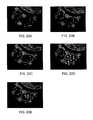
- FIGS. 12B and 12Care images of surgical instruments with the marker pattern of FIG. 12A during a minimally-invasive robotic surgery, in accordance with embodiments.
- FIGS. 13A, 13B, and 13Cillustrate versions of a 2-D marker, in accordance with embodiments.
- FIGS. 14A and 14Brespectively illustrate 2-D markers that can be used for an 8 mm instrument shaft and an 8 mm instrument shaft with the markers, in accordance with embodiments.
- FIGS. 15A and 15Brespectively illustrate 2-D markers that can be used for a 10 mm (ultrasound) instrument shaft and a 10 mm (ultrasound) instrument shaft with the markers, in accordance Keith embodiments.
- FIGS. 16A and 16Brespectively illustrate 2-D markers that can be used for a 5 mm instrument shaft and a 5 mm instrument shaft with the markers, in accordance with embodiments.
- FIGS. 17A and 17Brespectively illustrate 2-D markers that can be used for an ultrasound transducer and an ultrasound transducer with the markers, in accordance with embodiments.
- FIG. 18is a flow diagram of a method for processing stereoscopic images of tool tracking markers, in accordance with embodiments.
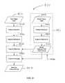
- FIG. 19is a flow diagram of a method for processing stereoscopic images of 2-D tool tracking markers, in accordance with embodiments.
- FIGS. 20A through 20Eillustrate steps for processing an image of a 2-D tool tracking marker, in accordance with embodiments.
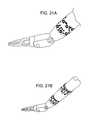
- FIGS. 21A and 21Billustrate how markers at multiple locations can support different operational ranges, in accordance with embodiments.
- FIG. 22Adiagrammatically illustrates a one-dimensional (1-D) tool tracking marker, in accordance with embodiments.
- FIG. 22Bdiagrammatically illustrates a surgical tool having multiple 1-D tool tracking markers, in accordance with embodiments.
- FIGS. 22C and 22Ddiagrammatically illustrate another 1-D tool tracking marker, in accordance with embodiments.
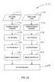
- FIG. 23is a flow diagram for processing stereoscopic images of 1-D tool tracking markers, in accordance with embodiments.
- FIG. 24diagrammatically illustrates primitive features, each feature having a reflective concave spherical surface, being illuminated/imaged from three different directions, in accordance with embodiments.
- FIG. 25diagrammatically illustrates primitive features, each feature having a reflective convex spherical surface, in accordance with embodiments.
- FIGS. 26A and 26Bare endoscopic images of prototype surgical tools having point configuration markers with reflective spherical surfaces, in accordance with embodiments.
- FIG. 27is a flow diagram of a tool tracking method that employs processing of stereoscopic images of a surgical tool having primitive features with reflective spherical surfaces, in accordance with embodiments.
- FIGS. 28A and 28Billustrate discernible tool markers, in accordance with embodiments.
- FIGS. 29A, 29B, 29C, 29D, 29E, 29F, 29G, and 29Hillustrate some exemplar % approaches that can be used to incorporate positional and/or identification information within a discernible marker, in accordance with embodiments.
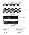
- FIGS. 30A, 30B, 30C, and 30Dillustrate some additional exemplary discernible marker designs, in accordance with embodiments.
- FIG. 31is a flow diagram of a tool tracking method that employs processing of an image of a surgical tool having a discernible marker, in accordance with embodiments.
- improved methods and systemsare provided for three-dimensional (3-D) object tracking using image-derived data from one or more object located reference features. Such methods and systems can be particularly advantageous when employed for tracking surgical tools during minimally-invasive robotic surgery.
- a “feature”is a general term used to denote whatever useful information can be extracted from an image.
- a “primitive feature”is used to denote small or simple features that can be extracted locally from an image (e.g., a salient blob, a small circle, a dot, a bar, etc.).
- a primitive featureis in contrast with a “composite feature”, where multiple primitive features are used to create a composite feature.
- a “marker”is some discernible (typically visible) pattern used for locating an object or computing the pose of an object. A marker can be composed of multiple primitive features.
- a “tool state”is a general term used to denote any information relating to a tool, such as pose (position and orientation), as well as related information for any articulated parts of the tool or any robotic or positioning system used to manipulate the tool.
- a tool statecan include the pose of the tool, robotic joint parameters of a robotic actuation system used to effectuate movement of the tool, articulated end effector positions, velocity of the tool acceleration of the tool, forces on the tool, and the like.
- a “localizer feature”is a feature that can be processed so as to provide positional information for the feature. Multiple primitive localizer features can be processed so as to provide position and orientation (i.e., alignment) information for the rest of the features of a pattern.
- a “model”is a general term used to refer to any, prior knowledge of the physical tool being tracked. This can include a physical model, a virtual model, the locations of the features on the tool and their properties, and the like.
- a tool-located reference featureprovides at least one feature that can be more easily detected within an image.
- Some tool use environmentssuch as minimally-invasive robotic surgery, present challenges to the use of image-derived tool tracking, such as the presence of bodily fluids on the tool and/or the presence of cauterization vapors, which can result in partial or total occlusion of the tool. BY configuring a tool to include one or more reference features, the impact of the environment on image-derived tool tracking can be reduced.
- multiple reference featurescan be used to define a marker that includes position/orientation information and/or identification information.
- a 3-D pose (position and orientation) of an objecte.g., tool
- Position and orientation informationcan be included within a single marker, or it can be included within a combination of markers.
- Identification informationcan be used to relate an imaged marker with associated positional relationship data for that imaged marker and the object. Such identification can be used to distinguish between imaged markers % here multiple markers features are used on the object.
- a toolcan include multiple markers distributed around the tool so as to provide reference features regardless of the particular orientation of the tool during use.
- Any single marker in a collection of markerscan include a number of features so as to provide positional and orientation information for the determination of the 3-D pose of the tool.
- Any particular marker in a collection of markerscan include identification features associated with an identification for the particular marker.
- the redundancy provided by multiple markerscan contribute to a more accurate pose estimation by providing multiple pose estimations that can be averaged so as to reduce random error that may arise during feature localization.
- a markercan include redundant features defining error-checking data.
- the error-checking datacan be checked for consistency with a identification for the marker so as to validate the determined identification.
- the redundant featurescan include check-sum data which can be used to guard against misidentification due to occlusion (or non-imaging in general) of one or more marker features.
- the explicit error-checking mechanismprovides confidence in the detection of such markers by reducing the chance of falsely detecting a marker from background clutter, or accidental alignment of markers close by, to a very low probability.
- a determined 3-D posecan be used to modify a displayed image of the tool in a variety of ways.
- the displayed imagecan be modified so that the added reference features are less visually obtrusive or are “erased” entirely by altering portions of the images located at the reference features.
- FIG. 1provides an appropriate starting point for a discussion of the present invention.
- FIG. 1is a plan view illustration of a Minimally-Invasive Robotic Surgical (MIRS) system 10 , typically used for performing a minimally-invasive diagnostic or surgical procedure on a Patient 12 who is lying on an Operating table 14 .
- the systemcan include a Surgeon's Console 16 for use by a Surgeon 18 during the procedure.
- One or more Assistants 20may also participate in the procedure.
- the MIRS system 10can further include a Patient Side Cart 22 (surgical robot), and a Vision Cart 24 .
- the Patient Side Cart 22can manipulate at least one removably coupled instrument or tool assembly 26 (hereinafter simply referred to as a “tool”) through a minimally invasive incision in the body of the Patient 12 while the Surgeon 18 views the surgical site through the Console 16 .
- An image of the surgical sitecan be obtained bay an endoscope 28 , such as a stereoscopic endoscope, which can be manipulated by the Patient Side Cart 22 so as to orient the endoscope 28 .
- the Vision Cart 24can be used to process the images of the surgical site for subsequent display to the Surgeon 18 through the Surgeon's Console 16 .
- the number of surgical tools 26 used at one timewill generally depend on the diagnostic or surgical procedure and the space constraints within the operating room among other factors.
- an Assistant 20may remove the tool 26 no longer being used at the time from the Patient Side Cart 22 and replace it with another tool 26 from a tray 30 in the operating room.
- An illustrative example of system 10is the da Vinci® Surgical System manufactured by Intuitive Surgical, Inc., Sunnyvale, Calif.
- FIG. 2is a front view of the Surgeon's Console 16 .
- the Surgeon's Console 16includes a left eye display 32 and a right eye display 34 for presenting the Surgeon 18 with a coordinated stereo view of the surgical site that enables depth perception.
- the Console 16further includes one or more control devices 36 , which in turn cause the Patient Side Cart 22 (shown in FIG. 1 ) to manipulate one or more tools.
- control devices 36will provide the same degrees of freedom as their associated tools 26 (shown in FIG. 1 ) so as to provide the Surgeon with telepresence, or the perception that the control devices 36 are integral with the tools 26 so that the Surgeon has a strong sense of directly controlling the tools 26 .
- position, force, and tactile feedback sensorsare preferably, employed to transmit position, force, and tactile sensations from the tools 26 back to the Surgeon's hands through the control devices 36 .
- the Surgeon's Console 16is usually located in the same room as the patient so that the Surgeon may directly monitor the procedure, be physically present if necessary, and speak to an Assistant directly rather than over the telephone or other communication medium. However, it will be understood that the Surgeon can be located in a different room, a different building, or other remote location from the Patient, thus allowing for remote surgical procedures.
- FIG. 3is a front view of a Vision Cart 24 .
- a Vision Cart 24can be coupled with the endoscope 28 and can include a processor to process captured images for subsequent display, such as to a Surgeon on the Surgeon's Console or on any other suitable display located locally and/or remotely.
- the Vision Cart 24can process the captured images so as to present the Surgeon with coordinated stereo images of the surgical site.
- Such coordinationcan include alignment between the opposing images and can include adjusting the stereo working distance of the stereoscopic endoscope.
- image processingcan include the use of previously determined camera calibration parameters so as to compensate for imaging errors of the image capture device, such as optical aberrations.
- FIG. 4diagrammatically illustrates a robotic surgery system 50 (such as MIRS system 10 of FIG. 1 ), showing communication paths between components.
- Surgeon's Console 52(such as Surgeon's Console 16 in FIG. 1 ) can be used by a Surgeon to control a Patient Side Cart (Surgical Robot) 54 (such as Patent Side Cart 22 in FIG. 1 ) during a minimally-invasive procedure.
- the Patient Side Cart 54can use an imaging device, such as a stereoscopic endoscope, to capture images of the procedure site and output the captured images to a Vision Cart 56 (such as Vision Cart 24 in FIG. 1 ).
- a Vision Cart 56can process the captured images in a variety of ways prior to any subsequent display.
- the Patient Side Cart 54can output the captured images for processing outside the Vision Cart 56 .
- the Patient Side Cart 54can output the captured images to a processor 58 , which can be used to process the captured images.
- the imagescan also be processed by a combination the Vision Cart 56 and the processor 58 , which can be coupled together so as to process the captured images jointly, sequentially, and/or combinations thereof.
- One or more separate displays 60can also be coupled with the processor 58 and/or the Vision Cart 56 for local and/or remote display of images, such as images of the procedure site, or any other related images.
- FIGS. 5A, 5B, and 5Cshow a Patient Side Cart 22 , an 8 mm shaft surgical tool 62 , and a 5 mm shaft surgical tool (A, respectively.
- Surgical tools 62 and 64are examples of surgical tools 26 .
- the Patient Side Cart 22 shownprovides for the manipulation of three surgical tools 26 and an imaging device 28 , such as a stereoscopic endoscope used for the capture of images of the site of the procedure. Manipulation is provided bad robotic mechanisms having a number of robotic joints.
- the imaging device 28 and the surgical tools 26e.g., the end effectors 66
- Images of the surgical sitecan include images of distal ends of the surgical tools 26 when they are positioned within the field of view of the imaging device 28 .
- FIG. 6diagrammatically illustrates relative differences between a kinematics-estimated surgical tool pose 70 , an image-derived estimated surgical tool pose 72 , and a true surgical tool pose 74 .
- accurate information of a tool's 3-D poseis important for a number of image-guided surgical and user-interface applications.
- kinematic joint sensor datais used to estimate the tool's 3-D pose, a significant amount of error can be introduced. Although many sources of error exist, such as random sensor noise, a predominant portion of this error can be attributed to offset error, which arises due to fixed differences between a kinematic joint's true position and a kinematic joint's indicated position as indicated by kinematic joint sensor data.
- a kinematics-estimated pose 70can deviate significantly from a true pose 74 for the surgical tool.
- a kinematics-estimated tool pose for an exemplary surgical robot maltdiffer from a true pose for the tool by up to 10 to 15 mm on a well-calibrated system, and even more if the system has not been recently and/or accurately calibrated.
- An image-derived tool pose estimate 72can be significantly more accurate than a raw kinematics-estimated tool pose 70 . This increased accuracy is diagrammatically illustrated in FIG. 6 by the relatively small positional difference between the image-derived tool pose 72 and the true tool pose 74 shown.
- an image-derived tool pose 72may be available at a significantly lower rate (e.g., less than or equal to approximately 30 frames per second) than a raw kinematics-estimated tool pose (e.g., updated at an approximately 1333 Hz rate) due to a number of factors, such as required image processing times, and at certain times it may not be available at all where the tool is outside the view of the imaging device, or is occluded for some reason, such as by patient tissue, by patient bodily fluids, and/or by opaque or translucent vapors due to cauterization, or the like.
- a significantly lower ratee.g., less than or equal to approximately 30 frames per second
- a raw kinematics-estimated tool posee.g., updated at an approximately 1333 Hz rate
- FIG. 7diagrammatically illustrates variations with time between various estimated poses and the true pose 76 of a tool.
- a raw kinematics estimate 78 for a pose for the toolcan deviate significantly from the true pose 76 .
- a predominant portion of this deviationma) be associated with a fixed offset error, which is illustrated by way, of the substantially constant offset between the raw kinematics estimate 78 and the true pose 76 .
- the raw kinematics-estimated pose 78can be available at a high rate, such as 1333 times per second.
- an image-derived pose estimate 80may be available at a lower rate, but can be relatively accurate.
- a combination of kinematics-estimated poses and image-derived estimated posescan be used to determine a true pose estimate 82 , which may track the true pose 76 relatively well. Details of the use of a combination of raw kinematics-estimated poses and image-derived estimated poses for the determination of a true pose estimate 82 are described in numerous patents and patent applications assigned to Intuitive Surgical, Inc. including, for example in U.S. Pat. App. Pub. No. 2006/0258938 A1 (filed May 16, 2005), the full disclosure of which is included herein by reference.
- FIG. 8illustrates variations that can occur in the portion of a surgical instrument 84 (e.g., the tool 26 ) that may, be within view of an imaging device 86 , such as the stereoscopic endoscope 28 .
- the imaging device 86can include two overlapping fields of view 88 used to capture images of the procedure site and any surgical instrument portion within a field of view 88 .
- a greater portion of the surgical instrument 84may be included within the captured image, but the relative size of any imaged tool feature(s) will be smaller as compared with the field of view as a whole.
- a relatively smaller portionmay be included within the captured image, but the relative size of any imaged tool feature(s) will be larger as compared with the field of view as a whole.
- FIG. 9is a flow diagram of a tool tracking method 100 employing imaging of one or more markers attached to a tool.
- a toolsuch as the tool 26
- a toolcan include one or more markers so as to provide features that can be imaged and processed to provide an image-derived tool pose estimate.
- step 102one or more images of the tool and marker are captured.
- the captured image(s)can be a single image obtained through the use of a mono-vision imaging device or stereo images obtained with a stereo-vision imaging device, such as a stereo endoscope.
- the captured image(s)are processed so as to determine positional data associated with one or more marker(s).
- the positional datacan include the location of one or more marker features within the image(s).
- the imagecan be processed in step 106 to determine the identification of one or more of the markers.
- a markercan contain one or more identification features that can be imaged and subsequently processed to determine the identification of the marker.
- the positional data and any identificationcan be used to determine tool state data, such as the tool's 3-D pose. Additional information, such as relative positional data between a marker and the tool can be used during the determination of tool state data. For example, relative 3-D pose offset data (offset position and offset orientation) between the 3-D pose of the marker and the 3-D pose of the tool can provide the relative positional data.
- the tool state data determined in step 108can be rejected if it is insufficiently consistent with an expected tool state data range.
- an estimated 3-D pose for the toolcan be generated by using a prior image of the tool or joint data from a robotic actuation system effecting movement of the tool. This estimated 3-D pose can be compared with the tool state data determined in step 108 so as to verify that they are consistent with each other. Any inconsistency can be evaluated to determine whether to reject the determined tool state data as being an outlier.
- FIG. 10diagrammatically illustrates a system 110 for tracking a tool with marker(s) 112 .
- the systemincludes at least one tool with a marker(s) 112 , similar to the tool 26 .
- An imaging device 114such as the stereoscopic endoscope 28 , is used to capture one or more image(s) of the tool with marker(s) 112 .
- the imaging device 114is coupled with a processor 116 and transfers image data to the processor 116 in response to imaging the tool with marker(s) 112 .
- the processor 116is configured to process the received image data so as to generate tool state data 118 , which can include an estimated 3-D pose for the tool with marker(s) 1112 .
- FIG. 11is a flow diagram of a tool tracking method 120 for determining a tool state showing steps for processing stereo images of markers and raw kinematics data to generate a corrected kinematics-estimated tool state using an image-derived 3-D pose offset, in accordance with an embodiment. Because of the higher update rate of the joint sensor data used to generate an estimated tool state from raw kinematics data 124 as compared to an image-derived estimated tool state, an image-derived pose offset can be combined with an estimated tool state from raw kinematics to generate a corrected kinematics estimated tool state.
- a series of corrected kinematics estimated tool statescan be generated using a single pose offset combined with a corresponding series of estimated tool states from raw kinematics data 124 .
- the pose offsetcan be updated over time in response to new image data 122 .
- the determination of a pose offsetstarts in step 126 with the acquisition of image data of the tool with marker(s) and corresponding raw kinematics data 124 for the tool with marker(s).
- the image data 122can include left image data and right image data, but it should be understood that a single image of one or more marker features can be processed so as to generate image-derived positional information useful in generating a pose offset.
- the location within an image of a single marker featurecan be compared with an expected location within the image for the single marker feature so as to generate a one-dimensional (1-D) correction for the previous pose offset.
- the raw kinematics data 124can include basic sensor data, such as kinematic joint position parameters, and/or can include a current raw kinematics-derived tool state.
- a markerin step 128 , the left image and the right image are processed so as to detect marker features.
- the position of the marker(s) feature(s) within the left image and the position of the marker(s) feature(s) within the right imageare used in step 130 to generate 3-D coordinates for the marker(s) feature(s).
- 3-D coordinatesfor the marker(s) feature(s).
- a markercan include at least one identification feature that can be processed to determine the identification of the marker.
- the 3-D coordinates for the marker(s) features(s)can be processed in combination with any identification(s) of markers(s) so as to determine an image-derived tool state.
- images of a number of markerscan be used to provide sufficient pose information for determining a 3-D pose for the tool, it can be advantageous for a single marker to contain a sufficient number of features for determining a 3-D pose for the tool. Additionally, it can be advantageous for each marker on a tool to have an identification that differs from neighboring markers. With such a marker, an image-derived tool state can be determined by determining the 3-D pose of the marker, determining the identification of the marker, and using data regarding how the identified marker is positioned and oriented on the tool.
- features from a combination of markerscan be combined to determine the 3-D pose of the combination of markers, which can be combined with data regarding how the features from the combination of markers are positioned and oriented on the tool.
- a corrected kinematics estimated tool state(from a previously determined pose offset) can be compared against the image-derived estimated tool state so as to reject any image-derived estimated tool states that differ too much from the corrected kinematics estimated tool state.
- the pose offsetis determined so that it can be combined with a raw kinematics data 124 estimated tool state to obtain a corrected kinematics estimated tool state.
- the pose offsetcan be calculated as a difference between an estimate of the true tool pose (shown in FIG. 7 ) and a corresponding raw kinematics data 124 estimated tool state for substantially the same point in time.
- the pose offsetcan be calculated as a difference between an image-derived estimated tool state and a corresponding raw kinematics data 124 estimated tool state for substantially the same point in time.
- a corrected kinematics based tool stateis determined.
- a single pose offsetcan be used to correct one or more raw kinematics data 124 based tool states so as to compensate when raw kinematics data 124 based tool states are available at a higher rate as compared to image-derived tool states.
- the corrected kinematicscan then be provided back to the start of the process (step 126 ), where the “fetched” current image and kinematics data can include image data, raw kinematics data, and the current pose offset and/or corrected kinematics data.
- a marker design(i) provides sufficient constraint for tool pose estimation; (ii) is distinguishable under various realistic conditions (e.g., viewpoint, lighting) and under various realistic backgrounds; (iii) works with different operational ranges of the tool; (iv) is resilient and/or robust to partial occlusions; (v) is visually acceptable; (vi) is easily manufactured; (vii) is compact enough to allow the use of multiple markers within the space provided (e.g., enough to supply a sufficient level of redundancy), and (viii) can be extracted by an image analysis algorithm.
- One-dimensional (1-D) and two-dimensional (2-D) markerscan provide a number of advantageous aspects. These include: (i) the use of separate localizer and identification features that support more efficient detection and parsing; (ii) the use of explicit coding schemes for primitive feature locations; (iii) the use of explicit error checking and error correction; (iv) the ability, to create a large number of different patterns; (v) the use of a compact marker with dense information; and (vi) the use of a “hypothesize and test” detection algorithm framework, which scales very well with the total number of marker patterns.
- FIGS. 12A, 12B, and 12Cillustrate a marker design 140 , tools 146 employing the marker design 140 operating at a far range from the imaging devices and a tool employing the marker design 140 operating in close range to the imaging device, respectively.
- the marker design 140 of FIG. 12Aincludes three groups of identical patterns 142 that can be placed at 120-degree intervals around a tool shaft. Each pattern 142 has 16 circles in 8 rows and 2 columns on a yellow background. Each pattern 142 can be aligned with the longitudinal axis of a tool shaft so that all of the center points of the 16 circles reside on a single plane. The two columns of circles 144 are spaced relatively closer as compared to the spacing between each pattern 142 .
- This differential spacingcan be used to identify the specific pattern 142 in an image. Since the three patterns 142 are arranged around a tool at 120-degree intervals, there may be a sufficient differential between identical images of the overall marker 140 , given the inherent level of accuracy of a corrected kinematics estimated tool state, to discriminate between imaged patterns 142 .
- Marker 140provides an example how marker features, such as the identical patterns 142 shown, can be arranged so as to present features that can be imaged so as to determine a tool state.
- Drawbacks of this marker designinclude: (i) the yellow background is very bright under surgical illumination and appears intrusive; (ii) although the marker 140 covers the end of the instrument shaft, in most cases it is not fully) visible during surgery; (iii) there is a need to rely on the assumption that the maximum error in an estimated tool roll angle is less than 60 degrees to associate the image observation with one of the three patterns 142 ; and (iv) it is difficult to add more markers on another part of the instrument since the markers are difficult to differentiate.
- FIGS. 13A, 13B, and 13Cillustrate three embodiments of a 2-D marker 150 , 170 , 190 that can be used on a tool for tracking the tool's state.
- a 2-D markerincludes primitive features arranged in two dimensions. Some of the features can serve as localizer features, and the other features can serve as identification features. Localizer features provide positional or orientation information to determine pose/alignment of the marker, and the identification features are used to differentiate different markers. The identification features can follow a certain coding scheme and can include redundant information for error checking and/or correction.
- By using compact 2-D markersmultiple markers can be arranged in different ways to fit the geometric shapes of different tools.
- the markerscan also be arranged at different locations on the tool shaft to cope with different operational ranges.
- the markerscan also be used to estimate the roll of the tool or instrument. Compared to multiple 1-D patterns stacked together, a 2-D marker pattern may advantageously provide better information compactness and locality.
- These 2-D self-discriminative markershave been designed to meet a number of considerations.
- the size of the markershas been selected to be as small as possible, given the constraint of image resolution.
- These 2-D markersdo not rely on a specific color, because color can be an unreliable feature due to dependence on lighting and white balance. Additionally, some colors can be visually intrusive.
- These 2-D markerswere designed to include features that could be reliably detected in images, because some features are easier to detect than others.
- these 2-D markerswere designed to include localizer shapes (the black circles 152 , 154 , 156 , 158 ; 172 , 174 , 176 , 178 ; the black bar 160 ; 180 ; and the saddle points 192 ) and a number of information bits or identification features (nine gray dots 162 in FIG. 13A , thirteen grays dots 182 in FIG. 13B , and the 16 dots 194 in FIG. 13C ).
- localizer shapesthe black circles 152 , 154 , 156 , 158 ; 172 , 174 , 176 , 178 ; the black bar 160 ; 180 ; and the saddle points 192
- a number of information bits or identification featuresno gray dots 162 in FIG. 13A , thirteen grays dots 182 in FIG. 13B , and the 16 dots 194 in FIG. 13C .
- a circlewas chosen as a localizer shape because its topology (a dark blob inside a bright blob, or vice versa) is invariant to view point and it usually does not appear in the background. Other such features include certain corners, especially a saddle point 192 as shown in FIG. 13C .
- the marker designsdo not restrict how the information bits 162 , 182 , 194 (identification features) are used, they can be divided into data and error checking bits. The presence or absence of the dots corresponding to data bits can be used to designate a number of unique codes (or identifications). The presence or absence of the gray dots corresponding to error checking bits can be used to validate a code or identification determination.
- the size of the marker patterns 150 , 170 , 190were selected considering a desired working distance range for minimally-invasive robotic surgery. However, it is appreciated that if the instrument usually works closer or farther away, from an imaging device, the size of the pattern could be made smaller or larger accordingly.
- the markers 150 and 170 shown in FIGS. 13A and 13Binclude a white background and dark features, as can be seen in subsequent figures, a dark background with white features was selected based on clinical feedback on the visual experience. However, it is appreciated that a white background and dark features can also be used.
- the 3-D geometry of the pattern(the 3-D coordinates of all the circles and dots in a local coordinate system) is fixed and known. If a single image is used to provide 2-D coordinates, coordinates of four points are sufficient to determine the pose of the marker (and hence the tool). If stereo images are used to provide 3-D coordinates, coordinates of three points are sufficient to determine the pose of the instrument. Accordingly, the design of these 2-D markers 150 and 170 includes four circles, thereby providing a sufficient number for either single image or stereo image processing. The dots can also be used for object pose estimation. Also, although the markers can be placed on a tool in any number of different orientations, it is presently preferred that the markers be placed so that the vertical direction aligns with the instrument axial direction.
- the marker designs 150 and 170 of FIGS. 13A and 13Brepresent two separate design versions, with the design version of FIG. 13B representing an improved version after experiments. Although the overall size of the pattern did not change, a number of differences exist. The number of information bits 162 and 182 (or identification features) was increased from nine to thirteen, which effectively increased the number of unique patterns. The number of columns for the information bits 162 and 182 increased from three to four, which provided for a more efficient use of limited space. Because it was observed that many typical viewing directions in robotic surgery led to more severe foreshortening of the tool image in the axial direction than in the lateral direction, the pattern of FIG. 13B includes larger vertical spacing between the information bits 182 than horizontal spacing. The rows of the information bits 182 in the pattern of FIG.
- 13Bare also interleaved, which also helps alleviate foreshortening relative to a non-interleaved pattern.
- the diameter of the information bits 162 and 182 (dots) and the thickness of the circleswere also reduced, which resulted from an observation that the testing vision system usually dilated bright features. Accordingly, the features were made thinner to maintain isolation.
- the information bits 162 , 182 , 194 in these 2-D patternscan be used in a variety of ways, such as using a number for identification bits and the remaining number for error checking/correction bits.
- the partition between identification bits and error checking/correction bits and their arrangementare flexible and can be determined based upon the specific application requirements. One may use fewer numbers of bits for error checking/correction if the imaging situation is less challenging.
- the thirteen information bits of the marker of FIG. 13Bare separated into six bits used to carry, identification information (resulting in 64 unique codes), with the remaining seven bits used for error checking/correction. Among the seven error checking/correction bits, six can be set to be the inverse of the identification bits, and the remaining bit can be used as checksum data.
- FIGS. 14A, 14B, 15A, 15B, 16A, 16B, 17A, and 17Bshow four different multiple marker patterns by themselves and as applied to specific robotic tool instruments.
- FIGS. 14A and 14Brespectively illustrate 2-D markers that can be used for an 8 mm (diameter, same convention for other instruments) instrument shaft and an 8 mm instrument shaft with the markers.
- FIGS. 15A and 15Brespectively illustrate 2-D markers that can be used for a 10 mm instrument shaft and a 10 mm instrument shaft with the markers.
- FIGS. 16A and 16Brespectively illustrate 2-D markers that can be used for a 5 mm instrument shaft and a 5 mm instrument shaft with the markers.
- FIGS. 17A and 17Brespectively illustrate a 2-D markers that can be used for an ultrasound transducer and an ultrasound transducer with the markers.
- multiple rows of patternscan be shifted by a half a pattern to ensure some pattern is fully visible at any angle.
- a variety of approachescan be used to extract marker features from images and process the extracted information to determine image-derived tool pose estimates.
- possible approachescan include a top-down approach, a bottom-up approach, and combined top-down/bottom-up approach.
- 2-D imagescan be rendered from a 3-D model of the instrument at a given pose, and the rendered images can be compared with the real input images to evaluate how well they match.
- the pose that gives the best matching scoreis the best solution.
- a bottom-up approachtries to find some local feature in the image and then compute the solution.
- a bottom-up approachcan apply to scenarios where salient local features can be extracted and grouped easily, often under some assumptions or using some heuristics. Since local features are more likely to have ambiguity, markers or background color can be added to ensure the robustness of the method.
- a bottom-up approachis generally more computationally efficient than a top-down approach, since the features can be computed locally and the approach does not involve search or iterative optimization.
- a combined top-down/bottom-up approachcan be used that integrates the advantages of both of the above two classes of methods.
- a bottom-up approachcan be used to report a finite number of hypotheses, which are then tested and verified using a top-down method. This type of method has sometimes been called “hypothesize and test.”
- FIG. 18is a flow diagram of a method 200 for processing stereoscopic endoscope images of tool tracking markers.
- left image data 202 and right image data 204are processed to extract primitive image features.
- Primary image featuresrefers to visually salient features that can be detected locally, such as blobs and corners.
- a blobis a small patch with sufficient contrast with respect to its surroundings.
- a corneris the intersection of two edges.
- a Maximum Stable Extremal Region (MSER) approachprovides an excellent way to detect blobs at an affordable cost.
- MSERis based on a very minimal assumption of boundary contrast and is therefore able to detect salient regions (blobs) of any size, and any shape.
- MS ERsee J. Matas, O. Chum, M. Urban, and T. Pajdla, “Robust wide baseline stereo from maximally stable extremal regions.” In. Proc. BMVC, 2002. We have found MSER to be very effective in detecting artificial fiducial markers.
- An alternative feature (blob) detector approachis to use adaptive thresholding plus connected component analysis.
- the threshold used for binarizationis computed adaptively according to the mean grey value of its neighborhood.
- the kernel convolution to compute the mean at each pixelcan be implemented using integral image for fast mean within a rectangular window.
- adaptive thresholdingis that it works for a fixed scale. For multiple scales, it has to be run multiple times at different scales. One may also consider to run adaptive thresholding and connected component analysis in a pyramid fashion.
- a learning-based approachis also available for dot detection that considers the fine appearance of the dot to disambiguate with background dots (see D. Claus and A. W. Fitzgibbon, “Reliable fiducial detection in natural scenes,” In Proc. European Conf. Computer Vision, 2004). This approach could be used for more complex marker patterns than dots.
- the output from a blob detectoris a list of blobs from the image. It can be much faster to analyze these blobs than all the image pixels.
- We detected circlesby a simple heuristics that the centroid of a bright blob is inside the bounding box of a dark blob and the bounding box of the dark blob is fully contained by the bounding box of the bright blob. There may be better ways to detect bars and circles (e.g., by analyzing their higher order moments). Since our overall method is tolerant to the errors in the lower level processing, we have found these methods to be sufficient.
- the extracted featuresare grouped. Grouping refers to the process of establishing correspondences between the extracted primitive features and the object being imaged, such as a particular marker. This process also needs to account for extracted features that belong to the background instead of the object.
- the primitive feature groupingrelies on knowledge of the marker's configuration to assemble extracted features into groups of features belonging to any particular marker.
- the grouped features of the left image data 202are matched with corresponding grouped features of the right image data 204 .
- the stereo image matched featurescan be processed to determine 3-D data for the features.
- the 3-D data for the featurescan be processed so as to identify the marker and determine a 3-D pose for the marker (data 214 ), which can then be used to determine a 3-D pose for the tool having the marker.
- FIG. 19is a flow diagram of a method 220 that can be used for processing stereo images of tool tracking markers (embodiments of which are shown in FIGS. 13A and 13B ).
- Method 220follows a “hypothesize and test” framework.
- the left image data 222 and the right image data 224can be processed to extract primitive features, which can be accomplished using a variety of methods, such as an above-described method.
- step 228some of the extracted primitive features are processed so as to generate one or more localizer hypotheses (for one or more markers) by identifying one or more primitive features that exhibit characteristics of one or more marker localizer features.
- a localizer hypothesisis a tentative assumption that one or more extracted primitive features correspond to one or more localizer features in a marker.
- One or more localizer featurescan be used to determine positional and at least partial orientation of the marker. For example, in the 2-D markers of FIGS. 13A and 13B , the four circles and the bar can be used as localizer features. With these 2-D markers, the extracted primitive features (or the image data in general) can be processed to look for two circles (designated in FIGS.
- 13A and 13Bas “0” and “1”) within a minimum and maximum distance that have a bar in the middle that is aligned with a line connecting the two circles.
- a partial orientation of the patterncan be determined (i.e., about a line in the image). It is appreciated that a range of different marker patterns can be used and that various combinations of any of the features within a marker pattern can be used as one or more localizer feature.
- step 230the extracted primitive features are processed so as to generate one or more full pattern hypotheses.
- a full pattern hypothesisis a tentative assumption that multiple primitive features correspond to one or more marker features that can be used to determine the basic position and orientation of the marker pattern within the image, which can be skewed or foreshortened as determined by the 3-D pose of the marker relative to the imaging device.
- the localizer hypothesis(the identified circles “0” and “1” with the bar in between) can be used as a starting point to search for the remaining localizer circles (designated in FIGS. 13A and 13B as “2” and “3”).
- the searchcan look for all the compatible localizer “2” and “3” features within a search area defined by a minimum and a maximum pattern skew, and a minimum and a maximum pattern aspect ratio.
- the “2” and “3” circlesdo not have bar between them, which can be used to aid in their identification.
- the combination of the localizer hypothesis and the identified “2” and “3” localizer circlescan be used generate a full pattern hypothesis.
- the full pattern hypothesiscan also be checked to see if its perspective is less than a maximum value, by which the consistency of skew and aspect ratio can be checked.
- step 232one or more of the generated full pattern hypotheses are verified by processing the image features so as to identify the marker.
- the generation of a full pattern hypothesisprovides information regarding the position and orientation of a marker pattern within the image. This information can be used to orient or align candidate marker patterns with the imaged pattern.
- the imaged patterns and the aligned candidate marker patternscan then be checked for consistency. Where consistency exists, the imaged marker pattern can be identified as the candidate marker pattern. For example, with the 2-D marker patterns of FIGS.
- the location of detected 2-D blobs within a full pattern hypothesiscan be compared with locations of information bits set to “1” (i.e., physically present) of a candidate marker pattern model that has been aligned with the full pattern hypothesis.
- the alignment of a candidate marker pattern with a marker imagecan be accomplished by estimating the 3-D pose of the marker relative to the imaging device and aligning a candidate marker with the estimated pose.
- Pose estimationcomputes the 3-D pose of the marker by knowledge of the 3-D geometry of the marker and its 2-D projections in the image.
- the imaging device calibrationis used in the pose estimation process using known methods.
- the pose estimationcan be accomplished using the locations within the image of the four localizer circles.
- the 3-D coordinates of a candidate marker's featurescan be determined and be projected into the image using the known image device calibration. The pixels at these image locations can be checked to decide if there is a dot at that location.
- the alignment of a candidate marker pattern with a marker imagecan also be accomplished by homography.
- Four 2-D point correspondencesdefine a plane perspective transformation (i.e., homography), which contains all the possible transformations of a plane under perspective transformation.
- a plane approximationcan be useful for a wide range of viewpoints.
- This approachinvolves an approximation that the marker features reside on a plane, which provides a simplified process for aligning a candidate marker pattern with a marker image.
- the image locations for the dotscan be based on the image locations of the four circles by assuming the pattern is attached to a plane through a plane perspective transformation (see R.
- the “planar” model dotsdo not exactly coincide with the marker image dots.
- the on/off status of a model dotcan be determined using a nearest-neighbor scheme. When the nearest-neighbor scheme fails, the verification fails.
- homographyhas been found to be able to detect the 2-D pattern correctly for oblique angles up to 45 degrees. Compared to pose estimation, alignment by homography is an approximation. However, it is still appealing in that the imaging device calibration is not required.
- the exact 3-D geometry of the markerdoes not need to be known (e.g., it does not matter if the marker is attached to a 5 mm, a 8 mm, or a 10 mm tool shaft) and therefore allows markers to be attached to different instrument geometries at the same time. These flexibilities may not be critical in a surgical instrument tracking application but may enable other applications.
- Marker designis closely related to how marker features are detected from images.
- the design of marker embodiments disclosed herein and feature detection methods disclosed hereinhave been co-evolved for better overall system performance. For example, with respect to the 2-D marker patterns of FIGS. 13A and 13B , if the bar between the localizer circles “0” and “1” did not exist, the specific details of the detection method would likely need to be modified. However, it is appreciated that a wide variety of marker patterns and corresponding marker feature detection methods can be practice and still be within the spirit and scope of the present invention.
- FIGS. 20A, 20B, 20C, 20D, and 20Eillustrate the method of FIG. 19 as applied to the 2-D marker of FIG. 13B .
- the bright circles in the imageare detected (as shown by the crosshair annotations).
- two localizer hypothesesare formed using adjacent bright circles that have aligned bars.
- a full pattern hypothesisis formed by identifying the designated bright circles by searching relative to the associated localizer hypothesis.
- a candidate marker patternis aligned with the image full pattern hypothesis and the location of candidate marker pattern features relative to the image are determined. The determined locations are used to check the image to see if corresponding detected features are present.
- FIG. 20Eillustrates an exemplar pattern identification code for a verified candidate marker pattern.
- any existing pose estimatessuch as a raw kinematics pose estimate or a corrected kinematics pose estimate, may be used to limit the number of candidate marker patterns.
- the detected marker featuresmay be used directly to determine an identification of a marker pattern by determining directly what marker pattern features are present and which are not present.
- Marker patternscan be arranged on a tool in a variety of ways for a variety of purposes. For example, markers can be arranged at multiple locations on a tool so as to provide for multiple operational ranges.
- FIGS. 21A and 21Billustrate a robotic surgical tool having two circumferential bands of markers that are separated by an axial distance along the tool shaft. In FIG. 21A , the tool is being operated close to the imaging device, thereby placing one of the bands of markers outside the view. In FIG. 21B , the tool is being operated farther away from the imaging device, thereby placing both bands of markers within the view. As shown in FIG. 21B , the features in the marker band closest to the imaging device are larger than the features in the marker band farthest from the imaging device.
- the band of markers disposed closest to the distal operating end of the surgical toolcan provide distinct features for imaging when the other band is out of view.
- One-dimensional (1-D) markerscan be used to determine instrument pose.
- a 1-D markerincludes primitive features arranged in one dimension. Some of the features can serve as localizer features, and the rest of the features can serve as identification features. Similar to 2-D markers, localizer features can be used to provide positional or orientation information to determine the pose/alignment of the marker, and identification features can be used to differentiate different markers. Identification features can follow a coding scheme and can include redundant information for error checking and/or correction.
- FIGS. 22A, 22B, and 22Cillustrate 1-D markers, which employ dots, or a combination of circles and dots.
- FIG. 22Aillustrates a 1-D marker 240 that includes dots forming a straight line.
- marker 240employs dots that are either present (i.e., set to “1”) or absent (i.e., set to “0”).
- Marker 240includes a start pattern 242 , an end pattern 244 , and a center portion 246 having 12 data bits. These 12 data bits can be used in a variety of ways, such as by using some of the data bits as identification bits and some of the data bits as error checking/correction bits, which can include one or more checksum data bits.
- the start pattern 242 and the end pattern 244can be delineated by adjacent blank areas 248 .
- One-dimensional patternshave advantages and disadvantages.
- an advantage of using a 1-D patternis that it works for very, thin instruments, such as a needle where a 2-D pattern would not work.
- a disadvantage of a 1-D patternis that a single 1-D marker does not give the full six-dimensional pose for the object. At least two non-collinear markers are required for a full six-dimensional pose. For very thin objects, the axial roll is not typically observable, so the five-dimensional pose provided by a single 1-D marker is already the most that can be typically obtained.
- FIG. 22Billustrates an image of a surgical tool 250 having 1-D markers 240 , showing three such markers 240 placed in alignment with the surgical tool's shaft axis.
- the markerWhen attaching a 1-D marker to a cylindrical surface, the marker can be aligned with the axis of the cylinder, which results in the marker being disposed along a straight line in 3-D space.
- Such markersmay be particularly advantageous when used on relatively small diameter tool shafts, where more 1-D markers can typically be arranged around the shaft than comparable 2-D markers.
- one concern with a 1-D markeris the length that it requires on an instrument shaft, which may become an issue at close operational ranges that may result in part of a 1-D marker being out of view.
- FIG. 22Cillustrates a modified version of the 1-D marker 240 of FIG. 22A .
- Marker 260incorporates circular features 262 that can be used as localizer features similar to the localizer features of the 2-D markers of FIGS. 13A and 13B described above.
- the use of the circle features 262may help to reduce the length of the pattern, thereby providing a better close range pattern.
- Dots 264can be used for marker identification and error checking/correction data.
- FIG. 22Dillustrates an alternative version of the 1-D marker 260 of FIG. 22C .
- Marker 265incorporates a combination of circular features 266 and bar features 268 .
- Circular features 266can be used as localizer features and bar features 268 can be used for marker identification and error checking/correction data.
- a difference between dots 264 of marker 260 and bar features 268 of marker 265is that with marker 265 information is coded by the positions of the transitions between dark and bright regions, whereas marker 260 uses the positions of the centers of the dots to carry information.
- FIG. 23is a flow diagram of a method 270 that can be used for processing stereo images of one or more 1-D tool tracking markers (embodiments of which are shown in FIGS. 22A, 22B, and 22C ).
- left image data 272 and right image data 274can be processed to extract 2-D blobs (i.e., features), which can be accomplished using approaches as described above with reference to the extraction of 2-D blobs from 2-D markers (see FIG. 19 and related discussion).
- the extracted blobsare grouped into lines. Line grouping can be performed using a Random Sample Consensus (RANSAC) approach by extracting multiple straight lines from all the detected feature points.
- RNSACRandom Sample Consensus
- Random Sample Consensus(For details of Random Sample Consensus, refer to M. A. Fischler and R. C. Bolles, “Random sample Consensus: A paradigm for model fitting with applications to image analysis and automated cartography” Comm. of the ACM, 24: 381-395, 1981, which is hereby incorporated by reference.) More discriminative features against background clutter, such as the circles in the marker of FIG. 22C , can also be used to form hypotheses.
- one or more linesare rectified.
- Line rectificationrefers to removing the perspective effect on the line to restore the metric relationship of the information bits (e.g., dots).
- the vanishing point of the lines parallel to the shaftis sufficient to rectify the line.
- There are a number of ways to obtain the location of the vanishing pointFor example, if there are more than one-visible linear markers on the shaft, the vanishing point is the intersection of these lines.
- images of points with equal or known spacescan be used to compute the vanishing point. (See, for example, FIG. 22C for examples of linear markers having equally spaced circles.)
- one or more markersare identified. Marker identification can involve locating the start and end patterns and then reading the data bits to identify the pattern. It is appreciated that the coding scheme can be designed so as to encode sufficient redundancy for error checking. Where some data bits have been used for error checking, the error checking bits can be read to validate the identification. As discussed above, the error checking data bits can include at least one data bit used as checksum data.
- step 282When a stereo camera is used, once a marker (1-D or 2-D) has been identified, the 3-D reconstruction of step 282 becomes a simple step. The correspondences between the imaged features in both the left and right images are known at this state, and only triangulation is needed. The resulting 3-D marker feature locations can then be used in combination with the known relative spatial arrangement of the marker features relative to the tool to determine a 3-D pose for the tool.
- a toolsuch as the surgical tool 26
- An individual primitive featureis usually not sufficient to serve as a marker because it may not be unique and does not provide enough geometric constraints to determine object pose.
- a number of primitive featurescan be used to form a pattern having a unique configuration in 3-D space, which is herein referred to as a “configuration marker.”
- the patterni.e., configuration
- Three non-collinear features extracted from stereo imagesprovide sufficient information to determine pose for the tool. However, having more features than the minimum requirement can be beneficial in gaining more confidence in detection and better accuracy in pose determination.
- the shape or appearance of the primitive featurescan be identical (e.g., circular disks of the same size), can include a few variations, or can be unique. As such, a wide variety of primitive features can be used, such as circles, dots, bars, corners, etc. Where the primitive features used include some level of variations, the resulting differences in appearance can be used to help match image locations for particular features between two stereoscopic images (i.e., using feature signatures during feature matching) and the images with the model (i.e., using feature signatures invariant or less sensitive to viewpoint and lighting changes).
- a reflective spherical surfacehas the nice property that it appears as a bright spot irrespective of viewpoint as long as a light source and an imaging device are aligned along a common direction, as is tropically the case with endoscopic imaging during minimally-invasive robotic surgery.
- the center of the bright spotalso coincides with the projection of the center of the spherical surface.
- a reflective spherical surfacecan be either concave or convex. In most cases, a reflective spherical surface may produce a bright spot with sufficient contrast with respect to its background to allow detection in an image for a variety, of viewpoints and distances.
- FIG. 24illustrates a primitive feature 300 that includes a concave spherical surface and that is being illuminated/imaged from three directions.
- the spherical surface 302 of the marker 300has a center point 304 through which illumination light that is reflected directly back towards the imaging device travels. Illumination light that does not travel substantially through the center point is reflected away from the illumination/imaging direction.
- Some natural features on a toolmay also appear as salient visual features in captured images. These natural features may provide additional image-derived information regarding the 3-D pose of a tool. Examples of such natural features for an exemplary surgical tool can include the end of a bolt having an approximately spherical surface, and the end of a hinge of an articulated instrument having a reflective concave spherical surface. Such natural features may form stable bright blobs in images similar to those of artificial markers. However, for many tools, such natural features by themselves may not provide a sufficient number of features to form patterns distinctive enough to be extracted against a cluttered background. By introducing artificial primitive features in conjunction with such natural features, sufficient distinctiveness can be achieved. The use of existing natural features helps reduce the number of artificial features added and therefore reduces the changes (such as appearance) to the mechanical device to be tracked.
- FIG. 25illustrates a primitive feature 320 that includes a convex spherical surface 322 and that is being illuminated/imaged from three directions. Similar to the primitive feature of FIG. 24 , the spherical surface 322 has a center point 324 through which illumination light that is reflected directly back towards the imaging device travels. Illumination light that does not travel substantially through the center point is reflected away from the illumination/imaging direction.
- Reflective convex spherical surfacesmay be more suitable for surgical applications than concave reflective spherical surfaces in that blood (or any fluid or substance in general) may be more easily trapped in concave recesses, which may cause a concave primitive feature to lose its contrast with adjacent areas of the tool, or become darker than adjacent areas depending on the amount of blood trapped.
- a reflective convex spherical surfaceis less likely to trap blood.
- the interaction of the reflective convex spherical surface and tissuemay help keep the surface clean, which may help it to produce a bright spot even in a heavy blood field.
- FIGS. 26A and 26Bshow surgical tools having primitive features with reflective spherical surfaces. These surgical tools are for use without any special illumination, but instead are for use with an existing stereo imaging system used by a surgeon to view a procedure site in an exemplary robotic surgery system. This use is in contrast with existing systems that use controlled active infra-red (IR) illumination, which ensures that only the marker points are bright in the view. Which significantly simplifies related image processing and estimation. However, the use of an existing stereo imaging system avoids the added system complexity associated with controlled active IR illumination. Although these surgical tools have primitive features placed on their distal clevis, it is appreciated that primitive features can be placed at other locations, such as on the instrument shaft and/or the proximal clevis. It may be advantageous to select locations that are not prone to reflective image saturation.
- IRactive infra-red
- FIG. 27is a flow diagram of a tool tracking method 340 that employs processing of stereo images of a tool having a configuration marker.
- the methodmakes use of the geometric invariance between the primitive features in three-dimensional space, therefore stereo matching/3-D reconstruction is performed first.
- left image data 342 and right image data 344can be separately processed so as to extract primitive features that exhibit a qualifying amount of contrast relative to adjacent areas (i.e. bright spots).
- the extracted primitive image featuresare processed so as to identify “image signatures” that are consistent with the primitive features used.
- “Signatures”can be extracted for every primitive image feature. Where the primitive features used are identical in shape, their image signatures may be substantially similar. Where the primitive features used have shape or appearance variations, the resulting differences in appearance can be used to help associate a particular primitive feature with a particular primitive image feature, such as a bright spot.
- a primitive image feature signaturecan be extracted from the primitive image feature (i.e., image patch) around the feature point.
- a simple feature signature approachis to use the extracted primitive image feature (image patch) itself as used in traditional stereo.
- HOGHistogram of Gradient
- step 350features in the two stereo images (i.e., left image and right image) are matched.
- Different signatures approachesmay require different matching methods. For example, normalized correlation is used for an image patch signature (see David Forsyth and Jean Ponce, “Computer Vision A Modem Approach,” page 240, Prentice Hall, 2003). With an HOG signature, it has been proposed to use the relative matching score as a measure of confidence, which may likely be a useful approach. Epipolar constraint can be used to constrain the matching only on a straight line (see R. Hartley and A. Zisserman, “Multiple View Geometry in Computer Vision,” Cambridge University Press, 2000). Where multiple good matches exist, all can be kept for processing in the next step.
- the matched featuresare used to generate 3-D coordinates by using stereo triangulation.
- model based signatures maltbe used in step 354 .
- Matching feature signatures between image and modelis expected to be more difficult than matching feature signatures between left and right stereo images, since stereo images have similar viewpoints, illumination, and epipolar constraint.
- the featuresmay need to be invariant to viewpoint and lighting conditions. If identical primitive features are used, it may be more difficult to match against a model.
- primitive featurescan be designed to have shapes (and resulting appearances) that are easy to match under large viewpoint variations.
- One approachis to rely on topological properties that are invariant to viewpoint change.
- An exampleis a circle, such as described above with reference to 1- and 2-D markers.
- a primitive featurecan use multiple bright dots inside a dark dot. Even if not all of the dots are matched with a model, or even if the matches are not unique, partial matching can be useful in feature grouping.
- the matched featuresare used to perform three-dimensional feature grouping so that the correspondence of the observed features with features in the model is established (i.e., to get identified marker points in 3-D 358 ).
- the processuses 3-D positions of the features and optionally their matching score with the model primitive features and/or optionally prior knowledge on the instrument pose.
- Step 352can be performed by a “Constellation algorithm.”
- the Constellation algorithm performedis an efficient Bayesian approach for 3-D grouping based on geometric constraint, appearance constraint, and other prior pose information on the object pose (i.e., prior object pose data 356 ).
- the use of appearance constraintis an option if the geometric constraint is insufficient.
- the output of the Constellation algorithmis the label for each observed feature, taking values from one of the model primitive features or background clutter. Random Sample Consensus (RANSAC) is used at the end to enforce the rigidity constraint.
- RASACRandom Sample Consensus
- the input nodescontains an unknown number of patterns. Missing data and background nodes can exist.
- O[o 1 , . . . , o m ] to be the ownership of each input node; o i ⁇ [0, t]. It is possible that we know a priori knowledge of the ownership of each input node. The prior ownership knowledge can be from local node observation (independent of other nodes) or other sources.
- q(l)denotes the probability of input node i corresponds to model label l. q i (0) should be set to be a small probability.
- P ⁇ ( O )1 Z ⁇ ( ⁇ i , j ⁇ ⁇ 1 , m ⁇ ⁇ ⁇ P i - P j ⁇ ⁇ ⁇ ⁇ ⁇ ⁇ ( o i , o j ) ) ⁇ ( ⁇ i ⁇ ⁇ 1 , m ⁇ ⁇ ⁇ q i ⁇ ( o i ) ) * ( 1 )
- ⁇ i,j (o i , o j )is the pair-wise distance compatibility function within each pattern.
- ⁇is a neighborhood radius defined by the maximum pattern spread in the model.
- the prior knowledge on the pose of the objectcan be used as the following.
- the prior on translationcan be represented in the prior q( ) since this knowledge can be applied to each individual node.
- the prior on rotationcan be represented in the pair-wise potential ⁇ ( ) by the relative orientation of two nodes.
- the joint probability function, equation (1),is in a form of a combination of local potentials and pair-wise potentials.
- This problemcan be solved efficiently using the belief propagation (BP) algorithm.
- the algorithmgives the marginal distribution (ownership) of each node as output. In these particular cases, the interconnection of the nodes can form loops.
- This class of methodis referred to as loopy belief propagation (see K. Murphy, Y. Weiss, and M. Jordan, “Loopy-belief propagation for approximate inference: An empirical study,” In UAI , volume 15, pages 467-475, 1999). It shows very good empirical result even though the optimality is not proven.
- the BP algorithmsee Judea Pearl, “Probabilistic Reasoning in Intelligent Systems: Networks of Plausible Inference.” Morgan Kaufmann, 1988.
- a discernible marker that includes text and/or one or more symbolscan be used for tool tracking.
- Such a discernible markercan include a wide range of text and symbols.
- a discernible markercan include a company name, a company trademark symbol, a product name, a product trademark symbol, a component name, and/or a user name.
- a discernible markercan use a variety of colors set on a variety of backgrounds.
- text and/or symbolsmay be light colored (such as white) set against a dark background (such as black), and vice-versa
- FIGS. 28A and 28Billustrate some exemplary discernible tool markers. It can be advantageous to use a discernible marker that is familiar to a human user. Familiar information tends to blend well with the scene and may cause less distraction to users compared to other markers with similar information content.
- Discernible markerscan include local features that can be used for object pose estimation.
- Standard textcan be used as markers.
- some modifications to the fontcan increase the number of stable features (e.g., corner points), create features that are highly discriminative against background (e.g., a corner within a “checkerboard” pattern or array, or a saddle point), and/or enable more efficient detection methods.
- a markercan include text and/or a symbol that is constructed from a number of rectangular elements selected from a rectangular “checkerboard” array. The selected elements can have a color or a range of colors, and the unselected elements can have a contrasting color or range of colors.
- Local patterns of the selected and/or unselected elementscan provide a local feature that can be imaged and processed so as to determine position and/or identification information for the local feature.
- Such local patternscan include a variety of patterns.
- a local patterncan include variations in the rectangles themselves (e.g., such as size, aspect ratio, color, etc.), variations in local combinations of rectangles (e.g., such as at corners), variations in lines, and variations in scale (e.g., markers at multiple scales or markers within markers).
- FIGS. 29A, 29B, 29C, 29D, 29E, 29F, 29G, and 29Hillustrate some exemplary approaches that can be used to incorporate positional and/or identification information within a discernible marker.
- FIG. 29Aillustrates variations in local combinations of rectangles that can be used at text corner locations. Three exemplar, corner types are shown, specifically corner type 1 360 , corner type 2 362 , and corner type 3 364 . Although three are shown, additional corner types can be formulated using four adjacent grid squares. Additionally, other combinations of grid squares can be used to formulate patterns that can be imaged and processed so as to be identified (e.g., a 3 by 3 pattern, a 3 by 2 pattern, etc.).
- FIGS. 29A, 29B, 29C, 29D, 29E, 29F, 29G, and 29Hillustrate some exemplary approaches that can be used to incorporate positional and/or identification information within a discernible marker.
- FIG. 29Aillustrates variations in local combinations of rectangles that can be used at text corner locations. Three
- FIGS. 29B and 29Cillustrate discernible text constructed using rectangular features selected from a 2-D array (i.e., checkerboard array) of rectangular primitives.
- FIG. 29Dillustrates how a discernible text marker can be configured to have more corner features while still being readable.
- FIGS. 29E and 29Fillustrate how a variation in the amount of overlap between adjacent rectangles can be used to change the appearance of the resulting text ( FIG. 29E having no overlap and FIG. 29F having slight overlap, which makes the “cross” point/saddle point look like a cross point). Such an overlap may help compensate where an imaging system dilates the white area(s).
- FIGS. 29G and 29Hillustrate discernible text markers having features at multiple scales. Unlike the marker shown in FIG. 29G , the marker shown in FIG. 29H does not include a second level that is readily discernible by a human viewer, which may be advantageous in certain situations.
- FIGS. 30A, 30B, 30C, and 30Dillustrate some additional exemplary discernible marker designs.
- Marker 370is similar to marker 190 (shown in FIG. 13C ), but information dots 194 are replaced with discernible letters 372 .
- Marker 380is similar to marker 370 , but has been extended to multiple rows.
- Marker 390is an example where the text background 392 differs from its surroundings 394 so that the rectangular structure of the text background can be used to provide alignment.
- Marker 400is similar to marker 390 , but includes four corners 402 having saddle points, which are more distinctive relative to surroundings.
- Marker 410illustrates the use of a portion of text as a localizer, such as the letter “V” 412 shown and the rest of the text for identification and/or verification (i.e., error checking/correction).
- the part(s) chosen for a localizer(s)can be enlarged or modified with more visual features to ensure they can be detected reliably from images.
- Marker 420illustrates the use of added localizer features, such as circles 422 , that are blended with the text.
- FIG. 31is a flow diagram of a tool tracking method 430 that employs processing of an image of a tool having a discernible marker.
- the method 430produces matched feature points that can be used to estimate a three-dimensional pose for a tool using above described methods.
- step 434feature detection
- feature pointse.g., corners
- a discernable markercan be configured to boost the number of such stable features, such as by using a rectangular font or by including zigzagged strokes (e.g., see FIG. 29D ).
- a variety of approachescan be used for feature detection.
- One such approachis to use a corner detector. (See C. Harris and M. Stephens (1988). “A combined corner and edge detector.” in Proceedings of the 4 th Alvey Vision Conference : pages 147-151.)
- Another approachis to locate distinctive image features from scale-invariant keypoints. (See D. Lowe (2004), “Distinctive Image Features from Scale-Invariant Key points,” in International Journal of Computer Vision, 2004.)
- a description of the neighborhood around a feature point(s)is determined.
- a variety of approachescan be used for feature description.
- One such approachis to use adaptive thresholding to convert a gray scale image to a binary image and use Shape Context as the descriptor.
- Shape ContextAs the descriptor.
- Another approachis to use Histogram of Orientation as the descriptor on a gray scale image. (see D. Lowe (2004), “Distinctive Image Features from Scale-Invariant Keypoints,” in International Journal of Computer Vision, 2004, which is hereby incorporated by reference.)
- step 438feature matching
- individual feature pointsare matched against feature points from images of models using model features with descriptions data 450 .
- the model feature with descriptions data 450can be formulated off-line (using 442 ) by processing model image data 444 so as to detect (step 446 ) and generate descriptions (step 448 ) for model features, which can be accomplished using the above described approaches.
- a number of model images from various viewpointscan be used to facilitate the matching of markers viewed at different viewpoints.
- step 440feature grouping
- the matched featuresare grouped so as to enforce geometric constraints among the matched points.
- Pose estimation and robust estimationcan be used during the grouping of the feature points and can provide for outlier rejection of inconsistent feature points.
- the resulting matched feature points data 452can be used for tool state estimation using above-described methods.
- Pose data from multiple time instancescan be used in the determination of an object's pose. For example, different video frames over time can provide extra constraint on the pose of an object, such as a minimally invasive surgical instrument, that can be used to help outliers which are not consistent with the constraint.
- an objectsuch as a minimally invasive surgical instrument
- Kinematic constrainscan also be used in the determination of an object's pose.
- the surgical instrumentsare inserted into the patient body through insertion points on the body wall. These insertion points are fixed and surgical tools are constrained to pass through these points.
- Such insertion point constraintimplies that the surgical tool's axes at different times intersect at a common point. Accordingly, a tool pose whose axis does not pass through the insertion point can be classified as an outlier and therefore discarded by using a robust estimation technique, such as RANSAC.
- kinematics joint datacan also be used in the determination of an object's pose.
- kinematics joint datacan also be used in the determination of an object's pose.
- Pose data for multiple tools for multiple time instancescan be used to identify a tool in an image of two or more tools. For example, when two or more tools in an image have identical markers, an image-derived pose for one of the tools can be compared with an estimated pose for that tool.
- the estimated posecan be generated by using at least one prior tool state from a prior image of the tool or joint data from a robotic actuation system effectuating movement of the tool. Where the imaged-derived tool pose is within a predetermined deviation of the estimated pose, the identity of the tool can be confirmed.
Landscapes
- Health & Medical Sciences (AREA)
- Engineering & Computer Science (AREA)
- Life Sciences & Earth Sciences (AREA)
- Surgery (AREA)
- Robotics (AREA)
- Animal Behavior & Ethology (AREA)
- Biomedical Technology (AREA)
- Heart & Thoracic Surgery (AREA)
- Medical Informatics (AREA)
- Molecular Biology (AREA)
- Nuclear Medicine, Radiotherapy & Molecular Imaging (AREA)
- General Health & Medical Sciences (AREA)
- Public Health (AREA)
- Veterinary Medicine (AREA)
- Oral & Maxillofacial Surgery (AREA)
- Pathology (AREA)
- Mechanical Engineering (AREA)
- Human Computer Interaction (AREA)
- Multimedia (AREA)
- Signal Processing (AREA)
- Manipulator (AREA)
- Endoscopes (AREA)
- Image Processing (AREA)
Abstract
Description
where ψi,j(oi, oj) is the pair-wise distance compatibility function within each pattern. ε is a neighborhood radius defined by the maximum pattern spread in the model.
where σ is the measurement noise of the distance between nodes and α is a background likelihood which should be lower than the likelihood of a true match.
Claims (24)
Priority Applications (6)
| Application Number | Priority Date | Filing Date | Title |
|---|---|---|---|
| US12/428,657US9526587B2 (en) | 2008-12-31 | 2009-04-23 | Fiducial marker design and detection for locating surgical instrument in images |
| US12/495,304US8971597B2 (en) | 2005-05-16 | 2009-06-30 | Efficient vision and kinematic data fusion for robotic surgical instruments and other applications |
| KR1020117017600AKR101650161B1 (en) | 2008-12-31 | 2009-12-17 | Fiducial marker design and detection for locating surgical instrument in images |
| PCT/US2009/068395WO2010078009A1 (en) | 2008-12-31 | 2009-12-17 | Fiducial marker design and detection for locating surgical instrument in images |
| CN2009801577687ACN102341055A (en) | 2008-12-31 | 2009-12-17 | Fiducial marker design and detection for locating surgical instrument in images |
| EP09801614.0AEP2391290B1 (en) | 2008-12-31 | 2009-12-17 | Fiducial marker design and detection for locating surgical instrument in images |
Applications Claiming Priority (2)
| Application Number | Priority Date | Filing Date | Title |
|---|---|---|---|
| US20408408P | 2008-12-31 | 2008-12-31 | |
| US12/428,657US9526587B2 (en) | 2008-12-31 | 2009-04-23 | Fiducial marker design and detection for locating surgical instrument in images |
Publications (2)
| Publication Number | Publication Date |
|---|---|
| US20100168562A1 US20100168562A1 (en) | 2010-07-01 |
| US9526587B2true US9526587B2 (en) | 2016-12-27 |
Family
ID=42285779
Family Applications (1)
| Application Number | Title | Priority Date | Filing Date |
|---|---|---|---|
| US12/428,657Active2030-02-07US9526587B2 (en) | 2005-05-16 | 2009-04-23 | Fiducial marker design and detection for locating surgical instrument in images |
Country Status (5)
| Country | Link |
|---|---|
| US (1) | US9526587B2 (en) |
| EP (1) | EP2391290B1 (en) |
| KR (1) | KR101650161B1 (en) |
| CN (1) | CN102341055A (en) |
| WO (1) | WO2010078009A1 (en) |
Cited By (148)
| Publication number | Priority date | Publication date | Assignee | Title |
|---|---|---|---|---|
| US20160361819A1 (en)* | 2014-02-28 | 2016-12-15 | Olympus Corporation | Manipulator-calibrating method, manipulator, and manipulator system |
| US20190269465A1 (en)* | 2018-03-02 | 2019-09-05 | Ethicon Llc | System and method for closed-loop surgical tool homing |
| US10413364B1 (en) | 2018-08-08 | 2019-09-17 | Sony Corporation | Internal organ localization of a subject for providing assistance during surgery |
| WO2020009830A1 (en)* | 2018-07-03 | 2020-01-09 | Covidien Lp | Systems, methods, and computer-readable media for detecting image degradation during surgical procedures |
| US10595887B2 (en) | 2017-12-28 | 2020-03-24 | Ethicon Llc | Systems for adjusting end effector parameters based on perioperative information |
| US10605875B2 (en) | 2017-08-28 | 2020-03-31 | Synaptive Medical (Barbados) Inc. | Contrast system and methods for reflective markers |
| WO2020035730A3 (en)* | 2018-08-13 | 2020-05-07 | Body Vision Medical Ltd. | Methods and systems for multi view pose estimation using digital computational tomography |
| US10695081B2 (en) | 2017-12-28 | 2020-06-30 | Ethicon Llc | Controlling a surgical instrument according to sensed closure parameters |
| US10755813B2 (en) | 2017-12-28 | 2020-08-25 | Ethicon Llc | Communication of smoke evacuation system parameters to hub or cloud in smoke evacuation module for interactive surgical platform |
| US10758310B2 (en) | 2017-12-28 | 2020-09-01 | Ethicon Llc | Wireless pairing of a surgical device with another device within a sterile surgical field based on the usage and situational awareness of devices |
| US10772651B2 (en) | 2017-10-30 | 2020-09-15 | Ethicon Llc | Surgical instruments comprising a system for articulation and rotation compensation |
| US10849697B2 (en) | 2017-12-28 | 2020-12-01 | Ethicon Llc | Cloud interface for coupled surgical devices |
| US10881469B2 (en) | 2011-02-15 | 2021-01-05 | Intuitive Surgical Operations, Inc. | System for moveable element position indication |
| US10892899B2 (en) | 2017-12-28 | 2021-01-12 | Ethicon Llc | Self describing data packets generated at an issuing instrument |
| US10892995B2 (en) | 2017-12-28 | 2021-01-12 | Ethicon Llc | Surgical network determination of prioritization of communication, interaction, or processing based on system or device needs |
| US10898622B2 (en) | 2017-12-28 | 2021-01-26 | Ethicon Llc | Surgical evacuation system with a communication circuit for communication between a filter and a smoke evacuation device |
| US10932872B2 (en) | 2017-12-28 | 2021-03-02 | Ethicon Llc | Cloud-based medical analytics for linking of local usage trends with the resource acquisition behaviors of larger data set |
| US10944728B2 (en) | 2017-12-28 | 2021-03-09 | Ethicon Llc | Interactive surgical systems with encrypted communication capabilities |
| US10943454B2 (en) | 2017-12-28 | 2021-03-09 | Ethicon Llc | Detection and escalation of security responses of surgical instruments to increasing severity threats |
| US10966791B2 (en) | 2017-12-28 | 2021-04-06 | Ethicon Llc | Cloud-based medical analytics for medical facility segmented individualization of instrument function |
| US10973520B2 (en) | 2018-03-28 | 2021-04-13 | Ethicon Llc | Surgical staple cartridge with firing member driven camming assembly that has an onboard tissue cutting feature |
| US10987178B2 (en) | 2017-12-28 | 2021-04-27 | Ethicon Llc | Surgical hub control arrangements |
| US11013563B2 (en) | 2017-12-28 | 2021-05-25 | Ethicon Llc | Drive arrangements for robot-assisted surgical platforms |
| US11026687B2 (en) | 2017-10-30 | 2021-06-08 | Cilag Gmbh International | Clip applier comprising clip advancing systems |
| US11026751B2 (en) | 2017-12-28 | 2021-06-08 | Cilag Gmbh International | Display of alignment of staple cartridge to prior linear staple line |
| US11051876B2 (en) | 2017-12-28 | 2021-07-06 | Cilag Gmbh International | Surgical evacuation flow paths |
| US11056244B2 (en) | 2017-12-28 | 2021-07-06 | Cilag Gmbh International | Automated data scaling, alignment, and organizing based on predefined parameters within surgical networks |
| US11058498B2 (en) | 2017-12-28 | 2021-07-13 | Cilag Gmbh International | Cooperative surgical actions for robot-assisted surgical platforms |
| US11069012B2 (en) | 2017-12-28 | 2021-07-20 | Cilag Gmbh International | Interactive surgical systems with condition handling of devices and data capabilities |
| US11076921B2 (en) | 2017-12-28 | 2021-08-03 | Cilag Gmbh International | Adaptive control program updates for surgical hubs |
| US11090047B2 (en) | 2018-03-28 | 2021-08-17 | Cilag Gmbh International | Surgical instrument comprising an adaptive control system |
| US11096693B2 (en) | 2017-12-28 | 2021-08-24 | Cilag Gmbh International | Adjustment of staple height of at least one row of staples based on the sensed tissue thickness or force in closing |
| US11096688B2 (en) | 2018-03-28 | 2021-08-24 | Cilag Gmbh International | Rotary driven firing members with different anvil and channel engagement features |
| US11100631B2 (en) | 2017-12-28 | 2021-08-24 | Cilag Gmbh International | Use of laser light and red-green-blue coloration to determine properties of back scattered light |
| US11109866B2 (en) | 2017-12-28 | 2021-09-07 | Cilag Gmbh International | Method for circular stapler control algorithm adjustment based on situational awareness |
| US11114195B2 (en) | 2017-12-28 | 2021-09-07 | Cilag Gmbh International | Surgical instrument with a tissue marking assembly |
| US11132462B2 (en) | 2017-12-28 | 2021-09-28 | Cilag Gmbh International | Data stripping method to interrogate patient records and create anonymized record |
| US11129611B2 (en) | 2018-03-28 | 2021-09-28 | Cilag Gmbh International | Surgical staplers with arrangements for maintaining a firing member thereof in a locked configuration unless a compatible cartridge has been installed therein |
| US11147607B2 (en) | 2017-12-28 | 2021-10-19 | Cilag Gmbh International | Bipolar combination device that automatically adjusts pressure based on energy modality |
| US11160605B2 (en) | 2017-12-28 | 2021-11-02 | Cilag Gmbh International | Surgical evacuation sensing and motor control |
| US11166772B2 (en) | 2017-12-28 | 2021-11-09 | Cilag Gmbh International | Surgical hub coordination of control and communication of operating room devices |
| US11179175B2 (en) | 2017-12-28 | 2021-11-23 | Cilag Gmbh International | Controlling an ultrasonic surgical instrument according to tissue location |
| US11179208B2 (en) | 2017-12-28 | 2021-11-23 | Cilag Gmbh International | Cloud-based medical analytics for security and authentication trends and reactive measures |
| US11202570B2 (en) | 2017-12-28 | 2021-12-21 | Cilag Gmbh International | Communication hub and storage device for storing parameters and status of a surgical device to be shared with cloud based analytics systems |
| US11207067B2 (en) | 2018-03-28 | 2021-12-28 | Cilag Gmbh International | Surgical stapling device with separate rotary driven closure and firing systems and firing member that engages both jaws while firing |
| US11219453B2 (en) | 2018-03-28 | 2022-01-11 | Cilag Gmbh International | Surgical stapling devices with cartridge compatible closure and firing lockout arrangements |
| US11229436B2 (en) | 2017-10-30 | 2022-01-25 | Cilag Gmbh International | Surgical system comprising a surgical tool and a surgical hub |
| US11234756B2 (en) | 2017-12-28 | 2022-02-01 | Cilag Gmbh International | Powered surgical tool with predefined adjustable control algorithm for controlling end effector parameter |
| US11250604B2 (en) | 2019-05-06 | 2022-02-15 | Apple Inc. | Device, method, and graphical user interface for presenting CGR files |
| US11257589B2 (en) | 2017-12-28 | 2022-02-22 | Cilag Gmbh International | Real-time analysis of comprehensive cost of all instrumentation used in surgery utilizing data fluidity to track instruments through stocking and in-house processes |
| US11253315B2 (en) | 2017-12-28 | 2022-02-22 | Cilag Gmbh International | Increasing radio frequency to create pad-less monopolar loop |
| US11259806B2 (en) | 2018-03-28 | 2022-03-01 | Cilag Gmbh International | Surgical stapling devices with features for blocking advancement of a camming assembly of an incompatible cartridge installed therein |
| US11259830B2 (en) | 2018-03-08 | 2022-03-01 | Cilag Gmbh International | Methods for controlling temperature in ultrasonic device |
| US11259807B2 (en) | 2019-02-19 | 2022-03-01 | Cilag Gmbh International | Staple cartridges with cam surfaces configured to engage primary and secondary portions of a lockout of a surgical stapling device |
| US11266468B2 (en) | 2017-12-28 | 2022-03-08 | Cilag Gmbh International | Cooperative utilization of data derived from secondary sources by intelligent surgical hubs |
| US11273001B2 (en) | 2017-12-28 | 2022-03-15 | Cilag Gmbh International | Surgical hub and modular device response adjustment based on situational awareness |
| US11278280B2 (en) | 2018-03-28 | 2022-03-22 | Cilag Gmbh International | Surgical instrument comprising a jaw closure lockout |
| US11278281B2 (en) | 2017-12-28 | 2022-03-22 | Cilag Gmbh International | Interactive surgical system |
| US11284936B2 (en) | 2017-12-28 | 2022-03-29 | Cilag Gmbh International | Surgical instrument having a flexible electrode |
| US11291495B2 (en) | 2017-12-28 | 2022-04-05 | Cilag Gmbh International | Interruption of energy due to inadvertent capacitive coupling |
| US11291510B2 (en) | 2017-10-30 | 2022-04-05 | Cilag Gmbh International | Method of hub communication with surgical instrument systems |
| US11298148B2 (en) | 2018-03-08 | 2022-04-12 | Cilag Gmbh International | Live time tissue classification using electrical parameters |
| US11304763B2 (en) | 2017-12-28 | 2022-04-19 | Cilag Gmbh International | Image capturing of the areas outside the abdomen to improve placement and control of a surgical device in use |
| US11304699B2 (en) | 2017-12-28 | 2022-04-19 | Cilag Gmbh International | Method for adaptive control schemes for surgical network control and interaction |
| US11304745B2 (en) | 2017-12-28 | 2022-04-19 | Cilag Gmbh International | Surgical evacuation sensing and display |
| US11304720B2 (en) | 2017-12-28 | 2022-04-19 | Cilag Gmbh International | Activation of energy devices |
| US11308075B2 (en) | 2017-12-28 | 2022-04-19 | Cilag Gmbh International | Surgical network, instrument, and cloud responses based on validation of received dataset and authentication of its source and integrity |
| US11311306B2 (en) | 2017-12-28 | 2022-04-26 | Cilag Gmbh International | Surgical systems for detecting end effector tissue distribution irregularities |
| US11311342B2 (en) | 2017-10-30 | 2022-04-26 | Cilag Gmbh International | Method for communicating with surgical instrument systems |
| US11317937B2 (en) | 2018-03-08 | 2022-05-03 | Cilag Gmbh International | Determining the state of an ultrasonic end effector |
| US11317915B2 (en) | 2019-02-19 | 2022-05-03 | Cilag Gmbh International | Universal cartridge based key feature that unlocks multiple lockout arrangements in different surgical staplers |
| US11317919B2 (en) | 2017-10-30 | 2022-05-03 | Cilag Gmbh International | Clip applier comprising a clip crimping system |
| USD950728S1 (en) | 2019-06-25 | 2022-05-03 | Cilag Gmbh International | Surgical staple cartridge |
| US11324557B2 (en) | 2017-12-28 | 2022-05-10 | Cilag Gmbh International | Surgical instrument with a sensing array |
| USD952144S1 (en) | 2019-06-25 | 2022-05-17 | Cilag Gmbh International | Surgical staple cartridge retainer with firing system authentication key |
| US11337746B2 (en) | 2018-03-08 | 2022-05-24 | Cilag Gmbh International | Smart blade and power pulsing |
| US11357503B2 (en) | 2019-02-19 | 2022-06-14 | Cilag Gmbh International | Staple cartridge retainers with frangible retention features and methods of using same |
| US11364075B2 (en) | 2017-12-28 | 2022-06-21 | Cilag Gmbh International | Radio frequency energy device for delivering combined electrical signals |
| US11369377B2 (en) | 2019-02-19 | 2022-06-28 | Cilag Gmbh International | Surgical stapling assembly with cartridge based retainer configured to unlock a firing lockout |
| US11376002B2 (en) | 2017-12-28 | 2022-07-05 | Cilag Gmbh International | Surgical instrument cartridge sensor assemblies |
| US11385761B2 (en) | 2019-05-06 | 2022-07-12 | Apple Inc. | Device, method, and graphical user interface for composing CGR files |
| US11389164B2 (en) | 2017-12-28 | 2022-07-19 | Cilag Gmbh International | Method of using reinforced flexible circuits with multiple sensors to optimize performance of radio frequency devices |
| US11410259B2 (en) | 2017-12-28 | 2022-08-09 | Cilag Gmbh International | Adaptive control program updates for surgical devices |
| WO2022174240A1 (en)* | 2021-02-11 | 2022-08-18 | Siemens Healthcare Diagnostics Inc. | Apparatus and methods for aligning a robotic arm with a sample tube carrier |
| US11424027B2 (en) | 2017-12-28 | 2022-08-23 | Cilag Gmbh International | Method for operating surgical instrument systems |
| US11423007B2 (en) | 2017-12-28 | 2022-08-23 | Cilag Gmbh International | Adjustment of device control programs based on stratified contextual data in addition to the data |
| US11419630B2 (en) | 2017-12-28 | 2022-08-23 | Cilag Gmbh International | Surgical system distributed processing |
| US11419667B2 (en) | 2017-12-28 | 2022-08-23 | Cilag Gmbh International | Ultrasonic energy device which varies pressure applied by clamp arm to provide threshold control pressure at a cut progression location |
| US11432885B2 (en) | 2017-12-28 | 2022-09-06 | Cilag Gmbh International | Sensing arrangements for robot-assisted surgical platforms |
| USD964564S1 (en) | 2019-06-25 | 2022-09-20 | Cilag Gmbh International | Surgical staple cartridge retainer with a closure system authentication key |
| US11446052B2 (en) | 2017-12-28 | 2022-09-20 | Cilag Gmbh International | Variation of radio frequency and ultrasonic power level in cooperation with varying clamp arm pressure to achieve predefined heat flux or power applied to tissue |
| US11464559B2 (en) | 2017-12-28 | 2022-10-11 | Cilag Gmbh International | Estimating state of ultrasonic end effector and control system therefor |
| US11464511B2 (en) | 2019-02-19 | 2022-10-11 | Cilag Gmbh International | Surgical staple cartridges with movable authentication key arrangements |
| US11464535B2 (en) | 2017-12-28 | 2022-10-11 | Cilag Gmbh International | Detection of end effector emersion in liquid |
| US11471156B2 (en) | 2018-03-28 | 2022-10-18 | Cilag Gmbh International | Surgical stapling devices with improved rotary driven closure systems |
| US11504192B2 (en) | 2014-10-30 | 2022-11-22 | Cilag Gmbh International | Method of hub communication with surgical instrument systems |
| US11510741B2 (en) | 2017-10-30 | 2022-11-29 | Cilag Gmbh International | Method for producing a surgical instrument comprising a smart electrical system |
| US11529187B2 (en) | 2017-12-28 | 2022-12-20 | Cilag Gmbh International | Surgical evacuation sensor arrangements |
| US11540855B2 (en) | 2017-12-28 | 2023-01-03 | Cilag Gmbh International | Controlling activation of an ultrasonic surgical instrument according to the presence of tissue |
| US11559308B2 (en) | 2017-12-28 | 2023-01-24 | Cilag Gmbh International | Method for smart energy device infrastructure |
| US11559307B2 (en) | 2017-12-28 | 2023-01-24 | Cilag Gmbh International | Method of robotic hub communication, detection, and control |
| US11564756B2 (en) | 2017-10-30 | 2023-01-31 | Cilag Gmbh International | Method of hub communication with surgical instrument systems |
| US11571234B2 (en) | 2017-12-28 | 2023-02-07 | Cilag Gmbh International | Temperature control of ultrasonic end effector and control system therefor |
| US11576677B2 (en) | 2017-12-28 | 2023-02-14 | Cilag Gmbh International | Method of hub communication, processing, display, and cloud analytics |
| US11589888B2 (en) | 2017-12-28 | 2023-02-28 | Cilag Gmbh International | Method for controlling smart energy devices |
| US11589932B2 (en) | 2017-12-28 | 2023-02-28 | Cilag Gmbh International | Usage and technique analysis of surgeon / staff performance against a baseline to optimize device utilization and performance for both current and future procedures |
| US11596291B2 (en) | 2017-12-28 | 2023-03-07 | Cilag Gmbh International | Method of compressing tissue within a stapling device and simultaneously displaying of the location of the tissue within the jaws |
| US11602393B2 (en) | 2017-12-28 | 2023-03-14 | Cilag Gmbh International | Surgical evacuation sensing and generator control |
| US11612444B2 (en) | 2017-12-28 | 2023-03-28 | Cilag Gmbh International | Adjustment of a surgical device function based on situational awareness |
| US11659023B2 (en) | 2017-12-28 | 2023-05-23 | Cilag Gmbh International | Method of hub communication |
| US11666331B2 (en) | 2017-12-28 | 2023-06-06 | Cilag Gmbh International | Systems for detecting proximity of surgical end effector to cancerous tissue |
| WO2023102422A1 (en)* | 2021-12-01 | 2023-06-08 | Smith & Nephew, Inc. | Bone reamer video based navigation |
| US11744604B2 (en) | 2017-12-28 | 2023-09-05 | Cilag Gmbh International | Surgical instrument with a hardware-only control circuit |
| US11771487B2 (en) | 2017-12-28 | 2023-10-03 | Cilag Gmbh International | Mechanisms for controlling different electromechanical systems of an electrosurgical instrument |
| US11786251B2 (en) | 2017-12-28 | 2023-10-17 | Cilag Gmbh International | Method for adaptive control schemes for surgical network control and interaction |
| US11786245B2 (en) | 2017-12-28 | 2023-10-17 | Cilag Gmbh International | Surgical systems with prioritized data transmission capabilities |
| US11801098B2 (en) | 2017-10-30 | 2023-10-31 | Cilag Gmbh International | Method of hub communication with surgical instrument systems |
| US11818052B2 (en) | 2017-12-28 | 2023-11-14 | Cilag Gmbh International | Surgical network determination of prioritization of communication, interaction, or processing based on system or device needs |
| US11832899B2 (en) | 2017-12-28 | 2023-12-05 | Cilag Gmbh International | Surgical systems with autonomously adjustable control programs |
| US11832840B2 (en) | 2017-12-28 | 2023-12-05 | Cilag Gmbh International | Surgical instrument having a flexible circuit |
| US11857152B2 (en) | 2017-12-28 | 2024-01-02 | Cilag Gmbh International | Surgical hub spatial awareness to determine devices in operating theater |
| US11864728B2 (en) | 2017-12-28 | 2024-01-09 | Cilag Gmbh International | Characterization of tissue irregularities through the use of mono-chromatic light refractivity |
| US11871901B2 (en) | 2012-05-20 | 2024-01-16 | Cilag Gmbh International | Method for situational awareness for surgical network or surgical network connected device capable of adjusting function based on a sensed situation or usage |
| US11896443B2 (en) | 2017-12-28 | 2024-02-13 | Cilag Gmbh International | Control of a surgical system through a surgical barrier |
| US11896322B2 (en) | 2017-12-28 | 2024-02-13 | Cilag Gmbh International | Sensing the patient position and contact utilizing the mono-polar return pad electrode to provide situational awareness to the hub |
| US11903601B2 (en) | 2017-12-28 | 2024-02-20 | Cilag Gmbh International | Surgical instrument comprising a plurality of drive systems |
| US11911045B2 (en) | 2017-10-30 | 2024-02-27 | Cllag GmbH International | Method for operating a powered articulating multi-clip applier |
| US11937769B2 (en) | 2017-12-28 | 2024-03-26 | Cilag Gmbh International | Method of hub communication, processing, storage and display |
| US11969216B2 (en) | 2017-12-28 | 2024-04-30 | Cilag Gmbh International | Surgical network recommendations from real time analysis of procedure variables against a baseline highlighting differences from the optimal solution |
| US11998193B2 (en) | 2017-12-28 | 2024-06-04 | Cilag Gmbh International | Method for usage of the shroud as an aspect of sensing or controlling a powered surgical device, and a control algorithm to adjust its default operation |
| US12029506B2 (en) | 2017-12-28 | 2024-07-09 | Cilag Gmbh International | Method of cloud based data analytics for use with the hub |
| US12035890B2 (en) | 2017-12-28 | 2024-07-16 | Cilag Gmbh International | Method of sensing particulate from smoke evacuated from a patient, adjusting the pump speed based on the sensed information, and communicating the functional parameters of the system to the hub |
| US12062442B2 (en) | 2017-12-28 | 2024-08-13 | Cilag Gmbh International | Method for operating surgical instrument systems |
| US12097002B2 (en) | 2007-06-13 | 2024-09-24 | Intuitive Surgical Operations, Inc. | Medical robotic system with coupled control modes |
| US12127729B2 (en) | 2017-12-28 | 2024-10-29 | Cilag Gmbh International | Method for smoke evacuation for surgical hub |
| US12133773B2 (en) | 2017-12-28 | 2024-11-05 | Cilag Gmbh International | Surgical hub and modular device response adjustment based on situational awareness |
| US12178401B2 (en) | 2019-10-07 | 2024-12-31 | S&N Orion Prime, S.A. | Systems and methods for characterization of an endoscope and automatic calibration of an endoscopic camera system |
| US12226151B2 (en) | 2017-12-28 | 2025-02-18 | Cilag Gmbh International | Capacitive coupled return path pad with separable array elements |
| US12239396B2 (en) | 2008-06-27 | 2025-03-04 | Intuitive Surgical Operations, Inc. | Medical robotic system providing an auxiliary view including range of motion limitations for articulatable instruments extending out of a distal end of an entry guide |
| US12266040B2 (en) | 2009-03-31 | 2025-04-01 | Intuitive Surgical Operations, Inc. | Rendering tool information as graphic overlays on displayed images of tools |
| US12274513B2 (en) | 2021-05-03 | 2025-04-15 | Mazor Robotics Ltd. | Devices, methods, and systems for robot-assisted surgery |
| US12295681B2 (en) | 2007-06-13 | 2025-05-13 | Intuitive Surgical Operations, Inc. | Method and system for retracting an instrument into an entry guide |
| US12303159B2 (en) | 2018-03-08 | 2025-05-20 | Cilag Gmbh International | Methods for estimating and controlling state of ultrasonic end effector |
| US12318152B2 (en) | 2017-12-28 | 2025-06-03 | Cilag Gmbh International | Computer implemented interactive surgical systems |
| US12357400B2 (en) | 2006-06-29 | 2025-07-15 | Intuitive Surgical Operations, Inc. | Synthetic representation of a surgical robot |
| US12376855B2 (en) | 2017-12-28 | 2025-08-05 | Cilag Gmbh International | Safety systems for smart powered surgical stapling |
| US12396806B2 (en) | 2017-12-28 | 2025-08-26 | Cilag Gmbh International | Adjustment of a surgical device function based on situational awareness |
| US12433508B2 (en) | 2017-12-28 | 2025-10-07 | Cilag Gmbh International | Surgical system having a surgical instrument controlled based on comparison of sensor and database data |
Families Citing this family (108)
| Publication number | Priority date | Publication date | Assignee | Title |
|---|---|---|---|---|
| US8073528B2 (en) | 2007-09-30 | 2011-12-06 | Intuitive Surgical Operations, Inc. | Tool tracking systems, methods and computer products for image guided surgery |
| US10555775B2 (en) | 2005-05-16 | 2020-02-11 | Intuitive Surgical Operations, Inc. | Methods and system for performing 3-D tool tracking by fusion of sensor and/or camera derived data during minimally invasive robotic surgery |
| US9867669B2 (en)* | 2008-12-31 | 2018-01-16 | Intuitive Surgical Operations, Inc. | Configuration marker design and detection for instrument tracking |
| US7907166B2 (en)* | 2005-12-30 | 2011-03-15 | Intuitive Surgical Operations, Inc. | Stereo telestration for robotic surgery |
| ES2595366T3 (en) | 2008-01-09 | 2016-12-29 | Stryker European Holdings I, Llc | Computer-assisted stereotactic surgery system based on a three-dimensional visualization |
| US8723795B2 (en) | 2008-04-24 | 2014-05-13 | Oblong Industries, Inc. | Detecting, representing, and interpreting three-space input: gestural continuum subsuming freespace, proximal, and surface-contact modes |
| JP2010082188A (en)* | 2008-09-30 | 2010-04-15 | Olympus Corp | Surgical manipulator system |
| US8184880B2 (en) | 2008-12-31 | 2012-05-22 | Intuitive Surgical Operations, Inc. | Robust sparse image matching for robotic surgery |
| US8830224B2 (en) | 2008-12-31 | 2014-09-09 | Intuitive Surgical Operations, Inc. | Efficient 3-D telestration for local robotic proctoring |
| US8594841B2 (en)* | 2008-12-31 | 2013-11-26 | Intuitive Surgical Operations, Inc. | Visual force feedback in a minimally invasive surgical procedure |
| US8939894B2 (en) | 2009-03-31 | 2015-01-27 | Intuitive Surgical Operations, Inc. | Three-dimensional target devices, assemblies and methods for calibrating an endoscopic camera |
| EP2491337A4 (en)* | 2009-10-20 | 2017-03-22 | Imris Inc. | Imaging system using markers |
| US10588647B2 (en)* | 2010-03-01 | 2020-03-17 | Stryker European Holdings I, Llc | Computer assisted surgery system |
| JP5950902B2 (en)* | 2010-03-31 | 2016-07-13 | コーニンクレッカ フィリップス エヌ ヴェKoninklijke Philips N.V. | Apparatus and method for automatically determining a part of anatomy, image processing system, and computer program |
| US9517107B2 (en) | 2010-07-16 | 2016-12-13 | Stryker European Holdings I, Llc | Surgical targeting system and method |
| US9259289B2 (en) | 2011-05-13 | 2016-02-16 | Intuitive Surgical Operations, Inc. | Estimation of a position and orientation of a frame used in controlling movement of a tool |
| US9198737B2 (en) | 2012-11-08 | 2015-12-01 | Navigate Surgical Technologies, Inc. | System and method for determining the three-dimensional location and orientation of identification markers |
| US8938282B2 (en) | 2011-10-28 | 2015-01-20 | Navigate Surgical Technologies, Inc. | Surgical location monitoring system and method with automatic registration |
| US9566123B2 (en) | 2011-10-28 | 2017-02-14 | Navigate Surgical Technologies, Inc. | Surgical location monitoring system and method |
| US9585721B2 (en) | 2011-10-28 | 2017-03-07 | Navigate Surgical Technologies, Inc. | System and method for real time tracking and modeling of surgical site |
| US11304777B2 (en) | 2011-10-28 | 2022-04-19 | Navigate Surgical Technologies, Inc | System and method for determining the three-dimensional location and orientation of identification markers |
| US9554763B2 (en) | 2011-10-28 | 2017-01-31 | Navigate Surgical Technologies, Inc. | Soft body automatic registration and surgical monitoring system |
| US12070365B2 (en) | 2012-03-28 | 2024-08-27 | Navigate Surgical Technologies, Inc | System and method for determining the three-dimensional location and orientation of identification markers |
| US20130261433A1 (en)* | 2012-03-28 | 2013-10-03 | Navident Technologies, Inc. | Haptic simulation and surgical location monitoring system and method |
| KR20130121521A (en)* | 2012-04-27 | 2013-11-06 | 주식회사 고영테크놀러지 | Method for tracking of the affected part and surgery instrument |
| US11786324B2 (en)* | 2012-06-21 | 2023-10-17 | Globus Medical, Inc. | Surgical robotic automation with tracking markers |
| KR102194463B1 (en)* | 2012-08-14 | 2020-12-23 | 인튜어티브 서지컬 오퍼레이션즈 인코포레이티드 | Systems and methods for registration of multiple vision systems |
| KR102184960B1 (en) | 2012-08-15 | 2020-12-01 | 인튜어티브 서지컬 오퍼레이션즈 인코포레이티드 | Movable surgical mounting platform controlled by manual motion of robotic arms |
| US10039606B2 (en) | 2012-09-27 | 2018-08-07 | Stryker European Holdings I, Llc | Rotational position determination |
| DE102012217942A1 (en)* | 2012-10-01 | 2014-06-12 | Siemens Aktiengesellschaft | Medical instrument, medical system and method for displaying the position of a placemark |
| WO2014093824A1 (en)* | 2012-12-14 | 2014-06-19 | The Trustees Of Columbia University In The City Of New York | Markerless tracking of robotic surgical tools |
| US10588597B2 (en)* | 2012-12-31 | 2020-03-17 | Intuitive Surgical Operations, Inc. | Systems and methods for interventional procedure planning |
| CN105050525B (en) | 2013-03-15 | 2018-07-31 | 直观外科手术操作公司 | Shape sensor system for tracking interventional instruments and method of use |
| US10925493B2 (en)* | 2013-03-15 | 2021-02-23 | Lantos Technologies, Inc. | Fiducial markers for fluorescent 3D imaging |
| EP2996609A2 (en)* | 2013-03-18 | 2016-03-23 | Navigate Surgical Technologies Inc. | Method for determining the location and orientation of a fiducial reference |
| KR102117273B1 (en) | 2013-03-21 | 2020-06-01 | 삼성전자주식회사 | Surgical robot system and method for controlling the same |
| US20160045276A1 (en)* | 2013-04-04 | 2016-02-18 | The Board Of Trustees Of The University Of Illinois | Systems and methods for identifying instruments |
| KR20140126473A (en)* | 2013-04-23 | 2014-10-31 | 삼성전자주식회사 | Marker and method for estimating surgical instrument pose using the same |
| US9489738B2 (en) | 2013-04-26 | 2016-11-08 | Navigate Surgical Technologies, Inc. | System and method for tracking non-visible structure of a body with multi-element fiducial |
| US9456122B2 (en) | 2013-08-13 | 2016-09-27 | Navigate Surgical Technologies, Inc. | System and method for focusing imaging devices |
| JP2016536076A (en) | 2013-08-13 | 2016-11-24 | ナビゲート サージカル テクノロジーズ インク | Method for determining the position and orientation of a reference reference |
| WO2015040657A1 (en)* | 2013-09-20 | 2015-03-26 | 富士通株式会社 | Image processing device, image processing method, and image processing program |
| KR101532717B1 (en)* | 2013-09-24 | 2015-07-01 | 주식회사 고영테크놀러지 | Tracking marker for a patient and tracking system using the same |
| CN105592818B (en)* | 2013-10-04 | 2017-11-03 | 史赛克公司 | system for interacting with objects |
| US9724795B2 (en)* | 2013-11-07 | 2017-08-08 | Apex Brands, Inc. | Tooling system with visual identification of attached component |
| US9622720B2 (en) | 2013-11-27 | 2017-04-18 | Clear Guide Medical, Inc. | Ultrasound system with stereo image guidance or tracking |
| US8880151B1 (en)* | 2013-11-27 | 2014-11-04 | Clear Guide Medical, Llc | Surgical needle for a surgical system with optical recognition |
| KR101527176B1 (en)* | 2013-12-09 | 2015-06-09 | (주)미래컴퍼니 | Surgical Robot Apparatus and Method for Controlling Surgical Robot Apparatus |
| US20150223899A1 (en)* | 2014-02-11 | 2015-08-13 | Brian Kieser | Method of manufacturing a structurally encoded implantable device |
| US10258414B2 (en)* | 2014-03-17 | 2019-04-16 | Intuitive Surgical Operations, Inc. | Methods and devices for table pose tracking using fudicial markers |
| WO2015155644A1 (en)* | 2014-04-11 | 2015-10-15 | Koninklijke Philips N.V. | Automatic configuration detection for sensor equipped needle |
| KR102477470B1 (en) | 2014-11-21 | 2022-12-13 | 씽크 써지컬, 인크. | Visible light communication system for transmitting data between visual tracking systems and tracking markers |
| US10869597B2 (en) | 2014-11-25 | 2020-12-22 | Lantos Technologies, Inc. | Air removal and fluid transfer from a closed system |
| US10376181B2 (en)* | 2015-02-17 | 2019-08-13 | Endochoice, Inc. | System for detecting the location of an endoscopic device during a medical procedure |
| US10792109B2 (en)* | 2015-03-05 | 2020-10-06 | Think Surgical, Inc. | Methods for locating and tracking a tool axis |
| US20160278864A1 (en)* | 2015-03-19 | 2016-09-29 | Medtronic Navigation, Inc. | Apparatus And Method For Instrument And Gesture Based Image Guided Surgery |
| US10499996B2 (en) | 2015-03-26 | 2019-12-10 | Universidade De Coimbra | Methods and systems for computer-aided surgery using intra-operative video acquired by a free moving camera |
| CN114795471A (en)* | 2015-04-06 | 2022-07-29 | 直观外科手术操作公司 | System and method for registration compensation in image-guided surgery |
| WO2017050761A1 (en)* | 2015-09-21 | 2017-03-30 | Navigate Surgical Technologies, Inc. | System and method for determining the three-dimensional location and orientation of identification markers |
| CN108476352A (en) | 2015-10-09 | 2018-08-31 | 兰托斯科技公司 | Custom Earbud Scanning and Manufacturing |
| EP4375934A3 (en) | 2016-02-12 | 2024-07-31 | Intuitive Surgical Operations, Inc. | Systems and methods of pose estimation and calibration of perspective imaging system in image guided surgery |
| WO2017144934A1 (en) | 2016-02-26 | 2017-08-31 | Trophy | Guided surgery apparatus and method |
| US20190090955A1 (en)* | 2016-03-01 | 2019-03-28 | Mirus Llc | Systems and methods for position and orientation tracking of anatomy and surgical instruments |
| KR101820682B1 (en) | 2016-08-09 | 2018-01-23 | 주식회사 고영테크놀러지 | Marker for optical tracking, optical tracking system, and optical tracking method |
| US10413373B2 (en)* | 2016-08-16 | 2019-09-17 | Ethicon, Llc | Robotic visualization and collision avoidance |
| CN110248618B (en) | 2016-09-09 | 2024-01-09 | 莫比乌斯成像公司 | Method and system for displaying patient data in computer-assisted surgery |
| US20180092698A1 (en)* | 2016-10-04 | 2018-04-05 | WortheeMed, Inc. | Enhanced Reality Medical Guidance Systems and Methods of Use |
| US11534243B2 (en)* | 2016-11-23 | 2022-12-27 | Clear Guide Medical, Inc. | System and methods for navigating interventional instrumentation |
| US11998282B2 (en) | 2016-12-16 | 2024-06-04 | Intuitive Surgical Operations, Inc. | Systems and methods for teleoperated control of an imaging instrument |
| CA3040177A1 (en) | 2016-12-19 | 2018-06-28 | Robert J. Fei | Manufacture of inflatable membranes |
| US10244926B2 (en) | 2016-12-28 | 2019-04-02 | Auris Health, Inc. | Detecting endolumenal buckling of flexible instruments |
| CN108261167B (en)* | 2017-01-03 | 2019-12-03 | 上银科技股份有限公司 | Introscope control system |
| US10357325B2 (en) | 2017-01-16 | 2019-07-23 | The Aga Khan University | Detection of surgical instruments on surgical tray |
| US10509513B2 (en) | 2017-02-07 | 2019-12-17 | Oblong Industries, Inc. | Systems and methods for user input device tracking in a spatial operating environment |
| US20200246105A1 (en)* | 2017-10-19 | 2020-08-06 | Intuitive Surgical Operations, Inc. | Systems and methods for illumination of a patient anatomy in a teleoperational system |
| CN108030551B (en)* | 2017-12-06 | 2020-02-18 | 上海波城医疗科技有限公司 | System and method for correcting stroke of surgical mechanical arm |
| US11510736B2 (en)* | 2017-12-14 | 2022-11-29 | Auris Health, Inc. | System and method for estimating instrument location |
| CN109109018B (en)* | 2018-09-13 | 2021-09-14 | 上海微创医疗机器人(集团)股份有限公司 | Device and method for detecting working state of sensing equipment on mechanical arm, mechanical arm and medical robot |
| US11113837B2 (en)* | 2019-10-25 | 2021-09-07 | 7-Eleven, Inc. | Sensor mapping to a global coordinate system |
| US11720766B2 (en)* | 2018-12-28 | 2023-08-08 | Packsize Llc | Systems and methods for text and barcode reading under perspective distortion |
| FR3092747A1 (en)* | 2019-02-14 | 2020-08-21 | Sylorus Robotics | Facility for robotic spine surgery |
| KR102275385B1 (en)* | 2019-05-16 | 2021-07-09 | 주식회사 데카사이트 | System and method for tracking motion of medical device using augmented reality |
| US11602258B2 (en)* | 2019-05-31 | 2023-03-14 | Intuitive Surgical Operations, Inc. | Surgical instruments and systems and methods for determining condition information thereof |
| CN110464469B (en)* | 2019-09-10 | 2020-12-01 | 深圳市精锋医疗科技有限公司 | Surgical robot, method and device for controlling distal end instrument, and storage medium |
| US12268459B2 (en)* | 2019-11-26 | 2025-04-08 | Intuitive Surgical Operations, Inc. | Physical medical element affixation systems, methods, and materials |
| WO2021158305A1 (en)* | 2020-02-04 | 2021-08-12 | Covidien Lp | Systems and methods for machine readable identification of surgical tools in-situ |
| EP4158532A1 (en)* | 2020-06-02 | 2023-04-05 | VISIONSENSE Ltd. | System and method for determining tool positioning, and fiducial marker therefore |
| WO2021252263A1 (en)* | 2020-06-08 | 2021-12-16 | Mazor Robotics Ltd | Robotic reference frames for navigation |
| KR20230034296A (en)* | 2020-06-11 | 2023-03-09 | 모노그램 올소패딕스 인크. | Navigation and/or robot tracking methods and systems |
| KR102426925B1 (en)* | 2020-06-23 | 2022-07-29 | (주)휴톰 | Method and program for acquiring motion information of a surgical robot using 3d simulation |
| EP4171890B1 (en) | 2020-06-30 | 2025-08-13 | Mazor Robotics Ltd. | Time-spaced robotic reference frames |
| CN111821025B (en)* | 2020-07-21 | 2022-05-13 | 腾讯科技(深圳)有限公司 | Space positioning method, device, equipment, storage medium and navigation bar |
| CN112043381B (en)* | 2020-08-24 | 2025-06-03 | 雅客智慧(北京)科技有限公司 | Surgical navigation system and identification method thereof |
| CN111768408B (en)* | 2020-09-01 | 2020-11-27 | 安翰科技(武汉)股份有限公司 | Gastrointestinal marker automatic identification method and gastrointestinal marker automatic identification system |
| CN112043397B (en)* | 2020-10-08 | 2021-09-24 | 深圳市精锋医疗科技有限公司 | Surgical robot and motion error detection method and detection device thereof |
| CN112515695B (en)* | 2020-12-02 | 2024-05-10 | 上海西门子医疗器械有限公司 | CT machine system and state monitoring method thereof |
| EP4338410A2 (en)* | 2021-05-12 | 2024-03-20 | Ncam Technologies Limited | Methods for tracking a camera bar, and related methods, systems and computer program products |
| CN115731289A (en)* | 2021-08-31 | 2023-03-03 | 术锐(上海)科技有限公司 | Method and surgical robotic system for determining the pose of an object |
| CN113496512B (en)* | 2021-09-06 | 2021-12-17 | 北京字节跳动网络技术有限公司 | Tissue cavity positioning method, device, medium and equipment for endoscope |
| CN113974837B (en)* | 2021-11-02 | 2023-09-19 | 武汉联影智融医疗科技有限公司 | End tool identification system, end tool identification method, end tool and surgical robot system |
| US11311346B1 (en)* | 2021-11-24 | 2022-04-26 | Bh2 Innovations Inc. | Systems and methods for automated control of medical instruments using artificial intelligence |
| DE102022104138A1 (en)* | 2022-02-22 | 2023-08-24 | Karl Storz Se & Co. Kg | Medical imaging device, medical system, method for operating a medical imaging device and method for medical imaging |
| EP4389050A1 (en) | 2022-12-22 | 2024-06-26 | Ecential Robotics | Tracking assembly and robotic system |
| US20240374318A1 (en)* | 2023-05-12 | 2024-11-14 | Stryker Corporation | Systems, devices, and methods for determining positions of surgical tools in endoscopic images |
| CN117243699B (en)* | 2023-11-14 | 2024-03-15 | 杭州三坛医疗科技有限公司 | Displacement detection method and device |
| US20250177700A1 (en)* | 2023-12-04 | 2025-06-05 | Freenav, Inc. | Device, system, and method for dual purpose tracking |
| CN117745826B (en)* | 2023-12-21 | 2024-09-06 | 武汉星巡智能科技有限公司 | Learning accompanying method, device, robot and medium based on text corner detection |
| CN117956670A (en)* | 2024-03-26 | 2024-04-30 | 有方(合肥)医疗科技有限公司 | Imaging control method, device, imaging system and readable storage medium |
Citations (34)
| Publication number | Priority date | Publication date | Assignee | Title |
|---|---|---|---|---|
| US4614366A (en) | 1983-11-18 | 1986-09-30 | Exactident, Inc. | Nail identification wafer |
| US5572999A (en)* | 1992-05-27 | 1996-11-12 | International Business Machines Corporation | Robotic system for positioning a surgical instrument relative to a patient's body |
| US5836869A (en) | 1994-12-13 | 1998-11-17 | Olympus Optical Co., Ltd. | Image tracking endoscope system |
| US5848967A (en)* | 1991-01-28 | 1998-12-15 | Cosman; Eric R. | Optically coupled frameless stereotactic system and method |
| US5891034A (en)* | 1990-10-19 | 1999-04-06 | St. Louis University | System for indicating the position of a surgical probe within a head on an image of the head |
| US6006126A (en)* | 1991-01-28 | 1999-12-21 | Cosman; Eric R. | System and method for stereotactic registration of image scan data |
| US6122541A (en)* | 1995-05-04 | 2000-09-19 | Radionics, Inc. | Head band for frameless stereotactic registration |
| US6167295A (en)* | 1991-01-28 | 2000-12-26 | Radionics, Inc. | Optical and computer graphic stereotactic localizer |
| US20020065461A1 (en)* | 1991-01-28 | 2002-05-30 | Cosman Eric R. | Surgical positioning system |
| US6434416B1 (en) | 1998-11-10 | 2002-08-13 | Olympus Optical Co., Ltd. | Surgical microscope |
| US6468265B1 (en) | 1998-11-20 | 2002-10-22 | Intuitive Surgical, Inc. | Performing cardiac surgery without cardioplegia |
| US20020193686A1 (en)* | 2000-01-10 | 2002-12-19 | Pinhas Gilboa | Methods and systems for performing medical procedures with reference to projective image and with respect to pre-stored images |
| US20030210812A1 (en) | 2002-02-26 | 2003-11-13 | Ali Khamene | Apparatus and method for surgical navigation |
| US20040002642A1 (en) | 2002-07-01 | 2004-01-01 | Doron Dekel | Video pose tracking system and method |
| US20040052333A1 (en) | 2002-09-13 | 2004-03-18 | James Sayre | Device and method for margin marking of radiography specimens |
| US20040138556A1 (en) | 1991-01-28 | 2004-07-15 | Cosman Eric R. | Optical object tracking system |
| US6826423B1 (en)* | 1999-01-04 | 2004-11-30 | Midco-Medical Instrumentation And Diagnostics Corporation | Whole body stereotactic localization and immobilization system |
| US20050182295A1 (en)* | 2003-12-12 | 2005-08-18 | University Of Washington | Catheterscope 3D guidance and interface system |
| WO2005102202A1 (en) | 2004-04-26 | 2005-11-03 | Orthosoft Inc. | Method for permanent calibration based on actual measurement |
| US20060142657A1 (en) | 2002-03-06 | 2006-06-29 | Mako Surgical Corporation | Haptic guidance system and method |
| US20060258938A1 (en)* | 2005-05-16 | 2006-11-16 | Intuitive Surgical Inc. | Methods and system for performing 3-D tool tracking by fusion of sensor and/or camera derived data during minimally invasive robotic surgery |
| WO2006131373A2 (en) | 2005-06-09 | 2006-12-14 | Ife Industrielle Forschung Und Entwicklung Gmbh | Device for the contactless determination and measurement of a spatial position and/or a spatial orientation of bodies |
| US20070013336A1 (en)* | 2005-05-19 | 2007-01-18 | Intuitive Surgical Inc. | Software center and highly configurable robotic systems for surgery and other uses |
| US20070167702A1 (en)* | 2005-12-30 | 2007-07-19 | Intuitive Surgical Inc. | Medical robotic system providing three-dimensional telestration |
| US20070183041A1 (en) | 2006-02-09 | 2007-08-09 | Northern Digital Inc. | Retroreflective marker-tracking systems |
| US20070265527A1 (en)* | 2006-05-11 | 2007-11-15 | Richard Wohlgemuth | Medical position determination using redundant position detection means and priority weighting for the position detection means |
| US20080132909A1 (en)* | 2006-12-01 | 2008-06-05 | Medtronic Navigation, Inc. | Portable electromagnetic navigation system |
| US20080240551A1 (en)* | 2007-03-30 | 2008-10-02 | Microsoft Corporation | Local bi-gram model for object recognition |
| US20080262345A1 (en) | 2003-07-21 | 2008-10-23 | The John Hopkins University | Image registration of multiple medical imaging modalities using a multiple degree-of-freedom-encoded fiducial device |
| US20080285724A1 (en)* | 2007-05-05 | 2008-11-20 | Ziehm Imaging Gmbh | X-ray diagnostic imaging system with a plurality of coded markers |
| US7747311B2 (en)* | 2002-03-06 | 2010-06-29 | Mako Surgical Corp. | System and method for interactive haptic positioning of a medical device |
| US20100168763A1 (en) | 2008-12-31 | 2010-07-01 | Intuitive Surgical, Inc. | Configuration marker design and detection for instrument tracking |
| US7797032B2 (en)* | 1999-10-28 | 2010-09-14 | Medtronic Navigation, Inc. | Method and system for navigating a catheter probe in the presence of field-influencing objects |
| US7831292B2 (en)* | 2002-03-06 | 2010-11-09 | Mako Surgical Corp. | Guidance system and method for surgical procedures with improved feedback |
Family Cites Families (1)
| Publication number | Priority date | Publication date | Assignee | Title |
|---|---|---|---|---|
| US6720988B1 (en) | 1998-12-08 | 2004-04-13 | Intuitive Surgical, Inc. | Stereo imaging system and method for use in telerobotic systems |
- 2009
- 2009-04-23USUS12/428,657patent/US9526587B2/enactiveActive
- 2009-12-17KRKR1020117017600Apatent/KR101650161B1/enactiveActive
- 2009-12-17EPEP09801614.0Apatent/EP2391290B1/enactiveActive
- 2009-12-17CNCN2009801577687Apatent/CN102341055A/enactivePending
- 2009-12-17WOPCT/US2009/068395patent/WO2010078009A1/enactiveApplication Filing
Patent Citations (42)
| Publication number | Priority date | Publication date | Assignee | Title |
|---|---|---|---|---|
| US4614366A (en) | 1983-11-18 | 1986-09-30 | Exactident, Inc. | Nail identification wafer |
| US5891034A (en)* | 1990-10-19 | 1999-04-06 | St. Louis University | System for indicating the position of a surgical probe within a head on an image of the head |
| US20060241400A1 (en)* | 1990-10-19 | 2006-10-26 | St. Louis University | Method of determining the position of an instrument relative to a body of a patient |
| US7072704B2 (en)* | 1990-10-19 | 2006-07-04 | St. Louis University | System for indicating the position of a surgical probe within a head on an image of the head |
| US20040138556A1 (en) | 1991-01-28 | 2004-07-15 | Cosman Eric R. | Optical object tracking system |
| US5848967A (en)* | 1991-01-28 | 1998-12-15 | Cosman; Eric R. | Optically coupled frameless stereotactic system and method |
| US6006126A (en)* | 1991-01-28 | 1999-12-21 | Cosman; Eric R. | System and method for stereotactic registration of image scan data |
| US6167295A (en)* | 1991-01-28 | 2000-12-26 | Radionics, Inc. | Optical and computer graphic stereotactic localizer |
| US20020188194A1 (en)* | 1991-01-28 | 2002-12-12 | Sherwood Services Ag | Surgical positioning system |
| US6405072B1 (en)* | 1991-01-28 | 2002-06-11 | Sherwood Services Ag | Apparatus and method for determining a location of an anatomical target with reference to a medical apparatus |
| US6275725B1 (en)* | 1991-01-28 | 2001-08-14 | Radionics, Inc. | Stereotactic optical navigation |
| US6351661B1 (en)* | 1991-01-28 | 2002-02-26 | Sherwood Services Ag | Optically coupled frameless stereotactic space probe |
| US20020065461A1 (en)* | 1991-01-28 | 2002-05-30 | Cosman Eric R. | Surgical positioning system |
| US6201984B1 (en) | 1991-06-13 | 2001-03-13 | International Business Machines Corporation | System and method for augmentation of endoscopic surgery |
| US5572999A (en)* | 1992-05-27 | 1996-11-12 | International Business Machines Corporation | Robotic system for positioning a surgical instrument relative to a patient's body |
| US5836869A (en) | 1994-12-13 | 1998-11-17 | Olympus Optical Co., Ltd. | Image tracking endoscope system |
| US6122541A (en)* | 1995-05-04 | 2000-09-19 | Radionics, Inc. | Head band for frameless stereotactic registration |
| US6246900B1 (en)* | 1995-05-04 | 2001-06-12 | Sherwood Services Ag | Head band for frameless stereotactic registration |
| US6434416B1 (en) | 1998-11-10 | 2002-08-13 | Olympus Optical Co., Ltd. | Surgical microscope |
| US6468265B1 (en) | 1998-11-20 | 2002-10-22 | Intuitive Surgical, Inc. | Performing cardiac surgery without cardioplegia |
| US6826423B1 (en)* | 1999-01-04 | 2004-11-30 | Midco-Medical Instrumentation And Diagnostics Corporation | Whole body stereotactic localization and immobilization system |
| US7797032B2 (en)* | 1999-10-28 | 2010-09-14 | Medtronic Navigation, Inc. | Method and system for navigating a catheter probe in the presence of field-influencing objects |
| US20020193686A1 (en)* | 2000-01-10 | 2002-12-19 | Pinhas Gilboa | Methods and systems for performing medical procedures with reference to projective image and with respect to pre-stored images |
| US20030210812A1 (en) | 2002-02-26 | 2003-11-13 | Ali Khamene | Apparatus and method for surgical navigation |
| US7747311B2 (en)* | 2002-03-06 | 2010-06-29 | Mako Surgical Corp. | System and method for interactive haptic positioning of a medical device |
| US7831292B2 (en)* | 2002-03-06 | 2010-11-09 | Mako Surgical Corp. | Guidance system and method for surgical procedures with improved feedback |
| US20060142657A1 (en) | 2002-03-06 | 2006-06-29 | Mako Surgical Corporation | Haptic guidance system and method |
| US20040002642A1 (en) | 2002-07-01 | 2004-01-01 | Doron Dekel | Video pose tracking system and method |
| US20040052333A1 (en) | 2002-09-13 | 2004-03-18 | James Sayre | Device and method for margin marking of radiography specimens |
| US20080262345A1 (en) | 2003-07-21 | 2008-10-23 | The John Hopkins University | Image registration of multiple medical imaging modalities using a multiple degree-of-freedom-encoded fiducial device |
| US20050182295A1 (en)* | 2003-12-12 | 2005-08-18 | University Of Washington | Catheterscope 3D guidance and interface system |
| WO2005102202A1 (en) | 2004-04-26 | 2005-11-03 | Orthosoft Inc. | Method for permanent calibration based on actual measurement |
| US20060258938A1 (en)* | 2005-05-16 | 2006-11-16 | Intuitive Surgical Inc. | Methods and system for performing 3-D tool tracking by fusion of sensor and/or camera derived data during minimally invasive robotic surgery |
| US20070013336A1 (en)* | 2005-05-19 | 2007-01-18 | Intuitive Surgical Inc. | Software center and highly configurable robotic systems for surgery and other uses |
| WO2006131373A2 (en) | 2005-06-09 | 2006-12-14 | Ife Industrielle Forschung Und Entwicklung Gmbh | Device for the contactless determination and measurement of a spatial position and/or a spatial orientation of bodies |
| US20070167702A1 (en)* | 2005-12-30 | 2007-07-19 | Intuitive Surgical Inc. | Medical robotic system providing three-dimensional telestration |
| US20070183041A1 (en) | 2006-02-09 | 2007-08-09 | Northern Digital Inc. | Retroreflective marker-tracking systems |
| US20070265527A1 (en)* | 2006-05-11 | 2007-11-15 | Richard Wohlgemuth | Medical position determination using redundant position detection means and priority weighting for the position detection means |
| US20080132909A1 (en)* | 2006-12-01 | 2008-06-05 | Medtronic Navigation, Inc. | Portable electromagnetic navigation system |
| US20080240551A1 (en)* | 2007-03-30 | 2008-10-02 | Microsoft Corporation | Local bi-gram model for object recognition |
| US20080285724A1 (en)* | 2007-05-05 | 2008-11-20 | Ziehm Imaging Gmbh | X-ray diagnostic imaging system with a plurality of coded markers |
| US20100168763A1 (en) | 2008-12-31 | 2010-07-01 | Intuitive Surgical, Inc. | Configuration marker design and detection for instrument tracking |
Non-Patent Citations (32)
| Title |
|---|
| Advisory Action mailed May 18, 2012 for U.S. Appl. No. 12/428,691, filed Apr. 23, 2009. |
| Burschka, Darius et al., "Navigating Inner Space: 3-D Assistance for Minimally Invasive Surgery," Robotics and Autonomous Systems, 2005, pp. 5-26, vol. 52-Issue 1, Elsevier. |
| Casals, A. et al., "Automatic Guidance of an Assistant Robot in Laparoscopic Surgery," 1996 IEEE International Conference on Robotics and Automation (ICRA '96), Minneapolis, MN, Apr. 1996, pp. 895-900. |
| Climent, Joan and Pere Mares, "Automatic Instrument Localization in Laparoscopic Surgery," Electronic Letters on Computer Vision and Image Analysis, vol. 4, Issue 1, pp. 21-31, 2004. |
| Doignon, C. et al., "Real-time Segmentation of Surgical Instruments Inside the Abdominal Cavity Using a Joint Hue Saturation Color Feature," Real-Time Imaging, vol. 11, pp. 429-442, 2005. |
| Doignon, Christophe et al., "The Role of Insertion Points in the Detection and Positioning of Instruments in Laparoscopy for Robotic Tasks," Proceedings of Medical Image Computing and Computer-Assisted Intervention Conference (MICCAI) 2006, Lecture Notes in Computer Science 4190, Springer, pp. 527-534, 2006. |
| Dutkiewicz, Piotr et al., "Visual Tracking of Surgical Tools for Laparoscopic Surgery," Fourth International Workshop on Robot Motion and Control (RoMoCo '04), Jun. 17-20, 2004, pp. 23-38. |
| Fergus R., et al., "A Sparse Object Category Model for Efficient Learning and Exhaustive Recognition," Proceedings of the IEEE Computer Society Conference on Computer Vision and Pattern Recognition, 2005, vol. 1. |
| Final Office Action mailed Feb. 29, 2012 for U.S. Appl. No. 12/428,691, filed Apr. 23, 2009. |
| Hynes P., et al., "Uncalibrated Visual-Servoing of a Dual-Arm Robot for MIS Suturing," Biomedical Robotics and Biomechatronics, 2006, pp. 420-426. |
| International Preliminary Report on Patentability for Application No. PCT/US2009/068395, mailed on Jan. 13, 2011, 16 pages. |
| Kato, Hirokazu and Mark Billinghurst, "Marker Tracking and HMD Calibration for a Video-based Augmented Reality Conferencing System," 2nd IEEE and ACM Workshop on Augmented Reality, Oct. 20-21, 1999, pp. 85-94. |
| Kim, Min-Seok et al., "Real-Time Visual Tracking for Laparoscopic Surgery," International Journal of Human-Friendly Welfare Robotic Systems, vol. 5, Issue 1, pp. 2-9, 2004. |
| Kosaka, Akio et al., "Augmented Reality System for Surgical Navigation Using Robust Target Vision," IEEE Conference on Computer Vision and Pattern Recognition, 2000, vol. 2, pp. 187-194. |
| Krupa, Alexandre et al., "Autonomous 3-D Positioning of Surgical Instruments in Robotized Laparoscopic Surgery Using Visual Servoing," IEEE Transactions on Robotics and Automation, vol. 19, No. 5, pp. 842-853, Oct. 2003. |
| Lopez De Ipiña, Diego et al., "TRIP: A Low-Cost Vision-based Location System for Ubiquitous Computing," Personal and Ubiquitous Computing, vol. 6, pp. 206-219, 2002. |
| McKenna, S.J. et al., "Towards Video Understanding of Laparoscopic Surgery: Instrument Tracking," Image and Vision Computing New Zealand (IVCNZ '05), Dunedin, Nov. 28-29, 2005, 5 pages. |
| Mooser, Jonathan et al., "Triocodes: A Barcode-like Fiducial Design for Augmented Reality Media," IEEE International Conference on Multimedia and Expo (ICME), Jul. 2006, pp. 1301-1304. |
| Naimark et al, "Circular Data Matrix Fiducial System and Robust Image Processing for a Wearable Vision-Inertial Self-Tracker", Proceedings of the International Symposium on Mixed and Augmented Reality (ISMAR'02) 0-7695-1781-1/02, 2002.* |
| Naimark, Leonid and Eric Foxlin, "Circular Data Matrix Fiducial System and Robust Image Processing for a Wearable Vision-Inertial Self-Tracker," International Symposium on Mixed and Augmented Reality (ISMAR '02), Sep. 30-Oct. 1, 2002, pp. 27-36. |
| Non-Final Office Action mailed Sep. 14, 2011 for U.S. Appl. No. 12/428,691, filed Apr. 23, 2009. |
| Office Action mailed Jan. 28, 2016 for Korean Application No. 10-2011-7017600, filed Jul. 27, 2011, 8 pages. |
| Office Action mailed May 11, 2015 for European Application No. 20090801614 filed Dec. 17, 2009, 7 pages. |
| PCT/US09/68395 International Search Report and Written Opinion of the International Searching Authority, mailed Mar. 29, 2010, 14 pages. |
| PCT/US09/68423 International Search Report and Written Opinion of the International Searching Authority, mailed Mar. 3, 2010, 15 pages. |
| Rekimoto, Jun and Yuji Ayatsuka, "CyberCode: Designing Augmented Reality Environments with Visual Tags," Proceedings of DARE 2000 on Designing Augmented Reality Environments, Elsinore, Denmark, Internet: http://ftp.csl.sony.co.jp/person/rekimoto/papers/dare2000.pdf. |
| SETRIX, Inc., "Novel Applications and Sunshiny Markers," White paper, 9 pages, 2003, Internet: http://www.setrix.net/pdf/papers/SetrixLogistics.pdf. |
| Uecker, Darrin R. et al., "Automated Instrument Tracking in Robotically-Assisted Laparoscopic Surgery," Journal of Image Guided Surgery, vol. 1, No. 6, pp. 308-325, 1998. |
| Vertut, Jean et al., Robot Technology: Teleoperation and Robotics Evolution and Development, 1986, vol. 3A, 332 pages, English translation Prentice-Hall, Inc., Inglewood Cliffs, NJ, USA. |
| Voros, Sandrine et al., "Automatic Detection of Instruments in Laparoscopic Images: A First Step Towards High Level Command of Robotized Endoscopic Holders," International Journal of Robotics Research, vol. 26, Issue 11-12, pp. 1173-1190, Nov.-Dec. 2007. |
| Wei, Guo-Quing et al., "Real-Time Visual Servoing for Laparoscopic Surgery," IEEE Engineering in Medicine and Biology Magazine, Jan./Feb. 1997, pp. 40-45, vol. 16-Issue 1, IEEE. |
| Zhang, Xiaoli and Shahram Payandeh, "Application of Visual Tracking for Robotic-Assisted Laparoscopic Surgery," Journal of Robotic Systems, vol. 19, No. 7, pp. 315-328, 2002. |
Cited By (268)
| Publication number | Priority date | Publication date | Assignee | Title |
|---|---|---|---|---|
| US12357400B2 (en) | 2006-06-29 | 2025-07-15 | Intuitive Surgical Operations, Inc. | Synthetic representation of a surgical robot |
| US12295681B2 (en) | 2007-06-13 | 2025-05-13 | Intuitive Surgical Operations, Inc. | Method and system for retracting an instrument into an entry guide |
| US12097002B2 (en) | 2007-06-13 | 2024-09-24 | Intuitive Surgical Operations, Inc. | Medical robotic system with coupled control modes |
| US12239396B2 (en) | 2008-06-27 | 2025-03-04 | Intuitive Surgical Operations, Inc. | Medical robotic system providing an auxiliary view including range of motion limitations for articulatable instruments extending out of a distal end of an entry guide |
| US12266040B2 (en) | 2009-03-31 | 2025-04-01 | Intuitive Surgical Operations, Inc. | Rendering tool information as graphic overlays on displayed images of tools |
| US12186034B2 (en) | 2011-02-15 | 2025-01-07 | Intuitive Surgical Operations, Inc. | System for moveable element position indication |
| US10881469B2 (en) | 2011-02-15 | 2021-01-05 | Intuitive Surgical Operations, Inc. | System for moveable element position indication |
| US11813029B2 (en) | 2011-02-15 | 2023-11-14 | Intuitive Surgical Operations, Inc. | System for cutting element position indication |
| US11871901B2 (en) | 2012-05-20 | 2024-01-16 | Cilag Gmbh International | Method for situational awareness for surgical network or surgical network connected device capable of adjusting function based on a sensed situation or usage |
| US10155316B2 (en)* | 2014-02-28 | 2018-12-18 | Olympus Corporation | Manipulator-calibrating method, manipulator, and manipulator system |
| US20160361819A1 (en)* | 2014-02-28 | 2016-12-15 | Olympus Corporation | Manipulator-calibrating method, manipulator, and manipulator system |
| US11504192B2 (en) | 2014-10-30 | 2022-11-22 | Cilag Gmbh International | Method of hub communication with surgical instrument systems |
| US10605875B2 (en) | 2017-08-28 | 2020-03-31 | Synaptive Medical (Barbados) Inc. | Contrast system and methods for reflective markers |
| US10980560B2 (en) | 2017-10-30 | 2021-04-20 | Ethicon Llc | Surgical instrument systems comprising feedback mechanisms |
| US11026712B2 (en) | 2017-10-30 | 2021-06-08 | Cilag Gmbh International | Surgical instruments comprising a shifting mechanism |
| US11648022B2 (en) | 2017-10-30 | 2023-05-16 | Cilag Gmbh International | Surgical instrument systems comprising battery arrangements |
| US11602366B2 (en) | 2017-10-30 | 2023-03-14 | Cilag Gmbh International | Surgical suturing instrument configured to manipulate tissue using mechanical and electrical power |
| US11564703B2 (en) | 2017-10-30 | 2023-01-31 | Cilag Gmbh International | Surgical suturing instrument comprising a capture width which is larger than trocar diameter |
| US11564756B2 (en) | 2017-10-30 | 2023-01-31 | Cilag Gmbh International | Method of hub communication with surgical instrument systems |
| US10932806B2 (en) | 2017-10-30 | 2021-03-02 | Ethicon Llc | Reactive algorithm for surgical system |
| US11510741B2 (en) | 2017-10-30 | 2022-11-29 | Cilag Gmbh International | Method for producing a surgical instrument comprising a smart electrical system |
| US11759224B2 (en) | 2017-10-30 | 2023-09-19 | Cilag Gmbh International | Surgical instrument systems comprising handle arrangements |
| US12059218B2 (en) | 2017-10-30 | 2024-08-13 | Cilag Gmbh International | Method of hub communication with surgical instrument systems |
| US10959744B2 (en) | 2017-10-30 | 2021-03-30 | Ethicon Llc | Surgical dissectors and manufacturing techniques |
| US11413042B2 (en) | 2017-10-30 | 2022-08-16 | Cilag Gmbh International | Clip applier comprising a reciprocating clip advancing member |
| US10772651B2 (en) | 2017-10-30 | 2020-09-15 | Ethicon Llc | Surgical instruments comprising a system for articulation and rotation compensation |
| US11793537B2 (en) | 2017-10-30 | 2023-10-24 | Cilag Gmbh International | Surgical instrument comprising an adaptive electrical system |
| US11406390B2 (en) | 2017-10-30 | 2022-08-09 | Cilag Gmbh International | Clip applier comprising interchangeable clip reloads |
| US11801098B2 (en) | 2017-10-30 | 2023-10-31 | Cilag Gmbh International | Method of hub communication with surgical instrument systems |
| US11026713B2 (en) | 2017-10-30 | 2021-06-08 | Cilag Gmbh International | Surgical clip applier configured to store clips in a stored state |
| US11026687B2 (en) | 2017-10-30 | 2021-06-08 | Cilag Gmbh International | Clip applier comprising clip advancing systems |
| US12121255B2 (en) | 2017-10-30 | 2024-10-22 | Cilag Gmbh International | Electrical power output control based on mechanical forces |
| US11696778B2 (en) | 2017-10-30 | 2023-07-11 | Cilag Gmbh International | Surgical dissectors configured to apply mechanical and electrical energy |
| US11317919B2 (en) | 2017-10-30 | 2022-05-03 | Cilag Gmbh International | Clip applier comprising a clip crimping system |
| US11045197B2 (en) | 2017-10-30 | 2021-06-29 | Cilag Gmbh International | Clip applier comprising a movable clip magazine |
| US11051836B2 (en) | 2017-10-30 | 2021-07-06 | Cilag Gmbh International | Surgical clip applier comprising an empty clip cartridge lockout |
| US11311342B2 (en) | 2017-10-30 | 2022-04-26 | Cilag Gmbh International | Method for communicating with surgical instrument systems |
| US11819231B2 (en) | 2017-10-30 | 2023-11-21 | Cilag Gmbh International | Adaptive control programs for a surgical system comprising more than one type of cartridge |
| US11291510B2 (en) | 2017-10-30 | 2022-04-05 | Cilag Gmbh International | Method of hub communication with surgical instrument systems |
| US11291465B2 (en) | 2017-10-30 | 2022-04-05 | Cilag Gmbh International | Surgical instruments comprising a lockable end effector socket |
| US11071560B2 (en) | 2017-10-30 | 2021-07-27 | Cilag Gmbh International | Surgical clip applier comprising adaptive control in response to a strain gauge circuit |
| US11911045B2 (en) | 2017-10-30 | 2024-02-27 | Cllag GmbH International | Method for operating a powered articulating multi-clip applier |
| US12329467B2 (en) | 2017-10-30 | 2025-06-17 | Cilag Gmbh International | Method of hub communication with surgical instrument systems |
| US11229436B2 (en) | 2017-10-30 | 2022-01-25 | Cilag Gmbh International | Surgical system comprising a surgical tool and a surgical hub |
| US12035983B2 (en) | 2017-10-30 | 2024-07-16 | Cilag Gmbh International | Method for producing a surgical instrument comprising a smart electrical system |
| US11925373B2 (en) | 2017-10-30 | 2024-03-12 | Cilag Gmbh International | Surgical suturing instrument comprising a non-circular needle |
| US11103268B2 (en) | 2017-10-30 | 2021-08-31 | Cilag Gmbh International | Surgical clip applier comprising adaptive firing control |
| US11109878B2 (en) | 2017-10-30 | 2021-09-07 | Cilag Gmbh International | Surgical clip applier comprising an automatic clip feeding system |
| US11129636B2 (en) | 2017-10-30 | 2021-09-28 | Cilag Gmbh International | Surgical instruments comprising an articulation drive that provides for high articulation angles |
| US11207090B2 (en) | 2017-10-30 | 2021-12-28 | Cilag Gmbh International | Surgical instruments comprising a biased shifting mechanism |
| US11123070B2 (en) | 2017-10-30 | 2021-09-21 | Cilag Gmbh International | Clip applier comprising a rotatable clip magazine |
| US11141160B2 (en) | 2017-10-30 | 2021-10-12 | Cilag Gmbh International | Clip applier comprising a motor controller |
| US11633237B2 (en) | 2017-12-28 | 2023-04-25 | Cilag Gmbh International | Usage and technique analysis of surgeon / staff performance against a baseline to optimize device utilization and performance for both current and future procedures |
| US10943454B2 (en) | 2017-12-28 | 2021-03-09 | Ethicon Llc | Detection and escalation of security responses of surgical instruments to increasing severity threats |
| US11132462B2 (en) | 2017-12-28 | 2021-09-28 | Cilag Gmbh International | Data stripping method to interrogate patient records and create anonymized record |
| US11147607B2 (en) | 2017-12-28 | 2021-10-19 | Cilag Gmbh International | Bipolar combination device that automatically adjusts pressure based on energy modality |
| US11160605B2 (en) | 2017-12-28 | 2021-11-02 | Cilag Gmbh International | Surgical evacuation sensing and motor control |
| US12009095B2 (en) | 2017-12-28 | 2024-06-11 | Cilag Gmbh International | Real-time analysis of comprehensive cost of all instrumentation used in surgery utilizing data fluidity to track instruments through stocking and in-house processes |
| US11166772B2 (en) | 2017-12-28 | 2021-11-09 | Cilag Gmbh International | Surgical hub coordination of control and communication of operating room devices |
| US11179175B2 (en) | 2017-12-28 | 2021-11-23 | Cilag Gmbh International | Controlling an ultrasonic surgical instrument according to tissue location |
| US11179204B2 (en) | 2017-12-28 | 2021-11-23 | Cilag Gmbh International | Wireless pairing of a surgical device with another device within a sterile surgical field based on the usage and situational awareness of devices |
| US11179208B2 (en) | 2017-12-28 | 2021-11-23 | Cilag Gmbh International | Cloud-based medical analytics for security and authentication trends and reactive measures |
| US12295674B2 (en) | 2017-12-28 | 2025-05-13 | Cilag Gmbh International | Usage and technique analysis of surgeon / staff performance against a baseline to optimize device utilization and performance for both current and future procedures |
| US11202570B2 (en) | 2017-12-28 | 2021-12-21 | Cilag Gmbh International | Communication hub and storage device for storing parameters and status of a surgical device to be shared with cloud based analytics systems |
| US11114195B2 (en) | 2017-12-28 | 2021-09-07 | Cilag Gmbh International | Surgical instrument with a tissue marking assembly |
| US11109866B2 (en) | 2017-12-28 | 2021-09-07 | Cilag Gmbh International | Method for circular stapler control algorithm adjustment based on situational awareness |
| US11100631B2 (en) | 2017-12-28 | 2021-08-24 | Cilag Gmbh International | Use of laser light and red-green-blue coloration to determine properties of back scattered light |
| US11213359B2 (en) | 2017-12-28 | 2022-01-04 | Cilag Gmbh International | Controllers for robot-assisted surgical platforms |
| US12318152B2 (en) | 2017-12-28 | 2025-06-03 | Cilag Gmbh International | Computer implemented interactive surgical systems |
| US11096693B2 (en) | 2017-12-28 | 2021-08-24 | Cilag Gmbh International | Adjustment of staple height of at least one row of staples based on the sensed tissue thickness or force in closing |
| US11234756B2 (en) | 2017-12-28 | 2022-02-01 | Cilag Gmbh International | Powered surgical tool with predefined adjustable control algorithm for controlling end effector parameter |
| US12256995B2 (en) | 2017-12-28 | 2025-03-25 | Cilag Gmbh International | Surgical network recommendations from real time analysis of procedure variables against a baseline highlighting differences from the optimal solution |
| US11257589B2 (en) | 2017-12-28 | 2022-02-22 | Cilag Gmbh International | Real-time analysis of comprehensive cost of all instrumentation used in surgery utilizing data fluidity to track instruments through stocking and in-house processes |
| US11253315B2 (en) | 2017-12-28 | 2022-02-22 | Cilag Gmbh International | Increasing radio frequency to create pad-less monopolar loop |
| US11076921B2 (en) | 2017-12-28 | 2021-08-03 | Cilag Gmbh International | Adaptive control program updates for surgical hubs |
| US11969142B2 (en) | 2017-12-28 | 2024-04-30 | Cilag Gmbh International | Method of compressing tissue within a stapling device and simultaneously displaying the location of the tissue within the jaws |
| US12239320B2 (en) | 2017-12-28 | 2025-03-04 | Cilag Gmbh International | Method of using reinforced flexible circuits with multiple sensors to optimize performance of radio frequency devices |
| US11266468B2 (en) | 2017-12-28 | 2022-03-08 | Cilag Gmbh International | Cooperative utilization of data derived from secondary sources by intelligent surgical hubs |
| US11273001B2 (en) | 2017-12-28 | 2022-03-15 | Cilag Gmbh International | Surgical hub and modular device response adjustment based on situational awareness |
| US12232729B2 (en) | 2017-12-28 | 2025-02-25 | Cilag Gmbh International | Systems for detecting proximity of surgical end effector to cancerous tissue |
| US12226151B2 (en) | 2017-12-28 | 2025-02-18 | Cilag Gmbh International | Capacitive coupled return path pad with separable array elements |
| US11278281B2 (en) | 2017-12-28 | 2022-03-22 | Cilag Gmbh International | Interactive surgical system |
| US11284936B2 (en) | 2017-12-28 | 2022-03-29 | Cilag Gmbh International | Surgical instrument having a flexible electrode |
| US11291495B2 (en) | 2017-12-28 | 2022-04-05 | Cilag Gmbh International | Interruption of energy due to inadvertent capacitive coupling |
| US11069012B2 (en) | 2017-12-28 | 2021-07-20 | Cilag Gmbh International | Interactive surgical systems with condition handling of devices and data capabilities |
| US12226166B2 (en) | 2017-12-28 | 2025-02-18 | Cilag Gmbh International | Surgical instrument with a sensing array |
| US11058498B2 (en) | 2017-12-28 | 2021-07-13 | Cilag Gmbh International | Cooperative surgical actions for robot-assisted surgical platforms |
| US12207817B2 (en) | 2017-12-28 | 2025-01-28 | Cilag Gmbh International | Safety systems for smart powered surgical stapling |
| US12193636B2 (en) | 2017-12-28 | 2025-01-14 | Cilag Gmbh International | Characterization of tissue irregularities through the use of mono-chromatic light refractivity |
| US12193766B2 (en) | 2017-12-28 | 2025-01-14 | Cilag Gmbh International | Situationally aware surgical system configured for use during a surgical procedure |
| US11969216B2 (en) | 2017-12-28 | 2024-04-30 | Cilag Gmbh International | Surgical network recommendations from real time analysis of procedure variables against a baseline highlighting differences from the optimal solution |
| US11304763B2 (en) | 2017-12-28 | 2022-04-19 | Cilag Gmbh International | Image capturing of the areas outside the abdomen to improve placement and control of a surgical device in use |
| US11304699B2 (en) | 2017-12-28 | 2022-04-19 | Cilag Gmbh International | Method for adaptive control schemes for surgical network control and interaction |
| US11304745B2 (en) | 2017-12-28 | 2022-04-19 | Cilag Gmbh International | Surgical evacuation sensing and display |
| US11304720B2 (en) | 2017-12-28 | 2022-04-19 | Cilag Gmbh International | Activation of energy devices |
| US11308075B2 (en) | 2017-12-28 | 2022-04-19 | Cilag Gmbh International | Surgical network, instrument, and cloud responses based on validation of received dataset and authentication of its source and integrity |
| US11056244B2 (en) | 2017-12-28 | 2021-07-06 | Cilag Gmbh International | Automated data scaling, alignment, and organizing based on predefined parameters within surgical networks |
| US11311306B2 (en) | 2017-12-28 | 2022-04-26 | Cilag Gmbh International | Surgical systems for detecting end effector tissue distribution irregularities |
| US11051876B2 (en) | 2017-12-28 | 2021-07-06 | Cilag Gmbh International | Surgical evacuation flow paths |
| US11937769B2 (en) | 2017-12-28 | 2024-03-26 | Cilag Gmbh International | Method of hub communication, processing, storage and display |
| US12144518B2 (en) | 2017-12-28 | 2024-11-19 | Cilag Gmbh International | Surgical systems for detecting end effector tissue distribution irregularities |
| US11045591B2 (en) | 2017-12-28 | 2021-06-29 | Cilag Gmbh International | Dual in-series large and small droplet filters |
| US12137991B2 (en) | 2017-12-28 | 2024-11-12 | Cilag Gmbh International | Display arrangements for robot-assisted surgical platforms |
| US11324557B2 (en) | 2017-12-28 | 2022-05-10 | Cilag Gmbh International | Surgical instrument with a sensing array |
| US12133773B2 (en) | 2017-12-28 | 2024-11-05 | Cilag Gmbh International | Surgical hub and modular device response adjustment based on situational awareness |
| US12133660B2 (en) | 2017-12-28 | 2024-11-05 | Cilag Gmbh International | Controlling a temperature of an ultrasonic electromechanical blade according to frequency |
| US12133709B2 (en) | 2017-12-28 | 2024-11-05 | Cilag Gmbh International | Communication hub and storage device for storing parameters and status of a surgical device to be shared with cloud based analytics systems |
| US12029506B2 (en) | 2017-12-28 | 2024-07-09 | Cilag Gmbh International | Method of cloud based data analytics for use with the hub |
| US12035890B2 (en) | 2017-12-28 | 2024-07-16 | Cilag Gmbh International | Method of sensing particulate from smoke evacuated from a patient, adjusting the pump speed based on the sensed information, and communicating the functional parameters of the system to the hub |
| US12127729B2 (en) | 2017-12-28 | 2024-10-29 | Cilag Gmbh International | Method for smoke evacuation for surgical hub |
| US11364075B2 (en) | 2017-12-28 | 2022-06-21 | Cilag Gmbh International | Radio frequency energy device for delivering combined electrical signals |
| US11026751B2 (en) | 2017-12-28 | 2021-06-08 | Cilag Gmbh International | Display of alignment of staple cartridge to prior linear staple line |
| US11376002B2 (en) | 2017-12-28 | 2022-07-05 | Cilag Gmbh International | Surgical instrument cartridge sensor assemblies |
| US11931110B2 (en) | 2017-12-28 | 2024-03-19 | Cilag Gmbh International | Surgical instrument comprising a control system that uses input from a strain gage circuit |
| US11382697B2 (en) | 2017-12-28 | 2022-07-12 | Cilag Gmbh International | Surgical instruments comprising button circuits |
| US12433508B2 (en) | 2017-12-28 | 2025-10-07 | Cilag Gmbh International | Surgical system having a surgical instrument controlled based on comparison of sensor and database data |
| US11389164B2 (en) | 2017-12-28 | 2022-07-19 | Cilag Gmbh International | Method of using reinforced flexible circuits with multiple sensors to optimize performance of radio frequency devices |
| US11918302B2 (en) | 2017-12-28 | 2024-03-05 | Cilag Gmbh International | Sterile field interactive control displays |
| US11013563B2 (en) | 2017-12-28 | 2021-05-25 | Ethicon Llc | Drive arrangements for robot-assisted surgical platforms |
| US10987178B2 (en) | 2017-12-28 | 2021-04-27 | Ethicon Llc | Surgical hub control arrangements |
| US11410259B2 (en) | 2017-12-28 | 2022-08-09 | Cilag Gmbh International | Adaptive control program updates for surgical devices |
| US10966791B2 (en) | 2017-12-28 | 2021-04-06 | Ethicon Llc | Cloud-based medical analytics for medical facility segmented individualization of instrument function |
| US12096985B2 (en) | 2017-12-28 | 2024-09-24 | Cilag Gmbh International | Surgical network recommendations from real time analysis of procedure variables against a baseline highlighting differences from the optimal solution |
| US11424027B2 (en) | 2017-12-28 | 2022-08-23 | Cilag Gmbh International | Method for operating surgical instrument systems |
| US11423007B2 (en) | 2017-12-28 | 2022-08-23 | Cilag Gmbh International | Adjustment of device control programs based on stratified contextual data in addition to the data |
| US11419630B2 (en) | 2017-12-28 | 2022-08-23 | Cilag Gmbh International | Surgical system distributed processing |
| US11419667B2 (en) | 2017-12-28 | 2022-08-23 | Cilag Gmbh International | Ultrasonic energy device which varies pressure applied by clamp arm to provide threshold control pressure at a cut progression location |
| US11432885B2 (en) | 2017-12-28 | 2022-09-06 | Cilag Gmbh International | Sensing arrangements for robot-assisted surgical platforms |
| US12096916B2 (en) | 2017-12-28 | 2024-09-24 | Cilag Gmbh International | Method of sensing particulate from smoke evacuated from a patient, adjusting the pump speed based on the sensed information, and communicating the functional parameters of the system to the hub |
| US11446052B2 (en) | 2017-12-28 | 2022-09-20 | Cilag Gmbh International | Variation of radio frequency and ultrasonic power level in cooperation with varying clamp arm pressure to achieve predefined heat flux or power applied to tissue |
| US12396806B2 (en) | 2017-12-28 | 2025-08-26 | Cilag Gmbh International | Adjustment of a surgical device function based on situational awareness |
| US11903587B2 (en) | 2017-12-28 | 2024-02-20 | Cilag Gmbh International | Adjustment to the surgical stapling control based on situational awareness |
| US11464559B2 (en) | 2017-12-28 | 2022-10-11 | Cilag Gmbh International | Estimating state of ultrasonic end effector and control system therefor |
| US12076010B2 (en) | 2017-12-28 | 2024-09-03 | Cilag Gmbh International | Surgical instrument cartridge sensor assemblies |
| US11464535B2 (en) | 2017-12-28 | 2022-10-11 | Cilag Gmbh International | Detection of end effector emersion in liquid |
| US12310586B2 (en) | 2017-12-28 | 2025-05-27 | Cilag Gmbh International | Method for adaptive control schemes for surgical network control and interaction |
| US10944728B2 (en) | 2017-12-28 | 2021-03-09 | Ethicon Llc | Interactive surgical systems with encrypted communication capabilities |
| US10932872B2 (en) | 2017-12-28 | 2021-03-02 | Ethicon Llc | Cloud-based medical analytics for linking of local usage trends with the resource acquisition behaviors of larger data set |
| US12062442B2 (en) | 2017-12-28 | 2024-08-13 | Cilag Gmbh International | Method for operating surgical instrument systems |
| US11529187B2 (en) | 2017-12-28 | 2022-12-20 | Cilag Gmbh International | Surgical evacuation sensor arrangements |
| US11903601B2 (en) | 2017-12-28 | 2024-02-20 | Cilag Gmbh International | Surgical instrument comprising a plurality of drive systems |
| US11540855B2 (en) | 2017-12-28 | 2023-01-03 | Cilag Gmbh International | Controlling activation of an ultrasonic surgical instrument according to the presence of tissue |
| US12059169B2 (en) | 2017-12-28 | 2024-08-13 | Cilag Gmbh International | Controlling an ultrasonic surgical instrument according to tissue location |
| US11559308B2 (en) | 2017-12-28 | 2023-01-24 | Cilag Gmbh International | Method for smart energy device infrastructure |
| US11559307B2 (en) | 2017-12-28 | 2023-01-24 | Cilag Gmbh International | Method of robotic hub communication, detection, and control |
| US10898622B2 (en) | 2017-12-28 | 2021-01-26 | Ethicon Llc | Surgical evacuation system with a communication circuit for communication between a filter and a smoke evacuation device |
| US10892995B2 (en) | 2017-12-28 | 2021-01-12 | Ethicon Llc | Surgical network determination of prioritization of communication, interaction, or processing based on system or device needs |
| US11571234B2 (en) | 2017-12-28 | 2023-02-07 | Cilag Gmbh International | Temperature control of ultrasonic end effector and control system therefor |
| US12059124B2 (en) | 2017-12-28 | 2024-08-13 | Cilag Gmbh International | Surgical hub spatial awareness to determine devices in operating theater |
| US11576677B2 (en) | 2017-12-28 | 2023-02-14 | Cilag Gmbh International | Method of hub communication, processing, display, and cloud analytics |
| US11896322B2 (en) | 2017-12-28 | 2024-02-13 | Cilag Gmbh International | Sensing the patient position and contact utilizing the mono-polar return pad electrode to provide situational awareness to the hub |
| US11589888B2 (en) | 2017-12-28 | 2023-02-28 | Cilag Gmbh International | Method for controlling smart energy devices |
| US11589932B2 (en) | 2017-12-28 | 2023-02-28 | Cilag Gmbh International | Usage and technique analysis of surgeon / staff performance against a baseline to optimize device utilization and performance for both current and future procedures |
| US12053159B2 (en) | 2017-12-28 | 2024-08-06 | Cilag Gmbh International | Method of sensing particulate from smoke evacuated from a patient, adjusting the pump speed based on the sensed information, and communicating the functional parameters of the system to the hub |
| US11601371B2 (en) | 2017-12-28 | 2023-03-07 | Cilag Gmbh International | Surgical network determination of prioritization of communication, interaction, or processing based on system or device needs |
| US11596291B2 (en) | 2017-12-28 | 2023-03-07 | Cilag Gmbh International | Method of compressing tissue within a stapling device and simultaneously displaying of the location of the tissue within the jaws |
| US10892899B2 (en) | 2017-12-28 | 2021-01-12 | Ethicon Llc | Self describing data packets generated at an issuing instrument |
| US11602393B2 (en) | 2017-12-28 | 2023-03-14 | Cilag Gmbh International | Surgical evacuation sensing and generator control |
| US11612408B2 (en) | 2017-12-28 | 2023-03-28 | Cilag Gmbh International | Determining tissue composition via an ultrasonic system |
| US11612444B2 (en) | 2017-12-28 | 2023-03-28 | Cilag Gmbh International | Adjustment of a surgical device function based on situational awareness |
| US11896443B2 (en) | 2017-12-28 | 2024-02-13 | Cilag Gmbh International | Control of a surgical system through a surgical barrier |
| US11998193B2 (en) | 2017-12-28 | 2024-06-04 | Cilag Gmbh International | Method for usage of the shroud as an aspect of sensing or controlling a powered surgical device, and a control algorithm to adjust its default operation |
| US12376855B2 (en) | 2017-12-28 | 2025-08-05 | Cilag Gmbh International | Safety systems for smart powered surgical stapling |
| US11659023B2 (en) | 2017-12-28 | 2023-05-23 | Cilag Gmbh International | Method of hub communication |
| US11666331B2 (en) | 2017-12-28 | 2023-06-06 | Cilag Gmbh International | Systems for detecting proximity of surgical end effector to cancerous tissue |
| US12048496B2 (en) | 2017-12-28 | 2024-07-30 | Cilag Gmbh International | Adaptive control program updates for surgical hubs |
| US11672605B2 (en) | 2017-12-28 | 2023-06-13 | Cilag Gmbh International | Sterile field interactive control displays |
| US11678881B2 (en) | 2017-12-28 | 2023-06-20 | Cilag Gmbh International | Spatial awareness of surgical hubs in operating rooms |
| US11890065B2 (en) | 2017-12-28 | 2024-02-06 | Cilag Gmbh International | Surgical system to limit displacement |
| US10595887B2 (en) | 2017-12-28 | 2020-03-24 | Ethicon Llc | Systems for adjusting end effector parameters based on perioperative information |
| US11696760B2 (en) | 2017-12-28 | 2023-07-11 | Cilag Gmbh International | Safety systems for smart powered surgical stapling |
| US11864845B2 (en) | 2017-12-28 | 2024-01-09 | Cilag Gmbh International | Sterile field interactive control displays |
| US11864728B2 (en) | 2017-12-28 | 2024-01-09 | Cilag Gmbh International | Characterization of tissue irregularities through the use of mono-chromatic light refractivity |
| US11857152B2 (en) | 2017-12-28 | 2024-01-02 | Cilag Gmbh International | Surgical hub spatial awareness to determine devices in operating theater |
| US11701185B2 (en) | 2017-12-28 | 2023-07-18 | Cilag Gmbh International | Wireless pairing of a surgical device with another device within a sterile surgical field based on the usage and situational awareness of devices |
| US11844579B2 (en) | 2017-12-28 | 2023-12-19 | Cilag Gmbh International | Adjustments based on airborne particle properties |
| US11712303B2 (en) | 2017-12-28 | 2023-08-01 | Cilag Gmbh International | Surgical instrument comprising a control circuit |
| US11737668B2 (en) | 2017-12-28 | 2023-08-29 | Cilag Gmbh International | Communication hub and storage device for storing parameters and status of a surgical device to be shared with cloud based analytics systems |
| US11744604B2 (en) | 2017-12-28 | 2023-09-05 | Cilag Gmbh International | Surgical instrument with a hardware-only control circuit |
| US12042207B2 (en) | 2017-12-28 | 2024-07-23 | Cilag Gmbh International | Estimating state of ultrasonic end effector and control system therefor |
| US11751958B2 (en) | 2017-12-28 | 2023-09-12 | Cilag Gmbh International | Surgical hub coordination of control and communication of operating room devices |
| US10849697B2 (en) | 2017-12-28 | 2020-12-01 | Ethicon Llc | Cloud interface for coupled surgical devices |
| US11771487B2 (en) | 2017-12-28 | 2023-10-03 | Cilag Gmbh International | Mechanisms for controlling different electromechanical systems of an electrosurgical instrument |
| US11775682B2 (en) | 2017-12-28 | 2023-10-03 | Cilag Gmbh International | Data stripping method to interrogate patient records and create anonymized record |
| US11779337B2 (en) | 2017-12-28 | 2023-10-10 | Cilag Gmbh International | Method of using reinforced flexible circuits with multiple sensors to optimize performance of radio frequency devices |
| US11786251B2 (en) | 2017-12-28 | 2023-10-17 | Cilag Gmbh International | Method for adaptive control schemes for surgical network control and interaction |
| US11786245B2 (en) | 2017-12-28 | 2023-10-17 | Cilag Gmbh International | Surgical systems with prioritized data transmission capabilities |
| US10758310B2 (en) | 2017-12-28 | 2020-09-01 | Ethicon Llc | Wireless pairing of a surgical device with another device within a sterile surgical field based on the usage and situational awareness of devices |
| US10755813B2 (en) | 2017-12-28 | 2020-08-25 | Ethicon Llc | Communication of smoke evacuation system parameters to hub or cloud in smoke evacuation module for interactive surgical platform |
| US11818052B2 (en) | 2017-12-28 | 2023-11-14 | Cilag Gmbh International | Surgical network determination of prioritization of communication, interaction, or processing based on system or device needs |
| US10695081B2 (en) | 2017-12-28 | 2020-06-30 | Ethicon Llc | Controlling a surgical instrument according to sensed closure parameters |
| US12383115B2 (en) | 2017-12-28 | 2025-08-12 | Cilag Gmbh International | Method for smart energy device infrastructure |
| US11832899B2 (en) | 2017-12-28 | 2023-12-05 | Cilag Gmbh International | Surgical systems with autonomously adjustable control programs |
| US11832840B2 (en) | 2017-12-28 | 2023-12-05 | Cilag Gmbh International | Surgical instrument having a flexible circuit |
| US10856942B2 (en)* | 2018-03-02 | 2020-12-08 | Ethicon Llc | System and method for closed-loop surgical tool homing |
| US20190269465A1 (en)* | 2018-03-02 | 2019-09-05 | Ethicon Llc | System and method for closed-loop surgical tool homing |
| US11457944B2 (en) | 2018-03-08 | 2022-10-04 | Cilag Gmbh International | Adaptive advanced tissue treatment pad saver mode |
| US11399858B2 (en) | 2018-03-08 | 2022-08-02 | Cilag Gmbh International | Application of smart blade technology |
| US11701139B2 (en) | 2018-03-08 | 2023-07-18 | Cilag Gmbh International | Methods for controlling temperature in ultrasonic device |
| US11844545B2 (en) | 2018-03-08 | 2023-12-19 | Cilag Gmbh International | Calcified vessel identification |
| US11678901B2 (en) | 2018-03-08 | 2023-06-20 | Cilag Gmbh International | Vessel sensing for adaptive advanced hemostasis |
| US11678927B2 (en) | 2018-03-08 | 2023-06-20 | Cilag Gmbh International | Detection of large vessels during parenchymal dissection using a smart blade |
| US11617597B2 (en) | 2018-03-08 | 2023-04-04 | Cilag Gmbh International | Application of smart ultrasonic blade technology |
| US11589915B2 (en) | 2018-03-08 | 2023-02-28 | Cilag Gmbh International | In-the-jaw classifier based on a model |
| US11534196B2 (en) | 2018-03-08 | 2022-12-27 | Cilag Gmbh International | Using spectroscopy to determine device use state in combo instrument |
| US11389188B2 (en) | 2018-03-08 | 2022-07-19 | Cilag Gmbh International | Start temperature of blade |
| US11701162B2 (en) | 2018-03-08 | 2023-07-18 | Cilag Gmbh International | Smart blade application for reusable and disposable devices |
| US11839396B2 (en) | 2018-03-08 | 2023-12-12 | Cilag Gmbh International | Fine dissection mode for tissue classification |
| US11464532B2 (en) | 2018-03-08 | 2022-10-11 | Cilag Gmbh International | Methods for estimating and controlling state of ultrasonic end effector |
| US11707293B2 (en) | 2018-03-08 | 2023-07-25 | Cilag Gmbh International | Ultrasonic sealing algorithm with temperature control |
| US12121256B2 (en) | 2018-03-08 | 2024-10-22 | Cilag Gmbh International | Methods for controlling temperature in ultrasonic device |
| US11344326B2 (en) | 2018-03-08 | 2022-05-31 | Cilag Gmbh International | Smart blade technology to control blade instability |
| US11337746B2 (en) | 2018-03-08 | 2022-05-24 | Cilag Gmbh International | Smart blade and power pulsing |
| US11317937B2 (en) | 2018-03-08 | 2022-05-03 | Cilag Gmbh International | Determining the state of an ultrasonic end effector |
| US11298148B2 (en) | 2018-03-08 | 2022-04-12 | Cilag Gmbh International | Live time tissue classification using electrical parameters |
| US11259830B2 (en) | 2018-03-08 | 2022-03-01 | Cilag Gmbh International | Methods for controlling temperature in ultrasonic device |
| US12303159B2 (en) | 2018-03-08 | 2025-05-20 | Cilag Gmbh International | Methods for estimating and controlling state of ultrasonic end effector |
| US11986233B2 (en) | 2018-03-08 | 2024-05-21 | Cilag Gmbh International | Adjustment of complex impedance to compensate for lost power in an articulating ultrasonic device |
| US11213294B2 (en) | 2018-03-28 | 2022-01-04 | Cilag Gmbh International | Surgical instrument comprising co-operating lockout features |
| US11166716B2 (en) | 2018-03-28 | 2021-11-09 | Cilag Gmbh International | Stapling instrument comprising a deactivatable lockout |
| US11937817B2 (en) | 2018-03-28 | 2024-03-26 | Cilag Gmbh International | Surgical instruments with asymmetric jaw arrangements and separate closure and firing systems |
| US11278280B2 (en) | 2018-03-28 | 2022-03-22 | Cilag Gmbh International | Surgical instrument comprising a jaw closure lockout |
| US11931027B2 (en) | 2018-03-28 | 2024-03-19 | Cilag Gmbh Interntional | Surgical instrument comprising an adaptive control system |
| US11259806B2 (en) | 2018-03-28 | 2022-03-01 | Cilag Gmbh International | Surgical stapling devices with features for blocking advancement of a camming assembly of an incompatible cartridge installed therein |
| US11219453B2 (en) | 2018-03-28 | 2022-01-11 | Cilag Gmbh International | Surgical stapling devices with cartridge compatible closure and firing lockout arrangements |
| US11207067B2 (en) | 2018-03-28 | 2021-12-28 | Cilag Gmbh International | Surgical stapling device with separate rotary driven closure and firing systems and firing member that engages both jaws while firing |
| US11589865B2 (en) | 2018-03-28 | 2023-02-28 | Cilag Gmbh International | Methods for controlling a powered surgical stapler that has separate rotary closure and firing systems |
| US11197668B2 (en) | 2018-03-28 | 2021-12-14 | Cilag Gmbh International | Surgical stapling assembly comprising a lockout and an exterior access orifice to permit artificial unlocking of the lockout |
| US11129611B2 (en) | 2018-03-28 | 2021-09-28 | Cilag Gmbh International | Surgical staplers with arrangements for maintaining a firing member thereof in a locked configuration unless a compatible cartridge has been installed therein |
| US11406382B2 (en) | 2018-03-28 | 2022-08-09 | Cilag Gmbh International | Staple cartridge comprising a lockout key configured to lift a firing member |
| US11471156B2 (en) | 2018-03-28 | 2022-10-18 | Cilag Gmbh International | Surgical stapling devices with improved rotary driven closure systems |
| US11986185B2 (en) | 2018-03-28 | 2024-05-21 | Cilag Gmbh International | Methods for controlling a surgical stapler |
| US10973520B2 (en) | 2018-03-28 | 2021-04-13 | Ethicon Llc | Surgical staple cartridge with firing member driven camming assembly that has an onboard tissue cutting feature |
| US11090047B2 (en) | 2018-03-28 | 2021-08-17 | Cilag Gmbh International | Surgical instrument comprising an adaptive control system |
| US11096688B2 (en) | 2018-03-28 | 2021-08-24 | Cilag Gmbh International | Rotary driven firing members with different anvil and channel engagement features |
| CN112105312A (en)* | 2018-07-03 | 2020-12-18 | 柯惠Lp公司 | Systems, methods, and computer-readable media for detecting image degradation during a surgical procedure |
| US20230005150A1 (en)* | 2018-07-03 | 2023-01-05 | Covidien Lp | Systems, methods, and computer-readable media for detecting image degradation during surgical procedures |
| EP3817683A4 (en)* | 2018-07-03 | 2022-04-20 | Covidien LP | Systems, methods, and computer-readable media for detecting image degradation during surgical procedures |
| US11576739B2 (en)* | 2018-07-03 | 2023-02-14 | Covidien Lp | Systems, methods, and computer-readable media for detecting image degradation during surgical procedures |
| WO2020009830A1 (en)* | 2018-07-03 | 2020-01-09 | Covidien Lp | Systems, methods, and computer-readable media for detecting image degradation during surgical procedures |
| US12029517B2 (en)* | 2018-07-03 | 2024-07-09 | Covidien Lp | Systems, methods, and computer-readable media for detecting image degradation during surgical procedures |
| US10413364B1 (en) | 2018-08-08 | 2019-09-17 | Sony Corporation | Internal organ localization of a subject for providing assistance during surgery |
| WO2020035730A3 (en)* | 2018-08-13 | 2020-05-07 | Body Vision Medical Ltd. | Methods and systems for multi view pose estimation using digital computational tomography |
| US11464511B2 (en) | 2019-02-19 | 2022-10-11 | Cilag Gmbh International | Surgical staple cartridges with movable authentication key arrangements |
| US11259807B2 (en) | 2019-02-19 | 2022-03-01 | Cilag Gmbh International | Staple cartridges with cam surfaces configured to engage primary and secondary portions of a lockout of a surgical stapling device |
| US11317915B2 (en) | 2019-02-19 | 2022-05-03 | Cilag Gmbh International | Universal cartridge based key feature that unlocks multiple lockout arrangements in different surgical staplers |
| US11298129B2 (en) | 2019-02-19 | 2022-04-12 | Cilag Gmbh International | Method for providing an authentication lockout in a surgical stapler with a replaceable cartridge |
| US11298130B2 (en) | 2019-02-19 | 2022-04-12 | Cilag Gmbh International | Staple cartridge retainer with frangible authentication key |
| US11291444B2 (en) | 2019-02-19 | 2022-04-05 | Cilag Gmbh International | Surgical stapling assembly with cartridge based retainer configured to unlock a closure lockout |
| US11291445B2 (en) | 2019-02-19 | 2022-04-05 | Cilag Gmbh International | Surgical staple cartridges with integral authentication keys |
| US11925350B2 (en) | 2019-02-19 | 2024-03-12 | Cilag Gmbh International | Method for providing an authentication lockout in a surgical stapler with a replaceable cartridge |
| US11272931B2 (en) | 2019-02-19 | 2022-03-15 | Cilag Gmbh International | Dual cam cartridge based feature for unlocking a surgical stapler lockout |
| US11369377B2 (en) | 2019-02-19 | 2022-06-28 | Cilag Gmbh International | Surgical stapling assembly with cartridge based retainer configured to unlock a firing lockout |
| US11331101B2 (en) | 2019-02-19 | 2022-05-17 | Cilag Gmbh International | Deactivator element for defeating surgical stapling device lockouts |
| US11357503B2 (en) | 2019-02-19 | 2022-06-14 | Cilag Gmbh International | Staple cartridge retainers with frangible retention features and methods of using same |
| US11331100B2 (en) | 2019-02-19 | 2022-05-17 | Cilag Gmbh International | Staple cartridge retainer system with authentication keys |
| US11751872B2 (en) | 2019-02-19 | 2023-09-12 | Cilag Gmbh International | Insertable deactivator element for surgical stapler lockouts |
| US11517309B2 (en) | 2019-02-19 | 2022-12-06 | Cilag Gmbh International | Staple cartridge retainer with retractable authentication key |
| US11250604B2 (en) | 2019-05-06 | 2022-02-15 | Apple Inc. | Device, method, and graphical user interface for presenting CGR files |
| US12079910B2 (en) | 2019-05-06 | 2024-09-03 | Apple Inc. | Device, method, and graphical user interface for presenting CGR files |
| US11385761B2 (en) | 2019-05-06 | 2022-07-12 | Apple Inc. | Device, method, and graphical user interface for composing CGR files |
| USD964564S1 (en) | 2019-06-25 | 2022-09-20 | Cilag Gmbh International | Surgical staple cartridge retainer with a closure system authentication key |
| USD952144S1 (en) | 2019-06-25 | 2022-05-17 | Cilag Gmbh International | Surgical staple cartridge retainer with firing system authentication key |
| USD950728S1 (en) | 2019-06-25 | 2022-05-03 | Cilag Gmbh International | Surgical staple cartridge |
| US12178401B2 (en) | 2019-10-07 | 2024-12-31 | S&N Orion Prime, S.A. | Systems and methods for characterization of an endoscope and automatic calibration of an endoscopic camera system |
| WO2022174240A1 (en)* | 2021-02-11 | 2022-08-18 | Siemens Healthcare Diagnostics Inc. | Apparatus and methods for aligning a robotic arm with a sample tube carrier |
| US12274513B2 (en) | 2021-05-03 | 2025-04-15 | Mazor Robotics Ltd. | Devices, methods, and systems for robot-assisted surgery |
| WO2023102422A1 (en)* | 2021-12-01 | 2023-06-08 | Smith & Nephew, Inc. | Bone reamer video based navigation |
Also Published As
| Publication number | Publication date |
|---|---|
| CN102341055A (en) | 2012-02-01 |
| EP2391290B1 (en) | 2020-02-05 |
| US20100168562A1 (en) | 2010-07-01 |
| KR101650161B1 (en) | 2016-08-23 |
| WO2010078009A1 (en) | 2010-07-08 |
| KR20110118639A (en) | 2011-10-31 |
| EP2391290A1 (en) | 2011-12-07 |
Similar Documents
| Publication | Publication Date | Title |
|---|---|---|
| US12251170B2 (en) | Configuration marker design and detection for instrument tracking | |
| US9526587B2 (en) | Fiducial marker design and detection for locating surgical instrument in images | |
| Bouget et al. | Detecting surgical tools by modelling local appearance and global shape | |
| Doignon et al. | Segmentation and guidance of multiple rigid objects for intra-operative endoscopic vision | |
| US9101267B2 (en) | Method of real-time tracking of moving/flexible surfaces | |
| US9402690B2 (en) | Efficient 3-D telestration for local and remote robotic proctoring | |
| US8184880B2 (en) | Robust sparse image matching for robotic surgery | |
| US8971597B2 (en) | Efficient vision and kinematic data fusion for robotic surgical instruments and other applications | |
| Reiter et al. | Feature classification for tracking articulated surgical tools | |
| WO2014093824A1 (en) | Markerless tracking of robotic surgical tools | |
| Padovan et al. | A deep learning framework for real‐time 3D model registration in robot‐assisted laparoscopic surgery | |
| Yang et al. | Review on vision‐based tracking in surgical navigation | |
| WO2015158756A1 (en) | Method and device for estimating an optimal pivot point | |
| US20230233272A1 (en) | System and method for determining tool positioning, and fiducial marker therefore | |
| Roberti | Medical SLAM in an autonomous robotic system | |
| Bagheri et al. | Semi-automatic 3-D pose estimation of laparoscopic tools to generate 3-D labeled database by developing a graphical user interface | |
| Allan et al. | Detection and Localization of Instruments in Minimally Invasive Surgery | |
| Farag et al. | Real-time vision-based approach for probe tracking in operating room | |
| Farag et al. | Computer Assisted Radiology and Surgery (CARS-2004) |
Legal Events
| Date | Code | Title | Description |
|---|---|---|---|
| AS | Assignment | Owner name:INTUITIVE SURGICAL, INC., CALIFORNIA Free format text:ASSIGNMENT OF ASSIGNORS INTEREST;ASSIGNORS:ZHAO, TAO;ZHAO, WENYI;HALABE, DANIEL J.;AND OTHERS;SIGNING DATES FROM 20090320 TO 20090326;REEL/FRAME:022587/0375 Owner name:INTUITIVE SURGICAL, INC.,CALIFORNIA Free format text:ASSIGNMENT OF ASSIGNORS INTEREST;ASSIGNORS:ZHAO, TAO;ZHAO, WENYI;HALABE, DANIEL J.;AND OTHERS;SIGNING DATES FROM 20090320 TO 20090326;REEL/FRAME:022587/0375 | |
| AS | Assignment | Owner name:INTUITIVE SURGICAL OPERATIONS, INC., CALIFORNIA Free format text:ASSIGNMENT OF ASSIGNORS INTEREST;ASSIGNOR:INTUITIVE SURGICAL, INC.;REEL/FRAME:040178/0392 Effective date:20100101 | |
| FEPP | Fee payment procedure | Free format text:PAYOR NUMBER ASSIGNED (ORIGINAL EVENT CODE: ASPN); ENTITY STATUS OF PATENT OWNER: LARGE ENTITY | |
| STCF | Information on status: patent grant | Free format text:PATENTED CASE | |
| AS | Assignment | Owner name:INTUITIVE SURGICAL OPERATIONS, INC., CALIFORNIA Free format text:CORRECTIVE ASSIGNMENT TO CORRECT THE EXECUTION DATE PREVIOUSLY RECORDED ON REEL 040178 FRAME 0392. ASSIGNOR(S) HEREBY CONFIRMS THE ASSIGNMENT;ASSIGNOR:INTUITIVE SURGICAL, INC.;REEL/FRAME:043102/0202 Effective date:20100219 | |
| MAFP | Maintenance fee payment | Free format text:PAYMENT OF MAINTENANCE FEE, 4TH YEAR, LARGE ENTITY (ORIGINAL EVENT CODE: M1551); ENTITY STATUS OF PATENT OWNER: LARGE ENTITY Year of fee payment:4 | |
| MAFP | Maintenance fee payment | Free format text:PAYMENT OF MAINTENANCE FEE, 8TH YEAR, LARGE ENTITY (ORIGINAL EVENT CODE: M1552); ENTITY STATUS OF PATENT OWNER: LARGE ENTITY Year of fee payment:8 |