US9526418B2 - Device for storage of intraluminally generated power - Google Patents
Device for storage of intraluminally generated powerDownload PDFInfo
- Publication number
- US9526418B2 US9526418B2US12/462,789US46278909AUS9526418B2US 9526418 B2US9526418 B2US 9526418B2US 46278909 AUS46278909 AUS 46278909AUS 9526418 B2US9526418 B2US 9526418B2
- Authority
- US
- United States
- Prior art keywords
- intraluminal
- storage apparatus
- energy storage
- energy
- pressure change
- Prior art date
- Legal status (The legal status is an assumption and is not a legal conclusion. Google has not performed a legal analysis and makes no representation as to the accuracy of the status listed.)
- Expired - Fee Related, expires
Links
- 238000004146energy storageMethods0.000claimsabstractdescription90
- 230000008859changeEffects0.000claimsabstractdescription54
- 230000008878couplingEffects0.000claimsdescription37
- 238000010168coupling processMethods0.000claimsdescription37
- 238000005859coupling reactionMethods0.000claimsdescription37
- 230000004044responseEffects0.000claimsdescription25
- 239000012530fluidSubstances0.000claimsdescription15
- 239000000463materialSubstances0.000claimsdescription8
- 230000005670electromagnetic radiationEffects0.000claimsdescription6
- 230000005611electricityEffects0.000claims6
- 239000000446fuelSubstances0.000description31
- 230000033001locomotionEffects0.000description28
- 238000000034methodMethods0.000description13
- 230000008569processEffects0.000description10
- 230000008901benefitEffects0.000description8
- 230000001939inductive effectEffects0.000description8
- OKKJLVBELUTLKV-UHFFFAOYSA-NMethanolChemical compoundOCOKKJLVBELUTLKV-UHFFFAOYSA-N0.000description6
- 238000010248power generationMethods0.000description6
- 239000000126substanceSubstances0.000description6
- 244000122871Caryocar villosumSpecies0.000description5
- 230000003287optical effectEffects0.000description5
- 239000002023woodSubstances0.000description5
- OKTJSMMVPCPJKN-UHFFFAOYSA-NCarbonChemical compound[C]OKTJSMMVPCPJKN-UHFFFAOYSA-N0.000description4
- 229910001416lithium ionInorganic materials0.000description4
- BDAGIHXWWSANSR-UHFFFAOYSA-Nmethanoic acidNatural productsOC=OBDAGIHXWWSANSR-UHFFFAOYSA-N0.000description4
- 230000004048modificationEffects0.000description3
- 238000012986modificationMethods0.000description3
- OSWFIVFLDKOXQC-UHFFFAOYSA-N4-(3-methoxyphenyl)anilineChemical compoundCOC1=CC=CC(C=2C=CC(N)=CC=2)=C1OSWFIVFLDKOXQC-UHFFFAOYSA-N0.000description2
- HBBGRARXTFLTSG-UHFFFAOYSA-NLithium ionChemical compound[Li+]HBBGRARXTFLTSG-UHFFFAOYSA-N0.000description2
- 238000004590computer programMethods0.000description2
- 238000010586diagramMethods0.000description2
- 235000019253formic acidNutrition0.000description2
- 230000007246mechanismEffects0.000description2
- 229910052987metal hydrideInorganic materials0.000description2
- 230000000813microbial effectEffects0.000description2
- 229920000642polymerPolymers0.000description2
- -1polypropylenePolymers0.000description2
- UFHFLCQGNIYNRP-UHFFFAOYSA-NHydrogenChemical compound[H][H]UFHFLCQGNIYNRP-UHFFFAOYSA-N0.000description1
- 239000004743PolypropyleneSubstances0.000description1
- XUIMIQQOPSSXEZ-UHFFFAOYSA-NSiliconChemical compound[Si]XUIMIQQOPSSXEZ-UHFFFAOYSA-N0.000description1
- RTAQQCXQSZGOHL-UHFFFAOYSA-NTitaniumChemical compound[Ti]RTAQQCXQSZGOHL-UHFFFAOYSA-N0.000description1
- 239000004699Ultra-high molecular weight polyethyleneSubstances0.000description1
- 210000003484anatomyAnatomy0.000description1
- QVGXLLKOCUKJST-UHFFFAOYSA-Natomic oxygenChemical compound[O]QVGXLLKOCUKJST-UHFFFAOYSA-N0.000description1
- JRPBQTZRNDNNOP-UHFFFAOYSA-Nbarium titanateChemical compound[Ba+2].[Ba+2].[O-][Ti]([O-])([O-])[O-]JRPBQTZRNDNNOP-UHFFFAOYSA-N0.000description1
- 229910002113barium titanateInorganic materials0.000description1
- 239000000560biocompatible materialSubstances0.000description1
- OJIJEKBXJYRIBZ-UHFFFAOYSA-Ncadmium nickelChemical compound[Ni].[Cd]OJIJEKBXJYRIBZ-UHFFFAOYSA-N0.000description1
- 239000003990capacitorSubstances0.000description1
- 229910052799carbonInorganic materials0.000description1
- 229910021393carbon nanotubeInorganic materials0.000description1
- 239000002041carbon nanotubeSubstances0.000description1
- 239000000919ceramicSubstances0.000description1
- 238000012512characterization methodMethods0.000description1
- 238000010276constructionMethods0.000description1
- 238000013479data entryMethods0.000description1
- 230000001066destructive effectEffects0.000description1
- 238000001514detection methodMethods0.000description1
- 230000000694effectsEffects0.000description1
- 238000005516engineering processMethods0.000description1
- 210000002615epidermisAnatomy0.000description1
- 230000006870functionEffects0.000description1
- 239000007789gasSubstances0.000description1
- 239000001257hydrogenSubstances0.000description1
- 229910052739hydrogenInorganic materials0.000description1
- 238000001727in vivoMethods0.000description1
- 239000007788liquidSubstances0.000description1
- 239000012528membraneSubstances0.000description1
- 150000004681metal hydridesChemical class0.000description1
- 239000003607modifierSubstances0.000description1
- 229910052759nickelInorganic materials0.000description1
- PXHVJJICTQNCMI-UHFFFAOYSA-NnickelSubstances[Ni]PXHVJJICTQNCMI-UHFFFAOYSA-N0.000description1
- 239000001301oxygenSubstances0.000description1
- 229910052760oxygenInorganic materials0.000description1
- 229920002492poly(sulfone)Polymers0.000description1
- 229920001155polypropylenePolymers0.000description1
- 229920000128polypyrrolePolymers0.000description1
- 230000002441reversible effectEffects0.000description1
- 229910052710siliconInorganic materials0.000description1
- 239000010703siliconSubstances0.000description1
- 239000007787solidSubstances0.000description1
- 238000010897surface acoustic wave methodMethods0.000description1
- 239000010936titaniumSubstances0.000description1
- 229910052719titaniumInorganic materials0.000description1
- 238000012546transferMethods0.000description1
- 238000013519translationMethods0.000description1
- 229920000785ultra high molecular weight polyethylenePolymers0.000description1
- XLYOFNOQVPJJNP-UHFFFAOYSA-NwaterSubstancesOXLYOFNOQVPJJNP-UHFFFAOYSA-N0.000description1
Images


Classifications
- A—HUMAN NECESSITIES
- A61—MEDICAL OR VETERINARY SCIENCE; HYGIENE
- A61B—DIAGNOSIS; SURGERY; IDENTIFICATION
- A61B5/00—Measuring for diagnostic purposes; Identification of persons
- A—HUMAN NECESSITIES
- A61—MEDICAL OR VETERINARY SCIENCE; HYGIENE
- A61B—DIAGNOSIS; SURGERY; IDENTIFICATION
- A61B2560/00—Constructional details of operational features of apparatus; Accessories for medical measuring apparatus
- A61B2560/02—Operational features
- A61B2560/0204—Operational features of power management
- A61B2560/0214—Operational features of power management of power generation or supply
Definitions
- Small scale generatorsfor generating energy at levels suitable for powering devices which are in vivo or ex vivo to a human or animal are described. Such generators may be implanted in luminal structures so as to extract power from intraluminal pressure changes.
- FIG. 1shows a high-level block diagram of an intraluminal power generation device.
- FIG. 2shows a high-level block diagram of an intraluminal power generation device.
- FIG. 3shows a process for storage of intraluminally generated power.
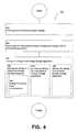
- FIG. 4shows a process for storage of intraluminally generated power.
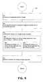
- FIG. 5shows a process for storage of intraluminally generated power.
- FIG. 6shows a process for storage of intraluminally generated power.
- FIG. 7shows a process for storage of intraluminally generated power.
- FIG. 8shows a process for storage of intraluminally generated power.
- FIG. 9shows a process for storage of intraluminally generated power.
- FIG. 10shows a process for storage of intraluminally generated power.
- FIG. 11shows a process for storage of intraluminally generated power.
- FIG. 12shows a process for storage of intraluminally generated power.
- FIGS. 1 and 2illustrate example environments in which one or more technologies may be implemented.
- An intraluminal power generation devicemay comprise intraluminal generator 100 configured for disposal within an anatomical lumen 101 defined by a lumen wall 102 .
- the intraluminal generator 100may be configured to convert a varying intraluminal pressure into energy (e.g. electrical energy, mechanical/elastic energy, chemical energy, thermal energy).
- the intraluminal generator 100may include an integrated pressure change receiving structure 103 A configured to receive a pressure change associated with a fluid pressure within the lumen 101 .
- the pressure change receiving structure 103may be an external pressure change receiving structure 103 B operably coupled to the intraluminal generator 100 via a coupling 104 to transfer a received pressure from the pressure change receiving structure 103 B to the intraluminal generator 100 in a form which the intraluminal generator 100 may convert to energy.
- the intraluminal power generation devicemay comprise an energy storage apparatus 105 for storage of energy generated by the intraluminal generator 100 .
- the energy storage apparatus 105may be operably coupled to the intraluminal generator 100 by a coupling 106 .
- the intraluminal power generation devicemay comprise a power utilization device 107 that may use energy generated by the intraluminal generator 100 and/or stored in the energy storage apparatus 105 to carry out a desired function.
- the power utilization device 107may be operably coupled to the intraluminal generator 100 and/or an energy storage apparatus 105 by a coupling 108 .
- FIG. 2illustrates various configurations of one or more components of an intraluminal power generation device.
- the intraluminal generator 100may be operably coupled to power utilization device 107 A disposed in a first lumen 101 A (e.g. in a distal relationship to the power utilization device 107 A).
- An intraluminal generator 100 disposed within in a first lumen 101 Amay be operably coupled to power utilization device 107 B disposed in a second lumen 101 B.
- An intraluminal generator 100 disposed within in a first lumen 101 Amay be operably coupled to an ex vivo power utilization device 107 C disposed outside an epidermis layer.
- the intraluminal generator 100may be a intraluminal generator.
- the intraluminal generator 100may be disposed (e.g. surgically implanted) within in a lumen 101 .
- the intraluminal generator 100may be coupled to the wall of the lumen 101 to maintain the intraluminal generator 100 in place.
- the intraluminal generator 100may comprise biocompatible materials (e.g. ultra high molecular weight polyethylene, polysulfone, polypropylene, titanium, and the like) such that the intraluminal generator 100 may be suitable for disposal within the lumen 101 .
- the exterior surface of the intraluminal generator 100may be configured such that the flow characteristics of a fluid moving through the lumen 101 are substantially maintained (e.g. the flow rate of the fluid, the flow dynamics of the fluid, and the like are not substantially disrupted.)
- the intraluminal generator 100may be a stent-type structure.
- a movement and/or deformation of the pressure change receiving structure 103may be translated either directly (e.g. the intraluminal generator 100 comprises the pressure change receiving structure 103 A) or indirectly (e.g. the pressure change receiving structure 103 B is operably coupled to a generator) into energy either through the motion of the pressure change receiving structure 103 and/or the electrical properties of the materials comprising the pressure change receiving structure 103 .
- a change in pressure within the lumen 101may be received by a pressure change receiving structure 103 .
- the pressure change receiving structure 103may receive a change in pressure through exposure of a surface of the pressure change receiving structure 103 to the luminal environment such that a change in the intraluminal pressure may exert a force on the pressure change receiving structure 103 thereby resulting in a movement and/or deformation of the pressure change receiving structure 103 .
- a movement and/or deformation of the pressure change receiving structure 103may be translated either directly (e.g. the intraluminal generator 100 comprises the pressure change receiving structure 103 A) or indirectly (e.g. the pressure change receiving structure 103 B is operably coupled to a generator) into energy either through the motion of the pressure change receiving structure 103 and/or the electrical properties of the materials comprising the pressure change receiving structure 103 and/or the intraluminal generator 100 .
- energy generated by the intraluminal generator 100 in response to the movement and/or deformation of the pressure change receiving structure 103may be stored in an energy storage apparatus 105 .
- the energy storage apparatus 105may be configured to store one or more forms of energy.
- the energy storage apparatus 105may be a chemical energy storage apparatus, an electrical energy storage apparatus, a mechanical energy storage apparatus, and the like.
- a capacitive energy storage apparatus 105may comprise two conducting electrodes separated by a dielectric.
- the capacitive energy storage apparatus 105may be electrolytic or electrostatic.
- An ultracapacitive energy storage apparatus 105may be an electric double-layer capacitor comprising two or more dielectric layers.
- the dielectric layersmay comprise activated carbon, carbon nanotubes, activated polypyrrole, barium titanate, and the like.
- the intraluminal generator 100may include a mechanical linkage (e.g. a lever mechanism) operably coupled to a mechanical energy storage apparatus 105 whereby movement of the mechanical linkage in response to the movement and/or deformation of the pressure change receiving structure 103 may cause the mechanical energy storage apparatus 105 to store a mechanical energy (e.g. as a spring force, kinetic energy, and the like).
- the mechanical energy storage apparatus 105may include a spring and ratchet, a flywheel, and the like.
- the intraluminal generator 100may include a pump mechanism operably coupled to a pressure energy storage apparatus 105 whereby movement and/or deformation of the pressure change receiving structure 103 may cause the pressure energy storage apparatus 105 to store pressure energy.
- the mechanical energy storage apparatus 105may include a rigid, semi-rigid or elastic pressure vessel.
- the chemical energy storage apparatus 105may include one or more electrochemical cells such as of a galvanic cell, an electrolytic cell, a fuel cell, a flow cell, a voltaic pile and the like.
- a chemical energy storage apparatus 105may comprise a battery.
- the batterymay comprise one or more voltaic cells.
- the batterymay be a rechargeable battery such as a nickel cadmium (NiCd), nickel metal hydride (NiMH), lithium ion (Li-ion), and lithium ion polymer (Li-ion polymer) which may be charged by energy produced by the intraluminal generator 100 .
- a chemical energy storage apparatus 105may comprise a fuel cell.
- the fuel cellmay be selected from one or more of a metal hydride fuel cell, an electro-galvanic fuel cell, a direct formic acid fuel cell (DFAFC), a zinc-air fuel cell, a microbial fuel cell, an upflow microbial fuel cell (UMFC), a direct borohydride fuel cell, an alkaline fuel cell, a direct methanol fuel cell, a reformed methanol fuel cell, a direct formic acid fuel cell, proton exchange membrane fuel cell, an RFC—Redox fuel cell, a protonic ceramic fuel cell, a direct carbon fuel cell, a planar solid oxide fuel cell, and the like.
- the fuel cellmay be a reversible fuel cell combined with an electrolyzer and a fuel storage apparatus to utilize an electrical current generated by the intraluminal generator 100 to generate fuel cell fuel components (e.g. oxygen and hydrogen) from a fuel cell product (e.g. water).
- fuel cell fuel componentse.g. oxygen and hydrogen
- a fuel cell producte.g. water
- the fuel cell fuel componentsmay be stored in a fuel cell storage apparatus for later use in recovering energy from the fuel cell fuel components via the fuel cell.
- energy stored in the energy storage apparatus 105 Bmay be transmitted to a secondary energy storage apparatus 105 C from the energy storage apparatus 105 B.
- energy transmitted from the energy storage apparatus 105 B to the secondary energy storage apparatus 105 Cmay be configured by a power converter.
- energy stored in energy storage apparatus 1058may be configured by a power converter 109 prior to storage in a secondary energy storage apparatus 105 C.
- the energy stored in the energy storage apparatus 105 Bmay be unsuitable for use by a particular power utilization device 107 D.
- the energy stored in the energy storage apparatus 105 Bmay be configured (e.g. voltage regulation, current regulation, inversion, rectification, phase modification, translation into another form of energy (e.g. converting electrical energy to mechanical energy) and the like) and stored in secondary energy storage apparatus 105 C for use by power utilization device 107 D.
- energy generated by the intraluminal generator 100 in response to the movement and/or deformation of the pressure change receiving structure 103may be transmitted to an energy storage apparatus 105 operably coupled to the intraluminal generator 100 by a coupling 106 .
- energy generated by the intraluminal generator 100 in response to the movement and/or deformation of the pressure change receiving structure 103may be transmitted to an energy storage apparatus 105 operably coupled to the intraluminal generator 100 by an electrical coupling 106 (e.g. one or more wires).
- an electrical coupling 106e.g. one or more wires.
- energy generated by the intraluminal generator 100 in response to the movement and/or deformation of the pressure change receiving structure 103may be transmitted to an energy storage apparatus 105 operably coupled to the intraluminal generator 100 by an mechanical coupling 106 (e.g. one or more torque shaft, levers, piston, crankshaft and the like).
- an energy storage apparatus 105operably coupled to the intraluminal generator 100 by an mechanical coupling 106 (e.g. one or more torque shaft, levers, piston, crankshaft and the like).
- energy generated by the intraluminal generator 100 in response to the movement and/or deformation of the pressure change receiving structure 103may be transmitted to an energy storage apparatus 105 operably coupled to the intraluminal generator 100 by an fluid coupling 106 (e.g. a hydraulic line, pneumatic line, pipe, hose, and the like).
- an energy storage apparatus 105operably coupled to the intraluminal generator 100 by an fluid coupling 106 (e.g. a hydraulic line, pneumatic line, pipe, hose, and the like).
- One or more of the intraluminal generator 100 and the energy storage apparatus 105may comprise a pump whereby energy may be transmitted via fluid flow (e.g. liquid or gas flow) between the intraluminal generator 100 and the energy storage apparatus 105 .
- energy generated by the intraluminal generator 100 in response to the movement and/or deformation of the pressure change receiving structure 103may be transmitted to an energy storage apparatus 105 operably coupled to the intraluminal generator 100 by an acoustical coupling 106 .
- One or more of the intraluminal generator 100 and the energy storage apparatus 105may comprise one or more of an acoustical transmitter (e.g. an acoustic transducer and the like) and an acoustical receiver (e.g. a hydrophone) whereby energy may be conveyed via acoustical signals transceived between the intraluminal generator 100 and the energy storage apparatus 105 .
- the one or more acoustical transmitters and acoustical receiversmay be in resonance (e.g. an acoustical transmitter generates acoustical waves that are in phase with a movement of the acoustical receiver).
- the one or more acoustical transmitters and acoustical receiversmay be in resonance (e.g. an acoustical transmitter generates acoustical waves that are in phase with a movement of the acoustical receiver) where the Q factor of the acoustical transmitter and acoustical receiver is at least 10,000.
- a transmitter/receiver devicemay be such as described in “Tunable high-Q surface-acoustic-wave resonator” by Dmitriev, et al., Technical Physics , Volume 52, Number 8, August 2007, pp. 1061-1067(7); U.S. Patent Application Publication No.
- energy generated by the intraluminal generator 100 in response to the movement and/or deformation of the pressure change receiving structure 103may be transmitted to an energy storage apparatus 105 operably coupled to the intraluminal generator 100 by an electromagnetic radiation (EMR) coupling 106 .
- EMRelectromagnetic radiation
- One or more of the intraluminal generator 100 and the energy storage apparatus 105may comprise one or more of an EMR transmitter and an EMR receiver whereby energy may be transmitted via EMR signals transceived between the intraluminal generator 100 and the energy storage apparatus 105 .
- energy generated by the intraluminal generator 100 in response to the movement and/or deformation of the pressure change receiving structure 103may be transmitted to an energy storage apparatus 105 operably coupled to the intraluminal generator 100 by an optical coupling 106 .
- One or more of the intraluminal generator 100 and the energy storage apparatus 105may comprise one or more of an optical transmitter (e.g. a light-emitting diode, a laser diode and the like) and an optical receiver (e.g. a photo diode, a photo detector and the like) whereby energy may be transmitted via optical signals transceived between the intraluminal generator 100 and the energy storage apparatus 105 .
- an optical transmittere.g. a light-emitting diode, a laser diode and the like
- an optical receivere.g. a photo diode, a photo detector and the like
- energy generated by the intraluminal generator 100 in response to the movement and/or deformation of the pressure change receiving structure 103may be transmitted to an energy storage apparatus 105 operably coupled to the intraluminal generator 100 by an infrared coupling 106 .
- One or more of the intraluminal generator 100 and the energy storage apparatus 105may comprise one or more of an infrared transmitter (e.g. a light-emitting diode, a laser diode and the like) and an optical receiver (e.g. a photo diode, a photo detector and the like) whereby energy may be transmitted via infrared signals transceived between the intraluminal generator 100 and the energy storage apparatus 105 .
- an infrared transmittere.g. a light-emitting diode, a laser diode and the like
- an optical receivere.g. a photo diode, a photo detector and the like
- energy generated by the intraluminal generator 100 in response to the movement and/or deformation of the pressure change receiving structure 103may be transmitted to an energy storage apparatus 105 operably coupled to the intraluminal generator 100 by an inductive coupling 106 .
- the intraluminal generator 100may include circuitry (e.g. a solenoid) configured to generate a magnetic field.
- the energy storage apparatus 105may include circuitry configured to generate an electrical current when disposed in a location proximate to the magnetic field.
- energy generated by the intraluminal generator 100 in response to the movement and/or deformation of the pressure change receiving structure 103may be transmitted to an energy storage apparatus 105 operably coupled to the intraluminal generator 100 by a resonant inductive coupling 106 .
- the intraluminal generator 100 and the energy storage apparatus 105may include one or more waveguides configured to transceive evanescent electromagnetic signals.
- the waveguidesmay be configured such that a receiving waveguide is in resonance with a transmitting waveguide so as to provide evanescent wave coupling between the waveguides.
- the evanescent wavesmay be rectified into DC power for storage in the energy storage apparatus 105 .
- a first intraluminal generator 100 and first energy storage apparatus 105 operably coupled by a first resonant inductive coupling 106may be at least partially co-located with a second intraluminal generator 100 and second energy storage apparatus 105 operably coupled by a second resonant inductive coupling 106 within one or more anatomical structures.
- the waveguides associated with the first resonant inductive coupling 106 and the waveguides associated with the second inductive coupling 106may be configured so as to be in mutual resonance.
- energy generated by the intraluminal generator 100 in response to the movement and/or deformation of the pressure change receiving structure 103may be transmitted to an at least partially intraluminal energy storage apparatus 105 (e.g. energy storage apparatus 105 ) via a coupling 106 .
- an at least partially intraluminal energy storage apparatus 105e.g. energy storage apparatus 105
- energy generated by the intraluminal generator 100 in response to the movement and/or deformation of the pressure change receiving structure 103may be transmitted to an at least partially extraluminal energy storage apparatus 105 (e.g. energy storage apparatus 105 B) via a coupling 106 .
- an at least partially extraluminal energy storage apparatus 105e.g. energy storage apparatus 105 B
- any two components so associatedcan also be viewed as being “operably connected,” or “operably coupled,” to each other to achieve the desired functionality, and any two components capable of being so associated can also be viewed as being “operably couplable,” to each other to achieve the desired functionality.
- operably couplableinclude but are not limited to physically mateable and/or physically interacting components and/or wirelessly interactable and/or wirelessly interacting components and/or logically interacting and/or logically interactable components.
Landscapes
- Life Sciences & Earth Sciences (AREA)
- Health & Medical Sciences (AREA)
- Medical Informatics (AREA)
- Biophysics (AREA)
- Pathology (AREA)
- Engineering & Computer Science (AREA)
- Biomedical Technology (AREA)
- Heart & Thoracic Surgery (AREA)
- Physics & Mathematics (AREA)
- Molecular Biology (AREA)
- Surgery (AREA)
- Animal Behavior & Ethology (AREA)
- General Health & Medical Sciences (AREA)
- Public Health (AREA)
- Veterinary Medicine (AREA)
- Charge And Discharge Circuits For Batteries Or The Like (AREA)
Abstract
Description
Claims (6)
Priority Applications (3)
| Application Number | Priority Date | Filing Date | Title |
|---|---|---|---|
| US12/462,789US9526418B2 (en) | 2008-12-04 | 2009-08-07 | Device for storage of intraluminally generated power |
| US12/462,796US9631610B2 (en) | 2008-12-04 | 2009-08-07 | System for powering devices from intraluminal pressure changes |
| US15/449,351US20170241411A1 (en) | 2008-12-04 | 2017-03-03 | System for powering devices from intraluminal pressure changes |
Applications Claiming Priority (6)
| Application Number | Priority Date | Filing Date | Title |
|---|---|---|---|
| US12/315,616US9759202B2 (en) | 2008-12-04 | 2008-12-04 | Method for generation of power from intraluminal pressure changes |
| US12/315,631US9567983B2 (en) | 2008-12-04 | 2008-12-04 | Method for generation of power from intraluminal pressure changes |
| US12/386,054US20100140958A1 (en) | 2008-12-04 | 2009-04-13 | Method for powering devices from intraluminal pressure changes |
| US12/455,669US9353733B2 (en) | 2008-12-04 | 2009-06-04 | Device and system for generation of power from intraluminal pressure changes |
| US12/462,789US9526418B2 (en) | 2008-12-04 | 2009-08-07 | Device for storage of intraluminally generated power |
| US12/462,796US9631610B2 (en) | 2008-12-04 | 2009-08-07 | System for powering devices from intraluminal pressure changes |
Related Parent Applications (2)
| Application Number | Title | Priority Date | Filing Date |
|---|---|---|---|
| US12/315,616Continuation-In-PartUS9759202B2 (en) | 2008-12-04 | 2008-12-04 | Method for generation of power from intraluminal pressure changes |
| US12/455,669Continuation-In-PartUS9353733B2 (en) | 2008-12-04 | 2009-06-04 | Device and system for generation of power from intraluminal pressure changes |
Related Child Applications (3)
| Application Number | Title | Priority Date | Filing Date |
|---|---|---|---|
| US12/455,669Continuation-In-PartUS9353733B2 (en) | 2008-12-04 | 2009-06-04 | Device and system for generation of power from intraluminal pressure changes |
| US12/455,699Continuation-In-PartUS7983129B2 (en) | 2008-06-16 | 2009-06-05 | High data capacity storage medium with protection code, method for obtaining the protection code and respective data reading apparatus |
| US12/462,796Continuation-In-PartUS9631610B2 (en) | 2008-12-04 | 2009-08-07 | System for powering devices from intraluminal pressure changes |
Publications (2)
| Publication Number | Publication Date |
|---|---|
| US20100140943A1 US20100140943A1 (en) | 2010-06-10 |
| US9526418B2true US9526418B2 (en) | 2016-12-27 |
Family
ID=42230234
Family Applications (1)
| Application Number | Title | Priority Date | Filing Date |
|---|---|---|---|
| US12/462,789Expired - Fee RelatedUS9526418B2 (en) | 2008-12-04 | 2009-08-07 | Device for storage of intraluminally generated power |
Country Status (1)
| Country | Link |
|---|---|
| US (1) | US9526418B2 (en) |
Families Citing this family (7)
| Publication number | Priority date | Publication date | Assignee | Title |
|---|---|---|---|---|
| US9631610B2 (en) | 2008-12-04 | 2017-04-25 | Deep Science, Llc | System for powering devices from intraluminal pressure changes |
| US9526418B2 (en) | 2008-12-04 | 2016-12-27 | Deep Science, Llc | Device for storage of intraluminally generated power |
| US20100140958A1 (en)* | 2008-12-04 | 2010-06-10 | Searete Llc, A Limited Liability Corporation Of The State Of Delaware | Method for powering devices from intraluminal pressure changes |
| US9759202B2 (en)* | 2008-12-04 | 2017-09-12 | Deep Science, Llc | Method for generation of power from intraluminal pressure changes |
| US9353733B2 (en) | 2008-12-04 | 2016-05-31 | Deep Science, Llc | Device and system for generation of power from intraluminal pressure changes |
| US9567983B2 (en)* | 2008-12-04 | 2017-02-14 | Deep Science, Llc | Method for generation of power from intraluminal pressure changes |
| EP3946119A1 (en)* | 2019-03-29 | 2022-02-09 | CONMED Corporation | High permittivity electrosurgical electrode coating |
Citations (142)
| Publication number | Priority date | Publication date | Assignee | Title |
|---|---|---|---|---|
| US3358690A (en)* | 1964-11-18 | 1967-12-19 | Marvin M Cohen | Heart stimulator utilizing a pressuresensitive semiconductor |
| US3421512A (en) | 1965-12-15 | 1969-01-14 | Int Rectifier Corp | Implanted electrical device with biological power supply |
| US3456134A (en) | 1967-10-05 | 1969-07-15 | Us Health Education & Welfare | Piezoelectric energy converter for electronic implants |
| US3522811A (en)* | 1969-02-13 | 1970-08-04 | Medtronic Inc | Implantable nerve stimulator and method of use |
| GB1220677A (en) | 1967-03-23 | 1971-01-27 | Plessey Co Ltd | Improvements in or relating to power-generating apparatus for incorporation in the human body |
| US3563245A (en)* | 1968-03-15 | 1971-02-16 | Donald Neil Mclean | Biologically implantable and energized power supply |
| US3649615A (en) | 1968-07-08 | 1972-03-14 | Sumitomo Chemical Co | Phenyl-azo-naphthol dyes |
| US3659615A (en) | 1970-06-08 | 1972-05-02 | Carl C Enger | Encapsulated non-permeable piezoelectric powered pacesetter |
| US3861397A (en)* | 1972-01-03 | 1975-01-21 | Siemens Ag | Implantable fuel cell |
| US3906960A (en)* | 1973-02-27 | 1975-09-23 | Siegfried R Lehr | Medical energy converter |
| US3943936A (en) | 1970-09-21 | 1976-03-16 | Rasor Associates, Inc. | Self powered pacers and stimulators |
| US4140132A (en) | 1978-03-23 | 1979-02-20 | Dahl Joseph D | Variable rate timer for a cardiac pacemaker |
| US4294891A (en)* | 1980-03-12 | 1981-10-13 | The Montefiore Hospital Association Of Western Pennsylvania | Intermittently refuelable implantable bio-oxidant fuel cell |
| US4453537A (en)* | 1981-08-04 | 1984-06-12 | Spitzer Daniel E | Apparatus for powering a body implant device |
| US4538616A (en) | 1983-07-25 | 1985-09-03 | Robert Rogoff | Blood sugar level sensing and monitoring transducer |
| US4661107A (en)* | 1986-07-21 | 1987-04-28 | Fink Irving E | Heart valve |
| US4690143A (en) | 1984-07-19 | 1987-09-01 | Cordis Corporation | Pacing lead with piezoelectric power generating means |
| US4798206A (en) | 1986-10-28 | 1989-01-17 | Telectronics N.V. | Implanted medical system including a self-powered sensing system |
| US5007927A (en)* | 1989-10-24 | 1991-04-16 | Purdue Research Foundation | Muscle-powered cardiac assist device |
| US5010893A (en) | 1987-01-15 | 1991-04-30 | Siemens-Pacesetter, Inc. | Motion sensor for implanted medical device |
| US5022395A (en) | 1989-07-07 | 1991-06-11 | Cardiac Pacemakers, Inc. | Implantable cardiac device with dual clock control of microprocessor |
| US5062841A (en) | 1988-08-12 | 1991-11-05 | The Regents Of The University Of California | Implantable, self-regulating mechanochemical insulin pump |
| US5154680A (en) | 1990-03-27 | 1992-10-13 | Rutgers University | Pressure waveform monitor |
| US5188738A (en) | 1990-08-06 | 1993-02-23 | Steven Kaali | Alternating current supplied electrically conductive method and system for treatment of blood and/or other body fluids and/or synthetic fluids with electric forces |
| US5205286A (en) | 1991-07-24 | 1993-04-27 | Intermedics, Inc. | Subcutaneous electrical data port |
| US5344385A (en)* | 1991-09-30 | 1994-09-06 | Thoratec Laboratories Corporation | Step-down skeletal muscle energy conversion system |
| US5348019A (en) | 1992-09-18 | 1994-09-20 | The Board Of Regents Of The University Of Oklahoma | Optical fiber pressure sensing catheter |
| US5366454A (en) | 1993-03-17 | 1994-11-22 | La Corporation De L'ecole Polytechnique | Implantable medication dispensing device |
| US5411537A (en)* | 1993-10-29 | 1995-05-02 | Intermedics, Inc. | Rechargeable biomedical battery powered devices with recharging and control system therefor |
| US5431694A (en) | 1992-08-18 | 1995-07-11 | Snaper; Alvin A. | Bio-operable power source |
| US5443504A (en)* | 1991-09-30 | 1995-08-22 | Hill; John D. | Basic skeletal muscle energy conversion system |
| US5457624A (en) | 1994-06-13 | 1995-10-10 | Texas Instruments Incorporated | Efficient switched mode power converter circuit and method |
| US5522394A (en) | 1993-06-15 | 1996-06-04 | Zurbruegg; Heinz R. | Implantable measuring probe for measuring the flow velocity of blood in humans and animals |
| US5535752A (en) | 1995-02-27 | 1996-07-16 | Medtronic, Inc. | Implantable capacitive absolute pressure and temperature monitor system |
| US5617876A (en) | 1994-09-19 | 1997-04-08 | Les Enterprises Laborie, Inc. | Apparatus for examining the functioning of body structures comprising smooth muscle walls |
| US5626141A (en) | 1990-04-13 | 1997-05-06 | Takeda Engineering Consultant Inc. | Blood pressure measurement apparatus and associated method |
| US5690693A (en)* | 1995-06-07 | 1997-11-25 | Sulzer Intermedics Inc. | Transcutaneous energy transmission circuit for implantable medical device |
| US5693952A (en) | 1995-12-18 | 1997-12-02 | Sulzer Intermedics Inc. | Optically controlled high-voltage switch for an implantable defibrillator |
| US5702431A (en)* | 1995-06-07 | 1997-12-30 | Sulzer Intermedics Inc. | Enhanced transcutaneous recharging system for battery powered implantable medical device |
| US5713939A (en)* | 1996-09-16 | 1998-02-03 | Sulzer Intermedics Inc. | Data communication system for control of transcutaneous energy transmission to an implantable medical device |
| US5715837A (en) | 1996-08-29 | 1998-02-10 | Light Sciences Limited Partnership | Transcutaneous electromagnetic energy transfer |
| US5734564A (en) | 1996-07-26 | 1998-03-31 | Lucent Technologies Inc. | High-efficiency switching power converter |
| US5745358A (en) | 1996-05-01 | 1998-04-28 | Compaq Computer Corporation | Variable-frequency converter with constant programmed delay |
| US5749909A (en)* | 1996-11-07 | 1998-05-12 | Sulzer Intermedics Inc. | Transcutaneous energy coupling using piezoelectric device |
| US5764495A (en) | 1996-05-01 | 1998-06-09 | Compaq Computer Corporation | Variable-frequency variable-input-voltage converter with minimum frequency limit |
| US5810015A (en) | 1995-09-01 | 1998-09-22 | Strato/Infusaid, Inc. | Power supply for implantable device |
| US5823199A (en) | 1992-11-25 | 1998-10-20 | Scimed Life Systems, Inc. | In vivo mechanical energy source |
| US5967986A (en) | 1997-11-25 | 1999-10-19 | Vascusense, Inc. | Endoluminal implant with fluid flow sensing capability |
| GB2350302A (en) | 1999-05-26 | 2000-11-29 | Demetriou Demetrios | Implanted power generator |
| US6164284A (en) | 1997-02-26 | 2000-12-26 | Schulman; Joseph H. | System of implantable devices for monitoring and/or affecting body parameters |
| US6268161B1 (en) | 1997-09-30 | 2001-07-31 | M-Biotech, Inc. | Biosensor |
| US6291900B1 (en)* | 1997-09-15 | 2001-09-18 | General Electric Company | Electrical energy management for manually powered devices |
| US20020028999A1 (en) | 2000-07-22 | 2002-03-07 | Biotronik Mess-Und Therapiegeraete Gmbh & Co. | Implantable measuring device, particularly a pressure measuring device for determining the intracardial or intraluminal blood pressure |
| US6409674B1 (en) | 1998-09-24 | 2002-06-25 | Data Sciences International, Inc. | Implantable sensor with wireless communication |
| US6426628B1 (en) | 1995-10-31 | 2002-07-30 | Cardiac Pacemakers, Inc. | Power management system for an implantable device |
| US6432050B1 (en) | 1997-12-30 | 2002-08-13 | Remon Medical Technologies Ltd. | Implantable acoustic bio-sensing system and method |
| US6475750B1 (en) | 1999-05-11 | 2002-11-05 | M-Biotech, Inc. | Glucose biosensor |
| US6580177B1 (en) | 1999-06-01 | 2003-06-17 | Continuum Control Corporation | Electrical power extraction from mechanical disturbances |
| US6589184B2 (en) | 2001-08-31 | 2003-07-08 | St. Jude Medical Ab | Implantable intravascular pressure determining device and method |
| US20030158584A1 (en) | 2002-02-19 | 2003-08-21 | Cates Adam W | Chronically-implanted device for sensing and therapy |
| US6635048B1 (en) | 1999-04-30 | 2003-10-21 | Medtronic, Inc. | Implantable medical pump with multi-layer back-up memory |
| US6638231B2 (en) | 2000-12-18 | 2003-10-28 | Biosense, Inc. | Implantable telemetric medical sensor and method |
| US6682490B2 (en) | 2001-12-03 | 2004-01-27 | The Cleveland Clinic Foundation | Apparatus and method for monitoring a condition inside a body cavity |
| US20040021322A1 (en)* | 2002-07-31 | 2004-02-05 | Arie Ariav | Method and apparatus for body generation of electrical energy |
| US20040039242A1 (en)* | 2002-04-02 | 2004-02-26 | Seedling Enterprises, Llc | Apparatus and methods using visible light for debilitating and/or killing microorganisms within the body |
| US6711423B2 (en) | 1998-08-26 | 2004-03-23 | Sensors For Medicine And Science, Inc. | Optical-based sensing devices |
| US20040078027A1 (en) | 2002-07-03 | 2004-04-22 | Yehoshua Shachar | Method and apparatus for piezoelectric layer-wise pump and valve for use in local administration of biological response modifiers and therapeutic agents |
| US20040158294A1 (en)* | 2003-02-12 | 2004-08-12 | Medtronic, Inc. | Self-powered implantable element |
| US20040173220A1 (en) | 2003-03-06 | 2004-09-09 | Harry Jason D. | Method and apparatus for improving human balance and gait and preventing foot injury |
| US20040193058A1 (en) | 2003-03-28 | 2004-09-30 | Valentino Montegrande | Blood pressure sensor apparatus |
| US6802811B1 (en) | 1999-09-17 | 2004-10-12 | Endoluminal Therapeutics, Inc. | Sensing, interrogating, storing, telemetering and responding medical implants |
| US20040204744A1 (en) | 2003-04-14 | 2004-10-14 | Remon Medicaltechnologies Ltd. | Apparatus and methods using acoustic telemetry for intrabody communications |
| US20040215279A1 (en) | 2003-04-25 | 2004-10-28 | Houben Richard P.M. | Implantable lead-based sensor powered by piezoelectric transformer |
| US6822343B2 (en) | 2002-02-28 | 2004-11-23 | Texas Instruments Incorporated | Generating electric power in response to activity of a biological system |
| US6829507B1 (en) | 1998-09-21 | 2004-12-07 | St. Jude Medical Ab | Apparatus for determining the actual status of a piezoelectric sensor in a medical implant |
| US6827682B2 (en) | 1999-06-23 | 2004-12-07 | Mogens Bugge | Implantable device for utilization of the hydraulic energy of the heart |
| US6860857B2 (en) | 2001-08-31 | 2005-03-01 | St. Jude Medical Ab | Implantable intravascular pressure determining device and method |
| US20050055061A1 (en)* | 2003-09-08 | 2005-03-10 | Asher Holzer | Cardiac implant device |
| US20050080346A1 (en) | 2002-12-16 | 2005-04-14 | The Regents Of The University Of Michigan | Antenna stent device for wireless, intraluminal monitoring |
| US6895265B2 (en) | 2000-05-15 | 2005-05-17 | James H. Silver | Implantable sensor |
| US6937894B1 (en) | 2001-11-08 | 2005-08-30 | Pacesetter, Inc. | Method of recharging battery for an implantable medical device |
| US6953469B2 (en) | 2001-08-30 | 2005-10-11 | Ethicon, Inc, | Device and method for treating intraluminal tissue |
| US20050256549A1 (en) | 2002-10-09 | 2005-11-17 | Sirius Implantable Systems Ltd. | Micro-generator implant |
| US20050261563A1 (en) | 2004-05-20 | 2005-11-24 | Peter Zhou | Transducer for embedded bio-sensor using body energy as a power source |
| US20060044078A1 (en) | 2004-08-24 | 2006-03-02 | Farrokh Ayazi | Capacitive vertical silicon bulk acoustic resonator |
| US7032600B2 (en) | 2003-01-16 | 2006-04-25 | Ntt Docomo, Inc. | Method and system for measuring a position, position measuring device, and an in vivo radio device |
| US20060152309A1 (en) | 2005-01-11 | 2006-07-13 | Mintchev Martin P | Magnetic levitation of intraluminal microelectronic capsule |
| US7081699B2 (en) | 2003-03-31 | 2006-07-25 | The Penn State Research Foundation | Thermoacoustic piezoelectric generator |
| US20060184206A1 (en)* | 2005-02-15 | 2006-08-17 | Baker Rex M Iii | Implantable generating system |
| US20060217776A1 (en)* | 2005-03-25 | 2006-09-28 | Robert White | Implantable cardiac motion powered piezoelectric energy source |
| US20060224214A1 (en)* | 2005-04-04 | 2006-10-05 | Koller Levente L | Piezoelectrically stimulated article |
| US20060247724A1 (en) | 2005-04-28 | 2006-11-02 | Medtronic, Inc. | Implantable optical pressure sensor for sensing urinary sphincter pressure |
| US20060287598A1 (en) | 2005-06-20 | 2006-12-21 | Lasater Brian J | System of implantable ultrasonic emitters for preventing restenosis following a stent procedure |
| US7167756B1 (en) | 2000-04-28 | 2007-01-23 | Medtronic, Inc. | Battery recharge management for an implantable medical device |
| US20070074731A1 (en)* | 2005-10-05 | 2007-04-05 | Nth Tech Corporation | Bio-implantable energy harvester systems and methods thereof |
| US20070088402A1 (en)* | 2005-10-18 | 2007-04-19 | Melvin David B | Muscle energy converter with smooth continuous tissue interface |
| US20070093875A1 (en) | 2005-10-24 | 2007-04-26 | Cardiac Pacemakers, Inc. | Implantable and rechargeable neural stimulator |
| US7223237B2 (en) | 2004-04-22 | 2007-05-29 | Pacesetter, Inc. | Implantable biosensor and methods for monitoring cardiac health |
| US20070149885A1 (en) | 1994-09-02 | 2007-06-28 | Corl Paul D | Ultra miniature pressure sensor |
| US20070167988A1 (en) | 2006-01-13 | 2007-07-19 | Cernasov Andre N | Apparatus and method for supplying power to subcutaneously implanted devices |
| US7263894B2 (en) | 2004-06-07 | 2007-09-04 | Radi Medical Systems Ab | Sensor and guide wire assembly |
| US20070221233A1 (en) | 2005-12-28 | 2007-09-27 | Olympus Medical Systems Corp. | Body-insertable device system and in-vivo observation method |
| US7302856B2 (en) | 2003-05-07 | 2007-12-04 | California Institute Of Technology | Strain sensors based on nanowire piezoresistor wires and arrays |
| US20070293904A1 (en)* | 2006-06-20 | 2007-12-20 | Daniel Gelbart | Self-powered resonant leadless pacemaker |
| US20080009687A1 (en) | 2003-06-06 | 2008-01-10 | Smith Joseph T | Coiled circuit bio-sensor |
| US20080021333A1 (en) | 2006-07-21 | 2008-01-24 | Cardiac Pacemakers, Inc. | Multiple sensor deployment |
| US20080082005A1 (en) | 2006-07-05 | 2008-04-03 | Stern David R | Method for Using a Wireless Pressure Sensor to Monitor Pressure Inside the Human Heart |
| US7362557B2 (en) | 2004-03-30 | 2008-04-22 | Continental Automotive Systems U.S. Inc. | Method, apparatus and article for bi-directional DC/DC power conversion |
| US7367968B2 (en) | 2003-09-05 | 2008-05-06 | Codman & Shurtleff, Inc. | Implantable pump with adjustable flow rate |
| US20080132967A1 (en) | 2004-08-20 | 2008-06-05 | Cardiac Pacemakers, Inc. | Techniques for blood pressure measurement by implantable device |
| US20080172043A1 (en) | 2000-10-10 | 2008-07-17 | Microchips, Inc. | Microchip reservoir devices using wireless transmission of power and data |
| US7403821B2 (en) | 2000-02-17 | 2008-07-22 | Neurodan A/S | Method and implantable systems for neural sensing and nerve stimulation |
| US7413547B1 (en) | 2004-11-08 | 2008-08-19 | Transoma Medical, Inc. | Reference sensor correction for implantable sensors |
| US20080212262A1 (en)* | 2006-10-10 | 2008-09-04 | Micallef Joseph A | Piezoelectric Ultracapacitor |
| US7427265B1 (en) | 1998-02-23 | 2008-09-23 | Cardiometrix, Inc. | Endoluminal implant with therapeutic and diagnostic capability |
| US20080262562A1 (en)* | 2007-04-17 | 2008-10-23 | Perpetuum Ltd. | Energy Harvester for an Implant Device |
| US20080281298A1 (en) | 2005-02-07 | 2008-11-13 | Andersen David R | Electronic support system for biological data sensor |
| US7465313B2 (en) | 2005-09-26 | 2008-12-16 | Depuy Spine, Inc. | Red light implant for treating degenerative disc disease |
| US7489966B2 (en) | 2002-04-26 | 2009-02-10 | Medtronic, Inc. | Independent therapy programs in an implantable medical device |
| US20090171413A1 (en) | 2007-08-31 | 2009-07-02 | Marco Zenati | Implantable device, system including same, and method utilizing same |
| US20090171448A1 (en) | 2007-04-27 | 2009-07-02 | Uri Eli | Implantable device with miniature rotating portion for energy harvesting |
| US20090270742A1 (en) | 2004-01-13 | 2009-10-29 | Remon Medical Technologies Ltd. | Devices for fixing a sensor in a lumen |
| US7616992B2 (en) | 2006-01-30 | 2009-11-10 | Medtronic, Inc. | Intravascular medical device |
| US20090281399A1 (en) | 2007-08-31 | 2009-11-12 | Keel Allen J | Standalone systemic arterial blood pressure monitoring device |
| US20090292335A1 (en)* | 2008-05-22 | 2009-11-26 | Stichting Imec Nederland | Thermoelectric Generator for Implants and Embedded Devices |
| US20100010600A1 (en) | 2006-04-25 | 2010-01-14 | Tom Eriksson | piezoelectric sensor, a method for manufacturing a piezoelectric sensor and a medical implantable lead comprising such a piezoelectric sensor |
| US20100030043A1 (en) | 2008-07-30 | 2010-02-04 | Medtronic, Inc. | Implantable medical system including multiple sensing modules |
| US20100036450A1 (en) | 2007-06-17 | 2010-02-11 | Physical Logic Ag | Carbon Nano-tube Power Cell |
| US20100076517A1 (en)* | 2008-09-23 | 2010-03-25 | Mir Imran | Energy harvesting mechanism for medical devices |
| US20100140956A1 (en) | 2008-12-04 | 2010-06-10 | Searete Llc. | Method for generation of power from intraluminal pressure changes |
| US20100141052A1 (en) | 2008-12-04 | 2010-06-10 | Searete Llc,A Limited Liability Corporation Of The State Of Delaware | System for powering devices from intraluminal pressure changes |
| US20100140943A1 (en) | 2008-12-04 | 2010-06-10 | Searete Llc, A Limited Liability Corporation Of The State Of Delaware | Device for storage of intraluminally generated power |
| US20100140959A1 (en) | 2008-12-04 | 2010-06-10 | Searete Llc, A Limited Liability Corporation Of The State Of Delaware | Device and system for generation of power from intraluminal pressure changes |
| US20100140957A1 (en) | 2008-12-04 | 2010-06-10 | Searete Llc | Method for generation of power from intraluminal pressure changes |
| US20100140958A1 (en) | 2008-12-04 | 2010-06-10 | Searete Llc, A Limited Liability Corporation Of The State Of Delaware | Method for powering devices from intraluminal pressure changes |
| US7777623B2 (en) | 2001-10-11 | 2010-08-17 | Enocean Gmbh | Wireless sensor system |
| US7798973B2 (en) | 2005-10-13 | 2010-09-21 | Cardiac Pacemakers, Inc. | Detection of hypovolemia using implantable medical device |
| US20100298720A1 (en)* | 2009-04-16 | 2010-11-25 | Potkay Joseph Allen | In Situ Energy Harvesting Systems for Implanted Medical Devices |
| US20110062713A1 (en) | 2008-01-14 | 2011-03-17 | Single Buoy Moorings Inc. | Wave energy absorber |
| US20110094314A1 (en) | 2007-08-27 | 2011-04-28 | Koninklijke Philips Electronics N.V. | Pressure sensor, sensor probe comprising a pressure sensor, medical apparatus comprising a sensor probe and a method of fabricating a sensor probe |
| US20110275947A1 (en) | 2007-01-04 | 2011-11-10 | Board Of Regents, The University Of Texas System | Cardiovascular power source for automatic implantable cardioverter defibrillators |
| EP1764034B1 (en) | 2005-09-20 | 2013-05-01 | Pacesetter, Inc. | Implantable self-calibrating optical sensors |
- 2009
- 2009-08-07USUS12/462,789patent/US9526418B2/ennot_activeExpired - Fee Related
Patent Citations (163)
| Publication number | Priority date | Publication date | Assignee | Title |
|---|---|---|---|---|
| US3358690A (en)* | 1964-11-18 | 1967-12-19 | Marvin M Cohen | Heart stimulator utilizing a pressuresensitive semiconductor |
| US3421512A (en) | 1965-12-15 | 1969-01-14 | Int Rectifier Corp | Implanted electrical device with biological power supply |
| GB1220677A (en) | 1967-03-23 | 1971-01-27 | Plessey Co Ltd | Improvements in or relating to power-generating apparatus for incorporation in the human body |
| US3456134A (en) | 1967-10-05 | 1969-07-15 | Us Health Education & Welfare | Piezoelectric energy converter for electronic implants |
| US3563245A (en)* | 1968-03-15 | 1971-02-16 | Donald Neil Mclean | Biologically implantable and energized power supply |
| US3649615A (en) | 1968-07-08 | 1972-03-14 | Sumitomo Chemical Co | Phenyl-azo-naphthol dyes |
| US3522811A (en)* | 1969-02-13 | 1970-08-04 | Medtronic Inc | Implantable nerve stimulator and method of use |
| US3659615A (en) | 1970-06-08 | 1972-05-02 | Carl C Enger | Encapsulated non-permeable piezoelectric powered pacesetter |
| US3943936A (en) | 1970-09-21 | 1976-03-16 | Rasor Associates, Inc. | Self powered pacers and stimulators |
| US3861397A (en)* | 1972-01-03 | 1975-01-21 | Siemens Ag | Implantable fuel cell |
| US3906960A (en)* | 1973-02-27 | 1975-09-23 | Siegfried R Lehr | Medical energy converter |
| US4140132A (en) | 1978-03-23 | 1979-02-20 | Dahl Joseph D | Variable rate timer for a cardiac pacemaker |
| US4294891A (en)* | 1980-03-12 | 1981-10-13 | The Montefiore Hospital Association Of Western Pennsylvania | Intermittently refuelable implantable bio-oxidant fuel cell |
| US4453537A (en)* | 1981-08-04 | 1984-06-12 | Spitzer Daniel E | Apparatus for powering a body implant device |
| US4538616A (en) | 1983-07-25 | 1985-09-03 | Robert Rogoff | Blood sugar level sensing and monitoring transducer |
| US4690143A (en) | 1984-07-19 | 1987-09-01 | Cordis Corporation | Pacing lead with piezoelectric power generating means |
| US4661107A (en)* | 1986-07-21 | 1987-04-28 | Fink Irving E | Heart valve |
| US4798206A (en) | 1986-10-28 | 1989-01-17 | Telectronics N.V. | Implanted medical system including a self-powered sensing system |
| US5010893A (en) | 1987-01-15 | 1991-04-30 | Siemens-Pacesetter, Inc. | Motion sensor for implanted medical device |
| US5062841A (en) | 1988-08-12 | 1991-11-05 | The Regents Of The University Of California | Implantable, self-regulating mechanochemical insulin pump |
| US5022395A (en) | 1989-07-07 | 1991-06-11 | Cardiac Pacemakers, Inc. | Implantable cardiac device with dual clock control of microprocessor |
| US5007927A (en)* | 1989-10-24 | 1991-04-16 | Purdue Research Foundation | Muscle-powered cardiac assist device |
| US5154680A (en) | 1990-03-27 | 1992-10-13 | Rutgers University | Pressure waveform monitor |
| US5363855A (en) | 1990-03-27 | 1994-11-15 | Rutgers University | Pressure waveform monitor |
| US5626141A (en) | 1990-04-13 | 1997-05-06 | Takeda Engineering Consultant Inc. | Blood pressure measurement apparatus and associated method |
| US5188738A (en) | 1990-08-06 | 1993-02-23 | Steven Kaali | Alternating current supplied electrically conductive method and system for treatment of blood and/or other body fluids and/or synthetic fluids with electric forces |
| US5205286A (en) | 1991-07-24 | 1993-04-27 | Intermedics, Inc. | Subcutaneous electrical data port |
| US5984857A (en)* | 1991-09-30 | 1999-11-16 | Thoratec Laboratories Corporation | Step-down skeletal muscle energy conversion system |
| US5344385A (en)* | 1991-09-30 | 1994-09-06 | Thoratec Laboratories Corporation | Step-down skeletal muscle energy conversion system |
| US5443504A (en)* | 1991-09-30 | 1995-08-22 | Hill; John D. | Basic skeletal muscle energy conversion system |
| US5701919A (en)* | 1991-09-30 | 1997-12-30 | Thoratec Laboratories Corporation | Step-down skeletal muscle energy conversion system |
| US5653676A (en)* | 1991-09-30 | 1997-08-05 | Thoratec Laboratories Corporation | Step-down skeletal muscle energy conversion method |
| US5431694A (en) | 1992-08-18 | 1995-07-11 | Snaper; Alvin A. | Bio-operable power source |
| US5348019A (en) | 1992-09-18 | 1994-09-20 | The Board Of Regents Of The University Of Oklahoma | Optical fiber pressure sensing catheter |
| US5823199A (en) | 1992-11-25 | 1998-10-20 | Scimed Life Systems, Inc. | In vivo mechanical energy source |
| US5366454A (en) | 1993-03-17 | 1994-11-22 | La Corporation De L'ecole Polytechnique | Implantable medication dispensing device |
| US5522394A (en) | 1993-06-15 | 1996-06-04 | Zurbruegg; Heinz R. | Implantable measuring probe for measuring the flow velocity of blood in humans and animals |
| US5411537A (en)* | 1993-10-29 | 1995-05-02 | Intermedics, Inc. | Rechargeable biomedical battery powered devices with recharging and control system therefor |
| US5457624A (en) | 1994-06-13 | 1995-10-10 | Texas Instruments Incorporated | Efficient switched mode power converter circuit and method |
| US20070149885A1 (en) | 1994-09-02 | 2007-06-28 | Corl Paul D | Ultra miniature pressure sensor |
| US5617876A (en) | 1994-09-19 | 1997-04-08 | Les Enterprises Laborie, Inc. | Apparatus for examining the functioning of body structures comprising smooth muscle walls |
| US5535752A (en) | 1995-02-27 | 1996-07-16 | Medtronic, Inc. | Implantable capacitive absolute pressure and temperature monitor system |
| US5690693A (en)* | 1995-06-07 | 1997-11-25 | Sulzer Intermedics Inc. | Transcutaneous energy transmission circuit for implantable medical device |
| US5702431A (en)* | 1995-06-07 | 1997-12-30 | Sulzer Intermedics Inc. | Enhanced transcutaneous recharging system for battery powered implantable medical device |
| US5810015A (en) | 1995-09-01 | 1998-09-22 | Strato/Infusaid, Inc. | Power supply for implantable device |
| US5954058A (en) | 1995-09-01 | 1999-09-21 | Strato/Infusaid, Inc. | Power supply for implantable device |
| US6426628B1 (en) | 1995-10-31 | 2002-07-30 | Cardiac Pacemakers, Inc. | Power management system for an implantable device |
| US5693952A (en) | 1995-12-18 | 1997-12-02 | Sulzer Intermedics Inc. | Optically controlled high-voltage switch for an implantable defibrillator |
| US5764495A (en) | 1996-05-01 | 1998-06-09 | Compaq Computer Corporation | Variable-frequency variable-input-voltage converter with minimum frequency limit |
| US5745358A (en) | 1996-05-01 | 1998-04-28 | Compaq Computer Corporation | Variable-frequency converter with constant programmed delay |
| US5734564A (en) | 1996-07-26 | 1998-03-31 | Lucent Technologies Inc. | High-efficiency switching power converter |
| US5715837A (en) | 1996-08-29 | 1998-02-10 | Light Sciences Limited Partnership | Transcutaneous electromagnetic energy transfer |
| US5713939A (en)* | 1996-09-16 | 1998-02-03 | Sulzer Intermedics Inc. | Data communication system for control of transcutaneous energy transmission to an implantable medical device |
| US5749909A (en)* | 1996-11-07 | 1998-05-12 | Sulzer Intermedics Inc. | Transcutaneous energy coupling using piezoelectric device |
| US6564807B1 (en) | 1997-02-26 | 2003-05-20 | Alfred E. Mann Foundation For Scientific Research | System of implantable devices for monitoring and/or affecting body parameters |
| US6164284A (en) | 1997-02-26 | 2000-12-26 | Schulman; Joseph H. | System of implantable devices for monitoring and/or affecting body parameters |
| US6291900B1 (en)* | 1997-09-15 | 2001-09-18 | General Electric Company | Electrical energy management for manually powered devices |
| US6268161B1 (en) | 1997-09-30 | 2001-07-31 | M-Biotech, Inc. | Biosensor |
| US5967986A (en) | 1997-11-25 | 1999-10-19 | Vascusense, Inc. | Endoluminal implant with fluid flow sensing capability |
| US6432050B1 (en) | 1997-12-30 | 2002-08-13 | Remon Medical Technologies Ltd. | Implantable acoustic bio-sensing system and method |
| US7427265B1 (en) | 1998-02-23 | 2008-09-23 | Cardiometrix, Inc. | Endoluminal implant with therapeutic and diagnostic capability |
| US6711423B2 (en) | 1998-08-26 | 2004-03-23 | Sensors For Medicine And Science, Inc. | Optical-based sensing devices |
| US6829507B1 (en) | 1998-09-21 | 2004-12-07 | St. Jude Medical Ab | Apparatus for determining the actual status of a piezoelectric sensor in a medical implant |
| US6409674B1 (en) | 1998-09-24 | 2002-06-25 | Data Sciences International, Inc. | Implantable sensor with wireless communication |
| US7425200B2 (en) | 1998-09-24 | 2008-09-16 | Transoma Medical, Inc. | Implantable sensor with wireless communication |
| US6635048B1 (en) | 1999-04-30 | 2003-10-21 | Medtronic, Inc. | Implantable medical pump with multi-layer back-up memory |
| US6475750B1 (en) | 1999-05-11 | 2002-11-05 | M-Biotech, Inc. | Glucose biosensor |
| GB2350302A (en) | 1999-05-26 | 2000-11-29 | Demetriou Demetrios | Implanted power generator |
| US6580177B1 (en) | 1999-06-01 | 2003-06-17 | Continuum Control Corporation | Electrical power extraction from mechanical disturbances |
| US6827682B2 (en) | 1999-06-23 | 2004-12-07 | Mogens Bugge | Implantable device for utilization of the hydraulic energy of the heart |
| US6802811B1 (en) | 1999-09-17 | 2004-10-12 | Endoluminal Therapeutics, Inc. | Sensing, interrogating, storing, telemetering and responding medical implants |
| US7403821B2 (en) | 2000-02-17 | 2008-07-22 | Neurodan A/S | Method and implantable systems for neural sensing and nerve stimulation |
| US7167756B1 (en) | 2000-04-28 | 2007-01-23 | Medtronic, Inc. | Battery recharge management for an implantable medical device |
| US6895265B2 (en) | 2000-05-15 | 2005-05-17 | James H. Silver | Implantable sensor |
| US7033322B2 (en) | 2000-05-15 | 2006-04-25 | Silver James H | Implantable sensor |
| US6524256B2 (en) | 2000-07-22 | 2003-02-25 | Biotronik Mess-und Therapiegeraete GmbH & Co. Ingenieürbuero Berlin | Implantable measuring device, particularly a pressure measuring device for determining the intracardial or intraluminal blood pressure |
| US20020028999A1 (en) | 2000-07-22 | 2002-03-07 | Biotronik Mess-Und Therapiegeraete Gmbh & Co. | Implantable measuring device, particularly a pressure measuring device for determining the intracardial or intraluminal blood pressure |
| US20080172043A1 (en) | 2000-10-10 | 2008-07-17 | Microchips, Inc. | Microchip reservoir devices using wireless transmission of power and data |
| US6638231B2 (en) | 2000-12-18 | 2003-10-28 | Biosense, Inc. | Implantable telemetric medical sensor and method |
| US6953469B2 (en) | 2001-08-30 | 2005-10-11 | Ethicon, Inc, | Device and method for treating intraluminal tissue |
| US6589184B2 (en) | 2001-08-31 | 2003-07-08 | St. Jude Medical Ab | Implantable intravascular pressure determining device and method |
| US6860857B2 (en) | 2001-08-31 | 2005-03-01 | St. Jude Medical Ab | Implantable intravascular pressure determining device and method |
| US7777623B2 (en) | 2001-10-11 | 2010-08-17 | Enocean Gmbh | Wireless sensor system |
| US6937894B1 (en) | 2001-11-08 | 2005-08-30 | Pacesetter, Inc. | Method of recharging battery for an implantable medical device |
| US6682490B2 (en) | 2001-12-03 | 2004-01-27 | The Cleveland Clinic Foundation | Apparatus and method for monitoring a condition inside a body cavity |
| US20030158584A1 (en) | 2002-02-19 | 2003-08-21 | Cates Adam W | Chronically-implanted device for sensing and therapy |
| US6822343B2 (en) | 2002-02-28 | 2004-11-23 | Texas Instruments Incorporated | Generating electric power in response to activity of a biological system |
| US20040039242A1 (en)* | 2002-04-02 | 2004-02-26 | Seedling Enterprises, Llc | Apparatus and methods using visible light for debilitating and/or killing microorganisms within the body |
| US7489966B2 (en) | 2002-04-26 | 2009-02-10 | Medtronic, Inc. | Independent therapy programs in an implantable medical device |
| US20040078027A1 (en) | 2002-07-03 | 2004-04-22 | Yehoshua Shachar | Method and apparatus for piezoelectric layer-wise pump and valve for use in local administration of biological response modifiers and therapeutic agents |
| US20040021322A1 (en)* | 2002-07-31 | 2004-02-05 | Arie Ariav | Method and apparatus for body generation of electrical energy |
| US7081683B2 (en)* | 2002-07-31 | 2006-07-25 | Arie Ariav | Method and apparatus for body generation of electrical energy |
| US20050256549A1 (en) | 2002-10-09 | 2005-11-17 | Sirius Implantable Systems Ltd. | Micro-generator implant |
| US7452334B2 (en) | 2002-12-16 | 2008-11-18 | The Regents Of The University Of Michigan | Antenna stent device for wireless, intraluminal monitoring |
| US20050080346A1 (en) | 2002-12-16 | 2005-04-14 | The Regents Of The University Of Michigan | Antenna stent device for wireless, intraluminal monitoring |
| US7032600B2 (en) | 2003-01-16 | 2006-04-25 | Ntt Docomo, Inc. | Method and system for measuring a position, position measuring device, and an in vivo radio device |
| US20040158294A1 (en)* | 2003-02-12 | 2004-08-12 | Medtronic, Inc. | Self-powered implantable element |
| US20040173220A1 (en) | 2003-03-06 | 2004-09-09 | Harry Jason D. | Method and apparatus for improving human balance and gait and preventing foot injury |
| US20040193058A1 (en) | 2003-03-28 | 2004-09-30 | Valentino Montegrande | Blood pressure sensor apparatus |
| US7081699B2 (en) | 2003-03-31 | 2006-07-25 | The Penn State Research Foundation | Thermoacoustic piezoelectric generator |
| US20070142728A1 (en) | 2003-04-14 | 2007-06-21 | Avi Penner | Apparatus and methods using acoustic telemetry for intrabody communications |
| US20040204744A1 (en) | 2003-04-14 | 2004-10-14 | Remon Medicaltechnologies Ltd. | Apparatus and methods using acoustic telemetry for intrabody communications |
| US20040215279A1 (en) | 2003-04-25 | 2004-10-28 | Houben Richard P.M. | Implantable lead-based sensor powered by piezoelectric transformer |
| US7302856B2 (en) | 2003-05-07 | 2007-12-04 | California Institute Of Technology | Strain sensors based on nanowire piezoresistor wires and arrays |
| US20080009687A1 (en) | 2003-06-06 | 2008-01-10 | Smith Joseph T | Coiled circuit bio-sensor |
| US7367968B2 (en) | 2003-09-05 | 2008-05-06 | Codman & Shurtleff, Inc. | Implantable pump with adjustable flow rate |
| US20050055061A1 (en)* | 2003-09-08 | 2005-03-10 | Asher Holzer | Cardiac implant device |
| US20090270742A1 (en) | 2004-01-13 | 2009-10-29 | Remon Medical Technologies Ltd. | Devices for fixing a sensor in a lumen |
| US7362557B2 (en) | 2004-03-30 | 2008-04-22 | Continental Automotive Systems U.S. Inc. | Method, apparatus and article for bi-directional DC/DC power conversion |
| US7223237B2 (en) | 2004-04-22 | 2007-05-29 | Pacesetter, Inc. | Implantable biosensor and methods for monitoring cardiac health |
| US7241266B2 (en) | 2004-05-20 | 2007-07-10 | Digital Angel Corporation | Transducer for embedded bio-sensor using body energy as a power source |
| US20050261563A1 (en) | 2004-05-20 | 2005-11-24 | Peter Zhou | Transducer for embedded bio-sensor using body energy as a power source |
| US7263894B2 (en) | 2004-06-07 | 2007-09-04 | Radi Medical Systems Ab | Sensor and guide wire assembly |
| US20080132967A1 (en) | 2004-08-20 | 2008-06-05 | Cardiac Pacemakers, Inc. | Techniques for blood pressure measurement by implantable device |
| US20060044078A1 (en) | 2004-08-24 | 2006-03-02 | Farrokh Ayazi | Capacitive vertical silicon bulk acoustic resonator |
| US7413547B1 (en) | 2004-11-08 | 2008-08-19 | Transoma Medical, Inc. | Reference sensor correction for implantable sensors |
| US20060152309A1 (en) | 2005-01-11 | 2006-07-13 | Mintchev Martin P | Magnetic levitation of intraluminal microelectronic capsule |
| US20080281298A1 (en) | 2005-02-07 | 2008-11-13 | Andersen David R | Electronic support system for biological data sensor |
| US7729767B2 (en) | 2005-02-15 | 2010-06-01 | Baker Iii Rex M | Implantable generating system |
| US20060184206A1 (en)* | 2005-02-15 | 2006-08-17 | Baker Rex M Iii | Implantable generating system |
| US7729768B2 (en) | 2005-03-25 | 2010-06-01 | Proteus Biomedical, Inc. | Implantable cardiac motion powered piezoelectric energy source |
| US20100228312A1 (en)* | 2005-03-25 | 2010-09-09 | Robert White | Implantable Cardiac Motion Powered Piezoelectric Energy Source |
| US20060217776A1 (en)* | 2005-03-25 | 2006-09-28 | Robert White | Implantable cardiac motion powered piezoelectric energy source |
| US7424325B2 (en) | 2005-04-04 | 2008-09-09 | Levente Lajos Koller | Piezoelectrically stimulated article |
| US20060224214A1 (en)* | 2005-04-04 | 2006-10-05 | Koller Levente L | Piezoelectrically stimulated article |
| US20060247724A1 (en) | 2005-04-28 | 2006-11-02 | Medtronic, Inc. | Implantable optical pressure sensor for sensing urinary sphincter pressure |
| US20060287598A1 (en) | 2005-06-20 | 2006-12-21 | Lasater Brian J | System of implantable ultrasonic emitters for preventing restenosis following a stent procedure |
| EP1764034B1 (en) | 2005-09-20 | 2013-05-01 | Pacesetter, Inc. | Implantable self-calibrating optical sensors |
| US7465313B2 (en) | 2005-09-26 | 2008-12-16 | Depuy Spine, Inc. | Red light implant for treating degenerative disc disease |
| US20070074731A1 (en)* | 2005-10-05 | 2007-04-05 | Nth Tech Corporation | Bio-implantable energy harvester systems and methods thereof |
| US7798973B2 (en) | 2005-10-13 | 2010-09-21 | Cardiac Pacemakers, Inc. | Detection of hypovolemia using implantable medical device |
| US7715918B2 (en)* | 2005-10-18 | 2010-05-11 | University Of Cincinnati | Muscle energy converter with smooth continuous tissue interface |
| US20070088402A1 (en)* | 2005-10-18 | 2007-04-19 | Melvin David B | Muscle energy converter with smooth continuous tissue interface |
| US20070093875A1 (en) | 2005-10-24 | 2007-04-26 | Cardiac Pacemakers, Inc. | Implantable and rechargeable neural stimulator |
| US20100049275A1 (en) | 2005-10-24 | 2010-02-25 | Abhi Chavan | Implantable and rechargeable neural stimulator |
| US7616990B2 (en) | 2005-10-24 | 2009-11-10 | Cardiac Pacemakers, Inc. | Implantable and rechargeable neural stimulator |
| US20070221233A1 (en) | 2005-12-28 | 2007-09-27 | Olympus Medical Systems Corp. | Body-insertable device system and in-vivo observation method |
| US20070167988A1 (en) | 2006-01-13 | 2007-07-19 | Cernasov Andre N | Apparatus and method for supplying power to subcutaneously implanted devices |
| US7616992B2 (en) | 2006-01-30 | 2009-11-10 | Medtronic, Inc. | Intravascular medical device |
| US20100010600A1 (en) | 2006-04-25 | 2010-01-14 | Tom Eriksson | piezoelectric sensor, a method for manufacturing a piezoelectric sensor and a medical implantable lead comprising such a piezoelectric sensor |
| US20070293904A1 (en)* | 2006-06-20 | 2007-12-20 | Daniel Gelbart | Self-powered resonant leadless pacemaker |
| US20080082005A1 (en) | 2006-07-05 | 2008-04-03 | Stern David R | Method for Using a Wireless Pressure Sensor to Monitor Pressure Inside the Human Heart |
| US20080021333A1 (en) | 2006-07-21 | 2008-01-24 | Cardiac Pacemakers, Inc. | Multiple sensor deployment |
| US7859171B2 (en)* | 2006-10-10 | 2010-12-28 | Micallef Joseph A | Piezoelectric ultracapacitor |
| US20080212262A1 (en)* | 2006-10-10 | 2008-09-04 | Micallef Joseph A | Piezoelectric Ultracapacitor |
| US20110275947A1 (en) | 2007-01-04 | 2011-11-10 | Board Of Regents, The University Of Texas System | Cardiovascular power source for automatic implantable cardioverter defibrillators |
| US20080262562A1 (en)* | 2007-04-17 | 2008-10-23 | Perpetuum Ltd. | Energy Harvester for an Implant Device |
| US20090171448A1 (en) | 2007-04-27 | 2009-07-02 | Uri Eli | Implantable device with miniature rotating portion for energy harvesting |
| US20100036450A1 (en) | 2007-06-17 | 2010-02-11 | Physical Logic Ag | Carbon Nano-tube Power Cell |
| US20110094314A1 (en) | 2007-08-27 | 2011-04-28 | Koninklijke Philips Electronics N.V. | Pressure sensor, sensor probe comprising a pressure sensor, medical apparatus comprising a sensor probe and a method of fabricating a sensor probe |
| US20090171413A1 (en) | 2007-08-31 | 2009-07-02 | Marco Zenati | Implantable device, system including same, and method utilizing same |
| US20090281399A1 (en) | 2007-08-31 | 2009-11-12 | Keel Allen J | Standalone systemic arterial blood pressure monitoring device |
| US20110062713A1 (en) | 2008-01-14 | 2011-03-17 | Single Buoy Moorings Inc. | Wave energy absorber |
| US20090292335A1 (en)* | 2008-05-22 | 2009-11-26 | Stichting Imec Nederland | Thermoelectric Generator for Implants and Embedded Devices |
| US20100030043A1 (en) | 2008-07-30 | 2010-02-04 | Medtronic, Inc. | Implantable medical system including multiple sensing modules |
| US20100076517A1 (en)* | 2008-09-23 | 2010-03-25 | Mir Imran | Energy harvesting mechanism for medical devices |
| US20100140959A1 (en) | 2008-12-04 | 2010-06-10 | Searete Llc, A Limited Liability Corporation Of The State Of Delaware | Device and system for generation of power from intraluminal pressure changes |
| US20100140957A1 (en) | 2008-12-04 | 2010-06-10 | Searete Llc | Method for generation of power from intraluminal pressure changes |
| US20100140958A1 (en) | 2008-12-04 | 2010-06-10 | Searete Llc, A Limited Liability Corporation Of The State Of Delaware | Method for powering devices from intraluminal pressure changes |
| US20100140943A1 (en) | 2008-12-04 | 2010-06-10 | Searete Llc, A Limited Liability Corporation Of The State Of Delaware | Device for storage of intraluminally generated power |
| US20100141052A1 (en) | 2008-12-04 | 2010-06-10 | Searete Llc,A Limited Liability Corporation Of The State Of Delaware | System for powering devices from intraluminal pressure changes |
| US20100140956A1 (en) | 2008-12-04 | 2010-06-10 | Searete Llc. | Method for generation of power from intraluminal pressure changes |
| US20100298720A1 (en)* | 2009-04-16 | 2010-11-25 | Potkay Joseph Allen | In Situ Energy Harvesting Systems for Implanted Medical Devices |
Non-Patent Citations (8)
| Title |
|---|
| Chaimanonart, et al., Implantable RF Power Converter for Small Animal in Vivo Biological Monitoring, Sep. 1-4, 2005, Publisher: Proceedings of the 2005 IEEE Engineering in Medicine and Biology 27th Annual Conference. |
| Dmitriev, et al., Tunable High-Q Surface-Acoustic-Wave Resonator, http://www.ingentaconnect.com/content/maok/10637842/2007/00000052/ . . . , Aug. 2007, pp. 1061-1067, vol. 52, No. 8, Publisher: Maik Naukal Interperiodica. |
| Dmitriev, V.F., et al., "Tunable High-Q Surface-Acoustic-Wave Resonator"; Technical Physics, vol. 52, No. 8, Aug. 2007, pp. 1061-1067. |
| Franklin Hadley, Goodbye Wires . . . MIT team experimentally demonstrates wireless power transfer, potentially useful for powering laptops, cell phones without cords; MIT News, Jun. 7, 2007, Publisher: http://web.mit.edu/newsoffice/2007/wireless-0607.html, Published in: US. |
| Kara Gavin, Zapping the Heart Back Into Rhythm, University of Michigan Health Minute, Jun. 2, 2005, Published in: Ann Arbor, MI. |
| Lucklum, et al., Acoustic Wave Generation and Detection in Non-Piezoelectric High-Q Resonators, Ultrasonic Symposium 2006, Oct. 2006, pp. 1132-1135. |
| Lucklum, Frieder, et al., "Acoustic Wave Generation and Detection in Non-Piezoelectric High-Q Resonators", Ultrasonics Symposium, 2006, Oct. 2006, pp. 1132-1135. |
| Zhong Lin Wang, Self-Powered Nanotech: Nanosize Machines Need Still Tinier Power Plants, Scientific American Magazine, Dec. 16, 2007, pp. 82-87, Published in: US. |
Also Published As
| Publication number | Publication date |
|---|---|
| US20100140943A1 (en) | 2010-06-10 |
Similar Documents
| Publication | Publication Date | Title |
|---|---|---|
| US9526418B2 (en) | Device for storage of intraluminally generated power | |
| US9759202B2 (en) | Method for generation of power from intraluminal pressure changes | |
| Iqbal et al. | Vibration‐based piezoelectric, electromagnetic, and hybrid energy harvesters for microsystems applications: a contributed review | |
| McKay et al. | Dielectric elastomer generators that stack up | |
| Anton et al. | A review of power harvesting using piezoelectric materials (2003–2006) | |
| US8508193B2 (en) | Environmentally-powered wireless sensor module | |
| US11424695B2 (en) | Piezoelectric generator, method of its operation and its application in production, storage and transmission of electric energy | |
| KR20130039031A (en) | Wireless power transfer device, wireless power recieve device and wireless power transfer and recieve device | |
| EP3192163B1 (en) | Flexible, hybrid energy generating and storage power cell | |
| Sherrit | The physical acoustics of energy harvesting | |
| US20170241411A1 (en) | System for powering devices from intraluminal pressure changes | |
| TW201039109A (en) | Rechargeable electromagnetic pen | |
| CN202906786U (en) | Piezoelectric vibration power generation system | |
| Ock et al. | Harvesting ocean wave energy via magnetoelastic generators for self-powered hydrogen production | |
| Khan et al. | Performance-improved highly integrated uniaxial tristate hybrid nanogenerator for sustainable mechanical energy harvesting | |
| CN208638268U (en) | A Friction Electrostatic Power Generation Device Based on Ocean Riser Vibration | |
| Kumar | Electrical power generation using piezoelectric crystal | |
| Ding et al. | Vibration energy harvesting and its application for nano-and microrobotics | |
| JP2014136002A (en) | Ultrasonic diagnostic signal transmitter, ultrasonic diagnostic system, and charging method for ultrasonic diagnostic system | |
| Karthik et al. | Wi-Pie: Energy harvesting in mobile electronic devices | |
| Dayou et al. | Generating electricity using piezoelectric material | |
| JP2011193665A (en) | Power generation system | |
| Çevik et al. | Piezoelectric wind power harnessing–an overview | |
| Huang et al. | Research progress of acoustic energy harvesters based on nanogenerators | |
| Dong et al. | Stackable triboelectric nanogenerators for self-powered marine monitoring buoy |
Legal Events
| Date | Code | Title | Description |
|---|---|---|---|
| AS | Assignment | Owner name:SEARETE LLC, WASHINGTON Free format text:ASSIGNMENT OF ASSIGNORS INTEREST;ASSIGNORS:HYDE, RODERICK A.;ISHIKAWA, MURIEL Y.;LEUTHARDT, ERIC C.;AND OTHERS;SIGNING DATES FROM 20090817 TO 20091025;REEL/FRAME:023636/0763 Owner name:SEARETE LLC,WASHINGTON Free format text:ASSIGNMENT OF ASSIGNORS INTEREST;ASSIGNORS:HYDE, RODERICK A.;ISHIKAWA, MURIEL Y.;LEUTHARDT, ERIC C.;AND OTHERS;SIGNING DATES FROM 20090817 TO 20091025;REEL/FRAME:023636/0763 | |
| FEPP | Fee payment procedure | Free format text:PAYOR NUMBER ASSIGNED (ORIGINAL EVENT CODE: ASPN); ENTITY STATUS OF PATENT OWNER: LARGE ENTITY | |
| AS | Assignment | Owner name:DEEP SCIENCE, LLC, WASHINGTON Free format text:ASSIGNMENT OF ASSIGNORS INTEREST;ASSIGNOR:SEARETE LLC;REEL/FRAME:037535/0584 Effective date:20160113 | |
| STCF | Information on status: patent grant | Free format text:PATENTED CASE | |
| CC | Certificate of correction | ||
| FEPP | Fee payment procedure | Free format text:MAINTENANCE FEE REMINDER MAILED (ORIGINAL EVENT CODE: REM.); ENTITY STATUS OF PATENT OWNER: LARGE ENTITY | |
| LAPS | Lapse for failure to pay maintenance fees | Free format text:PATENT EXPIRED FOR FAILURE TO PAY MAINTENANCE FEES (ORIGINAL EVENT CODE: EXP.); ENTITY STATUS OF PATENT OWNER: LARGE ENTITY | |
| STCH | Information on status: patent discontinuation | Free format text:PATENT EXPIRED DUE TO NONPAYMENT OF MAINTENANCE FEES UNDER 37 CFR 1.362 | |
| FP | Lapsed due to failure to pay maintenance fee | Effective date:20201227 | |
| AS | Assignment | Owner name:ENTERPRISE SCIENCE FUND, LLC, WASHINGTON Free format text:ASSIGNMENT OF ASSIGNORS INTEREST;ASSIGNOR:DEEP SCIENCE LLC;REEL/FRAME:064943/0001 Effective date:20230601 |