US9525931B2 - Playback based on received sound waves - Google Patents
Playback based on received sound wavesDownload PDFInfo
- Publication number
- US9525931B2 US9525931B2US14/584,680US201414584680AUS9525931B2US 9525931 B2US9525931 B2US 9525931B2US 201414584680 AUS201414584680 AUS 201414584680AUS 9525931 B2US9525931 B2US 9525931B2
- Authority
- US
- United States
- Prior art keywords
- playback device
- speaker
- audio
- sound wave
- angle
- Prior art date
- Legal status (The legal status is an assumption and is not a legal conclusion. Google has not performed a legal analysis and makes no representation as to the accuracy of the status listed.)
- Expired - Fee Related, expires
Links
- 238000000034methodMethods0.000claimsabstractdescription36
- 230000005236sound signalEffects0.000claimsdescription21
- 238000005457optimizationMethods0.000abstractdescription2
- 230000008569processEffects0.000description16
- 238000012545processingMethods0.000description13
- 239000000463materialSubstances0.000description8
- 238000004891communicationMethods0.000description6
- 230000006870functionEffects0.000description6
- 230000009471actionEffects0.000description4
- 238000010586diagramMethods0.000description4
- 238000005516engineering processMethods0.000description4
- 230000004044responseEffects0.000description4
- 238000000926separation methodMethods0.000description4
- 230000008859changeEffects0.000description3
- 238000004519manufacturing processMethods0.000description3
- 238000003032molecular dockingMethods0.000description3
- 230000003213activating effectEffects0.000description2
- 230000000903blocking effectEffects0.000description2
- 235000009508confectioneryNutrition0.000description2
- 230000000694effectsEffects0.000description2
- 230000002452interceptive effectEffects0.000description2
- 238000005259measurementMethods0.000description2
- 230000007246mechanismEffects0.000description2
- 239000007787solidSubstances0.000description2
- 238000003860storageMethods0.000description2
- 230000001360synchronised effectEffects0.000description2
- 230000001960triggered effectEffects0.000description2
- 208000031361HiccupDiseases0.000description1
- 229920001247Reticulated foamPolymers0.000description1
- 230000003321amplificationEffects0.000description1
- 238000007596consolidation processMethods0.000description1
- 238000013500data storageMethods0.000description1
- 230000001934delayEffects0.000description1
- 238000013461designMethods0.000description1
- 239000006185dispersionSubstances0.000description1
- 238000009826distributionMethods0.000description1
- 239000004744fabricSubstances0.000description1
- 230000002349favourable effectEffects0.000description1
- 238000001914filtrationMethods0.000description1
- 235000013305foodNutrition0.000description1
- 238000005304joiningMethods0.000description1
- 238000012544monitoring processMethods0.000description1
- 230000006855networkingEffects0.000description1
- 238000003199nucleic acid amplification methodMethods0.000description1
- 239000004033plasticSubstances0.000description1
- 229920003023plasticPolymers0.000description1
- 238000007781pre-processingMethods0.000description1
- 238000003825pressingMethods0.000description1
- 238000012163sequencing techniqueMethods0.000description1
- 208000000649small cell carcinomaDiseases0.000description1
- 125000006850spacer groupChemical group0.000description1
- 230000002269spontaneous effectEffects0.000description1
- 239000000126substanceSubstances0.000description1
Images


Classifications
- H—ELECTRICITY
- H04—ELECTRIC COMMUNICATION TECHNIQUE
- H04R—LOUDSPEAKERS, MICROPHONES, GRAMOPHONE PICK-UPS OR LIKE ACOUSTIC ELECTROMECHANICAL TRANSDUCERS; DEAF-AID SETS; PUBLIC ADDRESS SYSTEMS
- H04R1/00—Details of transducers, loudspeakers or microphones
- H04R1/20—Arrangements for obtaining desired frequency or directional characteristics
- H—ELECTRICITY
- H04—ELECTRIC COMMUNICATION TECHNIQUE
- H04R—LOUDSPEAKERS, MICROPHONES, GRAMOPHONE PICK-UPS OR LIKE ACOUSTIC ELECTROMECHANICAL TRANSDUCERS; DEAF-AID SETS; PUBLIC ADDRESS SYSTEMS
- H04R1/00—Details of transducers, loudspeakers or microphones
- H04R1/02—Casings; Cabinets ; Supports therefor; Mountings therein
- H—ELECTRICITY
- H04—ELECTRIC COMMUNICATION TECHNIQUE
- H04R—LOUDSPEAKERS, MICROPHONES, GRAMOPHONE PICK-UPS OR LIKE ACOUSTIC ELECTROMECHANICAL TRANSDUCERS; DEAF-AID SETS; PUBLIC ADDRESS SYSTEMS
- H04R1/00—Details of transducers, loudspeakers or microphones
- H04R1/20—Arrangements for obtaining desired frequency or directional characteristics
- H04R1/32—Arrangements for obtaining desired frequency or directional characteristics for obtaining desired directional characteristic only
- H04R1/34—Arrangements for obtaining desired frequency or directional characteristics for obtaining desired directional characteristic only by using a single transducer with sound reflecting, diffracting, directing or guiding means
- H04R1/345—Arrangements for obtaining desired frequency or directional characteristics for obtaining desired directional characteristic only by using a single transducer with sound reflecting, diffracting, directing or guiding means for loudspeakers
- H—ELECTRICITY
- H04—ELECTRIC COMMUNICATION TECHNIQUE
- H04R—LOUDSPEAKERS, MICROPHONES, GRAMOPHONE PICK-UPS OR LIKE ACOUSTIC ELECTROMECHANICAL TRANSDUCERS; DEAF-AID SETS; PUBLIC ADDRESS SYSTEMS
- H04R29/00—Monitoring arrangements; Testing arrangements
- H04R29/001—Monitoring arrangements; Testing arrangements for loudspeakers
- H—ELECTRICITY
- H04—ELECTRIC COMMUNICATION TECHNIQUE
- H04R—LOUDSPEAKERS, MICROPHONES, GRAMOPHONE PICK-UPS OR LIKE ACOUSTIC ELECTROMECHANICAL TRANSDUCERS; DEAF-AID SETS; PUBLIC ADDRESS SYSTEMS
- H04R1/00—Details of transducers, loudspeakers or microphones
- H04R1/02—Casings; Cabinets ; Supports therefor; Mountings therein
- H04R1/023—Screens for loudspeakers
- H—ELECTRICITY
- H04—ELECTRIC COMMUNICATION TECHNIQUE
- H04R—LOUDSPEAKERS, MICROPHONES, GRAMOPHONE PICK-UPS OR LIKE ACOUSTIC ELECTROMECHANICAL TRANSDUCERS; DEAF-AID SETS; PUBLIC ADDRESS SYSTEMS
- H04R1/00—Details of transducers, loudspeakers or microphones
- H04R1/20—Arrangements for obtaining desired frequency or directional characteristics
- H04R1/22—Arrangements for obtaining desired frequency or directional characteristics for obtaining desired frequency characteristic only
- H04R1/24—Structural combinations of separate transducers or of two parts of the same transducer and responsive respectively to two or more frequency ranges
- H—ELECTRICITY
- H04—ELECTRIC COMMUNICATION TECHNIQUE
- H04R—LOUDSPEAKERS, MICROPHONES, GRAMOPHONE PICK-UPS OR LIKE ACOUSTIC ELECTROMECHANICAL TRANSDUCERS; DEAF-AID SETS; PUBLIC ADDRESS SYSTEMS
- H04R1/00—Details of transducers, loudspeakers or microphones
- H04R1/20—Arrangements for obtaining desired frequency or directional characteristics
- H04R1/22—Arrangements for obtaining desired frequency or directional characteristics for obtaining desired frequency characteristic only
- H04R1/26—Spatial arrangements of separate transducers responsive to two or more frequency ranges
- H—ELECTRICITY
- H04—ELECTRIC COMMUNICATION TECHNIQUE
- H04R—LOUDSPEAKERS, MICROPHONES, GRAMOPHONE PICK-UPS OR LIKE ACOUSTIC ELECTROMECHANICAL TRANSDUCERS; DEAF-AID SETS; PUBLIC ADDRESS SYSTEMS
- H04R1/00—Details of transducers, loudspeakers or microphones
- H04R1/20—Arrangements for obtaining desired frequency or directional characteristics
- H04R1/32—Arrangements for obtaining desired frequency or directional characteristics for obtaining desired directional characteristic only
- H04R1/40—Arrangements for obtaining desired frequency or directional characteristics for obtaining desired directional characteristic only by combining a number of identical transducers
- H04R1/403—Arrangements for obtaining desired frequency or directional characteristics for obtaining desired directional characteristic only by combining a number of identical transducers loud-speakers
- H—ELECTRICITY
- H04—ELECTRIC COMMUNICATION TECHNIQUE
- H04R—LOUDSPEAKERS, MICROPHONES, GRAMOPHONE PICK-UPS OR LIKE ACOUSTIC ELECTROMECHANICAL TRANSDUCERS; DEAF-AID SETS; PUBLIC ADDRESS SYSTEMS
- H04R2201/00—Details of transducers, loudspeakers or microphones covered by H04R1/00 but not provided for in any of its subgroups
- H04R2201/34—Directing or guiding sound by means of a phase plug
- H—ELECTRICITY
- H04—ELECTRIC COMMUNICATION TECHNIQUE
- H04R—LOUDSPEAKERS, MICROPHONES, GRAMOPHONE PICK-UPS OR LIKE ACOUSTIC ELECTROMECHANICAL TRANSDUCERS; DEAF-AID SETS; PUBLIC ADDRESS SYSTEMS
- H04R2420/00—Details of connection covered by H04R, not provided for in its groups
- H04R2420/07—Applications of wireless loudspeakers or wireless microphones
- H—ELECTRICITY
- H04—ELECTRIC COMMUNICATION TECHNIQUE
- H04R—LOUDSPEAKERS, MICROPHONES, GRAMOPHONE PICK-UPS OR LIKE ACOUSTIC ELECTROMECHANICAL TRANSDUCERS; DEAF-AID SETS; PUBLIC ADDRESS SYSTEMS
- H04R5/00—Stereophonic arrangements
- H04R5/02—Spatial or constructional arrangements of loudspeakers
- H—ELECTRICITY
- H04—ELECTRIC COMMUNICATION TECHNIQUE
- H04R—LOUDSPEAKERS, MICROPHONES, GRAMOPHONE PICK-UPS OR LIKE ACOUSTIC ELECTROMECHANICAL TRANSDUCERS; DEAF-AID SETS; PUBLIC ADDRESS SYSTEMS
- H04R5/00—Stereophonic arrangements
- H04R5/04—Circuit arrangements, e.g. for selective connection of amplifier inputs/outputs to loudspeakers, for loudspeaker detection, or for adaptation of settings to personal preferences or hearing impairments
Definitions
- the disclosureis related to consumer goods and, more particularly, to systems, products, features, services, and other items directed to media playback or some aspect thereof.
- Technological advancementshave increased the accessibility of music content, as well as other types of media, such as television content, movies, and interactive content.
- a usercan access audio, video, or both audio and video content over the Internet through an online store, an Internet radio station, a music service, a movie service, and so on, in addition to the more traditional avenues of accessing audio and video content.
- Demand for audio, video, and both audio and video content inside and outside of the homecontinues to increase.
- FIG. 1shows an example configuration in which certain embodiments may be practiced
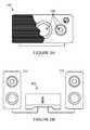
- FIG. 2Ashows an illustration of an example zone player having a built-in amplifier and transducers
- FIG. 2Bshows an illustration of an example zone player having a built-in amplifier and connected to external speakers
- FIG. 2Cshows an illustration of an example zone player connected to an A/V receiver and speakers
- FIG. 3shows an illustration of an example controller
- FIG. 4shows an internal functional block diagram of an example zone player
- FIG. 5shows an internal functional block diagram of an example controller
- FIG. 6shows an example ad-hoc playback network
- FIG. 7shows a system including a plurality of networks including a cloud-based network and at least one local playback network
- FIG. 8illustrates a profile view of an example playback device including an example acoustic grille
- FIG. 9illustrates an angled view of the example playback device including the example acoustic grille
- FIG. 10is an illustrated example of a playback device including first and second example tweeters, first and second example mid-range drivers and an example low-range woofer;
- FIG. 11illustrates a profile view of the example playback device, the first and second example tweeters and the example acoustic grille
- FIG. 12is a flowchart representative of an example process to optimize acoustics in a multiple transducer playback device
- FIG. 13is a flowchart representative of another example process to optimize acoustical output in a multiple transducer playback device
- Acoustic transducersgenerally output sound waves, receive sound waves, or output and receive sound waves.
- an audio playback devicemay include a tweeter, a mid-range driver, a low-range driver and/or any other combination of a tweeter, a mid-range driver and a low-range driver.
- the structure of the playback devicee.g., the enclosure, the baffle, the proximity of an adjacent transducer, and so on
- these interference patternsare often undesirable and, for example, can result in audio distortion (e.g., Doppler or intermodulation distortion (IMD)) or phase shifting (e.g., as seen in the frequency response as comb filtering).
- IMDintermodulation distortion
- an audio playback devicemay include at least two (e.g., mid-range) drivers, one to play sound waves and one to receive sound waves.
- the adjacent driversmay interfere such that the sound waves from the driver playing the sound waves may be received from the driver receiving the sound waves. This interference often manifests itself as feedback or noise.
- an audio receiving devicemay include multiple acoustic transducers to receive sound waves.
- a two-dimensional microphone arraymay include four mid-range drivers to receive audio in the four corners of a large presentation board mounted on a wall or flat surface.
- the microphone arraymay be used to detect the general location of an audio source (e.g., detect the location of a person giving a presentation) relative to the presentation board.
- the sound waves of an audio sourcemay arrive at varying angles at each microphone giving similar, or substantially similar, level measurements (e.g., sound pressure level (SPL), electrical signal output, etc.)
- the examples disclosed hereinenable optimizing acoustical output via an acoustic grille.
- the examples disclosed hereinprovide an acoustic grille composed of a variable-acoustic-opacity material.
- the properties of the materialallow higher angles of incidence wave components to pass through the acoustic grille. Additionally, the properties of the material block (or reflect) lower angles of incidence wave components from passing through the acoustic grille. Additional embodiments are described herein.
- FIG. 1shows an example system configuration 100 in which one or more embodiments disclosed herein can be practiced or implemented.
- the system configuration 100represents a home with multiple zones, though the home could have been configured with only one zone.
- Each zonefor example, may represent a different room or space, such as an office, bathroom, bedroom, kitchen, dining room, family room, home theater room, utility or laundry room, and patio.
- a single zonemight also include multiple rooms or spaces if so configured.
- One or more of zone players 102 - 124are shown in each respective zone.
- a zone player 102 - 124also referred to as a playback device, multimedia unit, speaker, player, and so on, provides audio, video, and/or audiovisual output.
- a controller 130e.g., shown in the kitchen for purposes of illustration) provides control to the system configuration 100 .
- Controller 130may be fixed to a zone, or alternatively, mobile such that it can be moved about the zones.
- the system configuration 100may also include more than one controller 130 .
- the system configuration 100illustrates an example whole house audio system, though it is understood that the technology described herein is not limited to its particular place of application or to an expansive system like a whole house audio system 100 of FIG. 1 .
- FIGS. 2A, 2B, and 2Cshow example types of zone players.
- Zone players 200 , 202 , and 204 of FIGS. 2A, 2B, and 2Ccan correspond to any of the zone players 102 - 124 of FIG. 1 , for example.
- audiois reproduced using only a single zone player, such as by a full-range player.
- audiois reproduced using two or more zone players, such as by using a combination of full-range players or a combination of full-range and specialized players.
- zone players 200 - 204may also be referred to as a “smart speaker,” because they contain processing capabilities beyond the reproduction of audio, more of which is described below.
- FIG. 2Aillustrates zone player 200 that includes sound producing equipment 208 capable of reproducing full-range sound.
- the soundmay come from an audio signal that is received and processed by zone player 200 over a wired or wireless data network.
- Sound producing equipment 208includes one or more built-in amplifiers and one or more acoustic transducers (e.g., speakers).
- a built-in amplifieris described in more detail below with respect to FIG. 4 .
- a speaker or acoustic transducercan include, for example, any of a tweeter, a mid-range driver, a low-range driver, and a subwoofer.
- zone player 200can be statically or dynamically configured to play stereophonic audio, monaural audio, or both.
- zone player 200is configured to reproduce a subset of full-range sound, such as when zone player 200 is grouped with other zone players to play stereophonic audio, monaural audio, and/or surround audio or when the audio content received by zone player 200 is less than full-range.
- FIG. 2Billustrates zone player 202 that includes a built-in amplifier to power a set of detached speakers 210 .
- a detached speakercan include, for example, any type of loudspeaker.
- Zone player 202may be configured to power one, two, or more separate loudspeakers.
- Zone player 202may be configured to communicate an audio signal (e.g., right and left channel audio or more channels depending on its configuration) to the detached speakers 210 via a wired path.
- an audio signale.g., right and left channel audio or more channels depending on its configuration
- FIG. 2Cillustrates zone player 204 that does not include a built-in amplifier, but is configured to communicate an audio signal, received over a data network, to an audio (or “audio/video”) receiver 214 with built-in amplification.
- one, some, or all of the zone players 102 to 124can retrieve audio directly from a source.
- a zone playermay contain a playlist or queue of audio items to be played (also referred to herein as a “playback queue”). Each item in the queue may comprise a uniform resource identifier (URI) or some other identifier.
- URIuniform resource identifier
- the URI or identifiercan point the zone player to the audio source.
- the sourcemight be found on the Internet (e.g., the cloud), locally from another device over data network 128 (described further below), from the controller 130 , stored on the zone player itself, or from an audio source communicating directly to the zone player.
- the zone playercan reproduce the audio itself, send it to another zone player for reproduction, or both where the audio is played by the zone player and one or more additional zone players in synchrony.
- the zone playercan play a first audio content (or not play at all), while sending a second, different audio content to another zone player(s) for reproduction.
- SONOS, Inc. of Santa Barbara, Calif.presently offers for sale zone players referred to as a “PLAY:5,” “PLAY:3,” “CONNECT:AMP,” “CONNECT,” and “SUB.” Any other past, present, and/or future zone players can additionally or alternatively be used to implement the zone players of example embodiments disclosed herein.
- a zone playeris not limited to the particular examples illustrated in FIGS. 2A, 2B, and 2C or to the SONOS product offerings.
- a zone playermay include a wired or wireless headphone.
- a zone playermight include a sound bar for television.
- a zone playercan include or interact with a docking station for an Apple IPODTM or similar device.
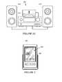
- FIG. 3illustrates an example wireless controller 300 in docking station 302 .
- controller 300can correspond to controlling device 130 of FIG. 1 .
- Docking station 302may be used to charge a battery of controller 300 .
- controller 300is provided with a touch screen 304 that allows a user to interact through touch with the controller 300 , for example, to retrieve and navigate a playlist of audio items, control operations of one or more zone players, and provide overall control of the system configuration 100 .
- any number of controllerscan be used to control the system configuration 100 .
- the controllersmight be wireless like wireless controller 300 or wired to data network 128 .
- each controllermay be coordinated to display common content, and may all be dynamically updated to indicate changes made from a single controller. Coordination can occur, for instance, by a controller periodically requesting a state variable directly or indirectly from one or more zone players; the state variable may provide information about system 100 , such as current zone group configuration, what is playing in one or more zones, volume levels, and other items of interest. The state variable may be passed around on data network 128 between zone players (and controllers, if so desired) as needed or as often as programmed.
- controller 130an application running on any network-enabled portable device, such as an IPHONETM, IPADTM, ANDROIDTM powered phone, or any other smart phone or network-enabled device can be used as controller 130 .
- An application running on a laptop or desktop personal computer (PC) or MAC®can also be used as controller 130 .
- Such controllersmay connect to system 100 through an interface with data network 128 , a zone player, a wireless router, or using some other configured connection path.
- Example controllers offered by SONOS, Inc. of Santa Barbara, Calif.include a “Controller 200 ,” “SONOS® CONTROL,” “SONOS® Controller for iPhone,” “SONOS® Controller for IPADTM,” “SONOS® Controller for ANDROIDTM, “SONOS® Controller for MAC or PC.”
- Zone players 102 to 124 of FIG. 1are coupled directly or indirectly to a data network, such as data network 128 . Controller 130 may also be coupled directly or indirectly to data network 128 or individual zone players.
- Data network 128is represented by an octagon in the figure to stand out from other representative components. While data network 128 is shown in a single location, it is understood that such a network is distributed in and around system 100 . Particularly, data network 128 can be a wired network, a wireless network, or a combination of both wired and wireless networks.
- one or more of the zone players 102 - 124are wirelessly coupled to data network 128 based on a proprietary mesh network.
- one or more of the zone players 102 - 124are wirelessly coupled to data network 128 using a non-mesh topology. In some embodiments, one or more of the zone players 102 - 124 are coupled via a wire to data network 128 using Ethernet or similar technology. In addition to the one or more zone players 102 - 124 connecting to data network 128 , data network 128 can further allow access to a wide area network, such as the Internet.
- connecting any of the zone players 102 - 124 , or some other connecting device, to a broadband routercan create data network 128 .
- Other zone players 102 - 124can then be added wired or wirelessly to the data network 128 .
- a zone playere.g., any of zone players 102 - 124
- the broadband routercan be connected to an Internet Service Provider (ISP), for example.
- ISPInternet Service Provider
- the broadband routercan be used to form another data network within the system configuration 100 , which can be used in other applications (e.g., web surfing).
- Data network 128can also be used in other applications, if so programmed.
- second networkmay implement SONOSNETTM protocol, developed by SONOS, Inc. of Santa Barbara.
- SONOSNETTMrepresents a secure, AES-encrypted, peer-to-peer wireless mesh network.
- the data network 128is the same network, such as a traditional wired or wireless network, used for other applications in the household.
- a particular zonecan contain one or more zone players.
- the family room of FIG. 1contains two zone players 106 and 108 , while the kitchen is shown with one zone player 102 .
- the home theater roomcontains additional zone players to play audio from a 5.1 channel or greater audio source (e.g., a movie encoded with 5.1 or greater audio channels).
- zonesmay be created, combined with another zone, removed, and given a specific name (e.g., “Kitchen”), if so desired and programmed to do so with controller 130 .
- zone configurationsmay be dynamically changed even after being configured using controller 130 or some other mechanism.
- a zonecontains two or more zone players, such as the two zone players 106 and 108 in the family room
- the two zone players 106 and 108can be configured to play the same audio source in synchrony, or the two zone players 106 and 108 can be paired to play two separate sounds in left and right channels, for example.
- the stereo effects of a soundcan be reproduced or enhanced through the two zone players 106 and 108 , one for the left sound and the other for the right sound.
- paired zone playersalso referred to as “bonded zone players” can play audio in synchrony with other zone players in the same or different zones.
- two or more zone playerscan be sonically consolidated to form a single, consolidated zone player.
- a consolidated zone player(though made up of multiple, separate devices) can be configured to process and reproduce sound differently than an unconsolidated zone player or zone players that are paired, because a consolidated zone player will have additional speaker drivers from which sound can be passed.
- the consolidated zone playercan further be paired with a single zone player or yet another consolidated zone player.
- Each playback device of a consolidated playback devicecan be set in a consolidated mode, for example.
- the actions of grouping, consolidation, and pairingare preferably performed through a control interface, such as using controller 130 , and not by physically connecting and re-connecting speaker wire, for example, to individual, discrete speakers to create different configurations.
- controller 130a control interface
- shore embodiments described hereinprovide a more flexible and dynamic platform through which sound reproduction can be offered to the end-user.
- each zonecan play from the same audio source as another zone or each zone can play from a different audio source.
- someonecan be grilling on the patio and listening to jazz music via zone player 124 , while someone is preparing food in the kitchen and listening to classical music via zone player 102 .
- someonecan be in the office listening to the same jazz music via zone player 110 that is playing on the patio via zone player 124 .
- the jazz music played via zone players 110 and 124is played in synchrony. Synchronizing playback amongst zones allows for someone to pass through zones while seamlessly (or substantially seamlessly) listening to the audio. Further, zones can be put into a “party mode” such that all associated zones will play audio in synchrony.
- Sources of audio content to be played by zone players 102 - 124are numerous.
- music on a zone player itselfmay be accessed and played.
- music from a personal library stored on a computer or networked-attached storage (NAS)may be accessed via the data network 128 and played.
- NASnetworked-attached storage
- Internet radio stations, shows, and podcastscan be accessed via the data network 128 .
- Music or cloud servicesthat let a user stream and/or download music and audio content can be accessed via the data network 128 .
- musiccan be obtained from traditional sources, such as a turntable or CD player, via a line-in connection to a zone player, for example.
- Audio contentcan also be accessed using a different protocol, such as AIRPLAYTM, which is a wireless technology by Apple, Inc., for example. Audio content received from one or more sources can be shared amongst the zone players 102 to 124 via data network 128 and/or controller 130 .
- AIRPLAYTMa wireless technology by Apple, Inc.
- Audio content received from one or more sourcescan be shared amongst the zone players 102 to 124 via data network 128 and/or controller 130 .
- the above-disclosed sources of audio contentare referred to herein as network-based audio information sources. However, network-based audio information sources are not limited thereto.
- the example home theater zone players 116 , 118 , 120are coupled to an audio information source such as a television 132 .
- the television 132is used as a source of audio for the home theater zone players 116 , 118 , 120 , while in other examples audio information from the television 132 can be shared with any of the zone players 102 - 124 in the audio system 100 .
- Zone player 400includes a network interface 402 , a processor 408 , a memory 410 , an audio processing component 412 , one or more modules 414 , an audio amplifier 416 , and a speaker unit 418 coupled to the audio amplifier 416 .
- FIG. 2Ashows an example illustration of such a zone player.
- Other types of zone playersmay not include the speaker unit 418 (e.g., such as shown in FIG. 2B ) or the audio amplifier 416 (e.g., such as shown in FIG. 2C ).
- the zone player 400can be integrated into another component.
- the zone player 400could be constructed as part of a television, lighting, or some other device for indoor or outdoor use.
- network interface 402facilitates a data flow between zone player 400 and other devices on a data network 128 .
- zone player 400may access audio directly from the audio source, such as over a wide area network or on the local network.
- the network interface 402can further handle the address part of each packet so that it gets to the right destination or intercepts packets destined for the zone player 400 .
- each of the packetsincludes an Internet Protocol (IP)-based source address as well as an IP-based destination address.
- IPInternet Protocol
- network interface 402can include one or both of a wireless interface 404 and a wired interface 406 .
- the wireless interface 404also referred to as a radio frequency (RF) interface, provides network interface functions for the zone player 400 to wirelessly communicate with other devices (e.g., other zone player(s), speaker(s), receiver(s), component(s) associated with the data network 128 , and so on) in accordance with a communication protocol (e.g., any wireless standard including IEEE 802.11a, 802.11b, 802.11g, 802.11n, or 802.15).
- Wireless interface 404may include one or more radios.
- the zone player 400includes one or more antennas 420 .
- the wired interface 406provides network interface functions for the zone player 400 to communicate over a wire with other devices in accordance with a communication protocol (e.g., IEEE 802.3).
- a zone player 400includes multiple wireless interfaces 404 .
- a zone playerincludes multiple wired interfaces 406 .
- a zone playerincludes both of the interfaces 404 and 406 .
- a zone player 400includes only the wireless interface 404 or the wired interface 406 .
- the processor 408is a clock-driven electronic device that is configured to process input data according to instructions stored in memory 410 .
- the memory 410is data storage that can be loaded with one or more software module(s) 414 , which can be executed by the processor 408 to achieve certain tasks.
- the memory 410is a tangible machine-readable medium storing instructions that can be executed by the processor 408 .
- a taskmight be for the zone player 400 to retrieve audio data from another zone player or a device on a network (e.g., using a uniform resource locator (URL) or some other identifier).
- a taskmay be for the zone player 400 to send audio data to another zone player or device on a network.
- URLuniform resource locator
- a taskmay be for the zone player 400 to synchronize playback of audio with one or more additional zone players. In some embodiments, a task may be to pair the zone player 400 with one or more zone players to create a multi-channel audio environment. Additional or alternative tasks can be achieved via the one or more software module(s) 414 and the processor 408 .
- the audio processing component 412can include one or more digital-to-analog converters (DAC), an audio preprocessing component, an audio enhancement component or a digital signal processor, and so on. In some embodiments, the audio processing component 412 may be part of processor 408 . In some embodiments, the audio that is retrieved via the network interface 402 is processed and/or intentionally altered by the audio processing component 412 . Further, the audio processing component 412 can produce analog audio signals. The processed analog audio signals are then provided to the audio amplifier 416 for playback through speakers 418 . In addition, the audio processing component 412 can include circuitry to process analog or digital signals as inputs to play from zone player 400 , send to another zone player on a network, or both play and send to another zone player on the network. An example input includes a line-in connection (e.g., an auto-detecting 3.5 mm audio line-in connection).
- DACdigital-to-analog converters
- the audio amplifier 416is a device(s) that amplifies audio signals to a level for driving one or more speakers 418 .
- the one or more speakers 418can include an individual transducer (e.g., a “driver”) or a complete speaker system that includes an enclosure including one or more drivers.
- a particular drivercan be a subwoofer (e.g., for low frequencies), a mid-range driver (e.g., for middle frequencies), and a tweeter (e.g., for high frequencies), for example.
- An enclosurecan be sealed or ported, for example.
- Each transducermay be driven by its own individual amplifier.
- a commercial example, presently known as the PLAY:5TMis a zone player with a built-in amplifier and speakers that is capable of retrieving audio directly from the source, such as on the Internet or on the local network, for example.
- the PLAY:5TMis a five-amp, five-driver speaker system that includes two tweeters, two mid-range drivers, and one woofer.
- the left audio data of a trackis sent out of the left tweeter and left mid-range driver
- the right audio data of a trackis sent out of the right tweeter and the right mid-range driver
- mono bassis sent out of the subwoofer.
- both mid-range drivers and both tweetershave the same equalization (or substantially the same equalization). That is, they are both sent the same frequencies, but from different channels of audio. Audio from Internet radio stations, online music and video services, downloaded music, analog audio inputs, television, DVD, and so on, can be played from the PLAY:5TM.
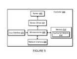
- Controller 500can be used to facilitate the control of multi-media applications, automation and others in a system.
- the controller 500may be configured to facilitate a selection of a plurality of audio sources available on the network and enable control of one or more zone players (e.g., the zone players 102 - 124 in FIG. 1 ) through a wireless or wired network interface 508 .
- the wireless communicationsis based on an industry standard (e.g., infrared, radio, wireless standards including IEEE 802.11a, 802.11b 802.11g, 802.11n, or 802.15, and so on).
- a picturee.g., album art
- any other data, associated with the audio and/or audio sourcecan be transmitted from a zone player or other electronic device to controller 500 for display.
- Controller 500is provided with a screen 502 and an input interface 514 that allows a user to interact with the controller 500 , for example, to navigate a playlist of many multimedia items and to control operations of one or more zone players.
- the screen 502 on the controller 500can be an LCD screen, for example.
- the screen 502communicates with and is commanded by a screen driver 504 that is controlled by a microcontroller (e.g., a processor) 506 .
- the memory 510can be loaded with one or more application modules 512 that can be executed by the microcontroller 506 with or without a user input via the input interface 514 to achieve certain tasks.
- an application module 512is configured to facilitate grouping a number of selected zone players into a zone group and synchronizing the zone players for audio playback. In some embodiments, an application module 512 is configured to control the audio sounds (e.g., volume) of the zone players in a zone group. In operation, when the microcontroller 506 executes one or more of the application modules 512 , the screen driver 504 generates control signals to drive the screen 502 to display an application specific user interface accordingly.
- the controller 500includes a network interface 508 that facilitates wired or wireless communication with a zone player.
- the commandssuch as volume control and audio playback synchronization are sent via the network interface 508 .
- a saved zone group configurationis transmitted between a zone player and a controller via the network interface 508 .
- the controller 500can control one or more zone players, such as 102 - 124 of FIG. 1 . There can be more than one controller for a particular system, and each controller may share common information with another controller, or retrieve the common information from a zone player, if such a zone player stores configuration data (e.g., such as a state variable). Further, a controller can be integrated into a zone player.
- network-enabled devicessuch as an IPHONE®, IPAD® or any other smart phone or network-enabled device (e.g., a networked computer such as a PC or MAC®) can also be used as a controller to interact or control zone players in a particular environment.
- a software application or upgradecan be downloaded onto a network-enabled device to perform the functions described herein.
- a usercan create a zone group (also referred to as a bonded zone) including at least two zone players from the controller 500 .
- the zone players in the zone groupcan play audio in a synchronized fashion, such that all of the zone players in the zone group playback an identical audio source or a list of identical audio sources in a synchronized manner such that no (or substantially no) audible delays or hiccups are to be heard.
- the signals or data of increasing the audio volume for the groupare sent to one of the zone players and causes other zone players in the group to be increased together in volume.
- a user via the controller 500can group zone players into a zone group by activating a “Link Zones” or “Add Zone” soft button, or de-grouping a zone group by activating an “Unlink Zones” or “Drop Zone” button.
- one mechanism for ‘joining’ zone players together for audio playbackis to link a number of zone players together to form a group.
- a usercan manually link each zone player or room one after the other. For example, assume that there is a multi-zone system that includes the following zones: Bathroom, Bedroom, Den, Dining Room, Family Room, and Foyer.
- a usercan link any number of the six zone players, for example, by starting with a single zone and then manually linking each zone to that zone.
- a set of zonescan be dynamically linked together using a command to create a zone scene or theme (subsequent to first creating the zone scene). For instance, a “Morning” zone scene command can link the Bedroom, Office, and Kitchen zones together in one action. Without this single command, the user would manually and individually link each zone.
- the single commandmay include a mouse click, a double mouse click, a button press, a gesture, or some other programmed action. Other kinds of zone scenes can be programmed.
- a zone scenecan be triggered based on time (e.g., an alarm clock function). For instance, a zone scene can be set to apply at 8:00 am. The system can link appropriate zones automatically, set specific music to play, and then stop the music after a defined duration. Although any particular zone can be triggered to an “On” or “Off” state based on time, for example, a zone scene enables any zone(s) linked to the scene to play a predefined audio (e.g., a favorable song, a predefined playlist) at a specific time and/or for a specific duration.
- a predefined audioe.g., a favorable song, a predefined playlist
- a backup buzzercan be programmed to sound.
- the buzzercan include a sound file that is stored in a zone player, for example.
- FIG. 6shows that there are three zone players 602 , 604 and 606 and a controller 608 that form a network branch that is also referred to as an Ad-Hoc network 610 .
- the network 610may be wireless, wired, or a combination of wired and wireless.
- an Ad-Hoc (or “spontaneous”) networkis a local area network or other small network in which there is generally no one access point for all traffic.
- the devices 602 , 604 , 606 and 608can all communicate with each other in a “peer-to-peer” style of communication, for example. Furthermore, devices may join and/or leave the network 610 , and the network 610 will automatically reconfigure itself without needing the user to reconfigure the network 610 . While an Ad-Hoc network is referenced in FIG. 6 , it is understood that a playback network may be based on a type of network that is completely or partially different from an Ad-Hoc network.
- the devices 602 , 604 , 606 , and 608can share or exchange one or more audio sources and be dynamically grouped to play the same or different audio sources.
- the devices 602 and 604are grouped to playback one piece of music, and at the same time, the device 606 plays back another piece of music.
- the devices 602 , 604 , 606 and 608form a HOUSEHOLD that distributes audio and/or reproduces sound.
- the term HOUSEHOLD(provided in uppercase letters to disambiguate from the user's domicile) is used to represent a collection of networked devices that are cooperating to provide an application or service. An instance of a HOUSEHOLD is identified with a household 610 (or household identifier), though a HOUSEHOLD may be identified with a different area or place.
- a household identifieris a short string or an identifier that is computer-generated to help ensure that it is unique.
- the network 610can be characterized by a unique HHID and a unique set of configuration variables or parameters, such as channels (e.g., respective frequency bands), service set identifier (SSID) (a sequence of alphanumeric characters as a name of a wireless network), and WEP keys (wired equivalent privacy or other security keys).
- channelse.g., respective frequency bands
- SSIDservice set identifier
- WEP keyswireless equivalent privacy or other security keys
- each HOUSEHOLDincludes two types of network nodes: a control point (CP) and a zone player (ZP).
- the control pointcontrols an overall network setup process and sequencing, including an automatic generation of required network parameters (e.g., WEP keys).
- the CPalso provides the user with a HOUSEHOLD configuration user interface.
- the CP functioncan be provided by a computer running a CP application module, or by a handheld controller (e.g., the controller 308 ) also running a CP application module, for example.
- the zone playeris any other device on the network that is placed to participate in the automatic configuration process.
- the ZPincludes the controller 308 or a computing device, for example.
- the functionality, or certain parts of the functionality, in both the CP and the ZPare combined at a single node (e.g., a ZP contains a CP or vice-versa).
- configuration of a HOUSEHOLDinvolves multiple CPs and ZPs that rendezvous and establish a known configuration such that they can use a standard networking protocol (e.g., IP over Wired or Wireless Ethernet) for communication.
- a standard networking protocole.g., IP over Wired or Wireless Ethernet
- two types of networks/protocolsare employed: Ethernet 802.3 and Wireless 802.11g. Interconnections between a CP and a ZP can use either of the networks/protocols.
- a device in the system as a member of a HOUSEHOLDcan connect to both networks simultaneously.
- the zone player 606 in FIG. 6is shown to be connected to both networks, for example.
- the connectivity to the network 612is based on Ethernet and/or Wireless, while the connectivity to other devices 602 , 604 and 608 is based on Wireless and Ethernet if so desired.
- each zone player 606 , 604 , 602may access the Internet when retrieving media from the cloud (e.g., the Internet) via the bridging device.
- zone player 602may contain a uniform resource locator (URL) that specifies an address to a particular audio track in the cloud. Using the URL, the zone player 602 may retrieve the audio track from the cloud, and ultimately play the audio out of one or more zone players.
- URLuniform resource locator
- FIG. 7shows a system including a plurality of networks including a cloud-based network and at least one local playback network.
- a local playback networkincludes a plurality of playback devices or players, though it is understood that the playback network may contain only one playback device.
- each playerhas an ability to retrieve its content for playback. Control and content retrieval can be distributed or centralized, for example.
- Inputcan include streaming content provider input, third party application input, mobile device input, user input, and/or other playback network input into the cloud for local distribution and playback.
- a plurality of content providers 720 - 750can be connected to one or more local playback networks 760 - 770 via a cloud and/or other network 710 .
- a multimedia playback system 720e.g., SonosTM
- a mobile device 730e.g., a mobile phone 730
- a third party application 740e.g., a content provider 750
- multimedia contentrequested or otherwise
- a controller 762 , 772 and a playback device 764 , 774can be used to playback audio content.
- transducer playback devicessuch as, for example, a playback device including at least one tweeter and at least one woofer (e.g., the example playback device 200 )
- the placement and configuration of the transducersimpacts the overall playback experienced by the listener.
- the sound waves output by each transducermay interact with the environment (e.g., may be absorbed by a noise baffle, may be reflected off a solid wall, etc.) and may also interact with the other transducers of the playback device.
- the physical structure of the woofermay interact with the sound waves output by the tweeter.
- While sound waves output from a tweetermay travel (or radiate) in all directions due to broad dispersion or low directivity (e.g., “omni-directional”), in some examples, lower frequency wave components of the sound waves output from the tweeter may travel substantially horizontal relative to the surface of the playback device and towards the woofer. Furthermore, sound waves traveling along (or substantially near) the surface of the playback device may bend (or wrap) accordingly as the sound waves pass an edge. This phenomenon is similar to how a person can hear somebody shouting while standing around a corner from the shouter.
- a playback devicemay include a raised tweeter (in relation to a woofer), resulting in a “lip” or “step” between the tweeter and the woofer.
- some components of the sound waves output from the tweeterwill travel at a downward angle towards the woofer and/or travel along (or substantially near) the surface of the playback device towards the woofer (e.g., the sound wave will travel (or bend) over the “lip” or “step”).
- some playback devicesposition the tweeter relatively close to the woofer.
- a flat front wooferis used to try to avoid frequency response dips caused by the cavity of most traditional cone speakers.
- the flat front woofermay eliminate (or substantially reduce) the interference due to any step or dip, other issues, such as Doppler distortion or intermodulation distortion (IMD), may continue to affect the frequency response of the tweeter.
- IMDintermodulation distortion
- FIG. 8illustrates a profile view of an example playback device 800 including an example acoustic grille 825 .
- FIG. 9illustrates an angled view of the example playback device 800 including the example acoustic grille 825 .
- the example playback device 800includes an example lower baffle 805 and an example upper baffle 810 .
- the lower baffle 805 and the upper baffle 810is comprised of a single baffle.
- an example woofer 815is mounted to the face of the example lower baffle 805 and an example tweeter 820 is mounted to the face of the example upper baffle 810 .
- the example acoustic grille 825is positioned on top of (or substantially flush with) the example lower baffle 805 and covers the example woofer 815 .
- the acoustic grille 825may be placed directly on top of the lower baffle 805 or may be separated by, for example, a spacer but still effectively affect any or all sound waves received or output by the transducer (e.g., the example woofer 815 ) mounted in the lower baffle 805 .
- the acoustic grille 825is positioned adjacent to the upper baffle 810 and removes the step between the upper baffle 810 and the lower baffle 805 .
- the acoustic grille 825may be positioned to cover the lower baffle 805 and the upper baffle 810 .
- audio output from a transducerincludes a plurality of wave components. Each of these wave components is traveling in a different direction from the transducer.
- higher frequency wave components of an audio waveare output at an angle substantially perpendicular (e.g., at or effectively near a perpendicular angle) to the surface of the example playback device 800 (e.g., the example wave components 830 , 832 , 834 and 836 ).
- lower frequency wave components of the audio waveoutput at an angle relatively horizontal to the surface of the example playback device 800 (e.g., the example wave components 840 , 842 , 844 and 846 ).
- these wave componentscan be affected by the physical structure of the playback device 800 .
- the wave components 840 and 842bend along the face of the upper baffle 810 .
- wave componentsmay bend (or change the direction of travel) and travel along the face of the lower baffle 805 and/or into the cavity created by a recessed woofer 815 .
- the acoustic grille 825is a variable-acoustic-opacity grille.
- the example acoustic grille 825does not interact uniformly with received wave components.
- the acoustic grille 825is acoustically transparent (or open) to higher angle of incidence wave components relative to the surface of the acoustic grille 825 .
- the example wave components 832 , 834 and 836pass through the example acoustic grille 825 .
- the example acoustic grille 825is acoustically solid (e.g., opaque) to lower angle incidence wave components relative to the surface of the acoustic grille 825 .
- the wave components 844 and 846reflect off the acoustic grille 825 .
- the wave componentsare blocked from continuing in that direction of travel and reflect off the surface of the acoustic grille 825 .
- the acoustic grille 825may be composed of any material having properties that allow a portion of the sound wave to pass through the material (e.g., higher angle of incidence wave components) while blocking and/or reflecting a portion of the sound wave from passing through the material (e.g., lower angle of incidence wave components).
- the acoustic grille 825may be composed of small-cell reticulated foam.
- the surface of the acoustic grille 825may be a porous surface. However, other foamed plastics or materials may also be used.
- the acoustic grille 825may include a wired frame covered by a cloth with similar properties of allowing higher angle of incidence wave components to pass through and blocking/reflecting lower angle of incidence wave components.
- the acoustic grille 825may be designed with a threshold angle to determine higher angle and lower angle of incidence wave components. For example, all wave components with an angle of incidence relative to the surface of the acoustic grill 825 less than ten degrees may be blocked from passing through the material.
- acoustic grille 825in a multiple transducer playback device (e.g., the example playback device 800 ), most of the interference issues between transducers can be eliminated (or substantially reduced/constrained).
- an acoustic grille 825 positioned on top of the multiple transducersmay completely prevent or stop interference between the multiple transducers or may effectively prevent the sound waves from interfering with each other (e.g., substantially constrain interference).
- a raised tweeter 820is used in a playback device 800 (e.g., the top of the dome of the tweeter 820 is raised above the face of the upper baffle 810 )
- lower frequency wave componentsmay output in the direction of the woofer 815 .
- the example acoustic grille 825blocks lower frequency wave components that also have a low angle of incidence relative to the surface of the acoustic grille 825 .
- low-angle (or low directivity) waveguides for the example tweeter 820are used to increase the area of improved sound quality in the listening area (e.g., an increased sweet spot). This is in contrast to reducing the sweet spot by using a waveguide to prevent sound waves from the tweeter radiating towards the woofer.
- FIGS. 8 and 9relate to the bottom of an example acoustic grille 825 interacting with wave components output from a transducer (e.g., the example tweeter 820 , the example woofer 815 ), the example acoustic grille 825 functions similarly when sound waves interact with the top or any of the other surfaces of the acoustic grille 825 .
- a transducere.g., the example tweeter 820 , the example woofer 815
- the example acoustic grille 825functions similarly when sound waves interact with the top or any of the other surfaces of the acoustic grille 825 .
- lower angle of incidence wave components of the sound wavesare blocked from passing through the acoustic grille 825 and into the woofer 815 .
- the example acoustic grille 825diffuses external noise sources as well.
- FIG. 10is an illustrated example of a playback device 1000 including first and second example tweeters 1005 and 1010 , first and second example mid-range drivers 1015 and 1020 and an example low-range woofer 1025 .
- the mid-range drivers 1015 and 1020 and the low-range woofer 1025are covered by an example acoustic grille 1030 .
- FIG. 11illustrates a profile view of the example playback device 1000 , the first and second example tweeters 1005 and 1010 and the example acoustic grille 1030 .
- the acoustic grille 1030includes angled edges. As a result of the angled edges, the example acoustic grille 1030 improves left and right separation of the audio output from the first and second example tweeters 1005 and 1010 . In other words, the angled edges of the example acoustic grille 1030 stop (or substantially prevent) left channel audio output from crossing over to the right side of a listener, and vice versa. For example, the acoustic grille 1030 may completely stop left channel audio output crossover or may effectively prevent a crossover effect from being noticed by a listener (e.g., substantially prevent crossover).
- one or more transducersmay be positioned behind an acoustic grille and receive sound waves from an outside source.
- an acoustic grillemay be disposed atop an array of transducers (e.g., microphones).
- an audio sourceoutputs sound waves (e.g., a person speaking) towards the array of transducers
- the acoustic grillereceives sound waves at varying angles.
- the acoustic grillefilters sound waves received at relatively lower angles of incidence, the sound waves that pass through the acoustic grille indicate the general direction of the audio source.
- monitoring the level measurements of the transducerse.g., sound pressure level, electrical signal output, etc.
- identifying the angles of incidence of the sound waves that pass through the acoustic grillecan be used to determine the location of the audio source.
- a playback devicemay include input transducers (e.g., microphones) and output transducers (e.g., speakers).
- the input transducerscan identify the location of a user in the room (or if no user is in the room) and the characteristics of the output transducers may adjust accordingly.
- the output transducersmay automatically reduce the sound levels if no user is identified in the room.
- the output transducersmay automatically increase the sound levels if no user is identified in the room.
- the sound characteristics of the individual output transducersmay automatically adjust based on the location of a user in the room. For example, if a user is identified in a corner of the room, the gain or sound levels of the individual output transducers may change to continue providing the best overall playback experienced by the user.
- FIG. 12A flowchart representative of an example process 1200 to optimize acoustics in a multiple transducer playback device is shown in FIG. 12 .
- the example process 1200begins at block 1205 when the example acoustic grille 825 of FIG. 8 receives a sound wave.
- the playback device 800processes an audio input and outputs a sound wave via a transducer (e.g., a speaker).
- wave components of the sound wave radiating (or output) from the transducere.g., the example tweeter 820
- the acoustic grille 825receives wave components of the sound wave radiating (or output) from the transducer (e.g., the example tweeter 820 ) at a plurality of angles of incidence relative to the surface of the acoustic grille 825 .
- the acoustic grille 825blocks the wave component.
- the wave componentmay be a lower frequency wave component output from the example tweeter 820 .
- the wave componentmay travel along (or substantially near) the surface of the playback device 800 and travel towards the example woofer 815 .
- the example acoustic grille 825blocks (or reflects) the wave component to prevent (or nearly eliminate or constrain) interference issues due to the wave component output from the example tweeter 820 .
- the process 1200then ends.
- the wave componentpasses through the acoustic grille 825 .
- the properties of the acoustic grille 825include a threshold angle. When the wave component angle of incidence is less than the threshold angle, the wave component is blocked from passing through the acoustic grille 825 . In some examples when the wave component angle of incidence is greater than the threshold angle, the wave component passes through the acoustic grille 825 . The process 1200 then ends.
- FIG. 13is a flowchart representative of another example process 1300 to optimize acoustical output in a multiple transducer playback device.
- the example process 1300begins at block 1305 when the example playback device 800 receives an audio signal.
- the playback device 800may receive audio from another playback device via the network interface 402 , may retrieve the audio from an audio source (e.g., the cloud, a networked-attached storage, etc.).
- the audio signalis processed at the playback device.
- the audio processing component 412may adjust the gain of the example woofer 815 .
- the audio processing component 412may adjust equalization settings of the drivers based at least in part on the characteristics of the audio signal (e.g., left and right audio channels), the characteristics of the listening area, etc. For example, the audio processing component 412 may receive information (via a sensor such as a camera) regarding the position of a listener in the room. In some such examples, the audio processing component 412 may adjust characteristics of the audio signal to direct the audio towards the position of the listener.
- the characteristics of the audio signale.g., left and right audio channels
- the audio processing component 412may receive information (via a sensor such as a camera) regarding the position of a listener in the room. In some such examples, the audio processing component 412 may adjust characteristics of the audio signal to direct the audio towards the position of the listener.
- a sound wave corresponding to the processed audio signalis output.
- the processed audio signalmay be provided to the example audio amplifier 416 to output via the woofer 815 and tweeter 820 .
- wave components of the sound waveradiate outwards from the drivers in all directions.
- some wave componentsmay be altered at least in part on the physical transducer structure.
- low frequency wave components from the tweetermay be modulated by the structure of the woofer cone and/or the up/down (e.g., “thumping”) movement of the woofer.
- wave components of the sound wave incident on the acoustic grille 825are filtered. For example, lower angle of incidence wave components of the first sound wave may be blocked by the acoustic grille 825 . Additionally, higher angle of incidence wave components of the sound wave may pass through the acoustic grille 825 .
- the processends at block 1325 when the audio is output from the playback device 800 to the listening area. In the illustrated example, a portion of the sound wave (e.g., higher angles of incidence wave components) is output to be experienced by the listener.
- apparatus and methodsare provided to optimize acoustics in a multiple transducer playback device.
- the embodiments described hereinprovide and/or use an acoustic grill to filter wave components of a sound wave so that only a portion of the wave components pass through the acoustic grill.
- the embodiments described hereinmay also be used to selectively reflect wave components of sound waves to prevent the sound waves from crossing each other.
- An example embodimentincludes a playback device having a first transducer to at least one of output sound waves and receive sound waves, and a second transducer to at least one of output sound waves and receive sound waves, where the second transducer is positioned adjacent to the first transducer.
- the example playback devicealso includes an acoustic grille positioned in relation to the first transducer, and the acoustic grille is to reflect sound waves received at a first angle of incidence.
- the acoustic grilleis to pass through sound waves that are received at a second angle of incidence.
- the acoustic grilleis to include a threshold angle of incidence, where the first angle of incidence is less than the threshold angle.
- the second angle of incidenceis greater than the threshold angle.
- the acoustic grilleis positioned on the first transducer. In some such examples, the acoustic grille is positioned substantially flush with a baffle of the second transducer. In some such examples, the position of the acoustic grille is to constrain sound wave interference between the first transducer and the second transducer. In some examples, the acoustic grille is positioned between the first transducer and the second transducer. In some such examples, the position of the acoustic grille is to improve sound wave separation between the first transducer and the second transducer. In some examples, if the first transducer receives sound waves and the second transducer at least outputs sound waves, the acoustic grille is to reflect the output sound waves from being received by the first transducer.
- Another example embodimentincludes a method of adjusting a sound wave having at least a first wave component and a second wave component.
- the example methodincludes receiving the first wave component at an acoustic grille at a first angle of incidence, where the acoustic grille is positioned in relation to a plurality of transducers.
- the methodfurther includes receiving a second wave component at the acoustic grille at a second angle of incidence.
- the methodfurther includes reflecting the first wave component based on the first angle of incidence.
- the methodfurther includes passing through the second wave component based on the second angle of incidence, where the first angle of incidence is less than a threshold angle. In some examples, the second angle of incidence is greater than the threshold angle.
- the acoustic grilleis positioned on top of the plurality of transducers. In some such examples, the acoustic grille reduces sound wave interference between the plurality of transducers. In some examples, a portion of the plurality of transducers receive sound wave components pass through the acoustic grille. In some examples, a sound wave source location is identified based on the portion of the plurality of transducers. In some examples, the acoustic grille is positioned between one or more of the plurality of transducers. In some such examples, the acoustic grille improves sound wave separation between the one or more of the plurality of transducers.
- a playback deviceincluding a first baffle, a second baffle and an acoustic grille.
- the first baffleincludes a first transducer and a first surface opposite a second surface, where the first transducer is mounted in the first surface.
- the second baffleis positioned adjacent to the first baffle, and the second baffle includes a second transducer and a third surface opposite a fourth surface, and wherein the second transducer is mounted in the third surface.
- the distance between the third surface and the fourth surfaceis different than the difference between the first surface and the second surface.
- the acoustic grilleis positioned on top of the first baffle and is positioned substantially flush to the second baffle.
- the acoustic grilleis to reflect sound waves received at a first angle of incidence and is to pass through sound waves received at a second angle of incidence, where the position of the acoustic grille is to substantially constrain sound wave interference between the first transducer and the second transducer. In some examples, the position of the acoustic grille is to improve sound wave separation between the first transducer and the second transducer.
- At least one of the elements in at least one exampleis hereby expressly defined to include a tangible medium such as a memory, DVD, CD, Blu-ray, and so on, storing the software and/or firmware.
Landscapes
- Physics & Mathematics (AREA)
- Engineering & Computer Science (AREA)
- Acoustics & Sound (AREA)
- Signal Processing (AREA)
- Health & Medical Sciences (AREA)
- Otolaryngology (AREA)
- General Health & Medical Sciences (AREA)
- Circuit For Audible Band Transducer (AREA)
- Details Of Audible-Bandwidth Transducers (AREA)
- Obtaining Desirable Characteristics In Audible-Bandwidth Transducers (AREA)
Abstract
Description
Claims (20)
Priority Applications (2)
| Application Number | Priority Date | Filing Date | Title |
|---|---|---|---|
| US14/584,680US9525931B2 (en) | 2012-08-31 | 2014-12-29 | Playback based on received sound waves |
| US15/341,575US9736572B2 (en) | 2012-08-31 | 2016-11-02 | Playback based on received sound waves |
Applications Claiming Priority (2)
| Application Number | Priority Date | Filing Date | Title |
|---|---|---|---|
| US13/601,519US8965033B2 (en) | 2012-08-31 | 2012-08-31 | Acoustic optimization |
| US14/584,680US9525931B2 (en) | 2012-08-31 | 2014-12-29 | Playback based on received sound waves |
Related Parent Applications (1)
| Application Number | Title | Priority Date | Filing Date |
|---|---|---|---|
| US13/601,519ContinuationUS8965033B2 (en) | 2012-08-31 | 2012-08-31 | Acoustic optimization |
Related Child Applications (1)
| Application Number | Title | Priority Date | Filing Date |
|---|---|---|---|
| US15/341,575ContinuationUS9736572B2 (en) | 2012-08-31 | 2016-11-02 | Playback based on received sound waves |
Publications (2)
| Publication Number | Publication Date |
|---|---|
| US20150110293A1 US20150110293A1 (en) | 2015-04-23 |
| US9525931B2true US9525931B2 (en) | 2016-12-20 |
Family
ID=50184367
Family Applications (3)
| Application Number | Title | Priority Date | Filing Date |
|---|---|---|---|
| US13/601,519Active2033-02-15US8965033B2 (en) | 2012-08-31 | 2012-08-31 | Acoustic optimization |
| US14/584,680Expired - Fee RelatedUS9525931B2 (en) | 2012-08-31 | 2014-12-29 | Playback based on received sound waves |
| US15/341,575Expired - Fee RelatedUS9736572B2 (en) | 2012-08-31 | 2016-11-02 | Playback based on received sound waves |
Family Applications Before (1)
| Application Number | Title | Priority Date | Filing Date |
|---|---|---|---|
| US13/601,519Active2033-02-15US8965033B2 (en) | 2012-08-31 | 2012-08-31 | Acoustic optimization |
Family Applications After (1)
| Application Number | Title | Priority Date | Filing Date |
|---|---|---|---|
| US15/341,575Expired - Fee RelatedUS9736572B2 (en) | 2012-08-31 | 2016-11-02 | Playback based on received sound waves |
Country Status (5)
| Country | Link |
|---|---|
| US (3) | US8965033B2 (en) |
| EP (1) | EP2891325A4 (en) |
| JP (1) | JP6082814B2 (en) |
| CN (1) | CN104769964B (en) |
| WO (1) | WO2014036271A1 (en) |
Cited By (7)
| Publication number | Priority date | Publication date | Assignee | Title |
|---|---|---|---|---|
| US10440473B1 (en) | 2018-06-22 | 2019-10-08 | EVA Automation, Inc. | Automatic de-baffling |
| US10484809B1 (en) | 2018-06-22 | 2019-11-19 | EVA Automation, Inc. | Closed-loop adaptation of 3D sound |
| US10511906B1 (en) | 2018-06-22 | 2019-12-17 | EVA Automation, Inc. | Dynamically adapting sound based on environmental characterization |
| US10524053B1 (en) | 2018-06-22 | 2019-12-31 | EVA Automation, Inc. | Dynamically adapting sound based on background sound |
| US10531221B1 (en) | 2018-06-22 | 2020-01-07 | EVA Automation, Inc. | Automatic room filling |
| US10708691B2 (en) | 2018-06-22 | 2020-07-07 | EVA Automation, Inc. | Dynamic equalization in a directional speaker array |
| US10869128B2 (en) | 2018-08-07 | 2020-12-15 | Pangissimo Llc | Modular speaker system |
Families Citing this family (60)
| Publication number | Priority date | Publication date | Assignee | Title |
|---|---|---|---|---|
| US9084058B2 (en) | 2011-12-29 | 2015-07-14 | Sonos, Inc. | Sound field calibration using listener localization |
| US9668049B2 (en) | 2012-06-28 | 2017-05-30 | Sonos, Inc. | Playback device calibration user interfaces |
| US9219460B2 (en) | 2014-03-17 | 2015-12-22 | Sonos, Inc. | Audio settings based on environment |
| US9706323B2 (en) | 2014-09-09 | 2017-07-11 | Sonos, Inc. | Playback device calibration |
| US9106192B2 (en) | 2012-06-28 | 2015-08-11 | Sonos, Inc. | System and method for device playback calibration |
| US9690271B2 (en) | 2012-06-28 | 2017-06-27 | Sonos, Inc. | Speaker calibration |
| US9690539B2 (en) | 2012-06-28 | 2017-06-27 | Sonos, Inc. | Speaker calibration user interface |
| US8965033B2 (en) | 2012-08-31 | 2015-02-24 | Sonos, Inc. | Acoustic optimization |
| US9798510B2 (en)* | 2013-05-29 | 2017-10-24 | Sonos, Inc. | Connected state indicator |
| US9264839B2 (en) | 2014-03-17 | 2016-02-16 | Sonos, Inc. | Playback device configuration based on proximity detection |
| US9910634B2 (en) | 2014-09-09 | 2018-03-06 | Sonos, Inc. | Microphone calibration |
| US9891881B2 (en) | 2014-09-09 | 2018-02-13 | Sonos, Inc. | Audio processing algorithm database |
| US9952825B2 (en) | 2014-09-09 | 2018-04-24 | Sonos, Inc. | Audio processing algorithms |
| US10127006B2 (en) | 2014-09-09 | 2018-11-13 | Sonos, Inc. | Facilitating calibration of an audio playback device |
| US9782672B2 (en) | 2014-09-12 | 2017-10-10 | Voyetra Turtle Beach, Inc. | Gaming headset with enhanced off-screen awareness |
| JP6526185B2 (en) | 2014-09-30 | 2019-06-05 | アップル インコーポレイテッドApple Inc. | Loudspeaker with reduced audio coloration caused by surface reflections |
| US10609473B2 (en) | 2014-09-30 | 2020-03-31 | Apple Inc. | Audio driver and power supply unit architecture |
| USRE49437E1 (en) | 2014-09-30 | 2023-02-28 | Apple Inc. | Audio driver and power supply unit architecture |
| RU2685038C2 (en)* | 2014-10-06 | 2019-04-16 | Генелек Ой | Load speaker equipped with waveguide |
| US10664224B2 (en) | 2015-04-24 | 2020-05-26 | Sonos, Inc. | Speaker calibration user interface |
| WO2016172593A1 (en) | 2015-04-24 | 2016-10-27 | Sonos, Inc. | Playback device calibration user interfaces |
| US9538305B2 (en) | 2015-07-28 | 2017-01-03 | Sonos, Inc. | Calibration error conditions |
| US9712912B2 (en) | 2015-08-21 | 2017-07-18 | Sonos, Inc. | Manipulation of playback device response using an acoustic filter |
| CN108028985B (en) | 2015-09-17 | 2020-03-13 | 搜诺思公司 | Method for computing device |
| US9693165B2 (en) | 2015-09-17 | 2017-06-27 | Sonos, Inc. | Validation of audio calibration using multi-dimensional motion check |
| US9743207B1 (en) | 2016-01-18 | 2017-08-22 | Sonos, Inc. | Calibration using multiple recording devices |
| US10003899B2 (en) | 2016-01-25 | 2018-06-19 | Sonos, Inc. | Calibration with particular locations |
| US11106423B2 (en) | 2016-01-25 | 2021-08-31 | Sonos, Inc. | Evaluating calibration of a playback device |
| CN107172527B (en)* | 2016-03-08 | 2020-06-09 | 中兴通讯股份有限公司 | Volume adjusting method and device for collaborative playing and collaborative playing device |
| US9860662B2 (en) | 2016-04-01 | 2018-01-02 | Sonos, Inc. | Updating playback device configuration information based on calibration data |
| US9864574B2 (en) | 2016-04-01 | 2018-01-09 | Sonos, Inc. | Playback device calibration based on representation spectral characteristics |
| US9763018B1 (en) | 2016-04-12 | 2017-09-12 | Sonos, Inc. | Calibration of audio playback devices |
| US9860670B1 (en) | 2016-07-15 | 2018-01-02 | Sonos, Inc. | Spectral correction using spatial calibration |
| US9794710B1 (en) | 2016-07-15 | 2017-10-17 | Sonos, Inc. | Spatial audio correction |
| US10372406B2 (en) | 2016-07-22 | 2019-08-06 | Sonos, Inc. | Calibration interface |
| US10459684B2 (en) | 2016-08-05 | 2019-10-29 | Sonos, Inc. | Calibration of a playback device based on an estimated frequency response |
| US10602296B2 (en)* | 2017-06-09 | 2020-03-24 | Nokia Technologies Oy | Audio object adjustment for phase compensation in 6 degrees of freedom audio |
| CN107437063A (en)* | 2017-07-04 | 2017-12-05 | 上海小蚁科技有限公司 | For sensing apparatus and method, the non-transitory computer-readable medium of environment |
| US10466962B2 (en) | 2017-09-29 | 2019-11-05 | Sonos, Inc. | Media playback system with voice assistance |
| US11343614B2 (en) | 2018-01-31 | 2022-05-24 | Sonos, Inc. | Device designation of playback and network microphone device arrangements |
| CN108536418A (en)* | 2018-03-26 | 2018-09-14 | 深圳市冠旭电子股份有限公司 | A kind of method, apparatus and wireless sound box of the switching of wireless sound box play mode |
| US10623844B2 (en) | 2018-03-29 | 2020-04-14 | Sonos, Inc. | Headphone interaction with media playback system |
| US10959029B2 (en) | 2018-05-25 | 2021-03-23 | Sonos, Inc. | Determining and adapting to changes in microphone performance of playback devices |
| WO2020006410A1 (en) | 2018-06-28 | 2020-01-02 | Sonos, Inc. | Systems and methods for associating playback devices with voice assistant services |
| US10764661B1 (en)* | 2018-06-29 | 2020-09-01 | Warner Music Inc. | Loudspeaker enclosures and loudspeaker devices |
| US10299061B1 (en) | 2018-08-28 | 2019-05-21 | Sonos, Inc. | Playback device calibration |
| US11206484B2 (en) | 2018-08-28 | 2021-12-21 | Sonos, Inc. | Passive speaker authentication |
| US10586540B1 (en) | 2019-06-12 | 2020-03-10 | Sonos, Inc. | Network microphone device with command keyword conditioning |
| EP4004909B1 (en) | 2019-07-31 | 2024-03-06 | Sonos Inc. | Locally distributed keyword detection |
| US10871943B1 (en) | 2019-07-31 | 2020-12-22 | Sonos, Inc. | Noise classification for event detection |
| US10734965B1 (en) | 2019-08-12 | 2020-08-04 | Sonos, Inc. | Audio calibration of a portable playback device |
| US11551670B1 (en) | 2019-09-26 | 2023-01-10 | Sonos, Inc. | Systems and methods for generating labeled data to facilitate configuration of network microphone devices |
| US11189286B2 (en) | 2019-10-22 | 2021-11-30 | Sonos, Inc. | VAS toggle based on device orientation |
| US11200900B2 (en) | 2019-12-20 | 2021-12-14 | Sonos, Inc. | Offline voice control |
| US11562740B2 (en) | 2020-01-07 | 2023-01-24 | Sonos, Inc. | Voice verification for media playback |
| US12108207B2 (en) | 2020-03-10 | 2024-10-01 | Sonos, Inc. | Audio device transducer array and associated systems and methods |
| US12387716B2 (en) | 2020-06-08 | 2025-08-12 | Sonos, Inc. | Wakewordless voice quickstarts |
| US20230385017A1 (en) | 2020-10-06 | 2023-11-30 | Sonos, Inc. | Modifying audio system parameters based on environmental characteristics |
| EP4564154A3 (en) | 2021-09-30 | 2025-07-23 | Sonos Inc. | Conflict management for wake-word detection processes |
| US12327549B2 (en) | 2022-02-09 | 2025-06-10 | Sonos, Inc. | Gatekeeping for voice intent processing |
Citations (153)
| Publication number | Priority date | Publication date | Assignee | Title |
|---|---|---|---|---|
| JPS52164522U (en) | 1976-06-07 | 1977-12-13 | ||
| JPS5650695U (en) | 1979-09-28 | 1981-05-06 | ||
| US4296278A (en) | 1979-01-05 | 1981-10-20 | Altec Corporation | Loudspeaker overload protection circuit |
| US4306113A (en) | 1979-11-23 | 1981-12-15 | Morton Roger R A | Method and equalization of home audio systems |
| US4592088A (en) | 1982-10-14 | 1986-05-27 | Matsushita Electric Industrial Co., Ltd. | Speaker apparatus |
| US4995778A (en) | 1989-01-07 | 1991-02-26 | Krupp Maschinentechnik Gesellschaft Mit Beschrankter Haftung | Gripping apparatus for transporting a panel of adhesive material |
| US5025472A (en)* | 1987-05-27 | 1991-06-18 | Yamaha Corporation | Reverberation imparting device |
| US5031220A (en)* | 1989-01-17 | 1991-07-09 | Pioneer Electronic Corporation | Mobile stereo speaker set |
| US5117463A (en)* | 1989-03-14 | 1992-05-26 | Pioneer Electronic Corporation | Speaker system having directivity |
| JPH04167697A (en) | 1990-10-26 | 1992-06-15 | Mitsubishi Electric Corp | speaker system |
| EP0492919A2 (en) | 1990-12-22 | 1992-07-01 | Sony Corporation | Television receiver loudspeaker device |
| JPH0543692Y2 (en) | 1987-07-15 | 1993-11-04 | ||
| US5386478A (en) | 1993-09-07 | 1995-01-31 | Harman International Industries, Inc. | Sound system remote control with acoustic sensor |
| JPH08317488A (en) | 1995-05-19 | 1996-11-29 | Sony Corp | Speaker device |
| JPH0937372A (en) | 1995-05-17 | 1997-02-07 | Nanao:Kk | Speaker unit for video monitor and video monitor for loading the speaker unit |
| US5673323A (en) | 1995-04-12 | 1997-09-30 | L. S. Research, Inc. | Analog spread spectrum wireless speaker system |
| JPH10108292A (en) | 1996-09-26 | 1998-04-24 | Yamaha Corp | Speaker device |
| US5910991A (en) | 1996-08-02 | 1999-06-08 | Apple Computer, Inc. | Method and apparatus for a speaker for a personal computer for selective use as a conventional speaker or as a sub-woofer |
| US5923902A (en) | 1996-02-20 | 1999-07-13 | Yamaha Corporation | System for synchronizing a plurality of nodes to concurrently generate output signals by adjusting relative timelags based on a maximum estimated timelag |
| US5946343A (en) | 1994-11-22 | 1999-08-31 | L. S. Research, Inc. | Digital wireless speaker system |
| US6243322B1 (en)* | 1999-11-05 | 2001-06-05 | Wavemakers Research, Inc. | Method for estimating the distance of an acoustic signal |
| US6256554B1 (en) | 1999-04-14 | 2001-07-03 | Dilorenzo Mark | Multi-room entertainment system with in-room media player/dispenser |
| US20010042107A1 (en) | 2000-01-06 | 2001-11-15 | Palm Stephen R. | Networked audio player transport protocol and architecture |
| US6343132B1 (en)* | 1997-02-28 | 2002-01-29 | Matsushita Electric Industrial Co., Ltd. | Loudspeaker |
| US20020022453A1 (en) | 2000-03-31 | 2002-02-21 | Horia Balog | Dynamic protocol selection and routing of content to mobile devices |
| US20020026442A1 (en) | 2000-01-24 | 2002-02-28 | Lipscomb Kenneth O. | System and method for the distribution and sharing of media assets between media players devices |
| US6404811B1 (en) | 1996-05-13 | 2002-06-11 | Tektronix, Inc. | Interactive multimedia system |
| US20020086656A1 (en)* | 2000-12-28 | 2002-07-04 | Sven Mattisson | Sound-based proximity detector |
| EP1133896B1 (en) | 1998-10-06 | 2002-08-28 | Bang & Olufsen A/S | Environment adaptable loudspeaker |
| US20020124097A1 (en) | 2000-12-29 | 2002-09-05 | Isely Larson J. | Methods, systems and computer program products for zone based distribution of audio signals |
| WO2001053994A9 (en) | 2000-01-24 | 2002-10-31 | Friskit Inc | Streaming media search and playback system |
| US6522886B1 (en) | 1999-11-22 | 2003-02-18 | Qwest Communications International Inc. | Method and system for simultaneously sharing wireless communications among multiple wireless handsets |
| JP2003084782A (en) | 2001-09-14 | 2003-03-19 | Yoichi Tanaka | Musical sound playing output branch system and microphone device |
| US20030053644A1 (en) | 2001-09-18 | 2003-03-20 | Vandersteen Richard J. | Coincident source stereo speaker |
| US20030157951A1 (en) | 2002-02-20 | 2003-08-21 | Hasty William V. | System and method for routing 802.11 data traffic across channels to increase ad-hoc network capacity |
| US6611537B1 (en) | 1997-05-30 | 2003-08-26 | Centillium Communications, Inc. | Synchronous network for digital media streams |
| US6631410B1 (en) | 2000-03-16 | 2003-10-07 | Sharp Laboratories Of America, Inc. | Multimedia wired/wireless content synchronization system and method |
| US20040005074A1 (en) | 2002-07-08 | 2004-01-08 | Sun Technique Electric Co., Ltd. | Hi-fi tweeter |
| US20040024478A1 (en) | 2002-07-31 | 2004-02-05 | Hans Mathieu Claude | Operating a digital audio player in a collaborative audio session |
| US6721428B1 (en) | 1998-11-13 | 2004-04-13 | Texas Instruments Incorporated | Automatic loudspeaker equalizer |
| US6757517B2 (en) | 2001-05-10 | 2004-06-29 | Chin-Chi Chang | Apparatus and method for coordinated music playback in wireless ad-hoc networks |
| US20040131217A1 (en)* | 2000-07-31 | 2004-07-08 | Opie Scott M. | Arbitrary coverage angle sound integrator |
| US6766025B1 (en) | 1999-03-15 | 2004-07-20 | Koninklijke Philips Electronics N.V. | Intelligent speaker training using microphone feedback and pre-loaded templates |
| US6778869B2 (en) | 2000-12-11 | 2004-08-17 | Sony Corporation | System and method for request, delivery and use of multimedia files for audiovisual entertainment in the home environment |
| US20040252400A1 (en)* | 2003-06-13 | 2004-12-16 | Microsoft Corporation | Computer media synchronization player |
| US20050254662A1 (en)* | 2004-05-14 | 2005-11-17 | Microsoft Corporation | System and method for calibration of an acoustic system |
| JP2006115180A (en) | 2004-10-14 | 2006-04-27 | Sony Corp | Electronic appliance |
| US7058186B2 (en) | 1999-12-01 | 2006-06-06 | Matsushita Electric Industrial Co., Ltd. | Loudspeaker device |
| US7072477B1 (en) | 2002-07-09 | 2006-07-04 | Apple Computer, Inc. | Method and apparatus for automatically normalizing a perceived volume level in a digitally encoded file |
| US7103187B1 (en) | 1999-03-30 | 2006-09-05 | Lsi Logic Corporation | Audio calibration system |
| US7130608B2 (en) | 1999-12-03 | 2006-10-31 | Telefonaktiegolaget Lm Ericsson (Publ) | Method of using a communications device together with another communications device, a communications system, a communications device and an accessory device for use in connection with a communications device |
| US7130616B2 (en) | 2000-04-25 | 2006-10-31 | Simple Devices | System and method for providing content, management, and interactivity for client devices |
| US7143939B2 (en) | 2000-12-19 | 2006-12-05 | Intel Corporation | Wireless music device and method therefor |
| US20070142944A1 (en) | 2002-05-06 | 2007-06-21 | David Goldberg | Audio player device for synchronous playback of audio signals with a compatible device |
| US7236773B2 (en) | 2000-05-31 | 2007-06-26 | Nokia Mobile Phones Limited | Conference call method and apparatus therefor |
| US7433483B2 (en)* | 2001-02-09 | 2008-10-07 | Thx Ltd. | Narrow profile speaker configurations and systems |
| US7483538B2 (en) | 2004-03-02 | 2009-01-27 | Ksc Industries, Inc. | Wireless and wired speaker hub for a home theater system |
| US7490044B2 (en) | 2004-06-08 | 2009-02-10 | Bose Corporation | Audio signal processing |
| US7489784B2 (en) | 2003-11-19 | 2009-02-10 | Pioneer Corporation | Automatic sound field correcting device and computer program therefor |
| US7492909B2 (en) | 2001-04-05 | 2009-02-17 | Motorola, Inc. | Method for acoustic transducer calibration |
| US20090046875A1 (en)* | 2005-12-22 | 2009-02-19 | Tadashi Masuda | Speaker device |
| US7519188B2 (en) | 2003-09-18 | 2009-04-14 | Bose Corporation | Electroacoustical transducing |
| US7529377B2 (en) | 2005-07-29 | 2009-05-05 | Klipsch L.L.C. | Loudspeaker with automatic calibration and room equalization |
| US7571014B1 (en) | 2004-04-01 | 2009-08-04 | Sonos, Inc. | Method and apparatus for controlling multimedia players in a multi-zone system |
| US7630500B1 (en) | 1994-04-15 | 2009-12-08 | Bose Corporation | Spatial disassembly processor |
| US7643894B2 (en) | 2002-05-09 | 2010-01-05 | Netstreams Llc | Audio network distribution system |
| US7657910B1 (en) | 1999-07-26 | 2010-02-02 | E-Cast Inc. | Distributed electronic entertainment method and apparatus |
| US7676044B2 (en) | 2003-12-10 | 2010-03-09 | Sony Corporation | Multi-speaker audio system and automatic control method |
| US20100142735A1 (en) | 2008-12-10 | 2010-06-10 | Samsung Electronics Co., Ltd. | Audio apparatus and signal calibration method thereof |
| KR20100126014A (en) | 2009-05-22 | 2010-12-01 | 에스텍 주식회사 | speaker |
| US7853341B2 (en) | 2002-01-25 | 2010-12-14 | Ksc Industries, Inc. | Wired, wireless, infrared, and powerline audio entertainment systems |
| US7866438B2 (en)* | 2008-06-27 | 2011-01-11 | Rgb Systems, Inc. | Method and apparatus for a loudspeaker assembly |
| US7912238B2 (en)* | 2006-01-13 | 2011-03-22 | Lamarra Frank | Speaker attenuation system, method and apparatus |
| US7949140B2 (en) | 2005-10-18 | 2011-05-24 | Sony Corporation | Sound measuring apparatus and method, and audio signal processing apparatus |
| US7961893B2 (en) | 2005-10-19 | 2011-06-14 | Sony Corporation | Measuring apparatus, measuring method, and sound signal processing apparatus |
| US20110170710A1 (en) | 2010-01-12 | 2011-07-14 | Samsung Electronics Co., Ltd. | Method and apparatus for adjusting volume |
| US8014545B2 (en)* | 2006-12-18 | 2011-09-06 | Dei Headquarters, Inc. | Ceiling or wall-mounted loudspeaker system with anti-diffraction wave launch device |
| US8014423B2 (en) | 2000-02-18 | 2011-09-06 | Smsc Holdings S.A.R.L. | Reference time distribution over a network |
| US8031897B2 (en) | 2008-04-11 | 2011-10-04 | Bose Corporation | System and method for reduced baffle vibration |
| US8031896B2 (en) | 2003-07-21 | 2011-10-04 | Bose Corporation | Passive acoustic radiating |
| US8045952B2 (en) | 1998-01-22 | 2011-10-25 | Horsham Enterprises, Llc | Method and device for obtaining playlist content over a network |
| US8063698B2 (en) | 2008-05-02 | 2011-11-22 | Bose Corporation | Bypassing amplification |
| US8103009B2 (en) | 2002-01-25 | 2012-01-24 | Ksc Industries, Inc. | Wired, wireless, infrared, and powerline audio entertainment systems |
| US20120051558A1 (en) | 2010-09-01 | 2012-03-01 | Samsung Electronics Co., Ltd. | Method and apparatus for reproducing audio signal by adaptively controlling filter coefficient |
| US8139774B2 (en) | 2010-03-03 | 2012-03-20 | Bose Corporation | Multi-element directional acoustic arrays |
| US8160281B2 (en) | 2004-09-08 | 2012-04-17 | Samsung Electronics Co., Ltd. | Sound reproducing apparatus and sound reproducing method |
| US8175292B2 (en) | 2001-06-21 | 2012-05-08 | Aylward J Richard | Audio signal processing |
| US20120121092A1 (en) | 2010-11-12 | 2012-05-17 | Starobin Bradley M | Single enclosure surround sound loudspeaker system and method |
| US20120127831A1 (en) | 2010-11-24 | 2012-05-24 | Samsung Electronics Co., Ltd. | Position determination of devices using stereo audio |
| US8189841B2 (en) | 2008-03-27 | 2012-05-29 | Bose Corporation | Acoustic passive radiating |
| FR2969894A1 (en) | 2010-12-23 | 2012-06-29 | Texte Edouard Durand | Speaker system, has loudspeakers arranged in box, and flange pivotally mounted on central portion to form angle of about specific degrees, where sounds from speakers extend in opposition on outward axis |
| US8218397B2 (en)* | 2008-10-24 | 2012-07-10 | Qualcomm Incorporated | Audio source proximity estimation using sensor array for noise reduction |
| US8229125B2 (en) | 2009-02-06 | 2012-07-24 | Bose Corporation | Adjusting dynamic range of an audio system |
| US8233632B1 (en) | 2011-05-20 | 2012-07-31 | Google Inc. | Method and apparatus for multi-channel audio processing using single-channel components |
| US8234395B2 (en) | 2003-07-28 | 2012-07-31 | Sonos, Inc. | System and method for synchronizing operations among a plurality of independently clocked digital data processing devices |
| US8238578B2 (en) | 2002-12-03 | 2012-08-07 | Bose Corporation | Electroacoustical transducing with low frequency augmenting devices |
| US8243961B1 (en) | 2011-06-27 | 2012-08-14 | Google Inc. | Controlling microphones and speakers of a computing device |
| US8265310B2 (en) | 2010-03-03 | 2012-09-11 | Bose Corporation | Multi-element directional acoustic arrays |
| US8270620B2 (en) | 2005-12-16 | 2012-09-18 | The Tc Group A/S | Method of performing measurements by means of an audio system comprising passive loudspeakers |
| US8290185B2 (en) | 2008-01-31 | 2012-10-16 | Samsung Electronics Co., Ltd. | Method of compensating for audio frequency characteristics and audio/video apparatus using the method |
| EP1825713B1 (en) | 2004-11-22 | 2012-10-17 | Bang & Olufsen A/S | A method and apparatus for multichannel upmixing and downmixing |
| US20120263325A1 (en) | 2011-04-14 | 2012-10-18 | Bose Corporation | Orientation-Responsive Acoustic Array Control |
| US8306235B2 (en) | 2007-07-17 | 2012-11-06 | Apple Inc. | Method and apparatus for using a sound sensor to adjust the audio output for a device |
| US8325935B2 (en) | 2007-03-14 | 2012-12-04 | Qualcomm Incorporated | Speaker having a wireless link to communicate with another speaker |
| US8331585B2 (en) | 2006-05-11 | 2012-12-11 | Google Inc. | Audio mixing |
| US20120327115A1 (en)* | 2011-06-21 | 2012-12-27 | Chhetri Amit S | Signal-enhancing Beamforming in an Augmented Reality Environment |
| US8345892B2 (en) | 2006-11-01 | 2013-01-01 | Samsung Electronics Co., Ltd. | Front surround sound reproduction system using beam forming speaker array and surround sound reproduction method thereof |
| US20130010970A1 (en) | 2010-03-26 | 2013-01-10 | Bang & Olufsen A/S | Multichannel sound reproduction method and device |
| US20130028443A1 (en) | 2011-07-28 | 2013-01-31 | Apple Inc. | Devices with enhanced audio |
| US8391501B2 (en) | 2006-12-13 | 2013-03-05 | Motorola Mobility Llc | Method and apparatus for mixing priority and non-priority audio signals |
| US8401202B2 (en) | 2008-03-07 | 2013-03-19 | Ksc Industries Incorporated | Speakers with a digital signal processor |
| US20130089218A1 (en)* | 2010-07-23 | 2013-04-11 | Nec Casio Mobile Communications, Ltd. | Audio equipment and oscillation unit |
| US8452020B2 (en) | 2008-08-20 | 2013-05-28 | Apple Inc. | Adjustment of acoustic properties based on proximity detection |
| US20130202149A1 (en) | 2012-02-02 | 2013-08-08 | Samsung Electronics Co., Ltd. | Speaker apparatus with n-divided magnet structure |
| US20130259254A1 (en) | 2012-03-28 | 2013-10-03 | Qualcomm Incorporated | Systems, methods, and apparatus for producing a directional sound field |
| US8577048B2 (en) | 2005-09-02 | 2013-11-05 | Harman International Industries, Incorporated | Self-calibrating loudspeaker system |
| US8577045B2 (en) | 2007-09-25 | 2013-11-05 | Motorola Mobility Llc | Apparatus and method for encoding a multi-channel audio signal |
| US20130315429A1 (en) | 2006-12-22 | 2013-11-28 | Robert Preston Parker | Portable audio system having waveguide structure |
| US8600075B2 (en) | 2007-09-11 | 2013-12-03 | Samsung Electronics Co., Ltd. | Method for equalizing audio, and video apparatus using the same |
| US8620006B2 (en) | 2009-05-13 | 2013-12-31 | Bose Corporation | Center channel rendering |
| US20140016786A1 (en) | 2012-07-15 | 2014-01-16 | Qualcomm Incorporated | Systems, methods, apparatus, and computer-readable media for three-dimensional audio coding using basis function coefficients |
| US20140016802A1 (en) | 2012-07-16 | 2014-01-16 | Qualcomm Incorporated | Loudspeaker position compensation with 3d-audio hierarchical coding |
| US20140016784A1 (en) | 2012-07-15 | 2014-01-16 | Qualcomm Incorporated | Systems, methods, apparatus, and computer-readable media for backward-compatible audio coding |
| US20140023196A1 (en) | 2012-07-20 | 2014-01-23 | Qualcomm Incorporated | Scalable downmix design with feedback for object-based surround codec |
| US8638968B2 (en) | 2010-01-01 | 2014-01-28 | Dei Headquarters, Inc. | Low-profile loudspeaker driver and enclosure assembly |
| US8675899B2 (en) | 2007-01-31 | 2014-03-18 | Samsung Electronics Co., Ltd. | Front surround system and method for processing signal using speaker array |
| US20140112481A1 (en) | 2012-10-18 | 2014-04-24 | Google Inc. | Hierarchical deccorelation of multichannel audio |
| US20140219456A1 (en) | 2013-02-07 | 2014-08-07 | Qualcomm Incorporated | Determining renderers for spherical harmonic coefficients |
| US20140226823A1 (en) | 2013-02-08 | 2014-08-14 | Qualcomm Incorporated | Signaling audio rendering information in a bitstream |
| US8811648B2 (en) | 2011-03-31 | 2014-08-19 | Apple Inc. | Moving magnet audio transducer |
| US20140294200A1 (en) | 2013-03-29 | 2014-10-02 | Apple Inc. | Metadata for loudness and dynamic range control |
| US8855319B2 (en) | 2011-05-25 | 2014-10-07 | Mediatek Inc. | Audio signal processing apparatus and audio signal processing method |
| US8879761B2 (en) | 2011-11-22 | 2014-11-04 | Apple Inc. | Orientation-based audio |
| US20140355794A1 (en) | 2013-05-29 | 2014-12-04 | Qualcomm Incorporated | Binaural rendering of spherical harmonic coefficients |
| US20140355768A1 (en) | 2013-05-28 | 2014-12-04 | Qualcomm Incorporated | Performing spatial masking with respect to spherical harmonic coefficients |
| US8914559B2 (en) | 2006-12-12 | 2014-12-16 | Apple Inc. | Methods and systems for automatic configuration of peripherals |
| US8934647B2 (en) | 2011-04-14 | 2015-01-13 | Bose Corporation | Orientation-responsive acoustic driver selection |
| US8934657B2 (en) | 2013-02-07 | 2015-01-13 | Apple Inc. | Speaker magnet assembly with included spider |
| US8934655B2 (en) | 2011-04-14 | 2015-01-13 | Bose Corporation | Orientation-responsive use of acoustic reflection |
| US8965546B2 (en) | 2010-07-26 | 2015-02-24 | Qualcomm Incorporated | Systems, methods, and apparatus for enhanced acoustic imaging |
| US8965033B2 (en) | 2012-08-31 | 2015-02-24 | Sonos, Inc. | Acoustic optimization |
| WO2015024881A1 (en) | 2013-08-20 | 2015-02-26 | Bang & Olufsen A/S | A system for and a method of generating sound |
| US20150063610A1 (en) | 2013-08-30 | 2015-03-05 | GN Store Nord A/S | Audio rendering system categorising geospatial objects |
| US8977974B2 (en) | 2008-12-08 | 2015-03-10 | Apple Inc. | Ambient noise based augmentation of media playback |
| US8984442B2 (en) | 2006-11-17 | 2015-03-17 | Apple Inc. | Method and system for upgrading a previously purchased media asset |
| EP2860992A1 (en) | 2013-10-10 | 2015-04-15 | Samsung Electronics Co., Ltd | Audio system, method of outputting audio, and speaker apparatus |
| US9020153B2 (en) | 2012-10-24 | 2015-04-28 | Google Inc. | Automatic detection of loudspeaker characteristics |
| US20150146886A1 (en) | 2013-11-25 | 2015-05-28 | Apple Inc. | Loudness normalization based on user feedback |
| US20150201274A1 (en) | 2013-02-28 | 2015-07-16 | Google Inc. | Stream caching for audio mixers |
| US20150208188A1 (en)* | 2014-01-20 | 2015-07-23 | Sony Corporation | Distributed wireless speaker system with automatic configuration determination when new speakers are added |
| US20150281866A1 (en) | 2014-03-31 | 2015-10-01 | Bose Corporation | Audio speaker |
| US20150382128A1 (en)* | 2014-06-30 | 2015-12-31 | Microsoft Corporation | Audio calibration and adjustment |
| US9264839B2 (en)* | 2014-03-17 | 2016-02-16 | Sonos, Inc. | Playback device configuration based on proximity detection |
Family Cites Families (16)
| Publication number | Priority date | Publication date | Assignee | Title |
|---|---|---|---|---|
| DE1042024B (en)* | 1956-06-23 | 1958-10-30 | Siemens Ag | Loudspeaker arrangement with several loudspeakers arranged in a row or row |
| US4283606A (en)* | 1979-07-16 | 1981-08-11 | Cerwin Vega, Inc. | Coaxial loudspeaker system |
| US4884655A (en)* | 1988-10-03 | 1989-12-05 | Sparkomatic Corporation | Tower-type speaker cabinet with pivoted plural speaker subassembly |
| JPH0757038B2 (en) | 1989-12-21 | 1995-06-14 | 三菱電機株式会社 | Speaker device |
| US5440644A (en) | 1991-01-09 | 1995-08-08 | Square D Company | Audio distribution system having programmable zoning features |
| JP3077290B2 (en) | 1991-08-09 | 2000-08-14 | 東ソー株式会社 | Curing method of polyphenylene sulfide |
| JP2582178Y2 (en)* | 1991-11-08 | 1998-09-30 | 弘 知名 | A diffuser that improves the directional characteristics of the speaker |
| JPH0757038A (en) | 1993-08-20 | 1995-03-03 | Nec Corp | Bar code read system |
| US6469633B1 (en) | 1997-01-06 | 2002-10-22 | Openglobe Inc. | Remote control of electronic devices |
| US6032202A (en) | 1998-01-06 | 2000-02-29 | Sony Corporation Of Japan | Home audio/video network with two level device control |
| EP1389853B1 (en) | 2002-08-14 | 2006-03-29 | Sony Deutschland GmbH | Bandwidth oriented reconfiguration of wireless ad hoc networks |
| US7295548B2 (en) | 2002-11-27 | 2007-11-13 | Microsoft Corporation | Method and system for disaggregating audio/visual components |
| DE202005007262U1 (en)* | 2005-04-27 | 2005-10-20 | Interkom Electronic Kock & Mreches Gmbh | Conference speech point, has acoustic conductor provided in part of housing surface |
| US8483853B1 (en) | 2006-09-12 | 2013-07-09 | Sonos, Inc. | Controlling and manipulating groupings in a multi-zone media system |
| JP2010507294A (en) | 2006-10-17 | 2010-03-04 | アベガ システムズ ピーティーワイ リミテッド | Integration of multimedia devices |
| US8983089B1 (en) | 2011-11-28 | 2015-03-17 | Rawles Llc | Sound source localization using multiple microphone arrays |
- 2012
- 2012-08-31USUS13/601,519patent/US8965033B2/enactiveActive
- 2013
- 2013-08-29EPEP13833100.4Apatent/EP2891325A4/ennot_activeWithdrawn
- 2013-08-29JPJP2015530043Apatent/JP6082814B2/enactiveActive
- 2013-08-29CNCN201380055845.4Apatent/CN104769964B/enactiveActive
- 2013-08-29WOPCT/US2013/057305patent/WO2014036271A1/enunknown
- 2014
- 2014-12-29USUS14/584,680patent/US9525931B2/ennot_activeExpired - Fee Related
- 2016
- 2016-11-02USUS15/341,575patent/US9736572B2/ennot_activeExpired - Fee Related
Patent Citations (157)
| Publication number | Priority date | Publication date | Assignee | Title |
|---|---|---|---|---|
| JPS52164522U (en) | 1976-06-07 | 1977-12-13 | ||
| US4296278A (en) | 1979-01-05 | 1981-10-20 | Altec Corporation | Loudspeaker overload protection circuit |
| JPS5650695U (en) | 1979-09-28 | 1981-05-06 | ||
| US4306113A (en) | 1979-11-23 | 1981-12-15 | Morton Roger R A | Method and equalization of home audio systems |
| US4592088A (en) | 1982-10-14 | 1986-05-27 | Matsushita Electric Industrial Co., Ltd. | Speaker apparatus |
| US5025472A (en)* | 1987-05-27 | 1991-06-18 | Yamaha Corporation | Reverberation imparting device |
| JPH0543692Y2 (en) | 1987-07-15 | 1993-11-04 | ||
| US4995778A (en) | 1989-01-07 | 1991-02-26 | Krupp Maschinentechnik Gesellschaft Mit Beschrankter Haftung | Gripping apparatus for transporting a panel of adhesive material |
| US5031220A (en)* | 1989-01-17 | 1991-07-09 | Pioneer Electronic Corporation | Mobile stereo speaker set |
| US5117463A (en)* | 1989-03-14 | 1992-05-26 | Pioneer Electronic Corporation | Speaker system having directivity |
| JPH04167697A (en) | 1990-10-26 | 1992-06-15 | Mitsubishi Electric Corp | speaker system |
| EP0492919A2 (en) | 1990-12-22 | 1992-07-01 | Sony Corporation | Television receiver loudspeaker device |
| US5386478A (en) | 1993-09-07 | 1995-01-31 | Harman International Industries, Inc. | Sound system remote control with acoustic sensor |
| US7630500B1 (en) | 1994-04-15 | 2009-12-08 | Bose Corporation | Spatial disassembly processor |
| US5946343A (en) | 1994-11-22 | 1999-08-31 | L. S. Research, Inc. | Digital wireless speaker system |
| US5673323A (en) | 1995-04-12 | 1997-09-30 | L. S. Research, Inc. | Analog spread spectrum wireless speaker system |
| JPH0937372A (en) | 1995-05-17 | 1997-02-07 | Nanao:Kk | Speaker unit for video monitor and video monitor for loading the speaker unit |
| US5970161A (en) | 1995-05-17 | 1999-10-19 | Nanao Corporation | Speaker system for a video monitor and a video monitor equipped with a speaker system |
| JPH08317488A (en) | 1995-05-19 | 1996-11-29 | Sony Corp | Speaker device |
| US5923902A (en) | 1996-02-20 | 1999-07-13 | Yamaha Corporation | System for synchronizing a plurality of nodes to concurrently generate output signals by adjusting relative timelags based on a maximum estimated timelag |
| US6404811B1 (en) | 1996-05-13 | 2002-06-11 | Tektronix, Inc. | Interactive multimedia system |
| US5910991A (en) | 1996-08-02 | 1999-06-08 | Apple Computer, Inc. | Method and apparatus for a speaker for a personal computer for selective use as a conventional speaker or as a sub-woofer |
| JPH10108292A (en) | 1996-09-26 | 1998-04-24 | Yamaha Corp | Speaker device |
| US6343132B1 (en)* | 1997-02-28 | 2002-01-29 | Matsushita Electric Industrial Co., Ltd. | Loudspeaker |
| US6611537B1 (en) | 1997-05-30 | 2003-08-26 | Centillium Communications, Inc. | Synchronous network for digital media streams |
| US8045952B2 (en) | 1998-01-22 | 2011-10-25 | Horsham Enterprises, Llc | Method and device for obtaining playlist content over a network |
| EP1133896B1 (en) | 1998-10-06 | 2002-08-28 | Bang & Olufsen A/S | Environment adaptable loudspeaker |
| US6721428B1 (en) | 1998-11-13 | 2004-04-13 | Texas Instruments Incorporated | Automatic loudspeaker equalizer |
| US6766025B1 (en) | 1999-03-15 | 2004-07-20 | Koninklijke Philips Electronics N.V. | Intelligent speaker training using microphone feedback and pre-loaded templates |
| US7103187B1 (en) | 1999-03-30 | 2006-09-05 | Lsi Logic Corporation | Audio calibration system |
| US6256554B1 (en) | 1999-04-14 | 2001-07-03 | Dilorenzo Mark | Multi-room entertainment system with in-room media player/dispenser |
| US7657910B1 (en) | 1999-07-26 | 2010-02-02 | E-Cast Inc. | Distributed electronic entertainment method and apparatus |
| US6243322B1 (en)* | 1999-11-05 | 2001-06-05 | Wavemakers Research, Inc. | Method for estimating the distance of an acoustic signal |
| US6522886B1 (en) | 1999-11-22 | 2003-02-18 | Qwest Communications International Inc. | Method and system for simultaneously sharing wireless communications among multiple wireless handsets |
| US7058186B2 (en) | 1999-12-01 | 2006-06-06 | Matsushita Electric Industrial Co., Ltd. | Loudspeaker device |
| US7130608B2 (en) | 1999-12-03 | 2006-10-31 | Telefonaktiegolaget Lm Ericsson (Publ) | Method of using a communications device together with another communications device, a communications system, a communications device and an accessory device for use in connection with a communications device |
| US20010042107A1 (en) | 2000-01-06 | 2001-11-15 | Palm Stephen R. | Networked audio player transport protocol and architecture |
| US20020026442A1 (en) | 2000-01-24 | 2002-02-28 | Lipscomb Kenneth O. | System and method for the distribution and sharing of media assets between media players devices |
| WO2001053994A9 (en) | 2000-01-24 | 2002-10-31 | Friskit Inc | Streaming media search and playback system |
| US8014423B2 (en) | 2000-02-18 | 2011-09-06 | Smsc Holdings S.A.R.L. | Reference time distribution over a network |
| US6631410B1 (en) | 2000-03-16 | 2003-10-07 | Sharp Laboratories Of America, Inc. | Multimedia wired/wireless content synchronization system and method |
| US20020022453A1 (en) | 2000-03-31 | 2002-02-21 | Horia Balog | Dynamic protocol selection and routing of content to mobile devices |
| US7130616B2 (en) | 2000-04-25 | 2006-10-31 | Simple Devices | System and method for providing content, management, and interactivity for client devices |
| US7236773B2 (en) | 2000-05-31 | 2007-06-26 | Nokia Mobile Phones Limited | Conference call method and apparatus therefor |
| US20040131217A1 (en)* | 2000-07-31 | 2004-07-08 | Opie Scott M. | Arbitrary coverage angle sound integrator |
| US7324654B2 (en)* | 2000-07-31 | 2008-01-29 | Harman International Industries, Inc. | Arbitrary coverage angle sound integrator |
| US6778869B2 (en) | 2000-12-11 | 2004-08-17 | Sony Corporation | System and method for request, delivery and use of multimedia files for audiovisual entertainment in the home environment |
| US7143939B2 (en) | 2000-12-19 | 2006-12-05 | Intel Corporation | Wireless music device and method therefor |
| US20020086656A1 (en)* | 2000-12-28 | 2002-07-04 | Sven Mattisson | Sound-based proximity detector |
| US20020124097A1 (en) | 2000-12-29 | 2002-09-05 | Isely Larson J. | Methods, systems and computer program products for zone based distribution of audio signals |
| US7433483B2 (en)* | 2001-02-09 | 2008-10-07 | Thx Ltd. | Narrow profile speaker configurations and systems |
| US7492909B2 (en) | 2001-04-05 | 2009-02-17 | Motorola, Inc. | Method for acoustic transducer calibration |
| US6757517B2 (en) | 2001-05-10 | 2004-06-29 | Chin-Chi Chang | Apparatus and method for coordinated music playback in wireless ad-hoc networks |
| US8175292B2 (en) | 2001-06-21 | 2012-05-08 | Aylward J Richard | Audio signal processing |
| JP2003084782A (en) | 2001-09-14 | 2003-03-19 | Yoichi Tanaka | Musical sound playing output branch system and microphone device |
| US20030053644A1 (en) | 2001-09-18 | 2003-03-20 | Vandersteen Richard J. | Coincident source stereo speaker |
| US8103009B2 (en) | 2002-01-25 | 2012-01-24 | Ksc Industries, Inc. | Wired, wireless, infrared, and powerline audio entertainment systems |
| US7853341B2 (en) | 2002-01-25 | 2010-12-14 | Ksc Industries, Inc. | Wired, wireless, infrared, and powerline audio entertainment systems |
| US20030157951A1 (en) | 2002-02-20 | 2003-08-21 | Hasty William V. | System and method for routing 802.11 data traffic across channels to increase ad-hoc network capacity |
| US20070142944A1 (en) | 2002-05-06 | 2007-06-21 | David Goldberg | Audio player device for synchronous playback of audio signals with a compatible device |
| US7643894B2 (en) | 2002-05-09 | 2010-01-05 | Netstreams Llc | Audio network distribution system |
| US20040005074A1 (en) | 2002-07-08 | 2004-01-08 | Sun Technique Electric Co., Ltd. | Hi-fi tweeter |
| US7072477B1 (en) | 2002-07-09 | 2006-07-04 | Apple Computer, Inc. | Method and apparatus for automatically normalizing a perceived volume level in a digitally encoded file |
| US20040024478A1 (en) | 2002-07-31 | 2004-02-05 | Hans Mathieu Claude | Operating a digital audio player in a collaborative audio session |
| US8238578B2 (en) | 2002-12-03 | 2012-08-07 | Bose Corporation | Electroacoustical transducing with low frequency augmenting devices |
| US20040252400A1 (en)* | 2003-06-13 | 2004-12-16 | Microsoft Corporation | Computer media synchronization player |
| US8031896B2 (en) | 2003-07-21 | 2011-10-04 | Bose Corporation | Passive acoustic radiating |
| US8234395B2 (en) | 2003-07-28 | 2012-07-31 | Sonos, Inc. | System and method for synchronizing operations among a plurality of independently clocked digital data processing devices |
| US7519188B2 (en) | 2003-09-18 | 2009-04-14 | Bose Corporation | Electroacoustical transducing |
| US7489784B2 (en) | 2003-11-19 | 2009-02-10 | Pioneer Corporation | Automatic sound field correcting device and computer program therefor |
| US7676044B2 (en) | 2003-12-10 | 2010-03-09 | Sony Corporation | Multi-speaker audio system and automatic control method |
| US7483538B2 (en) | 2004-03-02 | 2009-01-27 | Ksc Industries, Inc. | Wireless and wired speaker hub for a home theater system |
| US7571014B1 (en) | 2004-04-01 | 2009-08-04 | Sonos, Inc. | Method and apparatus for controlling multimedia players in a multi-zone system |
| US7630501B2 (en) | 2004-05-14 | 2009-12-08 | Microsoft Corporation | System and method for calibration of an acoustic system |
| US20050254662A1 (en)* | 2004-05-14 | 2005-11-17 | Microsoft Corporation | System and method for calibration of an acoustic system |
| US7490044B2 (en) | 2004-06-08 | 2009-02-10 | Bose Corporation | Audio signal processing |
| US8160281B2 (en) | 2004-09-08 | 2012-04-17 | Samsung Electronics Co., Ltd. | Sound reproducing apparatus and sound reproducing method |
| JP2006115180A (en) | 2004-10-14 | 2006-04-27 | Sony Corp | Electronic appliance |
| US20060109997A1 (en) | 2004-10-14 | 2006-05-25 | Shinichi Kano | Electronic apparatus |
| EP1825713B1 (en) | 2004-11-22 | 2012-10-17 | Bang & Olufsen A/S | A method and apparatus for multichannel upmixing and downmixing |
| US7529377B2 (en) | 2005-07-29 | 2009-05-05 | Klipsch L.L.C. | Loudspeaker with automatic calibration and room equalization |
| US8577048B2 (en) | 2005-09-02 | 2013-11-05 | Harman International Industries, Incorporated | Self-calibrating loudspeaker system |
| US7949140B2 (en) | 2005-10-18 | 2011-05-24 | Sony Corporation | Sound measuring apparatus and method, and audio signal processing apparatus |
| US7961893B2 (en) | 2005-10-19 | 2011-06-14 | Sony Corporation | Measuring apparatus, measuring method, and sound signal processing apparatus |
| US8270620B2 (en) | 2005-12-16 | 2012-09-18 | The Tc Group A/S | Method of performing measurements by means of an audio system comprising passive loudspeakers |
| US20090046875A1 (en)* | 2005-12-22 | 2009-02-19 | Tadashi Masuda | Speaker device |
| US7912238B2 (en)* | 2006-01-13 | 2011-03-22 | Lamarra Frank | Speaker attenuation system, method and apparatus |
| US8331585B2 (en) | 2006-05-11 | 2012-12-11 | Google Inc. | Audio mixing |
| US8345892B2 (en) | 2006-11-01 | 2013-01-01 | Samsung Electronics Co., Ltd. | Front surround sound reproduction system using beam forming speaker array and surround sound reproduction method thereof |
| US8984442B2 (en) | 2006-11-17 | 2015-03-17 | Apple Inc. | Method and system for upgrading a previously purchased media asset |
| US8914559B2 (en) | 2006-12-12 | 2014-12-16 | Apple Inc. | Methods and systems for automatic configuration of peripherals |
| US8391501B2 (en) | 2006-12-13 | 2013-03-05 | Motorola Mobility Llc | Method and apparatus for mixing priority and non-priority audio signals |
| US8014545B2 (en)* | 2006-12-18 | 2011-09-06 | Dei Headquarters, Inc. | Ceiling or wall-mounted loudspeaker system with anti-diffraction wave launch device |
| US20130315429A1 (en) | 2006-12-22 | 2013-11-28 | Robert Preston Parker | Portable audio system having waveguide structure |
| US8675899B2 (en) | 2007-01-31 | 2014-03-18 | Samsung Electronics Co., Ltd. | Front surround system and method for processing signal using speaker array |
| US8325935B2 (en) | 2007-03-14 | 2012-12-04 | Qualcomm Incorporated | Speaker having a wireless link to communicate with another speaker |
| US8306235B2 (en) | 2007-07-17 | 2012-11-06 | Apple Inc. | Method and apparatus for using a sound sensor to adjust the audio output for a device |
| US8600075B2 (en) | 2007-09-11 | 2013-12-03 | Samsung Electronics Co., Ltd. | Method for equalizing audio, and video apparatus using the same |
| US8577045B2 (en) | 2007-09-25 | 2013-11-05 | Motorola Mobility Llc | Apparatus and method for encoding a multi-channel audio signal |
| US8290185B2 (en) | 2008-01-31 | 2012-10-16 | Samsung Electronics Co., Ltd. | Method of compensating for audio frequency characteristics and audio/video apparatus using the method |
| US8401202B2 (en) | 2008-03-07 | 2013-03-19 | Ksc Industries Incorporated | Speakers with a digital signal processor |
| US8189841B2 (en) | 2008-03-27 | 2012-05-29 | Bose Corporation | Acoustic passive radiating |
| US8031897B2 (en) | 2008-04-11 | 2011-10-04 | Bose Corporation | System and method for reduced baffle vibration |
| US8063698B2 (en) | 2008-05-02 | 2011-11-22 | Bose Corporation | Bypassing amplification |
| US7866438B2 (en)* | 2008-06-27 | 2011-01-11 | Rgb Systems, Inc. | Method and apparatus for a loudspeaker assembly |
| US8452020B2 (en) | 2008-08-20 | 2013-05-28 | Apple Inc. | Adjustment of acoustic properties based on proximity detection |
| US8218397B2 (en)* | 2008-10-24 | 2012-07-10 | Qualcomm Incorporated | Audio source proximity estimation using sensor array for noise reduction |
| US8977974B2 (en) | 2008-12-08 | 2015-03-10 | Apple Inc. | Ambient noise based augmentation of media playback |
| US20100142735A1 (en) | 2008-12-10 | 2010-06-10 | Samsung Electronics Co., Ltd. | Audio apparatus and signal calibration method thereof |
| US8229125B2 (en) | 2009-02-06 | 2012-07-24 | Bose Corporation | Adjusting dynamic range of an audio system |
| US8620006B2 (en) | 2009-05-13 | 2013-12-31 | Bose Corporation | Center channel rendering |
| KR20100126014A (en) | 2009-05-22 | 2010-12-01 | 에스텍 주식회사 | speaker |
| US8638968B2 (en) | 2010-01-01 | 2014-01-28 | Dei Headquarters, Inc. | Low-profile loudspeaker driver and enclosure assembly |
| US20110170710A1 (en) | 2010-01-12 | 2011-07-14 | Samsung Electronics Co., Ltd. | Method and apparatus for adjusting volume |
| US8139774B2 (en) | 2010-03-03 | 2012-03-20 | Bose Corporation | Multi-element directional acoustic arrays |
| US8265310B2 (en) | 2010-03-03 | 2012-09-11 | Bose Corporation | Multi-element directional acoustic arrays |
| US20130010970A1 (en) | 2010-03-26 | 2013-01-10 | Bang & Olufsen A/S | Multichannel sound reproduction method and device |
| US20130089218A1 (en)* | 2010-07-23 | 2013-04-11 | Nec Casio Mobile Communications, Ltd. | Audio equipment and oscillation unit |
| US8965546B2 (en) | 2010-07-26 | 2015-02-24 | Qualcomm Incorporated | Systems, methods, and apparatus for enhanced acoustic imaging |
| US20120051558A1 (en) | 2010-09-01 | 2012-03-01 | Samsung Electronics Co., Ltd. | Method and apparatus for reproducing audio signal by adaptively controlling filter coefficient |
| US20120121092A1 (en) | 2010-11-12 | 2012-05-17 | Starobin Bradley M | Single enclosure surround sound loudspeaker system and method |
| US20120127831A1 (en) | 2010-11-24 | 2012-05-24 | Samsung Electronics Co., Ltd. | Position determination of devices using stereo audio |
| FR2969894A1 (en) | 2010-12-23 | 2012-06-29 | Texte Edouard Durand | Speaker system, has loudspeakers arranged in box, and flange pivotally mounted on central portion to form angle of about specific degrees, where sounds from speakers extend in opposition on outward axis |
| US8811648B2 (en) | 2011-03-31 | 2014-08-19 | Apple Inc. | Moving magnet audio transducer |
| US8934655B2 (en) | 2011-04-14 | 2015-01-13 | Bose Corporation | Orientation-responsive use of acoustic reflection |
| US8934647B2 (en) | 2011-04-14 | 2015-01-13 | Bose Corporation | Orientation-responsive acoustic driver selection |
| US20120263325A1 (en) | 2011-04-14 | 2012-10-18 | Bose Corporation | Orientation-Responsive Acoustic Array Control |
| US8233632B1 (en) | 2011-05-20 | 2012-07-31 | Google Inc. | Method and apparatus for multi-channel audio processing using single-channel components |
| US8855319B2 (en) | 2011-05-25 | 2014-10-07 | Mediatek Inc. | Audio signal processing apparatus and audio signal processing method |
| US20120327115A1 (en)* | 2011-06-21 | 2012-12-27 | Chhetri Amit S | Signal-enhancing Beamforming in an Augmented Reality Environment |
| US8243961B1 (en) | 2011-06-27 | 2012-08-14 | Google Inc. | Controlling microphones and speakers of a computing device |
| US20130028443A1 (en) | 2011-07-28 | 2013-01-31 | Apple Inc. | Devices with enhanced audio |
| US8879761B2 (en) | 2011-11-22 | 2014-11-04 | Apple Inc. | Orientation-based audio |
| US20130202149A1 (en) | 2012-02-02 | 2013-08-08 | Samsung Electronics Co., Ltd. | Speaker apparatus with n-divided magnet structure |
| US20130259254A1 (en) | 2012-03-28 | 2013-10-03 | Qualcomm Incorporated | Systems, methods, and apparatus for producing a directional sound field |
| US20140016786A1 (en) | 2012-07-15 | 2014-01-16 | Qualcomm Incorporated | Systems, methods, apparatus, and computer-readable media for three-dimensional audio coding using basis function coefficients |
| US20140016784A1 (en) | 2012-07-15 | 2014-01-16 | Qualcomm Incorporated | Systems, methods, apparatus, and computer-readable media for backward-compatible audio coding |
| US20140016802A1 (en) | 2012-07-16 | 2014-01-16 | Qualcomm Incorporated | Loudspeaker position compensation with 3d-audio hierarchical coding |
| US20140023196A1 (en) | 2012-07-20 | 2014-01-23 | Qualcomm Incorporated | Scalable downmix design with feedback for object-based surround codec |
| US8965033B2 (en) | 2012-08-31 | 2015-02-24 | Sonos, Inc. | Acoustic optimization |
| US20140112481A1 (en) | 2012-10-18 | 2014-04-24 | Google Inc. | Hierarchical deccorelation of multichannel audio |
| US9020153B2 (en) | 2012-10-24 | 2015-04-28 | Google Inc. | Automatic detection of loudspeaker characteristics |
| US8934657B2 (en) | 2013-02-07 | 2015-01-13 | Apple Inc. | Speaker magnet assembly with included spider |
| US20140219456A1 (en) | 2013-02-07 | 2014-08-07 | Qualcomm Incorporated | Determining renderers for spherical harmonic coefficients |
| US20140226823A1 (en) | 2013-02-08 | 2014-08-14 | Qualcomm Incorporated | Signaling audio rendering information in a bitstream |
| US20150201274A1 (en) | 2013-02-28 | 2015-07-16 | Google Inc. | Stream caching for audio mixers |
| US20140294200A1 (en) | 2013-03-29 | 2014-10-02 | Apple Inc. | Metadata for loudness and dynamic range control |
| US20140355768A1 (en) | 2013-05-28 | 2014-12-04 | Qualcomm Incorporated | Performing spatial masking with respect to spherical harmonic coefficients |
| US20140355794A1 (en) | 2013-05-29 | 2014-12-04 | Qualcomm Incorporated | Binaural rendering of spherical harmonic coefficients |
| WO2015024881A1 (en) | 2013-08-20 | 2015-02-26 | Bang & Olufsen A/S | A system for and a method of generating sound |
| US20150063610A1 (en) | 2013-08-30 | 2015-03-05 | GN Store Nord A/S | Audio rendering system categorising geospatial objects |
| EP2860992A1 (en) | 2013-10-10 | 2015-04-15 | Samsung Electronics Co., Ltd | Audio system, method of outputting audio, and speaker apparatus |
| US20150146886A1 (en) | 2013-11-25 | 2015-05-28 | Apple Inc. | Loudness normalization based on user feedback |
| US20150208188A1 (en)* | 2014-01-20 | 2015-07-23 | Sony Corporation | Distributed wireless speaker system with automatic configuration determination when new speakers are added |
| US9264839B2 (en)* | 2014-03-17 | 2016-02-16 | Sonos, Inc. | Playback device configuration based on proximity detection |
| US20150281866A1 (en) | 2014-03-31 | 2015-10-01 | Bose Corporation | Audio speaker |
| US20150382128A1 (en)* | 2014-06-30 | 2015-12-31 | Microsoft Corporation | Audio calibration and adjustment |
Non-Patent Citations (30)
| Title |
|---|
| Bluetooth, "Specification of the Bluetooth System: The Ad Hoc SCATTERNET for Affordable and Highly Functional Wireless Connectivity," Core, Version 1.0 A, Jul. 26, 1999 (1068 pages). (Document uploaded in 7 different files: NPL1-part1 pp. 1 to 150, NPL1-part2 pp. 151 to 300, NPL1-part3 pp. 301 to 450, NPL1-part4 pp. 451 to 600,NPL1-part5 pp. 601 to 750, NPL1-part6 pp. 751 to 900 and NPL1-part7 pp. 901 to 1068). |
| Bluetooth, "Specification of the Bluetooth System: Wireless Connections Made Easy," Core, Version 1.0 B, Dec. 1, 1999 (1082 pages). (Document uploaded in 9 different files: NPL2-part1 pp. 1 to 152, NPL2-part2 pp. 153 to 303, NPL2-part3 pp. 304 to 453, NPL2-part4 pp. 454 to 603,NPL2-part5 pp. 604 to 704, NPL2-part6 pp. 705 to 753, NPL2-part7 pp. 754 to 854, NPL2-part8 pp. 855-1005 and NPL2-part9 pp. 1006-1081). |
| Dell Computer Corporation, "Dell Digital Audio Receiver: Reference Guide," Jun. 2000 (70 pages). |
| Dell Computer Corporation, "Dell Digital Audio Receiver: Start Here," Jun. 2000 (2 pages). |
| European Patent Office, "Extended European Search Report", issued in connection with corresponding European Patent Application No. 13833100.4, on Jul. 21, 2015, 7 pages. |
| Higgins et al., Microsoft Corporation, "Presentations at WinHEC 2000", May 2000 (138 pages). |
| International Searching Authority, "International Preliminary Report on Patentability," issued in connection with International Patent Application No. PCT/US2013/057305, mailed Mar. 12, 2015 (7 pages). |
| International Searching Authority, "International Search Report and Written Opinion," issued in connection with International Patent Application No. PCT/US2013/057305, mailed Dec. 17, 2013 (10 pages). |
| Japanese Patent Office, Office Action mailed on Feb. 16, 2016, issued in connection with JP Application No. 2015-530043, 7 pages. |
| Jo et al., "Synchronized One-to-Many Media Streaming with Adaptive Playout Control," Proceedings of SPIE, vol. 4861, Dec. 2002 (11 pages). |
| Jones, Stephen, "Dell Digital Audio Receiver: Digital Upgrade for your Analog Stereo," Reviews Online, Jun. 24, 2000, retrieved from , retrieved on Jun. 18, 2014 (2 pages). |
| Jones, Stephen, "Dell Digital Audio Receiver: Digital Upgrade for your Analog Stereo," Reviews Online, Jun. 24, 2000, retrieved from <http://www.reviewsonline.com/articles/961906864.htm>, retrieved on Jun. 18, 2014 (2 pages). |
| Louderback, Jim, "Affordable Audio Receiver Furnishes Homes With MP3," TechTV Vault, Jun. 28, 2000, retrieved from , retrieved on Jul. 10, 2014 (2 pages). |
| Louderback, Jim, "Affordable Audio Receiver Furnishes Homes With MP3," TechTV Vault, Jun. 28, 2000, retrieved from <http://www.g4tv.com/articles/17923/affordable-audio-receiver-furnishes-homes-with-mp3/>, retrieved on Jul. 10, 2014 (2 pages). |
| Meyer Sound Laboratories, Inc., "Constellation Acoustic System: a revolutionary breakthrough in acoustical design," retrieved from , 2012, 32 pages. |
| Meyer Sound Laboratories, Inc., "Constellation Acoustic System: a revolutionary breakthrough in acoustical design," retrieved from <http://www.meyersound.com/pdf/brochures/constellation-brochure-c.pdf>, 2012, 32 pages. |
| Meyer Sound Laboratories, Inc., "Constellation Microphones," retrieved from , 2013, 2 pages. |
| Meyer Sound Laboratories, Inc., "Constellation Microphones," retrieved from <http://www.meyersound.com/sites/default/files/constellation-microphones.pdf>, 2013, 2 pages. |
| Microsoft Corporation, "Universal Plug and Play Device Architecture, Version 1.0," Jun. 8, 2000, retrieved from , retrieved on Apr. 6, 2010 (54 pages). |
| Microsoft Corporation, "Universal Plug and Play Device Architecture, Version 1.0," Jun. 8, 2000, retrieved from <ftp://vtm.upnp.org/upnp/specs/arch/UPnPDA10-20000613.htm>, retrieved on Apr. 6, 2010 (54 pages). |
| Palm, Inc., "Handbook for the Palm VII Handheld," May 19, 2000 (311 pages).(Document uploaded in 2 different files: NPL8-part1 pp. 1 to 150 and NPL8-part2 pp. 151 to 300). |
| Ross, Alex, "Wizards of Sound: Retouching acoustics, from the restaurant to the concert hall," The New Yorker, Feb. 23, 2015, retrieved on Jun. 1, 2015, 9 pages. |
| United States Patent and Trademark Office, "Advisory Action," issued in connection with U.S. Appl. No. 13/601,519, mailed Nov. 14, 2014 (2 pages). |
| United States Patent and Trademark Office, "Final Office Action," issued in connection with U.S. Appl. No. 13/601,519, mailed Sep. 4, 2014 (7 pages). |
| United States Patent and Trademark Office, "Non-Final Office Action," issued in connection with U.S. Appl. No. 13/601,519, mailed May 21, 2014 (7 pages). |
| United States Patent and Trademark Office, "Notice of Allowance," issued in connection with U.S. Appl. No. 13/601,519, mailed Dec. 10, 2014 (12 pages). |
| United States Patent and Trademark Office, "Supplemental Notice of Allowability," issued in connection with U.S. Appl. No. 13/601,519, mailed Jan. 21, 2015 (2 pages). |
| Voyetra Turtle Beach, Inc., "AudioTron Quick Start Guide, Version 1.0," Mar. 2001 (24 pages). |
| Voyetra Turtle Beach, Inc., "AudioTron Reference Manual, Version 3.0," May 2002 (70 pages). |
| Voyetra Turtle Beach, Inc., "AudioTron Setup Guide, Version 3.0," May 2002 (38 pages). |
Cited By (7)
| Publication number | Priority date | Publication date | Assignee | Title |
|---|---|---|---|---|
| US10440473B1 (en) | 2018-06-22 | 2019-10-08 | EVA Automation, Inc. | Automatic de-baffling |
| US10484809B1 (en) | 2018-06-22 | 2019-11-19 | EVA Automation, Inc. | Closed-loop adaptation of 3D sound |
| US10511906B1 (en) | 2018-06-22 | 2019-12-17 | EVA Automation, Inc. | Dynamically adapting sound based on environmental characterization |
| US10524053B1 (en) | 2018-06-22 | 2019-12-31 | EVA Automation, Inc. | Dynamically adapting sound based on background sound |
| US10531221B1 (en) | 2018-06-22 | 2020-01-07 | EVA Automation, Inc. | Automatic room filling |
| US10708691B2 (en) | 2018-06-22 | 2020-07-07 | EVA Automation, Inc. | Dynamic equalization in a directional speaker array |
| US10869128B2 (en) | 2018-08-07 | 2020-12-15 | Pangissimo Llc | Modular speaker system |
Also Published As
| Publication number | Publication date |
|---|---|
| US20150110293A1 (en) | 2015-04-23 |
| JP6082814B2 (en) | 2017-02-15 |
| WO2014036271A1 (en) | 2014-03-06 |
| US20140064550A1 (en) | 2014-03-06 |
| US9736572B2 (en) | 2017-08-15 |
| CN104769964B (en) | 2018-05-22 |
| EP2891325A4 (en) | 2015-08-19 |
| US8965033B2 (en) | 2015-02-24 |
| CN104769964A (en) | 2015-07-08 |
| US20170078796A1 (en) | 2017-03-16 |
| JP2015528677A (en) | 2015-09-28 |
| EP2891325A1 (en) | 2015-07-08 |
Similar Documents
| Publication | Publication Date | Title |
|---|---|---|
| US9736572B2 (en) | Playback based on received sound waves | |
| US12093604B2 (en) | Smart audio settings | |
| US11778378B2 (en) | Volume management in a media playback system | |
| US10536123B2 (en) | Volume interactions for connected playback devices | |
| US10306364B2 (en) | Audio processing adjustments for playback devices based on determined characteristics of audio content |
Legal Events
| Date | Code | Title | Description |
|---|---|---|---|
| AS | Assignment | Owner name:SONOS, INC., CALIFORNIA Free format text:ASSIGNMENT OF ASSIGNORS INTEREST;ASSIGNOR:WIGGINS, DANIEL C.;REEL/FRAME:035594/0914 Effective date:20120831 | |
| AS | Assignment | Owner name:GORDON BROTHERS FINANCE COMPANY, MASSACHUSETTS Free format text:SECURITY INTEREST;ASSIGNOR:SONOS, INC.;REEL/FRAME:038329/0253 Effective date:20160330 | |
| STCF | Information on status: patent grant | Free format text:PATENTED CASE | |
| AS | Assignment | Owner name:SONOS, INC., CALIFORNIA Free format text:RELEASE BY SECURED PARTY;ASSIGNOR:GORDON BROTHERS FINANCE COMPANY;REEL/FRAME:046625/0882 Effective date:20180720 | |
| AS | Assignment | Owner name:JPMORGAN CHASE BANK, N.A., CALIFORNIA Free format text:SECURITY INTEREST;ASSIGNOR:SONOS, INC.;REEL/FRAME:046991/0433 Effective date:20180720 | |
| MAFP | Maintenance fee payment | Free format text:PAYMENT OF MAINTENANCE FEE, 4TH YEAR, LARGE ENTITY (ORIGINAL EVENT CODE: M1551); ENTITY STATUS OF PATENT OWNER: LARGE ENTITY Year of fee payment:4 | |
| AS | Assignment | Owner name:JPMORGAN CHASE BANK, N.A., ILLINOIS Free format text:SECURITY AGREEMENT;ASSIGNOR:SONOS, INC.;REEL/FRAME:058123/0206 Effective date:20211013 | |
| AS | Assignment | Owner name:SONOS, INC., CALIFORNIA Free format text:RELEASE BY SECURED PARTY;ASSIGNOR:JPMORGAN CHASE BANK, N.A.;REEL/FRAME:058213/0597 Effective date:20211013 | |
| FEPP | Fee payment procedure | Free format text:MAINTENANCE FEE REMINDER MAILED (ORIGINAL EVENT CODE: REM.); ENTITY STATUS OF PATENT OWNER: LARGE ENTITY | |
| LAPS | Lapse for failure to pay maintenance fees | Free format text:PATENT EXPIRED FOR FAILURE TO PAY MAINTENANCE FEES (ORIGINAL EVENT CODE: EXP.); ENTITY STATUS OF PATENT OWNER: LARGE ENTITY | |
| STCH | Information on status: patent discontinuation | Free format text:PATENT EXPIRED DUE TO NONPAYMENT OF MAINTENANCE FEES UNDER 37 CFR 1.362 | |
| FP | Lapsed due to failure to pay maintenance fee | Effective date:20241220 |