US9524582B2 - Method and system for constructing personalized avatars using a parameterized deformable mesh - Google Patents
Method and system for constructing personalized avatars using a parameterized deformable meshDownload PDFInfo
- Publication number
- US9524582B2 US9524582B2US14/604,829US201514604829AUS9524582B2US 9524582 B2US9524582 B2US 9524582B2US 201514604829 AUS201514604829 AUS 201514604829AUS 9524582 B2US9524582 B2US 9524582B2
- Authority
- US
- United States
- Prior art keywords
- mesh
- avatar
- avatar mesh
- point cloud
- subject
- Prior art date
- Legal status (The legal status is an assumption and is not a legal conclusion. Google has not performed a legal analysis and makes no representation as to the accuracy of the status listed.)
- Active, expires
Links
Images


Classifications
- G—PHYSICS
- G06—COMPUTING OR CALCULATING; COUNTING
- G06T—IMAGE DATA PROCESSING OR GENERATION, IN GENERAL
- G06T17/00—Three dimensional [3D] modelling, e.g. data description of 3D objects
- G06T17/20—Finite element generation, e.g. wire-frame surface description, tesselation
- G06T17/205—Re-meshing
- G—PHYSICS
- G06—COMPUTING OR CALCULATING; COUNTING
- G06T—IMAGE DATA PROCESSING OR GENERATION, IN GENERAL
- G06T17/00—Three dimensional [3D] modelling, e.g. data description of 3D objects
- G06T17/20—Finite element generation, e.g. wire-frame surface description, tesselation
- G—PHYSICS
- G06—COMPUTING OR CALCULATING; COUNTING
- G06T—IMAGE DATA PROCESSING OR GENERATION, IN GENERAL
- G06T11/00—2D [Two Dimensional] image generation
- G06T11/003—Reconstruction from projections, e.g. tomography
- G06T11/008—Specific post-processing after tomographic reconstruction, e.g. voxelisation, metal artifact correction
- G—PHYSICS
- G06—COMPUTING OR CALCULATING; COUNTING
- G06T—IMAGE DATA PROCESSING OR GENERATION, IN GENERAL
- G06T19/00—Manipulating 3D models or images for computer graphics
- G06T7/0051—
- G—PHYSICS
- G06—COMPUTING OR CALCULATING; COUNTING
- G06T—IMAGE DATA PROCESSING OR GENERATION, IN GENERAL
- G06T7/00—Image analysis
- G06T7/50—Depth or shape recovery
- G—PHYSICS
- G06—COMPUTING OR CALCULATING; COUNTING
- G06T—IMAGE DATA PROCESSING OR GENERATION, IN GENERAL
- G06T2200/00—Indexing scheme for image data processing or generation, in general
- G06T2200/08—Indexing scheme for image data processing or generation, in general involving all processing steps from image acquisition to 3D model generation
- G—PHYSICS
- G06—COMPUTING OR CALCULATING; COUNTING
- G06T—IMAGE DATA PROCESSING OR GENERATION, IN GENERAL
- G06T2207/00—Indexing scheme for image analysis or image enhancement
- G06T2207/10—Image acquisition modality
- G06T2207/10004—Still image; Photographic image
- G06T2207/10012—Stereo images
- G—PHYSICS
- G06—COMPUTING OR CALCULATING; COUNTING
- G06T—IMAGE DATA PROCESSING OR GENERATION, IN GENERAL
- G06T2207/00—Indexing scheme for image analysis or image enhancement
- G06T2207/10—Image acquisition modality
- G06T2207/10028—Range image; Depth image; 3D point clouds
- G—PHYSICS
- G06—COMPUTING OR CALCULATING; COUNTING
- G06T—IMAGE DATA PROCESSING OR GENERATION, IN GENERAL
- G06T2207/00—Indexing scheme for image analysis or image enhancement
- G06T2207/20—Special algorithmic details
- G06T2207/20081—Training; Learning
- G—PHYSICS
- G06—COMPUTING OR CALCULATING; COUNTING
- G06T—IMAGE DATA PROCESSING OR GENERATION, IN GENERAL
- G06T2207/00—Indexing scheme for image analysis or image enhancement
- G06T2207/20—Special algorithmic details
- G06T2207/20092—Interactive image processing based on input by user
- G06T2207/20101—Interactive definition of point of interest, landmark or seed
- G—PHYSICS
- G06—COMPUTING OR CALCULATING; COUNTING
- G06T—IMAGE DATA PROCESSING OR GENERATION, IN GENERAL
- G06T2207/00—Indexing scheme for image analysis or image enhancement
- G06T2207/30—Subject of image; Context of image processing
- G06T2207/30004—Biomedical image processing
- G—PHYSICS
- G06—COMPUTING OR CALCULATING; COUNTING
- G06T—IMAGE DATA PROCESSING OR GENERATION, IN GENERAL
- G06T2207/00—Indexing scheme for image analysis or image enhancement
- G06T2207/30—Subject of image; Context of image processing
- G06T2207/30196—Human being; Person
Definitions
- the present inventionrelates to constructing a personalized avatar of a human subject, and more particularly, to constructing a 3D mesh model of a human subject from a single image obtained using a depth sensor.
- Depth sensorsare cameras that provide depth information along with typical image information, such as RGB (Red, Green, Blue) data.
- a depth cameracan be a structured light based camera (such as Microsoft Kinect or ASUS Xtion), a stereo camera, or a time of flight camera (such as Creative TOF camera).
- the image data obtained from a depth camerais typically referred to as RGB-D (RGB+Depth) data, which typically includes an RGB image, in which each pixel has an RGB value, and a depth image, in which the value of each pixel corresponds to a depth or distance of the pixel from the camera.
- RGB-DRGB+Depth
- RGB-DRGB+Depth
- SCAPEis a method for human body modeling that is described in Draomir Anguelov et al., “SCAPE: Shape Completion and Animation of People”, ACM Trans. Graph , Vol. 24 (2005), pp. 408-416.
- SCAPEis widely used due to its capability to model the human body shape and pose variations in a compact fashion. Instead of learning a complex function for many correlated pose and shape parameters, SCAPE decouples the model and learns a pose deformation model from one person with different poses, and then learns a shape deformation model from different people with one pose.
- SCAPEis only applied to skin clad subjects and does not accurately deal with closing variations and sensor noise.
- the present inventionprovides a method and system for automatic generation of a 3D mesh of a person from an image obtained using a depth camera.
- Embodiments of the present inventionreconstruct a detailed mesh of a person from a single snapshot from a depth camera sensor, even from a partial view of the body.
- Embodiments of the present inventionprovide body shape estimation of a person under the clothing and provide sensor noise statistics modeling to obtain precise pose and body shape.
- Embodiments of the present inventiongenerate a 3D mesh of a patient and utilize the 3D mesh for medical imaging scan planning.
- a depth camera image of a subject to a 3D point cloudA plurality of anatomical landmarks are detected in the 3D point cloud.
- a 3D avatar meshis initialized by aligning a template mesh to the 3D point cloud based on the detected anatomical landmarks.
- a personalized 3D avatar mesh of the subjectis generated by optimizing the 3D avatar mesh using a trained parametric deformable model (PDM).
- PDMparametric deformable model
- FIG. 1illustrates an example of representing a surface using point cloud and polygon mesh
- FIG. 2illustrates examples of pose deformations obtained from a trained pose deformation model
- FIG. 3illustrates examples of shape deformations obtained using a trained shape deformation model
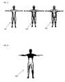
- FIG. 4illustrates synthetic mesh instances having different poses
- FIG. 5illustrates synthetic mesh instances having different body shapes
- FIG. 6illustrates an example of a template mesh model
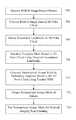
- FIG. 7illustrates a method of generating a personalized 3D avatar mesh model for a patient according to an embodiment of the present invention
- FIG. 8shows an example of a depth camera sensor mounted on a CT scanner
- FIG. 9illustrates exemplary results of generating a personalized avatar mesh from RGB-D image data using a trained PDM.
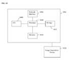
- FIG. 10is a high-level block diagram of a computer capable of implementing the present invention.
- the present inventionrelates to a method and system for automatic generation of a personalized 3D mesh of a person from an image obtained using a depth camera.
- Embodiments of the present inventionare described herein to give a visual understanding of the personalized mesh generation method.
- a digital imageis often composed of digital representations of one or more objects (or shapes).
- the digital representation of an objectis often described herein in terms of identifying and manipulating the objects.
- Such manipulationsare virtual manipulations accomplished in the memory or other circuitry/hardware of a computer system. Accordingly, is to be understood that embodiments of the present invention may be performed within a computer system using data stored within the computer system.
- Embodiments of the present inventiongenerate a personalized 3D mesh model of a person that estimates the detailed body pose as well as the shape of the person from RGB-D image data obtained from a depth camera, such as a Microsoft Kinect depth camera.
- a personalized 3D mesh model of a personis referred to herein as an avatar.
- embodiments of the present inventiongenerate a personalized mesh from a single snapshot from a depth camera that captures a partial view of the person and deals with body clothing.
- Embodiments of the present inventionprovide reconstruction of a detailed body shape (mesh) even from a partial view of the body, body shape estimation from a single snapshot from any depth camera sensor, body shape estimation of the person under the clothing, and appropriate sensor noise statistics modeling to obtain precise body pose and shape.
- embodiments of the present inventionemploy a model based approach to fit a human skeleton model to depth image data of the person.
- the estimated pose skeletonis then used to initialize a detailed parametrized deformable mesh (PDM) that is learned in an offline training phase.
- PDMis then optimized to fit the input depth data by perturbing the body pose and shape.
- an important differenceis the sampling based optimization procedure to fit the PDM to the depth data.
- embodiments of the present inventionutilize this sampling based approach to deal with clothing variations of the subject.
- the sampling based approachalso enables embodiments of the present invention to deal with bias introduce due to sensor noise.
- Embodiments of the present inventioncan be used in a workflow for patient scanning using computed tomography (CT) or positron emission tomography (PET) scanners.
- CTcomputed tomography
- PETpositron emission tomography
- the radiologist/technicianfirst roughly estimates the patient iso-center of the scan region by observing the patient contour from profile viewpoint, and then aligns the patient iso-center with the scanner gantry center that is usually reflected by the laser projection. If the alignment is perfectly conducted, the best imaging quality will be achieved. However, the current alignment done by the radiologist/technician is inaccurate and inconsistent.
- Embodiments of the present inventioncan be used to generate a personalized 3D avatar mesh that accurately fits the patient, which will be further used to calculate the iso-center of the scan region.
- a topogram (x-ray) imageis first generated with the scanner to help the radiologist determine the necessary scan region.
- Embodiments of the present inventioncan be used to generate a personalized 3D avatar mesh that accurately fits the patient from a snapshot obtained using a depth camera, and the personalized 3D avatar mesh can be used in place of the topogram to predict the position of organs in the patient's body in order to determine the scan region. This can provide a more accurate estimation of the scan range for an organ and decrease the patient's exposure to radiation.
- 3D object shapesare generally represented by three-dimensional (3D) surfaces X.
- Three popular ways to represent a 3D surfaceis using a point cloud (generated by point sampling the surface) and using a polygon mesh (generated by polygonal approximation of the surface).
- a point cloudis generally viewed as a collection of sensor readings of the object surface, where each element in the cloud represents the 3D coordinate of a surface point.
- point cloudsmay be more computationally manageable than other models, especially for complex surfaces, point cloud discard information about the surface continuity, including the topology of surface connectivity.
- a polygon meshis a collection of vertices and edges that defines the shape of an object.
- Trianglesare commonly used as polygons in the mesh, and each triangle t k is represented using three vertices (p 1,k , p 2,k , p 3,k ) and three edges (v 1,k , v 2,k , v 3,k ).
- FIG. 1illustrates an example of representing a surface using point cloud and polygon mesh. As shown in FIG. 1 , human body surface 100 is represented using a point cloud 102 and a polygon mesh 104 .
- Embodiments of the present inventionutilize a learned parametric deformable model (PDM) of the human body to generate the personalized avatar model for a patient.
- PDMlearned parametric deformable model
- the PDMdivides the full human body deformation into two separate deformations, pose and shape deformations, where the pose deformation can be further divided into rigid and non-rigid deformations.
- the human bodycan be represented using a polygon mesh comprising a set of triangles. Therefore, the triangles t k i in any given mesh M i representing the human body can be represented as the triangles of a template mesh ⁇ circumflex over (M) ⁇ with some deformations.
- R l[k] iis the rigid rotation that has the same value for all of the triangles belonging to the same body part l
- S k iis the shape deformation matrix
- Q k iis the pose deformation matrix.
- FIG. 2illustrates examples of pose deformations obtained from a trained pose deformation model.
- image 202shows a driving pose obtained using the trained pose deformation model
- image 204shows the template pose
- image 206shows a walking pose obtained using the trained pose deformation model.
- the pose deformations of FIG. 2were obtained using a pose deformation model trained with 200 training instances having different poses.
- PCAprinciple component analysis
- FIG. 3illustrates examples of shape deformations obtained using a trained shape deformation model.
- the shape deformations of FIG. 3are obtained by PDM shape deformation along the direction of the first principal component ( ⁇ ).
- image 302shows an extreme case of an underweight body shape obtained using the trained shape deformation model
- image 304shows the template mesh
- image 306shows an extreme case of an overweight body shape obtained using the trained shape deformation model.
- the shape deformations of FIG. 3were obtained using a shape deformation model trained with 200 training instances having different body shapes.
- the training process to train the pose deformation model and shape deformation model for the PDMrequires a large number of 3D mesh training examples. Building such a dataset from real human models is one plausible solution, but it is expensive and time-consuming. Building the training dataset from real human models requires a high-precision laser scanner that captures each person from different viewing angles. Then, a registration algorithm needs to be applied to construct the full body model for each person from the partial views. In addition, filling holes, removing noises, and smoothing surfaces may also require tremendous human efforts.
- synthetic human modelscan be used to train the PDM. Compared to using real human models, synthetic human models from 3D commercial software is much simpler and faster to generate.
- a 3D animation software called POSERcan be used to generate synthetic human models to populate the training dataset.
- POSERis a 3D rendering software that can be used for posing and animation of 3D polygon meshes of humans. This software comes with a library of pre-built human models with large freedom of joint and shape parameters. Together with the Python programming interface, POSER can generate thousands of 3D human mesh instances with different poses and shapes in about an hour. Another advantage of using POSER is that all of the mesh instances originated from the same mesh template are fully labeled and registered.
- the number of vertices in each mesh instanceis the same as the template mesh and the vertex order remains the same no matter what kind of pose the mesh forms.
- POSERthe data generation is fully unsupervised with only some initial user input, so some poses can be generated that are unrealistic to a real person. Accordingly, it may be necessary to examine the meshes generated using POSER and manually remove the unrealistic meshes.
- POSERitself does not simulate the gravity effect of the human body, so a person with a standing pose had the same body shape as that person in a lying down pose.
- FIG. 4illustrates mesh instances 402 , 404 , and 406 in different poses generated using POSER.
- FIG. 5illustrates mesh instances 502 , 504 , and 506 having different body shapes generated using POSER.
- the pose deformation modelis trained with different mesh instances of the same human subject in various poses, while the shape deformation model is trained with mesh instances from many subjects in a neutral pose.
- decoupling of the shape and pose deformationcan lead to problems. For example, if the human subject is male for the pose training data, then the pose and shape estimation for a given female subject will not be accurate.
- two separate pose deformation modelsmale and female
- the appropriate one of the trained pose deformation modelsis applied when generating a personalized avatar mesh for a patient according to the known gender of the patient.
- a person with a regular (e.g., average or median) body size and a neutral poseis selected as the template mesh.
- the full body of the template meshis divided into a plurality of different body parts and a plurality of joint landmarks on the template mesh are manually selected.
- the template meshcan be divided into 18 body parts and 16 points on the template mesh are selected as joint landmarks.
- the 18 body partsare as follows: left and right foot (0,1), left and right lower leg (2,3), left and right upper leg (4,5), pelvis (6), left and right hand (7,8), left and right forearm (9,10), left and right upper arm (11,12), abdomen (13), chest (14), left and right shoulder (15, 16), and head (17).
- the joint landmarkscorrespond to locations of various joints and other significant anatomical locations.
- the 16 joint landmarksare as follows: left and right ankle (0,1), left and right knee (2,3), left and right waist (4,5), groin (6), left and right wrist (7,8), left and right elbow (9,10), left and right shoulder top (11,12), chest center (13), head bottom (14), and head top (15).
- FIG. 6illustrates an example of a template mesh model. As shown in FIG.
- the template mesh model 600is divided into 18 body parts (left and right foot, left and right lower leg, left and right upper leg, pelvis, left and right hand, left and right forearm, left and right upper arm, abdomen, chest, left and right shoulder, and head) and annotated with 16 joint landmarks (left and right ankle, left and right knee, left and right waist, groin, left and right wrist, left and right elbow, left and right shoulder top, chest center, head bottom, and head top).
- FIG. 7illustrates a method of generating a personalized 3D avatar mesh model for a patient according to an embodiment of the present invention.
- the method of FIG. 7can be used as part of a scanning planning procedure to plan a scan for acquiring medical image data of a patient, such as a CT scan or a PET scan.
- the method of FIG. 7utilizes priors, such as the knowledge that the patient is lying on a table, and the knowledge that the patient is covered with clothing, a radiation protector, blankets, pillows, etc., and applies constraints corresponding to such priors to the generation of the 3D avatar mesh model for the patient.
- RGB-D image data of a patientis received from a depth camera.
- the RGB-D image datacan be obtained in a single snapshot from the depth camera.
- the depth cameracan be a structured light based camera (such as Microsoft Kinect or ASUS Xtion), a stereo camera, or a time of flight camera (such as Creative TOF camera).
- the RGB-D (RGB+Depth) image dataincludes an RGB image, in which each pixel has an RGB value, and a depth image, in which the value of each pixel corresponds to a depth or distance of the pixel from the camera.
- the depth camerashould be appropriately mounted such that it has an unobstructed view of the patient on the table.
- the depth cameramay be mounted on a ceiling above the table or on the medical image scanner.
- FIG. 8shows an example of a depth camera sensor 802 mounted on a CT scanner 804 .
- the RGB-D image datacan be received directly from the depth camera, or can be received by loading previously acquired RGB-D image data of a patient.
- the RGB-D image datais converted to a 3D point cloud.
- the depth image of the RGB-D image datais used to map each pixel in the RGB image to a 3D location, resulting in a 3D point cloud representing the patient.
- anatomical landmarksare detected in the 3D point cloud.
- each of the joint landmarks selected in the template meshis detected in the 3D point cloud.
- the joint landmarkscan be detected in the 3D point cloud using trained machine learning based classifiers trained based on annotated training data.
- a respective probabilistic boosting tree (PBT) classifiercan be trained for each of the joint landmarks and each joint landmark can be detected by scanning the 3D point cloud using the respective trained PBT classifier. It is also possible that the relative locations of the landmarks can be utilized in the landmark detection.
- PBTprobabilistic boosting tree
- the trained classifiers for each of the joint landmarkscan be connected in a discriminative anatomical network (DAN) to take into account the relative locations of the landmarks, or the trained classifiers can be applied to the 3D point cloud in a predetermined order where each landmark that is detected helps to narrow the search range for the subsequent landmarks.
- DANdiscriminative anatomical network
- PBT classifierscan be trained to detect a plurality of body parts (e.g., head, torso, pelvis) and the detected body parts can be used to constrain the search range for the PBT classifiers used to detect the joint landmarks.
- the template mesh modelis initialized in the 3D point cloud using the detected anatomical landmarks.
- the template mesh modelis a mesh selected from the meshes in the training dataset that has a regular (e.g., average or median) body size and a neutral pose.
- the template mesh modelis divided into a plurality body parts and a corresponding location for each of the plurality joint landmarks on the template mesh is stored.
- the template meshis initialized in the 3D point cloud by calculating a rigid transformation of the template mesh to the 3D point cloud that minimizes error between the detected locations of the joint landmarks in the 3D point cloud and the corresponding locations of the joint landmarks in the template mesh. This rigid transformation provides and initial rigid rotation matrix R, which when applied to the template mesh results in an initialized avatar mesh model.
- a personalized avatar meshis generated by deforming the template mesh to fit the 3D point cloud using the trained parametric deformable model (PDM).
- the PDMis trained offline by training a pose deformation model and a shape deformation model from the training data.
- the trained PDMis directly applied to the task of data completion. Given the 3D point cloud and the joint landmarks, the PDM can generate a realistic full 3D mesh output that is consistent with the partial data by minimizing the objective function:
- Equation (6)there are three parameter sets (R, Y, and ⁇ ) to be optimized. This forms a standard non-linear and non-convex optimization problem.
- embodiments of the present inventionutilize an iterative process to optimize the three parameters.
- the three sets of parametersare treated separately, optimizing only one of them at a time while keeping the other two fixed.
- a three-step optimizationcan be performed as follows:
- step (1) of three-step optimization procedurethe rigid rotation matrix R is optimized using Equation (6) while the shape deformation S and the vertices Y of the estimated avatar mesh model are fixed. This results in an updated value of ⁇ r for each triangle in the estimated avatar mesh model and the pose deformation Q for each triangle is updated based on the updated ⁇ r using the trained posed deformation model ⁇ ak ( ⁇ r l[k] ). Accordingly, step (1) of the optimization procedure optimizes the pose of the estimated avatar model.
- step (2) of the three-step optimization procedurethe locations of the vertices Y of the estimated avatar mesh are optimized using Equation (6) while the shape deformation S and rigid rotation matrix R (and pose deformation) are fixed.
- This stepis a fine-tuning step that adjusts the locations of the vertices Y to better match the 3D point cloud.
- step (3) of the optimization procedurethe shape deformation S is optimized using Equation (6) while the rigid rotation matrix R, the pose deformation Q, and the vertices Y of the estimated avatar mesh are fixed.
- first principal component ⁇is adjusted to find the shape deformation calculated using the trained deformation model F U, ⁇ ( ⁇ ) that minimizes the objective function in Equation (6).
- the three-step optimization procedurefirst finds an optimal pose deformation, then performs fine-tuning adjustments of the vertices of the estimated avatar model, and then finds an optimal shape deformation.
- This three-step optimization procedurecan be iterated a plurality of times. For example, the three-step optimization procedure can be iterated a predetermined number of times or can be iterated until it converges.
- Equation (6)requires finding correspondences between the 3D point cloud and landmarks on the 3D mesh model.
- a registration algorithm based on the Iterative Closest Point algorithmcan be performed to obtain a full registration between the 3D point cloud and the current 3D mesh model M curr .
- the registration between the 3D point cloud and the current 3D mesh model M curris performed, correspondences between corresponding pairs of points in the 3D point cloud and the current 3D mesh model that have a distance ( ⁇ y l ⁇ z l ⁇ ) larger than a predetermined threshold are removed.
- the remaining correspondencesare then used to estimate a new rigid rotation matrix R, and the three-step optimization procedure is repeated. This optimization-registration process is iterated until convergence.
- the avatar meshis below the 3D point cloud when n z l T (z l ⁇ y l )>0, ⁇ l ⁇ L.
- the term ⁇ l ⁇ 0ensures that the avatar mesh lies sufficiently below the input 3D point cloud within the clothing region while the avatar overlaps with the input 3D point cloud in the non-clothing region.
- the probability P(Y)is calculated using a trained probability model that is learned statistically from ground truth training data.
- the threshold ⁇represents the maximal distance between the avatar surface and the clothing surface, including the thickness of the clothing. It is to be understood that the clothing constraint can be applied, not just for clothing, but for anything covering the patient, such as a radiation protector, blankets, pillows, etc. Since what is covering the patient can be known as a prior, different probability models can be trained for different patient coverings (e.g., clothing, radiation protector, blanket, etc.), and the threshold ⁇ can be adjusted based on what is covering the patient.
- the input 3D point cloud datais generated from RGB-D image data collected from the patient lying on a table
- another constraint d tablereferred to herein as the table constraint, can be utilized to specify that all vertices of the avatar mesh should be above the table.
- d table ( y )⁇ k ⁇ X,y k z ⁇ h table ⁇ table +y k z ⁇ h table ⁇ 2 , (9)
- y k zis the z-axis value (perpendicular to the surface of the table) of the avatar vertex y k
- h tableis the current table height (which is known)
- e tableensures that the avatar mesh lies sufficiently above the table.
- s ⁇ ( y )⁇ k ⁇ X ⁇ ⁇ ( y k - y ⁇ k ) - 1 [ N k ] ⁇ ⁇ j ⁇ N k ⁇ ( y j - y ⁇ j ) ⁇ 2 , ( 10 )
- ydenotes the vertices of the new avatar mesh
- ⁇denotes the vertices of the current avatar mesh
- N kis the set of vertices adjacent to the vertex y k .
- This regularizationprefers a deformation of a vertex that is similar to the average deformation of its neighboring vertices.
- the cost function of Equation (11)can be used in place of the cost function expressed in Equation (6) to optimize the parameter sets (R, Y, and ⁇ ).
- the iterated optimization-registration process described abovecan be used to find the optimal parameters to minimize the cost function of Equation (11). This procedure is iterated until convergence, resulting in a 3D personalized avatar mesh for the patient.
- the 3D personalized avatar mesh for the patientis output.
- the 3D personalized avatar meshcan be output by displaying the 3D personalized avatar mesh on a display screen of a computer system.
- the 3D personalized avatar mesh of the patientis used for medical imaging scan planning.
- the 3D personalized avatar meshcan provide a prediction of locations of the patient's organs. For example, an atlas of organs can be aligned with the 3D personalized avatar mesh for the patient and superimposed on the patient body. This can assist an operator in specifying a scan range of a specific organ for a medical imaging (e.g. CT or PET) scan.
- the 3D personalized avatar mesh of the patientcan be used in place of a topography scan to plan a CT or PET scan.
- the best CT scan qualityis to be expected for image regions in the center of gravity, the so-called iso-center. Since the 3D avatar mesh accurately fits to the patient, the iso-center of the scan can also be estimated from the 3D avatar mesh with minimum error, thus helping to generate high quality CT scan images.
- FIG. 9illustrates exemplary results of generating a personalized avatar mesh from RGB-D image data using a trained PDM.
- image (a)shows an RGB image and image (b) shows the corresponding depth image.
- Image (c)shows the RGB-D image data re-projected as a 3D point cloud as seen from above the table.
- Image (d)shows the PDM initialization to the detected joint landmarks.
- Image (e)shows the estimated 3D avatar mesh after four iterations of optimization, and image (f) shows the final personalized 3D avatar mesh obtained using the PDM.
- Computer 1002contains a processor 1004 , which controls the overall operation of the computer 1002 by executing computer program instructions which define such operation.
- the computer program instructionsmay be stored in a storage device 1012 (e.g., magnetic disk) and loaded into memory 1010 when execution of the computer program instructions is desired.
- a storage device 1012e.g., magnetic disk
- the steps of the method of FIG. 7may be defined by the computer program instructions stored in the memory 1010 and/or storage 1012 and controlled by the processor 1004 executing the computer program instructions.
- a depth camera 1020can be connected to the computer 1002 to input RGB-D image data to the computer 1002 .
- the depth camera 1020 and the computer 1002may be directly connected or may communicate wirelessly through a network or other wireless communication protocol.
- a medical image acquisition device(not shown), such as a CT scanning device, can also be connected to the computer 1002 to input medical image data to the computer 1002 . It is also possible to implement the medical image acquisition device and the computer 1002 as one device.
- the computer 1002also includes one or more network interfaces 1006 for communicating with other devices via a network.
- the computer 1002also includes other input/output devices 1008 that enable user interaction with the computer 1002 (e.g., display, keyboard, mouse, speakers, buttons, etc.).
- Such input/output devices 1008may be used in conjunction with a set of computer programs as an annotation tool to annotate volumes received from the image acquisition device 1020 .
- a set of computer programsas an annotation tool to annotate volumes received from the image acquisition device 1020 .
- FIG. 10is a high level representation of some of the components of such a computer for illustrative purposes.
Landscapes
- Engineering & Computer Science (AREA)
- Physics & Mathematics (AREA)
- General Physics & Mathematics (AREA)
- Theoretical Computer Science (AREA)
- Computer Graphics (AREA)
- Software Systems (AREA)
- Geometry (AREA)
- Computer Hardware Design (AREA)
- General Engineering & Computer Science (AREA)
- Computer Vision & Pattern Recognition (AREA)
- Processing Or Creating Images (AREA)
- Image Analysis (AREA)
Abstract
Description
vk,ji=Rl[k]iSkiQki{circumflex over (v)}k,j, (1)
where Rl[k]iis the rigid rotation that has the same value for all of the triangles belonging to the same body part l, Skiis the shape deformation matrix, and Qkiis the pose deformation matrix.
In the above equation, Δr can be calculated from the rigid rotation matrix R. If Q is given, the regression parameter a can be easily calculated. However, the non-rigid deformation matrix Q for each triangle is unknown. Accordingly, the deformation matrices for each of the triangles are solved by solving an optimization problem that minimizes the distance between the deformed template mesh and the training mesh data subject to a smoothness constraint. This optimization problem can be expressed as:
where the first term minimizes the distance between the deformed template mesh and the training mesh data and the second term is a smoothness constraint that prefers similar deformations in adjacent triangles that belong to the same body part. wsis a weight that can be used to tune the smoothness constraint and I(lk
Ski=FU
In equation (4), F is the function of PCA coefficient β, μ is the mean vector, and U is the eigenvector of the data when doing the PCA dimension reduction. Similar to the pose estimation, the shape deformation matrix S for each triangle is unknown. Again, an optimization problem that minimizes the distance between the deformed template mesh and the training mesh data subject to a smoothness constraint is used to estimate the matrix S:
where the first term minimizes the distance between the deformed template mesh and the training mesh data and the second term is a smoothness constraint that prefers similar shape deformations in adjacent triangles.
where Rkis the rigid rotation matrix, FU,μ(β) is the trained shape deformation model, Γa
dcloth(Y)=ΣlεL∥εl+nz
where L is the set of correspondences between the avatar vertex yland the corresponding point zlin the 3D point cloud, and nz
ek=(1−P(yk))τ, (8)
where kεX, P(yk) represents the probability that an avatar vertex ykbelongs to a non-clothing region. The probability P(Y) is calculated using a trained probability model that is learned statistically from ground truth training data. The threshold τ represents the maximal distance between the avatar surface and the clothing surface, including the thickness of the clothing. It is to be understood that the clothing constraint can be applied, not just for clothing, but for anything covering the patient, such as a radiation protector, blankets, pillows, etc. Since what is covering the patient can be known as a prior, different probability models can be trained for different patient coverings (e.g., clothing, radiation protector, blanket, etc.), and the threshold τ can be adjusted based on what is covering the patient.
dtable(y)=ΣkεX,y
where ykzis the z-axis value (perpendicular to the surface of the table) of the avatar vertex yk, htableis the current table height (which is known), and the term etableensures that the avatar mesh lies sufficiently above the table.
where y denotes the vertices of the new avatar mesh, ŷ denotes the vertices of the current avatar mesh, and Nkis the set of vertices adjacent to the vertex yk. This regularization prefers a deformation of a vertex that is similar to the average deformation of its neighboring vertices.
E[Y]=ΣkΣj=2,3∥RkFU,μΓa
where first term is the same as the first term in Equation (6), the second term is the clothing constraint dcloth(Y) defined in Equation (7), the third term is the table constraint dtable(Y) defined in Equation (9), and the fourth term is the smoothing constraint s(Y) defined in Equation (10). The cost function of Equation (11) can be used in place of the cost function expressed in Equation (6) to optimize the parameter sets (R, Y, and β). In particular, the iterated optimization-registration process described above (including the iterated three-step optimization procedure) can be used to find the optimal parameters to minimize the cost function of Equation (11). This procedure is iterated until convergence, resulting in a 3D personalized avatar mesh for the patient.
Claims (44)
ΣkΣj=2,3∥RkFU,μΓa
Priority Applications (5)
| Application Number | Priority Date | Filing Date | Title |
|---|---|---|---|
| US14/604,829US9524582B2 (en) | 2014-01-28 | 2015-01-26 | Method and system for constructing personalized avatars using a parameterized deformable mesh |
| CN201580006226.5ACN106164978B (en) | 2014-01-28 | 2015-01-27 | Methods and systems for constructing personalized avatars using parametric deformable meshes |
| KR1020167023651AKR101833364B1 (en) | 2014-01-28 | 2015-01-27 | Method and system for constructing personalized avatars using a parameterized deformable mesh |
| PCT/US2015/013013WO2015116563A1 (en) | 2014-01-28 | 2015-01-27 | Method and system for constructing personalized avatars using a parameterized deformable mesh |
| EP15704154.2AEP3100236B1 (en) | 2014-01-28 | 2015-01-27 | Method and system for constructing personalized avatars using a parameterized deformable mesh |
Applications Claiming Priority (2)
| Application Number | Priority Date | Filing Date | Title |
|---|---|---|---|
| US201461932441P | 2014-01-28 | 2014-01-28 | |
| US14/604,829US9524582B2 (en) | 2014-01-28 | 2015-01-26 | Method and system for constructing personalized avatars using a parameterized deformable mesh |
Publications (2)
| Publication Number | Publication Date |
|---|---|
| US20150213646A1 US20150213646A1 (en) | 2015-07-30 |
| US9524582B2true US9524582B2 (en) | 2016-12-20 |
Family
ID=53679531
Family Applications (1)
| Application Number | Title | Priority Date | Filing Date |
|---|---|---|---|
| US14/604,829Active2035-07-31US9524582B2 (en) | 2014-01-28 | 2015-01-26 | Method and system for constructing personalized avatars using a parameterized deformable mesh |
Country Status (5)
| Country | Link |
|---|---|
| US (1) | US9524582B2 (en) |
| EP (1) | EP3100236B1 (en) |
| KR (1) | KR101833364B1 (en) |
| CN (1) | CN106164978B (en) |
| WO (1) | WO2015116563A1 (en) |
Cited By (19)
| Publication number | Priority date | Publication date | Assignee | Title |
|---|---|---|---|---|
| US20160253807A1 (en)* | 2015-02-26 | 2016-09-01 | Mitsubishi Electric Research Laboratories, Inc. | Method and System for Determining 3D Object Poses and Landmark Points using Surface Patches |
| CN108319786A (en)* | 2018-02-05 | 2018-07-24 | 湖南省忘不了服饰有限公司 | A kind of intelligent formulating method of woven fabric bottom crimping sewing technological parameter |
| EP3360483A1 (en) | 2017-02-10 | 2018-08-15 | Siemens Healthcare GmbH | Method and system for dose-optimized computed tomography scanning of a target organ |
| US20190007671A1 (en)* | 2017-06-28 | 2019-01-03 | Siemens Healthcare Gmbh | System For Dense Registration Of Two-Dimensional Depth Images |
| US10186038B1 (en) | 2017-07-18 | 2019-01-22 | Siemens Healthcare Gmbh | Segmentation and representation network for pose discrimination |
| EP3503113A1 (en) | 2017-12-22 | 2019-06-26 | Siemens Healthcare GmbH | Cloud-based mr imaging |
| US20200051257A1 (en)* | 2018-08-08 | 2020-02-13 | Siemens Medical Solutions Usa, Inc. | Scan alignment based on patient-based surface in medical diagnostic ultrasound imaging |
| US10595039B2 (en) | 2017-03-31 | 2020-03-17 | Nvidia Corporation | System and method for content and motion controlled action video generation |
| US10621788B1 (en) | 2018-09-25 | 2020-04-14 | Sony Corporation | Reconstructing three-dimensional (3D) human body model based on depth points-to-3D human body model surface distance |
| US10732284B2 (en)* | 2017-07-28 | 2020-08-04 | The Boeing Company | Live metrology of an object during manufacturing or other operations |
| US10748034B2 (en) | 2018-01-10 | 2020-08-18 | Siemens Healthcare Gmbh | Method and system for learning to obtain medical scans of patients |
| US10799206B2 (en) | 2018-09-28 | 2020-10-13 | General Electric Company | System and method for calibrating an imaging system |
| US10891744B1 (en) | 2019-03-13 | 2021-01-12 | Argo AI, LLC | Determining the kinetic state of a body using LiDAR point cloud registration with importance sampling |
| US11284850B2 (en) | 2020-03-13 | 2022-03-29 | Siemens Healthcare Gmbh | Reduced interaction CT scanning |
| US11317884B2 (en) | 2019-12-20 | 2022-05-03 | GE Precision Healthcare LLC | Methods and systems for mammography and biopsy workflow optimization |
| US20220319114A1 (en)* | 2021-04-01 | 2022-10-06 | Sony Group Corporation | Automatic blending of human facial expression and full-body poses for dynamic digital human model creation using integrated photo-video volumetric capture system and mesh-tracking |
| US11703373B2 (en) | 2019-02-25 | 2023-07-18 | Siemens Healthcare Gmbh | Patient weight estimation from surface data using a patient model |
| US11734849B2 (en) | 2020-03-10 | 2023-08-22 | Siemens Healthcare Gmbh | Estimating patient biographic data parameters |
| US12073527B2 (en) | 2021-02-24 | 2024-08-27 | Sony Group Corporation | Three-dimensional (3D) human modeling under specific body-fitting of clothes |
Families Citing this family (87)
| Publication number | Priority date | Publication date | Assignee | Title |
|---|---|---|---|---|
| EP2811463B1 (en) | 2013-06-04 | 2018-11-21 | Dassault Systèmes | Designing a 3d modeled object with 2d views |
| US20150106993A1 (en) | 2013-10-18 | 2015-04-23 | The Regents Of The University Of California | Anatomy shading for garments |
| US10314357B2 (en) | 2013-10-18 | 2019-06-11 | Vf Corporation | Anatomy shading for garments |
| EP2874118B1 (en) | 2013-11-18 | 2017-08-02 | Dassault Systèmes | Computing camera parameters |
| DE102014210051A1 (en)* | 2014-05-27 | 2015-12-03 | Carl Zeiss Meditec Ag | Method and device for determining a surface topography of a body |
| US9911220B2 (en)* | 2014-07-28 | 2018-03-06 | Adobe Systes Incorporated | Automatically determining correspondences between three-dimensional models |
| US10430551B2 (en) | 2014-11-06 | 2019-10-01 | Siemens Healthcare Gmbh | Scan data retrieval with depth sensor data |
| EP3032495B1 (en) | 2014-12-10 | 2019-11-13 | Dassault Systèmes | Texturing a 3d modeled object |
| US10474927B2 (en)* | 2015-09-03 | 2019-11-12 | Stc. Unm | Accelerated precomputation of reduced deformable models |
| EP3188033B1 (en) | 2015-12-31 | 2024-02-14 | Dassault Systèmes | Reconstructing a 3d modeled object |
| DE102016200225B4 (en)* | 2016-01-12 | 2017-10-19 | Siemens Healthcare Gmbh | Perspective showing a virtual scene component |
| USD802256S1 (en) | 2016-01-29 | 2017-11-14 | V.F. Corporation | Pant with anatomy enhancing pockets |
| CN108475439B (en) | 2016-02-16 | 2022-06-17 | 乐天集团股份有限公司 | Three-dimensional model generation system, three-dimensional model generation method, and recording medium |
| US10127717B2 (en)* | 2016-02-16 | 2018-11-13 | Ohzone, Inc. | System for 3D Clothing Model Creation |
| CN108701493A (en)* | 2016-02-29 | 2018-10-23 | 皇家飞利浦有限公司 | Equipment, system and method for the photographed image-related information for verifying medical image |
| US9919217B2 (en) | 2016-03-08 | 2018-03-20 | Electronic Arts Inc. | Dynamic difficulty adjustment |
| AU2017260525B2 (en)* | 2016-05-04 | 2022-06-30 | Styku Llc | Method and system for body scanning and display of biometric data |
| US9898858B2 (en)* | 2016-05-18 | 2018-02-20 | Siemens Healthcare Gmbh | Human body representation with non-rigid parts in an imaging system |
| US10215858B1 (en)* | 2016-06-30 | 2019-02-26 | Google Llc | Detection of rigid shaped objects |
| US20180014590A1 (en) | 2016-07-18 | 2018-01-18 | Vf Corporation | Body-enhancing garment and garment construction |
| US10327487B2 (en)* | 2016-07-19 | 2019-06-25 | Vf Corporation | Body-enhancing garment and garment design |
| EP4131172A1 (en) | 2016-09-12 | 2023-02-08 | Dassault Systèmes | Deep convolutional neural network for 3d reconstruction of a real object |
| US10384133B1 (en) | 2016-12-30 | 2019-08-20 | Electronic Arts Inc. | Systems and methods for automatically measuring a video game difficulty |
| CN108310677B (en)* | 2017-01-11 | 2020-02-28 | 南京中硼联康医疗科技有限公司 | A method for establishing smooth geometric model based on medical image data |
| EP3571627A2 (en) | 2017-01-19 | 2019-11-27 | Mindmaze Holding S.A. | Systems, methods, apparatuses and devices for detecting facial expression and for tracking movement and location including for at least one of a virtual and augmented reality system |
| US10943100B2 (en) | 2017-01-19 | 2021-03-09 | Mindmaze Holding Sa | Systems, methods, devices and apparatuses for detecting facial expression |
| US11367198B2 (en)* | 2017-02-07 | 2022-06-21 | Mindmaze Holding Sa | Systems, methods, and apparatuses for tracking a body or portions thereof |
| CN110892408A (en) | 2017-02-07 | 2020-03-17 | 迈恩德玛泽控股股份有限公司 | Systems, methods, and apparatus for stereo vision and tracking |
| US10546415B2 (en)* | 2017-02-07 | 2020-01-28 | Siemens Healthcare Gmbh | Point cloud proxy for physically-based volume rendering |
| CN110268448B (en)* | 2017-02-20 | 2023-11-24 | 交互数字Vc控股公司 | Dynamically present augmented reality information to reduce peak cognitive demands |
| US10635930B2 (en)* | 2017-02-24 | 2020-04-28 | Siemens Healthcare Gmbh | Patient position control for scanning |
| US10357718B2 (en) | 2017-02-28 | 2019-07-23 | Electronic Arts Inc. | Realtime dynamic modification and optimization of gameplay parameters within a video game application |
| US10507002B2 (en) | 2017-05-23 | 2019-12-17 | Siemens Healthcare Gmbh | X-ray system and method for standing subject |
| EP3593323B1 (en)* | 2017-06-07 | 2020-08-05 | Google LLC | High speed, high-fidelity face tracking |
| US10354444B2 (en) | 2017-07-28 | 2019-07-16 | The Boeing Company | Resolution adaptive mesh that is generated using an intermediate implicit representation of a point cloud |
| US10438408B2 (en) | 2017-07-28 | 2019-10-08 | The Boeing Company | Resolution adaptive mesh for performing 3-D metrology of an object |
| US10470825B2 (en) | 2017-08-16 | 2019-11-12 | Synaptive Medical (Barbados) Inc. | Method, system and apparatus for surface rendering using medical imaging data |
| KR102357355B1 (en)* | 2017-10-23 | 2022-01-28 | 삼성전자주식회사 | Method and apparatus for generating virtual object |
| US10842412B2 (en) | 2017-10-31 | 2020-11-24 | Pixa4 Llc | Systems and methods to estimate human length |
| EP3483839B1 (en) | 2017-11-08 | 2025-09-10 | Siemens Healthineers AG | Dynamic generation of a medical scene model |
| US20190142358A1 (en)* | 2017-11-13 | 2019-05-16 | Siemens Medical Solutions Usa, Inc. | Method And System For Dose-Less Attenuation Correction For PET And SPECT |
| CN107798726B (en)* | 2017-11-14 | 2021-07-20 | 刘芳圃 | Method and device for manufacturing three-dimensional cartoon |
| US10962355B2 (en)* | 2017-12-25 | 2021-03-30 | Htc Corporation | 3D model reconstruction method, electronic device, and non-transitory computer readable storage medium thereof |
| US11328533B1 (en) | 2018-01-09 | 2022-05-10 | Mindmaze Holding Sa | System, method and apparatus for detecting facial expression for motion capture |
| CN118890482A (en)* | 2018-01-19 | 2024-11-01 | 交互数字Vc控股公司 | Method, program product, computer readable medium and device for processing point cloud |
| EP3759693A4 (en) | 2018-02-27 | 2021-11-24 | Magic Leap, Inc. | Matching meshes for virtual avatars |
| US10925565B2 (en) | 2018-04-11 | 2021-02-23 | Siemens Healthcare Gmbh | Machine-learning based contrast agent administration |
| CN108895979B (en)* | 2018-05-10 | 2020-04-07 | 西安电子科技大学 | Line segment coded structured light depth acquisition method |
| FI20185517A1 (en) | 2018-06-06 | 2019-12-07 | Nomo Tech Oy | Measuring surface distances on human bodies |
| US10713543B1 (en) | 2018-06-13 | 2020-07-14 | Electronic Arts Inc. | Enhanced training of machine learning systems based on automatically generated realistic gameplay information |
| HK1253750A2 (en)* | 2018-07-04 | 2019-06-28 | 桂滨 | Method and apparatus for converting 3d scanned objects to avatars |
| ES3037621T3 (en) | 2018-07-19 | 2025-10-03 | Activ Surgical Inc | Systems and methods for multi-modal sensing of depth in vision systems for automated surgical robots |
| JP7459050B2 (en) | 2018-07-27 | 2024-04-01 | マジック リープ, インコーポレイテッド | Pose space dimension reduction for pose space deformation of virtual characters |
| FR3085521A1 (en)* | 2018-09-04 | 2020-03-06 | Exsens | IMPROVED PROCESS FOR CREATING A THREE-DIMENSIONAL VIRTUAL REPRESENTATION OF THE BUST OF A PERSON |
| US11475630B2 (en)* | 2018-10-17 | 2022-10-18 | Midea Group Co., Ltd. | System and method for generating acupuncture points on reconstructed 3D human body model for physical therapy |
| EP3827414B1 (en)* | 2018-11-09 | 2025-07-02 | Samsung Electronics Co., Ltd. | Textured neural avatars |
| US10984609B2 (en)* | 2018-11-21 | 2021-04-20 | Electronics And Telecommunications Research Institute | Apparatus and method for generating 3D avatar |
| KR102655987B1 (en)* | 2018-11-21 | 2024-04-11 | 한국전자통신연구원 | Apparatus and method for generating 3d avatar |
| US11995854B2 (en)* | 2018-12-19 | 2024-05-28 | Nvidia Corporation | Mesh reconstruction using data-driven priors |
| EP3671660B1 (en)* | 2018-12-20 | 2025-06-18 | Dassault Systèmes | Designing a 3d modeled object via user-interaction |
| EP3671557B1 (en)* | 2018-12-20 | 2025-03-12 | RaySearch Laboratories AB | Data augmentation |
| CN109859306A (en)* | 2018-12-24 | 2019-06-07 | 青岛红创众投科技发展有限公司 | A method of extracting manikin in the slave photo based on machine learning |
| WO2020140044A1 (en)* | 2018-12-28 | 2020-07-02 | Activ Surgical, Inc. | Generation of synthetic three-dimensional imaging from partial depth maps |
| US11276216B2 (en) | 2019-03-27 | 2022-03-15 | Electronic Arts Inc. | Virtual animal character generation from image or video data |
| US10953334B2 (en)* | 2019-03-27 | 2021-03-23 | Electronic Arts Inc. | Virtual character generation from image or video data |
| US11282180B1 (en) | 2019-04-24 | 2022-03-22 | Apple Inc. | Object detection with position, pose, and shape estimation |
| US20220237880A1 (en)* | 2019-05-31 | 2022-07-28 | Applications Mobiles Overview Inc. | System and method of generating a 3d representation of an object |
| EP3751524A1 (en)* | 2019-06-13 | 2020-12-16 | RaySearch Laboratories AB | Method, computer program product and computer system for providing an approximate image |
| CN119478284A (en) | 2019-06-14 | 2025-02-18 | 通用电气精准医疗有限责任公司 | Method and system for generating a 3D point cloud of an object in an imaging system |
| CN112102223B (en)* | 2019-06-18 | 2024-05-14 | 通用电气精准医疗有限责任公司 | Method and system for automatically setting scan range |
| US11430168B2 (en)* | 2019-08-16 | 2022-08-30 | Samsung Electronics Co., Ltd. | Method and apparatus for rigging 3D scanned human models |
| KR20220062259A (en)* | 2019-09-10 | 2022-05-16 | 머큐리스 게엠베하 | A computer-implemented method for providing standardized locations for anatomical data of a patient scan, a computer-implemented method for performing standardized measurements on anatomical data of a patient scan, a data processing system, and a computer-readable medium |
| US11592820B2 (en) | 2019-09-13 | 2023-02-28 | The Boeing Company | Obstacle detection and vehicle navigation using resolution-adaptive fusion of point clouds |
| US10820307B2 (en)* | 2019-10-31 | 2020-10-27 | Zebra Technologies Corporation | Systems and methods for automatic camera installation guidance (CIG) |
| US11276166B2 (en) | 2019-12-30 | 2022-03-15 | GE Precision Healthcare LLC | Systems and methods for patient structure estimation during medical imaging |
| KR102326902B1 (en)* | 2020-01-10 | 2021-11-17 | (주)내스타일 | Image-based Posture Preservation Virtual Fitting System Supporting Multi-Poses |
| US11547323B2 (en)* | 2020-02-14 | 2023-01-10 | Siemens Healthcare Gmbh | Patient model estimation from camera stream in medicine |
| CN111402397B (en)* | 2020-02-28 | 2022-07-29 | 清华大学 | TOF depth data optimization method and device based on unsupervised data |
| KR20210121628A (en) | 2020-03-31 | 2021-10-08 | 주식회사 만도 | Method and system for automatically processing point cloud based on Reinforcement learning |
| CN112017296B (en)* | 2020-09-01 | 2024-02-23 | 上海融军科技有限公司 | Human body grid deformation method and system based on RIMD deformation components |
| US12046374B2 (en)* | 2021-05-23 | 2024-07-23 | Zhiqing Cheng | Digital twin |
| CN113742809B (en)* | 2021-11-04 | 2022-02-11 | 山东神力索具有限公司 | Rigging grid adjusting method and device and electronic equipment |
| US11810256B2 (en) | 2021-11-11 | 2023-11-07 | Qualcomm Incorporated | Image modification techniques |
| KR20230089228A (en) | 2021-12-13 | 2023-06-20 | 주식회사 케이티 | Apparatus and method for augmentating point cloud data |
| CN114708389B (en)* | 2022-05-10 | 2024-10-22 | 大连理工大学 | Staged three-dimensional human body parameterization reconstruction method based on single human body scanning point cloud input |
| CN114913149B (en)* | 2022-05-11 | 2023-03-10 | 盐城工学院 | A head deformation statistical atlas construction method based on CT images |
| CN117315196B (en)* | 2023-10-08 | 2024-06-11 | 广州中望龙腾软件股份有限公司 | Model construction method, device, equipment and storage medium |
Citations (30)
| Publication number | Priority date | Publication date | Assignee | Title |
|---|---|---|---|---|
| US20020067362A1 (en) | 1998-11-06 | 2002-06-06 | Agostino Nocera Luciano Pasquale | Method and system generating an avatar animation transform using a neutral face image |
| US20030185436A1 (en)* | 2002-03-26 | 2003-10-02 | Smith David R. | Method and system of object classification employing dimension reduction |
| US20050057569A1 (en)* | 2003-08-26 | 2005-03-17 | Berger Michael A. | Static and dynamic 3-D human face reconstruction |
| US20050168460A1 (en)* | 2002-04-04 | 2005-08-04 | Anshuman Razdan | Three-dimensional digital library system |
| US20100111370A1 (en)* | 2008-08-15 | 2010-05-06 | Black Michael J | Method and apparatus for estimating body shape |
| US20100203968A1 (en) | 2007-07-06 | 2010-08-12 | Sony Computer Entertainment Europe Limited | Apparatus And Method Of Avatar Customisation |
| US20100317961A1 (en)* | 2009-06-16 | 2010-12-16 | Jenkins Kimble L | MRI-Guided Devices and MRI-Guided Interventional Systems that can Track and Generate Dynamic Visualizations of the Devices in near Real Time |
| US20110025689A1 (en)* | 2009-07-29 | 2011-02-03 | Microsoft Corporation | Auto-Generating A Visual Representation |
| US20110115798A1 (en)* | 2007-05-10 | 2011-05-19 | Nayar Shree K | Methods and systems for creating speech-enabled avatars |
| US7978918B2 (en)* | 2006-07-20 | 2011-07-12 | Eastman Kodak Company | Digital image cropping using a blended map |
| US20110298897A1 (en)* | 2010-06-08 | 2011-12-08 | Iva Sareen | System and method for 3d virtual try-on of apparel on an avatar |
| US20120070070A1 (en)* | 2010-09-16 | 2012-03-22 | Primesense Ltd. | Learning-based pose estimation from depth maps |
| US20120139899A1 (en) | 2010-12-06 | 2012-06-07 | Microsoft Corporation | Semantic Rigging of Avatars |
| US20120314031A1 (en)* | 2011-06-07 | 2012-12-13 | Microsoft Corporation | Invariant features for computer vision |
| US20130201187A1 (en) | 2011-08-09 | 2013-08-08 | Xiaofeng Tong | Image-based multi-view 3d face generation |
| US20130237842A1 (en)* | 2012-03-06 | 2013-09-12 | Spectrascience, Inc. | Determining condition of tissue using spectral analysis |
| US20130279779A1 (en)* | 2012-04-19 | 2013-10-24 | General Electric Company | Systems and methods for landmark correction in magnetic resonance imaging |
| US20130286012A1 (en)* | 2012-04-25 | 2013-10-31 | University Of Southern California | 3d body modeling from one or more depth cameras in the presence of articulated motion |
| US20130329011A1 (en)* | 2011-06-29 | 2013-12-12 | Kyungsuk David Lee | Probabilistic And Constraint Based Articulated Model Fitting |
| US20130342527A1 (en) | 2012-06-21 | 2013-12-26 | Microsoft Corporation | Avatar construction using depth camera |
| US20140035901A1 (en)* | 2012-07-31 | 2014-02-06 | Microsoft Corporation | Animating objects using the human body |
| US20140043329A1 (en)* | 2011-03-21 | 2014-02-13 | Peng Wang | Method of augmented makeover with 3d face modeling and landmark alignment |
| US20140119640A1 (en)* | 2012-10-31 | 2014-05-01 | Microsoft Corporation | Scenario-specific body-part tracking |
| US20140169623A1 (en)* | 2012-12-19 | 2014-06-19 | Microsoft Corporation | Action recognition based on depth maps |
| US20140334670A1 (en)* | 2012-06-14 | 2014-11-13 | Softkinetic Software | Three-Dimensional Object Modelling Fitting & Tracking |
| US20140341421A1 (en)* | 2013-05-20 | 2014-11-20 | Mitsubishi Electric Research Laboratories, Inc. | Method for Detecting Persons Using 1D Depths and 2D Texture |
| US20140375635A1 (en)* | 2013-06-21 | 2014-12-25 | Kabushiki Kaisha Toshiba | Methods and systems for generating a three dimensional representation of a subject |
| US20150123967A1 (en)* | 2013-11-01 | 2015-05-07 | Microsoft Corporation | Generating an avatar from real time image data |
| US20150154783A1 (en)* | 2013-12-04 | 2015-06-04 | Disney Enterprises, Inc. | Augmenting physical appearance using illumination |
| US20160109545A1 (en)* | 2013-06-07 | 2016-04-21 | Koninklijke Philips N.V. | Visual pre-scan patient information for magnetic resonance protocol |
Family Cites Families (3)
| Publication number | Priority date | Publication date | Assignee | Title |
|---|---|---|---|---|
| WO2008087629A2 (en)* | 2007-01-16 | 2008-07-24 | Simbionix Ltd. | Preoperative surgical simulation |
| WO2010144402A2 (en)* | 2009-06-08 | 2010-12-16 | Surgivision, Inc. | Mri-guided surgical systems with preset scan planes |
| CN102800103B (en)* | 2012-06-18 | 2015-02-18 | 清华大学 | Unmarked motion capturing method and device based on multi-visual angle depth camera |
- 2015
- 2015-01-26USUS14/604,829patent/US9524582B2/enactiveActive
- 2015-01-27WOPCT/US2015/013013patent/WO2015116563A1/enactiveApplication Filing
- 2015-01-27KRKR1020167023651Apatent/KR101833364B1/ennot_activeExpired - Fee Related
- 2015-01-27EPEP15704154.2Apatent/EP3100236B1/enactiveActive
- 2015-01-27CNCN201580006226.5Apatent/CN106164978B/enactiveActive
Patent Citations (30)
| Publication number | Priority date | Publication date | Assignee | Title |
|---|---|---|---|---|
| US20020067362A1 (en) | 1998-11-06 | 2002-06-06 | Agostino Nocera Luciano Pasquale | Method and system generating an avatar animation transform using a neutral face image |
| US20030185436A1 (en)* | 2002-03-26 | 2003-10-02 | Smith David R. | Method and system of object classification employing dimension reduction |
| US20050168460A1 (en)* | 2002-04-04 | 2005-08-04 | Anshuman Razdan | Three-dimensional digital library system |
| US20050057569A1 (en)* | 2003-08-26 | 2005-03-17 | Berger Michael A. | Static and dynamic 3-D human face reconstruction |
| US7978918B2 (en)* | 2006-07-20 | 2011-07-12 | Eastman Kodak Company | Digital image cropping using a blended map |
| US20110115798A1 (en)* | 2007-05-10 | 2011-05-19 | Nayar Shree K | Methods and systems for creating speech-enabled avatars |
| US20100203968A1 (en) | 2007-07-06 | 2010-08-12 | Sony Computer Entertainment Europe Limited | Apparatus And Method Of Avatar Customisation |
| US20100111370A1 (en)* | 2008-08-15 | 2010-05-06 | Black Michael J | Method and apparatus for estimating body shape |
| US20100317961A1 (en)* | 2009-06-16 | 2010-12-16 | Jenkins Kimble L | MRI-Guided Devices and MRI-Guided Interventional Systems that can Track and Generate Dynamic Visualizations of the Devices in near Real Time |
| US20110025689A1 (en)* | 2009-07-29 | 2011-02-03 | Microsoft Corporation | Auto-Generating A Visual Representation |
| US20110298897A1 (en)* | 2010-06-08 | 2011-12-08 | Iva Sareen | System and method for 3d virtual try-on of apparel on an avatar |
| US20120070070A1 (en)* | 2010-09-16 | 2012-03-22 | Primesense Ltd. | Learning-based pose estimation from depth maps |
| US20120139899A1 (en) | 2010-12-06 | 2012-06-07 | Microsoft Corporation | Semantic Rigging of Avatars |
| US20140043329A1 (en)* | 2011-03-21 | 2014-02-13 | Peng Wang | Method of augmented makeover with 3d face modeling and landmark alignment |
| US20120314031A1 (en)* | 2011-06-07 | 2012-12-13 | Microsoft Corporation | Invariant features for computer vision |
| US20130329011A1 (en)* | 2011-06-29 | 2013-12-12 | Kyungsuk David Lee | Probabilistic And Constraint Based Articulated Model Fitting |
| US20130201187A1 (en) | 2011-08-09 | 2013-08-08 | Xiaofeng Tong | Image-based multi-view 3d face generation |
| US20130237842A1 (en)* | 2012-03-06 | 2013-09-12 | Spectrascience, Inc. | Determining condition of tissue using spectral analysis |
| US20130279779A1 (en)* | 2012-04-19 | 2013-10-24 | General Electric Company | Systems and methods for landmark correction in magnetic resonance imaging |
| US20130286012A1 (en)* | 2012-04-25 | 2013-10-31 | University Of Southern California | 3d body modeling from one or more depth cameras in the presence of articulated motion |
| US20140334670A1 (en)* | 2012-06-14 | 2014-11-13 | Softkinetic Software | Three-Dimensional Object Modelling Fitting & Tracking |
| US20130342527A1 (en) | 2012-06-21 | 2013-12-26 | Microsoft Corporation | Avatar construction using depth camera |
| US20140035901A1 (en)* | 2012-07-31 | 2014-02-06 | Microsoft Corporation | Animating objects using the human body |
| US20140119640A1 (en)* | 2012-10-31 | 2014-05-01 | Microsoft Corporation | Scenario-specific body-part tracking |
| US20140169623A1 (en)* | 2012-12-19 | 2014-06-19 | Microsoft Corporation | Action recognition based on depth maps |
| US20140341421A1 (en)* | 2013-05-20 | 2014-11-20 | Mitsubishi Electric Research Laboratories, Inc. | Method for Detecting Persons Using 1D Depths and 2D Texture |
| US20160109545A1 (en)* | 2013-06-07 | 2016-04-21 | Koninklijke Philips N.V. | Visual pre-scan patient information for magnetic resonance protocol |
| US20140375635A1 (en)* | 2013-06-21 | 2014-12-25 | Kabushiki Kaisha Toshiba | Methods and systems for generating a three dimensional representation of a subject |
| US20150123967A1 (en)* | 2013-11-01 | 2015-05-07 | Microsoft Corporation | Generating an avatar from real time image data |
| US20150154783A1 (en)* | 2013-12-04 | 2015-06-04 | Disney Enterprises, Inc. | Augmenting physical appearance using illumination |
Non-Patent Citations (8)
| Title |
|---|
| Alexandru O Balan et al: "The Naked Truth: Estimating Body Shape Under Clothing", Oct. 12, 2008, Computer Vision ECCV 2008; [Lecture Notes in Computer Science], Springer Berlin Heidelberg, Berlin, Heidelberg, pp. 15-29, XP019109200; 2008. |
| Balan et al., The Naked Truth: Estimating Body Shape Under Clothing, 2008, European Conference on Computer Vision, pp. 15-29.* |
| Dragomir Anguelov et al., "SCAPE: Shape Completion and Animation of People," ACM Trans. Graph, vol. 24 (2005), pp. 408-416. |
| Guan et al., Estimating Human Shape and Pose from a Single Image, 2009, IEEE 12th International Conference on Computer Vision, pp. 1381-1388.* |
| Hasler et al., Estimating Body Shape of Dressed Humans, 2009, Computer & Graphics, pp. 211-216.* |
| Hasler N. et al: "Estimating body shape of dressed humans", Computers and Graphics, Elsevier, GB, vol. 33, No. 3, Jun. 2009, pp. 211-216, XP026448475; 2009. |
| PCT International Search Report mailed Jun. 30, 2015 corresponding to PCT International Application No. PCT/US2015/013013 filed Jan. 27, 2015 (17 pages). |
| Peng Guan et al: "A Human Body Model Dressed in Eigen Clothing", Sep. 5, 2010, Computer Vision-ECCV 2010, Springer Berlin Heidelberg, Berlin, Heidelberg, pp. 285-298, XP019150515; 2010. |
Cited By (25)
| Publication number | Priority date | Publication date | Assignee | Title |
|---|---|---|---|---|
| US20160253807A1 (en)* | 2015-02-26 | 2016-09-01 | Mitsubishi Electric Research Laboratories, Inc. | Method and System for Determining 3D Object Poses and Landmark Points using Surface Patches |
| US10515259B2 (en)* | 2015-02-26 | 2019-12-24 | Mitsubishi Electric Research Laboratories, Inc. | Method and system for determining 3D object poses and landmark points using surface patches |
| EP3360483A1 (en) | 2017-02-10 | 2018-08-15 | Siemens Healthcare GmbH | Method and system for dose-optimized computed tomography scanning of a target organ |
| US10182771B2 (en) | 2017-02-10 | 2019-01-22 | Siemens Healthcare Gmbh | Method and system for dose-optimized computed tomography scanning of a target organ |
| US10595039B2 (en) | 2017-03-31 | 2020-03-17 | Nvidia Corporation | System and method for content and motion controlled action video generation |
| US20190007671A1 (en)* | 2017-06-28 | 2019-01-03 | Siemens Healthcare Gmbh | System For Dense Registration Of Two-Dimensional Depth Images |
| US10425629B2 (en)* | 2017-06-28 | 2019-09-24 | Siemens Healthcare Gmbh | System for dense registration of two-dimensional depth images |
| US10186038B1 (en) | 2017-07-18 | 2019-01-22 | Siemens Healthcare Gmbh | Segmentation and representation network for pose discrimination |
| US10732284B2 (en)* | 2017-07-28 | 2020-08-04 | The Boeing Company | Live metrology of an object during manufacturing or other operations |
| EP3503113A1 (en) | 2017-12-22 | 2019-06-26 | Siemens Healthcare GmbH | Cloud-based mr imaging |
| US10809335B2 (en) | 2017-12-22 | 2020-10-20 | Siemens Healthcare Gmbh | Cloud-based MR imaging |
| US10748034B2 (en) | 2018-01-10 | 2020-08-18 | Siemens Healthcare Gmbh | Method and system for learning to obtain medical scans of patients |
| CN108319786A (en)* | 2018-02-05 | 2018-07-24 | 湖南省忘不了服饰有限公司 | A kind of intelligent formulating method of woven fabric bottom crimping sewing technological parameter |
| CN108319786B (en)* | 2018-02-05 | 2021-08-10 | 湖南省忘不了服饰有限公司 | Intelligent setting method for technological parameters of hemming and sewing of lower hem of woven fabric |
| US20200051257A1 (en)* | 2018-08-08 | 2020-02-13 | Siemens Medical Solutions Usa, Inc. | Scan alignment based on patient-based surface in medical diagnostic ultrasound imaging |
| US10621788B1 (en) | 2018-09-25 | 2020-04-14 | Sony Corporation | Reconstructing three-dimensional (3D) human body model based on depth points-to-3D human body model surface distance |
| US10799206B2 (en) | 2018-09-28 | 2020-10-13 | General Electric Company | System and method for calibrating an imaging system |
| US11703373B2 (en) | 2019-02-25 | 2023-07-18 | Siemens Healthcare Gmbh | Patient weight estimation from surface data using a patient model |
| US10891744B1 (en) | 2019-03-13 | 2021-01-12 | Argo AI, LLC | Determining the kinetic state of a body using LiDAR point cloud registration with importance sampling |
| US11317884B2 (en) | 2019-12-20 | 2022-05-03 | GE Precision Healthcare LLC | Methods and systems for mammography and biopsy workflow optimization |
| US11734849B2 (en) | 2020-03-10 | 2023-08-22 | Siemens Healthcare Gmbh | Estimating patient biographic data parameters |
| US11284850B2 (en) | 2020-03-13 | 2022-03-29 | Siemens Healthcare Gmbh | Reduced interaction CT scanning |
| US12073527B2 (en) | 2021-02-24 | 2024-08-27 | Sony Group Corporation | Three-dimensional (3D) human modeling under specific body-fitting of clothes |
| US20220319114A1 (en)* | 2021-04-01 | 2022-10-06 | Sony Group Corporation | Automatic blending of human facial expression and full-body poses for dynamic digital human model creation using integrated photo-video volumetric capture system and mesh-tracking |
| US12033281B2 (en)* | 2021-04-01 | 2024-07-09 | Sony Group Corporation | Automatic blending of human facial expression and full-body poses for dynamic digital human model creation using integrated photo-video volumetric capture system and mesh-tracking |
Also Published As
| Publication number | Publication date |
|---|---|
| EP3100236A1 (en) | 2016-12-07 |
| US20150213646A1 (en) | 2015-07-30 |
| KR20160115959A (en) | 2016-10-06 |
| CN106164978B (en) | 2019-11-01 |
| CN106164978A (en) | 2016-11-23 |
| KR101833364B1 (en) | 2018-02-28 |
| EP3100236B1 (en) | 2019-07-10 |
| WO2015116563A1 (en) | 2015-08-06 |
Similar Documents
| Publication | Publication Date | Title |
|---|---|---|
| US9524582B2 (en) | Method and system for constructing personalized avatars using a parameterized deformable mesh | |
| US10507002B2 (en) | X-ray system and method for standing subject | |
| US11335456B2 (en) | Sensing device for medical facilities | |
| US10842379B2 (en) | Multi-modality image fusion for 3D printing of organ morphology and physiology | |
| US8345927B2 (en) | Registration processing apparatus, registration method, and storage medium | |
| US9292917B2 (en) | Method and system for model-based fusion of computed tomography and non-contrasted C-arm computed tomography | |
| US20180174311A1 (en) | Method and system for simultaneous scene parsing and model fusion for endoscopic and laparoscopic navigation | |
| US20180330496A1 (en) | Generation Of Personalized Surface Data | |
| JP4138371B2 (en) | Anatomical feature position detecting device, recording medium, subject structure measuring device, and recording medium | |
| US11941738B2 (en) | Systems and methods for personalized patient body modeling | |
| US20240371034A1 (en) | Heart Position Estimation | |
| US20220375099A1 (en) | Segmentating a medical image | |
| KR20120007878A (en) | 3D motion implementation method of human body motion | |
| JP6340315B2 (en) | Image processing method | |
| Singh et al. | Estimating a patient surface model for optimizing the medical scanning workflow | |
| KR102689375B1 (en) | Skeleton estimate apparatus using multiple x-ray views and method thereof | |
| JP7673869B2 (en) | Learning program, generation program, learning method and generation method | |
| US12183019B2 (en) | Systems and methods for human model recovery | |
| US11948250B2 (en) | Multi-view patient model construction | |
| EP4586215A1 (en) | Accurate body keypoint detection using purely synthetic data for workflow support | |
| KR20230051374A (en) | Method and apparatus for providing information to monitor lung disease progression | |
| Namayega | A deep learning algorithm for contour detection in synthetic 2D biplanar X-ray images of the scapula: towards improved 3D reconstruction of the scapula | |
| KR20230049936A (en) | Method and apparatus for detecting diaphragm using average figure | |
| Ruiz Fernández | 3D reconstruction for plastic surgery simulation based on statistical shape models |
Legal Events
| Date | Code | Title | Description |
|---|---|---|---|
| AS | Assignment | Owner name:SIEMENS AKTIENGESELLSCHAFT, GERMANY Free format text:ASSIGNMENT OF ASSIGNORS INTEREST;ASSIGNORS:SOZA, GRZEGORZ;WELS, MICHAEL;SIGNING DATES FROM 20160513 TO 20160530;REEL/FRAME:038746/0170 | |
| AS | Assignment | Owner name:SIEMENS CORPORATION, NEW JERSEY Free format text:ASSIGNMENT OF ASSIGNORS INTEREST;ASSIGNORS:CHANG, YAO-JEN;CHEN, TERRENCE;MA, KAI;AND OTHERS;SIGNING DATES FROM 20160531 TO 20160601;REEL/FRAME:038771/0510 | |
| AS | Assignment | Owner name:SIEMENS AKTIENGESELLSCHAFT, GERMANY Free format text:ASSIGNMENT OF ASSIGNORS INTEREST;ASSIGNOR:SIEMENS CORPORATION;REEL/FRAME:039062/0208 Effective date:20160620 | |
| AS | Assignment | Owner name:SIEMENS HEALTHCARE GMBH, GERMANY Free format text:ASSIGNMENT OF ASSIGNORS INTEREST;ASSIGNOR:SIEMENS AKTIENGESELLSCHAFT;REEL/FRAME:039083/0618 Effective date:20160629 | |
| STCF | Information on status: patent grant | Free format text:PATENTED CASE | |
| AS | Assignment | Owner name:SIEMENS HEALTHCARE GMBH, GERMANY Free format text:ASSIGNMENT OF ASSIGNORS INTEREST;ASSIGNOR:SIEMENS AKTIENGESELLSCHAFT;REEL/FRAME:042535/0623 Effective date:20170524 | |
| MAFP | Maintenance fee payment | Free format text:PAYMENT OF MAINTENANCE FEE, 4TH YEAR, LARGE ENTITY (ORIGINAL EVENT CODE: M1551); ENTITY STATUS OF PATENT OWNER: LARGE ENTITY Year of fee payment:4 | |
| AS | Assignment | Owner name:SIEMENS HEALTHINEERS AG, GERMANY Free format text:ASSIGNMENT OF ASSIGNORS INTEREST;ASSIGNOR:SIEMENS HEALTHCARE GMBH;REEL/FRAME:066088/0256 Effective date:20231219 | |
| AS | Assignment | Owner name:SIEMENS HEALTHINEERS AG, GERMANY Free format text:CORRECTIVE ASSIGNMENT TO CORRECT THE ASSIGNEE PREVIOUSLY RECORDED AT REEL: 066088 FRAME: 0256. ASSIGNOR(S) HEREBY CONFIRMS THE ASSIGNMENT;ASSIGNOR:SIEMENS HEALTHCARE GMBH;REEL/FRAME:071178/0246 Effective date:20231219 | |
| MAFP | Maintenance fee payment | Free format text:PAYMENT OF MAINTENANCE FEE, 8TH YEAR, LARGE ENTITY (ORIGINAL EVENT CODE: M1552); ENTITY STATUS OF PATENT OWNER: LARGE ENTITY Year of fee payment:8 |