US9524460B2 - System for processing media units and an associated media roll - Google Patents
System for processing media units and an associated media rollDownload PDFInfo
- Publication number
- US9524460B2 US9524460B2US11/755,600US75560007AUS9524460B2US 9524460 B2US9524460 B2US 9524460B2US 75560007 AUS75560007 AUS 75560007AUS 9524460 B2US9524460 B2US 9524460B2
- Authority
- US
- United States
- Prior art keywords
- media
- coupler
- identification
- roll according
- core
- Prior art date
- Legal status (The legal status is an assumption and is not a legal conclusion. Google has not performed a legal analysis and makes no representation as to the accuracy of the status listed.)
- Active, expires
Links
Images


Classifications
- G—PHYSICS
- G06—COMPUTING OR CALCULATING; COUNTING
- G06K—GRAPHICAL DATA READING; PRESENTATION OF DATA; RECORD CARRIERS; HANDLING RECORD CARRIERS
- G06K19/00—Record carriers for use with machines and with at least a part designed to carry digital markings
- G06K19/06—Record carriers for use with machines and with at least a part designed to carry digital markings characterised by the kind of the digital marking, e.g. shape, nature, code
- G06K19/067—Record carriers with conductive marks, printed circuits or semiconductor circuit elements, e.g. credit or identity cards also with resonating or responding marks without active components
- G06K19/07—Record carriers with conductive marks, printed circuits or semiconductor circuit elements, e.g. credit or identity cards also with resonating or responding marks without active components with integrated circuit chips
- G06K19/077—Constructional details, e.g. mounting of circuits in the carrier
- G06K19/07749—Constructional details, e.g. mounting of circuits in the carrier the record carrier being capable of non-contact communication, e.g. constructional details of the antenna of a non-contact smart card
- B—PERFORMING OPERATIONS; TRANSPORTING
- B41—PRINTING; LINING MACHINES; TYPEWRITERS; STAMPS
- B41J—TYPEWRITERS; SELECTIVE PRINTING MECHANISMS, i.e. MECHANISMS PRINTING OTHERWISE THAN FROM A FORME; CORRECTION OF TYPOGRAPHICAL ERRORS
- B41J15/00—Devices or arrangements of selective printing mechanisms, e.g. ink-jet printers or thermal printers, specially adapted for supporting or handling copy material in continuous form, e.g. webs
- B41J15/02—Web rolls or spindles; Attaching webs to cores or spindles
- B—PERFORMING OPERATIONS; TRANSPORTING
- B41—PRINTING; LINING MACHINES; TYPEWRITERS; STAMPS
- B41J—TYPEWRITERS; SELECTIVE PRINTING MECHANISMS, i.e. MECHANISMS PRINTING OTHERWISE THAN FROM A FORME; CORRECTION OF TYPOGRAPHICAL ERRORS
- B41J3/00—Typewriters or selective printing or marking mechanisms characterised by the purpose for which they are constructed
- B41J3/44—Typewriters or selective printing mechanisms having dual functions or combined with, or coupled to, apparatus performing other functions
- B41J3/50—Mechanisms producing characters by printing and also producing a record by other means, e.g. printer combined with RFID writer
- B—PERFORMING OPERATIONS; TRANSPORTING
- B65—CONVEYING; PACKING; STORING; HANDLING THIN OR FILAMENTARY MATERIAL
- B65H—HANDLING THIN OR FILAMENTARY MATERIAL, e.g. SHEETS, WEBS, CABLES
- B65H18/00—Winding webs
- B65H18/28—Wound package of webs
- G—PHYSICS
- G06—COMPUTING OR CALCULATING; COUNTING
- G06K—GRAPHICAL DATA READING; PRESENTATION OF DATA; RECORD CARRIERS; HANDLING RECORD CARRIERS
- G06K19/00—Record carriers for use with machines and with at least a part designed to carry digital markings
- G06K19/06—Record carriers for use with machines and with at least a part designed to carry digital markings characterised by the kind of the digital marking, e.g. shape, nature, code
- G06K19/067—Record carriers with conductive marks, printed circuits or semiconductor circuit elements, e.g. credit or identity cards also with resonating or responding marks without active components
- G06K19/07—Record carriers with conductive marks, printed circuits or semiconductor circuit elements, e.g. credit or identity cards also with resonating or responding marks without active components with integrated circuit chips
- G06K19/077—Constructional details, e.g. mounting of circuits in the carrier
- G06K19/07718—Constructional details, e.g. mounting of circuits in the carrier the record carrier being manufactured in a continuous process, e.g. using endless rolls
- B—PERFORMING OPERATIONS; TRANSPORTING
- B65—CONVEYING; PACKING; STORING; HANDLING THIN OR FILAMENTARY MATERIAL
- B65H—HANDLING THIN OR FILAMENTARY MATERIAL, e.g. SHEETS, WEBS, CABLES
- B65H2557/00—Means for control not provided for in groups B65H2551/00 - B65H2555/00
- B65H2557/10—Means for control not provided for in groups B65H2551/00 - B65H2555/00 for signal transmission
- B65H2557/13—Data carrier, e.g. chip, transponder, magnetic strip
- B—PERFORMING OPERATIONS; TRANSPORTING
- B65—CONVEYING; PACKING; STORING; HANDLING THIN OR FILAMENTARY MATERIAL
- B65H—HANDLING THIN OR FILAMENTARY MATERIAL, e.g. SHEETS, WEBS, CABLES
- B65H2701/00—Handled material; Storage means
- B65H2701/50—Storage means for webs, tapes, or filamentary material
- B65H2701/52—Integration of elements inside the core or reel
- B—PERFORMING OPERATIONS; TRANSPORTING
- B65—CONVEYING; PACKING; STORING; HANDLING THIN OR FILAMENTARY MATERIAL
- B65H—HANDLING THIN OR FILAMENTARY MATERIAL, e.g. SHEETS, WEBS, CABLES
- B65H2801/00—Application field
- B65H2801/03—Image reproduction devices
- B65H2801/12—Single-function printing machines, typically table-top machines
Definitions
- the present applicationrelates to the application entitled “MEDIA PROCESSING SYSTEM AND ASSOCIATED SPINDLE” filed the same day as the present application and assigned to the same assignee as the present application.
- Embodimentsrelate to media processing systems, such as printers, RF encoders and RF printer-encoders, and, more particularly, to devices and methods for authenticating or otherwise identifying a consumable within the media processing systems.
- RF printer-encodersare devices capable of programming and printing a series or stream of smart media units. Smart media units are labels, tickets, cards, or other media forms carried on a liner or other web support with embedded or attached RFID tags or transponders. Many RF printer-encoders include a transceiver and coupler for encoding the transponders and a printhead for printing indicia onto the media units. A RF printer-encoder may be configured to receive a supply of media units. For example, a RF printer-encoder may have a spindle for receiving a roll of media units. A RF printer-encoder also includes a media conveyance means for moving the media units along a feed path from the supply of media units toward the encoding coupler and the printhead.
- Media unitslike other consumables of a RF printer-encoder, are intended to be used up and replaced. Because many RF printer-encoders may be configured to process various types and forms of media units, the new media units may differ from the media units that were replaced. In order to optimize the processing of the new media units, adjustments may have to be made in the print, encode, and other settings of the printer-encoder.
- the adjustmentsmay be made by an operator through a keypad or another operator input means of the printer-encoder. However it would be generally easier and faster if the printer-encoder could identify the new media units and make the adjustments automatically.
- Embodimentsrelate to media rolls, support structures for the media rolls, and systems for processing a plurality of media units.
- the media rollmay include an identification transponder having retrievable information regarding the media units and associated media unit transponders wound around a core of the media roll.
- the support structuremay include a spindle for supporting the media roll and include an identification coupler for communicating with the identification transponder.
- the media processing systemsmay include a second coupler for encoding the media unit transponders and a printhead for printing indicia onto the media units. The information retrieved from the identification transponder may be used to adjust one or more encoding or printing settings of the processing systems or for counting purposes to estimate remaining or spent media units.
- a media rollmay include a core, a plurality of media units, an identification transponder, and a RF field insulator.
- the media unitsmay be wound about the core and include one or more media unit transponders.
- the identification transpondermay be attached to the core and have retrievable information or data pertaining to one or more of the plurality of media units.
- the RF field insulatormay be positioned at least partially between the identification transponder and the plurality of media units such that the identification transponder is less susceptible to the influence of the one or more media unit transponders.
- the identification transpondermay be at least partially embedded into the core.
- the coremay extend from a first end to a second end and include an outer surface and an inner surface and the identification transponder may be attached to either the inner surface or the outer surface of the core.
- the identification transpondermay be attached to an edge of the core.
- the RF field insulatormay be a ferrite patch that covers at least the identification transponder opposite the outer surface of the core or the ferrite patch may substantially cover the entire outer surface of the core.
- the media rollmay further include a conductive foil extending around the core and the ferrite patch.
- the media unit transpondersmay be configured to operate within a first frequency band and the identification transponder may be configured to operate within a second frequency band that is different from the first frequency band.
- a hanger or spindlefor, supporting the media roll within a media processing system.
- a hangertypically refers to a core support that is sized relative to the core so as to provide a low friction connection with the core
- a spindletypically refers to a core support that is sized so as to provide a snug fit with the core.
- spindleis used to refer to both a spindle or a hanger.
- the spindlemay include a support member, a coupler, and a coupler housing member.
- the support membermay extend from a first end and a second end and define at least a portion of a contact area between the spindle and the media roll.
- the coupleris adapted to link a transceiver of the media processing system with the identification transponder.
- the couplermay also define an opening for accepting at a portion of the support member.
- the coupler housing membermay be configured to substantially surround the coupler.
- a top surface area of the support membermay define a contact area between the spindle and the media roll and a top area of the coupler housing member may be configured to mimic the contact area defined by the support member such that the top area of the coupler housing member effectively becomes an extension of the contact area.
- the coupler housing membermay also include a cone-shaped loading edge to facilitate the loading of the media roll onto the spindle.
- the couplermay be based on a resonant magnetic planar antenna configured to establish an edge magnetic coupling with the identification transponder.
- the couplermay include one or more printed circuit boards having one or more coil traces responsive to a RF signal supplied by the transceiver of the media processing system.
- the couplermay also include one or more tuning and impedance matching components and one or more Faraday shielding rings for electrical field insulation.
- a system for processing a plurality of media unitsmay include a transceiver and a spindle.
- the spindleis configured to support a roll of media units, wherein the roll includes an identification transponder.
- the spindlemay include a support member, a coupler, and a coupler housing member.
- the support membermay extend from a first end and a second end and define at least a portion of a contact area between the spindle and the media roll.
- the couplermay be adapted to link the transceiver with the identification transponder.
- the couplermay also define an opening for accepting at a portion of the support member.
- the coupler housing membermay be configured to substantially surround the coupler.
- the systemmay include a printhead for printing indicia onto the media units and a controller element adapted to adjust one or more printing settings of the system at least partially based on information retrieved from the identification transponder.
- the systemmay include a second coupler and a second transceiver configured to encode one or more media unit transponders associated with the plurality of media units and the controller element may be adapted to adjust one or more encoding settings of the system at least partially based on information retrieved from the identification transponder.
- the systemincludes a spindle, a first coupler adapted to link with the identification transponder, a second coupler adapted to link with the associated media units, wherein the second coupler is orthogonally oriented with the first coupler, and a first transceiver in communication with at least one of the first coupler and the second coupler.
- Each of the first and second couplersmay be configured to operate within a first frequency band, such as ultra high frequency (UHF).
- UHFultra high frequency
- the systemmay include a second transceiver in communication with the second coupler while the first transceiver is in communication with the first coupler.
- the first couplermay include a microstrip band pass filter adapted to couple the first transceiver with a targeted media unit transponder in a transponder encoding region from among a group of multiple adjacent media unit transponders.
- the second couplermay include a cylindrical shaped conductive strip configured to fit within a core of the media roll.
- the systemmay further include a cylindrical support member for supporting the second coupler relative to the spindle.
- FIG. 1is a side schematic view of a printer-encoder according to an exemplary embodiment
- FIG. 2is a perspective view of a media roll according to an exemplary embodiment
- FIG. 3is a perspective view of a spindle of the printer-encoder
- FIG. 4is a side view of a spindle with a locking member and a media roll loaded onto the spindle according to an exemplary embodiment
- FIG. 5 ais a perspective view of a core of a media roll according to an exemplary embodiment
- FIG. 5 bis a partial side view of the core of FIG. 5 a;
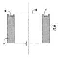
- FIG. 6is a partial cross-sectional view of a core according to an exemplary embodiment
- FIG. 7is a partial cross-sectional view of the core and couplers of FIG. 4 taken along a mid-point of the media roll illustrating an identification coupler and an identification transponder according to an exemplary embodiment
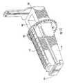
- FIG. 8is a perspective view of FIG. 4 with the identification coupler, identification transponder, and media unit transponders superimposed in order to illustrate the relative orientation of each component according to an exemplary embodiment
- FIG. 9 ais a front view of a HF identification coupler according to an exemplary embodiment
- FIG. 9 bis a rear view of the HF identification coupler of FIG. 9 a;
- FIG. 10is a front view of a PCB board of the HF identification coupler illustrating the coil traces according to an exemplary embodiment
- FIG. 11is a perspective view of a spindle with the HF identification coupler inserted and without an coupler housing member according to an exemplary embodiment
- FIG. 12is the perspective view of FIG. 11 with the coupler housing member
- FIG. 13is a perspective view of FIG. 4 with PCB based HF planar antenna and an identification transponder superimposed in order to illustrate the relative orientation of each component according to an exemplary embodiment
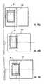
- FIG. 14 ais top view of an identification transponder being at a minimum offset position relative to an identification coupler according to an exemplary embodiment
- FIG. 14 bis a top view of an identification transponder being at a middle offset position relative to an identification coupler according to an exemplary embodiment
- FIG. 14 cis a top view of an identification transponder being at a maximum offset position relative to an identification coupler according to an exemplary embodiment
- FIG. 15illustrates a S 11 parameter of a tuned HF identification coupler according to an exemplary embodiment
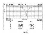
- FIG. 16illustrates the S 11 parameter of FIG. 15 in the vicinity of 13.56 MHz in a substantially worst case
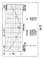
- FIG. 17illustrates a coupler bandwidth at VSWR equals to two according to an exemplary embodiment.
- printer-encodershave been depicted, for illustration purposes, in the context of a specific application, namely, RFID enabled printer systems, also referred to herein as “printer-encoders.” Examples of printer-encoders are disclosed in commonly-owned U.S. Pat. Nos. 6,481,907; 6,848,616; and 7,137,000, which are hereby incorporated herein by reference. However, the inventive concepts described herein are not limited to printer-encoders and may be applied to other media processing systems (e.g., printers, encoders) that may, among other things, benefit from the ability to authenticate or otherwise identify a consumable.
- FIG. 1illustrates an RFID printer-encoder 20 structured for printing and programming a series or stream of media units (e.g., labels, tickets, tags, cards, and other media forms) according to an embodiment of the present invention.
- media unitse.g., labels, tickets, tags, cards, and other media forms
- FIG. 2at least a few of the media units 24 include transponders, referred to herein as media unit transponders 26 .
- media unitsmay include labels, cards, etc, that are carried by a substrate liner or web 22 as shown in FIG. 2 . Alternatively, a web may not be necessary.
- the printer-encoder 20includes several components, such as a printhead 28 , a platen roller 29 , a feed path 30 , a peeler bar 32 , a media exit path 34 , rollers 36 , a carrier exit path 38 , a take-up spool 40 , a ribbon supply roll 41 , at least a first transceiver 42 , a controller 45 , at least one memory element 47 , and at least a first coupler 50 .
- the web 22is directed along the feed path 30 and between the printhead 28 and the platen roller 29 for printing indicia onto the media units 24 .
- the ribbon supply roll 41provides a thermal ribbon (not shown for clarity) that extends along a path such that a portion of the ribbon is positioned between the printhead 28 and the media units 24 .
- the printhead 28heats up and presses a portion of the ribbon onto the media units 24 to print indicia.
- the take-up spool 40is configured to receive and spool the used ribbon.
- the ribbon supply roll 41 and the take-up spool 40may be supported by one or more spindles 43 , 44 of the printer-encoder.
- This printing techniqueis commonly referred to as a thermal transfer printing. However, several other printing techniques may be used including, but not limited to, direct thermal printing, inkjet printing, dot matrix printing, and electro-photographic printing.
- the media unit web 22proceeds to the media exit path 34 where the media units are typically individually removed from the web 22 .
- pre-cut media units 24may be simply peeled from the web 22 using the peeler bar 32 as shown.
- a group of multiple media unitsmay be peeled together and transmitted downstream to an in-line cutter for subsequent separation (not shown).
- Various other known media unit removal techniquesmay be used as will be apparent to one of ordinary skill in the art.
- the web 22may be guided out of the printer-encoder 20 along the carrier exit path 38 by rollers 36 or other devices.
- Techniques and structures for conveying or guiding the web of media units along the entire feed path of the printer-encoderare well known in the art and, thus, such techniques and conveyance systems are not described in great detail.
- the printer-encoderfurther includes a transceiver for reading and/or encoding transponders located in media units.
- the first transceiver 42is configured for receiving, generating, and transmitting RF communication signals that are broadcast by the first coupler 50 located proximate the media feed path 30 .
- the first coupleralso referred to as the encoding coupler 50 , is configured to establish, at predetermined transceiver power levels from the first transceiver 42 , a mutual coupling between the first transceiver 42 and a targeted media unit transponder that is located in the transponder encoding region. More specifically, as the media web 22 proceeds along the media feed path 30 through the transponder encoding region, data may be read from and written to transponders disposed on media units 24 carried by the web 22 .
- the encoding coupler 50may be configured as a spatially selective coupler capable of selectively communicating with a targeted transponder from among a group of adjacent transponders.
- a spatially selective coupleris adapted to have a limited range in order to minimize inadvertent communication (e.g., activation, reading, or writing) of additional transponders beyond the targeted transponder as further explained in U.S. Patent Application Publication Nos. 2005/0045732 and 2005/0045724 and U.S. application Ser. No. 11/371,785, each to Tsirline et al. and each is hereby incorporated by reference as examples of spatially selective couplers and as background to potential concerns and techniques when interrogating multiple adjacent transponders.
- the printer-encodermay include other anti-collision management techniques, such as an RF-shielded housing or an anechoic chamber, instead of or in addition to employing a spatially selective coupler.
- the first transceiver 42is a device configured to generate, process, and receive electrical communication signals.
- Transceiverrefers to the devices noted above and to any device capable of generating, processing, transmitting, or receiving electrical and/or electromagnetic signals.
- the printer-encoder 20further includes a spindle 100 for supporting a roll 60 of the media units.
- the roll 60includes a core 62 in which the media units are wound around in numerous layers.
- the core 62is configured to fit around the spindle 100 as shown in FIGS. 1 and 4 .
- the spindle 100may be fixed with the core 62 rotating around the spindle 100 (i.e., hanger). Or the core 62 may be held to the spindle 100 with the spindle 100 and core 62 rotating together.
- a first end of the spindle 100may be mounted to a wall 52 or other structure within the printer-encoder 20 .
- a second end of the spindle 100may be a free end allowing for the insertion or removal of the core 62 from the spindle 100 .
- the printer-encoder 20may further include a locking member 106 configured to engage the second end of the spindle 100 to help secure the roll 60 of the media units to the spindle 100 (locking member not illustrated in FIGS. 1 and 3 ).
- the core 62may vary. However, as shown in FIGS. 5 a and 5 b , the core 62 may extend from a first end 68 to a second end 69 along a longitudinal axis and include a cylindrical wall 70 having an inner surface 71 and an outer surface 72 .
- the media roll 60may also include at least one identification transponder 64 .
- the identification transponder 64may contain data or information pertaining to the roll 60 and more particularly regarding the media units 24 on the roll 60 .
- any or all of the following informationmay be stored within the identification transponder 64 : the type of media units (e.g., dimensions and other physical properties of the media unit), the type of embedded media unit transponder (e.g., operational frequency, type of antenna, position relative to the rest of the media unit), read/write power levels to be used in reading and writing to the transponders, the number of media units, the manufacture of the media units and/or transponders, and a serial number or other unique identifier of the roll, communication protocol type, printing parameters (such as optimal darkness level for thermal printing), optimal media sensor parameters (such as emitter brightness, detector sensitivity, and detection threshold), a count of remaining or used media units, generic data or customer tables, an encryption scheme, types of compatible or recommended encoding couplers, encoding configuration settings, general printing and en
- Another example of information that may be stored within the identification transponder 64is an optimal retry level.
- a trade-offexists between cost of wasted media units 24 and time or through-put. Not every media unit transponder 26 may successfully encode during a first attempt. In many cases, multiple attempts increase the likelihood of encoding one or all of the media unit transponders 26 that did not encode during the first attempt. The eventual successfully encoding of as many media unit transponders 26 as possible reduces the number of wasted media units 24 . However, multiple attempts increase time needed for the encoding process and reduces the overall through-put of the printer-encoder 20 . Also, some media unit transponders 26 may never encode due to damage or malfunction.
- An optimal retry levelis a number of retries or attempts that the printer-encoder should perform on a media unit transponder 26 that is not encoding before rejecting the media unit 24 .
- the optimal retry levelmay vary depending on several factors such as transponder type, power levels, and transponder manufacturing process variations.
- formatting or printing and encoding setting instructionsmay be stored or otherwise retrievable from the identification transponder 64 .
- the instructionsmay include read and write power settings and optimal or acceptable printing techniques, e.g., direct thermal v. thermal transfer printing.
- the instructions retrievable from the identification transponder 64may be complete or provide information to be used with additional information already stored within the printer-encoder 20 .
- the identification transponder 64may include the complete print format and/or encoding instructions for the media unit transponders 26 .
- the identification transponder 64may include all or some of the instructions for the controller 45 of the printer-encoder that are necessary to determine the recommended or optimal print settings for the media units and encoding settings for the media unit transponders 26 .
- a memory element 47 of the printer-encodermay store printing and encoding settings for various types of media units.
- the stored settingsmay be customized, i.e., an operator may have entered the settings through the input devices of the printer-encoder, and/or the stored settings may be a factory setting or provided through firmware/software updates or downloads.
- the controller 45may be configured to identify the media units 24 from the information retrieved from the identification transponder 64 and determine or adjust the printing and encoding settings from the information stored within the memory element 47 .
- the information that is retrievable from the identification transponder 64may facilitate an automatic setting feature for the printer-encoder, in which the printer-encoder 24 is configured to adjust the print and encoding settings automatically based on the media units 24 inserted or loaded into the printer-encoder 20 without requiring additional input from an operator.
- the controller 45may generate an input request or recommendation, i.e., a message to the operator, based on the information retrieved from the identification transponder 64 for an operator input. For example, based on the retrieved information, the controller may generate a message on an output display of the printer-encoder asking the operator to select one or more print and encoding settings.
- the nature and amount of information stored or otherwise retrievable from the identification transponder 64may vary depending on the memory capability of the identification transponder 64 .
- the identification transponder 64may be an active or a passive transponder.
- the identification transponder 64may be a 256 bit passive tag or even a passive tag with an expanded memory capability, including, but not limited to, 1 gigabit.
- the identification transponder 64may function as part of a file system of the printer-encoder 20 .
- the size of the file that the identification transponder 64 contributes to the file systemmay vary depending on the memory capability of the identification transponder 64 .
- additional informationmay be retrievable by a second identification transponder associated with the printer ribbon supply roll.
- the printer ribbon supply roll 41may also have at least one identification transponder that contains data or information pertaining to the printer ribbon supply roll 60 .
- the information contained by the identification transponder of the printer ribbon supply rollmay be retrievable by a coupler and a transceiver of the printer-encoder.
- the controller 45may be configured to process the information retrieved from the identification transponder 64 of the media roll and the identification transponder of the print supply roll to determine an optimal or proper print setting.
- the information retrievable from the identification transponder 64may also help to reduce or prevent an improper combination of a particular media type with a print and/or encode application or accidental usage of RFID enabled media units (i.e., media units with embedded transponders) in non-RFID applications.
- RFID enabled media unitsi.e., media units with embedded transponders
- pharmaceutical labeling or “Underwriters Laboratory” labelingmay require a specific printer ribbon and label face-stock combination.
- the controllermay be configured to confirm the proper media type, i.e., face-stock, before allowing the media units to be used in such applications.
- the controllermay be configured to generate an error message when RFID enabled media units are identified but the formatting instructions do not provide for an encoding operation.
- the formatting instructionsmay have to be updated or RFID enabled media units may have been accidentally loaded for a non-RFID application.
- the controllermay detect an improper media type for a particular format, the controller may generate an error message that may be overridden by an operator to allow the printing and encoding operations to continue.
- the controllermay be configured to lock out the printer-encoder until it receives an override password or other override control that is only available to particular operators or managers.
- the retrievable informationmay be used to further assist in set-up operations, or to prevent operators from making unauthorized printer adjustments. Examples of such parameters include but are not limited to: RFID number of retries (expensive tags may have high retries, inexpensive ones low number of retries); language setting; and print speed.
- the information retrievable from the identification transponder 64may be specifically formatted for the formatting setting of the printer-encoder 20 . More specifically, a stored format setting, i.e., printing and encoding settings, of the printer-encoder may be in a form of a particular markup language, such as XML, that includes one or more fields to be either printed onto the media label in a specific location and manner and/or encoded into the media unit transponder.
- the identification transpondermay contain information according to one or more fields that correspond to the fields of the printer-encoder to facilitate a data merge, also referred to as a mail merge.
- the format setting of the printer-encodermay be configured to program an EPC (electronic product code) into a particular field, e.g., field number three on the media unit transponder.
- EPCelectronic product code
- the identification transpondermay be encoded with the EPC in its field number three such that the controller downloads the value of field number three from the identification transponder directly to the media unit transponder.
- the identification transponder 64may be embedded or otherwise attached to the core in various locations.
- the core 62may include a groove 66 extending around an end 68 of the core.
- the groove 66may be configured to receive a ring-shaped identification transponder 64 .
- the identification transponder 64may extend along the inner surface 71 , the outer surface 72 (such as in the embodiment depicted in FIGS. 5 a and 5 b ), or embedded into the wall 70 of the core.
- the printer-encoder 20may include at least a second coupler, referred to herein as the identification coupler, such as UHF identification coupler 210 discussed below.
- the identification coupleris configured to establish, at predetermined transceiver power levels, a mutual coupling between a transceiver of the printer-encoder 20 and the identification transponder 64 .
- the transceivermay be the first transceiver 42 that is in communication with the encoding coupler 50 or a separate, second transceiver of the printer-encoder.
- the identification coupler and the identification transponder 64may be operable in the same frequency band as the encoding coupler 50 and the media unit transponders 26 or in a different frequency band.
- the identification coupler, identification transponder 64 , the encoding coupler 50 , and the media unit transponders 26may each be configured to operate within UHF.
- the identification coupler 110 and the identification transponder 64may be configured for HF while the encoding coupler 50 and the media unit transponders 26 may be configured for UHF.
- the identification coupler and the identification transponders 64may be configured to operate in a first sub frequency band within UHF or HF and the encoding coupler 50 and the media unit transponders 26 may be configured to operate in a second sub frequency band within UHF or HF.
- the printer-encoderincludes a UHF identification coupler in communication with the first transceiver.
- the printer-encoder 20has a first transceiver 42 in communication with a UHF spatially selective encoding coupler 50 and with a UHF identification coupler 210 .
- the UHF identification coupler 210 and the identification transponder 64may be orthogonally oriented with the media unit transponders 26 as illustrated in FIGS. 7 and 8 .
- the encoding coupler 50may be based on a microstrip band pass filter.
- the encoding coupler 50may be positioned close to the printhead 28 and have a “landscape” orientation (i.e., the encoding extends perpendicular to the label feed direction) for optimal coupling with a targeted media unit transponder 26 .
- the encoding coupler 50may also be perpendicular to the UHF identification coupler 210 which minimizes the likelihood of the encoding coupler 50 inadvertently or otherwise interfering with identification transponder 64 .
- the UHF identification coupler 210may comprise a flexible microstrip transmission line. According to the embodiment illustrated in FIGS. 7 and 8 , the UHF identification coupler 210 includes a cylindrical shaped conductive strip extending between a first end 214 and a second end 216 . The first end 214 and second end 216 define an opening 218 between the two ends 214 , 216 .
- the depicted printer-encoder 20further includes a support member configured to help hold the UHF identification transponder in sufficient proximity to the identification coupler.
- the support membermay be a cylindrical support member 220 having an outer surface 222 and an inner surface 224 .
- the outer surface 222 of the cylindrical support memberis configured to engage the inner surface 71 of the core and the inner surface 224 of the cylindrical support member is configured to support the UHF identification coupler 210 .
- a portion of the inner surface 224 of the cylindrical support member 220 that corresponds to the opening 218 defined between the two ends 214 , 216 of the conductive stripmay engage the spindle 100 for supporting the cylindrical support member 220 and the UHF identification coupler 210 relative to the spindle 100 .
- the cylindrical support member 220may be constructed from a synthetic polymer, such as polytetrafluoroethylene (e.g., Telfon®) or other low permittivity materials.
- the printer-encodermay include a second transceiver.
- the first transceivercommunicates with the encoding coupler and the second transceiver communicates with the identification coupler.
- the identification couplercommunicates with the second transceiver of the printer-encoder and the identification coupler may operate within the HF band and, thus, may be referred to as a HF identification coupler.
- a HF identification coupler 310may be based on a resonant magnetic planar antenna configured to establish, at predetermined transceiver power levels, an edge magnetic coupling with the identification transponder 64 .
- the HF identification coupler 310may include one or more coils responsive to RF signals supplied by the second transceiver converting RF signals to an appropriate magnetic field.
- the coilsmay take the form of a planar elongated coils created, for example, by one or more conductors coupled with a coil support structure.
- the conductors and coil support structuremay comprise, for example, one or more coil traces 312 on, within, or between one or more layers of a printed circuit board or boards (PCBs) 314 .
- the couplermay include two PCBs, each having a ground layer, a dielectric layer, and at least one coil trace.
- the two PCBsmay be in parallel and adjacent one another with the coil traces facing each other.
- Each coil trace 312may be formed without sharp corners to minimize creation of impedance discontinuities.
- the number of turns used in the coilsis determined in part by the intended range from and longitudinal dimensions of the identification transponder 64 which is magnetically coupled to the coils.
- the HF identification coupler 310may include one or more impedance matching and tuning components.
- the HF identification couplermay include one or more capacitors 316 , for example 4, for 50 ohms impedance match. And the HF identification coupler 310 may be tuned at 13.56 MHz. The HF identification coupler 310 may also include Faraday shielding rings 318 above the coil traces 312 for electrical field insulation.
- the HF identification coupler 310may be configured to engage the spindle 100 .
- the HF identification coupler 310may define an opening 320 for accepting at least a portion of the spindle 100 . With the HF identification coupler 310 positioned around at least a portion of the spindle 100 via the opening 320 , the spindle 100 at least partially supports the HF identification coupler 310 .
- the spindle 100may include a radome or coupler housing member 112 and a support member 114 .
- the support member 114extends from the first end 102 to the second end 104 of the spindle 100 and defines a contact area 116 , such as a top surface area, between the core 62 and the spindle 100 .
- the support member 114may be one integrated element or include one or more elements interconnected to form the support member 114 .
- the coupler housing member 112may be configured to help reduce environmental influences on the coupler 310 and to help provide a smooth surface for the loading of the media roll.
- the coupler housing member 112may be generally cylindrical and configured to surround the coupler 310 near the first end 102 (i.e., the end attached to the wall 52 of the printer-encoder) of the spindle.
- a top area 118 of the coupler housing member 112may be configured to mimic the contact area 116 of the support member such that the top area 118 effectively becomes an extension of the contact area 116 defined by the support member.
- the coupler housing member 112may include a sloped or cone-shaped loading edge 120 extending toward the second end 104 of the spindle to help with the loading of the media roll.
- the inner surface of the cone-shaped loading edge 120may also provide a mounting surface for the coupler 310 within the coupler housing member 112 .
- the media roll 60may include a core 62 , an identification label 74 , and a RF field insulator 80 .
- the core 62provides the general support to the rolled media units 24 and includes an inner surface 71 engageable with the spindle 100 and an outer surface 72 .
- the identification label 74includes a substrate 76 , such as a sticker label, and a HF identification transponder 64 , which may be embedded within or otherwise attached to the substrate 76 .
- the sticker labelmay be used to attach the HF identification transponder 64 to the outer surface 70 of the core.
- the RF field insulator 80is configured to make the HF identification transponder 64 less susceptible to interference from the media unit transponders wound above it also referred to as a winding effect.
- the RF field insulator 80may be a ferrite patch, a metal foil, or both extending over the HF identification transponder 64 .
- the RF field insulator 80may cover a limited area of the outer surface 70 that corresponds to the HF identification transponder 64 or the entire outer surface 70 of the core.
- the HF identification coupler 310may be configured to couple with the transponder 64 through a core positioning range.
- an identification transponder placement on the core 62is defined by a distance to the coupler's plane to a maximize core positioning range.
- the transponder locationcorresponds to a beginning of the core positioning range and the beginning of a range of coupling, above a minimum level, between the coupler 310 and the identification transponder 64 .
- FIG. 14 awhen a core offset is approximately 0 mm, the transponder location corresponds to a beginning of the core positioning range and the beginning of a range of coupling, above a minimum level, between the coupler 310 and the identification transponder 64 .
- a transponder-coupler alignmentin the middle of the core position range relates to a maximum coupling between the coupler 310 and the transponder 64 .
- a transponder-coupler alignment at a maximum core positioning rangerelates to the end of the range of transponder-coupler coupling above a minimum coupling value.
- the transponder-coupler alignmentmay vary due to variations in dimensions between different media rolls and/or due to variations between the loadings of the different media rolls, i.e., a media roll may be loaded onto the spindle rolls at different distances from the first end of the spindle.
- the HF identification couplermay be tuned at 13.56 ⁇ 0.25 MHz and its impedance may be matched to 50 ohms.
- Optimum couple tuning and its impedance matchingmay be performed when an empty core, i.e., no media unit transponders are wound around the core, with the identification transponder 64 positioned on the spindle at approximately 0 mm distance from a reference point, as illustrated in FIG. 14 a .
- the couplermay provide a sufficient coupling with the identification transponder (at least 3 dB RF power margin) at any angular position within a specified (e.g., 9 mm) core offset positioning range and transponder placement tolerance ( ⁇ 1.5 mm) while maintaining impedance mismatch and return loss not exceeding ⁇ 10 dB at 13.56 MHz for the S 11 parameter in the worse case as illustrated in FIG. 16 (shown as ⁇ 14.458 dB).
- the bandwidthis shown as 423 kHz.
- the RF power delivered to the transpondershould exceed the minimum energizing level by a margin of at least 3 dB.
- the minimum RF power level for this embodimentmay depend on angular and core offset positions.
- One technique, which may be used to determine power level margin above the minimum energizing level,is based on the use of an external RF power attenuator. The device is inserted between the identification coupler and a HF transceiver.
- the value of the inserted RF power attenuationis varied to determine the successful operating range in relative power (dB).
- the devicemay connect a HF reader and a coupler. A suppression of maximum available RF power from the transceiver allows for an estimation in relative power in dB at which the identification starts and stops working, i.e., communicating.
- the identification transpondermay store or otherwise provide data or information regarding intended or optimal print and encode format settings.
- the printer-encodermay be configured to recognize print and encode format settings or other user preferences through a transponder attached to or otherwise carried with a particular user.
- the transpondermay be embedded in the clothing, jewelry, or another item carried or worn by the user or somewhere in the user's body.
- the printer-encodermay include an antennae configured to recognize the transponder that is closest to the printer-encoder and a transponder reader of the printer-encoder may identify and notify the printer-encoder through the transponder in the person's clothing or body to tailor the printer settings to the preferences associated with the transponder.
- Embodiments described aboveinclude a printer-encoder having at least one transceiver and one or more couplers for establishing a mutual coupling between the at least one transceiver and one or more transponders associated with consumables of the printer-encoder, such as a first identification transponder associated with the media roll, a second identification transponder associated with the printer ribbon supply roll, and the media unit transponders.
- a transceiver of the printer-encodermay be in communication with one or more of the couplers or a transceiver may be in communication with a coupler.
- the printer-encodermay equal number of transceivers to couplers.
- the couplers and transpondersmay be positioned to have offsetting or different orientation to one another as discussed above.
- the printer-encodermay have anti-collision software operable through a controller element and/or RF shielding components configured to reduce interference between the different couplers and transponder.
- one or more of the transceivers, couplers, and transpondersmay be configured to operate within different frequency bands or sub-bands.
- one or more of the transceivers, couplers, and transpondersmay be configured to operate within different protocols, such as ISO 15693, ISO 14443, or other RF protocols.
Landscapes
- Engineering & Computer Science (AREA)
- Computer Hardware Design (AREA)
- Microelectronics & Electronic Packaging (AREA)
- Physics & Mathematics (AREA)
- General Physics & Mathematics (AREA)
- Theoretical Computer Science (AREA)
- Accessory Devices And Overall Control Thereof (AREA)
Abstract
Description
Claims (19)
Priority Applications (4)
| Application Number | Priority Date | Filing Date | Title |
|---|---|---|---|
| US11/755,600US9524460B2 (en) | 2007-05-30 | 2007-05-30 | System for processing media units and an associated media roll |
| CN200880023482ACN101689243A (en) | 2007-05-30 | 2008-05-29 | A system for processing media units and an associated media roll |
| PCT/US2008/065035WO2008150834A1 (en) | 2007-05-30 | 2008-05-29 | A system for processing media units and an associated media roll |
| EP08756412.6AEP2158559B1 (en) | 2007-05-30 | 2008-05-29 | A system for processing media units and an associated media roll |
Applications Claiming Priority (1)
| Application Number | Priority Date | Filing Date | Title |
|---|---|---|---|
| US11/755,600US9524460B2 (en) | 2007-05-30 | 2007-05-30 | System for processing media units and an associated media roll |
Publications (2)
| Publication Number | Publication Date |
|---|---|
| US20080298822A1 US20080298822A1 (en) | 2008-12-04 |
| US9524460B2true US9524460B2 (en) | 2016-12-20 |
Family
ID=39731169
Family Applications (1)
| Application Number | Title | Priority Date | Filing Date |
|---|---|---|---|
| US11/755,600Active2032-02-24US9524460B2 (en) | 2007-05-30 | 2007-05-30 | System for processing media units and an associated media roll |
Country Status (4)
| Country | Link |
|---|---|
| US (1) | US9524460B2 (en) |
| EP (1) | EP2158559B1 (en) |
| CN (1) | CN101689243A (en) |
| WO (1) | WO2008150834A1 (en) |
Cited By (1)
| Publication number | Priority date | Publication date | Assignee | Title |
|---|---|---|---|---|
| US20220230002A1 (en)* | 2021-01-20 | 2022-07-21 | Westrock Shared Services, Llc | Multi stream rfid tag applicator |
Families Citing this family (6)
| Publication number | Priority date | Publication date | Assignee | Title |
|---|---|---|---|---|
| US8878652B2 (en)* | 2009-11-13 | 2014-11-04 | Zih Corp. | Encoding module, associated encoding element, connector, printer-encoder and access control system |
| US9434191B2 (en) | 2010-04-12 | 2016-09-06 | Zih Corp. | Label peeling, universal printheads and related methods |
| US8752922B2 (en) | 2010-04-12 | 2014-06-17 | Zih Corp. | Mobile printer networking and interfacing |
| EP2817708B1 (en) | 2012-02-21 | 2020-08-26 | Zebra Technologies Corporation | Method and apparatus for implementing near field communications with a printer |
| EP3206130B1 (en)* | 2014-07-01 | 2018-01-31 | Axis AB | Methods and devices for finding settings to be used in relation to a sensor unit connected to a processing unit |
| US9632734B2 (en)* | 2014-12-09 | 2017-04-25 | Zih Corp. | Spindle supported near field communication device |
Citations (67)
| Publication number | Priority date | Publication date | Assignee | Title |
|---|---|---|---|---|
| US2812501A (en) | 1954-03-04 | 1957-11-05 | Sanders Associates Inc | Transmission line |
| US4509039A (en) | 1983-07-05 | 1985-04-02 | Minnesota Mining And Manufacturing Company | Shielded, closely spaced transmit-receiver antennas for electronic article surveillance system |
| US5192954A (en) | 1981-02-13 | 1993-03-09 | Mark Iv Transportation Products Corporation | Roadway antennae |
| US5318370A (en) | 1992-11-17 | 1994-06-07 | Varitronic Systems, Inc. | Cartridge with data memory system and method regarding same |
| US5587578A (en) | 1994-08-10 | 1996-12-24 | Gemplus | Method and apparatus for optimizing magnetic flux through an electronic label of a contact-free identification system |
| US5777586A (en) | 1993-03-17 | 1998-07-07 | Luxon; Norval N. | Radiation shielding and range extending antenna assembly |
| US5838253A (en) | 1995-05-17 | 1998-11-17 | Accu-Sort Systems, Inc. | Radio frequency identification label |
| US6099178A (en)* | 1998-08-12 | 2000-08-08 | Eastman Kodak Company | Printer with media supply spool adapted to sense type of media, and method of assembling same |
| US6104291A (en) | 1998-01-09 | 2000-08-15 | Intermec Ip Corp. | Method and apparatus for testing RFID tags |
| US6123024A (en)* | 1998-01-15 | 2000-09-26 | Alpha Metals, Inc. | Stencil incorporating electronic tag |
| US6150809A (en) | 1996-09-20 | 2000-11-21 | Tpl, Inc. | Giant magnetorestive sensors and sensor arrays for detection and imaging of anomalies in conductive materials |
| US6166637A (en)* | 1999-02-09 | 2000-12-26 | Micron Technology, Inc. | Apparatuses for electronic identification of a plurality of passing units and methods of electronic identification of a plurality of passing units |
| US6227643B1 (en) | 1997-05-20 | 2001-05-08 | Encad, Inc. | Intelligent printer components and printing system |
| US6246326B1 (en) | 1999-05-05 | 2001-06-12 | Intermec Ip Corp. | Performance optimized smart label printer |
| US6247857B1 (en) | 1999-08-11 | 2001-06-19 | Eastman Kodak Company | Multistage system for processing photographic film |
| US6267521B1 (en) | 1995-09-22 | 2001-07-31 | Eltron International, Inc. | Computer driven printer with a stripper roller and latching assembly |
| US20010024160A1 (en) | 2000-03-01 | 2001-09-27 | Matthew Banach | Contact programmer |
| US6327972B2 (en)* | 1998-10-07 | 2001-12-11 | Meto International Gmbh | Printer with a device for the driving of transponder chips |
| US20020044164A1 (en) | 2000-10-16 | 2002-04-18 | Yoshiaki Kaburagi | Recording apparatus |
| US6392544B1 (en) | 2000-09-25 | 2002-05-21 | Motorola, Inc. | Method and apparatus for selectively activating radio frequency identification tags that are in close proximity |
| US6409401B1 (en)* | 2000-03-30 | 2002-06-25 | Zih Corp. | Portable printer with RFID encoder |
| US6425663B1 (en) | 2000-05-25 | 2002-07-30 | Encad, Inc. | Microwave energy ink drying system |
| US20020101498A1 (en) | 2000-08-28 | 2002-08-01 | Vt Tech Corp. | Proximity card printer and encoder system |
| FR2822594A1 (en) | 2001-03-20 | 2002-09-27 | Thomson Csf | Multilayer planar antenna has via grounding to buried ground plane at orthogonal connector |
| US20020191998A1 (en) | 1996-08-07 | 2002-12-19 | Mats Cremon | Arrangement for automatic setting of programmable devices and materials therefor |
| US6512594B1 (en) | 2000-01-05 | 2003-01-28 | Fargo Electronics, Inc. | Printer or laminator with multi-threaded program architecture |
| US20030023337A1 (en)* | 2000-02-26 | 2003-01-30 | Godfrey James William | Manufacturing method |
| US6527356B1 (en) | 2000-06-02 | 2003-03-04 | Eastman Kodak Company | Printer capable of forming an image on a receiver substrate according to type of receiver substrate and a method of assembling the printer |
| US20030059050A1 (en) | 2001-08-24 | 2003-03-27 | Hohberger Clive P. | Method and apparatus for article authentication |
| US20030062131A1 (en) | 2001-10-01 | 2003-04-03 | Hohberger Clive P. | Method and apparatus for associating on demand certain selected media and value-adding elements |
| US20030076520A1 (en) | 2001-10-17 | 2003-04-24 | Haines Robert E. | Active packaging providing print media information |
| US6565188B1 (en) | 1999-10-06 | 2003-05-20 | Canon Kabushiki Kaisha | Cleaning device for inkjet recording head and inkjet recording device including the same |
| US6585345B2 (en) | 2000-12-05 | 2003-07-01 | Seiko Epson Corporation | Printing apparatus and ink cartridge therefor |
| US6593853B1 (en) | 2000-02-18 | 2003-07-15 | Brady Worldwide, Inc. | RFID label printing system |
| US6628316B1 (en) | 1998-12-22 | 2003-09-30 | Eastman Kodak Company | Printer with donor and receiver media supply trays each adapted to allow a printer to sense type of media therein, and method of assembling the printer and trays |
| US6634814B2 (en) | 1998-08-12 | 2003-10-21 | Eastman Kodak Company | Printer media supply spool adapted to allow the printer to sense type of media, and method of assembling same |
| US6644544B1 (en) | 1999-06-16 | 2003-11-11 | Eastman Kodak Company | Imaging apparatus capable of forming an image consistent with type of imaging consumable loaded therein and method of assembling the apparatus |
| US20040002305A1 (en)* | 2002-06-26 | 2004-01-01 | Nokia Corporation | System, apparatus, and method for effecting network connections via wireless devices using radio frequency identification |
| US20040061649A1 (en) | 2001-06-01 | 2004-04-01 | Agere Systems Inc. | Low-loss printed circuit board antenna structure and method of manufacture thereof |
| US20040102870A1 (en)* | 2002-11-26 | 2004-05-27 | Andersen Scott Paul | RFID enabled paper rolls and system and method for tracking inventory |
| US20040178267A1 (en) | 2003-03-11 | 2004-09-16 | Zebra Technologies Corporation | System and Method for Selective Communication with RFID Transponders |
| US20040184801A1 (en) | 2000-09-18 | 2004-09-23 | Vraa Timothy S. | Sheet media package having radio-frequency identification transponder |
| US6811079B1 (en) | 1998-12-22 | 2004-11-02 | Eastman Kodak Company | Sheet media package having radio-frequency identification transponder |
| US6832866B2 (en) | 1999-01-25 | 2004-12-21 | Fargo Electronics, Inc. | Printer or laminator supply |
| JP2004362170A (en) | 2003-06-03 | 2004-12-24 | Nippon Signal Co Ltd:The | Roller type reader/writer |
| US20050021172A1 (en)* | 2003-06-25 | 2005-01-27 | Intermec Ip Corp. | Method and apparatus for preparing media |
| US20050024393A1 (en) | 2003-07-28 | 2005-02-03 | Canon Kabushiki Kaisha | Image forming apparatus and method of controlling image forming apparatus |
| US20050045723A1 (en) | 2003-08-29 | 2005-03-03 | Zih Corp. | Spatially Selective UHF Near Field Microstrip Coupler Device and RFID Systems Using Device |
| US6938976B2 (en) | 1999-06-16 | 2005-09-06 | Eastman Kodak Company | Printer and method therefor adapted to sense data uniquely associated with a consumable loaded into the printer |
| US6943678B2 (en)* | 2000-01-24 | 2005-09-13 | Nextreme, L.L.C. | Thermoformed apparatus having a communications device |
| US6967579B1 (en)* | 2004-03-05 | 2005-11-22 | Single Chip Systems Corporation | Radio frequency identification for advanced security screening and sortation of baggage |
| US6969134B2 (en) | 2001-10-01 | 2005-11-29 | Zih Corp. | Printer or other media processor with on-demand selective media converter |
| US20050280537A1 (en) | 2004-06-22 | 2005-12-22 | Feltz John F | RFID printer and antennas |
| US20060019135A1 (en)* | 2003-12-01 | 2006-01-26 | Curello Andrew J | Fuel cell with fuel monitoring system and method of use |
| US20060066441A1 (en) | 2004-09-30 | 2006-03-30 | Knadle Richard T Jr | Multi-frequency RFID apparatus and methods of reading RFID tags |
| US7059248B2 (en) | 2004-01-16 | 2006-06-13 | Nandakumar Vaidyanathan | Digital semiconductor based printing system and method |
| US7077489B2 (en) | 2002-11-21 | 2006-07-18 | Hewlett-Packard Development Company, L.P. | Apparatus for printing and memory tag application and method therefor |
| US20060221363A1 (en) | 2002-08-16 | 2006-10-05 | Paxar Corporation | Hand held portable printer with rfid read write capability |
| US20060238600A1 (en) | 2002-12-24 | 2006-10-26 | Esselte Industriepark-Noord 30, B-9100 | Information on consumables |
| US7128408B2 (en) | 2000-12-05 | 2006-10-31 | Seiko Epson Corporation | Printing apparatus and ink cartridge therefor |
| US20060255945A1 (en) | 2005-05-13 | 2006-11-16 | 3M Innovative Properties Company | Radio frequency identification tags for use on metal or other conductive objects |
| US20070013520A1 (en) | 2005-03-01 | 2007-01-18 | Kevin Conwell | Printhead with RFID antenna |
| US20070063843A1 (en) | 2005-09-21 | 2007-03-22 | Zih Corp. | Multi-layered efficient RFID coupler |
| US7212123B2 (en) | 2002-11-21 | 2007-05-01 | Hewlett-Packard Development Company, L.P. | Detector |
| US20070099566A1 (en) | 2005-10-31 | 2007-05-03 | Zih Corp. | Multi-element RFID coupler |
| US20070147938A1 (en) | 2005-12-13 | 2007-06-28 | Zih Corp. | Printer encoder adapted for positioning aboard a mobile unit |
| US7342499B2 (en) | 2006-01-26 | 2008-03-11 | Printronix, Inc. | Multi-band RFID encoder |
- 2007
- 2007-05-30USUS11/755,600patent/US9524460B2/enactiveActive
- 2008
- 2008-05-29EPEP08756412.6Apatent/EP2158559B1/enactiveActive
- 2008-05-29WOPCT/US2008/065035patent/WO2008150834A1/enactiveApplication Filing
- 2008-05-29CNCN200880023482Apatent/CN101689243A/enactivePending
Patent Citations (80)
| Publication number | Priority date | Publication date | Assignee | Title |
|---|---|---|---|---|
| US2812501A (en) | 1954-03-04 | 1957-11-05 | Sanders Associates Inc | Transmission line |
| US5192954A (en) | 1981-02-13 | 1993-03-09 | Mark Iv Transportation Products Corporation | Roadway antennae |
| US4509039A (en) | 1983-07-05 | 1985-04-02 | Minnesota Mining And Manufacturing Company | Shielded, closely spaced transmit-receiver antennas for electronic article surveillance system |
| US5318370A (en) | 1992-11-17 | 1994-06-07 | Varitronic Systems, Inc. | Cartridge with data memory system and method regarding same |
| US5777586A (en) | 1993-03-17 | 1998-07-07 | Luxon; Norval N. | Radiation shielding and range extending antenna assembly |
| US5587578A (en) | 1994-08-10 | 1996-12-24 | Gemplus | Method and apparatus for optimizing magnetic flux through an electronic label of a contact-free identification system |
| US5838253A (en) | 1995-05-17 | 1998-11-17 | Accu-Sort Systems, Inc. | Radio frequency identification label |
| US6267521B1 (en) | 1995-09-22 | 2001-07-31 | Eltron International, Inc. | Computer driven printer with a stripper roller and latching assembly |
| US6802659B2 (en)* | 1996-08-07 | 2004-10-12 | Mats Cremon | Arrangement for automatic setting of programmable devices and materials therefor |
| US20020191998A1 (en) | 1996-08-07 | 2002-12-19 | Mats Cremon | Arrangement for automatic setting of programmable devices and materials therefor |
| US6150809A (en) | 1996-09-20 | 2000-11-21 | Tpl, Inc. | Giant magnetorestive sensors and sensor arrays for detection and imaging of anomalies in conductive materials |
| US6227643B1 (en) | 1997-05-20 | 2001-05-08 | Encad, Inc. | Intelligent printer components and printing system |
| US6104291A (en) | 1998-01-09 | 2000-08-15 | Intermec Ip Corp. | Method and apparatus for testing RFID tags |
| US6123024A (en)* | 1998-01-15 | 2000-09-26 | Alpha Metals, Inc. | Stencil incorporating electronic tag |
| US6634814B2 (en) | 1998-08-12 | 2003-10-21 | Eastman Kodak Company | Printer media supply spool adapted to allow the printer to sense type of media, and method of assembling same |
| US6099178A (en)* | 1998-08-12 | 2000-08-08 | Eastman Kodak Company | Printer with media supply spool adapted to sense type of media, and method of assembling same |
| US6327972B2 (en)* | 1998-10-07 | 2001-12-11 | Meto International Gmbh | Printer with a device for the driving of transponder chips |
| US6628316B1 (en) | 1998-12-22 | 2003-09-30 | Eastman Kodak Company | Printer with donor and receiver media supply trays each adapted to allow a printer to sense type of media therein, and method of assembling the printer and trays |
| US6811079B1 (en) | 1998-12-22 | 2004-11-02 | Eastman Kodak Company | Sheet media package having radio-frequency identification transponder |
| US6832866B2 (en) | 1999-01-25 | 2004-12-21 | Fargo Electronics, Inc. | Printer or laminator supply |
| US6166637A (en)* | 1999-02-09 | 2000-12-26 | Micron Technology, Inc. | Apparatuses for electronic identification of a plurality of passing units and methods of electronic identification of a plurality of passing units |
| US6246326B1 (en) | 1999-05-05 | 2001-06-12 | Intermec Ip Corp. | Performance optimized smart label printer |
| US6938976B2 (en) | 1999-06-16 | 2005-09-06 | Eastman Kodak Company | Printer and method therefor adapted to sense data uniquely associated with a consumable loaded into the printer |
| US6644544B1 (en) | 1999-06-16 | 2003-11-11 | Eastman Kodak Company | Imaging apparatus capable of forming an image consistent with type of imaging consumable loaded therein and method of assembling the apparatus |
| US6247857B1 (en) | 1999-08-11 | 2001-06-19 | Eastman Kodak Company | Multistage system for processing photographic film |
| US6565188B1 (en) | 1999-10-06 | 2003-05-20 | Canon Kabushiki Kaisha | Cleaning device for inkjet recording head and inkjet recording device including the same |
| US6512594B1 (en) | 2000-01-05 | 2003-01-28 | Fargo Electronics, Inc. | Printer or laminator with multi-threaded program architecture |
| US6943678B2 (en)* | 2000-01-24 | 2005-09-13 | Nextreme, L.L.C. | Thermoformed apparatus having a communications device |
| US6593853B1 (en) | 2000-02-18 | 2003-07-15 | Brady Worldwide, Inc. | RFID label printing system |
| US20030023337A1 (en)* | 2000-02-26 | 2003-01-30 | Godfrey James William | Manufacturing method |
| US20010024160A1 (en) | 2000-03-01 | 2001-09-27 | Matthew Banach | Contact programmer |
| US6409401B1 (en)* | 2000-03-30 | 2002-06-25 | Zih Corp. | Portable printer with RFID encoder |
| US6425663B1 (en) | 2000-05-25 | 2002-07-30 | Encad, Inc. | Microwave energy ink drying system |
| US20030067504A1 (en) | 2000-06-02 | 2003-04-10 | Spurr Robert W. | Printer capable of forming an image on a receiver substrate according to type of receiver substrate and a method of assembling the printer |
| US6527356B1 (en) | 2000-06-02 | 2003-03-04 | Eastman Kodak Company | Printer capable of forming an image on a receiver substrate according to type of receiver substrate and a method of assembling the printer |
| US20020101498A1 (en) | 2000-08-28 | 2002-08-01 | Vt Tech Corp. | Proximity card printer and encoder system |
| US20040184801A1 (en) | 2000-09-18 | 2004-09-23 | Vraa Timothy S. | Sheet media package having radio-frequency identification transponder |
| US6392544B1 (en) | 2000-09-25 | 2002-05-21 | Motorola, Inc. | Method and apparatus for selectively activating radio frequency identification tags that are in close proximity |
| US20020044164A1 (en) | 2000-10-16 | 2002-04-18 | Yoshiaki Kaburagi | Recording apparatus |
| US6793301B2 (en) | 2000-10-16 | 2004-09-21 | Canon Kabushiki Kaisha | Recording apparatus |
| US7128408B2 (en) | 2000-12-05 | 2006-10-31 | Seiko Epson Corporation | Printing apparatus and ink cartridge therefor |
| US6585345B2 (en) | 2000-12-05 | 2003-07-01 | Seiko Epson Corporation | Printing apparatus and ink cartridge therefor |
| US20030160839A1 (en) | 2000-12-05 | 2003-08-28 | Seiko Epson Corporation | Printing apparatus and ink cartridge therefor |
| FR2822594A1 (en) | 2001-03-20 | 2002-09-27 | Thomson Csf | Multilayer planar antenna has via grounding to buried ground plane at orthogonal connector |
| US20040061649A1 (en) | 2001-06-01 | 2004-04-01 | Agere Systems Inc. | Low-loss printed circuit board antenna structure and method of manufacture thereof |
| US20030059050A1 (en) | 2001-08-24 | 2003-03-27 | Hohberger Clive P. | Method and apparatus for article authentication |
| US20060191022A1 (en) | 2001-08-24 | 2006-08-24 | Zih Corp. | Method and apparatus for article authentication |
| US20030062131A1 (en) | 2001-10-01 | 2003-04-03 | Hohberger Clive P. | Method and apparatus for associating on demand certain selected media and value-adding elements |
| US20030063139A1 (en) | 2001-10-01 | 2003-04-03 | Hohberger Clive P. | Method and apparatus for associating on demand certain selected media and value-adding elements |
| US6969134B2 (en) | 2001-10-01 | 2005-11-29 | Zih Corp. | Printer or other media processor with on-demand selective media converter |
| US20030063001A1 (en) | 2001-10-01 | 2003-04-03 | Hohberger Clive P. | Method and apparatus for associating on demand certain selected media and value-adding elements |
| US20050025553A1 (en) | 2001-10-01 | 2005-02-03 | Zih Corp. | Method and apparatus for associating on demand certain selected media and value-adding elements |
| US6857714B2 (en) | 2001-10-01 | 2005-02-22 | Zih Corp. | Method and apparatus for associating on demand certain selected media and value-adding elements |
| US20030076520A1 (en) | 2001-10-17 | 2003-04-24 | Haines Robert E. | Active packaging providing print media information |
| US20040002305A1 (en)* | 2002-06-26 | 2004-01-01 | Nokia Corporation | System, apparatus, and method for effecting network connections via wireless devices using radio frequency identification |
| US20060221363A1 (en) | 2002-08-16 | 2006-10-05 | Paxar Corporation | Hand held portable printer with rfid read write capability |
| US7077489B2 (en) | 2002-11-21 | 2006-07-18 | Hewlett-Packard Development Company, L.P. | Apparatus for printing and memory tag application and method therefor |
| US7212123B2 (en) | 2002-11-21 | 2007-05-01 | Hewlett-Packard Development Company, L.P. | Detector |
| US20040102870A1 (en)* | 2002-11-26 | 2004-05-27 | Andersen Scott Paul | RFID enabled paper rolls and system and method for tracking inventory |
| US20060238600A1 (en) | 2002-12-24 | 2006-10-26 | Esselte Industriepark-Noord 30, B-9100 | Information on consumables |
| US20040178267A1 (en) | 2003-03-11 | 2004-09-16 | Zebra Technologies Corporation | System and Method for Selective Communication with RFID Transponders |
| US6848616B2 (en) | 2003-03-11 | 2005-02-01 | Zih Corp., A Delaware Corporation With Its Principal Office In Hamilton, Bermuda | System and method for selective communication with RFID transponders |
| JP2004362170A (en) | 2003-06-03 | 2004-12-24 | Nippon Signal Co Ltd:The | Roller type reader/writer |
| US20050021172A1 (en)* | 2003-06-25 | 2005-01-27 | Intermec Ip Corp. | Method and apparatus for preparing media |
| US20050024393A1 (en) | 2003-07-28 | 2005-02-03 | Canon Kabushiki Kaisha | Image forming apparatus and method of controlling image forming apparatus |
| US20050045723A1 (en) | 2003-08-29 | 2005-03-03 | Zih Corp. | Spatially Selective UHF Near Field Microstrip Coupler Device and RFID Systems Using Device |
| US20050045724A1 (en)* | 2003-08-29 | 2005-03-03 | Zih Corp. | Spatially Selective UHF Near Field Microstrip Coupler Device and RFID Systems Using Device |
| US7398054B2 (en) | 2003-08-29 | 2008-07-08 | Zih Corp. | Spatially selective UHF near field microstrip coupler device and RFID systems using device |
| US20060019135A1 (en)* | 2003-12-01 | 2006-01-26 | Curello Andrew J | Fuel cell with fuel monitoring system and method of use |
| US7059248B2 (en) | 2004-01-16 | 2006-06-13 | Nandakumar Vaidyanathan | Digital semiconductor based printing system and method |
| US7133055B2 (en) | 2004-01-16 | 2006-11-07 | Nandakumar Vaidyanathan | Digital semiconductor based smart surface |
| US6967579B1 (en)* | 2004-03-05 | 2005-11-22 | Single Chip Systems Corporation | Radio frequency identification for advanced security screening and sortation of baggage |
| US20050280537A1 (en) | 2004-06-22 | 2005-12-22 | Feltz John F | RFID printer and antennas |
| US20060066441A1 (en) | 2004-09-30 | 2006-03-30 | Knadle Richard T Jr | Multi-frequency RFID apparatus and methods of reading RFID tags |
| US20070013520A1 (en) | 2005-03-01 | 2007-01-18 | Kevin Conwell | Printhead with RFID antenna |
| US20060255945A1 (en) | 2005-05-13 | 2006-11-16 | 3M Innovative Properties Company | Radio frequency identification tags for use on metal or other conductive objects |
| US20070063843A1 (en) | 2005-09-21 | 2007-03-22 | Zih Corp. | Multi-layered efficient RFID coupler |
| US20070099566A1 (en) | 2005-10-31 | 2007-05-03 | Zih Corp. | Multi-element RFID coupler |
| US20070147938A1 (en) | 2005-12-13 | 2007-06-28 | Zih Corp. | Printer encoder adapted for positioning aboard a mobile unit |
| US7342499B2 (en) | 2006-01-26 | 2008-03-11 | Printronix, Inc. | Multi-band RFID encoder |
Non-Patent Citations (11)
| Title |
|---|
| Boris Y. Tsirline; UHF RFID Antennas for Printer-Encoders-Part 1: System Requirements; High Frequency Electronics; Sep. 2007; pp. 28-39 (8 pgs); Summit Technical Media, LLC. |
| Boris Y. Tsirline; UHF RFID Antennas for Printer-Encoders-Part 2: Antenna Types; High Frequency Electronics; Oct. 2007; pp. 36-45 (8 pgs.); Summit Technical Media, LLC. |
| Boris Y. Tsirline; UHF RFID Antennas for Printer-Encoders-Part 3: Mobile Equipment; High Frequency Electronics; Nov. 2007; pp. 18-25 (5 pgs.); Summit Technical Media, LLC. |
| Constantine A. Balanis; Chapter 2-Fundamental Parameters of Antennas: Paragraph 2.2.4-Field Regions; Antenna Theory: Analysis and Design; 2005; pp. 34-36; Third Edition; John Wiley & Sons, Inc. |
| David M. Pozar; Paragraph 2.5-The Quarter-Wave Transformer; Microwave Engineering; 2005; pp. 73-76; Third Edition; John Wiley & Sons, Inc. |
| International Search Report for corresponding International Application No. PCT/US2008/065035. |
| International Search Report from corresponding International Application No. PCT/US2008/064883. |
| Office Action issued Aug. 31, 2011 in corresponding Chines Application 200880023482.5 (English Summary of Office Action attached). |
| Ron Schmitt; Understanding electromagnetic fields and antenna radiation takes (almost) no math; EDN; Mar. 2, 2000; pp. 77-88; available at . |
| Ron Schmitt; Understanding electromagnetic fields and antenna radiation takes (almost) no math; EDN; Mar. 2, 2000; pp. 77-88; available at <http://www.ednmag.com>. |
| Xianming Qing and Ning Yang; 2.45 GHZ Circularly Polarized RFID Reader Antenna; IEEE; 2004; pp. 612-615 (XP10743394). |
Cited By (2)
| Publication number | Priority date | Publication date | Assignee | Title |
|---|---|---|---|---|
| US20220230002A1 (en)* | 2021-01-20 | 2022-07-21 | Westrock Shared Services, Llc | Multi stream rfid tag applicator |
| US12099889B2 (en)* | 2021-01-20 | 2024-09-24 | Westrock Shared Services, Llc | Multi stream RFID tag applicator |
Also Published As
| Publication number | Publication date |
|---|---|
| US20080298822A1 (en) | 2008-12-04 |
| EP2158559A1 (en) | 2010-03-03 |
| EP2158559B1 (en) | 2016-05-11 |
| WO2008150834A1 (en) | 2008-12-11 |
| CN101689243A (en) | 2010-03-31 |
Similar Documents
| Publication | Publication Date | Title |
|---|---|---|
| US8870478B2 (en) | Media processing system and associated spindle | |
| EP2158559B1 (en) | A system for processing media units and an associated media roll | |
| US11062193B2 (en) | Encoding module, associated encoding element, connector, printer-encoder and access control system | |
| US9391675B2 (en) | Multi-element RFID coupler | |
| US9108434B2 (en) | RFID near-field antenna and associated systems | |
| US6899476B1 (en) | RFID tag, antenna, and printer system | |
| US8525676B2 (en) | Container for including at least a RFID tag, apparatus for communicating with a RFID tag, management server for managing production information of a RFID tag, and management system for managing production information of a RFID tag | |
| WO2005029721A1 (en) | Radio tag reader/writer | |
| WO2007007739A1 (en) | Wireless tag circuit element accommodating unit and wireless tag information communicating apparatus | |
| EP1670642B1 (en) | Rfid tag, antenna, and printer system | |
| US7839287B2 (en) | Near-field miniature coupler | |
| US9513856B2 (en) | Beam shaping near field communication device | |
| JP2005094584A (en) | Wireless tag reader / writer |
Legal Events
| Date | Code | Title | Description |
|---|---|---|---|
| AS | Assignment | Owner name:ZIH CORP., BERMUDA Free format text:ASSIGNMENT OF ASSIGNORS INTEREST;ASSIGNORS:TSIRLINE, BORIS Y.;TORCHALSKI, KARL;KOVANKO, STEVEN;AND OTHERS;REEL/FRAME:019639/0043 Effective date:20070726 | |
| AS | Assignment | Owner name:MORGAN STANLEY SENIOR FUNDING, INC. AS THE COLLATERAL AGENT, MARYLAND Free format text:SECURITY AGREEMENT;ASSIGNORS:ZIH CORP.;LASER BAND, LLC;ZEBRA ENTERPRISE SOLUTIONS CORP.;AND OTHERS;REEL/FRAME:034114/0270 Effective date:20141027 Owner name:MORGAN STANLEY SENIOR FUNDING, INC. AS THE COLLATE Free format text:SECURITY AGREEMENT;ASSIGNORS:ZIH CORP.;LASER BAND, LLC;ZEBRA ENTERPRISE SOLUTIONS CORP.;AND OTHERS;REEL/FRAME:034114/0270 Effective date:20141027 | |
| STCF | Information on status: patent grant | Free format text:PATENTED CASE | |
| AS | Assignment | Owner name:JPMORGAN CHASE BANK, N.A., AS THE SUCCESSOR AGENT, NEW YORK Free format text:PATENT SECURITY INTEREST ASSIGNMENT AGREEMENT;ASSIGNOR:MORGAN STANLEY SENIOR FUNDING, INC., AS THE EXISTING AGENT;REEL/FRAME:044791/0842 Effective date:20170907 Owner name:JPMORGAN CHASE BANK, N.A., AS THE SUCCESSOR AGENT, Free format text:PATENT SECURITY INTEREST ASSIGNMENT AGREEMENT;ASSIGNOR:MORGAN STANLEY SENIOR FUNDING, INC., AS THE EXISTING AGENT;REEL/FRAME:044791/0842 Effective date:20170907 | |
| AS | Assignment | Owner name:ZEBRA TECHNOLOGIES CORPORATION, ILLINOIS Free format text:MERGER;ASSIGNOR:ZIH CORP.;REEL/FRAME:048884/0618 Effective date:20181220 | |
| AS | Assignment | Owner name:JPMORGAN CHASE BANK, N.A., AS COLLATERAL AGENT, NE Free format text:NOTICE OF TRANSFER OF SECURITY INTEREST IN PATENTS;ASSIGNOR:ZEBRA TECHNOLOGIES CORPORATION;REEL/FRAME:049675/0049 Effective date:20190701 Owner name:JPMORGAN CHASE BANK, N.A., AS COLLATERAL AGENT, NEW YORK Free format text:NOTICE OF TRANSFER OF SECURITY INTEREST IN PATENTS;ASSIGNOR:ZEBRA TECHNOLOGIES CORPORATION;REEL/FRAME:049675/0049 Effective date:20190701 | |
| MAFP | Maintenance fee payment | Free format text:PAYMENT OF MAINTENANCE FEE, 4TH YEAR, LARGE ENTITY (ORIGINAL EVENT CODE: M1551); ENTITY STATUS OF PATENT OWNER: LARGE ENTITY Year of fee payment:4 | |
| AS | Assignment | Owner name:JPMORGAN CHASE BANK, N.A., NEW YORK Free format text:SECURITY INTEREST;ASSIGNORS:ZEBRA TECHNOLOGIES CORPORATION;LASER BAND, LLC;TEMPTIME CORPORATION;REEL/FRAME:053841/0212 Effective date:20200901 | |
| AS | Assignment | Owner name:TEMPTIME CORPORATION, NEW JERSEY Free format text:RELEASE OF SECURITY INTEREST - 364 - DAY;ASSIGNOR:JPMORGAN CHASE BANK, N.A.;REEL/FRAME:056036/0590 Effective date:20210225 Owner name:LASER BAND, LLC, ILLINOIS Free format text:RELEASE OF SECURITY INTEREST - 364 - DAY;ASSIGNOR:JPMORGAN CHASE BANK, N.A.;REEL/FRAME:056036/0590 Effective date:20210225 Owner name:ZEBRA TECHNOLOGIES CORPORATION, ILLINOIS Free format text:RELEASE OF SECURITY INTEREST - 364 - DAY;ASSIGNOR:JPMORGAN CHASE BANK, N.A.;REEL/FRAME:056036/0590 Effective date:20210225 | |
| MAFP | Maintenance fee payment | Free format text:PAYMENT OF MAINTENANCE FEE, 8TH YEAR, LARGE ENTITY (ORIGINAL EVENT CODE: M1552); ENTITY STATUS OF PATENT OWNER: LARGE ENTITY Year of fee payment:8 |