US9523865B2 - Contact lenses with hybrid power sources - Google Patents
Contact lenses with hybrid power sourcesDownload PDFInfo
- Publication number
- US9523865B2 US9523865B2US13/559,261US201213559261AUS9523865B2US 9523865 B2US9523865 B2US 9523865B2US 201213559261 AUS201213559261 AUS 201213559261AUS 9523865 B2US9523865 B2US 9523865B2
- Authority
- US
- United States
- Prior art keywords
- power
- contact lens
- different types
- component
- sensing device
- Prior art date
- Legal status (The legal status is an assumption and is not a legal conclusion. Google has not performed a legal analysis and makes no representation as to the accuracy of the status listed.)
- Active, expires
Links
- 239000000758substrateSubstances0.000claimsabstractdescription41
- 238000000034methodMethods0.000claimsabstractdescription32
- 230000001939inductive effectEffects0.000claimsabstractdescription30
- HVYWMOMLDIMFJA-DPAQBDIFSA-NcholesterolChemical compoundC1C=C2C[C@@H](O)CC[C@]2(C)[C@@H]2[C@@H]1[C@@H]1CC[C@H]([C@H](C)CCCC(C)C)[C@@]1(C)CC2HVYWMOMLDIMFJA-DPAQBDIFSA-N0.000claimsdescription8
- 239000003990capacitorSubstances0.000claimsdescription7
- XSQUKJJJFZCRTK-UHFFFAOYSA-NUreaChemical compoundNC(N)=OXSQUKJJJFZCRTK-UHFFFAOYSA-N0.000claimsdescription6
- WQZGKKKJIJFFOK-GASJEMHNSA-NGlucoseNatural productsOC[C@H]1OC(O)[C@H](O)[C@@H](O)[C@@H]1OWQZGKKKJIJFFOK-GASJEMHNSA-N0.000claimsdescription4
- JVTAAEKCZFNVCJ-UHFFFAOYSA-MLactateChemical compoundCC(O)C([O-])=OJVTAAEKCZFNVCJ-UHFFFAOYSA-M0.000claimsdescription4
- WQZGKKKJIJFFOK-VFUOTHLCSA-Nbeta-D-glucoseChemical compoundOC[C@H]1O[C@@H](O)[C@H](O)[C@@H](O)[C@@H]1OWQZGKKKJIJFFOK-VFUOTHLCSA-N0.000claimsdescription4
- 239000004202carbamideSubstances0.000claimsdescription4
- 235000012000cholesterolNutrition0.000claimsdescription4
- 239000008103glucoseSubstances0.000claimsdescription4
- 230000004044responseEffects0.000claimsdescription4
- 239000010409thin filmSubstances0.000claimsdescription4
- 230000001133accelerationEffects0.000claimsdescription3
- 238000004891communicationMethods0.000description14
- 230000006870functionEffects0.000description14
- 238000010586diagramMethods0.000description12
- 238000012545processingMethods0.000description9
- 230000005611electricityEffects0.000description3
- 230000007613environmental effectEffects0.000description3
- 238000005516engineering processMethods0.000description2
- 210000000744eyelidAnatomy0.000description2
- 239000002609mediumSubstances0.000description2
- 238000012986modificationMethods0.000description2
- 230000004048modificationEffects0.000description2
- 239000002159nanocrystalSubstances0.000description2
- 229920000620organic polymerPolymers0.000description2
- 230000000737periodic effectEffects0.000description2
- 230000003068static effectEffects0.000description2
- 239000000126substanceSubstances0.000description2
- 239000011800void materialSubstances0.000description2
- MARUHZGHZWCEQU-UHFFFAOYSA-N5-phenyl-2h-tetrazoleChemical compoundC1=CC=CC=C1C1=NNN=N1MARUHZGHZWCEQU-UHFFFAOYSA-N0.000description1
- GYHNNYVSQQEPJS-UHFFFAOYSA-NGalliumChemical compound[Ga]GYHNNYVSQQEPJS-UHFFFAOYSA-N0.000description1
- XUIMIQQOPSSXEZ-UHFFFAOYSA-NSiliconChemical compound[Si]XUIMIQQOPSSXEZ-UHFFFAOYSA-N0.000description1
- 238000007792additionMethods0.000description1
- 230000004075alterationEffects0.000description1
- 238000003491arrayMethods0.000description1
- 230000005540biological transmissionEffects0.000description1
- 230000001413cellular effectEffects0.000description1
- HVMJUDPAXRRVQO-UHFFFAOYSA-Ncopper indiumChemical compound[Cu].[In]HVMJUDPAXRRVQO-UHFFFAOYSA-N0.000description1
- 238000013461designMethods0.000description1
- 239000000975dyeSubstances0.000description1
- 229910052733galliumInorganic materials0.000description1
- RBTKNAXYKSUFRK-UHFFFAOYSA-Nheliogen blueChemical compound[Cu].[N-]1C2=C(C=CC=C3)C3=C1N=C([N-]1)C3=CC=CC=C3C1=NC([N-]1)=C(C=CC=C3)C3=C1N=C([N-]1)C3=CC=CC=C3C1=N2RBTKNAXYKSUFRK-UHFFFAOYSA-N0.000description1
- 230000003993interactionEffects0.000description1
- 229910021421monocrystalline siliconInorganic materials0.000description1
- 230000002093peripheral effectEffects0.000description1
- 229920000553poly(phenylenevinylene)Polymers0.000description1
- -1polyphenylene vinylenePolymers0.000description1
- 150000003346selenoethersChemical class0.000description1
- 229910052710siliconInorganic materials0.000description1
- 239000010703siliconSubstances0.000description1
- 238000012546transferMethods0.000description1
- 230000007723transport mechanismEffects0.000description1
- 239000006163transport mediaSubstances0.000description1
Images


Classifications
- G—PHYSICS
- G02—OPTICS
- G02C—SPECTACLES; SUNGLASSES OR GOGGLES INSOFAR AS THEY HAVE THE SAME FEATURES AS SPECTACLES; CONTACT LENSES
- G02C7/00—Optical parts
- G02C7/02—Lenses; Lens systems ; Methods of designing lenses
- G02C7/04—Contact lenses for the eyes
- G—PHYSICS
- G02—OPTICS
- G02C—SPECTACLES; SUNGLASSES OR GOGGLES INSOFAR AS THEY HAVE THE SAME FEATURES AS SPECTACLES; CONTACT LENSES
- G02C11/00—Non-optical adjuncts; Attachment thereof
- G02C11/10—Electronic devices other than hearing aids
- H—ELECTRICITY
- H10—SEMICONDUCTOR DEVICES; ELECTRIC SOLID-STATE DEVICES NOT OTHERWISE PROVIDED FOR
- H10F—INORGANIC SEMICONDUCTOR DEVICES SENSITIVE TO INFRARED RADIATION, LIGHT, ELECTROMAGNETIC RADIATION OF SHORTER WAVELENGTH OR CORPUSCULAR RADIATION
- H10F19/00—Integrated devices, or assemblies of multiple devices, comprising at least one photovoltaic cell covered by group H10F10/00, e.g. photovoltaic modules
- H10F19/30—Integrated devices, or assemblies of multiple devices, comprising at least one photovoltaic cell covered by group H10F10/00, e.g. photovoltaic modules comprising thin-film photovoltaic cells
- A—HUMAN NECESSITIES
- A61—MEDICAL OR VETERINARY SCIENCE; HYGIENE
- A61B—DIAGNOSIS; SURGERY; IDENTIFICATION
- A61B5/00—Measuring for diagnostic purposes; Identification of persons
- A61B5/145—Measuring characteristics of blood in vivo, e.g. gas concentration or pH-value ; Measuring characteristics of body fluids or tissues, e.g. interstitial fluid or cerebral tissue
- A61B5/14507—Measuring characteristics of blood in vivo, e.g. gas concentration or pH-value ; Measuring characteristics of body fluids or tissues, e.g. interstitial fluid or cerebral tissue specially adapted for measuring characteristics of body fluids other than blood
- A—HUMAN NECESSITIES
- A61—MEDICAL OR VETERINARY SCIENCE; HYGIENE
- A61B—DIAGNOSIS; SURGERY; IDENTIFICATION
- A61B5/00—Measuring for diagnostic purposes; Identification of persons
- A61B5/145—Measuring characteristics of blood in vivo, e.g. gas concentration or pH-value ; Measuring characteristics of body fluids or tissues, e.g. interstitial fluid or cerebral tissue
- A61B5/14532—Measuring characteristics of blood in vivo, e.g. gas concentration or pH-value ; Measuring characteristics of body fluids or tissues, e.g. interstitial fluid or cerebral tissue for measuring glucose, e.g. by tissue impedance measurement
- A—HUMAN NECESSITIES
- A61—MEDICAL OR VETERINARY SCIENCE; HYGIENE
- A61B—DIAGNOSIS; SURGERY; IDENTIFICATION
- A61B5/00—Measuring for diagnostic purposes; Identification of persons
- A61B5/68—Arrangements of detecting, measuring or recording means, e.g. sensors, in relation to patient
- A61B5/6801—Arrangements of detecting, measuring or recording means, e.g. sensors, in relation to patient specially adapted to be attached to or worn on the body surface
- A61B5/6813—Specially adapted to be attached to a specific body part
- A61B5/6814—Head
- A61B5/6821—Eye
- Y—GENERAL TAGGING OF NEW TECHNOLOGICAL DEVELOPMENTS; GENERAL TAGGING OF CROSS-SECTIONAL TECHNOLOGIES SPANNING OVER SEVERAL SECTIONS OF THE IPC; TECHNICAL SUBJECTS COVERED BY FORMER USPC CROSS-REFERENCE ART COLLECTIONS [XRACs] AND DIGESTS
- Y02—TECHNOLOGIES OR APPLICATIONS FOR MITIGATION OR ADAPTATION AGAINST CLIMATE CHANGE
- Y02E—REDUCTION OF GREENHOUSE GAS [GHG] EMISSIONS, RELATED TO ENERGY GENERATION, TRANSMISSION OR DISTRIBUTION
- Y02E10/00—Energy generation through renewable energy sources
- Y02E10/50—Photovoltaic [PV] energy
Definitions
- This disclosuregenerally relates to contact lenses having hybrid power sources.
- FIG. 1is an illustration of a block diagram of an exemplary non-limiting system that facilitates contact lenses having hybrid power sources in accordance with aspects described herein.
- FIGS. 2A, 2B and 2Care illustrations of block diagrams of exemplary non-limiting contact lenses having hybrid power sources in accordance with aspects described herein.
- FIG. 3is an illustration of a block diagram of an exemplary non-limiting hybrid power component that facilitates contact lenses having hybrid power sources in accordance with aspects described herein.
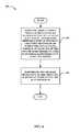
- FIGS. 4, 5 and 6are illustrations of exemplary flow diagrams of methods that facilitate contact lenses having hybrid power sources in accordance with aspects described herein.
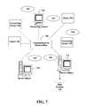
- FIG. 7is an illustration of a schematic diagram of an exemplary networked or distributed computing environment for implementing one or more aspects described herein.
- FIG. 8is an illustration of a schematic diagram of an exemplary computing environment for implementing one or more aspects described herein.
- a contact lenscan include: a substrate; and a circuit.
- the circuitcan include: one or more sensors disposed on or within the substrate; circuitry disposed on or within at least a portion of the substrate; one or more photovoltaic cells disposed on or within at least a portion of the substrate; and a hybrid power component that supplies at least one of two or more different types of power to the circuitry, wherein at least one of the two or more different types of power is RF/inductive power.
- a contact lenscan include: a substrate; and a circuit.
- the circuitcan include: one or more sensors disposed on or within the substrate; circuitry disposed on or within at least a portion of the substrate; and one or more solar cells disposed on or within at least a portion of the substrate, that supply power to the circuitry, wherein the one or more solar cells are transparent.
- a methodcan include: supplying, from a hybrid power component on or within the contact lens, at least one of two or more different types of power to circuitry disposed on or within the contact lens, wherein at least one of the two or more different types of power is RF/inductive power; and performing one or more operations, by the circuitry, in response to receiving the supplied power.
- a methodcan include: determining at least one of a type of operation performed via the contact lens or an environment outside of the contact lens; selecting a type of power based, at least, on the type of the operation or the environment outside of the contact lens; and outputting the type of the power.
- One or more aspects of the apparatus, systems and/or methods described hereincan advantageously facilitate two or more different forms of power supply on contact lenses.
- the different forms of powercan be supplied intermittently, periodically, based on conditions and the like.
- FIG. 1is an illustration of a block diagram of an exemplary non-limiting system that facilitates contact lenses having hybrid power sources in accordance with aspects described herein.
- the system 100can include a light source 106 that emits light rays 108 (resulting in light 110 incident on the contact lens 102 ), an RF reader 114 that emits RF energy 112 , a contact lens 102 positioned on an eye 104 of a wearer of the contact lens and having a circuit (not shown).
- the circuitcan include one or more sensors (not shown), a hybrid power component (not shown), photovoltaic or solar cells (not shown) and/or circuitry (not shown), disposed on or within a substrate of the contact lens 102 .
- the hybrid power componentcan supply different types of power in connection with the contact lens 102 .
- the hybrid power componentcan select a type of power to output from the hybrid power component.
- the power outputcan be supplied to the circuit, one or more sensors and/or any other portions of the contact lens 102 that employ power.
- the different types of power that the hybrid power component can outputcan include, but are not limited to, RF/inductive power, solar power and/or microelectrical mechanical systems (MEMS)-generated electric power.
- MEMSmicroelectrical mechanical systems
- the RF/inductive powercan be received from an RF reader in the geographic proximity of the contact lens 102 .
- the RF/inductive powercan be received via an antenna on the contact lens 102 .
- the solar powercan be received from sunlight and/or ambient light incident on photovoltaic cells of the contact lens 102 .
- the MEMS-based powercan be generated based, at least, on one or more MEMS devices on the contact lens 102 .
- the MEMS devicescan be adapted to generate power based, at least, on for example stress and corresponding deformation applied to the contact lens 102 when the wearer of the contact lens 102 blinks and the eyelid applies pressure to the contact lens 102 while the eyelid is closed.
- the contact lens 102can output information 116 to the RF reader 114 in response to detecting that the RF reader 114 is within a selected geographic proximity to the contact lens 102 .
- the contact lens 102can include values or information sensed by the one or more sensors.
- the system 100includes the contact lens 102 having the circuit that includes one or more sensors, one or more photovoltaic or solar cells, the microelectromechanical system (MEMS) components, RF components (e.g., antenna), a power storage and/or circuitry disposed on or within a substrate of the contact lens.
- MEMSmicroelectromechanical system
- RF componentse.g., antenna
- FIGS. 2A, 2B, 2C and 3are illustrations of block diagrams of exemplary non-limiting contact lenses having hybrid power sources in accordance with aspects described herein.
- the contact lens 200can include a substrate 202 .
- the substrate 202is formed to cover at least a portion of an iris of an eye. While not shown in FIG. 2A , in some aspects, the substrate 202 is formed as a ring. In various aspects, one or more portions of the substrate 202 can be transparent or translucent. In some aspects, the substrate 202 can be flexible or semi-rigid.
- the contact lens 200can include a circuit 204 disposed on or within the substrate 202 .
- the circuit 204can be encapsulated in the substrate 202 .
- the circuit 204can include a number of chips, photovoltaic or solar cells and/or sensors communicatively and/or electrically coupled to one another and having one or more different functions.
- the photovoltaic cellscan be single crystal silicon photovoltaic cells in some embodiments.
- the photovoltaic cellscan be formed from or include biocompatible organic dyes, thin films, organic polymers and/or nanocrystals in various aspects.
- the nanocrystalscan be based on silicon, cadmium telluride or copper indium gallium (di)selenide.
- the organic polymerscan be or include polyphenylene vinylene or copper phthalocyanine.
- the circuit 204can include one or more photovoltaic cells 203 , 205 , a sensor 206 , a power storage component 207 , a hybrid power component 208 , and/or circuitry 209 .
- the one or more photovoltaic cells 203 , 205 , sensor 206 , power storage component 207 , hybrid power component 208 and/or circuitry 209can be operably, electrically and/or communicatively coupled to one another to perform one or more functions performed on or via the contact lens 200 .
- One or more of the photovoltaic cells 203 , 205 , sensor 206 , power storage component 207 , hybrid power component 208 and/or circuitry 209can be disposed on or within the substrate 202 .
- the senor 206can sense information associated with the wearer of the contact lens 200 (or information associated with an environment outside of the contact lens). Accordingly, in various aspects, the sensor 206 can sense biological and/or chemical features. By way of example, but not limitation, the sensor 206 can sense biological and/or chemical features such as a level of lactate, glucose, cholesterol and/or urea in the body of the wearer of the contact lens 200 . In some embodiments, the sensor 206 can sense other features, including, but not limited to, pressure, light, acceleration, temperature and/or strain.
- the circuit 204can include more than one sensor.
- the sensorscan be formed in any number of different types of configurations, including, but not limited to, a circular array of sensors and/or sensors disposed along the perimeter of the substrate 202 .
- FIG. 2Billustrates a contact lens 210 having components disposed along a perimeter of the substrate 212 .
- sensors 214 , 216 , 218 , hybrid power component 224 , photovoltaic cell 220 and the circuitry 222are disposed along a perimeter of the substrate 212 .
- Other examples of configurationsinclude semi-circular arrangements, square or rectangular arrangements of components positioned around the periphery of the iris, for example, or the like.
- the sensorscan be positioned over the surface of the substrate 202 in any number of different configurations.
- FIG. 2Cillustrates a contact lens 230 having sensors 234 , 238 disposed across the surface of the substrate 232 .
- the contact lens 230can also include a hybrid power component 244 , photovoltaic cell 236 and/or circuitry 242 disposed across the surface of the substrate 232 .
- the sensors 234 , 238can be disposed across 25%, 50% or 75% of the surface of the substrate 232 .
- one or more of the sensors 234 , 238can be transparent or translucent in order to enable a wearer of the contact lens 230 to view a sufficient portion of the environment outside of the contact lens 230 .
- the one or more photovoltaic cells 203 , 205can receive light incident on the photovoltaic cells 203 , 205 .
- the lightcan be sunlight and/or ambient light.
- the photovoltaic cells 203 , 205can generate solar power based on the received light. In various aspects, the one or more photovoltaic cells 203 , 205 can output solar energy to the hybrid power component 208 .
- the one or more photovoltaic cells 203 , 205can output solar power to trickle charge a storage capacitor (not shown) of the power storage component 207 , to enable a memory (not shown) in the circuit 204 to retain state information and/or to enable the sensor 206 to sense information associated with the wearer of the contact lens 200 (or about an environment outside of the contact lens).
- the photovoltaic cells 203 , 205can convert the light received into electricity.
- the electricitycan be output at a rate that is approximately equal to the rate of discharge of the electrical charge of the storage capacitor.
- the rate of electricity output from the photovoltaic cells 203 , 205can be such that the storage capacitor receives a trickle charge.
- the power storage component 207can be or include a thin film battery.
- the one or more photovoltaic cells 203 , 205can be disposed across 25%, 50% or 75% of the surface of the substrate 202 .
- one or more of the photovoltaic cells 203 , 205can be transparent or translucent in order to enable a wearer of the contact lens 200 to view a sufficient portion of the environment outside of the contact lens 200 .
- photovoltaic cellhas been used herein, in various aspects, solar cells can be employed in lieu of or in addition to the one or more photovoltaic cells 203 , 205 .
- the power storage component 207can store power from the photovoltaic cells 203 , 205 .
- the power storage component 207can include a storage capacitor (not shown) that can store a charge based on the power stored at the power storage component 207 .
- the stored powercan be employed for one or more different functions of the contact lens 200 .
- the stored powercan be employed to retain state information in the memory of the circuitry 209 .
- the stored powercan be employed to retain state information by maintaining the memory of the circuitry 209 in an on state and/or in a state such that the state information stored in the memory is not erased.
- the circuitry 209can perform one or more functions including, but not limited to, processing information sensed by the sensor 206 , communicating with an external reader or other device (e.g., RF reader 114 of FIG. 1 ), processing information or the like. In some aspects, the circuitry 209 can determine the information (e.g., level of glucose, cholesterol urea or lactate or pressure, light, acceleration, temperature and/or strain) sensed at the sensor 206 and/or output such information.
- processing informatione.g., level of glucose, cholesterol urea or lactate or pressure, light, acceleration, temperature and/or strain
- FIG. 3is an illustration of a block diagram of an exemplary non-limiting hybrid power component that facilitates contact lenses having hybrid power sources in accordance with aspects described herein.
- one or more of the structure and/or functionality described with reference to the hybrid power component 208can be included in the hybrid power component 208 ′ (and vice versa).
- the hybrid power component 208 ′can be referred to as a hybrid power component because the component can select and/or output different types of power to the circuit of the contact lens in various aspects.
- respective power sources described hereincan be employed to provide power to a storage device (e.g., capacitor) and/or directly provide power to devices or circuitry.
- one or more of the power sourcescan be employed individually or in cooperation with other power sources (e.g., to provide load balancing, redundancy, fail-over, etc.).
- the hybrid power componentcan select optimal power source(s) to employ given state of user, device, environment, etc.
- the hybrid power component 208 ′can include a communication component 300 , power selection component 302 , power scheduling component 304 , RF/inductive power component 306 , solar power component 308 , MEMS power component 310 , memory 312 and/or logic circuit 314 .
- one or more of the communication component 300 , power selection component 302 , power scheduling component 304 , RF/inductive power component 306 , solar power component 308 , MEMS power component 310 , memory 312 and/or logic circuit 314can be electrically and/or communicatively coupled to one another to perform one or more functions of the hybrid power component 208 ′.
- the communication component 300can transmit and/or receive information.
- the communication component 300can transmit information indicative of the features sensed by the sensor 206 .
- the communication component 300can receive information or energy from an RF reader, light source or the like.
- the power selection component 302can select a type of power to output from the hybrid power component 208 ′.
- the hybrid power component 208 ′can supply different types of power to the circuitry 209 , sensor 206 and/or any other portions of the contact lens 200 .
- the different types of powercan include, but are not limited to, RF/inductive power, solar power and/or MEMS-generated electric power.
- the RF/inductive power component 306can receive RF energy from an RF reader in the geographic proximity of the contact lens 200 .
- the RF readercan be the RF reader 114 of FIG. 1 .
- the RF/inductive power component 306can include an antenna that can receive the RF energy.
- the RF/inductive power component 306can employ the received RF energy to generate RF/inductive power in some aspects.
- the RF/inductive powercan be output from the hybrid power component 208 to the sensor 206 , circuitry 209 or any of the components of the contact lens 200 .
- the solar power component 308can receive solar energy from sunlight and/or ambient light incident on the one or more photovoltaic cells 203 , 205 of the contact lens 200 .
- the solar power component 308can employ the received solar energy to generate solar power in some aspects.
- the solar powercan be output from the hybrid power component 208 ′ to the sensor 206 , circuitry 209 or any of the components of the contact lens 200 .
- the MEMS power component 310can generate electric power.
- the MEMS power component 310can include one or more MEMS devices adapted to generate power based, at least, on the stress and corresponding deformation applied to the contact lens when the wearer of the contact lens 200 blinks.
- electric powercan be output from the hybrid power component 208 ′ to the sensor 206 , circuitry 209 or any of the components of the contact lens 200 .
- the power scheduling component 304can cause the hybrid power component 208 ′ to output different types of power continually, intermittently, periodically, based upon a condition being satisfied, based on an environment outside of the contact lens 200 and/or based on the operations performed on or via the contact lens 200 , as described below in greater detail in the subsequent paragraphs.
- the power scheduling component 304can cause one or more different types of power to be supplied from the hybrid power component 208 ′ concurrently and/or in series.
- a first type of powercan be supplied and at a second time, a second type of power can be supplied.
- RF/inductive powercan be output at a first time
- solar powercan be output at a second time
- RF/inductive powercan be output again at a third time.
- the type of power outputcan be alternated between any number of different types of power. Accordingly, one or more different types of power can be intermittently output in sequence from the hybrid power component 208 ′.
- the power scheduling component 304can cause the hybrid power component 208 ′ to output the one or more different types of power based on one or more different environmental conditions (e.g., time of day, hour, weather condition indicating whether light is available to power the one or more photovoltaic cells 203 , 205 (e.g., level of fog or overcast conditions in the environment)).
- the time at which particular power is outputcan be static and/or dynamically-determined.
- the power scheduling component 304can cause the hybrid power component 208 ′ to output the one or more different types of power based on whether a particular source of power is available to the hybrid power component 208 ′. For example, if a light source is available, the hybrid power component 208 ′ can generate and output solar power. As another example, if an RF reader is available, the hybrid power component can receive RF energy from the RF reader and generate and output RF/inductive power. As another example, if neither solar nor RF energy is available (e.g., the environment is void of light and the contact lens 200 is not near an RF reader), the hybrid power supply can output MEMS-generated electric power.
- the power scheduling component 304can cause the hybrid power component 208 ′ to output the one or more different types of power based on the type of operations performed on or via the contact lens 200 (or sensor 206 or circuitry 209 of the contact lens 200 ). For example, a first type of operation can require a first level of power and a second type of operation can require a second level of power.
- the operationscan include, but are not limited to, sensing, processing, communication or any of a number of different types of operations performed on or via the circuit 204 .
- the hybrid power component 208 ′can output a type of power that meets or exceeds the level of power required for the operation to be performed.
- the power scheduling component 304can cause the hybrid power component 208 ′ to output power periodically.
- the hybrid power component 208 ′can awake and output power at periodic intervals to enable the contact lens 200 to perform sensing, communication and/or any number of other different types of functions.
- the hybrid power component 208 ′can awake at periodic intervals and the circuit 204 can output information indicative of sensed information. The information can be output to the RF reader or the like.
- the hybrid power component 208 ′can include a memory 312 and a logic circuit 314 .
- the memory 312can be a computer-readable storage medium storing computer-executable instructions and/or information for performing the functions described in this disclosure with reference to the contact lens 200 (or components thereof).
- the logic circuit 314can perform one or more of the functions described in this disclosure with reference to the contact lens 200 (or components thereof).
- the contact lens 200can include a memory and/or logic circuit separate from the memory 312 and the logic circuit 314 .
- a single memory and a single logic circuitcan be employed on the contact lens 200 .
- FIGS. 4, 5 and 6are illustrations of exemplary flow diagrams of methods that facilitate contact lenses having hybrid power sources in accordance with aspects described herein.
- method 400can include supplying, from a hybrid power component on or within the contact lens, at least one of two or more different types of power to circuitry disposed on or within the contact lens, wherein at least one of the two or more different types of power is RF/inductive power (e.g., using the hybrid power component 208 ′).
- two or more different types of powercan be supplied to the circuitry.
- solar, RF and/or MEMS-based powercan be supplied to the circuitry.
- the powercan be supplied intermittently. For example, at a first time, a first type of power can be supplied and at a second time, a second type of power can be supplied.
- the time at which a particular type of power is outputcan be static and/or dynamically-determined based on any number of factors including, but not limited to, the environment of the contact lens wearer.
- the type of power suppliedcan be based on whether a particular source of power is available to the hybrid power component. For example, if a light source is available, the hybrid power component can output solar power. As another example, if an RF reader is available, the hybrid power component can receive RF energy from the RF reader and output RF/inductive power. As another example, if neither solar nor RF energy is available (e.g., the environment is void of light and is not near an RF reader), the hybrid power supply can output MEMS-generated electric power.
- the type of power suppliedcan be based on the operations performed by the circuitry. For example, a first type of operation can require a first level of power and a second type of operation can require a second level of power.
- the hybrid power componentcan output a type of power that meets or exceeds the power required for the operation.
- method 400can include performing one or more operations, by the circuitry, in response to receiving the supplied power (e.g., using the circuit 204 ).
- the operationscan include sensing, processing, communication or any of a number of different types of operations performed on or via the circuit 204 .
- method 500can include determining at least one of a type of operation or an environment associated with the contact lens (e.g., using the hybrid power component 208 ′).
- the environmentcan be a time of day (e.g., nighttime, twilight, daytime or hour), an indicator of whether light is available to power photovoltaic cells (e.g., level of fog or overcast conditions in the environment), whether an RF reader is within a particular geographic proximity to the circuit 204 or the like.
- the operation typecan include, but is not limited to, sensing, communication or the like.
- method 500can include selecting a type of power based, at least, on the type of the operation or environment (e.g., using the hybrid power component 208 ′).
- the type of powercan be RF, solar and/or MEMS-generated power and can be determined based on whether sensing is being performed, for example.
- the type of powercan be based on whether nighttime conditions exist, for example, and solar power is not available.
- method 500can include outputting the type of the power (e.g., using the hybrid power component 208 ′).
- the powercan be output continually and/or intermittently.
- two or more different types of powercan be intermittently output in sequence from the hybrid power component.
- RF/inductive powercan be output at a first time
- solar powercan be output at a second time
- RF/inductive powercan be output again at a third time.
- the type of power outputcan be alternated between any number of different types of power.
- powercan be output periodically.
- power of a first typecan be output during a time period corresponding to a first type of operation or environmental condition while power of a second type can be output during a time period corresponding to a second type of operation or environmental condition.
- method 600can include determining whether a RF reader is within a selected geographic proximity to the contact lens (e.g., using the communication component 300 ).
- method 600can include generating RF/inductive power based, at least, on the RF reader being within the selected geographic proximity (e.g., using the hybrid power component 208 ′). For example, the RF/inductive power can be generated upon receiving a signal from the RF reader.
- method 600can include generating solar power based, at least, on the RF reader not being within the selected geographic proximity and sunlight or ambient light being received at one or more photovoltaic cells (e.g., using the hybrid power component 208 ′).
- FIG. 7provides a schematic diagram of an exemplary networked or distributed computing environment with which one or more aspects described in this disclosure can be associated.
- the distributed computing environmentincludes computing objects 710 , 712 , etc. and computing objects or devices 720 , 722 , 724 , 726 , 728 , etc., which can include programs, methods, data stores, programmable logic, etc., as represented by applications 730 , 732 , 734 , 736 , 738 .
- computing objects 710 , 712 , etc. and computing objects or devices 720 , 722 , 724 , 726 , 728 , etc.can include different devices, such as active contact lenses (and components thereof), personal digital assistants (PDAs), audio/video devices, mobile phones, MPEG-1 Audio Layer 3 (MP3) players, personal computers, laptops, tablets, etc.
- PDAspersonal digital assistants
- MP3MPEG-1 Audio Layer 3
- Each computing object 710 , 712 , etc. and computing objects or devices 720 , 722 , 724 , 726 , 728 , etc.can communicate with one or more other computing objects 710 , 712 , etc. and computing objects or devices 720 , 722 , 724 , 726 , 728 , etc. by way of the communications network 740 , either directly or indirectly.
- network 740can include other computing objects and computing devices that provide services to the system of FIG. 7 , and/or can represent multiple interconnected networks, which are not shown.
- the computing objects 710 , 712 , etc.can be Web servers, file servers, media servers, etc. with which the client computing objects or devices 720 , 722 , 724 , 726 , 728 , etc. communicate via any of a number of known protocols, such as the hypertext transfer protocol (HTTP).
- HTTPhypertext transfer protocol
- the techniques described in this disclosurecan be associated with any suitable device. It is to be understood, therefore, that handheld, portable and other computing devices (including active contact lens having circuitry or components that compute and/or perform various functions).
- the devicecan be the contact lens (or components of the contact lens) and/or reader described herein.
- the data storecan include or be included within, any of the memory described herein, any of the contact lenses described herein and/or the RF reader described herein.
- the data storecan be any repository for storing information transmitted to or received from the contact lens.
- FIG. 8illustrates an example of a suitable computing system environment 800 in which one or aspects of the aspects described in this disclosure can be implemented.
- Components of computer 810can include, but are not limited to, a processing unit 820 , a system memory 830 , and a system bus 822 that couples various system components including the system memory to the processing unit 820 .
- Computer 810typically includes a variety of computer readable media and can be any available media that can be accessed by computer 810 .
- the system memory 830can include computer storage media in the form of volatile and/or nonvolatile memory such as read only memory (ROM) and/or random access memory (RAM).
- ROMread only memory
- RAMrandom access memory
- memory 830can also include an operating system, application programs, other program components, and program data.
- a usercan enter commands and information into the computer 810 through input devices 840 (e.g., keyboard, keypad, a pointing device, a mouse, stylus, touchpad, touch screen, motion detector, camera, microphone or any other device that allows the user to interact with the computer 810 ).
- input devices 840e.g., keyboard, keypad, a pointing device, a mouse, stylus, touchpad, touch screen, motion detector, camera, microphone or any other device that allows the user to interact with the computer 810 ).
- a monitor or other type of display devicecan be also connected to the system bus 822 via an interface, such as output interface 850 .
- computerscan also include other peripheral output devices such as speakers and a printer, which can be connected through output interface 850 .
- the computer 810can operate in a networked or distributed environment using logical connections to one or more other remote computers, such as remote computer 880 .
- the remote computer 880can be a personal computer, a server, a router, a network PC, a peer device or other common network node, or any other remote media consumption or transmission device, and can include any or all of the elements described above relative to the computer 810 .
- the logical connections depicted in FIG. 8include a network 882 , such local area network (LAN) or a wide area network (WAN), but can also include other networks/buses e.g., cellular networks.
- Computer-readable storage mediacan be any available storage media that can be accessed by the computer, can be typically of a non-transitory nature, and can include both volatile and nonvolatile media, removable and non-removable media.
- Computer-readable storage mediacan be implemented in connection with any method or technology for storage of information such as computer-readable instructions, program components, structured data, or unstructured data.
- Computer-readable storage mediacan include, but are not limited to, RAM, ROM, electrically erasable programmable read only memory (EEPROM), flash memory or other memory technology, or other tangible and/or non-transitory media which can be used to store desired information.
- Computer-readable storage mediacan be accessed by one or more local or remote computing devices, e.g., via access requests, queries or other data retrieval protocols, for a variety of operations with respect to the information stored by the medium.
- the computer-readable storage mediacan be, or be included within, the memory, contact lens (or components thereof) or reader described herein.
- communications mediatypically embody computer-readable instructions, data structures, program components or other structured or unstructured data in a data signal such as a modulated data signal, e.g., a carrier wave or other transport mechanism, and includes any information delivery or transport media.
- modulated data signalrefers to a signal that has one or more of its characteristics set or changed in such a manner as to encode information in one or more signals.
- the aspects described in this disclosurecan be implemented in hardware, software, firmware, middleware, microcode, or any combination thereof.
- the processing unitscan be implemented within one or more application specific integrated circuits (ASICs), digital signal processors (DSPs), digital signal processing devices (DSPDs), programmable logic devices (PLDs), field programmable gate arrays (FPGAs), processors, controllers, micro-controllers, microprocessors and/or other electronic units designed to perform the functions described in this disclosure, or a combination thereof.
- ASICsapplication specific integrated circuits
- DSPsdigital signal processors
- DSPDsdigital signal processing devices
- PLDsprogrammable logic devices
- FPGAsfield programmable gate arrays
- processorscontrollers, micro-controllers, microprocessors and/or other electronic units designed to perform the functions described in this disclosure, or a combination thereof.
- the techniques described in this disclosurecan be implemented with components or components (e.g., procedures, functions, and so on) that perform the functions described in this disclosure.
- the software codescan be stored in memory units and executed by processors.
- the term “or”is intended to mean an inclusive “or” rather than an exclusive “or.” That is, unless specified otherwise, or clear from the context, the phrase “X employs A or B” is intended to mean any of the natural inclusive permutations. That is, the phrase “X employs A or B” is satisfied by any of the following instances: X employs A; X employs B; or X employs both A and B.
- the articles “a” and “an” as used in this application and the appended claimsshould generally be construed to mean “one or more” unless specified otherwise or clear from the context to be directed to a singular form.
Landscapes
- Physics & Mathematics (AREA)
- Health & Medical Sciences (AREA)
- Ophthalmology & Optometry (AREA)
- Optics & Photonics (AREA)
- General Health & Medical Sciences (AREA)
- General Physics & Mathematics (AREA)
- Acoustics & Sound (AREA)
- Otolaryngology (AREA)
- Photovoltaic Devices (AREA)
- Sustainable Energy (AREA)
- Sustainable Development (AREA)
- Engineering & Computer Science (AREA)
- Life Sciences & Earth Sciences (AREA)
Abstract
Description
Claims (33)
Priority Applications (2)
| Application Number | Priority Date | Filing Date | Title |
|---|---|---|---|
| US13/559,261US9523865B2 (en) | 2012-07-26 | 2012-07-26 | Contact lenses with hybrid power sources |
| US15/349,357US10120203B2 (en) | 2012-07-26 | 2016-11-11 | Contact lenses with hybrid power sources |
Applications Claiming Priority (1)
| Application Number | Priority Date | Filing Date | Title |
|---|---|---|---|
| US13/559,261US9523865B2 (en) | 2012-07-26 | 2012-07-26 | Contact lenses with hybrid power sources |
Related Child Applications (1)
| Application Number | Title | Priority Date | Filing Date |
|---|---|---|---|
| US15/349,357ContinuationUS10120203B2 (en) | 2012-07-26 | 2016-11-11 | Contact lenses with hybrid power sources |
Publications (2)
| Publication Number | Publication Date |
|---|---|
| US20140192311A1 US20140192311A1 (en) | 2014-07-10 |
| US9523865B2true US9523865B2 (en) | 2016-12-20 |
Family
ID=51060725
Family Applications (2)
| Application Number | Title | Priority Date | Filing Date |
|---|---|---|---|
| US13/559,261Active2033-05-13US9523865B2 (en) | 2012-07-26 | 2012-07-26 | Contact lenses with hybrid power sources |
| US15/349,357Active2032-08-31US10120203B2 (en) | 2012-07-26 | 2016-11-11 | Contact lenses with hybrid power sources |
Family Applications After (1)
| Application Number | Title | Priority Date | Filing Date |
|---|---|---|---|
| US15/349,357Active2032-08-31US10120203B2 (en) | 2012-07-26 | 2016-11-11 | Contact lenses with hybrid power sources |
Country Status (1)
| Country | Link |
|---|---|
| US (2) | US9523865B2 (en) |
Cited By (14)
| Publication number | Priority date | Publication date | Assignee | Title |
|---|---|---|---|---|
| US20150076909A1 (en)* | 2013-09-16 | 2015-03-19 | Google Inc. | Device With Dual Power Sources |
| US10505394B2 (en) | 2018-04-21 | 2019-12-10 | Tectus Corporation | Power generation necklaces that mitigate energy absorption in the human body |
| US10529107B1 (en) | 2018-09-11 | 2020-01-07 | Tectus Corporation | Projector alignment in a contact lens |
| US10644543B1 (en) | 2018-12-20 | 2020-05-05 | Tectus Corporation | Eye-mounted display system including a head wearable object |
| US10649233B2 (en) | 2016-11-28 | 2020-05-12 | Tectus Corporation | Unobtrusive eye mounted display |
| US10673414B2 (en) | 2018-02-05 | 2020-06-02 | Tectus Corporation | Adaptive tuning of a contact lens |
| US10790700B2 (en) | 2018-05-18 | 2020-09-29 | Tectus Corporation | Power generation necklaces with field shaping systems |
| US10838239B2 (en) | 2018-04-30 | 2020-11-17 | Tectus Corporation | Multi-coil field generation in an electronic contact lens system |
| US10838232B2 (en) | 2018-11-26 | 2020-11-17 | Tectus Corporation | Eye-mounted displays including embedded solenoids |
| US10845621B1 (en) | 2019-08-02 | 2020-11-24 | Tectus Corporation | Headgear providing inductive coupling to a contact lens, with controller |
| US10895762B2 (en) | 2018-04-30 | 2021-01-19 | Tectus Corporation | Multi-coil field generation in an electronic contact lens system |
| US20210221080A1 (en)* | 2018-06-04 | 2021-07-22 | 3M Innovative Properties Company | Thermoformed abrasion-resistant multilayer optical film and method of making the same |
| US11137622B2 (en) | 2018-07-15 | 2021-10-05 | Tectus Corporation | Eye-mounted displays including embedded conductive coils |
| US12174462B2 (en) | 2020-12-21 | 2024-12-24 | Alcon Inc. | Cosmetic functional contact lens |
Families Citing this family (33)
| Publication number | Priority date | Publication date | Assignee | Title |
|---|---|---|---|---|
| US9812096B2 (en) | 2008-01-23 | 2017-11-07 | Spy Eye, Llc | Eye mounted displays and systems using eye mounted displays |
| EP3915519A1 (en) | 2012-01-24 | 2021-12-01 | The Regents of the University of Colorado, a body corporate | Modular intraocular lens designs |
| US9364316B1 (en) | 2012-01-24 | 2016-06-14 | Clarvista Medical, Inc. | Modular intraocular lens designs, tools and methods |
| US10028824B2 (en) | 2012-01-24 | 2018-07-24 | Clarvista Medical, Inc. | Modular intraocular lens designs, tools and methods |
| US10080648B2 (en) | 2012-01-24 | 2018-09-25 | Clarvista Medical, Inc. | Modular intraocular lens designs, tools and methods |
| US9696564B1 (en) | 2012-08-21 | 2017-07-04 | Verily Life Sciences Llc | Contact lens with metal portion and polymer layer having indentations |
| US9993335B2 (en) | 2014-01-08 | 2018-06-12 | Spy Eye, Llc | Variable resolution eye mounted displays |
| ES2948036T3 (en) | 2014-02-18 | 2023-08-30 | Alcon Inc | Apparatus for resection of an intraocular lens |
| US10541342B2 (en)* | 2014-04-22 | 2020-01-21 | Lenovo (Singapore) Pte. Ltd. | Sensor with a photovoltaic cell power source |
| US10317702B2 (en) | 2014-06-13 | 2019-06-11 | Verily Life Sciences Llc | Failsafe operation of eye-mountable device |
| US9690118B2 (en) | 2014-06-13 | 2017-06-27 | Verily Life Sciences Llc | Eye-mountable device to provide automatic accommodation and method of making same |
| US9933634B2 (en) | 2014-06-13 | 2018-04-03 | Verily Life Sciences Llc | Apparatus, system and method for gaze tracking based on photodetection by an eye-mountable device |
| US9854437B1 (en) | 2014-06-13 | 2017-12-26 | Verily Life Sciences Llc | Apparatus, system and method for exchanging encrypted communications with an eye-mountable device |
| US9442310B2 (en) | 2014-06-13 | 2016-09-13 | Verily Life Sciences Llc | Capacitive gaze tracking for auto-accommodation in a contact lens |
| US9678361B2 (en) | 2014-06-13 | 2017-06-13 | Verily Life Sciences Llc | Power delivery for accommodation by an eye-mountable device |
| US9442311B2 (en) | 2014-06-13 | 2016-09-13 | Verily Life Sciences Llc | Contact lens with capacitive gaze tracking |
| US9841614B2 (en) | 2014-06-13 | 2017-12-12 | Verily Life Sciences Llc | Flexible conductor for use within a contact lens |
| EP4523656A3 (en) | 2015-01-30 | 2025-05-21 | Alcon Inc. | Modular intraocular lens designs, tools and methods |
| JP2016142981A (en)* | 2015-02-04 | 2016-08-08 | 株式会社東芝 | Self-powered display device |
| US10506206B2 (en)* | 2015-05-06 | 2019-12-10 | Dolby Laboratories Licensing Corporation | Thermal compensation in image projection |
| KR102248847B1 (en)* | 2015-06-01 | 2021-05-06 | 삼성전자주식회사 | Contact lens with an energy harvesting unit |
| CN118873298A (en) | 2015-11-04 | 2024-11-01 | 克拉维斯塔医疗有限公司 | Modular intraocular lens designs, tools and methods |
| US11045309B2 (en) | 2016-05-05 | 2021-06-29 | The Regents Of The University Of Colorado | Intraocular lens designs for improved stability |
| EP3554832B1 (en) | 2016-12-16 | 2021-06-16 | 3M Innovative Properties Company | Infrared-reflecting optically transparent assembly and method of making the same |
| US11058890B2 (en) | 2017-02-15 | 2021-07-13 | Iridex Corporation | Method and apparatus for cyclo-scanner using surface emitting lasers or LEDs |
| WO2018152020A1 (en) | 2017-02-15 | 2018-08-23 | Iridex Corporation | Method and eye mask apparatus for treating an eye using a broad area light source |
| US11382736B2 (en) | 2017-06-27 | 2022-07-12 | Alcon Inc. | Injector, intraocular lens system, and related methods |
| RU2674230C1 (en)* | 2017-07-17 | 2018-12-05 | Общество с ограниченной ответственностью "МедГранд" | Pedicle awl |
| CN112118782A (en)* | 2018-05-15 | 2020-12-22 | 国立研究开发法人科学技术振兴机构 | Measuring instrument, storage device, and measuring system |
| US11745024B2 (en) | 2018-12-27 | 2023-09-05 | Iridex Corporation | Electrical methods and devices for ophthalmic treatment |
| US20210066525A1 (en)* | 2019-09-03 | 2021-03-04 | Leo Volfson | Optical assembly with photovoltaic layer |
| US12001085B1 (en)* | 2019-09-30 | 2024-06-04 | Snap Inc. | Contact lenses with multiple power sources |
| US11357620B1 (en) | 2021-09-10 | 2022-06-14 | California LASIK & Eye, Inc. | Exchangeable optics and therapeutics |
Citations (176)
| Publication number | Priority date | Publication date | Assignee | Title |
|---|---|---|---|---|
| US3958560A (en) | 1974-11-25 | 1976-05-25 | Wayne Front March | Non-invasive automatic glucose sensor system |
| US4014321A (en) | 1974-11-25 | 1977-03-29 | March Wayne F | Non-invasive glucose sensor system |
| US4055378A (en) | 1971-12-31 | 1977-10-25 | Agfa-Gevaert Aktiengesellschaft | Silicone contact lens with hydrophilic surface treatment |
| US4122942A (en) | 1974-01-31 | 1978-10-31 | Wolfson Leonard G | Hydrophilic contact lens case |
| US4136250A (en) | 1977-07-20 | 1979-01-23 | Ciba-Geigy Corporation | Polysiloxane hydrogels |
| US4143949A (en) | 1976-10-28 | 1979-03-13 | Bausch & Lomb Incorporated | Process for putting a hydrophilic coating on a hydrophobic contact lens |
| US4153641A (en) | 1977-07-25 | 1979-05-08 | Bausch & Lomb Incorporated | Polysiloxane composition and contact lens |
| US4214014A (en) | 1977-12-16 | 1980-07-22 | Titmus Eurocon Kontaklinsen GmbH & Co. KG | Method for surface treatment of contact lenses |
| US4309085A (en) | 1979-07-12 | 1982-01-05 | Morrison Robert J | Method for measuring eye features with a contact lens |
| US4312575A (en) | 1979-09-18 | 1982-01-26 | Peyman Gholam A | Soft corneal contact lens with tightly cross-linked polymer coating and method of making same |
| US4401371A (en) | 1979-09-24 | 1983-08-30 | Neefe Charles W | Hydrogel oxygen generator with improved fluid flow |
| US4463149A (en) | 1982-03-29 | 1984-07-31 | Polymer Technology Corporation | Silicone-containing contact lens material and contact lenses made thereof |
| US4555372A (en) | 1981-03-23 | 1985-11-26 | Bausch & Lomb Incorporated | Rotational molding of contact lenses |
| US4604479A (en) | 1981-12-04 | 1986-08-05 | Polymer Technology Corporation | Silicone-containing contact lens material and contact lenses made thereof |
| US4632844A (en) | 1984-02-04 | 1986-12-30 | Japan Synthetic Rubber Co., Ltd. | Optical product having a thin film on the surface |
| US4686267A (en) | 1985-10-11 | 1987-08-11 | Polymer Technology Corporation | Fluorine containing polymeric compositions useful in contact lenses |
| US4740533A (en) | 1987-07-28 | 1988-04-26 | Ciba-Geigy Corporation | Wettable, flexible, oxygen permeable, substantially non-swellable contact lens containing block copolymer polysiloxane-polyoxyalkylene backbone units, and use thereof |
| US4826936A (en) | 1981-12-04 | 1989-05-02 | Polymer Technology Corp. | Silicone-containing contact lens material and contact lenses made thereof |
| US4996275A (en) | 1985-10-11 | 1991-02-26 | Polymer Technology Corporation | Fluorine containing polymeric compositions useful in contact lenses |
| US4997770A (en) | 1987-05-26 | 1991-03-05 | Alcoholism And Drug Addiction Res. Foundation | Method and means for detecting blood alcohol in humans by testing vapor above the eye |
| US5032658A (en) | 1989-10-17 | 1991-07-16 | Polymer Technology Corporation | Polymeric compositions useful in oxygen permeable contact lenses |
| US5034461A (en) | 1989-06-07 | 1991-07-23 | Bausch & Lomb Incorporated | Novel prepolymers useful in biomedical devices |
| US5070215A (en) | 1989-05-02 | 1991-12-03 | Bausch & Lomb Incorporated | Novel vinyl carbonate and vinyl carbamate contact lens material monomers |
| US5135297A (en) | 1990-11-27 | 1992-08-04 | Bausch & Lomb Incorporated | Surface coating of polymer objects |
| US5177168A (en) | 1989-10-17 | 1993-01-05 | Polymer Technology Corp. | Polymeric compositions useful in oxygen permeable contact lenses |
| US5177165A (en) | 1990-11-27 | 1993-01-05 | Bausch & Lomb Incorporated | Surface-active macromonomers |
| US5219965A (en) | 1990-11-27 | 1993-06-15 | Bausch & Lomb Incorporated | Surface modification of polymer objects |
| US5260000A (en) | 1992-08-03 | 1993-11-09 | Bausch & Lomb Incorporated | Process for making silicone containing hydrogel lenses |
| US5271875A (en) | 1991-09-12 | 1993-12-21 | Bausch & Lomb Incorporated | Method for molding lenses |
| EP0369942B1 (en) | 1988-11-16 | 1993-12-29 | Ciba-Geigy Ag | Colored contact lens and method of making the same |
| US5310779A (en) | 1991-11-05 | 1994-05-10 | Bausch & Lomb Incorporated | UV curable crosslinking agents useful in copolymerization |
| US5321108A (en) | 1993-02-12 | 1994-06-14 | Bausch & Lomb Incorporated | Fluorosilicone hydrogels |
| US5326584A (en) | 1989-04-24 | 1994-07-05 | Drexel University | Biocompatible, surface modified materials and method of making the same |
| US5336797A (en) | 1992-12-30 | 1994-08-09 | Bausch & Lomb Incorporated | Siloxane macromonomers |
| US5346976A (en) | 1993-03-29 | 1994-09-13 | Polymer Technology Corporation | Itaconate copolymeric compositions for contact lenses |
| US5358995A (en) | 1992-05-15 | 1994-10-25 | Bausch & Lomb Incorporated | Surface wettable silicone hydrogels |
| WO1995004609A1 (en) | 1993-08-09 | 1995-02-16 | Ciba-Geigy Ag | Hydrophilic films by plasma polymerisation |
| US5472436A (en) | 1994-07-26 | 1995-12-05 | Fremstad; Daria A. | Ocular appliance for delivering medication |
| US5585871A (en) | 1995-05-26 | 1996-12-17 | Linden; Harry | Multi-function display apparatus |
| US5616757A (en) | 1993-04-08 | 1997-04-01 | Bausch & Lomb Incorporated | Organosilicon-containing materials useful for biomedical devices |
| US5682210A (en) | 1995-12-08 | 1997-10-28 | Weirich; John | Eye contact lens video display system |
| US5708094A (en) | 1996-12-17 | 1998-01-13 | Bausch & Lomb Incorporated | Polybutadiene-based compositions for contact lenses |
| US5710302A (en) | 1995-12-07 | 1998-01-20 | Bausch & Lomb Incorporated | Monomeric units useful for reducing the modules of silicone hydrogels |
| US5714557A (en) | 1995-12-07 | 1998-02-03 | Bausch & Lomb Incorporated | Monomeric units useful for reducing the modulus of low water polymeric silicone compositions |
| US5726733A (en) | 1993-12-21 | 1998-03-10 | Bausch & Lomb Incorporated | Method for increasing hydrophilicity of contact lenses |
| US5760100A (en) | 1994-09-06 | 1998-06-02 | Ciba Vision Corporation | Extended wear ophthalmic lens |
| US5981669A (en) | 1997-12-29 | 1999-11-09 | Bausch & Lomb Incorporated | Silicone-containing prepolymers and low water materials |
| US6087941A (en) | 1998-09-01 | 2000-07-11 | Ferraz; Mark | Warning device for alerting a person falling asleep |
| US6131580A (en) | 1998-04-17 | 2000-10-17 | The University Of Washington | Template imprinted materials by RFGD plasma deposition |
| EP0686372B1 (en) | 1989-04-26 | 2001-01-17 | GLYNN, Christopher James | Device for monitoring body functions |
| US6193369B1 (en) | 1998-05-05 | 2001-02-27 | Bausch & Lomb Incorporated | Plasma surface treatment of silicone hydrogel contact lenses |
| WO2001016641A1 (en) | 1999-08-31 | 2001-03-08 | Johnson & Johnson Vision Care, Inc. | Rotationally stabilized contact lenses |
| US6200626B1 (en) | 1999-05-20 | 2001-03-13 | Bausch & Lomb Incorporated | Surface-treatment of silicone medical devices comprising an intermediate carbon coating and graft polymerization |
| US6213604B1 (en) | 1999-05-20 | 2001-04-10 | Bausch & Lomb Incorporated | Plasma surface treatment of silicone hydrogel contact lenses with a flexible carbon coating |
| WO2001034312A1 (en) | 1999-11-05 | 2001-05-17 | Bausch & Lomb Incorporated | Surface treatment of non-plasma treated silicone hydrogel contact lenses |
| US6312393B1 (en) | 1996-09-04 | 2001-11-06 | Marcio Marc A. M. Abreu | Contact device for placement in direct apposition to the conjunctive of the eye |
| US6348507B1 (en) | 1998-05-05 | 2002-02-19 | Bausch & Lomb Incorporated | Surface treatment of silicone hydrogel contact lenses |
| US6366794B1 (en) | 1998-11-20 | 2002-04-02 | The University Of Connecticut | Generic integrated implantable potentiostat telemetry unit for electrochemical sensors |
| US6428839B1 (en) | 2000-06-02 | 2002-08-06 | Bausch & Lomb Incorporated | Surface treatment of medical device |
| US6431705B1 (en) | 1999-11-10 | 2002-08-13 | Infoeye | Eyewear heart rate monitor |
| US6440571B1 (en) | 1999-05-20 | 2002-08-27 | Bausch & Lomb Incorporated | Surface treatment of silicone medical devices with reactive hydrophilic polymers |
| US6450642B1 (en) | 1999-01-12 | 2002-09-17 | California Institute Of Technology | Lenses capable of post-fabrication power modification |
| US20020193674A1 (en) | 2000-08-21 | 2002-12-19 | The Cleveland Clinic Foundation | Measurement system including a sensor mounted in a contact lens |
| US6532298B1 (en) | 1998-11-25 | 2003-03-11 | Iridian Technologies, Inc. | Portable authentication device and method using iris patterns |
| US6550915B1 (en) | 1998-12-21 | 2003-04-22 | Bausch & Lomb Incorporated | Surface treatment of fluorinated contact lens materials |
| US6570386B2 (en) | 2001-07-30 | 2003-05-27 | Hewlett-Packard Development Company, L.P. | System and method for providing power to electrical devices |
| US6579235B1 (en) | 1999-11-01 | 2003-06-17 | The Johns Hopkins University | Method for monitoring intraocular pressure using a passive intraocular pressure sensor and patient worn monitoring recorder |
| US6599559B1 (en) | 2000-04-03 | 2003-07-29 | Bausch & Lomb Incorporated | Renewable surface treatment of silicone medical devices with reactive hydrophilic polymers |
| US6614408B1 (en) | 1998-03-25 | 2003-09-02 | W. Stephen G. Mann | Eye-tap for electronic newsgathering, documentary video, photojournalism, and personal safety |
| US20030179094A1 (en) | 2002-03-08 | 2003-09-25 | Abreu Marcio Marc | Signal-to-product coupling |
| US6630243B2 (en) | 1999-05-20 | 2003-10-07 | Bausch & Lomb Incorporated | Surface treatment of silicone hydrogel contact lenses comprising hydrophilic polymer chains attached to an intermediate carbon coating |
| US6638563B2 (en) | 2000-09-19 | 2003-10-28 | Bausch & Lomb Incorporated | Method for applying renewable polymeric lens coating |
| WO2003065876A3 (en) | 2002-02-05 | 2003-10-30 | Vittorio Porciatti | Glaucoma screening system and method |
| US20040027536A1 (en) | 1999-07-02 | 2004-02-12 | Blum Ronald D. | Electro-active contact lens system |
| US6726322B2 (en) | 2000-09-28 | 2004-04-27 | Novartis Ag | Fenestrated lens for increased tear flow and method of making the same |
| US6735328B1 (en) | 2000-03-07 | 2004-05-11 | Agilent Technologies, Inc. | Personal viewing device with system for providing identification information to a connected system |
| US20040116794A1 (en)* | 2002-10-16 | 2004-06-17 | Wolfgang Fink | Optically powered and optically data-transmitting wireless intraocular pressure sensor device |
| WO2004060431A1 (en) | 2002-12-17 | 2004-07-22 | Bausch & Lomb Incorporated | Surface treatment of medical device |
| WO2004064629A1 (en) | 2003-01-21 | 2004-08-05 | Ehrfeld Miktotechnik Ag | Sensor system for detecting analytes in tear fluid |
| US6779888B2 (en) | 2000-07-28 | 2004-08-24 | Ocular Sciences, Inc. | Contact lenses with microchannels |
| US6804560B2 (en) | 1999-05-07 | 2004-10-12 | Eberhard-Karls-Universitat Tubingen Universitatsklinikum | Retina implant |
| US20040242976A1 (en)* | 2002-04-22 | 2004-12-02 | Abreu Marcio Marc | Apparatus and method for measuring biologic parameters |
| US20050045589A1 (en) | 2003-08-25 | 2005-03-03 | Sanjay Rastogi | Plasma treatment of contact lens and IOL |
| US6885818B2 (en) | 2001-07-30 | 2005-04-26 | Hewlett-Packard Development Company, L.P. | System and method for controlling electronic devices |
| US6939299B1 (en) | 1999-12-13 | 2005-09-06 | Kurt Petersen | Implantable continuous intraocular pressure sensor |
| US20050221276A1 (en) | 2002-10-11 | 2005-10-06 | Case Western Reserve University | Sensor system |
| US6980842B2 (en) | 1999-08-26 | 2005-12-27 | Novartis | Ocular analyte sensor |
| EP1061874B1 (en) | 1998-03-13 | 2006-06-07 | The Johns Hopkins University | Visual prosthesis |
| US20070016074A1 (en) | 1996-09-04 | 2007-01-18 | Abreu Marcio M | Contact lens for collecting tears and detecting analytes for determining health status, ovulation detection, and diabetes screening |
| US20070030443A1 (en) | 2003-08-07 | 2007-02-08 | Chapoy Lawrence L | Opthalmic sensor |
| WO2006015315A3 (en) | 2004-07-30 | 2007-04-19 | Univ Rochester Medical Ct | Intraocular video system |
| US20070121065A1 (en) | 2005-03-24 | 2007-05-31 | Cox David D | Device and method for tracking eye gaze direction |
| US20070188710A1 (en) | 2006-02-16 | 2007-08-16 | Hetling John R | Mapping retinal function using corneal electrode array |
| US20080076974A1 (en)* | 2006-04-28 | 2008-03-27 | Semiconductor Energy Laboratory Co., Ltd. | Biological information detection sensor device |
| US20080091090A1 (en)* | 2006-10-12 | 2008-04-17 | Kenneth Shane Guillory | Self-contained surface physiological monitor with adhesive attachment |
| US20080139953A1 (en)* | 2006-11-01 | 2008-06-12 | Welch Allyn, Inc. | Body worn physiological sensor device having a disposable electrode module |
| US7398119B2 (en) | 1998-07-13 | 2008-07-08 | Childrens Hospital Los Angeles | Assessing blood brain barrier dynamics or identifying or measuring selected substances, including ethanol or toxins, in a subject by analyzing Raman spectrum signals |
| US20080208335A1 (en) | 2007-01-22 | 2008-08-28 | Blum Ronald D | Flexible electro-active lens |
| US7423801B2 (en) | 2003-10-03 | 2008-09-09 | Invisia Ltd | Lens with SLM |
| US20080218696A1 (en) | 2005-07-01 | 2008-09-11 | Jose Mir | Non-Invasive Monitoring System |
| US7429465B2 (en) | 2002-09-13 | 2008-09-30 | Novartis Ag | Process for analyzing tear fluid |
| US7443016B2 (en) | 2005-06-07 | 2008-10-28 | Silicon Precision Industries Co., Ltd. | Semiconductor device for use as multimedia memory card, has encapsulant with chamfer such that portion of substrate and chamfer are exposed from encapsulant and remaining portion of surface of substrate is covered by encapsulant |
| US7441892B2 (en) | 2006-04-28 | 2008-10-28 | Wei-Pin Hsu | Contact lenses |
| US7450981B2 (en) | 2004-11-11 | 2008-11-11 | Samsung Electronics Co., Ltd. | Apparatus and method for measuring blood component using light trans-reflectance |
| US20090033863A1 (en) | 2007-02-23 | 2009-02-05 | Blum Ronald D | Ophthalmic dynamic aperture |
| US20090057164A1 (en) | 2007-08-31 | 2009-03-05 | Kasey Jon Minick | Contact lens packaging solutions |
| US20090076367A1 (en) | 2006-05-17 | 2009-03-19 | Mayo Foundation For Medical Education And Research | Monitoring Intraocular Pressure |
| US20090118604A1 (en) | 2007-11-02 | 2009-05-07 | Edwards Lifesciences Corporation | Analyte monitoring system having back-up power source for use in either transport of the system or primary power loss |
| WO2009094643A2 (en) | 2008-01-26 | 2009-07-30 | Deering Michael F | Systems using eye mounted displays |
| US20090189830A1 (en) | 2008-01-23 | 2009-07-30 | Deering Michael F | Eye Mounted Displays |
| US20090196460A1 (en) | 2008-01-17 | 2009-08-06 | Thomas Jakobs | Eye tracking system and method |
| EP1617757B1 (en) | 2003-03-12 | 2009-08-26 | Novartis AG | Devices for collecting analytes of interest in tears |
| US7639845B2 (en) | 2004-08-06 | 2009-12-29 | Canon Kabushiki Kaisha | Detection apparatus for detecting an amount of an object of analysis in a fluid present in an eye or on an eye surface |
| US20100001926A1 (en) | 2007-03-07 | 2010-01-07 | Washington, University Of | Contact lens with integrated light-emitting component |
| US20100013114A1 (en) | 2006-03-10 | 2010-01-21 | Roderick William Jonathan Bowers | Method of forming |
| US20100016704A1 (en) | 2008-07-16 | 2010-01-21 | Naber John F | Method and system for monitoring a condition of an eye |
| US7654671B2 (en) | 2005-01-27 | 2010-02-02 | Christopher Glynn | Device for monitoring body functions |
| US20100028559A1 (en) | 2007-03-12 | 2010-02-04 | The State Of Oregon Acting By And Through State Board Of Higher Education On Behalf Of Portland | Method for functionalizing materials and devices comprising such materials |
| US20100072643A1 (en) | 2008-09-22 | 2010-03-25 | Pugh Randall B | Binder of energized components in an ophthalmic lens |
| US7699465B2 (en) | 2006-04-12 | 2010-04-20 | Rikke Dootjes | Contact lens |
| US20100110372A1 (en) | 2008-10-31 | 2010-05-06 | Pugh Randall B | Ophthalmic device with embedded microcontroller |
| US20100109175A1 (en) | 2008-10-31 | 2010-05-06 | Pugh Randall B | Processor controlled ophthalmic device |
| US20100113901A1 (en) | 2008-10-24 | 2010-05-06 | Jin Zhang | Contact lens integrated with a biosensor for the detection of glucose and other components in tears |
| US7728949B2 (en) | 2007-01-22 | 2010-06-01 | Pixeloptics, Inc. | Electro-active lens |
| US20100133510A1 (en) | 2008-11-29 | 2010-06-03 | Electronics And Telecommunications Research Institute | Bio-sensor chip |
| US7751896B2 (en) | 2003-06-23 | 2010-07-06 | Retina Implant Ag | Active retina implant with a multiplicity of pixel elements |
| US20100191072A1 (en)* | 2009-01-23 | 2010-07-29 | Qualcomm Incorporated | Button Sensor |
| US7799243B2 (en) | 2004-03-31 | 2010-09-21 | University Of Connecticut | Shape memory main-chain smectic-C elastomers |
| WO2010105728A2 (en) | 2009-03-20 | 2010-09-23 | Retina Implant Ag | Active retinal implant |
| US20100249548A1 (en) | 2007-01-17 | 2010-09-30 | Eyesense Ag | Ocular sensor for the detection of an analyte in eye water |
| US20110015512A1 (en) | 2008-03-06 | 2011-01-20 | The Regents Of The University Of California | Measuring outflow resistance/facility of an eye |
| WO2011011344A1 (en) | 2009-07-24 | 2011-01-27 | Bausch & Lomb Incorporated | Contact lens |
| US7878650B2 (en) | 2006-06-29 | 2011-02-01 | Fritsch Michael H | Contact lens materials, designs, substances, and methods |
| US7885698B2 (en) | 2006-02-28 | 2011-02-08 | Abbott Diabetes Care Inc. | Method and system for providing continuous calibration of implantable analyte sensors |
| US20110055317A1 (en) | 2009-08-27 | 2011-03-03 | Musigy Usa, Inc. | System and Method for Pervasive Computing |
| US7907931B2 (en) | 2003-05-26 | 2011-03-15 | Securecom Technologies Limited | Portable communications device |
| WO2011034592A1 (en) | 2009-09-18 | 2011-03-24 | University Of Akron | Optical device and method for non-invasive real-time testing of blood sugar levels |
| WO2011035262A1 (en) | 2009-09-18 | 2011-03-24 | Orthomems, Inc. | Implantable ophthalmic mems sensor devices and methods for eye surgery |
| WO2011035228A1 (en) | 2009-09-18 | 2011-03-24 | Orthomems, Inc. | Implantable mems intraocular pressure sensor devices and methods for glaucoma monitoring |
| US20110084834A1 (en) | 2009-10-13 | 2011-04-14 | Anton Sabeta | Method and System for Contact Lens Care and Compliance |
| US7926940B2 (en) | 2007-02-23 | 2011-04-19 | Pixeloptics, Inc. | Advanced electro-active optic device |
| US7931832B2 (en) | 2008-03-31 | 2011-04-26 | Johnson & Johnson Vision Care, Inc. | Ophthalmic lens media insert |
| US20110157541A1 (en) | 2009-03-11 | 2011-06-30 | Peyman Gholam A | Transition lenses with virtual pupil |
| WO2011083105A1 (en) | 2010-01-05 | 2011-07-14 | Sensimed Sa | Intraocular pressure monitoring device |
| US20110184271A1 (en) | 2008-06-06 | 2011-07-28 | Jaume Veciana | Sensor contact lens, system for the non-invasive monitoring of intraocular pressure and method for measuring same |
| WO2010133317A9 (en) | 2009-05-17 | 2011-10-06 | Helmut Binder | Lens with variable refraction power for the human eye |
| US20110274680A1 (en) | 2009-10-02 | 2011-11-10 | Mazed Mohammad A | Chemical composition and its delivery for lowering the risks of alzheimer's, cardiov ascular and type-2 diabetes diseases |
| US20110286064A1 (en) | 2000-01-07 | 2011-11-24 | Barry Burles | Ophthalmic device comprising a holographic sensor |
| US20110298794A1 (en) | 2010-06-08 | 2011-12-08 | Barney Freedman | Circular polarized contact lenses and methods thereof |
| US8080187B2 (en) | 2008-02-20 | 2011-12-20 | Johnson & Johnson Vision Care, Inc. | Energized biomedical device |
| WO2011163080A1 (en) | 2010-06-20 | 2011-12-29 | Elenza, Inc. | Ophthalmic devices and methods with application specific integrated circuits |
| US8096654B2 (en) | 2007-03-07 | 2012-01-17 | University Of Washington Through Its Center For Commercialization | Active contact lens |
| US20120026458A1 (en) | 2010-07-30 | 2012-02-02 | Yongxing Qiu | Silicone hydrogel lenses with water-rich surfaces |
| US20120041552A1 (en) | 2003-01-09 | 2012-02-16 | Chuck Roy S | Implantable Devices and Methods for Measuring Intraocular, Subconjunctival or Subdermal Pressure and/or Analyte Concentration |
| US20120038881A1 (en) | 2007-11-07 | 2012-02-16 | University Of Washington | Free-standing two-sided device fabrication |
| US20120041287A1 (en) | 2008-12-04 | 2012-02-16 | Searete Llc, A Limited Liability Corporation Of The State Of Delaware | Systems, devices, and methods including implantable devices with anti-microbial properties |
| US8118752B2 (en) | 2006-02-16 | 2012-02-21 | The Board Of Trustees Of The University Of Illinois | Apparatus and methods for mapping retinal function |
| WO2012037455A1 (en) | 2010-09-16 | 2012-03-22 | Orthomems, Inc. | Expandable implantable pressure sensor for intraocular surgery |
| WO2012035429A2 (en) | 2010-09-13 | 2012-03-22 | The University Of British Columbia | Remotely controlled drug delivery systems |
| US20120068848A1 (en)* | 2010-09-15 | 2012-03-22 | Colorado State University Research Foundation | Multi-sensor environmental and physiological monitor system and methods of use |
| US20120069254A1 (en) | 2011-09-29 | 2012-03-22 | Ehren Ray Burton | Color changing contact lenses |
| US8142016B2 (en) | 2008-09-04 | 2012-03-27 | Innovega, Inc. | Method and apparatus for constructing a contact lens with optics |
| US20120078071A1 (en) | 2010-09-29 | 2012-03-29 | Dexcom, Inc. | Advanced continuous analyte monitoring system |
| US20120075168A1 (en) | 2010-09-14 | 2012-03-29 | Osterhout Group, Inc. | Eyepiece with uniformly illuminated reflective display |
| US20120075574A1 (en) | 2008-10-28 | 2012-03-29 | Pugh Randall B | Apparatus and method for activation of components of an energized ophthalmic lens |
| US20120088258A1 (en) | 2009-03-26 | 2012-04-12 | Arizona Board Of Regents, A Body Corporate Of The State Of Arizona | Integrated device for surface-contact sampling, extraction and electrochemical measurements |
| WO2012051167A1 (en) | 2010-10-11 | 2012-04-19 | William Egan | Fluid filled adjustable contact lenses |
| EP1947501B1 (en) | 2002-08-09 | 2012-04-25 | E-Vision, LLC | Electro-active contact lens system |
| US20120109296A1 (en) | 2010-10-27 | 2012-05-03 | National Tsing-Hua University | Flexible artificial retina devices |
| WO2012051223A3 (en) | 2010-10-11 | 2012-07-12 | The Regents Of The University Of California | Telescopic contact lens |
| US8224415B2 (en) | 2009-01-29 | 2012-07-17 | Abbott Diabetes Care Inc. | Method and device for providing offset model based calibration for analyte sensor |
| WO2012052765A3 (en) | 2010-10-20 | 2012-08-09 | University Of Dundee | Device for monitoring intraocular pressure |
| US20120245444A1 (en) | 2007-11-07 | 2012-09-27 | University Of Washington | Wireless powered contact lens with glucose sensor |
| US20120259188A1 (en) | 2011-04-08 | 2012-10-11 | Nxp B.V. | Flexible Eye Insert and Glucose Measuring System |
| US20120271121A1 (en)* | 2010-12-29 | 2012-10-25 | Basis Science, Inc. | Integrated Biometric Sensing and Display Device |
| US9133024B2 (en)* | 2003-09-03 | 2015-09-15 | Brigitte Chau Phan | Personal diagnostic devices including related methods and systems |
Family Cites Families (1)
| Publication number | Priority date | Publication date | Assignee | Title |
|---|---|---|---|---|
| US9675443B2 (en) | 2009-09-10 | 2017-06-13 | Johnson & Johnson Vision Care, Inc. | Energized ophthalmic lens including stacked integrated components |
- 2012
- 2012-07-26USUS13/559,261patent/US9523865B2/enactiveActive
- 2016
- 2016-11-11USUS15/349,357patent/US10120203B2/enactiveActive
Patent Citations (201)
| Publication number | Priority date | Publication date | Assignee | Title |
|---|---|---|---|---|
| US4055378A (en) | 1971-12-31 | 1977-10-25 | Agfa-Gevaert Aktiengesellschaft | Silicone contact lens with hydrophilic surface treatment |
| US4122942A (en) | 1974-01-31 | 1978-10-31 | Wolfson Leonard G | Hydrophilic contact lens case |
| US3958560A (en) | 1974-11-25 | 1976-05-25 | Wayne Front March | Non-invasive automatic glucose sensor system |
| US4014321A (en) | 1974-11-25 | 1977-03-29 | March Wayne F | Non-invasive glucose sensor system |
| US4143949A (en) | 1976-10-28 | 1979-03-13 | Bausch & Lomb Incorporated | Process for putting a hydrophilic coating on a hydrophobic contact lens |
| US4136250A (en) | 1977-07-20 | 1979-01-23 | Ciba-Geigy Corporation | Polysiloxane hydrogels |
| US4153641A (en) | 1977-07-25 | 1979-05-08 | Bausch & Lomb Incorporated | Polysiloxane composition and contact lens |
| US4214014A (en) | 1977-12-16 | 1980-07-22 | Titmus Eurocon Kontaklinsen GmbH & Co. KG | Method for surface treatment of contact lenses |
| US4309085A (en) | 1979-07-12 | 1982-01-05 | Morrison Robert J | Method for measuring eye features with a contact lens |
| US4312575A (en) | 1979-09-18 | 1982-01-26 | Peyman Gholam A | Soft corneal contact lens with tightly cross-linked polymer coating and method of making same |
| US4401371A (en) | 1979-09-24 | 1983-08-30 | Neefe Charles W | Hydrogel oxygen generator with improved fluid flow |
| US4555372A (en) | 1981-03-23 | 1985-11-26 | Bausch & Lomb Incorporated | Rotational molding of contact lenses |
| US4826936A (en) | 1981-12-04 | 1989-05-02 | Polymer Technology Corp. | Silicone-containing contact lens material and contact lenses made thereof |
| US4604479A (en) | 1981-12-04 | 1986-08-05 | Polymer Technology Corporation | Silicone-containing contact lens material and contact lenses made thereof |
| US4463149A (en) | 1982-03-29 | 1984-07-31 | Polymer Technology Corporation | Silicone-containing contact lens material and contact lenses made thereof |
| US4632844A (en) | 1984-02-04 | 1986-12-30 | Japan Synthetic Rubber Co., Ltd. | Optical product having a thin film on the surface |
| US4996275A (en) | 1985-10-11 | 1991-02-26 | Polymer Technology Corporation | Fluorine containing polymeric compositions useful in contact lenses |
| US4686267A (en) | 1985-10-11 | 1987-08-11 | Polymer Technology Corporation | Fluorine containing polymeric compositions useful in contact lenses |
| US4997770A (en) | 1987-05-26 | 1991-03-05 | Alcoholism And Drug Addiction Res. Foundation | Method and means for detecting blood alcohol in humans by testing vapor above the eye |
| US4740533A (en) | 1987-07-28 | 1988-04-26 | Ciba-Geigy Corporation | Wettable, flexible, oxygen permeable, substantially non-swellable contact lens containing block copolymer polysiloxane-polyoxyalkylene backbone units, and use thereof |
| EP0369942B1 (en) | 1988-11-16 | 1993-12-29 | Ciba-Geigy Ag | Colored contact lens and method of making the same |
| US5326584A (en) | 1989-04-24 | 1994-07-05 | Drexel University | Biocompatible, surface modified materials and method of making the same |
| EP0686372B1 (en) | 1989-04-26 | 2001-01-17 | GLYNN, Christopher James | Device for monitoring body functions |
| US5610252A (en) | 1989-05-02 | 1997-03-11 | Bausch & Lomb Incorporated | Vinyl carbonate and vinyl carbamate contact lens material monomers |
| US5070215A (en) | 1989-05-02 | 1991-12-03 | Bausch & Lomb Incorporated | Novel vinyl carbonate and vinyl carbamate contact lens material monomers |
| US5034461A (en) | 1989-06-07 | 1991-07-23 | Bausch & Lomb Incorporated | Novel prepolymers useful in biomedical devices |
| US5032658A (en) | 1989-10-17 | 1991-07-16 | Polymer Technology Corporation | Polymeric compositions useful in oxygen permeable contact lenses |
| US5177168A (en) | 1989-10-17 | 1993-01-05 | Polymer Technology Corp. | Polymeric compositions useful in oxygen permeable contact lenses |
| US5364918A (en) | 1990-11-27 | 1994-11-15 | Bausch & Lomb Incorporated | Surface modification of polymer objects |
| US5219965A (en) | 1990-11-27 | 1993-06-15 | Bausch & Lomb Incorporated | Surface modification of polymer objects |
| US5135297A (en) | 1990-11-27 | 1992-08-04 | Bausch & Lomb Incorporated | Surface coating of polymer objects |
| US5177165A (en) | 1990-11-27 | 1993-01-05 | Bausch & Lomb Incorporated | Surface-active macromonomers |
| US5271875A (en) | 1991-09-12 | 1993-12-21 | Bausch & Lomb Incorporated | Method for molding lenses |
| US5310779A (en) | 1991-11-05 | 1994-05-10 | Bausch & Lomb Incorporated | UV curable crosslinking agents useful in copolymerization |
| US5449729A (en) | 1991-11-05 | 1995-09-12 | Bausch & Lomb Incorporated | UV curable crosslinking agents useful in copolymerization |
| US5512205A (en) | 1991-11-05 | 1996-04-30 | Bausch & Lomb Incorporated | UV curable crosslinking agents useful in copolymerization |
| US5358995A (en) | 1992-05-15 | 1994-10-25 | Bausch & Lomb Incorporated | Surface wettable silicone hydrogels |
| US5260000A (en) | 1992-08-03 | 1993-11-09 | Bausch & Lomb Incorporated | Process for making silicone containing hydrogel lenses |
| US5336797A (en) | 1992-12-30 | 1994-08-09 | Bausch & Lomb Incorporated | Siloxane macromonomers |
| US5387662A (en) | 1993-02-12 | 1995-02-07 | Bausch & Lomb Incorporated | Fluorosilicone hydrogels |
| US5321108A (en) | 1993-02-12 | 1994-06-14 | Bausch & Lomb Incorporated | Fluorosilicone hydrogels |
| US5346976A (en) | 1993-03-29 | 1994-09-13 | Polymer Technology Corporation | Itaconate copolymeric compositions for contact lenses |
| US5616757A (en) | 1993-04-08 | 1997-04-01 | Bausch & Lomb Incorporated | Organosilicon-containing materials useful for biomedical devices |
| WO1995004609A1 (en) | 1993-08-09 | 1995-02-16 | Ciba-Geigy Ag | Hydrophilic films by plasma polymerisation |
| US5726733A (en) | 1993-12-21 | 1998-03-10 | Bausch & Lomb Incorporated | Method for increasing hydrophilicity of contact lenses |
| US5472436A (en) | 1994-07-26 | 1995-12-05 | Fremstad; Daria A. | Ocular appliance for delivering medication |
| US5760100B1 (en) | 1994-09-06 | 2000-11-14 | Ciba Vision Corp | Extended wear ophthalmic lens |
| US5760100A (en) | 1994-09-06 | 1998-06-02 | Ciba Vision Corporation | Extended wear ophthalmic lens |
| US5585871A (en) | 1995-05-26 | 1996-12-17 | Linden; Harry | Multi-function display apparatus |
| US5710302A (en) | 1995-12-07 | 1998-01-20 | Bausch & Lomb Incorporated | Monomeric units useful for reducing the modules of silicone hydrogels |
| US5714557A (en) | 1995-12-07 | 1998-02-03 | Bausch & Lomb Incorporated | Monomeric units useful for reducing the modulus of low water polymeric silicone compositions |
| US5908906A (en) | 1995-12-07 | 1999-06-01 | Bausch & Lomb Incorporated | Monomeric units useful for reducing the modulus of silicone hydrogels |
| US5682210A (en) | 1995-12-08 | 1997-10-28 | Weirich; John | Eye contact lens video display system |
| US7809417B2 (en) | 1996-09-04 | 2010-10-05 | Marcio Marc Abreu | Contact lens for collecting tears and detecting analytes for determining health status, ovulation detection, and diabetes screening |
| US20110028807A1 (en) | 1996-09-04 | 2011-02-03 | Marcio Marc Abreu | Contact lens for collecting tears and detecting at least one analyte |
| US20110040161A1 (en) | 1996-09-04 | 2011-02-17 | Marcio Marc Abreu | Device for generating a detectable signal based upon concentration of at least one substance |
| US6423001B1 (en) | 1996-09-04 | 2002-07-23 | Marcio Marc Abreu | Method and apparatus for signal transmission and detection using a contact device |
| US6312393B1 (en) | 1996-09-04 | 2001-11-06 | Marcio Marc A. M. Abreu | Contact device for placement in direct apposition to the conjunctive of the eye |
| US20070016074A1 (en) | 1996-09-04 | 2007-01-18 | Abreu Marcio M | Contact lens for collecting tears and detecting analytes for determining health status, ovulation detection, and diabetes screening |
| US5708094A (en) | 1996-12-17 | 1998-01-13 | Bausch & Lomb Incorporated | Polybutadiene-based compositions for contact lenses |
| US5981669A (en) | 1997-12-29 | 1999-11-09 | Bausch & Lomb Incorporated | Silicone-containing prepolymers and low water materials |
| EP1061874B1 (en) | 1998-03-13 | 2006-06-07 | The Johns Hopkins University | Visual prosthesis |
| US6614408B1 (en) | 1998-03-25 | 2003-09-02 | W. Stephen G. Mann | Eye-tap for electronic newsgathering, documentary video, photojournalism, and personal safety |
| US6131580A (en) | 1998-04-17 | 2000-10-17 | The University Of Washington | Template imprinted materials by RFGD plasma deposition |
| US6193369B1 (en) | 1998-05-05 | 2001-02-27 | Bausch & Lomb Incorporated | Plasma surface treatment of silicone hydrogel contact lenses |
| US6348507B1 (en) | 1998-05-05 | 2002-02-19 | Bausch & Lomb Incorporated | Surface treatment of silicone hydrogel contact lenses |
| US7398119B2 (en) | 1998-07-13 | 2008-07-08 | Childrens Hospital Los Angeles | Assessing blood brain barrier dynamics or identifying or measuring selected substances, including ethanol or toxins, in a subject by analyzing Raman spectrum signals |
| US6087941A (en) | 1998-09-01 | 2000-07-11 | Ferraz; Mark | Warning device for alerting a person falling asleep |
| US6366794B1 (en) | 1998-11-20 | 2002-04-02 | The University Of Connecticut | Generic integrated implantable potentiostat telemetry unit for electrochemical sensors |
| US6532298B1 (en) | 1998-11-25 | 2003-03-11 | Iridian Technologies, Inc. | Portable authentication device and method using iris patterns |
| US6550915B1 (en) | 1998-12-21 | 2003-04-22 | Bausch & Lomb Incorporated | Surface treatment of fluorinated contact lens materials |
| US6450642B1 (en) | 1999-01-12 | 2002-09-17 | California Institute Of Technology | Lenses capable of post-fabrication power modification |
| US6804560B2 (en) | 1999-05-07 | 2004-10-12 | Eberhard-Karls-Universitat Tubingen Universitatsklinikum | Retina implant |
| US6630243B2 (en) | 1999-05-20 | 2003-10-07 | Bausch & Lomb Incorporated | Surface treatment of silicone hydrogel contact lenses comprising hydrophilic polymer chains attached to an intermediate carbon coating |
| US6440571B1 (en) | 1999-05-20 | 2002-08-27 | Bausch & Lomb Incorporated | Surface treatment of silicone medical devices with reactive hydrophilic polymers |
| US6200626B1 (en) | 1999-05-20 | 2001-03-13 | Bausch & Lomb Incorporated | Surface-treatment of silicone medical devices comprising an intermediate carbon coating and graft polymerization |
| US6213604B1 (en) | 1999-05-20 | 2001-04-10 | Bausch & Lomb Incorporated | Plasma surface treatment of silicone hydrogel contact lenses with a flexible carbon coating |
| US7018040B2 (en) | 1999-07-02 | 2006-03-28 | E-Vision, Llc | Stabilized electro-active contact lens |
| US20040027536A1 (en) | 1999-07-02 | 2004-02-12 | Blum Ronald D. | Electro-active contact lens system |
| US6851805B2 (en) | 1999-07-02 | 2005-02-08 | E-Vision, Llc | Stabilized electro-active contact lens |
| US6980842B2 (en) | 1999-08-26 | 2005-12-27 | Novartis | Ocular analyte sensor |
| WO2001016641A1 (en) | 1999-08-31 | 2001-03-08 | Johnson & Johnson Vision Care, Inc. | Rotationally stabilized contact lenses |
| US6579235B1 (en) | 1999-11-01 | 2003-06-17 | The Johns Hopkins University | Method for monitoring intraocular pressure using a passive intraocular pressure sensor and patient worn monitoring recorder |
| WO2001034312A1 (en) | 1999-11-05 | 2001-05-17 | Bausch & Lomb Incorporated | Surface treatment of non-plasma treated silicone hydrogel contact lenses |
| US6431705B1 (en) | 1999-11-10 | 2002-08-13 | Infoeye | Eyewear heart rate monitor |
| US6939299B1 (en) | 1999-12-13 | 2005-09-06 | Kurt Petersen | Implantable continuous intraocular pressure sensor |
| US20110286064A1 (en) | 2000-01-07 | 2011-11-24 | Barry Burles | Ophthalmic device comprising a holographic sensor |
| US6735328B1 (en) | 2000-03-07 | 2004-05-11 | Agilent Technologies, Inc. | Personal viewing device with system for providing identification information to a connected system |
| US6599559B1 (en) | 2000-04-03 | 2003-07-29 | Bausch & Lomb Incorporated | Renewable surface treatment of silicone medical devices with reactive hydrophilic polymers |
| US6428839B1 (en) | 2000-06-02 | 2002-08-06 | Bausch & Lomb Incorporated | Surface treatment of medical device |
| US6779888B2 (en) | 2000-07-28 | 2004-08-24 | Ocular Sciences, Inc. | Contact lenses with microchannels |
| US7169106B2 (en) | 2000-08-21 | 2007-01-30 | The Cleveland Clinic Foundation | Intraocular pressure measurement system including a sensor mounted in a contact lens |
| US20020193674A1 (en) | 2000-08-21 | 2002-12-19 | The Cleveland Clinic Foundation | Measurement system including a sensor mounted in a contact lens |
| US6638563B2 (en) | 2000-09-19 | 2003-10-28 | Bausch & Lomb Incorporated | Method for applying renewable polymeric lens coating |
| US6726322B2 (en) | 2000-09-28 | 2004-04-27 | Novartis Ag | Fenestrated lens for increased tear flow and method of making the same |
| US20090036761A1 (en) | 2001-02-23 | 2009-02-05 | Marcio Marc Abreu | Noninvasive measurement of chemical substances |
| EP1818008B1 (en) | 2001-02-23 | 2011-11-02 | Marcio Marc Aurelio Martins Abreu | Noninvasive measurements of chemical substances |
| US6885818B2 (en) | 2001-07-30 | 2005-04-26 | Hewlett-Packard Development Company, L.P. | System and method for controlling electronic devices |
| US6570386B2 (en) | 2001-07-30 | 2003-05-27 | Hewlett-Packard Development Company, L.P. | System and method for providing power to electrical devices |
| WO2003065876A3 (en) | 2002-02-05 | 2003-10-30 | Vittorio Porciatti | Glaucoma screening system and method |
| US20030179094A1 (en) | 2002-03-08 | 2003-09-25 | Abreu Marcio Marc | Signal-to-product coupling |
| US20040242976A1 (en)* | 2002-04-22 | 2004-12-02 | Abreu Marcio Marc | Apparatus and method for measuring biologic parameters |
| EP1947501B1 (en) | 2002-08-09 | 2012-04-25 | E-Vision, LLC | Electro-active contact lens system |
| US7429465B2 (en) | 2002-09-13 | 2008-09-30 | Novartis Ag | Process for analyzing tear fluid |
| US7964390B2 (en) | 2002-10-11 | 2011-06-21 | Case Western Reserve University | Sensor system |
| US20050221276A1 (en) | 2002-10-11 | 2005-10-06 | Case Western Reserve University | Sensor system |
| US20120201755A1 (en) | 2002-10-11 | 2012-08-09 | George Rozakis | Sensor system |
| US7131945B2 (en) | 2002-10-16 | 2006-11-07 | California Institute Of Technology | Optically powered and optically data-transmitting wireless intraocular pressure sensor device |
| US20040116794A1 (en)* | 2002-10-16 | 2004-06-17 | Wolfgang Fink | Optically powered and optically data-transmitting wireless intraocular pressure sensor device |
| WO2004060431A1 (en) | 2002-12-17 | 2004-07-22 | Bausch & Lomb Incorporated | Surface treatment of medical device |
| US20120041552A1 (en) | 2003-01-09 | 2012-02-16 | Chuck Roy S | Implantable Devices and Methods for Measuring Intraocular, Subconjunctival or Subdermal Pressure and/or Analyte Concentration |
| WO2004064629A1 (en) | 2003-01-21 | 2004-08-05 | Ehrfeld Miktotechnik Ag | Sensor system for detecting analytes in tear fluid |
| EP1617757B1 (en) | 2003-03-12 | 2009-08-26 | Novartis AG | Devices for collecting analytes of interest in tears |
| US7907931B2 (en) | 2003-05-26 | 2011-03-15 | Securecom Technologies Limited | Portable communications device |
| US7751896B2 (en) | 2003-06-23 | 2010-07-06 | Retina Implant Ag | Active retina implant with a multiplicity of pixel elements |
| US20070030443A1 (en) | 2003-08-07 | 2007-02-08 | Chapoy Lawrence L | Opthalmic sensor |
| US20050045589A1 (en) | 2003-08-25 | 2005-03-03 | Sanjay Rastogi | Plasma treatment of contact lens and IOL |
| US9133024B2 (en)* | 2003-09-03 | 2015-09-15 | Brigitte Chau Phan | Personal diagnostic devices including related methods and systems |
| US7423801B2 (en) | 2003-10-03 | 2008-09-09 | Invisia Ltd | Lens with SLM |
| US7799243B2 (en) | 2004-03-31 | 2010-09-21 | University Of Connecticut | Shape memory main-chain smectic-C elastomers |
| WO2006015315A3 (en) | 2004-07-30 | 2007-04-19 | Univ Rochester Medical Ct | Intraocular video system |
| US7639845B2 (en) | 2004-08-06 | 2009-12-29 | Canon Kabushiki Kaisha | Detection apparatus for detecting an amount of an object of analysis in a fluid present in an eye or on an eye surface |
| US7450981B2 (en) | 2004-11-11 | 2008-11-11 | Samsung Electronics Co., Ltd. | Apparatus and method for measuring blood component using light trans-reflectance |
| US7654671B2 (en) | 2005-01-27 | 2010-02-02 | Christopher Glynn | Device for monitoring body functions |
| US20070121065A1 (en) | 2005-03-24 | 2007-05-31 | Cox David D | Device and method for tracking eye gaze direction |
| US7443016B2 (en) | 2005-06-07 | 2008-10-28 | Silicon Precision Industries Co., Ltd. | Semiconductor device for use as multimedia memory card, has encapsulant with chamfer such that portion of substrate and chamfer are exposed from encapsulant and remaining portion of surface of substrate is covered by encapsulant |
| US20080218696A1 (en) | 2005-07-01 | 2008-09-11 | Jose Mir | Non-Invasive Monitoring System |
| US8118752B2 (en) | 2006-02-16 | 2012-02-21 | The Board Of Trustees Of The University Of Illinois | Apparatus and methods for mapping retinal function |
| US20070188710A1 (en) | 2006-02-16 | 2007-08-16 | Hetling John R | Mapping retinal function using corneal electrode array |
| US7885698B2 (en) | 2006-02-28 | 2011-02-08 | Abbott Diabetes Care Inc. | Method and system for providing continuous calibration of implantable analyte sensors |
| US20100013114A1 (en) | 2006-03-10 | 2010-01-21 | Roderick William Jonathan Bowers | Method of forming |
| US7699465B2 (en) | 2006-04-12 | 2010-04-20 | Rikke Dootjes | Contact lens |
| US7441892B2 (en) | 2006-04-28 | 2008-10-28 | Wei-Pin Hsu | Contact lenses |
| US20080076974A1 (en)* | 2006-04-28 | 2008-03-27 | Semiconductor Energy Laboratory Co., Ltd. | Biological information detection sensor device |
| US20090076367A1 (en) | 2006-05-17 | 2009-03-19 | Mayo Foundation For Medical Education And Research | Monitoring Intraocular Pressure |
| US20110116035A1 (en) | 2006-06-29 | 2011-05-19 | Fritsch Michael H | Contact lens materials, designs, substances, and methods |
| US7878650B2 (en) | 2006-06-29 | 2011-02-01 | Fritsch Michael H | Contact lens materials, designs, substances, and methods |
| US20080091090A1 (en)* | 2006-10-12 | 2008-04-17 | Kenneth Shane Guillory | Self-contained surface physiological monitor with adhesive attachment |
| US20080139953A1 (en)* | 2006-11-01 | 2008-06-12 | Welch Allyn, Inc. | Body worn physiological sensor device having a disposable electrode module |
| US20100249548A1 (en) | 2007-01-17 | 2010-09-30 | Eyesense Ag | Ocular sensor for the detection of an analyte in eye water |
| US20080208335A1 (en) | 2007-01-22 | 2008-08-28 | Blum Ronald D | Flexible electro-active lens |
| US7728949B2 (en) | 2007-01-22 | 2010-06-01 | Pixeloptics, Inc. | Electro-active lens |
| US7926940B2 (en) | 2007-02-23 | 2011-04-19 | Pixeloptics, Inc. | Advanced electro-active optic device |
| US20090033863A1 (en) | 2007-02-23 | 2009-02-05 | Blum Ronald D | Ophthalmic dynamic aperture |
| US8096654B2 (en) | 2007-03-07 | 2012-01-17 | University Of Washington Through Its Center For Commercialization | Active contact lens |
| US20100001926A1 (en) | 2007-03-07 | 2010-01-07 | Washington, University Of | Contact lens with integrated light-emitting component |
| US20100028559A1 (en) | 2007-03-12 | 2010-02-04 | The State Of Oregon Acting By And Through State Board Of Higher Education On Behalf Of Portland | Method for functionalizing materials and devices comprising such materials |
| US20090057164A1 (en) | 2007-08-31 | 2009-03-05 | Kasey Jon Minick | Contact lens packaging solutions |
| US20090118604A1 (en) | 2007-11-02 | 2009-05-07 | Edwards Lifesciences Corporation | Analyte monitoring system having back-up power source for use in either transport of the system or primary power loss |
| US20120038881A1 (en) | 2007-11-07 | 2012-02-16 | University Of Washington | Free-standing two-sided device fabrication |
| US20120245444A1 (en) | 2007-11-07 | 2012-09-27 | University Of Washington | Wireless powered contact lens with glucose sensor |
| US20090196460A1 (en) | 2008-01-17 | 2009-08-06 | Thomas Jakobs | Eye tracking system and method |
| US20090189830A1 (en) | 2008-01-23 | 2009-07-30 | Deering Michael F | Eye Mounted Displays |
| WO2009094643A2 (en) | 2008-01-26 | 2009-07-30 | Deering Michael F | Systems using eye mounted displays |
| US8080187B2 (en) | 2008-02-20 | 2011-12-20 | Johnson & Johnson Vision Care, Inc. | Energized biomedical device |
| US20110015512A1 (en) | 2008-03-06 | 2011-01-20 | The Regents Of The University Of California | Measuring outflow resistance/facility of an eye |
| US20110157544A1 (en) | 2008-03-31 | 2011-06-30 | Pugh Randall B | Ophthalmic lens media insert |
| US7931832B2 (en) | 2008-03-31 | 2011-04-26 | Johnson & Johnson Vision Care, Inc. | Ophthalmic lens media insert |
| US20110184271A1 (en) | 2008-06-06 | 2011-07-28 | Jaume Veciana | Sensor contact lens, system for the non-invasive monitoring of intraocular pressure and method for measuring same |
| US20100016704A1 (en) | 2008-07-16 | 2010-01-21 | Naber John F | Method and system for monitoring a condition of an eye |
| US8142016B2 (en) | 2008-09-04 | 2012-03-27 | Innovega, Inc. | Method and apparatus for constructing a contact lens with optics |
| US20100072643A1 (en) | 2008-09-22 | 2010-03-25 | Pugh Randall B | Binder of energized components in an ophthalmic lens |
| US20100113901A1 (en) | 2008-10-24 | 2010-05-06 | Jin Zhang | Contact lens integrated with a biosensor for the detection of glucose and other components in tears |
| US20120075574A1 (en) | 2008-10-28 | 2012-03-29 | Pugh Randall B | Apparatus and method for activation of components of an energized ophthalmic lens |
| US20100110372A1 (en) | 2008-10-31 | 2010-05-06 | Pugh Randall B | Ophthalmic device with embedded microcontroller |
| US20100109175A1 (en) | 2008-10-31 | 2010-05-06 | Pugh Randall B | Processor controlled ophthalmic device |
| US20100133510A1 (en) | 2008-11-29 | 2010-06-03 | Electronics And Telecommunications Research Institute | Bio-sensor chip |
| US20120041287A1 (en) | 2008-12-04 | 2012-02-16 | Searete Llc, A Limited Liability Corporation Of The State Of Delaware | Systems, devices, and methods including implantable devices with anti-microbial properties |
| US20100191072A1 (en)* | 2009-01-23 | 2010-07-29 | Qualcomm Incorporated | Button Sensor |
| US8224415B2 (en) | 2009-01-29 | 2012-07-17 | Abbott Diabetes Care Inc. | Method and device for providing offset model based calibration for analyte sensor |
| US20110157541A1 (en) | 2009-03-11 | 2011-06-30 | Peyman Gholam A | Transition lenses with virtual pupil |
| WO2010105728A2 (en) | 2009-03-20 | 2010-09-23 | Retina Implant Ag | Active retinal implant |
| US20120088258A1 (en) | 2009-03-26 | 2012-04-12 | Arizona Board Of Regents, A Body Corporate Of The State Of Arizona | Integrated device for surface-contact sampling, extraction and electrochemical measurements |
| WO2010133317A9 (en) | 2009-05-17 | 2011-10-06 | Helmut Binder | Lens with variable refraction power for the human eye |
| US20120092612A1 (en) | 2009-05-17 | 2012-04-19 | Helmut Binder | Lens with variable refraction power for the human eye |
| EP2457122A1 (en) | 2009-07-24 | 2012-05-30 | Bausch & Lomb Incorporated | Contact lens |
| WO2011011344A1 (en) | 2009-07-24 | 2011-01-27 | Bausch & Lomb Incorporated | Contact lens |
| US20110063568A1 (en) | 2009-07-24 | 2011-03-17 | Richard Fanqing Meng | Contact lens |
| US20110055317A1 (en) | 2009-08-27 | 2011-03-03 | Musigy Usa, Inc. | System and Method for Pervasive Computing |
| WO2011035262A1 (en) | 2009-09-18 | 2011-03-24 | Orthomems, Inc. | Implantable ophthalmic mems sensor devices and methods for eye surgery |
| US20120177576A1 (en) | 2009-09-18 | 2012-07-12 | Jun Jack Hu | Optical device and method for non-invasive real-time testing of blood sugar levels |
| WO2011034592A1 (en) | 2009-09-18 | 2011-03-24 | University Of Akron | Optical device and method for non-invasive real-time testing of blood sugar levels |
| WO2011035228A1 (en) | 2009-09-18 | 2011-03-24 | Orthomems, Inc. | Implantable mems intraocular pressure sensor devices and methods for glaucoma monitoring |
| US20110274680A1 (en) | 2009-10-02 | 2011-11-10 | Mazed Mohammad A | Chemical composition and its delivery for lowering the risks of alzheimer's, cardiov ascular and type-2 diabetes diseases |
| US20110084834A1 (en) | 2009-10-13 | 2011-04-14 | Anton Sabeta | Method and System for Contact Lens Care and Compliance |
| WO2011083105A1 (en) | 2010-01-05 | 2011-07-14 | Sensimed Sa | Intraocular pressure monitoring device |
| US20110298794A1 (en) | 2010-06-08 | 2011-12-08 | Barney Freedman | Circular polarized contact lenses and methods thereof |
| WO2011163080A1 (en) | 2010-06-20 | 2011-12-29 | Elenza, Inc. | Ophthalmic devices and methods with application specific integrated circuits |
| US20120026458A1 (en) | 2010-07-30 | 2012-02-02 | Yongxing Qiu | Silicone hydrogel lenses with water-rich surfaces |
| WO2012035429A2 (en) | 2010-09-13 | 2012-03-22 | The University Of British Columbia | Remotely controlled drug delivery systems |
| US20120075168A1 (en) | 2010-09-14 | 2012-03-29 | Osterhout Group, Inc. | Eyepiece with uniformly illuminated reflective display |
| US20120068848A1 (en)* | 2010-09-15 | 2012-03-22 | Colorado State University Research Foundation | Multi-sensor environmental and physiological monitor system and methods of use |
| WO2012037455A1 (en) | 2010-09-16 | 2012-03-22 | Orthomems, Inc. | Expandable implantable pressure sensor for intraocular surgery |
| US20120078071A1 (en) | 2010-09-29 | 2012-03-29 | Dexcom, Inc. | Advanced continuous analyte monitoring system |
| WO2012051223A3 (en) | 2010-10-11 | 2012-07-12 | The Regents Of The University Of California | Telescopic contact lens |
| WO2012051167A1 (en) | 2010-10-11 | 2012-04-19 | William Egan | Fluid filled adjustable contact lenses |
| WO2012052765A3 (en) | 2010-10-20 | 2012-08-09 | University Of Dundee | Device for monitoring intraocular pressure |
| US20120109296A1 (en) | 2010-10-27 | 2012-05-03 | National Tsing-Hua University | Flexible artificial retina devices |
| US20120271121A1 (en)* | 2010-12-29 | 2012-10-25 | Basis Science, Inc. | Integrated Biometric Sensing and Display Device |
| US20120259188A1 (en) | 2011-04-08 | 2012-10-11 | Nxp B.V. | Flexible Eye Insert and Glucose Measuring System |
| US20120069254A1 (en) | 2011-09-29 | 2012-03-22 | Ehren Ray Burton | Color changing contact lenses |
Non-Patent Citations (50)
| Title |
|---|
| "Contact Lenses: Look Into My Eyes," The Economist, Jun. 2, 2011 , http://www.economist.com/node/18750624/print, Last accessed Mar. 13, 2012, 8 pages. |
| Badugu et al., "A Glucose Sensing Contact Lens: A Non-Invasive Technique for Continuous Physiological Glucose Monitoring," Journal of Fluorescence, Sep. 2003, pp. 371-374, vol. 13, No. 5. |
| Baxter, "Capacitive Sensors," 2000, 17 pages. |
| Bionic contact lens 'to project emails before eyes,' http://www.kurzweilai.net/forums/topic/bionic-contact-lens-to-project-emails-before-eyes, Last accessed Mar. 14, 2012, 2 pages. |
| Brahim, et al., "Polypyrrole-hydrogel composites for the construction of clinically important biosensors," 2002, Biosensors & Bioelectronics, vol. 17, pp. 53-59. |
| Carlson et al., "A 20 mV Input Boost Converter With Efficient Digital Control for Thermoelectric Energy Harvesting," IEEE Journal of Solid-State Circuits, Apr. 2010, pp. 741-750, vol. 45, No. 4. |
| Chen, et al., "Microfabricated Implantable Parylene-Based Wireless Passive Intraocular Pressure Sensors," Journal of Microelectromechanical Systems, Dec. 2008, vol. 17, No. 6, pp. 1342-1351. |
| Chu et al., "Biomedical soft contact-lens sensor for in situ ocular biomonitoring of tear contents," Biomed Microdevices, 2011, pp. 603-611, vol. 13. |
| Chu et al., "Soft contact lens biosensor for in situ monitoring of tear glucose as non-invasive blood sugar assessment," Talanta, 2011, pp. 960-965, vol. 83. |
| Chu, et al., "Soft Contact-lens Sensor for Monitoring Tear Sugar as Novel Wearable Device of Body Sensor Network," http://www.ksi.edu/seke/dms11/DMS/2-Kohji-Mitsubayashi.pdf, Last accessed Jul. 27, 2012, 4 pages. |
| Haders, "New Controlled Release Technologies Broaden Opportunities for Ophthalmic Therapies," Drug Delivery Technology, Jul./Aug. 2009, pp. 48-53, vol. 8, No. 7. |
| Ho et al., "Contact Lens With Integrated Inorganic Semiconductor Devices," MEMS 2008. IEEE 21st International Conference on. IEEE, 2008., pp. 403-406. |
| Holloway, "Microsoft developing electronic contact lens to monitor blood sugar," Gizmag, Jan. 5, 2012, http://www.gizmag.com/microsoft-electronic-diabetic-contact-lens/20987/, Last accessed Mar. 13, 2012. 5 pages. |
| Huang, et al., "Wrinkling of Ultrathin Polymer Films," Mater. Res. Soc. Symp. Proc., 2006, vol. 924, 6 pages, Materials Research Society. |
| Hurst, "How contact lenses could help save your life," Mail Online, Apr. 19, 2010, http://www.dailymail.co.uk/health/article-1267345/How-contact-lenses-help-save-life.html, Last accessed Jul. 27, 2012. |
| International Searching Authority, International Search Report and Written Opinion for International Application No. PCT/US2014/024124 mailed Dec. 16, 2014, 17 pages. |
| Lähdesmäki et al., "Possibilities for Continuous Glucose Monitoring by a Functional Contact Lens," IEEE Instrumentation & Measurement Magazine, Jun. 2010, pp. 14-17. |
| Liao, et al., "A 3 muW Wirelessly Powered CMOS Glucose Sensor for an Active Contact Lens," 2011 IEEE International Solid-State Circuits Conference, Session 2, Feb. 21, 2011, 3 pages. |
| Liao, et al., "A 3 μW Wirelessly Powered CMOS Glucose Sensor for an Active Contact Lens," 2011 IEEE International Solid-State Circuits Conference, Session 2, Feb. 21, 2011, 3 pages. |
| Liao, et al., "A 3-muW CMOS Glucose Sensor for Wireless Contact-Lens Tear Glucose Monitoring," IEEE Journal of Solid-State Circuits, Jan. 2012, vol. 47, No. 1, pp. 335-344. |
| Liao, et al., "A 3-μW CMOS Glucose Sensor for Wireless Contact-Lens Tear Glucose Monitoring," IEEE Journal of Solid-State Circuits, Jan. 2012, vol. 47, No. 1, pp. 335-344. |
| Lingley et al., "A contact lens with integrated micro solar cells," Microsyst Technol, 2012, pp. 453-458, vol. 18. |
| Lingley, et al., "A Single-Pixel Wireless Contact Lens Display," Journal of Micromechanics and Microengineering, 2011, 9 pages. |
| Lingley, et al., "Multipurpose integrated active contact lenses," SPIE, 2009, 2 pages. |
| Liu, et al., "Miniature Amperometric Self-Powered Continuous Glucose Sensor with Linear Response," Analytical Chemistry, 7 pages, Mar. 14, 2012. |
| Lon{hacek over (c)}ar, et al., "Design and Fabrication of Silicon Photonic Crystal Optical Waveguides," Journal of Lightwave Technology, Oct. 2000, vol. 18, No. 10, pp. 1402-1411. |
| Murdan, "Electro-responsive drug delivery from hydrogels," Journal of Controlled Release, 2003, pp. 1-17, vol. 92. |
| Pandey, et al., "A Fully Integrated RF-Powered Contact Lens With a Single Element Display," IEEE Transactions on Biomedical Circuits and Systems, Dec. 2010, vol. 4, No. 6, pages. |
| Parviz, Babak A., "Augmented Reality in a Contact Lens," IEEE Spectrum, Sep. 2009, http://spectrum.ieee.org/biomedical/bionics/augmented-reality-in-a-contact-lens/0, Last accessed Mar. 14, 2012, 6 pages. |
| Parviz, Babak A., "For Your Eyes Only," IEEE Spectrum, Sep. 2009, pp. 36-41. |
| Saeedi et al., "Self-Assembled Inorganic Micro-Display on Plastic," Micro Electro Mechanical Systems, 2007. MEMS. IEEE 20th International Conference on. IEEE, 2007., pp. 755-758. |
| Saeedi, E. et al., "Self-assembled crystalline semiconductor optoelectronics on glass and plastic," J. Micromech. Microeng., 2008, pp. 1-7, vol. 18. |
| Selner, et al., "Novel Contact Lens Electrode Array for Multi-electrode Electroretinography (meERG)," IEEE, 2011, 2 pages. |
| Sensimed Triggerfish, Sensimed Brochure, 2010, 10 pages. |
| Shih, Yi-Chun et al., "An Inductorless DC-DC Converter for Energy Harvesting With a 1.2-muW Bandgap-Referenced Output Controller," IEEE Transactions on Circuits and Systems-II: Express Briefs, Dec. 2011, pp. 832-836, vol. 58, No. 12. |
| Shih, Yi-Chun et al., "An Inductorless DC-DC Converter for Energy Harvesting With a 1.2-μW Bandgap-Referenced Output Controller," IEEE Transactions on Circuits and Systems-II: Express Briefs, Dec. 2011, pp. 832-836, vol. 58, No. 12. |
| Shum et al., "Functional modular contact lens," Proc. of SPIE, 2009, pp. 73970K-1 to 73970K-8, vol. 7397. |
| Singh , et al., "Novel Approaches in Formulation and Drug Delivery using Contact Lenses," Journal of Basic and Clinical Pharmacy, May 2011, pp. 87-101, vol. 2, Issue 2. |
| Stauth et al., "Self-assembled single-crystal silicon circuits on plastic," PNAS, Sep. 19, 2006, pp. 13922-13927, vol. 103, No. 38. |
| Thomas, et al., "Functional Contact Lenses for Remote Health Monitoring in Developing Countries," IEEE Global Humanitarian Technology Conference, 2011, pp. 212-217, IEEE Computer Society. |
| Tweedie, et al., "Contact creep compliance of viscoelastic materials via nanoindentation," J. Mater. Res., Jun. 2006, vol. 21, No. 2, pp. 1576-1589, Materials Research Society. |
| Wall, K., "Active contact lens that lets you see like the Terminator patented," Feb. 10, 2012, http://www.patexia.com/feed/active-contact-lens-that-lets-you-see-like-the-terminator-patented-2407, Last accessed Mar. 28, 2012, 5 pages. |
| Yao et al., "A contact lens with embedded sensor for monitoring tear glucose level," Biosensors and Bioelectronics, 2011, pp. 3290-3296, vol. 26. |
| Yao, H. et al., "A contact lens with integrated telecommunication circuit and sensors for wireless and continuous tear glucose monitoring," J. Micromech. Microeng., 2012, pp. 1-10, vol. 22. |
| Yao, H. et al., "A Dual Microscal Glucose Sensor on a Contact Lens, Tested in Conditions Mimicking the Eye," Micro Electro Mechanical Systems (MEMS), 2011 IEEE 24th International Conference on. IEEE, 2011, pp. 25-28. |
| Yao, H. et al., "A Soft Hydrogel Contact Lens with an Encapsulated Sensor for Tear Glucose Monitoring," Micro Electro Mechanical Systems (MEMS), 2012 IEEE 25th International Conference on. IEEE, 2012, pp. 769-772. |
| Yeager et al., "A 9 muA, Addressable Gen2 Sensor Tag for Biosignal Acquistion," IEEE Journal of Solid-State Circuits, Oct. 2010, pp. 2198-2209, vol. 45, No. 10. |
| Yeager et al., "A 9 μA, Addressable Gen2 Sensor Tag for Biosignal Acquistion," IEEE Journal of Solid-State Circuits, Oct. 2010, pp. 2198-2209, vol. 45, No. 10. |
| Zarbin, et al., "Nanotechnology in ophthalmology," Can J Ophthalmol, 2010, vol. 45, No. 5, pp. 457-476. |
| Zhang et al., "Design for Ultra-Low Power Biopotential Amplifiers for Biosignal Acquistion Applications," IEEE Transactions on Biomedical Circuits and Systems, 2012, pp. 344-355, vol. 6, No. 4. |
Cited By (19)
| Publication number | Priority date | Publication date | Assignee | Title |
|---|---|---|---|---|
| US9692230B2 (en)* | 2013-09-16 | 2017-06-27 | Verily Life Sciences Llc | Device with dual power sources |
| US20150076909A1 (en)* | 2013-09-16 | 2015-03-19 | Google Inc. | Device With Dual Power Sources |
| US11624938B2 (en) | 2016-11-28 | 2023-04-11 | Tectus Corporation | Unobtrusive eye mounted display |
| US10649233B2 (en) | 2016-11-28 | 2020-05-12 | Tectus Corporation | Unobtrusive eye mounted display |
| US11029535B2 (en) | 2016-11-28 | 2021-06-08 | Tectus Corporation | Unobtrusive eye mounted display |
| US10673414B2 (en) | 2018-02-05 | 2020-06-02 | Tectus Corporation | Adaptive tuning of a contact lens |
| US10505394B2 (en) | 2018-04-21 | 2019-12-10 | Tectus Corporation | Power generation necklaces that mitigate energy absorption in the human body |
| US10895762B2 (en) | 2018-04-30 | 2021-01-19 | Tectus Corporation | Multi-coil field generation in an electronic contact lens system |
| US10838239B2 (en) | 2018-04-30 | 2020-11-17 | Tectus Corporation | Multi-coil field generation in an electronic contact lens system |
| US10790700B2 (en) | 2018-05-18 | 2020-09-29 | Tectus Corporation | Power generation necklaces with field shaping systems |
| US20210221080A1 (en)* | 2018-06-04 | 2021-07-22 | 3M Innovative Properties Company | Thermoformed abrasion-resistant multilayer optical film and method of making the same |
| US12053945B2 (en)* | 2018-06-04 | 2024-08-06 | 3M Innovative Properties Company | Thermoformed abrasion-resistant multilayer optical film and method of making the same |
| US11137622B2 (en) | 2018-07-15 | 2021-10-05 | Tectus Corporation | Eye-mounted displays including embedded conductive coils |
| US10529107B1 (en) | 2018-09-11 | 2020-01-07 | Tectus Corporation | Projector alignment in a contact lens |
| US10838232B2 (en) | 2018-11-26 | 2020-11-17 | Tectus Corporation | Eye-mounted displays including embedded solenoids |
| US10644543B1 (en) | 2018-12-20 | 2020-05-05 | Tectus Corporation | Eye-mounted display system including a head wearable object |
| US10944290B2 (en) | 2019-08-02 | 2021-03-09 | Tectus Corporation | Headgear providing inductive coupling to a contact lens |
| US10845621B1 (en) | 2019-08-02 | 2020-11-24 | Tectus Corporation | Headgear providing inductive coupling to a contact lens, with controller |
| US12174462B2 (en) | 2020-12-21 | 2024-12-24 | Alcon Inc. | Cosmetic functional contact lens |
Also Published As
| Publication number | Publication date |
|---|---|
| US20170059881A1 (en) | 2017-03-02 |
| US10120203B2 (en) | 2018-11-06 |
| US20140192311A1 (en) | 2014-07-10 |
Similar Documents
| Publication | Publication Date | Title |
|---|---|---|
| US10120203B2 (en) | Contact lenses with hybrid power sources | |
| Mathuna et al. | Energy scavenging for long-term deployable wireless sensor networks | |
| Yang et al. | Flexible hybrid energy cell for simultaneously harvesting thermal, mechanical, and solar energies | |
| Hu et al. | Self-powered system with wireless data transmission | |
| US10083042B2 (en) | Mobile terminal and control method thereof | |
| Somov et al. | Powering IoT devices: Technologies and opportunities | |
| US11651373B2 (en) | Edge-computing-based bottom-up hierarchical architecture for data administration in a digital network | |
| US10915713B2 (en) | Apparatus, methods and computer programs for enabling information to be read from an apparatus | |
| WO2010069619A1 (en) | Arrangement and method in an electronic device for detecting a user input to a key | |
| Pourshaban et al. | Flexible and semi-transparent silicon solar cells as a power supply to smart contact lenses | |
| US20180261704A1 (en) | Monolithic integration of dissimilar photovoltaic layers in wearable devices | |
| Magno et al. | Infinitime: A multi-sensor energy neutral wearable bracelet | |
| Bouguera et al. | A novel solar energy predictor for communicating sensors | |
| US20170359018A1 (en) | Photovoltaic cell having polarization characteristic and electronic device having the same | |
| US12001085B1 (en) | Contact lenses with multiple power sources | |
| EP3117264B1 (en) | Contact lenses with hybrid power sources | |
| Schuss et al. | Efficient use of solar chargers with the help of ambient light sensors on smartphones | |
| Larus | The cloud will change everything. | |
| US10992757B2 (en) | Edge-computing-based forensic feedback architecture | |
| Lu et al. | Towards the world smallest wireless sensor nodes with low power consumption for ‘Green’sensor networks | |
| CN208589802U (en) | Charging devices and electronic equipment | |
| Drumea et al. | Study on available photovoltaic energy inside office building rooms | |
| Meredith | Indoor light harvesting for the IoT: an ideal application for organic photovoltaics? | |
| Kirby et al. | Wearable tech: why architectures matter | |
| Lupo et al. | Roadmapping: General Principles and Application to Organic and Printed Electronics |
Legal Events
| Date | Code | Title | Description |
|---|---|---|---|
| AS | Assignment | Owner name:GOOGLE INC., CALIFORNIA Free format text:ASSIGNMENT OF ASSIGNORS INTEREST;ASSIGNORS:PLETCHER, NATHAN;OTIS, BRIAN;REEL/FRAME:028650/0441 Effective date:20120724 | |
| AS | Assignment | Owner name:GOOGLE LIFE SCIENCES LLC, CALIFORNIA Free format text:ASSIGNMENT OF ASSIGNORS INTEREST;ASSIGNOR:GOOGLE INC.;REEL/FRAME:037288/0768 Effective date:20150805 | |
| AS | Assignment | Owner name:VERILY LIFE SCIENCES LLC, CALIFORNIA Free format text:CHANGE OF NAME;ASSIGNOR:GOOGLE LIFE SCIENCES LLC;REEL/FRAME:037317/0139 Effective date:20151207 | |
| STCF | Information on status: patent grant | Free format text:PATENTED CASE | |
| AS | Assignment | Owner name:GOOGLE LLC, CALIFORNIA Free format text:CHANGE OF NAME;ASSIGNOR:GOOGLE INC.;REEL/FRAME:044142/0357 Effective date:20170929 | |
| AS | Assignment | Owner name:VERILY LIFE SCIENCES LLC, CALIFORNIA Free format text:CHANGE OF NAME;ASSIGNOR:GOOGLE LIFE SCIENCES LLC;REEL/FRAME:047630/0640 Effective date:20151207 | |
| AS | Assignment | Owner name:GOOGLE LLC, CALIFORNIA Free format text:CORRECTIVE ASSIGNMENT TO CORRECT THE CORRECTIVE BY NULLIFICATIONTO CORRECT INCORRECTLY RECORDED APPLICATION NUMBERS PREVIOUSLY RECORDED ON REEL 044142 FRAME 0357. ASSIGNOR(S) HEREBY CONFIRMS THE CHANGE OF NAME;ASSIGNOR:GOOGLE INC.;REEL/FRAME:047837/0678 Effective date:20170929 | |
| MAFP | Maintenance fee payment | Free format text:PAYMENT OF MAINTENANCE FEE, 4TH YEAR, LARGE ENTITY (ORIGINAL EVENT CODE: M1551); ENTITY STATUS OF PATENT OWNER: LARGE ENTITY Year of fee payment:4 | |
| AS | Assignment | Owner name:TWENTY TWENTY THERAPEUTICS LLC, CALIFORNIA Free format text:ASSIGNMENT OF ASSIGNORS INTEREST;ASSIGNOR:VERILY LIFE SCIENCES LLC;REEL/FRAME:064163/0186 Effective date:20230606 | |
| MAFP | Maintenance fee payment | Free format text:PAYMENT OF MAINTENANCE FEE, 8TH YEAR, LARGE ENTITY (ORIGINAL EVENT CODE: M1552); ENTITY STATUS OF PATENT OWNER: LARGE ENTITY Year of fee payment:8 | |
| AS | Assignment | Owner name:VERILY LIFE SCIENCES LLC, TEXAS Free format text:ASSIGNMENT OF ASSIGNORS INTEREST;ASSIGNOR:TWENTY TWENTY THERAPEUTICS LLC;REEL/FRAME:068846/0001 Effective date:20240807 |