US9523422B2 - Flexible support structure for a geared architecture gas turbine engine - Google Patents
Flexible support structure for a geared architecture gas turbine engineDownload PDFInfo
- Publication number
- US9523422B2 US9523422B2US13/938,476US201313938476AUS9523422B2US 9523422 B2US9523422 B2US 9523422B2US 201313938476 AUS201313938476 AUS 201313938476AUS 9523422 B2US9523422 B2US 9523422B2
- Authority
- US
- United States
- Prior art keywords
- stiffness
- geared architecture
- gear
- recited
- frame
- Prior art date
- Legal status (The legal status is an assumption and is not a legal conclusion. Google has not performed a legal analysis and makes no representation as to the accuracy of the status listed.)
- Active, expires
Links
- 230000008878couplingEffects0.000claimsabstractdescription43
- 238000010168coupling processMethods0.000claimsabstractdescription43
- 238000005859coupling reactionMethods0.000claimsabstractdescription43
- 230000003068static effectEffects0.000claimsdescription11
- 238000005452bendingMethods0.000claimsdescription4
- 230000033001locomotionEffects0.000claimsdescription4
- 230000008901benefitEffects0.000description4
- 238000013461designMethods0.000description3
- 230000005540biological transmissionEffects0.000description2
- 230000009467reductionEffects0.000description2
- 238000005204segregationMethods0.000description2
- 238000004891communicationMethods0.000description1
- 230000006835compressionEffects0.000description1
- 238000007906compressionMethods0.000description1
- 239000000446fuelSubstances0.000description1
- 210000003041ligamentAnatomy0.000description1
- 238000012986modificationMethods0.000description1
- 230000004048modificationEffects0.000description1
- 230000004044responseEffects0.000description1
- 238000012360testing methodMethods0.000description1
Images


Classifications
- F—MECHANICAL ENGINEERING; LIGHTING; HEATING; WEAPONS; BLASTING
- F16—ENGINEERING ELEMENTS AND UNITS; GENERAL MEASURES FOR PRODUCING AND MAINTAINING EFFECTIVE FUNCTIONING OF MACHINES OR INSTALLATIONS; THERMAL INSULATION IN GENERAL
- F16H—GEARING
- F16H57/00—General details of gearing
- F16H57/02—Gearboxes; Mounting gearing therein
- F16H57/028—Gearboxes; Mounting gearing therein characterised by means for reducing vibration or noise
- F—MECHANICAL ENGINEERING; LIGHTING; HEATING; WEAPONS; BLASTING
- F01—MACHINES OR ENGINES IN GENERAL; ENGINE PLANTS IN GENERAL; STEAM ENGINES
- F01D—NON-POSITIVE DISPLACEMENT MACHINES OR ENGINES, e.g. STEAM TURBINES
- F01D25/00—Component parts, details, or accessories, not provided for in, or of interest apart from, other groups
- F01D25/16—Arrangement of bearings; Supporting or mounting bearings in casings
- F01D25/162—Bearing supports
- F01D25/164—Flexible supports; Vibration damping means associated with the bearing
- F—MECHANICAL ENGINEERING; LIGHTING; HEATING; WEAPONS; BLASTING
- F02—COMBUSTION ENGINES; HOT-GAS OR COMBUSTION-PRODUCT ENGINE PLANTS
- F02C—GAS-TURBINE PLANTS; AIR INTAKES FOR JET-PROPULSION PLANTS; CONTROLLING FUEL SUPPLY IN AIR-BREATHING JET-PROPULSION PLANTS
- F02C7/00—Features, components parts, details or accessories, not provided for in, or of interest apart form groups F02C1/00 - F02C6/00; Air intakes for jet-propulsion plants
- F02C7/36—Power transmission arrangements between the different shafts of the gas turbine plant, or between the gas-turbine plant and the power user
- F—MECHANICAL ENGINEERING; LIGHTING; HEATING; WEAPONS; BLASTING
- F02—COMBUSTION ENGINES; HOT-GAS OR COMBUSTION-PRODUCT ENGINE PLANTS
- F02K—JET-PROPULSION PLANTS
- F02K3/00—Plants including a gas turbine driving a compressor or a ducted fan
- F02K3/02—Plants including a gas turbine driving a compressor or a ducted fan in which part of the working fluid by-passes the turbine and combustion chamber
- F02K3/04—Plants including a gas turbine driving a compressor or a ducted fan in which part of the working fluid by-passes the turbine and combustion chamber the plant including ducted fans, i.e. fans with high volume, low pressure outputs, for augmenting the jet thrust, e.g. of double-flow type
- F02K3/06—Plants including a gas turbine driving a compressor or a ducted fan in which part of the working fluid by-passes the turbine and combustion chamber the plant including ducted fans, i.e. fans with high volume, low pressure outputs, for augmenting the jet thrust, e.g. of double-flow type with front fan
- F—MECHANICAL ENGINEERING; LIGHTING; HEATING; WEAPONS; BLASTING
- F04—POSITIVE - DISPLACEMENT MACHINES FOR LIQUIDS; PUMPS FOR LIQUIDS OR ELASTIC FLUIDS
- F04D—NON-POSITIVE-DISPLACEMENT PUMPS
- F04D25/00—Pumping installations or systems
- F04D25/02—Units comprising pumps and their driving means
- F04D25/028—Units comprising pumps and their driving means the driving means being a planetary gear
- F—MECHANICAL ENGINEERING; LIGHTING; HEATING; WEAPONS; BLASTING
- F04—POSITIVE - DISPLACEMENT MACHINES FOR LIQUIDS; PUMPS FOR LIQUIDS OR ELASTIC FLUIDS
- F04D—NON-POSITIVE-DISPLACEMENT PUMPS
- F04D29/00—Details, component parts, or accessories
- F04D29/05—Shafts or bearings, or assemblies thereof, specially adapted for elastic fluid pumps
- F04D29/053—Shafts
- F—MECHANICAL ENGINEERING; LIGHTING; HEATING; WEAPONS; BLASTING
- F04—POSITIVE - DISPLACEMENT MACHINES FOR LIQUIDS; PUMPS FOR LIQUIDS OR ELASTIC FLUIDS
- F04D—NON-POSITIVE-DISPLACEMENT PUMPS
- F04D29/00—Details, component parts, or accessories
- F04D29/05—Shafts or bearings, or assemblies thereof, specially adapted for elastic fluid pumps
- F04D29/056—Bearings
- F—MECHANICAL ENGINEERING; LIGHTING; HEATING; WEAPONS; BLASTING
- F16—ENGINEERING ELEMENTS AND UNITS; GENERAL MEASURES FOR PRODUCING AND MAINTAINING EFFECTIVE FUNCTIONING OF MACHINES OR INSTALLATIONS; THERMAL INSULATION IN GENERAL
- F16H—GEARING
- F16H1/00—Toothed gearings for conveying rotary motion
- F16H1/28—Toothed gearings for conveying rotary motion with gears having orbital motion
- F—MECHANICAL ENGINEERING; LIGHTING; HEATING; WEAPONS; BLASTING
- F05—INDEXING SCHEMES RELATING TO ENGINES OR PUMPS IN VARIOUS SUBCLASSES OF CLASSES F01-F04
- F05D—INDEXING SCHEME FOR ASPECTS RELATING TO NON-POSITIVE-DISPLACEMENT MACHINES OR ENGINES, GAS-TURBINES OR JET-PROPULSION PLANTS
- F05D2220/00—Application
- F05D2220/30—Application in turbines
- F05D2220/32—Application in turbines in gas turbines
- F05D2220/323—Application in turbines in gas turbines for aircraft propulsion, e.g. jet engines
- F—MECHANICAL ENGINEERING; LIGHTING; HEATING; WEAPONS; BLASTING
- F05—INDEXING SCHEMES RELATING TO ENGINES OR PUMPS IN VARIOUS SUBCLASSES OF CLASSES F01-F04
- F05D—INDEXING SCHEME FOR ASPECTS RELATING TO NON-POSITIVE-DISPLACEMENT MACHINES OR ENGINES, GAS-TURBINES OR JET-PROPULSION PLANTS
- F05D2260/00—Function
- F05D2260/40—Transmission of power
- F05D2260/403—Transmission of power through the shape of the drive components
- F05D2260/4031—Transmission of power through the shape of the drive components as in toothed gearing
- F05D2260/40311—Transmission of power through the shape of the drive components as in toothed gearing of the epicyclical, planetary or differential type
- F—MECHANICAL ENGINEERING; LIGHTING; HEATING; WEAPONS; BLASTING
- F05—INDEXING SCHEMES RELATING TO ENGINES OR PUMPS IN VARIOUS SUBCLASSES OF CLASSES F01-F04
- F05D—INDEXING SCHEME FOR ASPECTS RELATING TO NON-POSITIVE-DISPLACEMENT MACHINES OR ENGINES, GAS-TURBINES OR JET-PROPULSION PLANTS
- F05D2300/00—Materials; Properties thereof
- F05D2300/50—Intrinsic material properties or characteristics
- F05D2300/501—Elasticity
- Y—GENERAL TAGGING OF NEW TECHNOLOGICAL DEVELOPMENTS; GENERAL TAGGING OF CROSS-SECTIONAL TECHNOLOGIES SPANNING OVER SEVERAL SECTIONS OF THE IPC; TECHNICAL SUBJECTS COVERED BY FORMER USPC CROSS-REFERENCE ART COLLECTIONS [XRACs] AND DIGESTS
- Y02—TECHNOLOGIES OR APPLICATIONS FOR MITIGATION OR ADAPTATION AGAINST CLIMATE CHANGE
- Y02T—CLIMATE CHANGE MITIGATION TECHNOLOGIES RELATED TO TRANSPORTATION
- Y02T50/00—Aeronautics or air transport
- Y02T50/60—Efficient propulsion technologies, e.g. for aircraft
Definitions
- the present disclosurerelates to a gas turbine engine, and more particularly to a flexible support structure for a geared architecture therefor.
- Planetary and star gear trainsmay be used in gas turbine engines for their compact designs and efficient high gear reduction capabilities.
- Planetary and star gear trainsgenerally include three gear train elements: a central sun gear, an outer ring gear with internal gear teeth, and a plurality of planet gears supported by a planet carrier between and in meshed engagement with both the sun gear and the ring gear.
- the gear train elementsshare a common longitudinal central axis, about which at least two rotate.
- the central sun gearIn gas turbine engine applications, where a speed reduction transmission is required, the central sun gear generally receives rotary input from the powerplant, the outer ring gear is generally held stationary and the planet gear carrier rotates in the same direction as the sun gear to provide torque output at a reduced rotational speed.
- the planet carrierIn star gear trains, the planet carrier is held stationary and the output shaft is driven by the ring gear in a direction opposite that of the sun gear.
- a geared architecture for a gas turbine engineincludes, among other things, a fan shaft and a frame which supports the fan shaft, the frame defines a frame stiffness.
- a plurality of gearsdrives the fan shaft.
- a flexible supportat least partially supports the plurality of gears, the flexible support defines a flexible support stiffness that is less than the frame stiffness.
- An input coupling to the plurality of gears, the input couplingdefines an input coupling stiffness with respect to the frame stiffness.
- the frame and the flexible supportare mounted to a static structure of a gas turbine engine.
- the frame and the flexible supportare mounted to a front center body of a gas turbine engine.
- the input couplingis mounted to a sun gear of the gear system.
- the fan shaftis mounted to a ring gear of the gear system.
- the plurality of gearsform a star system.
- the fan shaftis mounted to a planet carrier of the gear system.
- the plurality of gearsform a planet system.
- a low speed spooldrives the input coupling.
- the flexible support stiffnessdefines at least one of a lateral stiffness and a transverse stiffness
- the frame stiffnessdefines at least one of a lateral stiffness and a transverse stiffness
- the input coupling stiffnessdefines at least one of a lateral stiffness and a transverse stiffness
- At least one of the flexible support stiffness and the input coupling stiffnessare less than about 20% of the frame stiffness.
- the flexible support stiffness and the input coupling stiffnessare each less than about 20% of the frame stiffness.
- At least one of the flexible support stiffness and the input coupling stiffnessare less than about 11% of the frame stiffness.
- the flexible support stiffness and the input coupling stiffnessare each less than about 11% of the frame stiffness.
- the framesupports the fan shaft and defines the frame stiffness is a K-frame bearing support, the K-frame bearing support supporting a bearing system that supports the fan shaft.
- a geared architecture for a gas turbine engineincludes, among other things, a fan shaft, a frame which supports the fan shaft and a plurality of gears which drives the fan shaft, the plurality of gears includes a gear mesh that defines a gear mesh.
- a flexible supportat least partially supports the plurality of gears, the flexible support defines a flexible support stiffness that is less than a gear mesh stiffness and an input coupling to the plurality of gears, the input coupling defines an input coupling stiffness with respect to the gear mesh stiffness.
- the flexible support stiffnessdefines at least one of a lateral stiffness and a transverse stiffness
- the gear mesh stiffnessdefines at least one of a lateral stiffness and a transverse stiffness
- the input coupling stiffnessdefines at least one of a lateral stiffness and a transverse stiffness
- the flexible support stiffnessis less than about 8% of the gear mesh stiffness.
- the input coupling stiffnessis less than about 5% of the gear mesh stiffness.
- At least one of a lateral stiffness and a transverse stiffness of a ring gear of the plurality of gearsis less than about 20% of the gear mesh stiffness.
- At least one of a lateral stiffness and a transverse stiffness of a ring gear of the plurality of gearsis less than about 12% of the gear mesh stiffness.
- At least one of a lateral stiffness and a transverse stiffness of a planet journal bearing which supports a planet gear of the plurality of gearsis less than or equal to the gear mesh stiffness.
- the gear mesh stiffnessis defined between a sun gear and a multiple planet gears of the plurality of gears.
- the plurality of gearsfloats with the fan shaft.
- a planet journal bearing which supports a planet gear of the plurality of gearsdefines at least one of a lateral stiffness and a transverse stiffness with respect to the gear mesh stiffness.
- a ring gear of the plurality of gearsdefines at least one of a lateral stiffness and a transverse stiffness with respect to the gear mesh stiffness.
- FIG. 1is a schematic cross-section of a gas turbine engine
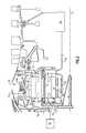
- FIG. 2is an enlarged cross-section of a section of the gas turbine engine which illustrates a fan drive gear system (FDGS);
- FDGSfan drive gear system
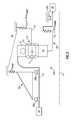
- FIG. 3is a schematic view of a flex mount arrangement for one non-limiting embodiment of the FDGS
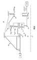
- FIG. 4is a schematic view of a flex mount arrangement for another non-limiting embodiment of the FDGS
- FIG. 5is a schematic view of a flex mount arrangement for another non-limiting embodiment of a star system FDGS.
- FIG. 6is a schematic view of a flex mount arrangement for another non-limiting embodiment of a planetary system FDGS.
- FIG. 7is a schematic view of a flex mount arrangement for another non-limiting embodiment of a star system FDGS.
- FIG. 8is a schematic view of a flex mount arrangement for another non-limiting embodiment of a planetary system FDGS.
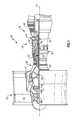
- FIG. 1schematically illustrates a gas turbine engine 20 .
- the gas turbine engine 20is disclosed herein as a two-spool turbofan that generally incorporates a fan section 22 , a compressor section 24 , a combustor section 26 and a turbine section 28 .
- Alternative enginesmight include an augmentor section (not shown) among other systems or features.
- the fan section 22drives air along a bypass flowpath while the compressor section 24 drives air along a core flowpath for compression and communication into the combustor section 26 then expansion through the turbine section 28 .
- turbofan gas turbine enginein the disclosed non-limiting embodiment, it should be understood that the concepts described herein are not limited to use with turbofans as the teachings may be applied to other types of turbine engines such as a three-spool architecture gas turbine engine and an open rotor (unducted fan) engine.
- the engine 20generally includes a low speed spool 30 and a high speed spool 32 mounted for rotation about an engine central longitudinal axis A relative to an engine static structure 36 via several bearing systems 38 A- 38 C. It should be understood that various bearing systems 38 at various locations may alternatively or additionally be provided.
- the low speed spool 30generally includes an inner shaft 40 that interconnects a fan 42 , a low pressure compressor 44 and a low pressure turbine 46 .
- the inner shaft 40is connected to the fan 42 through a geared architecture 48 to drive the fan 42 at a lower speed than the low speed spool 30 .
- the high speed spool 32includes an outer shaft 50 that interconnects a high pressure compressor 52 and high pressure turbine 54 .
- a combustor 56is arranged between the high pressure compressor 52 and the high pressure turbine 54 .
- the inner shaft 40 and the outer shaft 50are concentric and rotate about the engine central longitudinal axis A which is collinear with their longitudinal axes.
- the core airflowis compressed by the low pressure compressor 44 then the high pressure compressor 52 , mixed and burned with fuel in the combustor 56 , then expanded over the high pressure turbine 54 and low pressure turbine 46 .
- the turbines 46 , 54rotationally drive the respective low speed spool 30 and high speed spool 32 in response to the expansion of the airflow passing therethrough.
- the geared architecture 48generally includes a fan drive gear system (FDGS) 60 driven by the low speed spool 30 (illustrated schematically) through an input coupling 62 .
- the input coupling 62both transfers torque from the low speed spool 30 to the geared architecture 48 and facilitates the segregation of vibrations and other transients therebetween.
- the FDGS 60may include an epicyclic gear system which may be, for example, a star system or a planet system.
- the input coupling 62may include an interface spline 64 joined, by a gear spline 66 , to a sun gear 68 of the FDGS 60 .
- the sun gear 68is in meshed engagement with multiple planet gears 70 , of which the illustrated planet gear 70 is representative.
- Each planet gear 70is rotatably mounted in a planet carrier 72 by a respective planet journal bearing 75 .
- Rotary motion of the sun gear 68urges each planet gear 70 to rotate about a respective longitudinal axis P.
- Each planet gear 70is also in meshed engagement with rotating ring gear 74 that is mechanically connected to a fan shaft 76 . Since the planet gears 70 mesh with both the rotating ring gear 74 as well as the rotating sun gear 68 , the planet gears 70 rotate about their own axes to drive the ring gear 74 to rotate about engine axis A. The rotation of the ring gear 74 is conveyed to the fan 42 ( FIG. 1 ) through the fan shaft 76 to thereby drive the fan 42 at a lower speed than the low speed spool 30 . It should be understood that the described geared architecture 48 is but a single non-limiting embodiment and that various other geared architectures will alternatively benefit herefrom.
- a flexible support 78supports the planet carrier 72 to at least partially support the FDGS 60 A with respect to the static structure 36 such as a front center body which facilitates the segregation of vibrations and other transients therebetween.
- the static structure 36such as a front center body which facilitates the segregation of vibrations and other transients therebetween.
- various gas turbine engine case structuresmay alternatively or additionally provide the static structure and flexible support 78 .
- the term “lateral” as used hereinrefers to a perpendicular direction with respect to the axis of rotation A and the term “transverse” refers to a pivotal bending movement with respect to the axis of rotation A so as to absorb deflections which may be otherwise applied to the FDGS 60 .
- the static structure 36may further include a number 1 and 1.5 bearing support static structure 82 which is commonly referred to as a “K-frame” which supports the number 1 and number 1.5 bearing systems 38 A. 38 B.
- K-frame bearing supportdefines a lateral stiffness (represented as Kframe in FIG. 3 ) and a transverse stiffness (represented as Kframe BEND in FIG. 3 ) as the referenced factors in this non-limiting embodiment.
- the lateral stiffness (KFS; KIC) of both the flexible support 78 and the input coupling 62are each less than about 11% of the lateral stiffness (Kframe).
- the lateral stiffness (KFS; KIC) of both the flexible support 78 and the input coupling 62are each less than about 20% of the lateral stiffness (Kframe). That is, the lateral stiffness of the entire FDGS 60 is controlled by this lateral stiffness relationship.
- the transverse stiffness of both the flexible support 78 and the input coupling 62are each less than about 11% of the transverse stiffness (Kframe BEND ). That is, the transverse stiffness of the entire FDGS 60 is controlled by this transverse stiffness relationship.
- a FDGS 60 Bincludes a flexible support 78 ′ that supports a rotationally fixed ring gear 74 ′.
- the fan shaft 76 ′is driven by the planet carrier 72 ′ in the schematically illustrated planet system which otherwise generally follows the star system architecture of FIG. 3 .
- lateral stiffness relationship within a FDGS 60 C itselfis schematically represented.
- the lateral stiffness (KIC) of an input coupling 62 , a lateral stiffness (KFS) of a flexible support 78 , a lateral stiffness (KRG) of a ring gear 74 and a lateral stiffness (KJB) of a planet journal bearing 75are controlled with respect to a lateral stiffness (KGM) of a gear mesh within the FDGS 60 .
- the stiffness (KGM)may be defined by the gear mesh between the sun gear 68 and the multiple planet gears 70 .
- the lateral stiffness (KGM) within the FDGS 60is the referenced factor and the static structure 82 ′ rigidly supports the fan shaft 76 . That is, the fan shaft 76 is supported upon bearing systems 38 A, 38 B which are essentially rigidly supported by the static structure 82 ′.
- the lateral stiffness (KJB)may be mechanically defined by, for example, the stiffness within the planet journal bearing 75 and the lateral stiffness (KRG) of the ring gear 74 may be mechanically defined by, for example, the geometry of the ring gear wings 74 L, 74 R ( FIG. 2 ).
- the lateral stiffness (KRG) of the ring gear 74is less than about 12% of the lateral stiffness (KGM) of the gear mesh; the lateral stiffness (KFS) of the flexible support 78 is less than about 8% of the lateral stiffness (KGM) of the gear mesh; the lateral stiffness (KJB) of the planet journal bearing 75 is less than or equal to the lateral stiffness (KGM) of the gear mesh; and the lateral stiffness (KIC) of an input coupling 62 is less than about 5% of the lateral stiffness (KGM) of the gear mesh.
- the lateral stiffness (KRG) of the ring gear 74is less than about 20% of the lateral stiffness (KGM) of the gear mesh.
- FIG. 6another non-limiting embodiment of a lateral stiffness relationship within a FDGS 60 D itself are schematically illustrated for a planetary gear system architecture, which otherwise generally follows the star system architecture of FIG. 5 .
- lateral stiffness relationshipsmay be utilized as well.
- the lateral stiffness of each of structural componentsmay be readily measured as compared to film stiffness and spline stiffness which may be relatively difficult to determine.
- the flex mountfacilitates alignment to increase system life and reliability.
- the lateral flexibility in the flexible support and input couplingallows the FDGS to essentially ‘float’ with the fan shaft during maneuvers. This allows: (a) the torque transmissions in the fan shaft, the input coupling and the flexible support to remain constant during maneuvers; (b) maneuver induced lateral loads in the fan shaft (which may otherwise potentially misalign gears and damage teeth) to be mainly reacted to through the number 1 and 1.5 bearing support K-frame; and (c) both the flexible support and the input coupling to transmit small amounts of lateral loads into the FDGS.
- the splines, gear tooth stiffness, journal bearings, and ring gear ligamentsare specifically designed to minimize gear tooth stress variations during maneuvers.
- the other connections to the FDGSare flexible mounts (turbine coupling, case flex mount). These mount spring rates have been determined from analysis and proven in rig and flight testing to isolate the gears from engine maneuver loads.
- the planet journal bearing spring ratemay also be controlled to support system flexibility.
- FIG. 7is similar to FIG. 5 but shows the transverse stiffness relationships within the FDGS 60 C (for a star system architecture).
- the transverse stiffness (KIC BEND ) of the input coupling 62 , a transverse stiffness (KFS BEND ) of the flexible support 78 , a transverse stiffness (KRG BEND ) of the ring gear 74 and a transverse stiffness (KJB BEND ) of the planet journal bearing 75are controlled with respect to a transverse stiffness (KGM BEND ) of the gear mesh within the FDGS 60 .
- the stiffness (KGM BEND )may be defined by the gear mesh between the sun gear 68 and the multiple planet gears 70 .
- the transverse stiffness (KGM BEND ) within the FDGS 60is the referenced factor and the static structure 82 ′ rigidly supports the fan shaft 76 . That is, the fan shaft 76 is supported upon bearing systems 38 A, 38 B which are essentially rigidly supported by the static structure 82 ′.
- the transverse stiffness (KJB BEND )may be mechanically defined by, for example, the stiffness within the planet journal bearing 75 and the transverse stiffness (KRG BEND ) of the ring gear 74 may be mechanically defined by, for example, the geometry of the ring gear wings 74 L, 74 R ( FIG. 2 ).
- the transverse stiffness (KRG BEND ) of the ring gear 74is less than about 12% of the transverse stiffness (KGM BEND ) of the gear mesh; the transverse stiffness (KFS BEND ) of the flexible support 78 is less than about 8% of the transverse stiffness (KGM BEND ) of the gear mesh; the transverse stiffness (KJB BEND ) of the planet journal bearing 75 is less than or equal to the transverse stiffness (KGM BEND ) of the gear mesh; and the transverse stiffness (KIC BEND ) of an input coupling 62 is less than about 5% of the transverse stiffness (KGM BEND ) of the gear mesh.
- FIG. 8is similar to FIG. 6 but shows the transverse stiffness relationship within the FDGS 60 D for the planetary gear system architecture.
Landscapes
- Engineering & Computer Science (AREA)
- General Engineering & Computer Science (AREA)
- Mechanical Engineering (AREA)
- Chemical & Material Sciences (AREA)
- Combustion & Propulsion (AREA)
- Retarders (AREA)
Abstract
Description
Claims (22)
Priority Applications (1)
| Application Number | Priority Date | Filing Date | Title |
|---|---|---|---|
| US13/938,476US9523422B2 (en) | 2011-06-08 | 2013-07-10 | Flexible support structure for a geared architecture gas turbine engine |
Applications Claiming Priority (4)
| Application Number | Priority Date | Filing Date | Title |
|---|---|---|---|
| US201161494453P | 2011-06-08 | 2011-06-08 | |
| US13/342,508US8297916B1 (en) | 2011-06-08 | 2012-01-03 | Flexible support structure for a geared architecture gas turbine engine |
| US13/623,309US9133729B1 (en) | 2011-06-08 | 2012-09-20 | Flexible support structure for a geared architecture gas turbine engine |
| US13/938,476US9523422B2 (en) | 2011-06-08 | 2013-07-10 | Flexible support structure for a geared architecture gas turbine engine |
Related Parent Applications (1)
| Application Number | Title | Priority Date | Filing Date |
|---|---|---|---|
| US13/623,309ContinuationUS9133729B1 (en) | 2011-06-08 | 2012-09-20 | Flexible support structure for a geared architecture gas turbine engine |
Publications (2)
| Publication Number | Publication Date |
|---|---|
| US20130331224A1 US20130331224A1 (en) | 2013-12-12 |
| US9523422B2true US9523422B2 (en) | 2016-12-20 |
Family
ID=49715757
Family Applications (5)
| Application Number | Title | Priority Date | Filing Date |
|---|---|---|---|
| US13/938,476Active2033-05-26US9523422B2 (en) | 2011-06-08 | 2013-07-10 | Flexible support structure for a geared architecture gas turbine engine |
| US13/938,466Active2033-08-31US9410608B2 (en) | 2011-06-08 | 2013-07-10 | Flexible support structure for a geared architecture gas turbine engine |
| US15/185,292Active2034-03-24US10539222B2 (en) | 2011-06-08 | 2016-06-17 | Flexible support structure for a geared architecture gas turbine engine |
| US16/747,934Active2032-01-04US11174936B2 (en) | 2011-06-08 | 2020-01-21 | Flexible support structure for a geared architecture gas turbine engine |
| US17/505,015Active2032-01-05US12163582B2 (en) | 2011-06-08 | 2021-10-19 | Flexible support structure for a geared architecture gas turbine engine |
Family Applications After (4)
| Application Number | Title | Priority Date | Filing Date |
|---|---|---|---|
| US13/938,466Active2033-08-31US9410608B2 (en) | 2011-06-08 | 2013-07-10 | Flexible support structure for a geared architecture gas turbine engine |
| US15/185,292Active2034-03-24US10539222B2 (en) | 2011-06-08 | 2016-06-17 | Flexible support structure for a geared architecture gas turbine engine |
| US16/747,934Active2032-01-04US11174936B2 (en) | 2011-06-08 | 2020-01-21 | Flexible support structure for a geared architecture gas turbine engine |
| US17/505,015Active2032-01-05US12163582B2 (en) | 2011-06-08 | 2021-10-19 | Flexible support structure for a geared architecture gas turbine engine |
Country Status (1)
| Country | Link |
|---|---|
| US (5) | US9523422B2 (en) |
Cited By (9)
| Publication number | Priority date | Publication date | Assignee | Title |
|---|---|---|---|---|
| US20170298770A1 (en)* | 2011-06-08 | 2017-10-19 | United Technologies Corporation | Flexible support structure for a geared architecture gas turbine engine |
| US10539222B2 (en) | 2011-06-08 | 2020-01-21 | United Technologies Corporation | Flexible support structure for a geared architecture gas turbine engine |
| US10677087B2 (en) | 2018-05-11 | 2020-06-09 | General Electric Company | Support structure for geared turbomachine |
| US10823003B2 (en) | 2018-05-25 | 2020-11-03 | General Electric Company | System and method for mitigating undesired vibrations at a turbo machine |
| US11047337B2 (en) | 2011-06-08 | 2021-06-29 | Raytheon Technologies Corporation | Geared architecture for high speed and small volume fan drive turbine |
| US11060584B2 (en)* | 2018-05-29 | 2021-07-13 | Ge Avio S.R.L. | Gear assembly mount for gas turbine engine |
| US11493407B2 (en) | 2018-09-28 | 2022-11-08 | Ge Avio S.R.L. | Torque measurement system |
| US11970984B2 (en) | 2012-04-02 | 2024-04-30 | Rtx Corporation | Gas turbine engine with power density range |
| US12366179B2 (en) | 2012-01-31 | 2025-07-22 | Rtx Corporation | Gas turbine engine with high speed low pressure turbine section and bearing support features |
Families Citing this family (22)
| Publication number | Priority date | Publication date | Assignee | Title |
|---|---|---|---|---|
| US9863326B2 (en)* | 2013-03-12 | 2018-01-09 | United Technologies Corporation | Flexible coupling for geared turbine engine |
| FR3010449B1 (en)* | 2013-09-06 | 2015-09-25 | Snecma | ROTARY ASSEMBLY COMPRISING A TRANSMISSION MEMBER AND AN OIL DISTRIBUTION SYSTEM |
| WO2015156885A2 (en)* | 2014-01-22 | 2015-10-15 | United Technologies Corporation | Flexible support structure for a geared architecture gas turbine engine |
| US10119465B2 (en) | 2015-06-23 | 2018-11-06 | United Technologies Corporation | Geared turbofan with independent flexible ring gears and oil collectors |
| US9869205B2 (en) | 2015-11-23 | 2018-01-16 | General Electric Company | Bearing outer race retention during high load events |
| US10196980B2 (en) | 2016-02-08 | 2019-02-05 | General Electric Company | Bearing outer race retention during high load events |
| US10041534B2 (en) | 2016-02-08 | 2018-08-07 | General Electric Company | Bearing outer race retention during high load events |
| ITUA20162733A1 (en)* | 2016-04-20 | 2017-10-20 | Ge Avio Srl | OIL TRANSFER UNIT TO TRANSFER OIL BETWEEN A STATIC PART AND A ROTATING PART |
| US10323541B2 (en) | 2017-03-15 | 2019-06-18 | General Electric Company | Bearing outer race retention during high load events |
| EP3441575B1 (en) | 2017-08-11 | 2021-12-01 | General Electric Company Polska sp. z o.o. | Turbine engine |
| GB201917773D0 (en) | 2019-12-05 | 2020-01-22 | Rolls Royce Plc | High power epicyclic gearbox and operation thereof |
| CN110067771B (en)* | 2019-05-22 | 2025-03-04 | 苏州顺福利智能科技有限公司 | Axis-stable fan bearing system |
| FR3096744B1 (en)* | 2019-06-03 | 2022-01-14 | Safran Aircraft Engines | AIRCRAFT TURBOMACHINE DRIVE SHAFT SUPPORT AND GUIDE ASSEMBLY |
| US10794222B1 (en) | 2019-08-14 | 2020-10-06 | General Electric Company | Spring flower ring support assembly for a bearing |
| GB201917774D0 (en) | 2019-12-05 | 2020-01-22 | Rolls Royce Plc | Gas turbine engine arrangement |
| GB201917777D0 (en) | 2019-12-05 | 2020-01-22 | Rolls Royce Plc | High power epicyclic gearbox and operation thereof |
| GB201917781D0 (en) | 2019-12-05 | 2020-01-22 | Rolls Royce Plc | Reliable gearbox for gas turbine engine |
| GB201917765D0 (en) | 2019-12-05 | 2020-01-22 | Rolls Royce Plc | Aircraft engine |
| GB201917764D0 (en) | 2019-12-05 | 2020-01-22 | Rolls Royce Plc | Reliable gearbox for gas turbine engine |
| US20210301763A1 (en) | 2020-03-26 | 2021-09-30 | Rolls-Royce Plc | Gas turbine engine |
| US11828235B2 (en) | 2020-12-08 | 2023-11-28 | General Electric Company | Gearbox for a gas turbine engine utilizing shape memory alloy dampers |
| US12168960B2 (en) | 2023-05-15 | 2024-12-17 | General Electric Company | Gas turbine engine |
Citations (56)
| Publication number | Priority date | Publication date | Assignee | Title |
|---|---|---|---|---|
| US3287906A (en) | 1965-07-20 | 1966-11-29 | Gen Motors Corp | Cooled gas turbine vanes |
| US3754484A (en) | 1971-01-08 | 1973-08-28 | Secr Defence | Gearing |
| US3892358A (en) | 1971-03-17 | 1975-07-01 | Gen Electric | Nozzle seal |
| GB1516041A (en) | 1977-02-14 | 1978-06-28 | Secr Defence | Multistage axial flow compressor stators |
| US4130872A (en) | 1975-10-10 | 1978-12-19 | The United States Of America As Represented By The Secretary Of The Air Force | Method and system of controlling a jet engine for avoiding engine surge |
| GB2041090A (en) | 1979-01-31 | 1980-09-03 | Rolls Royce | By-pass gas turbine engines |
| EP0253548A2 (en) | 1986-07-15 | 1988-01-20 | Savyon Diagnostics Ltd. | Method for the determination of occult blood and chemical compositions therefor |
| US5433674A (en) | 1994-04-12 | 1995-07-18 | United Technologies Corporation | Coupling system for a planetary gear train |
| US5447411A (en) | 1993-06-10 | 1995-09-05 | Martin Marietta Corporation | Light weight fan blade containment system |
| US5524847A (en) | 1993-09-07 | 1996-06-11 | United Technologies Corporation | Nacelle and mounting arrangement for an aircraft engine |
| US5778659A (en) | 1994-10-20 | 1998-07-14 | United Technologies Corporation | Variable area fan exhaust nozzle having mechanically separate sleeve and thrust reverser actuation systems |
| US5857836A (en) | 1996-09-10 | 1999-01-12 | Aerodyne Research, Inc. | Evaporatively cooled rotor for a gas turbine engine |
| US5915917A (en) | 1994-12-14 | 1999-06-29 | United Technologies Corporation | Compressor stall and surge control using airflow asymmetry measurement |
| US5975841A (en) | 1997-10-03 | 1999-11-02 | Thermal Corp. | Heat pipe cooling for turbine stators |
| US6073439A (en) | 1997-03-05 | 2000-06-13 | Rolls-Royce Plc | Ducted fan gas turbine engine |
| US6223616B1 (en) | 1999-12-22 | 2001-05-01 | United Technologies Corporation | Star gear system with lubrication circuit and lubrication method therefor |
| US6260351B1 (en) | 1998-12-10 | 2001-07-17 | United Technologies Corporation | Controlled spring rate gearbox mount |
| US6318070B1 (en) | 2000-03-03 | 2001-11-20 | United Technologies Corporation | Variable area nozzle for gas turbine engines driven by shape memory alloy actuators |
| US6663530B2 (en) | 2001-12-14 | 2003-12-16 | Pratt & Whitney Canada Corp. | Zero twist carrier |
| US6735954B2 (en) | 2001-12-21 | 2004-05-18 | Pratt & Whitney Canada Corp. | Offset drive for gas turbine engine |
| US6814541B2 (en) | 2002-10-07 | 2004-11-09 | General Electric Company | Jet aircraft fan case containment design |
| US6895741B2 (en) | 2003-06-23 | 2005-05-24 | Pratt & Whitney Canada Corp. | Differential geared turbine engine with torque modulation capability |
| US7021042B2 (en) | 2002-12-13 | 2006-04-04 | United Technologies Corporation | Geartrain coupling for a turbofan engine |
| US7104918B2 (en) | 2003-07-29 | 2006-09-12 | Pratt & Whitney Canada Corp. | Compact epicyclic gear carrier |
| US7144349B2 (en) | 2004-04-06 | 2006-12-05 | Pratt & Whitney Canada Corp. | Gas turbine gearbox |
| WO2007038674A1 (en) | 2005-09-28 | 2007-04-05 | Entrotech Composites, Llc | Braid-reinforced composites and processes for their preparation |
| US20070214795A1 (en) | 2006-03-15 | 2007-09-20 | Paul Cooker | Continuous real time EGT margin control |
| US20080044276A1 (en)* | 2006-08-15 | 2008-02-21 | Mccune Michael E | Ring gear mounting arrangement with oil scavenge scheme |
| US20080098713A1 (en) | 2006-10-27 | 2008-05-01 | Robert Joseph Orlando | Gas turbine engine assembly and methods of assembling same |
| US7451592B2 (en) | 2004-03-19 | 2008-11-18 | Rolls-Royce Plc | Counter-rotating turbine engine including a gearbox |
| US7591754B2 (en) | 2006-03-22 | 2009-09-22 | United Technologies Corporation | Epicyclic gear train integral sun gear coupling design |
| US7631484B2 (en) | 2006-03-13 | 2009-12-15 | Rollin George Giffin | High pressure ratio aft fan |
| US7665293B2 (en) | 2007-08-02 | 2010-02-23 | Florida Turbine Technologies, Inc. | Low speed rotor shaft for a small twin spool gas turbine engine |
| US7704178B2 (en) | 2006-07-05 | 2010-04-27 | United Technologies Corporation | Oil baffle for gas turbine fan drive gear system |
| US20100105516A1 (en) | 2006-07-05 | 2010-04-29 | United Technologies Corporation | Coupling system for a star gear train in a gas turbine engine |
| US20100148396A1 (en) | 2007-04-17 | 2010-06-17 | General Electric Company | Methods of making articles having toughened and untoughened regions |
| US7841165B2 (en) | 2006-10-31 | 2010-11-30 | General Electric Company | Gas turbine engine assembly and methods of assembling same |
| US7841163B2 (en) | 2006-11-13 | 2010-11-30 | Hamilton Sundstrand Corporation | Turbofan emergency generator |
| US20100331139A1 (en) | 2009-06-25 | 2010-12-30 | United Technologies Corporation | Epicyclic gear system with superfinished journal bearing |
| EP2270361A2 (en) | 2009-06-26 | 2011-01-05 | United Technologies Corporation | Epicyclic gear system with load share reduction |
| US7926260B2 (en) | 2006-07-05 | 2011-04-19 | United Technologies Corporation | Flexible shaft for gas turbine engine |
| US20110116510A1 (en) | 2009-10-14 | 2011-05-19 | Vss Monitoring, Inc. | System, method and apparatus for distributing captured data packets including tunneling identifiers |
| US20110130246A1 (en) | 2009-11-30 | 2011-06-02 | United Technologies Corporation | Mounting system for a planatary gear train in a gas turbine engine |
| US7959532B2 (en) | 2004-12-01 | 2011-06-14 | United Technologies Corporation | Hydraulic seal for a gearbox of a tip turbine engine |
| US8001763B2 (en) | 2007-06-25 | 2011-08-23 | United Technologies Corporation | Managing spool bearing load using variable area flow nozzle |
| US20110286836A1 (en)* | 2010-05-24 | 2011-11-24 | Davis Todd A | Geared turbofan engine with integral gear and bearing supports |
| US8172717B2 (en) | 2011-06-08 | 2012-05-08 | General Electric Company | Compliant carrier wall for improved gearbox load sharing |
| US8205432B2 (en) | 2007-10-03 | 2012-06-26 | United Technologies Corporation | Epicyclic gear train for turbo fan engine |
| US8297916B1 (en) | 2011-06-08 | 2012-10-30 | United Technologies Corporation | Flexible support structure for a geared architecture gas turbine engine |
| EP2551488A2 (en) | 2011-07-29 | 2013-01-30 | United Technologies Corporation | Three spool engine bearing configuration |
| CA2789325A1 (en) | 2011-10-27 | 2013-04-27 | United Technologies Corporation | Gas turbine engine front center body architecture |
| CA2789465A1 (en) | 2011-10-27 | 2013-04-27 | United Technologies Corporation | Gas turbine engine front center body architecture |
| US20130219913A1 (en) | 2012-02-28 | 2013-08-29 | Michael E. McCune | Geared turbofan gas turbine engine with reliability check on gear connection |
| US20130224003A1 (en) | 2012-02-28 | 2013-08-29 | Daniel Bernard Kupratis | Gas turbine engine with fan-tied inducer section |
| WO2014047040A1 (en) | 2012-09-20 | 2014-03-27 | United Technologies Corporation | Flexible support structure for a geared architecture gas turbine engine |
| US20140174056A1 (en) | 2008-06-02 | 2014-06-26 | United Technologies Corporation | Gas turbine engine with low stage count low pressure turbine |
Family Cites Families (238)
| Publication number | Priority date | Publication date | Assignee | Title |
|---|---|---|---|---|
| US3111005A (en) | 1963-11-19 | Jet propulsion plant | ||
| US791754A (en) | 1903-10-23 | 1905-06-06 | Ai Root Co | Beehive. |
| US1090416A (en) | 1913-04-10 | 1914-03-17 | Karl H Roth | Knife. |
| US2258792A (en) | 1941-04-12 | 1941-10-14 | Westinghouse Electric & Mfg Co | Turbine blading |
| US2608821A (en) | 1949-10-08 | 1952-09-02 | Gen Electric | Contrarotating turbojet engine having independent bearing supports for each turbocompressor |
| US3021731A (en) | 1951-11-10 | 1962-02-20 | Wilhelm G Stoeckicht | Planetary gear transmission |
| US2748623A (en) | 1952-02-05 | 1956-06-05 | Boeing Co | Orbit gear controlled reversible planetary transmissions |
| US2936655A (en) | 1955-11-04 | 1960-05-17 | Gen Motors Corp | Self-aligning planetary gearing |
| US3033002A (en) | 1957-11-08 | 1962-05-08 | Fairfield Shipbuilding And Eng | Marine propulsion steam turbine installations |
| US3185857A (en) | 1960-02-01 | 1965-05-25 | Lear Siegler Inc | Control apparatus for the parallel operation of alternators |
| GB969579A (en) | 1962-11-09 | 1964-09-09 | Rolls Royce | Gas turbine engine |
| US3172717A (en) | 1963-02-26 | 1965-03-09 | Clewes Antony Brasher | Electrical contact and edge connector for such contact |
| US3194487A (en) | 1963-06-04 | 1965-07-13 | United Aircraft Corp | Noise abatement method and apparatus |
| US3352178A (en) | 1965-11-15 | 1967-11-14 | Gen Motors Corp | Planetary gearing |
| US3412560A (en) | 1966-08-03 | 1968-11-26 | Gen Motors Corp | Jet propulsion engine with cooled combustion chamber, fuel heater, and induced air-flow |
| GB1313841A (en) | 1967-01-18 | 1973-04-18 | Secr Defence | Gas turbine jet propulsion engine |
| GB1135129A (en) | 1967-09-15 | 1968-11-27 | Rolls Royce | Gas turbine engine |
| US3527054A (en) | 1969-01-23 | 1970-09-08 | Gen Electric | Pressurization of lubrication sumps in gas turbine engines |
| US3664612A (en) | 1969-12-22 | 1972-05-23 | Boeing Co | Aircraft engine variable highlight inlet |
| GB1309721A (en) | 1971-01-08 | 1973-03-14 | Secr Defence | Fan |
| US3765623A (en) | 1971-10-04 | 1973-10-16 | Mc Donnell Douglas Corp | Air inlet |
| US3747343A (en) | 1972-02-10 | 1973-07-24 | United Aircraft Corp | Low noise prop-fan |
| GB1418905A (en) | 1972-05-09 | 1975-12-24 | Rolls Royce | Gas turbine engines |
| US3861139A (en) | 1973-02-12 | 1975-01-21 | Gen Electric | Turbofan engine having counterrotating compressor and turbine elements and unique fan disposition |
| US3843277A (en) | 1973-02-14 | 1974-10-22 | Gen Electric | Sound attenuating inlet duct |
| US3988889A (en) | 1974-02-25 | 1976-11-02 | General Electric Company | Cowling arrangement for a turbofan engine |
| US3932058A (en) | 1974-06-07 | 1976-01-13 | United Technologies Corporation | Control system for variable pitch fan propulsor |
| GB1521465A (en)* | 1974-09-04 | 1978-08-16 | Vickers Ltd | Gearboxes |
| US3935558A (en) | 1974-12-11 | 1976-01-27 | United Technologies Corporation | Surge detector for turbine engines |
| US4084861A (en)* | 1976-11-11 | 1978-04-18 | United Technologies Corporation | Thrust bearing damping means |
| US4201513A (en) | 1976-12-07 | 1980-05-06 | Rolls-Royce (1971) Limited | Gas turbine engines |
| US4136286A (en) | 1977-07-05 | 1979-01-23 | Woodward Governor Company | Isolated electrical power generation system with multiple isochronous, load-sharing engine-generator units |
| US4240250A (en) | 1977-12-27 | 1980-12-23 | The Boeing Company | Noise reducing air inlet for gas turbine engines |
| US4275557A (en) | 1978-01-25 | 1981-06-30 | General Electric Company | Method and apparatus for controlling thrust in a gas turbine engine |
| US4233555A (en) | 1979-04-05 | 1980-11-11 | Dyna Technology, Inc. | Alternating current generator for providing three phase and single phase power at different respective voltages |
| US4284174A (en) | 1979-04-18 | 1981-08-18 | Avco Corporation | Emergency oil/mist system |
| US4220171A (en) | 1979-05-14 | 1980-09-02 | The United States Of America As Represented By The Administrator Of The National Aeronautics And Space Administration | Curved centerline air intake for a gas turbine engine |
| US4405892A (en) | 1979-07-19 | 1983-09-20 | Brunswick Corporation | Regulator for a generator energized battery |
| US4289360A (en) | 1979-08-23 | 1981-09-15 | General Electric Company | Bearing damper system |
| DE2940446C2 (en) | 1979-10-05 | 1982-07-08 | B. Braun Melsungen Ag, 3508 Melsungen | Cultivation of animal cells in suspension and monolayer cultures in fermentation vessels |
| US4304522A (en) | 1980-01-15 | 1981-12-08 | Pratt & Whitney Aircraft Of Canada Limited | Turbine bearing support |
| FR2506840A1 (en) | 1981-05-29 | 1982-12-03 | Onera (Off Nat Aerospatiale) | TURBOREACTOR WITH CONTRA-ROTATING WHEELS |
| US4478551A (en) | 1981-12-08 | 1984-10-23 | United Technologies Corporation | Turbine exhaust case design |
| US4660376A (en) | 1984-04-27 | 1987-04-28 | General Electric Company | Method for operating a fluid injection gas turbine engine |
| DE3532456A1 (en) | 1985-09-11 | 1987-03-19 | Mtu Muenchen Gmbh | INTERMEDIATE SHAFT (INTERSHAFT) BEARING WITH SQUEEZE FILM DAMPING WITH OR WITHOUT SQUIRREL CAGE |
| US5252905A (en) | 1985-12-23 | 1993-10-12 | York International Corporation | Driving system for single phase A-C induction motor |
| US4722357A (en) | 1986-04-11 | 1988-02-02 | United Technologies Corporation | Gas turbine engine nacelle |
| US4696156A (en) | 1986-06-03 | 1987-09-29 | United Technologies Corporation | Fuel and oil heat management system for a gas turbine engine |
| GB8630754D0 (en) | 1986-12-23 | 1987-02-04 | Rolls Royce Plc | Turbofan gas turbine engine |
| US4885912A (en) | 1987-05-13 | 1989-12-12 | Gibbs & Hill, Inc. | Compressed air turbomachinery cycle with reheat and high pressure air preheating in recuperator |
| GB2207191B (en) | 1987-07-06 | 1992-03-04 | Gen Electric | Gas turbine engine |
| US4825723A (en) | 1987-09-04 | 1989-05-02 | Allied-Signal Inc. | Compound planetary gear assembly |
| US4825644A (en) | 1987-11-12 | 1989-05-02 | United Technologies Corporation | Ventilation system for a nacelle |
| US4808076A (en) | 1987-12-15 | 1989-02-28 | United Technologies Corporation | Rotor for a gas turbine engine |
| US4879624A (en) | 1987-12-24 | 1989-11-07 | Sundstrand Corporation | Power controller |
| US5168208A (en) | 1988-05-09 | 1992-12-01 | Onan Corporation | Microprocessor based integrated generator set controller apparatus and method |
| US4916894A (en) | 1989-01-03 | 1990-04-17 | General Electric Company | High bypass turbofan engine having a partially geared fan drive turbine |
| FR2644844B1 (en) | 1989-03-23 | 1994-05-06 | Snecma | SUSPENSION OF THE LOW PRESSURE TURBINE ROTOR OF A DOUBLE BODY TURBOMACHINE |
| US4979362A (en) | 1989-05-17 | 1990-12-25 | Sundstrand Corporation | Aircraft engine starting and emergency power generating system |
| US5081832A (en) | 1990-03-05 | 1992-01-21 | Rolf Jan Mowill | High efficiency, twin spool, radial-high pressure, gas turbine engine |
| US5058617A (en) | 1990-07-23 | 1991-10-22 | General Electric Company | Nacelle inlet for an aircraft gas turbine engine |
| US5182464A (en) | 1991-01-09 | 1993-01-26 | Techmatics, Inc. | High speed transfer switch |
| US5141400A (en) | 1991-01-25 | 1992-08-25 | General Electric Company | Wide chord fan blade |
| US5102379A (en) | 1991-03-25 | 1992-04-07 | United Technologies Corporation | Journal bearing arrangement |
| US5160251A (en) | 1991-05-13 | 1992-11-03 | General Electric Company | Lightweight engine turbine bearing support assembly for withstanding radial and axial loads |
| JP2789915B2 (en)* | 1992-03-19 | 1998-08-27 | 株式会社日立製作所 | Planetary gear reducer and coaxial starter using the reducer |
| US5317877A (en) | 1992-08-03 | 1994-06-07 | General Electric Company | Intercooled turbine blade cooling air feed system |
| CA2100319C (en) | 1992-08-31 | 2003-10-07 | Michael J. Deaner | Advanced polymer/wood composite structural member |
| BR9307206A (en) | 1992-10-09 | 1999-03-30 | Uniroyal Chemical Ltd | Compound preparation process fungicidal composition method to control phytopalogenic fungi |
| US5466198A (en) | 1993-06-11 | 1995-11-14 | United Technologies Corporation | Geared drive system for a bladed propulsor |
| US5361580A (en) | 1993-06-18 | 1994-11-08 | General Electric Company | Gas turbine engine rotor support system |
| US5307622A (en) | 1993-08-02 | 1994-05-03 | General Electric Company | Counterrotating turbine support assembly |
| US5388964A (en) | 1993-09-14 | 1995-02-14 | General Electric Company | Hybrid rotor blade |
| RU2082824C1 (en) | 1994-03-10 | 1997-06-27 | Московский государственный авиационный институт (технический университет) | Method of protection of heat-resistant material from effect of high-rapid gaseous flow of corrosive media (variants) |
| JPH07286503A (en) | 1994-04-20 | 1995-10-31 | Hitachi Ltd | High efficiency gas turbine |
| US5625276A (en) | 1994-09-14 | 1997-04-29 | Coleman Powermate, Inc. | Controller for permanent magnet generator |
| JP3489106B2 (en) | 1994-12-08 | 2004-01-19 | 株式会社サタケ | Brushless three-phase synchronous generator |
| US5607165A (en) | 1995-06-07 | 1997-03-04 | Cooper Cameron Corporation | Sealing system for a valve having biassed sealant under pressure |
| US5729059A (en) | 1995-06-07 | 1998-03-17 | Kilroy; Donald G. | Digital no-break power transfer system |
| JP2969075B2 (en) | 1996-02-26 | 1999-11-02 | ジャパンゴアテックス株式会社 | Degassing device |
| US5754033A (en) | 1996-03-13 | 1998-05-19 | Alaska Power Systems Inc. | Control system and circuits for distributed electrical-power generating stations |
| US5734255A (en) | 1996-03-13 | 1998-03-31 | Alaska Power Systems Inc. | Control system and circuits for distributed electrical power generating stations |
| US5806303A (en) | 1996-03-29 | 1998-09-15 | General Electric Company | Turbofan engine with a core driven supercharged bypass duct and fixed geometry nozzle |
| US5634767A (en) | 1996-03-29 | 1997-06-03 | General Electric Company | Turbine frame having spindle mounted liner |
| DE69738593T2 (en) | 1996-06-24 | 2009-04-23 | Sanyo Electric Co., Ltd., Moriguchi | Power supply system with system connection |
| US5949153A (en) | 1997-03-06 | 1999-09-07 | Consolidated Natural Gas Service Company, Inc. | Multi-engine controller |
| US6172717B1 (en) | 1997-07-31 | 2001-01-09 | Sony Corporation | Apparatus and methods for synthesizing foreground and background images |
| US5985470A (en) | 1998-03-16 | 1999-11-16 | General Electric Company | Thermal/environmental barrier coating system for silicon-based materials |
| US6209311B1 (en) | 1998-04-13 | 2001-04-03 | Nikkiso Company, Ltd. | Turbofan engine including fans with reduced speed |
| JP2002512337A (en) | 1998-04-16 | 2002-04-23 | 3カー−ヴァルナー・トゥルボズュステームズ・ゲーエムベーハー | Internal combustion engine with turbocharge |
| US6205432B1 (en) | 1998-06-05 | 2001-03-20 | Creative Internet Concepts, Llc | Background advertising system |
| US6230480B1 (en) | 1998-08-31 | 2001-05-15 | Rollins, Iii William Scott | High power density combined cycle power plant |
| US6104171A (en) | 1998-11-23 | 2000-08-15 | Caterpillar Inc. | Generator set with redundant bus sensing and automatic generator on-line control |
| US6307622B1 (en) | 1999-02-17 | 2001-10-23 | Infineon Technologies North America Corp. | Correlation based optical ranging and proximity detector |
| US6517341B1 (en) | 1999-02-26 | 2003-02-11 | General Electric Company | Method to prevent recession loss of silica and silicon-containing materials in combustion gas environments |
| US6410148B1 (en) | 1999-04-15 | 2002-06-25 | General Electric Co. | Silicon based substrate with environmental/ thermal barrier layer |
| USH2032H1 (en) | 1999-10-01 | 2002-07-02 | The United States Of America As Represented By The Secretary Of The Air Force | Integrated fan-core twin spool counter-rotating turbofan gas turbine engine |
| US6668629B1 (en) | 1999-11-26 | 2003-12-30 | General Electric Company | Methods and apparatus for web-enabled engine-generator systems |
| US6315815B1 (en) | 1999-12-16 | 2001-11-13 | United Technologies Corporation | Membrane based fuel deoxygenator |
| US6444335B1 (en) | 2000-04-06 | 2002-09-03 | General Electric Company | Thermal/environmental barrier coating for silicon-containing materials |
| EP1317608A4 (en) | 2000-09-05 | 2004-12-15 | Sudarshan Paul Dev | COMPACT GAS TURBINE |
| US6631310B1 (en) | 2000-09-15 | 2003-10-07 | General Electric Company | Wireless engine-generator systems digital assistant |
| US6555929B1 (en) | 2000-10-24 | 2003-04-29 | Kohler Co. | Method and apparatus for preventing excessive reaction to a load disturbance by a generator set |
| US6657416B2 (en) | 2001-06-15 | 2003-12-02 | Generac Power Systems, Inc. | Control system for stand-by electrical generator |
| US6653821B2 (en) | 2001-06-15 | 2003-11-25 | Generac Power Systems, Inc. | System controller and method for monitoring and controlling a plurality of generator sets |
| US6669393B2 (en) | 2001-10-10 | 2003-12-30 | General Electric Co. | Connector assembly for gas turbine engines |
| US6708482B2 (en) | 2001-11-29 | 2004-03-23 | General Electric Company | Aircraft engine with inter-turbine engine frame |
| US6639331B2 (en) | 2001-11-30 | 2003-10-28 | Onan Corporation | Parallel generator power system |
| US6914763B2 (en) | 2002-01-15 | 2005-07-05 | Wellspring Heritage, Llc | Utility control and autonomous disconnection of distributed generation from a power distribution system |
| WO2003073179A1 (en) | 2002-02-25 | 2003-09-04 | General Electric Company | Method and apparatus for node electronics unit architecture |
| US6732502B2 (en) | 2002-03-01 | 2004-05-11 | General Electric Company | Counter rotating aircraft gas turbine engine with high overall pressure ratio compressor |
| US6619030B1 (en) | 2002-03-01 | 2003-09-16 | General Electric Company | Aircraft engine with inter-turbine engine frame supported counter rotating low pressure turbine rotors |
| US6966174B2 (en) | 2002-04-15 | 2005-11-22 | Paul Marius A | Integrated bypass turbojet engines for air craft and other vehicles |
| US20030235523A1 (en) | 2002-06-24 | 2003-12-25 | Maxim Lyubovsky | Method for methane oxidation and, apparatus for use therewith |
| US6607165B1 (en) | 2002-06-28 | 2003-08-19 | General Electric Company | Aircraft engine mount with single thrust link |
| US6763653B2 (en) | 2002-09-24 | 2004-07-20 | General Electric Company | Counter rotating fan aircraft gas turbine engine with aft booster |
| US6847297B2 (en) | 2003-01-06 | 2005-01-25 | General Electric Company | Locator devices and methods for centrally controlled power distribution systems |
| US6709492B1 (en) | 2003-04-04 | 2004-03-23 | United Technologies Corporation | Planar membrane deoxygenator |
| CN101208509A (en) | 2003-04-28 | 2008-06-25 | 马里厄斯·A·保罗 | Turbo rocket engine with real Carnot cycle |
| US7055306B2 (en) | 2003-04-30 | 2006-06-06 | Hamilton Sundstrand Corporation | Combined stage single shaft turbofan engine |
| US7019495B2 (en) | 2003-08-28 | 2006-03-28 | C.E. Neihoff & Co. | Inter-regulator control of multiple electric power sources |
| US7216475B2 (en) | 2003-11-21 | 2007-05-15 | General Electric Company | Aft FLADE engine |
| FR2866387B1 (en) | 2004-02-12 | 2008-03-14 | Snecma Moteurs | AERODYNAMIC ADAPTATION OF THE BACK BLOW OF A DOUBLE BLOWER TURBOREACTOR |
| US7338259B2 (en) | 2004-03-02 | 2008-03-04 | United Technologies Corporation | High modulus metallic component for high vibratory operation |
| DE102004016246A1 (en) | 2004-04-02 | 2005-10-20 | Mtu Aero Engines Gmbh | Turbine, in particular low-pressure turbine, a gas turbine, in particular an aircraft engine |
| US7168949B2 (en) | 2004-06-10 | 2007-01-30 | Georgia Tech Research Center | Stagnation point reverse flow combustor for a combustion system |
| US7328580B2 (en) | 2004-06-23 | 2008-02-12 | General Electric Company | Chevron film cooled wall |
| DE102004042739A1 (en) | 2004-09-03 | 2006-03-09 | Mtu Aero Engines Gmbh | Fan for an aircraft engine and aircraft engine |
| US7458202B2 (en) | 2004-10-29 | 2008-12-02 | General Electric Company | Lubrication system for a counter-rotating turbine engine and method of assembling same |
| US7195446B2 (en) | 2004-10-29 | 2007-03-27 | General Electric Company | Counter-rotating turbine engine and method of assembling same |
| US7269938B2 (en) | 2004-10-29 | 2007-09-18 | General Electric Company | Counter-rotating gas turbine engine and method of assembling same |
| US7334392B2 (en) | 2004-10-29 | 2008-02-26 | General Electric Company | Counter-rotating gas turbine engine and method of assembling same |
| US7409819B2 (en) | 2004-10-29 | 2008-08-12 | General Electric Company | Gas turbine engine and method of assembling same |
| EP1825117B1 (en) | 2004-12-01 | 2012-06-13 | United Technologies Corporation | Turbine engine with differential gear driven fan and compressor |
| US7309210B2 (en) | 2004-12-17 | 2007-12-18 | United Technologies Corporation | Turbine engine rotor stack |
| FR2879720B1 (en) | 2004-12-17 | 2007-04-06 | Snecma Moteurs Sa | COMPRESSION-EVAPORATION SYSTEM FOR LIQUEFIED GAS |
| CN1332500C (en) | 2005-02-04 | 2007-08-15 | 艾纯 | Small-sized dipolar single-phase generator |
| US20060177302A1 (en) | 2005-02-04 | 2006-08-10 | Berry Henry M | Axial flow compressor |
| US7845902B2 (en) | 2005-02-15 | 2010-12-07 | Massachusetts Institute Of Technology | Jet engine inlet-fan system and design method |
| GB0502324D0 (en) | 2005-03-14 | 2005-03-16 | Rolls Royce Plc | A multi-shaft arrangement for a turbine engine |
| GB0506685D0 (en) | 2005-04-01 | 2005-05-11 | Hopkins David R | A design to increase and smoothly improve the throughput of fluid (air or gas) through the inlet fan (or fans) of an aero-engine system |
| US7374403B2 (en) | 2005-04-07 | 2008-05-20 | General Electric Company | Low solidity turbofan |
| US7151332B2 (en) | 2005-04-27 | 2006-12-19 | Stephen Kundel | Motor having reciprocating and rotating permanent magnets |
| US7393182B2 (en) | 2005-05-05 | 2008-07-01 | Florida Turbine Technologies, Inc. | Composite tip shroud ring |
| US7685808B2 (en) | 2005-10-19 | 2010-03-30 | General Electric Company | Gas turbine engine assembly and methods of assembling same |
| US7513103B2 (en) | 2005-10-19 | 2009-04-07 | General Electric Company | Gas turbine engine assembly and methods of assembling same |
| US20080097813A1 (en) | 2005-12-28 | 2008-04-24 | Collins Robert J | System and method for optimizing advertisement campaigns according to advertiser specified business objectives |
| DE102006001984A1 (en) | 2006-01-16 | 2007-07-19 | Robert Bosch Gmbh | Method and device for providing a supply voltage by means of parallel-connected generator units |
| US7610763B2 (en) | 2006-05-09 | 2009-11-03 | United Technologies Corporation | Tailorable design configuration topologies for aircraft engine mid-turbine frames |
| BE1017135A3 (en) | 2006-05-11 | 2008-03-04 | Hansen Transmissions Int | A GEARBOX FOR A WIND TURBINE. |
| US7600370B2 (en) | 2006-05-25 | 2009-10-13 | Siemens Energy, Inc. | Fluid flow distributor apparatus for gas turbine engine mid-frame section |
| US20080003096A1 (en) | 2006-06-29 | 2008-01-03 | United Technologies Corporation | High coverage cooling hole shape |
| JP4911344B2 (en) | 2006-07-04 | 2012-04-04 | 株式会社Ihi | Turbofan engine |
| US7594405B2 (en) | 2006-07-27 | 2009-09-29 | United Technologies Corporation | Catenary mid-turbine frame design |
| US7594404B2 (en) | 2006-07-27 | 2009-09-29 | United Technologies Corporation | Embedded mount for mid-turbine frame |
| US7694505B2 (en) | 2006-07-31 | 2010-04-13 | General Electric Company | Gas turbine engine assembly and method of assembling same |
| WO2008105815A2 (en) | 2006-08-22 | 2008-09-04 | Rolls-Royce North American Technologies, Inc. | Gas turbine engine with intermediate speed booster |
| US7815417B2 (en) | 2006-09-01 | 2010-10-19 | United Technologies Corporation | Guide vane for a gas turbine engine |
| US7632064B2 (en) | 2006-09-01 | 2009-12-15 | United Technologies Corporation | Variable geometry guide vane for a gas turbine engine |
| US7816813B2 (en) | 2006-09-28 | 2010-10-19 | Asco Power Technologies, L.P. | Method and apparatus for parallel engine generators |
| US7662059B2 (en) | 2006-10-18 | 2010-02-16 | United Technologies Corporation | Lubrication of windmilling journal bearings |
| US7966806B2 (en) | 2006-10-31 | 2011-06-28 | General Electric Company | Turbofan engine assembly and method of assembling same |
| US7926259B2 (en) | 2006-10-31 | 2011-04-19 | General Electric Company | Turbofan engine assembly and method of assembling same |
| US8020665B2 (en) | 2006-11-22 | 2011-09-20 | United Technologies Corporation | Lubrication system with extended emergency operability |
| US7882693B2 (en) | 2006-11-29 | 2011-02-08 | General Electric Company | Turbofan engine assembly and method of assembling same |
| US7797946B2 (en) | 2006-12-06 | 2010-09-21 | United Technologies Corporation | Double U design for mid-turbine frame struts |
| US20080148881A1 (en) | 2006-12-21 | 2008-06-26 | Thomas Ory Moniz | Power take-off system and gas turbine engine assembly including same |
| US7716914B2 (en) | 2006-12-21 | 2010-05-18 | General Electric Company | Turbofan engine assembly and method of assembling same |
| US7791235B2 (en) | 2006-12-22 | 2010-09-07 | General Electric Company | Variable magnetic coupling of rotating machinery |
| FR2912181B1 (en) | 2007-02-07 | 2009-04-24 | Snecma Sa | GAS TURBINE WITH HP AND BP TURBINES CONTRA-ROTATIVES |
| US7721549B2 (en) | 2007-02-08 | 2010-05-25 | United Technologies Corporation | Fan variable area nozzle for a gas turbine engine fan nacelle with cam drive ring actuation system |
| US8015828B2 (en) | 2007-04-03 | 2011-09-13 | General Electric Company | Power take-off system and gas turbine engine assembly including same |
| US7557544B2 (en) | 2007-04-23 | 2009-07-07 | Cummins Power Generation Ip, Inc. | Zero crossing detection for an electric power generation system |
| US20080318066A1 (en) | 2007-05-11 | 2008-12-25 | Asml Holding N.V. | Optical Component Fabrication Using Coated Substrates |
| US8262817B2 (en) | 2007-06-11 | 2012-09-11 | Honeywell International Inc. | First stage dual-alloy turbine wheel |
| US8104265B2 (en) | 2007-06-28 | 2012-01-31 | United Technologies Corporation | Gas turbines with multiple gas flow paths |
| US8347633B2 (en) | 2007-07-27 | 2013-01-08 | United Technologies Corporation | Gas turbine engine with variable geometry fan exit guide vane system |
| US20120124964A1 (en) | 2007-07-27 | 2012-05-24 | Hasel Karl L | Gas turbine engine with improved fuel efficiency |
| US8256707B2 (en) | 2007-08-01 | 2012-09-04 | United Technologies Corporation | Engine mounting configuration for a turbofan gas turbine engine |
| US8844265B2 (en) | 2007-08-01 | 2014-09-30 | United Technologies Corporation | Turbine section of high bypass turbofan |
| US8074440B2 (en) | 2007-08-23 | 2011-12-13 | United Technologies Corporation | Gas turbine engine with axial movable fan variable area nozzle |
| US9957918B2 (en) | 2007-08-28 | 2018-05-01 | United Technologies Corporation | Gas turbine engine front architecture |
| US8075261B2 (en) | 2007-09-21 | 2011-12-13 | United Technologies Corporation | Gas turbine engine compressor case mounting arrangement |
| US7656060B2 (en) | 2007-10-31 | 2010-02-02 | Caterpillar Inc. | Power system with method for adding multiple generator sets |
| US8590286B2 (en) | 2007-12-05 | 2013-11-26 | United Technologies Corp. | Gas turbine engine systems involving tip fans |
| US8511986B2 (en) | 2007-12-10 | 2013-08-20 | United Technologies Corporation | Bearing mounting system in a low pressure turbine |
| US8015798B2 (en) | 2007-12-13 | 2011-09-13 | United Technologies Corporation | Geared counter-rotating gas turbofan engine |
| EP2235329A4 (en) | 2007-12-20 | 2018-02-21 | GKN Aerospace Sweden AB | Gas turbine engine |
| US8118251B2 (en) | 2008-01-18 | 2012-02-21 | United Technologies Corporation | Mounting system for a gas turbine engine |
| US7762086B2 (en) | 2008-03-12 | 2010-07-27 | United Technologies Corporation | Nozzle extension assembly for ground and flight testing |
| GB0807775D0 (en) | 2008-04-29 | 2008-06-04 | Romax Technology Ltd | Methods for model-based diagnosis of gearbox |
| DE102008023990A1 (en) | 2008-05-16 | 2009-11-19 | Rolls-Royce Deutschland Ltd & Co Kg | Two-shaft engine for an aircraft gas turbine |
| US8128021B2 (en) | 2008-06-02 | 2012-03-06 | United Technologies Corporation | Engine mount system for a turbofan gas turbine engine |
| US8210800B2 (en) | 2008-06-12 | 2012-07-03 | United Technologies Corporation | Integrated actuator module for gas turbine engine |
| US8973364B2 (en) | 2008-06-26 | 2015-03-10 | United Technologies Corporation | Gas turbine engine with noise attenuating variable area fan nozzle |
| US20100005810A1 (en) | 2008-07-11 | 2010-01-14 | Rob Jarrell | Power transmission among shafts in a turbine engine |
| DK2331813T3 (en) | 2008-09-10 | 2012-09-03 | Timken Co | Wind turbine transmission |
| US7997868B1 (en) | 2008-11-18 | 2011-08-16 | Florida Turbine Technologies, Inc. | Film cooling hole for turbine airfoil |
| US8166748B2 (en) | 2008-11-21 | 2012-05-01 | General Electric Company | Gas turbine engine booster having rotatable radially inwardly extending blades and non-rotatable vanes |
| US20100132377A1 (en) | 2008-11-28 | 2010-06-03 | Pratt & Whitney Canada Corp. | Fabricated itd-strut and vane ring for gas turbine engine |
| US8091371B2 (en) | 2008-11-28 | 2012-01-10 | Pratt & Whitney Canada Corp. | Mid turbine frame for gas turbine engine |
| US8061969B2 (en) | 2008-11-28 | 2011-11-22 | Pratt & Whitney Canada Corp. | Mid turbine frame system for gas turbine engine |
| US8177488B2 (en) | 2008-11-29 | 2012-05-15 | General Electric Company | Integrated service tube and impingement baffle for a gas turbine engine |
| US8106633B2 (en) | 2008-12-18 | 2012-01-31 | Caterpillar Inc. | Generator set control system |
| US8191352B2 (en) | 2008-12-19 | 2012-06-05 | General Electric Company | Geared differential speed counter-rotatable low pressure turbine |
| US8307626B2 (en) | 2009-02-26 | 2012-11-13 | United Technologies Corporation | Auxiliary pump system for fan drive gear system |
| US8181441B2 (en) | 2009-02-27 | 2012-05-22 | United Technologies Corporation | Controlled fan stream flow bypass |
| GB0903423D0 (en) | 2009-03-02 | 2009-04-08 | Rolls Royce Plc | Variable drive gas turbine engine |
| FR2944558B1 (en) | 2009-04-17 | 2014-05-02 | Snecma | DOUBLE BODY GAS TURBINE ENGINE PROVIDED WITH SUPPLEMENTARY BP TURBINE BEARING. |
| US8375695B2 (en) | 2009-06-30 | 2013-02-19 | General Electric Company | Aircraft gas turbine engine counter-rotatable generator |
| US8176725B2 (en) | 2009-09-09 | 2012-05-15 | United Technologies Corporation | Reversed-flow core for a turbofan with a fan drive gear system |
| US8500392B2 (en) | 2009-10-01 | 2013-08-06 | Pratt & Whitney Canada Corp. | Sealing for vane segments |
| JP5282731B2 (en) | 2009-12-22 | 2013-09-04 | 株式会社安川電機 | Power converter |
| US9170616B2 (en) | 2009-12-31 | 2015-10-27 | Intel Corporation | Quiet system cooling using coupled optimization between integrated micro porous absorbers and rotors |
| US8566000B2 (en) | 2010-02-23 | 2013-10-22 | Williams International Co., L.L.C. | System and method for controlling a single-spool turboshaft engine |
| US8905713B2 (en) | 2010-05-28 | 2014-12-09 | General Electric Company | Articles which include chevron film cooling holes, and related processes |
| US9006930B2 (en) | 2010-07-08 | 2015-04-14 | Delta Electronics Inc. | Power supply having converters with serially connected inputs and parallel connected outputs |
| JP5411111B2 (en) | 2010-11-25 | 2014-02-12 | 川崎重工業株式会社 | Planetary gear reducer |
| US8366385B2 (en) | 2011-04-15 | 2013-02-05 | United Technologies Corporation | Gas turbine engine front center body architecture |
| US9523422B2 (en) | 2011-06-08 | 2016-12-20 | United Technologies Corporation | Flexible support structure for a geared architecture gas turbine engine |
| US8770922B2 (en) | 2011-06-08 | 2014-07-08 | United Technologies Corporation | Flexible support structure for a geared architecture gas turbine engine |
| US9631558B2 (en) | 2012-01-03 | 2017-04-25 | United Technologies Corporation | Geared architecture for high speed and small volume fan drive turbine |
| US9239012B2 (en) | 2011-06-08 | 2016-01-19 | United Technologies Corporation | Flexible support structure for a geared architecture gas turbine engine |
| US8814503B2 (en) | 2011-06-08 | 2014-08-26 | United Technologies Corporation | Flexible support structure for a geared architecture gas turbine engine |
| US9938898B2 (en) | 2011-07-29 | 2018-04-10 | United Technologies Corporation | Geared turbofan bearing arrangement |
| US9498823B2 (en) | 2011-11-07 | 2016-11-22 | United Technologies Corporation | Metal casting apparatus, cast work piece and method therefor |
| US20130186058A1 (en) | 2012-01-24 | 2013-07-25 | William G. Sheridan | Geared turbomachine fan and compressor rotation |
| CN104204856A (en) | 2012-01-25 | 2014-12-10 | 英洛瓦(天津)物探装备有限责任公司 | High-precision time synchronization for cable networks in linear topologies |
| US20130192266A1 (en) | 2012-01-31 | 2013-08-01 | United Technologies Corporation | Geared turbofan gas turbine engine architecture |
| US20130192196A1 (en) | 2012-01-31 | 2013-08-01 | Gabriel L. Suciu | Gas turbine engine with high speed low pressure turbine section |
| US20130259650A1 (en) | 2012-04-02 | 2013-10-03 | Frederick M. Schwarz | Geared turbofan with three turbines with first two co-rotating and third rotating in an opposed direction |
| US20130259653A1 (en) | 2012-04-02 | 2013-10-03 | Frederick M. Schwarz | Geared turbofan engine with power density range |
| US8756908B2 (en) | 2012-05-31 | 2014-06-24 | United Technologies Corporation | Fundamental gear system architecture |
| EP2811120B1 (en) | 2013-06-03 | 2017-07-12 | United Technologies Corporation | Geared architecture for high speed and small volume fan drive turbine |
| WO2015156885A2 (en) | 2014-01-22 | 2015-10-15 | United Technologies Corporation | Flexible support structure for a geared architecture gas turbine engine |
| US20160032826A1 (en) | 2014-08-04 | 2016-02-04 | MTU Aero Engines AG | Turbofan aircraft engine |
| US10107378B2 (en) | 2015-11-03 | 2018-10-23 | General Electric Company | Systems and methods for a gas turbine engine with combined multi-directional gearbox deflection limiters and dampers |
| GB201917769D0 (en) | 2019-12-05 | 2020-01-22 | Rolls Royce Plc | Geared gas turbine engine |
- 2013
- 2013-07-10USUS13/938,476patent/US9523422B2/enactiveActive
- 2013-07-10USUS13/938,466patent/US9410608B2/enactiveActive
- 2016
- 2016-06-17USUS15/185,292patent/US10539222B2/enactiveActive
- 2020
- 2020-01-21USUS16/747,934patent/US11174936B2/enactiveActive
- 2021
- 2021-10-19USUS17/505,015patent/US12163582B2/enactiveActive
Patent Citations (61)
| Publication number | Priority date | Publication date | Assignee | Title |
|---|---|---|---|---|
| US3287906A (en) | 1965-07-20 | 1966-11-29 | Gen Motors Corp | Cooled gas turbine vanes |
| US3754484A (en) | 1971-01-08 | 1973-08-28 | Secr Defence | Gearing |
| US3892358A (en) | 1971-03-17 | 1975-07-01 | Gen Electric | Nozzle seal |
| US4130872A (en) | 1975-10-10 | 1978-12-19 | The United States Of America As Represented By The Secretary Of The Air Force | Method and system of controlling a jet engine for avoiding engine surge |
| GB1516041A (en) | 1977-02-14 | 1978-06-28 | Secr Defence | Multistage axial flow compressor stators |
| GB2041090A (en) | 1979-01-31 | 1980-09-03 | Rolls Royce | By-pass gas turbine engines |
| EP0253548A2 (en) | 1986-07-15 | 1988-01-20 | Savyon Diagnostics Ltd. | Method for the determination of occult blood and chemical compositions therefor |
| US5447411A (en) | 1993-06-10 | 1995-09-05 | Martin Marietta Corporation | Light weight fan blade containment system |
| US5524847A (en) | 1993-09-07 | 1996-06-11 | United Technologies Corporation | Nacelle and mounting arrangement for an aircraft engine |
| US5433674A (en) | 1994-04-12 | 1995-07-18 | United Technologies Corporation | Coupling system for a planetary gear train |
| US5778659A (en) | 1994-10-20 | 1998-07-14 | United Technologies Corporation | Variable area fan exhaust nozzle having mechanically separate sleeve and thrust reverser actuation systems |
| US5915917A (en) | 1994-12-14 | 1999-06-29 | United Technologies Corporation | Compressor stall and surge control using airflow asymmetry measurement |
| US5857836A (en) | 1996-09-10 | 1999-01-12 | Aerodyne Research, Inc. | Evaporatively cooled rotor for a gas turbine engine |
| US6073439A (en) | 1997-03-05 | 2000-06-13 | Rolls-Royce Plc | Ducted fan gas turbine engine |
| US5975841A (en) | 1997-10-03 | 1999-11-02 | Thermal Corp. | Heat pipe cooling for turbine stators |
| US6260351B1 (en) | 1998-12-10 | 2001-07-17 | United Technologies Corporation | Controlled spring rate gearbox mount |
| US6223616B1 (en) | 1999-12-22 | 2001-05-01 | United Technologies Corporation | Star gear system with lubrication circuit and lubrication method therefor |
| US6318070B1 (en) | 2000-03-03 | 2001-11-20 | United Technologies Corporation | Variable area nozzle for gas turbine engines driven by shape memory alloy actuators |
| US6663530B2 (en) | 2001-12-14 | 2003-12-16 | Pratt & Whitney Canada Corp. | Zero twist carrier |
| US6855089B2 (en) | 2001-12-14 | 2005-02-15 | Pratt & Whitney Canada Corp. | Reduced twist carrier |
| US7223197B2 (en) | 2001-12-14 | 2007-05-29 | Pratt & Whitney Canada Corp. | Reduced twist carrier |
| US6735954B2 (en) | 2001-12-21 | 2004-05-18 | Pratt & Whitney Canada Corp. | Offset drive for gas turbine engine |
| US6814541B2 (en) | 2002-10-07 | 2004-11-09 | General Electric Company | Jet aircraft fan case containment design |
| US7021042B2 (en) | 2002-12-13 | 2006-04-04 | United Technologies Corporation | Geartrain coupling for a turbofan engine |
| US6895741B2 (en) | 2003-06-23 | 2005-05-24 | Pratt & Whitney Canada Corp. | Differential geared turbine engine with torque modulation capability |
| US7104918B2 (en) | 2003-07-29 | 2006-09-12 | Pratt & Whitney Canada Corp. | Compact epicyclic gear carrier |
| US7451592B2 (en) | 2004-03-19 | 2008-11-18 | Rolls-Royce Plc | Counter-rotating turbine engine including a gearbox |
| US7144349B2 (en) | 2004-04-06 | 2006-12-05 | Pratt & Whitney Canada Corp. | Gas turbine gearbox |
| US7959532B2 (en) | 2004-12-01 | 2011-06-14 | United Technologies Corporation | Hydraulic seal for a gearbox of a tip turbine engine |
| WO2007038674A1 (en) | 2005-09-28 | 2007-04-05 | Entrotech Composites, Llc | Braid-reinforced composites and processes for their preparation |
| US7631484B2 (en) | 2006-03-13 | 2009-12-15 | Rollin George Giffin | High pressure ratio aft fan |
| US20070214795A1 (en) | 2006-03-15 | 2007-09-20 | Paul Cooker | Continuous real time EGT margin control |
| US7591754B2 (en) | 2006-03-22 | 2009-09-22 | United Technologies Corporation | Epicyclic gear train integral sun gear coupling design |
| US7824305B2 (en) | 2006-03-22 | 2010-11-02 | United Technologies Corporation | Integral sun gear coupling |
| US8640336B2 (en) | 2006-07-05 | 2014-02-04 | United Technologies Corporation | Oil baffle for gas turbine fan drive gear system |
| US7704178B2 (en) | 2006-07-05 | 2010-04-27 | United Technologies Corporation | Oil baffle for gas turbine fan drive gear system |
| US20100105516A1 (en) | 2006-07-05 | 2010-04-29 | United Technologies Corporation | Coupling system for a star gear train in a gas turbine engine |
| US7926260B2 (en) | 2006-07-05 | 2011-04-19 | United Technologies Corporation | Flexible shaft for gas turbine engine |
| US20080044276A1 (en)* | 2006-08-15 | 2008-02-21 | Mccune Michael E | Ring gear mounting arrangement with oil scavenge scheme |
| US20080098713A1 (en) | 2006-10-27 | 2008-05-01 | Robert Joseph Orlando | Gas turbine engine assembly and methods of assembling same |
| US7841165B2 (en) | 2006-10-31 | 2010-11-30 | General Electric Company | Gas turbine engine assembly and methods of assembling same |
| US7841163B2 (en) | 2006-11-13 | 2010-11-30 | Hamilton Sundstrand Corporation | Turbofan emergency generator |
| US20100148396A1 (en) | 2007-04-17 | 2010-06-17 | General Electric Company | Methods of making articles having toughened and untoughened regions |
| US8001763B2 (en) | 2007-06-25 | 2011-08-23 | United Technologies Corporation | Managing spool bearing load using variable area flow nozzle |
| US7665293B2 (en) | 2007-08-02 | 2010-02-23 | Florida Turbine Technologies, Inc. | Low speed rotor shaft for a small twin spool gas turbine engine |
| US8205432B2 (en) | 2007-10-03 | 2012-06-26 | United Technologies Corporation | Epicyclic gear train for turbo fan engine |
| US20140174056A1 (en) | 2008-06-02 | 2014-06-26 | United Technologies Corporation | Gas turbine engine with low stage count low pressure turbine |
| US20100331139A1 (en) | 2009-06-25 | 2010-12-30 | United Technologies Corporation | Epicyclic gear system with superfinished journal bearing |
| EP2270361A2 (en) | 2009-06-26 | 2011-01-05 | United Technologies Corporation | Epicyclic gear system with load share reduction |
| US20110116510A1 (en) | 2009-10-14 | 2011-05-19 | Vss Monitoring, Inc. | System, method and apparatus for distributing captured data packets including tunneling identifiers |
| US20110130246A1 (en) | 2009-11-30 | 2011-06-02 | United Technologies Corporation | Mounting system for a planatary gear train in a gas turbine engine |
| US20110286836A1 (en)* | 2010-05-24 | 2011-11-24 | Davis Todd A | Geared turbofan engine with integral gear and bearing supports |
| US8172717B2 (en) | 2011-06-08 | 2012-05-08 | General Electric Company | Compliant carrier wall for improved gearbox load sharing |
| EP2532841A2 (en) | 2011-06-08 | 2012-12-12 | United Technologies Corporation | Flexible support structure for a geared architecture gas turbine engine |
| US8297916B1 (en) | 2011-06-08 | 2012-10-30 | United Technologies Corporation | Flexible support structure for a geared architecture gas turbine engine |
| EP2551488A2 (en) | 2011-07-29 | 2013-01-30 | United Technologies Corporation | Three spool engine bearing configuration |
| CA2789325A1 (en) | 2011-10-27 | 2013-04-27 | United Technologies Corporation | Gas turbine engine front center body architecture |
| CA2789465A1 (en) | 2011-10-27 | 2013-04-27 | United Technologies Corporation | Gas turbine engine front center body architecture |
| US20130219913A1 (en) | 2012-02-28 | 2013-08-29 | Michael E. McCune | Geared turbofan gas turbine engine with reliability check on gear connection |
| US20130224003A1 (en) | 2012-02-28 | 2013-08-29 | Daniel Bernard Kupratis | Gas turbine engine with fan-tied inducer section |
| WO2014047040A1 (en) | 2012-09-20 | 2014-03-27 | United Technologies Corporation | Flexible support structure for a geared architecture gas turbine engine |
Non-Patent Citations (72)
| Title |
|---|
| "Civil Turbojet/Turbofan Specifications", Jet Engine Specification Database (Apr. 3, 2005). |
| Agarwal, B.D and Broutman, L.J. (1990). Analysis and performance of fiber composites, 2nd Edition. John Viley & Sons, Inc. New York: New York. |
| Aviadvigatel D-110. Jane's Aero-engines, Aero-engines- Turbofan. Jun. 1, 2010. |
| Brennan, P.J. and Kroliczek, E.J. (1979). Heat pipe design handbook. Prepared for National Aeronautics and Space Administration by B & K Engineering, Inc. Jun. 1979. |
| Brines, G.L. (1990). The turbofan of tomorrow. Mechanical Engineering: The Journal of the American Society of Mechanical Engineers,108(8), 65-67. |
| Carney, K., Pereira, M. Revilock, and Matheny, P. Jet engine fan blade containment using two alternate geometries. 4th European LS-DYNA Users Conference. |
| Conference on Engineering and Physics: Synergy for Success 2006. Journal of Physics: Conference Series vol. 105. London, UK. Oct. 5, 2006. |
| Cusick, M. (1981). Avco Lycoming's ALF 502 high bypass fan engine. Society of Automotive Engineers, inc. Business Aircraft Meeting & Exposition. Wichita, Kansas. Apr. 7-10, 1981. |
| Dickey, T.A. and Dobak, E.R. (1972). The evolution and development status of ALF 502 turbofan engine. National Aerospace Engineering and Manufacturing Meeting. San Diego, California. Oct. 2-5, 1972. |
| European Search Report for European Application No. 15152745.4 mailed Jun. 15, 2015. |
| European Search Report for European Application No. 16152821.1 completed Jun. 16, 2016. |
| European Search Report for European Patent Application No. 12170479.5 completed on Jun. 26, 2014. |
| European Search Report for European Patent Application No. 12170483.7 completed Apr. 29, 2014. |
| European Search Report for European Patent Application No. 15175203.7 mailed Oct. 15, 2015. |
| European Search Report for European Patent Application No. 15175205.2 mailed Oct. 15, 2015. |
| European Search Report for European Patent Application No. 16159312.4 completed Jun. 8, 2016. |
| Faghri, A. (1995). Heat pipe and science technology. Washington, D.C: Taylor & Francis. |
| File History for U.S. Appl. No. 12/131,876. |
| Fledderjohn, K.R. (1983). The TFE731-5: Evolution of a decade of business jet service. SAE Technical Paper Series. Business Aircraft Meeting & Exposition. Wichita, Kansas. Apr. 12-15, 1983. |
| Gliebe, P.R. and Janardan, B.A. (2003). Ultra-high bypass engine aeroacoustic study. NASA/CR-2003-21252. GE Aircraft Engines, Cincinnati, Ohio. Oct. 2003. pp. 1-103. |
| Grady, J.E., Weir, D.S., Lamoureux, M.G., and Martinez, M.M. (2007). Engine noise research in NASA's quiet aircraft technology project. Papers from the International Symposium on Air Breathing Engines (ISABE). 2007. |
| Griffiths, B. (2005). Composite fan blade containment case. Modem Machine Shop. Retrieved from: http://www.mmsonline.com/articles/composite-fan-blade-containment-case. |
| Grzegorz Litak et al.: "Dynamics of a Gear System with Faults in Meshing Stiffness", Nonlinear Dynamics, Kluwer Academic Publishers, DO, vol. 41, No. 4, Sep. 1, 2005, pp. 415-421. |
| Gunston, B. (Ed.) (2000). Jane's aero-engines, Issue seven. Coulsdon, Surrey, UK: Jane's Information Group Limited. |
| Guynn, M. D., Berton, J.J., Fisher, K. L., Haller, W.J., Tong, M. T., and Thurman, D.R. (2011). Refined exploration of turbofan design options for an advanced single-aisle transport. NASA/TM-2011-216883. |
| Hall, C.A. and Crichton, D. (2007). Engine design studies for a silent aircraft. Journal of Turbomachinery, 129, 479-487. |
| Haque, A. and Shamsuzzoha, M., Hussain, F., and Dean, D. (2003). S20-glass/epoxy polymer nanocomposites: Manufacturing, structures, thermal and mechanical properties. Journal of Composite Materials, 37 (20), 1821-1837. |
| Hendricks, E.S. and Tong, M.T. (2012). Performance and weight estimates for an advanced open rotor engine. NASA/TM-2012-217710. |
| Hess, C. (1998). Pratt & Whitney develops geared turbofan. Flug Revue 43(7). Oct. 1998. |
| Honeywell LF502. Jane's Aero-engines, Aero-engines- Turbofan. Feb. 9, 2012. |
| Honeywell LF507. Jane's Aero-engines, Aero-engines- Turbofan. Feb. 9, 2012. |
| Honeywell TFE731. Jane's Aero-engines, Aero-engines- Turbofan. Jul. 18, 2012. |
| Horikoshi, S. and Serpone, N. (2013). Introduction to nanoparticles. Microwaves in nanoparticle synthesis. Wiley-VCH Verlag GmbH & Co. KGaA. |
| Hughes, C. (2010). Geared turbofan technology. NASA Environmentally Responsible Aviation Project. Green Aviation Summit. NASA Ames Research Center. Sep. 8-9, 2010. |
| International Preliminary Report on Patentability for International Application No. PCT/US2013/060105 mailed on Apr. 2, 2015. |
| International Preliminary Report on Patentability for International Application No. PCT/US2015/012346 mailed Aug. 4, 2016. |
| International Search Report and Written Opinion for International Application No. PCT/US2013/060105 completed on Jan. 30, 2014. |
| Ivchenko-Progress AI-727M. Jane's Aero-engines, Aero-engines- Turbofan. Nov. 27, 2011. |
| Ivchenko-Progress D-436. Jane's Aero-engines, Aero-engines- Turbofan. Feb. 8, 2012. |
| Ivchenko-Progress D-727. Jane's Aero-engines, Aero-engines- Turbofan. Feb. 7, 2007. |
| Kandebo, S.W. (1993). Geared-turbofan engine design targets cost, complexity. Aviation Week & Space Technology, 148(8), p. 32. |
| Kerrebrock, J.L. (1977). Aircraft engines and gas turbines. Cambridge, MA: The MIT Press. |
| Knip, Jr., G. (1987). Analysis of an advanced technology subsonic turbofan incorporating revolutionary materials. NASA Technical Memorandum. May 1987. |
| Kojima, Y., Usuki, A. Kawasumi, M., Okada, A., Fukushim, Y., Kurauchi, T., and Kamigaito, O. (1992). Mechanical properties of nylon 6-clay hybrid. Journal of Materials Research, 8(5), 1185-1189. |
| Kollar, L.P. and Springer, G.S. (2003). Mechanics of composite structures. Cambridge, UK: Cambridge University Press. |
| Kurzke, J. (2009). Fundamental differences between conventional and geared turbofans. Proceedings of ASME Turbo Expo: Power for Land, Sea, and Air. 2009, Orlando, Florida. |
| Langston, L. and Faghri, A. Heat pipe turbine vane cooling. Prepared for Advanced Turbine Systems Annual Program Review. Morgantown, West Virginia. Oct. 17-19, 1995. |
| Lau, K., Gu, C., and Hui, D. (2005). A critical review on nanotube and nanotube/nanoclay related polymer composite materials. Composites: Part B 37(2006) 425-436. |
| Litak, G. and Friswell, M.I. (2004). Dynamics of a gear system with faults in meshing stiffness. Nonlinear Dynamics (2005) 41: 415-421. |
| Lynwander, P. (1983). Gear drive systems: Design and application. New York, New York: Marcel Dekker, Inc. |
| Mattingly, J.D. (1996). Elements of gas turbine propulsion. New York, New York: McGraw-Hill, Inc. |
| Merriam-Webster's collegiate dictionary, 10th Ed. (2001). p. 1125-1126. |
| Merriam-Webster's collegiate dictionary, 11th Ed. (2009). p. 824. |
| Moxon, J. How to save fuel in tomorrow's engines. Flight International. Jul. 30, 1983. 3873(124). pp. 272-273. |
| Nanocor Technical Data for Epoxy Nanocomposites using Nanomer 1.30E Nanoclay. Nnacor, Inc. |
| NASA Conference Publication. Quiet, powered-lift propulsion. Cleveland, Ohio. Nov. 14-15, 1978. |
| NASA, Engine Weight Model, Glenn Research Center, retrieved from, http://www.grc.nasa.gov/WWW/K-12/airplane/turbwt.html, Mar. 11, 2016. |
| Oates, G.C. (Ed). (1989). Aircraft propulsion systems and technology and design. Washington, D.C.: American Institute of Aeronautics, Inc. |
| Pyrograf-III Carbon Nanofiber. Product guide. Retrieved from: http://pyrografproducts.com/Merchant5/merchant.mvc?Screen=cp-nanofiber. |
| Ramsden, J.M. (Ed). (1978). The new European airliner. Flight International, 113(3590). Jan. 7, 1978. |
| Ratna, D. (2009). Handbook of thermoset resins. Shawbury, UK: iSmithers. |
| Rauch, Dale, "Design Study of an Air Pump and Integral Lift Engine ALF-504 Using the Lycoming 502 Core," NASA Report CR-120992, Jul. 31, 1972. |
| Rolls-Royce M45H. Jane's Aero-engines, Aero-engines- Turbofan. Feb. 24, 2010. |
| Shorter Oxford English dictionary, 6th Edition. (2007). vol. 2, N-Z. p. 1888. |
| Silverstein, C.C., Gottschlich, J.M., and Meininger, M. The feasibility of heat pipe turbine vane cooling. Presented at the International Gas Turbine and Aeroengine Congress and Exposition, The Hague, Netherlands. Jun. 13-16, 1994. |
| Sweetman, B. and Sutton, O. (1998). Pratt & Whitney's surprise leap. Interavia Business & Technology, 53.621, p. 25. |
| Turbomeca Aubisque. Jane's Aero-engines, Aero-engines- Turbofan. Nov. 2, 2009. |
| Wendus, B.E., Stark, D.F., Holler, R.P., and Funkhouser, M.E. (2003). Follow-on technology requirement study for advanced subsonic transport. NASA/CR-2003-212467. |
| Whitaker, R. (1982). ALF 502: plugging the turbofan gap. Flight International, p. 237-241, Jan. 30, 1982. |
| Willis, W.S. (1979). Quiet clean short-haul experimental engine (QCSEE) final report NASA/CR-159473. |
| Xie, M. (2008). Intelligent engine systems: Smart case system. NASA/CR-2008-215233. |
| Zalud, T. (1998). Gears put a new spin on turbofan performance. Machine Design, 70(20), p. 104. |
Cited By (19)
| Publication number | Priority date | Publication date | Assignee | Title |
|---|---|---|---|---|
| US11174936B2 (en) | 2011-06-08 | 2021-11-16 | Raytheon Technologies Corporation | Flexible support structure for a geared architecture gas turbine engine |
| US10539222B2 (en) | 2011-06-08 | 2020-01-21 | United Technologies Corporation | Flexible support structure for a geared architecture gas turbine engine |
| US10301968B2 (en) | 2011-06-08 | 2019-05-28 | United Technologies Corporation | Flexible support structure for a geared architecture gas turbine engine |
| US11698007B2 (en) | 2011-06-08 | 2023-07-11 | Raytheon Technologies Corporation | Flexible support structure for a geared architecture gas turbine engine |
| US11635043B2 (en) | 2011-06-08 | 2023-04-25 | Raytheon Technologies Corporation | Geared architecture for high speed and small volume fan drive turbine |
| US11047337B2 (en) | 2011-06-08 | 2021-06-29 | Raytheon Technologies Corporation | Geared architecture for high speed and small volume fan drive turbine |
| US11021996B2 (en) | 2011-06-08 | 2021-06-01 | Raytheon Technologies Corporation | Flexible support structure for a geared architecture gas turbine engine |
| US11021997B2 (en) | 2011-06-08 | 2021-06-01 | Raytheon Technologies Corporation | Flexible support structure for a geared architecture gas turbine engine |
| US10227893B2 (en) | 2011-06-08 | 2019-03-12 | United Technologies Corporation | Flexible support structure for a geared architecture gas turbine engine |
| US11073106B2 (en) | 2011-06-08 | 2021-07-27 | Raytheon Technologies Corporation | Geared architecture for high speed and small volume fan drive turbine |
| US12163582B2 (en) | 2011-06-08 | 2024-12-10 | Rtx Corporation | Flexible support structure for a geared architecture gas turbine engine |
| US11111818B2 (en) | 2011-06-08 | 2021-09-07 | Raytheon Technologies Corporation | Flexible support structure for a geared architecture gas turbine engine |
| US20170298770A1 (en)* | 2011-06-08 | 2017-10-19 | United Technologies Corporation | Flexible support structure for a geared architecture gas turbine engine |
| US12366179B2 (en) | 2012-01-31 | 2025-07-22 | Rtx Corporation | Gas turbine engine with high speed low pressure turbine section and bearing support features |
| US11970984B2 (en) | 2012-04-02 | 2024-04-30 | Rtx Corporation | Gas turbine engine with power density range |
| US10677087B2 (en) | 2018-05-11 | 2020-06-09 | General Electric Company | Support structure for geared turbomachine |
| US10823003B2 (en) | 2018-05-25 | 2020-11-03 | General Electric Company | System and method for mitigating undesired vibrations at a turbo machine |
| US11060584B2 (en)* | 2018-05-29 | 2021-07-13 | Ge Avio S.R.L. | Gear assembly mount for gas turbine engine |
| US11493407B2 (en) | 2018-09-28 | 2022-11-08 | Ge Avio S.R.L. | Torque measurement system |
Also Published As
| Publication number | Publication date |
|---|---|
| US20200158226A1 (en) | 2020-05-21 |
| US20130331223A1 (en) | 2013-12-12 |
| US12163582B2 (en) | 2024-12-10 |
| US20130331224A1 (en) | 2013-12-12 |
| US20160319829A1 (en) | 2016-11-03 |
| US11174936B2 (en) | 2021-11-16 |
| US20220034394A1 (en) | 2022-02-03 |
| US10539222B2 (en) | 2020-01-21 |
| US9410608B2 (en) | 2016-08-09 |
Similar Documents
| Publication | Publication Date | Title |
|---|---|---|
| US12163582B2 (en) | Flexible support structure for a geared architecture gas turbine engine | |
| US8297917B1 (en) | Flexible support structure for a geared architecture gas turbine engine | |
| US9133729B1 (en) | Flexible support structure for a geared architecture gas turbine engine | |
| US11021997B2 (en) | Flexible support structure for a geared architecture gas turbine engine | |
| US8770922B2 (en) | Flexible support structure for a geared architecture gas turbine engine |
Legal Events
| Date | Code | Title | Description |
|---|---|---|---|
| STCF | Information on status: patent grant | Free format text:PATENTED CASE | |
| MAFP | Maintenance fee payment | Free format text:PAYMENT OF MAINTENANCE FEE, 4TH YEAR, LARGE ENTITY (ORIGINAL EVENT CODE: M1551); ENTITY STATUS OF PATENT OWNER: LARGE ENTITY Year of fee payment:4 | |
| AS | Assignment | Owner name:RAYTHEON TECHNOLOGIES CORPORATION, MASSACHUSETTS Free format text:CHANGE OF NAME;ASSIGNOR:UNITED TECHNOLOGIES CORPORATION;REEL/FRAME:054062/0001 Effective date:20200403 | |
| AS | Assignment | Owner name:RAYTHEON TECHNOLOGIES CORPORATION, CONNECTICUT Free format text:CORRECTIVE ASSIGNMENT TO CORRECT THE AND REMOVE PATENT APPLICATION NUMBER 11886281 AND ADD PATENT APPLICATION NUMBER 14846874. TO CORRECT THE RECEIVING PARTY ADDRESS PREVIOUSLY RECORDED AT REEL: 054062 FRAME: 0001. ASSIGNOR(S) HEREBY CONFIRMS THE CHANGE OF ADDRESS;ASSIGNOR:UNITED TECHNOLOGIES CORPORATION;REEL/FRAME:055659/0001 Effective date:20200403 | |
| AS | Assignment | Owner name:RTX CORPORATION, CONNECTICUT Free format text:CHANGE OF NAME;ASSIGNOR:RAYTHEON TECHNOLOGIES CORPORATION;REEL/FRAME:064714/0001 Effective date:20230714 | |
| MAFP | Maintenance fee payment | Free format text:PAYMENT OF MAINTENANCE FEE, 8TH YEAR, LARGE ENTITY (ORIGINAL EVENT CODE: M1552); ENTITY STATUS OF PATENT OWNER: LARGE ENTITY Year of fee payment:8 |