US9522499B2 - Heat sealing systems and methods, and related articles and materials - Google Patents
Heat sealing systems and methods, and related articles and materialsDownload PDFInfo
- Publication number
- US9522499B2 US9522499B2US14/448,374US201414448374AUS9522499B2US 9522499 B2US9522499 B2US 9522499B2US 201414448374 AUS201414448374 AUS 201414448374AUS 9522499 B2US9522499 B2US 9522499B2
- Authority
- US
- United States
- Prior art keywords
- preformed tube
- outer portion
- tube
- air
- preformed
- Prior art date
- Legal status (The legal status is an assumption and is not a legal conclusion. Google has not performed a legal analysis and makes no representation as to the accuracy of the status listed.)
- Active, expires
Links
Images


Classifications
- B—PERFORMING OPERATIONS; TRANSPORTING
- B29—WORKING OF PLASTICS; WORKING OF SUBSTANCES IN A PLASTIC STATE IN GENERAL
- B29C—SHAPING OR JOINING OF PLASTICS; SHAPING OF MATERIAL IN A PLASTIC STATE, NOT OTHERWISE PROVIDED FOR; AFTER-TREATMENT OF THE SHAPED PRODUCTS, e.g. REPAIRING
- B29C66/00—General aspects of processes or apparatus for joining preformed parts
- B29C66/40—General aspects of joining substantially flat articles, e.g. plates, sheets or web-like materials; Making flat seams in tubular or hollow articles; Joining single elements to substantially flat surfaces
- B29C66/41—Joining substantially flat articles ; Making flat seams in tubular or hollow articles
- B29C66/43—Joining a relatively small portion of the surface of said articles
- B29C66/431—Joining the articles to themselves
- B29C66/4312—Joining the articles to themselves for making flat seams in tubular or hollow articles, e.g. transversal seams
- B29C66/43121—Closing the ends of tubular or hollow single articles, e.g. closing the ends of bags
- B—PERFORMING OPERATIONS; TRANSPORTING
- B29—WORKING OF PLASTICS; WORKING OF SUBSTANCES IN A PLASTIC STATE IN GENERAL
- B29C—SHAPING OR JOINING OF PLASTICS; SHAPING OF MATERIAL IN A PLASTIC STATE, NOT OTHERWISE PROVIDED FOR; AFTER-TREATMENT OF THE SHAPED PRODUCTS, e.g. REPAIRING
- B29C65/00—Joining or sealing of preformed parts, e.g. welding of plastics materials; Apparatus therefor
- B29C65/02—Joining or sealing of preformed parts, e.g. welding of plastics materials; Apparatus therefor by heating, with or without pressure
- B29C65/10—Joining or sealing of preformed parts, e.g. welding of plastics materials; Apparatus therefor by heating, with or without pressure using hot gases (e.g. combustion gases) or flames coming in contact with at least one of the parts to be joined
- B—PERFORMING OPERATIONS; TRANSPORTING
- B29—WORKING OF PLASTICS; WORKING OF SUBSTANCES IN A PLASTIC STATE IN GENERAL
- B29C—SHAPING OR JOINING OF PLASTICS; SHAPING OF MATERIAL IN A PLASTIC STATE, NOT OTHERWISE PROVIDED FOR; AFTER-TREATMENT OF THE SHAPED PRODUCTS, e.g. REPAIRING
- B29C65/00—Joining or sealing of preformed parts, e.g. welding of plastics materials; Apparatus therefor
- B29C65/78—Means for handling the parts to be joined, e.g. for making containers or hollow articles, e.g. means for handling sheets, plates, web-like materials, tubular articles, hollow articles or elements to be joined therewith; Means for discharging the joined articles from the joining apparatus
- B29C65/7858—Means for handling the parts to be joined, e.g. for making containers or hollow articles, e.g. means for handling sheets, plates, web-like materials, tubular articles, hollow articles or elements to be joined therewith; Means for discharging the joined articles from the joining apparatus characterised by the feeding movement of the parts to be joined
- B29C65/7888—Means for handling of moving sheets or webs
- B29C65/7894—Means for handling of moving sheets or webs of continuously moving sheets or webs
- B—PERFORMING OPERATIONS; TRANSPORTING
- B29—WORKING OF PLASTICS; WORKING OF SUBSTANCES IN A PLASTIC STATE IN GENERAL
- B29C—SHAPING OR JOINING OF PLASTICS; SHAPING OF MATERIAL IN A PLASTIC STATE, NOT OTHERWISE PROVIDED FOR; AFTER-TREATMENT OF THE SHAPED PRODUCTS, e.g. REPAIRING
- B29C66/00—General aspects of processes or apparatus for joining preformed parts
- B29C66/80—General aspects of machine operations or constructions and parts thereof
- B29C66/84—Specific machine types or machines suitable for specific applications
- B29C66/851—Bag or container making machines
- B29C66/8511—Bag making machines
- B—PERFORMING OPERATIONS; TRANSPORTING
- B31—MAKING ARTICLES OF PAPER, CARDBOARD OR MATERIAL WORKED IN A MANNER ANALOGOUS TO PAPER; WORKING PAPER, CARDBOARD OR MATERIAL WORKED IN A MANNER ANALOGOUS TO PAPER
- B31B—MAKING CONTAINERS OF PAPER, CARDBOARD OR MATERIAL WORKED IN A MANNER ANALOGOUS TO PAPER
- B31B70/00—Making flexible containers, e.g. envelopes or bags
- B31B70/26—Folding sheets, blanks or webs
- B31B70/36—Folding sheets, blanks or webs by continuously feeding them to stationary members, e.g. plates, ploughs or cores
- B—PERFORMING OPERATIONS; TRANSPORTING
- B31—MAKING ARTICLES OF PAPER, CARDBOARD OR MATERIAL WORKED IN A MANNER ANALOGOUS TO PAPER; WORKING PAPER, CARDBOARD OR MATERIAL WORKED IN A MANNER ANALOGOUS TO PAPER
- B31B—MAKING CONTAINERS OF PAPER, CARDBOARD OR MATERIAL WORKED IN A MANNER ANALOGOUS TO PAPER
- B31B70/00—Making flexible containers, e.g. envelopes or bags
- B31B70/60—Uniting opposed surfaces or edges; Taping
- B31B70/64—Uniting opposed surfaces or edges; Taping by applying heat or pressure
- B—PERFORMING OPERATIONS; TRANSPORTING
- B32—LAYERED PRODUCTS
- B32B—LAYERED PRODUCTS, i.e. PRODUCTS BUILT-UP OF STRATA OF FLAT OR NON-FLAT, e.g. CELLULAR OR HONEYCOMB, FORM
- B32B27/00—Layered products comprising a layer of synthetic resin
- B32B27/06—Layered products comprising a layer of synthetic resin as the main or only constituent of a layer, which is next to another layer of the same or of a different material
- B32B27/08—Layered products comprising a layer of synthetic resin as the main or only constituent of a layer, which is next to another layer of the same or of a different material of synthetic resin
- B—PERFORMING OPERATIONS; TRANSPORTING
- B32—LAYERED PRODUCTS
- B32B—LAYERED PRODUCTS, i.e. PRODUCTS BUILT-UP OF STRATA OF FLAT OR NON-FLAT, e.g. CELLULAR OR HONEYCOMB, FORM
- B32B27/00—Layered products comprising a layer of synthetic resin
- B32B27/06—Layered products comprising a layer of synthetic resin as the main or only constituent of a layer, which is next to another layer of the same or of a different material
- B32B27/10—Layered products comprising a layer of synthetic resin as the main or only constituent of a layer, which is next to another layer of the same or of a different material of paper or cardboard
- B—PERFORMING OPERATIONS; TRANSPORTING
- B32—LAYERED PRODUCTS
- B32B—LAYERED PRODUCTS, i.e. PRODUCTS BUILT-UP OF STRATA OF FLAT OR NON-FLAT, e.g. CELLULAR OR HONEYCOMB, FORM
- B32B27/00—Layered products comprising a layer of synthetic resin
- B32B27/12—Layered products comprising a layer of synthetic resin next to a fibrous or filamentary layer
- B—PERFORMING OPERATIONS; TRANSPORTING
- B32—LAYERED PRODUCTS
- B32B—LAYERED PRODUCTS, i.e. PRODUCTS BUILT-UP OF STRATA OF FLAT OR NON-FLAT, e.g. CELLULAR OR HONEYCOMB, FORM
- B32B27/00—Layered products comprising a layer of synthetic resin
- B32B27/30—Layered products comprising a layer of synthetic resin comprising vinyl (co)polymers; comprising acrylic (co)polymers
- B32B27/308—Layered products comprising a layer of synthetic resin comprising vinyl (co)polymers; comprising acrylic (co)polymers comprising acrylic (co)polymers
- B—PERFORMING OPERATIONS; TRANSPORTING
- B32—LAYERED PRODUCTS
- B32B—LAYERED PRODUCTS, i.e. PRODUCTS BUILT-UP OF STRATA OF FLAT OR NON-FLAT, e.g. CELLULAR OR HONEYCOMB, FORM
- B32B27/00—Layered products comprising a layer of synthetic resin
- B32B27/32—Layered products comprising a layer of synthetic resin comprising polyolefins
- B32B27/327—Layered products comprising a layer of synthetic resin comprising polyolefins comprising polyolefins obtained by a metallocene or single-site catalyst
- B—PERFORMING OPERATIONS; TRANSPORTING
- B32—LAYERED PRODUCTS
- B32B—LAYERED PRODUCTS, i.e. PRODUCTS BUILT-UP OF STRATA OF FLAT OR NON-FLAT, e.g. CELLULAR OR HONEYCOMB, FORM
- B32B27/00—Layered products comprising a layer of synthetic resin
- B32B27/36—Layered products comprising a layer of synthetic resin comprising polyesters
- B—PERFORMING OPERATIONS; TRANSPORTING
- B32—LAYERED PRODUCTS
- B32B—LAYERED PRODUCTS, i.e. PRODUCTS BUILT-UP OF STRATA OF FLAT OR NON-FLAT, e.g. CELLULAR OR HONEYCOMB, FORM
- B32B29/00—Layered products comprising a layer of paper or cardboard
- B32B29/002—Layered products comprising a layer of paper or cardboard as the main or only constituent of a layer, which is next to another layer of the same or of a different material
- B32B29/005—Layered products comprising a layer of paper or cardboard as the main or only constituent of a layer, which is next to another layer of the same or of a different material next to another layer of paper or cardboard layer
- B—PERFORMING OPERATIONS; TRANSPORTING
- B32—LAYERED PRODUCTS
- B32B—LAYERED PRODUCTS, i.e. PRODUCTS BUILT-UP OF STRATA OF FLAT OR NON-FLAT, e.g. CELLULAR OR HONEYCOMB, FORM
- B32B5/00—Layered products characterised by the non- homogeneity or physical structure, i.e. comprising a fibrous, filamentary, particulate or foam layer; Layered products characterised by having a layer differing constitutionally or physically in different parts
- B32B5/02—Layered products characterised by the non- homogeneity or physical structure, i.e. comprising a fibrous, filamentary, particulate or foam layer; Layered products characterised by having a layer differing constitutionally or physically in different parts characterised by structural features of a fibrous or filamentary layer
- B32B5/022—Non-woven fabric
- B—PERFORMING OPERATIONS; TRANSPORTING
- B32—LAYERED PRODUCTS
- B32B—LAYERED PRODUCTS, i.e. PRODUCTS BUILT-UP OF STRATA OF FLAT OR NON-FLAT, e.g. CELLULAR OR HONEYCOMB, FORM
- B32B5/00—Layered products characterised by the non- homogeneity or physical structure, i.e. comprising a fibrous, filamentary, particulate or foam layer; Layered products characterised by having a layer differing constitutionally or physically in different parts
- B32B5/02—Layered products characterised by the non- homogeneity or physical structure, i.e. comprising a fibrous, filamentary, particulate or foam layer; Layered products characterised by having a layer differing constitutionally or physically in different parts characterised by structural features of a fibrous or filamentary layer
- B32B5/024—Woven fabric
- B—PERFORMING OPERATIONS; TRANSPORTING
- B32—LAYERED PRODUCTS
- B32B—LAYERED PRODUCTS, i.e. PRODUCTS BUILT-UP OF STRATA OF FLAT OR NON-FLAT, e.g. CELLULAR OR HONEYCOMB, FORM
- B32B5/00—Layered products characterised by the non- homogeneity or physical structure, i.e. comprising a fibrous, filamentary, particulate or foam layer; Layered products characterised by having a layer differing constitutionally or physically in different parts
- B32B5/22—Layered products characterised by the non- homogeneity or physical structure, i.e. comprising a fibrous, filamentary, particulate or foam layer; Layered products characterised by having a layer differing constitutionally or physically in different parts characterised by the presence of two or more layers which are next to each other and are fibrous, filamentary, formed of particles or foamed
- B32B5/24—Layered products characterised by the non- homogeneity or physical structure, i.e. comprising a fibrous, filamentary, particulate or foam layer; Layered products characterised by having a layer differing constitutionally or physically in different parts characterised by the presence of two or more layers which are next to each other and are fibrous, filamentary, formed of particles or foamed one layer being a fibrous or filamentary layer
- B32B5/26—Layered products characterised by the non- homogeneity or physical structure, i.e. comprising a fibrous, filamentary, particulate or foam layer; Layered products characterised by having a layer differing constitutionally or physically in different parts characterised by the presence of two or more layers which are next to each other and are fibrous, filamentary, formed of particles or foamed one layer being a fibrous or filamentary layer another layer next to it also being fibrous or filamentary
- B—PERFORMING OPERATIONS; TRANSPORTING
- B32—LAYERED PRODUCTS
- B32B—LAYERED PRODUCTS, i.e. PRODUCTS BUILT-UP OF STRATA OF FLAT OR NON-FLAT, e.g. CELLULAR OR HONEYCOMB, FORM
- B32B7/00—Layered products characterised by the relation between layers; Layered products characterised by the relative orientation of features between layers, or by the relative values of a measurable parameter between layers, i.e. products comprising layers having different physical, chemical or physicochemical properties; Layered products characterised by the interconnection of layers
- B32B7/04—Interconnection of layers
- B32B7/12—Interconnection of layers using interposed adhesives or interposed materials with bonding properties
- B—PERFORMING OPERATIONS; TRANSPORTING
- B29—WORKING OF PLASTICS; WORKING OF SUBSTANCES IN A PLASTIC STATE IN GENERAL
- B29K—INDEXING SCHEME ASSOCIATED WITH SUBCLASSES B29B, B29C OR B29D, RELATING TO MOULDING MATERIALS OR TO MATERIALS FOR MOULDS, REINFORCEMENTS, FILLERS OR PREFORMED PARTS, e.g. INSERTS
- B29K2023/00—Use of polyalkenes or derivatives thereof as moulding material
- B29K2023/04—Polymers of ethylene
- B29K2023/06—PE, i.e. polyethylene
- B29K2023/0608—PE, i.e. polyethylene characterised by its density
- B29K2023/0625—LLDPE, i.e. linear low density polyethylene
- B—PERFORMING OPERATIONS; TRANSPORTING
- B29—WORKING OF PLASTICS; WORKING OF SUBSTANCES IN A PLASTIC STATE IN GENERAL
- B29K—INDEXING SCHEME ASSOCIATED WITH SUBCLASSES B29B, B29C OR B29D, RELATING TO MOULDING MATERIALS OR TO MATERIALS FOR MOULDS, REINFORCEMENTS, FILLERS OR PREFORMED PARTS, e.g. INSERTS
- B29K2023/00—Use of polyalkenes or derivatives thereof as moulding material
- B29K2023/04—Polymers of ethylene
- B29K2023/06—PE, i.e. polyethylene
- B29K2023/0608—PE, i.e. polyethylene characterised by its density
- B29K2023/0633—LDPE, i.e. low density polyethylene
- B—PERFORMING OPERATIONS; TRANSPORTING
- B29—WORKING OF PLASTICS; WORKING OF SUBSTANCES IN A PLASTIC STATE IN GENERAL
- B29K—INDEXING SCHEME ASSOCIATED WITH SUBCLASSES B29B, B29C OR B29D, RELATING TO MOULDING MATERIALS OR TO MATERIALS FOR MOULDS, REINFORCEMENTS, FILLERS OR PREFORMED PARTS, e.g. INSERTS
- B29K2023/00—Use of polyalkenes or derivatives thereof as moulding material
- B29K2023/04—Polymers of ethylene
- B29K2023/08—Copolymers of ethylene
- B—PERFORMING OPERATIONS; TRANSPORTING
- B29—WORKING OF PLASTICS; WORKING OF SUBSTANCES IN A PLASTIC STATE IN GENERAL
- B29K—INDEXING SCHEME ASSOCIATED WITH SUBCLASSES B29B, B29C OR B29D, RELATING TO MOULDING MATERIALS OR TO MATERIALS FOR MOULDS, REINFORCEMENTS, FILLERS OR PREFORMED PARTS, e.g. INSERTS
- B29K2023/00—Use of polyalkenes or derivatives thereof as moulding material
- B29K2023/10—Polymers of propylene
- B29K2023/12—PP, i.e. polypropylene
- B—PERFORMING OPERATIONS; TRANSPORTING
- B29—WORKING OF PLASTICS; WORKING OF SUBSTANCES IN A PLASTIC STATE IN GENERAL
- B29K—INDEXING SCHEME ASSOCIATED WITH SUBCLASSES B29B, B29C OR B29D, RELATING TO MOULDING MATERIALS OR TO MATERIALS FOR MOULDS, REINFORCEMENTS, FILLERS OR PREFORMED PARTS, e.g. INSERTS
- B29K2105/00—Condition, form or state of moulded material or of the material to be shaped
- B29K2105/0088—Blends of polymers
- B—PERFORMING OPERATIONS; TRANSPORTING
- B29—WORKING OF PLASTICS; WORKING OF SUBSTANCES IN A PLASTIC STATE IN GENERAL
- B29K—INDEXING SCHEME ASSOCIATED WITH SUBCLASSES B29B, B29C OR B29D, RELATING TO MOULDING MATERIALS OR TO MATERIALS FOR MOULDS, REINFORCEMENTS, FILLERS OR PREFORMED PARTS, e.g. INSERTS
- B29K2105/00—Condition, form or state of moulded material or of the material to be shaped
- B29K2105/04—Condition, form or state of moulded material or of the material to be shaped cellular or porous
- B—PERFORMING OPERATIONS; TRANSPORTING
- B29—WORKING OF PLASTICS; WORKING OF SUBSTANCES IN A PLASTIC STATE IN GENERAL
- B29K—INDEXING SCHEME ASSOCIATED WITH SUBCLASSES B29B, B29C OR B29D, RELATING TO MOULDING MATERIALS OR TO MATERIALS FOR MOULDS, REINFORCEMENTS, FILLERS OR PREFORMED PARTS, e.g. INSERTS
- B29K2995/00—Properties of moulding materials, reinforcements, fillers, preformed parts or moulds
- B29K2995/0037—Other properties
- B29K2995/005—Oriented
- B29K2995/0053—Oriented bi-axially
- B—PERFORMING OPERATIONS; TRANSPORTING
- B29—WORKING OF PLASTICS; WORKING OF SUBSTANCES IN A PLASTIC STATE IN GENERAL
- B29K—INDEXING SCHEME ASSOCIATED WITH SUBCLASSES B29B, B29C OR B29D, RELATING TO MOULDING MATERIALS OR TO MATERIALS FOR MOULDS, REINFORCEMENTS, FILLERS OR PREFORMED PARTS, e.g. INSERTS
- B29K2995/00—Properties of moulding materials, reinforcements, fillers, preformed parts or moulds
- B29K2995/0037—Other properties
- B29K2995/0063—Density
- B—PERFORMING OPERATIONS; TRANSPORTING
- B29—WORKING OF PLASTICS; WORKING OF SUBSTANCES IN A PLASTIC STATE IN GENERAL
- B29K—INDEXING SCHEME ASSOCIATED WITH SUBCLASSES B29B, B29C OR B29D, RELATING TO MOULDING MATERIALS OR TO MATERIALS FOR MOULDS, REINFORCEMENTS, FILLERS OR PREFORMED PARTS, e.g. INSERTS
- B29K2995/00—Properties of moulding materials, reinforcements, fillers, preformed parts or moulds
- B29K2995/0037—Other properties
- B29K2995/0094—Geometrical properties
- B29K2995/0097—Thickness
- B—PERFORMING OPERATIONS; TRANSPORTING
- B29—WORKING OF PLASTICS; WORKING OF SUBSTANCES IN A PLASTIC STATE IN GENERAL
- B29L—INDEXING SCHEME ASSOCIATED WITH SUBCLASS B29C, RELATING TO PARTICULAR ARTICLES
- B29L2009/00—Layered products
- B—PERFORMING OPERATIONS; TRANSPORTING
- B31—MAKING ARTICLES OF PAPER, CARDBOARD OR MATERIAL WORKED IN A MANNER ANALOGOUS TO PAPER; WORKING PAPER, CARDBOARD OR MATERIAL WORKED IN A MANNER ANALOGOUS TO PAPER
- B31B—MAKING CONTAINERS OF PAPER, CARDBOARD OR MATERIAL WORKED IN A MANNER ANALOGOUS TO PAPER
- B31B2160/00—Shape of flexible containers
- B31B2160/20—Shape of flexible containers with structural provision for thickness of contents
- B—PERFORMING OPERATIONS; TRANSPORTING
- B31—MAKING ARTICLES OF PAPER, CARDBOARD OR MATERIAL WORKED IN A MANNER ANALOGOUS TO PAPER; WORKING PAPER, CARDBOARD OR MATERIAL WORKED IN A MANNER ANALOGOUS TO PAPER
- B31B—MAKING CONTAINERS OF PAPER, CARDBOARD OR MATERIAL WORKED IN A MANNER ANALOGOUS TO PAPER
- B31B2170/00—Construction of flexible containers
- B31B2170/20—Construction of flexible containers having multi-layered walls, e.g. laminated or lined
- B—PERFORMING OPERATIONS; TRANSPORTING
- B32—LAYERED PRODUCTS
- B32B—LAYERED PRODUCTS, i.e. PRODUCTS BUILT-UP OF STRATA OF FLAT OR NON-FLAT, e.g. CELLULAR OR HONEYCOMB, FORM
- B32B2262/00—Composition or structural features of fibres which form a fibrous or filamentary layer or are present as additives
- B32B2262/02—Synthetic macromolecular fibres
- B32B2262/0253—Polyolefin fibres
- B—PERFORMING OPERATIONS; TRANSPORTING
- B32—LAYERED PRODUCTS
- B32B—LAYERED PRODUCTS, i.e. PRODUCTS BUILT-UP OF STRATA OF FLAT OR NON-FLAT, e.g. CELLULAR OR HONEYCOMB, FORM
- B32B2270/00—Resin or rubber layer containing a blend of at least two different polymers
- B—PERFORMING OPERATIONS; TRANSPORTING
- B32—LAYERED PRODUCTS
- B32B—LAYERED PRODUCTS, i.e. PRODUCTS BUILT-UP OF STRATA OF FLAT OR NON-FLAT, e.g. CELLULAR OR HONEYCOMB, FORM
- B32B2307/00—Properties of the layers or laminate
- B32B2307/30—Properties of the layers or laminate having particular thermal properties
- B32B2307/31—Heat sealable
- B—PERFORMING OPERATIONS; TRANSPORTING
- B32—LAYERED PRODUCTS
- B32B—LAYERED PRODUCTS, i.e. PRODUCTS BUILT-UP OF STRATA OF FLAT OR NON-FLAT, e.g. CELLULAR OR HONEYCOMB, FORM
- B32B2307/00—Properties of the layers or laminate
- B32B2307/50—Properties of the layers or laminate having particular mechanical properties
- B32B2307/514—Oriented
- B32B2307/518—Oriented bi-axially
- B—PERFORMING OPERATIONS; TRANSPORTING
- B32—LAYERED PRODUCTS
- B32B—LAYERED PRODUCTS, i.e. PRODUCTS BUILT-UP OF STRATA OF FLAT OR NON-FLAT, e.g. CELLULAR OR HONEYCOMB, FORM
- B32B2307/00—Properties of the layers or laminate
- B32B2307/50—Properties of the layers or laminate having particular mechanical properties
- B32B2307/54—Yield strength; Tensile strength
- B—PERFORMING OPERATIONS; TRANSPORTING
- B32—LAYERED PRODUCTS
- B32B—LAYERED PRODUCTS, i.e. PRODUCTS BUILT-UP OF STRATA OF FLAT OR NON-FLAT, e.g. CELLULAR OR HONEYCOMB, FORM
- B32B2307/00—Properties of the layers or laminate
- B32B2307/50—Properties of the layers or laminate having particular mechanical properties
- B32B2307/582—Tearability
- B32B2307/5825—Tear resistant
- B—PERFORMING OPERATIONS; TRANSPORTING
- B32—LAYERED PRODUCTS
- B32B—LAYERED PRODUCTS, i.e. PRODUCTS BUILT-UP OF STRATA OF FLAT OR NON-FLAT, e.g. CELLULAR OR HONEYCOMB, FORM
- B32B2307/00—Properties of the layers or laminate
- B32B2307/70—Other properties
- B32B2307/718—Weight, e.g. weight per square meter
- B—PERFORMING OPERATIONS; TRANSPORTING
- B32—LAYERED PRODUCTS
- B32B—LAYERED PRODUCTS, i.e. PRODUCTS BUILT-UP OF STRATA OF FLAT OR NON-FLAT, e.g. CELLULAR OR HONEYCOMB, FORM
- B32B2307/00—Properties of the layers or laminate
- B32B2307/70—Other properties
- B32B2307/724—Permeability to gases, adsorption
- B32B2307/7242—Non-permeable
- B32B2307/7244—Oxygen barrier
- B—PERFORMING OPERATIONS; TRANSPORTING
- B32—LAYERED PRODUCTS
- B32B—LAYERED PRODUCTS, i.e. PRODUCTS BUILT-UP OF STRATA OF FLAT OR NON-FLAT, e.g. CELLULAR OR HONEYCOMB, FORM
- B32B2307/00—Properties of the layers or laminate
- B32B2307/70—Other properties
- B32B2307/724—Permeability to gases, adsorption
- B32B2307/7242—Non-permeable
- B32B2307/7246—Water vapor barrier
- B—PERFORMING OPERATIONS; TRANSPORTING
- B32—LAYERED PRODUCTS
- B32B—LAYERED PRODUCTS, i.e. PRODUCTS BUILT-UP OF STRATA OF FLAT OR NON-FLAT, e.g. CELLULAR OR HONEYCOMB, FORM
- B32B2307/00—Properties of the layers or laminate
- B32B2307/70—Other properties
- B32B2307/726—Permeability to liquids, absorption
- B32B2307/7265—Non-permeable
- B—PERFORMING OPERATIONS; TRANSPORTING
- B32—LAYERED PRODUCTS
- B32B—LAYERED PRODUCTS, i.e. PRODUCTS BUILT-UP OF STRATA OF FLAT OR NON-FLAT, e.g. CELLULAR OR HONEYCOMB, FORM
- B32B2307/00—Properties of the layers or laminate
- B32B2307/70—Other properties
- B32B2307/75—Printability
- B—PERFORMING OPERATIONS; TRANSPORTING
- B32—LAYERED PRODUCTS
- B32B—LAYERED PRODUCTS, i.e. PRODUCTS BUILT-UP OF STRATA OF FLAT OR NON-FLAT, e.g. CELLULAR OR HONEYCOMB, FORM
- B32B2439/00—Containers; Receptacles
- B32B2439/02—Open containers
- B32B2439/06—Bags, sacks, sachets
- B—PERFORMING OPERATIONS; TRANSPORTING
- B32—LAYERED PRODUCTS
- B32B—LAYERED PRODUCTS, i.e. PRODUCTS BUILT-UP OF STRATA OF FLAT OR NON-FLAT, e.g. CELLULAR OR HONEYCOMB, FORM
- B32B2439/00—Containers; Receptacles
- B32B2439/40—Closed containers
- B32B2439/46—Bags
- B—PERFORMING OPERATIONS; TRANSPORTING
- B32—LAYERED PRODUCTS
- B32B—LAYERED PRODUCTS, i.e. PRODUCTS BUILT-UP OF STRATA OF FLAT OR NON-FLAT, e.g. CELLULAR OR HONEYCOMB, FORM
- B32B2553/00—Packaging equipment or accessories not otherwise provided for
- Y—GENERAL TAGGING OF NEW TECHNOLOGICAL DEVELOPMENTS; GENERAL TAGGING OF CROSS-SECTIONAL TECHNOLOGIES SPANNING OVER SEVERAL SECTIONS OF THE IPC; TECHNICAL SUBJECTS COVERED BY FORMER USPC CROSS-REFERENCE ART COLLECTIONS [XRACs] AND DIGESTS
- Y10—TECHNICAL SUBJECTS COVERED BY FORMER USPC
- Y10T—TECHNICAL SUBJECTS COVERED BY FORMER US CLASSIFICATION
- Y10T156/00—Adhesive bonding and miscellaneous chemical manufacture
- Y10T156/10—Methods of surface bonding and/or assembly therefor
- Y10T156/1002—Methods of surface bonding and/or assembly therefor with permanent bending or reshaping or surface deformation of self sustaining lamina
- Y10T156/1007—Running or continuous length work
- Y10T156/1015—Folding
- Y—GENERAL TAGGING OF NEW TECHNOLOGICAL DEVELOPMENTS; GENERAL TAGGING OF CROSS-SECTIONAL TECHNOLOGIES SPANNING OVER SEVERAL SECTIONS OF THE IPC; TECHNICAL SUBJECTS COVERED BY FORMER USPC CROSS-REFERENCE ART COLLECTIONS [XRACs] AND DIGESTS
- Y10—TECHNICAL SUBJECTS COVERED BY FORMER USPC
- Y10T—TECHNICAL SUBJECTS COVERED BY FORMER US CLASSIFICATION
- Y10T156/00—Adhesive bonding and miscellaneous chemical manufacture
- Y10T156/10—Methods of surface bonding and/or assembly therefor
- Y10T156/1002—Methods of surface bonding and/or assembly therefor with permanent bending or reshaping or surface deformation of self sustaining lamina
- Y10T156/1051—Methods of surface bonding and/or assembly therefor with permanent bending or reshaping or surface deformation of self sustaining lamina by folding
Definitions
- This disclosurerelates to heat sealing systems and methods and, more particularly, to using heat to close an end of a tube to form a bag.
- a tubeis formed from a heat sealable material, and heat is used to form a seal that closes an end of the tube.
- heatis used to form a seal that closes an end of the tube.
- the end of a tubeis sewn closed to form a bag, such as when the tube is constructed of a material that is not heat sealable, or in other circumstances in which a suitable heat seal may not be formed (e.g., in tubes constructed of high strength packaging material).
- a heat sealis considered superior to a sewn seal. Accordingly, it is desirable to provide improvements that promote the usage of heat seals (e.g., in some tubes constructed of high strength packaging material).
- a tubetypically has opposite first and second sides that each extend between opposite ends of the tube.
- the opposite ends of the tubesmay be “straight cut” (e.g., at least substantially straight cut (i.e., not step cut)).
- the first side of the tubeincludes a first outer portion of the tube and a second outer portion of the tube, and the second side of the tube includes a third outer portion of the tube and a fourth outer portion of the tube.
- the tubemay be at least partially constructed of a woven polymer material.
- the systemincludes a transportation system for transporting the tube in a downstream direction along a path.
- a folding apparatusis positioned along the path for moving the first and third outer portions of the tube relative to the second and fourth outer portions of the tube and, thereby, folding the tube into a folded-over configuration while the transportation system transports the tube proximate the folding apparatus.
- the first and second outer portions of the tubeare facing substantially toward one another, and the third and fourth outer portions of the tube are facing substantially away from one another.
- a supplying apparatuse.g., air outlet
- a supplying apparatusis positioned along the path for being in opposing face-to-face relation with, and for causing heat transfer with, at least one outer portion of the tube while the transportation system transports the tube proximate the supplying apparatus.
- the at least one outer portion of the tubeis selected from the group consisting of the second outer portion of the tube, the third outer portion of the tube, and the fourth outer portion of the tube.
- a nipping apparatusis positioned downstream from both the folding apparatus and the supplying apparatus along the path, for receiving the at least partially heated tube in the folded-over configuration from the transportation system.
- the nipping apparatusis for nipping at least the first, second, third and fourth outer portions of the tube while the tube is in the folded-over configuration. The nipping typically completes the folding and the forming of the seal(s).
- the supplying apparatuscomprises an air outlet mounted for being in opposing face-to-face relation with the at least one outer portion of the tube while the transportation system transports the tube proximate the air outlet.
- the air outletis for discharging air onto the at least one outer portion of the tube while the transportation system transports the tube proximate the air outlet, so that forced convection causes heat transfer with the at least one outer portion of the tube.
- a system for sealing a tubeincludes a transportation system for transporting the tube in a downstream direction along a path.
- a first supplying apparatuse.g., air outlet
- a second supplying apparatusis positioned along the path for being in opposing face-to-face relation with, and for causing heat transfer with, a second outer portion of the tube while the transportation system transports the tube proximate the second supplying apparatus.
- the first and second supplying apparatusesare opposite from one another, and the first and second outer portions of the tube are opposite from one another.
- a nipping apparatusis positioned downstream from both the first and second supplying apparatuses, for receiving the tube from the transportation system and completing the folding and the forming of the seal(s).
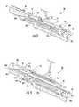
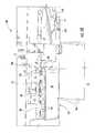
- FIG. 1is a schematic, front elevation view of a sealing system, in accordance with a first embodiment of this disclosure.
- FIG. 2is a schematic, front perspective view of a portion of the sealing system of FIG. 1 .
- FIG. 3is a schematic, front perspective view of a portion of the sealing system of FIG. 1 , with a cover assembly of the sealing system in a closed configuration.
- FIG. 4is a schematic, front perspective view of the portion of the sealing system shown in FIG. 3 , with the cover assembly in an open configuration.
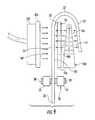
- FIG. 5is a schematic, left elevation, isolated view primarily of guide rails and downstream and rearward plenums of the sealing system of FIG. 1 .
- FIG. 6is a schematic illustration of a representative forced air system of the sealing system, in accordance with the first embodiment.
- FIG. 7is a schematic front elevation view of a flat tube being conveyed through a portion of the sealing system of FIG. 1 , and it shows an upper end of the tube being bent over by an upstream diverter of the sealing system, in accordance with the first embodiment.
- FIG. 8is a schematic front elevation view of a portion of the sealing system of FIG. 1 , and it shows an upper end of the tube being bent downwardly by a downstream diverter of the sealing system, which substantially completes the folding of the upper end of the tube, in accordance with the first embodiment.
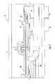
- FIG. 9is schematic and similar to FIG. 5 , except for schematically illustrating the folded-over upper end of the tube, and showing a portion of the transport conveyor of the sealing system.
- FIG. 10is a schematic front elevation view of a portion of the sealing system of FIG. 1 , showing the folded-over upper end of the tube being received by a nipping apparatus, in accordance with the first embodiment.
- FIG. 11is an isolated, front, top perspective view of the tube in isolation prior to having either of its ends sealed, with the tube being slightly open and having its right and left side pleats folded inwardly, in accordance with the first embodiment.
- FIG. 12is a schematic, front elevation view of the tube of FIG. 11 , with the side pleats folded outwardly and the tube in a flattened configuration.
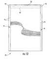
- FIG. 13is a schematic, rear elevation view of the tube of FIG. 11 , with the side pleats folded outwardly and the tube in the flattened configuration.
- FIG. 14is a schematic, top perspective view of the interior of the tube of FIG. 11 in an open configuration, with the pleats folded inwardly.
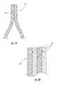
- FIG. 15is an isolated, schematic, cross-sectional view of a portion of an exemplary packaging material from which the tube to be processed by the sealing system may be constructed, in accordance with the first embodiment.
- FIG. 16is a schematic, front elevation view of the bag formed from the tube by the sealing system, in accordance with the first embodiment.
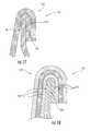
- FIG. 17is a schematic cross-sectional view of a top portion of the bag of FIG. 16 , with the cross section taken along line 17 - 17 of FIG. 16 , only the cross-section being shown, and the bag not being entirely flattened, so that a portion of the interior of the bag is shown.
- FIG. 18is a schematic cross-sectional view of a top portion of the bag of FIG. 16 , with the cross section taken along line 18 - 18 of FIG. 16 , only the cross-section being shown, and the bag not being entirely flattened, so that a portion of the interior of the bag is shown.
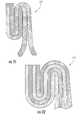
- FIG. 19is a schematic cross-sectional view of a portion of a bag of a second embodiment of this disclosure, with the cross section taken similarly to that for FIG. 17 .
- FIG. 20is a schematic cross-sectional view of a portion of the bag of the second embodiment, with the cross section taken similarly to that for FIG. 18 .
- FIG. 21is a schematic cross-sectional view of a portion of a bag of a third embodiment of this disclosure, with the cross section taken similarly to that for FIG. 17 .
- FIG. 22is a schematic cross-sectional view of a portion of the bag of the third embodiment, with the cross section taken similarly to that for FIG. 18 .
- FIG. 23is a schematic cross-sectional view of a portion of a bag of a fourth embodiment of this disclosure, with the cross section taken similarly to that for FIG. 17 .
- FIG. 24is a schematic cross-sectional view of an exemplary packaging material in accordance with various aspects of the present disclosure.
- FIG. 25is a schematic cross-sectional view of another exemplary packaging material in accordance with various aspects of the present disclosure.
- FIG. 26is a schematic cross-sectional view of still another exemplary packaging material in accordance with various aspects of the present disclosure.
- sealing system 20is disclosed in the following, in accordance with a first embodiment of this disclosure.
- the sealing system 20may be like conventional closers systems that are available as Model 90-I and Model 92-I from Stonepak by Premier Tech Systems, of Salt Lake City, Utah, except for variations noted in this disclosure and variations that will be apparent to one of ordinary skill in the art.
- the sealing system 20is discussed primarily with reference to FIGS. 1-6 , only with very general reference to a tube 22 ( FIGS. 7-14 ) that is to have its upper end sealed closed by the sealing system 20 to form a bag 112 ( FIGS. 16-18 ). Then, a method of the sealing system 20 processing the tube 22 is discussed very generally and briefly with reference to FIGS. 7-10 . Then, the tube 22 with its ends unsealed is discussed in greater detail with reference to FIGS. 11-14 . Then, material from which the tube may be constructed is discussed with reference to FIG. 15 . Then, the bag 112 constructed from the tube 22 by the sealing system 20 is discussed with reference to FIGS. 16-18 . Then, other embodiments and variations are discussed with reference to the remaining figures.
- the sealing system 20includes a conventional frame.
- the framehas upright supports (not shown) that support an upper subframe 24 at a position that is elevated above a floor (not shown) or other suitable surface.
- the frameincludes other frame components that support a wide variety of mounting brackets and other components of the sealing system 20 .
- the tube 22( FIGS. 7-14 ) that is to have its upper end sealed closed by the sealing system 20 is introduced into an upstream end of the sealing system (i.e., the right-hand end in FIG. 1 ).
- the resulting bag 112( FIGS. 16-18 ) with a sealed closed upper end exits a downstream end of the sealing system 20 (i.e., the left-hand end in FIG. 1 ). That is, the tube 22 /bag 112 travels along a path in a downstream direction through the sealing system 20 , and the downstream direction extends along the length of the sealing system 20 .
- upstream and downstreamare defined by/relate to the direction in which the tube 22 /bag 112 travels through/along the length of the sealing system 20 .
- the sealing system 20includes a transportation system comprising a conventional transport conveyor 26 that is not novel per se.
- the transport conveyor 26extends between the upstream and downstream ends of the sealing system 20 , although the transport conveyor may not extend for the entire length of the sealing system.
- the tube 22is introduced to the transport conveyor 26 at the upstream end, and the transport conveyor carries the tube/bag through the sealing system 20 , and discharges the bag from the downstream end of the sealing system.
- the transport conveyor 26includes a rearward pulley system 28 b that is positioned behind a forward pulley system 28 a .
- Each of the transport conveyor's pulley systems 28 a , 28 bincludes an endless belt 30 that extends around an upstream pulley 32 and a downstream pulley 34 , and there may be intermediate pulleys (not shown) in the pulley system.
- the upstream and downstream pulleys 32 , 34are supported by shafts that hang down from the upper subframe 24 .
- the transport systemmay be configured differently.
- the transport systemmay include multiple transport conveyors, or the like, arranged end to end.
- the transport conveyor 26may not extend all the way to the downstream end of the sealing system (e.g., the folded tube 22 ( FIGS. 7-9 ) may be passed from a downstream end of a shorter transport conveyor to another conveyor (e.g., a nip conveyor/nipping apparatus 76 ) that may be characterized as being part of the transport system).
- the sealing system 20includes a conventional upstream guide that comprises a pair of adjacent guide rollers 36 and is not novel per se.
- the guide rollers 36are supported by shafts hanging down from the upper subframe 24 .
- the upstream guide/guide rollers 36are for guiding an upper portion of the tube 22 , which is being transported by the transport conveyor, into an upstream end of a guide channel 38 ( FIGS. 3 and 4 ) defined between forward and rearward guide rails 40 a , 40 b .
- the guide rollers 36may be driven, such that the guide rollers may be characterized as being part of the sealing system's transportation system (which also includes the transport conveyor 26 ).
- the guide channel 38is upwardly and downwardly open.
- the upper opening of the guide channel 38may be covered and somewhat obstructed by a cover assembly 42 that is mounted to the frame of the sealing system 20 .
- the cover assembly 42may, optionally, be mounted by hinges 44 ( FIG. 3 ), so that the cover assembly may be pivoted between a closed configuration ( FIGS. 1-3 ) and an open configuration (e.g., see the partially open configuration shown in FIG. 4 ). More specifically, the closed cover assembly 42 covers (e.g., obstructs, typically without fully closing) the upper opening of the guide channel 38 .
- the cover assembly 42comprises a substantially rigid cover plate 43 that is pivotably mounted by the hinge assemblies 44 and carries other components of the cover assembly 42 .
- the cover assembly 42includes a folding apparatus, which includes upstream and downstream diverters 46 , 47 , for folding the tube 22 into a folded-over configuration while the transport conveyor 26 transports the tube proximate (e.g., by, past, or the like) the folding apparatus.
- the lower surface of the cover plate 43may optionally also be characterized as being part of the folding apparatus since it may play some role in the folding of the tube 22 (e.g., such as by not allowing the partially folded tube to unfold due to any resiliency of the tube).
- the cover assembly 42includes a conventional, concavely curved upstream diverter 46 that is not novel per se.
- the upstream diverter 46is mounted to and/or defined by the upstream end of the cover plate 43 , for pivoting with the cover plate 43 .
- the upstream diverter 46is for initiating a folding over of the upper marginal portion of the tube 22 .
- the upstream diverter 46typically folds the upper marginal portion of the tube 22 downwardly about ninety degrees relative to the lower portion of the tube, so that the upper marginal portion of the tube extends approximately perpendicularly relative to the lower portion of the tube.
- the upstream diverter 46may be defined by a concavely cut upstream end of the cover plate 43 , and/or the upstream diverter may include any suitable structure or material that is mounted to the upstream end of the cover plate 43 for aiding in the folding of the upper marginal portion of the tube.
- a folding apparatusdownstream from the upstream diverter 46 for substantially completing the folding over of the upper portion of the tube 22 .
- a curved downstream diverter 47is mounted to and/or defined by the downstream end of the cover plate 43 , for pivoting with the cover plate 43 .
- the downstream diverter 47is shaped (e.g., contoured) for substantially completing the folding over of the upper portion of the tube 22 , as will be discussed in greater detail below. More specifically, the downstream diverter 47 typically folds what was originally the upper marginal portion of the tube 22 about an additional ninety degrees downward relative to the lower portion of the tube.
- the cover assembly 42further includes an upper heat supplying apparatus (e.g., upper air outlet 48 a ( FIG. 4 )) that may be any suitable apparatus (e.g., an infrared radiant heater) for causing heat transfer with at least one outer portion of the tube 22 while the transport conveyor 26 transports the tube proximate (e.g., by, past, or the like) the upper heat supplying apparatus.
- the upper heat supplying apparatusis an upper air outlet 48 a that is in the form of a plate that defines a wall of an upper plenum 50 a ( FIGS. 3 and 4 ) and has numerous holes (e.g., discharge ports) extending therethrough for discharging air from the upper plenum.
- the upper air outlet 48 aextends along a portion of the length of the sealing system 20 .
- the upper air outlet 48 amay be a perforated plate, an air vent, louvers, an air distributor, or any other suitable structure for discharging a flow of air. Substantially all of the air outlet 48 a is positioned downstream from the upstream diverter 46 , although variations are within the scope of this disclosure.
- the upper plenum 50 awhich includes the upper air outlet 48 a , may be mounted to and/or defined by the cover plate 43 , such that the upper plenum 50 a pivots with the cover plate 43 .
- the upper plenum 50 ais located at a position between the upstream and downstream ends of the cover plate 43 .
- the upper plenum 50 ais typically completely closed, except for including an inlet opening and the holes of the upper air outlet 48 a .
- the holes of the upper air outlet 48 aare located at a lower face of the upper plenum 50 a /cover assembly 42 .
- the inlet opening to the upper plenum 50 amay be located at the upper side or rear side of the upper plenum 50 a /cover assembly 42 . Since the cover assembly 42 is mounted for pivoting, provisions may be made so that the supply duct connected to the inlet opening of the upper plenum 50 a accommodates for the pivoting.
- the supply ductmay be flexible, or it may comprise first and second ducts fit one inside the other and between which there can be relative rotation when the cover assembly is pivoted.
- the supply ductmay be removably connected by a removable clamp to the inlet opening of the upper plenum 50 a . Any suitable connection may be used.
- the upper plenum 50 ais one of several plenums of the sealing system 20 , and the supply of air to the several plenums is discussed below, after all of the plenums are introduced.
- a lower heat supplying apparatuse.g., upstream lower air outlet 48 b and/or downstream lower air outlet 48 c
- the lower heat supplying apparatusmay be any suitable apparatus (e.g., an infrared radiant heater) for causing heat transfer with at least one outer portion of the tube 22 while the transport conveyor 26 transports the tube proximate (e.g., by, past, or the like) the lower heat supplying apparatus.
- the lower heat supplying apparatuscomprises one or more of the lower air outlets 48 b , 48 c , each of which is a plate that defines a wall of a lower plenum 50 b and has numerous holes (e.g., discharge ports) extending therethrough for discharging air from the lower plenum.
- the lower air outlets 48 b , 48 ceach extend along a portion of the length of the sealing system 20 .
- the lower air outlets 48 b , 48 ceach may be a perforated plate, an air vent, louvers, an air distributor, or any other suitable structure for discharging a flow of air.
- the lower plenum 50 bis fixedly mounted to the frame of the sealing system 20 , so that the lower plenum is beneath the upper plenum 50 a and covered by the cover assembly 42 while the cover assembly 42 is in its closed configuration.
- the lower plenum 50 bincludes a conventional upper section that includes the lower air outlet 48 b and is not novel per se.
- the lower air outlet 48 bis an upper face of the upper section of the lower plenum 50 b , and the lower air outlet 48 b extends parallel to, and is in opposing face-to-face relation with (e.g., is opposite), the lower face (i.e., the upper air outlet 48 a ) of the upper plenum 50 a.
- the lower plenum 50 bincludes a lower section that includes the lower air outlet 48 c .
- the lower air outlet 48 cextends obliquely, downwardly from the upper section of the lower plenum 50 b .
- the lower plenum 50 bis typically completely closed, except for including an inlet opening 53 ( FIG. 1 ), the holes in the air outlets 48 b , 48 c , and an outlet opening in communication with a passageway 54 (e.g., tube) for supplying air to an inlet opening of a downstream plenum 50 d.
- a passageway 54e.g., tube
- Downstream heat supplying apparatusese.g., downstream air outlets 48 d , 48 e ( FIG. 5 ) are covered by the cover assembly 42 while the cover assembly is in its closed configuration.
- the downstream heat supplying apparatusesmay be any suitable apparatuses (e.g., infrared radiant heaters) for causing heat transfer with at least one outer portion of the tube 22 while the transport conveyor 26 transports the tube proximate (e.g., by, past, or the like) the downstream heat supplying apparatuses.
- the downstream heat supplying apparatusesare the downstream air outlets 48 d , 48 e , each of which is a plate that defines a wall of a downstream plenum 50 d and has numerous holes (e.g., discharge ports) extending therethrough for discharging air from the downstream plenum.
- the downstream air outlets 48 d , 48 eeach may be a perforated plate, an air vent, louvers, an air distributor, or any other suitable structure for discharging a flow of air.
- the downstream plenum 50 dis fixedly mounted to the frame of the sealing system 20 , so that the downstream plenum is downstream from the upper and lower plenums 50 a , 50 b . As schematically shown by dashed lines in FIG. 3 , the downstream plenum 50 d is covered by the downstream diverter 47 while the cover assembly 42 is in its closed configuration.
- the downstream diverter 47 and/or downstream plenum 50 dare adapted (e.g., sized and arranged) so that the downstream diverter 47 fits over the downstream plenum 50 d with clearance for allowing the folded tube 22 to pass between the downstream diverter and the downstream plenum, as will be discussed in greater detail below with reference to FIG. 9 .
- the downstream plenum 50 dis generally (e.g., substantially) triangular shaped in that its opposite upright faces/downstream air outlets 48 d , 48 e extend obliquely and divergently with respect to one another and downwardly from an convexly curved upper surface of the downstream plenum.
- Each of the opposite upright faces/downstream air outlets 48 d , 48 eextends along a portion of the length of the sealing system 20 .
- each of the opposite upright faces/downstream air outlets 48 d , 48 eextend obliquely and convergently with respect to one another in the downstream direction.
- the upstream end of the downstream plenum 50 dis wider than the downstream end of the downstream plenum. That is, the downstream plenum 50 d becomes more narrow in the downstream direction.
- the downstream plenum 50 dis typically completely closed, except for including the holes in the downstream air outlets 48 d , 48 e and an inlet opening in communication with the passageway 54 (e.g., tube) for receiving a flow of air from the lower plenum 50 b .
- the downstream plenum 50 dmay receive its flow of air from any other suitable source.
- the downstream plenum 50 dand more particularly the downstream air outlet 48 e , is proximate the downstream portion of the forward guide rail 40 a .
- An opening 56( FIGS. 4 and 5 ) is defined in and extends through the downstream portion of the forward guide rail 40 a , so that the rearward face/air outlet 48 e of the downstream plenum 50 d is in opposing face-to-face relation with the opening 56 .
- the downstream air outlet 48 eis configured for discharging air through the opening 56 , as will be discussed in greater detail below.
- the opening 56( FIGS. 4 and 5 ) that extends through the downstream portion of the forward guide rail 40 a is arranged and sized so that the rearward face/air outlet 48 e of the downstream plenum 50 d is in opposing face-to-face relation with a rearward supplying apparatus (e.g., rearward air outlet 48 f ).
- the rearward supplying apparatusmay be any suitable apparatus (e.g., an infrared radiant heater, or simply a fan or another type of conventional air mover) for causing heat transfer with at least one outer portion of the tube 22 while the transport conveyor 26 transports the tube proximate (e.g., by, past, or the like) the rearward supplying apparatus. More specifically, the rearward supplying apparatus is for providing a forced flow of cool air and/or air at substantially the same temperature as ambient air, for cooling a portion of the tube 22 , as will be discussed in greater detail below.
- the rearward supplying apparatusis the rearward air outlet 48 f , which is a plate (e.g., a portion of the rearward guide rail 40 b ) that defines a wall of a rearward plenum 50 f and has numerous holes (e.g., discharge ports) extending therethrough for discharging air from the rearward plenum.
- the rearward air outlet 48 fextends along a portion of the length of the sealing system 20 .
- the rearward air outlet 48 fmay be a perforated plate, an air vent, louvers, an air distributor, or any other suitable structure for discharging a flow of air.
- the opening 56 in the forward guide rail 40 ais substantially rectangular and substantially corresponds to the substantially rectangular shape of (e.g., the pattern of discharge ports in) the air outlet 48 , although different shapes and arrangements are within the scope of this disclosure.
- the rearward plenum 50 fis fixedly mounted to the frame or another component of the sealing system 20 .
- the rearward plenum 50 fmay be mounted to a portion of the rearward guide rail 40 b as shown in FIG. 5 , so that the rearward plenum is downstream from the upper and lower plenums 50 a , 50 b .
- the rearward plenum 50 fis covered by the downstream diverter 47 while the cover assembly 42 is in its closed configuration.
- the rearward plenum 50 fis typically completely closed, except for including the holes in the rearward air outlet 48 f and an inlet opening for receiving a flow of air.
- the rearward plenum's inlet openingmay be located at the rear side of the rearward plenum 50 f.
- Airmay be supplied to the plenums 50 a , 50 b , 50 d , 50 f in any suitable manner for helping to facilitate the desired sealing of the tube 22 to form (or close) a bag 112 ( FIGS. 16-18 ).
- Each of the plenums 50 a , 50 b , 50 d , 50 fmay be part of a forced air system that is for providing a forced flow of air that may be heated or cooled.
- Each of the forced air supply systemsmay be at least generally conventional in nature.
- a first forced air systemincludes the upper plenum 50 a ; a second forced air system includes the plenums 50 b , 50 d ; and a third forced air system includes the rearward plenum 50 f .
- the plenums 50 b , 50 dmay respectively be part of separate forced air systems, and/or other arrangements of plenums/forced air systems are within the scope of this disclosure.
- the forced air systemcomprising the rearward air outlet 48 f may alternatively simply be in the form of a fan or another type of conventional air mover that is for supplying a flow of otherwise ambient air (e.g., relatively cool ambient air) for causing cooling heat transfer with the respective outer portion of the tube 22 while the transport conveyor 26 transports the tube proximate (e.g., by, past, or the like) the fan or the like.
- otherwise ambient aire.g., relatively cool ambient air
- the transport conveyor 26transports the tube proximate (e.g., by, past, or the like) the fan or the like.
- FIG. 6schematically illustrates a forced air system 58 that may be representative of each of the forced air systems (which respectively include the plenums 50 a , 50 b , 50 d , 50 f ) of the sealing system 20 .
- the forced air system 58may include a conventional air handler 60 having an air inlet 62 , a heating and/or coiling coil 64 (e.g., any suitable device for changing the temperature of the flow of air, by adding and/or removing heat (e.g., a refrigeration system and/or heating element(s))), and a motor-operate air mover 66 (e.g., a motor-driven fan or any other suitable device for moving air).
- a heating and/or coiling coil 64e.g., any suitable device for changing the temperature of the flow of air, by adding and/or removing heat (e.g., a refrigeration system and/or heating element(s)
- a motor-operate air mover 66e.g.
- the air supplied from the air handler 60may flow in conventional duct(s) 68 or any other suitable structure that is optionally equipped with a conventional motor-operated, flow-control damper 70 or another suitable device.
- the duct(s) 68discharge into one or more plenums 50 (e.g., the respective one or more of the plenums 50 a , 50 b , 50 d , 50 f ), and the flow of air is discharged from the plenum(s) 50 by way of one or more air outlets 48 (e.g., the respective one or more of the air outlets 48 a - 48 f ).
- the air outlet 48may include one or more holes or other openings for discharging a forced flow of air that is for providing forced convention.
- the air outlet 48may be a perforated plate, an air vent, louvers, an air distributor, or any other suitable structure for discharging a flow of air.
- the plenum(s) 50may be equipped with one or more temperature sensors 72 that may be connected to a controller 74 .
- the controller 74may also connected to the coil 64 , air mover 66 and damper 70 for purposes of control.
- the forced air system 58may include any other suitable components such as, but not limited to, components for filtration.
- the forced air system including the plenum 50 f( FIG. 5 ) may omit the coil 64 , and the coils 64 in the forced air systems including the plenums 50 a , 50 b , 50 d may only be for adding heat.
- a variety of different forced air systemsare within the scope of this disclosure (e.g., the types of or usage of the features of the forced air systems may vary, depending upon the types of materials, tubes 22 and bags being processed by the sealing system 20 ).
- Features of the controller 74may be embodied in any suitable manner, such as in software, firmware and/or hardware modules, for providing control over operation of the sealing system 20 /components of the sealing system/forced air systems/components of the forced air systems.
- a conventional nipping apparatus 76which is not novel per se, is positioned downstream from the folding apparatus (e.g., the upstream and downstream diverters 46 , 47 ) and the supplying apparatuses (e.g., the air outlets 48 a - 48 f ).
- the nipping apparatus 76receives the tube 22 from the transport conveyor 26 . Nonetheless, the transport conveyor 26 extends all the way to the downstream end of the sealing system 20 , and the transport conveyor 26 at least partially carries the tube 22 /bag all the way to the downstream end of the sealing system.
- the nipping apparatus 76performs a nipping function, but it may also be characterized as being part of the sealing system's transportation system (which also includes the transport conveyor 26 ), since the nipping apparatus may help in carrying the tube 22 /bag to the downstream end of the sealing system 20 . Also, and for example, the transport conveyor 26 may not extend all the way to the downstream end of the sealing system 20 , such that the nipping apparatus 76 , or another suitable device, completes the transporting of the tube 22 to the downstream end of the sealing system.
- the nipping apparatus 76includes a rearward pulley system 78 b that is positioned behind a forward pulley system 78 a.
- Each of the nipping apparatus' pulley systems 78 a , 78 bincludes an endless belt 80 that extends around an upstream pulley 82 , intermediate pulleys 84 , and a respective one of the downstream pulleys 34 ( FIG. 1 ).
- the upstream and intermediate pulleys 82 , 84are supported by shafts that hang down from the upper subframe 24 .
- the nipping apparatus 76may be configured differently.
- the nipping apparatus 76may include multiple nipping conveyors, or the like, arranged end to end.
- the sealing system 20includes a conventional drive system, which is not novel per se, for driving the respective pulleys of the transport conveyor 26 and the nipping apparatus 76 , and the guide rollers 36 .
- the drive systemincludes an electric motor 86 and a gear box 88 .
- a drive chain or belt 89or any other suitable device for transferring rotary power, connects the output shaft of the motor 86 to the input shaft of the gear box 88 .
- the respective pulleys of the transport conveyor 26 and the nipping apparatus 76 , and the guide rollers 36are driven in a conventional manner by way of one or more chains or belts 90 , or any other suitable devices for transferring rotary power.
- the one or more belts 90connect the output shaft(s) 88 a of the gear box 88 to the respective shafts that hang down from the upper subframe 24 and support the respective pulleys of the transport conveyor 26 and the nipping apparatus 76 , and the guide rollers 36 .
- One or more of the pulleys of the transport conveyor 26 and the nipping apparatus 76 , and the guide rollers 36may be idler pulleys or rollers that are not directly driven by the sealing system's drive system. Any suitable drive system(s) may be used in the sealing system 20 .
- the sealing system 20may be constructed of any suitable materials.
- surfaces (e.g., metal surfaces) of the sealing system 20 that the tube 22 comes into sliding contact withe.g., the folding apparatus
- Teflon brand coating or other suitable materialsfor reducing friction.
- the hot air supplied by the sealing system 20may also help to reduce the friction associated with the tube 22 sliding relative to features of the sealing system.
- FIGS. 7 and 8schematically show the flat tube 22 being conveyed through and folded over by the folding apparatus (e.g., the upstream and downstream diverters 46 , 47 ).
- FIG. 9schematically shows the folded-over upper end of the tube 22 being conveyed between the downstream and rearward plenums 50 d , 50 f by the transport conveyor 26 .
- FIG. 9is schematic because, for example, some of the clearances shown are exaggerated. For example and in the context of the tube 22 passing between the downstream diverter 47 ( FIGS.
- FIG. 10schematically shows the folded-over upper end of the tube 22 being introduced into the nipping apparatus 76 for nipping.
- FIG. 11shows the tube 22 with its optional side pleats 91 folded inwardly.
- FIGS. 12 and 13show the pleats 91 folded outwardly, although the pleats typically remain folded inwardly at least until after the bag containing the pleats is filled.
- the pleats 91are defined by lines of disruption 92 (e.g., fold lines).
- FIG. 14is a top perspective view of the interior of the tube 22 in an open configuration, with the pleats 91 folded inwardly.
- FIG. 12 and 13are schematic because, for example, they include dashed lines for schematically identifying that the front side of the tube 22 includes a first outer (marginal) portion O 1 of the tube and a second outer portion O 2 of the tube, and the rear side of the tube includes a third outer (marginal) portion O 3 of the tube and a fourth outer portion O 4 of the tube.
- FIG. 12 and 13are schematic because, for example, they include dashed lines for schematically identifying that the front side of the tube 22 includes a first outer (marginal) portion O 1 of the tube and a second outer portion O 2 of the tube, and the rear side of the tube includes a third outer (marginal) portion O 3 of the tube and a fourth outer portion O 4 of the tube.
- each pleat 91is schematically shown as including surface portions P 1 , P 2 , P 3 , P 4 . The pleats 91 may be omitted.
- the tube 22comprises a sheet of packaging material 100 ( FIG. 15 ) with opposite edges that have been joined together at a longitudinal seal 93 ( FIGS. 11, 12 and 14 ) that extends been the opposite ends of the tube and may be in the form of a foldover seal, fin seal, or any other suitable seal, or the like.
- the edges at the opposite ends of the tube 22are “straight cut” (e.g., at least substantially straight cut (i.e., not step cut)). Alternatively, the edges may not be required to be “straight cut.”
- the packaging material 100 from which the tube 22 may be constructedis described in the following with reference to FIG. 15 , in accordance with the first embodiment.
- the packaging material 100generally includes a substrate 102 (any suitable substrate (e.g., a high strength substrate) such as, but not limited to, paper, polymer film, or a woven polymer substrate) and a pair of facing systems 104 , 106 , each of which may include one or more layers that are coextruded and/or otherwise joined to one another.
- Such layersmay include polymer films, polymer or polymeric coatings or layers, paper layers, other woven materials or nonwoven materials, or any other suitable material.
- the substrate 102is a woven polymer substrate, although other substrates may be used.
- Each facing system 104 , 106 of the packaging material 100includes an outermost surface 108 , 110 that respectively defines the inner (i.e., interior) and outer (i.e., exterior) sides or faces 108 , 110 of the packaging material 100 .
- Each side 108 , 110 of the packaging material 100includes (or is provided with) at least one area or zone (e.g., one or more of outer portions O 1 -O 4 and inner portions I 1 -I 4 ) that is capable of being joined to the respective surface of the packaging material 100 using a heat sealable material, adhesive, or otherwise.
- the entirety of the interior and exterior surfaces of the tube 22comprise (e.g., are constructed of or have had applied thereto) a heat sealable material.
- a bag 112( FIGS. 16-18 ) formed form the tube 22 by the sealing system 20 , and an example of a suitable method for forming the bag, are discussed in the following, in accordance with the first embodiment.
- the side pleats 91 of the bag 112typically remain folded inwardly until the bag is filled.
- the end of the bag 112includes a shear seal closure 114 that includes both a pinch seal 116 and a foldover seal 118 . Referring to FIGS. 12-14, 17 and 18 , in the pinch seal 116 :
- the sealing system 20when used to form the shear seal closure 114 , the sealing system operates in a manner that seeks to avoid formation of any seals in addition to those discussed immediately above for the shear seal closure 114 /pinch seal 116 /foldover seal 118 , in order to maximize the volume of the interior of the bag 112 .
- unsealed areas 94are identified in FIGS. 17 and 18 .
- additional seals or sealed areasmay be included.
- the flattened tube 22is introduced into the upstream end of the sealing system 20 .
- the tube 22is introduced so that the longitudinal seal 93 faces forwardly (as shown in FIGS. 7 and 8 ) and the imaginary demarcation (e.g., see the respective dashed line in FIG. 12 ) between the outer portions O 1 , O 2 is at substantially the same elevation as the upstream diverter 46 . Therefore, when the tube 22 engages the upstream diverter 46 , the upstream diverter begins to form a fold/fold line in the tube at the imaginary demarcation between the outer portions O 1 , O 2 .
- the air outlets 48 a , 48 b , 48 care respectively in opposing face-to-face relation with and discharge hot air against the outer portions O 3 , O 1 so that the outer portions O 3 , O 1 are heated by forced convention.
- the air outlets 48 a , 48 bare opposite from one another.
- the air outlets 48 a , 48 care opposite from one another.
- the outer portions O 3 , O 1are opposite from one another.
- the surfaces that are sealed together as part of the pinch seal 116may comprise (or have applied to at least a portion thereof) a heat sealable and/or adhesive material, for example, a heat sealable polymer film, a heat sealable coating, a hot melt adhesive, or any other suitable material for forming the pinch seal 116 , as needed to create the desired heat seal (e.g., to provide strength, protection from contamination or infestation by insects, and so on).
- a heat sealable and/or adhesive materialis operative for joining the surfaces that are sealed together as part of the pinch seal 116 .
- the pinch seal 116extends all the way (substantially all the way) from one side of the bag 112 to the other side of the bag.
- the pinch seal 116may be spaced from the opposite edges of the bag 112 and/or may have other transverse and/or longitudinal dimensions.
- the pinch seal 116may generally be formed at a temperature below the distortion or softening temperature of the woven polymer substrate 102 ( FIG. 15 ) and/or any other components of the packaging material 100 that are not intended to be softened.
- the heat seal temperature for forming the pinch seal 116may generally be less than about 350° F., for example, from about 250° F. to about 300° F., or to about 325° F.
- the air outlets 48 a , 48 b , 48 cthat are respectively in opposing face-to-face relation with and discharge hot air against the outer portions O 3 , O 1 provide the hot air at a temperature that is high enough to provide the heat seal temperature for forming the pinch seal 116 , yet not so high so as to cause the woven polymer substrate 102 to reach its softening temperature.
- the desired or required temperature of the hot air discharged by the air outlets 48 a , 48 b , 48 cmay depend upon various factors such as, but not limited to, the dwell time (e.g., how quickly the tube 22 is transported through the sealing system 20 ).
- the tube 22engages the downstream diverter 47 which completes (e.g., substantially completes) folding the tube so that the tube is in the folded-over configuration that is schematically shown in FIG. 9 (e.g., the substantially one hundred eight degree folded-over configuration).
- the downstream diverter 47completes (e.g., substantially completes) folding the tube so that the tube is in the folded-over configuration that is schematically shown in FIG. 9 (e.g., the substantially one hundred eight degree folded-over configuration).
- the first and second outer portions O 1 , O 2 of the tube 22are facing substantially toward one another, and the third and fourth outer portions O 3 , O 4 of the tube are facing substantially away from one another.
- the air outlets 48 d , 48 e , 48 fare respectively in opposing face-to-face relation with and discharge air against the outer portions O 1 , O 2 , O 4 so that heat is transferred with respect to the outer portions O 1 , O 2 , O 4 by way of forced convention.
- the air outlets 48 d , 48 eare opposite from one another.
- the air outlets 48 e , 48 fare opposite from one another.
- the air outlets 48 d , 48 fmay also be characterized as being opposite from one another.
- the outer portions O 3 , O 1are opposite from one another.
- outer portions O 1 , O 2are opposite from one another.
- the outer portions O 1 , O 4may also be characterized as being opposite from one another, and the outer portions O 3 , O 2 may also be characterized as being opposite from one another.
- the air outlets 48 d , 48 edischarge hot air against the outer portions O 1 , O 2 so that the outer portions O 1 , O 2 are heated by forced convention; and the air outlet 48 f discharges cool air or air at ambient temperature (e.g., relatively cool air) against the outer portion O 4 so that the outer portion O 4 is cooled by forced convention.
- the above-discussed heating by forced convectionis for helping to facilitate forming of the above-discussed seals of the shear seal closure, and the above-discussed cooling by forced convection is for helping to avoid forming any more than the seal between the outer portions O 1 , O 2 when the foldover seal 118 is formed.
- the surfaces that are sealed together as part of the foldover seal 118may comprise (or have applied to at least a portion thereof) a heat sealable and/or adhesive material, for example, a heat sealable polymer film, a heat sealable coating, a hot melt adhesive, or any other suitable material for forming the foldover seal 118 , as needed to create the desired heat seal (e.g., to provide strength, protection from contamination or infestation by insects, and so on).
- the heat sealable and/or adhesive materialis operative for joining the surfaces that are sealed together as part of the foldover seal 118 .
- the foldover seal 118extends all the way (substantially all the way) from one side of the bag 112 to the other side of the bag.
- the foldover seal 118may be spaced from the opposite edges of the bag 112 and/or may have other transverse and/or longitudinal dimensions.
- the foldover seal 118may generally be formed at a temperature below the distortion or softening temperature of the woven polymer substrate 102 ( FIG. 15 ) and/or any other components of the packaging material 100 that are not intended to be heat sealed.
- the heat seal temperature for forming the foldover seal 118may generally be less than about 350° F., for example, from about 250° F. to about 300° F., or to about 325° F.
- the air outlets 48 b , 48 c , 48 d , 48 ethat are respectively in opposing face-to-face relation with and discharge hot air against the outer portions O 2 , O 1 provide the hot air at a temperature that is high enough to provide the heat seal temperature for forming the foldover seal 118 , yet not so high so as to cause the woven polymer substrate 102 to reach its softening temperature.
- air substantially at ambient temperature or cooled airmay be directed by the air outlet 48 f against the outer portion O 4 in a manner that seeks to prevent the interior surfaces 108 of the tube 22 from being joined to one another behind the foldover seal 118 (which would reduce the volume of the interior space of the bag 112 ).
- the desired or required temperature of the air discharged by the air outlets 48 d , 48 e , 48 fmay depend upon various factors such as, but not limited to, the dwell time (e.g., how quickly the tube 22 is transported through the sealing system 20 ).
- the heat sealable and/or adhesive materialmay lie outside of the area in which the foldover seal 118 and the pinch seal 116 are to be formed.
- all or a portion of the interior or exterior surfaces 108 , 110 of the tube 22may comprise a heat sealable polymer film or polymeric material.
- the nipping apparatus 76nips the upper portion of the tube 22 in the folded-over configuration to simultaneously (e.g., substantially simultaneously) complete the formation of the pinch seal 116 and the foldover seal 118 . Then, the resulting bag 112 is discharged from the downstream end of the sealing system 20 /conveyor assembly 42 /nipping apparatus 76 .
- FIG. 19is a schematic cross-sectional view of a portion of a bag of the bag 112 ′ second embodiment, with the cross section taken similarly to that of FIG. 17 ; and
- FIG. 20is a schematic cross-sectional view of a portion of the bag 112 ′ of the second embodiment, with the cross section taken similarly to that of FIG. 18 .
- the sealed closure of the bag 112 ′ of the second embodimentis not folded over, and it only includes the pinch seal 116 (i.e., the foldover seal 118 ( FIGS. 17 and 18 ) is omitted).
- the closure of the bag 112 ′ of the second embodimentmay be formed in the sealing system by 20 by introducing the tube 22 so that the top edge of the tube is slightly below the elevation as the upstream diverter 46 (i.e., the tube is not folded) and hot air is discharged by both of the air outlets 48 e , 48 f ( FIG. 5 ).
- the other air outlets 48 a , 48 b , 48 c , 48 dmay be disabled or otherwise not used, or the like. That is, it is within the scope of this disclosure for a user of the sealing system 20 to select the air outlets to be used/not to be used, depending upon the circumstances.
- dampers 70FIG.
- valves and/or any other suitable controlling devicesmay be included in the sealing system 20 , or more specifically in the forced air systems 58 ( FIG. 6 ), for selectively controlling (e.g., disabling or enabling) flow to one or more of the above-discussed plenums and/or air outlets.
- FIG. 21is a schematic cross-sectional view of a portion of a bag 112 ′′ of the third embodiment, with the cross section taken similarly to that of FIG. 17 ; and
- FIG. 22is a schematic cross-sectional view of a portion of the bag 112 ′′ of the third embodiment, with the cross section taken similarly to that of FIG. 18 .
- the closure of the bag 112 ′′ of the third embodimentmay be formed in the sealing system by 20 by passing the upper end of the bag 112 of FIG. 16 through the sealing system a second time, to substantially repeat the method of the first embodiment, and therefore form a double shear seal closure.
- FIG. 23is a schematic cross-sectional view of a portion of a bag 112 ′′′ of the fourth embodiment, with the cross section taken similarly to that of FIG. 17 .
- the end/pinch seal farthest from the interior of the bagis extended, and an integral grasping feature or handle generally comprising an aperture 95 or cutout extends through the pinch seal farthest from the interior of the bag.
- a flapmay be retained in the aperture 95 , such as for providing cushioning against a hand inserted into the aperture.
- Countless packaging materials 100may be used in accordance with the present disclosure to form any of the constructs and structures (e.g., tubes and bags) described above, with the substrate 102 and facing systems 104 , 106 being selected to impart various properties to the resulting packaging material.
- FIGS. 24-26several exemplary packaging materials 200 , 300 , 400 are illustrated schematically in FIGS. 24-26 .
- Each packaging material 200 , 300 , 400generally includes a woven polymer substrate 202 , 302 , 402 and a respective pair of facing systems 104 , 106 ; 204 , 206 ; 304 , 306 , each of which may include a plurality of layers, as discussed above in connection with FIG. 15 .
- packaging materials 200 , 300 , 400may be described as “overlying” or being disposed “on” other layers. However, it will be appreciated that each packaging material 200 , 300 , 400 may be inverted, such that other layers may be said to “overlie” or be disposed “on” one another. Accordingly, such terminology is provided merely for convenience of explanation and not limitation in any manner.
- each of such packaging materialsmay include various layers. Layers may be added or omitted as needed. It also will be appreciated that various materials may be used to form each layer of the packaging material, and that each layer may have various basis weights or coat weights and may be present in the packaging material in any suitable relative amount, depending on the particular application. Further, it will be appreciated that each layer may serve more than one purpose in a particular packaging material, and that the layer names are provided for convenience of explanation and not limitation in any manner.
- a first exemplary packaging material 200includes a woven polymer substrate 202 , a first facing system 204 comprising a first polymer film layer 212 and a tie layer (e.g., a first tie layer) 214 disposed between the substrate 202 and the first polymer film layer 212 , and a second facing system 206 comprising a second polymer film layer 216 , which may be optionally printed with ink 218 , and a tie layer (e.g., a second tie layer) 220 disposed between the substrate 202 and the second polymer film layer 216 .
- a tie layere.g., a second tie layer
- Each layer 202 , 212 , 214 , 216 , 218 , 220is in a substantially facing, contacting relationship with the respective adjacent layer(s).
- the second polymer film layer 216may be reverse printed such that the ink 218 lies between the second polymer film layer 216 and the second tie layer 220 .
- the first polymer film layer 212When used to form a package, the first polymer film layer 212 (i.e., the outermost surface of the first polymer film layer 212 ) generally faces inwardly and/or defines the interior surface 208 of the tube, bag, package or the like, and the second polymer film layer 216 (i.e., the outermost surface of the second polymer film layer 216 and/or ink 218 , where present) generally defines the exterior surface 210 of the tube, bag, package or the like. Accordingly, one or both polymer film layers 212 , 216 may comprise heat sealable materials.
- the substrate 202generally comprises a base material from which the packaging material is formed.
- the substrate 202may comprise a woven polymer, for example, a woven polypropylene.
- the substrate 202may have a denier of from about 600 to about 1200 dpf (denier per filament), for example, from about 700 to 1000 dpf, and in one example, the substrate 202 comprises a woven material having a denier of about 850 dpf.
- the substrate 202may have any suitable weave, for example, from about 8 ⁇ 8 to about 12 ⁇ 12, for example, about 10 ⁇ 10.
- the substrate 202comprises a woven polypropylene having a denier of about 850 dpf and a 10 ⁇ 10 weave.
- One example of such a materialis commercially available from Mayur Wovens Pvt., Ltd. (India). However, countless other deniers, ranges of deniers, weaves, ranges of weaves, and other substrates may be used.
- the first polymer film layer 212 and the second polymer film layer 216may be used to impart strength, water resistance, heat sealability, and/or other attributes to the packaging material 200 .
- one or both polymer films 212 , 216may generally comprise a thermoplastic polymer having a sufficiently low melting or softening point so the heat seal can be initiated at a relatively low temperature (“heat seal temperature”), for example, from about 180° F. to about 300° F.
- the polymermay be selected to provide a wide hot tack sealing window, such that the heat seal may be formed over a range of temperatures with the degree of tackiness for the desired duration.
- suitable polymersmay include, for example, polypropylene (PP), for example, biaxially oriented polypropylene (BOPP) (e.g., BEM19 BOPP film, Vifan USA, Inc., Morristown, Tenn.), polyethylene terephthalate (PET), metallized polyethylene terephthalate, low density polyethylene (LDPE), poly(ethylene-co-methacrylic acid) (EMAA) (e.g., Surlyn® films available from DuPont, Wilmington, Del.), or any other suitable material.
- PPpolypropylene
- BOPPbiaxially oriented polypropylene
- PETpolyethylene terephthalate
- PETmetallized polyethylene terephthalate
- LDPElow density polyethylene
- EEMAApoly(ethylene-co-methacrylic acid)
- the polymer film layers 212 , 216may generally have any suitable thickness (i.e., caliper), for example, from about 0.4 to about 1.5 mil, for example, from about 0.5 to about 1.2 mil. In one example, one or both polymer film layers 212 , 216 may have a thickness of about 0.7 mil. In another example, one or both polymer film layers 212 , 216 may have a thickness of about 1 mil. However, other suitable thicknesses and ranges of thicknesses are contemplated.
- the first polymer film layer 212may comprise low density polyethylene (LDPE).
- LDPElow density polyethylene
- the first polymer film layer 212may have a thickness of from about 0.5 to about 3 mil, for example, from about 0.8 to about 1.5 mil, for example, about 1 mil.
- other suitable materialsare contemplated.
- the second polymer film layer 216may comprise biaxially oriented polypropylene (BOPP).
- the second polymer film layer 216may have a thickness of from about 0.4 to about 1 mil, for example, from about 0.6 to about 0.8 mil, for example, about 0.7 mil.
- other suitable materialsare contemplated.
- the first polymer film layer 212may comprise LDPE having a thickness of from about 0.8 to about 1.5 mil, for example, about 1 mil
- the second polymer film layer 216may comprise BOPP having a thickness of from about 0.4 to about 1 mil, for example, about 0.7 mil.
- numerous other configurations of layersare contemplated.
- layers 212 and/or 216may be used to provide strength and/or water resistance, while one or more other layers (not shown) may be provided for heat sealability. Countless possibilities are contemplated.
- tie layers 214 , 220generally serve to join two adjacent layers, but may have additional functionality if desired.
- tie layer 214is generally operative for joining the first polymer film layer 212 and the substrate 202
- tie layer 220is generally operative for joining the second polymer film layer 216 and the substrate 202 .
- Each tie layer 214 , 220may have any suitable composition and basis weight needed to attain the desired level of adhesion between the adjacent layers.
- tie layer 220may comprise PP.
- a PPthat may be suitable as a tie layer 220 is HMX 370 or HMX 340 , commercially available from Chevron.
- the tie layer 214may comprise a blend of polymers.
- the blendmay include one or more components that provide adhesion to the substrate 202 and one or more components that provide adhesion to the first polymer film layer 212 .
- the blendmay comprise a blend of linear low density polyethylene (LLDPE), for example, metallocene catalyzed LLPDE (“m-LLDPE”) and LDPE.
- LLDPElinear low density polyethylene
- m-LLDPEmetallocene catalyzed LLPDE
- LDPElow density polyethylene
- Dow Affinity PT 1450G1Dow Chemical Co., Midland, Mich.
- Dow Affinity PT 1450G1 LLDPEmay include one or more components that may enhance the adhesion with PP.
- LDPEis Chevron 1018 LDPE (Chevron Phillips Chemical Co.
- LDPEsinclude, but are not limited to, Westlake EC-482 (Westlake Chemical Corp., Houston, Tex.) and Marflex® 1013 LDPE (Phillips Chemical Co. LLC, The Woodlands, Tex.).
- the relative amounts of LLDPE (e.g., m-LLDPE) and LDPE in the tie layer 214may vary for each application.
- the blendmay generally comprise from about 70% to about 95% LLDPE and about 5% to about 30% LDPE (by weight), for example, from about 80% to about 90% LLDPE and about 10% to about 20% LDPE. In one exemplary embodiment, the blend may comprise about 85% LLDPE and about 15% LDPE. However, other suitable amounts and ratios of LDPE and PP may be used.
- the tie layer 214may comprise a blend of PP and LDPE. Numerous other possibilities are contemplated.
- Each tie layer 214 , 220may have any suitable basis weight, for example, from about 1 to about 15 lb/ream, for example, from about 6 to about 10 lb/ream. In one specific example, one of the tie layers 214 , 220 has a basis weight of about 8 lb/ream. In another example, both of the tie layers 214 , 220 have a basis weight of from about 8 lb/ream. However, other basis weights and ranges of basis weights are contemplated.
- FIG. 25schematically illustrates another exemplary packaging material 300 .
- the packaging material 300includes a substrate 302 including a pair of opposed sides, a first facing system 304 including a tie layer 312 (e.g., a first tie layer), a core layer 314 , and a heat seal layer 316 disposed on a first side of the substrate 302 , and a second facing system 306 including a polymer film layer 318 , which may optionally be printed with an ink 320 , and a tie layer 322 (e.g., a second tie layer) disposed on a second side of the substrate 302 .
- the polymer film layer 318may include printing (i.e., ink 320 ) on the exterior surface 310 of the film 318 .
- Each layer or material 302 , 312 , 314 , 316 , 318 , 320 , 322is in a substantially facing, contacting relationship with the respective adjacent layer(s) or material.
- polymer film layer 318i.e., the outermost surface 310 of polymer film layer 318
- heat seal layer 316i.e., the outermost surface 308 of heat seal layer 316
- interior surface 308 of the tube, bag, package or the likeWhen used to form a package, polymer film layer 318 (i.e., the outermost surface 310 of polymer film layer 318 ) generally faces outwardly and/or at least partially defines the exterior surface 310 of the tube, bag, package or the like
- heat seal layer 316i.e., the outermost surface 308 of heat seal layer 316 ) generally faces inwardly and/or defines the interior surface 308 of the tube, bag, package or the like.
- the substrate 302may be any suitable material, for example, the woven polymer materials described in connection with FIG. 24 .
- Layers 312 , 314 , 316generally define a multifunctional polymer system 304 .
- the polymer system 304may be used to impart numerous properties to the packaging material 300 .
- the layers of the polymer system 304may be described independently, it will be appreciated that the layers cooperate with one another to enhance the packaging material 300 , as will be discussed below.
- the heat seal layer 316generally renders the interior side 308 of the packaging material 300 heat sealable. This may be desirable for numerous package configurations.
- the core layer 314generally comprises a polymer layer, which may, if desired, impart various attributes to the packaging material 300 .
- the core layer 314may serve as a barrier layer to oils (i.e., as an oil resistant layer). This may be important where the contents of the tube, bag, package or the like include a fatty or oily component, for example, as with pet food, bird seed, etc.
- the tie layer 312generally joins the core layer 314 to the substrate 302 . However, in some embodiments, the tie layer may be omitted, such that the core layer 314 also serves as a tie layer.
- the core layer 314may be selected to have a melting point that is greater than the heat seal temperature to ensure that the integrity of the core layer 314 is maintained during the heat sealing process.
- the core layer 314may comprise a blend of materials, at least one of which may have a melting point less than the heat seal temperature.
- the lower melting component(s)may soften during the heat sealing process, such that a portion of the core layer 314 serves as a heat seal material or layer in conjunction with heat seal layer 316 .
- each of the various layers 312 , 314 , 316may cooperate in various ways to achieve a desired result.
- the heat seal layer 316may comprise a blend of low density polyethylene (LLDPE), low density polyethylene (LDPE), and an ethylene/methacrylic acid copolymer (EMA).
- LLDPElow density polyethylene
- LDPElow density polyethylene
- EMAethylene/methacrylic acid copolymer
- the LLDPEmay be a metallocene LLDPE (m-LLDPE).
- m-LLDPEmetallocene LLDPE
- the ratio of each componentmay vary for each application.
- the blendmay comprise from about 60% to 100% LLDPE, from 0 to about 35% LDPE, and from 0 to about 5% EMA.
- the blendmay comprise from about 60% to about 80% LLDPE, from about 15% to about 35% LDPE, and from about 1 to about 5% EMA.
- the blendmay comprise about 60% LLDPE, about 35% LDPE, and about 5% EMA, such that the ratio of the components is about 12:7:1.
- LLDPELow Density Polyethylene
- LDPELow Density Polyethylene
- EMAEMA
- the present inventorshave found that a blend of LLDPE, LDPE, and EMA offers superior processability and resulting heat seal strength. Specifically, the present inventors have found that by adding LLDPE to LDPE, the melting point (and, therefore, the heat seal temperature) is lowered from about 230° F. to about 220° F., and that by adding EMA to the mixture of LLDPE and LDPE, the melting point (and, therefore, the heat seal temperature) of the blend is lowered to about 210-215° F. As a result, the heat seal may be initiated at a lower temperature, which allows for the packaging material 300 to be heat sealed at greater processing speeds. The present inventors have also found that the heat seal formed from the blend of LLDPE, LDPE, and EMA has superior strength relative to a heat seal formed from any of the individual components.
- LLPDEsWhile various LLPDEs, LDPEs, and EMAs may be used, one example of an LLDPE that may be suitable for use is Dow Affinity PT 1450G1 (Dow Chemical Co., Midland, Mich.) (believed to be m-LLDPE). While not wishing to be bound by theory, it is believed that Dow Affinity PT 1450G1 LLDPE may include one or more components that may enhance the affinity with PP.
- LDPEOne example of an LDPE that may be suitable is Chevron 1018 LDPE (Chevron Phillips Chemical Co. LLC, The Woodlands, Tex.).
- Other examples of LDPEs that may be suitableare set forth above in connection with the discussion of the exemplary packaging material 200 of FIG. 24 .
- the heat seal layer 316may have any suitable basis weight, for example, from about 1 to about 5 lb/ream, for example, from about 2 to about 4 lb/ream, for example, about 3 lb/ream. In one specific example, the heat seal layer 316 has a basis weight of about 3.06 lb/ream. However, other basis weights and ranges thereof are contemplated.
- the tie layer 312may be formed from any suitable material that sufficiently adheres to (and therefore joins) the adjacent layers.
- the tie layer 312may comprise a blend of LLDPE, LDPE, and EMA, as described above.
- the ratio of each componentmay vary for each application.
- the blendmay comprise from about 60% to 100% LLDPE, from 0 to about 35% LDPE, and from 0 to about 5% EMA.
- the blendmay comprise from about 60% to about 80% LLDPE, from about 15% to about 35% LDPE, and from about 1 to about 5% EMA.
- the blendmay comprise about 60% LLDPE, about 35% LDPE, and about 5% EMA, such that the ratio of the components is about 12:7:1.
- Other blends of LLDPE, LDPE, and EMAare contemplated.
- this exemplary blendprovides superior processability and adhesive properties with a variety of substrates.
- PPpolypropylene
- the exemplary blend of LLDPE, LDPE, and EMAwhich has a relatively low melting point (about 210-215° F. as compared with about 350° F. for PP), tends to flow readily into the spaces between the woven filaments, even at high processing speeds (e.g., 2000-2500 ft/min).
- the present inventorshave found that the tie layer 312 has a greater affinity for core layers including PP (e.g., core layer 314 ), as compared with other LLDPEs. As stated above, while not wishing to be bound by theory, it is believed that the Dow Affinity 1450G1 LLDPE includes one or more components that enhance the affinity of the LLPDE to PP.
- the tie layer 312may have any suitable basis weight, for example, from about 0.5 to about 5 lb/ream, for example, from about 0.75 to about 2 lb/ream, for example, about 1 lb/ream. In one specific example, the tie layer 312 has a basis weight of about 1.19 lb/ream. Other ranges and basis weights are contemplated.
- the core layer 314may comprise a blend of PP and LDPE.
- the relative amounts of PP and LDPE in the core layer 314may vary for each application.
- the blendmay generally comprise from about 70% to about 90% PP and about 10% to about 30% LDPE.
- the blendmay comprise about 75% PP and about 25% LDPE, about 80% PP and about 20% LDPE, or about 85% PP and about 15% LDPE.
- other suitable amounts and ratios of LDPE and PPmay be used.
- a core layer 314 including from about 80 to about 85% PP and about 15 to 20% LDPE (by weight)provides about the same level of oil resistance as a core layer 314 comprising 100% PP. Further, the presence of the LDPE improves adhesion with the adjacent layers.
- the heat seal layer 316 and/or the tie layer 312comprise a blend of LLDPE, LDPE, and EMA (e.g., as discussed above)
- the blend of LDPE and PP in the core layer 314has a greater affinity for the polymer blend of the heat seal layer 316 and/or the tie layer 312 , as compared with PP alone.
- LDPEhas a lower melting point than PP (about 230° F. for LDPE and about 320° F. for PP)
- the LDPE in the core layer 314 and the tie layer 312may soften during the heat sealing process, such that a part of the core layer 314 and tie layer 312 also effectively serves as part of the heat seal layer 316 .
- the basis weight of the heat seal layer 316 and/or the tie layer 312may be reduced, thereby reducing the cost of the overall structure.
- a packaging materialincluding:
- a heat seal layer 316having a basis weight of about 1.3 lb/ream and comprising a blend of about 60% LLDPE, about 35% LDPE, and about 5% EMA (by weight);
- a core layer 314having a basis weight of about 3.33 lb/ream and comprising an 80/20 blend of PP/LDPE;
- tie layer 312having a basis weight of about 0.37 lb/ream and comprising a blend of about 60% LLDPE, about 35% LDPE, and about 5% EMA,
- a packaging materialincluding:
- a heat seal layer 316having a basis weight of about 3.12 lb/ream and comprising a blend of about 60% LLDPE, about 35% LDPE, and about 5% EMA;
- a core layer 314having a basis weight of about 4 lb/ream and comprising PP;
- tie layer 312having a basis weight of about 0.88 lb/ream and comprising a blend of about 60% LLDPE, about 35% LDPE, and about 5% EMA.
- each polymer system 304had about the same basis weight (about 5 lb/ream)
- the packaging material including the blend of LDPE and PP in the core layer 314exhibited superior peel strength at a reduced cost (based on the present cost of various polymers in each layer). While not wishing to be bound by theory, it is believed that this is because the presence of the LDPE in the core layer contributed to the overall heat sealability of the material, as discussed above.
- the core layer 314may generally have a basis weight of from about 1 to about 8 lb/ream, for example, from about 2 to about 6 lb/ream, for example, about 4 lb/ream. In one specific example, the basis weight of the core layer 314 may be about 3.75 lb/ream. Other ranges and basis weights are contemplated.
- the polymer system 304may have any suitable total basis weight.
- the polymer system 304may have a basis weight of about 5 lb/ream, about 5.5 lb/ream, about 6 lb/ream, about 6.5 lb/ream, about 7 lb/ream, about 7.5 lb/ream, about 8 lb/ream, about 8.5 lb/ream, about 9 lb/ream, about 9.5 lb/ream, about 10 lb/ream, about 10.5 lb/ream, about 11 lb/ream, about 11.5 lb/ream, about 12 lb/ream, about 12.5 lb/ream, about 13 lb/ream, about 13.5 lb/ream, about 14 lb/ream, about 14.5 lb/ream, about 15 lb
- the components of the polymer system 304may be present in any suitable ratio.
- the weight % ratio of the heat seal layer 316 , core layer 314 , and tie layer 312may be about 3.06:3.15:1. However, other ratios are contemplated.
- the heat seal layer 316may have a basis weight of from about 1 to about 5 lb/ream
- the core layer 314may have a basis weight of from about 1 to about 8 lb/ream
- the tie layer 312may have a basis weight of from about 0.5 to about 5 lb/ream.
- the heat seal layer 316may have a basis weight of from about 2 to about 4 lb/ream
- the core layer 314may have a basis weight of from about 2 to about 6 lb/ream
- the tie layer 312may have a basis weight of from about 0.75 to about 2 lb/ream.
- the heat seal layer 316may have a basis weight of about 3 lb/ream
- the core layer 314may have a basis weight of about 4 lb/ream
- the tie layer 312may have a basis weight of about 1 lb/ream.
- the heat seal layer 316may have a basis weight of about 3.06 lb/ream
- the core layer 314may have a basis weight of about 3.75
- the tie layer 312may have a basis weight of about 1.19 lb/ream.
- the polymer film layer 318may be used to impart strength, water resistance, heat sealability, and/or other attributes to the packaging material 300 .
- the polymer film 318may generally comprise a thermoplastic polymer having a sufficiently low melting or softening point so the heat seal can be initiated at a relatively low temperature (“heat seal temperature”), for example, from about 180° F. to about 300° F., as discussed above in connection with polymer film layers 212 , 216 of FIG. 24 .
- heat seal temperaturea relatively low temperature
- Examples of polymers that may be suitable for the polymer film layer 318are also discussed in connection with polymer film layers 212 , 216 of FIG. 24 .
- the polymer film layer 318may have any suitable thickness (i.e., caliper) of, for example, from about 0.4 to about 1.5 mil, for example, from about 0.5 to about 1.2 mil. In one example, the film may have a thickness of about 0.7 mil. However, other suitable thicknesses and ranges of thicknesses are contemplated.
- the polymer film layer 318may comprise biaxially oriented polypropylene (BOPP).
- the polymer film layer 318may have a thickness of from about 0.4 to about 1 mil, for example, from about 0.6 to about 0.8 mil. In one variation of this example, the polymer film layer 318 may have a thickness of about 0.7 mil.
- BOPPbiaxially oriented polypropylene
- other suitable materialsare contemplated.
- the tie layer 322generally serves to join the two adjacent layers, in this example, the polymer film layer 318 and the substrate 302 , but may provide functionality if desired.
- the tie layer 322may have any suitable composition and basis weight as needed to attain the desired level of adhesion between the adjacent layers.
- the blendmay comprise a blend of linear low density polyethylene (LLDPE), for example, metallocene catalyzed LLPDE (“m-LLDPE”) and LDPE.
- LLDPElinear low density polyethylene
- m-LLDPEmetallocene catalyzed LLPDE
- LDPElow density polyethylene
- the present inventorshave discovered that this exemplary blend provides superior processability and adhesive properties.
- LLDPElinear low density polyethylene
- Dow Affinity PT 1450G1Dow Chemical Co., Midland, Mich.
- Dow Affinity PT 1450G1 LLDPEmay include one or more components that may enhance the adhesion with PP.
- LDPELDPE
- Chevron 1018 LDPEChevron Phillips Chemical Co. LLC, The Woodlands, Tex.
- Other examples of LDPEs that may be suitableinclude, but are not limited to, Westlake EC-482 (Westlake Chemical Corp., Houston, Tex.) and Marflex® 1013 LDPE (Phillips Chemical Co. LLC, The Woodlands, Tex.).
- numerous other possible tie layersare contemplated.
- the relative amounts of LLDPE (e.g., m-LLDPE) and LDPE in the tie layer 322may vary for each application.
- the blendmay generally comprise from about 70% to about 95% LLDPE and about 5% to about 30% LDPE (by weight), for example, from about 80% to about 90% LLDPE and about 10% to about 20% LDPE. In one exemplary embodiment, the blend may comprise about 85% LLDPE and about 15% LDPE. However, other suitable amounts and ratios of LDPE and PP may be used.
- the tie layer 322may have any suitable basis weight, for example, from about 1 to about 15 lb/ream, for example, from about 6 to about 10 lb/ream. In one specific example, the tie layer 322 has a basis weight of about 8 lb/ream. However, other basis weights and ranges of basis weights are contemplated.
- FIG. 26schematically illustrates an alternate packaging material 400 .
- the packaging material 400includes features that are similar to the packaging material 300 of FIG. 25 , except for variations noted and variations that will be understood by those of skill in the art. For simplicity, the reference numerals of similar features are preceded in the figures with a “4” instead of a “3”.
- the packaging material 400includes a substrate 402 including a pair of opposed sides, a first tie layer 412 , a first core layer 414 , and a first heat seal layer 416 disposed on a first side of the substrate 402 , and a second tie layer 424 , a second core layer 426 , and a second heat seal layer 428 disposed on a second side of the substrate 402 , such that the arrangement of layers is generally symmetrical.
- the outermost surface 408 , 410 of layers 416 and/or 428may be printed with ink (not shown).
- Each pair of layers(e.g., the first and second heat seal layers 416 , 418 , the first and second core layers 414 , 426 , and the first and second tie layers 412 , 424 ) independently may have the same or different composition and/or weight. Exemplary basis weights are provided above with respect to the packaging material 300 of FIG. 25 .
- either or both of layers 412 , 424may be omitted, such that layers 414 , 426 serve as tie layers that join the heat seal layers 416 , 428 to the respective sides of the substrate 402 .
- this packaging material 400may find particular use where less strength is needed and/or where a lower cost alternative is desired.
- one or both of the facing systemsmay comprise a layer of paper that defines the first and/or second surface of the packaging material. It will be appreciated that shear seals and/or other seals may be formed from such materials using a hot melt adhesive or other adhesive material. Numerous other possibilities are contemplated.
- a packaging material having the following structurewas made by extrusion laminating the polymer film layers to the woven substrate:
Landscapes
- Engineering & Computer Science (AREA)
- Mechanical Engineering (AREA)
- Textile Engineering (AREA)
- Chemical & Material Sciences (AREA)
- Chemical Kinetics & Catalysis (AREA)
- Combustion & Propulsion (AREA)
- Package Closures (AREA)
- Containers And Plastic Fillers For Packaging (AREA)
- Closing Of Containers (AREA)
Abstract
Description
- all (e.g., substantially all) of the portions of the inner portions I1, I3 that are in opposing face-to-face relation with one another are in opposing face-to-face contact with one another and are sealed to one another;
- at each
pleat 91, all (e.g., substantially all) of the surface portions P1, P2 are in opposing face-to-face contact with one another and are sealed to one another; - at each
pleat 91, all (e.g., substantially all) of the surface portion P3 and the inner portion I1 are in opposing face-to-face contact with one another and are sealed to one another; and - at each
pleat 91, all (e.g., substantially all) of the surface portion P4 and the inner portion I3 are in opposing face-to-face contact with one another and are sealed to one another.
- about 0.7 mil BOPP film;
- about 8 lb/ream PP;
- about 850
dpf 10×10 woven PP substrate; - about 8 lb/ream blend of 80% Dow Affinity m-LLDPE+20% LDPE;
- about 1 mil LDPE film
| TABLE 1 | |
| Weight (lb/ream) | 66.2 |
| Caliper (mils) | 7.69 |
| Grease resistance | No grease |
| penetration | |
| Oxygen transmission rate (OTR) (cc/m2/day) | 16.01 |
| Water vapor transmission rate (WVTR) (100 g/m2/day) | 0.105 |
| Puncture (g) | Would not |
| puncture | |
| Gurley stiffness, MD | 132.6 |
| Gurley stiffness, CD | 137.9 |
| Tear, MD (g) | Would not tear |
| Tear, CD (g) | Would not tear |
| Tensile, MD (lb/in) | Would not break |
| Tensile, CD (lb/in) | Would not break |
Claims (18)
Priority Applications (1)
| Application Number | Priority Date | Filing Date | Title |
|---|---|---|---|
| US14/448,374US9522499B2 (en) | 2006-06-29 | 2014-07-31 | Heat sealing systems and methods, and related articles and materials |
Applications Claiming Priority (7)
| Application Number | Priority Date | Filing Date | Title |
|---|---|---|---|
| US81748806P | 2006-06-29 | 2006-06-29 | |
| US11/824,175US20070292569A1 (en) | 2005-06-29 | 2007-06-28 | Packaging material for food items containing permeating oils |
| US27806009P | 2009-10-02 | 2009-10-02 | |
| US24798309P | 2009-10-02 | 2009-10-02 | |
| US12/616,371US20100120313A1 (en) | 2005-06-29 | 2009-11-11 | Packaging Material |
| US12/776,507US8826959B2 (en) | 2006-06-29 | 2010-05-10 | Heat sealing systems and methods, and related articles and materials |
| US14/448,374US9522499B2 (en) | 2006-06-29 | 2014-07-31 | Heat sealing systems and methods, and related articles and materials |
Related Parent Applications (1)
| Application Number | Title | Priority Date | Filing Date |
|---|---|---|---|
| US12/776,507DivisionUS8826959B2 (en) | 2006-06-29 | 2010-05-10 | Heat sealing systems and methods, and related articles and materials |
Publications (2)
| Publication Number | Publication Date |
|---|---|
| US20140338823A1 US20140338823A1 (en) | 2014-11-20 |
| US9522499B2true US9522499B2 (en) | 2016-12-20 |
Family
ID=42979926
Family Applications (2)
| Application Number | Title | Priority Date | Filing Date |
|---|---|---|---|
| US12/776,507Active2028-02-10US8826959B2 (en) | 2006-06-29 | 2010-05-10 | Heat sealing systems and methods, and related articles and materials |
| US14/448,374Active2027-11-06US9522499B2 (en) | 2006-06-29 | 2014-07-31 | Heat sealing systems and methods, and related articles and materials |
Family Applications Before (1)
| Application Number | Title | Priority Date | Filing Date |
|---|---|---|---|
| US12/776,507Active2028-02-10US8826959B2 (en) | 2006-06-29 | 2010-05-10 | Heat sealing systems and methods, and related articles and materials |
Country Status (1)
| Country | Link |
|---|---|
| US (2) | US8826959B2 (en) |
Cited By (9)
| Publication number | Priority date | Publication date | Assignee | Title |
|---|---|---|---|---|
| US20190009970A1 (en)* | 2017-07-10 | 2019-01-10 | Westrock Mwv, Llc | Paperboard, paperboard container, and method for using a paperboard article |
| US10562675B2 (en) | 2015-04-29 | 2020-02-18 | Graphic Packaging International, Llc | Method and system for forming packages |
| US10640271B2 (en) | 2015-04-29 | 2020-05-05 | Graphic Packaging International, Llc | Method and system for forming packages |
| US11040798B2 (en) | 2017-08-09 | 2021-06-22 | Graphie Packaging International, LLC | Method and system for forming packages |
| US11059255B2 (en) | 2015-07-14 | 2021-07-13 | Graphic Packaging International, Llc | Method and system for forming packages |
| US11198534B2 (en) | 2019-01-28 | 2021-12-14 | Graphic Packaging International, Llc | Reinforced package |
| US11491755B2 (en) | 2018-07-09 | 2022-11-08 | Graphic Packaging International, Llc | Method and system for forming packages |
| US11981103B2 (en) | 2020-12-22 | 2024-05-14 | Graphic Packaging International, Llc | End flap engagement assembly for erecting cartons and related systems and methods |
| USD1042113S1 (en) | 2020-01-24 | 2024-09-17 | Graphic Packaging International, Llc | Reinforcing carton |
Families Citing this family (18)
| Publication number | Priority date | Publication date | Assignee | Title |
|---|---|---|---|---|
| US20100120313A1 (en)* | 2005-06-29 | 2010-05-13 | Bohme Reinhard D | Packaging Material |
| US20130022295A1 (en)* | 2006-05-26 | 2013-01-24 | Allen Michael Shapiro | Gusseted polymeric bag having stepped bottom hot air sealed |
| US20100273377A1 (en)* | 2006-06-29 | 2010-10-28 | Files John C | High Strength Packages and Packaging Materials |
| US20100273017A1 (en)* | 2006-06-29 | 2010-10-28 | Files John C | Hybrid Packaging Material |
| US8826959B2 (en) | 2006-06-29 | 2014-09-09 | Graphic Packaging International, Inc. | Heat sealing systems and methods, and related articles and materials |
| US8753012B2 (en) | 2006-06-29 | 2014-06-17 | Graphic Flexible Packaging, Llc | High strength packages and packaging materials |
| NZ584957A (en)* | 2007-10-29 | 2012-03-30 | Shikoku Kakoh Co Ltd | Food packaging film |
| US8241193B2 (en)* | 2008-12-22 | 2012-08-14 | Coating Excellence International Llc | Method and apparatus for bag closure and sealing |
| US9340328B2 (en)* | 2008-12-22 | 2016-05-17 | Coating Excellence International Llc | Modified manifold system for folding and sealing bags |
| MX2012002293A (en) | 2009-08-27 | 2012-03-29 | Graphic Packaging Int Inc | Reinforced bag. |
| CA2886041C (en) | 2012-11-05 | 2017-12-05 | Graphic Packaging International, Inc. | Method and system for manufacturing bags |
| US9771176B2 (en) | 2013-09-25 | 2017-09-26 | Graphic Packaging International, Inc. | Reinforced package |
| EP3049338B1 (en) | 2013-09-25 | 2018-12-26 | Graphic Packaging International, LLC | Reinforced package |
| US9957080B2 (en) | 2013-09-25 | 2018-05-01 | Graphic Packaging International, Llc | Reinforced package |
| US10294001B2 (en) | 2014-10-21 | 2019-05-21 | Graphic Packaging International, Llc | Package for a product |
| US12162643B2 (en)* | 2014-10-29 | 2024-12-10 | General Packer Co., Ltd. | Packaging machine |
| CA2993449C (en) | 2015-08-21 | 2021-03-16 | Graphic Packaging International, Llc | Reinforced package |
| BR112018070261B1 (en) | 2016-03-30 | 2024-01-02 | Pregis Innovative Packaging Llc | PROTECTIVE PACKAGING FORMING DEVICE |
Citations (234)
| Publication number | Priority date | Publication date | Assignee | Title |
|---|---|---|---|---|
| US1928758A (en) | 1931-05-18 | 1933-10-03 | Robert A Mairson | Method and means of color printing |
| US1975404A (en) | 1933-05-31 | 1934-10-02 | Emil A Prucha | Dual compartment bag |
| US2146831A (en) | 1938-01-05 | 1939-02-14 | Stokes & Smith Co | Method of making containers |
| US2339304A (en) | 1940-09-30 | 1944-01-18 | Haase Victor A Von | Sealed bag and process for making same |
| US2941894A (en) | 1955-03-16 | 1960-06-21 | American Marietta Co | Metallized coating compositions |
| US3018189A (en) | 1952-08-07 | 1962-01-23 | Traver Investments Inc | Method of conditioning polyethylene surfaces for the adhesion of materials coated thereon and resulting product |
| US3196038A (en) | 1959-12-15 | 1965-07-20 | Waldhof Zellstoff Fab | Process and apparatus for the production of coated paper and the like |
| GB1083357A (en) | 1963-09-12 | 1967-09-13 | Waldhof Zellstoff Fab | Inserts for containers |
| US3364056A (en) | 1963-05-25 | 1968-01-16 | Kalle Ag | Flame and halogen treatment of a polyolefin to improve adhesivity |
| GB1103466A (en) | 1964-03-10 | 1968-02-14 | Alfred Windmoeller | Production of sealed thermoplastic bags |
| US3394871A (en) | 1966-11-25 | 1968-07-30 | Bemis Co Inc | Bags |
| US3462070A (en) | 1968-02-05 | 1969-08-19 | Arthur P Corella | Closure for flexible packages |
| US3463659A (en) | 1965-10-22 | 1969-08-26 | Oxford Paper Co | Vacuum metallized paper |
| DE1461247B1 (en) | 1964-01-02 | 1970-01-29 | Aschaffenburger Zellstoffwerke | Opaque metal pigment-coated packaging material made of paper, cardboard or cardboard |
| US3653894A (en) | 1966-07-18 | 1972-04-04 | Allied Paper Inc | Electroconductive paper, electrographic recording paper, and method of making same |
| US3807626A (en) | 1972-03-20 | 1974-04-30 | St Regis Paper Co | Gusseted pinch bottom breakaway pouch bag |
| US3863835A (en) | 1972-09-18 | 1975-02-04 | Us Envelope Co | Letter packages |
| US3873345A (en) | 1973-02-12 | 1975-03-25 | Scott Paper Co | Method of finishing coated paper |
| USRE28554E (en) | 1966-12-06 | 1975-09-16 | Flexible wrapping material | |
| US3910488A (en) | 1972-03-20 | 1975-10-07 | St Regis Paper Co | Gusseted pinch bottom breakaway pouch bag |
| US3936383A (en) | 1973-05-14 | 1976-02-03 | Nobutoshi Daimon | Sol of ultra-fine particles of synthetic hectorite |
| US4003311A (en) | 1975-08-13 | 1977-01-18 | Bardin Karl D | Gravure printing method |
| US4015085A (en) | 1975-04-30 | 1977-03-29 | Larry Lakey | Container for the microwave heating of frozen sandwiches |
| US4072769A (en) | 1970-10-13 | 1978-02-07 | Eastman Kodak Company | Treating polymeric surfaces |
| JPS5450575U (en) | 1977-09-16 | 1979-04-07 | ||
| GB1546607A (en) | 1975-09-04 | 1979-05-23 | Int Paper Co | Heat resistant paperboard product |
| US4166054A (en) | 1976-02-25 | 1979-08-28 | Reichhold Chemicals, Inc. | Water dispersible epoxy resin copolymers and method of making the same |
| US4173558A (en) | 1977-06-30 | 1979-11-06 | Am International, Inc. | Non-aqueous polymeric dispersion alkyl methacrylate copolymers in mixtures of organic solvents and glossy coatings produced therefrom |
| US4173480A (en) | 1975-08-04 | 1979-11-06 | Wiggins Teape Limited | Photographic sheet with synthetic hectorite antistatic additive as sizing or backcoat |
| US4181567A (en) | 1975-07-17 | 1980-01-01 | Martin Clark Riddell | Paper manufacture employing filler and acrylamide polymer conglomerates |
| US4233195A (en) | 1979-02-26 | 1980-11-11 | Reynolds Metals Company | Metallic printing inks and metallized papers printed therewith |
| US4239519A (en) | 1979-03-26 | 1980-12-16 | Corning Glass Works | Inorganic gels and ceramic papers, films, fibers, boards, and coatings made therefrom |
| US4265969A (en) | 1978-05-19 | 1981-05-05 | Mitsubishi Paper Mills, Ltd. | Method for manufacturing cast-coated paper |
| US4282059A (en) | 1974-12-10 | 1981-08-04 | Associated Portland Cement Manufacturers Limited | Paper fillers |
| US4336306A (en) | 1978-11-13 | 1982-06-22 | Fellows Adrian N | Electrostatic imaging sheet |
| US4343858A (en) | 1981-04-17 | 1982-08-10 | Champion International Corporation | Pigmented coated paperboard |
| US4371596A (en) | 1981-02-27 | 1983-02-01 | The United States Of America As Represented By The Administrator Of The National Aeronautics And Space Administration | Advanced inorganic separators for alkaline batteries and method of making the same |
| US4373979A (en) | 1980-09-26 | 1983-02-15 | Workman Bag Company Ltd. | Sealed bags of plastic materials |
| US4375989A (en) | 1981-07-16 | 1983-03-08 | Kemira Oy | Coated titanium dioxide pigment and a process for the production of the same |
| US4391833A (en) | 1975-09-04 | 1983-07-05 | International Paper Company | Method of making and using heat resistant resin coated paperboard product and product thereof |
| US4401256A (en) | 1981-12-10 | 1983-08-30 | Mobil Oil Corporation | Laminar thermoplastic films, bags thereof |
| US4410578A (en) | 1981-04-29 | 1983-10-18 | Miller Alan H | Receptacle for moisture exuding food products |
| US4455184A (en) | 1980-09-10 | 1984-06-19 | Champion International Corporation | Production of laminate polyester and paperboard |
| US4471904A (en) | 1982-10-22 | 1984-09-18 | International Paper Company | Collapsible container |
| US4490960A (en) | 1980-07-25 | 1985-01-01 | Doboy Packaging Machinery, Inc. | Apparatus and method for closing reclosable bags |
| US4493685A (en) | 1981-03-10 | 1985-01-15 | Bagcraft Corporation Of America | Method of making tubular bag |
| US4521492A (en) | 1982-04-05 | 1985-06-04 | Champion International Corporation | Light refractive coated paperboard |
| US4568574A (en) | 1982-04-05 | 1986-02-04 | Champion International Corporation | Light refractive coated paperboard |
| US4587154A (en) | 1985-07-08 | 1986-05-06 | Kimberly-Clark Corporation | Oil and grease absorbent rinsable nonwoven fabric |
| US4595611A (en) | 1985-06-26 | 1986-06-17 | International Paper Company | Ink-printed ovenable food containers |
| US4608259A (en) | 1984-11-21 | 1986-08-26 | Taco Bell | Pocket wrap |
| US4613542A (en) | 1985-04-05 | 1986-09-23 | American Colloid Company | Method of impregnating a water-penetrable article with a swell-inhibited water swellable clay slurry |
| US4618992A (en) | 1984-12-06 | 1986-10-21 | Grotteria Julius K | Bag convertable to place mat |
| US4735308A (en) | 1985-04-17 | 1988-04-05 | Barner Juliane S | Compound food storage bag |
| US4739003A (en) | 1985-08-22 | 1988-04-19 | The Wiggins Teape Group Limited | Aqueous conductivizing composition for conductivizing sheet material |
| US4744466A (en) | 1981-12-08 | 1988-05-17 | Chase Bag Company | Quick opening pinch seal bag |
| US4749444A (en) | 1985-11-21 | 1988-06-07 | Basf Aktiengesellschaft | Production of paper and cardboard |
| EP0271268A2 (en) | 1986-12-05 | 1988-06-15 | CONAGRA, Inc. | Package of bacon slices adapted for microwave cooking |
| US4757930A (en) | 1986-08-29 | 1988-07-19 | Adolph Coors Company | Web indicia reference signal generating system |
| US4762643A (en) | 1984-10-18 | 1988-08-09 | Armstrong World Industries, Inc. | Binders and fibers combined with flocced mineral materials and water-resistant articles made therefrom |
| US4775771A (en) | 1987-07-30 | 1988-10-04 | James River Corporation | Sleeve for crisping and browning of foods in a microwave oven and package and method utilizing same |
| US4775586A (en) | 1987-02-17 | 1988-10-04 | Armstrong World Industries, Inc. | Paper, paper products, films composites and other silicate-polymer, construction materials |
| US4781317A (en) | 1986-08-29 | 1988-11-01 | Adolph Coors Company | Phasing control system for web having variable repeat length portions |
| US4786558A (en) | 1986-01-31 | 1988-11-22 | Toray Industries, Ltd. | Composite film and antistatic composite film comprising a swellable inorganic silicate |
| EP0313356A2 (en) | 1987-10-21 | 1989-04-26 | Polycoat A/S | A carton blank, especially for use in containers for food products, and laminate |
| US4854971A (en) | 1986-12-02 | 1989-08-08 | E.C.C. International Limited | Clay composition |
| US4865921A (en) | 1987-03-10 | 1989-09-12 | James Riker Corporation Of Virginia | Microwave interactive laminate |
| US4867844A (en) | 1985-02-22 | 1989-09-19 | Hoechst Ag | Method for treating paper to improve the holdout characteristics of printing inks |
| US4890439A (en) | 1988-11-09 | 1990-01-02 | James River Corporation | Flexible disposable material for forming a food container for microwave cooking |
| US4913773A (en) | 1987-01-14 | 1990-04-03 | James River-Norwalk, Inc. | Method of manufacture of paperboard |
| US4933212A (en) | 1987-03-09 | 1990-06-12 | James River Paper Company, Inc. | Process for producing a decorative printed packaging material |
| US4935276A (en) | 1988-12-16 | 1990-06-19 | James River Corporation Of Virginia | Absorbent pad and method of manufacture |
| US4936935A (en) | 1988-05-20 | 1990-06-26 | Beckett Industries Inc. | Microwave heating material |
| US4953708A (en) | 1989-08-23 | 1990-09-04 | Fes-Co System Usa, Inc. | Flexible package with pour spout and handle |
| US4954356A (en) | 1987-09-11 | 1990-09-04 | Milprint, Inc. | Ovenable package for bacon and the like |
| US4982064A (en) | 1989-06-20 | 1991-01-01 | James River Corporation Of Virginia | Microwave double-bag food container |
| US4984907A (en) | 1989-08-07 | 1991-01-15 | Brenda Power | Grease absorbent device |
| US4988561A (en) | 1986-06-17 | 1991-01-29 | J. M. Huber Corporation | Paper coated with synthetic alkali metal aluminosilicates |
| US5015334A (en) | 1988-12-10 | 1991-05-14 | Laporte Industries Limited | Colloidal composition and its use in the production of paper and paperboard |
| US5023227A (en) | 1988-12-23 | 1991-06-11 | Kanzaki Paper Mfg. Co., Ltd. | Heat-sensitive recording material |
| US5029521A (en) | 1987-10-20 | 1991-07-09 | Kleinewefers Gmbh | Calender and method of operating the same |
| US5032227A (en) | 1990-07-03 | 1991-07-16 | Vinings Industries Inc. | Production of paper or paperboard |
| JPH03169540A (en) | 1989-11-28 | 1991-07-23 | Kanzaki Paper Mfg Co Ltd | Coating-treated film |
| US5037682A (en) | 1987-03-09 | 1991-08-06 | James River Paper Company, Inc. | Decorative printed packaging material and a process for producing the same |
| US5041325A (en) | 1987-08-10 | 1991-08-20 | Minnesota Mining And Manufacturing Company | Microwave food package and grease absorbent pad therefor |
| US5070067A (en) | 1988-08-22 | 1991-12-03 | Kanzaki Paper Mfg. Co., Ltd. | Heat-sensitive recording material |
| US5071512A (en) | 1988-06-24 | 1991-12-10 | Delta Chemicals, Inc. | Paper making using hectorite and cationic starch |
| US5089320A (en) | 1989-01-09 | 1992-02-18 | James River Ii, Inc. | Resealable packaging material |
| US5091236A (en) | 1991-05-14 | 1992-02-25 | Mobil Oil Corporation | Multi-layer high opacity film structures |
| US5092516A (en) | 1990-11-19 | 1992-03-03 | Graphic Packaging Corporation | Carton blank and carton |
| US5093364A (en) | 1988-08-24 | 1992-03-03 | Schering Agrochemicals Limited | 5-fluoroanthranilic fungicides |
| US5094863A (en) | 1990-01-24 | 1992-03-10 | James River Corporation Of Virginia | Food package with rip-cord opener |
| JPH0480745A (en) | 1990-07-24 | 1992-03-13 | Fuji Photo Film Co Ltd | Production of packing material for photosensitive substance |
| US5100934A (en) | 1991-04-30 | 1992-03-31 | Sun Chemical Corporation | Heatset intaglio printing ink |
| US5117078A (en) | 1990-02-02 | 1992-05-26 | Beckett Industries Inc. | Controlled heating of foodstuffs by microwave energy |
| US5124519A (en) | 1990-01-23 | 1992-06-23 | International Paper Company | Absorbent microwave susceptor composite and related method of manufacture |
| US5128182A (en) | 1989-04-04 | 1992-07-07 | The James River Corporation | Composite integral sheet of wrap material and method of making |
| US5143546A (en) | 1990-01-08 | 1992-09-01 | Canon Kabushiki Kaisha | Recording material |
| US5169496A (en) | 1991-04-23 | 1992-12-08 | International Paper Company | Method of producing multi-ply paper and board products exhibiting increased stiffness |
| US5175031A (en) | 1988-10-24 | 1992-12-29 | Golden Valley Microwave Foods, Inc. | Laminated sheets for microwave heating |
| US5178730A (en) | 1990-06-12 | 1993-01-12 | Delta Chemicals | Paper making |
| US5192613A (en) | 1990-01-26 | 1993-03-09 | E. I. Du Pont De Nemours And Company | Electrographic recording element with reduced humidity sensitivity |
| US5194120A (en) | 1991-05-17 | 1993-03-16 | Delta Chemicals | Production of paper and paper products |
| US5198490A (en) | 1987-03-07 | 1993-03-30 | Basf Lacke & Farben Ag | Aqueous sheet silicate dispersions, use of these dispersions as coating assistants and water-dilutable coating compositions containing sheet silicates |
| US5199792A (en) | 1991-10-18 | 1993-04-06 | International Paper Company | Sandwich pouch |
| US5213902A (en) | 1991-02-19 | 1993-05-25 | Beckett Industries Inc. | Microwave oven package |
| JPH05147664A (en) | 1991-10-17 | 1993-06-15 | Dainippon Ink & Chem Inc | Powder packaging bag and method of using the same |
| US5221419A (en) | 1991-02-19 | 1993-06-22 | Beckett Industries Inc. | Method for forming laminate for microwave oven package |
| US5223098A (en) | 1990-11-05 | 1993-06-29 | Allied Colloids Limited | Clay compositions and their use in paper making |
| US5223311A (en) | 1989-05-22 | 1993-06-29 | Showa Denko K.K. | Laminate and process for producing the same |
| US5231068A (en) | 1990-11-21 | 1993-07-27 | Ricoh Company, Ltd. | Thermosensitive recording material |
| US5240777A (en) | 1992-02-11 | 1993-08-31 | E. I. Du Pont De Nemours And Company | Electrostatic recording media |
| US5252445A (en) | 1990-07-20 | 1993-10-12 | Agfa-Gevaert, N.V. | Element containing solvent-resistant polymer beads |
| US5260537A (en) | 1991-06-17 | 1993-11-09 | Beckett Industries Inc. | Microwave heating structure |
| US5266386A (en) | 1991-02-14 | 1993-11-30 | Beckett Industries Inc. | Demetallizing procedure |
| US5310587A (en) | 1990-02-21 | 1994-05-10 | Kuraray Co., Ltd. | Wrapping for foods |
| CA2113244A1 (en) | 1993-01-11 | 1994-07-12 | Donald C. Mccarthy | Synthetic hectorite coated flexible film |
| USRE34683E (en) | 1987-03-10 | 1994-08-02 | James River Corporation Of Virginia | Control of microwave interactive heating by patterned deactivation |
| US5335996A (en) | 1993-07-08 | 1994-08-09 | Bagcraft Corporation Of America | Openable bag construction |
| US5340436A (en) | 1991-02-14 | 1994-08-23 | Beckett Industries Inc. | Demetallizing procedure |
| US5346312A (en) | 1993-06-07 | 1994-09-13 | Flexo Transparent Inc. | Bags for maintaining crispness of cooked foodstuff |
| US5354973A (en) | 1992-01-29 | 1994-10-11 | Beckett Industries Inc. | Microwave heating structure comprising an array of shaped elements |
| US5376392A (en) | 1990-08-13 | 1994-12-27 | Kohjin Co., Ltd. | Food packaging bag |
| US5384295A (en) | 1991-01-29 | 1995-01-24 | British Technology Group Limited | Method of creating a pillared layered clay (PILC) |
| US5385771A (en) | 1993-05-10 | 1995-01-31 | Rexham Graphics Inc. | Outdoor poster grade electrographic paper |
| US5399366A (en) | 1992-07-06 | 1995-03-21 | The James River Corporation Of Virginia | Perforated package of a composite integral sheet material |
| US5407480A (en) | 1993-09-30 | 1995-04-18 | Vinings Industries, Inc. | Stabilized, high solids, low viscosity smectite slurries, and method of preparation |
| US5410135A (en) | 1988-09-01 | 1995-04-25 | James River Paper Company, Inc. | Self limiting microwave heaters |
| US5414248A (en) | 1991-12-24 | 1995-05-09 | Eastman Chemical Company | Grease and moisture absorbing inserts for microwave cooking |
| US5415340A (en) | 1993-12-06 | 1995-05-16 | Westvaco Corporation | Heat sealed paperboard carton having a patterned solvent-based polymer coating on one side only |
| US5423911A (en) | 1992-05-29 | 1995-06-13 | Sud-Chemie A.G. Aktiengesellschaft | Coating pigment for cellulose - based printing media |
| US5424517A (en) | 1993-10-27 | 1995-06-13 | James River Paper Company, Inc. | Microwave impedance matching film for microwave cooking |
| US5454955A (en) | 1994-03-25 | 1995-10-03 | Nalco Chemical Company | Use of hectorite as a clarification aid for deink plant effluent |
| US5491013A (en) | 1994-08-31 | 1996-02-13 | Rexam Industries Corp. | Static-dissipating adhesive tape |
| US5494738A (en) | 1990-03-01 | 1996-02-27 | Agfa-Gevaert, N.V. | Sheet or web material having antistatic properties |
| US5519195A (en) | 1989-02-09 | 1996-05-21 | Beckett Technologies Corp. | Methods and devices used in the microwave heating of foods and other materials |
| WO1996015321A1 (en) | 1994-11-10 | 1996-05-23 | Peterson Seffle Aktiebolag | Greaseproof and grease-resistant wrapping material |
| US5552002A (en) | 1993-12-01 | 1996-09-03 | Westvaco Corporation | Method for making paperboard packaging containing a PVOH barrier |
| US5603996A (en) | 1992-01-22 | 1997-02-18 | A*Ware Technologies, L.C. | Coated sheet material and method |
| US5628921A (en) | 1991-02-14 | 1997-05-13 | Beckett Technologies Corp. | Demetallizing procedure |
| US5632404A (en) | 1992-12-21 | 1997-05-27 | Graphic Packaging Corporation | Carton blank |
| EP0743258B1 (en) | 1995-07-27 | 1997-12-10 | Miroslav Rojnik | Bulk product packaging tube, installation and process for forming such tubes |
| US5728416A (en) | 1996-06-21 | 1998-03-17 | The Procter & Gamble Company | Container for heating frozen french fries in a toaster |
| US5759422A (en) | 1996-02-14 | 1998-06-02 | Fort James Corporation | Patterned metal foil laminate and method for making same |
| US5766732A (en) | 1996-06-05 | 1998-06-16 | Westvaco Corporation | Moisture resistant frozen food packaging using an over-print varnish |
| US5799978A (en) | 1996-02-12 | 1998-09-01 | Rexam Dsi Incorporated | Coated book cover |
| US5800724A (en) | 1996-02-14 | 1998-09-01 | Fort James Corporation | Patterned metal foil laminate and method for making same |
| US5837383A (en) | 1993-05-10 | 1998-11-17 | International Paper Company | Recyclable and compostable coated paper stocks and related methods of manufacture |
| US5858153A (en)* | 1997-01-17 | 1999-01-12 | Colgate-Palmolive Company | Method for making tubular containers |
| US5868567A (en) | 1996-06-24 | 1999-02-09 | Shikoku Kakoki Co., Ltd. | Heater for top portions of containers |
| US5882746A (en) | 1995-12-28 | 1999-03-16 | Hoffman Environmental Systems, Inc. | Laminated package and method of producing the same |
| US5928741A (en) | 1992-08-11 | 1999-07-27 | E. Khashoggi Industries, Llc | Laminated articles of manufacture fashioned from sheets having a highly inorganically filled organic polymer matrix |
| US5935697A (en) | 1995-05-02 | 1999-08-10 | Wolff Walsrode Ag | Highly transparent thermoforming film with a heat sealing layer based on polypropylene and linear low density polyethylene |
| WO1999044909A1 (en) | 1998-03-04 | 1999-09-10 | Peterson Scanproof Aktiebolag | Material for trays or packagings |
| US5989696A (en) | 1996-02-13 | 1999-11-23 | Fort James Corporation | Antistatic coated substrates and method of making same |
| US6096384A (en) | 1995-04-12 | 2000-08-01 | Westvaco Corporation | Method for producing a lid having a cured overprint varnish |
| US6114679A (en) | 1997-01-29 | 2000-09-05 | Graphic Packaging Corporation | Microwave oven heating element having broken loops |
| US6120860A (en) | 1990-08-23 | 2000-09-19 | American National Can Company | Multilayer film structure and packages therefrom for organics |
| US6150646A (en) | 1996-08-26 | 2000-11-21 | Graphic Packaging Corporation | Microwavable container having active microwave energy heating elements for combined bulk and surface heating |
| WO2000077300A1 (en) | 1999-06-16 | 2000-12-21 | Vacumet Corp. | Metallized paper with grease resistance |
| WO2001005671A1 (en) | 1999-07-14 | 2001-01-25 | Starlinger & Co. Gesellschaft M.B.H. | Bag and method for closing bags |
| US6179467B1 (en)* | 1997-05-27 | 2001-01-30 | Super Sack Mfg. Corp. | Woven polypropylene bulk bag with polypropylene lining or liner and process for manufacturing same |
| JP2001048126A (en) | 1999-08-05 | 2001-02-20 | Asahi Chemical Polyflex Co Ltd | Packaging body of fish cake or the like |
| US6204492B1 (en) | 1999-09-20 | 2001-03-20 | Graphic Packaging Corporation | Abuse-tolerant metallic packaging materials for microwave cooking |
| US6207242B1 (en) | 1995-12-28 | 2001-03-27 | Hoffman Environmental System, Inc. | Laminated package with enhanced interior and exterior |
| US6210776B1 (en) | 1995-10-24 | 2001-04-03 | Contra Vision Limited | Partial printing of a substrate |
| EP1092526A1 (en) | 1999-10-11 | 2001-04-18 | Sonoco Development, Inc. | Sealant layer for container lid |
| US6251451B1 (en) | 1996-08-26 | 2001-06-26 | Graphic Packaging Corporation | Microwavable package |
| KR20010069849A (en) | 2001-05-15 | 2001-07-25 | 이청규 | Sealing apparatus for synthetic resin bags |
| US6284034B1 (en) | 1998-07-17 | 2001-09-04 | Imerys Minerals Limited | Pigment materials and their use in coating compositions |
| US6312742B1 (en) | 1997-02-17 | 2001-11-06 | Cryovac, Inc. | Bag-in-bag packaging system |
| US20020028336A1 (en) | 1999-04-07 | 2002-03-07 | Bertrand Jaccoud | Packaging laminate with gas and aroma barrier properties |
| US6387500B1 (en) | 1997-11-06 | 2002-05-14 | Cabot Corporation | Multi-layered coatings and coated paper and paperboards |
| US6414290B1 (en) | 1998-03-19 | 2002-07-02 | Graphic Packaging Corporation | Patterned microwave susceptor |
| US6433322B2 (en) | 1999-09-20 | 2002-08-13 | Graphic Packaging Corporation | Abuse-tolerant metallic packaging materials for microwave cooking |
| US6437046B1 (en) | 2000-10-04 | 2002-08-20 | E. I. Du Pont De Nemours And Company | Low-acid ethylene copolymers for improving the adhesion of LDPE to aluminum foil in extrusion coating |
| US20020114933A1 (en) | 2000-12-28 | 2002-08-22 | Gould Richard J. | Grease masking packaging materials and methods thereof |
| US20020132071A1 (en) | 2000-12-27 | 2002-09-19 | Livio Buongiorno | Multi-layer quiet barrier film and container made therefrom |
| US6526726B1 (en)* | 2000-08-10 | 2003-03-04 | Pactiv Corporation | Method of applying a slider to a fastener-carrying plastic web |
| US6534171B1 (en) | 1998-08-07 | 2003-03-18 | Wolff Walsrode Ag | Gas-tight laminating film and packaging material produced therefrom |
| US20030064181A1 (en) | 2001-09-07 | 2003-04-03 | Brian Ingraham | Peelable film and packaging made therefrom |
| US20030091847A1 (en) | 2001-09-13 | 2003-05-15 | Hawes David H. | Tear resistant heat sealable packaging structure |
| US6576329B2 (en) | 2001-06-12 | 2003-06-10 | Exxonmobil Oil Corporation | Multilayer thermoplastic film |
| US6574946B1 (en)* | 1997-12-05 | 2003-06-10 | Norden Pac Development Ab | Method and device for end closure of packaging tubes |
| WO2003066435A2 (en) | 2002-02-08 | 2003-08-14 | Graphic Packaging International, Inc. | Insulating microwave interactive packaging |
| US20030166368A1 (en) | 2002-03-04 | 2003-09-04 | Bushman Alexander Craig | Laminate for improved bonding |
| US20030226648A1 (en) | 2002-06-06 | 2003-12-11 | Mcdonnell William T. | Multiple ply paperboard material having improved oil and grease resistance and stain masking properties and method for forming same |
| US20030232161A1 (en) | 2002-06-14 | 2003-12-18 | Paul Lin | Poly-woven laminated paper bag with window |
| US6669814B2 (en) | 2002-03-08 | 2003-12-30 | Rock-Tenn Company | Multi-ply paperboard prepared from recycled materials and methods of manufacturing same |
| US6677563B2 (en) | 2001-12-14 | 2004-01-13 | Graphic Packaging Corporation | Abuse-tolerant metallic pattern arrays for microwave packaging materials |
| US6680103B1 (en) | 2000-10-10 | 2004-01-20 | Graphic Packaging International, Inc. | Packaging material and method |
| US20040016216A1 (en) | 2002-07-23 | 2004-01-29 | Tecnomeccanica S.R.L. | Apparatus for sealing a flattened tube of heat-sealable filter paper to make filter bags for infusion products |
| US20040023000A1 (en) | 2002-08-02 | 2004-02-05 | Robert C. Young | Microwave susceptor with fluid absorbent structure |
| US20040053066A1 (en) | 2002-09-06 | 2004-03-18 | Cretekos George F. | Metallized, metallocene-catalyzed, polypropylene films |
| US6717121B2 (en) | 2001-09-28 | 2004-04-06 | Graphic Packaging International, Inc. | Patterned microwave susceptor element and microwave container incorporating same |
| US20040105600A1 (en) | 2002-11-25 | 2004-06-03 | Floyd Thomas M | Multi-wall bag |
| US20040105941A1 (en) | 2001-03-07 | 2004-06-03 | Masaki Terada | Packaging material and container |
| US6777067B1 (en) | 1998-02-12 | 2004-08-17 | Hoechst Trespaphan Gmbh | Heat sealable, biaxally oriented polypropylene film with improved barrier properties |
| US6787205B1 (en) | 1998-11-02 | 2004-09-07 | Stora Enso Oyj | Coated paperboard process for manufacturing the same and products obtained thereof |
| US20040175465A1 (en) | 2003-03-07 | 2004-09-09 | Buelow Duane H. | Thermoplastic multilayer structures |
| US6800051B2 (en) | 2001-02-06 | 2004-10-05 | Windomeller & Hoelscher | Process for manufacturing side fold sacks made of plastic film |
| US20050037162A1 (en) | 2003-08-11 | 2005-02-17 | Adams John Peter | Paperboard laminate for food packaging applications |
| US20050084185A1 (en) | 2003-10-15 | 2005-04-21 | Moon Byung J. | Synthetic resin bag for grain or feed |
| US6893686B2 (en) | 2002-01-31 | 2005-05-17 | Exopack, L.L.C. | Non-fluorocarbon oil and grease barrier methods of application and packaging |
| US20050203249A1 (en) | 2003-12-16 | 2005-09-15 | Lenges Geraldine M. | Heat seal modifiers for linear polyethylenes |
| US20050272585A1 (en) | 2003-01-14 | 2005-12-08 | Exopack, L.L.C. | Apparatus forming a bag |
| US20050276525A1 (en) | 2004-06-11 | 2005-12-15 | Sonoco Development, Inc. | Flexible packaging structure with a built-in opening and reclose feature, and method for making same |
| US20060014022A1 (en) | 2004-07-15 | 2006-01-19 | Kendig Terrance D | Composition comprising ethylene copolymer and polyolefin |
| US20060049190A1 (en) | 2004-08-25 | 2006-03-09 | Middleton Scott W | Absorbent microwave interactive packaging |
| US20060233985A1 (en) | 2005-04-04 | 2006-10-19 | Pockat Gregory R | Myoglobin blooming agent containing shrink films, packages and methods for packaging |
| US20060269173A1 (en) | 2005-05-25 | 2006-11-30 | Uwe Koehn | Side fold sack with roll bottom |
| US20070000568A1 (en) | 2005-06-29 | 2007-01-04 | Bohme Reinhard D | Packaging material for food items containing permeating oils |
| US20070140600A1 (en) | 2005-10-06 | 2007-06-21 | Nowak Michael R | Composite film bag for packaging bulk products |
| US20070166512A1 (en) | 2004-08-25 | 2007-07-19 | Jesch Norman L | Absorbent Release Sheet |
| US7291370B2 (en) | 2001-08-08 | 2007-11-06 | Milliken & Company | Packaging material and containers formed therefrom |
| US20070274614A1 (en) | 2006-05-26 | 2007-11-29 | Abel James W | Method for closing and sealing a woven polymeric bag |
| US20070292569A1 (en) | 2005-06-29 | 2007-12-20 | Bohme Reinhard D | Packaging material for food items containing permeating oils |
| WO2008003025A2 (en) | 2006-06-29 | 2008-01-03 | Graphic Packaging International, Inc. | Packaging material for food items containing permeating oils |
| US20080085065A1 (en) | 2006-10-05 | 2008-04-10 | Nowak Michael R | Package with folded handle and method for making same |
| US20080187695A1 (en) | 2007-02-01 | 2008-08-07 | Coating Excellence International, Inc. | Package having a printed laminate |
| US20080292223A1 (en) | 2007-05-22 | 2008-11-27 | Roger Bannister | High Strength Multi-Layer Bags |
| US20100098355A1 (en) | 2008-10-20 | 2010-04-22 | Jansen Mark E | Bag having a closure assembly |
| US20100120313A1 (en) | 2005-06-29 | 2010-05-13 | Bohme Reinhard D | Packaging Material |
| US7731425B2 (en) | 2006-06-15 | 2010-06-08 | Standard Multiwall Bag Manufacturing Co. | Polywoven pinch bottom open mouth bag |
| US20100150479A1 (en) | 2008-12-15 | 2010-06-17 | Exopack, Llc | Multi-layered bags and methods of manufacturing the same |
| US20100263332A1 (en) | 2006-06-29 | 2010-10-21 | Graphic Packaging International, Inc. | Heat Sealing Systems and Methods, and Related Articles and Materials |
| US20100273377A1 (en) | 2006-06-29 | 2010-10-28 | Files John C | High Strength Packages and Packaging Materials |
| US20100273017A1 (en) | 2006-06-29 | 2010-10-28 | Files John C | Hybrid Packaging Material |
| US20100270309A1 (en) | 2006-06-29 | 2010-10-28 | Files John C | High Strength Packages and Packaging Materials |
| WO2011040994A1 (en) | 2009-10-02 | 2011-04-07 | Graphic Packaging International, Inc. | Heat sealing systems and methods, and related articles and materials |
| US20110230323A1 (en) | 2006-05-26 | 2011-09-22 | James Alan Robinette | Assembly for forming a bag with a pinch-bottom seal |
| US20110255807A1 (en) | 2006-05-26 | 2011-10-20 | Allen Michael Shapiro | Woven Polymeric Bag with Pinch-Bottom Seal and Method of Making the Same |
| US8104959B2 (en) | 2003-09-09 | 2012-01-31 | Cargill, Incorporated | Multi-handled sealed bag |
| US8486500B2 (en) | 2007-06-20 | 2013-07-16 | Coating Excellence International Llc | Flat bottom bag |
Family Cites Families (2)
| Publication number | Priority date | Publication date | Assignee | Title |
|---|---|---|---|---|
| KR100446636B1 (en)* | 2002-11-21 | 2004-09-04 | 삼성전자주식회사 | Apparatus and method for measuring ego motion of autonomous vehicles and 3D shape of object in front of autonomous vehicles |
| JP5450575B2 (en) | 2011-12-09 | 2014-03-26 | 本田技研工業株式会社 | Gasket with beads |
- 2010
- 2010-05-10USUS12/776,507patent/US8826959B2/enactiveActive
- 2014
- 2014-07-31USUS14/448,374patent/US9522499B2/enactiveActive
Patent Citations (256)
| Publication number | Priority date | Publication date | Assignee | Title |
|---|---|---|---|---|
| US1928758A (en) | 1931-05-18 | 1933-10-03 | Robert A Mairson | Method and means of color printing |
| US1975404A (en) | 1933-05-31 | 1934-10-02 | Emil A Prucha | Dual compartment bag |
| US2146831A (en) | 1938-01-05 | 1939-02-14 | Stokes & Smith Co | Method of making containers |
| US2339304A (en) | 1940-09-30 | 1944-01-18 | Haase Victor A Von | Sealed bag and process for making same |
| US3018189A (en) | 1952-08-07 | 1962-01-23 | Traver Investments Inc | Method of conditioning polyethylene surfaces for the adhesion of materials coated thereon and resulting product |
| US2941894A (en) | 1955-03-16 | 1960-06-21 | American Marietta Co | Metallized coating compositions |
| US3196038A (en) | 1959-12-15 | 1965-07-20 | Waldhof Zellstoff Fab | Process and apparatus for the production of coated paper and the like |
| US3364056A (en) | 1963-05-25 | 1968-01-16 | Kalle Ag | Flame and halogen treatment of a polyolefin to improve adhesivity |
| GB1083357A (en) | 1963-09-12 | 1967-09-13 | Waldhof Zellstoff Fab | Inserts for containers |
| DE1461247B1 (en) | 1964-01-02 | 1970-01-29 | Aschaffenburger Zellstoffwerke | Opaque metal pigment-coated packaging material made of paper, cardboard or cardboard |
| GB1103466A (en) | 1964-03-10 | 1968-02-14 | Alfred Windmoeller | Production of sealed thermoplastic bags |
| US3463659A (en) | 1965-10-22 | 1969-08-26 | Oxford Paper Co | Vacuum metallized paper |
| US3653894A (en) | 1966-07-18 | 1972-04-04 | Allied Paper Inc | Electroconductive paper, electrographic recording paper, and method of making same |
| US3394871A (en) | 1966-11-25 | 1968-07-30 | Bemis Co Inc | Bags |
| USRE28554E (en) | 1966-12-06 | 1975-09-16 | Flexible wrapping material | |
| US3462070A (en) | 1968-02-05 | 1969-08-19 | Arthur P Corella | Closure for flexible packages |
| US4072769A (en) | 1970-10-13 | 1978-02-07 | Eastman Kodak Company | Treating polymeric surfaces |
| US3807626A (en) | 1972-03-20 | 1974-04-30 | St Regis Paper Co | Gusseted pinch bottom breakaway pouch bag |
| US3910488A (en) | 1972-03-20 | 1975-10-07 | St Regis Paper Co | Gusseted pinch bottom breakaway pouch bag |
| US3863835A (en) | 1972-09-18 | 1975-02-04 | Us Envelope Co | Letter packages |
| US3873345A (en) | 1973-02-12 | 1975-03-25 | Scott Paper Co | Method of finishing coated paper |
| US3936383A (en) | 1973-05-14 | 1976-02-03 | Nobutoshi Daimon | Sol of ultra-fine particles of synthetic hectorite |
| US4282059A (en) | 1974-12-10 | 1981-08-04 | Associated Portland Cement Manufacturers Limited | Paper fillers |
| US4015085A (en) | 1975-04-30 | 1977-03-29 | Larry Lakey | Container for the microwave heating of frozen sandwiches |
| US4181567A (en) | 1975-07-17 | 1980-01-01 | Martin Clark Riddell | Paper manufacture employing filler and acrylamide polymer conglomerates |
| US4173480A (en) | 1975-08-04 | 1979-11-06 | Wiggins Teape Limited | Photographic sheet with synthetic hectorite antistatic additive as sizing or backcoat |
| US4003311A (en) | 1975-08-13 | 1977-01-18 | Bardin Karl D | Gravure printing method |
| GB1546607A (en) | 1975-09-04 | 1979-05-23 | Int Paper Co | Heat resistant paperboard product |
| US4391833A (en) | 1975-09-04 | 1983-07-05 | International Paper Company | Method of making and using heat resistant resin coated paperboard product and product thereof |
| US4166054A (en) | 1976-02-25 | 1979-08-28 | Reichhold Chemicals, Inc. | Water dispersible epoxy resin copolymers and method of making the same |
| US4173558A (en) | 1977-06-30 | 1979-11-06 | Am International, Inc. | Non-aqueous polymeric dispersion alkyl methacrylate copolymers in mixtures of organic solvents and glossy coatings produced therefrom |
| JPS5450575U (en) | 1977-09-16 | 1979-04-07 | ||
| US4301210A (en) | 1978-05-19 | 1981-11-17 | Mitsubishi Paper Mills, Ltd. | Method for manufacturing cast-coated paper |
| US4265969A (en) | 1978-05-19 | 1981-05-05 | Mitsubishi Paper Mills, Ltd. | Method for manufacturing cast-coated paper |
| US4336306A (en) | 1978-11-13 | 1982-06-22 | Fellows Adrian N | Electrostatic imaging sheet |
| US4233195A (en) | 1979-02-26 | 1980-11-11 | Reynolds Metals Company | Metallic printing inks and metallized papers printed therewith |
| US4239519A (en) | 1979-03-26 | 1980-12-16 | Corning Glass Works | Inorganic gels and ceramic papers, films, fibers, boards, and coatings made therefrom |
| US4490960A (en) | 1980-07-25 | 1985-01-01 | Doboy Packaging Machinery, Inc. | Apparatus and method for closing reclosable bags |
| US4455184A (en) | 1980-09-10 | 1984-06-19 | Champion International Corporation | Production of laminate polyester and paperboard |
| US4373979A (en) | 1980-09-26 | 1983-02-15 | Workman Bag Company Ltd. | Sealed bags of plastic materials |
| US4371596A (en) | 1981-02-27 | 1983-02-01 | The United States Of America As Represented By The Administrator Of The National Aeronautics And Space Administration | Advanced inorganic separators for alkaline batteries and method of making the same |
| US4493685A (en) | 1981-03-10 | 1985-01-15 | Bagcraft Corporation Of America | Method of making tubular bag |
| US4343858A (en) | 1981-04-17 | 1982-08-10 | Champion International Corporation | Pigmented coated paperboard |
| US4410578A (en) | 1981-04-29 | 1983-10-18 | Miller Alan H | Receptacle for moisture exuding food products |
| US4375989A (en) | 1981-07-16 | 1983-03-08 | Kemira Oy | Coated titanium dioxide pigment and a process for the production of the same |
| US4744466A (en) | 1981-12-08 | 1988-05-17 | Chase Bag Company | Quick opening pinch seal bag |
| US4401256A (en) | 1981-12-10 | 1983-08-30 | Mobil Oil Corporation | Laminar thermoplastic films, bags thereof |
| US4521492A (en) | 1982-04-05 | 1985-06-04 | Champion International Corporation | Light refractive coated paperboard |
| US4568574A (en) | 1982-04-05 | 1986-02-04 | Champion International Corporation | Light refractive coated paperboard |
| US4471904A (en) | 1982-10-22 | 1984-09-18 | International Paper Company | Collapsible container |
| US4762643A (en) | 1984-10-18 | 1988-08-09 | Armstrong World Industries, Inc. | Binders and fibers combined with flocced mineral materials and water-resistant articles made therefrom |
| US4608259A (en) | 1984-11-21 | 1986-08-26 | Taco Bell | Pocket wrap |
| US4618992A (en) | 1984-12-06 | 1986-10-21 | Grotteria Julius K | Bag convertable to place mat |
| US4867844A (en) | 1985-02-22 | 1989-09-19 | Hoechst Ag | Method for treating paper to improve the holdout characteristics of printing inks |
| US4613542A (en) | 1985-04-05 | 1986-09-23 | American Colloid Company | Method of impregnating a water-penetrable article with a swell-inhibited water swellable clay slurry |
| US4735308A (en) | 1985-04-17 | 1988-04-05 | Barner Juliane S | Compound food storage bag |
| US4595611A (en) | 1985-06-26 | 1986-06-17 | International Paper Company | Ink-printed ovenable food containers |
| US4587154A (en) | 1985-07-08 | 1986-05-06 | Kimberly-Clark Corporation | Oil and grease absorbent rinsable nonwoven fabric |
| US4739003A (en) | 1985-08-22 | 1988-04-19 | The Wiggins Teape Group Limited | Aqueous conductivizing composition for conductivizing sheet material |
| US4868048A (en) | 1985-08-22 | 1989-09-19 | The Wiggins Teape Group Limited | Conductive sheet material having an aqueous conductive composition |
| US4749444A (en) | 1985-11-21 | 1988-06-07 | Basf Aktiengesellschaft | Production of paper and cardboard |
| US4786558A (en) | 1986-01-31 | 1988-11-22 | Toray Industries, Ltd. | Composite film and antistatic composite film comprising a swellable inorganic silicate |
| US4988561A (en) | 1986-06-17 | 1991-01-29 | J. M. Huber Corporation | Paper coated with synthetic alkali metal aluminosilicates |
| US4781317A (en) | 1986-08-29 | 1988-11-01 | Adolph Coors Company | Phasing control system for web having variable repeat length portions |
| US4757930A (en) | 1986-08-29 | 1988-07-19 | Adolph Coors Company | Web indicia reference signal generating system |
| US4854971A (en) | 1986-12-02 | 1989-08-08 | E.C.C. International Limited | Clay composition |
| EP0271268A2 (en) | 1986-12-05 | 1988-06-15 | CONAGRA, Inc. | Package of bacon slices adapted for microwave cooking |
| US4913773A (en) | 1987-01-14 | 1990-04-03 | James River-Norwalk, Inc. | Method of manufacture of paperboard |
| US4775586A (en) | 1987-02-17 | 1988-10-04 | Armstrong World Industries, Inc. | Paper, paper products, films composites and other silicate-polymer, construction materials |
| US5198490A (en) | 1987-03-07 | 1993-03-30 | Basf Lacke & Farben Ag | Aqueous sheet silicate dispersions, use of these dispersions as coating assistants and water-dilutable coating compositions containing sheet silicates |
| US4933212A (en) | 1987-03-09 | 1990-06-12 | James River Paper Company, Inc. | Process for producing a decorative printed packaging material |
| US5037682A (en) | 1987-03-09 | 1991-08-06 | James River Paper Company, Inc. | Decorative printed packaging material and a process for producing the same |
| US4865921A (en) | 1987-03-10 | 1989-09-12 | James Riker Corporation Of Virginia | Microwave interactive laminate |
| USRE34683E (en) | 1987-03-10 | 1994-08-02 | James River Corporation Of Virginia | Control of microwave interactive heating by patterned deactivation |
| US4775771A (en) | 1987-07-30 | 1988-10-04 | James River Corporation | Sleeve for crisping and browning of foods in a microwave oven and package and method utilizing same |
| US5041325A (en) | 1987-08-10 | 1991-08-20 | Minnesota Mining And Manufacturing Company | Microwave food package and grease absorbent pad therefor |
| US4954356A (en) | 1987-09-11 | 1990-09-04 | Milprint, Inc. | Ovenable package for bacon and the like |
| US5029521A (en) | 1987-10-20 | 1991-07-09 | Kleinewefers Gmbh | Calender and method of operating the same |
| EP0313356A2 (en) | 1987-10-21 | 1989-04-26 | Polycoat A/S | A carton blank, especially for use in containers for food products, and laminate |
| US4963424A (en) | 1988-05-20 | 1990-10-16 | Beckett Industries Inc. | Microwave heating material |
| US4936935A (en) | 1988-05-20 | 1990-06-26 | Beckett Industries Inc. | Microwave heating material |
| US5071512A (en) | 1988-06-24 | 1991-12-10 | Delta Chemicals, Inc. | Paper making using hectorite and cationic starch |
| US5070067A (en) | 1988-08-22 | 1991-12-03 | Kanzaki Paper Mfg. Co., Ltd. | Heat-sensitive recording material |
| US5093364A (en) | 1988-08-24 | 1992-03-03 | Schering Agrochemicals Limited | 5-fluoroanthranilic fungicides |
| US5410135A (en) | 1988-09-01 | 1995-04-25 | James River Paper Company, Inc. | Self limiting microwave heaters |
| US5175031A (en) | 1988-10-24 | 1992-12-29 | Golden Valley Microwave Foods, Inc. | Laminated sheets for microwave heating |
| US4890439A (en) | 1988-11-09 | 1990-01-02 | James River Corporation | Flexible disposable material for forming a food container for microwave cooking |
| US5015334A (en) | 1988-12-10 | 1991-05-14 | Laporte Industries Limited | Colloidal composition and its use in the production of paper and paperboard |
| US4935276A (en) | 1988-12-16 | 1990-06-19 | James River Corporation Of Virginia | Absorbent pad and method of manufacture |
| US5023227A (en) | 1988-12-23 | 1991-06-11 | Kanzaki Paper Mfg. Co., Ltd. | Heat-sensitive recording material |
| US5089320A (en) | 1989-01-09 | 1992-02-18 | James River Ii, Inc. | Resealable packaging material |
| US5519195A (en) | 1989-02-09 | 1996-05-21 | Beckett Technologies Corp. | Methods and devices used in the microwave heating of foods and other materials |
| US5128182A (en) | 1989-04-04 | 1992-07-07 | The James River Corporation | Composite integral sheet of wrap material and method of making |
| US5223311A (en) | 1989-05-22 | 1993-06-29 | Showa Denko K.K. | Laminate and process for producing the same |
| US4982064A (en) | 1989-06-20 | 1991-01-01 | James River Corporation Of Virginia | Microwave double-bag food container |
| US4984907A (en) | 1989-08-07 | 1991-01-15 | Brenda Power | Grease absorbent device |
| US4953708A (en) | 1989-08-23 | 1990-09-04 | Fes-Co System Usa, Inc. | Flexible package with pour spout and handle |
| JPH03169540A (en) | 1989-11-28 | 1991-07-23 | Kanzaki Paper Mfg Co Ltd | Coating-treated film |
| US5143546A (en) | 1990-01-08 | 1992-09-01 | Canon Kabushiki Kaisha | Recording material |
| US5124519A (en) | 1990-01-23 | 1992-06-23 | International Paper Company | Absorbent microwave susceptor composite and related method of manufacture |
| US5094863A (en) | 1990-01-24 | 1992-03-10 | James River Corporation Of Virginia | Food package with rip-cord opener |
| US5192613A (en) | 1990-01-26 | 1993-03-09 | E. I. Du Pont De Nemours And Company | Electrographic recording element with reduced humidity sensitivity |
| US5117078A (en) | 1990-02-02 | 1992-05-26 | Beckett Industries Inc. | Controlled heating of foodstuffs by microwave energy |
| US5310587A (en) | 1990-02-21 | 1994-05-10 | Kuraray Co., Ltd. | Wrapping for foods |
| US5494738A (en) | 1990-03-01 | 1996-02-27 | Agfa-Gevaert, N.V. | Sheet or web material having antistatic properties |
| US5178730A (en) | 1990-06-12 | 1993-01-12 | Delta Chemicals | Paper making |
| US5032227A (en) | 1990-07-03 | 1991-07-16 | Vinings Industries Inc. | Production of paper or paperboard |
| US5252445A (en) | 1990-07-20 | 1993-10-12 | Agfa-Gevaert, N.V. | Element containing solvent-resistant polymer beads |
| JPH0480745A (en) | 1990-07-24 | 1992-03-13 | Fuji Photo Film Co Ltd | Production of packing material for photosensitive substance |
| US5376392A (en) | 1990-08-13 | 1994-12-27 | Kohjin Co., Ltd. | Food packaging bag |
| US6120860A (en) | 1990-08-23 | 2000-09-19 | American National Can Company | Multilayer film structure and packages therefrom for organics |
| US5223098A (en) | 1990-11-05 | 1993-06-29 | Allied Colloids Limited | Clay compositions and their use in paper making |
| US5092516A (en) | 1990-11-19 | 1992-03-03 | Graphic Packaging Corporation | Carton blank and carton |
| US5231068A (en) | 1990-11-21 | 1993-07-27 | Ricoh Company, Ltd. | Thermosensitive recording material |
| US5384295A (en) | 1991-01-29 | 1995-01-24 | British Technology Group Limited | Method of creating a pillared layered clay (PILC) |
| US5266386A (en) | 1991-02-14 | 1993-11-30 | Beckett Industries Inc. | Demetallizing procedure |
| US5672407A (en) | 1991-02-14 | 1997-09-30 | Beckett Technologies Corp. | Structure with etchable metal |
| US5340436A (en) | 1991-02-14 | 1994-08-23 | Beckett Industries Inc. | Demetallizing procedure |
| US5628921A (en) | 1991-02-14 | 1997-05-13 | Beckett Technologies Corp. | Demetallizing procedure |
| US5213902A (en) | 1991-02-19 | 1993-05-25 | Beckett Industries Inc. | Microwave oven package |
| US5221419A (en) | 1991-02-19 | 1993-06-22 | Beckett Industries Inc. | Method for forming laminate for microwave oven package |
| US5169496A (en) | 1991-04-23 | 1992-12-08 | International Paper Company | Method of producing multi-ply paper and board products exhibiting increased stiffness |
| US5100934A (en) | 1991-04-30 | 1992-03-31 | Sun Chemical Corporation | Heatset intaglio printing ink |
| US5091236A (en) | 1991-05-14 | 1992-02-25 | Mobil Oil Corporation | Multi-layer high opacity film structures |
| US5194120A (en) | 1991-05-17 | 1993-03-16 | Delta Chemicals | Production of paper and paper products |
| US5260537A (en) | 1991-06-17 | 1993-11-09 | Beckett Industries Inc. | Microwave heating structure |
| JPH05147664A (en) | 1991-10-17 | 1993-06-15 | Dainippon Ink & Chem Inc | Powder packaging bag and method of using the same |
| US5199792A (en) | 1991-10-18 | 1993-04-06 | International Paper Company | Sandwich pouch |
| US5414248A (en) | 1991-12-24 | 1995-05-09 | Eastman Chemical Company | Grease and moisture absorbing inserts for microwave cooking |
| US5603996A (en) | 1992-01-22 | 1997-02-18 | A*Ware Technologies, L.C. | Coated sheet material and method |
| US5354973A (en) | 1992-01-29 | 1994-10-11 | Beckett Industries Inc. | Microwave heating structure comprising an array of shaped elements |
| US5360643A (en) | 1992-02-11 | 1994-11-01 | International Paper Company | Electrostatic recording media |
| US5240777A (en) | 1992-02-11 | 1993-08-31 | E. I. Du Pont De Nemours And Company | Electrostatic recording media |
| US5423911A (en) | 1992-05-29 | 1995-06-13 | Sud-Chemie A.G. Aktiengesellschaft | Coating pigment for cellulose - based printing media |
| US5399366A (en) | 1992-07-06 | 1995-03-21 | The James River Corporation Of Virginia | Perforated package of a composite integral sheet material |
| US5609901A (en) | 1992-07-06 | 1997-03-11 | James River Corporation | Method of using a perforated package |
| US5928741A (en) | 1992-08-11 | 1999-07-27 | E. Khashoggi Industries, Llc | Laminated articles of manufacture fashioned from sheets having a highly inorganically filled organic polymer matrix |
| US5632404B1 (en) | 1992-12-21 | 2000-04-25 | Graphic Packaging Corp | Carton blank |
| US5632404A (en) | 1992-12-21 | 1997-05-27 | Graphic Packaging Corporation | Carton blank |
| US5429867A (en) | 1993-01-11 | 1995-07-04 | James River Corporation Of Virginia | Synthetic hectorite coated flexible film |
| CA2113244A1 (en) | 1993-01-11 | 1994-07-12 | Donald C. Mccarthy | Synthetic hectorite coated flexible film |
| US5837383A (en) | 1993-05-10 | 1998-11-17 | International Paper Company | Recyclable and compostable coated paper stocks and related methods of manufacture |
| US5385771A (en) | 1993-05-10 | 1995-01-31 | Rexham Graphics Inc. | Outdoor poster grade electrographic paper |
| US5346312A (en) | 1993-06-07 | 1994-09-13 | Flexo Transparent Inc. | Bags for maintaining crispness of cooked foodstuff |
| US5335996A (en) | 1993-07-08 | 1994-08-09 | Bagcraft Corporation Of America | Openable bag construction |
| US5407480A (en) | 1993-09-30 | 1995-04-18 | Vinings Industries, Inc. | Stabilized, high solids, low viscosity smectite slurries, and method of preparation |
| US5424517A (en) | 1993-10-27 | 1995-06-13 | James River Paper Company, Inc. | Microwave impedance matching film for microwave cooking |
| US5552002A (en) | 1993-12-01 | 1996-09-03 | Westvaco Corporation | Method for making paperboard packaging containing a PVOH barrier |
| US5415340A (en) | 1993-12-06 | 1995-05-16 | Westvaco Corporation | Heat sealed paperboard carton having a patterned solvent-based polymer coating on one side only |
| US5454955A (en) | 1994-03-25 | 1995-10-03 | Nalco Chemical Company | Use of hectorite as a clarification aid for deink plant effluent |
| US5491013A (en) | 1994-08-31 | 1996-02-13 | Rexam Industries Corp. | Static-dissipating adhesive tape |
| WO1996015321A1 (en) | 1994-11-10 | 1996-05-23 | Peterson Seffle Aktiebolag | Greaseproof and grease-resistant wrapping material |
| US6096384A (en) | 1995-04-12 | 2000-08-01 | Westvaco Corporation | Method for producing a lid having a cured overprint varnish |
| US5935697A (en) | 1995-05-02 | 1999-08-10 | Wolff Walsrode Ag | Highly transparent thermoforming film with a heat sealing layer based on polypropylene and linear low density polyethylene |
| EP0743258B1 (en) | 1995-07-27 | 1997-12-10 | Miroslav Rojnik | Bulk product packaging tube, installation and process for forming such tubes |
| US6210776B1 (en) | 1995-10-24 | 2001-04-03 | Contra Vision Limited | Partial printing of a substrate |
| US5882746A (en) | 1995-12-28 | 1999-03-16 | Hoffman Environmental Systems, Inc. | Laminated package and method of producing the same |
| US6207242B1 (en) | 1995-12-28 | 2001-03-27 | Hoffman Environmental System, Inc. | Laminated package with enhanced interior and exterior |
| US5799978A (en) | 1996-02-12 | 1998-09-01 | Rexam Dsi Incorporated | Coated book cover |
| US5989696A (en) | 1996-02-13 | 1999-11-23 | Fort James Corporation | Antistatic coated substrates and method of making same |
| US5800724A (en) | 1996-02-14 | 1998-09-01 | Fort James Corporation | Patterned metal foil laminate and method for making same |
| US5759422A (en) | 1996-02-14 | 1998-06-02 | Fort James Corporation | Patterned metal foil laminate and method for making same |
| US5766732A (en) | 1996-06-05 | 1998-06-16 | Westvaco Corporation | Moisture resistant frozen food packaging using an over-print varnish |
| US5728416A (en) | 1996-06-21 | 1998-03-17 | The Procter & Gamble Company | Container for heating frozen french fries in a toaster |
| US5868567A (en) | 1996-06-24 | 1999-02-09 | Shikoku Kakoki Co., Ltd. | Heater for top portions of containers |
| US6251451B1 (en) | 1996-08-26 | 2001-06-26 | Graphic Packaging Corporation | Microwavable package |
| US6150646A (en) | 1996-08-26 | 2000-11-21 | Graphic Packaging Corporation | Microwavable container having active microwave energy heating elements for combined bulk and surface heating |
| US6455827B2 (en) | 1996-08-26 | 2002-09-24 | Graphic Packaging Corporation | Heating element for a microwavable package |
| US5858153A (en)* | 1997-01-17 | 1999-01-12 | Colgate-Palmolive Company | Method for making tubular containers |
| US6114679A (en) | 1997-01-29 | 2000-09-05 | Graphic Packaging Corporation | Microwave oven heating element having broken loops |
| US6312742B1 (en) | 1997-02-17 | 2001-11-06 | Cryovac, Inc. | Bag-in-bag packaging system |
| US6179467B1 (en)* | 1997-05-27 | 2001-01-30 | Super Sack Mfg. Corp. | Woven polypropylene bulk bag with polypropylene lining or liner and process for manufacturing same |
| US6387500B1 (en) | 1997-11-06 | 2002-05-14 | Cabot Corporation | Multi-layered coatings and coated paper and paperboards |
| US6574946B1 (en)* | 1997-12-05 | 2003-06-10 | Norden Pac Development Ab | Method and device for end closure of packaging tubes |
| US6777067B1 (en) | 1998-02-12 | 2004-08-17 | Hoechst Trespaphan Gmbh | Heat sealable, biaxally oriented polypropylene film with improved barrier properties |
| WO1999044909A1 (en) | 1998-03-04 | 1999-09-10 | Peterson Scanproof Aktiebolag | Material for trays or packagings |
| US6765182B2 (en) | 1998-03-19 | 2004-07-20 | Graphic Packaging International, Inc. | Patterned microwave susceptor |
| US6414290B1 (en) | 1998-03-19 | 2002-07-02 | Graphic Packaging Corporation | Patterned microwave susceptor |
| US6284034B1 (en) | 1998-07-17 | 2001-09-04 | Imerys Minerals Limited | Pigment materials and their use in coating compositions |
| US6534171B1 (en) | 1998-08-07 | 2003-03-18 | Wolff Walsrode Ag | Gas-tight laminating film and packaging material produced therefrom |
| US6787205B1 (en) | 1998-11-02 | 2004-09-07 | Stora Enso Oyj | Coated paperboard process for manufacturing the same and products obtained thereof |
| US20020028336A1 (en) | 1999-04-07 | 2002-03-07 | Bertrand Jaccoud | Packaging laminate with gas and aroma barrier properties |
| WO2000077300A1 (en) | 1999-06-16 | 2000-12-21 | Vacumet Corp. | Metallized paper with grease resistance |
| WO2001005671A1 (en) | 1999-07-14 | 2001-01-25 | Starlinger & Co. Gesellschaft M.B.H. | Bag and method for closing bags |
| JP2001048126A (en) | 1999-08-05 | 2001-02-20 | Asahi Chemical Polyflex Co Ltd | Packaging body of fish cake or the like |
| US6433322B2 (en) | 1999-09-20 | 2002-08-13 | Graphic Packaging Corporation | Abuse-tolerant metallic packaging materials for microwave cooking |
| US6204492B1 (en) | 1999-09-20 | 2001-03-20 | Graphic Packaging Corporation | Abuse-tolerant metallic packaging materials for microwave cooking |
| US6552315B2 (en) | 1999-09-20 | 2003-04-22 | Graphic Packaging Corporation | Abuse-tolerant metallic packaging materials for microwave cooking |
| EP1092526A1 (en) | 1999-10-11 | 2001-04-18 | Sonoco Development, Inc. | Sealant layer for container lid |
| US6526726B1 (en)* | 2000-08-10 | 2003-03-04 | Pactiv Corporation | Method of applying a slider to a fastener-carrying plastic web |
| US6437046B1 (en) | 2000-10-04 | 2002-08-20 | E. I. Du Pont De Nemours And Company | Low-acid ethylene copolymers for improving the adhesion of LDPE to aluminum foil in extrusion coating |
| US6680103B1 (en) | 2000-10-10 | 2004-01-20 | Graphic Packaging International, Inc. | Packaging material and method |
| US6858252B2 (en) | 2000-10-10 | 2005-02-22 | Graphic Packaging International, Inc. | Method of making packaging material |
| US20050158524A1 (en) | 2000-10-10 | 2005-07-21 | Sloat Jeffrey T. | Packaging material and method |
| US20040101661A1 (en) | 2000-10-10 | 2004-05-27 | Sloat Jeffrey T. | Packaging material and method |
| US20020132071A1 (en) | 2000-12-27 | 2002-09-19 | Livio Buongiorno | Multi-layer quiet barrier film and container made therefrom |
| US20020114933A1 (en) | 2000-12-28 | 2002-08-22 | Gould Richard J. | Grease masking packaging materials and methods thereof |
| US6800051B2 (en) | 2001-02-06 | 2004-10-05 | Windomeller & Hoelscher | Process for manufacturing side fold sacks made of plastic film |
| US20040105941A1 (en) | 2001-03-07 | 2004-06-03 | Masaki Terada | Packaging material and container |
| KR20010069849A (en) | 2001-05-15 | 2001-07-25 | 이청규 | Sealing apparatus for synthetic resin bags |
| US6576329B2 (en) | 2001-06-12 | 2003-06-10 | Exxonmobil Oil Corporation | Multilayer thermoplastic film |
| US7291370B2 (en) | 2001-08-08 | 2007-11-06 | Milliken & Company | Packaging material and containers formed therefrom |
| US20030064181A1 (en) | 2001-09-07 | 2003-04-03 | Brian Ingraham | Peelable film and packaging made therefrom |
| US20030091847A1 (en) | 2001-09-13 | 2003-05-15 | Hawes David H. | Tear resistant heat sealable packaging structure |
| US6717121B2 (en) | 2001-09-28 | 2004-04-06 | Graphic Packaging International, Inc. | Patterned microwave susceptor element and microwave container incorporating same |
| US6677563B2 (en) | 2001-12-14 | 2004-01-13 | Graphic Packaging Corporation | Abuse-tolerant metallic pattern arrays for microwave packaging materials |
| US6893686B2 (en) | 2002-01-31 | 2005-05-17 | Exopack, L.L.C. | Non-fluorocarbon oil and grease barrier methods of application and packaging |
| WO2003066435A2 (en) | 2002-02-08 | 2003-08-14 | Graphic Packaging International, Inc. | Insulating microwave interactive packaging |
| US20030166368A1 (en) | 2002-03-04 | 2003-09-04 | Bushman Alexander Craig | Laminate for improved bonding |
| US6669814B2 (en) | 2002-03-08 | 2003-12-30 | Rock-Tenn Company | Multi-ply paperboard prepared from recycled materials and methods of manufacturing same |
| US20030226648A1 (en) | 2002-06-06 | 2003-12-11 | Mcdonnell William T. | Multiple ply paperboard material having improved oil and grease resistance and stain masking properties and method for forming same |
| US20030232161A1 (en) | 2002-06-14 | 2003-12-18 | Paul Lin | Poly-woven laminated paper bag with window |
| US20040016216A1 (en) | 2002-07-23 | 2004-01-29 | Tecnomeccanica S.R.L. | Apparatus for sealing a flattened tube of heat-sealable filter paper to make filter bags for infusion products |
| US20040023000A1 (en) | 2002-08-02 | 2004-02-05 | Robert C. Young | Microwave susceptor with fluid absorbent structure |
| US20040053066A1 (en) | 2002-09-06 | 2004-03-18 | Cretekos George F. | Metallized, metallocene-catalyzed, polypropylene films |
| US20040105600A1 (en) | 2002-11-25 | 2004-06-03 | Floyd Thomas M | Multi-wall bag |
| US20050272585A1 (en) | 2003-01-14 | 2005-12-08 | Exopack, L.L.C. | Apparatus forming a bag |
| US20040175465A1 (en) | 2003-03-07 | 2004-09-09 | Buelow Duane H. | Thermoplastic multilayer structures |
| US20050037162A1 (en) | 2003-08-11 | 2005-02-17 | Adams John Peter | Paperboard laminate for food packaging applications |
| US8104959B2 (en) | 2003-09-09 | 2012-01-31 | Cargill, Incorporated | Multi-handled sealed bag |
| US20050084185A1 (en) | 2003-10-15 | 2005-04-21 | Moon Byung J. | Synthetic resin bag for grain or feed |
| US7635736B2 (en) | 2003-12-16 | 2009-12-22 | E. I. Du Pont De Nemours And Company | Heat seal modifiers for linear polyethylenes |
| US20050203249A1 (en) | 2003-12-16 | 2005-09-15 | Lenges Geraldine M. | Heat seal modifiers for linear polyethylenes |
| US20050276525A1 (en) | 2004-06-11 | 2005-12-15 | Sonoco Development, Inc. | Flexible packaging structure with a built-in opening and reclose feature, and method for making same |
| US20060014022A1 (en) | 2004-07-15 | 2006-01-19 | Kendig Terrance D | Composition comprising ethylene copolymer and polyolefin |
| US20060049190A1 (en) | 2004-08-25 | 2006-03-09 | Middleton Scott W | Absorbent microwave interactive packaging |
| US20070166512A1 (en) | 2004-08-25 | 2007-07-19 | Jesch Norman L | Absorbent Release Sheet |
| US20060233985A1 (en) | 2005-04-04 | 2006-10-19 | Pockat Gregory R | Myoglobin blooming agent containing shrink films, packages and methods for packaging |
| US20110013859A1 (en) | 2005-05-25 | 2011-01-20 | Windmoller & Hoelscher | Side fold sack with roll bottom |
| US20060269173A1 (en) | 2005-05-25 | 2006-11-30 | Uwe Koehn | Side fold sack with roll bottom |
| US20070292569A1 (en) | 2005-06-29 | 2007-12-20 | Bohme Reinhard D | Packaging material for food items containing permeating oils |
| US20070000568A1 (en) | 2005-06-29 | 2007-01-04 | Bohme Reinhard D | Packaging material for food items containing permeating oils |
| WO2007002896A2 (en) | 2005-06-29 | 2007-01-04 | Graphic Packaging International, Inc. | Packaging material for food items containing permeating oils |
| US20100120313A1 (en) | 2005-06-29 | 2010-05-13 | Bohme Reinhard D | Packaging Material |
| US20070140600A1 (en) | 2005-10-06 | 2007-06-21 | Nowak Michael R | Composite film bag for packaging bulk products |
| US20070274614A1 (en) | 2006-05-26 | 2007-11-29 | Abel James W | Method for closing and sealing a woven polymeric bag |
| US20120070105A1 (en) | 2006-05-26 | 2012-03-22 | Abel James W | Woven polymeric bag and a method for closing and sealing |
| US20110255807A1 (en) | 2006-05-26 | 2011-10-20 | Allen Michael Shapiro | Woven Polymeric Bag with Pinch-Bottom Seal and Method of Making the Same |
| US20110230323A1 (en) | 2006-05-26 | 2011-09-22 | James Alan Robinette | Assembly for forming a bag with a pinch-bottom seal |
| US7731425B2 (en) | 2006-06-15 | 2010-06-08 | Standard Multiwall Bag Manufacturing Co. | Polywoven pinch bottom open mouth bag |
| US20100273017A1 (en) | 2006-06-29 | 2010-10-28 | Files John C | Hybrid Packaging Material |
| US20100263332A1 (en) | 2006-06-29 | 2010-10-21 | Graphic Packaging International, Inc. | Heat Sealing Systems and Methods, and Related Articles and Materials |
| US20100273377A1 (en) | 2006-06-29 | 2010-10-28 | Files John C | High Strength Packages and Packaging Materials |
| US8826959B2 (en) | 2006-06-29 | 2014-09-09 | Graphic Packaging International, Inc. | Heat sealing systems and methods, and related articles and materials |
| US20100270309A1 (en) | 2006-06-29 | 2010-10-28 | Files John C | High Strength Packages and Packaging Materials |
| US8753012B2 (en) | 2006-06-29 | 2014-06-17 | Graphic Flexible Packaging, Llc | High strength packages and packaging materials |
| WO2008003025A2 (en) | 2006-06-29 | 2008-01-03 | Graphic Packaging International, Inc. | Packaging material for food items containing permeating oils |
| US20080085065A1 (en) | 2006-10-05 | 2008-04-10 | Nowak Michael R | Package with folded handle and method for making same |
| US20080187695A1 (en) | 2007-02-01 | 2008-08-07 | Coating Excellence International, Inc. | Package having a printed laminate |
| US20080292223A1 (en) | 2007-05-22 | 2008-11-27 | Roger Bannister | High Strength Multi-Layer Bags |
| US8486500B2 (en) | 2007-06-20 | 2013-07-16 | Coating Excellence International Llc | Flat bottom bag |
| US20100098355A1 (en) | 2008-10-20 | 2010-04-22 | Jansen Mark E | Bag having a closure assembly |
| US20100150479A1 (en) | 2008-12-15 | 2010-06-17 | Exopack, Llc | Multi-layered bags and methods of manufacturing the same |
| WO2011040993A1 (en) | 2009-10-02 | 2011-04-07 | Graphic Packaging International, Inc. | Hybrid packaging material |
| WO2011040992A1 (en) | 2009-10-02 | 2011-04-07 | Graphic Packaging International, Inc. | High strength packages and packaging materials |
| WO2011040994A1 (en) | 2009-10-02 | 2011-04-07 | Graphic Packaging International, Inc. | Heat sealing systems and methods, and related articles and materials |
Non-Patent Citations (79)
| Title |
|---|
| Advisory Action dated Dec. 2, 2009 in U.S. Appl. No. 11/824,175. |
| Amendment and Response dated Jun. 12, 2014 in U.S. Appl. No. 12/616,371. |
| Amendment and Response dated Sep. 14, 2012 in U.S. Appl. No. 12/776,507. |
| Amendment and Response to Office Action dated Mar. 18, 2014 in U.S. Appl. No. 12/776,507. |
| Amendment filed Apr. 8, 2013 in U.S. Appl. No. 12/776,494. |
| Amendment filed Jan. 3, 2013 in U.S. Appl. No. 12/776,483. |
| Amendment Under 37 C.F.R. § 1.114 dated Jan. 25, 2013 in U.S. Appl. No. 12/776,507. |
| Declaration of John C. Files dated Aug. 30, 2010. |
| Declaration Regarding Prior Art executed by John C. Files on Jan. 22, 2013 in U.S. Appl. No. 12/776,507.* |
| Declaration Regarding Prior Art executed by John C. Files on Jan. 22, 2013. |
| Definition of "Film", <http://www.google.com/search?q=define%3A+film&sourceid=1e7&ris=com.microsoft:en, printed Nov. 27, 2012>. |
| Final Office Action dated Dec. 6, 2012 in U.S. Appl. No. 12/776,468. |
| Final Office Action dated Jan. 7, 2013 in U.S. Appl. No. 12/616,371. |
| Final Office Action dated Mar. 26, 2013 in U.S. Appl. No. 12/776,483. |
| International Search Report and Written Opinion for International Application No. PCT/US2006/025557 dated May 7, 2007. |
| International Search Report and Written Opinion for International Application No. PCT/US2007/072329 dated Feb. 12, 2008. |
| International Search Report-PCT/US2005/30231 dated Feb. 15, 2006. |
| International Search Report-PCT/US2010/034179 dated Feb. 1, 2011. |
| International Search Report-PCT/US2010/034181 dated Jan. 20, 2011. |
| International Search Report-PCT/US2010/034184 dated Dec. 29, 2010. |
| Issue Notification dated Aug. 20, 2014 in U.S. Appl. No. 12/776,507. |
| Issue Notification dated May 28, 2014 in U.S. Appl. No. 12/776,483. |
| Maier, Clive et al., "Propylene: The Definitive User's Guide and Databook," 1998, Plastics Design Library, pp. 57-58. |
| Non-final Office Action dated Feb. 14, 2013 in U.S. Appl. No. 12/776,494. |
| Notice of Allowance and Fee(s) Due dated 01/72/2014 in U.S. Appl. No. 12/776,483. |
| Notice of Allowance and Fee(s) Due dated May 1, 2014 in U.S. Appl. No. 12/776,507. |
| Office Action dated Aug. 1, 2013 in U.S. Appl. No. 12/776,494. |
| Office Action dated Dec. 18, 2013 in U.S. Appl. No. 12/776,507. |
| Office Action dated Dec. 23, 2008 in U.S. Appl. No. 11/824,175. |
| Office Action dated Feb. 13, 2014 in U.S. Appl. No. 12/776,468. |
| Office Action dated Jun. 14, 2012 in U.S. Appl. No. 12/776,507. |
| Office Action dated Mar. 13, 2014 in U.S. Appl. No. 12/616,371. |
| Office Action dated May 14, 2009 in U.S. Appl. No. 11/824,175. |
| Office Action dated May 29, 2014 in U.S. Appl. No. 12/776,468. |
| Office Action dated May 4, 2012 in U.S. Appl. No. 12/776,507. |
| Office Action dated Oct. 1, 2008 in U.S. Appl. No. 11/824,175. |
| Office Action dated Oct. 11, 2013 in U.S. Appl. No. 12/776,483. |
| Office Action dated Oct. 25, 2012 in U.S. Appl. No. 12/776,507. |
| Office Action dated Oct. 5, 2012 in U.S. Appl. No. 12/776,483. |
| Office Action dated Sep. 15, 2014 in U.S. Appl. No. 12/616,371. |
| Office Action issued Aug. 3, 2012 in U.S. Appl. No. 12/776,468. |
| Office Action issued Dec. 5, 2011 in U.S. Appl. No. 12/616,371. |
| Office Action issued Jan. 23, 2011 in U.S. Appl. No. 12/616,371. |
| Office Action issued Jun. 14, 2012 in U.S. Appl. No. 12/616,371. |
| Office Action issued Jun. 22, 2012 in U.S. Appl. No. 12/776,483. |
| Office Action issued Mar. 22, 2012 in U.S. Appl. No. 12/776,468. |
| Part B-Fee(s) Transmittal dated Apr. 23, 2014 in U.S. Appl. No. 12/776,483. |
| Part B-Fee(s) Transmittal dated Jul. 31, 2014 in U.S. Appl. No. 12/776,507. |
| Peacock, Andrew J., Handbook of Polyethylene: Structures, Properties, and Applications, New York: Marcel Dekker, 2000, p. 519, ISBN 0-8247-9546-6. |
| Request for Continued Examination (RCE) Transmittal dated Jan. 25, 2013 in U.S. Appl. No. 12/776,507. |
| Request for Continued Examination (RCE) Transmittal dated Jun. 25, 2013 in U.S. Appl. No. 12/776,483. |
| Request for Continued Examination (RCE) Transmittal dated Nov. 26, 2013 in U.S. Appl. No. 12/776,494. |
| Request for Continued Examination and Amendment filed Apr. 8, 2013 in U.S. Appl. No. 12/616,371. |
| Request for Continued Examination and Amendment filed Apr. 8, 2013 in U.S. Appl. No. 12/776,468. |
| Request for Continued Examination and Amendment Pursuant to 37 C.F.R. § 1.114 in U.S. Appl. No. 12/776,494, dated Nov. 26, 2013. |
| Response filed Apr. 19, 2012 in U.S. Appl. No. 12/776,468. |
| Response filed Dec. 19, 2011 in U.S. Appl. No. 12/616,371. |
| Response filed Jul. 17, 2012 in U.S. Appl. No. 12/776,483. |
| Response filed Mar. 26, 2012 in U.S. Appl. No. 12/616,371. |
| Response filed Oct. 31, 2012 in U.S. Appl. No. 12/776,468. |
| Response filed Sep. 13, 2012 in U.S. Appl. No. 12/616,371. |
| Response to Office Action and Amendment dated Dec. 26, 2013 in U.S. Appl. No. 12/776,483. |
| Response to Office Action and Amendment dated Jun. 25, 2013 in U.S. Appl. No. 12/776,483. |
| Response to Office Action and Amendment dated May 13, 2014 in U.S. Appl. No. 12/776,468. |
| Response to Office Action and Amendment Pursuant to 37 C.F.R. § 1.111 dated Mar. 19, 2009 in U.S. Appl. No. 11/824,175. |
| Response to Office Action dated Nov. 12, 2009 in U.S. Appl. No. 11/824,175. |
| Response to Restriction Requirement dated May 25, 2012 in U.S. Appl. No. 12/776,507. |
| Response to Restriction Requirement dated Oct. 22, 2008 in U.S. Appl. No. 11/824,175. |
| Stonepak, Premier Tech Systems, "90-I Pinch Bottom Bag Closer", http://www.stonepak.com/content/products/6/1.shtml, at least as early as May 6, 2010. |
| Stonepak, Premier Tech Systems, "Model 92-I, Pinch Bottom Bag Sealer / Closer", http://www.stonepak.com/content/products/6/2.shtml, at least as early as May 6, 2010. |
| Stonepak, Premier Tech Systems, "Product Brochure-90-I Pinch Bottom Bag Closer", at least as early as May 6, 2010. |
| Stonepak, Premier Tech Systems, "Product Brochure-Model 92-I, Pinch Bottom Bag Sealer / Closer", at least as early as May 6, 2010. |
| Supplemental Notice of Allowability dated Apr. 15, 2014 in U.S. Appl. No. 12/776,483. |
| Supplemental Notice of Allowability dated Jun. 24, 2014 in U.S. Appl. No. 12/776,507. |
| Supplemental Notice of Allowability dated May 2, 2014 in U.S. Appl. No. 12/776,483. |
| Written Opinion-PCT/US2005/30231 dated Feb. 15, 2006. |
| Written Opinion-PCT/US2010/034179 dated Feb. 1, 2011. |
| Written Opinion-PCT/US2010/034181 dated Jan. 20, 2011. |
| Written Opinion-PCT/US2010/034184 dated Dec. 29, 2010. |
Cited By (12)
| Publication number | Priority date | Publication date | Assignee | Title |
|---|---|---|---|---|
| US10562675B2 (en) | 2015-04-29 | 2020-02-18 | Graphic Packaging International, Llc | Method and system for forming packages |
| US10640271B2 (en) | 2015-04-29 | 2020-05-05 | Graphic Packaging International, Llc | Method and system for forming packages |
| US11325336B2 (en) | 2015-04-29 | 2022-05-10 | Graphic Packaging International, Llc | Method and system for forming packages |
| US11518133B2 (en) | 2015-04-29 | 2022-12-06 | Graphic Packaging International, Llc | Method and system for forming packages |
| US11059255B2 (en) | 2015-07-14 | 2021-07-13 | Graphic Packaging International, Llc | Method and system for forming packages |
| US20190009970A1 (en)* | 2017-07-10 | 2019-01-10 | Westrock Mwv, Llc | Paperboard, paperboard container, and method for using a paperboard article |
| US11040798B2 (en) | 2017-08-09 | 2021-06-22 | Graphie Packaging International, LLC | Method and system for forming packages |
| US11760534B2 (en) | 2017-08-09 | 2023-09-19 | Graphic Packaging International, Llc | Method and system for forming packages |
| US11491755B2 (en) | 2018-07-09 | 2022-11-08 | Graphic Packaging International, Llc | Method and system for forming packages |
| US11198534B2 (en) | 2019-01-28 | 2021-12-14 | Graphic Packaging International, Llc | Reinforced package |
| USD1042113S1 (en) | 2020-01-24 | 2024-09-17 | Graphic Packaging International, Llc | Reinforcing carton |
| US11981103B2 (en) | 2020-12-22 | 2024-05-14 | Graphic Packaging International, Llc | End flap engagement assembly for erecting cartons and related systems and methods |
Also Published As
| Publication number | Publication date |
|---|---|
| US20140338823A1 (en) | 2014-11-20 |
| US20100263332A1 (en) | 2010-10-21 |
| US8826959B2 (en) | 2014-09-09 |
Similar Documents
| Publication | Publication Date | Title |
|---|---|---|
| US9522499B2 (en) | Heat sealing systems and methods, and related articles and materials | |
| CA2908218C (en) | Heat sealing systems and methods, and related articles and materials | |
| CA2775811C (en) | Heat sealing systems and methods, and related articles and materials | |
| US8753012B2 (en) | High strength packages and packaging materials | |
| US20100273377A1 (en) | High Strength Packages and Packaging Materials | |
| US5709915A (en) | Adhesive structure for heat sealing | |
| CN104379349B (en) | Planar composite with plastic layers of different damping properties | |
| BRPI0819016A2 (en) | multilayer structure, article and process | |
| EP2758239A1 (en) | A multilayer barrier film, a packaging laminate comprising the film, a packaging container formed from the packaging laminate and a method for the production of the film | |
| CZ289369B6 (en) | Sack made of polymer, particularly polyolefin fabric and process for producing thereof | |
| CN103313852A (en) | Non-foil packaging laminate, method for manufacturing of the packaging laminate and packaging container produced therefrom | |
| US20130309515A1 (en) | Container with high moisture barrier properties and a reclosable pour spout | |
| CN106536182A (en) | Sheet-form composites with m‑polyolefin layers with reduced proportion of antioxidants, especially for food packaging | |
| JP2008512317A (en) | Strip tape, packaging container having such strip tape, and method of manufacturing such strip tape | |
| EP1791694A1 (en) | A polymer film, a packaging laminate comprising the polymer film, a packaging container formed from the packaging laminate and a process for the production of the polymer film | |
| CN111132906A (en) | Reclosable lap seal packaging | |
| JP4679039B2 (en) | Packaging material, packaging bag made of the packaging material, and method for producing the packaging material | |
| AU2004200759A1 (en) | Heat-shrinkable packaging receptacle | |
| EP1531988B1 (en) | A sheet material, a package thereof and use thereof for packing | |
| US11492177B2 (en) | Bag with multi-layer seam structure | |
| WO2007067228A2 (en) | Laminate structure for sealing channel leakers | |
| JP2022047784A (en) | Manufacturing method of self-standing packaging bag, self-standing packaging bag, and manufacturing apparatus of self-standing packaging bag | |
| SE530801C2 (en) | Packaging laminates containing light absorbing particles for protection against UV light and method of making this | |
| BR112020018751A2 (en) | BAG TO COOK A FOOD PRODUCT AND RELATED METHOD | |
| AU2016378944A1 (en) | Sealable bag and method of sealing the same |
Legal Events
| Date | Code | Title | Description |
|---|---|---|---|
| AS | Assignment | Owner name:BANK OF AMERICA, N.A., AS ADMINISTRATIVE AGENT, ILLINOIS Free format text:NOTICE AND CONFIRMATION OF GRANT OF SECURITY INTEREST IN PATENTS;ASSIGNORS:GRAPHIC PACKAGING HOLDING COMPANY;GRAPHIC PACKAGING CORPORATION;GRAPHIC PACKAGING INTERNATIONAL, INC.;AND OTHERS;REEL/FRAME:034689/0185 Effective date:20141001 Owner name:BANK OF AMERICA, N.A., AS ADMINISTRATIVE AGENT, IL Free format text:NOTICE AND CONFIRMATION OF GRANT OF SECURITY INTEREST IN PATENTS;ASSIGNORS:GRAPHIC PACKAGING HOLDING COMPANY;GRAPHIC PACKAGING CORPORATION;GRAPHIC PACKAGING INTERNATIONAL, INC.;AND OTHERS;REEL/FRAME:034689/0185 Effective date:20141001 | |
| AS | Assignment | Owner name:GRAPHIC FLEXIBLE PACKAGING, LLC, GEORGIA Free format text:CHANGE OF NAME;ASSIGNOR:BLUEGRASS/CVI PACKAGING COMPANY, LLC;REEL/FRAME:040552/0025 Effective date:20111219 Owner name:GRAPHIC PACKAGING INTERNATIONAL, INC., GEORGIA Free format text:ASSIGNMENT OF ASSIGNORS INTEREST;ASSIGNOR:GRAPHIC FLEXIBLE PACKAGING, LLC;REEL/FRAME:040208/0766 Effective date:20140530 Owner name:GRAPHIC PACKAGING INTERNATIONAL, INC., GEORGIA Free format text:ASSIGNMENT OF ASSIGNORS INTEREST;ASSIGNORS:FILES, JOHN C.;BECKSTROM, SCOTT;REEL/FRAME:040208/0089 Effective date:20100608 Owner name:BLUEGRASS/CVI PACKAGING COMPANY, LLC, GEORGIA Free format text:ASSIGNMENT OF ASSIGNORS INTEREST;ASSIGNOR:GRAPHIC PACKAGING INTERNATIONAL, INC.;REEL/FRAME:040208/0627 Effective date:20111208 | |
| STCF | Information on status: patent grant | Free format text:PATENTED CASE | |
| AS | Assignment | Owner name:BANK OF AMERICA, N.A., AS ADMINISTRATIVE AGENT, TEXAS Free format text:SECURITY INTEREST;ASSIGNORS:GRAPHIC PACKAGING INTERNATIONAL, LLC (FORMERLY KNOWN AS GRAPHIC PACKAGING INTERNATIONAL, INC.);FIELD CONTAINER QUERETARO (USA), L.L.C.;REEL/FRAME:045009/0001 Effective date:20180101 Owner name:BANK OF AMERICA, N.A., AS ADMINISTRATIVE AGENT, TE Free format text:SECURITY INTEREST;ASSIGNORS:GRAPHIC PACKAGING INTERNATIONAL, LLC (FORMERLY KNOWN AS GRAPHIC PACKAGING INTERNATIONAL, INC.);FIELD CONTAINER QUERETARO (USA), L.L.C.;REEL/FRAME:045009/0001 Effective date:20180101 | |
| AS | Assignment | Owner name:BANK OF AMERICA, N.A., AS ADMINISTRATIVE AGENT, NORTH CAROLINA Free format text:SECURITY AGREEMENT;ASSIGNOR:GRAPHIC PACKAGING INTERNATIONAL, LLC;REEL/FRAME:045020/0746 Effective date:20180101 Owner name:BANK OF AMERICA, N.A., AS ADMINISTRATIVE AGENT, NO Free format text:SECURITY AGREEMENT;ASSIGNOR:GRAPHIC PACKAGING INTERNATIONAL, LLC;REEL/FRAME:045020/0746 Effective date:20180101 | |
| AS | Assignment | Owner name:GRAPHIC PACKAGING INTERNATIONAL, LLC, GEORGIA Free format text:CERTIFICATE OF CONVERSION;ASSIGNOR:GRAPHIC PACKAGING INTERNATIONAL, INC.;REEL/FRAME:045177/0577 Effective date:20171215 | |
| MAFP | Maintenance fee payment | Free format text:PAYMENT OF MAINTENANCE FEE, 4TH YEAR, LARGE ENTITY (ORIGINAL EVENT CODE: M1551); ENTITY STATUS OF PATENT OWNER: LARGE ENTITY Year of fee payment:4 | |
| AS | Assignment | Owner name:U.S. BANK NATIONAL ASSOCIATION, GEORGIA Free format text:SECURITY AGREEMENT;ASSIGNOR:GRAPHIC PACKAGING INTERNATIONAL, LLC;REEL/FRAME:055520/0204 Effective date:20210308 | |
| AS | Assignment | Owner name:GRAPHIC PACKAGING INTERNATIONAL, LLC, GEORGIA Free format text:RELEASE BY SECURED PARTY;ASSIGNOR:BANK OF AMERICA, N.A., AS ADMINISTRATIVE AGENT;REEL/FRAME:055545/0204 Effective date:20210308 Owner name:FIELD CONTAINER QUERETARO (USA), L.L.C., GEORGIA Free format text:RELEASE BY SECURED PARTY;ASSIGNOR:BANK OF AMERICA, N.A., AS ADMINISTRATIVE AGENT;REEL/FRAME:055545/0204 Effective date:20210308 | |
| AS | Assignment | Owner name:BANK OF AMERICA, N.A., AS ADMINISTRATIVE AGENT, NORTH CAROLINA Free format text:SECURITY INTEREST;ASSIGNOR:GRAPHIC PACKAGING INTERNATIONAL, LLC;REEL/FRAME:055811/0676 Effective date:20210401 | |
| MAFP | Maintenance fee payment | Free format text:PAYMENT OF MAINTENANCE FEE, 8TH YEAR, LARGE ENTITY (ORIGINAL EVENT CODE: M1552); ENTITY STATUS OF PATENT OWNER: LARGE ENTITY Year of fee payment:8 |