US9522402B2 - Method and apparatus for orienting magnetic flakes - Google Patents
Method and apparatus for orienting magnetic flakesDownload PDFInfo
- Publication number
- US9522402B2 US9522402B2US14/681,551US201514681551AUS9522402B2US 9522402 B2US9522402 B2US 9522402B2US 201514681551 AUS201514681551 AUS 201514681551AUS 9522402 B2US9522402 B2US 9522402B2
- Authority
- US
- United States
- Prior art keywords
- flakes
- magnetic
- carrier
- substrate
- image
- Prior art date
- Legal status (The legal status is an assumption and is not a legal conclusion. Google has not performed a legal analysis and makes no representation as to the accuracy of the status listed.)
- Expired - Lifetime
Links
Images


Classifications
- B—PERFORMING OPERATIONS; TRANSPORTING
- B05—SPRAYING OR ATOMISING IN GENERAL; APPLYING FLUENT MATERIALS TO SURFACES, IN GENERAL
- B05B—SPRAYING APPARATUS; ATOMISING APPARATUS; NOZZLES
- B05B5/00—Electrostatic spraying apparatus; Spraying apparatus with means for charging the spray electrically; Apparatus for spraying liquids or other fluent materials by other electric means
- B—PERFORMING OPERATIONS; TRANSPORTING
- B41—PRINTING; LINING MACHINES; TYPEWRITERS; STAMPS
- B41M—PRINTING, DUPLICATING, MARKING, OR COPYING PROCESSES; COLOUR PRINTING
- B41M1/00—Inking and printing with a printer's forme
- B—PERFORMING OPERATIONS; TRANSPORTING
- B05—SPRAYING OR ATOMISING IN GENERAL; APPLYING FLUENT MATERIALS TO SURFACES, IN GENERAL
- B05D—PROCESSES FOR APPLYING FLUENT MATERIALS TO SURFACES, IN GENERAL
- B05D3/00—Pretreatment of surfaces to which liquids or other fluent materials are to be applied; After-treatment of applied coatings, e.g. intermediate treating of an applied coating preparatory to subsequent applications of liquids or other fluent materials
- B05D3/20—Pretreatment of surfaces to which liquids or other fluent materials are to be applied; After-treatment of applied coatings, e.g. intermediate treating of an applied coating preparatory to subsequent applications of liquids or other fluent materials by magnetic fields
- B05D3/207—Pretreatment of surfaces to which liquids or other fluent materials are to be applied; After-treatment of applied coatings, e.g. intermediate treating of an applied coating preparatory to subsequent applications of liquids or other fluent materials by magnetic fields post-treatment by magnetic fields
- B—PERFORMING OPERATIONS; TRANSPORTING
- B05—SPRAYING OR ATOMISING IN GENERAL; APPLYING FLUENT MATERIALS TO SURFACES, IN GENERAL
- B05D—PROCESSES FOR APPLYING FLUENT MATERIALS TO SURFACES, IN GENERAL
- B05D5/00—Processes for applying liquids or other fluent materials to surfaces to obtain special surface effects, finishes or structures
- B05D5/06—Processes for applying liquids or other fluent materials to surfaces to obtain special surface effects, finishes or structures to obtain multicolour or other optical effects
- B05D5/061—Special surface effect
- B—PERFORMING OPERATIONS; TRANSPORTING
- B41—PRINTING; LINING MACHINES; TYPEWRITERS; STAMPS
- B41F—PRINTING MACHINES OR PRESSES
- B41F11/00—Rotary presses or machines having forme cylinders carrying a plurality of printing surfaces, or for performing letterpress, lithographic, or intaglio processes selectively or in combination
- B41F11/02—Rotary presses or machines having forme cylinders carrying a plurality of printing surfaces, or for performing letterpress, lithographic, or intaglio processes selectively or in combination for securities
- B—PERFORMING OPERATIONS; TRANSPORTING
- B41—PRINTING; LINING MACHINES; TYPEWRITERS; STAMPS
- B41F—PRINTING MACHINES OR PRESSES
- B41F23/00—Devices for treating the surfaces of sheets, webs, or other articles in connection with printing
- B—PERFORMING OPERATIONS; TRANSPORTING
- B41—PRINTING; LINING MACHINES; TYPEWRITERS; STAMPS
- B41M—PRINTING, DUPLICATING, MARKING, OR COPYING PROCESSES; COLOUR PRINTING
- B41M3/00—Printing processes to produce particular kinds of printed work, e.g. patterns
- B—PERFORMING OPERATIONS; TRANSPORTING
- B41—PRINTING; LINING MACHINES; TYPEWRITERS; STAMPS
- B41M—PRINTING, DUPLICATING, MARKING, OR COPYING PROCESSES; COLOUR PRINTING
- B41M3/00—Printing processes to produce particular kinds of printed work, e.g. patterns
- B41M3/14—Security printing
- B—PERFORMING OPERATIONS; TRANSPORTING
- B41—PRINTING; LINING MACHINES; TYPEWRITERS; STAMPS
- B41M—PRINTING, DUPLICATING, MARKING, OR COPYING PROCESSES; COLOUR PRINTING
- B41M5/00—Duplicating or marking methods; Sheet materials for use therein
- B—PERFORMING OPERATIONS; TRANSPORTING
- B42—BOOKBINDING; ALBUMS; FILES; SPECIAL PRINTED MATTER
- B42D—BOOKS; BOOK COVERS; LOOSE LEAVES; PRINTED MATTER CHARACTERISED BY IDENTIFICATION OR SECURITY FEATURES; PRINTED MATTER OF SPECIAL FORMAT OR STYLE NOT OTHERWISE PROVIDED FOR; DEVICES FOR USE THEREWITH AND NOT OTHERWISE PROVIDED FOR; MOVABLE-STRIP WRITING OR READING APPARATUS
- B42D25/00—Information-bearing cards or sheet-like structures characterised by identification or security features; Manufacture thereof
- B42D25/20—Information-bearing cards or sheet-like structures characterised by identification or security features; Manufacture thereof characterised by a particular use or purpose
- B42D25/29—Securities; Bank notes
- B—PERFORMING OPERATIONS; TRANSPORTING
- B42—BOOKBINDING; ALBUMS; FILES; SPECIAL PRINTED MATTER
- B42D—BOOKS; BOOK COVERS; LOOSE LEAVES; PRINTED MATTER CHARACTERISED BY IDENTIFICATION OR SECURITY FEATURES; PRINTED MATTER OF SPECIAL FORMAT OR STYLE NOT OTHERWISE PROVIDED FOR; DEVICES FOR USE THEREWITH AND NOT OTHERWISE PROVIDED FOR; MOVABLE-STRIP WRITING OR READING APPARATUS
- B42D25/00—Information-bearing cards or sheet-like structures characterised by identification or security features; Manufacture thereof
- B42D25/30—Identification or security features, e.g. for preventing forgery
- B42D25/36—Identification or security features, e.g. for preventing forgery comprising special materials
- B42D25/369—Magnetised or magnetisable materials
- B—PERFORMING OPERATIONS; TRANSPORTING
- B41—PRINTING; LINING MACHINES; TYPEWRITERS; STAMPS
- B41P—INDEXING SCHEME RELATING TO PRINTING, LINING MACHINES, TYPEWRITERS, AND TO STAMPS
- B41P2200/00—Printing processes
- B41P2200/30—Heliography
- B42D2033/16—
- B42D2035/20—
Definitions
- the present inventionrelates generally to optically variable pigments, films, devices, and images and, more particularly, to aligning or orienting magnetic flakes during a painting or printing process, to obtain an illusive optical effect.
- Optically variable devicesare used in a wide variety of applications, both decorative and utilitarian. Optically variable devices can be made in variety of ways to achieve a variety of effects. Examples of optically variable devices include the holograms imprinted on credit cards and authentic software documentation, color-shifting images printed on banknotes, and enhancing the surface appearance of items such as motorcycle helmets and wheel covers.
- Optically variable devicescan be made as film or foil that is pressed, stamped, glued, or otherwise attached to an object, and can also be made using optically variable pigments.
- One type of optically variable pigmentis commonly called a color-shifting pigment because the apparent color of images appropriately printed with such pigments changes as the angle of view and/or illumination is tilted.
- a common exampleis the “ 20 ” printed with color-shifting pigment in the lower right-hand corner of a U.S. twenty-dollar bill, which serves as an anti-counterfeiting device.
- Some anti-counterfeiting devicesare covert, while others are intended to be noticed. Flakes having covert features therein, such as indicia, gratings, and holographic features, can be used in addition to overt features. Furthermore flakes with can be used.
- some optically variable devices that are intended to be noticedare not widely known because the optically variable aspect of the device is not sufficiently dramatic. For example, the color shift of an image printed with color-shifting pigment might not be noticed under uniform fluorescent ceiling lights, but more noticeable in direct sunlight or under single-point illumination. This can make it easier for a counterfeiter to pass counterfeit notes without the optically variable feature because the recipient might not be aware of the optically variable feature, or because the counterfeit note might look substantially similar to the authentic note under certain conditions.
- Optically variable devicescan also be made with magnetic pigments that are aligned with a magnetic field after applying the pigment (typically in a carrier such as an ink vehicle or a paint vehicle) to a surface.
- a carriersuch as an ink vehicle or a paint vehicle
- painting with magnetic pigmentshas been used mostly for decorative purposes.
- use of magnetic pigmentshas been described to produce painted cover wheels having a decorative feature that appears as a three-dimensional shape.
- a patternwas formed on the painted product by applying a magnetic field to the product while the paint medium still was in a liquid state.
- the paint mediumhad dispersed magnetic non-spherical particles that aligned along the magnetic field lines.
- the fieldhad two regions. The first region contained lines of a magnetic force that were oriented parallel to the surface and arranged in a shape of a desired pattern.
- the second regioncontained lines that were non-parallel to the surface of the painted product and arranged around the pattern.
- permanent magnets or electromagnetswith the shape corresponding to the shape of desired pattern were located underneath the painted product to orient in the magnetic field non-spherical magnetic particles dispersed in the paint while the paint was still wet.
- the patternwas visible on the surface of the painted product as the light rays incident on the paint layer were influenced differently by the oriented magnetic particles.
- a rolling bar used as a fill within an outline of a curved recognizable objectparticularly a smooth curved recognizable object such as a bell, a shield, container, or a soccer ball
- the barwhile providing realistic dynamic shading to an image of an object not only appears to move across the image but also appears to grow and shrink or expand and contract with this movement within the closed region in which it is contained.
- the size or area of the bardoesn't vary, for example wherein it is used a as a partial fill within an image between two conforming curved lines that move together with a space between, filled by the bar, the bar appears to move across the image while simultaneously moving up and down.
- a highly desired optical effectis provided by using the rolling bar inside a non rectangular outlined closed shape of an object, wherein the area of the rolling bar changes as the bar moves across the image, and, or wherein the bar appears to move horizontally and vertically simultaneously as the image is tilted or the light source upon the image is varied.
- the baris designed to be of a suitable size and radius of curvature, it can be used as a dynamic, moving, shrinking or expanding shading element in the image, providing exceptional realism. It has also been found, that the rolling bar appears to have a most profound effect when it appears to mimic moving shading on an image of a real object that is capable or producing a shadow when light is incident upon it. In these important applications, it is preferred that the radius of curvature of the flakes forming the rolling bar be within a range of values wherein the image of the real-object it is applied to, appears to be correctly curved so as to appear realistic.
- Patent Publication EP 710508A1 to Richter et al.discloses methods for providing three dimensional effects by drawing with magnetic tips.
- Richterdescribes three dimensional effects achieved by aligning magnetically active pigments in a spatially-varying magnetic field.
- Richteruses standard pigments (barium ferrite, strontium ferrite, samarium/cobalt, Al/Co/Ni alloys, and metal oxides made by sintering and quick quenching, none of which are composed of optical thin film stacks. Rather, the particles are of the hard magnetic type.
- Richteruses electromagnetic pole pieces either on top of the coating or on both sides of the coating. However, Richter uses a moving system and requires “drawing” of the image. The “drawing” method provides only limited optical effects. In particular, the “rolling-bar” and the “flip-flop” images can not be formed using this method.
- kinematic featuressuch as the “rolling-bar” and the “flip-flop” images, as well as images appearing to be 3-dimensional curved objects as a soccer ball, rely on particular, intrinsic flake patterns.
- two parts of a “flip-flop” imageshould be clearly separated and a blurred border would downgrade the image quality.
- the high precision alignment of the flakesis required.
- a method of painting an object with a paint containing magnetic flakesincludes placing a magnet under or above the object's surface, painting the object using a spray gun, and leaving the object in place until the paint solvent evaporates. This method, as well as “drawing”, takes time and is not conducive to production type processes.
- optically illusive images with kinematic featuressuch as the “rolling-bar” and the “flip-flop” images, as well as images appearing to be 3-dimensional curved objects like, provide highly visible security features.
- Such featuresattract a person's attention, are easy to verify and difficult to forge, thus they are used more extensively over time in different applications, such as currency, documents, packaging.
- Mass productionrequires high-speed methods of manufacturing of such images while providing high precision alignment of the flakes therein.
- an object of the present inventionis to provide a method and apparatus for aligning of magnetic flakes with a high degree of precision performed at a speed suitable for mass production.
- the present inventionrelates to a method of aligning magnetic flakes, which includes: (a) coating a substrate with a carrier having the magnetic flakes dispersed therein; (b) after step (a), moving the substrate in a magnetic field so as to align the magnetic flakes along force lines of the magnetic field in the absence of an effect from a solidifying means; and, (c) after step (b) and before the substrate reaches an exit field part of the magnetic field, at least partially solidifying the carrier using a solidifying means while further moving the substrate in the magnetic field so as to secure the magnetic flakes in the carrier while the magnetic field maintains alignment of the magnetic flakes.
- Another feature of the present inventionprovides an apparatus for aligning magnetic flakes dispersed in a carrier, which includes: a support for supporting a substrate, movable along a support path; a dispenser for coating the substrate with the carrier having the magnetic flakes; a magnet assembly for aligning the magnetic flakes by a magnetic field, disposed along a first path segment of the support path, wherein the first segment comprises second and third path segments; and, a solidifying means for at least partially solidifying the carrier, disposed along the third path segment, wherein no solidifying means is disposed along the second path segment, so as to align the magnetic flakes by the magnetic field, when the magnetic flakes move on the support within the second path segment, and to secure the magnetic flakes in the carrier using the solidifying means while alignment of the magnetic flakes is maintained by the magnetic field, when the carrier with the magnetic flakes move on the support within the third path segment.
- the supportmay be a belt
- the magnet assemblycan be in a form of an elongate assembly or a rotary magnet assembly.
- the substratemoves on a belt
- an elongate magnet assemblyis disposed under the belt and the solidifying means, e.g. a UV light or e-beam source, is disposed above the belt.
- Another feature of the present inventionprovides a screen within the apparatus so as to protect the flakes from the effect of the solidifying/currying means during the aligning step of the aforementioned method.
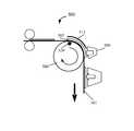
- the apparatusincludes: a rotatable roller comprising a magnet for creating a magnetic field emanating from an outer surface of the roller; a movable belt bending about the rotatable roller, for supporting the substrate and for moving the substrate proximate to the magnet along an arc on the outer surface of the rotatable roller, wherein the arc comprises first and second arc segments; and, a solidifying means for at least partially solidifying the carrier, disposed along the second arc segment, wherein no solidifying means is disposed along the first arc segment, so as to align the magnetic flakes by the magnetic field, when the magnetic flakes move on the support within the first arc segment, and to secure the magnetic flakes in the carrier using the solidifying means while alignment of the magnetic flakes is maintained by the magnetic field, when the carrier with the magnetic flakes move on the support within the second arc segment.
- Yet another aspect of this inventionprovides an apparatus for aligning magnetic flakes dispersed in a carrier.
- the apparatusincludes: a support for supporting a substrate with the magnetic flakes in the carrier, movable along a support path; a magnet assembly for providing a first magnetic field for aligning magnetic flakes into a first alignment; and, a solidifying station located in a predetermined position for at least partially solidifying the carrier, before the carrier exits the first magnetic field and before the carrier reaches an exit field which is provided by the magnet assembly and differs from the first field such that the flakes remain in said first alignment.
- FIG. 1Ais a simplified flow chart of a method of aligning magnetic flakes.
- FIG. 1Bis a simplified cross section of apparatus for aligning magnetic flakes according to an embodiment of the present invention.
- FIG. 1Cis a simplified cross section of apparatus for aligning magnetic flakes according to another embodiment of the present invention.
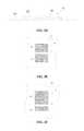
- FIG. 2Ais a simplified cross section of a printed image that will be referred to as a “flip-flop.”
- FIG. 2Bis a simplified plan view of the printed image on a document at a first selected viewing angle.
- FIG. 2Cis a simplified plan view of the printed image at a second selected viewing angle, obtained by tilting the image relative to the point of view.
- FIG. 2Dis a simplified cross section of a printed image that will be referred to as a “rolling bar” for purposes of discussion, according to another embodiment of the present invention.
- FIGS. 2E and 2Fshow plan views of the rolling bar image at first and second selected viewing angles respectively.
- FIG. 3Ais a simplified cross view of apparatus for producing a flip-flop type image.
- FIG. 3Bis a simplified cross-section of apparatus for producing a flip-flop type image.
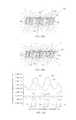
- FIG. 3Cillustrates the calculated magnitude of the field intensity across the apparatus of FIG. 3B .
- FIG. 4is a simplified schematic of a magnet assembly that can be installed in the in-line printing or painting equipment.
- FIG. 5Ais a simplified cross section of apparatus for producing a flip-flop type image with a sharper transition, according to an embodiment of the present invention.
- FIG. 5Bis a simplified cross section of apparatus for producing an image according to another embodiment of the present invention.
- FIG. 5Cis a simplified cross section of a portion of the apparatus illustrated in FIG. 5B , showing the orientation of the flakes in such a magnetic device.
- FIG. 5Dis a graph illustrating the calculated magnitude of field intensity for the apparatus of FIGS. 5B and 5C .
- FIG. 6is a simplified schematic of a magnet assembly that can be installed in the in-line printing or painting equipment.
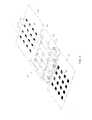
- FIG. 7Ais a simplified perspective view of an apparatus for forming a semi-circular orientation of flakes in paint or ink for a rolling bar type image.
- FIG. 7Bis a simplified side view of an apparatus for forming a rolling bar image in accordance with another embodiment of the present invention.
- FIG. 8is a simplified schematic of an apparatus for printing rolling bar images according to an embodiment of the present invention that can be installed in the in-line printing or painting equipment
- FIG. 9Ais a simplified cross section of another optical effect that is possible to achieve using magnetic alignment techniques in high-speed printing processes.
- FIG. 9Bis a simplified cross section of apparatus according to an embodiment of the present invention capable of producing the image illustrated in FIG. 9A .
- FIG. 9Cis a simplified cross section of apparatus according to another embodiment of the present invention.
- FIG. 9Dis a simplified cross section of apparatus according to yet another embodiment of the present invention.
- FIG. 9Eillustrates the calculated magnetic field intensity for an associated five-magnet apparatus.
- FIG. 10Ais a simplified side view of an apparatus for printing illusive images that tilts magnetic flakes in a selected direction according to another embodiment of the present invention.
- FIG. 10Bis a simplified side view of an apparatus for printing illusive images that includes auxiliary magnets according to another embodiment of the present invention.
- FIG. 10Cis a simplified plot illustrating the magnetic field intensity for the apparatus of FIGS. 10A and 10B .
- FIG. 11Ais a simplified side view of an apparatus for aligning magnetic pigment flakes to the plane of the substrate after printing.
- FIG. 11Bis a simplified side view of a portion of an apparatus for enhancing the visual quality of an image printed with magnetically alignable flakes.
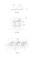
- FIG. 12Ais a simplified perspective of one embodiment of the roller with magnetic assemblies for use in the apparatus illustrated in FIG. 1C .
- FIG. 12Bis a simplified perspective view of a magnetic roller incorporating embedded permanent magnets.
- the present inventionin its various embodiments solves the problem of pre-determined orientation of magnetic flakes of optically variable ink in a high-speed printing process.
- particles of an optically variable pigment dispersed in a liquid paint or ink vehiclegenerally orient themselves to be substantially parallel to the surface when printed or painted on to a surface.
- Orientation of reflective flakes parallel to the surfaceprovides high reflectance of incident light from the coated surface.
- Magnetic flakescan be tilted while in the liquid medium by applying a magnetic field. The flakes generally align in such way that the longest diagonal of a flake follows a magnetic field line. Depending on the position and strength of the magnet, the magnetic field lines can penetrate the substrate at different angles, tilting magnetic flakes to these angles.
- a tilted reflective flakereflects incident light differently than a reflective flake that is parallel to the surface of the printed substrate. Reflectance and hue both vary dependent on the flake orientation. Tilted flakes typically look darker and have a different color than flakes parallel to the surface at a normal viewing angle.
- the effect of moving through the field without being affected by the movementcan be achieved by using a specially designed magnet assembly which extends along the substrate path and has magnetic lines perpendicular to the direction of movement of the substrate.
- painted or printed liquid paint or ink medium with dispersed magnetic flakes on the substratemoves perpendicular to magnetic lines of the field to cause re-orientation of the flakes.
- a method 320 of aligning magnetic flakesincludes: a coating step 322 , when a substrate is coated with a carrier having the magnetic flakes dispersed therein, followed by an aligning step 324 , wherein the substrate moves in a magnetic field so as to align the magnetic flakes along force lines of the magnetic field.
- a solidifying step 326is performed after the aligning step 324 and before the substrate reaches an exit field part of the magnetic field, and includes at least partially solidifying the carrier using a solidifying means while further moving the substrate in the magnetic field so as to secure the magnetic flakes in the carrier while the magnetic field maintains alignment of the magnetic flakes.
- no solidifying meansaffect the carrier during the alignment step 324 , when the flakes are moving within the carrier and may have not reached the desired orientation yet.
- the carrier with flakes thereine.g. in the form of ink or paint
- the flakesare non-spherical, preferably planar, magnetic flakes, i.e. pigment flakes that can be aligned using a magnetic field. They may or may not retain remnant magnetization.
- a typical flakeis twenty microns across and about one micron thick.
- the imageis printed or painted on the substrate, such as paper, plastic film, laminate, card stock, or other surface.
- the substratemay be a continuous roll, or a sequence of substrate sheets, or have any discrete or continuous shape.
- the substrateis supported by a support which may be a belt, a platform, a frame, etc.
- the term “printed”will be used to generally describe the application of pigments in a carrier to a surface, which may include painting, ink jet printing, silk printing, intaglio printing, etc.
- the carriercan be a liquid or paste-like carrier, curable by the UV-light or e-beam source, e.g. a photopolymer, or a solvent-based carrier, including water-based.
- the substrateBefore the carrier dries or sets, the substrate is moved relative to a magnet assembly to orient the magnetic pigment flakes.
- a portion of the carrier with flakesalso referred to as “printed image,” moves along a substrate path in the magnetic field provided by a magnet assembly perpendicular to force lines of the field.
- the magnetic fieldit is desirable for the magnetic field to have a constant profile along the substrate path.
- the magnet assemblyis designed so that the profile of the field, a cross-section of the field in a plane normal to the substrate path, changes very little while the substrate moves along the substrate path during the aligning step 324 and solidifying step 326 , before the carrier is at least partially solidified in the solidifying step 326 , so as to obtain an optically variable image resulting from the alignment of the flakes.
- first and second cross-sections of the magnetic field in any first and second points of the substrate pathare substantially a same desired field profile.
- the imagemay have additional optically variable effects, such as color-shifting.
- the magnet assemblyis configured to provide a flip-flop image.
- the magnet assemblyis configured to provide a rolling bar image.
- the thin planar substrateis a sheet that is printed with several images. The images on the sheet can be the same or different, and different inks or paints can be used to print the images on the sheet. Similarly, different magnetic assemblies can be used to create different images on a single sheet of substrate.
- the substratecan be an essentially continuous substrate, such as a roll of paper.
- the flakesare being aligned and secured while the substrate moves along the magnet assembly perpendicular to the field force lines.
- the cross-sectional profile of the fieldchanges insignificantly, if at all, and the flakes are aligned and secured while affected by a substantially same field configuration.
- the step of securing the flakes in the carrierhappens while the alignment of the flakes is maintained by the magnetic field, which ensures the desired flake pattern rendered with a high degree of precision. Since the printed image moves pass the magnetic assembly at a relatively high speed, the method of this invention is suitable for mass production of printed images having magnetic flakes aligned therein.
- FIG. 1BAn exemplary apparatus for aligning magnetic flakes dispersed in a carrier is shown in FIG. 1B .
- the apparatus 400includes a magnet assembly 406 , a support in the form of a belt 401 for supporting a substrate and a dispenser in the form of a printing press rollers 402 for coating the substrate with the carrier having the magnetic flakes.
- the apparatus 400also includes a solidifying means 409 for partial solidifying or complete solidifying (curing) the carrier with aligned magnetic flakes.
- the belt 401passes through the rollers 402 of the printing press in a direction 403 .
- the carrier printed onto the substrate 404is supported by the belt 401 and moves along a support path, which, in this instance, coincides with the belt 401 .
- the substrate 404further referred to as “image 404 ,” is shown in FIG. 1B in several positions and is also referred to as an “image 405 .”
- the wet ink of the image on the substrate 404contains magnetic flakes.
- the flakes in the inkapproach a linear magnet assembly 406 , they start to change their orientation following magnetic lines of the field. While moving through an alignment segment 407 of the substrate path, the flakes have enough time to orient in the direction of the field in this region. Moving further with the belt 401 , the flakes approach and subsequently enter a solidifying segment 408 of the substrate path.
- a solidifying means 409e.g. a UV lamp, e-beam source, or a heater, is installed above of the assembly 406 , so as to illuminate the image 405 .
- any solidifying source compatible with the carriercan be used.
- UV-curing or e-beam curingcause almost instantaneous solidifying of the carrier.
- Solidifying solvent-based carriers with a heat source or drierrequires more time and evaporation of the solvent may cause the thickness of the ink or paint layer to lessen up to 60% , whereas UV- or e-beam curable organic carriers do not shrink when cure.
- the solidifying means 409secure the magnetic flakes in the carrier within the image 405 , while the alignment of the magnetic flakes is maintained by the magnetic field of the magnet assembly 406 .
- a screen 411prevents solidifying of the ink or paint when the printed image 405 is in the alignment segment 407 where the flakes change their orientation.
- the light screenprevents solidifying of the carrier in the areas of the image where the flakes were not aligned yet.
- the shieldis made from a non-magnetic sheet metal having thickness in the range of 0.01′′ to 0.1′′ and extends along a half of the magnetic assembly length from the point of the first contact of the printed image and the magnets.
- the screen 411is not necessary if the solidifying means 409 , e.g. a UV light source, is mounted very close to the belt 401 . However, the screen 411 prevents the wet image 405 from any possible scattered or diffused UV light radiated from the lamp that can cause partial solidifying of the ink while the image 405 is in the alignment segment 407 of the substrate path.
- the solidifying of the ink in the segment 408can be either full or partial.
- another solidifying source 412may be used downstream along the belt 401 .
- the magnet assemblymay be an elongate assembly including one or more permanent magnets with North and South poles at long surfaces of the magnets. Exemplary magnet assemblies are shown in FIGS. 4, 6, and 8 and are described further herein.
- the elongate assemblymay be formed of elongate magnet(s), as shown in FIGS. 6 and 8 , or row(s) of magnets, as shown on FIG. 4 .
- the belt supporting a printed imagemoves along the support path, which is a straight line.
- a support supporting a printed imagemay move along a curve as soon as it follows the surface of a magnet assembly and the support moves orthogonally to force lines of the magnetic field so as to ensure that the profile of the field is a substantially same profile, i.e. it changes insignificantly along the support path in the proximity of the magnet assembly.
- FIG. 1Cshows an apparatus 500 for aligning magnetic flakes dispersed in a carrier. Differently from the apparatus 400 shown in FIG. 1B , the apparatus 500 has a belt 501 which bends about a rotary magnet assembly 506 .
- the magnet assembly 506includes a rotatable roller and one or more magnets 520 along the cylindrical surface thereof for creating a magnetic field emanating from an outer surface of the roller.
- the belt 501moves while bending about the roller so that a substrate path is an arc on the outer surface of the roller.
- a substrate 505 with magnetic flakes thereon for a period of timemoves together with the magnet 520 along the arc, initially without being affected by a solidifying means 509 , e.g. protected by a screen 511 and, then, under the solidifying means 509 for at least partially solidifying the carrier and securing the flakes while their alignment is maintained by the magnet 520 .
- the solidifying means 509may be a UV- or e-beam source, a heater, or a drier. Exemplary rotary magnet assemblies are shown in FIGS. 12A ,B.
- Fixing magnetic flakes in a predetermined orientation on the fast moving support in the last segment of the support path right before the exit fieldallows printing of images with very crisp optical effects.
- the flakescome to the exit field of a magnet assembly with their orientation permanently or partially fixed.
- This methodprovides remarkable illusive optical effects in the printed image.
- One type of optical effectswill be referred to as a kinematic optical effect for purposes of discussion.
- An illusive kinematic optical effectgenerally provides an illusion of motion in the printed image as the image is tilted relative to the viewing angle, assuming a stationary illumination source.
- Another illusive optical effectprovides virtual depth to a printed, two-dimensional image. Some images may provide both motion and virtual depth.
- Another type of illusive optical effectsswitches the appearance of a printed field, such as by alternating between bright and dark colors as the image is tilted back and forth.
- FIG. 2Ais a simplified cross section of a printed image 20 that will be referred to as a “switching” optical effect, or “flip-flop”, for purposes of discussion, according to an embodiment of the present invention.
- the flip-flopincludes a first printed portion 22 and a second printed portion 24 , separated by a transition 25 .
- Pigment flakes 26 surrounded by carrier 28such as an ink vehicle or a paint vehicle have been aligned parallel to a first plane in the first portion, and pigment flakes 26 ′ in the second portion have been aligned parallel to a second plane.
- the flakesare shown as short lines in the cross-sectional view.
- the flakesare magnetic flakes, i.e. pigment flakes that can be aligned using a magnetic field.
- the figuresare not drawn to scale. A typical flake might be from 1 to 500 microns across and 0.1 to 100 micron thick, hence the figures are merely illustrative.
- the imageis printed or painted on a substrate 29 , such as paper, plastic film, laminate, card stock, or other surface.
- a substrate 29such as paper, plastic film, laminate, card stock, or other surface.
- the term “printed”will be used to generally describe the application of pigments in a carrier to a surface, which may include other techniques, including techniques others might refer to as “painting”.
- flakes viewed normal to the plane of the flakeappear bright, while flakes viewed along the edge of the plane appear dark.
- light from an illumination source 30is reflected off the flakes in the first region to the viewer 32 .
- the flakes in the first region 22will be viewed on-end, while light will be reflected off the flakes in the second region 24 .
- the first regionwill appear light and the second region will appear dark, while in the second viewing position the fields will flip-flop, the first region becoming dark and the second region becoming light. This provides a very striking visual effect.
- the pigment flakesare color-shifting, one portion may appear to be a first color and the other portion another color.
- the carrieris typically transparent, either clear or tinted, and the flakes are typically fairly reflective.
- the carriercould be tinted green and the flakes could include a metallic layer, such as a thin film of aluminum, gold, nickel, platinum, or metal alloy, or be a metal flake, such as a nickel or alloy flake.
- the light reflected off a metal layer through the green-tinted carriermight appear bright green, while another portion with flakes viewed on end might appear dark green or other color. If the flakes are merely metallic flakes in a clear carrier, then one portion of the image might appear bright metallic, while another appears dark.
- the metallic flakesmight be coated with a tinted layer, or the flakes might include an optical interference structure, such as an absorber-spacer-reflector Fabry-Perot type structure.
- FIG. 2Bis a simplified plan view of the printed image 20 on the substrate 29 , which could be a document, such as a bank note or stock certificate, at a first selected viewing angle.
- the printed imagecan act as a security and/or authentication feature because the illusive image will not photocopy and cannot be produced using conventional printing techniques.
- the first portion 22appears bright and the second portion 24 appears dark.
- the section line 40indicates the cross section shown in FIG. 2A .
- the transition 25 between the first and second portionsis relatively sharp.
- the documentcould be a bank note, stock certificate, or other high-value printed material, for example.
- FIG. 2Cis a simplified plan view of the printed image 20 on the substrate 29 at a second selected viewing angle, obtained by tilting the image relative to the point of view.
- the first portion 22now appears dark, while the second portion 24 appears light.
- the tilt angle at which the image flip-flopsdepends on the angle between the alignment planes of the flakes in the different portions of the image. In one sample, the image flipped from light to dark when tilted through about 15 degrees.
- FIG. 2Dis a simplified cross section of a printed image 42 of a kinematic optical device that will be referred to as a “rolling bar” for purposes of discussion, according to another embodiment of the present invention.
- the imageincludes pigment flakes 26 surrounded by a transparent carrier 28 printed on a substrate 29 .
- the pigment flakesare aligned in a curving fashion.
- the region(s) of the rolling bar that reflect light off the faces of the pigment flakes to the viewerappear lighter than areas that do not directly reflect the light to the viewer.
- This imageprovides a light band(s) or bar(s) that appear to move (“roll”) across the image when the image is tilted with respect to the viewing angle (assuming a fixed illumination source(s)).
- FIG. 2Eis a simplified plan view of the rolling bar image 42 at a first selected viewing angle.
- a bright bar 44appears in a first position in the image between two contrasting fields 46 , 48 .
- FIG. 2Fis a simplified plan view of the rolling bar image at a second selected viewing angle.
- the bright bar 44 ′appears to have “moved” to a second position in the image, and the sizes of the contrasting fields 46 ′, 48 ′ have changed.
- the alignment of the pigment flakescreates the illusion of a bar “rolling” down the image as the image is tilted (at a fixed viewing angle and fixed illumination). Tilting the image in the other direction makes the bar appear to roll in the opposite direction (up).
- the barmay also appear to have depth, even though it is printed in a plane.
- the virtual depthcan appear to be much greater than the physical thickness of the printed image.
- the tilting of the flakes in a selected patternreflects light to provide the illusion of depth or “3D”, as it is commonly referred to.
- a three-dimensional effectcan be obtained by placing a shaped magnet behind the paper or other substrate with magnetic pigment flakes printed on the substrate in a fluid carrier.
- the flakesalign along magnetic field lines and create the 3D image after setting (e.g. drying or curing) the carrier.
- the imageoften appears to move as it is tilted, hence kinematic 3D images may be formed.
- Flip-flops and rolling barscan be printed with magnetic pigment flakes, i.e. pigment flakes that can be aligned using a magnetic field.
- a printed flip-flop type imageprovides an optically variable device with two distinct fields that can be obtained with a single print step and using a single ink formulation.
- a rolling bar type imageprovides an optically variable device that has a contrasting band that appears to move as the image is tilted, similar to the semi-precious stone known as Tiger's Eye. These printed images are quite noticeable and the illusive aspects would not photocopy.
- Such imagesmay be applied to bank notes, stock certificates, software documentation, security seals, and similar objects as authentication and/or anti-counterfeiting devices. They are particularly desirable for high-volume printed documents, such as bank notes, packaging, and labels, because they can be printed in a high-speed printing operation, as is described below.
- FIG. 3Ais a simplified cross view of a portion of an apparatus 50 for producing a flip-flop type image.
- the flakes 26are arranged in a V-shaped manner where both branches of the V represent directions of the tilt and the apex represents a transition point. Such orientation of the flakes is possible when two magnetic fields oppose each other.
- Two magnets 52 , 54are aligned with opposing poles (in this case north-north).
- the magnetswere assumed to be 2′′W by 1.5′′H NdFeB magnets 40 MOe spaced 0.125 inches between the north poles.
- the type of magnet(material and strength) is selected according to the material of the flake, viscosity of the paint vehicle, and a substrate translation speed.
- neodymium-boron-iron, samarium-cobalt, and/or ALNICO magnetcan be utilized.
- the optimum distance between magnetsis important for the formation of the uniformity of the optical effect for a particular printed image size.
- the image 56is printed on a thin printing or painting substrate 58 , such as a sheet of paper, plastic, film, or card stock in a previous printing step, which is not illustrated in this figure.
- a thin printing or painting substrate 58such as a sheet of paper, plastic, film, or card stock in a previous printing step, which is not illustrated in this figure.
- several imagesare printed on the substrate, which is subsequently cut into individual documents, such as printing a sheet of banknotes that is cut into currency.
- the carrier 28is still wet or at least sufficiently fluid to allow alignment of the magnetic flakes with the magnets.
- the carriertypically sets shortly after alignment to allow handling of the printed substrate without smearing the image.
- the magnetic flakes 26follow direction of magnetic lines 60 and tilt.
- FIG. 3Bis a simplified cross-section of a portion of an apparatus for producing a flip-flop type image where the magnets 52 , 54 are mounted on a base 62 made from a metal alloy with high magnetic permeability, such as S UPERMALLOY . It is easier to make an assembly of several magnets if they are attached to a base, and the base provides a path for the magnetic field on the opposite side of the magnet, and alters the magnetic field lines on the print side of the assembly.
- the magnetic baseacts as a shunt for the magnetic field and reduces the magnetic field behind (“underneath”) the assembly, thus screening objects near the backside from high magnetic fields and forces.
- the magnetic basealso holds the magnets securely in position without screws, bolts, welds, or the like. Magnetic field circulates inside the base 62 providing uniformity of the field between the magnets. The field is the most intensive in the gap between magnets and above it.
- FIG. 3Cillustrates the calculated magnitude of the field intensity across the apparatus of FIG. 3B .
- Intensityis low near the edges of magnets, and becomes very high in the middle, providing a sharp transition between the flakes in adjacent portions of the image.
- FIG. 4is a simplified schematic of a magnet assembly 64 that can be installed in the in-line printing or painting equipment.
- Permanent magnets 66 , 68 , 70 , 72 , 74 , 76 with their north and south poles indicated with “N” and “S”, respectively, similar to those illustrated in FIG. 3B ,are attached to the base 62 by magnetic attraction.
- the magnetsmay be magnetic bars, or may be segmented. That is, rows of magnets, e.g. 74 , 76 , etc., may be used.
- Plastic spacers(not shown in the picture) may be inserted between magnets to prevent their collision and provide safety.
- the assemblyis enclosed in a case 78 and covered with a cover 80 .
- the case and covermay be aluminum or other non-magnetic material.
- a plastic or paper substrate 29 with printed fields 20 ′moves at high speed over the top of the assembly in the direction of the arrows 82 in such way that gaps between two magnets, e.g. magnets 72 and 74 , go through the centers of the printed fields.
- the gaps between the magnetsmay be offset from the centers of the printed fields.
- the substratecould be a continuous roll, rather than sequential sheets. In many cases, several sets of images are printed on a sheet, and the sheet is cut into individual documents, such as bank notes, after the printing is completed.
- a drier for water- or solvent-based paints or inks (not shown in the picture) or UV-light source for photopolymerstypically follows the magnet assembly shortly in the line to dry the ink or paint vehicle and fix re-oriented flakes in their aligned positions. It is generally desirable to avoid magnetizing flakes before application, as they may clump together. Pigment flakes with layers of nickel or P ERMALLOY about 100-150 nm thick have been found to be suitable.
- FIG. 5Ais a simplified cross section of an apparatus for producing a flip-flop type image with a sharper transition, according to an embodiment of the present invention.
- Two NdFeB magnets 84(modeled as being 2′′W by 1.5′′H each) are placed on the magnetic base 62 facing with their north poles “up”. The distance between magnets is about one inch.
- a blade 88 made of a high-permeability metal or metal alloy, such as S UPERMALLOYis attached to the base between the magnets. The point of attack of the tip 90 of the blade is in the range of about 5 degrees to about 150 degrees. The blade re-shapes the magnetic field lines, pulling them closer and making the tip as a point where the magnetic field lines originate.
- FIG. 5Bis a simplified cross section of an apparatus for producing an image according to another embodiment of the present invention.
- Shaped S UPERMALLOY caps 92are placed on the top of magnets 84 to bend the magnetic field lines, as illustrated. The caps bend the field, bringing it closer to the tip, which makes the V-shape transition of the lines even sharper.
- FIG. 5Cis a simplified cross section of a portion of the apparatus illustrated in FIG. 5B , showing the orientation of the flakes in such a magnetic device.
- the substrate 29is placed on the top of the device sliding along the caps 92 (or magnets, in the case of FIG. 5A ) in the direction from the viewer into the page.
- the printed image 85is located above the tip.
- the flakes 26follow magnetic lines 94 and tilt accordingly. This view more clearly shows the pointed nature of the tip of the blade, which produces a sharp transition between the two areas of the illusive image.
- FIG. 5Dis a graph illustrating the calculated magnitude of field intensity for the apparatus of FIGS. 5B and 5C .
- the field intensityis narrower compared with the field intensity plot of FIG. 3C , and produces a sharper transition.
- FIG. 6is a simplified schematic of a magnet assembly 100 that can be installed in the in-line printing or painting equipment.
- Permanent magnets 84 with their north and south poles as illustrated in FIGS. 5A and 5Bare mounted on a magnetic base 62 . Alternatively, the south poles could be facing up.
- Cap plates 92are magnetically attached to the top of magnets.
- Blades 88are mounted on the base with their edges extending along the direction of translation 82 of the substrates 29 , 29 ′.
- the in-line magnets 84can be installed either next to each other or with a gap 102 between them.
- the magnet assemblyis typically enclosed in a case 78 with a cover plate 80 .
- Fields 104 ′ printed on the substrate 29have generally non-oriented flakes. Some alignment of the flakes may occur as an artifact of the printing process, and generally some of the flakes tending to align in the plane of the substrate. When the substrate moves at high speed in the direction indicated by the arrow 82 above the magnet assembly, the flakes change their orientation along lines of the magnetic field forming an illusive image 104 (flip-flop). The image has two areas which reflect light in different directions and a relatively sharp border (transition) between them.
- FIG. 7Ais a simplified perspective view of an apparatus for forming a semi-circular orientation of flakes in paint or ink for a rolling bar type image.
- a thin permanent magnet 106has North and South poles at the side surfaces thereof.
- the substrate 29 with the printed magnetic flakes dispersed in a fluid carriermoves along the magnet from the viewer into the paper.
- the flakes 26tilt along direction of the magnetic lines and form a semi-circle pattern above the magnet.
- the substrate 29moves across the magnet 106 in the direction of the arrow.
- the image 110forms a rolling bar feature 114 , which will appear to move up and down as the image is tilted or the viewing angle is changed.
- the flakes 26are shown as being tilted in relation to the magnetic field lines.
- the imageis typically very thin, and the flakes might not form a hump, as illustrated, but generally align along the magnetic field lines to provide the desired arched reflective properties to create a rolling bar effect.
- the barappeared to roll up and down the image when tilted through an angle of about 25 degrees in one example.
- the intensity of the rolling bar effectcould be enhanced by chamfering 116 the trailing edge 118 of the magnet. It is believed that this gradually reduces the magnetic field as the image clears the magnet. Otherwise, the magnetic transition occurring at a sharp corner of the magnet might re-arrange the orientation of the flakes and degrade the visual effect of the rolling bar.
- the corner of the magnetwas chamfered at an angle of thirty degrees from the plane of the substrate.
- An alternative approachis to fix the flakes before they pass over the trailing edge of the magnet. By way of example, this could be done by providing a UV source part way down the run of the magnet, for a UV-curable carrier, or a drying source for evaporative carriers.
- FIG. 7Bis a simplified side view of another apparatus 120 for forming a rolling bar image according to another embodiment of the present invention.
- the rolling bar effectis obtained using two magnets 122 .
- the magnetic pigment flakes 26orient themselves in the liquid carrier 28 along the oval magnetic field lines.
- FIG. 8is a simplified schematic of an apparatus 130 for printing rolling bar images according to an embodiment of the present invention that can be installed in the in-line printing or painting equipment.
- Thin vertical magnets 106with their north-south polarization as shown, are installed in a plastic housing 132 that separates the magnets at selected distances, generally according to the location of the printed fields 110 ′ on the substrate 29 .
- the magnetsare aligned in such fashion that they oppose each other. In other words, the north pole of one row of magnets faces the north pole of an adjacent row, while the south pole faces the south pole of an adjacent row of magnets from the other side.
- the apparatus FIG. 8does not have a metallic base.
- a base made from a metal having high magnetic permeabilitywould reduce the strength of a magnetic field on the side of the magnet that is responsible for the tilt of the flakes.
- the magnetsare inserted in slits of the plastic housing in such way that the upper part of the magnets goes underneath of the center of printed fields, but could be offset from the center.
- the substrate 29 , 29 ′move at high speed atop the magnets in the direction of the arrows 82 . Passing above the magnets, the flakes in the printed images orient themselves along lines of the magnetic field, creating an illusive optical effect in rolling bar image 110 .
- FIG. 9Ais a simplified cross section of another optical effect that is possible to achieve using magnetic alignment techniques in high-speed printing processes.
- the pigment flakes 26 in the image 134are generally aligned parallel to each other, but not parallel to the surface of the substrate 29 . Again, it is not necessary that each flake be perfectly aligned with each other flake, but the visual impression obtained is essentially in accordance with the illustration. Alignment of the majority of the flakes in the manner illustrated causes an interesting optical effect. The image looks dark when observed from one direction 136 and bright when observed from another direction 138 .
- FIG. 9Bis a simplified cross section of an apparatus 139 according to an embodiment of the present invention capable of producing the image illustrated in FIG. 9A .
- a printed field 134 with still-wet paint or inkis placed above permanent magnet 140 with offset position relatively the magnet axes.
- the analysis of the magnetic fieldwas modeled assuming a 2′′ by 1.5′′ NdFeB 40 MOe magnet. The magnitude of the field intensity is lower in the center of the magnet and higher towards its edges.
- electromagnetsmight be used in some embodiments, but it is difficult to obtain magnetic fields as high as can be obtained with current supermagnets in the confined spaces of a high-speed printing machine.
- the coils of electromagneticalso tend to generate heat, which can affect the solidifying time of the ink or paint and add another process variable. Nonetheless, electromagnetic may be useful in some embodiments of the invention.
- FIG. 9Cis a simplified cross section of an apparatus according to another embodiment of the present invention.
- Magnets 142 , 142 ′ having a diamond-shaped cross sectionare used to spread the magnetic field and make it wider.
- the apparatuswas modeled with three two-inches by one and a half inches NdFeB magnets arranged one inch from each other.
- the magnetsshow a cross-section of a magnet assembly for re-orientation of flakes in a magnetic field.
- the substrate 29moves at a high speed in the direction from the viewer into the drawing.
- Two magnetshave their north pole facing up while the intervening magnet 142 ′ has its south pole facing up.
- Each magnethas the same field intensity as the magnets illustrated in FIG. 9B , but provides a wider area for placement of the field 134 ′ for orienting the flakes 26 .
- FIG. 9Dis a simplified cross section of an apparatus according to yet another embodiment of the present invention.
- An effect similar to that obtained with the apparatus illustrated in FIG. 9Ccan be obtained with magnets 144 , 144 ′ having a roof-shaped cross-section, as well as with magnets having hexagonal, rounded, trapezoidal, or other cross-sections.
- Different shapes of magnetsprovide different performance that can create various printed or painted images with tilted flakes.
- the magnitude of magnetic field intensitycan be very different for magnets having different shapes (cross sections).
- FIG. 9Eillustrates the calculated magnetic field intensity for a five-magnet apparatus.
- the first magnet 142is a diamond-shaped NdFeB 40 MOe magnet with dimensions close to 2′′ by 1.5′′ with its north pole facing up.
- the second magnet 146is a rectangular 2′′ by 1.5′′ NdFeB 40 MOe magnet with its south pole facing the substrate 29 .
- the third magnet 148is a NdFeB 40 MOe magnet with rounded top. This magnet has its north pole facing the substrate.
- the fourth magnet 150has its south pole facing up, and is roof-shaped (with the angle of the tip being about 185°).
- the fifth magnet 152is also roof-shaped but the angle of the tip is about 175°.
- the curve 160shows the calculated magnitude of magnetic field intensity in this illustrative assembly.
- Shapes of the field intensityare different for different magnets.
- the field intensityis low in the center of rectangular, diamond and roof-shaped magnets while it becomes almost flat at 380,000 A/m for the rounded magnet 148 .
- the curveshows that shaping of the magnet helps to get a field intensity that will be enough to provide a torque of the flake to orient it.
- FIG. 10Ais a simplified side view of an apparatus 162 according to an embodiment of the present invention that tilts the flakes in a preferred direction and is suitable for adaptation to a high-speed printing process.
- Three 2′′ by 1.5′′ NdFeB 40MOe magnets 164 , 164 ′are tilted 10° relative to the substrate 29 and printed images 166 . Flakes 26 follow magnetic lines and re-orient themselves. The magnets have the same alignment similar to the alignment shown in FIG. 9D .
- Two of the magnets 164have their north poles up and the magnet 164 ′ between them has its south pole facing the substrate 29 .
- the printed images 166should be placed above the central axis of the magnet to take advantage of the tilted magnetic field lines generated by the tilted magnets. Such arrangement produces uniform tilt of the flake on an area that is larger than for the magnetic assemblies described in reference to FIGS. 9A-9E .
- Magnetic lines in the fieldare not parallel. The difference is minor in the near order and becomes larger with increase of a distance between the lines. It means, that on a large printed image, placed in magnetic field, all flakes would have different tilt resulting in a non-consistent image appearance. The inconsistency can be reduced by deflecting of magnetic lines toward the center of the magnet to keep them more parallel. It is possible to do with small auxiliary magnets.
- FIG. 10Bis a simplified side view of an apparatus 168 according to an embodiment of the present invention including auxiliary magnets 170 , 170 ′.
- the tilted primary magnets 172 , 172 ′are arranged similar to the magnets shown in FIG. 10A , with alternating magnets presenting alternating poles (north-south-north) next to the substrate 29 .
- the smaller auxiliary magnetsare located beneath the substrate and between the larger primary magnets.
- the auxiliary magnetsare arranged so that the north pole of an auxiliary magnet faces the north pole of a primary magnet, and its south pole faces the south pole of a primary magnet. In such an arrangement, two fields (north-north, south-south) oppose each other and magnetic lines become deflected toward the center of the primary magnets.
- FIG. 10Cis a simplified plot showing the calculated field intensity for the magnetic assemblies shown in FIGS. 10A and 10B , represented by curves 174 and 176 , respectively.
- the substrate 29 , primary magnets 172 , 172 ′and auxiliary magnets 170 , 170 ′are shown to illustrate how the plots relate to the assembly dimensions, although the auxiliary magnets are only relevant to the plot of the second curve 176 .
- the first curve 174shows how the magnitude of field intensity of the assembly in FIG. 10A changes in the direction from one edge of the substrate to another.
- the curvehas two minima 178 , 180 corresponding to the center of the primary magnets 172 , 172 ′.
- a central axis 182 of the center magnet 172 ′shows where the center of the magnet and the plot of field intensity coincide.
- auxiliary magnets 170 , 170 ′shifts magnitude of field intensity to the left.
- the second curve 176shows magnitude of field intensity of an assembly according to FIG. 10B .
- the maxima 184 , 186 on the curveare shifted to the left relative to the first curve 174 associated with FIG. 10A . This shows that opposing fields on the auxiliary magnets deflect the fields of the primary magnets.
- FIG. 11Ais a simplified side view of an apparatus 190 for aligning magnetic pigment flakes in printed fields 192 in the plane of a substrate after printing.
- Magnets 194 , 196are arranged to produce magnetic field lines 198 essentially parallel to the surface of the substrate 29 .
- the flakesalign essentially parallel to the substrate when applied (printed), but are “pulled” out of plane when the printing screen is lifted, for example. This disorganization of the flakes tends to reduce the visual effect of the print, such as a reduction in chroma.
- magnetic color-shifting pigment flakeswere applied to a paper card using a conventional silkscreen process.
- the same inkwas applied to another paper card, but before the ink carrier dried, a magnet was used to re-orient the flakes in the plane of the card.
- the difference in visual appearance, such as the intensity of the colors,was very dramatic. Measurements indicated that a 10% improvement in chroma had been attained. This level of improvement is very significant, and it is believed that it would be very difficult to achieve such an improvement through modifications of the pigment flake production techniques, such as changes to the substrate and thin film layers of the flake. It is believed that even greater improvement in chroma is possible, and that a 40% improvement might be obtained when magnetic re-alignment techniques are applied to images formed using an Intaglio printing process.
- FIG. 11Bis a simplified side view of a portion of an apparatus for enhancing the visual quality of an image printed with magnetically alignable flakes according to another embodiment of the present invention.
- Magnets 194 , 196create magnetic field lines 198 that are essentially parallel to the substrate 29 , which causes the magnetic pigment flakes 26 in the fluid carrier 28 to flatten out.
- the magnetscan be spaced some distance apart to provide the desired magnetic field, and the apparatus can be adapted to an in-line printing process.
- FIG. 12Ashows a magnetic roller 232 that can be used in the apparatus 500 ; it has been described in U.S. Pat. No. 7,047,883.
- Magnetic assemblies 234 , 236 , 238 , 240 , 241are attached to the roller with screws 242 , which allow the magnetic assemblies to be changed without removing the roller from the printer.
- the magnetic assembliescould be configured to produce flip-flop 234 , 236 or rolling bar 238 images, or could be patterned magnetic material 240 , 241 that produces a patterned image on the printed substrate, or other selected magnetic configuration.
- the magnetic structures on the rollerare aligned to the sheet or roll to provide the desired magnetic field pattern to fields printed on the substrate with magnetic pigment flakes.
- the illustrated patternsrepresent flat patterns that follow the curve of the circumference of the roller.
- the outer surface 244 of the roller 232is advantageous in applications to have the outer surface 244 of the roller 232 sufficiently even or smooth, otherwise it can potentially deform or even damage the substrate 212 .
- the outer surface 244does not have any protruding portions, resulting in a substantially even and uniform contact of the roller with the substrate across the outer surface of the roller.
- FIG. 12Bschematically illustrates a magnetic roller 332 for orienting magnetic flakes according to an embodiment of the present invention.
- the magnetic roller 332has a solid cylindrical body 301 , hereinafter also referred to as a cylindrical member or drum, of preferably non-magnetic material, wherein a plurality of cavities is formed, i.e. milled out of the body 301 from its outer surface 333 .
- Permanent magnets of pre-determined shapes, as required for forming the desired flake patterns, e.g. magnets 302 and 303are inserted in the cavities as shown by dark-shaded areas of the roller 332 , forming magnetic portions of the roller 332 .
- the cavitiesare shown as dark-shaded areas with the magnets inserted therein, e.g. the magnets 302 , 303 and 335 , with a cut-out in a portion of the body 301 shown for the benefit of the viewer to illustrate the positions of the magnets, e.g. the cylindrical magnet 302 and the prism-shaped magnet 335 , within the drum 301 .
- the cavitieshave the pre-determined shape and dimensions of the permanent magnets, and the magnets are statically and immovably kept therein.
- the magnets 302 , 303can be fixed in their position by glue, screws, brackets, etc, or can be press-fitted and kept in their positions by traction.
- the permanent magnets 302 , 303although shown by way of illustration having cylindrical and rectangular shapes, have at least their outer surfaces, e.g. as indicated by an arrow 335 , shaped for creating magnetic fields of predetermined configurations, so as to orient the magnetic flakes in desired 3D patterns when the roller is used in the printing apparatus 200 .
- the roller 332is mounted on an axel 304 with bearings that are not shown in the figure, and a gear wheel 305 fixedly attached to the roller is further provided for rotating the roller 332 about the axel 304 during the printing process.
- the magnets 302 , 303are positioned flush with the outer surface 333 of the body 301 , so that the outer surface of the roller 332 with the magnets 303 , 302 therein is substantially even for providing substantially uniform contact with the substrate 212 across the outer surface of the roller 332 during the linear printing process.
- the term “contact”is used herein to mean either direct or indirect contact between two surfaces, i.e. via an intermediate sheet or plate.
- at least one of the magnets 302 , 303is recessed relative to the outer surface 333 of the drum 301 , and the recess is filled with a non-magnetic filler, e.g.
- the ability to have different magnets at different distances from the ink layeris advantageous for creating different types of optical effects provided by the respective magnetic flake arrangements.
- the ink-magnet distanceshould be minimized.
- the magnetsare preferably positioned at a larger distance from the ink layer, for example between 0.125′′ to 0.75′ for a rolling bar image depending on particular requirements of the graphics.
Landscapes
- Engineering & Computer Science (AREA)
- Mechanical Engineering (AREA)
- Accounting & Taxation (AREA)
- Finance (AREA)
- Business, Economics & Management (AREA)
- Printing Methods (AREA)
- Credit Cards Or The Like (AREA)
- Application Of Or Painting With Fluid Materials (AREA)
- Inks, Pencil-Leads, Or Crayons (AREA)
- Pigments, Carbon Blacks, Or Wood Stains (AREA)
- Soft Magnetic Materials (AREA)
- Manufacturing Of Magnetic Record Carriers (AREA)
- Hard Magnetic Materials (AREA)
Abstract
Description
Claims (12)
Priority Applications (3)
| Application Number | Priority Date | Filing Date | Title |
|---|---|---|---|
| US14/681,551US9522402B2 (en) | 2002-07-15 | 2015-04-08 | Method and apparatus for orienting magnetic flakes |
| US15/350,021US10059137B2 (en) | 2002-07-15 | 2016-11-12 | Apparatus for orienting magnetic flakes |
| US16/113,977US11230127B2 (en) | 2002-07-15 | 2018-08-27 | Method and apparatus for orienting magnetic flakes |
Applications Claiming Priority (17)
| Application Number | Priority Date | Filing Date | Title |
|---|---|---|---|
| US39621002P | 2002-07-15 | 2002-07-15 | |
| US41054702P | 2002-09-13 | 2002-09-13 | |
| US41054602P | 2002-09-13 | 2002-09-13 | |
| US10/386,894US7047883B2 (en) | 2002-07-15 | 2003-03-11 | Method and apparatus for orienting magnetic flakes |
| US11/022,106US7517578B2 (en) | 2002-07-15 | 2004-12-22 | Method and apparatus for orienting magnetic flakes |
| US66885205P | 2005-04-06 | 2005-04-06 | |
| US73792605P | 2005-11-18 | 2005-11-18 | |
| US11/313,165US7604855B2 (en) | 2002-07-15 | 2005-12-20 | Kinematic images formed by orienting alignable flakes |
| US75935606P | 2006-01-17 | 2006-01-17 | |
| US77708606P | 2006-02-27 | 2006-02-27 | |
| US11/278,600US8343615B2 (en) | 2002-07-15 | 2006-04-04 | Dynamic appearance-changing optical devices (DACOD) printed in a shaped magnetic field including printable fresnel structures |
| US11/552,219US7876481B2 (en) | 1999-07-08 | 2006-10-24 | Patterned optical structures with enhanced security feature |
| US11/560,927US7717038B2 (en) | 2005-11-18 | 2006-11-17 | Magnetic plate for printing of optical effects |
| US11/623,190US7934451B2 (en) | 2002-07-15 | 2007-01-15 | Apparatus for orienting magnetic flakes |
| US10428908P | 2008-10-10 | 2008-10-10 | |
| US12/574,007US9027479B2 (en) | 2002-07-15 | 2009-10-06 | Method and apparatus for orienting magnetic flakes |
| US14/681,551US9522402B2 (en) | 2002-07-15 | 2015-04-08 | Method and apparatus for orienting magnetic flakes |
Related Parent Applications (1)
| Application Number | Title | Priority Date | Filing Date |
|---|---|---|---|
| US12/574,007DivisionUS9027479B2 (en) | 2002-07-15 | 2009-10-06 | Method and apparatus for orienting magnetic flakes |
Related Child Applications (1)
| Application Number | Title | Priority Date | Filing Date |
|---|---|---|---|
| US15/350,021ContinuationUS10059137B2 (en) | 2002-07-15 | 2016-11-12 | Apparatus for orienting magnetic flakes |
Publications (2)
| Publication Number | Publication Date |
|---|---|
| US20150217307A1 US20150217307A1 (en) | 2015-08-06 |
| US9522402B2true US9522402B2 (en) | 2016-12-20 |
Family
ID=31999561
Family Applications (4)
| Application Number | Title | Priority Date | Filing Date |
|---|---|---|---|
| US10/386,894Expired - LifetimeUS7047883B2 (en) | 1999-07-08 | 2003-03-11 | Method and apparatus for orienting magnetic flakes |
| US12/574,007Expired - LifetimeUS9027479B2 (en) | 2002-07-15 | 2009-10-06 | Method and apparatus for orienting magnetic flakes |
| US14/681,551Expired - LifetimeUS9522402B2 (en) | 2002-07-15 | 2015-04-08 | Method and apparatus for orienting magnetic flakes |
| US15/350,021Expired - LifetimeUS10059137B2 (en) | 2002-07-15 | 2016-11-12 | Apparatus for orienting magnetic flakes |
Family Applications Before (2)
| Application Number | Title | Priority Date | Filing Date |
|---|---|---|---|
| US10/386,894Expired - LifetimeUS7047883B2 (en) | 1999-07-08 | 2003-03-11 | Method and apparatus for orienting magnetic flakes |
| US12/574,007Expired - LifetimeUS9027479B2 (en) | 2002-07-15 | 2009-10-06 | Method and apparatus for orienting magnetic flakes |
Family Applications After (1)
| Application Number | Title | Priority Date | Filing Date |
|---|---|---|---|
| US15/350,021Expired - LifetimeUS10059137B2 (en) | 2002-07-15 | 2016-11-12 | Apparatus for orienting magnetic flakes |
Country Status (9)
| Country | Link |
|---|---|
| US (4) | US7047883B2 (en) |
| EP (5) | EP2263807B1 (en) |
| JP (1) | JP4421555B2 (en) |
| KR (3) | KR101029846B1 (en) |
| CN (1) | CN100384546C (en) |
| AT (1) | ATE493208T1 (en) |
| DE (1) | DE60335544D1 (en) |
| TW (1) | TWI281419B (en) |
| WO (1) | WO2004007095A2 (en) |
Cited By (3)
| Publication number | Priority date | Publication date | Assignee | Title |
|---|---|---|---|---|
| US20170056902A1 (en)* | 2002-07-15 | 2017-03-02 | Viavi Solutions Inc. | Method and apparatus for orienting magnetic flakes |
| CN112691862A (en)* | 2020-03-09 | 2021-04-23 | 斯佩(新昌)科技有限公司 | Inflatable stretching dispersion type anti-counterfeiting particle printing method |
| US11230127B2 (en) | 2002-07-15 | 2022-01-25 | Viavi Solutions Inc. | Method and apparatus for orienting magnetic flakes |
Families Citing this family (207)
| Publication number | Priority date | Publication date | Assignee | Title |
|---|---|---|---|---|
| US7604855B2 (en)* | 2002-07-15 | 2009-10-20 | Jds Uniphase Corporation | Kinematic images formed by orienting alignable flakes |
| US7517578B2 (en)* | 2002-07-15 | 2009-04-14 | Jds Uniphase Corporation | Method and apparatus for orienting magnetic flakes |
| US6761959B1 (en)* | 1999-07-08 | 2004-07-13 | Flex Products, Inc. | Diffractive surfaces with color shifting backgrounds |
| US7667895B2 (en)* | 1999-07-08 | 2010-02-23 | Jds Uniphase Corporation | Patterned structures with optically variable effects |
| US20070195392A1 (en)* | 1999-07-08 | 2007-08-23 | Jds Uniphase Corporation | Adhesive Chromagram And Method Of Forming Thereof |
| JP2003520986A (en)* | 2000-01-21 | 2003-07-08 | フレックス プロダクツ インコーポレイテッド | Optical modulation security device |
| US11768321B2 (en) | 2000-01-21 | 2023-09-26 | Viavi Solutions Inc. | Optically variable security devices |
| US6902807B1 (en) | 2002-09-13 | 2005-06-07 | Flex Products, Inc. | Alignable diffractive pigment flakes |
| US7625632B2 (en)* | 2002-07-15 | 2009-12-01 | Jds Uniphase Corporation | Alignable diffractive pigment flakes and method and apparatus for alignment and images formed therefrom |
| US7934451B2 (en)* | 2002-07-15 | 2011-05-03 | Jds Uniphase Corporation | Apparatus for orienting magnetic flakes |
| US8211509B2 (en)* | 2002-07-15 | 2012-07-03 | Raksha Vladimir P | Alignment of paste-like ink having magnetic particles therein, and the printing of optical effects |
| US7258900B2 (en) | 2002-07-15 | 2007-08-21 | Jds Uniphase Corporation | Magnetic planarization of pigment flakes |
| US20100208351A1 (en)* | 2002-07-15 | 2010-08-19 | Nofi Michael R | Selective and oriented assembly of platelet materials and functional additives |
| US7674501B2 (en)* | 2002-09-13 | 2010-03-09 | Jds Uniphase Corporation | Two-step method of coating an article for security printing by application of electric or magnetic field |
| US9164575B2 (en)* | 2002-09-13 | 2015-10-20 | Jds Uniphase Corporation | Provision of frames or borders around pigment flakes for covert security applications |
| US7258915B2 (en)* | 2003-08-14 | 2007-08-21 | Jds Uniphase Corporation | Flake for covert security applications |
| US7645510B2 (en)* | 2002-09-13 | 2010-01-12 | Jds Uniphase Corporation | Provision of frames or borders around opaque flakes for covert security applications |
| US7241489B2 (en)* | 2002-09-13 | 2007-07-10 | Jds Uniphase Corporation | Opaque flake for covert security applications |
| US9458324B2 (en) | 2002-09-13 | 2016-10-04 | Viava Solutions Inc. | Flakes with undulate borders and method of forming thereof |
| US8025952B2 (en) | 2002-09-13 | 2011-09-27 | Jds Uniphase Corporation | Printed magnetic ink overt security image |
| US7013211B2 (en)* | 2002-12-02 | 2006-03-14 | Hitachi, Ltd. | Variable valve control apparatus for internal combustion engine and method thereof |
| DE10325559B3 (en)* | 2003-06-05 | 2004-12-09 | Fraunhofer-Gesellschaft zur Förderung der angewandten Forschung e.V. | Method and device for producing a system with a component applied to a predetermined location on a surface of a substrate |
| CA2530413C (en)* | 2003-06-30 | 2012-06-19 | Kba-Giori S.A. | Printing machine |
| EP1493590A1 (en)* | 2003-07-03 | 2005-01-05 | Sicpa Holding S.A. | Method and means for producing a magnetically induced design in a coating containing magnetic particles |
| US7550197B2 (en)* | 2003-08-14 | 2009-06-23 | Jds Uniphase Corporation | Non-toxic flakes for authentication of pharmaceutical articles |
| EP1669213A1 (en) | 2004-12-09 | 2006-06-14 | Sicpa Holding S.A. | Security element having a viewing-angle dependent aspect |
| TWI391249B (en)* | 2004-12-22 | 2013-04-01 | Jds Uniphase Corp | Kinematic images formed by orienting alignable flakes |
| US7588817B2 (en) | 2005-03-11 | 2009-09-15 | Jds Uniphase Corporation | Engraved optically variable image device |
| CA2541568C (en) | 2005-04-06 | 2014-05-13 | Jds Uniphase Corporation | Dynamic appearance-changing optical devices (dacod) printed in a shaped magnetic field including printable fresnel structures |
| DE102005019919A1 (en)* | 2005-04-27 | 2006-11-16 | Leonhard Kurz Gmbh & Co. Kg | Method of producing color effect images |
| DE102005033598A1 (en)* | 2005-07-19 | 2007-01-25 | Giesecke & Devrient Gmbh | Value document, production and testing of value documents |
| PT1745940E (en)* | 2005-07-20 | 2014-02-24 | Jds Uniphase Corp | A two-step method of coating an article for security printing |
| EP1760118A3 (en)* | 2005-08-31 | 2008-07-09 | JDS Uniphase Corporation | Alignable diffractive pigment flakes and method for their alignment |
| CA2564764C (en) | 2005-10-25 | 2014-05-13 | Jds Uniphase Corporation | Patterned optical structures with enhanced security feature |
| JP5259946B2 (en)* | 2005-11-18 | 2013-08-07 | ジェイディーエス ユニフェイズ コーポレーション | Magnetic plate for optical effect printing |
| CA2570965A1 (en)* | 2005-12-15 | 2007-06-15 | Jds Uniphase Corporation | Security device with metameric features using diffractive pigment flakes |
| AU2007200128B8 (en) | 2006-01-17 | 2013-02-07 | Viavi Solutions Inc. | Apparatus for orienting magnetic flakes |
| US10343436B2 (en)* | 2006-02-27 | 2019-07-09 | Viavi Solutions Inc. | Security device formed by printing with special effect inks |
| US12204120B2 (en) | 2006-03-06 | 2025-01-21 | Viavi Solutions Inc. | Optically variable security devices |
| CA2580321C (en)* | 2006-03-06 | 2014-11-04 | Jds Uniphase Corporation | Security devices incorporating optically variable adhesive |
| RU2425722C2 (en)* | 2006-03-21 | 2011-08-10 | Акцо Нобель Коатингс Интернэшнл Б.В. | Method of applying pattern on substrate |
| CA2582010A1 (en)* | 2006-03-21 | 2007-09-21 | Jds Uniphase Corporation | Brand protection label with a tamper evident abrasion-removable magnetic ink |
| JP4283817B2 (en)* | 2006-04-05 | 2009-06-24 | 日本ビー・ケミカル株式会社 | Method for manufacturing pattern forming apparatus |
| US8287989B2 (en)* | 2006-04-11 | 2012-10-16 | Jds Uniphase Corporation | Security image coated with a single coating having visually distinct regions |
| EP1854852A1 (en) | 2006-05-12 | 2007-11-14 | Sicpa Holding S.A. | Coating composition for producing magnetically induced images |
| AU2007202166A1 (en)* | 2006-05-19 | 2007-12-06 | Jds Uniphase Corporation | Heating magnetically orientable pigment in a printing process |
| TWI437059B (en)* | 2006-07-12 | 2014-05-11 | Jds Uniphase Corp | Stamping a coating of cured field aligned special effect flakes and image formed thereby |
| EP1880866A1 (en)* | 2006-07-19 | 2008-01-23 | Sicpa Holding S.A. | Oriented image coating on transparent substrate |
| US20080084634A1 (en)* | 2006-09-22 | 2008-04-10 | Board Of Regents Of The Nevada System Of Higher Education On Behalf Of The University Nevada | Devices and methods for storing data |
| US7950587B2 (en)* | 2006-09-22 | 2011-05-31 | The Board of Regents of the Nevada System of Higher Education on behalf of the University of Reno, Nevada | Devices and methods for storing data |
| EP1908598A1 (en)* | 2006-10-04 | 2008-04-09 | Sang Broli Company Limited | Process and material for producing printed designs having three-dimensional visual effect |
| CA2666650C (en)* | 2006-10-17 | 2015-04-28 | Sicpa Holding S.A. | Method and means for producing a magnetically induced indicia in a coating containing magnetic particles |
| CA2613830A1 (en)* | 2006-12-15 | 2008-06-15 | Alberto Argoitia | An article with micro indicia security enhancement |
| EP1961559A1 (en) | 2007-02-20 | 2008-08-27 | Kba-Giori S.A. | Cylinder body for orienting magnetic flakes contained in an ink or varnish vehicle applied on a sheet-like or web-like substrate |
| EP1990208A1 (en) | 2007-05-10 | 2008-11-12 | Kba-Giori S.A. | Device and method for magnetically transferring indica to a coating composition applied to a substrate |
| MX2009013099A (en)* | 2007-06-05 | 2010-08-18 | Bank Of Canada | Ink or toner compositions, methods of use, and products derived therefrom. |
| AU2008219354B2 (en)* | 2007-09-19 | 2014-02-13 | Viavi Solutions Inc. | Anisotropic magnetic flakes |
| WO2009094063A1 (en) | 2008-01-24 | 2009-07-30 | Quad/Graphics, Inc. | Printing using color changeable material |
| JP2009193069A (en) | 2008-02-13 | 2009-08-27 | Jds Uniphase Corp | Laser printing media containing optical special effect flakes |
| US8281997B2 (en)* | 2008-02-19 | 2012-10-09 | Bilcare Technologies Singapore Pte. Ltd. | Reading device for identifying a tag or an object adapted to be identified, related methods and systems |
| TW200948631A (en)* | 2008-05-26 | 2009-12-01 | San Fang Chemical Industry Co | Resin cover layer, method for manufacturing the same, composite material having the same and method for manufacturing the composition material |
| RU2499635C2 (en)* | 2008-08-18 | 2013-11-27 | Джей Ди Эс ЮНИФЕЙЗ КОРПОРЕЙШН | Biaxial leveling of magnetic plates |
| TWI487628B (en)* | 2008-11-24 | 2015-06-11 | Sicpa Holding Sa | Magnetically oriented ink on primer layer |
| AR076210A1 (en) | 2009-04-07 | 2011-05-26 | Bank Of Canada | PIEZOCROMIC SAFETY ELEMENT |
| UA103693C2 (en) | 2009-07-28 | 2013-11-11 | Сикпа Холдинг Са | Transfer foil comprising optically variable magnetic pigment, method for manufacturing, usage of transfer foil and object or document carrying thereof |
| DE102010041398A1 (en) | 2009-10-22 | 2011-04-28 | Manroland Ag | Device and method for coating |
| US8511712B2 (en) | 2009-11-24 | 2013-08-20 | Jds Uniphase Corporation | Mixture of magnetically orientable color shifting flakes and non-magnetically orientable color shifting flakes exhibiting a common color |
| JP5200284B2 (en)* | 2009-12-15 | 2013-06-05 | 独立行政法人 国立印刷局 | Latent image printed matter |
| GB201001603D0 (en) | 2010-02-01 | 2010-03-17 | Rue De Int Ltd | Security elements, and methods and apparatus for their manufacture |
| DE102010009977A1 (en) | 2010-03-03 | 2011-09-08 | Giesecke & Devrient Gmbh | Security element with aligned magnetic pigments |
| AR080431A1 (en) | 2010-03-03 | 2012-04-11 | Sicpa Holding Sa | SECURITY THREAD OR STRIP THAT INCLUDES MAGNETIC PARTICULES ORIENTED IN INK AND PROCEDURE AND MEANS TO PRODUCE THE SAME |
| US9508475B2 (en) | 2010-06-30 | 2016-11-29 | Viavi Solutions Inc. | Magnetic multilayer pigment flake and coating composition |
| US20120001116A1 (en) | 2010-06-30 | 2012-01-05 | Jds Uniphase Corporation | Magnetic multilayer pigment flake and coating composition |
| DE102010035313A1 (en) | 2010-08-25 | 2012-03-01 | Giesecke & Devrient Gmbh | Security element with aligned magnetic pigments |
| EP2845732B1 (en) | 2010-09-24 | 2017-03-22 | KBA-NotaSys SA | Sheet-fed printing press and process for orienting magnetic flakes contained in an ink or varnish vehicle applied on a sheet-like substrate |
| WO2012038531A1 (en)* | 2010-09-24 | 2012-03-29 | Sicpa Holding Sa | Device, system and method for producing a magnetically induced visual effect |
| DK2468423T3 (en) | 2010-12-27 | 2016-08-22 | Viavi Solutions Inc | System and method for forming an image on a substrate |
| EP2484455B1 (en) | 2011-02-07 | 2014-12-24 | Sicpa Holding Sa | Device displaying a dynamic visual motion effect and method for producing same |
| DE102011102999A1 (en)* | 2011-05-24 | 2012-11-29 | Leonhard Kurz Stiftung & Co. Kg | Foil and its production process |
| EP2548658A1 (en)* | 2011-07-21 | 2013-01-23 | Pago Etikettiersysteme GmbH | Magnetic printing method and device for performing the method |
| AU2013208056B2 (en) | 2012-01-12 | 2015-05-14 | Viavi Solutions Inc. | Article with curved patterns formed of aligned pigment flakes |
| FR2986181B1 (en)* | 2012-01-27 | 2014-02-21 | Oreal | METHOD FOR MAKING A DECORATION ON A MATERIAL SUPPORT FOR PRODUCING CASES FOR PACKAGING A COSMETIC PRODUCT |
| CN102642419B (en)* | 2012-04-11 | 2014-10-08 | 惠州市华阳光学技术有限公司 | Manufacturing method and manufacturing device of printing magnetic orientation mother set and magnetic pigment presswork |
| UA112356C2 (en)* | 2012-05-07 | 2016-08-25 | Сікпа Холдінг Са | BALL WITH OPTICAL EFFECT |
| KR102040897B1 (en)* | 2012-05-31 | 2019-11-06 | (주)아모레퍼시픽 | Apparatus, System and Method for Nail Art using Magnetism |
| EP2855164B1 (en)* | 2012-06-01 | 2019-01-23 | President and Fellows of Harvard College | Anti-counterfeiting methods |
| WO2014019163A1 (en) | 2012-08-01 | 2014-02-06 | Sicpa Holding Sa | Optically variable security threads and stripes |
| CN102837492B (en)* | 2012-08-03 | 2015-06-17 | 惠州市华阳光学技术有限公司 | Magnetic printing apparatus |
| CN102825903B (en)* | 2012-08-03 | 2015-06-17 | 惠州市华阳光学技术有限公司 | Magnetic printing equipment and magnetic printing method |
| WO2014032238A1 (en) | 2012-08-29 | 2014-03-06 | Sicpa Holding Sa | Optically variable security threads and stripes |
| DE102012018434A1 (en)* | 2012-09-18 | 2014-03-20 | Giesecke & Devrient Gmbh | Optically variable security element with additional open / see-through effect |
| BR112015007856B1 (en) | 2012-12-07 | 2021-08-03 | Sicpa Holding Sa | OXIDATIVE DRYING INK FOR PRINTING, METHOD FOR THE PRODUCTION OF THE SAME, SAFETY ELEMENT, SAFETY DOCUMENT, METHOD FOR THE PRODUCTION OF A SAFETY ELEMENT AND USES |
| AR094362A1 (en)* | 2013-01-09 | 2015-07-29 | Sicpa Holding Sa | LAYERS OF OPTICAL EFFECTS THAT SHOW AN OPTICAL EFFECT THAT DEPENDS ON THE VISION ANGLE; PROCESSES AND DEVICES FOR THE PRODUCTION OF THESE LAYERS, ITEMS THAT HAVE A LAYER OF OPTICAL EFFECTS AND USES OF THESE LAYERS |
| CN104918715B (en)* | 2013-01-09 | 2018-06-05 | 锡克拜控股有限公司 | Optical effect layer, its production process and device, article with optical effect layer and its use of the display dependent on the optical effect at visual angle |
| US8789925B1 (en) | 2013-02-01 | 2014-07-29 | Xerox Corporation | Method and apparatus for printing of magnetic inks |
| EP2961615B8 (en)* | 2013-03-01 | 2024-02-14 | Sicpa Holding Sa | Intaglio printing |
| CN108790388B (en)* | 2013-03-27 | 2021-06-04 | 唯亚威通讯技术有限公司 | Optical device with illusion optical effect and manufacturing method thereof |
| ES2655504T3 (en) | 2013-05-01 | 2018-02-20 | Sicpa Holding Sa | Security elements that have a dynamic visual movement |
| RU2649547C2 (en)* | 2013-05-02 | 2018-04-03 | Сикпа Холдинг Са | Methods of producing security threads or stripes |
| US9482800B2 (en) | 2013-06-10 | 2016-11-01 | Viavi Solutions Inc. | Durable optical interference pigment with a bimetal core |
| AU2014280095A1 (en) | 2013-06-14 | 2015-12-17 | Sicpa Holding Sa | Permanent magnet assemblies for generating concave field lines and process for creating optical effect coating therewith (inverse rolling bar) |
| TWI641660B (en) | 2013-08-05 | 2018-11-21 | 瑞士商西克帕控股有限公司 | Magnetic or magnetizable pigment particles and optical effect layers |
| US9617189B2 (en)* | 2013-08-30 | 2017-04-11 | Ut-Battelle, Llc | Apparatus and method for materials processing utilizing a rotating magnetic field |
| JP6303413B2 (en)* | 2013-11-11 | 2018-04-04 | カシオ計算機株式会社 | Nail printing apparatus and printing method for nail printing apparatus |
| WO2015082344A1 (en)* | 2013-12-04 | 2015-06-11 | Sicpa Holding Sa | Devices for producing optical effect layers |
| CA2928108A1 (en) | 2013-12-11 | 2015-06-18 | Sicpa Holding Sa | Optically variable security threads and stripes |
| UA116704C2 (en)* | 2013-12-13 | 2018-04-25 | Сікпа Холдінг Са | Processes for producing effects layers |
| US10023000B2 (en) | 2014-02-13 | 2018-07-17 | Sicpa Holding Sa | Security threads and stripes |
| CN105082713B (en) | 2014-05-12 | 2018-11-13 | 唯亚威通讯技术有限公司 | Optically variable device containing magnetic flakes |
| CN103950279B (en)* | 2014-05-15 | 2016-02-10 | 常德金鹏印务有限公司 | A kind of printing equipment of belt variable figure magnetic orientation device |
| EP2946938B1 (en) | 2014-05-23 | 2017-04-12 | Merck Patent GmbH | Method for the laser treatment of coatings |
| PL2965920T3 (en) | 2014-07-09 | 2018-03-30 | Sicpa Holding Sa | Optically variable magnetic security threads and stripes |
| TW201605655A (en) | 2014-07-29 | 2016-02-16 | 西克帕控股有限公司 | Processes for in-field hardening of optical effect layers produced by magnetic-field generating devices generating concave field lines |
| CN106660066B (en)* | 2014-07-30 | 2020-08-04 | 锡克拜控股有限公司 | Belt drive for producing an optical effect layer, belt drive method and use of a belt drive |
| RU2017105255A (en) | 2014-08-22 | 2018-08-17 | Сикпа Холдинг Са | DEVICE AND METHOD FOR PRODUCING LAYERS WITH OPTICAL EFFECT |
| RU2672944C2 (en) | 2014-08-26 | 2018-11-21 | КБА-НотаСис СА | Combined printing press |
| US10434807B2 (en) | 2014-09-12 | 2019-10-08 | Kba-Notasys Sa | Combined printing press |
| WO2016065331A2 (en) | 2014-10-24 | 2016-04-28 | Wavefront Technology, Inc. | Optical products, masters for fabricating optical products, and methods for manufacturing masters and optical products |
| CN104309289A (en)* | 2014-11-05 | 2015-01-28 | 广东乐佳印刷有限公司 | Fence-shaped oriented printing device and method of magnetic inks |
| FR3028801B1 (en) | 2014-11-24 | 2021-11-19 | Arjowiggins Security | SECURITY ELEMENT |
| US20170305184A1 (en)* | 2014-11-27 | 2017-10-26 | Sicpa Holdings Sa | Devices and methods for orienting platelet-shaped magnetic or magnetizable pigment particles |
| CN104674609A (en)* | 2015-02-06 | 2015-06-03 | 深圳劲嘉彩印集团股份有限公司 | Dynamic paper, processing equipment and method for processing dynamic paper |
| KR102630381B1 (en) | 2015-07-13 | 2024-01-29 | 웨이브프론트 테크놀로지, 인코퍼레이티드 | Optical products, masters for manufacturing optical products, and methods for manufacturing masters and optical products |
| US10357582B1 (en) | 2015-07-30 | 2019-07-23 | Vital Vio, Inc. | Disinfecting lighting device |
| KR102104951B1 (en) | 2015-07-30 | 2020-04-27 | 바이탈 바이오, 잉크. | Single diode disinfection |
| US10918747B2 (en) | 2015-07-30 | 2021-02-16 | Vital Vio, Inc. | Disinfecting lighting device |
| KR101714714B1 (en)* | 2015-08-28 | 2017-03-09 | 주식회사 펨스 | Three-dimensional patterning apparatus and three-dimensional patterned sheet |
| US10410779B2 (en)* | 2015-10-09 | 2019-09-10 | Lexmark International, Inc. | Methods of making physical unclonable functions having magnetic and non-magnetic particles |
| TWI709626B (en) | 2015-10-15 | 2020-11-11 | 瑞士商西克帕控股有限公司 | Magnetic assemblies and processes for producing optical effect layers comprising oriented non-spherical magnetic or magnetizable pigment particles |
| MA42359B1 (en) | 2015-11-10 | 2019-01-31 | Sicpa Holding Sa | Apparatus and methods for producing optical effect layers comprising non-spherical oriented magnetic or magnetizable pigment particles |
| JP2019503308A (en)* | 2016-01-18 | 2019-02-07 | テトラ ラバル ホールディングス アンド ファイナンス エス エイ | Filling machine and method for filling a packaging container of packaging material web with food |
| AR107681A1 (en) | 2016-02-29 | 2018-05-23 | Sicpa Holding Sa | APPLIANCES AND PROCESSES TO PRODUCE LAYERS WITH OPTICAL EFFECT THAT INCLUDE MAGNETIC ORIENTED OR MAGNETIZABLE ORPHERIC PIGMENT PARTICLES |
| CA3015684A1 (en) | 2016-04-22 | 2017-10-26 | Wavefront Technology, Inc. | Optical switch devices |
| EP3178569A1 (en) | 2016-06-29 | 2017-06-14 | Sicpa Holding Sa | Processes and devices for producing optical effect layers using a photomask |
| KR102255329B1 (en)* | 2016-08-31 | 2021-05-26 | 비아비 솔루션즈 아이엔씨. | How to orient magneto-orientable flakes |
| MX394581B (en)* | 2016-08-31 | 2025-03-24 | Viavi Solutions Inc | ITEM WITH ANGLED REFLECTIVE SEGMENTS. |
| WO2018099413A1 (en)* | 2016-12-01 | 2018-06-07 | 任磊 | System for forming security pattern using optical and magnetic fields |
| US10357991B2 (en) | 2016-12-19 | 2019-07-23 | Viavi Solutions Inc. | Security ink based security feature |
| US20180185533A1 (en) | 2016-12-29 | 2018-07-05 | Vital Vio, Inc. | Control systems for disinfecting light systems and methods of regulating operations of disinfecting light systems |
| CN110234440B (en) | 2017-01-31 | 2022-04-15 | 锡克拜控股有限公司 | Device and method for producing optical effect layers |
| DE102017112015A1 (en)* | 2017-05-31 | 2018-12-06 | Heinatz GmbH | Apparatus and methods for magnetic printing and printed matter |
| EP3421551A1 (en) | 2017-06-28 | 2019-01-02 | Andres Ruiz Quevedo | Effect pigment |
| DE102017008919A1 (en) | 2017-09-22 | 2019-03-28 | Giesecke+Devrient Currency Technology Gmbh | Value document and method for producing the same |
| CA3073365A1 (en) | 2017-10-20 | 2019-04-25 | Wavefront Technology, Inc. | Optical switch devices |
| US10617774B2 (en) | 2017-12-01 | 2020-04-14 | Vital Vio, Inc. | Cover with disinfecting illuminated surface |
| US10309614B1 (en) | 2017-12-05 | 2019-06-04 | Vital Vivo, Inc. | Light directing element |
| CN108189534A (en)* | 2017-12-28 | 2018-06-22 | 天津环球磁卡股份有限公司 | A kind of security printing magnetic orientation mother matrix and preparation method thereof |
| TWI772576B (en) | 2018-01-17 | 2022-08-01 | 瑞士商西克帕控股有限公司 | Processes for producing optical effects layers |
| DE102018000385A1 (en) | 2018-01-18 | 2019-07-18 | Giesecke+Devrient Currency Technology Gmbh | Setting magnet for the production of security elements with magnetically oriented effect pigments and production method for such setting magnets |
| US10413626B1 (en) | 2018-03-29 | 2019-09-17 | Vital Vio, Inc. | Multiple light emitter for inactivating microorganisms |
| DE102018004433A1 (en)* | 2018-06-05 | 2019-12-05 | Giesecke+Devrient Currency Technology Gmbh | Method for producing a value document, value document and printing device |
| US11072164B2 (en)* | 2018-07-25 | 2021-07-27 | Koenig & Bauer Ag | Devices for aligning magnetic or magnetizable particles, machine, and method for producing optically variable image elements |
| US10974536B2 (en) | 2018-08-13 | 2021-04-13 | Crane & Co., Inc. | Lens-less micro-optic film |
| US10642214B2 (en)* | 2018-08-13 | 2020-05-05 | Viavi Solutions Inc. | Optical security device based on a surface of revolution |
| DE102018127936A1 (en)* | 2018-11-08 | 2020-05-14 | Koenig & Bauer Ag | Device, printing machine and method for producing a security element on a substrate |
| US12194168B2 (en) | 2018-12-19 | 2025-01-14 | Vyv, Inc. | Lighting and dissipation device |
| KR102147931B1 (en)* | 2018-12-28 | 2020-08-25 | 울산과학기술원 | Method for forming unevenness using magnet and apparatus therefor |
| CN109622275B (en)* | 2018-12-28 | 2024-06-14 | 中山市奔达打印耗材有限公司 | Full-automatic magnetic roller spraying equipment |
| CN111251739A (en)* | 2018-12-29 | 2020-06-09 | 任磊 | Security device with variable-coding information |
| US11618053B2 (en) | 2019-01-15 | 2023-04-04 | Sicpa Holding Sa | Process for producing optical effect layers |
| KR102820751B1 (en)* | 2019-02-08 | 2025-06-12 | 시크파 홀딩 에스에이 | Magnetic assemblies and processes for producing optical effect layers comprising oriented non-spherical oblate magnetic or magnetizable pigment particles |
| TWI844619B (en) | 2019-02-28 | 2024-06-11 | 瑞士商西克帕控股有限公司 | Method for authenticating a magnetically induced mark with a portable device |
| EP3932099B1 (en) | 2019-02-28 | 2023-01-25 | Sicpa Holding Sa | Verifiable access credential |
| US11639897B2 (en) | 2019-03-29 | 2023-05-02 | Vyv, Inc. | Contamination load sensing device |
| EP3938216A4 (en) | 2019-04-19 | 2022-12-07 | Wavefront Technology, Inc. | OPTICAL SWITCHING DEVICES |
| EP3959080B1 (en) | 2019-04-26 | 2025-08-20 | Viavi Solutions Inc. | Optical device with magnetic flakes and structured substrate |
| US11541135B2 (en) | 2019-06-28 | 2023-01-03 | Vyv, Inc. | Multiple band visible light disinfection |
| WO2021030748A1 (en) | 2019-08-15 | 2021-02-18 | Vital Vio, Inc. | Devices configured to disinfect interiors |
| CN110682703B (en)* | 2019-08-27 | 2021-03-30 | 安徽紫江喷铝环保材料有限公司 | Image and text printing method and energy-saving colorful holographic environment-friendly material manufacturing method |
| US11878084B2 (en) | 2019-09-20 | 2024-01-23 | Vyv, Inc. | Disinfecting light emitting subcomponent |
| CN114710954A (en) | 2019-10-08 | 2022-07-05 | 唯亚威通讯技术有限公司 | Security Pigments and Optical Security Elements |
| DE102020002259A1 (en) | 2020-04-09 | 2021-10-14 | Giesecke+Devrient Currency Technology Gmbh | Effect pigment, printing ink, security element and data carrier |
| CN111645411B (en)* | 2020-05-13 | 2022-07-26 | 惠州市华阳光学技术有限公司 | Magnetic orientation device and printing equipment |
| CN111619210A (en)* | 2020-05-19 | 2020-09-04 | 韩艳丽 | Printing device |
| KR20230015445A (en) | 2020-05-26 | 2023-01-31 | 시크파 홀딩 에스에이 | Magnetic assembly and method for producing optical effect layers comprising oriented platelet-shaped magnetic or magnetizable pigment particles |
| US12152152B2 (en) | 2020-06-05 | 2024-11-26 | Viavi Solutions Inc. | Security pigment |
| CN111693540A (en)* | 2020-06-16 | 2020-09-22 | 成都印钞有限公司 | Device and method for detecting printing image-text quality of colorful light variable ink |
| CN115768566B (en) | 2020-06-23 | 2024-04-12 | 锡克拜控股有限公司 | Method for producing an optical effect layer comprising magnetic or magnetizable pigment particles |
| CN111907235A (en)* | 2020-08-07 | 2020-11-10 | 广州中码科技股份有限公司 | Special bar code printing thermal transfer ribbon and preparation method thereof |
| AR123351A1 (en)* | 2020-09-02 | 2022-11-23 | Sicpa Holding Sa | SECURITY DOCUMENTS OR ARTICLES INCLUDING OPTICAL EFFECT COATINGS COMPRISING MAGNETIC OR MAGNETIZABLE PIGMENT PARTICLES AND METHODS FOR PRODUCING SUCH OPTICAL EFFECT LAYERS |
| CN112140746B (en)* | 2020-09-16 | 2022-06-21 | 任磊 | Preparation system of safety pattern |
| DE102020125727B3 (en) | 2020-10-01 | 2022-04-07 | Koenig & Bauer Ag | Device for aligning magnetic or magnetizable particles and machine for generating optically variable picture elements |
| KR102754421B1 (en) | 2020-10-01 | 2025-01-13 | 쾨니히 운트 바우어 아게 | Machine for producing optically variable image elements |
| DE102020125728B3 (en) | 2020-10-01 | 2022-04-07 | Koenig & Bauer Ag | Device for aligning magnetic or magnetizable particles and machine for generating optically variable picture elements |
| EP4217792A4 (en) | 2020-10-07 | 2024-10-30 | Wavefront Technology, Inc. | Optical products, masters for fabricating optical products, and methods for manufacturing masters and optical products |
| CA3195189A1 (en) | 2020-10-07 | 2022-04-14 | Christopher Chapman Rich | Optical products, masters for fabricating optical products, and methods for manufacturing masters and optical products |
| CN112373179B (en)* | 2020-11-12 | 2022-03-04 | 兰溪市野马摩托配件有限公司 | Silk screen printing equipment of safety helmet |
| CN112918092B (en)* | 2021-02-05 | 2022-11-11 | 明光市瑞洁日用品有限公司 | Textile printing device |
| TW202239482A (en) | 2021-03-31 | 2022-10-16 | 瑞士商西克帕控股有限公司 | Methods for producing optical effect layers comprising magnetic or magnetizable pigment particles and exhibiting one or more indicia |
| KR20240019318A (en) | 2021-06-11 | 2024-02-14 | 시크파 홀딩 에스에이 | Optical effect layer containing magnetic or magnetisable pigment particles and method of manufacturing the optical effect layer |
| WO2022265997A1 (en) | 2021-06-14 | 2022-12-22 | Viavi Solutions Inc. | Optical security element |
| JP2025507666A (en) | 2022-02-28 | 2025-03-21 | シクパ ホルディング ソシエテ アノニム | Method for producing an optical effect layer containing magnetic or magnetisable pigment particles and exhibiting one or more indicia - Patents.com |
| KR20240155328A (en) | 2022-03-01 | 2024-10-28 | 시크파 홀딩 에스에이 | Exposure Security Features |
| CN114633574A (en)* | 2022-03-24 | 2022-06-17 | 彭亮 | Safety line or strip with dynamic visual three-dimensional effect |
| CN115091843B (en)* | 2022-05-10 | 2024-04-12 | 惠州市华阳光学技术有限公司 | Fixed magnetic curing equipment and method |
| AU2023317785A1 (en) | 2022-08-05 | 2025-03-13 | Sicpa Holding Sa | Methods for producing optical effect layers comprising magnetic or magnetizable pigment particles and exhibiting one or more indicia |
| CN115366552A (en)* | 2022-08-05 | 2022-11-22 | 云南侨通包装印刷有限公司 | Method for manufacturing printed matter with motion-sensing grain effect |
| KR102535199B1 (en)* | 2022-11-22 | 2023-05-30 | (주)아셈스 | Sole of Shoe Having Magnetic Pigment Pattern And Method for Manufacturing the Same |
| WO2024218531A1 (en) | 2023-04-20 | 2024-10-24 | Htc Technology Consulting | Magnetic alignment of magnetically orientable pigments in an ink with superimposed magnetic fields. |
| CN116442647B (en)* | 2023-04-21 | 2025-09-12 | 贵州劲嘉新型包装材料有限公司 | A magnetization orientation device and operation method for magnetic optically variable effect ink |
| KR20250007842A (en) | 2023-07-06 | 2025-01-14 | 데코밸리(주) | Apparatus and method for realizing patterns with improved productivity |
| TW202528492A (en) | 2023-08-24 | 2025-07-16 | 瑞士商西克帕控股有限公司 | Uv-vis radiation curable coating compositions comprising magnetic or magnetizable pigment particles and methods for producing optical effect layers |
| WO2025132834A1 (en) | 2023-12-20 | 2025-06-26 | Sicpa Holding Sa | Processes for producing optical effects layers |
| WO2025132602A1 (en) | 2023-12-20 | 2025-06-26 | Sicpa Holding Sa | Processes for producing optical effects layers |
| EP4338854A3 (en) | 2023-12-20 | 2024-12-25 | Sicpa Holding SA | Processes for producing optical effects layers |
| WO2025132601A1 (en) | 2023-12-20 | 2025-06-26 | Sicpa Holding Sa | Processes for producing optical effects layers |
| WO2025181133A1 (en) | 2024-02-27 | 2025-09-04 | Sicpa Holding Sa | Processes for producing optical effects layers |
Citations (182)
| Publication number | Priority date | Publication date | Assignee | Title |
|---|---|---|---|---|
| US2570856A (en) | 1947-03-25 | 1951-10-09 | Du Pont | Process for obtaining pigmented films |
| DE1696245U (en) | 1955-02-14 | 1955-04-07 | Willy Bucke | LETTER CLIP. |
| US3011383A (en) | 1957-04-30 | 1961-12-05 | Carpenter L E Co | Decorative optical material |
| US3123490A (en) | 1961-05-04 | 1964-03-03 | Nacreous pigment and method for preparing same | |
| US3293331A (en) | 1962-11-13 | 1966-12-20 | Little Inc A | Method of forming replicas of contoured substrates |
| US3338730A (en) | 1964-02-18 | 1967-08-29 | Little Inc A | Method of treating reflective surfaces to make them multihued and resulting product |
| GB1107395A (en) | 1964-06-05 | 1968-03-27 | Agfa Ag | Printing method and rotary duplicator for use therein |
| GB1131038A (en) | 1965-04-15 | 1968-10-16 | Tefal Sa | Procedure for producing a pattern of particles in a polytetrafluoroethylene matrix |
| US3610721A (en) | 1969-10-29 | 1971-10-05 | Du Pont | Magnetic holograms |
| US3627580A (en) | 1969-02-24 | 1971-12-14 | Eastman Kodak Co | Manufacture of magnetically sensitized webs |
| US3633720A (en) | 1969-09-25 | 1972-01-11 | Honeywell Inc | Alphanumeric printing device employing magnetically positionable particles |
| DE1696245A1 (en) | 1967-01-26 | 1972-01-13 | Portal Ltd | Process for the production of security |
| US3676273A (en) | 1970-07-30 | 1972-07-11 | Du Pont | Films containing superimposed curved configurations of magnetically orientated pigment |
| US3790407A (en) | 1970-12-28 | 1974-02-05 | Ibm | Recording media and method of making |
| US3791864A (en) | 1970-11-07 | 1974-02-12 | Magnetfab Bonn Gmbh | Method of ornamenting articles by means of magnetically oriented particles |
| US3845499A (en) | 1969-09-25 | 1974-10-29 | Honeywell Inc | Apparatus for orienting magnetic particles having a fixed and varying magnetic field component |
| US3853676A (en) | 1970-07-30 | 1974-12-10 | Du Pont | Reference points on films containing curved configurations of magnetically oriented pigment |
| US3873975A (en) | 1973-05-02 | 1975-03-25 | Minnesota Mining & Mfg | System and method for authenticating and interrogating a magnetic record medium |
| AU488652B2 (en) | 1973-09-26 | 1976-04-01 | Commonwealth Scientific And Industrial Research Organisation | Improvements in or relating to security tokens |
| US4011009A (en) | 1975-05-27 | 1977-03-08 | Xerox Corporation | Reflection diffraction grating having a controllable blaze angle |
| US4054922A (en) | 1975-05-09 | 1977-10-18 | Kienzle Apparate Gmbh | Apparatus for forming an erasable record of the value of a measured quantity |
| US4066280A (en) | 1976-06-08 | 1978-01-03 | American Bank Note Company | Documents of value printed to prevent counterfeiting |
| US4099838A (en) | 1976-06-07 | 1978-07-11 | Minnesota Mining And Manufacturing Company | Reflective sheet material |
| US4126373A (en) | 1975-12-22 | 1978-11-21 | Hoechst Aktiengesellschaft | Holographic identification elements and method and apparatus for manufacture thereof |
| US4155627A (en) | 1976-02-02 | 1979-05-22 | Rca Corporation | Color diffractive subtractive filter master recording comprising a plurality of superposed two-level relief patterns on the surface of a substrate |
| US4168983A (en) | 1978-04-13 | 1979-09-25 | Vittands Walter A | Phosphate coating composition |
| US4197563A (en) | 1977-11-10 | 1980-04-08 | Transac - Compagnie Pour Le Developpement Des Transactions Automatiques | Method and device for orientating and fixing in a determined direction magnetic particles contained in a polymerizable ink |
| US4244998A (en) | 1976-12-06 | 1981-01-13 | E M I Limited | Patterned layers including magnetizable material |
| US4271782A (en) | 1978-06-05 | 1981-06-09 | International Business Machines Corporation | Apparatus for disorienting magnetic particles |
| US4310584A (en) | 1979-12-26 | 1982-01-12 | The Mearl Corporation | Multilayer light-reflecting film |
| US4398798A (en) | 1980-12-18 | 1983-08-16 | Sperry Corporation | Image rotating diffraction grating |
| US4434010A (en) | 1979-12-28 | 1984-02-28 | Optical Coating Laboratory, Inc. | Article and method for forming thin film flakes and coatings |
| EP0138194A2 (en) | 1983-10-14 | 1985-04-24 | The Dow Chemical Company | Coextruded multi-layered articles |
| US4543551A (en) | 1984-07-02 | 1985-09-24 | Polaroid Corporation | Apparatus for orienting magnetic particles in recording media |
| EP0185396A2 (en) | 1984-12-21 | 1986-06-25 | GAO Gesellschaft für Automation und Organisation mbH | Security document incorporating a security thread, and process for manufacturing and checking the authenticity of the security document |
| US4657349A (en) | 1984-08-14 | 1987-04-14 | Temple University | Electro- and magneto-optic devices |
| US4705356A (en) | 1984-07-13 | 1987-11-10 | Optical Coating Laboratory, Inc. | Thin film optical variable article having substantial color shift with angle and method |
| US4705300A (en) | 1984-07-13 | 1987-11-10 | Optical Coating Laboratory, Inc. | Thin film optically variable article and method having gold to green color shift for currency authentication |
| US4721217A (en) | 1986-08-07 | 1988-01-26 | Optical Coating Laboratory, Inc. | Tamper evident optically variable device and article utilizing the same |
| US4756771A (en) | 1985-01-03 | 1988-07-12 | Henkel Kommanditgesellschaft Auf Aktien | Colorless sealing layers for anodized aluminum surfaces |
| WO1988007214A1 (en) | 1987-03-10 | 1988-09-22 | Precis (549) Limited | Light reflective materials |
| US4779898A (en) | 1986-11-21 | 1988-10-25 | Optical Coating Laboratory, Inc. | Thin film optically variable article and method having gold to green color shift for currency authentication |
| JPS63172779U (en) | 1987-05-01 | 1988-11-09 | ||
| US4788116A (en) | 1986-03-31 | 1988-11-29 | Xerox Corporation | Full color images using multiple diffraction gratings and masking techniques |
| US4838648A (en) | 1988-05-03 | 1989-06-13 | Optical Coating Laboratory, Inc. | Thin film structure having magnetic and color shifting properties |
| US4867793A (en) | 1986-05-23 | 1989-09-19 | Merck Patent Gesellschaft Mit Beschrankter Haftung | Nacreous pigments |
| US4931309A (en) | 1988-01-18 | 1990-06-05 | Fuji Photo Film Co., Ltd. | Method and apparatus for producing magnetic recording medium |
| US4930866A (en) | 1986-11-21 | 1990-06-05 | Flex Products, Inc. | Thin film optical variable article and method having gold to green color shift for currency authentication |
| US5002312A (en) | 1988-05-03 | 1991-03-26 | Flex Products, Inc. | Pre-imaged high resolution hot stamp transfer foil, article and method |
| EP0420261A2 (en) | 1989-09-28 | 1991-04-03 | GAO Gesellschaft für Automation und Organisation mbH | Record carrier with an optical variable element and method of producing it |
| US5009486A (en) | 1984-06-08 | 1991-04-23 | Canadian Patents And Development Limited/Societe Canadienne Des Brevets Et D'exploitation Limitee | Form depicting, optical interference authenticating device |
| US5059245A (en) | 1979-12-28 | 1991-10-22 | Flex Products, Inc. | Ink incorporating optically variable thin film flakes |
| EP0453131A2 (en) | 1990-04-12 | 1991-10-23 | Crown Paper Co. | Security paper and method of manufacturing same |
| US5079058A (en) | 1989-03-03 | 1992-01-07 | Kansai Paint Co., Ltd. | Patterned film forming laminated sheet |
| US5079085A (en) | 1988-10-05 | 1992-01-07 | Fuji Photo Film Co., Ltd. | Magnetic recording medium containing a binder which is chemically bonded to crosslinked resin fine particles contained in the magnetic layer |
| US5084351A (en) | 1979-12-28 | 1992-01-28 | Flex Products, Inc. | Optically variable multilayer thin film interference stack on flexible insoluble web |
| US5106125A (en) | 1989-12-01 | 1992-04-21 | Landis & Gyr Betriebs Ag | Arrangement to improve forgery protection of credit documents |
| US5128779A (en) | 1988-02-12 | 1992-07-07 | American Banknote Holographics, Inc. | Non-continuous holograms, methods of making them and articles incorporating them |
| US5135812A (en) | 1979-12-28 | 1992-08-04 | Flex Products, Inc. | Optically variable thin film flake and collection of the same |
| US5142383A (en) | 1990-01-25 | 1992-08-25 | American Banknote Holographics, Inc. | Holograms with discontinuous metallization including alpha-numeric shapes |
| US5171363A (en) | 1979-12-28 | 1992-12-15 | Flex Products, Inc. | Optically variable printing ink |
| US5177344A (en) | 1990-10-05 | 1993-01-05 | Rand Mcnally & Company | Method and appparatus for enhancing a randomly varying security characteristic |
| US5186787A (en) | 1988-05-03 | 1993-02-16 | Phillips Roger W | Pre-imaged high resolution hot stamp transfer foil, article and method |
| US5192611A (en) | 1989-03-03 | 1993-03-09 | Kansai Paint Co., Ltd. | Patterned film forming laminated sheet |
| US5214530A (en) | 1990-08-16 | 1993-05-25 | Flex Products, Inc. | Optically variable interference device with peak suppression and method |
| DE4212290C1 (en) | 1992-02-29 | 1993-05-27 | Leonhard Kurz Gmbh & Co, 8510 Fuerth, De | Security element for e.g. credit card, identity card - consists of magnetic layer with dispersed magnetisable particles and security later for diffracted light e.g. hologram of computer generated diffraction structure |
| US5223360A (en) | 1989-11-16 | 1993-06-29 | Merck Patent Gesellschaft Mit Beschrankter Haftung | Materials coated with plate-like pigments |
| EP0556449A1 (en) | 1992-02-21 | 1993-08-25 | Hashimoto Forming Industry Co., Ltd. | Painting with magnetically formed pattern and painted product with magnetically formed pattern |
| US5254390A (en) | 1990-11-15 | 1993-10-19 | Minnesota Mining And Manufacturing Company | Plano-convex base sheet for retroreflective articles and method for making same |
| WO1993023251A1 (en) | 1992-05-11 | 1993-11-25 | Avery Dennison Corporation | Method of enhancing the visibility of diffraction pattern surface embossment |
| US5278590A (en) | 1989-04-26 | 1994-01-11 | Flex Products, Inc. | Transparent optically variable device |
| US5339737A (en) | 1992-07-20 | 1994-08-23 | Presstek, Inc. | Lithographic printing plates for use with laser-discharge imaging apparatus |
| US5364467A (en) | 1992-05-27 | 1994-11-15 | Basf Aktiengesellschaft | Luster pigments based on multiply coated plateletlike metalic substrates |
| US5368898A (en) | 1992-09-09 | 1994-11-29 | Agency Of Industrial Science & Technology | Method of generating micro-topography on a surface |
| EP0406667B1 (en) | 1989-06-27 | 1995-01-11 | Nippon Paint Co., Ltd. | Forming method of patterned coating |
| US5411296A (en) | 1988-02-12 | 1995-05-02 | American Banknote Holographics, Inc. | Non-continuous holograms, methods of making them and articles incorporating them |
| WO1995013569A1 (en) | 1993-11-08 | 1995-05-18 | E.I. Du Pont De Nemours And Company | Holographic flake pigment |
| US5424119A (en) | 1994-02-04 | 1995-06-13 | Flex Products, Inc. | Polymeric sheet having oriented multilayer interference thin film flakes therein, product using the same and method |
| EP0660262A2 (en) | 1993-12-27 | 1995-06-28 | Toppan Printing Co., Ltd. | Transparent hologram seal |
| DE4343387A1 (en) | 1993-12-18 | 1995-06-29 | Kurz Leonhard Fa | Visually identifiable, optical security element for documents of value |
| WO1995017475A1 (en) | 1993-12-23 | 1995-06-29 | Basf Corporation | Coating composition containing optically-variable dichroic pigment and interference mica pigment |
| US5437931A (en) | 1993-10-20 | 1995-08-01 | Industrial Technology Research Institute | Optically variable multilayer film and optically variable pigment obtained therefrom |
| US5447335A (en) | 1990-11-22 | 1995-09-05 | Thomas De La Rue Limited | Security device and authenticatable item |
| US5464710A (en) | 1993-12-10 | 1995-11-07 | Deposition Technologies, Inc. | Enhancement of optically variable images |
| US5474814A (en) | 1992-03-13 | 1995-12-12 | Fuji Photo Film Co., Ltd. | Magnetic recording medium and method for producing the same |
| EP0710508A1 (en) | 1994-11-04 | 1996-05-08 | Basf Aktiengesellschaft | Process for making coatings having three dimensional optical effects |
| US5549953A (en) | 1993-04-29 | 1996-08-27 | National Research Council Of Canada | Optical recording media having optically-variable security properties |
| US5571624A (en) | 1979-12-28 | 1996-11-05 | Flex Products, Inc. | High chroma multilayer interference platelets |
| US5591527A (en) | 1994-11-02 | 1997-01-07 | Minnesota Mining And Manufacturing Company | Optical security articles and methods for making same |
| EP0756945A1 (en) | 1995-07-31 | 1997-02-05 | National Bank Of Belgium | Colour copy protection of security documents |
| US5613022A (en) | 1993-07-16 | 1997-03-18 | Luckoff Display Corporation | Diffractive display and method utilizing reflective or transmissive light yielding single pixel full color capability |
| US5624076A (en) | 1992-05-11 | 1997-04-29 | Avery Dennison Corporation | Process for making embossed metallic leafing pigments |
| US5627663A (en) | 1993-08-31 | 1997-05-06 | Control Module Inc. | Secure optical identification method and means |
| USRE35512E (en) | 1992-07-20 | 1997-05-20 | Presstek, Inc. | Lithographic printing members for use with laser-discharge imaging |
| WO1997019820A1 (en) | 1995-11-28 | 1997-06-05 | Electrowatt Technology Innovation Ag | Optical information carrier |
| US5643686A (en) | 1994-01-06 | 1997-07-01 | Tokyo Magnetic Printing Co., Ltd. | Magnetic recording medium and method for manufacturing the same |
| DE19611383A1 (en) | 1996-03-22 | 1997-09-25 | Giesecke & Devrient Gmbh | Data carrier with optically variable element |
| EP0698256B1 (en) | 1993-05-11 | 1997-10-22 | Thomas De La Rue Limited | Security device |
| WO1998012583A1 (en) | 1996-09-23 | 1998-03-26 | The Secretary Of State For Defence | Multi layer interference coatings |
| US5742411A (en) | 1996-04-23 | 1998-04-21 | Advanced Deposition Technologies, Inc. | Security hologram with covert messaging |
| US5744223A (en) | 1993-10-16 | 1998-04-28 | Mercedes Benz Ag | Marking of vehicles to hinder theft and/or unauthorized sale |
| US5763086A (en) | 1995-10-14 | 1998-06-09 | Basf Aktiengesellschaft | Goniochromatic luster pigments with silicon-containing coating |
| EP0741370B1 (en) | 1995-05-05 | 1998-08-19 | Landis & Gyr Technology Innovation AG | Method for applying a security element on a substrate |
| US5811775A (en) | 1993-04-06 | 1998-09-22 | Commonwealth Scientific And Industrial Research Organisation | Optical data element including a diffraction zone with a multiplicity of diffraction gratings |
| US5815292A (en) | 1996-02-21 | 1998-09-29 | Advanced Deposition Technologies, Inc. | Low cost diffraction images for high security application |
| US5856048A (en) | 1992-07-27 | 1999-01-05 | Dai Nippon Printing Co., Ltd. | Information-recorded media and methods for reading the information |
| US5858078A (en) | 1996-05-09 | 1999-01-12 | Merck Patent Gesellschaft Mit Beschrankter Haftung | Platelet-shaped titanium dioxide pigment |
| JPH1110771A (en) | 1997-06-20 | 1999-01-19 | Toppan Printing Co Ltd | Forgery prevention film and forgery prevention transfer foil |
| DE19731968A1 (en) | 1997-07-24 | 1999-01-28 | Giesecke & Devrient Gmbh | Security document |
| DE19744953A1 (en) | 1997-10-10 | 1999-04-15 | Giesecke & Devrient Gmbh | Security element with an auxiliary inorganic layer |
| EP0914261A1 (en) | 1995-06-06 | 1999-05-12 | Flex Products, Inc. | Paired optically variable device with optically variable pigments |
| US5907436A (en) | 1995-09-29 | 1999-05-25 | The Regents Of The University Of California | Multilayer dielectric diffraction gratings |
| US5912767A (en) | 1993-11-23 | 1999-06-15 | Commonwealth Scientific And Industrial Research Organisation | Diffractive indicia for a surface |
| EP0953937A1 (en) | 1998-04-30 | 1999-11-03 | Securency Pty. Ltd. | Security element to prevent counterfeiting of value documents |
| US5989626A (en) | 1995-05-09 | 1999-11-23 | Flex Products, Inc. | Mixed oxide high index optical coating material and method |
| US5991078A (en) | 1992-08-19 | 1999-11-23 | Dai Nippon Printing Co., Ltd. | Display medium employing diffraction grating and method of producing diffraction grating assembly |
| US6013370A (en) | 1998-01-09 | 2000-01-11 | Flex Products, Inc. | Bright metal flake |
| EP0978373A2 (en) | 1998-08-06 | 2000-02-09 | Sicpa Holding S.A. | Inorganic sheet for making pigments |
| US6031457A (en) | 1998-06-09 | 2000-02-29 | Flex Products, Inc. | Conductive security article and method of manufacture |
| US6033782A (en) | 1993-08-13 | 2000-03-07 | General Atomics | Low volume lightweight magnetodielectric materials |
| US6043936A (en) | 1995-12-06 | 2000-03-28 | De La Rue International Limited | Diffractive structure on inclined facets |
| US6045230A (en) | 1998-02-05 | 2000-04-04 | 3M Innovative Properties Company | Modulating retroreflective article |
| US6103361A (en) | 1997-09-08 | 2000-08-15 | E. I. Du Pont De Nemours And Company | Patterned release finish |
| US6112388A (en) | 1997-07-07 | 2000-09-05 | Toyota Jidosha Kabushiki Kaisha | Embossed metallic flakelets and method for producing the same |
| US6150022A (en) | 1998-12-07 | 2000-11-21 | Flex Products, Inc. | Bright metal flake based pigments |
| US6157489A (en) | 1998-11-24 | 2000-12-05 | Flex Products, Inc. | Color shifting thin film pigments |
| US6168100B1 (en) | 1997-10-23 | 2001-01-02 | Toyota Jidosha Kabushiki Kaisha | Method for producing embossed metallic flakelets |
| WO2001003945A1 (en) | 1999-07-08 | 2001-01-18 | Flex Products, Inc. | Diffractive surfaces with color shifting backgrounds |
| US6242510B1 (en) | 1999-04-02 | 2001-06-05 | Green Bay Packaging, Inc. | Label adhesive with dispersed refractive particles |
| US6241858B1 (en) | 1999-09-03 | 2001-06-05 | Flex Products, Inc. | Methods and apparatus for producing enhanced interference pigments |
| WO2001053113A1 (en) | 2000-01-21 | 2001-07-26 | Flex Products, Inc. | Optically variable security devices |
| WO2002000446A1 (en) | 2000-06-28 | 2002-01-03 | De La Rue International Limited | A security device |
| WO2002004234A1 (en) | 2000-07-10 | 2002-01-17 | De La Rue International Limited | Method of providing an image on a substrate, and an ink for use therein |
| EP1174278A1 (en) | 2000-07-11 | 2002-01-23 | Oji Paper Co., Ltd. | Antifalsification recording paper and paper support therefor |
| WO2002040599A1 (en) | 2000-11-17 | 2002-05-23 | Flex Products, Inc. | Luminescent pigments and foils with color-shifting properties |
| WO2002040600A1 (en) | 2000-11-17 | 2002-05-23 | Flex Products, Inc. | Color-shifting pigments and foils with luminescent coatings |
| US6403169B1 (en) | 1997-06-11 | 2002-06-11 | Securency Pty Ltd. | Method of producing a security document |
| WO2002053677A1 (en) | 2001-01-05 | 2002-07-11 | Biocrystal, Ltd. | Fluorescent ink compositions comprising functionalized fluorescent nanocrystals |
| EP1239307A1 (en) | 2001-03-09 | 2002-09-11 | Sicpa Holding S.A. | Magnetic thin film interference device |
| US20020182383A1 (en) | 2001-05-07 | 2002-12-05 | Flex Products, Inc. | Methods for producing imaged coated articles by using magnetic pigments |
| WO2003011980A1 (en) | 2001-07-31 | 2003-02-13 | Flex Products, Inc. | Diffractive pigment flakes and compositions |
| US20030058491A1 (en) | 2000-06-28 | 2003-03-27 | Holmes Brian William | Optically variable security device |
| US6549131B1 (en) | 1999-10-07 | 2003-04-15 | Crane & Co., Inc. | Security device with foil camouflaged magnetic regions and methods of making same |
| US20030087070A1 (en) | 2000-05-03 | 2003-05-08 | Hologram Industries (S.A.) | Apparatus for maintaining the security of a substrate |
| US6586098B1 (en) | 2000-07-27 | 2003-07-01 | Flex Products, Inc. | Composite reflective flake based pigments comprising reflector layers on bothside of a support layer |
| US6589331B2 (en) | 2001-03-23 | 2003-07-08 | Eckart Gmbh & Co. Kg | Soft iron pigments |
| US20030190473A1 (en) | 2002-04-05 | 2003-10-09 | Flex Products, Inc. | Chromatic diffractive pigments and foils |
| DE19639165C2 (en) | 1996-09-24 | 2003-10-16 | Wacker Chemie Gmbh | Process for obtaining new color effects using pigments with a color that depends on the viewing angle |
| US6643001B1 (en) | 1998-11-20 | 2003-11-04 | Revco, Inc. | Patterned platelets |
| US6649256B1 (en) | 2000-01-24 | 2003-11-18 | General Electric Company | Article including particles oriented generally along an article surface and method for making |
| WO2003102084A1 (en) | 2002-05-31 | 2003-12-11 | Jds Uniphase Corporation | All-dielectric optical diffractive pigments |
| US20040001973A1 (en)* | 2002-06-28 | 2004-01-01 | Xinhao Gao | UV/EB cured integrated magnets-composition and method of fabrication |
| US20040009309A1 (en) | 2002-07-15 | 2004-01-15 | Flex Products, Inc., A Jds Uniphase Company | Magnetic planarization of pigment flakes |
| US6686027B1 (en) | 2000-09-25 | 2004-02-03 | Agra Vadeko Inc. | Security substrate for documents of value |
| US20040028905A1 (en) | 2001-04-27 | 2004-02-12 | Phillips Roger W. | Multi-layered magnetic pigments and foils |
| US6692031B2 (en) | 1998-12-31 | 2004-02-17 | Mcgrew Stephen P. | Quantum dot security device and method |
| US20040051297A1 (en) | 2002-07-15 | 2004-03-18 | Flex Products, Inc., A Jds Uniphase Company | Method and apparatus for orienting magnetic flakes |
| US6712399B1 (en) | 1999-07-23 | 2004-03-30 | De La Rue International Limited | Security device |
| WO2004024836A3 (en) | 2002-09-13 | 2004-06-03 | Flex Products Inc | Alignable diffractive pigment flakes |
| US6749936B2 (en) | 2001-12-20 | 2004-06-15 | Flex Products, Inc. | Achromatic multilayer diffractive pigments and foils |
| US6751022B2 (en) | 1999-10-20 | 2004-06-15 | Flex Products, Inc. | Color shifting carbon-containing interference pigments and foils |
| US20040151827A1 (en) | 2002-09-13 | 2004-08-05 | Flex Products, Inc., A Jds Uniphase Company | Opaque flake for covert security applications |
| US20040166308A1 (en) | 2003-02-13 | 2004-08-26 | Raksha Vladimir P. | Robust multilayer magnetic pigments and foils |
| EP1493590A1 (en) | 2003-07-03 | 2005-01-05 | Sicpa Holding S.A. | Method and means for producing a magnetically induced design in a coating containing magnetic particles |
| EP1498545A1 (en) | 2003-07-14 | 2005-01-19 | Flex Products, Inc. a JDS Uniphase Company | Security thread comprising an optically variable structure |
| US20050037192A1 (en) | 2003-08-14 | 2005-02-17 | Flex Prodcuts, Inc., A Jds Uniphase Company | Flake for covert security applications |
| EP1516957A1 (en) | 2003-09-17 | 2005-03-23 | Hueck Folien Ges.m.b.H | Security element with colored indicia |
| US20050063067A1 (en) | 2003-09-18 | 2005-03-24 | Phillips Roger W. | Patterned reflective optical structures |
| EP1529653A1 (en) | 2003-11-07 | 2005-05-11 | Sicpa Holding S.A. | Security document, method for producing a security document and the use of a security document |
| US20050106367A1 (en) | 2002-07-15 | 2005-05-19 | Jds Uniphase Corporation | Method and apparatus for orienting magnetic flakes |
| US20050189060A1 (en) | 2004-02-26 | 2005-09-01 | Film Technologies International, Inc. | Method for manufacturing spandrel glass film with metal flakes |
| US20060035080A1 (en) | 2002-09-13 | 2006-02-16 | Jds Uniphase Corporation | Provision of frames or borders around opaque flakes for covert security applications |
| US20060077496A1 (en) | 1999-07-08 | 2006-04-13 | Jds Uniphase Corporation | Patterned structures with optically variable effects |
| US7029525B1 (en) | 2003-10-21 | 2006-04-18 | The Standard Register Company | Optically variable water-based inks |
| US20060097515A1 (en) | 2002-07-15 | 2006-05-11 | Jds Uniphase Corporation | Kinematic images formed by orienting alignable flakes |
| US20060194040A1 (en) | 2002-09-13 | 2006-08-31 | Jds Uniphase Corporation | Two-step method of coating an article for security printing |
| US20060198998A1 (en) | 2002-07-15 | 2006-09-07 | Jds Uniphase Corporation | Dynamic appearance-changing optical devices (dacod) printed in a shaped magnetic field including printable fresnel structures |
| WO2006114289A1 (en) | 2005-04-27 | 2006-11-02 | Leonhard Kurz Gmbh & Co. Kg | Method for the creation of color effect images |
| EP1719636A1 (en) | 2005-05-04 | 2006-11-08 | Sicpa Holding S.A. | Black-to-color shifting security element |
| US20060263539A1 (en) | 2002-07-15 | 2006-11-23 | Jds Uniphase Corporation | Alignable Diffractive Pigment Flakes And Method And Apparatus For Alignment And Images Formed Therefrom |
| US20070058227A1 (en) | 1999-07-08 | 2007-03-15 | Jds Uniphase Corporation | Patterned Optical Structures With Enhanced Security Feature |
| US20080069979A1 (en) | 2006-04-11 | 2008-03-20 | Jds Uniphase Corporation | Security image coated with a single coating having visually distinct regions |
Family Cites Families (18)
| Publication number | Priority date | Publication date | Assignee | Title |
|---|---|---|---|---|
| US3859913A (en)* | 1970-08-28 | 1975-01-14 | Heller William C Jun | Apparatus and process for printing |
| GB1510105A (en)* | 1974-04-17 | 1978-05-10 | Emi Ltd | Printing |
| US4054992A (en) | 1974-05-30 | 1977-10-25 | Weed Eater, Inc. | Rotary cutting assembly |
| US4518627A (en)* | 1984-09-04 | 1985-05-21 | Polaroid Corporation | Apparatus and method for disorienting magnetic particles in magnetic recording media |
| DE3744857C2 (en)* | 1986-08-05 | 1991-02-14 | Ricoh Co., Ltd., Tokio/Tokyo, Jp | |
| JPH0694543B2 (en) | 1987-01-09 | 1994-11-24 | 三菱自動車工業株式会社 | Paint |
| US4744017A (en)* | 1987-08-24 | 1988-05-10 | Grady John K | High tension power supply with means for preventing transformer saturation |
| US5192462A (en)* | 1989-03-21 | 1993-03-09 | Croda Inc. | Thickening agents for topical preparations |
| DE4002979A1 (en)* | 1990-02-01 | 1991-08-08 | Gao Ges Automation Org | Banknote with optically variable security elements - are transformed and pressed onto smooth surface to form hologram or relief pattern |
| JPH05337424A (en)* | 1992-06-11 | 1993-12-21 | Hashimoto Forming Ind Co Ltd | Production of molded goods formed with pattern having contour line and production apparatus therefor |
| JP2857276B2 (en)* | 1992-02-21 | 1999-02-17 | 橋本フォーミング工業株式会社 | Magnetic painting |
| JPH05337436A (en)* | 1992-06-11 | 1993-12-21 | Hashimoto Forming Ind Co Ltd | Molded goods having pattern of prescribed shape and manufacture thereof |
| DE4432062C1 (en)* | 1994-09-09 | 1995-11-30 | Kurz Leonhard Fa | Visually identifiable optical security element for credit cards etc. |
| US5886798A (en)* | 1995-08-21 | 1999-03-23 | Landis & Gyr Technology Innovation Ag | Information carriers with diffraction structures |
| US5853197A (en)* | 1996-03-05 | 1998-12-29 | The Standard Register Company | Security document |
| WO1998022291A2 (en)* | 1996-11-05 | 1998-05-28 | Eastman Chemical Company | Security document and method using invisible coded markings |
| US6772683B2 (en)* | 2002-02-19 | 2004-08-10 | Sun Chemical Corporation | Method and apparatus for wet trapping with energy-curable flexographic liquid inks |
| JP5259946B2 (en) | 2005-11-18 | 2013-08-07 | ジェイディーエス ユニフェイズ コーポレーション | Magnetic plate for optical effect printing |
- 2003
- 2003-03-11USUS10/386,894patent/US7047883B2/ennot_activeExpired - Lifetime
- 2003-07-01KRKR1020107006277Apatent/KR101029846B1/ennot_activeExpired - Lifetime
- 2003-07-01EPEP10179378.4Apatent/EP2263807B1/ennot_activeExpired - Lifetime
- 2003-07-01ATAT03764338Tpatent/ATE493208T1/ennot_activeIP Right Cessation
- 2003-07-01TWTW092117980Apatent/TWI281419B/ennot_activeIP Right Cessation
- 2003-07-01EPEP10179367Apatent/EP2263806A1/ennot_activeCeased
- 2003-07-01EPEP10012861.0Apatent/EP2308608B1/ennot_activeExpired - Lifetime
- 2003-07-01KRKR1020047021669Apatent/KR100991504B1/ennot_activeExpired - Lifetime
- 2003-07-01KRKR1020107006276Apatent/KR101176090B1/ennot_activeExpired - Lifetime
- 2003-07-01EPEP09177912.4Apatent/EP2165774B8/ennot_activeExpired - Lifetime
- 2003-07-01DEDE60335544Tpatent/DE60335544D1/ennot_activeExpired - Lifetime
- 2003-07-01CNCNB038168359Apatent/CN100384546C/ennot_activeExpired - Lifetime
- 2003-07-01WOPCT/US2003/020665patent/WO2004007095A2/enactiveApplication Filing
- 2003-07-01EPEP03742356.3Apatent/EP1545799B1/ennot_activeExpired - Lifetime
- 2003-07-01JPJP2005505109Apatent/JP4421555B2/ennot_activeExpired - Lifetime
- 2009
- 2009-10-06USUS12/574,007patent/US9027479B2/ennot_activeExpired - Lifetime
- 2015
- 2015-04-08USUS14/681,551patent/US9522402B2/ennot_activeExpired - Lifetime
- 2016
- 2016-11-12USUS15/350,021patent/US10059137B2/ennot_activeExpired - Lifetime
Patent Citations (255)
| Publication number | Priority date | Publication date | Assignee | Title |
|---|---|---|---|---|
| US2570856A (en) | 1947-03-25 | 1951-10-09 | Du Pont | Process for obtaining pigmented films |
| DE1696245U (en) | 1955-02-14 | 1955-04-07 | Willy Bucke | LETTER CLIP. |
| US3011383A (en) | 1957-04-30 | 1961-12-05 | Carpenter L E Co | Decorative optical material |
| US3123490A (en) | 1961-05-04 | 1964-03-03 | Nacreous pigment and method for preparing same | |
| US3293331A (en) | 1962-11-13 | 1966-12-20 | Little Inc A | Method of forming replicas of contoured substrates |
| US3338730A (en) | 1964-02-18 | 1967-08-29 | Little Inc A | Method of treating reflective surfaces to make them multihued and resulting product |
| GB1107395A (en) | 1964-06-05 | 1968-03-27 | Agfa Ag | Printing method and rotary duplicator for use therein |
| GB1131038A (en) | 1965-04-15 | 1968-10-16 | Tefal Sa | Procedure for producing a pattern of particles in a polytetrafluoroethylene matrix |
| DE1696245A1 (en) | 1967-01-26 | 1972-01-13 | Portal Ltd | Process for the production of security |
| US3627580A (en) | 1969-02-24 | 1971-12-14 | Eastman Kodak Co | Manufacture of magnetically sensitized webs |
| US3633720A (en) | 1969-09-25 | 1972-01-11 | Honeywell Inc | Alphanumeric printing device employing magnetically positionable particles |
| US3845499A (en) | 1969-09-25 | 1974-10-29 | Honeywell Inc | Apparatus for orienting magnetic particles having a fixed and varying magnetic field component |
| US3610721A (en) | 1969-10-29 | 1971-10-05 | Du Pont | Magnetic holograms |
| US3676273A (en) | 1970-07-30 | 1972-07-11 | Du Pont | Films containing superimposed curved configurations of magnetically orientated pigment |
| US3853676A (en) | 1970-07-30 | 1974-12-10 | Du Pont | Reference points on films containing curved configurations of magnetically oriented pigment |
| US3791864A (en) | 1970-11-07 | 1974-02-12 | Magnetfab Bonn Gmbh | Method of ornamenting articles by means of magnetically oriented particles |
| US3790407A (en) | 1970-12-28 | 1974-02-05 | Ibm | Recording media and method of making |
| US3873975A (en) | 1973-05-02 | 1975-03-25 | Minnesota Mining & Mfg | System and method for authenticating and interrogating a magnetic record medium |
| AU488652B2 (en) | 1973-09-26 | 1976-04-01 | Commonwealth Scientific And Industrial Research Organisation | Improvements in or relating to security tokens |
| US4054922A (en) | 1975-05-09 | 1977-10-18 | Kienzle Apparate Gmbh | Apparatus for forming an erasable record of the value of a measured quantity |
| US4011009A (en) | 1975-05-27 | 1977-03-08 | Xerox Corporation | Reflection diffraction grating having a controllable blaze angle |
| US4126373A (en) | 1975-12-22 | 1978-11-21 | Hoechst Aktiengesellschaft | Holographic identification elements and method and apparatus for manufacture thereof |
| US4155627A (en) | 1976-02-02 | 1979-05-22 | Rca Corporation | Color diffractive subtractive filter master recording comprising a plurality of superposed two-level relief patterns on the surface of a substrate |
| US4099838A (en) | 1976-06-07 | 1978-07-11 | Minnesota Mining And Manufacturing Company | Reflective sheet material |
| US4066280A (en) | 1976-06-08 | 1978-01-03 | American Bank Note Company | Documents of value printed to prevent counterfeiting |
| US4244998A (en) | 1976-12-06 | 1981-01-13 | E M I Limited | Patterned layers including magnetizable material |
| US4197563A (en) | 1977-11-10 | 1980-04-08 | Transac - Compagnie Pour Le Developpement Des Transactions Automatiques | Method and device for orientating and fixing in a determined direction magnetic particles contained in a polymerizable ink |
| US4168983A (en) | 1978-04-13 | 1979-09-25 | Vittands Walter A | Phosphate coating composition |
| US4271782A (en) | 1978-06-05 | 1981-06-09 | International Business Machines Corporation | Apparatus for disorienting magnetic particles |
| US4310584A (en) | 1979-12-26 | 1982-01-12 | The Mearl Corporation | Multilayer light-reflecting film |
| US5279657A (en) | 1979-12-28 | 1994-01-18 | Flex Products, Inc. | Optically variable printing ink |
| US4434010A (en) | 1979-12-28 | 1984-02-28 | Optical Coating Laboratory, Inc. | Article and method for forming thin film flakes and coatings |
| US5571624A (en) | 1979-12-28 | 1996-11-05 | Flex Products, Inc. | High chroma multilayer interference platelets |
| US5648165A (en) | 1979-12-28 | 1997-07-15 | Flex Products, Inc. | Hot stamp article for applying optically variable coating to substrates |
| US5059245A (en) | 1979-12-28 | 1991-10-22 | Flex Products, Inc. | Ink incorporating optically variable thin film flakes |
| US5084351A (en) | 1979-12-28 | 1992-01-28 | Flex Products, Inc. | Optically variable multilayer thin film interference stack on flexible insoluble web |
| US5135812A (en) | 1979-12-28 | 1992-08-04 | Flex Products, Inc. | Optically variable thin film flake and collection of the same |
| US5171363A (en) | 1979-12-28 | 1992-12-15 | Flex Products, Inc. | Optically variable printing ink |
| US4398798A (en) | 1980-12-18 | 1983-08-16 | Sperry Corporation | Image rotating diffraction grating |
| EP0138194B1 (en) | 1983-10-14 | 1988-11-09 | The Dow Chemical Company | Coextruded multi-layered articles |
| EP0138194A2 (en) | 1983-10-14 | 1985-04-24 | The Dow Chemical Company | Coextruded multi-layered articles |
| US5009486A (en) | 1984-06-08 | 1991-04-23 | Canadian Patents And Development Limited/Societe Canadienne Des Brevets Et D'exploitation Limitee | Form depicting, optical interference authenticating device |
| US4543551A (en) | 1984-07-02 | 1985-09-24 | Polaroid Corporation | Apparatus for orienting magnetic particles in recording media |
| EP0170439B2 (en) | 1984-07-13 | 1995-04-05 | Flex Products, Inc. | Thin film optical variable article having substantial color shift with angle and method |
| US4705300A (en) | 1984-07-13 | 1987-11-10 | Optical Coating Laboratory, Inc. | Thin film optically variable article and method having gold to green color shift for currency authentication |
| US4705356A (en) | 1984-07-13 | 1987-11-10 | Optical Coating Laboratory, Inc. | Thin film optical variable article having substantial color shift with angle and method |
| US4657349A (en) | 1984-08-14 | 1987-04-14 | Temple University | Electro- and magneto-optic devices |
| EP0185396B1 (en) | 1984-12-21 | 1990-08-08 | GAO Gesellschaft für Automation und Organisation mbH | Security document incorporating a security thread, and process for manufacturing and checking the authenticity of the security document |
| EP0185396A2 (en) | 1984-12-21 | 1986-06-25 | GAO Gesellschaft für Automation und Organisation mbH | Security document incorporating a security thread, and process for manufacturing and checking the authenticity of the security document |
| US4756771A (en) | 1985-01-03 | 1988-07-12 | Henkel Kommanditgesellschaft Auf Aktien | Colorless sealing layers for anodized aluminum surfaces |
| US4788116A (en) | 1986-03-31 | 1988-11-29 | Xerox Corporation | Full color images using multiple diffraction gratings and masking techniques |
| US4867793A (en) | 1986-05-23 | 1989-09-19 | Merck Patent Gesellschaft Mit Beschrankter Haftung | Nacreous pigments |
| US4721217A (en) | 1986-08-07 | 1988-01-26 | Optical Coating Laboratory, Inc. | Tamper evident optically variable device and article utilizing the same |
| US4779898A (en) | 1986-11-21 | 1988-10-25 | Optical Coating Laboratory, Inc. | Thin film optically variable article and method having gold to green color shift for currency authentication |
| US4930866A (en) | 1986-11-21 | 1990-06-05 | Flex Products, Inc. | Thin film optical variable article and method having gold to green color shift for currency authentication |
| WO1988007214A1 (en) | 1987-03-10 | 1988-09-22 | Precis (549) Limited | Light reflective materials |
| JPS63172779U (en) | 1987-05-01 | 1988-11-09 | ||
| US4931309A (en) | 1988-01-18 | 1990-06-05 | Fuji Photo Film Co., Ltd. | Method and apparatus for producing magnetic recording medium |
| US5411296A (en) | 1988-02-12 | 1995-05-02 | American Banknote Holographics, Inc. | Non-continuous holograms, methods of making them and articles incorporating them |
| US5128779A (en) | 1988-02-12 | 1992-07-07 | American Banknote Holographics, Inc. | Non-continuous holograms, methods of making them and articles incorporating them |
| US4838648A (en) | 1988-05-03 | 1989-06-13 | Optical Coating Laboratory, Inc. | Thin film structure having magnetic and color shifting properties |
| US5002312A (en) | 1988-05-03 | 1991-03-26 | Flex Products, Inc. | Pre-imaged high resolution hot stamp transfer foil, article and method |
| EP0341002A2 (en) | 1988-05-03 | 1989-11-08 | Flex Products, Inc. | Thin film structure having magnetic and colour shifting properties |
| US5186787A (en) | 1988-05-03 | 1993-02-16 | Phillips Roger W | Pre-imaged high resolution hot stamp transfer foil, article and method |
| EP0341002B2 (en) | 1988-05-03 | 1999-02-24 | Flex Products, Inc. | Thin film structure having magnetic and colour shifting properties |
| US5079085A (en) | 1988-10-05 | 1992-01-07 | Fuji Photo Film Co., Ltd. | Magnetic recording medium containing a binder which is chemically bonded to crosslinked resin fine particles contained in the magnetic layer |
| US5079058A (en) | 1989-03-03 | 1992-01-07 | Kansai Paint Co., Ltd. | Patterned film forming laminated sheet |
| US5192611A (en) | 1989-03-03 | 1993-03-09 | Kansai Paint Co., Ltd. | Patterned film forming laminated sheet |
| US5278590A (en) | 1989-04-26 | 1994-01-11 | Flex Products, Inc. | Transparent optically variable device |
| EP0395410B1 (en) | 1989-04-26 | 1997-08-13 | Flex Products, Inc. | Transparent optically variable device |
| EP0406667B1 (en) | 1989-06-27 | 1995-01-11 | Nippon Paint Co., Ltd. | Forming method of patterned coating |
| DE3932505C2 (en) | 1989-09-28 | 2001-03-15 | Gao Ges Automation Org | Data carrier with an optically variable element |
| EP0420261B1 (en) | 1989-09-28 | 1999-03-24 | GAO Gesellschaft für Automation und Organisation mbH | Record carrier with an optical variable element and method of producing it |
| DE3932505A1 (en) | 1989-09-28 | 1991-04-11 | Gao Ges Automation Org | Machine readable data carrier with optically variable element |
| EP0420261A2 (en) | 1989-09-28 | 1991-04-03 | GAO Gesellschaft für Automation und Organisation mbH | Record carrier with an optical variable element and method of producing it |
| US5223360A (en) | 1989-11-16 | 1993-06-29 | Merck Patent Gesellschaft Mit Beschrankter Haftung | Materials coated with plate-like pigments |
| US5106125A (en) | 1989-12-01 | 1992-04-21 | Landis & Gyr Betriebs Ag | Arrangement to improve forgery protection of credit documents |
| US5142383A (en) | 1990-01-25 | 1992-08-25 | American Banknote Holographics, Inc. | Holograms with discontinuous metallization including alpha-numeric shapes |
| EP0453131A3 (en) | 1990-04-12 | 1992-04-29 | James River Corporation | Security paper and method of manufacturing same |
| EP0453131A2 (en) | 1990-04-12 | 1991-10-23 | Crown Paper Co. | Security paper and method of manufacturing same |
| US5214530A (en) | 1990-08-16 | 1993-05-25 | Flex Products, Inc. | Optically variable interference device with peak suppression and method |
| US5177344A (en) | 1990-10-05 | 1993-01-05 | Rand Mcnally & Company | Method and appparatus for enhancing a randomly varying security characteristic |
| US5254390B1 (en) | 1990-11-15 | 1999-05-18 | Minnesota Mining & Mfg | Plano-convex base sheet for retroreflective articles |
| US5254390A (en) | 1990-11-15 | 1993-10-19 | Minnesota Mining And Manufacturing Company | Plano-convex base sheet for retroreflective articles and method for making same |
| US5447335A (en) | 1990-11-22 | 1995-09-05 | Thomas De La Rue Limited | Security device and authenticatable item |
| US5630877A (en) | 1992-02-21 | 1997-05-20 | Hashimoto Forming Industry Co., Ltd. | Painting with magnetically formed pattern and painted product with magnetically formed pattern |
| US5364689A (en) | 1992-02-21 | 1994-11-15 | Hashimoto Forming Industry Co., Ltd. | Painting with magnetically formed pattern and painted product with magnetically formed pattern |
| EP0556449A1 (en) | 1992-02-21 | 1993-08-25 | Hashimoto Forming Industry Co., Ltd. | Painting with magnetically formed pattern and painted product with magnetically formed pattern |
| EP0556449B1 (en) | 1992-02-21 | 1997-03-26 | Hashimoto Forming Industry Co., Ltd. | Painting with magnetically formed pattern and painted product with magnetically formed pattern |
| DE4212290C2 (en) | 1992-02-29 | 1996-08-01 | Kurz Leonhard Fa | value document |
| DE4212290C1 (en) | 1992-02-29 | 1993-05-27 | Leonhard Kurz Gmbh & Co, 8510 Fuerth, De | Security element for e.g. credit card, identity card - consists of magnetic layer with dispersed magnetisable particles and security later for diffracted light e.g. hologram of computer generated diffraction structure |
| US5474814A (en) | 1992-03-13 | 1995-12-12 | Fuji Photo Film Co., Ltd. | Magnetic recording medium and method for producing the same |
| US5672410A (en) | 1992-05-11 | 1997-09-30 | Avery Dennison Corporation | Embossed metallic leafing pigments |
| US5650248A (en) | 1992-05-11 | 1997-07-22 | Avery Dennison Corporation | Process for making machine readable images |
| US6068691A (en) | 1992-05-11 | 2000-05-30 | Avery Dennison Corporation | Process for making machine readable images |
| US5549774A (en) | 1992-05-11 | 1996-08-27 | Avery Dennison Corporation | Method of enhancing the visibility of diffraction pattern surface embossment |
| WO1993023251A1 (en) | 1992-05-11 | 1993-11-25 | Avery Dennison Corporation | Method of enhancing the visibility of diffraction pattern surface embossment |
| US5629068A (en) | 1992-05-11 | 1997-05-13 | Avery Dennison Corporation | Method of enhancing the visibility of diffraction pattern surface embossment |
| US5624076A (en) | 1992-05-11 | 1997-04-29 | Avery Dennison Corporation | Process for making embossed metallic leafing pigments |
| US5364467A (en) | 1992-05-27 | 1994-11-15 | Basf Aktiengesellschaft | Luster pigments based on multiply coated plateletlike metalic substrates |
| US5339737A (en) | 1992-07-20 | 1994-08-23 | Presstek, Inc. | Lithographic printing plates for use with laser-discharge imaging apparatus |
| USRE35512F1 (en) | 1992-07-20 | 1998-08-04 | Presstek Inc | Lithographic printing members for use with laser-discharge imaging |
| USRE35512E (en) | 1992-07-20 | 1997-05-20 | Presstek, Inc. | Lithographic printing members for use with laser-discharge imaging |
| US5339737B1 (en) | 1992-07-20 | 1997-06-10 | Presstek Inc | Lithographic printing plates for use with laser-discharge imaging apparatus |
| US5856048A (en) | 1992-07-27 | 1999-01-05 | Dai Nippon Printing Co., Ltd. | Information-recorded media and methods for reading the information |
| US5991078A (en) | 1992-08-19 | 1999-11-23 | Dai Nippon Printing Co., Ltd. | Display medium employing diffraction grating and method of producing diffraction grating assembly |
| US5368898A (en) | 1992-09-09 | 1994-11-29 | Agency Of Industrial Science & Technology | Method of generating micro-topography on a surface |
| US5811775A (en) | 1993-04-06 | 1998-09-22 | Commonwealth Scientific And Industrial Research Organisation | Optical data element including a diffraction zone with a multiplicity of diffraction gratings |
| US5549953A (en) | 1993-04-29 | 1996-08-27 | National Research Council Of Canada | Optical recording media having optically-variable security properties |
| EP0698256B2 (en) | 1993-05-11 | 2001-01-17 | De La Rue International Limited | Security device |
| EP0698256B1 (en) | 1993-05-11 | 1997-10-22 | Thomas De La Rue Limited | Security device |
| US5613022A (en) | 1993-07-16 | 1997-03-18 | Luckoff Display Corporation | Diffractive display and method utilizing reflective or transmissive light yielding single pixel full color capability |
| US6033782A (en) | 1993-08-13 | 2000-03-07 | General Atomics | Low volume lightweight magnetodielectric materials |
| US5627663A (en) | 1993-08-31 | 1997-05-06 | Control Module Inc. | Secure optical identification method and means |
| US5744223A (en) | 1993-10-16 | 1998-04-28 | Mercedes Benz Ag | Marking of vehicles to hinder theft and/or unauthorized sale |
| US5437931A (en) | 1993-10-20 | 1995-08-01 | Industrial Technology Research Institute | Optically variable multilayer film and optically variable pigment obtained therefrom |
| WO1995013569A1 (en) | 1993-11-08 | 1995-05-18 | E.I. Du Pont De Nemours And Company | Holographic flake pigment |
| US5912767A (en) | 1993-11-23 | 1999-06-15 | Commonwealth Scientific And Industrial Research Organisation | Diffractive indicia for a surface |
| US5464710A (en) | 1993-12-10 | 1995-11-07 | Deposition Technologies, Inc. | Enhancement of optically variable images |
| DE4343387A1 (en) | 1993-12-18 | 1995-06-29 | Kurz Leonhard Fa | Visually identifiable, optical security element for documents of value |
| WO1995017475A1 (en) | 1993-12-23 | 1995-06-29 | Basf Corporation | Coating composition containing optically-variable dichroic pigment and interference mica pigment |
| EP0660262A2 (en) | 1993-12-27 | 1995-06-28 | Toppan Printing Co., Ltd. | Transparent hologram seal |
| EP0660262B1 (en) | 1993-12-27 | 2001-09-26 | Toppan Printing Co., Ltd. | Transparent hologram seal |
| US5700550A (en) | 1993-12-27 | 1997-12-23 | Toppan Printing Co., Ltd. | Transparent hologram seal |
| US5643686A (en) | 1994-01-06 | 1997-07-01 | Tokyo Magnetic Printing Co., Ltd. | Magnetic recording medium and method for manufacturing the same |
| US5424119A (en) | 1994-02-04 | 1995-06-13 | Flex Products, Inc. | Polymeric sheet having oriented multilayer interference thin film flakes therein, product using the same and method |
| US5591527A (en) | 1994-11-02 | 1997-01-07 | Minnesota Mining And Manufacturing Company | Optical security articles and methods for making same |
| EP0710508A1 (en) | 1994-11-04 | 1996-05-08 | Basf Aktiengesellschaft | Process for making coatings having three dimensional optical effects |
| EP0741370B1 (en) | 1995-05-05 | 1998-08-19 | Landis & Gyr Technology Innovation AG | Method for applying a security element on a substrate |
| EP0741370B2 (en) | 1995-05-05 | 2001-11-14 | OVD Kinegram AG | Method for applying a security element on a substrate |
| US5989626A (en) | 1995-05-09 | 1999-11-23 | Flex Products, Inc. | Mixed oxide high index optical coating material and method |
| EP0914261A1 (en) | 1995-06-06 | 1999-05-12 | Flex Products, Inc. | Paired optically variable device with optically variable pigments |
| EP0914261B1 (en) | 1995-06-06 | 2004-12-29 | Flex Products, Inc. | Paired optically variable device with optically variable pigments |
| US6114018A (en) | 1995-06-06 | 2000-09-05 | Flex Products, Inc. | Paired optically variable article with paired optical structures and ink, paint and foil incorporating the same and method |
| EP0756945A1 (en) | 1995-07-31 | 1997-02-05 | National Bank Of Belgium | Colour copy protection of security documents |
| US5907436A (en) | 1995-09-29 | 1999-05-25 | The Regents Of The University Of California | Multilayer dielectric diffraction gratings |
| US5763086A (en) | 1995-10-14 | 1998-06-09 | Basf Aktiengesellschaft | Goniochromatic luster pigments with silicon-containing coating |
| WO1997019820A1 (en) | 1995-11-28 | 1997-06-05 | Electrowatt Technology Innovation Ag | Optical information carrier |
| US6043936A (en) | 1995-12-06 | 2000-03-28 | De La Rue International Limited | Diffractive structure on inclined facets |
| US5815292A (en) | 1996-02-21 | 1998-09-29 | Advanced Deposition Technologies, Inc. | Low cost diffraction images for high security application |
| DE19611383A1 (en) | 1996-03-22 | 1997-09-25 | Giesecke & Devrient Gmbh | Data carrier with optically variable element |
| US5742411A (en) | 1996-04-23 | 1998-04-21 | Advanced Deposition Technologies, Inc. | Security hologram with covert messaging |
| US5858078A (en) | 1996-05-09 | 1999-01-12 | Merck Patent Gesellschaft Mit Beschrankter Haftung | Platelet-shaped titanium dioxide pigment |
| WO1998012583A1 (en) | 1996-09-23 | 1998-03-26 | The Secretary Of State For Defence | Multi layer interference coatings |
| DE19639165C2 (en) | 1996-09-24 | 2003-10-16 | Wacker Chemie Gmbh | Process for obtaining new color effects using pigments with a color that depends on the viewing angle |
| US6403169B1 (en) | 1997-06-11 | 2002-06-11 | Securency Pty Ltd. | Method of producing a security document |
| JPH1110771A (en) | 1997-06-20 | 1999-01-19 | Toppan Printing Co Ltd | Forgery prevention film and forgery prevention transfer foil |
| US6112388A (en) | 1997-07-07 | 2000-09-05 | Toyota Jidosha Kabushiki Kaisha | Embossed metallic flakelets and method for producing the same |
| DE19731968A1 (en) | 1997-07-24 | 1999-01-28 | Giesecke & Devrient Gmbh | Security document |
| US6103361A (en) | 1997-09-08 | 2000-08-15 | E. I. Du Pont De Nemours And Company | Patterned release finish |
| DE19744953A1 (en) | 1997-10-10 | 1999-04-15 | Giesecke & Devrient Gmbh | Security element with an auxiliary inorganic layer |
| US6168100B1 (en) | 1997-10-23 | 2001-01-02 | Toyota Jidosha Kabushiki Kaisha | Method for producing embossed metallic flakelets |
| US6013370A (en) | 1998-01-09 | 2000-01-11 | Flex Products, Inc. | Bright metal flake |
| US6045230A (en) | 1998-02-05 | 2000-04-04 | 3M Innovative Properties Company | Modulating retroreflective article |
| EP0953937A1 (en) | 1998-04-30 | 1999-11-03 | Securency Pty. Ltd. | Security element to prevent counterfeiting of value documents |
| US6031457A (en) | 1998-06-09 | 2000-02-29 | Flex Products, Inc. | Conductive security article and method of manufacture |
| EP0978373A2 (en) | 1998-08-06 | 2000-02-09 | Sicpa Holding S.A. | Inorganic sheet for making pigments |
| EP0978373B1 (en) | 1998-08-06 | 2011-10-12 | Sicpa Holding Sa | Inorganic sheet for making pigments |
| WO2000008596A1 (en) | 1998-08-06 | 2000-02-17 | Sicpa Holding S.A. | Inorganic sheet carrying symbols for making pigments |
| US6643001B1 (en) | 1998-11-20 | 2003-11-04 | Revco, Inc. | Patterned platelets |
| US6157489A (en) | 1998-11-24 | 2000-12-05 | Flex Products, Inc. | Color shifting thin film pigments |
| US6243204B1 (en) | 1998-11-24 | 2001-06-05 | Flex Products, Inc. | Color shifting thin film pigments |
| US6150022A (en) | 1998-12-07 | 2000-11-21 | Flex Products, Inc. | Bright metal flake based pigments |
| US6692031B2 (en) | 1998-12-31 | 2004-02-17 | Mcgrew Stephen P. | Quantum dot security device and method |
| US6242510B1 (en) | 1999-04-02 | 2001-06-05 | Green Bay Packaging, Inc. | Label adhesive with dispersed refractive particles |
| US20040105963A1 (en) | 1999-07-08 | 2004-06-03 | Bonkowski Richard L. | Security articles having diffractive surfaces and color shifting backgrounds |
| US20070058227A1 (en) | 1999-07-08 | 2007-03-15 | Jds Uniphase Corporation | Patterned Optical Structures With Enhanced Security Feature |
| US7029745B2 (en) | 1999-07-08 | 2006-04-18 | Jds Uniphase Corporation | Security articles having diffractive surfaces and color shifting backgrounds |
| US20040081807A1 (en) | 1999-07-08 | 2004-04-29 | Bonkowski Richard L. | Security articles having diffractive surfaces and color shifting backgrounds |
| WO2001003945A1 (en) | 1999-07-08 | 2001-01-18 | Flex Products, Inc. | Diffractive surfaces with color shifting backgrounds |
| US20060077496A1 (en) | 1999-07-08 | 2006-04-13 | Jds Uniphase Corporation | Patterned structures with optically variable effects |
| US6761959B1 (en) | 1999-07-08 | 2004-07-13 | Flex Products, Inc. | Diffractive surfaces with color shifting backgrounds |
| US7005178B2 (en) | 1999-07-08 | 2006-02-28 | Jds Uniphase Corporation | Security articles having diffractive surfaces and color shifting backgrounds |
| US20040094850A1 (en) | 1999-07-08 | 2004-05-20 | Bonkowski Richard L. | Methods for forming security articles having diffractive surfaces and color shifting backgrounds |
| US6712399B1 (en) | 1999-07-23 | 2004-03-30 | De La Rue International Limited | Security device |
| US6241858B1 (en) | 1999-09-03 | 2001-06-05 | Flex Products, Inc. | Methods and apparatus for producing enhanced interference pigments |
| US6549131B1 (en) | 1999-10-07 | 2003-04-15 | Crane & Co., Inc. | Security device with foil camouflaged magnetic regions and methods of making same |
| US6751022B2 (en) | 1999-10-20 | 2004-06-15 | Flex Products, Inc. | Color shifting carbon-containing interference pigments and foils |
| WO2001053113A1 (en) | 2000-01-21 | 2001-07-26 | Flex Products, Inc. | Optically variable security devices |
| US20050128543A1 (en) | 2000-01-21 | 2005-06-16 | Flex Products, Inc. | Optically variable security devices |
| US7224528B2 (en) | 2000-01-21 | 2007-05-29 | Jds Uniphase Corporation | Optically variable security devices |
| US20040101676A1 (en) | 2000-01-21 | 2004-05-27 | Phillips Roger W. | Optically variable security devices |
| US20040052976A1 (en) | 2000-01-24 | 2004-03-18 | General Electric Company | Article including particles oriented generally along an article surface and method for making |
| US6649256B1 (en) | 2000-01-24 | 2003-11-18 | General Electric Company | Article including particles oriented generally along an article surface and method for making |
| US20030087070A1 (en) | 2000-05-03 | 2003-05-08 | Hologram Industries (S.A.) | Apparatus for maintaining the security of a substrate |
| US7054042B2 (en) | 2000-06-28 | 2006-05-30 | De La Rue International Limited | Optically variable security device |
| WO2002000446A1 (en) | 2000-06-28 | 2002-01-03 | De La Rue International Limited | A security device |
| US6903850B2 (en) | 2000-06-28 | 2005-06-07 | De La Rue International Limited | Security device |
| US20040100707A1 (en) | 2000-06-28 | 2004-05-27 | Ralph Kay | Security device |
| US20030058491A1 (en) | 2000-06-28 | 2003-03-27 | Holmes Brian William | Optically variable security device |
| WO2002004234A1 (en) | 2000-07-10 | 2002-01-17 | De La Rue International Limited | Method of providing an image on a substrate, and an ink for use therein |
| EP1174278B1 (en) | 2000-07-11 | 2004-01-28 | Oji Paper Co., Ltd. | Antifalsification recording paper and paper support therefor |
| EP1174278A1 (en) | 2000-07-11 | 2002-01-23 | Oji Paper Co., Ltd. | Antifalsification recording paper and paper support therefor |
| US6586098B1 (en) | 2000-07-27 | 2003-07-01 | Flex Products, Inc. | Composite reflective flake based pigments comprising reflector layers on bothside of a support layer |
| US6686027B1 (en) | 2000-09-25 | 2004-02-03 | Agra Vadeko Inc. | Security substrate for documents of value |
| WO2002040599A1 (en) | 2000-11-17 | 2002-05-23 | Flex Products, Inc. | Luminescent pigments and foils with color-shifting properties |
| WO2002040600A1 (en) | 2000-11-17 | 2002-05-23 | Flex Products, Inc. | Color-shifting pigments and foils with luminescent coatings |
| WO2002053677A1 (en) | 2001-01-05 | 2002-07-11 | Biocrystal, Ltd. | Fluorescent ink compositions comprising functionalized fluorescent nanocrystals |
| EP1239307A1 (en) | 2001-03-09 | 2002-09-11 | Sicpa Holding S.A. | Magnetic thin film interference device |
| US6589331B2 (en) | 2001-03-23 | 2003-07-08 | Eckart Gmbh & Co. Kg | Soft iron pigments |
| US6838166B2 (en) | 2001-04-27 | 2005-01-04 | Flex Products, Inc. | Multi-layered magnetic pigments and foils |
| US6818299B2 (en) | 2001-04-27 | 2004-11-16 | Flex Products, Inc. | Multi-layered magnetic pigments and foils |
| US20040028905A1 (en) | 2001-04-27 | 2004-02-12 | Phillips Roger W. | Multi-layered magnetic pigments and foils |
| US20020182383A1 (en) | 2001-05-07 | 2002-12-05 | Flex Products, Inc. | Methods for producing imaged coated articles by using magnetic pigments |
| US6759097B2 (en) | 2001-05-07 | 2004-07-06 | Flex Products, Inc. | Methods for producing imaged coated articles by using magnetic pigments |
| WO2002090002A3 (en) | 2001-05-07 | 2004-02-26 | Flex Products Inc | Methods for producing imaged coated articles by using magnetic pigments |
| US20030165637A1 (en) | 2001-05-07 | 2003-09-04 | Flex Products, Inc. | Methods for producing imaged coated articles by using magnetic pigments |
| US6808806B2 (en) | 2001-05-07 | 2004-10-26 | Flex Products, Inc. | Methods for producing imaged coated articles by using magnetic pigments |
| US6749777B2 (en) | 2001-07-31 | 2004-06-15 | Flex Products, Inc. | Diffractive pigment flakes and compositions |
| US6692830B2 (en) | 2001-07-31 | 2004-02-17 | Flex Products, Inc. | Diffractive pigment flakes and compositions |
| WO2003011980A1 (en) | 2001-07-31 | 2003-02-13 | Flex Products, Inc. | Diffractive pigment flakes and compositions |
| US6749936B2 (en) | 2001-12-20 | 2004-06-15 | Flex Products, Inc. | Achromatic multilayer diffractive pigments and foils |
| US6841238B2 (en) | 2002-04-05 | 2005-01-11 | Flex Products, Inc. | Chromatic diffractive pigments and foils |
| US20030190473A1 (en) | 2002-04-05 | 2003-10-09 | Flex Products, Inc. | Chromatic diffractive pigments and foils |
| EP1353197A2 (en) | 2002-04-05 | 2003-10-15 | Flexible Products Inc. | Chromatic diffractive pigments and foils |
| WO2003102084A1 (en) | 2002-05-31 | 2003-12-11 | Jds Uniphase Corporation | All-dielectric optical diffractive pigments |
| US6815065B2 (en) | 2002-05-31 | 2004-11-09 | Flex Products, Inc. | All-dielectric optical diffractive pigments |
| US20040001973A1 (en)* | 2002-06-28 | 2004-01-01 | Xinhao Gao | UV/EB cured integrated magnets-composition and method of fabrication |
| US20060263539A1 (en) | 2002-07-15 | 2006-11-23 | Jds Uniphase Corporation | Alignable Diffractive Pigment Flakes And Method And Apparatus For Alignment And Images Formed Therefrom |
| US7258900B2 (en) | 2002-07-15 | 2007-08-21 | Jds Uniphase Corporation | Magnetic planarization of pigment flakes |
| WO2004007096A3 (en) | 2002-07-15 | 2004-05-06 | Flex Products Inc | Magnetic planarization of pigment flakes |
| US20060097515A1 (en) | 2002-07-15 | 2006-05-11 | Jds Uniphase Corporation | Kinematic images formed by orienting alignable flakes |
| US20040051297A1 (en) | 2002-07-15 | 2004-03-18 | Flex Products, Inc., A Jds Uniphase Company | Method and apparatus for orienting magnetic flakes |
| US20050106367A1 (en) | 2002-07-15 | 2005-05-19 | Jds Uniphase Corporation | Method and apparatus for orienting magnetic flakes |
| US20040009309A1 (en) | 2002-07-15 | 2004-01-15 | Flex Products, Inc., A Jds Uniphase Company | Magnetic planarization of pigment flakes |
| US7047883B2 (en) | 2002-07-15 | 2006-05-23 | Jds Uniphase Corporation | Method and apparatus for orienting magnetic flakes |
| US20060198998A1 (en) | 2002-07-15 | 2006-09-07 | Jds Uniphase Corporation | Dynamic appearance-changing optical devices (dacod) printed in a shaped magnetic field including printable fresnel structures |
| WO2004007095A3 (en) | 2002-07-15 | 2004-06-17 | Flex Products Inc | Method and apparatus for orienting magnetic flakes and image obtained by said method |
| US7241489B2 (en) | 2002-09-13 | 2007-07-10 | Jds Uniphase Corporation | Opaque flake for covert security applications |
| US20050123755A1 (en) | 2002-09-13 | 2005-06-09 | Flex Products Inc. | Alignable diffractive pigment flakes |
| US20060035080A1 (en) | 2002-09-13 | 2006-02-16 | Jds Uniphase Corporation | Provision of frames or borders around opaque flakes for covert security applications |
| US6902807B1 (en) | 2002-09-13 | 2005-06-07 | Flex Products, Inc. | Alignable diffractive pigment flakes |
| US7300695B2 (en) | 2002-09-13 | 2007-11-27 | Jds Uniphase Corporation | Alignable diffractive pigment flakes |
| US20060194040A1 (en) | 2002-09-13 | 2006-08-31 | Jds Uniphase Corporation | Two-step method of coating an article for security printing |
| WO2004024836A3 (en) | 2002-09-13 | 2004-06-03 | Flex Products Inc | Alignable diffractive pigment flakes |
| US20040151827A1 (en) | 2002-09-13 | 2004-08-05 | Flex Products, Inc., A Jds Uniphase Company | Opaque flake for covert security applications |
| US7169472B2 (en) | 2003-02-13 | 2007-01-30 | Jds Uniphase Corporation | Robust multilayer magnetic pigments and foils |
| US20040166308A1 (en) | 2003-02-13 | 2004-08-26 | Raksha Vladimir P. | Robust multilayer magnetic pigments and foils |
| EP1493590A1 (en) | 2003-07-03 | 2005-01-05 | Sicpa Holding S.A. | Method and means for producing a magnetically induced design in a coating containing magnetic particles |
| EP1498545A1 (en) | 2003-07-14 | 2005-01-19 | Flex Products, Inc. a JDS Uniphase Company | Security thread comprising an optically variable structure |
| US20050037192A1 (en) | 2003-08-14 | 2005-02-17 | Flex Prodcuts, Inc., A Jds Uniphase Company | Flake for covert security applications |
| US7258915B2 (en) | 2003-08-14 | 2007-08-21 | Jds Uniphase Corporation | Flake for covert security applications |
| WO2005017048A3 (en) | 2003-08-14 | 2005-08-04 | Jds Uniphase Corp | Flake for covert security applications |
| EP1516957A1 (en) | 2003-09-17 | 2005-03-23 | Hueck Folien Ges.m.b.H | Security element with colored indicia |
| US20050063067A1 (en) | 2003-09-18 | 2005-03-24 | Phillips Roger W. | Patterned reflective optical structures |
| US6987590B2 (en) | 2003-09-18 | 2006-01-17 | Jds Uniphase Corporation | Patterned reflective optical structures |
| WO2005026848A3 (en) | 2003-09-18 | 2005-05-19 | Jds Uniphase Corp | Patterned reflective optical micro-structures |
| US7029525B1 (en) | 2003-10-21 | 2006-04-18 | The Standard Register Company | Optically variable water-based inks |
| EP1529653A1 (en) | 2003-11-07 | 2005-05-11 | Sicpa Holding S.A. | Security document, method for producing a security document and the use of a security document |
| US7229520B2 (en) | 2004-02-26 | 2007-06-12 | Film Technologies International, Inc. | Method for manufacturing spandrel glass film with metal flakes |
| US20050189060A1 (en) | 2004-02-26 | 2005-09-01 | Film Technologies International, Inc. | Method for manufacturing spandrel glass film with metal flakes |
| WO2006114289A1 (en) | 2005-04-27 | 2006-11-02 | Leonhard Kurz Gmbh & Co. Kg | Method for the creation of color effect images |
| EP1719636A1 (en) | 2005-05-04 | 2006-11-08 | Sicpa Holding S.A. | Black-to-color shifting security element |
| EP1741757A1 (en) | 2005-07-05 | 2007-01-10 | JDS Uniphase Corporation | Opaque pigment flakes containing symbols for covert security applications |
| US20080069979A1 (en) | 2006-04-11 | 2008-03-20 | Jds Uniphase Corporation | Security image coated with a single coating having visually distinct regions |
Non-Patent Citations (68)
| Title |
|---|
| Alberto Argoitia, "Pigments Exhibiting a Combination of Thin Film and Diffractive Light Interference", AIMCAL Fall Technical Conference, 16th International Vacuum Web Coating Conference, Jan. 2002, pp. 1-9. |
| Argoitia et al, "Pigments Exhibiting Diffractive Effects", Soc. of Vac. Coaters, 45th Annual Tech. Conf. Proceed. (2002). |
| Argoitia et al. "The concept of printable holograms through the alignment of diffractive pigments" Electronic Imaging Science and Technology Proceedings, SPIE vol. 5310, Jan. 2004. |
| Argoitia et al., "Pigments Exhibiting Diffractive Effects", Soc. of Vac. Coaters, 45th Annual Tech. Conf. Proceed. (2002). |
| Argoitia et al., "The concept of printable holograms through the alignment of diffractive pigments", Electronic Imaging Science and Technology Proceedings, SPIE vol. 5310, Jan. 2004. |
| Argoitia, "Pigments Exhibiting a Combination of Thin Film and Diffractive Light Interference", AIMCAL Fall Technical Conference, 16th International Vacuum Web Coating Conference, Jan. 2002, pp. 1-9. |
| Coombs et al, "Integration of contracting technologies into advanced optical security devices", SPIE Conference on Document Security, Jan. 2004. |
| Coombs et al., "Integration of contracting technologies into advanced optical security devices", SPIE Conference on Document Security, Jan. 2004. |
| DeFilet, LGZ Landis & Gyr Zug Corporation, "Kinegrams 'Optical Variable Devices' (OVD's) for Banknotes, Security Documents and Plastic Cards", San Diego, CA, Apr. 1-3, 1987. |
| Definition of "directly" from Webster's Third New International Dictionary, 1993, p. 641. |
| Dobrowolski et al, "Research on Thin Film Anticounterfeiting Coatings at the National Research Council of Canada", Applied Optics, vol. 28, No. 14, pp. 2701-2717 (Jul. 15, 1989). |
| Dobrowolski et al., "Research on Thin Film Anticounterfeiting Coatings at the National Research Council of Canada", Applied Optics, vol. 28, No. 14, pp. 2701-2717 (Jul. 15, 1989). |
| Domnick et al., "Influence of Nanosized Metal Clusters on the Generation of Strong Colors and Controlling of their Properties through Physical Vapor Deposition (PVD)", 49th Annual Technical Conference Proceedings, Society of Vacuum Coasters, (2006). |
| Don W. Tomkins, Kurz Hastings, "Transparent Overlays for Security Printing and Plastic ID Cards" pp. 1-8, Nov. 1997. |
| European Search Report for EP Application No. 09177912, Jan. 19, 2010. |
| European Search Repot for EP Application No. 09177912, Jan. 19, 2010. |
| Frans Defilet, LGZ Landis & Gyr Zug Corporation, "Kinegrams 'Optical Variable Devices' (OVD's) for Banknotes, Security Documents and Plastic Cards" San Diego, Apr. 1-3, 1987. |
| Gale, Scherrer, "Diffractive Microstructures for Security Applications: Institute, Zurich, IEEE Conference Publication London 1991", Sep. 16-18, 1991, pp. 205-209. |
| Halliday et al, "Fundamental of Physics, Sixth Edition", p. 662, Jul. 2000. |
| Halliday et al., "Fundamental of Physics, Sixth Edition", Jul. 2000, p. 662. |
| Hardin, "Optical tricks designed to foil counterfeiters" OE Reports, No. 191, Nov. 1999. |
| Hardin, "Optical tricks designed to foil counterfeiters", OE Reports, No. 191, Nov. 1999. |
| Himpsel et al, "Nanowires by Step Decoration", Mat. Research Soc. Bul., p. 20-24 (Aug. 1999). |
| Himpsel et al., "Nanowires by Step Decoration", Mat. Research Soc. Bul., Aug. 1999. pp. 20-24. |
| I.M. Boswarva et al., "Roll Coater System for the Production of Optically Variable Devices (OVD's) for Security Applications" Proceedings, 33rd Annual technical Conference, Society of Vacuum Coaters, pp. 103-109 (1990). |
| I.M. Boswarva et al., "Roll Coater System for the Production of Optically Variable Devices (OVD's) for Security Applications", Proceedings, 33rd Annual Technical Conference, Society of Vacuum Coaters, pp. 103-109 (1990). |
| J. Rolfe "Optically Variable Devices for use on Bank Notes" SPIE, vol. 1210 Optical Security and Anticounterfeiting Systems, pp. 14-19, 1990. |
| J.A. Dobrowolski "Optical Thin-Film Security Devices", , Optical Security Document, Rudolf Van Renesse, Artech House, 1998, pp. 289-328. |
| J.A. Dobrowolski et al, "Optical Interference Coatings for Inhibiting of Counterfeiting" Optica Acta, 1973, vol. 20, No. 12, 925-037. |
| J.A. Dobrowolski et al., "Optical Interference Coatings for Inhibiting of Counterfeiting", Optica Acta, 1973, vol. 20, No. 12, pp. 925-037. |
| J.A. Dobrowolski, "Optical Thin-Film Security Devices", Optical Security Document, Rudolf Van Renesse, Artech House, 1998, pp. 289-328. |
| Jeffrey I. Zink et al, "Optical Probes and Properties of Aluminosilicate Glasses Prepared by the Sol-Gel Method," Polym. Mater. Sci. Eng., pp. 204-208 (1989). |
| John M. McKiernan et al; "Luminescence and Laser Action of Coumarin Dyes Doped in Silicate and Aluminosilicate Glasses Prepared by Sol-Gel Technique," Journal of Inorganic and Organometallic Polymers, vol. 1, No. 1, 1991, pp. 87-103. |
| Llewellyn, "Dovids: Functional Beauty-discussion about holography", Paper, Film, and Foil Converter, Aug. 2002. |
| Lotz et al., "Optical Layers on Large Area Plastic Films" Precision, Applied Films (Nov. 2001). |
| Lotz et al., "Optical Layers on Large Area Plastic Films", Precision, Applied Films, Nov. 2001. |
| M. T. Gale, Paul Scherrer Diffractive Microstructures for Security Applications: Institute, Zurich, IEEE Conference Publication London 1991, pp. 205-209, Sep. 16-18, 1991. |
| McGrew, "Countermeasures Against Hologram Counterfeiting", Internet site www.iea.com/nli/imblicalHons/countermeasures.htm, Jan. 6, 2000. |
| McGrew, "Hologram Counterfeiting: Problems and Solutions", SPIE, vol. 1210, Optical Security and Anticounterfeiting Systems, 1990, pp. 66-76. |
| McKiernan et al., "Luminescence and Laser Action of Coumarin Dyes Doped in Silicate and Aluminosilicate Glasses Prepared by Sol-Gel Technique", Journal of Inorganic and Organometallic Polymers, vol. 1, No. 1, 1991, pp. 87-103. |
| OVD Kinegram Cor "OVD Kinegram Management of Light to Provide Security" Internet site www.kiknegram.com.xhome.html, Dec. 17, 1999. |
| OVD Kinegram Cor "OVD Kinegram Management of Light to Provide Security" Internet site w-ww.kil.megram.com.xhome.html, Dec. 17, 1999. |
| Phillips et al., "Optical Coatings for Document Security", Applied Optics, vol. 35, No. 28, Oct. 1, 1996, pp. 5529-5534. |
| Phillips et al., "Security Enhancement of Holograms with Interference Coatings" Optical Security and Counterfeit Deterrence Techniques III Proceedings of SPIE vol. 3973 p. 304-316 (2000). |
| Phillips et al., "Security Enhancement of Holograms with Interference Coatings", Optical Security and Counterfeit Deterrence Techniques III Proceedings of SPIE, vol. 3973, pp. 304-316 (2000). |
| Powell et al (Ed) "Vapor Deposition" John Wiley & Sons, p. 132 (1996). |
| Powell et al. (Ed)., "Vapor Deposition", John Wiley & Sons, 1996, p. 132. |
| Prokes and Wang (Ed)., "Novel Methods of Nanoscale Wire Formation", Mat. Reseach Soc. Bul. pp. 13-14 (Aug. 1999). |
| Prokes and Wang (Ed)., "Novel Methods ofNanoscale Wire Formation", Mat. Reseach Soc. Bul., Aug. 1999, pp. 13-14. |
| R. Domnick et al, "Influence of Nanosized Metal Clusters on the Generation of Strong Colors and Controlling of their Properties through Physical Vapor Deposition (PVD)" 49th Annual Technical Conference Proceedings (2006), Society of vacuum Coasters. |
| Roger W. Phillips et al. "Optical Coatings for Document Security" Applied Optics, vol. 35, No. 28, Oct. 1, 1996 pp. 5529-5534. |
| Roger W. Phillips, "Optically Variable Films, Pigments, and Inks" SPIE vol. 1323 Optical Thin Films III: New Developments, 1990, pp. 98-109. |
| Roger W. Phillips, "Optically Variable Films, Pigments, and Inks", SPIE vol. 1323 Optical Thin Films III: New Developments, 1990, pp. 98-109. |
| Rolfe, "Optically Variable Devices for use on Bank Notes", SPIE, vol. 1210, Optical Security and Anticounterfeiting Systems, 1990, pp. 14-19. |
| Rudolf L. van Renesse "Paper Based Document Security-a Review", European Conference on Security and Detection, Apr. 28-30, 1997, Conference Publication No. 437, p. 75-80. |
| Rudolf L. van Renesse, "Security Design of Valuable Documents and Products" SPIE, vol. 2659, Jun. 1996, pp. 10-20. |
| S.P. McGrew, "Hologram Counterfeiting: Problems and Solutions" SPIE, vol. 1210 Optical Security and Anticounterfeiting Systems, 1990, pp. 66-76. |
| Steve McGrew, "Countermeasures Against Hologram Counterfeiting" Internet site www.iea.com/nli/publications/countermeasures.htm, Jan. 6, 2000. |
| The Mearl Corporation Brochure for "Mearl Iridescent Film" Peekskill, NY, 1986. |
| The Mearl Corporation Brochure for "Mearl Iridescent Film", Peekskill, NY, 1986. |
| The R.D. Mathis Company Manual for "Thin Film Evaporation Source Reference" Long Beach, CA, Oct. 2001. |
| The R.D. Mathis Company Manual for "Thin Film Evaporation Source Reference", Long Beach, CA, Oct. 2001. |
| Tomkins, Hastings, "Transparent Overlays for Security Printing and Plastic ID Cards", Nov. 1997, pp. 1-8. |
| Van Renesse (Ed) "Optical Document Security" 2nd Ed., Artech House, 254, 349-69 (1997). |
| van Renesse (Ed)., "Optical Document Security", 2nd Ed., Artech House, vol. 254, 1997, pp. 349-369. |
| van Renesse, "Paper Based Document Security-a Review", European Conference on Security and Detection, Apr. 28-30, 1997, Conference Publication No. 437, pp. 75-80. |
| van Renesse, "Security Design of Valuable Documents and Products", SPIE, vol. 2659, Jun. 1996, pp. 10-20. |
| Zink et al., "Optical Probes and Properties of Aluminosilicate Glasses Prepared by the Sol-Gel Method", Polym. Mater. Sci. Eng., 1989, pp. 204-208. |
Cited By (4)
| Publication number | Priority date | Publication date | Assignee | Title |
|---|---|---|---|---|
| US20170056902A1 (en)* | 2002-07-15 | 2017-03-02 | Viavi Solutions Inc. | Method and apparatus for orienting magnetic flakes |
| US10059137B2 (en)* | 2002-07-15 | 2018-08-28 | Viavi Solutions Inc. | Apparatus for orienting magnetic flakes |
| US11230127B2 (en) | 2002-07-15 | 2022-01-25 | Viavi Solutions Inc. | Method and apparatus for orienting magnetic flakes |
| CN112691862A (en)* | 2020-03-09 | 2021-04-23 | 斯佩(新昌)科技有限公司 | Inflatable stretching dispersion type anti-counterfeiting particle printing method |
Also Published As
| Publication number | Publication date |
|---|---|
| ATE493208T1 (en) | 2011-01-15 |
| KR100991504B1 (en) | 2010-11-04 |
| US10059137B2 (en) | 2018-08-28 |
| CN1668392A (en) | 2005-09-14 |
| WO2004007095A3 (en) | 2004-06-17 |
| EP2263806A1 (en) | 2010-12-22 |
| EP2165774A1 (en) | 2010-03-24 |
| KR101029846B1 (en) | 2011-04-15 |
| EP2263807B1 (en) | 2019-06-12 |
| EP1545799B1 (en) | 2013-10-30 |
| US20100021658A1 (en) | 2010-01-28 |
| EP2308608A1 (en) | 2011-04-13 |
| KR20100036395A (en) | 2010-04-07 |
| US20040051297A1 (en) | 2004-03-18 |
| DE60335544D1 (en) | 2011-02-10 |
| JP2005532941A (en) | 2005-11-04 |
| EP2165774B2 (en) | 2021-01-06 |
| KR20050021376A (en) | 2005-03-07 |
| EP2165774B1 (en) | 2013-08-07 |
| EP2308608B1 (en) | 2022-01-12 |
| EP1545799A2 (en) | 2005-06-29 |
| KR101176090B1 (en) | 2012-08-22 |
| US20150217307A1 (en) | 2015-08-06 |
| EP2263807A1 (en) | 2010-12-22 |
| US7047883B2 (en) | 2006-05-23 |
| KR20100036396A (en) | 2010-04-07 |
| WO2004007095A2 (en) | 2004-01-22 |
| TW200409678A (en) | 2004-06-16 |
| CN100384546C (en) | 2008-04-30 |
| US9027479B2 (en) | 2015-05-12 |
| TWI281419B (en) | 2007-05-21 |
| EP2165774B8 (en) | 2021-03-17 |
| US20170056902A1 (en) | 2017-03-02 |
| JP4421555B2 (en) | 2010-02-24 |
Similar Documents
| Publication | Publication Date | Title |
|---|---|---|
| US10059137B2 (en) | Apparatus for orienting magnetic flakes | |
| EP3059019B1 (en) | Image obtained by a method for orienting magnetic flakes | |
| US7517578B2 (en) | Method and apparatus for orienting magnetic flakes | |
| US11230127B2 (en) | Method and apparatus for orienting magnetic flakes | |
| US20220056238A1 (en) | Orienting magnetically-orientable flakes | |
| US11193002B2 (en) | Orienting magnetically-orientable flakes | |
| HK1228333B (en) | Image obtained by a method for orienting magnetic flakes | |
| HK1228333A1 (en) | Image obtained by a method for orienting magnetic flakes | |
| US20250319718A1 (en) | Orienting magnetically-orientable flakes | |
| HK40083124A (en) | Orienting magnetically-orientable flakes | |
| HK40009220B (en) | Orienting magnetically-orientable flakes | |
| HK40009220A (en) | Orienting magnetically-orientable flakes | |
| PT2165774E (en) | Method for orienting magnetic flakes |
Legal Events
| Date | Code | Title | Description |
|---|---|---|---|
| AS | Assignment | Owner name:JDS UNIPHASE CORPORATION, CALIFORNIA Free format text:ASSIGNMENT OF ASSIGNORS INTEREST;ASSIGNORS:RAKSHA, VLADIMIR P;COOMBS, PAUL G.;MARKANTES, CHARLES T.;SIGNING DATES FROM 20090930 TO 20091001;REEL/FRAME:035792/0295 | |
| AS | Assignment | Owner name:VIAVI SOLUTIONS INC., CALIFORNIA Free format text:CHANGE OF NAME;ASSIGNOR:JDS UNIPHASE CORPORATION;REEL/FRAME:036866/0337 Effective date:20150731 | |
| AS | Assignment | Owner name:VIAVI SOLUTIONS INC., CALIFORNIA Free format text:CORRECTIVE ASSIGNMENT TO CORRECT TO REMOVE PATENT NOS. 7161738 AND 7396401 PREVIOUSLY RECORDED AT REEL: 036866 FRAME: 0337. ASSIGNOR(S) HEREBY CONFIRMS THE CHANGE OF NAME;ASSIGNOR:JDS UNIPHASE CORPORATION;REEL/FRAME:037151/0444 Effective date:20150731 | |
| STCF | Information on status: patent grant | Free format text:PATENTED CASE | |
| FEPP | Fee payment procedure | Free format text:PAYOR NUMBER ASSIGNED (ORIGINAL EVENT CODE: ASPN); ENTITY STATUS OF PATENT OWNER: LARGE ENTITY | |
| AS | Assignment | Owner name:WELLS FARGO BANK, NATIONAL ASSOCIATION, AS ADMINISTRATIVE AGENT, COLORADO Free format text:SECURITY INTEREST;ASSIGNORS:VIAVI SOLUTIONS INC.;3Z TELECOM, INC.;ACTERNA LLC;AND OTHERS;REEL/FRAME:052729/0321 Effective date:20200519 | |
| MAFP | Maintenance fee payment | Free format text:PAYMENT OF MAINTENANCE FEE, 4TH YEAR, LARGE ENTITY (ORIGINAL EVENT CODE: M1551); ENTITY STATUS OF PATENT OWNER: LARGE ENTITY Year of fee payment:4 | |
| AS | Assignment | Owner name:RPC PHOTONICS, INC., NEW YORK Free format text:TERMINATIONS OF SECURITY INTEREST AT REEL 052729, FRAME 0321;ASSIGNOR:WELLS FARGO BANK, NATIONAL ASSOCIATION, AS ADMINISTRATIVE AGENT;REEL/FRAME:058666/0639 Effective date:20211229 Owner name:VIAVI SOLUTIONS INC., CALIFORNIA Free format text:TERMINATIONS OF SECURITY INTEREST AT REEL 052729, FRAME 0321;ASSIGNOR:WELLS FARGO BANK, NATIONAL ASSOCIATION, AS ADMINISTRATIVE AGENT;REEL/FRAME:058666/0639 Effective date:20211229 | |
| MAFP | Maintenance fee payment | Free format text:PAYMENT OF MAINTENANCE FEE, 8TH YEAR, LARGE ENTITY (ORIGINAL EVENT CODE: M1552); ENTITY STATUS OF PATENT OWNER: LARGE ENTITY Year of fee payment:8 |