US9522396B2 - Apparatus and method for automatic detection of pathogens - Google Patents
Apparatus and method for automatic detection of pathogensDownload PDFInfo
- Publication number
- US9522396B2 US9522396B2US13/338,291US201113338291AUS9522396B2US 9522396 B2US9522396 B2US 9522396B2US 201113338291 AUS201113338291 AUS 201113338291AUS 9522396 B2US9522396 B2US 9522396B2
- Authority
- US
- United States
- Prior art keywords
- sample
- image
- images
- cartridge
- candidate
- Prior art date
- Legal status (The legal status is an assumption and is not a legal conclusion. Google has not performed a legal analysis and makes no representation as to the accuracy of the status listed.)
- Active, expires
Links
Images


Classifications
- B—PERFORMING OPERATIONS; TRANSPORTING
- B01—PHYSICAL OR CHEMICAL PROCESSES OR APPARATUS IN GENERAL
- B01L—CHEMICAL OR PHYSICAL LABORATORY APPARATUS FOR GENERAL USE
- B01L3/00—Containers or dishes for laboratory use, e.g. laboratory glassware; Droppers
- B01L3/50—Containers for the purpose of retaining a material to be analysed, e.g. test tubes
- B01L3/502—Containers for the purpose of retaining a material to be analysed, e.g. test tubes with fluid transport, e.g. in multi-compartment structures
- B01L3/5027—Containers for the purpose of retaining a material to be analysed, e.g. test tubes with fluid transport, e.g. in multi-compartment structures by integrated microfluidic structures, i.e. dimensions of channels and chambers are such that surface tension forces are important, e.g. lab-on-a-chip
- B01L3/502715—Containers for the purpose of retaining a material to be analysed, e.g. test tubes with fluid transport, e.g. in multi-compartment structures by integrated microfluidic structures, i.e. dimensions of channels and chambers are such that surface tension forces are important, e.g. lab-on-a-chip characterised by interfacing components, e.g. fluidic, electrical, optical or mechanical interfaces
- G—PHYSICS
- G01—MEASURING; TESTING
- G01N—INVESTIGATING OR ANALYSING MATERIALS BY DETERMINING THEIR CHEMICAL OR PHYSICAL PROPERTIES
- G01N15/00—Investigating characteristics of particles; Investigating permeability, pore-volume or surface-area of porous materials
- G01N15/10—Investigating individual particles
- G01N15/14—Optical investigation techniques, e.g. flow cytometry
- G01N15/1429—Signal processing
- G01N15/1433—Signal processing using image recognition
- G01N15/1463—
- G—PHYSICS
- G01—MEASURING; TESTING
- G01N—INVESTIGATING OR ANALYSING MATERIALS BY DETERMINING THEIR CHEMICAL OR PHYSICAL PROPERTIES
- G01N21/00—Investigating or analysing materials by the use of optical means, i.e. using sub-millimetre waves, infrared, visible or ultraviolet light
- G01N21/17—Systems in which incident light is modified in accordance with the properties of the material investigated
- G01N21/59—Transmissivity
- G01N21/5907—Densitometers
- G—PHYSICS
- G01—MEASURING; TESTING
- G01N—INVESTIGATING OR ANALYSING MATERIALS BY DETERMINING THEIR CHEMICAL OR PHYSICAL PROPERTIES
- G01N21/00—Investigating or analysing materials by the use of optical means, i.e. using sub-millimetre waves, infrared, visible or ultraviolet light
- G01N21/62—Systems in which the material investigated is excited whereby it emits light or causes a change in wavelength of the incident light
- G01N21/63—Systems in which the material investigated is excited whereby it emits light or causes a change in wavelength of the incident light optically excited
- G01N21/64—Fluorescence; Phosphorescence
- G01N21/645—Specially adapted constructive features of fluorimeters
- G01N21/6456—Spatial resolved fluorescence measurements; Imaging
- G01N21/6458—Fluorescence microscopy
- B—PERFORMING OPERATIONS; TRANSPORTING
- B01—PHYSICAL OR CHEMICAL PROCESSES OR APPARATUS IN GENERAL
- B01L—CHEMICAL OR PHYSICAL LABORATORY APPARATUS FOR GENERAL USE
- B01L2300/00—Additional constructional details
- B01L2300/08—Geometry, shape and general structure
- B01L2300/0809—Geometry, shape and general structure rectangular shaped
- B01L2300/0816—Cards, e.g. flat sample carriers usually with flow in two horizontal directions
- B—PERFORMING OPERATIONS; TRANSPORTING
- B01—PHYSICAL OR CHEMICAL PROCESSES OR APPARATUS IN GENERAL
- B01L—CHEMICAL OR PHYSICAL LABORATORY APPARATUS FOR GENERAL USE
- B01L2300/00—Additional constructional details
- B01L2300/08—Geometry, shape and general structure
- B01L2300/0861—Configuration of multiple channels and/or chambers in a single devices
- B01L2300/0864—Configuration of multiple channels and/or chambers in a single devices comprising only one inlet and multiple receiving wells, e.g. for separation, splitting
- G—PHYSICS
- G01—MEASURING; TESTING
- G01N—INVESTIGATING OR ANALYSING MATERIALS BY DETERMINING THEIR CHEMICAL OR PHYSICAL PROPERTIES
- G01N15/00—Investigating characteristics of particles; Investigating permeability, pore-volume or surface-area of porous materials
- G01N15/01—Investigating characteristics of particles; Investigating permeability, pore-volume or surface-area of porous materials specially adapted for biological cells, e.g. blood cells
- G01N2015/016—White blood cells
- G—PHYSICS
- G01—MEASURING; TESTING
- G01N—INVESTIGATING OR ANALYSING MATERIALS BY DETERMINING THEIR CHEMICAL OR PHYSICAL PROPERTIES
- G01N15/00—Investigating characteristics of particles; Investigating permeability, pore-volume or surface-area of porous materials
- G01N15/10—Investigating individual particles
- G01N2015/1006—Investigating individual particles for cytology
- G—PHYSICS
- G01—MEASURING; TESTING
- G01N—INVESTIGATING OR ANALYSING MATERIALS BY DETERMINING THEIR CHEMICAL OR PHYSICAL PROPERTIES
- G01N21/00—Investigating or analysing materials by the use of optical means, i.e. using sub-millimetre waves, infrared, visible or ultraviolet light
- G01N21/17—Systems in which incident light is modified in accordance with the properties of the material investigated
- G01N21/59—Transmissivity
- G01N21/5907—Densitometers
- G01N2021/5957—Densitometers using an image detector type detector, e.g. CCD
- G—PHYSICS
- G01—MEASURING; TESTING
- G01N—INVESTIGATING OR ANALYSING MATERIALS BY DETERMINING THEIR CHEMICAL OR PHYSICAL PROPERTIES
- G01N21/00—Investigating or analysing materials by the use of optical means, i.e. using sub-millimetre waves, infrared, visible or ultraviolet light
- G01N21/62—Systems in which the material investigated is excited whereby it emits light or causes a change in wavelength of the incident light
- G01N21/63—Systems in which the material investigated is excited whereby it emits light or causes a change in wavelength of the incident light optically excited
- G01N21/64—Fluorescence; Phosphorescence
- G01N2021/6417—Spectrofluorimetric devices
- G01N2021/6419—Excitation at two or more wavelengths
- G—PHYSICS
- G01—MEASURING; TESTING
- G01N—INVESTIGATING OR ANALYSING MATERIALS BY DETERMINING THEIR CHEMICAL OR PHYSICAL PROPERTIES
- G01N21/00—Investigating or analysing materials by the use of optical means, i.e. using sub-millimetre waves, infrared, visible or ultraviolet light
- G01N21/62—Systems in which the material investigated is excited whereby it emits light or causes a change in wavelength of the incident light
- G01N21/63—Systems in which the material investigated is excited whereby it emits light or causes a change in wavelength of the incident light optically excited
- G01N21/64—Fluorescence; Phosphorescence
- G01N2021/6417—Spectrofluorimetric devices
- G01N2021/6421—Measuring at two or more wavelengths
- G—PHYSICS
- G01—MEASURING; TESTING
- G01N—INVESTIGATING OR ANALYSING MATERIALS BY DETERMINING THEIR CHEMICAL OR PHYSICAL PROPERTIES
- G01N21/00—Investigating or analysing materials by the use of optical means, i.e. using sub-millimetre waves, infrared, visible or ultraviolet light
- G01N21/17—Systems in which incident light is modified in accordance with the properties of the material investigated
- G01N21/21—Polarisation-affecting properties
- G01N21/23—Bi-refringence
- G—PHYSICS
- G06—COMPUTING OR CALCULATING; COUNTING
- G06V—IMAGE OR VIDEO RECOGNITION OR UNDERSTANDING
- G06V2201/00—Indexing scheme relating to image or video recognition or understanding
- G06V2201/03—Recognition of patterns in medical or anatomical images
- G—PHYSICS
- G06—COMPUTING OR CALCULATING; COUNTING
- G06V—IMAGE OR VIDEO RECOGNITION OR UNDERSTANDING
- G06V2201/00—Indexing scheme relating to image or video recognition or understanding
- G06V2201/04—Recognition of patterns in DNA microarrays
Definitions
- the present inventionrelates to the field of medical devices. More particularly, the invention relates to an apparatus and method for automatically detecting and identifying pathogens, and particularly parasites, in bodily fluid or tissue samples.
- Parasitesrepresent a group of extremely abundant human pathogens, which is estimated to infect around one third of the world population. These diseases are source of immense suffering and millions of deaths annually worldwide. In the US alone 11 million new cases of parasitic infections are diagnosed each year. The economic burden imposed by parasitic infections is immense and impossible to calculate.
- the “gold standard” for diagnosis of most types of parasitesis manual identification under a microscope of stained smears of biological fluids. Most frequently, peripheral blood, is used, or in other instances, lymphatic fluid and cerebrospinal fluid (CSF). This method is laborious and requires highly trained personnel, and as a result it is typically low-throughput and expensive. Despite that, microscopic analysis remains the most sensitive and specific method for the diagnosis of many parasitic diseases, including malaria and babesiosis. According to the World Health Organization, a patient is to be certified as free of malaria after a trained technician observes no parasites by examining 100 images of a “thick” peripheral blood smear at 100 ⁇ magnification.
- Additional prior art methods for detecting parasitesare based on immunological or PCR tests. All such methods that are in use today are either laborious and/or expensive, preventing their use in high-throughput screening applications. For example, many versions of malaria-testing “dip sticks” have recently been described. While these may be used for initial screening in remote locations, they are not usable, for example, in blood-bank screening, as their high false positive rates would result in too many parasite-free samples to be discarded. Even when immunological and PCR tests yield a positive result, the patient's blood is most often tested by the microscopic method for conformation.
- the method of the inventioncan be utilized to detect the presence of parasites, or other microorganisms.
- the method of the inventionincludes steps of automated microscopy and machine-vision algorithms.
- the method of the inventioncan be utilized, for instance, to detect the presence of blood parasites, such as those associated with Malaria and Babesiosis.
- the inventionprovides an apparatus for automatic detection of pathogens within a sample, comprising:
- the apparatuswherein the cartridge support frame is coupled to a moveable stage, movable in at least one dimension.
- optical imaging systemfurther comprises a focus actuator for focusing upon an image.
- optical imaging systemfurther comprises a plurality of objective lenses of varied magnification.
- optical imaging systemfurther comprises: at least one optical filter or at least one dichroic beamsplitters/mirror, for exciting or detecting fluorescence.
- optical imaging systemfurther comprises an actuator to switch the optical filters or the dichroic beamsplitter/mirror in and out of the optical path.
- the apparatuswherein the at least one processor performs at least one of the following:
- At least one of the at least one processoroutputs a result that includes at least one of the following: the presence or absence of a pathogen; the species of pathogen; the number or concentration of pathogens detected; the life stage of the pathogen; a finding of anemia; a finding of an unusual white blood cell count; and information on the quality of the sample.
- the apparatuswherein the processor outputs one or more images of suspected pathogens.
- pathogenis a parasite
- the apparatuswherein the processor is present in an external computer wired to at least one of the following: to one or more internal processors, and to the digital camera.
- the apparatuswherein the processor is connected via a data network to at least one of the following: to one or more internal processors, and to the digital camera.
- the apparatuswherein one or more images captured by the apparatus are sent to a remote server for image processing at a remote location.
- the inventionprovides a cartridge for supporting a sample, wherein the cartridge comprises at least one microfluidic channel upon the cartridge.
- the cartridgewherein the cartridge has dimensions of 25 mm ⁇ 75 mm.
- the cartridgehaving a plurality of microfluidic channels, and the channels are connected to one another to facilitate simultaneous filling.
- the cartridge wherein the microfluidic channelhas a channel height permitting only a single layer of cells to fill the channel height, thereby presenting a monolayer for imaging.
- the cartridge wherein the channelis manufactured with a hydrophilic material or is treated to promote capillary filling.
- the cartridge wherein the cartridgefurther comprises a staining reagent, present in a form selected from: a liquid, solid, a coating, and dried within the cartridge.
- a staining reagentpresent in a form selected from: a liquid, solid, a coating, and dried within the cartridge.
- the cartridge wherein the cartridgefurther comprises with one or more anticoagulation reagents.
- the cartridgewherein the cartridge comprises a secondary application orifice allowing addition of an additional reagent to the sample after sample application is completed.
- the cartridge wherein the cartridgeis sterile.
- the inventionalso provides a method for automatic detection of pathogens within a sample, comprising: performing image processing of at least one digital image captured using classification algorithms, the image processing including extracting visual classification features from the image.
- the methodcomprising the step of obtaining one or more digital images of a sample using an automated microscopy system comprising at least one light source, at least one lens, and at least one digital camera; the images are obtained prior to image processing.
- the sampleis a slide selected from one or more of the following: a blood smear (thin or thick), a fecal smear, a lympathic smear, a cerebrospinal fluid smear, and a tissue biopsy.
- the methodcomprising the step of preparing a sample within a cartridge, performed prior to the imaging.
- the cartridgecomprises microfluidic channels for creating a monolayer of cells in at least one area, in order to facilitate imaging.
- the methodwherein the preparing the sample further comprises staining the sample with one or more stains.
- the one or more stainsare selected to affect a change in at least one of the following: optical absorption, opaqueness, scattering, and color of structures within a sample.
- the one or more stainsinclude acridine orange
- a plurality of the one or more digital imagesare taken using configurations that allow discerning respective staining of DNA and RNA.
- the one or more stainsinclude Giemsa, Romanowsky or related stains.
- the methodwherein the sample is anticoagulated before or after application to the slide or cartridge.
- the methodwherein the sample is anticoagulated by preloading one or more corresponding reagents onto the cartridge.
- the method, wherein the obtaining one or more digital imagesincludes moving the slide or cartridge with respect to the automated microscopy system in order to image multiple locations within a sample.
- the method, wherein the obtaining one or more digital imagesincludes automatically focusing the sample for the digital images.
- the focusingincludes moving at least one of the following: the at least one lens, the slide or cartridge, and the at least one component of the at least one digital camera.
- the methodwherein the obtaining one or more digital images employs at least one of the following: brightfield, darkfield, phase-contrast, any interference-contrast, and fluorescence microscopy and any combination thereof.
- the methodwherein the obtaining one or more digital images employs a plurality of objective lenses of varied magnification.
- the methodwherein the obtaining one or more digital images employs one or more optical filters or one or more dichroic beamsplitters/mirrors for exciting or detecting fluorescence.
- the method, wherein the obtaining one or more digital imagesincludes obtaining a plurality of digital images for at least one sample location and employing a plurality of microscopy methods.
- the methodwherein the plurality of microscopy methods comprise different fluorescence excitations and/or emissions.
- the methodwherein the obtaining one or more digital images includes a processor that interacts with and activates mechanical and optical components by performing at least one of the following:
- the image processingoutputs a result that includes at least one of the following: the presence or absence of a pathogen; the species of pathogen; the number or concentration of pathogens detected; the life stage of the pathogen; a finding of anemia; a finding of an unusual white blood cell count; and information on the quality of the sample.
- classification featuresinclude one or more of the following: motion, size, shape, coloring, contrast, location in respect to additional biological structures, presence of internal structures, presence of extracellular structures, the aspect ratio, the optical density, florescence at predetermined wavelengths, optical birefringence, clustering behavior, and pattern matching.
- the image processingincludes searching at least one of the one or more digital images for at least one patch which is likely to contain a target in the digital image and marking it as a candidate.
- the image processingfurther includes at least one of the following:
- the methodwherein the searching for at least one patch which is likely to contain a target is performed using at least one of the following: pattern matching, model matching, motion detection, high florescence segmenting and clustering, and multi-frame tracking.
- the methodwherein the image processing is performed using at least one of the following modules: a single frame classification cascade module; a multi-frame candidate construction module; a multi-frame candidate tracking module; a multi-frame candidate classification module; a sample classification module; a motion field construction module; an image verification module; a camera control model; and a masking module.
- the method wherein the image processingincludes finding the motion vector of the background of the image of the sample, and where the motion vector is used to reconstruct the image in order to compensate for the background motion.
- the method wherein the image processingidentifies at least one region within at least one of the digital images as a region not likely to contain a target.
- the inventionprovides computer readable storage medium that includes software capable of performing the image processing method of the invention.
- the inventionalso provides computer readable storage medium that includes software capable of activating the apparatus of the invention.
- FIG. 1is an external view of the apparatus of the invention.
- FIG. 2is an isometric diagram of the central internal components of the apparatus.
- FIG. 3illustrates a cartridge for analysis, resting within a cartridge support frame.
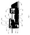
- FIG. 4is an isometric view is shown, in which upper components have been removed for optimal viewing of the internal elements of the device.
- FIG. 5is a side view of the right side of the apparatus, showing components such as the battery, base for mounting and adjusting angled mirror, support components and sliding connectors of moveable stage.
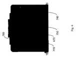
- FIG. 6is a rear view of the apparatus, showing communication ports and electrical power inlet.
- FIG. 7is an image captured showing Trypanosoma brucei parasites in a peripheral blood sample, for analysis using the invention.
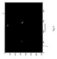
- FIG. 8is a florescent image of Trypanosoma brucei parasites. Automatic detection of the parasites was successful using the apparatus of the invention.
- FIG. 9illustrates an enlarged view of a cartridge.
- the present inventiondiscloses an automated apparatus for detection of parasitic and other pathogenic infection in a bodily fluid, human tissue or human waste product.
- images of known pathogensPrior to sample testing, images of known pathogens are saved in a database, and image processing software of the invention is activated on the images to extract visual characteristics which are typically associated with each known pathogen. Classification features are constructed manually, automatically extracted or refined from a database of known pathogens, or a combination thereof.
- the apparatuscaptures one or more digital images from a sample undergoing analysis.
- the apparatusthen utilizes image analysis software to locate putative appearances of the pathogen in the image.
- the apparatuscompares the characteristics of a suspected pathogen present in the image, to a succinct set of characteristics extracted from images of known pathogens.
- the characteristicstermed “classification features” herein, may include, but are not limited to, typical motion of live parasites, their typical shape, size, their coloring, their contrast, and their location with respect to other elements of the biological sample (for example, if the pathogen is located within a mammalian cell). Additional classification features are enlarged upon hereinbelow.
- the analysisis rapid, and in certain instances may be performed in less than 1 second per image or less than 2 minutes per sample.
- Images takenmay include still digital images, video images in digital format or simulated video images. One or more images may be utilized from each sample, as deemed necessary.
- the sensitivity of the present inventionrelates, in part, to the number of images captured of various areas within the sample. By preselecting this parameter, the user can set the sensitivity as needed during a given analysis. By choosing a sufficiently large number of imaged locations, therefore, the test described herein can exceed the sensitivity of the current gold standard.
- Another advantage of the invention over prior art techniques for detecting pathogensis the ability to identify the presence of several pathogens by performing a single run of the sample in the apparatus of the invention. Since the algorithm of the apparatus can contain classification features associated with several known pathogens, a single test of the sample can be sufficient to identify a wide range of pathogens.
- the apparatus of the inventionthus simplifies and expedites the diagnostic procedure, by using a single test in the apparatus to identify a plurality of pathogens.
- the inventiongrants an advantage over prior art techniques for identification of parasites, as the invention is not dependent upon, for instance, an antibody binding to a specific epitope that may disappear from the surface of the parasite after mutation occurs.
- the inventionmaintains its efficacy, since parasite visual form tends to stay conserved despite rapid antigen mutation. Even if parasite visual form changes, the classification features may be updated to suitably detect the new form, and these classification features may be disseminated to all users of the invention.
- Sensitivities and specificities greater than 99%were achieved using the apparatus and software of the invention on several test cases, in which a known parasite sample was analyzed in order to test the accuracy of diagnosis. This accuracy is greater than the 97% specificity achieved using prior art ELISA methods to identify parasitic samples.
- the term “cartridge”refers to a support upon which a sample of human bodily material may be placed, after which the cartridge may be inserted into the apparatus of the invention, for analysis.
- the cartridgemay resemble a traditional slide for a light-microscope in general appearance and size, typically 75 ⁇ 25 mm, and is typically for a single use per sample.
- the cartridgemay be a specialized sample support element, and may have dimensions of 1′′ ⁇ 3′′, or may resemble a multi-well plate.
- bodily materialoriginating in the human or mammalian body, and from which a portion may be readily removed for analysis for the presence of pathogens or for visually apparent changes related to disease progression.
- Non-limiting examplesinclude: blood, feces, saliva, plasma, serum, sweat, urine, milk, tears, pus, lymphatic fluid, cerebrospinal fluid, and mammalian tissues.
- pathogensrefers to disease causing organisms, including parasites, bacteria, fungi and viruses.
- the apparatus of the inventioncan identify visual changes in bodily tissues and in fluids, which may occur as various diseases progress.
- classification featuresrefers to visually apparent characteristics of a particular pathogen or of disease progression.
- the classification featuresmay be used to identify a particular pathogen.
- Non-limiting examplesinclude: typical motion of a pathogen (i.e. direction and velocity), size, typical shape, coloring, contrast, autofluorescence with or without staining, derived fluorescence, the aspect ratio, internal or external structures (organelles), etc. Additional classification features are described hereinbelow.
- fieldrefers to a region of the sample supported by the cartridge that may be viewed by the microscope and camera.
- cliprefers to a series of images captured in rapid succession by the camera.
- the term “patch”refers to a region within an image, e.g. a set of adjacent pixels, which is focused upon during processing.
- targetrefers to a real appearance of a pathogen in the image
- candidaterefers to a patch which, during the algorithmic processing stages, is suspected to contain a pathogen
- classification algorithmrefers to an algorithm that is composed of two phases.
- the firstis the “pre-processing” training phase, during which numerous examples of the data of interest, containing both “positive” and “negative” examples are analyzed manually, automatically or in combination thereof, and a model for separating these examples is computed.
- a positive exampleis a patch depicting a pathogen
- a negative exampleis one that does not depict a pathogen.
- the actual classificationtakes place in the second phase.
- the algorithmGiven a novel candidate, the algorithm uses the separation model computed in the previous phase and extracts classification features to determine whether the candidate is a target or not.
- the first “pre-processing” steptypically occurs while the apparatus is customized and configured for particular parasites, and the resulting separation model is not usually modified by the clinical user, with the exception of potential software updates.
- Software updatescan, for example, be used to improve classification results or to introduce new diagnostic capabilities.
- FIG. 1illustrates an external view of an apparatus for detecting pathogens, according to an embodiment of the invention.
- the apparatus 100is preferably covered by a rigid casing 400 , e.g. plastic or metal, for protecting the inner components of the apparatus.
- Apparatus 100includes a hinged cover 300 which may be opened to reveal a cartridge support frame (best shown in FIG. 3 ) for receiving a cartridge upon which a sample has been applied.
- the cartridge support framefor supporting a cartridge, is designed to protect the apparatus from direct contact with the tissue or sample undergoing analysis.
- Cartridge support frameis located such that after insertion of a cartridge containing a sample, cartridge is present within optical viewing path of microscope elements of the invention (described hereinbelow).
- Cartridge support framerests on a moveable stage, and both of which can be automatically moved to capture images from different areas of the cartridge.
- Display screen 200may display the analysis results.
- Display screen 200may be a touch screen, which may be used to interact with the device.
- LCD touch screenis the “Thunderpack TAO-3530W” manufactured by TechnexionTM of Taiwan, including its interface board.
- touch screenmay be replaced with a display screen and keys for interaction with device.
- FIG. 2is an isometric diagram of the central internal components of the apparatus, according to an embodiment of the invention.
- Apparatus 100includes touch screen 200 , which is in wired communication with processor 210 and controller 220 .
- Controller 220may be a printed circuit board, designed to time and control the various operations of various other components.
- Light source 340is part of an optical viewing path, which includes angled mirror 520 , beam splitter 350 and digital camera 500 . Additional components of the optical viewing path are described in relation to FIG. 3 .
- Optical viewing pathacts to reflect an image from a cartridge undergoing analysis, after cartridge has been placed in cartridge support frame. Image is reflected towards digital camera 500 .
- Processor 210is configured to receive images from the digital camera 500 . Processor 210 then utilizes software of the invention to perform image analysis and compares a sample image to images stored in electronic memory, within a database of known images pertaining to known pathogens or known tissue views.
- processor and controllermay be a single processing unit. Alternatively, any number of processors may be included in the invention, as deemed necessary. In certain embodiments, activation of the apparatus may be controlled by an external computer, such that the processor is located in the external computer.
- Lateral movement servo 330 and longitudinal movement servoare configured to move the cartridge support frame 310 including a cartridge, when present, in 4 horizontal directions, thus allowing scanning of the cartridge and capturing of several images from the entire area of a cartridge.
- a cartridge 380is depicted, resting within a cartridge support frame 310 .
- Hinged cover 300(not shown) has been removed for ideal viewing.
- cartridge 380is located within optical viewing path, as mirror 392 and LED circuit board 394 rest above cartridge 380 and are born by hinged cover 300 (not shown).
- Lens 396is located beneath cartridge 380 , thus focusing and continuing the optical viewing path.
- Cartridge 380receives and supports a sample for analysis, replacing a traditional slide. After placing a sample of human bodily material upon the cartridge, the cartridge may be inserted into the apparatus of the invention, for analysis.
- the cartridgemay resemble a traditional slide for a light-microscope in general appearance and size, typically 75 ⁇ 25 mm, and is typically for a single use per sample.
- branched tracks 360extend from an arched application recess 370 .
- Branched tracks 360act as microfluidic channels, to ensure diffusion of the sample over the majority of the cartridge 380 area by capillary force and can create a single layer of cells that is highly suitable for microscopic imaging.
- This novel cartridge designobviates the need for trained personnel to prepare the sample.
- Microfluidic channelstypically have a maximal depth of 1 mm.
- the cartridgeis typically disposable, however in certain embodiments it may be washed and reused.
- the cartridgemay additionally be pre-coated with various coatings useful for sample-preparation, such as staining, coatings for maintaining sample freshness or viability, for processing or pre-processing of the sample, and for facilitating imaging.
- the cartridgemay be packaged to maintain the sterility and/or the quality of preloaded stains or reagents to prevent degradation during storage.
- the cartridgemay have a secondary orifice to allow addition of another reagent after sample application has been performed.
- a bodily sampleis applied to the arched application recess 370 of a cartridge 380 .
- the cartridge 380is inserted into cartridge support frame 310 , which is affixed to a moveable stage 320 , and hinged cover 300 is closed.
- the controller 220will activate light source 340 , to emit a light beam to illuminate the cartridge.
- the light beammay be emitted from one light source or a number of different light sources each emitting light beams of different wave lengths, or a combination thereof.
- Light sourceis located internal to light source heat sink 610 .
- FIG. 4an isometric view is shown, in which certain upper or outer components have been removed, or made transparent for optimal viewing of the internal elements of the device.
- a white light source 340 and a blue light source 620are included in the apparatus, and are manufactured by Quadica Developments Inc. of Ontario, Canada:
- White light for transilluminationis provided by a Luxeon® LXML-PWN 1-0120 Rebel Neutral White high power LED, producing 120 lumens of light at 350 mA, and 220 lumens at 700 mA.
- Blue light for detecting epifluorescenceis provided by Luxeon® Blue Rebel LED, 23.5 Lumens at 350 mA and 48 Lumens at 700 mA pre-soldered to a MCPCB base.
- the MCPCB baseis a mounted heat sink. Additional components (not shown) may be included in the apparatus that allow florescence microscopy, such as an excitation filter, a dichroic mirror or beamsplitter, and an emission filter.
- one or more of the following light sourcesmay be used: a light emitting diode (LED), laser, halogen lamp, an arc lamp, white light, blue light, yellow light, green light, red light, ultraviolet light, and infrared light, to facilitate fluorescence and non-fluorescence imaging.
- LEDlight emitting diode
- laserhalogen lamp
- an arc lampwhite light, blue light, yellow light, green light, red light, ultraviolet light, and infrared light
- the controller 220may select from among one or more emitting light sources, in order to change the wave length of the light beam according to the requirements and needs of a specific analysis.
- the controller 220selects the exposure time, namely how long the light source will be on, how long the shutter time of the digital camera will be, the specifics of moving the moving stage (timing and direction of movement), focus and zooming in of digital camera, adjustment of the angle of angled mirror (for adjusting angle of beam, thus obtaining a depth-perspective of the sample).
- Controller 220co-ordinates timing and directional movement of the cartridge support frame 310 and moveable stage 320 bearing the cartridge, with the timing of activation of light source and with image capture of the digital camera, to ensure proper sequence is maintained and to ensure images are initially captured from different areas of the cartridge. Subsequently, when images have been processed and certain areas of the sample have been tagged as requiring additional analysis, controller may move the cartridge support frame 310 , may move the stage 320 , or may instruct camera to zoom in on these areas, may replace or add optical filters, or may illuminate the area of interest with a different light source to gather additional information.
- Digital cameramay be any electronic camera.
- digital camerawas monochrome 5Mpixel 12 bit, CMOS (complementary metal-oxide-silicon) camera. Model no. BTE-B050-U, manufactured by Mightex Systems of Toronto Canada and California USA.
- Cameraincludes a CCTV lens 510 , or may have other type of lens.
- lensis a CCTV lens of 5 MP resolution, catalog number SV-5014H manufactured by NET of Finning, Germany.
- the resolution obtainedwas approximately 0.5 micron per pixel with a 10 ⁇ objective. This resolution is sufficient to detect parasites such as T. brucei , which are typically 20 microns in length. In other embodiments, the resolution obtained was approximately 0.15 micron per pixel with a 40 ⁇ objective, which is sufficient to detect parasites such as Plasmodium falciparum.
- objective lens 396is located above angled mirror 520 , and below cartridge 380 .
- Angled mirror 520reflects the illumination from the cartridge 380 in support frame 310 to the camera 500 .
- the viewing pathmay include any of the following (not shown): a field, aperture and/or condenser diaphragm, one or more shutters, a condenser lens, a plurality of objective lenses of different magnifications, and a plurality of fluorescence filters of different optical passbands.
- the digital imageis then transmitted to processor 210 which is designed to process and analyze the image.
- processor 210which is designed to process and analyze the image.
- the image processing techniques used for analyzing the pictureare described hereinbelow in the section titled “Image Processing Modules”.
- Controllercan instruct lateral movement servo 330 to move the moveable stage 320 , in order to scan and capture images from different areas of the cartridge (when present in the apparatus).
- servois “Dynamixel AX-12A Robot Actuator” manufactured by Trossen Robotics LLC of Illinois, USA.
- Servoincludes a gear reducer, DC motor and servo regulating circuitry.
- the depicted cartridge support frame 310is born by two horizontal rods 640 a , 640 b fixed to the upper surface of the moveable stage 320 .
- Moveable stage 320is also supported by two horizontal rods 690 a , 690 b which are perpendicular to the upper two rods, thus it is possible to shift the cartridge when present in its support frame 310 , in all 4 cardinal directions, when lateral movement servo 330 and longitudinal movement servo 730 act to slide the movable stage 320 and/or cartridge support frame 310 on the rods.
- moveable stagemay be moved using any of the following components: stepper motor, servo motor, lead screw, belt drive and worm drive.
- the controller 220can instruct servos 330 , 730 , to move the cartridge in all the planar directions, either in a preset pattern or according to contemporary needs, whether for image capture of the whole cartridge or for picturing specific areas of interest on the cartridge.
- the imagesmay be analyzed one by one or may be aggregated to be analyzed together. Images may be captured from each area one or more times, and may be sequential or non-sequential.
- an additional servo termed the “autofocus servo” 650is a focus actuator that acts to focus objective lens.
- lithium ion battery 660is depicted, and acts to provide power to the apparatus when the apparatus is used in a remote location.
- apparatusmay be connected to the electricity power grid using power inlet 670 for electrical cord, best shown in FIG. 6 .
- Display screen 200is shown in side view.
- Strut 700 and stand 710support horizontal rod 690 b , which extends towards moveable stage 320 .
- Sliding connectors 720 a , 720 bsurround horizontal rod 690 b , and are fixed to moveable stage 320 , allowing stage 320 to slide upon rod 690 b when longitudinal servo 730 exerts directional force upon stage 320 .
- processor 210stores the images obtained, in local memory, and image analysis is performed within the apparatus.
- the apparatusmay send the images or portions thereof to be stored in an outer repository and/or analyzed on a remote computer.
- Ethernet port jack 740is included at the rear of the apparatus, and provides the apparatus with the option to be wired into a local area network or any other communication network for sending images obtained to a remote computer, or for communicating any other information.
- remote computermay send and update images of known parasites for storing within the memory of the apparatus.
- USB port 750additionally allows two way data transfer, such as of images captured.
- Power inlet 670is provided to connect the apparatus to the electrical grid, when desired.
- Power switch 770is used to switch the apparatus on/off.
- Cooling fan 780cools interior electrical components of the device.
- the remote computermay be a central server which constantly receives images from apparatuses utilized at various locations, and server may be programmed to disseminate images of various new parasitical species to all users.
- the imagesare uploaded to the remote server, where image processing and analysis is performed, and the final decision and pathogen identification is returned to the apparatus for display on the display screen.
- the image processing and analysis software of the inventionmay be run using processing hardware that may be included in the device, or can be collocated on a standalone computer, or may be run on a remote computer in communication with the device, such as over the internet.
- the computer softwaremakes use of machine vision algorithms that detects the presence or suspected presence of parasites and optionally other information about the parasites. Some embodiments of this software are described herein below.
- Image analysiscan take place following, alongside and/or intermittently with image capture.
- the ApparatusComprises the Following Central Components:
- Components manufactured by Olympus Corporationincluded: microscope BX43, manual florescence illuminator BX3-URA, Trinocular tube U-CTR30-2-2, Camera adapter with C-mount, 0.5 ⁇ U-TV0.5 ⁇ C-3-7, Quintuple revolving nosepiece U-5RE-2, Abbe condenser U-AC2, True color LED light source U-LHLEDC, Power Cord 1.8 M UYCP, FITC filter cube U-FBW, UPLFLN20 ⁇ /0.5 Universal Plan Fluorite objective with 20 ⁇ magnification, and UPLFLN40 ⁇ /0.75 Universal Plan Fluorite objective with 40 ⁇ magnification.
- Components manufactured by Prior Scientific of Rockland, Mass. USAinclude:
- Optiscan XYZ stage(Cat. No. ES103PS) comprising: two 10-position filter wheels (for 25 mm diameter filters), probe encoder for Z, travel XY stage, focus drive with adapter, joystick, RS232 and USB cables.
- Lumen 200 florescence illumination system(Cat. No. L2000L2)
- classification featureswhich are associated with specific pathogens, in order to reach an algorithmic decision whether a pathogen is identified in the sample or not.
- Each pathogenis associated with specific visually identifiable classification features.
- These classification featurescan be collected when known samples are imaged using brightfield, darkfield, phase-contrast, any interference-contrast, or fluorescence microscopy. Samples can be treated to induce fluorescence, and samples can be viewed either with or without suitable staining.
- classification featuresinclude:
- the set of classification featuresis relatively small for each known pathogen, thereby their use for classification of a suspected pathogen is efficient and rapid.
- the method and apparatusmay be used on biological samples from various tissue sources or their combinations.
- sample materialscan include but are not limited to blood (peripheral or otherwise), lymphatic fluid, cerebrospinal fluid (CSF), urine, fecal matter, saliva, and tissue biopsies (for example, muscle, liver, etc.)
- the biological sampleis prepared for imaging using methods known in the art, such as thick or thin peripheral blood smears, or using a cartridge as presented herein.
- the samplemay be stained with a sample-appropriate stain, before the sample is applied to the slide or cartridge, for example acridine orange may be added to peripheral blood samples.
- acridine orangemay be added to peripheral blood samples.
- the samplemay be stained after application to the slide or cartridge, for example by dipping a thin or thick smear preparation into a stain.
- a staining reagentmay be present within the cartridge. Certain samples are best analyzed without undergoing staining.
- Imagesare obtained using one or more imaging modalities to illuminate the sample, including for instance, brightfield, darkfield, phase-contrast, any interference-contrast and fluorescence microscopies.
- One or more optical filter combinationsmay be included in the device, and used for example, in excitation and emission light paths.
- One or more light sourcesmay be used.
- One or more magnification powersmay be utilized, and images may be obtained at one or more locations within the sample. Images may be captured using one or more focus depths for each sample or for each imaging location.
- Fluorescence microscopyoffers unique advantages in the context of the invention. Most notably, by employing a suitably chosen fluorescent staining or by imaging suitable autofluorescence channels, the resultant images can emphasize pathogen markers. For example, when blood is stained with acridine orange, fluorescence images reveal only white blood cells and parasites, due to their nucleic-acid content; red blood cells remain invisible. Such emphasis can greatly ease the computation burden on machine-vision algorithms. Furthermore, fluorescence and autofluoresence permit the identification of defined sample or cell components (such as DNA, RNA, or cell membranes). This significance can be used to inform machine-vision algorithms, thereby yielding substantially improved results.
- Microscopic imagingcan take advantage of autofocus capabilities. These can be implemented, for example, by providing the objective (or potentially any other lens in the optical path) with an actuated stage, actuating the sample support stage in the optical direction or by providing focus control in the camera. Focus information for the control of such actuators can be computed based on captured image sharpness, which may optionally be automatically obtained for this purpose, or with a hardware-based autofocus system, such as one based on laser return (e.g. Prior Scientific LF210). In other embodiments, the invention can take advantage of objectives with high depth of fields or with one of a number of computational and hardware techniques to extend depth of field that are known in the art (“Extended depth of field” methods).
- stains or staining methodsmay result in a change in optical absorption, opaqueness or scattering, and may influence the color or fluorescence observed in the sample.
- Some stainsinclude but are not limited to; acridine orange, Giemsa stain, Romanowsky stain, Leishman stain, H&E stain, Jenner stain, Wright stain, Field stain, silver stain, Papanicolaou stain, Sudan stain, Masson's trichrome, Gram stain, eosin, orange G, DAPI, Ethidium bromide, Hoechst, SYBR stains, and other nucleic acid stains.
- stains and combinationsmay produce effects in multiple imagining modalities: for example, Giemsa stain produces both a color that is visible in brightfield microscopy and a fluorescence signature that is visible in epifluorescence microscopy.
- Giemsa stainproduces both a color that is visible in brightfield microscopy and a fluorescence signature that is visible in epifluorescence microscopy.
- eosinis typically used for its chromogenic effect, it also carries a distinct fluorescent signature, which can be advantageous.
- single or multiple stainscan be imaged for fluorescence using one of more excitation wavelengths and imaged using multiple emission filters to yield multiparametric image data.
- samples stained using acridine orangecan be illuminated using blue fluorescent excitation (e.g. wavelengths 460 nm to 495 nm) and imaged, either sequentially or simultaneously, using an emission filter or filter combination for yellow-green light (e.g. bandpass filter for 515 nm to 535 nm) and an emission filter or filter combination for red light (e.g. longpass filter for 600 nm and up).
- the yellow-green filtered imagecorresponds roughly to sample DNA content
- the red filtered imagecorresponds roughly to sample RNA content.
- Such multiparameteric biologically-meaningful datacan be used to identify various parasites, using the software algorithms of the invention.
- multiple fluorescence imagesare obtained in part by mechanically switching optical filters and/or dichroic beamsplitters/mirrors in and out of the optical path.
- the optical pathis split at least once using dichroic or partial beamsplitters/mirrors and multiple fluorescence images (or fluorescence and non-fluorescence images) are obtained on multiple cameras.
- the one or more camerasare high-sensitivity CMOS cameras, such as those based on the Aptina/Micron MT9P031 sensor family.
- any of the camerascan be CCD, cooled CCD, intensified CCD, or electron-multiplied CCD.
- a cartridge or a traditional slideis used to support the sample for analysis within the apparatus of the invention.
- the cartridgeis intended to simplify sample preparation, and is the presently preferred embodiment.
- the cartridgemay be designed to present a single layer of cells in order to ease microscopic imaging.
- Use of a cartridgepresents an improvement over prior art, since prior art sample preparation is known to require training, experience and time. For example, thick blood smears typically take over an hour to dry, whereas thin blood smear require significant operator skill in order to yield large useful area.
- the cartridgemay be disposable or reusable. In particular embodiments the cartridge has dimensions similar to a typical microscope slide, 1′′ ⁇ 3′′ or 25 mm ⁇ 75 mm.
- the cartridgehas one or more fluidic or microfluidic channels, which may optionally be connected to each other to facilitate simultaneous filling. These channels may be comprised of at least one section with a channel height that permits only a single layer of cells to fill it, hence presenting a monolayer for imaging. In the preferred embodiment, the channels may be designed for capillary filling, for example, by choice of materials, coatings or postprocessing, as is known in the art.
- the cartridgemay be prefilled or pretreated with a staining reagent or reagents, which may be stored as a liquid, solid, a coating or dried within the cartridge. In particular embodiments, the cartridge is preloaded or pretreated with one or more anticoagulation reagents.
- stains and/or anticoagulation reagentsare added to the sample before loading onto the cartridge.
- the cartridgeis sterile or sterilized.
- the cartridgeis packaged to maintain the sterility or the quality of preloaded stains or reagents to prevent degradation during storage.
- the cartridgepermits washing, staining or otherwise treating the sample using reagents that are provided externally or that are preloaded.
- the samplemay be prepared, loaded onto a cartridge or microscope slide, or stained using one or more automated instruments.
- Each such instrumentmay either be separate from or may be included in the apparatus of the invention.
- the apparatusmay employ a Prior ScientificTM PL200 slide loader to automatically load microscope slides of cartridges with a microscope-slide form factor of 1′′ ⁇ 3′′.
- the slide loadermay be modified to additionally dip the slide into appropriate staining and washing solutions.
- a sample of 10 ⁇ lis sufficient in volume for analysis.
- a finger prickcan be utilized to obtain this minute quantity, with blood being collected into a capillary, thus obviating the need for trained blood technicians for taking a sample from a patient.
- the capillarycan then be brought into contact with the cartridge to apply the blood sample to the cartridge.
- Suitable processors for implementation of the inventioninclude, by way of example, both general and special purpose microprocessors.
- a processorwill receive instructions and data from a read-only memory and/or a random access memory.
- the apparatusmay include one or more mass storage devices for storing data files (such as images obtained or images of known pathogens).
- mass storage devicesinclude magnetic disks, such as internal hard disks and removable disks; magneto-optical disks; and optical disks.
- Storage devices suitable for tangibly embodying computer program instructions and datainclude all forms of non-volatile memory, including by way of example semiconductor memory devices, such as EPROM, EEPROM, and flash memory devices; magnetic disks such as internal hard disks and removable disks; magneto-optical disks; and CD-ROM disks.
- the cover 300may be opened and the cartridge may be taken out and disposed of, after which, the apparatus 100 is ready for a new analysis.
- Sample removalcan be automated, for example, using a Prior Scientific PL200 slide loader.
- a number of modulesare described below for processing an image and finding pathogens.
- the apparatus described abovemay utilize one or more of the following image processing modules.
- the apparatusinvokes the following modules in a preset sequence.
- the following descriptionis a presently preferred order of the processing steps, although alternative embodiments may use a different order:
- This modulescans an entire image, which depicts a field within the sample, and searches for patches in the image within which it is likely that a pathogen of interest, referred to hereinafter as the “target”, appears.
- One or more of the following methodsmay be used to detect these candidate patches:
- the second step of the sequencemay be:
- Single Frame Classification Cascade Modulemay also be called “Multi Frame Classification Cascade Module”.
- This modulereceives candidates, from the first step, in a single frame, and computes the likelihood that they indeed contain an occurrence of the desired target.
- the main tool used in this moduleis a Classifying algorithm.
- Classifying algorithmsare machine-learning algorithms which may operate according to the following techniques used in sequence:
- the third step of the sequencemay be:
- This moduleclusters together appearances of the same target in multiple frames.
- Single-frame candidatesmay be matched to other such candidates based on their location in the image. If the target is relatively static, then candidates are matched if they are roughly in the same location in the image (or, more precisely, in the same relative location within the motion field). More generally, if the target is moving, it is tracked using the Tracking Module (described below), and is matched to candidates appearing in roughly the same location to where it is tracked.
- the Tracking Moduledescribed below
- the Multi-Frame Candidate Construction Moduleconstructs a graph with the single-frame candidates as its vertices, and matches defining edges. Connected components within this graph are checked for coherency, i.e. that the target appears “the same” in all occurrences. In an iterative implementation, temporal gaps within these components may be filled by extrapolating the locations of missing occurrences, and processing them with the Single-Frame Classification Cascade Module. In this case, the entire set of single-frame classifying algorithms may be used, rather than conditioning on pervious results, since only a small number of candidates are processed this way.
- the coherent, and possibly gap-filled, backbone of the connected componentsis the multi-frame candidate—a collection of all single-frame appearances of a specific target along with the results of its classification cascade.
- Multi-Frame Candidate Tracking Module
- Partially-constructed multi-frame candidatesmay be tracked to frames temporally-adjacent to the ones in which their single-frame constituents were identified in the previous step. This can be done by various computer-vision algorithms, such as mean-shift or differential methods.
- this modulefacilitates initial candidate detection when other signals are weak. Candidates are created in location to which multi-frame candidates were tracked, as described in the Parasite Candidate Detection Module, above.
- trackingdefines the matching of single-frame candidates, on which the construction of multi-frame candidates is based.
- the multi-frame constructioncan be seen as a form of agglomerated clustering: initially all single-frame candidates are distinct multi-frame candidates. They are then iteratively tracked, matched, and merged together into bigger clusters.
- Multi-Frame Candidate Classification Module
- the entire set of target occurrencesmay be classified as a whole.
- thisis similar to the single frame classification, but here features from multiple images are used, as well as the relations between them (e.g. the trajectory of the target).
- This moduledetermines, for each multi-frame candidate, the likelihood that it's a true occurrence of the desired target.
- This modulemay be used to identify sample elements that are not the pathogens themselves but are useful in determining pathogen presence. For example, red blood cells may be identified in malaria diagnosis in order to determine whether a suspected target is located within a red blood cell. Similarly, white blood cells may be identified in order to rule out their nuclei as suspects. This module may itself take advantage of the same algorithms and modules that are described for the identification and analysis of pathogen suspects.
- the sampleis classified as either containing the defined microorganism or not containing it.
- This moduleis to construct the image of the blood ambient background at each image-capture time point.
- the purpose of this moduleis to construct the image of the blood ambient background at each image-capture time point.
- dense optic flowmay be used to determine the motion vector of the background from frame to frame, by taking the mean motion value.
- the background imageis constructed by taking the median value of pixels in the same location relative to the background motion.
- This moduleis to recognize and report poor samples, such as images taken from a blocked lens or damaged camera or images in which the sample does not appear at all.
- This moduleis to control image capturing.
- the location and magnificationcan be adjusted to clear ambiguities in the image.
- the cameracan be adjusted to zoom in on a candidate, to visualize it in finer detail.
- the modulemay control exposure, illumination parameters and aperture parameters in order to obtain optimal images.
- This moduleis to identify regions in the image in which targets are not likely to occur. Such regions are ignored by the Parasite Candidate Detection Module.
- the inventionis embodied in any suitable programming language or combination of programming languages, including Google Web Toolkit, JAVA, database managers and MySQL.
- Each software componentcan be implemented in a high-level procedural or object-oriented programming language, or in assembly or machine language if desired.
- the programming languagemay be a compiled or interpreted language.
- Imagesare entered into and saved in a database which may be any suitable database for storing data objects and metadata relating thereto. Any suitable database program may be used.
- the databaseis a relational database and a key/value database.
- databaseis a modified relational database.
- the search logic used for subsequent retrieval of experiments from the databaseis any suitable step, process, function or series of steps, processes and functions known in the art for searching a database.
- the software of the inventionmay include a graphical user interface (GUI).
- GUIgraphical user interface
- the contents of the screens, the functionality of the system and the work processmay be adjustable to a user's needs.
- the screen designs, terms and work processreflect the medical field and are user-friendly since they display and interact with the user in syntax familiar to medical technicians. Thus use of the system may appear intuitive.
- the final analysis resultmay include the presence or suspected presence of parasites, as well as parameters regarding parasites detected, such as: their type or species, parasite load or number, life stage or maturity and any other medically relevant information.
- the softwaremay report medically pertinent information obtained from the biological sample yet unrelated to parasites, (such as detection of anemia, or detection of an unusual white blood-cell count). Information relevant to the quality of the test or sample may be displayed.
- the separator or separatormay be configured such that the provided images are only highly enriched for potential pathogens, enabling the user to make a determination based on a condensed subset of information. In these latter cases, the algorithm can be tuned to provide very high sensitivity at the cost of lower specificity.
- Trypanosoma Cruziis the parasite responsible for the potentially fatal Chaggas disease.
- One of its life cycle stages(Trypomastigotes) occurs in the blood, where it has a worm-like shape—an elongated body and a flagellum—which constantly twirls and spins in the blood. This motion is the cue for the detection algorithm.
- an image capturedshows Trypanosoma brucei parasites (indicated by arrows), surrounded by red blood cells.
- Plasmodiumare parasites responsible for Malaria disease; Babesia are parasites responsible for Babesiosis disease. Both types of parasites infect red blood cells (RBCs) and in the initial stages of the infection form ring-like structures. Importantly, normal RBCs expel their organelles, and in particular their nucleus, before entering the blood stream. Hence the goal is to detect RBCs which contain a significant amount of DNA, indicating parasitic infection of Plasmodium or Babesia.
- RBCsred blood cells
- Plasmodium and Babesia species of interestinclude P. Falciparum, P. Vivax, P. Ovale, P. Malariae, B. Microti and B. Divergens.
- the apparatus and method of the inventionanswer a long-felt need for automatic identification of pathogens, and especially of parasites within a mammalian sample.
- the apparatus and methodallow rapid identification of parasites that previously required use of expensive resources and trained personnel that are unavailable in many third world countries.
- the inventionnow allows blood donations and blood tests to be screened for parasites, such that a single run through the apparatus will identify a great many parasites, representing maximal efficiency.
- the apparatus and methodovercome the difficulty of parasites constantly evolving, as an image of the new species may be easily uploaded into the database of known images and the characteristics of the new species may be analyzed to allow its identification in future.
Landscapes
- Chemical & Material Sciences (AREA)
- Health & Medical Sciences (AREA)
- General Health & Medical Sciences (AREA)
- Analytical Chemistry (AREA)
- General Physics & Mathematics (AREA)
- Immunology (AREA)
- Physics & Mathematics (AREA)
- Pathology (AREA)
- Biochemistry (AREA)
- Life Sciences & Earth Sciences (AREA)
- Dispersion Chemistry (AREA)
- Engineering & Computer Science (AREA)
- Nuclear Medicine, Radiotherapy & Molecular Imaging (AREA)
- Hematology (AREA)
- Clinical Laboratory Science (AREA)
- Chemical Kinetics & Catalysis (AREA)
- Signal Processing (AREA)
- Investigating Or Analysing Biological Materials (AREA)
- Computer Vision & Pattern Recognition (AREA)
- Investigating, Analyzing Materials By Fluorescence Or Luminescence (AREA)
Abstract
Description
- a) a cartridge support frame for receiving and supporting a cartridge having a sample within or thereupon;
- b) an optical imaging system having an optical path and comprising:
- at least one light source, at least one lens, and at least one digital camera; wherein the cartridge support frame is located within or may be moved into the optical path, such that images of the sample may be captured by the at least one digital camera;
- at least one processor interacting with and activating at least one of components a)-b); wherein the processor is adapted to perform image processing using classification algorithms on visual classification features to detect one or more suspected pathogens, when present, in the sample.
- selecting at least one light source from among a plurality of light sources, and activating the light source;
- selecting an exposure time of a light source;
- selecting an exposure time for the digital camera.
- selecting at least one light source from among a plurality of light sources, and activating the light source;
- selecting an exposure time of a light source;
- selecting an exposure time for the digital camera.
- calculating the likelihood that the at least one candidate contains a target;
- processing the candidates for finding if more than one candidate belongs to the same target, and where found, candidates of the same target are clustered together;
- tracking at least one candidate, in relation to the at least one cluster, that may belong to the cluster, and where the tracked candidate belongs, adding the tracked candidate to the cluster; determining and classifying the likelihood that the at least one cluster contains a target; and
- determining if the image contains a target, based on the classification, and thus determining if the sample contains a pathogen.
- Typical motion: certain parasites are known to move in a specific directional course, and at a typical speed.
- Size.
- Presence of intracellular structures associated with the pathogen (e.g. nucleus, kinetoplast, granularity).
- Extraceullular structures associated with the known pathogen (e.g. flagella, knobs).
- Location with respect to other sample elements (e.g. whether suspected parasite is within a red blood cell).
- Aspect ratio: the ratio between the length/width of suspected structures.
- Optical density (intensity shade).
- Florescence in various channels: each pathogen is associated with specific florescence which can be viewed upon illumination and emission-filtering at predetermined wavelengths.
- Optical birefringence: illumination in a specific wavelength results in detection of internal structures in certain parasites.
- Clustering behavior: parasites maintain typical distances between one another within the human body.
- Distance from human cells to suspected pathogen: Typically, pathogens maintain a predetermined distance between themselves and human cells.
- Pattern matching: general appearance of pathogen.
- a. Pattern matching—if the general form of the target is well defined, a pattern describing this form is constructed in a pre-processing stage: numerous examples of its form are manually collected, and the general pattern is extracted. When processing an image, this pattern is then matched at every location, and those locations which exhibit high similarity to the pattern are taken as candidates. In an example of preprocessing, a human operator collects a number of images, containing a known target microorganism, and marks the target on these images. Then these marked images are fed to a processor adapted to extract the general pattern of the target, based on the numerous images of the target. This pattern matching module, which is invoked by the apparatus, can use the resultant pattern of the target for finding other similar patterns in the image. The threshold of high similarity may be flexibly defined using trial and error, which may be steered by the application, or it may be defined rigidly as a pattern which has 90% similarity to the general pattern of the pathogen. Various image-processing filters (e.g. wavelettes) may be applied to enhance the features in the image which are relevant to the target's pattern and suppress those which are not. For example, when seeking pathogens which are well defined by their boundary, an edge-avoiding wavelette may be used to smooth out noise, while keeping the sharp features of the pathogen's boundary.
- b. Model matching—if the general pattern of the target can be described by a simple model of a few image parameters (e.g. a blood cell can be described by a circle or an ellipse), patterns of this model are sought out in the image. In one embodiment, Hough transform may be used to transform the image into the parameter space, and parameter sets which gain support from numerous pixels are taken as candidates.
- c. Motion detection—Using the Motion Field Detection Module (described below) the image can be segmented into pixels which are part of the ambient motion field, and pixels which move differently, i.e. move in other directions. The latter are clustered together spatially. The clustering algorithm takes into account the form and movement of the desired target. Clusters which confer to the characteristics of the target, such as size, are taken as candidates.
- d. High fluorescence—The fluorescence image, which roughly overlays the intensity image, is segmented and clustered in a manner analogous to the motion detection above. Instead of looking for patches which move differently from the background, patches whose fluorescence is higher than the background, e.g. patches having high SNR, are sought. High fluorescence can refer to high fluorescence intensity values, or high sum fluorescence, e.g. as integrated over an area.
- e. Multi Frame—Using the Tracking Module (described below), multi-frame candidates (described below as well) are tracked to frames in which they are likely to appear. If the tracking is successful, the location to which the candidate was tracked is taken as a candidate in that frame.
- Note that this can be done in batch or on-the-fly. In a batch implementation, multi-frame candidates are tracked to temporally-adjacent frames, leading to new candidates. This is done iteratively to enhance the construction of multi-frame candidates.
- In an on-the-fly implementation multi-frame candidates are found and processed as the images are being streamed into the processing device. They can be tracked only forward in time, and the process is performed only once.
- a. A set of “classification features”—functions of the data to be classified—are determined. Therefore, these classification features must be relevant to the objects which are being classified. In our case these classification features may include the intensity and gradient of the candidate, the fluorescence of the candidate and/or motion of the candidate. Additional classification features are described hereinabove, in a separate section. The images are then processed to create rotationally-invariant images, to make the classifying features independent of the viewing angle.
- Magnification also affects the type of classification features used. In low magnification, the contour of the microorganism is an important hint, while in high magnification, finer details, such as pathogen-specific internal or external structures, are used.
- b. In a pre-processing stage, the classifying algorithm is “trained” to differentiate between sets of classification features which describe the target and sets which do not. This is done in a so-called supervised manner, where clips in which all occurrences of the desired target are manually tagged. The Parasite Candidate Detection Module is then used on these clips. The candidates the module outputs, along with their manual tags, are used as input to train a maching-learning algorithm, such as a Support Vector Machine (SVM). An SVM is a known classifier, which uses tagged inputs as above to construct a separator in the features space between true and spurious candidates. Other machine-learning algorithms are known in the art.
- c. When processing new data, the same set of classification features is extracted. The machine-learning algorithm, such as SVM, determines the likelihood of this set representing a true occurrence of the target using the separator constructed in the pre-processing stage.
- The Single Frame Classification Cascade Module may employ a cascade of classifying algorithms. Candidates which are found to be highly likely to contain a target are passed to the next classifying algorithm. This cascade allows using more powerful (and computationally intensive) classifying algorithms along the cascade—the fewer candidates remaining, the more powerful the classifying algorithm can be, while maintaining reasonable running times. Importantly, the pre-processing training of a classifying algorithm is done on the output of the previous classifying algorithm up the cascade.
- In addition to classifying candidates, the Single Frame Classification Cascade Module may also align them to canonical coordinates. This augments and complements the selection of rotationally-invariant features, allowing some flexibility in the latter. That is, classification features which are not invariant to rotation are still sometimes used, and the alignment phase rotates the patches to a canonical angle.
- For example, when seeking the appearance of the ring-form of the malaria pathogenP. falciparum, it may be important that the ring form appears roughly in the same relative position within the patch. Candidates which pass the entire cascade are called “single-frame candidates”.
- In an alternative embodiment, classification features and/or the separator may be determined or modified manually or with non-machine-learning analysis algorithms. For example, the human expert knowledge of a trained medical professional may be transcribed into classification features or separator algorithms that may be used independently or to supplement machine-learning based processing.
- a. A set of “classification features”—functions of the data to be classified—are determined. Therefore, these classification features must be relevant to the objects which are being classified. In our case these classification features may include the intensity and gradient of the candidate, the fluorescence of the candidate and/or motion of the candidate. Additional classification features are described hereinabove, in a separate section. The images are then processed to create rotationally-invariant images, to make the classifying features independent of the viewing angle.
- 1. Prepare thin blood smears upon a cartridge, and capture images. Divide the images into fields of images. Analyze each field independently by recording a series of images from that field, effectively creating a clip of images.
- 2. For each frame, verify its validity using the Image Verification Module. If more than a specified number of consecutive images are poor (e.g. 4 images), report an error on this field.
- 3. Normalize the image to compensate for lighting variance, since typically the image is more strongly illuminated at its center.
- 4. For each frame in the clip, construct the background image using the Motion Field Construction Module. In thin blood samples it is possible to wait for the red blood cells to dry in order to use the simpler version of the algorithm.
- 5. Create initial single-frame candidates using the Motion Detection method of the Parasite Candidate detection Module.
- 6. Proceed to the next frame:
- 1. Use the Multi-Frame Candidate Tracking Module to track the single-frame candidates to the next frame,
- 2. Repeat steps 2-4 above for the next frame.
- 7. Use the Multi-frame Candidate Construction Module to match candidates from one frame to the next one.
- 8. Classify candidates which were matched for at least a specified fraction of consecutive frames (e.g. 3 of 4 frames) using the Multi-frame Candidate Classification Module.
- 9. Record the number of candidates classified as “true” targets (an appearance ofT. Brucei), over all fields.
- 10. Determine if the blood sample is contaminated using the Blood Sample Classification Module.
Using the Training Algorithm—Single/Multi-Frame Candidate Classification Module: - 1. Run the detection algorithm up to step 6
- 2. Tag the candidates as “true” and “false” occurrences ofT. Brucei.
- 3. Create a database of false and true occurrences. In the database each occurrence appears multiple times, e.g. 12, by uniformly rotating it.
- 4. Extract classification features for each database entry. For example, compute a Census Transform of the entry: divide the result into equal-sized rectangular regions (e.g. 9 non-overlapping squares) and compute a histogram of the census transform in each region. The feature vector for the entry is a concatenation of these histograms.
- 5. Train an SVM classifier with a polynomial kernel (e.g. a 2nddegree polynomial) on this database.
Using the Training Algorithm—Blood Sample Classification Module: - 1. Run the detection algorithm up to step 9.
- 2. Tag each sample as “clean” or “contaminated”.
- 3. Create histograms of the number of “true” candidates over the “clean” samples and over the “contaminated” samples.
- 4. Determine the optimal value that differentiates between these two histograms (in the sense of maximum likelihood). This value determines how a blood sample is classified in the detection algorithm.
- 1. Initially, the blood is stained with fluorochromatic dyes such as Acridine Orange, Giemsa or Ethidium Bromide. Dyes which stain DNA and not RNA or which create a contrast between the two, are preferable.
- 2. A thin blood smear is prepared upon a cartridge, images are captured, and the images are divided into fields, as explained in the first example. Each field is analyzed independently by recording two images from that field—a “bright field” (BF) image (visible light) and “florescence image” (FL) radiated with a wave length appropriate to cause the dye to fluoresce.
- 3. For each BF-image, verify its validity using the Image Verification Module. If more than a specified number of images are poor (e.g. >10%) report an error on this field.
- 4. Normalize the image to compensate for lighting variance, since typically the image is more strongly illuminated at its center.
- 5. For each FL-image, locate high-intensity patches, indicative of DNA using the High Fluorescence method of the Parasite Candidate Detection Module.
- 6. For each such patch, tag it as inside a RBC, and identify a candidate RBC, if one the following holds:
- a) A Hough Transform of its vicinity indicates that it's contained inside a circle in the image whose size is appropriate for a RBC. This is, effectively, the use of the Model Matching method of the Parasite Candidate Detection Module.
- b) A contour detection algorithm of its vicinity indicates that it's within a convex shape in the image, whose size is appropriate for a RBC.
- c) The Pattern Matching method of the Parasite Candidate Detection Module processing the patch's vicinity locates a strong RBC pattern overlapping the patch.
- 7. Using the Single-frame Classification Cascade Module, each candidate RBC is classified as to whether or not it's a RBC containing a parasite.
- 8. Record the number of candidates classified as “true” (an appearance of an infected RBC), over all fields.
- 9. Determine if the blood sample is contaminated using the Blood Sample Classification Module.
Training Algorithm—Single-Frame Candidate Classification Cascade Module:
- 1. Run the detection algorithm up to step 6
- 2. Tag the candidates as “true” or “false” occurrences of infected RBCs.
- 3. Create a database of false and true occurrences. In the database each occurrence appears multiple times, e.g. 12, by uniformly rotating it.
- 4. Extract classification features for each database entry. For example, compute the Census Transform of the entry; divide the result into equal-sized rectangular regions (e.g. 9 non-overlapping squares) and compute a histogram of the census transform in each region. The feature vector for the entry is a concatenation of these histograms.
- 5. Train an SVM classifier with a polynomial kernel, e.g. a 2nddegree polynomial, on this database.
Training Algorithm—Blood Sample Classification Module: - 1. Run the detection algorithm up to step 8.
- 2. Tag each sample as “clean” or “contaminated”.
- 3. Create histograms of the number of “true” candidates over the “clean” samples and over the “contaminated” samples.
- 4. Determine the optimal value that differentiates between these two histograms (in the sense of maximum likelihood). This value determines how a blood sample is classified in the detection algorithm.
Claims (20)
Priority Applications (4)
| Application Number | Priority Date | Filing Date | Title |
|---|---|---|---|
| US13/338,291US9522396B2 (en) | 2010-12-29 | 2011-12-28 | Apparatus and method for automatic detection of pathogens |
| US15/174,490US10843190B2 (en) | 2010-12-29 | 2016-06-06 | Apparatus and method for analyzing a bodily sample |
| US17/064,193US12005443B2 (en) | 2010-12-29 | 2020-10-06 | Apparatus and method for analyzing a bodily sample |
| US18/654,698US20240293812A1 (en) | 2010-12-29 | 2024-05-03 | Apparatus and method for analyzing a bodily sample |
Applications Claiming Priority (2)
| Application Number | Priority Date | Filing Date | Title |
|---|---|---|---|
| US201061427809P | 2010-12-29 | 2010-12-29 | |
| US13/338,291US9522396B2 (en) | 2010-12-29 | 2011-12-28 | Apparatus and method for automatic detection of pathogens |
Related Child Applications (1)
| Application Number | Title | Priority Date | Filing Date |
|---|---|---|---|
| US15/174,490DivisionUS10843190B2 (en) | 2010-12-29 | 2016-06-06 | Apparatus and method for analyzing a bodily sample |
Publications (2)
| Publication Number | Publication Date |
|---|---|
| US20120169863A1 US20120169863A1 (en) | 2012-07-05 |
| US9522396B2true US9522396B2 (en) | 2016-12-20 |
Family
ID=46380428
Family Applications (4)
| Application Number | Title | Priority Date | Filing Date |
|---|---|---|---|
| US13/338,291Active2035-05-28US9522396B2 (en) | 2010-12-29 | 2011-12-28 | Apparatus and method for automatic detection of pathogens |
| US15/174,490ActiveUS10843190B2 (en) | 2010-12-29 | 2016-06-06 | Apparatus and method for analyzing a bodily sample |
| US17/064,193Active2034-07-04US12005443B2 (en) | 2010-12-29 | 2020-10-06 | Apparatus and method for analyzing a bodily sample |
| US18/654,698PendingUS20240293812A1 (en) | 2010-12-29 | 2024-05-03 | Apparatus and method for analyzing a bodily sample |
Family Applications After (3)
| Application Number | Title | Priority Date | Filing Date |
|---|---|---|---|
| US15/174,490ActiveUS10843190B2 (en) | 2010-12-29 | 2016-06-06 | Apparatus and method for analyzing a bodily sample |
| US17/064,193Active2034-07-04US12005443B2 (en) | 2010-12-29 | 2020-10-06 | Apparatus and method for analyzing a bodily sample |
| US18/654,698PendingUS20240293812A1 (en) | 2010-12-29 | 2024-05-03 | Apparatus and method for analyzing a bodily sample |
Country Status (3)
| Country | Link |
|---|---|
| US (4) | US9522396B2 (en) |
| IN (1) | IN2012DN05069A (en) |
| WO (1) | WO2012090198A2 (en) |
Cited By (24)
| Publication number | Priority date | Publication date | Assignee | Title |
|---|---|---|---|---|
| USD786707S1 (en)* | 2016-01-19 | 2017-05-16 | Stem Arts Projects, Llc | Wavelength scanning apparatus |
| US10482595B2 (en) | 2014-08-27 | 2019-11-19 | S.D. Sight Diagnostics Ltd. | System and method for calculating focus variation for a digital microscope |
| US10488644B2 (en) | 2015-09-17 | 2019-11-26 | S.D. Sight Diagnostics Ltd. | Methods and apparatus for detecting an entity in a bodily sample |
| US10640807B2 (en)* | 2011-12-29 | 2020-05-05 | S.D. Sight Diagnostics Ltd | Methods and systems for detecting a pathogen in a biological sample |
| US20200300750A1 (en)* | 2016-03-30 | 2020-09-24 | S.D. Sight Diagnostics Ltd. | Distinguishing between blood sample components |
| US10831013B2 (en) | 2013-08-26 | 2020-11-10 | S.D. Sight Diagnostics Ltd. | Digital microscopy systems, methods and computer program products |
| US10843190B2 (en) | 2010-12-29 | 2020-11-24 | S.D. Sight Diagnostics Ltd. | Apparatus and method for analyzing a bodily sample |
| WO2021116959A1 (en) | 2019-12-12 | 2021-06-17 | S.D. Sight Diagnostics Ltd | Analyzing an analyte disposed within a medium |
| WO2021116962A1 (en) | 2019-12-12 | 2021-06-17 | S.D. Sight Diagnostics Ltd | Artificial generation of color blood smear image |
| WO2021116957A1 (en) | 2019-12-12 | 2021-06-17 | S.D. Sight Diagnostics Ltd | Off-focus microscopic images of a sample |
| WO2021116955A1 (en) | 2019-12-12 | 2021-06-17 | S.D. Sight Diagnostics Ltd | Detecting platelets in a blood sample |
| WO2021116960A1 (en) | 2019-12-12 | 2021-06-17 | S.D. Sight Diagnostics Ltd | Classification models for analyzing a sample |
| US11099175B2 (en) | 2016-05-11 | 2021-08-24 | S.D. Sight Diagnostics Ltd. | Performing optical measurements on a sample |
| US11100634B2 (en) | 2013-05-23 | 2021-08-24 | S.D. Sight Diagnostics Ltd. | Method and system for imaging a cell sample |
| WO2022009104A2 (en) | 2020-07-07 | 2022-01-13 | S.D. Sight Diagnostics Ltd | Focusing a microscope using fluorescent images |
| US11307196B2 (en) | 2016-05-11 | 2022-04-19 | S.D. Sight Diagnostics Ltd. | Sample carrier for optical measurements |
| US11434515B2 (en) | 2013-07-01 | 2022-09-06 | S.D. Sight Diagnostics Ltd. | Method and system for imaging a blood sample |
| US11609413B2 (en) | 2017-11-14 | 2023-03-21 | S.D. Sight Diagnostics Ltd. | Sample carrier for microscopy and optical density measurements |
| US11708596B2 (en) | 2017-02-02 | 2023-07-25 | PhAST Corp. | Analyzing and using motility kinematics of microorganisms |
| WO2023144713A1 (en) | 2022-01-25 | 2023-08-03 | S.D. Sight Diagnostics Ltd | Sample carrier for use with a bodily sample |
| WO2024127207A1 (en) | 2022-12-12 | 2024-06-20 | S.D. Sight Diagnostics Ltd | System and method for analyzing bodily samples |
| WO2024236537A1 (en) | 2023-05-18 | 2024-11-21 | S.D. Sight Diagnostics Ltd | Apparatus and methods for microscopic analysis of a biological sample |
| US12390548B2 (en) | 2020-05-14 | 2025-08-19 | Mehrdad Michael HOGHOOGHI | System and method for protecting a workspace from airborne contaminants |
| US12442029B2 (en) | 2013-07-01 | 2025-10-14 | S.D. Sight Diagnostics Ltd. | Method and system for imaging a blood sample |
Families Citing this family (39)
| Publication number | Priority date | Publication date | Assignee | Title |
|---|---|---|---|---|
| US20120077206A1 (en) | 2003-07-12 | 2012-03-29 | Accelr8 Technology Corporation | Rapid Microbial Detection and Antimicrobial Susceptibility Testing |
| EP1648286B1 (en) | 2003-07-12 | 2017-12-20 | Accelerate Diagnostics, Inc. | Sensitive and rapid biodetection |
| EP2683831B1 (en) | 2011-03-07 | 2015-09-23 | Accelerate Diagnostics, Inc. | Rapid cell purification systems |
| US10254204B2 (en) | 2011-03-07 | 2019-04-09 | Accelerate Diagnostics, Inc. | Membrane-assisted purification |
| US9677109B2 (en) | 2013-03-15 | 2017-06-13 | Accelerate Diagnostics, Inc. | Rapid determination of microbial growth and antimicrobial susceptibility |
| US9536304B2 (en)* | 2013-08-30 | 2017-01-03 | Dairy Quality Inc. | Determining pathogens based on an image of somatic cells in a fluid sample |
| ES2552405B1 (en)* | 2014-05-27 | 2016-09-14 | Tecnología Marina Ximo, S.L. | System and method of detection of Anisakis parasites in fish fillets |
| JP6692049B2 (en)* | 2014-07-29 | 2020-05-13 | 国立大学法人浜松医科大学 | Identification device and identification method |
| US10524665B2 (en)* | 2014-10-22 | 2020-01-07 | Institute Of Automation, Chinese Academy Of Sciences | Handheld molecular imaging navigation system |
| US12005441B1 (en) | 2014-11-26 | 2024-06-11 | Medica Corporation | Automated microscopic cell analysis |
| US20170328924A1 (en) | 2014-11-26 | 2017-11-16 | Ronald Jones | Automated microscopic cell analysis |
| US10625259B1 (en) | 2014-11-26 | 2020-04-21 | Medica Corporation | Automated microscopic cell analysis |
| US11478789B2 (en)* | 2014-11-26 | 2022-10-25 | Medica Corporation | Automated microscopic cell analysis |
| US10253355B2 (en) | 2015-03-30 | 2019-04-09 | Accelerate Diagnostics, Inc. | Instrument and system for rapid microorganism identification and antimicrobial agent susceptibility testing |
| US10023895B2 (en)* | 2015-03-30 | 2018-07-17 | Accelerate Diagnostics, Inc. | Instrument and system for rapid microogranism identification and antimicrobial agent susceptibility testing |
| CN108738339B (en)* | 2016-01-28 | 2022-02-01 | 西门子医疗保健诊断公司 | Method and apparatus for classifying artifacts in a sample |
| CN108738338B (en)* | 2016-01-28 | 2022-01-14 | 西门子医疗保健诊断公司 | Method and apparatus for detecting interferents in a sample |
| EP3408653B1 (en) | 2016-01-28 | 2024-01-17 | Siemens Healthcare Diagnostics Inc. | Methods and apparatus adapted to quantify a specimen from multiple lateral views |
| EP3482189B1 (en)* | 2016-07-08 | 2025-02-26 | Medica Corporation | Automated microscopic cell analysis |
| US20200018749A1 (en)* | 2016-12-20 | 2020-01-16 | Indevr, Inc. | Plug-in expertise for pathogen identification using modular neural networks |
| KR101791029B1 (en)* | 2017-05-31 | 2017-10-27 | 주식회사 뷰노 | Method for diagnosis of protozoal disease and apparatus using the same |
| US11067526B2 (en) | 2017-08-17 | 2021-07-20 | Abbott Point Of Care Inc. | Devices, systems, and methods for performing optical and electrochemical assays |
| US11047845B1 (en) | 2017-11-15 | 2021-06-29 | Medica Corporation | Control material and methods for cell analyzers |
| JP7628945B2 (en)* | 2018-07-02 | 2025-02-12 | オルト-クリニカル ダイアグノスティックス インコーポレイテッド | Method and apparatus for selecting a position for reading an image on a slide medium - Patents.com |
| EP3824433B1 (en)* | 2018-07-18 | 2022-08-31 | Intervet International B.V. | Automated parasite analysis system |
| CN110569856B (en)* | 2018-08-24 | 2020-07-21 | 阿里巴巴集团控股有限公司 | Sample labeling method and device, and damage category identification method and device |
| WO2020212628A1 (en)* | 2019-04-18 | 2020-10-22 | Fundació Institut De Ciències Fotòniques | Fluidic apparatus for optical interrogation of individual microorganisms |
| US11402331B2 (en)* | 2019-05-08 | 2022-08-02 | City University Of Hong Kong | Imaging and manipulation of biological sample |
| WO2020242978A1 (en)* | 2019-05-24 | 2020-12-03 | The Board Of Trustees Of The Leland Stanford Junior University | A spectral imaging platform for infectious disease diagnosis |
| US20220218242A1 (en)* | 2019-05-29 | 2022-07-14 | Ohio State Innovation Foundation | Methods and apparatus for making a determination about a presence or an absence of a parasite in a blood sample |
| BR112022007708A2 (en) | 2019-10-22 | 2022-07-12 | S D Sight Diagnostics Ltd | ACCOUNTING OF ERRORS IN OPTICAL MEASUREMENTS |
| US11914131B1 (en)* | 2020-08-16 | 2024-02-27 | Gregory Dimitrenko | Optical testing system for detecting infectious disease, testing device, specimen collector and related methods |
| EP3978901A1 (en)* | 2020-10-01 | 2022-04-06 | Siemens Healthcare GmbH | Maturity classification of stained reticulocytes using optical microscopy |
| GB2600719B (en)* | 2020-11-05 | 2023-10-11 | Oxford Nanoimaging Ltd | Fluorescence assay |
| CN113537306A (en)* | 2021-06-29 | 2021-10-22 | 复旦大学 | Image classification method based on progressive growth element learning |
| CN115612613B (en)* | 2021-07-12 | 2025-09-30 | 上海傲睿科技有限公司 | An integrated microfluidic chip and single cell culture, screening and export method thereof |
| US20230129946A1 (en)* | 2021-10-25 | 2023-04-27 | Principia Life, LLC | Smart material sample analysis |
| US20250012697A1 (en)* | 2021-11-17 | 2025-01-09 | Arizona Board Of Regents On Behalf Of Arizona State University | Methods and related aspects of rapid microbial detection using intrinsic feature tracking |
| USD1069128S1 (en)* | 2024-04-12 | 2025-04-01 | Thenextpangea, S.L. | Device for detection of industrial pathogens |
Citations (69)
| Publication number | Priority date | Publication date | Assignee | Title |
|---|---|---|---|---|
| EP0183717A1 (en) | 1984-05-15 | 1986-06-11 | Lawrence Kass | Single dye replacement for romanowsky plural dye variable compositions in human biopsy specimen constituent identifications. |
| US4700298A (en) | 1984-09-14 | 1987-10-13 | Branko Palcic | Dynamic microscope image processing scanner |
| US4803352A (en) | 1986-05-16 | 1989-02-07 | Fritz Bierleutgeb | Autofocusing system for a microscope and method of using the same |
| US4902101A (en) | 1986-10-16 | 1990-02-20 | Olympus Optical Co., Ltd. | Automatic focusing method |
| US5470751A (en) | 1993-02-22 | 1995-11-28 | Toa Medical Electronics Co., Ltd. | Reagent for detecting malaria infected cells and a detecting method for malaria infected cells using the same |
| US5663057A (en) | 1994-11-17 | 1997-09-02 | Chemunex | Process for rapid and ultrasensitive detection and counting of microorganisms by fluorescence |
| US5782770A (en) | 1994-05-12 | 1998-07-21 | Science Applications International Corporation | Hyperspectral imaging methods and apparatus for non-invasive diagnosis of tissue for cancer |
| GB2329014A (en) | 1997-09-05 | 1999-03-10 | Colin Campbell | Automated identification of tubercle bacilli |
| US5932872A (en) | 1994-07-01 | 1999-08-03 | Jeffrey H. Price | Autofocus system for scanning microscopy having a volume image formation |
| US5985595A (en) | 1995-06-07 | 1999-11-16 | The University Of Connecticut | Early detection of Borrelia infection |
| US6005964A (en)* | 1996-01-24 | 1999-12-21 | The Board Of Trustees Of The University Of Illinois | Automatic machine vision microscope slide inspection system and method |
| US6101404A (en) | 1996-05-23 | 2000-08-08 | Samsung Electronics Co., Ltd. | Optical diagnosis point detector for noninvasive diagnosis of blood constituents and noninvasive diagnostic device |
| WO2000052195A1 (en) | 1999-03-01 | 2000-09-08 | Novus International, Inc. | Viability assay for sporocyst-forming protozoa |
| US6320979B1 (en) | 1998-10-06 | 2001-11-20 | Canon Kabushiki Kaisha | Depth of field enhancement |
| US6350613B1 (en) | 1998-03-07 | 2002-02-26 | Belton Dickinson & Co. | Determination of white blood cell differential and reticulocyte counts |
| US20020028471A1 (en) | 1998-02-20 | 2002-03-07 | Oberhardt Bruce J. | Cell analysis methods and apparatus |
| WO2002033400A1 (en) | 2000-10-18 | 2002-04-25 | Bayer Aktiengesellschaft | Method for characterizing, identifying and designating microbial mixtures by comparing ir, ft-ir, raman, ft-raman and gc analysis data with data from a reference database |
| US20030017085A1 (en) | 1998-08-10 | 2003-01-23 | Caliper Technologies Corp. | High throughput microfluidic systems and methods |
| WO2003073365A1 (en) | 2002-02-22 | 2003-09-04 | Bacus Research Laboratories, Inc. | Focusable virtual microscopy apparatus and method |
| US20030170613A1 (en) | 2001-09-06 | 2003-09-11 | Don Straus | Rapid and sensitive detection of cells and viruses |
| US20030224522A1 (en)* | 2002-05-01 | 2003-12-04 | De Jong Gary | Methods for delivering nucleic acid molecules into cells and assessment thereof |
| US20030231791A1 (en) | 2002-06-12 | 2003-12-18 | Torre-Bueno Jose De La | Automated system for combining bright field and fluorescent microscopy |
| JP2004144526A (en) | 2002-10-22 | 2004-05-20 | Japan Science & Technology Agency | Malaria infection diagnostic agent and malaria parasite stain |
| US20040132171A1 (en) | 2003-01-06 | 2004-07-08 | Peter Rule | Wearable device for measuring analyte concentration |
| JP2004257768A (en) | 2003-02-24 | 2004-09-16 | Horiba Ltd | Micro blood cell counter |
| US6799119B1 (en) | 2000-05-15 | 2004-09-28 | Colorado School Of Mines | Method for detection of biological related materials using biomarkers |
| US20040241677A1 (en)* | 2003-05-29 | 2004-12-02 | Lin Jeffrey S | Techniques for automated diagnosis of cell-borne anomalies with digital optical microscope |
| US6834237B2 (en) | 2000-06-02 | 2004-12-21 | Medicometrics Aps | Method and system for classifying a biological sample |
| WO2004111610A2 (en) | 2003-06-12 | 2004-12-23 | Accupath Diagnostic Laboratories, Inc. | Method and system for the analysis of high density cells samples |
| US6955872B2 (en) | 2003-03-20 | 2005-10-18 | Coulter International Corp. | Dye compositions which provide enhanced differential fluorescence and light scatter characteristics |
| US20060003458A1 (en) | 2003-08-15 | 2006-01-05 | Golovchenko Jene A | Study of polymer molecules and conformations with a nanopore |
| US20060063185A1 (en) | 2004-09-09 | 2006-03-23 | Edouard Vannier | Methods for detection of pathogens in red blood cells |
| US7034883B1 (en) | 1999-08-10 | 2006-04-25 | Cellavision Ab | Automatic focusing |
| US20060190226A1 (en) | 2004-10-29 | 2006-08-24 | Microsoft Corporation | Systems and methods that utilize machine learning algorithms to facilitate assembly of aids vaccine cocktails |
| US20060222567A1 (en) | 2005-04-01 | 2006-10-05 | Hafellner | Body fluid testing component for simultaneous analyte detection |
| WO2006121266A1 (en) | 2005-05-06 | 2006-11-16 | Jae Chern Yoo | Digital bio disc(dbd), dbd driver apparatus, and assay method using the same |
| US20070250301A1 (en)* | 2006-03-09 | 2007-10-25 | Cytokinetics, Inc., A Delaware Corporation | Normalizing cell assay data for models |
| US20080059135A1 (en) | 2006-07-24 | 2008-03-06 | Sangeeta Murugkar | Pathogen Detection Using Coherent Anti-Stokes Raman Scattering Microscopy |
| US7369696B2 (en) | 2003-04-02 | 2008-05-06 | Ge Healthcare Uk Limited | Classification of cells into subpopulations using cell classifying data |
| US20080118399A1 (en) | 2004-12-13 | 2008-05-22 | Roger Fleming | Self-Contained Test Sensor |
| WO2008063135A1 (en) | 2006-11-24 | 2008-05-29 | Agency For Science, Technology And Research | Apparatus for processing a sample in a liquid droplet and method of using the same |
| US7417213B2 (en) | 2005-06-22 | 2008-08-26 | Tripath Imaging, Inc. | Apparatus and method for rapid microscopic image focusing having a movable objective |
| US20080260369A1 (en)* | 2007-04-19 | 2008-10-23 | Canon Kabushiki Kaisha | Camera having an image blur reducing function and rotation means |
| US7490085B2 (en) | 2002-12-18 | 2009-02-10 | Ge Medical Systems Global Technology Company, Llc | Computer-assisted data processing system and method incorporating automated learning |
| US20090128618A1 (en) | 2007-11-16 | 2009-05-21 | Samsung Electronics Co., Ltd. | System and method for object selection in a handheld image capture device |
| US20090191098A1 (en) | 2003-09-19 | 2009-07-30 | Life Technologies Corporation | High Density Plate Filler |
| US20090269799A1 (en) | 2008-04-25 | 2009-10-29 | Constitutional Medical Investors, Inc. | Method of determining a complete blood count and a white blood cell differential count |
| US20090291854A1 (en) | 2006-07-05 | 2009-11-26 | Austrian Research Centers Gmbh - Arc | Identification of Pathogens |
| US20100068747A1 (en) | 2005-12-01 | 2010-03-18 | Evotec Technologies Gmbh | Generic Assay for Monitoring Endocytosis |
| US7706862B2 (en) | 2003-04-17 | 2010-04-27 | Research Foundation Of The City University Of New York | Detecting human cancer through spectral optical imaging using key water absorption wavelengths |
| US20100112631A1 (en) | 2007-01-09 | 2010-05-06 | Digital Bio Technology | Chip Having Microchannel For Counting Specific Micro Particles Among Floating Micro Particle Mixture By Optical Means And A Method For Counting Micro Particles Using The Same |
| US20100120129A1 (en) | 2008-08-27 | 2010-05-13 | Life Technologies Corporation | Apparatus for and method of processing biological samples |
| US20100136556A1 (en) | 2007-05-04 | 2010-06-03 | Eads Deutschland Gmbh | Detection device for detecting biological microparticles such as bacteria, viruses, spores, pollen or biological toxins, and detection method |
| US20100136570A1 (en) | 2003-07-12 | 2010-06-03 | Goldberg David A | Sensitive and rapid determination of antimicrobial susceptibility |
| WO2010126903A1 (en) | 2009-04-27 | 2010-11-04 | Constitution Medical Investors, Inc. | Systems and methods for analyzing body fluids |
| US20100295998A1 (en) | 2009-05-21 | 2010-11-25 | Canon Kabushiki Kaisha | Image processing apparatus and method of controlling the apparatus and program thereof |
| US20100300563A1 (en) | 2009-05-27 | 2010-12-02 | John Ramunas | Modular device and method for moving fluids to and from a sample delivery element |
| US20110144480A1 (en) | 2009-12-10 | 2011-06-16 | Siemens Corporation | Stent marker detection using a learning based classifier in medical imaging |
| WO2011076413A1 (en) | 2009-12-22 | 2011-06-30 | Universität Heidelberg | Means and methods for detecting plasmodia and for screening or diagnosing drug resistance or altered drug responsiveness of plasmodia |
| US7998435B2 (en) | 2003-09-19 | 2011-08-16 | Life Technologies Corporation | High density plate filler |
| US20110275111A1 (en) | 2009-01-27 | 2011-11-10 | Koninklijke Philips Electronics N.V. | Microfluidic device for full blood count |
| WO2011143075A2 (en) | 2010-05-08 | 2011-11-17 | Veridex, Llc | A simple and affordable method for immuophenotyping using a microfluidic chip sample preparation with image cytometry |
| WO2012000102A1 (en) | 2010-06-30 | 2012-01-05 | The Governors Of The University Of Alberta | Apparatus and method for microscope-based label-free microflutdic cytometry |
| US20120021951A1 (en) | 2000-10-10 | 2012-01-26 | Life Technologies Corporation | Apparatus for Assay, Synthesis and Storage, and Methods of Manufacture, Use, and Manipulation Thereof |
| US8105554B2 (en) | 2004-03-12 | 2012-01-31 | Life Technologies Corporation | Nanoliter array loading |
| US20120030618A1 (en) | 2010-07-08 | 2012-02-02 | Life Technologies Corporation | Systems and methods for assigning attributes to a plurality of samples |
| USD655421S1 (en) | 2010-11-03 | 2012-03-06 | Life Technologies Corporation | Cell counter |
| US20120058504A1 (en) | 2009-10-30 | 2012-03-08 | Simon Fraser University | Methods and apparatus for dielectrophoretic shuttling and measurement of single cells or other particles in microfluidic chips |
| US20120092477A1 (en) | 2010-10-18 | 2012-04-19 | Olympus America Inc. | Wide field microscopic imaging system and method |
Family Cites Families (276)
| Publication number | Priority date | Publication date | Assignee | Title |
|---|---|---|---|---|
| US3603156A (en) | 1970-02-04 | 1971-09-07 | Gradko Glass Lab Inc | Disposable dilution system |
| US3676076A (en) | 1970-09-24 | 1972-07-11 | Gradko Glass Lab Inc | Disposable container |
| GB1324323A (en) | 1971-02-05 | 1973-07-25 | Image Analysing Computers Ltd | Automatic focusing of an optical image |
| US3967056A (en) | 1973-02-26 | 1976-06-29 | Minolta Camera Kabushiki Kaisha | Automatic focusing apparatus |
| US3916205A (en) | 1973-05-31 | 1975-10-28 | Block Engineering | Differential counting of leukocytes and other cells |
| US4076419A (en) | 1976-07-12 | 1978-02-28 | Kleker Richard G | Method and apparatus for hematology |
| US4209548A (en) | 1976-11-01 | 1980-06-24 | Rush-Presbyterian-St. Luke's Medical Center | Method for the preparation of blood samples for automated analysis |
| DE2910875C2 (en) | 1979-03-20 | 1985-11-14 | Kernforschungszentrum Karlsruhe Gmbh, 7500 Karlsruhe | Auto-focus procedure |
| ES8307122A1 (en) | 1981-08-27 | 1983-06-16 | Becton Dickinson Co | "IMPROVEMENTS INTRODUCED IN A DEVICE TO INTRODUCE REAGENTS IN SAMPLE COLLECTION CONTAINERS". |
| US4454235A (en) | 1982-06-01 | 1984-06-12 | Miles Laboratories, Inc. | Capillary tube holder for liquid transfer in immunoassay |
| US4494479A (en) | 1982-10-14 | 1985-01-22 | Coulter Electronics, Inc. | Slide preparation apparatus |
| AU2490284A (en) | 1983-01-10 | 1984-08-02 | Gen-Probe Incorporated | Method for detecting, identitifying, and quantitating organisms and viruses |
| US4580895A (en) | 1983-10-28 | 1986-04-08 | Dynatech Laboratories, Incorporated | Sample-scanning photometer |
| JPS61198204A (en) | 1985-02-28 | 1986-09-02 | Disco Abrasive Sys Ltd | Microscope autofocus method |
| US5164598A (en) | 1985-08-05 | 1992-11-17 | Biotrack | Capillary flow device |
| US4761381A (en) | 1985-09-18 | 1988-08-02 | Miles Inc. | Volume metering capillary gap device for applying a liquid sample onto a reactive surface |
| US4774192A (en) | 1987-01-28 | 1988-09-27 | Technimed Corporation | A dry reagent delivery system with membrane having porosity gradient |
| US4849340A (en) | 1987-04-03 | 1989-07-18 | Cardiovascular Diagnostics, Inc. | Reaction system element and method for performing prothrombin time assay |
| US6262798B1 (en) | 1992-09-29 | 2001-07-17 | Board Of Regents, The University Of Texas System | Method and apparatus for direct spectrophotometric measurements in unaltered whole blood |
| US5001067A (en) | 1989-09-18 | 1991-03-19 | Nova Biomedical Corporation | Determining the concentration of water soluble species in biological fluid |
| US5064282A (en) | 1989-09-26 | 1991-11-12 | Artel, Inc. | Photometric apparatus and method for measuring hemoglobin |
| US5229265A (en) | 1990-03-13 | 1993-07-20 | Litron Laboratories | Process for analyzing clastogenic agents |
| EP0479231B1 (en) | 1990-10-01 | 1996-03-27 | Canon Kabushiki Kaisha | Apparatus and method for measuring specimen |
| US5331958A (en) | 1992-03-31 | 1994-07-26 | University Of Manitoba | Spectrophotometric blood analysis |
| US5430542A (en) | 1992-04-10 | 1995-07-04 | Avox Systems, Inc. | Disposable optical cuvette |
| US5342790A (en) | 1992-10-30 | 1994-08-30 | Becton Dickinson And Company | Apparatus for indirect fluorescent assay of blood samples |
| US5483055A (en) | 1994-01-18 | 1996-01-09 | Thompson; Timothy V. | Method and apparatus for performing an automatic focus operation for a microscope |
| US6074789A (en) | 1994-03-08 | 2000-06-13 | Philips Electronics N.A. Corp. | Method for producing phosphor screens, and color cathode ray tubes incorporating same |
| US5590660A (en) | 1994-03-28 | 1997-01-07 | Xillix Technologies Corp. | Apparatus and method for imaging diseased tissue using integrated autofluorescence |
| JPH07325247A (en) | 1994-05-31 | 1995-12-12 | Nikon Corp | Automatic focusing device |
| EP0834758B1 (en) | 1994-07-01 | 1999-09-01 | Jeffrey H. Price | Continuous volume imaging system for scanning microscopy |
| WO1996012981A1 (en) | 1994-10-21 | 1996-05-02 | Kla Instruments Corporation | Autofocusing apparatus and method for high resolution microscope system |
| AU4131796A (en) | 1994-10-27 | 1996-05-23 | Entremed, Inc | Identification of infection with flow cytometry |
| SE504193C2 (en) | 1995-04-21 | 1996-12-02 | Hemocue Ab | Capillary microcuvette |
| ATE555375T1 (en) | 1997-05-05 | 2012-05-15 | Chemometec As | METHOD AND DEVICE FOR DETERMINING PARTICLES IN A LIQUID SAMPLE |
| US6074879A (en) | 1997-06-23 | 2000-06-13 | Bayer Corporation | Synthetic polymer particles for use as standards and calibrators in flow cytometry |
| JPH1173903A (en) | 1997-08-28 | 1999-03-16 | Jeol Ltd | Autofocus method for scanning electron microscope |
| US6064474A (en) | 1998-02-06 | 2000-05-16 | Optical Sensors, Inc. | Optical measurement of blood hematocrit incorporating a self-calibration algorithm |
| US6723290B1 (en) | 1998-03-07 | 2004-04-20 | Levine Robert A | Container for holding biologic fluid for analysis |
| US6929953B1 (en) | 1998-03-07 | 2005-08-16 | Robert A. Levine | Apparatus for analyzing biologic fluids |
| US5948686A (en) | 1998-03-07 | 1999-09-07 | Robert A. Leuine | Method for performing blood cell counts |
| US6027695A (en) | 1998-04-01 | 2000-02-22 | Dupont Pharmaceuticals Company | Apparatus for holding small volumes of liquids |
| KR20010083041A (en) | 1998-06-02 | 2001-08-31 | 추후 | Methods and apparatus for confocal interference microscopy using wavenumber domain reflectometry and background amplitude reduction and compensation |
| US6101104A (en) | 1998-06-04 | 2000-08-08 | Hughes Electronics Corporation | Predictive threshold synchronous rectifier control |
| IT1304854B1 (en) | 1998-07-29 | 2001-04-05 | Paolo Fazii | METHOD OF CHROMATIC DIFFERENTIATION OF FLUORESCENCE MICROORGANISMS |
| US6340613B1 (en) | 1998-11-12 | 2002-01-22 | Micron Technology, Inc. | Structural integrity enhancement of dielectric films |
| US6496260B1 (en) | 1998-12-23 | 2002-12-17 | Molecular Devices Corp. | Vertical-beam photometer for determination of light absorption pathlength |
| JP2000199845A (en) | 1999-01-05 | 2000-07-18 | Ricoh Co Ltd | Automatic focusing device and automatic focusing method |
| WO2000070350A1 (en) | 1999-05-12 | 2000-11-23 | Cme Telemetrix Inc. | METHOD AND APPARATUS FOR RAPID MEASUREMENT OF HbA¿1c? |
| JP3901427B2 (en) | 1999-05-27 | 2007-04-04 | 松下電器産業株式会社 | Electronic device, manufacturing method thereof, and manufacturing device thereof |
| US6611777B2 (en) | 1999-11-23 | 2003-08-26 | James Samsoondar | Method for calibrating spectrophotometric apparatus |
| US6711516B2 (en) | 1999-11-23 | 2004-03-23 | Spectromedical Inc. | Method for calibrating spectrophotometric apparatus |
| US6949384B2 (en) | 2001-12-21 | 2005-09-27 | Spectromedical Inc. | Method for monitoring degradation of Hb-based blood substitutes |
| WO2001049874A1 (en) | 2000-01-06 | 2001-07-12 | Caliper Technologies Corp. | Methods and systems for monitoring intracellular binding reactions |
| JP2001199845A (en) | 2000-01-24 | 2001-07-24 | Kao Corp | Hair cosmetics |
| US6836559B2 (en) | 2000-03-09 | 2004-12-28 | The Regents Of The University Of California | Automated video-microscopic imaging and data acquisition system for colloid deposition measurements |
| US7274810B2 (en) | 2000-04-11 | 2007-09-25 | Cornell Research Foundation, Inc. | System and method for three-dimensional image rendering and analysis |
| US6711283B1 (en) | 2000-05-03 | 2004-03-23 | Aperio Technologies, Inc. | Fully automatic rapid microscope slide scanner |
| US7668362B2 (en) | 2000-05-03 | 2010-02-23 | Aperio Technologies, Inc. | System and method for assessing virtual slide image quality |
| AU6492301A (en) | 2000-05-23 | 2002-03-13 | Munroe Chirnomas | Method and apparatus for including article identification in an article handlingdevice |
| US7630063B2 (en) | 2000-08-02 | 2009-12-08 | Honeywell International Inc. | Miniaturized cytometer for detecting multiple species in a sample |
| US6554788B1 (en) | 2000-06-02 | 2003-04-29 | Cobe Cardiovascular, Inc. | Hematocrit sampling system |
| US6632681B1 (en) | 2000-07-24 | 2003-10-14 | Ey Laboratories | Reagent delivery device and method of use |
| US6819408B1 (en)* | 2000-09-27 | 2004-11-16 | Becton, Dickinson And Company | Method for obtaining a monolayer of desired particles in a liquid sample |
| US6448024B1 (en) | 2000-10-03 | 2002-09-10 | Roche Diagnostics Corporation | Method, reagent, cartridge, and device for determining fibrinogen |
| US7027628B1 (en) | 2000-11-14 | 2006-04-11 | The United States Of America As Represented By The Department Of Health And Human Services | Automated microscopic image acquisition, compositing, and display |
| US7155049B2 (en) | 2001-01-11 | 2006-12-26 | Trestle Acquisition Corp. | System for creating microscopic digital montage images |
| CA2434283A1 (en) | 2001-01-12 | 2002-07-25 | General Hospital Corporation | System and method for enabling simultaneous calibration and imaging of a medium |
| JP4937457B2 (en) | 2001-03-01 | 2012-05-23 | オリンパス株式会社 | Microscope control apparatus, microscope control system, microscope control method, program, and recording medium |
| US6898451B2 (en) | 2001-03-21 | 2005-05-24 | Minformed, L.L.C. | Non-invasive blood analyte measuring system and method utilizing optical absorption |
| US6519355B2 (en) | 2001-03-28 | 2003-02-11 | Alan C. Nelson | Optical projection imaging system and method for automatically detecting cells having nuclear and cytoplasmic densitometric features associated with disease |
| EP1381229B1 (en) | 2001-03-30 | 2008-12-10 | National Institute of Advanced Industrial Science and Technology | Real-time omnifocus microscope camera |
| US7248716B2 (en) | 2001-07-06 | 2007-07-24 | Palantyr Research, Llc | Imaging system, methodology, and applications employing reciprocal space optical design |
| US7288751B2 (en) | 2001-07-06 | 2007-10-30 | Palantyr Research, Llc | Imaging system, methodology, and applications employing reciprocal space optical design |
| US6884983B2 (en) | 2002-06-10 | 2005-04-26 | Palantyr Research, Llc | Imaging system for examining biological material |
| US7151246B2 (en) | 2001-07-06 | 2006-12-19 | Palantyr Research, Llc | Imaging system and methodology |
| US7132636B1 (en) | 2001-07-06 | 2006-11-07 | Palantyr Research, Llc | Imaging system and methodology employing reciprocal space optical design |
| US6664528B1 (en) | 2001-07-06 | 2003-12-16 | Palantyr Research, Llc | Imaging system and methodology employing reciprocal space optical design |
| US6872930B2 (en) | 2003-03-31 | 2005-03-29 | Palantyr Research, Llc | Imaging system and methodology employing reciprocal space optical design |
| US7105795B2 (en) | 2001-07-06 | 2006-09-12 | Palantyr Research, Llc | Imaging system, methodology, and applications employing reciprocal space optical design |
| US7439478B2 (en) | 2001-07-06 | 2008-10-21 | Palantyr Research, Llc | Imaging system, methodology, and applications employing reciprocal space optical design having at least one pixel being scaled to about a size of a diffraction-limited spot defined by a microscopic optical system |
| US7338168B2 (en) | 2001-07-06 | 2008-03-04 | Palantyr Research, Llc | Particle analyzing system and methodology |
| US7863552B2 (en) | 2001-07-06 | 2011-01-04 | Palantyr Research Llc | Digital images and related methodologies |
| US7385168B2 (en) | 2001-07-06 | 2008-06-10 | Palantyr Research, Llc | Imaging system, methodology, and applications employing reciprocal space optical design |
| JP4751535B2 (en) | 2001-07-26 | 2011-08-17 | シスメックス株式会社 | Fractionation method and blood analyzer using the same |
| US6989891B2 (en) | 2001-11-08 | 2006-01-24 | Optiscan Biomedical Corporation | Device and method for in vitro determination of analyte concentrations within body fluids |
| SE0104443D0 (en) | 2001-12-28 | 2001-12-28 | Hemocue Ab | Analysis method and cuvette for that |
| US7713474B2 (en) | 2002-01-15 | 2010-05-11 | Siemens Healthcare Diagnostics Inc. | Liquid permeable composition in dry reagent devices |
| US7133547B2 (en) | 2002-01-24 | 2006-11-07 | Tripath Imaging, Inc. | Method for quantitative video-microscopy and associated system and computer software program product |
| US7764821B2 (en) | 2002-02-14 | 2010-07-27 | Veridex, Llc | Methods and algorithms for cell enumeration in a low-cost cytometer |
| US20030161514A1 (en) | 2002-02-28 | 2003-08-28 | Curry Bo U. | Bi-directional scanner control system |
| DE10246777A1 (en) | 2002-03-21 | 2003-10-02 | Endress & Hauser Wetzer Gmbh | Device for identifying sample container and/or for preparing information connected with sample container comprises electronic label assigned to container |
| DE10217404A1 (en) | 2002-04-18 | 2003-11-06 | Leica Microsystems | Autofocus method for a microscope and system for adjusting the focus for a microscope |
| US6658143B2 (en) | 2002-04-29 | 2003-12-02 | Amersham Biosciences Corp. | Ray-based image analysis for biological specimens |
| JP2004061942A (en) | 2002-07-30 | 2004-02-26 | Nikon Corp | Microscope system |
| US7177767B2 (en) | 2002-10-18 | 2007-02-13 | Abaxis, Inc. | Systems and methods for the detection of short and long samples |
| DE10254685A1 (en) | 2002-11-22 | 2004-06-03 | Roche Diagnostics Gmbh | Measuring device for the optical examination of a test element |
| US20040128077A1 (en)* | 2002-12-27 | 2004-07-01 | Automated Cell, Inc. | Method and apparatus for following cells |
| US7596251B2 (en) | 2003-01-31 | 2009-09-29 | Nexus Biosystems, Inc. | Automated sample analysis system and method |
| JP4585511B2 (en)* | 2003-03-27 | 2010-11-24 | バートロン メディカル イマジング、エルエルシー | Systems and methods for rapid identification of pathogens, bacteria and abnormal cells |
| US7329537B2 (en) | 2003-04-17 | 2008-02-12 | Nexcelom Bioscience, Llc | Micro-pattern embedded plastic optical film device for cell-based assays |
| US7324694B2 (en) | 2003-05-23 | 2008-01-29 | International Remote Imaging Systems, Inc. | Fluid sample analysis using class weights |
| US7425421B2 (en) | 2003-06-26 | 2008-09-16 | Litron Laboratories, Ltd. | Method for the enumeration of micronucleated erythrocyte populations while distinguishing platelets and/or platelet-associated aggregates |
| KR100573621B1 (en) | 2003-07-18 | 2006-04-25 | 주식회사 디지탈바이오테크놀러지 | Cell population counting device and manufacturing method thereof |
| WO2005008226A1 (en) | 2003-07-19 | 2005-01-27 | Digital Bio Technology | Device for counting micro particles |
| SE0302114D0 (en) | 2003-07-21 | 2003-07-21 | Cellavision Ab | Ways to distinguish an object outline |
| US20050089208A1 (en) | 2003-07-22 | 2005-04-28 | Rui-Tao Dong | System and method for generating digital images of a microscope slide |
| WO2005050479A1 (en) | 2003-11-21 | 2005-06-02 | National University Corporation Kochi University | Similar pattern searching apparatus, method of similar pattern searching, program for similar pattern searching, and fractionation apparatus |
| US7030351B2 (en) | 2003-11-24 | 2006-04-18 | Mitutoyo Corporation | Systems and methods for rapidly automatically focusing a machine vision inspection system |
| JP5630936B2 (en) | 2004-02-09 | 2014-11-26 | ラピッド パトゲン スクリーニング インコーポレイテッドRapid Pathogen Screening Inc. | A method for detecting diseases at high speed by identifying targets in human body fluids |
| US9176121B2 (en) | 2004-02-13 | 2015-11-03 | Roche Diagnostics Hematology, Inc. | Identification of blood elements using inverted microscopy |
| JP4417143B2 (en) | 2004-03-11 | 2010-02-17 | シスメックス株式会社 | SAMPLE ANALYZER, PROGRAM, AND RECORDING MEDIUM CONTAINING THE PROGRAM |
| US7925070B2 (en) | 2004-03-30 | 2011-04-12 | Sysmex Corporation | Method for displaying virtual slide and terminal device for displaying virtual slide |
| US7850916B2 (en) | 2004-04-07 | 2010-12-14 | Abbott Laboratories | Disposable chamber for analyzing biologic fluids |
| WO2005121863A1 (en) | 2004-06-11 | 2005-12-22 | Nicholas Etienne Ross | Automated diagnosis of malaria and other infections |
| US7663748B2 (en) | 2004-06-17 | 2010-02-16 | Koninklijke Philips Electronics N.V. | Autofocus mechanism for spectroscopic system |
| GB0414201D0 (en) | 2004-06-24 | 2004-07-28 | Fujifilm Electronic Imaging | Method and apparatus for forming a multiple focus stack image |
| US8582924B2 (en) | 2004-06-30 | 2013-11-12 | Carl Zeiss Microimaging Gmbh | Data structure of an image storage and retrieval system |
| US7456377B2 (en) | 2004-08-31 | 2008-11-25 | Carl Zeiss Microimaging Ais, Inc. | System and method for creating magnified images of a microscope slide |
| WO2006040387A1 (en) | 2004-10-11 | 2006-04-20 | Thermo Fisher Scientific Oy | Method for automatically detecting factors that disturb analysis by a photometer |
| US8045782B2 (en) | 2004-12-07 | 2011-10-25 | Ge Healthcare Niagara, Inc. | Method of, and apparatus and computer software for, implementing image analysis protocols |
| CA2589996C (en) | 2004-12-13 | 2012-02-21 | Bayer Healthcare Llc | Transmission spectroscopy system for use in the determination of analytes in body fluid |
| EP1836490A2 (en) | 2004-12-14 | 2007-09-26 | University Of The Witwatersrand Johannesburg | A method for diagnosing and monitoring cellular reservoirs of disease |
| US20070103678A1 (en) | 2005-02-14 | 2007-05-10 | Sterling Bernhard B | Analyte detection system with interferent identification and correction |
| US20060223052A1 (en) | 2005-03-30 | 2006-10-05 | Kimberly-Clark Worldwide, Inc. | Technique for detecting microorganisms |
| JP2006313151A (en) | 2005-04-07 | 2006-11-16 | Sysmex Corp | Blood analyzer, sample analyzer and flow cytometer |
| JP4667944B2 (en) | 2005-04-20 | 2011-04-13 | シスメックス株式会社 | Image creation device |
| JP2006301270A (en) | 2005-04-20 | 2006-11-02 | Hitachi Kokusai Electric Inc | Autofocus device and autofocus method |
| FR2884920B1 (en) | 2005-04-21 | 2007-08-10 | Horiba Abx Sa Sa | DEVICE AND METHOD FOR MULTIPARAMETRIC ANALYSIS OF MICROSCOPIC ELEMENTS |
| AT501944B1 (en) | 2005-06-15 | 2007-06-15 | Tissuegnostics Gmbh | PROCESS FOR SEGMENTING LEUKOCYTES |
| US7518710B2 (en) | 2005-07-14 | 2009-04-14 | Battelle Memorial Institute | Optical devices for biological and chemical detection |
| US20070031056A1 (en) | 2005-08-02 | 2007-02-08 | Perz Cynthia B | System for and method of focusing in automated microscope systems |
| JP2007040814A (en) | 2005-08-03 | 2007-02-15 | Matsushita Electric Ind Co Ltd | Absorbance measurement sensor and absorbance measurement method |
| US7776553B2 (en) | 2005-09-16 | 2010-08-17 | Presidents And Fellows Of Harvard College | Screening assays and methods |
| US7609369B2 (en) | 2005-09-24 | 2009-10-27 | Beckman Coulter, Inc. | Methods of detection of iron deficiency and hemochromatosis |
| US7796797B2 (en) | 2005-09-28 | 2010-09-14 | Sysmex Corporation | Apparatus for obtaining an image of a blood cell and method for obtaining an image of a blood cell |
| US7599893B2 (en) | 2005-10-13 | 2009-10-06 | Aureon Laboratories, Inc. | Methods and systems for feature selection in machine learning based on feature contribution and model fitness |
| GB2431537B (en) | 2005-10-20 | 2011-05-04 | Amersham Biosciences Uk Ltd | Method of processing an image |
| US7344890B2 (en) | 2005-11-09 | 2008-03-18 | Beckman Coulter, Inc. | Method for discriminating platelets from red blood cells |
| US7933435B2 (en) | 2005-11-21 | 2011-04-26 | Vala Sciences, Inc. | System, method, and kit for processing a magnified image of biological material to identify components of a biological object |
| SE529536C2 (en) | 2006-01-25 | 2007-09-04 | Hemocue Ab | Method for ensuring the quality of a sample container |
| SE530244C2 (en) | 2006-05-05 | 2008-04-08 | Hemocue Ab | Method and system for quantitative hemoglobin determination |
| JP5040191B2 (en) | 2006-06-29 | 2012-10-03 | 富士通株式会社 | Microinjection apparatus and automatic focus adjustment method |
| DE102006031177A1 (en) | 2006-07-06 | 2008-01-10 | Carl Zeiss Microimaging Gmbh | Method and device for producing an image of a thin layer of an object |
| SE530750C2 (en) | 2006-07-19 | 2008-09-02 | Hemocue Ab | A measuring device, a method and a computer program |
| US8067245B2 (en) | 2006-07-24 | 2011-11-29 | Medica Corporation | Automated microscope for blood cell analysis |
| US8428331B2 (en) | 2006-08-07 | 2013-04-23 | Northeastern University | Phase subtraction cell counting method |
| US8526704B2 (en) | 2007-01-11 | 2013-09-03 | Intellectual Property Mvm B.V. | Measurement of functional microcirculatory geometry and velocity distributions using automated image analysis |
| US7738094B2 (en) | 2007-01-26 | 2010-06-15 | Becton, Dickinson And Company | Method, system, and compositions for cell counting and analysis |
| EP2115424B1 (en) | 2007-02-02 | 2018-10-24 | Canadian Blood Services | Method of detecting bacterial contamination using dynamic light scattering |
| CN101657840B (en) | 2007-02-05 | 2013-07-31 | 西门子医疗保健诊断公司 | System and method for cell analysis in microscopy |
| US20080305514A1 (en) | 2007-06-06 | 2008-12-11 | Alcon Research, Ltd. | Method for detecting microbes |
| KR100900511B1 (en) | 2007-07-23 | 2009-06-03 | 주식회사 디지탈바이오테크놀러지 | Fluid Analysis Chip |
| WO2009018473A1 (en) | 2007-07-31 | 2009-02-05 | Micronics, Inc. | Sanitary swab collection system, microfluidic assay device, and methods for diagnostic assays |
| US7936913B2 (en) | 2007-08-07 | 2011-05-03 | Nextslide Imaging Llc | Network image review in clinical hematology |
| US7884254B2 (en) | 2007-08-08 | 2011-02-08 | Honeywell International Inc. | Dehydrochlorination of hydrochlorofluorocarbons using pre-treated activated carbon catalysts |
| US8878923B2 (en) | 2007-08-23 | 2014-11-04 | General Electric Company | System and method for enhanced predictive autofocusing |
| CN101387599B (en) | 2007-09-13 | 2011-01-26 | 深圳迈瑞生物医疗电子股份有限公司 | A method and particle analyzer for distinguishing particle communities |
| JP2010540698A (en) | 2007-09-21 | 2010-12-24 | ダウ グローバル テクノロジーズ インコーポレイティド | Prepolymers and polymers for elastomers |
| WO2009041918A1 (en) | 2007-09-26 | 2009-04-02 | Agency For Science, Technology And Research | A method and system for generating an entirely well-focused image of a large three-dimensional scene |
| JP2009109198A (en) | 2007-10-26 | 2009-05-21 | Arkray Inc | Analyzer |
| KR101009447B1 (en) | 2007-11-12 | 2011-01-19 | 바디텍메드 주식회사 | Body fluid sampling, pretreatment and dosing device and method |
| EP2227711A4 (en)* | 2008-01-02 | 2014-01-22 | Univ California | TELEMICROSCOPY APPARATUS WITH HIGH DIGITAL OPENING |
| US20090185734A1 (en) | 2008-01-18 | 2009-07-23 | Hemocue Ab | Apparatus and method for analysis of particles in a liquid sample |
| JP4558047B2 (en) | 2008-01-23 | 2010-10-06 | オリンパス株式会社 | Microscope system, image generation method, and program |
| US20110007178A1 (en)* | 2008-03-12 | 2011-01-13 | Koninklijke Philips Electronics N.V. | Correction of spot area in measuring brightness of sample in biosensing device |
| CA2719020C (en) | 2008-03-21 | 2014-07-08 | Abbott Point Of Care, Inc. | Method and apparatus for analyzing individual cells or particulates using fluorescent quenching and/or bleaching |
| CN103823051B (en) | 2008-03-21 | 2015-11-18 | 艾博特健康公司 | Utilize the intrinsic pigmentation of the haemoglobin contained in red blood cell to determine the method and apparatus of the red cell index of blood sample |
| EP3026433A1 (en) | 2008-03-21 | 2016-06-01 | Abbott Point Of Care, Inc. | Method and apparatus for detecting and counting platelets individually and in aggregate clumps |
| ES2392380T3 (en) | 2008-03-21 | 2012-12-10 | Abbott Point Of Care, Inc. | Procedure and apparatus for determining the hematocrit of a blood sample using the intrinsic pigmentation of the hemoglobin contained in the red blood cells |
| CN102016595B (en) | 2008-03-27 | 2014-08-06 | 哈佛学院院长等 | Three-dimensional microfluidic devices |
| US8883491B2 (en) | 2008-04-09 | 2014-11-11 | Nexcelom Bioscience Llc | Systems and methods for counting cells and biomolecules |
| US8379944B2 (en) | 2008-04-29 | 2013-02-19 | Siemens Healthcare Diagnostics Inc. | Identification, classification and counting of targets of interest in multispectral image data |
| CN102076841B (en) | 2008-06-27 | 2015-04-22 | 古河电气工业株式会社 | Method for distinguishing and sorting cells and device therefor |
| DE102008030874A1 (en) | 2008-06-30 | 2010-01-07 | Fraunhofer-Gesellschaft zur Förderung der angewandten Forschung e.V. | Method and device for determining a contour and a center point of an object |
| KR20100007809A (en) | 2008-07-14 | 2010-01-22 | 삼성전자주식회사 | Microfluidic device, sample analyzing method using the same, and dilution ratio measuring method |
| US8385971B2 (en) | 2008-08-19 | 2013-02-26 | Digimarc Corporation | Methods and systems for content processing |
| ES2573945T3 (en)* | 2008-09-16 | 2016-06-13 | Novartis Ag | Reproducible quantification of biomarker expression |
| US8280134B2 (en) | 2008-09-22 | 2012-10-02 | Cambridge Research & Instrumentation, Inc. | Multi-spectral imaging including at least one common stain |
| JP5380973B2 (en) | 2008-09-25 | 2014-01-08 | 株式会社ニコン | Image processing apparatus and image processing program |
| JP2012506060A (en) | 2008-10-14 | 2012-03-08 | サンフォード−バーナム メディカル リサーチ インスティテュート | Automated scanning cytometry using chromatic aberration for multi-plane image acquisition. |
| US8842900B2 (en) | 2008-10-28 | 2014-09-23 | Sysmex Corporation | Specimen processing system and blood cell image classifying apparatus |
| PL2356465T3 (en) | 2008-11-13 | 2015-04-30 | Beckman Coulter Inc | Method of correction of particle interference to hemoglobin measurement |
| CN101403650B (en) | 2008-11-21 | 2010-06-23 | 北京理工大学 | Differential confocal combination ultra-long focal length measuring method and apparatus |
| JP2012510069A (en) | 2008-11-27 | 2012-04-26 | コーニンクレッカ フィリップス エレクトロニクス エヌ ヴィ | Generation of multicolor images of unstained biological samples |
| US20100157086A1 (en) | 2008-12-15 | 2010-06-24 | Illumina, Inc | Dynamic autofocus method and system for assay imager |
| GB0900526D0 (en) | 2009-01-14 | 2009-02-11 | Perkinelmer Ltd | Fluorescence microscopy methods and apparatus |
| JP5426181B2 (en) | 2009-01-21 | 2014-02-26 | シスメックス株式会社 | Specimen processing system, cell image classification apparatus, and specimen processing method |
| US9778188B2 (en) | 2009-03-11 | 2017-10-03 | Industrial Technology Research Institute | Apparatus and method for detection and discrimination molecular object |
| JP5859425B2 (en) | 2009-04-09 | 2016-02-10 | コーニンクレッカ フィリップス エヌ ヴェKoninklijke Philips N.V. | Preparation of a thin layer of fluid containing cells for analysis |
| US8891851B2 (en) | 2009-07-15 | 2014-11-18 | Glenn F. Spaulding | Home healthcare management system and hardware |
| US8481303B2 (en) | 2009-10-12 | 2013-07-09 | Corning Incorporated | Microfluidic device for cell culture |
| US8320655B2 (en) | 2009-10-16 | 2012-11-27 | General Electric Company | Process and system for analyzing the expression of biomarkers in cells |
| SG10201403755RA (en) | 2009-10-19 | 2014-10-30 | Ventana Med Syst Inc | Imaging System And Techniques |
| JP5394887B2 (en) | 2009-10-29 | 2014-01-22 | オリンパス株式会社 | Microscope device and microscope observation method |
| CN102053051A (en) | 2009-10-30 | 2011-05-11 | 西门子公司 | Body fluid analysis system as well as image processing device and method for body fluid analysis |
| US9072772B2 (en)* | 2009-11-05 | 2015-07-07 | University of Pittsburgh—of the Commonwealth System of Higher Education | Methods of treating disorders associated with protein aggregation |
| US8748186B2 (en) | 2009-12-22 | 2014-06-10 | Abbott Laboratories | Method for performing a blood count and determining the morphology of a blood smear |
| US8237786B2 (en) | 2009-12-23 | 2012-08-07 | Applied Precision, Inc. | System and method for dense-stochastic-sampling imaging |
| US8837803B2 (en) | 2009-12-31 | 2014-09-16 | Abbott Point Of Care, Inc. | Method and apparatus for determining mean cell volume of red blood cells |
| US8906308B2 (en) | 2010-01-15 | 2014-12-09 | Abbott Laboratories | Method for determining volume and hemoglobin content of individual red blood cells |
| WO2011091007A2 (en) | 2010-01-20 | 2011-07-28 | Nexcelom Bioscience Llc | Cell counting and sample chamber and methods of fabrication |
| CN102740976B (en) | 2010-01-29 | 2016-04-20 | 精密公司 | Sample-Response Microfluidic Cartridges |
| JP5490568B2 (en) | 2010-02-26 | 2014-05-14 | オリンパス株式会社 | Microscope system, specimen observation method and program |
| WO2011119678A2 (en)* | 2010-03-23 | 2011-09-29 | California Institute Of Technology | Super resolution optofluidic microscopes for 2d and 3d imaging |
| SG174650A1 (en) | 2010-03-31 | 2011-10-28 | Agency Science Tech & Res | A method of monitoring parasite development in blood |
| US8396269B2 (en) | 2010-04-08 | 2013-03-12 | Digital Pathco LLC | Image quality assessment including comparison of overlapped margins |
| US8040517B1 (en) | 2010-04-30 | 2011-10-18 | General Electric Company | Arc flash detection system and method |
| US8813294B2 (en) | 2010-07-07 | 2014-08-26 | Clean & Go, Llc | Grout and tile cleaning implement with replaceable member |
| US20150032671A9 (en) | 2010-07-23 | 2015-01-29 | General Electric Company | Systems and methods for selecting and analyzing particles in a biological tissue |
| US10139613B2 (en) | 2010-08-20 | 2018-11-27 | Sakura Finetek U.S.A., Inc. | Digital microscope and method of sensing an image of a tissue sample |
| US8933927B2 (en) | 2010-09-02 | 2015-01-13 | Samsung Electronics Co., Ltd. | Display system with image conversion mechanism and method of operation thereof |
| US8351676B2 (en) | 2010-10-12 | 2013-01-08 | Sony Corporation | Digital image analysis using multi-step analysis |
| US9050595B2 (en) | 2010-12-03 | 2015-06-09 | Abbott Point Of Care Inc. | Assay devices with integrated sample dilution and dilution verification and methods of using same |
| US9522396B2 (en) | 2010-12-29 | 2016-12-20 | S.D. Sight Diagnostics Ltd. | Apparatus and method for automatic detection of pathogens |
| JP5331828B2 (en) | 2011-01-14 | 2013-10-30 | 株式会社日立ハイテクノロジーズ | Charged particle beam equipment |
| AU2012228063A1 (en) | 2011-03-14 | 2013-10-24 | The University Of Warwick | Histology analysis |
| US8982206B2 (en) | 2011-04-07 | 2015-03-17 | Uwm Research Foundation, Inc. | High speed microscope with narrow detector and pixel binning |
| US9064301B2 (en) | 2011-04-14 | 2015-06-23 | Abbott Point Of Care, Inc. | Method and apparatus for compressing imaging data of whole blood sample analyses |
| US8488111B2 (en) | 2011-04-15 | 2013-07-16 | Constitution Medical, Inc. | Measuring volume and constituents of cells |
| TWI493505B (en) | 2011-06-20 | 2015-07-21 | Mstar Semiconductor Inc | Image processing method and image processing apparatus thereof |
| US10426356B2 (en) | 2011-07-09 | 2019-10-01 | Gauss Surgical, Inc. | Method for estimating a quantity of a blood component in a fluid receiver and corresponding error |
| US9652655B2 (en) | 2011-07-09 | 2017-05-16 | Gauss Surgical, Inc. | System and method for estimating extracorporeal blood volume in a physical sample |
| CA2842377C (en) | 2011-07-19 | 2019-08-27 | Ovizio Imaging Systems N.V. | A method and system for detecting and/or classifying cancerous cells in a cell sample |
| EP2734828B1 (en) | 2011-07-22 | 2019-12-18 | Roche Diagnostics Hematology, Inc. | Identifying and measuring reticulocytes |
| JP5959814B2 (en) | 2011-08-08 | 2016-08-02 | ソニー株式会社 | Blood analyzer and blood analysis method |
| WO2013041951A1 (en) | 2011-09-22 | 2013-03-28 | Foce Technology International Bv | Optical platelet counter method |
| US9046473B2 (en) | 2011-09-28 | 2015-06-02 | Abbott Point Of Care, Inc. | Method and apparatus for detecting the presence of intraerythrocytic parasites |
| KR101860605B1 (en) | 2011-10-19 | 2018-05-23 | 바이오보션 아게 | System for noninvasive optical measurements of physiological properties in tissue |
| TWI431264B (en) | 2011-10-20 | 2014-03-21 | Lite On It Corp | Optical detection apparatus and optical measurement system |
| US8885912B2 (en) | 2011-11-03 | 2014-11-11 | General Electric Company | Generate percentage of positive cells for biomarkers by normalizing and autothresholding the image intensity produced by immunohistochemistry technique |
| BR112014016072B1 (en) | 2011-12-29 | 2021-01-12 | Sight Diagnostics Ltd. | method and system for detecting a plasmodium infection in a blood sample |
| EP3244209B1 (en) | 2011-12-30 | 2018-12-19 | Abbott Point Of Care, Inc. | Method and apparatus for automated platelet identification within a whole blood sample from microscopy images |
| WO2013158506A2 (en) | 2012-04-17 | 2013-10-24 | Ehrenkranz Joel R L | Device for performing a blood, cell, and/or pathogen count and methods for use thereof |
| US20150283531A1 (en) | 2012-04-18 | 2015-10-08 | Biofire Diagnostics, Llc | Microspotting Device |
| US20140186859A1 (en) | 2012-05-09 | 2014-07-03 | Advanced Animal Diagnostic, Inc. | Autofocus method for imaging a biological sample and cartridge for use therein |
| US8873827B2 (en) | 2012-06-29 | 2014-10-28 | General Electric Company | Determination of spatial proximity between features of interest in biological tissue |
| US8744165B2 (en) | 2012-07-19 | 2014-06-03 | Sony Corporation | Method and apparatus for stain separation in digital pathology images |
| CN103580818B (en) | 2012-07-31 | 2018-08-03 | 中兴通讯股份有限公司 | A kind of feedback method of channel state information, base station and terminal |
| JP5333635B1 (en) | 2012-08-23 | 2013-11-06 | 富士ゼロックス株式会社 | Image processing apparatus, program, and image processing system |
| JP5464244B2 (en) | 2012-08-24 | 2014-04-09 | 富士ゼロックス株式会社 | Image processing apparatus, program, and image processing system |
| EP2731051A1 (en) | 2012-11-07 | 2014-05-14 | bioMérieux | Bio-imaging method |
| US9400414B2 (en) | 2012-11-19 | 2016-07-26 | Raytheon Company | Methods and apparatus for imaging without retro-reflection using a tilted image plane and structured relay optic |
| DK2927311T3 (en) | 2012-11-28 | 2020-01-13 | Japan Science & Tech Agency | CELL MONITORING DEVICE, CELL MONITORING PROCEDURE, AND PROGRAM THEREOF |
| US20140170678A1 (en) | 2012-12-17 | 2014-06-19 | Leukodx Ltd. | Kits, compositions and methods for detecting a biological condition |
| US9976963B2 (en) | 2012-12-21 | 2018-05-22 | Integrated Plasmonics Corporation | Microcuvette cartridge |
| CN105228749B (en) | 2013-03-13 | 2018-03-27 | 塔霍农村卫生研究所有限公司 | Portable blood cell count monitor |
| WO2014159620A1 (en) | 2013-03-14 | 2014-10-02 | Samuels Mark A | Encoded calibration device and systems and methods thereof |
| EP2999988A4 (en) | 2013-05-23 | 2017-01-11 | S.D. Sight Diagnostics Ltd. | Method and system for imaging a cell sample |
| IL227276A0 (en) | 2013-07-01 | 2014-03-06 | Parasight Ltd | A method and system for preparing a monolayer of cells, particularly suitable for diagnosis |
| US10831013B2 (en) | 2013-08-26 | 2020-11-10 | S.D. Sight Diagnostics Ltd. | Digital microscopy systems, methods and computer program products |
| JP6194791B2 (en) | 2013-12-27 | 2017-09-13 | 富士ゼロックス株式会社 | Image processing apparatus and program |
| EP3186778B1 (en) | 2014-08-27 | 2023-01-11 | S.D. Sight Diagnostics Ltd. | System and method for calculating focus variation for a digital microscope |
| JP6352750B2 (en) | 2014-09-26 | 2018-07-04 | シスメックス株式会社 | Blood analyzer and blood analysis method |
| EP3201311A4 (en) | 2014-09-29 | 2018-06-20 | Chipcare Corporation | A device for optical detection of cells comprising a cartridge and fluidic chip and methods thereof |
| US11478789B2 (en) | 2014-11-26 | 2022-10-25 | Medica Corporation | Automated microscopic cell analysis |
| US20170328924A1 (en) | 2014-11-26 | 2017-11-16 | Ronald Jones | Automated microscopic cell analysis |
| US10061972B2 (en) | 2015-05-28 | 2018-08-28 | Tokitae Llc | Image analysis systems and related methods |
| JP6461739B2 (en) | 2015-07-28 | 2019-01-30 | 富士フイルム株式会社 | Image processing apparatus, endoscope system, and method of operating image processing apparatus |
| DE102015113557B4 (en) | 2015-08-17 | 2019-05-02 | Gerresheimer Regensburg Gmbh | Sample device with reference mark |
| EP3350644B1 (en) | 2015-09-17 | 2021-04-28 | S.D. Sight Diagnostics Ltd. | Methods and apparatus for detecting an entity in a bodily sample |
| CA3003172A1 (en) | 2015-11-02 | 2017-05-11 | Biofire Diagnostics, Llc | Sample preparation for difficult sample types |
| JP6559555B2 (en) | 2015-12-02 | 2019-08-14 | 株式会社日立エルジーデータストレージ | Optical measurement method and apparatus |
| CA3018536A1 (en) | 2016-03-30 | 2017-10-05 | S.D. Sight Diagnostics Ltd | Distinguishing between blood sample components |
| EP4177593A1 (en) | 2016-05-11 | 2023-05-10 | S.D. Sight Diagnostics Ltd. | Sample carrier for optical measurements |
| US10281386B2 (en) | 2016-05-11 | 2019-05-07 | Bonraybio Co., Ltd. | Automated testing apparatus |
| JP6942148B2 (en) | 2016-05-11 | 2021-09-29 | エス.ディー.サイト ダイアグノスティクス リミテッド | Performing optical measurements on the sample |
| EP3482189B1 (en) | 2016-07-08 | 2025-02-26 | Medica Corporation | Automated microscopic cell analysis |
| WO2019035084A1 (en) | 2017-08-17 | 2019-02-21 | Abbott Point Of Care Inc. | A single-use test device for imaging blood cells |
| JP6505792B2 (en) | 2017-08-29 | 2019-04-24 | 富士フイルム株式会社 | LIGHT SOURCE DEVICE FOR ENDOSCOPE AND ENDOSCOPE SYSTEM |
| AU2018369859B2 (en) | 2017-11-14 | 2024-01-25 | S.D. Sight Diagnostics Ltd | Sample carrier for optical measurements |
| WO2019102277A1 (en) | 2017-11-23 | 2019-05-31 | Sigtuple Technologies Private Limited | Method and system for determining hematological parameters in a peripheral blood smear |
| WO2019198094A1 (en) | 2018-04-09 | 2019-10-17 | Sigtuple Technologies Private Limited | Method and system for estimating total count of blood cells in a blood smear |
| JP7678424B2 (en) | 2018-05-10 | 2025-05-16 | 学校法人順天堂 | Image analysis method, device, computer program, and method for generating deep learning algorithm |
| BR112022007708A2 (en) | 2019-10-22 | 2022-07-12 | S D Sight Diagnostics Ltd | ACCOUNTING OF ERRORS IN OPTICAL MEASUREMENTS |
| WO2021188569A1 (en) | 2020-03-17 | 2021-09-23 | Detect, Inc. | Rapid diagnostic test with blister pack |
- 2011
- 2011-12-28USUS13/338,291patent/US9522396B2/enactiveActive
- 2011-12-29ININ5069DEN2012patent/IN2012DN05069A/enunknown
- 2011-12-29WOPCT/IL2011/000973patent/WO2012090198A2/enactiveApplication Filing
- 2016
- 2016-06-06USUS15/174,490patent/US10843190B2/enactiveActive
- 2020
- 2020-10-06USUS17/064,193patent/US12005443B2/enactiveActive
- 2024
- 2024-05-03USUS18/654,698patent/US20240293812A1/enactivePending
Patent Citations (70)
| Publication number | Priority date | Publication date | Assignee | Title |
|---|---|---|---|---|
| EP0183717A1 (en) | 1984-05-15 | 1986-06-11 | Lawrence Kass | Single dye replacement for romanowsky plural dye variable compositions in human biopsy specimen constituent identifications. |
| US4700298A (en) | 1984-09-14 | 1987-10-13 | Branko Palcic | Dynamic microscope image processing scanner |
| US4803352A (en) | 1986-05-16 | 1989-02-07 | Fritz Bierleutgeb | Autofocusing system for a microscope and method of using the same |
| US4902101A (en) | 1986-10-16 | 1990-02-20 | Olympus Optical Co., Ltd. | Automatic focusing method |
| US5470751A (en) | 1993-02-22 | 1995-11-28 | Toa Medical Electronics Co., Ltd. | Reagent for detecting malaria infected cells and a detecting method for malaria infected cells using the same |
| US5782770A (en) | 1994-05-12 | 1998-07-21 | Science Applications International Corporation | Hyperspectral imaging methods and apparatus for non-invasive diagnosis of tissue for cancer |
| US5932872A (en) | 1994-07-01 | 1999-08-03 | Jeffrey H. Price | Autofocus system for scanning microscopy having a volume image formation |
| US5663057A (en) | 1994-11-17 | 1997-09-02 | Chemunex | Process for rapid and ultrasensitive detection and counting of microorganisms by fluorescence |
| US5985595A (en) | 1995-06-07 | 1999-11-16 | The University Of Connecticut | Early detection of Borrelia infection |
| US6005964A (en)* | 1996-01-24 | 1999-12-21 | The Board Of Trustees Of The University Of Illinois | Automatic machine vision microscope slide inspection system and method |
| US6101404A (en) | 1996-05-23 | 2000-08-08 | Samsung Electronics Co., Ltd. | Optical diagnosis point detector for noninvasive diagnosis of blood constituents and noninvasive diagnostic device |
| GB2329014A (en) | 1997-09-05 | 1999-03-10 | Colin Campbell | Automated identification of tubercle bacilli |
| US20020028471A1 (en) | 1998-02-20 | 2002-03-07 | Oberhardt Bruce J. | Cell analysis methods and apparatus |
| US6350613B1 (en) | 1998-03-07 | 2002-02-26 | Belton Dickinson & Co. | Determination of white blood cell differential and reticulocyte counts |
| US20030017085A1 (en) | 1998-08-10 | 2003-01-23 | Caliper Technologies Corp. | High throughput microfluidic systems and methods |
| US6320979B1 (en) | 1998-10-06 | 2001-11-20 | Canon Kabushiki Kaisha | Depth of field enhancement |
| WO2000052195A1 (en) | 1999-03-01 | 2000-09-08 | Novus International, Inc. | Viability assay for sporocyst-forming protozoa |
| US7034883B1 (en) | 1999-08-10 | 2006-04-25 | Cellavision Ab | Automatic focusing |
| US6799119B1 (en) | 2000-05-15 | 2004-09-28 | Colorado School Of Mines | Method for detection of biological related materials using biomarkers |
| US6834237B2 (en) | 2000-06-02 | 2004-12-21 | Medicometrics Aps | Method and system for classifying a biological sample |
| US20120021951A1 (en) | 2000-10-10 | 2012-01-26 | Life Technologies Corporation | Apparatus for Assay, Synthesis and Storage, and Methods of Manufacture, Use, and Manipulation Thereof |
| WO2002033400A1 (en) | 2000-10-18 | 2002-04-25 | Bayer Aktiengesellschaft | Method for characterizing, identifying and designating microbial mixtures by comparing ir, ft-ir, raman, ft-raman and gc analysis data with data from a reference database |
| US20030170613A1 (en) | 2001-09-06 | 2003-09-11 | Don Straus | Rapid and sensitive detection of cells and viruses |
| WO2003073365A1 (en) | 2002-02-22 | 2003-09-04 | Bacus Research Laboratories, Inc. | Focusable virtual microscopy apparatus and method |
| US20030224522A1 (en)* | 2002-05-01 | 2003-12-04 | De Jong Gary | Methods for delivering nucleic acid molecules into cells and assessment thereof |
| US20030231791A1 (en) | 2002-06-12 | 2003-12-18 | Torre-Bueno Jose De La | Automated system for combining bright field and fluorescent microscopy |
| JP2004144526A (en) | 2002-10-22 | 2004-05-20 | Japan Science & Technology Agency | Malaria infection diagnostic agent and malaria parasite stain |
| US7490085B2 (en) | 2002-12-18 | 2009-02-10 | Ge Medical Systems Global Technology Company, Llc | Computer-assisted data processing system and method incorporating automated learning |
| US20040132171A1 (en) | 2003-01-06 | 2004-07-08 | Peter Rule | Wearable device for measuring analyte concentration |
| JP2004257768A (en) | 2003-02-24 | 2004-09-16 | Horiba Ltd | Micro blood cell counter |
| US6955872B2 (en) | 2003-03-20 | 2005-10-18 | Coulter International Corp. | Dye compositions which provide enhanced differential fluorescence and light scatter characteristics |
| US7369696B2 (en) | 2003-04-02 | 2008-05-06 | Ge Healthcare Uk Limited | Classification of cells into subpopulations using cell classifying data |
| US7706862B2 (en) | 2003-04-17 | 2010-04-27 | Research Foundation Of The City University Of New York | Detecting human cancer through spectral optical imaging using key water absorption wavelengths |
| US20040241677A1 (en)* | 2003-05-29 | 2004-12-02 | Lin Jeffrey S | Techniques for automated diagnosis of cell-borne anomalies with digital optical microscope |
| WO2004111610A2 (en) | 2003-06-12 | 2004-12-23 | Accupath Diagnostic Laboratories, Inc. | Method and system for the analysis of high density cells samples |
| US20100136570A1 (en) | 2003-07-12 | 2010-06-03 | Goldberg David A | Sensitive and rapid determination of antimicrobial susceptibility |
| US20060003458A1 (en) | 2003-08-15 | 2006-01-05 | Golovchenko Jene A | Study of polymer molecules and conformations with a nanopore |
| US7998435B2 (en) | 2003-09-19 | 2011-08-16 | Life Technologies Corporation | High density plate filler |
| US20090191098A1 (en) | 2003-09-19 | 2009-07-30 | Life Technologies Corporation | High Density Plate Filler |
| US8105554B2 (en) | 2004-03-12 | 2012-01-31 | Life Technologies Corporation | Nanoliter array loading |
| US20060063185A1 (en) | 2004-09-09 | 2006-03-23 | Edouard Vannier | Methods for detection of pathogens in red blood cells |
| US20060190226A1 (en) | 2004-10-29 | 2006-08-24 | Microsoft Corporation | Systems and methods that utilize machine learning algorithms to facilitate assembly of aids vaccine cocktails |
| US20080118399A1 (en) | 2004-12-13 | 2008-05-22 | Roger Fleming | Self-Contained Test Sensor |
| US20060222567A1 (en) | 2005-04-01 | 2006-10-05 | Hafellner | Body fluid testing component for simultaneous analyte detection |
| WO2006121266A1 (en) | 2005-05-06 | 2006-11-16 | Jae Chern Yoo | Digital bio disc(dbd), dbd driver apparatus, and assay method using the same |
| US7417213B2 (en) | 2005-06-22 | 2008-08-26 | Tripath Imaging, Inc. | Apparatus and method for rapid microscopic image focusing having a movable objective |
| US20100068747A1 (en) | 2005-12-01 | 2010-03-18 | Evotec Technologies Gmbh | Generic Assay for Monitoring Endocytosis |
| US20070250301A1 (en)* | 2006-03-09 | 2007-10-25 | Cytokinetics, Inc., A Delaware Corporation | Normalizing cell assay data for models |
| US20090291854A1 (en) | 2006-07-05 | 2009-11-26 | Austrian Research Centers Gmbh - Arc | Identification of Pathogens |
| US20080059135A1 (en) | 2006-07-24 | 2008-03-06 | Sangeeta Murugkar | Pathogen Detection Using Coherent Anti-Stokes Raman Scattering Microscopy |
| WO2008063135A1 (en) | 2006-11-24 | 2008-05-29 | Agency For Science, Technology And Research | Apparatus for processing a sample in a liquid droplet and method of using the same |
| US20100112631A1 (en) | 2007-01-09 | 2010-05-06 | Digital Bio Technology | Chip Having Microchannel For Counting Specific Micro Particles Among Floating Micro Particle Mixture By Optical Means And A Method For Counting Micro Particles Using The Same |
| US20080260369A1 (en)* | 2007-04-19 | 2008-10-23 | Canon Kabushiki Kaisha | Camera having an image blur reducing function and rotation means |
| US20100136556A1 (en) | 2007-05-04 | 2010-06-03 | Eads Deutschland Gmbh | Detection device for detecting biological microparticles such as bacteria, viruses, spores, pollen or biological toxins, and detection method |
| US20090128618A1 (en) | 2007-11-16 | 2009-05-21 | Samsung Electronics Co., Ltd. | System and method for object selection in a handheld image capture device |
| WO2012030313A1 (en) | 2008-04-25 | 2012-03-08 | James Winkelman | Method of determining a complete blood count and a white blood cell differential count |
| US20090269799A1 (en) | 2008-04-25 | 2009-10-29 | Constitutional Medical Investors, Inc. | Method of determining a complete blood count and a white blood cell differential count |
| US20100120129A1 (en) | 2008-08-27 | 2010-05-13 | Life Technologies Corporation | Apparatus for and method of processing biological samples |
| US20110275111A1 (en) | 2009-01-27 | 2011-11-10 | Koninklijke Philips Electronics N.V. | Microfluidic device for full blood count |
| WO2010126903A1 (en) | 2009-04-27 | 2010-11-04 | Constitution Medical Investors, Inc. | Systems and methods for analyzing body fluids |
| US20100295998A1 (en) | 2009-05-21 | 2010-11-25 | Canon Kabushiki Kaisha | Image processing apparatus and method of controlling the apparatus and program thereof |
| US20100300563A1 (en) | 2009-05-27 | 2010-12-02 | John Ramunas | Modular device and method for moving fluids to and from a sample delivery element |
| US20120058504A1 (en) | 2009-10-30 | 2012-03-08 | Simon Fraser University | Methods and apparatus for dielectrophoretic shuttling and measurement of single cells or other particles in microfluidic chips |
| US20110144480A1 (en) | 2009-12-10 | 2011-06-16 | Siemens Corporation | Stent marker detection using a learning based classifier in medical imaging |
| WO2011076413A1 (en) | 2009-12-22 | 2011-06-30 | Universität Heidelberg | Means and methods for detecting plasmodia and for screening or diagnosing drug resistance or altered drug responsiveness of plasmodia |
| WO2011143075A2 (en) | 2010-05-08 | 2011-11-17 | Veridex, Llc | A simple and affordable method for immuophenotyping using a microfluidic chip sample preparation with image cytometry |
| WO2012000102A1 (en) | 2010-06-30 | 2012-01-05 | The Governors Of The University Of Alberta | Apparatus and method for microscope-based label-free microflutdic cytometry |
| US20120030618A1 (en) | 2010-07-08 | 2012-02-02 | Life Technologies Corporation | Systems and methods for assigning attributes to a plurality of samples |
| US20120092477A1 (en) | 2010-10-18 | 2012-04-19 | Olympus America Inc. | Wide field microscopic imaging system and method |
| USD655421S1 (en) | 2010-11-03 | 2012-03-06 | Life Technologies Corporation | Cell counter |
Non-Patent Citations (23)
| Title |
|---|
| "Malaria Diagnostics Technology and Market Landscape", 2nd edition, UNITAID, Jul. 2014. |
| Biéler, Sylvain, et al. "Improved detection of Trypanosoma brucei by lysis of red blood cells, concentration and LED fluorescence microscopy." Acta tropica 121.2 (2012): 135-140. |
| Centers for Disease Control and Prevention. "DPDx-Laboratory Identification of Parasitic Diseases of Public Health Concern", , Nov. 29, 2013. |
| Centers for Disease Control and Prevention. "DPDx-Laboratory Identification of Parasitic Diseases of Public Health Concern", <http://www.cdc.gov/dpdx/diagnosticProcedures/blood/microexam.html>, Nov. 29, 2013. |
| F. Kawamoto, P.F. Billingsley, Rapid diagnosis of malaria by fluorescence microscopy, Parasitology Today, vol. 8, Issue 2, Feb. 1992, pp. 69-71, ISSN 0169-4758, http://dx.doi.org/10.1016/0169-4758(92)90093-H. (http://www.sciencedirect.com/science/article/pii/016947589290093H). |
| Jager, M. M., et al. "Five-minute Giemsa stain for rapid detection of malaria parasites in blood smears." Tropical doctor, 41.1 (2011): 33-35. |
| Joanny, Fanny, Jana Held, and Benjamin Mordmüller. "In vitro activity of fluorescent dyes against asexual blood stages of Plasmodium falciparum." Antimicrobial agents and chemotherapy 56.11 (2012): 5982-5985. |
| Kawamoto, F. and P. F. Billingsley. "Rapid diagnosis of malaria by fluorescence microscopy." Parasitology today 8.2 (1992): 69-71. |
| Kawamoto, Fumihiko, "Rapid diagnosis of malaria by fluorescence microscopy with light microscope and interference filter". The Lancet, vol. 337, pp. 200-202, Jan. 26, 1991. |
| Keiser, J., et al. "Acridine Orange for malaria diagnosis: its diagnostic performance, its promotion and implementation in Tanzania, and the implications for malaria control." Annals of tropical medicine and parasitology, 96.7 (2002): 643-654. |
| Kumar, Amit, et al. "Enhanced identification of malarial infected objects using Otsu algorithm from thin smear digital images." Int. J. Lat. Res. Sc. Tech 1 (2012): 159-163. |
| Laboratory diagnosis of blood-borne parasitic diseases: approved guideline. NCCLS, 2000. |
| Mendiratta, D. K., et al. "Evaluation of different methods for diagnosis of P. falciparum malaria." Indian journal of medical microbiology 24.1 (2006): 49-51. |
| Moon, Seunghyun, et al. "An image analysis algorithm for malaria parasite stage classification and viability quantification." PloS one 8.4 (2013): e61812. |
| Parasight Ltd, WO 2012/090198 A3, WIPO International Publication, "An Apparatus and Method for Automatic Detection of Pathogens," published Nov. 15, 2012, including International Search Report mailed Jul. 27, 2012. |
| Pasini, Erica M., et al. "A novel live-dead staining methodology to study malaria parasite viability." Malaria journal 12.1 (2013): 190. |
| Price, Jeffrey H., and David A. Gough. "Comparison of phase-contrast and fluorescence digital autofocus for scanning microscopy." Cytometry 16.4 (1994): 283-297. |
| Shute, G. T., and T. M. Sodeman. "Identification of malaria parasites by fluorescence microscopy and acridine orange staining." Bulletin of the World Health Organization, 48.5 (1973): 591-159. |
| Sun, Yu, Stefan Duthaler, and Bradley J. Nelson. "Autofocusing algorithm selection in computer microscopy." Intelligent Robots and Systems, 2005.(IROS 2005). 2005 IEEE/RSJ International Conference on. IEEE, 2005. |
| Tek, F. Boray, Andrew G. Dempster, and Izzet Kale. "Parasite detection and identification for automated thin blood film malaria diagnosis." Computer Vision and Image Understanding 114.1 (2010): 21-32. |
| Vink, J. P., et al. "An automatic vision-based malaria diagnosis system."Journal of microscopy 250.3 (2013): 166-178. |
| Wright, James H. "A rapid method for the differential staining of blood films and malarial parasites." The Journal of medical research 7.1 (1902): 138. |
| Yao, L. N., et al. "Pathogen identification and clinical diagnosis for one case infected with Babesia." Zhongguo ji sheng chong xue yu ji sheng chong bing za zhi, Chinese journal of parasitology & parasitic diseases 30.2 (2012): 118-121. |
Cited By (52)
| Publication number | Priority date | Publication date | Assignee | Title |
|---|---|---|---|---|
| US12005443B2 (en)* | 2010-12-29 | 2024-06-11 | S.D. Sight Diagnostics Ltd. | Apparatus and method for analyzing a bodily sample |
| US10843190B2 (en) | 2010-12-29 | 2020-11-24 | S.D. Sight Diagnostics Ltd. | Apparatus and method for analyzing a bodily sample |
| US20210101147A1 (en)* | 2010-12-29 | 2021-04-08 | S.D. Sight Diagnostics Ltd. | Apparatus and method for analyzing a bodily sample |
| US12428664B2 (en) | 2011-12-29 | 2025-09-30 | S.D. Sight Diagnostics Ltd. | Methods and systems for detecting entities in a biological sample |
| US10640807B2 (en)* | 2011-12-29 | 2020-05-05 | S.D. Sight Diagnostics Ltd | Methods and systems for detecting a pathogen in a biological sample |
| US11584950B2 (en) | 2011-12-29 | 2023-02-21 | S.D. Sight Diagnostics Ltd. | Methods and systems for detecting entities in a biological sample |
| US11803964B2 (en) | 2013-05-23 | 2023-10-31 | S.D. Sight Diagnostics Ltd. | Method and system for imaging a cell sample |
| US11295440B2 (en) | 2013-05-23 | 2022-04-05 | S.D. Sight Diagnostics Ltd. | Method and system for imaging a cell sample |
| US12430765B2 (en) | 2013-05-23 | 2025-09-30 | S.D. Diagnostics Ltd. | Method and system for imaging a cell sample |
| US11100634B2 (en) | 2013-05-23 | 2021-08-24 | S.D. Sight Diagnostics Ltd. | Method and system for imaging a cell sample |
| US12442029B2 (en) | 2013-07-01 | 2025-10-14 | S.D. Sight Diagnostics Ltd. | Method and system for imaging a blood sample |
| US11434515B2 (en) | 2013-07-01 | 2022-09-06 | S.D. Sight Diagnostics Ltd. | Method and system for imaging a blood sample |
| US10831013B2 (en) | 2013-08-26 | 2020-11-10 | S.D. Sight Diagnostics Ltd. | Digital microscopy systems, methods and computer program products |
| US12393010B2 (en) | 2013-08-26 | 2025-08-19 | S.D. Sight Diagnostics Ltd. | Distinguishing between entities in a blood sample |
| US12387328B2 (en) | 2014-08-27 | 2025-08-12 | S.D. Sight Diagnostics Ltd. | System and method for calculating focus variation for a digital microscope |
| US11100637B2 (en) | 2014-08-27 | 2021-08-24 | S.D. Sight Diagnostics Ltd. | System and method for calculating focus variation for a digital microscope |
| US10482595B2 (en) | 2014-08-27 | 2019-11-19 | S.D. Sight Diagnostics Ltd. | System and method for calculating focus variation for a digital microscope |
| US11721018B2 (en) | 2014-08-27 | 2023-08-08 | S.D. Sight Diagnostics Ltd. | System and method for calculating focus variation for a digital microscope |
| US11914133B2 (en) | 2015-09-17 | 2024-02-27 | S.D. Sight Diagnostics Ltd. | Methods and apparatus for analyzing a bodily sample |
| US11262571B2 (en) | 2015-09-17 | 2022-03-01 | S.D. Sight Diagnostics Ltd. | Determining a staining-quality parameter of a blood sample |
| US10488644B2 (en) | 2015-09-17 | 2019-11-26 | S.D. Sight Diagnostics Ltd. | Methods and apparatus for detecting an entity in a bodily sample |
| US10663712B2 (en) | 2015-09-17 | 2020-05-26 | S.D. Sight Diagnostics Ltd. | Methods and apparatus for detecting an entity in a bodily sample |
| US11796788B2 (en) | 2015-09-17 | 2023-10-24 | S.D. Sight Diagnostics Ltd. | Detecting a defect within a bodily sample |
| US11199690B2 (en) | 2015-09-17 | 2021-12-14 | S.D. Sight Diagnostics Ltd. | Determining a degree of red blood cell deformity within a blood sample |
| USD786707S1 (en)* | 2016-01-19 | 2017-05-16 | Stem Arts Projects, Llc | Wavelength scanning apparatus |
| US12196664B2 (en)* | 2016-03-30 | 2025-01-14 | S.D. Sight Diagnostics Ltd. | Distinguishing between blood sample components |
| US20200300750A1 (en)* | 2016-03-30 | 2020-09-24 | S.D. Sight Diagnostics Ltd. | Distinguishing between blood sample components |
| US11733150B2 (en)* | 2016-03-30 | 2023-08-22 | S.D. Sight Diagnostics Ltd. | Distinguishing between blood sample components |
| US11307196B2 (en) | 2016-05-11 | 2022-04-19 | S.D. Sight Diagnostics Ltd. | Sample carrier for optical measurements |
| US11808758B2 (en) | 2016-05-11 | 2023-11-07 | S.D. Sight Diagnostics Ltd. | Sample carrier for optical measurements |
| US12174175B2 (en) | 2016-05-11 | 2024-12-24 | S.D. Sight Diagnostics Ltd. | Performing measurements on a sample |
| US11099175B2 (en) | 2016-05-11 | 2021-08-24 | S.D. Sight Diagnostics Ltd. | Performing optical measurements on a sample |
| US12181463B2 (en) | 2016-05-11 | 2024-12-31 | S.D. Sight Diagnostics Ltd. | Performing optical measurements on a sample |
| US11708596B2 (en) | 2017-02-02 | 2023-07-25 | PhAST Corp. | Analyzing and using motility kinematics of microorganisms |
| US11761023B2 (en) | 2017-02-02 | 2023-09-19 | PhAST Corp. | Analyzing and using motility kinematics of microorganisms |
| US11614609B2 (en) | 2017-11-14 | 2023-03-28 | S.D. Sight Diagnostics Ltd. | Sample carrier for microscopy measurements |
| US11609413B2 (en) | 2017-11-14 | 2023-03-21 | S.D. Sight Diagnostics Ltd. | Sample carrier for microscopy and optical density measurements |
| US12196940B2 (en) | 2017-11-14 | 2025-01-14 | S.D. Sight Diagnostics Ltd. | Sample carrier for microscopy and optical density measurements |
| US11921272B2 (en) | 2017-11-14 | 2024-03-05 | S.D. Sight Diagnostics Ltd. | Sample carrier for optical measurements |
| WO2021116955A1 (en) | 2019-12-12 | 2021-06-17 | S.D. Sight Diagnostics Ltd | Detecting platelets in a blood sample |
| US12189112B2 (en) | 2019-12-12 | 2025-01-07 | S.D. Sight Diagnostics Ltd. | Artificial generation of color blood smear image |
| US20230011382A1 (en)* | 2019-12-12 | 2023-01-12 | S.D. Sight Diagnostics Ltd. | Off-focus microscopic images of a sample |
| WO2021116960A1 (en) | 2019-12-12 | 2021-06-17 | S.D. Sight Diagnostics Ltd | Classification models for analyzing a sample |
| WO2021116957A1 (en) | 2019-12-12 | 2021-06-17 | S.D. Sight Diagnostics Ltd | Off-focus microscopic images of a sample |
| WO2021116962A1 (en) | 2019-12-12 | 2021-06-17 | S.D. Sight Diagnostics Ltd | Artificial generation of color blood smear image |
| US12436101B2 (en) | 2019-12-12 | 2025-10-07 | S.D. Sight Diagnostics Ltd. | Microscopy unit |
| WO2021116959A1 (en) | 2019-12-12 | 2021-06-17 | S.D. Sight Diagnostics Ltd | Analyzing an analyte disposed within a medium |
| US12390548B2 (en) | 2020-05-14 | 2025-08-19 | Mehrdad Michael HOGHOOGHI | System and method for protecting a workspace from airborne contaminants |
| WO2022009104A2 (en) | 2020-07-07 | 2022-01-13 | S.D. Sight Diagnostics Ltd | Focusing a microscope using fluorescent images |
| WO2023144713A1 (en) | 2022-01-25 | 2023-08-03 | S.D. Sight Diagnostics Ltd | Sample carrier for use with a bodily sample |
| WO2024127207A1 (en) | 2022-12-12 | 2024-06-20 | S.D. Sight Diagnostics Ltd | System and method for analyzing bodily samples |
| WO2024236537A1 (en) | 2023-05-18 | 2024-11-21 | S.D. Sight Diagnostics Ltd | Apparatus and methods for microscopic analysis of a biological sample |
Also Published As
| Publication number | Publication date |
|---|---|
| US10843190B2 (en) | 2020-11-24 |
| IN2012DN05069A (en) | 2015-10-09 |
| US20240293812A1 (en) | 2024-09-05 |
| US20120169863A1 (en) | 2012-07-05 |
| US12005443B2 (en) | 2024-06-11 |
| US20210101147A1 (en) | 2021-04-08 |
| US20160279633A1 (en) | 2016-09-29 |
| WO2012090198A3 (en) | 2012-11-15 |
| WO2012090198A2 (en) | 2012-07-05 |
Similar Documents
| Publication | Publication Date | Title |
|---|---|---|
| US12005443B2 (en) | Apparatus and method for analyzing a bodily sample | |
| AU2022200112B2 (en) | Methods and apparatus for detecting an entity in a bodily sample | |
| US12196664B2 (en) | Distinguishing between blood sample components | |
| Gopakumar et al. | Convolutional neural network‐based malaria diagnosis from focus stack of blood smear images acquired using custom‐built slide scanner | |
| JP4911172B2 (en) | Analytical apparatus and use thereof | |
| JP5320510B2 (en) | Cell analyzer | |
| JP5469070B2 (en) | Method and system using multiple wavelengths for processing biological specimens | |
| CN109142195A (en) | Autofocus system and method for the particle analysis in humoral sample | |
| JP7011067B2 (en) | Systems and methods for classifying cells in tissue images based on membrane characteristics | |
| US20240412371A1 (en) | Method and apparatus for searching and analyzing cell images | |
| WO2024137310A1 (en) | Point-of-care devices and methods for biopsy assessment | |
| WO2025205006A1 (en) | Analysis method, method for classifying chromatin state, cancer-testing method, analysis system, testing system for cancer or small residual lesion, and analysis kit | |
| WO2022091038A1 (en) | A method for automated determination of platelet count based on microscopic images of peripheral blood smears |
Legal Events
| Date | Code | Title | Description |
|---|---|---|---|
| AS | Assignment | Owner name:PARASIGHT LTD, ISRAEL Free format text:ASSIGNMENT OF ASSIGNORS INTEREST;ASSIGNORS:BACHELET, IDO;POLLAK, JOSEPH JOEL;LEVNER, DANIEL;AND OTHERS;SIGNING DATES FROM 20110105 TO 20120105;REEL/FRAME:027515/0040 | |
| AS | Assignment | Owner name:PARASIGHT LTD., ISRAEL Free format text:CORRECT AN ERROR IN A COVER SHEET PREVIOUSLY RECORDED FOR AN ASSIGNMENT OF ASSIGNORS ENTIRE RIGHTS (ASSIGNEE SHOULD READ "PARASIGHT LTD."; ALL EXECUTION DATES SHOULD READ "01/05/2012");ASSIGNORS:BACHELET, IDO;POLLAK, JOSEPH JOEL;LEVNER, DANIEL;AND OTHERS;REEL/FRAME:036420/0803 Effective date:20120105 | |
| AS | Assignment | Owner name:S.D. SIGHT DIAGNOSTICS LTD., ISRAEL Free format text:CHANGE OF NAME;ASSIGNOR:PARASIGHT LTD.;REEL/FRAME:036483/0663 Effective date:20140923 | |
| STCF | Information on status: patent grant | Free format text:PATENTED CASE | |
| MAFP | Maintenance fee payment | Free format text:PAYMENT OF MAINTENANCE FEE, 4TH YR, SMALL ENTITY (ORIGINAL EVENT CODE: M2551); ENTITY STATUS OF PATENT OWNER: SMALL ENTITY Year of fee payment:4 | |
| FEPP | Fee payment procedure | Free format text:ENTITY STATUS SET TO UNDISCOUNTED (ORIGINAL EVENT CODE: BIG.); ENTITY STATUS OF PATENT OWNER: LARGE ENTITY | |
| MAFP | Maintenance fee payment | Free format text:PAYMENT OF MAINTENANCE FEE UNDER 1.28(C) (ORIGINAL EVENT CODE: M1559); ENTITY STATUS OF PATENT OWNER: LARGE ENTITY | |
| AS | Assignment | Owner name:BANK LEUMI LE-ISRAEL B.M., ISRAEL Free format text:SECURITY INTEREST;ASSIGNOR:S.D. SIGHT DIAGNOSTICS LTD.;REEL/FRAME:060393/0580 Effective date:20220628 | |
| AS | Assignment | Owner name:S.D. SIGHT DIAGNOSTICS LTD., ISRAEL Free format text:RELEASE BY SECURED PARTY;ASSIGNOR:BANK LEUMI LE-ISRAEL B.M.;REEL/FRAME:065673/0880 Effective date:20231127 | |
| AS | Assignment | Owner name:KREOS CAPITAL VII AGGREGATOR SCSP, LUXEMBOURG Free format text:SECURITY INTEREST;ASSIGNOR:S.D. SIGHT DIAGNOSTICS LTD;REEL/FRAME:065788/0001 Effective date:20231204 | |
| MAFP | Maintenance fee payment | Free format text:PAYMENT OF MAINTENANCE FEE, 8TH YEAR, LARGE ENTITY (ORIGINAL EVENT CODE: M1552); ENTITY STATUS OF PATENT OWNER: LARGE ENTITY Year of fee payment:8 | |
| AS | Assignment | Owner name:S.D. SIGHT DIAGNOSTICS LTD., ISRAEL Free format text:RELEASE OF INTELLECTUAL PROPERTY SECURITY AGREEMENT;ASSIGNOR:KREOS CAPITAL VII AGGREGATOR SCSP;REEL/FRAME:069993/0260 Effective date:20241201 |