US9522028B2 - Method and apparatus for sacroiliac joint fixation - Google Patents
Method and apparatus for sacroiliac joint fixationDownload PDFInfo
- Publication number
- US9522028B2 US9522028B2US14/030,391US201314030391AUS9522028B2US 9522028 B2US9522028 B2US 9522028B2US 201314030391 AUS201314030391 AUS 201314030391AUS 9522028 B2US9522028 B2US 9522028B2
- Authority
- US
- United States
- Prior art keywords
- anchor
- proximal
- distal
- fixation device
- bone
- Prior art date
- Legal status (The legal status is an assumption and is not a legal conclusion. Google has not performed a legal analysis and makes no representation as to the accuracy of the status listed.)
- Active, expires
Links
- 210000003131sacroiliac jointAnatomy0.000titleclaimsabstractdescription34
- 238000000034methodMethods0.000titleclaimsdescription34
- 210000000988bone and boneAnatomy0.000claimsabstractdescription137
- 230000006835compressionEffects0.000claimsabstractdescription18
- 238000007906compressionMethods0.000claimsabstractdescription18
- 230000014759maintenance of locationEffects0.000claimsdescription48
- 210000003692iliumAnatomy0.000claimsdescription43
- 230000000295complement effectEffects0.000claimsdescription38
- 230000033001locomotionEffects0.000claimsdescription31
- 239000000463materialSubstances0.000claimsdescription30
- 230000008468bone growthEffects0.000claimsdescription9
- 239000002639bone cementSubstances0.000claimsdescription8
- 239000007952growth promoterSubstances0.000claimsdescription8
- 238000004904shorteningMethods0.000claimsdescription7
- 238000004891communicationMethods0.000claimsdescription5
- 239000012530fluidSubstances0.000claimsdescription5
- 230000006641stabilisationEffects0.000abstractdescription9
- 238000011105stabilizationMethods0.000abstractdescription9
- 210000001621ilium boneAnatomy0.000abstractdescription2
- 239000007943implantSubstances0.000description12
- 230000004927fusionEffects0.000description10
- 238000013459approachMethods0.000description8
- 230000008878couplingEffects0.000description8
- 238000010168coupling processMethods0.000description8
- 238000005859coupling reactionMethods0.000description8
- 238000002594fluoroscopyMethods0.000description7
- 238000003780insertionMethods0.000description7
- 230000037431insertionEffects0.000description7
- RTAQQCXQSZGOHL-UHFFFAOYSA-NTitaniumChemical compound[Ti]RTAQQCXQSZGOHL-UHFFFAOYSA-N0.000description6
- 239000010936titaniumSubstances0.000description6
- 229910052719titaniumInorganic materials0.000description6
- 238000002513implantationMethods0.000description5
- 230000007246mechanismEffects0.000description5
- 229920000642polymerPolymers0.000description5
- 210000004872soft tissueAnatomy0.000description5
- 230000001954sterilising effectEffects0.000description5
- 238000004659sterilization and disinfectionMethods0.000description5
- 210000001519tissueAnatomy0.000description5
- 208000027418Wounds and injuryDiseases0.000description4
- 230000004323axial lengthEffects0.000description4
- 230000008901benefitEffects0.000description4
- 230000001054cortical effectEffects0.000description4
- 230000006870functionEffects0.000description4
- 239000000203mixtureSubstances0.000description4
- 230000037361pathwayEffects0.000description4
- 210000004197pelvisAnatomy0.000description4
- -1poly(p-dioxanone)Polymers0.000description4
- RKDVKSZUMVYZHH-UHFFFAOYSA-N1,4-dioxane-2,5-dioneChemical compoundO=C1COC(=O)CO1RKDVKSZUMVYZHH-UHFFFAOYSA-N0.000description3
- 230000009102absorptionEffects0.000description3
- 238000010521absorption reactionMethods0.000description3
- JJTUDXZGHPGLLC-UHFFFAOYSA-NlactideChemical compoundCC1OC(=O)C(C)OC1=OJJTUDXZGHPGLLC-UHFFFAOYSA-N0.000description3
- 230000005012migrationEffects0.000description3
- 238000013508migrationMethods0.000description3
- 239000010935stainless steelSubstances0.000description3
- 229910001220stainless steelInorganic materials0.000description3
- 239000000126substanceSubstances0.000description3
- 238000011282treatmentMethods0.000description3
- 208000005137Joint instabilityDiseases0.000description2
- 208000037873arthrodesisDiseases0.000description2
- 230000000975bioactive effectEffects0.000description2
- 210000002805bone matrixAnatomy0.000description2
- 229920001577copolymerPolymers0.000description2
- 230000006378damageEffects0.000description2
- 230000035876healingEffects0.000description2
- 208000015181infectious diseaseDiseases0.000description2
- 238000009434installationMethods0.000description2
- 210000003041ligamentAnatomy0.000description2
- 229910052751metalInorganic materials0.000description2
- 239000002184metalSubstances0.000description2
- 210000005036nerveAnatomy0.000description2
- 230000000704physical effectEffects0.000description2
- 238000010079rubber tappingMethods0.000description2
- 239000007787solidSubstances0.000description2
- 210000003813thumbAnatomy0.000description2
- VPVXHAANQNHFSF-UHFFFAOYSA-N1,4-dioxan-2-oneChemical compoundO=C1COCCO1VPVXHAANQNHFSF-UHFFFAOYSA-N0.000description1
- 208000036487ArthropathiesDiseases0.000description1
- 102000007350Bone Morphogenetic ProteinsHuman genes0.000description1
- 108010007726Bone Morphogenetic ProteinsProteins0.000description1
- GUTLYIVDDKVIGB-OUBTZVSYSA-NCobalt-60Chemical compound[60Co]GUTLYIVDDKVIGB-OUBTZVSYSA-N0.000description1
- IAYPIBMASNFSPL-UHFFFAOYSA-NEthylene oxideChemical compoundC1CO1IAYPIBMASNFSPL-UHFFFAOYSA-N0.000description1
- 206010061218InflammationDiseases0.000description1
- 241000489861MaximusSpecies0.000description1
- 206010031150Osteitis condensansDiseases0.000description1
- 206010039361SacroiliitisDiseases0.000description1
- 239000002253acidSubstances0.000description1
- 230000009471actionEffects0.000description1
- 230000001154acute effectEffects0.000description1
- 239000000956alloySubstances0.000description1
- 229910045601alloyInorganic materials0.000description1
- 238000004873anchoringMethods0.000description1
- 230000002491angiogenic effectEffects0.000description1
- 239000003242anti bacterial agentSubstances0.000description1
- 230000003466anti-cipated effectEffects0.000description1
- 229940088710antibiotic agentDrugs0.000description1
- 239000000560biocompatible materialSubstances0.000description1
- 210000004204blood vesselAnatomy0.000description1
- 210000001124body fluidAnatomy0.000description1
- 239000010839body fluidSubstances0.000description1
- 230000037182bone densityEffects0.000description1
- 229940112869bone morphogenetic proteinDrugs0.000description1
- 210000000845cartilageAnatomy0.000description1
- 239000003795chemical substances by applicationSubstances0.000description1
- 230000000973chemotherapeutic effectEffects0.000description1
- 239000011248coating agentSubstances0.000description1
- 239000011247coating layerSubstances0.000description1
- 238000000576coating methodMethods0.000description1
- 239000002131composite materialSubstances0.000description1
- 238000010276constructionMethods0.000description1
- 239000004035construction materialSubstances0.000description1
- 238000005520cutting processMethods0.000description1
- 238000005553drillingMethods0.000description1
- 238000010894electron beam technologyMethods0.000description1
- 210000003195fasciaAnatomy0.000description1
- 239000003527fibrinolytic agentSubstances0.000description1
- 239000006260foamSubstances0.000description1
- 239000006261foam materialSubstances0.000description1
- 210000002683footAnatomy0.000description1
- 239000003102growth factorSubstances0.000description1
- 239000000122growth hormoneSubstances0.000description1
- 229920001519homopolymerPolymers0.000description1
- 229910052588hydroxylapatiteInorganic materials0.000description1
- 238000003384imaging methodMethods0.000description1
- 238000001727in vivoMethods0.000description1
- 230000004054inflammatory processEffects0.000description1
- 238000002347injectionMethods0.000description1
- 239000007924injectionSubstances0.000description1
- 208000014674injuryDiseases0.000description1
- 230000001788irregularEffects0.000description1
- 210000002414legAnatomy0.000description1
- 238000004519manufacturing processMethods0.000description1
- 238000005259measurementMethods0.000description1
- 150000002739metalsChemical class0.000description1
- 210000001872metatarsal boneAnatomy0.000description1
- 238000012986modificationMethods0.000description1
- 230000004048modificationEffects0.000description1
- 230000000921morphogenic effectEffects0.000description1
- 210000003205muscleAnatomy0.000description1
- 230000000399orthopedic effectEffects0.000description1
- 201000008482osteoarthritisDiseases0.000description1
- 238000004806packaging method and processMethods0.000description1
- XYJRXVWERLGGKC-UHFFFAOYSA-Dpentacalcium;hydroxide;triphosphateChemical compound[OH-].[Ca+2].[Ca+2].[Ca+2].[Ca+2].[Ca+2].[O-]P([O-])([O-])=O.[O-]P([O-])([O-])=O.[O-]P([O-])([O-])=OXYJRXVWERLGGKC-UHFFFAOYSA-D0.000description1
- 229920002463poly(p-dioxanone) polymerPolymers0.000description1
- 108090000623proteins and genesProteins0.000description1
- 102000004169proteins and genesHuman genes0.000description1
- 230000005855radiationEffects0.000description1
- 230000009103reabsorptionEffects0.000description1
- 230000004044responseEffects0.000description1
- 230000000717retained effectEffects0.000description1
- 230000037390scarringEffects0.000description1
- 239000007921spraySubstances0.000description1
- 238000001356surgical procedureMethods0.000description1
- 239000000725suspensionSubstances0.000description1
- YFHICDDUDORKJB-UHFFFAOYSA-Ntrimethylene carbonateChemical compoundO=C1OCCCO1YFHICDDUDORKJB-UHFFFAOYSA-N0.000description1
- 210000000689upper legAnatomy0.000description1
- 230000000007visual effectEffects0.000description1
- PAPBSGBWRJIAAV-UHFFFAOYSA-Nε-CaprolactoneChemical compoundO=C1CCCCCO1PAPBSGBWRJIAAV-UHFFFAOYSA-N0.000description1
Images


Classifications
- A—HUMAN NECESSITIES
- A61—MEDICAL OR VETERINARY SCIENCE; HYGIENE
- A61B—DIAGNOSIS; SURGERY; IDENTIFICATION
- A61B17/00—Surgical instruments, devices or methods
- A61B17/56—Surgical instruments or methods for treatment of bones or joints; Devices specially adapted therefor
- A61B17/58—Surgical instruments or methods for treatment of bones or joints; Devices specially adapted therefor for osteosynthesis, e.g. bone plates, screws or setting implements
- A61B17/68—Internal fixation devices, including fasteners and spinal fixators, even if a part thereof projects from the skin
- A61B17/84—Fasteners therefor or fasteners being internal fixation devices
- A61B17/86—Pins or screws or threaded wires; nuts therefor
- A61B17/8685—Pins or screws or threaded wires; nuts therefor comprising multiple separate parts
- A—HUMAN NECESSITIES
- A61—MEDICAL OR VETERINARY SCIENCE; HYGIENE
- A61B—DIAGNOSIS; SURGERY; IDENTIFICATION
- A61B17/00—Surgical instruments, devices or methods
- A61B17/56—Surgical instruments or methods for treatment of bones or joints; Devices specially adapted therefor
- A61B17/58—Surgical instruments or methods for treatment of bones or joints; Devices specially adapted therefor for osteosynthesis, e.g. bone plates, screws or setting implements
- A61B17/68—Internal fixation devices, including fasteners and spinal fixators, even if a part thereof projects from the skin
- A61B17/84—Fasteners therefor or fasteners being internal fixation devices
- A61B17/86—Pins or screws or threaded wires; nuts therefor
- A61B17/8625—Shanks, i.e. parts contacting bone tissue
- A—HUMAN NECESSITIES
- A61—MEDICAL OR VETERINARY SCIENCE; HYGIENE
- A61B—DIAGNOSIS; SURGERY; IDENTIFICATION
- A61B17/00—Surgical instruments, devices or methods
- A61B17/56—Surgical instruments or methods for treatment of bones or joints; Devices specially adapted therefor
- A61B17/58—Surgical instruments or methods for treatment of bones or joints; Devices specially adapted therefor for osteosynthesis, e.g. bone plates, screws or setting implements
- A61B17/68—Internal fixation devices, including fasteners and spinal fixators, even if a part thereof projects from the skin
- A61B17/84—Fasteners therefor or fasteners being internal fixation devices
- A61B17/86—Pins or screws or threaded wires; nuts therefor
- A61B17/864—Pins or screws or threaded wires; nuts therefor hollow, e.g. with socket or cannulated
- A—HUMAN NECESSITIES
- A61—MEDICAL OR VETERINARY SCIENCE; HYGIENE
- A61B—DIAGNOSIS; SURGERY; IDENTIFICATION
- A61B17/00—Surgical instruments, devices or methods
- A61B17/56—Surgical instruments or methods for treatment of bones or joints; Devices specially adapted therefor
- A61B17/58—Surgical instruments or methods for treatment of bones or joints; Devices specially adapted therefor for osteosynthesis, e.g. bone plates, screws or setting implements
- A61B17/88—Osteosynthesis instruments; Methods or means for implanting or extracting internal or external fixation devices
- A61B17/8802—Equipment for handling bone cement or other fluid fillers
- A61B17/8805—Equipment for handling bone cement or other fluid fillers for introducing fluid filler into bone or extracting it
- A—HUMAN NECESSITIES
- A61—MEDICAL OR VETERINARY SCIENCE; HYGIENE
- A61B—DIAGNOSIS; SURGERY; IDENTIFICATION
- A61B17/00—Surgical instruments, devices or methods
- A61B17/56—Surgical instruments or methods for treatment of bones or joints; Devices specially adapted therefor
- A61B17/58—Surgical instruments or methods for treatment of bones or joints; Devices specially adapted therefor for osteosynthesis, e.g. bone plates, screws or setting implements
- A61B17/68—Internal fixation devices, including fasteners and spinal fixators, even if a part thereof projects from the skin
- A61B17/84—Fasteners therefor or fasteners being internal fixation devices
- A61B17/86—Pins or screws or threaded wires; nuts therefor
- A61B2017/8655—Pins or screws or threaded wires; nuts therefor with special features for locking in the bone
Definitions
- the present inventionrelates to medical devices and, more particularly, to methods and apparatus for sacroiliac joint stabilization.
- the sacroiliac jointis the joint between the sacrum and the ilium of the pelvis. Strong ligaments connect the sacrum to the ilium. The sacrum supports the spine and is supported on each side by an ilium.
- the sacroiliac jointis a synovial joint with cartilage and irregular elevations and depressions that produce interlocking of the two bones.
- Pain in the sacroiliac jointcan be caused by a number of conditions, including fracture or dislocation of the pelvis, degenerative arthritis, sacroiliitis (inflammation of the sacroiliac joint), or osteitis condensans ilii.
- One method for treatment of sacroiliac joint dysfunctionis fusion of the sacroiliac joint. Fusion can be accomplished in a number of ways, for example an anterior approach, a posterior approach, or percutaneous screw fixation. The anterior approach can involve an incision along the iliac crest to the anterior superior iliac spine, followed by stripping the iliacus muscle to gain access to the sacroiliac joint.
- the posterior approachcan use any of a number of different incisions, followed by stripping the gluteus maximus off the ilium to gain access to the joint. Both the anterior and posterior approaches pose risk of infection, and require relatively large incisions, resulting in unsightly scarring.
- Percutaneous sacroiliac joint fusioncan reduce the size of necessary incisions and lower the risk of infection through the minimally invasive introduction of joint fixation elements.
- Such methodstypically include various fixation systems that are used for the stabilization of the sacroiliac joint.
- fixation systemsmay include a variety of longitudinal elements such as screws which span the sacroiliac joint and are affixed to the sacrum through the ilium. These systems may be affixed to one side of the patient or to both sides.
- a bone fixation deviceincludes an elongate body, having a proximal end and a distal end; a distal anchor on the distal end; a retention structure on the body, proximal to the anchor; a proximal anchor, moveably carried by the body; at least one complementary retention structure on the proximal anchor configured to permit proximal movement of the body with respect to the proximal anchor but to resist distal movement of the body with respect the proximal anchor; and an inner member disposed within the elongate body, the inner member comprising a distal end configured to abut the distal anchor when proximally retracted.
- the distal anchoris configured to flare outwardly upon proximal movement of the inner member.
- the distal end of the inner memberis tapered.
- the distal anchorcomprises a helical flange having a plurality of slits formed therein.
- the distal anchoris configured to be advanced through a bore in the ilium and into the sacrum.
- the proximal anchorcomprises a tubular housing.
- the devicefurther comprises a flange configured to receive the proximal anchor, the proximal anchor and the flange having complementary surface structures to permit angular adjustment with respect to the longitudinal axis of the proximal anchor and the body and the longitudinal axis of the flange.
- the corresponding surfaces of the proximal anchor and the flangecomprise a spherical outer surface of the proximal anchor and a corresponding spherical recess in the flange.
- the elongate bodyhas a length of between about 30 mm and about 120 mm. In some embodiments, the elongate body has a maximum diameter of between about 3 mm and about 12 mm.
- the elongate bodycomprise an interior passageway in fluid communication with at least one exit hole. In some embodiments, the elongate body comprises a plurality of exit holes in fluid communication with the interior passageway.
- a method of providing bone fixationincludes positioning a fixation device against the bone, the fixation device comprising a body having a distal anchor, a proximal anchor, and an inner member disposed within the body; advancing the distal anchor of the fixation device into the bone; axially shortening the fixation device by reducing the distance between the distal anchor and the proximal anchor, such that a locking element on the proximal anchor engages at least one retention structure on the body; and proximally retracting the inner member to cause the distal anchor to flare outwardly.
- axially shortening the fixation devicecomprises axially advancing the proximal anchor without rotating the proximal anchor with respect to the body.
- the bonecomprises an ilium
- advancing the distal anchorcomprises advancing the distal anchor through a bore in the ilium and into a sacrum.
- proximally axially shortening the fixation device and proximally retracting the inner memberapply compression between the sacrum and the ilium.
- the methodfurther comprises introducing bone graft material, bone growth promoters, and/or bone cement into the sacroiliac joint.
- the bodyhas a length of between about 30 mm and about 120 mm. In some embodiments, the body has a maximum diameter of between about 3 mm and about 12 mm.
- the distal anchorcomprises a helical flange having a plurality of slits formed therein.
- a sacroiliac joint fixation devicein accordance with another aspect of the present invention, includes an elongate body having a proximal end and a distal end, a distal anchor on the distal end, and a retention structure on the body, proximal to the anchor.
- a proximal anchoris movably carried by the body.
- At least one complementary retention structureis included on the proximal anchor, and is configured to permit proximal movement of the body with respect to the proximal anchor, but to resist distal movement of the body with respect to the proximal anchor.
- a flangeis configured to receive the proximal anchor, the proximal anchor and flange having complementary surface structures to permit angular adjustment with respect to the longitudinal axis of the proximal anchor and the body, and the longitudinal axis of the flange.
- a fixation devicethat comprises a body having a distal anchor and a proximal anchor can be provided.
- the distal anchorcan be advanced through an ilium of a pelvis and into a sacrum.
- the fixation devicecan then be rotated to engage the distal anchor with the sacrum.
- the fixation devicecan be axially shortened by reducing the distance between the distal anchor and the proximal anchor, such that a locking element on the proximal anchor engages at least one retention structure on the body thereby applying compression between the sacrum and the ilium.
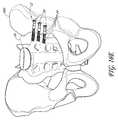
- FIG. 1is a front oblique view of a portion of a sacroiliac joint having a exemplary embodiment of a fixation device implanted therein.
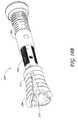
- FIG. 2is a side perspective view of an exemplary fixation device similar to that of FIG. 1 .
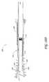
- FIG. 3is a side elevational view of the fixation device of FIG. 2 .
- FIG. 4is a cross-sectional view taken through line 4 - 4 of FIG. 3 .
- FIG. 4Ais an enlarged view of portion 4 A of FIG. 4 .
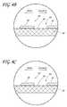
- FIG. 4Bis an enlarged view of portion 4 B of FIG. 4 with the fixation device in a first position.
- FIG. 4Cis an enlarged view of portion 4 C of FIG. 4 with the fixation device in a second position.
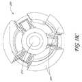
- FIG. 5is a cross-sectional view taken through line 5 - 5 of FIG. 3 .
- FIG. 6Ais a side perspective view of another embodiment of a proximal anchor for the bone fixation device of FIG. 2 .
- FIG. 6Bis a cross-sectional view of the proximal anchor of FIG. 6A .
- FIG. 6Cis a side perspective view of another embodiment of a proximal anchor for the bone fixation device of FIG. 2 .
- FIG. 6Dis a cross-sectional view of the proximal anchor of FIG. 6C .
- FIG. 6Eis a cross-sectional view of another embodiment of a proximal anchor for the bone fixation device of FIG. 2 .
- FIG. 6Fis a cross-sectional view of the proximal anchor of FIG. 6E .
- FIG. 7is a cross sectional view through an angularly adjustable proximal anchor plate.
- FIG. 8is a front perspective view of the proximal anchor plate of FIG. 7 .
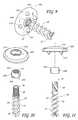
- FIG. 9is a bottom perspective view of a modified embodiment of a bone fixation device.
- FIG. 10is an unassembled side perspective view of the bone fixation device of FIG. 9 .
- FIG. 11is an unassembled side view of the bone fixation device of FIG. 9 .
- FIG. 12is a cross-sectional view of the flange and proximal anchor of the bone fixation device of FIG. 11 .
- FIG. 13is an unassembled bottom perspective view of the bone fixation device of FIG. 9 .
- FIG. 14is an unassembled side perspective view of another modified embodiment of a bone fixation device.
- FIG. 15is an unassembled side view of the bone fixation device of FIG. 9 .
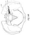
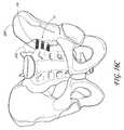
- FIGS. 16A-Hare various views of the pelvis and sacrum with the fixation device of FIG. 2 implanted therein.
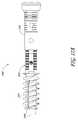
- FIG. 17Ashows a side view of an expandable bone fixation device in an unexpanded configuration.
- FIG. 17Bshows a perspective view of the expandable bone fixation device of FIG. 17A .
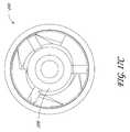
- FIG. 17Cshows a front view of the expandable bone fixation device of FIG. 17A .
- FIG. 17Dshows a cross-sectional side view of the expandable bone fixation device of FIG. 17A .
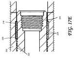
- FIG. 17Eshows an enlarged cross-sectional side view of the retention structure of the expandable fixation device of FIG. 17A .
- FIG. 18Ashows a side view of an expandable bone fixation device in an expanded configuration
- FIG. 18Bshows a perspective view of the expandable bone fixation device of FIG. 18A .
- FIG. 18Cshows a front view of the expandable bone fixation device of FIG. 18A .
- FIG. 18Dshows a cross-sectional side view of the expandable bone fixation device of FIG. 18A .
- fixation devices of the present inventionwill be disclosed primarily in the context of a sacroilial fixation procedure, the methods and structures disclosed herein are intended for application in any of a variety medical applications, as will be apparent to those of skill in the art in view of the disclosure herein.
- the bone fixation devicemay be applicable to proximal fractures of the femur, for spinal fixation, and a wide variety of fractures and osteotomies, the hand, such as interphalangeal and metacarpophalangeal arthrodesis, transverse phalangeal and metacarpal fracture fixation, spiral phalangeal and metacarpal fracture fixation, oblique phalangeal and metacarpal fracture fixation, intercondylar phalangeal and metacarpal fracture fixation, phalangeal and metacarpal osteotomy fixation as well as others known in the art. See e.g., U.S. Pat. No. 6,511,481, which is hereby incorporated by reference herein.
- a wide variety of phalangeal and metatarsal osteotomies and fractures of the footmay also be stabilized using the bone fixation devices described herein. These include, among others, distal metaphyseal osteotomies such as those described by Austin and Reverdin-Laird, base wedge osteotomies, oblique diaphyseal, digital arthrodesis as well as a wide variety of others that will be known to those of skill in the art.
- Fractures of the fibular and tibial malleoli, pilon fractures and other fractures of the bones of the legmay be fixated and stabilized with these bone fixation devices with or without the use of plates, both absorbable or non-absorbing types, and with alternate embodiments of the current invention
- the fixation devicesmay also be used to attach tissue or structure to the bone, such as in ligament reattachment and other soft tissue attachment procedures. Plates and washers, with or without tissue spikes for soft tissue attachment, and other implants may also be attached to bone, using either resorbable or nonresorbable fixation devices depending upon the implant and procedure.
- the fixation devicesmay also be used to attach sutures to the bone, such as in any of a variety of tissue suspension procedures.
- the bone fixation device described hereinmay be used with or without plate(s) or washer(s), all of which can be either permanent, absorbable, or combinations.
- FIG. 1there is illustrated an exemplary embodiment of implanted bone fixation devices 12 .
- the left ilium and a portion of the sacrumare shown as transparent in order to identify the locations of the fixation devices 12 .
- three fixation devices 12are positioned across the sacroiliac joint.
- the bone fixation device 12may be used in a variety of techniques to stabilize the sacroiliac joint. Accordingly, in modified embodiments, more than three or less than three fixation device can be used.
- the fixation device 12comprises a body 28 that extends between a proximal end 30 and a distal end 32 .
- the length, diameter and construction materials of the body 28can be varied, depending upon the intended clinical application. In embodiments optimized for sacroiliac fixation in an adult human population, the body 28 will generally be within the range of from about 30-120 mm in length and within the range of from about 3-12 mm in maximum diameter.
- the length of the helical anchordiscussed below, may be about 8-100 millimeters. Of course, it is understood that these dimensions are illustrative and that they may be varied as required for a particular patient or procedure.
- the body 28comprises titanium.
- other metals or bioabsorbable or nonabsorbable polymeric materialsmay be utilized, depending upon the dimensions and desired structural integrity of the finished fixation device 12 .
- the distal end 32 of the body 28is provided with a cancellous bone anchor or distal cortical bone anchor 34 .
- the distal bone anchor 34is adapted to be rotationally inserted into a portion of the sacrum.
- the distal anchor 34comprises a helical locking structure 72 for engaging cancellous and/or distal cortical bone.
- the locking structure 72comprises a flange that is wrapped around an axial lumen. The flange extends through at least one and generally from about 2 to about 50 or more full revolutions depending upon the axial length of the distal anchor and intended application. The flange will can complete from about 2 to about 20 revolutions.
- the helical flange 72is provided with a pitch and an axial spacing to optimize the retention force within cancellous bone, to optimize compression.
- the helical flange 72 of the illustrated embodimenthas a generally triangular cross-sectional shape (see FIG. 4 ).
- the helical flange 72can have any of a variety of cross sectional shapes, such as rectangular, oval or other as deemed desirable for a particular application through routine experimentation in view of the disclosure herein.
- the outer edge of the helical flange 72defines an outer boundary.
- the ratio of the diameter of the outer boundary to the diameter of the central lumencan be optimized with respect to the desired retention force within the cancellous bone and giving due consideration to the structural integrity and strength of the distal anchor 34 .
- Another aspect of the distal anchor 34 that can be optimizedis the shape of the outer boundary and the central core, which in the illustrated embodiment are generally cylindrical.
- the distal end 32 and/or the outer edges of the helical flange 72may be atraumatic (e.g., blunt or soft). This inhibits the tendency of the fixation device 12 to migrate anatomically distally after implantation. Distal migration is also inhibited by the dimensions and presence of a proximal anchor 50 , which will be described below.
- the various distal anchors described in co-pending U.S. patent application Ser. No. 10/012,687, filed Nov. 13, 2001can be incorporated into the fixation device 12 described herein.
- the entire contents of this applicationis hereby expressly incorporated by reference.
- the distal anchormay comprise a single helical thread surrounding a central core, much as in a conventional screw, which has been cannulated to facilitate placement over a wire.
- a double helical threadmay be utilized, with the distal end of the first thread rotationally offset from the distal end of the second thread.
- a double helical threadcan enable a greater axial travel for a given degree of rotation and greater retention force than a corresponding single helical thread.
- Specific distal anchor designscan be optimized for the intended use, taking into account desired performance characteristics, the integrity of the distal bone, and whether the distal anchor is intended to engage exclusively cancellous bone or will also engage cortical bone.
- the body 28comprises a first portion 36 and a second portion 38 that are coupled together at a junction 40 .
- the first portion 36carries the distal anchor 34 while the second portion 38 forms the proximal end 30 of the body 28 .
- the second portion 38may be used to pull the body 28 and therefore will sometimes be referred to as a “pull-pin”.
- the first and second portions 36 , 38are preferably detachably coupled to each other at the junction 40 .
- the first and second portions 36 , 38are detachably coupled to each other via interlocking threads. Specifically, as best seen in FIG.
- the body 28includes an inner surface 41 , which defines a central lumen 42 that preferably extends from the proximal end 30 to the distal end 32 throughout the body 28 .
- the inner surface 41includes a first threaded portion 44 .
- the first threaded portion 44is configured to mate with a second threaded portion 46 , which is located on the outer surface 45 of the second portion 38 .
- the interlocking annular threads of the first and second threaded portions 44 , 46allow the first and second portions 36 , 38 to be detachably coupled to each other. In one modified embodiment, the orientation of the first and second threaded portions 44 , 46 can be reversed.
- first threaded portion 44can be located on the outer surface of the first portion 36 and the second threaded portion 46 can be located on the inner surface 41 at the distal end of the second portion 38 .
- Any of a variety of other releasable complementary engagement structuresmay also be used, to allow removal of second portion 38 following implantation, as is discussed below.
- the second portion 38can comprise any of a variety of tensioning elements for permitting proximal tension to be placed on the distal anchor 34 while the proximal anchor is advanced distally to compress the fracture.
- tensioning elementsfor permitting proximal tension to be placed on the distal anchor 34 while the proximal anchor is advanced distally to compress the fracture.
- any of a variety of tubes or wirescan be removably attached to the first portion 36 and extend proximally to the proximal handpiece.
- the first portion 36can include a releasable connector in the form of a latching element, such as an eye or hook.
- the second portion 38can include a complementary releasable connector (e.g., a complementary hook) for engaging the first portion 36 .
- the second portion 38can be detachably coupled to the first portion 36 such proximal traction can be applied to the first portion 36 through the second portion as will be explained below.
- the second portion 48may be provided with an eye or hook, or transverse bar, around which or through which a suture or wire may be advanced, both ends of which are retained at the proximal end of the device. Following proximal tension on the tensioning element during the compression step, one end of the suture or wire is released, and the other end may be pulled free of the device.
- Alternate releasable proximal tensioning structuresmay be devised by those of skill in the art in view of the disclosure herein. It should also be appreciated that the body may be from a single piece as described in U.S. Pat. No. 6,511,481, which has been incorporated by reference herein.
- the body 28is cannulated to accommodate installation over a placement wire as is understood in the art.
- the cross section of the illustrated central cannulationis circular but in other embodiments may be non circular, e.g., hexagonal, to accommodate a corresponding male tool for installation or removal of the second portion 38 of the body 28 as explained above.
- the body 28may partially or wholly solid.
- the proximal end 30 of the body 28may be provided with a rotational coupling 70 , for allowing the second portion 38 of the body 28 to be rotationally coupled to a rotation device.
- the proximal end 30 of the body 28may be desirably rotated to accomplish one or two discrete functions. In one application, the proximal end 30 is rotated to remove the second portion 38 of the body 28 following tensioning of the device to anchor an attachment to the bone. Rotation of the rotational coupling 70 may also be utilized to rotationally drive the distal anchor into the bone. Any of a variety of rotation devices may be utilized, such as electric drills or hand tools, which allow the clinician to manually rotate the proximal end 30 of the body.
- the rotational coupling 70may have any of a variety of cross sectional configurations, such as one or more flats or splines.
- the rotational coupling 70comprises a proximal projection of the body 28 having an axial recess with a polygonal cross section, such as a hexagonal cross section.
- the rotational coupling 70is illustrated as a female component, machined or milled or attached to the proximal end 30 of the body 28 .
- the rotational couplingmay also be in the form of a male element, such as a hexagonal or other noncircular cross sectioned projection.
- the proximal end 30 of the fixation deviceis provided with a proximal anchor 50 .
- Proximal anchor 50is axially distally moveable along the body 28 , to permit compression of between the distal and proximal ends 32 , 30 of the fixation device 12 .
- complementary locking structuressuch as threads or ratchet like structures between the proximal anchor 50 and the body 28 resist proximal movement of the anchor 50 with respect to the body 28 under normal use conditions.
- the proximal anchor 50preferably can be axially advanced along the body 28 with and/or without rotation as will be apparent from the disclosure herein.
- the proximal anchor 50comprises a housing 52 such as a tubular body, for coaxial movement along the body 28 .
- the housing 50may have diameter sized to fit through an opening formed in fixation bar or plate.
- the distal end of the housing 52preferably extends distally past the junction 40 between the first portion 36 and the second portion 38 .
- the housing 52is provided with one or more surface structures 54 such as a radially inwardly projecting flange 56 (see FIGS. 4B and 4C ), for cooperating with complementary surface structures 58 on the first portion 36 of the body 28 .
- the complementary surface structures 58comprise a series of annular ridges or grooves and/or threads 60 .
- the surface structures 54 and complementary surface structures 58permit distal axial travel of the proximal anchor 50 with respect to the body 28 , but resist proximal travel of the proximal anchor 50 with respect to the body 28 .
- the proximal end of the flange 56is biased towards the longitudinal axis of the body 28 .
- the flange 56engages the grooves or ridges 60 of the complementary surface structures 58 . This prevents proximal movement of the proximal anchor 50 with respect to the body 28 .
- the flange 56can bend outwardly away from the body 28 and the ridges 60 so as to allow the proximal anchor 50 to move distally.
- complementary surface structureswhich permit one way ratchet like movement.
- a plurality of annular rings or helical threads, ramped ratchet structures and the like for cooperating with an opposing ramped structure or pawlcan also be used.
- opposing screw threadsare dimensioned to function as a ratchet.
- the complementary surface structurescan comprise complementary threads.
- Retention structures 58are spaced axially apart along the body 28 , between a proximal limit 62 and a distal limit 64 .
- the axial distance between proximal limit 62 and distal limit 64is related to the desired axial working range of the proximal anchor 50 , and thus the range of functional sizes of the fixation device 12 .
- the fixation device 12 of the exemplary embodimentcan provide compression between the distal anchor 34 and the proximal anchor 50 throughout a range of motion following the placement of the distal anchor in bone.
- the distal anchormay be positioned within the cancellous and/or distal cortical bone of the sacrum, and the proximal anchor may be distally advanced with respect to the distal anchor throughout a range to provide compression without needing to relocate the distal anchor and without needing to initially locate the distal anchor in a precise position with respect to the proximal side of the ilium.
- Providing a working range throughout which tensioning of the proximal anchor is independent from setting the distal anchorallows a single device to be useful for a wide variety of fixation procedures, as well as eliminates the need for accurate device measurement.
- this arrangementallows the clinician to adjust the compression force during the procedure without adjusting the position of the distal anchor. In this manner, the clinician may focus on positioning the distal anchor sufficiently within the sacrum to avoid or reduce the potential for distal migration, which may damage the particularly delicate tissue, blood vessels, and/or nerves.
- the working rangeis at least about 10% of the overall length of the device, and may be as much as 20% or 50% or more of the overall device length.
- working ranges of up to about 15 mm or moremay be provided, since estimates within that range can normally be readily accomplished within the clinical setting.
- the embodiments disclosed hereincan be scaled to have a greater or a lesser working range, as will be apparent to those of skill in the art in view of the disclosure herein.
- the proximal anchor 50includes a flange 66 that, as will be explained below, may be configured to sit against the outer surface of the ilium and/or a fixation rod or plate.
- the flange 66is preferably an annular flange, to optimize the footprint or contact surface area between the flange 66 and the bone or fixation rod or plate.
- Circular or polygonal shaped flanges for use in sacroilial fixationwill generally have a diameter of at least about 3 mm greater than the adjacent body 28 and often within the range of from about 2 mm to about 30 mm or more greater than the adjacent body 28 .
- the fixation devicemay include an antirotation lock between the first portion 36 of the body 28 and the proximal collar 50 .
- the first portion 36includes a pair of flat sides 80 , which interact with corresponding flat structures 82 in the proximal collar 50 .
- One or three or more axially extending flatsmay also be used.
- rotation of the proximal collar 50is transmitted to the first portion 36 and distal anchor 34 of the body 28 .
- splines or other interfit structurescan be used to prevent relative rotation of the proximal anchor and the first portion 36 of the body 28 .
- the flange 66is preferably provided with a gripping structure to permit an insertion tool to rotate the flange 66 .
- a gripping structuremay be provided, such as one or more slots, flats, bores or the like.
- the flange 44is provided with a polygonal, and, in particular, a pentagonal or hexagonal recess 84 (see FIG. 4 ).
- the housing 52 of the proximal anchor 50can include one or more one or more barbs that extend radially outwardly from the tubular housing 52 .
- Such barbsprovide for self tightening after the device has been implanted in the patient as described in a co-pending U.S. patent application Ser. No. 10/012,687, filed Nov. 13, 2001, which was incorporated by reference above.
- the barbsmay be radially symmetrically distributed about the longitudinal axis of the housing 52 .
- Each barbis provided with a transverse engagement surface, for anchoring the proximal anchor 50 in the bone.
- the transverse engagement surfacemay lie on a plane which is transverse to the longitudinal axis of the housing 50 or may be inclined with respect to the longitudinal axis of the tubular 50 . In either arrangement, the transverse engagement surface 43 generally faces the contacting surface 68 of the flange 44 . As such, the transverse engagement surface inhibits proximal movement of the proximal anchor with respect to the bone.
- FIGS. 6A and 6Billustrate another embodiment of a proximal anchor 100 .
- This embodimentalso includes a tubular housing 102 and a flange 104 that may be configured as describe above with respect to FIGS. 2-4 .
- the tubular housing 102may include an anti-rotational lock, which, in the illustrated embodiment, is in the form of one or more sides 106 that interact with corresponding flat structures formed in the body 28 as described above.
- the surfaces structurescomprises one or more teeth or grooves 112 , which are configured to engage the complementary surfaces structures on the body 28 (see FIG. 2 ).
- One or more slots or openings 110are formed in the tubular housing 102 to form one or more bridges 112 , which carry the teeth 102 .
- the anchor proximal anchor 100may be pushed towards the distal end of the body and the teeth 102 can slide along the and over the complementary surface structures 58 on the body 28 .
- the bridge 113may flex slightly away from the body 28 to allow such movement.
- the number and shape of the openings 110 and bridges 112may be varied depending of the desired flexing of the bridges 112 when the proximal anchor 110 is moved distally over the body and the desired retention force of the distal anchor when appropriately tensioned.
- the teeth on the proximal anchor 100 and the grooves on the body 28may be configured such that the proximal anchor 100 can be rotated or threaded onto the pin in the distal direct and/or so that that the proximal anchor can be removed by rotation.
- the illustrated embodimentalso advantageously includes visual indicia 114 (e.g., marks, grooves, ridges etc.) on the tubular housing 102 for indicating the depth of the proximal housing 100 within the bone.
- FIGS. 6C and 6Dillustrate another embodiment of a proximal anchor 150 .
- the proximal anchor 150comprises a housing 152 such as a tubular body, for coaxial movement along the body 28 .
- the proximal anchor 150also includes a flange 154 that is configured that to set against the outer surface of, for example, a bone or fixation bar or rod.
- the flange 154defines a contacting surface 156 , which preferably forms an obtuse angle with respect to the exterior of the housing 152 .
- the contacting surface 154may be perpendicular or form an acute angle with respect to the housing 152 .
- the complementary retention structures 54comprise one or more inwardly projecting teeth or flanges 158 , for cooperating with the complementary rentention structures 58 on the body 28 .
- the complementary retention structures 58 of the bodypreferably comprise a plurality of annular ridges or grooves a first surface and a second surface.
- the first surfacegenerally faces the proximal direction and is preferably inclined with respect to the longitudinal axis of the body 28 .
- the second surfacegenerally faces the distal direction and lies generally perpendicular to the longitudinal axis of the body 28 .
- the proximal anchor 150preferably includes one or more of axial slots 160 .
- the axial slots 160cooperate to form lever arm(s) on which the teeth or projections 158 are positioned.
- the teeth 158can slide along the first surface and ride over the retention structures 58 of the body 28 as the teeth 158 are flexed away from the body 28 .
- the bonemay push on the angled portion contacting surface 156 of the proximal anchor 150 .
- This forceis transmitted to the teeth 158 through the lever arms.
- the teeth 158are prevented from flexing away from the body 28 , which keeps the teeth 158 engaged with the retention structures 58 of the body 28 .
- proximal movement of the proximal anchor 150 with respect to the body 28is resisted.
- the axial length and width of the slots 160may be varied, depending upon the desired flexing of the lever arms when the proximal anchor 150 is moved distally over the body 28 and the desired retention force of the distal anchor when appropriately tensioned.
- axial lengths and widths of the slots 160are approximately 0.5 mm for a proximal anchor having a length of approximately 4 mm, an inner diameter of approximately 3 mm.
- the slots 160extend through the flange 154 and at least partially into the housing 152 .
- the proximal anchor 150includes four teeth or flanges 158 , which are positioned near the proximal end of the anchor 150 .
- the proximal anchor 150may include more or less teeth and/or the teeth may be positioned more distally or proximally on the anchor 150 .
- these retention structuresmay be configured such that the proximal anchor 150 may be proximally and/or distally advanced with rotation by providing for a screw like configuration between the retention structures.
- a proximal anchor 180is illustrated in FIGS. 6E and 6F .
- the proximal anchor 180may include a tubular housing 152 and a flange 154 with a bone contacting surface 156 .
- the complementary structure of the proximal anchor 180comprises an annular ring 182 , which is positioned within an annular recess 184 that is preferably positioned at the distal end of the tubular housing 152 .
- the annular recess 184includes a proximal portion 186 and a distal portion 188 .
- the proximal portion 186is sized and dimensioned such that as the proximal anchor 180 is advanced distally over the body 28 the annular ring 182 can ride over the complementary retention structures 58 of the body 28 . That is, the proximal portion 182 provides a space for the annular ring 182 can move radially away from the body 28 as the proximal anchor 180 is advanced distally.
- the annular ring 182is made from a material that provides sufficient strength and elasticity such as, for example, stainless steel or titanium.
- the annular ring 182is preferably split such that it can be positioned over the body 405 .
- the annular ring 182includes a plurality of teeth 192 although in modified embodiments the annular ring 182 may be formed without the teeth.
- the distal portion 188 of the recess 184is sized and dimensioned such that after the proximal anchor 180 is appropriately tensioned the annular ring 192 becomes wedged between the body 28 and an angled engagement surface of the distal portion 188 . In this manner, proximal movement of the proximal anchor 180 with respect to the body is prevented.
- the ring 192can be formed without a gap.
- Other embodiments and further details of the proximal anchor described abovecan be found in U.S.
- the contacting surface 68 of the flange 44is tapered and generally faces the outer surface of the ilium, fixation rod, and/or plate.
- the bone contacting surface 69can reside in or approximately on a plane, which is perpendicular with respect to the longitudinal axis of the body 28 .
- other angular relationships between the bone contacting surface 68 of the flange 66 and the longitudinal axis of the body 28 and housing 52may be utilized, depending upon the anticipated entrance angle of the body 28 and associated entrance point surface of the ilium.
- the clinicianmay be provided an array of proximal anchors 50 of varying angular relationships between the contacting surface 68 and the longitudinal axis of the body 28 and housing 52 (e.g., 90°, 100°, 110°, 120°, and 130°).
- a single body 28can be associated with the array such as in a single sterile package.
- the clinicianupon identifying the entrance angle of the body 28 and the associated entrance point surface orientation can choose the anchor 50 from the array with the best fit angular relationship, for use with the body 28 .
- the proximal anchor 50may be used with a washer 66 ′ that is angularly adjustable with respect to the longitudinal axis of the body 28 .
- the proximal anchor 50 and the washer 66 ′include corresponding semi-spherical or radiused surfaces 45 a and 45 b .
- the surface 45 bsurrounds an aperture 49 in the washer 66 .
- This arrangementallows the proximal anchor 50 to extend through and pivot with respect to the washer 66 ′.
- the angular relationship between the bone contacting surface 68 ′ of the washer 66 ′ and the longitudinal axis of the body 28can vary in response to the entrance angle.
- FIGS. 9-13illustrate another embodiment of a bone fixation device 200 with an angularly adjustable proximal anchor 202 .
- similar reference numbersare used to identify components that are similar components described above.
- the bone fixation device 200comprises a body 28 that extending between a proximal end 30 and a distal end 32 .
- the distal end 32 of the bodyis provide with a bone anchor 34 as described above.
- the illustrated body 28is cannulated; however, it should be appreciated that in modified embodiments the body 28 can be solid.
- the proximal end of the anchoris provided with a hexagonal recess, which can be used in combination with a rotational tool to rotate the body 28 .
- modified embodimentsmay use a variety of different male or female anti-rotational couplings.
- the illustrated fixation deviceincludes an annular flange 202 and proximal anchor 204 .
- the proximal anchor 204defines a housing 206 that is axially distally moveable along the body 28 .
- Complementary locking structures 54 , 58 on the housing 206 and the body 28such as threads or ratchet like structures resist proximal movement of the anchor 204 with respect to the body 28 under normal use conditions.
- the complementary locking structures 54 , 48may permit the anchor 204 to be axially advanced along the body 28 by rotation.
- the complementary locking structures 54 , 58may permit the anchor 204 to be axially advanced along the body 24 without rotation.
- the illustrated proximal anchor 204also includes a gap 205 such that the illustrated anchor 204 forms a split ring collar. In modified embodiments, the proximal anchor 204 can be formed without the gap 205 .
- the proximal anchor 204preferably includes a smooth and more preferably rounded or spherical outer surface portion 208 , which is configured to fit within a corresponding smooth and preferably rounded recessed portion 210 in the flange 202 .
- the flange 202resists distal movement of the proximal anchor 204 while permitting at least limited rotation of between the proximal anchor 204 and the flange 202 .
- the illustrate arrangementallows for angular movement of the flange 202 with respect to the anchor 204 to accommodate variable anatomical angles of the bone surface.
- the flange 202may seat directly against the outer surface of the ilium. Because the outer surface of the ilium is typically non-planar and/or the angle of insertion may not be perpendicular to the outer surface of the ilium, a fixed flange may contact only a portion of the outer surface of the ilium. This may cause the ilium to crack due to high stress concentrations. In contrast, the angularly adjustable flange 202 can rotate with respect to the body and thereby the bone contacting surface may be positioned more closely to the outer surface. More bone contacting surface is thereby utilized and the stress is spread out over a larger area. In addition, the flange 202 , which has a larger diameter than the proximal anchor 50 , effectively increases the shaft to head diameter of the fixation device, thereby increasing the size of the loading surface and reducing stress concentrations.
- the flange 202includes a plurality of bone engagement features 212 , which in the illustrated embodiment comprises one or more spikes 212 positioned on a contacting surface 216 of the flange 202 .
- the spikes 212provide additional gripping support especially when the flange 202 is positioned against, for example, uneven bone surfaces and/or soft tissue.
- the flange 202may be formed without the bone engagement features 212 .
- Other structures for the bone engagement feature 212may also be used, such as, for example, ridges, serrations etc.
- the illustrated embodimentalso includes a tapered upper surface 214 that in certain embodiments may be flat.
- FIGS. 14 and 15illustrate a modified embodiment of the angularity adjustable fixation device 200 .
- the proximal anchor 204 ′includes an upper portion 211 and a lower portion 213 .
- the upper portion 211is configured as described above with respect to the housing.
- the lower portion in the illustrated embodimentis generally tubular and a generally smaller diameter than the upper portion.
- the lower portionincludes complementary retention structures 54 and generally provides the fixation device with a greater range of adjustable compression and additional retention structures as compared to the previous embodiment.
- FIGS. 16A-Hare various views of the pelvis and sacrum with the fixation device of FIG. 2 implanted therein.
- FIGS. 16A-Billustrate top views
- FIGS. 16C-Eillustrate front views
- FIGS. 16F-Hillustrate rear views.
- one or both of the ilium 300 and the sacrum 302are illustrated as transparent, in order to more clearly identify the position of the fixation devices 12 .
- three fixation devices 12are implanted. Each fixation device 12 is inserted through the ilium 300 and into the sacrum 302 .
- the distal anchor 34is disposed within the sacrum 302 .
- the proximal anchor 50is disposed against the surface of the ilium 300 .
- fixation devices 12utilizes three fixation devices 12 , in other embodiments the number of devices can vary. For example, in some embodiments one fixation device can be employed, while in others two can be used. In various embodiments, three, four, or more fixation devices can be used.
- a patient with a sacroiliac joint instabilityis identified.
- the target entry point on the ilium 300 and a trajectory angleis then localized by intraoperative imaging, for example by fluoroscopy.
- a small incisionis then made in the skin, and the tip of a guide wire or K-wire is driven through the soft tissue of the patient at an advantageous angle down to the target site on the ilium.
- the skin incisioncan then be lengthened, as necessary. In some embodiments, the incision may be lengthened to approximately 17 mm, for example.
- a similar incisioncan be made in the fascia, using the guide wire as the midpoint of the incision.
- a first dilator tubecan then be passed over the guide wire until the tip of the dilator tube reaches the target point on the ilium 300 .
- a second dilator tube having a larger diametercan then be passed over the first dilator tube. Advancing the second dilator tube to the target point on the ilium 300 further retracts tissue along the trajectory path. This can be repeated with additional dilator tubes, as necessary, with progressively wider dilator tubes to expand the patient's soft tissue down to the entry point on the ilium 300 .
- An outer dilator tube, or cannulais then left in place.
- a depth gaugemay then be used to verify that the appropriate depth has been reached.
- a pre-drillcan thereafter be advanced to the ilium 300 , which is then verified by fluoroscopy.
- a drillcan be advanced until it passes through the ilium and into the sacrum 302 .
- the distal tip of a tapis driven into the sacrum until it reaches the appropriate depth, which can then be verified by fluoroscopy.
- a bone fixation device 12is then driven through the ilium 300 and into the sacrum 302 until it reaches the appropriate depth, which can then also be verified by fluoroscopy.
- proximal tractionis applied to the proximal end 30 of body 28 , such as by conventional hemostats, pliers or a calibrated loading device, while distal force is applied to the proximal anchor.
- the proximal anchoris advanced distally with respect to the body until the proximal anchor fits snugly against the outer surface of the ilium or a fixation plate/rod.
- Appropriate tensioning of the fixation deviceis accomplished by tactile feedback or through the use of a calibration device for applying a predetermined load on the implantation device.
- one advantage of the structure of the illustrated embodimentsis the ability to adjust compression independently of the setting of the distal anchor 34 within the sacrum. Appropriate stabilization of the sacroiliac joint can then be verified by fluoroscopy.
- the second portion 38 of the body 28is preferably detached from the first portion 36 and removed. In the illustrated embodiment, this involves rotating the second portion 38 with respect to the first portion via the coupling 70 . In other embodiments, this may involve cutting the proximal end of the body 28 .
- the proximal end of the bodymay be separated by cauterizing.
- Cauterizingmay fuse the proximal anchor 50 to the body 32 thereby adding to the retention force between the proximal anchor 50 and the body 28 .
- Such fusion between the proximal anchor and the bodymay be particularly advantageous if the pin and the proximal anchor are made from a bioabsorbable and/or biodegradable material. In this manner, as the material of the proximal anchor and/or the pin is absorbed or degrades, the fusion caused by the cauterizing continues to provide retention force between the proximal anchor and the body.
- additional fixations devicesmay be implanted and/or additional stabilization implants (e.g., rods, plates, etc.) may be coupled to the body.
- additional stabilization implantse.g., rods, plates, etc.
- the access sitemay be closed and dressed in accordance with conventional wound closure techniques.
- the second portion 38may form part of the driving device, which is used to rotate the proximal anchor 50 and thus distal anchor 34 into the sacrum.
- the second portion 38is used to apply proximal traction. After appropriate tensioning, the second portion 38 can be de-coupled from the first portion 36 and removed with the driving device.
- the second portion 38may be connected to a rotatable control such as a thumb wheel on the deployment device.
- a containermay be opened at the clinical site exposing the proximal end of the implant, such that the distal end of the second portion 38 may be removably coupled thereto. Proximal retraction of the hand tool will pull the implant out of its packaging.
- the implantmay then be positioned within the aperture in the bone, rotated to set the distal anchor, and the hand piece may be manipulated to place proximal traction on the second portion 38 while simultaneously distally advancing the proximal anchor. Following appropriate tensioning, the second portion 38 may be disengaged from the implant, and removed from the patient.
- the second portion 38may be disengaged from the implant by rotating a thumb wheel or other rotational control on the hand piece.
- the second portion 38comprises a pull wire
- following appropriate tensioning across the jointa first end of the pull wire is released such that the pull wire may be removed from the implant by proximal retraction of the second end which may be attached to the hand piece.
- the clinicianwill have access to an array of fixation devices 12 , having, for example, different diameters, axial lengths and, if applicable, angular relationships. These may be packaged one or more per package in sterile or non-sterile envelopes or peelable pouches, or in dispensing cartridges which may each hold a plurality of devices 12 . The clinician can assess the dimensions and load requirements, and select a fixation device from the array, which meets the desired specifications.
- a dilatorcan be introduced directly, without the use of a guidewire.
- a self-tapping high-speed drillcan be used. The surgery may be performed percutaneously, minimally invasively, mini-open, or open, depending on surgeon preference.
- the proximal anchor 50may be carried by the fixation device 12 prior to advancing the body into the sacrum 302 , or may be attached following placement of the body within the sacrum 302 .
- stabilization implantse.g., a fixation plate and/or rod
- the distal anchor of one or more bone fixation devices described hereinare advanced through the ilium and into a suitable portion of the sacrum.
- the threads of the fixation devicecan be placed across the sacroiliac joint, and compression achieved by distally advancing the proximal anchor.
- This approachnot only provides compression across the sacroiliac joint which helps promote fusion, but also provides intraoperative flexibility to stop the distal anchor of the device where necessary and compress to the length to achieve an appropriate fit.
- the devicemay be used with or without a washer.
- the proximal anchoris typically supported directly against the outer surface of the ilium 300 .
- an angularly adjustable flangemay be used that can rotate with respect to the body and thereby the bone contacting surface may be positioned more closely to the outer surface of the ilium 300 . This results in more bone contacting surface being utilized and the stress supported by the fixation device is spread out over a larger area of the ilium 300 .
- the surface of the fixation devices 12may be treated to promote bone in-growth, and therefore fusion across the sacroiliac joint. These treatments may be placed over the entire length of the device or only on certain portions of the device depending on the specific needs it addresses or the advantages it provides. These treatments can include titanium plasma spray, a coating of hydroxyapatite, resorbable blast media, and others.
- bone graftautogenous, demineralized bone matrix, bone morphogenetic protein, or other
- an allograft sleevemay be placed over the fixation device so that the sleeve spans the sacroiliac joint, thereby encouraging bone in-growth and sacroiliac joint fusion.
- FIG. 17A-Dshow side, perspective, front, and cross-sectional side views, respectively, of an embodiment of an expandable bone fixation device in an unexpanded configuration, with FIG. 17E showing an enlarged portion of the cross-sectional side view seen in FIG. 17D .
- FIGS. 18A-Dshow side, perspective, front, and cross-sectional side views, respectively, of an expandable bone fixation device in an expanded configuration.
- the fixation device 200comprises an elongate body 202 having a distal anchor 204 , which can be configured as described above.
- a separate proximal anchor 206 with complementary retention structurescan be advanced longitudinally along the length of the body 202 over retention structures of the body (e.g., as described above).
- the proximal anchor 206can include features and elements described above to permit proximal movement of the elongate body 202 with respect to the proximal anchor 206 but to resist distal movement of the elongate body 202 with respect the proximal anchor 204 .
- an interior shaft 208is disposed within an inner lumen of the elongate body 202 .
- the expandable bone fixation device of FIGS. 17A-18Dcan be used in the techniques described above and/or features of the illustrated expandable bone fixation device can be combined with the embodiments of the bone fixation device described above.
- the bone fixation device 200can function similar to the fixation devices described elsewhere herein, including distal advancement of the proximal anchor 206 over the retention structures of the elongate body 202 for secondary purchase, following insertion of the distal anchor 204 into bone.
- the bone fixation device 200in the illustrated embodiment, can include additional functionality allowing for expansion (and accompanying additional purchase) of the distal anchor 204 .
- the distal anchorcan be inserted into bone, for example into the sacrum.
- the interior shaft 208can be disposed as illustrated in the unexpanded configuration of FIGS. 17A-E , with the tapered distal end 210 protruding from the distal end of the distal anchor 204 .
- the interior shaft 208can be proximally retracted, upon which the outer surface 209 of the interior shaft 208 tapered distal end 210 abuts the inner surface 205 of the distal end of the anchor 204 .
- the distal anchor 204can include a plurality of slits 212 , which can allow for flaring of the distal anchor upon contact with the tapered end 210 of the interior shaft 208 .
- the distal anchor 204can flare, expanding radially and thereby provide additional purchase against bone. This additional purchase can be particularly advantageous in use with the soft bone in the sacrum.
- the inner memberis proximally retracted to thereby flare the distal anchor.
- the devicecan be configured such that the inner member can be advanced distally to cause flaring of the distal anchor.
- the taper of the inner membermay be configured to abut an angled surface interior to the distal anchor such that, upon distally moving the inner member, the tapered portion of the inner mamber contacts the angled surface of the distal anchor, causing flaring of the distal anchor as a result.
- Other such configurationsare possible in which distal movement of the inner member causes the distal anchor to expand.
- proximal retraction of the interior shaft 208can be accomplished by use of a pull pin (not shown), which can be inserted through the lumen of the elongate body 202 and threaded into the proximal end 214 of the interior shaft 208 . Once the pull pin is engaged with the proximal end 214 via threading or other engagement mechanism, the interior shaft 208 can be proximally retracted.
- a retention structuresuch as, for example, a ratchet mechanism
- a slip-ringsimilar to that described above with respect to the proximal anchor
- a modified complementary retention structurescan be used, such as, for example, the various ratchet-like and threaded mechanisms described herein.
- the complementary retention structurescan comprise an annular ring 218 , which is positioned within an annular recess 220 formed in the elongate body 202 .
- the inner surface of the annular ring 218is complementary to ridges or threads 222 on the outer surface of interior shaft 208 .
- the proximal portion of the annular recess 220is sized and dimensioned such that as the interior shaft 208 is retracted proximally, the annular ring 218 can ride over the complementary retention structures 222 of the body 28 .
- the annular recess 220provides a space for the annular ring 218 to move radially away from the interior shaft 208 as the interior shaft 208 is advanced distally.
- the annular ring 218is made from a material that provides sufficient strength and elasticity such as, for example, stainless steel or titanium.
- the annular ring 208may be split such that it can be positioned over the interior shaft 208 .
- the annular ring 218includes a plurality of teeth 224 although in modified embodiments the annular ring 218 may be formed without the teeth.
- the recess 220is also sized and dimensioned such that after the interior shaft 208 is appropriately positioned, the annular ring 218 becomes wedged between the interior shaft 208 a surface of the annular recess 220 . In this manner, distal movement of the interior shaft 208 with respect to the elongate body 202 is prevented.
- the ring 218can be formed without a gap.
- the retention structuremay also include features which assist in releasing the structure so that removal of the device is easier.
- the annular ringcan be based on threads so that the inner member can be rotated to advance forward, thereby collapsing the distal anchor that had been previously expanded. Other such mechanisms may likewise be used to assist in releasing the retention structure and thereby collapsing the flared distal anchor.
- bone graft of other materialfrom within the interior lumen 216 of the bone fixation device 200 to the surrounding area outside of the bone fixation device by passing out the distal end 210 of the interior shaft 208 .
- the devicecan accommodate bone graft through the assembly, as well as increasing the purchase with an expandable bone thread on the distal end, or both.
- the bone graft aperturescould be holes or slots.
- the graft materialmay also exit the additional apertures in the device so that bone graft (or other material) can be placed at advantageous locations such as directly at or into the joint or fracture.
- the inner member 208may also have multiple apertures along its length to assist in bone graft exiting from varoius points along the device.
- the aperturesmay be various shapes, round, ovular, rectangular, etc.
- the devicecan have a very large and relatively sharp edged distal bone screw thread which works very well with the soft bone in the sacrum. With a larger screw assembly, the device can accommodate some geometry that will allow the injecting of bone graft thru it after it is in place (either before or after final compression).
- the devicecan also include holes and/or slots for the injection of bone graft or similar material.
- the distal anchorcan be flared out in-vivo. This option may greatly enhance the purchase in areas where bone density is less.
- the flaring actioncan easily be managed with a compression instrument or pull pin. So not only can a surgeon carefully and accurately position the distal end of the screw, she can dial in distal flare/purchase as well as the amount of secondary compression by compressing the collar.
- a washercan be used to slip on prior to inserting the screw, as described elsewhere herein.
- a patient with a sacroiliac joint instabilityis identified, and a drill can be advanced until it passes through the ilium and into the sacrum.
- the distal tip of a tapis driven into the sacrum until it reaches the appropriate depth, which can then be verified by fluoroscopy.
- An expandable bone fixation device 200is then driven through the ilium and into the sacrum until it reaches the appropriate depth, which can then also be verified by fluoroscopy.
- proximal tractioncan be applied to the proximal end 204 of elongate body 202 , such as by conventional hemostats, pliers or a calibrated loading device, while distal force is applied to the proximal anchor 206 .
- the proximal anchor 206is advanced distally with respect to the elongate body 202 until the proximal anchor 206 fits snugly against the outer surface of the ilium or a fixation plate/rod.
- a pull pin or rodmay then be inserted into the device 200 and coupled with the inner member 210 , after which the inner member 210 can be proximally retracted with respect to the distal anchor 204 .
- Proximal retraction of the inner member 210causes the distal anchor 204 to flare, thereby increasing purchase within the sacrum.
- the distal anchor 204may be flared before the proximal anchor 206 is advanced distally with respect to the elongate body 202 .
- the pull pinmay then be removed, and additional fixation devices may be implanted and/or additional stabilization implants may be coupled to the elongated body.
- the access sitemay be closed and dressed in accordance with conventional wound closure techniques.
- an expandable bone anchormay be used in other applications, for example various orthopedic or spinal applications, pedicle screws, etc.
- the expandable bone anchormay include a flaring distal anchor but may omit a proximal anchor.
- bone graft materiale.g., autograft, allograft, demineralized bone matrix
- bone growth promoterse.g., bone morphogenic proteins
- bone cementmay be used in conjunction with the fixation devices described herein.
- bone graft material, bone growth promoters, and/or bone cementcan be introduced into the sacroiliac joint before and/or after insertion of the fixation device(s) across the joint. This may help promote fusion of the joint, and/or to increase fixation. This can be particularly advantageous in cases in which the bone quality is poor, but the approach may be applied to any quality of bone.
- the fixation deviceis cannulated.
- the fixation devicemay be cannulated and may also include a plurality of exit holes.
- a plurality of exit holesmay be arranged on the outer surface of the fixation device.
- the exit holesmay be in fluid communication with the interior passageway, such that bone graft material, bone growth promoters, and/or bone cement introduced through the interior passageway can exit through the plurality of exit holes.
- one or more of the exit holesmay be oriented in a direction transverse to the interior passageway.
- the exit holesmay be distributed along substantially the entire length of the fixation device.
- the exit holesmay be limited to one or more regions of the fixation device.
- the exit holesmay be limited to certain regions such that the bone graft material, bone growth promoters, and/or bone cement exits the fixation device in preferential areas to promote fusion, such as at the joint.
- the exit holesmay be limited to the distal region, such that the exiting bone graft material, bone growth promoters, and/or bone cement improves fixation.
- fixation devices described abovemay be made from either conventional bioabsorbable materials or conventional non-absorbable materials, combinations thereof and equivalents thereof.
- natural materialssuch as allografts may be used.
- absorbable materialsinclude homopolymers and copolymers of lactide, glycolide, trimethylene carbonate, caprolactone, and p-dioxanone and blends thereof. The following two blends may be useful: 1) the blend of poly(p-dioxanone) and a lactide/glycolide copolymer, as disclosed in U.S. Pat. No.
- the fixation devicesmay also be made from conventional non-absorbable, biocompatible materials including stainless steel, titanium, alloys thereof, polymers, composites and the like and equivalents thereof.
- the distal anchorcomprises a metal helix
- the body and the proximal anchorcomprise a bioabsorbable material.
- the distal anchorcomprises a bioabsorbable material
- the body and proximal anchorcomprise either a bioabsorbable material or a non-absorbable material.
- each of the distal anchor and the bodycomprise a non-absorbable material, connected by an absorbable link. This may be accomplished by providing a concentric fit between the distal anchor and the body, with a transverse absorbable pin extending therethrough. This embodiment will enable removal of the body following dissipation of the pin, while leaving the distal anchor within the bone.
- the components of the inventionmay contain one or more bioactive substances, such as antibiotics, chemotherapeutic substances, angiogenic growth factors, substances for accelerating the healing of the wound, growth hormones, antithrombogenic agents, bone growth accelerators or agents, and the like.
- bioactive substancessuch as antibiotics, chemotherapeutic substances, angiogenic growth factors, substances for accelerating the healing of the wound, growth hormones, antithrombogenic agents, bone growth accelerators or agents, and the like.
- bioactive implantsmay be desirable because they contribute to the healing of the injury in addition to providing mechanical support.
- the terms “approximately”, “about”, and “substantially” as used hereinrepresent an amount or characteristic close to the stated amount or characteristic that still performs a desired function or achieves a desired result.
- the terms “approximately”, “about”, and “substantially”may refer to an amount that is within less than 10% of, within less than 5% of, within less than 1% of, within less than 0.1% of, and within less than 0.01% of the stated amount or characteristic.
- the term “up to about” as used hereinhas its ordinary meaning as known to those skilled in the art and may include 0 wt. %, minimum or trace wt. %, the given wt. %, and all wt. % in between.
- the componentsmay be provided with any of a variety of structural modifications to accomplish various objectives, such as osteoincorporation, or more rapid or uniform absorption into the body.
- osteoincorporationmay be enhanced by providing a micropitted or otherwise textured surface on the components.
- capillary pathwaysmay be provided throughout the body and collar, such as by manufacturing the anchor and body from an open cell foam material, which produces tortuous pathways through the device. This construction increases the surface area of the device which is exposed to body fluids, thereby generally increasing the absorption rate.
- Capillary pathwaysmay alternatively be provided by laser drilling or other technique, which will be understood by those of skill in the art in view of the disclosure herein.
- the extent to which the anchor can be permeated by capillary pathways or open cell foam passagewaysmay be determined by balancing the desired structural integrity of the device with the desired reabsorption time, taking into account the particular strength and absorption characteristics of the desired polymer.
- U.S. Pat. No. 6,005,161is described in U.S. Pat. No. 6,005,161 as a poly(hydroxy) acid in the form of an interconnecting, open-cell meshwork which duplicates the architecture of human cancellous bone from the iliac crest and possesses physical property (strength) values in excess of those demonstrated by human (mammalian) iliac crest cancellous bone.
- the gross structureis said to maintain physical property values at least equal to those of human, iliac crest, cancellous bone for a minimum of 90 days following implantation.
- the disclosure of U.S. Pat. No. 6,005,161is incorporated by reference in its entirety herein.
- distal anchormay be configured to be used with a pre-drilled hole and/or self tapping.
- the components of the present inventionmay be sterilized by any of the well known sterilization techniques, depending on the type of material. Suitable sterilization techniques include heat sterilization, radiation sterilization, such as cobalt 60 irradiation or electron beams, ethylene oxide sterilization, and the like.
- any of the bone fixation devices of the present inventioncan be readily varied depending upon the intended application, as will be apparent to those of skill in the art in view of the disclosure herein.
- the present inventionhas been described in terms of certain preferred embodiments, other embodiments of the invention including variations in dimensions, configuration and materials will be apparent to those of skill in the art in view of the disclosure herein.
- all features discussed in connection with any one embodiment hereincan be readily adapted for use in other embodiments herein.
- the use of different terms or reference numerals for similar features in different embodimentsdoes not imply differences other than those which may be expressly set forth. Accordingly, the present invention is intended to be described solely by reference to the appended claims, and not limited to the preferred embodiments disclosed herein.
Landscapes
- Health & Medical Sciences (AREA)
- Orthopedic Medicine & Surgery (AREA)
- Surgery (AREA)
- Life Sciences & Earth Sciences (AREA)
- Heart & Thoracic Surgery (AREA)
- Nuclear Medicine, Radiotherapy & Molecular Imaging (AREA)
- Engineering & Computer Science (AREA)
- Biomedical Technology (AREA)
- Medical Informatics (AREA)
- Molecular Biology (AREA)
- Animal Behavior & Ethology (AREA)
- General Health & Medical Sciences (AREA)
- Public Health (AREA)
- Veterinary Medicine (AREA)
- Neurology (AREA)
- Surgical Instruments (AREA)
Abstract
Description
Claims (22)
Priority Applications (3)
| Application Number | Priority Date | Filing Date | Title |
|---|---|---|---|
| US14/030,391US9522028B2 (en) | 2013-07-03 | 2013-09-18 | Method and apparatus for sacroiliac joint fixation |
| US15/348,177US10166056B2 (en) | 2013-07-03 | 2016-11-10 | Method and apparatus for sacroiliac joint fixation |
| US16/191,789US11006991B2 (en) | 2013-07-03 | 2018-11-15 | Method and apparatus for sacroiliac joint fixation |
Applications Claiming Priority (2)
| Application Number | Priority Date | Filing Date | Title |
|---|---|---|---|
| US201361842664P | 2013-07-03 | 2013-07-03 | |
| US14/030,391US9522028B2 (en) | 2013-07-03 | 2013-09-18 | Method and apparatus for sacroiliac joint fixation |
Related Child Applications (1)
| Application Number | Title | Priority Date | Filing Date |
|---|---|---|---|
| US15/348,177ContinuationUS10166056B2 (en) | 2013-07-03 | 2016-11-10 | Method and apparatus for sacroiliac joint fixation |
Publications (2)
| Publication Number | Publication Date |
|---|---|
| US20150012051A1 US20150012051A1 (en) | 2015-01-08 |
| US9522028B2true US9522028B2 (en) | 2016-12-20 |
Family
ID=52133330
Family Applications (3)
| Application Number | Title | Priority Date | Filing Date |
|---|---|---|---|
| US14/030,391Active2034-01-30US9522028B2 (en) | 2013-07-03 | 2013-09-18 | Method and apparatus for sacroiliac joint fixation |
| US15/348,177ActiveUS10166056B2 (en) | 2013-07-03 | 2016-11-10 | Method and apparatus for sacroiliac joint fixation |
| US16/191,789Active2033-12-02US11006991B2 (en) | 2013-07-03 | 2018-11-15 | Method and apparatus for sacroiliac joint fixation |
Family Applications After (2)
| Application Number | Title | Priority Date | Filing Date |
|---|---|---|---|
| US15/348,177ActiveUS10166056B2 (en) | 2013-07-03 | 2016-11-10 | Method and apparatus for sacroiliac joint fixation |
| US16/191,789Active2033-12-02US11006991B2 (en) | 2013-07-03 | 2018-11-15 | Method and apparatus for sacroiliac joint fixation |
Country Status (1)
| Country | Link |
|---|---|
| US (3) | US9522028B2 (en) |
Cited By (19)
| Publication number | Priority date | Publication date | Assignee | Title |
|---|---|---|---|---|
| US20160242874A1 (en)* | 2015-02-23 | 2016-08-25 | Maurice Valen | Implantable surgical screw for bone reconstruction |
| US9839448B2 (en) | 2013-10-15 | 2017-12-12 | Si-Bone Inc. | Implant placement |
| US9949843B2 (en) | 2004-08-09 | 2018-04-24 | Si-Bone Inc. | Apparatus, systems, and methods for the fixation or fusion of bone |
| US10166033B2 (en) | 2014-09-18 | 2019-01-01 | Si-Bone Inc. | Implants for bone fixation or fusion |
| US10194962B2 (en) | 2014-09-18 | 2019-02-05 | Si-Bone Inc. | Matrix implant |
| US10363140B2 (en) | 2012-03-09 | 2019-07-30 | Si-Bone Inc. | Systems, device, and methods for joint fusion |
| US10376206B2 (en) | 2015-04-01 | 2019-08-13 | Si-Bone Inc. | Neuromonitoring systems and methods for bone fixation or fusion procedures |
| US11006991B2 (en) | 2013-07-03 | 2021-05-18 | DePuy Synthes Products, Inc. | Method and apparatus for sacroiliac joint fixation |
| US11452548B2 (en) | 2017-04-21 | 2022-09-27 | Stryker Corporation | Stabilization system, implant, and methods for preventing relative motion between sections of tissue |
| US11452554B2 (en)* | 2014-07-16 | 2022-09-27 | The Regents Of The University Of Colorado | System and method for fastening of two or more interacting elements |
| US11793652B2 (en) | 2017-11-21 | 2023-10-24 | Institute for Musculoskeletal Science and Education, Ltd. | Implant with improved bone contact |
| US11819419B2 (en) | 2015-04-29 | 2023-11-21 | Institute for Musculoskeletal Science and Education, Ltd. | Implant with curved bone contacting elements |
| US11826261B2 (en) | 2015-04-29 | 2023-11-28 | Institute for Musculoskeletal Science and Education, Ltd. | Coiled implants and systems and methods of use thereof |
| US11938039B2 (en) | 2017-03-13 | 2024-03-26 | Institute for Musculoskeletal Science and Education, Ltd. | Implant with structural members arranged around a ring |
| US11951018B2 (en) | 2017-11-21 | 2024-04-09 | Institute for Musculoskeletal Science and Education, Ltd. | Implant with improved flow characteristics |
| US12042399B2 (en) | 2016-10-25 | 2024-07-23 | Institute for Musculoskeletal Science and Education, Ltd. | Implant with protected fusion zones |
| US12097123B2 (en) | 2015-04-29 | 2024-09-24 | Institute for Musculoskeletal Science and Education, Ltd. | Implant with arched bone contacting elements |
| US12208011B2 (en) | 2016-10-25 | 2025-01-28 | Institute for Musculoskeletal Science and Education, Ltd. | Implant with multi-layer bone interfacing lattice |
| US12295850B2 (en) | 2022-12-13 | 2025-05-13 | Spinal Simplicity, Llc | Systems, methods, and devices for lateral and posterior sacroiliac joint fusion |
Families Citing this family (25)
| Publication number | Priority date | Publication date | Assignee | Title |
|---|---|---|---|---|
| US20180228621A1 (en) | 2004-08-09 | 2018-08-16 | Mark A. Reiley | Apparatus, systems, and methods for the fixation or fusion of bone |
| JP5631597B2 (en) | 2007-03-12 | 2014-11-26 | スタウト メディカル グループ,エル.ピー. | Expandable mounting device and method |
| WO2014145902A1 (en) | 2013-03-15 | 2014-09-18 | Si-Bone Inc. | Implants for spinal fixation or fusion |
| US11147688B2 (en) | 2013-10-15 | 2021-10-19 | Si-Bone Inc. | Implant placement |
| US9452065B1 (en)* | 2013-12-18 | 2016-09-27 | Robert Charles Hill | Sacroiliac joint exposure, fusion, and debridement |
| US9579123B2 (en) | 2014-09-19 | 2017-02-28 | Globus Medical, Inc. | Orthopedic stabilization devices and methods for installation thereof |
| US10299837B2 (en) | 2016-03-08 | 2019-05-28 | West End Bay Partners, Llc | Sacroiliac joint stabilization and fixation devices and related methods |
| US11116519B2 (en) | 2017-09-26 | 2021-09-14 | Si-Bone Inc. | Systems and methods for decorticating the sacroiliac joint |
| US10888363B2 (en) | 2017-12-06 | 2021-01-12 | Stout Medical Group, L.P. | Attachment device and method for use |
| US10864029B2 (en) | 2018-01-26 | 2020-12-15 | West End Bay Partners, Llc | Sacroiliac joint stabilization and fixation devices and related methods |
| ES3011907T3 (en) | 2018-03-28 | 2025-04-08 | Si Bone Inc | Threaded implants for use across bone segments |
| US11273043B1 (en) | 2018-06-15 | 2022-03-15 | Advance Research System, Llc | System and method for fusion of sacroiliac joint |
| US11045238B2 (en)* | 2018-06-20 | 2021-06-29 | Life Spine, Inc. | Bone screw implant for sacroiliac joint fusion |
| CN112955087A (en)* | 2018-10-17 | 2021-06-11 | 库尔瓦菲克斯有限公司 | Intramedullary fixation device |
| US10898244B2 (en)* | 2018-11-16 | 2021-01-26 | DePuy Synthes Products, Inc. | Packaging for trochanteric femoral nail telescoping head element |
| US11369419B2 (en) | 2019-02-14 | 2022-06-28 | Si-Bone Inc. | Implants for spinal fixation and or fusion |
| EP4613244A2 (en) | 2019-02-14 | 2025-09-10 | SI-Bone Inc. | Implants for spinal fixation and or fusion |
| US11660126B1 (en) | 2019-06-28 | 2023-05-30 | Advance Research System, Llc | Iliac anchor system |
| JP7646654B2 (en) | 2019-11-21 | 2025-03-17 | エスアイ-ボーン・インコーポレイテッド | Rod coupling assembly for bone stabilization construct - Patent application |
| AU2020392121B2 (en) | 2019-11-27 | 2025-05-22 | Si-Bone, Inc. | Bone stabilizing implants and methods of placement across SI joints |
| EP4072452A4 (en) | 2019-12-09 | 2023-12-20 | SI-Bone, Inc. | Sacro-iliac joint stabilizing implants and methods of implantation |
| AT524173A1 (en)* | 2020-09-07 | 2022-03-15 | V I E Systems Gmbh | implant |
| EP4259015A4 (en) | 2020-12-09 | 2024-09-11 | SI-Bone, Inc. | SACROILIAC JOINT STABILIZATION IMPLANTS AND METHODS OF IMPLANTATION |
| WO2025038769A1 (en) | 2023-08-15 | 2025-02-20 | Si-Bone Inc. | Pelvic stabilization implants, methods of use and manufacture |
| US11998255B1 (en) | 2023-08-26 | 2024-06-04 | University Of Utah Research Foundation | Cannulated continuous compression screw |
Citations (260)
| Publication number | Priority date | Publication date | Assignee | Title |
|---|---|---|---|---|
| US2077804A (en) | 1936-05-19 | 1937-04-20 | Morrison Gordon Monroe | Device for treating fractures of the neck of the femur |
| US2121193A (en) | 1932-12-21 | 1938-06-21 | Hanicke Paul Gustav Erich | Fracture clamping apparatus |
| US2381050A (en)* | 1943-12-04 | 1945-08-07 | Mervyn G Hardinge | Fracture reducing device |
| US2388056A (en) | 1943-07-17 | 1945-10-30 | Nathan V Hendricks | Adjustable support |
| US2485531A (en) | 1948-01-13 | 1949-10-18 | Dzus William | Surgical toggle bolt |
| US2489870A (en) | 1946-03-02 | 1949-11-29 | Dzus William | Bone fastening device |
| US2570465A (en) | 1949-08-01 | 1951-10-09 | Joseph S Lundholm | Means for fixation of hip fractures |
| US3115804A (en) | 1959-11-16 | 1963-12-31 | Wisconsin Alumni Res Found | Snap bolt having resiliently flexible shank portion |
| US3489143A (en) | 1967-12-15 | 1970-01-13 | William X Halloran | Convertible hip pin |
| US3678925A (en)* | 1969-10-03 | 1972-07-25 | Artur Fischer | Connector for fractured bones |
| US3698391A (en) | 1970-12-16 | 1972-10-17 | David T Mahony | Meatal dilator |
| US4052988A (en) | 1976-01-12 | 1977-10-11 | Ethicon, Inc. | Synthetic absorbable surgical devices of poly-dioxanone |
| US4175555A (en) | 1977-02-24 | 1979-11-27 | Interfix Limited | Bone screw |
| US4275717A (en) | 1979-07-27 | 1981-06-30 | Zimmer Usa, Inc. | Intramedullary fixation device for fractured tubular bones |
| US4456005A (en) | 1982-09-30 | 1984-06-26 | Lichty Terry K | External compression bone fixation device |
| US4463753A (en) | 1980-01-04 | 1984-08-07 | Gustilo Ramon B | Compression bone screw |
| US4532660A (en) | 1982-05-17 | 1985-08-06 | National Research Development Corporation | Endoprosthetic bone joint devices |
| GB2157788A (en) | 1984-04-11 | 1985-10-30 | Anthony John Nield | Anchoring devices |
| GB2173565A (en) | 1985-04-03 | 1986-10-15 | Hatif Himoud | Expansion screw for surgical use |
| US4632101A (en) | 1985-01-31 | 1986-12-30 | Yosef Freedland | Orthopedic fastener |
| US4640271A (en) | 1985-11-07 | 1987-02-03 | Zimmer, Inc. | Bone screw |
| US4667663A (en) | 1983-07-13 | 1987-05-26 | Keizo Miyata | Intramedullary nail used to unite separated fragments of fractured long bone |
| US4688561A (en) | 1985-09-17 | 1987-08-25 | Reese H William | Bone handling apparatus and method |
| US4721103A (en) | 1985-01-31 | 1988-01-26 | Yosef Freedland | Orthopedic device |
| US4743257A (en) | 1985-05-08 | 1988-05-10 | Materials Consultants Oy | Material for osteosynthesis devices |
| US4790304A (en) | 1984-01-20 | 1988-12-13 | Lior Rosenberg | Self-locking pin device particularly useful for internally fixing bone fractures |
| US4796612A (en) | 1986-08-06 | 1989-01-10 | Reese Hewitt W | Bone clamp and method |
| JPS6452439U (en) | 1987-09-29 | 1989-03-31 | ||
| US4827917A (en) | 1986-12-30 | 1989-05-09 | Richards Medical Company | Fermoral fracture device |
| US4873976A (en) | 1984-02-28 | 1989-10-17 | Schreiber Saul N | Surgical fasteners and method |
| US4898186A (en) | 1986-09-11 | 1990-02-06 | Gunze Limited | Osteosynthetic pin |
| US4903692A (en) | 1989-05-08 | 1990-02-27 | Reese Hewitt W | Bone clamp installation tool |
| US4917554A (en) | 1988-04-09 | 1990-04-17 | Cryotherm Limited | Screw unit to join semi-rigid mats together |
| US4940467A (en) | 1988-02-03 | 1990-07-10 | Tronzo Raymond G | Variable length fixation device |
| US4968317A (en) | 1987-01-13 | 1990-11-06 | Toermaelae Pertti | Surgical materials and devices |
| US4978349A (en) | 1989-08-03 | 1990-12-18 | Synthes (U.S.A.) | Fixation plate |
| WO1991009572A1 (en) | 1989-12-21 | 1991-07-11 | Bakinsky Nauchno-Issledovatelsky Institut Travmatologii I Ortopedii | Compressing screw for osteosynthesis |
| US5059193A (en) | 1989-11-20 | 1991-10-22 | Spine-Tech, Inc. | Expandable spinal implant and surgical method |
| US5062849A (en) | 1989-03-21 | 1991-11-05 | Bristol-Myers Squibb Company | Joint for coupling two elongated prosthesis sections |
| US5092891A (en) | 1990-03-08 | 1992-03-03 | Kummer Frederick J | Cement plug for the medullary canal of a bone and coacting tool for installing same |
| US5098433A (en) | 1989-04-12 | 1992-03-24 | Yosef Freedland | Winged compression bolt orthopedic fastener |
| US5098241A (en) | 1991-02-05 | 1992-03-24 | Xyzyx International Corp. | Variable length telescopic connector and method for use |
| US5116336A (en) | 1990-03-19 | 1992-05-26 | Synthes (U.S.A.) | Osteosynthetic anchor bolt |
| US5122133A (en) | 1990-10-26 | 1992-06-16 | Smith & Nephew Richards Inc. | Compression screw for a joint endoprosthesis |
| US5122141A (en) | 1990-08-30 | 1992-06-16 | Zimmer, Inc. | Modular intramedullary nail |
| US5167664A (en) | 1991-08-26 | 1992-12-01 | Zimmer, Inc. | Ratcheting bone screw |
| US5167663A (en) | 1986-12-30 | 1992-12-01 | Smith & Nephew Richards Inc. | Femoral fracture device |
| EP0525352A1 (en) | 1991-07-22 | 1993-02-03 | Synthes AG, Chur | Resorbable fixation device with controlled stiffness for treating bodily material in vivo and introducer therefor |
| US5217462A (en) | 1991-03-05 | 1993-06-08 | Pfizer Hospital Products Group, Inc. | Screw and driver |
| US5234431A (en) | 1991-04-03 | 1993-08-10 | Waldemar Link Gmbh & Co. | Bone plate arrangement |
| US5242447A (en) | 1992-02-06 | 1993-09-07 | Howmedica Inc. | Pin with tapered root diameter |
| US5246441A (en) | 1989-09-08 | 1993-09-21 | Linvatec Corporation | Bioabsorbable tack for joining bodily tissue |
| US5250049A (en) | 1992-01-10 | 1993-10-05 | Michael Roger H | Bone and tissue connectors |
| US5300074A (en) | 1990-12-17 | 1994-04-05 | Synthes (U.S.A.) | Two-part angle plate |
| US5334184A (en) | 1992-06-30 | 1994-08-02 | Bimman Lev A | Apparatus for intramedullary fixation broken bones |
| US5364398A (en) | 1986-06-23 | 1994-11-15 | Pfizer Hospital Products Group, Inc. | Modular femoral fixation system |
| JPH06319742A (en) | 1993-04-21 | 1994-11-22 | Amei Technol Inc | Fixing system and fixing method for fixing medical cable, medical cable fixing device, and crimping and cutting device |
| US5370646A (en) | 1992-11-16 | 1994-12-06 | Reese; H. William | Bone clamp and installation tool |
| US5370647A (en) | 1991-01-23 | 1994-12-06 | Surgical Innovations, Inc. | Tissue and organ extractor |
| US5382248A (en) | 1992-09-10 | 1995-01-17 | H. D. Medical, Inc. | System and method for stabilizing bone segments |
| US5387213A (en) | 1991-02-05 | 1995-02-07 | Safir S.A.R.L. | Osseous surgical implant particularly for an intervertebral stabilizer |
| US5395371A (en) | 1991-07-15 | 1995-03-07 | Danek Group, Inc. | Spinal fixation system |
| FR2699065B1 (en) | 1992-12-10 | 1995-03-10 | Hardy Jean Marie | Self-compressing screw for the treatment of epiphyseal and / or osteochondral fractures. |
| US5415661A (en) | 1993-03-24 | 1995-05-16 | University Of Miami | Implantable spinal assist device |
| US5449359A (en) | 1991-09-05 | 1995-09-12 | Groiso; Jorge A. | Elastic clip for osteosynthesis |
| US5452748A (en) | 1994-01-07 | 1995-09-26 | Simmons; John M. | Synchronized dual thread connector |
| US5470333A (en) | 1993-03-11 | 1995-11-28 | Danek Medical, Inc. | System for stabilizing the cervical and the lumbar region of the spine |
| US5496318A (en) | 1993-01-08 | 1996-03-05 | Advanced Spine Fixation Systems, Inc. | Interspinous segmental spine fixation device |
| US5498265A (en) | 1991-03-05 | 1996-03-12 | Howmedica Inc. | Screw and driver |
| US5501695A (en) | 1992-05-27 | 1996-03-26 | The Anspach Effort, Inc. | Fastener for attaching objects to bones |
| US5520690A (en) | 1995-04-13 | 1996-05-28 | Errico; Joseph P. | Anterior spinal polyaxial locking screw plate assembly |
| US5527312A (en) | 1994-08-19 | 1996-06-18 | Salut, Ltd. | Facet screw anchor |
| US5536127A (en) | 1994-10-13 | 1996-07-16 | Pennig; Dietmar | Headed screw construction for use in fixing the position of an intramedullary nail |
| US5540688A (en) | 1991-05-30 | 1996-07-30 | Societe "Psi" | Intervertebral stabilization device incorporating dampers |
| US5545164A (en) | 1992-12-28 | 1996-08-13 | Advanced Spine Fixation Systems, Incorporated | Occipital clamp assembly for cervical spine rod fixation |
| US5549610A (en) | 1994-10-31 | 1996-08-27 | Smith & Nephew Richards Inc. | Femoral intramedullary nail |
| US5558674A (en) | 1993-12-17 | 1996-09-24 | Smith & Nephew Richards, Inc. | Devices and methods for posterior spinal fixation |
| US5569548A (en) | 1993-08-05 | 1996-10-29 | Murata Manufacturing Co., Ltd. | Zinc oxide piezoelectric crystal film on sapphire plane |
| US5569248A (en) | 1992-03-17 | 1996-10-29 | Danek Medical, Inc. | Apparatus for subcutaneous suprafascial pedicular internal fixation |
| US5591168A (en) | 1993-10-25 | 1997-01-07 | Tornier S.A. | Device for stabilizing fractures of the upper end of the femur |
| US5609634A (en) | 1992-07-07 | 1997-03-11 | Voydeville; Gilles | Intervertebral prosthesis making possible rotatory stabilization and flexion/extension stabilization |
| US5626613A (en) | 1995-05-04 | 1997-05-06 | Arthrex, Inc. | Corkscrew suture anchor and driver |
| US5628751A (en) | 1993-06-21 | 1997-05-13 | United States Surgical Corporation | Orthopedic fastener applicator with rotational or longitudinal driver |
| US5645599A (en) | 1994-07-26 | 1997-07-08 | Fixano | Interspinal vertebral implant |
| US5649931A (en) | 1996-01-16 | 1997-07-22 | Zimmer, Inc. | Orthopaedic apparatus for driving and/or removing a bone screw |
| US5662683A (en) | 1995-08-22 | 1997-09-02 | Ortho Helix Limited | Open helical organic tissue anchor and method of facilitating healing |
| US5667508A (en) | 1996-05-01 | 1997-09-16 | Fastenetix, Llc | Unitary locking cap for use with a pedicle screw |
| US5669915A (en) | 1995-03-22 | 1997-09-23 | Aesculap Ag | Drilling jig for surgical drilling tools |
| US5713903A (en) | 1991-03-22 | 1998-02-03 | United States Surgical Corporation | Orthopedic fastener |
| US5720753A (en) | 1991-03-22 | 1998-02-24 | United States Surgical Corporation | Orthopedic fastener |
| US5725541A (en) | 1996-01-22 | 1998-03-10 | The Anspach Effort, Inc. | Soft tissue fastener device |
| US5728116A (en) | 1994-01-13 | 1998-03-17 | Ethicon, Inc. | Spiral surgical tack |
| JPH1085232A (en) | 1996-09-19 | 1998-04-07 | Takiron Co Ltd | Washer for bone joint screw |
| US5741282A (en) | 1996-01-22 | 1998-04-21 | The Anspach Effort, Inc. | Soft tissue fastener device |
| US5782865A (en) | 1995-08-25 | 1998-07-21 | Grotz; Robert Thomas | Stabilizer for human joints |
| FR2745709B1 (en) | 1996-03-08 | 1998-08-14 | Caffiniere Jean Yves De | COMPRESSION RECOVERY SCREW FOR PERCUTANEOUS OSTEOSYNTHESIS |
| FR2728778B1 (en) | 1994-12-30 | 1998-08-21 | Diebold Patrice Francois | TRANS- OR INTRA-BONE IMPLANT FOR THE APPROXIMATION AND PRESSURIZATION OF BONE AND ANCILLARY FRAGMENTS FOR THE IMPLEMENTATION OF THIS IMPLANT |
| US5810821A (en) | 1997-03-28 | 1998-09-22 | Biomet Inc. | Bone fixation screw system |
| US5849004A (en) | 1996-07-17 | 1998-12-15 | Bramlet; Dale G. | Surgical anchor |
| US5871485A (en) | 1998-03-18 | 1999-02-16 | Rao; G.V. Subba | Device for internal fixation of femoral neck fractures |
| JPH1189854A (en) | 1997-09-16 | 1999-04-06 | Kobe Steel Ltd | Cervical vertebra correcting holder |
| US5893850A (en) | 1996-11-12 | 1999-04-13 | Cachia; Victor V. | Bone fixation device |
| US5908422A (en) | 1997-01-13 | 1999-06-01 | Synthes (U.S.A) | Helical osteosynthetic implant |
| US5928244A (en) | 1996-10-04 | 1999-07-27 | United States Surgical Corporation | Tissue fastener implantation apparatus and method |
| US5928235A (en) | 1993-06-01 | 1999-07-27 | Endocare Ag | Osteosynthesis auxiliary for the treatment of subtrochanteric, peritrochanteric, and femoral-neck fractures |
| US5935129A (en) | 1997-03-07 | 1999-08-10 | Innovasive Devices, Inc. | Methods and apparatus for anchoring objects to bone |
| US5948000A (en) | 1996-10-03 | 1999-09-07 | United States Surgical Corporation | System for suture anchor placement |
| US5947999A (en) | 1996-12-03 | 1999-09-07 | Groiso; Jorge A. | Surgical clip and method |
| US5954722A (en) | 1997-07-29 | 1999-09-21 | Depuy Acromed, Inc. | Polyaxial locking plate |
| US5954747A (en) | 1997-11-20 | 1999-09-21 | Clark; Ron | Meniscus repair anchor system |
| US5957924A (en) | 1997-05-22 | 1999-09-28 | Bionx Implants Oy | Installation tool for suture anchor |
| US5968044A (en) | 1990-09-25 | 1999-10-19 | Innovasive Devices, Inc. | Bone fastener |
| US5976139A (en) | 1996-07-17 | 1999-11-02 | Bramlet; Dale G. | Surgical fastener assembly |
| DE19832798C1 (en) | 1998-07-21 | 1999-11-04 | Aesculap Ag & Co Kg | Instrument for installation of surgical bone plates |
| US5984927A (en) | 1998-03-03 | 1999-11-16 | Ethicon, Inc. | Device for sutureless attachment of soft tissue to bone |
| US5984966A (en) | 1998-03-02 | 1999-11-16 | Bionx Implants Oy | Bioabsorbable bone block fixation implant |
| US5989255A (en) | 1998-08-06 | 1999-11-23 | Smith & Nephew | Orthopaedic done screw apparatus |
| US5993459A (en) | 1996-10-04 | 1999-11-30 | Larsen; Scott | Suture anchor installation system with insertion tool |
| US5997538A (en) | 1998-03-23 | 1999-12-07 | New York Society For The Ruptured And Crippled Maintaining The Hospital For Special Surgery | Rotationally ratcheting bone screw |
| US5997541A (en) | 1996-01-18 | 1999-12-07 | Synthes (U.S.A) | Threaded washer |
| WO1999062417A1 (en) | 1998-06-04 | 1999-12-09 | Synthes Ag Chur | Surgical blind rivet with closing element |
| US6001101A (en) | 1994-07-05 | 1999-12-14 | Depuy France | Screw device with threaded head for permitting the coaptation of two bone fragments |
| US6001100A (en) | 1997-08-19 | 1999-12-14 | Bionx Implants Oy | Bone block fixation implant |
| US6004327A (en) | 1993-08-03 | 1999-12-21 | Stryker Technologies Corporation | Ratcheting compression device |
| US6005161A (en) | 1986-01-28 | 1999-12-21 | Thm Biomedical, Inc. | Method and device for reconstruction of articular cartilage |
| US6007580A (en) | 1995-06-13 | 1999-12-28 | Bionx Implants Oy | Joint prosthesis |
| US6007566A (en) | 1997-03-25 | 1999-12-28 | Mitek Surgical Products, Inc. | System for anchoring tissue to bone |
| US6010513A (en) | 1997-11-26 | 2000-01-04 | Bionx Implants Oy | Device for installing a tissue fastener |
| US6015410A (en) | 1997-12-23 | 2000-01-18 | Bionx Implants Oy | Bioabsorbable surgical implants for endoscopic soft tissue suspension procedure |
| US6019762A (en) | 1998-04-30 | 2000-02-01 | Orthodyne, Inc. | Adjustable length orthopedic fixation device |
| US6048342A (en) | 1997-01-02 | 2000-04-11 | St. Francis Medical Technologies, Inc. | Spine distraction implant |
| US6068648A (en) | 1998-01-26 | 2000-05-30 | Orthodyne, Inc. | Tissue anchoring system and method |
| US6083244A (en) | 1996-09-13 | 2000-07-04 | Tendon Technology, Ltd. | Apparatus and method for tendon or ligament repair |
| US6102914A (en) | 1996-07-23 | 2000-08-15 | Biomat B.V. | Detachably connecting cap for a screw used in orthopaedic surgery |
| US6126663A (en) | 1999-04-15 | 2000-10-03 | Hair; John Hunter | Expandable bone connector |
| US6126661A (en) | 1997-01-20 | 2000-10-03 | Orthofix S.R.L. | Intramedullary cavity nail and kit for the treatment of fractures of the hip |
| EP1046376A1 (en) | 1999-04-22 | 2000-10-25 | Newdeal | Compression screw for Osteosynthesis and ancillary equipment for fitting same |
| US6146384A (en) | 1995-10-13 | 2000-11-14 | Sdgi Holdings, Inc. | Orthopedic fixation device and method of implantation |
| US6161350A (en) | 1996-11-04 | 2000-12-19 | Espinosa; Thomas M. | Fastener assembly serving as a product, or combined with other components as a product allows automatic controlled movements in one direction and prevents movements in the opposite direction when forces are applied |
| US6168595B1 (en) | 1997-02-11 | 2001-01-02 | Orthomatrix, Inc. | Modular intramedullary fixation system and insertion instrumentation |
| US6183472B1 (en) | 1998-04-09 | 2001-02-06 | Howmedica Gmbh | Pedicle screw and an assembly aid therefor |
| DE20101793U1 (en) | 2001-02-02 | 2001-05-03 | Aesculap AG & Co. KG, 78532 Tuttlingen | Surgical implant for fixing adjacent bone plates |
| WO2000067652B1 (en) | 1999-05-11 | 2001-06-07 | Gerhard Hehl | Implant for operative treatment of femoral neck fractures and the like |
| US6248108B1 (en) | 1998-09-30 | 2001-06-19 | Bionx Implants Oy | Bioabsorbable surgical screw and washer system |
| US6251111B1 (en) | 1999-10-20 | 2001-06-26 | Sdgi Holdings, Inc. | Jack for pulling a vertebral anchor |
| US6267767B1 (en) | 1998-11-06 | 2001-07-31 | Karl Storz Gmbh & Co. Kg | Instrumentarium and method for implanting a cruciate ligament replacement in a knee joint |
| US6287313B1 (en) | 1999-11-23 | 2001-09-11 | Sdgi Holdings, Inc. | Screw delivery system and method |
| US6306136B1 (en) | 1997-07-28 | 2001-10-23 | Dimso (Distribution Medicales Du Sud-Ouest) | Implant, in particular front cervical plate |
| WO2001080751A1 (en) | 2000-04-26 | 2001-11-01 | Anchor Medical Technologies, Inc. | Bone fixation system |
| US20010049529A1 (en) | 1996-11-12 | 2001-12-06 | Cachia Victor V. | Bone fixation system |
| US20010049530A1 (en) | 1996-11-12 | 2001-12-06 | Culbert Brad S. | Bone fixation system with radially extendable anchor |
| FR2800601B1 (en) | 1999-11-05 | 2002-01-04 | Europ Foot Platform | ANKLE PROSTHESIS |
| US6355043B1 (en) | 1999-03-01 | 2002-03-12 | Sulzer Orthopedics Ltd. | Bone screw for anchoring a marrow nail |
| US6361538B1 (en) | 2000-01-31 | 2002-03-26 | Depuy Orthopaedics, Inc. | Method for treating orthopedic fractures with a fixation member |
| US6361537B1 (en) | 2001-05-18 | 2002-03-26 | Cinci M. Anderson | Surgical plate with pawl and process for repair of a broken bone |
| US6371989B1 (en) | 1996-09-13 | 2002-04-16 | Jean-Luc Chauvin | Method of providing proper vertebral spacing |
| US6379363B1 (en) | 1999-09-24 | 2002-04-30 | Walter Lorenz Surgical, Inc. | Method and apparatus for reattachment of a cranial flap using a cranial clamp |
| US6379355B1 (en) | 1997-01-02 | 2002-04-30 | St. Francis Medical Technologies, Inc. | Spine distraction implant and method |
| US6423067B1 (en) | 1999-04-29 | 2002-07-23 | Theken Surgical Llc | Nonlinear lag screw with captive driving device |
| US6423061B1 (en) | 2000-03-14 | 2002-07-23 | Amei Technologies Inc. | High tibial osteotomy method and apparatus |
| US6440169B1 (en) | 1998-02-10 | 2002-08-27 | Dimso | Interspinous stabilizer to be fixed to spinous processes of two vertebrae |
| EP0853929B1 (en) | 1997-01-16 | 2002-09-04 | Buechel-Pappas Trust | Orthopedic prosthesis employing bone screws and cement |
| US6458134B1 (en) | 1999-08-17 | 2002-10-01 | Pioneer Laboratories, Inc. | Bone connector system with anti-rotational feature |
| US20020143335A1 (en) | 2001-03-30 | 2002-10-03 | Von Hoffmann Gerard | Distal bone anchors for bone fixation with secondary compression |
| US20020143331A1 (en) | 1998-10-20 | 2002-10-03 | Zucherman James F. | Inter-spinous process implant and method with deformable spacer |
| US20020151895A1 (en) | 2001-02-16 | 2002-10-17 | Soboleski Donald A. | Method and device for treating scoliosis |
| US6468309B1 (en) | 2000-10-05 | 2002-10-22 | Cleveland Clinic Foundation | Method and apparatus for stabilizing adjacent bones |
| US6468277B1 (en) | 2000-04-04 | 2002-10-22 | Ethicon, Inc. | Orthopedic screw and method |
| FR2801189B1 (en) | 1999-11-24 | 2002-10-25 | Newdeal | IMPLANT FOR BONE SHORTENING, AND PARTICULARLY, METATARSIAN |
| FR2808182B1 (en) | 2000-04-28 | 2002-10-31 | Newdeal Sa | COMPRESSION SPINDLE FOR THE SOLIDARIZATION OF PHALANGES |
| US6485491B1 (en) | 2000-09-15 | 2002-11-26 | Sdgi Holdings, Inc. | Posterior fixation system |
| US6485518B1 (en) | 1999-12-10 | 2002-11-26 | Nuvasive | Facet screw and bone allograft intervertebral support and fusion system |
| US6488693B2 (en) | 2000-01-26 | 2002-12-03 | Hearport, Inc. | Vascular incisor and method |
| US6491714B1 (en) | 1996-05-03 | 2002-12-10 | William F. Bennett | Surgical tissue repair and attachment apparatus and method |
| US6506192B1 (en) | 1998-10-26 | 2003-01-14 | Musculoskeletal Transplant Foundation | Allograft bone fixation screw |
| US20030028250A1 (en) | 1999-10-22 | 2003-02-06 | Archus Orthopedics, Inc. | Prostheses, systems and methods for replacement of natural facet joints with artifical facet joint surfaces |
| US6520907B1 (en) | 1996-03-22 | 2003-02-18 | Sdgi Holdings, Inc. | Methods for accessing the spinal column |
| US6527774B2 (en) | 2000-11-08 | 2003-03-04 | The Cleveland Clinic Foundation | Apparatus for attaching fractured sections of bone |
| US6540747B1 (en) | 1999-04-16 | 2003-04-01 | Nuvasive, Inc. | System for securing joints together |
| US20030063582A1 (en) | 1998-12-23 | 2003-04-03 | Northern Telecom Limited | Wireless communication system in which a base station controller routes packet data between roaming mobile units and a coupled packet data network |
| US20030065330A1 (en) | 1998-10-20 | 2003-04-03 | St. Francis Medical Technologies, Inc. | Deflectable spacer for use as an interspinous process implant and method |
| US6544265B2 (en) | 2000-11-08 | 2003-04-08 | The Cleveland Clinic Foundation | Apparatus for implantation into bone related applications |
| US20030069582A1 (en) | 2001-03-30 | 2003-04-10 | Culbert Brad S. | Method and apparatus for bone fixation with secondary compression |
| US6547793B1 (en) | 1996-12-06 | 2003-04-15 | David A. McGuire | Systems and methods for producing osteotomies |
| US6547795B2 (en) | 2001-08-13 | 2003-04-15 | Depuy Acromed, Inc. | Surgical guide system for stabilization of the spine |
| US6551319B2 (en) | 2000-11-08 | 2003-04-22 | The Cleveland Clinic Foundation | Apparatus for implantation into bone |
| US6551322B1 (en) | 2000-10-05 | 2003-04-22 | The Cleveland Clinic Foundation | Apparatus for implantation into bone |
| US6558389B2 (en) | 1999-11-30 | 2003-05-06 | Ron Clark | Endosteal tibial ligament fixation with adjustable tensioning |
| US6562049B1 (en) | 2000-03-01 | 2003-05-13 | Cook Vascular Incorporated | Medical introducer apparatus |
| US6579293B1 (en) | 2000-08-02 | 2003-06-17 | Rama E. Chandran | Intramedullary rod with interlocking oblique screw for tibio-calcaneal arthrodesis |
| US6582453B1 (en) | 2000-07-14 | 2003-06-24 | Opus Medical, Inc. | Method and apparatus for attaching connective tissues to bone using a suture anchoring device |
| US6585740B2 (en) | 1998-11-26 | 2003-07-01 | Synthes (U.S.A.) | Bone screw |
| US6585730B1 (en) | 2000-08-30 | 2003-07-01 | Opus Medical, Inc. | Method and apparatus for attaching connective tissues to bone using a knotless suture anchoring device |
| US6589249B2 (en) | 1998-05-12 | 2003-07-08 | Scimed Life Systems, Inc. | Manual bone anchor placement devices |
| US6599297B1 (en) | 1996-09-02 | 2003-07-29 | Nobel Biocare Ab | Device for ventilating the middle ear |
| WO2003043488A3 (en) | 2001-11-19 | 2003-07-31 | Triage Medical Inc | Proximal anchors for bone fixation system |
| US6610091B1 (en) | 1999-10-22 | 2003-08-26 | Archus Orthopedics Inc. | Facet arthroplasty devices and methods |
| US6613050B1 (en) | 1996-10-24 | 2003-09-02 | Spinal Concepts, Inc. | Method and apparatus for spinal fixation |
| US6626944B1 (en) | 1998-02-20 | 2003-09-30 | Jean Taylor | Interspinous prosthesis |
| US6648893B2 (en) | 2000-10-27 | 2003-11-18 | Blackstone Medical, Inc. | Facet fixation devices |
| US20030220643A1 (en) | 2002-05-24 | 2003-11-27 | Ferree Bret A. | Devices to prevent spinal extension |
| US6669698B1 (en) | 2000-10-24 | 2003-12-30 | Sdgi Holdings, Inc. | Vertebrae fastener placement guide |
| US6669729B2 (en) | 2002-03-08 | 2003-12-30 | Kingsley Richard Chin | Apparatus and method for the replacement of posterior vertebral elements |
| EP1374784A1 (en) | 2002-06-18 | 2004-01-02 | Stryker Spine | Variable depth bone drill guide |
| US6673074B2 (en) | 2001-08-02 | 2004-01-06 | Endius Incorporated | Apparatus for retaining bone portions in a desired spatial relationship |
| US20040049190A1 (en) | 2002-08-09 | 2004-03-11 | Biedermann Motech Gmbh | Dynamic stabilization device for bones, in particular for vertebrae |
| US6733534B2 (en) | 2002-01-29 | 2004-05-11 | Sdgi Holdings, Inc. | System and method for spine spacing |
| US20040097941A1 (en) | 2002-11-20 | 2004-05-20 | Millennium Medical Technologies Inc. | Compression bone fragment wire |
| US6752831B2 (en) | 2000-12-08 | 2004-06-22 | Osteotech, Inc. | Biocompatible osteogenic band for repair of spinal disorders |
| US20040127906A1 (en)* | 2002-07-19 | 2004-07-01 | Culbert Brad S. | Method and apparatus for spinal fixation |
| US6761720B1 (en) | 1999-10-15 | 2004-07-13 | Spine Next | Intervertebral implant |
| US20040143734A1 (en) | 2002-12-05 | 2004-07-22 | Buer Mark L. | Data path security processing |
| US6770075B2 (en) | 2001-05-17 | 2004-08-03 | Robert S. Howland | Spinal fixation apparatus with enhanced axial support and methods for use |
| WO2004064603A2 (en) | 2003-01-16 | 2004-08-05 | Triage Medical Inc. | Locking plate for bone anchors |
| US20040186482A1 (en) | 2003-03-21 | 2004-09-23 | Kolb Eric D. | Modular drill guide |
| US6796983B1 (en) | 1997-01-02 | 2004-09-28 | St. Francis Medical Technologies, Inc. | Spine distraction implant and method |
| US6808526B1 (en) | 1998-07-13 | 2004-10-26 | Sepitec Foundation | Osteosynthesis screw, especially for application by a translaminar vertebral screw |
| WO2004078220A9 (en) | 2003-02-28 | 2004-10-28 | Triage Medical Inc | Tool for bone fixation device |
| US20040225292A1 (en) | 2003-05-05 | 2004-11-11 | Sasso Ricardo C. | Bone anchor and methods of using the same |
| US20040254575A1 (en) | 2003-06-13 | 2004-12-16 | Obenchain Theodore G. | Method and apparatus for stabilization of facet joint |
| US6835205B2 (en) | 2000-04-04 | 2004-12-28 | Spinalabs, Llc | Devices and methods for the treatment of spinal disorders |
| US20050033434A1 (en) | 2003-08-06 | 2005-02-10 | Sdgi Holdings, Inc. | Posterior elements motion restoring device |
| WO2004078221A3 (en) | 2003-02-28 | 2005-04-14 | Triage Medical Inc | Deployment tool for distal bone anchors with secondary compression |
| US20050090833A1 (en) | 2003-10-24 | 2005-04-28 | Dipoto Gene | Methods and apparatuses for fixation of the spine through an access device |
| WO2004098453A3 (en) | 2003-05-06 | 2005-05-12 | Triage Medical Inc | Proximal anchors for bone fixation system |
| US20050119657A1 (en) | 2003-10-28 | 2005-06-02 | Goldsmith Michael E. | Facet triangle spinal fixation device and method of use |
| US20050143734A1 (en) | 1996-11-12 | 2005-06-30 | Cachia Victor V. | Bone fixation system with radially extendable anchor |
| US20050149030A1 (en) | 2003-12-19 | 2005-07-07 | Depuy Spine, Inc. | Facet joint fixation system |
| US6921403B2 (en) | 2000-02-16 | 2005-07-26 | Trans1 Inc. | Method and apparatus for spinal distraction and fusion |
| US6923811B1 (en) | 1999-05-10 | 2005-08-02 | Spray Venture Partners | Systems and methods for spinal fixation |
| US6929606B2 (en) | 2001-01-29 | 2005-08-16 | Depuy Spine, Inc. | Retractor and method for spinal pedicle screw placement |
| US6945975B2 (en) | 2003-07-07 | 2005-09-20 | Aesculap, Inc. | Bone fixation assembly and method of securement |
| US20050216026A1 (en) | 2004-01-14 | 2005-09-29 | Culbert Brad S | Guidance system for spinal stabilization |
| US20050256525A1 (en) | 2002-11-14 | 2005-11-17 | Brad Culbert | Dilation introducer for orthopedic surgery |
| US20060030872A1 (en) | 2004-08-03 | 2006-02-09 | Brad Culbert | Dilation introducer for orthopedic surgery |
| US20060036256A1 (en) | 2004-08-03 | 2006-02-16 | Carl Allen L | Spine stabilization device and method |
| US20060036259A1 (en) | 2004-08-03 | 2006-02-16 | Carl Allen L | Spine treatment devices and methods |
| WO2006017507A2 (en) | 2004-08-03 | 2006-02-16 | Triage Medical | Telescopic percutaneous tissue dilation systems and related methods |
| US20060036323A1 (en) | 2004-08-03 | 2006-02-16 | Carl Alan L | Facet device and method |
| US20060058790A1 (en) | 2004-08-03 | 2006-03-16 | Carl Allen L | Spinous process reinforcement device and method |
| US20060079908A1 (en) | 2004-09-29 | 2006-04-13 | The Cleveland Clinic Foundation | Minimally invasive method and apparatus for placing facet screws and fusing adjacent vertebrae |
| US20060084977A1 (en) | 2004-09-29 | 2006-04-20 | The Cleveland Clinic Foundation | Minimally invasive method and apparatus for fusing adjacent vertebrae |
| US20060100707A1 (en) | 2003-07-08 | 2006-05-11 | David Stinson | Prostheses, tools and methods for replacement of natural facet joints with artificial facet joint surfaces |
| US20060122610A1 (en) | 2004-12-08 | 2006-06-08 | Culbert Brad S | Method and apparatus for spinal stabilization |
| US20060122609A1 (en) | 2004-12-08 | 2006-06-08 | Srdjan Mirkovic | Method and apparatus for spinal stabilization |
| US7074203B1 (en) | 1990-09-25 | 2006-07-11 | Depuy Mitek, Inc. | Bone anchor and deployment device therefor |
| WO2006108067A2 (en) | 2005-04-05 | 2006-10-12 | Triage Medical, Inc. | Tissue dilation systems and related methods |
| EP1757529A1 (en) | 2003-08-07 | 2007-02-28 | Sacmi Cooperativa Meccanici Imola Societa' Cooperativa | Cap means |
| WO2007124130A2 (en) | 2006-04-21 | 2007-11-01 | Interventional Spine, Inc. | Method and apparatus for spinal fixation |
| US7422594B2 (en) | 2003-06-20 | 2008-09-09 | Stryker Trauma Gmbh | Drilling tool guide wire alignment device |
| US20080306537A1 (en) | 2007-06-08 | 2008-12-11 | Interventional Spine, Inc. | Method and apparatus for spinal stabilization |
| US7488326B2 (en) | 2004-01-02 | 2009-02-10 | Zimmer Technology, Inc. | Combination targeting guide and driver instrument for use in orthopaedic surgical procedures |
| US20090149857A1 (en) | 2004-08-03 | 2009-06-11 | Triage Medical | Telescopic Percutaneous Tissue Dilation Systems and Related Methods |
| US7625378B2 (en) | 2002-09-30 | 2009-12-01 | Warsaw Orthopedic, Inc. | Devices and methods for securing a bone plate to a bony segment |
| US7699878B2 (en) | 2002-11-13 | 2010-04-20 | Synthes Usa, Llc | Method for locking an artificial facet between two vertebral bodies |
| US7846183B2 (en) | 2004-02-06 | 2010-12-07 | Spinal Elements, Inc. | Vertebral facet joint prosthesis and method of fixation |
| US20100331891A1 (en) | 2009-06-24 | 2010-12-30 | Interventional Spine, Inc. | System and method for spinal fixation |
| US20110087296A1 (en) | 2004-08-09 | 2011-04-14 | Si-Bone, Inc. | Systems and methods for the fixation of fusion of bone using compressive implants |
| US20130245703A1 (en) | 2012-03-02 | 2013-09-19 | Interventional Spine, Inc. | Method and apparatus for sacroiliac joint fixation |
| US20140257408A1 (en)* | 2013-03-07 | 2014-09-11 | Warsaw Orthopedic, Inc. | Surgical implant system and method |
Family Cites Families (6)
| Publication number | Priority date | Publication date | Assignee | Title |
|---|---|---|---|---|
| US4646741A (en) | 1984-11-09 | 1987-03-03 | Ethicon, Inc. | Surgical fastener made from polymeric blends |
| US4889119A (en) | 1985-07-17 | 1989-12-26 | Ethicon, Inc. | Surgical fastener made from glycolide-rich polymer blends |
| JPS6452439A (en) | 1987-08-25 | 1989-02-28 | Fujitsu Ltd | Ultrasonic diagnostic apparatus |
| US5087199A (en)* | 1990-07-27 | 1992-02-11 | Sargon Lazarof | Dental implant and method of using same |
| US5929049A (en) | 1997-08-08 | 1999-07-27 | Dade Behring Marburg Gmbh | Polysaccharide conjugates of biomolecules |
| US9522028B2 (en) | 2013-07-03 | 2016-12-20 | Interventional Spine, Inc. | Method and apparatus for sacroiliac joint fixation |
- 2013
- 2013-09-18USUS14/030,391patent/US9522028B2/enactiveActive
- 2016
- 2016-11-10USUS15/348,177patent/US10166056B2/enactiveActive
- 2018
- 2018-11-15USUS16/191,789patent/US11006991B2/enactiveActive
Patent Citations (314)
| Publication number | Priority date | Publication date | Assignee | Title |
|---|---|---|---|---|
| US2121193A (en) | 1932-12-21 | 1938-06-21 | Hanicke Paul Gustav Erich | Fracture clamping apparatus |
| US2077804A (en) | 1936-05-19 | 1937-04-20 | Morrison Gordon Monroe | Device for treating fractures of the neck of the femur |
| US2388056A (en) | 1943-07-17 | 1945-10-30 | Nathan V Hendricks | Adjustable support |
| US2381050A (en)* | 1943-12-04 | 1945-08-07 | Mervyn G Hardinge | Fracture reducing device |
| US2489870A (en) | 1946-03-02 | 1949-11-29 | Dzus William | Bone fastening device |
| US2485531A (en) | 1948-01-13 | 1949-10-18 | Dzus William | Surgical toggle bolt |
| US2570465A (en) | 1949-08-01 | 1951-10-09 | Joseph S Lundholm | Means for fixation of hip fractures |
| US3115804A (en) | 1959-11-16 | 1963-12-31 | Wisconsin Alumni Res Found | Snap bolt having resiliently flexible shank portion |
| US3489143A (en) | 1967-12-15 | 1970-01-13 | William X Halloran | Convertible hip pin |
| US3678925A (en)* | 1969-10-03 | 1972-07-25 | Artur Fischer | Connector for fractured bones |
| US3698391A (en) | 1970-12-16 | 1972-10-17 | David T Mahony | Meatal dilator |
| US4052988A (en) | 1976-01-12 | 1977-10-11 | Ethicon, Inc. | Synthetic absorbable surgical devices of poly-dioxanone |
| US4175555A (en) | 1977-02-24 | 1979-11-27 | Interfix Limited | Bone screw |
| US4275717A (en) | 1979-07-27 | 1981-06-30 | Zimmer Usa, Inc. | Intramedullary fixation device for fractured tubular bones |
| US4463753A (en) | 1980-01-04 | 1984-08-07 | Gustilo Ramon B | Compression bone screw |
| US4532660A (en) | 1982-05-17 | 1985-08-06 | National Research Development Corporation | Endoprosthetic bone joint devices |
| US4456005A (en) | 1982-09-30 | 1984-06-26 | Lichty Terry K | External compression bone fixation device |
| US4667663A (en) | 1983-07-13 | 1987-05-26 | Keizo Miyata | Intramedullary nail used to unite separated fragments of fractured long bone |
| US4790304A (en) | 1984-01-20 | 1988-12-13 | Lior Rosenberg | Self-locking pin device particularly useful for internally fixing bone fractures |
| US4873976A (en) | 1984-02-28 | 1989-10-17 | Schreiber Saul N | Surgical fasteners and method |
| GB2157788A (en) | 1984-04-11 | 1985-10-30 | Anthony John Nield | Anchoring devices |
| US4632101A (en) | 1985-01-31 | 1986-12-30 | Yosef Freedland | Orthopedic fastener |
| US4721103A (en) | 1985-01-31 | 1988-01-26 | Yosef Freedland | Orthopedic device |
| GB2173565A (en) | 1985-04-03 | 1986-10-15 | Hatif Himoud | Expansion screw for surgical use |
| US4743257C1 (en) | 1985-05-08 | 2002-05-28 | Materials Consultants Oy | Material for osteosynthesis devices |
| US4743257A (en) | 1985-05-08 | 1988-05-10 | Materials Consultants Oy | Material for osteosynthesis devices |
| US4688561A (en) | 1985-09-17 | 1987-08-25 | Reese H William | Bone handling apparatus and method |
| US4640271A (en) | 1985-11-07 | 1987-02-03 | Zimmer, Inc. | Bone screw |
| US6005161A (en) | 1986-01-28 | 1999-12-21 | Thm Biomedical, Inc. | Method and device for reconstruction of articular cartilage |
| US5364398A (en) | 1986-06-23 | 1994-11-15 | Pfizer Hospital Products Group, Inc. | Modular femoral fixation system |
| US5772662A (en) | 1986-06-23 | 1998-06-30 | Howmedica Inc. | Femoral fixation system |
| US4796612A (en) | 1986-08-06 | 1989-01-10 | Reese Hewitt W | Bone clamp and method |
| US4898186A (en) | 1986-09-11 | 1990-02-06 | Gunze Limited | Osteosynthetic pin |
| US4827917A (en) | 1986-12-30 | 1989-05-09 | Richards Medical Company | Fermoral fracture device |
| US5167663A (en) | 1986-12-30 | 1992-12-01 | Smith & Nephew Richards Inc. | Femoral fracture device |
| US4968317A (en) | 1987-01-13 | 1990-11-06 | Toermaelae Pertti | Surgical materials and devices |
| US4968317B1 (en) | 1987-01-13 | 1999-01-05 | Biocon Oy | Surgical materials and devices |
| JPS6452439U (en) | 1987-09-29 | 1989-03-31 | ||
| US4940467A (en) | 1988-02-03 | 1990-07-10 | Tronzo Raymond G | Variable length fixation device |
| US4917554A (en) | 1988-04-09 | 1990-04-17 | Cryotherm Limited | Screw unit to join semi-rigid mats together |
| US5062849A (en) | 1989-03-21 | 1991-11-05 | Bristol-Myers Squibb Company | Joint for coupling two elongated prosthesis sections |
| US5098433A (en) | 1989-04-12 | 1992-03-24 | Yosef Freedland | Winged compression bolt orthopedic fastener |
| US4903692A (en) | 1989-05-08 | 1990-02-27 | Reese Hewitt W | Bone clamp installation tool |
| US4978349A (en) | 1989-08-03 | 1990-12-18 | Synthes (U.S.A.) | Fixation plate |
| US5246441A (en) | 1989-09-08 | 1993-09-21 | Linvatec Corporation | Bioabsorbable tack for joining bodily tissue |
| US5059193A (en) | 1989-11-20 | 1991-10-22 | Spine-Tech, Inc. | Expandable spinal implant and surgical method |
| WO1991009572A1 (en) | 1989-12-21 | 1991-07-11 | Bakinsky Nauchno-Issledovatelsky Institut Travmatologii I Ortopedii | Compressing screw for osteosynthesis |
| US5092891A (en) | 1990-03-08 | 1992-03-03 | Kummer Frederick J | Cement plug for the medullary canal of a bone and coacting tool for installing same |
| US5116336A (en) | 1990-03-19 | 1992-05-26 | Synthes (U.S.A.) | Osteosynthetic anchor bolt |
| US5122141A (en) | 1990-08-30 | 1992-06-16 | Zimmer, Inc. | Modular intramedullary nail |
| US7074203B1 (en) | 1990-09-25 | 2006-07-11 | Depuy Mitek, Inc. | Bone anchor and deployment device therefor |
| US5968044A (en) | 1990-09-25 | 1999-10-19 | Innovasive Devices, Inc. | Bone fastener |
| US5122133A (en) | 1990-10-26 | 1992-06-16 | Smith & Nephew Richards Inc. | Compression screw for a joint endoprosthesis |
| US5300074A (en) | 1990-12-17 | 1994-04-05 | Synthes (U.S.A.) | Two-part angle plate |
| US5370647A (en) | 1991-01-23 | 1994-12-06 | Surgical Innovations, Inc. | Tissue and organ extractor |
| US5098241A (en) | 1991-02-05 | 1992-03-24 | Xyzyx International Corp. | Variable length telescopic connector and method for use |
| US5387213A (en) | 1991-02-05 | 1995-02-07 | Safir S.A.R.L. | Osseous surgical implant particularly for an intervertebral stabilizer |
| US5498265A (en) | 1991-03-05 | 1996-03-12 | Howmedica Inc. | Screw and driver |
| US5217462A (en) | 1991-03-05 | 1993-06-08 | Pfizer Hospital Products Group, Inc. | Screw and driver |
| US5713903A (en) | 1991-03-22 | 1998-02-03 | United States Surgical Corporation | Orthopedic fastener |
| US5720753A (en) | 1991-03-22 | 1998-02-24 | United States Surgical Corporation | Orthopedic fastener |
| US5234431A (en) | 1991-04-03 | 1993-08-10 | Waldemar Link Gmbh & Co. | Bone plate arrangement |
| US5540688A (en) | 1991-05-30 | 1996-07-30 | Societe "Psi" | Intervertebral stabilization device incorporating dampers |
| US5395371A (en) | 1991-07-15 | 1995-03-07 | Danek Group, Inc. | Spinal fixation system |
| EP0525352A1 (en) | 1991-07-22 | 1993-02-03 | Synthes AG, Chur | Resorbable fixation device with controlled stiffness for treating bodily material in vivo and introducer therefor |
| US5167664A (en) | 1991-08-26 | 1992-12-01 | Zimmer, Inc. | Ratcheting bone screw |
| US5449359A (en) | 1991-09-05 | 1995-09-12 | Groiso; Jorge A. | Elastic clip for osteosynthesis |
| US5250049A (en) | 1992-01-10 | 1993-10-05 | Michael Roger H | Bone and tissue connectors |
| US5242447A (en) | 1992-02-06 | 1993-09-07 | Howmedica Inc. | Pin with tapered root diameter |
| US5728097A (en) | 1992-03-17 | 1998-03-17 | Sdgi Holding, Inc. | Method for subcutaneous suprafascial internal fixation |
| US5569248A (en) | 1992-03-17 | 1996-10-29 | Danek Medical, Inc. | Apparatus for subcutaneous suprafascial pedicular internal fixation |
| US6793656B1 (en) | 1992-03-17 | 2004-09-21 | Sdgi Holdings, Inc. | Systems and methods for fixation of adjacent vertebrae |
| US5501695A (en) | 1992-05-27 | 1996-03-26 | The Anspach Effort, Inc. | Fastener for attaching objects to bones |
| US5334184A (en) | 1992-06-30 | 1994-08-02 | Bimman Lev A | Apparatus for intramedullary fixation broken bones |
| US5609634A (en) | 1992-07-07 | 1997-03-11 | Voydeville; Gilles | Intervertebral prosthesis making possible rotatory stabilization and flexion/extension stabilization |
| US5382248A (en) | 1992-09-10 | 1995-01-17 | H. D. Medical, Inc. | System and method for stabilizing bone segments |
| US5370646A (en) | 1992-11-16 | 1994-12-06 | Reese; H. William | Bone clamp and installation tool |
| FR2699065B1 (en) | 1992-12-10 | 1995-03-10 | Hardy Jean Marie | Self-compressing screw for the treatment of epiphyseal and / or osteochondral fractures. |
| US5545164A (en) | 1992-12-28 | 1996-08-13 | Advanced Spine Fixation Systems, Incorporated | Occipital clamp assembly for cervical spine rod fixation |
| US5496318A (en) | 1993-01-08 | 1996-03-05 | Advanced Spine Fixation Systems, Inc. | Interspinous segmental spine fixation device |
| US5470333A (en) | 1993-03-11 | 1995-11-28 | Danek Medical, Inc. | System for stabilizing the cervical and the lumbar region of the spine |
| US5415661A (en) | 1993-03-24 | 1995-05-16 | University Of Miami | Implantable spinal assist device |
| EP0625336A2 (en) | 1993-04-21 | 1994-11-23 | AMEI TECHNOLOGIES Inc. | System and method for securing a medical cable |
| JPH06319742A (en) | 1993-04-21 | 1994-11-22 | Amei Technol Inc | Fixing system and fixing method for fixing medical cable, medical cable fixing device, and crimping and cutting device |
| US5928235A (en) | 1993-06-01 | 1999-07-27 | Endocare Ag | Osteosynthesis auxiliary for the treatment of subtrochanteric, peritrochanteric, and femoral-neck fractures |
| US5628751A (en) | 1993-06-21 | 1997-05-13 | United States Surgical Corporation | Orthopedic fastener applicator with rotational or longitudinal driver |
| US6004327A (en) | 1993-08-03 | 1999-12-21 | Stryker Technologies Corporation | Ratcheting compression device |
| US5569548A (en) | 1993-08-05 | 1996-10-29 | Murata Manufacturing Co., Ltd. | Zinc oxide piezoelectric crystal film on sapphire plane |
| US5591168A (en) | 1993-10-25 | 1997-01-07 | Tornier S.A. | Device for stabilizing fractures of the upper end of the femur |
| US5558674A (en) | 1993-12-17 | 1996-09-24 | Smith & Nephew Richards, Inc. | Devices and methods for posterior spinal fixation |
| US5452748A (en) | 1994-01-07 | 1995-09-26 | Simmons; John M. | Synchronized dual thread connector |
| US6036701A (en) | 1994-01-13 | 2000-03-14 | Ethicon, Inc. | Spiral surgical tack |
| US5728116A (en) | 1994-01-13 | 1998-03-17 | Ethicon, Inc. | Spiral surgical tack |
| US5904696A (en) | 1994-01-13 | 1999-05-18 | Ethicon, Inc. | Spiral surgical tack |
| US6001101A (en) | 1994-07-05 | 1999-12-14 | Depuy France | Screw device with threaded head for permitting the coaptation of two bone fragments |
| US5645599A (en) | 1994-07-26 | 1997-07-08 | Fixano | Interspinal vertebral implant |
| US5527312A (en) | 1994-08-19 | 1996-06-18 | Salut, Ltd. | Facet screw anchor |
| US5536127A (en) | 1994-10-13 | 1996-07-16 | Pennig; Dietmar | Headed screw construction for use in fixing the position of an intramedullary nail |
| US5549610A (en) | 1994-10-31 | 1996-08-27 | Smith & Nephew Richards Inc. | Femoral intramedullary nail |
| FR2728778B1 (en) | 1994-12-30 | 1998-08-21 | Diebold Patrice Francois | TRANS- OR INTRA-BONE IMPLANT FOR THE APPROXIMATION AND PRESSURIZATION OF BONE AND ANCILLARY FRAGMENTS FOR THE IMPLEMENTATION OF THIS IMPLANT |
| US5669915A (en) | 1995-03-22 | 1997-09-23 | Aesculap Ag | Drilling jig for surgical drilling tools |
| US5520690A (en) | 1995-04-13 | 1996-05-28 | Errico; Joseph P. | Anterior spinal polyaxial locking screw plate assembly |
| US5725588A (en) | 1995-04-13 | 1998-03-10 | Fastenetix, Llc | Acetabular cup having polyaxial locking screws |
| US5626613A (en) | 1995-05-04 | 1997-05-06 | Arthrex, Inc. | Corkscrew suture anchor and driver |
| US6007580A (en) | 1995-06-13 | 1999-12-28 | Bionx Implants Oy | Joint prosthesis |
| US20030229350A1 (en) | 1995-08-22 | 2003-12-11 | Kay David B. | Open helical organic tissue anchor having recessible head and method of making the organic tissue anchor |
| US5662683A (en) | 1995-08-22 | 1997-09-02 | Ortho Helix Limited | Open helical organic tissue anchor and method of facilitating healing |
| US5782865A (en) | 1995-08-25 | 1998-07-21 | Grotz; Robert Thomas | Stabilizer for human joints |
| US6146384A (en) | 1995-10-13 | 2000-11-14 | Sdgi Holdings, Inc. | Orthopedic fixation device and method of implantation |
| US5649931A (en) | 1996-01-16 | 1997-07-22 | Zimmer, Inc. | Orthopaedic apparatus for driving and/or removing a bone screw |
| US5997541A (en) | 1996-01-18 | 1999-12-07 | Synthes (U.S.A) | Threaded washer |
| US5741282A (en) | 1996-01-22 | 1998-04-21 | The Anspach Effort, Inc. | Soft tissue fastener device |
| US5725541A (en) | 1996-01-22 | 1998-03-10 | The Anspach Effort, Inc. | Soft tissue fastener device |
| FR2745709B1 (en) | 1996-03-08 | 1998-08-14 | Caffiniere Jean Yves De | COMPRESSION RECOVERY SCREW FOR PERCUTANEOUS OSTEOSYNTHESIS |
| US6183474B1 (en) | 1996-03-13 | 2001-02-06 | Dale G. Bramlet | Surgical fastener assembly |
| US6520907B1 (en) | 1996-03-22 | 2003-02-18 | Sdgi Holdings, Inc. | Methods for accessing the spinal column |
| US5667508A (en) | 1996-05-01 | 1997-09-16 | Fastenetix, Llc | Unitary locking cap for use with a pedicle screw |
| US6491714B1 (en) | 1996-05-03 | 2002-12-10 | William F. Bennett | Surgical tissue repair and attachment apparatus and method |
| US5849004A (en) | 1996-07-17 | 1998-12-15 | Bramlet; Dale G. | Surgical anchor |
| US5976139A (en) | 1996-07-17 | 1999-11-02 | Bramlet; Dale G. | Surgical fastener assembly |
| US6102914A (en) | 1996-07-23 | 2000-08-15 | Biomat B.V. | Detachably connecting cap for a screw used in orthopaedic surgery |
| US6599297B1 (en) | 1996-09-02 | 2003-07-29 | Nobel Biocare Ab | Device for ventilating the middle ear |
| US6083244A (en) | 1996-09-13 | 2000-07-04 | Tendon Technology, Ltd. | Apparatus and method for tendon or ligament repair |
| US6371989B1 (en) | 1996-09-13 | 2002-04-16 | Jean-Luc Chauvin | Method of providing proper vertebral spacing |
| JPH1085232A (en) | 1996-09-19 | 1998-04-07 | Takiron Co Ltd | Washer for bone joint screw |
| US5948000A (en) | 1996-10-03 | 1999-09-07 | United States Surgical Corporation | System for suture anchor placement |
| US5993459A (en) | 1996-10-04 | 1999-11-30 | Larsen; Scott | Suture anchor installation system with insertion tool |
| US5928244A (en) | 1996-10-04 | 1999-07-27 | United States Surgical Corporation | Tissue fastener implantation apparatus and method |
| US6613050B1 (en) | 1996-10-24 | 2003-09-02 | Spinal Concepts, Inc. | Method and apparatus for spinal fixation |
| US6161350A (en) | 1996-11-04 | 2000-12-19 | Espinosa; Thomas M. | Fastener assembly serving as a product, or combined with other components as a product allows automatic controlled movements in one direction and prevents movements in the opposite direction when forces are applied |
| US20010049529A1 (en) | 1996-11-12 | 2001-12-06 | Cachia Victor V. | Bone fixation system |
| US20010049530A1 (en) | 1996-11-12 | 2001-12-06 | Culbert Brad S. | Bone fixation system with radially extendable anchor |
| US20050143734A1 (en) | 1996-11-12 | 2005-06-30 | Cachia Victor V. | Bone fixation system with radially extendable anchor |
| US6648890B2 (en) | 1996-11-12 | 2003-11-18 | Triage Medical, Inc. | Bone fixation system with radially extendable anchor |
| US5893850A (en) | 1996-11-12 | 1999-04-13 | Cachia; Victor V. | Bone fixation device |
| US6632224B2 (en) | 1996-11-12 | 2003-10-14 | Triage Medical, Inc. | Bone fixation system |
| US5947999A (en) | 1996-12-03 | 1999-09-07 | Groiso; Jorge A. | Surgical clip and method |
| US6547793B1 (en) | 1996-12-06 | 2003-04-15 | David A. McGuire | Systems and methods for producing osteotomies |
| US6048342A (en) | 1997-01-02 | 2000-04-11 | St. Francis Medical Technologies, Inc. | Spine distraction implant |
| US6796983B1 (en) | 1997-01-02 | 2004-09-28 | St. Francis Medical Technologies, Inc. | Spine distraction implant and method |
| US6379355B1 (en) | 1997-01-02 | 2002-04-30 | St. Francis Medical Technologies, Inc. | Spine distraction implant and method |
| US5908422A (en) | 1997-01-13 | 1999-06-01 | Synthes (U.S.A) | Helical osteosynthetic implant |
| EP0853929B1 (en) | 1997-01-16 | 2002-09-04 | Buechel-Pappas Trust | Orthopedic prosthesis employing bone screws and cement |
| US6126661A (en) | 1997-01-20 | 2000-10-03 | Orthofix S.R.L. | Intramedullary cavity nail and kit for the treatment of fractures of the hip |
| US6168595B1 (en) | 1997-02-11 | 2001-01-02 | Orthomatrix, Inc. | Modular intramedullary fixation system and insertion instrumentation |
| US5935129A (en) | 1997-03-07 | 1999-08-10 | Innovasive Devices, Inc. | Methods and apparatus for anchoring objects to bone |
| US6007566A (en) | 1997-03-25 | 1999-12-28 | Mitek Surgical Products, Inc. | System for anchoring tissue to bone |
| US5810821A (en) | 1997-03-28 | 1998-09-22 | Biomet Inc. | Bone fixation screw system |
| US6022352A (en) | 1997-03-28 | 2000-02-08 | Biomet, Inc. | Bone fixation screw system |
| US5957924A (en) | 1997-05-22 | 1999-09-28 | Bionx Implants Oy | Installation tool for suture anchor |
| US6306136B1 (en) | 1997-07-28 | 2001-10-23 | Dimso (Distribution Medicales Du Sud-Ouest) | Implant, in particular front cervical plate |
| US5954722A (en) | 1997-07-29 | 1999-09-21 | Depuy Acromed, Inc. | Polyaxial locking plate |
| US6001100A (en) | 1997-08-19 | 1999-12-14 | Bionx Implants Oy | Bone block fixation implant |
| JPH1189854A (en) | 1997-09-16 | 1999-04-06 | Kobe Steel Ltd | Cervical vertebra correcting holder |
| US5954747A (en) | 1997-11-20 | 1999-09-21 | Clark; Ron | Meniscus repair anchor system |
| US6010513A (en) | 1997-11-26 | 2000-01-04 | Bionx Implants Oy | Device for installing a tissue fastener |
| US6015410A (en) | 1997-12-23 | 2000-01-18 | Bionx Implants Oy | Bioabsorbable surgical implants for endoscopic soft tissue suspension procedure |
| US6068648A (en) | 1998-01-26 | 2000-05-30 | Orthodyne, Inc. | Tissue anchoring system and method |
| US6440169B1 (en) | 1998-02-10 | 2002-08-27 | Dimso | Interspinous stabilizer to be fixed to spinous processes of two vertebrae |
| US6626944B1 (en) | 1998-02-20 | 2003-09-30 | Jean Taylor | Interspinous prosthesis |
| US5984966A (en) | 1998-03-02 | 1999-11-16 | Bionx Implants Oy | Bioabsorbable bone block fixation implant |
| US5984927A (en) | 1998-03-03 | 1999-11-16 | Ethicon, Inc. | Device for sutureless attachment of soft tissue to bone |
| US5871485A (en) | 1998-03-18 | 1999-02-16 | Rao; G.V. Subba | Device for internal fixation of femoral neck fractures |
| US5997538A (en) | 1998-03-23 | 1999-12-07 | New York Society For The Ruptured And Crippled Maintaining The Hospital For Special Surgery | Rotationally ratcheting bone screw |
| US6183472B1 (en) | 1998-04-09 | 2001-02-06 | Howmedica Gmbh | Pedicle screw and an assembly aid therefor |
| US6019762A (en) | 1998-04-30 | 2000-02-01 | Orthodyne, Inc. | Adjustable length orthopedic fixation device |
| US6589249B2 (en) | 1998-05-12 | 2003-07-08 | Scimed Life Systems, Inc. | Manual bone anchor placement devices |
| WO1999062417A1 (en) | 1998-06-04 | 1999-12-09 | Synthes Ag Chur | Surgical blind rivet with closing element |
| US6808526B1 (en) | 1998-07-13 | 2004-10-26 | Sepitec Foundation | Osteosynthesis screw, especially for application by a translaminar vertebral screw |
| DE19832798C1 (en) | 1998-07-21 | 1999-11-04 | Aesculap Ag & Co Kg | Instrument for installation of surgical bone plates |
| US5989255A (en) | 1998-08-06 | 1999-11-23 | Smith & Nephew | Orthopaedic done screw apparatus |
| US6248108B1 (en) | 1998-09-30 | 2001-06-19 | Bionx Implants Oy | Bioabsorbable surgical screw and washer system |
| US20020143331A1 (en) | 1998-10-20 | 2002-10-03 | Zucherman James F. | Inter-spinous process implant and method with deformable spacer |
| US20030065330A1 (en) | 1998-10-20 | 2003-04-03 | St. Francis Medical Technologies, Inc. | Deflectable spacer for use as an interspinous process implant and method |
| US6506192B1 (en) | 1998-10-26 | 2003-01-14 | Musculoskeletal Transplant Foundation | Allograft bone fixation screw |
| US6267767B1 (en) | 1998-11-06 | 2001-07-31 | Karl Storz Gmbh & Co. Kg | Instrumentarium and method for implanting a cruciate ligament replacement in a knee joint |
| US6585740B2 (en) | 1998-11-26 | 2003-07-01 | Synthes (U.S.A.) | Bone screw |
| US20030063582A1 (en) | 1998-12-23 | 2003-04-03 | Northern Telecom Limited | Wireless communication system in which a base station controller routes packet data between roaming mobile units and a coupled packet data network |
| US6355043B1 (en) | 1999-03-01 | 2002-03-12 | Sulzer Orthopedics Ltd. | Bone screw for anchoring a marrow nail |
| US6126663A (en) | 1999-04-15 | 2000-10-03 | Hair; John Hunter | Expandable bone connector |
| US6540747B1 (en) | 1999-04-16 | 2003-04-01 | Nuvasive, Inc. | System for securing joints together |
| US6319254B1 (en) | 1999-04-22 | 2001-11-20 | Newdeal | Compression osteosynthesis screw, and an ancillaty device for use therewith |
| EP1046376A1 (en) | 1999-04-22 | 2000-10-25 | Newdeal | Compression screw for Osteosynthesis and ancillary equipment for fitting same |
| US6423067B1 (en) | 1999-04-29 | 2002-07-23 | Theken Surgical Llc | Nonlinear lag screw with captive driving device |
| US6923811B1 (en) | 1999-05-10 | 2005-08-02 | Spray Venture Partners | Systems and methods for spinal fixation |
| WO2000067652B1 (en) | 1999-05-11 | 2001-06-07 | Gerhard Hehl | Implant for operative treatment of femoral neck fractures and the like |
| US6458134B1 (en) | 1999-08-17 | 2002-10-01 | Pioneer Laboratories, Inc. | Bone connector system with anti-rotational feature |
| US6379363B1 (en) | 1999-09-24 | 2002-04-30 | Walter Lorenz Surgical, Inc. | Method and apparatus for reattachment of a cranial flap using a cranial clamp |
| US6761720B1 (en) | 1999-10-15 | 2004-07-13 | Spine Next | Intervertebral implant |
| US6251111B1 (en) | 1999-10-20 | 2001-06-26 | Sdgi Holdings, Inc. | Jack for pulling a vertebral anchor |
| US20050283238A1 (en) | 1999-10-22 | 2005-12-22 | Reiley Mark A | Facet arthroplasty devices and methods |
| US20030028250A1 (en) | 1999-10-22 | 2003-02-06 | Archus Orthopedics, Inc. | Prostheses, systems and methods for replacement of natural facet joints with artifical facet joint surfaces |
| US6610091B1 (en) | 1999-10-22 | 2003-08-26 | Archus Orthopedics Inc. | Facet arthroplasty devices and methods |
| US20040006391A1 (en) | 1999-10-22 | 2004-01-08 | Archus Orthopedics Inc. | Facet arthroplasty devices and methods |
| FR2800601B1 (en) | 1999-11-05 | 2002-01-04 | Europ Foot Platform | ANKLE PROSTHESIS |
| US6287313B1 (en) | 1999-11-23 | 2001-09-11 | Sdgi Holdings, Inc. | Screw delivery system and method |
| US20010027320A1 (en) | 1999-11-23 | 2001-10-04 | Rick Sasso | Screw delivery system and method |
| US6562046B2 (en) | 1999-11-23 | 2003-05-13 | Sdgi Holdings, Inc. | Screw delivery system and method |
| FR2801189B1 (en) | 1999-11-24 | 2002-10-25 | Newdeal | IMPLANT FOR BONE SHORTENING, AND PARTICULARLY, METATARSIAN |
| US6558389B2 (en) | 1999-11-30 | 2003-05-06 | Ron Clark | Endosteal tibial ligament fixation with adjustable tensioning |
| US6485518B1 (en) | 1999-12-10 | 2002-11-26 | Nuvasive | Facet screw and bone allograft intervertebral support and fusion system |
| US6488693B2 (en) | 2000-01-26 | 2002-12-03 | Hearport, Inc. | Vascular incisor and method |
| US6361538B1 (en) | 2000-01-31 | 2002-03-26 | Depuy Orthopaedics, Inc. | Method for treating orthopedic fractures with a fixation member |
| US6921403B2 (en) | 2000-02-16 | 2005-07-26 | Trans1 Inc. | Method and apparatus for spinal distraction and fusion |
| US6562049B1 (en) | 2000-03-01 | 2003-05-13 | Cook Vascular Incorporated | Medical introducer apparatus |
| US6423061B1 (en) | 2000-03-14 | 2002-07-23 | Amei Technologies Inc. | High tibial osteotomy method and apparatus |
| US6835205B2 (en) | 2000-04-04 | 2004-12-28 | Spinalabs, Llc | Devices and methods for the treatment of spinal disorders |
| US6468277B1 (en) | 2000-04-04 | 2002-10-22 | Ethicon, Inc. | Orthopedic screw and method |
| WO2001080751A1 (en) | 2000-04-26 | 2001-11-01 | Anchor Medical Technologies, Inc. | Bone fixation system |
| FR2808182B1 (en) | 2000-04-28 | 2002-10-31 | Newdeal Sa | COMPRESSION SPINDLE FOR THE SOLIDARIZATION OF PHALANGES |
| US6582453B1 (en) | 2000-07-14 | 2003-06-24 | Opus Medical, Inc. | Method and apparatus for attaching connective tissues to bone using a suture anchoring device |
| US6579293B1 (en) | 2000-08-02 | 2003-06-17 | Rama E. Chandran | Intramedullary rod with interlocking oblique screw for tibio-calcaneal arthrodesis |
| US6585730B1 (en) | 2000-08-30 | 2003-07-01 | Opus Medical, Inc. | Method and apparatus for attaching connective tissues to bone using a knotless suture anchoring device |
| US6485491B1 (en) | 2000-09-15 | 2002-11-26 | Sdgi Holdings, Inc. | Posterior fixation system |
| US6551322B1 (en) | 2000-10-05 | 2003-04-22 | The Cleveland Clinic Foundation | Apparatus for implantation into bone |
| US6468309B1 (en) | 2000-10-05 | 2002-10-22 | Cleveland Clinic Foundation | Method and apparatus for stabilizing adjacent bones |
| US6669698B1 (en) | 2000-10-24 | 2003-12-30 | Sdgi Holdings, Inc. | Vertebrae fastener placement guide |
| US7060068B2 (en) | 2000-10-24 | 2006-06-13 | Sdgi Holdings, Inc. | Vertebrae fastener placement guide |
| US6648893B2 (en) | 2000-10-27 | 2003-11-18 | Blackstone Medical, Inc. | Facet fixation devices |
| US6527774B2 (en) | 2000-11-08 | 2003-03-04 | The Cleveland Clinic Foundation | Apparatus for attaching fractured sections of bone |
| US6551319B2 (en) | 2000-11-08 | 2003-04-22 | The Cleveland Clinic Foundation | Apparatus for implantation into bone |
| US6544265B2 (en) | 2000-11-08 | 2003-04-08 | The Cleveland Clinic Foundation | Apparatus for implantation into bone related applications |
| US6752831B2 (en) | 2000-12-08 | 2004-06-22 | Osteotech, Inc. | Biocompatible osteogenic band for repair of spinal disorders |
| US6929606B2 (en) | 2001-01-29 | 2005-08-16 | Depuy Spine, Inc. | Retractor and method for spinal pedicle screw placement |
| DE20101793U1 (en) | 2001-02-02 | 2001-05-03 | Aesculap AG & Co. KG, 78532 Tuttlingen | Surgical implant for fixing adjacent bone plates |
| US20020151895A1 (en) | 2001-02-16 | 2002-10-17 | Soboleski Donald A. | Method and device for treating scoliosis |
| US6511481B2 (en) | 2001-03-30 | 2003-01-28 | Triage Medical, Inc. | Method and apparatus for fixation of proximal femoral fractures |
| US20050251142A1 (en) | 2001-03-30 | 2005-11-10 | Hoffmann Gerard V | Distal bone anchors for bone fixation with secondary compression |
| US20030069582A1 (en) | 2001-03-30 | 2003-04-10 | Culbert Brad S. | Method and apparatus for bone fixation with secondary compression |
| US6908465B2 (en) | 2001-03-30 | 2005-06-21 | Triage Medical, Inc. | Distal bone anchors for bone fixation with secondary compression |
| US20050137595A1 (en) | 2001-03-30 | 2005-06-23 | Hoffmann Gerard V. | Method and apparatus for spinal fusion |
| US20020143334A1 (en) | 2001-03-30 | 2002-10-03 | Hoffmann Gerard Von | Method and apparatus for bone fixation with secondary compression |
| US20090069813A1 (en) | 2001-03-30 | 2009-03-12 | Interventional Spine, Inc. | Method and apparatus for bone fixation with secondary compression |
| US6890333B2 (en) | 2001-03-30 | 2005-05-10 | Triage Medical, Inc. | Method and apparatus for bone fixation with secondary compression |
| US6887243B2 (en) | 2001-03-30 | 2005-05-03 | Triage Medical, Inc. | Method and apparatus for bone fixation with secondary compression |
| US20020143335A1 (en) | 2001-03-30 | 2002-10-03 | Von Hoffmann Gerard | Distal bone anchors for bone fixation with secondary compression |
| US20050131411A1 (en) | 2001-03-30 | 2005-06-16 | Culbert Brad S. | Method and apparatus for bone fixation with secondary compression |
| US7556629B2 (en) | 2001-03-30 | 2009-07-07 | Interventional Spine, Inc. | Method and apparatus for bone fixation with secondary compression |
| US20040199162A1 (en) | 2001-03-30 | 2004-10-07 | Von Hoffmann Gerard | Method and apparatus for bone fixation with secondary compression |
| US6770075B2 (en) | 2001-05-17 | 2004-08-03 | Robert S. Howland | Spinal fixation apparatus with enhanced axial support and methods for use |
| US6361537B1 (en) | 2001-05-18 | 2002-03-26 | Cinci M. Anderson | Surgical plate with pawl and process for repair of a broken bone |
| US6673074B2 (en) | 2001-08-02 | 2004-01-06 | Endius Incorporated | Apparatus for retaining bone portions in a desired spatial relationship |
| US6547795B2 (en) | 2001-08-13 | 2003-04-15 | Depuy Acromed, Inc. | Surgical guide system for stabilization of the spine |
| US20080108996A1 (en) | 2001-08-23 | 2008-05-08 | Interventional Spine, Inc. | Deployment tool for distal bone anchors with secondary compression |
| US7326211B2 (en) | 2001-08-23 | 2008-02-05 | Interventional Spine, Inc. | Deployment tool for distal bone anchors with secondary compression |
| US6942668B2 (en) | 2001-11-19 | 2005-09-13 | Triage Medical, Inc. | Proximal anchors for bone fixation system |
| JP4309763B2 (en) | 2001-11-19 | 2009-08-05 | インターヴェンショナル スパイン、インコーポレイテッド | Prosthesis for bone anchor |
| EP1453413B1 (en) | 2001-11-19 | 2009-09-30 | Interventional Spine, Inc. | Proximal anchors for bone fixation system |
| WO2003043488A3 (en) | 2001-11-19 | 2003-07-31 | Triage Medical Inc | Proximal anchors for bone fixation system |
| US6685706B2 (en) | 2001-11-19 | 2004-02-03 | Triage Medical, Inc. | Proximal anchors for bone fixation system |
| US20060195103A1 (en) | 2001-11-19 | 2006-08-31 | Marty Padget | Proximal anchors for bone fixation system |
| US6733534B2 (en) | 2002-01-29 | 2004-05-11 | Sdgi Holdings, Inc. | System and method for spine spacing |
| US6669729B2 (en) | 2002-03-08 | 2003-12-30 | Kingsley Richard Chin | Apparatus and method for the replacement of posterior vertebral elements |
| US20030220643A1 (en) | 2002-05-24 | 2003-11-27 | Ferree Bret A. | Devices to prevent spinal extension |
| EP1374784A1 (en) | 2002-06-18 | 2004-01-02 | Stryker Spine | Variable depth bone drill guide |
| US20070118132A1 (en) | 2002-07-19 | 2007-05-24 | Triage Medical, Inc. | Method and apparatus for spinal fixation |
| WO2004008949A3 (en) | 2002-07-19 | 2004-07-01 | Triage Medical Inc | Method and apparatus for spinal fixation |
| US20070123868A1 (en) | 2002-07-19 | 2007-05-31 | Culbert Brad S | Method and apparatus for spinal fixation |
| US20040127906A1 (en)* | 2002-07-19 | 2004-07-01 | Culbert Brad S. | Method and apparatus for spinal fixation |
| US8109977B2 (en) | 2002-07-19 | 2012-02-07 | Interventional Spine, Inc. | Method and apparatus for spinal fixation |
| US20040049190A1 (en) | 2002-08-09 | 2004-03-11 | Biedermann Motech Gmbh | Dynamic stabilization device for bones, in particular for vertebrae |
| US7625378B2 (en) | 2002-09-30 | 2009-12-01 | Warsaw Orthopedic, Inc. | Devices and methods for securing a bone plate to a bony segment |
| US7699878B2 (en) | 2002-11-13 | 2010-04-20 | Synthes Usa, Llc | Method for locking an artificial facet between two vertebral bodies |
| US20050256525A1 (en) | 2002-11-14 | 2005-11-17 | Brad Culbert | Dilation introducer for orthopedic surgery |
| US20040097941A1 (en) | 2002-11-20 | 2004-05-20 | Millennium Medical Technologies Inc. | Compression bone fragment wire |
| US20040143734A1 (en) | 2002-12-05 | 2004-07-22 | Buer Mark L. | Data path security processing |
| US20060217711A1 (en) | 2003-01-16 | 2006-09-28 | Stevens Bruce E | Locking plate for bone anchors |
| US7070601B2 (en) | 2003-01-16 | 2006-07-04 | Triage Medical, Inc. | Locking plate for bone anchors |
| WO2004064603A2 (en) | 2003-01-16 | 2004-08-05 | Triage Medical Inc. | Locking plate for bone anchors |
| WO2004078220A9 (en) | 2003-02-28 | 2004-10-28 | Triage Medical Inc | Tool for bone fixation device |
| WO2004078221A3 (en) | 2003-02-28 | 2005-04-14 | Triage Medical Inc | Deployment tool for distal bone anchors with secondary compression |
| US20040186482A1 (en) | 2003-03-21 | 2004-09-23 | Kolb Eric D. | Modular drill guide |
| US20040225292A1 (en) | 2003-05-05 | 2004-11-11 | Sasso Ricardo C. | Bone anchor and methods of using the same |
| US6951561B2 (en) | 2003-05-06 | 2005-10-04 | Triage Medical, Inc. | Spinal stabilization device |
| WO2004098453A3 (en) | 2003-05-06 | 2005-05-12 | Triage Medical Inc | Proximal anchors for bone fixation system |
| US20060015105A1 (en) | 2003-05-06 | 2006-01-19 | Christopher Warren | Proximal anchors for bone fixation system |
| US20040254575A1 (en) | 2003-06-13 | 2004-12-16 | Obenchain Theodore G. | Method and apparatus for stabilization of facet joint |
| US7422594B2 (en) | 2003-06-20 | 2008-09-09 | Stryker Trauma Gmbh | Drilling tool guide wire alignment device |
| US6945975B2 (en) | 2003-07-07 | 2005-09-20 | Aesculap, Inc. | Bone fixation assembly and method of securement |
| US20060100707A1 (en) | 2003-07-08 | 2006-05-11 | David Stinson | Prostheses, tools and methods for replacement of natural facet joints with artificial facet joint surfaces |
| US20050033434A1 (en) | 2003-08-06 | 2005-02-10 | Sdgi Holdings, Inc. | Posterior elements motion restoring device |
| EP1757529A1 (en) | 2003-08-07 | 2007-02-28 | Sacmi Cooperativa Meccanici Imola Societa' Cooperativa | Cap means |
| US20050090833A1 (en) | 2003-10-24 | 2005-04-28 | Dipoto Gene | Methods and apparatuses for fixation of the spine through an access device |
| US20050119657A1 (en) | 2003-10-28 | 2005-06-02 | Goldsmith Michael E. | Facet triangle spinal fixation device and method of use |
| US20050149030A1 (en) | 2003-12-19 | 2005-07-07 | Depuy Spine, Inc. | Facet joint fixation system |
| US7488326B2 (en) | 2004-01-02 | 2009-02-10 | Zimmer Technology, Inc. | Combination targeting guide and driver instrument for use in orthopaedic surgical procedures |
| US20050216026A1 (en) | 2004-01-14 | 2005-09-29 | Culbert Brad S | Guidance system for spinal stabilization |
| US7846183B2 (en) | 2004-02-06 | 2010-12-07 | Spinal Elements, Inc. | Vertebral facet joint prosthesis and method of fixation |
| US20060030872A1 (en) | 2004-08-03 | 2006-02-09 | Brad Culbert | Dilation introducer for orthopedic surgery |
| US20060036246A1 (en) | 2004-08-03 | 2006-02-16 | Carl Allen L | Device and method for correcting a spinal deformity |
| US20060036256A1 (en) | 2004-08-03 | 2006-02-16 | Carl Allen L | Spine stabilization device and method |
| US20060058790A1 (en) | 2004-08-03 | 2006-03-16 | Carl Allen L | Spinous process reinforcement device and method |
| US20060036259A1 (en) | 2004-08-03 | 2006-02-16 | Carl Allen L | Spine treatment devices and methods |
| WO2006017507A2 (en) | 2004-08-03 | 2006-02-16 | Triage Medical | Telescopic percutaneous tissue dilation systems and related methods |
| US20060036324A1 (en) | 2004-08-03 | 2006-02-16 | Dan Sachs | Adjustable spinal implant device and method |
| US20090149857A1 (en) | 2004-08-03 | 2009-06-11 | Triage Medical | Telescopic Percutaneous Tissue Dilation Systems and Related Methods |
| US20060036323A1 (en) | 2004-08-03 | 2006-02-16 | Carl Alan L | Facet device and method |
| US20080287981A1 (en) | 2004-08-03 | 2008-11-20 | Interventional Spine, Inc. | Dilation introducer and methods for orthopedic surgery |
| US20110087296A1 (en) | 2004-08-09 | 2011-04-14 | Si-Bone, Inc. | Systems and methods for the fixation of fusion of bone using compressive implants |
| US20060085010A1 (en) | 2004-09-29 | 2006-04-20 | The Cleveland Clinic Foundation | Minimally invasive method and apparatus for placing facet screws and fusing adjacent vertebrae |
| US20060084977A1 (en) | 2004-09-29 | 2006-04-20 | The Cleveland Clinic Foundation | Minimally invasive method and apparatus for fusing adjacent vertebrae |
| US20060079908A1 (en) | 2004-09-29 | 2006-04-13 | The Cleveland Clinic Foundation | Minimally invasive method and apparatus for placing facet screws and fusing adjacent vertebrae |
| US20060122610A1 (en) | 2004-12-08 | 2006-06-08 | Culbert Brad S | Method and apparatus for spinal stabilization |
| US20070016191A1 (en) | 2004-12-08 | 2007-01-18 | Culbert Brad S | Method and apparatus for spinal stabilization |
| US20060122609A1 (en) | 2004-12-08 | 2006-06-08 | Srdjan Mirkovic | Method and apparatus for spinal stabilization |
| WO2006063083A1 (en) | 2004-12-08 | 2006-06-15 | Triage Medical, Inc. | Method and apparatus for spinal stabilization |
| US20090105745A1 (en) | 2005-04-05 | 2009-04-23 | Triage Medical | Tissue Dilation Systems and Related Methods |
| WO2006108067A2 (en) | 2005-04-05 | 2006-10-12 | Triage Medical, Inc. | Tissue dilation systems and related methods |
| US20080097436A1 (en) | 2006-04-21 | 2008-04-24 | Culbert Brad S | Method and apparatus for spinal fixation |
| WO2007124130A2 (en) | 2006-04-21 | 2007-11-01 | Interventional Spine, Inc. | Method and apparatus for spinal fixation |
| US20080306537A1 (en) | 2007-06-08 | 2008-12-11 | Interventional Spine, Inc. | Method and apparatus for spinal stabilization |
| US20100331891A1 (en) | 2009-06-24 | 2010-12-30 | Interventional Spine, Inc. | System and method for spinal fixation |
| US20130245703A1 (en) | 2012-03-02 | 2013-09-19 | Interventional Spine, Inc. | Method and apparatus for sacroiliac joint fixation |
| US20140257408A1 (en)* | 2013-03-07 | 2014-09-11 | Warsaw Orthopedic, Inc. | Surgical implant system and method |
Non-Patent Citations (10)
| Title |
|---|
| Apr. 13, 2006 International Search Report for App. No. PCT/US2005/044321. |
| Apr. 19, 2007 Office Action for European Application No. 02 719 402.6 filed Mar. 29, 2002. |
| Apr. 22, 2004 International Search Report for App. No. PCT/US03/23645 filed Jul. 18, 2003. |
| Aug. 4, 2009 Extended European Search Report received in European Application No. 09164698.4, 5 pages. |
| European Search Report for Application No. EP 02719402. |
| King, M.D., Don, "Internal Fixation for Lumbosacral Fusion", The Journal of Bone and Joint Surgery. J Bone Joint Surg Am. 1948; 30:560-578. |
| Mar. 23, 2011 Office Action for Japanese Application No. 2005-505552 filed Jul. 18, 2003. |
| Mar. 31, 2010 Office Action for Japanese Patent Application No. 2005-505552 filed on Jul. 18, 2003. |
| May 23, 2003 International Search Report received in corresponding PCT App. No. PCT/US02/37102. |
| May 27, 2009 Office Action for Japanese Patent Application No. 2005-50552 filed on Jul. 18, 2003. |
Cited By (23)
| Publication number | Priority date | Publication date | Assignee | Title |
|---|---|---|---|---|
| US9949843B2 (en) | 2004-08-09 | 2018-04-24 | Si-Bone Inc. | Apparatus, systems, and methods for the fixation or fusion of bone |
| US10363140B2 (en) | 2012-03-09 | 2019-07-30 | Si-Bone Inc. | Systems, device, and methods for joint fusion |
| US11006991B2 (en) | 2013-07-03 | 2021-05-18 | DePuy Synthes Products, Inc. | Method and apparatus for sacroiliac joint fixation |
| US9839448B2 (en) | 2013-10-15 | 2017-12-12 | Si-Bone Inc. | Implant placement |
| US11452554B2 (en)* | 2014-07-16 | 2022-09-27 | The Regents Of The University Of Colorado | System and method for fastening of two or more interacting elements |
| US10166033B2 (en) | 2014-09-18 | 2019-01-01 | Si-Bone Inc. | Implants for bone fixation or fusion |
| US10194962B2 (en) | 2014-09-18 | 2019-02-05 | Si-Bone Inc. | Matrix implant |
| US20160242874A1 (en)* | 2015-02-23 | 2016-08-25 | Maurice Valen | Implantable surgical screw for bone reconstruction |
| US10980617B2 (en)* | 2015-02-23 | 2021-04-20 | Maurice Valen | Implantable surgical screw for bone reconstruction |
| US10376206B2 (en) | 2015-04-01 | 2019-08-13 | Si-Bone Inc. | Neuromonitoring systems and methods for bone fixation or fusion procedures |
| US12097123B2 (en) | 2015-04-29 | 2024-09-24 | Institute for Musculoskeletal Science and Education, Ltd. | Implant with arched bone contacting elements |
| US11819419B2 (en) | 2015-04-29 | 2023-11-21 | Institute for Musculoskeletal Science and Education, Ltd. | Implant with curved bone contacting elements |
| US11826261B2 (en) | 2015-04-29 | 2023-11-28 | Institute for Musculoskeletal Science and Education, Ltd. | Coiled implants and systems and methods of use thereof |
| US12042399B2 (en) | 2016-10-25 | 2024-07-23 | Institute for Musculoskeletal Science and Education, Ltd. | Implant with protected fusion zones |
| US12208011B2 (en) | 2016-10-25 | 2025-01-28 | Institute for Musculoskeletal Science and Education, Ltd. | Implant with multi-layer bone interfacing lattice |
| US11938039B2 (en) | 2017-03-13 | 2024-03-26 | Institute for Musculoskeletal Science and Education, Ltd. | Implant with structural members arranged around a ring |
| US12303400B2 (en) | 2017-03-13 | 2025-05-20 | Institute for Musculoskeletal Science and Education, Ltd. | Implant with structural members arranged around a ring |
| US11452548B2 (en) | 2017-04-21 | 2022-09-27 | Stryker Corporation | Stabilization system, implant, and methods for preventing relative motion between sections of tissue |
| US12268423B2 (en) | 2017-04-21 | 2025-04-08 | Stryker Corporation | Stabilization system, implant, and methods for preventing relative motion between sections of tissue |
| US11793652B2 (en) | 2017-11-21 | 2023-10-24 | Institute for Musculoskeletal Science and Education, Ltd. | Implant with improved bone contact |
| US11951018B2 (en) | 2017-11-21 | 2024-04-09 | Institute for Musculoskeletal Science and Education, Ltd. | Implant with improved flow characteristics |
| US12186200B2 (en) | 2017-11-21 | 2025-01-07 | Institute for Musculoskeletal Science and Education, Ltd. | Implant with improved bone contact |
| US12295850B2 (en) | 2022-12-13 | 2025-05-13 | Spinal Simplicity, Llc | Systems, methods, and devices for lateral and posterior sacroiliac joint fusion |
Also Published As
| Publication number | Publication date |
|---|---|
| US11006991B2 (en) | 2021-05-18 |
| US20190083153A1 (en) | 2019-03-21 |
| US20150012051A1 (en) | 2015-01-08 |
| US10166056B2 (en) | 2019-01-01 |
| US20170151005A1 (en) | 2017-06-01 |
Similar Documents
| Publication | Publication Date | Title |
|---|---|---|
| US11006991B2 (en) | Method and apparatus for sacroiliac joint fixation | |
| US20130245703A1 (en) | Method and apparatus for sacroiliac joint fixation | |
| US7824429B2 (en) | Method and apparatus for spinal fixation | |
| US10349991B2 (en) | Method and apparatus for bone fixation with secondary compression | |
| US6951561B2 (en) | Spinal stabilization device | |
| US6890333B2 (en) | Method and apparatus for bone fixation with secondary compression | |
| JP4309763B2 (en) | Prosthesis for bone anchor | |
| US20060089647A1 (en) | Method and apparatus for delivering an agent | |
| US10413334B2 (en) | Method and apparatus for spondylolysis repair |
Legal Events
| Date | Code | Title | Description |
|---|---|---|---|
| AS | Assignment | Owner name:INTERVENTIONAL SPINE, INC., CALIFORNIA Free format text:ASSIGNMENT OF ASSIGNORS INTEREST;ASSIGNORS:WARREN, CHRISTOPHER R.;FLOWER, ROBERT J.;SIGNING DATES FROM 20131002 TO 20131003;REEL/FRAME:031708/0702 | |
| AS | Assignment | Owner name:SILICON VALLEY BANK, CALIFORNIA Free format text:SECURITY INTEREST;ASSIGNOR:INTERVENTIONAL SPINE, INC.;REEL/FRAME:036955/0771 Effective date:20151019 | |
| STCF | Information on status: patent grant | Free format text:PATENTED CASE | |
| AS | Assignment | Owner name:DEPUY SYNTHES PRODUCTS, INC., MASSACHUSETTS Free format text:ASSIGNMENT OF ASSIGNORS INTEREST;ASSIGNOR:INTERVENTIONAL SPINE, INC.;REEL/FRAME:041913/0103 Effective date:20161214 | |
| FEPP | Fee payment procedure | Free format text:ENTITY STATUS SET TO UNDISCOUNTED (ORIGINAL EVENT CODE: BIG.); ENTITY STATUS OF PATENT OWNER: LARGE ENTITY | |
| AS | Assignment | Owner name:DEPUY SYNTHES PRODUCTS, INC., MASSACHUSETTS Free format text:CORRECTIVE ASSIGNMENT TO CORRECT THE PROPERTY NUMBER PREVIOUSLY RECORDED AT REEL: 14913 FRAME: 103. ASSIGNOR(S) HEREBY CONFIRMS THE ASSIGNMENT;ASSIGNOR:INTERVENTIONAL SPINE, INC.;REEL/FRAME:052349/0156 Effective date:20161214 Owner name:DEPUY SYNTHES PRODUCTS, INC., MASSACHUSETTS Free format text:CORRECTIVE ASSIGNMENT TO CORRECT THE PROPERTY NUMBER PREVIOUSLY RECORDED AT REEL: 45065 FRAME: 001. ASSIGNOR(S) HEREBY CONFIRMS THE ASSIGNMENT;ASSIGNOR:INTERVENTIONAL SPINE, INC.;REEL/FRAME:052349/0752 Effective date:20161214 | |
| MAFP | Maintenance fee payment | Free format text:PAYMENT OF MAINTENANCE FEE, 4TH YEAR, LARGE ENTITY (ORIGINAL EVENT CODE: M1551); ENTITY STATUS OF PATENT OWNER: LARGE ENTITY Year of fee payment:4 | |
| AS | Assignment | Owner name:DEPUY SYNTHES PRODUCTS, INC., MASSACHUSETTS Free format text:CORRECTIVE ASSIGNMENT TO CORRECT THE INCORRECTLY RECORDED PATENT PROPERTIES (US 9277928 AND US 9855058) PREVIOUSLY RECORDED ON REEL 041913 FRAME 0103. ASSIGNOR(S) HEREBY CONFIRMS THE ASSIGNMENT;ASSIGNOR:INTERVENTIONAL SPINE, INC.;REEL/FRAME:054097/0590 Effective date:20161214 | |
| MAFP | Maintenance fee payment | Free format text:PAYMENT OF MAINTENANCE FEE, 8TH YEAR, LARGE ENTITY (ORIGINAL EVENT CODE: M1552); ENTITY STATUS OF PATENT OWNER: LARGE ENTITY Year of fee payment:8 |