US9520046B2 - Refuse removal reminders - Google Patents
Refuse removal remindersDownload PDFInfo
- Publication number
- US9520046B2 US9520046B2US14/481,709US201414481709AUS9520046B2US 9520046 B2US9520046 B2US 9520046B2US 201414481709 AUS201414481709 AUS 201414481709AUS 9520046 B2US9520046 B2US 9520046B2
- Authority
- US
- United States
- Prior art keywords
- refuse
- removal
- base station
- bin
- proximity
- Prior art date
- Legal status (The legal status is an assumption and is not a legal conclusion. Google has not performed a legal analysis and makes no representation as to the accuracy of the status listed.)
- Active, expires
Links
Images


Classifications
- G—PHYSICS
- G08—SIGNALLING
- G08B—SIGNALLING OR CALLING SYSTEMS; ORDER TELEGRAPHS; ALARM SYSTEMS
- G08B21/00—Alarms responsive to a single specified undesired or abnormal condition and not otherwise provided for
- G08B21/18—Status alarms
- G08B21/24—Reminder alarms, e.g. anti-loss alarms
- B—PERFORMING OPERATIONS; TRANSPORTING
- B30—PRESSES
- B30B—PRESSES IN GENERAL
- B30B9/00—Presses specially adapted for particular purposes
- B30B9/30—Presses specially adapted for particular purposes for baling; Compression boxes therefor
- B30B9/3003—Details
- B30B9/3007—Control arrangements
- G—PHYSICS
- G06—COMPUTING OR CALCULATING; COUNTING
- G06Q—INFORMATION AND COMMUNICATION TECHNOLOGY [ICT] SPECIALLY ADAPTED FOR ADMINISTRATIVE, COMMERCIAL, FINANCIAL, MANAGERIAL OR SUPERVISORY PURPOSES; SYSTEMS OR METHODS SPECIALLY ADAPTED FOR ADMINISTRATIVE, COMMERCIAL, FINANCIAL, MANAGERIAL OR SUPERVISORY PURPOSES, NOT OTHERWISE PROVIDED FOR
- G06Q10/00—Administration; Management
- G06Q10/06—Resources, workflows, human or project management; Enterprise or organisation planning; Enterprise or organisation modelling
- G—PHYSICS
- G06—COMPUTING OR CALCULATING; COUNTING
- G06Q—INFORMATION AND COMMUNICATION TECHNOLOGY [ICT] SPECIALLY ADAPTED FOR ADMINISTRATIVE, COMMERCIAL, FINANCIAL, MANAGERIAL OR SUPERVISORY PURPOSES; SYSTEMS OR METHODS SPECIALLY ADAPTED FOR ADMINISTRATIVE, COMMERCIAL, FINANCIAL, MANAGERIAL OR SUPERVISORY PURPOSES, NOT OTHERWISE PROVIDED FOR
- G06Q50/00—Information and communication technology [ICT] specially adapted for implementation of business processes of specific business sectors, e.g. utilities or tourism
- G—PHYSICS
- G08—SIGNALLING
- G08B—SIGNALLING OR CALLING SYSTEMS; ORDER TELEGRAPHS; ALARM SYSTEMS
- G08B21/00—Alarms responsive to a single specified undesired or abnormal condition and not otherwise provided for
- G08B21/18—Status alarms
- G08B21/182—Level alarms, e.g. alarms responsive to variables exceeding a threshold
- G—PHYSICS
- G08—SIGNALLING
- G08B—SIGNALLING OR CALLING SYSTEMS; ORDER TELEGRAPHS; ALARM SYSTEMS
- G08B25/00—Alarm systems in which the location of the alarm condition is signalled to a central station, e.g. fire or police telegraphic systems
- G08B25/004—Alarm propagated along alternative communication path or using alternative communication medium according to a hierarchy of available ways to communicate, e.g. if Wi-Fi not available use GSM
- H—ELECTRICITY
- H04—ELECTRIC COMMUNICATION TECHNIQUE
- H04L—TRANSMISSION OF DIGITAL INFORMATION, e.g. TELEGRAPHIC COMMUNICATION
- H04L12/00—Data switching networks
- H04L12/28—Data switching networks characterised by path configuration, e.g. LAN [Local Area Networks] or WAN [Wide Area Networks]
- H04L12/2803—Home automation networks
- H04L12/2823—Reporting information sensed by appliance or service execution status of appliance services in a home automation network
- H04L12/2825—Reporting to a device located outside the home and the home network
Definitions
- Home automation and security productscan help manage busy lives by reminding users to perform household chores and other duties.
- a computer-implemented method to communicate refuse reminders to a user of an automation systemis disclosed.
- a proximity of at least one refuse bin to a base stationmay be detected at a predetermined time period prior to the refuse removal day using one or more sensors.
- the usermay be alerted to move the at least one refuse bin to a removal location based at least in part on the detecting.
- the refuse removal scheduledmay be linked with the automation system, wherein the refuse removal schedule may comprise a schedule of refuse pick-up days for a first category of refuse.
- the proximity of the at least one refuse bin to the base stationis detected at a predetermined time period after a scheduled refuse removal.
- the usermay be alerted to return the at least one refuse bin to the base station based at least in part on the detecting.
- an administrator of the automation systemmay be alerted when the at least one refuse bin is within a predetermined proximity of the base station at a predetermined time period before the scheduled refuse removal.
- a proximity of a first refuse bin to a first base stationis detected on a first schedule and a proximity of a second refuse bin to a second base station is detected on a second schedule.
- a location of the refuse removal vehiclemay be detected.
- the location of the refuse removal vehiclemay be compared to a refuse removal route. It may be determined if the refuse removal vehicle passed the location of the automation system on the refuse removal route.
- the usermay be alerted of the missed opportunity to have refuse removed if the at least one refuse bin is within a proximity of the base station based at least in part on the determining.
- the usermay be alerted that the refuse removal vehicle emptied the at least one refuse bin when the at least one refuse bin is not within a predetermined proximity of the base station.
- a movement of the at least one refuse binemay be detected based at least in part on the one or more sensors and an administrator may be alerted of the detected movement.
- the one or more sensorsmay comprise one or more accelerometers and the movement may comprise at least a tilting motion.
- the one or more sensorsmay comprise load sensors which may detect a change in the weight applied to the one or more sensors.
- the one or more sensorsmay comprise at least one olfactory sensor. The olfactory sensors may detect a change in the smell of the at least one refuse bin.
- an apparatus to communicate refuse reminders to a user of an automation systemmay include a processor, a memory in electronic communication with the processor and instructions stored on the memory of the processor.
- the processormay execute the instructions to detect a proximity of at least one refuse bin to a base station at a predetermined time period prior to the refuse removal day using or more sensors and to alert the user to move the at least one refuse bin to a removal location based at least in part on the detecting.
- a non-transitory computer-readable mediumthat may store instructions executable by a processor is also described.
- the instructionsmay detect a proximity of at least one refuse bin to a base station at a predetermined time period prior to the refuse removal day using or more sensors and alert the user to move the at least one refuse bin to a removal location based at least in part on the detecting.
- FIG. 1is a block diagram of an environment in which the present systems and methods may be implemented
- FIG. 2is a block diagram of another environment in which the present systems and methods may be implemented;
- FIG. 3is a block diagram of an example refuse module of the environments shown in FIGS. 1 and 2 ;
- FIG. 4is a flow diagram illustrating an exemplary method for refuse reminders
- FIG. 5is another flow diagram illustrating another exemplary method for refuse reminders
- FIG. 6is a block diagram of a computer system suitable for implementing the present systems and methods of FIGS. 1-5 .
- the systems and methods described hereinrelate to home automation and home security, and related security systems and automation for use in commercial and business settings. More specifically, the systems and methods described herein relate to a system for reminding a user about refuse management.
- the remindersmay comprise reminding a user that refuse management duties need to occur.
- the refuse management dutiesmay comprise moving at least one refuse bin from one location to a removal location.
- Refusemay comprise any discarded, unwanted or unnecessary material.
- refusemay comprise garbage, recycling, yard waste, wet refuse, dry waste, bulky waste, non-compactible waste, and the like.
- refusemay comprise a combination of different types of refuse or may comprise a single category of refuse.
- refusemay be held in bins or containers. The refuse may be separated into different refuse bins.
- a recycling binmay contain recycled items, and the like.
- the refuse binsmay comprise trash cans, dustbin, litter bin, garbage can, waste basket, waste receptacle, dumpsters, or the like.
- FIG. 1is a block diagram illustrating one embodiment of an environment 100 in which the present systems and methods may be implemented.
- the systems and methods described hereinmay be performed at least in part on or using an automation system 105 .
- the environment 100may include the automation system 105 , a refuse module 110 and a user interface 115 .
- the refuse module 110may manage refuse duties. For example, a user may be required to move their refuse bins in order for refuse to be removed from their home and/or commercial location. The user may require reminders as to where the bins are located, when the bins need to be moved, when the bins need to be returned to a base location, and the like.
- a refuse removal schedulemay be linked to the refuse module 110 .
- the refuse removal schedulemay comprise one or more schedules for one or more types of refuse.
- the refuse removal schedulemay comprise a first schedule for a first type of waste, a second schedule for removing a second type of waste, a third schedule for a third type of waste, and the like.
- the schedulemay be an electronic schedule and may incorporate schedule changes due to holidays.
- the refuse module 110may receive alerts from a refuse removal organization. The alerts may convey changes to the refuse removal schedule and the like.
- the user interface 115may allow a user and/or administrator to interact with the automation system 105 .
- a usermay comprise any person with access to the automation and security system.
- a usermay comprise an administrator, a family member, an employee and the like. The user may have varying levels of access and control over the automation and security system.
- the user interface 115may facilitate communication between the user and the automation system 105 .
- the automation system 105may include a security system.
- an environment 200may include the components of the environment 100 described above, and may further include a network 205 , a service station 210 , and a database 215 . Additionally, the environment 200 may include an automation system 105 - a , which may be one example of the automation system 105 described above with reference to FIG. 1 .
- the automation system 105 - amay additionally include a display 220 , an automation controller 225 , a sensor 230 , a mobile computing device 235 , a personal computing device 240 , an application 245 , and a security module 250 .
- the automation system 105 - amay include various components and functionality that work cooperatively with the refuse module 110 and the user interface 115 , and/or may operate independently of the refuse module 110 and the user interface 115 .
- the sensor 230 shown in FIG. 2may represent one or more separate sensors or a combination of two or more sensors in a single sensor device.
- the sensor 230may represent one or more camera sensors and one or more motion sensors connected to the environment 200 .
- the sensor 230may represent a combination sensor such as both a camera sensor and a motion sensor integrated in the same sensor device.
- the sensor 230is depicted as connecting directly to the automation system 105 - a , in some embodiments, the sensor 230 may connect to the automation system 105 - a over network 205 . Additionally, or alternatively, the sensor 230 may be integrated with a home appliance or fixture such as a light bulb fixture.
- the sensor 230may include an accelerometer to enable the sensor 230 to detect a movement.
- the sensor 230may include a wireless communication device enabling the sensor 230 to send and receive data and/or information to and from one or more devices in the environment 200 . Additionally, or alternatively, the sensor 230 may include a GPS sensor to enable tracking a location of the sensor 230 .
- the sensor 230may include a proximity sensor to enable the sensor 230 to detect a proximity of a person relative to a predetermined distance from a dwelling (e.g., geo-fencing).
- the sensor 230may include one or more security detection sensors such as, for example, a glass break sensor, a motion detection sensor, or both.
- the senor 230may include a smoke detection sensor, a carbon monoxide sensor, or both.
- the sensor 230may include one or more olfactory sensors.
- the sensor 230may include one or more load sensors which may detect a load or weight applied to the sensor.
- the mobile computing device 235may include one or more processors, one or more memory devices, and/or a storage device. Examples of the mobile computing device 235 may include mobile phones, smart phones, tablets, personal digital assistants (PDAs), wearable computers, ultra-mobile PCs, etc. Although the mobile computing device 235 is depicted as connecting directly to the automation system 105 - a , in some embodiments, the mobile computing device 235 may connect to the automation system 105 - a over the network 205 . Additionally, the mobile computing device 235 may represent a single mobile computing device or multiple mobile computing devices that may access the automation system 105 - a.
- PDAspersonal digital assistants
- the personal computing device 240may include one or more processors, one or more memory devices, and/or a storage device. Examples of the personal computing device 240 may include a viewing device associated with a media content set top box, satellite set top box, cable set top box, DVRs, personal video recorders (PVRs), mobile computing devices, computers, servers, etc. Although the personal computing device 240 is depicted as connecting directly to the automation system 105 - a , in some embodiments, the personal computing device 240 may connect to the automation system 105 - a over the network 205 . Additionally, the personal computing device 240 may represent a single mobile computing device or multiple mobile computing devices that may access the automation system 105 - a.
- a usermay access the functions of automation system 105 - a from either the mobile computing device 235 or the personal computing device 240 .
- the usermay have a user profile associated with the automation system 105 - a and may access the system via the mobile computing device 235 or the personal computing device 240 .
- the usermay have been granted limited accessibility to the automation system 105 - a without generating a user profile.
- the usermay access the automation system 105 - a using their personal computing device 240 and/or mobile computing device 235 without a user profile associated with the automation system 105 - a .
- the mobile computing device 235 and/or the personal computing device 240may include a mobile application interfacing with one or more functions of the automation system 105 - a , and the service station 210 .
- Examples of the automation controller 225may include a dedicated automation computing device. Examples of a dedicated computing device may include a wall-mounted controller, a remote control, a voice activated controller, and the like. In some embodiments, the automation controller 225 may control aspects of a property as well as receive and display notifications regarding monitored activity of a property.
- the application 245may allow a user to control (either directly or via automation controller 225 ) an aspect of the monitored property based on the user accessibility permissions, including security, energy management, locking or unlocking a door, checking the status of a door, locating a person or item, controlling lighting, thermostat, cameras, receiving notification regarding a current status or anomaly associated with a home, office, place of business, and the like.
- the application 245may enable the automation system 105 - a to interface with the automation controller 225 and enable the user interface 115 to display automation, security, and/or user management content on the display 220 , the mobile computing device 235 and/or the personal computing device 240 . Further, the application 245 may be installed on the mobile computing device 235 and/or on the personal computing device 240 to allow a user to interface with the automation system 105 - a and the service station 210 .
- the automation system 105 - amay communicate with the service station 210 via the network 205 .
- the network 205include cloud networks, local area networks (LAN), wide area networks (WAN), virtual private networks (VPN), wireless networks (using 802.11, for example), and/or cellular networks (using 3G and/or LTE, for example), etc.
- the network 205may be a single network, or may include multiple interconnected, overlapping, or coincidental networks.
- the network 205may include multiple networks interconnected to facilitate communication or may include redundant networks.
- the network 205may represent a first network (e.g., the Internet) and a second network (e.g., cellular networks).
- the service station 210 shown in FIG. 2may represent one or more separate service stations or a combination service stations.
- the service station 210may be a network operations center, a monitoring center, a service station or any similar station in association with the automation system service provider.
- the service station 210may perform various and/or all aspects of the refuse module 110 .
- the service station 210may be coupled to the database 215 .
- the database 215may include, for example, schedules associated with varying types of refuse and neighborhoods for each automation system 105 - a monitored by the service station 210 .
- the database 215may include a schedule module 255 which may store and periodically update a schedule relating to refuse management.
- the schedule module 255may comprise historical information and may communicate directly with a refuse removal company.
- the database 215may include other information including, for example, historical information about the automation system 105 - a and other aspects of environment 200 , and the like.
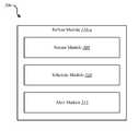
- FIG. 3is a block diagram 300 illustrating one example of a refuse module 110 - a .
- the refuse module 110 - amay be one example of the refuse module 110 depicted in FIGS. 1 and/or 2 .
- the refuse module 110 - amay include a sensor module 305 , a schedule module 310 , and an alert module 315 .
- the refuse module 110 - amay include additional modules and capabilities in other embodiments.
- the refuse module 110 - amay include fewer number of modules and functionality than that which is described with reference to FIG. 3 .
- the refuse module 110 - amay remind a user of the automation system when particular refuse needs to be relocated to a refuse removal location.
- the sensor module 305may track one or more sensors associated with one or more refuse bins.
- the refuse binsmay have a base station.
- the base stationmay be the location where one or more refuses bins are stored.
- a removal locationmay be a location where the one or more refuse bins are placed for its contents to be removed.
- the removal locationmay be a curbside or similar location where refuse can be picked up.
- a refuse removal companymay empty the refuse contained within the refuse bins into one or more refuse removal vehicles.
- one or more sensorsmay help determine a location of the refuse bin.
- the sensor module 305may track one or more sensors to determine if a refuse bin is located at its base station or at a removal location.
- a refuse containermay comprise a first sensor and a refuse home location may comprise a second sensor.
- the first sensor and second sensormay communicate with each other.
- the first sensor and second sensormay determine a proximity between the two.
- the proximitymay be a predetermined distance between the first and second sensor.
- the first and second sensormay only have detection capabilities when the two sensors are within the predetermined distance.
- the first sensormay detect the presence of the second sensor for a distance of two feet. If the first and second sensor are further than two feet apart, the sensors cannot detect the other's presence.
- the sensor module 305may monitor the proximity of the sensors to determine a location of the refuse bin. For example, the sensor module 305 may continuously monitor when the sensors are within the predetermined distance of each other. In other instances, the sensor module 305 may monitor the proximity of the sensors during predetermined times. For example, sensor module 305 may monitor the proximity of the sensors according to the schedule module 310 .
- Other sensorsmay also be used to track a location of one or more refuse bins.
- a GPS sensormay be attached to each refuse bin.
- An accelerometermay also be attached to the refuse bin to detect movement of the refuse bin.
- a motion detectormay be positioned at the home location which may detect movement of the refuse bin.
- An optical sensormay also detect when the refuse bin is at the home location or when it has been moved to the removal location.
- the sensor module 305may detect when refuse has been picked up.
- the at least one refuse binmay include one or more accelerometers.
- the one or more accelerometersmay detect movement of the refuse bin. Movement may include the physical moving of the refuse bin from a first location to a second location. The movement may also include a tipping or dumping motion. The tipping or dumping motion may occur when refuse contained within the refuse bin is being emptied into a refuse removal vehicle.
- the schedule module 310may track one or more schedules associated with refuse removal. For example, the schedule module 310 may receive one or more refuse removal schedules. The schedule module 310 may coordinate the refuse removal schedule with one or more calendars associated with an automation system. The one or more schedules may comprise different schedules for different types of refuse. For example, typical garbage may be picked up weekly, whereas recycling may be on a bi-weekly schedule. Yard waste and other refuse may also have different removal schedules. The schedule module 310 may observe the schedules for each type of refuse and associate the accurate schedule with the appropriate refuse bin. For example, the schedule module 310 may uniquely assign a sensor to a particular removal schedule.
- the alert module 315may generate and send alerts based at least in part on data from the sensor module 305 and the schedule module 310 . For example, the alert module 315 may send alerts notifying a user to move at least one refuse bin from a base station to a removal location and vice versa. In some embodiments, the alert module 315 may generate and send an alert to the user as a reminder to move the refuse bin to the removal location. In some embodiments, the refuse removal vehicle may have a GPS tracker or other sensor on it. The alert module 315 may detect when the removal vehicle is within a predetermined proximity of the refuse removal location.
- the alert module 315may generate and send an alert to a user of the automation system reminding them of the pending removal and the limited time frame with which to move the refuse bin to the removal location.
- alertsmay be generated specific to the refuse.
- the alert module 315may send a reminder to the user to relocate the garbage bin, the recycling bin, bulk items, yard waste, or some combination thereof based on different removal schedules for each type of refuse.
- the alert module 315may send a reminder regardless of the status of the refuse bin. For example, a predetermined time before a scheduled removal, the alert module 315 may remind a user of the upcoming removal and list the types of refuse scheduled to be removed. In other embodiments, an administrator or user may schedule reminders when the refuse bins have not been moved. For example, the alert module 315 may be programmed to send an alert at a predetermined time if the refuse bins have not been moved to a removal location. Prior to the scheduled alert time, the alert module 315 may determine, using the sensor module 305 , if the appropriate refuse bins have been moved. Based upon the response from the sensor module 305 , the alert module 315 may determine whether to send an alert.
- the usermay have forgotten to move one of the bins or moved an incorrect bin. For example, the user may have put out the garbage but forgot to put out the recycling bin.
- the alert module 315may send a reminder that the recycling bin also needs to be moved to a removal location. In other embodiments, the user may have accidently put out the recycling on a non-scheduled day. The alert module 315 may send a reminder that the recycling is not scheduled to be picked up and that the user should return the bin to the home station.
- FIG. 4is a flow diagram illustrating one embodiment of a method 400 for adding a one-time access to an automation system.
- the method 400may be implemented in whole or in part by the refuse module 110 of the automation system 105 shown in FIGS. 1 and/or 2 .
- the method 400may be performed generally by the automation system 105 shown in FIGS. 1 and/or 2 , or even more generally by the environments 100 , 200 shown in FIGS. 1 and/or 2 .
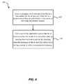
- a proximity of at least one refuse bin to a base station for the at least one refuse binmay be detected at a predetermined time period prior to a refuse removal day using one or more sensors. For example, one or more refuse bins may need to be moved from a home station to a removal location to have its contents emptied.
- a refuse removal companymay have a refuse removal vehicle empty the refuse on a set schedule.
- the at least one refuse binmay be proximate one or more sensors.
- the sensorsmay be affixed to a base station associated with the refuse bin.
- the sensorsmay also be affixed or otherwise coupled to the refuse bin.
- a single sensormay be used.
- the single sensormay be a GPS sensor which may detect a geographical location of the refuse bin.
- the automation systemmay create a geo-fence around the base station and may detect the presence of the refuse bin within the geo-fence location using the GPS sensor.
- one or more load sensorsmay be located at the base station.
- the one or more load sensorsmay detect a presence of the refuse bin at the base location by detecting the weight presence of the refuse bin.
- the one or more weight sensorsmay also calculate and track the weight of the accumulated refuse.
- two sensorsmay be used to detect a presence of the refuse bin at the base station.
- two proximity sensorsmay be used.
- One proximity sensormay be attached to the refuse bin and a second proximity sensor may be attached to the base station.
- the sensorsmay be aligned such that they detect a presence of the other sensor within a predetermined distance, which may be based in part on the capability of the sensors.
- the proximity sensorsmay have a functional distance range.
- a user of the automation systemmay be alerted that the at least one refuse bin needs to be moved to a removal location based at least in part on the detecting when the proximity of the at least first refuse bin to the base station is within a predetermined distance.
- the user of the automation systemmay receive an alert a predetermined time frame prior to a scheduled refuse removal time.
- the predetermined time framemay be a default time or may be set by the user.
- the usermay wish to receive multiple notifications. For example, the user may wish to receive a notification at 5:00 PM the day before a removal day. The user may additionally wish to receive further notifications either later on that day or the morning of the removal day or both.
- the usermay also receive multiple reminders for each type of refuse scheduled to be picked up. For example, the user may receive a notification that the garbage has been moved to a removal location but that the recycling also needs to be moved to the removal location.
- FIG. 5is a flow diagram illustrating one embodiment of a method 500 for permitting a user one time access to an automation system.
- the method 500may be implemented in whole or in part by the refuse module 110 of the automation system 105 shown in FIGS. 1 and 2 .
- the method 500may be performed generally by the automation system 105 shown in FIGS. 1 and/or 2 , or even more generally by the environments 100 , 200 shown in FIGS. 1 and/or 2 .
- a refuse removal scheduledmay be linked to an automation system.
- an administrator of the automation systemmay manually input the refuse removal schedule into a calendar associated with an automation system.
- a usermay upload a schedule which the automation system may enter into its calendar.
- the automation systemmay receive the refuse removal schedule directly from a refuse removal company.
- the refuse removal schedulemay be emailed or otherwise directly sent to the automation system.
- the automation systemmay receive the schedule and update the calendar.
- the automation systemmay adjust the refuse removal schedule based on inputs.
- the refuse removal schedulemay change based on weather, holidays, changes in schedule and the like.
- the automation systemmay receive notifications of a schedule change and alter the automation system schedule accordingly.
- the at least refuse binmay comprise a first type of refuse.
- the first type of refusemay be garbage.
- Additional refuse binsmay be present.
- a second refuse binmay comprise recycling and a third refuse bin may comprise yard waste.
- multiple recycling binsmay be present.
- multiple garbage bins, and the likemay be present.
- there may be wet refusesuch as food waste, product and meat waste.
- Theremay also be dry waste, bulky waste, non-compactible waste, and the like. Dry waste may comprise paper, corrugated boxes, and the like.
- Bulky wastemay comprise wooden crates, pallets, drums, appliances, metal cabinets, furniture, and the like.
- Non-compactible wastemay comprise stacked newspapers, bundled computer paper, phone books, and the like.
- the proximity of the at least one refuse bin to a base stationmay be detected using one or more sensors.
- one or more sensorsmay detect a proximity of the refuse bin to a base station.
- the sensorsmay comprise GPS sensors, proximity sensors, load sensors, olfactory sensors, accelerometers, optical sensors, and the like.
- the number of sensorsmay depend upon the number of refuse bins and the type of sensor. For example, if a GPS sensor is used, one GPS sensor may be attached to each refuse bin to track the location of the refuse bin.
- two or more sensorsmay be used to determine the proximity of a refuse bin to a base location. For example, proximity sensors may detect a distance between the two sensors. If proximity sensors are used, a proximity sensor may be coupled to the refuse bin and to the base station. The proximity sensors may then determine a distance between the sensors to determine if the refuse bin is within an acceptable proximity of the base station.
- the usermay be alerted that the refuse bin needs to be moved to a removal location. For example, if the at least one refuse bin is still at a base location, the user may be reminded to move the at least one refuse bin to the removal location.
- the sensorsmay detect the location of the refuse bin and determine if the refuse bin is located at the base station. If the refuse bin is located at the base station a predetermined time period before a scheduled removal, the user may receive an alert to move the refuse bin. In some embodiments, the user may also receive a reminder of a pending refuse removal regardless of the location of the refuse bin. Additionally, the user may receive multiple alerts if more than one refuse bin is present.
- the usermay be a delegate assigned the task of refuse management.
- an administrator of the automation systemmay assign a delegate to handle the refuse bins.
- the administratormay be a parent, an employer, or the like and the delegate may be a child, an employee, or the like.
- the administratormay receive a message and/or alert if the at least one refuse bin has not been relocated to a removal location.
- the administratormay receive a notice at a predetermined time period prior to a scheduled removal that the refuse bin is still located at the base station.
- the administratormay move the refuse bins or may directly contact the delegate to have them move the refuse bins.
- an accelerometer on the refuse binmay detect when the refuse bin is tilted, thus the refuse is emptied into a refuse removal vehicle.
- the removal locationmay also be equipped with a load sensor, which may detect a change in the weight of the refuse bin thus signaling when the bin has been emptied.
- the refuse removal vehiclemay also be equipped with a GPS or other tracking mechanism.
- the automation systemmay detect when the refuse removal vehicle has passed the removal location, thus signaling the refuse has been removed.
- the automation systemmay also have optical sensors which may detect when a refuse removal vehicle has removed the refuse.
- An olfactory sensor located within a receptacle of the refuse binmay also detect a reduction in smell thus signaling the refuse has been removed.
- the usermay be alerted to return the at least one refuse bin to the base station. For example, if the refuse bin has not been returned to the base station within a predetermined time period, the user may receive an alert to do so. For example, the user may receive an alert notifying the user that the refuse has been removed and that the refuse bins are ready to be moved back to a base station. If the user has not moved the bins within a predetermined time period, the user may continue to receive reminders until the refuse bins are returned. In other embodiments, the user may start receiving alerts if the refuse bins have not been returned by a predetermined time. The time may be a default time set by the automation system or may be set by an administrator or user. Additionally, an administrator may be alerted if a delegate has not performed their refuse management duties. For example, the administrator may receive an alert if the one or more refuse bins were not returned to the base station by a predetermined time.
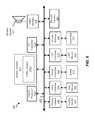
- FIG. 6depicts a block diagram of a controller 600 suitable for implementing the present systems and methods.
- the controller 600may be an example of the automation controller 225 , the personal computing device 240 , and/or the mobile computing device 235 illustrated in FIG. 2 .
- the controller 600may include a bus 605 which interconnects major subsystems of controller 600 , such as a central processor 610 , a system memory 615 (typically RAM, but which may also include ROM, flash RAM, or the like), an input/output controller 620 , an external audio device, such as a speaker system 625 via an audio output interface 630 , an external device, such as a display screen 635 via display adapter 640 , an input device 645 (e.g., remote control device interfaced with an input controller 650 ), multiple USB devices 665 (interfaced with a USB controller 670 ), and a storage interface 680 . Also included are at least one sensor 655 connected to bus 605 through a sensor controller 660 and a network
- Bus 605allows data communication between central processor 610 and system memory 615 , which may include read-only memory (ROM) or flash memory (neither shown), and random access memory (RAM) (not shown), as previously noted.
- the RAMis generally the main memory into which the operating system and application programs are loaded.
- the ROM or flash memorycan include, among other code, the Basic Input-Output system (BIOS) which controls basic hardware operation such as the interaction with peripheral components or devices.
- BIOSBasic Input-Output system
- a refuse module 110 - b to implement the present systems and methodsmay be stored within the system memory 615 .
- the refuse module 110 - bmay be an example of the refuse module 110 illustrated in FIGS. 1, 2 , and/or 3 .
- Applicationse.g., application 245
- controller 600are generally stored on and accessed via a non-transitory computer readable medium, such as a hard disk drive (e.g., fixed disk drive 675 ) or other storage medium. Additionally, applications can be in the form of electronic signals modulated in accordance with the application and data communication technology when accessed via the network interface 685 .
- a non-transitory computer readable mediumsuch as a hard disk drive (e.g., fixed disk drive 675 ) or other storage medium.
- applicationscan be in the form of electronic signals modulated in accordance with the application and data communication technology when accessed via the network interface 685 .
- Storage interface 680can connect to a standard computer readable medium for storage and/or retrieval of information, such as a fixed disk drive 675 .
- the fixed disk drive 675may be a part of controller 600 or may be separate and accessed through other interface systems.
- Network interface 685may provide a direct connection to a remote server via a direct network link to the Internet via a POP (point of presence).
- Network interface 685may provide such connection using wireless techniques, including digital cellular telephone connection, Cellular Digital Packet Data (CDPD) connection, digital satellite data connection, or the like.
- one or more sensorse.g., motion sensor, smoke sensor, glass break sensor, door sensor, window sensor, carbon monoxide sensor, and the like) connect to controller 600 wirelessly via network interface 685 .
- controller 600may be iOS® ANDROID®, MS-DOS®, MS-WINDOWS®, OS/2® UNIX®, LINUX® or another known operating system.
- a signalcan be directly transmitted from a first block to a second block, or a signal can be modified (e.g., amplified, attenuated, delayed, latched, buffered, inverted, filtered, or otherwise modified) between the blocks.
- a signalcan be directly transmitted from a first block to a second block, or a signal can be modified (e.g., amplified, attenuated, delayed, latched, buffered, inverted, filtered, or otherwise modified) between the blocks.
- a signal input at a second blockcan be conceptualized as a second signal derived from a first signal output from a first block due to physical limitations of the circuitry involved (e.g., there will inevitably be some attenuation and delay). Therefore, as used herein, a second signal derived from a first signal includes the first signal or any modifications to the first signal, whether due to circuit limitations or due to passage through other circuit elements which do not change the informational and/or final functional aspect of the first signal.
- the terms “a” or “an,” as used in the specification and claims,are to be construed as meaning “at least one of.”
- the words “including” and “having,” as used in the specification and claimsare interchangeable with and have the same meaning as the word “comprising.”
- the term “based on” as used in the specification and the claimsis to be construed as meaning “based at least upon.”
Landscapes
- Engineering & Computer Science (AREA)
- Business, Economics & Management (AREA)
- Physics & Mathematics (AREA)
- General Physics & Mathematics (AREA)
- Emergency Management (AREA)
- Economics (AREA)
- Strategic Management (AREA)
- Human Resources & Organizations (AREA)
- Theoretical Computer Science (AREA)
- General Business, Economics & Management (AREA)
- Entrepreneurship & Innovation (AREA)
- Computer Networks & Wireless Communication (AREA)
- Automation & Control Theory (AREA)
- Marketing (AREA)
- Tourism & Hospitality (AREA)
- Mechanical Engineering (AREA)
- Primary Health Care (AREA)
- Health & Medical Sciences (AREA)
- General Health & Medical Sciences (AREA)
- Development Economics (AREA)
- Educational Administration (AREA)
- Signal Processing (AREA)
- Game Theory and Decision Science (AREA)
- Operations Research (AREA)
- Quality & Reliability (AREA)
- Alarm Systems (AREA)
- Management, Administration, Business Operations System, And Electronic Commerce (AREA)
Abstract
Description
Claims (18)
Priority Applications (2)
| Application Number | Priority Date | Filing Date | Title |
|---|---|---|---|
| US14/481,709US9520046B2 (en) | 2014-09-09 | 2014-09-09 | Refuse removal reminders |
| US15/375,116US20170193798A1 (en) | 2014-09-09 | 2016-12-11 | Refuse removal reminders |
Applications Claiming Priority (1)
| Application Number | Priority Date | Filing Date | Title |
|---|---|---|---|
| US14/481,709US9520046B2 (en) | 2014-09-09 | 2014-09-09 | Refuse removal reminders |
Related Child Applications (1)
| Application Number | Title | Priority Date | Filing Date |
|---|---|---|---|
| US15/375,116ContinuationUS20170193798A1 (en) | 2014-09-09 | 2016-12-11 | Refuse removal reminders |
Publications (2)
| Publication Number | Publication Date |
|---|---|
| US20160071396A1 US20160071396A1 (en) | 2016-03-10 |
| US9520046B2true US9520046B2 (en) | 2016-12-13 |
Family
ID=55438008
Family Applications (2)
| Application Number | Title | Priority Date | Filing Date |
|---|---|---|---|
| US14/481,709Active2034-11-08US9520046B2 (en) | 2014-09-09 | 2014-09-09 | Refuse removal reminders |
| US15/375,116AbandonedUS20170193798A1 (en) | 2014-09-09 | 2016-12-11 | Refuse removal reminders |
Family Applications After (1)
| Application Number | Title | Priority Date | Filing Date |
|---|---|---|---|
| US15/375,116AbandonedUS20170193798A1 (en) | 2014-09-09 | 2016-12-11 | Refuse removal reminders |
Country Status (1)
| Country | Link |
|---|---|
| US (2) | US9520046B2 (en) |
Cited By (23)
| Publication number | Priority date | Publication date | Assignee | Title |
|---|---|---|---|---|
| US20170193798A1 (en)* | 2014-09-09 | 2017-07-06 | Vivint, Inc. | Refuse removal reminders |
| US20180079591A1 (en)* | 2016-09-19 | 2018-03-22 | Jackson State University | Automated trash cart |
| US10332197B2 (en)* | 2012-11-25 | 2019-06-25 | Enevo Oy | Optimal waste collection routing using smart waste containers and smart waste collection vehicles |
| US10594991B1 (en) | 2018-01-09 | 2020-03-17 | Wm Intellectual Property Holdings, Llc | System and method for managing service and non-service related activities associated with a waste collection, disposal and/or recycling vehicle |
| US10692353B1 (en)* | 2018-01-23 | 2020-06-23 | Alarm.Com Incorporated | Trash monitoring using video analytics |
| US11373536B1 (en) | 2021-03-09 | 2022-06-28 | Wm Intellectual Property Holdings, L.L.C. | System and method for customer and/or container discovery based on GPS drive path and parcel data analysis for a waste / recycling service vehicle |
| US11386362B1 (en) | 2020-12-16 | 2022-07-12 | Wm Intellectual Property Holdings, L.L.C. | System and method for optimizing waste / recycling collection and delivery routes for service vehicles |
| US11475417B1 (en) | 2019-08-23 | 2022-10-18 | Wm Intellectual Property Holdings, Llc | System and method for auditing the fill status of a customer waste container by a waste services provider during performance of a waste service activity |
| US11488118B1 (en) | 2021-03-16 | 2022-11-01 | Wm Intellectual Property Holdings, L.L.C. | System and method for auditing overages and contamination for a customer waste container by a waste services provider during performance of a waste service activity |
| US11636870B2 (en) | 2020-08-20 | 2023-04-25 | Denso International America, Inc. | Smoking cessation systems and methods |
| US11760169B2 (en) | 2020-08-20 | 2023-09-19 | Denso International America, Inc. | Particulate control systems and methods for olfaction sensors |
| US11760170B2 (en) | 2020-08-20 | 2023-09-19 | Denso International America, Inc. | Olfaction sensor preservation systems and methods |
| US11813926B2 (en) | 2020-08-20 | 2023-11-14 | Denso International America, Inc. | Binding agent and olfaction sensor |
| US11828210B2 (en) | 2020-08-20 | 2023-11-28 | Denso International America, Inc. | Diagnostic systems and methods of vehicles using olfaction |
| US11881093B2 (en) | 2020-08-20 | 2024-01-23 | Denso International America, Inc. | Systems and methods for identifying smoking in vehicles |
| US11928693B1 (en) | 2021-03-09 | 2024-03-12 | Wm Intellectual Property Holdings, L.L.C. | System and method for customer and/or container discovery based on GPS drive path analysis for a waste / recycling service vehicle |
| US11932080B2 (en) | 2020-08-20 | 2024-03-19 | Denso International America, Inc. | Diagnostic and recirculation control systems and methods |
| US11977381B1 (en) | 2022-04-01 | 2024-05-07 | Wm Intellectual Property Holdings, L.L.C. | System and method for autonomous waste collection by a waste services provider during performance of a waste service activity |
| US12017506B2 (en) | 2020-08-20 | 2024-06-25 | Denso International America, Inc. | Passenger cabin air control systems and methods |
| US12251991B2 (en) | 2020-08-20 | 2025-03-18 | Denso International America, Inc. | Humidity control for olfaction sensors |
| US12269315B2 (en) | 2020-08-20 | 2025-04-08 | Denso International America, Inc. | Systems and methods for measuring and managing odor brought into rental vehicles |
| US12332073B1 (en) | 2021-11-02 | 2025-06-17 | Wm Intellectual Property Holdings, L.L.C. | System and method for efficient customer and container on-property service based on collection of off-street data for a waste / recycling service vehicle |
| US12377711B2 (en) | 2020-08-20 | 2025-08-05 | Denso International America, Inc. | Vehicle feature control systems and methods based on smoking |
Families Citing this family (7)
| Publication number | Priority date | Publication date | Assignee | Title |
|---|---|---|---|---|
| US11074556B2 (en)* | 2012-11-25 | 2021-07-27 | Enevo Oy | Smart waste collection system rerouting collection based on waste container accessibility |
| US10037679B1 (en)* | 2017-01-27 | 2018-07-31 | Bengi Crosby | Garbage reminder system |
| US11144066B1 (en)* | 2018-01-31 | 2021-10-12 | AI Incorporated | Autonomous refuse bag replacement system |
| CN112905654A (en)* | 2019-12-04 | 2021-06-04 | 北京城市机扫服务有限公司 | Garbage can setting and processing method and device |
| CN112265754B (en)* | 2020-10-15 | 2022-12-23 | 国网浙江省电力有限公司台州供电公司 | Method and system for cleaning garbage used in buildings |
| CN113721531A (en)* | 2021-09-06 | 2021-11-30 | 珠海格力电器股份有限公司 | Linkage control method, device and system for garbage can and readable storage medium |
| CN113682439B (en)* | 2021-09-29 | 2024-08-09 | 河北工业大学 | Base station butt joint type water surface garbage collection device |
Citations (39)
| Publication number | Priority date | Publication date | Assignee | Title |
|---|---|---|---|---|
| US4860267A (en)* | 1988-08-15 | 1989-08-22 | Mobil Oil Corporation | Method for providing a signal to prepare waste materials for collection and waste containers incorporating an alarm device |
| US4912687A (en)* | 1988-10-26 | 1990-03-27 | Eagle River Industries, Inc. | Time of tip-over indicator |
| US5163805A (en)* | 1989-03-17 | 1992-11-17 | Mezey Armand G | Waste collection system for segregating solid waste into preselected component materials |
| US5205698A (en)* | 1989-03-17 | 1993-04-27 | Mezey Armand G | Waste collection system for segregating solid waste into preselected component materials |
| US5230393A (en)* | 1991-06-27 | 1993-07-27 | Mezey Armand G | Refuse collection and weighing system |
| US5610516A (en)* | 1992-04-06 | 1997-03-11 | Maier; Hans-Juergen | Process of and device for checking presence of metal in refuse container of refuse collecting vehicle |
| US5967028A (en)* | 1996-04-29 | 1999-10-19 | Professional Management Disposal Systems (Pmds), L.L.C. | Refuse management system and method |
| US6150939A (en)* | 1999-01-28 | 2000-11-21 | Lin; Chung-Ren | Garbage container with automatic opening and closing functions |
| US20020030595A1 (en)* | 1999-12-16 | 2002-03-14 | Kasik John P. | System for auditing refuse collection |
| US6360186B1 (en)* | 2000-03-07 | 2002-03-19 | One Plus Corp. | Systems for remote management of a network of waste containers |
| US6367377B1 (en)* | 1998-10-16 | 2002-04-09 | Compact Waste Systems, Inc. | Level sensitive waste compactor |
| US6408261B1 (en)* | 2000-03-07 | 2002-06-18 | One Plus Corp. | Systems for remote management of a network of waste containers |
| US20020108507A1 (en)* | 2001-02-14 | 2002-08-15 | May Charlotte Mary-Anne | Interactive waste receptacle |
| US6453270B1 (en)* | 2000-03-07 | 2002-09-17 | One Plus Corp. | Systems for remote management of a network of waste containers |
| US6526421B1 (en)* | 1999-03-31 | 2003-02-25 | Koninklijke Philips Electronics N.V. | Method of scheduling garbage collection |
| US6561085B1 (en)* | 2002-03-04 | 2003-05-13 | One Plus Corp. | System and method for variably adjusting the pick-up level of one or more waste compactor containers |
| US20050281653A1 (en) | 2004-05-27 | 2005-12-22 | Donald Channel | Automated trash delivery system |
| US20070262878A1 (en)* | 2006-05-15 | 2007-11-15 | Casella Waste Systems, Inc. | Systems and methods for identifying banned waste in a municipal solid waste environment |
| US20070268759A1 (en)* | 2006-05-18 | 2007-11-22 | Casella Waste Systems, Inc. | Systems for and methods of asset management in a waste management service environment |
| US20080061977A1 (en)* | 2006-09-06 | 2008-03-13 | Casella Waste Systems, Inc. | Systems and methods for identifying and collecting banned waste |
| US7406402B1 (en)* | 2003-02-06 | 2008-07-29 | Mgm Services, Inc. | Systems and methods for material management |
| US20090119962A1 (en)* | 2007-11-13 | 2009-05-14 | Bruce De La Cruz | Methods and apparatuses for the display of promotional images |
| WO2009114582A2 (en) | 2008-03-13 | 2009-09-17 | Verde Home Products, Inc. | Receptacle for recyclables |
| US20100071572A1 (en)* | 2008-09-23 | 2010-03-25 | Carroll Robert B | Waste compactor and container monitoring system |
| US20100119341A1 (en)* | 2008-11-07 | 2010-05-13 | Advanced Custom Engineered Systems & Equipment Co. | Method and apparatus for waste removing and hauling |
| US20110238598A1 (en)* | 2009-09-09 | 2011-09-29 | David Borowski | Waste Recycling Systems, Processes, and Methods |
| US20110259467A1 (en)* | 2010-04-27 | 2011-10-27 | Maness David A | Pharmaceutical waste disposal assembly including waste diverter |
| WO2012164098A1 (en) | 2011-06-03 | 2012-12-06 | Zerobin Group Limited | A refuse collection system and method |
| US20130062444A1 (en)* | 2011-09-08 | 2013-03-14 | Fellowes, Inc. | Zero watt standby energy consumption apparatus |
| WO2014063184A1 (en) | 2012-10-23 | 2014-05-01 | Xorro Pty Ltd | Distributed monitoring system and waste management system and method |
| WO2014066429A1 (en) | 2012-10-22 | 2014-05-01 | Jean-Louis Fiorucci | Apparatus and methods for providing city services |
| US8720686B1 (en)* | 2013-02-14 | 2014-05-13 | Keith E. Shuman | Lidded container with signaling assembly |
| US20140172174A1 (en)* | 2012-12-19 | 2014-06-19 | Big Belly Solar, Inc. | System and method for controlling electrically-powered trash compactors and receptacles |
| US20140278630A1 (en)* | 2013-03-15 | 2014-09-18 | Compology, Inc. | System and method for waste material managment |
| US20150307273A1 (en)* | 2014-04-25 | 2015-10-29 | Vivint, Inc. | Automated waste management |
| US20150323366A1 (en)* | 2013-01-28 | 2015-11-12 | Enevo Oy | Sensor device for smart waste collection systems and method |
| US20150324760A1 (en)* | 2009-09-09 | 2015-11-12 | Ultra Smart Recycling Llc | Smart waste device and waste tracking system |
| US20150339914A1 (en)* | 2013-01-28 | 2015-11-26 | Enevo Oy | Sensor device for remote monitoring |
| US20150348252A1 (en)* | 2014-05-28 | 2015-12-03 | Cox Enterprises, Inc. | Systems and Methods of Monitoring Waste |
Family Cites Families (1)
| Publication number | Priority date | Publication date | Assignee | Title |
|---|---|---|---|---|
| US9520046B2 (en)* | 2014-09-09 | 2016-12-13 | Vivint, Inc. | Refuse removal reminders |
- 2014
- 2014-09-09USUS14/481,709patent/US9520046B2/enactiveActive
- 2016
- 2016-12-11USUS15/375,116patent/US20170193798A1/ennot_activeAbandoned
Patent Citations (43)
| Publication number | Priority date | Publication date | Assignee | Title |
|---|---|---|---|---|
| US4860267A (en)* | 1988-08-15 | 1989-08-22 | Mobil Oil Corporation | Method for providing a signal to prepare waste materials for collection and waste containers incorporating an alarm device |
| US4912687A (en)* | 1988-10-26 | 1990-03-27 | Eagle River Industries, Inc. | Time of tip-over indicator |
| US5163805A (en)* | 1989-03-17 | 1992-11-17 | Mezey Armand G | Waste collection system for segregating solid waste into preselected component materials |
| US5205698A (en)* | 1989-03-17 | 1993-04-27 | Mezey Armand G | Waste collection system for segregating solid waste into preselected component materials |
| US5230393A (en)* | 1991-06-27 | 1993-07-27 | Mezey Armand G | Refuse collection and weighing system |
| US5610516A (en)* | 1992-04-06 | 1997-03-11 | Maier; Hans-Juergen | Process of and device for checking presence of metal in refuse container of refuse collecting vehicle |
| US5967028A (en)* | 1996-04-29 | 1999-10-19 | Professional Management Disposal Systems (Pmds), L.L.C. | Refuse management system and method |
| US6367377B1 (en)* | 1998-10-16 | 2002-04-09 | Compact Waste Systems, Inc. | Level sensitive waste compactor |
| US6150939A (en)* | 1999-01-28 | 2000-11-21 | Lin; Chung-Ren | Garbage container with automatic opening and closing functions |
| US6526421B1 (en)* | 1999-03-31 | 2003-02-25 | Koninklijke Philips Electronics N.V. | Method of scheduling garbage collection |
| US20020030595A1 (en)* | 1999-12-16 | 2002-03-14 | Kasik John P. | System for auditing refuse collection |
| US6408261B1 (en)* | 2000-03-07 | 2002-06-18 | One Plus Corp. | Systems for remote management of a network of waste containers |
| US6453270B1 (en)* | 2000-03-07 | 2002-09-17 | One Plus Corp. | Systems for remote management of a network of waste containers |
| US6687656B2 (en)* | 2000-03-07 | 2004-02-03 | One Plus Corp. | Systems for remote management of a network of waste containers |
| US6360186B1 (en)* | 2000-03-07 | 2002-03-19 | One Plus Corp. | Systems for remote management of a network of waste containers |
| US20020108507A1 (en)* | 2001-02-14 | 2002-08-15 | May Charlotte Mary-Anne | Interactive waste receptacle |
| US6561085B1 (en)* | 2002-03-04 | 2003-05-13 | One Plus Corp. | System and method for variably adjusting the pick-up level of one or more waste compactor containers |
| US7957937B2 (en)* | 2003-02-06 | 2011-06-07 | Wm Trash Monitor Plus, Llc | Systems and methods for material management |
| US7406402B1 (en)* | 2003-02-06 | 2008-07-29 | Mgm Services, Inc. | Systems and methods for material management |
| US20050281653A1 (en) | 2004-05-27 | 2005-12-22 | Donald Channel | Automated trash delivery system |
| US20070262878A1 (en)* | 2006-05-15 | 2007-11-15 | Casella Waste Systems, Inc. | Systems and methods for identifying banned waste in a municipal solid waste environment |
| US20070268759A1 (en)* | 2006-05-18 | 2007-11-22 | Casella Waste Systems, Inc. | Systems for and methods of asset management in a waste management service environment |
| US20080061977A1 (en)* | 2006-09-06 | 2008-03-13 | Casella Waste Systems, Inc. | Systems and methods for identifying and collecting banned waste |
| US20090119962A1 (en)* | 2007-11-13 | 2009-05-14 | Bruce De La Cruz | Methods and apparatuses for the display of promotional images |
| WO2009114582A2 (en) | 2008-03-13 | 2009-09-17 | Verde Home Products, Inc. | Receptacle for recyclables |
| US20100071572A1 (en)* | 2008-09-23 | 2010-03-25 | Carroll Robert B | Waste compactor and container monitoring system |
| US20100119341A1 (en)* | 2008-11-07 | 2010-05-13 | Advanced Custom Engineered Systems & Equipment Co. | Method and apparatus for waste removing and hauling |
| US20110238598A1 (en)* | 2009-09-09 | 2011-09-29 | David Borowski | Waste Recycling Systems, Processes, and Methods |
| US20150324760A1 (en)* | 2009-09-09 | 2015-11-12 | Ultra Smart Recycling Llc | Smart waste device and waste tracking system |
| US20110259467A1 (en)* | 2010-04-27 | 2011-10-27 | Maness David A | Pharmaceutical waste disposal assembly including waste diverter |
| US20140214697A1 (en)* | 2011-06-03 | 2014-07-31 | Paul Terence McSweeney | Refuse collection system and method |
| WO2012164098A1 (en) | 2011-06-03 | 2012-12-06 | Zerobin Group Limited | A refuse collection system and method |
| US20130062444A1 (en)* | 2011-09-08 | 2013-03-14 | Fellowes, Inc. | Zero watt standby energy consumption apparatus |
| WO2014066429A1 (en) | 2012-10-22 | 2014-05-01 | Jean-Louis Fiorucci | Apparatus and methods for providing city services |
| WO2014063184A1 (en) | 2012-10-23 | 2014-05-01 | Xorro Pty Ltd | Distributed monitoring system and waste management system and method |
| US20150298903A1 (en)* | 2012-10-23 | 2015-10-22 | Xorro Pty Ltd | Distributed monitoring system and waste management system and method |
| US20140172174A1 (en)* | 2012-12-19 | 2014-06-19 | Big Belly Solar, Inc. | System and method for controlling electrically-powered trash compactors and receptacles |
| US20150323366A1 (en)* | 2013-01-28 | 2015-11-12 | Enevo Oy | Sensor device for smart waste collection systems and method |
| US20150339914A1 (en)* | 2013-01-28 | 2015-11-26 | Enevo Oy | Sensor device for remote monitoring |
| US8720686B1 (en)* | 2013-02-14 | 2014-05-13 | Keith E. Shuman | Lidded container with signaling assembly |
| US20140278630A1 (en)* | 2013-03-15 | 2014-09-18 | Compology, Inc. | System and method for waste material managment |
| US20150307273A1 (en)* | 2014-04-25 | 2015-10-29 | Vivint, Inc. | Automated waste management |
| US20150348252A1 (en)* | 2014-05-28 | 2015-12-03 | Cox Enterprises, Inc. | Systems and Methods of Monitoring Waste |
Cited By (40)
| Publication number | Priority date | Publication date | Assignee | Title |
|---|---|---|---|---|
| US10332197B2 (en)* | 2012-11-25 | 2019-06-25 | Enevo Oy | Optimal waste collection routing using smart waste containers and smart waste collection vehicles |
| US20170193798A1 (en)* | 2014-09-09 | 2017-07-06 | Vivint, Inc. | Refuse removal reminders |
| US20180079591A1 (en)* | 2016-09-19 | 2018-03-22 | Jackson State University | Automated trash cart |
| US12015880B1 (en) | 2018-01-09 | 2024-06-18 | Wm Intellectual Property Holdings, L.L.C. | System and method for managing service and non-service related activities associated with a waste collection, disposal and/or recycling vehicle |
| US11172171B1 (en) | 2018-01-09 | 2021-11-09 | Wm Intellectual Property Holdings, Llc | System and method for managing service and non-service related activities associated with a waste collection, disposal and/or recycling vehicle |
| US10750134B1 (en) | 2018-01-09 | 2020-08-18 | Wm Intellectual Property Holdings, L.L.C. | System and method for managing service and non-service related activities associated with a waste collection, disposal and/or recycling vehicle |
| US10855958B1 (en) | 2018-01-09 | 2020-12-01 | Wm Intellectual Property Holdings, Llc | System and method for managing service and non-service related activities associated with a waste collection, disposal and/or recycling vehicle |
| US10911726B1 (en) | 2018-01-09 | 2021-02-02 | Wm Intellectual Property Holdings, Llc | System and method for managing service and non-service related activities associated with a waste collection, disposal and/or recycling vehicle |
| US11425340B1 (en) | 2018-01-09 | 2022-08-23 | Wm Intellectual Property Holdings, Llc | System and method for managing service and non-service related activities associated with a waste collection, disposal and/or recycling vehicle |
| US11140367B1 (en) | 2018-01-09 | 2021-10-05 | Wm Intellectual Property Holdings, Llc | System and method for managing service and non-service related activities associated with a waste collection, disposal and/or recycling vehicle |
| US11616933B1 (en) | 2018-01-09 | 2023-03-28 | Wm Intellectual Property Holdings, L.L.C. | System and method for managing service and non-service related activities associated with a waste collection, disposal and/or recycling vehicle |
| US10594991B1 (en) | 2018-01-09 | 2020-03-17 | Wm Intellectual Property Holdings, Llc | System and method for managing service and non-service related activities associated with a waste collection, disposal and/or recycling vehicle |
| US11128841B1 (en) | 2018-01-09 | 2021-09-21 | Wm Intellectual Property Holdings, Llc | System and method for managing service and non service related activities associated with a waste collection, disposal and/or recycling vehicle |
| US10692353B1 (en)* | 2018-01-23 | 2020-06-23 | Alarm.Com Incorporated | Trash monitoring using video analytics |
| US12136071B1 (en) | 2019-08-23 | 2024-11-05 | Wm Intellectual Property Holdings, L.L.C. | System and method for auditing the fill status of a customer waste container by a waste services provider during performance of a waste service activity |
| US11475417B1 (en) | 2019-08-23 | 2022-10-18 | Wm Intellectual Property Holdings, Llc | System and method for auditing the fill status of a customer waste container by a waste services provider during performance of a waste service activity |
| US11475416B1 (en) | 2019-08-23 | 2022-10-18 | Wm Intellectual Property Holdings Llc | System and method for auditing the fill status of a customer waste container by a waste services provider during performance of a waste service activity |
| US12017506B2 (en) | 2020-08-20 | 2024-06-25 | Denso International America, Inc. | Passenger cabin air control systems and methods |
| US11760170B2 (en) | 2020-08-20 | 2023-09-19 | Denso International America, Inc. | Olfaction sensor preservation systems and methods |
| US12377711B2 (en) | 2020-08-20 | 2025-08-05 | Denso International America, Inc. | Vehicle feature control systems and methods based on smoking |
| US11760169B2 (en) | 2020-08-20 | 2023-09-19 | Denso International America, Inc. | Particulate control systems and methods for olfaction sensors |
| US12269315B2 (en) | 2020-08-20 | 2025-04-08 | Denso International America, Inc. | Systems and methods for measuring and managing odor brought into rental vehicles |
| US12251991B2 (en) | 2020-08-20 | 2025-03-18 | Denso International America, Inc. | Humidity control for olfaction sensors |
| US11636870B2 (en) | 2020-08-20 | 2023-04-25 | Denso International America, Inc. | Smoking cessation systems and methods |
| US11828210B2 (en) | 2020-08-20 | 2023-11-28 | Denso International America, Inc. | Diagnostic systems and methods of vehicles using olfaction |
| US11881093B2 (en) | 2020-08-20 | 2024-01-23 | Denso International America, Inc. | Systems and methods for identifying smoking in vehicles |
| US11813926B2 (en) | 2020-08-20 | 2023-11-14 | Denso International America, Inc. | Binding agent and olfaction sensor |
| US11932080B2 (en) | 2020-08-20 | 2024-03-19 | Denso International America, Inc. | Diagnostic and recirculation control systems and methods |
| US11386362B1 (en) | 2020-12-16 | 2022-07-12 | Wm Intellectual Property Holdings, L.L.C. | System and method for optimizing waste / recycling collection and delivery routes for service vehicles |
| US11790290B1 (en) | 2020-12-16 | 2023-10-17 | Wm Intellectual Property Holdings, L.L.C. | System and method for optimizing waste / recycling collection and delivery routes for service vehicles |
| US12008506B1 (en) | 2021-03-09 | 2024-06-11 | Wm Intellectual Property Holdings, L.L.C. | System and method for customer and/or container discovery based on GPS drive path and parcel data analysis for a waste / recycling service vehicle |
| US11373536B1 (en) | 2021-03-09 | 2022-06-28 | Wm Intellectual Property Holdings, L.L.C. | System and method for customer and/or container discovery based on GPS drive path and parcel data analysis for a waste / recycling service vehicle |
| US11928693B1 (en) | 2021-03-09 | 2024-03-12 | Wm Intellectual Property Holdings, L.L.C. | System and method for customer and/or container discovery based on GPS drive path analysis for a waste / recycling service vehicle |
| US12266268B1 (en) | 2021-03-09 | 2025-04-01 | Wm Intellectual Property Holdings, L.L.C. | System and method for customer and/or container discovery based on GPS drive path and parcel data analysis for a waste / recycling service vehicle |
| US12361432B1 (en) | 2021-03-09 | 2025-07-15 | Wm Intellectual Property Holdings, L.L.C. | System and method for customer and/or container discovery based on GPS drive path analysis for a waste / recycling service vehicle |
| US12373850B1 (en) | 2021-03-09 | 2025-07-29 | Wm Intellectual Property Holdings, L.L.C. | System and method for customer and/or container discovery based on GPS drive path analysis for a waste / recycling service vehicle |
| US11727337B1 (en) | 2021-03-09 | 2023-08-15 | Wm Intellectual Property Holdings, L.L.C. | System and method for customer and/or container discovery based on GPS drive path and parcel data analysis for a waste / recycling service vehicle |
| US11488118B1 (en) | 2021-03-16 | 2022-11-01 | Wm Intellectual Property Holdings, L.L.C. | System and method for auditing overages and contamination for a customer waste container by a waste services provider during performance of a waste service activity |
| US12332073B1 (en) | 2021-11-02 | 2025-06-17 | Wm Intellectual Property Holdings, L.L.C. | System and method for efficient customer and container on-property service based on collection of off-street data for a waste / recycling service vehicle |
| US11977381B1 (en) | 2022-04-01 | 2024-05-07 | Wm Intellectual Property Holdings, L.L.C. | System and method for autonomous waste collection by a waste services provider during performance of a waste service activity |
Also Published As
| Publication number | Publication date |
|---|---|
| US20160071396A1 (en) | 2016-03-10 |
| US20170193798A1 (en) | 2017-07-06 |
Similar Documents
| Publication | Publication Date | Title |
|---|---|---|
| US9520046B2 (en) | Refuse removal reminders | |
| US9721342B2 (en) | Systems and methods of monitoring waste | |
| US10152737B2 (en) | Automated waste management | |
| US20240078502A1 (en) | System and method for deterring theft of package, and device therefor | |
| Samann | The design and implementation of smart trash bin | |
| US10445684B2 (en) | Actively managed food delivery | |
| CN114186922B (en) | Association management in wireless node networks | |
| KR20200136937A (en) | Method and apparatus for monitoring and managing loading dock and facility operations | |
| EP2835078A1 (en) | Locker for a delivery or collection system. | |
| RU2614582C2 (en) | Schedule management method and device | |
| US20120194337A1 (en) | Warning of hazardous conditions in monitored spaces using rfid technology | |
| US12347287B2 (en) | Physical knowledge action triggers | |
| CN110980050B (en) | Garbage disposal method, storage medium and garbage storage equipment | |
| JP2020528613A (en) | Goods transportation method and related devices | |
| CN105564866A (en) | Prompting method and prompting device | |
| US11275943B2 (en) | Enabling intelligent disposal | |
| US20180211346A1 (en) | Pickup location operations performed based on user feedback | |
| CN211015757U (en) | Intelligent express cabinet | |
| CN112446664A (en) | Article processing method, device and equipment for automatically removing expired articles | |
| CN107730757B (en) | Parking lot management method and device | |
| CN112907012A (en) | Intelligent garbage can cleaning and transporting treatment method and device | |
| CN107531388A (en) | Actively Managed Food Delivery | |
| CN114037381B (en) | Multi-warehouse delivery robot order delivery method, device, storage medium and equipment | |
| CN114104556B (en) | Garbage clearing method and device, storage medium and equipment of epidemic prevention robot | |
| CN113160533A (en) | Reminding information generation method, device, equipment and medium |
Legal Events
| Date | Code | Title | Description |
|---|---|---|---|
| AS | Assignment | Owner name:VIVINT, INC., UTAH Free format text:ASSIGNMENT OF ASSIGNORS INTEREST;ASSIGNORS:CALL, BRIAN;BROWN, NICHOLAS;CARTER, JASON;AND OTHERS;REEL/FRAME:033703/0917 Effective date:20140814 | |
| AS | Assignment | Owner name:WILMINGTON TRUST, NATIONAL ASSOCIATION, DELAWARE Free format text:SECURITY INTEREST;ASSIGNOR:VIVINT, INC.;REEL/FRAME:038275/0377 Effective date:20160328 | |
| AS | Assignment | Owner name:BANK OF AMERICA, N.A., AS ADMINISTRATIVE AGENT, NORTH CAROLINA Free format text:SECURITY AGREEMENT;ASSIGNOR:VIVINT, INC.;REEL/FRAME:038402/0356 Effective date:20160411 Owner name:BANK OF AMERICA, N.A., AS ADMINISTRATIVE AGENT, NO Free format text:SECURITY AGREEMENT;ASSIGNOR:VIVINT, INC.;REEL/FRAME:038402/0356 Effective date:20160411 | |
| STCF | Information on status: patent grant | Free format text:PATENTED CASE | |
| AS | Assignment | Owner name:BANK OF AMERICA, N.A., NORTH CAROLINA Free format text:SECURITY AGREEMENT;ASSIGNOR:VIVINT, INC.;REEL/FRAME:047029/0304 Effective date:20180906 | |
| AS | Assignment | Owner name:WILMINGTON TRUST, NATIONAL ASSOCIATION, DELAWARE Free format text:SECURITY AGREEMENT;ASSIGNOR:VIVINT, INC.;REEL/FRAME:049283/0566 Effective date:20190510 | |
| MAFP | Maintenance fee payment | Free format text:PAYMENT OF MAINTENANCE FEE, 4TH YEAR, LARGE ENTITY (ORIGINAL EVENT CODE: M1551); ENTITY STATUS OF PATENT OWNER: LARGE ENTITY Year of fee payment:4 | |
| AS | Assignment | Owner name:VIVINT, INC., UTAH Free format text:RELEASE BY SECURED PARTY;ASSIGNOR:BANK OF AMERICA, N.A.;REEL/FRAME:056832/0725 Effective date:20210709 | |
| MAFP | Maintenance fee payment | Free format text:PAYMENT OF MAINTENANCE FEE, 8TH YEAR, LARGE ENTITY (ORIGINAL EVENT CODE: M1552); ENTITY STATUS OF PATENT OWNER: LARGE ENTITY Year of fee payment:8 | |
| AS | Assignment | Owner name:VIVINT LLC (F/K/A VIVINT, INC.), UTAH Free format text:RELEASE (REEL 047029/ FRAME 0304);ASSIGNOR:BANK OF AMERICA, N.A.;REEL/FRAME:069289/0468 Effective date:20241030 | |
| AS | Assignment | Owner name:VIVINT, INC., UTAH Free format text:TERMINATION AND RELEASE OF SECURITY INTEREST IN PATENTS RECORDED AT REEL 038275, FRAME 0377;ASSIGNOR:WILMINGTON TRUST, NATIONAL ASSOCIATION, AS COLLATERAL AGENT;REEL/FRAME:069334/0010 Effective date:20241108 Owner name:VIVINT, INC., UTAH Free format text:TERMINATION AND RELEASE OF SECURITY INTEREST IN PATENTS RECORDED AT REEL 049283, FRAME 0566;ASSIGNOR:WILMINGTON TRUST, NATIONAL ASSOCIATION, AS COLLATERAL AGENT;REEL/FRAME:069334/0137 Effective date:20241108 | |
| AS | Assignment | Owner name:DEUTSCHE BANK TRUST COMPANY AMERICAS, AS PRIORITY COLLATERAL TRUSTEE, NEW JERSEY Free format text:AFTER-ACQUIRED INTELLECTUAL PROPERTY SECURITY AGREEMENT;ASSIGNORS:VIVINT LLC;SMART HOME PROS, INC.;VIVINT AMIGO, INC.;REEL/FRAME:070349/0816 Effective date:20241220 |