US9519972B2 - Systems and methods for synthesizing images from image data captured by an array camera using restricted depth of field depth maps in which depth estimation precision varies - Google Patents
Systems and methods for synthesizing images from image data captured by an array camera using restricted depth of field depth maps in which depth estimation precision variesDownload PDFInfo
- Publication number
- US9519972B2 US9519972B2US14/207,254US201414207254AUS9519972B2US 9519972 B2US9519972 B2US 9519972B2US 201414207254 AUS201414207254 AUS 201414207254AUS 9519972 B2US9519972 B2US 9519972B2
- Authority
- US
- United States
- Prior art keywords
- depth
- field
- restricted
- image processing
- different viewpoints
- Prior art date
- Legal status (The legal status is an assumption and is not a legal conclusion. Google has not performed a legal analysis and makes no representation as to the accuracy of the status listed.)
- Active, expires
Links
Images


Classifications
- H—ELECTRICITY
- H04—ELECTRIC COMMUNICATION TECHNIQUE
- H04N—PICTORIAL COMMUNICATION, e.g. TELEVISION
- H04N13/00—Stereoscopic video systems; Multi-view video systems; Details thereof
- H04N13/10—Processing, recording or transmission of stereoscopic or multi-view image signals
- H04N13/106—Processing image signals
- G—PHYSICS
- G06—COMPUTING OR CALCULATING; COUNTING
- G06T—IMAGE DATA PROCESSING OR GENERATION, IN GENERAL
- G06T7/00—Image analysis
- G06T7/50—Depth or shape recovery
- G06T7/55—Depth or shape recovery from multiple images
- G06T7/557—Depth or shape recovery from multiple images from light fields, e.g. from plenoptic cameras
- G06T7/0065—
- G—PHYSICS
- G06—COMPUTING OR CALCULATING; COUNTING
- G06T—IMAGE DATA PROCESSING OR GENERATION, IN GENERAL
- G06T1/00—General purpose image data processing
- G06T1/20—Processor architectures; Processor configuration, e.g. pipelining
- H—ELECTRICITY
- H04—ELECTRIC COMMUNICATION TECHNIQUE
- H04N—PICTORIAL COMMUNICATION, e.g. TELEVISION
- H04N13/00—Stereoscopic video systems; Multi-view video systems; Details thereof
- H04N13/20—Image signal generators
- H04N13/271—Image signal generators wherein the generated image signals comprise depth maps or disparity maps
- G—PHYSICS
- G06—COMPUTING OR CALCULATING; COUNTING
- G06T—IMAGE DATA PROCESSING OR GENERATION, IN GENERAL
- G06T2207/00—Indexing scheme for image analysis or image enhancement
- G06T2207/10—Image acquisition modality
- G06T2207/10016—Video; Image sequence
- G—PHYSICS
- G06—COMPUTING OR CALCULATING; COUNTING
- G06T—IMAGE DATA PROCESSING OR GENERATION, IN GENERAL
- G06T2207/00—Indexing scheme for image analysis or image enhancement
- G06T2207/10—Image acquisition modality
- G06T2207/10052—Images from lightfield camera
- H—ELECTRICITY
- H04—ELECTRIC COMMUNICATION TECHNIQUE
- H04N—PICTORIAL COMMUNICATION, e.g. TELEVISION
- H04N13/00—Stereoscopic video systems; Multi-view video systems; Details thereof
- H04N2013/0074—Stereoscopic image analysis
- H04N2013/0081—Depth or disparity estimation from stereoscopic image signals
Definitions
- the present inventiongenerally relates to digital cameras and more specifically to systems and methods for capturing video and images using array cameras.
- Binocular viewing of a scenecreates two slightly different images of the scene due to the different fields of view of each eye. These differences, referred to as binocular disparity (or parallax), provide information that can be used to calculate depth in the visual scene, providing a major means of depth perception. The impression of depth associated with stereoscopic depth perception can also be obtained under other conditions, such as when an observer views a scene with only one eye while moving. The observed parallax can be utilized to obtain depth information for objects in the scene. Similar principles in machine vision can be used to gather depth information.
- Two cameras separated by a distancecan take pictures of the same scene and the captured images can be compared by shifting the pixels of two or more images to find parts of the images that match.
- the amount an object shifts between two different camera viewsis called the disparity, which is inversely proportional to the distance to the object.
- a disparity searchthat detects the shift of an object in the multiple images that results in the best match can be used to calculate the distance to the object based upon the baseline distance between the cameras and the focal length of the cameras involved (as well as knowledge of additional properties of the camera).
- the approach of using two or more cameras to generate stereoscopic three-dimensional imagesis commonly referred to as multi-view stereo.
- a light fieldwhich is often defined as a 4D function characterizing the light from all directions at all points in a scene, can be interpreted as a two-dimensional (2D) collection of 2D images of a scene. Due to practical constraints, it is typically difficult to simultaneously capture the collection of 2D images of a scene that form a light field. However, the closer in time at which the image data is captured by each of the cameras, the less likely that variations in light intensity (e.g. the otherwise imperceptible flicker of fluorescent lights) or object motion will result in time dependent variations between the captured images.
- variations in light intensitye.g. the otherwise imperceptible flicker of fluorescent lights
- Processes involving capturing and resampling a light fieldcan be utilized to simulate cameras with large apertures.
- an array of M ⁇ N cameras pointing at a scenecan simulate the focusing effects of a lens as large as the array.
- camerasneed not be arranged in a rectangular pattern and can have configurations including circular configurations and/or any arbitrary configuration appropriate to the requirements of a specific application. Use of camera arrays in this way can be referred to as synthetic aperture photography.
- Objectsare well focused at a distance determined by the focal length of the camera lens. Objects at other distances are imaged as a blur, sometimes called the circle of confusion. If the object lies far enough from the imager plane that the circle of confusion is larger than some nominal diameter (called maximum acceptable circle of confusion, representing the blur size for which the image is acceptably sharp and typically defined as the size of one pixel in the camera's sensor), the object can be referred to as outside the depth of field for the current camera's settings. Depth of field is defined as the distance between the nearest and farthest objects in the scene for which the circle of confusion is less than the maximum acceptable value.
- an aperture stop(diaphragm) into such an optical system and partially closing it reduces the effective diameter of the lens. This reduces the circle of confusion for objects off the plane of best focus, hence increasing the camera's depth of field. Conversely, opening the diaphragm expands the circle of confusion, decreasing depth of field. If the aperture is made extremely large (e.g. as wide as the distance to the plane of best focus), the depth of field becomes so shallow that only objects lying on the plane of best focus are sharp. When an object lying outside the depth of field is small enough that for every point on the plane of best focus, at least some of its rays still reach the lens, the object no longer obscures the camera's view of these points.
- Systems and methods in accordance with embodiments of the inventiongenerate a restricted depth of field depth map from a reference viewpoint using a set of images captured from different viewpoints, where depth estimation precision is higher for pixels with depth estimates within the range of distances corresponding to the restricted depth of field and lower for pixels with depth estimates outside of the range of distances corresponding to the restricted depth of field.
- restricted depth of field depth mapsare utilized to render a video sequence from a set of video sequences captured from different viewpoints.
- One embodiment of the inventionincludes a processor and memory containing a set of images captured from different viewpoints and an image processing pipeline application.
- the image processing pipeline applicationconfigures the processor to: determine a desired focal plane distance and a range of distances corresponding to a restricted depth of field for an image rendered from a reference viewpoint; generate a restricted depth of field depth map from the reference viewpoint using the set of images captured from different viewpoints, where depth estimation precision is higher for pixels with depth estimates within the range of distances corresponding to the restricted depth of field and lower for pixels with depth estimates outside of the range of distances corresponding to the restricted depth of field; and render a restricted depth of field image from the reference viewpoint using the set of images captured from different viewpoints and the restricted depth of field depth map.
- the image processing pipeline applicationfurther configures the processor to automatically determine the desired focal plane distance and the range of distances corresponding to a restricted depth of field.
- the image processing pipeline applicationfurther configures the processor to automatically determine the desired focal plane distance and the range of distances corresponding to the restricted depth of field by determining a distance to a surface of a scene object using the set of images captured from different viewpoints.
- the image processing pipeline applicationfurther configures the processor to determine a distance to a surface of a scene object using the set of images captured from different viewpoints by: generating an initial depth map and a confidence map from at least a portion of the set of images captured from different viewpoints, where the confidence map indicates the reliability of pixel depth estimates in the initial depth map; and determining the depth of the surface of the scene object based upon at least one pixel depth estimate within the initial depth map marked as confident within the confidence map.
- the image processing pipeline applicationfurther configures the processor to receive a user instruction identifying a surface of a scene object by: generating a preview image from the set of images captured from different viewpoints, where the preview image includes a user interface cue; and identifying a surface of a scene object visible within the set of images captured from different viewpoints based upon the location of the user interface cue.
- the image processing pipeline applicationfurther configures the processor to automatically determine the range of distances corresponding to the restricted depth of field based upon the desired focal plane distance.
- the image processing pipeline applicationfurther configures the processor to determine the range of distances corresponding to the restricted depth of field based upon user instructions.
- each image in the set of images captured from different viewpointsforms part of a video sequence in a set of video sequences captured from different viewpoints
- the image processing pipeline applicationfurther configures the processor to determine a distance to a surface of a scene object using the set of images captured from different viewpoints by tracking an object over time within the frames of the set of video sequences captured from different viewpoints.
- the image processing pipeline applicationfurther configures the processor to determine a distance to a surface of a scene object using the set of images captured from different viewpoints by selecting a previous object distance when a tracked object is occluded.
- the image processing pipeline applicationfurther configures the processor to determine a distance to a surface of a scene object using the set of images captured from different viewpoints by performing time based filtering to smooth variations over time in the desired focal plane distance relative to variations in the distance to the surface of the scene object.
- the image processing pipeline applicationfurther configures the processor to generate a restricted depth of field depth map by: generating an initial depth map using the set of images captured from different viewpoints; determining pixel locations with depth estimates from the initial depth map indicating that the pixel locations are likely to have depths within the range of distances corresponding to the restricted depth of field; generating higher depth estimation precision depth estimates for at least some of the pixel locations that are likely to have depths within the range of distances corresponding to the restricted depth of field using the set of images captured from different viewpoints; and generating a restricted depth of field depth map using at least some of the depth estimates from the initial depth map and at least some of the higher depth estimation precision depth estimates.
- the image processing pipeline applicationfurther configures the processor to generate an initial depth map by: downsampling at least some of the images in the set of images captured from different viewpoints to obtain a set of lower spatial resolution images; and determining a low spatial resolution depth map using the set of lower spatial resolution images.
- the image processing pipeline applicationfurther configures the processor to determine a low spatial resolution depth map using the set of lower spatial resolution images by performing a disparity search with respect to a given pixel location using the set of lower spatial resolution images.
- the disparity searchis performed by searching a first set of disparities.
- the image processing pipeline applicationfurther configures the processor to generate the higher precision depth estimates by performing a disparity search with respect to a given pixel location using the set of images captured from different viewpoints.
- the disparity searchis performed by searching a second set of disparities, and a search performed using the second set of disparities provides greater depth estimation precision within the range of distances corresponding to the restricted depth of field than the precision of a depth estimate obtained within the same range of distances by a search performed using the first set of disparities.
- the image processing pipeline applicationfurther configures the processor to perform a disparity search with respect to a given pixel location using the set of images captured from different viewpoints by searching at least one range of disparities within the second set of disparities.
- the range of disparities searchedis determined based upon the depth estimates in the initial depth map for pixel locations within a neighborhood of the given pixel location.
- the image processing pipeline applicationfurther configures the processor to generate an initial confidence map for the initial depth map.
- the range of disparities searchedis determined based upon confident depth estimates in the initial depth map for pixel locations within a neighborhood of the given pixel location.
- the first set of disparitiesis not uniformly distributed with respect to disparity.
- the first set of disparitiesis uniformly distributed with respect to disparity.
- the second set of disparitiesis not uniformly distributed with respect to disparity.
- the second set of disparitiesis uniformly distributed with respect to disparity.
- the image processing pipeline applicationfurther configures the processor to generate an initial depth map by performing a disparity search with respect to a given pixel location using the set of images captured from different viewpoints.
- the disparity searchis performed by searching a first set of disparities.
- the image processing pipeline applicationfurther configures the processor to generate depth estimates for at least some of the pixel locations determined to be likely within the range of distances corresponding to the restricted depth of field at a higher depth estimation precision than the depth estimates for the pixel locations in the initial depth map using the set of images captured from different viewpoints by performing a disparity search with respect to a given pixel location using the set of images captured from different viewpoints.
- the disparity searchis performed by searching a second set of disparities; and a search performed using the second set of disparities provides greater depth estimation precision within the range of distances corresponding to the restricted depth of field than the precision of a depth estimate obtained within the same range of distances by a search performed using the first set of disparities.
- the first set of disparitiesis not uniformly distributed with respect to disparity.
- the first set of disparitiesis uniformly distributed with respect to disparity.
- the second set of disparitiesis not uniformly distributed with respect to disparity.
- the second set of disparitiesis uniformly distributed with respect to disparity.
- the image processing pipeline applicationfurther configures the processor to perform a disparity search with respect to a given pixel location using the set of images captured from different viewpoints by searching a range of disparities within the second set of disparities.
- the range of disparities searchedis determined based upon the depth estimates in the initial depth map for pixel locations within a neighborhood of the given pixel location.
- the image processing pipeline applicationfurther configures the processor to generate an initial confidence map for the initial depth map.
- the range of disparities searchedis determined based upon confident depth estimates in the initial depth map for pixel locations within a neighborhood of the given pixel location.
- the image processing pipeline applicationfurther configures the processor to: generate an initial confidence map for the initial depth map; and determine pixel locations with depth estimates from the initial depth map indicating that the pixel locations are likely to have depths within the range of distances corresponding to the restricted depth of field based upon the depth estimate for the pixel location in the initial depth map and the confidence of the depth estimate for the pixel location indicated by the initial confidence map.
- the image processing pipeline applicationfurther configures the processor to determine pixel locations with depth estimates from the initial depth map indicating that the pixel locations are likely to have depths within the range of distances corresponding to the restricted depth of field based upon the depth estimate for the pixel location and a determination that the pixel is not contained within a textureless region.
- the image processing pipeline applicationfurther configures the processor to generate a restricted depth of field depth map by performing a disparity search with respect to a given pixel location using the set of images captured from different viewpoints.
- the disparity searchis performed using a greater density of depth samples within the range of distances corresponding to the restricted depth of field and a lower density of depth samples for distances outside the range of distances corresponding to the restricted depth of field.
- the image processing pipeline applicationfurther configures the processor to render a restricted depth of field image from the reference viewpoint using the set of images captured from different viewpoints and the restricted depth of field depth map by: compositing pixels from the set of images captured from different viewpoints having depth estimates outside the range of distances corresponding to the restricted depth of field by applying scene dependent geometric corrections determined based upon the depth estimates of the composited pixels in the restricted depth of field depth map; and performing super-resolution processing using pixels from the set of images captured from different viewpoints having depth estimates within the range of distances corresponding to the restricted depth of field to synthesize portions of the rendered image at a spatial resolution that is greater than the spatial resolution of the individual images in the set of images captured from different viewpoints.
- the image processing pipeline applicationfurther configures the processor to perform super-resolution processing by: performing fusion of pixels from the set of images captured from different viewpoints having depth estimates within the range of distances corresponding to the restricted depth of field to obtain a set of fused pixels by applying scene dependent geometric corrections determined based upon the depth estimates of the fused pixels in the restricted depth of field depth map; and interpolating the set of fused pixels to achieve increases in spatial resolution.
- the super-resolution processingsynthesizes portion of the rendered image at a spatial resolution that is greater than the spatial resolution of the individual images in the set of images captured from different viewpoints by a super-resolution factor; and depth estimation precision for pixels with depth estimates within the range of distances corresponding to the restricted depth of field is at least a precision with respect to disparity corresponding to the spatial resolution of the pixels of at least one of the images in the set of images captured from different viewpoints divided by the super-resolution factor.
- the image processing pipeline applicationfurther configures the processor to generate a restricted depth of field depth map by generating an initial depth map using the set of images captured from different viewpoints by: downsampling at least some of the images in the set of images captured from different viewpoints to obtain a set of lower spatial resolution images; and determining a low spatial resolution depth map using the set of lower spatial resolution images.
- generating a restricted depth of field depth mapincludes: determining pixel locations with depth estimates from the initial depth map indicating that the pixel locations are likely to have depths within the range of distances corresponding to the restricted depth of field; generating higher depth estimation precision depth estimates for at least some of the pixel locations that are likely to have depths within the range of distances corresponding to the restricted depth of field using the set of images captured from different viewpoints; and generating a restricted depth of field depth map using at least some of the depth estimates from the initial depth map and at least some of the higher depth estimation precision depth estimates.
- the image processing pipeline applicationfurther configures the processor to composite pixels from the set of images captured from different viewpoints and pixels from the set of lower spatial resolution images by applying scene dependent geometric corrections to the pixels from the set of lower spatial resolution images determined based upon the depth estimates in the initial depth map.
- the set of images captured from different viewpointscomprises a plurality of subsets of images captured from different viewpoints in a plurality of different color channels.
- the image processing pipeline applicationfurther configures the processor to render a restricted depth of field image from the reference viewpoint using the set of images captured from different viewpoints and the restricted depth of field depth map by: rendering images from each of the plurality of different color channels using the restricted depth of field depth map; and compositing the rendered image from each of the plurality of different color channels to form a full color reduced depth of field image.
- the reference viewpointis a virtual viewpoint.
- the restricted depth of field depth mapcomprises multiple ranges of distances that each correspond to a restricted depth of field.
- Another further additional embodimentagain includes: an array of cameras configured to capture image data forming a set of images captured from different viewpoints; a processor; and memory containing an image processing pipeline application.
- the image processing pipeline applicationconfigures the processor to: capture a set of images captured from different viewpoints using the array of cameras; store the set of images captured from different viewpoints in memory; determine a desired focal plane distance and a range of distances corresponding to a restricted depth of field for an image rendered from a reference viewpoint; generate a restricted depth of field depth map from the reference viewpoint using the set of images captured from different viewpoints, where depth estimation precision is higher for pixels with depth estimates within the range of distances corresponding to the restricted depth of field and lower for pixels with depth estimates outside of the range of distances corresponding to the restricted depth of field; and render a restricted depth of field image from the reference viewpoint using the set of images captured from different viewpoints and the restricted depth of field depth map.
- Still yet another further embodimentagain also includes a display.
- the image processing pipeline applicationfurther configures the processor to generate a preview image from the set of images captured from different viewpoints and display the preview image via the display.
- the displayprovides a touch user interface
- the image processing pipeline applicationfurther configures the processor to determine a desired focal plane distance based upon a touch gesture received via the touch user interface during the display of the preview image.
- At least one of the cameras in the array of camerasincludes an autofocus module configured to determine an autofocus distance, and the image processing pipeline application configures the processor to determine a desired focal plane distance based upon the autofocus distance.
- the array of camerasincludes a ⁇ filter group comprising and a 3 ⁇ 3 array of cameras including: a reference camera at the center of the 3 ⁇ 3 array of cameras; two red color cameras located on opposite sides of the 3 ⁇ 3 array of cameras; two blue color cameras located on opposite sides of the 3 ⁇ 3 array of cameras; and four green color cameras surrounding the reference camera.
- FIG. 1is a block diagram of an array camera in accordance with an embodiment of the invention.
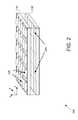
- FIG. 2conceptually illustrates an optic array and an imager array in an array camera module in accordance with an embodiment of the invention.
- FIG. 3conceptually illustrates a layout of color filters and the location of a reference camera in an array camera module in accordance with an embodiment of the invention.
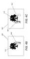
- FIGS. 4A-4Cconceptually illustrate the disparity associated with the effects of parallax in two images of a scene captured from a reference viewpoint and an alternate viewpoint.
- FIG. 5is a chart illustrating the effect of object distance within a sampled scene on disparity and on depth of field when the focal depth is located at the object distance.
- FIG. 6is a flow chart illustrating a process for synthesizing images using depth maps that determine disparity with varying levels of precision and varying resolution in accordance with embodiments of the invention.
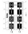
- FIG. 7is a flow chart illustrating a video processing pipeline in accordance with an embodiment of the invention.
- FIG. 8is a flow chart illustrating a process for determining a focal depth and depth of field based upon a selected region of interest in accordance with an embodiment of the invention.
- FIG. 9is a flow chart illustrating a process for generating a depth map and confidence map in a region of interest and determining a plane of best focus within the region of interest in accordance with an embodiment of the invention.
- FIG. 10is a flow chart illustrating a process for determining a plane of best focus based upon confident depths of objects within a region of interest in accordance with an embodiment of the invention.
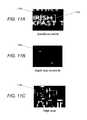
- FIG. 11Aillustrates a region of interest within a portion of an image captured by a Green camera within an array camera.
- FIG. 11Billustrates a depth map for the region of interest shown in FIG. 11A .
- FIG. 11Cillustrates an edge map for the region of interest shown in FIG. 11A .
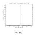
- FIG. 11Dis a chart showing a histogram of depth values for pixels within the region of interest shown in FIG. 11A .
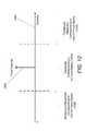
- FIG. 12conceptually illustrates the selection of a focal depth and depth of field when capturing image data using an array camera in accordance with embodiments of the invention.
- FIG. 13is a flow chart illustrating a process for selecting disparities to search during the creation of a depth map based upon a selected focus depth and depth of field in accordance with an embodiment of the invention.
- FIG. 14conceptually illustrates pixel locations searched along an epipolar line corresponding to depths within a selected depth of field when determining depth in accordance with embodiments of the invention.
- FIG. 15conceptually illustrates pixel locations searched along an epipolar line corresponding to depths within a selected depth of field and locations corresponding to depths outside the selected depth of field when determining depth in accordance with embodiments of the invention.
- FIG. 16is a flow chart illustrating a process for generating restricted depth of field depth maps by compositing depth maps generated using downsampled image data captured from a reference viewpoint and from alternate viewpoints in accordance with an embodiment of the invention.
- FIG. 17conceptually illustrates pixel locations within a downsampled image searched along an epipolar line when determining depth in accordance with an embodiment of the invention.
- FIG. 18Ais a flow chart illustrating a process for determining the depth to assign to a pixel based upon a plurality of depth maps having different resolutions in accordance with an embodiment of the invention.
- FIG. 18Bis a flow chart illustrating a process for propagating depth estimates from coarser spatial resolution depth maps to higher spatial resolution depth maps based upon the values of the lower spatial resolution depth estimates in accordance with an embodiment of the invention.
- FIG. 18Cconceptually illustrates a first coarse precision disparity search (optionally) performed using downsampled images.
- FIG. 18Dconceptually illustrates a second higher precision disparity search performed within (at least) a range of distances corresponding to a restricted depth of field.
- FIG. 19is a flow chart illustrating a process for applying depths determined from downsampled images to selected regions of higher resolution images in accordance with embodiments of the invention.
- FIG. 20is a flow chart illustrating a process for rendering pixels having an associated depth that is outside the selected depth of field in accordance with an embodiment of the invention.
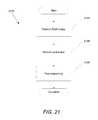
- FIG. 21is a flow chart illustrating a process for rendering pixels having an associated depth that is within the selected depth of field in accordance with an embodiment of the invention.
- restricted depth of field depth mapcan be used to describe a depth map in which precision of depth estimates and/or spatial resolution of depth estimates may vary based upon characteristics of the scene including (but not limited to) object distance and object characteristics.
- depth and distancewhen used to describe the depth or distance of a pixel (as expressed in a depth map or restricted depth of field depth map), typically refers to the distance to an imaged object within a scene along an axis extending from the array camera to the object.
- depth estimation precisioncan be used to collectively encompass the precision with which depth is estimated (e.g. the number of disparities sampled to obtain a depth estimate and/or the spacing of the disparity samples at the estimated depth) and the spatial resolution with which depth is estimated (e.g. a depth estimate based upon a 16 ⁇ 16 block of pixels may have lower precision with respect to an individual pixel location within the 16 ⁇ 16 block than estimating depth with the same precision for each pixel individually).
- restricted depth of field depth mapscan be considered to be depth maps in which depth estimation precision varies based upon characteristics of the scene visible from the viewpoint of the cameras in the array camera.
- Array cameras including camera modules that can be utilized to capture image data from different viewpointsare disclosed in U.S. patent application Ser. No. 12/935,504 entitled “Capturing and Processing of Images using Monolithic Camera Array with Heterogeneous Imagers” to Venkataraman et al. and U.S. Provisional Patent Application Ser. No. 61/904,947 entitled “Array Camera Modules and Methods of Manufacturing Array Camera Modules Incorporating Independently Aligned Lens Stacks” to Rodda et al.
- fusion and super-resolution processessuch as those described in U.S. patent application Ser. No. 12/967,807 entitled “Systems and Methods for Synthesizing High Resolution Images Using Super-Resolution Processes” to Lelescu et al., can be utilized to synthesize a higher resolution 2D image or a stereo pair of higher resolution 2D images from the lower resolution images in the light field captured by an array camera.
- the terms high or higher resolution and low or lower resolutionare used here in a relative sense and not to indicate the specific resolutions of the images captured by the array camera.
- the disclosures of U.S. patent application Ser. No. 12/935,504, U.S. Provisional Patent Application Ser. No. 61/904,947, and U.S. patent application Ser. No. 12/967,807are hereby incorporated by reference in their entirety.
- Each two-dimensional (2D) image in a captured light fieldis from the viewpoint of one of the cameras in the array camera. Due to the different viewpoint of each of the cameras, parallax results in variations in the position of objects within the images of the scene.
- Processessuch as those disclosed in U.S. Provisional Patent Application No. 61/691,666 entitled “Systems and Methods for Parallax Detection and Correction in Images Captured Using Array Cameras” to Venkataraman et al. can be utilized to provide an accurate account of the pixel disparity as a result of parallax between the different cameras in an array.
- the disclosure of U.S. Patent Application Ser. No. 61/691,666is hereby incorporated by reference in its entirety.
- Array camerascan use disparity between pixels in images within a light field to generate a depth map from a reference viewpoint.
- a depth mapindicates the distance of the surfaces of scene objects from the reference viewpoint and can be utilized to determine scene dependent geometric corrections to apply to the pixels from each of the images within a captured light field to eliminate disparity when performing fusion and/or super-resolution processing.
- Capturing still images or video in real or near-real timecan impose considerable processing and power demands on an array camera.
- One capability of array cameras with short focal lengthsis that they can create high resolution images synthesized from captured lower resolution image data using super-resolution processes, where the super-resolved scene is rendered almost entirely in focus.
- the image data which is captured from the arrayis used to form a depth map, the depth map is used to register the individual images in the array and fuse a high quality super-resolved image, and the super-resolution processing takes additional steps to recover resolution or reduce artifacts in the image.
- the same processingoccurs regardless of the depths of the objects in the scene.
- a compromisecan be made to reduce the computational requirements of synthesizing a satisfactory image or video. Instead of rendering a final image which is ‘all-in-focus,’ a synthetic effect is generated which mimics the depth-of-field effects of a larger aperture camera.
- a depth mapis first calculated and examined, and objects in the image which are sufficiently far away from the desired depth of best focus (i.e. objects located at ‘out-of-focus depths’) are rendered to be blurred in an amount proportional to their distance from the plane of best focus. Regions of the image where objects are sufficiently near to the plane of best focus (i.e. within the range of ‘in-focus depths’) are rendered with sufficient precision so that they appear to be in focus when fused to synthesize a higher resolution image. In many embodiments, for these super-resolved regions of the image, the depth is estimated with precision at least as high (or higher) than the precision of a high resolution grid used for performing super-resolution processing.
- the disparity between objects in the various low resolution cameraswould typically be detected to a precision of at least 1 ⁇ 3 pixel or higher.
- the in-focus and out-of-focus regions synthesized aboveare combined into a single final output image.
- the aesthetic result of this effectis an image that appears to have a reduced depth-of-field which, though restricted compared to the all-in-focus image, mimics the depth-of-field and focus behavior effects of a larger aperture camera and/or a camera with a longer hyperfocal distance.
- the methodcan be used to blur anything closer than a particular distance (i.e. everything beyond a specified distance can be rendered in focus).
- Reducing depth of fieldcan provide certain computational savings. Relaxed sharpness constraints allow the parallax search process to search fewer disparities in the ranges of disparities corresponding to out-of-focus depths, because multiple images do not have to be precisely registered in order to generate a blurred output. In the case that a region of the image is out-of-focus, it is sufficient to detect that the region is at an out-of-focus depth, and only then, to relatively coarse precision. The images need only be matched precisely enough that color banding does not appear when different color channels (e.g. the R, G, and B color channels) are combined in the blurred out-of-focus region during rendering. Additionally, the depths of out-of-focus pixels can be detected at reduced spatial resolution (i.e.
- the ability to tolerate blur in the out-of-focus regionscan enable the use of less computationally complex rendering (or fusion) processes to synthesize the out-of-focus regions in the final image.
- the array cameraincludes auto focus capabilities and the desired depth is determined using the autofocus module of the array camera.
- a usercan select a region of interest and can provide specific parameters which specify how wide the in-focus depth range should be about the desired best focus point (i.e. the range of the restricted depth of field) and how rapidly the blurring should be increased at depths which are increasingly farther away from the plane of best focus (i.e., such parameters essentially define the desired restricted depth of field effect delivered in the final image).
- the parametermay be a synthetic F# setting and the blur applied as a rapid or not rapidly increasing function of depth (depending on the F#).
- the parametermay specify or indicate a blur profile that may or may not be physically realizable by a traditional camera system.
- a desired plane of best focus for an imageis determined by constructing a depth map within the selected region of interest.
- a map which indicates which pixels in the region of interest are likely to yield confident depthsmay also be calculated within the same region-of-interest.
- confidencecan be determined based upon a high signal to noise ratio (SNR).
- SNRsignal to noise ratio
- edge mapscan also be utilized to determine pixels for which confident depths can be determined.
- any of a variety of techniquescan be utilized to determine pixels that can be used with confidence to determine a desired plane of best focus.
- the region of interestis automatically and/or continuously monitored or tracked during video capture and time based filtering can be utilized to avoid rapid jumps in the plane of best focus and/or to determine the plane of best focus in circumstances in which a plane of best focus cannot be reliably determined from a single frame.
- a depth map within a region of interestcan be constructed by determining disparity between pixels from the region of interest in image data captured from a reference viewpoint, which may be a virtual viewpoint, and corresponding pixels from image data captured from one or more alternate viewpoints. The most confident pixels in the depth map corresponding to the region of interest can be examined to determine the depth of the object contained within the region of interest. Processes for automatically determining a plane of best focus are described further below.
- the plane of best focusis not determined automatically, but is determined manually based on user input.
- the expected blur for depths other than the best focus depthcan be defined based on additional blur parameters that can be predefined and/or provided via the user interface.
- the resulting focal depth and depth of fieldcan then be used to define at which depths in the final image greater sharpness constraints will apply and at which depths higher levels of blur will be rendered.
- the resulting focal depth and depth of fieldcan be utilized to determine image capture settings based upon the image data captured by pixels having depths falling within the range of distances corresponding to the restricted depth of field.
- a single restricted depth of field depth mapis calculated from the input images.
- the single restricted depth of field depth mapcan be the same size as the resolution of a single camera input (hereafter, the term 10 ′ is used to signify that the final depth map or any image or data is the same resolution as an input image from a camera in the array).
- the parallax stageincorporates knowledge of the desired plane of best focus to reduce the computation required to form the final restricted depth of field depth map.
- a variety of techniquescan be utilized to construct the final restricted depth of field depth map from image data captured using an array camera.
- the process of constructing the final restricted depth of field depth mapcan include, for selected pixels, searching a greater density of pixel locations along epipolar lines where the disparity corresponds to depths falling within a range of in-focus depths, and reducing number and/or density of the disparities searched that correspond to depths falling in the out-of-focus region.
- in-focus depths and out-of-focus depthsmany embodiments of the invention treat transition depths outside a specified restricted depth of field in the same, or a similar, manner as in-focus depths to avoid artifacts. Therefore, the term in-focus depths should be understood to include depths outside the restricted depth of field in many implementations of the invention.
- a hierarchy or pyramid of imagesis formed from the L0 input images, which are filtered and downsampled one or more times to create lower resolution versions of the L0 input images.
- Each level of lower resolutioncan be denoted by an increasing number.
- the highest spatial resolution imagesare denoted L0, the next lower resolution images denoted as L1, and so forth.
- imagesare calculated corresponding to each resolution level (L0, L1, L2, etc.) by filtering and downscaling the images from the previous (next-highest) resolution level to create the hierarchy of images.
- depth mapsare calculated at each resolution level using the corresponding images from that spatial resolution level, and the final depth map draws selected pixels from the different resolution depth maps to create a final combined depth map.
- the L0 imagesare used for a disparity search to generate an L0 depth map
- the L1 imagesare used for a disparity search to generate an L1 depth map
- the final depth map(which may also be L0-sized)
- some pixelsare drawn from the L0 depth map, some from the L1 depth map, and some from the L2 depth map according to a variety of criteria.
- all depthsare calculated at the lowest or lower resolution levels first, but only certain pixels for which the low resolution depths are deemed unreliable or which are determined to belong to in-focus regions which require higher precision of depth estimation are calculated at the highest or higher resolution level(s) to improve the quality of the synthesized image in these regions.
- lower precision depths generated using the lower resolution imagescan be utilized to modify and/or bound the higher precision disparity search performed using the higher resolution images.
- a higher precision depth estimatecan be obtained by performing a disparity search within a predetermined range of disparities relative to the disparity corresponding to a lower precision depth estimate.
- a searchis performed within a bounded range of disparities determined based upon the lower precision depth estimates of pixels in a neighborhood of the pixel location for which a higher precision depth estimate is sought.
- a searchis performed at multiple different ranges of disparities determined based upon the lower precision depth estimates of pixels in a neighborhood of the pixel location for which a higher precision depth estimate is sought.
- any of a variety of techniques for generating restricted depth of field depth maps with depth estimation precision that varies with object distancecan be utilized as appropriate to the requirements of specific applications.
- the final restricted depth of field depth mapis used to synthesize images from the captured image data.
- the higher the spatial resolution and also precision of depth estimation of the depth mapthe greater the accuracy with which pixels captured from different viewpoints can be assembled (i.e. fused) to synthesize a final high resolution image.
- the rendering stagecan use knowledge of which depths are rendered out-of-focus to reduce computation. If a region of the image is determined to be out-of-focus based on the restricted depth of field depth map, there is no need to fuse data from multiple cameras, because a high resolution rendering (i.e. super-resolution) is not required to generate the blurred out-of-focus region.
- Array cameras in accordance with embodiments of the inventioncan include a camera module including an array of cameras and a processor configured to read out and process image data from the camera module to synthesize images.
- An array camera in accordance with an embodiment of the inventionis illustrated in FIG. 1 .
- the array camera 100includes a camera module 102 with an array of individual cameras 104 where an array of individual cameras refers to a plurality of cameras in a particular arrangement, such as (but not limited to) the square arrangement utilized in the illustrated embodiment.
- the camera module 102is connected to the processor 106 .
- the processoris also configured to communicate with one or more different types of memory 108 that can be utilized to store image data and/or contain machine readable instructions utilized to configure the processor to perform processes including (but not limited to) the various processes described below.
- Processors 108 in accordance with many embodiments of the inventioncan be implemented using a microprocessor and/or a coprocessor configured using appropriate software to take the image data within the light field and synthesize one or more high resolution images.
- the high resolution imageis synthesized from a reference viewpoint, typically that of a reference focal plane 104 within the sensor 102 .
- the processoris able to synthesize an image from one or more virtual viewpoints, which do not correspond to the viewpoints of any of the focal planes 104 in the sensor 102 .
- the images in the light fieldwill include disparity due to the different fields of view of the focal planes used to capture the images. Processes for detecting and correcting for disparity are discussed further below.
- FIG. 1Although a specific array camera architecture is illustrated in FIG. 1 , alternative architectures can also be utilized in accordance with embodiments of the invention.
- Array camera modules in accordance with embodiments of the inventioncan be constructed from an imager array or sensor including an array of focal planes and an optic array including a lens stack for each focal plane in the imager array. Sensors including multiple focal planes are discussed in U.S. patent application Ser. No. 13/106,797 entitled “Architectures for System on Chip Array Cameras”, to Pain et al., the disclosure of which is incorporated herein by reference in its entirety.
- Light filterscan be used within each optical channel formed by the lens stacks in the optic array to enable different cameras within an array camera module to capture image data with respect to different portions of the electromagnetic spectrum.
- the array camera module 200includes an imager array 230 including an array of focal planes 240 along with a corresponding optic array 210 including an array of lens stacks 220 .
- each lens stack 220creates an optical channel that forms an image of the scene on an array of light sensitive pixels within a corresponding focal plane 240 .
- Each pairing of a lens stack 220 and focal plane 240forms a single camera 104 within the camera module.
- Each pixel within a focal plane 240 of a camera 104generates image data that can be sent from the camera 104 to the processor 108 .
- the lens stack within each optical channelis configured so that pixels of each focal plane 240 sample the same object space or region within the scene.
- the lens stacksare configured so that the pixels that sample the same object space do so with sub-pixel offsets to provide sampling diversity that can be utilized to recover increased resolution through the use of super-resolution processes.
- each focal plane 240 on the sensoris capable of capturing an image of the scene.
- each focal planeincludes a plurality of rows of pixels that also forms a plurality of columns of pixels, and each focal plane is contained within a region of the imager that does not contain pixels from another focal plane.
- image data capture and readout of each focal planecan be independently controlled. In this way, image capture settings including (but not limited to) the exposure times and analog gains of pixels within a focal plane can be determined independently to enable image capture settings to be tailored based upon factors including (but not limited to) a specific color channel and/or a specific portion of the scene dynamic range.
- the sensor elements utilized in the focal planescan be individual light sensing elements such as, but not limited to, traditional CIS (CMOS Image Sensor) pixels, CCD (charge-coupled device) pixels, high dynamic range sensor elements, multispectral sensor elements and/or any other structure configured to generate an electrical signal indicative of light incident on the structure.
- the sensor elements of each focal planehave similar physical properties and receive light via the same optical channel and color filter (where present).
- the sensor elementshave different characteristics and, in many instances, the characteristics of the sensor elements are related to the color filter applied to each sensor element.
- color filters in individual camerascan be used to pattern the camera module with ⁇ filter groups as further discussed in U.S. Provisional Patent Application No. 61/641,165 entitled “Camera Modules Patterned with pi Filter Groups” filed May 1, 2012, the disclosure of which is incorporated by reference herein in its entirety. These cameras can be used to capture data with respect to different colors, or a specific portion of the spectrum.
- color filters in many embodiments of the inventionare included in the lens stack.
- a Green color cameracan include a lens stack with a Green light filter that allows Green light to pass through the optical channel.
- the pixels in each focal planeare the same and the light information captured by the pixels is differentiated by the color filters in the corresponding lens stack for each filter plane.
- camera modules including ⁇ filter groupscan be implemented in a variety of ways including (but not limited to) by applying color filters to the pixels of the focal planes of the camera module similar to the manner in which color filters are applied to the pixels of a conventional color camera.
- at least one of the cameras in the camera modulecan include uniform color filters applied to the pixels in its focal plane.
- a Bayer filter patternis applied to the pixels of one of the cameras in a camera module.
- camera modulesare constructed in which color filters are utilized in both the lens stacks and on the pixels of the imager array.
- Active cameras in an array camera module in accordance with embodiments of the inventioncan be grouped into subsets for capturing image data.
- a single 3 ⁇ 3 ⁇ filter groupis used to capture image data from which frames of video are synthesized.
- a 4 ⁇ 4 array camera module including a subset of active cameras configured to capture image data used to synthesize an image from the viewpoint of a reference camera in accordance with an embodiment of the inventionis illustrated in FIG. 3 .
- the 4 ⁇ 4 camera module 300includes a first subset 302 of 3 ⁇ 3 active cameras patterned using a ⁇ filter group and utilized to capture image data that can be utilized to synthesize color images and/or video sequences.
- a ⁇ filter groupincludes a Green camera at each corner, a Green reference camera in the center indicated by a box 304 , Blue cameras above and below the reference camera, and Red cameras to the left and right sides of the reference camera.
- the locations of the Red and Blue cameras within the ⁇ filter groupare swapped and/or an alternative collection of cameras can be utilized to capture image data to synthesize images.
- a second subset 306 of active camerasincludes a row of Blue, Green, and Red cameras placed below the ⁇ filter group and a column of Blue, Green, and Red cameras placed to the right side of the ⁇ filter group with a Green camera connecting the row and the column.
- the second subset of active camerasis configured to capture image data for measuring scene information as is described in U.S. Patent Application Ser. No. 61/775,395 entitled “Systems and Methods for Measuring Scene Information While Capturing Images Using Array Cameras” filed Mar. 8, 2013, the disclosure of which is hereby incorporated by reference in its entirety.
- the cameras in the array camera module illustrated in FIG. 3are shown as capturing image data for use in synthesizing video, in many embodiments more cameras than a single ⁇ filter group are used to capture image data from which video can be synthesized. Processes for synthesizing video from image data captured using an array camera module in accordance with embodiments of the invention are discussed further below.
- the individual cameras in the array camera module used to capture a light fieldhave similar fields of view, fixed apertures, and focal lengths.
- Parallax in a two camera systemis illustrated in FIG. 4A .
- the two cameras 200 , 202include a lens stack 204 and a focal plane 206 .
- Each camerahas a back focal length f, and the two cameras are separated by the baseline distance of 2h.
- the field of view of both camerasencompasses a scene including a foreground object 408 and a background object 410 .
- the scene from the viewpoint of the first camera 400is illustrated in FIG. 4B .
- the foreground object 408appears located slightly to the right of the background object 410 .
- the scene from the viewpoint of the second camera 402is illustrated in FIG. 4C .
- the foreground object 408appears shifted to the left hand side of the background object 410 .
- the disparity introduced by the different fields of view of the two cameras 400 , 402is equal to the difference in location of the foreground object 408 between its location in the image captured by the first camera (indicated in the image captured by the second camera by ghost lines 454 ) and its location in the image captured by the second camera.
- the distance from the two cameras to the foreground objectcan be obtained by determining the disparity of the foreground object in the two captured images.
- the point (x o , y o , z o ) on the foreground objectwill appear on the focal plane of each camera at an offset from the camera's optical axis.
- the offset of the point on the focal plane of the first camera 400 relative to its optical axis 412is shown as ⁇ u L .
- the offset of the point on the focal plane of the second camera 402 relative to its optical axis 414is shown as u R .
- the offset between the images captured by the two camerascan be observed as follows:
- disparity between images captured by the camerasis along a vector in the direction of the baseline of the two cameras, which can be referred to as the epipolar line between the two cameras.
- the magnitude of the disparityis directly proportional to the baseline separation of the two cameras and the back focal length of the cameras and is inversely proportional to the distance from the camera to an object appearing in the scene.
- the disparity in the location of the foreground object in each of the imagesresults in portions of the scene behind the foreground object being visible in some but not all of the images.
- a pixel that captures image data concerning a portion of a scene, which is not visible in images captured of the scene from other viewpoints,can be referred to as an occluded pixel.
- the viewpoint of the second camerais selected as a reference viewpoint the pixels contained within the ghost lines 454 in the image 452 can be considered to be occluded pixels (i.e.
- the pixelscapture image data from a portion of the scene that is visible in the image 452 captured by the second camera 402 and is not visible in the image 450 captured by the first camera 400 ).
- the pixels of the foreground object 408can be referred to as occluding pixels as they capture portions of the scene that occlude the pixels contained within the ghost lines 454 in the image 452 . Due to the occlusion of the pixels contained within the ghost lines 454 in the second image 452 , the distance from the camera to portions of the scene visible within the ghost lines 454 cannot be determined from the two images as there are no corresponding pixels in the image 450 shown in FIG. 4B .
- Array cameras in accordance with many embodiments of the inventionuse disparity observed in images captured by the array cameras to generate a restricted depth of field depth map.
- a depth mapis typically regarded as being a layer of meta-data concerning an image that describes the distance from the camera to specific pixels or groups of pixels within the image (depending upon the resolution of the depth map relative to the resolution of the image).
- Array cameras in accordance with a number of embodiments of the inventionuse depth maps for a variety of purposes including (but not limited to) generating scene dependent geometric shifts during the synthesis of a high resolution image and/or performing dynamic refocusing of a synthesized image.
- the process of determining the depth of a portion of a scene based upon pixel disparityis theoretically straightforward.
- the viewpoint of a specific camera in the array camerais chosen as a reference viewpoint
- the distance to a portion of the scene visible from the reference viewpointcan be determined using the disparity between the corresponding pixels in some or all of the images captured by the camera array.
- a pixel corresponding to a pixel in the image captured from the reference viewpointwill be located in each image along an epipolar line (i.e. a line parallel to the baseline vector between the two cameras).
- the distance along the epipolar line of the disparitycorresponds to the distance between the camera and the portion of the scene captured by the pixels.
- a searchcan be conducted for the depth that yields the pixels having the highest degree of similarity.
- the depth at which the corresponding pixels in the captured images have the highest degree of similaritycan be assumed to be the most likely distance between the camera and the portion of the scene captured by the pixel. Similar processes can be utilized when synthesizing a depth map from a virtual viewpoint.
- the cameras in an array cameraare similar but not the same. Therefore, characteristics including (but not limited to) optical characteristics, different sensor characteristics (such as variations in sensor response due to offsets, different transmission or gain responses, non-linear characteristics of pixel response), noise in the captured images, and/or warps or distortions related to manufacturing tolerances related to the assembly process can vary between the images reducing the similarity of corresponding pixels in different images.
- super-resolution processesrely on sampling diversity and/or aliasing in the images captured by an imager array in order to synthesize higher resolution images.
- increasing sampling diversitycan also involve decreasing similarity between corresponding pixels in captured images in a light field. Given that the process for determining depth outlined above relies upon the similarity of pixels, the presence of photometric differences and sampling diversity between the captured images can reduce the accuracy with which a depth map can be determined.
- occlusionsoccur when a pixel that is visible from the reference viewpoint is not visible in one or more of the captured images.
- the effect of an occlusionis that at the correct depth, the pixel location that would otherwise be occupied by a corresponding pixel is occupied by a pixel capturing another portion of the scene (typically an object closer to the camera).
- the occluding pixelis likely very different to the occluded pixel. Therefore, a comparison of the similarity of the pixels at the correct depth is less likely to result in a significantly higher degree of similarity than at other depths.
- the occluding pixelacts as a strong outlier masking the similarity of those pixels, which correspond. Accordingly, the presence of occlusions can introduce a strong source of error into a depth map and processes for determining depth maps such as those disclosed in U.S. Patent Application Ser. No. 61/691,666, incorporated by reference above, involve detecting occlusions and determining depths using non-occluded pixels. Systems and methods for generating restricted depth of field depth maps in accordance with embodiments of the invention are discussed further below.
- a focal depth 416can be defined with an associated range of in-focus depths 418 .
- the plane of best focus and range of in-focus depthscan be utilized to determine a depth search that can be performed in such a way that depth is estimated with a lower precision at depths outside the range of in-focus depths in an L0 (highest resolution) depth map.
- Additional depth mapscan be determined with respect to a pyramid of images generated by downsampling the captured images (e.g. L1, L2, etc. images).
- the depth maps of these lower resolution imagescan involve determining depth with greater precision at depths outside the range of in-focus depths than the precision of the L0 depth estimates at the corresponding depths. Accordingly, the precision of the depth information available in the L0 depth map may be reduced at depths in the out-of-focus region and the spatial resolution of the L1, and lower resolution depth maps in the out-of-focus regions is lower despite higher precision. Therefore, a single depth map can be constructed by first searching for the depth of a pixel in the L0 image and using the depth in an L1 or lower spatial resolution depth map (e.g. L2, L3, etc.) depending upon the depth of the pixel in the L0 image (and the depth of the pixel location in other higher levels, e.g.
- L1 or lower spatial resolution depth mape.g. L2, L3, etc.
- a low spatial resolution depth mapcan be constructed and the low spatial resolution depth map used to determine when to perform a depth search with respect to a specific pixel or pixels that have a depth in the next-lowest or a lower level depth map (i.e. a higher spatial resolution depth map) that is within the in-focus depth range or outside the subset of the out-of-focus range mapped to the current level of spatial resolution.
- depthis determined by performing uniform depth sampling with respect to disparity irrespective of whether the disparity corresponds to a range of in-focus or out-of-focus depths.
- a coarse precision disparity searchcan be performed using lower resolution images and the precision of the disparity search increased as disparity searches are performed with respect to pixels from higher spatial resolution images.
- the depth estimates from coarse precision disparity searchescan be used to identify pixels that are likely to be in-focus and modify and/or bound a higher precision disparity search for in-focus pixels, where the higher precision disparity search is performed using pixels from the higher spatial resolution images.
- the disparities searched using the higher spatial resolution imagescan be predetermined based upon the coarse precision disparity estimate for the pixel.
- the disparities searched using the higher spatial resolution imagesare determined based upon the coarse precision disparity estimates of pixels within the neighborhood of the pixel.
- a best focus depthcan be defined based upon the distance of an object within a region of interest from the array camera.
- the desired best focus depth 416is determined to be the distance from the array camera to the foreground object 408 .
- the depths which are considered in-focus 418can then be determined relative to the best focus depth in any of a variety of ways appropriate to the requirements of a specific application.
- the range of depths which are considered in focusis automatically determined based upon a synthetic aperture parameter provided to the pipeline which specifies how much blur should be applied for objects which are increasing distances from the best focus depth.
- the range of in-focus depthscan be dependent based upon factors including (but not limited to) the content of the scene and user input.
- the observed disparity and depth of field associated with an object located at specific focal depths (object distances)is illustrated in FIG. 5 .
- object distancesThe observed disparity and depth of field associated with an object located at specific focal depths (object distances) is illustrated in FIG. 5 .
- the precision with which object distance can be determineddecreases rapidly with increased object distance.
- the range of depths which are in focusincreases as the best focus distance increases. As one can see, at a focal depth of 30 cm, the range of depths in focus is much smaller than if the desired best focus depth is set to a farther distance such as 10 meters.
- the array cameraautomatically identifies regions of interest within a scene and determines an appropriate focal depth.
- the confident pixels in the region of interestcan be determined by calculating edge gradients within the same region of interest in the reference image and selecting pixels as confident which have edge gradients that are stronger than a particular threshold.
- the map of confident pixels in the depth map of the region-of-interestcan be determined using any metric indicating the reliability of specific depth measurements within the region of interest.
- an SNR estimatoris applied to the reference image (within the region-of-interest), and pixels which are determined to have high SNR relative to a known or characterized noise floor or otherwise with respect to a threshold are deemed confident and likely to have reliable depth estimates.
- edge mapscan also be generated and confident pixels that lie on edges can be utilized to determine depth. Once the pixels with confident depths within the region of interest are marked, a histogram is formed which counts how many of these confident pixels in the region of interest belong to each possible depth. From the resulting histogram, the desired focal depth can be selected using statistical measures or other measures applied to the histogram. In one embodiment, the depth which is confident and occurs most frequently in the region of interest (i.e. the mode of the histogram) is selected as the desired best focal plane. In many embodiments, temporal hysteresis can be utilized to control the extent to which the desired best focal plane and/or range of in-focus depths changes from one frame of video to the next.
- time based filtering of the best focal plane and/or range of in-focus depthsis utilized to smooth transitions between different best focal planes and/or ranges of in-focus depths during the capture of video using an array camera.
- the damping of the rate of temporal change of the desired best focal pointis a function of the number of confident depth measurements within the region of interest. If the number of confident pixels within the region is low, the resulting ‘best focus depth’ may be discarded or may influence the temporal hysteresis by a discounted amount to avoid introducing spurious temporal changes in the best focal point due to low-confidence depth measures.
- depth information for pixels within the region of interestcan be used in any of a variety of ways to select a best focal plane including (but not limited to) selecting the depth which appears as the median of the histogram distribution as the desired focal depth.
- a usercan specify one or more regions of interest containing objects from which a focal depth can be determined.
- the useris provided with the ability to modify the plane of best focus and/or the range of in-focus depths utilized by the array camera to synthesize images from image data captured by the array camera.
- a plane of best focus and an in-focus range of depthsare selected, and these are utilized to synthesize video or still image data in real or near-real time and the raw image data can be reprocessed post capture to generate video sequences having different planes of best focus and ranges of in focus depths including (but not limited to) synthesizing all in focus images.
- the raw image datacan be processed post capture to generate a higher resolution depth map and/or a restricted depth of field depth map in which pixels that sample objects at different depths are uniformly processed (i.e. the process for determining the depth of a given pixel is not determined in a depth dependent manner).
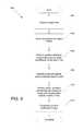
- FIG. 6A process for synthesizing images from image data captured by array cameras using restricted depth of field depth maps to reduce computation and provide a synthetic depth of field effect in accordance with an embodiment of the invention is illustrated in FIG. 6 .
- the process 600includes capturing ( 602 ) image data using multiple active cameras within an array camera.
- a selectionis made ( 604 ) of a desired plane of best focus and based on a parameter provided to the pipeline which specifies how blur should be increased with distance from the best focus point, the ranges of depths which are considered ‘in-focus’ and ‘out-of-focus’ can be determined.
- pixels at the transition between ‘in-focus’ and ‘out-of-focus’ depthscan be treated in a similar manner to ‘in-focus’ pixels to reduce artifacts associated with incorrect depth estimates.
- the selectioncan be made based upon direct user input (e.g. using a manual slider user interface element) and/or based upon an automatic determination of a relevant object distance.
- a process similar to the processes described in U.S. Patent Application Ser. No. 61/691,666, incorporated by reference above,can be used to detect disparity associated with parallax between viewpoints of the active cameras in the array.
- a restricted depth of field depth mapwhich incorporates depth values drawn from different spatial resolutions and/or searches of varying precision which take into account relaxed rendering constraints to reduce computational requirements can be generated ( 606 ) in accordance with embodiments of the invention.
- the depth mapscan include multiple levels. At the highest resolution level L0 the depth map can be determined using a lower precision at depths outside the range of in-focus depths. Lower resolution depth maps can include higher precision depth estimates at depths outside the range of in-focus depths determined with a lower spatial resolution.
- the depth estimate utilized at a specific object depthcan be determined using any of a variety of factors that are discussed further below.
- Restricted depth of field depth maps in which precision of depth estimation and/or spatial resolution vary that are generated in accordance with embodiments of the inventioncan be utilized to synthesize images from the captured image data.
- a restricted depth of field depth map in which precision of depth estimation and spatial resolution varyis used to render ( 608 ) pixels that sample objects located at depths outside of the selected depth of field (out-of-focus regions).
- the restricted depth of field depth mapcan then be used to perform super-resolution processing ( 610 ) with respect to pixels that sample objects located within the selected depth of field (in-focus regions).
- the rendered pixels ( 608 ) and the pixels synthesized using super-resolution processes ( 610 )can then be composited ( 612 ) to produce the final synthesized image.
- out-of-focus regionsare intentionally rendered to be blurry, and so an image is formed in these regions can use less computationally complex techniques and/or contributions from fewer cameras than are used in the in-focus region.
- out-of-focus regionscan be rendered using pixels from the pyramid of images generated by downsampling the captured images (e.g. L1, L2, etc. images).
- the number of levels of the pyramid of images used to generate the restricted depth of field depth mapis different from the number of levels of the pyramid of images used to render the out-of-focus regions of the image. For example, two levels (e.g. L0 and L1) of the pyramid of images can be utilized to generate the restricted depth of field depth map and three levels (e.g.
- L0, L1 and L2can be utilized to render the out-of-focus regions of the image.
- any number of levels of a pyramid of images generated by downsampling the captured imagescan be utilized to generate a restricted depth of field depth map and/or to render out-of-focus regions of an image as appropriate to the requirements of specification applications in accordance with embodiments of the invention.
- the provided restricted depth of field depth maphas higher resolution and this is used for super-resolution processing to achieve increased sharpness compared to the out-of-focus regions.
- the composited imagepixels in in-focus regions that sample objects located within the selected depth of field are super-resolved.
- the process illustrated in FIG. 6can be repeated with sets of image data to synthesize a sequence of video frames that can then be encoded and stored.
- the raw image datais also stored and/or compressed for storage. In this way, the raw image data can be used to synthesize additional images and/or video sequences utilizing alternative viewpoints, focal depths and/or depths of field.
- specific processes for synthesizing images from image data captured by array cameras using restricted depth of field depth maps to render a synthetic depth of field effect within a selected depth of fieldare described above with respect to FIG. 6
- any of a variety of processescan be utilized to synthesize images from image data captured by array cameras using restricted depth of field depth maps in accordance with embodiments of the invention.
- Image processing pipelinesthat can be implemented in the software of an array camera in order to synthesize images from image data captured by the array camera using restricted depth of field depth maps to provide synthetic depth of field effects within selected depths of field are discussed below.
- the image processing pipeline 700receives low resolution image data and performs normalization ( 702 ) on the low resolution image data.
- the normalizationinvolves performing photometric and/or geometric corrections with respect to image data received from different cameras in the array camera module. Photometric differences and scene-independent geometric distortions can be corrected through calibration. Photometric calibration data used to perform photometric normalization and scene-independent geometric corrections that compensate for scene-independent geometric distortions can be generated using an off line calibration process and/or a subsequent recalibration process.
- the photometric calibration datacan be provided to a photometric normalization module or process that can perform any of a variety of photometric adjustments to the images captured by an array camera including (but not limited to) Black Level calculation and adjustments, vignetting correction, and lateral color correction.
- the photometric normalization modulealso performs temperature normalization.
- the scene-independent geometric corrections determined using a calibration processcan also be applied to the captured images to increase the correspondence between the images. When the captured images are used to synthesize a higher resolution image using super-resolution processing, the scene-independent geometric corrections applied to the images are typically determined at a sub-pixel resolution.
- the scene-independent geometric correctionsare typically determined with a higher degree of precision than the corrections utilized during registration in conventional stereoscopic 3D imaging.
- the scene-independent geometric correctionsalso involve rectification to account for distortion and rotation of the lenses of the array camera relative to the focal planes so that the epipolar lines of the alternate view images are easily aligned with those of the image captured from the reference viewpoint.
- the image processing pipeline 700can perform focus detection and varying depth estimation precision parallax detection 704 .
- varying depth estimation precision parallax detection processescan involve performing disparity searches with greater precision at depths which are to be rendered in-focus.
- the varying depth estimation precision parallax detection processcan involve filtering and downsampling captured image data to reduce the resolution of the image data. Lower spatial resolution disparity searches can then be performed with respect to the downsampled image data to produce one or more low resolution depth maps.
- the image processing pipeline 700can composite the depth maps to produce a single restricted depth of field depth map which combines estimates from multiple levels of spatial resolution and/or precision of depth estimation that can be used to synthesize the final rendered image.
- a restricted depth of field depth mapcan then be used to synthesize a high resolution image from the low resolution image data received by the image processing pipeline 700 .
- the process of synthesizing a high resolution imagecan involve compositing 706 pixels from different viewpoints that sample objects located outside the selected depth of field (out-of-focus regions) by applying scene dependent geometric corrections based upon pixel depth.
- Super-resolution processescan then be utilized to synthesize portions of a high resolution image corresponding to pixels that sample objects located within the selected depth of field (i.e. in in-focus regions).
- the super-resolution processcan involve performing raw fusion 708 and pilot fusion 710 (i.e.
- additional super-resolution processingcan be performed including processes similar to those described in U.S. patent application Ser. No. 12/967,807, incorporated by reference above, to achieve additional increases in resolution (potentially at the expense of additional computational complexity).
- the low resolution image datacan be produced in out-of-focus areas and used to generate out-of-focus parts of a high resolution image using a compositing mechanism as part of the post capture image processing. For in-focus areas additional super-resolution processes using restricted depth of field depth maps and portions of images from multiple cameras in the camera array may be used in order to obtain a final high resolution image.
- the composited pixels ( 706 ) and the synthesized pixels ( 708 , 710 ) in the synthesized imagecan then be post processed ( 712 ) to apply one or more filters to remove artifacts within the synthesized image associated with the image processing techniques utilized to synthesize the image.
- Color processing and gamma correction 714can be applied to the synthesized image and sequences of images forming a sequence of video frames can be encoded 716 using any of a variety of well known video encoding techniques to reduce the maximum bitrate of the video stream output by the video processing pipeline 700 .
- out-of-focus pixelsare blurred, therefore, any denoising and sharpening filter applied in the post processing 712 stage of the video processing pipeline 700 can be applied to the in-focus region(s) only.
- the final video framecan be generated through a color processing and gamma correction 714 stage of the video processing pipeline 700 .
- the color correction matrixis computed per frame based on the histogram of the red, green and blue color channels, while the gamma correction function as well as the exposure compensation for the next frame is computed from luma information.
- many embodiments of the inventionuse color information from lower spatial resolution images generated during the process of generating a restricted depth of field depth map 704 . Flicker artifacts in color and exposure control can also be reduced by adding temporal hysteresis to the parameters.
- any of a variety of video processing pipelines involving the creation of restricted depth of field depth maps in which precision of depth estimation and spatial resolution varycan be utilized to provide synthetic depth of field effects when synthesizing images in accordance with embodiments of the invention.
- Processes for selecting pixels from the different images using the restricted depth of field depth map based upon the distance of a pixel from the plane of best focus in accordance with embodiments of the inventionare discussed further below.
- the process of generating a restricted depth of field depth mapinvolves definition of a best focus depth and the range of depths corresponding to the ‘in-focus region.’
- the best focus depth and blur characteristics which define the range of in-focus depthsis selected by the user (e.g., as an F# setting).
- a preview imagecan be generated and a user interface cue, such as (but not limited to) the overlay of a small box or target similar to a conventional auto-focus reticle, can be presented to the user.
- the usercan indicate an object using the user interface cue to guide the determination of a selected focal depth.
- a full resolution parallax detection processis performed within the region of interest of the reference image indicated by the user to generate a depth map and a confidence map.
- a lower resolution depth mapis utilized to determine the plane of best focus. Measured depths at pixels deemed to be confident with the confidence map within the indicated region of interest can then be used to determine a focal depth.
- a confidence mapcan be generated utilizing processes similar to those described in U.S. Patent Application Ser. No. 61/691,666, which is incorporated by reference above.
- An appropriate range of in-focus depthscan be determined based upon the plane of best focus depth and or based upon further instructions received from the user.
- the process of selecting a focal depthcan be automated.
- a depth map of the preview imageis utilized to identify objects close to the center of the field of view shown in the preview image.
- a box or an outline of the edge of the object used to determine the plane of best focus depthcan be overlaid over the preview image and the user can provide an indication of a different region of interest in the event that the user wishes to modify the focal depth.
- the process 800includes determining ( 802 ) a region of interest.
- the region of interestcan be determined based upon user input received, for example, via a touch screen display on which a preview image is shown and/or an automated process that detects objects within the field of view.
- Objectscan be located within the region of interest based upon pixels for which depths are confident and the distance to the object from the array camera can be used to select ( 804 ) the desired best focus depth.
- a range of in-focus depthscan be selected ( 806 ) in accordance with any of a variety of criterion appropriate to a specific application.
- the range of in-focus depthsis determined based upon distances corresponding to a (symmetrical) range of disparity on either side of the disparity corresponding to the desired best focus depth.
- the size of range of in-focus depthsis a parameter, which can be modified based upon user input.
- the process 900includes generating ( 902 ) a depth map for the region of interest and ( 904 ) a confidence map.
- the depth map and a confidence mapcan be utilized to identify the depth of objects within the region of interest for which depth is estimated with confidence (i.e. a confidence exceeding a predetermined threshold) that can be utilized to determine the depths of the objects and hence determine ( 906 ) an appropriate plane of best focus.
- the plane of best focuscan be determined to be the dominant depth of confident pixels located along intensity edges within the region of interest.
- any of a variety of techniquescan be utilized to select the desired best focus depth based upon the depths of pixels within a region of interest.
- the determination of a plane of best focus and/or a restricted depth of fieldcan be (optionally) utilized in determining ( 908 ) the image capture parameters that are utilized during image capture.
- the mechanism of exposureprovides adjustment of the device sensitivity to the light intensity in the scene. This is in part motivated by the limited dynamic range (ratio of highest to lowest light intensity) of the camera system compared to the dynamic range of intensities in the real world.
- a metering and auto-exposure algorithmfinds optimal values for the above parameters (some of these parameters may be specified or fixed).
- An auto-exposure algorithmaims to find the optimal exposure settings for the camera system by modifying a subset of the following parameters: exposure time, iris/lens aperture, sensor gain, and the use of neutral density filters.
- Auto-exposure algorithmsmay rely on external light meters/sensors or may evaluate optimal exposure time through the lens by successive image capturing as described above.
- a depth mapis utilized to identify pixels within the restricted depth of field and the scene information obtained from the image data of the identified pixels is used to determine whether the image capture settings satisfy a set of predetermined criteria for parameters including (but not limited to) exposure, focus settings, shutter speed, aperture, and light sensitivity.
- an auto-exposure processperformed based upon the image data of a subset of pixels with depths falling within the range(s) of distances corresponding to the restricted depth of field.
- the image capture parametersare determined based upon the pixels that are rendered at higher resolution.
- processesare utilized that separately considers the impact of the image capture settings on pixels with depths within the range of distances corresponding to the restricted depth of field and for pixels with depths outside the range of distances corresponding to the restricted depth of field.
- an initial set of image capture settingsare determined based upon the pixels with depths within the range of distances corresponding to the restricted depth of field and then a verification process is performed to confirm that the image capture settings will not result in artifacts with respect to pixels with depths outside the range of distances corresponding to the restricted depth of field.
- a verification processis performed to confirm that the image capture settings will not result in artifacts with respect to pixels with depths outside the range of distances corresponding to the restricted depth of field.
- any process that can be utilized in the determination of image capture settingscan be applied to the subset of pixels with depths within the range of distances corresponding to the restricted depth of field and/or any verification process can be applied to confirm the image capture settings are appropriate to the overall scene as appropriate to the requirements of specific applications in accordance with embodiments of the invention.
- FIG. 10A process for determining focal depth based upon depths of pixels located along intensity edges within a region of interest in accordance with an embodiment of the invention is illustrated in FIG. 10 .
- the process 1000includes counting ( 1002 ) the number of pixels located along intensity edges within the region of interest having specific depths or depths within specific ranges of depths.
- the focal depthcan then be selected ( 1004 ) based upon the median pixel depth.
- any of a variety of techniquescan be utilized to determine focal depth based upon the depth of pixels located along edges within a region of interest.
- FIGS. 9 and 10can be understood with reference to FIGS. 11A-11D .
- a portion of an image constructed using image data captured by a Green reference camera in an array camera module in accordance with an embodiment of the inventionis illustrated in FIG. 11A .
- the image portion 1100includes a target 1102 defining a region of interest.
- a depth map of the region of interest shown in FIG. 11Ais illustrated in FIG. 11B . Due to the resolution of the high resolution depth map 1104 , the depth map contains a considerable amount of noise.
- the captured image 1100can be utilized to generate the edge map 1106 shown in FIG. 11C .
- a histogram showing the depths of pixels within the edge map shown in FIG. 11Cis illustrated in FIG. 11D .
- any of a variety of techniquescan be utilized to select a focal depth based upon the edge depth counts.
- the median depth within the region of interest and/or of pixels along intensity edges within the region of interestis selected as the focal depth.
- alternative criterioncan be utilized to select focal depth based upon depth measurements of objects located within a region of interest as appropriate to the requirements of specific applications in accordance with embodiments of the invention.
- a depth of fieldcan be automatically generated as described above and/or selected by the user.
- focal depthis determined with respect to frames of video sequences captured by an array camera. Once a focal depth is determined based upon an edge and/or object in a first frame, object tracking can be utilized to determine focal depth for subsequent frames. Alternatively, a process for determining focal depth can be independently applied to each new set of frames in the set of video sequences. In many embodiments, time based filtering is applied to the focal depth to prevent rapid jumps in focal plane depth.
- focal plane depth information from one or more previous framescan be utilized to determine focal plane depth in a set of frames in which a distance to an intensity edge and/or object cannot be confidently determined.
- a restricted depth of field depth mapcan be generated for image data captured by the array camera. Processes for generating restricted depth of field depth maps in accordance with embodiments of the invention are discussed further below.
- the process of generating a depth mapis described in general above and in U.S. Patent Application Ser. No. 61/691,666, incorporated by reference above.
- the computational complexity of generating a depth mapcan be reduced in a variety of ways including (but not limited to) varying the resolution and/or precision of depth estimation of the depth map.
- the precision of depth estimation of a depth map for a given reference imagecan be varied by changing the sampling frequency of the depth range that objects in the scene span.
- the spatial resolution of the depth mapcan be varied by modifying the resolution of the areas within the reference image for which depth information is computed within the depth map.
- the process of determining depth using disparity between corresponding pixels in image data captured by a reference camera and an alternate view cameracan involve searching (i.e. performing comparisons between a pixel from a reference image and pixels in an alternate view image) along an epipolar line.
- the number of depth samples (i.e. comparisons performed) taken along the epipolar linetypically depends upon the array camera geometry and the camera baselines.
- An appropriate number of samples for a monolithic array cameracan be in the order of 32 samples, but the number can change based upon quality criteria appropriate to the requirements of a specific application as well as the particular design parameters for the array being considered.
- the number of depth samples taken along the epipolar linecan depend on the size of the baselines, focal length, pixel size, number of cameras in the array, desired nearest resolvable depth, and the targeted super-resolution factor.
- the depth samplesare evenly distributed in disparity, which means that the samples are spaced the same distance apart along the epipolar line (which does not correspond to samples being taken at uniform object distances). For example, referring to the disparity relationship with respect to object distance measured for the array camera illustrated in FIG. 5 , a maximum disparity of 40 pixels is observed at an object distance of 20 cm (i.e. the minimum focal distance for the array camera).
- Dividing the maximum disparity of 40 pixels by 32 samplessuggests sampling every 1.25 pixels along the epipolar line from the minimum anticipated disparity, which in the case of the array camera illustrated in FIG. 5 is 0.8 pixels at infinity. Therefore, depth samples can be performed initially at 0.8 pixels along the epipolar line, and then at 2.05, 3.3, etc. up to 40 pixels. As can readily be appreciated, reducing the number of depth samples (a technique for reducing depth estimation precision) reduces the number of computations needed to generate the depth map. In many embodiments, selection of a desired best focus depth and a limited range of in-focus depths enables one to limit higher density depth sampling to only occur within the in-focus regions and allows lower density depth sampling in the range of out-of-focus depths.
- a process of determining the precision of depth searches by performing higher density depth samples within a selected range of disparities corresponding to a range of in-focus depthscan be appreciated with reference to FIG. 12 .
- the disparity along the epipolar line 1200 corresponding to a selected desired depth of best focus 1202can be determined as can the range of disparities along the epipolar line corresponding to a selected range of in-focus depths 1204 .
- Disparities corresponding to a foreground range of out-of-focus depths ( 1206 ) and a background range of out-of-focus depths ( 1208 ), which are both outside of the range of in-focus depths ( 1204 ),can be determined.
- the density with which depth samples are takencan be greater within the range of in-focus depths than within the foreground and background (i.e. the range of disparities corresponding to out-of-focus depths). Consequently, the depth map can be considered to have different precisions of depth estimation within the range of disparities corresponding to in-focus and out-of-focus ranges.
- the reduced computational complexity of performing a depth search along the epipolar lineresults in increased blur or lack of sharpness for pixels that image objects within the out-of-focus regions of the scene.
- the density of depth samplingis gradually increased and decreased in the transition along the epipolar line between disparities corresponding to depths that are bordering the ranges of in-focus and out-of-focus disparities.
- the process 1300includes selecting ( 1302 ) disparities to search within the in-focus region.
- the selected disparitiescan be uniformly distributed across the range of disparities within a range of in-focus depths or can be distributed with spacing that provides a smooth transition across disparities at the edges of the range of disparities corresponding to the in-focus region.
- disparities to search within the disparity ranges corresponding to disparities outside the range of in-focus depthscan also be determined ( 1304 ). By performing depth samples at the selected disparities, parallax can be detected ( 1306 ).
- the disparitiesare selected in an offline process and are retrieved from memory based upon the selected focal depth and/or depth of field. In a number of embodiments, the disparities are selected during the synthesis of an image based upon the selected focal depth and/or depth of field.
- rendering the in-focus region of an imageinvolves placing pixels onto a higher level fusion grid and the precision with which depth is sampled is determined based upon the resolution of the higher level fusion grid. For example, super-resolution processes that increase resolution by a factor of two utilize a fusion grid with pixel spacing equivalent to 0.5 a low resolution pixel.
- a disparity search with at least a 0.5 low resolution pixel resolutioncan be performed to generate a restricted depth of field depth map with sufficient precision to perform super-resolution processing of pixels that sample objects within the scene located within the selected depth of field.
- the array cameraestimates depth by performing depth samples at distances separated by a distance equal to or less than the size of a pixel multiplied by the inverse of a super-resolution factor by which the super-resolution process increases the resolution of the synthesized images relative to the resolution of the captured low resolution image data within a disparity range corresponding to the selected depth of field, and by performing depth samples at distances separated by a distance equal to more than the size of a pixel multiplied by the inverse of the super-resolution factor within disparity ranges outside the selected depth of field.
- the super-resolution ratiocan be determined as the ratio of the resolution of the reference image data and resolution of the grid on which the synthesized image is formed within the selected depth of field of the image.
- a lower density of depth samplingcan be performed with respect to disparities corresponding to depths outside of the range of depths which are rendered in-focus.
- Selection of additional depth samples 1500 in a foreground region and a background region to smoothly transition between regions of the image containing objects within the depth of field and regions of the image that do not contain objects within the depth of fieldis illustrated in FIG. 15 .
- a minimum number of depth samplesis performed in each of the regions outside of the depth of field to provide a threshold level of registration so that pixels from different color channels can be aligned with sufficient precision to reduce the incidence of color artifacts within the out-of-focus regions in a synthesized image.
- any of a variety of factorscan be utilized in selecting depth samples within disparity ranges corresponding to depths outside of a selected range of in-focus depths.
- specific depth sample selections involving depth samples that are evenly spaced with respect to disparity within the range of in-focus depths and are unevenly spaced with respect to disparity outside the range of in-focus depthsare conceptually illustrated in FIG. 15
- any of a variety of processescan be utilized to select depth samples to achieve a higher density of depth samples with respect to disparity within a selected restricted depth of field in accordance with embodiments of the invention.
- processing efficienciescan be achieved by generating an initial depth map in which a coarse depth estimation precision is utilized.
- FIGS. 12-15describe how the number of depth samples used when generating a depth map can be reduced by reducing the number of depth samples searched with respect to disparities corresponding to object depths falling outside of a selected range of in-focus depths.
- the out-of-focus regionspossess smoothly increasing blur as distance from the focal depth increases.
- the smoothness of the transitionis largely dependent upon the number of depth samples performed with respect to disparities corresponding to object depths falling outside of a selected range of in-focus depths.
- computational efficienciescan be achieved when performing disparity searches with respect to pixels with disparities corresponding to object depths falling outside of a selected restricted depth of field by performing the depth searches at lower pixel resolutions.
- these depth searchesare performed by downsampling the captured image data and performing depth searches in these downsampled images.
- a depth search in the manner described abovecan be performed with respect to the captured image data
- a second depth searchcan be performed with respect to downsampled image data having a resolution of one quarter the resolution of the original image data
- a third depth searchcan be performed with respect to downsampled image data having a resolution of one sixteenth the resolution of the original image data.
- a depth searchcan first be performed with the downsampled image data and additional depth searches performed with the original image data (and/or downsampled but higher spatial resolution image data) based upon the initial coarse depth estimates obtained with the downsampled image data.
- any number of depth searches involving any combination of downsampled image resolutionscan be performed.
- the resulting depth informationcan be composited and the depth measurements in the composited depth map can provide higher precision compared to using only a few depth samples without incurring considerable computational overhead.
- depth estimationusing lower spatial resolutions in portions of the depth map corresponding to regions of a reference image that sample portions of the object space that lie outside of the selected depth of field, a greater number of disparities can be searched for a given computational budget. In this way, smoother transitions in blur can be obtained at a given computational load through multi-resolution image compositing in the out-of-focus regions of the synthesized image.
- the process 1600includes generating ( 1602 ) calibrated images by performing processes including (but not limited) to applying scene independent geometric corrections to the image data captured from different viewpoints to facilitate parallax detection using searches for corresponding pixels along epipolar lines.
- the calibrated image datacan be down-sampled ( 1604 ) and then (portions of) depth maps generated ( 1606 ) at each resolution.
- the resulting (portions of) depth mapscan then be composited ( 1608 ) to obtain a single restricted depth of field depth map for use in the synthesis of a higher resolution image.
- the finest spatial resolution depth mapcan be generated using the approach to varying precision of depth estimates when performing depth sampling described above. In other embodiments, the finest resolution depth map can be generated using depth samples that are uniformly distributed with respect to disparity.
- depth maps with respect to down-sampled imagescan be generated using the approach to varying precision of depth estimates when performing depth sampling described above or using depth samples that are uniformly distributed with respect to disparity. Depth samples used to determine depth with respect to down-sampled pixels that are uniformly distributed with respect to disparity are conceptually illustrated in FIG. 17 .
- the low spatial resolution depth samples 1700are selected to provide depth information at one or more depths that may or may not be sampled during the generation of a higher spatial resolution depth map.
- a final L0 level depth mapcan be constructed with additional precision than the sparsely sampled depth map alone. This increased precision obtained with only marginal computational overhead allows for gradual blur differences along smoother depth transitions in out-of-focus regions of the image.
- the depth samplesare performed at disparities that are not uniformly distributed around the plane of best focus. In many embodiments, the depth samples are performed at disparities that are uniformly distributed around the plane of best focus.
- FIG. 18AAnother process for assigning a depth measurement from a plurality of depth maps determined at different resolutions is illustrated in FIG. 18A .
- the process 1800includes selecting ( 1802 ) a depth for a pixel location within a reference image from the high resolution depth map.
- a determination ( 1804 )is made concerning whether the depth is within a selected depth of field.
- the highest resolution depth mapwill provide the highest precision depth measurement and so the depth from the highest resolution depth map is used ( 1806 ) to populate the depth map for the selected pixel location in the reference image.
- the confidence of the depth estimatemay be low. In such cases a lower resolution depth map (i.e.
- a depth map generated using down-sampled image datais likely to contain a more accurate depth measurement and the depth of the pixel can be utilized to select the specific lower resolution depth map to use.
- the further the depth estimate for the pixel is from the depth in focusthe larger the desired level of blur for the pixel in the synthesized image.
- depth estimates of pixels with depths increasingly further from in-focus depth regionsare composited from lower resolution images formed with larger downsampling factors.
- the depth measurement from the lower resolution depth mapcan then be assigned ( 1808 ) to the pixel location within the reference image.
- a confidence map quantifying the level of accuracy expected with the depth estimate at each pixel locationis generated with respect to each of the depth maps within the pyramid of depth maps and these confidence maps can be utilized when selecting a depth to assign to a pixel.
- the computational complexity of generating a pyramid of depth maps at different resolutionscan be reduced by eliminating the need to recalculate the depth at every pixel location. In many embodiments, this can be achieved by selectively propagating depth measurements from one or more lower spatial resolution depth maps to one or more higher spatial resolution depth maps.
- the selectivity criteria for propagating depths across one or more pyramid levelscan be highly beneficial in speeding up the depth calculation process for finer precision of depth estimation and/or resolution pyramid levels without sacrificing accuracy of the depth estimates.
- the selective criterion for propagating depths across pyramid levelsis the depth estimate for a pixel and/or the (confident) depth estimates for pixels in a neighborhood surrounding a pixel.
- the selective criterioncan be based on the position of the pixel with respect to the amount of texture in the neighborhood. If a pixel lies in a region devoid of considerable high frequency content such as edge transitions or textures, we can classify the pixel to belong to a “textureless region” of the image. In an embodiment, such regions can be identified by their low signal-to-noise ratio (SNR). There are typically a much larger number of such low SNR pixels in an image than the number of edge or texture pixels in an image. In the varying depth estimation precision framework described above, the reduction of noise in the coarser pyramid levels of the image data can lead to reduction of random variations in the corresponding depth estimates, especially in the textureless regions of a reference image.
- SNRsignal-to-noise ratio
- the process 1820includes downsampling ( 1822 ) captured image data to obtain at least one set of lower resolution images that can be used to perform ( 1824 ) a lower spatial resolution depth search.
- the lower spatial resolution depth searchis also a coarser precision depth search (i.e. larger steps in disparity along the epipolar line are searched than are performed in later higher spatial resolution depth searches).
- a decisionis made using the lower spatial resolution depth estimates as to whether the pixel depth is within the in-focus range of depths.
- the decisioncan be based upon the depth and/or confidence of the lower spatial resolution depth estimate for the pixel location. In a number of embodiments, the decision is based upon the depth and/or confidence of the lower spatial resolution depth estimates of pixels in a neighborhood surrounding the pixel location.
- the lower spatial resolution depth estimateis propagated ( 1828 ) to the higher spatial resolution depth map.
- a higher spatial resolution depth searchis conducted ( 1830 ). As noted above, pixels in a transition zone adjacent the desired depth of field can be treated as in-focus to reduce artifacts.
- the higher spatial resolution depth searchis also a higher precision depth search (i.e. the depth estimate is performed by searching narrower disparity intervals).
- the higher spatial resolution depth searchis accelerated by searching a bounded range or range(s) of disparities.
- the bounded range(s)can be determined based upon the depth and (optionally) confidence of the lower spatial resolution depth estimate for the pixel, or the depth and/or confidence of the lower spatial resolution depth estimates of pixels in a neighborhood surrounding the pixel location.
- a restricted depth of field depth mapcan be generated by combining the propagated lower spatial resolution depth estimates for pixels determined to have depths outside the in-focus range of depths and the higher spatial resolution depth estimates for pixels determined to have depths within the in-focus range of depths.
- FIGS. 18C and 18DDepth sampling in a process that performs coarse depth estimates using a set of downsampled images and performs higher precision depth estimates using higher resolution images in a manner similar to that described above with respect to FIG. 18B is illustrated in FIGS. 18C and 18D .
- FIG. 18Cconceptually illustrates a first coarse precision disparity search (optionally) performed using downsampled images. Based upon a determination concerning whether the pixel is within an in-focus range of depths, a higher precision disparity search is performed using the original resolution of the captured image data. A comparison of the disparities 1850 searched in FIG. 18C and the disparities searched in FIG. 18D reveals that the disparities 1850 illustrated in FIG. 18C are spaced further apart than the disparities 1860 illustrated in FIG. 18D .
- disparitiesare shown as evenly spaced, non-uniform spacing can also be utilized in either disparity search.
- the higher precision disparity searchcan be accelerated by seeding the search with the coarser precision depth estimate (e.g. 1862 ).
- the searchcan be bounded (e.g. 1864 ) based upon factors including (but not limited to) depth and/or confidence of the lower spatial resolution depth estimate for the pixel, or the depth and/or confidence of the lower spatial resolution depth estimates of pixels in a neighborhood surrounding the pixel location.
- FIGS. 18B-18DFor generating a restricted depth of field depth map by generating an initial lower spatial resolution and/or coarser precision depth map, propagating depth estimates for pixels determined to image objects located at depths outside an in-focus range of depths, and generating higher spatial resolution and/or higher precision depth estimates for pixels within the in-focus range of depths, any of a variety of processes can be utilized to propagate depths from one or more lower spatial resolution and/or coarser precision depth map(s) to a higher spatial resolution and/or higher precision depth map to generate a restricted depth of field depth map in accordance with embodiments of the invention.
- a process for propagating depth estimates from lower spatial resolution and/or coarser precision depth maps to higher resolution and/or higher precision depth maps with respect to regions of an image satisfying a smoothness criterion in accordance with an embodiment of the inventionis illustrated in FIG. 19 .
- the process 1900 illustrated in FIG. 19includes identifying ( 1902 ) regions of the image in accordance with one or more smoothness criteria.
- the smoothness criteriais designed to detect textureless regions.
- any of a variety of criteriaare used to select regions for which depth information is propagated in the manner outlined below.
- Depth estimates obtained from a downsampled version of the imageare propagated ( 1904 ) into the higher resolution depth map for pixels within the identified regions of the image.
- the depths of pixels outside the selected regionsare then determined ( 1906 ) and inserted into the higher resolution depth map.
- the depth propagation processes described aboveutilizes the ability to identify low SNR regions. This can be done for each resolution level (e.g., L 0 , L 1 , . . . , L N-1 ).
- the distribution of textureless regions within captured image datais typically scene dependent.
- the level of noise in the imagealso influences the accurate identification of such regions.
- the noise level in any given pixel in the imagecan be, to some extent, estimated from a noise level curve that can be obtained from the calibration process of the array camera module.
- the noise level curveenables estimation of the noise variance for different intensity levels, given a certain analog gain (which corresponds to the light level in the scene).
- the estimated noise variancecan guide selection of a threshold for classifying each pixel as positioned in a textured or textureless region.
- edge gradients in the horizontal and vertical directionsare obtained from convolving the reference image with a low complexity edge detection kernel, such as a 3 ⁇ 3 Scharr operator.
- edge detection kernelsuch as a 3 ⁇ 3 Scharr operator.
- any of a variety of approachescan be utilized to obtain information concerning edge magnitude.
- a conservative thresholdcan be selected to provide a low rate of false negatives (pixels identified as belonging to a textureless region when they actually do not).
- the decision of whether a particular depth is propagated to a finer resolution depth mapcan be based on the image gradient magnitude of the pixel intensity values of the finer as well as coarser resolution levels, while the depth estimate is obtained from one or more corresponding coarser resolution level in the depth map pyramid. In many embodiments, the decision can be based upon the depth and edge map of multiple corresponding levels in a pyramid of images and associated depth and edge maps.
- the edge map from this limited scene informationmay not be adequate in ensuring accurate depths being propagated. Although not very prevalent, this may occur when two objects, one partially occluding the other in the line of vision of the reference camera, exhibit very similar signatures at frequencies which are captured by a reference camera, even though their actual colors can be considerably different (e.g. a green object on certain yellow backgrounds). If the reference camera captures predominantly green intensities, objects with a narrow range of intensity variation in the green channel may not be captured as an edge in the reference image despite possibly having a wider range of intensity variation in one or more other different color channels (e.g. red or blue).
- a shallow range of light frequenciesfor example, green color component only
- pixels that sample objects that have a narrow range of intensity variation in a single color channelcan be incorrectly classified as low SNR regions for which depth will be propagated across pyramid levels.
- edges present in either (or both) of the red and blue color channelsmay not line up for these propagated depths during image synthesis, which can result in color bleeding and/or artifacts.
- similar effectscan be observed in other color spaces.
- pixels associated with such incorrect depthsmay lead to an unnatural level of blur, which can manifest visually as objectionable artifacts.
- the confidence of a depth estimate at a lower resolutioncan also be considered during propagation as an additional check to increase the likelihood that correct depths are propagated through to the finer resolution levels.
- the depth for a pixel in the finer resolutionis populated from a lower resolution grid when the pixel under consideration does not lie on or close to an edge, and when the depth being propagated has a high confidence, and this confidence map may take into account detections of possible regions that exhibit narrow intensity variation in some color channels but not in other color channels.
- an imagecan be scanned to specify a mask of pixels for which the depth need not be recomputed.
- the maskmay not be very contiguous leading to a loss of parallelization (especially on an embedded platform).
- the maskcan be dilated so that the depth estimate for a group of pixels is computed or propagated from a lower resolution estimate. While this does reduce the number of pixels for which the depth needs to be recomputed, an overall gain in speed can be achieved through the ability to parallelize computations and lower memory reads.
- any of a variety of processes for generating a restricted depth of field depth map providing depth information determined using different spatial resolutions and/or precisionscan be utilized as appropriate to the requirements of specific applications in accordance with embodiments of the invention.
- many embodiments of the inventionutilize the pyramid of depth maps at different spatial resolutions and associated confidence maps (optionally) during image synthesis. Processes for synthesizing images using restricted depth of field depth maps in accordance with embodiments of the invention are discussed further below.
- a restricted depth of field depth map and/or pyramid of depth maps generated using the techniques discussed abovecan be used to generate a synthesized image with a high resolution in-focus region and blurry out-of-focus regions.
- the level of blurcan mimic the behavior of a chosen F-stop or may implement an arbitrary blur profile (e.g. a blur characteristic that may not be physically realizable by a traditional camera architecture).
- an imagecan be synthesized by rendering ( 608 ) pixels with depths outside of a selected restricted depth of field and performing super-resolution processing ( 610 ) with respect to pixels with depths within the selected restricted depth of field.
- the rendered pixels ( 608 ) and the pixels synthesized through super-resolution processing ( 610 )are composited ( 612 ) to obtain an image.
- pixels in the out-of-focus regions of the imageare rendered using scene dependent geometric corrections based upon depth information of each pixel and the distance of the object sampled by the pixel from a selected focal depth. The further the distance, the coarser the image data resolution levels used to render the pixel. In this way, successively higher levels of blur with distance from the selected focal depth are achieved in the rendering of pixels in the out-of-focus regions of an image.
- the process of rendering a pixelinvolves blending one or more down-sampled versions of the pixel to increase the smoothness of blur within the out of focus regions.
- FIG. 20A process for rendering a pixel in an out-of-focus region of a synthesized image in accordance with an embodiment of the invention is illustrated in FIG. 20 .
- the process 2000includes selecting pixels for rendering and interpolating ( 2002 ) the selected pixels with corresponding pixels in one or more down-sampled images based upon the depth of the pixel to obtain updated pixel values.
- a deblocking filtercan be applied ( 2004 ) to the updated pixel values to reduce blockiness resulting from the interpolation and the updated pixel values are placed ( 2006 ) in appropriate pixel locations in the synthesized high resolution image using scene dependent geometric corrections determined based upon the depths of the updated pixels.
- the above processcan be considered in the context of pairs of pyramid levels, where the first step is to divide the entire range of sampled depths into discrete levels of blur, based on the range of the in-focus depths.
- the in-focus regionis associated with the highest resolution of the image data pyramid.
- the in-focus depth rangedivides the entire range of depths sampled into a foreground and background region.
- level of detail mappingsare constructed to associate depth planes with particular blur levels. The number of such mappings is dependent on the number of pyramid levels selected and the amount of blur in out-of-focus regions desired based on the desired synthetic aperture as well as the method used to blur the original pyramid.
- Blurry pixels in out-of-focus regionscan then be synthesized using one or more pixels from adjacent image data pyramids, where the image data pyramids are selected based on the depth of the pixel to be synthesized and the blur level mapping.
- the blending function usedcan be trilinear interpolation.
- Each lower resolution pixelcan correspond to a number of (say n ⁇ n) pixels in the next finer resolution image, where n is a function of the decimation factor used to generate the image data pyramids.
- nis a function of the decimation factor used to generate the image data pyramids.
- the newly updated image pixelscan have some blockiness.
- a deblocking filtering processsuch as (but not limited to) Gaussian filtering can be performed on pixels that are updated in the compositing stage.
- this processcan be performed between the two coarsest pairs of pyramid levels using the corresponding levels from the depth map pyramid based on the level of detail mappings. This can then be repeated for each consecutive pair of pyramid levels, leading to the highest resolution mimicking the target reduced depth of field image at camera resolution.
- only one (typically the finest resolution) depth mapis used to select the pair of pyramid levels to blend and synthesize each input camera resolution pixel based on its depth and level of detail mapping.
- each camera of the camera arraysamples only a filtered version (typically red, green or blue color filters are used although in other embodiments array cameras sample other color spaces including but not limited to color spaces that image outside of the visible light spectrum) of the input light, and the reference camera does not contain enough information to synthesize the full color image
- “virtual” reference imagescan be formed prior to the compositing process outlined above.
- one or more image pyramids from non-reference cameras, encompassing the different color components captured by the image array but not sampled by the reference cameracan be generated.
- these non-reference imagesare geometrically warped to synthesize each missing color component pyramid levels from the viewpoint of a reference camera.
- this processcan be used to generate a high resolution virtual reference images that can be generated and the virtual reference images blurred and downsampled from each of the virtual reference pyramid levels.
- this warping mechanismis the same as used in raw fusion (described in U.S. patent application Ser. No. 12/967,807), but with a scaling factor of 1 for each pyramid level. Compositing is then performed for these “virtual” color components, typically in the same way as that of the reference image data pyramid, to form the full color reduced depth of field synthetic image.
- a restricted depth of field depth mapindicates that a pixel in a reference image is located within a selected in-focus depth of field
- super-resolution processingcan be utilized to place the pixel from the reference image on a high resolution grid for the synthesized image and to place pixels from image data captured from alternate viewpoints onto the high resolution grid to increase the overall resolution of in-focus regions of the synthesized image.
- a process for performing super-resolution processing in accordance with an embodiment of the inventionis illustrated in FIG. 21 .
- the process 2100includes performing ( 2102 ) fusion of the raw camera data (henceforth called raw fusion) to place unoccluded pixels from the image data captured by the array camera onto the target high resolution grid based upon the scene dependent geometric corrections determined using the restricted depth of field depth map and/or any occlusion maps determined during the creation of the restricted depth of field depth map.
- the raw fusioncreates a high resolution grid in which holes are likely to exist in various pixel locations.
- An additional pilot fusion processis then performed ( 2104 ), which fills the holes on the high resolution grid.
- a post sharpening processcan also be applied that includes processes to enhance the synthesized image including (but not limited to) smoothing images along edges and sharpening the image perpendicular to edges.
- the output of the pilot fusion processis utilized as an input to a super-resolution process that iteratively estimates higher resolution image data based upon information including (but not limited to) the image data captured by the array camera and/or an imaging prior.
- a super-resolution processthat iteratively estimates higher resolution image data based upon information including (but not limited to) the image data captured by the array camera and/or an imaging prior.
Landscapes
- Engineering & Computer Science (AREA)
- Multimedia (AREA)
- Signal Processing (AREA)
- Physics & Mathematics (AREA)
- General Physics & Mathematics (AREA)
- Theoretical Computer Science (AREA)
- Computer Vision & Pattern Recognition (AREA)
- Image Processing (AREA)
- Computer Graphics (AREA)
Abstract
Description
Claims (28)
Priority Applications (2)
| Application Number | Priority Date | Filing Date | Title |
|---|---|---|---|
| US14/207,254US9519972B2 (en) | 2013-03-13 | 2014-03-12 | Systems and methods for synthesizing images from image data captured by an array camera using restricted depth of field depth maps in which depth estimation precision varies |
| US15/376,529US9800856B2 (en) | 2013-03-13 | 2016-12-12 | Systems and methods for synthesizing images from image data captured by an array camera using restricted depth of field depth maps in which depth estimation precision varies |
Applications Claiming Priority (2)
| Application Number | Priority Date | Filing Date | Title |
|---|---|---|---|
| US201361780974P | 2013-03-13 | 2013-03-13 | |
| US14/207,254US9519972B2 (en) | 2013-03-13 | 2014-03-12 | Systems and methods for synthesizing images from image data captured by an array camera using restricted depth of field depth maps in which depth estimation precision varies |
Related Child Applications (1)
| Application Number | Title | Priority Date | Filing Date |
|---|---|---|---|
| US15/376,529ContinuationUS9800856B2 (en) | 2013-03-13 | 2016-12-12 | Systems and methods for synthesizing images from image data captured by an array camera using restricted depth of field depth maps in which depth estimation precision varies |
Publications (2)
| Publication Number | Publication Date |
|---|---|
| US20140267243A1 US20140267243A1 (en) | 2014-09-18 |
| US9519972B2true US9519972B2 (en) | 2016-12-13 |
Family
ID=51525377
Family Applications (2)
| Application Number | Title | Priority Date | Filing Date |
|---|---|---|---|
| US14/207,254Active2034-11-14US9519972B2 (en) | 2013-03-13 | 2014-03-12 | Systems and methods for synthesizing images from image data captured by an array camera using restricted depth of field depth maps in which depth estimation precision varies |
| US15/376,529ActiveUS9800856B2 (en) | 2013-03-13 | 2016-12-12 | Systems and methods for synthesizing images from image data captured by an array camera using restricted depth of field depth maps in which depth estimation precision varies |
Family Applications After (1)
| Application Number | Title | Priority Date | Filing Date |
|---|---|---|---|
| US15/376,529ActiveUS9800856B2 (en) | 2013-03-13 | 2016-12-12 | Systems and methods for synthesizing images from image data captured by an array camera using restricted depth of field depth maps in which depth estimation precision varies |
Country Status (2)
| Country | Link |
|---|---|
| US (2) | US9519972B2 (en) |
| WO (1) | WO2014165244A1 (en) |
Cited By (67)
| Publication number | Priority date | Publication date | Assignee | Title |
|---|---|---|---|---|
| US20170031151A1 (en)* | 2014-04-11 | 2017-02-02 | The Regents Of The University Of Colorado, A Body Corporate | Scanning Imaging For Encoded PSF Identification and Light Field Imaging |
| US20170094243A1 (en)* | 2013-03-13 | 2017-03-30 | Pelican Imaging Corporation | Systems and Methods for Synthesizing Images from Image Data Captured by an Array Camera Using Restricted Depth of Field Depth Maps in which Depth Estimation Precision Varies |
| US9706132B2 (en) | 2012-05-01 | 2017-07-11 | Fotonation Cayman Limited | Camera modules patterned with pi filter groups |
| US9733486B2 (en) | 2013-03-13 | 2017-08-15 | Fotonation Cayman Limited | Systems and methods for controlling aliasing in images captured by an array camera for use in super-resolution processing |
| US9743051B2 (en) | 2013-02-24 | 2017-08-22 | Fotonation Cayman Limited | Thin form factor computational array cameras and modular array cameras |
| US9749547B2 (en) | 2008-05-20 | 2017-08-29 | Fotonation Cayman Limited | Capturing and processing of images using camera array incorperating Bayer cameras having different fields of view |
| US9749568B2 (en) | 2012-11-13 | 2017-08-29 | Fotonation Cayman Limited | Systems and methods for array camera focal plane control |
| US9754422B2 (en) | 2012-02-21 | 2017-09-05 | Fotonation Cayman Limited | Systems and method for performing depth based image editing |
| US9774789B2 (en) | 2013-03-08 | 2017-09-26 | Fotonation Cayman Limited | Systems and methods for high dynamic range imaging using array cameras |
| US9794476B2 (en) | 2011-09-19 | 2017-10-17 | Fotonation Cayman Limited | Systems and methods for controlling aliasing in images captured by an array camera for use in super resolution processing using pixel apertures |
| US9807382B2 (en) | 2012-06-28 | 2017-10-31 | Fotonation Cayman Limited | Systems and methods for detecting defective camera arrays and optic arrays |
| US9813616B2 (en) | 2012-08-23 | 2017-11-07 | Fotonation Cayman Limited | Feature based high resolution motion estimation from low resolution images captured using an array source |
| US9811753B2 (en) | 2011-09-28 | 2017-11-07 | Fotonation Cayman Limited | Systems and methods for encoding light field image files |
| US9858673B2 (en) | 2012-08-21 | 2018-01-02 | Fotonation Cayman Limited | Systems and methods for estimating depth and visibility from a reference viewpoint for pixels in a set of images captured from different viewpoints |
| US9888194B2 (en) | 2013-03-13 | 2018-02-06 | Fotonation Cayman Limited | Array camera architecture implementing quantum film image sensors |
| US9898856B2 (en) | 2013-09-27 | 2018-02-20 | Fotonation Cayman Limited | Systems and methods for depth-assisted perspective distortion correction |
| US20180075294A1 (en)* | 2016-09-12 | 2018-03-15 | Intel Corporation | Determining a pointing vector for gestures performed before a depth camera |
| US9924092B2 (en) | 2013-11-07 | 2018-03-20 | Fotonation Cayman Limited | Array cameras incorporating independently aligned lens stacks |
| US9955070B2 (en) | 2013-03-15 | 2018-04-24 | Fotonation Cayman Limited | Systems and methods for synthesizing high resolution images using image deconvolution based on motion and depth information |
| US9986224B2 (en) | 2013-03-10 | 2018-05-29 | Fotonation Cayman Limited | System and methods for calibration of an array camera |
| US10009538B2 (en) | 2013-02-21 | 2018-06-26 | Fotonation Cayman Limited | Systems and methods for generating compressed light field representation data using captured light fields, array geometry, and parallax information |
| US10027901B2 (en) | 2008-05-20 | 2018-07-17 | Fotonation Cayman Limited | Systems and methods for generating depth maps using a camera arrays incorporating monochrome and color cameras |
| US10089740B2 (en) | 2014-03-07 | 2018-10-02 | Fotonation Limited | System and methods for depth regularization and semiautomatic interactive matting using RGB-D images |
| US10091405B2 (en) | 2013-03-14 | 2018-10-02 | Fotonation Cayman Limited | Systems and methods for reducing motion blur in images or video in ultra low light with array cameras |
| US10119808B2 (en) | 2013-11-18 | 2018-11-06 | Fotonation Limited | Systems and methods for estimating depth from projected texture using camera arrays |
| US10127682B2 (en) | 2013-03-13 | 2018-11-13 | Fotonation Limited | System and methods for calibration of an array camera |
| US10182216B2 (en) | 2013-03-15 | 2019-01-15 | Fotonation Limited | Extended color processing on pelican array cameras |
| US10218889B2 (en) | 2011-05-11 | 2019-02-26 | Fotonation Limited | Systems and methods for transmitting and receiving array camera image data |
| US10250871B2 (en) | 2014-09-29 | 2019-04-02 | Fotonation Limited | Systems and methods for dynamic calibration of array cameras |
| US10261219B2 (en) | 2012-06-30 | 2019-04-16 | Fotonation Limited | Systems and methods for manufacturing camera modules using active alignment of lens stack arrays and sensors |
| US10306120B2 (en) | 2009-11-20 | 2019-05-28 | Fotonation Limited | Capturing and processing of images captured by camera arrays incorporating cameras with telephoto and conventional lenses to generate depth maps |
| US10366472B2 (en) | 2010-12-14 | 2019-07-30 | Fotonation Limited | Systems and methods for synthesizing high resolution images using images captured by an array of independently controllable imagers |
| US10390005B2 (en) | 2012-09-28 | 2019-08-20 | Fotonation Limited | Generating images from light fields utilizing virtual viewpoints |
| US10412314B2 (en) | 2013-03-14 | 2019-09-10 | Fotonation Limited | Systems and methods for photometric normalization in array cameras |
| US10455218B2 (en) | 2013-03-15 | 2019-10-22 | Fotonation Limited | Systems and methods for estimating depth using stereo array cameras |
| US10455168B2 (en) | 2010-05-12 | 2019-10-22 | Fotonation Limited | Imager array interfaces |
| US10482618B2 (en) | 2017-08-21 | 2019-11-19 | Fotonation Limited | Systems and methods for hybrid depth regularization |
| US10518414B1 (en)* | 2018-06-08 | 2019-12-31 | Ankobot (Shenzhen) Smart Technologies Co., Ltd. | Navigation method, navigation system, movement control system and mobile robot |
| US10565966B2 (en)* | 2016-10-06 | 2020-02-18 | Arm Limited | Display controllers |
| US10582190B2 (en)* | 2015-11-23 | 2020-03-03 | Walmart Apollo, Llc | Virtual training system |
| US10674138B2 (en) | 2013-03-15 | 2020-06-02 | Fotonation Limited | Autofocus system for a conventional camera that uses depth information from an array camera |
| US10708492B2 (en) | 2013-11-26 | 2020-07-07 | Fotonation Limited | Array camera configurations incorporating constituent array cameras and constituent cameras |
| US20210118162A1 (en)* | 2019-10-22 | 2021-04-22 | Tsinghua University | Depth information calculation method and device based on light-field-binocular system |
| US11024046B2 (en) | 2018-02-07 | 2021-06-01 | Fotonation Limited | Systems and methods for depth estimation using generative models |
| US11227405B2 (en) | 2017-06-21 | 2022-01-18 | Apera Ai Inc. | Determining positions and orientations of objects |
| US11232579B1 (en)* | 2021-07-15 | 2022-01-25 | Weta Digital Ltd. | Smoothly changing a focus of a camera between multiple target objects |
| US11270110B2 (en) | 2019-09-17 | 2022-03-08 | Boston Polarimetrics, Inc. | Systems and methods for surface modeling using polarization cues |
| US11290658B1 (en) | 2021-04-15 | 2022-03-29 | Boston Polarimetrics, Inc. | Systems and methods for camera exposure control |
| US11295463B2 (en)* | 2020-06-25 | 2022-04-05 | Intel Corporation | Methods, systems, articles of manufacture, and apparatus to enhance image depth confidence maps |
| US11302012B2 (en) | 2019-11-30 | 2022-04-12 | Boston Polarimetrics, Inc. | Systems and methods for transparent object segmentation using polarization cues |
| US11525906B2 (en) | 2019-10-07 | 2022-12-13 | Intrinsic Innovation Llc | Systems and methods for augmentation of sensor systems and imaging systems with polarization |
| US11580667B2 (en) | 2020-01-29 | 2023-02-14 | Intrinsic Innovation Llc | Systems and methods for characterizing object pose detection and measurement systems |
| US20230098110A1 (en)* | 2021-09-28 | 2023-03-30 | Johnson Controls Tyco IP Holdings LLP | System and method to improve object detection accuracy by focus bracketing |
| US11689813B2 (en) | 2021-07-01 | 2023-06-27 | Intrinsic Innovation Llc | Systems and methods for high dynamic range imaging using crossed polarizers |
| US11792538B2 (en) | 2008-05-20 | 2023-10-17 | Adeia Imaging Llc | Capturing and processing of images including occlusions focused on an image sensor by a lens stack array |
| US11797863B2 (en) | 2020-01-30 | 2023-10-24 | Intrinsic Innovation Llc | Systems and methods for synthesizing data for training statistical models on different imaging modalities including polarized images |
| US11953700B2 (en) | 2020-05-27 | 2024-04-09 | Intrinsic Innovation Llc | Multi-aperture polarization optical systems using beam splitters |
| US11954886B2 (en) | 2021-04-15 | 2024-04-09 | Intrinsic Innovation Llc | Systems and methods for six-degree of freedom pose estimation of deformable objects |
| US20240153038A1 (en)* | 2021-07-15 | 2024-05-09 | Boe Technology Group Co., Ltd. | Image processing method and device, and training method of image processing model and training method thereof |
| US12020455B2 (en) | 2021-03-10 | 2024-06-25 | Intrinsic Innovation Llc | Systems and methods for high dynamic range image reconstruction |
| US12069227B2 (en) | 2021-03-10 | 2024-08-20 | Intrinsic Innovation Llc | Multi-modal and multi-spectral stereo camera arrays |
| US12067746B2 (en) | 2021-05-07 | 2024-08-20 | Intrinsic Innovation Llc | Systems and methods for using computer vision to pick up small objects |
| US12175741B2 (en) | 2021-06-22 | 2024-12-24 | Intrinsic Innovation Llc | Systems and methods for a vision guided end effector |
| US12172310B2 (en) | 2021-06-29 | 2024-12-24 | Intrinsic Innovation Llc | Systems and methods for picking objects using 3-D geometry and segmentation |
| US12211881B2 (en) | 2018-08-22 | 2025-01-28 | Stmicroelectronics (Research & Development) Limited | Pixel circuit and method of operating the same in an always-on mode |
| US12293535B2 (en) | 2021-08-03 | 2025-05-06 | Intrinsic Innovation Llc | Systems and methods for training pose estimators in computer vision |
| US12340538B2 (en) | 2021-06-25 | 2025-06-24 | Intrinsic Innovation Llc | Systems and methods for generating and using visual datasets for training computer vision models |
Families Citing this family (236)
| Publication number | Priority date | Publication date | Assignee | Title |
|---|---|---|---|---|
| US10298834B2 (en) | 2006-12-01 | 2019-05-21 | Google Llc | Video refocusing |
| US8428342B2 (en) | 2010-08-12 | 2013-04-23 | At&T Intellectual Property I, L.P. | Apparatus and method for providing three dimensional media content |
| US20130265459A1 (en) | 2011-06-28 | 2013-10-10 | Pelican Imaging Corporation | Optical arrangements for use with an array camera |
| JP6140935B2 (en) | 2012-05-17 | 2017-06-07 | キヤノン株式会社 | Image processing apparatus, image processing method, image processing program, and imaging apparatus |
| US9858649B2 (en) | 2015-09-30 | 2018-01-02 | Lytro, Inc. | Depth-based image blurring |
| JP2014016965A (en)* | 2012-07-11 | 2014-01-30 | Toshiba Corp | Image processor, image processing method and program, and imaging device |
| US9214013B2 (en) | 2012-09-14 | 2015-12-15 | Pelican Imaging Corporation | Systems and methods for correcting user identified artifacts in light field images |
| US9894269B2 (en) | 2012-10-31 | 2018-02-13 | Atheer, Inc. | Method and apparatus for background subtraction using focus differences |
| US9568713B2 (en) | 2013-01-05 | 2017-02-14 | Light Labs Inc. | Methods and apparatus for using multiple optical chains in parallel to support separate color-capture |
| US9521416B1 (en) | 2013-03-11 | 2016-12-13 | Kip Peli P1 Lp | Systems and methods for image data compression |
| WO2014150856A1 (en) | 2013-03-15 | 2014-09-25 | Pelican Imaging Corporation | Array camera implementing quantum dot color filters |
| US9633442B2 (en) | 2013-03-15 | 2017-04-25 | Fotonation Cayman Limited | Array cameras including an array camera module augmented with a separate camera |
| US10334151B2 (en) | 2013-04-22 | 2019-06-25 | Google Llc | Phase detection autofocus using subaperture images |
| US9786062B2 (en)* | 2013-05-06 | 2017-10-10 | Disney Enterprises, Inc. | Scene reconstruction from high spatio-angular resolution light fields |
| JP6244655B2 (en)* | 2013-05-16 | 2017-12-13 | ソニー株式会社 | Image processing apparatus and image processing method |
| EP2833637A1 (en)* | 2013-07-31 | 2015-02-04 | Thomson Licensing | Method for processing a current image of an image sequence, and corresponding computer program and processing device |
| US20150104101A1 (en)* | 2013-10-14 | 2015-04-16 | Apple Inc. | Method and ui for z depth image segmentation |
| US9374514B2 (en) | 2013-10-18 | 2016-06-21 | The Lightco Inc. | Methods and apparatus relating to a camera including multiple optical chains |
| US9549127B2 (en) | 2013-10-18 | 2017-01-17 | Light Labs Inc. | Image capture control methods and apparatus |
| US9851527B2 (en) | 2013-10-18 | 2017-12-26 | Light Labs Inc. | Methods and apparatus for capturing and/or combining images |
| US9736365B2 (en) | 2013-10-26 | 2017-08-15 | Light Labs Inc. | Zoom related methods and apparatus |
| US9467627B2 (en) | 2013-10-26 | 2016-10-11 | The Lightco Inc. | Methods and apparatus for use with multiple optical chains |
| US9426365B2 (en) | 2013-11-01 | 2016-08-23 | The Lightco Inc. | Image stabilization related methods and apparatus |
| TWI521255B (en)* | 2013-11-29 | 2016-02-11 | 光寶科技股份有限公司 | Automatic focusing method, and automatic focusing device, image capturing device using the same |
| US9734551B1 (en)* | 2013-12-01 | 2017-08-15 | Google Inc. | Providing depth-of-field renderings |
| US9554031B2 (en) | 2013-12-31 | 2017-01-24 | Light Labs Inc. | Camera focusing related methods and apparatus |
| US10931866B2 (en) | 2014-01-05 | 2021-02-23 | Light Labs Inc. | Methods and apparatus for receiving and storing in a camera a user controllable setting that is used to control composite image generation performed after image capture |
| US10311633B2 (en)* | 2014-01-17 | 2019-06-04 | Nokia Technologies Oy | Method and apparatus for visualization of geo-located media contents in 3D rendering applications |
| US20150244949A1 (en) | 2014-02-21 | 2015-08-27 | Rajiv Laroia | Illumination methods and apparatus |
| US9979878B2 (en) | 2014-02-21 | 2018-05-22 | Light Labs Inc. | Intuitive camera user interface methods and apparatus |
| US9519956B2 (en)* | 2014-02-28 | 2016-12-13 | Nokia Technologies Oy | Processing stereo images |
| US9305375B2 (en)* | 2014-03-25 | 2016-04-05 | Lytro, Inc. | High-quality post-rendering depth blur |
| DE102014104619A1 (en)* | 2014-04-02 | 2015-10-08 | Claas Agrosystems Kgaa Mbh & Co. Kg | Planning system and method for planning fieldwork |
| US9247117B2 (en) | 2014-04-07 | 2016-01-26 | Pelican Imaging Corporation | Systems and methods for correcting for warpage of a sensor array in an array camera module by introducing warpage into a focal plane of a lens stack array |
| US9524556B2 (en)* | 2014-05-20 | 2016-12-20 | Nokia Technologies Oy | Method, apparatus and computer program product for depth estimation |
| US9939253B2 (en)* | 2014-05-22 | 2018-04-10 | Brain Corporation | Apparatus and methods for distance estimation using multiple image sensors |
| JP6362433B2 (en)* | 2014-06-04 | 2018-07-25 | キヤノン株式会社 | Image processing apparatus, control method therefor, and program |
| EP3055831B1 (en) | 2014-06-10 | 2019-11-20 | Ramot at Tel-Aviv University Ltd. | Method and system for processing an image |
| US9521319B2 (en) | 2014-06-18 | 2016-12-13 | Pelican Imaging Corporation | Array cameras and array camera modules including spectral filters disposed outside of a constituent image sensor |
| US10158847B2 (en)* | 2014-06-19 | 2018-12-18 | Vefxi Corporation | Real—time stereo 3D and autostereoscopic 3D video and image editing |
| CN106575366A (en) | 2014-07-04 | 2017-04-19 | 光实验室股份有限公司 | Method and apparatus for detecting and/or indicating dirty lens condition |
| JP6608194B2 (en)* | 2014-07-09 | 2019-11-20 | キヤノン株式会社 | Image processing apparatus, control method therefor, and program |
| US10110794B2 (en) | 2014-07-09 | 2018-10-23 | Light Labs Inc. | Camera device including multiple optical chains and related methods |
| ES2874559T3 (en)* | 2014-09-15 | 2021-11-05 | Dti Group Ltd | Arc filtering using multiple image capture devices |
| CN108924428A (en) | 2014-09-30 | 2018-11-30 | 华为技术有限公司 | A kind of Atomatic focusing method, device and electronic equipment |
| US9773155B2 (en)* | 2014-10-14 | 2017-09-26 | Microsoft Technology Licensing, Llc | Depth from time of flight camera |
| WO2016061565A1 (en) | 2014-10-17 | 2016-04-21 | The Lightco Inc. | Methods and apparatus for using a camera device to support multiple modes of operation |
| US10008027B1 (en) | 2014-10-20 | 2018-06-26 | Henry Harlyn Baker | Techniques for determining a three-dimensional representation of a surface of an object from a set of images |
| DE102014115292A1 (en)* | 2014-10-21 | 2016-04-21 | Connaught Electronics Ltd. | Method for providing image files from a camera system, camera system and motor vehicle |
| US9804392B2 (en) | 2014-11-20 | 2017-10-31 | Atheer, Inc. | Method and apparatus for delivering and controlling multi-feed data |
| US9292926B1 (en)* | 2014-11-24 | 2016-03-22 | Adobe Systems Incorporated | Depth map generation |
| WO2016092533A1 (en)* | 2014-12-09 | 2016-06-16 | Inuitive Ltd. | A method for obtaining and merging multi-resolution data |
| WO2016100756A1 (en) | 2014-12-17 | 2016-06-23 | The Lightco Inc. | Methods and apparatus for implementing and using camera devices |
| US9544503B2 (en)* | 2014-12-30 | 2017-01-10 | Light Labs Inc. | Exposure control methods and apparatus |
| US10277888B2 (en)* | 2015-01-16 | 2019-04-30 | Qualcomm Incorporated | Depth triggered event feature |
| US9984494B2 (en)* | 2015-01-26 | 2018-05-29 | Uber Technologies, Inc. | Map-like summary visualization of street-level distance data and panorama data |
| PT3326358T (en) | 2015-02-27 | 2022-11-25 | Leia Inc | Multiview camera |
| WO2019067134A1 (en)* | 2017-08-27 | 2019-04-04 | Mine One Gmbh | Visual communications methods, systems and software |
| WO2016154123A2 (en) | 2015-03-21 | 2016-09-29 | Mine One Gmbh | Virtual 3d methods, systems and software |
| US11501406B2 (en)* | 2015-03-21 | 2022-11-15 | Mine One Gmbh | Disparity cache |
| US12169944B2 (en) | 2015-03-21 | 2024-12-17 | Mine One Gmbh | Image reconstruction for virtual 3D |
| US12322071B2 (en) | 2015-03-21 | 2025-06-03 | Mine One Gmbh | Temporal de-noising |
| US10853625B2 (en) | 2015-03-21 | 2020-12-01 | Mine One Gmbh | Facial signature methods, systems and software |
| US10412373B2 (en) | 2015-04-15 | 2019-09-10 | Google Llc | Image capture for virtual reality displays |
| US10546424B2 (en) | 2015-04-15 | 2020-01-28 | Google Llc | Layered content delivery for virtual and augmented reality experiences |
| US10469873B2 (en) | 2015-04-15 | 2019-11-05 | Google Llc | Encoding and decoding virtual reality video |
| US10419737B2 (en) | 2015-04-15 | 2019-09-17 | Google Llc | Data structures and delivery methods for expediting virtual reality playback |
| US10565734B2 (en) | 2015-04-15 | 2020-02-18 | Google Llc | Video capture, processing, calibration, computational fiber artifact removal, and light-field pipeline |
| US10440407B2 (en) | 2017-05-09 | 2019-10-08 | Google Llc | Adaptive control for immersive experience delivery |
| US10275898B1 (en) | 2015-04-15 | 2019-04-30 | Google Llc | Wedge-based light-field video capture |
| US10444931B2 (en) | 2017-05-09 | 2019-10-15 | Google Llc | Vantage generation and interactive playback |
| US10567464B2 (en) | 2015-04-15 | 2020-02-18 | Google Llc | Video compression with adaptive view-dependent lighting removal |
| US9824427B2 (en) | 2015-04-15 | 2017-11-21 | Light Labs Inc. | Methods and apparatus for generating a sharp image |
| US10341632B2 (en) | 2015-04-15 | 2019-07-02 | Google Llc. | Spatial random access enabled video system with a three-dimensional viewing volume |
| US11328446B2 (en) | 2015-04-15 | 2022-05-10 | Google Llc | Combining light-field data with active depth data for depth map generation |
| US10540818B2 (en) | 2015-04-15 | 2020-01-21 | Google Llc | Stereo image generation and interactive playback |
| US9857584B2 (en) | 2015-04-17 | 2018-01-02 | Light Labs Inc. | Camera device methods, apparatus and components |
| US9967535B2 (en) | 2015-04-17 | 2018-05-08 | Light Labs Inc. | Methods and apparatus for reducing noise in images |
| US10075651B2 (en) | 2015-04-17 | 2018-09-11 | Light Labs Inc. | Methods and apparatus for capturing images using multiple camera modules in an efficient manner |
| US10091447B2 (en) | 2015-04-17 | 2018-10-02 | Light Labs Inc. | Methods and apparatus for synchronizing readout of multiple image sensors |
| EP3284061B1 (en)* | 2015-04-17 | 2021-11-10 | FotoNation Limited | Systems and methods for performing high speed video capture and depth estimation using array cameras |
| US9942474B2 (en) | 2015-04-17 | 2018-04-10 | Fotonation Cayman Limited | Systems and methods for performing high speed video capture and depth estimation using array cameras |
| KR102483838B1 (en)* | 2015-04-19 | 2023-01-02 | 포토내이션 리미티드 | Multi-Baseline Camera Array System Architecture for Depth Augmentation in VR/AR Applications |
| US9930233B2 (en) | 2015-04-22 | 2018-03-27 | Light Labs Inc. | Filter mounting methods and apparatus and related camera apparatus |
| WO2016176840A1 (en)* | 2015-05-06 | 2016-11-10 | 北京大学深圳研究生院 | Depth/disparity map post-processing method and device |
| JP6582557B2 (en)* | 2015-05-28 | 2019-10-02 | 株式会社ソシオネクスト | Drawing apparatus, drawing method, and drawing program |
| EP3099054A1 (en)* | 2015-05-29 | 2016-11-30 | Thomson Licensing | Method and apparatus for determining a focal stack of images from light field data associated with a scene, and corresponding computer program product |
| US10129483B2 (en) | 2015-06-23 | 2018-11-13 | Light Labs Inc. | Methods and apparatus for implementing zoom using one or more moveable camera modules |
| US9979909B2 (en) | 2015-07-24 | 2018-05-22 | Lytro, Inc. | Automatic lens flare detection and correction for light-field images |
| US11089286B2 (en) | 2015-07-29 | 2021-08-10 | Samsung Electronics Co., Ltd. | Image sensor |
| US11469265B2 (en) | 2015-07-29 | 2022-10-11 | Samsung Electronics Co., Ltd. | Imaging apparatus and image sensor including the same |
| US10790325B2 (en) | 2015-07-29 | 2020-09-29 | Samsung Electronics Co., Ltd. | Imaging apparatus and image sensor including the same |
| US10403668B2 (en) | 2015-07-29 | 2019-09-03 | Samsung Electronics Co., Ltd. | Imaging apparatus and image sensor including the same |
| US10491806B2 (en) | 2015-08-03 | 2019-11-26 | Light Labs Inc. | Camera device control related methods and apparatus |
| CN107850445B (en)* | 2015-08-03 | 2021-08-27 | 通腾全球信息公司 | Method and system for generating and using positioning reference data |
| US10365480B2 (en) | 2015-08-27 | 2019-07-30 | Light Labs Inc. | Methods and apparatus for implementing and/or using camera devices with one or more light redirection devices |
| US10237473B2 (en)* | 2015-09-04 | 2019-03-19 | Apple Inc. | Depth map calculation in a stereo camera system |
| US10284835B2 (en)* | 2015-09-04 | 2019-05-07 | Apple Inc. | Photo-realistic shallow depth-of-field rendering from focal stacks |
| US10349040B2 (en) | 2015-09-21 | 2019-07-09 | Inuitive Ltd. | Storing data retrieved from different sensors for generating a 3-D image |
| US9940701B2 (en)* | 2015-09-25 | 2018-04-10 | Intel Corporation | Device and method for depth image dequantization |
| US10051182B2 (en) | 2015-10-05 | 2018-08-14 | Light Labs Inc. | Methods and apparatus for compensating for motion and/or changing light conditions during image capture |
| US9749549B2 (en) | 2015-10-06 | 2017-08-29 | Light Labs Inc. | Methods and apparatus for facilitating selective blurring of one or more image portions |
| US20170109026A1 (en)* | 2015-10-16 | 2017-04-20 | Hewlett Packard Enterprise Development Lp | Dial control for touch screen navigation |
| CL2015003495A1 (en)* | 2015-11-30 | 2016-07-15 | Univ Concepcion | A process that allows the elimination of fixed pattern noise in effective images formed by arrays of electromagnetic sensors in a light field through a digital refocusing. |
| US10003738B2 (en) | 2015-12-18 | 2018-06-19 | Light Labs Inc. | Methods and apparatus for detecting and/or indicating a blocked sensor or camera module |
| CN105578005B (en)* | 2015-12-18 | 2018-01-19 | 广东欧珀移动通信有限公司 | imaging method of image sensor, imaging device and electronic device |
| US10225445B2 (en) | 2015-12-18 | 2019-03-05 | Light Labs Inc. | Methods and apparatus for providing a camera lens or viewing point indicator |
| JP6687039B2 (en)* | 2016-02-05 | 2020-04-22 | 株式会社リコー | Object detection device, device control system, imaging device, object detection method, and program |
| US10257394B2 (en) | 2016-02-12 | 2019-04-09 | Contrast, Inc. | Combined HDR/LDR video streaming |
| US10264196B2 (en) | 2016-02-12 | 2019-04-16 | Contrast, Inc. | Systems and methods for HDR video capture with a mobile device |
| WO2017143550A1 (en)* | 2016-02-25 | 2017-08-31 | SZ DJI Technology Co., Ltd. | Imaging system and method |
| US10218968B2 (en)* | 2016-03-05 | 2019-02-26 | Maximilian Ralph Peter von und zu Liechtenstein | Gaze-contingent display technique |
| US9934557B2 (en)* | 2016-03-22 | 2018-04-03 | Samsung Electronics Co., Ltd | Method and apparatus of image representation and processing for dynamic vision sensor |
| US10306218B2 (en) | 2016-03-22 | 2019-05-28 | Light Labs Inc. | Camera calibration apparatus and methods |
| US10976535B2 (en)* | 2016-03-30 | 2021-04-13 | Optical Wavefront Laboratories | Multiple camera microscope imaging with patterned illumination |
| US10275892B2 (en) | 2016-06-09 | 2019-04-30 | Google Llc | Multi-view scene segmentation and propagation |
| US9948832B2 (en) | 2016-06-22 | 2018-04-17 | Light Labs Inc. | Methods and apparatus for synchronized image capture in a device including optical chains with different orientations |
| US10554901B2 (en) | 2016-08-09 | 2020-02-04 | Contrast Inc. | Real-time HDR video for vehicle control |
| US10218944B2 (en)* | 2016-08-10 | 2019-02-26 | Semiconductor Components Industries, Llc | Methods and devices for increasing the spectral response of an image sensor |
| US11102467B2 (en) | 2016-08-25 | 2021-08-24 | Facebook Technologies, Llc | Array detector for depth mapping |
| US10559095B2 (en)* | 2016-08-31 | 2020-02-11 | Canon Kabushiki Kaisha | Image processing apparatus, image processing method, and medium |
| CN109690557B (en)* | 2016-09-06 | 2023-06-13 | 苹果公司 | Image adjustment based on depth of field estimation |
| WO2018066760A1 (en)* | 2016-10-06 | 2018-04-12 | 주식회사 카이 | Method for acquiring optimal spherical image by using multiple cameras |
| CN107959855B (en)* | 2016-10-16 | 2020-02-14 | 华为技术有限公司 | Motion compensated prediction method and apparatus |
| ES2866975T3 (en)* | 2016-10-18 | 2021-10-20 | Photonic Sensors & Algorithms S L | Device and method for obtaining distance information from views |
| US10298914B2 (en)* | 2016-10-25 | 2019-05-21 | Intel Corporation | Light field perception enhancement for integral display applications |
| US10430994B1 (en)* | 2016-11-07 | 2019-10-01 | Henry Harlyn Baker | Techniques for determining a three-dimensional textured representation of a surface of an object from a set of images with varying formats |
| KR102608466B1 (en)* | 2016-11-22 | 2023-12-01 | 삼성전자주식회사 | Method and apparatus for processing image |
| WO2018097831A1 (en) | 2016-11-24 | 2018-05-31 | Smith Joshua R | Light field capture and rendering for head-mounted displays |
| US10679361B2 (en) | 2016-12-05 | 2020-06-09 | Google Llc | Multi-view rotoscope contour propagation |
| JP6651679B2 (en)* | 2016-12-06 | 2020-02-19 | コーニンクレッカ フィリップス エヌ ヴェKoninklijke Philips N.V. | Apparatus and method for generating a light intensity image |
| US10003787B1 (en)* | 2016-12-21 | 2018-06-19 | Canon Kabushiki Kaisha | Method, system and apparatus for refining a depth map |
| US10460505B2 (en)* | 2016-12-30 | 2019-10-29 | Google Llc | Systems and methods for lightfield reconstruction utilizing contribution regions |
| US11652978B2 (en)* | 2017-01-05 | 2023-05-16 | Eys3D Microelectronics, Co. | Depth map generation device |
| EP3586269A4 (en) | 2017-02-22 | 2021-04-14 | Mine One GmbH | Image reconstruction for virtual 3d |
| US10419741B2 (en)* | 2017-02-24 | 2019-09-17 | Analog Devices Global Unlimited Company | Systems and methods for compression of three dimensional depth sensing |
| JP2018148383A (en)* | 2017-03-06 | 2018-09-20 | キヤノン株式会社 | Imaging device and imaging unit |
| TWI641264B (en)* | 2017-03-30 | 2018-11-11 | 晶睿通訊股份有限公司 | Image processing system and lens state determination method |
| US10499042B2 (en)* | 2017-04-01 | 2019-12-03 | Intel Corporation | Barreling and compositing of images |
| US10594945B2 (en) | 2017-04-03 | 2020-03-17 | Google Llc | Generating dolly zoom effect using light field image data |
| US20230107110A1 (en)* | 2017-04-10 | 2023-04-06 | Eys3D Microelectronics, Co. | Depth processing system and operational method thereof |
| US10474227B2 (en) | 2017-05-09 | 2019-11-12 | Google Llc | Generation of virtual reality with 6 degrees of freedom from limited viewer data |
| US10354399B2 (en) | 2017-05-25 | 2019-07-16 | Google Llc | Multi-view back-projection to a light-field |
| CN107124604B (en)* | 2017-06-29 | 2019-06-04 | 诚迈科技(南京)股份有限公司 | A method and device for realizing three-dimensional images using dual cameras |
| US10411798B2 (en)* | 2017-07-13 | 2019-09-10 | Qualcomm Incorporated | Power optimized VLC signal processing with efficient handling of ISP/VFE |
| CN107403447B (en)* | 2017-07-14 | 2020-11-06 | 梅卡曼德(北京)机器人科技有限公司 | Depth image acquisition method |
| US10545215B2 (en) | 2017-09-13 | 2020-01-28 | Google Llc | 4D camera tracking and optical stabilization |
| JP6931306B2 (en)* | 2017-09-20 | 2021-09-01 | キヤノン株式会社 | Image shift amount calculation device and method, imaging device, defocus amount calculation device, and distance calculation device |
| CN108496201A (en)* | 2017-09-27 | 2018-09-04 | 深圳市大疆创新科技有限公司 | Image processing method and equipment |
| CA3075164C (en) | 2017-10-02 | 2023-06-27 | Leia Inc. | Multiview camera array, multiview system, and method having camera sub-arrays with a shared camera |
| US10437065B2 (en)* | 2017-10-03 | 2019-10-08 | Microsoft Technology Licensing, Llc | IPD correction and reprojection for accurate mixed reality object placement |
| JP7145943B2 (en)* | 2017-10-04 | 2022-10-03 | グーグル エルエルシー | Depth estimation using a single camera |
| US10484667B2 (en)* | 2017-10-31 | 2019-11-19 | Sony Corporation | Generating 3D depth map using parallax |
| CN108055452B (en)* | 2017-11-01 | 2020-09-18 | Oppo广东移动通信有限公司 | Image processing method, device and equipment |
| US10460512B2 (en)* | 2017-11-07 | 2019-10-29 | Microsoft Technology Licensing, Llc | 3D skeletonization using truncated epipolar lines |
| US10643307B2 (en)* | 2017-11-10 | 2020-05-05 | Intel Corporation | Super-resolution based foveated rendering |
| CN108154514B (en)* | 2017-12-06 | 2021-08-13 | Oppo广东移动通信有限公司 | Image processing method, device and equipment |
| JP7105062B2 (en)* | 2017-12-21 | 2022-07-22 | 株式会社ソニー・インタラクティブエンタテインメント | Image processing device, content processing device, content processing system, and image processing method |
| US10949700B2 (en)* | 2018-01-10 | 2021-03-16 | Qualcomm Incorporated | Depth based image searching |
| US10965862B2 (en) | 2018-01-18 | 2021-03-30 | Google Llc | Multi-camera navigation interface |
| JP7098342B2 (en)* | 2018-02-06 | 2022-07-11 | キヤノン株式会社 | Image processing equipment, imaging equipment, image processing methods, and programs |
| CN108242063B (en)* | 2018-02-06 | 2020-06-19 | 清华大学深圳研究生院 | Light field image depth estimation method based on GPU acceleration |
| KR102042343B1 (en)* | 2018-04-13 | 2019-11-07 | 경북대학교 산학협력단 | Apparatus and method for genaration of depth image based on point-cloud data obtained by 3d scanning and method for identifing 3d object using the same |
| US10951888B2 (en) | 2018-06-04 | 2021-03-16 | Contrast, Inc. | Compressed high dynamic range video |
| US10848768B2 (en)* | 2018-06-08 | 2020-11-24 | Sony Interactive Entertainment Inc. | Fast region of interest coding using multi-segment resampling |
| US10549186B2 (en) | 2018-06-26 | 2020-02-04 | Sony Interactive Entertainment Inc. | Multipoint SLAM capture |
| WO2020006519A1 (en) | 2018-06-29 | 2020-01-02 | Eloupes, Inc. | Synthesizing an image from a virtual perspective using pixels from a physical imager array |
| CN109191512B (en) | 2018-07-27 | 2020-10-30 | 深圳市商汤科技有限公司 | Binocular image depth estimation method, binocular image depth estimation device, binocular image depth estimation apparatus, program, and medium |
| US10762394B2 (en) | 2018-07-31 | 2020-09-01 | Intel Corporation | System and method for 3D blob classification and transmission |
| US10911799B2 (en)* | 2018-07-31 | 2021-02-02 | Intel Corporation | Video refinement mechanism |
| US11178373B2 (en) | 2018-07-31 | 2021-11-16 | Intel Corporation | Adaptive resolution of point cloud and viewpoint prediction for video streaming in computing environments |
| US11212506B2 (en) | 2018-07-31 | 2021-12-28 | Intel Corporation | Reduced rendering of six-degree of freedom video |
| US10893299B2 (en) | 2018-07-31 | 2021-01-12 | Intel Corporation | Surface normal vector processing mechanism |
| US10887574B2 (en) | 2018-07-31 | 2021-01-05 | Intel Corporation | Selective packing of patches for immersive video |
| US10740694B2 (en)* | 2018-08-10 | 2020-08-11 | Vis Machina Inc. | System and method for capture and adaptive data generation for training for machine vision |
| WO2020036955A1 (en)* | 2018-08-14 | 2020-02-20 | Contrast, Inc. | Image processing noise reduction |
| US11303932B2 (en) | 2018-08-14 | 2022-04-12 | Contrast, Inc. | Image compression |
| US11543655B1 (en)* | 2018-09-07 | 2023-01-03 | Apple Inc. | Rendering for multi-focus display systems |
| US10916023B2 (en) | 2018-09-14 | 2021-02-09 | Facebook Technologies, Llc | Depth measurement assembly with a structured light source and a time of flight camera |
| US11589031B2 (en)* | 2018-09-26 | 2023-02-21 | Google Llc | Active stereo depth prediction based on coarse matching |
| US10896494B1 (en)* | 2018-09-27 | 2021-01-19 | Snap Inc. | Dirty lens image correction |
| CN110969591B (en)* | 2018-09-28 | 2023-04-07 | 中国科学院合肥物质科学研究院 | Experimental device and method for evaluating moving object background image fusion degree |
| DE102019127349A1 (en) | 2018-10-10 | 2020-04-16 | Intel Corporation | POINT CLOUD CODE STANDARD CONFORMITY DEFINITION IN COMPUTER ENVIRONMENTS |
| US11057631B2 (en) | 2018-10-10 | 2021-07-06 | Intel Corporation | Point cloud coding standard conformance definition in computing environments |
| US11055866B2 (en) | 2018-10-29 | 2021-07-06 | Samsung Electronics Co., Ltd | System and method for disparity estimation using cameras with different fields of view |
| US11902677B2 (en) | 2018-11-12 | 2024-02-13 | Magic Leap, Inc. | Patch tracking image sensor |
| WO2020101891A1 (en) | 2018-11-12 | 2020-05-22 | Magic Leap, Inc. | Depth based dynamic vision sensor |
| WO2020101895A1 (en) | 2018-11-12 | 2020-05-22 | Magic Leap, Inc. | Event-based camera with high-resolution frame output |
| US12041380B2 (en) | 2018-11-13 | 2024-07-16 | Magic Leap, Inc. | Event-based IR camera |
| CN109685842B (en)* | 2018-12-14 | 2023-03-21 | 电子科技大学 | Sparse depth densification method based on multi-scale network |
| WO2020132920A1 (en)* | 2018-12-26 | 2020-07-02 | Zhejiang Dahua Technology Co., Ltd. | Systems and methods for object recognition |
| CN111380668B (en)* | 2018-12-27 | 2022-10-11 | 浙江舜宇智能光学技术有限公司 | Precision detection system and precision detection method of depth camera |
| CN109767466B (en)* | 2019-01-10 | 2021-07-13 | 深圳看到科技有限公司 | Screen rendering method, device, terminal and corresponding storage medium |
| JP7074090B2 (en)* | 2019-01-30 | 2022-05-24 | 日本電信電話株式会社 | Depth super-resolution device, depth super-resolution method, and program |
| JP7538806B2 (en)* | 2019-02-07 | 2024-08-22 | マジック リープ, インコーポレイテッド | A lightweight and low-power cross-reality device with high temporal resolution |
| JP7720783B2 (en) | 2019-02-07 | 2025-08-08 | マジック リープ, インコーポレイテッド | A lightweight cross-reality device with passive depth extraction |
| US11257283B2 (en) | 2019-03-07 | 2022-02-22 | Alibaba Group Holding Limited | Image reconstruction method, system, device and computer-readable storage medium |
| US11094072B2 (en)* | 2019-04-09 | 2021-08-17 | Samsung Electronics Co., Ltd | System and method for providing single image depth estimation based on deep neural network |
| WO2020241954A1 (en)* | 2019-05-31 | 2020-12-03 | 엘지전자 주식회사 | Vehicular electronic device and operation method of vehicular electronic device |
| CN112215880B (en)* | 2019-07-10 | 2022-05-06 | 浙江商汤科技开发有限公司 | Image depth estimation method and device, electronic equipment and storage medium |
| US11514102B2 (en)* | 2019-08-14 | 2022-11-29 | Adobe Inc. | Methods and systems for depth-aware image searching |
| US20210156881A1 (en)* | 2019-11-26 | 2021-05-27 | Faro Technologies, Inc. | Dynamic machine vision sensor (dmvs) that performs integrated 3d tracking |
| CN113795862B (en)* | 2019-11-27 | 2024-06-21 | 深圳市晟视科技有限公司 | A depth-of-field synthesis system, camera and microscope |
| US11902497B2 (en)* | 2019-11-28 | 2024-02-13 | Arm Limited | Depth measurement |
| US11094041B2 (en)* | 2019-11-29 | 2021-08-17 | Samsung Electronics Co., Ltd. | Generation of bokeh images using adaptive focus range and layered scattering |
| US10902607B1 (en)* | 2019-12-06 | 2021-01-26 | Black Sesame International Holding Limited | Fast instance segmentation |
| US11957974B2 (en) | 2020-02-10 | 2024-04-16 | Intel Corporation | System architecture for cloud gaming |
| FR3107376B1 (en)* | 2020-02-14 | 2022-01-28 | Idemia Identity & Security France | Process for authenticating or identifying an individual |
| US10949986B1 (en) | 2020-05-12 | 2021-03-16 | Proprio, Inc. | Methods and systems for imaging a scene, such as a medical scene, and tracking objects within the scene |
| TWI772806B (en)* | 2020-05-22 | 2022-08-01 | 國立陽明交通大學 | System and method for scene understanding |
| GB202009515D0 (en)* | 2020-06-22 | 2020-08-05 | Ariel Ai Ltd | 3D object model reconstruction from 2D images |
| CN111986248B (en)* | 2020-08-18 | 2024-02-09 | 东软睿驰汽车技术(沈阳)有限公司 | Multi-vision sensing method and device and automatic driving automobile |
| US11657529B2 (en)* | 2020-10-12 | 2023-05-23 | Black Sesame Technologies Inc. | Multiple camera system with flash for depth map generation |
| CN112132771B (en)* | 2020-11-02 | 2022-05-27 | 西北工业大学 | Multi-focus image fusion method based on light field imaging |
| CN112492212B (en)* | 2020-12-02 | 2022-05-06 | 维沃移动通信有限公司 | Photographing method, device, electronic device and storage medium |
| US11605174B2 (en)* | 2020-12-03 | 2023-03-14 | Black Sesame Technologies Inc. | Depth-of-field simulation via optical-based depth extraction |
| CN112714303B (en)* | 2020-12-28 | 2023-05-12 | 烟台艾睿光电科技有限公司 | Infrared stereoscopic imaging method, system and equipment |
| US11657512B2 (en)* | 2021-02-02 | 2023-05-23 | Black Sesame Technologies Inc. | Fast instance segmentation |
| EP4121938B1 (en)* | 2021-02-24 | 2025-04-23 | Google LLC | Merging split-pixel data for deeper depth of field |
| US12254644B2 (en)* | 2021-03-31 | 2025-03-18 | Leica Camera Ag | Imaging system and method |
| US11831931B2 (en)* | 2021-04-14 | 2023-11-28 | Microsoft Technology Licensing, Llc | Systems and methods for generating high-resolution video or animated surface meshes from low-resolution images |
| US11849220B2 (en) | 2021-04-14 | 2023-12-19 | Microsoft Technology Licensing, Llc | Systems and methods for generating depth information from low-resolution images |
| CN112801074B (en)* | 2021-04-15 | 2021-07-16 | 速度时空信息科技股份有限公司 | Depth map estimation method based on traffic camera |
| US11606517B1 (en) | 2021-06-07 | 2023-03-14 | Waymo Llc | Enhanced depth of focus cameras using variable apertures and pixel binning |
| CN113781538B (en)* | 2021-07-27 | 2024-02-13 | 武汉中海庭数据技术有限公司 | Image depth information fusion method, system, electronic equipment and storage medium |
| WO2023034076A1 (en) | 2021-08-31 | 2023-03-09 | Illumina, Inc. | Flow cell with enhanced well imaging resolution |
| CN113838114B (en)* | 2021-09-22 | 2023-08-29 | 中南大学 | Blast furnace burden surface depth estimation method and system based on edge defocus tracking |
| WO2023211435A1 (en)* | 2022-04-27 | 2023-11-02 | Innopeak Technology, Inc. | Depth estimation for slam systems using monocular cameras |
| TWI819639B (en)* | 2022-06-02 | 2023-10-21 | 鴻海精密工業股份有限公司 | Training depth estimation model method, device, electronic device and storage medium |
| CN115546515B (en)* | 2022-08-31 | 2025-07-04 | 北京鉴智科技有限公司 | A method and device for obtaining depth information |
| CN115170745B (en)* | 2022-09-07 | 2022-12-06 | 武汉图科智能科技有限公司 | Unmanned aerial vehicle distance measurement method based on stereoscopic vision |
| US11721063B1 (en)* | 2023-01-26 | 2023-08-08 | Illuscio, Inc. | Systems and methods for dynamic image rendering using a depth map |
| US12354211B2 (en) | 2023-03-07 | 2025-07-08 | Snap Inc. | Ray tracing between AR and real objects |
| US20250104197A1 (en)* | 2023-09-26 | 2025-03-27 | Adobe Inc. | Interactively refining a digital image depth map for non destructive synthetic lens blur |
| FR3155340A1 (en)* | 2023-11-10 | 2025-05-16 | Stellantis Auto Sas | Method and device for rapid determination of depth using a stereoscopic vision system on board a vehicle. |
| CN119316576B (en)* | 2024-12-11 | 2025-04-18 | 长江龙新媒体有限公司 | A virtual scene real-time color correction method and system |
Citations (399)
| Publication number | Priority date | Publication date | Assignee | Title |
|---|---|---|---|---|
| US4124798A (en) | 1965-12-09 | 1978-11-07 | Thompson Kenneth B | Optical viewing apparatus |
| US4198646A (en) | 1978-10-13 | 1980-04-15 | Hughes Aircraft Company | Monolithic imager for near-IR |
| US4323925A (en) | 1980-07-07 | 1982-04-06 | Avco Everett Research Laboratory, Inc. | Method and apparatus for arraying image sensor modules |
| US4460449A (en) | 1983-01-03 | 1984-07-17 | Amerace Corporation | Apparatus for making a tool |
| US5005083A (en) | 1988-05-19 | 1991-04-02 | Siemens Aktiengesellschaft | FLIR system with two optical channels for observing a wide and a narrow field of view |
| US5327125A (en) | 1992-07-13 | 1994-07-05 | Sharp Kabushiki Kaisha | Apparatus for and method of converting a sampling frequency according to a data driven type processing |
| EP0677821A2 (en) | 1994-04-14 | 1995-10-18 | Hewlett-Packard Company | Magnify a digital image using feedback |
| JPH09181913A (en) | 1995-12-26 | 1997-07-11 | Olympus Optical Co Ltd | Camera system |
| EP0840502A2 (en) | 1996-11-04 | 1998-05-06 | Eastman Kodak Company | Compact digital camera with segmented fields of view |
| US5808350A (en) | 1997-01-03 | 1998-09-15 | Raytheon Company | Integrated IR, visible and NIR sensor and methods of fabricating same |
| US5832312A (en) | 1996-02-22 | 1998-11-03 | Eastman Kodak Company | Watertight body for accommodating a photographic camera |
| US5880691A (en) | 1995-11-07 | 1999-03-09 | California Institute Of Technology | Capacitively coupled successive approximation ultra low power analog-to-digital converter |
| US5933190A (en) | 1995-04-18 | 1999-08-03 | Imec Vzw | Pixel structure, image sensor using such pixel structure and corresponding peripheral circuitry |
| US5973844A (en) | 1996-01-26 | 1999-10-26 | Proxemics | Lenslet array systems and methods |
| US6002743A (en) | 1996-07-17 | 1999-12-14 | Telymonde; Timothy D. | Method and apparatus for image acquisition from a plurality of cameras |
| US6005607A (en) | 1995-06-29 | 1999-12-21 | Matsushita Electric Industrial Co., Ltd. | Stereoscopic computer graphics image generating apparatus and stereoscopic TV apparatus |
| US6034690A (en) | 1996-08-02 | 2000-03-07 | U.S. Philips Corporation | Post-processing generation of focus/defocus effects for computer graphics images |
| US6069365A (en) | 1997-11-25 | 2000-05-30 | Alan Y. Chow | Optical processor based imaging system |
| US6124974A (en) | 1996-01-26 | 2000-09-26 | Proxemics | Lenslet array systems and methods |
| US6137100A (en) | 1998-06-08 | 2000-10-24 | Photobit Corporation | CMOS image sensor with different pixel sizes for different colors |
| US6141048A (en) | 1996-08-19 | 2000-10-31 | Eastman Kodak Company | Compact image capture device |
| US6163414A (en) | 1997-10-20 | 2000-12-19 | Fuji Xerox Co., Ltd. | Image reading apparatus |
| US6239909B1 (en) | 1997-12-25 | 2001-05-29 | Olympus Optical Co. Ltd. | Image-forming method and image-forming apparatus |
| US20010005225A1 (en) | 1997-07-24 | 2001-06-28 | Vincent S. Clark | Focal plane exposure control system for cmos area image sensors |
| US20010019621A1 (en) | 1998-08-28 | 2001-09-06 | Hanna Keith James | Method and apparatus for processing images |
| US20020012056A1 (en) | 1999-02-26 | 2002-01-31 | Roy T. Trevino | Light sensor with increased dynamic range |
| US20020027608A1 (en) | 1998-09-23 | 2002-03-07 | Honeywell, Inc. | Method and apparatus for calibrating a tiled display |
| US6358862B1 (en) | 1999-09-02 | 2002-03-19 | Micron Technology, Inc | Passivation integrity improvements |
| US20020039438A1 (en) | 1996-02-21 | 2002-04-04 | Katsuhiko Mori | Matching point extracting method and apparatus therefor |
| US20020057845A1 (en) | 2000-10-20 | 2002-05-16 | Fossum Eric R. | Dynamic range extension for CMOS image sensors |
| US20020063807A1 (en) | 1999-04-19 | 2002-05-30 | Neal Margulis | Method for Performing Image Transforms in a Digital Display System |
| US20020087403A1 (en) | 2001-01-03 | 2002-07-04 | Nokia Corporation | Statistical metering and filtering of content via pixel-based metadata |
| US20020089596A1 (en) | 2000-12-28 | 2002-07-11 | Yasuo Suda | Image sensing apparatus |
| US20020094027A1 (en) | 2001-01-15 | 2002-07-18 | Noriyuki Sato | Transmission header compressor not compressing transmission headers attached to intra-frame coded moving-picture data |
| US20020113888A1 (en) | 2000-12-18 | 2002-08-22 | Kazuhiro Sonoda | Image pickup apparatus |
| US20020113867A1 (en) | 1997-02-20 | 2002-08-22 | Tomoshi Takigawa | Stereoscopic image display apparatus for detecting viewpoint position and forming stereoscopic image while following up viewpoint position |
| US6443579B1 (en) | 2001-05-02 | 2002-09-03 | Kenneth Myers | Field-of-view controlling arrangements |
| US6477260B1 (en) | 1998-11-02 | 2002-11-05 | Nissan Motor Co., Ltd. | Position measuring apparatus using a pair of electronic cameras |
| US20020163054A1 (en) | 2001-03-21 | 2002-11-07 | Yasuo Suda | Semiconductor device and its manufacture method |
| US20020167537A1 (en) | 2001-05-11 | 2002-11-14 | Miroslav Trajkovic | Motion-based tracking with pan-tilt-zoom camera |
| US20020177054A1 (en) | 2001-04-24 | 2002-11-28 | Kenji Saitoh | Exposure method and apparatus |
| US6525302B2 (en) | 2001-06-06 | 2003-02-25 | The Regents Of The University Of Colorado | Wavefront coding phase contrast imaging systems |
| US20030086079A1 (en) | 2001-10-31 | 2003-05-08 | Lfk-Lenkflugkoerpersysteme Gmbh | Process and apparatus for automatically determining the modulation transfer function of focal plane array cameras |
| US6563537B1 (en) | 1997-07-31 | 2003-05-13 | Fuji Photo Film Co., Ltd. | Image signal interpolation |
| US20030124763A1 (en) | 2001-05-30 | 2003-07-03 | Taiwan Semiconductor Manufacturing Company | Colors only process to reduce package yield loss |
| US6603513B1 (en) | 1999-02-16 | 2003-08-05 | Micron Technology, Inc. | Using a single control line to provide select and reset signals to image sensors in two rows of a digital imaging device |
| US6611289B1 (en) | 1999-01-15 | 2003-08-26 | Yanbin Yu | Digital cameras using multiple sensors with multiple lenses |
| US20030179418A1 (en) | 2002-03-19 | 2003-09-25 | Eastman Kodak Company | Producing a defective pixel map from defective cluster pixels in an area array image sensor |
| US6628330B1 (en) | 1999-09-01 | 2003-09-30 | Neomagic Corp. | Color interpolator and horizontal/vertical edge enhancer using two line buffer and alternating even/odd filters for digital camera |
| US6639596B1 (en) | 1999-09-20 | 2003-10-28 | Microsoft Corporation | Stereo reconstruction from multiperspective panoramas |
| US20030211405A1 (en) | 2002-05-13 | 2003-11-13 | Kartik Venkataraman | Color filter imaging array and method of formation |
| US6657218B2 (en) | 2000-11-01 | 2003-12-02 | Seiko Epson Corporation | Method and apparatus for measuring gap, method and apparatus for measuring shape and method for manufacturing liquid crystal device |
| US6671399B1 (en) | 1999-10-27 | 2003-12-30 | Canon Kabushiki Kaisha | Fast epipolar line adjustment of stereo pairs |
| US20040008271A1 (en) | 2002-07-04 | 2004-01-15 | Minolta Co., Ltd. | Imaging device and digital camera using the imaging device |
| US20040012689A1 (en) | 2002-07-16 | 2004-01-22 | Fairchild Imaging | Charge coupled devices in tiled arrays |
| US20040047274A1 (en) | 2002-06-27 | 2004-03-11 | Olumpus Optical Co., Ltd. | Image pickup lens unit and image pickup device |
| US20040050104A1 (en) | 2002-09-18 | 2004-03-18 | Eastman Kodak Company | Forming information transfer lens array |
| US20040056966A1 (en) | 2000-07-21 | 2004-03-25 | Schechner Yoav Y. | Method and apparatus for image mosaicing |
| US20040066454A1 (en) | 2002-07-03 | 2004-04-08 | Topcon Corporation | Device and method of measuring data for calibration, program for measuring data for calibration, program recording medium readable with computer, and image data processing device |
| US20040096119A1 (en) | 2002-09-12 | 2004-05-20 | Inoe Technologies, Llc | Efficient method for creating a viewpoint from plurality of images |
| US20040100570A1 (en) | 2002-11-19 | 2004-05-27 | Makoto Shizukuishi | Image sensor and digital camera |
| US20040114807A1 (en) | 2002-12-13 | 2004-06-17 | Dan Lelescu | Statistical representation and coding of light field data |
| US6765617B1 (en) | 1997-11-14 | 2004-07-20 | Tangen Reidar E | Optoelectronic camera and method for image formatting in the same |
| US6771833B1 (en) | 1999-08-20 | 2004-08-03 | Eastman Kodak Company | Method and system for enhancing digital images |
| US20040151401A1 (en) | 2000-12-01 | 2004-08-05 | Sawhney Harpreet S. | Techniques and systems for developing high-resolution imagery |
| US6774941B1 (en) | 1999-10-26 | 2004-08-10 | National Semiconductor Corporation | CCD output processing stage that amplifies signals from colored pixels based on the conversion efficiency of the colored pixels |
| US20040165090A1 (en) | 2003-02-13 | 2004-08-26 | Alex Ning | Auto-focus (AF) lens and process |
| US20040169617A1 (en) | 2003-03-01 | 2004-09-02 | The Boeing Company | Systems and methods for providing enhanced vision imaging with decreased latency |
| US20040170340A1 (en) | 2003-02-27 | 2004-09-02 | Microsoft Corporation | Bayesian image super resolution |
| US20040174439A1 (en) | 2003-03-07 | 2004-09-09 | Upton Wayne A. | High frame rate high definition imaging system and method |
| US6795253B2 (en) | 2002-05-08 | 2004-09-21 | Fuji Photo Optical Co., Ltd. | Imaging lens |
| US20040207836A1 (en) | 2002-09-27 | 2004-10-21 | Rajeshwar Chhibber | High dynamic range optical inspection system and method |
| US20040213449A1 (en) | 2003-02-03 | 2004-10-28 | Photon Dynamics, Inc. | Method and apparatus for optical inspection of a display |
| US6819358B1 (en) | 1999-04-26 | 2004-11-16 | Microsoft Corporation | Error calibration for digital image sensors and apparatus using the same |
| US20040240052A1 (en) | 2003-06-02 | 2004-12-02 | Pentax Corporation | Multiple-focal imaging device, and a mobile device having the multiple-focal-length imaging device |
| US20040251509A1 (en) | 2003-06-11 | 2004-12-16 | Choi Kyoung-Sei | CMOS type image sensor module having transparent polymeric encapsulation material |
| US20040264806A1 (en) | 2003-06-24 | 2004-12-30 | Microsoft Corporation | System and method for de-noising multiple copies of a signal |
| US20050007461A1 (en) | 2003-07-11 | 2005-01-13 | Novatek Microelectronic Co. | Correction system and method of analog front end |
| US20050006477A1 (en) | 2003-07-07 | 2005-01-13 | Mehul Patel | Imaging arrangement and barcode imager for imaging an optical code or target at a plurality of focal planes |
| US20050012035A1 (en) | 2003-01-21 | 2005-01-20 | Miller Steven D. | System and method for significant dust detection and enhancement of dust images over land and ocean |
| US20050036778A1 (en) | 2003-08-12 | 2005-02-17 | Demonte Frank J. | Fixed-focus camera module and associated method of assembly |
| US20050047678A1 (en) | 2003-09-03 | 2005-03-03 | Jones James L. | Image change detection systems, methods, and articles of manufacture |
| US20050048690A1 (en) | 2003-06-24 | 2005-03-03 | Katsumi Yamamoto | Image sensor having micro-lens array separated with trench structures and method of making |
| US20050068436A1 (en) | 2001-05-29 | 2005-03-31 | Miriam Fraenkel | CMOS imager for cellular applications and methods of using such |
| US6879735B1 (en) | 1998-09-14 | 2005-04-12 | University Of Utah Reasearch Foundation | Method of digital image enhancement and sharpening |
| US6903770B1 (en) | 1998-07-27 | 2005-06-07 | Sanyo Electric Co., Ltd. | Digital camera which produces a single image based on two exposures |
| US20050132098A1 (en) | 2003-12-11 | 2005-06-16 | Canon Kabushiki Kaisha | Relay apparatus for relaying communication from CPU to peripheral device |
| US6909121B2 (en) | 1998-05-11 | 2005-06-21 | Seiko Epson Corporation | Microlens array substrate, method of manufacturing the same, and display device |
| US20050134712A1 (en) | 2003-12-18 | 2005-06-23 | Gruhlke Russell W. | Color image sensor having imaging element array forming images on respective regions of sensor elements |
| US20050134698A1 (en) | 2003-12-18 | 2005-06-23 | Schroeder Dale W. | Color image sensor with imaging elements imaging on respective regions of sensor elements |
| US20050147277A1 (en) | 2004-01-05 | 2005-07-07 | Honda Motor Co., Ltd | Apparatus, method and program for moving object detection |
| US20050151759A1 (en) | 2003-09-08 | 2005-07-14 | Gonzalez-Banos Hector H. | Systems and methods for directly generating a view using a layered approach |
| US6927922B2 (en) | 2001-12-18 | 2005-08-09 | The University Of Rochester | Imaging using a multifocal aspheric lens to obtain extended depth of field |
| US20050175257A1 (en) | 2002-05-21 | 2005-08-11 | Yoshihiko Kuroki | Information processing apparatus, information processing system, and dialogist displaying method |
| US20050185711A1 (en) | 2004-02-20 | 2005-08-25 | Hanspeter Pfister | 3D television system and method |
| US20050205785A1 (en) | 2001-05-11 | 2005-09-22 | Bert Hornback | Imaging device with multiple fields of view incorporating memory-based temperature compensation of an uncooled focal plane array |
| US20050219363A1 (en) | 2004-04-05 | 2005-10-06 | Kohler Timothy L | Imaging device analysis systems and imaging device analysis methods |
| US20050224843A1 (en) | 2004-04-07 | 2005-10-13 | Christian Boemler | High dynamic range pixel amplifier |
| US20050225654A1 (en) | 2004-04-08 | 2005-10-13 | Digital Optics Corporation | Thin color camera |
| US6958862B1 (en) | 2003-04-21 | 2005-10-25 | Foveon, Inc. | Use of a lenslet array with a vertically stacked pixel array |
| JP2005354124A (en) | 2004-06-08 | 2005-12-22 | Seiko Epson Corp | Generation of high pixel density image from multiple low pixel density images |
| US20050286612A1 (en) | 2004-06-28 | 2005-12-29 | Nec Electronics Corporation | De-interleaver, mobile communication terminal, and de-interleaving method |
| US20060002635A1 (en) | 2004-06-30 | 2006-01-05 | Oscar Nestares | Computing a higher resolution image from multiple lower resolution images using model-based, robust bayesian estimation |
| US20060007331A1 (en) | 2004-06-28 | 2006-01-12 | Sony Corporation | Image sensor |
| US20060018509A1 (en) | 2004-07-20 | 2006-01-26 | Takashi Miyoshi | Image generation device |
| JP2006033493A (en) | 2004-07-16 | 2006-02-02 | Matsushita Electric Ind Co Ltd | Imaging device |
| US20060023197A1 (en) | 2004-07-27 | 2006-02-02 | Joel Andrew H | Method and system for automated production of autostereoscopic and animated prints and transparencies from digital and non-digital media |
| US20060023314A1 (en) | 2004-07-27 | 2006-02-02 | Boettiger Ulrich C | Controlling lens shape in a microlens array |
| US20060034003A1 (en) | 2004-08-16 | 2006-02-16 | Xceed Imaging Ltd. | Optical method and system for extended depth of focus |
| US20060034531A1 (en) | 2004-05-10 | 2006-02-16 | Seiko Epson Corporation | Block noise level evaluation method for compressed images and control method of imaging device utilizing the evaluation method |
| US20060038891A1 (en) | 2003-01-31 | 2006-02-23 | Masatoshi Okutomi | Method for creating high resolution color image, system for creating high resolution color image and program creating high resolution color image |
| US20060039611A1 (en) | 2004-08-09 | 2006-02-23 | Microsoft Corporation | Border matting by dynamic programming |
| US20060049930A1 (en) | 2002-07-15 | 2006-03-09 | Levi Zruya | Method and apparatus for implementing multipurpose monitoring system |
| US20060054782A1 (en) | 2004-08-25 | 2006-03-16 | Olsen Richard I | Apparatus for multiple camera devices and method of operating same |
| US20060069478A1 (en) | 2004-09-30 | 2006-03-30 | Clarion Co., Ltd. | Parking-assist system using image information from an imaging camera and distance information from an infrared laser camera |
| US20060072029A1 (en) | 2002-10-25 | 2006-04-06 | Konica Minolta Holdings, Inc. | Image input device |
| US20060087747A1 (en) | 2004-10-21 | 2006-04-27 | Konica Minolta Opto. Inc. | Optical system, image pickup device and digital apparatus |
| US20060098888A1 (en) | 2004-10-22 | 2006-05-11 | Nikon Corporation | Imaging device and image processing program for estimating fixed pattern noise from partial noise output of available pixel area |
| US20060125936A1 (en) | 2004-12-15 | 2006-06-15 | Gruhike Russell W | Multi-lens imaging systems and methods |
| US20060138322A1 (en) | 2003-01-31 | 2006-06-29 | Costello Kenneth A | Backside imaging through a doped layer |
| US20060159369A1 (en) | 2005-01-19 | 2006-07-20 | U.S. Army Research Laboratory | Method of super-resolving images |
| US20060157640A1 (en) | 2005-01-18 | 2006-07-20 | Perlman Stephen G | Apparatus and method for capturing still images and video using coded aperture techniques |
| US7085409B2 (en) | 2000-10-18 | 2006-08-01 | Sarnoff Corporation | Method and apparatus for synthesizing new video and/or still imagery from a collection of real video and/or still imagery |
| US20060187338A1 (en) | 2005-02-18 | 2006-08-24 | May Michael J | Camera phone using multiple lenses and image sensors to provide an extended zoom range |
| US20060197937A1 (en) | 2005-02-08 | 2006-09-07 | Canesta, Inc. | Methods and system to quantify depth data accuracy in three-dimensional sensors using single frame capture |
| US20060210186A1 (en) | 1999-12-10 | 2006-09-21 | Kathrin Berkner | Multiscale sharpening and smoothing with wavelets |
| US20060214085A1 (en) | 2005-03-24 | 2006-09-28 | Micron Technology, Inc. | Readout technique for increasing or maintaining dynamic range in image sensors |
| US20060239549A1 (en) | 2005-04-26 | 2006-10-26 | Kelly Sean C | Method and apparatus for correcting a channel dependent color aberration in a digital image |
| US20060243889A1 (en) | 2004-07-19 | 2006-11-02 | Farnworth Warren M | Microelectronic imagers with optical devices and methods of manufacturing such microelectronic imagers |
| US20060251410A1 (en) | 2005-05-05 | 2006-11-09 | Trutna William R Jr | Imaging device employing optical motion sensor as gyroscope |
| US20060279648A1 (en) | 2005-06-09 | 2006-12-14 | Fuji Photo Film Co., Ltd. | Imaging device and digital camera |
| US20060278948A1 (en) | 2005-06-08 | 2006-12-14 | Matsushita Electric Industrial Co., Ltd. | Solid-state image sensor and manufacturing method thereof |
| US20070002159A1 (en) | 2005-07-01 | 2007-01-04 | Olsen Richard I | Method and apparatus for use in camera and systems employing same |
| US7161614B1 (en) | 1999-11-26 | 2007-01-09 | Sanyo Electric Co., Ltd. | Device and method for converting two-dimensional video to three-dimensional video |
| US20070009150A1 (en) | 2005-07-08 | 2007-01-11 | Omron Corporation | Method and apparatus for generating projecting pattern |
| US20070024614A1 (en) | 2005-07-26 | 2007-02-01 | Tam Wa J | Generating a depth map from a two-dimensional source image for stereoscopic and multiview imaging |
| US20070036427A1 (en) | 2005-08-15 | 2007-02-15 | Makibi Nakamura | Depth information for auto focus using two pictures and two-dimensional gaussian scale space theory |
| US20070041391A1 (en) | 2005-08-18 | 2007-02-22 | Micron Technology, Inc. | Method and apparatus for controlling imager output data rate |
| US20070040922A1 (en) | 2005-08-22 | 2007-02-22 | Micron Technology, Inc. | HDR/AB on multi-way shared pixels |
| US20070040828A1 (en) | 2003-05-13 | 2007-02-22 | Eceed Imaging Ltd. | Optical method and system for enhancing image resolution |
| US20070052825A1 (en) | 2000-08-07 | 2007-03-08 | Kwang-Bo Cho | Pixel optimization for color |
| US20070083114A1 (en) | 2005-08-26 | 2007-04-12 | The University Of Connecticut | Systems and methods for image resolution enhancement |
| US20070085917A1 (en) | 2005-10-14 | 2007-04-19 | Fujifilm Corporation | Image pickup apparatus for preventing linearity defect |
| US20070127831A1 (en) | 2003-04-10 | 2007-06-07 | Kartik Venkataraman | Compression system for integrated sensor devices |
| US20070126898A1 (en) | 2004-09-27 | 2007-06-07 | Digital Optics Corporation | Thin camera and associated methods |
| US20070139333A1 (en) | 2004-08-26 | 2007-06-21 | Susumu Sato | Optical element |
| US20070146511A1 (en) | 2005-11-17 | 2007-06-28 | Sony Corporation | Signal processing apparatus for solid-state imaging device, signal processing method, and imaging system |
| US20070158427A1 (en) | 2003-11-13 | 2007-07-12 | Xiaoxun Zhu | Method of automatically reading code symbols on objects present within the field of view (FOV) of a hand-supportable digital-imaging based code symbol reader, by simultaneously projecting an image cropping zone (ICZ) framing pattern and a field of illumination within the FOV during object illuminationand imaging operations |
| US20070160310A1 (en) | 2003-12-01 | 2007-07-12 | Japan Science And Technology Agency | Apparatus and method for image configuring |
| US20070165931A1 (en) | 2005-12-07 | 2007-07-19 | Honda Motor Co., Ltd. | Human being detection apparatus, method of detecting human being, and human being detecting program |
| US20070171290A1 (en) | 2003-05-08 | 2007-07-26 | Ronald Kroger | Pixel patterns |
| WO2007083579A1 (en) | 2006-01-20 | 2007-07-26 | Matsushita Electric Industrial Co., Ltd. | Compound eye camera module and method of producing the same |
| US7262799B2 (en) | 2000-10-25 | 2007-08-28 | Canon Kabushiki Kaisha | Image sensing apparatus and its control method, control program, and storage medium |
| US20070206241A1 (en) | 2006-03-06 | 2007-09-06 | Micron Technology, Inc. | Fused multi-array color image sensor |
| US20070211164A1 (en) | 2004-08-25 | 2007-09-13 | Olsen Richard I | Imager module optical focus and assembly method |
| US20070216765A1 (en) | 2006-03-16 | 2007-09-20 | Wong Earl Q | Simple method for calculating camera defocus from an image scene |
| US7292735B2 (en) | 2004-04-16 | 2007-11-06 | Microsoft Corporation | Virtual image artifact detection |
| US20070258706A1 (en) | 2006-05-08 | 2007-11-08 | Ramesh Raskar | Method for deblurring images using optimized temporal coding patterns |
| US20070258006A1 (en) | 2005-08-25 | 2007-11-08 | Olsen Richard I | Solid state camera optics frame and assembly |
| US20070257184A1 (en) | 2005-08-25 | 2007-11-08 | Olsen Richard I | Large dynamic range cameras |
| US7295697B1 (en) | 1999-12-06 | 2007-11-13 | Canon Kabushiki Kaisha | Depth information measurement apparatus and mixed reality presentation system |
| US20070268374A1 (en) | 2006-05-12 | 2007-11-22 | Robinson M D | End-to-end design of superresolution electro-optic imaging systems |
| US20070296832A1 (en) | 2006-06-12 | 2007-12-27 | Masataka Ota | Imaging apparatus |
| US20070296835A1 (en) | 2005-08-25 | 2007-12-27 | Olsen Richard I | Digital cameras with direct luminance and chrominance detection |
| US20080019611A1 (en) | 2004-03-31 | 2008-01-24 | Canon Kabushiki Kaisha | Imaging System Performance Measurement |
| US20080025649A1 (en) | 2002-02-07 | 2008-01-31 | Microsoft Coporation | Transformation of exif images |
| US20080043096A1 (en) | 2006-04-04 | 2008-02-21 | Anthony Vetro | Method and System for Decoding and Displaying 3D Light Fields |
| US20080043095A1 (en) | 2006-04-04 | 2008-02-21 | Anthony Vetro | Method and System for Acquiring, Encoding, Decoding and Displaying 3D Light Fields |
| US20080056302A1 (en) | 2006-08-29 | 2008-03-06 | Brix Networks, Inc. | Real-time transport protocol stream detection system and method |
| US20080062164A1 (en) | 2006-08-11 | 2008-03-13 | Bassi Zorawar | System and method for automated calibration and correction of display geometry and color |
| US20080080028A1 (en) | 2006-10-02 | 2008-04-03 | Micron Technology, Inc. | Imaging method, apparatus and system having extended depth of field |
| US20080079805A1 (en) | 2006-09-29 | 2008-04-03 | Ayako Takagi | Stereoscopic image display apparatus and stereoscopic image producing method |
| US20080084486A1 (en) | 2006-10-04 | 2008-04-10 | Enge Amy D | Providing multiple video signals from single sensor |
| US20080088793A1 (en) | 2006-09-25 | 2008-04-17 | Sverdrup Lawrence H | Methods and lenses for correction of chromatic aberration |
| US7369165B2 (en) | 2001-08-31 | 2008-05-06 | Stmicroelectronics S.R.L. | Noise filter for Bayer pattern image data |
| US20080112635A1 (en) | 2006-11-15 | 2008-05-15 | Sony Corporation | Imaging apparatus and method, and method for designing imaging apparatus |
| US20080118241A1 (en) | 2006-11-16 | 2008-05-22 | Tekolste Robert | Control of stray light in camera systems employing an optics stack and associated methods |
| US20080131019A1 (en) | 2006-12-01 | 2008-06-05 | Yi-Ren Ng | Interactive Refocusing of Electronic Images |
| US7391572B2 (en) | 2006-03-01 | 2008-06-24 | International Business Machines Corporation | Hybrid optical/electronic structures fabricated by a common molding process |
| US20080152296A1 (en) | 2006-12-21 | 2008-06-26 | Byung Tae Oh | Methods and Systems for Processing Film Grain Noise |
| US20080151097A1 (en) | 2006-12-22 | 2008-06-26 | Industrial Technology Research Institute | Autofocus searching method |
| US20080156991A1 (en) | 2005-03-21 | 2008-07-03 | Qing Hu | Real-time, continuous-wave terahertz imaging using a microbolometer focal-plane array |
| US20080158375A1 (en) | 2006-12-29 | 2008-07-03 | Nokia Corporation | Method and system for image pre-processing |
| US20080158259A1 (en) | 2006-12-28 | 2008-07-03 | Texas Instruments Incorporated | Image warping and lateral color correction |
| US7408725B2 (en) | 2005-09-29 | 2008-08-05 | Fujinon Corporation | Single focus lens |
| US20080187305A1 (en) | 2007-02-06 | 2008-08-07 | Ramesh Raskar | 4D light field cameras |
| US20080219654A1 (en) | 2007-03-09 | 2008-09-11 | Border John N | Camera using multiple lenses and image sensors to provide improved focusing capability |
| US20080218610A1 (en) | 2005-09-30 | 2008-09-11 | Glenn Harrison Chapman | Methods and Apparatus for Detecting Defects in Imaging Arrays by Image Analysis |
| US20080239116A1 (en) | 2007-03-27 | 2008-10-02 | Micron Technology, Inc. | Method and apparatus for automatic linear shift parallax correction for multi-array image systems |
| US20080240598A1 (en) | 2007-03-30 | 2008-10-02 | Brother Kogyo Kabushiki Kaisha | Image processor |
| US20080247653A1 (en) | 2007-04-03 | 2008-10-09 | Micron Technology, Inc. | Method and apparatus for parallelization of image compression encoders |
| US20080247638A1 (en) | 2007-03-26 | 2008-10-09 | Funai Electric Co., Ltd. | Three-Dimensional Object Imaging Device |
| US20080273751A1 (en) | 2006-10-16 | 2008-11-06 | Chang Yuan | Detection and Tracking of Moving Objects from a Moving Platform in Presence of Strong Parallax |
| US20080272416A1 (en) | 2007-05-03 | 2008-11-06 | Young Je Yun | Image sensor and method of manufacturing the same |
| US20080278591A1 (en) | 2007-05-09 | 2008-11-13 | Barna Sandor L | Method and apparatus for improving low-light performance for small pixel image sensors |
| US20080291295A1 (en) | 2007-05-24 | 2008-11-27 | Sony Corporation | Imaging apparatus, imaging circuit and imaging method |
| US20080310501A1 (en) | 2004-04-23 | 2008-12-18 | Brightside Technologies Inc. | Apparatus and methods for encoding, decoding and representing high dynamic range images |
| US20090052743A1 (en) | 2004-10-12 | 2009-02-26 | Axel Techmer | Motion estimation in a plurality of temporally successive digital images |
| US20090050946A1 (en) | 2004-07-25 | 2009-02-26 | Jacques Duparre | Camera module, array based thereon, and method for the production thereof |
| US20090060281A1 (en) | 2007-03-26 | 2009-03-05 | Funai Electric Co., Ltd. | Object Distance Deriving Device |
| US20090086074A1 (en) | 2007-09-27 | 2009-04-02 | Omnivision Technologies, Inc. | Dual mode camera solution apparatus, system, and method |
| US20090096050A1 (en) | 2007-10-11 | 2009-04-16 | Park Seung Ryong | Image Sensor and Method for Manufacturing the Same |
| US20090102956A1 (en) | 2007-10-18 | 2009-04-23 | Georgiev Todor G | Fast Computational Camera Based On Two Arrays of Lenses |
| US20090109306A1 (en) | 2007-10-26 | 2009-04-30 | Jizhang Shan | High dynamic range sensor with reduced line memory for color interpolation |
| US20090128833A1 (en) | 2007-11-15 | 2009-05-21 | Giora Yahav | Dual mode depth imaging |
| US20090152664A1 (en) | 2007-04-18 | 2009-06-18 | Ethan Jacob Dukenfield Klem | Materials, Systems and Methods for Optoelectronic Devices |
| US20090179142A1 (en) | 2006-01-23 | 2009-07-16 | Jacques Duparre | Image Detection System and Method For Production at Least One Image Detection System |
| US20090180021A1 (en) | 2008-01-15 | 2009-07-16 | Fujifilm Corporation | Method for adjusting position of image sensor, method and apparatus for manufacturing a camera module, and camera module |
| US20090201371A1 (en) | 2005-03-23 | 2009-08-13 | Panasonic Corporation | On-vehicle imaging device |
| US20090200622A1 (en) | 2008-02-11 | 2009-08-13 | Omnivision Technologies, Inc. | Self-aligned filter for an image sensor |
| US20090207235A1 (en) | 2005-11-30 | 2009-08-20 | Gianluca Francini | Method for Determining Scattered Disparity Fields in Stereo Vision |
| US20090225203A1 (en) | 2008-02-28 | 2009-09-10 | Funai Electric Co., Ltd. | Compound-eye imaging device |
| US20090256947A1 (en) | 2008-04-15 | 2009-10-15 | Sony Corporation | Method and apparatus for performing touch-based adjustments within imaging devices |
| US7606484B1 (en) | 2006-03-23 | 2009-10-20 | Flir Systems, Inc. | Infrared and near-infrared camera hyperframing |
| US20090263017A1 (en) | 2002-10-10 | 2009-10-22 | Anthony Amir Tanbakuchi | Method for reconstruction of pixel color values |
| US20090268970A1 (en) | 2008-04-29 | 2009-10-29 | Sevket Derin Babacan | Method and Apparatus for Block-Based Compression of Light-field Images |
| US20090268192A1 (en) | 2008-04-25 | 2009-10-29 | Rockwell Collins, Inc. | High dynamic range sensor system and method |
| US20090274387A1 (en) | 2008-05-05 | 2009-11-05 | Micron Technology, Inc. | Method of capturing high dynamic range images with objects in the scene |
| US20090284651A1 (en) | 2008-05-19 | 2009-11-19 | Microsoft Corporation | Quantization and differential coding of alpha image data |
| US20090297056A1 (en) | 2008-05-28 | 2009-12-03 | Micron Technology, Inc. | Method and apparatus for extended depth-of-field image restoration |
| US20090302205A9 (en) | 2004-08-25 | 2009-12-10 | Olsen Richard I | Lens frame and optical focus assembly for imager module |
| US7633511B2 (en) | 2004-04-01 | 2009-12-15 | Microsoft Corporation | Pop-up light field |
| US20090323195A1 (en) | 2008-06-27 | 2009-12-31 | Micron Technology, Inc. | Lens master devices, lens structures, imaging devices, and methods and apparatuses of making the same |
| US20090323206A1 (en) | 2008-06-25 | 2009-12-31 | Micron Technology, Inc. | Imaging module with symmetrical lens system and method of manufacture |
| US20090324118A1 (en) | 2008-06-30 | 2009-12-31 | Oleg Maslov | Computing higher resolution images from multiple lower resolution images |
| US20100002313A1 (en) | 2008-07-02 | 2010-01-07 | Jacques Duparre | Method and apparatus providing singlet wafer lens system with field flattener |
| US20100002126A1 (en) | 2004-11-16 | 2010-01-07 | Aptina Imaging Corporation | System and method for focusing a digital camera |
| US20100002314A1 (en) | 2008-07-01 | 2010-01-07 | Micron Technology, Inc. | Lens system with symmetrical optics |
| US7646549B2 (en) | 2006-12-18 | 2010-01-12 | Xceed Imaging Ltd | Imaging system and method for providing extended depth of focus, range extraction and super resolved imaging |
| US20100013927A1 (en) | 2008-04-11 | 2010-01-21 | Nearmap Pty Ltd. | Systems and Methods of Capturing Large Area Images in Detail Including Cascaded Cameras and/or Calibration Features |
| US7657090B2 (en) | 2003-05-26 | 2010-02-02 | Noritsu Koki Co., Ltd. | Region detecting method and region detecting apparatus |
| US20100053342A1 (en) | 2008-09-04 | 2010-03-04 | Samsung Electronics Co. Ltd. | Image edit method and apparatus for mobile terminal |
| US20100053600A1 (en) | 2008-09-01 | 2010-03-04 | Funai Electric Co., Ltd. | Optical Condition Design Method for a Compound-Eye Imaging Device |
| US7675080B2 (en) | 2006-01-10 | 2010-03-09 | Aptina Imaging Corp. | Uniform color filter arrays in a moat |
| US7675681B2 (en) | 2007-02-02 | 2010-03-09 | Toshiba Matsushita Display Technology Co., Ltd. | Display device |
| US20100060746A9 (en) | 2004-08-25 | 2010-03-11 | Richard Ian Olsen | Simultaneous multiple field of view digital cameras |
| US20100074532A1 (en) | 2006-11-21 | 2010-03-25 | Mantisvision Ltd. | 3d geometric modeling and 3d video content creation |
| US20100086227A1 (en) | 2008-10-04 | 2010-04-08 | Microsoft Corporation | Image super-resolution using gradient profile prior |
| US20100085425A1 (en) | 2008-10-07 | 2010-04-08 | Kar-Han Tan | One-Touch Projector Alignment for 3D Stereo Display |
| US20100097491A1 (en) | 2008-10-21 | 2010-04-22 | Stmicroelectronics S.R.L. | Compound camera sensor and related method of processing digital images |
| US7706634B2 (en) | 2003-01-20 | 2010-04-27 | Fraunhofer-Gesellschaft Zur Foerderung Der Angewandten Forschung E.V. | Method and camera (apparatus) for optically capturing a screen |
| US20100103308A1 (en) | 2008-10-29 | 2010-04-29 | Jabil Circuit, Inc. | Positioning wafer lenses on electronic imagers |
| US20100103259A1 (en) | 2008-10-20 | 2010-04-29 | Funai Electric Co., Ltd. | Object Distance Deriving Device |
| US20100118127A1 (en) | 2008-11-13 | 2010-05-13 | Samsung Electronics Co., Ltd. | Wide depth of field 3D display apparatus and method |
| US7723662B2 (en) | 2005-10-07 | 2010-05-25 | The Board Of Trustees Of The Leland Stanford Junior University | Microscopy arrangements and approaches |
| US20100133418A1 (en) | 2005-01-07 | 2010-06-03 | Edward Sargent | Quantum dot optical devices with enhanced gain and sensitivity and methods of making same |
| US20100142839A1 (en) | 2008-11-19 | 2010-06-10 | Canon Kabushiki Kaisha | Dvc as generic file format for plenoptic camera |
| US7738013B2 (en) | 2001-05-29 | 2010-06-15 | Samsung Electronics Co., Ltd. | Systems and methods for power conservation in a CMOS imager |
| US20100157073A1 (en) | 2008-12-22 | 2010-06-24 | Yuhi Kondo | Image processing apparatus, image processing method, and program |
| US20100177411A1 (en) | 2009-01-09 | 2010-07-15 | Shashikant Hegde | Wafer level lens replication on micro-electrical-mechanical systems |
| US20100195716A1 (en) | 2007-06-26 | 2010-08-05 | Koninklijke Philips Electronics N.V. | Method and system for encoding a 3d video signal, enclosed 3d video signal, method and system for decoder for a 3d video signal |
| US20100201834A1 (en) | 2009-02-10 | 2010-08-12 | Sony Corporation | Solid-state imaging device, method of manufacturing the same, and electronic apparatus |
| US7782364B2 (en) | 2007-08-21 | 2010-08-24 | Aptina Imaging Corporation | Multi-array sensor with integrated sub-array for parallax detection and photometer functionality |
| US20100223237A1 (en) | 2007-11-05 | 2010-09-02 | University Of Florida Research Foundation, Inc. | Lossless data compression and real-time decompression |
| US20100220212A1 (en) | 2005-01-18 | 2010-09-02 | Perlman Stephen G | Apparatus and method for capturing still images and video using coded lens imaging techniques |
| US20100231285A1 (en) | 2009-03-12 | 2010-09-16 | Boomer James B | Mipi analog switch for automatic selection of multiple image sensors |
| US20100244165A1 (en) | 2009-03-26 | 2010-09-30 | Micron Technology, Inc. | Method and apparatus providing combined spacer and optical lens element |
| US20100265385A1 (en) | 2009-04-18 | 2010-10-21 | Knight Timothy J | Light Field Camera Image, File and Configuration Data, and Methods of Using, Storing and Communicating Same |
| US20100281070A1 (en) | 2009-05-01 | 2010-11-04 | Creative Technology Ltd | Data file having more than one mode of operation |
| US7840067B2 (en) | 2003-10-24 | 2010-11-23 | Arcsoft, Inc. | Color matching and color correction for images forming a panoramic image |
| US20100302423A1 (en) | 2009-05-27 | 2010-12-02 | Adams Jr James E | Four-channel color filter array pattern |
| US20110019243A1 (en) | 2009-07-21 | 2011-01-27 | Constant Jr Henry J | Stereoscopic form reader |
| US20110032370A1 (en) | 2008-05-25 | 2011-02-10 | Avistar Communications Corporation | Synthetic image formation signal processing hardware for vignetted optoelectronic arrays, lensless cameras, and integrated camera-displays |
| US20110043661A1 (en) | 2008-02-08 | 2011-02-24 | University Of Kent | Camera Adapter Based Optical Imaging Apparatus |
| US20110043665A1 (en) | 2009-08-19 | 2011-02-24 | Kabushiki Kaisha Toshiba | Image processing device, solid-state imaging device, and camera module |
| US20110043668A1 (en) | 2009-08-24 | 2011-02-24 | Mckinnon Patrick R | Detection of Defective Pixels in an Image Sensor |
| US20110069189A1 (en) | 2008-05-20 | 2011-03-24 | Pelican Imaging Corporation | Capturing and processing of images using monolithic camera array with heterogeneous imagers |
| US20110080487A1 (en) | 2008-05-20 | 2011-04-07 | Pelican Imaging Corporation | Capturing and processing of images using monolithic camera array with heterogeneous imagers |
| US20110121421A1 (en) | 2008-05-09 | 2011-05-26 | Ecole Polytechnique Federate de Lausanne EPFL | Image sensor having nonlinear response |
| US20110122308A1 (en) | 2009-11-20 | 2011-05-26 | Pelican Imaging Corporation | Capturing and processing of images using monolithic camera array with heterogeneous imagers |
| JP2011109484A (en) | 2009-11-18 | 2011-06-02 | Sharp Corp | Multi-lens camera apparatus and electronic information device |
| EP2336816A2 (en) | 2009-12-04 | 2011-06-22 | Ricoh Company, Ltd. | Imaging device |
| US20110153248A1 (en) | 2009-12-23 | 2011-06-23 | Yeming Gu | Ophthalmic quality metric system |
| US7986018B2 (en) | 2006-10-23 | 2011-07-26 | Sony Corporation | Solid-state imaging device |
| US7990447B2 (en) | 2006-06-14 | 2011-08-02 | Kabushiki Kaisha Toshiba | Solid-state image sensor |
| US8000498B2 (en) | 2007-12-21 | 2011-08-16 | Industrial Research Institute | Moving object detection apparatus and method |
| US20110206291A1 (en) | 2010-02-04 | 2011-08-25 | University Of Southern California | Combined spectral and polarimetry imaging and diagnostics |
| KR20110097647A (en) | 2010-02-23 | 2011-08-31 | 삼성전자주식회사 | Apparatus and method for generating stereoscopic image data in a portable terminal |
| US20110211824A1 (en) | 2008-01-23 | 2011-09-01 | Georgiev Todor G | Methods and Apparatus for Full-Resolution Light-Field Capture and Rendering |
| US8013904B2 (en) | 2008-12-09 | 2011-09-06 | Seiko Epson Corporation | View projection matrix based high performance low latency display pipeline |
| US20110221658A1 (en) | 2010-02-28 | 2011-09-15 | Osterhout Group, Inc. | Augmented reality eyepiece with waveguide having a mirrored surface |
| US20110221599A1 (en) | 2010-03-09 | 2011-09-15 | Flir Systems, Inc. | Imager with multiple sensor arrays |
| WO2011116203A1 (en) | 2010-03-17 | 2011-09-22 | Pelican Imaging Corporation | Fabrication process for mastering imaging lens arrays |
| US8027531B2 (en) | 2004-07-21 | 2011-09-27 | The Board Of Trustees Of The Leland Stanford Junior University | Apparatus and method for capturing a scene using staggered triggering of dense camera arrays |
| US20110234841A1 (en) | 2009-04-18 | 2011-09-29 | Lytro, Inc. | Storage and Transmission of Pictures Including Multiple Frames |
| US20110255745A1 (en) | 2008-11-14 | 2011-10-20 | The Scripps Research Institute | Image analysis platform for identifying artifacts in samples and laboratory consumables |
| US20110261993A1 (en) | 2010-04-26 | 2011-10-27 | City University Of Hong Kong | Well focused catadioptric image acquisition |
| US20110273531A1 (en) | 2009-12-14 | 2011-11-10 | Atsushi Ito | Image processing apparatus, image processing method and program |
| US20110274366A1 (en) | 2010-05-07 | 2011-11-10 | Microsoft Corporation | Depth map confidence filtering |
| WO2011143501A1 (en) | 2010-05-12 | 2011-11-17 | Pelican Imaging Corporation | Architectures for imager arrays and array cameras |
| US20110279705A1 (en) | 2010-05-14 | 2011-11-17 | Omnivision Technologies, Inc. | Alternative Color Image Array And Associated Methods |
| US20110285866A1 (en) | 2010-05-18 | 2011-11-24 | Satish Kumar Bhrugumalla | Multi-Channel Imager |
| US20110285910A1 (en) | 2006-06-01 | 2011-11-24 | Canesta, Inc. | Video manipulation of red, green, blue, distance (RGB-Z) data including segmentation, up-sampling, and background substitution techniques |
| US20110300929A1 (en) | 2010-06-03 | 2011-12-08 | Microsoft Corporation | Synthesis of information from multiple audiovisual sources |
| US8077245B2 (en) | 2004-03-17 | 2011-12-13 | Adamo Thomas J | Apparatus for imaging using an array of lenses |
| US20110310980A1 (en) | 2010-06-22 | 2011-12-22 | Qualcomm Mems Technologies, Inc. | Apparatus and methods for processing frames of video data across a display interface using a block-based encoding scheme and a tag id |
| US20110317766A1 (en)* | 2010-06-25 | 2011-12-29 | Gwangju Institute Of Science And Technology | Apparatus and method of depth coding using prediction mode |
| US8098297B2 (en) | 2008-09-03 | 2012-01-17 | Sony Corporation | Pre- and post-shutter signal image capture and sort for digital camera |
| US20120023456A1 (en) | 2010-07-21 | 2012-01-26 | Microsoft Corporation | Interactive image matting |
| US8106949B2 (en) | 2009-03-26 | 2012-01-31 | Seiko Epson Corporation | Small memory footprint light transport matrix capture |
| US20120026342A1 (en) | 2010-07-27 | 2012-02-02 | Xiaoguang Yu | Electronic system communicating with image sensor |
| US20120039525A1 (en) | 2010-08-12 | 2012-02-16 | At&T Intellectual Property I, L.P. | Apparatus and method for providing three dimensional media content |
| US20120044249A1 (en) | 2002-03-27 | 2012-02-23 | Sanyo Electric Co., Ltd. | Method and apparatus for processing three-dimensional images |
| US8126279B2 (en) | 2007-11-19 | 2012-02-28 | The University Of Arizona | Lifting-based view compensated compression and remote visualization of volume rendered images |
| US8130120B2 (en) | 2007-02-27 | 2012-03-06 | Toyota Jidosha Kabushiki Kaisha | Parking assistance device |
| US20120069235A1 (en) | 2010-09-20 | 2012-03-22 | Canon Kabushiki Kaisha | Image capture with focus adjustment |
| US8169486B2 (en) | 2006-06-05 | 2012-05-01 | DigitalOptics Corporation Europe Limited | Image acquisition method and apparatus |
| US20120105691A1 (en) | 2010-11-03 | 2012-05-03 | Sony Corporation | Lens and colour filter arrangement, super-resolution camera system and method |
| WO2012057622A1 (en) | 2010-10-24 | 2012-05-03 | Ziv Attar | System and method for imaging using multi aperture camera |
| US20120113413A1 (en) | 2009-08-11 | 2012-05-10 | Ether Precision, Inc | Method and device for algining a lens with an optical system |
| US8180145B2 (en) | 2007-12-28 | 2012-05-15 | Industrial Technology Research Institute | Method for producing image with depth by using 2D images |
| US8189089B1 (en) | 2009-01-20 | 2012-05-29 | Adobe Systems Incorporated | Methods and apparatus for reducing plenoptic camera artifacts |
| WO2012074361A1 (en) | 2010-12-03 | 2012-06-07 | Mimos Berhad | Method of image segmentation using intensity and depth information |
| WO2012078126A1 (en) | 2010-12-08 | 2012-06-14 | Thomson Licensing | System and method for trinocular depth acquisition with triangular sensor |
| US20120147205A1 (en) | 2010-12-14 | 2012-06-14 | Pelican Imaging Corporation | Systems and methods for synthesizing high resolution images using super-resolution processes |
| US20120153153A1 (en) | 2007-07-25 | 2012-06-21 | Eminent Electronic Technology Corp. | Integrated Ambient Light Sensor and Distance Sensor |
| US20120155830A1 (en) | 2009-02-20 | 2012-06-21 | Taiji Sasaki | Recording medium, playback device, and integrated circuit |
| US8213711B2 (en) | 2007-04-03 | 2012-07-03 | Her Majesty The Queen In Right Of Canada As Represented By The Minister Of Industry, Through The Communications Research Centre Canada | Method and graphical user interface for modifying depth maps |
| US8212914B2 (en) | 2009-07-24 | 2012-07-03 | Hon Hai Precision Industry Co., Ltd. | Computational imaging system |
| US20120176479A1 (en) | 2002-11-21 | 2012-07-12 | Vision Iii Imaging, Inc. | Critical Alignment of Parallax Images for Autostereoscopic Display |
| US20120188420A1 (en) | 2011-01-25 | 2012-07-26 | Black Robert A | Imaging systems with array cameras for depth sensing |
| US20120200726A1 (en)* | 2011-02-09 | 2012-08-09 | Research In Motion Limited | Method of Controlling the Depth of Field for a Small Sensor Camera Using an Extension for EDOF |
| US20120200669A1 (en)* | 2009-10-14 | 2012-08-09 | Wang Lin Lai | Filtering and edge encoding |
| US20120200734A1 (en) | 2011-02-09 | 2012-08-09 | Research In Motion Limited | Increased low light sensitivity for image sensors by combining quantum dot sensitivity to visible and infrared light |
| US8242426B2 (en) | 2006-12-12 | 2012-08-14 | Dolby Laboratories Licensing Corporation | Electronic camera having multiple sensors for capturing high dynamic range images and related methods |
| US8244027B2 (en) | 2008-01-25 | 2012-08-14 | Fuji Jukogyo Kabushiki Kaisha | Vehicle environment recognition system |
| US20120219236A1 (en) | 2011-02-28 | 2012-08-30 | Sony Corporation | Method and apparatus for performing a blur rendering process on an image |
| US20120224083A1 (en) | 2011-03-04 | 2012-09-06 | Hand Held Products, Inc. | Imaging and decoding device with quantum dot imager |
| US8280194B2 (en) | 2008-04-29 | 2012-10-02 | Sony Corporation | Reduced hardware implementation for a two-picture depth map algorithm |
| US20120249550A1 (en) | 2009-04-18 | 2012-10-04 | Lytro, Inc. | Selective Transmission of Image Data Based on Device Attributes |
| US20120249836A1 (en) | 2011-03-28 | 2012-10-04 | Sony Corporation | Method and apparatus for performing user inspired visual effects rendering on an image |
| US8289440B2 (en) | 2008-12-08 | 2012-10-16 | Lytro, Inc. | Light field data acquisition devices, and methods of using and manufacturing same |
| US8289409B2 (en) | 2010-01-20 | 2012-10-16 | Hon Hai Precision Industry Co., Ltd. | Compact camera module with lens array |
| US20120262601A1 (en) | 2011-03-08 | 2012-10-18 | Research In Motion Limited | Quantum dot image sensor with dummy pixels used for intensity calculations |
| US20120262607A1 (en) | 2009-12-24 | 2012-10-18 | Tomoya Shimura | Multocular image pickup apparatus and multocular image pickup method |
| US20120268574A1 (en) | 2011-04-22 | 2012-10-25 | Commissariat A L'energie Atomique Et Aux Ene Alt | Imager integrated circuit and stereoscopic image capture device |
| US8305456B1 (en) | 2011-05-11 | 2012-11-06 | Pelican Imaging Corporation | Systems and methods for transmitting and receiving array camera image data |
| US20120293695A1 (en) | 2011-02-28 | 2012-11-22 | Seiji Tanaka | Color imaging apparatus |
| US8345144B1 (en) | 2009-07-15 | 2013-01-01 | Adobe Systems Incorporated | Methods and apparatus for rich image capture with focused plenoptic cameras |
| US20130003184A1 (en) | 2011-06-28 | 2013-01-03 | Pelican Imaging Corporation | Optical arrangements for use with an array camera |
| US20130010073A1 (en) | 2011-07-08 | 2013-01-10 | Do Minh N | System and method for generating a depth map and fusing images from a camera array |
| US20130016885A1 (en) | 2011-07-14 | 2013-01-17 | Canon Kabushiki Kaisha | Image processing apparatus, imaging system, and image processing system |
| US20130022111A1 (en) | 2011-07-22 | 2013-01-24 | Qualcomm Incorporated | Coding motion depth maps with depth range variation |
| US8360574B2 (en) | 2006-03-20 | 2013-01-29 | High Performance Optics, Inc. | High performance selective light wavelength filtering providing improved contrast sensitivity |
| US20130033579A1 (en) | 2010-02-19 | 2013-02-07 | Dual Aperture Inc. | Processing multi-aperture image data |
| US20130050504A1 (en) | 2011-08-29 | 2013-02-28 | Qualcomm Incorporated | Fast calibration of displays using spectral-based colorimetrically calibrated multicolor camera |
| US20130050526A1 (en) | 2011-08-24 | 2013-02-28 | Brian Keelan | Super-resolution imaging systems |
| US20130070060A1 (en) | 2011-09-19 | 2013-03-21 | Pelican Imaging Corporation | Systems and methods for determining depth from multiple views of a scene that include aliasing using hypothesized fusion |
| US20130077882A1 (en) | 2011-09-28 | 2013-03-28 | Pelican Imaging Corporation | Systems and methods for decoding light field image files |
| US20130088637A1 (en) | 2011-10-11 | 2013-04-11 | Pelican Imaging Corporation | Lens Stack Arrays Including Adaptive Optical Elements |
| US20130088489A1 (en) | 2010-06-29 | 2013-04-11 | Koninklijke Philips Electronics N.V. | Method and system for producing a virtual output image from data obtained by an array of image capturing devices |
| US20130121559A1 (en)* | 2011-11-16 | 2013-05-16 | Sharp Laboratories Of America, Inc. | Mobile device with three dimensional augmented reality |
| US8446492B2 (en) | 2009-12-10 | 2013-05-21 | Honda Motor Co., Ltd. | Image capturing device, method of searching for occlusion region, and program |
| US20130128087A1 (en) | 2010-08-27 | 2013-05-23 | Todor G. Georgiev | Methods and Apparatus for Super-Resolution in Integral Photography |
| US8456517B2 (en) | 2008-07-09 | 2013-06-04 | Primesense Ltd. | Integrated processor for 3D mapping |
| US20130147979A1 (en) | 2010-05-12 | 2013-06-13 | Pelican Imaging Corporation | Systems and methods for extending dynamic range of imager arrays by controlling pixel analog gain |
| US8493496B2 (en) | 2007-04-02 | 2013-07-23 | Primesense Ltd. | Depth mapping using projected patterns |
| WO2013119706A1 (en) | 2012-02-06 | 2013-08-15 | Pelican Imaging Corporation | Systems and methods for extending dynamic range of imager arrays by controlling pixel analog gain |
| US20130215108A1 (en) | 2012-02-21 | 2013-08-22 | Pelican Imaging Corporation | Systems and Methods for the Manipulation of Captured Light Field Image Data |
| US20130230237A1 (en) | 2012-03-05 | 2013-09-05 | Thomson Licensing | Method and apparatus for bi-layer segmentation |
| US20130259317A1 (en) | 2008-10-15 | 2013-10-03 | Spinella Ip Holdings, Inc. | Digital processing method and system for determination of optical flow |
| US8553093B2 (en) | 2008-09-30 | 2013-10-08 | Sony Corporation | Method and apparatus for super-resolution imaging using digital imaging devices |
| US20130265459A1 (en) | 2011-06-28 | 2013-10-10 | Pelican Imaging Corporation | Optical arrangements for use with an array camera |
| US8559756B2 (en) | 2007-08-06 | 2013-10-15 | Adobe Systems Incorporated | Radiance processing by demultiplexing in the frequency domain |
| US20130293760A1 (en) | 2012-05-01 | 2013-11-07 | Pelican Imaging Corporation | Camera modules patterned with pi filter groups |
| US8648918B2 (en) | 2010-02-18 | 2014-02-11 | Sony Corporation | Method and system for obtaining a point spread function using motion information |
| US8655052B2 (en) | 2007-01-26 | 2014-02-18 | Intellectual Discovery Co., Ltd. | Methodology for 3D scene reconstruction from 2D image sequences |
| US20140079336A1 (en) | 2012-09-14 | 2014-03-20 | Pelican Imaging Corporation | Systems and methods for correcting user identified artifacts in light field images |
| US20140076336A1 (en) | 2009-09-17 | 2014-03-20 | Ascentia Health, Inc. | Ear insert for relief of tmj discomfort and headaches |
| US8682107B2 (en) | 2010-12-22 | 2014-03-25 | Electronics And Telecommunications Research Institute | Apparatus and method for creating 3D content for oriental painting |
| US8687087B2 (en) | 2006-08-29 | 2014-04-01 | Csr Technology Inc. | Digital camera with selectively increased dynamic range by control of parameters during image acquisition |
| US20140092281A1 (en) | 2012-09-28 | 2014-04-03 | Pelican Imaging Corporation | Generating Images from Light Fields Utilizing Virtual Viewpoints |
| US20140098267A1 (en) | 2009-10-30 | 2014-04-10 | Invisage Technologies, Inc. | Systems and methods for color binning |
| US20140118493A1 (en) | 2009-04-16 | 2014-05-01 | Primesense Ltd. | Three-dimensional mapping and imaging |
| US20140118584A1 (en) | 2012-10-31 | 2014-05-01 | Jess Jan Young Lee | Devices, methods, and systems for expanded-field-of-view image and video capture |
| WO2014032020A3 (en) | 2012-08-23 | 2014-05-08 | Pelican Imaging Corporation | Feature based high resolution motion estimation from low resolution images captured using an array source |
| US20140132810A1 (en) | 2012-11-13 | 2014-05-15 | Pelican Imaging Corporation | Systems and methods for array camera focal plane control |
| US20140176592A1 (en) | 2011-02-15 | 2014-06-26 | Lytro, Inc. | Configuring two-dimensional image processing based on light-field parameters |
| US8780113B1 (en) | 2012-08-21 | 2014-07-15 | Pelican Imaging Corporation | Systems and methods for performing depth estimation using image data from multiple spectral channels |
| US20140232822A1 (en) | 2013-02-21 | 2014-08-21 | Pelican Imaging Corporation | Systems and methods for generating compressed light field representation data using captured light fields, array geometry, and parallax information |
| US20140253738A1 (en) | 2013-03-10 | 2014-09-11 | Pelican Imaging Corporation | System and methods for calibration of an array camera using a single captured image |
| WO2014138697A1 (en) | 2013-03-08 | 2014-09-12 | Pelican Imaging Corporation | Systems and methods for high dynamic range imaging using array cameras |
| US20140267286A1 (en) | 2013-03-15 | 2014-09-18 | Pelican Imaging Corporation | Systems and Methods for Providing an Array Projector |
| US20140267633A1 (en) | 2013-03-15 | 2014-09-18 | Pelican Imaging Corporation | Systems and Methods for Stereo Imaging with Camera Arrays |
| WO2014144157A1 (en) | 2013-03-15 | 2014-09-18 | Pelican Imaging Corporation | Optical arrangements for use with an array camera |
| US20140267890A1 (en) | 2013-03-13 | 2014-09-18 | Pelican Imaging Corporation | Systems and methods for controlling aliasing in images captured by an array camera for use in super-resolution processing |
| US20140285675A1 (en) | 2013-03-13 | 2014-09-25 | Pelican Imaging Corporation | System and Methods for Calibration of an Array Camera |
| WO2014150856A1 (en) | 2013-03-15 | 2014-09-25 | Pelican Imaging Corporation | Array camera implementing quantum dot color filters |
| WO2014160142A1 (en) | 2013-03-13 | 2014-10-02 | Pelican Imaging Corporation | Systems and methods for using alignment to increase sampling diversity of cameras in an array camera module |
| WO2014159779A1 (en) | 2013-03-14 | 2014-10-02 | Pelican Imaging Corporation | Systems and methods for reducing motion blur in images or video in ultra low light with array cameras |
| US8854462B2 (en) | 2006-08-24 | 2014-10-07 | Valeo Vision | Method of determining the passage of a vehicle through a gap |
| WO2014164909A1 (en) | 2013-03-13 | 2014-10-09 | Pelican Imaging Corporation | Array camera architecture implementing quantum film sensors |
| WO2014165244A1 (en) | 2013-03-13 | 2014-10-09 | Pelican Imaging Corporation | Systems and methods for synthesizing images from image data captured by an array camera using restricted depth of field depth maps in which depth estimation precision varies |
| US20140313315A1 (en) | 2011-11-15 | 2014-10-23 | Technion Research & Development Foundation Limited | Method and system for transmitting light |
| US8896594B2 (en) | 2012-06-30 | 2014-11-25 | Microsoft Corporation | Depth sensing with depth-adaptive illumination |
| US20150091900A1 (en) | 2013-09-27 | 2015-04-02 | Pelican Imaging Corporation | Systems and Methods for Depth-Assisted Perspective Distortion Correction |
| US9019426B2 (en) | 2009-12-30 | 2015-04-28 | Samsung Electronics Co., Ltd. | Method of generating image data by an image device including a plurality of lenses and apparatus for generating image data |
| US9030528B2 (en) | 2011-04-04 | 2015-05-12 | Apple Inc. | Multi-zone imaging sensor and lens array |
| US9256974B1 (en) | 2010-05-04 | 2016-02-09 | Stephen P Hines | 3-D motion-parallax portable display software application |
Family Cites Families (305)
| Publication number | Priority date | Publication date | Assignee | Title |
|---|---|---|---|---|
| JPS5769476A (en) | 1980-10-16 | 1982-04-28 | Fuji Xerox Co Ltd | Reader control system |
| JPS5925483A (en) | 1982-08-04 | 1984-02-09 | Hitachi Denshi Ltd | solid-state imaging device |
| US4652909A (en) | 1982-09-14 | 1987-03-24 | New York Institute Of Technology | Television camera and recording system for high definition television having imagers of different frame rate |
| EP0289885A1 (en) | 1987-05-08 | 1988-11-09 | Siemens Aktiengesellschaft | Aperture system for production of several partical probes with changeable cross-section |
| JPS6437177A (en) | 1987-08-03 | 1989-02-07 | Canon Kk | Image pickup device |
| US5070414A (en) | 1988-09-20 | 1991-12-03 | Kabushiki Kaisha Toshiba | Method and apparatus for reading image information formed on material |
| JPH02285772A (en) | 1989-04-26 | 1990-11-26 | Toshiba Corp | Image reading device |
| US5157499A (en) | 1990-06-29 | 1992-10-20 | Kabushiki Kaisha N A C | High-speed video camera using solid-state image sensor |
| US5144448A (en) | 1990-07-31 | 1992-09-01 | Vidar Systems Corporation | Scanning apparatus using multiple CCD arrays and related method |
| US5325449A (en) | 1992-05-15 | 1994-06-28 | David Sarnoff Research Center, Inc. | Method for fusing images and apparatus therefor |
| US5659424A (en) | 1993-05-25 | 1997-08-19 | Hitachi, Ltd. | Projecting lens and image display device |
| JPH0715457A (en) | 1993-06-18 | 1995-01-17 | Hitachi Ltd | Digital communication switching system |
| US20020195548A1 (en) | 2001-06-06 | 2002-12-26 | Dowski Edward Raymond | Wavefront coding interference contrast imaging systems |
| US5629524A (en) | 1995-02-21 | 1997-05-13 | Advanced Scientific Concepts, Inc. | High speed crystallography detector |
| MY118360A (en) | 1996-04-30 | 2004-10-30 | Nippon Telegraph & Telephone | Scheme for detecting shot boundaries in compressed video data using inter-frame/inter field prediction coding and intra-frame/intra-field coding |
| US6097394A (en) | 1997-04-28 | 2000-08-01 | Board Of Trustees, Leland Stanford, Jr. University | Method and system for light field rendering |
| JP4243779B2 (en) | 1997-11-14 | 2009-03-25 | 株式会社ニコン | Diffusion plate manufacturing method, diffusion plate, microlens array manufacturing method, and microlens array |
| US6721008B2 (en) | 1998-01-22 | 2004-04-13 | Eastman Kodak Company | Integrated CMOS active pixel digital camera |
| JPH11223708A (en) | 1998-02-09 | 1999-08-17 | Nikon Corp | Method of manufacturing indenter and micro optical element array |
| US6054703A (en) | 1998-03-20 | 2000-04-25 | Syscan, Inc. | Sensing module for accelerating signal readout from image sensors |
| US6160909A (en) | 1998-04-01 | 2000-12-12 | Canon Kabushiki Kaisha | Depth control for stereoscopic images |
| US6205241B1 (en) | 1998-06-01 | 2001-03-20 | Canon Kabushiki Kaisha | Compression of stereoscopic images |
| US6069351A (en) | 1998-07-16 | 2000-05-30 | Intel Corporation | Focal plane processor for scaling information from image sensors |
| US6340994B1 (en) | 1998-08-12 | 2002-01-22 | Pixonics, Llc | System and method for using temporal gamma and reverse super-resolution to process images for use in digital display systems |
| GB2343320B (en) | 1998-10-31 | 2003-03-26 | Ibm | Camera system for three dimentional images and video |
| JP3875423B2 (en) | 1999-01-19 | 2007-01-31 | 日本放送協会 | Solid-state imaging device and video signal output device therefor |
| JP2001008235A (en) | 1999-06-25 | 2001-01-12 | Minolta Co Ltd | Image input method for reconfiguring three-dimensional data and multiple-lens data input device |
| JP2001042042A (en) | 1999-07-27 | 2001-02-16 | Canon Inc | Imaging device |
| US7015954B1 (en) | 1999-08-09 | 2006-03-21 | Fuji Xerox Co., Ltd. | Automatic video system using multiple cameras |
| US6647142B1 (en) | 1999-08-19 | 2003-11-11 | Mitsubishi Electric Research Laboratories, Inc. | Badge identification system |
| JP2001195050A (en) | 1999-11-05 | 2001-07-19 | Mitsubishi Electric Corp | Graphic accelerator |
| JP3950926B2 (en) | 1999-11-30 | 2007-08-01 | エーユー オプトロニクス コーポレイション | Image display method, host device, image display device, and display interface |
| FI107680B (en) | 1999-12-22 | 2001-09-14 | Nokia Oyj | Procedure for transmitting video images, data transmission systems, transmitting video terminal and receiving video terminal |
| US6502097B1 (en) | 1999-12-23 | 2002-12-31 | Microsoft Corporation | Data structure for efficient access to variable-size data objects |
| US6476805B1 (en) | 1999-12-23 | 2002-11-05 | Microsoft Corporation | Techniques for spatial displacement estimation and multi-resolution operations on light fields |
| JP2001194114A (en) | 2000-01-14 | 2001-07-19 | Sony Corp | Image processing apparatus and method and program providing medium |
| US6523046B2 (en) | 2000-02-25 | 2003-02-18 | Microsoft Corporation | Infrastructure and method for supporting generic multimedia metadata |
| JP2001264033A (en) | 2000-03-17 | 2001-09-26 | Sony Corp | Three-dimensional shape-measuring apparatus and its method, three-dimensional modeling device and its method, and program providing medium |
| US6571466B1 (en) | 2000-03-27 | 2003-06-03 | Amkor Technology, Inc. | Flip chip image sensor package fabrication method |
| JP2001277260A (en) | 2000-03-30 | 2001-10-09 | Seiko Epson Corp | Microlens array, method for manufacturing the same, master for manufacturing the same, and display device |
| KR20020084288A (en) | 2000-04-04 | 2002-11-04 | 주식회사 아도반테스토 | Multibeam exposure apparatus comprising multiaxis electron lens and method for manufacturing semiconductor device |
| WO2001082593A1 (en) | 2000-04-24 | 2001-11-01 | The Government Of The United States Of America, As Represented By The Secretary Of The Navy | Apparatus and method for color image fusion |
| JP2001337263A (en) | 2000-05-25 | 2001-12-07 | Olympus Optical Co Ltd | Range-finding device |
| DE60115789T2 (en) | 2000-08-25 | 2006-08-31 | Fuji Photo Film Co., Ltd., Minami-Ashigara | Apparatus for parallax image acquisition and parallax image processing |
| US6476971B1 (en) | 2000-10-31 | 2002-11-05 | Eastman Kodak Company | Method of manufacturing a microlens array mold and a microlens array |
| US6788338B1 (en) | 2000-11-20 | 2004-09-07 | Petko Dimitrov Dinev | High resolution video camera apparatus having two image sensors and signal processing |
| JP2002171537A (en) | 2000-11-30 | 2002-06-14 | Canon Inc | Compound eye imaging system, imaging device, and electronic device |
| EP1356431A2 (en) | 2000-12-05 | 2003-10-29 | YEDA RESEARCH AND DEVELOPMENT Co. LTD. | Apparatus and method for alignment of spatial or temporal non-overlapping image sequences |
| JP2002195910A (en) | 2000-12-26 | 2002-07-10 | Omron Corp | System for testing optical part |
| US20030025227A1 (en) | 2001-08-02 | 2003-02-06 | Zograph, Llc | Reproduction of relief patterns |
| JP3978706B2 (en) | 2001-09-20 | 2007-09-19 | セイコーエプソン株式会社 | Manufacturing method of fine structure |
| JP2003139910A (en) | 2001-10-30 | 2003-05-14 | Sony Corp | Optical element, method and device for manufacturing the same, and liquid crystal display device and image projection type display device using the same |
| JP3705766B2 (en) | 2001-11-28 | 2005-10-12 | 独立行政法人科学技術振興機構 | Image input device |
| JP2003298920A (en) | 2002-03-29 | 2003-10-17 | Fuji Photo Film Co Ltd | Digital camera |
| US20030188659A1 (en) | 2002-04-05 | 2003-10-09 | Canadian Bank Note Company Limited | Method and apparatus for reproducing a color image based on monochrome images derived therefrom |
| US6856314B2 (en) | 2002-04-18 | 2005-02-15 | Stmicroelectronics, Inc. | Method and system for 3D reconstruction of multiple views with altering search path and occlusion modeling |
| JP2003347192A (en) | 2002-05-24 | 2003-12-05 | Toshiba Corp | Energy beam exposure method and exposure device |
| US7129981B2 (en) | 2002-06-27 | 2006-10-31 | International Business Machines Corporation | Rendering system and method for images having differing foveal area and peripheral view area resolutions |
| JP2004078296A (en) | 2002-08-09 | 2004-03-11 | Victor Co Of Japan Ltd | Picture generation device |
| US7084904B2 (en) | 2002-09-30 | 2006-08-01 | Microsoft Corporation | Foveated wide-angle imaging system and method for capturing and viewing wide-angle images in real time |
| US20040105021A1 (en) | 2002-12-02 | 2004-06-03 | Bolymedia Holdings Co., Ltd. | Color filter patterns for image sensors |
| US6878918B2 (en) | 2003-01-09 | 2005-04-12 | Dialdg Semiconductor Gmbh | APS pixel with reset noise suppression and programmable binning capability |
| US7340099B2 (en) | 2003-01-17 | 2008-03-04 | University Of New Brunswick | System and method for image fusion |
| US7595817B1 (en) | 2003-02-12 | 2009-09-29 | The Research Foundation Of State University Of New York | Linear system based, qualitative independent motion detection from compressed MPEG surveillance video |
| JP2004266369A (en) | 2003-02-21 | 2004-09-24 | Sony Corp | Solid-state image pickup unit and its driving method |
| US7218320B2 (en) | 2003-03-13 | 2007-05-15 | Sony Corporation | System and method for capturing facial and body motion |
| US6801719B1 (en) | 2003-03-14 | 2004-10-05 | Eastman Kodak Company | Camera using beam splitter with micro-lens image amplification |
| US7206449B2 (en) | 2003-03-19 | 2007-04-17 | Mitsubishi Electric Research Laboratories, Inc. | Detecting silhouette edges in images |
| US7425984B2 (en) | 2003-04-04 | 2008-09-16 | Stmicroelectronics, Inc. | Compound camera and methods for implementing auto-focus, depth-of-field and high-resolution functions |
| US7097311B2 (en) | 2003-04-19 | 2006-08-29 | University Of Kentucky Research Foundation | Super-resolution overlay in multi-projector displays |
| US7428330B2 (en) | 2003-05-02 | 2008-09-23 | Microsoft Corporation | Cyclopean virtual imaging via generalized probabilistic smoothing |
| JP2004363478A (en) | 2003-06-06 | 2004-12-24 | Sanyo Electric Co Ltd | Manufacturing method of semiconductor device |
| US7388609B2 (en) | 2003-07-07 | 2008-06-17 | Zoran Corporation | Dynamic identification and correction of defective pixels |
| JP3731589B2 (en) | 2003-07-18 | 2006-01-05 | ソニー株式会社 | Imaging device and synchronization signal generator |
| JP4020850B2 (en) | 2003-10-06 | 2007-12-12 | 株式会社東芝 | Magnetic recording medium manufacturing method, manufacturing apparatus, imprint stamper and manufacturing method thereof |
| JP4071793B2 (en) | 2003-10-22 | 2008-04-02 | 松下電器産業株式会社 | IMAGING DEVICE, MANUFACTURING METHOD THEREOF, AND PORTABLE DEVICE |
| JP4118916B2 (en) | 2003-11-11 | 2008-07-16 | オリンパス株式会社 | Multispectral imaging device |
| US20050128509A1 (en) | 2003-12-11 | 2005-06-16 | Timo Tokkonen | Image creating method and imaging device |
| JP3859158B2 (en) | 2003-12-16 | 2006-12-20 | セイコーエプソン株式会社 | Microlens concave substrate, microlens substrate, transmissive screen, and rear projector |
| US7496293B2 (en) | 2004-01-14 | 2009-02-24 | Elbit Systems Ltd. | Versatile camera for various visibility conditions |
| US8134637B2 (en) | 2004-01-28 | 2012-03-13 | Microsoft Corporation | Method and system to increase X-Y resolution in a depth (Z) camera using red, blue, green (RGB) sensing |
| JP2006047944A (en) | 2004-03-24 | 2006-02-16 | Fuji Photo Film Co Ltd | Photographing lens |
| JP4665422B2 (en) | 2004-04-02 | 2011-04-06 | ソニー株式会社 | Imaging device |
| US7620265B1 (en) | 2004-04-12 | 2009-11-17 | Equinox Corporation | Color invariant image fusion of visible and thermal infrared video |
| US7355793B2 (en) | 2004-05-19 | 2008-04-08 | The Regents Of The University Of California | Optical system applicable to improving the dynamic range of Shack-Hartmann sensors |
| US20050265633A1 (en) | 2004-05-25 | 2005-12-01 | Sarnoff Corporation | Low latency pyramid processor for image processing systems |
| US7330593B2 (en) | 2004-06-25 | 2008-02-12 | Stmicroelectronics, Inc. | Segment based image matching method and system |
| GB0416496D0 (en) | 2004-07-23 | 2004-08-25 | Council Of The Central Lab Of | Imaging device |
| US20060028476A1 (en) | 2004-08-03 | 2006-02-09 | Irwin Sobel | Method and system for providing extensive coverage of an object using virtual cameras |
| JP2006050263A (en) | 2004-08-04 | 2006-02-16 | Olympus Corp | Image generation method and device |
| US7609302B2 (en) | 2004-08-11 | 2009-10-27 | Micron Technology, Inc. | Correction of non-uniform sensitivity in an image array |
| US7645635B2 (en) | 2004-08-16 | 2010-01-12 | Micron Technology, Inc. | Frame structure and semiconductor attach process for use therewith for fabrication of image sensor packages and the like, and resulting packages |
| US20070247517A1 (en) | 2004-08-23 | 2007-10-25 | Sarnoff Corporation | Method and apparatus for producing a fused image |
| CN100489599C (en) | 2004-08-26 | 2009-05-20 | 财团法人秋田企业活性化中心 | Liquid crystal lens |
| US20060046204A1 (en) | 2004-08-31 | 2006-03-02 | Sharp Laboratories Of America, Inc. | Directly patternable microlens |
| US20060055811A1 (en) | 2004-09-14 | 2006-03-16 | Frtiz Bernard S | Imaging system having modules with adaptive optical elements |
| US7145124B2 (en) | 2004-09-15 | 2006-12-05 | Raytheon Company | Multispectral imaging chip using photonic crystals |
| DE102004052994C5 (en) | 2004-11-03 | 2010-08-26 | Vistec Electron Beam Gmbh | Multi-beam modulator for a particle beam and use of the multi-beam modulator for maskless substrate structuring |
| WO2006060746A2 (en) | 2004-12-03 | 2006-06-08 | Infrared Solutions, Inc. | Visible light and ir combined image camera with a laser pointer |
| US8854486B2 (en) | 2004-12-17 | 2014-10-07 | Mitsubishi Electric Research Laboratories, Inc. | Method and system for processing multiview videos for view synthesis using skip and direct modes |
| US7073908B1 (en) | 2005-01-11 | 2006-07-11 | Anthony Italo Provitola | Enhancement of depth perception |
| US7965314B1 (en) | 2005-02-09 | 2011-06-21 | Flir Systems, Inc. | Foveal camera systems and methods |
| CA2656163C (en) | 2005-03-11 | 2011-07-19 | Creaform Inc. | Auto-referenced system and apparatus for three-dimensional scanning |
| JP2006258930A (en) | 2005-03-15 | 2006-09-28 | Nikon Corp | Microlens manufacturing method and microlens mold manufacturing method |
| WO2006101064A1 (en) | 2005-03-24 | 2006-09-28 | Matsushita Electric Industrial Co., Ltd. | Imaging device and lens array used therein |
| EP1882449A4 (en) | 2005-05-18 | 2010-05-05 | Hitachi Medical Corp | Radiograph and image processing program |
| US8411182B2 (en) | 2005-06-02 | 2013-04-02 | Xerox Corporation | System for controlling integration times of photosensors in an imaging device |
| KR100813961B1 (en) | 2005-06-14 | 2008-03-14 | 삼성전자주식회사 | Video receiver |
| US7364306B2 (en) | 2005-06-20 | 2008-04-29 | Digital Display Innovations, Llc | Field sequential light source modulation for a digital display system |
| JP4826152B2 (en) | 2005-06-23 | 2011-11-30 | 株式会社ニコン | Image composition method and imaging apparatus |
| WO2007014293A1 (en) | 2005-07-25 | 2007-02-01 | The Regents Of The University Of California | Digital imaging system and method to produce mosaic images |
| US7969488B2 (en) | 2005-08-03 | 2011-06-28 | Micron Technologies, Inc. | Correction of cluster defects in imagers |
| US7806604B2 (en) | 2005-10-20 | 2010-10-05 | Honeywell International Inc. | Face detection and tracking in a wide field of view |
| KR100730406B1 (en) | 2005-11-16 | 2007-06-19 | 광운대학교 산학협력단 | Stereoscopic image display device using intermediate element image |
| JP4501855B2 (en) | 2005-12-22 | 2010-07-14 | ソニー株式会社 | Image signal processing apparatus, imaging apparatus, image signal processing method, and computer program |
| JP2007180730A (en) | 2005-12-27 | 2007-07-12 | Eastman Kodak Co | Digital camera and data management method |
| US7855786B2 (en) | 2006-01-09 | 2010-12-21 | Bae Systems Spectral Solutions Llc | Single camera multi-spectral imager |
| JP4834412B2 (en) | 2006-02-03 | 2011-12-14 | 富士フイルム株式会社 | Solid-state imaging device and electronic endoscope using the same |
| US20070201859A1 (en) | 2006-02-24 | 2007-08-30 | Logitech Europe S.A. | Method and system for use of 3D sensors in an image capture device |
| JP4615468B2 (en) | 2006-03-23 | 2011-01-19 | 富士フイルム株式会社 | Imaging device |
| US7342212B2 (en) | 2006-03-31 | 2008-03-11 | Micron Technology, Inc. | Analog vertical sub-sampling in an active pixel sensor (APS) image sensor |
| CN101064780B (en) | 2006-04-30 | 2012-07-04 | 台湾新力国际股份有限公司 | Method and apparatus for improving image stitching accuracy using lens distortion correction |
| US20070263114A1 (en) | 2006-05-01 | 2007-11-15 | Microalign Technologies, Inc. | Ultra-thin digital imaging device of high resolution for mobile electronic devices and method of imaging |
| US9736346B2 (en) | 2006-05-09 | 2017-08-15 | Stereo Display, Inc | Imaging system improving image resolution of the system with low resolution image sensor |
| US7916362B2 (en) | 2006-05-22 | 2011-03-29 | Eastman Kodak Company | Image sensor with improved light sensitivity |
| FR2902530A1 (en) | 2006-06-19 | 2007-12-21 | St Microelectronics Rousset | Polymer lens fabricating method for e.g. complementary MOS imager, involves realizing opaque zones on convex lens by degrading molecular structure of polymer material, where zones form diaphragm and diffraction network that forms filter |
| TWI362550B (en) | 2007-06-21 | 2012-04-21 | Ether Precision Inc | The method for manufacturing the image captures unit |
| US7925117B2 (en) | 2006-06-27 | 2011-04-12 | Honeywell International Inc. | Fusion of sensor data and synthetic data to form an integrated image |
| KR100793369B1 (en) | 2006-07-06 | 2008-01-11 | 삼성전자주식회사 | Image sensor with improved resolution and image detection method using the same |
| US20080024683A1 (en) | 2006-07-31 | 2008-01-31 | Niranjan Damera-Venkata | Overlapped multi-projector system with dithering |
| US20080030592A1 (en) | 2006-08-01 | 2008-02-07 | Eastman Kodak Company | Producing digital image with different resolution portions |
| JP2008039852A (en) | 2006-08-01 | 2008-02-21 | Agc Techno Glass Co Ltd | Glass optical element and its manufacturing method |
| KR100746360B1 (en) | 2006-08-31 | 2007-08-06 | 삼성전기주식회사 | Stamper manufacturing method |
| NO326372B1 (en) | 2006-09-21 | 2008-11-17 | Polight As | Polymer Lens |
| US8045280B2 (en) | 2006-10-11 | 2011-10-25 | Polight As | Compact adjustable lens |
| KR101360545B1 (en) | 2006-10-11 | 2014-02-10 | 포라이트 에이에스 | Method for manufacturing adjustable lens |
| US7702229B2 (en) | 2006-10-18 | 2010-04-20 | Eastman Kodak Company | Lens array assisted focus detection |
| US7888159B2 (en) | 2006-10-26 | 2011-02-15 | Omnivision Technologies, Inc. | Image sensor having curved micro-mirrors over the sensing photodiode and method for fabricating |
| JP4452951B2 (en) | 2006-11-02 | 2010-04-21 | 富士フイルム株式会社 | Distance image generation method and apparatus |
| KR20080043106A (en) | 2006-11-13 | 2008-05-16 | 삼성전자주식회사 | Optical lens and manufacturing method thereof |
| KR20080047002A (en) | 2006-11-24 | 2008-05-28 | 엘지이노텍 주식회사 | Lens assembly of camera module and its manufacturing method |
| JP4406937B2 (en) | 2006-12-01 | 2010-02-03 | 富士フイルム株式会社 | Imaging device |
| JP5040493B2 (en) | 2006-12-04 | 2012-10-03 | ソニー株式会社 | Imaging apparatus and imaging method |
| US8103111B2 (en) | 2006-12-26 | 2012-01-24 | Olympus Imaging Corp. | Coding method, electronic camera, recording medium storing coded program, and decoding method |
| US20080158698A1 (en) | 2006-12-29 | 2008-07-03 | Chao-Chi Chang | Lens barrel array and lens array and the method of making the same |
| US20080165257A1 (en) | 2007-01-05 | 2008-07-10 | Micron Technology, Inc. | Configurable pixel array system and method |
| JP4969474B2 (en) | 2007-02-09 | 2012-07-04 | オリンパスイメージング株式会社 | Decoding method, decoding device, and decoding program |
| JP4153013B1 (en) | 2007-03-06 | 2008-09-17 | シャープ株式会社 | Imaging lens, imaging unit, and portable information terminal including the same |
| US7755679B2 (en) | 2007-03-07 | 2010-07-13 | Altasens, Inc. | Apparatus and method for reducing edge effect in an image sensor |
| US7683962B2 (en) | 2007-03-09 | 2010-03-23 | Eastman Kodak Company | Camera using multiple lenses and image sensors in a rangefinder configuration to provide a range map |
| JP2008258885A (en) | 2007-04-04 | 2008-10-23 | Texas Instr Japan Ltd | Imaging apparatus and driving method of imaging apparatus |
| CN101281282A (en) | 2007-04-04 | 2008-10-08 | 鸿富锦精密工业(深圳)有限公司 | Lens module |
| WO2009023044A2 (en) | 2007-04-24 | 2009-02-19 | 21 Ct, Inc. | Method and system for fast dense stereoscopic ranging |
| US7812869B2 (en) | 2007-05-11 | 2010-10-12 | Aptina Imaging Corporation | Configurable pixel array system and method |
| JP4341695B2 (en) | 2007-05-17 | 2009-10-07 | ソニー株式会社 | Image input processing device, imaging signal processing circuit, and imaging signal noise reduction method |
| US20080298674A1 (en) | 2007-05-29 | 2008-12-04 | Image Masters Inc. | Stereoscopic Panoramic imaging system |
| EP2206013A4 (en) | 2007-05-31 | 2011-07-20 | Artificial Muscle Inc | Optical systems employing compliant electroactive materials |
| US8290358B1 (en) | 2007-06-25 | 2012-10-16 | Adobe Systems Incorporated | Methods and apparatus for light-field imaging |
| JP5006727B2 (en) | 2007-07-26 | 2012-08-22 | 株式会社リコー | Image processing apparatus and digital camera |
| EP2034338A1 (en) | 2007-08-11 | 2009-03-11 | ETH Zurich | Liquid Lens System |
| EP2026563A1 (en) | 2007-08-14 | 2009-02-18 | Deutsche Thomson OHG | System and method for detecting defective pixels |
| US7973834B2 (en) | 2007-09-24 | 2011-07-05 | Jianwen Yang | Electro-optical foveated imaging and tracking system |
| US7940311B2 (en) | 2007-10-03 | 2011-05-10 | Nokia Corporation | Multi-exposure pattern for enhancing dynamic range of images |
| JP5172267B2 (en) | 2007-10-09 | 2013-03-27 | 富士フイルム株式会社 | Imaging device |
| US7920193B2 (en) | 2007-10-23 | 2011-04-05 | Aptina Imaging Corporation | Methods, systems and apparatuses using barrier self-calibration for high dynamic range imagers |
| US20090128644A1 (en) | 2007-11-15 | 2009-05-21 | Camp Jr William O | System and method for generating a photograph |
| US8351685B2 (en) | 2007-11-16 | 2013-01-08 | Gwangju Institute Of Science And Technology | Device and method for estimating depth map, and method for generating intermediate image and method for encoding multi-view video using the same |
| JP5010445B2 (en) | 2007-11-29 | 2012-08-29 | パナソニック株式会社 | Manufacturing method of mold for microlens array |
| KR20090055803A (en) | 2007-11-29 | 2009-06-03 | 광주과학기술원 | Method and apparatus for generating multiview depth map and method for generating variance in multiview image |
| WO2009073950A1 (en) | 2007-12-13 | 2009-06-18 | Keigo Izuka | Camera system and method for amalgamating images to create an omni-focused image |
| US20110031381A1 (en) | 2007-12-28 | 2011-02-10 | Hiok-Nam Tay | Light guide array for an image sensor |
| JP4413261B2 (en) | 2008-01-10 | 2010-02-10 | シャープ株式会社 | Imaging apparatus and optical axis control method |
| US8189065B2 (en) | 2008-01-23 | 2012-05-29 | Adobe Systems Incorporated | Methods and apparatus for full-resolution light-field capture and rendering |
| CN101520532A (en) | 2008-02-29 | 2009-09-02 | 鸿富锦精密工业(深圳)有限公司 | Composite lens |
| GB2492247B (en) | 2008-03-03 | 2013-04-10 | Videoiq Inc | Dynamic object classification |
| US20110018973A1 (en) | 2008-03-26 | 2011-01-27 | Konica Minolta Holdings, Inc. | Three-dimensional imaging device and method for calibrating three-dimensional imaging device |
| US8244058B1 (en) | 2008-05-30 | 2012-08-14 | Adobe Systems Incorporated | Method and apparatus for managing artifacts in frequency domain processing of light-field images |
| JP2009300268A (en) | 2008-06-13 | 2009-12-24 | Nippon Hoso Kyokai <Nhk> | Three-dimensional information detection device |
| CN102016654A (en) | 2008-06-25 | 2011-04-13 | 柯尼卡美能达精密光学株式会社 | Imaging optical system, and imaging lens manufacturing method |
| KR101000531B1 (en) | 2008-06-26 | 2010-12-14 | 에스디씨마이크로 주식회사 | CC management system using wireless LAN that increases data transmission range |
| KR101445185B1 (en) | 2008-07-10 | 2014-09-30 | 삼성전자주식회사 | Flexible image capturing apparatus having a plurality of image capturing units and method of manufacturing the same |
| CN101656259A (en) | 2008-08-20 | 2010-02-24 | 鸿富锦精密工业(深圳)有限公司 | Image sensor packaging structure, packaging method and camera module |
| WO2010022503A1 (en) | 2008-09-01 | 2010-03-04 | Lensvector Inc. | Wafer-level fabrication of liquid crystal optoelectronic devices |
| JP5238429B2 (en) | 2008-09-25 | 2013-07-17 | 株式会社東芝 | Stereoscopic image capturing apparatus and stereoscopic image capturing system |
| US8913657B2 (en) | 2008-10-27 | 2014-12-16 | Lg Electronics Inc. | Virtual view image synthesis method and apparatus |
| US8279325B2 (en) | 2008-11-25 | 2012-10-02 | Lytro, Inc. | System and method for acquiring, editing, generating and outputting video data |
| US8149323B2 (en) | 2008-12-18 | 2012-04-03 | Qualcomm Incorporated | System and method to autofocus assisted by autoexposure control |
| CN101770060B (en) | 2008-12-27 | 2014-03-26 | 鸿富锦精密工业(深圳)有限公司 | Camera module and assembly method thereof |
| US8405742B2 (en) | 2008-12-30 | 2013-03-26 | Massachusetts Institute Of Technology | Processing images having different focus |
| US9354490B2 (en) | 2009-01-09 | 2016-05-31 | New York University | Method, computer-accessible, medium and systems for facilitating dark flash photography |
| US8315476B1 (en) | 2009-01-20 | 2012-11-20 | Adobe Systems Incorporated | Super-resolution with the focused plenoptic camera |
| US8300108B2 (en) | 2009-02-02 | 2012-10-30 | L-3 Communications Cincinnati Electronics Corporation | Multi-channel imaging devices comprising unit cells |
| US8290301B2 (en) | 2009-02-06 | 2012-10-16 | Raytheon Company | Optimized imaging system for collection of high resolution imagery |
| US8520970B2 (en) | 2010-04-23 | 2013-08-27 | Flir Systems Ab | Infrared resolution and contrast enhancement with fusion |
| US8542287B2 (en) | 2009-03-19 | 2013-09-24 | Digitaloptics Corporation | Dual sensor camera |
| JP4529010B1 (en) | 2009-03-30 | 2010-08-25 | シャープ株式会社 | Imaging device |
| WO2010116368A1 (en) | 2009-04-07 | 2010-10-14 | Nextvision Stabilized Systems Ltd | Methods for compensating for light distortions related noise in a camera system having multiple image sensors |
| US20100259610A1 (en) | 2009-04-08 | 2010-10-14 | Celsia, Llc | Two-Dimensional Display Synced with Real World Object Movement |
| US8294099B2 (en) | 2009-04-10 | 2012-10-23 | Bae Systems Information And Electronic Systems Integration Inc. | On-wafer butted microbolometer imaging array |
| JP5463718B2 (en) | 2009-04-16 | 2014-04-09 | ソニー株式会社 | Imaging device |
| EP2244484B1 (en) | 2009-04-22 | 2012-03-28 | Raytrix GmbH | Digital imaging method for synthesizing an image using data recorded with a plenoptic camera |
| CN101527046B (en) | 2009-04-28 | 2012-09-05 | 青岛海信数字多媒体技术国家重点实验室有限公司 | Motion detection method, device and system |
| KR20100130423A (en) | 2009-06-03 | 2010-12-13 | 삼성전자주식회사 | Wafer-level lens module and imaging module having same |
| CN101931742B (en) | 2009-06-18 | 2013-04-24 | 鸿富锦精密工业(深圳)有限公司 | Image sensing module and image capture module |
| US20100321640A1 (en) | 2009-06-22 | 2010-12-23 | Industrial Technology Research Institute | Projection display chip |
| WO2011008443A2 (en) | 2009-06-29 | 2011-01-20 | Lensvector Inc. | Wafer level camera module with active optical element |
| JP2011030184A (en) | 2009-07-01 | 2011-02-10 | Sony Corp | Image processing apparatus, and image processing method |
| US8212197B2 (en) | 2009-07-02 | 2012-07-03 | Xerox Corporation | Image sensor with integration time compensation |
| JP2011017764A (en) | 2009-07-07 | 2011-01-27 | Konica Minolta Opto Inc | Imaging lens, imaging apparatus and portable terminal |
| US20110025830A1 (en) | 2009-07-31 | 2011-02-03 | 3Dmedia Corporation | Methods, systems, and computer-readable storage media for generating stereoscopic content via depth map creation |
| US8577183B2 (en) | 2009-08-05 | 2013-11-05 | Raytheon Company | Resolution on demand |
| KR101680300B1 (en) | 2009-08-31 | 2016-11-28 | 삼성전자주식회사 | Liquid lens and method for manufacturing the same |
| US9274699B2 (en) | 2009-09-03 | 2016-03-01 | Obscura Digital | User interface for a large scale multi-user, multi-touch system |
| US8411146B2 (en) | 2009-09-04 | 2013-04-02 | Lockheed Martin Corporation | Single camera color and infrared polarimetric imaging |
| FR2950153B1 (en) | 2009-09-15 | 2011-12-23 | Commissariat Energie Atomique | OPTICAL DEVICE WITH DEFORMABLE MEMBRANE WITH PIEZOELECTRIC ACTUATION |
| WO2011039679A1 (en) | 2009-10-02 | 2011-04-07 | Koninklijke Philips Electronics N.V. | Selecting viewpoints for generating additional views in 3d video |
| DE102009049387B4 (en) | 2009-10-14 | 2016-05-25 | Fraunhofer-Gesellschaft zur Förderung der angewandten Forschung e.V. | Apparatus, image processing apparatus and method for optical imaging |
| US8199165B2 (en) | 2009-10-14 | 2012-06-12 | Hewlett-Packard Development Company, L.P. | Methods and systems for object segmentation in digital images |
| US8502909B2 (en) | 2009-10-19 | 2013-08-06 | Pixar | Super light-field lens |
| WO2011055655A1 (en) | 2009-11-05 | 2011-05-12 | コニカミノルタオプト株式会社 | Image pickup device, optical unit, wafer lens laminated body, and method for manufacturing wafer lens laminated body |
| CN102597693B (en) | 2009-11-13 | 2015-04-01 | 富士胶片株式会社 | Distance measuring device, distance measuring method, distance measuring program, distance measuring system, and image capturing device |
| US8497934B2 (en) | 2009-11-25 | 2013-07-30 | Massachusetts Institute Of Technology | Actively addressable aperture light field camera |
| KR101608970B1 (en) | 2009-11-27 | 2016-04-05 | 삼성전자주식회사 | Apparatus and method for processing image using light field data |
| US8400555B1 (en) | 2009-12-01 | 2013-03-19 | Adobe Systems Incorporated | Focused plenoptic camera employing microlenses with different focal lengths |
| US8730338B2 (en) | 2009-12-01 | 2014-05-20 | Nokia Corporation | Set of camera modules hinged on a body and functionally connected to a single actuator |
| US9030530B2 (en) | 2009-12-15 | 2015-05-12 | Thomson Licensing | Stereo-image quality and disparity/depth indications |
| JP4983905B2 (en) | 2009-12-25 | 2012-07-25 | カシオ計算機株式会社 | Imaging apparatus, 3D modeling data generation method, and program |
| KR20110097690A (en) | 2010-02-23 | 2011-08-31 | 삼성전자주식회사 | Method and apparatus for providing multiview still image service, Method and apparatus for receiving multiview still image service |
| US8817015B2 (en) | 2010-03-03 | 2014-08-26 | Adobe Systems Incorporated | Methods, apparatus, and computer-readable storage media for depth-based rendering of focused plenoptic camera data |
| US20110221950A1 (en) | 2010-03-12 | 2011-09-15 | Doeke Jolt Oostra | Camera device, wafer scale package |
| WO2011116345A1 (en) | 2010-03-19 | 2011-09-22 | Invisage Technologies, Inc. | Dark current reduction in image sensors via dynamic electrical biasing |
| WO2011114572A1 (en) | 2010-03-19 | 2011-09-22 | 富士フイルム株式会社 | Imaging device, method and program, and recording medium using same |
| US8890934B2 (en) | 2010-03-19 | 2014-11-18 | Panasonic Corporation | Stereoscopic image aligning apparatus, stereoscopic image aligning method, and program of the same |
| US8896668B2 (en) | 2010-04-05 | 2014-11-25 | Qualcomm Incorporated | Combining data from multiple image sensors |
| US20110242342A1 (en) | 2010-04-05 | 2011-10-06 | Qualcomm Incorporated | Combining data from multiple image sensors |
| US9053573B2 (en) | 2010-04-29 | 2015-06-09 | Personify, Inc. | Systems and methods for generating a virtual camera viewpoint for an image |
| US20130250150A1 (en) | 2010-05-03 | 2013-09-26 | Michael R. Malone | Devices and methods for high-resolution image and video capture |
| JP5545016B2 (en) | 2010-05-12 | 2014-07-09 | ソニー株式会社 | Imaging device |
| US20120062697A1 (en) | 2010-06-09 | 2012-03-15 | Chemimage Corporation | Hyperspectral imaging sensor for tracking moving targets |
| CN101883291B (en) | 2010-06-29 | 2012-12-19 | 上海大学 | Method for drawing viewpoints by reinforcing interested region |
| US8493432B2 (en) | 2010-06-29 | 2013-07-23 | Mitsubishi Electric Research Laboratories, Inc. | Digital refocusing for wide-angle images using axial-cone cameras |
| GB2482022A (en) | 2010-07-16 | 2012-01-18 | St Microelectronics Res & Dev | Method for measuring resolution and aberration of lens and sensor |
| US20120019700A1 (en) | 2010-07-26 | 2012-01-26 | American Technologies Network Corporation | Optical system with automatic mixing of daylight and thermal vision digital video signals |
| US20120026451A1 (en) | 2010-07-29 | 2012-02-02 | Lensvector Inc. | Tunable liquid crystal lens with single sided contacts |
| CN102375199B (en) | 2010-08-11 | 2015-06-03 | 鸿富锦精密工业(深圳)有限公司 | Camera module |
| US8493482B2 (en) | 2010-08-18 | 2013-07-23 | Apple Inc. | Dual image sensor image processing system and method |
| US8665341B2 (en) | 2010-08-27 | 2014-03-04 | Adobe Systems Incorporated | Methods and apparatus for rendering output images with simulated artistic effects from focused plenoptic camera data |
| US8749694B2 (en) | 2010-08-27 | 2014-06-10 | Adobe Systems Incorporated | Methods and apparatus for rendering focused plenoptic camera data using super-resolved demosaicing |
| US20120056982A1 (en) | 2010-09-08 | 2012-03-08 | Microsoft Corporation | Depth camera based on structured light and stereo vision |
| US9013550B2 (en) | 2010-09-09 | 2015-04-21 | Qualcomm Incorporated | Online reference generation and tracking for multi-user augmented reality |
| WO2012036902A1 (en) | 2010-09-14 | 2012-03-22 | Thomson Licensing | Compression methods and apparatus for occlusion data |
| US9013634B2 (en) | 2010-09-14 | 2015-04-21 | Adobe Systems Incorporated | Methods and apparatus for video completion |
| JP5392415B2 (en) | 2010-09-22 | 2014-01-22 | 富士通株式会社 | Stereo image generation apparatus, stereo image generation method, and computer program for stereo image generation |
| US9065991B2 (en) | 2010-11-04 | 2015-06-23 | Lensvector Inc. | Methods of adjustment free manufacture of focus free camera modules |
| JP5963422B2 (en) | 2010-12-17 | 2016-08-03 | キヤノン株式会社 | Imaging apparatus, display apparatus, computer program, and stereoscopic image display system |
| US9177381B2 (en) | 2010-12-22 | 2015-11-03 | Nani Holdings IP, LLC | Depth estimate determination, systems and methods |
| US8565709B2 (en) | 2010-12-30 | 2013-10-22 | Apple Inc. | Digital signal filter |
| JP5699609B2 (en) | 2011-01-06 | 2015-04-15 | ソニー株式会社 | Image processing apparatus and image processing method |
| WO2012100230A1 (en) | 2011-01-20 | 2012-07-26 | Fivefocal, Llc | Passively athermalized infrared imaging system and methods of manufacturing same |
| US8581995B2 (en) | 2011-01-25 | 2013-11-12 | Aptina Imaging Corporation | Method and apparatus for parallax correction in fused array imaging systems |
| WO2012100829A1 (en) | 2011-01-27 | 2012-08-02 | Metaio Gmbh | Method for determining correspondences between a first and a second image, and method for determining the pose of a camera |
| US9565449B2 (en) | 2011-03-10 | 2017-02-07 | Qualcomm Incorporated | Coding multiview video plus depth content |
| US20120249853A1 (en) | 2011-03-28 | 2012-10-04 | Marc Krolczyk | Digital camera for reviewing related images |
| JP5797016B2 (en) | 2011-05-30 | 2015-10-21 | キヤノン株式会社 | Image processing apparatus, image processing method, and program |
| JP5762142B2 (en)* | 2011-05-31 | 2015-08-12 | キヤノン株式会社 | Imaging apparatus, image processing apparatus and method thereof |
| JP2013005259A (en) | 2011-06-17 | 2013-01-07 | Sony Corp | Image processing apparatus, image processing method, and program |
| US8773513B2 (en) | 2011-07-01 | 2014-07-08 | Seiko Epson Corporation | Context and epsilon stereo constrained correspondence matching |
| US9264689B2 (en) | 2011-08-04 | 2016-02-16 | Semiconductor Components Industries, Llc | Systems and methods for color compensation in multi-view video |
| US8432435B2 (en) | 2011-08-10 | 2013-04-30 | Seiko Epson Corporation | Ray image modeling for fast catadioptric light field rendering |
| CN103119516B (en) | 2011-09-20 | 2016-09-07 | 松下知识产权经营株式会社 | Light field camera and image processing device |
| EP2760209B1 (en) | 2011-09-21 | 2017-07-12 | FUJIFILM Corporation | Image processing device, method, program and recording medium, stereoscopic image capture device, portable electronic apparatus, printer, and stereoscopic image player device |
| US8724893B2 (en)* | 2011-09-27 | 2014-05-13 | Thomson Licensing | Method and system for color look up table generation |
| US8908083B2 (en) | 2011-09-28 | 2014-12-09 | Apple Inc. | Dynamic autofocus operations |
| JP5831105B2 (en) | 2011-09-30 | 2015-12-09 | ソニー株式会社 | Imaging apparatus and imaging method |
| EP2592823A3 (en) | 2011-10-12 | 2013-06-19 | Canon Kabushiki Kaisha | Image-capturing device |
| US20130107061A1 (en) | 2011-10-31 | 2013-05-02 | Ankit Kumar | Multi-resolution ip camera |
| JP5149435B1 (en) | 2011-11-04 | 2013-02-20 | 株式会社東芝 | Video processing apparatus and video processing method |
| US9692991B2 (en) | 2011-11-04 | 2017-06-27 | Qualcomm Incorporated | Multispectral imaging system |
| EP2590138B1 (en) | 2011-11-07 | 2019-09-11 | Flir Systems AB | Gas visualization arrangements, devices, and methods |
| US9172889B2 (en) | 2012-02-09 | 2015-10-27 | Semiconductor Components Industries, Llc | Imaging systems and methods for generating auto-exposed high-dynamic-range images |
| JP5860304B2 (en) | 2012-02-23 | 2016-02-16 | キヤノン株式会社 | Imaging apparatus, control method therefor, program, and storage medium |
| JP6112824B2 (en) | 2012-02-28 | 2017-04-12 | キヤノン株式会社 | Image processing method and apparatus, and program. |
| US9156168B2 (en) | 2012-04-13 | 2015-10-13 | Automation Engineering, Inc. | Active alignment using continuous motion sweeps and temporal interpolation |
| CN104303493A (en) | 2012-05-09 | 2015-01-21 | 莱特洛公司 | Optimization of Optical Systems for Improved Light Field Capture and Manipulation |
| JP2015534734A (en) | 2012-06-28 | 2015-12-03 | ペリカン イメージング コーポレイション | System and method for detecting defective camera arrays, optical arrays, and sensors |
| US20140002674A1 (en) | 2012-06-30 | 2014-01-02 | Pelican Imaging Corporation | Systems and Methods for Manufacturing Camera Modules Using Active Alignment of Lens Stack Arrays and Sensors |
| US9147251B2 (en) | 2012-08-03 | 2015-09-29 | Flyby Media, Inc. | Systems and methods for efficient 3D tracking of weakly textured planar surfaces for augmented reality applications |
| US8988566B2 (en) | 2012-08-09 | 2015-03-24 | Omnivision Technologies, Inc. | Lens array for partitioned image sensor having color filters |
| US9143673B2 (en) | 2012-09-19 | 2015-09-22 | Google Inc. | Imaging device with a plurality of pixel arrays |
| TW201415879A (en) | 2012-10-12 | 2014-04-16 | Wintek Corp | Image capture device |
| CN112911252B (en) | 2012-11-28 | 2023-07-04 | 核心光电有限公司 | Multi-aperture imaging system |
| US9001226B1 (en) | 2012-12-04 | 2015-04-07 | Lytro, Inc. | Capturing and relighting images using multiple devices |
| US9088369B2 (en) | 2012-12-28 | 2015-07-21 | Synergy Microwave Corporation | Self injection locked phase locked looped optoelectronic oscillator |
| US9568713B2 (en) | 2013-01-05 | 2017-02-14 | Light Labs Inc. | Methods and apparatus for using multiple optical chains in parallel to support separate color-capture |
| KR20140094395A (en) | 2013-01-22 | 2014-07-30 | 삼성전자주식회사 | photographing device for taking a picture by a plurality of microlenses and method thereof |
| US9374512B2 (en) | 2013-02-24 | 2016-06-21 | Pelican Imaging Corporation | Thin form factor computational array cameras and modular array cameras |
| US20150002734A1 (en) | 2013-07-01 | 2015-01-01 | Motorola Mobility Llc | Electronic Device with Modulated Light Flash Operation for Rolling Shutter Image Sensor |
| US9521416B1 (en) | 2013-03-11 | 2016-12-13 | Kip Peli P1 Lp | Systems and methods for image data compression |
| US9497429B2 (en) | 2013-03-15 | 2016-11-15 | Pelican Imaging Corporation | Extended color processing on pelican array cameras |
| US9445003B1 (en) | 2013-03-15 | 2016-09-13 | Pelican Imaging Corporation | Systems and methods for synthesizing high resolution images using image deconvolution based on motion and depth information |
| US20150104101A1 (en) | 2013-10-14 | 2015-04-16 | Apple Inc. | Method and ui for z depth image segmentation |
| US9264592B2 (en) | 2013-11-07 | 2016-02-16 | Pelican Imaging Corporation | Array camera modules incorporating independently aligned lens stacks |
| WO2015081279A1 (en) | 2013-11-26 | 2015-06-04 | Pelican Imaging Corporation | Array camera configurations incorporating multiple constituent array cameras |
| JP6211435B2 (en) | 2014-02-26 | 2017-10-11 | 株式会社アドバンテスト | Manufacturing method of semiconductor device |
| US9521319B2 (en) | 2014-06-18 | 2016-12-13 | Pelican Imaging Corporation | Array cameras and array camera modules including spectral filters disposed outside of a constituent image sensor |
- 2014
- 2014-03-12WOPCT/US2014/024947patent/WO2014165244A1/enactiveApplication Filing
- 2014-03-12USUS14/207,254patent/US9519972B2/enactiveActive
- 2016
- 2016-12-12USUS15/376,529patent/US9800856B2/enactiveActive
Patent Citations (531)
| Publication number | Priority date | Publication date | Assignee | Title |
|---|---|---|---|---|
| US4124798A (en) | 1965-12-09 | 1978-11-07 | Thompson Kenneth B | Optical viewing apparatus |
| US4198646A (en) | 1978-10-13 | 1980-04-15 | Hughes Aircraft Company | Monolithic imager for near-IR |
| US4323925A (en) | 1980-07-07 | 1982-04-06 | Avco Everett Research Laboratory, Inc. | Method and apparatus for arraying image sensor modules |
| US4460449A (en) | 1983-01-03 | 1984-07-17 | Amerace Corporation | Apparatus for making a tool |
| US5005083A (en) | 1988-05-19 | 1991-04-02 | Siemens Aktiengesellschaft | FLIR system with two optical channels for observing a wide and a narrow field of view |
| US5327125A (en) | 1992-07-13 | 1994-07-05 | Sharp Kabushiki Kaisha | Apparatus for and method of converting a sampling frequency according to a data driven type processing |
| EP0677821A2 (en) | 1994-04-14 | 1995-10-18 | Hewlett-Packard Company | Magnify a digital image using feedback |
| US5933190A (en) | 1995-04-18 | 1999-08-03 | Imec Vzw | Pixel structure, image sensor using such pixel structure and corresponding peripheral circuitry |
| US6005607A (en) | 1995-06-29 | 1999-12-21 | Matsushita Electric Industrial Co., Ltd. | Stereoscopic computer graphics image generating apparatus and stereoscopic TV apparatus |
| US6175379B1 (en) | 1995-06-29 | 2001-01-16 | Matsushita Electric Industrial Co., Ltd. | Stereoscopic CG image generating apparatus and stereoscopic TV apparatus |
| US5880691A (en) | 1995-11-07 | 1999-03-09 | California Institute Of Technology | Capacitively coupled successive approximation ultra low power analog-to-digital converter |
| JPH09181913A (en) | 1995-12-26 | 1997-07-11 | Olympus Optical Co Ltd | Camera system |
| US5973844A (en) | 1996-01-26 | 1999-10-26 | Proxemics | Lenslet array systems and methods |
| US6124974A (en) | 1996-01-26 | 2000-09-26 | Proxemics | Lenslet array systems and methods |
| US20020039438A1 (en) | 1996-02-21 | 2002-04-04 | Katsuhiko Mori | Matching point extracting method and apparatus therefor |
| US5832312A (en) | 1996-02-22 | 1998-11-03 | Eastman Kodak Company | Watertight body for accommodating a photographic camera |
| US6002743A (en) | 1996-07-17 | 1999-12-14 | Telymonde; Timothy D. | Method and apparatus for image acquisition from a plurality of cameras |
| US6034690A (en) | 1996-08-02 | 2000-03-07 | U.S. Philips Corporation | Post-processing generation of focus/defocus effects for computer graphics images |
| US6141048A (en) | 1996-08-19 | 2000-10-31 | Eastman Kodak Company | Compact image capture device |
| US6137535A (en) | 1996-11-04 | 2000-10-24 | Eastman Kodak Company | Compact digital camera with segmented fields of view |
| EP0840502A2 (en) | 1996-11-04 | 1998-05-06 | Eastman Kodak Company | Compact digital camera with segmented fields of view |
| US5808350A (en) | 1997-01-03 | 1998-09-15 | Raytheon Company | Integrated IR, visible and NIR sensor and methods of fabricating same |
| US20020113867A1 (en) | 1997-02-20 | 2002-08-22 | Tomoshi Takigawa | Stereoscopic image display apparatus for detecting viewpoint position and forming stereoscopic image while following up viewpoint position |
| US20010005225A1 (en) | 1997-07-24 | 2001-06-28 | Vincent S. Clark | Focal plane exposure control system for cmos area image sensors |
| US6563537B1 (en) | 1997-07-31 | 2003-05-13 | Fuji Photo Film Co., Ltd. | Image signal interpolation |
| US6163414A (en) | 1997-10-20 | 2000-12-19 | Fuji Xerox Co., Ltd. | Image reading apparatus |
| US6765617B1 (en) | 1997-11-14 | 2004-07-20 | Tangen Reidar E | Optoelectronic camera and method for image formatting in the same |
| US6069365A (en) | 1997-11-25 | 2000-05-30 | Alan Y. Chow | Optical processor based imaging system |
| US6239909B1 (en) | 1997-12-25 | 2001-05-29 | Olympus Optical Co. Ltd. | Image-forming method and image-forming apparatus |
| US6909121B2 (en) | 1998-05-11 | 2005-06-21 | Seiko Epson Corporation | Microlens array substrate, method of manufacturing the same, and display device |
| US6137100A (en) | 1998-06-08 | 2000-10-24 | Photobit Corporation | CMOS image sensor with different pixel sizes for different colors |
| US6903770B1 (en) | 1998-07-27 | 2005-06-07 | Sanyo Electric Co., Ltd. | Digital camera which produces a single image based on two exposures |
| US20010019621A1 (en) | 1998-08-28 | 2001-09-06 | Hanna Keith James | Method and apparatus for processing images |
| US20030190072A1 (en) | 1998-08-28 | 2003-10-09 | Sean Adkins | Method and apparatus for processing images |
| US6879735B1 (en) | 1998-09-14 | 2005-04-12 | University Of Utah Reasearch Foundation | Method of digital image enhancement and sharpening |
| US20020027608A1 (en) | 1998-09-23 | 2002-03-07 | Honeywell, Inc. | Method and apparatus for calibrating a tiled display |
| US6477260B1 (en) | 1998-11-02 | 2002-11-05 | Nissan Motor Co., Ltd. | Position measuring apparatus using a pair of electronic cameras |
| US6611289B1 (en) | 1999-01-15 | 2003-08-26 | Yanbin Yu | Digital cameras using multiple sensors with multiple lenses |
| US6603513B1 (en) | 1999-02-16 | 2003-08-05 | Micron Technology, Inc. | Using a single control line to provide select and reset signals to image sensors in two rows of a digital imaging device |
| US20020012056A1 (en) | 1999-02-26 | 2002-01-31 | Roy T. Trevino | Light sensor with increased dynamic range |
| US20020063807A1 (en) | 1999-04-19 | 2002-05-30 | Neal Margulis | Method for Performing Image Transforms in a Digital Display System |
| US6819358B1 (en) | 1999-04-26 | 2004-11-16 | Microsoft Corporation | Error calibration for digital image sensors and apparatus using the same |
| US6771833B1 (en) | 1999-08-20 | 2004-08-03 | Eastman Kodak Company | Method and system for enhancing digital images |
| US6628330B1 (en) | 1999-09-01 | 2003-09-30 | Neomagic Corp. | Color interpolator and horizontal/vertical edge enhancer using two line buffer and alternating even/odd filters for digital camera |
| US6358862B1 (en) | 1999-09-02 | 2002-03-19 | Micron Technology, Inc | Passivation integrity improvements |
| US6639596B1 (en) | 1999-09-20 | 2003-10-28 | Microsoft Corporation | Stereo reconstruction from multiperspective panoramas |
| US6774941B1 (en) | 1999-10-26 | 2004-08-10 | National Semiconductor Corporation | CCD output processing stage that amplifies signals from colored pixels based on the conversion efficiency of the colored pixels |
| US6671399B1 (en) | 1999-10-27 | 2003-12-30 | Canon Kabushiki Kaisha | Fast epipolar line adjustment of stereo pairs |
| US7161614B1 (en) | 1999-11-26 | 2007-01-09 | Sanyo Electric Co., Ltd. | Device and method for converting two-dimensional video to three-dimensional video |
| US7295697B1 (en) | 1999-12-06 | 2007-11-13 | Canon Kabushiki Kaisha | Depth information measurement apparatus and mixed reality presentation system |
| US20060210186A1 (en) | 1999-12-10 | 2006-09-21 | Kathrin Berkner | Multiscale sharpening and smoothing with wavelets |
| US20040056966A1 (en) | 2000-07-21 | 2004-03-25 | Schechner Yoav Y. | Method and apparatus for image mosaicing |
| US20070052825A1 (en) | 2000-08-07 | 2007-03-08 | Kwang-Bo Cho | Pixel optimization for color |
| US7085409B2 (en) | 2000-10-18 | 2006-08-01 | Sarnoff Corporation | Method and apparatus for synthesizing new video and/or still imagery from a collection of real video and/or still imagery |
| US20020057845A1 (en) | 2000-10-20 | 2002-05-16 | Fossum Eric R. | Dynamic range extension for CMOS image sensors |
| US7262799B2 (en) | 2000-10-25 | 2007-08-28 | Canon Kabushiki Kaisha | Image sensing apparatus and its control method, control program, and storage medium |
| US6657218B2 (en) | 2000-11-01 | 2003-12-02 | Seiko Epson Corporation | Method and apparatus for measuring gap, method and apparatus for measuring shape and method for manufacturing liquid crystal device |
| US20040151401A1 (en) | 2000-12-01 | 2004-08-05 | Sawhney Harpreet S. | Techniques and systems for developing high-resolution imagery |
| US20020113888A1 (en) | 2000-12-18 | 2002-08-22 | Kazuhiro Sonoda | Image pickup apparatus |
| US20020089596A1 (en) | 2000-12-28 | 2002-07-11 | Yasuo Suda | Image sensing apparatus |
| US20020087403A1 (en) | 2001-01-03 | 2002-07-04 | Nokia Corporation | Statistical metering and filtering of content via pixel-based metadata |
| US20020094027A1 (en) | 2001-01-15 | 2002-07-18 | Noriyuki Sato | Transmission header compressor not compressing transmission headers attached to intra-frame coded moving-picture data |
| US6635941B2 (en) | 2001-03-21 | 2003-10-21 | Canon Kabushiki Kaisha | Structure of semiconductor device with improved reliability |
| US20020163054A1 (en) | 2001-03-21 | 2002-11-07 | Yasuo Suda | Semiconductor device and its manufacture method |
| US20020177054A1 (en) | 2001-04-24 | 2002-11-28 | Kenji Saitoh | Exposure method and apparatus |
| US6443579B1 (en) | 2001-05-02 | 2002-09-03 | Kenneth Myers | Field-of-view controlling arrangements |
| US20020167537A1 (en) | 2001-05-11 | 2002-11-14 | Miroslav Trajkovic | Motion-based tracking with pan-tilt-zoom camera |
| US20050205785A1 (en) | 2001-05-11 | 2005-09-22 | Bert Hornback | Imaging device with multiple fields of view incorporating memory-based temperature compensation of an uncooled focal plane array |
| US7738013B2 (en) | 2001-05-29 | 2010-06-15 | Samsung Electronics Co., Ltd. | Systems and methods for power conservation in a CMOS imager |
| US20050068436A1 (en) | 2001-05-29 | 2005-03-31 | Miriam Fraenkel | CMOS imager for cellular applications and methods of using such |
| US20030124763A1 (en) | 2001-05-30 | 2003-07-03 | Taiwan Semiconductor Manufacturing Company | Colors only process to reduce package yield loss |
| US6525302B2 (en) | 2001-06-06 | 2003-02-25 | The Regents Of The University Of Colorado | Wavefront coding phase contrast imaging systems |
| US7369165B2 (en) | 2001-08-31 | 2008-05-06 | Stmicroelectronics S.R.L. | Noise filter for Bayer pattern image data |
| US20030086079A1 (en) | 2001-10-31 | 2003-05-08 | Lfk-Lenkflugkoerpersysteme Gmbh | Process and apparatus for automatically determining the modulation transfer function of focal plane array cameras |
| US6927922B2 (en) | 2001-12-18 | 2005-08-09 | The University Of Rochester | Imaging using a multifocal aspheric lens to obtain extended depth of field |
| US20080025649A1 (en) | 2002-02-07 | 2008-01-31 | Microsoft Coporation | Transformation of exif images |
| US20030179418A1 (en) | 2002-03-19 | 2003-09-25 | Eastman Kodak Company | Producing a defective pixel map from defective cluster pixels in an area array image sensor |
| US20120044249A1 (en) | 2002-03-27 | 2012-02-23 | Sanyo Electric Co., Ltd. | Method and apparatus for processing three-dimensional images |
| US8254668B2 (en) | 2002-03-27 | 2012-08-28 | Sanyo Electric Co., Ltd. | Method and apparatus for processing three-dimensional images |
| US6795253B2 (en) | 2002-05-08 | 2004-09-21 | Fuji Photo Optical Co., Ltd. | Imaging lens |
| US20030211405A1 (en) | 2002-05-13 | 2003-11-13 | Kartik Venkataraman | Color filter imaging array and method of formation |
| US20040234873A1 (en) | 2002-05-13 | 2004-11-25 | Kartik Venkataraman | Color filter imaging array and method of formation |
| US20050175257A1 (en) | 2002-05-21 | 2005-08-11 | Yoshihiko Kuroki | Information processing apparatus, information processing system, and dialogist displaying method |
| US20040047274A1 (en) | 2002-06-27 | 2004-03-11 | Olumpus Optical Co., Ltd. | Image pickup lens unit and image pickup device |
| US20040066454A1 (en) | 2002-07-03 | 2004-04-08 | Topcon Corporation | Device and method of measuring data for calibration, program for measuring data for calibration, program recording medium readable with computer, and image data processing device |
| US20040008271A1 (en) | 2002-07-04 | 2004-01-15 | Minolta Co., Ltd. | Imaging device and digital camera using the imaging device |
| US20060049930A1 (en) | 2002-07-15 | 2006-03-09 | Levi Zruya | Method and apparatus for implementing multipurpose monitoring system |
| US20040012689A1 (en) | 2002-07-16 | 2004-01-22 | Fairchild Imaging | Charge coupled devices in tiled arrays |
| US20040096119A1 (en) | 2002-09-12 | 2004-05-20 | Inoe Technologies, Llc | Efficient method for creating a viewpoint from plurality of images |
| US20040050104A1 (en) | 2002-09-18 | 2004-03-18 | Eastman Kodak Company | Forming information transfer lens array |
| US20040207836A1 (en) | 2002-09-27 | 2004-10-21 | Rajeshwar Chhibber | High dynamic range optical inspection system and method |
| US20090263017A1 (en) | 2002-10-10 | 2009-10-22 | Anthony Amir Tanbakuchi | Method for reconstruction of pixel color values |
| US20060072029A1 (en) | 2002-10-25 | 2006-04-06 | Konica Minolta Holdings, Inc. | Image input device |
| US20040100570A1 (en) | 2002-11-19 | 2004-05-27 | Makoto Shizukuishi | Image sensor and digital camera |
| US20120176479A1 (en) | 2002-11-21 | 2012-07-12 | Vision Iii Imaging, Inc. | Critical Alignment of Parallax Images for Autostereoscopic Display |
| US20040114807A1 (en) | 2002-12-13 | 2004-06-17 | Dan Lelescu | Statistical representation and coding of light field data |
| US7706634B2 (en) | 2003-01-20 | 2010-04-27 | Fraunhofer-Gesellschaft Zur Foerderung Der Angewandten Forschung E.V. | Method and camera (apparatus) for optically capturing a screen |
| US20050012035A1 (en) | 2003-01-21 | 2005-01-20 | Miller Steven D. | System and method for significant dust detection and enhancement of dust images over land and ocean |
| US20060138322A1 (en) | 2003-01-31 | 2006-06-29 | Costello Kenneth A | Backside imaging through a doped layer |
| US20060038891A1 (en) | 2003-01-31 | 2006-02-23 | Masatoshi Okutomi | Method for creating high resolution color image, system for creating high resolution color image and program creating high resolution color image |
| US20040213449A1 (en) | 2003-02-03 | 2004-10-28 | Photon Dynamics, Inc. | Method and apparatus for optical inspection of a display |
| US20040165090A1 (en) | 2003-02-13 | 2004-08-26 | Alex Ning | Auto-focus (AF) lens and process |
| US20040170340A1 (en) | 2003-02-27 | 2004-09-02 | Microsoft Corporation | Bayesian image super resolution |
| US20040169617A1 (en) | 2003-03-01 | 2004-09-02 | The Boeing Company | Systems and methods for providing enhanced vision imaging with decreased latency |
| US20040174439A1 (en) | 2003-03-07 | 2004-09-09 | Upton Wayne A. | High frame rate high definition imaging system and method |
| US20070127831A1 (en) | 2003-04-10 | 2007-06-07 | Kartik Venkataraman | Compression system for integrated sensor devices |
| US6958862B1 (en) | 2003-04-21 | 2005-10-25 | Foveon, Inc. | Use of a lenslet array with a vertically stacked pixel array |
| US20070171290A1 (en) | 2003-05-08 | 2007-07-26 | Ronald Kroger | Pixel patterns |
| US20070040828A1 (en) | 2003-05-13 | 2007-02-22 | Eceed Imaging Ltd. | Optical method and system for enhancing image resolution |
| US7657090B2 (en) | 2003-05-26 | 2010-02-02 | Noritsu Koki Co., Ltd. | Region detecting method and region detecting apparatus |
| US20040240052A1 (en) | 2003-06-02 | 2004-12-02 | Pentax Corporation | Multiple-focal imaging device, and a mobile device having the multiple-focal-length imaging device |
| US20040251509A1 (en) | 2003-06-11 | 2004-12-16 | Choi Kyoung-Sei | CMOS type image sensor module having transparent polymeric encapsulation material |
| US20040264806A1 (en) | 2003-06-24 | 2004-12-30 | Microsoft Corporation | System and method for de-noising multiple copies of a signal |
| US20050048690A1 (en) | 2003-06-24 | 2005-03-03 | Katsumi Yamamoto | Image sensor having micro-lens array separated with trench structures and method of making |
| US20050006477A1 (en) | 2003-07-07 | 2005-01-13 | Mehul Patel | Imaging arrangement and barcode imager for imaging an optical code or target at a plurality of focal planes |
| US20050007461A1 (en) | 2003-07-11 | 2005-01-13 | Novatek Microelectronic Co. | Correction system and method of analog front end |
| US20050036778A1 (en) | 2003-08-12 | 2005-02-17 | Demonte Frank J. | Fixed-focus camera module and associated method of assembly |
| US20050047678A1 (en) | 2003-09-03 | 2005-03-03 | Jones James L. | Image change detection systems, methods, and articles of manufacture |
| US20050151759A1 (en) | 2003-09-08 | 2005-07-14 | Gonzalez-Banos Hector H. | Systems and methods for directly generating a view using a layered approach |
| US7840067B2 (en) | 2003-10-24 | 2010-11-23 | Arcsoft, Inc. | Color matching and color correction for images forming a panoramic image |
| US20070158427A1 (en) | 2003-11-13 | 2007-07-12 | Xiaoxun Zhu | Method of automatically reading code symbols on objects present within the field of view (FOV) of a hand-supportable digital-imaging based code symbol reader, by simultaneously projecting an image cropping zone (ICZ) framing pattern and a field of illumination within the FOV during object illuminationand imaging operations |
| US20070160310A1 (en) | 2003-12-01 | 2007-07-12 | Japan Science And Technology Agency | Apparatus and method for image configuring |
| US20050132098A1 (en) | 2003-12-11 | 2005-06-16 | Canon Kabushiki Kaisha | Relay apparatus for relaying communication from CPU to peripheral device |
| US20050134698A1 (en) | 2003-12-18 | 2005-06-23 | Schroeder Dale W. | Color image sensor with imaging elements imaging on respective regions of sensor elements |
| US20050134712A1 (en) | 2003-12-18 | 2005-06-23 | Gruhlke Russell W. | Color image sensor having imaging element array forming images on respective regions of sensor elements |
| JP2007520107A (en) | 2003-12-18 | 2007-07-19 | アバゴ・テクノロジーズ・ジェネラル・アイピー(シンガポール)プライベート・リミテッド | Color image sensor having an image sensor for forming an image on each area of the sensor element |
| US20050147277A1 (en) | 2004-01-05 | 2005-07-07 | Honda Motor Co., Ltd | Apparatus, method and program for moving object detection |
| US20050185711A1 (en) | 2004-02-20 | 2005-08-25 | Hanspeter Pfister | 3D television system and method |
| US8077245B2 (en) | 2004-03-17 | 2011-12-13 | Adamo Thomas J | Apparatus for imaging using an array of lenses |
| US20080019611A1 (en) | 2004-03-31 | 2008-01-24 | Canon Kabushiki Kaisha | Imaging System Performance Measurement |
| US7633511B2 (en) | 2004-04-01 | 2009-12-15 | Microsoft Corporation | Pop-up light field |
| US20050219363A1 (en) | 2004-04-05 | 2005-10-06 | Kohler Timothy L | Imaging device analysis systems and imaging device analysis methods |
| US20050224843A1 (en) | 2004-04-07 | 2005-10-13 | Christian Boemler | High dynamic range pixel amplifier |
| US20050225654A1 (en) | 2004-04-08 | 2005-10-13 | Digital Optics Corporation | Thin color camera |
| US7292735B2 (en) | 2004-04-16 | 2007-11-06 | Microsoft Corporation | Virtual image artifact detection |
| US20080310501A1 (en) | 2004-04-23 | 2008-12-18 | Brightside Technologies Inc. | Apparatus and methods for encoding, decoding and representing high dynamic range images |
| US20060034531A1 (en) | 2004-05-10 | 2006-02-16 | Seiko Epson Corporation | Block noise level evaluation method for compressed images and control method of imaging device utilizing the evaluation method |
| JP2005354124A (en) | 2004-06-08 | 2005-12-22 | Seiko Epson Corp | Generation of high pixel density image from multiple low pixel density images |
| US20060007331A1 (en) | 2004-06-28 | 2006-01-12 | Sony Corporation | Image sensor |
| US20050286612A1 (en) | 2004-06-28 | 2005-12-29 | Nec Electronics Corporation | De-interleaver, mobile communication terminal, and de-interleaving method |
| US20060002635A1 (en) | 2004-06-30 | 2006-01-05 | Oscar Nestares | Computing a higher resolution image from multiple lower resolution images using model-based, robust bayesian estimation |
| JP2006033493A (en) | 2004-07-16 | 2006-02-02 | Matsushita Electric Ind Co Ltd | Imaging device |
| US20060243889A1 (en) | 2004-07-19 | 2006-11-02 | Farnworth Warren M | Microelectronic imagers with optical devices and methods of manufacturing such microelectronic imagers |
| US20060018509A1 (en) | 2004-07-20 | 2006-01-26 | Takashi Miyoshi | Image generation device |
| US8027531B2 (en) | 2004-07-21 | 2011-09-27 | The Board Of Trustees Of The Leland Stanford Junior University | Apparatus and method for capturing a scene using staggered triggering of dense camera arrays |
| US20090050946A1 (en) | 2004-07-25 | 2009-02-26 | Jacques Duparre | Camera module, array based thereon, and method for the production thereof |
| US20060176566A1 (en) | 2004-07-27 | 2006-08-10 | Boettiger Ulrich C | Controlling lens shape in a microlens array |
| US20060023314A1 (en) | 2004-07-27 | 2006-02-02 | Boettiger Ulrich C | Controlling lens shape in a microlens array |
| US20060023197A1 (en) | 2004-07-27 | 2006-02-02 | Joel Andrew H | Method and system for automated production of autostereoscopic and animated prints and transparencies from digital and non-digital media |
| US20060039611A1 (en) | 2004-08-09 | 2006-02-23 | Microsoft Corporation | Border matting by dynamic programming |
| US20060034003A1 (en) | 2004-08-16 | 2006-02-16 | Xceed Imaging Ltd. | Optical method and system for extended depth of focus |
| US20110108708A1 (en) | 2004-08-25 | 2011-05-12 | Richard Ian Olsen | Digital camera with multiple pipeline signal processors |
| US7199348B2 (en) | 2004-08-25 | 2007-04-03 | Newport Imaging Corporation | Apparatus for multiple camera devices and method of operating same |
| US20100060746A9 (en) | 2004-08-25 | 2010-03-11 | Richard Ian Olsen | Simultaneous multiple field of view digital cameras |
| US20100208100A9 (en) | 2004-08-25 | 2010-08-19 | Newport Imaging Corporation | Digital camera with multiple pipeline signal processors |
| US20080030597A1 (en) | 2004-08-25 | 2008-02-07 | Newport Imaging Corporation | Digital camera with multiple pipeline signal processors |
| US20090302205A9 (en) | 2004-08-25 | 2009-12-10 | Olsen Richard I | Lens frame and optical focus assembly for imager module |
| US20070211164A1 (en) | 2004-08-25 | 2007-09-13 | Olsen Richard I | Imager module optical focus and assembly method |
| US20060054782A1 (en) | 2004-08-25 | 2006-03-16 | Olsen Richard I | Apparatus for multiple camera devices and method of operating same |
| US20070139333A1 (en) | 2004-08-26 | 2007-06-21 | Susumu Sato | Optical element |
| US20070126898A1 (en) | 2004-09-27 | 2007-06-07 | Digital Optics Corporation | Thin camera and associated methods |
| US20060069478A1 (en) | 2004-09-30 | 2006-03-30 | Clarion Co., Ltd. | Parking-assist system using image information from an imaging camera and distance information from an infrared laser camera |
| US20090052743A1 (en) | 2004-10-12 | 2009-02-26 | Axel Techmer | Motion estimation in a plurality of temporally successive digital images |
| US20060087747A1 (en) | 2004-10-21 | 2006-04-27 | Konica Minolta Opto. Inc. | Optical system, image pickup device and digital apparatus |
| US20060098888A1 (en) | 2004-10-22 | 2006-05-11 | Nikon Corporation | Imaging device and image processing program for estimating fixed pattern noise from partial noise output of available pixel area |
| US20100002126A1 (en) | 2004-11-16 | 2010-01-07 | Aptina Imaging Corporation | System and method for focusing a digital camera |
| US20060125936A1 (en) | 2004-12-15 | 2006-06-15 | Gruhike Russell W | Multi-lens imaging systems and methods |
| US20100133418A1 (en) | 2005-01-07 | 2010-06-03 | Edward Sargent | Quantum dot optical devices with enhanced gain and sensitivity and methods of making same |
| US20100220212A1 (en) | 2005-01-18 | 2010-09-02 | Perlman Stephen G | Apparatus and method for capturing still images and video using coded lens imaging techniques |
| US20060157640A1 (en) | 2005-01-18 | 2006-07-20 | Perlman Stephen G | Apparatus and method for capturing still images and video using coded aperture techniques |
| US20060159369A1 (en) | 2005-01-19 | 2006-07-20 | U.S. Army Research Laboratory | Method of super-resolving images |
| US20060197937A1 (en) | 2005-02-08 | 2006-09-07 | Canesta, Inc. | Methods and system to quantify depth data accuracy in three-dimensional sensors using single frame capture |
| US20060187338A1 (en) | 2005-02-18 | 2006-08-24 | May Michael J | Camera phone using multiple lenses and image sensors to provide an extended zoom range |
| US20080156991A1 (en) | 2005-03-21 | 2008-07-03 | Qing Hu | Real-time, continuous-wave terahertz imaging using a microbolometer focal-plane array |
| US20090201371A1 (en) | 2005-03-23 | 2009-08-13 | Panasonic Corporation | On-vehicle imaging device |
| US20060214085A1 (en) | 2005-03-24 | 2006-09-28 | Micron Technology, Inc. | Readout technique for increasing or maintaining dynamic range in image sensors |
| US20060239549A1 (en) | 2005-04-26 | 2006-10-26 | Kelly Sean C | Method and apparatus for correcting a channel dependent color aberration in a digital image |
| US20060251410A1 (en) | 2005-05-05 | 2006-11-09 | Trutna William R Jr | Imaging device employing optical motion sensor as gyroscope |
| US20060278948A1 (en) | 2005-06-08 | 2006-12-14 | Matsushita Electric Industrial Co., Ltd. | Solid-state image sensor and manufacturing method thereof |
| US20060279648A1 (en) | 2005-06-09 | 2006-12-14 | Fuji Photo Film Co., Ltd. | Imaging device and digital camera |
| US20070002159A1 (en) | 2005-07-01 | 2007-01-04 | Olsen Richard I | Method and apparatus for use in camera and systems employing same |
| US20070102622A1 (en) | 2005-07-01 | 2007-05-10 | Olsen Richard I | Apparatus for multiple camera devices and method of operating same |
| US20070009150A1 (en) | 2005-07-08 | 2007-01-11 | Omron Corporation | Method and apparatus for generating projecting pattern |
| US20070024614A1 (en) | 2005-07-26 | 2007-02-01 | Tam Wa J | Generating a depth map from a two-dimensional source image for stereoscopic and multiview imaging |
| US20070036427A1 (en) | 2005-08-15 | 2007-02-15 | Makibi Nakamura | Depth information for auto focus using two pictures and two-dimensional gaussian scale space theory |
| US20070041391A1 (en) | 2005-08-18 | 2007-02-22 | Micron Technology, Inc. | Method and apparatus for controlling imager output data rate |
| US20070040922A1 (en) | 2005-08-22 | 2007-02-22 | Micron Technology, Inc. | HDR/AB on multi-way shared pixels |
| US20130027580A1 (en) | 2005-08-25 | 2013-01-31 | Protarius Filo Ag, L.L.C. | Digital cameras with direct luminance and chrominance detection |
| US20070258006A1 (en) | 2005-08-25 | 2007-11-08 | Olsen Richard I | Solid state camera optics frame and assembly |
| US20070257184A1 (en) | 2005-08-25 | 2007-11-08 | Olsen Richard I | Large dynamic range cameras |
| US20070296835A1 (en) | 2005-08-25 | 2007-12-27 | Olsen Richard I | Digital cameras with direct luminance and chrominance detection |
| US20070083114A1 (en) | 2005-08-26 | 2007-04-12 | The University Of Connecticut | Systems and methods for image resolution enhancement |
| US7408725B2 (en) | 2005-09-29 | 2008-08-05 | Fujinon Corporation | Single focus lens |
| US20080218610A1 (en) | 2005-09-30 | 2008-09-11 | Glenn Harrison Chapman | Methods and Apparatus for Detecting Defects in Imaging Arrays by Image Analysis |
| US7723662B2 (en) | 2005-10-07 | 2010-05-25 | The Board Of Trustees Of The Leland Stanford Junior University | Microscopy arrangements and approaches |
| US20070085917A1 (en) | 2005-10-14 | 2007-04-19 | Fujifilm Corporation | Image pickup apparatus for preventing linearity defect |
| US20070146511A1 (en) | 2005-11-17 | 2007-06-28 | Sony Corporation | Signal processing apparatus for solid-state imaging device, signal processing method, and imaging system |
| US20090207235A1 (en) | 2005-11-30 | 2009-08-20 | Gianluca Francini | Method for Determining Scattered Disparity Fields in Stereo Vision |
| US20070165931A1 (en) | 2005-12-07 | 2007-07-19 | Honda Motor Co., Ltd. | Human being detection apparatus, method of detecting human being, and human being detecting program |
| US7675080B2 (en) | 2006-01-10 | 2010-03-09 | Aptina Imaging Corp. | Uniform color filter arrays in a moat |
| WO2007083579A1 (en) | 2006-01-20 | 2007-07-26 | Matsushita Electric Industrial Co., Ltd. | Compound eye camera module and method of producing the same |
| US20090179142A1 (en) | 2006-01-23 | 2009-07-16 | Jacques Duparre | Image Detection System and Method For Production at Least One Image Detection System |
| US7391572B2 (en) | 2006-03-01 | 2008-06-24 | International Business Machines Corporation | Hybrid optical/electronic structures fabricated by a common molding process |
| US20070206241A1 (en) | 2006-03-06 | 2007-09-06 | Micron Technology, Inc. | Fused multi-array color image sensor |
| US20070216765A1 (en) | 2006-03-16 | 2007-09-20 | Wong Earl Q | Simple method for calculating camera defocus from an image scene |
| US8360574B2 (en) | 2006-03-20 | 2013-01-29 | High Performance Optics, Inc. | High performance selective light wavelength filtering providing improved contrast sensitivity |
| US7606484B1 (en) | 2006-03-23 | 2009-10-20 | Flir Systems, Inc. | Infrared and near-infrared camera hyperframing |
| US20080043096A1 (en) | 2006-04-04 | 2008-02-21 | Anthony Vetro | Method and System for Decoding and Displaying 3D Light Fields |
| US8044994B2 (en) | 2006-04-04 | 2011-10-25 | Mitsubishi Electric Research Laboratories, Inc. | Method and system for decoding and displaying 3D light fields |
| US20080043095A1 (en) | 2006-04-04 | 2008-02-21 | Anthony Vetro | Method and System for Acquiring, Encoding, Decoding and Displaying 3D Light Fields |
| US20070258706A1 (en) | 2006-05-08 | 2007-11-08 | Ramesh Raskar | Method for deblurring images using optimized temporal coding patterns |
| US20070268374A1 (en) | 2006-05-12 | 2007-11-22 | Robinson M D | End-to-end design of superresolution electro-optic imaging systems |
| US20110285910A1 (en) | 2006-06-01 | 2011-11-24 | Canesta, Inc. | Video manipulation of red, green, blue, distance (RGB-Z) data including segmentation, up-sampling, and background substitution techniques |
| US8169486B2 (en) | 2006-06-05 | 2012-05-01 | DigitalOptics Corporation Europe Limited | Image acquisition method and apparatus |
| US20070296832A1 (en) | 2006-06-12 | 2007-12-27 | Masataka Ota | Imaging apparatus |
| US7990447B2 (en) | 2006-06-14 | 2011-08-02 | Kabushiki Kaisha Toshiba | Solid-state image sensor |
| US8406562B2 (en) | 2006-08-11 | 2013-03-26 | Geo Semiconductor Inc. | System and method for automated calibration and correction of display geometry and color |
| US20080062164A1 (en) | 2006-08-11 | 2008-03-13 | Bassi Zorawar | System and method for automated calibration and correction of display geometry and color |
| US8854462B2 (en) | 2006-08-24 | 2014-10-07 | Valeo Vision | Method of determining the passage of a vehicle through a gap |
| US8687087B2 (en) | 2006-08-29 | 2014-04-01 | Csr Technology Inc. | Digital camera with selectively increased dynamic range by control of parameters during image acquisition |
| US20080056302A1 (en) | 2006-08-29 | 2008-03-06 | Brix Networks, Inc. | Real-time transport protocol stream detection system and method |
| US20080088793A1 (en) | 2006-09-25 | 2008-04-17 | Sverdrup Lawrence H | Methods and lenses for correction of chromatic aberration |
| US20080079805A1 (en) | 2006-09-29 | 2008-04-03 | Ayako Takagi | Stereoscopic image display apparatus and stereoscopic image producing method |
| US20080080028A1 (en) | 2006-10-02 | 2008-04-03 | Micron Technology, Inc. | Imaging method, apparatus and system having extended depth of field |
| US20080084486A1 (en) | 2006-10-04 | 2008-04-10 | Enge Amy D | Providing multiple video signals from single sensor |
| US20080273751A1 (en) | 2006-10-16 | 2008-11-06 | Chang Yuan | Detection and Tracking of Moving Objects from a Moving Platform in Presence of Strong Parallax |
| US7986018B2 (en) | 2006-10-23 | 2011-07-26 | Sony Corporation | Solid-state imaging device |
| US20080112635A1 (en) | 2006-11-15 | 2008-05-15 | Sony Corporation | Imaging apparatus and method, and method for designing imaging apparatus |
| US20080118241A1 (en) | 2006-11-16 | 2008-05-22 | Tekolste Robert | Control of stray light in camera systems employing an optics stack and associated methods |
| US20100074532A1 (en) | 2006-11-21 | 2010-03-25 | Mantisvision Ltd. | 3d geometric modeling and 3d video content creation |
| US20080131019A1 (en) | 2006-12-01 | 2008-06-05 | Yi-Ren Ng | Interactive Refocusing of Electronic Images |
| US8242426B2 (en) | 2006-12-12 | 2012-08-14 | Dolby Laboratories Licensing Corporation | Electronic camera having multiple sensors for capturing high dynamic range images and related methods |
| US7646549B2 (en) | 2006-12-18 | 2010-01-12 | Xceed Imaging Ltd | Imaging system and method for providing extended depth of focus, range extraction and super resolved imaging |
| US20080152296A1 (en) | 2006-12-21 | 2008-06-26 | Byung Tae Oh | Methods and Systems for Processing Film Grain Noise |
| US20080151097A1 (en) | 2006-12-22 | 2008-06-26 | Industrial Technology Research Institute | Autofocus searching method |
| US20080158259A1 (en) | 2006-12-28 | 2008-07-03 | Texas Instruments Incorporated | Image warping and lateral color correction |
| US20080158375A1 (en) | 2006-12-29 | 2008-07-03 | Nokia Corporation | Method and system for image pre-processing |
| US8655052B2 (en) | 2007-01-26 | 2014-02-18 | Intellectual Discovery Co., Ltd. | Methodology for 3D scene reconstruction from 2D image sequences |
| US7675681B2 (en) | 2007-02-02 | 2010-03-09 | Toshiba Matsushita Display Technology Co., Ltd. | Display device |
| US20080187305A1 (en) | 2007-02-06 | 2008-08-07 | Ramesh Raskar | 4D light field cameras |
| US8130120B2 (en) | 2007-02-27 | 2012-03-06 | Toyota Jidosha Kabushiki Kaisha | Parking assistance device |
| US20080219654A1 (en) | 2007-03-09 | 2008-09-11 | Border John N | Camera using multiple lenses and image sensors to provide improved focusing capability |
| US20080247638A1 (en) | 2007-03-26 | 2008-10-09 | Funai Electric Co., Ltd. | Three-Dimensional Object Imaging Device |
| US20090060281A1 (en) | 2007-03-26 | 2009-03-05 | Funai Electric Co., Ltd. | Object Distance Deriving Device |
| US20080239116A1 (en) | 2007-03-27 | 2008-10-02 | Micron Technology, Inc. | Method and apparatus for automatic linear shift parallax correction for multi-array image systems |
| US20080240598A1 (en) | 2007-03-30 | 2008-10-02 | Brother Kogyo Kabushiki Kaisha | Image processor |
| US8493496B2 (en) | 2007-04-02 | 2013-07-23 | Primesense Ltd. | Depth mapping using projected patterns |
| US20080247653A1 (en) | 2007-04-03 | 2008-10-09 | Micron Technology, Inc. | Method and apparatus for parallelization of image compression encoders |
| US8213711B2 (en) | 2007-04-03 | 2012-07-03 | Her Majesty The Queen In Right Of Canada As Represented By The Minister Of Industry, Through The Communications Research Centre Canada | Method and graphical user interface for modifying depth maps |
| US20090152664A1 (en) | 2007-04-18 | 2009-06-18 | Ethan Jacob Dukenfield Klem | Materials, Systems and Methods for Optoelectronic Devices |
| US20080272416A1 (en) | 2007-05-03 | 2008-11-06 | Young Je Yun | Image sensor and method of manufacturing the same |
| US20080278591A1 (en) | 2007-05-09 | 2008-11-13 | Barna Sandor L | Method and apparatus for improving low-light performance for small pixel image sensors |
| US20080291295A1 (en) | 2007-05-24 | 2008-11-27 | Sony Corporation | Imaging apparatus, imaging circuit and imaging method |
| US20100195716A1 (en) | 2007-06-26 | 2010-08-05 | Koninklijke Philips Electronics N.V. | Method and system for encoding a 3d video signal, enclosed 3d video signal, method and system for decoder for a 3d video signal |
| US20120153153A1 (en) | 2007-07-25 | 2012-06-21 | Eminent Electronic Technology Corp. | Integrated Ambient Light Sensor and Distance Sensor |
| US8559756B2 (en) | 2007-08-06 | 2013-10-15 | Adobe Systems Incorporated | Radiance processing by demultiplexing in the frequency domain |
| US7782364B2 (en) | 2007-08-21 | 2010-08-24 | Aptina Imaging Corporation | Multi-array sensor with integrated sub-array for parallax detection and photometer functionality |
| US20090086074A1 (en) | 2007-09-27 | 2009-04-02 | Omnivision Technologies, Inc. | Dual mode camera solution apparatus, system, and method |
| US20090096050A1 (en) | 2007-10-11 | 2009-04-16 | Park Seung Ryong | Image Sensor and Method for Manufacturing the Same |
| US20090102956A1 (en) | 2007-10-18 | 2009-04-23 | Georgiev Todor G | Fast Computational Camera Based On Two Arrays of Lenses |
| US20090109306A1 (en) | 2007-10-26 | 2009-04-30 | Jizhang Shan | High dynamic range sensor with reduced line memory for color interpolation |
| US20100223237A1 (en) | 2007-11-05 | 2010-09-02 | University Of Florida Research Foundation, Inc. | Lossless data compression and real-time decompression |
| US20090128833A1 (en) | 2007-11-15 | 2009-05-21 | Giora Yahav | Dual mode depth imaging |
| US8126279B2 (en) | 2007-11-19 | 2012-02-28 | The University Of Arizona | Lifting-based view compensated compression and remote visualization of volume rendered images |
| US8000498B2 (en) | 2007-12-21 | 2011-08-16 | Industrial Research Institute | Moving object detection apparatus and method |
| US8180145B2 (en) | 2007-12-28 | 2012-05-15 | Industrial Technology Research Institute | Method for producing image with depth by using 2D images |
| US20090180021A1 (en) | 2008-01-15 | 2009-07-16 | Fujifilm Corporation | Method for adjusting position of image sensor, method and apparatus for manufacturing a camera module, and camera module |
| US20110211824A1 (en) | 2008-01-23 | 2011-09-01 | Georgiev Todor G | Methods and Apparatus for Full-Resolution Light-Field Capture and Rendering |
| US8244027B2 (en) | 2008-01-25 | 2012-08-14 | Fuji Jukogyo Kabushiki Kaisha | Vehicle environment recognition system |
| US20110043661A1 (en) | 2008-02-08 | 2011-02-24 | University Of Kent | Camera Adapter Based Optical Imaging Apparatus |
| US20090200622A1 (en) | 2008-02-11 | 2009-08-13 | Omnivision Technologies, Inc. | Self-aligned filter for an image sensor |
| US20090225203A1 (en) | 2008-02-28 | 2009-09-10 | Funai Electric Co., Ltd. | Compound-eye imaging device |
| US20100013927A1 (en) | 2008-04-11 | 2010-01-21 | Nearmap Pty Ltd. | Systems and Methods of Capturing Large Area Images in Detail Including Cascaded Cameras and/or Calibration Features |
| US20090256947A1 (en) | 2008-04-15 | 2009-10-15 | Sony Corporation | Method and apparatus for performing touch-based adjustments within imaging devices |
| US20090268192A1 (en) | 2008-04-25 | 2009-10-29 | Rockwell Collins, Inc. | High dynamic range sensor system and method |
| US20090268970A1 (en) | 2008-04-29 | 2009-10-29 | Sevket Derin Babacan | Method and Apparatus for Block-Based Compression of Light-field Images |
| US8280194B2 (en) | 2008-04-29 | 2012-10-02 | Sony Corporation | Reduced hardware implementation for a two-picture depth map algorithm |
| US20090274387A1 (en) | 2008-05-05 | 2009-11-05 | Micron Technology, Inc. | Method of capturing high dynamic range images with objects in the scene |
| US20110121421A1 (en) | 2008-05-09 | 2011-05-26 | Ecole Polytechnique Federate de Lausanne EPFL | Image sensor having nonlinear response |
| US20090284651A1 (en) | 2008-05-19 | 2009-11-19 | Microsoft Corporation | Quantization and differential coding of alpha image data |
| US20140354844A1 (en) | 2008-05-20 | 2014-12-04 | Pelican Imaging Corporation | Systems and Methods for Measuring Depth Using Images Captured by Camera Arrays |
| US9191580B2 (en) | 2008-05-20 | 2015-11-17 | Pelican Imaging Corporation | Capturing and processing of images including occlusions captured by camera arrays |
| US8902321B2 (en) | 2008-05-20 | 2014-12-02 | Pelican Imaging Corporation | Capturing and processing of images using monolithic camera array with heterogeneous imagers |
| US20110080487A1 (en) | 2008-05-20 | 2011-04-07 | Pelican Imaging Corporation | Capturing and processing of images using monolithic camera array with heterogeneous imagers |
| US20110069189A1 (en) | 2008-05-20 | 2011-03-24 | Pelican Imaging Corporation | Capturing and processing of images using monolithic camera array with heterogeneous imagers |
| US8896719B1 (en) | 2008-05-20 | 2014-11-25 | Pelican Imaging Corporation | Systems and methods for parallax measurement using camera arrays incorporating 3 x 3 camera configurations |
| US9041829B2 (en) | 2008-05-20 | 2015-05-26 | Pelican Imaging Corporation | Capturing and processing of high dynamic range images using camera arrays |
| US20140354773A1 (en) | 2008-05-20 | 2014-12-04 | Pelican Imaging Corporation | Systems and Methods for Normalizing Image Data Captured by Camera Arrays |
| US20140340539A1 (en) | 2008-05-20 | 2014-11-20 | Pelican Imaging Corporation | Capturing and Processing of Images Captured by Arrays Including Polychromatic Cameras |
| US20140354855A1 (en) | 2008-05-20 | 2014-12-04 | Pelican Imaging Corporation | Systems and Methods for Synthesizing Higher Resolution Images Using Images Captured by Camera Arrays |
| US9041823B2 (en) | 2008-05-20 | 2015-05-26 | Pelican Imaging Corporation | Systems and methods for performing post capture refocus using images captured by camera arrays |
| US20140333731A1 (en) | 2008-05-20 | 2014-11-13 | Pelican Imaging Corporation | Systems and Methods for Performing Post Capture Refocus Using Images Captured by Camera Arrays |
| US20140333764A1 (en) | 2008-05-20 | 2014-11-13 | Pelican Imaging Corporation | Systems and Methods for Generating Depth Maps Using Images Captured by Camera Arrays |
| US20140354843A1 (en) | 2008-05-20 | 2014-12-04 | Pelican Imaging Corporation | Camera Arrays Incorporating 3 x 3 Imager Configurations |
| US20140333787A1 (en) | 2008-05-20 | 2014-11-13 | Pelican Imaging Corporation | Systems and Methods for Parallax Measurement Using Camera Arrays Incorporating 3 x 3 Camera Configurations |
| US20140354854A1 (en) | 2008-05-20 | 2014-12-04 | Pelican Imaging Corporation | Capturing and Processing of Images Including Occlusions Captured by Camera Arrays |
| US8885059B1 (en) | 2008-05-20 | 2014-11-11 | Pelican Imaging Corporation | Systems and methods for measuring depth using images captured by camera arrays |
| US20140354853A1 (en) | 2008-05-20 | 2014-12-04 | Pelican Imaging Corporation | Systems and methods for synthesizing higher resolution images using a set of images containing a baseline image |
| US20140355870A1 (en) | 2008-05-20 | 2014-12-04 | Pelican Imaging Corporation | Systems and Methods for Generating Depth Maps Using A Set of Images Containing A Baseline Image |
| US20140368685A1 (en) | 2008-05-20 | 2014-12-18 | Pelican Imaging Corporation | Capturing and Processing of High Dynamic Range Images Using Camera Arrays |
| US8866920B2 (en) | 2008-05-20 | 2014-10-21 | Pelican Imaging Corporation | Capturing and processing of images using monolithic camera array with heterogeneous imagers |
| US20140368662A1 (en) | 2008-05-20 | 2014-12-18 | Pelican Imaging Corporation | Capturing and Processing of Near-IR Images Including Occlusions Using Camera Arrays Incorporating Near-IR Light Sources |
| US20140368683A1 (en) | 2008-05-20 | 2014-12-18 | Pelican Imaging Corporation | Capturing and Processing of Images Using Non-Monolithic Camera Arrays |
| US20140368684A1 (en) | 2008-05-20 | 2014-12-18 | Pelican Imaging Corporation | Capturing and Processing of Images Captured by Camera Arrays Including Heterogeneous Optics |
| US20150009362A1 (en) | 2008-05-20 | 2015-01-08 | Pelican Imaging Corporation | Capturing and Processing of Images Captured by Camera Arrays Including Cameras Dedicated to Sampling Luma and Cameras Dedicated to Sampling Chroma |
| US20150009353A1 (en) | 2008-05-20 | 2015-01-08 | Pelican Imaging Corporation | Systems and Methods for Measuring Depth Using Images Captured by Monolithic Camera Arrays Including at Least One Bayer Camera |
| US9235898B2 (en) | 2008-05-20 | 2016-01-12 | Pelican Imaging Corporation | Systems and methods for generating depth maps using light focused on an image sensor by a lens element array |
| US9188765B2 (en) | 2008-05-20 | 2015-11-17 | Pelican Imaging Corporation | Capturing and processing of images including occlusions focused on an image sensor by a lens stack array |
| US20140347509A1 (en) | 2008-05-20 | 2014-11-27 | Pelican Imaging Corporation | Capturing and Processing of Images Including Occlusions Captured by Arrays of Luma and Chroma Cameras |
| US20150009354A1 (en) | 2008-05-20 | 2015-01-08 | Pelican Imaging Corporation | Capturing and Processing of Images Captured by Non-Grid Camera Arrays |
| US9124815B2 (en) | 2008-05-20 | 2015-09-01 | Pelican Imaging Corporation | Capturing and processing of images including occlusions captured by arrays of luma and chroma cameras |
| US9055233B2 (en) | 2008-05-20 | 2015-06-09 | Pelican Imaging Corporation | Systems and methods for synthesizing higher resolution images using a set of images containing a baseline image |
| US9094661B2 (en) | 2008-05-20 | 2015-07-28 | Pelican Imaging Corporation | Systems and methods for generating depth maps using a set of images containing a baseline image |
| US9077893B2 (en) | 2008-05-20 | 2015-07-07 | Pelican Imaging Corporation | Capturing and processing of images captured by non-grid camera arrays |
| US9060124B2 (en) | 2008-05-20 | 2015-06-16 | Pelican Imaging Corporation | Capturing and processing of images using non-monolithic camera arrays |
| US8830375B2 (en) | 2008-05-25 | 2014-09-09 | Lester F. Ludwig | Vignetted optoelectronic array for use in synthetic image formation via signal processing, lensless cameras, and integrated camera-displays |
| US20110032370A1 (en) | 2008-05-25 | 2011-02-10 | Avistar Communications Corporation | Synthetic image formation signal processing hardware for vignetted optoelectronic arrays, lensless cameras, and integrated camera-displays |
| US8131097B2 (en) | 2008-05-28 | 2012-03-06 | Aptina Imaging Corporation | Method and apparatus for extended depth-of-field image restoration |
| US20090297056A1 (en) | 2008-05-28 | 2009-12-03 | Micron Technology, Inc. | Method and apparatus for extended depth-of-field image restoration |
| US20090323206A1 (en) | 2008-06-25 | 2009-12-31 | Micron Technology, Inc. | Imaging module with symmetrical lens system and method of manufacture |
| US20090323195A1 (en) | 2008-06-27 | 2009-12-31 | Micron Technology, Inc. | Lens master devices, lens structures, imaging devices, and methods and apparatuses of making the same |
| US20090324118A1 (en) | 2008-06-30 | 2009-12-31 | Oleg Maslov | Computing higher resolution images from multiple lower resolution images |
| US20100002314A1 (en) | 2008-07-01 | 2010-01-07 | Micron Technology, Inc. | Lens system with symmetrical optics |
| US20100002313A1 (en) | 2008-07-02 | 2010-01-07 | Jacques Duparre | Method and apparatus providing singlet wafer lens system with field flattener |
| US8456517B2 (en) | 2008-07-09 | 2013-06-04 | Primesense Ltd. | Integrated processor for 3D mapping |
| US20100053600A1 (en) | 2008-09-01 | 2010-03-04 | Funai Electric Co., Ltd. | Optical Condition Design Method for a Compound-Eye Imaging Device |
| US8098297B2 (en) | 2008-09-03 | 2012-01-17 | Sony Corporation | Pre- and post-shutter signal image capture and sort for digital camera |
| US20100053342A1 (en) | 2008-09-04 | 2010-03-04 | Samsung Electronics Co. Ltd. | Image edit method and apparatus for mobile terminal |
| US8553093B2 (en) | 2008-09-30 | 2013-10-08 | Sony Corporation | Method and apparatus for super-resolution imaging using digital imaging devices |
| US20100086227A1 (en) | 2008-10-04 | 2010-04-08 | Microsoft Corporation | Image super-resolution using gradient profile prior |
| US20100085425A1 (en) | 2008-10-07 | 2010-04-08 | Kar-Han Tan | One-Touch Projector Alignment for 3D Stereo Display |
| US20130259317A1 (en) | 2008-10-15 | 2013-10-03 | Spinella Ip Holdings, Inc. | Digital processing method and system for determination of optical flow |
| US20100103259A1 (en) | 2008-10-20 | 2010-04-29 | Funai Electric Co., Ltd. | Object Distance Deriving Device |
| US20130229540A1 (en) | 2008-10-21 | 2013-09-05 | Stmicroelectronics S.R.L | Compound camera sensor and related method of processing digital images |
| US20100097491A1 (en) | 2008-10-21 | 2010-04-22 | Stmicroelectronics S.R.L. | Compound camera sensor and related method of processing digital images |
| US20100103308A1 (en) | 2008-10-29 | 2010-04-29 | Jabil Circuit, Inc. | Positioning wafer lenses on electronic imagers |
| US20100118127A1 (en) | 2008-11-13 | 2010-05-13 | Samsung Electronics Co., Ltd. | Wide depth of field 3D display apparatus and method |
| US20110255745A1 (en) | 2008-11-14 | 2011-10-20 | The Scripps Research Institute | Image analysis platform for identifying artifacts in samples and laboratory consumables |
| US20100142839A1 (en) | 2008-11-19 | 2010-06-10 | Canon Kabushiki Kaisha | Dvc as generic file format for plenoptic camera |
| US8289440B2 (en) | 2008-12-08 | 2012-10-16 | Lytro, Inc. | Light field data acquisition devices, and methods of using and manufacturing same |
| US20120327222A1 (en) | 2008-12-08 | 2012-12-27 | Lytro, Inc. | Light Field Data Acquisition |
| US8013904B2 (en) | 2008-12-09 | 2011-09-06 | Seiko Epson Corporation | View projection matrix based high performance low latency display pipeline |
| US20100157073A1 (en) | 2008-12-22 | 2010-06-24 | Yuhi Kondo | Image processing apparatus, image processing method, and program |
| US20100177411A1 (en) | 2009-01-09 | 2010-07-15 | Shashikant Hegde | Wafer level lens replication on micro-electrical-mechanical systems |
| US8189089B1 (en) | 2009-01-20 | 2012-05-29 | Adobe Systems Incorporated | Methods and apparatus for reducing plenoptic camera artifacts |
| US20100201834A1 (en) | 2009-02-10 | 2010-08-12 | Sony Corporation | Solid-state imaging device, method of manufacturing the same, and electronic apparatus |
| US20120155830A1 (en) | 2009-02-20 | 2012-06-21 | Taiji Sasaki | Recording medium, playback device, and integrated circuit |
| US20100231285A1 (en) | 2009-03-12 | 2010-09-16 | Boomer James B | Mipi analog switch for automatic selection of multiple image sensors |
| US8106949B2 (en) | 2009-03-26 | 2012-01-31 | Seiko Epson Corporation | Small memory footprint light transport matrix capture |
| US20100244165A1 (en) | 2009-03-26 | 2010-09-30 | Micron Technology, Inc. | Method and apparatus providing combined spacer and optical lens element |
| US20140118493A1 (en) | 2009-04-16 | 2014-05-01 | Primesense Ltd. | Three-dimensional mapping and imaging |
| US20110234841A1 (en) | 2009-04-18 | 2011-09-29 | Lytro, Inc. | Storage and Transmission of Pictures Including Multiple Frames |
| US20100265385A1 (en) | 2009-04-18 | 2010-10-21 | Knight Timothy J | Light Field Camera Image, File and Configuration Data, and Methods of Using, Storing and Communicating Same |
| US20120249550A1 (en) | 2009-04-18 | 2012-10-04 | Lytro, Inc. | Selective Transmission of Image Data Based on Device Attributes |
| US20100281070A1 (en) | 2009-05-01 | 2010-11-04 | Creative Technology Ltd | Data file having more than one mode of operation |
| US20100302423A1 (en) | 2009-05-27 | 2010-12-02 | Adams Jr James E | Four-channel color filter array pattern |
| US8345144B1 (en) | 2009-07-15 | 2013-01-01 | Adobe Systems Incorporated | Methods and apparatus for rich image capture with focused plenoptic cameras |
| US20110019243A1 (en) | 2009-07-21 | 2011-01-27 | Constant Jr Henry J | Stereoscopic form reader |
| US8212914B2 (en) | 2009-07-24 | 2012-07-03 | Hon Hai Precision Industry Co., Ltd. | Computational imaging system |
| US20120113413A1 (en) | 2009-08-11 | 2012-05-10 | Ether Precision, Inc | Method and device for algining a lens with an optical system |
| US20110043665A1 (en) | 2009-08-19 | 2011-02-24 | Kabushiki Kaisha Toshiba | Image processing device, solid-state imaging device, and camera module |
| US20110043668A1 (en) | 2009-08-24 | 2011-02-24 | Mckinnon Patrick R | Detection of Defective Pixels in an Image Sensor |
| US20140076336A1 (en) | 2009-09-17 | 2014-03-20 | Ascentia Health, Inc. | Ear insert for relief of tmj discomfort and headaches |
| US20120200669A1 (en)* | 2009-10-14 | 2012-08-09 | Wang Lin Lai | Filtering and edge encoding |
| US20140098267A1 (en) | 2009-10-30 | 2014-04-10 | Invisage Technologies, Inc. | Systems and methods for color binning |
| JP2011109484A (en) | 2009-11-18 | 2011-06-02 | Sharp Corp | Multi-lens camera apparatus and electronic information device |
| WO2011063347A2 (en) | 2009-11-20 | 2011-05-26 | Pelican Imaging Corporation | Capturing and processing of images using monolithic camera array with heterogeneous imagers |
| US8514491B2 (en) | 2009-11-20 | 2013-08-20 | Pelican Imaging Corporation | Capturing and processing of images using monolithic camera array with heterogeneous imagers |
| US20110122308A1 (en) | 2009-11-20 | 2011-05-26 | Pelican Imaging Corporation | Capturing and processing of images using monolithic camera array with heterogeneous imagers |
| WO2011063347A3 (en) | 2009-11-20 | 2011-10-06 | Pelican Imaging Corporation | Capturing and processing of images using monolithic camera array with heterogeneous imagers |
| EP2336816A2 (en) | 2009-12-04 | 2011-06-22 | Ricoh Company, Ltd. | Imaging device |
| US8446492B2 (en) | 2009-12-10 | 2013-05-21 | Honda Motor Co., Ltd. | Image capturing device, method of searching for occlusion region, and program |
| US20110273531A1 (en) | 2009-12-14 | 2011-11-10 | Atsushi Ito | Image processing apparatus, image processing method and program |
| US20110153248A1 (en) | 2009-12-23 | 2011-06-23 | Yeming Gu | Ophthalmic quality metric system |
| US20120262607A1 (en) | 2009-12-24 | 2012-10-18 | Tomoya Shimura | Multocular image pickup apparatus and multocular image pickup method |
| US9019426B2 (en) | 2009-12-30 | 2015-04-28 | Samsung Electronics Co., Ltd. | Method of generating image data by an image device including a plurality of lenses and apparatus for generating image data |
| US8289409B2 (en) | 2010-01-20 | 2012-10-16 | Hon Hai Precision Industry Co., Ltd. | Compact camera module with lens array |
| US20110206291A1 (en) | 2010-02-04 | 2011-08-25 | University Of Southern California | Combined spectral and polarimetry imaging and diagnostics |
| US8648918B2 (en) | 2010-02-18 | 2014-02-11 | Sony Corporation | Method and system for obtaining a point spread function using motion information |
| US20130033579A1 (en) | 2010-02-19 | 2013-02-07 | Dual Aperture Inc. | Processing multi-aperture image data |
| US20120314033A1 (en) | 2010-02-23 | 2012-12-13 | Lee Gun-Ill | Apparatus and method for generating 3d image data in a portable terminal |
| KR20110097647A (en) | 2010-02-23 | 2011-08-31 | 삼성전자주식회사 | Apparatus and method for generating stereoscopic image data in a portable terminal |
| US20110221658A1 (en) | 2010-02-28 | 2011-09-15 | Osterhout Group, Inc. | Augmented reality eyepiece with waveguide having a mirrored surface |
| US20110221599A1 (en) | 2010-03-09 | 2011-09-15 | Flir Systems, Inc. | Imager with multiple sensor arrays |
| US20110241234A1 (en) | 2010-03-17 | 2011-10-06 | Pelican Imaging Corporation | Fabrication process for mastering imaging lens arrays |
| WO2011116203A1 (en) | 2010-03-17 | 2011-09-22 | Pelican Imaging Corporation | Fabrication process for mastering imaging lens arrays |
| US8231814B2 (en) | 2010-03-17 | 2012-07-31 | Pelican Imaging Corporation | Fabrication process for mastering imaging lens arrays |
| US20120198677A1 (en) | 2010-03-17 | 2012-08-09 | Pelican Imaging Corporation | Fabrication process for mastering imaging lens arrays |
| US20110261993A1 (en) | 2010-04-26 | 2011-10-27 | City University Of Hong Kong | Well focused catadioptric image acquisition |
| US9256974B1 (en) | 2010-05-04 | 2016-02-09 | Stephen P Hines | 3-D motion-parallax portable display software application |
| US20110274366A1 (en) | 2010-05-07 | 2011-11-10 | Microsoft Corporation | Depth map confidence filtering |
| US20130147979A1 (en) | 2010-05-12 | 2013-06-13 | Pelican Imaging Corporation | Systems and methods for extending dynamic range of imager arrays by controlling pixel analog gain |
| US20110279721A1 (en) | 2010-05-12 | 2011-11-17 | Pelican Imaging Corporation | Imager array interfaces |
| US20120012748A1 (en) | 2010-05-12 | 2012-01-19 | Pelican Imaging Corporation | Architectures for imager arrays and array cameras |
| WO2011143501A1 (en) | 2010-05-12 | 2011-11-17 | Pelican Imaging Corporation | Architectures for imager arrays and array cameras |
| US20110279705A1 (en) | 2010-05-14 | 2011-11-17 | Omnivision Technologies, Inc. | Alternative Color Image Array And Associated Methods |
| US20110285866A1 (en) | 2010-05-18 | 2011-11-24 | Satish Kumar Bhrugumalla | Multi-Channel Imager |
| US20110300929A1 (en) | 2010-06-03 | 2011-12-08 | Microsoft Corporation | Synthesis of information from multiple audiovisual sources |
| US20110310980A1 (en) | 2010-06-22 | 2011-12-22 | Qualcomm Mems Technologies, Inc. | Apparatus and methods for processing frames of video data across a display interface using a block-based encoding scheme and a tag id |
| US20110317766A1 (en)* | 2010-06-25 | 2011-12-29 | Gwangju Institute Of Science And Technology | Apparatus and method of depth coding using prediction mode |
| US20130088489A1 (en) | 2010-06-29 | 2013-04-11 | Koninklijke Philips Electronics N.V. | Method and system for producing a virtual output image from data obtained by an array of image capturing devices |
| US20120023456A1 (en) | 2010-07-21 | 2012-01-26 | Microsoft Corporation | Interactive image matting |
| US20120026342A1 (en) | 2010-07-27 | 2012-02-02 | Xiaoguang Yu | Electronic system communicating with image sensor |
| US20120039525A1 (en) | 2010-08-12 | 2012-02-16 | At&T Intellectual Property I, L.P. | Apparatus and method for providing three dimensional media content |
| US20130128087A1 (en) | 2010-08-27 | 2013-05-23 | Todor G. Georgiev | Methods and Apparatus for Super-Resolution in Integral Photography |
| US20120069235A1 (en) | 2010-09-20 | 2012-03-22 | Canon Kabushiki Kaisha | Image capture with focus adjustment |
| WO2012057623A1 (en) | 2010-10-24 | 2012-05-03 | Ziv Attar | System and method for imaging and image processing |
| WO2012057620A2 (en) | 2010-10-24 | 2012-05-03 | Ziv Attar | System and method for imaging using multi aperture camera |
| WO2012057621A1 (en) | 2010-10-24 | 2012-05-03 | Ziv Attar | System and method for imaging using multi aperture camera |
| WO2012057619A1 (en) | 2010-10-24 | 2012-05-03 | Ziv Attar | System and method for imaging using multi aperture camera |
| WO2012057622A1 (en) | 2010-10-24 | 2012-05-03 | Ziv Attar | System and method for imaging using multi aperture camera |
| WO2012057620A3 (en) | 2010-10-24 | 2012-06-14 | Ziv Attar | System and method for imaging using multi aperture camera |
| US20120105691A1 (en) | 2010-11-03 | 2012-05-03 | Sony Corporation | Lens and colour filter arrangement, super-resolution camera system and method |
| WO2012074361A1 (en) | 2010-12-03 | 2012-06-07 | Mimos Berhad | Method of image segmentation using intensity and depth information |
| WO2012078126A1 (en) | 2010-12-08 | 2012-06-14 | Thomson Licensing | System and method for trinocular depth acquisition with triangular sensor |
| US9041824B2 (en)* | 2010-12-14 | 2015-05-26 | Pelican Imaging Corporation | Systems and methods for dynamic refocusing of high resolution images generated using images captured by a plurality of imagers |
| US9361662B2 (en) | 2010-12-14 | 2016-06-07 | Pelican Imaging Corporation | Systems and methods for synthesizing high resolution images using images captured by an array of independently controllable imagers |
| US8878950B2 (en) | 2010-12-14 | 2014-11-04 | Pelican Imaging Corporation | Systems and methods for synthesizing high resolution images using super-resolution processes |
| US20150042833A1 (en) | 2010-12-14 | 2015-02-12 | Pelican Imaging Corporation | Systems and Methods for Synthesizing High Resolution Images Using a Set of Geometrically Registered Images |
| US20150036014A1 (en) | 2010-12-14 | 2015-02-05 | Pelican Imaging Corporation | Systems and Methods for Synthesizing High Resolution Images Using Images Captured by an Array of Independently Controllable Imagers |
| US20150036015A1 (en) | 2010-12-14 | 2015-02-05 | Pelican Imaging Corporation | Systems and Methods for Dynamic Refocusing of High Resolution Images Generated Using Images Captured by a Plurality of Imagers |
| WO2012082904A1 (en) | 2010-12-14 | 2012-06-21 | Pelican Imaging Corporation | Systems and methods for synthesizing high resolution images using super-resolution processes |
| US20120147205A1 (en) | 2010-12-14 | 2012-06-14 | Pelican Imaging Corporation | Systems and methods for synthesizing high resolution images using super-resolution processes |
| US8682107B2 (en) | 2010-12-22 | 2014-03-25 | Electronics And Telecommunications Research Institute | Apparatus and method for creating 3D content for oriental painting |
| US20120188420A1 (en) | 2011-01-25 | 2012-07-26 | Black Robert A | Imaging systems with array cameras for depth sensing |
| US20120200734A1 (en) | 2011-02-09 | 2012-08-09 | Research In Motion Limited | Increased low light sensitivity for image sensors by combining quantum dot sensitivity to visible and infrared light |
| US20120200726A1 (en)* | 2011-02-09 | 2012-08-09 | Research In Motion Limited | Method of Controlling the Depth of Field for a Small Sensor Camera Using an Extension for EDOF |
| US20140176592A1 (en) | 2011-02-15 | 2014-06-26 | Lytro, Inc. | Configuring two-dimensional image processing based on light-field parameters |
| US20120293695A1 (en) | 2011-02-28 | 2012-11-22 | Seiji Tanaka | Color imaging apparatus |
| US20120219236A1 (en) | 2011-02-28 | 2012-08-30 | Sony Corporation | Method and apparatus for performing a blur rendering process on an image |
| US20120224083A1 (en) | 2011-03-04 | 2012-09-06 | Hand Held Products, Inc. | Imaging and decoding device with quantum dot imager |
| US20120262601A1 (en) | 2011-03-08 | 2012-10-18 | Research In Motion Limited | Quantum dot image sensor with dummy pixels used for intensity calculations |
| US20120249836A1 (en) | 2011-03-28 | 2012-10-04 | Sony Corporation | Method and apparatus for performing user inspired visual effects rendering on an image |
| US9030528B2 (en) | 2011-04-04 | 2015-05-12 | Apple Inc. | Multi-zone imaging sensor and lens array |
| US20120268574A1 (en) | 2011-04-22 | 2012-10-25 | Commissariat A L'energie Atomique Et Aux Ene Alt | Imager integrated circuit and stereoscopic image capture device |
| US20140218546A1 (en) | 2011-05-11 | 2014-08-07 | Pelican Imaging Corporation | Systems and Methods for Transmitting and Receiving Array Camera Image Data |
| US8305456B1 (en) | 2011-05-11 | 2012-11-06 | Pelican Imaging Corporation | Systems and methods for transmitting and receiving array camera image data |
| US8692893B2 (en) | 2011-05-11 | 2014-04-08 | Pelican Imaging Corporation | Systems and methods for transmitting and receiving array camera image data |
| US20120287291A1 (en) | 2011-05-11 | 2012-11-15 | Pelican Imaging Corporation | Systems and methods for transmitting and receiving array camera image data |
| US8804255B2 (en) | 2011-06-28 | 2014-08-12 | Pelican Imaging Corporation | Optical arrangements for use with an array camera |
| US20130265459A1 (en) | 2011-06-28 | 2013-10-10 | Pelican Imaging Corporation | Optical arrangements for use with an array camera |
| WO2013003276A1 (en) | 2011-06-28 | 2013-01-03 | Pelican Imaging Corporation | Optical arrangements for use with an array camera |
| US20130003184A1 (en) | 2011-06-28 | 2013-01-03 | Pelican Imaging Corporation | Optical arrangements for use with an array camera |
| US20130010073A1 (en) | 2011-07-08 | 2013-01-10 | Do Minh N | System and method for generating a depth map and fusing images from a camera array |
| US20130016885A1 (en) | 2011-07-14 | 2013-01-17 | Canon Kabushiki Kaisha | Image processing apparatus, imaging system, and image processing system |
| US20130022111A1 (en) | 2011-07-22 | 2013-01-24 | Qualcomm Incorporated | Coding motion depth maps with depth range variation |
| US20130050526A1 (en) | 2011-08-24 | 2013-02-28 | Brian Keelan | Super-resolution imaging systems |
| US20130050504A1 (en) | 2011-08-29 | 2013-02-28 | Qualcomm Incorporated | Fast calibration of displays using spectral-based colorimetrically calibrated multicolor camera |
| WO2013043751A1 (en) | 2011-09-19 | 2013-03-28 | Pelican Imaging Corporation | Systems and methods for controlling aliasing in images captured by an array camera for use in super resolution processing using pixel apertures |
| US20130070060A1 (en) | 2011-09-19 | 2013-03-21 | Pelican Imaging Corporation | Systems and methods for determining depth from multiple views of a scene that include aliasing using hypothesized fusion |
| WO2013043761A1 (en) | 2011-09-19 | 2013-03-28 | Pelican Imaging Corporation | Determining depth from multiple views of a scene that include aliasing using hypothesized fusion |
| US9025895B2 (en) | 2011-09-28 | 2015-05-05 | Pelican Imaging Corporation | Systems and methods for decoding refocusable light field image files |
| US9036928B2 (en) | 2011-09-28 | 2015-05-19 | Pelican Imaging Corporation | Systems and methods for encoding structured light field image files |
| WO2013049699A1 (en) | 2011-09-28 | 2013-04-04 | Pelican Imaging Corporation | Systems and methods for encoding and decoding light field image files |
| US8542933B2 (en) | 2011-09-28 | 2013-09-24 | Pelican Imaging Corporation | Systems and methods for decoding light field image files |
| US20150199841A1 (en) | 2011-09-28 | 2015-07-16 | Pelican Imaging Corporation | Systems and methods for decoding light field image files having low resolution images |
| US9025894B2 (en) | 2011-09-28 | 2015-05-05 | Pelican Imaging Corporation | Systems and methods for decoding light field image files having depth and confidence maps |
| US20150015669A1 (en) | 2011-09-28 | 2015-01-15 | Pelican Imaging Corporation | Systems and methods for decoding light field image files using a depth map |
| US20130077880A1 (en) | 2011-09-28 | 2013-03-28 | Pelican Imaging Corporation | Systems and methods for encoding light field image files |
| US9031342B2 (en) | 2011-09-28 | 2015-05-12 | Pelican Imaging Corporation | Systems and methods for encoding refocusable light field image files |
| US20130077882A1 (en) | 2011-09-28 | 2013-03-28 | Pelican Imaging Corporation | Systems and methods for decoding light field image files |
| US9031343B2 (en) | 2011-09-28 | 2015-05-12 | Pelican Imaging Corporation | Systems and methods for encoding light field image files having a depth map |
| US8831367B2 (en) | 2011-09-28 | 2014-09-09 | Pelican Imaging Corporation | Systems and methods for decoding light field image files |
| US20150003752A1 (en) | 2011-09-28 | 2015-01-01 | Pelican Imaging Corporation | Systems and methods for decoding refocusable light field image files |
| US9042667B2 (en) | 2011-09-28 | 2015-05-26 | Pelican Imaging Corporation | Systems and methods for decoding light field image files using a depth map |
| US9129183B2 (en) | 2011-09-28 | 2015-09-08 | Pelican Imaging Corporation | Systems and methods for encoding light field image files |
| US20150003753A1 (en) | 2011-09-28 | 2015-01-01 | Pelican Imaging Corporation | Systems and methods for encoding refocusable light field image files |
| US20140369615A1 (en) | 2011-09-28 | 2014-12-18 | Pelican Imaging Corporation | Systems and methods for decoding structured light field image files |
| US20150055884A1 (en) | 2011-09-28 | 2015-02-26 | Pelican Imaging Corporation | Systems and methods for encoding light field image files having a depth map |
| US9036931B2 (en) | 2011-09-28 | 2015-05-19 | Pelican Imaging Corporation | Systems and methods for decoding structured light field image files |
| US20140369612A1 (en) | 2011-09-28 | 2014-12-18 | Pelican Imaging Corporation | Systems and Methods for Encoding Structured Light Field Image Files |
| US9031335B2 (en) | 2011-09-28 | 2015-05-12 | Pelican Imaging Corporation | Systems and methods for encoding light field image files having depth and confidence maps |
| US20140376825A1 (en) | 2011-09-28 | 2014-12-25 | Pelican Imaging Corporation | Systems and methods for encoding light field image files having depth and confidence maps |
| US20140376826A1 (en) | 2011-09-28 | 2014-12-25 | Pelican Imaging Corporation | Systems and methods for decoding light field image files having depth and confidence maps |
| US20130088637A1 (en) | 2011-10-11 | 2013-04-11 | Pelican Imaging Corporation | Lens Stack Arrays Including Adaptive Optical Elements |
| WO2013055960A1 (en) | 2011-10-11 | 2013-04-18 | Pelican Imaging Corporation | Lens stack arrays including adaptive optical elements |
| US20140313315A1 (en) | 2011-11-15 | 2014-10-23 | Technion Research & Development Foundation Limited | Method and system for transmitting light |
| US20130121559A1 (en)* | 2011-11-16 | 2013-05-16 | Sharp Laboratories Of America, Inc. | Mobile device with three dimensional augmented reality |
| WO2013119706A1 (en) | 2012-02-06 | 2013-08-15 | Pelican Imaging Corporation | Systems and methods for extending dynamic range of imager arrays by controlling pixel analog gain |
| WO2013126578A1 (en) | 2012-02-21 | 2013-08-29 | Pelican Imaging Corporation | Systems and methods for the manipulation of captured light field image data |
| US20130215108A1 (en) | 2012-02-21 | 2013-08-22 | Pelican Imaging Corporation | Systems and Methods for the Manipulation of Captured Light Field Image Data |
| US20130230237A1 (en) | 2012-03-05 | 2013-09-05 | Thomson Licensing | Method and apparatus for bi-layer segmentation |
| US20130293760A1 (en) | 2012-05-01 | 2013-11-07 | Pelican Imaging Corporation | Camera modules patterned with pi filter groups |
| US8896594B2 (en) | 2012-06-30 | 2014-11-25 | Microsoft Corporation | Depth sensing with depth-adaptive illumination |
| US9129377B2 (en) | 2012-08-21 | 2015-09-08 | Pelican Imaging Corporation | Systems and methods for measuring depth based upon occlusion patterns in images |
| US9123118B2 (en) | 2012-08-21 | 2015-09-01 | Pelican Imaging Corporation | System and methods for measuring depth using an array camera employing a bayer filter |
| US20150049915A1 (en) | 2012-08-21 | 2015-02-19 | Pelican Imaging Corporation | Systems and Methods for Generating Depth Maps and Corresponding Confidence Maps Indicating Depth Estimation Reliability |
| US20150049917A1 (en) | 2012-08-21 | 2015-02-19 | Pelican Imaging Corporation | Systems and Methods for Measuring Depth In the Presence of Occlusions Using a Subset of Images |
| US20150049916A1 (en) | 2012-08-21 | 2015-02-19 | Pelican Imaging Corporation | Systems and Methods for Estimating Depth and Visibility from a Reference Viewpoint for Pixels in a Set of Images Captured from Different Viewpoints |
| US9240049B2 (en) | 2012-08-21 | 2016-01-19 | Pelican Imaging Corporation | Systems and methods for measuring depth using an array of independently controllable cameras |
| US20150042766A1 (en) | 2012-08-21 | 2015-02-12 | Pelican Imaging Corporation | System and Methods for Measuring Depth Using an Array Camera Employing a Bayer Filter |
| US9235900B2 (en) | 2012-08-21 | 2016-01-12 | Pelican Imaging Corporation | Systems and methods for estimating depth and visibility from a reference viewpoint for pixels in a set of images captured from different viewpoints |
| US9147254B2 (en) | 2012-08-21 | 2015-09-29 | Pelican Imaging Corporation | Systems and methods for measuring depth in the presence of occlusions using a subset of images |
| US20150042767A1 (en) | 2012-08-21 | 2015-02-12 | Pelican Imaging Corporation | Systems and Methods for Measuring Depth Based Upon Occlusion Patterns in Images |
| US8780113B1 (en) | 2012-08-21 | 2014-07-15 | Pelican Imaging Corporation | Systems and methods for performing depth estimation using image data from multiple spectral channels |
| US9123117B2 (en) | 2012-08-21 | 2015-09-01 | Pelican Imaging Corporation | Systems and methods for generating depth maps and corresponding confidence maps indicating depth estimation reliability |
| US20140321712A1 (en) | 2012-08-21 | 2014-10-30 | Pelican Imaging Corporation | Systems and Methods for Performing Depth Estimation using Image Data from Multiple Spectral Channels |
| WO2014032020A3 (en) | 2012-08-23 | 2014-05-08 | Pelican Imaging Corporation | Feature based high resolution motion estimation from low resolution images captured using an array source |
| US20160165134A1 (en) | 2012-08-23 | 2016-06-09 | Pelican Imaging Corporation | Feature Based High Resolution Motion Estimation from Low Resolution Images Captured Using an Array Source |
| US20140079336A1 (en) | 2012-09-14 | 2014-03-20 | Pelican Imaging Corporation | Systems and methods for correcting user identified artifacts in light field images |
| US20140092281A1 (en) | 2012-09-28 | 2014-04-03 | Pelican Imaging Corporation | Generating Images from Light Fields Utilizing Virtual Viewpoints |
| US20140118584A1 (en) | 2012-10-31 | 2014-05-01 | Jess Jan Young Lee | Devices, methods, and systems for expanded-field-of-view image and video capture |
| US9143711B2 (en) | 2012-11-13 | 2015-09-22 | Pelican Imaging Corporation | Systems and methods for array camera focal plane control |
| WO2014078443A1 (en) | 2012-11-13 | 2014-05-22 | Pelican Imaging Corporation | Systems and methods for array camera focal plane control |
| US20140132810A1 (en) | 2012-11-13 | 2014-05-15 | Pelican Imaging Corporation | Systems and methods for array camera focal plane control |
| WO2014130849A1 (en) | 2013-02-21 | 2014-08-28 | Pelican Imaging Corporation | Generating compressed light field representation data |
| US20140232822A1 (en) | 2013-02-21 | 2014-08-21 | Pelican Imaging Corporation | Systems and methods for generating compressed light field representation data using captured light fields, array geometry, and parallax information |
| WO2014138697A1 (en) | 2013-03-08 | 2014-09-12 | Pelican Imaging Corporation | Systems and methods for high dynamic range imaging using array cameras |
| US20160044257A1 (en) | 2013-03-08 | 2016-02-11 | Pelican Imaging Corporation | Systems and Methods for Measuring Scene Information While Capturing Images Using Array Cameras |
| US20160057332A1 (en) | 2013-03-08 | 2016-02-25 | Pelican Imaging Corporation | Systems and Methods for High Dynamic Range Imaging Using Array Cameras |
| WO2014138695A1 (en) | 2013-03-08 | 2014-09-12 | Pelican Imaging Corporation | Systems and methods for measuring scene information while capturing images using array cameras |
| US20140253738A1 (en) | 2013-03-10 | 2014-09-11 | Pelican Imaging Corporation | System and methods for calibration of an array camera using a single captured image |
| US20160037097A1 (en) | 2013-03-13 | 2016-02-04 | Pelican Imaging Corporation | Array Camera Architecture Implementing Quantum Film Image Sensors |
| WO2014164909A1 (en) | 2013-03-13 | 2014-10-09 | Pelican Imaging Corporation | Array camera architecture implementing quantum film sensors |
| US20160195733A1 (en) | 2013-03-13 | 2016-07-07 | Pelican Imaging Corporation | Systems and Methods for Controlling Aliasing in Images Captured by an Array Camera for Use in Super-Resolution Processing |
| WO2014165244A1 (en) | 2013-03-13 | 2014-10-09 | Pelican Imaging Corporation | Systems and methods for synthesizing images from image data captured by an array camera using restricted depth of field depth maps in which depth estimation precision varies |
| US20140267890A1 (en) | 2013-03-13 | 2014-09-18 | Pelican Imaging Corporation | Systems and methods for controlling aliasing in images captured by an array camera for use in super-resolution processing |
| WO2014164550A2 (en) | 2013-03-13 | 2014-10-09 | Pelican Imaging Corporation | System and methods for calibration of an array camera |
| US20140285675A1 (en) | 2013-03-13 | 2014-09-25 | Pelican Imaging Corporation | System and Methods for Calibration of an Array Camera |
| WO2014160142A1 (en) | 2013-03-13 | 2014-10-02 | Pelican Imaging Corporation | Systems and methods for using alignment to increase sampling diversity of cameras in an array camera module |
| WO2014159721A1 (en) | 2013-03-13 | 2014-10-02 | Pelican Imaging Corporation | Systems and methods for controlling aliasing in images captured by an array camera for use in super-resolution processing |
| US20160044252A1 (en) | 2013-03-14 | 2016-02-11 | Pelican Imaging Corporation | Systems and Methods for Reducing Motion Blur in Images or Video in Ultra Low Light with Array Cameras |
| WO2014159779A1 (en) | 2013-03-14 | 2014-10-02 | Pelican Imaging Corporation | Systems and methods for reducing motion blur in images or video in ultra low light with array cameras |
| US20150312455A1 (en) | 2013-03-15 | 2015-10-29 | Pelican Imaging Corporation | Array Camera Architecture Implementing Quantum Dot Color Filters |
| US20140267286A1 (en) | 2013-03-15 | 2014-09-18 | Pelican Imaging Corporation | Systems and Methods for Providing an Array Projector |
| WO2014150856A1 (en) | 2013-03-15 | 2014-09-25 | Pelican Imaging Corporation | Array camera implementing quantum dot color filters |
| US20140267633A1 (en) | 2013-03-15 | 2014-09-18 | Pelican Imaging Corporation | Systems and Methods for Stereo Imaging with Camera Arrays |
| WO2014144157A1 (en) | 2013-03-15 | 2014-09-18 | Pelican Imaging Corporation | Optical arrangements for use with an array camera |
| WO2014145856A1 (en) | 2013-03-15 | 2014-09-18 | Pelican Imaging Corporation | Systems and methods for stereo imaging with camera arrays |
| WO2015048694A2 (en) | 2013-09-27 | 2015-04-02 | Pelican Imaging Corporation | Systems and methods for depth-assisted perspective distortion correction |
| US20150091900A1 (en) | 2013-09-27 | 2015-04-02 | Pelican Imaging Corporation | Systems and Methods for Depth-Assisted Perspective Distortion Correction |
Non-Patent Citations (174)
| Title |
|---|
| Baker et al., "Limits on Super-Resolution and How to Break Them", IEEE Transactions on Pattern Analysis and Machine Intelligence, Sep. 2002, vol. 24, No. 9, pp. 1167-1183. |
| Bertero et al., "Super-resolution in computational imaging", Micron, 2003, vol. 34, Issues 6-7, 17 pgs. |
| Bishop et al., "Full-Resolution Depth Map Estimation from an Aliased Plenoptic Light Field", ACCV 2010, Part II, LNCS 6493, pp. 186-200, 2011. |
| Bishop et al., "Light Field Superresolution", Retrieved from http://home.eps.hw.ac.uk/~sz73/ICCP09/LightFieldSuperresolution.pdf, 9 pgs. |
| Bishop et al., "Light Field Superresolution", Retrieved from http://home.eps.hw.ac.uk/˜sz73/ICCP09/LightFieldSuperresolution.pdf, 9 pgs. |
| Bishop et al., "The Light Field Camera: Extended Depth of Field, Aliasing, and Superresolution", IEEE Transactions on Pattern Analysis and Machine Intelligence, May 2012, vol. 34, No. 5, pp. 972-986. |
| Borman et al, "Image Sequence Processing", Source unknown, Oct. 14, 2002, 81 pgs. |
| Borman et al., "Block-Matching Sub-Pixel Motion Estimation from Noisy, Under-Sampled Frames-An Empirical Performance Evaluation", Proc SPIE, Dec. 1998, 3653, 10 pgs. |
| Borman et al., "Image Resampling and Constraint Formulation for Multi-Frame Super-Resolution Restoration", Proc. SPIE, Jun. 2003, 5016, 12 pgs. |
| Borman et al., "Linear models for multi-frame super-resolution restoration under non-affine registration and spatially varying PSF", Proc. SPIE, May 2004, vol. 5299, 12 pgs. |
| Borman et al., "Nonlinear Prediction Methods for Estimation of Clique Weighting Parameters in NonGaussian Image Models", Proc. SPIE, 1998. 3459, 9 pgs. |
| Borman et al., "Simultaneous Multi-Frame Map Super-Resolution Video Enhancement Using Spatio-Temporal Priors", Image Processing, 1999, ICIP 99 Proceedings, vol. 3, pp. 469-473. |
| Borman et al., "Super-Resolution from Image Sequences-A Review", Circuits & Systems, 1998, pp. 374-378. |
| Borman, "Topics in Multiframe Superresolution Restoration", Thesis of Sean Borman, Apr. 2004, 282 pgs. |
| Bose et al., "Superresolution and Noise Filtering Using Moving Least Squares", IEEE Transactions on Image Processing, date unknown, 21 pgs. |
| Boye et al., "Comparison of Subpixel Image Registration Algorithms", Proc. of SPIE-IS&T Electronic Imaging, vol. 7246, pp. 72460X-1-72460X-9. |
| Bruckner et al., "Artificial compound eye applying hyperacuity", Optics Express, Dec. 11, 2006, vol. 14, No. 25, pp. 12076-12084. |
| Bruckner et al., "Driving microoptical imaging systems towards miniature camera applications", Proc. SPIE, Micro-Optics, 2010, 11 pgs. |
| Bruckner et al., "Thin wafer-level camera lenses inspired by insect compound eyes", Optics Express, Nov. 22, 2010, vol. 18, No. 24, pp. 24379-24394. |
| Capel, "Image Mosaicing and Super-resolution", [online], Retrieved on Nov. 10, 2012. Retrieved from the Internet at URL:, Title pg., abstract, table of contents, pp. 1-263 (269 total pages). |
| Capel, "Image Mosaicing and Super-resolution", [online], Retrieved on Nov. 10, 2012. Retrieved from the Internet at URL:<http://citeseerx.ist.psu.edu/viewdoc/download?doi=10.1.1.226.2643&rep=rep1 &type=pdf>, Title pg., abstract, table of contents, pp. 1-263 (269 total pages). |
| Chan et al., "Extending the Depth of Field in a Compound-Eye Imaging System with Super-Resolution Reconstruction", Proceedings-International Conference on Pattern Recognition, 2006, vol. 3, pp. 623-626. |
| Chan et al., "Investigation of Computational Compound-Eye Imaging System with Super-Resolution Reconstruction", IEEE, ISASSP 2006, pp. 1177-1180. |
| Chan et al., "Super-resolution reconstruction in a computational compound-eye imaging system", Multidim. Syst. Sign Process, 2007, vol. 18, pp. 83-101. |
| Chen et al., "Interactive deformation of light fields", In Proceedings of SIGGRAPH 13D 2005, pp. 139-146. |
| Chen et al., "KNN Matting", IEEE Transactions on Pattern Analysis and Machine Intelligence, Sep. 2013, vol. 35, No. 9, pp. 2175-2188. |
| Drouin et al., "Fast Multiple-Baseline Stereo with Occlusion", Proceedings of The Fifth International Conference on 3-D Digital Imaging and Modeling, 2005, 8 pgs. |
| Drouin et al., "Geo-Consistency for Wide Multi-Camera Stereo", Proceedings of the 2005 IEEE Computer Society Conference on Computer Vision and Pattern Recognition, 2005, 8 pgs. |
| Drouin et al., "Improving Border Localization of Multi-Baseline Stereo Using Border-Cut", International Journal of Computer Vision, Jul. 2009, vol. 83, Issue 3, 8 pgs. |
| Duparre et al., "Artificial apposition compound eye fabricated by micro-optics technology", Applied Optics, Aug. 1, 2004, vol. 43, No. 22, pp. 4303-4310. |
| Duparre et al., "Artificial compound eye zoom camera", Bioinspiration & Biomimetics, 2008, vol. 3, pp. 1-6. |
| Duparre et al., "Artificial compound eyes-different concepts and their application to ultra flat image acquisition sensors", MOEMS and Miniaturized Systems IV, Proc. SPIE 5346, Jan. 2004, pp. 89-100. |
| Duparre et al., "Chirped arrays of refractive ellipsoidal microlenses for aberration correction under oblique incidence", Optics Express, Dec. 26, 2005, vol. 13, No. 26, pp. 10539-10551. |
| Duparre et al., "Micro-optical artificial compound eyes", Bioinspiration & Biomimetics, 2006, vol. 1, pp. R1-R16. |
| Duparre et al., "Microoptical artificial compound eyes-from design to experimental verification of two different concepts", Proc. of SPIE, Optical Design and Engineering II, vol. 5962, pp. 59622A-1-59622A-12. |
| Duparre et al., "Microoptical Artificial Compound Eyes-Two Different Concepts for Compact Imaging Systems", 11th Microoptics Conference, Oct. 30-Nov. 2, 2005, 2 pgs. |
| Duparre et al., "Microoptical telescope compound eye", Optics Express, Feb. 7, 2005, vol. 13, No. 3, pp. 889-903. |
| Duparre et al., "Micro-optically fabricated artificial apposition compound eye", Electronic Imaging-Science and Technology, Prod. SPIE 5301, Jan. 2004, pp. 25-33. |
| Duparre et al., "Novel Optics/Micro-Optics for Miniature Imaging Systems", Proc. of SPIE, 2006, vol. 6196, pp. 619607-1-619607-15. |
| Duparre et al., "Theoretical analysis of an artificial superposition compound eye for application in ultra flat digital image acquisition devices", Optical Systems Design, Proc. SPIE 5249, Sep. 2003, pp. 408-418. |
| Duparre et al., "Thin compound-eye camera", Applied Optics, May 20, 3005, vol. 44, No. 15, pp. 2949-2956. |
| Duparre et al., "Ultra-Thin Camera Based on Artificial Apposistion Compound Eyes", 10th Microoptics Conference, Sep. 1-3, 2004, 2 pgs. |
| Extended European Search Report for European Application EP12835041.0, Report Completed Jan. 28, 2015, Mailed Feb. 4, 2015, 6 Pgs. |
| Fanaswala, "Regularized Super-Resolution of Multi-View Images", Retrieved on Nov. 10, 2012. Retrieved from the Internet at URL:<http://www.site.uottawa.ca/-edubois/theses/Fanaswala-thesis.pdf>, 163 pgs., Aug. 2009. |
| Farrell et al., "Resolution and Light Sensitivity Tradeoff with Pixel Size", Proceedings of the SPIE Electronic Imaging 2006 Conference, 2006, vol. 6069, 8 pgs. |
| Farsiu et al., "Advances and Challenges in Super-Resolution", International Journal of Imaging Systems and Technology, 2004, vol. 14, pp. 47-57. |
| Farsiu et al., "Fast and Robust Multiframe Super Resolution", IEEE Transactions on Image Processing, Oct. 2004, vol. 13, No. 10, pp. 1327-1344. |
| Farsiu et al., "Multiframe Demosaicing and Super-Resolution of Color Images", IEEE Transactions on Image Processing, Jan. 2006, vol. 15, No. 1, pp. 141-159. |
| Feris et al., "Multi-Flash Stereopsis: Depth Edge Preserving Stereo with Small Baseline Illumination", IEEE Trans on PAMI, 2006, 31 pgs. |
| Fife et al., "A 3D Multi-Aperture Image Sensor Architecture", Custom Integrated Circuits Conference, 2006, CICC '06, IEEE, pp. 281-284. |
| Fife et al., "A 3MPixel Multi-Aperture Image Sensor with 0.7Mu Pixels in 0.11Mu CMOS", ISSCC 2008, Session 2, Image Sensors & Technology, 2008, pp. 48-50. |
| Fischer et al., "Optical System Design, 2nd Edition, SPIE Press, pp. 49-58". |
| Fischer et al., Optical System Design, 2nd Edition, SPIE Press, pp. 191-198. |
| Goldman et al., "Video Object Annotation, Navigation, and Composition", In Proceedings of UIST 2008, pp. 3-12. |
| Gortler et al., "The Lumigraph", In Proceedings of SIGGRAPH 1996, pp. 43-54. |
| Hamilton, "JPEG File Interchange Format, Version 1.02", Sep. 1, 1992, 9 pgs. |
| Hardie, "A Fast Image Super-Algorithm Using an Adaptive Wiener Filter", IEEE Transactions on Image Processing, Dec. 2007, vol. 16, No. 12, pp. 2953-2964. |
| Hasinoff et al., "Search-and-Replace Editing for Personal Photo Collections", Computational Photography (ICCP) 2010, pp. 1-8. |
| Horisaki et al., "Irregular Lens Arrangement Design to Improve Imaging Performance of Compound-Eye Imaging Systems", Applied Physics Express, 2010, vol. 3, pp. 022501-1-022501-3. |
| Horisaki et al., "Superposition Imaging for Three-Dimensionally Space-Invariant Point Spread Functions", Applied Physics Express, 2011, vol. 4, pp. 112501-1-112501-3. |
| Horn et al., "LightShop: Interactive Light Field Manipulation and Rendering", In Proceedings of I3D 2007, pp. 121-128. |
| International Preliminary Report on Patentability for International Application PCT/US13/56065, Report Issued Feb. 24, 2015, Mailed Mar. 5, 2015, 4 Pgs. |
| International Preliminary Report on Patentability for International Application PCT/US2013/056502, Report Issued Feb. 24, 2015, Mailed Mar. 5, 2015, 7 Pgs. |
| International Preliminary Report on Patentability for International Application PCT/US2013/069932, Report issued May 19, 2015, Mailed May 28, 2015, 12 Pgs. |
| International Preliminary Report on Patentability for International Application PCT/US2014/017766, issued Aug. 25, 2015, Mailed Sep. 3, 2015, 8 Pgs. |
| International Preliminary Report on Patentability for International Application PCT/US2014/022118, issued Sep. 8, 2015, Mailed Sep. 17, 2015, 4pgs. |
| International Preliminary Report on Patentability for International Application PCT/US2014/022123, issued Sep. 8, 2015, Mailed Sep. 17, 2015, 4 Pgs. |
| International Preliminary Report on Patentability for International Application PCT/US2014/023762, issued Mar. 2, 2015, Mailed Mar. 9, 2015, 10 Pgs. |
| International Preliminary Report on Patentability for International Application PCT/US2014/024407, issued Sep. 15, 2015, Mailed Sep. 24, 2015, 8 Pgs. |
| International Preliminary Report on Patentability for International Application PCT/US2014/024903, issued Sep. 15, 2015, Mailed Sep. 24, 2015, 12 Pgs. |
| International Preliminary Report on Patentability for International Application PCT/US2014/024947, issued Sep. 15, 2015, Mailed Sep. 24, 2015, 7 Pgs. |
| International Preliminary Report on Patentability for International Application PCT/US2014/025100, issued Sep. 15, 2015, Mailed Sep. 24, 2015, 4 Pgs. |
| International Preliminary Report on Patentability for International Application PCT/US2014/066229, Report issued May 24, 2016, Mailed Jun. 6, 2016, 8 Pgs. |
| International Search Report and Written Opinion for International Application No. PCT/US13/46002, Search Completed Nov. 13, 2013, Mailed Nov. 29, 2013, 7 pgs. |
| International Search Report and Written Opinion for International Application No. PCT/US13/48772, Search Completed Oct. 21, 2013, Mailed Nov. 8, 2013, 6 pgs. |
| International Search Report and Written Opinion for International Application No. PCT/US13/56065, Search Completed Nov. 25, 2013, Mailed Nov. 26, 2013, 8 pgs. |
| International Search Report and Written Opinion for International Application No. PCT/US13/59991, Search Completed Feb. 6, 2014, Mailed Feb. 26, 2014, 8 pgs. |
| International Search Report and Written Opinion for International Application No. PCT/US2011/64921, Report Completed Feb. 25, 2011, mailed Mar. 6, 2012, 17 pgs. |
| International Search Report and Written Opinion for International Application No. PCT/US2013/024987, Search Completed Mar. 27, 2013, Mailed Apr. 15, 2013, 14 pgs. |
| International Search Report and Written Opinion for International Application No. PCT/US2013/027146, completed Apr. 2, 2013, 12 pgs. |
| International Search Report and Written Opinion for International Application No. PCT/US2013/056502, Search Completed Feb. 18, 2014, Mailed Mar. 19, 2014, 7 pgs. |
| International Search Report and Written Opinion for International Application No. PCT/US2013/069932, International Filing Date Nov. 13, 2013, Search Completed Mar. 14, 2014, Mailed Apr. 14, 2014, 12 pgs. |
| International Search Report and Written Opinion for International Application No. PCT/US2015/019529, completed May 5, 2015, Mailed Jun. 8, 2015, 10 Pgs. |
| International Search Report and Written Opinion for International Application PCT/US12/37670, Mailed Jul. 18, 2012, Search Completed Jul. 5, 2012, 9 pgs. |
| International Search Report and Written Opinion for International Application PCT/US14/024903 completed Jun. 12, 2014, Mailed, Jun. 27, 2014, 13 pgs. |
| International Search Report and Written Opinion for International Application PCT/US14/17766, completed May 28, 2014, 9 pgs. |
| International Search Report and Written Opinion for International Application PCT/US14/17766, report completed May 28, 2014, Mailed Jun. 18, 2014, 9 Pgs. |
| International Search Report and Written Opinion for International Application PCT/US14/18084, Report completed May 23, 2014, Mailed Jun. 10, 2014, 12 pgs. |
| International Search Report and Written Opinion for International Application PCT/US14/18116, report completed May 13, 2014, Mailed Jun. 2, 2014, 12 Pgs. |
| International Search Report and Written Opinion for International Application PCT/US14/22118, report completed Jun. 9, 2014, Mailed, Jun. 25, 2014, 5 pgs. |
| International Search Report and Written Opinion for International Application PCT/US14/24407, report completed Jun. 11, 2014, Mailed Jul. 8, 2014, 9 Pgs. |
| International Search Report and Written Opinion for International Application PCT/US14/25100, report completed Jul. 7, 2014, Mailed Aug. 7, 2014 5 Pgs. |
| International Search Report and Written Opinion for International Application PCT/US2009/044687, completed Jan. 5, 2010, 13 pgs. |
| International Search Report and Written Opinion for International Application PCT/US2010/057661, completed Mar. 9, 2011, 14 pgs. |
| International Search Report and Written Opinion for International Application PCT/US2012/044014, completed Oct. 12, 2012, 15 pgs. |
| International Search Report and Written Opinion for International Application PCT/US2012/056151, completed Nov. 14, 2012, 10 pgs. |
| International Search Report and Written Opinion for International Application PCT/US2012/059813, completed Dec. 17, 2012, 8 pgs. |
| International Search Report and Written Opinion for International Application PCT/US2012/58093, completed Nov. 15, 2012, 12 pgs. |
| International Search Report and Written Opinion for International Application PCT/US2014/022123, completed Jun. 9, 2014, Mailed Jun. 25, 2014, 5 pgs. |
| International Search Report and Written Opinion for International Application PCT/US2014/024947, Completed Jul. 8, 2014, Mailed Aug. 5, 2014, 8 Pgs. |
| International Search Report and Written Opinion for International Application PCT/US2014/030692, completed Jul. 28, 2014, Mailed Aug. 27, 2014, 7 Pages. |
| International Search Report and Written Opinion for International Application PCT/US2014/066229, Completed Mar. 6, 2015, Mailed Mar. 19, 2015, 9 Pgs. |
| International Search Report and Written Opinion for International Application PCT/US2014/23762, Report Completed May 30, 2014, Mailed Jul. 3, 2014, 6 Pgs. |
| Isaksen et al., "Dynamically Reparameterized Light Fields", In Proceedings of SIGGRAPH 2000, pp. 297-306. |
| Joshi, et al. , "Synthetic Aperture Tracking: Tracking Through Occlusions", ICCV IEEE 11th International Conference on Computer Vision; Publication [online]. Oct. 2007 [retrieved Jul. 28, 2014]. Retrieved from the Internet: <URL:http:I/ieeexplore.ieee.org/stamp/stamp.jsp?tp=&arnumber=4409032&isnumber=4408819>; pp. 1-8. |
| Kang et al., "Handling Occlusions inn Dense Multi-View Stereo", Computer Vision and Pattern Recognition, 2001, vol. 1, pp. 1-103-1-110. |
| Kitamura et al., "Reconstruction of a high-resolution image on a compound-eye image-capturing system", Applied Optics, Mar. 10, 2004, vol. 43, No. 8, pp. 1719-1727. |
| Krishnamurthy et al., "Compression and Transmission of Depth Maps for Image-Based Rendering", Image Processing, 2001, pp. 828-831. |
| Kutulakos et al., "Occluding Contour Detection Using Affine Invariants and Purposive Viewpoint Control", Proc., CVPR 94, 8 pgs. |
| Lai et al., "A Large-Scale Hierarchical Multi-View RGB-D Object Dataset", May 2011, 8 pgs. |
| Lensvector, "How LensVector Autofocus Works", printed Nov. 2, 2012 from http://www.lensvector.com/overview.html, 1 pg. |
| Levin et al., "A Closed Form Solution to Natural Image Matting", Pattern Analysis and Machine Intelligence, Feb. 2008, vol. 30, 8 pgs. |
| Levoy et al., "Light Field Rendering", Proc. ADM SIGGRAPH '96, pp. 1-12. |
| Levoy, "Light Fields and Computational Imaging", IEEE Computer Society, Aug. 2006, pp. 46-55. |
| Li et al., "A Hybrid Camera for Motion Deblurring and Depth Map Super-Resolution," Jun. 23-28, 2008, IEEE Conference on Computer Vision and Pattern Recognition, 8 pgs. Retrieved from www.eecis.udel.edu/~jye/lab-research/08/deblur-feng.pdf on Feb. 5, 2014. |
| Li et al., "A Hybrid Camera for Motion Deblurring and Depth Map Super-Resolution," Jun. 23-28, 2008, IEEE Conference on Computer Vision and Pattern Recognition, 8 pgs. Retrieved from www.eecis.udel.edu/˜jye/lab-research/08/deblur-feng.pdf on Feb. 5, 2014. |
| Liu et al., "Virtual View Reconstruction Using Temporal Information", 2012 IEEE International Conference on Multimedia and Expo, 2012, pp. 115-120. |
| Lo et al., "Stereoscopic 3D Copy & Paste", ACM Transactions on Graphics, vol. 29, No. 6, Article 147, Dec. 2010, pp. 147:1-147:10. |
| Merkle et al., "Adaptation and optimization of coding algorithms for mobile 3DTV", Mobile3DTV Project No. 216503, Nov. 2008, 55 pgs. |
| Mitra et al., "Light Field Denoising, Light Field Superresolution and Stereo Camera Based Refocussing using a GMM Light Field Patch Prior", Computer Vision and Pattern Recognition Workshops (CVPRVV), 2012 IEEE Computer Society Conference on Jun. 16-21, 2012, pp. 22-28. |
| Muehlebach, "Camera Auto Exposure Control for VSLAM Applications", Studies on Mechatronics, Swiss Federal Institute of Technology Zurich, Autumn Term 2010 course, 67 pgs. |
| Nayar, "Computational Cameras: Redefining the Image", IEEE Computer Society, Aug. 2006, pp. 30-38. |
| Ng et al., "Super-Resolution Image Restoration from Blurred Low-Resolution Images", Journal of Mathematical Imaging and Vision, 2005, vol. 23, pp. 367-378. |
| Ng, "Digital Light Field Photography", Thesis, Jul. 2006, 203 pgs. |
| Nitta et al., "Image reconstruction for thin observation module by bound optics by using the iterative backprojection method", Applied Optics, May 1, 2006, vol. 45, No. 13, pp. 2893-2900. |
| Nomura et al., "Scene Collages and Flexible Camera Arrays", Proceedings of Eurographics Symposium on Rendering, 2007, 12 pgs. |
| Office Action for U.S. Appl. No. 12/952,106, dated Aug. 16, 2012, 12 pgs. |
| Park et al., "Super-Resolution Image Reconstruction", IEEE Signal Processing Magazine, May 2003, pp. 21-36. |
| Perwass et al., "Single Lens 3D-Camera with Extended Depth-of-Field", printed from www.raytrix.de, Jan. 2012, 15 pgs. |
| Pham et al., "Robust Super-Resolution without Regularization", Journal of Physics: Conference Series 124, 2008, pp. 1-19. |
| Philips 3D Solutions, "3D Interface Specifications, White Paper", Philips 3D Solutions retrieved from www.philips.com/3dsolutions, 29 pgs., Feb. 15, 2008. |
| Polight, "Designing Imaging Products Using Reflowable Autofocus Lenses", http://www.polight.no/tunable-polymer-autofocus-lens-html--11.html. |
| Protter et al., "Generalizing the Nonlocal-Means to Super-Resolution Reconstruction", IEEE Transactions on Image Processing, Jan. 2009, vol. 18, No. 1, pp. 36-51. |
| Radtke et al., "Laser lithographic fabrication and characterization of a spherical artificial compound eye", Optics Express, Mar. 19, 2007, vol. 15, No. 6, pp. 3067-3077. |
| Rander et al., "Virtualized Reality: Constructing Time-Varying Virtual Worlds From Real World Events", Proc. of IEEE Visualization '97, Phoenix, Arizona, Oct. 19-24, 1997, pp. 277-283, 552. |
| Rhemann et al, "Fast Cost-Volume Filtering for Visual Correspondence and Beyond", IEEE Trans. Pattern Anal. Mach. Intell, 2013, vol. 35, No. 2, pp. 504-511. |
| Robertson et al., "Dynamic Range Improvement Through Multiple Exposures", in Proc. of the Int. Conf. on Image Processing, 1999, 5 pgs. |
| Robertson et al., "Estimation-theoretic approach to dynamic range enhancement using multiple exposures", Journal of Electronic Imaging, Apr. 2003, vol. 12, No. 2, pp. 219-228. |
| Roy et al., "Non-Uniform Hierarchical Pyramid Stereo for Large Images", Computer and Robot Vision, 2007, pp. 208-215. |
| Sauer et al., "Parallel Computation of Sequential Pixel Updates in Statistical Tomographic Reconstruction", ICIP 1995, pp. 93-96. |
| Search Report and Written Opinion for International Application PCT/US11/36349, mailed Aug. 22, 2011, 12 pgs. |
| Seitz et al., "Plenoptic Image Editing", International Journal of Computer Vision 48, 2, pp. 115-129. |
| Shum et al., "Pop-Up Light Field: An Interactive Image-Based Modeling and Rendering System," Apr. 2004, ACM Transactions on Graphics, vol. 23, No. 2, pp. 143-162. Retrieved from http://131.107.65.14/en-us/um/people/jiansun/papers/PopupLightField-TOG.pdf on Feb. 5. |
| Stollberg et al., "The Gabor superlens as an alternative wafer-level camera approach inspired by superposition compound eyes of nocturnal insects", Optics Express, Aug. 31, 2009, vol. 17, No. 18, pp. 15747-15759. |
| Sun et al., "Image Super-Resolution Using Gradient Profile Prior", Source and date unknown, 8 pgs. |
| Supplementary European Search Report for EP Application No. 13831768.0, Search completed May 18, 2016, Mailed May 30, 2016, 13 Pgs. |
| Takeda et al., "Super-resolution Without Explicit Subpixel Motion Estimation", IEEE Transaction on Image Processing, Sep. 2009, vol. 18, No. 9, pp. 1958-1975. |
| Tallon et al., "Upsampling and Denoising of Depth Maps Via Joint- Segmentation", 20th European Signal Processing Conference, Aug. 27-31, 2012, 5 pgs. |
| Tanida et al., "Color imaging with an integrated compound imaging system", Optics Express, Sep. 8, 2003, vol. 11, No. 18, pp. 2109-2117. |
| Tanida et al., "Thin observation module by bound optics (TOMBO): concept and experimental verification", Applied Optics, Apr. 10, 2001, vol. 40, No. 11, pp. 1806-1813. |
| Taylor, "Virtual camera movement: The way of the future?", American Cinematographer 77, Sep. 9, 93-100. |
| US 8,957,977, 02/2015, Venkataraman et al. (withdrawn) |
| US 8,964,053, 02/2015, Venkataraman et al. (withdrawn) |
| US 8,965,058, 02/2015, Venkataraman et al. (withdrawn) |
| US 9,014,491, 04/2015, Venkataraman et al. (withdrawn) |
| Vaish et al., "Reconstructing Occluded Surfaces Using Synthetic Apertures: Stereo, Focus and Robust Measures", Proceeding, CVPR '06 Proceedings of the 2006 IEEE Computer Society Conference on Computer Vision and Pattern Recognition-vol. 2, pp. 2331-2338. |
| Vaish et al., "Synthetic Aperture Focusing Using a Shear-Warp Factorization of the Viewing Transform", IEEE Workshop on A3DISS, CVPR, 2005, 8 pgs. |
| Vaish et al., "Using Plane + Parallax for Calibrating Dense Camera Arrays", IEEE Conference on Computer Vision and Pattern Recognition (CVPR), 2004, 8 pgs. |
| Vuong et al., "A New Auto Exposure and Auto White-Balance Algorithm to Detect High Dynamic Range Conditions Using CMOS Technology", Proceedings of the World Congress on Engineering and Computer Science 2008, WCECS 2008, Oct. 22-24. |
| Wang, "Calculation of Image Position, Size and Orientation Using First Order Properties", 10 pgs. |
| Wetzstein et al., "Computational Plenoptic Imaging", Computer Graphics Forum, 2011, vol. 30, No. 8, pp. 2397-2426. |
| Wheeler et al., "Super-Resolution Image Synthesis Using Projections Onto Convex Sets in the Frequency Domain", Proc. SPIE, 2005, 5674, 12 pgs. |
| Wikipedia, "Polarizing Filter (Photography)", http://en.wikipedia.org/wiki/Polarizing-filter-(photography), 1 pg. |
| Wilburn et al., "High Performance Imaging Using Large Camera Arrays", ACM Transactions on Graphics, Jul. 2005, vol. 24, No. 3, pp. 765-776. |
| Wilburn et al., "High-Speed Videography Using a Dense Camera Array", Proceeding, CVPR'04 Proceedings of the 2004 IEEE Computer Society Conference on Computer Vision and Pattern Recognition, pp. 294-301. |
| Wilburn et al., "The Light Field Video Camera", Proceedings of Media Processors 2002, SPIE Electronic Imaging, 2002, 8 pgs. |
| Wilburn, "High Performance Imaging Using Arrays of Inexpensive Cameras", Thesis of Bennett Wilburn, Dec. 2004, 128 pgs. |
| Wippermann et al., "Design and fabrication of a chirped array of refractive ellipsoidal micro-lenses for an apposition eye camera objective", Proceedings of SPIE, Optical Design and Engineering II, Oct. 15, 2005, 59622C-1-59622C-11. |
| Yang et al., "A Real-Time Distributed Light Field Camera", Eurographics Workshop on Rendering (2002)pp. 1-10. |
| Yang et al., "Superresolution Using Preconditioned Conjugate Gradient Method", Source and date unknown, 8 pgs. |
| Zhang et al., "A Self-Reconfigurable Camera Array", Eurographics Symposium on Rendering, 2004, 12 pgs. |
| Zhang et al., "Depth estimation, spatially variant image registration, and super-resolution using a multi-lenslet camera", Proceedings of SPIE, vol. 7705, Apr. 23, 2010, pp. 770505-770505-8, XP055113797 ISSN: 0277-786X, DOI: 10.1117/12.852171. |
| Zheng et al., "Balloon Motion Estimation Using Two Frames", Proceedings of the Asilomar Conference on Signals, Systems and Computers, IEEE, Comp. Soc. Press, US, vol. 2 of 02, Nov. 4, 1991, pp. 1057-1061. |
| Zomet et al., "Robust Super-Resolution", IEEE, 2001, pp. 1-6. |
Cited By (128)
| Publication number | Priority date | Publication date | Assignee | Title |
|---|---|---|---|---|
| US11792538B2 (en) | 2008-05-20 | 2023-10-17 | Adeia Imaging Llc | Capturing and processing of images including occlusions focused on an image sensor by a lens stack array |
| US11412158B2 (en) | 2008-05-20 | 2022-08-09 | Fotonation Limited | Capturing and processing of images including occlusions focused on an image sensor by a lens stack array |
| US12041360B2 (en) | 2008-05-20 | 2024-07-16 | Adeia Imaging Llc | Capturing and processing of images including occlusions focused on an image sensor by a lens stack array |
| US9749547B2 (en) | 2008-05-20 | 2017-08-29 | Fotonation Cayman Limited | Capturing and processing of images using camera array incorperating Bayer cameras having different fields of view |
| US10142560B2 (en) | 2008-05-20 | 2018-11-27 | Fotonation Limited | Capturing and processing of images including occlusions focused on an image sensor by a lens stack array |
| US12022207B2 (en)* | 2008-05-20 | 2024-06-25 | Adeia Imaging Llc | Capturing and processing of images including occlusions focused on an image sensor by a lens stack array |
| US10027901B2 (en) | 2008-05-20 | 2018-07-17 | Fotonation Cayman Limited | Systems and methods for generating depth maps using a camera arrays incorporating monochrome and color cameras |
| US20240040270A1 (en)* | 2008-05-20 | 2024-02-01 | Adeia Imaging Llc | Capturing and Processing of Images Including Occlusions Focused on an Image Sensor by a Lens Stack Array |
| US10306120B2 (en) | 2009-11-20 | 2019-05-28 | Fotonation Limited | Capturing and processing of images captured by camera arrays incorporating cameras with telephoto and conventional lenses to generate depth maps |
| US10455168B2 (en) | 2010-05-12 | 2019-10-22 | Fotonation Limited | Imager array interfaces |
| US11875475B2 (en) | 2010-12-14 | 2024-01-16 | Adeia Imaging Llc | Systems and methods for synthesizing high resolution images using images captured by an array of independently controllable imagers |
| US10366472B2 (en) | 2010-12-14 | 2019-07-30 | Fotonation Limited | Systems and methods for synthesizing high resolution images using images captured by an array of independently controllable imagers |
| US12243190B2 (en) | 2010-12-14 | 2025-03-04 | Adeia Imaging Llc | Systems and methods for synthesizing high resolution images using images captured by an array of independently controllable imagers |
| US11423513B2 (en) | 2010-12-14 | 2022-08-23 | Fotonation Limited | Systems and methods for synthesizing high resolution images using images captured by an array of independently controllable imagers |
| US10218889B2 (en) | 2011-05-11 | 2019-02-26 | Fotonation Limited | Systems and methods for transmitting and receiving array camera image data |
| US10742861B2 (en) | 2011-05-11 | 2020-08-11 | Fotonation Limited | Systems and methods for transmitting and receiving array camera image data |
| US9794476B2 (en) | 2011-09-19 | 2017-10-17 | Fotonation Cayman Limited | Systems and methods for controlling aliasing in images captured by an array camera for use in super resolution processing using pixel apertures |
| US10375302B2 (en) | 2011-09-19 | 2019-08-06 | Fotonation Limited | Systems and methods for controlling aliasing in images captured by an array camera for use in super resolution processing using pixel apertures |
| US9864921B2 (en) | 2011-09-28 | 2018-01-09 | Fotonation Cayman Limited | Systems and methods for encoding image files containing depth maps stored as metadata |
| US10019816B2 (en) | 2011-09-28 | 2018-07-10 | Fotonation Cayman Limited | Systems and methods for decoding image files containing depth maps stored as metadata |
| US9811753B2 (en) | 2011-09-28 | 2017-11-07 | Fotonation Cayman Limited | Systems and methods for encoding light field image files |
| US10984276B2 (en) | 2011-09-28 | 2021-04-20 | Fotonation Limited | Systems and methods for encoding image files containing depth maps stored as metadata |
| US10430682B2 (en) | 2011-09-28 | 2019-10-01 | Fotonation Limited | Systems and methods for decoding image files containing depth maps stored as metadata |
| US12052409B2 (en) | 2011-09-28 | 2024-07-30 | Adela Imaging LLC | Systems and methods for encoding image files containing depth maps stored as metadata |
| US10275676B2 (en) | 2011-09-28 | 2019-04-30 | Fotonation Limited | Systems and methods for encoding image files containing depth maps stored as metadata |
| US11729365B2 (en) | 2011-09-28 | 2023-08-15 | Adela Imaging LLC | Systems and methods for encoding image files containing depth maps stored as metadata |
| US20180197035A1 (en) | 2011-09-28 | 2018-07-12 | Fotonation Cayman Limited | Systems and Methods for Encoding Image Files Containing Depth Maps Stored as Metadata |
| US10311649B2 (en) | 2012-02-21 | 2019-06-04 | Fotonation Limited | Systems and method for performing depth based image editing |
| US9754422B2 (en) | 2012-02-21 | 2017-09-05 | Fotonation Cayman Limited | Systems and method for performing depth based image editing |
| US9706132B2 (en) | 2012-05-01 | 2017-07-11 | Fotonation Cayman Limited | Camera modules patterned with pi filter groups |
| US9807382B2 (en) | 2012-06-28 | 2017-10-31 | Fotonation Cayman Limited | Systems and methods for detecting defective camera arrays and optic arrays |
| US10334241B2 (en) | 2012-06-28 | 2019-06-25 | Fotonation Limited | Systems and methods for detecting defective camera arrays and optic arrays |
| US10261219B2 (en) | 2012-06-30 | 2019-04-16 | Fotonation Limited | Systems and methods for manufacturing camera modules using active alignment of lens stack arrays and sensors |
| US11022725B2 (en) | 2012-06-30 | 2021-06-01 | Fotonation Limited | Systems and methods for manufacturing camera modules using active alignment of lens stack arrays and sensors |
| US12437432B2 (en) | 2012-08-21 | 2025-10-07 | Adeia Imaging Llc | Systems and methods for estimating depth and visibility from a reference viewpoint for pixels in a set of images captured from different viewpoints |
| US12002233B2 (en) | 2012-08-21 | 2024-06-04 | Adeia Imaging Llc | Systems and methods for estimating depth and visibility from a reference viewpoint for pixels in a set of images captured from different viewpoints |
| US9858673B2 (en) | 2012-08-21 | 2018-01-02 | Fotonation Cayman Limited | Systems and methods for estimating depth and visibility from a reference viewpoint for pixels in a set of images captured from different viewpoints |
| US10380752B2 (en) | 2012-08-21 | 2019-08-13 | Fotonation Limited | Systems and methods for estimating depth and visibility from a reference viewpoint for pixels in a set of images captured from different viewpoints |
| US10462362B2 (en) | 2012-08-23 | 2019-10-29 | Fotonation Limited | Feature based high resolution motion estimation from low resolution images captured using an array source |
| US9813616B2 (en) | 2012-08-23 | 2017-11-07 | Fotonation Cayman Limited | Feature based high resolution motion estimation from low resolution images captured using an array source |
| US10390005B2 (en) | 2012-09-28 | 2019-08-20 | Fotonation Limited | Generating images from light fields utilizing virtual viewpoints |
| US9749568B2 (en) | 2012-11-13 | 2017-08-29 | Fotonation Cayman Limited | Systems and methods for array camera focal plane control |
| US10009538B2 (en) | 2013-02-21 | 2018-06-26 | Fotonation Cayman Limited | Systems and methods for generating compressed light field representation data using captured light fields, array geometry, and parallax information |
| US9743051B2 (en) | 2013-02-24 | 2017-08-22 | Fotonation Cayman Limited | Thin form factor computational array cameras and modular array cameras |
| US9774831B2 (en) | 2013-02-24 | 2017-09-26 | Fotonation Cayman Limited | Thin form factor computational array cameras and modular array cameras |
| US9774789B2 (en) | 2013-03-08 | 2017-09-26 | Fotonation Cayman Limited | Systems and methods for high dynamic range imaging using array cameras |
| US9917998B2 (en) | 2013-03-08 | 2018-03-13 | Fotonation Cayman Limited | Systems and methods for measuring scene information while capturing images using array cameras |
| US10225543B2 (en) | 2013-03-10 | 2019-03-05 | Fotonation Limited | System and methods for calibration of an array camera |
| US9986224B2 (en) | 2013-03-10 | 2018-05-29 | Fotonation Cayman Limited | System and methods for calibration of an array camera |
| US11570423B2 (en) | 2013-03-10 | 2023-01-31 | Adeia Imaging Llc | System and methods for calibration of an array camera |
| US11272161B2 (en) | 2013-03-10 | 2022-03-08 | Fotonation Limited | System and methods for calibration of an array camera |
| US11985293B2 (en) | 2013-03-10 | 2024-05-14 | Adeia Imaging Llc | System and methods for calibration of an array camera |
| US10958892B2 (en) | 2013-03-10 | 2021-03-23 | Fotonation Limited | System and methods for calibration of an array camera |
| US20170094243A1 (en)* | 2013-03-13 | 2017-03-30 | Pelican Imaging Corporation | Systems and Methods for Synthesizing Images from Image Data Captured by an Array Camera Using Restricted Depth of Field Depth Maps in which Depth Estimation Precision Varies |
| US10127682B2 (en) | 2013-03-13 | 2018-11-13 | Fotonation Limited | System and methods for calibration of an array camera |
| US9733486B2 (en) | 2013-03-13 | 2017-08-15 | Fotonation Cayman Limited | Systems and methods for controlling aliasing in images captured by an array camera for use in super-resolution processing |
| US9800856B2 (en)* | 2013-03-13 | 2017-10-24 | Fotonation Cayman Limited | Systems and methods for synthesizing images from image data captured by an array camera using restricted depth of field depth maps in which depth estimation precision varies |
| US9888194B2 (en) | 2013-03-13 | 2018-02-06 | Fotonation Cayman Limited | Array camera architecture implementing quantum film image sensors |
| US10091405B2 (en) | 2013-03-14 | 2018-10-02 | Fotonation Cayman Limited | Systems and methods for reducing motion blur in images or video in ultra low light with array cameras |
| US10547772B2 (en) | 2013-03-14 | 2020-01-28 | Fotonation Limited | Systems and methods for reducing motion blur in images or video in ultra low light with array cameras |
| US10412314B2 (en) | 2013-03-14 | 2019-09-10 | Fotonation Limited | Systems and methods for photometric normalization in array cameras |
| US9955070B2 (en) | 2013-03-15 | 2018-04-24 | Fotonation Cayman Limited | Systems and methods for synthesizing high resolution images using image deconvolution based on motion and depth information |
| US10674138B2 (en) | 2013-03-15 | 2020-06-02 | Fotonation Limited | Autofocus system for a conventional camera that uses depth information from an array camera |
| US10638099B2 (en) | 2013-03-15 | 2020-04-28 | Fotonation Limited | Extended color processing on pelican array cameras |
| US10455218B2 (en) | 2013-03-15 | 2019-10-22 | Fotonation Limited | Systems and methods for estimating depth using stereo array cameras |
| US10542208B2 (en) | 2013-03-15 | 2020-01-21 | Fotonation Limited | Systems and methods for synthesizing high resolution images using image deconvolution based on motion and depth information |
| US10182216B2 (en) | 2013-03-15 | 2019-01-15 | Fotonation Limited | Extended color processing on pelican array cameras |
| US9898856B2 (en) | 2013-09-27 | 2018-02-20 | Fotonation Cayman Limited | Systems and methods for depth-assisted perspective distortion correction |
| US10540806B2 (en) | 2013-09-27 | 2020-01-21 | Fotonation Limited | Systems and methods for depth-assisted perspective distortion correction |
| US9924092B2 (en) | 2013-11-07 | 2018-03-20 | Fotonation Cayman Limited | Array cameras incorporating independently aligned lens stacks |
| US10767981B2 (en) | 2013-11-18 | 2020-09-08 | Fotonation Limited | Systems and methods for estimating depth from projected texture using camera arrays |
| US10119808B2 (en) | 2013-11-18 | 2018-11-06 | Fotonation Limited | Systems and methods for estimating depth from projected texture using camera arrays |
| US11486698B2 (en) | 2013-11-18 | 2022-11-01 | Fotonation Limited | Systems and methods for estimating depth from projected texture using camera arrays |
| US10708492B2 (en) | 2013-11-26 | 2020-07-07 | Fotonation Limited | Array camera configurations incorporating constituent array cameras and constituent cameras |
| US10574905B2 (en) | 2014-03-07 | 2020-02-25 | Fotonation Limited | System and methods for depth regularization and semiautomatic interactive matting using RGB-D images |
| US10089740B2 (en) | 2014-03-07 | 2018-10-02 | Fotonation Limited | System and methods for depth regularization and semiautomatic interactive matting using RGB-D images |
| US10613312B2 (en)* | 2014-04-11 | 2020-04-07 | The Regents Of The University Of Colorado, A Body | Scanning imaging for encoded PSF identification and light field imaging |
| US20170031151A1 (en)* | 2014-04-11 | 2017-02-02 | The Regents Of The University Of Colorado, A Body Corporate | Scanning Imaging For Encoded PSF Identification and Light Field Imaging |
| US10250871B2 (en) | 2014-09-29 | 2019-04-02 | Fotonation Limited | Systems and methods for dynamic calibration of array cameras |
| US11546576B2 (en) | 2014-09-29 | 2023-01-03 | Adeia Imaging Llc | Systems and methods for dynamic calibration of array cameras |
| US10582190B2 (en)* | 2015-11-23 | 2020-03-03 | Walmart Apollo, Llc | Virtual training system |
| US10607069B2 (en)* | 2016-09-12 | 2020-03-31 | Intel Corporation | Determining a pointing vector for gestures performed before a depth camera |
| US20180075294A1 (en)* | 2016-09-12 | 2018-03-15 | Intel Corporation | Determining a pointing vector for gestures performed before a depth camera |
| US10565966B2 (en)* | 2016-10-06 | 2020-02-18 | Arm Limited | Display controllers |
| US11227405B2 (en) | 2017-06-21 | 2022-01-18 | Apera Ai Inc. | Determining positions and orientations of objects |
| US11562498B2 (en) | 2017-08-21 | 2023-01-24 | Adela Imaging LLC | Systems and methods for hybrid depth regularization |
| US10818026B2 (en) | 2017-08-21 | 2020-10-27 | Fotonation Limited | Systems and methods for hybrid depth regularization |
| US11983893B2 (en) | 2017-08-21 | 2024-05-14 | Adeia Imaging Llc | Systems and methods for hybrid depth regularization |
| US10482618B2 (en) | 2017-08-21 | 2019-11-19 | Fotonation Limited | Systems and methods for hybrid depth regularization |
| US11024046B2 (en) | 2018-02-07 | 2021-06-01 | Fotonation Limited | Systems and methods for depth estimation using generative models |
| US11615546B2 (en) | 2018-02-07 | 2023-03-28 | Adeia Imaging Llc | Systems and methods for depth estimation using generative models |
| US12056886B2 (en) | 2018-02-07 | 2024-08-06 | Adeia Imaging Llc | Systems and methods for depth estimation using generative models |
| US10518414B1 (en)* | 2018-06-08 | 2019-12-31 | Ankobot (Shenzhen) Smart Technologies Co., Ltd. | Navigation method, navigation system, movement control system and mobile robot |
| US12211881B2 (en) | 2018-08-22 | 2025-01-28 | Stmicroelectronics (Research & Development) Limited | Pixel circuit and method of operating the same in an always-on mode |
| US11699273B2 (en) | 2019-09-17 | 2023-07-11 | Intrinsic Innovation Llc | Systems and methods for surface modeling using polarization cues |
| US11270110B2 (en) | 2019-09-17 | 2022-03-08 | Boston Polarimetrics, Inc. | Systems and methods for surface modeling using polarization cues |
| US11525906B2 (en) | 2019-10-07 | 2022-12-13 | Intrinsic Innovation Llc | Systems and methods for augmentation of sensor systems and imaging systems with polarization |
| US12099148B2 (en) | 2019-10-07 | 2024-09-24 | Intrinsic Innovation Llc | Systems and methods for surface normals sensing with polarization |
| US11982775B2 (en) | 2019-10-07 | 2024-05-14 | Intrinsic Innovation Llc | Systems and methods for augmentation of sensor systems and imaging systems with polarization |
| US11461911B2 (en)* | 2019-10-22 | 2022-10-04 | Tsinghua University | Depth information calculation method and device based on light-field-binocular system |
| US20210118162A1 (en)* | 2019-10-22 | 2021-04-22 | Tsinghua University | Depth information calculation method and device based on light-field-binocular system |
| US12380568B2 (en) | 2019-11-30 | 2025-08-05 | Intrinsic Innovation Llc | Systems and methods for transparent object segmentation using polarization cues |
| US11842495B2 (en) | 2019-11-30 | 2023-12-12 | Intrinsic Innovation Llc | Systems and methods for transparent object segmentation using polarization cues |
| US11302012B2 (en) | 2019-11-30 | 2022-04-12 | Boston Polarimetrics, Inc. | Systems and methods for transparent object segmentation using polarization cues |
| US11580667B2 (en) | 2020-01-29 | 2023-02-14 | Intrinsic Innovation Llc | Systems and methods for characterizing object pose detection and measurement systems |
| US11797863B2 (en) | 2020-01-30 | 2023-10-24 | Intrinsic Innovation Llc | Systems and methods for synthesizing data for training statistical models on different imaging modalities including polarized images |
| US11953700B2 (en) | 2020-05-27 | 2024-04-09 | Intrinsic Innovation Llc | Multi-aperture polarization optical systems using beam splitters |
| US11295463B2 (en)* | 2020-06-25 | 2022-04-05 | Intel Corporation | Methods, systems, articles of manufacture, and apparatus to enhance image depth confidence maps |
| US12020455B2 (en) | 2021-03-10 | 2024-06-25 | Intrinsic Innovation Llc | Systems and methods for high dynamic range image reconstruction |
| US12069227B2 (en) | 2021-03-10 | 2024-08-20 | Intrinsic Innovation Llc | Multi-modal and multi-spectral stereo camera arrays |
| US11683594B2 (en) | 2021-04-15 | 2023-06-20 | Intrinsic Innovation Llc | Systems and methods for camera exposure control |
| US11290658B1 (en) | 2021-04-15 | 2022-03-29 | Boston Polarimetrics, Inc. | Systems and methods for camera exposure control |
| US11954886B2 (en) | 2021-04-15 | 2024-04-09 | Intrinsic Innovation Llc | Systems and methods for six-degree of freedom pose estimation of deformable objects |
| US12067746B2 (en) | 2021-05-07 | 2024-08-20 | Intrinsic Innovation Llc | Systems and methods for using computer vision to pick up small objects |
| US12175741B2 (en) | 2021-06-22 | 2024-12-24 | Intrinsic Innovation Llc | Systems and methods for a vision guided end effector |
| US12340538B2 (en) | 2021-06-25 | 2025-06-24 | Intrinsic Innovation Llc | Systems and methods for generating and using visual datasets for training computer vision models |
| US12172310B2 (en) | 2021-06-29 | 2024-12-24 | Intrinsic Innovation Llc | Systems and methods for picking objects using 3-D geometry and segmentation |
| US11689813B2 (en) | 2021-07-01 | 2023-06-27 | Intrinsic Innovation Llc | Systems and methods for high dynamic range imaging using crossed polarizers |
| US20240153038A1 (en)* | 2021-07-15 | 2024-05-09 | Boe Technology Group Co., Ltd. | Image processing method and device, and training method of image processing model and training method thereof |
| US12198302B2 (en)* | 2021-07-15 | 2025-01-14 | Boe Technology Group Co., Ltd. | Image processing method and device, and training method of image processing model and training method thereof |
| US11263766B1 (en) | 2021-07-15 | 2022-03-01 | Weta Digital Ltd. | Smoothly changing a focus of a camera between multiple target objects |
| US11245833B1 (en) | 2021-07-15 | 2022-02-08 | Weta Digital Ltd. | Smoothly changing a focus of a camera between multiple target objects |
| US20230018921A1 (en)* | 2021-07-15 | 2023-01-19 | Unity Technologies Sf | Smoothly changing a focus of a camera between multiple target objects |
| US11367210B1 (en) | 2021-07-15 | 2022-06-21 | Unity Technologies Sf | Smoothly changing a focus of a camera between multiple target objects |
| US11232579B1 (en)* | 2021-07-15 | 2022-01-25 | Weta Digital Ltd. | Smoothly changing a focus of a camera between multiple target objects |
| US12293535B2 (en) | 2021-08-03 | 2025-05-06 | Intrinsic Innovation Llc | Systems and methods for training pose estimators in computer vision |
| US20230098110A1 (en)* | 2021-09-28 | 2023-03-30 | Johnson Controls Tyco IP Holdings LLP | System and method to improve object detection accuracy by focus bracketing |
| US11995869B2 (en)* | 2021-09-28 | 2024-05-28 | Johnson Controls Tyco IP Holdings LLP | System and method to improve object detection accuracy by focus bracketing |
Also Published As
| Publication number | Publication date |
|---|---|
| US9800856B2 (en) | 2017-10-24 |
| US20140267243A1 (en) | 2014-09-18 |
| WO2014165244A1 (en) | 2014-10-09 |
| US20170094243A1 (en) | 2017-03-30 |
Similar Documents
| Publication | Publication Date | Title |
|---|---|---|
| US9800856B2 (en) | Systems and methods for synthesizing images from image data captured by an array camera using restricted depth of field depth maps in which depth estimation precision varies | |
| US12002233B2 (en) | Systems and methods for estimating depth and visibility from a reference viewpoint for pixels in a set of images captured from different viewpoints | |
| US10897609B2 (en) | Systems and methods for multiscopic noise reduction and high-dynamic range | |
| US9214013B2 (en) | Systems and methods for correcting user identified artifacts in light field images | |
| CN108055452B (en) | Image processing method, device and equipment | |
| JP5673764B2 (en) | Image processing apparatus, image processing method, image processing program, and recording medium |
Legal Events
| Date | Code | Title | Description |
|---|---|---|---|
| AS | Assignment | Owner name:PELICAN IMAGING CORPORATION, CALIFORNIA Free format text:ASSIGNMENT OF ASSIGNORS INTEREST;ASSIGNORS:VENKATARAMAN, KARTIK;NISENZON, SEMYON;CHATTERJEE, PRIYAM;AND OTHERS;SIGNING DATES FROM 20140311 TO 20140312;REEL/FRAME:032421/0141 | |
| AS | Assignment | Owner name:KIP PELI P1 LP, NEW YORK Free format text:ASSIGNMENT OF ASSIGNORS INTEREST;ASSIGNOR:PELICAN IMAGING CORPORATION;REEL/FRAME:037565/0385 Effective date:20151221 Owner name:KIP PELI P1 LP, NEW YORK Free format text:SECURITY INTEREST;ASSIGNOR:PELICAN IMAGING CORPORATION;REEL/FRAME:037565/0439 Effective date:20151221 Owner name:DBD CREDIT FUNDING LLC, NEW YORK Free format text:SECURITY INTEREST;ASSIGNOR:PELICAN IMAGING CORPORATION;REEL/FRAME:037565/0417 Effective date:20151221 | |
| AS | Assignment | Owner name:DBD CREDIT FUNDING LLC, NEW YORK Free format text:CORRECTIVE ASSIGNMENT TO CORRECT THE ASSIGNOR AND ASSIGNEE PREVIOUSLY RECORDED AT REEL: 037565 FRAME: 0439. ASSIGNOR(S) HEREBY CONFIRMS THE SECURITY INTEREST;ASSIGNOR:KIP PELI P1 LP;REEL/FRAME:037591/0377 Effective date:20151221 | |
| AS | Assignment | Owner name:DRAWBRIDGE OPPORTUNITIES FUND LP, NEW YORK Free format text:SECURITY INTEREST;ASSIGNOR:DBD CREDIT FUNDING LLC;REEL/FRAME:038982/0151 Effective date:20160608 Owner name:DRAWBRIDGE OPPORTUNITIES FUND LP, NEW YORK Free format text:SECURITY INTEREST;ASSIGNOR:DBD CREDIT FUNDING LLC;REEL/FRAME:039117/0345 Effective date:20160608 | |
| AS | Assignment | Owner name:DRAWBRIDGE SPECIAL OPPORTUNITIES FUND LP, NEW YORK Free format text:CHANGE OF NAME;ASSIGNOR:DBD CREDIT FUNDING LLC;REEL/FRAME:040494/0930 Effective date:20161019 Owner name:DRAWBRIDGE SPECIAL OPPORTUNITIES FUND LP, NEW YORK Free format text:CHANGE OF NAME;ASSIGNOR:DBD CREDIT FUNDING LLC;REEL/FRAME:040423/0725 Effective date:20161019 | |
| AS | Assignment | Owner name:PELICAN IMAGING CORPORATION, CALIFORNIA Free format text:ASSIGNMENT OF ASSIGNORS INTEREST;ASSIGNOR:KIP PELI P1 LP;REEL/FRAME:040674/0677 Effective date:20161031 Owner name:FOTONATION CAYMAN LIMITED, UNITED STATES Free format text:ASSIGNMENT OF ASSIGNORS INTEREST;ASSIGNOR:PELICAN IMAGING CORPORATION;REEL/FRAME:040675/0025 Effective date:20161031 | |
| STCF | Information on status: patent grant | Free format text:PATENTED CASE | |
| AS | Assignment | Owner name:FOTONATION LIMITED, IRELAND Free format text:ASSIGNMENT OF ASSIGNORS INTEREST;ASSIGNOR:FOTONATION CAYMAN LIMITED;REEL/FRAME:046539/0815 Effective date:20180516 | |
| MAFP | Maintenance fee payment | Free format text:PAYMENT OF MAINTENANCE FEE, 4TH YEAR, LARGE ENTITY (ORIGINAL EVENT CODE: M1551); ENTITY STATUS OF PATENT OWNER: LARGE ENTITY Year of fee payment:4 | |
| AS | Assignment | Owner name:BANK OF AMERICA, N.A., AS COLLATERAL AGENT, NORTH CAROLINA Free format text:SECURITY INTEREST;ASSIGNORS:ADEIA GUIDES INC.;ADEIA IMAGING LLC;ADEIA MEDIA HOLDINGS LLC;AND OTHERS;REEL/FRAME:063529/0272 Effective date:20230501 | |
| MAFP | Maintenance fee payment | Free format text:PAYMENT OF MAINTENANCE FEE, 8TH YEAR, LARGE ENTITY (ORIGINAL EVENT CODE: M1552); ENTITY STATUS OF PATENT OWNER: LARGE ENTITY Year of fee payment:8 |