US9519062B2 - Methods, systems, and computer readable media for mitigation of in-band interference of global positioning system (GPS) signals - Google Patents
Methods, systems, and computer readable media for mitigation of in-band interference of global positioning system (GPS) signalsDownload PDFInfo
- Publication number
- US9519062B2 US9519062B2US13/781,226US201313781226AUS9519062B2US 9519062 B2US9519062 B2US 9519062B2US 201313781226 AUS201313781226 AUS 201313781226AUS 9519062 B2US9519062 B2US 9519062B2
- Authority
- US
- United States
- Prior art keywords
- signal
- antenna
- signals
- jammer
- phase shift
- Prior art date
- Legal status (The legal status is an assumption and is not a legal conclusion. Google has not performed a legal analysis and makes no representation as to the accuracy of the status listed.)
- Active, expires
Links
Images


Classifications
- G—PHYSICS
- G01—MEASURING; TESTING
- G01S—RADIO DIRECTION-FINDING; RADIO NAVIGATION; DETERMINING DISTANCE OR VELOCITY BY USE OF RADIO WAVES; LOCATING OR PRESENCE-DETECTING BY USE OF THE REFLECTION OR RERADIATION OF RADIO WAVES; ANALOGOUS ARRANGEMENTS USING OTHER WAVES
- G01S19/00—Satellite radio beacon positioning systems; Determining position, velocity or attitude using signals transmitted by such systems
- G01S19/01—Satellite radio beacon positioning systems transmitting time-stamped messages, e.g. GPS [Global Positioning System], GLONASS [Global Orbiting Navigation Satellite System] or GALILEO
- G01S19/13—Receivers
- G01S19/21—Interference related issues ; Issues related to cross-correlation, spoofing or other methods of denial of service
- G01S19/215—Interference related issues ; Issues related to cross-correlation, spoofing or other methods of denial of service issues related to spoofing
- H—ELECTRICITY
- H01—ELECTRIC ELEMENTS
- H01Q—ANTENNAS, i.e. RADIO AERIALS
- H01Q21/00—Antenna arrays or systems
- H01Q21/28—Combinations of substantially independent non-interacting antenna units or systems
- H—ELECTRICITY
- H01—ELECTRIC ELEMENTS
- H01Q—ANTENNAS, i.e. RADIO AERIALS
- H01Q1/00—Details of, or arrangements associated with, antennas
- H01Q1/27—Adaptation for use in or on movable bodies
- H01Q1/32—Adaptation for use in or on road or rail vehicles
- H—ELECTRICITY
- H01—ELECTRIC ELEMENTS
- H01Q—ANTENNAS, i.e. RADIO AERIALS
- H01Q1/00—Details of, or arrangements associated with, antennas
- H01Q1/52—Means for reducing coupling between antennas; Means for reducing coupling between an antenna and another structure
- H—ELECTRICITY
- H01—ELECTRIC ELEMENTS
- H01Q—ANTENNAS, i.e. RADIO AERIALS
- H01Q11/00—Electrically-long antennas having dimensions more than twice the shortest operating wavelength and consisting of conductive active radiating elements
- H01Q11/02—Non-resonant antennas, e.g. travelling-wave antenna
- H01Q11/10—Logperiodic antennas
Definitions
- the subject matter described hereinrelates to methods and systems for enhancing reception of wireless signals. More particularly, the subject matter described herein relates to methods, systems, and computer readable media for mitigation of in-band interference of GPS signals.
- GPS signalsplay an ever increasing role in our commercial, civil and military enterprises, providing everything from cell tower synchronization to delivery truck tracking and unmanned vehicles navigation. This reliance on GPS makes the growing frequency, power and sophistication of interference affecting its reception a substantial threat to our economy, as well as our homeland and national security.
- Digital signal processingis sophisticated and diverse but depend on signals with an adequate signal to noise ratio (SNR) and preferably free of distortion before they are digitized. These methods can also require long signal records and substantial computation.
- Analog bandpass filtersimprove signal to noise ratio by rejecting frequencies outside a desirable frequency range. While this reduces the risk of distortion, it is ineffective against interference occurring at passband frequencies.
- Array steeringis used to reduce receiver sensitivity in the direction of a jamming source but has several disadvantages: the hardware imposes a substantial burden in terms of size, weight, power, cost, and computational complexity; and array steering equally reduces sensitivity to desirably received signals from the direction of the null and other bearings represented by null side lobes. As a result, null steering is largely restricted to ground stations or large vehicles with the payload capacity and energy to provide the required hardware and power.
- Temporal diversityexcises from an antenna signal periods of time when interference is present to avoid its degrading a signal of interest (SI).
- Spatial diversityrelies on differences in direction of propagation between interference and SI, acting to reduce sensitivity of the receiving system to signals from the direction of the interference. Sensitivity can be reduced by mechanically or electrically steering a null in the direction of the interference or by using directional antennas oriented in the direction of the interference and of SI.
- defeat of interference without degrading SIrequires a large number of array antenna elements, computationally intensive calculation of weightings applied to array element signals, and/or steered directional antennas.
- GPS receiverscomprising selective cancellation of spoofing and other types of in-band interference using omnidirectional receiving antennas providing greater angular operating range and cancellation bandwidth at reduced cost and complexity.
- a first object of the inventionis enhanced reception of navigation signals.
- a second objectis enhanced reception of radio frequency signals.
- a third objectis mitigation of signals that degrade GPS reception.
- a fourth objectis mitigation of GPS spoofing.
- a fifth objectis mitigating multiple sources of interference.
- a sixth objectis reducing signal power entering a receiver.
- Devices and methodsare disclosed for phase-controlled filtering of GPS signals to mitigate spoofing and other types of in-band interference.
- the subject matter described hereinincludes a device for phase-controlled filtering of GPS signals to mitigate spoofing and other types of in-band interference.
- the deviceincludes at least one of: an antenna set, a feed-forward type signal modifying circuit, a signal converter circuit, and a receiver circuit.
- the antenna setincludes a first antenna and a second antenna that can receive signals at GPS frequencies and an emitter antenna of any type that can emit a modified second antenna signal.
- Modifying circuitrymay be any type that can modify signals from the second antenna, comprising at least one of: a detector, an amplifier, a phase shifter, a delay element, a combiner, and a controller.
- the converter circuitmay be any type that can convert a signal for digital processing.
- the receivermay be any type that can process an antenna signal to provide enhanced GPS output.
- the subject matter described hereinincludes a method for phase-controlled filtering of GPS signals to mitigate spoofing and other types of in-band interference.
- the methodincludes modifying an antenna signal by amplitude equalizing, phase shifting and/or group delaying, followed by combining modified signals to selectively cancel interference content. Phase shifting is conducted according to a deterministic solution providing anti-phase alignment of desirably mitigated signals at the combiner.
- a first antennacomprises a combiner that combines interaction signals induced at the antenna surface; an element of the modifying circuitry is used to combine antenna signals from antennas.
- the methodincludes delay compensation to modify cancellation bandwidth.
- Cancellationwhich can be used to reduce more than one source or type of interference, is performed to provide an enhanced antenna signal.
- the enhanced signalis converted and processed to provide an enhanced GPS output, e.g. signal, data, message or display.
- the antenna setincludes two adjacent coplanar patch type antennas and an emitter mounted immediately beneath the first patch antenna.
- the patch antennasare primarily omnidirectional and emitter is primarily directional.
- the first antennamay be any type that can combine interaction signals induced at the antenna surface by simultaneously arriving RF signals.
- Modifying circuitrymay be any type that can anti-phase align an emitter type interaction signal with an interaction signal induced by a signal including GPS and interference contents.
- Modifying circuitrymay be any type that can combine a plurality of antenna signals.
- the subject matter described hereincan be implemented in software in combination with hardware and/or firmware.
- the subject matter described hereincan be implemented in software executed by a processor.
- the subject matter described hereincan be implemented using a non-transitory computer readable medium having stored thereon computer executable instructions that when executed by the processor of a computer control the computer to perform steps.
- Exemplary computer readable media suitable for implementing the subject matter described hereininclude non-transitory computer-readable media, such as disk memory devices, chip memory devices, programmable logic devices, and application specific integrated circuits.
- a computer readable medium that implements the subject matter described hereinmay be located on a single device or computing platform or may be distributed across multiple devices or computing platforms.
- FIG. 1is a graph of the performance of a system according to an embodiment of the subject matter described herein, illustrating a high degree of cancellation of boresight interference
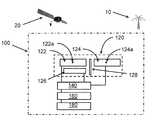
- FIG. 2is a block diagram illustrating an exemplary system for GPS anti-spoofing including boresight cancellation with omnidirectional antennas according to an embodiment of the subject matter described herein;
- FIG. 3is a block diagram illustrating exemplary modifying circuitry according to an embodiment of the subject matter described herein;
- FIG. 4is a block diagram illustrating an exemplary device for further enhanced GPS reception according to an embodiment of the subject matter described herein;
- FIG. 5is a block diagram illustrating exemplary modifying circuitry for further enhanced GPS reception according to another embodiment of the subject matter described herein;
- FIG. 6illustrates the design of an antenna set having a coplanar nesting arrangement and a common origin suitable for use in a system for enhanced GPS reception according to an embodiment of the subject matter described herein;
- FIG. 7is a flow chart illustrating an exemplary process for enhanced GPS reception according to an embodiment of the subject matter described herein.
- systems, methods, and computer readable mediaare provided for providing enhanced GPS reception by selectively cancelling spoofing, jamming and other types of interference (referred to collectively hereinafter as interference) at desirably received frequencies.
- a nullis frequency aligned with the interference and/or the transmission to mitigate interference and provide enhanced synchronization. It is described for canceling one or two sources of interference but the concepts described herein may be applied to cancel more than two sources of interference.
- Boresight interferenceis defined as interference propagating on a bearing that is more or less the same as a signal of interest, the latter represented herein by a GPS signal.
- a non-boresight bearingmay be any bearing that is substantially away from boresight, e.g. 5 or more degrees apart.
- the present disclosureis in terms of interfered signals, defined here as including GPS signal content and jamming and/or spoofing signal content but the concepts described herein may be applied to interfered signals comprising any type of interference.
- spoofingis define as a type of intentional interference It is in terms of a plurality of antenna signals, such as from a plurality of antennas, although it can also be practiced with one or more polarization signals from one antenna.
- Antenna signalsare characterized by differences in at least one of: amplitude, phase, delay, polarization, and bearing separation.
- interaction signalsare defined as those induced at an antenna face by interaction of an RF signal with the face of the antenna, and antenna signals are signals from an antenna due to induction of an interaction signal.
- Distortion filteringis defined as means of preventing with respect to at least one frequency the output of distortion induced by at least one distortion inducing type of circuitry element such as an active type. Distorting, such as by amplifying a signal to induce distortion is defined here as a type of signal modification.
- Devices and methods for phase-controlled in-band filtering that reduces amplitude of an undesirable signal with respect to at least one frequency of a desirably received signal as a means of providing enhanced reception of position, navigation and timing (“GPS”) signalscomprise at least one of: an antenna set, a feed-forward type signal modifying circuitry, a signal converter circuit, and a receiver circuit that can be of any type providing an enhanced GPS output.
- an antenna setincludes two omnidirectional antennas of any type that can receive GPS signals and an emitter type antenna of any type that can emit a signal that can induce interaction signals at the first antenna surface.
- An antenna setmay be any type that can provide an enhanced first antenna signal.
- Modifying circuitrymay be any type that can modify at least one antenna signal.
- Modifying circuitryincludes at least one of: a detector, an amplifier, a phase shifter, a delay element, a combiner, and a controller.
- Detectoris any type that can detect at least one of; amplitude, phase and delay.
- a converter circuitmay be any type that can convert an enhanced antenna signal for digital processing.
- a converterincludes at least one type of; signal conditioning, digital converting, mixing, down converting, direct sampling, demodulating and intermediate stage filtering.
- a receivermay be any type that can process an antenna signal to provide an enhanced GPS output.
- a receiverincludes any type of digital signal processor that can provide at least one of: decoding, decrypting, determining of at least one of: position, navigation and timing type signals, and output providing.
- One embodiment of the methodincludes phase shifting at least one amplitude modified signal according to a deterministic solution. In other embodiments, computationally less efficient solutions such as error minimization, synthetic annealing and steepest descent may be used.
- the methodincludes steps of phase shifting and electrical combining as means of at least partly cancelling interference in an arriving GPS signal to produce an enhanced antenna signal. In some cases, the method includes amplitude equalizing prior to phase shifting. Cancellation can be conducted by combining interaction signals at the surface of an antenna and/or combining antenna signals in circuitry. Cancellation can be provided for more than one source of interference.
- An enhanced signalis converted by a converter circuit and the converted signal is processed in a receiver circuit to provide enhanced GPS output of any type, e.g. signal, data, message or display.
- One acceptable antenna setincludes two adjacent coplanar patch antennas and an emitter antenna mounted immediately beneath a first patch antenna to provide an emitter signal created by modification of a signal from a second patch antenna, said emitter signal being modified so as to induce an interaction signal at the face of the first antenna which is amplitude equivalent to and anti-phase with respect to the interaction signal induced at the first antenna surface by interference.
- Modifying circuitrymay be any type that can provide at least one of: delaying, amplifying, phase shifting and combining. Antennas are characterized by at least one of: type, frequency range, bandwidth, gain pattern and/or polarization.
- a convertermay be any device that can convert a signal to digital form.
- a receivermay be any type that can provide a GPS output by processing converted signal.
- the antennaincludes a type of combiner.
- interference signal contentis highly correlated between antenna signals, as is GPS contents between antenna signals, while interference content and GPS content within a signal, being induced by separate sources are not correlated. This difference in correlation between and within signals is exploited here to selectively cancel interference content while retaining GPS content, yielding a GPS signal substantially free of interference content.
- the interference content in an interfered signalbeing stronger than GPS content, dominates measurements of an interfered signal, thereby affecting calculations and modifications based on such measurements.
- phase shifting of an interfered signal with respect to another to provide anti-phase alignmentprovides anti-phase alignment of interference contents but not of GPS contents.
- antenna combining of anti-phase interfered signalssubstantially cancels interference content but not GPS content, yielding a GPS signal having an enhanced signal to noise ratio (SNR).
- SNRsignal to noise ratio
- the subject matter described hereinprovides several benefits over conventional systems, including: the ability to cancel interference without requiring a difference in ratio of jamming to desired signals between antenna signals and without requiring temporal or spatial diversity; the ability to provide broadband cancellation instead of the narrow bandwidth resulting from the set-apart antenna configuration of receiving antennas used by conventional systems; the ability to operate in a flush mounted configuration suitable for mounting on vehicles that are desirably aerodynamic and/or free of elements that can be damaged or entangled during operation; and the ability to minimize cosite interaction of its antennas and of nearby antennas.
- FIG. 1is a graph of the performance of a system according to an embodiment of the subject matter described herein, illustrating a high degree of cancellation of boresight interference.
- FIG. 1illustrates data recorded during field testing of an embodiment of the present invention having two vertically mounted commercial omnidirectional type whip antennas separated by 0.25 lambda of the test center frequency, which antennas are used to receive signals from sources transmitting interference and desirably received signals at 700 MHz signals from a range of 10 m, which sources are separated by angles up to 90 degree apart, illustrating clearly a high degree of cancellation of boresight interference by an embodiment of the present invention.
- FIG. 2is a block diagram illustrating an exemplary system for GPS anti-spoofing including boresight cancellation with omnidirectional antennas according to an embodiment of the subject matter described herein.
- a device 100 disclosed herein to mitigate signals from an interfering source 10 as means of enhancing the signal to noise ratio (SNR) of GPS signals from one or more satellite 20includes at least one of: antenna set 120 , signal modifying circuitry 140 (hereinafter “modifier”), signal converter 160 and receiver 180 .
- Antenna set 120includes first antenna 122 , second antenna 124 and emitter antenna 126 , which antennas are of any type that can receive or emit an RF signal.
- First antenna 122has phase center 122 a with respect to at least one frequency and second antenna 124 includes phase center 124 a with respect to at least one frequency
- antenna set 120includes feedback or cosite interference preventer 128 of any type that can mitigate reception of signals from emitter 126 by second antenna 124 .
- Modifier 140may be any type that can modify, for at least one antenna signal, at least one of: amplitude, phase and group delay. Modifier 140 includes any type that can reduce distortion in at least one antenna signal according to the invention disclosed in PCT application serial number PCT/US11/49399, filed on Aug. 26, 2011, and U.S. Provisional Patent Application Ser. No. 61/546,784, filed Oct. 13, 2011, assigned to the assignee of the present invention, herein incorporated by reference in their entireties.
- Signal converter 160may be any type that can convert RF signals to digital form.
- Receiver 180may be any type that can process converted signal to provide a desirable output, such as signal, data, message or display.
- first antenna 122 and second antenna 124are coplanar and have proximately placed phase centers 122 a , 124 a , e.g. closely proximate for wide cancellation bandwidth or other placement for other cancellation bandwidth.
- emitter 126is mounted parallel to, directed at, and closely proximate first antenna 122 , although other locations, orientations and/or separations are also acceptable.
- first antenna 122 and second antenna 124are omnidirectional, although other direction types are acceptable. Emitter 126 is directional in direction of first antenna 122 although other direction types are acceptable.
- device 100includes shielding 128 or other means of mitigating interaction signal induction in second antenna signal or third antenna signal by signal transmitted by emitter 126 .
- FIG. 3is a block diagram illustrating exemplary modifying circuitry according to an embodiment of the subject matter described herein.
- modifier 140includes elements of any type that can provide at least one of: time delay, amplification and phase shift.
- modifier 140can include an amplifier 142 and a phase shifter 144 .
- Amplifier 142of any type that can increase or decrease amplitude of second antenna signal for amplitude equalization respect to first antenna signal amplitude.
- Amplifiermay be any type that can be controlled by a signal from a controller or exogenous source.
- Phase shifter 144may be any type that can provide a desirable phase shift of second antenna signal with respect to first antenna signal according to the method described below.
- Illustrative type of phase shifter 144includes, but is not limited to, controllable, fixed, continuously variable, selectable, of a combination thereof.
- Phase shiftermay be any type that can be controlled by a controller or exogenous control signal such as a bias voltage.
- Modifier 140includes a controller 1400 of any type that can determine and/or provide control signal providing desirable phase shift of at least one signal, e.g. to provide anti-phase alignment between antenna signals.
- Controller 1400includes at least one of: analog to digital converter, digital processor, digital to analog converter, exogenous signal source.
- Controller 1400includes a signal detector 1500 of any type that can determine at least one of: amplitude, phase and delay of one or more signal at one or more frequency, such as power detector or spectrum analyzer chip. In some cases, detector 1500 is configured to operate with respect to desirable center frequency and/or passband width.
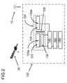
- FIG. 4is a block diagram illustrating an exemplary device for further enhanced GPS reception according to an embodiment of the subject matter described herein.
- device 100may be any type that can cancel interference from a first source 10 a and a second source 10 b , said device 100 comprising an antenna set 120 further comprising a first antenna 122 , second antenna 124 , emitter 126 , cosite blocker 128 and third antenna 130 , and modifier circuitry 140 of any type that can modify signal from second antenna 124 and modify signal from third antenna 130 .
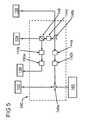
- FIG. 5is a block diagram illustrating exemplary modifying circuitry for further enhanced GPS reception according to another embodiment of the subject matter described herein.
- modifier 140may be any type that can modify signal from second antenna 124 to provide desirably modified signal to emitter 126 to be emitted in direction of first antenna 122 as means of creating an anti-phase interaction signal at surface of first antenna 122 that can at least partly cancel interference from a first source at the antenna surface and that can modify the signal from a third antenna 130 using a phase shifter 144 a and combine said modified third antenna signal with output signal from first antenna 122 using a combiner 146 a to further cancel interference from first source.
- Modifier 140can be modified by including a splitter ( 148 ) to split signal from second antenna 124 to provide two split signals, the first split signal being modified by a phase shifter 144 b and emitted by emitter 126 to provide interaction signals at surface of first antenna 122 to cancel interference from first source to provide a first output signal from first antenna 122 substantially free of interference from first source.
- Second split signalis modified by a phase shifter 144 c and combined with signal from third antenna 130 using a combiner 146 b to cancel interference from first source to provide a second output signal substantially free of interference from first source.
- Example phase shiftersinclude, but are not limited to, vector modulators.
- phase shifter( 144 a , 144 b , 144 c ) comprises variable amplifier type. Second output signal is combined with output signal from first antenna 122 using a combiner 146 a to provide a final output signal that is substantially free of interference from first source and substantially free of interference from said second source.
- modifier 140includes a delay element 150 a , 150 b of any type that can at least partly reduce difference in delay between third antenna signal and first antenna signal, e.g. due to circuitry elements used to modify second antenna signal.
- Delay element 150 a , 150 bmay be any type that can provide a difference in group delay between first antenna signal and at least one of second antenna signal and third antenna signal.
- FIG. 6illustrates the design of an antenna set having a coplanar nesting arrangement and a common origin suitable for use in a system for enhanced GPS reception according to an embodiment of the subject matter described herein.
- antenna set 120includes spiral type first antenna 122 and spiral type second antenna 124 , which antennas 122 , 124 comprise a coplanar nesting arrangement having a common origin 123 .
- First antenna 122 and second antenna 124have substantially the same shape, which shape provides for a lambda-constant separation of phase centers for at least one of a first frequency and a second frequency. Lambda-constant separation is defined here as phase separation comprising equal number of wavelengths, and/or part thereof, with respect to a plurality of resonant frequency of the antenna.
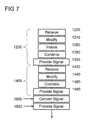
- FIG. 7is a flow chart illustrating an exemplary process for enhanced GPS reception according to an embodiment of the subject matter described herein.
- method 1000includes at least one of: interaction signal cancelling 1200 , antenna signal cancelling 1400 , antenna signal converting 1600 and converted signal processing 1800 .
- Interaction signal cancelling 1200includes; receiving first, and second antenna signals 1220 , modifying and transmitting second antenna signal 1240 , inducing anti-phase interaction signal 1260 , canceling interference content of interfered signal at first antenna face to provide an enhanced first antenna signal 1280 .
- Antenna signal cancelling 1400includes; receiving third antenna signal 1420 , modifying third antenna signal 1440 , combining modified third antenna signal with first antenna signal to further enhance first antenna signal 1460 .
- Converting 1600includes any means of converting first antenna signal for processing.
- Processing 1800includes digital processing of converted signal by any means to provide enhanced GPS output in at least one form of; signal, data, message and delay.
- Modifying 1240includes altering at least one of: amplitude and phase of second antenna signal and emitting the modified signal in the direction of first antenna to induce an interaction signal which is equal in amplitude and anti-phase with respect an interaction signal induced by an unmodified interfered signal at the surface of the first antenna.
- Phase shiftingis calculated by a method based on those disclosed in U.S. Provisional Patent Application Ser. No. 61/393,157, filed Oct. 14, 2010, and PCT Application Serial No. PCT/US11/49399, filed Aug. 26, 2011, that are assigned to the assignee of the present invention and herein incorporated by reference in their entireties, comprising using results of inducing a test phase shift of any degree, e.g. 90 degrees, into at least one antenna signal and using combined signal amplitude provided by said shift to calculate anti-phase shift providing selective cancellation of interference.
- a test phase shift of any degreee.g. 90 degrees
- Canceling at first antenna face 1260includes employing antenna as combiner of an interaction signal induced by signals from the emitter and interaction signal induced by interfered GPS signal.
- Third antenna signal modifying 1440includes at least one of: amplitude equalizing, delaying, and anti-phase shifting with respect to first antenna signal.
- Combining 1460includes using any type of circuit to combine first antenna signal and modified third antenna signal.
- Convertingincludes by any means including but not limited to; mixing, down converting, intermediate frequency filtering, demodulating, signal conditioning or digitizing.
- Processing 1800includes any means of determining desired GPS values, including but not limited to; dispreading, decoding, digital filtering, location and/or velocity calculating, time extracting, and forming display, although other forms of processing and outputting are also permitted.
- the systemdetermines which of the two values produced by equation (2) is the correct value, and applies that value. For example, the system may select each of the two values in turn, measure ⁇ for each value, and choose the phase shift value that resulted in the lowest ⁇ .
- the systemcould perform a second step of test phase shifting using a second test shift, e.g. 45 degrees, to resolve the ⁇ ambiguity in equation 2, for example by selecting the sum of test and calculated phase shifts that is reported by both the first test shift and the second test shift.
- modifyingfurther includes mitigating cosite interference by the emitter by any means of preventing induction of emitter content in output of second antenna, e.g. by shielding or by selecting gain pattern of second antenna and/or emitter.
- Cosite interference by the emittercan also be mitigated by combing a feed signal from the emitter with modified second antenna signal according to the systems and methods described herein.
- the methodincludes determining ⁇ from time to time and, when ⁇ has changed by a predetermined amount, updating at least one of: amplitude and phase shift of modified signal.
- the methodincludes determining calculated value of ⁇ is optimal by any means, e.g. steepest descent or statistical methods.
- An embodiment of the present inventioncan be operated in any manner.
- at least one portion of the devicecan be operated more or less continuously as directed by external input.
- Modifying circuitry operationcan be initiated when interference is detected, e.g. by the receiver portion of the device. Operation of modifying circuitry can be continuous without regard to presence of interference, e.g. as means of defeating spoofing type interference that can suborn navigation of a vehicle before such spoofing can be detected by current generation anti-spoofing technology.
- one use of the disclosed technologyis to defeat intentional or inadvertent interference that can degrade reception by cell towers of GPS signals which are used to synchronize communications across the system.
Landscapes
- Engineering & Computer Science (AREA)
- Radar, Positioning & Navigation (AREA)
- Remote Sensing (AREA)
- Computer Networks & Wireless Communication (AREA)
- Physics & Mathematics (AREA)
- General Physics & Mathematics (AREA)
- Position Fixing By Use Of Radio Waves (AREA)
- Noise Elimination (AREA)
Abstract
Description
α(ωt+φ1)+α(ωt+φ2+δφ)=β(ωt) (1)
δφ=nπ±2 arccos(β/2α) (2)
The system then determines which of the two values produced by equation (2) is the correct value, and applies that value. For example, the system may select each of the two values in turn, measure β for each value, and choose the phase shift value that resulted in the lowest β. Alternatively, the system could perform a second step of test phase shifting using a second test shift, e.g. 45 degrees, to resolve the ± ambiguity in equation 2, for example by selecting the sum of test and calculated phase shifts that is reported by both the first test shift and the second test shift.
Claims (39)
Priority Applications (1)
| Application Number | Priority Date | Filing Date | Title |
|---|---|---|---|
| US13/781,226US9519062B2 (en) | 2012-02-28 | 2013-02-28 | Methods, systems, and computer readable media for mitigation of in-band interference of global positioning system (GPS) signals |
Applications Claiming Priority (2)
| Application Number | Priority Date | Filing Date | Title |
|---|---|---|---|
| US201261604480P | 2012-02-28 | 2012-02-28 | |
| US13/781,226US9519062B2 (en) | 2012-02-28 | 2013-02-28 | Methods, systems, and computer readable media for mitigation of in-band interference of global positioning system (GPS) signals |
Publications (2)
| Publication Number | Publication Date |
|---|---|
| US20140152499A1 US20140152499A1 (en) | 2014-06-05 |
| US9519062B2true US9519062B2 (en) | 2016-12-13 |
Family
ID=49083287
Family Applications (1)
| Application Number | Title | Priority Date | Filing Date |
|---|---|---|---|
| US13/781,226Active2034-10-02US9519062B2 (en) | 2012-02-28 | 2013-02-28 | Methods, systems, and computer readable media for mitigation of in-band interference of global positioning system (GPS) signals |
Country Status (4)
| Country | Link |
|---|---|
| US (1) | US9519062B2 (en) |
| EP (1) | EP2820447A4 (en) |
| CN (1) | CN104136936A (en) |
| WO (1) | WO2013130818A1 (en) |
Cited By (4)
| Publication number | Priority date | Publication date | Assignee | Title |
|---|---|---|---|---|
| US9735758B2 (en) | 2010-08-30 | 2017-08-15 | Physical Devices, Llc | Tunable filter devices and methods |
| US9866267B2 (en) | 2014-02-21 | 2018-01-09 | Physical Devices, Llc | Devices and methods for diversity signal enhancement and cosite cancellation |
| US11675087B2 (en) | 2020-01-13 | 2023-06-13 | Archaius Llc | Magnetic velocity and position sensors |
| US12339392B2 (en) | 2023-02-23 | 2025-06-24 | Archaius Inc. | Devices, systems, and methods for cancellation bandwidth-adjustable nulling of interference |
Families Citing this family (16)
| Publication number | Priority date | Publication date | Assignee | Title |
|---|---|---|---|---|
| US9806790B2 (en) | 2010-03-29 | 2017-10-31 | Odyssey Wireless, Inc. | Systems/methods of spectrally efficient communications |
| US8666347B2 (en) | 2010-10-14 | 2014-03-04 | Physical Devices, Llc | Methods and devices for reducing radio frequency interference |
| US9042857B2 (en) | 2010-08-30 | 2015-05-26 | Physical Devices, Llc | Methods, systems, and non-transitory computer readable media for wideband frequency and bandwidth tunable filtering |
| US9519062B2 (en) | 2012-02-28 | 2016-12-13 | Physical Devices, Llc | Methods, systems, and computer readable media for mitigation of in-band interference of global positioning system (GPS) signals |
| US20140125520A1 (en)* | 2012-06-22 | 2014-05-08 | Patrick C. Fenton | Anti-jamming subsystem employing an antenna with a horizontal reception pattern |
| US10295675B2 (en) | 2013-07-26 | 2019-05-21 | Arbiter Systems, Incorporated | Cryptographically-secure autonomous detection of spoofed GNSS signals |
| JP6459014B2 (en) | 2015-03-31 | 2019-01-30 | エスゼット ディージェイアイ テクノロジー カンパニー リミテッドSz Dji Technology Co.,Ltd | Geo-fencing device |
| CN107409051B (en) | 2015-03-31 | 2021-02-26 | 深圳市大疆创新科技有限公司 | Authentication system and method for generating flight controls |
| WO2016154945A1 (en)* | 2015-03-31 | 2016-10-06 | SZ DJI Technology Co., Ltd. | Authentication systems and methods for detecting unauthorized uav activity |
| JP6598533B2 (en)* | 2015-06-30 | 2019-10-30 | ブリヂストンスポーツ株式会社 | Golf ball with built-in IC chip |
| SG10202001396XA (en) | 2015-08-28 | 2020-04-29 | Dow Global Technologies Llc | Chromatography of polymers with reduced co-crystallization |
| US9912467B2 (en)* | 2015-09-22 | 2018-03-06 | Qualcomm Incorporated | Full duplex technique |
| CN106990393B (en)* | 2017-05-19 | 2019-10-18 | 北京航空航天大学 | A navigation receiver anti-jamming system based on blind beamforming |
| JP7287128B2 (en)* | 2019-06-07 | 2023-06-06 | 三菱電機株式会社 | POSITIONING DEVICE, POSITIONING METHOD AND POSITIONING SYSTEM |
| US11698461B1 (en) | 2019-11-20 | 2023-07-11 | Telephonics Corp. | GPS denial detection and reporting and mitigation |
| CN112904377A (en)* | 2021-01-18 | 2021-06-04 | 中国商用飞机有限责任公司北京民用飞机技术研究中心 | Beidou short message anti-interference method and device, computer equipment and storage medium |
Citations (65)
| Publication number | Priority date | Publication date | Assignee | Title |
|---|---|---|---|---|
| US3946337A (en) | 1975-04-25 | 1976-03-23 | The Bendix Corporation | Phase modulator for phase shift key communications systems |
| US4085368A (en) | 1976-08-30 | 1978-04-18 | Bell Telephone Laboratories, Incorporated | Interference canceling method and apparatus |
| US4313116A (en) | 1980-01-30 | 1982-01-26 | Westinghouse Electric Corp. | Hybrid adaptive sidelobe canceling system |
| US5179727A (en) | 1989-02-16 | 1993-01-12 | Kabushiki Kaisha Toshiba | Automatic adjusting circuit for an analog filter |
| US5252930A (en) | 1989-09-07 | 1993-10-12 | Ortel Corporation | Predistorter for linearization of electronic and optical signals |
| US5285479A (en) | 1991-01-11 | 1994-02-08 | Mitsubishi Denki Kabushiki Kaisha | Quadrature modulation circuit |
| US5386198A (en) | 1993-01-28 | 1995-01-31 | Telefonaktiebolaget L M Ericsson | Linear amplifier control |
| US5412735A (en) | 1992-02-27 | 1995-05-02 | Central Institute For The Deaf | Adaptive noise reduction circuit for a sound reproduction system |
| US5442582A (en) | 1994-03-04 | 1995-08-15 | Loral Aerospace Corp. | Transversal filter allrate equalizer for use at intermediate frequency |
| US5712641A (en) | 1996-02-28 | 1998-01-27 | Electro-Radiation Incorporated | Interference cancellation system for global positioning satellite receivers |
| US5736909A (en) | 1996-02-02 | 1998-04-07 | Philips Electronics North America Corporation | Monolithic continuous-time analog filters |
| US5783977A (en) | 1996-02-07 | 1998-07-21 | Loral Aerospace Corporation | Tunable and bandwidth programmable multi-element filter system |
| US5872540A (en)* | 1997-06-26 | 1999-02-16 | Electro-Radiation Incorporated | Digital interference suppression system for radio frequency interference cancellation |
| US6154641A (en) | 1998-10-27 | 2000-11-28 | Lucent Technologies Inc. | Wideband multiple channel frequency converter |
| US6172970B1 (en) | 1997-05-05 | 2001-01-09 | The Hong Kong University Of Science And Technology | Low-complexity antenna diversity receiver |
| US6175327B1 (en) | 1999-01-16 | 2001-01-16 | Sensors Systems, Inc. | GPS receivers with adaptive antenna systems for suppressing interference signals |
| US6201955B1 (en) | 1998-05-29 | 2001-03-13 | Motorola, Inc. | Method and apparatus for receiving a radio frequency signal using a plurality of antennas |
| US6236315B1 (en)* | 1999-10-19 | 2001-05-22 | Lucent Technologies Inc. | Method and apparatus for improving the interrogation range of an RF tag |
| US6314127B1 (en) | 1999-02-23 | 2001-11-06 | Lucent Technologies Inc. | System and method for enhancing signal reception |
| US6323806B1 (en)* | 1997-11-19 | 2001-11-27 | Airsys Navigation Systems Gmbh | Antenna system and method for operating an antenna system |
| US6359503B1 (en) | 1995-02-22 | 2002-03-19 | Sgs-Thomson Microelectronics, S.R.L. | Basic cell for programmable analog time-continuous filter |
| US6363263B1 (en) | 1997-07-15 | 2002-03-26 | Metawave Communications Corporation | Universal wideband switchless channel selector |
| US6385435B1 (en) | 2000-04-20 | 2002-05-07 | Jhong Sam Lee | Coupled interference concellation system for wideband repeaters in a cellular system |
| US20020122406A1 (en) | 2000-12-28 | 2002-09-05 | Gopal Chillariga | Fast macrodiversity switching with time management in wireless networks |
| US20020125947A1 (en) | 2001-03-09 | 2002-09-12 | Qiming Ren | Linearizer for a power amplifier |
| US6486828B1 (en) | 2000-07-26 | 2002-11-26 | Western Multiplex | Adaptive array antenna nulling |
| US6590528B1 (en) | 2001-12-05 | 2003-07-08 | Rockwell Collins, Inc. | Low cost interference reduction system for GPS receivers |
| US20030130751A1 (en) | 2002-01-09 | 2003-07-10 | Freesystems Pte.,Ltd. | New filter bank for graphics equalizer implementation |
| US6639541B1 (en) | 2000-08-29 | 2003-10-28 | The United States Of America As Represented By The Secretary Of The Navy | Device and method for detecting, measuring, and reporting low-level interference at a receiver |
| US6710739B1 (en) | 2003-01-03 | 2004-03-23 | Northrop Grumman Corporation | Dual redundant GPS anti-jam air vehicle navigation system architecture and method |
| US20040185815A1 (en) | 2003-01-31 | 2004-09-23 | Ntt Docomo, Inc. | Radio communication terminal |
| US6847803B1 (en) | 1999-02-26 | 2005-01-25 | Nokia Mobile Phones Ltd. | Method for reducing interference in a receiver |
| US6961577B2 (en) | 2001-05-25 | 2005-11-01 | Ntt Docomo, Inc. | Radio communication system for reducing interferences with respect to other communication system using close frequency band |
| US7139592B2 (en) | 1999-06-21 | 2006-11-21 | Arraycomm Llc | Null deepening for an adaptive antenna based communication station |
| US20060262880A1 (en) | 2005-05-18 | 2006-11-23 | Ntt Docomo, Inc. | Power series predistorter and control method thereof |
| US20070066226A1 (en) | 2005-09-21 | 2007-03-22 | Samsung Electronics Co., Ltd. | Apparatus and method for interference cancellation in wireless mobile stations operating concurrently on two or more air interfaces |
| US20080136473A1 (en) | 2006-11-09 | 2008-06-12 | Jan Bollenbeck | Filter circuit arrangement |
| US20080211715A1 (en)* | 2006-08-17 | 2008-09-04 | Technology Focus Llc | Global positioning system using broadband noise reduction |
| US20100022197A1 (en) | 2006-09-11 | 2010-01-28 | Akira Kato | Wireless communication apparatus for simultaneously performing multiple wireless communications |
| US20100048156A1 (en)* | 2008-08-21 | 2010-02-25 | Intersil Americas Inc. | Noise cancellation for antenna module |
| US20100136941A1 (en) | 2008-12-03 | 2010-06-03 | Lackey Raymond J | Quadratic amplitude control circuit for cosite interference cancellation |
| US20100136925A1 (en) | 2008-12-03 | 2010-06-03 | Lackey Raymond J | Tuning amplitude slope matched filter architecture |
| US20100178874A1 (en) | 2009-01-13 | 2010-07-15 | Hsien-Chyi Chiou | Method for performing active jammer suppression on electronic device, and associated apparatus |
| US20100244943A1 (en) | 2009-03-27 | 2010-09-30 | Quellan, Inc. | Filter shaping using a signal cancellation function |
| US20110019722A1 (en) | 2009-07-27 | 2011-01-27 | Amir Amirkhany | Per-Tone Delay Adjustment for Multi-Tone Systems |
| US7904047B2 (en) | 2007-10-31 | 2011-03-08 | Broadcom Corporation | Radio frequency filtering technique with auto calibrated stop-band rejection |
| US20110227665A1 (en) | 2008-12-01 | 2011-09-22 | Nortel Networks Limited | Frequency Agile Filter Using a Digital Filter and Bandstop Filtering |
| US8064837B2 (en) | 2005-06-16 | 2011-11-22 | Qualcomm Incorporated | Method and apparatus for optimum selection of MIMO and interference cancellation |
| US20110300813A1 (en) | 2010-06-03 | 2011-12-08 | Broadcom Corporation | Multiple-phase frequency translated filter |
| US8078100B2 (en) | 2002-10-15 | 2011-12-13 | Qualcomm Incorporated | Physical layer repeater with discrete time filter for all-digital detection and delay generation |
| US8090339B1 (en) | 2008-12-03 | 2012-01-03 | Bae Systems Information And Electronic Systems Integration Inc. | Off-line channel tuning amplitude slope matched filter architecture |
| US20120025929A1 (en) | 2009-04-27 | 2012-02-02 | Max Ward Muterspaugh | Filter with improved impedance match to a hybrid coupler |
| WO2012030658A2 (en) | 2010-08-30 | 2012-03-08 | Physical Devices Llc | Tunable filter devices and methods |
| US20120201153A1 (en) | 2011-02-03 | 2012-08-09 | Dinesh Bharadia | Adaptive techniques for full duplex communications |
| US20120252392A1 (en) | 2010-10-14 | 2012-10-04 | Jonathan Ryan Wilkerson | Methods and Devices for Reducing Radio Frequency Interference |
| US8351889B2 (en) | 2006-12-22 | 2013-01-08 | Research In Motion Limited | Frequency agile duplex filter |
| US8355676B2 (en) | 2009-11-17 | 2013-01-15 | Franklin Technologies, Llc | System and method for reducing radio frequency interference |
| WO2013058270A1 (en) | 2011-10-20 | 2013-04-25 | ウィンテックポリマー株式会社 | Polybutylene terephthalate resin composition |
| US20130225099A1 (en) | 2010-08-30 | 2013-08-29 | Physical Devices, Llc | Methods, systems, and non-transitory computer readable media for wideband frequency and bandwidth tunable filtering |
| WO2013130818A1 (en) | 2012-02-28 | 2013-09-06 | Physical Devices Llc | Methods, systems, and computer readable media for mitigation of in-band interference of global positioning system (gps) signals |
| US8682275B2 (en) | 2000-10-11 | 2014-03-25 | Silicon Laboratories Inc. | Apparatus and methods for reducing interference in radio-frequency apparatus |
| US20140185723A1 (en) | 2012-12-27 | 2014-07-03 | Intel Mobile Communication GmbH | Signal Delay Estimator with Absolute Delay Amount and Direction Estimation |
| WO2014113613A1 (en) | 2013-01-18 | 2014-07-24 | Physical Devices, Llc | Methods, systems and non-transitory computer readable media for wideband frequency and bandwidth tunable filtering |
| US20150244431A1 (en) | 2014-02-21 | 2015-08-27 | Physical Devices, Llc | Devices and methods for diversity signal enhancement and cosite cancellation |
| US9219508B1 (en) | 2013-08-06 | 2015-12-22 | The Boeing Company | Interference mitigation for a communications system |
- 2013
- 2013-02-28USUS13/781,226patent/US9519062B2/enactiveActive
- 2013-02-28EPEP13754265.0Apatent/EP2820447A4/ennot_activeWithdrawn
- 2013-02-28CNCN201380011393.XApatent/CN104136936A/enactivePending
- 2013-02-28WOPCT/US2013/028338patent/WO2013130818A1/enactiveApplication Filing
Patent Citations (79)
| Publication number | Priority date | Publication date | Assignee | Title |
|---|---|---|---|---|
| US3946337A (en) | 1975-04-25 | 1976-03-23 | The Bendix Corporation | Phase modulator for phase shift key communications systems |
| US4085368A (en) | 1976-08-30 | 1978-04-18 | Bell Telephone Laboratories, Incorporated | Interference canceling method and apparatus |
| US4313116A (en) | 1980-01-30 | 1982-01-26 | Westinghouse Electric Corp. | Hybrid adaptive sidelobe canceling system |
| US5179727A (en) | 1989-02-16 | 1993-01-12 | Kabushiki Kaisha Toshiba | Automatic adjusting circuit for an analog filter |
| US5252930A (en) | 1989-09-07 | 1993-10-12 | Ortel Corporation | Predistorter for linearization of electronic and optical signals |
| US5285479A (en) | 1991-01-11 | 1994-02-08 | Mitsubishi Denki Kabushiki Kaisha | Quadrature modulation circuit |
| US5412735A (en) | 1992-02-27 | 1995-05-02 | Central Institute For The Deaf | Adaptive noise reduction circuit for a sound reproduction system |
| US5386198A (en) | 1993-01-28 | 1995-01-31 | Telefonaktiebolaget L M Ericsson | Linear amplifier control |
| US5442582A (en) | 1994-03-04 | 1995-08-15 | Loral Aerospace Corp. | Transversal filter allrate equalizer for use at intermediate frequency |
| US6359503B1 (en) | 1995-02-22 | 2002-03-19 | Sgs-Thomson Microelectronics, S.R.L. | Basic cell for programmable analog time-continuous filter |
| US5736909A (en) | 1996-02-02 | 1998-04-07 | Philips Electronics North America Corporation | Monolithic continuous-time analog filters |
| US5783977A (en) | 1996-02-07 | 1998-07-21 | Loral Aerospace Corporation | Tunable and bandwidth programmable multi-element filter system |
| US5712641A (en) | 1996-02-28 | 1998-01-27 | Electro-Radiation Incorporated | Interference cancellation system for global positioning satellite receivers |
| US6172970B1 (en) | 1997-05-05 | 2001-01-09 | The Hong Kong University Of Science And Technology | Low-complexity antenna diversity receiver |
| US5872540A (en)* | 1997-06-26 | 1999-02-16 | Electro-Radiation Incorporated | Digital interference suppression system for radio frequency interference cancellation |
| US6363263B1 (en) | 1997-07-15 | 2002-03-26 | Metawave Communications Corporation | Universal wideband switchless channel selector |
| US6323806B1 (en)* | 1997-11-19 | 2001-11-27 | Airsys Navigation Systems Gmbh | Antenna system and method for operating an antenna system |
| US6201955B1 (en) | 1998-05-29 | 2001-03-13 | Motorola, Inc. | Method and apparatus for receiving a radio frequency signal using a plurality of antennas |
| US6154641A (en) | 1998-10-27 | 2000-11-28 | Lucent Technologies Inc. | Wideband multiple channel frequency converter |
| US6175327B1 (en) | 1999-01-16 | 2001-01-16 | Sensors Systems, Inc. | GPS receivers with adaptive antenna systems for suppressing interference signals |
| US6314127B1 (en) | 1999-02-23 | 2001-11-06 | Lucent Technologies Inc. | System and method for enhancing signal reception |
| US6847803B1 (en) | 1999-02-26 | 2005-01-25 | Nokia Mobile Phones Ltd. | Method for reducing interference in a receiver |
| US7139592B2 (en) | 1999-06-21 | 2006-11-21 | Arraycomm Llc | Null deepening for an adaptive antenna based communication station |
| US6236315B1 (en)* | 1999-10-19 | 2001-05-22 | Lucent Technologies Inc. | Method and apparatus for improving the interrogation range of an RF tag |
| US6385435B1 (en) | 2000-04-20 | 2002-05-07 | Jhong Sam Lee | Coupled interference concellation system for wideband repeaters in a cellular system |
| US6486828B1 (en) | 2000-07-26 | 2002-11-26 | Western Multiplex | Adaptive array antenna nulling |
| US6639541B1 (en) | 2000-08-29 | 2003-10-28 | The United States Of America As Represented By The Secretary Of The Navy | Device and method for detecting, measuring, and reporting low-level interference at a receiver |
| US8682275B2 (en) | 2000-10-11 | 2014-03-25 | Silicon Laboratories Inc. | Apparatus and methods for reducing interference in radio-frequency apparatus |
| US20020122406A1 (en) | 2000-12-28 | 2002-09-05 | Gopal Chillariga | Fast macrodiversity switching with time management in wireless networks |
| US20020125947A1 (en) | 2001-03-09 | 2002-09-12 | Qiming Ren | Linearizer for a power amplifier |
| US6961577B2 (en) | 2001-05-25 | 2005-11-01 | Ntt Docomo, Inc. | Radio communication system for reducing interferences with respect to other communication system using close frequency band |
| US6590528B1 (en) | 2001-12-05 | 2003-07-08 | Rockwell Collins, Inc. | Low cost interference reduction system for GPS receivers |
| US20030130751A1 (en) | 2002-01-09 | 2003-07-10 | Freesystems Pte.,Ltd. | New filter bank for graphics equalizer implementation |
| US8078100B2 (en) | 2002-10-15 | 2011-12-13 | Qualcomm Incorporated | Physical layer repeater with discrete time filter for all-digital detection and delay generation |
| US6710739B1 (en) | 2003-01-03 | 2004-03-23 | Northrop Grumman Corporation | Dual redundant GPS anti-jam air vehicle navigation system architecture and method |
| US20040185815A1 (en) | 2003-01-31 | 2004-09-23 | Ntt Docomo, Inc. | Radio communication terminal |
| EP1727277A1 (en) | 2005-05-18 | 2006-11-29 | NTT DoCoMo INC. | Power series predistorter and control method thereof |
| US20060262880A1 (en) | 2005-05-18 | 2006-11-23 | Ntt Docomo, Inc. | Power series predistorter and control method thereof |
| US8064837B2 (en) | 2005-06-16 | 2011-11-22 | Qualcomm Incorporated | Method and apparatus for optimum selection of MIMO and interference cancellation |
| US20070066226A1 (en) | 2005-09-21 | 2007-03-22 | Samsung Electronics Co., Ltd. | Apparatus and method for interference cancellation in wireless mobile stations operating concurrently on two or more air interfaces |
| US20080211715A1 (en)* | 2006-08-17 | 2008-09-04 | Technology Focus Llc | Global positioning system using broadband noise reduction |
| US20100022197A1 (en) | 2006-09-11 | 2010-01-28 | Akira Kato | Wireless communication apparatus for simultaneously performing multiple wireless communications |
| US20080136473A1 (en) | 2006-11-09 | 2008-06-12 | Jan Bollenbeck | Filter circuit arrangement |
| US8351889B2 (en) | 2006-12-22 | 2013-01-08 | Research In Motion Limited | Frequency agile duplex filter |
| US7904047B2 (en) | 2007-10-31 | 2011-03-08 | Broadcom Corporation | Radio frequency filtering technique with auto calibrated stop-band rejection |
| US20100048156A1 (en)* | 2008-08-21 | 2010-02-25 | Intersil Americas Inc. | Noise cancellation for antenna module |
| US20110227665A1 (en) | 2008-12-01 | 2011-09-22 | Nortel Networks Limited | Frequency Agile Filter Using a Digital Filter and Bandstop Filtering |
| US8090339B1 (en) | 2008-12-03 | 2012-01-03 | Bae Systems Information And Electronic Systems Integration Inc. | Off-line channel tuning amplitude slope matched filter architecture |
| US8032103B2 (en) | 2008-12-03 | 2011-10-04 | Bae Systems Information And Electronic Systems Integration Inc. | Tuning amplitude slope matched filter architecture |
| US20100136941A1 (en) | 2008-12-03 | 2010-06-03 | Lackey Raymond J | Quadratic amplitude control circuit for cosite interference cancellation |
| US20100136925A1 (en) | 2008-12-03 | 2010-06-03 | Lackey Raymond J | Tuning amplitude slope matched filter architecture |
| US8086206B1 (en) | 2008-12-03 | 2011-12-27 | Bae Systems Information And Electronic Systems Integration Inc. | Quadratic amplitude control circuit for cosite interference cancellation |
| US8090338B1 (en) | 2008-12-03 | 2012-01-03 | Bae Systems Information And Electronic Systems Integration Inc. | Quadratic amplitude control circuit for cosite interference cancellation |
| US20100178874A1 (en) | 2009-01-13 | 2010-07-15 | Hsien-Chyi Chiou | Method for performing active jammer suppression on electronic device, and associated apparatus |
| US8380771B2 (en) | 2009-03-27 | 2013-02-19 | Quellan, Inc. | Filter shaping using a signal cancellation function |
| US20100244943A1 (en) | 2009-03-27 | 2010-09-30 | Quellan, Inc. | Filter shaping using a signal cancellation function |
| US20120025929A1 (en) | 2009-04-27 | 2012-02-02 | Max Ward Muterspaugh | Filter with improved impedance match to a hybrid coupler |
| US20110019722A1 (en) | 2009-07-27 | 2011-01-27 | Amir Amirkhany | Per-Tone Delay Adjustment for Multi-Tone Systems |
| US8355676B2 (en) | 2009-11-17 | 2013-01-15 | Franklin Technologies, Llc | System and method for reducing radio frequency interference |
| US20110300813A1 (en) | 2010-06-03 | 2011-12-08 | Broadcom Corporation | Multiple-phase frequency translated filter |
| US9042857B2 (en) | 2010-08-30 | 2015-05-26 | Physical Devices, Llc | Methods, systems, and non-transitory computer readable media for wideband frequency and bandwidth tunable filtering |
| WO2012030658A2 (en) | 2010-08-30 | 2012-03-08 | Physical Devices Llc | Tunable filter devices and methods |
| US9203461B2 (en) | 2010-08-30 | 2015-12-01 | Physical Devices, Llc | Methods, systems, and non-transitory computer readable media for wideband frequency and bandwidth tunable filtering |
| US20140199956A1 (en) | 2010-08-30 | 2014-07-17 | Physical Devices, Llc | Tunable filter devices and methods |
| US20130225099A1 (en) | 2010-08-30 | 2013-08-29 | Physical Devices, Llc | Methods, systems, and non-transitory computer readable media for wideband frequency and bandwidth tunable filtering |
| US20150288413A1 (en) | 2010-08-30 | 2015-10-08 | Physical Devices, Llc | Methods, systems, and non-transitory computer readable media for wideband frequency and bandwidth tunable filtering |
| US9350401B2 (en) | 2010-08-30 | 2016-05-24 | Physical Devices, Llc | Tunable filter devices and methods |
| US20160087659A1 (en) | 2010-08-30 | 2016-03-24 | Physical Devices, Llc | Methods, systems, and non-transitory computer readable media for wideband frequency and bandwidth tunable filtering |
| US8965319B2 (en) | 2010-10-14 | 2015-02-24 | Physical Devices, Llc | Methods and devices for reducing radio frequency interference |
| US20120252392A1 (en) | 2010-10-14 | 2012-10-04 | Jonathan Ryan Wilkerson | Methods and Devices for Reducing Radio Frequency Interference |
| US8666347B2 (en) | 2010-10-14 | 2014-03-04 | Physical Devices, Llc | Methods and devices for reducing radio frequency interference |
| US20120201173A1 (en) | 2011-02-03 | 2012-08-09 | Mayank Jain | Single channel full duplex wireless communications |
| US20120201153A1 (en) | 2011-02-03 | 2012-08-09 | Dinesh Bharadia | Adaptive techniques for full duplex communications |
| WO2013058270A1 (en) | 2011-10-20 | 2013-04-25 | ウィンテックポリマー株式会社 | Polybutylene terephthalate resin composition |
| WO2013130818A1 (en) | 2012-02-28 | 2013-09-06 | Physical Devices Llc | Methods, systems, and computer readable media for mitigation of in-band interference of global positioning system (gps) signals |
| US20140185723A1 (en) | 2012-12-27 | 2014-07-03 | Intel Mobile Communication GmbH | Signal Delay Estimator with Absolute Delay Amount and Direction Estimation |
| WO2014113613A1 (en) | 2013-01-18 | 2014-07-24 | Physical Devices, Llc | Methods, systems and non-transitory computer readable media for wideband frequency and bandwidth tunable filtering |
| US9219508B1 (en) | 2013-08-06 | 2015-12-22 | The Boeing Company | Interference mitigation for a communications system |
| US20150244431A1 (en) | 2014-02-21 | 2015-08-27 | Physical Devices, Llc | Devices and methods for diversity signal enhancement and cosite cancellation |
Non-Patent Citations (37)
| Title |
|---|
| Bharadia et al., "Full Duplex Radios," pp. 1-12 (Aug. 12, 2013). |
| Choi et al., "Achieving Single Channel, Full Duplex Wireless Communication," pp. 1-12 (Sep. 20, 2010). |
| Commonly assigned, co-pending U.S. continuation-in-part U.S. Appl. No. 13/745,729 titled "Methods, Systems, and Non-Transitory Computer Readable Media for Wideband Frequency and Bandwidth Tunable Filtering," (unpublished, filed Jan. 18, 2013). |
| Commonly-assigned, co-pending U.S. Appl. No. 14/629,326 for "Devices and Methods for Diversity Signal Enhancement and Cosite Cancellation," (Unpublished, filed Feb. 23, 2015). |
| Commonly-assigned, co-pending U.S. Appl. No. 15/149,030 for "Tunable Filter Devices and Methods," (Unpublished, filed May 6, 2016). |
| Communication of European publication number and information on the application of Article 67(3) EPC for European Application No. 14740838.9 (Oct. 28, 2015). |
| Communication of European Publication Number and Information on the Application of Article 67(3) EPC for European Patent Application No. 11822404.7 (Jun. 12, 2013). |
| Communication of European Publication Number and Information on the Application of Article 67(3) EPC for European Patent Application No. 12839313.9 (Jul. 23, 2014). |
| Communication of European Publication Number and Information on the Application of Article 67(3) EPC for European Patent Application No. 13754265.0 (Dec. 10, 2014). |
| Communication pursuant to Rule 164(1) EPC for European Patent Application No. 12839313.9 (Jun. 2, 2015). |
| Extended European Search Report for European Application No. 11822404.7 (Jan. 17, 2014). |
| Extended European Search Report for European Patent Application No. 12839313.9 (Sep. 24, 2015). |
| Extended European Search Report for European Patent Application No. 13754265.0 (Oct. 14, 2015). |
| Final Office Action for U.S. Appl. No. 13/820,064 (Sep. 9, 2015). |
| First Office Action for Chinese Patent Application No. 201180051482.8 (Oct. 29, 2014). |
| International Search Report for International Patent Application No. PCT/US2011/049399 (Mar. 2, 2012). |
| Jain et al., "Practical, Real-time, Full Duplex Wireless," pp. 1-12 (Sep. 19, 2011). |
| Non-Final Action for U.S. Appl. No. 13/271,420 (Feb. 6, 2013). |
| Non-Final Office Action for U.S. Appl. No. 13/820,064 (Feb. 18, 2015). |
| Non-Final Office Action for U.S. Appl. No. 14/194,924 (Jun. 13, 2014). |
| Non-Final Office Action for U.S. Appl. No. 14/629,326 (Jan. 22, 2016). |
| Non-Final Office Action for U.S. Appl. No. 14/927,374 (Jan. 25, 2016). |
| Notice of Allowance and Fee(s) Due for U.S. Appl. No. 13/271,420 (Jun. 25, 2013). |
| Notice of Allowance and Fee(s) Due for U.S. Appl. No. 13/271,420 (Oct. 15, 2013). |
| Notice of Allowance and Fee(s) Due for U.S. Appl. No. 13/745,729 (Jan. 22, 2015). |
| Notice of Allowance and Fee(s) Due for U.S. Appl. No. 13/820,064 (Jan. 22, 2016). |
| Notice of Allowance and Fee(s) Due for U.S. Appl. No. 14/194,924 (Oct. 17, 2014). |
| Notice of Allowance and Fee(s) Due for U.S. Appl. No. 14/719,302 (Jul. 31, 2015). |
| Notice of Allowance and Fee(s) Due for U.S. Appl. No. 14/927,374 (May 23, 2016). |
| Notification of Transmittal of the International Search Report and the Written Opinion of the International Searching Authority, or the Declaration for PCT International Patent Application No. PCT/US2012/066259 (Mar. 28, 2013). |
| Notification of Transmittal of the International Search Report and the Written Opinion of the International Searching Authority, or the Declaration for PCT International Patent Application No. PCT/US2013/028338 (Jul. 25, 2013). |
| Notification of Transmittal of the International Search Report and the Written Opinion of the International Searching Authority, or the Declaration for PCT International Patent Application No. PCT/US2014/011941 (Apr. 29, 2014). |
| Restriction and/or Election Requirement for U.S. Appl. No. 14/629,326 (Sep. 23, 2015). |
| Restriction/Election Requirement for U.S. Appl. No. 13/745,729 (Nov. 12, 2014). |
| U.S. Appl. No. 61/462,493 for "Single Channel Full-Duplex Wireless Communication," (Feb. 3, 2011). |
| U.S. Appl. No. 61/485,980 for "Adaptive Techniques for Full-Duplex Wireless," (May 13, 2011). |
| Widrow et al., "Adaptive Inverse Control," Proceedings of the 1993 International Symposium on Intelligent Control, pp. 1-6 (Aug. 1993). |
Cited By (6)
| Publication number | Priority date | Publication date | Assignee | Title |
|---|---|---|---|---|
| US9735758B2 (en) | 2010-08-30 | 2017-08-15 | Physical Devices, Llc | Tunable filter devices and methods |
| US9866267B2 (en) | 2014-02-21 | 2018-01-09 | Physical Devices, Llc | Devices and methods for diversity signal enhancement and cosite cancellation |
| US11675087B2 (en) | 2020-01-13 | 2023-06-13 | Archaius Llc | Magnetic velocity and position sensors |
| US11921224B2 (en) | 2020-01-13 | 2024-03-05 | Archaius Inc. | Magnetic velocity and position sensors |
| US12287411B2 (en) | 2020-01-13 | 2025-04-29 | Archaius Inc. | Magnetic velocity and position sensors |
| US12339392B2 (en) | 2023-02-23 | 2025-06-24 | Archaius Inc. | Devices, systems, and methods for cancellation bandwidth-adjustable nulling of interference |
Also Published As
| Publication number | Publication date |
|---|---|
| WO2013130818A1 (en) | 2013-09-06 |
| CN104136936A (en) | 2014-11-05 |
| US20140152499A1 (en) | 2014-06-05 |
| EP2820447A1 (en) | 2015-01-07 |
| EP2820447A4 (en) | 2015-11-11 |
Similar Documents
| Publication | Publication Date | Title |
|---|---|---|
| US9519062B2 (en) | Methods, systems, and computer readable media for mitigation of in-band interference of global positioning system (GPS) signals | |
| US9829580B2 (en) | Generating quiet zone by noise cancellation via injection techniques | |
| US10616768B2 (en) | Wireless communication with interference mitigation | |
| US10690776B2 (en) | Spoofing detection and anti-jam mitigation for GPS antennas | |
| US8934587B2 (en) | Selective-sampling receiver | |
| US8965319B2 (en) | Methods and devices for reducing radio frequency interference | |
| US9450625B2 (en) | Methods, systems, and non-transitory computer readable media for wideband frequency and bandwidth tunable filtering | |
| US8026839B2 (en) | Selective-sampling receiver | |
| CN105765871B (en) | feedforward canceller | |
| US9086477B2 (en) | Anti-jamming subsystem employing an antenna array with a horizontal circular reception pattern | |
| US8184751B2 (en) | Integrated interference cancellation system architecture with distortion correction | |
| US7386034B2 (en) | Anti-jamming method for spread-spectrum radio signal receivers | |
| US10050654B2 (en) | Method and system for suppressing a parasite signal received by a satellite payload | |
| CN119689525A (en) | Microwave array accurate positioning method based on radio frequency signals | |
| CN109425875B (en) | Satellite signal separation and processing device and method | |
| US10211946B2 (en) | Method and device for suppressing interfering signals in a satellite payload signal | |
| US10567021B1 (en) | Interference cancellation system | |
| US20230067483A1 (en) | Wireless Communication with Interference Mitigation | |
| Lei et al. | A multichannel self-interference cancellation prototyping system |
Legal Events
| Date | Code | Title | Description |
|---|---|---|---|
| AS | Assignment | Owner name:PHYSICAL DEVICES, LLC, NORTH CAROLINA Free format text:ASSIGNMENT OF ASSIGNORS INTEREST;ASSIGNORS:VOSBURGH, FREDERICK;WILSON, CHARLEY THEODORE, III;SIGNING DATES FROM 20130228 TO 20130303;REEL/FRAME:029948/0086 | |
| STCF | Information on status: patent grant | Free format text:PATENTED CASE | |
| FEPP | Fee payment procedure | Free format text:PETITION RELATED TO MAINTENANCE FEES GRANTED (ORIGINAL EVENT CODE: PTGR) | |
| AS | Assignment | Owner name:ARCHAIUS, LLC, NORTH CAROLINA Free format text:ASSIGNMENT OF ASSIGNORS INTEREST;ASSIGNOR:PHYSICAL DEVICES, LLC;REEL/FRAME:049666/0551 Effective date:20190628 | |
| MAFP | Maintenance fee payment | Free format text:PAYMENT OF MAINTENANCE FEE, 4TH YR, SMALL ENTITY (ORIGINAL EVENT CODE: M2551); ENTITY STATUS OF PATENT OWNER: SMALL ENTITY Year of fee payment:4 | |
| AS | Assignment | Owner name:ARCHAIUS INC., NORTH CAROLINA Free format text:ENTITY CONVERSION;ASSIGNOR:ARCHAIUS LLC;REEL/FRAME:063440/0307 Effective date:20220610 | |
| MAFP | Maintenance fee payment | Free format text:PAYMENT OF MAINTENANCE FEE, 8TH YR, SMALL ENTITY (ORIGINAL EVENT CODE: M2552); ENTITY STATUS OF PATENT OWNER: SMALL ENTITY Year of fee payment:8 |