US9511429B2 - Blade drop for power device and method of manufacturing thereof - Google Patents
Blade drop for power device and method of manufacturing thereofDownload PDFInfo
- Publication number
- US9511429B2 US9511429B2US14/203,928US201414203928AUS9511429B2US 9511429 B2US9511429 B2US 9511429B2US 201414203928 AUS201414203928 AUS 201414203928AUS 9511429 B2US9511429 B2US 9511429B2
- Authority
- US
- United States
- Prior art keywords
- swing arm
- coupling plate
- charge coupling
- blade
- shot box
- Prior art date
- Legal status (The legal status is an assumption and is not a legal conclusion. Google has not performed a legal analysis and makes no representation as to the accuracy of the status listed.)
- Active, expires
Links
- 238000004519manufacturing processMethods0.000titledescription2
- 230000008878couplingEffects0.000claimsabstractdescription23
- 238000010168coupling processMethods0.000claimsabstractdescription23
- 238000005859coupling reactionMethods0.000claimsabstractdescription23
- 230000007246mechanismEffects0.000claimsabstractdescription19
- 239000003990capacitorSubstances0.000claimsabstractdescription13
- 238000012546transferMethods0.000claimsabstractdescription13
- 230000004044responseEffects0.000claimsabstractdescription10
- 230000008859changeEffects0.000claimsabstractdescription9
- 238000007493shaping processMethods0.000claimsdescription9
- 230000033001locomotionEffects0.000description9
- 230000000116mitigating effectEffects0.000description7
- 238000002955isolationMethods0.000description6
- 239000012811non-conductive materialSubstances0.000description4
- 230000005540biological transmissionEffects0.000description3
- 238000000034methodMethods0.000description3
- 238000012986modificationMethods0.000description3
- 230000004048modificationEffects0.000description3
- 230000008569processEffects0.000description3
- 230000009467reductionEffects0.000description3
- 238000013459approachMethods0.000description2
- 238000013016dampingMethods0.000description2
- 238000003780insertionMethods0.000description2
- 230000037431insertionEffects0.000description2
- 239000000463materialSubstances0.000description2
- 239000012858resilient materialSubstances0.000description2
- 238000003466weldingMethods0.000description2
- 208000034693LacerationDiseases0.000description1
- 208000027418Wounds and injuryDiseases0.000description1
- 230000009471actionEffects0.000description1
- 230000004888barrier functionEffects0.000description1
- 230000008901benefitEffects0.000description1
- 239000011248coating agentSubstances0.000description1
- 238000000576coating methodMethods0.000description1
- 230000000295complement effectEffects0.000description1
- 239000004020conductorSubstances0.000description1
- 238000010276constructionMethods0.000description1
- 230000006378damageEffects0.000description1
- 238000013461designMethods0.000description1
- 238000001514detection methodMethods0.000description1
- 230000000694effectsEffects0.000description1
- 239000003292glueSubstances0.000description1
- 208000014674injuryDiseases0.000description1
- 230000002452interceptive effectEffects0.000description1
- 230000013011matingEffects0.000description1
- 239000007769metal materialSubstances0.000description1
- 238000000465mouldingMethods0.000description1
- 238000012545processingMethods0.000description1
- 208000037974severe injuryDiseases0.000description1
- 230000009528severe injuryEffects0.000description1
Images


Classifications
- B—PERFORMING OPERATIONS; TRANSPORTING
- B23—MACHINE TOOLS; METAL-WORKING NOT OTHERWISE PROVIDED FOR
- B23D—PLANING; SLOTTING; SHEARING; BROACHING; SAWING; FILING; SCRAPING; LIKE OPERATIONS FOR WORKING METAL BY REMOVING MATERIAL, NOT OTHERWISE PROVIDED FOR
- B23D45/00—Sawing machines or sawing devices with circular saw blades or with friction saw discs
- B23D45/06—Sawing machines or sawing devices with circular saw blades or with friction saw discs with a circular saw blade arranged underneath a stationary work-table
- B23D45/065—Sawing machines or sawing devices with circular saw blades or with friction saw discs with a circular saw blade arranged underneath a stationary work-table with the saw blade carried by a pivoted lever
- B—PERFORMING OPERATIONS; TRANSPORTING
- B23—MACHINE TOOLS; METAL-WORKING NOT OTHERWISE PROVIDED FOR
- B23D—PLANING; SLOTTING; SHEARING; BROACHING; SAWING; FILING; SCRAPING; LIKE OPERATIONS FOR WORKING METAL BY REMOVING MATERIAL, NOT OTHERWISE PROVIDED FOR
- B23D59/00—Accessories specially designed for sawing machines or sawing devices
- B23D59/001—Measuring or control devices, e.g. for automatic control of work feed pressure on band saw blade
- B—PERFORMING OPERATIONS; TRANSPORTING
- B27—WORKING OR PRESERVING WOOD OR SIMILAR MATERIAL; NAILING OR STAPLING MACHINES IN GENERAL
- B27G—ACCESSORY MACHINES OR APPARATUS FOR WORKING WOOD OR SIMILAR MATERIALS; TOOLS FOR WORKING WOOD OR SIMILAR MATERIALS; SAFETY DEVICES FOR WOOD WORKING MACHINES OR TOOLS
- B27G19/00—Safety guards or devices specially adapted for wood saws; Auxiliary devices facilitating proper operation of wood saws
- B27G19/02—Safety guards or devices specially adapted for wood saws; Auxiliary devices facilitating proper operation of wood saws for circular saws
- Y—GENERAL TAGGING OF NEW TECHNOLOGICAL DEVELOPMENTS; GENERAL TAGGING OF CROSS-SECTIONAL TECHNOLOGIES SPANNING OVER SEVERAL SECTIONS OF THE IPC; TECHNICAL SUBJECTS COVERED BY FORMER USPC CROSS-REFERENCE ART COLLECTIONS [XRACs] AND DIGESTS
- Y10—TECHNICAL SUBJECTS COVERED BY FORMER USPC
- Y10T—TECHNICAL SUBJECTS COVERED BY FORMER US CLASSIFICATION
- Y10T83/00—Cutting
- Y10T83/626—Operation of member controlled by means responsive to position of element remote from member [e.g., interlock]
Definitions
- the present disclosurerelates to power tools and more particularly to power tools with exposed shaping devices.
- a number of power toolshave been produced to facilitate forming a work piece into a desired shape.
- One such power toolis a table saw.
- table sawsA wide range of table saws are available for a variety of uses. Some table saws such a cabinet table saws are very heavy and relatively immobile. Other table saws, sometimes referred to as jobsite table saws, are relatively light. Jobsite table saws are thus portable so that a worker can position the table saw at a job site. Some accuracy is typically sacrificed in making a table saw sufficiently light to be mobile. The convenience of locating a table saw at a job site, however, makes job site table saws very desirable in applications such as general construction projects.
- All table sawsincluding cabinet table saws and job site table saws, present a safety concern because the saw blade of the table saw is typically very sharp and moving at a high rate of speed. Accordingly, severe injury such as severed digits and deep lacerations can occur almost instantaneously.
- a number of different safety systemshave been developed for table saws in response to the dangers inherent in an exposed blade moving at high speed.
- One such safety systemis a blade guard. Blade guards movably enclose the saw blade, thereby providing a physical barrier that must be moved before the rotating blade is exposed. While blade guards are effective to prevent some injuries, the blade guards can be removed by a user either for convenience of using the table saw or because the blade guard is not compatible for use with a particular shaping device.
- a blade guardis typically not compatible with a dado blade and must typically be removed when performing non-through cuts.
- Table saw safety systemshave also been developed which are intended to stop the blade when a user's hand approaches or touches the blade.
- Various stopping deviceshave been developed including braking devices which are physically inserted into the teeth of the blade. Such approaches are extremely effective. Upon actuation of this type of braking device, however, the blade is typically ruined because of the braking member. Additionally, the braking member is typically destroyed.
- table saw safety systemshave been developed which rapidly move a saw blade or other shaping device below the surface of the work support surface in response to a sensed condition.
- a saw blade or other shaping deviceis disclosed in U.S. Pat. No. 8,297,159, which issued on Oct. 30, 2012, the entire contents of which are herein incorporated by reference.
- the system disclosed in the '159 patentis highly effective in moving a saw blade or other shaping device away from a user by moving a swing arm assembly within the saw housing.
- a table sawincludes a swing arm movable along a swing arm path between a first swing arm position adjacent a latch hold mechanism and a second swing arm position spaced apart from the latch hold mechanism, a blade supported by the swing arm, a charge coupling plate mounted in close proximity to the blade so as to form a capacitor, an actuating device configured to transfer a force to the swing arm when the swing arm is maintained at the first swing arm position resulting in a bias on the latch hold mechanism, and a control system configured to control the actuating device to transfer the force to the swing arm in response to a sensed change in capacitance of the capacitor.
- a power toolin another embodiment, includes a swing arm movable along a swing arm path between a first swing arm position adjacent a latch hold mechanism and a second swing arm position spaced apart from the latch hold mechanism, a shaping tool supported by the swing arm, a charge coupling plate mounted in close proximity to the shaping tool so as to form a capacitor, an actuating device configured to transfer a force to the swing arm when the swing arm is maintained at the first swing arm position resulting in a bias on the latch hold mechanism, and a control system configured to control the actuating device to transfer the force to the swing arm in response to a sensed change in capacitance of the capacitor.
- a power devicein a further embodiment, includes a sensor, a swing arm movable along a swing arm path between a first swing arm position adjacent a latch hold mechanism and a second swing arm position spaced apart from the latch hold mechanism, an actuating device configured to transfer a force to the swing arm when the swing arm is maintained at the first swing arm position, and a control system configured to control the actuating device to transfer the force to the swing arm in response to a sensed change in signal of the sensor.
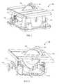
- FIG. 1depicts a perspective view of a table saw incorporating a movable swing arm assembly in accordance with principles of the disclosure
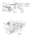
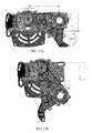
- FIG. 2depicts a perspective view of the table saw of FIG. 1 with the housing removed;
- FIG. 3depicts a perspective view of the table saw of FIG. 1 with the housing removed;
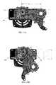
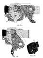
- FIG. 4depicts a side plan view of a carriage assembly, actuator, and latch assembly of the table saw of FIG. 1 with the swing arm assembly latched;
- FIG. 5depicts a side perspective view of the height adjustment carriage of FIG. 4 ;
- FIG. 6depicts a side plan view of the swing arm assembly, actuator, and latch assembly of the table saw of FIG. 4 with the swing arm assembly latched;
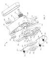
- FIG. 7depicts an exploded perspective view of the swing arm assembly of FIG. 4 ;
- FIG. 8depicts a schematic of a mitigation and control system of the table saw of FIG. 1 ;
- FIG. 9Adepicts a side plan view of the table saw of FIG. 1 with the housing removed and the swing arm assembly in an unlatched position;
- FIGS. 9B and 9Cdepicts a set screw and bushing which provides manual adjustment and isolation of the CCP
- FIG. 10depicts a front cross-sectional view through the blade wheel of the swing arm assembly of FIG. 4 ;
- FIG. 11Adepicts a front cross-sectional view through the power wheel of the swing arm assembly of FIG. 4 ;
- FIG. 11Bdepicts a front cross-sectional view through the power wheel of a swing arm assembly including set screws to eliminate the clearance between the hinge shaft and the hole in the carriage hinge section;
- FIGS. 11C and Ddepict a swing arm assembly including a set screw and a carriage hole formed along two offset arcs;
- FIG. 12depicts a side perspective view of a swing arm including multiple shot boxes for multiple counterweights
- FIG. 13depicts a partial top perspective view of the swing arm of FIG. 4 latched and secured with a spindle lock
- FIGS. 14A and Bdepict a linear horizontal belt adjustment configuration
- FIGS. 15A and Bdepict a rotational belt adjustment configuration
- FIGS. 16A and Bdepict a pivot belt adjustment configuration
- FIGS. 17A , B, and Cdepict a pivot belt adjustment configuration.
- a table saw 100is shown with a base housing 102 .
- the table saw 100includes a work piece support surface 104 .
- a riving knife or splitter 106is positioned adjacent to a blade 108 which extends from within the base housing 102 to above the work-piece support surface 104 .
- An anti-kickback assembly (not shown) and a blade guard (not shown)are attached to the riving knife 106 in some embodiments.
- the angle of the blade 108 with respect to the work-piece support surface 104is established by pivoting a frame 114 (see FIGS. 2 and 3 ) within the base housing 102 using an angle setting mechanism 112 .
- the frame 114supports a stop pad 116 .
- the frame 114further supports a carriage assembly 120 shown in FIG. 4 .
- the carriage assembly 120includes a carriage 122 (only a portion of which is shown in FIG. 4 ) which supports a motor 124 (see FIG. 3 ) which is powered through a power switch (not shown) located on the base housing 102 .
- the carriage 122also shown in FIG. 5 , is slidably mounted on two guiderails 126 / 128 through guide rail bores 130 / 132 . The position of the carriage 122 along the guiderails 126 / 128 is controlled by a blade height turn-wheel 134 (see FIG.
- the screw post bore 138is positioned in locations other than that depicted in FIG. 5 .
- the carriage 122pivotably supports a latch assembly 140 .
- the carriage 122also pivotably supports a swing arm assembly 142 on a swing arm support 144 .
- the swing arm assembly 142also shown in FIGS. 6 and 7 , includes a swing arm 146 .
- a strike bolt 148is mounted on the swing arm 146 .
- the swing arm 146encloses a power wheel 150 that is driven by an output shaft 152 of the motor 124 .
- a belt 154transfers rotational movement from the power wheel 150 to a blade wheel 156 .
- a nut 158(see FIG. 7 ) is used to affix the blade 108 (not shown in FIGS. 6 and 7 for purpose of clarity) to a shaft 160 of the blade wheel 156 .
- a tensioner 162maintains the belt 154 at a desired tension.
- a actuator assembly 164is an actuating assembly which includes a actuator pin 166 which is aligned with the strike bolt 148 when the swing arm assembly 142 is in a latched position as depicted in FIGS. 4 and 6 .
- the actuator assembly 164in the embodiment of FIGS. 4 and 6 , is a pyrotechnically activated system wherein a pyrotechnic charge is positioned within a receptacle which in this embodiment is a cylinder portion 170 which is closed at one end by a cap 172 . Operation of the actuator assembly 164 is controlled by a mitigation and control system 180 depicted in FIG. 8 .
- the mitigation and control system 180includes a sensing system 182 , a controller 184 , the motor 124 , and the actuator assembly 164 .
- the sensing system 182in different embodiments is any desired sensing circuit.
- One acceptable sensing systemis a part of the sensing and control circuit described in U.S. Pat. No. 6,922,153, the entire contents of which are herein incorporated by reference.
- the safety detection and protection system described in the '153 patentsenses an unsafe condition and provides a sense signal indicative of the sensed unsafe condition.
- the controller 184one embodiment comprises a microprocessor, ASIC or other type of processing unit.
- the controller 184receives the sense signal from the sensor subsystem 182 and, in response to an unsafe condition, fires the actuator assembly 164 to force the blade 108 and swing arm assembly 142 from the latched position shown in FIGS. 1 and 4 to an unlatched position below the work piece support surface 104 as depicted in FIG. 9A .
- the mitigation and control system 180 and other electronicsare housed within an electronics housing enclosure 190 shown in FIG. 3 .
- the sensing system 182includes a capacitive coupling plate (CCP) 224 shown in FIG. 7 .
- the CCP 224is a conductive material which, along with the blade 108 , defines a capacitor. If a user touches the blade 108 , the capacitance of the CCP 224 /blade 108 capacitor is changed and the change in capacitance is provided as a sense signal to the controller 184 .
- the CCP 224is mounted to a CCP holder 226 using a spring 232 , three springs 232 are illustrated, and screws 234 .
- a spring 232is placed into each of a plurality of spring wells 236 , 238 , and 240 .
- the screws 234are then inserted through mounting bores 242 , 244 , and 246 , through the springs 232 , and then threaded into the bottom portion of the spring wells 236 , 238 , and 240 .
- the springs 232 and screws 234allow the capacitive coupling plate 224 to be precisely positioned with respect to the blade 108 .
- the CCP 224is mounted using glue, a snap-in design, or by over-molding the CCP 224 with the CCP holder 226 .
- a CCPis formed by using a conductive coating on a portion of the CCP holder 226 .
- the CCP 224is mounted to the carriage 122 .
- FIGS. 9B and Cdepict a set screw 225 within a bushing 227 which is used to keep the CCP air gap constant by manual adjustment of the CCP mounting location.
- the set screw 225in one embodiment is used during manufacture of the table saw 100 .
- the set screw 225 and bushing 227thus provide manual control over the air gap and also provide isolation.
- the assembled configuration of the swing arm assembly 142is depicted in FIG. 10 , wherein the blade 108 is precisely spaced apart from the capacitive coupling plate 224 .
- Electrical isolation between the blade 108 , the swing arm 142 , the CCP 224 , or a combination thereofis provided by the CCP holder 226 which is formed from a non-conductive material.
- the CCP holder 226houses an output spindle bearing 248 which is in electrical contact with the shaft 160 , blade washers 250 / 252 , and the blade 108 .
- the output spindle bearing 248is maintained within the CCP holder 226 by a bearing retainer 254 . In other embodiments, the output spindle bearing 248 is insert molded or pressed.
- the blade/CCP capacitoris then formed by connecting cables (not shown) to the CCP 224 .
- the shaft 160is electrically isolated from the swing arm 146 by a back bearing isolator 256 which houses a spindle bearing 258 . Additional electrical isolation is provided by the blade wheel 156 which is made of a non-conductive material.
- the driving member 156is formed from a material with metallic content to provide the mechanical strength required to handle the power transmission.
- at least a portion of the content in some embodimentsincludes metallic/non-conductive, non-conductive/metallic/non-conductive, or the like.
- the insertcan be over molded or made with alternate assembly insertion processes such as ultrasonic welding or the like.
- a shot box 260in which one or more counterweights 262 is positioned.
- the counterweight 262is sized to move freely within the shot box 260 .
- the internal height of the shot box 260is selected to be about the same as the maximum height of the blade 108 above the work piece support surface 104 .
- a resilient materialis positioned within the shot box at the uppermost and lowermost locations. Further details of the mitigation and control system 180 and table saw 100 are provided in the following description of the operation of the table saw 100 .
- the swing arm assembly 142is maintained in a latched position with the swing arm 146 supported by the latch assembly 140 as shown in FIG. 4 .
- the blade wheel 156is positioned sufficiently close to the work-piece support surface 104 that the blade 108 extends above the work-piece support surface 104 as shown in FIG. 1 .
- a useroperates the angle setting mechanism 112 to pivot the frame 114 with respect to the work-piece support surface 104 to establish a desired angle between the blade 108 and the work-piece support surface 104 .
- the userfurther operates the blade height adjustment turn-wheel 134 to move the carriage 122 along the guiderails 126 / 128 to establish a desired height of the blade 108 above the work-piece support surface 104 .
- poweris applied to the motor 124 under the control of the controller 184 ( FIG. 8 ).
- the controller 184verifies that the actuator 170 is installed and functional and, once verified, power is applied to the motor 124 causing the output shaft 152 and the power wheel 150 to rotate. Rotation of the power wheel 150 causes the belt 154 to rotate the blade wheel 156 and the blade 108 which is mounted on the shaft 160 of the blade wheel 156 . A work-piece may then be shaped by moving the work-piece into contact with the blade 108 .
- the mitigation and control system 180monitors for an unsafe condition using the sensor system 182 . If an unsafe condition is detected, the controller 184 actuates the actuator assembly 164 . Upon actuation of the actuator assembly 164 , the actuator pin 166 is forced outwardly from the actuator assembly 164 . When the swing arm assembly 142 is maintained in a latched position with the swing arm 146 supported by the latch assembly 140 as shown in FIG. 4 , the strike bolt 148 is aligned with the actuator pin 166 . Accordingly, as the actuator pin 166 is forced out of the actuator assembly 164 , the actuator pin 166 impacts or impulses the strike bolt 148 .
- the strike bolt 148has a spherical or cylindrical profile.
- the spherical strike bolt 148keeps the actuator pin 166 in an in-line arrangement with the piston axis minimizing energy losses.
- the end of the actuator pin 166is also spherical.
- the actuator pinmay be in other form of geometry.
- the shape of the swing arm 146 and the latch assembly 140is selected such that the impact or impulse of the actuator pin 166 on the strike bolt 148 generates a force tending to rotate the latch assembly 140 in the direction of the arrow 270 in FIG. 4 against a spring 272 (see FIG. 6 ).
- the actionincludes impact, impulse, or combination thereof.
- the spring constant of the spring 272 and the force generated by the actuator assembly 164are selected such that when the actuator pin 166 acts on the strike bolt 148 the generated force is sufficient to compress the spring 272 and to force the latch assembly 140 to rotate into a position whereat the swing arm assembly 142 is no longer maintained in position adjacent to the latch assembly 140 .
- the swing arm assembly 142pivots about the output shaft 152 in the direction of the arrow 274 of FIG. 4 as the actuator pin continues to press against the strike bolt 148 such that the swing arm assembly 142 moves away from the work-piece support surface 104 to the position shown in FIG. 9A . Accordingly, the blade 108 (not shown in FIG. 9A for purpose of clarity) is pulled by the swing arm assembly 142 in a direction away from the work-piece support surface 104 .
- the configuration of the swing arm assembly 142provides improved efficiency of movement during the above described retraction of the blade 108 from a location above the work piece support surface 104 .
- the motor output axis 280 and the axis 282 of the swing arm 146are co-axial even though the output shaft 152 and the swing arm 146 are not directly connected as shown in FIG. 11A .
- the belt 154does not lose its tension after rotation.
- the swing arm bearings 284 / 286do not rotate with the motor shaft 152 which will increase the life of the swing arm bearings 284 / 286 .
- a hinge shaft 288which is used to pivotally connect the swing arm 146 and the swing arm support 144 .
- a shaft bolt 290pulls the inner races on swing arm bearings 284 / 286 toward each other. This minimizes the axial clearances of the swing arm bearings 284 / 286 which contributes to blade accuracy.
- a blade positioning pin 292extends through a bore 294 in the shaft bolt 290 .
- the blade positioning pin 292positions and creates the proper location of the swing arm 146 to the height adjustment carriage 122 , thereby controlling the location and position of the blade 108 .
- one or more set screwsare provided adjacent to the blade positioning pin 292 .
- FIG. 11Bdepicts set screws 293 positioned adjacent to the blade positioning pin 292 .
- the set screws 293are used to eliminate the clearance between the hinge shaft and the hole in the carriage hinge section.
- a single set screw 295is used to eliminate the clearance between the hinge shaft and the hole in the carriage hinge section.
- the hole 297 in the carriageincludes an upper portion 299 which is formed on an arc having an origin that is offset from the origin of a lower portion 301 (see FIG. 11D ).
- FIG. 11Afurther shows electrical isolation is provided by the power wheel 150 which is made of a non-conductive material which contains a metallic insert to provide the mechanical strength required to handle the power transmission.
- the power wheel 150can be metallic and non-conductive material.
- the insertcan be over molded or made with alternate assembly insertion processes such as ultrasonic welding or the like. Additional electrical isolation is provided by an isolator bearing plate 296 located between the carriage 122 and the swing arm 146 .
- Stopping of the swing arm 146 after the blade 108 is retracted below the work piece support surface 104is also enhanced in the table saw 100 . Specifically, as the support arm 146 is forced downwardly by the actuator pin 166 , the counterweight 262 (see FIG. 10 ) is not initially accelerated. As the shot box 260 is rotated by the swing arm 146 , the upper portion of the shot box 260 comes into contact with the counterweight 262 which slows the movement of the swing arm 146 . As discussed above, the height of the shot box 260 is selected such that this slowing occurs only after the blade 108 has been retracted to a location below the work piece support surface 104 .
- the stop pad 116is more effective in further slowing the swing arm 146 .
- the above sequenceis reversed with the counterweight 262 contacting the bottom of the shot box 260 .
- the counterweight 262thus dampens movement of the support arm 146 without interfering with the initial movement of the swing arm 146 .
- the counterweight 262is a sphere. In other embodiments, the counterweight is any desired geometry. Both the shot box 260 and the counter weight 262 are made of material strong enough to take the impact force of the counterweight. In some embodiments, the shot box 260 and/or the counterweight 262 include a resilient material to absorb some of the energy of the moving counterweight.
- FIG. 10shows a single counterweight 262
- other embodimentsinclude additional counterweights.
- the number, weight, and location of the counterweightsis selected to optimize the damping efficiency of the counterweights.
- FIG. 12depicts a swing arm 300 which includes two counterweights 302 / 304 within shot boxes 306 / 308 formed integrally with the swing arm 300 .
- the shot boxes 306 / 308are slightly arcuate to be complementary with the movement of the swing arm 300 along a swing path, and the distance from the axis of rotation 310 of the swing arm is selected to provide the desired moment arm for the desired damping effect.
- the configuration of the table saw 100is selected to also enhance resetting the swing arm 146 after the sensed condition has been cleared.
- the power wheel 150 and the blade wheel 156have the same diameter (same gear ratio). This prevents the blade 108 from changing speeds during dropping.
- the selected diameters of the power wheel 150 and the blade wheel 156provides a straight-up pull motion.
- the belt 154will roll around the same diameter pulley keeping the wrench in the same orientation during reset.
- the swing arm 146is provided with an alignment member 320 as depicted in FIG. 7 .
- the alignment member 320comes into contact with an alignment receptacle 322 mounted to the actuator assembly 164 (see FIGS. 4 and 13 ). Mating of the alignment member 320 and the alignment receptacle 322 provides increased blade accuracy.
- the shape of the alignment member 320is rectangular. In other embodiments, the alignment member 320 is any other desired geometrical shape such as triangular or circular. In a further embodiment, two cylindrical pins on top of each other are used to minimize friction.
- the table sawfurther includes a spindle lock 324 shown most clearly in FIGS. 7, 10, and 13 .
- the spindle lock 324includes an actuator 326 and a locking lip 328 .
- a useruses the actuator 326 to move the spindle lock 324 forwardly into a locked position whereat the locking lip 328 rests upon a locking ledge 330 which is part of the alignment receptacle 322 in one embodiment as shown in FIG. 13 .
- the swing arm 146is mechanically locked against unlatching.
- the blade 108may be changed without the chance of accidentally becoming unlatched.
- the spindle lock 324also locks the shaft 160 against rotation, easing the process of changing blades. In one embodiment, movement of the spindle lock 324 into the locked position disables the provision of power to the motor 124 . Upon return of the spindle lock 324 to an unlocked position, the swing arm 146 may be unlatched by the mitigation and control system 180 and power may be supplied to the motor 124 .
- the driving memberdoes not include an idle pulley (tensioner) 162 .
- the axis of rotationis of the swing arm is not coaxial with the axis of rotation of the power wheel 150 .
- FIGS. 14A and Bdepict a linear horizontal belt adjustment configuration 400 .
- the nominal distance between the axis of rotation of the power wheel 150 and the blade wheel 156is X when the swing arm is latched and can be modified by up to Y which is less than X as depicted in FIG. 14A so that the proper tension is achieved for the transmission.
- the nominal distance between the axis of rotation of the power wheel 150 and the blade wheel 156is Z that is less than X as depicted in FIG. 14B .
- Rotational de-tensioningallows the motor shaft to move away from the hinge axis. After rotation, the belt is loosened making the belt change over easier.
- the linear horizontal belt adjustment configurationprovides ease of assembly with adjustment provided using a set screw.
- the set screwlocks the gear housing from sliding in the tension direction.
- the only connections to the height adjustment carriageare four holding screws. Of course, the screws may lose the clamping tension due to plastic creep.
- FIGS. 15A and Bdepict a rotational belt tension adjustment configuration.
- the nominal distance between the axis of rotation of the power wheel 150 and the blade wheel 156is X when the swing arm is latched (see FIG. 15A ) and can be modified by up to B by 6.5 degrees rotation about a pivot 402 (see FIG. 15B ).
- the nominal distance between the axis of rotation of the power wheel 150 and the blade wheel 156is C and center distance reduction is D as depicted in FIG. 15B .
- the rotational belt adjustment configurationallows the set screw to lock the gear housing from rotating in the tension direction.
- FIGS. 16A and Bdepict a rotational belt tension adjustment configuration.
- the nominal distance between the axis of rotation of the power wheel 150 and the blade wheel 156is A when the swing arm is latched (see FIG. 16A ) and can be modified by up to B by 2.2 degrees rotation about a pivot 404 .
- a shoulder screwis used to allow the pivot and the pivot point is moved to clear the motor housing.
- the swing armrotates 50°
- the nominal distance between the axis of rotation of the power wheel 150 and the blade wheel 156is C and center distance reduction is D as depicted in FIG. 16B .
- FIGS. 17A and Bdepict a rotational belt tension adjustment configuration.
- the nominal distance between the axis of rotation of the power wheel 150 and the blade wheel 156is A when the swing arm is latched (see FIG. 17A ) and can be modified by up to B by 4.1 degrees rotation about a pivot 406 .
- a Press dowel pin in the height adjustment carriageis provided to allow pivoting and the pivot point is moved to clear the motor housing.
- a ⁇ 8.5° rotationchanges the distance between axes by C for fitting.
- the swing armrotates 50°
- the nominal distance between the axis of rotation of the power wheel 150 and the blade wheel 156is D and center distance reduction is E as depicted in FIG. 17B .
- a driving systemis mounted to at least one of the motor and swing arm.
- the driving systemincludes a first driving element coupled to the swing arm and a second driving element coupled to the motor.
- the pulleyis part of the swing arm.
- Bearingis integral to the motor shaft wherein the bearing is the second driving element. drive system and drop system.
Landscapes
- Engineering & Computer Science (AREA)
- Mechanical Engineering (AREA)
- Life Sciences & Earth Sciences (AREA)
- Wood Science & Technology (AREA)
- Forests & Forestry (AREA)
- Sawing (AREA)
- General Engineering & Computer Science (AREA)
Abstract
Description
Claims (20)
Priority Applications (1)
| Application Number | Priority Date | Filing Date | Title |
|---|---|---|---|
| US14/203,928US9511429B2 (en) | 2013-03-15 | 2014-03-11 | Blade drop for power device and method of manufacturing thereof |
Applications Claiming Priority (2)
| Application Number | Priority Date | Filing Date | Title |
|---|---|---|---|
| US201361787803P | 2013-03-15 | 2013-03-15 | |
| US14/203,928US9511429B2 (en) | 2013-03-15 | 2014-03-11 | Blade drop for power device and method of manufacturing thereof |
Publications (2)
| Publication Number | Publication Date |
|---|---|
| US20140260861A1 US20140260861A1 (en) | 2014-09-18 |
| US9511429B2true US9511429B2 (en) | 2016-12-06 |
Family
ID=51521417
Family Applications (1)
| Application Number | Title | Priority Date | Filing Date |
|---|---|---|---|
| US14/203,928Active2034-12-13US9511429B2 (en) | 2013-03-15 | 2014-03-11 | Blade drop for power device and method of manufacturing thereof |
Country Status (4)
| Country | Link |
|---|---|
| US (1) | US9511429B2 (en) |
| EP (1) | EP2969335B1 (en) |
| CN (1) | CN105517742B (en) |
| WO (1) | WO2014151073A1 (en) |
Cited By (2)
| Publication number | Priority date | Publication date | Assignee | Title |
|---|---|---|---|---|
| US20150343662A1 (en)* | 2014-05-29 | 2015-12-03 | Black & Decker Inc. | Table saws having integrated control systems |
| US20160167142A1 (en)* | 2014-12-15 | 2016-06-16 | Robert Bosch Gmbh | Ratchet and Release Mechanism for Swing Arm of Table Saw |
Families Citing this family (19)
| Publication number | Priority date | Publication date | Assignee | Title |
|---|---|---|---|---|
| US11097393B2 (en)* | 2014-05-02 | 2021-08-24 | Chih-Hui Chiu | Protective apparatus for a machine tool |
| US10071432B2 (en)* | 2015-03-12 | 2018-09-11 | Robert Bosch Tool Corporation | Power tool with arbor lock |
| US10758989B2 (en) | 2015-03-12 | 2020-09-01 | Robert Bosch Tool Corporation | System and method for sensing cable fault detection in a saw |
| US10821529B2 (en) | 2015-03-12 | 2020-11-03 | Robert Bosch Tool Corporation | Power tool with improved belt tensioning |
| US10213853B2 (en)* | 2015-03-12 | 2019-02-26 | Robert Bosch Tool Corporation | Power tool drop arm with offset ribbing |
| US10493543B2 (en)* | 2015-03-12 | 2019-12-03 | Robert Bosch Tool Corporation | Power tool motor with reduced electrical noise |
| US10799964B2 (en)* | 2015-03-12 | 2020-10-13 | Robert Bosch Tool Corporation | Table saw with pulley alignment mechanism |
| TWI693492B (en)* | 2015-03-12 | 2020-05-11 | 德商羅伯特博斯奇股份有限公司 | User interface system in a table saw |
| US9868166B2 (en)* | 2015-03-12 | 2018-01-16 | Robert Bosch Tool Corporation | Power tool with pyrotechnic lockout |
| US9969015B2 (en)* | 2015-03-12 | 2018-05-15 | Robert Bosch Tool Corporation | Power tool with protected coupling plate |
| US9868167B2 (en)* | 2015-03-12 | 2018-01-16 | Robert Bosch Tool Corporation | Power tool with drop arm orbit bracket |
| US10322522B2 (en) | 2015-03-12 | 2019-06-18 | Robert Bosch Tool Corporation | Electrical configuration for object detection system in a saw |
| US10786854B2 (en)* | 2015-03-12 | 2020-09-29 | Robert Bosch Tool Corporation | Table saw with electrically isolated arbor shaft |
| US10369642B2 (en)* | 2015-03-12 | 2019-08-06 | Robert Bosch Tool Corporation | Power tool with protected circuit board orientation |
| US10427227B2 (en)* | 2015-03-12 | 2019-10-01 | Robert Bosch Tool Corporation | Drop arm reset method |
| US10449648B2 (en) | 2016-08-04 | 2019-10-22 | Robert Bosch Tool Corporation | Transferring rotation torque through isolator for table saw |
| US10413979B2 (en)* | 2016-08-05 | 2019-09-17 | Robert Bosch Tool Corporation | Table saw with cutting blade safety feature |
| CA3034346A1 (en)* | 2016-08-18 | 2018-02-22 | Safety Cut Ltd | Electric bandsaw device |
| DE202019101777U1 (en)* | 2019-03-28 | 2020-07-03 | Altendorf Gmbh | Woodworking machine with a releasable rip fence |
Citations (123)
| Publication number | Priority date | Publication date | Assignee | Title |
|---|---|---|---|---|
| US1552665A (en) | 1923-07-13 | 1925-09-08 | Authenrieth Herschel | Chip box |
| US2044481A (en) | 1934-12-08 | 1936-06-16 | Western Electric Co | Material working machine |
| US2054932A (en) | 1935-04-03 | 1936-09-22 | Fleming Isaac | Dust collecting apparatus |
| USRE20687E (en) | 1938-04-05 | For cutting paper and other fibrous materials | ||
| US2236232A (en) | 1938-09-03 | 1941-03-25 | Western Electric Co | Exhausting apparatus |
| US2505958A (en) | 1946-07-19 | 1950-05-02 | John O Grierson | Swinging power saw |
| US2652863A (en) | 1948-05-11 | 1953-09-22 | Edward E Grabinski | Power-driven table tool with portable vertical-shaft motor |
| US2711061A (en) | 1954-07-29 | 1955-06-21 | Gallagher Kaiser Corp | Dust collector |
| US2719547A (en) | 1952-03-01 | 1955-10-04 | Gjerde Arne | Universally adjustable underbench saw |
| US2729927A (en) | 1952-04-19 | 1956-01-10 | United Shoe Machinery Corp | Dust collecting hoods |
| US2844173A (en) | 1954-09-13 | 1958-07-22 | King Seely Corp | Arbor saw with single handle control of tilt and elevation |
| US2898893A (en) | 1958-04-11 | 1959-08-11 | Little Inc A | Impact tool |
| US2903848A (en) | 1956-12-05 | 1959-09-15 | Republic Aviat Corp | Self-contained emergency fluid cylinder |
| US2937672A (en) | 1957-10-17 | 1960-05-24 | Gjerde Arne | Adjustable motor-driven saw |
| US3007501A (en) | 1959-06-11 | 1961-11-07 | Handman Inc | Combination woodworking machine |
| US3013592A (en) | 1959-03-23 | 1961-12-19 | Theodore G Ambrosio | Tilting table saw |
| US3036608A (en) | 1959-04-20 | 1962-05-29 | Weber Carl | Portable supporting and mounting device for power tools |
| US3320740A (en) | 1965-07-02 | 1967-05-23 | Walker Mfg Co | Press |
| US3344819A (en) | 1965-10-20 | 1967-10-03 | Donald H Benson | Table saw |
| US3394500A (en) | 1965-05-13 | 1968-07-30 | Fmc Corp | Grinder |
| US3444670A (en) | 1965-06-21 | 1969-05-20 | Ernest C Hungate | Apparatus for treating gas |
| US3954051A (en) | 1973-12-07 | 1976-05-04 | Hauni-Werke Koerber & Co. Kg | Apparatus for clipping wrapped rod-like fillers of fibrous material |
| US4063478A (en) | 1976-10-20 | 1977-12-20 | Diebold Incorporated | Saw enclosure construction |
| US4161272A (en) | 1976-12-01 | 1979-07-17 | Mafell-Maschinenfabrik Rudolf Mey Kg | Nail driver construction |
| US4184394A (en) | 1977-04-01 | 1980-01-22 | A/S Norcem | Motor-driven saw having a circular saw blade |
| US4192104A (en) | 1978-10-10 | 1980-03-11 | Wilderness Mold, Inc. | Dust shroud |
| US4241505A (en) | 1979-05-21 | 1980-12-30 | Johns-Manville Corporation | Dust shroud for portable circular saw |
| US4255995A (en) | 1980-01-24 | 1981-03-17 | Connor J Franklin | Dust confining and collection housing for power table saws and the like |
| US4326864A (en) | 1980-08-08 | 1982-04-27 | Sittler Werner G | Apparatus for and method of collecting sawdust particles |
| US4336733A (en) | 1980-06-06 | 1982-06-29 | Macksoud Albert A | Rocking arm saw |
| US4367665A (en) | 1980-12-19 | 1983-01-11 | Emerson Electric Co. | Sawdust collection system |
| US4385539A (en) | 1981-08-14 | 1983-05-31 | Black & Decker Inc. | Articulated dust cover means for table saw or other power-driven apparatus |
| US4576072A (en) | 1981-10-16 | 1986-03-18 | Emerson Electric Co. | Sawdust collection apparatus for a table saw |
| US4616447A (en) | 1983-02-26 | 1986-10-14 | Mafell-Saschinenfabrik Rudolf Mey GmbH & Co. KG | Method and apparatus for machining a workpiece ultrasonically |
| US4742743A (en) | 1986-04-24 | 1988-05-10 | Scarpone William J | Radial saw accessory for preventing sawdust buildup |
| US4875398A (en) | 1988-01-15 | 1989-10-24 | Atlantic Richfield Company | Retractable dust control hood and guard for rotary table saw |
| US4962685A (en) | 1988-10-27 | 1990-10-16 | Hagstrom Oscar E | Production table saw |
| US5033192A (en) | 1989-07-01 | 1991-07-23 | Hilti Aktiengesellschaft | Hand-held tool with cutting or grinding disk |
| US5123317A (en) | 1991-03-20 | 1992-06-23 | Ryobi Motor Products Corp. | Support structure for a table saw blade assembly |
| US5158001A (en) | 1991-08-09 | 1992-10-27 | Skil Corporation | Power table tool assemblies with dust collection system |
| US5181447A (en) | 1991-03-25 | 1993-01-26 | Timothy Hewitt | Adjustable protecting guard apparatus for a blade of a table saw |
| US5231906A (en) | 1992-09-30 | 1993-08-03 | Julien Kogej | Table saw guard |
| US5537748A (en) | 1991-07-09 | 1996-07-23 | Ryobi Limited | Cover structure for electric circular saw |
| US5588213A (en) | 1995-03-07 | 1996-12-31 | Swanberg; Alan M. | Circular saw with dust trapper |
| US5676319A (en) | 1995-10-23 | 1997-10-14 | Stiggins; Kendy Lee | Garbage disposal system |
| US5819625A (en) | 1994-12-12 | 1998-10-13 | Black & Decker Inc. | Double bevel table saw |
| US6009782A (en) | 1997-06-19 | 2000-01-04 | Makita Corporation | Table saw |
| US6036608A (en) | 1999-05-07 | 2000-03-14 | Morris; John K. | Golf putting and chipping training apparatus |
| DE20007037U1 (en) | 2000-04-17 | 2000-07-20 | Mafell AG, 78727 Oberndorf | Table saw |
| US6131629A (en) | 1996-09-20 | 2000-10-17 | Black & Decker Inc. | Table saw |
| US6139411A (en) | 1998-03-03 | 2000-10-31 | Ryobi North America, Inc. | Disc sander |
| US20020020265A1 (en) | 2000-08-14 | 2002-02-21 | Gass Stephen F. | Translation stop for use in power equipment |
| US20020025767A1 (en) | 2000-08-31 | 2002-02-28 | Peter Chen | Dust collecting structure of grinder |
| US6370997B1 (en) | 1997-06-09 | 2002-04-16 | Elektra Beckum Ag | Transportable bench circular saw |
| US6470778B1 (en) | 1998-05-20 | 2002-10-29 | Black & Decker Inc. | Dust collector for a power tool |
| US20020190581A1 (en) | 2001-06-13 | 2002-12-19 | Gass Stephen F. | Apparatus and method for detecting dangerous conditions in power equipment |
| US6503125B1 (en) | 2000-09-05 | 2003-01-07 | Raymond J. Harrington | Dust shroud for abrading machine |
| US6530303B1 (en) | 1999-06-10 | 2003-03-11 | Black & Decker Inc. | Table saw |
| US6536536B1 (en) | 1999-04-29 | 2003-03-25 | Stephen F. Gass | Power tools |
| US20030131703A1 (en)* | 2002-01-16 | 2003-07-17 | Gass Stephen F. | Apparatus and method for detecting dangerous conditions in power equipment |
| US20040035595A1 (en) | 2000-08-15 | 2004-02-26 | Fisher Hugh Edward | Cam operated devices |
| US6736042B2 (en) | 2001-03-01 | 2004-05-18 | Porter-Cable Corporation | Work piece guiding system for a table saw |
| WO2004045814A1 (en) | 2002-11-18 | 2004-06-03 | Young-Suok Lee | Apparatus for cutting lumber |
| DE202004004463U1 (en) | 2004-03-22 | 2004-08-12 | Durq Machinery Corp., Shen Kang | Saw bench with circular saw unit, has dust guard with tubular extension movable along curved opening in table side wall |
| US20040159198A1 (en) | 2003-01-31 | 2004-08-19 | Peot David G. | Table saw with cutting tool retraction system |
| US6796208B1 (en) | 1999-02-19 | 2004-09-28 | Matthew Roy Jorgensen | Sawdust collection hood for table saw |
| DE202004012468U1 (en) | 2003-11-21 | 2004-11-04 | Festool Gmbh | Table saw has carriage to support work for movement with respect to circular saw blade and drive shaft with handle having saw control switch |
| US6813983B2 (en) | 2000-09-29 | 2004-11-09 | Sd3, Llc | Power saw with improved safety system |
| US6826988B2 (en) | 2000-09-29 | 2004-12-07 | Sd3, Llc | Miter saw with improved safety system |
| US20040248507A1 (en) | 2003-06-05 | 2004-12-09 | Brazell Kenneth M. | Motor driven wood working tool with vacuum feature |
| US6857345B2 (en) | 2000-08-14 | 2005-02-22 | Sd3, Llc | Brake positioning system |
| US6877410B2 (en) | 2000-09-29 | 2005-04-12 | Sd3, Llc | Miter saw with improved safety system |
| US6880440B2 (en) | 2000-09-29 | 2005-04-19 | Sd3, Llc | Miter saw with improved safety system |
| US6922153B2 (en)* | 2003-05-13 | 2005-07-26 | Credo Technology Corporation | Safety detection and protection system for power tools |
| US6920814B2 (en) | 2000-08-14 | 2005-07-26 | Sd3, Llc | Cutting tool safety system |
| US20050166736A1 (en) | 2004-01-29 | 2005-08-04 | Gass Stephen F. | Table saws with safety systems and systems to mount and index attachments |
| US6945148B2 (en) | 2000-09-29 | 2005-09-20 | Sd3, Llc | Miter saw with improved safety system |
| US6945149B2 (en) | 2001-07-25 | 2005-09-20 | Sd3, Llc | Actuators for use in fast-acting safety systems |
| US6966350B1 (en) | 2002-09-25 | 2005-11-22 | Delta International Machinery Corp. | Power tool supporting cabinet with a detachable dust bin |
| US6994004B2 (en) | 2000-09-29 | 2006-02-07 | Sd3, Llc | Table saw with improved safety system |
| US6997090B2 (en) | 2001-08-13 | 2006-02-14 | Sd3, Llc | Safety systems for power equipment |
| US7000514B2 (en) | 2001-07-27 | 2006-02-21 | Sd3, Llc | Safety systems for band saws |
| US20060042440A1 (en) | 2004-08-27 | 2006-03-02 | Edward Quinlan | Dust collection shroud |
| US7024975B2 (en) | 2000-08-14 | 2006-04-11 | Sd3, Llc | Brake mechanism for power equipment |
| US7029384B2 (en) | 2003-06-27 | 2006-04-18 | Festool Gmbh | Grinding disk |
| US7055417B1 (en) | 1999-10-01 | 2006-06-06 | Sd3, Llc | Safety system for power equipment |
| US7077039B2 (en) | 2001-11-13 | 2006-07-18 | Sd3, Llc | Detection system for power equipment |
| US7098800B2 (en) | 2003-03-05 | 2006-08-29 | Sd3, Llc | Retraction system and motor position for use with safety systems for power equipment |
| US7100483B2 (en) | 2000-08-14 | 2006-09-05 | Sd3, Llc | Firing subsystem for use in a fast-acting safety system |
| US20060201302A1 (en) | 2005-03-11 | 2006-09-14 | Schwaiger Barry M | Cutting tool and parts and accessories therefor |
| US7137326B2 (en) | 2000-08-14 | 2006-11-21 | Sd3, Llc | Translation stop for use in power equipment |
| US7171879B2 (en) | 2001-07-02 | 2007-02-06 | Sd3, Llc | Discrete proximity detection system |
| US20070044609A1 (en) | 2005-08-30 | 2007-03-01 | Brazell Kenneth M | Motor driven wood working tool with vacuum feature |
| US7197969B2 (en) | 2001-09-24 | 2007-04-03 | Sd3, Llc | Logic control with test mode for fast-acting safety system |
| US20070074612A1 (en) | 2005-10-04 | 2007-04-05 | Ben Yu | Worktable having adjustable shield |
| US7210383B2 (en) | 2000-08-14 | 2007-05-01 | Sd3, Llc | Detection system for power equipment |
| US7225712B2 (en) | 2000-08-14 | 2007-06-05 | Sd3, Llc | Motion detecting system for use in a safety system for power equipment |
| US7241211B2 (en) | 1999-09-17 | 2007-07-10 | Husqvarna Outdoor Products Inc. | Guard for a moving tool |
| US7284467B2 (en) | 2000-08-14 | 2007-10-23 | Sd3, Llc | Apparatus and method for detecting dangerous conditions in power equipment |
| US7290474B2 (en)* | 2003-04-29 | 2007-11-06 | Black & Decker Inc. | System for rapidly stopping a spinning table saw blade |
| US7290967B2 (en) | 2004-02-13 | 2007-11-06 | Festool Gmbh | Dust extractor device for a router |
| US7290472B2 (en) | 2002-01-14 | 2007-11-06 | Sd3, Llc | Miter saw with improved safety system |
| US7308843B2 (en) | 2000-08-14 | 2007-12-18 | Sd3, Llc | Spring-biased brake mechanism for power equipment |
| DE4424615B4 (en) | 1994-07-13 | 2008-03-20 | Elumatec Gmbh & Co. Kg | Under-table miter saw |
| US7350445B2 (en) | 2003-08-20 | 2008-04-01 | Sd3, Llc | Brake cartridge for power equipment |
| US7350444B2 (en) | 2000-08-14 | 2008-04-01 | Sd3, Llc | Table saw with improved safety system |
| US7353737B2 (en) | 2001-08-13 | 2008-04-08 | Sd3, Llc | Miter saw with improved safety system |
| US7359174B2 (en) | 2000-08-14 | 2008-04-15 | Sd3, Llc | Motion detecting system for use in a safety system for power equipment |
| US7357056B2 (en) | 2000-09-29 | 2008-04-15 | Sd3, Llc | Cutting tool safety system |
| US7377199B2 (en) | 2000-09-29 | 2008-05-27 | Sd3, Llc | Contact detection system for power equipment |
| US7472634B2 (en) | 2003-08-20 | 2009-01-06 | Sd3, Llc | Woodworking machines with overmolded arbors |
| US7475542B2 (en) | 2005-03-24 | 2009-01-13 | Snpe Materiaux Energeriques | Pyrotechnic actuator furnished with a pressure regulator member |
| US7481140B2 (en) | 2005-04-15 | 2009-01-27 | Sd3, Llc | Detection systems for power equipment |
| US7509899B2 (en) | 2000-08-14 | 2009-03-31 | Sd3, Llc | Retraction system for use in power equipment |
| US7536238B2 (en) | 2003-12-31 | 2009-05-19 | Sd3, Llc | Detection systems for power equipment |
| US7600455B2 (en) | 2000-08-14 | 2009-10-13 | Sd3, Llc | Logic control for fast-acting safety system |
| US7628101B1 (en) | 2006-03-13 | 2009-12-08 | Power Tool Institute | Pyrotechnic drop mechanism for power tools |
| US7721633B2 (en) | 2006-10-24 | 2010-05-25 | Gaw Stanley E | Dual bevel table and slide miter saw |
| US20100307308A1 (en) | 2009-06-09 | 2010-12-09 | Butler David J | Blade enclosure for a table saw |
| US20110048194A1 (en)* | 2009-08-26 | 2011-03-03 | Credo Technology Corporation | Table saw with reset mechanism |
| US20110048199A1 (en) | 2009-08-26 | 2011-03-03 | Robert Bosch Tool Corporation | Table saw riving knife |
| US20110048207A1 (en) | 2009-08-26 | 2011-03-03 | Credo Technology Corporation | Table saw with linkage drop system |
| US8065943B2 (en) | 2000-09-18 | 2011-11-29 | Sd3, Llc | Translation stop for use in power equipment |
Family Cites Families (1)
| Publication number | Priority date | Publication date | Assignee | Title |
|---|---|---|---|---|
| CN2822846Y (en)* | 2005-08-09 | 2006-10-04 | 力山工业股份有限公司 | Circular saw machine with improved lifting structure of table saw saw table |
- 2014
- 2014-03-11USUS14/203,928patent/US9511429B2/enactiveActive
- 2014-03-12CNCN201480027719.2Apatent/CN105517742B/enactiveActive
- 2014-03-12EPEP14768366.8Apatent/EP2969335B1/enactiveActive
- 2014-03-12WOPCT/US2014/024893patent/WO2014151073A1/enactiveApplication Filing
Patent Citations (139)
| Publication number | Priority date | Publication date | Assignee | Title |
|---|---|---|---|---|
| USRE20687E (en) | 1938-04-05 | For cutting paper and other fibrous materials | ||
| US1552665A (en) | 1923-07-13 | 1925-09-08 | Authenrieth Herschel | Chip box |
| US2044481A (en) | 1934-12-08 | 1936-06-16 | Western Electric Co | Material working machine |
| US2054932A (en) | 1935-04-03 | 1936-09-22 | Fleming Isaac | Dust collecting apparatus |
| US2236232A (en) | 1938-09-03 | 1941-03-25 | Western Electric Co | Exhausting apparatus |
| US2505958A (en) | 1946-07-19 | 1950-05-02 | John O Grierson | Swinging power saw |
| US2652863A (en) | 1948-05-11 | 1953-09-22 | Edward E Grabinski | Power-driven table tool with portable vertical-shaft motor |
| US2719547A (en) | 1952-03-01 | 1955-10-04 | Gjerde Arne | Universally adjustable underbench saw |
| US2729927A (en) | 1952-04-19 | 1956-01-10 | United Shoe Machinery Corp | Dust collecting hoods |
| US2711061A (en) | 1954-07-29 | 1955-06-21 | Gallagher Kaiser Corp | Dust collector |
| US2844173A (en) | 1954-09-13 | 1958-07-22 | King Seely Corp | Arbor saw with single handle control of tilt and elevation |
| US2903848A (en) | 1956-12-05 | 1959-09-15 | Republic Aviat Corp | Self-contained emergency fluid cylinder |
| US2937672A (en) | 1957-10-17 | 1960-05-24 | Gjerde Arne | Adjustable motor-driven saw |
| US2898893A (en) | 1958-04-11 | 1959-08-11 | Little Inc A | Impact tool |
| US3013592A (en) | 1959-03-23 | 1961-12-19 | Theodore G Ambrosio | Tilting table saw |
| US3036608A (en) | 1959-04-20 | 1962-05-29 | Weber Carl | Portable supporting and mounting device for power tools |
| US3007501A (en) | 1959-06-11 | 1961-11-07 | Handman Inc | Combination woodworking machine |
| US3394500A (en) | 1965-05-13 | 1968-07-30 | Fmc Corp | Grinder |
| US3444670A (en) | 1965-06-21 | 1969-05-20 | Ernest C Hungate | Apparatus for treating gas |
| US3320740A (en) | 1965-07-02 | 1967-05-23 | Walker Mfg Co | Press |
| US3344819A (en) | 1965-10-20 | 1967-10-03 | Donald H Benson | Table saw |
| US3954051A (en) | 1973-12-07 | 1976-05-04 | Hauni-Werke Koerber & Co. Kg | Apparatus for clipping wrapped rod-like fillers of fibrous material |
| US4063478A (en) | 1976-10-20 | 1977-12-20 | Diebold Incorporated | Saw enclosure construction |
| US4161272A (en) | 1976-12-01 | 1979-07-17 | Mafell-Maschinenfabrik Rudolf Mey Kg | Nail driver construction |
| US4184394A (en) | 1977-04-01 | 1980-01-22 | A/S Norcem | Motor-driven saw having a circular saw blade |
| US4192104A (en) | 1978-10-10 | 1980-03-11 | Wilderness Mold, Inc. | Dust shroud |
| US4241505A (en) | 1979-05-21 | 1980-12-30 | Johns-Manville Corporation | Dust shroud for portable circular saw |
| US4255995A (en) | 1980-01-24 | 1981-03-17 | Connor J Franklin | Dust confining and collection housing for power table saws and the like |
| US4336733A (en) | 1980-06-06 | 1982-06-29 | Macksoud Albert A | Rocking arm saw |
| US4326864A (en) | 1980-08-08 | 1982-04-27 | Sittler Werner G | Apparatus for and method of collecting sawdust particles |
| US4367665A (en) | 1980-12-19 | 1983-01-11 | Emerson Electric Co. | Sawdust collection system |
| US4385539A (en) | 1981-08-14 | 1983-05-31 | Black & Decker Inc. | Articulated dust cover means for table saw or other power-driven apparatus |
| US4576072A (en) | 1981-10-16 | 1986-03-18 | Emerson Electric Co. | Sawdust collection apparatus for a table saw |
| US4616447A (en) | 1983-02-26 | 1986-10-14 | Mafell-Saschinenfabrik Rudolf Mey GmbH & Co. KG | Method and apparatus for machining a workpiece ultrasonically |
| US4742743A (en) | 1986-04-24 | 1988-05-10 | Scarpone William J | Radial saw accessory for preventing sawdust buildup |
| US4875398A (en) | 1988-01-15 | 1989-10-24 | Atlantic Richfield Company | Retractable dust control hood and guard for rotary table saw |
| US4962685A (en) | 1988-10-27 | 1990-10-16 | Hagstrom Oscar E | Production table saw |
| US5033192A (en) | 1989-07-01 | 1991-07-23 | Hilti Aktiengesellschaft | Hand-held tool with cutting or grinding disk |
| US5123317A (en) | 1991-03-20 | 1992-06-23 | Ryobi Motor Products Corp. | Support structure for a table saw blade assembly |
| US5181447A (en) | 1991-03-25 | 1993-01-26 | Timothy Hewitt | Adjustable protecting guard apparatus for a blade of a table saw |
| US5537748A (en) | 1991-07-09 | 1996-07-23 | Ryobi Limited | Cover structure for electric circular saw |
| US5158001A (en) | 1991-08-09 | 1992-10-27 | Skil Corporation | Power table tool assemblies with dust collection system |
| US5231906A (en) | 1992-09-30 | 1993-08-03 | Julien Kogej | Table saw guard |
| DE4424615B4 (en) | 1994-07-13 | 2008-03-20 | Elumatec Gmbh & Co. Kg | Under-table miter saw |
| US5819625A (en) | 1994-12-12 | 1998-10-13 | Black & Decker Inc. | Double bevel table saw |
| US5588213A (en) | 1995-03-07 | 1996-12-31 | Swanberg; Alan M. | Circular saw with dust trapper |
| US5676319A (en) | 1995-10-23 | 1997-10-14 | Stiggins; Kendy Lee | Garbage disposal system |
| US6131629A (en) | 1996-09-20 | 2000-10-17 | Black & Decker Inc. | Table saw |
| US6370997B1 (en) | 1997-06-09 | 2002-04-16 | Elektra Beckum Ag | Transportable bench circular saw |
| US6009782A (en) | 1997-06-19 | 2000-01-04 | Makita Corporation | Table saw |
| US6139411A (en) | 1998-03-03 | 2000-10-31 | Ryobi North America, Inc. | Disc sander |
| US6470778B1 (en) | 1998-05-20 | 2002-10-29 | Black & Decker Inc. | Dust collector for a power tool |
| US6796208B1 (en) | 1999-02-19 | 2004-09-28 | Matthew Roy Jorgensen | Sawdust collection hood for table saw |
| US7328752B2 (en) | 1999-04-29 | 2008-02-12 | Gass Stephen F | Power tools |
| US6834730B2 (en) | 1999-04-29 | 2004-12-28 | Stephen F. Gass | Power tools |
| US7540334B2 (en) | 1999-04-29 | 2009-06-02 | Gass Stephen F | Power tools |
| US7093668B2 (en) | 1999-04-29 | 2006-08-22 | Gass Stephen F | Power tools |
| US6536536B1 (en) | 1999-04-29 | 2003-03-25 | Stephen F. Gass | Power tools |
| US7121358B2 (en) | 1999-04-29 | 2006-10-17 | Gass Stephen F | Power tools |
| US6036608A (en) | 1999-05-07 | 2000-03-14 | Morris; John K. | Golf putting and chipping training apparatus |
| US6530303B1 (en) | 1999-06-10 | 2003-03-11 | Black & Decker Inc. | Table saw |
| US20030089212A1 (en) | 1999-06-10 | 2003-05-15 | Parks James R. | Table saw |
| US7241211B2 (en) | 1999-09-17 | 2007-07-10 | Husqvarna Outdoor Products Inc. | Guard for a moving tool |
| US7525055B2 (en) | 1999-10-01 | 2009-04-28 | Sd3, Llc | Switch box for power tools with safety systems |
| US7055417B1 (en) | 1999-10-01 | 2006-06-06 | Sd3, Llc | Safety system for power equipment |
| US7347131B2 (en) | 1999-10-01 | 2008-03-25 | Sd3, Llc | Miter saw with improved safety system |
| DE20007037U1 (en) | 2000-04-17 | 2000-07-20 | Mafell AG, 78727 Oberndorf | Table saw |
| US7225712B2 (en) | 2000-08-14 | 2007-06-05 | Sd3, Llc | Motion detecting system for use in a safety system for power equipment |
| US6920814B2 (en) | 2000-08-14 | 2005-07-26 | Sd3, Llc | Cutting tool safety system |
| US7100483B2 (en) | 2000-08-14 | 2006-09-05 | Sd3, Llc | Firing subsystem for use in a fast-acting safety system |
| US7600455B2 (en) | 2000-08-14 | 2009-10-13 | Sd3, Llc | Logic control for fast-acting safety system |
| US20020020265A1 (en) | 2000-08-14 | 2002-02-21 | Gass Stephen F. | Translation stop for use in power equipment |
| US6857345B2 (en) | 2000-08-14 | 2005-02-22 | Sd3, Llc | Brake positioning system |
| US7137326B2 (en) | 2000-08-14 | 2006-11-21 | Sd3, Llc | Translation stop for use in power equipment |
| US7509899B2 (en) | 2000-08-14 | 2009-03-31 | Sd3, Llc | Retraction system for use in power equipment |
| US7359174B2 (en) | 2000-08-14 | 2008-04-15 | Sd3, Llc | Motion detecting system for use in a safety system for power equipment |
| US7024975B2 (en) | 2000-08-14 | 2006-04-11 | Sd3, Llc | Brake mechanism for power equipment |
| US7350444B2 (en) | 2000-08-14 | 2008-04-01 | Sd3, Llc | Table saw with improved safety system |
| US7210383B2 (en) | 2000-08-14 | 2007-05-01 | Sd3, Llc | Detection system for power equipment |
| US7308843B2 (en) | 2000-08-14 | 2007-12-18 | Sd3, Llc | Spring-biased brake mechanism for power equipment |
| US6957601B2 (en) | 2000-08-14 | 2005-10-25 | Sd3, Llc | Translation stop for use in power equipment |
| US7284467B2 (en) | 2000-08-14 | 2007-10-23 | Sd3, Llc | Apparatus and method for detecting dangerous conditions in power equipment |
| US7228772B2 (en) | 2000-08-14 | 2007-06-12 | Sd3, Llc | Brake positioning system |
| US20040035595A1 (en) | 2000-08-15 | 2004-02-26 | Fisher Hugh Edward | Cam operated devices |
| US20020025767A1 (en) | 2000-08-31 | 2002-02-28 | Peter Chen | Dust collecting structure of grinder |
| US6503125B1 (en) | 2000-09-05 | 2003-01-07 | Raymond J. Harrington | Dust shroud for abrading machine |
| US8065943B2 (en) | 2000-09-18 | 2011-11-29 | Sd3, Llc | Translation stop for use in power equipment |
| US7377199B2 (en) | 2000-09-29 | 2008-05-27 | Sd3, Llc | Contact detection system for power equipment |
| US6826988B2 (en) | 2000-09-29 | 2004-12-07 | Sd3, Llc | Miter saw with improved safety system |
| US6877410B2 (en) | 2000-09-29 | 2005-04-12 | Sd3, Llc | Miter saw with improved safety system |
| US6880440B2 (en) | 2000-09-29 | 2005-04-19 | Sd3, Llc | Miter saw with improved safety system |
| US6813983B2 (en) | 2000-09-29 | 2004-11-09 | Sd3, Llc | Power saw with improved safety system |
| US7357056B2 (en) | 2000-09-29 | 2008-04-15 | Sd3, Llc | Cutting tool safety system |
| US6945148B2 (en) | 2000-09-29 | 2005-09-20 | Sd3, Llc | Miter saw with improved safety system |
| US6994004B2 (en) | 2000-09-29 | 2006-02-07 | Sd3, Llc | Table saw with improved safety system |
| US6736042B2 (en) | 2001-03-01 | 2004-05-18 | Porter-Cable Corporation | Work piece guiding system for a table saw |
| US20020190581A1 (en) | 2001-06-13 | 2002-12-19 | Gass Stephen F. | Apparatus and method for detecting dangerous conditions in power equipment |
| US7231856B2 (en) | 2001-06-13 | 2007-06-19 | Sd3, Llc | Apparatus and method for detecting dangerous conditions in power equipment |
| US7171879B2 (en) | 2001-07-02 | 2007-02-06 | Sd3, Llc | Discrete proximity detection system |
| US7591210B2 (en) | 2001-07-02 | 2009-09-22 | Sd3, Llc | Discrete proximity detection system |
| US6945149B2 (en) | 2001-07-25 | 2005-09-20 | Sd3, Llc | Actuators for use in fast-acting safety systems |
| US7000514B2 (en) | 2001-07-27 | 2006-02-21 | Sd3, Llc | Safety systems for band saws |
| US6997090B2 (en) | 2001-08-13 | 2006-02-14 | Sd3, Llc | Safety systems for power equipment |
| US7353737B2 (en) | 2001-08-13 | 2008-04-08 | Sd3, Llc | Miter saw with improved safety system |
| US7197969B2 (en) | 2001-09-24 | 2007-04-03 | Sd3, Llc | Logic control with test mode for fast-acting safety system |
| US7077039B2 (en) | 2001-11-13 | 2006-07-18 | Sd3, Llc | Detection system for power equipment |
| US7421315B2 (en) | 2001-11-13 | 2008-09-02 | Sd3, Llc | Detection system for power equipment |
| US7290472B2 (en) | 2002-01-14 | 2007-11-06 | Sd3, Llc | Miter saw with improved safety system |
| US20030131703A1 (en)* | 2002-01-16 | 2003-07-17 | Gass Stephen F. | Apparatus and method for detecting dangerous conditions in power equipment |
| US6966350B1 (en) | 2002-09-25 | 2005-11-22 | Delta International Machinery Corp. | Power tool supporting cabinet with a detachable dust bin |
| WO2004045814A1 (en) | 2002-11-18 | 2004-06-03 | Young-Suok Lee | Apparatus for cutting lumber |
| US7698975B2 (en) | 2003-01-31 | 2010-04-20 | Techtronic Power Tools Technology Limited | Table saw with cutting tool retraction system |
| US20040159198A1 (en) | 2003-01-31 | 2004-08-19 | Peot David G. | Table saw with cutting tool retraction system |
| US7098800B2 (en) | 2003-03-05 | 2006-08-29 | Sd3, Llc | Retraction system and motor position for use with safety systems for power equipment |
| US7290474B2 (en)* | 2003-04-29 | 2007-11-06 | Black & Decker Inc. | System for rapidly stopping a spinning table saw blade |
| US6922153B2 (en)* | 2003-05-13 | 2005-07-26 | Credo Technology Corporation | Safety detection and protection system for power tools |
| US20050268767A1 (en) | 2003-05-13 | 2005-12-08 | Credo Technology Corporation | Safety detection and protection system for power tools |
| US20040248507A1 (en) | 2003-06-05 | 2004-12-09 | Brazell Kenneth M. | Motor driven wood working tool with vacuum feature |
| US7029384B2 (en) | 2003-06-27 | 2006-04-18 | Festool Gmbh | Grinding disk |
| US7350445B2 (en) | 2003-08-20 | 2008-04-01 | Sd3, Llc | Brake cartridge for power equipment |
| US7472634B2 (en) | 2003-08-20 | 2009-01-06 | Sd3, Llc | Woodworking machines with overmolded arbors |
| DE202004012468U1 (en) | 2003-11-21 | 2004-11-04 | Festool Gmbh | Table saw has carriage to support work for movement with respect to circular saw blade and drive shaft with handle having saw control switch |
| US7536238B2 (en) | 2003-12-31 | 2009-05-19 | Sd3, Llc | Detection systems for power equipment |
| US20050166736A1 (en) | 2004-01-29 | 2005-08-04 | Gass Stephen F. | Table saws with safety systems and systems to mount and index attachments |
| US7290967B2 (en) | 2004-02-13 | 2007-11-06 | Festool Gmbh | Dust extractor device for a router |
| DE202004004463U1 (en) | 2004-03-22 | 2004-08-12 | Durq Machinery Corp., Shen Kang | Saw bench with circular saw unit, has dust guard with tubular extension movable along curved opening in table side wall |
| US20060042440A1 (en) | 2004-08-27 | 2006-03-02 | Edward Quinlan | Dust collection shroud |
| US7654181B2 (en) | 2004-08-27 | 2010-02-02 | Edward Quinlan | Dust collection shroud |
| US20060201302A1 (en) | 2005-03-11 | 2006-09-14 | Schwaiger Barry M | Cutting tool and parts and accessories therefor |
| US7475542B2 (en) | 2005-03-24 | 2009-01-13 | Snpe Materiaux Energeriques | Pyrotechnic actuator furnished with a pressure regulator member |
| US7481140B2 (en) | 2005-04-15 | 2009-01-27 | Sd3, Llc | Detection systems for power equipment |
| US20070044609A1 (en) | 2005-08-30 | 2007-03-01 | Brazell Kenneth M | Motor driven wood working tool with vacuum feature |
| US20070074612A1 (en) | 2005-10-04 | 2007-04-05 | Ben Yu | Worktable having adjustable shield |
| US7628101B1 (en) | 2006-03-13 | 2009-12-08 | Power Tool Institute | Pyrotechnic drop mechanism for power tools |
| US7721633B2 (en) | 2006-10-24 | 2010-05-25 | Gaw Stanley E | Dual bevel table and slide miter saw |
| US20100307308A1 (en) | 2009-06-09 | 2010-12-09 | Butler David J | Blade enclosure for a table saw |
| US20110048194A1 (en)* | 2009-08-26 | 2011-03-03 | Credo Technology Corporation | Table saw with reset mechanism |
| US20110048199A1 (en) | 2009-08-26 | 2011-03-03 | Robert Bosch Tool Corporation | Table saw riving knife |
| US20110048207A1 (en) | 2009-08-26 | 2011-03-03 | Credo Technology Corporation | Table saw with linkage drop system |
Non-Patent Citations (8)
| Title |
|---|
| Amazon website page "Bosch 4100-09 10-Inch Worksite Table Saw with Gravity-Rise Stand"; http://www.amazon.com . . . ; published at least as early as Aug. 10, 2010; (1 page). |
| Amazon website page "DeWalt DW745 Heavy-Duty 10-Inch Compact Job-Site Table Saw with 16-Inch Max Rip Capacity"; http://www.amazon.com . . . ; published at least as early as Aug. 10, 2010; (1 page). |
| Amazon website page "Hitachi C10RB 10-Inch Portable Jobsite Table Saw with Stand"; http://www.amazon.com . . . ; published at least as early as Aug. 10, 2010; (1 page). |
| Amazon website page "Makita 2704 Contractors 15 Amp 10-Inch Benchtop Table Saw"; http://www.amazon.com . . . : published at least as early as Aug. 10, 2010; (1 page). |
| Amazon website page "Metabo TS250 10-Inch Table Saw without Stand": http://www.amazon.com . . . ; published at least as early as Aug. 10, 2010; (1 page). |
| International Search Report and Written Opinion corresponding to PCT Application No. PCT/US2014/024893, mailed Aug. 7, 2014 (17 pages). |
| International Search Report in corresponding PCT Application (i.e., PCT/US2011/046876), mailed Nov. 17, 2011 (12 pages). |
| Photograph of Mafell Erika 70Ec Pull-Push saw, downloaded Oct. 29, 2009 from http://www.maschinensucher.de/ma2/bilderanzeigen-A600704-1-english.html. |
Cited By (3)
| Publication number | Priority date | Publication date | Assignee | Title |
|---|---|---|---|---|
| US20150343662A1 (en)* | 2014-05-29 | 2015-12-03 | Black & Decker Inc. | Table saws having integrated control systems |
| US20160167142A1 (en)* | 2014-12-15 | 2016-06-16 | Robert Bosch Gmbh | Ratchet and Release Mechanism for Swing Arm of Table Saw |
| US9962778B2 (en)* | 2014-12-15 | 2018-05-08 | Robert Bosch Tool Corporation | Ratchet and release mechanism for swing arm of table saw |
Also Published As
| Publication number | Publication date |
|---|---|
| EP2969335B1 (en) | 2019-05-29 |
| WO2014151073A1 (en) | 2014-09-25 |
| US20140260861A1 (en) | 2014-09-18 |
| CN105517742B (en) | 2019-03-19 |
| EP2969335A1 (en) | 2016-01-20 |
| CN105517742A (en) | 2016-04-20 |
| EP2969335A4 (en) | 2017-01-04 |
Similar Documents
| Publication | Publication Date | Title |
|---|---|---|
| US9511429B2 (en) | Blade drop for power device and method of manufacturing thereof | |
| US8316748B2 (en) | Table saw with alignment plate | |
| EP2289681B1 (en) | Table saw with dropping blade | |
| US8714061B2 (en) | Table saw with actuator reset mechanism | |
| US8291801B2 (en) | Table saw with ratchet mechanism | |
| US8651001B2 (en) | Table saw with reset mechanism | |
| EP2289679B1 (en) | Table saw with positive locking mechanism | |
| US8250957B2 (en) | Table saw with linkage drop system | |
| US8100039B2 (en) | Miter saw with safety system | |
| US7707920B2 (en) | Table saws with safety systems | |
| US9517516B2 (en) | Blade drop power tool with dust management | |
| US8245612B2 (en) | Table saw with swing arm support | |
| US9937573B2 (en) | Power tool with detection system | |
| EP2289680A2 (en) | Table Saw with Mechanical Fuse | |
| US20150283630A1 (en) | Table saws with elevation mechanisms | |
| US20150273725A1 (en) | Table saws with detection and reaction systems |
Legal Events
| Date | Code | Title | Description |
|---|---|---|---|
| AS | Assignment | Owner name:ROBERT BOSCH GMBH, GERMANY Free format text:ASSIGNMENT OF ASSIGNORS INTEREST;ASSIGNORS:DOUMANI, ROBERT;SZWEDA, TIMOTHY;TALESKY, MARK;REEL/FRAME:032403/0606 Effective date:20140310 Owner name:ROBERT BOSCH TOOL CORPORATION, ILLINOIS Free format text:ASSIGNMENT OF ASSIGNORS INTEREST;ASSIGNORS:DOUMANI, ROBERT;SZWEDA, TIMOTHY;TALESKY, MARK;REEL/FRAME:032403/0606 Effective date:20140310 | |
| AS | Assignment | Owner name:ROBERT BOSCH GMBH, GERMANY Free format text:ASSIGNMENT OF ASSIGNORS INTEREST;ASSIGNORS:DOUMANI, ROBERT;LALIBERTE, ERIC;SZWEDA, TIMOTHY;AND OTHERS;SIGNING DATES FROM 20140310 TO 20150819;REEL/FRAME:036455/0664 Owner name:ROBERT BOSCH TOOL CORPORATION, ILLINOIS Free format text:ASSIGNMENT OF ASSIGNORS INTEREST;ASSIGNORS:DOUMANI, ROBERT;LALIBERTE, ERIC;SZWEDA, TIMOTHY;AND OTHERS;SIGNING DATES FROM 20140310 TO 20150819;REEL/FRAME:036455/0664 | |
| STCF | Information on status: patent grant | Free format text:PATENTED CASE | |
| MAFP | Maintenance fee payment | Free format text:PAYMENT OF MAINTENANCE FEE, 4TH YEAR, LARGE ENTITY (ORIGINAL EVENT CODE: M1551); ENTITY STATUS OF PATENT OWNER: LARGE ENTITY Year of fee payment:4 | |
| MAFP | Maintenance fee payment | Free format text:PAYMENT OF MAINTENANCE FEE, 8TH YEAR, LARGE ENTITY (ORIGINAL EVENT CODE: M1552); ENTITY STATUS OF PATENT OWNER: LARGE ENTITY Year of fee payment:8 |