US9511185B2 - Intravenous line lifter devices, systems and methods - Google Patents
Intravenous line lifter devices, systems and methodsDownload PDFInfo
- Publication number
- US9511185B2 US9511185B2US14/472,894US201414472894AUS9511185B2US 9511185 B2US9511185 B2US 9511185B2US 201414472894 AUS201414472894 AUS 201414472894AUS 9511185 B2US9511185 B2US 9511185B2
- Authority
- US
- United States
- Prior art keywords
- support member
- elongated support
- clamp
- line
- retention device
- Prior art date
- Legal status (The legal status is an assumption and is not a legal conclusion. Google has not performed a legal analysis and makes no representation as to the accuracy of the status listed.)
- Expired - Fee Related
Links
- 238000001990intravenous administrationMethods0.000titleclaimsabstractdescription97
- 238000000034methodMethods0.000titledescription7
- 230000014759maintenance of locationEffects0.000claimsabstractdescription45
- 230000008878couplingEffects0.000claimsdescription8
- 238000010168coupling processMethods0.000claimsdescription8
- 238000005859coupling reactionMethods0.000claimsdescription8
- 230000001681protective effectEffects0.000claimsdescription4
- 239000000463materialSubstances0.000description20
- 238000004140cleaningMethods0.000description8
- 238000004659sterilization and disinfectionMethods0.000description7
- 239000002131composite materialSubstances0.000description6
- 230000001419dependent effectEffects0.000description5
- XAGFODPZIPBFFR-UHFFFAOYSA-NaluminiumChemical compound[Al]XAGFODPZIPBFFR-UHFFFAOYSA-N0.000description4
- 229910052782aluminiumInorganic materials0.000description4
- 238000010276constructionMethods0.000description4
- 239000012530fluidSubstances0.000description4
- 230000002093peripheral effectEffects0.000description4
- 239000004033plasticSubstances0.000description4
- 229920003023plasticPolymers0.000description4
- 229910001220stainless steelInorganic materials0.000description4
- 239000010935stainless steelSubstances0.000description4
- 210000003462veinAnatomy0.000description4
- 0CCC(CC(CC)*CC*CCC=*)*CCCN(C)C*CC*(C)=CNC(C)(CC)CCI*Chemical compoundCCC(CC(CC)*CC*CCC=*)*CCCN(C)C*CC*(C)=CNC(C)(CC)CCI*0.000description3
- 238000011109contaminationMethods0.000description3
- 239000011152fibreglassSubstances0.000description3
- 238000010348incorporationMethods0.000description3
- 239000000853adhesiveSubstances0.000description2
- 230000001070adhesive effectEffects0.000description2
- 230000008901benefitEffects0.000description2
- 238000000576coating methodMethods0.000description2
- 230000006378damageEffects0.000description2
- 239000003814drugSubstances0.000description2
- 238000001802infusionMethods0.000description2
- 230000007246mechanismEffects0.000description2
- 238000012986modificationMethods0.000description2
- 230000004048modificationEffects0.000description2
- 206010061598ImmunodeficiencyDiseases0.000description1
- 206010040047SepsisDiseases0.000description1
- 208000020221Short statureDiseases0.000description1
- 229910000639Spring steelInorganic materials0.000description1
- 208000027418Wounds and injuryDiseases0.000description1
- 230000036592analgesiaEffects0.000description1
- 238000007743anodisingMethods0.000description1
- 239000003242anti bacterial agentSubstances0.000description1
- 229940088710antibiotic agentDrugs0.000description1
- 238000005452bendingMethods0.000description1
- 208000037815bloodstream infectionDiseases0.000description1
- 238000002512chemotherapyMethods0.000description1
- 239000011248coating agentSubstances0.000description1
- 239000003086colorantSubstances0.000description1
- 239000004035construction materialSubstances0.000description1
- 239000000356contaminantSubstances0.000description1
- 239000002537cosmeticSubstances0.000description1
- 230000000249desinfective effectEffects0.000description1
- 229940079593drugDrugs0.000description1
- 229920001971elastomerPolymers0.000description1
- 229920002457flexible plasticPolymers0.000description1
- 239000006260foamSubstances0.000description1
- 230000036541healthEffects0.000description1
- 230000036571hydrationEffects0.000description1
- 238000006703hydration reactionMethods0.000description1
- 208000015181infectious diseaseDiseases0.000description1
- 230000002458infectious effectEffects0.000description1
- 208000014674injuryDiseases0.000description1
- 238000003780insertionMethods0.000description1
- 230000037431insertionEffects0.000description1
- 230000003993interactionEffects0.000description1
- 238000002642intravenous therapyMethods0.000description1
- 235000000396ironNutrition0.000description1
- 238000005304joiningMethods0.000description1
- 238000002483medicationMethods0.000description1
- 238000000465mouldingMethods0.000description1
- 230000035764nutritionEffects0.000description1
- 235000016709nutritionNutrition0.000description1
- 229920001084poly(chloroprene)Polymers0.000description1
- 238000000926separation methodMethods0.000description1
- 238000004904shorteningMethods0.000description1
- 238000003860storageMethods0.000description1
- 239000000725suspensionSubstances0.000description1
- 238000002560therapeutic procedureMethods0.000description1
- 238000012546transferMethods0.000description1
Images


Classifications
- A—HUMAN NECESSITIES
- A61—MEDICAL OR VETERINARY SCIENCE; HYGIENE
- A61M—DEVICES FOR INTRODUCING MEDIA INTO, OR ONTO, THE BODY; DEVICES FOR TRANSDUCING BODY MEDIA OR FOR TAKING MEDIA FROM THE BODY; DEVICES FOR PRODUCING OR ENDING SLEEP OR STUPOR
- A61M5/00—Devices for bringing media into the body in a subcutaneous, intra-vascular or intramuscular way; Accessories therefor, e.g. filling or cleaning devices, arm-rests
- A61M5/14—Infusion devices, e.g. infusing by gravity; Blood infusion; Accessories therefor
- A61M5/1414—Hanging-up devices
- A61M5/1418—Clips, separators or the like for supporting tubes or leads
- F—MECHANICAL ENGINEERING; LIGHTING; HEATING; WEAPONS; BLASTING
- F16—ENGINEERING ELEMENTS AND UNITS; GENERAL MEASURES FOR PRODUCING AND MAINTAINING EFFECTIVE FUNCTIONING OF MACHINES OR INSTALLATIONS; THERMAL INSULATION IN GENERAL
- F16M—FRAMES, CASINGS OR BEDS OF ENGINES, MACHINES OR APPARATUS, NOT SPECIFIC TO ENGINES, MACHINES OR APPARATUS PROVIDED FOR ELSEWHERE; STANDS; SUPPORTS
- F16M13/00—Other supports for positioning apparatus or articles; Means for steadying hand-held apparatus or articles
- F16M13/02—Other supports for positioning apparatus or articles; Means for steadying hand-held apparatus or articles for supporting on, or attaching to, an object, e.g. tree, gate, window-frame, cycle
- F16M13/022—Other supports for positioning apparatus or articles; Means for steadying hand-held apparatus or articles for supporting on, or attaching to, an object, e.g. tree, gate, window-frame, cycle repositionable
- F—MECHANICAL ENGINEERING; LIGHTING; HEATING; WEAPONS; BLASTING
- F16—ENGINEERING ELEMENTS AND UNITS; GENERAL MEASURES FOR PRODUCING AND MAINTAINING EFFECTIVE FUNCTIONING OF MACHINES OR INSTALLATIONS; THERMAL INSULATION IN GENERAL
- F16B—DEVICES FOR FASTENING OR SECURING CONSTRUCTIONAL ELEMENTS OR MACHINE PARTS TOGETHER, e.g. NAILS, BOLTS, CIRCLIPS, CLAMPS, CLIPS OR WEDGES; JOINTS OR JOINTING
- F16B2/00—Friction-grip releasable fastenings
- F16B2/02—Clamps, i.e. with gripping action effected by positive means other than the inherent resistance to deformation of the material of the fastening
- F16B2/06—Clamps, i.e. with gripping action effected by positive means other than the inherent resistance to deformation of the material of the fastening external, i.e. with contracting action
- F16B2/065—Clamps, i.e. with gripping action effected by positive means other than the inherent resistance to deformation of the material of the fastening external, i.e. with contracting action using screw-thread elements
Definitions
- the present disclosurerelates generally to intravenous (IV) lines, and more particularly to holders for minimizing contact of one or more IV lines with the floor or other surfaces.
- IVintravenous
- IV linesare typically small and flexible plastic tubes used to transfer fluids from a source into an IV needle or catheter that is positioned in the vein of a medical patient.
- Intravenous infusionsmay include fluids to provide hydration or nutrition, and/or medications such as IV antibiotics or IV chemotherapy.
- peripheral and central linesThere are two categories of IV lines: peripheral and central lines.
- a peripheral IV lineis one in which the needle is inserted through the skin directly into a vein in the hand or arm, often via a port needle. Peripheral IV's are usually used for a short time period (days) and can become easily dislodged from the vein if pulled on or bumped.
- the second category of IV linesis a central line.
- Central linesare IV catheters that are surgically threaded into a large vein leading to the heart, are semi-permanent, and are used for longer term therapies (weeks to years). Central lines provide a secure IV access but also have a risk of becoming infected, which can be serious and life-threatening.
- IV lineWhen a patient is in the hospital and receiving intravenous therapy, ambulation is often needed to maintain the patient's health, strength, and endurance. Because it is only possible for an IV line to deliver one fluid at a time, multiple IV lines may necessarily be attached to the patient depending on the number of fluids the patient needs at any given time. When multiple IV lines are attached concurrently to a patient, the IV lines often become tangled, causing nurses to spend valuable time attempting both to untangle the lines and to maintain the lines in an untangled state.
- the present disclosureprovides an IV line device, system, and method for lifting, holding, and managing the slack that is present in an IV line between a patient and patient care equipment for the purpose of keeping tubing of the IV line from contacting the floor and becoming contaminated and entangled in itself, other IV lines, or other medical equipment. Additionally, this device, system, and method permits flexibility in accommodating movement of the patient by allowing temporary slack in the IV line when slack is desired or needed, while at the same time reducing the likelihood of accidental port needle de-accessing and patient falls where the IV line presents a potential trip hazard.
- the IV line device, system, and methodcan be useful in the pediatric clinical setting for inpatient and outpatient children, such as those ages one to ten years or more, who have an IV (peripheral or central line) attached to an IV pump and are ambulatory.
- IVperipheral or central line
- between one and twelve or more IV linescan be accommodated simultaneously.
- Some embodimentsare fully adjustable to accommodate patients of different sizes, as well as different needs of the patient.
- embodiments of the system and devicelend themselves to ease in cleaning and disinfection. Further, all construction materials can be compatible with standard hospital cleaning and disinfecting protocols.
- the present disclosureprovides an intravenous line lifter system for supporting one or more IV lines that extend between a patient and patient care equipment.
- the systemincludes a first elongated support member, a second elongated support member, and at least two line retention devices.
- the first elongated support memberis configured to have a first end and a second end. The first end of the first elongated support member is selectively couplable to a support for the patient care equipment.
- the second elongated support memberis configured to have a first end and a second end. A portion of the second elongated support member proximal the first end of the second elongated support member is fixedly coupled to the first elongated support member.
- the first line retention deviceis coupled to the first elongated support member between the first and second ends of the first elongated support member, while the second line retention device is coupled to the second elongated support member proximate the second end of the second elongated support member.
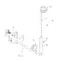
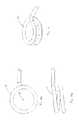
- FIG. 1is a perspective view of an intravenous line lifter device in accordance with an embodiment of the disclosure.
- FIG. 2is a perspective view of the intravenous line lifter device of FIG. 1 .
- FIG. 3is a perspective view of the intravenous line lifter device of FIG. 1 .
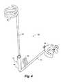
- FIG. 4is a perspective view of the intravenous line lifter device of FIG. 1 .
- FIG. 5is an exploded perspective view of the intravenous line lifter device of FIG. 1 .
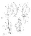
- FIG. 6Ais a perspective view of an intravenous line lifter system in accordance with an embodiment of the disclosure, wherein the intravenous line lifting system is in a relaxed position.
- FIG. 6Bis a perspective view of the intravenous line lifter system of FIG. 6A , wherein the intravenous line lifting system is in a flexed position.
- FIG. 7is a perspective view of an intravenous line lifter device in accordance with an embodiment of the disclosure wherein the second elongated support member is at least partially flexible.
- FIG. 8Ais a top view of the intravenous line lifter device of FIG. 7 .
- FIG. 8Bis a profile view of the intravenous line lifter device of FIG. 7 .
- FIG. 8Cis an end view intravenous line lifter device of FIG. 7 .
- FIG. 9Ais a perspective view of an intravenous line lifter system in accordance with an embodiment of the disclosure, wherein the intravenous line lifting system in a relaxed position.
- FIG. 9Bis a perspective view of the intravenous line lifter system of FIG. 9A , wherein the intravenous line lifting system is in a flexed position.
- FIG. 10Ais a perspective view of an intravenous line lifter system in accordance with an embodiment of the disclosure including alternative line retention devices, wherein the intravenous line lifter system is in a relaxed position.
- FIG. 10Bis a perspective view of the intravenous line lifter system of FIG. 10A , wherein the intravenous line lifting system is in a flexed position.
- FIG. 11is a perspective view of a clamp in accordance with an embodiment of the disclosure.
- FIG. 12is a perspective view of a clamp in accordance with an embodiment of the disclosure.
- FIG. 13Ais a perspective view of a swiveling clamp in accordance with an embodiment of the disclosure.
- FIG. 13Bis a top view of the clamp of FIG. 13A .
- FIG. 13Cis a close up perspective view of the clamp of FIG. 13A .
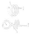
- FIG. 14Ais a top view of a spiraling hook in accordance with an embodiment of the disclosure.
- FIG. 14Bis a side view of the spiraling hook of FIG. 14A .
- FIG. 14Cis an end view of the spiraling hook of FIG. 14A .
- FIG. 15is a perspective view of the spiraling hook of FIG. 14A .
- FIG. 16Ais a top view of a spiraling hook in accordance with an embodiment of the disclosure.
- FIG. 16Bis a side view of the spiraling hook of FIG. 16A .
- FIG. 17is a perspective view of the spiraling hook of FIG. 16A .
- FIG. 18Ais a top view of a spiraling hook in accordance with an embodiment of the disclosure.
- FIG. 18Bis a side view of the spiraling hook of FIG. 18A .
- FIG. 19is a perspective view of the spiraling hook of FIG. 18A .
- FIG. 20is a perspective view of a tube holder in accordance with an embodiment of the disclosure.
- FIG. 21is a perspective view of a split ring in accordance with an embodiment of the disclosure.
- Intravenous line lifter device 100generally includes a first elongated support member 30 , a second elongated support member 32 , a first line retention device 34 , and a second line retention device 36 .
- second elongated support member 32can further include a flexible joint 37 , such as a spring-loaded joint or hinge.
- intravenous line lifter device 100can include clamp 38 for selectively coupling the intravenous line lifter device 100 to patient care equipment 92 .
- first elongated support member 30has a first end 40 and a second end 42 .
- first elongated support member 30can be constructed of a substantially rigid or semi-rigid material.
- first elongated support member 30can be constructed of stainless steel, aluminum, fiberglass, plastic, another material, or a composite of materials.
- first elongated support member 30can have a surface that lends itself to easy cleaning and disinfection.
- first elongated support member 30can be in the form of a cylindrical rod. In one embodiment, first elongated support member 30 can be substantially straight. In another embodiment, first elongated support member 30 can have a proximal portion 74 defining a longitudinal axis angularly displaced relative to a longitudinal axis defined by a distal portion 76 of first elongated support member 30 . In one embodiment, distal portion 76 can be substantially orthogonal to proximal portion 74 .
- First elongated support member 30can include a bore 78 , configured to receive attachments, for example first line retention device 34 .
- Bore 78can be a through bore that transversely passes entirely through first elongated support member 30 , or bore 78 can be a blind bore. In one embodiment, bore 78 can be threaded.
- first elongated support member 30is selectively couplable to patient care equipment 92 , or a support 44 for patient care equipment 92 .
- first elongated support member 30can be attached to an IV pole support 44 so that first elongated support member 30 extends radially outward from support 44 in a substantially horizontal manner.
- for patient care equipment 92 equipmentcan include one or more medical infusion pumps 94 , one or more medicament containers 96 , and one or more IV lines 70 .
- first elongated support member 30can be coupled to a hospital bed, wheelchair, cart, or wagon.
- first elongated support member 30can be coupled to support 44 in a manner that allows the radial extension of first elongated support member 30 to be lengthened or shortened as needed.
- first elongated support member 30can be telescoping, segmented, or otherwise constructed in a manner in which its length of configuration can be altered or adjusted in use or for storage.
- clamp 38can be a C-clamp.
- clamp 38can be comprised of a clamp body portion 46 and a threaded portion 48 , wherein threaded portion 48 is threadedly coupled to body portion 46 via bore 84 .
- Threaded portion 48can include a support engaging surface 50 , wherein threaded portion 48 and support engaging surface 50 can be positioned relative to clamp body portion 46 for coupling clamp 38 to support 44 .
- Clamp 38can be constructed of aluminum, stainless steel or another material or composite of materials to allow easy cleaning and disinfection. Numerous other configurations and constructions of clamp 38 can be used in other embodiments, with the embodiments of FIGS. 11-12 being but one example.
- clamp 38can be configured to allow a portion of first elongated support member 30 to pass therethrough, thereby allowing first elongated support member 30 to be coupled to support 44 in a manner that allows the radial extension of first elongated support member 30 to be lengthened or shortened relative to support 44 as needed.
- clamp 38can further include a threaded bore 80 for receiving a set screw 82 configured to apply a frictional force against first elongated support member 30 for the purpose of holding first elongated support member 30 in a fixed position relative to clamp 38 .
- first elongated support member 30is fixed in position relative to clamp body portion 46 .
- first elongated support member 30can move relative to clamp body portion 46 and swivel or pivot about support 44 by moving along a track, rail or other structure 52 defined in or on clamp body portion 46 .
- first end 40can be defined as a ball 54 slidable along track 52 .
- first elongated support member 30can pivot about 180 degrees or more relative to support 44 .
- first elongated support member 30can be coupled to support 44 by a cam lock, screw lock, rotational bearing attachment, frictional attachment, some other attachment device, or a combination of any of the forgoing attachment mechanisms or devices.
- first elongated support member 30 or second elongated support member 32can be folded or collapsed relative to support 44 when not in use or when extra slack in IV lines 70 is not needed or desired.
- second elongated support member 32has a first end 56 and a second end 58 .
- second elongated support member 32can be constructed of a substantially rigid or semi-rigid material.
- second elongated support member 32can be constructed of stainless steel, aluminum, fiberglass, plastic, another material, or a composite of materials.
- first elongated support member 30can have a surface that lends itself to easy cleaning and disinfection.
- second elongated support member 32proximal first end 56 is coupled to first elongated support member 30 .
- second elongated support member 32is coupled proximate the first elongated support member second end 42 .
- second elongated support member 32can be coupled to first elongated support member 30 via flexible joint 37 .
- flexible joint 37can be a spring-loaded joint or hinge, such as a coil spring hingedly coupling first elongated support member 30 to second elongated support member 32 .
- flexible joint 37can be fixedly coupled to first elongated support member 30 and second elongated support member 32 .
- flexible joint 37can be welded or soldered to first elongated support member 30 and second elongated support member 32 .
- first elongated support member 32can be coupled to first elongated support member 30 in a variety of ways, including but not limited to a press fitting, a threaded connection, via a set screw, an adhesive bond, a separate joining member, a strain relief connection, another suitable device or connector, or a combination of any of the forgoing attachment devices or connectors.
- a protective sheath 90such as a heat shrink wrap or another suitable material, for example neoprene, can at least partially surround flexible joint 37 to allow easy cleaning and disinfection and prevent contamination of, pinch points and other interactions with flexible joint 37 in use.
- second elongated support member 32can be constructed of a flexible material that is able to recoil or spring back into position or shape after bending.
- second elongated support member 32can be constructed of fiberglass or a similar material or composite to allow resilience, while at the same time permitting easy cleaning and disinfection.
- resilient membercan be constructed of spring steel, plastic or another material or composite of materials.
- second elongated support member 32can be foldable or adjustable.
- second elongated support member 32can be telescoping.
- second elongated support member 32can include a rigid portion and a flexible portion. In one embodiment, rigid portion and flexible portion can be constructed of different materials.
- first line retention device 34is coupled to first elongated support member 30 between the first end 40 and second end 42 , though the particular position at which device 34 is coupled to member 32 can vary from that depicted.
- First line retention device 34can be coupled to first elongated support member 30 by any of the methods described in connecting first elongated support member 30 to second elongated support member 32 .
- first line retention device 34can be welded to first elongated support member 30 , or integrally formed in, on or with first elongated support member 30 .
- first line retention device 34can be removably or adjustably coupled to first elongated support member 30 via bore 78 .
- second line retention device 36can be coupled to second elongated support member 32 proximate second elongated support member second end 58 .
- second line retention device 36can be integral molding into second elongated support member 32 .
- second line retention device 36can be configured to snuggly fit over second elongated support member second end 58 .
- second line retention device 36can be affixed to second elongated support member second end 58 by adhesive.
- any of the previously describe methods of connectioncan be used, for example, second line retention device 36 can be removably, or adjustably coupled to second elongated support member 32 .
- either or both line retention devices 34 and 36can be in the form of a bridle ring or spiraling hook.
- spiraling hook 60can circumscribe center point 62 one time.
- spiraling hook 60can circumscribe center point 62 two times.
- spiraling hook 60can circumscribe center point 64 any number of times, including fractions. For example, as depicted in FIGS. 18A-19 , spiraling hook 60 can circumscribe center point 62 one and a half times. In one embodiment, spiraling hook 60 can circumscribe center point 62 in a circular fashion.
- spiraling hook 60can be configured in a D-shape when viewed from the top.
- spiraling hook 60can have an opening oriented in a direction facing first elongated support member 30 , second elongated support member 30 , or any other direction that is advantageous to operation or retention of the IV lines 70 .
- either or both of line retention devices 34 and 36can comprise a carabiner or similar structure with spring-loaded gates or latches that enable easy insertion and removal of IV tubing while retaining the tubing therein during use.
- line retention devices 34 and/or 36also can comprise or interface with an S-clip or other device or structure that can facilitate more thorough securement of tubing in line retention devices 34 and/or 36 .
- line retention devices 34 and 36can be constructed of aluminum, stainless steel or another material or composite of materials to allow easy cleaning and disinfection. In another embodiment, line retention devices 34 and 36 can be constructed of a malleable material to allow for adjustment and customization. In another embodiment, line retention devices 34 and 36 can include individual tracks or recesses for each IV line 70 . In another embodiment, line retention devices 34 and 36 can have a rubber, plastic or other coating, or a surface texture or treatment, to either increase or reduce friction with IV tubing therein or provide an aesthetic or other benefit.
- either or both line retention devices 34 and 36can be in the form of a tube holder 64 .
- tube holder 64can be defined by a plurality of notches 66 sized to accept one or more IV lines 70 . Numerous other configurations and constructions of tube holder 64 can be used in other embodiments, with the embodiment of FIG. 20 being but one example.
- tube holder 64can be resilient.
- tube holder 64can be constructed of foam or a similar material.
- tube holder 64is selectively couplable to or positionable on first elongated support member 30 or second elongated support member 32 .
- tube holder 64can be integrally molded into first elongated member 30 or second elongated member 32 . In one embodiment, tube holder 64 can be used in place of, or in addition to, first line retention device 34 and/or second line retention device 36 .
- either or both line retention devices 34 and 36can be in the form of split ring 68 .
- a split 72 defined in split ring 68can be sized to allow only a single IV line 70 to pass at a given time or configured such that split ring 68 must be temporarily deformed in order for IV line 70 to pass in or out of split 72 .
- split 72can be oriented in a direction facing first elongated support member 30 , resilient elongated support member 30 , or any other direction that is advantageous to operation or retention of the IV lines 70 .
- intravenous line lifter device 100 and/or system 200can interact with or include other devices beyond IV lines 70 and patient care equipment 92 .
- intravenous line lifter device 100 and/or system 200can comprise a holder or other device to accommodate a patient controlled analgesia (PCA), timer, schedule, electronic or paper chart, or other device in easy access to the patient.
- intravenous line lifter device 100 and/or system 200can accommodate a name tag, label, protective bumper or padding, decorative covering or logo, toy, novelty or other item a patient or medical professional may desire to customize device 100 and/or system 200 .
- PCApatient controlled analgesia
- intravenous line lifter device 100 and/or system 200can accommodate a name tag, label, protective bumper or padding, decorative covering or logo, toy, novelty or other item a patient or medical professional may desire to customize device 100 and/or system 200 .
- the IV lines traversing from the patient care device to the patientare threaded through the first line retention device 34 and second line retention device 36 in the interim.
- the second elongated support memberof which the second line retention device 36 is coupled, suspends the IV lines, thereby minimizing any contact of the IV lines with the floor or other surfaces.
- second elongated support member 32flexes relative to first elongated support member 30 to provide slack to the patient without stressing the IV tubing connections on patient care device or patient.
- the direction of flexingcan vary with the direction of movement of the patient.
- second elongated support member 32returns to a non-flexed or relaxed position.
- Line lifter device 100is shown in connection with the suspension of IV lines, but is not restricted to medical applications.
- Line lifter device 100can be utilized with electrical or other cords, cables or tubes (e.g., those associated with computers, household or commercial grade appliances including hairdryers and other styling or cosmetic tools, irons, vacuums, and kitchen appliances, among myriad others), as well as pneumatic or hydraulic lines in other applications.
- line lifter device 100is not limited to the specific configuration of the embodiments shown.
- the various components of line lifter device 100can be assembled in reverse order, such that second line retention device 36 is near to the ground for line or cord management purposes.
- line lifter device 100can come in a range of sizes and configurations and can include colors (e.g., by colored materials, coatings, anodizing, etc.) and other aesthetic features.
- line lifter device 100can further comprise one or more bumpers or pads (not depicted) on the ends of first elongated support member 30 or resilient elongated support member 32 to prevent injury from inadvertent contact.
- embodimentsmay comprise fewer features than illustrated in any individual embodiment described above.
- the embodiments described hereinare not meant to be an exhaustive presentation of the ways in which the various features may be combined. Accordingly, the embodiments are not mutually exclusive combinations of features; rather, embodiments can comprise a combination of different individual features selected from different individual embodiments, as understood by persons of ordinary skill in the art.
- elements described with respect to one embodimentcan be implemented in other embodiments even when not described in such embodiments unless otherwise noted.
- a dependent claimmay refer in the claims to a specific combination with one or more other claims, other embodiments can also include a combination of the dependent claim with the subject matter of each other dependent claim or a combination of one or more features with other dependent or independent claims. Such combinations are proposed herein unless it is stated that a specific combination is not intended.
Landscapes
- Engineering & Computer Science (AREA)
- General Engineering & Computer Science (AREA)
- Health & Medical Sciences (AREA)
- Mechanical Engineering (AREA)
- Hematology (AREA)
- Heart & Thoracic Surgery (AREA)
- Biomedical Technology (AREA)
- Life Sciences & Earth Sciences (AREA)
- Animal Behavior & Ethology (AREA)
- General Health & Medical Sciences (AREA)
- Public Health (AREA)
- Veterinary Medicine (AREA)
- Anesthesiology (AREA)
- Vascular Medicine (AREA)
- Infusion, Injection, And Reservoir Apparatuses (AREA)
Abstract
Description
Claims (20)
Priority Applications (1)
| Application Number | Priority Date | Filing Date | Title |
|---|---|---|---|
| US14/472,894US9511185B2 (en) | 2014-04-18 | 2014-08-29 | Intravenous line lifter devices, systems and methods |
Applications Claiming Priority (2)
| Application Number | Priority Date | Filing Date | Title |
|---|---|---|---|
| US201461981567P | 2014-04-18 | 2014-04-18 | |
| US14/472,894US9511185B2 (en) | 2014-04-18 | 2014-08-29 | Intravenous line lifter devices, systems and methods |
Publications (2)
| Publication Number | Publication Date |
|---|---|
| US20150297826A1 US20150297826A1 (en) | 2015-10-22 |
| US9511185B2true US9511185B2 (en) | 2016-12-06 |
Family
ID=54321085
Family Applications (1)
| Application Number | Title | Priority Date | Filing Date |
|---|---|---|---|
| US14/472,894Expired - Fee RelatedUS9511185B2 (en) | 2014-04-18 | 2014-08-29 | Intravenous line lifter devices, systems and methods |
Country Status (1)
| Country | Link |
|---|---|
| US (1) | US9511185B2 (en) |
Cited By (5)
| Publication number | Priority date | Publication date | Assignee | Title |
|---|---|---|---|---|
| US10786407B2 (en) | 2018-06-13 | 2020-09-29 | Cardon Ellis | Chemo mobile cart system |
| US20220118175A1 (en)* | 2020-10-19 | 2022-04-21 | Walter L. Smith | Intravenous fluid bag supporting assembly |
| US11311664B1 (en)* | 2021-04-12 | 2022-04-26 | Denicia Dread Rankin | Shapeable intravenous tubing |
| US11320065B2 (en)* | 2019-04-15 | 2022-05-03 | Neotech Products Llc | Tubing and cable organizing device |
| US20230248460A1 (en)* | 2022-02-10 | 2023-08-10 | Lori Millward | Medical Instrument Storage Device |
Families Citing this family (3)
| Publication number | Priority date | Publication date | Assignee | Title |
|---|---|---|---|---|
| DE102015010431A1 (en)* | 2015-08-11 | 2017-02-16 | Fresenius Medical Care Deutschland Gmbh | peritoneal dialysis |
| CN106988199A (en)* | 2016-01-20 | 2017-07-28 | 固瑞克明尼苏达有限公司 | Mounting Fixtures for Marker Applicators |
| US10881782B2 (en)* | 2018-10-10 | 2021-01-05 | David Behrens | Intravenous tube holding assembly |
Citations (72)
| Publication number | Priority date | Publication date | Assignee | Title |
|---|---|---|---|---|
| US1865757A (en)* | 1929-07-02 | 1932-07-05 | Honsowetz Isabelle | Hanger |
| US2470524A (en)* | 1946-07-13 | 1949-05-17 | Jarvis & Jarvis Inc | Intravenous stand attachment for wheel stretchers |
| US2593567A (en)* | 1950-04-14 | 1952-04-22 | Tyson O Keck | Clothes rack attachment for securement to beds |
| US2607881A (en)* | 1951-04-04 | 1952-08-19 | John M Anderson | Light and mirror attachment for hospital beds |
| US2696963A (en)* | 1951-06-13 | 1954-12-14 | Trephine Instr Inc | Portable intravenous fluid carrier |
| US2913740A (en)* | 1957-03-11 | 1959-11-24 | Charles D Eldridge | Cord bracket for hospital beds |
| US2957187A (en)* | 1958-06-06 | 1960-10-25 | Wilmette Screw Products | Telescopic stand |
| US2982572A (en)* | 1958-09-26 | 1961-05-02 | Edward R Farber | Interlocking sectional units |
| US3298648A (en)* | 1966-04-08 | 1967-01-17 | Russell J Sepanski | Baby bottle holder |
| US3460789A (en)* | 1966-04-12 | 1969-08-12 | Horizon Ind Ltd | Container suspension device |
| US3709372A (en)* | 1971-01-06 | 1973-01-09 | L Alexander | Intravenous supply container support |
| US3709556A (en)* | 1970-10-16 | 1973-01-09 | E Allard | Telescoping i v pole attachment and wheel chairs |
| US3835486A (en)* | 1972-08-14 | 1974-09-17 | Inter Royal Corp | Telescoping novel stand assembly |
| US3866869A (en) | 1973-10-09 | 1975-02-18 | Carroll E Woods | Cord retractor for electric iron |
| US3966160A (en)* | 1975-05-12 | 1976-06-29 | The United States Of America As Represented By The Secretary Of The Air Force | Inflight intravenous bottle holder |
| US4225104A (en)* | 1978-11-20 | 1980-09-30 | Larson Godfrey R | Handle for mobile intravenous stand |
| US4541596A (en)* | 1982-09-13 | 1985-09-17 | Price Ronald K | Portable intravenous pole for use in an emergency |
| US4666111A (en)* | 1985-11-14 | 1987-05-19 | Robert Schuler | Holder for IV tube |
| US4744536A (en)* | 1986-06-25 | 1988-05-17 | Icu Medical, Inc. | Collapsable pole and stand combination |
| US4875651A (en)* | 1988-12-06 | 1989-10-24 | Wergin Dennis D | Transducer mounting device |
| US4905944A (en)* | 1989-01-26 | 1990-03-06 | Baxter International Inc. | Home care intravenous stand |
| US4988062A (en)* | 1988-03-10 | 1991-01-29 | London Robert A | Apparatus, system and method for organizing and maintaining a plurality of medical catheters and the like |
| US5219139A (en)* | 1992-06-25 | 1993-06-15 | Barnes Hospital | Device for connecting an IV pole to a wheelchair |
| US5236213A (en)* | 1991-02-12 | 1993-08-17 | Trickett James R | IV utility pole coupling and towing device |
| US5279486A (en)* | 1993-03-31 | 1994-01-18 | Harmon Elbert C | Medical support device |
| US5288093A (en)* | 1991-11-05 | 1994-02-22 | Gross Gary D | Coupler for a mobile intravenous support stand and mobile patient transport means |
| US5316246A (en)* | 1992-03-23 | 1994-05-31 | Scott/Ross Designs Inc. | Intravenous tube holder |
| US5344169A (en)* | 1992-01-27 | 1994-09-06 | Pryor Products | Multi-pole support stand |
| US5421548A (en)* | 1994-04-01 | 1995-06-06 | Bennett; James R. | I.V. stand and attachments |
| US5470037A (en)* | 1993-08-20 | 1995-11-28 | Willis; Rodney L. | Apparatus for self-administering fluids in patients, children and persons of limited capabilities |
| US5699988A (en)* | 1993-01-19 | 1997-12-23 | St. Francis Research Institute | Coupler clamping apparatus for interconnecting a free-standing, wheeled intravenous pole with mobile patient transfer devices |
| US5735806A (en)* | 1996-02-23 | 1998-04-07 | Leibovic; Stephen J. | Wrist traction apparatus |
| US5876016A (en)* | 1997-05-14 | 1999-03-02 | Urban; Theodore A. | Apparatus and method to elevate an infusion source |
| US6079678A (en)* | 1998-10-22 | 2000-06-27 | Schott; Jeffery C. | Intravenous stand support assembly |
| US6224026B1 (en)* | 1999-05-05 | 2001-05-01 | N/A | Overhead articulated support for the human arm |
| US6315759B1 (en)* | 1999-12-21 | 2001-11-13 | Travis Peterson | Protective cover for intravenous lines and other elongated members |
| US20020011543A1 (en)* | 2000-03-23 | 2002-01-31 | Chinn Robert C. | IV pole |
| US6375133B1 (en)* | 1998-03-04 | 2002-04-23 | Emergent Innovations, Llc. | Intravenous (IV) pole for transport with multiple infusion devices |
| US6382568B1 (en)* | 2000-07-26 | 2002-05-07 | Richard Snell | Portable medical diagnostic equipment organizer |
| US20020104934A1 (en)* | 1998-03-04 | 2002-08-08 | Emergent Innovations, Llc | Intravenous (IV) pole supporting systems |
| US6458104B2 (en)* | 2000-03-13 | 2002-10-01 | William E. Gautsche, Jr. | IV administration lines fastening and identification device |
| US20020162926A1 (en)* | 2001-05-04 | 2002-11-07 | Van Nguyen | Apparatus for supporting medical fluids |
| US6698044B2 (en)* | 2002-03-30 | 2004-03-02 | Saul P. Greenfield | Pediatric stirrup device and method |
| US20040104321A1 (en)* | 2002-08-06 | 2004-06-03 | Marsolais Thomas R. | Adjustable connector for I.V. poles and medical devices |
| US20040118982A1 (en)* | 2002-12-20 | 2004-06-24 | Shillings D. Kay | Organizer for medical tubes and cables |
| US6811541B2 (en)* | 2002-05-23 | 2004-11-02 | Dennis Michael Lambert | Traction device |
| US7013840B2 (en) | 2003-07-30 | 2006-03-21 | Leon Michael A | Dog leash for use on bicycle |
| US20060230540A1 (en)* | 2003-05-22 | 2006-10-19 | Mary Whelan | Patient hand support aid for bed |
| US20060253109A1 (en)* | 2006-02-08 | 2006-11-09 | David Chu | Surgical robotic helping hand system |
| US20060249635A1 (en) | 2003-03-18 | 2006-11-09 | Hill-Rom Services, Inc. | Patient line management apparatus |
| US20070045481A1 (en)* | 2005-08-15 | 2007-03-01 | Adams Edric J | Device and method for positioning a delivery tube |
| US7303527B2 (en)* | 2004-07-26 | 2007-12-04 | Ng Raymond C | Medical examination apparatus |
| US20090019678A1 (en) | 2007-07-19 | 2009-01-22 | Taylor Susan L | Intravenous tube organizer |
| US7533428B2 (en)* | 2006-07-18 | 2009-05-19 | Siemens Medical Solutions Usa, Inc. | Medical bag support assembly |
| US7546993B1 (en)* | 2008-03-25 | 2009-06-16 | Tyco Healthcare Group Lp | Flexible clamping apparatus for medical devices |
| US7731136B1 (en)* | 2007-03-19 | 2010-06-08 | Cory Chisolm | Combined IV bag and oxygen supporting pole and associated method |
| US7731138B2 (en)* | 2005-05-26 | 2010-06-08 | Covidien Ag | Flexible clamping apparatus for medical devices |
| US20100146702A1 (en)* | 2008-09-08 | 2010-06-17 | Impact Instrumentation, Inc. | Litter attachment bracket |
| US7766289B2 (en) | 2006-02-08 | 2010-08-03 | Hill-Rom Services, Inc. | Line management device |
| US7789361B2 (en)* | 2005-05-06 | 2010-09-07 | American Sterilizer Company | Transfer system and transfer device |
| US7896298B2 (en)* | 2008-07-11 | 2011-03-01 | Amg Medical Inc. | Intravenous support apparatus |
| US20110121149A1 (en)* | 2006-05-19 | 2011-05-26 | Arnold Herskovic | Clamping device |
| US8038330B2 (en)* | 2009-06-30 | 2011-10-18 | Yun-Zhao Liu | Movable multi-directional light stand |
| US8100371B2 (en)* | 2003-12-15 | 2012-01-24 | Ergotech Health Systems Pty Ltd. | I.V. support stand and clamp apparatus |
| US8152181B2 (en)* | 2005-11-21 | 2012-04-10 | About Time Technologies Pty. Ltd. | Mobility frame |
| US8361040B2 (en)* | 2007-09-14 | 2013-01-29 | Medrad, Inc. | Fluid path set providing gravity flow prevention |
| US8460272B2 (en) | 2009-05-22 | 2013-06-11 | Susan Leeds Kudo | Method and apparatus for extensible intravenous drip line |
| US8567730B1 (en)* | 2012-09-05 | 2013-10-29 | Cherie Stevenson | Collapsible intravenous fluid pole system |
| US8733719B2 (en)* | 2010-11-12 | 2014-05-27 | Wildcard Enterprises Llc | Method and apparatus for use in management of medical intravenous pole assemblies |
| US8739335B1 (en)* | 2012-07-17 | 2014-06-03 | Johnathan D. Hoggatt | Tactical stretcher and convertible first aid table with detachable IV pole |
| US20140191103A1 (en)* | 2012-09-28 | 2014-07-10 | David F. Simon | Support For Variably Positioning A Holder Platform For Books Or Electric Devices |
| US8863333B2 (en)* | 2011-12-08 | 2014-10-21 | North American Rescue, Llc | Portable IV pole and litter |
- 2014
- 2014-08-29USUS14/472,894patent/US9511185B2/ennot_activeExpired - Fee Related
Patent Citations (74)
| Publication number | Priority date | Publication date | Assignee | Title |
|---|---|---|---|---|
| US1865757A (en)* | 1929-07-02 | 1932-07-05 | Honsowetz Isabelle | Hanger |
| US2470524A (en)* | 1946-07-13 | 1949-05-17 | Jarvis & Jarvis Inc | Intravenous stand attachment for wheel stretchers |
| US2593567A (en)* | 1950-04-14 | 1952-04-22 | Tyson O Keck | Clothes rack attachment for securement to beds |
| US2607881A (en)* | 1951-04-04 | 1952-08-19 | John M Anderson | Light and mirror attachment for hospital beds |
| US2696963A (en)* | 1951-06-13 | 1954-12-14 | Trephine Instr Inc | Portable intravenous fluid carrier |
| US2913740A (en)* | 1957-03-11 | 1959-11-24 | Charles D Eldridge | Cord bracket for hospital beds |
| US2957187A (en)* | 1958-06-06 | 1960-10-25 | Wilmette Screw Products | Telescopic stand |
| US2982572A (en)* | 1958-09-26 | 1961-05-02 | Edward R Farber | Interlocking sectional units |
| US3298648A (en)* | 1966-04-08 | 1967-01-17 | Russell J Sepanski | Baby bottle holder |
| US3460789A (en)* | 1966-04-12 | 1969-08-12 | Horizon Ind Ltd | Container suspension device |
| US3709556A (en)* | 1970-10-16 | 1973-01-09 | E Allard | Telescoping i v pole attachment and wheel chairs |
| US3709372A (en)* | 1971-01-06 | 1973-01-09 | L Alexander | Intravenous supply container support |
| US3835486A (en)* | 1972-08-14 | 1974-09-17 | Inter Royal Corp | Telescoping novel stand assembly |
| US3866869A (en) | 1973-10-09 | 1975-02-18 | Carroll E Woods | Cord retractor for electric iron |
| US3966160A (en)* | 1975-05-12 | 1976-06-29 | The United States Of America As Represented By The Secretary Of The Air Force | Inflight intravenous bottle holder |
| US4225104A (en)* | 1978-11-20 | 1980-09-30 | Larson Godfrey R | Handle for mobile intravenous stand |
| US4541596A (en)* | 1982-09-13 | 1985-09-17 | Price Ronald K | Portable intravenous pole for use in an emergency |
| US4666111A (en)* | 1985-11-14 | 1987-05-19 | Robert Schuler | Holder for IV tube |
| US4744536A (en)* | 1986-06-25 | 1988-05-17 | Icu Medical, Inc. | Collapsable pole and stand combination |
| US4988062A (en)* | 1988-03-10 | 1991-01-29 | London Robert A | Apparatus, system and method for organizing and maintaining a plurality of medical catheters and the like |
| US4875651A (en)* | 1988-12-06 | 1989-10-24 | Wergin Dennis D | Transducer mounting device |
| US4905944A (en)* | 1989-01-26 | 1990-03-06 | Baxter International Inc. | Home care intravenous stand |
| US5236213A (en)* | 1991-02-12 | 1993-08-17 | Trickett James R | IV utility pole coupling and towing device |
| US5288093A (en)* | 1991-11-05 | 1994-02-22 | Gross Gary D | Coupler for a mobile intravenous support stand and mobile patient transport means |
| US5344169A (en)* | 1992-01-27 | 1994-09-06 | Pryor Products | Multi-pole support stand |
| US5316246A (en)* | 1992-03-23 | 1994-05-31 | Scott/Ross Designs Inc. | Intravenous tube holder |
| US5219139A (en)* | 1992-06-25 | 1993-06-15 | Barnes Hospital | Device for connecting an IV pole to a wheelchair |
| US5699988A (en)* | 1993-01-19 | 1997-12-23 | St. Francis Research Institute | Coupler clamping apparatus for interconnecting a free-standing, wheeled intravenous pole with mobile patient transfer devices |
| US5279486A (en)* | 1993-03-31 | 1994-01-18 | Harmon Elbert C | Medical support device |
| US5470037A (en)* | 1993-08-20 | 1995-11-28 | Willis; Rodney L. | Apparatus for self-administering fluids in patients, children and persons of limited capabilities |
| US5421548A (en)* | 1994-04-01 | 1995-06-06 | Bennett; James R. | I.V. stand and attachments |
| US5735806A (en)* | 1996-02-23 | 1998-04-07 | Leibovic; Stephen J. | Wrist traction apparatus |
| US5876016A (en)* | 1997-05-14 | 1999-03-02 | Urban; Theodore A. | Apparatus and method to elevate an infusion source |
| US6375133B1 (en)* | 1998-03-04 | 2002-04-23 | Emergent Innovations, Llc. | Intravenous (IV) pole for transport with multiple infusion devices |
| US20020104934A1 (en)* | 1998-03-04 | 2002-08-08 | Emergent Innovations, Llc | Intravenous (IV) pole supporting systems |
| US6079678A (en)* | 1998-10-22 | 2000-06-27 | Schott; Jeffery C. | Intravenous stand support assembly |
| US6224026B1 (en)* | 1999-05-05 | 2001-05-01 | N/A | Overhead articulated support for the human arm |
| US6315759B1 (en)* | 1999-12-21 | 2001-11-13 | Travis Peterson | Protective cover for intravenous lines and other elongated members |
| US6458104B2 (en)* | 2000-03-13 | 2002-10-01 | William E. Gautsche, Jr. | IV administration lines fastening and identification device |
| US20020011543A1 (en)* | 2000-03-23 | 2002-01-31 | Chinn Robert C. | IV pole |
| US6431505B2 (en)* | 2000-03-23 | 2002-08-13 | Ferno-Washington, Inc. | IV pole |
| US6382568B1 (en)* | 2000-07-26 | 2002-05-07 | Richard Snell | Portable medical diagnostic equipment organizer |
| US20020162926A1 (en)* | 2001-05-04 | 2002-11-07 | Van Nguyen | Apparatus for supporting medical fluids |
| US6698044B2 (en)* | 2002-03-30 | 2004-03-02 | Saul P. Greenfield | Pediatric stirrup device and method |
| US6811541B2 (en)* | 2002-05-23 | 2004-11-02 | Dennis Michael Lambert | Traction device |
| US20040104321A1 (en)* | 2002-08-06 | 2004-06-03 | Marsolais Thomas R. | Adjustable connector for I.V. poles and medical devices |
| US20040118982A1 (en)* | 2002-12-20 | 2004-06-24 | Shillings D. Kay | Organizer for medical tubes and cables |
| US20060249635A1 (en) | 2003-03-18 | 2006-11-09 | Hill-Rom Services, Inc. | Patient line management apparatus |
| US20060230540A1 (en)* | 2003-05-22 | 2006-10-19 | Mary Whelan | Patient hand support aid for bed |
| US7013840B2 (en) | 2003-07-30 | 2006-03-21 | Leon Michael A | Dog leash for use on bicycle |
| US8100371B2 (en)* | 2003-12-15 | 2012-01-24 | Ergotech Health Systems Pty Ltd. | I.V. support stand and clamp apparatus |
| US7303527B2 (en)* | 2004-07-26 | 2007-12-04 | Ng Raymond C | Medical examination apparatus |
| US7789361B2 (en)* | 2005-05-06 | 2010-09-07 | American Sterilizer Company | Transfer system and transfer device |
| US7731138B2 (en)* | 2005-05-26 | 2010-06-08 | Covidien Ag | Flexible clamping apparatus for medical devices |
| US20070045481A1 (en)* | 2005-08-15 | 2007-03-01 | Adams Edric J | Device and method for positioning a delivery tube |
| US8152181B2 (en)* | 2005-11-21 | 2012-04-10 | About Time Technologies Pty. Ltd. | Mobility frame |
| US8370977B2 (en)* | 2006-02-08 | 2013-02-12 | Hill-Rom Services, Inc. | Line management device for a hospital bed |
| US20060253109A1 (en)* | 2006-02-08 | 2006-11-09 | David Chu | Surgical robotic helping hand system |
| US7766289B2 (en) | 2006-02-08 | 2010-08-03 | Hill-Rom Services, Inc. | Line management device |
| US20110121149A1 (en)* | 2006-05-19 | 2011-05-26 | Arnold Herskovic | Clamping device |
| US7533428B2 (en)* | 2006-07-18 | 2009-05-19 | Siemens Medical Solutions Usa, Inc. | Medical bag support assembly |
| US7731136B1 (en)* | 2007-03-19 | 2010-06-08 | Cory Chisolm | Combined IV bag and oxygen supporting pole and associated method |
| US20090019678A1 (en) | 2007-07-19 | 2009-01-22 | Taylor Susan L | Intravenous tube organizer |
| US8361040B2 (en)* | 2007-09-14 | 2013-01-29 | Medrad, Inc. | Fluid path set providing gravity flow prevention |
| US7546993B1 (en)* | 2008-03-25 | 2009-06-16 | Tyco Healthcare Group Lp | Flexible clamping apparatus for medical devices |
| US7896298B2 (en)* | 2008-07-11 | 2011-03-01 | Amg Medical Inc. | Intravenous support apparatus |
| US20100146702A1 (en)* | 2008-09-08 | 2010-06-17 | Impact Instrumentation, Inc. | Litter attachment bracket |
| US8460272B2 (en) | 2009-05-22 | 2013-06-11 | Susan Leeds Kudo | Method and apparatus for extensible intravenous drip line |
| US8038330B2 (en)* | 2009-06-30 | 2011-10-18 | Yun-Zhao Liu | Movable multi-directional light stand |
| US8733719B2 (en)* | 2010-11-12 | 2014-05-27 | Wildcard Enterprises Llc | Method and apparatus for use in management of medical intravenous pole assemblies |
| US8863333B2 (en)* | 2011-12-08 | 2014-10-21 | North American Rescue, Llc | Portable IV pole and litter |
| US8739335B1 (en)* | 2012-07-17 | 2014-06-03 | Johnathan D. Hoggatt | Tactical stretcher and convertible first aid table with detachable IV pole |
| US8567730B1 (en)* | 2012-09-05 | 2013-10-29 | Cherie Stevenson | Collapsible intravenous fluid pole system |
| US20140191103A1 (en)* | 2012-09-28 | 2014-07-10 | David F. Simon | Support For Variably Positioning A Holder Platform For Books Or Electric Devices |
Non-Patent Citations (5)
| Title |
|---|
| Advent Medical Technologies, Koala Klip Medical Tube & IV Line Organizer (Box of 100), Model: KK1000, dated Mar. 11, 2011, 1 page. |
| MarketLab, Boa I.V. Line Organizer, 1 page, as available at http://www.pr.com/press-release/202957, as of Feb. 2, 2016. |
| MarketLab, IV Line Holder, available at http://www.marketlab.com/iv-line-holder/p/IVLineHolder as of Jan. 8, 2016, 1 page. |
| Simplicty, IV Management System, Innovative Medical Designs, available at www.imdusa.net, © 2010, 6 pages. |
| Springer America, Springer Product Specifications, available at www.springeramerica.com/product-specs.asp, dated Apr. 7, 2014, 1 page. |
Cited By (7)
| Publication number | Priority date | Publication date | Assignee | Title |
|---|---|---|---|---|
| US10786407B2 (en) | 2018-06-13 | 2020-09-29 | Cardon Ellis | Chemo mobile cart system |
| US11320065B2 (en)* | 2019-04-15 | 2022-05-03 | Neotech Products Llc | Tubing and cable organizing device |
| US20220118175A1 (en)* | 2020-10-19 | 2022-04-21 | Walter L. Smith | Intravenous fluid bag supporting assembly |
| US11944779B2 (en)* | 2020-10-19 | 2024-04-02 | Walter L. Smith | Intravenous fluid bag supporting assembly |
| US11311664B1 (en)* | 2021-04-12 | 2022-04-26 | Denicia Dread Rankin | Shapeable intravenous tubing |
| US20230248460A1 (en)* | 2022-02-10 | 2023-08-10 | Lori Millward | Medical Instrument Storage Device |
| US11969270B2 (en)* | 2022-02-10 | 2024-04-30 | Lori Millward | Medical instrument storage device |
Also Published As
| Publication number | Publication date |
|---|---|
| US20150297826A1 (en) | 2015-10-22 |
Similar Documents
| Publication | Publication Date | Title |
|---|---|---|
| US9511185B2 (en) | Intravenous line lifter devices, systems and methods | |
| EP3003424B1 (en) | Intravenous line organizing system | |
| US20140306070A1 (en) | IV Line Organizer | |
| US20020096608A1 (en) | IV stand cord/tube holder | |
| US20080011907A1 (en) | Intravenous line organizer | |
| US9492640B2 (en) | Catheter securement device and methods | |
| US20100100049A1 (en) | Securement device for vascular access system | |
| US20050116126A1 (en) | IV pole | |
| US9498572B2 (en) | Double arm post support assembly | |
| US11826525B2 (en) | Catheter securement device and related methods | |
| US20230310809A1 (en) | Catheter fixation device | |
| EP4065206B1 (en) | Catheter retaining device | |
| US20120116357A1 (en) | Urinary catheter stabilizer and method of use | |
| US5662623A (en) | Intravenous injection cap support apparatus | |
| US11000644B2 (en) | Equipment caddy for demountable engagement with a single-pole rolling stand | |
| US9878088B2 (en) | Apparatus for support of patients and medical fluid lines | |
| US20070259555A1 (en) | Cord apparatus | |
| US12005225B2 (en) | Line management device | |
| US12280238B2 (en) | IV administration system configured to prevent self-inflicted injury | |
| US12285588B1 (en) | Intravenous pole organizer for medical tubing and/or wiring | |
| JP2022527125A (en) | Extension tube Extension set to reduce kinking | |
| CN209984464U (en) | Medical transport shallow convenient to use | |
| US20230293854A1 (en) | Untethered Catheter Containment System and Method | |
| CN202427023U (en) | Fixing clamp for medical catheters | |
| CN217245869U (en) | Nursing clamp |
Legal Events
| Date | Code | Title | Description |
|---|---|---|---|
| AS | Assignment | Owner name:REGENTS OF THE UNIVERSITY OF MINNESOTA, MINNESOTA Free format text:ASSIGNMENT OF ASSIGNORS INTEREST;ASSIGNORS:HOOKE, MARY C;HERRIAGE, TERESA;SIGNING DATES FROM 20150320 TO 20150321;REEL/FRAME:035307/0161 | |
| AS | Assignment | Owner name:DESIGNWISE MEDICAL, INC., MINNESOTA Free format text:ASSIGNMENT OF ASSIGNORS INTEREST;ASSIGNORS:SLAKER, BRADLEY F.;GOSS, LARRY;SIGNING DATES FROM 20141226 TO 20160128;REEL/FRAME:037631/0757 | |
| STCF | Information on status: patent grant | Free format text:PATENTED CASE | |
| MAFP | Maintenance fee payment | Free format text:PAYMENT OF MAINTENANCE FEE, 4TH YR, SMALL ENTITY (ORIGINAL EVENT CODE: M2551); ENTITY STATUS OF PATENT OWNER: SMALL ENTITY Year of fee payment:4 | |
| AS | Assignment | Owner name:REGENTS OF THE UNIVERSITY OF MINNESOTA, MINNESOTA Free format text:ASSIGNMENT OF ASSIGNORS INTEREST;ASSIGNOR:DESIGNWISE MEDICAL, INC.;REEL/FRAME:061090/0752 Effective date:20220912 | |
| FEPP | Fee payment procedure | Free format text:MAINTENANCE FEE REMINDER MAILED (ORIGINAL EVENT CODE: REM.); ENTITY STATUS OF PATENT OWNER: SMALL ENTITY | |
| LAPS | Lapse for failure to pay maintenance fees | Free format text:PATENT EXPIRED FOR FAILURE TO PAY MAINTENANCE FEES (ORIGINAL EVENT CODE: EXP.); ENTITY STATUS OF PATENT OWNER: SMALL ENTITY | |
| STCH | Information on status: patent discontinuation | Free format text:PATENT EXPIRED DUE TO NONPAYMENT OF MAINTENANCE FEES UNDER 37 CFR 1.362 | |
| FP | Lapsed due to failure to pay maintenance fee | Effective date:20241206 |