US9510877B2 - Hybrid bone fixation element and methods of using the same - Google Patents
Hybrid bone fixation element and methods of using the sameDownload PDFInfo
- Publication number
- US9510877B2 US9510877B2US14/044,415US201314044415AUS9510877B2US 9510877 B2US9510877 B2US 9510877B2US 201314044415 AUS201314044415 AUS 201314044415AUS 9510877 B2US9510877 B2US 9510877B2
- Authority
- US
- United States
- Prior art keywords
- bone
- contacting portion
- fixation element
- hybrid
- bone contacting
- Prior art date
- Legal status (The legal status is an assumption and is not a legal conclusion. Google has not performed a legal analysis and makes no representation as to the accuracy of the status listed.)
- Active
Links
- 210000000988bone and boneAnatomy0.000titleclaimsabstractdescription258
- 238000000034methodMethods0.000titledescription13
- 230000001054cortical effectEffects0.000claimsabstractdescription49
- 238000003780insertionMethods0.000claimsdescription15
- 230000037431insertionEffects0.000claimsdescription15
- 208000010392Bone FracturesDiseases0.000description6
- 230000000994depressogenic effectEffects0.000description6
- 239000007943implantSubstances0.000description5
- 239000004568cementSubstances0.000description4
- 238000002347injectionMethods0.000description4
- 239000007924injectionSubstances0.000description4
- 238000001356surgical procedureMethods0.000description3
- 230000008901benefitEffects0.000description2
- 239000002639bone cementSubstances0.000description2
- 239000012530fluidSubstances0.000description2
- -1for exampleChemical class0.000description2
- 230000009467reductionEffects0.000description2
- 210000000689upper legAnatomy0.000description2
- 239000004696Poly ether ether ketoneSubstances0.000description1
- 208000002847Surgical WoundDiseases0.000description1
- 229910001069Ti alloyInorganic materials0.000description1
- RTAQQCXQSZGOHL-UHFFFAOYSA-NTitaniumChemical compound[Ti]RTAQQCXQSZGOHL-UHFFFAOYSA-N0.000description1
- 239000000654additiveSubstances0.000description1
- 230000000996additive effectEffects0.000description1
- JUPQTSLXMOCDHR-UHFFFAOYSA-Nbenzene-1,4-diol;bis(4-fluorophenyl)methanoneChemical compoundOC1=CC=C(O)C=C1.C1=CC(F)=CC=C1C(=O)C1=CC=C(F)C=C1JUPQTSLXMOCDHR-UHFFFAOYSA-N0.000description1
- 239000000560biocompatible materialSubstances0.000description1
- 238000006243chemical reactionMethods0.000description1
- 238000005553drillingMethods0.000description1
- 230000004927fusionEffects0.000description1
- 210000002758humerusAnatomy0.000description1
- 230000008676importEffects0.000description1
- 238000010348incorporationMethods0.000description1
- 230000003993interactionEffects0.000description1
- 239000007788liquidSubstances0.000description1
- 229910052751metalInorganic materials0.000description1
- 239000002184metalSubstances0.000description1
- 150000002739metalsChemical class0.000description1
- 238000012986modificationMethods0.000description1
- 230000004048modificationEffects0.000description1
- 229920002530polyetherether ketonePolymers0.000description1
- 229920000642polymerPolymers0.000description1
- 238000004904shorteningMethods0.000description1
- 239000010935stainless steelSubstances0.000description1
- 229910001220stainless steelInorganic materials0.000description1
- 239000000126substanceSubstances0.000description1
- 210000002303tibiaAnatomy0.000description1
- 239000010936titaniumSubstances0.000description1
- 229910052719titaniumInorganic materials0.000description1
- 238000003466weldingMethods0.000description1
Images


Classifications
- A—HUMAN NECESSITIES
- A61—MEDICAL OR VETERINARY SCIENCE; HYGIENE
- A61B—DIAGNOSIS; SURGERY; IDENTIFICATION
- A61B17/00—Surgical instruments, devices or methods
- A61B17/56—Surgical instruments or methods for treatment of bones or joints; Devices specially adapted therefor
- A61B17/58—Surgical instruments or methods for treatment of bones or joints; Devices specially adapted therefor for osteosynthesis, e.g. bone plates, screws or setting implements
- A61B17/68—Internal fixation devices, including fasteners and spinal fixators, even if a part thereof projects from the skin
- A61B17/72—Intramedullary devices, e.g. pins or nails
- A61B17/7283—Intramedullary devices, e.g. pins or nails with special cross-section of the nail
- A—HUMAN NECESSITIES
- A61—MEDICAL OR VETERINARY SCIENCE; HYGIENE
- A61B—DIAGNOSIS; SURGERY; IDENTIFICATION
- A61B17/00—Surgical instruments, devices or methods
- A61B17/56—Surgical instruments or methods for treatment of bones or joints; Devices specially adapted therefor
- A61B17/58—Surgical instruments or methods for treatment of bones or joints; Devices specially adapted therefor for osteosynthesis, e.g. bone plates, screws or setting implements
- A61B17/68—Internal fixation devices, including fasteners and spinal fixators, even if a part thereof projects from the skin
- A61B17/84—Fasteners therefor or fasteners being internal fixation devices
- A61B17/86—Pins or screws or threaded wires; nuts therefor
- A61B17/8625—Shanks, i.e. parts contacting bone tissue
- A—HUMAN NECESSITIES
- A61—MEDICAL OR VETERINARY SCIENCE; HYGIENE
- A61F—FILTERS IMPLANTABLE INTO BLOOD VESSELS; PROSTHESES; DEVICES PROVIDING PATENCY TO, OR PREVENTING COLLAPSING OF, TUBULAR STRUCTURES OF THE BODY, e.g. STENTS; ORTHOPAEDIC, NURSING OR CONTRACEPTIVE DEVICES; FOMENTATION; TREATMENT OR PROTECTION OF EYES OR EARS; BANDAGES, DRESSINGS OR ABSORBENT PADS; FIRST-AID KITS
- A61F2/00—Filters implantable into blood vessels; Prostheses, i.e. artificial substitutes or replacements for parts of the body; Appliances for connecting them with the body; Devices providing patency to, or preventing collapsing of, tubular structures of the body, e.g. stents
- A61F2/02—Prostheses implantable into the body
- A61F2/30—Joints
- A61F2/44—Joints for the spine, e.g. vertebrae, spinal discs
- A61F2/442—Intervertebral or spinal discs, e.g. resilient
- A—HUMAN NECESSITIES
- A61—MEDICAL OR VETERINARY SCIENCE; HYGIENE
- A61F—FILTERS IMPLANTABLE INTO BLOOD VESSELS; PROSTHESES; DEVICES PROVIDING PATENCY TO, OR PREVENTING COLLAPSING OF, TUBULAR STRUCTURES OF THE BODY, e.g. STENTS; ORTHOPAEDIC, NURSING OR CONTRACEPTIVE DEVICES; FOMENTATION; TREATMENT OR PROTECTION OF EYES OR EARS; BANDAGES, DRESSINGS OR ABSORBENT PADS; FIRST-AID KITS
- A61F2/00—Filters implantable into blood vessels; Prostheses, i.e. artificial substitutes or replacements for parts of the body; Appliances for connecting them with the body; Devices providing patency to, or preventing collapsing of, tubular structures of the body, e.g. stents
- A61F2/02—Prostheses implantable into the body
- A61F2/30—Joints
- A61F2/44—Joints for the spine, e.g. vertebrae, spinal discs
- A61F2/4455—Joints for the spine, e.g. vertebrae, spinal discs for the fusion of spinal bodies, e.g. intervertebral fusion of adjacent spinal bodies, e.g. fusion cages
- A—HUMAN NECESSITIES
- A61—MEDICAL OR VETERINARY SCIENCE; HYGIENE
- A61B—DIAGNOSIS; SURGERY; IDENTIFICATION
- A61B17/00—Surgical instruments, devices or methods
- A61B17/56—Surgical instruments or methods for treatment of bones or joints; Devices specially adapted therefor
- A61B17/58—Surgical instruments or methods for treatment of bones or joints; Devices specially adapted therefor for osteosynthesis, e.g. bone plates, screws or setting implements
- A61B17/68—Internal fixation devices, including fasteners and spinal fixators, even if a part thereof projects from the skin
- A61B17/70—Spinal positioners or stabilisers, e.g. stabilisers comprising fluid filler in an implant
- A61B17/7001—Screws or hooks combined with longitudinal elements which do not contact vertebrae
- A61B17/7032—Screws or hooks with U-shaped head or back through which longitudinal rods pass
- A—HUMAN NECESSITIES
- A61—MEDICAL OR VETERINARY SCIENCE; HYGIENE
- A61B—DIAGNOSIS; SURGERY; IDENTIFICATION
- A61B17/00—Surgical instruments, devices or methods
- A61B17/56—Surgical instruments or methods for treatment of bones or joints; Devices specially adapted therefor
- A61B17/58—Surgical instruments or methods for treatment of bones or joints; Devices specially adapted therefor for osteosynthesis, e.g. bone plates, screws or setting implements
- A61B17/68—Internal fixation devices, including fasteners and spinal fixators, even if a part thereof projects from the skin
- A61B17/74—Devices for the head or neck or trochanter of the femur
- A61B17/742—Devices for the head or neck or trochanter of the femur having one or more longitudinal elements oriented along or parallel to the axis of the neck
- A61B17/744—Devices for the head or neck or trochanter of the femur having one or more longitudinal elements oriented along or parallel to the axis of the neck the longitudinal elements coupled to an intramedullary nail
- A—HUMAN NECESSITIES
- A61—MEDICAL OR VETERINARY SCIENCE; HYGIENE
- A61B—DIAGNOSIS; SURGERY; IDENTIFICATION
- A61B17/00—Surgical instruments, devices or methods
- A61B17/56—Surgical instruments or methods for treatment of bones or joints; Devices specially adapted therefor
- A61B17/58—Surgical instruments or methods for treatment of bones or joints; Devices specially adapted therefor for osteosynthesis, e.g. bone plates, screws or setting implements
- A61B17/68—Internal fixation devices, including fasteners and spinal fixators, even if a part thereof projects from the skin
- A61B17/80—Cortical plates, i.e. bone plates; Instruments for holding or positioning cortical plates, or for compressing bones attached to cortical plates
- A—HUMAN NECESSITIES
- A61—MEDICAL OR VETERINARY SCIENCE; HYGIENE
- A61B—DIAGNOSIS; SURGERY; IDENTIFICATION
- A61B17/00—Surgical instruments, devices or methods
- A61B17/56—Surgical instruments or methods for treatment of bones or joints; Devices specially adapted therefor
- A61B17/58—Surgical instruments or methods for treatment of bones or joints; Devices specially adapted therefor for osteosynthesis, e.g. bone plates, screws or setting implements
- A61B17/68—Internal fixation devices, including fasteners and spinal fixators, even if a part thereof projects from the skin
- A61B17/84—Fasteners therefor or fasteners being internal fixation devices
- A61B17/86—Pins or screws or threaded wires; nuts therefor
- A61B17/8625—Shanks, i.e. parts contacting bone tissue
- A61B17/863—Shanks, i.e. parts contacting bone tissue with thread interrupted or changing its form along shank, other than constant taper
- A—HUMAN NECESSITIES
- A61—MEDICAL OR VETERINARY SCIENCE; HYGIENE
- A61B—DIAGNOSIS; SURGERY; IDENTIFICATION
- A61B17/00—Surgical instruments, devices or methods
- A61B17/56—Surgical instruments or methods for treatment of bones or joints; Devices specially adapted therefor
- A61B17/58—Surgical instruments or methods for treatment of bones or joints; Devices specially adapted therefor for osteosynthesis, e.g. bone plates, screws or setting implements
- A61B17/68—Internal fixation devices, including fasteners and spinal fixators, even if a part thereof projects from the skin
- A61B17/84—Fasteners therefor or fasteners being internal fixation devices
- A61B17/86—Pins or screws or threaded wires; nuts therefor
- A61B2017/8655—Pins or screws or threaded wires; nuts therefor with special features for locking in the bone
- A—HUMAN NECESSITIES
- A61—MEDICAL OR VETERINARY SCIENCE; HYGIENE
- A61F—FILTERS IMPLANTABLE INTO BLOOD VESSELS; PROSTHESES; DEVICES PROVIDING PATENCY TO, OR PREVENTING COLLAPSING OF, TUBULAR STRUCTURES OF THE BODY, e.g. STENTS; ORTHOPAEDIC, NURSING OR CONTRACEPTIVE DEVICES; FOMENTATION; TREATMENT OR PROTECTION OF EYES OR EARS; BANDAGES, DRESSINGS OR ABSORBENT PADS; FIRST-AID KITS
- A61F2/00—Filters implantable into blood vessels; Prostheses, i.e. artificial substitutes or replacements for parts of the body; Appliances for connecting them with the body; Devices providing patency to, or preventing collapsing of, tubular structures of the body, e.g. stents
- A61F2/02—Prostheses implantable into the body
- A61F2/30—Joints
- A61F2002/30001—Additional features of subject-matter classified in A61F2/28, A61F2/30 and subgroups thereof
- A61F2002/30316—The prosthesis having different structural features at different locations within the same prosthesis; Connections between prosthetic parts; Special structural features of bone or joint prostheses not otherwise provided for
- A61F2002/30535—Special structural features of bone or joint prostheses not otherwise provided for
- A61F2002/30579—Special structural features of bone or joint prostheses not otherwise provided for with mechanically expandable devices, e.g. fixation devices
Definitions
- the human boneis formed by a hard, thinner cortical outer portion surrounding a softer cancellous inner portion.
- Conventional bone screwsinclude a threaded shaft for engaging and obtaining purchase in the bone.
- the bone screwmay be manually inserted into the bone by, for example, a screw driver.
- torqueis applied to the bone screw to drive or rotate the screw so that it is inserted into the cortical and cancellous portions of the bone.
- substantially all, if not all, of the bone screw's purchaseis achieved via the engagement of the threads with the cortical outer portion. That is, the interaction between the threads and the cancellous inner portion of the human bone add little, if any, purchase as the cancellous inner portion is too soft for threadably engaging the threads of the bone screw.
- the present inventionis directed to an improved bone fixation element and method of using the same. More specifically, the present invention is directed to a hybrid bone fixation element including a proximal cortical bone contacting portion for contacting and/or engaging the cortical outer portion of a human bone and an expandable distal cancellous portion for contacting and/or engaging the cancellous inner portion of the human bone.
- the hybrid bone fixation elementcan be used, for example, as a pedicle screw, a bone screw or in any other type of bone fixation application.
- the hybrid bone fixation elementincludes a threaded proximal cortical bone contacting portion for threadably engaging a cortical outer portion of a patient's bone and a non-threaded expandable distal cancellous bone contacting portion for engaging a cancellous inner portion of the patient's bone.
- the non-threaded expandable distal cancellous bone contacting portionis preferably an expandable stent coupled to the threaded proximal cortical bone contacting portion.
- the expandable stentis preferably expanded from a first insertion configuration to a second expanded configuration via a balloon-catheter inserted into the expandable distal cancellous bone contacting portion via a cannulated bore formed therein.
- the first insertion positionpreferably has a first radial diameter and the second expanded configuration preferably has a second radial diameter, the second radial diameter being larger than the first radial diameter.
- the hybrid bone fixation elementmay also include an enlarged head portion coupled to the threaded proximal cortical bone contacting portion.
- the hybrid bone fixation elementis preferably inserted into a patient's bone by forming an insertion hole in the cortical outer portion of the patient's bone.
- at least a portion of the non-threaded expandable distal cancellous bone contacting portionis inserted through the insertion hole formed in the cortical outer portion of the patient's bone and into the cancellous inner portion of the patient's bone.
- the hybrid bone fixation elementis threaded so that the threaded proximal cortical bone contacting portion threadably engages the cortical outer portion.
- an expandable balloonis inserted into the cannulated bore formed in the hybrid bone fixation element so that the non-threaded expandable distal cancellous bone contacting portion is expanded within the cancellous inner portion of the patient's bone via the expandable balloon.
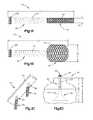
- FIG. 1Ais a side view of an exemplary embodiment of a hybrid bone fixation element in accordance with one aspect of the present invention, the hybrid bone fixation element is illustrated in an insertion configuration;
- FIG. 1Bis a side view of the hybrid bone fixation element shown in FIG. 1A in an expanded configuration
- FIG. 1Cis a bottom perspective view of an alternate exemplary embodiment of a hybrid bone fixation element in accordance with another aspect of the present invention.
- FIG. 1Dis a side view of an alternate exemplary embodiment of a hybrid bone fixation element implanted within a patient's bone, the hybrid bone fixation element illustrated in the expanded configuration;
- FIG. 2is a perspective view of the exemplary hybrid bone fixation element being used in a pedicle screw fixation system in accordance with one aspect of the present invention
- FIG. 2Ais a cross-sectional view of the hybrid bone fixation element taken along line 2 A- 2 A shown in FIG. 2 ;
- FIG. 3is a perspective view of the exemplary hybrid bone fixation element being used in connection with an intervertebral implant in accordance with one aspect of the present invention
- FIG. 4is a perspective view of the exemplary hybrid bone fixation element being used in connection with a plate in accordance with one aspect of the present invention
- FIG. 5is a perspective view of the exemplary hybrid bone fixation element being used in connection with a femur fixation procedure in accordance with one aspect of the present invention
- FIG. 6Ais a side view of a patient's bone having a depressed area
- FIG. 6Bis a side view of an exemplary embodiment of a hybrid bone fixation element implanted within the patient's bone to substantially fix the depressed area;
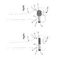
- FIG. 7Ais a side view of an alternate exemplary embodiment of a hybrid bone fixation element implanted within a patient's bone across a fracture site;
- FIG. 7Bis a side view of the hybrid bone fixation element shown in FIG. 7A in the expanded configuration to reduce the fracture in accordance with another aspect of the present invention.
- the hybrid bone fixation element 10preferably includes a first cortical bone contacting portion 20 and a second cancellous bone contacting portion 40 .
- the first cortical bone contacting portion 20is a proximal cortical bone contacting portion 20 and includes a threaded shaft portion 22 for threadably engaging the cortical outer portion 2 of the human bone B.
- the second cancellous bone contacting portion 40preferably is a distal expandable cancellous bone contacting portion 40 and is in the form of an expandable stent 42 for contacting and/or engaging the cancellous inner portion 4 of the human bone B.
- the hybrid bone fixation element 10may also include an enlarged head portion 50 and preferably includes a longitudinal bore 21 extending therethrough. The bore 21 may extend through both ends of the hybrid bone fixation element 10 or only extend partially along its length.
- the first cortical bone contacting portion 20may be non-threaded and/or the second cancellous bone contacting portion 40 may be threaded.
- the first cortical bone contacting portion 20may be distal and the second cancellous bone contacting portion 40 may be proximal depending on the procedure being performed.
- an insertion holemay be formed in the bone B, the hole being sized and configured to receive at least a portion of the hybrid bone fixation element 10 so that the expandable distal cancellous bone contacting portion 40 can be inserted through the cortical outer portion 2 of the bone B and into the cancellous inner portion 4 until the threaded proximal cortical bone contacting portion 20 contacts the cortical outer portion 2 of the bone B.
- the surgeonrotates the hybrid bone fixation element 10 via, for example, a screw driver, so that the threaded proximal cortical bone contacting portion 20 threadably engages the cortical outer portion 2 .
- the surgeonpreferably expands the expandable distal cancellous bone contacting portion 40 to increase the purchase strength of the hybrid bone fixation element 10 with respect to the bone B.
- the present inventionis generally directed to a hybrid bone fixation element 10 and to a method for inserting the hybrid bone fixation element 10 into a targeted human bone B.
- the hybrid bone fixation element 10includes a proximal cortical bone contacting portion 20 and an expandable distal cancellous bone contacting portion 40 .
- the hybrid bone fixation element 10preferably includes a cannulated bore 21 (as best shown in FIG. 1D ) for reasons that will become apparent below.
- the proximal cortical bone contacting portion 20is in the form of an externally threaded shaft 22 for threadably engaging the cortical outer portion 2 of the human bone B (as best shown in FIG. 2A ).
- the specific features of the externally threaded shaft 22including, for example, thread pitch, shaft diameter, shaft shape, etc. are interchangeable, and it would be apparent to one having ordinary skill in the art that the proximal threaded cortical bone contacting portion 20 is not limited to any particular type of thread.
- the hybrid bone fixation element 10 ′may include, for example, a proximal cortical bone contacting portion 20 including an integrally coupled plate 24 having one or more expandable distal cancellous bone contacting portions 40 extending therefrom.
- the expandable distal cancellous bone contacting portion 40is preferably in the form of an expandable stent 42 .
- the expandable distal cancellous bone contacting portion 40may be in the form of an expandable stent 42 wherein the entire distal portion of the hybrid bone fixation element 10 is expandable from a first insertion configuration (as generally shown in FIG. 1A ) to a second expanded configuration (as generally shown in FIG. 1B ).
- the expandable distal cancellous bone contacting portion 40may have any shape now or hereafter known in the art including, for example, barrel, dumbbell, disc, cylindrical, etc.
- the expandable distal cancellous bone contacting portion 40has a bulbous shape (as best shown in FIGS. 1B, 2, 2A, 3, 4,5, 6B and 7B ) or a funnel shape (as best shown in FIG. 1D ) so that the outer diameter of the expandable stent 42 is maximized.
- the stent 42may be comprised of a plurality of intersecting helices with opposite orientation. The intersecting helices define between them a plurality of holes.
- the intersecting helices of the stent 42 in FIG. 5form diamond-shaped holes wherein each of the holes has a closed periphery.
- the expandable distal cancellous bone contacting portion 40preferably has a first radial diameter D 1 .
- the hybrid bone fixation element 10in the first insertion configuration, preferably has a first overall length L 1 .
- the expandable distal cancellous bone contacting portion 40in the second expanded configuration, preferably has a second radial diameter D 2 .
- the hybrid bone fixation element 10in the second expanded configuration, preferably has a second overall length L 2 .
- the second radial diameter D 2preferably is larger than the first radial diameter D 1 while the second overall length L 2 is preferably shorter than the first overall length L 1 .
- expansion of the expandable distal cancellous bone contacting portion 40preferably causes the length of the hybrid bone fixation element 10 to shorten while causing the diameter of the expandable distal cancellous bone contacting portion 40 to expand.
- the expandable distal cancellous bone contacting portion 40may alternatively be in the form of a deformable portion wherein deformation of the expandable distal portion causes the expandable distal cancellous bone contacting portion 40 to expand.
- the expandable distal cancellous bone contacting portion 40may be coupled to the proximal cortical bone contacting portion 20 by any means now or hereafter known in the art including, but not limited to, a mechanical connection, threads, welding, bonding, press-fit connection, etc.
- the expandable distal cancellous bone contacting portion 40may be integrally formed with the proximal cortical bone contacting portion 20 .
- the expandable distal cancellous bone contacting portion 40may be expanded by any means now or hereafter known in the art.
- the expandable distal cancellous bone contacting portion 40may be expanded by a balloon-catheter inserted into the expandable distal cancellous bone contacting portion 40 via the cannulated bore 21 formed in the hybrid bone fixation element 10 .
- the inflatable balloon, and hence the expandable distal cancellous bone contacting portion 40may be expanded by injection of a contrast liquid via a high pressure inflation syringe connected to the balloon-catheter.
- the balloonmay be expanded by injection of, for example, a cement.
- the expandable distal cancellous bone contacting portion 40is maintained in the expanded configuration by the cured cement.
- the balloonmay be expanded by injection of a gas or by way of a chemical reaction.
- any other means for expanding the expandable distal cancellous bone contacting portion 40may be used including, for example, the direct injection of cement into the expandable distal cancellous bone contacting portion 40 without the incorporation of a balloon, a surgical instrument or tool, etc.
- the hybrid bone fixation element 10may also include an enlarged head portion 50 .
- the head portion 50preferably includes a drive surface (not shown) for receiving a corresponding tip formed on a drive tool, such as a screw driver (not shown) for rotating the hybrid bone fixation element 10 into engagement with the bone.
- the drive surfacemay have any form now or hereafter known including, but not limited to, an internal recess for engaging a corresponding external drive feature, an external hexagon, a star drive pattern, a Phillips head pattern, a slot for a screw driver, a threading for a correspondingly threaded post, etc.
- the hybrid bone fixation element 10can be used, for example, as a bone fixation element in a pedicle screw system (as best shown in FIG. 2 ) in connection with a spinal fusion procedure.
- the hybrid bone fixation element 10can be used, for example, as a bone fixation element in connection with the securement of a vertebral implant (as best shown in FIG. 3 ).
- the hybrid bone fixation element 10can be used, for example, as a bone fixation element for securing a bone plate to a patient's bone such as, for example, in connection with a fixation of a long bone (as best shown in FIG. 4 ) or adjacent vertebral bodies.
- the hybrid bone fixation element 10can be used, for example, as a bone fixation element in a femur fixation procedure (as best shown in FIG. 5 ).
- the hybrid bone fixation element 10can be used in any other type of bone fixation application either now or hereafter known such as, for example, in connection with a proximal tibia fixation procedure, a proximal humerus fixation procedure, etc.
- the hybrid bone fixation element 10can be used as a stand alone device to, for example, move a portion of the cortical outer portion 2 of the patient's bone B. That is, for example, in a pilon fracture, the patient's cortical outer portion 2 may move or collapse thereby forming a depressed area Da.
- the hybrid bone fixation element 10can be used to move and subsequently reinforce the cortical outer portion 2 of the patient's bone B in order to return the cortical outer portion 2 substantially to its original condition. Reduction of the depressed area Da may be achieved by inserting the hybrid bone fixation element 10 into the bone B adjacent to the depressed area Da. Thereafter subsequent expansion of the expandable distal cancellous bone contacting portion 40 may cause the cortical outer portion 2 of the patient's bone B to move to its original, non depressed condition.
- the hybrid bone fixation element 10 ′′may be used as a stand alone device in, for example, a fracture reduction procedure. That is, as best shown in FIGS. 7A and 7B , the hybrid bone fixation element 10 ′′ may include a threaded proximal portion 22 ′′, a threaded distal portion 60 ′′ and an expandable central portion 40 ′′.
- the hybrid bone fixation element 10 ′′is inserted in the bone B so that the expandable central portion 40 ′′ spans the bone fracture F. Thereafter, subsequent expansion of the expandable central portion 40 ′′ causes the overall length of the hybrid bone fixation element 10 ′′ to shorten thus reducing or closing the fracture F.
- the hybrid bone fixation element 10 ′′permits a shortening distance of about 5% to about 40%.
- the hybrid bone fixation element 10may be used in connection with this or other surgical methods.
- an X-rayis preferably taken to assist in confirming the precise patient positioning for surgery.
- accesscan be either via a minimally invasive surgical system such as, for example, a cannula or via an open surgical incision.
- a guide wire, trocar or other similar devicemay be used to assist the surgeon in guiding the hybrid bone fixation elements 10 and/or various surgical instruments into place.
- an insertion holeis then formed in the cortical outer portion 2 of the bone B in the desired locations.
- an implantsuch as, for example, an intervertebral implant, a bone plate, etc. is implanted.
- the hybrid bone fixation elements 10are inserted through the implant, if necessary, and into contact with the bone B.
- the hybrid bone fixation element 10and more preferably, the expandable distal cancellous bone contacting portion 40 is inserted through the cortical outer portion 2 of the bone B and into the cancellous inner portion 4 until the proximal cortical bone contacting portion 20 contacts the cortical outer portion 2 of the bone B.
- the surgeonrotates the hybrid bone fixation element 10 via, for example, a screw driver, so that the threaded proximal cortical bone contacting portion 20 threadably engages the cortical outer portion 2 .
- the surgeonpreferably expands the expandable distal cancellous bone contacting portion 40 to increase the purchase strength of the hybrid bone fixation element 10 with respect to the bone B.
- the expandable distal cancellous bone contacting portion 40may be expanded by inserting a balloon-catheter into the expandable distal cancellous bone contacting portion 40 via the cannulated bore 21 . Thereafter inflation of the balloon-catheter gradually expands the expandable distal cancellous bone contacting portion 40 . Once the expandable distal cancellous bone contacting portion 40 is properly expanded, the balloon-catheter is deflated and removed.
- a bone cementmay be inserted through the cannulated bore 21 to further solidify the expandable distal cancellous bone contacting portion 40 to the cancellous inner portion 4 .
- the expandable distal cancellous bone contacting portion 40may include one or more projections (not shown) formed thereon for increasing the purchase between the expandable distal cancellous bone contacting portion 40 and the cancellous inner portion 4 .
- the projectionsmay be in the form, for example, of teeth, ridges, undulations, etc.
- the expandable distal cancellous bone contacting portion 40may be coated with a chemical additive.
- the expandable distal cancellous bone contacting portion 40may also be sized and configured to be longitudinally expandable or telescopic. In this manner, for example, the expandable distal cancellous bone contacting portion 40 may reside inside of the proximal cortical bone contacting portion 20 . This may help to protect the expandable distal cancellous bone contacting portion 40 during insertion and may also eliminate the need for pre-drilling an insertion hole. For example, in use, the proximal cortical bone contacting portion 20 may be inserted into the bone B, either with or without a pre-drill insertion hole.
- the inflatable balloon and fluidmay be inserted into the hybrid bone fixation element 10 causing the expandable distal cancellous bone contacting portion 40 to telescope longitudinally out of the proximal bone contacting portion 20 . Additional insertion of fluid may also cause the expandable distal cancellous bone contacting portion 40 to expand in the transverse direction.
- the expandable distal cancellous bone contacting portion 40may be longitudinally expandable without residing within the proximal bone contacting portion 20 . In this manner, longitudinally expanding the expandable distal cancellous bone contacting portion 40 will increase the amount of surface area contact between the expandable distal cancellous bone contacting portion 40 and the cancellous inner portion 4 .
- the expandable distal cancellous bone contacting portion 40may also include one or more perforations or holes (not shown) to facilitate expansion and/or to permit bone cement to engage the cancellous inner portion 4 of the bone B.
- the hybrid bone fixation elementmay be made from any biocompatible material including, but not limited to, metals such as, for example, titanium, titanium alloys, stainless steel, etc., polymers such as, for example, PEEK, PCU, etc., and combinations thereof
Landscapes
- Health & Medical Sciences (AREA)
- Orthopedic Medicine & Surgery (AREA)
- Engineering & Computer Science (AREA)
- Biomedical Technology (AREA)
- Life Sciences & Earth Sciences (AREA)
- Neurology (AREA)
- Surgery (AREA)
- General Health & Medical Sciences (AREA)
- Veterinary Medicine (AREA)
- Heart & Thoracic Surgery (AREA)
- Public Health (AREA)
- Animal Behavior & Ethology (AREA)
- Nuclear Medicine, Radiotherapy & Molecular Imaging (AREA)
- Medical Informatics (AREA)
- Molecular Biology (AREA)
- Vascular Medicine (AREA)
- Transplantation (AREA)
- Oral & Maxillofacial Surgery (AREA)
- Cardiology (AREA)
- Prostheses (AREA)
- Surgical Instruments (AREA)
Abstract
Description
Claims (14)
Priority Applications (1)
| Application Number | Priority Date | Filing Date | Title |
|---|---|---|---|
| US14/044,415US9510877B2 (en) | 2007-11-14 | 2013-10-02 | Hybrid bone fixation element and methods of using the same |
Applications Claiming Priority (3)
| Application Number | Priority Date | Filing Date | Title |
|---|---|---|---|
| US98797307P | 2007-11-14 | 2007-11-14 | |
| US12/270,573US8556949B2 (en) | 2007-11-14 | 2008-11-13 | Hybrid bone fixation element and methods of using the same |
| US14/044,415US9510877B2 (en) | 2007-11-14 | 2013-10-02 | Hybrid bone fixation element and methods of using the same |
Related Parent Applications (1)
| Application Number | Title | Priority Date | Filing Date |
|---|---|---|---|
| US12/270,573ContinuationUS8556949B2 (en) | 2007-11-14 | 2008-11-13 | Hybrid bone fixation element and methods of using the same |
Publications (2)
| Publication Number | Publication Date |
|---|---|
| US20140107649A1 US20140107649A1 (en) | 2014-04-17 |
| US9510877B2true US9510877B2 (en) | 2016-12-06 |
Family
ID=40624466
Family Applications (2)
| Application Number | Title | Priority Date | Filing Date |
|---|---|---|---|
| US12/270,573Active2031-07-05US8556949B2 (en) | 2007-11-14 | 2008-11-13 | Hybrid bone fixation element and methods of using the same |
| US14/044,415ActiveUS9510877B2 (en) | 2007-11-14 | 2013-10-02 | Hybrid bone fixation element and methods of using the same |
Family Applications Before (1)
| Application Number | Title | Priority Date | Filing Date |
|---|---|---|---|
| US12/270,573Active2031-07-05US8556949B2 (en) | 2007-11-14 | 2008-11-13 | Hybrid bone fixation element and methods of using the same |
Country Status (1)
| Country | Link |
|---|---|
| US (2) | US8556949B2 (en) |
Cited By (1)
| Publication number | Priority date | Publication date | Assignee | Title |
|---|---|---|---|---|
| US20160220275A1 (en)* | 2013-09-11 | 2016-08-04 | Vexim | Helical bone fixation device |
Families Citing this family (63)
| Publication number | Priority date | Publication date | Assignee | Title |
|---|---|---|---|---|
| US7648523B2 (en) | 2004-12-08 | 2010-01-19 | Interventional Spine, Inc. | Method and apparatus for spinal stabilization |
| US7857832B2 (en)* | 2004-12-08 | 2010-12-28 | Interventional Spine, Inc. | Method and apparatus for spinal stabilization |
| WO2007112589A1 (en)* | 2006-04-06 | 2007-10-11 | Halifax Biomedical Inc. | Intramedullary rod with vent |
| US7806900B2 (en) | 2006-04-26 | 2010-10-05 | Illuminoss Medical, Inc. | Apparatus and methods for delivery of reinforcing materials to bone |
| US7879041B2 (en) | 2006-11-10 | 2011-02-01 | Illuminoss Medical, Inc. | Systems and methods for internal bone fixation |
| CA2669129C (en) | 2006-11-10 | 2014-09-16 | Illuminoss Medical, Inc. | Systems and methods for internal bone fixation |
| US8579985B2 (en) | 2006-12-07 | 2013-11-12 | Ihip Surgical, Llc | Method and apparatus for hip replacement |
| EP2094197B8 (en) | 2006-12-07 | 2016-03-09 | IHip Surgical, LLC | Apparatus for total hip replacement |
| US8974540B2 (en) | 2006-12-07 | 2015-03-10 | Ihip Surgical, Llc | Method and apparatus for attachment in a modular hip replacement or fracture fixation device |
| US9039768B2 (en) | 2006-12-22 | 2015-05-26 | Medos International Sarl | Composite vertebral spacers and instrument |
| JP5631597B2 (en)* | 2007-03-12 | 2014-11-26 | スタウト メディカル グループ,エル.ピー. | Expandable mounting device and method |
| US9427289B2 (en) | 2007-10-31 | 2016-08-30 | Illuminoss Medical, Inc. | Light source |
| US8556949B2 (en)* | 2007-11-14 | 2013-10-15 | DePuy Synthes Products, LLC | Hybrid bone fixation element and methods of using the same |
| CA2781407A1 (en) | 2008-01-14 | 2009-07-23 | Michael P. Brenzel | Apparatus and methods for fracture repair |
| US20090248092A1 (en) | 2008-03-26 | 2009-10-01 | Jonathan Bellas | Posterior Intervertebral Disc Inserter and Expansion Techniques |
| US9044282B2 (en)* | 2008-06-24 | 2015-06-02 | Extremity Medical Llc | Intraosseous intramedullary fixation assembly and method of use |
| US20100228301A1 (en)* | 2009-03-09 | 2010-09-09 | Greenhalgh E Skott | Attachment device and methods of use |
| US9526620B2 (en) | 2009-03-30 | 2016-12-27 | DePuy Synthes Products, Inc. | Zero profile spinal fusion cage |
| US8012155B2 (en)* | 2009-04-02 | 2011-09-06 | Zimmer, Inc. | Apparatus and method for prophylactic hip fixation |
| EP2416716B1 (en)* | 2009-04-06 | 2020-03-04 | Alphatec Spine, Inc. | Expandable spinal support device with attachable members |
| EP2298201A1 (en)* | 2009-08-31 | 2011-03-23 | Ozics Oy | Arrangement for internal bone support |
| WO2011038315A1 (en)* | 2009-09-28 | 2011-03-31 | Zimmer, Inc. | Expandable intramedullary rod |
| US9393129B2 (en) | 2009-12-10 | 2016-07-19 | DePuy Synthes Products, Inc. | Bellows-like expandable interbody fusion cage |
| US20110178520A1 (en) | 2010-01-15 | 2011-07-21 | Kyle Taylor | Rotary-rigid orthopaedic rod |
| WO2011091052A1 (en) | 2010-01-20 | 2011-07-28 | Kyle Taylor | Apparatus and methods for bone access and cavity preparation |
| WO2011112615A1 (en) | 2010-03-08 | 2011-09-15 | Krinke Todd A | Apparatus and methods for securing a bone implant |
| US20120078373A1 (en)* | 2010-09-23 | 2012-03-29 | Thomas Gamache | Stand alone intervertebral fusion device |
| US20120078372A1 (en) | 2010-09-23 | 2012-03-29 | Thomas Gamache | Novel implant inserter having a laterally-extending dovetail engagement feature |
| US11529241B2 (en) | 2010-09-23 | 2022-12-20 | DePuy Synthes Products, Inc. | Fusion cage with in-line single piece fixation |
| EP2654584A1 (en) | 2010-12-22 | 2013-10-30 | Illuminoss Medical, Inc. | Systems and methods for treating conditions and diseases of the spine |
| WO2012097326A2 (en)* | 2011-01-14 | 2012-07-19 | Alphatec Spine, Inc. | Expandable facet screw |
| US20130023876A1 (en) | 2011-07-19 | 2013-01-24 | Illuminoss Medical, Inc. | Combination Photodynamic Devices |
| US8936644B2 (en) | 2011-07-19 | 2015-01-20 | Illuminoss Medical, Inc. | Systems and methods for joint stabilization |
| US9248028B2 (en) | 2011-09-16 | 2016-02-02 | DePuy Synthes Products, Inc. | Removable, bone-securing cover plate for intervertebral fusion cage |
| US9155578B2 (en)* | 2012-02-28 | 2015-10-13 | DePuy Synthes Products, Inc. | Expandable fastener |
| US9271836B2 (en) | 2012-03-06 | 2016-03-01 | DePuy Synthes Products, Inc. | Nubbed plate |
| US9393126B2 (en)* | 2012-04-20 | 2016-07-19 | Peter L. Mayer | Bilaterally placed disc prosthesis for spinal implant and method of bilateral placement |
| US9364339B2 (en)* | 2012-04-30 | 2016-06-14 | Peter L. Mayer | Unilaterally placed expansile spinal prosthesis |
| US10405903B1 (en) | 2012-05-04 | 2019-09-10 | Xtraverse, LLC | Fasteners with shape changing zigzag structures and methods using same |
| US9295488B2 (en) | 2012-08-09 | 2016-03-29 | Wilson T. Asfora | Joint fusion |
| US20140067069A1 (en) | 2012-08-30 | 2014-03-06 | Interventional Spine, Inc. | Artificial disc |
| US10182921B2 (en) | 2012-11-09 | 2019-01-22 | DePuy Synthes Products, Inc. | Interbody device with opening to allow packing graft and other biologics |
| US9687281B2 (en) | 2012-12-20 | 2017-06-27 | Illuminoss Medical, Inc. | Distal tip for bone fixation devices |
| CN103445851B (en)* | 2012-12-28 | 2015-09-02 | 林达生 | The dynamic hip screw of bone grafting can be strutted |
| US9687284B2 (en)* | 2013-02-13 | 2017-06-27 | Stryker European Holdings I, Llc | Locking peg with extended thread |
| CN105939677A (en) | 2013-12-12 | 2016-09-14 | 康文图斯整形外科公司 | Tissue displacement tools and methods |
| CN106102613B (en)* | 2014-02-06 | 2019-07-19 | 英格奈特概念有限公司 | Bone screw assembly |
| CN105011993B (en)* | 2014-04-17 | 2018-06-01 | 思必瑞特脊椎股份有限公司 | Bone anchoring device |
| WO2015168478A1 (en)* | 2014-05-01 | 2015-11-05 | Lorio Morgan Packard | Sacroiliac joint fastener, systems, and methods of using the same |
| AU2014315021A1 (en)* | 2014-08-11 | 2016-02-25 | Wright Medical Technology, Inc. | Flexible screw and methods for syndesmosis repair |
| WO2016155665A1 (en)* | 2015-04-02 | 2016-10-06 | Versitech Limited | Anti-penetration bone implant device and method |
| US9907585B2 (en)* | 2015-04-30 | 2018-03-06 | William Casey Fox | Bone intramedullary fixation scaffold |
| US9827025B2 (en) | 2015-11-20 | 2017-11-28 | Globus Medical, Inc. | Expandable intramedullary systems and methods of using the same |
| US9974581B2 (en) | 2015-11-20 | 2018-05-22 | Globus Medical, Inc. | Expandable intramedullary systems and methods of using the same |
| US10111691B2 (en) | 2015-11-20 | 2018-10-30 | Globus Medical, Inc. | Expandable intramedullary systems and methods of using the same |
| TWI587847B (en) | 2015-12-07 | 2017-06-21 | 財團法人工業技術研究院 | Implant device for osseous integration |
| WO2018132503A1 (en)* | 2017-01-10 | 2018-07-19 | Conventus Orthopaedics, Inc. | Articular surface repair |
| WO2019010252A2 (en) | 2017-07-04 | 2019-01-10 | Conventus Orthopaedics, Inc. | APPARATUS AND METHODS FOR TREATING BONES |
| US10940016B2 (en) | 2017-07-05 | 2021-03-09 | Medos International Sarl | Expandable intervertebral fusion cage |
| US10888363B2 (en) | 2017-12-06 | 2021-01-12 | Stout Medical Group, L.P. | Attachment device and method for use |
| US11071572B2 (en) | 2018-06-27 | 2021-07-27 | Illuminoss Medical, Inc. | Systems and methods for bone stabilization and fixation |
| US11318026B2 (en)* | 2020-07-24 | 2022-05-03 | Synaptic Innovations, LLC | Implant having enhanced initial fixation force |
| US20240081870A1 (en)* | 2021-07-15 | 2024-03-14 | Blue Sky Technologies, LLC | Anchor |
Citations (215)
| Publication number | Priority date | Publication date | Assignee | Title |
|---|---|---|---|---|
| US1438648A (en) | 1921-08-04 | 1922-12-12 | Benjamin F Jacobs | Set screw |
| US3030951A (en) | 1959-04-10 | 1962-04-24 | Michael P Mandarino | Methods and materials for orthopedic surgery |
| US3343265A (en) | 1965-06-03 | 1967-09-26 | Miguel A Puerta | Drafting instrument |
| US3343263A (en) | 1965-06-14 | 1967-09-26 | Richard E Henlotter | Artificial tooth |
| US3867728A (en) | 1971-12-30 | 1975-02-25 | Cutter Lab | Prosthesis for spinal repair |
| US3875595A (en) | 1974-04-15 | 1975-04-08 | Edward C Froning | Intervertebral disc prosthesis and instruments for locating same |
| DE2558584A1 (en) | 1975-12-29 | 1977-07-07 | Hohmann Wolfgang | Expansible lamellar marker nail for bone processes - has multiple layer lamellar construction with expanded end caps |
| US4204531A (en) | 1977-12-28 | 1980-05-27 | Yacov Aginsky | Intramedullary nail with expanding mechanism |
| US4313434A (en) | 1980-10-17 | 1982-02-02 | David Segal | Fracture fixation |
| SU906530A1 (en) | 1980-06-12 | 1982-02-23 | Омский политехнический институт | Method of closing defects of air-bone cavities |
| SU995751A1 (en) | 1980-04-10 | 1983-02-15 | Горьковский государственный медицинский институт им.С.М.Кирова | Device for cardiodilation |
| GB2114005B (en) | 1982-01-15 | 1985-01-03 | Krupp Gmbh | Marrow nail |
| US4655777A (en) | 1983-12-19 | 1987-04-07 | Southern Research Institute | Method of producing biodegradable prosthesis and products therefrom |
| US4684370A (en) | 1985-10-02 | 1987-08-04 | Barrett Garret D | Stents for bone augmentation by surgical implant |
| US4686973A (en) | 1984-10-12 | 1987-08-18 | Dow Corning Corporation | Method of making an intramedullary bone plug and bone plug made thereby |
| US4733665A (en) | 1985-11-07 | 1988-03-29 | Expandable Grafts Partnership | Expandable intraluminal graft, and method and apparatus for implanting an expandable intraluminal graft |
| US4735625A (en) | 1985-09-11 | 1988-04-05 | Richards Medical Company | Bone cement reinforcement and method |
| US4755184A (en) | 1986-01-09 | 1988-07-05 | Mark Silverberg | Bone augmentation implant |
| US4772287A (en) | 1987-08-20 | 1988-09-20 | Cedar Surgical, Inc. | Prosthetic disc and method of implanting |
| US4854312A (en) | 1988-04-13 | 1989-08-08 | The University Of Toledo | Expanding intramedullary nail |
| US4863477A (en) | 1987-05-12 | 1989-09-05 | Monson Gary L | Synthetic intervertebral disc prosthesis |
| FR2629337A1 (en) | 1988-03-30 | 1989-10-06 | Bigan Michel | Device for intra-osseus sealing of a prosthesis element |
| FR2603256B1 (en) | 1986-08-26 | 1989-10-20 | Dominique Lepinoy | MULTI-SPEAKER PRESSURE POCKET |
| US4888024A (en) | 1985-11-08 | 1989-12-19 | Powlan Roy Y | Prosthetic device and method of fixation within the medullary cavity of bones |
| US4906190A (en) | 1988-10-11 | 1990-03-06 | Michna Claus G | Dental prosthesis |
| US4932975A (en) | 1989-10-16 | 1990-06-12 | Vanderbilt University | Vertebral prosthesis |
| US4932969A (en) | 1987-01-08 | 1990-06-12 | Sulzer Brothers Limited | Joint endoprosthesis |
| US4936848A (en) | 1989-09-22 | 1990-06-26 | Bagby George W | Implant for vertebrae |
| US4969888A (en) | 1989-02-09 | 1990-11-13 | Arie Scholten | Surgical protocol for fixation of osteoporotic bone using inflatable device |
| US4976725A (en) | 1986-06-05 | 1990-12-11 | Thomas J. Fogarty | Dilatation catheter and constant pressure syringe and method of using the same |
| WO1991000713A1 (en) | 1989-07-06 | 1991-01-24 | Martin Nolde | Nucleus prosthesis with an introductory device and probe to determine the size of nucleus prosthesis required |
| US5015247A (en) | 1988-06-13 | 1991-05-14 | Michelson Gary K | Threaded spinal implant |
| US5015255A (en) | 1989-05-10 | 1991-05-14 | Spine-Tech, Inc. | Spinal stabilization method |
| US5030233A (en) | 1984-10-17 | 1991-07-09 | Paul Ducheyne | Porous flexible metal fiber material for surgical implantation |
| US5037445A (en) | 1989-04-14 | 1991-08-06 | United States Surgical Corporation | Method and kit for molding surgical implants |
| US5047055A (en) | 1990-12-21 | 1991-09-10 | Pfizer Hospital Products Group, Inc. | Hydrogel intervertebral disc nucleus |
| US5053035A (en) | 1990-05-24 | 1991-10-01 | Mclaren Alexander C | Flexible intramedullary fixation rod |
| US5059193A (en) | 1989-11-20 | 1991-10-22 | Spine-Tech, Inc. | Expandable spinal implant and surgical method |
| US5071435A (en) | 1990-12-20 | 1991-12-10 | Albert Fuchs | Extendible bone prosthesis |
| EP0322334B1 (en) | 1987-12-23 | 1992-02-26 | Cremascoli France | Prosthesis implanted between vertebral spinous processes |
| US5102413A (en) | 1990-11-14 | 1992-04-07 | Poddar Satish B | Inflatable bone fixation device |
| US5108438A (en) | 1989-03-02 | 1992-04-28 | Regen Corporation | Prosthetic intervertebral disc |
| US5116305A (en) | 1990-02-01 | 1992-05-26 | Abiomed, Inc. | Curved intra aortic balloon with non-folding inflated balloon membrane |
| US5133767A (en) | 1989-10-12 | 1992-07-28 | Sulzer Brothers Limited | Prosthesis having a deformable implant surface |
| US5147359A (en) | 1988-12-21 | 1992-09-15 | Zimmer, Inc. | Spinal hook body |
| US5147360A (en) | 1990-02-19 | 1992-09-15 | Societe De Fabrication De Materiel Orthopedique | Osteosynthesis device for the correction of spinal curvatures |
| US5154718A (en) | 1988-12-21 | 1992-10-13 | Zimmer, Inc. | Spinal coupler assembly |
| US5171280A (en) | 1990-04-20 | 1992-12-15 | Sulzer Brothers Limited | Intervertebral prosthesis |
| US5171281A (en) | 1988-08-18 | 1992-12-15 | University Of Medicine & Dentistry Of New Jersey | Functional and biocompatible intervertebral disc spacer containing elastomeric material of varying hardness |
| US5176678A (en) | 1991-03-14 | 1993-01-05 | Tsou Paul M | Orthopaedic device with angularly adjustable anchor attachments to the vertebrae |
| US5176680A (en) | 1990-02-08 | 1993-01-05 | Vignaud Jean Louis | Device for the adjustable fixing of spinal osteosynthesis rods |
| US5176692A (en) | 1991-12-09 | 1993-01-05 | Wilk Peter J | Method and surgical instrument for repairing hernia |
| US5190543A (en) | 1990-11-26 | 1993-03-02 | Synthes (U.S.A.) | Anchoring device |
| US5192326A (en) | 1990-12-21 | 1993-03-09 | Pfizer Hospital Products Group, Inc. | Hydrogel bead intervertebral disc nucleus |
| US5207678A (en) | 1989-07-20 | 1993-05-04 | Prufer | Pedicle screw and receiver member therefore |
| US5209753A (en) | 1989-11-03 | 1993-05-11 | Lutz Biedermann | Bone screw |
| EP0321020B1 (en) | 1987-12-16 | 1993-06-02 | ENIRICERCHE S.p.A. | Process for preparing n-acyl-anilines |
| WO1993016664A1 (en) | 1992-02-28 | 1993-09-02 | Limbs & Things Limited | Artificial spinal disc |
| US5261913A (en) | 1989-07-26 | 1993-11-16 | J.B.S. Limited Company | Device for straightening, securing, compressing and elongating the spinal column |
| US5261907A (en) | 1991-05-17 | 1993-11-16 | Vignaud Jean L | Interconnecting device able to lock spinal osteosynthesis fasteners |
| US5263931A (en) | 1990-02-14 | 1993-11-23 | Advanced Cardiovascular Systems, Inc. | Balloon catheter for dilating a prostatic urethra |
| US5275600A (en) | 1992-10-05 | 1994-01-04 | Zimmer, Inc. | Telescoping rod to rod coupler for a spinal system |
| US5275622A (en) | 1983-12-09 | 1994-01-04 | Harrison Medical Technologies, Inc. | Endovascular grafting apparatus, system and method and devices for use therewith |
| US5282801A (en) | 1993-02-17 | 1994-02-01 | Danek Medical, Inc. | Top tightening clamp assembly for a spinal fixation system |
| US5282863A (en) | 1985-06-10 | 1994-02-01 | Charles V. Burton | Flexible stabilization system for a vertebral column |
| US5303718A (en) | 1990-12-29 | 1994-04-19 | Milan Krajicek | Method and device for the osteosynthesis of bones |
| US5306309A (en) | 1992-05-04 | 1994-04-26 | Calcitek, Inc. | Spinal disk implant and implantation kit |
| US5306311A (en) | 1987-07-20 | 1994-04-26 | Regen Corporation | Prosthetic articular cartilage |
| US5306308A (en) | 1989-10-23 | 1994-04-26 | Ulrich Gross | Intervertebral implant |
| US5306310A (en) | 1991-08-27 | 1994-04-26 | Man Ceramics Gmbh | Vertebral prosthesis |
| US5306307A (en) | 1991-07-22 | 1994-04-26 | Calcitek, Inc. | Spinal disk implant |
| US5314478A (en) | 1991-03-29 | 1994-05-24 | Kyocera Corporation | Artificial bone connection prosthesis |
| US5314477A (en) | 1990-03-07 | 1994-05-24 | J.B.S. Limited Company | Prosthesis for intervertebral discs and instruments for implanting it |
| US5331975A (en) | 1990-03-02 | 1994-07-26 | Bonutti Peter M | Fluid operated retractors |
| US5342298A (en) | 1992-07-31 | 1994-08-30 | Advanced Cardiovascular Systems, Inc. | Automated fluid pressure control system |
| WO1994020166A1 (en) | 1993-03-02 | 1994-09-15 | Metra Aps | Dilation catheter |
| US5350379A (en) | 1993-02-18 | 1994-09-27 | Genesis Orthopedics | Bone and tissue lengthening device |
| WO1994021320A1 (en) | 1993-03-15 | 1994-09-29 | Advanced Cardiovascular Systems, Inc. | Fluid delivery catheter |
| FR2639823B1 (en) | 1988-12-06 | 1994-12-23 | Garcia Alain | |
| US5376123A (en) | 1989-12-07 | 1994-12-27 | Ao-Forschungsinstitut Davos | Adaptable stem for endoprosthesis |
| FR2707477A1 (en) | 1993-07-02 | 1995-01-20 | Cahlix Marc Andre | Obturator for bone cavities |
| US5390683A (en) | 1991-02-22 | 1995-02-21 | Pisharodi; Madhavan | Spinal implantation methods utilizing a middle expandable implant |
| FR2662073B1 (en) | 1990-05-18 | 1995-03-17 | Bfl Medical Sarl | |
| RU2033755C1 (en) | 1986-07-17 | 1995-04-30 | Дамбаев Георгий Цыренович | Hollow organs space restrictor |
| FR2712486A1 (en) | 1993-11-19 | 1995-05-24 | Breslave Patrice | Intervertebral prosthesis |
| FR2714590A1 (en) | 1994-01-05 | 1995-07-07 | Lenfant Jean Pierre | Transverse fixing member for spinal column supporting rods |
| US5437834A (en) | 1992-10-08 | 1995-08-01 | Kyocera Corporation | Porous living body repairing member, and a method of imparting elasticity to it |
| FR2718634A1 (en) | 1994-04-13 | 1995-10-20 | Dynamique Sante Sarl | Implant with shape memory effect, designed to be implanted in bone e.g. during joint or ligament reconstructive surgery |
| FR2708192B1 (en) | 1993-07-02 | 1995-11-03 | Cahlik Marc Andre | Obturator for bone cavities. |
| US5474563A (en) | 1993-03-25 | 1995-12-12 | Myler; Richard | Cardiovascular stent and retrieval apparatus |
| FR2722679A1 (en) | 1994-07-25 | 1996-01-26 | Daniel Felman | Expansible arthrodesis implant for insertion between vertebrae |
| RU2056797C1 (en) | 1990-12-12 | 1996-03-27 | Педдер Валерий Викторович | Device for dilating rectum |
| US5503164A (en) | 1994-01-28 | 1996-04-02 | Osteogenics, Inc. | Device and method for repair of craniomaxillofacial bone defects including burr holes |
| FR2725892A1 (en) | 1994-10-21 | 1996-04-26 | Felman Daniel | Vertebral implant insertion process using shape memory material |
| FR2727304A1 (en) | 1994-11-28 | 1996-05-31 | Felman Daniel | Self-locking bone implant, e.g. for medullary canal |
| US5549679A (en) | 1994-05-20 | 1996-08-27 | Kuslich; Stephen D. | Expandable fabric implant for stabilizing the spinal motion segment |
| US5556429A (en) | 1994-05-06 | 1996-09-17 | Advanced Bio Surfaces, Inc. | Joint resurfacing system |
| US5562704A (en) | 1992-01-24 | 1996-10-08 | Biocon Oy | Surgical implant |
| US5599301A (en) | 1993-11-22 | 1997-02-04 | Advanced Cardiovascular Systems, Inc. | Motor control system for an automatic catheter inflation system |
| US5601593A (en) | 1995-03-06 | 1997-02-11 | Willy Rusch Ag | Stent for placement in a body tube |
| US5626581A (en) | 1995-11-27 | 1997-05-06 | Volunteers For Medical Engineering | Implantable bone lengthening apparatus |
| US5643265A (en)* | 1995-04-13 | 1997-07-01 | Fastenetix, L.L.C. | Dynamic compression polyaxial locking screw plate assembly |
| US5674295A (en) | 1994-10-17 | 1997-10-07 | Raymedica, Inc. | Prosthetic spinal disc nucleus |
| US5707390A (en) | 1990-03-02 | 1998-01-13 | General Surgical Innovations, Inc. | Arthroscopic retractors |
| US5716416A (en) | 1996-09-10 | 1998-02-10 | Lin; Chih-I | Artificial intervertebral disk and method for implanting the same |
| FR2753080A1 (en) | 1996-09-09 | 1998-03-13 | Boom Annemarieke V D | Spacer implant, for use especially in joint prosthesis surgery |
| US5749888A (en) | 1986-04-15 | 1998-05-12 | Yock; Paul G. | Method of using angioplasty apparatus facilitating rapid exchanges |
| EP0854198A1 (en) | 1997-01-15 | 1998-07-22 | Machner & Saurer GmbH | Process and apparatus for charging and melting small-sized light metal scrap |
| US5788703A (en) | 1995-02-17 | 1998-08-04 | Allo Pro Ag | Apparatus for the placement of a medullary space blocker |
| US5827289A (en) | 1994-01-26 | 1998-10-27 | Reiley; Mark A. | Inflatable device for use in surgical protocols relating to treatment of fractured or diseased bones |
| WO1998056301A1 (en) | 1997-06-09 | 1998-12-17 | Kyphon Inc. | Systems for treating fractured or diseased bone using expandable bodies |
| WO1999002108A1 (en) | 1997-07-10 | 1999-01-21 | Douglas Wardlaw | Intervertebral disc nucleus prosthesis |
| US5888220A (en) | 1994-05-06 | 1999-03-30 | Advanced Bio Surfaces, Inc. | Articulating joint repair |
| US5893850A (en) | 1996-11-12 | 1999-04-13 | Cachia; Victor V. | Bone fixation device |
| WO1999026554A1 (en) | 1997-11-25 | 1999-06-03 | Discotech Medical Technologies, Ltd. | Inflatable dental implant for receipt and support of a dental prosthesis |
| US5961554A (en) | 1996-12-31 | 1999-10-05 | Janson; Frank S | Intervertebral spacer |
| US5972015A (en) | 1997-08-15 | 1999-10-26 | Kyphon Inc. | Expandable, asymetric structures for deployment in interior body regions |
| US5989290A (en) | 1995-05-24 | 1999-11-23 | Biedermann; Lutz | Height-adjustable artificial vertebral body |
| US6015436A (en) | 1996-06-07 | 2000-01-18 | Heinrich Ulrich | Implant for filling a space between vertebrae |
| US6022376A (en) | 1997-06-06 | 2000-02-08 | Raymedica, Inc. | Percutaneous prosthetic spinal disc nucleus and method of manufacture |
| US6025537A (en) | 1995-04-21 | 2000-02-15 | Werding; Gerd | Nail for maintaining the location and shape of broken long bones |
| US6066154A (en) | 1994-01-26 | 2000-05-23 | Kyphon Inc. | Inflatable device for use in surgical protocol relating to fixation of bone |
| WO2000044319A1 (en) | 1999-01-27 | 2000-08-03 | Disc-O-Tech Medical Technologies, Ltd. | Expandable intervertebral spacer |
| US6127597A (en) | 1997-03-07 | 2000-10-03 | Discotech N.V. | Systems for percutaneous bone and spinal stabilization, fixation and repair |
| US6129763A (en) | 1996-09-13 | 2000-10-10 | Chauvin; Jean-Luc | Expandable osteosynthesis cage |
| FR2778082B1 (en) | 1998-05-04 | 2000-11-10 | Internova Int Innovation | STAPLING NAIL OF DYNAMICALLY LOCKED TISSUES, ITS CONDITIONING DEVICE AND ITS PLACING APPARATUS |
| US6149651A (en) | 1997-06-02 | 2000-11-21 | Sdgi Holdings, Inc. | Device for supporting weak bony structures |
| US6174334B1 (en) | 1998-12-16 | 2001-01-16 | Loubert Suddaby | Expandable intervertebral fusion implant and applicator |
| US6176882B1 (en) | 1998-02-20 | 2001-01-23 | Biedermann Motech Gmbh | Intervertebral implant |
| FR2796846A1 (en) | 1999-07-30 | 2001-02-02 | Mohamed Zouheir Naja | Thoraco-abdominal or pelvic anaesthesia apparatus comprises needle and electrode linked to electrical power source, extension, guide tube and catheter |
| US6183503B1 (en) | 1999-09-17 | 2001-02-06 | Applied Medical Resources Corporation | Mesh stent with variable hoop strength |
| US6183518B1 (en) | 1999-02-22 | 2001-02-06 | Anthony C. Ross | Method of replacing nucleus pulposus and repairing the intervertebral disk |
| US6187048B1 (en) | 1994-05-24 | 2001-02-13 | Surgical Dynamics, Inc. | Intervertebral disc implant |
| RU2164152C2 (en) | 1998-12-21 | 2001-03-20 | ЗАО "Научно-производственный комбинат "Экофлон" | Dilatation balloon-type catheter with reinforcing perfusion rod enclosure |
| US20010000186A1 (en) | 1996-03-13 | 2001-04-05 | Bramlet Dale G. | Surgical fastener assembly |
| FR2799117A1 (en) | 1999-09-30 | 2001-04-06 | Marc Andre Cahlik | Bone cavity plug comprises spiral of resorbable biocompatible material capable of radial expansion e.g. to support cement used with implant |
| US6213775B1 (en) | 1997-01-07 | 2001-04-10 | Reipur Technology A/S | Method of fastening an implant to a bone and an implant therefor |
| WO2001028464A1 (en) | 1999-10-20 | 2001-04-26 | Anulex Technologies, Inc. | Spinal disc annulus reconstruction method and spinal disc annulus stent |
| FR2791551B3 (en) | 1999-03-30 | 2001-04-27 | Braun Celsa Sa | EXPANDABLE SUPPORT WITH EXTENDED FREE END APEX |
| US6224630B1 (en) | 1998-05-29 | 2001-05-01 | Advanced Bio Surfaces, Inc. | Implantable tissue repair device |
| FR2787313B1 (en) | 1998-12-17 | 2001-05-04 | Orsco Internat | OSTEOSYNTHESIS IMPLANT |
| US6241734B1 (en) | 1998-08-14 | 2001-06-05 | Kyphon, Inc. | Systems and methods for placing materials into bone |
| US6245107B1 (en) | 1999-05-28 | 2001-06-12 | Bret A. Ferree | Methods and apparatus for treating disc herniation |
| US6248131B1 (en) | 1994-05-06 | 2001-06-19 | Advanced Bio Surfaces, Inc. | Articulating joint repair |
| US6248110B1 (en) | 1994-01-26 | 2001-06-19 | Kyphon, Inc. | Systems and methods for treating fractured or diseased bone using expandable bodies |
| US6261289B1 (en) | 1998-10-26 | 2001-07-17 | Mark Levy | Expandable orthopedic device |
| WO2001054598A1 (en) | 1998-03-06 | 2001-08-02 | Disc-O-Tech Medical Technologies, Ltd. | Expanding bone implants |
| FR2794019B1 (en) | 1999-05-26 | 2001-08-24 | Orsco Internat | OSTEOSYNTHESIS IMPLANT |
| US6293743B1 (en) | 1997-05-08 | 2001-09-25 | Illinois Tool Works Inc. | Expansion anchor and method therefor |
| WO2001076514A2 (en) | 2000-04-05 | 2001-10-18 | Kyphon Inc. | Methods and devices for treating fractured and/or diseased bone |
| US6306177B1 (en) | 1994-05-06 | 2001-10-23 | Advanced Bio Surfaces, Inc. | Biomaterial system for in situ tissue repair |
| US6319255B1 (en) | 1996-12-18 | 2001-11-20 | Eska Implants Gmbh & Co. | Prophylactic implant against fracture of osteoporosis-affected bone segments |
| RU2178681C2 (en) | 1999-05-25 | 2002-01-27 | Новосибирский научно-исследовательский институт травматологии и ортопедии | Method for treating the cases of vertebral column deformities |
| US20020045942A1 (en) | 2000-10-16 | 2002-04-18 | Ham Michael J. | Procedure for repairing damaged discs |
| US20020049447A1 (en) | 2000-08-29 | 2002-04-25 | Li Medical Technologies, Inc. | Expandable surgical fastener and method |
| US6383190B1 (en) | 1998-04-01 | 2002-05-07 | Parallax Medical, Inc. | High pressure applicator |
| US6395032B1 (en) | 1998-12-11 | 2002-05-28 | Dimso (Distribution Medicale Du Sud-Ouest) | Intervertebral disc prosthesis with liquid chamber |
| WO2002043628A1 (en) | 2000-12-01 | 2002-06-06 | Sabitzer Ronald J | Method and device for expanding a body cavity |
| US20020068939A1 (en) | 1998-10-26 | 2002-06-06 | Expanding Orthopedics Inc. | Expandable orthopedic device |
| US20020068974A1 (en) | 2000-07-21 | 2002-06-06 | Kuslich Stephen D. | Expandable porous mesh bag device and methods of use for reduction, filling, fixation and supporting of bone |
| US6425923B1 (en) | 2000-03-07 | 2002-07-30 | Zimmer, Inc. | Contourable polymer filled implant |
| US6428576B1 (en) | 1999-04-16 | 2002-08-06 | Endospine, Ltd. | System for repairing inter-vertebral discs |
| WO2001021246A9 (en) | 1999-09-20 | 2002-10-03 | Nuvasive Inc | Annulotomy closure device |
| US20020165544A1 (en) | 1999-11-11 | 2002-11-07 | Stephan Perren | Radially expandable intramedullary nail |
| US6478800B1 (en) | 2000-05-08 | 2002-11-12 | Depuy Acromed, Inc. | Medical installation tool |
| US6482235B1 (en) | 1999-08-18 | 2002-11-19 | Intrinsic Orthopedics, Inc. | Devices and methods of vertebral disc augmentation |
| US20020177866A1 (en) | 2001-04-19 | 2002-11-28 | Stuart Weikel | Inflatable device and method for reducing fractures in bone and in treating the spine |
| US20020198527A1 (en) | 2001-06-21 | 2002-12-26 | Helmut Muckter | Implantable screw for stabilization of a joint or a bone fracture |
| US6508839B1 (en) | 1999-08-18 | 2003-01-21 | Intrinsic Orthopedics, Inc. | Devices and methods of vertebral disc augmentation |
| WO2003007853A1 (en) | 2000-07-21 | 2003-01-30 | The Spineology Group, Llc | An expandable porous mesh bag device and its use for bone surgery |
| US20030033017A1 (en) | 2001-06-29 | 2003-02-13 | The Regents Of The University Of California | Biodegradable/bioactive nucleus pulposus implant and method for treating degenerated intervertebral discs |
| US20030088249A1 (en) | 2001-11-03 | 2003-05-08 | Sebastian Furderer | Device for straightening and stabilizing the vertebral column |
| US6582471B1 (en) | 1997-08-14 | 2003-06-24 | Sulzer Innotec Ag | Composition and device for in vivo cartilage repair |
| US6592625B2 (en) | 1999-10-20 | 2003-07-15 | Anulex Technologies, Inc. | Spinal disc annulus reconstruction method and spinal disc annulus stent |
| US6648893B2 (en) | 2000-10-27 | 2003-11-18 | Blackstone Medical, Inc. | Facet fixation devices |
| US20040097930A1 (en) | 2002-08-27 | 2004-05-20 | Justis Jeff R. | Systems and methods for intravertebral reduction |
| US20040122431A1 (en) | 2002-10-04 | 2004-06-24 | Lutz Biedermann | Bone screw and bone screw with holding element |
| FR2803532B1 (en) | 2000-01-11 | 2004-11-05 | Henri Julien Ronsse | TWO BALLOON CATHETER FOR PERFORMING INTERNAL CLAMPING ARTERIOTOMIES, FOR INTERNAL BYPASS OF BLOOD FLOW, AND FOR PERFORMING COUPLED ENDOARTERIAL TECHNIQUES AND CONTROLS |
| US6852095B1 (en) | 1997-07-09 | 2005-02-08 | Charles D. Ray | Interbody device and method for treatment of osteoporotic vertebral collapse |
| US6869445B1 (en) | 2000-05-04 | 2005-03-22 | Phillips Plastics Corp. | Packable ceramic beads for bone repair |
| US20050065526A1 (en) | 2001-12-04 | 2005-03-24 | Tim Drew | Fixing device and applicator therefor |
| US20050113929A1 (en) | 2000-02-16 | 2005-05-26 | Cragg Andrew H. | Spinal mobility preservation apparatus |
| WO2005048856A1 (en) | 2003-11-10 | 2005-06-02 | Umc Utrecht Holding B.V. | Expandable implant for treating fractured and/or collapsed bone |
| US20050159749A1 (en) | 2004-01-16 | 2005-07-21 | Expanding Orthopedics, Inc. | Bone fracture treatment devices and methods of their use |
| US20050187555A1 (en) | 2004-02-24 | 2005-08-25 | Biedermann Motech Gmbh | Bone anchoring element |
| US20050234498A1 (en) | 2002-05-25 | 2005-10-20 | Dietrich Gronemeyer | Dilatable balloon implant |
| US20060100706A1 (en) | 2004-11-10 | 2006-05-11 | Shadduck John H | Stent systems and methods for spine treatment |
| WO2006068682A1 (en) | 2004-09-24 | 2006-06-29 | Stout Medical Group, L.P. | Expandable support device and method of use |
| WO2006116760A2 (en) | 2005-04-27 | 2006-11-02 | Stout Medical Group, L.P. | Expandable support device and method of use |
| WO2006124764A1 (en) | 2005-05-18 | 2006-11-23 | Sonoma Orthopedic Products, Inc. | Minimally invasive actuable bone fixation devices, systems and methods of use |
| US7153306B2 (en) | 2000-10-25 | 2006-12-26 | Kyphon Inc. | Systems and methods for reducing fractured bone using a fracture reduction cannula |
| US20070038219A1 (en) | 2005-07-08 | 2007-02-15 | Wilfried Matthis | Bone anchoring element |
| US20070093899A1 (en) | 2005-09-28 | 2007-04-26 | Christof Dutoit | Apparatus and methods for treating bone |
| US20070198018A1 (en) | 2006-02-23 | 2007-08-23 | Lutz Biedermann | Bone anchoring device |
| US20080221623A1 (en) | 2005-10-17 | 2008-09-11 | Gooch Hubert L | Systems and Methods for the Medical Treatment of Structural Tissue |
| WO2008112308A1 (en) | 2007-03-12 | 2008-09-18 | Stout Medical Group, L.P. | Expandable attachment device and method |
| US20080288003A1 (en)* | 2006-11-06 | 2008-11-20 | Mckinley Laurence M | Reversibly expandable fixation device |
| US7520883B2 (en) | 2002-06-20 | 2009-04-21 | Tyco Healthcare Group Lp | Method and apparatus for anastomosis including an anchoring sleeve |
| US20090125028A1 (en)* | 2007-11-14 | 2009-05-14 | Jacques Teisen | Hybrid bone fixation element and methods of using the same |
| US20090131992A1 (en)* | 2007-11-02 | 2009-05-21 | Stout Medical Group, L.P. | Expandable attachment device and method |
| US7645279B1 (en) | 2003-07-25 | 2010-01-12 | Haupt Bruce F | Bone fixation method |
| US20100100135A1 (en) | 2008-10-21 | 2010-04-22 | Phan Christopher U | Bone fixation device having an expandable anchor |
| US20100217325A1 (en) | 2008-11-03 | 2010-08-26 | Hochschuler Stephen H | Expandable spinal support device with attachable members and methods of use |
| US20100228301A1 (en) | 2009-03-09 | 2010-09-09 | Greenhalgh E Skott | Attachment device and methods of use |
| WO2010105174A1 (en) | 2009-03-12 | 2010-09-16 | Expanding Orthopedics, Inc. | Bone implantation and stabilization assembly including deployment device |
| WO2010105196A1 (en) | 2009-03-13 | 2010-09-16 | University Of Toledo | Removable anchoring pedicle screw |
| US20100324607A1 (en) | 2009-06-23 | 2010-12-23 | Davis Reginald J | Pedicle screw with expansion anchor sleeve |
| US20110046737A1 (en) | 2009-08-19 | 2011-02-24 | Jacques Teisen | Method and apparatus for augmenting bone |
| US20110046682A1 (en) | 2009-07-06 | 2011-02-24 | Synthes Gmbh Or Synthes Usa, Llc | Expandable fixation assemblies |
| US20120184993A1 (en) | 2011-01-14 | 2012-07-19 | Alphatec Spine, Inc. | Expandable facet screw |
| US20120265258A1 (en) | 2011-04-14 | 2012-10-18 | Brian Garvey | Expanding Spinal Anchor |
| WO2013022625A1 (en) | 2011-08-10 | 2013-02-14 | Baratz Philip J | System and method for financing purchase of consumables, including heating oil or propane |
| US8388660B1 (en) | 2006-08-01 | 2013-03-05 | Samy Abdou | Devices and methods for superior fixation of orthopedic devices onto the vertebral column |
| WO2013130741A1 (en) | 2012-02-28 | 2013-09-06 | Synthes Usa, Llc | Expandable fastener |
| US8591582B2 (en) | 2009-02-26 | 2013-11-26 | Depuy International Limited | Support structure implant for a bone cavity |
- 2008
- 2008-11-13USUS12/270,573patent/US8556949B2/enactiveActive
- 2013
- 2013-10-02USUS14/044,415patent/US9510877B2/enactiveActive
Patent Citations (235)
| Publication number | Priority date | Publication date | Assignee | Title |
|---|---|---|---|---|
| US1438648A (en) | 1921-08-04 | 1922-12-12 | Benjamin F Jacobs | Set screw |
| US3030951A (en) | 1959-04-10 | 1962-04-24 | Michael P Mandarino | Methods and materials for orthopedic surgery |
| US3343265A (en) | 1965-06-03 | 1967-09-26 | Miguel A Puerta | Drafting instrument |
| US3343263A (en) | 1965-06-14 | 1967-09-26 | Richard E Henlotter | Artificial tooth |
| US3867728A (en) | 1971-12-30 | 1975-02-25 | Cutter Lab | Prosthesis for spinal repair |
| US3875595A (en) | 1974-04-15 | 1975-04-08 | Edward C Froning | Intervertebral disc prosthesis and instruments for locating same |
| DE2558584A1 (en) | 1975-12-29 | 1977-07-07 | Hohmann Wolfgang | Expansible lamellar marker nail for bone processes - has multiple layer lamellar construction with expanded end caps |
| US4204531A (en) | 1977-12-28 | 1980-05-27 | Yacov Aginsky | Intramedullary nail with expanding mechanism |
| SU995751A1 (en) | 1980-04-10 | 1983-02-15 | Горьковский государственный медицинский институт им.С.М.Кирова | Device for cardiodilation |
| SU906530A1 (en) | 1980-06-12 | 1982-02-23 | Омский политехнический институт | Method of closing defects of air-bone cavities |
| US4313434A (en) | 1980-10-17 | 1982-02-02 | David Segal | Fracture fixation |
| GB2114005B (en) | 1982-01-15 | 1985-01-03 | Krupp Gmbh | Marrow nail |
| US5275622A (en) | 1983-12-09 | 1994-01-04 | Harrison Medical Technologies, Inc. | Endovascular grafting apparatus, system and method and devices for use therewith |
| US4655777A (en) | 1983-12-19 | 1987-04-07 | Southern Research Institute | Method of producing biodegradable prosthesis and products therefrom |
| US4686973A (en) | 1984-10-12 | 1987-08-18 | Dow Corning Corporation | Method of making an intramedullary bone plug and bone plug made thereby |
| US5030233A (en) | 1984-10-17 | 1991-07-09 | Paul Ducheyne | Porous flexible metal fiber material for surgical implantation |
| US5282863A (en) | 1985-06-10 | 1994-02-01 | Charles V. Burton | Flexible stabilization system for a vertebral column |
| US4735625A (en) | 1985-09-11 | 1988-04-05 | Richards Medical Company | Bone cement reinforcement and method |
| US4684370A (en) | 1985-10-02 | 1987-08-04 | Barrett Garret D | Stents for bone augmentation by surgical implant |
| US4733665C2 (en) | 1985-11-07 | 2002-01-29 | Expandable Grafts Partnership | Expandable intraluminal graft and method and apparatus for implanting an expandable intraluminal graft |
| US4733665B1 (en) | 1985-11-07 | 1994-01-11 | Expandable Grafts Partnership | Expandable intraluminal graft,and method and apparatus for implanting an expandable intraluminal graft |
| US4733665A (en) | 1985-11-07 | 1988-03-29 | Expandable Grafts Partnership | Expandable intraluminal graft, and method and apparatus for implanting an expandable intraluminal graft |
| US4888024A (en) | 1985-11-08 | 1989-12-19 | Powlan Roy Y | Prosthetic device and method of fixation within the medullary cavity of bones |
| US4755184A (en) | 1986-01-09 | 1988-07-05 | Mark Silverberg | Bone augmentation implant |
| US5749888A (en) | 1986-04-15 | 1998-05-12 | Yock; Paul G. | Method of using angioplasty apparatus facilitating rapid exchanges |
| US4976725A (en) | 1986-06-05 | 1990-12-11 | Thomas J. Fogarty | Dilatation catheter and constant pressure syringe and method of using the same |
| RU2033755C1 (en) | 1986-07-17 | 1995-04-30 | Дамбаев Георгий Цыренович | Hollow organs space restrictor |
| FR2603256B1 (en) | 1986-08-26 | 1989-10-20 | Dominique Lepinoy | MULTI-SPEAKER PRESSURE POCKET |
| EP0277282B1 (en) | 1987-01-08 | 1991-08-07 | GebràDer Sulzer Aktiengesellschaft | Joint endoprosthesis |
| US4932969A (en) | 1987-01-08 | 1990-06-12 | Sulzer Brothers Limited | Joint endoprosthesis |
| US4863477A (en) | 1987-05-12 | 1989-09-05 | Monson Gary L | Synthetic intervertebral disc prosthesis |
| US5306311A (en) | 1987-07-20 | 1994-04-26 | Regen Corporation | Prosthetic articular cartilage |
| US4904260A (en) | 1987-08-20 | 1990-02-27 | Cedar Surgical, Inc. | Prosthetic disc containing therapeutic material |
| US4772287A (en) | 1987-08-20 | 1988-09-20 | Cedar Surgical, Inc. | Prosthetic disc and method of implanting |
| EP0321020B1 (en) | 1987-12-16 | 1993-06-02 | ENIRICERCHE S.p.A. | Process for preparing n-acyl-anilines |
| EP0322334B1 (en) | 1987-12-23 | 1992-02-26 | Cremascoli France | Prosthesis implanted between vertebral spinous processes |
| FR2629337A1 (en) | 1988-03-30 | 1989-10-06 | Bigan Michel | Device for intra-osseus sealing of a prosthesis element |
| US4854312A (en) | 1988-04-13 | 1989-08-08 | The University Of Toledo | Expanding intramedullary nail |
| US5015247A (en) | 1988-06-13 | 1991-05-14 | Michelson Gary K | Threaded spinal implant |
| US5171281A (en) | 1988-08-18 | 1992-12-15 | University Of Medicine & Dentistry Of New Jersey | Functional and biocompatible intervertebral disc spacer containing elastomeric material of varying hardness |
| US4906190A (en) | 1988-10-11 | 1990-03-06 | Michna Claus G | Dental prosthesis |
| FR2639823B1 (en) | 1988-12-06 | 1994-12-23 | Garcia Alain | |
| US5147359A (en) | 1988-12-21 | 1992-09-15 | Zimmer, Inc. | Spinal hook body |
| US5154718A (en) | 1988-12-21 | 1992-10-13 | Zimmer, Inc. | Spinal coupler assembly |
| US4969888A (en) | 1989-02-09 | 1990-11-13 | Arie Scholten | Surgical protocol for fixation of osteoporotic bone using inflatable device |
| US5108404A (en) | 1989-02-09 | 1992-04-28 | Arie Scholten | Surgical protocol for fixation of bone using inflatable device |
| US5108438A (en) | 1989-03-02 | 1992-04-28 | Regen Corporation | Prosthetic intervertebral disc |
| US5037445A (en) | 1989-04-14 | 1991-08-06 | United States Surgical Corporation | Method and kit for molding surgical implants |
| US5015255A (en) | 1989-05-10 | 1991-05-14 | Spine-Tech, Inc. | Spinal stabilization method |
| EP0480954B1 (en) | 1989-07-06 | 1993-04-14 | NOLDE, Martin, Dr. | Nucleus prosthesis with an introductory device and probe to determine the size of nucleus prosthesis required |
| WO1991000713A1 (en) | 1989-07-06 | 1991-01-24 | Martin Nolde | Nucleus prosthesis with an introductory device and probe to determine the size of nucleus prosthesis required |
| US5207678A (en) | 1989-07-20 | 1993-05-04 | Prufer | Pedicle screw and receiver member therefore |
| US5261913A (en) | 1989-07-26 | 1993-11-16 | J.B.S. Limited Company | Device for straightening, securing, compressing and elongating the spinal column |
| US4936848A (en) | 1989-09-22 | 1990-06-26 | Bagby George W | Implant for vertebrae |
| US5133767A (en) | 1989-10-12 | 1992-07-28 | Sulzer Brothers Limited | Prosthesis having a deformable implant surface |
| US4932975A (en) | 1989-10-16 | 1990-06-12 | Vanderbilt University | Vertebral prosthesis |
| US5306308A (en) | 1989-10-23 | 1994-04-26 | Ulrich Gross | Intervertebral implant |
| US5209753A (en) | 1989-11-03 | 1993-05-11 | Lutz Biedermann | Bone screw |
| US5059193A (en) | 1989-11-20 | 1991-10-22 | Spine-Tech, Inc. | Expandable spinal implant and surgical method |
| US5376123A (en) | 1989-12-07 | 1994-12-27 | Ao-Forschungsinstitut Davos | Adaptable stem for endoprosthesis |
| US5116305A (en) | 1990-02-01 | 1992-05-26 | Abiomed, Inc. | Curved intra aortic balloon with non-folding inflated balloon membrane |
| US5176680A (en) | 1990-02-08 | 1993-01-05 | Vignaud Jean Louis | Device for the adjustable fixing of spinal osteosynthesis rods |
| US5263931A (en) | 1990-02-14 | 1993-11-23 | Advanced Cardiovascular Systems, Inc. | Balloon catheter for dilating a prostatic urethra |
| US5147360A (en) | 1990-02-19 | 1992-09-15 | Societe De Fabrication De Materiel Orthopedique | Osteosynthesis device for the correction of spinal curvatures |
| US5331975A (en) | 1990-03-02 | 1994-07-26 | Bonutti Peter M | Fluid operated retractors |
| US5707390A (en) | 1990-03-02 | 1998-01-13 | General Surgical Innovations, Inc. | Arthroscopic retractors |
| US5314477A (en) | 1990-03-07 | 1994-05-24 | J.B.S. Limited Company | Prosthesis for intervertebral discs and instruments for implanting it |
| US5171280A (en) | 1990-04-20 | 1992-12-15 | Sulzer Brothers Limited | Intervertebral prosthesis |
| FR2662073B1 (en) | 1990-05-18 | 1995-03-17 | Bfl Medical Sarl | |
| US5053035A (en) | 1990-05-24 | 1991-10-01 | Mclaren Alexander C | Flexible intramedullary fixation rod |
| US5102413A (en) | 1990-11-14 | 1992-04-07 | Poddar Satish B | Inflatable bone fixation device |
| US5190543A (en) | 1990-11-26 | 1993-03-02 | Synthes (U.S.A.) | Anchoring device |
| RU2056797C1 (en) | 1990-12-12 | 1996-03-27 | Педдер Валерий Викторович | Device for dilating rectum |
| US5071435A (en) | 1990-12-20 | 1991-12-10 | Albert Fuchs | Extendible bone prosthesis |
| US5047055A (en) | 1990-12-21 | 1991-09-10 | Pfizer Hospital Products Group, Inc. | Hydrogel intervertebral disc nucleus |
| US5192326A (en) | 1990-12-21 | 1993-03-09 | Pfizer Hospital Products Group, Inc. | Hydrogel bead intervertebral disc nucleus |
| US5303718A (en) | 1990-12-29 | 1994-04-19 | Milan Krajicek | Method and device for the osteosynthesis of bones |
| US5390683A (en) | 1991-02-22 | 1995-02-21 | Pisharodi; Madhavan | Spinal implantation methods utilizing a middle expandable implant |
| US5176678A (en) | 1991-03-14 | 1993-01-05 | Tsou Paul M | Orthopaedic device with angularly adjustable anchor attachments to the vertebrae |
| US5314478A (en) | 1991-03-29 | 1994-05-24 | Kyocera Corporation | Artificial bone connection prosthesis |
| US5261907A (en) | 1991-05-17 | 1993-11-16 | Vignaud Jean L | Interconnecting device able to lock spinal osteosynthesis fasteners |
| US5306307A (en) | 1991-07-22 | 1994-04-26 | Calcitek, Inc. | Spinal disk implant |
| US5306310A (en) | 1991-08-27 | 1994-04-26 | Man Ceramics Gmbh | Vertebral prosthesis |
| US5176692A (en) | 1991-12-09 | 1993-01-05 | Wilk Peter J | Method and surgical instrument for repairing hernia |
| US5562704A (en) | 1992-01-24 | 1996-10-08 | Biocon Oy | Surgical implant |
| WO1993016664A1 (en) | 1992-02-28 | 1993-09-02 | Limbs & Things Limited | Artificial spinal disc |
| US5306309A (en) | 1992-05-04 | 1994-04-26 | Calcitek, Inc. | Spinal disk implant and implantation kit |
| US5342298A (en) | 1992-07-31 | 1994-08-30 | Advanced Cardiovascular Systems, Inc. | Automated fluid pressure control system |
| US5275600A (en) | 1992-10-05 | 1994-01-04 | Zimmer, Inc. | Telescoping rod to rod coupler for a spinal system |
| US5437834A (en) | 1992-10-08 | 1995-08-01 | Kyocera Corporation | Porous living body repairing member, and a method of imparting elasticity to it |
| US5282801A (en) | 1993-02-17 | 1994-02-01 | Danek Medical, Inc. | Top tightening clamp assembly for a spinal fixation system |
| US5350379A (en) | 1993-02-18 | 1994-09-27 | Genesis Orthopedics | Bone and tissue lengthening device |
| WO1994020166A1 (en) | 1993-03-02 | 1994-09-15 | Metra Aps | Dilation catheter |
| WO1994021320A1 (en) | 1993-03-15 | 1994-09-29 | Advanced Cardiovascular Systems, Inc. | Fluid delivery catheter |
| US5474563A (en) | 1993-03-25 | 1995-12-12 | Myler; Richard | Cardiovascular stent and retrieval apparatus |
| FR2708192B1 (en) | 1993-07-02 | 1995-11-03 | Cahlik Marc Andre | Obturator for bone cavities. |
| FR2707477A1 (en) | 1993-07-02 | 1995-01-20 | Cahlix Marc Andre | Obturator for bone cavities |
| FR2712486A1 (en) | 1993-11-19 | 1995-05-24 | Breslave Patrice | Intervertebral prosthesis |
| US5599301A (en) | 1993-11-22 | 1997-02-04 | Advanced Cardiovascular Systems, Inc. | Motor control system for an automatic catheter inflation system |
| FR2714590A1 (en) | 1994-01-05 | 1995-07-07 | Lenfant Jean Pierre | Transverse fixing member for spinal column supporting rods |
| US6248110B1 (en) | 1994-01-26 | 2001-06-19 | Kyphon, Inc. | Systems and methods for treating fractured or diseased bone using expandable bodies |
| US6066154A (en) | 1994-01-26 | 2000-05-23 | Kyphon Inc. | Inflatable device for use in surgical protocol relating to fixation of bone |
| US5827289A (en) | 1994-01-26 | 1998-10-27 | Reiley; Mark A. | Inflatable device for use in surgical protocols relating to treatment of fractured or diseased bones |
| US20010011174A1 (en) | 1994-01-26 | 2001-08-02 | Kyphon Inc. | Inflatable device for use in surgical protocol relating to fixation of bone |
| US5503164A (en) | 1994-01-28 | 1996-04-02 | Osteogenics, Inc. | Device and method for repair of craniomaxillofacial bone defects including burr holes |
| FR2718634A1 (en) | 1994-04-13 | 1995-10-20 | Dynamique Sante Sarl | Implant with shape memory effect, designed to be implanted in bone e.g. during joint or ligament reconstructive surgery |
| US5888220A (en) | 1994-05-06 | 1999-03-30 | Advanced Bio Surfaces, Inc. | Articulating joint repair |
| US5556429A (en) | 1994-05-06 | 1996-09-17 | Advanced Bio Surfaces, Inc. | Joint resurfacing system |
| US20020156531A1 (en) | 1994-05-06 | 2002-10-24 | Felt Jeffrey C. | Biomaterial system for in situ tissue repair |
| US6248131B1 (en) | 1994-05-06 | 2001-06-19 | Advanced Bio Surfaces, Inc. | Articulating joint repair |
| US6443988B2 (en) | 1994-05-06 | 2002-09-03 | Disc Dynamics, Inc. | Mold apparatus and kit for in situ tissue repair |
| US20030220649A1 (en) | 1994-05-06 | 2003-11-27 | Qi-Bin Bao | Intervertebral disc prosthesis |
| US6306177B1 (en) | 1994-05-06 | 2001-10-23 | Advanced Bio Surfaces, Inc. | Biomaterial system for in situ tissue repair |
| US5571189A (en) | 1994-05-20 | 1996-11-05 | Kuslich; Stephen D. | Expandable fabric implant for stabilizing the spinal motion segment |
| US5549679A (en) | 1994-05-20 | 1996-08-27 | Kuslich; Stephen D. | Expandable fabric implant for stabilizing the spinal motion segment |
| US6187048B1 (en) | 1994-05-24 | 2001-02-13 | Surgical Dynamics, Inc. | Intervertebral disc implant |
| FR2722679A1 (en) | 1994-07-25 | 1996-01-26 | Daniel Felman | Expansible arthrodesis implant for insertion between vertebrae |
| US5674295A (en) | 1994-10-17 | 1997-10-07 | Raymedica, Inc. | Prosthetic spinal disc nucleus |
| FR2725892A1 (en) | 1994-10-21 | 1996-04-26 | Felman Daniel | Vertebral implant insertion process using shape memory material |
| FR2727304A1 (en) | 1994-11-28 | 1996-05-31 | Felman Daniel | Self-locking bone implant, e.g. for medullary canal |
| US5788703A (en) | 1995-02-17 | 1998-08-04 | Allo Pro Ag | Apparatus for the placement of a medullary space blocker |
| US5601593A (en) | 1995-03-06 | 1997-02-11 | Willy Rusch Ag | Stent for placement in a body tube |
| US5643265A (en)* | 1995-04-13 | 1997-07-01 | Fastenetix, L.L.C. | Dynamic compression polyaxial locking screw plate assembly |
| US6025537A (en) | 1995-04-21 | 2000-02-15 | Werding; Gerd | Nail for maintaining the location and shape of broken long bones |
| US5989290A (en) | 1995-05-24 | 1999-11-23 | Biedermann; Lutz | Height-adjustable artificial vertebral body |
| US5626581A (en) | 1995-11-27 | 1997-05-06 | Volunteers For Medical Engineering | Implantable bone lengthening apparatus |
| US20010000186A1 (en) | 1996-03-13 | 2001-04-05 | Bramlet Dale G. | Surgical fastener assembly |
| US6015436A (en) | 1996-06-07 | 2000-01-18 | Heinrich Ulrich | Implant for filling a space between vertebrae |
| FR2753080A1 (en) | 1996-09-09 | 1998-03-13 | Boom Annemarieke V D | Spacer implant, for use especially in joint prosthesis surgery |
| US5716416A (en) | 1996-09-10 | 1998-02-10 | Lin; Chih-I | Artificial intervertebral disk and method for implanting the same |
| US6129763A (en) | 1996-09-13 | 2000-10-10 | Chauvin; Jean-Luc | Expandable osteosynthesis cage |
| US5893850A (en) | 1996-11-12 | 1999-04-13 | Cachia; Victor V. | Bone fixation device |
| US6319255B1 (en) | 1996-12-18 | 2001-11-20 | Eska Implants Gmbh & Co. | Prophylactic implant against fracture of osteoporosis-affected bone segments |
| US5961554A (en) | 1996-12-31 | 1999-10-05 | Janson; Frank S | Intervertebral spacer |
| US6213775B1 (en) | 1997-01-07 | 2001-04-10 | Reipur Technology A/S | Method of fastening an implant to a bone and an implant therefor |
| EP0854198A1 (en) | 1997-01-15 | 1998-07-22 | Machner & Saurer GmbH | Process and apparatus for charging and melting small-sized light metal scrap |
| US6127597A (en) | 1997-03-07 | 2000-10-03 | Discotech N.V. | Systems for percutaneous bone and spinal stabilization, fixation and repair |
| US6293743B1 (en) | 1997-05-08 | 2001-09-25 | Illinois Tool Works Inc. | Expansion anchor and method therefor |
| US6149651A (en) | 1997-06-02 | 2000-11-21 | Sdgi Holdings, Inc. | Device for supporting weak bony structures |
| US6022376A (en) | 1997-06-06 | 2000-02-08 | Raymedica, Inc. | Percutaneous prosthetic spinal disc nucleus and method of manufacture |
| WO1998056301A1 (en) | 1997-06-09 | 1998-12-17 | Kyphon Inc. | Systems for treating fractured or diseased bone using expandable bodies |
| US6852095B1 (en) | 1997-07-09 | 2005-02-08 | Charles D. Ray | Interbody device and method for treatment of osteoporotic vertebral collapse |
| WO1999002108A1 (en) | 1997-07-10 | 1999-01-21 | Douglas Wardlaw | Intervertebral disc nucleus prosthesis |
| US6582471B1 (en) | 1997-08-14 | 2003-06-24 | Sulzer Innotec Ag | Composition and device for in vivo cartilage repair |
| US5972015A (en) | 1997-08-15 | 1999-10-26 | Kyphon Inc. | Expandable, asymetric structures for deployment in interior body regions |
| WO1999026554A1 (en) | 1997-11-25 | 1999-06-03 | Discotech Medical Technologies, Ltd. | Inflatable dental implant for receipt and support of a dental prosthesis |
| US6176882B1 (en) | 1998-02-20 | 2001-01-23 | Biedermann Motech Gmbh | Intervertebral implant |
| WO2001054598A1 (en) | 1998-03-06 | 2001-08-02 | Disc-O-Tech Medical Technologies, Ltd. | Expanding bone implants |
| US6383190B1 (en) | 1998-04-01 | 2002-05-07 | Parallax Medical, Inc. | High pressure applicator |
| FR2778082B1 (en) | 1998-05-04 | 2000-11-10 | Internova Int Innovation | STAPLING NAIL OF DYNAMICALLY LOCKED TISSUES, ITS CONDITIONING DEVICE AND ITS PLACING APPARATUS |
| US6224630B1 (en) | 1998-05-29 | 2001-05-01 | Advanced Bio Surfaces, Inc. | Implantable tissue repair device |
| US6241734B1 (en) | 1998-08-14 | 2001-06-05 | Kyphon, Inc. | Systems and methods for placing materials into bone |
| US6261289B1 (en) | 1998-10-26 | 2001-07-17 | Mark Levy | Expandable orthopedic device |
| US20020068939A1 (en) | 1998-10-26 | 2002-06-06 | Expanding Orthopedics Inc. | Expandable orthopedic device |
| US6554833B2 (en) | 1998-10-26 | 2003-04-29 | Expanding Orthopedics, Inc. | Expandable orthopedic device |
| US6395032B1 (en) | 1998-12-11 | 2002-05-28 | Dimso (Distribution Medicale Du Sud-Ouest) | Intervertebral disc prosthesis with liquid chamber |
| US6174334B1 (en) | 1998-12-16 | 2001-01-16 | Loubert Suddaby | Expandable intervertebral fusion implant and applicator |
| FR2787313B1 (en) | 1998-12-17 | 2001-05-04 | Orsco Internat | OSTEOSYNTHESIS IMPLANT |
| RU2164152C2 (en) | 1998-12-21 | 2001-03-20 | ЗАО "Научно-производственный комбинат "Экофлон" | Dilatation balloon-type catheter with reinforcing perfusion rod enclosure |
| WO2000044319A1 (en) | 1999-01-27 | 2000-08-03 | Disc-O-Tech Medical Technologies, Ltd. | Expandable intervertebral spacer |
| US6183518B1 (en) | 1999-02-22 | 2001-02-06 | Anthony C. Ross | Method of replacing nucleus pulposus and repairing the intervertebral disk |
| FR2791551B3 (en) | 1999-03-30 | 2001-04-27 | Braun Celsa Sa | EXPANDABLE SUPPORT WITH EXTENDED FREE END APEX |
| US6428576B1 (en) | 1999-04-16 | 2002-08-06 | Endospine, Ltd. | System for repairing inter-vertebral discs |
| RU2178681C2 (en) | 1999-05-25 | 2002-01-27 | Новосибирский научно-исследовательский институт травматологии и ортопедии | Method for treating the cases of vertebral column deformities |
| FR2794019B1 (en) | 1999-05-26 | 2001-08-24 | Orsco Internat | OSTEOSYNTHESIS IMPLANT |
| US6245107B1 (en) | 1999-05-28 | 2001-06-12 | Bret A. Ferree | Methods and apparatus for treating disc herniation |
| FR2796846A1 (en) | 1999-07-30 | 2001-02-02 | Mohamed Zouheir Naja | Thoraco-abdominal or pelvic anaesthesia apparatus comprises needle and electrode linked to electrical power source, extension, guide tube and catheter |
| US6508839B1 (en) | 1999-08-18 | 2003-01-21 | Intrinsic Orthopedics, Inc. | Devices and methods of vertebral disc augmentation |
| US6482235B1 (en) | 1999-08-18 | 2002-11-19 | Intrinsic Orthopedics, Inc. | Devices and methods of vertebral disc augmentation |
| US6183503B1 (en) | 1999-09-17 | 2001-02-06 | Applied Medical Resources Corporation | Mesh stent with variable hoop strength |
| WO2001021246A9 (en) | 1999-09-20 | 2002-10-03 | Nuvasive Inc | Annulotomy closure device |
| FR2799117A1 (en) | 1999-09-30 | 2001-04-06 | Marc Andre Cahlik | Bone cavity plug comprises spiral of resorbable biocompatible material capable of radial expansion e.g. to support cement used with implant |
| US6592625B2 (en) | 1999-10-20 | 2003-07-15 | Anulex Technologies, Inc. | Spinal disc annulus reconstruction method and spinal disc annulus stent |
| WO2001028464A1 (en) | 1999-10-20 | 2001-04-26 | Anulex Technologies, Inc. | Spinal disc annulus reconstruction method and spinal disc annulus stent |
| US20020165544A1 (en) | 1999-11-11 | 2002-11-07 | Stephan Perren | Radially expandable intramedullary nail |
| FR2803532B1 (en) | 2000-01-11 | 2004-11-05 | Henri Julien Ronsse | TWO BALLOON CATHETER FOR PERFORMING INTERNAL CLAMPING ARTERIOTOMIES, FOR INTERNAL BYPASS OF BLOOD FLOW, AND FOR PERFORMING COUPLED ENDOARTERIAL TECHNIQUES AND CONTROLS |
| US7491236B2 (en) | 2000-02-16 | 2009-02-17 | Trans1, Inc. | Dual anchor prosthetic nucleus apparatus |
| US7547324B2 (en) | 2000-02-16 | 2009-06-16 | Trans1, Inc. | Spinal mobility preservation apparatus having an expandable membrane |
| US20050113929A1 (en) | 2000-02-16 | 2005-05-26 | Cragg Andrew H. | Spinal mobility preservation apparatus |
| US7662173B2 (en) | 2000-02-16 | 2010-02-16 | Transl, Inc. | Spinal mobility preservation apparatus |
| US6425923B1 (en) | 2000-03-07 | 2002-07-30 | Zimmer, Inc. | Contourable polymer filled implant |
| WO2001076514A2 (en) | 2000-04-05 | 2001-10-18 | Kyphon Inc. | Methods and devices for treating fractured and/or diseased bone |
| US6869445B1 (en) | 2000-05-04 | 2005-03-22 | Phillips Plastics Corp. | Packable ceramic beads for bone repair |
| US6478800B1 (en) | 2000-05-08 | 2002-11-12 | Depuy Acromed, Inc. | Medical installation tool |
| US20040073308A1 (en) | 2000-07-21 | 2004-04-15 | Spineology, Inc. | Expandable porous mesh bag device and methods of use for reduction, filling, fixation, and supporting of bone |
| US20020068974A1 (en) | 2000-07-21 | 2002-06-06 | Kuslich Stephen D. | Expandable porous mesh bag device and methods of use for reduction, filling, fixation and supporting of bone |
| WO2003007853A1 (en) | 2000-07-21 | 2003-01-30 | The Spineology Group, Llc | An expandable porous mesh bag device and its use for bone surgery |
| US20020049447A1 (en) | 2000-08-29 | 2002-04-25 | Li Medical Technologies, Inc. | Expandable surgical fastener and method |
| US20020045942A1 (en) | 2000-10-16 | 2002-04-18 | Ham Michael J. | Procedure for repairing damaged discs |
| US7153306B2 (en) | 2000-10-25 | 2006-12-26 | Kyphon Inc. | Systems and methods for reducing fractured bone using a fracture reduction cannula |
| US6648893B2 (en) | 2000-10-27 | 2003-11-18 | Blackstone Medical, Inc. | Facet fixation devices |
| WO2002043628A1 (en) | 2000-12-01 | 2002-06-06 | Sabitzer Ronald J | Method and device for expanding a body cavity |
| US20020177866A1 (en) | 2001-04-19 | 2002-11-28 | Stuart Weikel | Inflatable device and method for reducing fractures in bone and in treating the spine |
| US20020198527A1 (en) | 2001-06-21 | 2002-12-26 | Helmut Muckter | Implantable screw for stabilization of a joint or a bone fracture |
| US20030033017A1 (en) | 2001-06-29 | 2003-02-13 | The Regents Of The University Of California | Biodegradable/bioactive nucleus pulposus implant and method for treating degenerated intervertebral discs |
| US20030088249A1 (en) | 2001-11-03 | 2003-05-08 | Sebastian Furderer | Device for straightening and stabilizing the vertebral column |
| US20050065526A1 (en) | 2001-12-04 | 2005-03-24 | Tim Drew | Fixing device and applicator therefor |
| US20050234498A1 (en) | 2002-05-25 | 2005-10-20 | Dietrich Gronemeyer | Dilatable balloon implant |
| US7520883B2 (en) | 2002-06-20 | 2009-04-21 | Tyco Healthcare Group Lp | Method and apparatus for anastomosis including an anchoring sleeve |
| US20040097930A1 (en) | 2002-08-27 | 2004-05-20 | Justis Jeff R. | Systems and methods for intravertebral reduction |
| US7736381B2 (en) | 2002-10-04 | 2010-06-15 | Biedermann Motech Gmbh | Bone screw and bone screw with holding element |
| US20040122431A1 (en) | 2002-10-04 | 2004-06-24 | Lutz Biedermann | Bone screw and bone screw with holding element |
| US7645279B1 (en) | 2003-07-25 | 2010-01-12 | Haupt Bruce F | Bone fixation method |
| WO2005048856A1 (en) | 2003-11-10 | 2005-06-02 | Umc Utrecht Holding B.V. | Expandable implant for treating fractured and/or collapsed bone |
| US20050159749A1 (en) | 2004-01-16 | 2005-07-21 | Expanding Orthopedics, Inc. | Bone fracture treatment devices and methods of their use |
| US20050187555A1 (en) | 2004-02-24 | 2005-08-25 | Biedermann Motech Gmbh | Bone anchoring element |
| WO2006068682A1 (en) | 2004-09-24 | 2006-06-29 | Stout Medical Group, L.P. | Expandable support device and method of use |
| US20060100706A1 (en) | 2004-11-10 | 2006-05-11 | Shadduck John H | Stent systems and methods for spine treatment |
| WO2006116760A2 (en) | 2005-04-27 | 2006-11-02 | Stout Medical Group, L.P. | Expandable support device and method of use |
| WO2006124764A1 (en) | 2005-05-18 | 2006-11-23 | Sonoma Orthopedic Products, Inc. | Minimally invasive actuable bone fixation devices, systems and methods of use |
| US20070038219A1 (en) | 2005-07-08 | 2007-02-15 | Wilfried Matthis | Bone anchoring element |
| US20070093899A1 (en) | 2005-09-28 | 2007-04-26 | Christof Dutoit | Apparatus and methods for treating bone |
| US20080221623A1 (en) | 2005-10-17 | 2008-09-11 | Gooch Hubert L | Systems and Methods for the Medical Treatment of Structural Tissue |
| US20070198018A1 (en) | 2006-02-23 | 2007-08-23 | Lutz Biedermann | Bone anchoring device |
| US8388660B1 (en) | 2006-08-01 | 2013-03-05 | Samy Abdou | Devices and methods for superior fixation of orthopedic devices onto the vertebral column |
| US20080288003A1 (en)* | 2006-11-06 | 2008-11-20 | Mckinley Laurence M | Reversibly expandable fixation device |
| WO2008112308A1 (en) | 2007-03-12 | 2008-09-18 | Stout Medical Group, L.P. | Expandable attachment device and method |
| US20100016905A1 (en)* | 2007-03-12 | 2010-01-21 | Stout Medical Group, L.P. | Expandable attachment device and method |
| US20090131992A1 (en)* | 2007-11-02 | 2009-05-21 | Stout Medical Group, L.P. | Expandable attachment device and method |
| US20090125028A1 (en)* | 2007-11-14 | 2009-05-14 | Jacques Teisen | Hybrid bone fixation element and methods of using the same |
| US8556949B2 (en) | 2007-11-14 | 2013-10-15 | DePuy Synthes Products, LLC | Hybrid bone fixation element and methods of using the same |
| US20100100135A1 (en) | 2008-10-21 | 2010-04-22 | Phan Christopher U | Bone fixation device having an expandable anchor |
| US20100217325A1 (en) | 2008-11-03 | 2010-08-26 | Hochschuler Stephen H | Expandable spinal support device with attachable members and methods of use |
| US8591582B2 (en) | 2009-02-26 | 2013-11-26 | Depuy International Limited | Support structure implant for a bone cavity |
| US20100228301A1 (en) | 2009-03-09 | 2010-09-09 | Greenhalgh E Skott | Attachment device and methods of use |
| WO2010105174A1 (en) | 2009-03-12 | 2010-09-16 | Expanding Orthopedics, Inc. | Bone implantation and stabilization assembly including deployment device |
| WO2010105196A1 (en) | 2009-03-13 | 2010-09-16 | University Of Toledo | Removable anchoring pedicle screw |
| US20120109222A1 (en) | 2009-03-13 | 2012-05-03 | University Of Toledo | Removable Anchoring Pedicle Screw |
| US20100324607A1 (en) | 2009-06-23 | 2010-12-23 | Davis Reginald J | Pedicle screw with expansion anchor sleeve |
| US20110046682A1 (en) | 2009-07-06 | 2011-02-24 | Synthes Gmbh Or Synthes Usa, Llc | Expandable fixation assemblies |
| US20110046737A1 (en) | 2009-08-19 | 2011-02-24 | Jacques Teisen | Method and apparatus for augmenting bone |
| US20120184993A1 (en) | 2011-01-14 | 2012-07-19 | Alphatec Spine, Inc. | Expandable facet screw |
| US20120265258A1 (en) | 2011-04-14 | 2012-10-18 | Brian Garvey | Expanding Spinal Anchor |
| WO2013022625A1 (en) | 2011-08-10 | 2013-02-14 | Baratz Philip J | System and method for financing purchase of consumables, including heating oil or propane |
| WO2013130741A1 (en) | 2012-02-28 | 2013-09-06 | Synthes Usa, Llc | Expandable fastener |
Non-Patent Citations (5)
| Title |
|---|
| Expanding Orthopedics, "XPED Pedicle Screw System(TM)," http://www.xortho.com/xped-pedicle-screw-system%E2%84%A2, 2011. |
| Expanding Orthopedics, "XPED Pedicle Screw System™," http://www.xortho.com/xped-pedicle-screw-system%E2%84%A2, 2011. |
| International Search Report, dated Jun. 25, 2013, in connection with related International Application No. PCT/US2013/028227. |
| OsseoFix . . . the New Standard in VCF Treatment; OsseoFix Spinal Fracture Reduction system; Alphatee Spine, Inc.; www.alphatecspine.com (publication not available). |
| Related U.S. Appl. No. 13/406,928, filed Feb. 28, 2012. |
Cited By (2)
| Publication number | Priority date | Publication date | Assignee | Title |
|---|---|---|---|---|
| US20160220275A1 (en)* | 2013-09-11 | 2016-08-04 | Vexim | Helical bone fixation device |
| US10405890B2 (en)* | 2013-09-11 | 2019-09-10 | Vexim S.A. | Helical bone fixation device |
Also Published As
| Publication number | Publication date |
|---|---|
| US20140107649A1 (en) | 2014-04-17 |
| US20090125028A1 (en) | 2009-05-14 |
| US8556949B2 (en) | 2013-10-15 |
Similar Documents
| Publication | Publication Date | Title |
|---|---|---|
| US9510877B2 (en) | Hybrid bone fixation element and methods of using the same | |
| JP4344317B2 (en) | Inflatable percutaneous sheath | |
| US9615869B2 (en) | Bone screw | |
| JP5504182B2 (en) | Telescopic expandable sleeve implant | |
| US9724141B2 (en) | Bolt apparatus | |
| US8951293B2 (en) | Orthopedic screw insert | |
| US8343200B2 (en) | Orthopedic screw system | |
| US8784491B2 (en) | Implant for stabilizing vertebrae or bones | |
| JP5510860B2 (en) | Fixing device, set screw, use of set screw, combination of fixing device and longitudinal element, configuration with combination and retaining structure, and osteosynthesis set | |
| WO2001054598A1 (en) | Expanding bone implants | |
| US20110295319A1 (en) | Dynamic pedicle screw | |
| US20160038186A1 (en) | Devices and methods for bone anchoring | |
| JP2004524928A (en) | Bone fracture adhesion device | |
| JP2004535879A (en) | Bone implantation device | |
| JP2020062398A (en) | System and method for intramedullary nail implantation | |
| US20220168019A1 (en) | A bolt apparatus for vertebral fixation | |
| JP7646720B2 (en) | Expandable bone core for pedicle screw fixation | |
| IL297122B1 (en) | Osseous anchoring implant with facilitated extraction | |
| EP1253864B1 (en) | Expanding bone implants | |
| US20250275793A1 (en) | Fracture plating systems and methods | |
| IES85130Y1 (en) | A bolt apparatus | |
| IE20080551U1 (en) | A bolt apparatus |
Legal Events
| Date | Code | Title | Description |
|---|---|---|---|
| AS | Assignment | Owner name:SYNTHES USA, LLC, PENNSYLVANIA Free format text:CHANGE OF NAME;ASSIGNOR:SYNTHES (U.S.A);REEL/FRAME:032652/0803 Effective date:20081231 Owner name:DEPUY SYNTHES PRODUCTS, LLC, MASSACHUSETTS Free format text:CHANGE OF NAME;ASSIGNOR:HAND INNOVATIONS LLC;REEL/FRAME:032631/0487 Effective date:20121231 Owner name:SYNTHES (U.S.A.), PENNSYLVANIA Free format text:ASSIGNMENT OF ASSIGNORS INTEREST;ASSIGNOR:SYNTHES GMBH;REEL/FRAME:032625/0648 Effective date:20081202 Owner name:DEPUY SPINE, LLC, MASSACHUSETTS Free format text:ASSIGNMENT OF ASSIGNORS INTEREST;ASSIGNOR:SYNTHES USA, LLC;REEL/FRAME:032625/0660 Effective date:20121230 Owner name:HAND INNOVATIONS LLC, FLORIDA Free format text:ASSIGNMENT OF ASSIGNORS INTEREST;ASSIGNOR:DEPUY SPINE, LLC;REEL/FRAME:032625/0763 Effective date:20121230 Owner name:SYNTHES GMBH, SWITZERLAND Free format text:ASSIGNMENT OF ASSIGNORS INTEREST;ASSIGNORS:TEISEN, JACQUES;STUCKI, SIMON;SIGNING DATES FROM 20081124 TO 20081128;REEL/FRAME:032625/0645 | |
| AS | Assignment | Owner name:DEPUY SYNTHES PRODUCTS, INC., MASSACHUSETTS Free format text:CHANGE OF NAME;ASSIGNOR:DEPUY SYNTHES PRODUCTS, LLC;REEL/FRAME:035074/0647 Effective date:20141219 | |
| FEPP | Fee payment procedure | Free format text:PAYOR NUMBER ASSIGNED (ORIGINAL EVENT CODE: ASPN); ENTITY STATUS OF PATENT OWNER: LARGE ENTITY | |
| STCF | Information on status: patent grant | Free format text:PATENTED CASE | |
| MAFP | Maintenance fee payment | Free format text:PAYMENT OF MAINTENANCE FEE, 4TH YEAR, LARGE ENTITY (ORIGINAL EVENT CODE: M1551); ENTITY STATUS OF PATENT OWNER: LARGE ENTITY Year of fee payment:4 | |
| MAFP | Maintenance fee payment | Free format text:PAYMENT OF MAINTENANCE FEE, 8TH YEAR, LARGE ENTITY (ORIGINAL EVENT CODE: M1552); ENTITY STATUS OF PATENT OWNER: LARGE ENTITY Year of fee payment:8 |