US9510875B2 - Systems and methods for percutaneous spinal fusion - Google Patents
Systems and methods for percutaneous spinal fusionDownload PDFInfo
- Publication number
- US9510875B2 US9510875B2US14/206,431US201414206431AUS9510875B2US 9510875 B2US9510875 B2US 9510875B2US 201414206431 AUS201414206431 AUS 201414206431AUS 9510875 B2US9510875 B2US 9510875B2
- Authority
- US
- United States
- Prior art keywords
- access device
- locking member
- blade
- gripping member
- legs
- Prior art date
- Legal status (The legal status is an assumption and is not a legal conclusion. Google has not performed a legal analysis and makes no representation as to the accuracy of the status listed.)
- Active, expires
Links
Images


Classifications
- A—HUMAN NECESSITIES
- A61—MEDICAL OR VETERINARY SCIENCE; HYGIENE
- A61B—DIAGNOSIS; SURGERY; IDENTIFICATION
- A61B17/00—Surgical instruments, devices or methods
- A61B17/56—Surgical instruments or methods for treatment of bones or joints; Devices specially adapted therefor
- A61B17/58—Surgical instruments or methods for treatment of bones or joints; Devices specially adapted therefor for osteosynthesis, e.g. bone plates, screws or setting implements
- A61B17/68—Internal fixation devices, including fasteners and spinal fixators, even if a part thereof projects from the skin
- A61B17/70—Spinal positioners or stabilisers, e.g. stabilisers comprising fluid filler in an implant
- A61B17/7074—Tools specially adapted for spinal fixation operations other than for bone removal or filler handling
- A61B17/7083—Tools for guidance or insertion of tethers, rod-to-anchor connectors, rod-to-rod connectors, or longitudinal elements
- A61B17/7085—Tools for guidance or insertion of tethers, rod-to-anchor connectors, rod-to-rod connectors, or longitudinal elements for insertion of a longitudinal element down one or more hollow screw or hook extensions, i.e. at least a part of the element within an extension has a component of movement parallel to the extension's axis
- A—HUMAN NECESSITIES
- A61—MEDICAL OR VETERINARY SCIENCE; HYGIENE
- A61B—DIAGNOSIS; SURGERY; IDENTIFICATION
- A61B17/00—Surgical instruments, devices or methods
- A61B17/56—Surgical instruments or methods for treatment of bones or joints; Devices specially adapted therefor
- A61B17/58—Surgical instruments or methods for treatment of bones or joints; Devices specially adapted therefor for osteosynthesis, e.g. bone plates, screws or setting implements
- A61B17/68—Internal fixation devices, including fasteners and spinal fixators, even if a part thereof projects from the skin
- A61B17/70—Spinal positioners or stabilisers, e.g. stabilisers comprising fluid filler in an implant
- A61B17/7074—Tools specially adapted for spinal fixation operations other than for bone removal or filler handling
- A61B17/7076—Tools specially adapted for spinal fixation operations other than for bone removal or filler handling for driving, positioning or assembling spinal clamps or bone anchors specially adapted for spinal fixation
- A61B17/7077—Tools specially adapted for spinal fixation operations other than for bone removal or filler handling for driving, positioning or assembling spinal clamps or bone anchors specially adapted for spinal fixation for moving bone anchors attached to vertebrae, thereby displacing the vertebrae
- A61B17/708—Tools specially adapted for spinal fixation operations other than for bone removal or filler handling for driving, positioning or assembling spinal clamps or bone anchors specially adapted for spinal fixation for moving bone anchors attached to vertebrae, thereby displacing the vertebrae with tubular extensions coaxially mounted on the bone anchors
- A—HUMAN NECESSITIES
- A61—MEDICAL OR VETERINARY SCIENCE; HYGIENE
- A61B—DIAGNOSIS; SURGERY; IDENTIFICATION
- A61B17/00—Surgical instruments, devices or methods
- A61B17/56—Surgical instruments or methods for treatment of bones or joints; Devices specially adapted therefor
- A61B17/58—Surgical instruments or methods for treatment of bones or joints; Devices specially adapted therefor for osteosynthesis, e.g. bone plates, screws or setting implements
- A61B17/68—Internal fixation devices, including fasteners and spinal fixators, even if a part thereof projects from the skin
- A61B17/70—Spinal positioners or stabilisers, e.g. stabilisers comprising fluid filler in an implant
- A61B17/7074—Tools specially adapted for spinal fixation operations other than for bone removal or filler handling
- A61B17/7083—Tools for guidance or insertion of tethers, rod-to-anchor connectors, rod-to-rod connectors, or longitudinal elements
- A—HUMAN NECESSITIES
- A61—MEDICAL OR VETERINARY SCIENCE; HYGIENE
- A61B—DIAGNOSIS; SURGERY; IDENTIFICATION
- A61B17/00—Surgical instruments, devices or methods
- A61B17/56—Surgical instruments or methods for treatment of bones or joints; Devices specially adapted therefor
- A61B17/58—Surgical instruments or methods for treatment of bones or joints; Devices specially adapted therefor for osteosynthesis, e.g. bone plates, screws or setting implements
- A61B17/68—Internal fixation devices, including fasteners and spinal fixators, even if a part thereof projects from the skin
- A61B17/70—Spinal positioners or stabilisers, e.g. stabilisers comprising fluid filler in an implant
- A61B17/7074—Tools specially adapted for spinal fixation operations other than for bone removal or filler handling
- A61B17/7091—Tools specially adapted for spinal fixation operations other than for bone removal or filler handling for applying, tightening or removing longitudinal element-to-bone anchor locking elements, e.g. caps, set screws, nuts or wedges
- A—HUMAN NECESSITIES
- A61—MEDICAL OR VETERINARY SCIENCE; HYGIENE
- A61B—DIAGNOSIS; SURGERY; IDENTIFICATION
- A61B90/00—Instruments, implements or accessories specially adapted for surgery or diagnosis and not covered by any of the groups A61B1/00 - A61B50/00, e.g. for luxation treatment or for protecting wound edges
- A61B90/03—Automatic limiting or abutting means, e.g. for safety
- A61B2090/037—Automatic limiting or abutting means, e.g. for safety with a frangible part, e.g. by reduced diameter
Definitions
- the present inventionrelates to systems and methods for the insertion of spinal fixation rods, or simply spinal rods or fixation rods, and in particular, to systems and methods for percutaneously guiding spinal fixation rods to a target location adjacent the spinal column.
- Pedicle screw fixation systemshave been in use for decades in order to fuse adjacent vertebral segments to improve spinal stability or correct certain spinal deformities.
- Older approaches for inserting these fixation systemsinvolved open procedures, in which relatively large skin incisions were created to expose a substantial portion of the patient's spinal column, in order to allow for insertion of the pedicle screws and manipulation of spinal rods through openings in pedicle screws, such openings typically being in heads of the screws.
- pedicle screwsare inserted into the pedicles of selected vertebrae of a patient's spine through individual percutaneous incisions corresponding to the pedicle screws. Fixation or fusion rods are then inserted into the body through one of those incisions or through an additional incision adjacent to the most cephalad or caudal pedicle screw, and the rod is positioned through openings in the heads of the pedicle screws to fix the relative positions of the pedicle screws through which the rod is inserted.
- a percutaneous access devicee.g., a cannula or portal
- a percutaneous access deviceis connected to each of the pedicle screws and extends through the respective percutaneous incision.
- Such percutaneous access devicesprovide a pathway through the tissue from each incision to the respective pedicle screw, in order to aid in the insertion of a spinal rod.
- Examples of such percutaneous access devicesare described in commonly-assigned U.S. Pat. No. 7,955,355 (“the '355 patent”) and U.S. Pat. No. 8,002,798 (“the '798 patent”), the entireties of which are hereby incorporated by reference herein as if fully set forth herein.
- FIGS. 1A and 1BOne example of a commercially used minimally invasive spinal fusion system is the MANTIS® Spinal System developed by Stryker Corporation, the assignee of the present application, and exemplified by the spinal fixation system shown in FIGS. 1A and 1B .
- blades 2are connected to opposing sides of the heads 3 of pedicle screws implanted in respective vertebrae, such that the blades 2 extend posteriorly through respective incisions in the patient's skin and define pathways extending between each incision and the respective pedicle screw.
- the blades 2may be separately formed from and detachably connectable to the pedicle screw heads 3 , and, in other systems, the blades may be integrally formed with the pedicle screw heads 3 to form monolithic blade-screws.
- the blades 2may be connected to the pedicle screw heads 3 by frangible portions (e.g., reduced thickness portions, which may be defined by grooves formed in either or both of the interior and exterior surfaces of the blade-screws at the junction between the blades and the pedicle screw heads).
- frangible portionse.g., reduced thickness portions, which may be defined by grooves formed in either or both of the interior and exterior surfaces of the blade-screws at the junction between the blades and the pedicle screw heads.
- frangible portionsprovide a location for the blades to be broken away from the pedicle screw heads when desired.
- a rigid ring 7may be placed over and slid along each of the blades 2 until the rigid ring 7 abuts the skin of the patient. In this manner, the ring 7 may stabilize the spinal insertion system with respect to the skin and also provide rigidity to the spinal rod insertion system by maintaining the relative positioning of the blades 2 and resisting their disconnection from the pedicle screw heads 3 . Similar blade and abutment ring structures are described in the '798 patent.
- a rod insertion tool 4is used to insert a fixation rod 5 into the body between the blades 2 , which act to provide percutaneous pathways and help to guide the movement of the rod 5 to the desired position connecting the pedicle screw heads 3 .
- the blades 2are intentionally disconnected from the pedicle screw heads 3 and removed from the patient.
- one or both of the bladescan be broken at the respective one or both of the frangible connections between the blades and the screw head during insertion and manipulation of the rod 5 , and even during insertion of the blade-screw.
- the broken blade-screwneeds to be replaced in order to provide a guide in which to insert the fixation rod 5 , requiring dilation to retract the blade-screw.
- One aspect of the present inventionprovides a method for restoring a percutaneous pathway to a pedicle fastener connected to a vertebra of a patient.
- the method according to this aspect of the inventiondesirably includes inserting a percutaneous access device into a body of a patient through an incision, such that the percutaneous access device desirably provides a first pathway extending from the incision to a head of a pedicle fastener connected to a vertebra of the patient.
- the methodmay also include removing at least a portion of the percutaneous access device.
- the methoddesirably further includes attaching a supplemental access device to the head of the pedicle fastener.
- the supplemental access devicedesirably provides a second pathway extending from the incision to the head of the pedicle fastener.
- the step of removing at least a portion of the percutaneous access devicemay cause the cross-sectional area of the first pathway to be substantially reduced or eliminated.
- a cross-sectional area of the second pathway transverse to a longitudinal axis of the supplemental access devicepreferably has substantially the same size as a cross-sectional area of the first pathway transverse to a longitudinal axis of the percutaneous access device.
- the percutaneous access devicepreferably includes first and second slots diametrically opposed to one another so that a fixation rod may pass through the slots along a direction transverse to a longitudinal axis of the percutaneous access device.
- the supplemental access devicepreferably includes first and second slots diametrically opposed to one another so that a fixation rod may pass through the slots along a direction transverse to a longitudinal axis of the supplemental access device.
- the methodpreferably includes inserting the fixation rod into the body of the patient along at least a portion of the second pathway provided by the supplemental access device, such that the fixation rod passes through at least one of the slots of the supplemental access device.
- the percutaneous access devicepreferably includes a first and second blade spaced apart from one another and extending substantially parallel to one another when connected to the head of the pedicle fastener.
- the first and second slots of the percutaneous access deviceare preferably defined by the first and second blades, the slots extending along the longitudinal axis of the percutaneous access device between the first and second blades.
- the first and second bladesare preferably each integrally formed with the head of the pedicle fastener and connected thereto by a frangible portion.
- the step of removing at least a portion of the percutaneous access devicemay include removing the first blade from the head of the pedicle fastener.
- the step of attaching the supplemental access device to the head of the pedicle fastenerpreferably includes receiving the second blade in a receiving structure of the supplemental access device.
- the step of removing at least a portion of the percutaneous access devicemay include removing both of the first and second blades from the head of the pedicle fastener.
- the step of attaching the supplemental access device to the head of the pedicle fastenerpreferably includes engaging a gripping member and a locking member of the supplemental access device with the head of the pedicle fastener.
- the locking memberis preferably adapted to prevent disengagement between the gripping member and the head of the pedicle fastener.
- the access devicedesirably includes an elongate gripping member and an elongate locking member.
- the elongate gripping memberdesirably has a body portion and also has first and second legs.
- Each of the legsdesirably has a proximal portion connected to the body portion and a distal portion for engagement with a head of a pedicle fastener.
- the distal portion of each of the first and second legsdesirably includes a first prong and a second prong.
- the first and second prongsdesirably have a longitudinal slot between them which permits the first and second prongs to deflect relative to each other.
- the distal portions of the first and second legsare desirably deflectable away from one another so as to engage and disengage the head of the pedicle fastener.
- the elongate memberis connected to and movable relative to the gripping member between a retracted position and a locked position.
- the locking memberpreferably prevents the first and second legs of the gripping member from deflecting away from one another when the locking member is in the locked position.
- the locking memberpreferably includes at least one projection arranged to be received within the slot between the first and second prongs of either the first or second legs of the gripping member.
- movement of the locking member to the retracted positionpreferably causes the projection to move within the slot so as to deflect the first and second prongs away from one another.
- the locking memberpreferably includes at least one projection arranged to be received within a recess in the gripping member. According to this aspect of the invention, movement of the locking member to the locked position preferably causes the projection of the locking member to move into the recess of the gripping member so as to restrain movement of the first and second prongs away from one another.
- the gripping memberis preferably received within the locking member.
- the locking memberpreferably has a generally curved interior surface shaped to substantially match an exterior surface of the gripping member.
- the locking memberalso preferably includes a substantially flat exterior surface.
- an access devicefor percutaneously accessing a fixed pedicle fastener, which pedicle fastener preferably has a head and a blade.
- the access devicedesirably includes an elongate tubular body defining a central bore therethrough and a groove spaced from the central bore. The groove is desirably dimensioned to receive the blade therethrough. A distal end of the tubular body is desirably adapted for engagement with the head of the fastener.
- the pedicle fastenerpreferably has a head and a blade extending therefrom.
- the bladepreferably has a plurality of holes in linear alignment along its proximal portion, and the head preferably has a groove therein.
- the retractor according to this aspect of the inventiondesirably includes a body, a first leg extending from the body, and a second leg extending from the body.
- the bodydesirably defines a central bore having a longitudinal axis therethrough.
- the bodydesirably has grooves for gripping around a circumference thereof.
- the bodydesirably has at least one deflectable arm formed through a thickness of the body.
- the deflectable armis desirably a partial cutout of the thickness of the body such that the arm is predisposed to bending in a lateral direction.
- the armdesirably has an inwardly extending boss.
- the first legdesirably has a first prong on its distal end for insertion into the groove of the head of the pedicle fastener.
- the first legdesirably has a plurality of holes in linear alignment along its distal portion.
- the second legdesirably has a second prong on its distal end for insertion into the groove of the head of the pedicle fastener.
- the bodypreferably includes a groove therein offset from an inner perimeter of the central bore.
- the grooveis desirably dimensioned to receive the blade of the pedicle fastener such that the blade is not removable from the groove in a lateral direction.
- the groovedesirably shares inner edges with the central bore.
- the pedicle fastenerpreferably has a head and a blade extending therefrom.
- the bladepreferably has a plurality of holes in linear alignment along its proximal portion, and the head preferably has a groove therein.
- the system according to this aspect of the inventiondesirably includes a persuader and also desirably includes a retractor in accordance with aspects of the invention described above.
- the persuaderdesirably includes a body having an inner perimeter approximately equal to an outer perimeter of the retractor such that the persuader is slidable along the length of the retractor.
- the body of the persuaderdesirably has a viewing window for viewing the relative positions of the retractor and the persuader during placement of the persuader.
- the inner perimeter of the persuaderis desirably dimensioned to confine the retractor when the blade of the fastener is received in the retractor.
- the body of the persuaderdesirably includes one of a plurality of protrusions and a plurality of holes in linear alignment for engagement with a plurality of holes along a distal portion of the first leg of the retractor.
- a distal surface of the body of the persuaderis desirably adapted for exerting a force against the fixation rod to cause the fixation rod to move in a distal direction.
- the persuaderdesirably also includes a hollow flange.
- the hollow flangepreferably extends at an oblique angle to a longitudinal axis of the body.
- the persuaderdesirably also includes a handle assembly.
- the handle assemblypreferably extends at an oblique angle to the longitudinal axis of the body.
- the handle assemblydesirably has a connecting rod attached to the hollow flange by a fastener, and the connecting rod desirably has a handle extending therefrom.
- the pedicle fastenerpreferably has a head and a blade extending therefrom.
- the bladepreferably has a plurality of holes in linear alignment along its proximal portion, and the head preferably has a groove therein.
- the method according to this aspect of the inventiondesirably includes placing a retractor in accordance with aspects of the invention described above over the blade of the fastener.
- the methoddesirably further includes sliding the retractor such that the first and second prongs of the retractor are inserted into the groove of the head of the pedicle fastener.
- the methoddesirably further includes placing a persuader in accordance with aspects of the invention described above over at least the first and second prongs of the retractor.
- the methoddesirably further includes sliding the persuader along the length of the retractor to exert a force against the fixation rod to cause the fixation rod to move in a distal direction.
- the couplingdesirably includes a tubular body having a thickness and defining a central bore therethrough.
- the tubular bodydesirably includes at least two spaced apart channels therein. Each channel is desirably dimensioned to receive an adjacent blade therethrough.
- the tubular bodydesirably includes at least one tab formed through the thickness. The tab is desirably deflectable into the central bore for engagement with at least one of the holes of the adjacent blades.
- the couplingdesirably has inner and outer perimeters spaced apart by a thickness and extending along a length from a proximal to a distal end thereof.
- the inner perimeterdesirably defines a central hole having a longitudinal axis centrally located therethrough.
- the couplingdesirably defines a gap extending through its thickness and along its entire length.
- the couplingdesirably further includes a pair of opposing channels extending along the longitudinal axis. Each of the channels is desirably defined by opposing protrusions on both the proximal and distal ends of the coupling.
- Each of the channelsdesirably extends from the inner perimeter into the thickness, and each of the channels is desirably dimensioned to receive one of the adjacent blades of the pedicle fastener such that the blade is not removable from the corresponding channel in a lateral direction.
- the couplingdesirably further includes opposing deflectable tabs formed in the thickness and located within corresponding opposing slots, such that the tabs are predisposed to bending in the lateral direction.
- Each of the tabsdesirably has an inwardly extending protuberance.
- the couplingdesirably further includes a recess extending from the proximal end through the thickness. The recess is desirably dimensioned to receive a fixation rod.
- the recessis desirably located opposite the gap in the coupling.
- the couplingdesirably further includes flanges at both the proximal and distal ends.
- the flangesdesirably have a wider thickness than a portion of the coupling between the flanges.
- the coupling systemdesirably includes a pair of couplings in accordance with aspects of the invention described above. Each of the couplings is desirably placed on the adjacent blades of one of the adjacent pedicle fasteners.
- the coupling systemdesirably further includes a fixation rod placed within each of the recesses of the pair of couplings.
- FIGS. 1A and 1Bshow perspective views of a spinal fixation system during and after insertion of a fixation rod thereof, respectively, as known in the prior art.
- FIG. 2Ashows a perspective view of an arrangement of a coupling in accordance with an embodiment of the present invention.
- FIG. 2Bshows a perspective view of an assembly of a pedicle blade-screw and a coupling in accordance with an embodiment of the present invention.
- FIG. 3shows a perspective view of a pedicle blade-screw having a single blade.
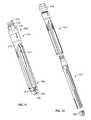
- FIG. 4shows a perspective view of a blade rescue system including the pedicle blade-screw of FIG. 3 in accordance with an embodiment of the present invention.
- FIG. 5shows a perspective view of a blade rescue retractor of the blade rescue system of FIG. 4 being placed over the blade-screw of FIG. 3 .
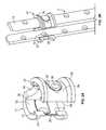
- FIGS. 6A and 6Bshow perspective and cross-sectional elevation views of the retractor of the blade rescue system of FIG. 4 assembled to the blade-screw of the blade rescue system of FIG. 4 .
- FIG. 7shows a perspective view of a persuader of the blade rescue system of FIG. 4 placed over the blade-screw of FIG. 3 .
- FIGS. 8A and 8Bshow enlarged perspective and cross-sectional elevation views of a distal portion of the blade rescue system of FIG. 4 .
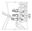
- FIG. 9illustrates the use of a blade rescue retractor over a blade-screw having a single blade during insertion of a spinal fixation rod during a spinal surgery in accordance with an embodiment of the present invention.
- FIG. 10illustrates persuasion of the spinal rod through the blade rescue system used during the spinal surgery illustrated in FIG. 9 .
- FIG. 11illustrates a perspective view of a blade rescue retractor engaging a pedicle screw head in accordance with another embodiment of the present invention.
- FIG. 12illustrates a perspective, exploded view of the components of the blade rescue retractor of FIG. 11 .
- FIG. 13illustrates a perspective view of a gripping member of the blade rescue retractor of FIG. 11 .
- FIG. 13Aillustrates an enlarged perspective view of section A in FIG. 13 .
- FIG. 13Billustrates a partial perspective view of the blade retractor system of FIG. 11 .
- FIG. 14illustrates a partial sectional view of the gripping member of FIG. 13 moving into engagement with a pedicle screw head.
- FIG. 15illustrates a perspective view of a component of a locking member of the blade rescue retractor of FIG. 11 .
- FIG. 16Aillustrates a perspective view of another component of a locking member of the blade rescue retractor of FIG. 11 .
- FIG. 16Billustrates a sectional view of the component FIG. 16B .
- FIGS. 17A-Dillustrate perspective views of portions of a method of using the blade rescue retractor of FIG. 11 .
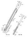
- FIG. 18illustrates a perspective view of a gripping member of a blade rescue retractor in accordance with another embodiment of the present invention.
- FIG. 19illustrates a perspective view of a locking member of a blade rescue retractor in accordance with another embodiment of the present invention.
- proximal and proximal mostrefer to locations closer to a user or operator of the device or method being described and that “distal” and “distal most” refer to locations further from a user or operator of the device or method being described.
- a coupling 17may include inner and outer perimeters 22 , 24 spaced from one another by a thickness of the coupling 17 in which the inner perimeter 22 defines a central opening along a longitudinal axis of the coupling 17 .
- the coupling 17may have ends 26 , 28 spaced from one another such that the ends 26 , 28 define a gap passing through the inner and outer perimeters 22 , 24 and the thickness therebetween.
- the coupling 17may be in the form of a “c-ring,” although other shapes, such as but not limited to a square having a gap through one of the sides, may be used.
- the coupling 17may be placed over and assembled with an integrally formed blade-screw 11 , as shown in FIG. 2B , or in some arrangements, a blade-screw that may be an assembly of a blade and a pedicle screw attached by a fastener, through a snapped connection, or by other attachment mechanisms known to those of ordinary skill in the art.
- the coupling 17may include opposing channels 32 , 34 set in or offset from the inner perimeter 22 that may receive the opposing blades 12 therethrough, as shown in FIGS. 2A and 2B .
- the coupling 17may maintain separation between the opposing blades 12 to stabilize and provide stiffness to the blades 12 during one or both of insertion of the blade screw 1 into the body and insertion of the fixation rod 5 into the blade-screw 1 , and to provide the surgeon or other qualified user with direct visualization of the fixation rod 5 during insertion thereof.
- the opposing channels 32 , 34may be dimensioned to align and orient the blades 12 of the blade-screw 11 at a particular angular position relative to each other.
- each of the channels 32 , 34may be defined by protrusions 37 , 38 that may form spaced apart walls separating the inner perimeter 22 from the channels 32 , 34 . In this manner, such walls may have edges common to both the inner perimeter 22 and the respective opposing channels 32 , 34 .
- Such protrusions 37 , 38desirably secure the blades 12 within the channels 32 , 34 by preventing the blades 12 from moving inwardly towards each other.
- at least one protrusionmay be located at the proximal end and at least one protrusion may be located at a distal end on one side of the coupling.
- the coupling 17may include either or both of upper and lower flanges 41 , 42 that may extend outwardly away from the longitudinal axis of the coupling 17 to stiffen the coupling 17 and also to provide surfaces against which a user may push to ease the sliding of the coupling 17 along the blades 12 .
- a flexible tab 35which may include a boss or protuberance 36 extending inwardly from the inner perimeter 24 towards the longitudinal axis may extend around a portion of the coupling 17 . As shown, the tab 35 may be formed by making a U-shaped cut through the thickness of the coupling 17 between the inner and outer perimeters 22 , 24 . As illustrated in FIG.
- the blades 12may include one or more holes 8 along a length of the blades 12 which pass through a thickness of the blades 12 and which may be sized to receive the boss 36 of the flexible tab 35 of the coupling 17 .
- the coupling 17may be flexible such that the ends 26 , 28 are separated a greater distance when the coupling 17 is placed over the opposing blades 12 than when the coupling 17 is not in use. In this manner, when the coupling 17 is placed over the opposing blades 12 , each of the tabs 35 may be predisposed to compress against the respective blades 12 such that the respective bosses 36 of the tabs 35 protrude slightly into the holes 8 as the bosses 36 passes over the holes 8 . In this manner, the coupling 17 provides feedback to the user that the coupling 17 is in a predetermined location.
- At least a pair, and desirably all, of couplings 17 forming a set of couplingsmay each include a recess 39 , in which each such recess 39 may be located opposite the respective gaps defined by the ends 26 and 28 of the respective couplings 17 .
- each of the holes 8 of the opposing blades 12 engaged by each of the set of couplings 17may be located at the same relative heights along the respective blades 12 .
- the recesses 39provide an extracorporeal template for contouring or selecting a fixation rod 5 to be implanted in the same manner as the rod configuration systems disclosed in commonly owned U.S. Pat. No. 8,177,817 (“the '817 patent”) and U.S. Patent Application Publication No. 2007/0233079 (“the '079 Publication”), the entireties of which are hereby incorporated by reference herein as if fully set forth herein.
- the recesses 39are desirably shaped to receive and support an appropriately shaped fixation rod 5 in a position such that the fixation rod 5 simultaneously extends through the various recesses 39 .
- the fixation rod 5may thus be contoured (e.g., with a French bender), selected from a kit of pre-shaped rods, or custom fabricated (e.g, by a CNC procedure) such that the rod 5 provides an optimal fit within the recesses 39 , and thus, in turn, within the rod receiving surfaces 55 of the pedicle screw heads of the blade-screws 11 .
- one or more bridgesmay be used to couple together two or more of the blade-screws 11 and constrain their relative orientations (e.g., such that they are substantially parallel to one another).
- a blade-screw 51may include only a single blade 52 extending from a pedicle screw head 53 in contrast to the blade-screws 1 , 11 previously described herein, which may be due to a previously attached opposing blade having become disconnected from the pedicle screw head 53 .
- the previously attached opposing blademay have been unintentionally broken off at the frangible portion 16 , or the blade may have been intentionally broken off before it was determined that further revision may be necessary.
- the blade-screw 51may be unable to provide a percutaneous pathway for the insertion of a fixation rod such as the rod insertion tool 4 previously described herein.
- a blade rescue system 10may be utilized to insert a fixation rod 105 by using the single blade 52 of the blade-screw 51 .
- the blade rescue system 10may include a blade rescue retractor 60 that may be placed over and engaged with a blade-screw 51 .
- a persuader 80 having a handle 95 extending therefrom described further hereinmay be placed over and engaged with the retractor 60 .
- a blocker inserter assembly 100may be inserted along a central longitudinal axis within the assembly of the blade-screw 51 , the retractor 60 , and the persuader 80 , into engagement with the blade-screw 51 in order to guide and persuade the insertion of the fixation rod 105 .
- the retractor 60may include a body 65 having opposing first and second legs 64 , 66 extending in a distal direction therefrom.
- the retractor 60may have a generally tubular shape, and the legs 64 , 66 may define diametrically opposed slots 67 extending proximally from the distal end of the retractor 60 .
- Such slots 67desirably provide a space through which a fixation rod may pass, and, in some instances, provide a viewing window between the legs 64 , 66 .
- the retractor 60may be placed over the blade-screw 51 such that the blade-screw 51 is received within an inner perimeter 77 of the retractor 60 .
- a gripping aid 61such as parallel grooves at a proximal portion of and perpendicular to the central axis of the retractor 60 , knurling (not shown), or other friction-inducing features may be added to the retractor 60 .
- the inner perimeter 77 of the retractor 60may include an inner diameter 78 defining a central bore having a longitudinal axis which may receive the blocker inserter assembly 100 .
- a groove 79may be offset from the inner diameter 78 along a length thereof.
- the retractor 60may be placed over the blade-screw 51 such that the single blade 52 of the blade-screw 51 may slide within and along a length of the groove 79 .
- the groove 79may have a shape similar to the grooves 32 , 34 of the coupling 17 as described above.
- the groove 79may interface with the inner perimeter 77 in a manner similar to the interfaces of the grooves 32 , 34 and the inner perimeter 22 of the coupling 17 (e.g., having protrusions to secure the blade 52 within the groove).
- the first leg 64may extend over the blade 52 .
- the first leg 64may have a thickness such that a total thickness of the first leg 64 and the blade 52 is approximately, i.e., within at least 10% and more preferably, within 1%, and still more preferably within 0.1%, of the thickness of the second leg 66 .
- the first leg 64 of the retractor 60may provide sufficient, and, in some arrangements, balanced rigidity to prohibit bending of the first leg 64 during insertion of a fixation rod while extending only minimally beyond the outer width dimension of the blade-screw 51 , consistent with the desire that the pathway through the tissue be as minimally invasive as possible.
- the retractor 60may include an arm 62 extending from the body 65 thereof. As shown, the arm 62 may extend from or be formed by a cutout of the body 65 . As further shown, a boss 63 may extend inwardly from the inner diameter 77 of the retractor 60 . In this manner, when the retractor 60 is placed over the blade 52 of the blade-screw 51 , the boss 63 , or in some arrangements, a plurality of bosses, may be predisposed to extend into one or more recesses or holes 54 of the blade 52 . The holes 54 may have a nominal diameter of 2 mm, although the holes 54 may have a different diameter.
- the boss 63may have a diameter slightly less than the diameter of the holes 54 , while in other arrangements, the boss 63 may have a diameter slightly greater than the diameter of the holes 63 such that an interference fit may be established upon insertion of the boss 63 into one of the holes 54 .
- such holesmay be placed in linear alignment along a length of the blade 52 such that the retractor 60 may be maintained at various positions relative to the blade-screw 51 .
- the corresponding hole or holes 54 of the blade-screw 51may be placed near a proximal end of the retractor 60 .
- the first and second legs 64 , 66 of the retractor 60may include respective prongs 68 , 69 at the distal end of the retractor 60 .
- the pedicle screw head 53 of the blade-screw 51may include a corresponding groove 56 around at least a portion of the perimeter thereof for receiving the prongs 68 , 69 .
- the first and second legs 64 , 66 of the retractor 60may include grooves 71 , 72 .
- the head 53 of the blade-screw 51may include a protrusion 57 around at least a portion of the perimeter thereof that may be inserted into the grooves 71 , 72 of the retractor 60 . In this manner, the retractor 60 may be placed into locking engagement with the blade-screw 51 .
- the persuader 80may be placed over and into engagement with the retractor 60 .
- the persuader 80may include a body 81 having an inner perimeter 85 along a length thereof that circumscribes a corresponding length of an outer perimeter 75 of the retractor 60 .
- the inner perimeter 85 of the persuader 80 and the outer perimeter 75 of the retractor 60may have corresponding diameters in which the inner perimeter 85 is only slightly larger than the outer perimeter 75 such that the persuader 80 may slide over the retractor 60 with the least amount of angulation or play allowable without forming an interference fit with the retractor 60 that prevents removal of the persuader 80 from the retractor 60 .
- the body 81 of the persuader 80may include a viewing window 84 , or, in some arrangements, a plurality of viewing windows, defining a hole or a plurality of holes through a thickness of the body 81 .
- the window 84may provide an area through which to view the relative positions of the retractor 60 and the persuader 80 during placement of the persuader 80 , for example to determine whether the fixation rod 5 has been fully persuaded.
- the body 81may include a flange 86 , which may be hollow as shown in FIG. 7 , extending at an oblique angle to a longitudinal axis defined by the inner perimeter 85 of the body 81 .
- a handle assembly 95may extend at an oblique angle to a longitudinal axis defined by the inner perimeter 85 .
- the handle assembly 95may include a handle 96 , which may include a friction-inducing grip for reducing slipping that may otherwise be experienced by a user, that may extend from a connecting rod 97 .
- the connecting rod 97may be attached to the flange 86 by a fastener, which may be inserted through a fastener inner perimeter 87 defining a hole through the flange 86 .
- a connecting rod of a handle assemblymay form an interference fit with a receiving bore of a hollow flange extending from the body into which the connecting rod may be inserted (not shown).
- a connecting rod of a handle assemblymay form a monolithic structure with a flange extending from the body.
- the blocker inserter assembly 100may be inserted along a longitudinal axis of a space defined by the single blade 52 of the blade-screw 51 and the retractor 60 .
- the blocker inserter assembly 100may include a blocker inserter 101 that may be temporarily engaged with a blocker 110 , in which such engagement may be through an interference fit between the blocker inserter 101 and the blocker 110 .
- the blocker 110may include external threads 111 that may engage corresponding threads 58 along a distal portion of the blade 52 and also threads 59 within the rod receiving surface 55 in the head 53 of the blade-screw 51 .
- the blocker 110may be rotated clockwise or counterclockwise by rotation of the blocker inserter 101 in a corresponding clockwise or counterclockwise direction to cause the blocker 110 to move distally or proximally, respectively.
- the fixation rod 105may be inserted within a working region defined by the blade 52 of the blade-screw 51 and the second leg 66 of the retractor 60 and the receiving surface 55 of the head 53 of the blade-screw 51 , which may be in the shape of a saddle (as best shown in FIG. 6B ), facing inwardly in a proximal direction, in which the receiving surface 55 may be U-shaped and the head 53 may be tulip-shaped as best shown in FIG. 3 .
- the blocker 110may contact the fixation rod 105 to push or persuade the fixation rod 105 distally towards the rod receiving surface 55 when the blocker 110 is turned in one direction and to allow the fixation rod to be raised proximally when the blocker 110 is turned in the opposite direction.
- the persuader 80may confine the retractor 60 attached to the single blade 52 to prevent the retractor legs 64 , 66 from splitting apart, i.e., separating in a direction away from each other.
- the persuader 80may prevent the retractor 60 from disengaging the blade-screw 51 during either of insertion of the blocker 110 into the working region described above or persuasion of the fixation rod 105 .
- the persuader 80may have a distal surface to exert a force against the fixation rod 105 to cause the fixation rod 105 to move distally.
- the persuader body 81optionally may have diametrically opposed recesses 83 , as shown by the dashed lines in FIGS. 4 and 8A , at the distal end thereof for receiving the rod 5 therein in a transverse orientation.
- the fixation rod 105may be pushed distally by the persuader 80 to a position such that the threads 111 of the blocker 110 may be engaged with either of the threads 58 , 59 without contacting, and thus without interference caused by a proximal force due to, the fixation rod 105 .
- the persuader 80may include one or more persuader holes 82 on a distal end of the persuader 80 .
- the body 81 of the persuader 80may be positioned such that the persuader holes 82 and the holes 74 of the retractor 60 may be in alignment.
- the persuader 80may be placed in a position relative to the retractor 60 in which the holes 82 of the persuader 80 and the holes 74 of the retractor are placed in visual alignment. In some arrangements, this position may be located at a position at which the persuader should not be pressed further along the retractor 60 .
- the persuadermay include protrusions in place of the holes 82 in which such protrusions may be dimensioned to be inserted into the holes 74 of the retractor 60 in order to establish a desired relative alignment and position between the persuader and the retractor.
- a qualified usersuch as but not limited to a physician, a surgeon, a physician's assistant, and a veterinarian, may insert a pedicle blade-screw 151 into a pedicle of a spine.
- a blade of the blade-screw 151may have been broken off or otherwise disconnected during insertion of the blade-screw 151 or during insertion of the fixation rod, while in rare instances, the blade-screw initially may have been produced with only a single blade.
- the usermay place a retractor 160 over the pedicle blade-screw 151 such that the blade 152 of the blade-screw 151 may be inserted into a groove 179 of the retractor 160 .
- the retractor 160may have first and second legs 164 , 166 extending from a body 165 , the second leg 166 being on the same side as the groove 179 , in which prongs extending from the legs 164 , 166 may be separated a distance such that a first prong 168 and a second prong 169 (not shown) snap into a groove on a head of the blade-screw 151 . (See FIG. 6B for example).
- the rodmay be inserted using the retractor 160 as a functional replacement for the blade-screw 151 having a missing blade. That is, the second leg 166 opposite the remaining blade 152 desirably acts as a replacement for the missing blade by holding back the surrounding tissue, such that the retractor 160 provides a pathway through the tissue from the respective pedicle screw head to the incision through which the retractor 160 is disposed.
- the slots 167 between the legs 164 , 166are analogous to the slots 67 between the blades of the blade-screws 51 described previously herein, as the slots 167 of the retractor 160 allow the rod 5 to extend transverse to the longitudinal axis of the retractor and be guided towards the pedicle screw heads.
- the rodmay then be persuaded towards and into the rod receiving surfaces of the pedicle screw heads.
- a usermay grab either or both of a body 181 or a handle 196 of a handle assembly 195 , in which the handle 196 as shown may extend at an angle from the body 181 , to place and position a persuader 180 over the retractor 160 .
- the persuader 180may then be advanced distally such that its distal end contacts the rod and persuades it towards the pedicle screw head, preferably at least until the rod is within the internally threaded region of the retractor blade 152 analogous to the threads on the blade 52 described previously herein.
- the persuader 180desirably overlaps the first and second prongs 168 , 169 of the retractor 160 to maintain the prongs 168 , 169 within the groove on the head of the blade-screw 151 .
- the rodmay be persuaded the remaining distance to the rod receiving surface of the pedicle screw head by using the blocker inserter 201 having a blocker (not shown) positioned on its distal end. Specifically, the blocker inserter 201 with blocker is inserted along the longitudinal axis of the retractor 160 , as shown in FIG. 10 .
- the external threads of the blockerare then engaged with the internal threads of the blade-screw 151 , which may be on either or both of the blade 152 and the head of the blade-screw 151 , and the blocker is advanced distally along the threads by rotating the blocker with the blocker inserter 201 , thereby pushing the rod distally with the distal end of the blocker.
- the usermay push the persuader 180 against the fixation rod (see FIGS. 7 and 8A for example) to persuade the fixation rod to cause the fixation rod to move distally and to maintain separation between the fixation rod and the blocker during insertion of the blocker into the working region.
- the persuadermay reduce or remove a proximal, often undesirable, force that may otherwise be exerted by the fixation rod against the blocker due to contact between the rod and the blocker during insertion.
- the blocker inserter 201 and persuader 180may be removed from the body. Thereafter, the retractor 160 may be removed, in some arrangements by first applying an outward force on the arm (see FIGS. 6A and 6B for example) of the retractor 160 to disengage the boss of the arm from the recess (see FIGS. 3 and 6B for example) in the blade 152 .
- the remaining blade 152may be broken off, such as by pivoting the blade 152 about the frangible portion (see FIG. 3 for example) until the frangible portion breaks.
- the incisions through which the blade screws 151 and other components of the blade rescue system extendedmay then be closed.
- a blade rescue retractor 310may be used when both blades have been disconnected from a pedicle screw head 300 .
- the retractor 310may define a longitudinal pathway 311 therealong between its distal end 308 and its proximal end 309 .
- the retractor 310may comprise a gripping member 312 and a locking member 314 .
- both the gripping member 312 and the locking member 314are hollow elongate bodies in which the gripping member 312 is received within the locking member 314 .
- the locking member 314may be constructed to move in a proximal direction and a distal direction along the gripping member 312 .
- the retractor 310desirably has an opening 313 into the longitudinal pathway 311 at its proximal end 309 , which opening 313 may be defined by an opening at the proximal end of the gripping member 312 .
- FIG. 12is an exploded view of the retractor 310 , illustrating the locking member 314 separated from the gripping member 312 and also illustrating the actuation mechanism 316 of the locking member 314 separated from the remainder of the locking member 314 .
- the gripping member 312is illustrated in FIG. 13 , separated from the locking member 314 of the retractor 310 .
- the gripping member 312has a proximal end 318 and a distal end 320 .
- An interior surface 321 of the gripping member 312preferably defines the longitudinal pathway 311 along the retractor 310 .
- the interior surface 321may include a threaded portion (not shown), preferably at least near the distal end 320 of the gripping member, for engagement with an externally threaded blocker and advancement of that blocker towards and into the pedicle screw head 300 , as discussed above in connection with the embodiments illustrated in FIGS. 8B and 10 .
- the gripping member 312may have a generally tubular shape with diametrically opposed slots 322 extending proximally from the distal end 320 so as to define first and second legs 324 , 326 extending distally from a body portion 328 .
- Such slots 322desirably provide a space through which a fixation rod may pass in an orientation transverse to the longitudinal axis of the retractor 310 , and, in some instances, the slots 322 may provide a viewing window between the legs 324 , 326 .
- the gripping member 312may be symmetrical on either side of the slots 322 , such that the legs 324 , 326 have the same structure.
- One or both legs 324 , 326 of the gripping member 312may include a slot 332 extending proximally from the distal end 320 so as to divide the distal portions of the legs 324 , 326 into a plurality of prongs 333 .
- the slot 332may have a distal end 334 open to the distal end 320 of the gripping member 312 and a proximal end 336 terminating at a hole 338 .
- the hole 338may be rounded to reduce stress concentrations at the proximal end 336 of the slot 332 , and, in some embodiments, the hole 338 may be circular.
- the slot 332is preferably tapered such that it narrows towards its proximal end 336 .
- the slot 332may have a substantially constant width between its distal and proximal ends 334 , 336 .
- the gripping member 312is desirably at least partially flexible, such that the legs 324 , 326 can deflect at least slightly away from one another.
- the gripping member 312is also preferably sufficiently flexible to allow the prongs 333 to spread apart from one another.
- the gripping member 312may include an engagement portion 330 at its distal end 320 for engaging the pedicle screw head 300 , as shown in FIGS. 17C and 17D .
- the engagement portion 330may be in the form of a collar protruding radially outward from the outer surfaces of the legs 324 , 326 .
- the proximal end of the engagement portion 330may define a ledge 340 extending substantially transverse to the longitudinal axis of the gripping member 312 .
- the ledge 340may include one or more recesses 342 extending distally therefrom.
- FIG. 13Billustrates a perspective view of the engagement portion 330 showing the various structures for engaging the pedicle screw head 300 .
- the engagement portion 330preferably includes one or more tabs 344 a,b projecting inwardly from an interior surface 346 of the engagement portion 330 and structured for engagement with corresponding structures on the exterior surface 350 of the pedicle screw head 300 .
- tabs 344 a located on either side of the slots 322 between the legs 324 , 326may be sized to engage the pedicle screw head 300 along the edges 352 of the lateral openings 354 through which the fixation rod passes when it is seated within the pedicle screw heads 300 (see FIG. 17D ).
- the pedicle screw head 300may include recesses 348 a along those edges 352 for receiving the tabs 344 a of the engagement portion 330 (see FIG. 17D ).
- tabs 344 b located on either side of the slots 332 of each leg 324 , 326may be sized to engage one or more recesses 348 b (see FIG. 17A ) in the exterior surface 350 of the pedicle screw head 300 between the lateral openings 354 .
- all of the tabs 344 a,bhave an angled chamfer 356 on their distal ends to ease insertion of the gripping member 312 and, in turn, the retractor 310 over the pedicle screw head 300 .
- the chamfers 356may be arranged such that, as the distal end 308 of the retractor 310 is moved distally over the proximal end 358 of the pedicle screw head 300 , the chamfers 356 will cause the engagement portion 330 to spread apart.
- the chamfers 356 on tabs 344 awill cause the prongs 333 to spread apart, and the chamfers 356 on tabs 344 b will cause the legs 324 , 326 to spread apart, such that the pedicle screw head 300 is received within the engagement portion 330 .
- Further distal movement of the retractor 310will move the tabs 344 a,b into engagement with the corresponding recesses 348 a,b of the pedicle screw head 300 .
- the engagement portion 330is preferably structured to at least somewhat resist unwanted separation of the retractor 310 from the pedicle screw head 300 .
- lateral surfaces 360 on the proximal ends of the tabs 344 a,bwill engage lateral surfaces 362 at the proximal ends of the recesses 348 a,b to prevent the retractor 310 from moving proximally and disengaging the pedicle screw head 300 .
- lateral surfaces 364 at the proximal end of the engagement portion 330will engage the proximal end 358 of the pedicle screw head 300 to prevent the retractor 310 from moving distally with respect to the pedicle screw head 300 .
- an exterior surface 365 of the gripping member 312 between its proximal and distal ends 318 , 320may include one or more projections 366 extending laterally outward.
- projectionsmay be in the form of generally cylindrical pins.
- the proximal end 318 of the gripping membermay include an externally threaded portion 368 .
- FIG. 15illustrates a perspective view of a portion of the locking member 314 , separated from the gripping member 312 , and with the actuation mechanism 316 removed.
- the locking member 314has a proximal end 370 and a distal end 372 .
- the locking member 314may have a hollow, sleeve-like shape constructed to receive the gripping member 312 within its interior.
- the locking member 314may have a generally tubular body portion 374 with first and second generally planar legs 376 , 378 extending distally from its distal end 379 , the legs 376 , 378 defining a pass-through slot 380 between the legs 376 , 378 .
- first and second generally planar legs 376 , 378extending distally from its distal end 379 , the legs 376 , 378 defining a pass-through slot 380 between the legs 376 , 378 .
- the legs 374 , 376have exterior surfaces 382 that are substantially flat, while the interior surfaces 384 are generally curved so as to substantially match the exterior surface 365 of the gripping member 312 .
- the locking member 314may be symmetrical on either side of the pass-through slot 380 , such that the legs 376 , 378 have the same structure.
- the entire locking member 314may have a generally tubular shape similar to that of the gripping member 312 illustrated in FIG. 13 , such that the legs 374 , 376 of the locking member 314 are generally arcuate segments.
- the legs 374 , 376may have a substantially smaller profile and may be in the form of rods extending distally from the body portion 374 .
- the interior surface 384 of the locking member 314may include at least one or more projections 388 extending laterally inwardly, and preferably includes one such projection 388 located on each of the legs 376 , 378 .
- the projections 388are preferably arranged to be received within the corresponding slots 332 in the legs 324 , 326 of the gripping member 324 .
- Such projectionsmay be in the form of generally cylindrical pins.
- the projections 388are shaped to cause the prongs 333 to spread apart as each projection 388 is moved proximally within the tapered slot 332 .
- the distal end 372 of the locking member 314may include one or more distally extending projections 386 configured to be received within the corresponding recesses 342 in the engagement portion 330 of the gripping member 312 .
- the projections 386 of the locking membermay desirably restrain the prongs 333 of the gripping member 312 from spreading apart.
- the locking member 314may include one or more slots 390 arranged to receive the one or more projections 366 of the gripping member 312 therein. Desirably, the interaction between the projections 366 and the slots 390 constrains the movement of the locking member 314 with respect to the gripping member 312 to be substantially linear along the proximal and distal directions, while preventing either the locking member 314 or the gripping member 312 from rotating with respect to one another about the longitudinal axis of the retractor 310 .
- the proximal end 392 of the body portion 374may include a connection 394 for engaging the actuation mechanism 316 .
- the connection 394may include an annular recess 393 extending around the circumference of the body portion 374 and an annular flange 395 positioned proximally of the recess 393 .
- the annular flange 395is preferably chamfered at its proximal end 397 to ease the connection of the actuation mechanism 316 to the body portion 374 .
- the proximal end 370 of the locking member 314also preferably includes at least one slot 396 extending distally from the proximal end 392 of the body portion 374 .
- the slot 396may have a proximal end 398 open to the proximal end 392 of the body portion 374 and a distal end 400 terminating at a hole 402 .
- the holemay be rounded to reduce stress concentrations at the distal end 400 of the slot 396 , and, desirably, the hole 402 may be circular.
- the slot 396preferably allows the proximal end 392 of the body portion 374 , and thus the connection 394 , to deflect at least slightly inwardly so that the actuation mechanism 316 can be snapped on to the proximal end 392 of the body portion 374 and into engagement with the connection 394 .
- one embodiment of the actuation mechanism 316is in the form of a generally tubular sleeve.
- the actuation mechanism 316has a distal end 404 and a proximal end 406 .
- a connection 408which is structured to engage the connection 394 at the proximal end 392 of the body portion 374 , may be located in the interior of the actuation mechanism 316 at its distal end 404 .
- the connection 408may include an annular recess 410 extending around the circumference of the body portion 374 and an annular flange 412 positioned distally of the recess 410 .
- the annular flange 412is preferably chamfered at its distal end 414 to ease the connection of the actuation mechanism 316 to the body portion 374 .
- the actuation mechanism 316may thus be connected to the body portion 374 by fitting the distal end 404 of the actuation mechanism 316 over the proximal end 392 of the body portion 374 until the annular flange 412 of the actuation mechanism 316 is received within the annular recess 393 of the body portion 374 and the annular flange 395 of the body portion is received within the annular recess 410 of the actuation mechanism 316 . That engagement desirably permits the actuation mechanism 316 to rotate with respect to the body portion 374 about the longitudinal axis of the retractor 310 while restraining the actuation mechanism 316 from separating from the body portion 374 .
- the actuation mechanism 316desirably includes an internally threaded portion 416 configured to engage the externally threaded portion 368 of the gripping member 312 when the gripping member is received within the locking member 314 .
- rotation of the actuation mechanism 316 with respect to the body portion 374 of the locking member 314will cause the locking member 314 to move in a proximal direction or a distal direction along the gripping member 312 .
- That rotationis preferably driven by a tool removably engaged to a tool interface 418 at the proximal end 406 of the actuation mechanism 316 . As shown in FIG.
- the tool interface 418may comprise an external, hexagonally shaped interface configured to be received within a correspondingly shaped recess of the tool or engaged by a wrench or other appropriate tool.
- any other configuration of a tool interface known in the artmay be used.
- the locking member 314and preferably at least the legs 376 , 378 of the locking member 314 , are desirably relatively rigid, while the gripping member 312 is desirably partially flexible, such that the legs 324 , 326 and prongs 333 can spread apart from one another, as discussed above.
- the flexibility of the legs 324 , 326 and prongs 333may permit the engagement portion 330 to spread apart when moved distally over the proximal end 358 of the pedicle screw head 300 , after which the tabs 344 a,b of the engagement portion 330 may become engaged with the recesses 348 a,b of the pedicle screw head 300 .
- the locking member 314may help to rigidly secure the retractor 310 to the pedicle screw head 300 by preventing the gripping member 312 from becoming disengaged with the pedicle screw head 300 .
- the locking member 314may be advanced distally along the gripping member 312 from a retracted position towards a locked position, which causes the legs 376 , 378 of the locking member 314 to move distally along the legs 324 , 326 of the gripping member 312 .
- the relatively rigid legs 376 , 378 of the locking member 314preferably restrain the relatively flexible legs 324 , 326 of the gripping member 312 from deflecting outwardly and thereby disengaging the pedicle screw head 300 .
- the relatively rigid legs 376 , 378 of the locking member 314also preferably restrain the prongs 333 of the gripping member 312 from spreading apart.
- FIGS. 17A-DAn exemplary method of using the blade rescue retractor 310 of FIGS. 11-16B is illustrated in FIGS. 17A-D .
- the use of the retractor 310may be particularly desirable in cases where both blades of the blade screw have been removed and further access to the pedicle screw head 300 is desired. Such scenarios may arise, for example, where both blades of the blade-screw were intentionally or unintentionally removed (e.g., broken off at frangible portions) before it was determined that further revision may be necessary.
- an elongate guide tool 420may first be inserted through a skin incision and distally into engagement with the pedicle screw head 300 .
- the guide tool 420may include an engagement portion 422 at its distal end 423 for stable engagement with the pedicle screw head 300 .
- the engagement portion 422may comprise a slot 424 extending proximally from the distal end 423 of the guide tool 420 .
- the slot 424may have a distal end 426 open to the distal end 423 of the guide tool 420 and a proximal end 428 terminating at a hole 430 .
- the holemay be rounded to reduce stress concentrations at the proximal end 428 of the slot 424 , and, desirably, the hole 430 may be circular.
- the slot 424may allow the engagement portion 422 to deflect at least slightly inwardly.
- the outer surface 431 of the guide tool 420is preferably slightly larger than the interior dimension of the rod receiving surface 432 (see FIGS. 17C and 17D ) in the pedicle screw head 300 , such that the engagement portion 422 may deflect slightly inwardly upon being received within the rod receiving surface 432 , so as to stabilize the engagement between the engagement portion 422 and the rod receiving surface 432 .
- the engagement portion 422may also include one or more laterally extending projections 434 , which may be sized to be received within the lateral openings 354 of the pedicle screw head 300 , to further stabilize the engagement between the engagement portion 422 and the pedicle screw head 300 .
- the outer surface 431 of the guide tool 420 proximal of the engagement portion 422is sized to be relatively closely received within the interior surface 321 of the gripping member 312 .
- the retractor 310may be advanced distally along the guide tool 420 towards the pedicle screw head 300 , preferably with the locking member 314 in a retracted position, as shown in FIG. 17A .
- the retractor 310may be advanced until the engagement portion 330 of the gripping member 312 moves over and into engagement with the pedicle screw head 300 , after which the locking member 314 may be advanced distally from the retracted position (as shown in FIG. 17C ) to a locked position (as shown in FIG. 17D ), in order to restrain the engagement portion 330 of the gripping member 312 from spreading apart and becoming disengaged with the pedicle screw head 300 .
- a tool 436may be engaged with the tool interface 418 at the proximal end 406 of the actuation mechanism 316 , as shown in FIG. 17B .
- the tool 436may include a recess (not shown) at its distal end 438 for receiving the tool interface 418 , and the tool 436 may include a handle 440 at its proximal end 442 for providing a gripping surface and also, preferably, leverage for rotating the tool 436 to drive the actuation mechanism 316 .
- the retractor 310may be used in much the same manner as the retractor 60 of FIGS. 4-8B . That is, if both blades were broken off before the fixation rod was inserted, the rod may be inserted using the retractor 310 as a functional replacement for the blade-screw having the missing blades.
- first and second legs 324 , 326 of the gripping member 312stabilized by the first and second legs 376 , 378 of the locking member 314 , desirably act as replacements for the missing blades by holding back the surrounding tissue, such that the retractor 310 provides a pathway through the tissue from the respective pedicle screw head 300 to the incision associated with that pedicle screw.
- the slots 322 between the legs 324 , 326 of the gripping member 312are analogous to the openings between the blades of the blade-screws, as the slots 322 of the gripping member 312 allow the fixation rod to extend transverse to the longitudinal axis of the retractor 310 and be guided towards the pedicle screw heads 300 .
- the rodmay then be persuaded towards and into the rod receiving surfaces 432 of the pedicle screw heads 300 . That may involve use of a persuader (not shown) in much the same manner as the persuader 80 illustrated in FIGS. 4 and 7-8B , which persuader may be sized and shaped to be positioned over the retractor 310 and advanced distally to persuade a transversely oriented rod towards the pedicle screw head 300 .
- a blocker inserter with blockermay also be used and positioned within the longitudinal pathway 311 of the retractor 310 through the opening 313 at its proximal end 309 .
- the blocker(not shown) may be engaged with the threads of such threaded portion and rotated to advance the blocker along the threaded portion and into engagement with the threads 444 (see FIG. 17D ) in the rod receiving surface 432 of the pedicle screw head 300 .
- the blocker inserter 201 and persuader 180may be removed from the body. Thereafter, the retractor 310 may be removed.
- the locking member 314may first be moved proximally into the retracted position, such as by rotation of the actuation mechanism 316 with the tool 436 . As discussed above, the proximal movement of the locking member 314 may cause the projections 388 of the locking member 314 to move proximally within the tapered slots 332 of the gripping member 312 , thus spreading apart the prongs 333 of the gripping member 312 .
- FIGS. 18 and 19illustrate alternative embodiments of a gripping member 312 ′ and a locking member 314 ′ (with actuation mechanism 316 ′), which are largely similar to those illustrated in FIGS. 13 and 15 , respectively, and in which like reference numerals refer to like elements.
- the gripping member 312 ′ of FIG. 18includes a threaded portion 500 along its inner surface 321 ′ near the distal end 320 ′.
- the threaded portion 500may be constructed for engagement with an externally threaded blocker so as to advance that blocker towards and into the pedicle screw head, as discussed above in connection with the embodiments illustrated in FIGS. 8B and 10 .
- FIG. 8B and 10also in the embodiment of FIG.
- the holes 338 ′ at the proximal ends 336 ′ of the slots 332 ′ in each of the legs 324 ′, 326 ′have an elongated shape.
- the holes 338 ′may have a generally elliptical shape having a major diameter extending substantially along the longitudinal axis of the gripping member 312 ′.
- the projections 366 ′ along the exterior surface 365 ′ of the gripping member 312 ′ of the embodiment of FIG. 18also may have an elongated shape.
- the projections 366 ′may be elongated substantially along the longitudinal axis of the gripping member 312 ′.
- the projections 388 ′are the shape of the projections 388 ′ extending inwardly from the interior surface 384 ′ for engagement with the slots 332 ′ of the gripping member 312 ′.
- the projections 388 ′may have an elongated shape (e.g., elongated substantially along the longitudinal axis of the locking member 314 ′).
- the locking memberneed not extend substantially along the entire length of the gripping member in locked position.
- Such an embodiment of the locking membermay not include legs, and the tubular body portion may instead be structured to extend at least partially along the legs 324 , 326 of the gripping member 312 in the locked position, so as to restrain the legs 324 , 326 of the gripping member 312 from deflecting outwardly and disengaging the pedicle screw head 300 .
- the locking member and gripping membermay instead be structured so that the locking member is received within the gripping member.
- the engagement between the locking member and the gripping membermay be such that, when the locking member is in the locked position, the locking member restrains the legs of the gripping member from deflecting outwardly and disengaging the pedicle screw head 300 .
- the gripping membermay include a structure such as an internal track for receiving the legs, or some other engagement structure on the legs, of the locking member.
- the legs of the locking membermay be structured as stiffening members which are received within and movable along channels formed inside the legs (i.e., between the interior and exterior surfaces of the gripping member).
- blade rescue systems and methods of use abovewere described in connection with integrated blade-screws in which one or both blades had been broken off (e.g., broken at the frangible portions), such blade rescue systems could also be used in connection with other types of percutaneous access devices (such as those described in the '355 patent or the '798 patent) after such percutaneous access devices have been removed or have failed.
- the blade rescue retractor 60 discussed in connection with FIGS. 4-8Bcould be used with a system having blades separately formed from and detachably connectable to the pedicle screw heads, as described in the '798 patent, and in which one of the blades has become disconnected to the associated pedicle screw head.
- the blade rescue retractor 310 discussed in connection with FIGS. 11-17Dcould also be used with a similar system of separately formed blades in which both blades have become disconnected from the pedicle screw head.
- bosses, projections, and protuberancesare described as interfacing with holes, slots, or recesses, such holes, slots, or recesses and either or all of the bosses, projections, and protuberances corresponding to, being inserted in, or being engaged with the respective holes, slots, or recesses may be reversed such that they are on the other feature than that previously described herein.
- bosses and protuberancesmay simply extend from a wall, an inner perimeter, or body that may be rigid or inflexible.
Landscapes
- Health & Medical Sciences (AREA)
- Orthopedic Medicine & Surgery (AREA)
- Neurology (AREA)
- Life Sciences & Earth Sciences (AREA)
- Surgery (AREA)
- Heart & Thoracic Surgery (AREA)
- Engineering & Computer Science (AREA)
- Biomedical Technology (AREA)
- Nuclear Medicine, Radiotherapy & Molecular Imaging (AREA)
- Medical Informatics (AREA)
- Molecular Biology (AREA)
- Animal Behavior & Ethology (AREA)
- General Health & Medical Sciences (AREA)
- Public Health (AREA)
- Veterinary Medicine (AREA)
- Surgical Instruments (AREA)
Abstract
Description
Claims (23)
Priority Applications (4)
| Application Number | Priority Date | Filing Date | Title |
|---|---|---|---|
| US14/206,431US9510875B2 (en) | 2013-03-14 | 2014-03-12 | Systems and methods for percutaneous spinal fusion |
| US15/360,083US10568669B2 (en) | 2013-03-14 | 2016-11-23 | Systems and methods for percutaneous spinal fusion |
| US16/749,440US11779377B2 (en) | 2013-03-14 | 2020-01-22 | Systems and methods for percutaneous spinal fusion |
| US18/369,436US20240008904A1 (en) | 2013-03-14 | 2023-09-18 | Systems and Methods for Percutaneous Spinal Fusion |
Applications Claiming Priority (2)
| Application Number | Priority Date | Filing Date | Title |
|---|---|---|---|
| US201361783098P | 2013-03-14 | 2013-03-14 | |
| US14/206,431US9510875B2 (en) | 2013-03-14 | 2014-03-12 | Systems and methods for percutaneous spinal fusion |
Related Child Applications (1)
| Application Number | Title | Priority Date | Filing Date |
|---|---|---|---|
| US15/360,083ContinuationUS10568669B2 (en) | 2013-03-14 | 2016-11-23 | Systems and methods for percutaneous spinal fusion |
Publications (2)
| Publication Number | Publication Date |
|---|---|
| US20140277206A1 US20140277206A1 (en) | 2014-09-18 |
| US9510875B2true US9510875B2 (en) | 2016-12-06 |
Family
ID=50289458
Family Applications (4)
| Application Number | Title | Priority Date | Filing Date |
|---|---|---|---|
| US14/206,431Active2034-07-25US9510875B2 (en) | 2013-03-14 | 2014-03-12 | Systems and methods for percutaneous spinal fusion |
| US15/360,083Active2035-02-21US10568669B2 (en) | 2013-03-14 | 2016-11-23 | Systems and methods for percutaneous spinal fusion |
| US16/749,440Active2035-11-21US11779377B2 (en) | 2013-03-14 | 2020-01-22 | Systems and methods for percutaneous spinal fusion |
| US18/369,436PendingUS20240008904A1 (en) | 2013-03-14 | 2023-09-18 | Systems and Methods for Percutaneous Spinal Fusion |
Family Applications After (3)
| Application Number | Title | Priority Date | Filing Date |
|---|---|---|---|
| US15/360,083Active2035-02-21US10568669B2 (en) | 2013-03-14 | 2016-11-23 | Systems and methods for percutaneous spinal fusion |
| US16/749,440Active2035-11-21US11779377B2 (en) | 2013-03-14 | 2020-01-22 | Systems and methods for percutaneous spinal fusion |
| US18/369,436PendingUS20240008904A1 (en) | 2013-03-14 | 2023-09-18 | Systems and Methods for Percutaneous Spinal Fusion |
Country Status (5)
| Country | Link |
|---|---|
| US (4) | US9510875B2 (en) |
| EP (2) | EP3335653B1 (en) |
| JP (1) | JP6353248B2 (en) |
| AU (3) | AU2014201569B2 (en) |
| CA (1) | CA2846149C (en) |
Cited By (15)
| Publication number | Priority date | Publication date | Assignee | Title |
|---|---|---|---|---|
| US20180132911A1 (en)* | 2015-05-12 | 2018-05-17 | Shandong Weigao Orthopedic Device Company Ltd | Grasping end of frog-style forceps |
| US20180338781A1 (en)* | 2016-08-12 | 2018-11-29 | Amendia, Inc. | Minimally invasive screw extension assembly |
| US10507046B2 (en) | 2013-12-13 | 2019-12-17 | Stryker European Holdings I, Llc | Tissue retraction and vertebral displacement devices, systems, and methods for posterior spinal fusion |
| US20200197052A1 (en)* | 2017-06-27 | 2020-06-25 | Silony Medical International AG | Extension device for a bone anchor |
| US10959760B2 (en)* | 2016-04-27 | 2021-03-30 | Warsaw Orthopedic, Inc. | Spinal correction system and method |
| US11096725B2 (en) | 2019-02-14 | 2021-08-24 | Medos International Sarl | Reduction screw tab break off and storage instrument |
| US20210282820A1 (en)* | 2018-06-13 | 2021-09-16 | Nuvasive, Inc. | Rod Reduction Assemblies and Related Methods |
| US11134994B2 (en)* | 2020-01-30 | 2021-10-05 | Warsaw Orthopedic, Inc. | Spinal-correction system having threaded extender tabs and reduction tab extenders |
| US11259940B2 (en) | 2019-06-28 | 2022-03-01 | Mis Spine Ip, Llc | Systems and methods for percutaneous spinal interbody fusion (PSIF) |
| US11439442B2 (en) | 2020-04-16 | 2022-09-13 | Warsaw Orthopedic, Inc. | Modular screw system with head locker and derotator |
| US11484349B2 (en)* | 2017-02-17 | 2022-11-01 | Warsaw Orthopedic, Inc. | Surgical system and method |
| US11617602B2 (en) | 2020-04-16 | 2023-04-04 | Medtronic, Inc. | Systems, methods of use and surgical instruments employing a secure slide lock to fasten a head |
| US20230240728A1 (en)* | 2015-10-27 | 2023-08-03 | Ctl Medical Corporation | Modular rod reduction tower and related methods |
| US12059168B2 (en) | 2021-06-16 | 2024-08-13 | Ludwig David Orozco Castillo | Systems and methods for ball probe ultrasonic foraminotomy |
| US12127949B1 (en) | 2013-12-06 | 2024-10-29 | Stryker European Operations Holdings Llc | Percutaneous posterior spinal fusion implant construction and method |
Families Citing this family (55)
| Publication number | Priority date | Publication date | Assignee | Title |
|---|---|---|---|---|
| JP3223264B2 (en) | 1992-03-06 | 2001-10-29 | 新日本製鐵株式会社 | Manufacturing method of coiled steel pipe with excellent cold workability |
| CA2739431C (en) | 2008-10-01 | 2016-12-06 | Sherwin Hua | System and method for wire-guided pedicle screw stabilization of spinal vertebrae |
| US9907582B1 (en)* | 2011-04-25 | 2018-03-06 | Nuvasive, Inc. | Minimally invasive spinal fixation system and related methods |
| FR2988582B1 (en)* | 2012-04-02 | 2014-03-14 | Safe Orthopaedics | INSTRUMENTATION KIT |
| US20140336709A1 (en)* | 2013-03-13 | 2014-11-13 | Baxano Surgical, Inc. | Multi-threaded pedicle screw system |
| US9370383B2 (en) | 2013-03-15 | 2016-06-21 | Zimmer Biomet Spine, Inc. | Minimally invasive splitable pedicle screw extender |
| US9655659B2 (en)* | 2013-04-20 | 2017-05-23 | Degen Medical, Inc. | Anchor tower |
| FR3010628B1 (en) | 2013-09-18 | 2015-10-16 | Medicrea International | METHOD FOR REALIZING THE IDEAL CURVATURE OF A ROD OF A VERTEBRAL OSTEOSYNTHESIS EQUIPMENT FOR STRENGTHENING THE VERTEBRAL COLUMN OF A PATIENT |
| US9402661B2 (en)* | 2013-09-23 | 2016-08-02 | Stryker European Holdings I, LCC | Lumbar-sacral screw insertion and manipulation |
| FR3012030B1 (en) | 2013-10-18 | 2015-12-25 | Medicrea International | METHOD FOR REALIZING THE IDEAL CURVATURE OF A ROD OF A VERTEBRAL OSTEOSYNTHESIS EQUIPMENT FOR STRENGTHENING THE VERTEBRAL COLUMN OF A PATIENT |
| US9271768B2 (en)* | 2013-12-20 | 2016-03-01 | Globus Medical, Inc. | Orthopedic fixation devices and instruments for installation thereof |
| FR3018678B1 (en)* | 2014-03-20 | 2016-03-11 | Spineway | SURGICAL ASSEMBLY, BONE ANCHORING SCREW AND DEVICE FOR EXTENSION OF SUCH SCREWS FORMING PART OF SAID SURGICAL ASSEMBLY |
| US20160058482A1 (en) | 2014-08-07 | 2016-03-03 | Jeffrey Scott Smith | Rod delivery tool for use in pedicle screw systems |
| DE102014114530A1 (en)* | 2014-10-07 | 2016-04-07 | Aesculap Ag | Locking sleeve for a pedicle screw |
| US10368923B2 (en)* | 2014-10-28 | 2019-08-06 | Neurostructures, Inc. | Bone fixation system |
| ZA201603814B (en)* | 2015-06-04 | 2019-08-28 | Minimal Invasive Tech Pty Ltd | Pedicle mountable retractor system |
| EP3334355B1 (en) | 2015-08-13 | 2024-04-10 | K2M, Inc. | Extended tab systems for reducing spinal rods |
| US10278687B2 (en)* | 2015-08-18 | 2019-05-07 | Globus Medical, Inc. | Devices and systems for surgical retraction |
| WO2017056125A1 (en)* | 2015-09-28 | 2017-04-06 | センチュリーメディカル株式会社 | Spinal-fixation holder and spinal fixation system provided with same |
| US20190262044A1 (en)* | 2016-09-16 | 2019-08-29 | Noah Roth | Bone anchor, instruments, and methods for use |
| WO2018109556A1 (en) | 2016-12-12 | 2018-06-21 | Medicrea International | Systems and methods for patient-specific spinal implants |
| US10779866B2 (en) | 2016-12-29 | 2020-09-22 | K2M, Inc. | Rod reducer assembly |
| EP3612122B1 (en) | 2017-04-21 | 2023-12-20 | Medicrea International | A system for developing one or more patient-specific spinal implants |
| US10980641B2 (en) | 2017-05-04 | 2021-04-20 | Neurostructures, Inc. | Interbody spacer |
| US10512547B2 (en) | 2017-05-04 | 2019-12-24 | Neurostructures, Inc. | Interbody spacer |
| US10973558B2 (en) | 2017-06-12 | 2021-04-13 | K2M, Inc. | Screw insertion instrument and methods of use |
| DE102017120110B4 (en)* | 2017-08-31 | 2019-05-29 | Silony Medical International AG | Extension device for a bone anchor, in particular for a pedicle screw |
| US10610269B2 (en)* | 2017-09-05 | 2020-04-07 | Medos International Sarl | Modular surgical instruments and related methods |
| US10918422B2 (en) | 2017-12-01 | 2021-02-16 | Medicrea International | Method and apparatus for inhibiting proximal junctional failure |
| US10966762B2 (en) | 2017-12-15 | 2021-04-06 | Medos International Sarl | Unilateral implant holders and related methods |
| USD919087S1 (en)* | 2018-06-19 | 2021-05-11 | Orthocision Inc. | Surgical tool |
| US10959859B2 (en)* | 2018-07-25 | 2021-03-30 | Warsaw Orthopedic, Inc. | Spinal implant system and method |
| US11076892B2 (en) | 2018-08-03 | 2021-08-03 | Neurostructures, Inc. | Anterior cervical plate |
| US11071629B2 (en) | 2018-10-13 | 2021-07-27 | Neurostructures Inc. | Interbody spacer |
| US11484350B2 (en) | 2018-12-13 | 2022-11-01 | Zimmer Biomet Spine, Inc. | Split tower for a bone anchor |
| US11559337B2 (en)* | 2018-12-14 | 2023-01-24 | Zimmer Biomet Spine, Inc. | Expended tab reinforcement sleeve |
| USD1004774S1 (en) | 2019-03-21 | 2023-11-14 | Medos International Sarl | Kerrison rod reducer |
| US11291481B2 (en) | 2019-03-21 | 2022-04-05 | Medos International Sarl | Rod reducers and related methods |
| US11291482B2 (en) | 2019-03-21 | 2022-04-05 | Medos International Sarl | Rod reducers and related methods |
| US11877801B2 (en) | 2019-04-02 | 2024-01-23 | Medicrea International | Systems, methods, and devices for developing patient-specific spinal implants, treatments, operations, and/or procedures |
| US11944385B2 (en) | 2019-04-02 | 2024-04-02 | Medicrea International | Systems and methods for medical image analysis |
| US11925417B2 (en) | 2019-04-02 | 2024-03-12 | Medicrea International | Systems, methods, and devices for developing patient-specific spinal implants, treatments, operations, and/or procedures |
| IT201900005358A1 (en)* | 2019-04-08 | 2020-10-08 | Medacta Int Sa | POLYAXIAL SURGICAL SCREW AND DEVICE FOR THE IMPLANTATION OF SAID SURGICAL SCREW |
| US11160580B2 (en) | 2019-04-24 | 2021-11-02 | Spine23 Inc. | Systems and methods for pedicle screw stabilization of spinal vertebrae |
| EP4065016A1 (en)* | 2019-11-27 | 2022-10-05 | Spine23 Inc. | Systems, devices and methods for treating a lateral curvature of a spine |
| US11769251B2 (en) | 2019-12-26 | 2023-09-26 | Medicrea International | Systems and methods for medical image analysis |
| CN113208716B (en)* | 2020-01-21 | 2024-06-21 | 上海三友医疗器械股份有限公司 | Structure for connecting pedicle screw and extension piece |
| US11382761B2 (en) | 2020-04-11 | 2022-07-12 | Neurostructures, Inc. | Expandable interbody spacer |
| US11304817B2 (en) | 2020-06-05 | 2022-04-19 | Neurostructures, Inc. | Expandable interbody spacer |
| EP4240262B1 (en) | 2020-11-09 | 2024-12-04 | Medos International Sàrl | Biplanar forceps reducers |
| US11717419B2 (en) | 2020-12-10 | 2023-08-08 | Neurostructures, Inc. | Expandable interbody spacer |
| US12262927B2 (en) | 2020-12-10 | 2025-04-01 | K2M, Inc. | Screw insertion instrument and methods of use |
| JP2024508548A (en) | 2021-03-05 | 2024-02-27 | メドス・インターナショナル・エスエイアールエル | sequential reducer |
| WO2022241140A1 (en) | 2021-05-12 | 2022-11-17 | Spine23 Inc. | Systems and methods for pedicle screw stabilization of spinal vertebrae |
| CN117179869A (en)* | 2022-06-01 | 2023-12-08 | 硕果生医科技有限公司 | Bone screw set |
Citations (244)
| Publication number | Priority date | Publication date | Assignee | Title |
|---|---|---|---|---|
| US3788318A (en) | 1972-06-12 | 1974-01-29 | S Kim | Expandable cannular, especially for medical purposes |
| US3789852A (en) | 1972-06-12 | 1974-02-05 | S Kim | Expandable trochar, especially for medical purposes |
| US3892232A (en) | 1973-09-24 | 1975-07-01 | Alonzo J Neufeld | Method and apparatus for performing percutaneous bone surgery |
| US4083370A (en) | 1976-11-03 | 1978-04-11 | Taylor John D | Bloat relief tube and holder |
| US4269184A (en) | 1980-02-28 | 1981-05-26 | Montgomery William W | Silicone tracheal cannula |
| SU839513A1 (en) | 1979-09-14 | 1981-06-23 | Центральный Ордена Трудовогокрасного Знамени Научно-Исследова-Тельский Институт Травматологии Иортопедии Им. H.H.Приорова | Device for guiding wires |
| US4350151A (en) | 1981-03-12 | 1982-09-21 | Lone Star Medical Products, Inc. | Expanding dilator |
| US4409968A (en) | 1980-02-04 | 1983-10-18 | Drummond Denis S | Method and apparatus for engaging a hook assembly to a spinal column |
| US4411259A (en) | 1980-02-04 | 1983-10-25 | Drummond Denis S | Apparatus for engaging a hook assembly to a spinal column |
| US4448191A (en) | 1981-07-07 | 1984-05-15 | Rodnyansky Lazar I | Implantable correctant of a spinal curvature and a method for treatment of a spinal curvature |
| US4449532A (en) | 1980-07-08 | 1984-05-22 | Karl Storz | Dilator to facilitate endoscope insertion into the body |
| US4474046A (en) | 1982-06-18 | 1984-10-02 | Zimmer, Inc. | Rod bender |
| US4545374A (en) | 1982-09-03 | 1985-10-08 | Jacobson Robert E | Method and instruments for performing a percutaneous lumbar diskectomy |
| US4562832A (en) | 1984-01-21 | 1986-01-07 | Wilder Joseph R | Medical instrument and light pipe illumination assembly |
| US4611581A (en) | 1983-12-16 | 1986-09-16 | Acromed Corporation | Apparatus for straightening spinal columns |
| US4653481A (en) | 1985-07-24 | 1987-03-31 | Howland Robert S | Advanced spine fixation system and method |
| US4790297A (en) | 1987-07-24 | 1988-12-13 | Biotechnology, Inc. | Spinal fixation method and system |
| US4817587A (en) | 1987-08-31 | 1989-04-04 | Janese Woodrow W | Ring para-spinal retractor |
| US4862891A (en) | 1988-03-14 | 1989-09-05 | Canyon Medical Products | Device for sequential percutaneous dilation |
| US4887595A (en) | 1987-07-29 | 1989-12-19 | Acromed Corporation | Surgically implantable device for spinal columns |
| US4899729A (en) | 1985-05-30 | 1990-02-13 | Gill Steven S | Expansible cannula |
| US4913134A (en) | 1987-07-24 | 1990-04-03 | Biotechnology, Inc. | Spinal fixation system |
| US4957495A (en) | 1987-04-01 | 1990-09-18 | Patrick Kluger | Device for setting the spinal column |
| US4984564A (en) | 1989-09-27 | 1991-01-15 | Frank Yuen | Surgical retractor device |
| US5010879A (en) | 1989-03-31 | 1991-04-30 | Tanaka Medical Instrument Manufacturing Co. | Device for correcting spinal deformities |
| US5027793A (en) | 1990-03-30 | 1991-07-02 | Boehringer Mannheim Corp. | Surgical retractor |
| US5035232A (en) | 1987-10-24 | 1991-07-30 | Aesculap Ag | Retractor |
| US5125396A (en) | 1990-10-05 | 1992-06-30 | Ray R Charles | Surgical retractor |
| US5139487A (en) | 1990-11-28 | 1992-08-18 | Baber Bloomfield W | Laparoscopic surgical instrument apparatus |
| US5171279A (en) | 1992-03-17 | 1992-12-15 | Danek Medical | Method for subcutaneous suprafascial pedicular internal fixation |
| US5183464A (en) | 1991-05-17 | 1993-02-02 | Interventional Thermodynamics, Inc. | Radially expandable dilator |
| EP0528562A2 (en) | 1991-08-15 | 1993-02-24 | Smith & Nephew Richards Inc | Pedicle screw and percutaneous fixation of vertebrae |
| US5195541A (en) | 1991-10-18 | 1993-03-23 | Obenchain Theodore G | Method of performing laparoscopic lumbar discectomy |
| US5197971A (en) | 1990-03-02 | 1993-03-30 | Bonutti Peter M | Arthroscopic retractor and method of using the same |
| US5293863A (en) | 1992-05-08 | 1994-03-15 | Loma Linda University Medical Center | Bladed endoscopic retractor |
| US5295994A (en) | 1991-11-15 | 1994-03-22 | Bonutti Peter M | Active cannulas |
| USD346217S (en) | 1992-07-13 | 1994-04-19 | Acromed Corporation | Combined hook holder and rod mover for spinal surgery |
| WO1994009726A1 (en) | 1992-10-23 | 1994-05-11 | Smith & Nephew Richards Inc. | Internal fixators |
| US5312417A (en) | 1992-07-29 | 1994-05-17 | Wilk Peter J | Laparoscopic cannula assembly and associated method |
| DE4238339A1 (en) | 1992-11-13 | 1994-05-19 | Peter Brehm | Fastening screw for spinal column support rod - has hollow slotted head with female thread to accommodate grub-screw to firmly clamp rod in place |
| US5360431A (en) | 1990-04-26 | 1994-11-01 | Cross Medical Products | Transpedicular screw system and method of use |
| US5373860A (en) | 1992-08-25 | 1994-12-20 | Catone; Guy A. | Apparatus for and method of contouring plates for bone fixation |
| US5377667A (en) | 1992-12-03 | 1995-01-03 | Michael T. Patton | Speculum for dilating a body cavity |
| US5381788A (en) | 1991-08-05 | 1995-01-17 | United States Surgical Corporation | Surgical retractor |
| US5395317A (en) | 1991-10-30 | 1995-03-07 | Smith & Nephew Dyonics, Inc. | Unilateral biportal percutaneous surgical procedure |
| US5409488A (en) | 1992-01-16 | 1995-04-25 | Ulrich; Heinrich | Spondylodesis implant |
| WO1995014437A1 (en) | 1993-11-25 | 1995-06-01 | Sofamor Danek Group, Inc. | Implant for an osteosynthesis device, particularly for the spine, and positioning instrument therefor |
| US5425732A (en) | 1992-01-16 | 1995-06-20 | Ulrich; Heinrich | Implant for internal fixation, particularly spondylodesis implant |
| US5439464A (en) | 1993-03-09 | 1995-08-08 | Shapiro Partners Limited | Method and instruments for performing arthroscopic spinal surgery |
| US5454365A (en) | 1990-11-05 | 1995-10-03 | Bonutti; Peter M. | Mechanically expandable arthroscopic retractors |
| US5464011A (en) | 1994-10-24 | 1995-11-07 | Bridge; Robert S. | Tracheostomy tube |
| US5480440A (en) | 1991-08-15 | 1996-01-02 | Smith & Nephew Richards, Inc. | Open surgical technique for vertebral fixation with subcutaneous fixators positioned between the skin and the lumbar fascia of a patient |
| US5490409A (en) | 1994-11-07 | 1996-02-13 | K-Medic, Inc. | Adjustable cam action rod bender for surgical rods |
| EP0611116B1 (en) | 1993-02-11 | 1996-07-17 | SMITH & NEPHEW RICHARDS, INC. | Spinal column retaining apparatus |
| EP0528177B1 (en) | 1991-08-17 | 1996-09-11 | Aesculap Ag | Internal fixator for the correction of a lumbar spondyldisthesis |
| US5569290A (en) | 1995-01-30 | 1996-10-29 | Paul C. McAfee | Method of and apparatus for laparoscopic or endoscopic spinal surgery using an unsealed anteriorly inserted transparent trochar |
| US5591165A (en) | 1992-11-09 | 1997-01-07 | Sofamor, S.N.C. | Apparatus and method for spinal fixation and correction of spinal deformities |
| US5601590A (en) | 1993-02-04 | 1997-02-11 | General Surgical Innovations, Inc. | Expandable cannulas |
| US5601562A (en) | 1995-02-14 | 1997-02-11 | Arthrex, Inc. | Forked insertion tool and metnod of arthroscopic surgery using the same |
| WO1997014457A1 (en) | 1995-10-18 | 1997-04-24 | Stouder Albert E Jr | Adjustable length cannula and trocar |
| US5658286A (en) | 1996-02-05 | 1997-08-19 | Sava; Garard A. | Fabrication of implantable bone fixation elements |
| DE29710979U1 (en) | 1997-06-24 | 1997-08-21 | Aesculap AG & Co. KG, 78532 Tuttlingen | Implant for fixing bone parts and tool for this implant |
| US5707359A (en) | 1995-11-14 | 1998-01-13 | Bufalini; Bruno | Expanding trocar assembly |
| US5720751A (en) | 1996-11-27 | 1998-02-24 | Jackson; Roger P. | Tools for use in seating spinal rods in open ended implants |
| US5741261A (en) | 1996-06-25 | 1998-04-21 | Sdgi Holdings, Inc. | Minimally invasive spinal surgical methods and instruments |
| US5743907A (en) | 1990-07-24 | 1998-04-28 | Acromed Corporation | Spinal column retaining method and apparatus |
| US5746720A (en) | 1995-10-18 | 1998-05-05 | Stouder, Jr.; Albert E. | Method and apparatus for insertion of a cannula and trocar |
| WO1998022030A1 (en) | 1996-11-18 | 1998-05-28 | University Of Massachusetts | Systems, methods, and instruments for minimally invasive surgery |
| US5762629A (en) | 1991-10-30 | 1998-06-09 | Smith & Nephew, Inc. | Oval cannula assembly and method of use |
| US5772594A (en) | 1995-10-17 | 1998-06-30 | Barrick; Earl F. | Fluoroscopic image guided orthopaedic surgery system with intraoperative registration |
| US5792044A (en) | 1996-03-22 | 1998-08-11 | Danek Medical, Inc. | Devices and methods for percutaneous surgery |
| US5795289A (en) | 1997-07-28 | 1998-08-18 | Wyttenbach; William H. | Speculum |
| WO1998038918A1 (en) | 1997-03-07 | 1998-09-11 | Mordechay Beyar | Systems for percutaneous bone and spinal stabilization, fixation and repair |
| US5814046A (en) | 1992-11-13 | 1998-09-29 | Sofamor S.N.C. | Pedicular screw and posterior spinal instrumentation |
| US5882344A (en) | 1995-10-18 | 1999-03-16 | Stouder, Jr.; Albert E. | Adjustable length cannula and trocar |
| USRE36221E (en) | 1989-02-03 | 1999-06-01 | Breard; Francis Henri | Flexible inter-vertebral stabilizer as well as process and apparatus for determining or verifying its tension before installation on the spinal column |
| WO1999029242A1 (en) | 1997-12-10 | 1999-06-17 | Phillips Plastics Corporation | Seal member for surgical trocar |
| US5928139A (en) | 1998-04-24 | 1999-07-27 | Koros; Tibor B. | Retractor with adjustable length blades and light pipe guides |
| US5938662A (en) | 1998-02-24 | 1999-08-17 | Beere Precision Medical Instruments, Inc. | Human spine fixation template and method of making same |
| US5944658A (en) | 1997-09-23 | 1999-08-31 | Koros; Tibor B. | Lumbar spinal fusion retractor and distractor system |
| US5957888A (en) | 1995-10-10 | 1999-09-28 | United States Surgical Corporation | Surgical cannula having a variable length |
| US5961499A (en) | 1993-02-04 | 1999-10-05 | Peter M. Bonutti | Expandable cannula |
| US5964761A (en) | 1997-07-15 | 1999-10-12 | Kambin; Parviz | Method and instruments for percutaneous arthroscopic disc removal, bone biopsy and fixation of vertebrae |
| US5976146A (en) | 1997-07-11 | 1999-11-02 | Olympus Optical Co., Ltd. | Surgical operation system and method of securing working space for surgical operation in body |
| WO1999051139A3 (en) | 1998-04-02 | 1999-11-18 | Alexander R Stefanov | A cannula of changeable length and shape |
| US6015409A (en) | 1994-05-25 | 2000-01-18 | Sdgi Holdings, Inc. | Apparatus and method for spinal fixation and correction of spinal deformities |
| US6036692A (en) | 1997-02-12 | 2000-03-14 | Sdgi Holdings, Inc. | Rod introducer forceps |
| US6035691A (en) | 1999-08-10 | 2000-03-14 | Lin; Ruey-Mo | Adjustable rod bending device for a corrective spinal rod which is used in a surgical operation |
| US6090113A (en) | 1996-12-27 | 2000-07-18 | Stryker France S.A. | Adjustable osteosynthesis system of the rachis |
| WO2000045720A1 (en) | 1999-02-08 | 2000-08-10 | Phillips Plastics Corporation | Laparoscopic tool and method |
| US6123707A (en) | 1999-01-13 | 2000-09-26 | Spinal Concepts, Inc. | Reduction instrument |
| US6152871A (en) | 1996-03-22 | 2000-11-28 | Sdgi Holdings, Inc. | Apparatus for percutaneous surgery |
| US6159179A (en) | 1999-03-12 | 2000-12-12 | Simonson; Robert E. | Cannula and sizing and insertion method |
| US6162170A (en) | 1996-03-22 | 2000-12-19 | Sdgi Holdings, Inc. | Devices and methods for percutaneous surgery |
| US6175758B1 (en) | 1997-07-15 | 2001-01-16 | Parviz Kambin | Method for percutaneous arthroscopic disc removal, bone biopsy and fixation of the vertebrae |
| US6183472B1 (en) | 1998-04-09 | 2001-02-06 | Howmedica Gmbh | Pedicle screw and an assembly aid therefor |
| US6187000B1 (en) | 1998-08-20 | 2001-02-13 | Endius Incorporated | Cannula for receiving surgical instruments |
| WO2001012080A1 (en) | 1999-08-13 | 2001-02-22 | Sdgi Holdings, Inc. | Minimal exposure posterior spinal interbody instrumentation and technique |
| US6206826B1 (en) | 1997-12-18 | 2001-03-27 | Sdgi Holdings, Inc. | Devices and methods for percutaneous surgery |
| US6226548B1 (en) | 1997-09-24 | 2001-05-01 | Surgical Navigation Technologies, Inc. | Percutaneous registration apparatus and method for use in computer-assisted surgical navigation |
| US6235028B1 (en) | 2000-02-14 | 2001-05-22 | Sdgi Holdings, Inc. | Surgical guide rod |
| WO2001041681A1 (en) | 1999-12-10 | 2001-06-14 | Nuvasive, Inc. | Facet screw and bone allograft intervertebral support and fusion system |
| WO2001056479A1 (en) | 2000-02-04 | 2001-08-09 | Hôpital Sainte-Justine | Surgical drill guide and method for using the same |
| WO2001060263A1 (en) | 2000-02-16 | 2001-08-23 | Axiamed, Inc. | Apparatus for providing posterior or anterior trans-sacral access to spinal vertebrae |
| US6287313B1 (en) | 1999-11-23 | 2001-09-11 | Sdgi Holdings, Inc. | Screw delivery system and method |
| US20010049498A1 (en) | 1998-08-20 | 2001-12-06 | Endius Incorporated | Sugical tool for use in expanding a cannula |
| US20010049527A1 (en) | 2000-02-16 | 2001-12-06 | Cragg Andrew H. | Methods and apparatus for performing therapeutic procedures in the spine |
| US20010053915A1 (en) | 2000-06-13 | 2001-12-20 | Jeffrey Grossman | Percutaneous needle alignment system |
| US6332780B1 (en) | 1997-11-21 | 2001-12-25 | Synthes (U.S.A.) | Implant simulating device |
| US6338730B1 (en) | 1993-02-04 | 2002-01-15 | Peter M. Bonutti | Method of using expandable cannula |
| US20020016583A1 (en) | 2000-02-16 | 2002-02-07 | Cragg Andrew H. | Methods of performing procedures in the spine |
| US6358266B1 (en) | 1990-03-02 | 2002-03-19 | General Surgical Innovations, Inc. | Active cannulas |
| US6371968B1 (en) | 1996-05-09 | 2002-04-16 | Olympus Optical Co., Ltd. | Cavity retaining tool for bone surgery, a cavity retaining tool for general surgery, an endoscopic surgery system involving the use of a cavity retaining tool, and a procedure for surgery |
| US20020045904A1 (en) | 1999-01-30 | 2002-04-18 | Aesculap Ag & Co. Kg | Surgical instrument for introducing intervertebral implants |
| US20020068975A1 (en) | 2000-06-23 | 2002-06-06 | Teitelbaum George P. | Formable orthopedic fixation system with cross linking |
| US20020082600A1 (en) | 2000-06-23 | 2002-06-27 | Shaolian Samuel M. | Formable orthopedic fixation system |
| US20020082598A1 (en) | 2000-06-23 | 2002-06-27 | Teitelbaum George P. | Percutaneous vertebral fusion system |
| US20020107519A1 (en) | 2001-02-05 | 2002-08-08 | Dixon Robert A. | Dual spreader flange-tube vertebral stabilizer |
| US20020116006A1 (en) | 2001-02-21 | 2002-08-22 | Herb Cohen | Instrumentation and method for implant insertion |
| WO2001060232A9 (en) | 2000-02-16 | 2002-10-10 | Axiamed Inc | Apparatus for forming curved axial bores through spinal vertebrae |
| US20020161367A1 (en) | 2001-03-27 | 2002-10-31 | Ferree Bret A. | Anatomic posterior lumbar plate |
| US20020161368A1 (en) | 1999-10-20 | 2002-10-31 | Foley Kevin T. | Instruments and methods for stabilization of bony structures |
| US6475218B2 (en) | 2000-06-30 | 2002-11-05 | Sofamor, S.N.C. | Spinal implant for an osteosynthesis device |
| WO2001060270A9 (en) | 2000-02-16 | 2002-11-07 | Axiamed Inc | Axial spinal implant and apparatus for implanting an axial spinal implant within the vertebrae of the spine |
| US20020173796A1 (en) | 2000-02-16 | 2002-11-21 | Cragg Andrew H. | Method and apparatus for spinal augmentation |
| WO2002085217A9 (en) | 2001-04-19 | 2002-12-12 | Spineology Inc | Stacked intermedular rods for spinal fixation |
| US20020198526A1 (en) | 2000-06-23 | 2002-12-26 | Shaolian Samuel M. | Formed in place fixation system with thermal acceleration |
| US20030004517A1 (en) | 2000-09-11 | 2003-01-02 | Anderson D. Greg | Percutaneous technique and implant for expanding the spinal canal |
| US6506151B2 (en) | 1998-04-09 | 2003-01-14 | Sdgi Holdings, Inc. | Method and instrumentation for posterior interbody fusion |
| US6524320B2 (en) | 2001-05-15 | 2003-02-25 | Endius Incorporated | Cannula for receiving surgical instruments |
| US6530926B1 (en) | 2000-08-01 | 2003-03-11 | Endius Incorporated | Method of securing vertebrae |
| US20030060824A1 (en) | 2000-01-18 | 2003-03-27 | Guy Viart | Linking rod for spinal instrumentation |
| WO2003028566A1 (en) | 2001-10-04 | 2003-04-10 | Stryker Spine | Spinal osteosynthesis assembly comprising the head of an anchoring member and a tool for fixing said head |
| US20030073998A1 (en) | 2000-08-01 | 2003-04-17 | Endius Incorporated | Method of securing vertebrae |
| US20030083688A1 (en) | 2001-10-30 | 2003-05-01 | Simonson Robert E. | Configured and sized cannula |
| WO2003057055A1 (en) | 2001-12-27 | 2003-07-17 | Osteotech Inc. | Orthopedic/neurosurgical system and method for securing vertebral bone facets |
| US6607530B1 (en) | 1999-05-10 | 2003-08-19 | Highgate Orthopedics, Inc. | Systems and methods for spinal fixation |
| DE10027988C2 (en) | 2000-06-06 | 2003-08-21 | Arkadiusz Kosmala | Device for stereotaxically guided percutaneous implantation of the longitudinal connection of the pedicle screws |
| US6613050B1 (en) | 1996-10-24 | 2003-09-02 | Spinal Concepts, Inc. | Method and apparatus for spinal fixation |
| US20030199872A1 (en) | 2002-04-17 | 2003-10-23 | Stryker Spine | Rod persuader |
| US20030199871A1 (en) | 1999-10-20 | 2003-10-23 | Foley Kevin T. | Methods and instruments for endoscopic interbody surgical techniques |
| US20030208202A1 (en) | 2002-05-04 | 2003-11-06 | Falahee Mark H. | Percutaneous screw fixation system |
| US6648888B1 (en) | 2002-09-06 | 2003-11-18 | Endius Incorporated | Surgical instrument for moving a vertebra |
| US20030225408A1 (en) | 2002-06-04 | 2003-12-04 | Howmedica Osteonics Corp. | Apparatus for securing a spinal rod system |
| US20040006344A1 (en) | 2002-07-02 | 2004-01-08 | Nguyen Thanh Van | Expandable percutaneous sheath |
| US20040006341A1 (en) | 2000-06-23 | 2004-01-08 | Shaolian Samuel M. | Curable media for implantable medical device |
| US6692434B2 (en) | 2000-09-29 | 2004-02-17 | Stephen Ritland | Method and device for retractor for microsurgical intermuscular lumbar arthrodesis |
| US6692473B2 (en) | 2001-05-24 | 2004-02-17 | John A. St. Cyr | Dual lumen adjustable length cannulae for liquid perfusion or lavage |
| US20040034351A1 (en) | 2002-08-14 | 2004-02-19 | Sherman Michael C. | Techniques for spinal surgery and attaching constructs to vertebral elements |
| US20040039384A1 (en) | 2002-08-21 | 2004-02-26 | Boehm Frank H. | Device and method for pertcutaneous placement of lumbar pedicle screws and connecting rods |
| WO2004021899A1 (en) | 2002-09-05 | 2004-03-18 | Endius Incorporated | System and methods for performing minimally-invasive surgical procedures |
| US6723095B2 (en) | 2001-12-28 | 2004-04-20 | Hemodynamics, Inc. | Method of spinal fixation using adhesive media |
| WO2004037070A2 (en) | 2002-10-25 | 2004-05-06 | Hamada James S | Minimal access lumbar diskectomy instrumentation and method |
| US20040092934A1 (en) | 2002-04-24 | 2004-05-13 | Howland Robert S. | Multi selective axis spinal fixation system |
| WO2004041100A1 (en) | 2002-10-30 | 2004-05-21 | Spinal Concepts, Inc. | Spinal stabilization system insertion and methods |
| US6740089B2 (en) | 2002-01-10 | 2004-05-25 | Thomas T. Haider | Orthopedic hook system |
| US6746449B2 (en) | 2001-09-12 | 2004-06-08 | Spinal Concepts, Inc. | Spinal rod translation instrument |
| US20040133201A1 (en) | 2000-08-01 | 2004-07-08 | Alan Shluzas | Methods and apparatuses for treating the spine through an access device |
| US20040143268A1 (en) | 2002-10-10 | 2004-07-22 | Falahee Mark H. | Percutaneous facet fixation system |
| US20040147936A1 (en) | 2003-01-28 | 2004-07-29 | Rosenberg William S. | Spinal rod approximator |
| US20040147937A1 (en) | 2003-01-24 | 2004-07-29 | Depuy Spine, Inc. | Spinal rod approximators |
| WO2003088810A3 (en) | 2002-04-17 | 2004-07-29 | Ricardo Sasso | Navigation instrumentation and method for surgical device |
| US20040147928A1 (en) | 2002-10-30 | 2004-07-29 | Landry Michael E. | Spinal stabilization system using flexible members |
| US6770074B2 (en) | 1988-06-13 | 2004-08-03 | Gary Karlin Michelson | Apparatus for use in inserting spinal implants |
| US20040162560A1 (en) | 2003-02-19 | 2004-08-19 | Raynor Donald E. | Implant device including threaded locking mechanism |
| US20040176763A1 (en) | 1996-03-22 | 2004-09-09 | Foley Kevin T. | Methods for percutaneous surgery |
| WO2004080318A1 (en) | 2003-03-10 | 2004-09-23 | Sdgi Holdings Inc. | Posterior pedicle screw and plate system and methods |
| WO2004028382A3 (en) | 2002-09-19 | 2004-10-07 | Sdgi Holdings Inc | Oval dilator and retractor set and method |
| US20040194791A1 (en) | 1992-12-03 | 2004-10-07 | Sterman Wesley D. | Methods and systems for performing thoracoscopic coronary bypass and other procedures |
| EP1468652A1 (en) | 2003-04-16 | 2004-10-20 | Paul M. Tsou | Apparatus for endoscopic spinal surgery |
| US20040215190A1 (en) | 2003-04-25 | 2004-10-28 | Nguyen Thanh V. | System and method for minimally invasive posterior fixation |
| WO2003037170A9 (en) | 2001-10-30 | 2004-12-16 | Nuvasive Inc | System and methods for performing percutaneous pedicle integrity assessments |
| US20040254576A1 (en) | 2003-06-16 | 2004-12-16 | Depuy Acromed, Inc. | Rod reduction nut and driver tool |
| US20040260287A1 (en) | 2001-03-26 | 2004-12-23 | Nuvasive, Inc. | Spinal alignment system and related methods |
| US20040267279A1 (en) | 2003-04-24 | 2004-12-30 | Simon Casutt | Distance measuring instrument for pedicle screws |
| US20040267275A1 (en) | 2003-06-26 | 2004-12-30 | Cournoyer John R. | Spinal implant holder and rod reduction systems and methods |
| US20050010221A1 (en) | 2003-07-07 | 2005-01-13 | Dalton Brian E. | Spinal stabilization implant and method of application |
| US20050010220A1 (en) | 2003-04-24 | 2005-01-13 | Simon Casutt | Instrument system for pedicle screws |
| US20050025771A1 (en) | 2003-03-04 | 2005-02-03 | Greenville Hospital System | Antitumor agents comprising a targeting portion and an immune response triggering portion |
| US20050043741A1 (en) | 2001-03-01 | 2005-02-24 | Michelson Gary K. | Retractor for percutaneous surgery in a patient and method for use thereof |
| US20050043742A1 (en) | 2003-08-21 | 2005-02-24 | Aurelian Bruneau | Systems and methods for positioning implants relative to bone anchors in surgical approaches to the spine |
| US20050059969A1 (en) | 2003-09-17 | 2005-03-17 | Depuy Acromed, Inc. | Rod approximator |
| US20050065517A1 (en) | 2003-09-24 | 2005-03-24 | Chin Kingsley Richard | Methods and devices for improving percutaneous access in minimally invasive surgeries |
| US20050065515A1 (en) | 2003-09-24 | 2005-03-24 | Tae-Ahn Jahng | Marking and guidance method and system for flexible fixation of a spine |
| US20050070917A1 (en) | 2003-09-29 | 2005-03-31 | Justis Jeff R. | Instruments and methods for securing a connecting element along a bony segment |
| US20050080418A1 (en) | 2001-10-30 | 2005-04-14 | Simonson Robert E. | Instruments and methods for minimally invasive spine surgery |
| US20050085813A1 (en) | 2003-10-21 | 2005-04-21 | Innovative Spinal Technologies | System and method for stabilizing of internal structures |
| US20050090833A1 (en) | 2003-10-24 | 2005-04-28 | Dipoto Gene | Methods and apparatuses for fixation of the spine through an access device |
| US20050090822A1 (en) | 2003-10-24 | 2005-04-28 | Dipoto Gene | Methods and apparatus for stabilizing the spine through an access device |
| US20050124991A1 (en) | 2003-12-05 | 2005-06-09 | Tae-Ahn Jahng | Method and apparatus for flexible fixation of a spine |
| US20050131422A1 (en) | 2003-12-16 | 2005-06-16 | Anderson David G. | Methods and devices for spinal fixation element placement |
| US20050131407A1 (en) | 2003-12-16 | 2005-06-16 | Sicvol Christopher W. | Flexible spinal fixation elements |
| US20050131421A1 (en) | 2003-12-16 | 2005-06-16 | Anderson David G. | Methods and devices for minimally invasive spinal fixation element placement |
| WO2005018466A3 (en) | 2003-08-26 | 2005-06-16 | Endius Inc | Access systems and methods for minimally invasive surgery |
| US20050131408A1 (en) | 2003-12-16 | 2005-06-16 | Sicvol Christopher W. | Percutaneous access devices and bone anchor assemblies |
| US20050137461A1 (en) | 2003-12-18 | 2005-06-23 | Depuy Spine, Inc. | Telescoping blade assembly and instruments for adjusting an adjustable blade |
| US20050137593A1 (en) | 2000-10-02 | 2005-06-23 | Sulzer Spine-Tech Inc. | Temporary spinal fixation apparatuses and methods |
| US20050149035A1 (en) | 2003-10-17 | 2005-07-07 | Nuvasive, Inc. | Surgical access system and related methods |
| WO2005032358A3 (en) | 2003-10-02 | 2005-07-21 | Endius Inc | Methods, systems and apparatuses for performing minimally invasive spinal procedures |
| US20050165396A1 (en) | 2001-07-18 | 2005-07-28 | Frederic Fortin | Flexible vertebral linking device |
| US20050171540A1 (en) | 2004-01-30 | 2005-08-04 | Roy Lim | Instruments and methods for minimally invasive spinal stabilization |
| US20050182410A1 (en) | 2002-09-06 | 2005-08-18 | Jackson Roger P. | Helical guide and advancement flange with radially loaded lip |
| US20050192570A1 (en) | 2004-02-27 | 2005-09-01 | Jackson Roger P. | Orthopedic implant rod reduction tool set and method |
| US20050228392A1 (en) | 2004-04-12 | 2005-10-13 | Keyer Thomas R | Rod persuader |
| US20050245928A1 (en) | 2004-05-03 | 2005-11-03 | Innovative Spinal Technologies | System and method for displacement of bony structures |
| US20050251139A1 (en) | 2004-05-07 | 2005-11-10 | Roh Jeffrey S | Systems and methods that facilitate minimally invasive spine surgery |
| US20050277942A1 (en) | 2004-05-27 | 2005-12-15 | Kullas Karen E | Method and apparatus for delivering a prosthetic fabric into a patient |
| US20050277934A1 (en) | 2004-06-10 | 2005-12-15 | Vardiman Arnold B | Rod delivery device and method |
| US20060030858A1 (en) | 2004-07-21 | 2006-02-09 | Simonson Robert E | Methods and devices for retracting tissue in minimally invasive surgery |
| US20060030839A1 (en) | 2004-07-21 | 2006-02-09 | Solco Biomedical Co., Ltd. | Pedicle screw and operating device thereof |
| US20060036252A1 (en) | 2004-08-12 | 2006-02-16 | Baynham Bret O | Polyaxial screw |
| WO2006036324A2 (en) | 2004-09-24 | 2006-04-06 | Jackson Roger P | Spinal fixation tool set and method for rod reduction and fastener insertion |
| US20060084980A1 (en) | 2004-10-05 | 2006-04-20 | Melkent Anthony J | Spinal implants and methods with extended multi-axial anchor assemblies |
| US20060111713A1 (en) | 2004-11-23 | 2006-05-25 | Jackson Roger P | Spinal fixation tool set and method |
| US20060200132A1 (en) | 2005-03-04 | 2006-09-07 | Chao Nam T | Instruments and methods for manipulating a vertebra |
| US20060217735A1 (en) | 2005-03-11 | 2006-09-28 | Macdonald Joel | Bone repair device and method |
| US20060247658A1 (en) | 2005-04-28 | 2006-11-02 | Pond John D Jr | Instrument and method for guiding surgical implants and instruments during surgery |
| US20060247630A1 (en)* | 2005-04-27 | 2006-11-02 | Andrew Iott | Percutaneous vertebral stabilization system |
| US20060264962A1 (en) | 2003-09-24 | 2006-11-23 | Chin Kingsley R | System and method for spinal implant placement |
| US20060264934A1 (en) | 2005-05-18 | 2006-11-23 | Medicinelodge, Inc. | System and method for orthopedic implant configuration |
| US20060293680A1 (en) | 2004-02-27 | 2006-12-28 | Jackson Roger P | Orthopedic implant rod reduction tool set and method |
| US20070043359A1 (en) | 2005-07-22 | 2007-02-22 | Moti Altarac | Systems and methods for stabilization of bone structures |
| EP1027988B1 (en) | 1998-08-27 | 2007-04-11 | Seiko Epson Corporation | Hydrophilic structure |
| US20070083210A1 (en) | 2005-09-16 | 2007-04-12 | Zimmer Spine, Inc. | Apparatus and method for minimally invasive spine surgery |
| US20070093824A1 (en) | 2005-09-22 | 2007-04-26 | Hestad Hugh D | Pedicle fixation rod alignment system |
| US7261714B2 (en) | 2002-04-18 | 2007-08-28 | Aesculap Implant Systems, Inc. | Screw and rod fixation assembly and device |
| US20070233079A1 (en) | 2006-02-06 | 2007-10-04 | Stryker Spine | Rod contouring apparatus and method for percutaneous pedicle screw extension |
| US20080009864A1 (en) | 2002-10-30 | 2008-01-10 | Charlie Forton | Instruments and methods for reduction of vertebral bodies |
| US20080125817A1 (en) | 2006-09-25 | 2008-05-29 | Stryker Spine | Rod contouring alignment linkage |
| US20080125789A1 (en) | 2006-09-25 | 2008-05-29 | Stryker Spine | Percutaneous compression and distraction system |
| US20090216328A1 (en) | 2004-03-19 | 2009-08-27 | Depuy Spine, Inc. | Spinal fixation element and methods |
| US20090228053A1 (en) | 2008-03-10 | 2009-09-10 | Eric Kolb | Derotation instrument with reduction functionality |
| US20090228054A1 (en)* | 2008-01-29 | 2009-09-10 | Jeffrey Hoffman | Rod Locking Instrument |
| US7811288B2 (en) | 2004-12-02 | 2010-10-12 | Zimmer Spine, Inc. | Instruments and methods for adjusting separation distance of vertebral bodies with a minimally invasive spinal stabilization procedure |
| US7842073B2 (en) | 2002-04-18 | 2010-11-30 | Aesculap Ii, Inc. | Screw and rod fixation assembly and device |
| US20110015678A1 (en) | 2004-11-23 | 2011-01-20 | Jackson Roger P | Spinal fixation tool set and method |
| US20110077692A1 (en) | 2004-02-27 | 2011-03-31 | Jackson Roger P | Dynamic spinal stabilization assemblies, tool set and method |
| US7927360B2 (en) | 2006-01-26 | 2011-04-19 | Warsaw Orthopedic, Inc. | Spinal anchor assemblies having extended receivers |
| US20110152940A1 (en) | 2005-08-25 | 2011-06-23 | Robert Frigg | Methods of spinal fixation and instrumentation |
| US20110245884A9 (en) | 2005-01-26 | 2011-10-06 | Warsaw Orthopedic, Inc. | Reducing Instrument for Spinal Surgery |
| US20120022594A1 (en) | 2010-07-26 | 2012-01-26 | Spinal USA LLC | Minimally invasive surgical tower access devices and related methods |
| US20120089191A1 (en) | 2005-07-22 | 2012-04-12 | Exactech, Inc. | Methods for stabilizing bone structures |
| US20120109208A1 (en)* | 2010-10-27 | 2012-05-03 | Warsaw Orthopedic, Inc. | Low Profile Extension Attachments for Bone Anchors |
| WO2012091737A1 (en) | 2010-12-29 | 2012-07-05 | Jackson, Roger, P. | Polyaxial bone anchor with open planar retainer, pop-on shank and friction fit insert |
Family Cites Families (27)
| Publication number | Priority date | Publication date | Assignee | Title |
|---|---|---|---|---|
| KR20070029650A (en) | 2003-12-16 | 2007-03-14 | 디퍼이 스파인 인코포레이티드 | Methods and instruments for minimally invasive spinal cord fixation element placement |
| US7666189B2 (en)* | 2004-09-29 | 2010-02-23 | Synthes Usa, Llc | Less invasive surgical system and methods |
| US7846093B2 (en)* | 2005-09-26 | 2010-12-07 | K2M, Inc. | Minimally invasive retractor and methods of use |
| US20070270817A1 (en) | 2006-04-24 | 2007-11-22 | Sdgi Holdings, Inc. | Connector apparatus |
| US8696560B2 (en)* | 2006-05-02 | 2014-04-15 | K2M, Inc. | Minimally open retraction device |
| US8663292B2 (en)* | 2006-08-22 | 2014-03-04 | DePuy Synthes Products, LLC | Reduction sleeve |
| US8162952B2 (en)* | 2006-09-26 | 2012-04-24 | Ebi, Llc | Percutaneous instrument assembly |
| US8038699B2 (en)* | 2006-09-26 | 2011-10-18 | Ebi, Llc | Percutaneous instrument assembly |
| US8052720B2 (en)* | 2006-11-09 | 2011-11-08 | Zimmer Spine, Inc. | Minimally invasive pedicle screw access system and associated method |
| US8409281B2 (en)* | 2007-05-01 | 2013-04-02 | Moximed, Inc. | Adjustable absorber designs for implantable device |
| US8016832B2 (en)* | 2007-05-02 | 2011-09-13 | Zimmer Spine, Inc. | Installation systems for spinal stabilization system and related methods |
| WO2009055026A1 (en)* | 2007-10-23 | 2009-04-30 | Alphatec Spine, Inc. | Systems and methods for spinal fixation |
| US8439922B1 (en)* | 2008-02-06 | 2013-05-14 | NiVasive, Inc. | Systems and methods for holding and implanting bone anchors |
| US8197515B2 (en) | 2008-02-18 | 2012-06-12 | Expanding Orthopedics Inc. | Cross-connector assembly |
| US8932210B2 (en)* | 2008-02-28 | 2015-01-13 | K2M, Inc. | Minimally invasive retraction device having detachable blades |
| US20090222044A1 (en)* | 2008-02-28 | 2009-09-03 | K2M, Inc. | Minimally Invasive Retractor Screw and Methods of Use |
| WO2010030916A2 (en)* | 2008-09-12 | 2010-03-18 | Synthes Usa, Llc | Reduction tool |
| US8506601B2 (en)* | 2008-10-14 | 2013-08-13 | Pioneer Surgical Technology, Inc. | Low profile dual locking fixation system and offset anchor member |
| FR2954689B1 (en)* | 2009-12-28 | 2012-12-21 | Sterispine | DEVICE AND METHOD FOR SPINAL SURGERY. |
| US8828006B2 (en) | 2010-02-17 | 2014-09-09 | Blackstone Medical, Inc. | Anti-splay apparatus |
| US20120109202A1 (en) | 2010-04-30 | 2012-05-03 | Neuraxis Llc | Intersegmental motion preservation system for use in the spine and methods for use thereof |
| FR2971698B1 (en)* | 2011-02-18 | 2014-01-24 | Spineway | SURGICAL DEVICE FOR THE CORRECTION OF DEFORMATION OF THE VERTEBRAL COLUMN |
| US9131963B2 (en) | 2011-03-08 | 2015-09-15 | Life Spine, Inc. | Posterior cross connector assembly |
| US9011449B1 (en)* | 2011-04-05 | 2015-04-21 | Scott Cochran | Screw and rod fixation system |
| US9414862B2 (en)* | 2011-10-24 | 2016-08-16 | Warsaw Orthopedic, Inc. | Bone fastener for a spinal surgical system |
| US9408716B1 (en)* | 2013-12-06 | 2016-08-09 | Stryker European Holdings I, Llc | Percutaneous posterior spinal fusion implant construction and method |
| US9744050B1 (en)* | 2013-12-06 | 2017-08-29 | Stryker European Holdings I, Llc | Compression and distraction system for percutaneous posterior spinal fusion |
- 2014
- 2014-03-12CACA2846149Apatent/CA2846149C/enactiveActive
- 2014-03-12USUS14/206,431patent/US9510875B2/enactiveActive
- 2014-03-14EPEP18154282.0Apatent/EP3335653B1/enactiveActive
- 2014-03-14JPJP2014051427Apatent/JP6353248B2/ennot_activeExpired - Fee Related
- 2014-03-14EPEP14159945.6Apatent/EP2777573B1/enactiveActive
- 2014-03-14AUAU2014201569Apatent/AU2014201569B2/enactiveActive
- 2016
- 2016-11-23USUS15/360,083patent/US10568669B2/enactiveActive
- 2019
- 2019-02-04AUAU2019200740Apatent/AU2019200740B2/enactiveActive
- 2020
- 2020-01-22USUS16/749,440patent/US11779377B2/enactiveActive
- 2021
- 2021-02-12AUAU2021200947Apatent/AU2021200947B2/enactiveActive
- 2023
- 2023-09-18USUS18/369,436patent/US20240008904A1/enactivePending
Patent Citations (375)
| Publication number | Priority date | Publication date | Assignee | Title |
|---|---|---|---|---|
| US3789852A (en) | 1972-06-12 | 1974-02-05 | S Kim | Expandable trochar, especially for medical purposes |
| US3788318A (en) | 1972-06-12 | 1974-01-29 | S Kim | Expandable cannular, especially for medical purposes |
| US3892232A (en) | 1973-09-24 | 1975-07-01 | Alonzo J Neufeld | Method and apparatus for performing percutaneous bone surgery |
| US4083370A (en) | 1976-11-03 | 1978-04-11 | Taylor John D | Bloat relief tube and holder |
| SU839513A1 (en) | 1979-09-14 | 1981-06-23 | Центральный Ордена Трудовогокрасного Знамени Научно-Исследова-Тельский Институт Травматологии Иортопедии Им. H.H.Приорова | Device for guiding wires |
| US4409968A (en) | 1980-02-04 | 1983-10-18 | Drummond Denis S | Method and apparatus for engaging a hook assembly to a spinal column |
| US4411259A (en) | 1980-02-04 | 1983-10-25 | Drummond Denis S | Apparatus for engaging a hook assembly to a spinal column |
| US4269184A (en) | 1980-02-28 | 1981-05-26 | Montgomery William W | Silicone tracheal cannula |
| US4449532A (en) | 1980-07-08 | 1984-05-22 | Karl Storz | Dilator to facilitate endoscope insertion into the body |
| US4350151A (en) | 1981-03-12 | 1982-09-21 | Lone Star Medical Products, Inc. | Expanding dilator |
| US4448191A (en) | 1981-07-07 | 1984-05-15 | Rodnyansky Lazar I | Implantable correctant of a spinal curvature and a method for treatment of a spinal curvature |
| US4474046A (en) | 1982-06-18 | 1984-10-02 | Zimmer, Inc. | Rod bender |
| US4545374A (en) | 1982-09-03 | 1985-10-08 | Jacobson Robert E | Method and instruments for performing a percutaneous lumbar diskectomy |
| US4611581A (en) | 1983-12-16 | 1986-09-16 | Acromed Corporation | Apparatus for straightening spinal columns |
| US4562832A (en) | 1984-01-21 | 1986-01-07 | Wilder Joseph R | Medical instrument and light pipe illumination assembly |
| US4899729A (en) | 1985-05-30 | 1990-02-13 | Gill Steven S | Expansible cannula |
| US4653481A (en) | 1985-07-24 | 1987-03-31 | Howland Robert S | Advanced spine fixation system and method |
| US4957495A (en) | 1987-04-01 | 1990-09-18 | Patrick Kluger | Device for setting the spinal column |
| DE3711091C2 (en) | 1987-04-02 | 1993-01-14 | Patrick Dr.Med. 7904 Erbach De Kluger | |
| US4790297A (en) | 1987-07-24 | 1988-12-13 | Biotechnology, Inc. | Spinal fixation method and system |
| US4913134A (en) | 1987-07-24 | 1990-04-03 | Biotechnology, Inc. | Spinal fixation system |
| US4887595A (en) | 1987-07-29 | 1989-12-19 | Acromed Corporation | Surgically implantable device for spinal columns |
| US4817587A (en) | 1987-08-31 | 1989-04-04 | Janese Woodrow W | Ring para-spinal retractor |
| US5035232A (en) | 1987-10-24 | 1991-07-30 | Aesculap Ag | Retractor |
| US4862891A (en) | 1988-03-14 | 1989-09-05 | Canyon Medical Products | Device for sequential percutaneous dilation |
| US6770074B2 (en) | 1988-06-13 | 2004-08-03 | Gary Karlin Michelson | Apparatus for use in inserting spinal implants |
| USRE36221E (en) | 1989-02-03 | 1999-06-01 | Breard; Francis Henri | Flexible inter-vertebral stabilizer as well as process and apparatus for determining or verifying its tension before installation on the spinal column |
| US5010879A (en) | 1989-03-31 | 1991-04-30 | Tanaka Medical Instrument Manufacturing Co. | Device for correcting spinal deformities |
| US4984564A (en) | 1989-09-27 | 1991-01-15 | Frank Yuen | Surgical retractor device |
| US5197971A (en) | 1990-03-02 | 1993-03-30 | Bonutti Peter M | Arthroscopic retractor and method of using the same |
| US6358266B1 (en) | 1990-03-02 | 2002-03-19 | General Surgical Innovations, Inc. | Active cannulas |
| US5027793A (en) | 1990-03-30 | 1991-07-02 | Boehringer Mannheim Corp. | Surgical retractor |
| US5624442A (en) | 1990-04-26 | 1997-04-29 | Cross Medical Products, Inc. | Transverse link for use with a spinal implant system |
| US5360431A (en) | 1990-04-26 | 1994-11-01 | Cross Medical Products | Transpedicular screw system and method of use |
| US5743907A (en) | 1990-07-24 | 1998-04-28 | Acromed Corporation | Spinal column retaining method and apparatus |
| US6080156A (en) | 1990-07-24 | 2000-06-27 | Depuy Acromed, Inc. | Spinal column retaining method and apparatus |
| US5125396A (en) | 1990-10-05 | 1992-06-30 | Ray R Charles | Surgical retractor |
| US5454365A (en) | 1990-11-05 | 1995-10-03 | Bonutti; Peter M. | Mechanically expandable arthroscopic retractors |
| US5139487A (en) | 1990-11-28 | 1992-08-18 | Baber Bloomfield W | Laparoscopic surgical instrument apparatus |
| US5183464A (en) | 1991-05-17 | 1993-02-02 | Interventional Thermodynamics, Inc. | Radially expandable dilator |
| US5381788A (en) | 1991-08-05 | 1995-01-17 | United States Surgical Corporation | Surgical retractor |
| EP0528562A2 (en) | 1991-08-15 | 1993-02-24 | Smith & Nephew Richards Inc | Pedicle screw and percutaneous fixation of vertebrae |
| US5584887A (en) | 1991-08-15 | 1996-12-17 | Smith & Nephew Richards, Inc. | Percutaneous screw adapter |
| US5545228A (en) | 1991-08-15 | 1996-08-13 | Smith & Nephew Richards Inc. | Offset bone bolt |
| US5480440A (en) | 1991-08-15 | 1996-01-02 | Smith & Nephew Richards, Inc. | Open surgical technique for vertebral fixation with subcutaneous fixators positioned between the skin and the lumbar fascia of a patient |
| US5242443A (en) | 1991-08-15 | 1993-09-07 | Smith & Nephew Dyonics, Inc. | Percutaneous fixation of vertebrae |
| EP0528177B1 (en) | 1991-08-17 | 1996-09-11 | Aesculap Ag | Internal fixator for the correction of a lumbar spondyldisthesis |
| US5195541A (en) | 1991-10-18 | 1993-03-23 | Obenchain Theodore G | Method of performing laparoscopic lumbar discectomy |
| US5762629A (en) | 1991-10-30 | 1998-06-09 | Smith & Nephew, Inc. | Oval cannula assembly and method of use |
| US5395317A (en) | 1991-10-30 | 1995-03-07 | Smith & Nephew Dyonics, Inc. | Unilateral biportal percutaneous surgical procedure |
| US5295994A (en) | 1991-11-15 | 1994-03-22 | Bonutti Peter M | Active cannulas |
| US5409488A (en) | 1992-01-16 | 1995-04-25 | Ulrich; Heinrich | Spondylodesis implant |
| US5425732A (en) | 1992-01-16 | 1995-06-20 | Ulrich; Heinrich | Implant for internal fixation, particularly spondylodesis implant |
| US5496322A (en) | 1992-03-17 | 1996-03-05 | Danek Medical Inc. | Method for subcutaneous suprafascial pedicular internal fixation |
| WO1993018722A1 (en) | 1992-03-17 | 1993-09-30 | Danek Medical, Inc. | Method for subcutaneous suprafascial pedicular internal fixation |
| US6793656B1 (en) | 1992-03-17 | 2004-09-21 | Sdgi Holdings, Inc. | Systems and methods for fixation of adjacent vertebrae |
| US5728097A (en) | 1992-03-17 | 1998-03-17 | Sdgi Holding, Inc. | Method for subcutaneous suprafascial internal fixation |
| US20050038434A1 (en) | 1992-03-17 | 2005-02-17 | Mathews Hallett H. | Systems and methods for fixation of adjacent vertebrae |
| US5569248A (en) | 1992-03-17 | 1996-10-29 | Danek Medical, Inc. | Apparatus for subcutaneous suprafascial pedicular internal fixation |
| US6033406A (en) | 1992-03-17 | 2000-03-07 | Sdgi Holdings, Inc. | Method for subcutaneous suprafascial pedicular internal fixation |
| US5357983A (en) | 1992-03-17 | 1994-10-25 | Danek Medical, Inc. | Method for subcutaneous suprafascial pedicular internal fixation |
| US5171279A (en) | 1992-03-17 | 1992-12-15 | Danek Medical | Method for subcutaneous suprafascial pedicular internal fixation |
| US5293863A (en) | 1992-05-08 | 1994-03-15 | Loma Linda University Medical Center | Bladed endoscopic retractor |
| USD346217S (en) | 1992-07-13 | 1994-04-19 | Acromed Corporation | Combined hook holder and rod mover for spinal surgery |
| US5312417A (en) | 1992-07-29 | 1994-05-17 | Wilk Peter J | Laparoscopic cannula assembly and associated method |
| US5373860A (en) | 1992-08-25 | 1994-12-20 | Catone; Guy A. | Apparatus for and method of contouring plates for bone fixation |
| WO1994009726A1 (en) | 1992-10-23 | 1994-05-11 | Smith & Nephew Richards Inc. | Internal fixators |
| EP0665731A4 (en) | 1992-10-23 | 1997-01-08 | Smith & Nephew Richards Inc | Internal fixators. |
| US5591165A (en) | 1992-11-09 | 1997-01-07 | Sofamor, S.N.C. | Apparatus and method for spinal fixation and correction of spinal deformities |
| DE4238339A1 (en) | 1992-11-13 | 1994-05-19 | Peter Brehm | Fastening screw for spinal column support rod - has hollow slotted head with female thread to accommodate grub-screw to firmly clamp rod in place |
| US5814046A (en) | 1992-11-13 | 1998-09-29 | Sofamor S.N.C. | Pedicular screw and posterior spinal instrumentation |
| US5377667A (en) | 1992-12-03 | 1995-01-03 | Michael T. Patton | Speculum for dilating a body cavity |
| US20040194791A1 (en) | 1992-12-03 | 2004-10-07 | Sterman Wesley D. | Methods and systems for performing thoracoscopic coronary bypass and other procedures |
| US5601590A (en) | 1993-02-04 | 1997-02-11 | General Surgical Innovations, Inc. | Expandable cannulas |
| US5961499A (en) | 1993-02-04 | 1999-10-05 | Peter M. Bonutti | Expandable cannula |
| US6338730B1 (en) | 1993-02-04 | 2002-01-15 | Peter M. Bonutti | Method of using expandable cannula |
| EP0611116B1 (en) | 1993-02-11 | 1996-07-17 | SMITH & NEPHEW RICHARDS, INC. | Spinal column retaining apparatus |
| US5439464A (en) | 1993-03-09 | 1995-08-08 | Shapiro Partners Limited | Method and instruments for performing arthroscopic spinal surgery |
| WO1995014437A1 (en) | 1993-11-25 | 1995-06-01 | Sofamor Danek Group, Inc. | Implant for an osteosynthesis device, particularly for the spine, and positioning instrument therefor |
| US6015409A (en) | 1994-05-25 | 2000-01-18 | Sdgi Holdings, Inc. | Apparatus and method for spinal fixation and correction of spinal deformities |
| US5464011A (en) | 1994-10-24 | 1995-11-07 | Bridge; Robert S. | Tracheostomy tube |
| US5490409A (en) | 1994-11-07 | 1996-02-13 | K-Medic, Inc. | Adjustable cam action rod bender for surgical rods |
| US5569290A (en) | 1995-01-30 | 1996-10-29 | Paul C. McAfee | Method of and apparatus for laparoscopic or endoscopic spinal surgery using an unsealed anteriorly inserted transparent trochar |
| US5601562A (en) | 1995-02-14 | 1997-02-11 | Arthrex, Inc. | Forked insertion tool and metnod of arthroscopic surgery using the same |
| US5957888A (en) | 1995-10-10 | 1999-09-28 | United States Surgical Corporation | Surgical cannula having a variable length |
| US5772594A (en) | 1995-10-17 | 1998-06-30 | Barrick; Earl F. | Fluoroscopic image guided orthopaedic surgery system with intraoperative registration |
| US5746720A (en) | 1995-10-18 | 1998-05-05 | Stouder, Jr.; Albert E. | Method and apparatus for insertion of a cannula and trocar |
| US5882344A (en) | 1995-10-18 | 1999-03-16 | Stouder, Jr.; Albert E. | Adjustable length cannula and trocar |
| WO1997014457A1 (en) | 1995-10-18 | 1997-04-24 | Stouder Albert E Jr | Adjustable length cannula and trocar |
| US5707359A (en) | 1995-11-14 | 1998-01-13 | Bufalini; Bruno | Expanding trocar assembly |
| WO1998036785A1 (en) | 1995-12-18 | 1998-08-27 | Stouder Albert E Jr | Method and apparatus for insertion of a cannula and trocar |
| US5658286A (en) | 1996-02-05 | 1997-08-19 | Sava; Garard A. | Fabrication of implantable bone fixation elements |
| US5792044A (en) | 1996-03-22 | 1998-08-11 | Danek Medical, Inc. | Devices and methods for percutaneous surgery |
| US6007487A (en) | 1996-03-22 | 1999-12-28 | Sdgi Holdings, Inc. | Tissue retractor for use through a cannula |
| US6162170A (en) | 1996-03-22 | 2000-12-19 | Sdgi Holdings, Inc. | Devices and methods for percutaneous surgery |
| US6176823B1 (en) | 1996-03-22 | 2001-01-23 | Sdgi Holdings, Inc. | Fixture for supporting a viewing element within a cannula |
| US20030139648A1 (en) | 1996-03-22 | 2003-07-24 | Foley Kevin Thomas | Devices and methods for percutaneous surgery |
| US5954635A (en) | 1996-03-22 | 1999-09-21 | Sdgi Holdings Inc. | Devices and methods for percutaneous surgery |
| US5902231A (en) | 1996-03-22 | 1999-05-11 | Sdgi Holdings, Inc. | Devices and methods for percutaneous surgery |
| US6206822B1 (en) | 1996-03-22 | 2001-03-27 | Sdgi Holdings, Inc. | Devices and methods for percutaneous surgery |
| US6425859B1 (en) | 1996-03-22 | 2002-07-30 | Sdgi Holdings, Inc. | Cannula and a retractor for percutaneous surgery |
| US20040176763A1 (en) | 1996-03-22 | 2004-09-09 | Foley Kevin T. | Methods for percutaneous surgery |
| US6520907B1 (en) | 1996-03-22 | 2003-02-18 | Sdgi Holdings, Inc. | Methods for accessing the spinal column |
| US6152871A (en) | 1996-03-22 | 2000-11-28 | Sdgi Holdings, Inc. | Apparatus for percutaneous surgery |
| US6217509B1 (en) | 1996-03-22 | 2001-04-17 | Sdgi Holdings, Inc. | Devices and methods for percutaneous surgery |
| US6371968B1 (en) | 1996-05-09 | 2002-04-16 | Olympus Optical Co., Ltd. | Cavity retaining tool for bone surgery, a cavity retaining tool for general surgery, an endoscopic surgery system involving the use of a cavity retaining tool, and a procedure for surgery |
| US5885291A (en) | 1996-06-25 | 1999-03-23 | Sdgi Holdings, Inc. | Minimally invasive spinal surgical methods and instruments |
| US5885292A (en) | 1996-06-25 | 1999-03-23 | Sdgi Holdings, Inc. | Minimally invasive spinal surgical methods and instruments |
| US5891147A (en) | 1996-06-25 | 1999-04-06 | Sdgi Holdings, Inc. | Minimally invasive spinal surgical methods & instruments |
| US5741261A (en) | 1996-06-25 | 1998-04-21 | Sdgi Holdings, Inc. | Minimally invasive spinal surgical methods and instruments |
| US6613050B1 (en) | 1996-10-24 | 2003-09-02 | Spinal Concepts, Inc. | Method and apparatus for spinal fixation |
| EP1006888B1 (en) | 1996-11-18 | 2006-03-15 | University of Massachusetts | Systems and instruments for minimally invasive surgery |
| WO1998022030A1 (en) | 1996-11-18 | 1998-05-28 | University Of Massachusetts | Systems, methods, and instruments for minimally invasive surgery |
| US5720751A (en) | 1996-11-27 | 1998-02-24 | Jackson; Roger P. | Tools for use in seating spinal rods in open ended implants |
| US6090113A (en) | 1996-12-27 | 2000-07-18 | Stryker France S.A. | Adjustable osteosynthesis system of the rachis |
| US6036692A (en) | 1997-02-12 | 2000-03-14 | Sdgi Holdings, Inc. | Rod introducer forceps |
| US6127597A (en) | 1997-03-07 | 2000-10-03 | Discotech N.V. | Systems for percutaneous bone and spinal stabilization, fixation and repair |
| WO1998038918A1 (en) | 1997-03-07 | 1998-09-11 | Mordechay Beyar | Systems for percutaneous bone and spinal stabilization, fixation and repair |
| DE19726754A1 (en) | 1997-06-24 | 1999-02-04 | Aesculap Ag & Co Kg | Implant for fixing parts of bones in particular at spine |
| DE29710979U1 (en) | 1997-06-24 | 1997-08-21 | Aesculap AG & Co. KG, 78532 Tuttlingen | Implant for fixing bone parts and tool for this implant |
| US5976146A (en) | 1997-07-11 | 1999-11-02 | Olympus Optical Co., Ltd. | Surgical operation system and method of securing working space for surgical operation in body |
| US6175758B1 (en) | 1997-07-15 | 2001-01-16 | Parviz Kambin | Method for percutaneous arthroscopic disc removal, bone biopsy and fixation of the vertebrae |
| US6596008B1 (en) | 1997-07-15 | 2003-07-22 | Parviz Kambin | Method and instruments for percutaneous arthroscopic disc removal, bone biopsy and fixation of the vertebral |
| US5964761A (en) | 1997-07-15 | 1999-10-12 | Kambin; Parviz | Method and instruments for percutaneous arthroscopic disc removal, bone biopsy and fixation of vertebrae |
| US5795289A (en) | 1997-07-28 | 1998-08-18 | Wyttenbach; William H. | Speculum |
| US5944658A (en) | 1997-09-23 | 1999-08-31 | Koros; Tibor B. | Lumbar spinal fusion retractor and distractor system |
| US6226548B1 (en) | 1997-09-24 | 2001-05-01 | Surgical Navigation Technologies, Inc. | Percutaneous registration apparatus and method for use in computer-assisted surgical navigation |
| US6332780B1 (en) | 1997-11-21 | 2001-12-25 | Synthes (U.S.A.) | Implant simulating device |
| US6197002B1 (en) | 1997-12-10 | 2001-03-06 | Phillips Plastics Corporation | Laparoscopic tool and method |
| WO1999029242A1 (en) | 1997-12-10 | 1999-06-17 | Phillips Plastics Corporation | Seal member for surgical trocar |
| US6206826B1 (en) | 1997-12-18 | 2001-03-27 | Sdgi Holdings, Inc. | Devices and methods for percutaneous surgery |
| US5938662A (en) | 1998-02-24 | 1999-08-17 | Beere Precision Medical Instruments, Inc. | Human spine fixation template and method of making same |
| WO1999051139A3 (en) | 1998-04-02 | 1999-11-18 | Alexander R Stefanov | A cannula of changeable length and shape |
| US6183472B1 (en) | 1998-04-09 | 2001-02-06 | Howmedica Gmbh | Pedicle screw and an assembly aid therefor |
| US6506151B2 (en) | 1998-04-09 | 2003-01-14 | Sdgi Holdings, Inc. | Method and instrumentation for posterior interbody fusion |
| US5928139A (en) | 1998-04-24 | 1999-07-27 | Koros; Tibor B. | Retractor with adjustable length blades and light pipe guides |
| US6811558B2 (en) | 1998-08-20 | 2004-11-02 | Endius Incorporated | Method for performing a surgical procedure and a cannula for use in performing the surgical procedure |
| US20010049498A1 (en) | 1998-08-20 | 2001-12-06 | Endius Incorporated | Sugical tool for use in expanding a cannula |
| US6187000B1 (en) | 1998-08-20 | 2001-02-13 | Endius Incorporated | Cannula for receiving surgical instruments |
| US20010011170A1 (en) | 1998-08-20 | 2001-08-02 | Endius Incorporated | Method for performing a surgical procedure and a cannula for use in performing the surgical procedure |
| US6800084B2 (en) | 1998-08-20 | 2004-10-05 | Endius Incorporated | Method for performing a surgical procedure and a cannula for use in performing the surgical procedure |
| US6652553B2 (en) | 1998-08-20 | 2003-11-25 | Endius Incorporated | Surgical tool for use in expanding a cannula |
| US6837891B2 (en) | 1998-08-20 | 2005-01-04 | Endius Incorporated | Cannula for receiving surgical instruments |
| US20030199884A1 (en) | 1998-08-20 | 2003-10-23 | Endius Incorporated | Method for performing a surgical procedure and a cannula for use in performing the surgical procedure |
| EP1027988B1 (en) | 1998-08-27 | 2007-04-11 | Seiko Epson Corporation | Hydrophilic structure |
| US6123707A (en) | 1999-01-13 | 2000-09-26 | Spinal Concepts, Inc. | Reduction instrument |
| US20020045904A1 (en) | 1999-01-30 | 2002-04-18 | Aesculap Ag & Co. Kg | Surgical instrument for introducing intervertebral implants |
| WO2000045720A1 (en) | 1999-02-08 | 2000-08-10 | Phillips Plastics Corporation | Laparoscopic tool and method |
| US20010029353A1 (en) | 1999-02-08 | 2001-10-11 | Phillips Plastics, Inc. | Laparoscopic tool and method |
| US6159179A (en) | 1999-03-12 | 2000-12-12 | Simonson; Robert E. | Cannula and sizing and insertion method |
| US6607530B1 (en) | 1999-05-10 | 2003-08-19 | Highgate Orthopedics, Inc. | Systems and methods for spinal fixation |
| US6923811B1 (en) | 1999-05-10 | 2005-08-02 | Spray Venture Partners | Systems and methods for spinal fixation |
| US20040059333A1 (en) | 1999-05-10 | 2004-03-25 | Allen Carl | Systems, methods, devices and device kits for fixation of bones and spinal vertebrae |
| US6035691A (en) | 1999-08-10 | 2000-03-14 | Lin; Ruey-Mo | Adjustable rod bending device for a corrective spinal rod which is used in a surgical operation |
| WO2001012080A1 (en) | 1999-08-13 | 2001-02-22 | Sdgi Holdings, Inc. | Minimal exposure posterior spinal interbody instrumentation and technique |
| US6200322B1 (en) | 1999-08-13 | 2001-03-13 | Sdgi Holdings, Inc. | Minimal exposure posterior spinal interbody instrumentation and technique |
| US20030199871A1 (en) | 1999-10-20 | 2003-10-23 | Foley Kevin T. | Methods and instruments for endoscopic interbody surgical techniques |
| US20020161368A1 (en) | 1999-10-20 | 2002-10-31 | Foley Kevin T. | Instruments and methods for stabilization of bony structures |
| US20060200135A1 (en) | 1999-10-20 | 2006-09-07 | Sherman Michael C | Instruments and methods for stabilization of bony structures |
| US7188626B2 (en) | 1999-10-20 | 2007-03-13 | Warsaw Orthopedic, Inc. | Instruments and methods for stabilization of bony structures |
| US20060111714A1 (en) | 1999-10-20 | 2006-05-25 | Foley Kevin T | Instruments and methods for stabilization of bony structures |
| US7011660B2 (en) | 1999-10-20 | 2006-03-14 | Sdgi Holdings, Inc. | Instruments and methods for stabilization of bony structures |
| US7008422B2 (en) | 1999-10-20 | 2006-03-07 | Sdgi Holdings, Inc. | Instruments and methods for stabilization of bony structures |
| US20030060826A1 (en) | 1999-10-20 | 2003-03-27 | Foley Kevin T. | Instruments and methods for stabilization of bony structures |
| US20050021031A1 (en) | 1999-10-20 | 2005-01-27 | Foley Kevin T. | Instruments and methods for stabilization of bony structures |
| US6530929B1 (en) | 1999-10-20 | 2003-03-11 | Sdgi Holdings, Inc. | Instruments for stabilization of bony structures |
| JP2003511190A (en) | 1999-10-20 | 2003-03-25 | エスディージーアイ・ホールディングス・インコーポレーテッド | Instruments and methods for stabilizing bone structures |
| EP1248568B1 (en) | 1999-11-23 | 2003-09-17 | SDGI Holdings, Inc. | Surgical screw delivery system |
| US6562046B2 (en) | 1999-11-23 | 2003-05-13 | Sdgi Holdings, Inc. | Screw delivery system and method |
| US20010027320A1 (en) | 1999-11-23 | 2001-10-04 | Rick Sasso | Screw delivery system and method |
| US6287313B1 (en) | 1999-11-23 | 2001-09-11 | Sdgi Holdings, Inc. | Screw delivery system and method |
| WO2001037744A3 (en) | 1999-11-23 | 2002-06-06 | Sdgi Holdings Inc | Surgical screw delivery system and method |
| US6485518B1 (en) | 1999-12-10 | 2002-11-26 | Nuvasive | Facet screw and bone allograft intervertebral support and fusion system |
| WO2001041681A1 (en) | 1999-12-10 | 2001-06-14 | Nuvasive, Inc. | Facet screw and bone allograft intervertebral support and fusion system |
| US20030060824A1 (en) | 2000-01-18 | 2003-03-27 | Guy Viart | Linking rod for spinal instrumentation |
| WO2001056479A1 (en) | 2000-02-04 | 2001-08-09 | Hôpital Sainte-Justine | Surgical drill guide and method for using the same |
| US6235028B1 (en) | 2000-02-14 | 2001-05-22 | Sdgi Holdings, Inc. | Surgical guide rod |
| US6558390B2 (en) | 2000-02-16 | 2003-05-06 | Axiamed, Inc. | Methods and apparatus for performing therapeutic procedures in the spine |
| US20030204189A1 (en) | 2000-02-16 | 2003-10-30 | Cragg Andrew H. | Axial spinal implant and method and apparatus for implanting an axial spinal implant within the vertebrae of the spine |
| US6558386B1 (en) | 2000-02-16 | 2003-05-06 | Trans1 Inc. | Axial spinal implant and method and apparatus for implanting an axial spinal implant within the vertebrae of the spine |
| WO2001060263A1 (en) | 2000-02-16 | 2001-08-23 | Axiamed, Inc. | Apparatus for providing posterior or anterior trans-sacral access to spinal vertebrae |
| US20030229353A1 (en) | 2000-02-16 | 2003-12-11 | Cragg Andrew H. | Method and apparatus for providing posterior or anterior trans-sacral access to spinal vertebrae |
| WO2001060234A3 (en) | 2000-02-16 | 2002-03-28 | Axiamed Inc | Apparatus for performing therapeutic procedures in the spine |
| WO2001060232A9 (en) | 2000-02-16 | 2002-10-10 | Axiamed Inc | Apparatus for forming curved axial bores through spinal vertebrae |
| US20020016583A1 (en) | 2000-02-16 | 2002-02-07 | Cragg Andrew H. | Methods of performing procedures in the spine |
| WO2001060262A9 (en) | 2000-02-16 | 2002-10-17 | Axiamed Inc | Apparatus for forming shaped axial bores through spinal vertebrae |
| US20020173796A1 (en) | 2000-02-16 | 2002-11-21 | Cragg Andrew H. | Method and apparatus for spinal augmentation |
| WO2001060270A9 (en) | 2000-02-16 | 2002-11-07 | Axiamed Inc | Axial spinal implant and apparatus for implanting an axial spinal implant within the vertebrae of the spine |
| US20030195518A1 (en) | 2000-02-16 | 2003-10-16 | Cragg Andrew H. | Methods and apparatus for performing therapeutic procedures in the spine |
| US6790210B1 (en) | 2000-02-16 | 2004-09-14 | Trans1, Inc. | Methods and apparatus for forming curved axial bores through spinal vertebrae |
| US6740090B1 (en) | 2000-02-16 | 2004-05-25 | Trans1 Inc. | Methods and apparatus for forming shaped axial bores through spinal vertebrae |
| US20010049527A1 (en) | 2000-02-16 | 2001-12-06 | Cragg Andrew H. | Methods and apparatus for performing therapeutic procedures in the spine |
| WO2003088878A1 (en) | 2000-02-16 | 2003-10-30 | Trans1 Inc. | Method and apparatus for spinal augmentation |
| US6575979B1 (en) | 2000-02-16 | 2003-06-10 | Axiamed, Inc. | Method and apparatus for providing posterior or anterior trans-sacral access to spinal vertebrae |
| DE10027988C2 (en) | 2000-06-06 | 2003-08-21 | Arkadiusz Kosmala | Device for stereotaxically guided percutaneous implantation of the longitudinal connection of the pedicle screws |
| WO2001095823A1 (en) | 2000-06-13 | 2001-12-20 | Sdgi Holdings, Inc. | Percutaneous needle alignment system |
| US20040106934A1 (en) | 2000-06-13 | 2004-06-03 | Sdgi Holdings, Inc. | Percutaneous Needle Alignment System |
| US20010053915A1 (en) | 2000-06-13 | 2001-12-20 | Jeffrey Grossman | Percutaneous needle alignment system |
| US6605095B2 (en) | 2000-06-13 | 2003-08-12 | Sdgi Holdings, Inc. | Percutaneous needle alignment system and associated method |
| US20050149022A1 (en) | 2000-06-23 | 2005-07-07 | Shaolian Samuel M. | Curable media for implantable medical device |
| US20020198526A1 (en) | 2000-06-23 | 2002-12-26 | Shaolian Samuel M. | Formed in place fixation system with thermal acceleration |
| US6875212B2 (en) | 2000-06-23 | 2005-04-05 | Vertelink Corporation | Curable media for implantable medical device |
| US20040006341A1 (en) | 2000-06-23 | 2004-01-08 | Shaolian Samuel M. | Curable media for implantable medical device |
| US20020082598A1 (en) | 2000-06-23 | 2002-06-27 | Teitelbaum George P. | Percutaneous vertebral fusion system |
| US20020082600A1 (en) | 2000-06-23 | 2002-06-27 | Shaolian Samuel M. | Formable orthopedic fixation system |
| US6964667B2 (en) | 2000-06-23 | 2005-11-15 | Sdgi Holdings, Inc. | Formed in place fixation system with thermal acceleration |
| US20040215193A1 (en) | 2000-06-23 | 2004-10-28 | Shaolian Samuel M. | Formable orthopedic fixation system |
| US20020068975A1 (en) | 2000-06-23 | 2002-06-06 | Teitelbaum George P. | Formable orthopedic fixation system with cross linking |
| US6821277B2 (en) | 2000-06-23 | 2004-11-23 | University Of Southern California Patent And Copyright Administration | Percutaneous vertebral fusion system |
| US6749614B2 (en) | 2000-06-23 | 2004-06-15 | Vertelink Corporation | Formable orthopedic fixation system with cross linking |
| US6899713B2 (en) | 2000-06-23 | 2005-05-31 | Vertelink Corporation | Formable orthopedic fixation system |
| US20040082961A1 (en) | 2000-06-23 | 2004-04-29 | Teitelbaum George P. | Percutaneous vertebral fusion system |
| US7008424B2 (en) | 2000-06-23 | 2006-03-07 | University Of Southern California | Percutaneous vertebral fusion system |
| US20040082954A1 (en) | 2000-06-23 | 2004-04-29 | Teitelbaum George P. | Formable orthopedic fixation system with cross linking |
| US20040087950A1 (en) | 2000-06-23 | 2004-05-06 | Teitelbaum George P. | Percutaneous vertebral fusion system |
| US6475218B2 (en) | 2000-06-30 | 2002-11-05 | Sofamor, S.N.C. | Spinal implant for an osteosynthesis device |
| US20050033297A1 (en) | 2000-08-01 | 2005-02-10 | Davison Thomas W. | Method of securing vertebrae |
| US20040133201A1 (en) | 2000-08-01 | 2004-07-08 | Alan Shluzas | Methods and apparatuses for treating the spine through an access device |
| US20040082960A1 (en) | 2000-08-01 | 2004-04-29 | Davison Thomas W. | Method of securing vertebrae |
| US20030073998A1 (en) | 2000-08-01 | 2003-04-17 | Endius Incorporated | Method of securing vertebrae |
| US20040236317A1 (en) | 2000-08-01 | 2004-11-25 | Davison Thomas W. | Method of securing vertebrae |
| US20050021030A1 (en) | 2000-08-01 | 2005-01-27 | Endius Incorporated | Method of securing vertebrae |
| US6530926B1 (en) | 2000-08-01 | 2003-03-11 | Endius Incorporated | Method of securing vertebrae |
| US20050113833A1 (en) | 2000-08-01 | 2005-05-26 | Davison Thomas W. | Method of securing vertebrae |
| US20030004517A1 (en) | 2000-09-11 | 2003-01-02 | Anderson D. Greg | Percutaneous technique and implant for expanding the spinal canal |
| US6692434B2 (en) | 2000-09-29 | 2004-02-17 | Stephen Ritland | Method and device for retractor for microsurgical intermuscular lumbar arthrodesis |
| US20050137593A1 (en) | 2000-10-02 | 2005-06-23 | Sulzer Spine-Tech Inc. | Temporary spinal fixation apparatuses and methods |
| US20020107519A1 (en) | 2001-02-05 | 2002-08-08 | Dixon Robert A. | Dual spreader flange-tube vertebral stabilizer |
| US20020116006A1 (en) | 2001-02-21 | 2002-08-22 | Herb Cohen | Instrumentation and method for implant insertion |
| US6929647B2 (en) | 2001-02-21 | 2005-08-16 | Howmedica Osteonics Corp. | Instrumentation and method for implant insertion |
| US20050043741A1 (en) | 2001-03-01 | 2005-02-24 | Michelson Gary K. | Retractor for percutaneous surgery in a patient and method for use thereof |
| US20040260287A1 (en) | 2001-03-26 | 2004-12-23 | Nuvasive, Inc. | Spinal alignment system and related methods |
| US20020161367A1 (en) | 2001-03-27 | 2002-10-31 | Ferree Bret A. | Anatomic posterior lumbar plate |
| WO2002085217A9 (en) | 2001-04-19 | 2002-12-12 | Spineology Inc | Stacked intermedular rods for spinal fixation |
| US6524320B2 (en) | 2001-05-15 | 2003-02-25 | Endius Incorporated | Cannula for receiving surgical instruments |
| US6692473B2 (en) | 2001-05-24 | 2004-02-17 | John A. St. Cyr | Dual lumen adjustable length cannulae for liquid perfusion or lavage |
| US20050165396A1 (en) | 2001-07-18 | 2005-07-28 | Frederic Fortin | Flexible vertebral linking device |
| WO2003020110A3 (en) | 2001-08-29 | 2003-07-24 | Vertelink Corp | Formed in place fixation system with thermal acceleration |
| US6746449B2 (en) | 2001-09-12 | 2004-06-08 | Spinal Concepts, Inc. | Spinal rod translation instrument |
| WO2003028566A1 (en) | 2001-10-04 | 2003-04-10 | Stryker Spine | Spinal osteosynthesis assembly comprising the head of an anchoring member and a tool for fixing said head |
| US20030083688A1 (en) | 2001-10-30 | 2003-05-01 | Simonson Robert E. | Configured and sized cannula |
| WO2003037170A9 (en) | 2001-10-30 | 2004-12-16 | Nuvasive Inc | System and methods for performing percutaneous pedicle integrity assessments |
| US20050080418A1 (en) | 2001-10-30 | 2005-04-14 | Simonson Robert E. | Instruments and methods for minimally invasive spine surgery |
| WO2003057055A1 (en) | 2001-12-27 | 2003-07-17 | Osteotech Inc. | Orthopedic/neurosurgical system and method for securing vertebral bone facets |
| US6723095B2 (en) | 2001-12-28 | 2004-04-20 | Hemodynamics, Inc. | Method of spinal fixation using adhesive media |
| US6740089B2 (en) | 2002-01-10 | 2004-05-25 | Thomas T. Haider | Orthopedic hook system |
| WO2003079914B1 (en) | 2002-03-19 | 2003-11-13 | Depuy Acromed Inc | Percutaneous technique and implant for expanding the spinal canal |
| WO2003088810A3 (en) | 2002-04-17 | 2004-07-29 | Ricardo Sasso | Navigation instrumentation and method for surgical device |
| US6660006B2 (en) | 2002-04-17 | 2003-12-09 | Stryker Spine | Rod persuader |
| US20030199872A1 (en) | 2002-04-17 | 2003-10-23 | Stryker Spine | Rod persuader |
| US7842073B2 (en) | 2002-04-18 | 2010-11-30 | Aesculap Ii, Inc. | Screw and rod fixation assembly and device |
| US7261714B2 (en) | 2002-04-18 | 2007-08-28 | Aesculap Implant Systems, Inc. | Screw and rod fixation assembly and device |
| US20040092934A1 (en) | 2002-04-24 | 2004-05-13 | Howland Robert S. | Multi selective axis spinal fixation system |
| US20030208202A1 (en) | 2002-05-04 | 2003-11-06 | Falahee Mark H. | Percutaneous screw fixation system |
| EP1374786A3 (en) | 2002-06-04 | 2007-12-19 | Howmedica Osteonics Corp. | Apparatus for securing a spinal rod system |
| US20030225408A1 (en) | 2002-06-04 | 2003-12-04 | Howmedica Osteonics Corp. | Apparatus for securing a spinal rod system |
| WO2004004584A1 (en) | 2002-07-02 | 2004-01-15 | Vertelink Corporation | Expandable percutaneous sheath |
| US20040006344A1 (en) | 2002-07-02 | 2004-01-08 | Nguyen Thanh Van | Expandable percutaneous sheath |
| US20040034351A1 (en) | 2002-08-14 | 2004-02-19 | Sherman Michael C. | Techniques for spinal surgery and attaching constructs to vertebral elements |
| WO2004017847A3 (en) | 2002-08-21 | 2004-07-01 | Frank H Boehm Jr | Device and method for percutaneous placement of lumbar pedicle screws and connecting rods |
| EP1545355B1 (en) | 2002-08-21 | 2008-12-10 | Boehm, Frank H. | Device for percutaneous placement of lumbar pedicle screws and connecting rods |
| US7306603B2 (en) | 2002-08-21 | 2007-12-11 | Innovative Spinal Technologies | Device and method for percutaneous placement of lumbar pedicle screws and connecting rods |
| US20040039384A1 (en) | 2002-08-21 | 2004-02-26 | Boehm Frank H. | Device and method for pertcutaneous placement of lumbar pedicle screws and connecting rods |
| WO2004021899A1 (en) | 2002-09-05 | 2004-03-18 | Endius Incorporated | System and methods for performing minimally-invasive surgical procedures |
| US20050182410A1 (en) | 2002-09-06 | 2005-08-18 | Jackson Roger P. | Helical guide and advancement flange with radially loaded lip |
| US6648888B1 (en) | 2002-09-06 | 2003-11-18 | Endius Incorporated | Surgical instrument for moving a vertebra |
| WO2004028382A3 (en) | 2002-09-19 | 2004-10-07 | Sdgi Holdings Inc | Oval dilator and retractor set and method |
| US20040143268A1 (en) | 2002-10-10 | 2004-07-22 | Falahee Mark H. | Percutaneous facet fixation system |
| US6849064B2 (en) | 2002-10-25 | 2005-02-01 | James S. Hamada | Minimal access lumbar diskectomy instrumentation and method |
| WO2004037070A2 (en) | 2002-10-25 | 2004-05-06 | Hamada James S | Minimal access lumbar diskectomy instrumentation and method |
| US20040093001A1 (en) | 2002-10-25 | 2004-05-13 | Hamada James S. | Minimal access lumbar diskectomy instrumentation and method |
| WO2004037074A3 (en) | 2002-10-25 | 2004-07-22 | Endius Inc | Method of securing vertebrae |
| US20040147928A1 (en) | 2002-10-30 | 2004-07-29 | Landry Michael E. | Spinal stabilization system using flexible members |
| US20040143265A1 (en) | 2002-10-30 | 2004-07-22 | Landry Michael E. | Spinal stabilization systems and methods using minimally invasive surgical procedures |
| US20120123477A1 (en) | 2002-10-30 | 2012-05-17 | Zimmer Spine, Inc. | Spinal stabilization systems and methods |
| JP2006504505A (en) | 2002-10-30 | 2006-02-09 | スパイナル・コンセプツ・インコーポレーテッド | Insertion and method of spinal stabilization system |
| WO2004041100A1 (en) | 2002-10-30 | 2004-05-21 | Spinal Concepts, Inc. | Spinal stabilization system insertion and methods |
| US20080009864A1 (en) | 2002-10-30 | 2008-01-10 | Charlie Forton | Instruments and methods for reduction of vertebral bodies |
| US20040138662A1 (en) | 2002-10-30 | 2004-07-15 | Landry Michael E. | Spinal stabilization systems and methods |
| US20040172022A1 (en) | 2002-10-30 | 2004-09-02 | Landry Michael E. | Bone fastener assembly for a spinal stabilization system |
| US7491218B2 (en) | 2002-10-30 | 2009-02-17 | Abbott Spine, Inc. | Spinal stabilization systems and methods using minimally invasive surgical procedures |
| US7250052B2 (en) | 2002-10-30 | 2007-07-31 | Abbott Spine Inc. | Spinal stabilization systems and methods |
| WO2004058045A3 (en) | 2002-12-20 | 2005-01-20 | Vertelink Corp | Curable media for implantable medical device |
| US20040147937A1 (en) | 2003-01-24 | 2004-07-29 | Depuy Spine, Inc. | Spinal rod approximators |
| US20040147936A1 (en) | 2003-01-28 | 2004-07-29 | Rosenberg William S. | Spinal rod approximator |
| US20040162560A1 (en) | 2003-02-19 | 2004-08-19 | Raynor Donald E. | Implant device including threaded locking mechanism |
| US20050025771A1 (en) | 2003-03-04 | 2005-02-03 | Greenville Hospital System | Antitumor agents comprising a targeting portion and an immune response triggering portion |
| WO2004080318A1 (en) | 2003-03-10 | 2004-09-23 | Sdgi Holdings Inc. | Posterior pedicle screw and plate system and methods |
| EP1468652A1 (en) | 2003-04-16 | 2004-10-20 | Paul M. Tsou | Apparatus for endoscopic spinal surgery |
| US20050010220A1 (en) | 2003-04-24 | 2005-01-13 | Simon Casutt | Instrument system for pedicle screws |
| US20040267279A1 (en) | 2003-04-24 | 2004-12-30 | Simon Casutt | Distance measuring instrument for pedicle screws |
| US7083621B2 (en) | 2003-04-25 | 2006-08-01 | Sdgi Holdings, Inc. | Articulating spinal fixation rod and system |
| US20040215190A1 (en) | 2003-04-25 | 2004-10-28 | Nguyen Thanh V. | System and method for minimally invasive posterior fixation |
| US20050038432A1 (en) | 2003-04-25 | 2005-02-17 | Shaolian Samuel M. | Articulating spinal fixation rod and system |
| US20040254576A1 (en) | 2003-06-16 | 2004-12-16 | Depuy Acromed, Inc. | Rod reduction nut and driver tool |
| US20040267275A1 (en) | 2003-06-26 | 2004-12-30 | Cournoyer John R. | Spinal implant holder and rod reduction systems and methods |
| US20050010221A1 (en) | 2003-07-07 | 2005-01-13 | Dalton Brian E. | Spinal stabilization implant and method of application |
| US20050043742A1 (en) | 2003-08-21 | 2005-02-24 | Aurelian Bruneau | Systems and methods for positioning implants relative to bone anchors in surgical approaches to the spine |
| WO2005020832A1 (en) | 2003-08-21 | 2005-03-10 | Sdgi Holdings, Inc. | Systems and methods for positioning implants relative to bone anchors in surgical approaches to the spine |
| WO2005018466A3 (en) | 2003-08-26 | 2005-06-16 | Endius Inc | Access systems and methods for minimally invasive surgery |
| WO2005023123A1 (en) | 2003-09-09 | 2005-03-17 | Endius, Inc. | Apparatuses and methods for treating the spine through an access device |
| US20050059969A1 (en) | 2003-09-17 | 2005-03-17 | Depuy Acromed, Inc. | Rod approximator |
| US20050065517A1 (en) | 2003-09-24 | 2005-03-24 | Chin Kingsley Richard | Methods and devices for improving percutaneous access in minimally invasive surgeries |
| US20110238120A1 (en) | 2003-09-24 | 2011-09-29 | Stryker Spine | Methods and devices for improving percutaneous access in minimally invasive surgeries |
| US8002798B2 (en) | 2003-09-24 | 2011-08-23 | Stryker Spine | System and method for spinal implant placement |
| US7955355B2 (en) | 2003-09-24 | 2011-06-07 | Stryker Spine | Methods and devices for improving percutaneous access in minimally invasive surgeries |
| US20050065515A1 (en) | 2003-09-24 | 2005-03-24 | Tae-Ahn Jahng | Marking and guidance method and system for flexible fixation of a spine |
| US20060264962A1 (en) | 2003-09-24 | 2006-11-23 | Chin Kingsley R | System and method for spinal implant placement |
| US20050070917A1 (en) | 2003-09-29 | 2005-03-31 | Justis Jeff R. | Instruments and methods for securing a connecting element along a bony segment |
| WO2005032358A3 (en) | 2003-10-02 | 2005-07-21 | Endius Inc | Methods, systems and apparatuses for performing minimally invasive spinal procedures |
| US20050149035A1 (en) | 2003-10-17 | 2005-07-07 | Nuvasive, Inc. | Surgical access system and related methods |
| US20050085813A1 (en) | 2003-10-21 | 2005-04-21 | Innovative Spinal Technologies | System and method for stabilizing of internal structures |
| US20050090822A1 (en) | 2003-10-24 | 2005-04-28 | Dipoto Gene | Methods and apparatus for stabilizing the spine through an access device |
| US20050090833A1 (en) | 2003-10-24 | 2005-04-28 | Dipoto Gene | Methods and apparatuses for fixation of the spine through an access device |
| WO2005072081A2 (en) | 2003-11-08 | 2005-08-11 | Stryker Spine | Methods and devices for improving percutaneous access in minimally invasive surgeries |
| US20050124991A1 (en) | 2003-12-05 | 2005-06-09 | Tae-Ahn Jahng | Method and apparatus for flexible fixation of a spine |
| US20100137915A1 (en) | 2003-12-16 | 2010-06-03 | Depuy Spine, Inc. | Methods and devices for spinal fixation element placement |
| US20050154389A1 (en) | 2003-12-16 | 2005-07-14 | Depuy Spine, Inc. | Methods and devices for minimally invasive spinal fixation element placement |
| US20050131422A1 (en) | 2003-12-16 | 2005-06-16 | Anderson David G. | Methods and devices for spinal fixation element placement |
| US8105361B2 (en) | 2003-12-16 | 2012-01-31 | Depuy Spine, Inc. | Methods and devices for minimally invasive spinal fixation element placement |
| US20050131407A1 (en) | 2003-12-16 | 2005-06-16 | Sicvol Christopher W. | Flexible spinal fixation elements |
| US20050131421A1 (en) | 2003-12-16 | 2005-06-16 | Anderson David G. | Methods and devices for minimally invasive spinal fixation element placement |
| US20050131408A1 (en) | 2003-12-16 | 2005-06-16 | Sicvol Christopher W. | Percutaneous access devices and bone anchor assemblies |
| US20050137461A1 (en) | 2003-12-18 | 2005-06-23 | Depuy Spine, Inc. | Telescoping blade assembly and instruments for adjusting an adjustable blade |
| US20050171540A1 (en) | 2004-01-30 | 2005-08-04 | Roy Lim | Instruments and methods for minimally invasive spinal stabilization |
| US20050192570A1 (en) | 2004-02-27 | 2005-09-01 | Jackson Roger P. | Orthopedic implant rod reduction tool set and method |
| US20120158070A1 (en) | 2004-02-27 | 2012-06-21 | Jackson Roger P | Orthopedic implant rod reductiion tool set and method |
| US20060293680A1 (en) | 2004-02-27 | 2006-12-28 | Jackson Roger P | Orthopedic implant rod reduction tool set and method |
| US7160300B2 (en) | 2004-02-27 | 2007-01-09 | Jackson Roger P | Orthopedic implant rod reduction tool set and method |
| US20090228056A1 (en) | 2004-02-27 | 2009-09-10 | Jackson Roger P | Orthopedic implant rod reduction tool set and method |
| US20110077692A1 (en) | 2004-02-27 | 2011-03-31 | Jackson Roger P | Dynamic spinal stabilization assemblies, tool set and method |
| US20090216328A1 (en) | 2004-03-19 | 2009-08-27 | Depuy Spine, Inc. | Spinal fixation element and methods |
| US20050228392A1 (en) | 2004-04-12 | 2005-10-13 | Keyer Thomas R | Rod persuader |
| US20050245928A1 (en) | 2004-05-03 | 2005-11-03 | Innovative Spinal Technologies | System and method for displacement of bony structures |
| US20050251139A1 (en) | 2004-05-07 | 2005-11-10 | Roh Jeffrey S | Systems and methods that facilitate minimally invasive spine surgery |
| US20050277942A1 (en) | 2004-05-27 | 2005-12-15 | Kullas Karen E | Method and apparatus for delivering a prosthetic fabric into a patient |
| US20050277934A1 (en) | 2004-06-10 | 2005-12-15 | Vardiman Arnold B | Rod delivery device and method |
| US20060030839A1 (en) | 2004-07-21 | 2006-02-09 | Solco Biomedical Co., Ltd. | Pedicle screw and operating device thereof |
| US20060030861A1 (en) | 2004-07-21 | 2006-02-09 | Simonson Robert E | Methods and devices for retracting tissue in minimally invasive surgery |
| US20060030858A1 (en) | 2004-07-21 | 2006-02-09 | Simonson Robert E | Methods and devices for retracting tissue in minimally invasive surgery |
| US20060036252A1 (en) | 2004-08-12 | 2006-02-16 | Baynham Bret O | Polyaxial screw |
| WO2006036324A2 (en) | 2004-09-24 | 2006-04-06 | Jackson Roger P | Spinal fixation tool set and method for rod reduction and fastener insertion |
| US20060084980A1 (en) | 2004-10-05 | 2006-04-20 | Melkent Anthony J | Spinal implants and methods with extended multi-axial anchor assemblies |
| US20060111713A1 (en) | 2004-11-23 | 2006-05-25 | Jackson Roger P | Spinal fixation tool set and method |
| US20110015678A1 (en) | 2004-11-23 | 2011-01-20 | Jackson Roger P | Spinal fixation tool set and method |
| US8192440B2 (en) | 2004-12-02 | 2012-06-05 | Zimmer Spine, Inc. | Instruments and methods for adjusting separation distance of vertebral bodies with a minimally invasive spinal stabilization procedure |
| US7811288B2 (en) | 2004-12-02 | 2010-10-12 | Zimmer Spine, Inc. | Instruments and methods for adjusting separation distance of vertebral bodies with a minimally invasive spinal stabilization procedure |
| US20110245884A9 (en) | 2005-01-26 | 2011-10-06 | Warsaw Orthopedic, Inc. | Reducing Instrument for Spinal Surgery |
| US20060200132A1 (en) | 2005-03-04 | 2006-09-07 | Chao Nam T | Instruments and methods for manipulating a vertebra |
| US20060217735A1 (en) | 2005-03-11 | 2006-09-28 | Macdonald Joel | Bone repair device and method |
| US7758617B2 (en) | 2005-04-27 | 2010-07-20 | Globus Medical, Inc. | Percutaneous vertebral stabilization system |
| US20060247630A1 (en)* | 2005-04-27 | 2006-11-02 | Andrew Iott | Percutaneous vertebral stabilization system |
| US20100331901A1 (en) | 2005-04-27 | 2010-12-30 | Andrew Iott | Percutaneous Vertebral Stabilization System |
| US20060247658A1 (en) | 2005-04-28 | 2006-11-02 | Pond John D Jr | Instrument and method for guiding surgical implants and instruments during surgery |
| WO2006116662A1 (en) | 2005-04-28 | 2006-11-02 | Warsaw Orthopedic, Inc. | Instrument and method for guiding surgical implants and instruments during surgery |
| US8177817B2 (en) | 2005-05-18 | 2012-05-15 | Stryker Spine | System and method for orthopedic implant configuration |
| US20060264934A1 (en) | 2005-05-18 | 2006-11-23 | Medicinelodge, Inc. | System and method for orthopedic implant configuration |
| US20120197302A1 (en) | 2005-05-18 | 2012-08-02 | Stryker Spine | System and method for orthopedic implant configuration |
| WO2006125029A3 (en) | 2005-05-18 | 2006-12-28 | Stryker Spine | System and method for orthopedic implant configuration |
| US20120089191A1 (en) | 2005-07-22 | 2012-04-12 | Exactech, Inc. | Methods for stabilizing bone structures |
| US20070043359A1 (en) | 2005-07-22 | 2007-02-22 | Moti Altarac | Systems and methods for stabilization of bone structures |
| US20110152940A1 (en) | 2005-08-25 | 2011-06-23 | Robert Frigg | Methods of spinal fixation and instrumentation |
| US20070083210A1 (en) | 2005-09-16 | 2007-04-12 | Zimmer Spine, Inc. | Apparatus and method for minimally invasive spine surgery |
| US20070093824A1 (en) | 2005-09-22 | 2007-04-26 | Hestad Hugh D | Pedicle fixation rod alignment system |
| US7927360B2 (en) | 2006-01-26 | 2011-04-19 | Warsaw Orthopedic, Inc. | Spinal anchor assemblies having extended receivers |
| US20070233079A1 (en) | 2006-02-06 | 2007-10-04 | Stryker Spine | Rod contouring apparatus and method for percutaneous pedicle screw extension |
| US20090099605A1 (en) | 2006-02-06 | 2009-04-16 | Stryker Spine | Rod contouring apparatus for percutaneous pedicle screw extension |
| US20080125789A1 (en) | 2006-09-25 | 2008-05-29 | Stryker Spine | Percutaneous compression and distraction system |
| US8157809B2 (en) | 2006-09-25 | 2012-04-17 | Stryker Spine | Percutaneous compression and distraction system |
| US20080125817A1 (en) | 2006-09-25 | 2008-05-29 | Stryker Spine | Rod contouring alignment linkage |
| US20090228054A1 (en)* | 2008-01-29 | 2009-09-10 | Jeffrey Hoffman | Rod Locking Instrument |
| US20090228053A1 (en) | 2008-03-10 | 2009-09-10 | Eric Kolb | Derotation instrument with reduction functionality |
| US20120022594A1 (en) | 2010-07-26 | 2012-01-26 | Spinal USA LLC | Minimally invasive surgical tower access devices and related methods |
| US20120109208A1 (en)* | 2010-10-27 | 2012-05-03 | Warsaw Orthopedic, Inc. | Low Profile Extension Attachments for Bone Anchors |
| WO2012091737A1 (en) | 2010-12-29 | 2012-07-05 | Jackson, Roger, P. | Polyaxial bone anchor with open planar retainer, pop-on shank and friction fit insert |
Non-Patent Citations (48)
| Title |
|---|
| Bare Bones; Monthly Executive Summary, vol. 12, No. 1, p. 1-4, Jan. 2003. |
| Charles Hartjen; The Atavi System, Surgical Technique Brochure. Endius, p. 1-l7, undated. |
| Communication from corresponding European Application, 06 76 0048, dated Sep. 29, 2009. |
| Diapason, Surgical Texchnique Catalog, Diapasan Spinal System, Jan. 2002. |
| Encore Spine; Degenerative System, Encore Surgical Product Brochure, p. 1-6, Oct. 2002. |
| Examination report from corresponding European Application, 06 76 0048, dated Aug. 20, 2008. |
| Extended European Search Report for Application No. EP14159945 dated Jul. 1, 2014. |
| Kambin et al, "Percutaneous Posterolateral Lumbar Discectomy and Decompression with a 6.9-millimeter cannula", The Journal of Bone and Joint Surgery, pp. 822-831, Jul. 1991. |
| Kambin et al., Anterior Column Support for Failed Fusion, Revision Spine Surgery, pp. 589-600, from 1999. |
| Kambin, "Arthroscopic Microdiscectomy", The Journal of Arthroscopy, vol. 8, No. 3, pp. 287-295, 1992. |
| Kambin, "Arthroscopic Microdiskectomy", The Mount Sinai Journal of Medicine, vol. 58, No. 2, Mar. 1991, pp. 159-164. |
| Kambin, "Posterolateral Percutaneous suction-excision of herniated lumbar intervertebral discs", Clinical Orthopaedics and Related Research. No. 207, pp. 37-42, Jun. 1988. |
| Kambin, Arthroscopic Lumbar Intervertebral Fusion, Chapter 95, The Adult Spine, vol. 2, pp. 2037-2046, 1997. |
| Kambin, Minimally Invasive Techniques in Spinal Surgery Current Practice, Neurosurgical Focus, wwwspineuniversecom, 16 pages, printed Aug. 24, 2005. |
| Kambin, Posterolateral Percutaneous Lumbar Discectomy and Decompression Arthroscopic Microdiscectomy, Section IV. pp. 67-100, 1991. |
| Kambin, Posterolateral Percutaneous Lumbar Interbody Fusion, Arthroscopic Microdiscectomy, pp. 117-121, 1991. |
| Kambin, The Role of Minimally Invasive Surgery in Spinal Disorders, Advance Operative Orthopedics, vol. 3, pp. 147-171, 1995. |
| Leu et al., Percutaneous Fusion of the Lumbar Spine, State of the Art Reviews, vol. 6, No. 3, pp. 593-604, Sep. 1992. |
| Maxcess; Decompression Surgical Technique. Nuvasive Creative Spine Technology Product Brochure, p. 1-16, undated. |
| Maxcess; XLIF 90� Surgical Technique. Nuvasive Creative Spine Technology Product Brochure, p. 1-26, 2005. |
| Maxcess; XLIF 90° Surgical Technique. Nuvasive Creative Spine Technology Product Brochure, p. 1-26, 2005. |
| Moss Miami Surgical Texhnique, DePuy, 14 pages, 1998. |
| Nex-Link; Spinal Fixation System, Spinal Concepts Web Page information, 1 page. |
| Nuvasive; SpheRx DBR Minimally Disruptive FLxation, Nuvasive web page information, undated. |
| Office Action from Japanese Application No. 2008-55422 dated Sep. 2, 2011. |
| Office Action from U.S. Appl. No. 10/868,075, dated Sep. 18, 2008. |
| Office Action from U.S. Appl. No. 10/868,075, mailed Mar. 24, 2008. |
| Office Action from U.S. Appl. No. 10/868,075, mailed Mar. 9, 2009. |
| Office Action from U.S. Appl. No. 10/868,075, mailed Oct. 12, 2007. |
| Office Action from U.S. Appl. No. 11/178,035, mailed Mar. 4, 2009. |
| Office Action from U.S. Appl. No. 11/178,035, mailed May 1, 2008. |
| Office Action from U.S. Appl. No. 11/178,035, mailed Nov. 13, 2009. |
| Office Action from U.S. Appl. No. 11/178,035, mailed Sep. 5, 2008. |
| Office Action from U.S. Appl. No. 11/202,487, dated Dec. 9, 2008. |
| Office Action from U.S. Appl. No. 11/202,487, mailed Aug. 5, 2009. |
| Office Action from U.S. Appl. No. 11/202,487, mailed Dec. 9, 2008. |
| Office Action from U.S. Appl. No. 11/526,785, dated Jan. 8, 2009. |
| Office Action from U.S. Appl. No. 11/526,785, mailed Jan. 8, 2009. |
| Office Action from U.S. Appl. No. 11/526,785, mailed Sep. 3, 2009. |
| Office Action from U.S. Appl. No. 12/316,637, mailed Oct. 17, 2011. |
| Pathfinder; Minimally Invasive Pedicie Fixation System. Spinal Concepts Product Brochure p. 1-4, May 2003. |
| Pathfinder; Minimally invasive Spinal Fixation System and Surgical Technique. Spinal Concepts Product Brochure, p. 1-26, undated. |
| Smith and Nephew; 6.5mm and 4.0mm Cannulated Screws, Surgical Technique, p. 1-24, 1998. |
| Sofamor Danek; Eclipse CD Horizon Eclipse Implants and Instruments, Information from the Sofamor Danek Web page, p. 1-3, printed Mar. 29, 2005. |
| Sofamor Danek; Metrx, X-Tube, Refraction System; Sofamor Danek Web page information p. 1-2, printed Mar. 29, 2005. |
| Sofamor Danek; Sextant CD Horizon Sextant Rod Insertion System, Surgical Technique, Techniques, p. 1-29, 2003. |
| Spinal Concepts; Access Dilation Port, Spinal Concepts Web Page information 2 pages, 2004. |
| Synthes; MIRA for M.LS.S, Surgical Technique Brochure. Synthes, p. 1-7, undated. |
Cited By (21)
| Publication number | Priority date | Publication date | Assignee | Title |
|---|---|---|---|---|
| US12127949B1 (en) | 2013-12-06 | 2024-10-29 | Stryker European Operations Holdings Llc | Percutaneous posterior spinal fusion implant construction and method |
| US10507046B2 (en) | 2013-12-13 | 2019-12-17 | Stryker European Holdings I, Llc | Tissue retraction and vertebral displacement devices, systems, and methods for posterior spinal fusion |
| US11622793B2 (en) | 2013-12-13 | 2023-04-11 | Stryker European Operations Holdings Llc | Tissue retraction and vertebral displacement devices, systems, and methods for posterior spinal fusion |
| US20180132911A1 (en)* | 2015-05-12 | 2018-05-17 | Shandong Weigao Orthopedic Device Company Ltd | Grasping end of frog-style forceps |
| US20230240728A1 (en)* | 2015-10-27 | 2023-08-03 | Ctl Medical Corporation | Modular rod reduction tower and related methods |
| US10959760B2 (en)* | 2016-04-27 | 2021-03-30 | Warsaw Orthopedic, Inc. | Spinal correction system and method |
| US20180338781A1 (en)* | 2016-08-12 | 2018-11-29 | Amendia, Inc. | Minimally invasive screw extension assembly |
| US10893895B2 (en)* | 2016-08-12 | 2021-01-19 | Spinal Elements, Inc. | Minimally invasive screw extension assembly |
| US11484349B2 (en)* | 2017-02-17 | 2022-11-01 | Warsaw Orthopedic, Inc. | Surgical system and method |
| US20200197052A1 (en)* | 2017-06-27 | 2020-06-25 | Silony Medical International AG | Extension device for a bone anchor |
| US11849982B2 (en)* | 2017-06-27 | 2023-12-26 | Silony Medical International AG | Extension device for a bone anchor |
| US12369954B2 (en)* | 2018-06-13 | 2025-07-29 | Nuvasive, Inc. | Rod reduction assemblies and related methods |
| US20210282820A1 (en)* | 2018-06-13 | 2021-09-16 | Nuvasive, Inc. | Rod Reduction Assemblies and Related Methods |
| US11096725B2 (en) | 2019-02-14 | 2021-08-24 | Medos International Sarl | Reduction screw tab break off and storage instrument |
| US11259940B2 (en) | 2019-06-28 | 2022-03-01 | Mis Spine Ip, Llc | Systems and methods for percutaneous spinal interbody fusion (PSIF) |
| US12178720B2 (en) | 2019-06-28 | 2024-12-31 | Mis Spine Ip, Llc | Systems and methods for Percutaneous Spinal Interbody Fusion (PSIF) |
| US11134994B2 (en)* | 2020-01-30 | 2021-10-05 | Warsaw Orthopedic, Inc. | Spinal-correction system having threaded extender tabs and reduction tab extenders |
| US11439442B2 (en) | 2020-04-16 | 2022-09-13 | Warsaw Orthopedic, Inc. | Modular screw system with head locker and derotator |
| US11717331B2 (en) | 2020-04-16 | 2023-08-08 | Warsaw Orthopedic, Inc. | Systems, methods of use and surgical instruments employing a secure slide lock to fasten a head |
| US11617602B2 (en) | 2020-04-16 | 2023-04-04 | Medtronic, Inc. | Systems, methods of use and surgical instruments employing a secure slide lock to fasten a head |
| US12059168B2 (en) | 2021-06-16 | 2024-08-13 | Ludwig David Orozco Castillo | Systems and methods for ball probe ultrasonic foraminotomy |
Also Published As
| Publication number | Publication date |
|---|---|
| AU2019200740B2 (en) | 2020-11-12 |
| JP6353248B2 (en) | 2018-07-04 |
| EP2777573A1 (en) | 2014-09-17 |
| AU2014201569A1 (en) | 2014-10-02 |
| US20140277206A1 (en) | 2014-09-18 |
| JP2014176705A (en) | 2014-09-25 |
| CA2846149C (en) | 2018-03-20 |
| US10568669B2 (en) | 2020-02-25 |
| EP2777573B1 (en) | 2018-01-31 |
| US20240008904A1 (en) | 2024-01-11 |
| AU2014201569B2 (en) | 2018-11-08 |
| US11779377B2 (en) | 2023-10-10 |
| EP3335653B1 (en) | 2021-05-19 |
| CA2846149A1 (en) | 2014-09-14 |
| US20170164985A1 (en) | 2017-06-15 |
| AU2021200947B2 (en) | 2022-10-20 |
| US20200237413A1 (en) | 2020-07-30 |
| AU2019200740A1 (en) | 2019-02-21 |
| EP3335653A1 (en) | 2018-06-20 |
| AU2021200947A1 (en) | 2021-03-11 |
Similar Documents
| Publication | Publication Date | Title |
|---|---|---|
| US20240008904A1 (en) | Systems and Methods for Percutaneous Spinal Fusion | |
| US9492209B2 (en) | Extension device for a bone anchor, in particular for minimally invasive surgery | |
| US9956012B2 (en) | Extension device for a bone anchor, in particular for minimally invasive surgery | |
| US8096996B2 (en) | Rod reducer | |
| US7226453B2 (en) | Instrument for inserting, adjusting and removing pedicle screws and other orthopedic implants | |
| US8551141B2 (en) | Minimally invasive surgical system | |
| US9827020B2 (en) | Percutaneous spinal cross link system and method | |
| US20060036244A1 (en) | Implant assembly and method for use in an internal structure stabilization system | |
| WO2014196531A1 (en) | Spinal implant and device for spinal fixing | |
| CN106137369B (en) | Bone nail and percutaneous minimally invasive pedicle fixing system | |
| EP2777568B1 (en) | spinal rod insertion instrument | |
| US10952870B2 (en) | Spinal fixation and guidance system and method | |
| EP4582036A1 (en) | Pedicle screw stabilization systems and instruments |
Legal Events
| Date | Code | Title | Description |
|---|---|---|---|
| AS | Assignment | Owner name:STRYKER SPINE, FRANCE Free format text:ASSIGNMENT OF ASSIGNORS INTEREST;ASSIGNORS:REITBLAT, ABRAM;STEIN, JOSHUA;SHARIFI-MEHR, AMIR ALI;SIGNING DATES FROM 20140610 TO 20140612;REEL/FRAME:033107/0927 | |
| AS | Assignment | Owner name:STRYKER EUROPEAN HOLDINGS VI, LLC, MICHIGAN Free format text:NUNC PRO TUNC ASSIGNMENT;ASSIGNOR:STRYKER SPINE SAS;REEL/FRAME:037152/0825 Effective date:20151008 Owner name:STRYKER EUROPEAN HOLDINGS I, LLC, MICHIGAN Free format text:NUNC PRO TUNC ASSIGNMENT;ASSIGNOR:STRYKER EUROPEAN HOLDINGS VI, LLC;REEL/FRAME:037153/0391 Effective date:20151008 | |
| STCF | Information on status: patent grant | Free format text:PATENTED CASE | |
| MAFP | Maintenance fee payment | Free format text:PAYMENT OF MAINTENANCE FEE, 4TH YEAR, LARGE ENTITY (ORIGINAL EVENT CODE: M1551); ENTITY STATUS OF PATENT OWNER: LARGE ENTITY Year of fee payment:4 | |
| AS | Assignment | Owner name:STRYKER EUROPEAN OPERATIONS HOLDINGS LLC, MICHIGAN Free format text:CHANGE OF NAME;ASSIGNOR:STRYKER EUROPEAN HOLDINGS III, LLC;REEL/FRAME:052860/0716 Effective date:20190226 Owner name:STRYKER EUROPEAN HOLDINGS III, LLC, DELAWARE Free format text:NUNC PRO TUNC ASSIGNMENT;ASSIGNOR:STRYKER EUROPEAN HOLDINGS I, LLC;REEL/FRAME:052861/0001 Effective date:20200519 | |
| MAFP | Maintenance fee payment | Free format text:PAYMENT OF MAINTENANCE FEE, 8TH YEAR, LARGE ENTITY (ORIGINAL EVENT CODE: M1552); ENTITY STATUS OF PATENT OWNER: LARGE ENTITY Year of fee payment:8 | |
| AS | Assignment | Owner name:STRYKER EUROPEAN OPERATIONS HOLDINGS LLC, MICHIGAN Free format text:CHANGE OF ADDRESS;ASSIGNOR:STRYKER EUROPEAN OPERATIONS HOLDINGS LLC;REEL/FRAME:069730/0754 Effective date:20241217 | |
| AS | Assignment | Owner name:VB SPINE US OPCO LLC, DELAWARE Free format text:ASSIGNMENT OF ASSIGNORS INTEREST;ASSIGNOR:STRYKER EUROPEAN OPERATIONS HOLDINGS LLC;REEL/FRAME:071267/0099 Effective date:20250401 | |
| AS | Assignment | Owner name:ANKURA TRUST COMPANY, LLC, AS COLLATERAL AGENT, CONNECTICUT Free format text:PATENT SECURITY AGREEMENT;ASSIGNORS:K2M, INC.;VB SPINE US OPCO LLC;VB SPINE LLC;REEL/FRAME:071682/0116 Effective date:20250616 | |
| AS | Assignment | Owner name:TEXAS CAPITAL BANK, AS COLLATERAL AGENT, TEXAS Free format text:SECURITY INTEREST;ASSIGNORS:K2M, INC.;VB SPINE US OPCO LLC;REEL/FRAME:072340/0397 Effective date:20250401 |