US9509217B2 - Asymmetric power flow controller for a power converter and method of operating the same - Google Patents
Asymmetric power flow controller for a power converter and method of operating the sameDownload PDFInfo
- Publication number
- US9509217B2 US9509217B2US14/690,921US201514690921AUS9509217B2US 9509217 B2US9509217 B2US 9509217B2US 201514690921 AUS201514690921 AUS 201514690921AUS 9509217 B2US9509217 B2US 9509217B2
- Authority
- US
- United States
- Prior art keywords
- converter
- power
- controller
- stages
- power converter
- Prior art date
- Legal status (The legal status is an assumption and is not a legal conclusion. Google has not performed a legal analysis and makes no representation as to the accuracy of the status listed.)
- Active
Links
- 238000000034methodMethods0.000titleclaimsabstractdescription71
- 230000008569processEffects0.000claimsdescription32
- 230000001419dependent effectEffects0.000claimsdescription7
- 230000004044responseEffects0.000abstractdescription4
- 238000006243chemical reactionMethods0.000description23
- 239000004065semiconductorSubstances0.000description23
- 238000010586diagramMethods0.000description17
- 230000008901benefitEffects0.000description8
- 238000005259measurementMethods0.000description6
- 230000008859changeEffects0.000description5
- 230000000295complement effectEffects0.000description5
- 238000005457optimizationMethods0.000description5
- 230000001276controlling effectEffects0.000description4
- 238000004519manufacturing processMethods0.000description4
- 239000003990capacitorSubstances0.000description3
- 238000013461designMethods0.000description3
- 238000005516engineering processMethods0.000description3
- 230000006872improvementEffects0.000description3
- 239000000203mixtureSubstances0.000description3
- 230000001105regulatory effectEffects0.000description3
- 238000012360testing methodMethods0.000description2
- 230000004075alterationEffects0.000description1
- 230000033228biological regulationEffects0.000description1
- 238000010276constructionMethods0.000description1
- 230000007423decreaseEffects0.000description1
- 230000003247decreasing effectEffects0.000description1
- 230000001934delayEffects0.000description1
- 238000011545laboratory measurementMethods0.000description1
- 229910044991metal oxideInorganic materials0.000description1
- 150000004706metal oxidesChemical class0.000description1
- 230000000737periodic effectEffects0.000description1
- 238000012545processingMethods0.000description1
- 230000009467reductionEffects0.000description1
- 238000004513sizingMethods0.000description1
- 238000004544sputter depositionMethods0.000description1
- 238000006467substitution reactionMethods0.000description1
Images


Classifications
- H—ELECTRICITY
- H02—GENERATION; CONVERSION OR DISTRIBUTION OF ELECTRIC POWER
- H02M—APPARATUS FOR CONVERSION BETWEEN AC AND AC, BETWEEN AC AND DC, OR BETWEEN DC AND DC, AND FOR USE WITH MAINS OR SIMILAR POWER SUPPLY SYSTEMS; CONVERSION OF DC OR AC INPUT POWER INTO SURGE OUTPUT POWER; CONTROL OR REGULATION THEREOF
- H02M3/00—Conversion of DC power input into DC power output
- H02M3/02—Conversion of DC power input into DC power output without intermediate conversion into AC
- H02M3/04—Conversion of DC power input into DC power output without intermediate conversion into AC by static converters
- H02M3/10—Conversion of DC power input into DC power output without intermediate conversion into AC by static converters using discharge tubes with control electrode or semiconductor devices with control electrode
- H02M3/145—Conversion of DC power input into DC power output without intermediate conversion into AC by static converters using discharge tubes with control electrode or semiconductor devices with control electrode using devices of a triode or transistor type requiring continuous application of a control signal
- H02M3/155—Conversion of DC power input into DC power output without intermediate conversion into AC by static converters using discharge tubes with control electrode or semiconductor devices with control electrode using devices of a triode or transistor type requiring continuous application of a control signal using semiconductor devices only
- H02M3/156—Conversion of DC power input into DC power output without intermediate conversion into AC by static converters using discharge tubes with control electrode or semiconductor devices with control electrode using devices of a triode or transistor type requiring continuous application of a control signal using semiconductor devices only with automatic control of output voltage or current, e.g. switching regulators
- H02M3/158—Conversion of DC power input into DC power output without intermediate conversion into AC by static converters using discharge tubes with control electrode or semiconductor devices with control electrode using devices of a triode or transistor type requiring continuous application of a control signal using semiconductor devices only with automatic control of output voltage or current, e.g. switching regulators including plural semiconductor devices as final control devices for a single load
- H—ELECTRICITY
- H02—GENERATION; CONVERSION OR DISTRIBUTION OF ELECTRIC POWER
- H02M—APPARATUS FOR CONVERSION BETWEEN AC AND AC, BETWEEN AC AND DC, OR BETWEEN DC AND DC, AND FOR USE WITH MAINS OR SIMILAR POWER SUPPLY SYSTEMS; CONVERSION OF DC OR AC INPUT POWER INTO SURGE OUTPUT POWER; CONTROL OR REGULATION THEREOF
- H02M1/00—Details of apparatus for conversion
- H02M1/42—Circuits or arrangements for compensating for or adjusting power factor in converters or inverters
- H—ELECTRICITY
- H02—GENERATION; CONVERSION OR DISTRIBUTION OF ELECTRIC POWER
- H02M—APPARATUS FOR CONVERSION BETWEEN AC AND AC, BETWEEN AC AND DC, OR BETWEEN DC AND DC, AND FOR USE WITH MAINS OR SIMILAR POWER SUPPLY SYSTEMS; CONVERSION OF DC OR AC INPUT POWER INTO SURGE OUTPUT POWER; CONTROL OR REGULATION THEREOF
- H02M3/00—Conversion of DC power input into DC power output
- H02M3/02—Conversion of DC power input into DC power output without intermediate conversion into AC
- H02M3/04—Conversion of DC power input into DC power output without intermediate conversion into AC by static converters
- H02M3/10—Conversion of DC power input into DC power output without intermediate conversion into AC by static converters using discharge tubes with control electrode or semiconductor devices with control electrode
- H02M3/145—Conversion of DC power input into DC power output without intermediate conversion into AC by static converters using discharge tubes with control electrode or semiconductor devices with control electrode using devices of a triode or transistor type requiring continuous application of a control signal
- H02M3/155—Conversion of DC power input into DC power output without intermediate conversion into AC by static converters using discharge tubes with control electrode or semiconductor devices with control electrode using devices of a triode or transistor type requiring continuous application of a control signal using semiconductor devices only
- H02M3/156—Conversion of DC power input into DC power output without intermediate conversion into AC by static converters using discharge tubes with control electrode or semiconductor devices with control electrode using devices of a triode or transistor type requiring continuous application of a control signal using semiconductor devices only with automatic control of output voltage or current, e.g. switching regulators
- H02M3/158—Conversion of DC power input into DC power output without intermediate conversion into AC by static converters using discharge tubes with control electrode or semiconductor devices with control electrode using devices of a triode or transistor type requiring continuous application of a control signal using semiconductor devices only with automatic control of output voltage or current, e.g. switching regulators including plural semiconductor devices as final control devices for a single load
- H02M3/1584—Conversion of DC power input into DC power output without intermediate conversion into AC by static converters using discharge tubes with control electrode or semiconductor devices with control electrode using devices of a triode or transistor type requiring continuous application of a control signal using semiconductor devices only with automatic control of output voltage or current, e.g. switching regulators including plural semiconductor devices as final control devices for a single load with a plurality of power processing stages connected in parallel
- H02M3/1586—Conversion of DC power input into DC power output without intermediate conversion into AC by static converters using discharge tubes with control electrode or semiconductor devices with control electrode using devices of a triode or transistor type requiring continuous application of a control signal using semiconductor devices only with automatic control of output voltage or current, e.g. switching regulators including plural semiconductor devices as final control devices for a single load with a plurality of power processing stages connected in parallel switched with a phase shift, i.e. interleaved
Definitions
- the present inventionis directed, in general, to electronic devices and, in particular, to a controller for a power converter formed with a plurality of converter stages, and method of operating the same.
- Modern electronic systemsare generally powered from a voltage source that provides a specified load input voltage such as a regulated direct current (“dc”) input voltage.
- the load input voltageis generally provided by a dedicated power converter.
- An important consideration in the design of such a dedicated power converteris the power conversion efficiency to produce the specified load input voltage from an input power source such as an alternating current (“ac”) mains. Power conversion efficiency is understood to be the ratio of an output power to an input power of the power converter.
- a conventional power convertercan generally be characterized by a nonlinear efficiency function that relates its power conversion efficiency to one or more operating parameters such as input voltage and output current. Further operating parameters such as an operating temperature are also known to affect efficiency, generally to a lesser extent.
- An efficiency functioncan be determined from laboratory measurements on a particular power converter design.
- Power convertersare often designed with a plurality of paralleled power processing stages (referred to as “converter stages” of a multi-stage power converter), each of which produces an equally divided proportionate part of the total output current.
- the several equally divided proportionate parts of the output current produced by the plurality of converter stagesare summed at a circuit node to produce the total output current from the power converter.
- the converter stagesare jointly regulated to control an output characteristic of the power converter such as an output voltage, and each of the converter stages produces its equal share of the total output current. The result is the efficiency of the power converter is substantially equal to that of the efficiencies of the converter stages, which efficiencies are all substantially equal for their equally divided proportionate part of the total output current.
- What is needed in the artis a technique to take advantage of the design of a power converter formed with a plurality of converter stages to produce improved power conversion efficiency.
- a technique that takes advantage of the plurality converter stages to improve overall power conversion efficiency without adding substantial cost to a power converterwould address an industry need in view of current market trends.
- the controllerincludes a power system controller configured to determine an unequal current allocation among the plurality of converter stages based on an operation of the power converter.
- the controlleralso includes a converter stage controller configured to control an output current produced by each of the plurality of converter stages in response to the current allocation.
- FIG. 1illustrates a schematic diagram of an embodiment of a power converter including power conversion circuitry
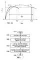
- FIG. 2illustrates a graphical representation demonstrating power converter efficiency of a power converter
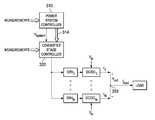
- FIGS. 3 and 4illustrate block diagrams of an embodiment of a power converter
- FIG. 5illustrates a flow diagram of an embodiment of a method of operating a power converter
- FIGS. 6 to 10illustrate block diagrams of an embodiment of a portion of a control process employable with a converter stage controller
- FIG. 11illustrates a graphical representation demonstrating power converter efficiency of a power converter
- FIG. 12illustrates a flow diagram of an embodiment of a method of operating a power converter.
- Embodimentswill be described in a specific context, namely, a controller for a power converter (also referred to as a “multi-stage power converter”) constructed with a plurality of converter stages that controls an output current of the plurality of converter stages to improve overall power conversion efficiency, and methods of operating the same. While the principles of the present invention will be described in the environment of a power converter formed with a plurality of paralleled converter stages, any application or related semiconductor technology such as a power amplifier or motor controller formed with a plurality of power converter stages that may benefit from individual (e.g., but unequal) control of the plurality of power converter stages is well within the broad scope of the present invention.
- FIG. 1illustrated is a schematic diagram of an embodiment of a power converter including power conversion circuitry. While the power converter illustrated in FIG. 1 includes a single converter stage, the power conversion circuitry can be replicated to form a multi-stage power converter.
- the power converterincludes a power train 110 , a controller 120 and a driver 130 including control circuit elements, and provides power to a power system such as a microprocessor. While in the illustrated embodiment, the power train 110 employs a buck converter topology, those skilled in the art should understand that other converter topologies such as a forward converter topology are well within the broad scope of the present invention.
- the power train 110receives an input voltage V in from a source of electrical power (represented by a battery) at an input thereof and provides a regulated output voltage V out to power, for instance, a microprocessor at an output thereof.
- the output voltage V outis generally less than the input voltage V in such that a switching operation of the power converter can regulate the output voltage V out .
- An active elementsuch as a power semiconductor switch (e.g., a main power semiconductor switch Q mn ) is enabled to conduct for a primary interval (generally co-existent with a primary duty cycle “D” of the main power semiconductor switch Q mn ) and couples the input voltage V in to an output filter inductor L out .
- an inductor current I Lout flowing through the output filter inductor L outincreases as a current flows from the input to the output of the power train 110 .
- a portion of the inductor current I Loutis filtered by the output capacitor C out .
- the main power semiconductor switch Q mnis transitioned to a non-conducting state and another active element such as another power semiconductor switch (e.g., an auxiliary power semiconductor switch Q aux ), is enabled to conduct.
- the auxiliary power semiconductor switch Q auxprovides a path to maintain a continuity of the inductor current I Lout flowing through the output filter inductor L out .
- the inductor current I Lout through the output filter inductor L outdecreases.
- the duty cycle of the main and auxiliary power semiconductor switches Q mn , Q auxmay be adjusted to maintain a regulation of the output voltage V out of the power converter.
- the conduction periods for the main and auxiliary power semiconductor switches Q mn , Q auxmay be separated by a small time interval to avoid cross conduction therebetween and beneficially to reduce the switching losses associated with the power converter.
- the duty cyclecan be controlled with respect to a phase angle of a periodic clock signal t clock produced by an oscillator that may be internal to the controller 120 .
- the designations VDRAIN and VGND illustrated in FIG. 1identify a drain terminal of the power semiconductor switch Q mn and a ground terminal of the power converter, respectively.
- the controller 120receives the desired characteristic such as a desired 1.2 volt power system bias voltage V system from an internal or external source associated with the microprocessor, and the output voltage V out of the power converter.
- the controller 120is also coupled to the input voltage V in of the power converter and a return lead of the source of electrical power (again, represented by a battery) to provide a ground connection therefor.
- a decoupling capacitor C decis coupled to the path from the input voltage V in to the controller 120 .
- the decoupling capacitor C decis configured to absorb high frequency noise signals associated with the source of electrical power to protect the controller 120 .
- the controller 120may receive an allocated stage current I stage to control an output current of a converter stage of a multi-stage power converter.
- the controller 120provides a signal (e.g., a pulse width modulated signal S PWM ) to control a duty cycle and a frequency of the main and auxiliary power semiconductor switches Q mn , Q aux of the power train 110 to regulate the output voltage V out or the allocated stage current I stage thereof.
- the controller 120may also provide a complement of the signal (e.g., a complementary pulse width modulated signal S 1-PWM ) in accordance with the aforementioned characteristics.
- Any controller adapted to control at least one power semiconductor switch of the power converteris well within the broad scope of the present invention.
- a controller employing digital circuitryis disclosed in U.S. Pat. No.
- the power converteralso includes the driver 130 configured to provide drive signals S DRV1 , S DRV2 to the main and auxiliary power semiconductor switches Q mn , Q aux , respectively, based on the signals S PWM , S 1-PWM provided by the controller 120 .
- the driver 130typically includes active elements such as switching circuitry incorporating a plurality of driver switches that cooperate to provide the drive signals S DRV1 , S DRV2 to the main and auxiliary power semiconductor switches Q mn , Q aux .
- any driver 130capable of providing the drive signals S DRV1 , S DRV2 to control a power semiconductor switch is well within the broad scope of the present invention.
- a driveris disclosed in U.S. Pat. No. 7,330,017, entitled “Driver for a Power Converter and Method of Driving a Switch Thereof,” to Dwarakanath, et al., which is incorporated herein by reference.
- an embodiment of a semiconductor device that may embody portions of the power conversion circuitryis disclosed in U.S. Pat. No. 7,230,302, entitled “Laterally Diffused Metal Oxide Semiconductor Device and Method of Forming the Same,” to Lotfi, et al., and U.S. patent application Ser. No.
- FIG. 2illustrated is a waveform diagram demonstrating power converter efficiency of a power converter.
- the waveform diagramdisplays power converter efficiency 11 verses load current I load of the power converter at a particular input voltage V in .
- a maximum power converter efficiency ⁇ maxis achieved at an optimum output current level I opt that is generally less than a maximum rated output current I max for the power converter.
- the designer of a power convertergenerally takes into account an expected operating current level for a particular application to maximize power converter efficiency ⁇ at an expected operating current level and at an expected operating input voltage.
- a power converteroperates over a range of input voltages and a range of output currents. Thus, the power converter frequently provides a power conversion efficiency substantially lower than its maximum value.
- the power converter efficiency curve illustrated in FIG. 2shows that a relatively high power converter efficiency ⁇ high can be obtained over a limited range of currents extending between the current levels I a , I b , which can reflect either the total output current of the power converter or the individual currents produced by symmetrically sized converter stages (i.e., for converter stages substantially equally constructed).
- a controller for a multi-stage power convertermay control the current produced by symmetric converter stages in equally allocated portions (i.e., each converter stage is controlled to produce the same contribution to the total output current). In such a case, a multi-stage power converter does not independently regulate power flow in each converter stage. Equal current/power sharing among the converter stages is achieved by using substantially identical components to construct the converter stages.
- a power converteris formed with a plurality of converter stages coupled to common input node and a common output node.
- a portion of the controllerreferred to herein as a power system controller, regulates a characteristic at the output node such as an output voltage.
- the power system controllerdetermines and regulates allocation of current produced by the individual converter stages and supplied to the common output node to improve an overall power conversion efficiency of the power converter.
- the power system controllerallocates and regulates the division of current produced by the individual converter stages with consideration of another power system characteristic such as a level of output ripple voltage, in addition to the overall power conversion efficiency.
- a duty-cycle phase angle of each converter stagemay be differently controlled to reduce, for example, an output voltage or current ripple.
- the converter stage controllersregulate individual output currents of respective converter stages to be equal to an allocation of current determined by the power system controller.
- the individual converter stagesare symmetrically constructed to exhibit essentially equal power conversion efficiencies at a particular output current level.
- the individual converter stagesare asymmetrically constructed to exhibit different power conversion efficiencies at a particular output current level.
- control of an output characteristic such as power converter output voltage and the current allocation among a plurality of converter stagesare arranged so that an overall improvement in power conversion efficiency is obtained without compromising control of the output characteristic.
- This power converter control architectureis applicable to both symmetric and asymmetric power converter architectures formed with a plurality of converter stages. It is noted that the power processed by each converter stage is proportional to the current produced by each converter stage because each converter stage produces substantially the same output voltage.
- the power converter constructed with a plurality of converter stages, particularly asymmetrically constructed converter stages that are asymmetrically controlledhave been found to exhibit an efficiency improvement as high as thirty percent in some environments in comparison to a power converter constructed with symmetric stages that are each identically controlled to contribute the same level of output current.
- the power converterincludes a power system controller 310 and a converter stage controller 320 that jointly control a plurality of N (where N>1) converter stages DC/DC 1 , . . . , DC/DC N .
- the power system controller 310produces the system output voltage V system coupled to converter stage controller 320 .
- power system controller 310produces current allocations 314 for the converter stage controller 320 to control their individual contributions to the load current I load produced by the converter stages DC/DC 1 , . . . , DC/DC N .
- the power system controller 310receives power converter measurements such as an input voltage V in and an output voltage V out produced at a circuit node 355 .
- the power system controller 310is constructed with power converter efficiency curves that represent efficiencies of the individual converter stages as a function of input voltage, output voltage, and individual converter stage output currents.
- the power system controller 310includes an optimization algorithm to reduce an operation/performance/penalty function, such as minimizing or otherwise reducing an overall power loss of the power converter under constraints, such as a maximum output current for a particular converter stage. Minimizing or otherwise reducing an overall power loss is substantially equivalent to maximizing or improving an overall power conversion efficiency. Processes to augment or optimize an operation function are well known in the art and will not be described herein in the interest of brevity.
- the converter stage controller 320also receives measurements such as measurements of the converter stage load currents I 1 , . . . , I N produced by the converter stages DC/DC 1 , . . . , DC/DC N .
- Corresponding driver circuits DRV 1 , . . . , DRV Nproduce drive signals for power switches (not shown) in the respective converter stages DC/DC 1 , . . . , DC/DC N to produce an allocated proportion of the load current I load as signaled by the power system controller 310 .
- one converter stagecontrols the output voltage V out to be equal to the system voltage V system , and the remaining N ⁇ 1 converter stages control their individual contributions to the load current I load .
- the efficiency curves employed by the power system controller 310can be represented, without limitation, by a look-up table or by an analytic function.
- the optimization algorithm that reduces the penalty functioncan be constructed, without limitation, with software code or with a state machine.
- the optimization algorithmcan reside in a field-programmable gate array (“FPGA”) and/or in a separate dc-dc controller.
- the control processes for the voltage and current employed by the converter stage controller 320can be linear or nonlinear, can operate in a voltage mode or a current mode, and can be operated continuously or can operate in discrete time steps.
- the implementation of the converter stage controller 320can be constructed with an analog or digital circuit.
- power converter efficiency functions as a function of individual converter stage currents, ⁇ 1 (I 1 ), ⁇ 2 (I 2 ), . . . , ⁇ N (I N ),are obtained and stored for each of the N converter stages.
- An example operation/performance/penalty function J dependent on the individual converter stage currents I 1 , . . . , I Nis represented below by equation (1):
- the optimization algorithmselects the individual allocated converter stage currents such that the operation/performance/penalty function J is minimized or otherwise reduced under the constraint of equation (2).
- the individual converter stage currents allocated by the power system controllerare used by the converter stage controller to control the proportionate share of current produced by the individual controller stages.
- the power converterincludes a power system controller formed with a reference generator RG that produces a system voltage (e.g., a reference voltage Vref) to control an output voltage V out of the power converter.
- the power system controllerincludes an estimator EST that performs a minimization (or reduction) of an operation/performance/penalty function such as the performance/penalty function J described previously above.
- the power system controllerproduces desired proportionate current levels I out1 _ est , I out2 _ est for each of the two converter stages CS 1 , CS 2 of the power converter.
- a measurement (via a current measurement device CMD) of a load current (e.g., an output current I out ) supplied to a load LD as well the output voltage V outare measured and supplied to the power system controller.
- the power system controllermay also measure an input voltage (not shown) to the power converter.
- the power system controllercan also provide a desired current Iref 2 for the converter stage CS 2 , a current ratio Iratio between the two converter stages CS 1 , CS 2 and an estimate of a load load 2 est for the converter stage CS 2 to the converter stage controller.
- the allocated proportionate current levels I out1 _ est , I out2 _ est for the two converter stages CS 1 , CS 2are coupled to the converter stage controller that produces control signals “high 1” (also designated “H1”), “low 1” (also designated “L1”), “high 2” (also designated “H2”), “low 2” (also designated “L2”) for power switches in the converter stages CS 1 , CS 2 .
- These control signalsproduce proportionate shares of respective converter stage currents that optimize (or other reduce) the performance/penalty function J.
- the measured inductor currents I_inductor 1 , I_inductor 2provide an indication of the current levels from the converter stages CS 1 , CS 2 , respectively, to the power system controller.
- FIG. 5illustrated is a flow diagram of an embodiment of a method of operating a power converter.
- the methoddescribes a process for computing individual converter stage currents that produce a minimum or improved value for the performance/penalty function J.
- the processbegins in a step or module 510 wherein various parameters such as power converter voltages V in , V out , efficiency curves, etc., to perform the method are initialized.
- a search sequenceis defined to find a desired set of values for the individual converter stage currents I 1 , . . . , I N that reduce or otherwise improve the performance/penalty function J. For example, test values or incremental changes for the individual converter stage currents I 1 , . . .
- I Ncan be selected, without limitation, by a random search process in an N-dimensional space spanning the N individual converter stage currents. Each converter stage current is constrained to lie in the range [0, I i _ max ], where I i _ max is a maximum current rating for the i th converter stage.
- a small change for a selected individual converter stage currentis made one at a time for each converter stage current, and an assessment is made whether the performance/penalty function J is increased or decreased. The direction of change for the individual converter stage current is then determined by the sign of the change of the performance/penalty function J.
- the performance/penalty function Jis calculated for a next combination of the individual converter stage currents I 1 , . . . , I N .
- the value of the performance/penalty function Jis compared to a previous value J min computed in a previous step. If the value of the performance/penalty function J is less than the previous value J min , then the process continues in a step or module 550 wherein the value J min is updated and the corresponding individual converter stage currents I 1 , . . . , I N are stored. If the value of the performance/penalty function J is not less than the previous value J min , then the method continues in a step or module 560 .
- Selection of the particular search process to minimize or otherwise improve the performance/penalty function Jwill generally be dependent on the nature of the function representing power conversion efficiency of the individual controller stages.
- the presence or absence of discontinuities in the performance/penalty function Jcan influence selection of the search process.
- a combination of search techniques to determine the desired individual converter stage currents I 1 , . . . , I Ncan be employed.
- an assessmentis made to determine if a sufficient number of combinations of the individual converter stage currents have been tested. For example, if the computed value of the performance/penalty function J is marginally less than a previous best value, then it can be judged that a sufficient number of combinations of individual converter stage currents have been tested.
- Another possible termination testis to count the number of combinations of individual converter stage currents that have been tested and terminate the process if the count reaches a predetermined number. A combination of termination criteria can be employed.
- the methodreturns to the step or module 530 . If sufficient combinations of the individual converter stage currents have been tested, then the optimization process is deemed to have finished and the corresponding individual converter stage currents I 1 , . . . , I N are output to a converter stage controller (see, e.g., converter stage controller 320 described with respect to FIG. 3 ) at a step or module 570 .
- a converter stage controllersee, e.g., converter stage controller 320 described with respect to FIG. 3
- the desired current values for the individual converter stagescan be given by the power system controller.
- a system voltage V system and output voltage V outare also supplied to the converter stage controller.
- the converter stage controllercan employ one converter stage to control the output voltage V out to be equal to the desired system voltage V system .
- a proportional-integral-differential controller or a nonlinear controllercan be employed for the converter stage controller.
- the remaining N ⁇ 1 controller stagesare employed to control the individual stage currents I 2 , . . . , I N to be equal to the values obtained from the power system controller.
- the individual stage current I 1 for the first converter stageis determined from equation (2) illustrated hereinabove.
- FIG. 6illustrated is a block diagram of an embodiment of a portion of a voltage-mode control process employable with a converter stage controller.
- a system voltage V system and an equivalent reciprocal load resistance 1/R loadare coupled to a multiplier that produces a current estimate I est to be produced by a converter stage.
- the current estimate I est and a measured current I inductor in a converter stage from an output filter inductorare subtracted with a sign change to generate an error signal I err that can be used to control the current of the converter stage.
- FIG. 7illustrated is a block diagram of an embodiment of a portion of a voltage-mode control process employable with a converter stage controller.
- a system voltage V system and an output voltage V out produced by the power converterare subtracted, and a voltage difference is coupled to a proportional-integral-differential (“PID”) control stage.
- An output of the PID control stageis fed to a pulse-width modulator (“PWM”) that produces a control signal S PWM for a control terminal of a power switch in the controller stage.
- PWMpulse-width modulator
- FIG. 8illustrated is a block diagram of an embodiment of a portion of a voltage-mode control process employable with a converter stage controller.
- a system voltage V system and an output voltage V out produced by the power converterare subtracted, and a voltage difference is presented to a proportional function (G) and integral gain functions.
- Gproportional function
- the result produced thereby and a measurement of a measured current I inductor in a converter stage from an output filter inductorare subtracted with a sign change to generate an error signal I err that can be used to control the current of the converter stage.
- Gproportional function
- I erran error signal
- several control processescan be employed, without limitation, for an analog or digital current-mode control process that can be used in a feedback process for the converter stage controller.
- FIG. 9illustrated is a block diagram of an embodiment of a portion of a current-mode control process employable with a converter stage controller.
- An input reference current I ref and an instantaneous measured current I inductor in a converter stage from an output filter inductorare subtracted with changed sign to produce a control signal S PWM for a control terminal of a power switch in the controller stage.
- FIG. 10illustrated is a block diagram of an embodiment of a portion of a current-mode control process employable with a converter stage controller.
- An input reference current I ref and an instantaneous measured current I inductor in a converter stage from an output filter inductorare subtracted and the difference is presented to a PID control stage.
- the output of the PID control stageis coupled to a pulse-width modulator that produces a control signal S PWM for a control terminal of a power switch in the controller stage.
- FIG. 11illustrated is a graphical representation demonstrating power converter efficiency of a power converter.
- the graphical representationillustrates a first power converter efficiency ⁇ 1 for a first converter stage and a second power converter efficiency ⁇ 2 for a second converter stage as a function of converter stage output current I stage .
- the first converter stage and the second converter stageare asymmetrically constructed with unequal output current ratings, as illustrated by the respective maximum current levels I max1 , I max2 , respectively.
- Such a processallows flexible sizing and control for the individual converter stages so that substantially higher power conversion efficiency can be obtained over a wide high-efficiency operating area, as illustrated by the arrow 1110 .
- the graphical representation of FIG. 11demonstrates asymmetrically sized converter stages, an improvement in a high-efficiency operating area can be obtained for symmetrically sized converter stages as well.
- FIG. 12illustrated is a flow diagram of an embodiment of a method of operating a power converter including a plurality of converter stages (e.g., coupled in parallel).
- the methodstarts at a step or module 1210 .
- the methodperforms a search process to ascertain an operation of the power converter.
- the operation of the power convertermay include a function proportional to an input current of the power converter.
- the operation of the power convertermay be dependent on an input voltage or an output voltage to the power converter and an output current of each of the plurality of converter stages.
- the operation of the power convertermay include an output current limit for each converter stage of the plurality of converter stages.
- the plurality of converter stagesmay be operated with different duty-cycle phase angles.
- the operation of the power convertermay include a sum of terms, ones of which include a ratio of the output current of a converter stage divided by a stage efficiency of the converter stage.
- the methoddetermines an unequal current allocation among the plurality of converter stages based on the operation of the power converter.
- the methodcontrols the output current produced by each of the plurality of converter stages in response to the current allocation.
- the current allocationmay be determined to control an output characteristic (e.g., an output voltage) of the power converter.
- one converter stage of the plurality of converter stagescontrols an output characteristic of the power converter and remaining converter stages of the plurality of converter stages are controlled with the current allocation to improve the operation of the power converter at a step or module 1250 .
- the plurality of converter stagesmay include at least one converter stage with a different maximum current rating than another converter stage. The method ends at a step or module 1260 .
- the controllerincludes a power system controller and a converter stage controller.
- the power system controlleris configured to determine an unequal current allocation among the plurality of converter stages based on an operation of the power converter, and the converter stage controller is configured to control an output current produced by each of the plurality of converter stages in response to the current allocation.
- the operation of the power convertercan be, without limitation, a function proportional to an input current of the power converter, or can be represented as a sum of terms, ones of which include a ratio of the output current of a converter stage divided by a stage efficiency of the converter stage.
- the power system controlleris configured to determine the current allocation to control an output characteristic of the power converter such as an output voltage.
- the current allocationcan be obtained by employing a search process for the operation of the power converter.
- the operation of the power convertermay be dependent on an input voltage or an output voltage to the power converter and the output current of each of the plurality of converter stages.
- the operation of the power convertercan include an output current limit for each converter stage of the plurality of converter stages.
- one converter stage controller of the plurality of converter stagesis controlled to control the output characteristic and remaining converter stages of the plurality of converter stages are controlled with the current allocation to improve the operation of the power converter.
- the plurality of converter stagescan include at least one converter stage with a different maximum current rating than another converter stage to enable higher power conversion efficiency to be obtained for the power converter.
- the plurality of converter stagesmay be coupled in parallel to produce the output current of the power converter.
- the plurality of converter stagescan be operated with different duty-cycle phase angles, for example to reduce output voltage or current ripple.
- at least one of the power system controller and the converter stage controllermay include a field-programmable gate array or other integrated circuit technology.
- controllers for a power converterand related methods of operating the same are submitted for illustrative purposes only.
- other embodiments capable of producing controllers employable with other power conversion arrangementsare well within the broad scope of the present invention.
- the controllerhas been described in the environment of a power converter, the controller may also be applied to other power systems such as, without limitation, a power amplifier, a motor controller, and a power system to control an actuator in accordance with a stepper motor or other electromechanical device.
Landscapes
- Engineering & Computer Science (AREA)
- Power Engineering (AREA)
- Dc-Dc Converters (AREA)
- Supply And Distribution Of Alternating Current (AREA)
- Ac-Ac Conversion (AREA)
Abstract
Description
The present invention is directed, in general, to electronic devices and, in particular, to a controller for a power converter formed with a plurality of converter stages, and method of operating the same.
Modern electronic systems are generally powered from a voltage source that provides a specified load input voltage such as a regulated direct current (“dc”) input voltage. The load input voltage is generally provided by a dedicated power converter. An important consideration in the design of such a dedicated power converter is the power conversion efficiency to produce the specified load input voltage from an input power source such as an alternating current (“ac”) mains. Power conversion efficiency is understood to be the ratio of an output power to an input power of the power converter.
A conventional power converter can generally be characterized by a nonlinear efficiency function that relates its power conversion efficiency to one or more operating parameters such as input voltage and output current. Further operating parameters such as an operating temperature are also known to affect efficiency, generally to a lesser extent. An efficiency function can be determined from laboratory measurements on a particular power converter design.
Power converters are often designed with a plurality of paralleled power processing stages (referred to as “converter stages” of a multi-stage power converter), each of which produces an equally divided proportionate part of the total output current. The several equally divided proportionate parts of the output current produced by the plurality of converter stages are summed at a circuit node to produce the total output current from the power converter. In conventional practice, the converter stages are jointly regulated to control an output characteristic of the power converter such as an output voltage, and each of the converter stages produces its equal share of the total output current. The result is the efficiency of the power converter is substantially equal to that of the efficiencies of the converter stages, which efficiencies are all substantially equal for their equally divided proportionate part of the total output current.
What is needed in the art is a technique to take advantage of the design of a power converter formed with a plurality of converter stages to produce improved power conversion efficiency. A technique that takes advantage of the plurality converter stages to improve overall power conversion efficiency without adding substantial cost to a power converter would address an industry need in view of current market trends.
These and other problems are generally solved or circumvented, and technical advantages are generally achieved, by advantageous embodiments of the present invention, which include a controller for a power converter formed with a plurality of converter stages, and method of operating the same. In one embodiment, the controller includes a power system controller configured to determine an unequal current allocation among the plurality of converter stages based on an operation of the power converter. The controller also includes a converter stage controller configured to control an output current produced by each of the plurality of converter stages in response to the current allocation.
The foregoing has outlined rather broadly the features and technical advantages of the present invention in order that the detailed description of the invention that follows may be better understood. Additional features and advantages of the invention will be described hereinafter, which form the subject of the claims of the invention. It should be appreciated by those skilled in the art that the conception and specific embodiment disclosed may be readily utilized as a basis for modifying or designing other structures or processes for carrying out the same purposes of the present invention. It should also be realized by those skilled in the art that such equivalent constructions do not depart from the spirit and scope of the invention as set forth in the appended claims.
For a more complete understanding of the present invention, reference is now made to the following descriptions taken in conjunction with the accompanying drawings, in which:
Corresponding numerals and symbols in the different figures generally refer to corresponding parts unless otherwise indicated. The figures are drawn to clearly illustrate the relevant aspects of the preferred embodiments and are not necessarily drawn to scale
The making and using of the presently preferred embodiments are discussed in detail below. It should be appreciated, however, that the embodiments provide many applicable inventive concepts that can be embodied in a wide variety of specific contexts. The specific embodiments discussed are merely illustrative of specific ways to make and use the invention, and do not limit the scope of the invention.
Embodiments will be described in a specific context, namely, a controller for a power converter (also referred to as a “multi-stage power converter”) constructed with a plurality of converter stages that controls an output current of the plurality of converter stages to improve overall power conversion efficiency, and methods of operating the same. While the principles of the present invention will be described in the environment of a power converter formed with a plurality of paralleled converter stages, any application or related semiconductor technology such as a power amplifier or motor controller formed with a plurality of power converter stages that may benefit from individual (e.g., but unequal) control of the plurality of power converter stages is well within the broad scope of the present invention.
Referring initially toFIG. 1 , illustrated is a schematic diagram of an embodiment of a power converter including power conversion circuitry. While the power converter illustrated inFIG. 1 includes a single converter stage, the power conversion circuitry can be replicated to form a multi-stage power converter. The power converter includes apower train 110, acontroller 120 and adriver 130 including control circuit elements, and provides power to a power system such as a microprocessor. While in the illustrated embodiment, thepower train 110 employs a buck converter topology, those skilled in the art should understand that other converter topologies such as a forward converter topology are well within the broad scope of the present invention.
Thepower train 110 receives an input voltage Vinfrom a source of electrical power (represented by a battery) at an input thereof and provides a regulated output voltage Voutto power, for instance, a microprocessor at an output thereof. In keeping with the principles of a buck converter topology, the output voltage Voutis generally less than the input voltage Vinsuch that a switching operation of the power converter can regulate the output voltage Vout. An active element such as a power semiconductor switch (e.g., a main power semiconductor switch Qmn) is enabled to conduct for a primary interval (generally co-existent with a primary duty cycle “D” of the main power semiconductor switch Qmn) and couples the input voltage Vinto an output filter inductor Lout. During the primary interval, an inductor current ILoutflowing through the output filter inductor Loutincreases as a current flows from the input to the output of thepower train 110. A portion of the inductor current ILoutis filtered by the output capacitor Cout.
During a complementary interval (generally co-existent with a complementary duty cycle “1-D” of the main power semiconductor switch Qmn), the main power semiconductor switch Qmnis transitioned to a non-conducting state and another active element such as another power semiconductor switch (e.g., an auxiliary power semiconductor switch Qaux), is enabled to conduct. The auxiliary power semiconductor switch Qauxprovides a path to maintain a continuity of the inductor current ILoutflowing through the output filter inductor Lout. During the complementary interval, the inductor current ILoutthrough the output filter inductor Loutdecreases. In general, the duty cycle of the main and auxiliary power semiconductor switches Qmn, Qauxmay be adjusted to maintain a regulation of the output voltage Voutof the power converter. Those skilled in the art should understand, however, that the conduction periods for the main and auxiliary power semiconductor switches Qmn, Qauxmay be separated by a small time interval to avoid cross conduction therebetween and beneficially to reduce the switching losses associated with the power converter. The duty cycle can be controlled with respect to a phase angle of a periodic clock signal tclockproduced by an oscillator that may be internal to thecontroller 120. The designations VDRAIN and VGND illustrated inFIG. 1 identify a drain terminal of the power semiconductor switch Qmnand a ground terminal of the power converter, respectively.
Thecontroller 120 receives the desired characteristic such as a desired 1.2 volt power system bias voltage Vsystemfrom an internal or external source associated with the microprocessor, and the output voltage Voutof the power converter. Thecontroller 120 is also coupled to the input voltage Vinof the power converter and a return lead of the source of electrical power (again, represented by a battery) to provide a ground connection therefor. A decoupling capacitor Cdecis coupled to the path from the input voltage Vinto thecontroller 120. The decoupling capacitor Cdecis configured to absorb high frequency noise signals associated with the source of electrical power to protect thecontroller 120. Alternatively, thecontroller 120 may receive an allocated stage current Istageto control an output current of a converter stage of a multi-stage power converter.
In accordance with the aforementioned characteristics, thecontroller 120 provides a signal (e.g., a pulse width modulated signal SPWM) to control a duty cycle and a frequency of the main and auxiliary power semiconductor switches Qmn, Qauxof thepower train 110 to regulate the output voltage Voutor the allocated stage current Istagethereof. Thecontroller 120 may also provide a complement of the signal (e.g., a complementary pulse width modulated signal S1-PWM) in accordance with the aforementioned characteristics. Any controller adapted to control at least one power semiconductor switch of the power converter is well within the broad scope of the present invention. As an example, a controller employing digital circuitry is disclosed in U.S. Pat. No. 7,038,438, entitled “Controller for a Power Converter and a Method of Controlling a Switch Thereof,” to Dwarakanath, et al. and U.S. Pat. No. 7,019,505, entitled “Digital Controller for a Power Converter Employing Selectable Stages of a Clock Signal,” to Dwarakanath, et al., which are incorporated herein by reference.
The power converter also includes thedriver 130 configured to provide drive signals SDRV1, SDRV2to the main and auxiliary power semiconductor switches Qmn, Qaux, respectively, based on the signals SPWM, S1-PWMprovided by thecontroller 120. There are a number of viable alternatives to implement adriver 130 that include techniques to provide sufficient signal delays to prevent crosscurrents when controlling multiple power semiconductor switches in the power converter. Thedriver 130 typically includes active elements such as switching circuitry incorporating a plurality of driver switches that cooperate to provide the drive signals SDRV1, SDRV2to the main and auxiliary power semiconductor switches Qmn, Qaux. Of course, anydriver 130 capable of providing the drive signals SDRV1, SDRV2to control a power semiconductor switch is well within the broad scope of the present invention. As an example, a driver is disclosed in U.S. Pat. No. 7,330,017, entitled “Driver for a Power Converter and Method of Driving a Switch Thereof,” to Dwarakanath, et al., which is incorporated herein by reference. Also, an embodiment of a semiconductor device that may embody portions of the power conversion circuitry is disclosed in U.S. Pat. No. 7,230,302, entitled “Laterally Diffused Metal Oxide Semiconductor Device and Method of Forming the Same,” to Lotfi, et al., and U.S. patent application Ser. No. 14/091,739, entitled “Semiconductor Device including Alternating Source and Drain Regions, and Respective Source and Drain Metallic Strips,” to Lotfi, et al., which are incorporated herein by reference, and an embodiment of an integrated circuit embodying power conversion circuitry, or portions thereof, is disclosed in U.S. Pat. No. 7,015,544, entitled “Integrated Circuit Employable with a Power Converter,” to Lotfi, et al., which is incorporated by reference. Also, an embodiment of a packaged integrated circuit embodying a power converter and controller is disclosed in U.S. patent application Ser. No. 14/632,641, entitled “Packaged Integrated Circuit Including a Switch-Mode Regulator and Method of Forming the Same,” which is incorporated by reference.
Turning now toFIG. 2 , illustrated is a waveform diagram demonstrating power converter efficiency of a power converter. The waveform diagram displayspower converter efficiency 11 verses load current Iloadof the power converter at a particular input voltage Vin. As illustrated by the curved line inFIG. 2 , a maximum power converter efficiency ηmaxis achieved at an optimum output current level Ioptthat is generally less than a maximum rated output current Imaxfor the power converter. The designer of a power converter generally takes into account an expected operating current level for a particular application to maximize power converter efficiency η at an expected operating current level and at an expected operating input voltage. However, in many power system applications a power converter operates over a range of input voltages and a range of output currents. Thus, the power converter frequently provides a power conversion efficiency substantially lower than its maximum value.
The power converter efficiency curve illustrated inFIG. 2 shows that a relatively high power converter efficiency ηhighcan be obtained over a limited range of currents extending between the current levels Ia, Ib, which can reflect either the total output current of the power converter or the individual currents produced by symmetrically sized converter stages (i.e., for converter stages substantially equally constructed).
A controller for a multi-stage power converter may control the current produced by symmetric converter stages in equally allocated portions (i.e., each converter stage is controlled to produce the same contribution to the total output current). In such a case, a multi-stage power converter does not independently regulate power flow in each converter stage. Equal current/power sharing among the converter stages is achieved by using substantially identical components to construct the converter stages.
As introduced herein, a power converter is formed with a plurality of converter stages coupled to common input node and a common output node. A portion of the controller, referred to herein as a power system controller, regulates a characteristic at the output node such as an output voltage. In addition, the power system controller determines and regulates allocation of current produced by the individual converter stages and supplied to the common output node to improve an overall power conversion efficiency of the power converter. In an embodiment, the power system controller allocates and regulates the division of current produced by the individual converter stages with consideration of another power system characteristic such as a level of output ripple voltage, in addition to the overall power conversion efficiency. In an embodiment, a duty-cycle phase angle of each converter stage may be differently controlled to reduce, for example, an output voltage or current ripple.
The converter stage controllers regulate individual output currents of respective converter stages to be equal to an allocation of current determined by the power system controller. In an embodiment, the individual converter stages are symmetrically constructed to exhibit essentially equal power conversion efficiencies at a particular output current level. In an embodiment, the individual converter stages are asymmetrically constructed to exhibit different power conversion efficiencies at a particular output current level.
Thus, control of an output characteristic such as power converter output voltage and the current allocation among a plurality of converter stages are arranged so that an overall improvement in power conversion efficiency is obtained without compromising control of the output characteristic. This power converter control architecture is applicable to both symmetric and asymmetric power converter architectures formed with a plurality of converter stages. It is noted that the power processed by each converter stage is proportional to the current produced by each converter stage because each converter stage produces substantially the same output voltage. The power converter constructed with a plurality of converter stages, particularly asymmetrically constructed converter stages that are asymmetrically controlled, have been found to exhibit an efficiency improvement as high as thirty percent in some environments in comparison to a power converter constructed with symmetric stages that are each identically controlled to contribute the same level of output current.
Turning now toFIG. 3 , illustrated is a block diagram of an embodiment of a power converter. The power converter includes apower system controller 310 and aconverter stage controller 320 that jointly control a plurality of N (where N>1) converter stages DC/DC1, . . . , DC/DCN. Thepower system controller 310 produces the system output voltage Vsystemcoupled toconverter stage controller 320. In addition,power system controller 310 producescurrent allocations 314 for theconverter stage controller 320 to control their individual contributions to the load current Iloadproduced by the converter stages DC/DC1, . . . , DC/DCN. Thepower system controller 310 receives power converter measurements such as an input voltage Vinand an output voltage Voutproduced at acircuit node 355. Thepower system controller 310 is constructed with power converter efficiency curves that represent efficiencies of the individual converter stages as a function of input voltage, output voltage, and individual converter stage output currents. In addition, thepower system controller 310 includes an optimization algorithm to reduce an operation/performance/penalty function, such as minimizing or otherwise reducing an overall power loss of the power converter under constraints, such as a maximum output current for a particular converter stage. Minimizing or otherwise reducing an overall power loss is substantially equivalent to maximizing or improving an overall power conversion efficiency. Processes to augment or optimize an operation function are well known in the art and will not be described herein in the interest of brevity.
Theconverter stage controller 320 also receives measurements such as measurements of the converter stage load currents I1, . . . , INproduced by the converter stages DC/DC1, . . . , DC/DCN. Corresponding driver circuits DRV1, . . . , DRVNproduce drive signals for power switches (not shown) in the respective converter stages DC/DC1, . . . , DC/DCNto produce an allocated proportion of the load current Iloadas signaled by thepower system controller 310. In an embodiment, one converter stage controls the output voltage Voutto be equal to the system voltage Vsystem, and the remaining N−1 converter stages control their individual contributions to the load current Iload.
The efficiency curves employed by thepower system controller 310 can be represented, without limitation, by a look-up table or by an analytic function. The optimization algorithm that reduces the penalty function can be constructed, without limitation, with software code or with a state machine. The optimization algorithm can reside in a field-programmable gate array (“FPGA”) and/or in a separate dc-dc controller. The control processes for the voltage and current employed by theconverter stage controller 320 can be linear or nonlinear, can operate in a voltage mode or a current mode, and can be operated continuously or can operate in discrete time steps. The implementation of theconverter stage controller 320 can be constructed with an analog or digital circuit.
In operation, power converter efficiency functions as a function of individual converter stage currents, η1(I1), η2(I2), . . . , ηN(IN), are obtained and stored for each of the N converter stages. An example operation/performance/penalty function J dependent on the individual converter stage currents I1, . . . , INis represented below by equation (1):
where the operation/performance/penalty function J is proportional to an equivalent overall power converter input current constructed as a sum of terms formed by dividing individual converter stage currents by their respective power converter efficiencies. Minimizing the function J is substantially equivalent to maximizing overall power converter efficiency. It is contemplated that other penalty functions can be employed in place of that illustrated above by equation (1). A constraint on the individual converter stage currents is that they sum to the load current Iloadas illustrated below by equation (2):
Iload=I1+I2+ . . . +IN. (2)
The optimization algorithm selects the individual allocated converter stage currents such that the operation/performance/penalty function J is minimized or otherwise reduced under the constraint of equation (2). The individual converter stage currents allocated by the power system controller are used by the converter stage controller to control the proportionate share of current produced by the individual controller stages.
Turning now toFIG. 4 , illustrated is a block diagram of an embodiment of a power converter. The power converter includes a power system controller formed with a reference generator RG that produces a system voltage (e.g., a reference voltage Vref) to control an output voltage Voutof the power converter. In addition, the power system controller includes an estimator EST that performs a minimization (or reduction) of an operation/performance/penalty function such as the performance/penalty function J described previously above. The power system controller produces desired proportionate current levels Iout1_est, Iout2_estfor each of the two converter stages CS1, CS2of the power converter. To perform the necessary control functions, a measurement (via a current measurement device CMD) of a load current (e.g., an output current Iout) supplied to a load LD as well the output voltage Voutare measured and supplied to the power system controller. The power system controller may also measure an input voltage (not shown) to the power converter. The power system controller can also provide a desired current Iref2 for the converter stage CS2, a current ratio Iratio between the two converter stages CS1, CS2and an estimate of a load load2 est for the converter stage CS2to the converter stage controller.
The allocated proportionate current levels Iout1_est, Iout2_estfor the two converter stages CS1, CS2are coupled to the converter stage controller that produces control signals “high 1” (also designated “H1”), “low 1” (also designated “L1”), “high 2” (also designated “H2”), “low 2” (also designated “L2”) for power switches in the converter stages CS1, CS2. These control signals produce proportionate shares of respective converter stage currents that optimize (or other reduce) the performance/penalty function J. The measured inductor currents I_inductor1, I_inductor2 provide an indication of the current levels from the converter stages CS1, CS2, respectively, to the power system controller.
Turning now toFIG. 5 , illustrated is a flow diagram of an embodiment of a method of operating a power converter. The method describes a process for computing individual converter stage currents that produce a minimum or improved value for the performance/penalty function J. The process begins in a step ormodule 510 wherein various parameters such as power converter voltages Vin, Vout, efficiency curves, etc., to perform the method are initialized. In a step ormodule 520, a search sequence is defined to find a desired set of values for the individual converter stage currents I1, . . . , INthat reduce or otherwise improve the performance/penalty function J. For example, test values or incremental changes for the individual converter stage currents I1, . . . , INcan be selected, without limitation, by a random search process in an N-dimensional space spanning the N individual converter stage currents. Each converter stage current is constrained to lie in the range [0, Ii_max], where Ii_maxis a maximum current rating for the ithconverter stage. In another alternative, a small change for a selected individual converter stage current is made one at a time for each converter stage current, and an assessment is made whether the performance/penalty function J is increased or decreased. The direction of change for the individual converter stage current is then determined by the sign of the change of the performance/penalty function J.
In a step ormodule 530, the performance/penalty function J is calculated for a next combination of the individual converter stage currents I1, . . . , IN. In a step ormodule 540, the value of the performance/penalty function J is compared to a previous value Jmincomputed in a previous step. If the value of the performance/penalty function J is less than the previous value Jmin, then the process continues in a step ormodule 550 wherein the value Jminis updated and the corresponding individual converter stage currents I1, . . . , INare stored. If the value of the performance/penalty function J is not less than the previous value Jmin, then the method continues in a step ormodule 560.
Selection of the particular search process to minimize or otherwise improve the performance/penalty function J will generally be dependent on the nature of the function representing power conversion efficiency of the individual controller stages. The presence or absence of discontinuities in the performance/penalty function J can influence selection of the search process. In an embodiment, a combination of search techniques to determine the desired individual converter stage currents I1, . . . , INcan be employed.
In the step ormodule 560, an assessment is made to determine if a sufficient number of combinations of the individual converter stage currents have been tested. For example, if the computed value of the performance/penalty function J is marginally less than a previous best value, then it can be judged that a sufficient number of combinations of individual converter stage currents have been tested. Another possible termination test is to count the number of combinations of individual converter stage currents that have been tested and terminate the process if the count reaches a predetermined number. A combination of termination criteria can be employed.
If sufficient combinations of individual converter stage currents have not been tested, the method returns to the step ormodule 530. If sufficient combinations of the individual converter stage currents have been tested, then the optimization process is deemed to have finished and the corresponding individual converter stage currents I1, . . . , INare output to a converter stage controller (see, e.g.,converter stage controller 320 described with respect toFIG. 3 ) at a step ormodule 570.
For the converter stage controller, the desired current values for the individual converter stages can be given by the power system controller. In addition, a system voltage Vsystemand output voltage Voutare also supplied to the converter stage controller. The converter stage controller can employ one converter stage to control the output voltage Voutto be equal to the desired system voltage Vsystem. As examples, a proportional-integral-differential controller or a nonlinear controller can be employed for the converter stage controller. The remaining N−1 controller stages are employed to control the individual stage currents I2, . . . , INto be equal to the values obtained from the power system controller. By Kirchoff's current law, the individual stage current I1for the first converter stage is determined from equation (2) illustrated hereinabove. The result is the output voltage Voutand the currents I1, . . . , INin each respective converter stage are controlled simultaneously. Several control structures can be employed, without limitation, for an analog or digital voltage-mode control process that can be used in a feedback process for the converter stage controller.
Turning now toFIG. 6 , illustrated is a block diagram of an embodiment of a portion of a voltage-mode control process employable with a converter stage controller. A system voltage Vsystemand an equivalentreciprocal load resistance 1/Rloadare coupled to a multiplier that produces a current estimate Iestto be produced by a converter stage. The current estimate Iestand a measured current Iinductorin a converter stage from an output filter inductor are subtracted with a sign change to generate an error signal Ierrthat can be used to control the current of the converter stage.
Turning now toFIG. 7 , illustrated is a block diagram of an embodiment of a portion of a voltage-mode control process employable with a converter stage controller. A system voltage Vsystemand an output voltage Voutproduced by the power converter are subtracted, and a voltage difference is coupled to a proportional-integral-differential (“PID”) control stage. An output of the PID control stage is fed to a pulse-width modulator (“PWM”) that produces a control signal SPWMfor a control terminal of a power switch in the controller stage.
Turning now toFIG. 8 , illustrated is a block diagram of an embodiment of a portion of a voltage-mode control process employable with a converter stage controller. A system voltage Vsystemand an output voltage Voutproduced by the power converter are subtracted, and a voltage difference is presented to a proportional function (G) and integral gain functions. The result produced thereby and a measurement of a measured current Iinductorin a converter stage from an output filter inductor are subtracted with a sign change to generate an error signal Ierrthat can be used to control the current of the converter stage. As set forth herein, several control processes can be employed, without limitation, for an analog or digital current-mode control process that can be used in a feedback process for the converter stage controller.
Turning now toFIG. 9 , illustrated is a block diagram of an embodiment of a portion of a current-mode control process employable with a converter stage controller. An input reference current Irefand an instantaneous measured current Iinductorin a converter stage from an output filter inductor are subtracted with changed sign to produce a control signal SPWMfor a control terminal of a power switch in the controller stage.
Turning now toFIG. 10 , illustrated is a block diagram of an embodiment of a portion of a current-mode control process employable with a converter stage controller. An input reference current Irefand an instantaneous measured current Iinductorin a converter stage from an output filter inductor are subtracted and the difference is presented to a PID control stage. The output of the PID control stage is coupled to a pulse-width modulator that produces a control signal SPWMfor a control terminal of a power switch in the controller stage.
Turning now toFIG. 11 , illustrated is a graphical representation demonstrating power converter efficiency of a power converter. The graphical representation illustrates a first power converter efficiency η1for a first converter stage and a second power converter efficiency η2for a second converter stage as a function of converter stage output current Istage. The first converter stage and the second converter stage are asymmetrically constructed with unequal output current ratings, as illustrated by the respective maximum current levels Imax1, Imax2, respectively. By controlling a current allocation ratio between the two converter stages and at the same time controlling the output voltage Vout, an improved current allocation ratio that provides enhanced power conversion efficiency can be obtained. Such a process allows flexible sizing and control for the individual converter stages so that substantially higher power conversion efficiency can be obtained over a wide high-efficiency operating area, as illustrated by thearrow 1110. Although the graphical representation ofFIG. 11 demonstrates asymmetrically sized converter stages, an improvement in a high-efficiency operating area can be obtained for symmetrically sized converter stages as well.
Turning now toFIG. 12 , illustrated is a flow diagram of an embodiment of a method of operating a power converter including a plurality of converter stages (e.g., coupled in parallel). The method starts at a step ormodule 1210. At a step ormodule 1220, the method performs a search process to ascertain an operation of the power converter. The operation of the power converter may include a function proportional to an input current of the power converter. The operation of the power converter may be dependent on an input voltage or an output voltage to the power converter and an output current of each of the plurality of converter stages. The operation of the power converter may include an output current limit for each converter stage of the plurality of converter stages. The plurality of converter stages may be operated with different duty-cycle phase angles. The operation of the power converter may include a sum of terms, ones of which include a ratio of the output current of a converter stage divided by a stage efficiency of the converter stage.
At a step ormodule 1230, the method determines an unequal current allocation among the plurality of converter stages based on the operation of the power converter. At a step ormodule 1240, the method controls the output current produced by each of the plurality of converter stages in response to the current allocation. The current allocation may be determined to control an output characteristic (e.g., an output voltage) of the power converter. In accordance therewith, one converter stage of the plurality of converter stages controls an output characteristic of the power converter and remaining converter stages of the plurality of converter stages are controlled with the current allocation to improve the operation of the power converter at a step ormodule 1250. The plurality of converter stages may include at least one converter stage with a different maximum current rating than another converter stage. The method ends at a step ormodule 1260.
Thus, a controller for a power converter formed with a plurality of converter stages and methods of operation thereof with readily attainable and quantifiable advantages has been introduced. In an embodiment, the controller includes a power system controller and a converter stage controller. The power system controller is configured to determine an unequal current allocation among the plurality of converter stages based on an operation of the power converter, and the converter stage controller is configured to control an output current produced by each of the plurality of converter stages in response to the current allocation. The operation of the power converter can be, without limitation, a function proportional to an input current of the power converter, or can be represented as a sum of terms, ones of which include a ratio of the output current of a converter stage divided by a stage efficiency of the converter stage.
In an embodiment, the power system controller is configured to determine the current allocation to control an output characteristic of the power converter such as an output voltage. The current allocation can be obtained by employing a search process for the operation of the power converter. The operation of the power converter may be dependent on an input voltage or an output voltage to the power converter and the output current of each of the plurality of converter stages. The operation of the power converter can include an output current limit for each converter stage of the plurality of converter stages.
In an embodiment, one converter stage controller of the plurality of converter stages is controlled to control the output characteristic and remaining converter stages of the plurality of converter stages are controlled with the current allocation to improve the operation of the power converter. The plurality of converter stages can include at least one converter stage with a different maximum current rating than another converter stage to enable higher power conversion efficiency to be obtained for the power converter.
The plurality of converter stages may be coupled in parallel to produce the output current of the power converter. The plurality of converter stages can be operated with different duty-cycle phase angles, for example to reduce output voltage or current ripple. Also, at least one of the power system controller and the converter stage controller may include a field-programmable gate array or other integrated circuit technology.
Those skilled in the art should understand that the previously described embodiments of a controller for a power converter and related methods of operating the same are submitted for illustrative purposes only. In addition, other embodiments capable of producing controllers employable with other power conversion arrangements are well within the broad scope of the present invention. While the controller has been described in the environment of a power converter, the controller may also be applied to other power systems such as, without limitation, a power amplifier, a motor controller, and a power system to control an actuator in accordance with a stepper motor or other electromechanical device.
For a better understanding of integrated circuits, semiconductor devices and methods of manufacture therefor see “Semiconductor Device Fundamentals,” by R. F. Pierret, Addison-Wesley (1996), and “Handbook of Sputter Deposition Technology,” by K. Wasa and S. Hayakawa, Noyes Publications (1992). For a better understanding of power converters, see “Modern DC-to-DC Switchmode Power Converter Circuits,” by Rudolph P. Severns and Gordon Bloom, Van Nostrand Reinhold Company, New York, N.Y. (1985) and “Principles of Power Electronics,” by J. G. Kassakian, M. F. Schlecht, and G. C. Verghese, Addison-Wesley (1991). The aforementioned references are incorporated herein by reference in their entirety.
Also, although the present invention and its advantages have been described in detail, it should be understood that various changes, substitutions, and alterations can be made herein without departing from the spirit and scope of the invention as defined by claims on embodiments. For example, many of the processes discussed above can be implemented in different methodologies and replaced by other processes, or a combination thereof.
Moreover, the scope of the present application is not intended to be limited to the particular embodiments of the process, machine, manufacture, composition of matter, means, methods, and steps described in the specification. As one of ordinary skill in the art will readily appreciate from the disclosure of the present invention, processes, machines, manufacture, compositions of matter, means, methods, or steps, presently existing or later to be developed, that perform substantially the same function or achieve substantially the same result as the corresponding embodiments described herein may be utilized according to the present invention. Accordingly, claims on embodiments are intended to include within their scope such processes, machines, manufacture, compositions of matter, means, methods, or steps.
Claims (20)
1. A controller for a power converter formed with a plurality of converter stages, comprising:
a power system controller configured to determine an unequal current allocation among at least two of the plurality of converter stages based on an operation of the power converter; and
a converter stage controller configured to adjust an output current produced by each of the at least two of the plurality of converter stages based at least in part on the unequal current allocation, wherein the output current produced by the at least two of the of the plurality of converter stages is adjusted to produce the unequal current allocation among the at least two of the plurality of converter stages.
2. The controller ofclaim 1 , wherein the power system controller is configured to determine the unequal current allocation to control an output characteristic of said power converter.
3. The controller ofclaim 2 , wherein the output characteristic is an output voltage.
4. The controller ofclaim 2 , wherein a converter stage controller associated with the plurality of converter stages is configured to control the output characteristic based on the unequal current allocation to improve the operation of the power converter.
5. The controller ofclaim 1 , wherein the unequal current allocation is determined by employing a search process for the operation of the power converter.
6. The controller ofclaim 1 , wherein the plurality of converter stages includes at least one converter stage with a different maximum current rating than another converter stage.
7. The controller ofclaim 1 , wherein the operation of the power converter comprises a function proportional to an input current of the power converter.
8. The controller ofclaim 1 , wherein the operation of the power converter is dependent on an input voltage to the power converter and the output current of each of the at least two of the plurality of converter stages.
9. The controller ofclaim 1 , wherein the operation of the power converter is dependent on an output voltage of the power converter and the output current of each of the at least two of the plurality of converter stages.
10. The controller ofclaim 1 , wherein the operation of the power converter comprises an output current limit for each converter stage of the at least two of the plurality of converter stages.
11. The controller ofclaim 1 , wherein the plurality of converter stages is coupled in parallel to produce a second output current of the power converter.
12. The controller ofclaim 1 , wherein the plurality of converter stages are operated with different duty-cycle phase angles.
13. The controller ofclaim 1 , wherein the operation of the power converter comprises a sum of terms, ones of which comprise a ratio of a first output current of a first converter stage of the plurality of converter stages divided by a stage efficiency of the first converter stage.
14. The controller ofclaim 1 , wherein power system controller or the converter stage controller comprises a field-programmable gate array.
15. A method of operating a power converter formed with a plurality of converter stages, comprising:
determining an unequal current allocation among at least two of the plurality of converter stages based on an operation of the power converter; and
adjusting an output current produced by each of the at least two of the plurality of converter stages based at least in part on the unequal current allocation, wherein adjusting the output current produced by the at least two of the of the plurality of converter stages comprising producing the unequal current allocation among the at least two of the plurality of converter stages.
16. The method ofclaim 15 , wherein the unequal current allocation is determined to control an output characteristic of the power converter.
17. The method ofclaim 15 , wherein the operation of the power converter is dependent on an input voltage to the power converter and the output current of each of the at least two of the plurality of converter stages.
18. The method ofclaim 15 , comprising employing a search process for the operation of the power converter to determine the unequal current allocation.
19. The method ofclaim 15 , wherein the plurality of converter stages comprises at least one converter stage with a different maximum current rating than another converter stage.
20. The method ofclaim 15 , wherein a converter stage associated with the plurality of converter stages is configured to control an output characteristic of the power converter based on the unequal current allocation to improve the operation of the power converter.
Priority Applications (4)
| Application Number | Priority Date | Filing Date | Title |
|---|---|---|---|
| US14/690,921US9509217B2 (en) | 2015-04-20 | 2015-04-20 | Asymmetric power flow controller for a power converter and method of operating the same |
| EP16165728.3AEP3086455B1 (en) | 2015-04-20 | 2016-04-18 | Asymmetric power flow controller for a power converter and method of operating the same |
| CN201610246312.XACN106067734B (en) | 2015-04-20 | 2016-04-20 | Asymmetric power flow controller for power converter and method of operating the same |
| US15/359,360US10084380B2 (en) | 2015-04-20 | 2016-11-22 | Asymmetric power flow controller for a power converter and method of operating the same |
Applications Claiming Priority (1)
| Application Number | Priority Date | Filing Date | Title |
|---|---|---|---|
| US14/690,921US9509217B2 (en) | 2015-04-20 | 2015-04-20 | Asymmetric power flow controller for a power converter and method of operating the same |
Related Child Applications (1)
| Application Number | Title | Priority Date | Filing Date |
|---|---|---|---|
| US15/359,360ContinuationUS10084380B2 (en) | 2015-04-20 | 2016-11-22 | Asymmetric power flow controller for a power converter and method of operating the same |
Publications (2)
| Publication Number | Publication Date |
|---|---|
| US20160308440A1 US20160308440A1 (en) | 2016-10-20 |
| US9509217B2true US9509217B2 (en) | 2016-11-29 |
Family
ID=55755507
Family Applications (2)
| Application Number | Title | Priority Date | Filing Date |
|---|---|---|---|
| US14/690,921ActiveUS9509217B2 (en) | 2015-04-20 | 2015-04-20 | Asymmetric power flow controller for a power converter and method of operating the same |
| US15/359,360ActiveUS10084380B2 (en) | 2015-04-20 | 2016-11-22 | Asymmetric power flow controller for a power converter and method of operating the same |
Family Applications After (1)
| Application Number | Title | Priority Date | Filing Date |
|---|---|---|---|
| US15/359,360ActiveUS10084380B2 (en) | 2015-04-20 | 2016-11-22 | Asymmetric power flow controller for a power converter and method of operating the same |
Country Status (3)
| Country | Link |
|---|---|
| US (2) | US9509217B2 (en) |
| EP (1) | EP3086455B1 (en) |
| CN (1) | CN106067734B (en) |
Families Citing this family (7)
| Publication number | Priority date | Publication date | Assignee | Title |
|---|---|---|---|---|
| US9941702B2 (en)* | 2015-12-28 | 2018-04-10 | King Fahd University Of Petroleum And Minerals | Fault ride-through and power smoothing system |
| CN110212762B (en)* | 2018-02-28 | 2021-05-28 | 新动力等离子体株式会社 | High-frequency power generator for improving pulse function |
| US10868429B2 (en)* | 2018-05-21 | 2020-12-15 | Nuvolta Technologies (Hefei) Co., Ltd. | High efficiency power converting apparatus |
| US11223237B2 (en)* | 2018-10-05 | 2022-01-11 | Nuvolta Technologies (Hefei) Co., Ltd. | High efficiency power converting apparatus and control method |
| EP4099552B1 (en)* | 2020-01-28 | 2025-08-20 | Mitsubishi Electric Corporation | Power conversion device |
| KR20230102539A (en)* | 2021-12-30 | 2023-07-07 | 주식회사 엘엑스세미콘 | Power converting device, power management integrated circuit and control method for power converting device |
| JP7601806B2 (en) | 2022-01-06 | 2024-12-17 | 株式会社豊田中央研究所 | Power System |
Citations (295)
| Publication number | Priority date | Publication date | Assignee | Title |
|---|---|---|---|---|
| US1889398A (en) | 1932-03-05 | 1932-11-29 | Western Electric Co | Electrical coil and a method of manufacturing it |
| US2600473A (en) | 1949-01-26 | 1952-06-17 | Philips Lab Inc | Magnetic core |
| US3210707A (en) | 1962-10-04 | 1965-10-05 | Gen Instrument Corp | Solid state inductor built up of multiple thin films |
| US3691497A (en) | 1970-10-15 | 1972-09-12 | Us Army | Leadless microminiature inductance element with a closed magnetic circuit |
| US3762039A (en) | 1971-09-10 | 1973-10-02 | Mos Technology Inc | Plastic encapsulation of microcircuits |
| US3902148A (en) | 1970-11-27 | 1975-08-26 | Signetics Corp | Semiconductor lead structure and assembly and method for fabricating same |
| US3908264A (en) | 1974-04-24 | 1975-09-30 | Gen Instrument Corp | Method for calibrating a resonant frequency |
| US3947699A (en) | 1974-08-29 | 1976-03-30 | Iowa State University Research Foundation, Inc. | Apparatus for selecting a predetermined portion of an analog signal and gating it to an output |
| US4016461A (en) | 1976-05-06 | 1977-04-05 | Amp Incorporated | Starting circuit for switching regulator |
| US4101389A (en) | 1976-05-20 | 1978-07-18 | Sony Corporation | Method of manufacturing amorphous alloy |
| US4103267A (en) | 1977-06-13 | 1978-07-25 | Burr-Brown Research Corporation | Hybrid transformer device |
| US4187128A (en) | 1978-09-26 | 1980-02-05 | Bell Telephone Laboratories, Incorporated | Magnetic devices including amorphous alloys |
| US4199743A (en) | 1978-02-06 | 1980-04-22 | Westinghouse Electric Corp. | Encapsulated current transformer |
| GB2041818A (en) | 1979-02-10 | 1980-09-17 | Plessey Co Ltd | Encapsulating a Magnetic Domain Component |
| US4247953A (en) | 1977-07-01 | 1981-01-27 | Hitachi, Ltd. | Tunable high-frequency input circuit |
| US4433927A (en) | 1981-02-25 | 1984-02-28 | Honeywell Information Systems Italia | Electromagnet assembly for mosaic printing head and related manufacturing method |
| US4586436A (en) | 1984-09-13 | 1986-05-06 | The United States Of America As Represented By The Secretary Of The Navy | Electronic assembly for moderate hard target penetrator fuze |
| US4636752A (en) | 1984-06-08 | 1987-01-13 | Murata Manufacturing Co., Ltd. | Noise filter |
| US4654770A (en) | 1983-12-22 | 1987-03-31 | General Electric Company | Current-limit circuit in X-ray generator |
| US4668310A (en) | 1979-09-21 | 1987-05-26 | Hitachi Metals, Ltd. | Amorphous alloys |
| US4681718A (en) | 1984-05-09 | 1987-07-21 | Hughes Aircraft Company | Method of fabricating composite or encapsulated articles |
| US4689735A (en) | 1985-02-06 | 1987-08-25 | Associated Electrical Industries Limited | Power supply for single-phase traction system |
| US4751199A (en) | 1983-12-06 | 1988-06-14 | Fairchild Semiconductor Corporation | Process of forming a compliant lead frame for array-type semiconductor packages |
| US4754317A (en) | 1986-04-28 | 1988-06-28 | Monolithic Memories, Inc. | Integrated circuit die-to-lead frame interconnection assembly and method |
| US4761725A (en) | 1986-08-01 | 1988-08-02 | Unisys Corporation | Digitally controlled A.C. to D.C. power conditioner |
| US4777465A (en) | 1986-04-28 | 1988-10-11 | Burr-Brown Corporation | Square toroid transformer for hybrid integrated circuit |
| US4801816A (en) | 1987-02-25 | 1989-01-31 | Sgs-Thomson Microelectronics S.P.A. | Generator of periodial signals, in particular for switch-mode power supplies |
| US4808118A (en) | 1987-11-25 | 1989-02-28 | Itt Corporation | Retention and ground plane connector clip |
| US4870224A (en) | 1988-07-01 | 1989-09-26 | Intel Corporation | Integrated circuit package for surface mount technology |
| US4912622A (en) | 1988-03-07 | 1990-03-27 | General Electric Company | Gate driver for a full-bridge lossless switching device |
| US4916522A (en) | 1988-04-21 | 1990-04-10 | American Telephone And Telegraph Company , At & T Bell Laboratories | Integrated circuit package using plastic encapsulant |
| JPH02228013A (en) | 1989-02-28 | 1990-09-11 | Sony Corp | Manufacture of molded coil |
| US4975671A (en) | 1988-08-31 | 1990-12-04 | Apple Computer, Inc. | Transformer for use with surface mounting technology |
| US4982353A (en) | 1989-09-28 | 1991-01-01 | General Electric Company | Subsampling time-domain digital filter using sparsely clocked output latch |
| US5056214A (en) | 1989-12-19 | 1991-10-15 | Mark Iv Industries, Inc | Method of making a molded transformer enclosure |
| US5059278A (en) | 1990-09-28 | 1991-10-22 | Seagate Technology | Selective chemical removal of coil seed-layer in thin film head magnetic transducer |
| US5096513A (en) | 1989-09-01 | 1992-03-17 | Kabushiki Kaisha Toshiba | Very thin soft magnetic alloy strips and magnetic core and electromagnetic apparatus made therefrom |
| US5118298A (en) | 1991-04-04 | 1992-06-02 | Advanced Interconnections Corporation | Through hole mounting of integrated circuit adapter leads |
| US5161098A (en) | 1991-09-09 | 1992-11-03 | Power Integrations, Inc. | High frequency switched mode converter |
| US5187119A (en) | 1991-02-11 | 1993-02-16 | The Boeing Company | Multichip module and integrated circuit substrates having planarized patterned surfaces |
| US5245228A (en) | 1991-03-22 | 1993-09-14 | Siemens Aktiengesellschaft | Level inverter circuit |
| US5258662A (en) | 1992-04-06 | 1993-11-02 | Linear Technology Corp. | Micropower gate charge pump for power MOSFETS |
| US5262296A (en) | 1988-03-30 | 1993-11-16 | Toray Industries, Inc. | Freeze-dried composition containing enzyme-labeled anti-human interferon-β antibody and enzyme immunoassay kit containing the composition |
| JPH05314885A (en) | 1992-04-02 | 1993-11-26 | Nec Corp | Electromagnetic relay |
| US5279988A (en) | 1992-03-31 | 1994-01-18 | Irfan Saadat | Process for making microcomponents integrated circuits |
| US5285369A (en) | 1992-09-01 | 1994-02-08 | Power Integrations, Inc. | Switched mode power supply integrated circuit with start-up self-biasing |
| JPH06251958A (en) | 1993-02-24 | 1994-09-09 | Matsushita Electric Ind Co Ltd | Mold transformer |
| US5345670A (en) | 1992-12-11 | 1994-09-13 | At&T Bell Laboratories | Method of making a surface-mount power magnetic device |
| US5353001A (en) | 1991-01-24 | 1994-10-04 | Burr-Brown Corporation | Hybrid integrated circuit planar transformer |
| US5371415A (en) | 1993-06-21 | 1994-12-06 | Motorola, Inc. | Two stage gate drive circuit for a FET |
| US5414341A (en) | 1993-12-07 | 1995-05-09 | Benchmarq Microelectronics, Inc. | DC-DC converter operable in an asyncronous or syncronous or linear mode |
| US5428245A (en) | 1994-05-06 | 1995-06-27 | National Semiconductor Corporation | Lead frame including an inductor or other such magnetic component |
| US5436409A (en) | 1991-01-10 | 1995-07-25 | Sumitomo Electric Industries, Ltd. | Electrical conductor member such as a wire with an inorganic insulating coating |
| US5457624A (en) | 1994-06-13 | 1995-10-10 | Texas Instruments Incorporated | Efficient switched mode power converter circuit and method |
| US5469334A (en) | 1991-09-09 | 1995-11-21 | Power Integrations, Inc. | Plastic quad-packaged switched-mode integrated circuit with integrated transformer windings and mouldings for transformer core pieces |
| US5481219A (en) | 1994-07-20 | 1996-01-02 | At&T Corp. | Apparatus and method for generting negative bias for isolated MOSFET gate-drive circuits |
| US5484494A (en) | 1992-05-14 | 1996-01-16 | Mitsubishi Rayon Company, Inc. | Amorphous alloy and method for its production |
| US5510739A (en) | 1994-03-28 | 1996-04-23 | Motorola, Inc. | Circuit and method for enhancing logic transitions appearing on a line |
| US5524334A (en) | 1990-03-13 | 1996-06-11 | Boesel; Robert P. | Method of making an encapsulated high efficiency transformer and power supply |
| US5541541A (en) | 1994-11-23 | 1996-07-30 | Texas Instruments Incorporated | Comparator circuit for decreasing shoot-through current on power switches |
| US5548206A (en) | 1993-09-30 | 1996-08-20 | National Semiconductor Corporation | System and method for dual mode DC-DC power conversion |
| US5561438A (en) | 1991-11-13 | 1996-10-01 | Seiko Epson Corporation | Ferrite Antenna |
| US5568044A (en) | 1994-09-27 | 1996-10-22 | Micrel, Inc. | Voltage regulator that operates in either PWM or PFM mode |
| US5574420A (en) | 1994-05-27 | 1996-11-12 | Lucent Technologies Inc. | Low profile surface mounted magnetic devices and components therefor |
| US5574273A (en) | 1993-06-14 | 1996-11-12 | Hitachi Maxell, Ltd. | Non-contact system parallel data transfer system |
| US5578261A (en) | 1993-05-17 | 1996-11-26 | Lucent Technologies Inc. | Method of encapsulating large substrate devices using reservoir cavities for balanced mold filling |
| US5592072A (en) | 1995-01-24 | 1997-01-07 | Dell Usa, L.P. | High performance dual section voltage regulator |
| US5594324A (en) | 1995-03-31 | 1997-01-14 | Space Systems/Loral, Inc. | Stabilized power converter having quantized duty cycle |
| US5625312A (en) | 1994-06-29 | 1997-04-29 | Fuji Electric Co., Ltd. | Control circuit for semiconductor device |
| US5689213A (en) | 1995-08-23 | 1997-11-18 | Micron Technology, Inc. | Post-fabrication programmable integrated circuit ring oscillator |
| US5692296A (en) | 1993-08-18 | 1997-12-02 | Lsi Logic Corporation | Method for encapsulating an integrated circuit package |
| US5783025A (en) | 1994-06-07 | 1998-07-21 | Texas Instruments Incorporated | Optical diebonding for semiconductor devices |
| US5788854A (en) | 1993-08-16 | 1998-08-04 | California Micro Devices Corporation | Methods for fabrication of thin film inductors, inductor networks, inductor/capactor filters, and integration with other passive and active devices, and the resultant devices |
| US5787569A (en) | 1996-02-21 | 1998-08-04 | Lucent Technologies Inc. | Encapsulated package for power magnetic devices and method of manufacture therefor |
| US5796276A (en) | 1994-12-30 | 1998-08-18 | Sgs-Thomson Microelectronics, Inc. | High-side-driver gate drive circuit |
| US5802702A (en) | 1994-06-30 | 1998-09-08 | Lucent Technologies Inc. | Method of making a device including a metallized magnetic substrate |
| US5807959A (en) | 1995-12-21 | 1998-09-15 | National Starch And Chemical Investment Holding Corporation | Flexible epoxy adhesives with low bleeding tendency |
| US5835350A (en) | 1996-12-23 | 1998-11-10 | Lucent Technologies Inc. | Encapsulated, board-mountable power supply and method of manufacture therefor |
| US5834691A (en) | 1995-01-19 | 1998-11-10 | Sharp Kabushiki Kaisha | Lead frame, its use in the fabrication of resin-encapsulated semiconductor device |
| US5837155A (en) | 1995-08-28 | 1998-11-17 | Taiyo Ink Manufacturing Co., Ltd. | Insulating resin composition for build-up by copper foil lamination and method for production of multilayer printed circuit board using the composition |
| US5846441A (en) | 1995-09-30 | 1998-12-08 | Daewoo Electronics Co., Ltd. | Method for forming a patterned metallic layer in a thin film magnetic head |
| US5864225A (en) | 1997-06-04 | 1999-01-26 | Fairchild Semiconductor Corporation | Dual adjustable voltage regulators |
| US5877611A (en) | 1996-10-09 | 1999-03-02 | Lucent Technologies Inc. | Simple and efficient switching regulator for fast transient loads such as microprocessors |
| US5898991A (en) | 1997-01-16 | 1999-05-04 | International Business Machines Corporation | Methods of fabrication of coaxial vias and magnetic devices |
| US5912589A (en) | 1997-06-26 | 1999-06-15 | Lucent Technologies | Arrangement for stabilizing the gain bandwidth product |
| US5920249A (en) | 1997-10-30 | 1999-07-06 | Ford Motor Company | Protective method of support for an electromagnetic apparatus |
| US5973923A (en) | 1998-05-28 | 1999-10-26 | Jitaru; Ionel | Packaging power converters |
| US5977811A (en) | 1996-07-16 | 1999-11-02 | Stmicroelectronics S.R.L. | Shift level circuit for a high side driver circuit |
| US5998925A (en) | 1996-07-29 | 1999-12-07 | Nichia Kagaku Kogyo Kabushiki Kaisha | Light emitting device having a nitride compound semiconductor and a phosphor containing a garnet fluorescent material |
| US6005377A (en) | 1997-09-17 | 1999-12-21 | Lucent Technologies Inc. | Programmable digital controller for switch mode power conversion and power supply employing the same |
| US6060176A (en) | 1995-11-30 | 2000-05-09 | International Business Machines Corporation | Corrosion protection for metallic features |
| US6081997A (en) | 1997-08-14 | 2000-07-04 | Lsi Logic Corporation | System and method for packaging an integrated circuit using encapsulant injection |
| US6094123A (en) | 1998-09-25 | 2000-07-25 | Lucent Technologies Inc. | Low profile surface mount chip inductor |
| US6101218A (en) | 1994-06-27 | 2000-08-08 | Advantest Corp. | Leakage power measurement apparatus and method |
| US6118351A (en) | 1997-06-10 | 2000-09-12 | Lucent Technologies Inc. | Micromagnetic device for power processing applications and method of manufacture therefor |
| US6118360A (en) | 1996-01-11 | 2000-09-12 | Systems, Machines, Automation Components Corporation | Linear actuator |
| US6169433B1 (en) | 1999-01-14 | 2001-01-02 | National Semiconductor Corporation | Method and apparatus using feedback to generate a ramped voltage with controlled maximum amplitude |
| US6201429B1 (en) | 1999-05-20 | 2001-03-13 | Analog Microelectronics, Inc. | Clamped cascode level shifter circuit |
| US6211706B1 (en) | 1995-05-04 | 2001-04-03 | International Rectifier Corp. | Method and circuit for driving power transistors in a half bridge configuration allowing for excessive negative swing of the output node and integrated circuit incorporating the circuit |
| US6222403B1 (en) | 1998-06-02 | 2001-04-24 | Nec Corporation | Slew rate output circuit with an improved driving capability of driving an output MOS field effect transistor |
| US6239509B1 (en) | 1999-07-16 | 2001-05-29 | Semtech Corporation | Method and apparatus for voltage regulation in multi-output switched mode power supplies |
| US6255714B1 (en) | 1999-06-22 | 2001-07-03 | Agere Systems Guardian Corporation | Integrated circuit having a micromagnetic device including a ferromagnetic core and method of manufacture therefor |
| US6262564B1 (en) | 2000-11-10 | 2001-07-17 | Lucent Technologies Inc. | Driver for a controllable switch in a power converter |
| US6285209B1 (en) | 1998-09-16 | 2001-09-04 | Nec Corporation | Interface circuit and input buffer integrated circuit including the same |
| US6285539B1 (en) | 1999-07-13 | 2001-09-04 | Mitsubishi Denki Kabushiki Kaisha | Switch driver |
| US6288920B1 (en) | 1998-10-21 | 2001-09-11 | Mark E. Jacobs | Drive compensation circuit for synchronous rectifier and method of operating the same |
| US20010030595A1 (en) | 2000-03-14 | 2001-10-18 | Junichi Hamatani | Inductor and method for manufacturing same |
| US20010033015A1 (en) | 1999-09-02 | 2001-10-25 | Corisis David J. | Ball array layout and method of making |
| US20010041384A1 (en) | 1998-05-12 | 2001-11-15 | Mitsubishi Denki Kabushiki Kaisha | Method of producing semiconductor device and configuration thereof, and lead frame used in said method |
| US6317948B1 (en) | 1997-08-25 | 2001-11-20 | Agere Systems Guardian Corp. | Embedded thin film passive components |
| US6320449B1 (en) | 1999-10-22 | 2001-11-20 | Stmicroelectronics S.R.L. | Driver circuit for P-channel MOS switches |
| US20020008566A1 (en) | 2000-07-18 | 2002-01-24 | Mitsubishi Denki Kabushiki Kaisha And Mitsubishi Electric Engineering Company Limited | Internal Voltage generation circuit |
| US20020024873A1 (en) | 1994-05-11 | 2002-02-28 | Shigeki Tomishima | Dynamic semiconductor memory device having excellent charge retention characteristics |
| US6353379B1 (en) | 2000-02-28 | 2002-03-05 | Lucent Technologies Inc. | Magnetic device employing a winding structure spanning multiple boards and method of manufacture thereof |
| US20020031032A1 (en) | 1994-08-04 | 2002-03-14 | Tsukasa Ooishi | Semiconductor memory device with a voltage down converter stably generating an internal down-converted voltage |
| US6366486B1 (en) | 2000-08-29 | 2002-04-02 | Delta Electronics Inc. | Power supply device for enhancing heat-dissipating effect |
| US6388468B1 (en) | 2000-08-30 | 2002-05-14 | Yazaki North America | Circuit and method for operating a MOSFET control circuit with a system operating voltage greater than a maximum supply voltage limit |
| US6407594B1 (en) | 1993-04-09 | 2002-06-18 | Sgs-Thomson Microelectronics S.R.L. | Zero bias current driver control circuit |
| US6407579B1 (en) | 2000-01-20 | 2002-06-18 | Koninklijke Philips Electronics N.V. | Fast high voltage level shifter with gate oxide protection |
| US20020076851A1 (en) | 2000-07-13 | 2002-06-20 | Eden Richard C. | Power semiconductor switching devices, power converters, integrated circuit assemblies, integrated circuitry, power current switching methods, methods of forming a power semiconductor switching device, power conversion methods, power semiconductor switching device packaging methods, and methods of forming a power transistor |
| US6440750B1 (en) | 1997-06-10 | 2002-08-27 | Agere Systems Guardian Corporation | Method of making integrated circuit having a micromagnetic device |
| US6452368B1 (en) | 2000-10-19 | 2002-09-17 | Semiconductor Components Industries Llc | Circuit and method of operating a low-noise, on-demand regulator in switched or linear mode |
| US20020135338A1 (en) | 2001-02-08 | 2002-09-26 | Hobrecht Stephen W. | Multiple phase switching regulators with stage shedding |
| US6466454B1 (en) | 1999-05-18 | 2002-10-15 | Ascom Energy Systems Ag | Component transformer |
| US20020153258A1 (en) | 2000-04-19 | 2002-10-24 | Filas Robert W. | Device comprising micromagnetic components for power applications and process for forming device |
| US6477065B2 (en) | 1994-10-31 | 2002-11-05 | Texas Instruments Incorporated | Resonant gate driver |
| US6479981B2 (en) | 1998-06-29 | 2002-11-12 | E.O. Schweitzer Manufacturing Co., Inc. | Remote light indication fault indicator with a timed reset circuit and a manual reset circuit |
| US20020175661A1 (en) | 2001-02-06 | 2002-11-28 | Koninklijke Philips Electronics N.V. | Integrated FET and driver |
| US6541819B2 (en) | 2001-05-24 | 2003-04-01 | Agere Systems Inc. | Semiconductor device having non-power enhanced and power enhanced metal oxide semiconductor devices and a method of manufacture therefor |
| US6541948B1 (en) | 2001-12-04 | 2003-04-01 | National Semiconductor Corporation | Voltage regulator and method using high density integrated inductors and capacitors for radio frequency suppression |
| US20030062541A1 (en) | 2001-08-28 | 2003-04-03 | Michael Warner | High-frequency chip packages |
| US6552629B2 (en) | 2000-12-12 | 2003-04-22 | Micrel, Incorporated | Universally stable output filter |
| US20030076662A1 (en) | 1999-05-14 | 2003-04-24 | Sokymat S.A. | Transponder and injection-molded part and method for manufacturing same |
| US6570413B1 (en) | 1999-09-20 | 2003-05-27 | Fuji Electric Co., Ltd. | Driver circuit for switching device |
| US6573694B2 (en) | 2001-06-27 | 2003-06-03 | Texas Instruments Incorporated | Stable low dropout, low impedance driver for linear regulators |
| US6580258B2 (en) | 1993-03-23 | 2003-06-17 | Linear Technology Corporation | Control circuit and method for maintaining high efficiency over broad current ranges in a switching regulator circuit |
| US6578253B1 (en) | 1991-10-04 | 2003-06-17 | Fmtt, Inc. | Transformer and inductor modules having directly bonded terminals and heat-sink fins |
| US6608332B2 (en) | 1996-07-29 | 2003-08-19 | Nichia Kagaku Kogyo Kabushiki Kaisha | Light emitting device and display |
| US6621256B2 (en) | 2000-05-03 | 2003-09-16 | Intersil Corporation | DC to DC converter method and circuitry |
| US20030189869A1 (en) | 1994-06-02 | 2003-10-09 | Mitsubishi Denki Kabushiki Kaisha | Semiconductor integrated circuit device having hierarchical power source arrangement |
| US6639427B2 (en) | 2000-11-29 | 2003-10-28 | Stmicroelectronics Sa | High-voltage switching device and application to a non-volatile memory |
| US6650169B2 (en) | 2001-10-01 | 2003-11-18 | Koninklijke Philips Electronics N.V. | Gate driver apparatus having an energy recovering circuit |
| US6661216B1 (en) | 2002-08-26 | 2003-12-09 | Texas Instruments Incorporated | Apparatus and method for controlling startup of a precharged switching regulator |
| US20030232196A1 (en) | 2002-06-14 | 2003-12-18 | Krishnamurthy Anand | Coated ferromagnetic particles and composite magnetic articles thereof |
| US6693805B1 (en) | 2002-07-31 | 2004-02-17 | Lockheed Martin Corporation | Ripple cancellation circuit for ultra-low-noise power supplies |
| US6691398B2 (en) | 1999-05-18 | 2004-02-17 | Pulse Engineering | Electronic packaging device and method |
| US6731002B2 (en) | 2001-05-04 | 2004-05-04 | Ixys Corporation | High frequency power device with a plastic molded package and direct bonded substrate |
| US6747538B2 (en) | 2001-09-28 | 2004-06-08 | Matsushita Electric Industrial Co., Ltd. | Inductance device |
| US20040125621A1 (en) | 2002-12-30 | 2004-07-01 | Ta-Yung Yang | Synchronous rectifier of flyback power converter |
| US6759836B1 (en) | 2002-10-01 | 2004-07-06 | National Semiconductor Corporation | Low drop-out regulator |
| US20040130428A1 (en) | 2002-10-31 | 2004-07-08 | Peter Mignano | Surface mount magnetic core winding structure |
| US20040150500A1 (en) | 2001-11-14 | 2004-08-05 | Kiko Frederick J. | Controlled induction device and method of manufacturing |
| US20040169498A1 (en) | 2003-02-28 | 2004-09-02 | Sipex Corporation | Apparatus for and method of adjusting a switching regulator output for a circuit having a pre-charge voltage |
| US6790379B2 (en) | 1999-09-20 | 2004-09-14 | Tdk Corporation | Magnetic ferrite composition and process of production thereof |
| US6791305B2 (en) | 2002-02-28 | 2004-09-14 | Tdk Corporation | Switching power supply control circuit and switching power supply using same |
| US6806807B2 (en) | 2000-06-30 | 2004-10-19 | Jordan Cayne | Intelligent locking system |
| US6815936B2 (en) | 2002-08-21 | 2004-11-09 | Intersil Americas Inc. | Closed loop diode emulator for DC-DC converter |
| US6822882B1 (en) | 2003-08-01 | 2004-11-23 | Tyco Electronics Power Systems, Inc. | Gate driver with a DC offset bias circuit and a power converter employing the same |
| US6828825B2 (en) | 2002-08-27 | 2004-12-07 | Texas Instruments Incorporated | Pulse response of fast level shifter |
| US20040246077A1 (en) | 2001-12-14 | 2004-12-09 | Koichiro Misu | Filter circuit |
| US20040268161A1 (en) | 2003-06-30 | 2004-12-30 | Ross Jason M | Reference voltage generator |
| US20050011672A1 (en) | 2003-07-17 | 2005-01-20 | Alawani Ashish D. | Overmolded MCM with increased surface mount component reliability |
| US20050035747A1 (en) | 2003-08-11 | 2005-02-17 | Semiconductor Components Industries, Llc | Method of forming a high efficiency power controller |
| US20050046405A1 (en) | 2003-01-06 | 2005-03-03 | Texas Instruments Incorporated | Reconfigurable topology for switching and linear voltage regulators |
| US6879137B2 (en) | 2002-06-17 | 2005-04-12 | Hitachi, Ltd. | Power-supply device |
| US20050088216A1 (en) | 2003-08-28 | 2005-04-28 | Infineon Technologies Ag | Circuit arrangement having a load transistor and a voltage limiting circuit and method for driving a load transistor |
| US6912781B2 (en) | 2000-01-31 | 2005-07-05 | Pulse Engineering, Inc. | Method of manufacturing electronic packaging device with insertable leads |
| US6922130B2 (en) | 2002-05-24 | 2005-07-26 | Minebea Co., Ltd. | Surface mount coil with edgewise winding |
| US6922044B2 (en) | 2002-09-06 | 2005-07-26 | Intersil Americas Inc. | Synchronization of multiphase synthetic ripple voltage regulator |
| US20050168203A1 (en) | 2004-01-29 | 2005-08-04 | Enpirion, Incorporated | Driver for a power converter and a method of driving a switch thereof |
| US20050169024A1 (en) | 2004-01-29 | 2005-08-04 | Enpirion, Incorporated, A Delaware Corporation | Controller for a power converter and a method of controlling a switch thereof |
| US20050167756A1 (en) | 2004-01-29 | 2005-08-04 | Enpirion, Incorporated | Laterally diffused metal oxide semiconductor device and method of forming the same |
| US20050168205A1 (en) | 2004-01-29 | 2005-08-04 | Enpirion, Incorporated | Controller for a power converter and a method of controlling a switch thereof |
| US20050179472A1 (en) | 2003-12-18 | 2005-08-18 | Kazutoshi Nakamura | Semiconductor device including power MOS field-effect transistor and driver circuit driving thereof |
| US20050212132A1 (en) | 2004-03-25 | 2005-09-29 | Min-Chih Hsuan | Chip package and process thereof |
| US6984968B2 (en) | 2002-11-18 | 2006-01-10 | Samsung Electronics Co., Ltd. | Switching power supply apparatus for outputting variable voltage |
| US20060009023A1 (en) | 2002-06-25 | 2006-01-12 | Unitive International Limited | Methods of forming electronic structures including conductive shunt layers and related structures |
| US6989121B2 (en) | 1998-02-05 | 2006-01-24 | Micron Technology, Inc. | Method for encasing plastic array packages |
| US6998952B2 (en) | 2003-12-05 | 2006-02-14 | Freescale Semiconductor, Inc. | Inductive device including bond wires |
| US20060038225A1 (en) | 2004-08-23 | 2006-02-23 | Lotfi Ashraf W | Integrated circuit employable with a power converter |
| US7020295B2 (en) | 2001-07-11 | 2006-03-28 | Murata Manufacturing Co., Ltd. | Piezoelectric electroacoustic transducer and manufacturing method of the same |
| US7023315B2 (en) | 2000-04-24 | 2006-04-04 | Chartered Semiconductor Manufacturing Ltd. | High performance RF inductors and transformers using bonding technique |
| US7038514B2 (en) | 2003-10-28 | 2006-05-02 | Intersil Americas Inc. | Startup circuit for a DC-DC converter |
| US20060097832A1 (en) | 2004-11-10 | 2006-05-11 | Lotfi Ashraf W | Encapsulated package for a magnetic device |
| US20060096088A1 (en) | 2004-11-10 | 2006-05-11 | Lotfi Ashraf W | Method of manufacturing an encapsulated package for a magnetic device |
| US20060096087A1 (en) | 2004-11-10 | 2006-05-11 | Lotfi Ashraf W | Method of manufacturing a power module |
| US20060097831A1 (en) | 2004-11-10 | 2006-05-11 | Lotfi Ashraf W | Power module |
| US20060097833A1 (en) | 2004-11-10 | 2006-05-11 | Lotfi Ashraf W | Encapsulated package for a magnetic device |
| US20060109072A1 (en) | 2002-05-31 | 2006-05-25 | International Rectifier Corporation | Planar transformer arrangement |
| US7061217B2 (en) | 2004-01-28 | 2006-06-13 | Texas Instruments Deutschland, Gmbh | Integrated power switching circuit |
| US20060132217A1 (en) | 2004-12-20 | 2006-06-22 | Chih-Hong Lou | BIAS generator that automatically adjusts its slew rate |
| US20060145800A1 (en) | 2004-08-31 | 2006-07-06 | Majid Dadafshar | Precision inductive devices and methods |
| US7101737B2 (en) | 2000-08-28 | 2006-09-05 | Micron Technology, Inc. | Method of encapsulating interconnecting units in packaged microelectronic devices |
| US20060197207A1 (en) | 2005-02-22 | 2006-09-07 | Stats Chippac Ltd. | Integrated circuit package system with die and package combination |
| US7109688B1 (en) | 2004-11-05 | 2006-09-19 | National Semiconductor Corporation | Apparatus and method for monotonic start up of a synchronous switching regulator |
| US20060239046A1 (en)* | 2005-02-25 | 2006-10-26 | Zane Regan A | Active current sharing multiphase DC-DC converter |
| US7148670B2 (en) | 2005-01-18 | 2006-12-12 | Micrel, Inc. | Dual mode buck regulator with improved transition between LDO and PWM operation |
| US20060294437A1 (en) | 2005-06-22 | 2006-12-28 | Thunder Creative Technologies, Inc. | Point-of-load power conditioning for memory modules |
| US7157888B2 (en) | 2005-06-06 | 2007-01-02 | Aimtron Technology Corp. | Light loading control circuit for a buck-boost voltage converter |
| US20070013356A1 (en)* | 2005-02-10 | 2007-01-18 | Intersil Americas Inc. | PWM controller with dual-edge modulation using dual ramps |
| US20070025092A1 (en) | 2005-08-01 | 2007-02-01 | Baik-Woo Lee | Embedded actives and discrete passives in a cavity within build-up layers |
| US20070023892A1 (en) | 2005-06-30 | 2007-02-01 | Paul Gauche | Method and apparatus for electrical isolation of semiconductor device |
| US7175718B2 (en) | 2001-06-19 | 2007-02-13 | Mitsubishi Denki Kabushiki Kaisha | Rare earth element permanent magnet material |
| US7190150B2 (en) | 2005-02-28 | 2007-03-13 | Freescale Semiconductor, Inc. | DC—DC converter for power level tracking power amplifiers |
| US20070074386A1 (en) | 2005-10-05 | 2007-04-05 | Lotfi Ashraf W | Method of forming a power module with a magnetic device having a conductive clip |
| US20070075817A1 (en) | 2005-10-05 | 2007-04-05 | Lotfi Ashraf W | Magnetic device having a conductive clip |
| US20070075816A1 (en) | 2005-10-05 | 2007-04-05 | Lotfi Ashraf W | Power module with a magnetic device having a conductive clip |
| US20070075815A1 (en) | 2005-10-05 | 2007-04-05 | Lotfi Ashraf W | Method of forming a magnetic device having a conductive clip |
| US7214985B2 (en) | 2004-08-23 | 2007-05-08 | Enpirion, Inc. | Integrated circuit incorporating higher voltage devices and low voltage devices therein |
| US20070109700A1 (en) | 2005-11-15 | 2007-05-17 | Nec Electronics Corporation | Semiconductor integrated circuit device |
| US20070109825A1 (en)* | 2005-11-16 | 2007-05-17 | Intersil Americas Inc. | Adaptive pwm pulse positioning for fast transient response |
| US7229886B2 (en) | 2004-08-23 | 2007-06-12 | Enpirion, Inc. | Method of forming an integrated circuit incorporating higher voltage devices and low voltage devices therein |
| US7230316B2 (en) | 2002-12-27 | 2007-06-12 | Semiconductor Energy Laboratory Co., Ltd. | Semiconductor device having transferred integrated circuit |
| US7232733B2 (en) | 2004-08-23 | 2007-06-19 | Enpirion, Inc. | Method of forming an integrated circuit incorporating higher voltage devices and low voltage devices therein |
| US7236086B1 (en) | 1993-06-14 | 2007-06-26 | Vlt, Inc. | Power converter configuration, control, and construction |
| US7235955B2 (en) | 2004-07-26 | 2007-06-26 | Intersil Americas Inc. | Method and apparatus for preventing boosting system bus when charging a battery |
| US20070164721A1 (en) | 2006-01-19 | 2007-07-19 | Han Kang K | Regulated internal power supply and method |
| US7250842B1 (en) | 2005-08-09 | 2007-07-31 | National Semiconductor Corporation | MEMS inductor with very low resistance |
| US20070210777A1 (en) | 2006-03-06 | 2007-09-13 | Cervera Pedro A | Controller for a power converter and method of operating the same |
| US20070246808A1 (en) | 2005-03-16 | 2007-10-25 | Henrik Ewe | Power semiconductor module having surface-mountable flat external contacts and method for producing the same |
| US20070296383A1 (en) | 2006-06-27 | 2007-12-27 | Ming Xu | Non-Isolated Bus Converters with Voltage Divider Topology |
| US20080010075A1 (en) | 2006-07-05 | 2008-01-10 | Vistaprint Technologies Limited | Customized security tint system and method |
| US7319311B2 (en) | 2004-07-20 | 2008-01-15 | Ricoh Company, Ltd. | Step down switching regulator with the substrate of the switching transistor selectively connected to either its drain or source |
| US20080018366A1 (en) | 2006-07-20 | 2008-01-24 | Enpirion, Inc. | Driver for switch and a method of driving the same |
| US20080055944A1 (en) | 2006-09-01 | 2008-03-06 | Delta Electronics, Inc. | Synchronous rectifier forward converter with reverse current suppressor |
| US7348829B2 (en) | 2006-03-24 | 2008-03-25 | Intersil Americas Inc. | Slew rate control of a charge pump |
| US7352162B1 (en) | 2006-09-18 | 2008-04-01 | Advanced Analog Technology, Inc. | PWM boost system and start-up method thereof |
| US20080079405A1 (en) | 2006-09-28 | 2008-04-03 | Shinya Shimizu | Switching regulator and control circuit and method used therein |
| US20080090079A1 (en) | 2006-09-28 | 2008-04-17 | Fajardo Arnel M | High-resistivity magnetic film from nano-particle plating |
| US20080094114A1 (en) | 2006-10-20 | 2008-04-24 | Mirmira Ramarao Dwarakanath | Controller including a sawtooth generator and method of operating the same |
| US7368897B2 (en) | 2005-10-07 | 2008-05-06 | Intel Corporation | Load adaptive power converter |
| US20080180075A1 (en) | 2007-01-29 | 2008-07-31 | Linear Technology Corporation | Current source with indirect load current signal extraction |
| US7423508B2 (en) | 2006-06-30 | 2008-09-09 | Intel Corporation | Control of eddy currents in magnetic vias for inductors and transformers in integrated circuits |
| US7434306B2 (en) | 1999-11-23 | 2008-10-14 | Intel Corporation | Integrated transformer |
| US20080258278A1 (en) | 2002-04-29 | 2008-10-23 | Mary Jean Ramos | Partially patterned lead frames and methods of making and using the same in semiconductor packaging |
| US20080258274A1 (en) | 2005-01-20 | 2008-10-23 | Infineon Technologies Ag | Semiconductor Package and Method |
| US20090004774A1 (en) | 2007-06-27 | 2009-01-01 | Ming Hsun Lee | Method of multi-chip packaging in a tsop package |
| US7482795B2 (en) | 2006-07-27 | 2009-01-27 | International Rectifier Corporation | Pre-bias protection circuit for converter |
| US7498522B2 (en) | 2006-01-30 | 2009-03-03 | Fujitsu Limited | Multilayer printed circuit board and manufacturing method thereof |
| US20090057822A1 (en) | 2007-09-05 | 2009-03-05 | Yenting Wen | Semiconductor component and method of manufacture |
| US7501805B2 (en) | 2005-09-21 | 2009-03-10 | Richtek Technology Corp. | Circuit and method for soft start from a residual voltage |
| US20090068400A1 (en) | 2007-09-10 | 2009-03-12 | Lotfi Ashraf W | Micromagnetic Device and Method of Forming the Same |
| US20090066300A1 (en) | 2007-09-10 | 2009-03-12 | Lotfi Ashraf W | Power Converter Employing a Micromagnetic Device |
| US20090068761A1 (en) | 2007-09-10 | 2009-03-12 | Lotfi Ashraf W | Method of Forming a Micromagnetic Device |
| US20090066468A1 (en) | 2007-09-10 | 2009-03-12 | Lotfi Ashraf W | Power Converter Employing a Micromagnetic Device |
| US20090068347A1 (en) | 2007-09-10 | 2009-03-12 | Lotfi Ashraf W | Method of Forming a Micromagnetic Device |
| US20090066467A1 (en) | 2007-09-10 | 2009-03-12 | Lotfi Ashraf W | Micromagnetic Device and Method of Forming the Same |
| US20090146297A1 (en) | 2007-12-06 | 2009-06-11 | Stats Chippac, Ltd. | Semiconductor Device and Method of Forming Wafer Level Ground Plane and Power Ring |
| US20090167267A1 (en) | 2007-12-27 | 2009-07-02 | Mirmira Ramarao Dwarakanath | Power Converter with Monotonic Turn-On for Pre-Charged Output Capacitor |
| US20090224823A1 (en) | 2004-05-25 | 2009-09-10 | Renesas Technology Corp. | Internal voltage generating circuit and semiconductor integrated circuit device |
| US20090261791A1 (en) | 2008-04-16 | 2009-10-22 | Lopata Douglas D | Power Converter with Power Switch Operable in Controlled Current Mode |
| US7610022B1 (en) | 2003-10-29 | 2009-10-27 | Marvell International Ltd. | Filter circuit with negative transconductance |
| US7612603B1 (en) | 2007-01-24 | 2009-11-03 | Intersil Americas Inc. | Switching frequency control of switched capacitor circuit using output voltage droop |
| US20090296310A1 (en) | 2008-06-03 | 2009-12-03 | Azuma Chikara | Chip capacitor precursors, packaged semiconductors, and assembly method for converting the precursors to capacitors |
| US20090295503A1 (en) | 2007-03-02 | 2009-12-03 | Murata Manufacturing Co., Ltd. | Variable-frequency band-elimination filter |
| US20100072816A1 (en) | 2008-09-19 | 2010-03-25 | Kenkare Prashant U | Integrated circuit having boosted array voltage and method therefor |
| US20100087036A1 (en) | 2008-10-02 | 2010-04-08 | Lotfi Ashraf W | Module having a stacked passive element and method of forming the same |
| US20100084750A1 (en) | 2008-10-02 | 2010-04-08 | Lotfi Ashraf W | Module having a stacked passive element and method of forming the same |
| US7696734B2 (en)* | 2006-11-30 | 2010-04-13 | Mitsumi Electric Co., Ltd. | Multiphase DC-DC converter |
| US20100111179A1 (en)* | 2002-04-18 | 2010-05-06 | Takeshi Chujoh | Video encoding/decoding method and apparatus |
| US20100110794A1 (en) | 2007-02-16 | 2010-05-06 | Jin-Ki Kim | Non-volatile semiconductor memory having multiple external power supplies |
| US7714558B2 (en) | 2004-08-30 | 2010-05-11 | Monolithic Power Systems, Inc. | Short circuit current ratcheting in switch mode DC/DC voltage regulators |
| US7728573B2 (en) | 2005-10-24 | 2010-06-01 | Semiconductor Components Industries, L.L.C. | DC-DC converter controller having optimized load transient response and method thereof |
| US7733072B2 (en) | 2007-08-27 | 2010-06-08 | Texas Instruments Incorporated | Step-down/step-up DC/DC converter apparatus and method with inductor current threshold value adjusting |
| US7746042B2 (en) | 2006-10-05 | 2010-06-29 | Advanced Analogic Technologies, Inc. | Low-noise DC/DC converter with controlled diode conduction |
| US20100164650A1 (en) | 2008-12-29 | 2010-07-01 | Ahmed Mohamed Abou-Alfotouh | Power Converter with a Dynamically Configurable Controller and Output Filter |
| US20100164449A1 (en) | 2008-12-29 | 2010-07-01 | Mirmira Ramarao Dwarakanath | Power Converter with a Dynamically Configurable Controller and Output Filter |
| US20100212150A1 (en) | 2008-10-02 | 2010-08-26 | Lotfi Ashraf W | Module Having a Stacked Magnetic Device and Semiconductor Device and Method of Forming the Same |
| US20100214746A1 (en) | 2008-10-02 | 2010-08-26 | Lotfi Ashraf W | Module Having a Stacked Magnetic Device and Semiconductor Device and Method of Forming the Same |
| US7791324B2 (en) | 2007-03-30 | 2010-09-07 | Intersil Americas Inc. | Switching regulator without a dedicated input current sense element |
| US7791440B2 (en) | 2004-06-09 | 2010-09-07 | Agency For Science, Technology And Research | Microfabricated system for magnetic field generation and focusing |
| US20100301496A1 (en) | 2009-05-28 | 2010-12-02 | Texas Instruments Incorporated | Structure and Method for Power Field Effect Transistor |
| US7859233B1 (en) | 2004-06-22 | 2010-12-28 | National Semiconductor Corporation | Apparatus and method for start-up for a synchronous switching regulator |
| US7876572B2 (en) | 2006-01-27 | 2011-01-25 | Sharp Kabushiki Kaisha | Wiring board and semiconductor apparatus |
| US20110031947A1 (en) | 2009-08-10 | 2011-02-10 | Silergy Technology | Flip chip package for monolithic switching regulator |
| US7888926B2 (en) | 2005-07-08 | 2011-02-15 | Rohm Co., Ltd. | Step-down type switching regulator |
| US7914808B2 (en) | 2001-07-16 | 2011-03-29 | Depuy Products, Inc. | Hybrid biologic/synthetic porous extracellular matrix scaffolds |
| US7923977B2 (en)* | 2007-12-12 | 2011-04-12 | Upi Semiconductor Corporation | DC-DC converters with transient response control |
| US20110095742A1 (en) | 2008-04-16 | 2011-04-28 | Douglas Dean Lopata | Power Converter with Controller Operable in Selected Modes of Operation |
| US7936160B1 (en) | 2007-04-25 | 2011-05-03 | National Semiconductor Corporation | Apparatus and method for valley emulated current mode control |
| US20110101933A1 (en) | 2008-04-16 | 2011-05-05 | Douglas Dean Lopata | Power Converter with Controller Operable in Selected Modes of Operation |
| US20110101934A1 (en) | 2008-04-16 | 2011-05-05 | Douglas Dean Lopata | Power Converter with Controller Operable in Selected Modes of Operation |
| US20110101948A1 (en) | 2008-04-16 | 2011-05-05 | Douglas Dean Lopata | Power Converter with Controller Operable in Selected Modes of Operation |
| US20110101949A1 (en) | 2008-04-16 | 2011-05-05 | Douglas Dean Lopata | Power Converter with Controller Operable in Selected Modes of Operation |
| US7948772B2 (en) | 2006-07-04 | 2011-05-24 | Orient Semiconductor Electronics | Memory card with electrostatic discharge protection and manufacturing method thereof |
| US7974103B2 (en) | 2006-09-13 | 2011-07-05 | Samsung Electronics Co., Ltd. | LCD signal transfer members |
| US8030908B2 (en)* | 2007-12-13 | 2011-10-04 | Upi Semiconductor Corporation | Control method for multi-phase DC-DC controller and multi-phase DC-DC controller |
| US8085106B2 (en) | 2008-10-09 | 2011-12-27 | Muzahid Bin Huda | Method and apparatus for dynamic modulation |
| US8109587B2 (en) | 2008-08-25 | 2012-02-07 | Fuji Xerox Co., Ltd. | Capacitive load driving circuit and liquid droplet jetting apparatus |
| US20120154013A1 (en) | 2010-12-17 | 2012-06-21 | Narciso Mera | Power Converter for a Memory Module |
| US20120153912A1 (en) | 2010-12-17 | 2012-06-21 | Jeffrey Demski | Controller for a Power Converter and Method of Operating the Same |
| US20120176105A1 (en)* | 2011-01-10 | 2012-07-12 | Richtek Technology Corporation, R.O.C. | Multi-phase switching regulator and driver circuit and control method thereof |
| US8520402B1 (en) | 2005-10-25 | 2013-08-27 | Xilinx, Inc. | Decoupling capacitor circuit assembly |
| US20130293203A1 (en)* | 2012-05-07 | 2013-11-07 | Anpec Electronics Corporation | Current Balance Circuit and Multiphase DC-DC Converter and Current Balance Method Thereof |
| US20130320951A1 (en)* | 2012-05-30 | 2013-12-05 | Linear Technology Corporation | Expanding dc/dc converter into multiphase dc/dc converter |
Family Cites Families (22)
| Publication number | Priority date | Publication date | Assignee | Title |
|---|---|---|---|---|
| US4601816A (en) | 1984-08-09 | 1986-07-22 | Mobil Oil Corporation | Upgrading heavy hydrocarbon oils using sodium hypochlorite |
| JPH0618146B2 (en) | 1987-09-12 | 1994-03-09 | ミネベア株式会社 | Chip inductor manufacturing method |
| JP2564148B2 (en) | 1987-10-13 | 1996-12-18 | 浜松ホトニクス株式会社 | Voltage detector |
| US5212652A (en) | 1989-08-15 | 1993-05-18 | Advanced Micro Devices, Inc. | Programmable gate array with improved interconnect structure |
| US5509139A (en) | 1993-03-22 | 1996-04-16 | Compaq Computer Corp. | Circuit for disabling an address masking control signal using OR gate when a microprocessor is in a system management mode |
| US5407579A (en) | 1993-07-02 | 1995-04-18 | National Science Council | Hemoglobin purification |
| US5371425A (en) | 1993-09-10 | 1994-12-06 | Sun Microsystems, Inc. | Digital damping method and apparatus for phase-locked loops |
| US5912569A (en) | 1997-09-22 | 1999-06-15 | Cypress Semiconductor Corp. | Methods, circuits and devices for improving crossover performance and/or monotonicity, and applications of the same in a universal serial bus (USB) low speed output driver |
| US6285639B1 (en) | 1998-04-29 | 2001-09-04 | Sony Corporation | On-the-fly of jitter during optical disc mastering/recording |
| US6651216B1 (en) | 1999-05-10 | 2003-11-18 | Dave Sullivan | Efficiently navigating a workbook linked to a database |
| FR2842217A1 (en) | 2002-07-12 | 2004-01-16 | St Microelectronics Sa | GROWTH OF A MONOCRYSTALLINE REGION OF A III-V COMPOUND ON A MONOCRYSTALLINE SILICON SUBSTRATE |
| US6946968B1 (en) | 2003-09-24 | 2005-09-20 | Johnson Clifford C | Hydraulic stroke measuring system |
| US6995548B2 (en)* | 2003-10-29 | 2006-02-07 | Intersil Americas Inc. | Asymmetrical multiphase DC-to-DC power converter |
| US20050187756A1 (en) | 2004-02-25 | 2005-08-25 | Nokia Corporation | System and apparatus for handling presentation language messages |
| US7462795B2 (en) | 2006-07-31 | 2008-12-09 | Delphi Technologies, Inc. | Rotary knob with a display |
| US8179116B2 (en)* | 2007-06-08 | 2012-05-15 | Intersil Americas LLC | Inductor assembly having a core with magnetically isolated forms |
| US8970195B2 (en)* | 2009-06-10 | 2015-03-03 | Stmicroelectronics S.R.L. | Method for controlling an interleaving multiphase regulator and corresponding system |
| TWI414932B (en)* | 2009-11-19 | 2013-11-11 | Asustek Comp Inc | Multiphase power supply device and current adjusting method thereof |
| JP5478536B2 (en)* | 2011-02-22 | 2014-04-23 | 株式会社京三製作所 | Power factor control method for three-phase converter, reactive power control method for three-phase converter, control device for three-phase converter |
| ITMI20111594A1 (en)* | 2011-09-05 | 2013-03-06 | St Microelectronics Srl | SWITCHING VOLTAGE REGULATOR |
| US9240721B2 (en)* | 2012-07-12 | 2016-01-19 | Infineon Technologies Austria Ag | Multiphase digital current mode controller with dynamic current allocation |
| JP2014171351A (en)* | 2013-03-05 | 2014-09-18 | Toshiba Corp | Power-supply circuit |
- 2015
- 2015-04-20USUS14/690,921patent/US9509217B2/enactiveActive
- 2016
- 2016-04-18EPEP16165728.3Apatent/EP3086455B1/enactiveActive
- 2016-04-20CNCN201610246312.XApatent/CN106067734B/enactiveActive
- 2016-11-22USUS15/359,360patent/US10084380B2/enactiveActive
Patent Citations (354)
| Publication number | Priority date | Publication date | Assignee | Title |
|---|---|---|---|---|
| US1889398A (en) | 1932-03-05 | 1932-11-29 | Western Electric Co | Electrical coil and a method of manufacturing it |
| US2600473A (en) | 1949-01-26 | 1952-06-17 | Philips Lab Inc | Magnetic core |
| US3210707A (en) | 1962-10-04 | 1965-10-05 | Gen Instrument Corp | Solid state inductor built up of multiple thin films |
| US3691497A (en) | 1970-10-15 | 1972-09-12 | Us Army | Leadless microminiature inductance element with a closed magnetic circuit |
| US3902148A (en) | 1970-11-27 | 1975-08-26 | Signetics Corp | Semiconductor lead structure and assembly and method for fabricating same |
| US3762039A (en) | 1971-09-10 | 1973-10-02 | Mos Technology Inc | Plastic encapsulation of microcircuits |
| US3908264A (en) | 1974-04-24 | 1975-09-30 | Gen Instrument Corp | Method for calibrating a resonant frequency |
| US3947699A (en) | 1974-08-29 | 1976-03-30 | Iowa State University Research Foundation, Inc. | Apparatus for selecting a predetermined portion of an analog signal and gating it to an output |
| US4016461A (en) | 1976-05-06 | 1977-04-05 | Amp Incorporated | Starting circuit for switching regulator |
| US4101389A (en) | 1976-05-20 | 1978-07-18 | Sony Corporation | Method of manufacturing amorphous alloy |
| US4103267A (en) | 1977-06-13 | 1978-07-25 | Burr-Brown Research Corporation | Hybrid transformer device |
| US4247953A (en) | 1977-07-01 | 1981-01-27 | Hitachi, Ltd. | Tunable high-frequency input circuit |
| US4199743A (en) | 1978-02-06 | 1980-04-22 | Westinghouse Electric Corp. | Encapsulated current transformer |
| US4187128A (en) | 1978-09-26 | 1980-02-05 | Bell Telephone Laboratories, Incorporated | Magnetic devices including amorphous alloys |
| GB2041818A (en) | 1979-02-10 | 1980-09-17 | Plessey Co Ltd | Encapsulating a Magnetic Domain Component |
| US4668310A (en) | 1979-09-21 | 1987-05-26 | Hitachi Metals, Ltd. | Amorphous alloys |
| US4433927A (en) | 1981-02-25 | 1984-02-28 | Honeywell Information Systems Italia | Electromagnet assembly for mosaic printing head and related manufacturing method |
| US4751199A (en) | 1983-12-06 | 1988-06-14 | Fairchild Semiconductor Corporation | Process of forming a compliant lead frame for array-type semiconductor packages |
| US4654770A (en) | 1983-12-22 | 1987-03-31 | General Electric Company | Current-limit circuit in X-ray generator |
| US4681718A (en) | 1984-05-09 | 1987-07-21 | Hughes Aircraft Company | Method of fabricating composite or encapsulated articles |
| US4636752A (en) | 1984-06-08 | 1987-01-13 | Murata Manufacturing Co., Ltd. | Noise filter |
| US4586436A (en) | 1984-09-13 | 1986-05-06 | The United States Of America As Represented By The Secretary Of The Navy | Electronic assembly for moderate hard target penetrator fuze |
| US4689735A (en) | 1985-02-06 | 1987-08-25 | Associated Electrical Industries Limited | Power supply for single-phase traction system |
| US4754317A (en) | 1986-04-28 | 1988-06-28 | Monolithic Memories, Inc. | Integrated circuit die-to-lead frame interconnection assembly and method |
| US4777465A (en) | 1986-04-28 | 1988-10-11 | Burr-Brown Corporation | Square toroid transformer for hybrid integrated circuit |
| US4847986A (en) | 1986-07-02 | 1989-07-18 | Burr Brown Corporation | Method of making square toroid transformer for hybrid integrated circuit |
| US4761725A (en) | 1986-08-01 | 1988-08-02 | Unisys Corporation | Digitally controlled A.C. to D.C. power conditioner |
| US4801816A (en) | 1987-02-25 | 1989-01-31 | Sgs-Thomson Microelectronics S.P.A. | Generator of periodial signals, in particular for switch-mode power supplies |
| US4808118A (en) | 1987-11-25 | 1989-02-28 | Itt Corporation | Retention and ground plane connector clip |
| US4912622A (en) | 1988-03-07 | 1990-03-27 | General Electric Company | Gate driver for a full-bridge lossless switching device |
| US5262296A (en) | 1988-03-30 | 1993-11-16 | Toray Industries, Inc. | Freeze-dried composition containing enzyme-labeled anti-human interferon-β antibody and enzyme immunoassay kit containing the composition |
| US4916522A (en) | 1988-04-21 | 1990-04-10 | American Telephone And Telegraph Company , At & T Bell Laboratories | Integrated circuit package using plastic encapsulant |
| US4870224A (en) | 1988-07-01 | 1989-09-26 | Intel Corporation | Integrated circuit package for surface mount technology |
| US4975671A (en) | 1988-08-31 | 1990-12-04 | Apple Computer, Inc. | Transformer for use with surface mounting technology |
| JPH02228013A (en) | 1989-02-28 | 1990-09-11 | Sony Corp | Manufacture of molded coil |
| US5096513A (en) | 1989-09-01 | 1992-03-17 | Kabushiki Kaisha Toshiba | Very thin soft magnetic alloy strips and magnetic core and electromagnetic apparatus made therefrom |
| US4982353A (en) | 1989-09-28 | 1991-01-01 | General Electric Company | Subsampling time-domain digital filter using sparsely clocked output latch |
| US5056214A (en) | 1989-12-19 | 1991-10-15 | Mark Iv Industries, Inc | Method of making a molded transformer enclosure |
| US5524334A (en) | 1990-03-13 | 1996-06-11 | Boesel; Robert P. | Method of making an encapsulated high efficiency transformer and power supply |
| US5059278A (en) | 1990-09-28 | 1991-10-22 | Seagate Technology | Selective chemical removal of coil seed-layer in thin film head magnetic transducer |
| US5436409A (en) | 1991-01-10 | 1995-07-25 | Sumitomo Electric Industries, Ltd. | Electrical conductor member such as a wire with an inorganic insulating coating |
| US5353001A (en) | 1991-01-24 | 1994-10-04 | Burr-Brown Corporation | Hybrid integrated circuit planar transformer |
| US5187119A (en) | 1991-02-11 | 1993-02-16 | The Boeing Company | Multichip module and integrated circuit substrates having planarized patterned surfaces |
| US5245228A (en) | 1991-03-22 | 1993-09-14 | Siemens Aktiengesellschaft | Level inverter circuit |
| US5118298A (en) | 1991-04-04 | 1992-06-02 | Advanced Interconnections Corporation | Through hole mounting of integrated circuit adapter leads |
| US5161098A (en) | 1991-09-09 | 1992-11-03 | Power Integrations, Inc. | High frequency switched mode converter |
| US5469334A (en) | 1991-09-09 | 1995-11-21 | Power Integrations, Inc. | Plastic quad-packaged switched-mode integrated circuit with integrated transformer windings and mouldings for transformer core pieces |
| US6578253B1 (en) | 1991-10-04 | 2003-06-17 | Fmtt, Inc. | Transformer and inductor modules having directly bonded terminals and heat-sink fins |
| US5561438A (en) | 1991-11-13 | 1996-10-01 | Seiko Epson Corporation | Ferrite Antenna |
| US5279988A (en) | 1992-03-31 | 1994-01-18 | Irfan Saadat | Process for making microcomponents integrated circuits |
| JPH05314885A (en) | 1992-04-02 | 1993-11-26 | Nec Corp | Electromagnetic relay |
| US5258662A (en) | 1992-04-06 | 1993-11-02 | Linear Technology Corp. | Micropower gate charge pump for power MOSFETS |
| US5484494A (en) | 1992-05-14 | 1996-01-16 | Mitsubishi Rayon Company, Inc. | Amorphous alloy and method for its production |
| US5285369A (en) | 1992-09-01 | 1994-02-08 | Power Integrations, Inc. | Switched mode power supply integrated circuit with start-up self-biasing |
| US5345670A (en) | 1992-12-11 | 1994-09-13 | At&T Bell Laboratories | Method of making a surface-mount power magnetic device |
| JPH06251958A (en) | 1993-02-24 | 1994-09-09 | Matsushita Electric Ind Co Ltd | Mold transformer |
| US6580258B2 (en) | 1993-03-23 | 2003-06-17 | Linear Technology Corporation | Control circuit and method for maintaining high efficiency over broad current ranges in a switching regulator circuit |
| US6407594B1 (en) | 1993-04-09 | 2002-06-18 | Sgs-Thomson Microelectronics S.R.L. | Zero bias current driver control circuit |
| US5578261A (en) | 1993-05-17 | 1996-11-26 | Lucent Technologies Inc. | Method of encapsulating large substrate devices using reservoir cavities for balanced mold filling |
| US7236086B1 (en) | 1993-06-14 | 2007-06-26 | Vlt, Inc. | Power converter configuration, control, and construction |
| US5574273A (en) | 1993-06-14 | 1996-11-12 | Hitachi Maxell, Ltd. | Non-contact system parallel data transfer system |
| US5371415A (en) | 1993-06-21 | 1994-12-06 | Motorola, Inc. | Two stage gate drive circuit for a FET |
| US5788854A (en) | 1993-08-16 | 1998-08-04 | California Micro Devices Corporation | Methods for fabrication of thin film inductors, inductor networks, inductor/capactor filters, and integration with other passive and active devices, and the resultant devices |
| US5692296A (en) | 1993-08-18 | 1997-12-02 | Lsi Logic Corporation | Method for encapsulating an integrated circuit package |
| US5548206A (en) | 1993-09-30 | 1996-08-20 | National Semiconductor Corporation | System and method for dual mode DC-DC power conversion |
| US5414341A (en) | 1993-12-07 | 1995-05-09 | Benchmarq Microelectronics, Inc. | DC-DC converter operable in an asyncronous or syncronous or linear mode |
| US5510739A (en) | 1994-03-28 | 1996-04-23 | Motorola, Inc. | Circuit and method for enhancing logic transitions appearing on a line |
| US5428245A (en) | 1994-05-06 | 1995-06-27 | National Semiconductor Corporation | Lead frame including an inductor or other such magnetic component |
| US20020024873A1 (en) | 1994-05-11 | 2002-02-28 | Shigeki Tomishima | Dynamic semiconductor memory device having excellent charge retention characteristics |
| US5574420A (en) | 1994-05-27 | 1996-11-12 | Lucent Technologies Inc. | Low profile surface mounted magnetic devices and components therefor |
| US20030189869A1 (en) | 1994-06-02 | 2003-10-09 | Mitsubishi Denki Kabushiki Kaisha | Semiconductor integrated circuit device having hierarchical power source arrangement |
| US5783025A (en) | 1994-06-07 | 1998-07-21 | Texas Instruments Incorporated | Optical diebonding for semiconductor devices |
| US5457624A (en) | 1994-06-13 | 1995-10-10 | Texas Instruments Incorporated | Efficient switched mode power converter circuit and method |
| US6101218A (en) | 1994-06-27 | 2000-08-08 | Advantest Corp. | Leakage power measurement apparatus and method |
| US5625312A (en) | 1994-06-29 | 1997-04-29 | Fuji Electric Co., Ltd. | Control circuit for semiconductor device |
| US5802702A (en) | 1994-06-30 | 1998-09-08 | Lucent Technologies Inc. | Method of making a device including a metallized magnetic substrate |
| US5481219A (en) | 1994-07-20 | 1996-01-02 | At&T Corp. | Apparatus and method for generting negative bias for isolated MOSFET gate-drive circuits |
| US20020031032A1 (en) | 1994-08-04 | 2002-03-14 | Tsukasa Ooishi | Semiconductor memory device with a voltage down converter stably generating an internal down-converted voltage |
| US5568044A (en) | 1994-09-27 | 1996-10-22 | Micrel, Inc. | Voltage regulator that operates in either PWM or PFM mode |
| US6477065B2 (en) | 1994-10-31 | 2002-11-05 | Texas Instruments Incorporated | Resonant gate driver |
| US5541541A (en) | 1994-11-23 | 1996-07-30 | Texas Instruments Incorporated | Comparator circuit for decreasing shoot-through current on power switches |
| US5796276A (en) | 1994-12-30 | 1998-08-18 | Sgs-Thomson Microelectronics, Inc. | High-side-driver gate drive circuit |
| US5834691A (en) | 1995-01-19 | 1998-11-10 | Sharp Kabushiki Kaisha | Lead frame, its use in the fabrication of resin-encapsulated semiconductor device |
| US5592072A (en) | 1995-01-24 | 1997-01-07 | Dell Usa, L.P. | High performance dual section voltage regulator |
| US5594324A (en) | 1995-03-31 | 1997-01-14 | Space Systems/Loral, Inc. | Stabilized power converter having quantized duty cycle |
| US6211706B1 (en) | 1995-05-04 | 2001-04-03 | International Rectifier Corp. | Method and circuit for driving power transistors in a half bridge configuration allowing for excessive negative swing of the output node and integrated circuit incorporating the circuit |
| US5689213A (en) | 1995-08-23 | 1997-11-18 | Micron Technology, Inc. | Post-fabrication programmable integrated circuit ring oscillator |
| US5837155A (en) | 1995-08-28 | 1998-11-17 | Taiyo Ink Manufacturing Co., Ltd. | Insulating resin composition for build-up by copper foil lamination and method for production of multilayer printed circuit board using the composition |
| US5846441A (en) | 1995-09-30 | 1998-12-08 | Daewoo Electronics Co., Ltd. | Method for forming a patterned metallic layer in a thin film magnetic head |
| US6060176A (en) | 1995-11-30 | 2000-05-09 | International Business Machines Corporation | Corrosion protection for metallic features |
| US5807959A (en) | 1995-12-21 | 1998-09-15 | National Starch And Chemical Investment Holding Corporation | Flexible epoxy adhesives with low bleeding tendency |
| US6118360A (en) | 1996-01-11 | 2000-09-12 | Systems, Machines, Automation Components Corporation | Linear actuator |
| US5787569A (en) | 1996-02-21 | 1998-08-04 | Lucent Technologies Inc. | Encapsulated package for power magnetic devices and method of manufacture therefor |
| US5977811A (en) | 1996-07-16 | 1999-11-02 | Stmicroelectronics S.R.L. | Shift level circuit for a high side driver circuit |
| US5998925A (en) | 1996-07-29 | 1999-12-07 | Nichia Kagaku Kogyo Kabushiki Kaisha | Light emitting device having a nitride compound semiconductor and a phosphor containing a garnet fluorescent material |
| US6608332B2 (en) | 1996-07-29 | 2003-08-19 | Nichia Kagaku Kogyo Kabushiki Kaisha | Light emitting device and display |
| US5877611A (en) | 1996-10-09 | 1999-03-02 | Lucent Technologies Inc. | Simple and efficient switching regulator for fast transient loads such as microprocessors |
| US5835350A (en) | 1996-12-23 | 1998-11-10 | Lucent Technologies Inc. | Encapsulated, board-mountable power supply and method of manufacture therefor |
| US5898991A (en) | 1997-01-16 | 1999-05-04 | International Business Machines Corporation | Methods of fabrication of coaxial vias and magnetic devices |
| US5864225A (en) | 1997-06-04 | 1999-01-26 | Fairchild Semiconductor Corporation | Dual adjustable voltage regulators |
| US6118351A (en) | 1997-06-10 | 2000-09-12 | Lucent Technologies Inc. | Micromagnetic device for power processing applications and method of manufacture therefor |
| US7021518B2 (en) | 1997-06-10 | 2006-04-04 | Agere Systems Inc. | Micromagnetic device for power processing applications and method of manufacture therefor |
| US6440750B1 (en) | 1997-06-10 | 2002-08-27 | Agere Systems Guardian Corporation | Method of making integrated circuit having a micromagnetic device |
| US6160721A (en) | 1997-06-10 | 2000-12-12 | Lucent Technologies Inc. | Micromagnetic device for power processing applications and method of manufacture therefor |
| US5912589A (en) | 1997-06-26 | 1999-06-15 | Lucent Technologies | Arrangement for stabilizing the gain bandwidth product |
| US6081997A (en) | 1997-08-14 | 2000-07-04 | Lsi Logic Corporation | System and method for packaging an integrated circuit using encapsulant injection |
| US6317948B1 (en) | 1997-08-25 | 2001-11-20 | Agere Systems Guardian Corp. | Embedded thin film passive components |
| US6005377A (en) | 1997-09-17 | 1999-12-21 | Lucent Technologies Inc. | Programmable digital controller for switch mode power conversion and power supply employing the same |
| US5920249A (en) | 1997-10-30 | 1999-07-06 | Ford Motor Company | Protective method of support for an electromagnetic apparatus |
| US6989121B2 (en) | 1998-02-05 | 2006-01-24 | Micron Technology, Inc. | Method for encasing plastic array packages |
| US20010041384A1 (en) | 1998-05-12 | 2001-11-15 | Mitsubishi Denki Kabushiki Kaisha | Method of producing semiconductor device and configuration thereof, and lead frame used in said method |
| US5973923A (en) | 1998-05-28 | 1999-10-26 | Jitaru; Ionel | Packaging power converters |
| US6222403B1 (en) | 1998-06-02 | 2001-04-24 | Nec Corporation | Slew rate output circuit with an improved driving capability of driving an output MOS field effect transistor |
| US6479981B2 (en) | 1998-06-29 | 2002-11-12 | E.O. Schweitzer Manufacturing Co., Inc. | Remote light indication fault indicator with a timed reset circuit and a manual reset circuit |
| US6285209B1 (en) | 1998-09-16 | 2001-09-04 | Nec Corporation | Interface circuit and input buffer integrated circuit including the same |
| US6094123A (en) | 1998-09-25 | 2000-07-25 | Lucent Technologies Inc. | Low profile surface mount chip inductor |
| US6288920B1 (en) | 1998-10-21 | 2001-09-11 | Mark E. Jacobs | Drive compensation circuit for synchronous rectifier and method of operating the same |
| US6169433B1 (en) | 1999-01-14 | 2001-01-02 | National Semiconductor Corporation | Method and apparatus using feedback to generate a ramped voltage with controlled maximum amplitude |
| US20030076662A1 (en) | 1999-05-14 | 2003-04-24 | Sokymat S.A. | Transponder and injection-molded part and method for manufacturing same |
| US6466454B1 (en) | 1999-05-18 | 2002-10-15 | Ascom Energy Systems Ag | Component transformer |
| US6691398B2 (en) | 1999-05-18 | 2004-02-17 | Pulse Engineering | Electronic packaging device and method |
| US6201429B1 (en) | 1999-05-20 | 2001-03-13 | Analog Microelectronics, Inc. | Clamped cascode level shifter circuit |
| US6649422B2 (en) | 1999-06-22 | 2003-11-18 | Agere Systems Inc. | Integrated circuit having a micromagnetic device and method of manufacture therefor |
| US6255714B1 (en) | 1999-06-22 | 2001-07-03 | Agere Systems Guardian Corporation | Integrated circuit having a micromagnetic device including a ferromagnetic core and method of manufacture therefor |
| US6285539B1 (en) | 1999-07-13 | 2001-09-04 | Mitsubishi Denki Kabushiki Kaisha | Switch driver |
| US6239509B1 (en) | 1999-07-16 | 2001-05-29 | Semtech Corporation | Method and apparatus for voltage regulation in multi-output switched mode power supplies |
| US20010033015A1 (en) | 1999-09-02 | 2001-10-25 | Corisis David J. | Ball array layout and method of making |
| US6790379B2 (en) | 1999-09-20 | 2004-09-14 | Tdk Corporation | Magnetic ferrite composition and process of production thereof |
| US6570413B1 (en) | 1999-09-20 | 2003-05-27 | Fuji Electric Co., Ltd. | Driver circuit for switching device |
| US6320449B1 (en) | 1999-10-22 | 2001-11-20 | Stmicroelectronics S.R.L. | Driver circuit for P-channel MOS switches |
| US7434306B2 (en) | 1999-11-23 | 2008-10-14 | Intel Corporation | Integrated transformer |
| US6407579B1 (en) | 2000-01-20 | 2002-06-18 | Koninklijke Philips Electronics N.V. | Fast high voltage level shifter with gate oxide protection |
| US6912781B2 (en) | 2000-01-31 | 2005-07-05 | Pulse Engineering, Inc. | Method of manufacturing electronic packaging device with insertable leads |
| US6353379B1 (en) | 2000-02-28 | 2002-03-05 | Lucent Technologies Inc. | Magnetic device employing a winding structure spanning multiple boards and method of manufacture thereof |
| US20010030595A1 (en) | 2000-03-14 | 2001-10-18 | Junichi Hamatani | Inductor and method for manufacturing same |
| US6624498B2 (en) | 2000-04-19 | 2003-09-23 | Agere Systems Inc. | Micromagnetic device having alloy of cobalt, phosphorus and iron |
| US20020153258A1 (en) | 2000-04-19 | 2002-10-24 | Filas Robert W. | Device comprising micromagnetic components for power applications and process for forming device |
| US6495019B1 (en) | 2000-04-19 | 2002-12-17 | Agere Systems Inc. | Device comprising micromagnetic components for power applications and process for forming device |
| US7023315B2 (en) | 2000-04-24 | 2006-04-04 | Chartered Semiconductor Manufacturing Ltd. | High performance RF inductors and transformers using bonding technique |
| US6621256B2 (en) | 2000-05-03 | 2003-09-16 | Intersil Corporation | DC to DC converter method and circuitry |
| US6806807B2 (en) | 2000-06-30 | 2004-10-19 | Jordan Cayne | Intelligent locking system |
| US20020076851A1 (en) | 2000-07-13 | 2002-06-20 | Eden Richard C. | Power semiconductor switching devices, power converters, integrated circuit assemblies, integrated circuitry, power current switching methods, methods of forming a power semiconductor switching device, power conversion methods, power semiconductor switching device packaging methods, and methods of forming a power transistor |
| US20020008566A1 (en) | 2000-07-18 | 2002-01-24 | Mitsubishi Denki Kabushiki Kaisha And Mitsubishi Electric Engineering Company Limited | Internal Voltage generation circuit |
| US7101737B2 (en) | 2000-08-28 | 2006-09-05 | Micron Technology, Inc. | Method of encapsulating interconnecting units in packaged microelectronic devices |
| US6366486B1 (en) | 2000-08-29 | 2002-04-02 | Delta Electronics Inc. | Power supply device for enhancing heat-dissipating effect |
| US6388468B1 (en) | 2000-08-30 | 2002-05-14 | Yazaki North America | Circuit and method for operating a MOSFET control circuit with a system operating voltage greater than a maximum supply voltage limit |
| US6452368B1 (en) | 2000-10-19 | 2002-09-17 | Semiconductor Components Industries Llc | Circuit and method of operating a low-noise, on-demand regulator in switched or linear mode |
| US6262564B1 (en) | 2000-11-10 | 2001-07-17 | Lucent Technologies Inc. | Driver for a controllable switch in a power converter |
| US6639427B2 (en) | 2000-11-29 | 2003-10-28 | Stmicroelectronics Sa | High-voltage switching device and application to a non-volatile memory |
| US6552629B2 (en) | 2000-12-12 | 2003-04-22 | Micrel, Incorporated | Universally stable output filter |
| US20020175661A1 (en) | 2001-02-06 | 2002-11-28 | Koninklijke Philips Electronics N.V. | Integrated FET and driver |
| US20020135338A1 (en) | 2001-02-08 | 2002-09-26 | Hobrecht Stephen W. | Multiple phase switching regulators with stage shedding |
| US6731002B2 (en) | 2001-05-04 | 2004-05-04 | Ixys Corporation | High frequency power device with a plastic molded package and direct bonded substrate |
| US6541819B2 (en) | 2001-05-24 | 2003-04-01 | Agere Systems Inc. | Semiconductor device having non-power enhanced and power enhanced metal oxide semiconductor devices and a method of manufacture therefor |
| US7175718B2 (en) | 2001-06-19 | 2007-02-13 | Mitsubishi Denki Kabushiki Kaisha | Rare earth element permanent magnet material |
| US6573694B2 (en) | 2001-06-27 | 2003-06-03 | Texas Instruments Incorporated | Stable low dropout, low impedance driver for linear regulators |
| US7020295B2 (en) | 2001-07-11 | 2006-03-28 | Murata Manufacturing Co., Ltd. | Piezoelectric electroacoustic transducer and manufacturing method of the same |
| US7914808B2 (en) | 2001-07-16 | 2011-03-29 | Depuy Products, Inc. | Hybrid biologic/synthetic porous extracellular matrix scaffolds |
| US6856007B2 (en) | 2001-08-28 | 2005-02-15 | Tessera, Inc. | High-frequency chip packages |
| US20030062541A1 (en) | 2001-08-28 | 2003-04-03 | Michael Warner | High-frequency chip packages |
| US6747538B2 (en) | 2001-09-28 | 2004-06-08 | Matsushita Electric Industrial Co., Ltd. | Inductance device |
| US6650169B2 (en) | 2001-10-01 | 2003-11-18 | Koninklijke Philips Electronics N.V. | Gate driver apparatus having an energy recovering circuit |
| US20040150500A1 (en) | 2001-11-14 | 2004-08-05 | Kiko Frederick J. | Controlled induction device and method of manufacturing |
| US7057486B2 (en) | 2001-11-14 | 2006-06-06 | Pulse Engineering, Inc. | Controlled induction device and method of manufacturing |
| US6541948B1 (en) | 2001-12-04 | 2003-04-01 | National Semiconductor Corporation | Voltage regulator and method using high density integrated inductors and capacitors for radio frequency suppression |
| US20040246077A1 (en) | 2001-12-14 | 2004-12-09 | Koichiro Misu | Filter circuit |
| US6791305B2 (en) | 2002-02-28 | 2004-09-14 | Tdk Corporation | Switching power supply control circuit and switching power supply using same |
| US20100111179A1 (en)* | 2002-04-18 | 2010-05-06 | Takeshi Chujoh | Video encoding/decoding method and apparatus |
| US7790500B2 (en) | 2002-04-29 | 2010-09-07 | Unisem (Mauritius) Holdings Limited | Partially patterned lead frames and methods of making and using the same in semiconductor packaging |
| US20080258278A1 (en) | 2002-04-29 | 2008-10-23 | Mary Jean Ramos | Partially patterned lead frames and methods of making and using the same in semiconductor packaging |
| US6922130B2 (en) | 2002-05-24 | 2005-07-26 | Minebea Co., Ltd. | Surface mount coil with edgewise winding |
| US7414507B2 (en) | 2002-05-31 | 2008-08-19 | International Rectifier Corporation | Planar transformer arrangement |
| US20060109072A1 (en) | 2002-05-31 | 2006-05-25 | International Rectifier Corporation | Planar transformer arrangement |
| US20030232196A1 (en) | 2002-06-14 | 2003-12-18 | Krishnamurthy Anand | Coated ferromagnetic particles and composite magnetic articles thereof |
| US6808807B2 (en) | 2002-06-14 | 2004-10-26 | General Electric Company | Coated ferromagnetic particles and composite magnetic articles thereof |
| US6879137B2 (en) | 2002-06-17 | 2005-04-12 | Hitachi, Ltd. | Power-supply device |
| US20060009023A1 (en) | 2002-06-25 | 2006-01-12 | Unitive International Limited | Methods of forming electronic structures including conductive shunt layers and related structures |
| US7297631B2 (en) | 2002-06-25 | 2007-11-20 | Unitive International Limited | Methods of forming electronic structures including conductive shunt layers and related structures |
| US6693805B1 (en) | 2002-07-31 | 2004-02-17 | Lockheed Martin Corporation | Ripple cancellation circuit for ultra-low-noise power supplies |
| US6815936B2 (en) | 2002-08-21 | 2004-11-09 | Intersil Americas Inc. | Closed loop diode emulator for DC-DC converter |
| US6661216B1 (en) | 2002-08-26 | 2003-12-09 | Texas Instruments Incorporated | Apparatus and method for controlling startup of a precharged switching regulator |
| US6828825B2 (en) | 2002-08-27 | 2004-12-07 | Texas Instruments Incorporated | Pulse response of fast level shifter |
| US6922044B2 (en) | 2002-09-06 | 2005-07-26 | Intersil Americas Inc. | Synchronization of multiphase synthetic ripple voltage regulator |
| US6759836B1 (en) | 2002-10-01 | 2004-07-06 | National Semiconductor Corporation | Low drop-out regulator |
| US20040130428A1 (en) | 2002-10-31 | 2004-07-08 | Peter Mignano | Surface mount magnetic core winding structure |
| US6984968B2 (en) | 2002-11-18 | 2006-01-10 | Samsung Electronics Co., Ltd. | Switching power supply apparatus for outputting variable voltage |
| US7230316B2 (en) | 2002-12-27 | 2007-06-12 | Semiconductor Energy Laboratory Co., Ltd. | Semiconductor device having transferred integrated circuit |
| US20040125621A1 (en) | 2002-12-30 | 2004-07-01 | Ta-Yung Yang | Synchronous rectifier of flyback power converter |
| US7602167B2 (en) | 2003-01-06 | 2009-10-13 | Texas Instruments Incorporated | Reconfigurable topology for switching and linear voltage regulators |
| US20050046405A1 (en) | 2003-01-06 | 2005-03-03 | Texas Instruments Incorporated | Reconfigurable topology for switching and linear voltage regulators |
| US6922041B2 (en) | 2003-02-28 | 2005-07-26 | Sipex Corporation | Apparatus for and method of adjusting a switching regulator output for a circuit having a pre-charge voltage |
| US20040169498A1 (en) | 2003-02-28 | 2004-09-02 | Sipex Corporation | Apparatus for and method of adjusting a switching regulator output for a circuit having a pre-charge voltage |
| US20040268161A1 (en) | 2003-06-30 | 2004-12-30 | Ross Jason M | Reference voltage generator |
| US20050011672A1 (en) | 2003-07-17 | 2005-01-20 | Alawani Ashish D. | Overmolded MCM with increased surface mount component reliability |
| US6822882B1 (en) | 2003-08-01 | 2004-11-23 | Tyco Electronics Power Systems, Inc. | Gate driver with a DC offset bias circuit and a power converter employing the same |
| US20050035747A1 (en) | 2003-08-11 | 2005-02-17 | Semiconductor Components Industries, Llc | Method of forming a high efficiency power controller |
| US20050088216A1 (en) | 2003-08-28 | 2005-04-28 | Infineon Technologies Ag | Circuit arrangement having a load transistor and a voltage limiting circuit and method for driving a load transistor |
| US7038514B2 (en) | 2003-10-28 | 2006-05-02 | Intersil Americas Inc. | Startup circuit for a DC-DC converter |
| US7610022B1 (en) | 2003-10-29 | 2009-10-27 | Marvell International Ltd. | Filter circuit with negative transconductance |
| US6998952B2 (en) | 2003-12-05 | 2006-02-14 | Freescale Semiconductor, Inc. | Inductive device including bond wires |
| US20050179472A1 (en) | 2003-12-18 | 2005-08-18 | Kazutoshi Nakamura | Semiconductor device including power MOS field-effect transistor and driver circuit driving thereof |
| US7061217B2 (en) | 2004-01-28 | 2006-06-13 | Texas Instruments Deutschland, Gmbh | Integrated power switching circuit |
| US7330017B2 (en) | 2004-01-29 | 2008-02-12 | Enpirion, Inc. | Driver for a power converter and a method of driving a switch thereof |
| US7710093B2 (en) | 2004-01-29 | 2010-05-04 | Enpirion, Inc. | Driver for a power converter and a method of driving a switch thereof |
| US7019505B2 (en) | 2004-01-29 | 2006-03-28 | Enpirion, Inc. | Digital controller for a power converter employing selectable phases of a clock signal |
| US20050168203A1 (en) | 2004-01-29 | 2005-08-04 | Enpirion, Incorporated | Driver for a power converter and a method of driving a switch thereof |
| US20080106246A1 (en) | 2004-01-29 | 2008-05-08 | Dwarakanath Mirmira R | Driver for a Power Converter and a Method of Driving a Switch Thereof |
| US7038438B2 (en) | 2004-01-29 | 2006-05-02 | Enpirion, Inc. | Controller for a power converter and a method of controlling a switch thereof |
| US20050169024A1 (en) | 2004-01-29 | 2005-08-04 | Enpirion, Incorporated, A Delaware Corporation | Controller for a power converter and a method of controlling a switch thereof |
| US7244994B2 (en) | 2004-01-29 | 2007-07-17 | Enpirion, Inc. | Laterally diffused metal oxide semiconductor device and method of forming the same |
| US20050167756A1 (en) | 2004-01-29 | 2005-08-04 | Enpirion, Incorporated | Laterally diffused metal oxide semiconductor device and method of forming the same |
| US20050168205A1 (en) | 2004-01-29 | 2005-08-04 | Enpirion, Incorporated | Controller for a power converter and a method of controlling a switch thereof |
| US7230302B2 (en) | 2004-01-29 | 2007-06-12 | Enpirion, Inc. | Laterally diffused metal oxide semiconductor device and method of forming the same |
| US20050212132A1 (en) | 2004-03-25 | 2005-09-29 | Min-Chih Hsuan | Chip package and process thereof |
| US20090224823A1 (en) | 2004-05-25 | 2009-09-10 | Renesas Technology Corp. | Internal voltage generating circuit and semiconductor integrated circuit device |
| US7791440B2 (en) | 2004-06-09 | 2010-09-07 | Agency For Science, Technology And Research | Microfabricated system for magnetic field generation and focusing |
| US7859233B1 (en) | 2004-06-22 | 2010-12-28 | National Semiconductor Corporation | Apparatus and method for start-up for a synchronous switching regulator |
| US7482796B2 (en) | 2004-07-20 | 2009-01-27 | Ricoh Company, Ltd | Switching regulator, power supply circuit and secondary cell charging circuit including the same |
| US7319311B2 (en) | 2004-07-20 | 2008-01-15 | Ricoh Company, Ltd. | Step down switching regulator with the substrate of the switching transistor selectively connected to either its drain or source |
| US7235955B2 (en) | 2004-07-26 | 2007-06-26 | Intersil Americas Inc. | Method and apparatus for preventing boosting system bus when charging a battery |
| US7232733B2 (en) | 2004-08-23 | 2007-06-19 | Enpirion, Inc. | Method of forming an integrated circuit incorporating higher voltage devices and low voltage devices therein |
| US7015544B2 (en) | 2004-08-23 | 2006-03-21 | Enpirion, Inc. | Intergrated circuit employable with a power converter |
| US20060038225A1 (en) | 2004-08-23 | 2006-02-23 | Lotfi Ashraf W | Integrated circuit employable with a power converter |
| US7214985B2 (en) | 2004-08-23 | 2007-05-08 | Enpirion, Inc. | Integrated circuit incorporating higher voltage devices and low voltage devices therein |
| US7229886B2 (en) | 2004-08-23 | 2007-06-12 | Enpirion, Inc. | Method of forming an integrated circuit incorporating higher voltage devices and low voltage devices therein |
| US7714558B2 (en) | 2004-08-30 | 2010-05-11 | Monolithic Power Systems, Inc. | Short circuit current ratcheting in switch mode DC/DC voltage regulators |
| US20060145800A1 (en) | 2004-08-31 | 2006-07-06 | Majid Dadafshar | Precision inductive devices and methods |
| US7109688B1 (en) | 2004-11-05 | 2006-09-19 | National Semiconductor Corporation | Apparatus and method for monotonic start up of a synchronous switching regulator |
| US20090065964A1 (en) | 2004-11-10 | 2009-03-12 | Lotfi Ashraf W | Method of Manufacturing an Encapsulated Package for a Magnetic Device |
| US20060097831A1 (en) | 2004-11-10 | 2006-05-11 | Lotfi Ashraf W | Power module |
| US7180395B2 (en) | 2004-11-10 | 2007-02-20 | Enpirion, Inc. | Encapsulated package for a magnetic device |
| US7462317B2 (en) | 2004-11-10 | 2008-12-09 | Enpirion, Inc. | Method of manufacturing an encapsulated package for a magnetic device |
| US20080301929A1 (en) | 2004-11-10 | 2008-12-11 | Lotfi Ashraf W | Method of Manufacturing a Power Module |
| US7426780B2 (en) | 2004-11-10 | 2008-09-23 | Enpirion, Inc. | Method of manufacturing a power module |
| US20060097833A1 (en) | 2004-11-10 | 2006-05-11 | Lotfi Ashraf W | Encapsulated package for a magnetic device |
| US7256674B2 (en) | 2004-11-10 | 2007-08-14 | Enpirion, Inc. | Power module |
| US20060096088A1 (en) | 2004-11-10 | 2006-05-11 | Lotfi Ashraf W | Method of manufacturing an encapsulated package for a magnetic device |
| US7276998B2 (en) | 2004-11-10 | 2007-10-02 | Enpirion, Inc. | Encapsulated package for a magnetic device |
| US20060096087A1 (en) | 2004-11-10 | 2006-05-11 | Lotfi Ashraf W | Method of manufacturing a power module |
| US20060097832A1 (en) | 2004-11-10 | 2006-05-11 | Lotfi Ashraf W | Encapsulated package for a magnetic device |
| US7102419B2 (en) | 2004-12-20 | 2006-09-05 | Industrial Technology Research Institute | Bias generator that automatically adjusts its slew rate |
| US20060132217A1 (en) | 2004-12-20 | 2006-06-22 | Chih-Hong Lou | BIAS generator that automatically adjusts its slew rate |
| US7148670B2 (en) | 2005-01-18 | 2006-12-12 | Micrel, Inc. | Dual mode buck regulator with improved transition between LDO and PWM operation |
| US20080258274A1 (en) | 2005-01-20 | 2008-10-23 | Infineon Technologies Ag | Semiconductor Package and Method |
| US7635910B2 (en) | 2005-01-20 | 2009-12-22 | Infineon Technologies Ag | Semiconductor package and method |
| US20070013356A1 (en)* | 2005-02-10 | 2007-01-18 | Intersil Americas Inc. | PWM controller with dual-edge modulation using dual ramps |
| US7598606B2 (en) | 2005-02-22 | 2009-10-06 | Stats Chippac Ltd. | Integrated circuit package system with die and package combination |
| US20060197207A1 (en) | 2005-02-22 | 2006-09-07 | Stats Chippac Ltd. | Integrated circuit package system with die and package combination |
| US20060239046A1 (en)* | 2005-02-25 | 2006-10-26 | Zane Regan A | Active current sharing multiphase DC-DC converter |
| US7190150B2 (en) | 2005-02-28 | 2007-03-13 | Freescale Semiconductor, Inc. | DC—DC converter for power level tracking power amplifiers |
| US20070246808A1 (en) | 2005-03-16 | 2007-10-25 | Henrik Ewe | Power semiconductor module having surface-mountable flat external contacts and method for producing the same |
| US7157888B2 (en) | 2005-06-06 | 2007-01-02 | Aimtron Technology Corp. | Light loading control circuit for a buck-boost voltage converter |
| US20060294437A1 (en) | 2005-06-22 | 2006-12-28 | Thunder Creative Technologies, Inc. | Point-of-load power conditioning for memory modules |
| US20070023892A1 (en) | 2005-06-30 | 2007-02-01 | Paul Gauche | Method and apparatus for electrical isolation of semiconductor device |
| US7888926B2 (en) | 2005-07-08 | 2011-02-15 | Rohm Co., Ltd. | Step-down type switching regulator |
| US20070025092A1 (en) | 2005-08-01 | 2007-02-01 | Baik-Woo Lee | Embedded actives and discrete passives in a cavity within build-up layers |
| US7250842B1 (en) | 2005-08-09 | 2007-07-31 | National Semiconductor Corporation | MEMS inductor with very low resistance |
| US7501805B2 (en) | 2005-09-21 | 2009-03-10 | Richtek Technology Corp. | Circuit and method for soft start from a residual voltage |
| US20070075816A1 (en) | 2005-10-05 | 2007-04-05 | Lotfi Ashraf W | Power module with a magnetic device having a conductive clip |
| US20070074386A1 (en) | 2005-10-05 | 2007-04-05 | Lotfi Ashraf W | Method of forming a power module with a magnetic device having a conductive clip |
| US20070075817A1 (en) | 2005-10-05 | 2007-04-05 | Lotfi Ashraf W | Magnetic device having a conductive clip |
| US20070075815A1 (en) | 2005-10-05 | 2007-04-05 | Lotfi Ashraf W | Method of forming a magnetic device having a conductive clip |
| US7688172B2 (en) | 2005-10-05 | 2010-03-30 | Enpirion, Inc. | Magnetic device having a conductive clip |
| US7368897B2 (en) | 2005-10-07 | 2008-05-06 | Intel Corporation | Load adaptive power converter |
| US7728573B2 (en) | 2005-10-24 | 2010-06-01 | Semiconductor Components Industries, L.L.C. | DC-DC converter controller having optimized load transient response and method thereof |
| US8520402B1 (en) | 2005-10-25 | 2013-08-27 | Xilinx, Inc. | Decoupling capacitor circuit assembly |
| US20070109700A1 (en) | 2005-11-15 | 2007-05-17 | Nec Electronics Corporation | Semiconductor integrated circuit device |
| US20070109825A1 (en)* | 2005-11-16 | 2007-05-17 | Intersil Americas Inc. | Adaptive pwm pulse positioning for fast transient response |
| US20070164721A1 (en) | 2006-01-19 | 2007-07-19 | Han Kang K | Regulated internal power supply and method |
| US7876572B2 (en) | 2006-01-27 | 2011-01-25 | Sharp Kabushiki Kaisha | Wiring board and semiconductor apparatus |
| US7498522B2 (en) | 2006-01-30 | 2009-03-03 | Fujitsu Limited | Multilayer printed circuit board and manufacturing method thereof |
| US20070210777A1 (en) | 2006-03-06 | 2007-09-13 | Cervera Pedro A | Controller for a power converter and method of operating the same |
| US8013580B2 (en) | 2006-03-06 | 2011-09-06 | Enpirion, Inc. | Controller for a power converter and method of operating the same |
| US20110316501A1 (en) | 2006-03-06 | 2011-12-29 | Enpirion, Inc. | Controller for a Power Converter and Method of Operating the Same |
| US20090212751A1 (en) | 2006-03-06 | 2009-08-27 | Pedro Alou Cervera | Controller for a Power Converter and Method of Operating The Same |
| US7521907B2 (en) | 2006-03-06 | 2009-04-21 | Enpirion, Inc. | Controller for a power converter and method of operating the same |
| US7348829B2 (en) | 2006-03-24 | 2008-03-25 | Intersil Americas Inc. | Slew rate control of a charge pump |
| US7746041B2 (en) | 2006-06-27 | 2010-06-29 | Virginia Tech Intellectual Properties, Inc. | Non-isolated bus converters with voltage divider topology |
| US20070296383A1 (en) | 2006-06-27 | 2007-12-27 | Ming Xu | Non-Isolated Bus Converters with Voltage Divider Topology |
| US7423508B2 (en) | 2006-06-30 | 2008-09-09 | Intel Corporation | Control of eddy currents in magnetic vias for inductors and transformers in integrated circuits |
| US7948772B2 (en) | 2006-07-04 | 2011-05-24 | Orient Semiconductor Electronics | Memory card with electrostatic discharge protection and manufacturing method thereof |
| US20080010075A1 (en) | 2006-07-05 | 2008-01-10 | Vistaprint Technologies Limited | Customized security tint system and method |
| US7676402B2 (en) | 2006-07-05 | 2010-03-09 | Vistaprint Technologies Limited | Customized security tint system and method |
| US20080018366A1 (en) | 2006-07-20 | 2008-01-24 | Enpirion, Inc. | Driver for switch and a method of driving the same |
| US7893676B2 (en) | 2006-07-20 | 2011-02-22 | Enpirion, Inc. | Driver for switch and a method of driving the same |
| US7482795B2 (en) | 2006-07-27 | 2009-01-27 | International Rectifier Corporation | Pre-bias protection circuit for converter |
| US20080055944A1 (en) | 2006-09-01 | 2008-03-06 | Delta Electronics, Inc. | Synchronous rectifier forward converter with reverse current suppressor |
| US7974103B2 (en) | 2006-09-13 | 2011-07-05 | Samsung Electronics Co., Ltd. | LCD signal transfer members |
| US7352162B1 (en) | 2006-09-18 | 2008-04-01 | Advanced Analog Technology, Inc. | PWM boost system and start-up method thereof |
| US20080090079A1 (en) | 2006-09-28 | 2008-04-17 | Fajardo Arnel M | High-resistivity magnetic film from nano-particle plating |
| US7522432B2 (en) | 2006-09-28 | 2009-04-21 | Ricoh Company, Ltd. | Switching regulator and control circuit and method used therein |
| US20080079405A1 (en) | 2006-09-28 | 2008-04-03 | Shinya Shimizu | Switching regulator and control circuit and method used therein |
| US7746042B2 (en) | 2006-10-05 | 2010-06-29 | Advanced Analogic Technologies, Inc. | Low-noise DC/DC converter with controlled diode conduction |
| US20080094114A1 (en) | 2006-10-20 | 2008-04-24 | Mirmira Ramarao Dwarakanath | Controller including a sawtooth generator and method of operating the same |
| US7948280B2 (en) | 2006-10-20 | 2011-05-24 | Enpirion, Inc. | Controller including a sawtooth generator and method of operating the same |
| US7696734B2 (en)* | 2006-11-30 | 2010-04-13 | Mitsumi Electric Co., Ltd. | Multiphase DC-DC converter |
| US7612603B1 (en) | 2007-01-24 | 2009-11-03 | Intersil Americas Inc. | Switching frequency control of switched capacitor circuit using output voltage droop |
| US20080180075A1 (en) | 2007-01-29 | 2008-07-31 | Linear Technology Corporation | Current source with indirect load current signal extraction |
| US7642762B2 (en) | 2007-01-29 | 2010-01-05 | Linear Technology Corporation | Current source with indirect load current signal extraction |
| US20100110794A1 (en) | 2007-02-16 | 2010-05-06 | Jin-Ki Kim | Non-volatile semiconductor memory having multiple external power supplies |
| US20090295503A1 (en) | 2007-03-02 | 2009-12-03 | Murata Manufacturing Co., Ltd. | Variable-frequency band-elimination filter |
| US7911294B2 (en) | 2007-03-02 | 2011-03-22 | Murata Manufacturing Co., Ltd. | Variable-frequency band-elimination filter |
| US7791324B2 (en) | 2007-03-30 | 2010-09-07 | Intersil Americas Inc. | Switching regulator without a dedicated input current sense element |
| US7936160B1 (en) | 2007-04-25 | 2011-05-03 | National Semiconductor Corporation | Apparatus and method for valley emulated current mode control |
| US20090004774A1 (en) | 2007-06-27 | 2009-01-01 | Ming Hsun Lee | Method of multi-chip packaging in a tsop package |
| US7733072B2 (en) | 2007-08-27 | 2010-06-08 | Texas Instruments Incorporated | Step-down/step-up DC/DC converter apparatus and method with inductor current threshold value adjusting |
| US20090057822A1 (en) | 2007-09-05 | 2009-03-05 | Yenting Wen | Semiconductor component and method of manufacture |
| US8018315B2 (en) | 2007-09-10 | 2011-09-13 | Enpirion, Inc. | Power converter employing a micromagnetic device |
| US20090068400A1 (en) | 2007-09-10 | 2009-03-12 | Lotfi Ashraf W | Micromagnetic Device and Method of Forming the Same |
| US7544995B2 (en) | 2007-09-10 | 2009-06-09 | Enpirion, Inc. | Power converter employing a micromagnetic device |
| US20090068761A1 (en) | 2007-09-10 | 2009-03-12 | Lotfi Ashraf W | Method of Forming a Micromagnetic Device |
| US20090066467A1 (en) | 2007-09-10 | 2009-03-12 | Lotfi Ashraf W | Micromagnetic Device and Method of Forming the Same |
| US20110181383A1 (en) | 2007-09-10 | 2011-07-28 | Lotfi Ashraf W | Micromagnetic Device and Method of Forming the Same |
| US20090068347A1 (en) | 2007-09-10 | 2009-03-12 | Lotfi Ashraf W | Method of Forming a Micromagnetic Device |
| US20090066468A1 (en) | 2007-09-10 | 2009-03-12 | Lotfi Ashraf W | Power Converter Employing a Micromagnetic Device |
| US20090066300A1 (en) | 2007-09-10 | 2009-03-12 | Lotfi Ashraf W | Power Converter Employing a Micromagnetic Device |
| US20090146297A1 (en) | 2007-12-06 | 2009-06-11 | Stats Chippac, Ltd. | Semiconductor Device and Method of Forming Wafer Level Ground Plane and Power Ring |
| US7838395B2 (en) | 2007-12-06 | 2010-11-23 | Stats Chippac, Ltd. | Semiconductor wafer level interconnect package utilizing conductive ring and pad for separate voltage supplies and method of making the same |
| US7923977B2 (en)* | 2007-12-12 | 2011-04-12 | Upi Semiconductor Corporation | DC-DC converters with transient response control |
| US8030908B2 (en)* | 2007-12-13 | 2011-10-04 | Upi Semiconductor Corporation | Control method for multi-phase DC-DC controller and multi-phase DC-DC controller |
| US20090167267A1 (en) | 2007-12-27 | 2009-07-02 | Mirmira Ramarao Dwarakanath | Power Converter with Monotonic Turn-On for Pre-Charged Output Capacitor |
| US7876080B2 (en) | 2007-12-27 | 2011-01-25 | Enpirion, Inc. | Power converter with monotonic turn-on for pre-charged output capacitor |
| US20110101934A1 (en) | 2008-04-16 | 2011-05-05 | Douglas Dean Lopata | Power Converter with Controller Operable in Selected Modes of Operation |
| US8410769B2 (en) | 2008-04-16 | 2013-04-02 | Enpirion, Inc. | Power converter with controller operable in selected modes of operation |
| US20110095742A1 (en) | 2008-04-16 | 2011-04-28 | Douglas Dean Lopata | Power Converter with Controller Operable in Selected Modes of Operation |
| US8283901B2 (en) | 2008-04-16 | 2012-10-09 | Enpirion, Inc. | Power converter with power switch operable in controlled current mode |
| US20110101933A1 (en) | 2008-04-16 | 2011-05-05 | Douglas Dean Lopata | Power Converter with Controller Operable in Selected Modes of Operation |
| US8154261B2 (en) | 2008-04-16 | 2012-04-10 | Enpirion, Inc. | Power converter with power switch operable in controlled current mode |
| US20110101948A1 (en) | 2008-04-16 | 2011-05-05 | Douglas Dean Lopata | Power Converter with Controller Operable in Selected Modes of Operation |
| US20110101949A1 (en) | 2008-04-16 | 2011-05-05 | Douglas Dean Lopata | Power Converter with Controller Operable in Selected Modes of Operation |
| US20090261791A1 (en) | 2008-04-16 | 2009-10-22 | Lopata Douglas D | Power Converter with Power Switch Operable in Controlled Current Mode |
| US8686698B2 (en) | 2008-04-16 | 2014-04-01 | Enpirion, Inc. | Power converter with controller operable in selected modes of operation |
| US8692532B2 (en) | 2008-04-16 | 2014-04-08 | Enpirion, Inc. | Power converter with controller operable in selected modes of operation |
| US7679342B2 (en) | 2008-04-16 | 2010-03-16 | Enpirion, Inc. | Power converter with power switch operable in controlled current mode |
| US20090296310A1 (en) | 2008-06-03 | 2009-12-03 | Azuma Chikara | Chip capacitor precursors, packaged semiconductors, and assembly method for converting the precursors to capacitors |
| US8109587B2 (en) | 2008-08-25 | 2012-02-07 | Fuji Xerox Co., Ltd. | Capacitive load driving circuit and liquid droplet jetting apparatus |
| US20100072816A1 (en) | 2008-09-19 | 2010-03-25 | Kenkare Prashant U | Integrated circuit having boosted array voltage and method therefor |
| US20100084750A1 (en) | 2008-10-02 | 2010-04-08 | Lotfi Ashraf W | Module having a stacked passive element and method of forming the same |
| US20100214746A1 (en) | 2008-10-02 | 2010-08-26 | Lotfi Ashraf W | Module Having a Stacked Magnetic Device and Semiconductor Device and Method of Forming the Same |
| US20100212150A1 (en) | 2008-10-02 | 2010-08-26 | Lotfi Ashraf W | Module Having a Stacked Magnetic Device and Semiconductor Device and Method of Forming the Same |
| US20100087036A1 (en) | 2008-10-02 | 2010-04-08 | Lotfi Ashraf W | Module having a stacked passive element and method of forming the same |
| US8085106B2 (en) | 2008-10-09 | 2011-12-27 | Muzahid Bin Huda | Method and apparatus for dynamic modulation |
| US20100164449A1 (en) | 2008-12-29 | 2010-07-01 | Mirmira Ramarao Dwarakanath | Power Converter with a Dynamically Configurable Controller and Output Filter |
| US20100164650A1 (en) | 2008-12-29 | 2010-07-01 | Ahmed Mohamed Abou-Alfotouh | Power Converter with a Dynamically Configurable Controller and Output Filter |
| US8698463B2 (en) | 2008-12-29 | 2014-04-15 | Enpirion, Inc. | Power converter with a dynamically configurable controller based on a power conversion mode |
| US20100301496A1 (en) | 2009-05-28 | 2010-12-02 | Texas Instruments Incorporated | Structure and Method for Power Field Effect Transistor |
| US20110031947A1 (en) | 2009-08-10 | 2011-02-10 | Silergy Technology | Flip chip package for monolithic switching regulator |
| US20120153912A1 (en) | 2010-12-17 | 2012-06-21 | Jeffrey Demski | Controller for a Power Converter and Method of Operating the Same |
| US20120154013A1 (en) | 2010-12-17 | 2012-06-21 | Narciso Mera | Power Converter for a Memory Module |
| US8867295B2 (en) | 2010-12-17 | 2014-10-21 | Enpirion, Inc. | Power converter for a memory module |
| US20140369147A1 (en) | 2010-12-17 | 2014-12-18 | Enpirion, Inc. | Power converter for a memory module |
| US20120176105A1 (en)* | 2011-01-10 | 2012-07-12 | Richtek Technology Corporation, R.O.C. | Multi-phase switching regulator and driver circuit and control method thereof |
| US20130293203A1 (en)* | 2012-05-07 | 2013-11-07 | Anpec Electronics Corporation | Current Balance Circuit and Multiphase DC-DC Converter and Current Balance Method Thereof |
| US20130320951A1 (en)* | 2012-05-30 | 2013-12-05 | Linear Technology Corporation | Expanding dc/dc converter into multiphase dc/dc converter |
Non-Patent Citations (27)
| Title |
|---|
| "Automotive Grade AUIRS2016S (TR) High Side Driver with Internal Vs Recharge," International Rectifier, Datasheet, Jan. 26, 2009, 23 pages. |
| "Holtek: HT7660: CMOS Switched-Capacitor Voltage Converter," Nov. 30, 1999, Holtek Semiconductor, Inc., Hsinchu, Taiwan, R.O.C., 9 pages. |
| "Linear Technology: LT1054: Switched-Capacitor Voltage Converter with Regulator," 1987, Linear Technology Corporation, Milpitas, CA, 16 pages. |
| "Linear Technology: LTC3736-1: Dual 2-Phase, No RSENSETM, Synchronous Controller with Spread Spectrum," 2004, 28 pp., Linear Technology Corporation, Milpitas, CA. |
| "Linear Technology; LTC1144: Switched-Capacitor Wide Input Range Voltage Converter with Shutdown," 1994, Linear Technology Corporation, Milpitas, CA, 8 pages. |
| "Maxim: MAX828/MAX829 Switched-Capacitor Voltage Inverters," 19-0495; Rev 3; 9/99, Maxim Integrated Products, Sunnyvale, CA, 8 pages. |
| "National Semiconductor: LM2665: Switched Capacitor Voltage Converter," Sep. 2005, National Semiconductor, Santa Clara, CA, 9 pages. |
| "TPS40100: Midrange Input Synchronous Buck Controller with Adavanced Sequencing and Output Margining" May 2005, 37 pp., Texas Instruments Incorporated, Dallas, TX. |
| Barrado, A., et al., "New DC/DC, Converter with Low Output Voltage and Fast Transient Response," Proceedings of the IEEE Applied Power Electronics Conference, 2003, pp. 432-437, IEEE, Los Alamitos, CA. |
| Betancourt-Zamora, R.J. et al., "A 1.5 mW, 200 MHz CMOS VCO for Wireless Biotelemetry," First International Workshop on Design of Mixed-Mode Integrated Circuits and Applications, Jul. 1997, pp. 72-74, Cancun, Mexico. |
| Chhawchharia, P., et al., "On the Reduction of Component Count in Switched Capacitor DC/DC Convertors," IEEE, Jun. 1997, pp. 1395-1401. |
| Crecraft and Gergely, Analog Electronics, Butterworth-Heinemann, First Published 2002, p. 242. |
| Feng, P., et al., "Chapter 1: History of the High-Voltage Charge Pump," Charge Pump Circuit Design, McGraw-Hill Electronic Engineering, Jun. 27, 2006, pp. 1-10. |
| Goder, D. et al., "V2 Architecture Provides Ultra-Fast Transient Response in Switch Mode Power Supplies," Proceedings of HFPC Power Conversion, 1996, pp. 414-420. |
| Goodman, J. et al., "An Energy/Security Scalable Encryption Processor Using an Embedded Variable Voltage DC/DC Converter," IEEE Journal of Solid-State Circuits, Nov. 1998, vol. 33, No. 11, IEEE, Los Alamitos, CA. |
| Han, J., "A New Approach to Reducing Output Ripple in Switched-Capacitor-Based Step-Down DC-DC Converters," IEEE Transactions on Power Electronics, vol. 21, No. 6, Nov. 2006, pp. 1548-1555. |
| Horowitz, P., et al., "The Art of Electronics," Second Edition, 1989, pp. 288-291, Cambridge University Press, Cambridge, MA. |
| Lotfi, A.W., et al., "Issues and Advances in High-Frequency Magnetics for Switching Power Supplies," Proceedings of the IEEE, Jun. 2001, vol. 89, No. 6, pp. 833-845, IEEE, Los Alamitos, CA. |
| Ludikhuize, A.W., "A Review of RESURF Technology," Proceedings of IEEE ISPSD 2000, May 22, 2000, pp. 11-18. |
| MA, M., "Design of High Efficiency Step-Down Switched Capacitor DC-DC Converter," Thesis submitted to Oregon State University, May 21, 2003, pp. 1-65. |
| Patella, B.J., et al., "High-Frequency Digital Controller IC for DC/DC Converters," IEEE Proceedings of the Applied Power Electronics Conference, Mar. 10, 2002, 7 pp., IEEE, Los Alamitos, CA. |
| Peterchev, A.V., et al., "Quantization Resolution and Limit Cycling in Digitally Controlled PWM Converters," IEEE Transactions on Power Electronics, Jan. 2003, pp. 301-303, vol. 18, No. 1, IEEE, Los Alamitos, CA. |
| Redi, R., et al., "Optimizing the Load Transient Response of the Buck Converter," Proceedings of the IEEE Applied Power Electronics Conference, 1998, pp. 170-176, IEEE, Los Alamitos, CA. |
| Schoneman, G.K., et al., "Output Impedance Considerations for Switching Regulators with Current-Injected Control," Proceedings of the 18th Annual IEEE Power Electronics Specialists Conference, Jun. 1987, pp. 324-355, IEEE, Los Alamitos, CA. |
| Soto, A., et al. "Analysis of the Buck Converter for Scalling the Supply Voltage of Digital Circuits," Proceedings of the IEEE Applied Power Electronics Conference, 2003, pp. 711-717, IEEE, Los Alamitos, CA. |
| Soto, A., et al. "Design Methodology for Dynamic Voltage Scaling in the Buck Converter," Proceedings of the IEEE Applied Power Electonics Conference, 2005, pp. 263-269, IEEE, Los Alamitos, CA. |
| Zhou, X., et al., "Improved Light-Load Efficiency for Synchronous Rectifier Voltage Regulation Module," IEEE Transactions on Power Electronics, Sep. 2000 , pp. 826-834, vol. 15, No. 5, IEEE, Los Alimitos, CA. |
Also Published As
| Publication number | Publication date |
|---|---|
| EP3086455B1 (en) | 2020-05-20 |
| CN106067734A (en) | 2016-11-02 |
| US10084380B2 (en) | 2018-09-25 |
| EP3086455A3 (en) | 2017-01-25 |
| US20160308440A1 (en) | 2016-10-20 |
| US20170077814A1 (en) | 2017-03-16 |
| EP3086455A2 (en) | 2016-10-26 |
| CN106067734B (en) | 2020-08-04 |
Similar Documents
| Publication | Publication Date | Title |
|---|---|---|
| US10084380B2 (en) | Asymmetric power flow controller for a power converter and method of operating the same | |
| US9369044B2 (en) | Multi-phase power circuit | |
| EP2555399B1 (en) | Switching power supply circuit, and method for control of switching power supply circuit | |
| US10069408B2 (en) | Switched capacitor circuit modifying voltage on the inductor of a buck regulator | |
| US9698694B2 (en) | Control circuits and methods for regulating output voltages based on adjustable references voltages | |
| US20120049818A1 (en) | Switching method to improve the efficiency of switched-mode power converters employing a bridge topology | |
| US20140015500A1 (en) | Multiphase digital current mode controller with dynamic current allocation | |
| JP6289574B1 (en) | DC power converter | |
| US8692531B2 (en) | Switching regulator performing output voltage changing function | |
| US11121630B2 (en) | In-vehicle DC-DC converter | |
| US20190181760A1 (en) | Buck boost converter | |
| US10050530B2 (en) | Method and apparatus for control adaptation in resonant-tapped inductor converters | |
| US20150109825A1 (en) | Controlling a Switched Mode Power Supply with Maximised Power Efficiency | |
| JP6976145B2 (en) | Power converter | |
| US20170005567A1 (en) | Determination of Phase Offsets in a Supply System having Multiple Switching Converters | |
| JP6086963B1 (en) | Voltage output circuit | |
| US9780637B2 (en) | Buck converter with changeable relationship between output voltage and duty cycle, and buck converting apparatus using the same | |
| WO2014123173A1 (en) | Dc-dc converter | |
| JP4934442B2 (en) | Switching power supply | |
| Sahu | Analysis and design of a fully-integrated current sharing scheme for multi-phase adaptive on-time modulated switching regulators | |
| JP6811903B1 (en) | DC / DC converter | |
| CN109792211B (en) | Partial Power Converters (PPC) in Electric Power Systems | |
| TWI581550B (en) | Method for Controlling a Converter | |
| US20250323578A1 (en) | Per-phase control for power converters | |
| US20210028709A1 (en) | A low differential switching regulator |
Legal Events
| Date | Code | Title | Description |
|---|---|---|---|
| AS | Assignment | Owner name:ALTERA CORPORATION, CALIFORNIA Free format text:ASSIGNMENT OF ASSIGNORS INTEREST;ASSIGNORS:YAN, WENGUANG;LOTFI, ASHRAF W.;REEL/FRAME:035449/0312 Effective date:20150420 | |
| STCF | Information on status: patent grant | Free format text:PATENTED CASE | |
| MAFP | Maintenance fee payment | Free format text:PAYMENT OF MAINTENANCE FEE, 4TH YEAR, LARGE ENTITY (ORIGINAL EVENT CODE: M1551); ENTITY STATUS OF PATENT OWNER: LARGE ENTITY Year of fee payment:4 | |
| MAFP | Maintenance fee payment | Free format text:PAYMENT OF MAINTENANCE FEE, 8TH YEAR, LARGE ENTITY (ORIGINAL EVENT CODE: M1552); ENTITY STATUS OF PATENT OWNER: LARGE ENTITY Year of fee payment:8 |