US9507465B2 - Technique for increasing the sensitivity of capacitive sensor arrays - Google Patents
Technique for increasing the sensitivity of capacitive sensor arraysDownload PDFInfo
- Publication number
- US9507465B2 US9507465B2US11/493,350US49335006AUS9507465B2US 9507465 B2US9507465 B2US 9507465B2US 49335006 AUS49335006 AUS 49335006AUS 9507465 B2US9507465 B2US 9507465B2
- Authority
- US
- United States
- Prior art keywords
- capacitance
- group
- groups
- array
- single value
- Prior art date
- Legal status (The legal status is an assumption and is not a legal conclusion. Google has not performed a legal analysis and makes no representation as to the accuracy of the status listed.)
- Active, expires
Links
Images


Classifications
- G—PHYSICS
- G06—COMPUTING OR CALCULATING; COUNTING
- G06F—ELECTRIC DIGITAL DATA PROCESSING
- G06F3/00—Input arrangements for transferring data to be processed into a form capable of being handled by the computer; Output arrangements for transferring data from processing unit to output unit, e.g. interface arrangements
- G06F3/01—Input arrangements or combined input and output arrangements for interaction between user and computer
- G06F3/03—Arrangements for converting the position or the displacement of a member into a coded form
- G06F3/041—Digitisers, e.g. for touch screens or touch pads, characterised by the transducing means
- G06F3/044—Digitisers, e.g. for touch screens or touch pads, characterised by the transducing means by capacitive means
- G—PHYSICS
- G01—MEASURING; TESTING
- G01D—MEASURING NOT SPECIALLY ADAPTED FOR A SPECIFIC VARIABLE; ARRANGEMENTS FOR MEASURING TWO OR MORE VARIABLES NOT COVERED IN A SINGLE OTHER SUBCLASS; TARIFF METERING APPARATUS; MEASURING OR TESTING NOT OTHERWISE PROVIDED FOR
- G01D5/00—Mechanical means for transferring the output of a sensing member; Means for converting the output of a sensing member to another variable where the form or nature of the sensing member does not constrain the means for converting; Transducers not specially adapted for a specific variable
- G01D5/12—Mechanical means for transferring the output of a sensing member; Means for converting the output of a sensing member to another variable where the form or nature of the sensing member does not constrain the means for converting; Transducers not specially adapted for a specific variable using electric or magnetic means
- G01D5/14—Mechanical means for transferring the output of a sensing member; Means for converting the output of a sensing member to another variable where the form or nature of the sensing member does not constrain the means for converting; Transducers not specially adapted for a specific variable using electric or magnetic means influencing the magnitude of a current or voltage
- G01D5/24—Mechanical means for transferring the output of a sensing member; Means for converting the output of a sensing member to another variable where the form or nature of the sensing member does not constrain the means for converting; Transducers not specially adapted for a specific variable using electric or magnetic means influencing the magnitude of a current or voltage by varying capacitance
- G01D5/241—Mechanical means for transferring the output of a sensing member; Means for converting the output of a sensing member to another variable where the form or nature of the sensing member does not constrain the means for converting; Transducers not specially adapted for a specific variable using electric or magnetic means influencing the magnitude of a current or voltage by varying capacitance by relative movement of capacitor electrodes
- G01D5/2417—Mechanical means for transferring the output of a sensing member; Means for converting the output of a sensing member to another variable where the form or nature of the sensing member does not constrain the means for converting; Transducers not specially adapted for a specific variable using electric or magnetic means influencing the magnitude of a current or voltage by varying capacitance by relative movement of capacitor electrodes by varying separation
- G—PHYSICS
- G06—COMPUTING OR CALCULATING; COUNTING
- G06F—ELECTRIC DIGITAL DATA PROCESSING
- G06F3/00—Input arrangements for transferring data to be processed into a form capable of being handled by the computer; Output arrangements for transferring data from processing unit to output unit, e.g. interface arrangements
- G06F3/01—Input arrangements or combined input and output arrangements for interaction between user and computer
- G06F3/048—Interaction techniques based on graphical user interfaces [GUI]
- G06F3/0484—Interaction techniques based on graphical user interfaces [GUI] for the control of specific functions or operations, e.g. selecting or manipulating an object, an image or a displayed text element, setting a parameter value or selecting a range
- G06F3/04847—Interaction techniques to control parameter settings, e.g. interaction with sliders or dials
Definitions
- This disclosurerelates generally to user interface devices, and in particular but not exclusively, relates to capacitive sense user interface devices.
- Computing devicessuch as notebook computers, personal data assistants (PDAs), and mobile handsets, have user interface devices, which are also known as human interface devices (“HID”).
- user interface deviceswhich are also known as human interface devices (“HID”).
- HIDhuman interface devices
- One type of user interface device that has become more commonis a capacitive sense interface. This technology is often referred to as capacitive touch-sense technology; however, this term is a misguided term since the user need not actually physically touch the interface to operate the technology. Rather, the user need only bring a conductive object (e.g., a finger) in close proximity to the capacitive sense interface.
- a conductive objecte.g., a finger
- Capacitive sense interfacesmay assume a variety of shapes and sizes.
- FIG. 1Aillustrates a conventional circular slider interface 105 having a center mechanical button 110 .
- the illustrated circular slider interface 105includes eight radial capacitive sensors 115 encircling mechanical button 110 and a processing device 120 .
- Processing device 120monitors capacitive changes in each of capacitive sensors 115 to register user interactions with circular slider interface 105 .
- Circular slidersmay be used to convey absolute positional information of a conductive object, such as to emulate a mouse in controlling cursor positioning on a display, or to emulate a scrolling function of the mouse, but may also be used to actuate one or more functions associated with the sensing elements of the sensing device.
- FIG. 1Billustrates a conventional linear slider interface 130 .
- Linear slider interface 130includes a surface area on which a conductive object may be used to position a cursor in the x-axis (or alternatively in the y-axis).
- Linear slider interface 130may include a one-dimensional array of capacitance sensors 135 .
- the individual capacitive sensors 135When making contact or coming in proximity with a particular portion of linear slider interface 100 , the individual capacitive sensors 135 will sense capacitive variations that are translated into absolute or relative user interaction position.
- the capacitance variationmay be sent as a signal to a coupled processing device (not illustrated) for analysis. For example, by detecting the capacitance variation of each sensor element, the position of the changing capacitance can be pinpointed. In other words, it can be determined which sensor element has detected the presence of the conductive object, and it can also be determined the motion and/or the position of the conductive object over multiple sensor elements.
- FIG. 1Cillustrates a conventional touch pad interface 140 .
- Touchpad interface 140is often used in notebooks to emulate the function of a personal computer (“PC”) mouse.
- a touch-sensor padis typically embedded into a PC notebook for built-in portability.
- Touch pad interface 140can replicate mouse x/y movement by using two defined axes which contain a collection of sensor elements that detect the position of a conductive object, such as a finger.
- Mouse right/left button clickscan be replicated by two mechanical buttons, located in the vicinity of the touchpad, or by tapping commands on touch pad interface 140 itself.
- Touch pad interface 140provides a user interface device for performing such functions as positioning a cursor, or selecting an item on a display.
- Touch pad interface 140may include multi-dimensional sensor arrays for detecting movement in multiple axes.
- touch pad interface 140may be implemented as a two-dimensional array of linear sliders.
- a smaller capacitive sense user interfacetypically means smaller individual capacitive sensors within the user interface.
- Shrinking the size of a capacitive sensoradversely affects its sensitivity, resulting in a detrimental effect on the user experience.
- Decreased sensitivity due to shrinking sensor sizecan be partially compensated by increasing the sampling time of a particular capacitive sensor.
- increasing the sampling time for each capacitive sensor within an array of capacitive sensorsreduces the response time of the user interface—once again with detrimental effects on the user experience.
- the overlay material that protects the capacitive sensorsmust typically be thicker and more durable to protect the underlying electronics from harsher environments.
- the thicker dielectric materialsalso adversely impact the sensitivity of capacitive sense user interfaces.
- FIG. 1Aillustrates a conventional circular slider interface having a center mechanical button.
- FIG. 1Billustrates a conventional linear slider interface
- FIG. 1Cillustrates a conventional touch pad interface
- FIG. 2illustrates a user finger interacting with a capacitance sensor, in accordance with an embodiment of the invention.
- FIG. 3is a diagram illustrating a capacitive sense interface including a circular slider array, in accordance with an embodiment of the invention.
- FIG. 4is a diagram illustrating a capacitive sense interface including a linear slider array, in accordance with an embodiment of the invention.
- FIG. 5is a flow chart illustrating a process to group scan a capacitive sense interface, in accordance with an embodiment of the invention.
- FIG. 6Ais a diagram illustrating a group scan of a circular slider array, in accordance with an embodiment of the invention.
- FIG. 6Bis a diagram illustrating a group scan of a linear slider array, in accordance with an embodiment of the invention.
- FIG. 7is a flow chart illustrating a process to perform quick discrete scans of a capacitive sense user interface until a user interaction is sensed and then perform a group scan to more precisely interpolate the location of the user interaction, in accordance with an embodiment of the invention.
- FIG. 8is a functional block diagram illustrating a demonstrative processing system for implementing a capacitance sense user interface, in accordance with an embodiment of the invention.
- FIG. 9is a circuit diagram illustrating a demonstrative capacitance sensor, in accordance with an embodiment of the invention.
- Embodiments of a method, apparatus, and system for implementing a capacitive sense user interfaceare described herein.
- numerous specific detailsare set forth to provide a thorough understanding of the embodiments.
- One skilled in the relevant artwill recognize, however, that the techniques described herein can be practiced without one or more of the specific details, or with other methods, components, materials, etc.
- well-known structures, materials, or operationsare not shown or described in detail to avoid obscuring certain aspects.
- FIG. 2illustrates a user finger 205 interacting with a capacitance sensor 200 , in accordance with an embodiment of the invention.
- a conductive objectsuch as user finger 205
- its baseline capacitanceis increased, resulting in a measurable capacitance change.
- capacitive sensor activationscan be determined and registered within software.
- a user interaction with capacitance sensor 200is not limited to a finger.
- Other conductive objectsmay be used to interact with capacitive sensor 200 including, a stylus, a pen, or any other conductive object.
- capacitive sensor arraysmay be used to implement user interfaces of a variety of products including: door switches, white goods (e.g., kitchen appliances), laptop computers, desktop computers, personal digital assistants (“PDAs”), portable music players (e.g., MP3 players), wireless telephones, cellular telephones, radios, or the like.
- Capacitive sensor arraysmay also be used to implement position sensors.
- FIG. 3is a diagram illustrating a capacitive (CAP) sense interface 300 including a circular slider, in accordance with an embodiment of the invention.
- the illustrated embodiment of CAP sense interface 300includes a capacitance sensor circuit 305 , an input/output (“I/O”) interface 310 , and a circular slider array 315 .
- the illustrated embodiment of circular slider array 315includes an array of pie-slice-shaped CAP sensors 320 A- 320 L (collectively 320 ).
- FIG. 3illustrates twelve CAP sensors 320 , it should be appreciated that other embodiments may include more or less CAP sensors 320 having regular or irregular sizes and shapes.
- some embodimentsmay include a mechanical/CAP sense button positioned in the center of circular slider array 315 .
- I/O interface 310links each CAP sensor 320 to capacitance sensor circuit 305 .
- I/O interface 310is a configurable analog interconnect between capacitance sensor circuit 305 and circular slider array 315 .
- I/O interface 310can be configured on the fly during regular operation to couple capacitance sensor circuit 305 to any one individual CAP sensor 320 at a time or to groups of CAP sensors 320 at a time.
- capacitive sensor circuit 305can measure the capacitance of the individual or group of CAP sensors 320 to determine whether its/their capacitance has deviated by a threshold amount for a threshold period of time, thus indicating that a user activation should be registered in software (i.e., acknowledged in software such that an appropriate action or function is executed).
- I/O interface 310can be configured to sequentially couple capacitance sensor circuit 305 to discrete or individual CAP sensor 320 to perform a “discrete scan” of circular slider array 315 .
- I/O interface 310can be configured to sequentially couple capacitance sensor circuit 305 to groups of CAP sensors 320 at a time (referred to as sensor groups) to perform a “group scan” of circular slider array 315 .
- sensor groupsgroups of CAP sensors 320 at a time
- Discrete scanscan be performed quicker than group scans since the capacitive load of a single CAP sensor 320 is inherently smaller than a group of CAP sensors 320 .
- discrete scansmay be performed to quickly approximate the location on circular slider array 315 of a user interaction (e.g., finger touch), while group scans may be performed to more precisely determine the location of the user interaction.
- the speed of a group scancan be increased by increasing the drive current used to measure capacitance changes on the groups of CAP sensors 320 .
- the group scansmay be performed exclusively.
- Use of the group scan techniquemay or may not increase the SNR; however, the absolute value of the signals measured from circular slider array 315 will increase thereby increasing the sensitivity of CAP sense interface 300 .
- CAP sensor circuit 305includes driver circuitry of a relaxation oscillator.
- the driver circuitry within CAP sensor circuit 305continually charges and discharges each CAP sensor 320 by reciprocally driving and discharging a current onto CAP sensors 320 .
- I/O interface 310connects the driver circuitry to a particular discrete CAP sensor 320 or a sensor group, the relaxation oscillator circuit is formed.
- the particular discrete CAP sensor 320 or sensor groupdetermines the frequency at which the relaxation oscillator circuit will oscillate.
- capacitance sensor circuit 305measures either a frequency change or period change of the oscillation associated with a particular discrete CAP sensor 320 or a particular sensor group. Accordingly, CAP sensor circuit 305 need not actually measure the absolute capacitance of a discrete CAP sensor 320 or sensor group to register an actuation, but rather can measure a value indicative of this capacitance. This value may be a simple count deviation from a baseline unactuated count value related to the period or frequency of oscillation.
- CAP sensor circuit 305may be implemented with a variety of other capacitive sense technologies including a current versus voltage phase shift measurement technique, a resistor-capacitor charge timing technique, a capacitive bridge divider technique, a charge transfer technique, or the like, described in greater detail below.
- CAP sensor circuit 305senses that one or more CAP sensors 320 are being actuated (e.g., threshold change in a baseline capacitance for a threshold duration), then the physical location of the user interaction on circular slider array 315 may be determined by analyzing the values measured by CAP sensor circuit 305 to determine which CAP sensors 320 are being actuated. In an embodiment where analog values are being sequentially sensed for sensor groups, a more precise location may be interpolated from the values.
- FIG. 4is a diagram illustrating a CAP sense interface 400 including a linear slider, in accordance with an embodiment of the invention.
- the illustrated embodiment of CAP sense interface 400includes a CAP sensor circuit 405 , an I/O interface 410 , and a linear slider array 415 .
- the illustrated embodiment of linear slider array 415includes an array of CAP sensors 420 A- 320 G (collectively 420 ).
- FIG. 4illustrates seven CAP sensors 420 , it should be appreciated that other embodiments may include more or less CAP sensors 420 having regular or irregular sizes and shapes.
- CAP sense interface 400operates in a similar manner as discussed above in connection with CAP sense interface 300 , except that it is implemented with a linear slider array as opposed to a circular slider array.
- CAP sensor 405can perform quick discrete scans of linear slider array 415 or more sensitive group scans of linear slider array 415 .
- a two dimensional array of linear slider array 415may be used to implement a CAP sense touch pad.
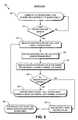
- FIG. 5is a flow chart illustrating a process 500 to group scan a CAP sense interface, in accordance with an embodiment of the invention.
- Process 500may be used in connection with CAP sense interfaces 300 , 400 , or otherwise.
- Process 500will be described with reference to FIGS. 5, 6A, and 6B .
- FIG. 6Ais a diagram illustrating a group scan of circular slider array 315
- FIG. 6Bis a diagram illustrating a group scan of a linear slider array 415 , in accordance with an embodiment of the invention.
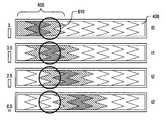
- a first group of CAP sensors(e.g., CAP sensors 320 or CAP sensors 420 ) are selected to be the current sensor group 605 .
- process 500will be discussed with reference to FIG. 6A and CAP sense interface 300 ; however, process 500 is equally applicable to CAP sense interface 400 and FIG. 6B .
- FIG. 6Aillustrates an embodiment where each sensor group includes three individual CAP sensors 320 ; however, it should be appreciated that sensor groups may include two or more CAP sensors 320 .
- a sensor groupis defined herein to include two or more CAP sensors 320 concurrently coupled to CAP sensor circuit 305 at a given instant in time via I/O interface 310 , such that their collective group capacitance can be measured.
- FIG. 6Aillustrates eight different current sensor groups 605 during eight different instants in time t 0 to t 7 . Current sensor groups 605 are illustrated as the shaded pie-sliced CAP sensors 320 .
- a userinteracts with CAP sense interface 300 by bring a conductive object (e.g., user's finger) in proximity to circular slider array 315 .
- FIG. 6Aillustrates the physical location of a user interaction with circular slider array 315 with location circles 610 (only a portion are labeled so as not to clutter the figure).
- CAP sensor circuit 305measures the combined capacitance of current sensor group 605 .
- CAP sensor circuit 305in fact measures a value that is indicative of a combined capacitance or a combined capacitance deviation from a baseline value for current sensor group 605 .
- Measuring a threshold capacitance deviation from the baseline value for a threshold period of timeis an indication that a user is interacting with current sensor group 605 .
- the measured valueis indicative of the capacitance or capacitance change/deviation and may include a count value related to a relaxation oscillator frequency or period.
- the combined capacitance of current sensor group 605is measured by electrically connecting CAP sensors 320 within current sensor group 605 and measuring this combined capacitance.
- the logical groupings of CAP sensors 320are temporal electrical connections of two or more CAP sensors 320 to CAP sensor circuit 305 .
- the sensor groupsare temporally connected through an analog bus to a shared relaxation oscillator circuit through low impedance switches. The analog bus conducts an analog value indicative of the combined capacitance change of all electrically connected CAP sensors 320 within the current sensor group 605 .
- FIG. 6Aillustrates values 615 measured at different times t 0 -t 7 for each sensor group.
- the measured valueincreases as the degree of coincidence between user interaction location 610 and current sensor groups 605 increases.
- the degree of coincidenceis decreasing with each successive current sensor group 605 and therefore the measured values decrease.
- the measured value for current sensor group 605is buffered.
- the measured value for the current sensor group 605is indexed or assigned to a nominal CAP sensor that is a member of the current sensor group 605 .
- the nominal CAP sensoris the particular CAP sensor 320 that is physically located in the middle of each sensor group.
- FIGS. 6A and 6Billustrate the nominal CAP sensor with the darkest shading. It should be appreciated though that the nominal CAP sensor need not be the middle CAP sensor and in the case where each sensor group includes an even number of CAP sensors 320 there may not be a physically middle CAP sensor.
- decision block 530it is determine whether all sensor groups within circular slider array 315 have been scanned (e.g., each combined group capacitance deviation value measured). If not, then process 500 continues to a process block 535 .
- the next sensor groupe.g., that illustrated at time t 1
- the next nominal CAP sensor 320is updated to be the current nominal CAP sensor 320 . It should be appreciated that updating current sensor group 605 to be the next sensor group may be implemented by reconfiguring I/O interface 310 to couple CAP sensor circuit 305 to the individual CAP sensors 320 making up the next sensor group.
- the CAP sensors 320 of the current logical sensor groupare disconnected and the CAP sensors 320 of the next logical sensor group are electrically connected via I/O interface 310 .
- the electrically connected CAP sensors 320 of the current logical sensor groupare temporally connected to a single CAP sensor circuit 305 for the next iteration through the loop within process 500 .
- process 500returns to process block 515 and proceeds as described above.
- CAP sensor circuit 305may include multiple relaxation oscillators and I/O interface 310 may be capable of coupling each relaxation oscillator to a different sensor group at the same time. In this alternative embodiment, CAP sensor circuit 305 would be capable of completing a scanning cycle of the sensor groups in less time than an embodiment where each sensor group is sequentially measured.
- process 500continues to a process block 540 .
- the buffered valuesare analyzed to determine the physical location and/or the direction of motion (in the case of scrolling) of physical location 610 .
- measured valuesmay be analyzed to interpolate the location 610 of the user interaction to a greater degree of accuracy/precision than the individual CAP sensors 320 using a discrete scan could provide.
- the measured valuesmay be fed into a decision algorithm, which analyses the values, making use of the fact that each value depends on how centrally located the user interaction is relative to each sensor group.
- the decision algorithmis a software entity.
- Process 500increases the SNR of a capacitive sense interface by logically combining discrete physical CAP sensors into sensor groups. Values indicative of a combine group capacitance are then measured for each sensor group and assigned to a nominal CAP sensor, which is a member of the particular sensor group. Since adjacent sensor groups may include common CAP sensors, the effective size and therefore resulting capacitance of each nominal CAP sensor is increased, thereby increasing the SNR.
- current sensor group 605 at time t 0includes two common CAP sensors 320 with current sensor group 605 at time t 1 .
- current sensor group 605 at time t 1includes two common CAP sensors 320 with current sensor group 605 at time t 2 .
- the increased SNR obtained by the group scanenables thicker dielectric protective overlays (e.g., for use with white goods or other durable consumer goods) and/or shrinkage of physical CAP sense interfaces for use in ever smaller electronic devices.
- FIG. 7is a flow chart illustrating a process 700 to perform quick discrete scans of CAP sense interfaces 300 or 400 until a user interaction is sensed and then perform a group scan to more precisely interpolate the location of the user interaction, in accordance with an embodiment of the invention.
- process 700implements a coarse, but quick, search function using the discrete scan to determine an approximate location of a user interaction and then implements a slower, but more precise, find function using the group scan on a portion of circular slider array 315 to determine with greater accuracy and sensitivity the location of the user interaction.
- process 700is described with reference to circular slider array 315 , but is equally applicable to linear slider array 415 or a planar touch pad array (not illustrated).
- the individual CAP sensors 320 of circular slider array 315are discretely scanned.
- Discretely scanning CAP sensors 320includes sequentially measuring a value indicative of a capacitance or capacitance change of each CAP sensor 320 . In one embodiment, this is accomplished by configuring I/O interface 310 to sequentially couple each CAP sensor 320 to CAP sensor circuit 305 to measure each value in isolation.
- CAP sensor circuit 305may be capable of measuring multiple values for discrete CAP sensors 320 concurrently, as discussed above.
- process 700continues to a process block 715 .
- process block 715an approximate location of the user interaction is determined based on the measured values obtained from the discrete scan in process block 705 .
- the approximate location determined via the quick discrete scanmay limit the possible location of the user interaction to a portion of circular slider array 315 , such as for example, the top half, the top quarter, etc.
- a group scan(see process 500 ) is performed only on a portion of CAP sensors 320 localized about the approximate location of the user interaction determined in process block 715 .
- the values indicative of the combined group capacitances or capacitance changes obtained from the localized group scancan then be used to more precisely, and with greater sensitivity, interpolate the location of the user interaction with circular slider array 315 .
- FIG. 8is a functional block diagram illustrating a demonstrative system 800 for implementing a capacitance sense user interface, in accordance with an embodiment of the invention.
- System 800includes a processing device 810 , a capacitive sense pad 820 , a capacitive sense linear slider 830 , a capacitive sense circular slider 840 , a host processor 850 , an embedded controller 860 , and non-capacitance sensor elements 870 .
- Processing device 810may include analog and/or digital general purpose input/output (“GPIO”) ports 807 .
- GPIO ports 807may be programmable.
- GPIO ports 807may be coupled to a Programmable Interconnect and Logic (“PIL”), which acts as an interconnect between GPIO ports 807 and a digital block array of processing device 810 (not illustrated).
- PILProgrammable Interconnect and Logic
- the digital block arraymay be configured to implement a variety of digital logic circuits (e.g., DAC, digital filters, digital control systems, etc.) using, in one embodiment, configurable user modules (“UMs”).
- UMsconfigurable user modules
- the digital block arraymay be coupled to a system bus.
- Processing device 810may also include memory, such as random access memory (RAM) 805 and program flash 804 .
- RAM 805may be static RAM (“SRAM”), and program flash 804 may be a non-volatile storage, which may be used to store firmware (e.g., control algorithms executable by processing core 802 to implement operations described herein such as the aforementioned decision algorithm).
- Processing device 810may also include a memory controller unit (“MCU”) 803 coupled to memory and the processing core 802 .
- MCUmemory controller unit
- Processing device 810may also include an analog block array (not illustrated).
- the analog block arrayis also coupled to the system bus.
- the analog block arrayalso may be configured to implement a variety of analog circuits (e.g., ADC, analog filters, etc.) using, in one embodiment, configurable UMs.
- the analog block arraymay also be coupled to the GPIO 807 .
- capacitance sensor 801may be integrated into processing device 810 .
- Capacitance sensor 801may include analog I/O for coupling to an external component, such as capacitive sense pad 820 , capacitive sense linear slider 830 , capacitive sense circular slider 840 , and/or other devices. Capacitance sensor 801 is described in more detail below.
- Processing device 810may include internal oscillator/clocks 806 and communication block 808 .
- the oscillator/clocks block 806provides clock signals to one or more of the components of processing device 810 .
- Communication block 808may be used to communicate with an external component, such as a host processor 850 , via host interface (I/F) line 851 .
- processing device 810may also be coupled to embedded controller 860 to communicate with the external components, such as host 850 .
- Interfacing to the host 850can be through various methods. In one exemplary embodiment, interfacing with the host 850 may be done using a standard PS/2 interface to connect to embedded controller 860 , which in turn sends data to the host 850 via low pin count (LPC) interface.
- LPClow pin count
- processing device 810may do both touch-sensor pad and keyboard control operations, thereby freeing up the embedded controller 860 for other housekeeping functions.
- interfacingmay be done using a universal serial bus (USB) interface directly coupled to host 850 via host interface line 851 .
- processing device 810may communicate to external components, such as host 850 using industry standard interfaces, such as USB, PS/2, inter-integrated circuit (I2C) bus, or system packet interfaces (SPI).
- Host 850 and/or embedded controller 860may be coupled to processing device 810 with a ribbon or flex cable from an assembly, which houses the sensing device and processing device.
- processing device 810is configured to communicate with embedded controller 860 or host 850 to send and/or receive data.
- the datamay be a command or alternatively a signal.
- system 800may operate in both standard-mouse compatible and enhanced modes.
- the standard-mouse compatible modeutilizes the HID class drivers already built into the Operating System (OS) software of host 850 . These drivers enable processing device 810 and sensing device to operate as a standard cursor control user interface device, such as a two-button PS/2 mouse.
- the enhanced modemay enable additional features such as scrolling (reporting absolute position) or disabling the sensing device, such as when a mouse is plugged into the notebook.
- processing device 810may be configured to communicate with embedded controller 860 or host 850 , using non-OS drivers, such as dedicated touch-sensor pad drivers, or other drivers known by those of ordinary skill in the art.
- Processing device 810may reside on a common carrier substrate such as, for example, an integrated circuit (IC) die substrate, a multi-chip module substrate, or the like. Alternatively, the components of processing device 810 may be one or more separate integrated circuits and/or discrete components. In one exemplary embodiment, processing device 810 may be a Programmable System on a Chip (PSoCTM) processing device, manufactured by Cypress Semiconductor Corporation, San Jose, Calif. Alternatively, processing device 810 may be one or more other processing devices known by those of ordinary skill in the art, such as a microprocessor or central processing unit, a controller, special-purpose processor, digital signal processor (“DSP”), an application specific integrated circuit (“ASIC”), a field programmable gate array (“FPGA”), or the like. In an alternative embodiment, for example, processing device 810 may be a network processor having multiple processors including a core unit and multiple microengines. Additionally, processing device 810 may include any combination of general-purpose processing device(s) and special-purpose processing device(s).
- Capacitance sensor 801may be integrated into the IC of processing device 810 , or alternatively, in a separate IC. Descriptions of capacitance sensor 801 may be generated and compiled for incorporation into other integrated circuits. For example, behavioral level code describing capacitance sensor 801 , or portions thereof, may be generated using a hardware descriptive language, such as VHDL or Verilog, and stored to a machine-accessible medium (e.g., CD-ROM, hard disk, floppy disk, etc.). Furthermore, the behavioral level code can be compiled into register transfer level (“RTL”) code, a netlist, or even a circuit layout and stored to a machine-accessible medium. The behavioral level code, the RTL code, the netlist, and the circuit layout all represent various levels of abstraction to describe capacitance sensor 801 .
- VHDLhardware descriptive language
- Verilogmachine-accessible medium
- RTLregister transfer level
- electronic system 800may be used in a notebook computer.
- system 800may be used in other applications, such as a mobile handset, a personal data assistant (PDA), a keyboard, a television, a remote control, a monitor, a handheld multi-media device, a handheld video player, a handheld gaming device, or a control panel.
- PDApersonal data assistant
- capacitance sensor 801may be a capacitive switch relaxation oscillator (CSR).
- CSRmay have an array of capacitive touch switches using a current-programmable relaxation oscillator, an analog multiplexer, digital counting functions, and high-level software routines to compensate for environmental and physical switch variations.
- the CSRmay include physical, electrical, and software components.
- the physical componentmay include the physical switch itself, typically a pattern constructed on a printed circuit board (“PCB”) with an insulating cover, a flexible membrane, or a transparent overlay.
- the electrical componentmay include an oscillator or other means to convert a changed capacitance into a measured signal.
- the electrical componentmay also include a counter or timer to measure the oscillator output.
- the software componentmay include detection, compensation, and decision software algorithms to convert the count value into a capacitive sensor detection decision.
- the current versus voltage phase shift measurementmay include driving the capacitance through a fixed-value resistor to yield voltage and current waveforms that are out of phase by a predictable amount.
- the drive frequencycan be adjusted to keep the phase measurement in a readily measured range.
- the resistor-capacitor charge timingmay include charging the capacitor through a fixed resistor and measuring timing on the voltage ramp. Small capacitor values may require very large resistors for reasonable timing.
- the capacitive bridge dividermay include driving the capacitor under test through a fixed reference capacitor. The reference capacitor and the capacitor under test form a voltage divider.
- the voltage signalis recovered with a synchronous demodulator, which may be done in processing device 810 .
- the charge transfermay be conceptually similar to an R-C charging circuit.
- C Pthe capacitance being sensed and C SUM is the summing capacitor, into which charge is transferred on successive cycles.
- the voltage on C SUMis reset.
- the voltage on C SUMincreases exponentially (and only slightly) with each clock cycle. The time for this voltage to reach a specific threshold is measured with a counter.
- FIG. 9illustrates one possible embodiment of capacitance sensor 801 implemented with a relaxation oscillator circuit 900 .
- the illustrated embodiment of capacitance sensor 801includes relaxation oscillator circuit 900 , an analog multiplexer (“MUX”) bus 901 , a sensor array 910 , and a digital counter 920 .
- Analog MUX bus 901 and selection circuit 930may collectively implement the functionality of I/O interconnects 310 and 410 .
- the remaining portions of relaxation oscillator 900 and digital counter 920may implement the functionality of CAP sensor circuits 305 and 405 .
- Sensor array 910may represent any of circular slider array 315 , linear slider array 415 , or a planar touch pad array.
- Relaxation oscillator 900is formed by the capacitance to be measured on capacitor sensors 951 , a charging current source 952 , a comparator 953 , and a reset switch 954 .
- capacitor sensor 951are representative of the capacitance measured on a sensor element of a CAP sensor array.
- the relaxation oscillatoris coupled to drive a charging current Ic in a single direction onto a device under test (“DUT”) capacitor, any of capacitor sensors 951 .
- DUTdevice under test
- Equation (1)describes the relation between current, capacitance, voltage and time for a charging capacitor.
- CdVI c dt (1)
- the relaxation oscillatorbegins by charging the capacitor sensor 951 from a ground potential or zero voltage and continues to pile charge on the capacitor 951 at a fixed charging current Ic until the voltage across the capacitor 951 at node 970 reaches a reference voltage or threshold voltage, V TH 955 .
- V TH 955the relaxation oscillator allows the accumulated charge at node 955 to discharge (e.g., the capacitor 951 to “relax” back to the ground potential) and then the process repeats itself.
- the output of comparator 953asserts a clock signal F OUT 956 (e.g., F OUT 956 goes high), which enables the reset switch 954 . This resets the voltage on the capacitor at node 970 to ground and the charge cycle starts again.
- the relaxation oscillatoroutputs a relaxation oscillator clock signal (F OUT 956 ) having a frequency (f RO ) dependent upon capacitance C of the capacitor 951 and charging current Ic.
- the comparator trip time of the comparator 953 and reset switch 954add a fixed delay.
- the output of the comparator 953is synchronized with a reference system clock to guarantee that the comparator reset time is long enough to completely reset the charging voltage on capacitor 955 .
- f ROwill change proportionally according to Equation (1).
- f REFfrequency of a known reference system clock signal
- equations (2) and (3) belowdescribe that a change in frequency between F OUT 956 and REF CLK is proportional to a change in capacitance of the capacitor 951 .
- a frequency comparatormay be coupled to receive relaxation oscillator clock signal (F OUT 956 ) and REF CLK, compare their frequencies f RO and f REF , respectively, and output a signal indicative of the difference ⁇ f between these frequencies. By monitoring ⁇ f one can determine whether the capacitance of the capacitor 951 has changed.
- the relaxation oscillator 950may be built using a programmable timer (e.g., 555 timer) to implement the comparator 953 and reset switch 954 .
- the relaxation oscillator 900may be built using other circuits.
- Sensor array 910includes a plurality of sensor elements 955 ( 1 )- 955 (N), where N is a positive integer value that represents the number of capacitive sensors within any of capacitive sense pad 820 , capacitive sense linear slider 830 , or capacitive sense circular slider 840 .
- Relaxation oscillator 900further includes a selection circuit 930 .
- Selection circuit 930is coupled to the plurality of sensor elements 951 ( 1 )- 951 (N), the reset switch 954 , the current source 952 , and the comparator 953 .
- Selection circuit 930may be used to allow the relaxation oscillator 900 to measure capacitance on multiple sensor elements (e.g., rows or columns).
- the selection circuit 930may be configured to sequentially select a sensor element of the plurality of sensor elements to provide the charge current and to measure the capacitance of each sensor element.
- selection circuit 930is a multiplexer array of the relaxation oscillator 900 .
- selection circuitmay be other circuitry outside the relaxation oscillator 900 , or even outside the capacitance sensor 801 to select the sensor element to be measured.
- Capacitance sensor 801may include one relaxation oscillator and digital counter for the plurality of sensor elements of the sensor array.
- capacitance sensor 801may include multiple relaxation oscillators and digital counters to measure capacitance on the plurality of sensor elements of the sensor array.
- the multiplexer arraymay also be used to ground the sensor elements that are not being measured. This may be done in conjunction with a dedicated pin in the GPIO port 807 .
- the capacitance sensor 801may be configured to simultaneously scan the sensor elements, as opposed to being configured to sequentially scan the sensor elements as described above.
- the sensing devicemay include a sensor array having a plurality of rows and columns. The rows may be scanned simultaneously, and the columns may be scanned simultaneously.
- the voltages on all of the rows of the sensor arrayare simultaneously moved, while the voltages of the columns are held at a constant voltage, with the complete set of sampled points simultaneously giving a profile of the conductive object in a first dimension.
- the voltages on all of the rowsare held at a constant voltage, while the voltages on all the rows are simultaneously moved, to obtain a complete set of sampled points simultaneously giving a profile of the conductive object in the other dimension.
- the voltages on all of the rows of the sensor arrayare simultaneously moved in a positive direction, while the voltages of the columns are moved in a negative direction.
- the voltages on all of the rows of the sensor arrayare simultaneously moved in a negative direction, while the voltages of the columns are moved in a positive direction.
- Digital counter 920is coupled to the output of the relaxation oscillator 900 .
- Digital counter 920receives the relaxation oscillator output signal 956 (F OUT ).
- Digital counter 920is configured to count at least one of a frequency or a period of the relaxation oscillator output received from the relaxation oscillator.
- the digital counter 920may include two multiplexers 923 and 924 . Multiplexers 923 and 924 are configured to select the inputs for the PWM 921 and the timer 922 for the two measurement methods, frequency and period measurement methods. Alternatively, other selection circuits may be used to select the inputs for the PWM 921 and the time 922 . In another embodiment, multiplexers 923 and 924 are not included in the digital counter, for example, digital counter 920 may be configured in one, or the other, measurement configuration.
- the relaxation oscillator output signal 956is counted for a fixed period of time.
- the counter 922is read to obtain the number of counts during the gate time. This method works well at low frequencies where the oscillator reset time is small compared to the oscillator period.
- a pulse width modulator (PWM) 921is clocked for a fixed period by a derivative of the system clock, VC3 926 (which is a divider from system clock 925 , e.g., 24 MHz). Pulse width modulation is a modulation technique that generates variable-length pulses to represent the amplitude of an analog input signal; in this case VC3 926 .
- the output of PWM 921enables timer 922 (e.g., 16-bit).
- the relaxation oscillator output signal 956clocks the timer 922 .
- the timer 922is reset at the start of the sequence, and the count value is read out at the end of the gate period.
- the relaxation oscillator output signal 956gates a timer 922 , which is clocked by the system clock 925 (e.g., 24 MHz). In order to improve sensitivity and resolution, multiple periods of the oscillator are counted with the PWM 921 . The output of PWM 921 is used to gate the timer 922 . In this method, the relaxation oscillator output signal 956 drives the clock input of PWM 921 .
- pulse width modulationis a modulation technique that generates variable-length pulses to represent the amplitude of an analog input signal; in this case the relaxation oscillator output signal 956 .
- the output of the PWM 921enables timer 922 (e.g., 16-bit), which is clocked at the system clock frequency 925 (e.g., 24 MHz).
- timer 922e.g. 16-bit
- the countstarts by releasing the capture control.
- the capture signalis asserted (e.g., goes high), stopping the count and setting the PWM's interrupt.
- the timer valueis read in this interrupt.
- the relaxation oscillator 900is indexed to the next capacitive sensor (e.g., capacitor 951 ( 2 )) to be measured and the count sequence is started again.
- the length of the counter 922 and the detection time required for capacitance sensor 801are determined by sensitivity requirements. Small changes in the capacitance on sensor element 951 result in small changes in frequency. In order to find these small changes, it may be necessary to count for a considerable time.
- the capacitive sensorse.g., sensor elements 951 ( 1 )-(N)
- the count values for each capacitive sensors with no actuationare stored as a baseline array (Cp).
- the presence of a finger on the switchis determined by the difference in counts between a stored value for no capacitive sensors actuation and the acquired value with capacitive sensors actuation, referred to here as ⁇ n.
- the sensitivity of a single capacitive sensorsis approximately:
- ⁇ ⁇ ⁇ n nCf Cp ( 4 )
- the value of ⁇ nshould be large enough for reasonable resolution and clear indication of capacitive sensors actuation.
- multiple sensor elementsmay be sequentially scanned to provide current to and measure the capacitance from the capacitors (e.g., sensor elements), as previously described. In other words, while one sensor element is being measured, the remaining sensor elements are grounded using the GPIO port 807 .
- This drive and multiplex arrangementbypasses the existing GPIO to connect the selected pin to an internal analog multiplexer (mux) bus.
- the capacitor charging current (e.g., current source 952 ) and reset switch 953are connected to the analog mux bus. This may limit the pin-count requirement to simply the number of capacitive sensors (e.g., capacitors 951 ( 1 )- 951 (N)) to be addressed. In one exemplary embodiment, no external resistors or capacitors are required inside or outside the processing device 910 to enable operation.
- the capacitor charging current for the relaxation oscillator 900is generated in a register programmable current output DAC (also known as IDAC). Accordingly, the current source 952 is a current DAC or IDAC.
- the IDAC output currentmay be set by an 8-bit value provided by the processing device 810 , such as from the processing core 802 .
- the 8-bit valuemay be stored in a register or in memory.
- the oscillator-reset timemay add to the oscillator period (especially at higher frequencies); and there may be some variation to the magnitude of the IDAC output current with operating frequency. Accordingly, the optimum oscillation frequency and operating current for a particular switch array may be determined to some degree by experimentation.
Landscapes
- Engineering & Computer Science (AREA)
- General Engineering & Computer Science (AREA)
- Theoretical Computer Science (AREA)
- Physics & Mathematics (AREA)
- General Physics & Mathematics (AREA)
- Human Computer Interaction (AREA)
- Power Engineering (AREA)
- Position Input By Displaying (AREA)
- Measurement Of Length, Angles, Or The Like Using Electric Or Magnetic Means (AREA)
Abstract
Description
CdV=Icdt (1)
ΔC∝1/Δf,where (2)
Δf=fRO−fREF. (3)
The value of Δn should be large enough for reasonable resolution and clear indication of capacitive sensors actuation.
Claims (18)
Priority Applications (2)
| Application Number | Priority Date | Filing Date | Title |
|---|---|---|---|
| US11/493,350US9507465B2 (en) | 2006-07-25 | 2006-07-25 | Technique for increasing the sensitivity of capacitive sensor arrays |
| US15/338,180US10133432B2 (en) | 2006-07-25 | 2016-10-28 | Technique for increasing the sensitivity of capacitive sense arrays |
Applications Claiming Priority (1)
| Application Number | Priority Date | Filing Date | Title |
|---|---|---|---|
| US11/493,350US9507465B2 (en) | 2006-07-25 | 2006-07-25 | Technique for increasing the sensitivity of capacitive sensor arrays |
Related Child Applications (1)
| Application Number | Title | Priority Date | Filing Date |
|---|---|---|---|
| US15/338,180ContinuationUS10133432B2 (en) | 2006-07-25 | 2016-10-28 | Technique for increasing the sensitivity of capacitive sense arrays |
Publications (2)
| Publication Number | Publication Date |
|---|---|
| US20080024455A1 US20080024455A1 (en) | 2008-01-31 |
| US9507465B2true US9507465B2 (en) | 2016-11-29 |
Family
ID=38985688
Family Applications (2)
| Application Number | Title | Priority Date | Filing Date |
|---|---|---|---|
| US11/493,350Active2033-07-01US9507465B2 (en) | 2006-07-25 | 2006-07-25 | Technique for increasing the sensitivity of capacitive sensor arrays |
| US15/338,180Active2026-09-27US10133432B2 (en) | 2006-07-25 | 2016-10-28 | Technique for increasing the sensitivity of capacitive sense arrays |
Family Applications After (1)
| Application Number | Title | Priority Date | Filing Date |
|---|---|---|---|
| US15/338,180Active2026-09-27US10133432B2 (en) | 2006-07-25 | 2016-10-28 | Technique for increasing the sensitivity of capacitive sense arrays |
Country Status (1)
| Country | Link |
|---|---|
| US (2) | US9507465B2 (en) |
Families Citing this family (53)
| Publication number | Priority date | Publication date | Assignee | Title |
|---|---|---|---|---|
| US8144125B2 (en) | 2006-03-30 | 2012-03-27 | Cypress Semiconductor Corporation | Apparatus and method for reducing average scan rate to detect a conductive object on a sensing device |
| US8040142B1 (en) | 2006-03-31 | 2011-10-18 | Cypress Semiconductor Corporation | Touch detection techniques for capacitive touch sense systems |
| US8004497B2 (en) | 2006-05-18 | 2011-08-23 | Cypress Semiconductor Corporation | Two-pin buttons |
| US7889176B2 (en)* | 2006-07-18 | 2011-02-15 | Avago Technologies General Ip (Singapore) Pte. Ltd. | Capacitive sensing in displacement type pointing devices |
| US9507465B2 (en) | 2006-07-25 | 2016-11-29 | Cypress Semiconductor Corporation | Technique for increasing the sensitivity of capacitive sensor arrays |
| US8069512B2 (en)* | 2006-09-14 | 2011-12-06 | Martin B Rawls-Meehan | Adjustable bed frame |
| US8926535B2 (en) | 2006-09-14 | 2015-01-06 | Martin B. Rawls-Meehan | Adjustable bed position control |
| US10864137B2 (en) | 2006-09-14 | 2020-12-15 | Ascion, Llc | System and method of an adjustable bed with a vibration motor |
| US7321811B1 (en) | 2006-09-14 | 2008-01-22 | Rawls-Meehan Martin B | Methods and systems of adjustable bed position control |
| US10064784B2 (en) | 2006-09-14 | 2018-09-04 | Martin B. Rawls-Meehan | System and method of an adjustable bed with a vibration motor |
| US8547114B2 (en) | 2006-11-14 | 2013-10-01 | Cypress Semiconductor Corporation | Capacitance to code converter with sigma-delta modulator |
| US8159462B1 (en)* | 2006-11-15 | 2012-04-17 | Cypress Semiconductor Corporation | Reference voltage offset for capacitive touch-sensor measurement |
| US7639234B2 (en)* | 2007-01-04 | 2009-12-29 | Avago Technologies Ecbu Ip (Singapore) Pte. Ltd. | Capacitive sensing and absolute position mapping in displacement type pointing devices |
| US8058937B2 (en) | 2007-01-30 | 2011-11-15 | Cypress Semiconductor Corporation | Setting a discharge rate and a charge rate of a relaxation oscillator circuit |
| US20100093311A1 (en)* | 2007-03-07 | 2010-04-15 | Katsuhisa Ide | Mobile information processing apparatus, operational item execution control program and operational item execution control method |
| US8144126B2 (en) | 2007-05-07 | 2012-03-27 | Cypress Semiconductor Corporation | Reducing sleep current in a capacitance sensing system |
| US9500686B1 (en) | 2007-06-29 | 2016-11-22 | Cypress Semiconductor Corporation | Capacitance measurement system and methods |
| US8169238B1 (en) | 2007-07-03 | 2012-05-01 | Cypress Semiconductor Corporation | Capacitance to frequency converter |
| US8570053B1 (en) | 2007-07-03 | 2013-10-29 | Cypress Semiconductor Corporation | Capacitive field sensor with sigma-delta modulator |
| WO2009006557A1 (en)* | 2007-07-03 | 2009-01-08 | Cypress Semiconductor Corporation | Method for improving scan time and sensitivity in touch sensitive user interface device |
| CA2703211A1 (en)* | 2007-10-22 | 2009-04-30 | Martin B. Rawls-Meehan | Adjustable bed position control |
| US9367166B1 (en)* | 2007-12-21 | 2016-06-14 | Cypress Semiconductor Corporation | System and method of visualizing capacitance sensing system operation |
| KR101427586B1 (en)* | 2007-12-26 | 2014-08-07 | 삼성디스플레이 주식회사 | Display device and driving method thereof |
| US8525798B2 (en) | 2008-01-28 | 2013-09-03 | Cypress Semiconductor Corporation | Touch sensing |
| US8487912B1 (en)* | 2008-02-01 | 2013-07-16 | Cypress Semiconductor Corporation | Capacitive sense touch device with hysteresis threshold |
| US8319505B1 (en) | 2008-10-24 | 2012-11-27 | Cypress Semiconductor Corporation | Methods and circuits for measuring mutual and self capacitance |
| US8797277B1 (en)* | 2008-02-27 | 2014-08-05 | Cypress Semiconductor Corporation | Method for multiple touch position estimation |
| US8358142B2 (en) | 2008-02-27 | 2013-01-22 | Cypress Semiconductor Corporation | Methods and circuits for measuring mutual and self capacitance |
| FI121979B (en) | 2008-03-26 | 2011-06-30 | Elsi Technologies Oy | Adapter component for measuring system |
| TWI469001B (en)* | 2008-07-31 | 2015-01-11 | Htc Corp | Touch control electronic device and operating method thereof |
| US8321174B1 (en) | 2008-09-26 | 2012-11-27 | Cypress Semiconductor Corporation | System and method to measure capacitance of capacitive sensor array |
| US8723825B2 (en) | 2009-07-28 | 2014-05-13 | Cypress Semiconductor Corporation | Predictive touch surface scanning |
| US9069405B2 (en)* | 2009-07-28 | 2015-06-30 | Cypress Semiconductor Corporation | Dynamic mode switching for fast touch response |
| US8723827B2 (en) | 2009-07-28 | 2014-05-13 | Cypress Semiconductor Corporation | Predictive touch surface scanning |
| WO2012061406A2 (en) | 2010-11-01 | 2012-05-10 | Rawls-Meehan Martin B | Adjustable bed controls |
| TWI475451B (en) | 2011-01-07 | 2015-03-01 | Egalax Empia Technology Inc | Capacitive sensor and detection method using the same |
| US9965104B2 (en)* | 2011-01-19 | 2018-05-08 | Synaptics Incorporated | Device and method for interference avoidance in an input device |
| US10712859B2 (en)* | 2012-08-03 | 2020-07-14 | Touchplus Information Corp. | Touch-sensitive control device |
| TWI560605B (en)* | 2012-09-03 | 2016-12-01 | Egalax Empia Technology Inc | Capacitive processor and detection method using the same |
| TWI478032B (en)* | 2012-09-03 | 2015-03-21 | Egalax Empia Technology Inc | Capacitive sensor and detection method using the same |
| US9229576B2 (en)* | 2012-10-09 | 2016-01-05 | Stmicroelectronics Asia Pacific Pte Ltd | Apparatus and method for preventing false touches in touch screen systems |
| US9024912B2 (en)* | 2012-11-08 | 2015-05-05 | Broadcom Corporation | Baseline recalculation after frequency reconfiguration of a mutual capacitive touch controller |
| US20140160087A1 (en)* | 2012-12-07 | 2014-06-12 | Research In Motion Limited | Method and Apparatus Pertaining to Gestures with Respect to a Stylus |
| KR20140086477A (en)* | 2012-12-28 | 2014-07-08 | 삼성전기주식회사 | Apparatus for sensing touch input |
| US9304575B2 (en) | 2013-11-26 | 2016-04-05 | Apple Inc. | Reducing touch sensor panel power consumption |
| US9785279B2 (en) | 2014-01-31 | 2017-10-10 | Hewlett-Packard Development Company, L.P. | Touch distance based on a column weighted sensor value |
| US10037100B2 (en)* | 2015-03-02 | 2018-07-31 | Apple Inc. | SNR-aware active mode touch scans with electrode reallocation |
| US9971463B2 (en)* | 2015-09-29 | 2018-05-15 | Synaptics Incorporated | Row-based sensing on matrix pad sensors |
| US10591250B2 (en)* | 2016-12-19 | 2020-03-17 | Crosman Corporation | Switchless sensing for electronic devices used with deterrent devices |
| GB201722248D0 (en) | 2017-12-28 | 2018-02-14 | Zedsen Ltd | Examining objects with electric field |
| DE102018209515A1 (en)* | 2018-06-14 | 2019-12-19 | BSH Hausgeräte GmbH | Method for actuating an operating device, in which at least one correction value is determined, operating device and household appliance |
| US11555687B2 (en) | 2019-08-08 | 2023-01-17 | Sigmasense, Llc. | Capacitive imaging glove |
| JP7353903B2 (en)* | 2019-10-07 | 2023-10-02 | 株式会社ジャパンディスプレイ | Display device and clock |
Citations (150)
| Publication number | Priority date | Publication date | Assignee | Title |
|---|---|---|---|---|
| US4266144A (en)* | 1979-05-14 | 1981-05-05 | Emhart Industries, Inc. | Detection means for multiple capacitive sensing devices |
| US4283713A (en) | 1979-01-15 | 1981-08-11 | Tektronix, Inc. | Waveform acquisition circuit |
| US4438404A (en) | 1982-01-04 | 1984-03-20 | Tektronix, Inc. | Signal sampling system |
| US4475151A (en) | 1982-11-04 | 1984-10-02 | Harald Philipp | Switching amplifier circuit |
| US4497575A (en) | 1982-11-01 | 1985-02-05 | Tektronix, Inc. | Optical fiber test instrument calibrator |
| US4736097A (en) | 1987-02-02 | 1988-04-05 | Harald Philipp | Optical motion sensor |
| US4773024A (en) | 1986-06-03 | 1988-09-20 | Synaptics, Inc. | Brain emulation circuit with reduced confusion |
| US4876534A (en) | 1988-02-05 | 1989-10-24 | Synaptics Incorporated | Scanning method and apparatus for current signals having large dynamic range |
| US4879461A (en) | 1988-04-25 | 1989-11-07 | Harald Philipp | Energy field sensor using summing means |
| US4935702A (en) | 1988-12-09 | 1990-06-19 | Synaptics, Inc. | Subthreshold CMOS amplifier with offset adaptation |
| US4953928A (en) | 1989-06-09 | 1990-09-04 | Synaptics Inc. | MOS device for long-term learning |
| US4962342A (en) | 1989-05-04 | 1990-10-09 | Synaptics, Inc. | Dynamic synapse for neural network |
| US5049758A (en) | 1988-12-09 | 1991-09-17 | Synaptics, Incorporated | Adaptable CMOS winner-take all circuit |
| US5055827A (en) | 1990-02-20 | 1991-10-08 | Harald Philipp | Fiber optic security system |
| US5059920A (en) | 1988-12-09 | 1991-10-22 | Synaptics, Incorporated | CMOS amplifier with offset adaptation |
| US5068622A (en) | 1988-12-09 | 1991-11-26 | Synaptics, Incorporated | CMOS amplifier with offset adaptation |
| US5073759A (en) | 1988-12-09 | 1991-12-17 | Synaptics, Incorporated | Adaptable current mirror |
| US5083044A (en) | 1989-03-10 | 1992-01-21 | Synaptics, Incorporated | Synaptic element and array |
| US5095284A (en) | 1990-09-10 | 1992-03-10 | Synaptics, Incorporated | Subthreshold CMOS amplifier with wide input voltage range |
| US5097305A (en) | 1991-02-19 | 1992-03-17 | Synaptics Corporation | Integrating photosensor and imaging system having wide dynamic range |
| US5107149A (en) | 1990-12-18 | 1992-04-21 | Synaptics, Inc. | Linear, continuous-time, two quadrant multiplier |
| US5109261A (en) | 1988-12-09 | 1992-04-28 | Synaptics, Incorporated | CMOS amplifier with offset adaptation |
| US5119038A (en) | 1988-12-09 | 1992-06-02 | Synaptics, Corporation | CMOS current mirror with offset adaptation |
| US5120996A (en) | 1989-03-10 | 1992-06-09 | Synaptics, Incorporated | Synaptic element and array |
| US5122800A (en) | 1989-01-26 | 1992-06-16 | Harald Philipp | Variable successive approximation converter |
| US5126685A (en) | 1990-12-18 | 1992-06-30 | Synaptics, Incorporated | Circuits for linear conversion between voltages and currents |
| US5146106A (en) | 1988-12-09 | 1992-09-08 | Synaptics, Incorporated | CMOS winner-take all circuit with offset adaptation |
| US5160899A (en) | 1988-12-09 | 1992-11-03 | Synaptics, Incorporated | Adaptable MOS current mirror |
| US5165054A (en) | 1990-12-18 | 1992-11-17 | Synaptics, Incorporated | Circuits for linear conversion between currents and voltages |
| US5166562A (en) | 1991-05-09 | 1992-11-24 | Synaptics, Incorporated | Writable analog reference voltage storage device |
| US5204549A (en) | 1992-01-28 | 1993-04-20 | Synaptics, Incorporated | Synaptic element including weight-storage and weight-adjustment circuit |
| US5237879A (en)* | 1991-10-11 | 1993-08-24 | At&T Bell Laboratories | Apparatus for dynamically varying the resolution of a tactile sensor array |
| US5243554A (en) | 1991-05-09 | 1993-09-07 | Synaptics, Incorporated | Writable analog reference voltage storage device |
| US5248873A (en) | 1991-06-10 | 1993-09-28 | Synaptics, Incorporated | Integrated device for recognition of moving objects |
| US5260592A (en) | 1991-02-19 | 1993-11-09 | Synaptics, Incorporated | Integrating photosensor and imaging system having wide dynamic range with varactors |
| US5270963A (en) | 1988-08-10 | 1993-12-14 | Synaptics, Incorporated | Method and apparatus for performing neighborhood operations on a processing plane |
| US5276407A (en) | 1991-02-19 | 1994-01-04 | Synaptics, Incorporated | Sense amplifier |
| US5289023A (en) | 1991-02-19 | 1994-02-22 | Synaptics, Incorporated | High-density photosensor and contactless imaging array having wide dynamic range |
| US5303329A (en) | 1991-12-10 | 1994-04-12 | Synaptics, Incorporated | Continuous synaptic weight update mechanism |
| US5305017A (en) | 1989-08-16 | 1994-04-19 | Gerpheide George E | Methods and apparatus for data input |
| US5331215A (en) | 1988-12-09 | 1994-07-19 | Synaptics, Incorporated | Electrically adaptable neural network with post-processing circuitry |
| US5336936A (en) | 1992-05-06 | 1994-08-09 | Synaptics, Incorporated | One-transistor adaptable analog storage element and array |
| US5339213A (en) | 1992-11-16 | 1994-08-16 | Cirque Corporation | Portable computer touch pad attachment |
| US5349303A (en) | 1993-07-02 | 1994-09-20 | Cirque Corporation | Electrical charge transfer apparatus |
| US5374787A (en) | 1992-06-08 | 1994-12-20 | Synaptics, Inc. | Object position detector |
| US5381515A (en) | 1988-12-09 | 1995-01-10 | Synaptics, Incorporated | Two layer neural network comprised of neurons with improved input range and input offset |
| US5384467A (en) | 1992-10-16 | 1995-01-24 | AVL Gesellschaft fur Verbrennungskraftmaschinen und Messtechnik m.b.H. Prof.Dr.Dr.h.c. Hans List | Optoelectronic measuring device for monitoring a combustion chamber |
| US5408194A (en) | 1993-06-25 | 1995-04-18 | Synaptics, Incorporated | Adaptive analog minimum/maximum selector and subtractor circuit |
| US5488204A (en) | 1992-06-08 | 1996-01-30 | Synaptics, Incorporated | Paintbrush stylus for capacitive touch sensor pad |
| US5541878A (en) | 1991-05-09 | 1996-07-30 | Synaptics, Incorporated | Writable analog reference voltage storage device |
| US5543588A (en) | 1992-06-08 | 1996-08-06 | Synaptics, Incorporated | Touch pad driven handheld computing device |
| US5543590A (en) | 1992-06-08 | 1996-08-06 | Synaptics, Incorporated | Object position detector with edge motion feature |
| US5543591A (en) | 1992-06-08 | 1996-08-06 | Synaptics, Incorporated | Object position detector with edge motion feature and gesture recognition |
| US5555907A (en) | 1995-06-02 | 1996-09-17 | Philipp; Harald | Divided box for valve controller |
| US5565658A (en) | 1992-07-13 | 1996-10-15 | Cirque Corporation | Capacitance-based proximity with interference rejection apparatus and methods |
| US5566702A (en) | 1994-12-30 | 1996-10-22 | Philipp; Harald | Adaptive faucet controller measuring proximity and motion |
| US5682032A (en) | 1996-02-22 | 1997-10-28 | Philipp; Harald | Capacitively coupled identity verification and escort memory apparatus |
| US5730165A (en) | 1995-12-26 | 1998-03-24 | Philipp; Harald | Time domain capacitive field detector |
| US5757368A (en) | 1995-03-27 | 1998-05-26 | Cirque Corporation | System and method for extending the drag function of a computer pointing device |
| US5767457A (en) | 1995-11-13 | 1998-06-16 | Cirque Corporation | Apparatus and method for audible feedback from input device |
| US5796183A (en) | 1996-01-31 | 1998-08-18 | Nartron Corporation | Capacitive responsive electronic switching circuit |
| US5812698A (en) | 1995-05-12 | 1998-09-22 | Synaptics, Inc. | Handwriting recognition system and method |
| US5844265A (en) | 1996-07-11 | 1998-12-01 | Synaptics, Incorporated | Sense amplifier for high-density imaging array |
| US5854625A (en) | 1996-11-06 | 1998-12-29 | Synaptics, Incorporated | Force sensing touchpad |
| US5861875A (en) | 1992-07-13 | 1999-01-19 | Cirque Corporation | Methods and apparatus for data input |
| US5861583A (en) | 1992-06-08 | 1999-01-19 | Synaptics, Incorporated | Object position detector |
| US5864392A (en) | 1995-12-15 | 1999-01-26 | Avl List Gmbh | Method for optically detecting gas bubbles moving in a coolant |
| US5880411A (en) | 1992-06-08 | 1999-03-09 | Synaptics, Incorporated | Object position detector with edge motion feature and gesture recognition |
| US5889236A (en) | 1992-06-08 | 1999-03-30 | Synaptics Incorporated | Pressure sensitive scrollbar feature |
| US5914708A (en) | 1996-04-04 | 1999-06-22 | Cirque Corporation | Computer input stylus method and apparatus |
| US5914465A (en) | 1992-06-08 | 1999-06-22 | Synaptics, Inc. | Object position detector |
| US5920310A (en) | 1996-11-15 | 1999-07-06 | Synaptics, Incorporated | Electronic device employing a touch sensitive transducer |
| US5926566A (en) | 1996-11-15 | 1999-07-20 | Synaptics, Inc. | Incremental ideographic character input method |
| US5942733A (en) | 1992-06-08 | 1999-08-24 | Synaptics, Inc. | Stylus input capacitive touchpad sensor |
| US5943052A (en) | 1997-08-12 | 1999-08-24 | Synaptics, Incorporated | Method and apparatus for scroll bar control |
| US5969513A (en) | 1998-03-24 | 1999-10-19 | Volterra Semiconductor Corporation | Switched capacitor current source for use in switching regulators |
| US6028271A (en) | 1992-06-08 | 2000-02-22 | Synaptics, Inc. | Object position detector with edge motion feature and gesture recognition |
| US6185450B1 (en) | 1998-01-26 | 2001-02-06 | Physio-Control Manufacturing Corporation | Digital sliding pole fast-restore for an electrocardiograph display |
| US6188228B1 (en) | 1997-11-21 | 2001-02-13 | Harald Philipp | Hammer having integral stud and mains sensor |
| US6188391B1 (en) | 1998-07-09 | 2001-02-13 | Synaptics, Inc. | Two-layer capacitive touchpad and method of making same |
| US6222528B1 (en) | 1997-03-07 | 2001-04-24 | Cirque Corporation | Method and apparatus for data input |
| US6239389B1 (en) | 1992-06-08 | 2001-05-29 | Synaptics, Inc. | Object position detection system and method |
| US6249447B1 (en) | 1999-08-13 | 2001-06-19 | Tyco Electronics Logistics Ag | System and method for determining output current and converter employing the same |
| US6262717B1 (en) | 1998-07-02 | 2001-07-17 | Cirque Corporation | Kiosk touch pad |
| US6280391B1 (en) | 1999-02-08 | 2001-08-28 | Physio-Control Manufacturing Corporation | Method and apparatus for removing baseline wander from an egg signal |
| US6288707B1 (en) | 1996-07-29 | 2001-09-11 | Harald Philipp | Capacitive position sensor |
| US6304014B1 (en) | 1997-10-02 | 2001-10-16 | Synaptics (Uk) Limited | Motor control system |
| US6320184B1 (en) | 1998-07-09 | 2001-11-20 | Avl List Gmbh | Optoelectric measuring device for monitoring combustion processes |
| US6323846B1 (en) | 1998-01-26 | 2001-11-27 | University Of Delaware | Method and apparatus for integrating manual input |
| US6326859B1 (en) | 1999-07-01 | 2001-12-04 | Telefonaktiebolaget Lm Ericsson (Publ) | Oscillator circuit having trimmable capacitor array receiving a reference current |
| US6377009B1 (en) | 1999-09-08 | 2002-04-23 | Harald Philipp | Capacitive closure obstruction sensor |
| US6380929B1 (en) | 1996-09-20 | 2002-04-30 | Synaptics, Incorporated | Pen drawing computer input device |
| US20020063688A1 (en) | 1999-11-04 | 2002-05-30 | Synaptics Incorporated | Capacitive mouse |
| US6430305B1 (en) | 1996-12-20 | 2002-08-06 | Synaptics, Incorporated | Identity verification methods |
| US6441073B1 (en) | 1999-08-17 | 2002-08-27 | Taki Chemical Co., Ltd. | Biological materials |
| US6452514B1 (en) | 1999-01-26 | 2002-09-17 | Harald Philipp | Capacitive sensor and array |
| US6457355B1 (en) | 1999-08-27 | 2002-10-01 | Harald Philipp | Level sensing |
| US6466036B1 (en) | 1998-11-25 | 2002-10-15 | Harald Philipp | Charge transfer capacitance measurement circuit |
| US6473069B1 (en) | 1995-11-13 | 2002-10-29 | Cirque Corporation | Apparatus and method for tactile feedback from input device |
| US6489899B1 (en) | 1994-05-14 | 2002-12-03 | Synaptics (Uk) Limited | Position detector |
| US20020191029A1 (en) | 2001-05-16 | 2002-12-19 | Synaptics, Inc. | Touch screen with user interface enhancement |
| US6498720B2 (en) | 2001-01-04 | 2002-12-24 | Cirque Corporation | Connector and support system for a touchpad keyboard for use with portable electronic appliances |
| US6499359B1 (en) | 2001-07-09 | 2002-12-31 | Nartron Corporation | Compressible capacitance sensor for determining the presence of an object |
| US20030025679A1 (en) | 1999-06-22 | 2003-02-06 | Cirque Corporation | System for disposing a proximity sensitive touchpad behind a mobile phone keypad |
| US6522128B1 (en) | 1997-10-15 | 2003-02-18 | Synaptics (Uk) Limited | Position sensor having compact arrangement of coils |
| US6523416B2 (en) | 2000-08-31 | 2003-02-25 | Kawasaki Steel Corporation | Method for setting shape and working stress, and working environment of steel member |
| US6534970B1 (en) | 1998-05-22 | 2003-03-18 | Synaptics (Uk) Limited | Rotary position sensor and transducer for use therein |
| US6535200B2 (en) | 1999-01-25 | 2003-03-18 | Harald Philipp | Capacitive position sensor |
| US20030063428A1 (en) | 2001-09-28 | 2003-04-03 | Fujitsu Quantum Devices Limited | Capacitor and method for fabricating the same |
| US20030062889A1 (en) | 1996-12-12 | 2003-04-03 | Synaptics (Uk) Limited | Position detector |
| US20030080755A1 (en) | 2001-10-31 | 2003-05-01 | Kabushiki Kaisha Honda Denshi Giken | Proximity sensor and object detecting device |
| US6570557B1 (en) | 2001-02-10 | 2003-05-27 | Finger Works, Inc. | Multi-touch system and method for emulating modifier keys via fingertip chords |
| US20030160808A1 (en) | 2001-06-07 | 2003-08-28 | Synaptics, Inc. | Method and apparatus for controlling a display of data on a display screen |
| US6624640B2 (en) | 2001-02-07 | 2003-09-23 | Fluke Corporation | Capacitance measurement |
| US20030183864A1 (en) | 2002-03-28 | 2003-10-02 | Fujitsu Quantum Devices Limited | Device having interdigital capacitor |
| US20030183884A1 (en) | 2002-03-28 | 2003-10-02 | Fujitsu Quantum Devices Limited | Interdigital capacitor and method for adjusting the same |
| US6639586B2 (en) | 2000-04-11 | 2003-10-28 | Cirque Corporation | Efficient entry of characters from a large character set into a portable information appliance |
| US6642857B1 (en) | 2000-01-19 | 2003-11-04 | Synaptics Incorporated | Capacitive pointing stick |
| US6649924B1 (en) | 1999-09-28 | 2003-11-18 | Avl List Gmbh | Optoelectronic measuring device |
| US6667740B2 (en) | 1998-11-27 | 2003-12-23 | Synaptics (Uk) Limited | Position sensor |
| US6673308B2 (en) | 2000-08-30 | 2004-01-06 | Kabushiki Kaisha Toshiba | Nickel-base single-crystal superalloys, method of manufacturing same and gas turbine high temperature parts made thereof |
| US6677932B1 (en) | 2001-01-28 | 2004-01-13 | Finger Works, Inc. | System and method for recognizing touch typing under limited tactile feedback conditions |
| US6680731B2 (en) | 2000-01-11 | 2004-01-20 | Cirque Corporation | Flexible touchpad sensor grid for conforming to arcuate surfaces |
| US6683462B2 (en) | 2000-11-30 | 2004-01-27 | Agilent Technologies, Inc. | Apparatus for and method of measuring capacitance with high accuracy |
| US6705511B1 (en) | 1997-05-28 | 2004-03-16 | Synaptics (Uk) Limited | Transducer and method of manufacture |
| US6714817B2 (en) | 2001-08-31 | 2004-03-30 | Medtronic Physio-Control Manufacturing Corp. | Hard paddle for an external defibrillator |
| US6730863B1 (en) | 1999-06-22 | 2004-05-04 | Cirque Corporation | Touchpad having increased noise rejection, decreased moisture sensitivity, and improved tracking |
| US6788221B1 (en) | 1996-06-28 | 2004-09-07 | Synaptics (Uk) Limited | Signal processing apparatus and method |
| US6798218B2 (en) | 2000-05-23 | 2004-09-28 | Semiconductor Ideas To Market (Itom) B.V. | Circuit for measuring absolute spread in capacitors implemented in planary technology |
| US6809275B1 (en) | 2002-05-13 | 2004-10-26 | Synaptics, Inc. | Rotary and push type input device |
| US20040252109A1 (en)* | 2002-04-11 | 2004-12-16 | Synaptics, Inc. | Closed-loop sensor on a solid-state object position detector |
| US20040263864A1 (en) | 2001-10-02 | 2004-12-30 | Fraunhofer-Gesellschaft Zur Forderung Der Angewandten Forschung E.V. | Apparatus and measurement procedure for the fast, quantitative, non-contact topographic investigation of semiconductor wafers and other mirror like surfaces |
| US20050021269A1 (en) | 2003-07-24 | 2005-01-27 | Synaptics (Uk) Limited | Magnetic calibration array |
| US20050024341A1 (en) | 2001-05-16 | 2005-02-03 | Synaptics, Inc. | Touch screen with user interface enhancement |
| US6856433B2 (en) | 2002-09-10 | 2005-02-15 | Pioneer Corporation | Holographic recording medium and holographic recording/reproducing apparatus using the same |
| US20050052429A1 (en)* | 2003-08-21 | 2005-03-10 | Harald Philipp | Capacitive position sensor |
| US6873203B1 (en) | 2003-10-20 | 2005-03-29 | Tyco Electronics Corporation | Integrated device providing current-regulated charge pump driver with capacitor-proportional current |
| US20050073322A1 (en) | 2003-10-07 | 2005-04-07 | Quantum Applied Science And Research, Inc. | Sensor system for measurement of one or more vector components of an electric field |
| US6893724B2 (en) | 2003-03-11 | 2005-05-17 | Grand Tek Advance Material Science Co., Ltd. | Silicone-polyester-polysilicate hybrid compositions for thermal resistance coating |
| US6969978B2 (en) | 2003-03-17 | 2005-11-29 | Rf Micro Devices, Inc. | DC-DC converter with reduced electromagnetic interference |
| US6975123B1 (en) | 2000-12-20 | 2005-12-13 | Maxtor Corporation | Method and apparatus for calibrating piezoelectric driver in dual actuator disk drive |
| US20060032680A1 (en) | 2004-08-16 | 2006-02-16 | Fingerworks, Inc. | Method of increasing the spatial resolution of touch sensitive devices |
| US20060097991A1 (en) | 2004-05-06 | 2006-05-11 | Apple Computer, Inc. | Multipoint touchscreen |
| US20060113974A1 (en) | 2004-12-01 | 2006-06-01 | Semiconductor Components Industries, L.L.C. | Method of forming a power supply control and device therefor |
| US20060139340A1 (en)* | 2001-10-03 | 2006-06-29 | 3M Innovative Properties Company | Touch panel system and method for distinguishing multiple touch inputs |
| US20060164142A1 (en) | 2005-01-21 | 2006-07-27 | Stanley Michael E | High resolution pulse width modulator |
| US7119550B2 (en) | 2004-05-14 | 2006-10-10 | Fujitsu Limited | Capacitance difference detecting circuit and MEMS sensor |
| US20060273804A1 (en) | 2003-06-20 | 2006-12-07 | Commissariat A L'energie Atomique | Capacitive measuring sensor and associated ,measurement method |
| US20070247446A1 (en)* | 2006-04-25 | 2007-10-25 | Timothy James Orsley | Linear positioning input device |
| US20080007434A1 (en)* | 2006-07-10 | 2008-01-10 | Luben Hristov | Priority and Combination Suppression Techniques (PST/CST) for a Capacitive Keyboard |
Family Cites Families (12)
| Publication number | Priority date | Publication date | Assignee | Title |
|---|---|---|---|---|
| US4928256A (en)* | 1988-03-16 | 1990-05-22 | Ametek, Inc. | Digitizer for position sensing |
| GB9406702D0 (en)* | 1994-04-05 | 1994-05-25 | Binstead Ronald P | Multiple input proximity detector and touchpad system |
| AU2003248369A1 (en)* | 2002-02-26 | 2003-09-09 | Cirque Corporation | Touchpad having fine and coarse input resolution |
| EP1351389A1 (en) | 2002-04-02 | 2003-10-08 | Dialog Semiconductor GmbH | Method and circuit for compensating mosfet capacitance variations in integrated circuits |
| US6891531B2 (en)* | 2002-07-05 | 2005-05-10 | Sentelic Corporation | Sensing an object with a plurality of conductors |
| JP4440603B2 (en)* | 2003-11-06 | 2010-03-24 | アルプス電気株式会社 | Capacitance detection circuit, detection method, and fingerprint sensor using the same |
| KR20060012200A (en)* | 2004-08-02 | 2006-02-07 | 삼성전자주식회사 | Display device and driving method thereof |
| WO2006086695A2 (en)* | 2005-02-10 | 2006-08-17 | Cirque Corporation | Expanded electrode grid of a capacitance sensitive touchpad by using demultiplexing of signals to the grid as controlled by binary patterns from a touch sensor circuit |
| GB2428306B (en)* | 2005-07-08 | 2007-09-26 | Harald Philipp | Two-dimensional capacitive position sensor |
| US20070249446A1 (en) | 2006-03-29 | 2007-10-25 | Minchun Hao | Tensioner |
| US9507465B2 (en) | 2006-07-25 | 2016-11-29 | Cypress Semiconductor Corporation | Technique for increasing the sensitivity of capacitive sensor arrays |
| US8976145B2 (en)* | 2011-02-15 | 2015-03-10 | Cirque Corporation | Reduction of noise and de-ghosting in a mutual capacitance multi-touch touchpad |
- 2006
- 2006-07-25USUS11/493,350patent/US9507465B2/enactiveActive
- 2016
- 2016-10-28USUS15/338,180patent/US10133432B2/enactiveActive
Patent Citations (175)
| Publication number | Priority date | Publication date | Assignee | Title |
|---|---|---|---|---|
| US4283713A (en) | 1979-01-15 | 1981-08-11 | Tektronix, Inc. | Waveform acquisition circuit |
| US4266144A (en)* | 1979-05-14 | 1981-05-05 | Emhart Industries, Inc. | Detection means for multiple capacitive sensing devices |
| US4438404A (en) | 1982-01-04 | 1984-03-20 | Tektronix, Inc. | Signal sampling system |
| US4497575A (en) | 1982-11-01 | 1985-02-05 | Tektronix, Inc. | Optical fiber test instrument calibrator |
| US4475151A (en) | 1982-11-04 | 1984-10-02 | Harald Philipp | Switching amplifier circuit |
| US4773024A (en) | 1986-06-03 | 1988-09-20 | Synaptics, Inc. | Brain emulation circuit with reduced confusion |
| US4802103A (en) | 1986-06-03 | 1989-01-31 | Synaptics, Inc. | Brain learning and recognition emulation circuitry and method of recognizing events |
| US4736097A (en) | 1987-02-02 | 1988-04-05 | Harald Philipp | Optical motion sensor |
| US4876534A (en) | 1988-02-05 | 1989-10-24 | Synaptics Incorporated | Scanning method and apparatus for current signals having large dynamic range |
| US4879461A (en) | 1988-04-25 | 1989-11-07 | Harald Philipp | Energy field sensor using summing means |
| US5270963A (en) | 1988-08-10 | 1993-12-14 | Synaptics, Incorporated | Method and apparatus for performing neighborhood operations on a processing plane |
| US5331215A (en) | 1988-12-09 | 1994-07-19 | Synaptics, Incorporated | Electrically adaptable neural network with post-processing circuitry |
| US5146106A (en) | 1988-12-09 | 1992-09-08 | Synaptics, Incorporated | CMOS winner-take all circuit with offset adaptation |
| US5049758A (en) | 1988-12-09 | 1991-09-17 | Synaptics, Incorporated | Adaptable CMOS winner-take all circuit |
| US5119038A (en) | 1988-12-09 | 1992-06-02 | Synaptics, Corporation | CMOS current mirror with offset adaptation |
| US5059920A (en) | 1988-12-09 | 1991-10-22 | Synaptics, Incorporated | CMOS amplifier with offset adaptation |
| US5068622A (en) | 1988-12-09 | 1991-11-26 | Synaptics, Incorporated | CMOS amplifier with offset adaptation |
| US5073759A (en) | 1988-12-09 | 1991-12-17 | Synaptics, Incorporated | Adaptable current mirror |
| US5109261A (en) | 1988-12-09 | 1992-04-28 | Synaptics, Incorporated | CMOS amplifier with offset adaptation |
| US4935702A (en) | 1988-12-09 | 1990-06-19 | Synaptics, Inc. | Subthreshold CMOS amplifier with offset adaptation |
| US5160899A (en) | 1988-12-09 | 1992-11-03 | Synaptics, Incorporated | Adaptable MOS current mirror |
| US5381515A (en) | 1988-12-09 | 1995-01-10 | Synaptics, Incorporated | Two layer neural network comprised of neurons with improved input range and input offset |
| US5122800A (en) | 1989-01-26 | 1992-06-16 | Harald Philipp | Variable successive approximation converter |
| US5083044A (en) | 1989-03-10 | 1992-01-21 | Synaptics, Incorporated | Synaptic element and array |
| US5120996A (en) | 1989-03-10 | 1992-06-09 | Synaptics, Incorporated | Synaptic element and array |
| US4962342A (en) | 1989-05-04 | 1990-10-09 | Synaptics, Inc. | Dynamic synapse for neural network |
| US4962342B1 (en) | 1989-05-04 | 1992-09-15 | Synaptics Inc | |
| US4953928A (en) | 1989-06-09 | 1990-09-04 | Synaptics Inc. | MOS device for long-term learning |
| US5305017A (en) | 1989-08-16 | 1994-04-19 | Gerpheide George E | Methods and apparatus for data input |
| US5055827A (en) | 1990-02-20 | 1991-10-08 | Harald Philipp | Fiber optic security system |
| US5095284A (en) | 1990-09-10 | 1992-03-10 | Synaptics, Incorporated | Subthreshold CMOS amplifier with wide input voltage range |
| US5107149A (en) | 1990-12-18 | 1992-04-21 | Synaptics, Inc. | Linear, continuous-time, two quadrant multiplier |
| US5165054A (en) | 1990-12-18 | 1992-11-17 | Synaptics, Incorporated | Circuits for linear conversion between currents and voltages |
| US5126685A (en) | 1990-12-18 | 1992-06-30 | Synaptics, Incorporated | Circuits for linear conversion between voltages and currents |
| US5260592A (en) | 1991-02-19 | 1993-11-09 | Synaptics, Incorporated | Integrating photosensor and imaging system having wide dynamic range with varactors |
| US5276407A (en) | 1991-02-19 | 1994-01-04 | Synaptics, Incorporated | Sense amplifier |
| US5289023A (en) | 1991-02-19 | 1994-02-22 | Synaptics, Incorporated | High-density photosensor and contactless imaging array having wide dynamic range |
| US5324958A (en) | 1991-02-19 | 1994-06-28 | Synaptics, Incorporated | Integrating imaging systgem having wide dynamic range with sample/hold circuits |
| US5097305A (en) | 1991-02-19 | 1992-03-17 | Synaptics Corporation | Integrating photosensor and imaging system having wide dynamic range |
| US5763909A (en) | 1991-02-19 | 1998-06-09 | Synaptics, Incorporated | Integrating imaging system with phototransistor having wide dynamic range |
| US5243554A (en) | 1991-05-09 | 1993-09-07 | Synaptics, Incorporated | Writable analog reference voltage storage device |
| US5166562A (en) | 1991-05-09 | 1992-11-24 | Synaptics, Incorporated | Writable analog reference voltage storage device |
| US5629891A (en) | 1991-05-09 | 1997-05-13 | Synaptics, Incorporated | Writable analog reference voltage storage device |
| US5541878A (en) | 1991-05-09 | 1996-07-30 | Synaptics, Incorporated | Writable analog reference voltage storage device |
| US5248873A (en) | 1991-06-10 | 1993-09-28 | Synaptics, Incorporated | Integrated device for recognition of moving objects |
| US5237879A (en)* | 1991-10-11 | 1993-08-24 | At&T Bell Laboratories | Apparatus for dynamically varying the resolution of a tactile sensor array |
| US5303329A (en) | 1991-12-10 | 1994-04-12 | Synaptics, Incorporated | Continuous synaptic weight update mechanism |
| US5204549A (en) | 1992-01-28 | 1993-04-20 | Synaptics, Incorporated | Synaptic element including weight-storage and weight-adjustment circuit |
| US5864242A (en) | 1992-05-06 | 1999-01-26 | Synaptics Incorporated | One-transistor adaptable analog storage element and array |
| US6023422A (en) | 1992-05-06 | 2000-02-08 | Synaptics, Inc. | Method for changing the weight of a synaptic element |
| US5336936A (en) | 1992-05-06 | 1994-08-09 | Synaptics, Incorporated | One-transistor adaptable analog storage element and array |
| US6028271A (en) | 1992-06-08 | 2000-02-22 | Synaptics, Inc. | Object position detector with edge motion feature and gesture recognition |
| US6610936B2 (en) | 1992-06-08 | 2003-08-26 | Synaptics, Inc. | Object position detector with edge motion feature and gesture recognition |
| US5488204A (en) | 1992-06-08 | 1996-01-30 | Synaptics, Incorporated | Paintbrush stylus for capacitive touch sensor pad |
| US5543588A (en) | 1992-06-08 | 1996-08-06 | Synaptics, Incorporated | Touch pad driven handheld computing device |
| US5543590A (en) | 1992-06-08 | 1996-08-06 | Synaptics, Incorporated | Object position detector with edge motion feature |
| US5543591A (en) | 1992-06-08 | 1996-08-06 | Synaptics, Incorporated | Object position detector with edge motion feature and gesture recognition |
| US6750852B2 (en) | 1992-06-08 | 2004-06-15 | Synaptics, Inc. | Object position detector with edge motion feature and gesture recognition |
| US6414671B1 (en) | 1992-06-08 | 2002-07-02 | Synaptics Incorporated | Object position detector with edge motion feature and gesture recognition |
| US20040178997A1 (en)* | 1992-06-08 | 2004-09-16 | Synaptics, Inc., A California Corporation | Object position detector with edge motion feature and gesture recognition |
| US6239389B1 (en) | 1992-06-08 | 2001-05-29 | Synaptics, Inc. | Object position detection system and method |
| US5648642A (en) | 1992-06-08 | 1997-07-15 | Synaptics, Incorporated | Object position detector |
| US6380931B1 (en) | 1992-06-08 | 2002-04-30 | Synaptics Incorporated | Object position detector with edge motion feature and gesture recognition |
| US5495077A (en) | 1992-06-08 | 1996-02-27 | Synaptics, Inc. | Object position and proximity detector |
| US5942733A (en) | 1992-06-08 | 1999-08-24 | Synaptics, Inc. | Stylus input capacitive touchpad sensor |
| US5914465A (en) | 1992-06-08 | 1999-06-22 | Synaptics, Inc. | Object position detector |
| US5889236A (en) | 1992-06-08 | 1999-03-30 | Synaptics Incorporated | Pressure sensitive scrollbar feature |
| US5880411A (en) | 1992-06-08 | 1999-03-09 | Synaptics, Incorporated | Object position detector with edge motion feature and gesture recognition |
| US5374787A (en) | 1992-06-08 | 1994-12-20 | Synaptics, Inc. | Object position detector |
| US5841078A (en) | 1992-06-08 | 1998-11-24 | Synaptics, Inc. | Object position detector |
| US5861583A (en) | 1992-06-08 | 1999-01-19 | Synaptics, Incorporated | Object position detector |
| US5861875A (en) | 1992-07-13 | 1999-01-19 | Cirque Corporation | Methods and apparatus for data input |
| US5565658A (en) | 1992-07-13 | 1996-10-15 | Cirque Corporation | Capacitance-based proximity with interference rejection apparatus and methods |
| US5384467A (en) | 1992-10-16 | 1995-01-24 | AVL Gesellschaft fur Verbrennungskraftmaschinen und Messtechnik m.b.H. Prof.Dr.Dr.h.c. Hans List | Optoelectronic measuring device for monitoring a combustion chamber |
| US5339213A (en) | 1992-11-16 | 1994-08-16 | Cirque Corporation | Portable computer touch pad attachment |
| US5408194A (en) | 1993-06-25 | 1995-04-18 | Synaptics, Incorporated | Adaptive analog minimum/maximum selector and subtractor circuit |
| US5349303A (en) | 1993-07-02 | 1994-09-20 | Cirque Corporation | Electrical charge transfer apparatus |
| US20040169594A1 (en) | 1994-05-14 | 2004-09-02 | Synaptics (Uk) Limited | Position detector |
| US6888538B2 (en) | 1994-05-14 | 2005-05-03 | Synaptics (Uk) Limited | Position sensor |
| US6489899B1 (en) | 1994-05-14 | 2002-12-03 | Synaptics (Uk) Limited | Position detector |
| US5566702A (en) | 1994-12-30 | 1996-10-22 | Philipp; Harald | Adaptive faucet controller measuring proximity and motion |
| US5757368A (en) | 1995-03-27 | 1998-05-26 | Cirque Corporation | System and method for extending the drag function of a computer pointing device |
| US5812698A (en) | 1995-05-12 | 1998-09-22 | Synaptics, Inc. | Handwriting recognition system and method |
| US5555907A (en) | 1995-06-02 | 1996-09-17 | Philipp; Harald | Divided box for valve controller |
| US5767457A (en) | 1995-11-13 | 1998-06-16 | Cirque Corporation | Apparatus and method for audible feedback from input device |
| US6473069B1 (en) | 1995-11-13 | 2002-10-29 | Cirque Corporation | Apparatus and method for tactile feedback from input device |
| US5864392A (en) | 1995-12-15 | 1999-01-26 | Avl List Gmbh | Method for optically detecting gas bubbles moving in a coolant |
| US5730165A (en) | 1995-12-26 | 1998-03-24 | Philipp; Harald | Time domain capacitive field detector |
| US5796183A (en) | 1996-01-31 | 1998-08-18 | Nartron Corporation | Capacitive responsive electronic switching circuit |
| US5682032A (en) | 1996-02-22 | 1997-10-28 | Philipp; Harald | Capacitively coupled identity verification and escort memory apparatus |
| US5914708A (en) | 1996-04-04 | 1999-06-22 | Cirque Corporation | Computer input stylus method and apparatus |
| US6788221B1 (en) | 1996-06-28 | 2004-09-07 | Synaptics (Uk) Limited | Signal processing apparatus and method |
| US6097432A (en) | 1996-07-11 | 2000-08-01 | Synaptics, Inc. | Sense amplifier for high-density imaging array |
| US5844265A (en) | 1996-07-11 | 1998-12-01 | Synaptics, Incorporated | Sense amplifier for high-density imaging array |
| US6288707B1 (en) | 1996-07-29 | 2001-09-11 | Harald Philipp | Capacitive position sensor |
| US6380929B1 (en) | 1996-09-20 | 2002-04-30 | Synaptics, Incorporated | Pen drawing computer input device |
| US5854625A (en) | 1996-11-06 | 1998-12-29 | Synaptics, Incorporated | Force sensing touchpad |
| US6148104A (en) | 1996-11-15 | 2000-11-14 | Synaptics, Inc. | Incremental ideographic character input method |
| US5920310A (en) | 1996-11-15 | 1999-07-06 | Synaptics, Incorporated | Electronic device employing a touch sensitive transducer |
| US5926566A (en) | 1996-11-15 | 1999-07-20 | Synaptics, Inc. | Incremental ideographic character input method |
| US6028959A (en) | 1996-11-15 | 2000-02-22 | Synaptics, Inc. | Incremental ideographic character input method |
| US20030062889A1 (en) | 1996-12-12 | 2003-04-03 | Synaptics (Uk) Limited | Position detector |
| US6430305B1 (en) | 1996-12-20 | 2002-08-06 | Synaptics, Incorporated | Identity verification methods |
| US6222528B1 (en) | 1997-03-07 | 2001-04-24 | Cirque Corporation | Method and apparatus for data input |
| US6705511B1 (en) | 1997-05-28 | 2004-03-16 | Synaptics (Uk) Limited | Transducer and method of manufacture |
| US5943052A (en) | 1997-08-12 | 1999-08-24 | Synaptics, Incorporated | Method and apparatus for scroll bar control |
| US6304014B1 (en) | 1997-10-02 | 2001-10-16 | Synaptics (Uk) Limited | Motor control system |
| US6522128B1 (en) | 1997-10-15 | 2003-02-18 | Synaptics (Uk) Limited | Position sensor having compact arrangement of coils |
| US6188228B1 (en) | 1997-11-21 | 2001-02-13 | Harald Philipp | Hammer having integral stud and mains sensor |
| US6323846B1 (en) | 1998-01-26 | 2001-11-27 | University Of Delaware | Method and apparatus for integrating manual input |
| US6185450B1 (en) | 1998-01-26 | 2001-02-06 | Physio-Control Manufacturing Corporation | Digital sliding pole fast-restore for an electrocardiograph display |
| US5969513A (en) | 1998-03-24 | 1999-10-19 | Volterra Semiconductor Corporation | Switched capacitor current source for use in switching regulators |
| US6534970B1 (en) | 1998-05-22 | 2003-03-18 | Synaptics (Uk) Limited | Rotary position sensor and transducer for use therein |
| US6262717B1 (en) | 1998-07-02 | 2001-07-17 | Cirque Corporation | Kiosk touch pad |
| US6320184B1 (en) | 1998-07-09 | 2001-11-20 | Avl List Gmbh | Optoelectric measuring device for monitoring combustion processes |
| US6188391B1 (en) | 1998-07-09 | 2001-02-13 | Synaptics, Inc. | Two-layer capacitive touchpad and method of making same |
| US6466036B1 (en) | 1998-11-25 | 2002-10-15 | Harald Philipp | Charge transfer capacitance measurement circuit |
| US6667740B2 (en) | 1998-11-27 | 2003-12-23 | Synaptics (Uk) Limited | Position sensor |
| US6535200B2 (en) | 1999-01-25 | 2003-03-18 | Harald Philipp | Capacitive position sensor |
| US6452514B1 (en) | 1999-01-26 | 2002-09-17 | Harald Philipp | Capacitive sensor and array |
| US6280391B1 (en) | 1999-02-08 | 2001-08-28 | Physio-Control Manufacturing Corporation | Method and apparatus for removing baseline wander from an egg signal |
| US20030025679A1 (en) | 1999-06-22 | 2003-02-06 | Cirque Corporation | System for disposing a proximity sensitive touchpad behind a mobile phone keypad |
| US6730863B1 (en) | 1999-06-22 | 2004-05-04 | Cirque Corporation | Touchpad having increased noise rejection, decreased moisture sensitivity, and improved tracking |
| US6326859B1 (en) | 1999-07-01 | 2001-12-04 | Telefonaktiebolaget Lm Ericsson (Publ) | Oscillator circuit having trimmable capacitor array receiving a reference current |
| US6249447B1 (en) | 1999-08-13 | 2001-06-19 | Tyco Electronics Logistics Ag | System and method for determining output current and converter employing the same |
| US6441073B1 (en) | 1999-08-17 | 2002-08-27 | Taki Chemical Co., Ltd. | Biological materials |
| US6457355B1 (en) | 1999-08-27 | 2002-10-01 | Harald Philipp | Level sensing |
| US6377009B1 (en) | 1999-09-08 | 2002-04-23 | Harald Philipp | Capacitive closure obstruction sensor |
| US6649924B1 (en) | 1999-09-28 | 2003-11-18 | Avl List Gmbh | Optoelectronic measuring device |
| US6587093B1 (en) | 1999-11-04 | 2003-07-01 | Synaptics Incorporated | Capacitive mouse |
| US20030156098A1 (en) | 1999-11-04 | 2003-08-21 | Synaptics, Inc. | Capacitive mouse |
| US20020063688A1 (en) | 1999-11-04 | 2002-05-30 | Synaptics Incorporated | Capacitive mouse |
| US6680731B2 (en) | 2000-01-11 | 2004-01-20 | Cirque Corporation | Flexible touchpad sensor grid for conforming to arcuate surfaces |
| US6642857B1 (en) | 2000-01-19 | 2003-11-04 | Synaptics Incorporated | Capacitive pointing stick |
| US6639586B2 (en) | 2000-04-11 | 2003-10-28 | Cirque Corporation | Efficient entry of characters from a large character set into a portable information appliance |
| US6798218B2 (en) | 2000-05-23 | 2004-09-28 | Semiconductor Ideas To Market (Itom) B.V. | Circuit for measuring absolute spread in capacitors implemented in planary technology |
| US6673308B2 (en) | 2000-08-30 | 2004-01-06 | Kabushiki Kaisha Toshiba | Nickel-base single-crystal superalloys, method of manufacturing same and gas turbine high temperature parts made thereof |
| US6523416B2 (en) | 2000-08-31 | 2003-02-25 | Kawasaki Steel Corporation | Method for setting shape and working stress, and working environment of steel member |
| US6683462B2 (en) | 2000-11-30 | 2004-01-27 | Agilent Technologies, Inc. | Apparatus for and method of measuring capacitance with high accuracy |
| US6975123B1 (en) | 2000-12-20 | 2005-12-13 | Maxtor Corporation | Method and apparatus for calibrating piezoelectric driver in dual actuator disk drive |
| US6498720B2 (en) | 2001-01-04 | 2002-12-24 | Cirque Corporation | Connector and support system for a touchpad keyboard for use with portable electronic appliances |
| US6677932B1 (en) | 2001-01-28 | 2004-01-13 | Finger Works, Inc. | System and method for recognizing touch typing under limited tactile feedback conditions |
| US6624640B2 (en) | 2001-02-07 | 2003-09-23 | Fluke Corporation | Capacitance measurement |
| US6570557B1 (en) | 2001-02-10 | 2003-05-27 | Finger Works, Inc. | Multi-touch system and method for emulating modifier keys via fingertip chords |
| US20050024341A1 (en) | 2001-05-16 | 2005-02-03 | Synaptics, Inc. | Touch screen with user interface enhancement |
| US20020191029A1 (en) | 2001-05-16 | 2002-12-19 | Synaptics, Inc. | Touch screen with user interface enhancement |
| US20030160808A1 (en) | 2001-06-07 | 2003-08-28 | Synaptics, Inc. | Method and apparatus for controlling a display of data on a display screen |
| US6499359B1 (en) | 2001-07-09 | 2002-12-31 | Nartron Corporation | Compressible capacitance sensor for determining the presence of an object |
| US6714817B2 (en) | 2001-08-31 | 2004-03-30 | Medtronic Physio-Control Manufacturing Corp. | Hard paddle for an external defibrillator |
| US20030063428A1 (en) | 2001-09-28 | 2003-04-03 | Fujitsu Quantum Devices Limited | Capacitor and method for fabricating the same |
| US20040263864A1 (en) | 2001-10-02 | 2004-12-30 | Fraunhofer-Gesellschaft Zur Forderung Der Angewandten Forschung E.V. | Apparatus and measurement procedure for the fast, quantitative, non-contact topographic investigation of semiconductor wafers and other mirror like surfaces |
| US20060139340A1 (en)* | 2001-10-03 | 2006-06-29 | 3M Innovative Properties Company | Touch panel system and method for distinguishing multiple touch inputs |
| US20030080755A1 (en) | 2001-10-31 | 2003-05-01 | Kabushiki Kaisha Honda Denshi Giken | Proximity sensor and object detecting device |
| US20030183864A1 (en) | 2002-03-28 | 2003-10-02 | Fujitsu Quantum Devices Limited | Device having interdigital capacitor |
| US20030183884A1 (en) | 2002-03-28 | 2003-10-02 | Fujitsu Quantum Devices Limited | Interdigital capacitor and method for adjusting the same |
| US20040252109A1 (en)* | 2002-04-11 | 2004-12-16 | Synaptics, Inc. | Closed-loop sensor on a solid-state object position detector |
| US6809275B1 (en) | 2002-05-13 | 2004-10-26 | Synaptics, Inc. | Rotary and push type input device |
| US6856433B2 (en) | 2002-09-10 | 2005-02-15 | Pioneer Corporation | Holographic recording medium and holographic recording/reproducing apparatus using the same |
| US6893724B2 (en) | 2003-03-11 | 2005-05-17 | Grand Tek Advance Material Science Co., Ltd. | Silicone-polyester-polysilicate hybrid compositions for thermal resistance coating |
| US6969978B2 (en) | 2003-03-17 | 2005-11-29 | Rf Micro Devices, Inc. | DC-DC converter with reduced electromagnetic interference |
| US20060273804A1 (en) | 2003-06-20 | 2006-12-07 | Commissariat A L'energie Atomique | Capacitive measuring sensor and associated ,measurement method |
| US20050021269A1 (en) | 2003-07-24 | 2005-01-27 | Synaptics (Uk) Limited | Magnetic calibration array |
| US20050052429A1 (en)* | 2003-08-21 | 2005-03-10 | Harald Philipp | Capacitive position sensor |
| US20050073322A1 (en) | 2003-10-07 | 2005-04-07 | Quantum Applied Science And Research, Inc. | Sensor system for measurement of one or more vector components of an electric field |
| US20050073302A1 (en) | 2003-10-07 | 2005-04-07 | Quantum Applied Science And Research, Inc. | Integrated sensor system for measuring electric and/or magnetic field vector components |
| US6873203B1 (en) | 2003-10-20 | 2005-03-29 | Tyco Electronics Corporation | Integrated device providing current-regulated charge pump driver with capacitor-proportional current |
| US20050083110A1 (en) | 2003-10-20 | 2005-04-21 | Tyco Electronics Corporation | Integrated device providing current-regulated charge pump driver with capacitor-proportional current |
| US20060097991A1 (en) | 2004-05-06 | 2006-05-11 | Apple Computer, Inc. | Multipoint touchscreen |
| US7119550B2 (en) | 2004-05-14 | 2006-10-10 | Fujitsu Limited | Capacitance difference detecting circuit and MEMS sensor |
| US20060032680A1 (en) | 2004-08-16 | 2006-02-16 | Fingerworks, Inc. | Method of increasing the spatial resolution of touch sensitive devices |
| US7932897B2 (en)* | 2004-08-16 | 2011-04-26 | Apple Inc. | Method of increasing the spatial resolution of touch sensitive devices |
| US20060113974A1 (en) | 2004-12-01 | 2006-06-01 | Semiconductor Components Industries, L.L.C. | Method of forming a power supply control and device therefor |
| US20060164142A1 (en) | 2005-01-21 | 2006-07-27 | Stanley Michael E | High resolution pulse width modulator |
| US20070247446A1 (en)* | 2006-04-25 | 2007-10-25 | Timothy James Orsley | Linear positioning input device |
| US20080007434A1 (en)* | 2006-07-10 | 2008-01-10 | Luben Hristov | Priority and Combination Suppression Techniques (PST/CST) for a Capacitive Keyboard |
Non-Patent Citations (16)
| Title |
|---|
| Chapweske, Adam, "The PS/2 Mouse Interface," PS/2 Mouse Interfacing, 2001. |
| Cypress Semiconductor Corporation, "CY8C21x34 Data Sheet," CSR User Module, CSR V.1.0, Oct. 6, 2005, pp. 1-36. |
| Cypress Semiconductor Corporation, "Cypress Introduces PSoC(TM)-Based Capacitive Touch Sensor Solution", Cypress Press Release, May 31, 2005, http://www.cypress.com/portal/server.pt?space=CommunityPage&control=SetCommunity&CommunityID=208&PageID=218&DirectoryID=661552 (Retrieved on Feb. 5, 2007). |
| Cypress Semiconductor Corporation, "FAN Controller CG6457AM and CG6462AM," PSoC(TM) Mixed-Signal Array Preliminary Data Sheet, pp. 1-25, May 24, 2005. |
| Cypress Semiconductor Corporation, "FAN Controller CG6457AM and CG6462AM," PSoC™ Mixed-Signal Array Preliminary Data Sheet, pp. 1-25, May 24, 2005. |
| Cypress Semiconductor Corporation, "PsoC Mixed-Signal Controllers," Product Description, pp. 1-2, http://www.cypress.com/portal/server.pt?space=CommunityPage&control=SetCommunity&CommunityID=209&PageID=215&gid=13&fid=24&category=false. (Sep. 27, 2005). |
| Cypress Semiconductor Corporation, "PSoC® CY8C20x34 Technical Reference Manual (TRM)," PSoC CY8C20x34 TRM, Version 1.0, pp. 1-218, 2006. |
| Cypress Semiconductor Corporation, "Release Notes srn017," pp. 1-3, Jan. 24, 2007. |
| Lee, Mark, "EMC Design considerations for PsoC(TM) CapSense(TM) Applications," Cypress Semiconductor Corporation, Application Note AN2318, pp. 1-6, Sep. 16, 2005. |
| Lee, Mark, "EMC Design considerations for PsoC™ CapSense™ Applications," Cypress Semiconductor Corporation, Application Note AN2318, pp. 1-6, Sep. 16, 2005. |
| Sedra, Adel S. et al., "Microelectronic Circuits," 3rd Edition, Oxford University Press, pp. xiii-xx and 861-883, 1991. |
| Seguine, Ryan, "Layout Guidelines for PSoC(TM) CapSense(TM)," Cypress Semiconductor Corporation, Application Note AN2292, pp. 1-10, Jul. 22, 2005. |
| Seguine, Ryan, "Layout Guidelines for PSoC™ CapSense™," Cypress Semiconductor Corporation, Application Note AN2292, pp. 1-10, Jul. 22, 2005. |
| USPTO Non-Final Rejection for U.S. Appl. No. 11/442,212 dated Feb. 25, 2011; 13 pages. |
| Van Ess, David, "Simulating a 555 Timer with PSoC(TM)," Cypress Semiconductor Corporation, Application Note AN2286, pp. 1-10, May 19, 2005. |
| Van Ess, David, "Simulating a 555 Timer with PSoC™," Cypress Semiconductor Corporation, Application Note AN2286, pp. 1-10, May 19, 2005. |
Also Published As
| Publication number | Publication date |
|---|---|
| US10133432B2 (en) | 2018-11-20 |
| US20170090626A1 (en) | 2017-03-30 |
| US20080024455A1 (en) | 2008-01-31 |
Similar Documents
| Publication | Publication Date | Title |
|---|---|---|
| US10133432B2 (en) | Technique for increasing the sensitivity of capacitive sense arrays | |
| US7253643B1 (en) | Uninterrupted radial capacitive sense interface | |
| US7876309B2 (en) | Toothed slider | |
| US8537121B2 (en) | Multi-function slider in touchpad | |
| US8599144B2 (en) | Grounded button for capacitive sensor | |
| US8121283B2 (en) | Tapered capacitive sensing structure | |
| US9152284B1 (en) | Apparatus and method for reducing average scan rate to detect a conductive object on a sensing device | |
| US8169421B2 (en) | Apparatus and method for detecting a touch-sensor pad gesture | |
| US8111243B2 (en) | Apparatus and method for recognizing a tap gesture on a touch sensing device | |
| US10248266B1 (en) | Two-pin buttons | |
| US8040321B2 (en) | Touch-sensor with shared capacitive sensors | |
| US8717302B1 (en) | Apparatus and method for recognizing a gesture on a sensing device | |
| US8068097B2 (en) | Apparatus for detecting conductive material of a pad layer of a sensing device | |
| US8089472B2 (en) | Bidirectional slider with delete function | |
| US20080036473A1 (en) | Dual-slope charging relaxation oscillator for measuring capacitance | |
| US20080001925A1 (en) | Navigation panel | |
| US20080001926A1 (en) | Bidirectional slider | |
| US20080012832A1 (en) | Multi-function touchpad | |
| US20070296712A1 (en) | Multifunction slider | |
| US20120046887A1 (en) | Two-pin coupling slider | |
| US8085252B1 (en) | Method and apparatus to determine direction of motion in a sensor array of a touch sensing device | |
| US9766738B1 (en) | Position and usage based prioritization for capacitance sense interface |
Legal Events
| Date | Code | Title | Description |
|---|---|---|---|
| AS | Assignment | Owner name:CYPRESS SEMICONDUCTOR CORPORATION, CALIFORNIA Free format text:ASSIGNMENT OF ASSIGNORS INTEREST;ASSIGNORS:LEE, MARK R.;SEGUINE, RYAN D.;REEL/FRAME:018093/0957;SIGNING DATES FROM 20060719 TO 20060721 Owner name:CYPRESS SEMICONDUCTOR CORPORATION, CALIFORNIA Free format text:ASSIGNMENT OF ASSIGNORS INTEREST;ASSIGNORS:LEE, MARK R.;SEGUINE, RYAN D.;SIGNING DATES FROM 20060719 TO 20060721;REEL/FRAME:018093/0957 | |
| AS | Assignment | Owner name:MORGAN STANLEY SENIOR FUNDING, INC., NEW YORK Free format text:PATENT SECURITY AGREEMENT;ASSIGNOR:CYPRESS SEMICONDUCTOR CORPORATION;REEL/FRAME:028863/0870 Effective date:20120822 | |
| AS | Assignment | Owner name:MORGAN STANLEY SENIOR FUNDING, INC., NEW YORK Free format text:SECURITY INTEREST;ASSIGNORS:CYPRESS SEMICONDUCTOR CORPORATION;SPANSION LLC;REEL/FRAME:035240/0429 Effective date:20150312 | |
| STCF | Information on status: patent grant | Free format text:PATENTED CASE | |
| AS | Assignment | Owner name:MUFG UNION BANK, N.A., CALIFORNIA Free format text:ASSIGNMENT AND ASSUMPTION OF SECURITY INTEREST IN INTELLECTUAL PROPERTY;ASSIGNOR:MORGAN STANLEY SENIOR FUNDING, INC.;REEL/FRAME:050896/0366 Effective date:20190731 | |
| MAFP | Maintenance fee payment | Free format text:PAYMENT OF MAINTENANCE FEE, 4TH YEAR, LARGE ENTITY (ORIGINAL EVENT CODE: M1551); ENTITY STATUS OF PATENT OWNER: LARGE ENTITY Year of fee payment:4 | |
| AS | Assignment | Owner name:MORGAN STANLEY SENIOR FUNDING, INC., NEW YORK Free format text:CORRECTIVE ASSIGNMENT TO CORRECT THE 8647899 PREVIOUSLY RECORDED ON REEL 035240 FRAME 0429. ASSIGNOR(S) HEREBY CONFIRMS THE SECURITY INTERST;ASSIGNORS:CYPRESS SEMICONDUCTOR CORPORATION;SPANSION LLC;REEL/FRAME:058002/0470 Effective date:20150312 | |
| AS | Assignment | Owner name:SPANSION LLC, CALIFORNIA Free format text:RELEASE BY SECURED PARTY;ASSIGNOR:MUFG UNION BANK, N.A.;REEL/FRAME:059410/0438 Effective date:20200416 Owner name:CYPRESS SEMICONDUCTOR CORPORATION, CALIFORNIA Free format text:RELEASE BY SECURED PARTY;ASSIGNOR:MUFG UNION BANK, N.A.;REEL/FRAME:059410/0438 Effective date:20200416 | |
| MAFP | Maintenance fee payment | Free format text:PAYMENT OF MAINTENANCE FEE, 8TH YEAR, LARGE ENTITY (ORIGINAL EVENT CODE: M1552); ENTITY STATUS OF PATENT OWNER: LARGE ENTITY Year of fee payment:8 |