US9507393B2 - Dynamic surface area expansion in a rear door heat exchanger - Google Patents
Dynamic surface area expansion in a rear door heat exchangerDownload PDFInfo
- Publication number
- US9507393B2 US9507393B2US13/929,356US201313929356AUS9507393B2US 9507393 B2US9507393 B2US 9507393B2US 201313929356 AUS201313929356 AUS 201313929356AUS 9507393 B2US9507393 B2US 9507393B2
- Authority
- US
- United States
- Prior art keywords
- fin tube
- rack
- tube assembly
- air
- air flow
- Prior art date
- Legal status (The legal status is an assumption and is not a legal conclusion. Google has not performed a legal analysis and makes no representation as to the accuracy of the status listed.)
- Active, expires
Links
Images


Classifications
- G—PHYSICS
- G06—COMPUTING OR CALCULATING; COUNTING
- G06F—ELECTRIC DIGITAL DATA PROCESSING
- G06F1/00—Details not covered by groups G06F3/00 - G06F13/00 and G06F21/00
- G06F1/16—Constructional details or arrangements
- G06F1/20—Cooling means
- G06F1/206—Cooling means comprising thermal management
- H—ELECTRICITY
- H05—ELECTRIC TECHNIQUES NOT OTHERWISE PROVIDED FOR
- H05K—PRINTED CIRCUITS; CASINGS OR CONSTRUCTIONAL DETAILS OF ELECTRIC APPARATUS; MANUFACTURE OF ASSEMBLAGES OF ELECTRICAL COMPONENTS
- H05K7/00—Constructional details common to different types of electric apparatus
- H05K7/20—Modifications to facilitate cooling, ventilating, or heating
- H05K7/20709—Modifications to facilitate cooling, ventilating, or heating for server racks or cabinets; for data centers, e.g. 19-inch computer racks
- H05K7/20763—Liquid cooling without phase change
- H05K7/20781—Liquid cooling without phase change within cabinets for removing heat from server blades
- G—PHYSICS
- G06—COMPUTING OR CALCULATING; COUNTING
- G06F—ELECTRIC DIGITAL DATA PROCESSING
- G06F2200/00—Indexing scheme relating to G06F1/04 - G06F1/32
- G06F2200/20—Indexing scheme relating to G06F1/20
- G06F2200/201—Cooling arrangements using cooling fluid
Definitions
- the present inventionrelates to a computer system rack having a rear door heat exchanger and methods of using a rear door heat exchanger.
- Rack-based computer systemsinclude many rack-mounted components in a high-density arrangement, which can produce a considerable amount of heat. Excess heat must be removed from the rack to control internal temperatures and to maintain system reliability, performance, and longevity.
- rack-mounted fansmove cool air through the rack to remove the excess heat and cool the components. The heated exhaust air must then be transported to a computer-room air conditioner (“CRAC”) that cools the air before returning the cooled air to the data center.
- CRACcomputer-room air conditioner
- a hot-aisle/cold-aisle layoutmay include alternating hot aisles and cold aisles, with the front of each rack sharing a cold aisle with one adjacent rack and the rear of each rack sharing a hot aisle with another adjacent rack.
- the CRACsupplies the cooled air to the cold aisles.
- the air from the cool aisleis drawn into the front of each rack and the heated air is exhausted through the rear of the rack to the hot aisle.
- the heated exhaust airrecirculates through the CRAC to be cooled and returned back to the cold aisles.
- Additional cooling capacitymay be added to a data center using a rear door heat exchanger.
- a rear door heat exchangeis typically secured to the back side of a computer system rack and uses a liquid, such as water, as a cooling fluid that is passed through one or more fin tubes. Hot exhaust air from exiting the rack passes over and through the fins so that heat energy is transferred from the air to the liquid.
- a rear door heat exchangermay facilitate data center configurations other than the conventional hot-aisle/cold-aisle configuration.
- One embodiment of the present inventionprovides a method comprising flowing a liquid through a plurality of supply pipe couplings to a fin tube assembly of an air-to-liquid heat exchanger and through the fin tube assembly to a plurality of return pipe couplings, wherein the fin tube assembly forms a central air flow pathway.
- the methodfurther comprises passing air through components within a rack secured to the rear door heat exchanger and through the fin tube assembly and detecting an operating condition within the rack.
- the methodthen automatically moves the fin tube assembly from a retracted position to an extended position in response to the operating condition exceeding an operating condition threshold, wherein the retracted position of the fin tube assembly directs substantially all of the air to exit the rack through the central air flow pathway, and wherein the extended position of the fin tube assembly allows the air to exit the rack through the central air flow pathway and also through first and second side air flow pathways.
- Moving the fin tube assembly from the retracted position to the extended positioncauses the plurality of supply pipe couplings to extend across the first side air flow pathway and the plurality of return pipe couplings to extend across the second side air flow pathway.
- the plurality of supply pipe couplingsinclude one or more fin tube sections for cooling the air that exits the rack through the first side air flow pathway and the plurality of return pipe couplings include one or more fin tube sections for cooling the air that exits the rack through the second side air flow pathway.
- FIG. 1is a perspective view of a computer system rack having a rear door heat exchanger.
- FIG. 2is a schematic side view of the computer system rack and rear door heat exchanger.
- FIG. 3is an elevation view of the of rear door heat exchanger.
- FIGS. 4A-Bare schematic plan views of the rear door heat exchanger in a retracted position and an extended position, respectively.
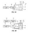
- FIGS. 5A-Bare schematic diagrams of an actuator based on a hydraulic piston.
- FIGS. 6A-Dare schematic diagrams of the rear door heat exchanger at retracted, intermediate and extended positions emphasizing the pivot coupling assemblies that couple the fin tubes to the supply and return manifolds.
- FIGS. 7A-Care diagrams of three types of pivot couplings that may be used in accordance with embodiments of the present invention.
- One embodiment of the present inventionprovides a rear door heat exchanger comprising a door frame have opposing first and second edges, a fluid supply manifold secured along the first edge of the door frame, a fluid return manifold secured along the second edge of the door frame, a fin tube assembly including a plurality of fin tubes extending across a central region of the rear door heat exchanger and forming an air flow pathway through the fin tube assembly, and an actuator for controllably moving the fin tube assembly from a retracted position to an extended position.
- the rear door heat exchangerfurther comprises a plurality of supply pipe coupling assemblies and a plurality of return pipe coupling assemblies, each supply pipe coupling assembly providing fluid communication from the fluid supply manifold to one of the plurality of fin tubes and each return pipe coupling assembly provide fluid communication from one of the plurality of fin tubes to the fluid return manifold.
- Each pipe coupling assemblypreferably includes cooling fins.
- aircan exit the rack through first and second side air flow pathways. Since the pipe coupling assemblies extend across the side air flow pathways, the cooling fins increase the cooling capacity of the rear door heat exchanger.
- a pipe coupling assemblyincludes three pipe joints and two rigid pipe sections. Accordingly, the pipe coupling assembly will fold and unfold in a controlled and repeatable manner without constricting the flow of cooling fluid within the pipe coupling assembly or getting in the way of the fin tube assembly when it retracts.
- each of the three pipe jointsmay be independently selected from a pivot coupling and a flexible tube.
- a non-limiting example of a pivot couplingincludes a housing and spherical member with a port through the spherical member, wherein a first pipe is coupled to the housing and a second pipe is coupled to the port of the spherical member such that fluid communication is provided from the first pipe through the housing and the port to the second pipe.
- a further embodiment of the rear door heat exchangerincludes a first sealing plate extending from a first edge of the fin tube assembly to the first edge of the door frame and a second sealing plate extending from a second edge of the fin tube assembly to the second edge of the door frame.
- the actuatoris a mechanical device responsible for moving the fin tube assembly back-and-forth between the retracted and expanded positions.
- the actuatormay take many forms, including, without limitation, a hydraulic cylinder or a motor and worm gear. Any number of actuators may be used. So that the fin tube assembly moves in a substantially translational rearward movement, the rear door heat exchanger will preferably include two actuators, and most preferably include four actuators located at each corner of the door frame.
- Embodiments of the rear door heat exchangermay further include a hinge secured to one edge of the door frame for attachment to a rack. Such a hinge allows rear access to the components within the rack.
- FIG. 1Further embodiments of the rear door heat exchanger may include a plurality of air-pressure sensors disposed across the fin tub assembly. Signals from the air pressure sensors may be provided to a rack management entity to determine when the air pressure is high enough to require extending the fin tube assembly so that an additional amount of air can be cooled. The additional cooling capacity provided in the extended position will reduce the air pressure on the rack side of the fin tube assembly. The lower air pressure will reduce the likelihood of hot exhaust air back flowing into any of the components in the rack. Components with low air flow fans are the most vulnerable to hot exhaust air backflow causing damaging component temperatures.
- Another embodiment of the present inventionprovides a method comprising flowing a liquid through a plurality of supply pipe couplings to a fin tube assembly of an air-to-liquid heat exchanger and through the fin tube assembly to a plurality of return pipe couplings, wherein the fin tube assembly forms a central air flow pathway.
- the methodfurther comprises passing air through components within a rack secured to the rear door heat exchanger and through the fin tube assembly and detecting an operating condition within the rack.
- the methodthen automatically moves the fin tube assembly from a retracted position to an extended position in response to the operating condition exceeding an operating condition threshold, wherein the retracted position of the fin tube assembly directs substantially all of the air to exit the rack through the central air flow pathway, and wherein the extended position of the fin tube assembly allows the air to exit the rack through the central air flow pathway and also through first and second side air flow pathways.
- Moving the fin tube assembly from the retracted position to the extended positioncauses the plurality of supply pipe couplings to extend across the first side air flow pathway and the plurality of return pipe couplings to extend across the second side air flow pathway.
- the plurality of supply pipe couplingsinclude one or more fin tube sections for cooling the air that exits the rack through the first side air flow pathway and the plurality of return pipe couplings include one or more fin tube sections for cooling the air that exits the rack through the second side air flow pathway.
- the step of automatically moving the fin tube assemblymay include actuating a hydraulic cylinder secured between a door frame and the fin tube assembly.
- Yet another embodiment of the methodmay include sealing a plate between the fin tube assembly and a door frame when the fin tube assembly is in the retracted position.
- Embodiments of the methodinclude detecting an operating condition within the rack.
- thismay include an air pressure sensor detecting an air pressure within the rack.
- the methodmay include providing air pressure signals from the air pressure sensors to a management entity, and sending a control signal from the management entity to the actuator.
- detecting an operating condition within the rackmay include detecting a temperature of one or more computer system components within the rack. Therefore, temperature signals may be provided from a temperature sensor to a management entity, and the management entity may provide a control signal to the actuator.
- FIG. 1is a perspective view of a computer system rack 10 having a rear door heat exchanger 20 .
- Components 12such as servers and switches are organized and operated within the rack 10 . Operation of the components 12 generates heat that must be removed to avoid damage to the components.
- Fans within the components or subchassis in the rack 10draw air (illustrated as wavy arrows) in the front of the components and the air is heated as it passes through the rack cooling the components. The host air then exits the rack through the rear door heat exchanger 20 , which cools the air.
- FIG. 2is a schematic side view of the computer system rack 10 having the rear door heat exchanger 20 .
- a fan 14is shown in each of the components 12 for generating the air flow through the rack from front to back (left to right as shown in FIG. 2 ).
- the rack 10includes an open air space or gap 16 downstream of the components 12 and just upstream of the rear door heat exchanger 20 .
- the rear door heat exchanger 20has a fin tube assembly 30 that provides air-to-liquid cooling.
- the rack 10typically contains a plurality of computing devices 12 , which may be, for example, servers, switches, power supplies, storage devices, and management modules. These computing devices typically have one or more on-board fan 14 to draw cool air into a housing and across heat-generating components within the housing before the warmed exhaust air is released to the rear of the housing.
- the fanscause an increase in air pressure near the outlet of the fans along the rear gap 16 of the rack.
- the high pressure air in the rear of the rackwill escape through one or more paths of least resistance. Most of the air passes through the rear door heat exchanger 20 .
- the present inventionrecognizes that the fin tube structure of the rear door heat exchanger has some impedance to air flow.
- the air pressure in the rear of the racki.e., the “rack side” of the rear door heat exchanger
- This higher air pressurecan have the negative effect of causing a loss of cooling air flow and perhaps also backflow of warmed exhaust air affecting one or more of the computing devices.
- These negative effectsare most likely to have an impact on computing devices having weaker fans or lower air flow output, such as may be measured in cubic feet per minute (CFM).
- CFMcubic feet per minute
- computing devices that have high-CFM fanscan force warmed exhaust air to backflow into other computing devices that have low-CFM fans.
- computing devices with the lowest airflow among the computing devices of a given rackmay be at risk of overheating when the total airflow through the rack exceeds the air flow capacity of the rear door heat exchanger.
- FIG. 3is an elevation view of the of rear door heat exchanger 20 .
- the rear door heat exchanger 20includes a door frame 22 having a first edge 21 and an opposing second edge 23 .
- a set of four actuators 24are secured to the door frame 22 and are used to controllably move the fin tube assembly 30 from a retracted position to an extended position, as described in greater detail below in reference to FIGS. 4A-B .
- a fluid supply manifold 25is secured along the first edge 21 of the door frame 22 and is coupled to a fluid supply hose 27 , preferably along the lower edge of the door 20 .
- a fluid return manifold 26is secured along the second edge 23 of the door frame 20 and is coupled to a fluid return hose 28 , preferably also along the lower edge of the door 20 .
- the fin tube assembly 30is located in a central region of the door 20 and forms a central air pathway for air to exit a rack.
- the fin tube assembly 30includes a plurality of fin tubes 32 extending across the central region.
- Each fin tube 32has a thermally conductive fluid conduit 34 and a large number of thermally conductive fins 36 extending in all directions surrounding the fluid conduit 34 .
- the fin tubes 32are preferably arranged in a pattern such that the fins 36 of one fin tube 32 are immediate adjacent or touching the fins 36 of an adjacent fin tube 32 . As shown, the fin tubes 32 may be arranged horizontally and in parallel with each other.
- Airis able to pass between the fins 36 , such that the air comes in contact with the fins 36 and transfers heat to the fins 36 and the outer surface of the fluid conduit 34 . As heat is transferred to the fin tubes 32 , the heat is then carried away in a cooling fluid that circulates through the fin tubes 32 .
- a plurality of supply pipe coupling assemblies 40 -Sprovide fluid communication from the fluid supply manifold 25 to the plurality of fin tubes 32 and a plurality of return pipe coupling assemblies 40 -R provide fluid communication from the plurality of fin tubes 32 to the fluid return manifold 26 .
- the supply and return pipe coupling assemblies 40 -S, 40 -Rare preferably mirror images of each other, and they may be described in greater detail in reference to FIGS. 6A-D , where they are referred to collectively as pipe coupling assemblies 40 . As shown in FIG.
- the cooling fluidfollows a pathway from the fluid supply hose 27 , through the fluid supply manifold 25 , through a plurality of parallel fluid pathways including a supply pipe coupling assembly 40 -S, a fin tube 32 and a return pipe coupling assembly 40 -R, to the fluid return manifold 26 , and out the fluid return hose 28 .
- FIGS. 4A-Bare schematic plan views of the rear door heat exchanger 20 in a retracted position and an extended position, respectively.
- a first actuator 24is secured to the first edge 21 of the door frame 22 (See FIG. 3 ) and a second actuator 24 is secured to the opposing second edge 23 of the door frame.
- Each of the actuators 24includes a rod 29 that is secured to a sealing plate 16 that is secured to the fin tube assembly 30 .
- the fin tube assembly 30is in the retracted position and the sealing plates 16 make contact with the first and second edges 21 , 23 of the door frame to prevent air passage there between. Therefore, air exiting the rack 10 may only flow through the fin tube assembly 30 .
- FIG. 4Athe fin tube assembly 30 is in the retracted position and the sealing plates 16 make contact with the first and second edges 21 , 23 of the door frame to prevent air passage there between. Therefore, air exiting the rack 10 may only flow through the fin tube assembly 30 .
- the actuator 24has its rod 29 extended such that the fin tube assembly 30 is in the extended position.
- air from the rack 10may still flow through the fin tube assembly 30 , but air may now also flow through the gaps between the sealing plates 16 and the first and second edges 21 , 23 of the door frame. These gaps may be referred to as side air pathways. Details of the fin tube assembly 30 and the pipe coupling assemblies 40 have been omitted from FIGS. 4A-B for clarity.
- FIGS. 5A-Bare schematic diagrams of an actuator 24 based on a hydraulic cylinder 50 .
- the hydraulic cylinder 50includes a piston 52 coupled to the rod 29 that extends through a sleeve 54 in the end of the cylinder 50 .
- a fluid supply or pump 56provides a pressurized fluid to the temperature or pressure switch 58 .
- the switch 58selectively directs the pressurized fluid through a first conduit 57 to a first side of the piston 52 so that the piston pushes the rod 29 to an extended position (as in FIG.
- the fluid supply or pump 56 , switch 58 , and hydraulic cylinder 50operate substantially as described in relation to FIG. 5A .
- the switch 58is controlled by a signal from a management entity 53 , which considers input signals from various temperature or pressure sensors 55 .
- a management entity 53which considers input signals from various temperature or pressure sensors 55 .
- These sensorsmay be placed throughout the rack and rear door heat exchanger, either as part of a computer component of the rack or as part of a dedicated control system for the rear door heat exchanger.
- pressure sensorsmay be spaced across the rack-side face of the fin tube assembly 30 (See FIG. 3 ).
- FIGS. 6A-Dare schematic diagrams of the rear door heat exchanger 20 at retracted ( FIG. 6A ), intermediate ( FIGS. 6B-C ), and extended ( FIG. 6D ) positions emphasizing the pivot coupling assemblies 40 that couple the fin tubes 32 to the supply manifold 25 and return manifold 26 .
- each pivot coupling assembly 40includes a first pivot coupling 41 secured to the manifold, a first fin tube 42 including fins 43 , a second pivot coupling 44 , a second fin tube 45 including fins 46 , and a third pivot coupling 47 secured to the fin tube 32 of the fin tube assembly 30 .
- the first, second and third pivot couplings 41 , 44 , 47allows the pivot coupling assemblies to bend as the fin tube assembly 30 is moved from the retracted position to the extended position through intermediate positions.
- the fin tube assembly 30is in a first intermediate position such that a small amount of air can exit the rack through side gaps or air pathways 60 .
- air passing through the side pathways 60passes through one of the pivot coupling assemblies 40 , such that the air is cooled by the first and second fin tubes 42 , 45 .
- the first, second and third pivot couplings 41 , 44 , 47allow a change in the angle between adjacent fin tube and conduit sections.
- the fin tube assembly 30is in a second intermediate position such that a somewhat greater amount of air (compared to FIG. 6B ) can exit the rack through side gaps or air pathways 60 . Air passing through the side pathways 60 still passes through one of the pivot coupling assemblies 40 , such that the air is cooled by the first and second fin tubes 42 , 45 . Note that the first, second and third pivot couplings 41 , 44 , 47 have allowed a further change in the angle between adjacent fin tube and conduit sections.
- FIG. 6Dthe fin tube assembly 30 is in the extended position such that a large amount of air (compared to FIG. 6C ) can exit the rack through side gaps or air pathways 60 . Air passing through the side pathways 60 still passes through one of the pivot coupling assemblies 40 , such that the air is cooled by the first and second fin tubes 42 , 45 . Note that the first, second and third pivot couplings 41 , 44 , 47 have allowed a further change in the angle between adjacent fin tube and conduit sections.
- FIG. 6Dillustrates the extended position of the fin tube assembly 30 , where the rear door heat exchanger 20 provides its maximum amount of cooling capacity (i.e., greatest amount of cooling surface area.
- FIGS. 6A-Drepresent the movement of the fin tube assembly 30 from the retracted position to the extended position. Movement from the extended position to the retracted position is the exact opposite. Both movements occur as the result of the forces imparted by the actuator 24 as described earlier in reference to FIGS. 4A-B .
- the pivot coupling assemblies 40support continuous fluid flow at any and all positions of the fin tube assembly 30 , and the fluid flow rate may be independently controlled.
- FIGS. 7A-Care diagrams of three types of pivot couplings that may be used in accordance with embodiments of the present invention.
- FIG. 7Ais a partial cross-sectional perspective view of two adjacent fin tube sections 72 , 74 coupled by a pivot coupling 76 .
- the pivot coupling 76includes a central channel 77 with a seat for securing a ball 78 .
- the ball 78includes its own central channel that is in fluid communication with the fin tube section 74 and is able to pivot within the seat.
- FIG. 7Bis a cross-sectional diagram of two adjacent fin tube sections 82 , 84 coupled by a pivot coupling 86 .
- the body of the coupling 86includes two seats for securing two balls 88 that pivot within the seats.
- a channel 87 between the two seatsallows the two adjacent fin tube sections 82 , 84 to achieve various angles while maintaining fluid communication.
- FIG. 7Cis a diagram of two adjacent fin tube sections 92 , 94 coupled by a pivot coupling that is made from a flexible hose 96 .
- the flexible hose 96may be secured to the fin tube sections 92 , 94 with hose clamps 98 .
- the present inventionmay be embodied as a system, method or computer program product. Accordingly, aspects of the present invention may take the form of an entirely hardware embodiment, an entirely software embodiment (including firmware, resident software, micro-code, etc.) or an embodiment combining software and hardware aspects that may all generally be referred to herein as a “circuit,” “module” or “system.” Furthermore, the present invention may take the form of a computer program product embodied in one or more computer-readable storage medium having computer-usable program code stored thereon.
- the computer-usable or computer-readable storage mediummay be, for example but not limited to, an electronic, magnetic, electromagnetic, or semiconductor apparatus or device. More specific examples (a non-exhaustive list) of the computer-readable medium include: a portable computer diskette, a hard disk, random access memory (RAM), read-only memory (ROM), an erasable programmable read-only memory (EPROM or Flash memory), a portable compact disc read-only memory (CD-ROM), an optical storage device, or a magnetic storage device.
- RAMrandom access memory
- ROMread-only memory
- EPROM or Flash memoryerasable programmable read-only memory
- CD-ROMcompact disc read-only memory
- optical storage deviceor a magnetic storage device.
- the computer-usable or computer-readable storage mediumcould even be paper or another suitable medium upon which the program is printed, as the program can be electronically captured via, for instance, optical scanning of the paper or other medium, then compiled, interpreted, or otherwise processed in a suitable manner, if necessary, and then stored in a computer memory.
- a computer-usable or computer-readable storage mediummay be any storage medium that can contain or store the program for use by a computer.
- Computer usable program code contained on the computer-usable storage mediummay be communicated by a propagated data signal, either in baseband or as part of a carrier wave.
- the computer usable program codemay be transmitted from one storage medium to another storage medium using any appropriate transmission medium, including but not limited to wireless, wireline, optical fiber cable, RF, etc.
- Computer program code for carrying out operations of the present inventionmay be written in any combination of one or more programming languages, including an object oriented programming language such as Java, Smalltalk, C++ or the like and conventional procedural programming languages, such as the “C” programming language or similar programming languages.
- the program codemay execute entirely on the user's computer, partly on the user's computer, as a stand-alone software package, partly on the user's computer and partly on a remote computer or entirely on the remote computer or server.
- the remote computermay be connected to the user's computer through any type of network, including a local area network (LAN) or a wide area network (WAN), or the connection may be made to an external computer (for example, through the Internet using an Internet Service Provider).
- LANlocal area network
- WANwide area network
- Internet Service Providerfor example, AT&T, MCI, Sprint, EarthLink, MSN, GTE, etc.
- These computer program instructionsmay also be stored in a computer-readable storage medium that can direct a computer or other programmable data processing apparatus to function in a particular manner, such that the instructions stored in the computer-readable storage medium produce an article of manufacture including instruction means which implement the function/act specified in the flowchart and/or block diagram block or blocks.
- the computer program instructionsmay also be loaded onto a computer or other programmable data processing apparatus to cause a series of operational steps to be performed on the computer or other programmable apparatus to produce a computer implemented process such that the instructions which execute on the computer or other programmable apparatus provide processes for implementing the functions/acts specified in the flowchart and/or block diagram block or blocks.
- each block in the flowchart or block diagramsmay represent a module, segment, or portion of code, which comprises one or more executable instructions for implementing the specified logical function(s).
- the functions noted in the blockmay occur out of the order noted in the figures.
- two blocks shown in successionmay, in fact, be executed substantially concurrently, or the blocks may sometimes be executed in the reverse order, depending upon the functionality involved.
- Each block of the block diagrams and/or flowchart illustration, and combinations of blocks in the block diagrams and/or flowchart illustrationcan be implemented by special purpose hardware-based systems that perform the specified functions or acts, or combinations of special purpose hardware and computer instructions.
Landscapes
- Engineering & Computer Science (AREA)
- Physics & Mathematics (AREA)
- Theoretical Computer Science (AREA)
- General Engineering & Computer Science (AREA)
- Human Computer Interaction (AREA)
- General Physics & Mathematics (AREA)
- Thermal Sciences (AREA)
- Microelectronics & Electronic Packaging (AREA)
- Computer Hardware Design (AREA)
- Cooling Or The Like Of Electrical Apparatus (AREA)
- Aviation & Aerospace Engineering (AREA)
Abstract
Description
Claims (6)
Priority Applications (1)
| Application Number | Priority Date | Filing Date | Title |
|---|---|---|---|
| US13/929,356US9507393B2 (en) | 2013-06-06 | 2013-06-27 | Dynamic surface area expansion in a rear door heat exchanger |
Applications Claiming Priority (2)
| Application Number | Priority Date | Filing Date | Title |
|---|---|---|---|
| US13/911,159US20140360696A1 (en) | 2013-06-06 | 2013-06-06 | Dynamic surface area expansion in a rear door heat exchanger |
| US13/929,356US9507393B2 (en) | 2013-06-06 | 2013-06-27 | Dynamic surface area expansion in a rear door heat exchanger |
Related Parent Applications (1)
| Application Number | Title | Priority Date | Filing Date |
|---|---|---|---|
| US13/911,159ContinuationUS20140360696A1 (en) | 2013-06-06 | 2013-06-06 | Dynamic surface area expansion in a rear door heat exchanger |
Publications (2)
| Publication Number | Publication Date |
|---|---|
| US20140362520A1 US20140362520A1 (en) | 2014-12-11 |
| US9507393B2true US9507393B2 (en) | 2016-11-29 |
Family
ID=52004464
Family Applications (2)
| Application Number | Title | Priority Date | Filing Date |
|---|---|---|---|
| US13/911,159AbandonedUS20140360696A1 (en) | 2013-06-06 | 2013-06-06 | Dynamic surface area expansion in a rear door heat exchanger |
| US13/929,356Active2035-06-05US9507393B2 (en) | 2013-06-06 | 2013-06-27 | Dynamic surface area expansion in a rear door heat exchanger |
Family Applications Before (1)
| Application Number | Title | Priority Date | Filing Date |
|---|---|---|---|
| US13/911,159AbandonedUS20140360696A1 (en) | 2013-06-06 | 2013-06-06 | Dynamic surface area expansion in a rear door heat exchanger |
Country Status (1)
| Country | Link |
|---|---|
| US (2) | US20140360696A1 (en) |
Cited By (6)
| Publication number | Priority date | Publication date | Assignee | Title |
|---|---|---|---|---|
| US20160044822A1 (en)* | 2013-04-04 | 2016-02-11 | Denso Corporation | Opening and closing control system and opening and closing control apparatus |
| US10203163B2 (en)* | 2014-10-17 | 2019-02-12 | Nec Platforms, Ltd | Cooling system and electronic device |
| US11076509B2 (en) | 2017-01-24 | 2021-07-27 | The Research Foundation for the State University | Control systems and prediction methods for it cooling performance in containment |
| US20210378124A1 (en)* | 2020-05-28 | 2021-12-02 | Baidu Usa Llc | Blind-mate connection design for liquid-cooled electronic racks |
| US20230137596A1 (en)* | 2021-11-02 | 2023-05-04 | Oracle International Corporation | Unified control of cooling in computers |
| US12108571B2 (en) | 2021-05-06 | 2024-10-01 | Rolls-Royce North American Technologies Inc. | Electronics cabinet cooling system |
Families Citing this family (10)
| Publication number | Priority date | Publication date | Assignee | Title |
|---|---|---|---|---|
| US10492341B2 (en)* | 2016-07-07 | 2019-11-26 | Commscope Technologies Llc | Modular data center |
| US10149411B2 (en)* | 2016-09-09 | 2018-12-04 | Seagate Technology Llc | Rack enclosure cooling systems and related methods |
| CN106604616A (en)* | 2017-01-04 | 2017-04-26 | 北京百度网讯科技有限公司 | Heat dissipation system and method of whole cabinet server system |
| DE202017100139U1 (en)* | 2017-01-12 | 2017-06-23 | Vacon Oy | door cooler |
| DE102018113806A1 (en)* | 2018-06-11 | 2019-12-12 | Vertiv Integrated Systems Gmbh | Equipment cabinet and method for operating a cooling device |
| CN109407775A (en)* | 2018-10-19 | 2019-03-01 | 合肥享淘科技有限公司 | A kind of computer hardware protective device |
| CA3153790A1 (en)* | 2019-09-23 | 2021-04-01 | Rittal Gmbh & Co. Kg | Switch cabinet arrangement with at least one it rack or switch cabinet housing and with at least one cooling unit, and a corresponding method |
| US11711905B2 (en)* | 2020-02-18 | 2023-07-25 | Nvidia Corporation | Heat sink with adjustable fin pitch |
| US11246241B1 (en)* | 2020-03-04 | 2022-02-08 | Amazon Technologies, Inc. | Movable media air handling unit |
| US20240040746A1 (en)* | 2022-08-01 | 2024-02-01 | Google Llc | Adapter And System For Thermal Management Of Computing Systems |
Citations (51)
| Publication number | Priority date | Publication date | Assignee | Title |
|---|---|---|---|---|
| US5467250A (en) | 1994-03-21 | 1995-11-14 | Hubbell Incorporated | Electrical cabinet with door-mounted heat exchanger |
| US6164369A (en) | 1999-07-13 | 2000-12-26 | Lucent Technologies Inc. | Door mounted heat exchanger for outdoor equipment enclosure |
| JP2004170040A (en) | 2002-11-22 | 2004-06-17 | Sahara Buresu Kogyo Kk | Ventilator |
| US7112131B2 (en) | 2003-05-13 | 2006-09-26 | American Power Conversion Corporation | Rack enclosure |
| US20060232945A1 (en)* | 2005-04-18 | 2006-10-19 | International Business Machines Corporation | Apparatus and method for facilitating cooling of an electronics rack employing a heat exchange assembly mounted to an outlet door cover of the electronics rack |
| US7170745B2 (en) | 2003-04-30 | 2007-01-30 | Hewlett-Packard Development Company, L.P. | Electronics rack having an angled panel |
| US7255640B2 (en) | 2002-10-11 | 2007-08-14 | Liebert Corporation | Cable and air management adapter system for enclosures housing electronic equipment |
| US7403391B2 (en) | 2004-12-29 | 2008-07-22 | American Power Conversion Corporation | Rack height cooling |
| US20080285228A1 (en)* | 2005-02-04 | 2008-11-20 | Knuerr Ag | Arrangement For Cooling Electronic Modular Units in Equipment and Network Cabinets |
| WO2009020668A1 (en)* | 2007-08-07 | 2009-02-12 | Cooligy Inc. | Internal access mechanism for a server rack |
| US20090080173A1 (en)* | 2007-09-25 | 2009-03-26 | International Business Machines Corporation | Vapor-compression heat exchange system with evaporator coil mounted to outlet door cover of an electronics rack |
| US20090100848A1 (en)* | 2007-10-22 | 2009-04-23 | Sanyo Electric Co., Ltd. | Electronic device cooling system and electronic device cooling apparatus |
| US20090120622A1 (en)* | 2006-03-09 | 2009-05-14 | Knuerr Ag | Heat Exchanger and Method For Cooling Network Cabinets |
| US20090150123A1 (en)* | 2007-12-05 | 2009-06-11 | International Business Machines Corporation | Method of laying out a data center using a plurality of thermal simulators |
| US20090154096A1 (en)* | 2007-12-17 | 2009-06-18 | International Business Machines Corporation | Apparatus and method for facilitating cooling of an electronics system |
| US20090188659A1 (en)* | 2008-01-27 | 2009-07-30 | International Business Machines Corporation | System and method for implementing a front door air to water heat exchanger |
| US20090201640A1 (en)* | 2008-02-13 | 2009-08-13 | International Business Machines Corporation | Noise-reducing attachment apparatus for heat exchanger door of an electronics rack of a data center |
| US20090205416A1 (en)* | 2008-02-15 | 2009-08-20 | International Business Machines Corporation | Monitoring method and system for determining rack airflow rate and rack power consumption |
| US20090225514A1 (en)* | 2008-03-10 | 2009-09-10 | Adrian Correa | Device and methodology for the removal of heat from an equipment rack by means of heat exchangers mounted to a door |
| US20090229194A1 (en) | 2008-03-11 | 2009-09-17 | Advanced Shielding Technologies Europe S.I. | Portable modular data center |
| US20090262501A1 (en)* | 2008-04-21 | 2009-10-22 | International Business Machines Corporation | Rack With Integrated Rear-Door Heat Exchanger |
| US20100147490A1 (en)* | 2008-12-11 | 2010-06-17 | International Business Machines Corporation | Apparatus and method for providing in situ cooling of computer data centers during service calls |
| US20100193175A1 (en) | 2009-02-05 | 2010-08-05 | International Business Machines Corporation | Heat Sink Apparatus with Extendable Pin Fins |
| US20110051372A1 (en)* | 2009-09-02 | 2011-03-03 | International Business Machines Corporation | Stress relieved hose routing to liquid-cooled electronics rack door |
| US20110069452A1 (en)* | 2009-09-23 | 2011-03-24 | International Business Machines Corporation | Apparatus and method for facilitating cooling of an electronics rack |
| US20110185758A1 (en)* | 2010-02-04 | 2011-08-04 | Hitachi Plant Technologies, Ltd. | Cooling system for electronic apparatus |
| US20110205705A1 (en)* | 2010-02-19 | 2011-08-25 | International Business Machines Corporation | Airflow recirculation and cooling apparatus and method for an electronics rack |
| US20110232889A1 (en)* | 2010-03-23 | 2011-09-29 | International Business Machines Corporation | Computer rack cooling using independently-controlled flow of coolants through a dual-section heat exchanger |
| US20110290448A1 (en)* | 2010-05-26 | 2011-12-01 | International Business Machines Corporation | Dehumidifying cooling apparatus and method for an electronics rack |
| US8144464B2 (en) | 2010-04-29 | 2012-03-27 | Brocade Communication Systems, Inc. | Side-exhaust cooling system with extensible duct for rack mounted equipment |
| US20120300398A1 (en)* | 2011-05-25 | 2012-11-29 | International Business Machines Corporation | Multi-rack, door-mounted heat exchanger |
| US20120298335A1 (en)* | 2011-05-25 | 2012-11-29 | International Business Machines Corporation | Air-cooling wall with slidable heat exchangers |
| US20130019627A1 (en)* | 2010-03-30 | 2013-01-24 | Nec Corporation | Cooling apparatus and cooling system for electronic-device exhaustion |
| US20130021746A1 (en)* | 2011-07-21 | 2013-01-24 | International Business Machines Corporation | Data center cooling with an air-side economizer and liquid-cooled electronics rack(s) |
| US20130098599A1 (en)* | 2011-10-19 | 2013-04-25 | International Business Machines Corporation | Independent computer system zone cooling responsive to zone power consumption |
| US20130107447A1 (en)* | 2011-10-31 | 2013-05-02 | International Business Machines Corporation | Multi-rack assembly with shared cooling apparatus |
| US20130105139A1 (en)* | 2011-10-31 | 2013-05-02 | International Business Machines Corporation | Multi-rack assembly with shared cooling unit |
| US8436246B1 (en)* | 2012-10-19 | 2013-05-07 | Calvary Applied Technologies, LLC | Refrigerant line electrical ground isolation device for data center cooling applications |
| US20130118712A1 (en)* | 2011-11-14 | 2013-05-16 | International Business Machines Corporation | Dual coil with adapter to move between redundant and non-redundant high performance heat exchanger |
| US20130133873A1 (en)* | 2011-11-29 | 2013-05-30 | International Business Machines Corporation | Direct facility coolant cooling of a rack-mounted heat exchanger |
| US20130166094A1 (en)* | 2011-12-21 | 2013-06-27 | International Business Machines Corporation | Operating efficiency of a rear door heat exchanger |
| US20130264026A1 (en)* | 2012-04-10 | 2013-10-10 | International Business Machines Corporation | Heat exchanger door for an electronics rack |
| US20130265719A1 (en)* | 2012-04-10 | 2013-10-10 | International Business Machines Corporation | Structural configuration of a heat exchanger door for an electronics rack |
| US20130264027A1 (en)* | 2012-04-10 | 2013-10-10 | International Business Machines Corporation | Process for optimizing a heat exchanger configuration |
| US20130306269A1 (en)* | 2012-05-21 | 2013-11-21 | Joerg Burkhard Helbig | Apparatus and methods for cooling rejected heat from server racks |
| US20130333414A1 (en)* | 2010-08-31 | 2013-12-19 | Kenichi Inaba | System for cooling electronic device |
| US20140133099A1 (en)* | 2012-11-12 | 2014-05-15 | International Business Machines Corporation | Air-cooling and vapor-condensing door assembly |
| US20140226280A1 (en)* | 2013-02-12 | 2014-08-14 | International Business Machines Corporation | Targeted cooling to specific overheating rack-mounted servers |
| US20140352107A1 (en)* | 2013-06-04 | 2014-12-04 | International Business Machines Corporation | Universal system for mounting rack doors |
| US20140355201A1 (en)* | 2013-05-28 | 2014-12-04 | International Business Machines Corporation | Protecting devices against hot air backflow in a computer system rack having a rear door heat exchanger |
| US9297571B1 (en)* | 2008-03-10 | 2016-03-29 | Liebert Corporation | Device and methodology for the removal of heat from an equipment rack by means of heat exchangers mounted to a door |
Family Cites Families (3)
| Publication number | Priority date | Publication date | Assignee | Title |
|---|---|---|---|---|
| US149842A (en)* | 1874-04-21 | Improvement in flexible-jointed metallic pipes for railroad-cars | ||
| US7233493B2 (en)* | 2004-08-10 | 2007-06-19 | E. I. Du Pont De Nemours And Company | Electronic device having a temperature control system including a ductwork assembly |
| US20090116186A1 (en)* | 2006-07-04 | 2009-05-07 | Fujitsu Limited | Cooling unit and electronic apparatus |
- 2013
- 2013-06-06USUS13/911,159patent/US20140360696A1/ennot_activeAbandoned
- 2013-06-27USUS13/929,356patent/US9507393B2/enactiveActive
Patent Citations (56)
| Publication number | Priority date | Publication date | Assignee | Title |
|---|---|---|---|---|
| US5467250A (en) | 1994-03-21 | 1995-11-14 | Hubbell Incorporated | Electrical cabinet with door-mounted heat exchanger |
| US6164369A (en) | 1999-07-13 | 2000-12-26 | Lucent Technologies Inc. | Door mounted heat exchanger for outdoor equipment enclosure |
| US7255640B2 (en) | 2002-10-11 | 2007-08-14 | Liebert Corporation | Cable and air management adapter system for enclosures housing electronic equipment |
| JP2004170040A (en) | 2002-11-22 | 2004-06-17 | Sahara Buresu Kogyo Kk | Ventilator |
| US7170745B2 (en) | 2003-04-30 | 2007-01-30 | Hewlett-Packard Development Company, L.P. | Electronics rack having an angled panel |
| US7112131B2 (en) | 2003-05-13 | 2006-09-26 | American Power Conversion Corporation | Rack enclosure |
| US7403391B2 (en) | 2004-12-29 | 2008-07-22 | American Power Conversion Corporation | Rack height cooling |
| US20080285228A1 (en)* | 2005-02-04 | 2008-11-20 | Knuerr Ag | Arrangement For Cooling Electronic Modular Units in Equipment and Network Cabinets |
| US20060232945A1 (en)* | 2005-04-18 | 2006-10-19 | International Business Machines Corporation | Apparatus and method for facilitating cooling of an electronics rack employing a heat exchange assembly mounted to an outlet door cover of the electronics rack |
| US20090120622A1 (en)* | 2006-03-09 | 2009-05-14 | Knuerr Ag | Heat Exchanger and Method For Cooling Network Cabinets |
| WO2009020668A1 (en)* | 2007-08-07 | 2009-02-12 | Cooligy Inc. | Internal access mechanism for a server rack |
| US7746634B2 (en) | 2007-08-07 | 2010-06-29 | Cooligy Inc. | Internal access mechanism for a server rack |
| US20090080173A1 (en)* | 2007-09-25 | 2009-03-26 | International Business Machines Corporation | Vapor-compression heat exchange system with evaporator coil mounted to outlet door cover of an electronics rack |
| US20090100848A1 (en)* | 2007-10-22 | 2009-04-23 | Sanyo Electric Co., Ltd. | Electronic device cooling system and electronic device cooling apparatus |
| US20090150123A1 (en)* | 2007-12-05 | 2009-06-11 | International Business Machines Corporation | Method of laying out a data center using a plurality of thermal simulators |
| US20090154096A1 (en)* | 2007-12-17 | 2009-06-18 | International Business Machines Corporation | Apparatus and method for facilitating cooling of an electronics system |
| US20090188659A1 (en)* | 2008-01-27 | 2009-07-30 | International Business Machines Corporation | System and method for implementing a front door air to water heat exchanger |
| US20090201640A1 (en)* | 2008-02-13 | 2009-08-13 | International Business Machines Corporation | Noise-reducing attachment apparatus for heat exchanger door of an electronics rack of a data center |
| US7646603B2 (en) | 2008-02-13 | 2010-01-12 | International Business Machines Corporation | Noise-reducing attachment apparatus for heat exchanger door of an electronics rack of a data center |
| US20090205416A1 (en)* | 2008-02-15 | 2009-08-20 | International Business Machines Corporation | Monitoring method and system for determining rack airflow rate and rack power consumption |
| US9297571B1 (en)* | 2008-03-10 | 2016-03-29 | Liebert Corporation | Device and methodology for the removal of heat from an equipment rack by means of heat exchangers mounted to a door |
| US20090225514A1 (en)* | 2008-03-10 | 2009-09-10 | Adrian Correa | Device and methodology for the removal of heat from an equipment rack by means of heat exchangers mounted to a door |
| US20090229194A1 (en) | 2008-03-11 | 2009-09-17 | Advanced Shielding Technologies Europe S.I. | Portable modular data center |
| US20090262501A1 (en)* | 2008-04-21 | 2009-10-22 | International Business Machines Corporation | Rack With Integrated Rear-Door Heat Exchanger |
| US20100147490A1 (en)* | 2008-12-11 | 2010-06-17 | International Business Machines Corporation | Apparatus and method for providing in situ cooling of computer data centers during service calls |
| US20100193175A1 (en) | 2009-02-05 | 2010-08-05 | International Business Machines Corporation | Heat Sink Apparatus with Extendable Pin Fins |
| US20110051372A1 (en)* | 2009-09-02 | 2011-03-03 | International Business Machines Corporation | Stress relieved hose routing to liquid-cooled electronics rack door |
| US20110069452A1 (en)* | 2009-09-23 | 2011-03-24 | International Business Machines Corporation | Apparatus and method for facilitating cooling of an electronics rack |
| US7990709B2 (en) | 2009-09-23 | 2011-08-02 | International Business Machines Corporation | Apparatus and method for facilitating cooling of an electronics rack |
| US20110185758A1 (en)* | 2010-02-04 | 2011-08-04 | Hitachi Plant Technologies, Ltd. | Cooling system for electronic apparatus |
| US20110205705A1 (en)* | 2010-02-19 | 2011-08-25 | International Business Machines Corporation | Airflow recirculation and cooling apparatus and method for an electronics rack |
| US20110232889A1 (en)* | 2010-03-23 | 2011-09-29 | International Business Machines Corporation | Computer rack cooling using independently-controlled flow of coolants through a dual-section heat exchanger |
| US20130019627A1 (en)* | 2010-03-30 | 2013-01-24 | Nec Corporation | Cooling apparatus and cooling system for electronic-device exhaustion |
| US8144464B2 (en) | 2010-04-29 | 2012-03-27 | Brocade Communication Systems, Inc. | Side-exhaust cooling system with extensible duct for rack mounted equipment |
| US20110290448A1 (en)* | 2010-05-26 | 2011-12-01 | International Business Machines Corporation | Dehumidifying cooling apparatus and method for an electronics rack |
| US20130333414A1 (en)* | 2010-08-31 | 2013-12-19 | Kenichi Inaba | System for cooling electronic device |
| US20120300398A1 (en)* | 2011-05-25 | 2012-11-29 | International Business Machines Corporation | Multi-rack, door-mounted heat exchanger |
| US20120298335A1 (en)* | 2011-05-25 | 2012-11-29 | International Business Machines Corporation | Air-cooling wall with slidable heat exchangers |
| US9314886B2 (en)* | 2011-05-25 | 2016-04-19 | Lenovo Enterprise Solutions (Singapore) Pte. Ltd. | Multi-rack, door-mounted heat exchanger |
| US20130021746A1 (en)* | 2011-07-21 | 2013-01-24 | International Business Machines Corporation | Data center cooling with an air-side economizer and liquid-cooled electronics rack(s) |
| US20130098599A1 (en)* | 2011-10-19 | 2013-04-25 | International Business Machines Corporation | Independent computer system zone cooling responsive to zone power consumption |
| US20130105139A1 (en)* | 2011-10-31 | 2013-05-02 | International Business Machines Corporation | Multi-rack assembly with shared cooling unit |
| US20130107447A1 (en)* | 2011-10-31 | 2013-05-02 | International Business Machines Corporation | Multi-rack assembly with shared cooling apparatus |
| US20130118712A1 (en)* | 2011-11-14 | 2013-05-16 | International Business Machines Corporation | Dual coil with adapter to move between redundant and non-redundant high performance heat exchanger |
| US20130133873A1 (en)* | 2011-11-29 | 2013-05-30 | International Business Machines Corporation | Direct facility coolant cooling of a rack-mounted heat exchanger |
| US20130166094A1 (en)* | 2011-12-21 | 2013-06-27 | International Business Machines Corporation | Operating efficiency of a rear door heat exchanger |
| US20130264026A1 (en)* | 2012-04-10 | 2013-10-10 | International Business Machines Corporation | Heat exchanger door for an electronics rack |
| US20130264027A1 (en)* | 2012-04-10 | 2013-10-10 | International Business Machines Corporation | Process for optimizing a heat exchanger configuration |
| US20130265719A1 (en)* | 2012-04-10 | 2013-10-10 | International Business Machines Corporation | Structural configuration of a heat exchanger door for an electronics rack |
| US20130306269A1 (en)* | 2012-05-21 | 2013-11-21 | Joerg Burkhard Helbig | Apparatus and methods for cooling rejected heat from server racks |
| US8436246B1 (en)* | 2012-10-19 | 2013-05-07 | Calvary Applied Technologies, LLC | Refrigerant line electrical ground isolation device for data center cooling applications |
| US20140133099A1 (en)* | 2012-11-12 | 2014-05-15 | International Business Machines Corporation | Air-cooling and vapor-condensing door assembly |
| US20140226280A1 (en)* | 2013-02-12 | 2014-08-14 | International Business Machines Corporation | Targeted cooling to specific overheating rack-mounted servers |
| US20140355201A1 (en)* | 2013-05-28 | 2014-12-04 | International Business Machines Corporation | Protecting devices against hot air backflow in a computer system rack having a rear door heat exchanger |
| US20140352107A1 (en)* | 2013-06-04 | 2014-12-04 | International Business Machines Corporation | Universal system for mounting rack doors |
| US9301413B2 (en)* | 2013-06-04 | 2016-03-29 | International Business Machines Corporation | Universal system for mounting rack doors |
Non-Patent Citations (8)
| Title |
|---|
| Grimshaw, J.; McSweeney, M.; Novotny, S. And Gagnon, M., "Data Center Rack Level Cooling Utilizing Water-Cooled, Passive Rear Door Heat Exchangers (RDHx) as a Cost Effective Alternative to Crah Air Cooling", Dec. 2011, Coolcentric®.* |
| IBM, "Rear Door Heat eXchanger, Planning Guide", Jul. 2008, IBM.* |
| Lawrence Berkeley National Laboratory/U.S. Dept. of Energy, "Data Center Rack Cooling with Rear-door Heat Exchanger, Technical Case-Study Bulletin", Jun. 2010.* |
| Lenovo®, "Rear Door Heat eXchanger V2", 2014, Lenovo®, document ID LYD03136-USEN-01.* |
| Vette Corp, "Coolcentric®, Rear Door Heat Exchanger: Planning Guide", 2011, Vette Corp., Part#104780 Rev D.* |
| Vette Thermal Solutions, LLC. , "Coolcentric®, Making Data Centers Sustainable", 2013, Pelham, NH, Vette Thermal Solutions, LLC.* |
| Vette Thermal Solutions, LLC. , "The Coolcentric® Family of Rear Door Heat Exchangers,", 2013, Pelham, NH, Vette Thermal Solutions, LLC.* |
| Vette Thermal Solutions, LLC. , "The Coolcentric® Sidecar", 2013, Pelham, NH, Vette Thermal Solutions, LLC.* |
Cited By (10)
| Publication number | Priority date | Publication date | Assignee | Title |
|---|---|---|---|---|
| US20160044822A1 (en)* | 2013-04-04 | 2016-02-11 | Denso Corporation | Opening and closing control system and opening and closing control apparatus |
| US10149404B2 (en)* | 2013-04-04 | 2018-12-04 | Denso Corporation | Opening and closing control system and opening and closing control apparatus |
| US10203163B2 (en)* | 2014-10-17 | 2019-02-12 | Nec Platforms, Ltd | Cooling system and electronic device |
| US11076509B2 (en) | 2017-01-24 | 2021-07-27 | The Research Foundation for the State University | Control systems and prediction methods for it cooling performance in containment |
| US11985802B2 (en) | 2017-01-24 | 2024-05-14 | The Research Foundation For The State University Of New York | Control systems and prediction methods for it cooling performance in containment |
| US20210378124A1 (en)* | 2020-05-28 | 2021-12-02 | Baidu Usa Llc | Blind-mate connection design for liquid-cooled electronic racks |
| US11388832B2 (en)* | 2020-05-28 | 2022-07-12 | Baidu Usa Llc | Blind-mate connection design for liquid-cooled electronic racks |
| US12108571B2 (en) | 2021-05-06 | 2024-10-01 | Rolls-Royce North American Technologies Inc. | Electronics cabinet cooling system |
| US20230137596A1 (en)* | 2021-11-02 | 2023-05-04 | Oracle International Corporation | Unified control of cooling in computers |
| US11729940B2 (en)* | 2021-11-02 | 2023-08-15 | Oracle International Corporation | Unified control of cooling in computers |
Also Published As
| Publication number | Publication date |
|---|---|
| US20140362520A1 (en) | 2014-12-11 |
| US20140360696A1 (en) | 2014-12-11 |
Similar Documents
| Publication | Publication Date | Title |
|---|---|---|
| US9507393B2 (en) | Dynamic surface area expansion in a rear door heat exchanger | |
| US10212857B2 (en) | Cooling system for a server | |
| US9699938B2 (en) | System and method for cooling information handling resources | |
| US9089078B2 (en) | Liquid cooling system for a server | |
| US9137930B2 (en) | Protecting devices against hot air backflow in a computer system rack having a rear door heat exchanger | |
| US10244665B2 (en) | Effectiveness-weighted control of cooling system components | |
| US7907406B1 (en) | System and method for standby mode cooling of a liquid-cooled electronics rack | |
| US8913384B2 (en) | Thermal transfer structures coupling electronics card(s) to coolant-cooled structure(s) | |
| US9313931B2 (en) | Multi-level redundant cooling method for continuous cooling of an electronic system(s) | |
| US9253921B2 (en) | Coolant-conditioning unit with automated control of coolant flow valves | |
| GB2496251A (en) | Multi-rack assembly with shared cooling apparatus | |
| JP5756573B2 (en) | Coolant manifold with separately rotatable manifold sections | |
| US9179574B2 (en) | Cooling unit for container-type data center | |
| US20130104383A1 (en) | Multi-rack assembly method with shared cooling unit | |
| GB2496020A (en) | System for cooling an electronics rack comprising a fluidly connected air-to-liquid heat exchanger and at least one cooling plate | |
| WO2008002380A2 (en) | Passive conductive cooling module | |
| US20180231295A1 (en) | Electronic apparatus and cooling method of electronic apparatus | |
| US9693483B2 (en) | Cooling device for heat-generating devices | |
| TWI687640B (en) | Cooling system amd coolant distribution module thereof | |
| WO2018000845A1 (en) | Flexible heat exchange unit, liquid cooling heat dissipation apparatus and liquid cooling heat dissipation system | |
| TWI809676B (en) | Closed-loop liquid cooling system and computer system | |
| CN107577317B (en) | Heat radiation joint and liquid cooling system | |
| JP7176643B2 (en) | Electronic device cooling device, water-cooled information processing device, and electronic device cooling method | |
| CN109511250B (en) | Heat dissipation device and electronic equipment | |
| CN113268128A (en) | Computer hardware assists heat abstractor |
Legal Events
| Date | Code | Title | Description |
|---|---|---|---|
| AS | Assignment | Owner name:INTERNATIONAL BUSINESS MACHINES CORPORATION, NEW Y Free format text:ASSIGNMENT OF ASSIGNORS INTEREST;ASSIGNORS:ALSHINNAWI, SHAREEF F.;CUDAK, GARY D.;SUFFERN, EDWARD S.;AND OTHERS;REEL/FRAME:030702/0686 Effective date:20130529 | |
| AS | Assignment | Owner name:LENOVO ENTERPRISE SOLUTIONS (SINGAPORE) PTE. LTD., SINGAPORE Free format text:ASSIGNMENT OF ASSIGNORS INTEREST;ASSIGNOR:INTERNATIONAL BUSINESS MACHINES CORPORATION;REEL/FRAME:034194/0111 Effective date:20140926 Owner name:LENOVO ENTERPRISE SOLUTIONS (SINGAPORE) PTE. LTD., Free format text:ASSIGNMENT OF ASSIGNORS INTEREST;ASSIGNOR:INTERNATIONAL BUSINESS MACHINES CORPORATION;REEL/FRAME:034194/0111 Effective date:20140926 | |
| FEPP | Fee payment procedure | Free format text:PAYOR NUMBER ASSIGNED (ORIGINAL EVENT CODE: ASPN); ENTITY STATUS OF PATENT OWNER: LARGE ENTITY | |
| STCF | Information on status: patent grant | Free format text:PATENTED CASE | |
| AS | Assignment | Owner name:LENOVO INTERNATIONAL LIMITED, HONG KONG Free format text:ASSIGNMENT OF ASSIGNORS INTEREST;ASSIGNOR:LENOVO ENTERPRISE SOLUTIONS (SINGAPORE) PTE LTD.;REEL/FRAME:050298/0505 Effective date:20170101 | |
| MAFP | Maintenance fee payment | Free format text:PAYMENT OF MAINTENANCE FEE, 4TH YEAR, LARGE ENTITY (ORIGINAL EVENT CODE: M1551); ENTITY STATUS OF PATENT OWNER: LARGE ENTITY Year of fee payment:4 | |
| MAFP | Maintenance fee payment | Free format text:PAYMENT OF MAINTENANCE FEE, 8TH YEAR, LARGE ENTITY (ORIGINAL EVENT CODE: M1552); ENTITY STATUS OF PATENT OWNER: LARGE ENTITY Year of fee payment:8 |