US9507270B2 - Vacuum system for immersion photolithography - Google Patents
Vacuum system for immersion photolithographyDownload PDFInfo
- Publication number
- US9507270B2 US9507270B2US14/469,389US201414469389AUS9507270B2US 9507270 B2US9507270 B2US 9507270B2US 201414469389 AUS201414469389 AUS 201414469389AUS 9507270 B2US9507270 B2US 9507270B2
- Authority
- US
- United States
- Prior art keywords
- liquid
- gas
- separator
- projection device
- separator chamber
- Prior art date
- Legal status (The legal status is an assumption and is not a legal conclusion. Google has not performed a legal analysis and makes no representation as to the accuracy of the status listed.)
- Expired - Fee Related, expires
Links
- 238000000206photolithographyMethods0.000titleclaimsabstractdescription16
- 238000007654immersionMethods0.000titledescription6
- 239000007788liquidSubstances0.000claimsabstractdescription55
- 239000012530fluidSubstances0.000claimsabstractdescription41
- 238000005086pumpingMethods0.000claimsabstractdescription32
- 239000012071phaseSubstances0.000claimsabstractdescription22
- 238000000605extractionMethods0.000claimsabstractdescription13
- 230000001105regulatory effectEffects0.000claimsabstractdescription11
- 239000007791liquid phaseSubstances0.000claimsabstractdescription5
- 238000000034methodMethods0.000claimsdescription21
- 230000001276controlling effectEffects0.000claimsdescription8
- 239000000203mixtureSubstances0.000claimsdescription7
- 230000005855radiationEffects0.000claimsdescription6
- 239000000758substrateSubstances0.000claims3
- 238000001459lithographyMethods0.000claims1
- 238000011144upstream manufacturingMethods0.000abstractdescription3
- XLYOFNOQVPJJNP-UHFFFAOYSA-NwaterSubstancesOXLYOFNOQVPJJNP-UHFFFAOYSA-N0.000description18
- 230000005540biological transmissionEffects0.000description4
- 230000008569processEffects0.000description4
- 239000000463materialSubstances0.000description3
- 230000003287optical effectEffects0.000description3
- 229920002120photoresistant polymerPolymers0.000description3
- 230000035945sensitivityEffects0.000description3
- 238000013461designMethods0.000description2
- 238000012423maintenanceMethods0.000description2
- 230000004044responseEffects0.000description2
- 229920006395saturated elastomerPolymers0.000description2
- 239000004065semiconductorSubstances0.000description2
- 238000000926separation methodMethods0.000description2
- 238000012546transferMethods0.000description2
- 238000010521absorption reactionMethods0.000description1
- 239000007864aqueous solutionSubstances0.000description1
- 230000008878couplingEffects0.000description1
- 238000010168coupling processMethods0.000description1
- 238000005859coupling reactionMethods0.000description1
- 230000007423decreaseEffects0.000description1
- 238000005137deposition processMethods0.000description1
- 239000000284extractSubstances0.000description1
- 238000000671immersion lithographyMethods0.000description1
- 238000004519manufacturing processMethods0.000description1
- 230000007246mechanismEffects0.000description1
- 238000012986modificationMethods0.000description1
- 230000004048modificationEffects0.000description1
- 238000010943off-gassingMethods0.000description1
- 238000005389semiconductor device fabricationMethods0.000description1
- 229910021642ultra pure waterInorganic materials0.000description1
- 239000012498ultrapure waterSubstances0.000description1
Images


Classifications
- G—PHYSICS
- G03—PHOTOGRAPHY; CINEMATOGRAPHY; ANALOGOUS TECHNIQUES USING WAVES OTHER THAN OPTICAL WAVES; ELECTROGRAPHY; HOLOGRAPHY
- G03F—PHOTOMECHANICAL PRODUCTION OF TEXTURED OR PATTERNED SURFACES, e.g. FOR PRINTING, FOR PROCESSING OF SEMICONDUCTOR DEVICES; MATERIALS THEREFOR; ORIGINALS THEREFOR; APPARATUS SPECIALLY ADAPTED THEREFOR
- G03F7/00—Photomechanical, e.g. photolithographic, production of textured or patterned surfaces, e.g. printing surfaces; Materials therefor, e.g. comprising photoresists; Apparatus specially adapted therefor
- G03F7/20—Exposure; Apparatus therefor
- G—PHYSICS
- G03—PHOTOGRAPHY; CINEMATOGRAPHY; ANALOGOUS TECHNIQUES USING WAVES OTHER THAN OPTICAL WAVES; ELECTROGRAPHY; HOLOGRAPHY
- G03F—PHOTOMECHANICAL PRODUCTION OF TEXTURED OR PATTERNED SURFACES, e.g. FOR PRINTING, FOR PROCESSING OF SEMICONDUCTOR DEVICES; MATERIALS THEREFOR; ORIGINALS THEREFOR; APPARATUS SPECIALLY ADAPTED THEREFOR
- G03F7/00—Photomechanical, e.g. photolithographic, production of textured or patterned surfaces, e.g. printing surfaces; Materials therefor, e.g. comprising photoresists; Apparatus specially adapted therefor
- G03F7/70—Microphotolithographic exposure; Apparatus therefor
- G03F7/708—Construction of apparatus, e.g. environment aspects, hygiene aspects or materials
- G03F7/70858—Environment aspects, e.g. pressure of beam-path gas, temperature
- G—PHYSICS
- G03—PHOTOGRAPHY; CINEMATOGRAPHY; ANALOGOUS TECHNIQUES USING WAVES OTHER THAN OPTICAL WAVES; ELECTROGRAPHY; HOLOGRAPHY
- G03F—PHOTOMECHANICAL PRODUCTION OF TEXTURED OR PATTERNED SURFACES, e.g. FOR PRINTING, FOR PROCESSING OF SEMICONDUCTOR DEVICES; MATERIALS THEREFOR; ORIGINALS THEREFOR; APPARATUS SPECIALLY ADAPTED THEREFOR
- G03F7/00—Photomechanical, e.g. photolithographic, production of textured or patterned surfaces, e.g. printing surfaces; Materials therefor, e.g. comprising photoresists; Apparatus specially adapted therefor
- G03F7/70—Microphotolithographic exposure; Apparatus therefor
- G03F7/70216—Mask projection systems
- G03F7/70341—Details of immersion lithography aspects, e.g. exposure media or control of immersion liquid supply
- B—PERFORMING OPERATIONS; TRANSPORTING
- B01—PHYSICAL OR CHEMICAL PROCESSES OR APPARATUS IN GENERAL
- B01D—SEPARATION
- B01D57/00—Separation, other than separation of solids, not fully covered by a single other group or subclass, e.g. B03C
- G—PHYSICS
- G03—PHOTOGRAPHY; CINEMATOGRAPHY; ANALOGOUS TECHNIQUES USING WAVES OTHER THAN OPTICAL WAVES; ELECTROGRAPHY; HOLOGRAPHY
- G03F—PHOTOMECHANICAL PRODUCTION OF TEXTURED OR PATTERNED SURFACES, e.g. FOR PRINTING, FOR PROCESSING OF SEMICONDUCTOR DEVICES; MATERIALS THEREFOR; ORIGINALS THEREFOR; APPARATUS SPECIALLY ADAPTED THEREFOR
- G03F7/00—Photomechanical, e.g. photolithographic, production of textured or patterned surfaces, e.g. printing surfaces; Materials therefor, e.g. comprising photoresists; Apparatus specially adapted therefor
- G03F7/70—Microphotolithographic exposure; Apparatus therefor
- G03F7/708—Construction of apparatus, e.g. environment aspects, hygiene aspects or materials
- G03F7/70808—Construction details, e.g. housing, load-lock, seals or windows for passing light in or out of apparatus
- G03F7/70841—Constructional issues related to vacuum environment, e.g. load-lock chamber
Definitions
- This inventionrelates to a vacuum system for extracting a multi-phase fluid, and more particularly for extracting a multi-phase fluid from an immersion photolithography exposure tool.
- Photolithographyis an important process step in semiconductor device fabrication.
- a circuit designis transferred to a wafer through a pattern imaged onto a photoresist layer deposited on the wafer surface.
- the waferthen undergoes various etch and deposition processes before a new design is transferred to the wafer surface. This cyclical process continues, building up multiple layers of the semiconductor device.
- the minimum feature that may be printed using photolithographyis determined by the resolution limit W, which is defined by the Rayleigh equation as:
- Wk 1 ⁇ ⁇ NA ( 1 )
- k 1is the resolution factor
- ⁇is the wavelength of the exposing radiation
- NAis the numerical aperture
- NAn sin ⁇ (2)
- Immersion photolithographyis a known technique for improving optical resolution by increasing the value of NA.
- a liquid 10 having a refractive index n>1is placed between the lower surface of the objective lens 12 of a projection device 14 and the upper surface of a wafer 16 located on a moveable wafer stage 18 .
- the liquid placed between lens 12 and wafer 16should, ideally, have a low optical absorption at 193 nm, be compatible with the lens material and the photoresist deposited on the wafer surface, and have good uniformity.
- ultra-pure, degassed waterwhich has a refractive index n ⁇ 1.44.
- the increased value of nin comparison to a technique where the medium between lens and wafer is CDA, increases the value of NA, which in turn decreases the resolution limit W, enabling smaller features to be reproduced.
- the lens and wafercould be immersed in a bath of water supported by the wafer stage, with a pump used to recirculate the water within the bath.
- this techniqueis generally considered undesirable.
- An alternative techniqueis to use a nozzle or showerhead device 20 connected to a water source and a vacuum system, shown generally at 22 , to produce a localized stream of ultra-pure, degassed water between the lens 12 and the wafer 16 .
- a vacuum systemshown generally at 22
- the vacuum system 22extracts from the tool a multi-phase mixture of water and CDA.
- the present inventionprovides a system for extracting a stream of multi-phase fluid from a photo-lithography tool, the system comprising a pumping arrangement for drawing the fluid from the tool, separating means located upstream from the pumping arrangement for separating the fluid drawn from the tool into gas and liquid phases, the pumping arrangement comprising a first pumping unit for extracting gas from the separating means and a second pumping unit for extracting liquid from the separating means, and a pressure control system for controlling the pressure within the separating means by regulating the amounts of gas and liquid therewithin.
- the pressure control systemcan maintain a substantially constant pressure in the separating means by regulating the amounts of liquid and gas within the separating means.
- the pressure control systempreferably comprises means for supplying gas to the separating means from a source thereof, and control means for controlling the flow of gas to the separating means.
- control meansfor controlling the flow of gas to the separating means.
- gascan be introduced into the separating means from the external source to compensate for such variations.
- the pressure control systemcomprises a variable flow control device, such as a butterfly or other control valve, through which gas is supplied to the separating means, with the control means being configured to vary the conductance of the valve to control the pressure within the separating means.
- a controllermay be configured to receive a signal indicative of the pressure within the separating means, and to control the conductance of the valve in dependence on the received signal.
- This signalmay be received from a pressure sensor, capacitance manometer or other form of sensor of sufficient sensitivity to achieve the required level of pressure control.
- the controlleris preferably configured to control the flow of gas from the separating means in dependence on the received signal.
- another variable flow control devicemay be provided, through which gas is extracted from the tank by the first pumping unit, with the controller being configured to control the conductance of this variable flow control device.
- the pressure control systempreferably comprises means for supplying liquid to the separating means from a source thereof, and control means for controlling the flow of liquid to the separating means.
- control meansfor controlling the flow of liquid to the separating means.
- the control meansis preferably configured to maintain a substantially constant level of liquid within the separating means.
- the liquid supply meanscomprises a variable flow control device such as a butterfly or other control valve, through which liquid is supplied to the separating means, with the control means being configured to vary the conductance of the valve to control the level of liquid within the separating means.
- a controllermay be configured to receive a signal indicative of the level of liquid within the separating means, and to control the conductance of the valve in dependence on the received signal.
- This signalmay be received from a level meter, float detector, or other form of sensor of sufficient sensitivity to allow a substantially constant level of liquid to be maintained within the separating means.
- One or more flexible tubesare preferably used to convey fluid (single and/or multi-phase) between the components of the system.
- a flexible tubemay be used to convey the multi-phase fluid to the separating means.
- Further flexible tubesmay also be used to convey the single phase streams from the separating means to respective pumping units. This can minimize the transmission of vibrations generated during use of the system back to the fluid within the tool.
- a method for extracting a stream of multi-phase fluid from a photo-lithography toolcomprising the steps of: connecting a pumping arrangement to the tool via an extraction tank; operating the pumping arrangement to draw the fluid from the tool; separating the fluid drawn from the tool into gas and liquid phases within the extraction tank, the pumping arrangement extracting separately gas and liquid from the extraction tank; and controlling the pressure within the extraction tank by regulating the amounts of gas and liquid therewithin.
- FIG. 1schematically illustrates a known system for immersion photolithography
- FIG. 2schematically illustrates the present invention vacuum system for extracting a multi-phase fluid from an immersion photolithography tool.
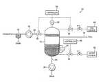
- a system 30 for extracting a multi-phase fluid from an immersion photolithography toolcomprises a separating means depicted for purposes of illustration as an extraction tank 32 for receiving the multi-stream fluid drawn from the tool by a pumping arrangement located downstream from the tank 32 .
- the tank 32is connected to the tool by flexible tubing 34 so as to minimize the amount of mechanical coupling between the system 30 and the tool, and thereby minimize the transmission of vibrations generated during use of the system 30 back to the tool.
- the tank 32is configured to separate the liquid and gas phases within the fluid received from the tool.
- the fluid received from the toolcomprises a mixture of clean dry air (CDA) and ultra-pure water, and so the tank 32 contains any suitable material and/or structure for affecting the separation of the CDA from the water.
- the tank 32may be configured to separate a different liquid-gas mixture received from the tool.
- the liquidmay comprise an aqueous or non-aqueous solution, and the gas may be other than CDA.
- the pumping arrangementcomprises a first pumping unit 36 for extracting gas from the tank 32 , and a second pumping unit 38 for extracting liquid from the tank 32 .
- the first pumping unit 36may comprise any suitable pump for extracting the gas from the tank 32 , and is preferably chosen for compatibility with the gas extracted from the tank 32 , which is likely to be saturated with liquid vapour, for minimum transmission of pressure fluctuations back to the gas contained in the tank 32 , and for relatively long maintenance periods.
- the first pumping unit 36may conveniently comprise an air-powered ejector pump or a water-based liquid ring pump for extracting CDA from the tank 32 .
- the first pumping unit 36is connected to the tank using flexible tubing 40 .
- a separator vessel 42may be connected to the exhaust of the first pumping unit 36 , the vessel 42 containing any suitable material and/or structure for affecting the separation of water vapour from the CDA.
- the water extracted from the CDAis exhaust to a drain, and the CDA is vented to the atmosphere.
- the second pumping unit 38may comprise any suitable pump for extracting the liquid from the tank 32 , and is preferably chosen for compatibility with the liquid extracted from the tank 32 and for relatively long maintenance periods.
- the second pumping unit 38may conveniently comprise a water-powered ejector pump or a diaphragm pump for extracting water from the tank 32 .
- the second pumping unit 38is connected to the tank using flexible tubing 44 .
- the internal diameter of the flexible tubing 44may be chosen to restrict the flow rate of liquid from the tank 32 to the second pumping unit 38 .
- a fixed or variable flow restrictormay be located between the tank 32 and the second pumping unit 38 .
- the system 30includes a pressure control system for maintain a substantially constant pressure in the tank 32 . In this embodiment, this is achieved by regulating the amounts of liquid and gas within the tank 32 .
- the amount of liquid contained in the tank 32is maintained at a substantially constant level by a controller 46 , thereby maintaining a substantially constant volume of gas in the tank 32 .
- the controller 46is connected to a sensor 48 for detecting the amount of liquid with the tank 32 .
- the sensor 48may comprise, for example, a level meter, float meter or other form of suitable sensor.
- the sensor 48outputs a signal to the controller 46 indicative of the level of the liquid within the tank 32 .
- the controller 46outputs to a variable flow control device 50 located between the tank 32 and a pressurised external liquid source 52 connected to the tank 32 a signal which causes the device 50 to vary the flow of liquid, in this embodiment water, to the tank 32 .
- the device 50may be a butterfly or other control valve having a conductance that can be varied in dependence on, preferably in proportion to, the signal received from the controller 46 .
- the controller 46can compensate for any variation in the flow rate of fluid to the tank 32 from the tool and/or any variation in the rate of extraction of liquid from the tank 32 by the second pumping unit 38 , and thus maintain the liquid in the tank 32 at a substantially constant level.
- the controller 46may be arranged to process the signal received from the sensor 48 to compensate for any ripples generated in the surface of the liquid during use.
- any variations in the amount of gas contained in the multi-phase fluid received from the tank, and/or any in the rate of extraction of gas from the tank 32 by the first pumping unit 36 , and any temperature fluctuations within the tank 32could vary the pressure of the gas within the tank 32 , and impart pressure and flow fluctuations to the fluid in the tool.
- the pressure control systemis therefore configured to maintain a substantially constant pressure within the tank 32 by also regulating the amount of gas within the tank 32 .
- the pressure control systemcomprises a controller 54 connected to a sensor 56 for detecting the gas pressure with the tank 32 .
- the sensor 56may comprise, for example, a pressure sensor, a capacitance manometer or other form of sensor of sufficient sensitivity to achieve the required level of pressure control.
- the sensor 56outputs a signal to the controller 54 indicative of the gas pressure within the tank 32 .
- the controller 54outputs to a variable flow control device 58 located between the tank 32 and a pressurised external gas source 60 connected to the tank 32 a signal which causes the device 58 to vary the flow of gas, in this embodiment CDA, to the tank 32 .
- a further variable flow control device 62may be located between the tank 32 and the first pumping unit 36 and configured to receive a signal from the controller 54 to vary the flow of gas from the tank 32 .
- the devices 58 , 62may also be butterfly or other control valves having a conductance that can be varied in dependence on, preferably in proportion to, the signal received from the controller, 54 .
- the controller 54can maintain a substantially constant gas pressure within the tank 32 .
- System 30provides the capability of extracting a multi-phase fluid from the immersion lithography tool while minimizing any pressure fluctuations imparted thereby to the fluid within the tool.
Landscapes
- General Physics & Mathematics (AREA)
- Physics & Mathematics (AREA)
- Health & Medical Sciences (AREA)
- Engineering & Computer Science (AREA)
- Environmental & Geological Engineering (AREA)
- Epidemiology (AREA)
- Public Health (AREA)
- Toxicology (AREA)
- Atmospheric Sciences (AREA)
- Life Sciences & Earth Sciences (AREA)
- Chemical & Material Sciences (AREA)
- Chemical Kinetics & Catalysis (AREA)
- Exposure And Positioning Against Photoresist Photosensitive Materials (AREA)
- Exposure Of Semiconductors, Excluding Electron Or Ion Beam Exposure (AREA)
- Degasification And Air Bubble Elimination (AREA)
- Crystals, And After-Treatments Of Crystals (AREA)
- Physical Or Chemical Processes And Apparatus (AREA)
Abstract
Description
where k1is the resolution factor, λ is the wavelength of the exposing radiation and NA is the numerical aperture. In lithographic processes used in the manufacture of semiconductor devices, it is therefore advantageous to use radiation of very short wavelength in order to improve optical resolution so that very small features in the device may be accurately reproduced. Monochromatic visible light of various wavelengths have been used, and more recently radiation in the deep ultra violet (DUV) range has been used, including radiation at 193 nm as generated using an ArF excimer laser.
NA=n sin α (2)
Claims (21)
Priority Applications (4)
| Application Number | Priority Date | Filing Date | Title |
|---|---|---|---|
| US14/469,389US9507270B2 (en) | 2004-06-16 | 2014-08-26 | Vacuum system for immersion photolithography |
| US15/362,530US9857699B2 (en) | 2004-06-16 | 2016-11-28 | Vacuum system for immersion photolithography |
| US15/857,368US10168624B2 (en) | 2004-06-16 | 2017-12-28 | Vacuum system for immersion photolithography |
| US16/202,170US20190094715A1 (en) | 2004-06-16 | 2018-11-28 | Vacuum system for immersion photolithography |
Applications Claiming Priority (4)
| Application Number | Priority Date | Filing Date | Title |
|---|---|---|---|
| US10/869,191US7481867B2 (en) | 2004-06-16 | 2004-06-16 | Vacuum system for immersion photolithography |
| US12/340,326US8164734B2 (en) | 2004-06-16 | 2008-12-19 | Vacuum system for immersion photolithography |
| US13/187,166US8830440B2 (en) | 2004-06-16 | 2011-07-20 | Vacuum system for immersion photolithography |
| US14/469,389US9507270B2 (en) | 2004-06-16 | 2014-08-26 | Vacuum system for immersion photolithography |
Related Parent Applications (1)
| Application Number | Title | Priority Date | Filing Date |
|---|---|---|---|
| US13/187,166ContinuationUS8830440B2 (en) | 2004-06-16 | 2011-07-20 | Vacuum system for immersion photolithography |
Related Child Applications (1)
| Application Number | Title | Priority Date | Filing Date |
|---|---|---|---|
| US15/362,530ContinuationUS9857699B2 (en) | 2004-06-16 | 2016-11-28 | Vacuum system for immersion photolithography |
Publications (2)
| Publication Number | Publication Date |
|---|---|
| US20140362358A1 US20140362358A1 (en) | 2014-12-11 |
| US9507270B2true US9507270B2 (en) | 2016-11-29 |
Family
ID=32851367
Family Applications (7)
| Application Number | Title | Priority Date | Filing Date |
|---|---|---|---|
| US10/869,191Expired - Fee RelatedUS7481867B2 (en) | 2004-06-16 | 2004-06-16 | Vacuum system for immersion photolithography |
| US12/340,326Expired - Fee RelatedUS8164734B2 (en) | 2004-06-16 | 2008-12-19 | Vacuum system for immersion photolithography |
| US13/187,166Expired - Fee RelatedUS8830440B2 (en) | 2004-06-16 | 2011-07-20 | Vacuum system for immersion photolithography |
| US14/469,389Expired - Fee RelatedUS9507270B2 (en) | 2004-06-16 | 2014-08-26 | Vacuum system for immersion photolithography |
| US15/362,530Expired - LifetimeUS9857699B2 (en) | 2004-06-16 | 2016-11-28 | Vacuum system for immersion photolithography |
| US15/857,368Expired - LifetimeUS10168624B2 (en) | 2004-06-16 | 2017-12-28 | Vacuum system for immersion photolithography |
| US16/202,170AbandonedUS20190094715A1 (en) | 2004-06-16 | 2018-11-28 | Vacuum system for immersion photolithography |
Family Applications Before (3)
| Application Number | Title | Priority Date | Filing Date |
|---|---|---|---|
| US10/869,191Expired - Fee RelatedUS7481867B2 (en) | 2004-06-16 | 2004-06-16 | Vacuum system for immersion photolithography |
| US12/340,326Expired - Fee RelatedUS8164734B2 (en) | 2004-06-16 | 2008-12-19 | Vacuum system for immersion photolithography |
| US13/187,166Expired - Fee RelatedUS8830440B2 (en) | 2004-06-16 | 2011-07-20 | Vacuum system for immersion photolithography |
Family Applications After (3)
| Application Number | Title | Priority Date | Filing Date |
|---|---|---|---|
| US15/362,530Expired - LifetimeUS9857699B2 (en) | 2004-06-16 | 2016-11-28 | Vacuum system for immersion photolithography |
| US15/857,368Expired - LifetimeUS10168624B2 (en) | 2004-06-16 | 2017-12-28 | Vacuum system for immersion photolithography |
| US16/202,170AbandonedUS20190094715A1 (en) | 2004-06-16 | 2018-11-28 | Vacuum system for immersion photolithography |
Country Status (10)
| Country | Link |
|---|---|
| US (7) | US7481867B2 (en) |
| EP (1) | EP1756672B1 (en) |
| JP (3) | JP4772787B2 (en) |
| KR (2) | KR101151767B1 (en) |
| CN (2) | CN101794081B (en) |
| AT (1) | ATE464589T1 (en) |
| DE (1) | DE602005020619D1 (en) |
| GB (1) | GB0414967D0 (en) |
| TW (1) | TWI339131B (en) |
| WO (1) | WO2005124464A2 (en) |
Cited By (1)
| Publication number | Priority date | Publication date | Assignee | Title |
|---|---|---|---|---|
| US10438820B2 (en)* | 2016-12-12 | 2019-10-08 | Ebara Corporation | Substrate processing apparatus, discharge method, and program |
Families Citing this family (34)
| Publication number | Priority date | Publication date | Assignee | Title |
|---|---|---|---|---|
| WO2005006415A1 (en) | 2003-07-09 | 2005-01-20 | Nikon Corporation | Exposure apparatus and method for manufacturing device |
| KR101641011B1 (en)* | 2003-07-28 | 2016-07-19 | 가부시키가이샤 니콘 | Exposure apparatus, device producing method, and exposure apparatus controlling method |
| EP3223053A1 (en) | 2003-09-03 | 2017-09-27 | Nikon Corporation | Apparatus and method for providing fluid for immersion lithography |
| US8054448B2 (en) | 2004-05-04 | 2011-11-08 | Nikon Corporation | Apparatus and method for providing fluid for immersion lithography |
| WO2005119742A1 (en)* | 2004-06-04 | 2005-12-15 | Nikon Corporation | Exposure apparatus, exposure method, and device producing method |
| KR101178755B1 (en) | 2004-06-10 | 2012-08-31 | 가부시키가이샤 니콘 엔지니어링 | Exposure equipment, exposure method and device manufacturing method |
| US8717533B2 (en)* | 2004-06-10 | 2014-05-06 | Nikon Corporation | Exposure apparatus, exposure method, and method for producing device |
| US8508713B2 (en)* | 2004-06-10 | 2013-08-13 | Nikon Corporation | Exposure apparatus, exposure method, and method for producing device |
| US8373843B2 (en)* | 2004-06-10 | 2013-02-12 | Nikon Corporation | Exposure apparatus, exposure method, and method for producing device |
| US20070139628A1 (en)* | 2004-06-10 | 2007-06-21 | Nikon Corporation | Exposure apparatus, exposure method, and method for producing device |
| US7481867B2 (en)* | 2004-06-16 | 2009-01-27 | Edwards Limited | Vacuum system for immersion photolithography |
| US7701550B2 (en) | 2004-08-19 | 2010-04-20 | Asml Netherlands B.V. | Lithographic apparatus and device manufacturing method |
| US7379155B2 (en)* | 2004-10-18 | 2008-05-27 | Asml Netherlands B.V. | Lithographic apparatus and device manufacturing method |
| US7397533B2 (en) | 2004-12-07 | 2008-07-08 | Asml Netherlands B.V. | Lithographic apparatus and device manufacturing method |
| SG124351A1 (en) | 2005-01-14 | 2006-08-30 | Asml Netherlands Bv | Lithographic apparatus and device manufacturing method |
| US8692973B2 (en) | 2005-01-31 | 2014-04-08 | Nikon Corporation | Exposure apparatus and method for producing device |
| KR101513840B1 (en) | 2005-01-31 | 2015-04-20 | 가부시키가이샤 니콘 | Exposure apparatus and method for manufacturing device |
| US8018573B2 (en)* | 2005-02-22 | 2011-09-13 | Asml Netherlands B.V. | Lithographic apparatus and device manufacturing method |
| US7433016B2 (en) | 2005-05-03 | 2008-10-07 | Asml Netherlands B.V. | Lithographic apparatus and device manufacturing method |
| US8514365B2 (en)* | 2007-06-01 | 2013-08-20 | Asml Netherlands B.V. | Lithographic apparatus and device manufacturing method |
| US7924404B2 (en)* | 2007-08-16 | 2011-04-12 | Asml Netherlands B.V. | Lithographic apparatus and device manufacturing method |
| NL1036306A1 (en) | 2007-12-20 | 2009-06-23 | Asml Netherlands Bv | Lithographic apparatus and in-line cleaning apparatus. |
| NL2003226A (en)* | 2008-08-19 | 2010-03-09 | Asml Netherlands Bv | Lithographic apparatus, drying device, metrology apparatus and device manufacturing method. |
| JP2010098172A (en)* | 2008-10-17 | 2010-04-30 | Canon Inc | Liquid recovery device, exposure device and device manufacturing method |
| JP5001343B2 (en) | 2008-12-11 | 2012-08-15 | エーエスエムエル ネザーランズ ビー.ブイ. | Fluid extraction system, immersion lithographic apparatus, and method for reducing pressure fluctuations of an immersion liquid used in an immersion lithographic apparatus |
| NL2004820A (en) | 2009-06-30 | 2011-01-04 | Asml Netherlands Bv | Lithographic apparatus and a method of measuring flow rate in a two phase flow. |
| CA2733042A1 (en)* | 2010-03-01 | 2011-09-01 | Wavefront Technology Solutions Inc. | Method and apparatus for enhancing multiphase extraction of contaminants |
| US20120012191A1 (en)* | 2010-07-16 | 2012-01-19 | Nikon Corporation | Liquid recovery apparatus, exposure apparatus, liquid recovering method, device fabricating method, program, and storage medium |
| NL2009899A (en)* | 2011-12-20 | 2013-06-24 | Asml Netherlands Bv | A pump system, a carbon dioxide supply system, an extraction system, a lithographic apparatus and a device manufacturing method. |
| CN104035288A (en)* | 2014-06-05 | 2014-09-10 | 浙江大学 | Continuous gas-liquid separation device used for immersion type photoetching machine under negative-pressure environment |
| US10646836B2 (en)* | 2014-07-31 | 2020-05-12 | Shigenkaihatsukenkyujyo, Inc. | Cleaning apparatus |
| CN112684675B (en)* | 2020-12-30 | 2023-02-21 | 浙江启尔机电技术有限公司 | Vacuum system and immersion lithography machine using same |
| TW202439039A (en)* | 2023-03-21 | 2024-10-01 | 聯華電子股份有限公司 | Lithography system and method of detecting fluid leakage in liquid storage tank of the same |
| WO2024208512A1 (en) | 2023-04-04 | 2024-10-10 | Asml Netherlands B.V. | Fluid handling system and method, and method of manufacturing devices |
Citations (126)
| Publication number | Priority date | Publication date | Assignee | Title |
|---|---|---|---|---|
| US3314219A (en) | 1965-03-10 | 1967-04-18 | Bass Brothers Entpr Inc | Drilling mud degassers for oil wells |
| US3573975A (en) | 1968-07-10 | 1971-04-06 | Ibm | Photochemical fabrication process |
| US3648587A (en) | 1967-10-20 | 1972-03-14 | Eastman Kodak Co | Focus control for optical instruments |
| US3675395A (en) | 1970-10-09 | 1972-07-11 | Keene Corp | Apparatus for the purification of oils and the like |
| EP0023231A1 (en) | 1979-07-27 | 1981-02-04 | Tabarelli, Werner, Dr. | Optical lithographic method and apparatus for copying a pattern onto a semiconductor wafer |
| FR2474708A1 (en) | 1980-01-24 | 1981-07-31 | Dme | Micro:photo:lithographic process giving high line resolution - with application of immersion oil between mask and photosensitive layer before exposure |
| US4315760A (en) | 1980-01-17 | 1982-02-16 | Bij De Leij Jan D | Method and apparatus for degasing, during transportation, a confined volume of liquid to be measured |
| US4346164A (en) | 1980-10-06 | 1982-08-24 | Werner Tabarelli | Photolithographic method for the manufacture of integrated circuits |
| US4390273A (en) | 1981-02-17 | 1983-06-28 | Censor Patent-Und Versuchsanstalt | Projection mask as well as a method and apparatus for the embedding thereof and projection printing system |
| US4396705A (en) | 1980-09-19 | 1983-08-02 | Hitachi, Ltd. | Pattern forming method and pattern forming apparatus using exposures in a liquid |
| JPS58202448A (en) | 1982-05-21 | 1983-11-25 | Hitachi Ltd | exposure equipment |
| JPS5919912A (en) | 1982-07-26 | 1984-02-01 | Hitachi Ltd | Immersion distance holding device |
| DD206607A1 (en) | 1982-06-16 | 1984-02-01 | Mikroelektronik Zt Forsch Tech | METHOD AND DEVICE FOR ELIMINATING INTERFERENCE EFFECTS |
| US4466253A (en) | 1982-12-23 | 1984-08-21 | General Electric Company | Flow control at flash tank of open cycle vapor compression heat pumps |
| US4480910A (en) | 1981-03-18 | 1984-11-06 | Hitachi, Ltd. | Pattern forming apparatus |
| US4509852A (en) | 1980-10-06 | 1985-04-09 | Werner Tabarelli | Apparatus for the photolithographic manufacture of integrated circuit elements |
| DD221563A1 (en) | 1983-09-14 | 1985-04-24 | Mikroelektronik Zt Forsch Tech | IMMERSIONS OBJECTIVE FOR THE STEP-BY-STEP PROJECTION IMAGING OF A MASK STRUCTURE |
| DD224448A1 (en) | 1984-03-01 | 1985-07-03 | Zeiss Jena Veb Carl | DEVICE FOR PHOTOLITHOGRAPHIC STRUCTURAL TRANSMISSION |
| US4641679A (en) | 1983-12-30 | 1987-02-10 | Institute Francais Du Petrole | Feed device for a two-phase fluid pump and a hydrocarbon producing installation with such feed device |
| DD242880A1 (en) | 1983-01-31 | 1987-02-11 | Kuch Karl Heinz | DEVICE FOR PHOTOLITHOGRAPHIC STRUCTURAL TRANSMISSION |
| JPS6265326A (en) | 1985-09-18 | 1987-03-24 | Hitachi Ltd | Exposure device |
| JPS62121417A (en) | 1985-11-22 | 1987-06-02 | Hitachi Ltd | Immersion objective lens device |
| US4696684A (en) | 1985-06-13 | 1987-09-29 | Hanshi Shen | Method and apparatus for eliminating cavitation in hydraulic systems |
| US4704140A (en) | 1985-02-15 | 1987-11-03 | Oy Hackman Ab | Procedure and means for use in pumping and volumetry of foodstuff liquids |
| US4730634A (en) | 1986-06-19 | 1988-03-15 | Amoco Corporation | Method and apparatus for controlling production of fluids from a well |
| JPS63157419A (en) | 1986-12-22 | 1988-06-30 | Toshiba Corp | Fine pattern transfer apparatus |
| US4886530A (en) | 1987-10-28 | 1989-12-12 | Sundstrand Corporation | Single stage pump and separator for two phase gas and liquid mixtures |
| EP0418427A2 (en) | 1989-09-06 | 1991-03-27 | Eiichi Miyake | Exposure process |
| US5040020A (en) | 1988-03-31 | 1991-08-13 | Cornell Research Foundation, Inc. | Self-aligned, high resolution resonant dielectric lithography |
| JPH04305917A (en) | 1991-04-02 | 1992-10-28 | Nikon Corp | Close-contact exposure equipment |
| JPH04305915A (en) | 1991-04-02 | 1992-10-28 | Nikon Corp | Adhesion type exposure device |
| JPH0562877A (en) | 1991-09-02 | 1993-03-12 | Yasuko Shinohara | Optical system for lsi manufacturing contraction projection aligner by light |
| JPH06124873A (en) | 1992-10-09 | 1994-05-06 | Canon Inc | Immersion projection exposure system |
| EP0605103A1 (en) | 1992-11-27 | 1994-07-06 | Canon Kabushiki Kaisha | Projection apparatus for immersed exposure |
| JPH07132262A (en) | 1992-12-21 | 1995-05-23 | Tokyo Electron Ltd | Liquid treating device of immersion type |
| JPH07220990A (en) | 1994-01-28 | 1995-08-18 | Hitachi Ltd | Pattern forming method and exposure apparatus thereof |
| JPH08907A (en) | 1994-06-17 | 1996-01-09 | Miura Co Ltd | Degassing degree adjusting method in vacuum degassing |
| JPH08316125A (en) | 1995-05-19 | 1996-11-29 | Hitachi Ltd | Projection exposure method and exposure apparatus |
| US5715039A (en) | 1995-05-19 | 1998-02-03 | Hitachi, Ltd. | Projection exposure apparatus and method which uses multiple diffraction gratings in order to produce a solid state device with fine patterns |
| JPH10228661A (en) | 1997-02-14 | 1998-08-25 | Sony Corp | Master disk manufacturing aligner for optical recording medium |
| JPH10255319A (en) | 1997-03-12 | 1998-09-25 | Hitachi Maxell Ltd | Master exposure apparatus and method |
| US5825043A (en) | 1996-10-07 | 1998-10-20 | Nikon Precision Inc. | Focusing and tilting adjustment system for lithography aligner, manufacturing apparatus or inspection apparatus |
| JPH10303114A (en) | 1997-04-23 | 1998-11-13 | Nikon Corp | Immersion type exposure equipment |
| JPH10340846A (en) | 1997-06-10 | 1998-12-22 | Nikon Corp | Aligner, its manufacture, exposing method and device manufacturing method |
| US5900354A (en) | 1997-07-03 | 1999-05-04 | Batchelder; John Samuel | Method for optical inspection and lithography |
| JPH11176727A (en) | 1997-12-11 | 1999-07-02 | Nikon Corp | Projection exposure equipment |
| WO1999049504A1 (en) | 1998-03-26 | 1999-09-30 | Nikon Corporation | Projection exposure method and system |
| JP2000058436A (en) | 1998-08-11 | 2000-02-25 | Nikon Corp | Projection exposure apparatus and exposure method |
| US6033475A (en) | 1994-12-27 | 2000-03-07 | Tokyo Electron Limited | Resist processing apparatus |
| EP1039511A1 (en) | 1997-12-12 | 2000-09-27 | Nikon Corporation | Projection exposure method and projection aligner |
| JP2001091849A (en) | 1999-09-21 | 2001-04-06 | Olympus Optical Co Ltd | Immersion objective lens for microscope |
| US6236634B1 (en) | 1996-08-26 | 2001-05-22 | Digital Papyrus Corporation | Method and apparatus for coupling an optical lens to a disk through a coupling medium having a relatively high index of refraction |
| US20020020821A1 (en) | 2000-08-08 | 2002-02-21 | Koninklijke Philips Electronics N.V. | Method of manufacturing an optically scannable information carrier |
| JP2002257138A (en) | 2001-02-28 | 2002-09-11 | Canon Inc | Hydrostatic bearing device, and stage apparatus, exposure apparatus and device manufacturing method using the same |
| JP2002257137A (en) | 2001-02-27 | 2002-09-11 | Koyo Seiko Co Ltd | Magnetic bearing device |
| US20020163629A1 (en) | 2001-05-07 | 2002-11-07 | Michael Switkes | Methods and apparatus employing an index matching medium |
| US6560032B2 (en) | 2000-03-27 | 2003-05-06 | Olympus Optical Co., Ltd. | Liquid immersion lens system and optical apparatus using the same |
| US20030123040A1 (en) | 2001-11-07 | 2003-07-03 | Gilad Almogy | Optical spot grid array printer |
| US6600547B2 (en) | 2001-09-24 | 2003-07-29 | Nikon Corporation | Sliding seal |
| US6603130B1 (en) | 1999-04-19 | 2003-08-05 | Asml Netherlands B.V. | Gas bearings for use with vacuum chambers and their application in lithographic projection apparatuses |
| WO2003077037A1 (en) | 2002-03-08 | 2003-09-18 | Carl Zeiss Smt Ag | Refractive projection objective for immersion lithography |
| US6633365B2 (en) | 2000-12-11 | 2003-10-14 | Nikon Corporation | Projection optical system and exposure apparatus having the projection optical system |
| US20040000627A1 (en) | 2002-06-28 | 2004-01-01 | Carl Zeiss Semiconductor Manufacturing Technologies Ag | Method for focus detection and an imaging system with a focus-detection system |
| US6716268B2 (en) | 2000-01-17 | 2004-04-06 | Lattice Intellectual Property Ltd. | Slugging control |
| US20040069330A1 (en) | 1996-09-30 | 2004-04-15 | Rolfson J. Brett | Device addressing gas contamination in a wet process |
| US20040075895A1 (en) | 2002-10-22 | 2004-04-22 | Taiwan Semiconductor Manufacturing Co., Ltd. | Apparatus for method for immersion lithography |
| KR20040044119A (en) | 2002-11-12 | 2004-05-27 | 에이에스엠엘 네델란즈 비.브이. | Lithographic Apparatus and Device Manufacturing Method |
| KR20040047713A (en) | 2002-11-29 | 2004-06-05 | 에이에스엠엘 네델란즈 비.브이. | Lithographic Apparatus and Device Manufacturing Method |
| US20040109237A1 (en) | 2002-12-09 | 2004-06-10 | Carl Zeiss Smt Ag | Projection objective, especially for microlithography, and method for adjusting a projection objective |
| JP2004165666A (en) | 2002-11-12 | 2004-06-10 | Asml Netherlands Bv | Lithographic apparatus and device manufacturing method |
| US20040114117A1 (en) | 2002-11-18 | 2004-06-17 | Asml Netherlands B.V. | Lithographic apparatus and device manufacturing method |
| WO2004053956A1 (en) | 2002-12-10 | 2004-06-24 | Nikon Corporation | Exposure apparatus, exposure method and method for manufacturing device |
| WO2004053953A1 (en) | 2002-12-10 | 2004-06-24 | Nikon Corporation | Exposure apparatus and method for manufacturing device |
| WO2004053957A1 (en) | 2002-12-10 | 2004-06-24 | Nikon Corporation | Surface position detection apparatus, exposure method, and device porducing method |
| WO2004053951A1 (en) | 2002-12-10 | 2004-06-24 | Nikon Corporation | Exposure method, exposure apparatus and method for manufacturing device |
| WO2004053955A1 (en) | 2002-12-10 | 2004-06-24 | Nikon Corporation | Exposure system and device producing method |
| WO2004053950A1 (en) | 2002-12-10 | 2004-06-24 | Nikon Corporation | Exposure apparatus and method for manufacturing device |
| WO2004053958A1 (en) | 2002-12-10 | 2004-06-24 | Nikon Corporation | Exposure apparatus and method for manufacturing device |
| WO2004053596A2 (en) | 2002-12-10 | 2004-06-24 | Carl Zeiss Smt Ag | Method for adjusting a desired optical property of a positioning lens and microlithographic projection exposure system |
| US20040119954A1 (en) | 2002-12-10 | 2004-06-24 | Miyoko Kawashima | Exposure apparatus and method |
| WO2004053952A1 (en) | 2002-12-10 | 2004-06-24 | Nikon Corporation | Exposure apparatus and method for manufacturing device |
| WO2004053954A1 (en) | 2002-12-10 | 2004-06-24 | Nikon Corporation | Exposure apparatus and method for manufacturing device |
| WO2004053959A1 (en) | 2002-12-10 | 2004-06-24 | Nikon Corporation | Optical device and projection exposure apparatus using such optical device |
| US20040125351A1 (en) | 2002-12-30 | 2004-07-01 | Krautschik Christof Gabriel | Immersion lithography |
| WO2004055803A1 (en) | 2002-12-13 | 2004-07-01 | Koninklijke Philips Electronics N.V. | Liquid removal in a method and device for irradiating spots on a layer |
| WO2004057589A1 (en) | 2002-12-19 | 2004-07-08 | Koninklijke Philips Electronics N.V. | Method and device for irradiating spots on a layer |
| JP2004193252A (en) | 2002-12-10 | 2004-07-08 | Nikon Corp | Exposure method and device manufacturing method |
| WO2004057590A1 (en) | 2002-12-19 | 2004-07-08 | Koninklijke Philips Electronics N.V. | Method and device for irradiating spots on a layer |
| US20040154641A1 (en) | 2002-05-17 | 2004-08-12 | P.C.T. Systems, Inc. | Substrate processing apparatus and method |
| US20040160582A1 (en) | 2002-11-12 | 2004-08-19 | Asml Netherlands B.V. | Lithographic apparatus and device manufacturing method |
| US20040165159A1 (en) | 2002-11-12 | 2004-08-26 | Asml Netherlands B.V. | Lithographic apparatus and device manufacturing method |
| JP2004282023A (en) | 2002-12-10 | 2004-10-07 | Nikon Corp | Exposure apparatus and device manufacturing method |
| WO2004019128A3 (en) | 2002-08-23 | 2004-10-28 | Nippon Kogaku Kk | Projection optical system and method for photolithography and exposure apparatus and method using same |
| US20040211920A1 (en) | 2002-11-12 | 2004-10-28 | Asml Netherlands B.V. | Lithographic apparatus and device manufacturing method |
| EP1486827A2 (en) | 2003-06-11 | 2004-12-15 | ASML Netherlands B.V. | Lithographic apparatus and device manufacturing method |
| EP1489462A2 (en) | 2003-06-19 | 2004-12-22 | ASML Holding N.V. | Immersion photolithography system comprising microchannel nozzles |
| EP1491957A2 (en) | 2003-06-27 | 2004-12-29 | ASML Holding N.V. | Immersion photolithography apparatus with projection system positioned below the substrate |
| WO2005006415A1 (en) | 2003-07-09 | 2005-01-20 | Nikon Corporation | Exposure apparatus and method for manufacturing device |
| JP2005057278A (en) | 2003-07-31 | 2005-03-03 | Asml Netherlands Bv | Lithography equipment and device manufacturing method |
| JP2005101488A (en) | 2002-12-10 | 2005-04-14 | Nikon Corp | Aligner, exposure method, and manufacturing method of device |
| EP1528433A2 (en) | 2003-10-28 | 2005-05-04 | ASML Netherlands B.V. | Lithographic apparatus |
| US20050110973A1 (en) | 2003-11-24 | 2005-05-26 | Asml Netherlands B.V. | Lithographic apparatus and device manufacturing method |
| US20050134815A1 (en) | 2003-12-23 | 2005-06-23 | Asml Netherlands B.V. | Lithographic apparatus and device manufacturing method |
| US20050134817A1 (en) | 2003-06-25 | 2005-06-23 | Takashi Nakamura | Liquid immersion type exposure apparatus |
| US20050132914A1 (en) | 2003-12-23 | 2005-06-23 | Asml Netherlands B.V. | Lithographic apparatus, alignment apparatus, device manufacturing method, and a method of converting an apparatus |
| JP2005175176A (en) | 2003-12-11 | 2005-06-30 | Nikon Corp | Exposure method and device manufacturing method |
| US20050140948A1 (en) | 2003-12-26 | 2005-06-30 | Canon Kabushiki Kaisha | Exposure apparatus and method |
| JP2005191344A (en) | 2003-12-26 | 2005-07-14 | Nikon Corp | Exposure apparatus and device manufacturing method |
| WO2005015315A3 (en) | 2003-07-24 | 2005-09-09 | Zeiss Carl Smt Ag | Microlithographic projection exposure system, and method for introducing an immersion liquid into an immersion chamber |
| WO2005024517A3 (en) | 2003-09-03 | 2005-09-29 | Nikon Res Corp Of America | Apparatus and method for providing fluid for immersion lithography |
| JP2005268759A (en) | 2004-02-19 | 2005-09-29 | Nikon Corp | Optical component and exposure apparatus |
| JP2005277363A (en) | 2003-05-23 | 2005-10-06 | Nikon Corp | Exposure apparatus and device manufacturing method |
| US6954256B2 (en) | 2003-08-29 | 2005-10-11 | Asml Netherlands B.V. | Gradient immersion lithography |
| US20050225734A1 (en) | 2004-04-08 | 2005-10-13 | Asml Netherlands B.V. | Lithographic apparatus and device manufacturing method |
| WO2005122221A1 (en) | 2004-06-10 | 2005-12-22 | Nikon Corporation | Exposure equipment, exposure method and device manufacturing method |
| US20060038968A1 (en) | 2004-08-19 | 2006-02-23 | Asml Netherlands B.V. | Lithographic apparatus and device manufacturing method |
| US20060082746A1 (en) | 2004-10-18 | 2006-04-20 | Asml Netherlands B.V. | Lithographic apparatus and device manufacturing method |
| US7053983B2 (en) | 2003-09-04 | 2006-05-30 | Canon Kabushiki Kaisha | Liquid immersion type exposure apparatus |
| WO2005111722A3 (en) | 2004-05-04 | 2006-06-15 | Nippon Kogaku Kk | Apparatus and method for providing fluid for immersion lithography |
| JP2006165500A (en) | 2004-06-10 | 2006-06-22 | Nikon Corp | Exposure apparatus, exposure method, and device manufacturing method |
| US7125438B2 (en) | 2000-09-29 | 2006-10-24 | Tetra Laval Holdings & Finance S.A. | Method and an apparatus for continuously deaerating a liquid |
| US20070139628A1 (en) | 2004-06-10 | 2007-06-21 | Nikon Corporation | Exposure apparatus, exposure method, and method for producing device |
| US20070195301A1 (en) | 2004-06-10 | 2007-08-23 | Nikon Corporation | Exposure apparatus, exposure method, and method for producing device |
| US20070222957A1 (en) | 2004-06-10 | 2007-09-27 | Nikon Corporation | Exposure apparatus, exposure method, and method for producing device |
| US20070263195A1 (en) | 2004-06-10 | 2007-11-15 | Nikon Corporation | Exposure apparatus, exposure method, and method for producing device |
| US7481867B2 (en)* | 2004-06-16 | 2009-01-27 | Edwards Limited | Vacuum system for immersion photolithography |
Family Cites Families (10)
| Publication number | Priority date | Publication date | Assignee | Title |
|---|---|---|---|---|
| US5312552A (en)* | 1993-02-02 | 1994-05-17 | Norman J M | Method and apparatus for removing BTX-type gases from a liquid |
| DE69516568T2 (en)* | 1994-03-04 | 2001-01-04 | Ncr International, Inc. | Extended wireless transmission system with modulated reflection |
| KR960024699U (en) | 1994-12-17 | 1996-07-22 | 임항준 | sticker |
| US6247903B1 (en)* | 1999-03-26 | 2001-06-19 | Lam Research Corporation | Pressure fluctuation dampening system |
| US8180871B2 (en)* | 2001-05-23 | 2012-05-15 | International Business Machines Corporation | Dynamic redeployment of services in a computing network |
| EP1420298B1 (en)* | 2002-11-12 | 2013-02-20 | ASML Netherlands B.V. | Lithographic apparatus |
| EP1424599B1 (en)* | 2002-11-29 | 2008-03-12 | ASML Netherlands B.V. | Lithographic apparatus and device manufacturing method |
| JP4428115B2 (en) | 2003-04-11 | 2010-03-10 | 株式会社ニコン | Immersion lithography system |
| JP2004320016A (en) | 2003-04-11 | 2004-11-11 | Nikon Corp | Immersion lithography system |
| EP1703548B1 (en)* | 2004-01-05 | 2010-05-12 | Nikon Corporation | Exposure apparatus, exposure method, and device producing method |
- 2004
- 2004-06-16USUS10/869,191patent/US7481867B2/ennot_activeExpired - Fee Related
- 2004-07-02GBGBGB0414967.0Apatent/GB0414967D0/ennot_activeCeased
- 2005
- 2005-06-06JPJP2007516020Apatent/JP4772787B2/ennot_activeExpired - Fee Related
- 2005-06-06KRKR1020067026392Apatent/KR101151767B1/ennot_activeExpired - Fee Related
- 2005-06-06CNCN2010101434052Apatent/CN101794081B/ennot_activeExpired - Lifetime
- 2005-06-06CNCN2005800199796Apatent/CN1997943B/ennot_activeExpired - Lifetime
- 2005-06-06WOPCT/GB2005/002205patent/WO2005124464A2/ennot_activeApplication Discontinuation
- 2005-06-06ATAT05747245Tpatent/ATE464589T1/ennot_activeIP Right Cessation
- 2005-06-06EPEP05747245Apatent/EP1756672B1/ennot_activeCeased
- 2005-06-06DEDE602005020619Tpatent/DE602005020619D1/ennot_activeExpired - Lifetime
- 2005-06-06KRKR1020117011954Apatent/KR101341923B1/ennot_activeExpired - Fee Related
- 2005-06-16TWTW094120050Apatent/TWI339131B/ennot_activeIP Right Cessation
- 2008
- 2008-12-19USUS12/340,326patent/US8164734B2/ennot_activeExpired - Fee Related
- 2010
- 2010-03-19JPJP2010063578Apatent/JP5226025B2/ennot_activeExpired - Fee Related
- 2011
- 2011-05-02JPJP2011102691Apatent/JP5226101B2/ennot_activeExpired - Fee Related
- 2011-07-20USUS13/187,166patent/US8830440B2/ennot_activeExpired - Fee Related
- 2014
- 2014-08-26USUS14/469,389patent/US9507270B2/ennot_activeExpired - Fee Related
- 2016
- 2016-11-28USUS15/362,530patent/US9857699B2/ennot_activeExpired - Lifetime
- 2017
- 2017-12-28USUS15/857,368patent/US10168624B2/ennot_activeExpired - Lifetime
- 2018
- 2018-11-28USUS16/202,170patent/US20190094715A1/ennot_activeAbandoned
Patent Citations (151)
| Publication number | Priority date | Publication date | Assignee | Title |
|---|---|---|---|---|
| US3314219A (en) | 1965-03-10 | 1967-04-18 | Bass Brothers Entpr Inc | Drilling mud degassers for oil wells |
| US3648587A (en) | 1967-10-20 | 1972-03-14 | Eastman Kodak Co | Focus control for optical instruments |
| US3573975A (en) | 1968-07-10 | 1971-04-06 | Ibm | Photochemical fabrication process |
| US3675395A (en) | 1970-10-09 | 1972-07-11 | Keene Corp | Apparatus for the purification of oils and the like |
| EP0023231A1 (en) | 1979-07-27 | 1981-02-04 | Tabarelli, Werner, Dr. | Optical lithographic method and apparatus for copying a pattern onto a semiconductor wafer |
| US4315760A (en) | 1980-01-17 | 1982-02-16 | Bij De Leij Jan D | Method and apparatus for degasing, during transportation, a confined volume of liquid to be measured |
| FR2474708A1 (en) | 1980-01-24 | 1981-07-31 | Dme | Micro:photo:lithographic process giving high line resolution - with application of immersion oil between mask and photosensitive layer before exposure |
| US4396705A (en) | 1980-09-19 | 1983-08-02 | Hitachi, Ltd. | Pattern forming method and pattern forming apparatus using exposures in a liquid |
| US4509852A (en) | 1980-10-06 | 1985-04-09 | Werner Tabarelli | Apparatus for the photolithographic manufacture of integrated circuit elements |
| US4346164A (en) | 1980-10-06 | 1982-08-24 | Werner Tabarelli | Photolithographic method for the manufacture of integrated circuits |
| US4390273A (en) | 1981-02-17 | 1983-06-28 | Censor Patent-Und Versuchsanstalt | Projection mask as well as a method and apparatus for the embedding thereof and projection printing system |
| US4480910A (en) | 1981-03-18 | 1984-11-06 | Hitachi, Ltd. | Pattern forming apparatus |
| JPS58202448A (en) | 1982-05-21 | 1983-11-25 | Hitachi Ltd | exposure equipment |
| DD206607A1 (en) | 1982-06-16 | 1984-02-01 | Mikroelektronik Zt Forsch Tech | METHOD AND DEVICE FOR ELIMINATING INTERFERENCE EFFECTS |
| JPS5919912A (en) | 1982-07-26 | 1984-02-01 | Hitachi Ltd | Immersion distance holding device |
| US4466253A (en) | 1982-12-23 | 1984-08-21 | General Electric Company | Flow control at flash tank of open cycle vapor compression heat pumps |
| DD242880A1 (en) | 1983-01-31 | 1987-02-11 | Kuch Karl Heinz | DEVICE FOR PHOTOLITHOGRAPHIC STRUCTURAL TRANSMISSION |
| DD221563A1 (en) | 1983-09-14 | 1985-04-24 | Mikroelektronik Zt Forsch Tech | IMMERSIONS OBJECTIVE FOR THE STEP-BY-STEP PROJECTION IMAGING OF A MASK STRUCTURE |
| US4641679A (en) | 1983-12-30 | 1987-02-10 | Institute Francais Du Petrole | Feed device for a two-phase fluid pump and a hydrocarbon producing installation with such feed device |
| DD224448A1 (en) | 1984-03-01 | 1985-07-03 | Zeiss Jena Veb Carl | DEVICE FOR PHOTOLITHOGRAPHIC STRUCTURAL TRANSMISSION |
| US4704140A (en) | 1985-02-15 | 1987-11-03 | Oy Hackman Ab | Procedure and means for use in pumping and volumetry of foodstuff liquids |
| US4696684A (en) | 1985-06-13 | 1987-09-29 | Hanshi Shen | Method and apparatus for eliminating cavitation in hydraulic systems |
| JPS6265326A (en) | 1985-09-18 | 1987-03-24 | Hitachi Ltd | Exposure device |
| JPS62121417A (en) | 1985-11-22 | 1987-06-02 | Hitachi Ltd | Immersion objective lens device |
| US4730634A (en) | 1986-06-19 | 1988-03-15 | Amoco Corporation | Method and apparatus for controlling production of fluids from a well |
| JPS63157419A (en) | 1986-12-22 | 1988-06-30 | Toshiba Corp | Fine pattern transfer apparatus |
| US4886530A (en) | 1987-10-28 | 1989-12-12 | Sundstrand Corporation | Single stage pump and separator for two phase gas and liquid mixtures |
| US5040020A (en) | 1988-03-31 | 1991-08-13 | Cornell Research Foundation, Inc. | Self-aligned, high resolution resonant dielectric lithography |
| EP0418427A2 (en) | 1989-09-06 | 1991-03-27 | Eiichi Miyake | Exposure process |
| JPH04305917A (en) | 1991-04-02 | 1992-10-28 | Nikon Corp | Close-contact exposure equipment |
| JPH04305915A (en) | 1991-04-02 | 1992-10-28 | Nikon Corp | Adhesion type exposure device |
| JPH0562877A (en) | 1991-09-02 | 1993-03-12 | Yasuko Shinohara | Optical system for lsi manufacturing contraction projection aligner by light |
| JPH06124873A (en) | 1992-10-09 | 1994-05-06 | Canon Inc | Immersion projection exposure system |
| US5610683A (en) | 1992-11-27 | 1997-03-11 | Canon Kabushiki Kaisha | Immersion type projection exposure apparatus |
| EP0605103A1 (en) | 1992-11-27 | 1994-07-06 | Canon Kabushiki Kaisha | Projection apparatus for immersed exposure |
| JPH07132262A (en) | 1992-12-21 | 1995-05-23 | Tokyo Electron Ltd | Liquid treating device of immersion type |
| JPH07220990A (en) | 1994-01-28 | 1995-08-18 | Hitachi Ltd | Pattern forming method and exposure apparatus thereof |
| JPH08907A (en) | 1994-06-17 | 1996-01-09 | Miura Co Ltd | Degassing degree adjusting method in vacuum degassing |
| US6033475A (en) | 1994-12-27 | 2000-03-07 | Tokyo Electron Limited | Resist processing apparatus |
| JPH08316125A (en) | 1995-05-19 | 1996-11-29 | Hitachi Ltd | Projection exposure method and exposure apparatus |
| US5715039A (en) | 1995-05-19 | 1998-02-03 | Hitachi, Ltd. | Projection exposure apparatus and method which uses multiple diffraction gratings in order to produce a solid state device with fine patterns |
| US6236634B1 (en) | 1996-08-26 | 2001-05-22 | Digital Papyrus Corporation | Method and apparatus for coupling an optical lens to a disk through a coupling medium having a relatively high index of refraction |
| US20040069330A1 (en) | 1996-09-30 | 2004-04-15 | Rolfson J. Brett | Device addressing gas contamination in a wet process |
| US5825043A (en) | 1996-10-07 | 1998-10-20 | Nikon Precision Inc. | Focusing and tilting adjustment system for lithography aligner, manufacturing apparatus or inspection apparatus |
| US6191429B1 (en) | 1996-10-07 | 2001-02-20 | Nikon Precision Inc. | Projection exposure apparatus and method with workpiece area detection |
| JPH10228661A (en) | 1997-02-14 | 1998-08-25 | Sony Corp | Master disk manufacturing aligner for optical recording medium |
| JPH10255319A (en) | 1997-03-12 | 1998-09-25 | Hitachi Maxell Ltd | Master exposure apparatus and method |
| JPH10303114A (en) | 1997-04-23 | 1998-11-13 | Nikon Corp | Immersion type exposure equipment |
| JPH10340846A (en) | 1997-06-10 | 1998-12-22 | Nikon Corp | Aligner, its manufacture, exposing method and device manufacturing method |
| US5900354A (en) | 1997-07-03 | 1999-05-04 | Batchelder; John Samuel | Method for optical inspection and lithography |
| JPH11176727A (en) | 1997-12-11 | 1999-07-02 | Nikon Corp | Projection exposure equipment |
| EP1039511A1 (en) | 1997-12-12 | 2000-09-27 | Nikon Corporation | Projection exposure method and projection aligner |
| WO1999049504A1 (en) | 1998-03-26 | 1999-09-30 | Nikon Corporation | Projection exposure method and system |
| JP2000058436A (en) | 1998-08-11 | 2000-02-25 | Nikon Corp | Projection exposure apparatus and exposure method |
| US6603130B1 (en) | 1999-04-19 | 2003-08-05 | Asml Netherlands B.V. | Gas bearings for use with vacuum chambers and their application in lithographic projection apparatuses |
| JP2001091849A (en) | 1999-09-21 | 2001-04-06 | Olympus Optical Co Ltd | Immersion objective lens for microscope |
| US6716268B2 (en) | 2000-01-17 | 2004-04-06 | Lattice Intellectual Property Ltd. | Slugging control |
| US6560032B2 (en) | 2000-03-27 | 2003-05-06 | Olympus Optical Co., Ltd. | Liquid immersion lens system and optical apparatus using the same |
| US20020020821A1 (en) | 2000-08-08 | 2002-02-21 | Koninklijke Philips Electronics N.V. | Method of manufacturing an optically scannable information carrier |
| US7125438B2 (en) | 2000-09-29 | 2006-10-24 | Tetra Laval Holdings & Finance S.A. | Method and an apparatus for continuously deaerating a liquid |
| US6633365B2 (en) | 2000-12-11 | 2003-10-14 | Nikon Corporation | Projection optical system and exposure apparatus having the projection optical system |
| US20040021844A1 (en) | 2000-12-11 | 2004-02-05 | Nikon Corporation | Projection optical system and exposure apparatus having the projection optical system |
| JP2002257137A (en) | 2001-02-27 | 2002-09-11 | Koyo Seiko Co Ltd | Magnetic bearing device |
| JP2002257138A (en) | 2001-02-28 | 2002-09-11 | Canon Inc | Hydrostatic bearing device, and stage apparatus, exposure apparatus and device manufacturing method using the same |
| US20020163629A1 (en) | 2001-05-07 | 2002-11-07 | Michael Switkes | Methods and apparatus employing an index matching medium |
| US6600547B2 (en) | 2001-09-24 | 2003-07-29 | Nikon Corporation | Sliding seal |
| US20030123040A1 (en) | 2001-11-07 | 2003-07-03 | Gilad Almogy | Optical spot grid array printer |
| US20030174408A1 (en) | 2002-03-08 | 2003-09-18 | Carl Zeiss Smt Ag | Refractive projection objective for immersion lithography |
| WO2003077037A1 (en) | 2002-03-08 | 2003-09-18 | Carl Zeiss Smt Ag | Refractive projection objective for immersion lithography |
| WO2003077036A1 (en) | 2002-03-08 | 2003-09-18 | Carl Zeiss Smt Ag | High-aperture projection lens |
| US20040154641A1 (en) | 2002-05-17 | 2004-08-12 | P.C.T. Systems, Inc. | Substrate processing apparatus and method |
| US20040000627A1 (en) | 2002-06-28 | 2004-01-01 | Carl Zeiss Semiconductor Manufacturing Technologies Ag | Method for focus detection and an imaging system with a focus-detection system |
| WO2004019128A3 (en) | 2002-08-23 | 2004-10-28 | Nippon Kogaku Kk | Projection optical system and method for photolithography and exposure apparatus and method using same |
| US20040075895A1 (en) | 2002-10-22 | 2004-04-22 | Taiwan Semiconductor Manufacturing Co., Ltd. | Apparatus for method for immersion lithography |
| US6788477B2 (en) | 2002-10-22 | 2004-09-07 | Taiwan Semiconductor Manufacturing Co., Ltd. | Apparatus for method for immersion lithography |
| US20040211920A1 (en) | 2002-11-12 | 2004-10-28 | Asml Netherlands B.V. | Lithographic apparatus and device manufacturing method |
| US20040136494A1 (en) | 2002-11-12 | 2004-07-15 | Asml Netherlands B.V. | Lithographic apparatus and device manufacturing method |
| US20040207824A1 (en) | 2002-11-12 | 2004-10-21 | Asml Netherlands B.V. | Lithographic apparatus and device manufacturing method |
| JP2004289127A (en) | 2002-11-12 | 2004-10-14 | Asml Netherlands Bv | Lithography system and process for fabricating device |
| JP2004289126A (en) | 2002-11-12 | 2004-10-14 | Asml Netherlands Bv | Lithography system and process for fabricating device |
| JP2004165666A (en) | 2002-11-12 | 2004-06-10 | Asml Netherlands Bv | Lithographic apparatus and device manufacturing method |
| US20040165159A1 (en) | 2002-11-12 | 2004-08-26 | Asml Netherlands B.V. | Lithographic apparatus and device manufacturing method |
| US20040160582A1 (en) | 2002-11-12 | 2004-08-19 | Asml Netherlands B.V. | Lithographic apparatus and device manufacturing method |
| KR20040044119A (en) | 2002-11-12 | 2004-05-27 | 에이에스엠엘 네델란즈 비.브이. | Lithographic Apparatus and Device Manufacturing Method |
| US20040114117A1 (en) | 2002-11-18 | 2004-06-17 | Asml Netherlands B.V. | Lithographic apparatus and device manufacturing method |
| US20040135099A1 (en) | 2002-11-29 | 2004-07-15 | Asml Netherlands B.V. | Lithographic apparatus and device manufacturing method |
| KR20040047713A (en) | 2002-11-29 | 2004-06-05 | 에이에스엠엘 네델란즈 비.브이. | Lithographic Apparatus and Device Manufacturing Method |
| US20040109237A1 (en) | 2002-12-09 | 2004-06-10 | Carl Zeiss Smt Ag | Projection objective, especially for microlithography, and method for adjusting a projection objective |
| WO2004053950A1 (en) | 2002-12-10 | 2004-06-24 | Nikon Corporation | Exposure apparatus and method for manufacturing device |
| WO2004053959A1 (en) | 2002-12-10 | 2004-06-24 | Nikon Corporation | Optical device and projection exposure apparatus using such optical device |
| WO2004053952A1 (en) | 2002-12-10 | 2004-06-24 | Nikon Corporation | Exposure apparatus and method for manufacturing device |
| JP2004193252A (en) | 2002-12-10 | 2004-07-08 | Nikon Corp | Exposure method and device manufacturing method |
| WO2004053954A1 (en) | 2002-12-10 | 2004-06-24 | Nikon Corporation | Exposure apparatus and method for manufacturing device |
| US20040119954A1 (en) | 2002-12-10 | 2004-06-24 | Miyoko Kawashima | Exposure apparatus and method |
| EP1571701A1 (en) | 2002-12-10 | 2005-09-07 | Nikon Corporation | Exposure apparatus and method for manufacturing device |
| WO2004053596A2 (en) | 2002-12-10 | 2004-06-24 | Carl Zeiss Smt Ag | Method for adjusting a desired optical property of a positioning lens and microlithographic projection exposure system |
| WO2004053958A1 (en) | 2002-12-10 | 2004-06-24 | Nikon Corporation | Exposure apparatus and method for manufacturing device |
| JP2005101488A (en) | 2002-12-10 | 2005-04-14 | Nikon Corp | Aligner, exposure method, and manufacturing method of device |
| WO2004053955A1 (en) | 2002-12-10 | 2004-06-24 | Nikon Corporation | Exposure system and device producing method |
| JP2004282023A (en) | 2002-12-10 | 2004-10-07 | Nikon Corp | Exposure apparatus and device manufacturing method |
| WO2004053951A1 (en) | 2002-12-10 | 2004-06-24 | Nikon Corporation | Exposure method, exposure apparatus and method for manufacturing device |
| WO2004053957A1 (en) | 2002-12-10 | 2004-06-24 | Nikon Corporation | Surface position detection apparatus, exposure method, and device porducing method |
| WO2004053953A1 (en) | 2002-12-10 | 2004-06-24 | Nikon Corporation | Exposure apparatus and method for manufacturing device |
| WO2004053956A1 (en) | 2002-12-10 | 2004-06-24 | Nikon Corporation | Exposure apparatus, exposure method and method for manufacturing device |
| WO2004055803A1 (en) | 2002-12-13 | 2004-07-01 | Koninklijke Philips Electronics N.V. | Liquid removal in a method and device for irradiating spots on a layer |
| WO2004057590A1 (en) | 2002-12-19 | 2004-07-08 | Koninklijke Philips Electronics N.V. | Method and device for irradiating spots on a layer |
| WO2004057589A1 (en) | 2002-12-19 | 2004-07-08 | Koninklijke Philips Electronics N.V. | Method and device for irradiating spots on a layer |
| US20040125351A1 (en) | 2002-12-30 | 2004-07-01 | Krautschik Christof Gabriel | Immersion lithography |
| JP2005277363A (en) | 2003-05-23 | 2005-10-06 | Nikon Corp | Exposure apparatus and device manufacturing method |
| EP1486827A2 (en) | 2003-06-11 | 2004-12-15 | ASML Netherlands B.V. | Lithographic apparatus and device manufacturing method |
| JP2005005713A (en) | 2003-06-11 | 2005-01-06 | Asml Netherlands Bv | Lithography apparatus and method of manufacturing device |
| US20050024609A1 (en) | 2003-06-11 | 2005-02-03 | Asml Netherlands B.V. | Lithographic apparatus and device manufacturing method |
| EP1489462A2 (en) | 2003-06-19 | 2004-12-22 | ASML Holding N.V. | Immersion photolithography system comprising microchannel nozzles |
| US20050134817A1 (en) | 2003-06-25 | 2005-06-23 | Takashi Nakamura | Liquid immersion type exposure apparatus |
| EP1491957A2 (en) | 2003-06-27 | 2004-12-29 | ASML Holding N.V. | Immersion photolithography apparatus with projection system positioned below the substrate |
| WO2005006415A1 (en) | 2003-07-09 | 2005-01-20 | Nikon Corporation | Exposure apparatus and method for manufacturing device |
| WO2005015315A3 (en) | 2003-07-24 | 2005-09-09 | Zeiss Carl Smt Ag | Microlithographic projection exposure system, and method for introducing an immersion liquid into an immersion chamber |
| JP2005057278A (en) | 2003-07-31 | 2005-03-03 | Asml Netherlands Bv | Lithography equipment and device manufacturing method |
| US20050048220A1 (en) | 2003-07-31 | 2005-03-03 | Asml Netherlands B.V. | Lithographic apparatus and device manufacturing method |
| US6954256B2 (en) | 2003-08-29 | 2005-10-11 | Asml Netherlands B.V. | Gradient immersion lithography |
| US7292313B2 (en) | 2003-09-03 | 2007-11-06 | Nikon Corporation | Apparatus and method for providing fluid for immersion lithography |
| US20060152697A1 (en) | 2003-09-03 | 2006-07-13 | Nikon Corporation | Apparatus and method for providing fluid for immersion lithography |
| WO2005024517A3 (en) | 2003-09-03 | 2005-09-29 | Nikon Res Corp Of America | Apparatus and method for providing fluid for immersion lithography |
| US7053983B2 (en) | 2003-09-04 | 2006-05-30 | Canon Kabushiki Kaisha | Liquid immersion type exposure apparatus |
| EP1528433A2 (en) | 2003-10-28 | 2005-05-04 | ASML Netherlands B.V. | Lithographic apparatus |
| US20050110973A1 (en) | 2003-11-24 | 2005-05-26 | Asml Netherlands B.V. | Lithographic apparatus and device manufacturing method |
| JP2005175176A (en) | 2003-12-11 | 2005-06-30 | Nikon Corp | Exposure method and device manufacturing method |
| US20050134815A1 (en) | 2003-12-23 | 2005-06-23 | Asml Netherlands B.V. | Lithographic apparatus and device manufacturing method |
| US20050132914A1 (en) | 2003-12-23 | 2005-06-23 | Asml Netherlands B.V. | Lithographic apparatus, alignment apparatus, device manufacturing method, and a method of converting an apparatus |
| JP2005191344A (en) | 2003-12-26 | 2005-07-14 | Nikon Corp | Exposure apparatus and device manufacturing method |
| US20050140948A1 (en) | 2003-12-26 | 2005-06-30 | Canon Kabushiki Kaisha | Exposure apparatus and method |
| JP2005268759A (en) | 2004-02-19 | 2005-09-29 | Nikon Corp | Optical component and exposure apparatus |
| US20050225734A1 (en) | 2004-04-08 | 2005-10-13 | Asml Netherlands B.V. | Lithographic apparatus and device manufacturing method |
| US20070222967A1 (en) | 2004-05-04 | 2007-09-27 | Nikon Corporation | Apparatus and Method for Providing Fluid for Immersion Lithography |
| WO2005111722A3 (en) | 2004-05-04 | 2006-06-15 | Nippon Kogaku Kk | Apparatus and method for providing fluid for immersion lithography |
| US20070139628A1 (en) | 2004-06-10 | 2007-06-21 | Nikon Corporation | Exposure apparatus, exposure method, and method for producing device |
| WO2005122221A1 (en) | 2004-06-10 | 2005-12-22 | Nikon Corporation | Exposure equipment, exposure method and device manufacturing method |
| US20080266533A1 (en) | 2004-06-10 | 2008-10-30 | Nikon Corporation | Exposure Apparatus, Exposure Method, and Method for Producing Device |
| US20070263195A1 (en) | 2004-06-10 | 2007-11-15 | Nikon Corporation | Exposure apparatus, exposure method, and method for producing device |
| US20070195301A1 (en) | 2004-06-10 | 2007-08-23 | Nikon Corporation | Exposure apparatus, exposure method, and method for producing device |
| JP2006165500A (en) | 2004-06-10 | 2006-06-22 | Nikon Corp | Exposure apparatus, exposure method, and device manufacturing method |
| US20070222957A1 (en) | 2004-06-10 | 2007-09-27 | Nikon Corporation | Exposure apparatus, exposure method, and method for producing device |
| US7481867B2 (en)* | 2004-06-16 | 2009-01-27 | Edwards Limited | Vacuum system for immersion photolithography |
| US8164734B2 (en)* | 2004-06-16 | 2012-04-24 | Asml Netherlands B.V. | Vacuum system for immersion photolithography |
| US8830440B2 (en)* | 2004-06-16 | 2014-09-09 | Asml Netherlands B.V. | Vacuum system for immersion photolithography |
| US20060038968A1 (en) | 2004-08-19 | 2006-02-23 | Asml Netherlands B.V. | Lithographic apparatus and device manufacturing method |
| JP2006060223A (en) | 2004-08-19 | 2006-03-02 | Asml Netherlands Bv | Lithography device and device manufacturing method |
| US7379155B2 (en) | 2004-10-18 | 2008-05-27 | Asml Netherlands B.V. | Lithographic apparatus and device manufacturing method |
| US20080259292A1 (en) | 2004-10-18 | 2008-10-23 | Asml Netherlands B.V. | Lithographic apparatus and device manufacturing method |
| US20060082746A1 (en) | 2004-10-18 | 2006-04-20 | Asml Netherlands B.V. | Lithographic apparatus and device manufacturing method |
| US8934082B2 (en)* | 2004-10-18 | 2015-01-13 | Asml Netherlands B.V. | Lithographic apparatus and device manufacturing method |
Non-Patent Citations (42)
| Title |
|---|
| "Depth-of-Focus Enhancement Using High Refractive Index Layer on the Imaging Layer", IBM Technical Disclosure Bulletin, vol. 27, No. 11, Apr. 1985, p. 6521. |
| A. Suzuki, "Lithography Advances on Multiple Fronts", EEdesign, EE Times, Jan. 5, 2004. |
| B. Lin, The k3 coefficient in nonparaxial lambda/NA scaling equations for resolution, depth of focus, and immersion lithography, J. Microlith., Microfab., Microsyst. 1(1):7-12 (2002). |
| B. Lin, The k3 coefficient in nonparaxial λ/NA scaling equations for resolution, depth of focus, and immersion lithography, J. Microlith., Microfab., Microsyst. 1(1):7-12 (2002). |
| B.J. Lin, "Drivers, Prospects and Challenges for Immersion Lithography", TSMC, Inc., Sep. 2002. |
| B.J. Lin, "Proximity Printing Through Liquid", IBM Technical Disclosure Bulletin, vol. 20, No. 11B, Apr. 1978, p. 4997. |
| B.J. Lin, "The Paths to Subhalf-Micrometer Optical Lithography", SPIE vol. 922, Optical/Laser Microlithography (1988), pp. 256-269. |
| B.W. Smith et al., "Immersion Optical Lithography at 193nm", Future Fab International, vol. 15, Jul. 11, 2003. |
| Canon KK; Abstract of JP 2002257138 entitled Static Pressure Fluid Bearing Device, Stage Device Using the Same, Exposure Device, and Manufacturing Method for Device, dated Sep. 11, 2002. |
| Chinese Office Action dated Jun. 29, 2011 in corresponding Chinese Patent Application No. 201010143405.2. |
| Communication from the European Patent Office informing of the intention to grant a EP patent for European Patent Application No. 05747245.8, dated Dec. 4, 2009. |
| English Translation of Notice of Reasons for Rejection for Japanese Patent Application No. 2005-301607, dated Mar. 9, 2009. |
| European Search Report issued for European Patent Application No. 05256461.4-2222 dated Feb. 16, 2006. |
| G. Owen et al., "1/8mum Optical Lithography", J. Vac. Sci. Technol. B., vol. 10, No. 6, Nov./Dec. 1992, pp. 3032-3036. |
| G. Owen et al., "1/8μm Optical Lithography", J. Vac. Sci. Technol. B., vol. 10, No. 6, Nov./Dec. 1992, pp. 3032-3036. |
| G.W.W. Stevens, "Reduction of Waste Resulting from Mask Defects", Solid State Technology, Aug. 1978, vol. 21 008, pp. 68-72. |
| H. Hata, "The Development of Immersion Exposure Tools", Litho Forum, International Sematech, Los Angeles, Jan. 27-29, 2004, Slide Nos. 1-22. |
| H. Hogan, "New Semiconductor Lithography Makes a Splash", Photonics Spectra, Photonics TechnologyWorld, Oct. 2003 Edition, pp. 1-3. |
| H. Kawata et al., "Fabrication of 0.2mum Fine Patterns Using Optical Projection Lithography with an Oil Immersion Lens", Jpn. J. Appl. Phys, vol. 31 (1992), pp. 4174-4177. |
| H. Kawata et al., "Fabrication of 0.2μm Fine Patterns Using Optical Projection Lithography with an Oil Immersion Lens", Jpn. J. Appl. Phys, vol. 31 (1992), pp. 4174-4177. |
| H. Kawata et al., "Optical Projection Lithography using Lenses with Numerical Apertures Greater than Unity", Microelectronic Engineering 9 (1989), pp. 31-36. |
| Information Disclosure Statement as filed on Dec. 21, 2006 for U.S. Appl. No. 11/642,626. |
| Information Disclosure Statement filed Apr. 19, 2007 for U.S. Appl. No. 11/785,722. |
| J.A. Hoffnagle et al., "Liquid Immersion Deep-Ultraviolet Interferometric Lithography", J. Vac. Sci. Technol. B., vol. 17, No. 6, Nov./Dec. 1999, pp. 3306-3309. |
| Japanese Office Action mailed Feb. 3, 2011 in related Japanese patent application No. 2007-516020. |
| Japanese Office Action mailed Mar. 7, 2012 in corresponding Japanese Patent Application No. 2010-063578. |
| Korean Office Action dated Apr. 23, 2013 in corresponding Korean Patent Application No. 10-2011-7011954. |
| M. Switkes et al., "Immersion Lithography at 157 nm", J. Vac. Sci. Technol. B., vol. 19, No. 6, Nov./Dec. 2001, pp. 2353-2356. |
| M. Switkes et al., "Immersion Lithography at 157 nm", MIT Lincoln Lab, Orlando 2001-1, Dec. 17, 2001. |
| M. Switkes et al., "Immersion Lithography: Optics for the 50 nm Node", 157 Anvers-1, Sep. 4, 2002. |
| Nikon Precision Europe GmbH, "Investor Relations-Nikon's Real Solutions", May 15, 2003. |
| S. Owa and N. Nagasaka, "Potential Lithography", NGL Workshop 2003, Jul. 10, 2003, Slide Nos. 1-33. |
| S. Owa et al., "Advantage and Feasibility of Immersion Lithography", Proc. SPIE 5040 (2003). |
| S. Owa et al., "Immersion Lithography; its potential performance and issues", SPIE Microlithography 2003, 5040-186, Feb. 27, 2003. |
| S. Owa et al., "Update on 193nm immersion exposure tool", Litho Forum, International Sematech, Los Angeles, Jan. 27-29, 2004, Slide Nos. 1-51. |
| T. Matsuyama et al., "Nikon Projection Lens Update", SPIE Microlithography 2004, 5377-65, Mar. 2004. |
| U.S. Office Action issued for U.S. Appl. No. 11/642,626, dated Oct. 1, 2008. |
| U.S. Office Action issued for U.S. Appl. No. 11/785,722, dated Apr. 17, 2008. |
| U.S. Office Action issued for U.S. Appl. No. 11/785,722, dated Feb. 4, 2010. |
| U.S. Office Action issued for U.S. Appl. No. 11/785,722, dated Oct. 14, 2008. |
| U.S. Office Action issued for U.S. Appl. No. 11/785,722, dated Oct. 25, 2010. |
| United Kingdom Patent Office Search Report for Application No. GB 0414967.0, dated Oct. 12, 2004. |
Cited By (1)
| Publication number | Priority date | Publication date | Assignee | Title |
|---|---|---|---|---|
| US10438820B2 (en)* | 2016-12-12 | 2019-10-08 | Ebara Corporation | Substrate processing apparatus, discharge method, and program |
Also Published As
Similar Documents
| Publication | Publication Date | Title |
|---|---|---|
| US10168624B2 (en) | Vacuum system for immersion photolithography | |
| JP6518305B2 (en) | Lithographic apparatus and device manufacturing method | |
| US10248033B2 (en) | Lithographic apparatus and device manufacturing method | |
| KR101135673B1 (en) | Fluid Extraction system, Lithographic Apparatus and Device Manufacturing Method | |
| KR100560181B1 (en) | Environmental exchange control for materials on the wafer surface | |
| US20060001851A1 (en) | Immersion photolithography system | |
| US8634055B2 (en) | Apparatus and method to control vacuum at porous material using multiple porous materials |
Legal Events
| Date | Code | Title | Description |
|---|---|---|---|
| AS | Assignment | Owner name:THE BOC GROUP PLC, UNITED KINGDOM Free format text:ASSIGNMENT OF ASSIGNORS INTEREST;ASSIGNORS:HARPHAM, ANDREW JOHN;SHECHTER, PAUL JOHN;STOCKMAN, PAUL ALAN;SIGNING DATES FROM 20040910 TO 20040919;REEL/FRAME:033632/0930 Owner name:EDWARDS LIMITED, UNITED KINGDOM Free format text:ASSIGNMENT OF ASSIGNORS INTEREST;ASSIGNORS:THE BOC GROUP PLC;BOC LIMITED;REEL/FRAME:033633/0001 Effective date:20070531 Owner name:ASML NETHERLANDS B.V., NETHERLANDS Free format text:ASSIGNMENT OF ASSIGNORS INTEREST;ASSIGNOR:EDWARDS LIMITED;REEL/FRAME:033633/0089 Effective date:20081201 | |
| STCF | Information on status: patent grant | Free format text:PATENTED CASE | |
| FEPP | Fee payment procedure | Free format text:PAYOR NUMBER ASSIGNED (ORIGINAL EVENT CODE: ASPN); ENTITY STATUS OF PATENT OWNER: LARGE ENTITY | |
| CC | Certificate of correction | ||
| MAFP | Maintenance fee payment | Free format text:PAYMENT OF MAINTENANCE FEE, 4TH YEAR, LARGE ENTITY (ORIGINAL EVENT CODE: M1551); ENTITY STATUS OF PATENT OWNER: LARGE ENTITY Year of fee payment:4 | |
| FEPP | Fee payment procedure | Free format text:MAINTENANCE FEE REMINDER MAILED (ORIGINAL EVENT CODE: REM.); ENTITY STATUS OF PATENT OWNER: LARGE ENTITY | |
| LAPS | Lapse for failure to pay maintenance fees | Free format text:PATENT EXPIRED FOR FAILURE TO PAY MAINTENANCE FEES (ORIGINAL EVENT CODE: EXP.); ENTITY STATUS OF PATENT OWNER: LARGE ENTITY | |
| STCH | Information on status: patent discontinuation | Free format text:PATENT EXPIRED DUE TO NONPAYMENT OF MAINTENANCE FEES UNDER 37 CFR 1.362 | |
| FP | Lapsed due to failure to pay maintenance fee | Effective date:20241129 |