US9506668B2 - Make-up air system and method - Google Patents
Make-up air system and methodDownload PDFInfo
- Publication number
- US9506668B2 US9506668B2US13/352,155US201213352155AUS9506668B2US 9506668 B2US9506668 B2US 9506668B2US 201213352155 AUS201213352155 AUS 201213352155AUS 9506668 B2US9506668 B2US 9506668B2
- Authority
- US
- United States
- Prior art keywords
- exhaust
- air
- switch
- duct
- make
- Prior art date
- Legal status (The legal status is an assumption and is not a legal conclusion. Google has not performed a legal analysis and makes no representation as to the accuracy of the status listed.)
- Active, expires
Links
- 238000000034methodMethods0.000titleclaimsdescription8
- 230000004913activationEffects0.000claimsabstractdescription33
- 238000004891communicationMethods0.000claimsabstractdescription22
- 230000009849deactivationEffects0.000claimsabstractdescription22
- 239000012530fluidSubstances0.000claimsdescription60
- 239000000523sampleSubstances0.000claimsdescription31
- 230000008859changeEffects0.000claimsdescription9
- 230000003287optical effectEffects0.000claimsdescription9
- 230000004044responseEffects0.000claimsdescription7
- 230000000153supplemental effectEffects0.000claims4
- 238000011144upstream manufacturingMethods0.000claims3
- 238000012544monitoring processMethods0.000claims1
- 230000001419dependent effectEffects0.000abstract1
- 101150104383ALOX5AP geneProteins0.000description15
- 101100236114Mus musculus Lrrfip1 geneProteins0.000description15
- 238000010586diagramMethods0.000description15
- 239000000463materialSubstances0.000description9
- 230000004941influxEffects0.000description6
- 230000005540biological transmissionEffects0.000description5
- 238000009434installationMethods0.000description3
- 230000008569processEffects0.000description3
- 230000003213activating effectEffects0.000description2
- 150000001875compoundsChemical class0.000description2
- 238000010276constructionMethods0.000description2
- 238000010411cookingMethods0.000description2
- 230000008878couplingEffects0.000description2
- 238000010168coupling processMethods0.000description2
- 238000005859coupling reactionMethods0.000description2
- 230000007613environmental effectEffects0.000description2
- 239000007789gasSubstances0.000description2
- 230000004048modificationEffects0.000description2
- 238000012986modificationMethods0.000description2
- 238000001556precipitationMethods0.000description2
- 230000008054signal transmissionEffects0.000description2
- 238000009423ventilationMethods0.000description2
- XLYOFNOQVPJJNP-UHFFFAOYSA-NwaterSubstancesOXLYOFNOQVPJJNP-UHFFFAOYSA-N0.000description2
- 238000009825accumulationMethods0.000description1
- 238000002485combustion reactionMethods0.000description1
- 238000001816coolingMethods0.000description1
- 239000000428dustSubstances0.000description1
- 230000000694effectsEffects0.000description1
- 238000005265energy consumptionMethods0.000description1
- 238000005516engineering processMethods0.000description1
- 239000002657fibrous materialSubstances0.000description1
- 239000003517fumeSubstances0.000description1
- 231100001261hazardousToxicity0.000description1
- 238000010438heat treatmentMethods0.000description1
- 230000001788irregularEffects0.000description1
- 230000001473noxious effectEffects0.000description1
- 239000000779smokeSubstances0.000description1
- 230000001960triggered effectEffects0.000description1
Images


Classifications
- F—MECHANICAL ENGINEERING; LIGHTING; HEATING; WEAPONS; BLASTING
- F24—HEATING; RANGES; VENTILATING
- F24F—AIR-CONDITIONING; AIR-HUMIDIFICATION; VENTILATION; USE OF AIR CURRENTS FOR SCREENING
- F24F7/00—Ventilation
- F24F7/04—Ventilation with ducting systems, e.g. by double walls; with natural circulation
- F24F7/06—Ventilation with ducting systems, e.g. by double walls; with natural circulation with forced air circulation, e.g. by fan positioning of a ventilator in or against a conduit
- F—MECHANICAL ENGINEERING; LIGHTING; HEATING; WEAPONS; BLASTING
- F24—HEATING; RANGES; VENTILATING
- F24F—AIR-CONDITIONING; AIR-HUMIDIFICATION; VENTILATION; USE OF AIR CURRENTS FOR SCREENING
- F24F13/00—Details common to, or for air-conditioning, air-humidification, ventilation or use of air currents for screening
- F24F13/08—Air-flow control members, e.g. louvres, grilles, flaps or guide plates
- F24F13/10—Air-flow control members, e.g. louvres, grilles, flaps or guide plates movable, e.g. dampers
- F24F13/14—Air-flow control members, e.g. louvres, grilles, flaps or guide plates movable, e.g. dampers built up of tilting members, e.g. louvre
- F24F13/1426—Air-flow control members, e.g. louvres, grilles, flaps or guide plates movable, e.g. dampers built up of tilting members, e.g. louvre characterised by actuating means
- F24F11/04—
- F—MECHANICAL ENGINEERING; LIGHTING; HEATING; WEAPONS; BLASTING
- F24—HEATING; RANGES; VENTILATING
- F24F—AIR-CONDITIONING; AIR-HUMIDIFICATION; VENTILATION; USE OF AIR CURRENTS FOR SCREENING
- F24F11/00—Control or safety arrangements
- F24F11/70—Control systems characterised by their outputs; Constructional details thereof
- F24F11/72—Control systems characterised by their outputs; Constructional details thereof for controlling the supply of treated air, e.g. its pressure
- F24F11/74—Control systems characterised by their outputs; Constructional details thereof for controlling the supply of treated air, e.g. its pressure for controlling air flow rate or air velocity
- F24F11/755—Control systems characterised by their outputs; Constructional details thereof for controlling the supply of treated air, e.g. its pressure for controlling air flow rate or air velocity for cyclical variation of air flow rate or air velocity
- F—MECHANICAL ENGINEERING; LIGHTING; HEATING; WEAPONS; BLASTING
- F24—HEATING; RANGES; VENTILATING
- F24F—AIR-CONDITIONING; AIR-HUMIDIFICATION; VENTILATION; USE OF AIR CURRENTS FOR SCREENING
- F24F7/00—Ventilation
- F24F2007/001—Ventilation with exhausting air ducts
- F24F2011/0042—
- F—MECHANICAL ENGINEERING; LIGHTING; HEATING; WEAPONS; BLASTING
- F24—HEATING; RANGES; VENTILATING
- F24F—AIR-CONDITIONING; AIR-HUMIDIFICATION; VENTILATION; USE OF AIR CURRENTS FOR SCREENING
- F24F13/00—Details common to, or for air-conditioning, air-humidification, ventilation or use of air currents for screening
- F24F13/08—Air-flow control members, e.g. louvres, grilles, flaps or guide plates
- F24F13/10—Air-flow control members, e.g. louvres, grilles, flaps or guide plates movable, e.g. dampers
- F24F13/14—Air-flow control members, e.g. louvres, grilles, flaps or guide plates movable, e.g. dampers built up of tilting members, e.g. louvre
- F24F13/1426—Air-flow control members, e.g. louvres, grilles, flaps or guide plates movable, e.g. dampers built up of tilting members, e.g. louvre characterised by actuating means
- F24F2013/1433—Air-flow control members, e.g. louvres, grilles, flaps or guide plates movable, e.g. dampers built up of tilting members, e.g. louvre characterised by actuating means with electric motors
- F—MECHANICAL ENGINEERING; LIGHTING; HEATING; WEAPONS; BLASTING
- F24—HEATING; RANGES; VENTILATING
- F24F—AIR-CONDITIONING; AIR-HUMIDIFICATION; VENTILATION; USE OF AIR CURRENTS FOR SCREENING
- F24F2110/00—Control inputs relating to air properties
- F24F2110/30—Velocity
- F—MECHANICAL ENGINEERING; LIGHTING; HEATING; WEAPONS; BLASTING
- F24—HEATING; RANGES; VENTILATING
- F24F—AIR-CONDITIONING; AIR-HUMIDIFICATION; VENTILATION; USE OF AIR CURRENTS FOR SCREENING
- F24F2110/00—Control inputs relating to air properties
- F24F2110/40—Pressure, e.g. wind pressure
- F—MECHANICAL ENGINEERING; LIGHTING; HEATING; WEAPONS; BLASTING
- F24—HEATING; RANGES; VENTILATING
- F24F—AIR-CONDITIONING; AIR-HUMIDIFICATION; VENTILATION; USE OF AIR CURRENTS FOR SCREENING
- F24F2140/00—Control inputs relating to system states
- F24F2140/60—Energy consumption
- F—MECHANICAL ENGINEERING; LIGHTING; HEATING; WEAPONS; BLASTING
- F24—HEATING; RANGES; VENTILATING
- F24F—AIR-CONDITIONING; AIR-HUMIDIFICATION; VENTILATION; USE OF AIR CURRENTS FOR SCREENING
- F24F7/00—Ventilation
- F24F7/003—Ventilation in combination with air cleaning
Definitions
- Some of these structurescan include air flow systems, including ventilation systems, so that a portion of the air within the structure can be exhausted to the outside environment.
- air flow systemsincluding ventilation systems, so that a portion of the air within the structure can be exhausted to the outside environment.
- negative pressurecan be generated within the structure. Negatively pressurized structures can experience exhaust gas inflow and some increases in potentially harmful compounds.
- the systemcan include a make-up air system that can be configured and arranged to be installed within a structure.
- the systemcan include a pressure switch that can be configured and arranged to sense a pressure within an exhaust duct coupled to an exhaust device.
- the pressure switchcan also be configured and arranged to communicate at least one of an activation signal and a deactivation signal to the make-up air system.
- communication of the activation or deactivation signalcan at least partially depend on the pressure within the exhaust duct.
- the pressure switchcan be configured and arranged to be retroactively coupled to one of the exhaust duct and the exhaust device.
- the systemcan include a make-up air system that can include a duct housing and a damper operatively coupled to a motor.
- the dampercan be movable between a first position and a second position.
- the make-up air systemcan be capable of being installed through a portion of a structure to fluidly connect an internal environment of the structure and an external environment of the structure when the damper is substantially disposed in the second position.
- the systemcan comprise one or more switches that can be configured and arranged to communicate at least one of an activation signal and a deactivation signal to the make-up air system.
- the switchcan be configured and arranged to be retroactively coupled to one of an exhaust duct and an exhaust device.
- FIG. 1is a perspective view of a make-up air system according to one embodiment of the invention.
- FIG. 2is a perspective view of a make-up air system according to one embodiment of the invention.
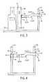
- FIG. 3is a diagram of a make-up air system installed in a structure according to one embodiment of the invention.
- FIG. 4is a diagram of a make-up air system installed in a structure according to one embodiment of the invention.
- FIG. 5is a diagram of a make-up air system installed in a structure according to one embodiment of the invention.
- FIG. 6is a diagram of a make-up air system installed in a structure according to one embodiment of the invention.
- FIGS. 7A-7Care diagrams of a pressure switch retroactively coupled to an exhaust device according to one embodiment of the invention.
- FIG. 7Dis a perspective view of a pin and switch module arrangement according to one embodiment of the invention.
- FIG. 7Eis a diagram of a make-up air system and pressure switch installed in a structure according to one embodiment of the invention.
- FIG. 7Fis a diagram of a pressure switch retroactively coupled to an exhaust device according to one embodiment of the invention.
- FIG. 7Gis a diagram of portions of a pressure switch coupled to an exhaust duct according to one embodiment of the invention.
- FIG. 7His a diagram of a probe according to one embodiment of the invention.
- FIG. 7Iis a diagram of a probe according to one embodiment of the invention.
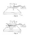
- FIG. 8is a diagram of a mechanical switch retroactively coupled to an exhaust device according to one embodiment of the invention.
- FIG. 9is a diagram of an optical switch retroactively coupled to an exhaust device according to one embodiment of the invention.
- FIG. 10is a diagram of a current-sensing switch retroactively coupled to an exhaust device according to one embodiment of the invention.
- FIG. 11is a diagram of a jumper retroactively coupled to an exhaust device according to one embodiment of the invention.
- FIG. 12is a diagram of a flow meter and a switch coupled to an exhaust device according to one embodiment of the invention.
- FIGS. 1 and 2illustrate a make-up air system 10 according to one embodiment of the invention.
- the system 10can include a duct housing 12 , one or more dampers 14 , a motor 18 , and a seal element 20 .
- portions of the system 10can comprise a generally circular cross-section, although in other embodiments, the cross-section of the system 10 can comprise other shapes such as, but not limited to square, rectangular, regular or irregular polygonal, or other shapes.
- the damper 14can be positioned substantially within the duct housing 12 .
- the make-up air system 10can include a transformer 10 or similar structure that can modulate the voltage of an electrical current.
- the damper 14can be operatively coupled to the motor 18 so that upon receiving a signal, the motor 18 can move the damper 14 .
- the motor 18can rotate the damper 14 about an axis (e.g., a horizontal axis), although in other embodiments, the motor 18 can move the damper 14 in other manners, such as sliding, translating, or other single or compound forms of movement.
- the damper 14can move about a horizontal axis, a vertical axis, or other axes between a vertical and a horizontal axis.
- the motor 18can rotate the damper 14 about a vertical axis so that environments on one or more sides of the damper 14 are in fluid communication with each other.
- the motor 18can move the damper 14 from a first position to a second position upon receiving a signal.
- the first positioncan comprise a substantially closed position so that no fluids (e.g., air, gas, or other fluids) in material amounts can pass through the duct housing 12 (i.e., the duct housing 12 is substantially sealed).
- the second positioncan comprise a substantially open position so that fluids can pass through the duct housing 12 and environments on both sides of the damper 14 are in fluid communication with each other.
- the second positioncan be about ninety degrees away from the first position, although in other embodiments, the second position can be positioned at other angles relative to the first position.
- the motor 18can move the damper 14 to other positions (e.g., other angles relative to the first position including from about 1 degree to about 360 degrees).
- the seal element 20can be positioned within the duct housing 12 . In some embodiments, the seal element 20 can be positioned within the duct housing 12 so that when the damper 14 is in the first position, the seal element 20 can contact the damper 14 to aid in preventing any material amounts of a fluid or other materials (e.g., debris) from moving through the duct housing 12 . In some embodiments, the seal element 20 can comprise rubber, a polymeric material, a fibrous material, or other similar materials and can be configured and arranged to comprise a substantially similar shape relative to the damper 14 .
- the system 10can be installed into, and/or comprise a portion of, an exhaust device 22 in structures 24 including dwellings, commercial buildings, and other structures that can employ ventilation systems.
- some exhaust devices 22 installed in structures 24can include apparatuses that can exhaust fluids (e.g., air, smoke, effluents, such as cooking effluent, or any other fluids) from inside of the structure 24 .
- some exhaust devices 22can include range hoods, exhaust fans positioned in different locations throughout structures 24 , fume hoods, and other air-moving or other fluid-moving apparatuses.
- the exhaust devices 22can comprise and/or can be coupled to a duct system 23 that can at least partially provide an avenue for air or other fluids moving through some or all portions of the structure 24 .
- the duct system 23can fluidly connect an outside environment with the exhaust devices 22 and/or can fluidly connect multiple rooms or areas of the structure 24 .
- the duct housing 12can comprise a portion of the duct system 23 .
- the duct housing 12can be coupled to the duct system 23 so that fluids, such as air, can pass through the duct housing 12 , if the damper 14 is in the first position.
- the duct housing 12can be substantially or wholly integral with the duct system 23 and, in other embodiments, the duct housing 12 can be a separate element relative to the duct system 23 .
- relatively large amounts of air or other fluidscan be exhausted from the structure 24 .
- some exhaust devices 22can exhaust more than 300 cubic feet per minute (CFM) of air from the structure 24 , although some exhaust devices 22 can exhaust air at either a greater or lesser rate than 300 CFM.
- some structures 24can be relatively impermeable to outside fluids, such as air. Although the relative impermeability of some structures 24 can result in relatively less natural fluid exchange between the inside and outside of the structure 24 , it can result in a more-efficient structure (e.g., potentially lower energy consumption to maintain a desired internal temperature of the structure 24 ).
- the combination of an exhaust device 22 and relative impermeabilitycan at least partially create negative pressure during operation of one or more exhaust devices 22 .
- the creation of negative pressurecan lead to a “back draft” of potentially noxious and/or harmful outputs from some combustion appliances such as water heaters, stoves, fireplaces, and other similar appliances designed to vent to the outside environment.
- some combustion appliancessuch as water heaters, stoves, fireplaces, and other similar appliances designed to vent to the outside environment.
- at least some municipalities, states, counties, and/or other jurisdictions and non-governmental entitiesare mandating that at least some structures 24 with exhaust devices 22 with exhaust rates over a predetermined value (e.g., greater than 300 CFM) include systems to prevent or reduce negative pressure.
- a predetermined valuee.g., greater than 300 CFM
- the system 10can be installed within one or more structures 24 .
- the structure 24can include an aperture 26 through a portion of an outer wall 28 and a first end 30 of the duct housing 12 can be positioned immediately adjacent to and/or through the aperture 26 so that portions of the duct housing 12 can be in fluid communication with the outside environment.
- a cap 32can be coupled to the outside wall 28 adjacent to the aperture 26 to at least partially shield the aperture 26 from environmental conditions (e.g., precipitation, dust, debris, etc.).
- a second end 34 of the duct housing 12can be coupled to other portions of the structure 24 .
- the second end 34 of the duct housing 12can be operatively coupled to at least a portion the duct system 23 , such as an air return duct 36 so that the duct housing 12 can be in fluid communication with the air return duct 36 .
- the duct system 23 of the structure 24can comprise the air return duct 36 that is in fluid communication with portions of the structure 24 .
- a portion of the air within the structurecan be circulated through an air handler unit 38 via the air return duct 36 from portions of the structure 24 .
- a fluidsuch as air
- a fluidcan enter the duct system 23 .
- at least some of the air circulating through the air return duct 36can enter into the structure 24 .
- a filter 40can be positioned between the second end 34 of the duct housing 12 and the air return duct 36 to at least partially filter any fluids passing through the duct housing 12 before entering the air return duct 36 .
- the duct housing 12can be positioned so that it is in fluid communication with a room or other area and/or region of the structure 24 .
- the duct housing 12can substantially extend from the outer wall 28 to and/or through an interior wall 42 .
- the interior wall 42can comprise an aperture 44 into which the second end 34 of the duct housing 12 can extend.
- the interior wall 42can comprise a register 46 operatively coupled to the wall 42 and the second end 34 so that any air or other fluids circulating through the duct housing 12 can at least partially flow through the register 46 before entering the room.
- a filter 40can be positioned substantially between the second end 34 of the duct housing 12 and the interior wall 42 to at least partially filter any fluids passing through the duct housing 12 before entering the room.
- a portion of a fluidsuch as air, can flow from the environment outside of the structure 24 to the inside of the structure 24 , which, in some embodiments, can at least partially reduce and/or eliminate some or all of the negative pressure within the structure 24 .
- the motor 18can receive one or more signals to move the damper 14 .
- the signalcan originate from different locations.
- the structure 24can further comprise a control module 17 (e.g., a digital and/or analog control module) operatively coupled to an electrical network of the structure 24 , as shown in FIG. 5 .
- the control module 17can send, receive, and/or process communication protocols that can enable transmission of a signal from one device to another. Wired and/or wireless communication can be used for such signal transmissions.
- the control module 17can comprise InsteonTM and/or LinkLogicTM protocols.
- a signalcan be relayed through the electrical network via the control module 17 to activate the motor 18 to move the damper 14 .
- the system 10also can be activated to move the damper 14 and allow air to enter the structure 24 to substantially reduce and/or substantially prevent the build up of negative pressure within the structure 24 .
- a signalalso can be transmitted from an exhaust device 22 to the motor 18 via a dry contact relay to lead to movement of the damper 14 .
- multiple systemscan be installed into a structure 24 so that multiple dampers 14 can be present, to meet any structure occupants' needs and requirements.
- structures 24can comprise multiple exhaust devices 22 and each device 22 can signal a different make-up air system 10 to operate a damper 14 .
- the structure 24can comprise an in-structure network so that activation of a first exhaust device 22 in a first zone or region of the structure 24 can activate a damper 14 to enable influx of air or other fluids in the first zone or region of the structure 24 .
- larger structures 24can comprise a plurality of zone or regions and a plurality of corresponding make-up air systems 10 so that individual zones can be networked with one or more make-up air systems 10 to reduce and/or eliminate negative pressure within one or more zones or regions.
- a deactivation signalcan be transmitted to the system 10 to return the damper 14 to the first position and substantially seal the duct housing 12 .
- the damper 14can remain open for a pre-determined period of time after deactivation of the exhaust device 22 , and then can return to the first position (i.e., movement of the damper 14 can be at least partially controlled based on passage of time since receiving an activation signal).
- the system 10can be substantially and/or completely passive.
- the system 10can function effectively without a motor 18 and/or other electrical components.
- some negative pressurecan develop within the structure 24 .
- the damper 14can be configured and arranged so that when the negative pressure reaches a pre-determined threshold, a differential in pressure between the inside and the outside of the structure 24 can cause the damper 14 to move, which can allow air into the structure 24 to reduce the negative pressure.
- the damper 14can be configured so that, in the event of a failure of the motor 18 and/or other electrical components, by default the damper 14 can open as a result of a differential in pressure between the inside and the outside of the structure 24 to reduce negative pressure.
- some or all of the activation and/or deactivation signals discussed above and belowcan be coupled to (e.g., installed) existing exhaust devices 22 and/or existing duct systems 23 within structures 24 (e.g., some or all of the activation apparatuses can be “retro-fit” onto existing elements of the structure 24 ).
- some structures 22 that require a make-up air system 10e.g., a structure 22 including one or more exhaust devices 22 and configured to be relatively impermeable to air or other fluids from the outside environment
- some or all of the activation apparatuses that transmit activation signalscan be installed within structures 24 (e.g., exhaust devices 22 , duct systems 23 , etc.) after all or partial completion of the structure 24 and prior installation of one or more exhaust devices 22 .
- one or more activation apparatusescan be coupled to the duct systems 23 , exhaust devices 22 , or other elements of some structures 24 to retroactively provide a make-up air system 10 for pre-existing ventilating and other fluid-movement configurations.
- the following paragraphsdescribe retroactively installing the make-up air systems 10 and their activation apparatuses, some or all of embodiments can be installed during initial construction of the structure 24 and the duct system 23 , and/or installation of the exhaust device 22 .
- FIGS. 7-12depict the exhaust device 22 as an apparatus substantially similar to a conventional range hood, the make-up air system 10 can be used in connection with operations of clothing dryers, vented water heaters, fireplace fans, and any other appliance or apparatus that vents exhaust.
- one or more switches 48can be coupled to the duct system 23 to provide an activation signal to the motor 18 to move the damper 14 .
- the switch 48can comprise a pressure switch 48 (i.e., the switch 48 can be configured and arranged to detect changes in pressure).
- an exhaust device 22can be coupled to an exhaust duct 50 that can be in fluid communication with the outside environment or other portions of the duct system 23 to provide an avenue for exhausted fluid (e.g., air, cooking effluent, etc.) to exit the structure 24 .
- one or more switches 48can be coupled to the exhaust duct 50 so that at least a portion of the switch 48 can be in fluid communication with an interior of the exhaust duct 50 .
- the switch 48can comprise one or more probes 48 a and one or more switch modules 48 b .
- the switch module 48 bcan be coupled to an exterior of the exhaust duct 50 and the one or more probes 48 a can be at least partially inserted through the exhaust duct 50 so that the probe 48 a is in fluid communication with the interior of the exhaust duct 50 .
- the probe 48 acan be in communication with the switch module 48 b via a hose 53 coupled an inlet 54 of the module 48 b , so that the probe 48 a can relay the pressure present within the exhaust duct 50 to the module 48 b so that the module 48 b can assess the pressure level.
- the probe 48 aconveys changes in pressure within the exhaust duct 50 to the switch module 48 b which can process the pressure values to assess whether the make-up air system 10 should be activated or deactivated.
- the switch module 48 bcan be in electrical communication with one or more make-up air systems 10 .
- one or more electrical lines 55can connect the make-up air system 10 and the switch module 48 b .
- the make-up air system 10can be in fluid communication with the outside environment through one or more outer walls 28 .
- the make-up air system 10need not be substantially adjacent to the switch 48 (e.g., the electrical lines 55 can extend a small or great distance through the structure 24 to where the system 10 is positioned), although, the make-up air system 10 can be substantially adjacent to the switch 48 .
- the switch module 48 bcan communicate with the motor 18 in other manners.
- the switch module 48 bcan be wirelessly connected to a conventional controller for the motor 18 (e.g., via radio-frequency transmission) to transmit the activation signal.
- the switch module 48 bcan provide a current (e.g., a low voltage current, such as a 24 Volt current), via the electrical lines 55 , to the motor 18 to move the damper 14 .
- a currente.g., a low voltage current, such as a 24 Volt current
- activation of the exhaust device 22can trigger air flow through the exhaust duct 50 (e.g., air or other fluids moving toward the outside environment), and, as a result of the probe 48 a being in fluid communication with the interior of the exhaust duct 50 , the probe 48 a can convey pressure changes within the exhaust duct 50 arising from air flow through the duct 50 .
- the switch module 48 bcan activate the motor 18 to move the damper 14 to enable air from the outside environment to enter the structure 24 to reduce or eliminate any negative pressure accumulation. Moreover, in some embodiments, after the switch module 48 b fails to detect sufficient pressure within the exhaust duct 50 , the switch 48 can open so that current ceases flowing to the make-up air system 10 to closer the damper 14 .
- the switch 48can be configured and arranged ensure activation of the make-up air system 10 at appropriate times.
- the make-up air system 10can be used to reduce or eliminate negative pressure that can result from a great volume of air being exhausted from the structure 24 (e.g., greater than or equal to about 300 CFM). Accordingly, it could be unnecessary to activate the make-up air system 10 when exhaust devices 22 exhaust air from the structure 24 at a lesser rate.
- the switch 48can be configured and arranged so that the switch module 48 b does not activate the make-up air system 10 unless the probe 48 a conveys a pressure change within the exhaust duct 50 indicative of an exhaust rate greater than or equal to about 300 CFM.
- the make-up air system 10is not activated at times when it is not necessary to reduce or eliminate negative pressure.
- the switch module 48 bcan activate the make-up air system 10 when the probe 48 a conveys pressure changes within the exhaust duct 50 indicative of other flow rates (e.g., less than about 300 CFM).
- the switch 48can comprise other configurations to ensure activation of the make-up air system 10 at appropriate times.
- one or more pins 52can be disposed in the inlet 54 of the switch module 48 b .
- the pin 52can comprise a conventional orifice pin 52
- the pin 52can comprise other types of pins 52 .
- the pin 52by at least partially disposing the pin 52 within the inlet 54 , the pin 52 can at least partially dampen the response of the module 48 b to changes in pressure within the exhaust duct 50 .
- the exhaust duct 50can fluidly connect the exhaust device 22 to the outside environment.
- the exhaust duct 50can comprise a cap 32 to reduce or prevent an influx of some unwanted materials (e.g., precipitation, debris, etc.), the cap 32 cannot prevent entry of all unwanted phenomena.
- windcan pass across the cap 32 and an outlet 56 of the exhaust duct 50 and can at least partially enter the exhaust duct 50 , which can at least partially impact pressure levels within the duct 50 , as shown in FIG. 7E .
- the changes in pressure within the exhaust duct 50can cause the switch module 48 b to activate the make-up air system 10 under the mistaken analysis (e.g., the wind creates a “false positive” exhaust event) that air is being exhausted from the structure 24 .
- the pin 52can function to “dampen” the switch module 48 b to changes in pressure (e.g., make the switch module 48 b less sensitive to changes in pressure within the exhaust duct 50 ).
- the make-up air system 10can be triggered when pressure within the exhaust duct 50 reaches a level sufficient to overcome the dampening effect of the pins 52 and can remain substantially inactive when pressure levels are not sufficient to reach levels of producing negative pressure.
- Other orifice metering or throttling devicescan also be used.
- the switch 48can comprise other configurations to ensure activation of the make-up air system 10 at appropriate times.
- the exhaust device 22can comprise one or more damper flaps 58 operatively coupled to the device 22 substantially adjacent to an outlet (not shown) of the device 22 .
- the damper flap 58can be coupled to the exhaust device 22 and/or the exhaust duct 50 so that the flap 58 moves in response to the exhaust device 22 moving air (e.g., air flow through the exhaust duct 50 causes the flap 58 to move from a closed positioned to an open position).
- the switch 48by disposing a portion of the switch 48 (e.g., the probe 48 a ) between the damper flap 58 and the exhaust device 22 , at least a portion of the wind or other natural phenomenon that could cause the switch 48 to register a pressure change could go undetected by the switch 48 .
- the probe 48 aby disposing the probe 48 a in the exhaust duct 50 so that the damper flap 58 separates the exhaust duct outlet 56 and the probe 48 a , the probe 48 a can be at least partially insulated from the natural phenomena that could cause unnecessary activation of the system 10 .
- the probe 48 acan comprise alternative configurations to ensure activation of the make-up air system 10 at appropriate times.
- some conventional probes 48 acan comprise an end region 48 c that is configured and arranged to detect fluid flow.
- the end region 48 ccan be angled, bent, hooked, or otherwise configured so that at least a portion of the passing fluid (e.g., air or other exhaust) can be received within the probe 48 a and transported to the module 48 b , as shown in FIG. 7G .
- the probe 48 acan comprise a configuration to at least partially reduce the risk of unnecessary activation of the make-up air system 10 .
- the end region 48 ccan comprise an angled configuration and a seal 49 can be operatively coupled to the end region 48 c .
- the seal 49can be pivotably coupled to the probe 48 a so that air or other fluids can only be detected by the probe 48 a and module 48 b from one general direction.
- the seal 49can be coupled to the probe 48 a at the end region 48 c so that when air or other fluids come down the exhaust duct 50 (e.g., caused by wind or other natural phenomena), the force of the fluids contacting the seal 49 can cause the seal 49 to engage the end region 48 c so that no pressure change registers at the module 48 b .
- air or other fluidscome down the exhaust duct 50 (e.g., caused by wind or other natural phenomena)
- the force of the fluids contacting the seal 49can cause the seal 49 to engage the end region 48 c so that no pressure change registers at the module 48 b .
- the switch 48can comprise other configurations. As shown in FIG. 8 , in some embodiments, the switch 48 can comprise a mechanical switch 48 , such as a conventional limit switch 48 . In some embodiments, the mechanical switch 48 can be coupled to the wall of the exhaust duct 50 so that at least a portion of the mechanical switch 48 is in fluid communication with the interior of the exhaust duct 50 . In some embodiments, as a result of the damper flap 58 moving in response to air flow through the exhaust duct 50 , the damper flap 58 can contact the mechanical switch 48 (e.g., cause the switch to close) to activate the make-up air system 10 .
- the mechanical switch 48e.g., cause the switch to close
- the mechanical switch 48can be electrically connected to the motor 18 in a manner substantially similar to some of the previously mentioned embodiments.
- the mechanical switch 48can be coupled to the system 10 via electrical lines 55 that can carry a current to the motor 18 to move the damper 14 upon closing of the mechanical switch 48 by the damper flap 58 .
- the mechanical switch 48be wirelessly connected to the make-up air system 10 (e.g., via radio-frequency transmission) to provide a signal to activate the motor 18 .
- movement of the damper flap 58can, at least partially, correspond to increased exhaust through the exhaust duct 50 and can contact the mechanical switch 48 to function as a signal to activate the make-up air system 10 , allowing ingress of air from the outside environment.
- deactivation of the exhaust device 22can result in the damper flap 58 returning to a substantially closed position, which can result in an opening of the mechanical switch 48 to cease current flow to the make-up air system 10 .
- material volumes of air or other fluids from the outside environmentcan cease to enter the structure 24 upon a deactivation of the exhaust device 22 .
- the switch 48can comprise other configurations.
- the switch 48can comprise an optical switch 48 .
- the optical switch 48can be configured and arranged to employ infrared sensors, lasers, etc.
- the optical switch 48can be positioned within the exhaust duct 50 and at least partially directed toward the damper flap 58 .
- the optical switch 48can be configured and arranged to detect movement of the damper flap 58 (e.g., in response to activation of the exhaust device 22 ) and activate the make-up air damper system 10 in response to flap 58 movement.
- movement of the damper flap 58can be indicative of air movement out the structure 24 via the exhaust duct 50 .
- the optical switch 48can provide a signal to the motor 18 to move the damper 14 (e.g., via electrical lines 55 , wireless technologies, etc.) to enable an influx of air or other fluids from the outside environment to reduce or eliminate negative pressure.
- deactivation of the exhaust device 22can result in the damper flap 58 returning to a substantially closed position, which can be detected by the optical switch 48 and can lead to cessation of current flow to the make-up air system 10 .
- air or other fluids from the outside environmentcan cease to enter the structure 24 upon a deactivation of the exhaust device 22 .
- the switch 48can comprise a current-sensing switch 48 .
- the current-sensing switch 48can be in communication with a motor 60 of the exhaust device 22 .
- the motor 60 of the exhaust device 22can provide the driving force to move air and other fluids out of the structure 24 via the exhaust duct 50 .
- the motor 60can receive current from the electrical network of the structure 24 to drive air and other fluids out of the structure 24 .
- the current-sensing switch 48can be coupled to the motor 60 and/or the electrical lines 55 leading from the electrical network of the structure 24 to the motor 60 .
- the current-sensing switch 48can close when the motor 60 receives current from the electrical network of the structure 24 to begin exhausting air and other fluids from the structure 24 .
- the current-sensing switch 48upon closing, can provide current to the motor 18 to the move the damper 14 to allow an influx of air or other fluids from the outside environment to reduce or eliminate negative pressure.
- the current-sensing switch 48can also wirelessly communicate (e.g., via radio-frequency transmission) with the make-up air system 10 in addition to, or lieu of, the wired connection.
- deactivation of the exhaust device 22can result in the little to no current flowing to the motor 60 , which can result in an opening of the current-sensing switch 48 to cease current flow to the make-up air system 10 .
- material volumes of air or other fluids from the outside environmentcan cease to enter the structure 24 upon a deactivation of the exhaust device 22 .
- the make-up air system 10can be in communication with one or more jumpers 62 .
- one or more of the electrical lines 55can be electrically coupled to the jumper 62 so that some or all of the current entering the motor 60 of the exhaust device 22 passes through the jumper 62 .
- at least one of the electrical lines 55 from the electrical network of the structure 24can be connected to the jumper 62 and the jumper 62 can be electrically connected to the motor 60 and the make-up air system 10 .
- the exhaust device 22can begin exhausting air or other fluids from the structure 22 , which can, as previously mentioned, create negative pressure.
- the jumper 62can comprise a dry-contact relay that can enable current to flow from the jumper 62 to the motor 18 to move the damper 14 (e.g., via one or more electrical lines 55 ) to allow an influx of air from the outside environment to reduce or eliminate negative pressure.
- the jumper 62can also wirelessly communicate (e.g., via radio-frequency transmission) with the make-up air system 10 in addition to, or lieu of, the wired connection.
- deactivation of the exhaust device 22can result in the little to no current flowing to the motor 60 , which can result in an opening of the dry-circuit relay coupled to the jumper 62 which will then cease current flow to the make-up air system 10 .
- material volumes of air or other fluids from the outside environmentcan cease to enter the structure 24 upon a deactivation of the exhaust device 22 .
- the switch 48can be coupled to a flow meter 64 .
- the flow meter 64can comprise a conventional vane anemometer, and in other embodiments, the flow meter 64 can comprise other structures that are configured and arranged to measure the rate of air moving through the exhaust duct 50 .
- the switch 48e.g., the switch module 48 b
- the flow meter 64can be coupled to the outside of the exhaust duct 50 and the flow meter 64 can be disposed inside of the exhaust duct 50 , as shown in FIG. 12 .
- the flow meter 64can measure a rate of fluid flow through the exhaust duct 50 .
- the flow meter 64can be coupled to the switch 48 so that the flow rate of fluid flow through the exhaust duct 50 can be relayed from the meter 64 to the switch 48 .
- the switch 48can be configured and arranged to process the data from the flow meter 64 to determine the fluid flow rate.
- the switch 48can be preprogrammed with a cross-sectional area of the exhaust duct 50 and the flow meter 64 can supply a velocity of the air or other fluids passing through and/or adjacent to the flow meter 64 . Accordingly, the switch 48 can multiply the velocity by the cross-sectional area of the exhaust duct 50 to arrive at the air flow rate.
- the switch 48can be configured and arranged to trigger the make-up air system 10 when the air flow rate reaches a pre-determined threshold.
- the switch 48can be configured to activate the make-up air system 10 when the exhaust flow rate reaches about 300 CFM or greater.
- the pre-determined thresholdcan comprise other values (e.g., 100 CFM, 400 CFM, 500 CFM, etc.) to meet user needs.
- the switch 48can close to circulate a current to the motor 18 to move the damper 14 to enable an influx of air from the outside environment to reduce or eliminate negative pressure.
- the flow meter 64can comprise alternate configurations.
- the flow meter 64can comprise a flow wheel (not shown), including a dry-contact relay, which can be disposed within the exhaust duct 50 .
- the flow wheelcan be moved (e.g., rotated) when the exhaust device 22 moves air or other fluids through the exhaust duct 50 .
- the dry-contact relaycan close, which can lead to current flowing to the make-up air system 10 and result in air or other fluids entering the structure 24 via the system 10 .
- some or all of the previous embodimentscan include the make-up air system 10 coupled to the apparatus providing an activation signal and/or a deactivation signal via electrical lines 55 or wireless communication capabilities, such as radio-frequency transmissions.
- the switch 48can comprise a radio-frequency transmitter (not shown) and the make-up air system 10 can comprise a radio-frequency receiver so that some or all of the activation/deactivation signals can be wirelessly transmitted.
- the make-up air system 10can also receive activation/deactivation signals via InsteonTM and/or LinkLogicTM protocols.
- the apparatuses, devices, or structures that provide activation signals to the make-up air system 10can be installed in multiple configurations.
- the switch 48 and accompanying elementscan be coupled to an existing exhaust duct 50 or other portions of the duct system 23 .
- the switch 48 and accompanying elementscan be manufactured so that they are substantially or completely integral with a section of an exhaust duct 50 . As a result, an installer can remove a portion of an existing exhaust duct 50 and install the replacement exhaust duct portion that includes the switch 48 and accompanying elements in lieu of installing the switch 48 on an existing duct 50 .
Landscapes
- Engineering & Computer Science (AREA)
- Chemical & Material Sciences (AREA)
- Combustion & Propulsion (AREA)
- Mechanical Engineering (AREA)
- General Engineering & Computer Science (AREA)
- Physics & Mathematics (AREA)
- Fluid Mechanics (AREA)
- Ventilation (AREA)
- Air Conditioning Control Device (AREA)
Abstract
Description
Claims (23)
Priority Applications (3)
| Application Number | Priority Date | Filing Date | Title |
|---|---|---|---|
| US13/352,155US9506668B2 (en) | 2011-05-03 | 2012-01-17 | Make-up air system and method |
| CA2766813ACA2766813C (en) | 2011-05-03 | 2012-02-03 | Make-up air system and method |
| US15/346,514US20170051939A1 (en) | 2011-05-03 | 2016-11-08 | Make-up air system and method |
Applications Claiming Priority (2)
| Application Number | Priority Date | Filing Date | Title |
|---|---|---|---|
| US201161482068P | 2011-05-03 | 2011-05-03 | |
| US13/352,155US9506668B2 (en) | 2011-05-03 | 2012-01-17 | Make-up air system and method |
Related Child Applications (1)
| Application Number | Title | Priority Date | Filing Date |
|---|---|---|---|
| US15/346,514ContinuationUS20170051939A1 (en) | 2011-05-03 | 2016-11-08 | Make-up air system and method |
Publications (2)
| Publication Number | Publication Date |
|---|---|
| US20120282853A1 US20120282853A1 (en) | 2012-11-08 |
| US9506668B2true US9506668B2 (en) | 2016-11-29 |
Family
ID=47090530
Family Applications (2)
| Application Number | Title | Priority Date | Filing Date |
|---|---|---|---|
| US13/352,155Active2034-05-17US9506668B2 (en) | 2011-05-03 | 2012-01-17 | Make-up air system and method |
| US15/346,514AbandonedUS20170051939A1 (en) | 2011-05-03 | 2016-11-08 | Make-up air system and method |
Family Applications After (1)
| Application Number | Title | Priority Date | Filing Date |
|---|---|---|---|
| US15/346,514AbandonedUS20170051939A1 (en) | 2011-05-03 | 2016-11-08 | Make-up air system and method |
Country Status (2)
| Country | Link |
|---|---|
| US (2) | US9506668B2 (en) |
| CA (1) | CA2766813C (en) |
Cited By (14)
| Publication number | Priority date | Publication date | Assignee | Title |
|---|---|---|---|---|
| US10712038B2 (en) | 2017-04-14 | 2020-07-14 | Johnson Controls Technology Company | Multi-function thermostat with air quality display |
| US10731885B2 (en) | 2017-04-14 | 2020-08-04 | Johnson Controls Technology Company | Thermostat with occupancy detection via proxy measurements of a proxy sensor |
| US10837665B2 (en) | 2017-04-14 | 2020-11-17 | Johnson Controls Technology Company | Multi-function thermostat with intelligent ventilator control for frost/mold protection and air quality control |
| US10866003B2 (en) | 2017-04-14 | 2020-12-15 | Johnson Controls Technology Company | Thermostat with preemptive heating, cooling, and ventilation in response to elevated occupancy detection via proxy |
| US10928084B2 (en) | 2017-04-14 | 2021-02-23 | Johnson Controls Technology Company | Multi-function thermostat with intelligent supply fan control for maximizing air quality and optimizing energy usage |
| US20210172779A1 (en)* | 2018-01-17 | 2021-06-10 | Johnson Controls, Inc. | Systems and methods for control of an air duct |
| US11131474B2 (en) | 2018-03-09 | 2021-09-28 | Johnson Controls Tyco IP Holdings LLP | Thermostat with user interface features |
| US11162698B2 (en) | 2017-04-14 | 2021-11-02 | Johnson Controls Tyco IP Holdings LLP | Thermostat with exhaust fan control for air quality and humidity control |
| US11441799B2 (en) | 2017-03-29 | 2022-09-13 | Johnson Controls Tyco IP Holdings LLP | Thermostat with interactive installation features |
| US12000721B2 (en) | 2018-01-17 | 2024-06-04 | Tyco Fire & Security Gmbh | Air duct airflow sensor with internal low-pressure detector |
| US12025335B2 (en) | 2018-01-17 | 2024-07-02 | Johnson Controls, Inc. | Air duct damper |
| US12038185B2 (en) | 2018-01-17 | 2024-07-16 | Tyco Fire & Security Gmbh | Air duct assembly with field accessible ports in communication with a pressure source and pressure sensing ports in communication with a pressure sensor |
| US12372270B2 (en) | 2018-01-17 | 2025-07-29 | Air Distribution Technologies Ip, Llc | Air duct damper and installation components |
| US12385768B2 (en) | 2022-08-31 | 2025-08-12 | Tyco Fire & Security Gmbh | Air duct airflow sensor |
Families Citing this family (17)
| Publication number | Priority date | Publication date | Assignee | Title |
|---|---|---|---|---|
| US8505529B2 (en)* | 2009-02-25 | 2013-08-13 | Jerry J. King | Alternate intake apparatus |
| US9263214B2 (en)* | 2011-09-15 | 2016-02-16 | Ccb Innovations, Llc | Make-up air intake system |
| US10119721B2 (en) | 2012-06-14 | 2018-11-06 | Honeywell International Inc. | Standoff for use with an insulated HVAC duct |
| US9664409B2 (en)* | 2012-06-14 | 2017-05-30 | Honeywell International Inc. | HVAC damper system |
| US10302207B2 (en) | 2012-06-14 | 2019-05-28 | Honeywell International Inc. | Spring loaded HVAC damper |
| US10941960B2 (en) | 2013-12-18 | 2021-03-09 | Ademco Inc. | HVAC actuator with position indicator |
| US9732980B2 (en) | 2013-12-18 | 2017-08-15 | Honeywell International Inc. | HVAC actuator with range adjustment |
| US10203703B2 (en) | 2014-03-04 | 2019-02-12 | Mi Valve, Llc | Airflow balancing valve for HVAC systems |
| US20170198941A1 (en)* | 2015-02-02 | 2017-07-13 | John P. Hanus | Method and Apparatus to Provide Ventilation for a Building |
| WO2016197239A1 (en)* | 2015-06-11 | 2016-12-15 | Hubert Gervais | Autonomous air vent closure system |
| CN107289170B (en)* | 2016-03-31 | 2020-08-28 | 倚世节能科技(上海)有限公司 | ventilation valve |
| CN106247460B (en)* | 2016-09-30 | 2022-02-08 | 芜湖美智空调设备有限公司 | Wall-mounted air conditioner and control method thereof |
| CN106287988B (en)* | 2016-09-30 | 2022-03-18 | 芜湖美智空调设备有限公司 | Double-through-flow air conditioner and control method thereof |
| CN106247595B (en)* | 2016-09-30 | 2021-12-17 | 芜湖美智空调设备有限公司 | Wall-mounted spherical indoor unit and control method thereof |
| JP6934592B2 (en)* | 2017-03-30 | 2021-09-15 | パナソニックIpマネジメント株式会社 | Air volume adjustment damper |
| US11345215B2 (en)* | 2018-03-30 | 2022-05-31 | Bayerische Motoren Werke Aktiengesellschaft | Vehicles and methods for cooling a cabin using a cold roof |
| US11009243B2 (en)* | 2018-05-16 | 2021-05-18 | Johnson Controls Technology Company | Systems and methods for zoning system configuration |
Citations (46)
| Publication number | Priority date | Publication date | Assignee | Title |
|---|---|---|---|---|
| US4266528A (en)* | 1978-12-13 | 1981-05-12 | The Celotex Corporation | Ducted/ductless range hood |
| USRE31112E (en)* | 1977-03-28 | 1982-12-28 | Automatic flue damper | |
| US4498624A (en)* | 1984-05-07 | 1985-02-12 | Kogut Jimmy A | Control unit with separate dampers for make-up and combustion air circulation |
| US4773311A (en)* | 1986-11-24 | 1988-09-27 | Phoenix Controls Corporation | Make up air controller for use with fume hood systems |
| US4784114A (en)* | 1982-05-05 | 1988-11-15 | Richard F. Muckler | Kitchen ventilating system |
| US4995307A (en)* | 1989-09-11 | 1991-02-26 | Bobby Floyd | Variable air volume ventilation system and method |
| US5131887A (en)* | 1989-12-27 | 1992-07-21 | Don E. Reiner | Pressure controlled fresh air supply ventilation system using soil gas pressure as a reference, and method of use |
| US5205783A (en)* | 1991-08-22 | 1993-04-27 | Accu*Aire Systems, Inc. | Air flow control equipment in chemical laboratory buildings |
| US5362273A (en)* | 1994-01-19 | 1994-11-08 | Exhaust Track, Inc. | Vehicle exhaust distribution system for buildings |
| USRE35199E (en)* | 1990-05-18 | 1996-04-02 | Gervais; Hubert | Air vent closure system |
| US5720658A (en)* | 1992-02-11 | 1998-02-24 | Belusa; Manfred L. | Space pressurization control system for high containment laboratories |
| US5764579A (en)* | 1990-10-01 | 1998-06-09 | American Auto-Matrix, Inc. | System for controlling laboratories with fume hoods |
| US5820456A (en)* | 1996-10-24 | 1998-10-13 | Sandy J. Pangle | Paint spray booth |
| US6170480B1 (en)* | 1999-01-22 | 2001-01-09 | Melink Corporation | Commercial kitchen exhaust system |
| US6283851B1 (en)* | 2000-03-06 | 2001-09-04 | Honeywell International Inc. | Make up air equipment control |
| US6358137B1 (en)* | 2000-04-17 | 2002-03-19 | Siemens Building Technologies, Inc. | Laboratory fume hood control apparatus having rotary sash door position sensor |
| US6364211B1 (en)* | 2000-08-30 | 2002-04-02 | Saleh A. Saleh | Wireless damper and duct fan system |
| US6634939B2 (en)* | 2001-08-31 | 2003-10-21 | Thomas W. Johnson | Ventilation system and method |
| US20030207662A1 (en)* | 2000-05-01 | 2003-11-06 | Mingsheng Liu | Fume hood exhaust stack system |
| US6669547B2 (en)* | 2001-08-28 | 2003-12-30 | Board Of Regents Of University Of Nebraska | Multi-stack exhaust system |
| US20040020304A1 (en)* | 2002-08-05 | 2004-02-05 | Bruce Roesler | Differential static pressure measuring device |
| US20040020485A1 (en)* | 2002-08-05 | 2004-02-05 | Bruce Roesler | Adjustable orifice plate for exhaust ducts |
| US6779735B1 (en)* | 2003-09-24 | 2004-08-24 | Onstott Richard S | Air ventilation control system |
| US6981915B2 (en)* | 2004-03-15 | 2006-01-03 | Hewlett-Packard Development Company, L.P. | Airflow volume control system |
| US7001263B2 (en)* | 2003-08-14 | 2006-02-21 | Cornell Research Foundation, Inc. | Air flow monitoring and control system with reduced false alarms |
| US20070026786A1 (en)* | 2005-07-22 | 2007-02-01 | Mingsheng Liu | Variable source diameter stack system and method |
| US20070068509A1 (en)* | 2002-08-09 | 2007-03-29 | Halton Company | Zone control of space conditioning system with varied uses |
| US7216495B1 (en)* | 2006-03-02 | 2007-05-15 | Harrison Thomas D | Air conditioning system |
| US20070167126A1 (en)* | 2006-01-19 | 2007-07-19 | Ray Ghattas | Air handling system for clean room |
| US20070205294A1 (en)* | 2005-09-15 | 2007-09-06 | Byczynski Kenneth C | Ventilation system and method of using the ventilation system |
| US20070207724A1 (en)* | 2006-03-02 | 2007-09-06 | Coogan James J | Air pressure control system and method |
| US7275533B2 (en)* | 2003-03-06 | 2007-10-02 | Exhausto, Inc. | Pressure controller for a mechanical draft system |
| US20080135041A1 (en)* | 2006-12-12 | 2008-06-12 | Illinois Tool Works Inc. | Kitchen ventilator system |
| US20080184991A1 (en)* | 2004-03-25 | 2008-08-07 | Supplier Support International Inc. | Heated replacement air system for commercial applications |
| US20080233860A1 (en)* | 2007-03-21 | 2008-09-25 | Brr Technologies, Inc. | Air handling system with self balancing air entrance door |
| US20090047894A1 (en)* | 2007-08-17 | 2009-02-19 | Siemens Building Technologies, Inc. | Pressure control with coarse and fine adjustment |
| US7494524B1 (en)* | 2004-08-16 | 2009-02-24 | Lehmann Jr Erwin | Method and apparatus for maintaining a desired air pressure in a home |
| US20090191493A1 (en)* | 2008-01-29 | 2009-07-30 | Field Controls Llc. | Apparatus and method for controlling a damper in a gas-fired appliance |
| US20100294259A1 (en)* | 2004-07-23 | 2010-11-25 | Oy Halton Group Ltd. | Control of exhaust systems |
| US20110053488A1 (en)* | 2008-01-18 | 2011-03-03 | Mpc Inc. | Control system for exhaust gas fan system |
| US7963830B2 (en)* | 2004-09-22 | 2011-06-21 | Captive-Aire Systems, Inc. | System for directing and controlling two separate streams of air to a kitchen |
| US20110212010A1 (en)* | 2009-09-02 | 2011-09-01 | Despatch Industries Limited Partnership | Apparatus and Method for Thermal Destruction of Volatile Organic Compounds |
| US8100746B2 (en)* | 2006-01-04 | 2012-01-24 | Broan-Nutone Llc | Indoor air quality systems and methods |
| US20130072102A1 (en)* | 2011-09-15 | 2013-03-21 | Ccb Innovations, Llc | Make-Up Air Intake System |
| US20130180700A1 (en)* | 2010-10-07 | 2013-07-18 | James L. Aycock | Whole House Ventilation System |
| US8597092B2 (en)* | 2005-03-25 | 2013-12-03 | Minel Kupferberg | Fan control system |
Family Cites Families (2)
| Publication number | Priority date | Publication date | Assignee | Title |
|---|---|---|---|---|
| US4352349A (en)* | 1979-11-14 | 1982-10-05 | Yoho Robert W | Control circuit for air conditioning systems |
| US9921591B2 (en)* | 2012-03-26 | 2018-03-20 | Siemens Schweiz Ag | System and method for HVAC interlocks |
- 2012
- 2012-01-17USUS13/352,155patent/US9506668B2/enactiveActive
- 2012-02-03CACA2766813Apatent/CA2766813C/enactiveActive
- 2016
- 2016-11-08USUS15/346,514patent/US20170051939A1/ennot_activeAbandoned
Patent Citations (52)
| Publication number | Priority date | Publication date | Assignee | Title |
|---|---|---|---|---|
| USRE31112E (en)* | 1977-03-28 | 1982-12-28 | Automatic flue damper | |
| US4266528A (en)* | 1978-12-13 | 1981-05-12 | The Celotex Corporation | Ducted/ductless range hood |
| US4784114A (en)* | 1982-05-05 | 1988-11-15 | Richard F. Muckler | Kitchen ventilating system |
| US4498624A (en)* | 1984-05-07 | 1985-02-12 | Kogut Jimmy A | Control unit with separate dampers for make-up and combustion air circulation |
| US4773311A (en)* | 1986-11-24 | 1988-09-27 | Phoenix Controls Corporation | Make up air controller for use with fume hood systems |
| US4995307A (en)* | 1989-09-11 | 1991-02-26 | Bobby Floyd | Variable air volume ventilation system and method |
| US5131887A (en)* | 1989-12-27 | 1992-07-21 | Don E. Reiner | Pressure controlled fresh air supply ventilation system using soil gas pressure as a reference, and method of use |
| USRE35199E (en)* | 1990-05-18 | 1996-04-02 | Gervais; Hubert | Air vent closure system |
| US5764579A (en)* | 1990-10-01 | 1998-06-09 | American Auto-Matrix, Inc. | System for controlling laboratories with fume hoods |
| US5205783A (en)* | 1991-08-22 | 1993-04-27 | Accu*Aire Systems, Inc. | Air flow control equipment in chemical laboratory buildings |
| US5720658A (en)* | 1992-02-11 | 1998-02-24 | Belusa; Manfred L. | Space pressurization control system for high containment laboratories |
| US5362273A (en)* | 1994-01-19 | 1994-11-08 | Exhaust Track, Inc. | Vehicle exhaust distribution system for buildings |
| US5820456A (en)* | 1996-10-24 | 1998-10-13 | Sandy J. Pangle | Paint spray booth |
| US6170480B1 (en)* | 1999-01-22 | 2001-01-09 | Melink Corporation | Commercial kitchen exhaust system |
| US6283851B1 (en)* | 2000-03-06 | 2001-09-04 | Honeywell International Inc. | Make up air equipment control |
| US6358137B1 (en)* | 2000-04-17 | 2002-03-19 | Siemens Building Technologies, Inc. | Laboratory fume hood control apparatus having rotary sash door position sensor |
| US6890252B2 (en)* | 2000-05-01 | 2005-05-10 | Mingsheng Liu | Fume hood exhaust stack system |
| US20030207662A1 (en)* | 2000-05-01 | 2003-11-06 | Mingsheng Liu | Fume hood exhaust stack system |
| US6364211B1 (en)* | 2000-08-30 | 2002-04-02 | Saleh A. Saleh | Wireless damper and duct fan system |
| US6669547B2 (en)* | 2001-08-28 | 2003-12-30 | Board Of Regents Of University Of Nebraska | Multi-stack exhaust system |
| US6634939B2 (en)* | 2001-08-31 | 2003-10-21 | Thomas W. Johnson | Ventilation system and method |
| US20040020304A1 (en)* | 2002-08-05 | 2004-02-05 | Bruce Roesler | Differential static pressure measuring device |
| US20040020485A1 (en)* | 2002-08-05 | 2004-02-05 | Bruce Roesler | Adjustable orifice plate for exhaust ducts |
| US7601054B2 (en)* | 2002-08-09 | 2009-10-13 | Oy Halton Group Ltd. | Zone control of space conditioning system with varied uses |
| US20070068509A1 (en)* | 2002-08-09 | 2007-03-29 | Halton Company | Zone control of space conditioning system with varied uses |
| US7275533B2 (en)* | 2003-03-06 | 2007-10-02 | Exhausto, Inc. | Pressure controller for a mechanical draft system |
| US7001263B2 (en)* | 2003-08-14 | 2006-02-21 | Cornell Research Foundation, Inc. | Air flow monitoring and control system with reduced false alarms |
| US6779735B1 (en)* | 2003-09-24 | 2004-08-24 | Onstott Richard S | Air ventilation control system |
| US6981915B2 (en)* | 2004-03-15 | 2006-01-03 | Hewlett-Packard Development Company, L.P. | Airflow volume control system |
| US20080184991A1 (en)* | 2004-03-25 | 2008-08-07 | Supplier Support International Inc. | Heated replacement air system for commercial applications |
| US8038515B2 (en)* | 2004-07-23 | 2011-10-18 | Oy Halton Group Ltd. | Control of exhaust systems |
| US8444462B2 (en)* | 2004-07-23 | 2013-05-21 | Oy Halton Group Ltd. | Control of exhaust systems |
| US20100294259A1 (en)* | 2004-07-23 | 2010-11-25 | Oy Halton Group Ltd. | Control of exhaust systems |
| US7494524B1 (en)* | 2004-08-16 | 2009-02-24 | Lehmann Jr Erwin | Method and apparatus for maintaining a desired air pressure in a home |
| US7963830B2 (en)* | 2004-09-22 | 2011-06-21 | Captive-Aire Systems, Inc. | System for directing and controlling two separate streams of air to a kitchen |
| US8597092B2 (en)* | 2005-03-25 | 2013-12-03 | Minel Kupferberg | Fan control system |
| US20070026786A1 (en)* | 2005-07-22 | 2007-02-01 | Mingsheng Liu | Variable source diameter stack system and method |
| US20070205294A1 (en)* | 2005-09-15 | 2007-09-06 | Byczynski Kenneth C | Ventilation system and method of using the ventilation system |
| US8100746B2 (en)* | 2006-01-04 | 2012-01-24 | Broan-Nutone Llc | Indoor air quality systems and methods |
| US8147301B2 (en)* | 2006-01-19 | 2012-04-03 | Ray Ghattas | Air handling system for clean room |
| US20070167126A1 (en)* | 2006-01-19 | 2007-07-19 | Ray Ghattas | Air handling system for clean room |
| US7216495B1 (en)* | 2006-03-02 | 2007-05-15 | Harrison Thomas D | Air conditioning system |
| US20070207724A1 (en)* | 2006-03-02 | 2007-09-06 | Coogan James J | Air pressure control system and method |
| US20070204640A1 (en)* | 2006-03-02 | 2007-09-06 | Harrison Thomas D | Air conditioning system |
| US20080135041A1 (en)* | 2006-12-12 | 2008-06-12 | Illinois Tool Works Inc. | Kitchen ventilator system |
| US20080233860A1 (en)* | 2007-03-21 | 2008-09-25 | Brr Technologies, Inc. | Air handling system with self balancing air entrance door |
| US20090047894A1 (en)* | 2007-08-17 | 2009-02-19 | Siemens Building Technologies, Inc. | Pressure control with coarse and fine adjustment |
| US20110053488A1 (en)* | 2008-01-18 | 2011-03-03 | Mpc Inc. | Control system for exhaust gas fan system |
| US20090191493A1 (en)* | 2008-01-29 | 2009-07-30 | Field Controls Llc. | Apparatus and method for controlling a damper in a gas-fired appliance |
| US20110212010A1 (en)* | 2009-09-02 | 2011-09-01 | Despatch Industries Limited Partnership | Apparatus and Method for Thermal Destruction of Volatile Organic Compounds |
| US20130180700A1 (en)* | 2010-10-07 | 2013-07-18 | James L. Aycock | Whole House Ventilation System |
| US20130072102A1 (en)* | 2011-09-15 | 2013-03-21 | Ccb Innovations, Llc | Make-Up Air Intake System |
Cited By (14)
| Publication number | Priority date | Publication date | Assignee | Title |
|---|---|---|---|---|
| US11441799B2 (en) | 2017-03-29 | 2022-09-13 | Johnson Controls Tyco IP Holdings LLP | Thermostat with interactive installation features |
| US11162698B2 (en) | 2017-04-14 | 2021-11-02 | Johnson Controls Tyco IP Holdings LLP | Thermostat with exhaust fan control for air quality and humidity control |
| US10731885B2 (en) | 2017-04-14 | 2020-08-04 | Johnson Controls Technology Company | Thermostat with occupancy detection via proxy measurements of a proxy sensor |
| US10837665B2 (en) | 2017-04-14 | 2020-11-17 | Johnson Controls Technology Company | Multi-function thermostat with intelligent ventilator control for frost/mold protection and air quality control |
| US10866003B2 (en) | 2017-04-14 | 2020-12-15 | Johnson Controls Technology Company | Thermostat with preemptive heating, cooling, and ventilation in response to elevated occupancy detection via proxy |
| US10928084B2 (en) | 2017-04-14 | 2021-02-23 | Johnson Controls Technology Company | Multi-function thermostat with intelligent supply fan control for maximizing air quality and optimizing energy usage |
| US10712038B2 (en) | 2017-04-14 | 2020-07-14 | Johnson Controls Technology Company | Multi-function thermostat with air quality display |
| US12000721B2 (en) | 2018-01-17 | 2024-06-04 | Tyco Fire & Security Gmbh | Air duct airflow sensor with internal low-pressure detector |
| US20210172779A1 (en)* | 2018-01-17 | 2021-06-10 | Johnson Controls, Inc. | Systems and methods for control of an air duct |
| US12025335B2 (en) | 2018-01-17 | 2024-07-02 | Johnson Controls, Inc. | Air duct damper |
| US12038185B2 (en) | 2018-01-17 | 2024-07-16 | Tyco Fire & Security Gmbh | Air duct assembly with field accessible ports in communication with a pressure source and pressure sensing ports in communication with a pressure sensor |
| US12372270B2 (en) | 2018-01-17 | 2025-07-29 | Air Distribution Technologies Ip, Llc | Air duct damper and installation components |
| US11131474B2 (en) | 2018-03-09 | 2021-09-28 | Johnson Controls Tyco IP Holdings LLP | Thermostat with user interface features |
| US12385768B2 (en) | 2022-08-31 | 2025-08-12 | Tyco Fire & Security Gmbh | Air duct airflow sensor |
Also Published As
| Publication number | Publication date |
|---|---|
| CA2766813C (en) | 2018-10-23 |
| CA2766813A1 (en) | 2012-11-03 |
| US20170051939A1 (en) | 2017-02-23 |
| US20120282853A1 (en) | 2012-11-08 |
Similar Documents
| Publication | Publication Date | Title |
|---|---|---|
| US9506668B2 (en) | Make-up air system and method | |
| KR101003258B1 (en) | Total heat exchange ventilator for both air cooling | |
| US4741257A (en) | Fume hood air flow control | |
| USRE48081E1 (en) | Venturi valve and control system | |
| US6514138B2 (en) | Demand ventilation module | |
| US20190101302A1 (en) | Air pressure controller for air ventilation devices | |
| US20150354845A1 (en) | Optimized airflow distribution system | |
| US6776708B1 (en) | Smoke extraction system | |
| KR101221240B1 (en) | Control method of total heat recovery ventilator with outdoor air cooling function | |
| CN109780601A (en) | A range hood and its control method | |
| KR101574682B1 (en) | Fume hood system for laboratory with indoor suction and exhaust | |
| US20080048853A1 (en) | Backdraft Detector | |
| KR101911820B1 (en) | Automatic dire extinguishing apparatus for kitchen, and control method therof | |
| KR101847426B1 (en) | Exhaust system for communal housing with underground space ventilation function | |
| EP2726793B1 (en) | Pressure control and air conditioning of a multi-story building | |
| JP2014009823A (en) | Air-conditioning device | |
| KR102569971B1 (en) | Balcony condensation prevention system and balcony condensation prevention method using thereof | |
| US12130032B2 (en) | Compact duct detectors for HVAC systems | |
| US10941957B2 (en) | Building controller utilizing multiple sensors and a programmable schedule | |
| KR20010113079A (en) | Auto smoke removed system for smoke removed zone of building | |
| EP2584278B1 (en) | Ventilation system for ventilating a fire compartment in a building | |
| NL1036988C2 (en) | CENTRAL VENTILATION SYSTEM. | |
| US10876776B1 (en) | System and method for freeze protection of an air handling system | |
| KR20170089047A (en) | Ventilating system | |
| KR102091702B1 (en) | Air Inlet method of Ventilation Utility and Operation |
Legal Events
| Date | Code | Title | Description |
|---|---|---|---|
| AS | Assignment | Owner name:BROAN-NUTONE LLC, WISCONSIN Free format text:ASSIGNMENT OF ASSIGNORS INTEREST;ASSIGNORS:SINUR, RICHARD R;HEIDEL, TOM P;WELLNITZ, BRIAN R;SIGNING DATES FROM 20120123 TO 20120126;REEL/FRAME:027614/0427 | |
| AS | Assignment | Owner name:UBS AG, STAMFORD BRANCH, AS COLLATERAL AGENT, CONNECTICUT Free format text:SECURITY AGREEMENT;ASSIGNORS:BROAN-NUTONE LLC;ERGOTRON, INC.;NORDYNE LLC;REEL/FRAME:028283/0706 Effective date:20120330 Owner name:UBS AG, STAMFORD BRANCH, AS COLLATERAL AGENT, CONN Free format text:SECURITY AGREEMENT;ASSIGNORS:BROAN-NUTONE LLC;ERGOTRON, INC.;NORDYNE LLC;REEL/FRAME:028283/0706 Effective date:20120330 | |
| AS | Assignment | Owner name:WELLS FARGO BANK, NATIONAL ASSOCIATION, AS COLLATERAL AGENT, NORTH CAROLINA Free format text:INTELLECTUAL PROPERTY SECURITY AGREEMENT;ASSIGNORS:LINEAR LLC;GTO ACCESS SYSTEMS, LLC (F/K/A GATES THAT OPEN, LLC);BROAN-NUTONE LLC;AND OTHERS;REEL/FRAME:032891/0753 Effective date:20140430 Owner name:WELLS FARGO BANK, NATIONAL ASSOCIATION, AS COLLATE Free format text:INTELLECTUAL PROPERTY SECURITY AGREEMENT;ASSIGNORS:LINEAR LLC;GTO ACCESS SYSTEMS, LLC (F/K/A GATES THAT OPEN, LLC);BROAN-NUTONE LLC;AND OTHERS;REEL/FRAME:032891/0753 Effective date:20140430 | |
| AS | Assignment | Owner name:BROAN-NUTONE LLC, WISCONSIN Free format text:RELEASE OF SECURITY INTEREST;ASSIGNOR:UBS AG, STAMFORD BRANCH, AS COLLATERAL AGENT;REEL/FRAME:033064/0894 Effective date:20140430 Owner name:ERGOTRON, INC., MINNESOTA Free format text:RELEASE OF SECURITY INTEREST;ASSIGNOR:UBS AG, STAMFORD BRANCH, AS COLLATERAL AGENT;REEL/FRAME:033064/0894 Effective date:20140430 Owner name:NORDYNE LLC, MISSOURI Free format text:RELEASE OF SECURITY INTEREST;ASSIGNOR:UBS AG, STAMFORD BRANCH, AS COLLATERAL AGENT;REEL/FRAME:033064/0894 Effective date:20140430 | |
| STCF | Information on status: patent grant | Free format text:PATENTED CASE | |
| AS | Assignment | Owner name:CES GROUP, LLC (SUCCESSOR BY MERGER TO HUNTAIR, INC.), MINNESOTA Free format text:NOTICE OF RELEASE OF SECURITY INTEREST IN PATENTS;ASSIGNOR:WELLS FARGO BANK, NATIONAL ASSOCIATION;REEL/FRAME:041346/0048 Effective date:20160831 Owner name:GTO ACCESS SYSTEMS, LLC (F/K/A GATES THAT OPEN, LLC), FLORIDA Free format text:NOTICE OF RELEASE OF SECURITY INTEREST IN PATENTS;ASSIGNOR:WELLS FARGO BANK, NATIONAL ASSOCIATION;REEL/FRAME:041346/0048 Effective date:20160831 Owner name:ZEPHYR VENTILATION, LLC, CALIFORNIA Free format text:NOTICE OF RELEASE OF SECURITY INTEREST IN PATENTS;ASSIGNOR:WELLS FARGO BANK, NATIONAL ASSOCIATION;REEL/FRAME:041346/0048 Effective date:20160831 Owner name:BROAN-NUTONE LLC, WISCONSIN Free format text:NOTICE OF RELEASE OF SECURITY INTEREST IN PATENTS;ASSIGNOR:WELLS FARGO BANK, NATIONAL ASSOCIATION;REEL/FRAME:041346/0048 Effective date:20160831 Owner name:PACIFIC ZEPHYR RANGE HOOD, INC., CALIFORNIA Free format text:NOTICE OF RELEASE OF SECURITY INTEREST IN PATENTS;ASSIGNOR:WELLS FARGO BANK, NATIONAL ASSOCIATION;REEL/FRAME:041346/0048 Effective date:20160831 Owner name:BROAN-NUTONE STORAGE SOLUTIONS LP, WISCONSIN Free format text:NOTICE OF RELEASE OF SECURITY INTEREST IN PATENTS;ASSIGNOR:WELLS FARGO BANK, NATIONAL ASSOCIATION;REEL/FRAME:041346/0048 Effective date:20160831 Owner name:REZNOR LLC, MISSOURI Free format text:NOTICE OF RELEASE OF SECURITY INTEREST IN PATENTS;ASSIGNOR:WELLS FARGO BANK, NATIONAL ASSOCIATION;REEL/FRAME:041346/0048 Effective date:20160831 Owner name:NORDYNE INTERNATIONAL, INC., CALIFORNIA Free format text:NOTICE OF RELEASE OF SECURITY INTEREST IN PATENTS;ASSIGNOR:WELLS FARGO BANK, NATIONAL ASSOCIATION;REEL/FRAME:041346/0048 Effective date:20160831 Owner name:LINEAR LLC, CALIFORNIA Free format text:NOTICE OF RELEASE OF SECURITY INTEREST IN PATENTS;ASSIGNOR:WELLS FARGO BANK, NATIONAL ASSOCIATION;REEL/FRAME:041346/0048 Effective date:20160831 Owner name:BARCOM ASIA HOLDINGS, LLC, RHODE ISLAND Free format text:NOTICE OF RELEASE OF SECURITY INTEREST IN PATENTS;ASSIGNOR:WELLS FARGO BANK, NATIONAL ASSOCIATION;REEL/FRAME:041346/0048 Effective date:20160831 Owner name:BNSS LP, INC., RHODE ISLAND Free format text:NOTICE OF RELEASE OF SECURITY INTEREST IN PATENTS;ASSIGNOR:WELLS FARGO BANK, NATIONAL ASSOCIATION;REEL/FRAME:041346/0048 Effective date:20160831 Owner name:TV ONE BROADCAST SALES CORPORATION, RHODE ISLAND Free format text:NOTICE OF RELEASE OF SECURITY INTEREST IN PATENTS;ASSIGNOR:WELLS FARGO BANK, NATIONAL ASSOCIATION;REEL/FRAME:041346/0048 Effective date:20160831 Owner name:ERGOTRON, INC., MINNESOTA Free format text:NOTICE OF RELEASE OF SECURITY INTEREST IN PATENTS;ASSIGNOR:WELLS FARGO BANK, NATIONAL ASSOCIATION;REEL/FRAME:041346/0048 Effective date:20160831 Owner name:HUNTAIR MIDDLE EAST HOLDINGS, INC., MINNESOTA Free format text:NOTICE OF RELEASE OF SECURITY INTEREST IN PATENTS;ASSIGNOR:WELLS FARGO BANK, NATIONAL ASSOCIATION;REEL/FRAME:041346/0048 Effective date:20160831 Owner name:CORE BRANDS, LLC, CALIFORNIA Free format text:NOTICE OF RELEASE OF SECURITY INTEREST IN PATENTS;ASSIGNOR:WELLS FARGO BANK, NATIONAL ASSOCIATION;REEL/FRAME:041346/0048 Effective date:20160831 Owner name:GTO ACCESS SYSTEMS, LLC (F/K/A GATES THAT OPEN, LL Free format text:NOTICE OF RELEASE OF SECURITY INTEREST IN PATENTS;ASSIGNOR:WELLS FARGO BANK, NATIONAL ASSOCIATION;REEL/FRAME:041346/0048 Effective date:20160831 Owner name:MAGENTA RESEARCH LTD., RHODE ISLAND Free format text:NOTICE OF RELEASE OF SECURITY INTEREST IN PATENTS;ASSIGNOR:WELLS FARGO BANK, NATIONAL ASSOCIATION;REEL/FRAME:041346/0048 Effective date:20160831 Owner name:GEFEN, LLC, CALIFORNIA Free format text:NOTICE OF RELEASE OF SECURITY INTEREST IN PATENTS;ASSIGNOR:WELLS FARGO BANK, NATIONAL ASSOCIATION;REEL/FRAME:041346/0048 Effective date:20160831 Owner name:NORTEK, INC., RHODE ISLAND Free format text:NOTICE OF RELEASE OF SECURITY INTEREST IN PATENTS;ASSIGNOR:WELLS FARGO BANK, NATIONAL ASSOCIATION;REEL/FRAME:041346/0048 Effective date:20160831 Owner name:OPERATOR SPECIALTY COMPANY, INC., MICHIGAN Free format text:NOTICE OF RELEASE OF SECURITY INTEREST IN PATENTS;ASSIGNOR:WELLS FARGO BANK, NATIONAL ASSOCIATION;REEL/FRAME:041346/0048 Effective date:20160831 Owner name:CES INTERNATIONAL LTD., MINNESOTA Free format text:NOTICE OF RELEASE OF SECURITY INTEREST IN PATENTS;ASSIGNOR:WELLS FARGO BANK, NATIONAL ASSOCIATION;REEL/FRAME:041346/0048 Effective date:20160831 Owner name:BNSS GP, INC., RHODE ISLAND Free format text:NOTICE OF RELEASE OF SECURITY INTEREST IN PATENTS;ASSIGNOR:WELLS FARGO BANK, NATIONAL ASSOCIATION;REEL/FRAME:041346/0048 Effective date:20160831 Owner name:BARCOM CHINA HOLDINGS, LLC, RHODE ISLAND Free format text:NOTICE OF RELEASE OF SECURITY INTEREST IN PATENTS;ASSIGNOR:WELLS FARGO BANK, NATIONAL ASSOCIATION;REEL/FRAME:041346/0048 Effective date:20160831 Owner name:NORTEK INTERNATIONAL, INC., RHODE ISLAND Free format text:NOTICE OF RELEASE OF SECURITY INTEREST IN PATENTS;ASSIGNOR:WELLS FARGO BANK, NATIONAL ASSOCIATION;REEL/FRAME:041346/0048 Effective date:20160831 Owner name:CES GROUP, LLC (SUCCESSOR BY MERGER TO HUNTAIR, IN Free format text:NOTICE OF RELEASE OF SECURITY INTEREST IN PATENTS;ASSIGNOR:WELLS FARGO BANK, NATIONAL ASSOCIATION;REEL/FRAME:041346/0048 Effective date:20160831 Owner name:NORDYNE LLC, MISSOURI Free format text:NOTICE OF RELEASE OF SECURITY INTEREST IN PATENTS;ASSIGNOR:WELLS FARGO BANK, NATIONAL ASSOCIATION;REEL/FRAME:041346/0048 Effective date:20160831 | |
| MAFP | Maintenance fee payment | Free format text:PAYMENT OF MAINTENANCE FEE, 4TH YEAR, LARGE ENTITY (ORIGINAL EVENT CODE: M1551); ENTITY STATUS OF PATENT OWNER: LARGE ENTITY Year of fee payment:4 | |
| AS | Assignment | Owner name:GOLDMAN SACHS BANK USA, AS COLLATERAL AGENT, NEW YORK Free format text:SECURITY INTEREST;ASSIGNORS:BROAN-NUTONE LLC;NORTEK AIR SOLUTIONS, LLC;NORTEK GLOBAL HVAC, LLC;AND OTHERS;REEL/FRAME:056647/0868 Effective date:20210621 Owner name:U.S. BANK NATIONAL ASSOCIATION, AS COLLATERAL AGENT, TENNESSEE Free format text:SECURITY INTEREST;ASSIGNORS:BROAN-NUTONE LLC;NORTEK AIR SOLUTIONS, LLC;NORTEK GLOBAL HVAC, LLC;AND OTHERS;REEL/FRAME:056650/0303 Effective date:20210621 | |
| MAFP | Maintenance fee payment | Free format text:PAYMENT OF MAINTENANCE FEE, 8TH YEAR, LARGE ENTITY (ORIGINAL EVENT CODE: M1552); ENTITY STATUS OF PATENT OWNER: LARGE ENTITY Year of fee payment:8 |