US9506463B2 - Disc pump and valve structure - Google Patents
Disc pump and valve structureDownload PDFInfo
- Publication number
- US9506463B2 US9506463B2US13/591,951US201213591951AUS9506463B2US 9506463 B2US9506463 B2US 9506463B2US 201213591951 AUS201213591951 AUS 201213591951AUS 9506463 B2US9506463 B2US 9506463B2
- Authority
- US
- United States
- Prior art keywords
- pump
- cavity
- valve
- pressure
- fluid
- Prior art date
- Legal status (The legal status is an assumption and is not a legal conclusion. Google has not performed a legal analysis and makes no representation as to the accuracy of the status listed.)
- Active, expires
Links
Images


Classifications
- F—MECHANICAL ENGINEERING; LIGHTING; HEATING; WEAPONS; BLASTING
- F04—POSITIVE - DISPLACEMENT MACHINES FOR LIQUIDS; PUMPS FOR LIQUIDS OR ELASTIC FLUIDS
- F04B—POSITIVE-DISPLACEMENT MACHINES FOR LIQUIDS; PUMPS
- F04B43/00—Machines, pumps, or pumping installations having flexible working members
- F04B43/02—Machines, pumps, or pumping installations having flexible working members having plate-like flexible members, e.g. diaphragms
- F04B43/04—Pumps having electric drive
- F04B43/043—Micropumps
- F04B43/046—Micropumps with piezoelectric drive
- F—MECHANICAL ENGINEERING; LIGHTING; HEATING; WEAPONS; BLASTING
- F04—POSITIVE - DISPLACEMENT MACHINES FOR LIQUIDS; PUMPS FOR LIQUIDS OR ELASTIC FLUIDS
- F04B—POSITIVE-DISPLACEMENT MACHINES FOR LIQUIDS; PUMPS
- F04B43/00—Machines, pumps, or pumping installations having flexible working members
- F04B43/02—Machines, pumps, or pumping installations having flexible working members having plate-like flexible members, e.g. diaphragms
- F04B43/028—Machines, pumps, or pumping installations having flexible working members having plate-like flexible members, e.g. diaphragms with in- or outlet valve arranged in the plate-like flexible member
- F—MECHANICAL ENGINEERING; LIGHTING; HEATING; WEAPONS; BLASTING
- F04—POSITIVE - DISPLACEMENT MACHINES FOR LIQUIDS; PUMPS FOR LIQUIDS OR ELASTIC FLUIDS
- F04B—POSITIVE-DISPLACEMENT MACHINES FOR LIQUIDS; PUMPS
- F04B45/00—Pumps or pumping installations having flexible working members and specially adapted for elastic fluids
- F04B45/04—Pumps or pumping installations having flexible working members and specially adapted for elastic fluids having plate-like flexible members, e.g. diaphragms
- F04B45/045—Pumps or pumping installations having flexible working members and specially adapted for elastic fluids having plate-like flexible members, e.g. diaphragms with in- or outlet valve arranged in the plate-like pumping flexible members
- F—MECHANICAL ENGINEERING; LIGHTING; HEATING; WEAPONS; BLASTING
- F04—POSITIVE - DISPLACEMENT MACHINES FOR LIQUIDS; PUMPS FOR LIQUIDS OR ELASTIC FLUIDS
- F04B—POSITIVE-DISPLACEMENT MACHINES FOR LIQUIDS; PUMPS
- F04B45/00—Pumps or pumping installations having flexible working members and specially adapted for elastic fluids
- F04B45/04—Pumps or pumping installations having flexible working members and specially adapted for elastic fluids having plate-like flexible members, e.g. diaphragms
- F04B45/047—Pumps having electric drive
Definitions
- the illustrative embodiments of the inventionrelate generally to a pump for fluid and, more specifically, to a pump in which the pumping cavity is substantially cylindrically shaped having end walls and a side wall between them with an actuator disposed between the end walls.
- the illustrative embodiments of the inventionrelate more specifically to a disc pump having a valve mounted in the actuator and at least one additional valve mounted in one of the end walls.
- thermo-acousticsThe generation of high amplitude pressure oscillations in closed cavities has received significant attention in the fields of thermo-acoustics and pump type compressors. Recent developments in non-linear acoustics have allowed the generation of pressure waves with higher amplitudes than previously thought possible.
- acoustic resonanceit is known to use acoustic resonance to achieve fluid pumping from defined inlets and outlets. This can be achieved using a cylindrical cavity with an acoustic driver at one end, which drives an acoustic standing wave. In such a cylindrical cavity, the acoustic pressure wave has limited amplitude. Varying cross-section cavities, such as cone, horn-cone, bulb have been used to achieve high amplitude pressure oscillations thereby significantly increasing the pumping effect. In such high amplitude waves the non-linear mechanisms with energy dissipation have been suppressed. However, high amplitude acoustic resonance has not been employed within disc-shaped cavities in which radial pressure oscillations are excited until recently.
- International Patent Application No. PCT/GB2006/001487published as WO 2006/111775, discloses a pump having a substantially disc-shaped cavity with a high aspect ratio, i.e., the ratio of the radius of the cavity to the height of the cavity.
- Such a pumphas a substantially cylindrical cavity comprising a side wall closed at each end by end walls.
- the pumpalso comprises an actuator that drives either one of the end walls to oscillate in a direction substantially perpendicular to the surface of the driven end wall.
- the spatial profile of the motion of the driven end wallis described as being matched to the spatial profile of the fluid pressure oscillations within the cavity, a state described herein as mode-matching.
- work done by the actuator on the fluid in the cavityadds constructively across the driven end wall surface, thereby enhancing the amplitude of the pressure oscillation in the cavity and delivering high pump efficiency.
- the efficiency of a mode-matched pumpis dependent upon the interface between the driven end wall and the side wall. It is desirable to maintain the efficiency of such pump by structuring the interface so that it does not decrease or dampen the motion of the driven end wall thereby mitigating any reduction in the amplitude of the fluid pressure oscillations within the cavity.
- the actuator of the pump described abovecauses an oscillatory motion of the driven end wall (“displacement oscillations”) in a direction substantially perpendicular to the end wall or substantially parallel to the longitudinal axis of the cylindrical cavity, referred to hereinafter as “axial oscillations” of the driven end wall within the cavity.
- the axial oscillations of the driven end wallgenerate substantially proportional “pressure oscillations” of fluid within the cavity creating a radial pressure distribution approximating that of a Bessel function of the first kind as described in International Patent Application No. PCT/GB2006/001487 which is incorporated by reference herein, such oscillations referred to hereinafter as “radial oscillations” of the fluid pressure within the cavity.
- a portion of the driven end wall between the actuator and the side wallprovides an interface with the side wall of the pump that decreases dampening of the displacement oscillations to mitigate any reduction of the pressure oscillations within the cavity, that portion being referred to hereinafter as an “isolator” as described more specifically in U.S. patent application Ser. No. 12/477,594 which is incorporated by reference herein.
- the illustrative embodiments of the isolatorare operatively associated with the peripheral portion of the driven end wall to reduce dampening of the displacement oscillations.
- Such pumpsalso require one or more valves for controlling the flow of fluid through the pump and, more specifically, valves being capable of operating at high frequencies.
- Conventional valvestypically operate at lower frequencies below 500 Hz for a variety of applications.
- many conventional compressorstypically operate at 50 or 60 Hz.
- Linear resonance compressors known in the artoperate between 150 and 350 Hz.
- many portable electronic devices including medical devicesrequire pumps for delivering a positive pressure or providing a vacuum that are relatively small in size and it is advantageous for such pumps to be inaudible in operation so as to provide discrete operation.
- such pumpsmust operate at very high frequencies requiring valves capable of operating at about 20 kHz and higher.
- the valvemust be responsive to a high frequency oscillating pressure that can be rectified to create a net flow of fluid through the pump.
- Valvesmay be disposed in either the first or second aperture, or both apertures, for controlling the flow of fluid through the pump.
- Each valvecomprises a first plate having apertures extending generally perpendicular therethrough and a second plate also having apertures extending generally perpendicular therethrough, wherein the apertures of the second plate are substantially offset from the apertures of the first plate.
- the valvefurther comprises a sidewall disposed between the first and second plate, wherein the sidewall is closed around the perimeter of the first and second plates to form a cavity between the first and second plates in fluid communication with the apertures of the first and second plates.
- the valvefurther comprises a flap disposed and moveable between the first and second plates, wherein the flap has apertures substantially offset from the apertures of the first plate and substantially aligned with the apertures of the second plate.
- the flapis motivated between the first and second plates in response to a change in direction of the differential pressure of the fluid across the valve.
- a design for an actuator-mounted valveis disclosed, suitable for controlling the flow of fluid at high frequencies under the vibration it is subjected to during operation when located within the driven end-wall of the pump cavity described above.
- valve suitable for operation at high frequenciesis described in related International Patent Application No PCT/GB2009/050614, which is incorporated herein by reference.
- the illustrative embodiments of the inventionrelate to a disc pump having a dual-cavity structure including a common interior wall between the cavities of the pump.
- one preferred embodiment of the pumpcomprises a pump body having a substantially elliptically shaped side wall closed by two end walls, and a pair of internal plates adjacent each other and supported by the side wall to form two cavities within said pump body for containing fluids.
- Each cavityhas a height (h) and a radius (r), wherein a ratio of the radius (r) to the height (h) is greater than about 1.2.
- This pumpalso comprises an actuator formed by the internal plates wherein one of the internal plates is operatively associated with a central portion of the other internal plate and adapted to cause an oscillatory motion thereby generating radial pressure oscillations of the fluid within each of the cavities including at least one annular pressure node in response to a drive signal being applied to the actuator when in use.
- the pumpfurther comprises a first aperture extending through the actuator to enable the fluid to flow from one cavity to the other cavity with a first valve disposed in said first aperture to control the flow of fluid through the first aperture.
- the pumpfurther comprises a second aperture extending through a first one of the end walls to enable the fluid to flow through the cavity adjacent the first one of the end walls with a second valve disposed in the second aperture to control the flow of fluid through the second aperture.
- the pumpfurther comprises a third aperture extending through a second one of the end walls to enable the fluid to flow through the cavity adjacent the second one of the end walls, whereby fluids flow into one cavity and out the other cavity when in use.
- the pumpmay further comprise a third valve disposed in the third aperture to control the flow of fluid through the third aperture when in use.
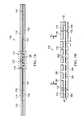
- FIG. 1Ashows a schematic, cross-section view of a first pump according to an illustrative embodiment of the invention.
- FIG. 1Bshows a schematic, perspective view of the first pump of FIG. 1A .
- FIG. 1Cshows a schematic, cross-section view of the first pump of FIG. 1A taken along line 1 C- 1 C in FIG. 1A .
- FIG. 2Ashows a schematic, cross-section view of a second pump according to an illustrative embodiment of the invention.
- FIG. 2Bshows a schematic, cross-section view of a third pump according to an illustrative embodiment of the invention.
- FIG. 3shows a schematic, cross-section view of a fourth pump according to an illustrative embodiment of the invention.
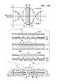
- FIG. 4Ashows a graph of the axial displacement oscillations for the fundamental bending mode of an actuator of the first pump of FIG. 1A .
- FIG. 4Bshows a graph of the pressure oscillations of fluid within the cavity of the first pump of FIG. 1A in response to the bending mode shown in FIG. 4A .
- FIG. 5Ashows a schematic, cross-section view of the first pump of FIG. 1A wherein the three valves are represented by a single valve illustrated in FIGS. 7A-7D .
- FIG. 5Bshows a schematic, cross-sectional, exploded view of a center portion of the valve of FIGS. 7A-7D
- FIG. 6shows a graph of pressure oscillations of fluid of within the cavities of the first pump of FIG. 5A as shown in FIG. 4B to illustrate the pressure differential applied across the valve of FIG. 5A as indicated by the dashed lines.
- FIG. 7Ashows a schematic, cross-section view of an illustrative embodiment of a valve in a closed position.
- FIG. 7Bshows an exploded, sectional view of the valve of FIG. 7A taken along line 7 B- 7 B in FIG. 7D .
- FIG. 7Cshows a schematic, perspective view of the valve of FIG. 7B .
- FIG. 7Dshows a schematic, top view of the valve of FIG. 7B .
- FIG. 8Ashows a schematic, cross-section view of the valve in FIG. 7B in an open position when fluid flows through the valve.
- FIG. 8Bshows a schematic, cross-section view of the valve in FIG. 7B in transition between the open and closed positions before closing.
- FIG. 8Cshows a schematic, cross-section view of the valve of FIG. 7B in a closed position when fluid flow is blocked by the valve.
- FIG. 9Ashows a pressure graph of an oscillating differential pressure applied across the valve of FIG. 5B according to an illustrative embodiment.
- FIG. 9Bshows a fluid-flow graph of an operating cycle of the valve of FIG. 5B between an open and closed position.
- FIGS. 10A and 10Bshow a schematic, cross-section view of the fourth pump of FIG. 3 including an exploded view of the center portion of the valves and a graph of the positive and negative portion, of an oscillating pressure wave, respectively, being applied within a cavity;
- FIG. 11shows the open and closed states of the valves of the fourth pump
- FIGS. 11A and 11Bshows the resulting flow and pressure characteristics, respectively, when the fourth pump is in a free-flow mode
- FIG. 12shows a graph of the maximum differential pressure provided by the fourth pump when the pump reaches the stall condition
- FIGS. 13A and 13Bshow a schematic, cross-section view of the third pump of FIG. 2B including an exploded view of the center portion of the valves and a graph of the positive and negative portion, of oscillating pressure waves, respectively, being applied within two cavities;
- FIG. 14shows the open and closed states of the valves of the third pump
- FIGS. 14A and 14Bshows the resulting flow and pressure characteristics, respectively, when the third pump is in a free-flow mode
- FIG. 15shows a graph of the maximum differential pressure provided by the third pump when the pump reaches the stall condition.
- FIG. 16, 16A, and 16Bshow the open and closed states of the valves of the third pump, and the resulting flow and pressure characteristics when the third pump is operating near the stall condition.
- FIG. 1Ais a schematic cross-section view of a pump 10 according to an illustrative embodiment of the invention.
- the pump 10comprises a pump body having a substantially elliptical shape including a cylindrical wall 11 closed at each end by end plates 12 , 13 .
- the pump 10further comprises a pair of disc-shaped interior plates 14 , 15 supported within the pump 10 by a ring-shaped isolator 30 affixed to the cylindrical wall 11 of the pump body.
- the internal surfaces of the cylindrical wall 11 , the end plate 12 , the interior plate 14 , and the ring-shaped isolator 30form a first cavity 16 within the pump 10
- the internal surfaces of the cylindrical wall 11 , the end plate 13 , the interior plate 15 , and the ring-shaped isolator 30form a second cavity 17 within the pump 10
- the internal surfaces of the first cavity 16comprise a side wall 18 which is a first portion of the inside surface of the cylindrical wall 11 that is closed at both ends by end walls 20 , 22 wherein the end wall 20 is the internal surface of the end plate 12 and the end wall 22 comprises the internal surface of the interior plate 14 and a first side of the isolator 30 .
- the end wall 22thus comprises a central portion corresponding to the inside surface of the interior plate 14 and a peripheral portion corresponding to the inside surface of the ring-shaped isolator 30 .
- the internal surfaces of the second cavity 17comprise a side wall 19 which is a second portion of the inside surface of the cylindrical wall 11 that is closed at both ends by end walls 21 , 23 wherein the end wall 21 is the internal surface of the end plate 13 and the end wall 23 comprises the internal surface of the interior plate 15 and a second side of the isolator 30 .
- the end wall 23thus comprises a central portion corresponding to the inside surface of the interior plate 15 and a peripheral portion corresponding to the inside surface of the ring-shaped isolator 30 .
- the cylindrical wall 11 and the end plates 12 , 13may be a single component comprising the pump body as shown in FIG. 1A or separate components such as the pump body of a pump 60 shown in FIG. 2A wherein the end plate 12 is formed by a separate substrate 12 ′ that may be an assembly board or printed wire assembly (PWA) on which the pump 60 is mounted.
- the cavity 11is substantially circular in shape, the cavity 11 may also be more generally elliptical in shape.
- the end walls defining the cavities 16 , 17are shown as being generally planar and parallel. However the end walls 12 , 13 defining the inside surfaces of the cavities 16 , 17 , respectively, may also include frusto-conical surfaces.
- pump 70comprises frusto-conical surfaces 20 ′, 21 ′ as described in more detail in the WO2006/111775 publication which is incorporated by reference herein.
- the end plates 12 , 13 and cylindrical wall 11 of the pump bodymay be formed from any suitable rigid material including, without limitation, metal, ceramic, glass, or plastic including, without limitation, inject-molded plastic.
- the interior plates 14 , 15 of the pump 10together form an actuator 40 that is operatively associated with the central portion of the end walls 22 , 23 which are the internal surfaces of the cavities 16 , 17 respectfully.
- One of the interior plates 14 , 15must be formed of a piezoelectric material which may include any electrically active material that exhibits strain in response to an applied electrical signal, such as, for example, an electrostrictive or magnetostrictive material.
- the interior plate 15is formed of piezoelectric material that that exhibits strain in response to an applied electrical signal, i.e., the active interior plate.
- the other one of the interior plates 14 , 15preferably possess a bending stiffness similar to the active interior plate and may be formed of a piezoelectric material or an electrically inactive material, such as a metal or ceramic.
- the interior plate 14possess a bending stiffness similar to the active interior plate 15 and is formed of an electrically inactive material, such as a metal or ceramic, i.e., the inert interior plate.
- the active interior plate 15When the active interior plate 15 is excited by an electrical current, the active interior plate 15 expands and contracts in a radial direction relative to the longitudinal axis of the cavities 16 , 17 causing the interior plates 14 , 15 to bend, thereby inducing an axial deflection of their respective end walls 22 , 23 in a direction substantially perpendicular to the end walls 22 , 23 (See FIG. 4A ).
- the isolator 30may support either one of the interior plates 14 , 15 , whether the active or inert internal plate, from the top or the bottom surfaces depending on the specific design and orientation of the pump 10 .
- the actuator 40may be replaced by a device in a force-transmitting relation with only one of the interior plates 14 , 15 such as, for example, a mechanical, magnetic or electrostatic device, wherein the interior plate may be formed as an electrically inactive or passive layer of material driven into oscillation by such device (not shown) in the same manner as described above.
- the pump 10further comprises at least one aperture extending from each of the cavities 16 , 17 to the outside of the pump 10 , wherein at least one of the apertures contain a valve to control the flow of fluid through the aperture.
- the aperturesmay be located at any position in the cavities 16 , 17 where the actuator 40 generates a pressure differential as described below in more detail
- one embodiment of the pump 10 shown in FIGS. 1A-1Ccomprises an inlet aperture 26 and an outlet aperture 27 , each one located at approximately the centre of and extending through the end plates 12 , 13 .
- the apertures 26 , 27contain at least one end valve.
- the apertures 26 , 27contain end valves 28 , 29 which regulate the flow of fluid in one direction as indicated by the arrows so that end valve 28 functions as an inlet valve for the pump 10 while valve 29 functions as an outlet valve for the pump 10 .
- Any reference to the apertures 26 , 27 that include the end valves 28 , 29refers to that portion of the openings outside of the end valves 28 , 29 , i.e., outside the cavities 16 , 17 , respectively, of the pump 10 .
- the pump 10further comprises at least one aperture extending between the cavities 16 , 17 through the actuator 40 , wherein at least one of the apertures contains a valve to control the flow of fluid through the aperture.
- these aperturesmay be located at any position on the actuator 40 between the cavities 16 , 17 where the actuator 40 generates a pressure differential as described below in more detail, one preferred embodiment of the pump 10 shown in FIGS. 1A-1C comprises an actuator aperture 31 located at approximately the centre of and extending through the interior plates 14 , 15 .
- the actuator aperture 31contains an actuator valve 32 which regulates the flow of fluid in one direction between the cavities 16 , 17 (in this embodiment from the first cavity 16 to the second cavity 17 ) as indicated by the arrow so that the actuator valve 32 functions as an outlet valve from the first cavity 16 and as an inlet valve to the second cavity 17 .
- the actuator valve 32enhances the output of the pump 10 by augmenting the flow of fluid between the cavities 16 , 17 and supplementing the operation of the inlet valve 26 in conjunction with the outlet valve 27 as described in more detail below.
- the dimensions of the cavities 16 , 17 described hereinshould each preferably satisfy certain inequalities with respect to the relationship between the height (h) of the cavities 16 , 17 and their radius (r) which is the distance from the longitudinal axis of the cavities 16 , 17 to the side walls 18 , 19 .
- These equationsare as follows: r/h> 1.2; and h 2 /r >4 ⁇ 10 ⁇ 10 meters.
- the ratio of the cavity radius to the cavity heightis between about 10 and about 50 when the fluid within the cavities 16 , 17 is a gas.
- the volume of the cavities 16 , 17may be less than about 10 ml.
- the ratio of h 2 /ris preferably within a range between about 10 ⁇ 6 and about 10 ⁇ 7 meters where the working fluid is a gas as opposed to a liquid.
- each of the cavities 16 , 17 disclosed hereinshould preferably satisfy the following inequality relating the cavity radius (r) and operating frequency (f) which is the frequency at which the actuator 40 vibrates to generate the axial displacement of the end walls 22 , 23 .
- the inequality equationis as follows:
- the frequency of the oscillatory motion of the actuator 40is preferably about equal to the lowest resonant frequency of radial pressure oscillations in the cavities 16 , 17 , but may be within 20% that value.
- the lowest resonant frequency of radial pressure oscillations in the cavity 11is preferably greater than about 500 Hz.
- each of the cavities 16 , 17 disclosed hereinshould satisfy individually the inequalities identified above, the relative dimensions of the cavities 16 , 17 should not be limited to cavities having the same height and radius.
- each of the cavities 16 , 17may have a slightly different shape requiring different radii or heights creating different frequency responses so that the two cavities 14 , 15 resonate in a desired fashion to generate the optimal output from the pump 10 .
- the pump 10may function as a source of positive pressure adjacent the outlet valve 27 to pressurize a load (not shown) or as a source of negative or reduced pressure adjacent the inlet valve 26 to depressurize a load (not shown) as illustrated by the arrows.
- the loadmay be a tissue treatment system that utilizes negative pressure for treatment.
- reduced pressuregenerally refers to a pressure less than the ambient pressure where the pump 10 is located.
- vacuumand “negative pressure” may be used to describe the reduced pressure, the actual pressure reduction may be significantly less than the pressure reduction normally associated with a complete vacuum.
- the pressureis “negative” in the sense that it is a gauge pressure, i.e., the pressure is reduced below ambient atmospheric pressure. Unless otherwise indicated, values of pressure stated herein are gauge pressures. References to increases in reduced pressure typically refer to a decrease in absolute pressure, while decreases in reduced pressure typically refer to an increase in absolute pressure.
- the pump 10comprises at least one actuator valve 32 and at least one end valve, i.e., one of the end valves 28 , 29 .
- the pump 70may comprise only one of the end valves 28 , 29 leaving the other one of the apertures 26 , 27 open.
- either one of the end walls 12 , 13may be removed completely to eliminate one of the cavities 16 , 17 along with one of the end valves 28 , 29 .
- pump 80includes only one end wall and cavity, i.e., end wall 13 and cavity 17 , with only one end valve, i.e., end valve 29 contained within the outlet aperture 27 .
- the actuator valve 32functions as an inlet for the pump 80 so that the aperture extending through the actuator 40 serves as an inlet aperture 33 as shown by the arrow.
- the actuator 40 of the pump 80is oriented such that the position of the interior plates 14 , 15 are reversed with the interior plate 14 positioned inside the cavity 17 .
- a secondary cavity 16 ′may be formed with the active interior plate 15 positioned therein.
- FIG. 4Ashows one possible displacement profile illustrating the axial oscillation of the driven end walls 22 , 23 of the respective cavities 16 , 17 .
- the solid curved line and arrowsrepresent the displacement of the driven end wall 23 at one point in time, and the dashed curved line represents the displacement of the driven end wall 23 one half-cycle later.
- the displacement as shown in this figure and the other figuresis exaggerated. Because the actuator 40 is not rigidly mounted at its perimeter, but rather suspended by the ring-shaped isolator 30 , the actuator 40 is free to oscillate about its centre of mass in its fundamental mode.
- the amplitude of the displacement oscillations of the actuator 40is substantially zero at an annular displacement node 42 located between the centre of the driven end walls 22 , 23 and the side walls 18 , 19 .
- the amplitudes of the displacement oscillations at other points on the end wall 12are greater than zero as represented by the vertical arrows.
- a central displacement anti-node 43exists near the centre of the actuator 40 and a peripheral displacement anti-node 43 ′ exists near the perimeter of the actuator 40 .
- the central displacement anti-node 43is represented by the dashed curve after one half-cycle.
- FIG. 4Bshows one possible pressure oscillation profile illustrating the pressure oscillation within each one of the cavities 16 , 17 resulting from the axial displacement oscillations shown in FIG. 4A .
- the solid curved line and arrowsrepresent the pressure at one point in time.
- the amplitude of the pressure oscillationshas a positive central pressure anti-node 45 near the centre of the cavity 17 and a peripheral pressure anti-node 45 ′ near the side wall 18 of the cavity 16 .
- the amplitude of the pressure oscillationsis substantially zero at the annular pressure node 44 between the central pressure anti-node 45 and the peripheral pressure anti-node 45 ′.
- the amplitude of the pressure oscillations as represented by the dashed linehas a negative central pressure anti-node 47 near the centre of the cavity 16 with a peripheral pressure anti-node 47 ′ and the same annular pressure node 44 .
- the radial dependence of the amplitude of the pressure oscillations in the cavities 16 , 17may be approximated by a Bessel function of the first kind.
- the pressure oscillations described aboveresult from the radial movement of the fluid in the cavities 16 , 17 and so will be referred to as the “radial pressure oscillations” of the fluid within the cavities 16 , 17 as distinguished from the axial displacement oscillations of the actuator 40 .
- the radial dependence of the amplitude of the axial displacement oscillations of the actuator 40should approximate a Bessel function of the first kind so as to match more closely the radial dependence of the amplitude of the desired pressure oscillations in each one of the cavities 16 , 17 (the “mode-shape” of the pressure oscillation).
- the mode-shape of the displacement oscillationssubstantially matches the mode-shape of the pressure oscillations in the cavities 16 , 17 thus achieving mode-shape matching or, more simply, mode-matching.
- the mode-matchingmay not always be perfect in this respect, the axial displacement oscillations of the actuator 40 and the corresponding pressure oscillations in the cavities 16 , 17 have substantially the same relative phase across the full surface of the actuator 40 wherein the radial position of the annular pressure node 44 of the pressure oscillations in the cavities 16 , 17 and the radial position of the annular displacement node 42 of the axial displacement oscillations of actuator 40 are substantially coincident.
- the radial position of the annular displacement node 42will necessarily lie inside the radius of the actuator 40 when the actuator 40 vibrates in its fundamental bending mode as illustrated in FIG. 4A .
- the radius of the actuatorshould preferably be greater than the radius of the annular pressure node 44 to optimize mode-matching.
- the radius of the annular pressure node 44would be approximately 0.63 of the radius from the centre of the end walls 22 , 23 to the side walls 18 , 19 , i.e., the radius of the cavities 16 , 17 (“r”), as shown in FIG. 1A . Therefore, the radius of the actuator 40 (r act ) should preferably satisfy the following inequality: r act ⁇ 0.63r.
- the ring-shaped isolator 30may be a flexible membrane which enables the edge of the actuator 40 to move more freely as described above by bending and stretching in response to the vibration of the actuator 40 as shown by the displacement at the peripheral displacement anti-node 43 ′ in FIG. 4A .
- the flexible membraneovercomes the potential dampening effects of the side walls 18 , 19 on the actuator 40 by providing a low mechanical impedance support between the actuator 40 and the cylindrical wall 11 of the pump 10 thereby reducing the dampening of the axial oscillations at the peripheral displacement anti-node 43 ′ of the actuator 40 .
- the flexible membraneminimizes the energy being transferred from the actuator 40 to the side walls 18 , 19 with the outer peripheral edge of the flexible membrane remaining substantially stationary.
- the annular displacement node 42will remain substantially aligned with the annular pressure node 44 so as to maintain the mode-matching condition of the pump 10 .
- the axial displacement oscillations of the driven end walls 22 , 23continue to efficiently generate oscillations of the pressure within the cavities 16 , 17 from the central pressure anti-nodes 45 , 47 to the peripheral pressure anti-nodes 45 ′, 47 ′ at the side walls 18 , 19 as shown in FIG. 4B .
- FIG. 5Athe pump 10 of FIG. 1A is shown with the valves 28 , 29 , 32 , all of which are substantially similar in structure as represented, for example, by a valve 110 shown in FIGS. 7A-7D and having a center portion 111 shown in FIG. 5B .
- the following description associated with FIGS. 5-9are all based on the function of a single valve 110 that may be positioned in any one of the apertures 26 , 27 , 31 of the pump 10 or pumps 60 , 70 , or 80 .
- FIG. 6shows a graph of the pressure oscillations of fluid within the pump 10 as shown in FIG. 4B .
- the valve 110allows fluid to flow in only one direction as described above.
- the valve 110may be a check valve or any other valve that allows fluid to flow in only one direction. Some valve types may regulate fluid flow by switching between an open and closed position. For such valves to operate at the high frequencies generated by the actuator 40 , the valves 28 , 29 , 32 must have an extremely fast response time such that they are able to open and close on a timescale significantly shorter than the timescale of the pressure variation. One embodiment of the valves 28 , 29 , 32 achieves this by employing an extremely light flap valve which has low inertia and consequently is able to move rapidly in response to changes in relative pressure across the valve structure.
- valve 110 referred to aboveis such a flap valve for the pump 10 according to an illustrative embodiment.
- the valve 110comprises a substantially cylindrical wall 112 that is ring-shaped and closed at one end by a retention plate 114 and at the other end by a sealing plate 116 .
- the inside surface of the wall 112 , the retention plate 114 , and the sealing plate 116form a cavity 115 within the valve 110 .
- the valve 110further comprises a substantially circular flap 117 disposed between the retention plate 114 and the sealing plate 116 , but adjacent the sealing plate 116 .
- the circular flap 117may be disposed adjacent the retention plate 114 in an alternative embodiment as will be described in more detail below, and in this sense the flap 117 is considered to be “biased” against either one of the sealing plate 116 or the retention plate 114 .
- the peripheral portion of the flap 117is sandwiched between the sealing plate 116 and the ring-shaped wall 112 so that the motion of the flap 117 is restrained in the plane substantially perpendicular the surface of the flap 117 .
- the motion of the flap 117 in such planemay also be restrained by the peripheral portion of the flap 117 being attached directly to either the sealing plate 116 or the wall 112 , or by the flap 117 being a close fit within the ring-shaped wall 112 , in an alternative embodiment.
- the remainder of the flap 117is sufficiently flexible and movable in a direction substantially perpendicular to the surface of the flap 117 , so that a force applied to either surface of the flap 117 will motivate the flap 117 between the sealing plate 116 and the retention plate 114 .
- the retention plate 114 and the sealing plate 116both have holes 118 and 120 , respectively, which extend through each plate.
- the flap 117also has holes 122 that are generally aligned with the holes 118 of the retention plate 114 to provide a passage through which fluid may flow as indicated by the dashed arrows 124 in FIGS. 5B and 8A .
- the holes 122 in the flap 117may also be partially aligned, i.e., having only a partial overlap, with the holes 118 in the retention plate 114 .
- the holes 118 , 120 , 122are shown to be of substantially uniform size and shape, they may be of different diameters or even different shapes without limiting the scope of the invention.
- the holes 118 and 120form an alternating pattern across the surface of the plates as shown by the solid and dashed circles, respectively, in FIG. 7D .
- the holes 118 , 120 , 122may be arranged in different patterns without effecting the operation of the valve 110 with respect to the functioning of the individual pairings of holes 118 , 120 , 122 as illustrated by individual sets of the dashed arrows 124 .
- the pattern of holes 118 , 120 , 122may be designed to increase or decrease the number of holes to control the total flow of fluid through the valve 110 as required. For example, the number of holes 118 , 120 , 122 may be increased to reduce the flow resistance of the valve 110 to increase the total flow rate of the valve 110 .
- the center portion 111 of the valve 110illustrates how the flap 117 is motivated between the sealing plate 116 and the retention plate 114 when a force applied to either surface of the flap 117 .
- the valve 110is in a “normally closed” position because the flap 117 is disposed adjacent the sealing plate 116 where the holes 122 of the flap are offset or not aligned with the holes 118 of the sealing plate 116 .
- this “normally closed” positionthe flow of fluid through the sealing plate 116 is substantially blocked or covered by the non-perforated portions of the flap 117 as shown in FIGS. 7A and 7B .
- valve 110moves from the normally closed position to an “open” position over a time period, i.e., an opening time delay (T o ), allowing fluid to flow in the direction indicated by the dashed arrows 124 .
- T oopening time delay
- a closing time delayT c
- the flap 117may be biased against the retention plate 114 with the holes 118 , 122 aligned in a “normally open” position. In this embodiment, applying positive pressure against the flap 117 will be necessary to motivate the flap 117 into a “closed” position.
- valve operationin relation to valve operation are intended to include cases in which substantial (but incomplete) sealing or blockage occurs, such that the flow resistance of the valve is greater in the “closed” position than in the “open” position.
- the operation of the valve 110is a function of the change in direction of the differential pressure ( ⁇ P) of the fluid across the valve 110 .
- the differential pressurehas been assigned a negative value ( ⁇ P) as indicated by the downward pointing arrow.
- ⁇ Pnegative value
- the fluid pressure at the outside surface of the retention plate 114is greater than the fluid pressure at the outside surface of the sealing plate 116 .
- This negative differential pressure ( ⁇ P)drives the flap 117 into the fully closed position as described above wherein the flap 117 is pressed against the sealing plate 116 to block the holes 120 in the sealing plate 116 , thereby substantially preventing the flow of fluid through the valve 110 .
- the changing differential pressurecycles the valve 110 between closed and open positions based on the direction (i.e., positive or negative) of the differential pressure across the valve 110 .
- the flap 117could be biased against the retention plate 114 in an open position when no differential pressure is applied across the valve 110 , i.e., the valve 110 would then be in a “normally open” position.
- the operation of the valve 110is a function of the change in direction of the differential pressure ( ⁇ P) of the fluid across the valve 110 .
- the differential pressure ( ⁇ P)is assumed to be substantially uniform across the entire surface of the retention plate 114 because (1) the diameter of the retention plate 114 is small relative to the wavelength of the pressure oscillations in the cavity 115 , and (2) the valve 110 is located near the centre of the cavities 16 , 17 where the amplitude of the positive central pressure anti-node 45 is relatively constant as indicated by the positive square-shaped portion 55 of the positive central pressure anti-node 45 and the negative square-shaped portion 65 of the negative central pressure anti-node 47 shown in FIG. 6 . Therefore, there is virtually no spatial variation in the pressure across the center portion 111 of the valve 110 .
- FIG. 9further illustrates the dynamic operation of the valve 110 when it is subject to a differential pressure which varies in time between a positive value (+ ⁇ P) and a negative value ( ⁇ P). While in practice the time-dependence of the differential pressure across the valve 110 may be approximately sinusoidal, the time-dependence of the differential pressure across the valve 110 is approximated as varying in the square-wave form shown in FIG. 9A to facilitate explanation of the operation of the valve.
- the positive differential pressure 55is applied across the valve 110 over the positive pressure time period (t p+ ) and the negative differential pressure 65 is applied across the valve 110 over the negative pressure time period (t p ⁇ ) of the square wave.
- FIG. 9Billustrates the motion of the flap 117 in response to this time-varying pressure.
- the retention plate 114 and the sealing plate 116should be strong enough to withstand the fluid pressure oscillations to which they are subjected without significant mechanical deformation.
- the retention plate 114 and the sealing plate 116may be formed from any suitable rigid material, such as glass, silicon, ceramic, or metal.
- the holes 118 , 120 in the retention plate 114 and the sealing plate 116may be formed by any suitable process including chemical etching, laser machining, mechanical drilling, powder blasting, and stamping.
- the retention plate 114 and the sealing plate 116are formed from sheet steel between 100 and 200 microns thick, and the holes 118 , 120 therein are formed by chemical etching.
- the flap 117may be formed from any lightweight material, such as a metal or polymer film.
- the flap 117may be formed from a thin polymer sheet between 1 micron and 20 microns in thickness.
- the flap 117may be formed from polyethylene terephthalate (PET) or a liquid crystal polymer film approximately 3 microns in thickness.
- FIGS. 10A and 10Ban exploded view of the two-valve pump 80 is shown that utilizes valve 110 as valves 29 and 32 .
- the actuator valve 32gates airflow 232 between the inlet aperture 33 and cavity 17 of the pump 80 ( FIG. 10A ), while end valve 29 gates airflow between the cavity 17 and the outlet aperture 27 of the pump 80 ( FIG. 10B ).
- Each of the figuresalso shows the pressure generated in the cavity 17 as the actuator 40 oscillates.
- Both of the valves 29 and 32are located near the center of the cavity 17 where the amplitudes of the positive and negative central pressure anti-nodes 45 and 47 , respectively, are relatively constant as indicated by the positive and negative square-shaped portions 55 and 65 , respectively, as described above.
- valves 29 and 32are both biased in the closed position as shown by the flap 117 and operate as described above when the flap 117 is motivated to the open position as indicated by flap 117 ′.
- the figuresalso show an exploded view of the positive and negative square-shaped portions 55 , 65 of the central pressure anti-nodes 45 , 47 and their simultaneous impact on the operation of both valves 29 , 32 and the corresponding airflow 229 and 232 , respectively, generated through each one
- FIGS. 11, 11A and 11Bthe open and closed states of the valves 29 and 32 ( FIG. 11 ) and the resulting flow characteristics of each one ( FIG. 11A ) are shown as related to the pressure in the cavity 17 ( FIG. 11B ).
- the actuator 40begins vibrating to generate pressure oscillations within the cavity 17 as described above, air begins flowing alternately through the valves 29 , 32 causing air to flow from the inlet aperture 33 to the outlet aperture 27 of the pump 80 , i.e., the pump 80 begins operating in a “free-flow” mode.
- the inlet aperture 33 of the pump 80may be supplied with air at ambient pressure while the outlet aperture 27 of the pump 80 is pneumatically coupled to a load (not shown) that becomes pressurized through the action of the pump 80 .
- the inlet aperture 33 of the pump 80may be pneumatically coupled to a load (not shown) that becomes depressurized to generate a negative pressure in the load, such as a wound dressing, through the action of the pump 80 .
- the square-shaped portion 55 of the positive central pressure anti-node 45is generated within the cavity 17 by the vibration of the actuator 40 during one half of the pump cycle as described above.
- the square-shaped portion 55 of the positive central anti-node 45creates a positive differential pressure across the end valve 29 and a negative differential pressure across the actuator valve 32 .
- the actuator valve 32begins closing and the end valve 29 begins opening so that the actuator valve 32 blocks the airflow 232 x through the inlet aperture 33 , while the end valve 29 opens to release air from within the cavity 17 allowing the airflow 229 to exit the cavity 17 through the outlet aperture 27 .
- the actuator valve 32 closes and the end valve 29 opensFIG. 11
- the airflow 229 at the outlet aperture 27 of the pump 80increases to a maximum value dependent on the design characteristics of the end valve 29 ( FIG. 11A ).
- the opened end valve 29allows airflow 229 to exit the pump cavity 17 ( FIG. 11 B) while the actuator valve 32 is closed.
- the square-shaped portion 65 of the negative central anti-node 47is generated within the cavity 17 by the vibration of the actuator 40 during the second half of the pump cycle as described above.
- the square-shaped portion 65 the negative central anti-node 47creates a negative differential pressure across the end valve 29 and a positive differential pressure across the actuator valve 32 .
- the actuator valve 32begins opening and the end valve 29 begins closing so that the end valve 29 blocks the airflow 229 x through the outlet aperture 27 , while the actuator valve 32 opens allowing air to flow into the cavity 17 as shown by the airflow 232 through the inlet aperture 33 .
- the actuator valve 32opens and the end valve 29 closes ( FIG. 11 )
- the airflow at the outlet aperture 27 of the pump 80is substantially zero except for the small amount of backflow 329 as described above ( FIG. 11A ).
- the opened actuator valve 32allows airflow 232 into the pump cavity 17 ( FIG. 11B ) while the end valve 29 is closed.
- the airflow 232begins to drop until the differential pressure across the actuator valve 32 reaches zero.
- FIG. 12illustrates the pressures within the cavity 17 and outside the cavity 17 at the inlet aperture 33 and the outlet aperture 27 when the pump 80 is in the stall condition. More specifically, the mean pressure in the cavity 17 is approximately 1P above the inlet pressure (i.e.
- FIGS. 13A and 13Ban exploded view of the 3-valve pump 70 that utilizes valve 110 as valves 28 , 29 and 32 is shown.
- the end valve 28gates airflow 228 between the inlet aperture 26 and the cavity 16 of the pump 70
- the end valve 29gates airflow 229 between the cavity 17 and the outlet aperture 27 of the pump 70 ( FIG. 13A ).
- the actuator valve 32is positioned between the cavities 16 , 17 and gates the airflow 232 between these cavities ( FIG. 13B ).
- the valves 28 , 29 and 32are all biased in the closed position as shown by the flaps 117 and operate as described above when the flaps 117 are motivated to the open position as indicated by the flaps 117 ′.
- the actuator 40 of the 3-valve pump 70creates pressure oscillations in each of cavities 16 and 17 including a primary pressure oscillation within the cavity 17 on one side of the actuator 40 and a complementary pressure oscillation within the cavity 16 on the other side of the actuator 40 .
- the primary and complementary pressure oscillations within cavities 17 , 16are approximately 180 ° out of phase with one another as indicated by the solid and dashed curves respectively in FIGS. 13A, 13B and 14B .
- All three of the valves 28 , 29 , and 32are located near the center of the cavities 16 and 17 where (i) the amplitude of the primary positive and negative central pressure anti-nodes 45 and 47 , respectively, in the cavity 17 is relatively constant as indicated by the positive and negative square-shaped portions 55 and 65 , respectively, as described above, and (ii) the amplitude of the complementary positive and negative central pressure anti-nodes 46 and 48 , respectively, in the cavity 16 is also relatively constant as indicated by the positive and negative square-shaped portions 56 and 66 , respectively.
- FIGS. 1-10show an exploded views of the pump 70 showing (i) the impact of the positive and negative square-shaped portions 55 , 65 within the cavity 17 on the operation of the end valve 29 and the actuator valve 32 including the corresponding airflows 229 and 232 , respectively, generated through both of them and exiting the outlet aperture 27 , and (i) the impact of the positive and negative square-shaped portions 56 , 66 within the cavity 16 on the operation of the end valve 28 and the actuator valve 32 including the corresponding airflows 228 and 232 , respectively, generated through both of them from the inlet aperture 26 .
- FIGS. 14, 14A and 14Bthe open and closed states of the end valves 28 , 29 and the actuator valve 32 ( FIG. 14 ), and the resulting flow characteristics of each one ( FIG. 14A ) are shown as related to the pressure in the cavities 16 , 17 ( FIG. 14B ).
- the actuator 40begins vibrating to generate pressure oscillations within the cavities 16 , 17 as described above, air begins flowing alternately through the end valves 28 , 29 and the actuator valve 32 causing air to flow from the inlet aperture 26 to the outlet aperture 27 of the pump 70 , i.e., the pump 70 begins operating in a “free-flow” mode as described above.
- the inlet aperture 26 of the pump 70may be supplied with air at ambient pressure while the outlet aperture 27 of the pump 70 is pneumatically coupled to a load (not shown) that becomes pressurized through the action of the pump 70 .
- the inlet aperture 26 of the pump 70may be pneumatically coupled to a load (not shown) that becomes depressurized to generate a negative pressure through the action of the pump 70 .
- the positive square-shaped portion 55 of the primary positive center pressure anti-node 45is generated within the cavity 17 by the vibration of the actuator 40 during one half of the pump cycle as described above, while at the same time the complementary negative square-shaped portion 66 of the complementary negative center pressure anti-node 48 is generated on the other side of the actuator 40 within the cavity 16 .
- the positive square-shaped portion 55 of the positive central anti-node 45creates a positive differential pressure across the end valve 29 and the negative square-shaped portion 66 of the negative central anti-node 48 creates a positive differential pressure across the end valve 28 .
- the combined action of the primary positive square-shaped portion 55 and the complementary negative square-shaped portion 66create a negative differential pressure across the valve 32 .
- the actuator valve 32begins closing and the end valves 28 , 29 simultaneously begin opening so that the actuator valve 32 blocks the airflow 232 x while the end valves 28 , 29 open to (i) release air from within the cavity 17 allowing the airflow 229 to exit the cavity 17 through the outlet aperture 27 , and (ii) draw air into the cavity 16 allowing airflow 228 into the cavity 16 through the inlet aperture 26 .
- the actuator valve 32closes and the end valves 28 , 29 open ( FIG.
- the airflow 229 at the outlet aperture 27 of the pump 70increases to a maximum value dependent on the design characteristics of the end valve 29 ( FIG. 14A ).
- the open end valve 29allows airflow 229 to exit the pump cavity 17 ( FIG. 11B ) while the actuator valve 32 is closed.
- the airflows 228 , 229begin to drop until the differential pressure across the end valves 28 , 29 reaches zero.
- the primary negative square-shaped portion 65 of the primary negative center pressure anti-node 47is generated within the cavity 17 by the vibration of the actuator 40 during the second half of the pump cycle, while at the same time the complementary positive square-shaped portion 56 of the complementary positive central pressure anti-node 46 is generated within the cavity 16 by the vibration of the actuator 40 .
- the primary negative square-shaped portion 65 of the primary negative central anti-node 47creates a negative differential pressure across the end valve 29 and the complementary positive square-shaped portion 56 of the complementary positive central anti-node 46 creates a negative differential pressure across the end valve 28 .
- the combined action of the primary negative square-shaped portion 65 and the complementary positive square-shaped portion 56creates a negative differential pressure across the valve 32 .
- the actuator valve 32begins opening and the end valves 28 , 29 begin closing so that the end valves 28 , 29 block the airflows 228 x , 229 x , respectively, through the inlet aperture 26 and the outlet aperture 27 , while the actuator valve 32 opens to allow airflow 232 from the cavity 16 into the cavity 17 .
- the actuator valve 32 opens and the end valves 28 , 29 closeFIG. 14
- the airflows at the inlet aperture 26 and the outlet aperture 27 of the pump 70are substantially zero except for the small amount of backflow 328 , 329 through each valve ( FIG. 14A ).
- FIG. 15illustrates the pressures within the cavities 16 , 17 , outside the cavity 16 at the inlet aperture 26 , and outside the cavity 17 at the outlet aperture 27 when the pump 70 is in the stall condition. More specifically, the mean pressure in the cavity 16 is approximately 1P above the inlet pressure (i.e.
- the pump 70utilizes three valves with two cavities, the pump 70 is capable of increasing the differential pressure between the inlet aperture 26 and the outlet aperture 27 of the pump 70 to a maximum differential pressure of 4P, four times that of a single valve pump.
- the outlet pressure of the two-cavity, three-valve pump 70increases from ambient in the free-flow mode to a maximum differential pressure of 4P when the pump reaches the stall condition.
- valve differential pressures, valve movements, and airflow operational characteristicsvary significantly between the initial free-flow condition and the stall condition described above where there is virtually no airflow ( FIGS. 12, 15 ).
- the pump 70is shown in a “near-stall” condition wherein the pump 70 is delivering a differential pressure of about 3P as shown in FIG. 16 .
- the open/close duty cycle of the end valves 28 , 29is substantially lower than the duty cycle when the valves are in the free-flow mode ( FIG. 16A ), which substantially reduces the airflow from the outlet of the pump 70 as the total differential pressure increases ( FIG. 16B ).
Landscapes
- Engineering & Computer Science (AREA)
- Mechanical Engineering (AREA)
- General Engineering & Computer Science (AREA)
- Reciprocating Pumps (AREA)
Abstract
Description
r/h>1.2; and
h2/r>4×10−10meters.
wherein the speed of sound in the working fluid within the
Claims (20)
Priority Applications (1)
| Application Number | Priority Date | Filing Date | Title |
|---|---|---|---|
| US13/591,951US9506463B2 (en) | 2011-09-21 | 2012-08-22 | Disc pump and valve structure |
Applications Claiming Priority (2)
| Application Number | Priority Date | Filing Date | Title |
|---|---|---|---|
| US201161537431P | 2011-09-21 | 2011-09-21 | |
| US13/591,951US9506463B2 (en) | 2011-09-21 | 2012-08-22 | Disc pump and valve structure |
Publications (2)
| Publication Number | Publication Date |
|---|---|
| US20130071273A1 US20130071273A1 (en) | 2013-03-21 |
| US9506463B2true US9506463B2 (en) | 2016-11-29 |
Family
ID=46796779
Family Applications (1)
| Application Number | Title | Priority Date | Filing Date |
|---|---|---|---|
| US13/591,951Active2034-05-22US9506463B2 (en) | 2011-09-21 | 2012-08-22 | Disc pump and valve structure |
Country Status (6)
| Country | Link |
|---|---|
| US (1) | US9506463B2 (en) |
| EP (1) | EP2758666B1 (en) |
| JP (1) | JP6179993B2 (en) |
| AU (1) | AU2012312898B2 (en) |
| CA (1) | CA2845880C (en) |
| WO (1) | WO2013043300A1 (en) |
Cited By (11)
| Publication number | Priority date | Publication date | Assignee | Title |
|---|---|---|---|---|
| US20160377073A1 (en)* | 2014-03-07 | 2016-12-29 | Murata Manufacturing Co., Ltd. | Blower |
| US20170002839A1 (en)* | 2013-12-13 | 2017-01-05 | The Technology Partnership Plc | Acoustic-resonance fluid pump |
| US9901664B2 (en) | 2012-03-20 | 2018-02-27 | Smith & Nephew Plc | Controlling operation of a reduced pressure therapy system based on dynamic duty cycle threshold determination |
| US20180100495A1 (en)* | 2015-06-11 | 2018-04-12 | Murata Manufacturing Co., Ltd. | Pump |
| US10143783B2 (en) | 2011-11-02 | 2018-12-04 | Smith & Nephew Plc | Reduced pressure therapy apparatuses and methods of using same |
| US10299964B2 (en) | 2012-05-15 | 2019-05-28 | Smith & Nephew Plc | Negative pressure wound therapy apparatus |
| US10307517B2 (en) | 2010-09-20 | 2019-06-04 | Smith & Nephew Plc | Systems and methods for controlling operation of a reduced pressure therapy system |
| US10682446B2 (en) | 2014-12-22 | 2020-06-16 | Smith & Nephew Plc | Dressing status detection for negative pressure wound therapy |
| US10871156B2 (en)* | 2016-07-29 | 2020-12-22 | Murata Manufacturing Co., Ltd. | Valve and gas control device |
| US12097095B2 (en) | 2011-05-26 | 2024-09-24 | Smith & Nephew, Inc. | Method and apparatus for providing negative pressure to a negative pressure wound therapy bandage |
| US12331759B2 (en) | 2020-07-31 | 2025-06-17 | Lee Ventus Ltd. | Method of making an actuator for a resonant acoustic pump |
Families Citing this family (14)
| Publication number | Priority date | Publication date | Assignee | Title |
|---|---|---|---|---|
| US10105504B2 (en)* | 2012-12-18 | 2018-10-23 | Koninklijke Philips N.V. | EAP-driven air pump for patient interfaces |
| CN108317093B (en)* | 2014-02-21 | 2019-12-10 | 株式会社村田制作所 | Blower fan |
| CN104100541A (en)* | 2014-07-18 | 2014-10-15 | 长春隆美科技发展有限公司 | Micro piezoelectric type axial flow fan |
| CN104100542B (en)* | 2014-07-19 | 2019-10-22 | 长春隆美科技发展有限公司 | Piezoelectric driving type micro fan |
| JP6481769B2 (en)* | 2015-10-05 | 2019-03-13 | 株式会社村田製作所 | Fluid control device, decompression device, and pressurization device |
| TWI613367B (en) | 2016-09-05 | 2018-02-01 | 研能科技股份有限公司 | Fluid control device |
| TWI625468B (en) | 2016-09-05 | 2018-06-01 | 研能科技股份有限公司 | Fluid control device |
| TWI602995B (en)* | 2016-09-05 | 2017-10-21 | 研能科技股份有限公司 | Fluid control device |
| CN109642681B (en)* | 2017-05-31 | 2021-01-15 | 株式会社村田制作所 | Valve and fluid control device |
| TWI689665B (en)* | 2017-09-15 | 2020-04-01 | 研能科技股份有限公司 | Gas transmitting device |
| TWI646261B (en)* | 2017-09-15 | 2019-01-01 | 研能科技股份有限公司 | Gas delivery device |
| JP7435785B2 (en)* | 2020-07-17 | 2024-02-21 | 株式会社村田製作所 | fluid control device |
| GB2624475B (en) | 2023-02-08 | 2025-06-18 | Foster & Freeman Ltd | Volatile sampling device |
| CN117189554B (en)* | 2023-09-13 | 2024-05-28 | 深圳白边精密科技有限公司 | Acoustic pressure pump, working method and application equipment |
Citations (128)
| Publication number | Priority date | Publication date | Assignee | Title |
|---|---|---|---|---|
| US1355846A (en) | 1920-02-06 | 1920-10-19 | David A Rannells | Medical appliance |
| US2547758A (en) | 1949-01-05 | 1951-04-03 | Wilmer B Keeling | Instrument for treating the male urethra |
| US2632443A (en) | 1949-04-18 | 1953-03-24 | Eleanor P Lesher | Surgical dressing |
| GB692578A (en) | 1949-09-13 | 1953-06-10 | Minnesota Mining & Mfg | Improvements in or relating to drape sheets for surgical use |
| US2682873A (en) | 1952-07-30 | 1954-07-06 | Johnson & Johnson | General purpose protective dressing |
| US2910763A (en) | 1955-08-17 | 1959-11-03 | Du Pont | Felt-like products |
| US2969057A (en) | 1957-11-04 | 1961-01-24 | Brady Co W H | Nematodic swab |
| US3066672A (en) | 1960-09-27 | 1962-12-04 | Jr William H Crosby | Method and apparatus for serial sampling of intestinal juice |
| US3367332A (en) | 1965-08-27 | 1968-02-06 | Gen Electric | Product and process for establishing a sterile area of skin |
| US3520300A (en) | 1967-03-15 | 1970-07-14 | Amp Inc | Surgical sponge and suction device |
| US3568675A (en) | 1968-08-30 | 1971-03-09 | Clyde B Harvey | Fistula and penetrating wound dressing |
| US3648692A (en) | 1970-12-07 | 1972-03-14 | Parke Davis & Co | Medical-surgical dressing for burns and the like |
| US3682180A (en) | 1970-06-08 | 1972-08-08 | Coilform Co Inc | Drain clip for surgical drain |
| US3826254A (en) | 1973-02-26 | 1974-07-30 | Verco Ind | Needle or catheter retaining appliance |
| DE2640413A1 (en) | 1976-09-08 | 1978-03-09 | Wolf Gmbh Richard | CATHETER MONITORING DEVICE |
| US4080970A (en) | 1976-11-17 | 1978-03-28 | Miller Thomas J | Post-operative combination dressing and internal drain tube with external shield and tube connector |
| US4096853A (en) | 1975-06-21 | 1978-06-27 | Hoechst Aktiengesellschaft | Device for the introduction of contrast medium into an anus praeter |
| US4139004A (en) | 1977-02-17 | 1979-02-13 | Gonzalez Jr Harry | Bandage apparatus for treating burns |
| US4165748A (en) | 1977-11-07 | 1979-08-28 | Johnson Melissa C | Catheter tube holder |
| US4184510A (en) | 1977-03-15 | 1980-01-22 | Fibra-Sonics, Inc. | Valued device for controlling vacuum in surgery |
| WO1980002182A1 (en) | 1979-04-06 | 1980-10-16 | J Moss | Portable suction device for collecting fluids from a closed wound |
| US4233969A (en) | 1976-11-11 | 1980-11-18 | Lock Peter M | Wound dressing materials |
| US4245630A (en) | 1976-10-08 | 1981-01-20 | T. J. Smith & Nephew, Ltd. | Tearable composite strip of materials |
| US4256109A (en) | 1978-07-10 | 1981-03-17 | Nichols Robert L | Shut off valve for medical suction apparatus |
| US4261363A (en) | 1979-11-09 | 1981-04-14 | C. R. Bard, Inc. | Retention clips for body fluid drains |
| US4275721A (en) | 1978-11-28 | 1981-06-30 | Landstingens Inkopscentral Lic, Ekonomisk Forening | Vein catheter bandage |
| US4284079A (en) | 1979-06-28 | 1981-08-18 | Adair Edwin Lloyd | Method for applying a male incontinence device |
| US4297995A (en) | 1980-06-03 | 1981-11-03 | Key Pharmaceuticals, Inc. | Bandage containing attachment post |
| US4333468A (en) | 1980-08-18 | 1982-06-08 | Geist Robert W | Mesentery tube holder apparatus |
| US4373519A (en) | 1981-06-26 | 1983-02-15 | Minnesota Mining And Manufacturing Company | Composite wound dressing |
| US4382441A (en) | 1978-12-06 | 1983-05-10 | Svedman Paul | Device for treating tissues, for example skin |
| US4392853A (en) | 1981-03-16 | 1983-07-12 | Rudolph Muto | Sterile assembly for protecting and fastening an indwelling device |
| US4392858A (en) | 1981-07-16 | 1983-07-12 | Sherwood Medical Company | Wound drainage device |
| US4419097A (en) | 1981-07-31 | 1983-12-06 | Rexar Industries, Inc. | Attachment for catheter tube |
| EP0100148A1 (en) | 1982-07-06 | 1984-02-08 | Dow Corning Limited | Medical-surgical dressing and a process for the production thereof |
| US4465485A (en) | 1981-03-06 | 1984-08-14 | Becton, Dickinson And Company | Suction canister with unitary shut-off valve and filter features |
| EP0117632A2 (en) | 1983-01-27 | 1984-09-05 | Johnson & Johnson Products Inc. | Adhesive film dressing |
| US4475909A (en) | 1982-05-06 | 1984-10-09 | Eisenberg Melvin I | Male urinary device and method for applying the device |
| US4480638A (en) | 1980-03-11 | 1984-11-06 | Eduard Schmid | Cushion for holding an element of grafted skin |
| US4525166A (en) | 1981-11-21 | 1985-06-25 | Intermedicat Gmbh | Rolled flexible medical suction drainage device |
| US4525374A (en) | 1984-02-27 | 1985-06-25 | Manresa, Inc. | Treating hydrophobic filters to render them hydrophilic |
| US4540412A (en) | 1983-07-14 | 1985-09-10 | The Kendall Company | Device for moist heat therapy |
| US4543100A (en) | 1983-11-01 | 1985-09-24 | Brodsky Stuart A | Catheter and drain tube retainer |
| US4548202A (en) | 1983-06-20 | 1985-10-22 | Ethicon, Inc. | Mesh tissue fasteners |
| US4551139A (en) | 1982-02-08 | 1985-11-05 | Marion Laboratories, Inc. | Method and apparatus for burn wound treatment |
| EP0161865A2 (en) | 1984-05-03 | 1985-11-21 | Smith and Nephew Associated Companies p.l.c. | Adhesive wound dressing |
| US4569348A (en) | 1980-02-22 | 1986-02-11 | Velcro Usa Inc. | Catheter tube holder strap |
| US4605399A (en) | 1984-12-04 | 1986-08-12 | Complex, Inc. | Transdermal infusion device |
| US4608041A (en) | 1981-10-14 | 1986-08-26 | Frese Nielsen | Device for treatment of wounds in body tissue of patients by exposure to jets of gas |
| US4640688A (en) | 1985-08-23 | 1987-02-03 | Mentor Corporation | Urine collection catheter |
| US4655754A (en) | 1984-11-09 | 1987-04-07 | Stryker Corporation | Vacuum wound drainage system and lipids baffle therefor |
| US4664662A (en) | 1984-08-02 | 1987-05-12 | Smith And Nephew Associated Companies Plc | Wound dressing |
| WO1987004626A1 (en) | 1986-01-31 | 1987-08-13 | Osmond, Roger, L., W. | Suction system for wound and gastro-intestinal drainage |
| US4710165A (en) | 1985-09-16 | 1987-12-01 | Mcneil Charles B | Wearable, variable rate suction/collection device |
| US4733659A (en) | 1986-01-17 | 1988-03-29 | Seton Company | Foam bandage |
| GB2195255A (en) | 1986-09-30 | 1988-04-07 | Vacutec Uk Limited | Method and apparatus for vacuum treatment of an epidermal surface |
| US4743232A (en) | 1986-10-06 | 1988-05-10 | The Clinipad Corporation | Package assembly for plastic film bandage |
| GB2197789A (en) | 1986-11-28 | 1988-06-02 | Smiths Industries Plc | Anti-foaming disinfectants used in surgical suction apparatus |
| US4758220A (en) | 1985-09-26 | 1988-07-19 | Alcon Laboratories, Inc. | Surgical cassette proximity sensing and latching apparatus |
| US4787888A (en) | 1987-06-01 | 1988-11-29 | University Of Connecticut | Disposable piezoelectric polymer bandage for percutaneous delivery of drugs and method for such percutaneous delivery (a) |
| US4826494A (en) | 1984-11-09 | 1989-05-02 | Stryker Corporation | Vacuum wound drainage system |
| US4838883A (en) | 1986-03-07 | 1989-06-13 | Nissho Corporation | Urine-collecting device |
| US4840187A (en) | 1986-09-11 | 1989-06-20 | Bard Limited | Sheath applicator |
| US4863449A (en) | 1987-07-06 | 1989-09-05 | Hollister Incorporated | Adhesive-lined elastic condom cathether |
| US4872450A (en) | 1984-08-17 | 1989-10-10 | Austad Eric D | Wound dressing and method of forming same |
| US4878901A (en) | 1986-10-10 | 1989-11-07 | Sachse Hans Ernst | Condom catheter, a urethral catheter for the prevention of ascending infections |
| GB2220357A (en) | 1988-05-28 | 1990-01-10 | Smiths Industries Plc | Medico-surgical containers |
| US4897081A (en) | 1984-05-25 | 1990-01-30 | Thermedics Inc. | Percutaneous access device |
| US4906240A (en) | 1988-02-01 | 1990-03-06 | Matrix Medica, Inc. | Adhesive-faced porous absorbent sheet and method of making same |
| US4906233A (en) | 1986-05-29 | 1990-03-06 | Terumo Kabushiki Kaisha | Method of securing a catheter body to a human skin surface |
| US4919654A (en) | 1988-08-03 | 1990-04-24 | Kalt Medical Corporation | IV clamp with membrane |
| CA2005436A1 (en) | 1988-12-13 | 1990-06-13 | Glenda G. Kalt | Transparent tracheostomy tube dressing |
| US4941882A (en) | 1987-03-14 | 1990-07-17 | Smith And Nephew Associated Companies, P.L.C. | Adhesive dressing for retaining a cannula on the skin |
| US4953565A (en) | 1986-11-26 | 1990-09-04 | Shunro Tachibana | Endermic application kits for external medicines |
| WO1990010424A1 (en) | 1989-03-16 | 1990-09-20 | Smith & Nephew Plc | Absorbent devices and precursors therefor |
| US4969880A (en) | 1989-04-03 | 1990-11-13 | Zamierowski David S | Wound dressing and treatment method |
| US4985019A (en) | 1988-03-11 | 1991-01-15 | Michelson Gary K | X-ray marker |
| GB2235877A (en) | 1989-09-18 | 1991-03-20 | Antonio Talluri | Closed wound suction apparatus |
| US5037397A (en) | 1985-05-03 | 1991-08-06 | Medical Distributors, Inc. | Universal clamp |
| US5086170A (en) | 1989-01-16 | 1992-02-04 | Roussel Uclaf | Process for the preparation of azabicyclo compounds |
| US5092858A (en) | 1990-03-20 | 1992-03-03 | Becton, Dickinson And Company | Liquid gelling agent distributor device |
| US5100396A (en) | 1989-04-03 | 1992-03-31 | Zamierowski David S | Fluidic connection system and method |
| US5134994A (en) | 1990-02-12 | 1992-08-04 | Say Sam L | Field aspirator in a soft pack with externally mounted container |
| US5149331A (en) | 1991-05-03 | 1992-09-22 | Ariel Ferdman | Method and device for wound closure |
| US5167613A (en) | 1992-03-23 | 1992-12-01 | The Kendall Company | Composite vented wound dressing |
| US5176663A (en) | 1987-12-02 | 1993-01-05 | Pal Svedman | Dressing having pad with compressibility limiting elements |
| WO1993009727A1 (en) | 1991-11-14 | 1993-05-27 | Wake Forest University | Method and apparatus for treating tissue damage |
| US5215522A (en) | 1984-07-23 | 1993-06-01 | Ballard Medical Products | Single use medical aspirating device and method |
| US5232453A (en) | 1989-07-14 | 1993-08-03 | E. R. Squibb & Sons, Inc. | Catheter holder |
| US5261893A (en) | 1989-04-03 | 1993-11-16 | Zamierowski David S | Fastening system and method |
| US5278100A (en) | 1991-11-08 | 1994-01-11 | Micron Technology, Inc. | Chemical vapor deposition technique for depositing titanium silicide on semiconductor wafers |
| US5279550A (en) | 1991-12-19 | 1994-01-18 | Gish Biomedical, Inc. | Orthopedic autotransfusion system |
| US5298015A (en) | 1989-07-11 | 1994-03-29 | Nippon Zeon Co., Ltd. | Wound dressing having a porous structure |
| US5342376A (en) | 1993-05-03 | 1994-08-30 | Dermagraphics, Inc. | Inserting device for a barbed tissue connector |
| US5344415A (en) | 1993-06-15 | 1994-09-06 | Deroyal Industries, Inc. | Sterile system for dressing vascular access site |
| DE4306478A1 (en) | 1993-03-02 | 1994-09-08 | Wolfgang Dr Wagner | Drainage device, in particular pleural drainage device, and drainage method |
| WO1994020041A1 (en) | 1993-03-09 | 1994-09-15 | Wake Forest University | Wound treatment employing reduced pressure |
| US5358494A (en) | 1989-07-11 | 1994-10-25 | Svedman Paul | Irrigation dressing |
| US5437622A (en) | 1992-04-29 | 1995-08-01 | Laboratoire Hydrex (Sa) | Transparent adhesive dressing with reinforced starter cuts |
| US5437651A (en) | 1993-09-01 | 1995-08-01 | Research Medical, Inc. | Medical suction apparatus |
| DE29504378U1 (en) | 1995-03-15 | 1995-09-14 | MTG Medizinisch, technische Gerätebau GmbH, 66299 Friedrichsthal | Electronically controlled low-vacuum pump for chest and wound drainage |
| WO1996005873A1 (en) | 1994-08-22 | 1996-02-29 | Kinetic Concepts Inc. | Wound drainage equipment |
| US5527293A (en) | 1989-04-03 | 1996-06-18 | Kinetic Concepts, Inc. | Fastening system and method |
| US5549584A (en) | 1994-02-14 | 1996-08-27 | The Kendall Company | Apparatus for removing fluid from a wound |
| US5556375A (en) | 1994-06-16 | 1996-09-17 | Hercules Incorporated | Wound dressing having a fenestrated base layer |
| US5607388A (en) | 1994-06-16 | 1997-03-04 | Hercules Incorporated | Multi-purpose wound dressing |
| WO1997018007A1 (en) | 1995-11-14 | 1997-05-22 | Kci Medical Limited | Portable wound treatment apparatus |
| WO1999013793A1 (en) | 1997-09-12 | 1999-03-25 | Kci Medical Limited | Surgical drape and suction head for wound treatment |
| US6071267A (en) | 1998-02-06 | 2000-06-06 | Kinetic Concepts, Inc. | Medical patient fluid management interface system and method |
| US6135116A (en) | 1997-07-28 | 2000-10-24 | Kci Licensing, Inc. | Therapeutic method for treating ulcers |
| US6241747B1 (en) | 1993-05-03 | 2001-06-05 | Quill Medical, Inc. | Barbed Bodily tissue connector |
| US6287316B1 (en) | 1999-03-26 | 2001-09-11 | Ethicon, Inc. | Knitted surgical mesh |
| US20020077661A1 (en) | 2000-12-20 | 2002-06-20 | Vahid Saadat | Multi-barbed device for retaining tissue in apposition and methods of use |
| US20020115951A1 (en) | 2001-02-22 | 2002-08-22 | Core Products International, Inc. | Ankle brace providing upper and lower ankle adjustment |
| US20020120185A1 (en) | 2000-05-26 | 2002-08-29 | Kci Licensing, Inc. | System for combined transcutaneous blood gas monitoring and vacuum assisted wound closure |
| US20020143286A1 (en) | 2001-03-05 | 2002-10-03 | Kci Licensing, Inc. | Vacuum assisted wound treatment apparatus and infection identification system and method |
| US6488643B1 (en) | 1998-10-08 | 2002-12-03 | Kci Licensing, Inc. | Wound healing foot wrap |
| US6493568B1 (en) | 1994-07-19 | 2002-12-10 | Kci Licensing, Inc. | Patient interface system |
| AU755496B2 (en) | 1997-09-12 | 2002-12-12 | Kci Licensing, Inc. | Surgical drape and suction head for wound treatment |
| US20060232167A1 (en)* | 2005-04-13 | 2006-10-19 | Par Technologies Llc | Piezoelectric diaphragm with aperture(s) |
| WO2006111775A1 (en) | 2005-04-22 | 2006-10-26 | The Technology Partnership Plc | Pump |
| JP2007092677A (en) | 2005-09-29 | 2007-04-12 | Casio Comput Co Ltd | Pump device |
| JP4129536B2 (en) | 2000-02-24 | 2008-08-06 | ヴェネテック インターナショナル,インコーポレイテッド | Highly compatible catheter anchoring system |
| WO2009053027A2 (en)* | 2007-10-22 | 2009-04-30 | Fraunhofer-Gesellschaft zur Förderung der angewandten Forschung e.V. | Pump, pump arrangement and pump module |
| WO2010139917A1 (en) | 2009-06-03 | 2010-12-09 | The Technology Partnership Plc | Valve |
| WO2010139916A1 (en) | 2009-06-03 | 2010-12-09 | The Technology Partnership Plc | Fluid disc pump |
| US20100310398A1 (en) | 2009-06-03 | 2010-12-09 | The Technology Partnership Plc | Fluid disc pump |
| US20100310397A1 (en)* | 2009-06-03 | 2010-12-09 | The Technology Partnership Plc | Fluid Disc Pump |
- 2012
- 2012-08-22AUAU2012312898Apatent/AU2012312898B2/enactiveActive
- 2012-08-22USUS13/591,951patent/US9506463B2/enactiveActive
- 2012-08-22CACA2845880Apatent/CA2845880C/enactiveActive
- 2012-08-22WOPCT/US2012/051937patent/WO2013043300A1/enunknown
- 2012-08-22EPEP12754177.9Apatent/EP2758666B1/enactiveActive
- 2012-08-22JPJP2014531828Apatent/JP6179993B2/enactiveActive
Patent Citations (140)
| Publication number | Priority date | Publication date | Assignee | Title |
|---|---|---|---|---|
| US1355846A (en) | 1920-02-06 | 1920-10-19 | David A Rannells | Medical appliance |
| US2547758A (en) | 1949-01-05 | 1951-04-03 | Wilmer B Keeling | Instrument for treating the male urethra |
| US2632443A (en) | 1949-04-18 | 1953-03-24 | Eleanor P Lesher | Surgical dressing |
| GB692578A (en) | 1949-09-13 | 1953-06-10 | Minnesota Mining & Mfg | Improvements in or relating to drape sheets for surgical use |
| US2682873A (en) | 1952-07-30 | 1954-07-06 | Johnson & Johnson | General purpose protective dressing |
| US2910763A (en) | 1955-08-17 | 1959-11-03 | Du Pont | Felt-like products |
| US2969057A (en) | 1957-11-04 | 1961-01-24 | Brady Co W H | Nematodic swab |
| US3066672A (en) | 1960-09-27 | 1962-12-04 | Jr William H Crosby | Method and apparatus for serial sampling of intestinal juice |
| US3367332A (en) | 1965-08-27 | 1968-02-06 | Gen Electric | Product and process for establishing a sterile area of skin |
| US3520300A (en) | 1967-03-15 | 1970-07-14 | Amp Inc | Surgical sponge and suction device |
| US3568675A (en) | 1968-08-30 | 1971-03-09 | Clyde B Harvey | Fistula and penetrating wound dressing |
| US3682180A (en) | 1970-06-08 | 1972-08-08 | Coilform Co Inc | Drain clip for surgical drain |
| US3648692A (en) | 1970-12-07 | 1972-03-14 | Parke Davis & Co | Medical-surgical dressing for burns and the like |
| US3826254A (en) | 1973-02-26 | 1974-07-30 | Verco Ind | Needle or catheter retaining appliance |
| US4096853A (en) | 1975-06-21 | 1978-06-27 | Hoechst Aktiengesellschaft | Device for the introduction of contrast medium into an anus praeter |
| DE2640413A1 (en) | 1976-09-08 | 1978-03-09 | Wolf Gmbh Richard | CATHETER MONITORING DEVICE |
| US4245630A (en) | 1976-10-08 | 1981-01-20 | T. J. Smith & Nephew, Ltd. | Tearable composite strip of materials |
| US4233969A (en) | 1976-11-11 | 1980-11-18 | Lock Peter M | Wound dressing materials |
| US4080970A (en) | 1976-11-17 | 1978-03-28 | Miller Thomas J | Post-operative combination dressing and internal drain tube with external shield and tube connector |
| US4139004A (en) | 1977-02-17 | 1979-02-13 | Gonzalez Jr Harry | Bandage apparatus for treating burns |
| US4184510A (en) | 1977-03-15 | 1980-01-22 | Fibra-Sonics, Inc. | Valued device for controlling vacuum in surgery |
| US4165748A (en) | 1977-11-07 | 1979-08-28 | Johnson Melissa C | Catheter tube holder |
| US4256109A (en) | 1978-07-10 | 1981-03-17 | Nichols Robert L | Shut off valve for medical suction apparatus |
| US4275721A (en) | 1978-11-28 | 1981-06-30 | Landstingens Inkopscentral Lic, Ekonomisk Forening | Vein catheter bandage |
| US4382441A (en) | 1978-12-06 | 1983-05-10 | Svedman Paul | Device for treating tissues, for example skin |
| WO1980002182A1 (en) | 1979-04-06 | 1980-10-16 | J Moss | Portable suction device for collecting fluids from a closed wound |
| US4284079A (en) | 1979-06-28 | 1981-08-18 | Adair Edwin Lloyd | Method for applying a male incontinence device |
| US4261363A (en) | 1979-11-09 | 1981-04-14 | C. R. Bard, Inc. | Retention clips for body fluid drains |
| US4569348A (en) | 1980-02-22 | 1986-02-11 | Velcro Usa Inc. | Catheter tube holder strap |
| US4480638A (en) | 1980-03-11 | 1984-11-06 | Eduard Schmid | Cushion for holding an element of grafted skin |
| US4297995A (en) | 1980-06-03 | 1981-11-03 | Key Pharmaceuticals, Inc. | Bandage containing attachment post |
| US4333468A (en) | 1980-08-18 | 1982-06-08 | Geist Robert W | Mesentery tube holder apparatus |
| US4465485A (en) | 1981-03-06 | 1984-08-14 | Becton, Dickinson And Company | Suction canister with unitary shut-off valve and filter features |
| US4392853A (en) | 1981-03-16 | 1983-07-12 | Rudolph Muto | Sterile assembly for protecting and fastening an indwelling device |
| US4373519A (en) | 1981-06-26 | 1983-02-15 | Minnesota Mining And Manufacturing Company | Composite wound dressing |
| US4392858A (en) | 1981-07-16 | 1983-07-12 | Sherwood Medical Company | Wound drainage device |
| US4419097A (en) | 1981-07-31 | 1983-12-06 | Rexar Industries, Inc. | Attachment for catheter tube |
| US4608041A (en) | 1981-10-14 | 1986-08-26 | Frese Nielsen | Device for treatment of wounds in body tissue of patients by exposure to jets of gas |
| US4525166A (en) | 1981-11-21 | 1985-06-25 | Intermedicat Gmbh | Rolled flexible medical suction drainage device |
| US4551139A (en) | 1982-02-08 | 1985-11-05 | Marion Laboratories, Inc. | Method and apparatus for burn wound treatment |
| US4475909A (en) | 1982-05-06 | 1984-10-09 | Eisenberg Melvin I | Male urinary device and method for applying the device |
| EP0100148A1 (en) | 1982-07-06 | 1984-02-08 | Dow Corning Limited | Medical-surgical dressing and a process for the production thereof |
| EP0117632A2 (en) | 1983-01-27 | 1984-09-05 | Johnson & Johnson Products Inc. | Adhesive film dressing |
| US4548202A (en) | 1983-06-20 | 1985-10-22 | Ethicon, Inc. | Mesh tissue fasteners |
| US4540412A (en) | 1983-07-14 | 1985-09-10 | The Kendall Company | Device for moist heat therapy |
| US4543100A (en) | 1983-11-01 | 1985-09-24 | Brodsky Stuart A | Catheter and drain tube retainer |
| US4525374A (en) | 1984-02-27 | 1985-06-25 | Manresa, Inc. | Treating hydrophobic filters to render them hydrophilic |
| EP0161865A2 (en) | 1984-05-03 | 1985-11-21 | Smith and Nephew Associated Companies p.l.c. | Adhesive wound dressing |
| US4897081A (en) | 1984-05-25 | 1990-01-30 | Thermedics Inc. | Percutaneous access device |
| US5215522A (en) | 1984-07-23 | 1993-06-01 | Ballard Medical Products | Single use medical aspirating device and method |
| US4664662A (en) | 1984-08-02 | 1987-05-12 | Smith And Nephew Associated Companies Plc | Wound dressing |
| US4872450A (en) | 1984-08-17 | 1989-10-10 | Austad Eric D | Wound dressing and method of forming same |
| US4655754A (en) | 1984-11-09 | 1987-04-07 | Stryker Corporation | Vacuum wound drainage system and lipids baffle therefor |
| US4826494A (en) | 1984-11-09 | 1989-05-02 | Stryker Corporation | Vacuum wound drainage system |
| US4605399A (en) | 1984-12-04 | 1986-08-12 | Complex, Inc. | Transdermal infusion device |
| US5037397A (en) | 1985-05-03 | 1991-08-06 | Medical Distributors, Inc. | Universal clamp |
| US4640688A (en) | 1985-08-23 | 1987-02-03 | Mentor Corporation | Urine collection catheter |
| US4710165A (en) | 1985-09-16 | 1987-12-01 | Mcneil Charles B | Wearable, variable rate suction/collection device |
| US4758220A (en) | 1985-09-26 | 1988-07-19 | Alcon Laboratories, Inc. | Surgical cassette proximity sensing and latching apparatus |
| US4733659A (en) | 1986-01-17 | 1988-03-29 | Seton Company | Foam bandage |
| WO1987004626A1 (en) | 1986-01-31 | 1987-08-13 | Osmond, Roger, L., W. | Suction system for wound and gastro-intestinal drainage |
| US4838883A (en) | 1986-03-07 | 1989-06-13 | Nissho Corporation | Urine-collecting device |
| US4906233A (en) | 1986-05-29 | 1990-03-06 | Terumo Kabushiki Kaisha | Method of securing a catheter body to a human skin surface |
| US4840187A (en) | 1986-09-11 | 1989-06-20 | Bard Limited | Sheath applicator |
| GB2195255A (en) | 1986-09-30 | 1988-04-07 | Vacutec Uk Limited | Method and apparatus for vacuum treatment of an epidermal surface |
| US4743232A (en) | 1986-10-06 | 1988-05-10 | The Clinipad Corporation | Package assembly for plastic film bandage |
| US4878901A (en) | 1986-10-10 | 1989-11-07 | Sachse Hans Ernst | Condom catheter, a urethral catheter for the prevention of ascending infections |
| US4953565A (en) | 1986-11-26 | 1990-09-04 | Shunro Tachibana | Endermic application kits for external medicines |
| GB2197789A (en) | 1986-11-28 | 1988-06-02 | Smiths Industries Plc | Anti-foaming disinfectants used in surgical suction apparatus |
| US4941882A (en) | 1987-03-14 | 1990-07-17 | Smith And Nephew Associated Companies, P.L.C. | Adhesive dressing for retaining a cannula on the skin |
| US4787888A (en) | 1987-06-01 | 1988-11-29 | University Of Connecticut | Disposable piezoelectric polymer bandage for percutaneous delivery of drugs and method for such percutaneous delivery (a) |
| US4863449A (en) | 1987-07-06 | 1989-09-05 | Hollister Incorporated | Adhesive-lined elastic condom cathether |
| US5176663A (en) | 1987-12-02 | 1993-01-05 | Pal Svedman | Dressing having pad with compressibility limiting elements |
| US4906240A (en) | 1988-02-01 | 1990-03-06 | Matrix Medica, Inc. | Adhesive-faced porous absorbent sheet and method of making same |
| US4985019A (en) | 1988-03-11 | 1991-01-15 | Michelson Gary K | X-ray marker |
| EP0358302A2 (en) | 1988-05-28 | 1990-03-14 | Smiths Industries Public Limited Company | Medico-surgical suction container |
| GB2220357A (en) | 1988-05-28 | 1990-01-10 | Smiths Industries Plc | Medico-surgical containers |
| US4919654A (en) | 1988-08-03 | 1990-04-24 | Kalt Medical Corporation | IV clamp with membrane |
| CA2005436A1 (en) | 1988-12-13 | 1990-06-13 | Glenda G. Kalt | Transparent tracheostomy tube dressing |
| US5086170A (en) | 1989-01-16 | 1992-02-04 | Roussel Uclaf | Process for the preparation of azabicyclo compounds |
| WO1990010424A1 (en) | 1989-03-16 | 1990-09-20 | Smith & Nephew Plc | Absorbent devices and precursors therefor |
| US5100396A (en) | 1989-04-03 | 1992-03-31 | Zamierowski David S | Fluidic connection system and method |
| US5261893A (en) | 1989-04-03 | 1993-11-16 | Zamierowski David S | Fastening system and method |
| US4969880A (en) | 1989-04-03 | 1990-11-13 | Zamierowski David S | Wound dressing and treatment method |
| US5527293A (en) | 1989-04-03 | 1996-06-18 | Kinetic Concepts, Inc. | Fastening system and method |
| US5358494A (en) | 1989-07-11 | 1994-10-25 | Svedman Paul | Irrigation dressing |
| US5298015A (en) | 1989-07-11 | 1994-03-29 | Nippon Zeon Co., Ltd. | Wound dressing having a porous structure |
| US5232453A (en) | 1989-07-14 | 1993-08-03 | E. R. Squibb & Sons, Inc. | Catheter holder |
| GB2235877A (en) | 1989-09-18 | 1991-03-20 | Antonio Talluri | Closed wound suction apparatus |
| US5134994A (en) | 1990-02-12 | 1992-08-04 | Say Sam L | Field aspirator in a soft pack with externally mounted container |
| US5092858A (en) | 1990-03-20 | 1992-03-03 | Becton, Dickinson And Company | Liquid gelling agent distributor device |
| US5149331A (en) | 1991-05-03 | 1992-09-22 | Ariel Ferdman | Method and device for wound closure |
| US5278100A (en) | 1991-11-08 | 1994-01-11 | Micron Technology, Inc. | Chemical vapor deposition technique for depositing titanium silicide on semiconductor wafers |
| US5645081A (en) | 1991-11-14 | 1997-07-08 | Wake Forest University | Method of treating tissue damage and apparatus for same |
| US5636643A (en) | 1991-11-14 | 1997-06-10 | Wake Forest University | Wound treatment employing reduced pressure |
| WO1993009727A1 (en) | 1991-11-14 | 1993-05-27 | Wake Forest University | Method and apparatus for treating tissue damage |
| US5279550A (en) | 1991-12-19 | 1994-01-18 | Gish Biomedical, Inc. | Orthopedic autotransfusion system |
| US5167613A (en) | 1992-03-23 | 1992-12-01 | The Kendall Company | Composite vented wound dressing |
| US5437622A (en) | 1992-04-29 | 1995-08-01 | Laboratoire Hydrex (Sa) | Transparent adhesive dressing with reinforced starter cuts |
| DE4306478A1 (en) | 1993-03-02 | 1994-09-08 | Wolfgang Dr Wagner | Drainage device, in particular pleural drainage device, and drainage method |
| WO1994020041A1 (en) | 1993-03-09 | 1994-09-15 | Wake Forest University | Wound treatment employing reduced pressure |
| US6241747B1 (en) | 1993-05-03 | 2001-06-05 | Quill Medical, Inc. | Barbed Bodily tissue connector |
| US5342376A (en) | 1993-05-03 | 1994-08-30 | Dermagraphics, Inc. | Inserting device for a barbed tissue connector |
| US5344415A (en) | 1993-06-15 | 1994-09-06 | Deroyal Industries, Inc. | Sterile system for dressing vascular access site |
| US5437651A (en) | 1993-09-01 | 1995-08-01 | Research Medical, Inc. | Medical suction apparatus |
| US5549584A (en) | 1994-02-14 | 1996-08-27 | The Kendall Company | Apparatus for removing fluid from a wound |
| US5607388A (en) | 1994-06-16 | 1997-03-04 | Hercules Incorporated | Multi-purpose wound dressing |
| US5556375A (en) | 1994-06-16 | 1996-09-17 | Hercules Incorporated | Wound dressing having a fenestrated base layer |
| US6493568B1 (en) | 1994-07-19 | 2002-12-10 | Kci Licensing, Inc. | Patient interface system |
| WO1996005873A1 (en) | 1994-08-22 | 1996-02-29 | Kinetic Concepts Inc. | Wound drainage equipment |
| DE29504378U1 (en) | 1995-03-15 | 1995-09-14 | MTG Medizinisch, technische Gerätebau GmbH, 66299 Friedrichsthal | Electronically controlled low-vacuum pump for chest and wound drainage |
| WO1997018007A1 (en) | 1995-11-14 | 1997-05-22 | Kci Medical Limited | Portable wound treatment apparatus |
| US6135116A (en) | 1997-07-28 | 2000-10-24 | Kci Licensing, Inc. | Therapeutic method for treating ulcers |
| EP1018967B1 (en) | 1997-09-12 | 2004-08-18 | KCI Licensing, Inc. | Suction head for wound treatment and combination with a surgical drape |
| AU755496B2 (en) | 1997-09-12 | 2002-12-12 | Kci Licensing, Inc. | Surgical drape and suction head for wound treatment |
| US6345623B1 (en) | 1997-09-12 | 2002-02-12 | Keith Patrick Heaton | Surgical drape and suction head for wound treatment |
| AU745271B2 (en) | 1997-09-12 | 2002-03-14 | Kci Licensing, Inc. | Surgical drape and suction head for wound treatment |
| GB2329127B (en) | 1997-09-12 | 2000-08-16 | Kci Medical Ltd | Surgical drape and suction head for wound treatment |
| US6814079B2 (en) | 1997-09-12 | 2004-11-09 | Kci Licensing, Inc. | Surgical drape and suction head for wound treatment |
| WO1999013793A1 (en) | 1997-09-12 | 1999-03-25 | Kci Medical Limited | Surgical drape and suction head for wound treatment |
| US6553998B2 (en) | 1997-09-12 | 2003-04-29 | Kci Licensing, Inc. | Surgical drape and suction head for wound treatment |
| GB2333965A (en) | 1997-09-12 | 1999-08-11 | Kci Medical Ltd | Surgical drape |
| US6071267A (en) | 1998-02-06 | 2000-06-06 | Kinetic Concepts, Inc. | Medical patient fluid management interface system and method |
| US6488643B1 (en) | 1998-10-08 | 2002-12-03 | Kci Licensing, Inc. | Wound healing foot wrap |
| US6287316B1 (en) | 1999-03-26 | 2001-09-11 | Ethicon, Inc. | Knitted surgical mesh |
| JP4129536B2 (en) | 2000-02-24 | 2008-08-06 | ヴェネテック インターナショナル,インコーポレイテッド | Highly compatible catheter anchoring system |
| US20020120185A1 (en) | 2000-05-26 | 2002-08-29 | Kci Licensing, Inc. | System for combined transcutaneous blood gas monitoring and vacuum assisted wound closure |
| US20020077661A1 (en) | 2000-12-20 | 2002-06-20 | Vahid Saadat | Multi-barbed device for retaining tissue in apposition and methods of use |
| US20020115951A1 (en) | 2001-02-22 | 2002-08-22 | Core Products International, Inc. | Ankle brace providing upper and lower ankle adjustment |
| US20020143286A1 (en) | 2001-03-05 | 2002-10-03 | Kci Licensing, Inc. | Vacuum assisted wound treatment apparatus and infection identification system and method |
| US20060232167A1 (en)* | 2005-04-13 | 2006-10-19 | Par Technologies Llc | Piezoelectric diaphragm with aperture(s) |
| WO2006111775A1 (en) | 2005-04-22 | 2006-10-26 | The Technology Partnership Plc | Pump |
| US20090087323A1 (en)* | 2005-04-22 | 2009-04-02 | David Mark Blakey | Pump |
| JP2007092677A (en) | 2005-09-29 | 2007-04-12 | Casio Comput Co Ltd | Pump device |
| WO2009053027A2 (en)* | 2007-10-22 | 2009-04-30 | Fraunhofer-Gesellschaft zur Förderung der angewandten Forschung e.V. | Pump, pump arrangement and pump module |
| WO2010139917A1 (en) | 2009-06-03 | 2010-12-09 | The Technology Partnership Plc | Valve |
| WO2010139916A1 (en) | 2009-06-03 | 2010-12-09 | The Technology Partnership Plc | Fluid disc pump |
| US20100310398A1 (en) | 2009-06-03 | 2010-12-09 | The Technology Partnership Plc | Fluid disc pump |
| US20100310397A1 (en)* | 2009-06-03 | 2010-12-09 | The Technology Partnership Plc | Fluid Disc Pump |
| US8297947B2 (en)* | 2009-06-03 | 2012-10-30 | The Technology Partnership Plc | Fluid disc pump |
Non-Patent Citations (43)
| Title |
|---|
| A.A. Safronov, Dissertation Abstract, Vacuum Therapy of Trophic Ulcers of the Lower Leg with Simultaneous Autoplasty of the Skin (Central Scientific Research Institute of Traumatology and Orthopedics, Moscow, U.S.S.R. 1967) (certified translation). |
| Arnljots, Björn et al.: "Irrigation Treatment in Split-Thickness Skin Grafting of Intractable Leg Ulcers", Scand J. Plast Reconstr. Surg., No. 19, 1985, pp. 211-213. |
| C.E. Tennants, "The Use of Hypermia in the Postoperative Treatment of Lesions of the Extremities and Thorax,"Journal of the American Medical Association 64 (1915), pp. 1548-1549. |
| Chariker, Mark E., M.D., et al; "Effective Management of incisional and cutaneous fistulae with closed suction wound drainage"; Contemporary Surgery, vol. 34, Jun. 1989, pp. 59-63. |
| Chinn, Steven D. et al.: "Closed Wound Suction Drainage", The Journal of Foot Surgery, vol. 24, No. 1, 1985, pp. 76-81. |
| D.E. Tribble, An Improved Sump Drain-Irrigation Device of Simple Construction, Archives of Surgery 105 (1972) pp. 511-513. |
| Dattilo, Philip P., Jr., et al; "Medical Textiles: Application of an Absorbable Barbed Bi-directional Surgical Suture"; Journal of Textile and Apparel, Technology and Management, vol. 2, Issue 2, Spring 2002, pp. 1-5. |
| Davydov, Yu. A., et al; "Bacteriological and Cytological Assessment of Vacuum Therapy for Purulent Wounds"; Vestnik Khirurgi, Oct. 1988, pp. 48-52, and 8 page English translation thereof. |
| Davydov, Yu. A., et al; "Concepts for the Clinical-Biological Management of the Wound Process in the Treatment of Purulent Wounds by Means of Vacuum Therapy"; Vestnik Khirurgi, Jul. 7, 1980, pp. 132-136, and 8 page English translation thereof. |
| Davydov, Yu. A., et al; "Vacuum Therapy in the Treatment of Purulent Lactation Mastitis"; Vestnik Khirurgi, May 14, 1986, pp. 66-70, and 9 page English translation thereof. |
| Egnell Minor, Instruction Book, First Edition, 300 7502, Feb. 1975, pp. 24. |
| Egnell Minor: Addition to the Users Manual Concerning Overflow Protection-Concerns all Egnell Pumps, Feb. 3, 1983, pp. 2. |
| F.E. Johnson, "An Improved Technique for Skin Graft Placement Using a Suction Drain," Surgery, Gynecology, and Obstetrics 159 (1984), pp. 584-585. |
| G. {hacek over (Z)}ivadinovic, V. ukic, {hacek over (Z)}. Maksimovic, . Radak, and P. Pe{hacek over (s)}ka, "Vacuum Therapy in the Treatment of Peripheral Blood Vessels," Timok Medical Journal 11 (1986), pp. 161-164 (certified translation). |
| G. {hacek over (Z)}ivadinović, V. ukić, {hacek over (Z)}. Maksimović, . Radak, and P. Pe{hacek over (s)}ka, "Vacuum Therapy in the Treatment of Peripheral Blood Vessels," Timok Medical Journal 11 (1986), pp. 161-164 (certified translation). |
| George V. Letsou, MD., et al; "Stimulation of Adenylate Cyclase Activity in Cultured Endothelial Cells Subjected to Cyclic Stretch"; Journal of Cardiovascular Surgery, 31, 1990, pp. 634-639. |
| International Search Report and Written Opinion for PCT/US2012/051937 filed Aug. 22, 2012. |
| International Search Report for PCT International Application PCT/GB95/01983; Nov. 23, 1995. |
| James H. Blackburn, II, MD, et al; "Negative-Pressure Dressings as a Bolster for Skin Grafts"; Annals of Plastic Surgery, vol. 40, No. 5, May 1998, pp. 453-457. |
| John Masters; "Reliable, Inexpensive and Simple Suction Dressings"; Letter to the Editor, British Journal of Plastic Surgery, 1998, vol. 51 (3), p. 267; Elsevier Science/The British Association of Plastic Surgeons, UK. |
| K.F. Jeter, T.E. Tintle, and M. Chariker, "Managing Draining Wounds and Fistulae: New and Established Methods," Chronic Wound Care, edited by D. Krasner (Health Management Publications, Inc., King of Prussia, PA 1990), pp. 240-246. |
| Kostyuchenok, B.M., et al; "Vacuum Treatment in the Surgical Management of Purulent Wounds"; Vestnik Khirurgi, Sep. 1986, pp. 18-21 and 6 page English translation thereof. |
| Louis C. Argenta, MD and Michael J. Morykwas, PhD; "Vacuum-Assisted Closure: A New Method for Wound Control and Treatment: Clinical Experience"; Annals of Plastic Surgery, vol. 38, No. 6, Jun. 1997; pp. 563-576. |
| M. Schein, R. Saadia, J.R. Jamieson, and G.A.G. Decker, "The 'Sandwich Technique' in the Management of the Open Abdomen," British Journal of Surgery 73 (1986), pp. 369-370. |
| M.J. Morykwas, L.C. Argenta, E.I. Shelton-Brown, and W. McGuirt, "Vacuum-Assisted Closure: A New Method for Wound Control and Treatment: Animal Studies and Basic Foundation," Annals of Plastic Surgery 38 (1997), pp. 553-562 (Morykwas I). |
| N.A. Bagautdinov, "Variant of External Vacuum Aspiration in the Treatment of Purulent Diseases of the Soft Tissues," Current Problems in Modern Clinical Surgery: Interdepartmental Collection, edited by V. Ye Volkov et al. (Chuvashia State University, Cheboksary, U.S.S.R. 1986);pp. 94-96 (certified translation). |
| Orringer, Jay, et al; "Management of Wounds in Patients with Complex Enterocutaneous Fistulas"; Surgery, Gynecology & Obstetrics, Jul. 1987, vol. 165, pp. 79-80. |
| PCT International Examination and Search Report, PCT International Application PCT/GB96/02802; Jan. 15, 1998 & Apr. 29, 1997. |
| PCT International Search Report for PCT International Application PCT/GB98/02713; Jan. 8, 1999. |
| PCT Written Opinion, PCT International Application PCT/GB96/02802; Sep. 3, 1997. |
| PCT Written Opinion; PCT International Application PCT/GB98/02713; Jun. 8, 1999. |
| S.E. Greer, et al "The Use of Subatmospheric Pressure Dressing Therapy to Close Lymphocutaneous Fistulas of the Groin" British Journal of Plastic Surgery (2000), 53, pp. 484-487. |
| Selections from W. Meyer and V. Schmieden, Bier's Hyperemic Treatment in Surgery, Medicine, and the Specialties: A Manual of Its Practical Application, (W.B. Saunders Co., Philadelphia, PA 1909), pp. 17-25, 44-64, 90-96, 167-170, and 210-211. |
| Susan Mendez-Eastmen, RN; "When Wounds Won't Heal" RN Jan. 1998, vol. 61 (1); Medical Economics Company Inc., Montvale, NJ, USA; pp. 20-24. |
| Svedman, P. et al.: "A Dressing System Providing Fluid Supply and Suction Drainage Used for Continuous or Intermittent Irrigation", Annals of Plastic Surgery, vol. 17, No. 2, Aug. 1986, pp. 125-133. |
| Svedman, P.: "A Dressing Allowing Continuous Treatment of a Biosurface", IRCS Medical Science: Biomedical Technology, Clinical Medicine, Surgery and Transplantation, vol. 7, 1979, p. 221. |
| Svedman, P.: "Irrigation Treatment of Leg Ulcers", The Lancet, Sep. 3, 1983, pp. 532-534. |
| V.A. Kuznetsov & N.A. Bagautdinov, "Vacuum and Vacuum-Sorption Treatment of Open Septic Wounds," in II All-Union Conference on Wounds and Wound Infections: Presentation Abstracts, edited by B.M. Kostyuchenok et al. (Moscow, U.S.S.R. Oct. 28-29, 1986) pp. 91-92 ("Bagautdinov II"). |
| V.A. Solovev et al., Guidelines, The Method of Treatment of Immature External Fistulas in the Upper Gastrointestinal Tract, editor-in-chief Prov. V.I. Parahonyak (S.M. Kirov Gorky State Medical Institute, Gorky, U.S.S.R. 1987) ("Solovev Guidelines"). |
| V.A. Solovev, Dissertation Abstract, Treatment and Prevention of Suture Failures after Gastric Resection (S.M. Kirov Gorky State Medical Institute, Gorky, U.S.S.R. 1988) ("Solovev Abstract"). |
| V.A.C.® Therapy Clinical Guidelines: A Reference Source for Clinicians (Jul. 2007). |
| WO 2009/053027 Machine Translation.* |
| Yusupov. Yu. N., et al; "Active Wound Drainage", Vestnik Khirurgi, vol. 138, Issue 4, 1987, and 7 page English translation thereof. |
Cited By (28)
| Publication number | Priority date | Publication date | Assignee | Title |
|---|---|---|---|---|
| US12226611B2 (en) | 2010-09-20 | 2025-02-18 | Smith & Nephew Plc | Pressure control apparatus |
| US11623039B2 (en) | 2010-09-20 | 2023-04-11 | Smith & Nephew Plc | Systems and methods for controlling operation of a reduced pressure therapy system |
| US10307517B2 (en) | 2010-09-20 | 2019-06-04 | Smith & Nephew Plc | Systems and methods for controlling operation of a reduced pressure therapy system |
| US11534540B2 (en) | 2010-09-20 | 2022-12-27 | Smith & Nephew Plc | Pressure control apparatus |
| US11027051B2 (en) | 2010-09-20 | 2021-06-08 | Smith & Nephew Plc | Pressure control apparatus |
| US12097095B2 (en) | 2011-05-26 | 2024-09-24 | Smith & Nephew, Inc. | Method and apparatus for providing negative pressure to a negative pressure wound therapy bandage |
| US10143783B2 (en) | 2011-11-02 | 2018-12-04 | Smith & Nephew Plc | Reduced pressure therapy apparatuses and methods of using same |
| US11648342B2 (en) | 2011-11-02 | 2023-05-16 | Smith & Nephew Plc | Reduced pressure therapy apparatuses and methods of using same |
| US11253639B2 (en) | 2011-11-02 | 2022-02-22 | Smith & Nephew Plc | Reduced pressure therapy apparatuses and methods of using same |
| US10881764B2 (en) | 2012-03-20 | 2021-01-05 | Smith & Nephew Plc | Controlling operation of a reduced pressure therapy system based on dynamic duty cycle threshold determination |
| US9901664B2 (en) | 2012-03-20 | 2018-02-27 | Smith & Nephew Plc | Controlling operation of a reduced pressure therapy system based on dynamic duty cycle threshold determination |
| US11730877B2 (en) | 2012-03-20 | 2023-08-22 | Smith & Nephew Plc | Controlling operation of a reduced pressure therapy system based on dynamic duty cycle threshold determination |
| US10299964B2 (en) | 2012-05-15 | 2019-05-28 | Smith & Nephew Plc | Negative pressure wound therapy apparatus |
| US12116991B2 (en) | 2012-05-15 | 2024-10-15 | Smith & Nephew Plc | Negative pressure wound therapy apparatus |
| US10702418B2 (en) | 2012-05-15 | 2020-07-07 | Smith & Nephew Plc | Negative pressure wound therapy apparatus |
| US10598192B2 (en)* | 2013-12-13 | 2020-03-24 | Ttp Ventus Limited | Acoustic-resonance fluid pump |
| US20170002839A1 (en)* | 2013-12-13 | 2017-01-05 | The Technology Partnership Plc | Acoustic-resonance fluid pump |
| US10221845B2 (en)* | 2014-03-07 | 2019-03-05 | Murata Manufacturing Co., Ltd. | Blower |
| US20160377073A1 (en)* | 2014-03-07 | 2016-12-29 | Murata Manufacturing Co., Ltd. | Blower |
| US10973965B2 (en) | 2014-12-22 | 2021-04-13 | Smith & Nephew Plc | Systems and methods of calibrating operating parameters of negative pressure wound therapy apparatuses |
| US10682446B2 (en) | 2014-12-22 | 2020-06-16 | Smith & Nephew Plc | Dressing status detection for negative pressure wound therapy |
| US10780202B2 (en) | 2014-12-22 | 2020-09-22 | Smith & Nephew Plc | Noise reduction for negative pressure wound therapy apparatuses |
| US11654228B2 (en) | 2014-12-22 | 2023-05-23 | Smith & Nephew Plc | Status indication for negative pressure wound therapy |
| US10737002B2 (en) | 2014-12-22 | 2020-08-11 | Smith & Nephew Plc | Pressure sampling systems and methods for negative pressure wound therapy |
| US10125760B2 (en)* | 2015-06-11 | 2018-11-13 | Murata Manufacturing Co., Ltd. | Pump |
| US20180100495A1 (en)* | 2015-06-11 | 2018-04-12 | Murata Manufacturing Co., Ltd. | Pump |
| US10871156B2 (en)* | 2016-07-29 | 2020-12-22 | Murata Manufacturing Co., Ltd. | Valve and gas control device |
| US12331759B2 (en) | 2020-07-31 | 2025-06-17 | Lee Ventus Ltd. | Method of making an actuator for a resonant acoustic pump |
Also Published As
| Publication number | Publication date |
|---|---|
| US20130071273A1 (en) | 2013-03-21 |
| JP2014526654A (en) | 2014-10-06 |
| AU2012312898B2 (en) | 2016-11-17 |
| CA2845880C (en) | 2019-08-20 |
| AU2012312898A1 (en) | 2014-02-27 |
| JP6179993B2 (en) | 2017-08-16 |
| EP2758666A1 (en) | 2014-07-30 |
| WO2013043300A1 (en) | 2013-03-28 |
| CN103814217A (en) | 2014-05-21 |
| CA2845880A1 (en) | 2013-03-28 |
| EP2758666B1 (en) | 2020-07-22 |
Similar Documents
| Publication | Publication Date | Title |
|---|---|---|
| US9506463B2 (en) | Disc pump and valve structure | |
| US8297947B2 (en) | Fluid disc pump | |
| AU2016200869B2 (en) | Pump with disc-shaped cavity | |
| US10502199B2 (en) | Systems and methods for supplying reduced pressure using a disc pump with electrostatic actuation | |
| US8371829B2 (en) | Fluid disc pump with square-wave driver | |
| US9777851B2 (en) | Disc pump valve with performance enhancing valve flap | |
| US8763633B2 (en) | Valve | |
| US9234518B2 (en) | Systems and methods for monitoring reduced pressure supplied by a disc pump system |
Legal Events
| Date | Code | Title | Description |
|---|---|---|---|
| AS | Assignment | Owner name:KCI LICENSING, INC., TEXAS Free format text:ASSIGNMENT OF ASSIGNORS INTEREST;ASSIGNORS:LOCKE, CHRISTOPHER BRIAN;TOUT, AIDAN MARCUS;SIGNING DATES FROM 20120912 TO 20120927;REEL/FRAME:029512/0563 | |
| AS | Assignment | Owner name:WILMINGTON TRUST, NATIONAL ASSOCIATION, AS COLLATERAL AGENT, MINNESOTA Free format text:SECOND LIEN SECURITY AGREEMENT;ASSIGNORS:KCI USA, INC.;LIFECELL CORPORATION;KCI LICENSING, INC.;REEL/FRAME:040098/0268 Effective date:20160920 Owner name:WILMINGTON TRUST, NATIONAL ASSOCIATION, AS COLLATE Free format text:SECOND LIEN SECURITY AGREEMENT;ASSIGNORS:KCI USA, INC.;LIFECELL CORPORATION;KCI LICENSING, INC.;REEL/FRAME:040098/0268 Effective date:20160920 | |
| AS | Assignment | Owner name:WILMINGTON TRUST, NATIONAL ASSOCIATION, AS COLLATERAL AGENT, MINNESOTA Free format text:LIMITED THIRD LIEN INTELLECTUAL PROPERTY SECURITY AGREEMENT;ASSIGNORS:KCI USA, INC.;LIFECELL CORPORATION;KCI LICENSING, INC.;REEL/FRAME:040291/0237 Effective date:20161006 Owner name:WILMINGTON TRUST, NATIONAL ASSOCIATION, AS COLLATE Free format text:LIMITED THIRD LIEN INTELLECTUAL PROPERTY SECURITY AGREEMENT;ASSIGNORS:KCI USA, INC.;LIFECELL CORPORATION;KCI LICENSING, INC.;REEL/FRAME:040291/0237 Effective date:20161006 | |
| STCF | Information on status: patent grant | Free format text:PATENTED CASE | |
| AS | Assignment | Owner name:KCI USA, INC., TEXAS Free format text:RELEASE OF SECURITY INTEREST REEL/FRAME 040098/0268;ASSIGNOR:WILMINGTON TRUST;REEL/FRAME:041666/0320 Effective date:20170203 | |
| AS | Assignment | Owner name:KCI LICENSING, INC., TEXAS Free format text:RELEASE OF SECURITY INTEREST IN PATENTS;ASSIGNOR:WILMINGTON TRUST, NATIONAL ASSOCIATION;REEL/FRAME:050966/0547 Effective date:20191011 Owner name:KCI USA, INC., TEXAS Free format text:RELEASE OF SECURITY INTEREST IN PATENTS;ASSIGNOR:WILMINGTON TRUST, NATIONAL ASSOCIATION;REEL/FRAME:050966/0547 Effective date:20191011 | |
| MAFP | Maintenance fee payment | Free format text:PAYMENT OF MAINTENANCE FEE, 4TH YEAR, LARGE ENTITY (ORIGINAL EVENT CODE: M1551); ENTITY STATUS OF PATENT OWNER: LARGE ENTITY Year of fee payment:4 | |
| AS | Assignment | Owner name:3M INNOVATIVE PROPERTIES COMPANY, MINNESOTA Free format text:ASSIGNMENT OF ASSIGNORS INTEREST;ASSIGNOR:KCI LICENSING, INC.;REEL/FRAME:064730/0218 Effective date:20230824 | |
| AS | Assignment | Owner name:SOLVENTUM INTELLECTUAL PROPERTIES COMPANY, MINNESOTA Free format text:ASSIGNMENT OF ASSIGNORS INTEREST;ASSIGNOR:3M INNOVATIVE PROPERTIES COMPANY;REEL/FRAME:066430/0333 Effective date:20240201 | |
| MAFP | Maintenance fee payment | Free format text:PAYMENT OF MAINTENANCE FEE, 8TH YEAR, LARGE ENTITY (ORIGINAL EVENT CODE: M1552); ENTITY STATUS OF PATENT OWNER: LARGE ENTITY Year of fee payment:8 |