US9506333B2 - One trip multi-interval plugging, perforating and fracking method - Google Patents
One trip multi-interval plugging, perforating and fracking methodDownload PDFInfo
- Publication number
- US9506333B2 US9506333B2US14/139,941US201314139941AUS9506333B2US 9506333 B2US9506333 B2US 9506333B2US 201314139941 AUS201314139941 AUS 201314139941AUS 9506333 B2US9506333 B2US 9506333B2
- Authority
- US
- United States
- Prior art keywords
- gun
- fracking
- fracturing
- well
- pressure
- Prior art date
- Legal status (The legal status is an assumption and is not a legal conclusion. Google has not performed a legal analysis and makes no representation as to the accuracy of the status listed.)
- Expired - Fee Related, expires
Links
- 238000000034methodMethods0.000titleclaimsdescription40
- 230000015572biosynthetic processEffects0.000claimsabstractdescription12
- 238000010304firingMethods0.000claimsabstractdescription11
- 230000002706hydrostatic effectEffects0.000claimsabstractdescription6
- 238000004519manufacturing processMethods0.000claimsdescription21
- 239000012530fluidSubstances0.000claimsdescription20
- 238000005086pumpingMethods0.000claimsdescription9
- 238000003801millingMethods0.000claimsdescription6
- 238000007789sealingMethods0.000claimsdescription4
- 238000004458analytical methodMethods0.000claimsdescription3
- 238000011156evaluationMethods0.000claimsdescription3
- 230000002093peripheral effectEffects0.000claimsdescription3
- 230000000638stimulationEffects0.000claimsdescription2
- 239000002360explosiveSubstances0.000claims6
- 230000000977initiatory effectEffects0.000claims1
- 230000001960triggered effectEffects0.000claims1
- 230000004888barrier functionEffects0.000abstractdescription17
- XLYOFNOQVPJJNP-UHFFFAOYSA-NwaterSubstancesOXLYOFNOQVPJJNP-UHFFFAOYSA-N0.000abstractdescription7
- 238000012544monitoring processMethods0.000abstractdescription4
- 206010017076FractureDiseases0.000description32
- 208000010392Bone FracturesDiseases0.000description21
- 238000005755formation reactionMethods0.000description9
- 238000002955isolationMethods0.000description9
- 230000008569processEffects0.000description8
- 230000008901benefitEffects0.000description7
- 238000004891communicationMethods0.000description4
- 239000004568cementSubstances0.000description3
- 239000002131composite materialSubstances0.000description3
- 238000005259measurementMethods0.000description3
- 238000005553drillingMethods0.000description2
- 238000005516engineering processMethods0.000description2
- 230000005484gravityEffects0.000description2
- 229930195733hydrocarbonNatural products0.000description2
- 150000002430hydrocarbonsChemical class0.000description2
- 244000309464bullSpecies0.000description1
- 238000012512characterization methodMethods0.000description1
- 238000002347injectionMethods0.000description1
- 239000007924injectionSubstances0.000description1
- 238000012986modificationMethods0.000description1
- 230000004048modificationEffects0.000description1
- 230000037361pathwayEffects0.000description1
- 238000003825pressingMethods0.000description1
- 238000012913prioritisationMethods0.000description1
- 230000009467reductionEffects0.000description1
- 238000012552reviewMethods0.000description1
- 239000011435rockSubstances0.000description1
- 230000003068static effectEffects0.000description1
- 238000011079streamline operationMethods0.000description1
- 230000008685targetingEffects0.000description1
- 230000001052transient effectEffects0.000description1
Images


Classifications
- E—FIXED CONSTRUCTIONS
- E21—EARTH OR ROCK DRILLING; MINING
- E21B—EARTH OR ROCK DRILLING; OBTAINING OIL, GAS, WATER, SOLUBLE OR MELTABLE MATERIALS OR A SLURRY OF MINERALS FROM WELLS
- E21B43/00—Methods or apparatus for obtaining oil, gas, water, soluble or meltable materials or a slurry of minerals from wells
- E21B43/25—Methods for stimulating production
- E21B43/26—Methods for stimulating production by forming crevices or fractures
- E—FIXED CONSTRUCTIONS
- E21—EARTH OR ROCK DRILLING; MINING
- E21B—EARTH OR ROCK DRILLING; OBTAINING OIL, GAS, WATER, SOLUBLE OR MELTABLE MATERIALS OR A SLURRY OF MINERALS FROM WELLS
- E21B43/00—Methods or apparatus for obtaining oil, gas, water, soluble or meltable materials or a slurry of minerals from wells
- E21B43/11—Perforators; Permeators
- E21B43/119—Details, e.g. for locating perforating place or direction
- E—FIXED CONSTRUCTIONS
- E21—EARTH OR ROCK DRILLING; MINING
- E21B—EARTH OR ROCK DRILLING; OBTAINING OIL, GAS, WATER, SOLUBLE OR MELTABLE MATERIALS OR A SLURRY OF MINERALS FROM WELLS
- E21B43/00—Methods or apparatus for obtaining oil, gas, water, soluble or meltable materials or a slurry of minerals from wells
- E21B43/25—Methods for stimulating production
- E21B43/26—Methods for stimulating production by forming crevices or fractures
- E21B43/261—Separate steps of (1) cementing, plugging or consolidating and (2) fracturing or attacking the formation
Definitions
- the field of the inventionis completion of a multi-interval zone and more particularly where the isolating, perforating and fracking can sequentially occur to treat the zone in a single trip in the hole.
- Fracturingis a completion method that enhances subsequent production by directing high pressure fluid with high flow rates at perforations or at selectively opened ports in casing or in open hole.
- the plug-and-perforate techniquetypically uses cement to isolate the annulus between the open hole and the liner, perforations (perforations) to regain communication with the wellbore at the desired location, and composite frack plugs to provide through tubing isolation from the stages below.
- This techniquestarts by running pipe, called liner, into the open hole and cementing it in place. The cement hardens, and the rig is then moved off location. Because the liner is cemented in place there is no communication to the formation. Without communication tools cannot be pumped down, so the first stage perforations are run using coiled tubing, a wireline tractor, or a workover rig. The perforations penetrate though the liner and into the formation, creating an injection point for the fracture treatment.
- the running assemblyis pulled out of hole, the fracking crew rigs up, and the first stage fracture is performed through these perforations.
- the perforationsalso reestablish fluid flow into the formation, so a pump down assembly on wireline can be used for the remaining stages.
- the pump down assemblyconsists of a composite frack plug, a plug setting tool, and perforation guns. All of these tools are operated by the electrical signals sent through the wireline. This assembly is pumped downhole and when it reaches the appropriate depth, a signal is sent through the wireline which sets and then releases the plug.
- the perforating gunsare then pulled up hole to the intended perforation depth. These guns are often select-fire guns that will selectively fire sections of the guns independently.
- a signalis sent to fire the first section of the guns.
- the gunsare then pulled up hole to the next perforation depth, and another signal is sent to fire the second section of the guns. This process is repeated until all of the selected depths are perforated.
- This techniqueis called cluster perforating.
- the wirelineis pulled out of hole, rigged down, and the fracking crew rigs up to fracture this zone.
- the fracking crew rigs down and the wirelineis rigged up with another pump down assembly. This process is repeated until all stages are fractured.
- the plugsare milled up and the well can be put on production.
- the FracPoint system offered by Baker Hughes Inc.was designed to provide multistage isolation in open hole. It uses open hole packers to isolate the annulus between the open hole and the liner and ball-activated frack sleeves to divert the fracture and isolate individual stages.
- the frack sleevecontains a ball seat that corresponds to a frack ball. Because this system is completed in open hole and uses ball activated sleeves to divert the fracture, there are no cementing or wireline operations required.
- the FracPoint componentsare run in the hole on liner and strategically placed and spaced out to isolate and fracture the desired stages. The completion string is often hung in the well using a casing packer in the intermediate casing.
- a float shoeis run at the toe of the completion, and acts as a check valve to isolate the well through the liner while running in hole.
- the first ballwhich is also the smallest ball, is circulated down to the wellbore isolation valve (WIV). Once the ball seats, applying pressure closes the WIV, essentially creating a bull plug that will not allow flow through the liner from either direction. Now that the WIV is closed, the hydraulic-set packers and casing packer can be set by applying the appropriate amount of pressure. At this point the rig can be moved off of location, because the WIV provides through tubing isolation in the liner and the casing packer isolates the annulus.
- WIVwellbore isolation valve
- the pressure activated sleeve(P-sleeve) is opened by simply applying the appropriate amount of pressure (which is much higher than the packer setting pressure), and the first stage fracture can begin. Once the first stage fracture is complete, a flush of clean fluid is pumped between the first and second stage to clean out any proppant that has settled in the liner. The pump rate is briefly slowed down and the ball corresponding to the second stage is dropped into the well, and pumped down the first ball activated sleeve. The balls and ball seats in the frack
- sleeveshave different size increments with the smallest being at the toe and the largest being at the heel, so that all of the balls can pass through the other ball seats and land on the corresponding seat.
- pressuring upwill shift the sleeve open, and the second stage fracture can begin. This process is then repeated until all stages are fractured. After the fracture, the ball and ball seats can be milled up, but it is not required unless a full liner diameter is needed.
- An alternative to the hydraulic-set open hole packeris the reactive element REPackerTM offered by Baker Hughes Inc. This packer is fluid-activated, so it is set by circulating a setting fluid over the packer and simply giving it time to swell.
- CMB frack sleevesoffered by Baker Hughes Inc.
- the CMB sleevescan be closed and reopened with a coiled tubing shifting tool. These can be used to isolate water producing stages, or used to re-isolate the liner for re-fracturing purposes.
- the OptiPort system offered by Baker Hughes Inc.is a coiled tubing-activated multistage hydraulic fracturing completion. This system has the versatility to use either cement or open hole packers to isolate in the annulus.
- the OptiPort pressure-balanced frack collarsprovide the medium for the frack fluid to enter the selected portion of the formation, and a coiled tubing (CT) packer is used to open the frack collars and isolate through tubing from the stages below.
- CTcoiled tubing
- the frack collarshave internal ports that are exposed to the internal pressure of the liner. As long as both ports have the same pressure applied, the sleeve will not open. The intended collar is opened by setting a CT packer between these two pressure ports and applying annular pressure.
- the OptiPort systemis run in hole and strategically spaced out on a liner string, but the liner is often ran back to surface and hung on the wellhead. Once the string reaches the setting depth, the system is cemented in place or the open hole packers are set, and the rig is moved off of location. When it comes time to fracture, a CT unit is brought out to location and the bottom hole assembly (BHA) is set up with a casing collar locator (CCL), CT packer, and circulation sub.
- CCLcasing collar locator
- the CT BHAis run to the bottom of the well and the CCL is used to locate the first frack collar.
- the CT packeris set between the two internal pressure ports on the OptiPort collar. Pressure is applied to the CT annulus and the intended collar opens, while all other remain in a pressure-balanced and closed position, and the first stage fracture is performed through the annulus of the liner and the CT.
- the pumping unitsare shut down. Applying a pulling force on the packer releases it, and it is moved up hole to the next stage.
- the CCLlocates the second frack collar and the CT packer is reset, pressure is applied, the second collar is opened, and the frack for this stage is performed. This process is then repeated until all stages are fractured. If there is a scenario where the fracture flow area in the CT is larger than the flow area of the annulus, the BHA can be set up to fracture down the coiled tubing.
- Stage placementthe placement of the stage is not final until the perforations are fired, sochanging the placement can be done on the fly by moving the perforating guns up or down the well.
- Re-fracturing optionsstraddling the perforations with through-tubing tools is the only way to provide isolation, causing a reduction in flow diameter which could limit the parameters of the re-fracture.
- stage placementcan be a huge benefit in the appraisal phase. Additional data can be gathered with logs, micro-seismic, and other tools, and the stages can be adjusted on the fly if needed.
- Number of stagesthe number of stages is limited to the number of ball and ball seat combinations, but technology has tightened that gap by allowing 40 individual ball and ball seat combinations.
- Stage placementonce the system is set, the stages are fixed at the depth of the frack sleeves.
- Contingency optionsvery limited contingency options due to diameter restrictions in the ball seats hindering the use of through tubing tools.
- Fracturing operation efficiencyNonstop fracturing operations, only slowing down briefly to drop the frack ball.
- Re-fracturing optionsre-closable frack sleeves leave the option of completely re-isolating the liner string, providing a variety of different re-fracturing options.
- CTContingency options
- Having coiled tubing in the hole while fracturinghas offers several benefits. Having efficient contingency options can allow a more aggressive frack plan, because screenouts can be cleaned out with little nonproductive time. Also, it allows real time down hole pressure monitoring through the static column of fluid inside of the CT.
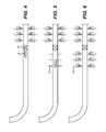
- FIGS. 1-12illustrate a known sequence of isolating intervals already perforated from new intervals to be perforated where the method requires a trip out of the hole every time an interval is perforated and then fractured to grab another isolation device that is then set above the recently perforated interval so that the next interval can be perforated.
- a perforating gun 10is run to the bottom of the well using coiled tubing, wired tubing, wired pipe, one-trip wired drillpipe casing, wired pipe or a wireline tractor and fired as shown in FIG. 2 .
- FIG. 3shows the guns 10 removed from the borehole 12 and the perforations 14 are then fractured by pressuring up the entire borehole 12 so as to create pathways or fractures 16 for subsequent production.
- FIG. 4another gun 18 with a plug 20 is run in and the plug 20 is set in FIG. 5 to isolate the fractures 16 created in FIG. 3 .
- the gun 18is shot to make perforations 22 that are then fractured to create fractures 24 .
- FIG. 7another gun 26 with a plug 28 below is run in and plug 28 is set above fractures 24 .
- Perforations 30are made with gun 26 and fractures 32 result from a fracturing operation as shown in FIG. 9 .
- FIGS. 10-12show a mill 34 sequentially milling the plugs 20 and 28 so that the borehole 12 is ready for production.
- the present inventionis focused on a one trip system using guns and a releasable barrier as well as logging tool and instrumentation to allow staying in the hole after isolating a lower interval and fracturing while perforating the adjacent interval.
- Pressureis built up before the gun is fired in a new interval to enhance the fracture formation.
- Pressureis boosted at the bottom hole assembly to aid in the fracturing and for rapid deployment of the resettable barrier that is preferably an inflatable. In this manner the borehole is not fully pressurized for the fracturing.
- the assemblyis run in with a tractor or on coiled tubing that can have an internal cable for the instrumentation that gives real time feedback as to pressure and flow conditions or seismic conditions during the fracture and powers other logging equipment so that the gun can be placed at an optimal location in any given interval.
- the BHAcan be pumped to the desired location using a known volume of water to minimize water consumption when pumping down the BHA on wireline, for example. Barrier milling is not required as the barrier is simply released and removed from the borehole.
- a one trip system for perforating and fracking multiple intervalsuses a releasable barrier.
- the barriercan be an inflatable.
- a pressure booster systemis associated with the BHA so that the existing hydrostatic pressure is boosted when the gun or portions thereof are fired. After firing in one interval, the BHA is raised and the barrier is redeployed and the pattern repeats. Instruments allow sensing the conditions in the interval for optimal placement of the gun therein and for monitoring flow, pressure and formation conditions during the fracturing. Circulation between gun firings cleans up the hole. If run in on wireline a water saving tool can be associated with the BHA to rapidly position it where desired. Tractors coiled tubing, wired tubing, one-trip wired drillpipe casing or wired pipe can be used in the alternative for BHA positioning.
- FIG. 1is a schematic view of a prior art perforating and fracturing method showing the gun run into hole bottom for initial perforation;
- FIG. 2is the view of FIG. 1 with the guns fired
- FIG. 3is the view of FIG. 2 showing fracturing the first interval after the guns are fired;
- FIG. 4is the view of FIG. 3 with another gun with a plug at its bottom being run in;
- FIG. 5is the view of FIG. 4 showing the second gun being fired
- FIG. 6is the view of FIG. 5 showing fracturing after the second gun is fired
- FIG. 7is the view of FIG. 6 with a third gun with a plug below it being run in;
- FIG. 8is the view of FIG. 7 with perforating after setting the plug
- FIG. 9is the view of FIG. 8 with the guns removed and fracking against the set plug;
- FIGS. 10-12are the view of FIG. 9 showing the sequential milling of the previously set plugs so that the borehole is ready for production;
- FIG. 13is the present invention showing the BHA at hole bottom
- FIG. 14is the view of FIG. 13 showing the combined pressuring up for perforation the initial time
- FIG. 15is the view of FIG. 14 showing the plug repositioned above the initial perforation
- FIG. 16is the view of FIG. 15 showing the plug set and the next interval pressured while perforated;
- FIG. 17is the view of FIG. 16 with the barrier released
- FIG. 18is the view of FIG. 17 with the barrier repositioned uphole for perforating and fracturing at the same time;
- FIG. 19is the view of FIG. 18 showing the perforating and fracturing of the next interval
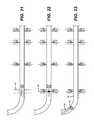
- FIG. 20is the view of FIG. 19 showing the barrier released
- FIG. 21is the view of FIG. 20 with the barrier repositioned above the previously made fractures
- FIG. 22is the view of FIG. 21 showing perforating and fracturing the next interval with the barrier set;
- FIG. 23is the view of FIG. 22 with the barrier removed from the borehole with the spent perforating gun.
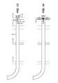
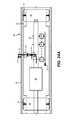
- FIGS. 24 and 24 aare a schematic view of the pressure boost system associated with the gun and the control system for selective firing of portions of the gun as well as the inflatable barrier(s) and its connection to the pressure booster device.
- FIG. 13illustrates a borehole 36 with intervals 38 , 40 , 42 and 44 and a bottom hole assembly 46 that includes a resettable plug 48 and a multi-component gun 50 topped by a formation correlation tool 52 such as a logging tool and/or sensors for flow or pressure to be used during fracturing.
- a formation correlation tool 52such as a logging tool and/or sensors for flow or pressure to be used during fracturing.
- the assembly 46is run to near interval 38 at hole bottom 54 .
- Plug 48is not activated for the initial perforation of interval 38 .
- the fracking fluidis spotted at the gun 50 that portion of the gun to be fired at interval 38 is pressurized with a booster system to be later described so that pressure is raised above hydrostatic in the gun 50 before the gun 50 is fired.
- the plug 48which is preferably an inflatable, is released and moved uphole to just below interval 40 .
- the plug 48is set and the pressure is boosted as the gun 50 is fired to create fractures 56 from the high pressure and high flow rates that ensue when the gun 50 fires.
- the plug 48is deflated in FIG. 17 and moved to just below interval 42 in FIG. 18 .
- the plug 48is inflated in FIG. 19 and again pressure is built up with the booster system and gun 50 is fired to create fractures 58 after which the plug 48 is released in FIG. 20 and repositioned next to interval 44 so the process above can be repeated to create fractures 60 after which the gun 50 and associated plug 48 are removed from the borehole, as shown in FIG. 23 .
- FIGS. 24 and 24 ashow schematically the assembly 46 in more detail.
- the inflatable plug 48is connected to the discharge line 64 from a pressure booster assembly 66 .
- Assembly 66can be a pump operated with power from a wireline that delivers assembly 46 or from a cable that extends through coiled tubing that delivers assembly 46 .
- Igniter 68is used to fire gun 50 resulting in a release of force from the shooting of the gun that is schematically illustrated by arrow 70 .
- the boosted hydrostatic pressure as a result of the use of booster 66delivers a high pressure pulse combined with high flow rates from surface pumping through now opened passages through gun 50 as a result of its being fired as well as direct flow from the borehole into the perforations.
- Arrow 72This is represented by arrow 72 .
- Arrows 74schematically represent how the inflatable(s) 48 grows in diameter to seal off against the inside wall 76 of casing 78 .
- Arrow 80represents a communication/power cable that powers a controller 82 to determine what portions of the gun 50 are to be fired at each location.
- Items 84 and 86represent instruments or logging tools that provide real time data at the surface of conditions close to the fracking location including such data as pressure, temperature and flow rate to give some examples.
- the gun 50is configured to punch out back plates to allow the pressurized fracking fluid to rush into the perforating tunnels to intensify creation and propagation of fractures in the rock.
- the pressure booster of FIGS. 24 and 24 aoptionally in a separate scenario can be chosen not to be used.
- the fracking pressurewould be provided from the surface and the well would be controlled by mud weight and therefore being over balanced to hold back fracked zones' reservoir producing pressures as the well is progressively fracked during the well fracking program
- the assembly 46can be run in on wireline and advanced with a tractor or with an articulated peripheral seal that allows a volume of fluid behind the seal to be pumped to advance the assembly 46 with a minimum of pumped fluid.
- circulationcan take place to clean up the borehole of residual proppant delivered as part of the fracturing operation.
- the effectiveness of the fracturingis enhanced with pressure buildup into the gun as it is fired so that the high pressure fluid at high volumes can rush through the gun and into the perforations as they are made by the firing of the gun.
- the BHAcan be positioned with minimal water consumption by using a peripheral articulated seal and pumping water behind it to reach a desired location.
- Logging tools with the assembly 46allow pinpoint location of the gun 50 in a given interval based on real time data. This can be a very advantageous feature in re-fracturing applications.
- the assembly 46can be delivered on coiled tubing with an interior cable for signal or power supply functions. The coiled tubing allows better control of the BHA in pushing and pulling maneuvers as compared to small outside diameter wirelines. Seismic sensors can be employed in the assembly 46 for monitoring of the fracking operation.
- the BHAcontains multitude of charges and corresponding detonators selectively activated from the surface or following a pre-programmed operational sequence, therefore detonating simultaneously or in a prescribed sequence to take advantage of the operational efficiency benefits introduced by this invention.
- a charge or group of chargescan be selectively detonated in the operational sequence at each fracking station isolated by the retractable pressure sealing packer for the combined perforation and fracking operation which can be done in sequence, simultaneously or overlapping in time soon after perforation is developed.
- an upper sealing retractable packercould be deployed on top of the BHA allowing perforating and fracking in any sequence along the well or in different fracking events or BHA trips downhole during the production life cycle of a fracked well possibly targeting a secondary well or a reservoir re-fracking stimulation.
- a pressure boostercould pressurize the fracking fluid volume between the upper and lower retractable packers deployed with the BHA. This pressure booster could operate under telemetry control which could be wireline, pressure pulse, dropped or pumped down balls triggering a prescribed or pre-programmed operational sequence.
- This well zone selection analysisis conducted optionally assisted and jointly interpreted with seismic data obtained either in the surface or borehole.
- the selected well zones to be frackedcould be isolated with the lower upper and or lower retractable packers.
- the reservoircould be characterized by other deep measurements like borehole seismic and surface seismic, deep transient Electromagnetic (EM) survey (surface and borehole), and during the reservoir production phase after fracking program is completed gravity measurements (Surface and borehole gravity measurements).
Landscapes
- Engineering & Computer Science (AREA)
- Life Sciences & Earth Sciences (AREA)
- Geology (AREA)
- Mining & Mineral Resources (AREA)
- Physics & Mathematics (AREA)
- Environmental & Geological Engineering (AREA)
- Fluid Mechanics (AREA)
- General Life Sciences & Earth Sciences (AREA)
- Geochemistry & Mineralogy (AREA)
- Geophysics (AREA)
- Geophysics And Detection Of Objects (AREA)
- Remote Sensing (AREA)
Abstract
Description
Claims (20)
Priority Applications (1)
| Application Number | Priority Date | Filing Date | Title |
|---|---|---|---|
| US14/139,941US9506333B2 (en) | 2013-12-24 | 2013-12-24 | One trip multi-interval plugging, perforating and fracking method |
Applications Claiming Priority (1)
| Application Number | Priority Date | Filing Date | Title |
|---|---|---|---|
| US14/139,941US9506333B2 (en) | 2013-12-24 | 2013-12-24 | One trip multi-interval plugging, perforating and fracking method |
Publications (2)
| Publication Number | Publication Date |
|---|---|
| US20150176384A1 US20150176384A1 (en) | 2015-06-25 |
| US9506333B2true US9506333B2 (en) | 2016-11-29 |
Family
ID=53399465
Family Applications (1)
| Application Number | Title | Priority Date | Filing Date |
|---|---|---|---|
| US14/139,941Expired - Fee RelatedUS9506333B2 (en) | 2013-12-24 | 2013-12-24 | One trip multi-interval plugging, perforating and fracking method |
Country Status (1)
| Country | Link |
|---|---|
| US (1) | US9506333B2 (en) |
Cited By (49)
| Publication number | Priority date | Publication date | Assignee | Title |
|---|---|---|---|---|
| US10605041B2 (en) | 2018-06-07 | 2020-03-31 | Saudi Arabian Oil Company | System and method for isolating a wellbore zone for rigless hydraulic fracturing |
| US10689955B1 (en) | 2019-03-05 | 2020-06-23 | SWM International Inc. | Intelligent downhole perforating gun tube and components |
| US10914156B2 (en) | 2019-05-30 | 2021-02-09 | Halliburton Energy Services, Inc. | Frac pulser system and method of use thereof |
| US11009162B1 (en) | 2019-12-27 | 2021-05-18 | U.S. Well Services, LLC | System and method for integrated flow supply line |
| US11035207B2 (en) | 2018-04-16 | 2021-06-15 | U.S. Well Services, LLC | Hybrid hydraulic fracturing fleet |
| US11066912B2 (en) | 2012-11-16 | 2021-07-20 | U.S. Well Services, LLC | Torsional coupling for electric hydraulic fracturing fluid pumps |
| US11067481B2 (en) | 2017-10-05 | 2021-07-20 | U.S. Well Services, LLC | Instrumented fracturing slurry flow system and method |
| US11078762B2 (en) | 2019-03-05 | 2021-08-03 | Swm International, Llc | Downhole perforating gun tube and components |
| US11091992B2 (en) | 2012-11-16 | 2021-08-17 | U.S. Well Services, LLC | System for centralized monitoring and control of electric powered hydraulic fracturing fleet |
| US11114857B2 (en) | 2018-02-05 | 2021-09-07 | U.S. Well Services, LLC | Microgrid electrical load management |
| US11136870B2 (en) | 2012-11-16 | 2021-10-05 | U.S. Well Services, LLC | System for pumping hydraulic fracturing fluid using electric pumps |
| US11181107B2 (en) | 2016-12-02 | 2021-11-23 | U.S. Well Services, LLC | Constant voltage power distribution system for use with an electric hydraulic fracturing system |
| US11181879B2 (en) | 2012-11-16 | 2021-11-23 | U.S. Well Services, LLC | Monitoring and control of proppant storage from a datavan |
| US11203924B2 (en) | 2017-10-13 | 2021-12-21 | U.S. Well Services, LLC | Automated fracturing system and method |
| US11208878B2 (en) | 2018-10-09 | 2021-12-28 | U.S. Well Services, LLC | Modular switchgear system and power distribution for electric oilfield equipment |
| US11211801B2 (en) | 2018-06-15 | 2021-12-28 | U.S. Well Services, LLC | Integrated mobile power unit for hydraulic fracturing |
| US11268376B1 (en) | 2019-03-27 | 2022-03-08 | Acuity Technical Designs, LLC | Downhole safety switch and communication protocol |
| US11434737B2 (en) | 2017-12-05 | 2022-09-06 | U.S. Well Services, LLC | High horsepower pumping configuration for an electric hydraulic fracturing system |
| US11449018B2 (en) | 2012-11-16 | 2022-09-20 | U.S. Well Services, LLC | System and method for parallel power and blackout protection for electric powered hydraulic fracturing |
| US11451016B2 (en) | 2012-11-16 | 2022-09-20 | U.S. Well Services, LLC | Switchgear load sharing for oil field equipment |
| US11454170B2 (en) | 2012-11-16 | 2022-09-27 | U.S. Well Services, LLC | Turbine chilling for oil field power generation |
| US11454079B2 (en) | 2018-09-14 | 2022-09-27 | U.S. Well Services Llc | Riser assist for wellsites |
| US11459863B2 (en) | 2019-10-03 | 2022-10-04 | U.S. Well Services, LLC | Electric powered hydraulic fracturing pump system with single electric powered multi-plunger fracturing pump |
| US11476781B2 (en) | 2012-11-16 | 2022-10-18 | U.S. Well Services, LLC | Wireline power supply during electric powered fracturing operations |
| US11492886B2 (en) | 2019-12-31 | 2022-11-08 | U.S. Wells Services, LLC | Self-regulating FRAC pump suction stabilizer/dampener |
| US11506126B2 (en) | 2019-06-10 | 2022-11-22 | U.S. Well Services, LLC | Integrated fuel gas heater for mobile fuel conditioning equipment |
| US11542786B2 (en) | 2019-08-01 | 2023-01-03 | U.S. Well Services, LLC | High capacity power storage system for electric hydraulic fracturing |
| US11560887B2 (en) | 2019-12-31 | 2023-01-24 | U.S. Well Services, LLC | Segmented fluid end plunger pump |
| US11578580B2 (en) | 2018-10-09 | 2023-02-14 | U.S. Well Services, LLC | Electric powered hydraulic fracturing pump system with single electric powered multi-plunger pump fracturing trailers, filtration units, and slide out platform |
| US11578577B2 (en) | 2019-03-20 | 2023-02-14 | U.S. Well Services, LLC | Oversized switchgear trailer for electric hydraulic fracturing |
| US11619119B1 (en) | 2020-04-10 | 2023-04-04 | Integrated Solutions, Inc. | Downhole gun tube extension |
| US11674352B2 (en) | 2012-11-16 | 2023-06-13 | U.S. Well Services, LLC | Slide out pump stand for hydraulic fracturing equipment |
| US11674484B2 (en) | 2012-11-16 | 2023-06-13 | U.S. Well Services, LLC | System for fueling electric powered hydraulic fracturing equipment with multiple fuel sources |
| US11713661B2 (en)* | 2012-11-16 | 2023-08-01 | U.S. Well Services, LLC | Electric powered pump down |
| US11728709B2 (en) | 2019-05-13 | 2023-08-15 | U.S. Well Services, LLC | Encoderless vector control for VFD in hydraulic fracturing applications |
| US11808125B2 (en) | 2017-10-25 | 2023-11-07 | U.S. Well Services, LLC | Smart fracturing system and method |
| US11846167B2 (en) | 2019-12-30 | 2023-12-19 | U.S. Well Services, LLC | Blender tub overflow catch |
| US11850563B2 (en) | 2012-11-16 | 2023-12-26 | U.S. Well Services, LLC | Independent control of auger and hopper assembly in electric blender system |
| US11859483B2 (en) | 2021-04-30 | 2024-01-02 | Matthew Brooks | Selective overbalanced perforation and injection |
| US11885206B2 (en) | 2019-12-30 | 2024-01-30 | U.S. Well Services, LLC | Electric motor driven transportation mechanisms for fracturing blenders |
| US11920425B2 (en) | 2022-02-16 | 2024-03-05 | Saudi Arabian Oil Company | Intelligent detect, punch, isolate, and squeeze system |
| US11959371B2 (en) | 2012-11-16 | 2024-04-16 | Us Well Services, Llc | Suction and discharge lines for a dual hydraulic fracturing unit |
| US11960305B2 (en) | 2019-12-31 | 2024-04-16 | U.S. Well Services, LLC | Automated blender bucket testing and calibration |
| US11959533B2 (en) | 2017-12-05 | 2024-04-16 | U.S. Well Services Holdings, Llc | Multi-plunger pumps and associated drive systems |
| US12012952B2 (en) | 2019-11-18 | 2024-06-18 | U.S. Well Services, LLC | Electrically actuated valves for manifold trailers or skids |
| US12078110B2 (en) | 2015-11-20 | 2024-09-03 | Us Well Services, Llc | System for gas compression on electric hydraulic fracturing fleets |
| US12221872B2 (en) | 2014-10-14 | 2025-02-11 | U.S. Well Services, LLC | System and method for parallel power and blackout protection for electric powered hydraulic fracturing |
| US12291945B1 (en) | 2019-03-05 | 2025-05-06 | Swm International, Llc | Downhole perforating gun system |
| US12442281B2 (en) | 2023-11-07 | 2025-10-14 | U.S. Well Services, LLC | Smart fracturing system and method |
Families Citing this family (11)
| Publication number | Priority date | Publication date | Assignee | Title |
|---|---|---|---|---|
| US9528360B2 (en) | 2013-12-24 | 2016-12-27 | Baker Hughes Incorporated | Using a combination of a perforating gun with an inflatable to complete multiple zones in a single trip |
| US20160265329A1 (en)* | 2015-03-10 | 2016-09-15 | Schlumberger Technology Corporation | Fracturing while tripping |
| US20170051605A1 (en)* | 2015-08-18 | 2017-02-23 | Tech Flo Consulting, Llc | Method and Apparatus for Evaluating the Potential Effectiveness of Refracing a Well |
| US10415382B2 (en)* | 2016-05-03 | 2019-09-17 | Schlumberger Technology Corporation | Method and system for establishing well performance during plug mill-out or cleanout/workover operations |
| US10753183B2 (en) | 2016-10-13 | 2020-08-25 | Geodynamics, Inc. | Refracturing in a multistring casing with constant entrance hole perforating gun system and method |
| US9725993B1 (en) | 2016-10-13 | 2017-08-08 | Geodynamics, Inc. | Constant entrance hole perforating gun system and method |
| US10450813B2 (en) | 2017-08-25 | 2019-10-22 | Salavat Anatolyevich Kuzyaev | Hydraulic fraction down-hole system with circulation port and jet pump for removal of residual fracking fluid |
| US11512572B2 (en)* | 2020-05-28 | 2022-11-29 | Exxonmobil Upstream Research Company | Methods of stimulating a hydrocarbon well |
| US11713670B2 (en) | 2021-09-30 | 2023-08-01 | Saudi Arabian Oil Company | Casing collar locator for drill pipe |
| CN115341880A (en)* | 2022-07-27 | 2022-11-15 | 陕西三丰石油科技有限公司 | A built-in secondary synergistic composite perforating device with high stability for petroleum development |
| CN117267965B (en)* | 2023-11-21 | 2024-01-16 | 吉林大学 | Method for mining dry and hot rock by closed circulation of multilayer multi-branch horizontal well |
Citations (11)
| Publication number | Priority date | Publication date | Assignee | Title |
|---|---|---|---|---|
| US4105073A (en)* | 1977-09-26 | 1978-08-08 | Brieger Emmet F | Tubing conveyed sand consolidating method |
| US5131472A (en)* | 1991-05-13 | 1992-07-21 | Oryx Energy Company | Overbalance perforating and stimulation method for wells |
| US6138764A (en)* | 1999-04-26 | 2000-10-31 | Camco International, Inc. | System and method for deploying a wireline retrievable tool in a deviated well |
| US6491098B1 (en)* | 2000-11-07 | 2002-12-10 | L. Murray Dallas | Method and apparatus for perforating and stimulating oil wells |
| US20040188093A1 (en)* | 2003-03-24 | 2004-09-30 | Funchess Thomas A. | One trip completion process |
| US20050178551A1 (en)* | 2000-02-15 | 2005-08-18 | Tolman Randy C. | Method and apparatus for stimulation of multiple formation intervals |
| US20080264640A1 (en)* | 2007-04-30 | 2008-10-30 | David Milton Eslinger | Well treatment using electric submersible pumping system |
| US20100236781A1 (en)* | 2009-03-20 | 2010-09-23 | Integrated Production Services Ltd. | Method and apparatus for perforating multiple wellbore intervals |
| US20120232859A1 (en)* | 2011-03-09 | 2012-09-13 | Schlumberger Technology Corporation | Method ans systems for reservoir modeling, evaluation and simulation |
| US20150176386A1 (en)* | 2013-12-24 | 2015-06-25 | Baker Hughes Incorporated | Using a Combination of a Perforating Gun with an Inflatable to Complete Multiple Zones in a Single Trip |
| US20150176385A1 (en)* | 2013-12-24 | 2015-06-25 | Baker Hughes Incorporated | Providing a Pressure Boost While Perforating to Initiate Fracking |
- 2013
- 2013-12-24USUS14/139,941patent/US9506333B2/ennot_activeExpired - Fee Related
Patent Citations (13)
| Publication number | Priority date | Publication date | Assignee | Title |
|---|---|---|---|---|
| US4105073A (en)* | 1977-09-26 | 1978-08-08 | Brieger Emmet F | Tubing conveyed sand consolidating method |
| US5131472A (en)* | 1991-05-13 | 1992-07-21 | Oryx Energy Company | Overbalance perforating and stimulation method for wells |
| US6138764A (en)* | 1999-04-26 | 2000-10-31 | Camco International, Inc. | System and method for deploying a wireline retrievable tool in a deviated well |
| US7059407B2 (en)* | 2000-02-15 | 2006-06-13 | Exxonmobil Upstream Research Company | Method and apparatus for stimulation of multiple formation intervals |
| US20050178551A1 (en)* | 2000-02-15 | 2005-08-18 | Tolman Randy C. | Method and apparatus for stimulation of multiple formation intervals |
| US6491098B1 (en)* | 2000-11-07 | 2002-12-10 | L. Murray Dallas | Method and apparatus for perforating and stimulating oil wells |
| US6962203B2 (en)* | 2003-03-24 | 2005-11-08 | Owen Oil Tools Lp | One trip completion process |
| US20040188093A1 (en)* | 2003-03-24 | 2004-09-30 | Funchess Thomas A. | One trip completion process |
| US20080264640A1 (en)* | 2007-04-30 | 2008-10-30 | David Milton Eslinger | Well treatment using electric submersible pumping system |
| US20100236781A1 (en)* | 2009-03-20 | 2010-09-23 | Integrated Production Services Ltd. | Method and apparatus for perforating multiple wellbore intervals |
| US20120232859A1 (en)* | 2011-03-09 | 2012-09-13 | Schlumberger Technology Corporation | Method ans systems for reservoir modeling, evaluation and simulation |
| US20150176386A1 (en)* | 2013-12-24 | 2015-06-25 | Baker Hughes Incorporated | Using a Combination of a Perforating Gun with an Inflatable to Complete Multiple Zones in a Single Trip |
| US20150176385A1 (en)* | 2013-12-24 | 2015-06-25 | Baker Hughes Incorporated | Providing a Pressure Boost While Perforating to Initiate Fracking |
Cited By (72)
| Publication number | Priority date | Publication date | Assignee | Title |
|---|---|---|---|---|
| US11449018B2 (en) | 2012-11-16 | 2022-09-20 | U.S. Well Services, LLC | System and method for parallel power and blackout protection for electric powered hydraulic fracturing |
| US11454170B2 (en) | 2012-11-16 | 2022-09-27 | U.S. Well Services, LLC | Turbine chilling for oil field power generation |
| US12404756B2 (en) | 2012-11-16 | 2025-09-02 | U.S. Well Services, LLC | Torsional coupling for electric hydraulic fracturing fluid pumps |
| US11674352B2 (en) | 2012-11-16 | 2023-06-13 | U.S. Well Services, LLC | Slide out pump stand for hydraulic fracturing equipment |
| US12209490B2 (en) | 2012-11-16 | 2025-01-28 | U.S. Well Services, LLC | System for pumping hydraulic fracturing fluid using electric pumps |
| US11066912B2 (en) | 2012-11-16 | 2021-07-20 | U.S. Well Services, LLC | Torsional coupling for electric hydraulic fracturing fluid pumps |
| US11136870B2 (en) | 2012-11-16 | 2021-10-05 | U.S. Well Services, LLC | System for pumping hydraulic fracturing fluid using electric pumps |
| US11476781B2 (en) | 2012-11-16 | 2022-10-18 | U.S. Well Services, LLC | Wireline power supply during electric powered fracturing operations |
| US11091992B2 (en) | 2012-11-16 | 2021-08-17 | U.S. Well Services, LLC | System for centralized monitoring and control of electric powered hydraulic fracturing fleet |
| US11850563B2 (en) | 2012-11-16 | 2023-12-26 | U.S. Well Services, LLC | Independent control of auger and hopper assembly in electric blender system |
| US12438480B2 (en) | 2012-11-16 | 2025-10-07 | U.S. Well Services, LLC | Wireline power supply during electric powered fracturing operations |
| US11674484B2 (en) | 2012-11-16 | 2023-06-13 | U.S. Well Services, LLC | System for fueling electric powered hydraulic fracturing equipment with multiple fuel sources |
| US11713661B2 (en)* | 2012-11-16 | 2023-08-01 | U.S. Well Services, LLC | Electric powered pump down |
| US11451016B2 (en) | 2012-11-16 | 2022-09-20 | U.S. Well Services, LLC | Switchgear load sharing for oil field equipment |
| US11181879B2 (en) | 2012-11-16 | 2021-11-23 | U.S. Well Services, LLC | Monitoring and control of proppant storage from a datavan |
| US11959371B2 (en) | 2012-11-16 | 2024-04-16 | Us Well Services, Llc | Suction and discharge lines for a dual hydraulic fracturing unit |
| US12221872B2 (en) | 2014-10-14 | 2025-02-11 | U.S. Well Services, LLC | System and method for parallel power and blackout protection for electric powered hydraulic fracturing |
| US12078110B2 (en) | 2015-11-20 | 2024-09-03 | Us Well Services, Llc | System for gas compression on electric hydraulic fracturing fleets |
| US12085017B2 (en) | 2015-11-20 | 2024-09-10 | Us Well Services, Llc | System for gas compression on electric hydraulic fracturing fleets |
| US11181107B2 (en) | 2016-12-02 | 2021-11-23 | U.S. Well Services, LLC | Constant voltage power distribution system for use with an electric hydraulic fracturing system |
| US11952996B2 (en) | 2016-12-02 | 2024-04-09 | U.S. Well Services, LLC | Constant voltage power distribution system for use with an electric hydraulic fracturing system |
| US12092095B2 (en) | 2016-12-02 | 2024-09-17 | Us Well Services, Llc | Constant voltage power distribution system for use with an electric hydraulic fracturing system |
| US11067481B2 (en) | 2017-10-05 | 2021-07-20 | U.S. Well Services, LLC | Instrumented fracturing slurry flow system and method |
| US11203924B2 (en) | 2017-10-13 | 2021-12-21 | U.S. Well Services, LLC | Automated fracturing system and method |
| US11808125B2 (en) | 2017-10-25 | 2023-11-07 | U.S. Well Services, LLC | Smart fracturing system and method |
| US11959533B2 (en) | 2017-12-05 | 2024-04-16 | U.S. Well Services Holdings, Llc | Multi-plunger pumps and associated drive systems |
| US11434737B2 (en) | 2017-12-05 | 2022-09-06 | U.S. Well Services, LLC | High horsepower pumping configuration for an electric hydraulic fracturing system |
| US11114857B2 (en) | 2018-02-05 | 2021-09-07 | U.S. Well Services, LLC | Microgrid electrical load management |
| US12392232B2 (en) | 2018-02-05 | 2025-08-19 | U.S. Well Services, LLC | Microgrid electrical load management |
| US11035207B2 (en) | 2018-04-16 | 2021-06-15 | U.S. Well Services, LLC | Hybrid hydraulic fracturing fleet |
| US12378865B2 (en) | 2018-04-16 | 2025-08-05 | U.S. Well Services, LLC | Hybrid hydraulic fracturing fleet |
| US10605041B2 (en) | 2018-06-07 | 2020-03-31 | Saudi Arabian Oil Company | System and method for isolating a wellbore zone for rigless hydraulic fracturing |
| US11211801B2 (en) | 2018-06-15 | 2021-12-28 | U.S. Well Services, LLC | Integrated mobile power unit for hydraulic fracturing |
| US12142928B2 (en) | 2018-06-15 | 2024-11-12 | U.S. Well Services, LLC | Integrated mobile power unit for hydraulic fracturing |
| US11454079B2 (en) | 2018-09-14 | 2022-09-27 | U.S. Well Services Llc | Riser assist for wellsites |
| US11578580B2 (en) | 2018-10-09 | 2023-02-14 | U.S. Well Services, LLC | Electric powered hydraulic fracturing pump system with single electric powered multi-plunger pump fracturing trailers, filtration units, and slide out platform |
| US11208878B2 (en) | 2018-10-09 | 2021-12-28 | U.S. Well Services, LLC | Modular switchgear system and power distribution for electric oilfield equipment |
| US12116875B2 (en) | 2018-10-09 | 2024-10-15 | U.S. Well Services, LLC | Electric powered hydraulic fracturing pump system with single electric powered multi-plunger pump fracturing trailers, filtration units, and slide out platform |
| US11624266B2 (en) | 2019-03-05 | 2023-04-11 | Swm International, Llc | Downhole perforating gun tube and components |
| US12221864B1 (en) | 2019-03-05 | 2025-02-11 | Swm International, Llc | Downhole perforating gun tube and components |
| US12291945B1 (en) | 2019-03-05 | 2025-05-06 | Swm International, Llc | Downhole perforating gun system |
| US12398627B1 (en) | 2019-03-05 | 2025-08-26 | Swm International, Llc | Downhole perforating gun tube and components |
| US11078762B2 (en) | 2019-03-05 | 2021-08-03 | Swm International, Llc | Downhole perforating gun tube and components |
| US10689955B1 (en) | 2019-03-05 | 2020-06-23 | SWM International Inc. | Intelligent downhole perforating gun tube and components |
| US11976539B2 (en) | 2019-03-05 | 2024-05-07 | Swm International, Llc | Downhole perforating gun tube and components |
| US11578577B2 (en) | 2019-03-20 | 2023-02-14 | U.S. Well Services, LLC | Oversized switchgear trailer for electric hydraulic fracturing |
| US12428942B2 (en) | 2019-03-20 | 2025-09-30 | U.S. Well Services, LLC | Oversized switchgear trailer for electric hydraulic fracturing |
| US11686195B2 (en) | 2019-03-27 | 2023-06-27 | Acuity Technical Designs, LLC | Downhole switch and communication protocol |
| US11268376B1 (en) | 2019-03-27 | 2022-03-08 | Acuity Technical Designs, LLC | Downhole safety switch and communication protocol |
| US11728709B2 (en) | 2019-05-13 | 2023-08-15 | U.S. Well Services, LLC | Encoderless vector control for VFD in hydraulic fracturing applications |
| US10914156B2 (en) | 2019-05-30 | 2021-02-09 | Halliburton Energy Services, Inc. | Frac pulser system and method of use thereof |
| US11506126B2 (en) | 2019-06-10 | 2022-11-22 | U.S. Well Services, LLC | Integrated fuel gas heater for mobile fuel conditioning equipment |
| US11542786B2 (en) | 2019-08-01 | 2023-01-03 | U.S. Well Services, LLC | High capacity power storage system for electric hydraulic fracturing |
| US12385362B2 (en) | 2019-08-01 | 2025-08-12 | U.S. Well Services, LLC | High capacity power storage system for electric hydraulic fracturing |
| US12084952B2 (en) | 2019-10-03 | 2024-09-10 | U.S. Well Services, LLC | Electric powered hydraulic fracturing pump system with single electric powered multi-plunger fracturing pump |
| US11905806B2 (en) | 2019-10-03 | 2024-02-20 | U.S. Well Services, LLC | Electric powered hydraulic fracturing pump system with single electric powered multi-plunger fracturing pump |
| US11459863B2 (en) | 2019-10-03 | 2022-10-04 | U.S. Well Services, LLC | Electric powered hydraulic fracturing pump system with single electric powered multi-plunger fracturing pump |
| US12012952B2 (en) | 2019-11-18 | 2024-06-18 | U.S. Well Services, LLC | Electrically actuated valves for manifold trailers or skids |
| US12152711B2 (en) | 2019-12-27 | 2024-11-26 | U.S. Well Services, LLC | System and method for integrated flow supply line |
| US11009162B1 (en) | 2019-12-27 | 2021-05-18 | U.S. Well Services, LLC | System and method for integrated flow supply line |
| US11846167B2 (en) | 2019-12-30 | 2023-12-19 | U.S. Well Services, LLC | Blender tub overflow catch |
| US11885206B2 (en) | 2019-12-30 | 2024-01-30 | U.S. Well Services, LLC | Electric motor driven transportation mechanisms for fracturing blenders |
| US12359548B2 (en) | 2019-12-30 | 2025-07-15 | U.S. Well Services, LLC | Electric motor driven transportation mechanisms for fracturing blenders |
| US12241353B2 (en) | 2019-12-31 | 2025-03-04 | U.S. Well Services, LLC | Self-regulating frac pump suction stabilizer/dampener |
| US11492886B2 (en) | 2019-12-31 | 2022-11-08 | U.S. Wells Services, LLC | Self-regulating FRAC pump suction stabilizer/dampener |
| US12416304B2 (en) | 2019-12-31 | 2025-09-16 | U.S. Well Services, LLC | Segmented fluid end plunger pump |
| US11560887B2 (en) | 2019-12-31 | 2023-01-24 | U.S. Well Services, LLC | Segmented fluid end plunger pump |
| US11960305B2 (en) | 2019-12-31 | 2024-04-16 | U.S. Well Services, LLC | Automated blender bucket testing and calibration |
| US11619119B1 (en) | 2020-04-10 | 2023-04-04 | Integrated Solutions, Inc. | Downhole gun tube extension |
| US11859483B2 (en) | 2021-04-30 | 2024-01-02 | Matthew Brooks | Selective overbalanced perforation and injection |
| US11920425B2 (en) | 2022-02-16 | 2024-03-05 | Saudi Arabian Oil Company | Intelligent detect, punch, isolate, and squeeze system |
| US12442281B2 (en) | 2023-11-07 | 2025-10-14 | U.S. Well Services, LLC | Smart fracturing system and method |
Also Published As
| Publication number | Publication date |
|---|---|
| US20150176384A1 (en) | 2015-06-25 |
Similar Documents
| Publication | Publication Date | Title |
|---|---|---|
| US10053969B2 (en) | Using a combination of a perforating gun with an inflatable to complete multiple zones in a single trip | |
| US9506333B2 (en) | One trip multi-interval plugging, perforating and fracking method | |
| US9540919B2 (en) | Providing a pressure boost while perforating to initiate fracking | |
| US10030473B2 (en) | Method for remediating a screen-out during well completion | |
| EP1180195B1 (en) | Casing conveyed perforating process and apparatus | |
| CA2953571C (en) | Methods for multi-zone fracture stimulation of a well | |
| US8631872B2 (en) | Complex fracturing using a straddle packer in a horizontal wellbore | |
| EP2434092B1 (en) | Apparatus and method for fracturing portions of an earth formation | |
| US8960296B2 (en) | Complex fracturing using a straddle packer in a horizontal wellbore | |
| EA039092B1 (en) | Perforating gun | |
| AU2015324487B2 (en) | Method of remediating a screen-out during well completion |
Legal Events
| Date | Code | Title | Description |
|---|---|---|---|
| AS | Assignment | Owner name:BAKER HUGHES INCORPORATED, TEXAS Free format text:ASSIGNMENT OF ASSIGNORS INTEREST;ASSIGNORS:CASTILLO, HOMERO C.;FANINI, OTTO N.;SIGNING DATES FROM 20140102 TO 20140107;REEL/FRAME:032455/0763 | |
| FEPP | Fee payment procedure | Free format text:PAYOR NUMBER ASSIGNED (ORIGINAL EVENT CODE: ASPN); ENTITY STATUS OF PATENT OWNER: LARGE ENTITY | |
| ZAAA | Notice of allowance and fees due | Free format text:ORIGINAL CODE: NOA | |
| ZAAB | Notice of allowance mailed | Free format text:ORIGINAL CODE: MN/=. | |
| ZAAA | Notice of allowance and fees due | Free format text:ORIGINAL CODE: NOA | |
| STCF | Information on status: patent grant | Free format text:PATENTED CASE | |
| MAFP | Maintenance fee payment | Free format text:PAYMENT OF MAINTENANCE FEE, 4TH YEAR, LARGE ENTITY (ORIGINAL EVENT CODE: M1551); ENTITY STATUS OF PATENT OWNER: LARGE ENTITY Year of fee payment:4 | |
| AS | Assignment | Owner name:BAKER HUGHES, A GE COMPANY, LLC, TEXAS Free format text:CHANGE OF NAME;ASSIGNOR:BAKER HUGHES INCORPORATED;REEL/FRAME:059497/0467 Effective date:20170703 | |
| AS | Assignment | Owner name:BAKER HUGHES HOLDINGS LLC, TEXAS Free format text:CHANGE OF NAME;ASSIGNOR:BAKER HUGHES, A GE COMPANY, LLC;REEL/FRAME:059620/0651 Effective date:20200413 | |
| FEPP | Fee payment procedure | Free format text:MAINTENANCE FEE REMINDER MAILED (ORIGINAL EVENT CODE: REM.); ENTITY STATUS OF PATENT OWNER: LARGE ENTITY | |
| LAPS | Lapse for failure to pay maintenance fees | Free format text:PATENT EXPIRED FOR FAILURE TO PAY MAINTENANCE FEES (ORIGINAL EVENT CODE: EXP.); ENTITY STATUS OF PATENT OWNER: LARGE ENTITY | |
| STCH | Information on status: patent discontinuation | Free format text:PATENT EXPIRED DUE TO NONPAYMENT OF MAINTENANCE FEES UNDER 37 CFR 1.362 | |
| FP | Lapsed due to failure to pay maintenance fee | Effective date:20241129 |