US9504583B2 - Implant and method for facet immobilization - Google Patents
Implant and method for facet immobilizationDownload PDFInfo
- Publication number
- US9504583B2 US9504583B2US12/106,248US10624808AUS9504583B2US 9504583 B2US9504583 B2US 9504583B2US 10624808 AUS10624808 AUS 10624808AUS 9504583 B2US9504583 B2US 9504583B2
- Authority
- US
- United States
- Prior art keywords
- implant
- face
- facet
- facet joint
- facets
- Prior art date
- Legal status (The legal status is an assumption and is not a legal conclusion. Google has not performed a legal analysis and makes no representation as to the accuracy of the status listed.)
- Active, expires
Links
- 239000007943implantSubstances0.000titleclaimsabstractdescription177
- 238000000034methodMethods0.000titleabstractdescription50
- 210000002517zygapophyseal jointAnatomy0.000claimsabstractdescription128
- 239000000853adhesiveSubstances0.000claimsabstractdescription8
- 230000001070adhesive effectEffects0.000claimsabstractdescription8
- 230000033001locomotionEffects0.000claimsdescription17
- 210000000988bone and boneAnatomy0.000claimsdescription14
- 239000000463materialSubstances0.000claimsdescription11
- 210000000281joint capsuleAnatomy0.000claimsdescription8
- 239000004696Poly ether ether ketoneSubstances0.000claimsdescription6
- MCMNRKCIXSYSNV-UHFFFAOYSA-NZirconium dioxideChemical compoundO=[Zr]=OMCMNRKCIXSYSNV-UHFFFAOYSA-N0.000claimsdescription6
- 229920001652poly(etherketoneketone)Polymers0.000claimsdescription6
- 229920002530polyetherether ketonePolymers0.000claimsdescription6
- 229910052751metalInorganic materials0.000claimsdescription5
- 239000002184metalSubstances0.000claimsdescription5
- 239000000565sealantSubstances0.000claimsdescription5
- 229910000684Cobalt-chromeInorganic materials0.000claimsdescription4
- 229910001069Ti alloyInorganic materials0.000claimsdescription4
- RTAQQCXQSZGOHL-UHFFFAOYSA-NTitaniumChemical compound[Ti]RTAQQCXQSZGOHL-UHFFFAOYSA-N0.000claimsdescription4
- WAIPAZQMEIHHTJ-UHFFFAOYSA-N[Cr].[Co]Chemical compound[Cr].[Co]WAIPAZQMEIHHTJ-UHFFFAOYSA-N0.000claimsdescription4
- 239000010952cobalt-chromeSubstances0.000claimsdescription4
- -1polyethylenePolymers0.000claimsdescription4
- 239000010935stainless steelSubstances0.000claimsdescription4
- 229910001220stainless steelInorganic materials0.000claimsdescription4
- 229910052719titaniumInorganic materials0.000claimsdescription4
- 239000010936titaniumSubstances0.000claimsdescription4
- 239000004698PolyethyleneSubstances0.000claimsdescription3
- 229910052581Si3N4Inorganic materials0.000claimsdescription3
- PNEYBMLMFCGWSK-UHFFFAOYSA-Naluminium oxideInorganic materials[O-2].[O-2].[O-2].[Al+3].[Al+3]PNEYBMLMFCGWSK-UHFFFAOYSA-N0.000claimsdescription3
- 239000000919ceramicSubstances0.000claimsdescription3
- 230000002401inhibitory effectEffects0.000claimsdescription3
- 229920000573polyethylenePolymers0.000claimsdescription3
- 229920000642polymerPolymers0.000claimsdescription3
- HQVNEWCFYHHQES-UHFFFAOYSA-Nsilicon nitrideChemical compoundN12[Si]34N5[Si]62N3[Si]51N64HQVNEWCFYHHQES-UHFFFAOYSA-N0.000claimsdescription3
- 208000020307Spinal diseaseDiseases0.000claims2
- 230000003100immobilizing effectEffects0.000abstractdescription10
- 210000000845cartilageAnatomy0.000abstractdescription7
- 230000008569processEffects0.000description38
- 238000004873anchoringMethods0.000description16
- 230000003412degenerative effectEffects0.000description5
- 210000000115thoracic cavityAnatomy0.000description5
- 238000006073displacement reactionMethods0.000description4
- 230000004927fusionEffects0.000description4
- 239000002775capsuleSubstances0.000description3
- 238000007796conventional methodMethods0.000description3
- 230000007850degenerationEffects0.000description3
- 229920001651CyanoacrylatePolymers0.000description2
- MWCLLHOVUTZFKS-UHFFFAOYSA-NMethyl cyanoacrylateChemical compoundCOC(=O)C(=C)C#NMWCLLHOVUTZFKS-UHFFFAOYSA-N0.000description2
- 206010003246arthritisDiseases0.000description2
- 230000008901benefitEffects0.000description2
- 230000006735deficitEffects0.000description2
- 230000012010growthEffects0.000description2
- 238000003780insertionMethods0.000description2
- 230000037431insertionEffects0.000description2
- 210000004705lumbosacral regionAnatomy0.000description2
- 229910001092metal group alloyInorganic materials0.000description2
- 229920003229poly(methyl methacrylate)Polymers0.000description2
- 239000004926polymethyl methacrylateSubstances0.000description2
- 238000007788rougheningMethods0.000description2
- 210000001519tissueAnatomy0.000description2
- 241000906034OrthopsSpecies0.000description1
- 208000020339Spinal injuryDiseases0.000description1
- 230000001133accelerationEffects0.000description1
- 230000004075alterationEffects0.000description1
- 239000011324beadSubstances0.000description1
- 230000008468bone growthEffects0.000description1
- 230000000295complement effectEffects0.000description1
- 208000037265diseases, disorders, signs and symptomsDiseases0.000description1
- 208000035475disorderDiseases0.000description1
- 238000005553drillingMethods0.000description1
- 230000004064dysfunctionEffects0.000description1
- 230000002757inflammatory effectEffects0.000description1
- 238000012423maintenanceMethods0.000description1
- 230000007246mechanismEffects0.000description1
- 150000002739metalsChemical class0.000description1
- 238000013508migrationMethods0.000description1
- 230000005012migrationEffects0.000description1
- 238000012986modificationMethods0.000description1
- 230000004048modificationEffects0.000description1
- 230000007170pathologyEffects0.000description1
- 239000011148porous materialSubstances0.000description1
- 239000000843powderSubstances0.000description1
- 239000012255powdered metalSubstances0.000description1
- 230000001737promoting effectEffects0.000description1
- 238000002271resectionMethods0.000description1
- 210000000278spinal cordAnatomy0.000description1
- 238000005507sprayingMethods0.000description1
- 238000004381surface treatmentMethods0.000description1
- 238000001356surgical procedureMethods0.000description1
- 208000011580syndromic diseaseDiseases0.000description1
- 230000000472traumatic effectEffects0.000description1
- 238000012800visualizationMethods0.000description1
Images


Classifications
- A—HUMAN NECESSITIES
- A61—MEDICAL OR VETERINARY SCIENCE; HYGIENE
- A61B—DIAGNOSIS; SURGERY; IDENTIFICATION
- A61B17/00—Surgical instruments, devices or methods
- A61B17/56—Surgical instruments or methods for treatment of bones or joints; Devices specially adapted therefor
- A61B17/58—Surgical instruments or methods for treatment of bones or joints; Devices specially adapted therefor for osteosynthesis, e.g. bone plates, screws or setting implements
- A61B17/68—Internal fixation devices, including fasteners and spinal fixators, even if a part thereof projects from the skin
- A61B17/70—Spinal positioners or stabilisers, e.g. stabilisers comprising fluid filler in an implant
- A61B17/7062—Devices acting on, attached to, or simulating the effect of, vertebral processes, vertebral facets or ribs ; Tools for such devices
- A61B17/7064—Devices acting on, attached to, or simulating the effect of, vertebral facets; Tools therefor
- A—HUMAN NECESSITIES
- A61—MEDICAL OR VETERINARY SCIENCE; HYGIENE
- A61F—FILTERS IMPLANTABLE INTO BLOOD VESSELS; PROSTHESES; DEVICES PROVIDING PATENCY TO, OR PREVENTING COLLAPSING OF, TUBULAR STRUCTURES OF THE BODY, e.g. STENTS; ORTHOPAEDIC, NURSING OR CONTRACEPTIVE DEVICES; FOMENTATION; TREATMENT OR PROTECTION OF EYES OR EARS; BANDAGES, DRESSINGS OR ABSORBENT PADS; FIRST-AID KITS
- A61F2/00—Filters implantable into blood vessels; Prostheses, i.e. artificial substitutes or replacements for parts of the body; Appliances for connecting them with the body; Devices providing patency to, or preventing collapsing of, tubular structures of the body, e.g. stents
- A61F2/02—Prostheses implantable into the body
- A61F2/30—Joints
- A61F2/44—Joints for the spine, e.g. vertebrae, spinal discs
- A61F2/4405—Joints for the spine, e.g. vertebrae, spinal discs for apophyseal or facet joints, i.e. between adjacent spinous or transverse processes
- A—HUMAN NECESSITIES
- A61—MEDICAL OR VETERINARY SCIENCE; HYGIENE
- A61F—FILTERS IMPLANTABLE INTO BLOOD VESSELS; PROSTHESES; DEVICES PROVIDING PATENCY TO, OR PREVENTING COLLAPSING OF, TUBULAR STRUCTURES OF THE BODY, e.g. STENTS; ORTHOPAEDIC, NURSING OR CONTRACEPTIVE DEVICES; FOMENTATION; TREATMENT OR PROTECTION OF EYES OR EARS; BANDAGES, DRESSINGS OR ABSORBENT PADS; FIRST-AID KITS
- A61F2/00—Filters implantable into blood vessels; Prostheses, i.e. artificial substitutes or replacements for parts of the body; Appliances for connecting them with the body; Devices providing patency to, or preventing collapsing of, tubular structures of the body, e.g. stents
- A61F2/02—Prostheses implantable into the body
- A61F2/28—Bones
- A61F2002/2821—Bone stimulation by electromagnetic fields or electric current for enhancing ossification
- A—HUMAN NECESSITIES
- A61—MEDICAL OR VETERINARY SCIENCE; HYGIENE
- A61F—FILTERS IMPLANTABLE INTO BLOOD VESSELS; PROSTHESES; DEVICES PROVIDING PATENCY TO, OR PREVENTING COLLAPSING OF, TUBULAR STRUCTURES OF THE BODY, e.g. STENTS; ORTHOPAEDIC, NURSING OR CONTRACEPTIVE DEVICES; FOMENTATION; TREATMENT OR PROTECTION OF EYES OR EARS; BANDAGES, DRESSINGS OR ABSORBENT PADS; FIRST-AID KITS
- A61F2/00—Filters implantable into blood vessels; Prostheses, i.e. artificial substitutes or replacements for parts of the body; Appliances for connecting them with the body; Devices providing patency to, or preventing collapsing of, tubular structures of the body, e.g. stents
- A61F2/02—Prostheses implantable into the body
- A61F2/30—Joints
- A61F2002/30001—Additional features of subject-matter classified in A61F2/28, A61F2/30 and subgroups thereof
- A61F2002/30108—Shapes
- A61F2002/30199—Three-dimensional shapes
- A61F2002/302—Three-dimensional shapes toroidal, e.g. rings
- A—HUMAN NECESSITIES
- A61—MEDICAL OR VETERINARY SCIENCE; HYGIENE
- A61F—FILTERS IMPLANTABLE INTO BLOOD VESSELS; PROSTHESES; DEVICES PROVIDING PATENCY TO, OR PREVENTING COLLAPSING OF, TUBULAR STRUCTURES OF THE BODY, e.g. STENTS; ORTHOPAEDIC, NURSING OR CONTRACEPTIVE DEVICES; FOMENTATION; TREATMENT OR PROTECTION OF EYES OR EARS; BANDAGES, DRESSINGS OR ABSORBENT PADS; FIRST-AID KITS
- A61F2/00—Filters implantable into blood vessels; Prostheses, i.e. artificial substitutes or replacements for parts of the body; Appliances for connecting them with the body; Devices providing patency to, or preventing collapsing of, tubular structures of the body, e.g. stents
- A61F2/02—Prostheses implantable into the body
- A61F2/30—Joints
- A61F2002/30001—Additional features of subject-matter classified in A61F2/28, A61F2/30 and subgroups thereof
- A61F2002/30316—The prosthesis having different structural features at different locations within the same prosthesis; Connections between prosthetic parts; Special structural features of bone or joint prostheses not otherwise provided for
- A61F2002/30329—Connections or couplings between prosthetic parts, e.g. between modular parts; Connecting elements
- A61F2002/30433—Connections or couplings between prosthetic parts, e.g. between modular parts; Connecting elements using additional screws, bolts, dowels, rivets or washers e.g. connecting screws
- A61F2002/30446—
- A—HUMAN NECESSITIES
- A61—MEDICAL OR VETERINARY SCIENCE; HYGIENE
- A61F—FILTERS IMPLANTABLE INTO BLOOD VESSELS; PROSTHESES; DEVICES PROVIDING PATENCY TO, OR PREVENTING COLLAPSING OF, TUBULAR STRUCTURES OF THE BODY, e.g. STENTS; ORTHOPAEDIC, NURSING OR CONTRACEPTIVE DEVICES; FOMENTATION; TREATMENT OR PROTECTION OF EYES OR EARS; BANDAGES, DRESSINGS OR ABSORBENT PADS; FIRST-AID KITS
- A61F2/00—Filters implantable into blood vessels; Prostheses, i.e. artificial substitutes or replacements for parts of the body; Appliances for connecting them with the body; Devices providing patency to, or preventing collapsing of, tubular structures of the body, e.g. stents
- A61F2/02—Prostheses implantable into the body
- A61F2/30—Joints
- A61F2002/30001—Additional features of subject-matter classified in A61F2/28, A61F2/30 and subgroups thereof
- A61F2002/30316—The prosthesis having different structural features at different locations within the same prosthesis; Connections between prosthetic parts; Special structural features of bone or joint prostheses not otherwise provided for
- A61F2002/30329—Connections or couplings between prosthetic parts, e.g. between modular parts; Connecting elements
- A61F2002/30462—Connections or couplings between prosthetic parts, e.g. between modular parts; Connecting elements retained or tied with a rope, string, thread, wire or cable
- A—HUMAN NECESSITIES
- A61—MEDICAL OR VETERINARY SCIENCE; HYGIENE
- A61F—FILTERS IMPLANTABLE INTO BLOOD VESSELS; PROSTHESES; DEVICES PROVIDING PATENCY TO, OR PREVENTING COLLAPSING OF, TUBULAR STRUCTURES OF THE BODY, e.g. STENTS; ORTHOPAEDIC, NURSING OR CONTRACEPTIVE DEVICES; FOMENTATION; TREATMENT OR PROTECTION OF EYES OR EARS; BANDAGES, DRESSINGS OR ABSORBENT PADS; FIRST-AID KITS
- A61F2/00—Filters implantable into blood vessels; Prostheses, i.e. artificial substitutes or replacements for parts of the body; Appliances for connecting them with the body; Devices providing patency to, or preventing collapsing of, tubular structures of the body, e.g. stents
- A61F2/02—Prostheses implantable into the body
- A61F2/30—Joints
- A61F2002/30001—Additional features of subject-matter classified in A61F2/28, A61F2/30 and subgroups thereof
- A61F2002/30316—The prosthesis having different structural features at different locations within the same prosthesis; Connections between prosthetic parts; Special structural features of bone or joint prostheses not otherwise provided for
- A61F2002/30329—Connections or couplings between prosthetic parts, e.g. between modular parts; Connecting elements
- A61F2002/30476—Connections or couplings between prosthetic parts, e.g. between modular parts; Connecting elements locked by an additional locking mechanism
- A61F2002/30507—Connections or couplings between prosthetic parts, e.g. between modular parts; Connecting elements locked by an additional locking mechanism using a threaded locking member, e.g. a locking screw or a set screw
- A61F2002/30512—
- A—HUMAN NECESSITIES
- A61—MEDICAL OR VETERINARY SCIENCE; HYGIENE
- A61F—FILTERS IMPLANTABLE INTO BLOOD VESSELS; PROSTHESES; DEVICES PROVIDING PATENCY TO, OR PREVENTING COLLAPSING OF, TUBULAR STRUCTURES OF THE BODY, e.g. STENTS; ORTHOPAEDIC, NURSING OR CONTRACEPTIVE DEVICES; FOMENTATION; TREATMENT OR PROTECTION OF EYES OR EARS; BANDAGES, DRESSINGS OR ABSORBENT PADS; FIRST-AID KITS
- A61F2/00—Filters implantable into blood vessels; Prostheses, i.e. artificial substitutes or replacements for parts of the body; Appliances for connecting them with the body; Devices providing patency to, or preventing collapsing of, tubular structures of the body, e.g. stents
- A61F2/02—Prostheses implantable into the body
- A61F2/30—Joints
- A61F2/30721—Accessories
- A61F2002/30754—Implants for interposition between two natural articular surfaces
- A—HUMAN NECESSITIES
- A61—MEDICAL OR VETERINARY SCIENCE; HYGIENE
- A61F—FILTERS IMPLANTABLE INTO BLOOD VESSELS; PROSTHESES; DEVICES PROVIDING PATENCY TO, OR PREVENTING COLLAPSING OF, TUBULAR STRUCTURES OF THE BODY, e.g. STENTS; ORTHOPAEDIC, NURSING OR CONTRACEPTIVE DEVICES; FOMENTATION; TREATMENT OR PROTECTION OF EYES OR EARS; BANDAGES, DRESSINGS OR ABSORBENT PADS; FIRST-AID KITS
- A61F2/00—Filters implantable into blood vessels; Prostheses, i.e. artificial substitutes or replacements for parts of the body; Appliances for connecting them with the body; Devices providing patency to, or preventing collapsing of, tubular structures of the body, e.g. stents
- A61F2/02—Prostheses implantable into the body
- A61F2/30—Joints
- A61F2/30767—Special external or bone-contacting surface, e.g. coating for improving bone ingrowth
- A61F2/30771—Special external or bone-contacting surface, e.g. coating for improving bone ingrowth applied in original prostheses, e.g. holes or grooves
- A61F2002/30772—Apertures or holes, e.g. of circular cross section
- A61F2002/30777—Oblong apertures
- A—HUMAN NECESSITIES
- A61—MEDICAL OR VETERINARY SCIENCE; HYGIENE
- A61F—FILTERS IMPLANTABLE INTO BLOOD VESSELS; PROSTHESES; DEVICES PROVIDING PATENCY TO, OR PREVENTING COLLAPSING OF, TUBULAR STRUCTURES OF THE BODY, e.g. STENTS; ORTHOPAEDIC, NURSING OR CONTRACEPTIVE DEVICES; FOMENTATION; TREATMENT OR PROTECTION OF EYES OR EARS; BANDAGES, DRESSINGS OR ABSORBENT PADS; FIRST-AID KITS
- A61F2/00—Filters implantable into blood vessels; Prostheses, i.e. artificial substitutes or replacements for parts of the body; Appliances for connecting them with the body; Devices providing patency to, or preventing collapsing of, tubular structures of the body, e.g. stents
- A61F2/02—Prostheses implantable into the body
- A61F2/30—Joints
- A61F2/3094—Designing or manufacturing processes
- A61F2002/30968—Sintering
- A—HUMAN NECESSITIES
- A61—MEDICAL OR VETERINARY SCIENCE; HYGIENE
- A61F—FILTERS IMPLANTABLE INTO BLOOD VESSELS; PROSTHESES; DEVICES PROVIDING PATENCY TO, OR PREVENTING COLLAPSING OF, TUBULAR STRUCTURES OF THE BODY, e.g. STENTS; ORTHOPAEDIC, NURSING OR CONTRACEPTIVE DEVICES; FOMENTATION; TREATMENT OR PROTECTION OF EYES OR EARS; BANDAGES, DRESSINGS OR ABSORBENT PADS; FIRST-AID KITS
- A61F2220/00—Fixations or connections for prostheses classified in groups A61F2/00 - A61F2/26 or A61F2/82 or A61F9/00 or A61F11/00 or subgroups thereof
- A61F2220/0025—Connections or couplings between prosthetic parts, e.g. between modular parts; Connecting elements
- A61F2220/0041—Connections or couplings between prosthetic parts, e.g. between modular parts; Connecting elements using additional screws, bolts, dowels or rivets, e.g. connecting screws
- A—HUMAN NECESSITIES
- A61—MEDICAL OR VETERINARY SCIENCE; HYGIENE
- A61F—FILTERS IMPLANTABLE INTO BLOOD VESSELS; PROSTHESES; DEVICES PROVIDING PATENCY TO, OR PREVENTING COLLAPSING OF, TUBULAR STRUCTURES OF THE BODY, e.g. STENTS; ORTHOPAEDIC, NURSING OR CONTRACEPTIVE DEVICES; FOMENTATION; TREATMENT OR PROTECTION OF EYES OR EARS; BANDAGES, DRESSINGS OR ABSORBENT PADS; FIRST-AID KITS
- A61F2220/00—Fixations or connections for prostheses classified in groups A61F2/00 - A61F2/26 or A61F2/82 or A61F9/00 or A61F11/00 or subgroups thereof
- A61F2220/0025—Connections or couplings between prosthetic parts, e.g. between modular parts; Connecting elements
- A61F2220/0075—Connections or couplings between prosthetic parts, e.g. between modular parts; Connecting elements sutured, ligatured or stitched, retained or tied with a rope, string, thread, wire or cable
- A—HUMAN NECESSITIES
- A61—MEDICAL OR VETERINARY SCIENCE; HYGIENE
- A61F—FILTERS IMPLANTABLE INTO BLOOD VESSELS; PROSTHESES; DEVICES PROVIDING PATENCY TO, OR PREVENTING COLLAPSING OF, TUBULAR STRUCTURES OF THE BODY, e.g. STENTS; ORTHOPAEDIC, NURSING OR CONTRACEPTIVE DEVICES; FOMENTATION; TREATMENT OR PROTECTION OF EYES OR EARS; BANDAGES, DRESSINGS OR ABSORBENT PADS; FIRST-AID KITS
- A61F2230/00—Geometry of prostheses classified in groups A61F2/00 - A61F2/26 or A61F2/82 or A61F9/00 or A61F11/00 or subgroups thereof
- A61F2230/0063—Three-dimensional shapes
- A61F2230/0065—Three-dimensional shapes toroidal, e.g. ring-shaped, doughnut-shaped
- A—HUMAN NECESSITIES
- A61—MEDICAL OR VETERINARY SCIENCE; HYGIENE
- A61F—FILTERS IMPLANTABLE INTO BLOOD VESSELS; PROSTHESES; DEVICES PROVIDING PATENCY TO, OR PREVENTING COLLAPSING OF, TUBULAR STRUCTURES OF THE BODY, e.g. STENTS; ORTHOPAEDIC, NURSING OR CONTRACEPTIVE DEVICES; FOMENTATION; TREATMENT OR PROTECTION OF EYES OR EARS; BANDAGES, DRESSINGS OR ABSORBENT PADS; FIRST-AID KITS
- A61F2310/00—Prostheses classified in A61F2/28 or A61F2/30 - A61F2/44 being constructed from or coated with a particular material
- A61F2310/00005—The prosthesis being constructed from a particular material
- A61F2310/00011—Metals or alloys
- A61F2310/00017—Iron- or Fe-based alloys, e.g. stainless steel
- A—HUMAN NECESSITIES
- A61—MEDICAL OR VETERINARY SCIENCE; HYGIENE
- A61F—FILTERS IMPLANTABLE INTO BLOOD VESSELS; PROSTHESES; DEVICES PROVIDING PATENCY TO, OR PREVENTING COLLAPSING OF, TUBULAR STRUCTURES OF THE BODY, e.g. STENTS; ORTHOPAEDIC, NURSING OR CONTRACEPTIVE DEVICES; FOMENTATION; TREATMENT OR PROTECTION OF EYES OR EARS; BANDAGES, DRESSINGS OR ABSORBENT PADS; FIRST-AID KITS
- A61F2310/00—Prostheses classified in A61F2/28 or A61F2/30 - A61F2/44 being constructed from or coated with a particular material
- A61F2310/00005—The prosthesis being constructed from a particular material
- A61F2310/00011—Metals or alloys
- A61F2310/00023—Titanium or titanium-based alloys, e.g. Ti-Ni alloys
- A—HUMAN NECESSITIES
- A61—MEDICAL OR VETERINARY SCIENCE; HYGIENE
- A61F—FILTERS IMPLANTABLE INTO BLOOD VESSELS; PROSTHESES; DEVICES PROVIDING PATENCY TO, OR PREVENTING COLLAPSING OF, TUBULAR STRUCTURES OF THE BODY, e.g. STENTS; ORTHOPAEDIC, NURSING OR CONTRACEPTIVE DEVICES; FOMENTATION; TREATMENT OR PROTECTION OF EYES OR EARS; BANDAGES, DRESSINGS OR ABSORBENT PADS; FIRST-AID KITS
- A61F2310/00—Prostheses classified in A61F2/28 or A61F2/30 - A61F2/44 being constructed from or coated with a particular material
- A61F2310/00005—The prosthesis being constructed from a particular material
- A61F2310/00011—Metals or alloys
- A61F2310/00029—Cobalt-based alloys, e.g. Co-Cr alloys or Vitallium
- A—HUMAN NECESSITIES
- A61—MEDICAL OR VETERINARY SCIENCE; HYGIENE
- A61F—FILTERS IMPLANTABLE INTO BLOOD VESSELS; PROSTHESES; DEVICES PROVIDING PATENCY TO, OR PREVENTING COLLAPSING OF, TUBULAR STRUCTURES OF THE BODY, e.g. STENTS; ORTHOPAEDIC, NURSING OR CONTRACEPTIVE DEVICES; FOMENTATION; TREATMENT OR PROTECTION OF EYES OR EARS; BANDAGES, DRESSINGS OR ABSORBENT PADS; FIRST-AID KITS
- A61F2310/00—Prostheses classified in A61F2/28 or A61F2/30 - A61F2/44 being constructed from or coated with a particular material
- A61F2310/00005—The prosthesis being constructed from a particular material
- A61F2310/00179—Ceramics or ceramic-like structures
- A61F2310/00185—Ceramics or ceramic-like structures based on metal oxides
- A61F2310/00203—Ceramics or ceramic-like structures based on metal oxides containing alumina or aluminium oxide
- A—HUMAN NECESSITIES
- A61—MEDICAL OR VETERINARY SCIENCE; HYGIENE
- A61F—FILTERS IMPLANTABLE INTO BLOOD VESSELS; PROSTHESES; DEVICES PROVIDING PATENCY TO, OR PREVENTING COLLAPSING OF, TUBULAR STRUCTURES OF THE BODY, e.g. STENTS; ORTHOPAEDIC, NURSING OR CONTRACEPTIVE DEVICES; FOMENTATION; TREATMENT OR PROTECTION OF EYES OR EARS; BANDAGES, DRESSINGS OR ABSORBENT PADS; FIRST-AID KITS
- A61F2310/00—Prostheses classified in A61F2/28 or A61F2/30 - A61F2/44 being constructed from or coated with a particular material
- A61F2310/00005—The prosthesis being constructed from a particular material
- A61F2310/00179—Ceramics or ceramic-like structures
- A61F2310/00185—Ceramics or ceramic-like structures based on metal oxides
- A61F2310/00239—Ceramics or ceramic-like structures based on metal oxides containing zirconia or zirconium oxide ZrO2
- A—HUMAN NECESSITIES
- A61—MEDICAL OR VETERINARY SCIENCE; HYGIENE
- A61F—FILTERS IMPLANTABLE INTO BLOOD VESSELS; PROSTHESES; DEVICES PROVIDING PATENCY TO, OR PREVENTING COLLAPSING OF, TUBULAR STRUCTURES OF THE BODY, e.g. STENTS; ORTHOPAEDIC, NURSING OR CONTRACEPTIVE DEVICES; FOMENTATION; TREATMENT OR PROTECTION OF EYES OR EARS; BANDAGES, DRESSINGS OR ABSORBENT PADS; FIRST-AID KITS
- A61F2310/00—Prostheses classified in A61F2/28 or A61F2/30 - A61F2/44 being constructed from or coated with a particular material
- A61F2310/00005—The prosthesis being constructed from a particular material
- A61F2310/00179—Ceramics or ceramic-like structures
- A61F2310/00299—Ceramics or ceramic-like structures based on metal nitrides
- A61F2310/00317—Ceramics or ceramic-like structures based on metal nitrides containing silicon nitride
- A—HUMAN NECESSITIES
- A61—MEDICAL OR VETERINARY SCIENCE; HYGIENE
- A61F—FILTERS IMPLANTABLE INTO BLOOD VESSELS; PROSTHESES; DEVICES PROVIDING PATENCY TO, OR PREVENTING COLLAPSING OF, TUBULAR STRUCTURES OF THE BODY, e.g. STENTS; ORTHOPAEDIC, NURSING OR CONTRACEPTIVE DEVICES; FOMENTATION; TREATMENT OR PROTECTION OF EYES OR EARS; BANDAGES, DRESSINGS OR ABSORBENT PADS; FIRST-AID KITS
- A61F2310/00—Prostheses classified in A61F2/28 or A61F2/30 - A61F2/44 being constructed from or coated with a particular material
- A61F2310/00005—The prosthesis being constructed from a particular material
- A61F2310/00359—Bone or bony tissue
Definitions
- the present inventionrelates to an implant and method for immobilizing a vertebral facet joint.
- back and spinal musculoskeletal impairmentsare significant causes of lost work productivity in the United States. Pain as a result of some type of spinal impairment may have its source in a variety of pathologies or clinical conditions.
- the vertebral column 2 of the spineincludes a series of alternating vertebrae 4 and fibrous discs 6 that provide axial support and movement to the upper portions of the body.
- the vertebral column 2typically includes thirty-three vertebrae 4 , with seven cervical (C1-C7), twelve thoracic (T1-T12), five lumbar (L1-15), five fused sacral (S1-S5) and four fused coccygeal vertebrae.
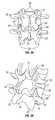
- FIGS. 2A and 2Bdepict a typical thoracic vertebra.
- Each vertebraincludes an anterior body 8 with a posterior arch 10 .
- the posterior arch 10has two pedicles 12 and two laminae 14 that join posteriorly to form a spinous process 16 .
- Projecting from each side of the posterior arch 10is a transverse 18 , superior 20 and inferior articular process 22 .
- the facets 24 , 26 of the superior 20 and inferior articular processes 22form facet joints 28 where they align with the articular processes of the adjacent vertebrae, as shown in FIGS. 3A and 3B .
- the facet jointsare true synovial joints, with cartilaginous surfaces and a joint capsule.
- FIGS. 4A to 6Bdepict the orientations of the facet joints at different levels of the vertebral column.
- the facet jointsare substantially parallel to the transverse plane.
- the facetsare oriented at an approximately 45-degree angle to the transverse plane 30 and are substantially parallel to the frontal plane 32 .
- This orientationallows the facet joints of the cervical vertebrae to flex, extend, laterally flex, and rotate.
- the 45-degree angle orientation with respect to the transverse plane 30allows the facet joints of the cervical spine to guide the movement of the cervical vertebrae without limiting such movement.
- FIGS. 5A and 5Bdepict the thoracic vertebrae, which include facets oriented at an approximately 60-degree angle to the transverse plane 30 and an approximately 20-degree angle to the frontal plane 32 . This orientation is capable of allowing lateral flexion and rotation, but only limited flexion and extension.
- FIGS. 6A and 6Billustrate the lumbar region, where the facet joints are oriented at approximately 90-degree angles to the transverse plane 30 and an approximately 45-degree angle to the frontal plane 32 .
- the lumbar vertebraeallow flexion, extension and lateral flexion of the lumbar region, but little, if any, rotation because of the 90-degree orientation of the facet joints in the transverse plane.
- the actual range of motion along the vertebral columncan vary considerably with each individual vertebra.
- the facet jointsIn addition to guiding movement of the vertebrae, the facet joints also contribute to the load-bearing ability of the vertebral column. For example, facet joints can bear up to 30% of the load on the spine in some positions of the vertebral column as described, e.g., in King et al., Mechanism of Spinal Injury Due to Caudocephalad Acceleration, Orthop. Clin. North Am., 6:19 (1975). The facet joints may also play a role in resisting shear stresses between the vertebrae. Over time, these forces acting on the facet joints can cause degeneration and arthritis.
- One source of back and spine painis related to degeneration of the facets of the spine or facet arthritis. Bony contact or grinding of degenerated facet joint surfaces between two vertebrae may play a role in some pain syndromes. Such degenerative problems with the facet joints are often treated by fusing the two adjacent vertebrae together. By performing this surgical procedure, the relative motion between the two adjacent vertebrae is effectively stopped. This fusion procedure significantly reduces relative motion of the facets between the adjacent vertebrae. However, the facets between fused vertebrae may still exhibit some relative motion as the vertebral column is subjected to overall movement and various stresses. Such motion can lead to further problems, such as pain, arising from the degenerative facet joint.
- the facet joints between fused vertebraeare not treated as part of the fusion procedure.
- the facetsmay simply be screwed together.
- the jointsmay not fuse and can still be a source of further discomfort.
- Embodiments of the present inventionprovide a method and device for immobilizing a facet joint.
- the method and deviceallow maintenance of the relative spacing between the facets within the facet joint, while allowing each of the adjacent articular surfaces of the facet joint to fuse to an implant provided between the facets.
- Such immobilization of the facet jointcan alleviate the bone on bone contact that is common in degenerative facet joints and which may be a source of pain or discomfort even when the adjacent vertebrae are fused together.
- embodiments of the inventionprovide a device for inhibiting movement at a facet joint which includes an implant.
- the faces of the implantare shaped such that they can be secured to the adjacent articular surfaces of the facet joint.
- the implantis dimensioned to fit substantially within the joint capsule of the facet joint.
- the implantmay have an average diameter that is between about 5 mm and about 25 mm, or between about 10 mm and about 20 mm.
- the implantcan be formed using a polymer, including but not limited to polyetheretherketone (PEEK), polyetherketoneketone (PEKK), or polyethylene; a ceramic including but not limited to zirconia, alumina, or silicon nitride; or a metal including but not limited to titanium, a titanium alloy, cobalt chromium, or a stainless steel.
- the implantcan also be formed using other metals or metal alloys, an allograft, an autograft, or a combination of two or more of the above materials.
- the faces of the implantcan be roughened or porous to improve bonding, friction, adherence, and/or osteoincorporation with the articular surfaces.
- the implantcan be made partially or entirely from a partially-sintered powdered metal.
- the implantpreferably has a thickness that is approximately the same as the normal anatomic spacing between the facets of the facet joint or slightly larger.
- the thickness of the implantmay be between about 0.5 mm and about 3 mm, or between about 1 mm and about 2 mm.
- the implantmay be configured to be bonded to the articular surfaces of the facets using an adhesive or a sealant.
- the devicemay include an anchoring arrangement configured to maintain the implant in a fixed position relative to the adjacent articular surfaces of the facet joint.
- the anchoring arrangementcan also provide a compressive force between the implant and the articular surfaces to better immobilize the facet joint.
- the anchoring arrangementis preferably configured to pass through holes formed in the implant and articular processes associated with the facet joint.
- the anchoring arrangementis preferably a rigid fastener such as a threaded retainer, e.g., a threaded bolt, or a rod or cylinder which includes a flange, a retainer ring or disc, or a threaded nut provided at one or both ends
- a threaded retainere.g., a threaded bolt
- rod or cylinderwhich includes a flange, a retainer ring or disc, or a threaded nut provided at one or both ends
- the anchoring arrangementcan also be curved or bent along its primary axis.
- a method of treating vertebral dysfunction by immobilizing a facet jointin which an incision is made above the facet joint and the facet joint capsule is opened. Some or all of the cartilage within the facet joint is removed, and the articular surfaces may optionally be roughened. An implant is then placed within the facet joint between the articular surfaces and secured therein. In certain embodiments, the implant is secured using an adhesive or a sealant.
- an anchoring arrangementis provided to secure the implant to the articular processes and immobilize the facet joint.
- a holecan be formed through the implant and the articular processes of the facet joint.
- a retaining memberwhich preferably has the shape of a rod or cylinder, is then inserted through the holes, and one or more fasteners are provided at the ends of the retaining member to secure the articular processes and implant together.
- the fastenerscan include, for example, a threaded nut, a retainer ring with a set screw, a disc with a friction fit, or a flange.
- the incisionis closed and allowed to heal.
- FIG. 1is a lateral elevational view of a portion of the vertebral column
- FIGS. 2A and 2Bare schematic superior and side views, respectively, of an isolated thoracic vertebra
- FIGS. 3A and 3Bare schematic posterior and posterior-oblique elevational views, respectively, of a portion of the vertebral column;
- FIGS. 4A and 4Bare schematic side and superior views, respectively, of a facet joint in the cervical vertebrae
- FIGS. 5A and 5Bare schematic side and superior views, respectively, of a facet joint in the thoracic vertebrae
- FIGS. 6A and 6Bare schematic side and superior views, respectively, of a facet joint in the lumbar vertebrae
- FIGS. 7A and 7Bare schematic views of a facet joint implant having a circular disc shape
- FIG. 8is a schematic view of the implant of FIG. 7A implanted in a facet joint
- FIGS. 9A and 9Bare schematic views of a facet joint implant having an octagonal disc shape
- FIGS. 10A and 10Bare schematic views of a facet joint implant having a biconcave disc shape
- FIGS. 11A and 11Bare schematic views of a facet joint implant having a single-face variable thickness disc shape
- FIGS. 12A and 12Bare schematic views of a facet joint implant having a curved disc shape
- FIG. 13is a schematic view of the implant of FIG. 12A implanted in a facet joint
- FIGS. 14A and 14Bare schematic views of a facet joint implant having a disc shape with roughened surfaces
- FIGS. 15A and 15Bare schematic views of a facet joint implant having a disc shape with porous surfaces
- FIGS. 16A and 16Bare schematic views of a facet joint implant having a bent disc shape with roughened surfaces
- FIG. 17is a schematic view of the implant of FIG. 16A implanted in a facet joint
- FIGS. 18A and 18Bare schematic views of a facet joint implant which includes a centrally located hole
- FIGS. 19A and 19Bare schematic views of a facet joint implant having a curved disc shape which includes a centrally located hole;
- FIG. 20depicts a retaining member which in the shape of a rod or cylinder with threaded ends adapted to accept threaded nuts;
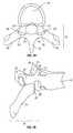
- FIG. 21depicts the retaining member of FIG. 20 which is used to affix the implant to the articular processes of a facet joint using threaded nuts;
- FIG. 22depicts a retaining member which in the shape of a rod or cylinder with one threaded end adapted to accept a threaded nut and a flange provided at the opposite end;
- FIG. 23Adepicts a curved retaining member which is used to affix the implant to the articular processes of a facet joint together with threaded nuts;
- FIG. 23Bdepicts a retaining member which is a curved bolt that is used to affix the implant to the articular processes of a facet joint together with a threaded nut;
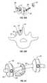
- FIG. 24depicts a retaining member in the shape of a rod or cylinder which is adapted to accept two set-screw retaining rings;
- FIGS. 25A and 25Bare elevational and cross-sectional views, respectively, of the set-screw retaining rings shown in FIG. 24 ;
- FIGS. 26 through 28are elevational views of various embodiments of the screw in the set-screw retaining rings
- FIGS. 29A and 29Bare friction fit retaining rings shown in a relaxed state
- FIGS. 30A and 30Bdepict the retaining rings of FIGS. 29A and 29B in an expanded state
- FIG. 31depicts a retaining member which is a bone screw that is used to affix the implant to the articular processes of a facet joint.
- embodiments of the present inventionprovide a device for immobilizing a facet joint, and which can further maintain a spacing between the two facets of the immobilized facet joint.
- the deviceincludes an implant 34 with two faces: a first face 36 adapted to contact the articular surface of one facet of the facet joint and a second face 38 adapted to contact the articular surface of the other facet.
- the implantcan be formed from any of a variety of materials known in the art, including but not limited to a polymer such as polyetheretherketone (PEEK), polyetherketoneketone (PEKK), or polyethylene.
- the implantcan be formed from a ceramic such as zirconia, alumina, or silicon nitride.
- the implantmay also be formed from a metal including, but not limited to, titanium, a titanium alloy, cobalt chromium, or a stainless steel.
- the implantcan also be formed from a wafer of allograft material or autograft material, which can promote growth of bone tissue from the facets into the implant.
- the implantcan also be formed from a combination of two or more of the materials cited herein.
- the implant 34has a generally circular profile and is sized to fit substantially within the joint capsule of the facet joint 28 .
- FIG. 8illustrates the implant 34 of FIGS. 7A and 7B positioned in a facet joint to be immobilized.
- the implantcan have any of a variety of profiles, including but not limited to square, rectangle, oval, star, polygon or a combination or variation thereof.
- an octagonal implant 40is shown in FIGS. 9A and 9B .
- the shape of a particular implantcan be selected based on radiographic or other visualization of the articular processes and/or the joint capsule.
- the shape of the implantis preferably selected so the two faces contact a substantial portion of the articular surfaces of the two facets of the facet joint.
- the implanthas a diameter between about 4 mm and about 30 mm. In another embodiment, the implant has a diameter between about 5 mm and about 25 mm. In still another embodiment, the implant has a diameter between about 10 mm and about 20 mm. If the implant is not circular in shape, the diameter can refer to the longest dimension measured across one of the two faces thereof.
- the diameter of a particular implantcan be selected based on the size of the articular surfaces in the facet joint to be immobilized, which varies with location in a particular vertebral column. Preferably, the diameter of the implant should not be so large that the implant protrudes significantly beyond the edges of the articular surfaces, and is large enough such that the faces of the implant contact a substantial portion of the articular surfaces. Further, the implant should not protrude past the periphery of the facet joint closest to the vertebral column, as such protrusion may interfere with a disc or the spinal cord.
- the implantpreferably has a thickness approximately the same as the anatomic spacing between two facets of the facet joint to be immobilized.
- the implantgenerally has a thickness between about 0.5 mm and about 3.0 mm.
- the implanthas a thickness between about 1 mm and about 2 mm.
- the implanthas a thickness between about 0.5 mm and about 1.5 mm.
- the thickness of the implantmay also be slightly larger than the anatomic spacing between two facets of the facet joint.
- a thicker implantcan improve contact between the implant faces and the articular surfaces when the implant 34 is placed between the facets 20 , 222 as shown, for example, in FIG. 8 .
- the implantcan be configured to provide an improved fit with the articular process and/or joint capsule.
- the thickness of a particular implantis nonuniform.
- the thickness of the implant 42is increased around the entire outer edge 44 along both faces 46 , 48 .
- FIGS. 11A and 11Bonly a portion of the edge 44 on one face 46 of the implant 42 has a thickness that is greater than the thickness of a central region, and, optionally, also thicker than the typical anatomic spacing between two facets of a facet joint.
- Such variations in thickness of the implantmay also resist lateral displacement of the implant out of the facet joint.
- the implantmay also be shaped to better conform to the shape of the articular surfaces of a facet joint.
- the implant 49 shown in FIGS. 12A and 12Bhas a bend, angle or curve 50 to more closely match the natural shape of an articular facet.
- FIG. 13depicts the implant 49 shown in FIGS. 12A and 12B positioned in a facet joint.
- the implantmay be rigid with a preformed bend.
- the implantmay be sufficiently malleable that it will conform to some degree to the specific configuration of the adjacent facet surfaces when placed between them.
- the facet joint capsuleis incised and at least a portion of the cartilage is removed from the joint space between the facets before the implant is placed therein.
- Preferably, enough of the cartilage in the facet jointis removed such that all or a substantial portion of the articular surfaces of the facets are exposed.
- One or both of the adjacent articular surfacescan be roughened to improve contact with the implant and reduce slippage between the implant faces and the articular surfaces of the facets.
- each face of the implantis porous and/or roughened.
- at least a portion of the surfaces 51 , 52 of the implant 50are roughened. Such roughening can improve adhesion and reduce slippage between the surfaces 51 , 52 and the articular faces of the facet joint.
- the surfaces 53 , 54 of the implant 50are porous as shown in FIGS. 15A and 15B .
- the porous surfaces 53 , 54can be created in any of a variety of conventional techniques, such as by applying sintered beads or spraying plasma onto the implant surface.
- the implant 50can be made partially or entirely from a porous material such as a partially-sintered powder metal form.
- porous surfaces 53 , 54can allow bone to grow into or attach to the surfaces 53 , 54 of the implant 50 , thus securing the implant 50 to the bone in the adjacent facets.
- a curved implant 56is shown in FIGS. 16A and 16B .
- the implanthas a convex face 58 with a roughened surface 52 , and a concave face 62 with a roughened face 51 .
- the implant 56can be placed in the facet joint 28 between facets 20 , 22 , as shown in FIG. 17 .
- the implant 56is shaped to provide good contact with the articular surfaces of the facets 20 , 22 .
- the roughened faces 51 , 52 of the implant 56can promote friction and/or adhesion between the articular surfaces and the implant 56 , promoting immobilization of the facet joint 28 .
- the roughened faces 51 , 52 of the implant 56may also promote growth of bone from the articular surfaces of the facets 20 , 22 into the implant to fuse the facet joint.
- the spacing between the facets 20 , 22can be substantially the same when the implant 56 is inserted as the spacing before fusion of the joint 28 using the implant 56 .
- the implantis maintained between the two facets of the facet joint by taking advantage of the joint capsule and/or other body tissue surrounding the facet joint to limit the migration of the implant out of the facet joint.
- the shape of the implantitself may be capable of resisting displacement of the implant from its position generally between the facet joint surfaces.
- a concave or biconcave configurationsuch as that shown in FIGS. 10A and 10B , may resist displacement of the implant by providing an increased thickness at the periphery of the implant that requires a larger force and/or greater distraction of facet joint surfaces in order to cause displacement.
- Surface treatments or texturing of the implantcan also be used to maintain the implant against the articular surfaces of the facet joint, as described herein.
- a combination of disc configuration, surface texturing, and existing body tissue or structurescan be used to maintain the position of the implant between the facets of the facet joint to be immobilized.
- an adhesive or sealantsuch as a cyanoacrylate, polymethylmethacrylate, or another biocompatible adhesive, is used to bond the faces of the implant to the adjacent articular surfaces of the facet joint. Such bonding can promote fusion of the facet joint.
- bone growth facilitators, electrical current, or other conventional techniquesmay be used to accelerate osteoincorporation of textured or porous anchoring surfaces of the implant.
- the devicefurther includes an anchoring arrangement configured to secure the implant in a fixed position relative to the adjacent facets.
- the anchoring arrangementpreferably provides a compressive force between the implant and the facets to promote adhesion and/or osteoincorporation of the implant with the articular surfaces of the facets.
- a hole 78is provided through the implant 76 between opposite faces 82 , 84 , as shown in FIGS. 18A and 18B .
- the hole 78can be provided through a curved implant 90 , as shown in FIGS. 19A and 19B .
- the anchoring assemblyincludes a retaining member 72 , which can have the shape of a rod or cylinder and is preferably made from a rigid material, as shown in FIG. 20 .
- the anchoring assemblyfurther includes two threaded nuts 94 which are configured to engage with threaded ends 96 of the retaining member 72 .
- a holeis formed through both articular processes 20 , 22 of the facet joint to be immobilized or fused, as shown in FIG. 21 .
- the implant 76is placed between the facets and the retainer member 72 is inserted through the hole in each articular process 20 , 22 and through the hole 78 in the implant 76 , also shown in FIG. 20 .
- Each nut 94can then be threaded onto a threaded end 96 of the retaining member 72 , and tightened to secure the articular processes 20 , 22 to the implant 76 , and to provide a compressive force between the facets and the implant 76 .
- the threaded portion 96is preferably made from titanium, a titanium alloy, cobalt chromium, a stainless steel, another metal alloy, or a combination of two or more such materials.
- the diameter of the hole 78 in the implant 76 and the diameters of the holes in the articular processes 20 , 22are preferably at least slightly larger than the diameter of the retainer member 72 . This allows the retainer member 72 to be easily inserted through the holes, and can also allow the implant 76 and the articular processes 20 , 22 to move freely with respect to the retainer member 72 when the nuts 94 are tightened onto the threaded ends 96 . This can assist in providing compressive forces between the faces of the implant 76 and the adjacent facet surfaces when the nuts 94 are tightened on the retainer member 72 .
- the hole 78can be formed in the implant 76 before it is inserted into the facet joint. Alternatively, the hole 78 can be formed together with the holes through the articular processes 20 , 22 after the implant 76 is placed in the facet joint. Such holes can be formed by drilling, by using a punch, or by other conventional techniques suitable for creating a hole in the bone and implant materials.
- the cross-sectional shape of the retaining member 72can be selected from a variety of shapes, including but not limited to circles, ovals, squares, rectangles, other polygons, or other shapes. A circular shape is preferred to better conform to the threaded ends 96 and to provide a close fit with the drilled or punched holes in the articular processes 20 , 22 .
- the retaining member 72generally has a diameter between about 0.25 mm and about 2 mm, or between about 0.5 mm and about 1.25 mm, or preferably between about 0.75 mm and about 1.25 mm.
- the diameter of the retaining member 72may optionally vary along its length. The diameter of a particular retaining member 72 may be selected based on the facet joint being immobilized.
- a larger diametercan be used for immobilizing facet joints in the lower vertebrae (e.g., lumbar vertebrae) which tend to have larger facets.
- a smaller diametercan be used for immobilizing facet joints in the upper vertebrae (e.g., cervical vertebrae) which tend to have smaller facets.
- the retaining member 72has a length that is generally between about 5 mm and about 60 mm, or between about 10 mm and about 40 mm.
- the retaining member 72can have a length of about 20 mm to about 30 mm.
- the length of a particular retaining member 72may be selected based on the facet joint being immobilized. For example, a longer retaining member 72 can be used for immobilizing facet joints in the lower vertebrae (e.g., lumbar vertebrae) which tend to have thicker articular processes 20 , 22 . Similarly, a shorter retaining member 72 can be used for immobilizing facet joints in the upper vertebrae (e.g., cervical vertebrae) which tend to have thinner or smaller articular processes 20 , 22 .
- the ends of the retaining member 72do not protrude too far from the surfaces of the articular processes 20 , 22 when inserted into the holes therethrough, but the retaining member 72 should be long enough to allow engagement of the nuts 94 onto the threaded ends 96 .
- the retaining member 97is provided with a flange 95 at or near one end, and a single threaded end 96 at the opposite end.
- the retaining member 97can be a bolt having suitable dimensions and made from a suitable material.
- the threaded end 96can be inserted through holes in the implant 76 and articular processes 20 , 22 , and a single nut 94 can be threaded onto the threaded end 96 to immobilize the facet joint and optionally provide a compressive force across the joint.
- the flange 95is preferably larger in diameter than the hole diameters, such that it can engage one of the articular processes 20 , 22 .
- the flange 96can be provided in any of a variety of shapes.
- the side of the flange 95 closest to the threaded end 96can be shaped to approximately conform to the outer surface of the articular process around the hole therethrough, to provide better contact and a more uniform force between the flange 95 and the articular process.
- the retaining member 72 of the anchoring assemblyhas a bend or a curve along the main axis, as shown in FIG. 23A .
- the bend or curvecan provide a better orientation for the nuts 94 with respect to the articular processes 20 , 22 for certain facet joints.
- a curved retaining member 72may allow the nuts to be positioned approximately flush with an outer surface of the articular processes 20 , 22 when the nuts 94 are threaded onto the threaded ends 96 .
- a retaining member 97such as that shown in FIG. 22 , which may be a bolt or the like, can be provided with a bend or curve such that it passes through holes in the articular processes 20 , 22 , and optionally through an implant 76 , if such implant is provided in the facet joint.
- a nut 94is threaded onto the distal end of the fastener 97 to secure the articular processes 20 , 22 of the facet joint together, as shown in FIG. 23 B.
- Such a curve or bendcan be provided in any of the various exemplary retaining member configurations described herein.
- the anchoring arrangementincludes a retaining member 99 which can be secured to the articular process with retaining rings 98 instead of with threaded nuts.
- the retaining rings 98include a ring 100 with a central lumen 102 and a locking element to facilitate locking the ring 100 to the retaining member 99 .
- the central lumen 102is adapted to accept insertion of the retaining member 99 therethrough.
- the retaining member 99also passes through a hole in the implant 101 when placed in the facet joint, similar to the configuration shown in FIG. 21 .
- the illustrated locking elementincludes a side lumen 104 which is threaded and configured to accept a rotatable screw 106 (e.g., a “set screw”) with a proximal end 108 , a threaded body 110 and a distal end 112 .
- the threaded body 110is complementary to the threads of the side lumen 104 so that when the screw 106 is rotated at its proximal end 108 , the distal end 112 of the screw 106 moves further into the central lumen 102 and is capable of applying increasing force to the retaining member 99 inserted through the central lumen 102 .
- the force on the retaining member 99is capable of creating a friction fit or a mechanical fit to resist movement between the retaining member 99 and the retaining ring 98 , thereby securing the retaining member 99 to the articular process 20 or 22 .
- the distal end 112 of the screw 106can be configured to engage the retaining member 99 using any of a variety designs, including but no limited to a blunt tip 114 , a curved tip 116 , or a piercing tip 118 .
- the retaining member 99is securable to the articular process 20 or 22 with a retaining disc 120 have radially inward biased projections 122 defining a central lumen 124 .
- the central lumenhas a cross-sectional diameter that is smaller than that of the retaining member 99 but is capable of enlargement when the inward projections 122 are bent away, as shown in FIGS. 30A and 30B .
- the inward projections 122apply increasing force to the retaining member 99 within the central lumen 124 as the projections 122 are bent, thereby creating a friction fit.
- the outer perimeter of the retaining disc 120can have a shape that is non-circular.
- the shape of the retaining disc 120can be oval or ovoid, rectangular, polygonal, or any other shape surrounding a central lumen.
- the retaining memberis configured to accept a retaining ring 98 or a retaining disc 120 at or near one end, and has a single threaded end 96 at the opposite end.
- the retaining membercan be inserted through holes in the implant and articular processes 20 , 22 , and the retaining ring 98 or retaining disc 120 can be fastened at or near the one end of the retaining member as described herein.
- a single nut 94can then be threaded onto the threaded end 96 to immobilize the facet joint and more easily provide a compressive force across the joint.
- the retaining memberis a bone screw 130 or the like.
- the bone screw 130is placed from the medial side of the facet joint to the lateral side thereof, such that it passes through the articular processes 20 , 22 , and through an implant 76 provided in the facet joint.
- a small pilot holecan be formed in the articular processes 20 , 22 and/or in the implant 76 prior to the insertion of the bone screw 130 .
- the bone screw 130can be screwed directly through the bone and the implant 76 .
- embodiments of the inventionprovide a method for immobilizing a facet joint.
- a midline skin incisionis made over the desired vertebrae, or a paraspinous skin incision is made over the particular facet joint to be immobilized.
- the facet joint capsuleis incised and at least a portion of the cartilage is removed from the joint space between the facets.
- substantially all of the cartilageis removed from the joint space to expose all or a substantial portion of the articular surfaces of the facets.
- One or both of the adjacent articular surfacescan be roughened to improve contact with an implant and reduce slippage between the implant faces and the articular surfaces of the facets. Such roughening may also promote osteoincorporation of the implant with the articular surfaces.
- An implantis provided as described herein that is configured to be positioned within the facet joint.
- at least a portion of each face of the implantis porous and/or roughened.
- the implant 56is then inserted into the facet joint 28 between the articular surfaces 20 , 22 as shown in FIG. 17 .
- the implant 56is preferably shaped such that it fits substantially within the facet joint 28 and conforms to the shape of the facet surfaces.
- the implantis bonded to at least a portion of the articular surfaces using an adhesive or sealant, such as a cyanoacrylate, polymethylmethacrylate, or another biocompatible adhesive.
- an adhesive or sealantsuch as a cyanoacrylate, polymethylmethacrylate, or another biocompatible adhesive.
- the thickness of the implantis slightly larger than the natural distance between the opposing articular surfaces. A thicker implant can provide some compressive force between the implant and the articular surfaces, which can help to maintain the implant in a desired position and result in a more secure bond.
- a holeis then formed through the articular surfaces 20 , 22 as shown in FIG. 21 .
- a holecan also be formed in the implant 76 at this time, or the implant 76 may be provided with a hole therethrough before it is inserted into the facet joint.
- a drill, a punch, or any other conventional apparatus or techniquecan be used to form the holes.
- An anchoring arrangementis then used to secure the implant in a fixed position relative to the adjacent facets.
- the anchoring arrangementcan also provide a compressive force between the implant and the facets to promote adhesion and/or osteoincorporation of the implant with the articular surfaces of the facets. Any appropriate anchoring arrangement, such as those described herein, may be used.
- the surgical siteis then closed, cleaned and dressed.
Landscapes
- Health & Medical Sciences (AREA)
- Orthopedic Medicine & Surgery (AREA)
- Engineering & Computer Science (AREA)
- Biomedical Technology (AREA)
- Neurology (AREA)
- Life Sciences & Earth Sciences (AREA)
- General Health & Medical Sciences (AREA)
- Surgery (AREA)
- Veterinary Medicine (AREA)
- Heart & Thoracic Surgery (AREA)
- Public Health (AREA)
- Animal Behavior & Ethology (AREA)
- Cardiology (AREA)
- Vascular Medicine (AREA)
- Transplantation (AREA)
- Nuclear Medicine, Radiotherapy & Molecular Imaging (AREA)
- Oral & Maxillofacial Surgery (AREA)
- Medical Informatics (AREA)
- Molecular Biology (AREA)
- Prostheses (AREA)
Abstract
Description
Claims (20)
Priority Applications (4)
| Application Number | Priority Date | Filing Date | Title |
|---|---|---|---|
| US12/106,248US9504583B2 (en) | 2004-06-10 | 2008-04-18 | Implant and method for facet immobilization |
| PCT/US2009/040559WO2009129262A1 (en) | 2008-04-18 | 2009-04-14 | Implant and method for facet immobilization |
| US15/360,400US9931142B2 (en) | 2004-06-10 | 2016-11-23 | Implant and method for facet immobilization |
| US15/942,680US20180221064A1 (en) | 2004-06-10 | 2018-04-02 | Implant and method for facet immobilization |
Applications Claiming Priority (2)
| Application Number | Priority Date | Filing Date | Title |
|---|---|---|---|
| US10/865,073US7846183B2 (en) | 2004-02-06 | 2004-06-10 | Vertebral facet joint prosthesis and method of fixation |
| US12/106,248US9504583B2 (en) | 2004-06-10 | 2008-04-18 | Implant and method for facet immobilization |
Related Parent Applications (1)
| Application Number | Title | Priority Date | Filing Date |
|---|---|---|---|
| US10/865,073Continuation-In-PartUS7846183B2 (en) | 2004-02-06 | 2004-06-10 | Vertebral facet joint prosthesis and method of fixation |
Related Child Applications (1)
| Application Number | Title | Priority Date | Filing Date |
|---|---|---|---|
| US15/360,400DivisionUS9931142B2 (en) | 2004-06-10 | 2016-11-23 | Implant and method for facet immobilization |
Publications (3)
| Publication Number | Publication Date |
|---|---|
| US20090264928A1 US20090264928A1 (en) | 2009-10-22 |
| US20120046695A9 US20120046695A9 (en) | 2012-02-23 |
| US9504583B2true US9504583B2 (en) | 2016-11-29 |
Family
ID=41199452
Family Applications (3)
| Application Number | Title | Priority Date | Filing Date |
|---|---|---|---|
| US12/106,248Active2027-04-26US9504583B2 (en) | 2004-06-10 | 2008-04-18 | Implant and method for facet immobilization |
| US15/360,400Expired - LifetimeUS9931142B2 (en) | 2004-06-10 | 2016-11-23 | Implant and method for facet immobilization |
| US15/942,680AbandonedUS20180221064A1 (en) | 2004-06-10 | 2018-04-02 | Implant and method for facet immobilization |
Family Applications After (2)
| Application Number | Title | Priority Date | Filing Date |
|---|---|---|---|
| US15/360,400Expired - LifetimeUS9931142B2 (en) | 2004-06-10 | 2016-11-23 | Implant and method for facet immobilization |
| US15/942,680AbandonedUS20180221064A1 (en) | 2004-06-10 | 2018-04-02 | Implant and method for facet immobilization |
Country Status (2)
| Country | Link |
|---|---|
| US (3) | US9504583B2 (en) |
| WO (1) | WO2009129262A1 (en) |
Cited By (23)
| Publication number | Priority date | Publication date | Assignee | Title |
|---|---|---|---|---|
| US20160008040A1 (en)* | 2008-06-06 | 2016-01-14 | Providence Medical Technology, Inc. | Facet joint implants and delivery tools |
| US10039649B2 (en) | 2008-06-06 | 2018-08-07 | Providence Medical Technology, Inc. | Composite spinal facet implant with textured surfaces |
| US10149673B2 (en) | 2008-06-06 | 2018-12-11 | Providence Medical Technology, Inc. | Facet joint implants and delivery tools |
| US10172721B2 (en) | 2008-06-06 | 2019-01-08 | Providence Technology, Inc. | Spinal facet cage implant |
| US10201375B2 (en) | 2014-05-28 | 2019-02-12 | Providence Medical Technology, Inc. | Lateral mass fixation system |
| USD841165S1 (en) | 2015-10-13 | 2019-02-19 | Providence Medical Technology, Inc. | Cervical cage |
| US10219910B2 (en) | 2006-12-29 | 2019-03-05 | Providence Medical Technology, Inc. | Cervical distraction method |
| US10238501B2 (en) | 2008-06-06 | 2019-03-26 | Providence Medical Technology, Inc. | Cervical distraction/implant delivery device |
| US10682243B2 (en) | 2015-10-13 | 2020-06-16 | Providence Medical Technology, Inc. | Spinal joint implant delivery device and system |
| USD887552S1 (en) | 2016-07-01 | 2020-06-16 | Providence Medical Technology, Inc. | Cervical cage |
| USD911525S1 (en) | 2019-06-21 | 2021-02-23 | Providence Medical Technology, Inc. | Spinal cage |
| USRE48501E1 (en) | 2012-10-23 | 2021-04-06 | Providence Medical Technology, Inc. | Cage spinal implant |
| US11065039B2 (en) | 2016-06-28 | 2021-07-20 | Providence Medical Technology, Inc. | Spinal implant and methods of using the same |
| USD933230S1 (en) | 2019-04-15 | 2021-10-12 | Providence Medical Technology, Inc. | Cervical cage |
| US11224521B2 (en) | 2008-06-06 | 2022-01-18 | Providence Medical Technology, Inc. | Cervical distraction/implant delivery device |
| USD945621S1 (en) | 2020-02-27 | 2022-03-08 | Providence Medical Technology, Inc. | Spinal cage |
| US11272964B2 (en) | 2008-06-06 | 2022-03-15 | Providence Medical Technology, Inc. | Vertebral joint implants and delivery tools |
| US11559408B2 (en) | 2008-01-09 | 2023-01-24 | Providence Medical Technology, Inc. | Methods and apparatus for accessing and treating the facet joint |
| US11648128B2 (en) | 2018-01-04 | 2023-05-16 | Providence Medical Technology, Inc. | Facet screw and delivery device |
| US11871968B2 (en) | 2017-05-19 | 2024-01-16 | Providence Medical Technology, Inc. | Spinal fixation access and delivery system |
| US12004781B2 (en) | 2014-05-27 | 2024-06-11 | Providence Medical Technology, Inc. | Lateral mass fixation implant |
| US12144513B2 (en) | 2018-09-21 | 2024-11-19 | Providence Medical Technology, Inc. | Vertebral joint access and decortication devices and methods of using |
| USD1098433S1 (en) | 2023-12-28 | 2025-10-14 | Providence Medical Technology, Inc. | Spinal cage |
Families Citing this family (100)
| Publication number | Priority date | Publication date | Assignee | Title |
|---|---|---|---|---|
| US6610067B2 (en) | 2000-05-01 | 2003-08-26 | Arthrosurface, Incorporated | System and method for joint resurface repair |
| US7678151B2 (en)* | 2000-05-01 | 2010-03-16 | Ek Steven W | System and method for joint resurface repair |
| US8177841B2 (en) | 2000-05-01 | 2012-05-15 | Arthrosurface Inc. | System and method for joint resurface repair |
| US6520964B2 (en) | 2000-05-01 | 2003-02-18 | Std Manufacturing, Inc. | System and method for joint resurface repair |
| US7163541B2 (en)* | 2002-12-03 | 2007-01-16 | Arthrosurface Incorporated | Tibial resurfacing system |
| US20100185294A1 (en)* | 2002-06-04 | 2010-07-22 | Arthrosurface Incorporated | Nanorough Alloy Substrate |
| US7914545B2 (en) | 2002-12-03 | 2011-03-29 | Arthrosurface, Inc | System and method for retrograde procedure |
| US7901408B2 (en) | 2002-12-03 | 2011-03-08 | Arthrosurface, Inc. | System and method for retrograde procedure |
| US8388624B2 (en) | 2003-02-24 | 2013-03-05 | Arthrosurface Incorporated | Trochlear resurfacing system and method |
| AU2004293042A1 (en) | 2003-11-20 | 2005-06-09 | Arthrosurface, Inc. | Retrograde delivery of resurfacing devices |
| US7846183B2 (en) | 2004-02-06 | 2010-12-07 | Spinal Elements, Inc. | Vertebral facet joint prosthesis and method of fixation |
| US9504583B2 (en) | 2004-06-10 | 2016-11-29 | Spinal Elements, Inc. | Implant and method for facet immobilization |
| WO2006004885A2 (en) | 2004-06-28 | 2006-01-12 | Arthrosurface, Inc. | System for articular surface replacement |
| US7828853B2 (en) | 2004-11-22 | 2010-11-09 | Arthrosurface, Inc. | Articular surface implant and delivery system |
| US8696707B2 (en) | 2005-03-08 | 2014-04-15 | Zyga Technology, Inc. | Facet joint stabilization |
| US8591590B2 (en) | 2005-05-06 | 2013-11-26 | Titan Spine, Llc | Spinal implant having a transverse aperture |
| US8814939B2 (en) | 2005-05-06 | 2014-08-26 | Titan Spine, Llc | Implants having three distinct surfaces |
| US8758442B2 (en) | 2005-05-06 | 2014-06-24 | Titan Spine, Llc | Composite implants having integration surfaces composed of a regular repeating pattern |
| US8480749B2 (en) | 2005-05-06 | 2013-07-09 | Titan Spine, Llc | Friction fit and vertebral endplate-preserving spinal implant |
| US8617248B2 (en) | 2005-05-06 | 2013-12-31 | Titan Spine, Llc | Spinal implant having variable ratios of the integration surface area to the axial passage area |
| US9168147B2 (en) | 2005-05-06 | 2015-10-27 | Titan Spine, Llc | Self-deploying locking screw retention device |
| US20120312779A1 (en) | 2005-05-06 | 2012-12-13 | Titian Spine, LLC | Methods for manufacturing implants having integration surfaces |
| US8262737B2 (en) | 2005-05-06 | 2012-09-11 | Titan Spine, Llc | Composite interbody spinal implant having openings of predetermined size and shape |
| US8992622B2 (en) | 2005-05-06 | 2015-03-31 | Titan Spine, Llc | Interbody spinal implant having a roughened surface topography |
| US8758443B2 (en) | 2005-05-06 | 2014-06-24 | Titan Spine, Llc | Implants with integration surfaces having regular repeating surface patterns |
| US8585767B2 (en) | 2005-05-06 | 2013-11-19 | Titan Spine, Llc | Endplate-preserving spinal implant with an integration plate having durable connectors |
| US8585765B2 (en) | 2005-05-06 | 2013-11-19 | Titan Spine, Llc | Endplate-preserving spinal implant having a raised expulsion-resistant edge |
| US8562684B2 (en) | 2005-05-06 | 2013-10-22 | Titan Spine, Llc | Endplate-preserving spinal implant with an integration plate having a roughened surface topography |
| US8545568B2 (en) | 2005-05-06 | 2013-10-01 | Titan Spine, Llc | Method of using instruments and interbody spinal implants to enhance distraction |
| US8562685B2 (en) | 2005-05-06 | 2013-10-22 | Titan Spine, Llc | Spinal implant and integration plate for optimizing vertebral endplate contact load-bearing edges |
| US8435302B2 (en) | 2005-05-06 | 2013-05-07 | Titan Spine, Llc | Instruments and interbody spinal implants enhancing disc space distraction |
| US8551176B2 (en) | 2005-05-06 | 2013-10-08 | Titan Spine, Llc | Spinal implant having a passage for enhancing contact between bone graft material and cortical endplate bone |
| US11096796B2 (en) | 2005-05-06 | 2021-08-24 | Titan Spine, Llc | Interbody spinal implant having a roughened surface topography on one or more internal surfaces |
| US9125756B2 (en) | 2005-05-06 | 2015-09-08 | Titan Spine, Llc | Processes for producing regular repeating patterns on surfaces of interbody devices |
| US8585766B2 (en) | 2005-05-06 | 2013-11-19 | Titan Spine, Llc | Endplate-preserving spinal implant with an integration plate having durable connectors |
| US8403991B2 (en) | 2005-05-06 | 2013-03-26 | Titan Spine Llc | Implant with critical ratio of load bearing surface area to central opening area |
| US9358029B2 (en) | 2006-12-11 | 2016-06-07 | Arthrosurface Incorporated | Retrograde resection apparatus and method |
| US8992533B2 (en) | 2007-02-22 | 2015-03-31 | Spinal Elements, Inc. | Vertebral facet joint drill and method of use |
| EP2813190B1 (en) | 2007-02-22 | 2017-04-26 | Spinal Elements, Inc. | Vertebral facet joint drill |
| US8343189B2 (en) | 2007-09-25 | 2013-01-01 | Zyga Technology, Inc. | Method and apparatus for facet joint stabilization |
| EP2262448A4 (en) | 2008-03-03 | 2014-03-26 | Arthrosurface Inc | Bone resurfacing system and method |
| CA2958962C (en) | 2008-10-21 | 2020-03-10 | Ww Technology Ag | Method for fusing a human or animal joint as well as fusion device and tool set for carrying out the method |
| US9636121B2 (en)* | 2008-11-11 | 2017-05-02 | Harbinger Medical Group, Llc | Facet distraction device, facet joint implant, and associated methods |
| AU2010236182A1 (en) | 2009-04-17 | 2011-11-24 | Arthrosurface Incorporated | Glenoid resurfacing system and method |
| US10945743B2 (en) | 2009-04-17 | 2021-03-16 | Arthrosurface Incorporated | Glenoid repair system and methods of use thereof |
| WO2010121250A1 (en) | 2009-04-17 | 2010-10-21 | Arthrosurface Incorporated | Glenoid resurfacing system and method |
| US8394125B2 (en) | 2009-07-24 | 2013-03-12 | Zyga Technology, Inc. | Systems and methods for facet joint treatment |
| EP2542165A4 (en) | 2010-03-05 | 2015-10-07 | Arthrosurface Inc | Tibial resurfacing system and method |
| US9233006B2 (en) | 2010-06-15 | 2016-01-12 | Zyga Technology, Inc. | Systems and methods for facet joint treatment |
| US8663293B2 (en) | 2010-06-15 | 2014-03-04 | Zyga Technology, Inc. | Systems and methods for facet joint treatment |
| US20120010658A1 (en) | 2010-07-08 | 2012-01-12 | X-Spine Systems, Inc. | Spinal stabilization system utilizing screw and external facet and/or lamina fixation |
| US8945193B2 (en) | 2010-07-20 | 2015-02-03 | X-Spine Systems, Inc. | Minimally invasive spinal facet compression screw and system for bone joint fusion and fixation |
| WO2012012328A1 (en) | 2010-07-20 | 2012-01-26 | X-Spine Systems, Inc. | Spinal facet compression screw with variable pitch thread zones and buttress head |
| RU2585694C2 (en) | 2010-09-21 | 2016-06-10 | Спайнуэлдинг Аг | Device for restoration of human or animal joint |
| CN105326533B (en) | 2010-09-24 | 2017-12-08 | 斯博特威尔丁股份有限公司 | Apparatus and method for suture holdfast to be fixed in sclerous tissues |
| ES2516190T3 (en) | 2010-09-24 | 2014-10-30 | Sportwelding Gmbh | Device for fixing a suture anchor in a hard fabric |
| PL2618746T3 (en) | 2010-09-24 | 2020-07-13 | Sportwelding Gmbh | Suture anchor for fixating a suture relative to hard tissue |
| US8409257B2 (en)* | 2010-11-10 | 2013-04-02 | Warsaw Othopedic, Inc. | Systems and methods for facet joint stabilization |
| WO2012100358A1 (en) | 2011-01-28 | 2012-08-02 | Sportwelding Gmbh | Device and method for fixating a suture anchor with a suture or a headed anchor in hard tissue |
| RU2725095C2 (en) | 2011-01-28 | 2020-06-29 | СпортУэлдинг ГмбХ | Suture anchor, a suture anchor in a solid tissue and a surgical device comprising a suture anchor |
| US8740949B2 (en) | 2011-02-24 | 2014-06-03 | Spinal Elements, Inc. | Methods and apparatus for stabilizing bone |
| US9271765B2 (en) | 2011-02-24 | 2016-03-01 | Spinal Elements, Inc. | Vertebral facet joint fusion implant and method for fusion |
| USD724733S1 (en) | 2011-02-24 | 2015-03-17 | Spinal Elements, Inc. | Interbody bone implant |
| US9265620B2 (en) | 2011-03-18 | 2016-02-23 | Raed M. Ali, M.D., Inc. | Devices and methods for transpedicular stabilization of the spine |
| EP2685921B1 (en)* | 2011-03-18 | 2019-03-13 | Raed M. Ali, M.D., Inc. | Transpedicular access to intervertebral spaces and related spinal fusion systems and methods |
| US9066716B2 (en) | 2011-03-30 | 2015-06-30 | Arthrosurface Incorporated | Suture coil and suture sheath for tissue repair |
| US8998905B2 (en) | 2011-04-29 | 2015-04-07 | Warsaw Orthopedic, Inc. | Methods and instruments for use in vertebral treatment |
| USD739935S1 (en) | 2011-10-26 | 2015-09-29 | Spinal Elements, Inc. | Interbody bone implant |
| US8992619B2 (en) | 2011-11-01 | 2015-03-31 | Titan Spine, Llc | Microstructured implant surfaces |
| EP2804565B1 (en) | 2011-12-22 | 2018-03-07 | Arthrosurface Incorporated | System for bone fixation |
| CA2880825C (en) | 2012-03-20 | 2021-03-16 | Titan Spine, Llc | Friction-fit spinal endplate and endplate-preserving method |
| US9173692B1 (en)* | 2012-06-15 | 2015-11-03 | Stc.Unm | Composite metal and bone orthopedic fixation devices |
| WO2014008126A1 (en) | 2012-07-03 | 2014-01-09 | Arthrosurface Incorporated | System and method for joint resurfacing and repair |
| EP2716261A1 (en) | 2012-10-02 | 2014-04-09 | Titan Spine, LLC | Implants with self-deploying anchors |
| US9498349B2 (en) | 2012-10-09 | 2016-11-22 | Titan Spine, Llc | Expandable spinal implant with expansion wedge and anchor |
| CA2887215A1 (en) | 2012-11-15 | 2014-05-22 | Zyga Technology, Inc. | Systems and methods for facet joint treatment |
| US8998968B1 (en) | 2012-11-28 | 2015-04-07 | Choice Spine, Lp | Facet screw system |
| US9861495B2 (en) | 2013-03-14 | 2018-01-09 | Raed M. Ali, M.D., Inc. | Lateral interbody fusion devices, systems and methods |
| US10687962B2 (en) | 2013-03-14 | 2020-06-23 | Raed M. Ali, M.D., Inc. | Interbody fusion devices, systems and methods |
| USD765853S1 (en) | 2013-03-14 | 2016-09-06 | Spinal Elements, Inc. | Flexible elongate member with a portion configured to receive a bone anchor |
| US9820784B2 (en) | 2013-03-14 | 2017-11-21 | Spinal Elements, Inc. | Apparatus for spinal fixation and methods of use |
| US9421044B2 (en) | 2013-03-14 | 2016-08-23 | Spinal Elements, Inc. | Apparatus for bone stabilization and distraction and methods of use |
| US9730737B2 (en)* | 2013-03-14 | 2017-08-15 | Atlas Spine, Inc. | Facet fixation with anchor wire |
| US9492200B2 (en) | 2013-04-16 | 2016-11-15 | Arthrosurface Incorporated | Suture system and method |
| US9839450B2 (en) | 2013-09-27 | 2017-12-12 | Spinal Elements, Inc. | Device and method for reinforcement of a facet |
| US9456855B2 (en) | 2013-09-27 | 2016-10-04 | Spinal Elements, Inc. | Method of placing an implant between bone portions |
| US10213231B2 (en)* | 2014-01-28 | 2019-02-26 | Life Spine, Inc. | System and method for reducing and stabilizing a bone fracture |
| US9615935B2 (en) | 2014-01-30 | 2017-04-11 | Titan Spine, Llc | Thermally activated shape memory spring assemblies for implant expansion |
| US9931219B2 (en) | 2014-03-07 | 2018-04-03 | Arthrosurface Incorporated | Implant and anchor assembly |
| US11607319B2 (en) | 2014-03-07 | 2023-03-21 | Arthrosurface Incorporated | System and method for repairing articular surfaces |
| US10624748B2 (en) | 2014-03-07 | 2020-04-21 | Arthrosurface Incorporated | System and method for repairing articular surfaces |
| US11478275B2 (en) | 2014-09-17 | 2022-10-25 | Spinal Elements, Inc. | Flexible fastening band connector |
| AU2016212009C1 (en) | 2015-01-27 | 2021-02-25 | Spinal Elements, Inc. | Facet joint implant |
| US11160663B2 (en) | 2017-08-04 | 2021-11-02 | Arthrosurface Incorporated | Multicomponent articular surface implant |
| WO2020186099A1 (en) | 2019-03-12 | 2020-09-17 | Arthrosurface Incorporated | Humeral and glenoid articular surface implant systems and methods |
| US11457959B2 (en) | 2019-05-22 | 2022-10-04 | Spinal Elements, Inc. | Bone tie and bone tie inserter |
| BR112021022695A2 (en) | 2019-05-22 | 2021-12-28 | Spinal Elements Inc | Bone tethering and bone tethering inserter |
| DE102019005770A1 (en)* | 2019-08-16 | 2021-02-18 | Alfons Erdmann | Surgical kit to supplement a joint |
| WO2021163313A1 (en) | 2020-02-14 | 2021-08-19 | Spinal Elements, Inc. | Bone tie methods |
| US12369952B2 (en) | 2021-12-10 | 2025-07-29 | Spinal Elements, Inc. | Bone tie and portal |
Citations (19)
| Publication number | Priority date | Publication date | Assignee | Title |
|---|---|---|---|---|
| US6007580A (en)* | 1995-06-13 | 1999-12-28 | Bionx Implants Oy | Joint prosthesis |
| US6056749A (en)* | 1999-03-15 | 2000-05-02 | Spineology, Inc. | Method and device for fixing and correcting spondylolisthesis anteriorly |
| US20020151895A1 (en)* | 2001-02-16 | 2002-10-17 | Soboleski Donald A. | Method and device for treating scoliosis |
| DE10135771A1 (en)* | 2001-07-23 | 2003-02-20 | Aesculap Ag & Co Kg | Vertebral facet joint implant comprises at least one fixing element with surfaces which are in full areal contact with at least one facet |
| US20030045936A1 (en)* | 2001-08-29 | 2003-03-06 | Angelucci Christopher M. | Laminoplasty implants and methods of use |
| US20040111093A1 (en)* | 2002-12-02 | 2004-06-10 | Chappuis James L. | Facet fusion system |
| US20040143268A1 (en)* | 2002-10-10 | 2004-07-22 | Falahee Mark H. | Percutaneous facet fixation system |
| US20050043797A1 (en)* | 2003-07-17 | 2005-02-24 | Lee Casey K. | Facet joint prosthesis |
| US20050177240A1 (en)* | 2004-02-06 | 2005-08-11 | Jason Blain | Vertebral facet joint prosthesis and method of fixation |
| US20050197660A1 (en)* | 2004-03-08 | 2005-09-08 | Haid Regis W.Jr. | Occipital and cervical stabilization systems and methods |
| US6966930B2 (en)* | 2003-10-20 | 2005-11-22 | Impliant Ltd. | Facet prosthesis |
| US6974478B2 (en)* | 1999-10-22 | 2005-12-13 | Archus Orthopedics, Inc. | Prostheses, systems and methods for replacement of natural facet joints with artificial facet joint surfaces |
| US20060004367A1 (en)* | 2004-06-17 | 2006-01-05 | Alamin Todd F | Facet joint fusion devices and methods |
| US7037342B2 (en)* | 2001-01-15 | 2006-05-02 | Artimplant Ab | Implant for reconstruction of joints |
| US7087084B2 (en)* | 1999-10-22 | 2006-08-08 | Archus Orthopedics, Inc. | Method for replacing a natural facet joint with a prosthesis having an artificial facet joint structure |
| US20060190081A1 (en)* | 2005-02-09 | 2006-08-24 | Gary Kraus | Facet stabilization schemes |
| US20060235403A1 (en)* | 2005-03-17 | 2006-10-19 | Jason Blain | Flanged interbody fusion device with locking plate |
| US20070179617A1 (en)* | 2006-01-25 | 2007-08-02 | Spinemedica Corporation | Prosthetic wide range motion facets and methods of fabricating same |
| US20090024166A1 (en)* | 2004-08-03 | 2009-01-22 | Vertech Innovations, Llc. | Facet device and method |
Family Cites Families (387)
| Publication number | Priority date | Publication date | Assignee | Title |
|---|---|---|---|---|
| US86016A (en) | 1869-01-19 | Silas j | ||
| US1630239A (en) | 1924-05-09 | 1927-05-24 | Roy S Binkley | Antrum burr |
| US1822280A (en) | 1929-06-26 | 1931-09-08 | John F Ervay | Carpenter's hammer |
| US1822330A (en) | 1930-01-13 | 1931-09-08 | Ainslie George | Suturing instrument |
| US2486303A (en) | 1948-04-29 | 1949-10-25 | Harry Herschel Leiter | Surgical appliance for bone fractures |
| US2706023A (en) | 1952-01-02 | 1955-04-12 | Ronald A Merritt | Gripping device for securing guy wires to a mast |
| US3111945A (en) | 1961-01-05 | 1963-11-26 | Solbrig Charles R Von | Bone band and process of applying the same |
| US3149808A (en) | 1963-09-25 | 1964-09-22 | Weckesser Co | Wedge-lock band clamp |
| US3570497A (en) | 1969-01-16 | 1971-03-16 | Gerald M Lemole | Suture apparatus and methods |
| SE391122B (en) | 1971-01-25 | 1977-02-07 | Cutter Lab | PROTESTS IN THE FORM OF A SPINE BONIC DISC AND PROCEDURES FOR MANUFACTURE THEREOF |
| US3879767A (en) | 1972-01-26 | 1975-04-29 | Cutter Lab | Prosthesis for articulating body structures |
| US3875595A (en) | 1974-04-15 | 1975-04-08 | Edward C Froning | Intervertebral disc prosthesis and instruments for locating same |
| US4085466A (en) | 1974-11-18 | 1978-04-25 | National Research Development Corporation | Prosthetic joint device |
| US4037603A (en) | 1975-05-13 | 1977-07-26 | Wendorff Erwin R | Metallic surgical suture |
| US4001896A (en) | 1975-06-09 | 1977-01-11 | Zimmer, U.S.A. Inc. | Prosthetic joint for total knee replacement |
| GB1552677A (en) | 1976-07-06 | 1979-09-19 | Chichester Partridge Ltd | Tie for use in surgery |
| US4156296A (en) | 1977-04-08 | 1979-05-29 | Bio-Dynamics, Inc. | Great (large) toe prosthesis and method of implanting |
| USD261935S (en) | 1978-12-18 | 1981-11-17 | Halloran William X | Slotted intramedullary rod |
| US4231121A (en) | 1979-07-05 | 1980-11-04 | Wright Dow Corning | Metacarpal-phalangeal prosthesis |
| US4323217A (en) | 1980-01-30 | 1982-04-06 | General Electric Company | Motor mounting assembly including extendable band |
| CA1146301A (en) | 1980-06-13 | 1983-05-17 | J. David Kuntz | Intervertebral disc prosthesis |
| US4312337A (en) | 1980-09-08 | 1982-01-26 | Donohue Brian T | Cannula and drill guide apparatus |
| IE52501B1 (en) | 1981-01-30 | 1987-11-25 | Oec Europ Ltd | A joint prosthesis |
| US4502161A (en) | 1981-09-21 | 1985-03-05 | Wall W H | Prosthetic meniscus for the repair of joints |
| US4573458A (en) | 1982-08-17 | 1986-03-04 | Zimmer, Inc. | Bone fixation plate |
| USD279503S (en) | 1982-11-26 | 1985-07-02 | Halloran William X | Grooved intramedullary rod |
| USD279502S (en) | 1982-11-26 | 1985-07-02 | Halloran William X | Intramedullary rod having a s-shaped cross section |
| US4662371A (en) | 1983-01-26 | 1987-05-05 | Whipple Terry L | Surgical instrument |
| US4535764A (en) | 1983-04-15 | 1985-08-20 | Tayco Developments, Inc. | Surgical bone tie |
| US4573459A (en) | 1983-08-25 | 1986-03-04 | Litton Bruce W | Thumb and finger extension device |
| EP0176728B1 (en) | 1984-09-04 | 1989-07-26 | Humboldt-Universität zu Berlin | Intervertebral-disc prosthesis |
| US4706659A (en) | 1984-12-05 | 1987-11-17 | Regents Of The University Of Michigan | Flexible connecting shaft for intramedullary reamer |
| US4722331A (en) | 1985-09-03 | 1988-02-02 | Fox James M | Orthopaedic tool guide |
| US4773402A (en) | 1985-09-13 | 1988-09-27 | Isola Implants, Inc. | Dorsal transacral surgical implant |
| US4730615A (en) | 1986-03-03 | 1988-03-15 | Pfizer Hospital Products Group, Inc. | Sternum closure device |
| US4834757A (en) | 1987-01-22 | 1989-05-30 | Brantigan John W | Prosthetic implant |
| CA1283501C (en) | 1987-02-12 | 1991-04-30 | Thomas P. Hedman | Artificial spinal disc |
| US4714469A (en) | 1987-02-26 | 1987-12-22 | Pfizer Hospital Products Group, Inc. | Spinal implant |
| US4941466A (en) | 1987-04-13 | 1990-07-17 | Romano Jack W | Curved bore drilling method and apparatus |
| US5002546A (en) | 1987-04-13 | 1991-03-26 | Romano Jack W | Curved bore drilling apparatus |
| US4863477A (en) | 1987-05-12 | 1989-09-05 | Monson Gary L | Synthetic intervertebral disc prosthesis |
| DE8706912U1 (en) | 1987-05-14 | 1987-08-27 | Howmedica GmbH, 2314 Schönkirchen | Small bone plate and screws, particularly for the treatment of fractures of the skull and facial skeleton or similar. |
| US4772287A (en) | 1987-08-20 | 1988-09-20 | Cedar Surgical, Inc. | Prosthetic disc and method of implanting |
| FR2622100B1 (en) | 1987-10-27 | 1991-02-15 | Barouk Louis | JOINT PROSTHETIC IMPLANT WITH TEMPORARY FIXING |
| FR2623085B1 (en) | 1987-11-16 | 1992-08-14 | Breard Francis | SURGICAL IMPLANT TO LIMIT THE RELATIVE MOVEMENT OF VERTEBRES |
| US5147404A (en) | 1987-12-07 | 1992-09-15 | Downey Ernest L | Vertebra prosthesis |
| FR2625097B1 (en) | 1987-12-23 | 1990-05-18 | Cote Sarl | INTER-SPINOUS PROSTHESIS COMPOSED OF SEMI-ELASTIC MATERIAL COMPRISING A TRANSFILING EYE AT ITS END AND INTER-SPINOUS PADS |
| US4911718A (en) | 1988-06-10 | 1990-03-27 | University Of Medicine & Dentistry Of N.J. | Functional and biocompatible intervertebral disc spacer |
| US5545229A (en) | 1988-08-18 | 1996-08-13 | University Of Medicine And Dentistry Of Nj | Functional and biocompatible intervertebral disc spacer containing elastomeric material of varying hardness |
| US4919667A (en) | 1988-12-02 | 1990-04-24 | Stryker Corporation | Implant |
| FR2642645B1 (en) | 1989-02-03 | 1992-08-14 | Breard Francis | FLEXIBLE INTERVERTEBRAL STABILIZER AND METHOD AND APPARATUS FOR CONTROLLING ITS VOLTAGE BEFORE PLACEMENT ON THE RACHIS |
| USRE36221E (en) | 1989-02-03 | 1999-06-01 | Breard; Francis Henri | Flexible inter-vertebral stabilizer as well as process and apparatus for determining or verifying its tension before installation on the spinal column |
| CA1318469C (en) | 1989-02-15 | 1993-06-01 | Acromed Corporation | Artificial disc |
| US4907577A (en) | 1989-04-03 | 1990-03-13 | Wu Shing Sheng | Spinal transpedicle drill jig |
| US5062845A (en) | 1989-05-10 | 1991-11-05 | Spine-Tech, Inc. | Method of making an intervertebral reamer |
| CA2007210C (en) | 1989-05-10 | 1996-07-09 | Stephen D. Kuslich | Intervertebral reamer |
| US5000165A (en) | 1989-05-15 | 1991-03-19 | Watanabe Robert S | Lumbar spine rod fixation system |
| DE3918720A1 (en) | 1989-06-08 | 1990-12-20 | Wolf Gmbh Richard | RETROGRAD CUTTING HOOK PUNCH |
| US4959065A (en) | 1989-07-14 | 1990-09-25 | Techmedica, Inc. | Bone plate with positioning member |
| US4936848A (en) | 1989-09-22 | 1990-06-26 | Bagby George W | Implant for vertebrae |
| US4923471A (en) | 1989-10-17 | 1990-05-08 | Timesh, Inc. | Bone fracture reduction and fixation devices with identity tags |
| DE8912648U1 (en) | 1989-10-23 | 1990-11-22 | Mecron Medizinische Produkte Gmbh, 1000 Berlin | Vertebral body implant |
| US5286249A (en) | 1989-10-31 | 1994-02-15 | Thibodaux Peggy L | Brace for fixation of bone fractures |
| US5135188A (en) | 1990-02-06 | 1992-08-04 | Anderson Franklin R | Attachable bundling strap |
| DE59100448D1 (en) | 1990-04-20 | 1993-11-11 | Sulzer Ag | Implant, in particular intervertebral prosthesis. |
| WO1991016020A1 (en) | 1990-04-26 | 1991-10-31 | Danninger Medical Technology, Inc. | Transpedicular screw system and method of use |
| US5127912A (en) | 1990-10-05 | 1992-07-07 | R. Charles Ray | Sacral implant system |
| US5300073A (en) | 1990-10-05 | 1994-04-05 | Salut, Ltd. | Sacral implant system |
| WO1992008415A1 (en) | 1990-11-09 | 1992-05-29 | Arthrotek, Inc. | Surgical cutting instrument |
| US5192326A (en) | 1990-12-21 | 1993-03-09 | Pfizer Hospital Products Group, Inc. | Hydrogel bead intervertebral disc nucleus |
| US5047055A (en) | 1990-12-21 | 1991-09-10 | Pfizer Hospital Products Group, Inc. | Hydrogel intervertebral disc nucleus |
| US5112013A (en) | 1991-02-25 | 1992-05-12 | Chrysler Corporation | Tie strap structure for electric wiring |
| JP3007903B2 (en) | 1991-03-29 | 2000-02-14 | 京セラ株式会社 | Artificial disc |
| GB9111972D0 (en) | 1991-06-04 | 1991-07-24 | Clinical Product Dev Ltd | Medical/surgical devices |
| US5577995A (en) | 1991-06-13 | 1996-11-26 | Grace L. Walker | Spinal and soft tissue mobilizer |
| US5603713A (en) | 1991-09-24 | 1997-02-18 | Aust; Gilbert M. | Anterior lumbar/cervical bicortical compression plate |
| US5258031A (en) | 1992-01-06 | 1993-11-02 | Danek Medical | Intervertebral disk arthroplasty |
| US5425773A (en) | 1992-01-06 | 1995-06-20 | Danek Medical, Inc. | Intervertebral disk arthroplasty device |
| US5282861A (en) | 1992-03-11 | 1994-02-01 | Ultramet | Open cell tantalum structures for cancellous bone implants and cell and tissue receptors |
| US5766251A (en) | 1992-03-13 | 1998-06-16 | Tomihisa Koshino | Wedge-shaped spacer for correction of deformed extremities |
| DE4208115A1 (en) | 1992-03-13 | 1993-09-16 | Link Waldemar Gmbh Co | DISC ENDOPROTHESIS |
| DE4208116C2 (en) | 1992-03-13 | 1995-08-03 | Link Waldemar Gmbh Co | Intervertebral disc prosthesis |
| US5368596A (en) | 1992-03-18 | 1994-11-29 | Burkhart; Stephen S. | Augmented awl for creating channels in human bone tissue |
| EP0566810B1 (en) | 1992-04-21 | 1996-08-14 | SULZER Medizinaltechnik AG | Artificial spinal disc |
| US5306309A (en) | 1992-05-04 | 1994-04-26 | Calcitek, Inc. | Spinal disk implant and implantation kit |
| US5209755A (en) | 1992-06-05 | 1993-05-11 | Stella Abrahan | Dermal exciser |
| GB9217578D0 (en) | 1992-08-19 | 1992-09-30 | Surgicarft Ltd | Surgical implants,etc |
| FR2697743B1 (en) | 1992-11-09 | 1995-01-27 | Fabrication Mat Orthopedique S | Spinal osteosynthesis device applicable in particular to degenerative vertebrae. |
| ATE206602T1 (en) | 1992-11-12 | 2001-10-15 | Neville Alleyne | DEVICE FOR PROTECTING THE HEART |
| US5611354A (en) | 1992-11-12 | 1997-03-18 | Alleyne; Neville | Cardiac protection device |
| US5306275A (en) | 1992-12-31 | 1994-04-26 | Bryan Donald W | Lumbar spine fixation apparatus and method |
| US5527314A (en) | 1993-01-04 | 1996-06-18 | Danek Medical, Inc. | Spinal fixation system |
| US5496318A (en) | 1993-01-08 | 1996-03-05 | Advanced Spine Fixation Systems, Inc. | Interspinous segmental spine fixation device |
| US5676701A (en) | 1993-01-14 | 1997-10-14 | Smith & Nephew, Inc. | Low wear artificial spinal disc |
| US5540706A (en) | 1993-01-25 | 1996-07-30 | Aust; Gilbert M. | Surgical instrument |
| EP0610837B1 (en) | 1993-02-09 | 2001-09-05 | Acromed Corporation | Spine disc |
| US5413576A (en) | 1993-02-10 | 1995-05-09 | Rivard; Charles-Hilaire | Apparatus for treating spinal disorder |
| US5330479A (en) | 1993-03-11 | 1994-07-19 | Whitmore Henry B | Reciprocating bone punch |
| DE9304368U1 (en) | 1993-03-18 | 1993-05-13 | AAP GmbH & Co. Betriebs KG, 1000 Berlin | Spinal implant |
| US5415661A (en) | 1993-03-24 | 1995-05-16 | University Of Miami | Implantable spinal assist device |
| US5534028A (en) | 1993-04-20 | 1996-07-09 | Howmedica, Inc. | Hydrogel intervertebral disc nucleus with diminished lateral bulging |
| FR2704745B1 (en) | 1993-05-07 | 1995-11-24 | Erpios | Device for connecting the ends of a ligament for osteosynthesis, in particular for vertebral osteosynthesis. |
| US5509918A (en) | 1993-05-11 | 1996-04-23 | David Romano | Method and apparatus for drilling a curved bore in an object |
| FR2707480B1 (en) | 1993-06-28 | 1995-10-20 | Bisserie Michel | Intervertebral disc prosthesis. |
| EP0737445A3 (en) | 1993-07-06 | 1996-11-06 | Ferdinand Gundolf | Pliers for placing and driving a spike in a bone |
| CN1156255C (en) | 1993-10-01 | 2004-07-07 | 美商-艾克罗米德公司 | Spinal implant |
| US5400784A (en) | 1993-10-15 | 1995-03-28 | Case Western Reserve University | Slowly penetrating inter-fascicular nerve cuff electrode and method of using |
| US5491882A (en) | 1993-12-28 | 1996-02-20 | Walston; D. Kenneth | Method of making joint prosthesis having PTFE cushion |
| US5879396A (en) | 1993-12-28 | 1999-03-09 | Walston; D. Kenneth | Joint prosthesis having PTFE cushion |
| US5514180A (en) | 1994-01-14 | 1996-05-07 | Heggeness; Michael H. | Prosthetic intervertebral devices |
| US5458642A (en) | 1994-01-18 | 1995-10-17 | Beer; John C. | Synthetic intervertebral disc |
| US5462542A (en) | 1994-01-24 | 1995-10-31 | United States Surgical Corporation | Sternum buckle with serrated strap |
| US20060100635A1 (en)* | 1994-01-26 | 2006-05-11 | Kyphon, Inc. | Inflatable device for use in surgical protocol relating to fixation of bone |
| AU1967095A (en) | 1994-02-17 | 1995-09-04 | Surgical Accessories, Inc. | Fastener and tensioner for bone securing cable |
| US5536270A (en) | 1994-02-24 | 1996-07-16 | Pioneer Laboratories, Inc. | Cable system for bone securance |
| US5653762A (en) | 1994-03-18 | 1997-08-05 | Pisharodi; Madhavan | Method of stabilizing adjacent vertebrae with rotating, lockable, middle-expanded intervertebral disk stabilizer |
| US5571189A (en) | 1994-05-20 | 1996-11-05 | Kuslich; Stephen D. | Expandable fabric implant for stabilizing the spinal motion segment |
| FR2721501B1 (en) | 1994-06-24 | 1996-08-23 | Fairant Paulette | Prostheses of the vertebral articular facets. |
| FR2722980B1 (en) | 1994-07-26 | 1996-09-27 | Samani Jacques | INTERTEPINOUS VERTEBRAL IMPLANT |
| US5527312A (en) | 1994-08-19 | 1996-06-18 | Salut, Ltd. | Facet screw anchor |
| US5824093A (en) | 1994-10-17 | 1998-10-20 | Raymedica, Inc. | Prosthetic spinal disc nucleus |
| JPH10507386A (en) | 1994-10-17 | 1998-07-21 | レイメディカ, インコーポレイテッド | Artificial spinal disc nucleus |
| US5674296A (en) | 1994-11-14 | 1997-10-07 | Spinal Dynamics Corporation | Human spinal disc prosthesis |
| US5487756A (en) | 1994-12-23 | 1996-01-30 | Simon Fraser University | Implantable cuff having improved closure |
| US5586989A (en) | 1995-01-27 | 1996-12-24 | Bray, Jr.; Robert | Microsurgical curette |
| US5702468A (en) | 1995-03-09 | 1997-12-30 | Uresil Corporation | Carpal bone biaxially restrained prosthesis |
| US5571191A (en) | 1995-03-16 | 1996-11-05 | Fitz; William R. | Artificial facet joint |
| US5571131A (en) | 1995-06-07 | 1996-11-05 | Smith & Nephew Endoscopy, Inc. | Back biting punch |
| US5713542A (en) | 1995-07-11 | 1998-02-03 | Avery Dennison Corporation | Locator tie |
| NZ272994A (en) | 1995-09-12 | 2001-06-29 | C G Surgical Ltd | Spinal prosthesis device which stabilises lamina after laminoplasty |
| US5645597A (en) | 1995-12-29 | 1997-07-08 | Krapiva; Pavel I. | Disc replacement method and apparatus |
| US5638700A (en) | 1996-01-11 | 1997-06-17 | Shechter; Jaime | Earring post |
| US5766253A (en) | 1996-01-16 | 1998-06-16 | Surgical Dynamics, Inc. | Spinal fusion device |
| DE29724567U1 (en) | 1996-02-14 | 2003-01-16 | Walter Lorenz Surgical, Inc., Jacksonville, Fla. | Bone fixation device and instrument for inserting the bone fixation device |
| US5707373A (en) | 1996-04-26 | 1998-01-13 | Ikonos Corporation | Bone fastener and instrument for insertion thereof |
| US5683466A (en) | 1996-03-26 | 1997-11-04 | Vitale; Glenn C. | Joint surface replacement system |
| US5951555A (en) | 1996-03-27 | 1999-09-14 | Rehak; Lubos | Device for the correction of spinal deformities |
| USD395138S (en) | 1996-05-20 | 1998-06-16 | Kenji Ohata | Metallic cranial burr hole cover and bone flap fixation plate |
| IL119151A0 (en) | 1996-06-10 | 1996-11-14 | Influence Med Tech Ltd | Surgical suture insertion device and method for treatment of urinary stress incontinence using fixation to bone |
| US5741261A (en) | 1996-06-25 | 1998-04-21 | Sdgi Holdings, Inc. | Minimally invasive spinal surgical methods and instruments |
| US6066325A (en) | 1996-08-27 | 2000-05-23 | Fusion Medical Technologies, Inc. | Fragmented polymeric compositions and methods for their use |
| US5851208A (en) | 1996-10-15 | 1998-12-22 | Linvatec Corporation | Rotatable surgical burr |
| JP3426460B2 (en) | 1996-10-25 | 2003-07-14 | グンゼ株式会社 | Osteosynthesis |
| US5895428A (en) | 1996-11-01 | 1999-04-20 | Berry; Don | Load bearing spinal joint implant |
| US5797916A (en) | 1996-12-10 | 1998-08-25 | Johnson & Johnson Professional, Inc. | Trochanteric reattachment cerclage device |
| JPH10179622A (en) | 1996-12-20 | 1998-07-07 | Mizuho Ika Kogyo Kk | Vertebral implant |
| US7201751B2 (en) | 1997-01-02 | 2007-04-10 | St. Francis Medical Technologies, Inc. | Supplemental spine fixation device |
| US6902566B2 (en) | 1997-01-02 | 2005-06-07 | St. Francis Medical Technologies, Inc. | Spinal implants, insertion instruments, and methods of use |
| US5836948A (en) | 1997-01-02 | 1998-11-17 | Saint Francis Medical Technologies, Llc | Spine distraction implant and method |
| US5860977A (en) | 1997-01-02 | 1999-01-19 | Saint Francis Medical Technologies, Llc | Spine distraction implant and method |
| US6068630A (en) | 1997-01-02 | 2000-05-30 | St. Francis Medical Technologies, Inc. | Spine distraction implant |
| US7101375B2 (en) | 1997-01-02 | 2006-09-05 | St. Francis Medical Technologies, Inc. | Spine distraction implant |
| US7468075B2 (en) | 2001-05-25 | 2008-12-23 | Conformis, Inc. | Methods and compositions for articular repair |
| US7077863B2 (en) | 1997-02-12 | 2006-07-18 | Arthrex, Inc. | Transverse fixation technique for ACL reconstruction using bone-tendon-bone graft with loop at end |
| US5918604A (en) | 1997-02-12 | 1999-07-06 | Arthrex, Inc. | Method of loading tendons into the knee |
| US6017366A (en)* | 1997-04-18 | 2000-01-25 | W. L. Gore & Associates, Inc. | Resorbable interposition arthroplasty implant |
| IES970323A2 (en) | 1997-04-30 | 1998-06-03 | Eskina Developments Limited | Spinal osteosynthesis device for mechanically interconnecting two adjacent vertebrae, in particular lumbar vertebrae |
| US6641614B1 (en) | 1997-05-01 | 2003-11-04 | Spinal Concepts, Inc. | Multi-variable-height fusion device |
| US6113640A (en)* | 1997-06-11 | 2000-09-05 | Bionx Implants Oy | Reconstructive bioabsorbable joint prosthesis |
| US5893889A (en) | 1997-06-20 | 1999-04-13 | Harrington; Michael | Artificial disc |
| US6102347A (en) | 1997-09-03 | 2000-08-15 | Avery Dennison Corporation | Cable tie |
| US6379386B1 (en) | 1997-09-09 | 2002-04-30 | Stryker Technologies Corporation | Anatomic glenoid shoulder prosthesis together with methods and tools for implanting same |
| US6106558A (en) | 1997-09-15 | 2000-08-22 | Applied Medical Research, Inc. | Neuro decompression device |
| US5824094A (en) | 1997-10-17 | 1998-10-20 | Acromed Corporation | Spinal disc |
| EP1867293A2 (en) | 1997-10-27 | 2007-12-19 | St. Francis Medical Technologies, Inc. | Spine distraction implant |
| FR2770767B1 (en) | 1997-11-10 | 2000-03-10 | Dimso Sa | IMPLANT FOR VERTEBRA |
| US5997542A (en) | 1997-11-18 | 1999-12-07 | Biomet, Inc. | Surgical wire assembly and method of use |
| US6090145A (en) | 1997-12-10 | 2000-07-18 | Societe Industrielle De Combustible Nucleaire S I C N | Partial scaphoid implant and method of treating ailments of the scaphoid |
| KR20010033792A (en) | 1997-12-31 | 2001-04-25 | 잭 더블류 로마노 | Method and apparatus for transferring drilling energy to a cutting member |
| FR2773463B1 (en) | 1998-01-12 | 2000-03-31 | Salvatore Sessa | INTERVERTEBRAL CONNECTION DEVICE |
| US6325803B1 (en) | 1998-02-18 | 2001-12-04 | Walter Lorenz Surgical, Inc. | Method and apparatus for mandibular osteosynthesis |
| FR2775183B1 (en) | 1998-02-20 | 2000-08-04 | Jean Taylor | INTER-SPINOUS PROSTHESIS |
| US6014588A (en) | 1998-04-07 | 2000-01-11 | Fitz; William R. | Facet joint pain relief method and apparatus |
| US5964765A (en) | 1998-04-16 | 1999-10-12 | Axya Medical, Inc. | Soft tissue fixation device |
| US6019792A (en) | 1998-04-23 | 2000-02-01 | Cauthen Research Group, Inc. | Articulating spinal implant |
| US6368325B1 (en) | 1998-05-27 | 2002-04-09 | Nuvasive, Inc. | Bone blocks and methods for inserting bone blocks into intervertebral spaces |
| US6132465A (en) | 1998-06-04 | 2000-10-17 | Raymedica, Inc. | Tapered prosthetic spinal disc nucleus |
| US6063121A (en) | 1998-07-29 | 2000-05-16 | Xavier; Ravi | Vertebral body prosthesis |
| US6099531A (en) | 1998-08-20 | 2000-08-08 | Bonutti; Peter M. | Changing relationship between bones |
| US5993452A (en) | 1998-08-24 | 1999-11-30 | Biomet Inc. | Cerclage system |
| US6669697B1 (en) | 1998-09-25 | 2003-12-30 | Perumala Corporation | Self-retaining bolt for internal spinal stabilizers |
| US6248108B1 (en)* | 1998-09-30 | 2001-06-19 | Bionx Implants Oy | Bioabsorbable surgical screw and washer system |
| US6113637A (en) | 1998-10-22 | 2000-09-05 | Sofamor Danek Holdings, Inc. | Artificial intervertebral joint permitting translational and rotational motion |
| US6039763A (en) | 1998-10-27 | 2000-03-21 | Disc Replacement Technologies, Inc. | Articulating spinal disc prosthesis |
| US6312443B1 (en) | 1998-12-23 | 2001-11-06 | Nuvasive, Inc. | Expandable cannula |
| US6146422A (en) | 1999-01-25 | 2000-11-14 | Lawson; Kevin Jon | Prosthetic nucleus replacement for surgical reconstruction of intervertebral discs and treatment method |
| JP2000210297A (en) | 1999-01-26 | 2000-08-02 | Ishibashi Toru | Steel wire |
| WO2000053126A1 (en) | 1999-03-10 | 2000-09-14 | Aesculap Ag & Co. Kg | Implant for fixing an articulated joint |
| US6368350B1 (en) | 1999-03-11 | 2002-04-09 | Sulzer Spine-Tech Inc. | Intervertebral disc prosthesis and method |
| WO2000054821A1 (en) | 1999-03-16 | 2000-09-21 | Regeneration Technologies, Inc. | Molded implants for orthopedic applications |
| US6470207B1 (en) | 1999-03-23 | 2002-10-22 | Surgical Navigation Technologies, Inc. | Navigational guidance via computer-assisted fluoroscopic imaging |
| US6436099B1 (en) | 1999-04-23 | 2002-08-20 | Sdgi Holdings, Inc. | Adjustable spinal tether |
| US6607530B1 (en) | 1999-05-10 | 2003-08-19 | Highgate Orthopedics, Inc. | Systems and methods for spinal fixation |
| WO2007084649A2 (en) | 2006-01-17 | 2007-07-26 | Highgate Orthopedics, Inc. | Systems, devices and apparatuses for bony fixation and disk repair and replacement and methods related thereto |
| US6050998A (en) | 1999-05-21 | 2000-04-18 | Stephen A. Fletcher | Bone fastener |
| US6419704B1 (en)* | 1999-10-08 | 2002-07-16 | Bret Ferree | Artificial intervertebral disc replacement methods and apparatus |
| IL130307A0 (en) | 1999-06-04 | 2000-06-01 | Influence Med Tech Ltd | Bone suturing device |
| WO2001003609A1 (en) | 1999-07-07 | 2001-01-18 | Tapic International Co., Ltd. | Artificial neural tube |
| US6200322B1 (en) | 1999-08-13 | 2001-03-13 | Sdgi Holdings, Inc. | Minimal exposure posterior spinal interbody instrumentation and technique |
| US6179839B1 (en) | 1999-09-20 | 2001-01-30 | Kinetikos Medical Incorporated | Bone fusion apparatus and method |
| US6436101B1 (en) | 1999-10-13 | 2002-08-20 | James S. Hamada | Rasp for use in spine surgery |
| FR2799640B1 (en) | 1999-10-15 | 2002-01-25 | Spine Next Sa | IMPLANT INTERVETEBRAL |
| US6764491B2 (en) | 1999-10-21 | 2004-07-20 | Sdgi Holdings, Inc. | Devices and techniques for a posterior lateral disc space approach |
| US6811567B2 (en) | 1999-10-22 | 2004-11-02 | Archus Orthopedics Inc. | Facet arthroplasty devices and methods |
| USD442691S1 (en) | 2000-09-28 | 2001-05-22 | Gary K. Michelson | Trailing end of a spinal implant |
| USD439340S1 (en) | 2000-01-03 | 2001-03-20 | Gary K. Michelson | End cap for a spinal implant |
| US6740090B1 (en) | 2000-02-16 | 2004-05-25 | Trans1 Inc. | Methods and apparatus for forming shaped axial bores through spinal vertebrae |
| US6293949B1 (en) | 2000-03-01 | 2001-09-25 | Sdgi Holdings, Inc. | Superelastic spinal stabilization system and method |
| US6371958B1 (en) | 2000-03-02 | 2002-04-16 | Ethicon, Inc. | Scaffold fixation device for use in articular cartilage repair |
| US6482234B1 (en)* | 2000-04-26 | 2002-11-19 | Pearl Technology Holdings, Llc | Prosthetic spinal disc |
| US7163541B2 (en) | 2002-12-03 | 2007-01-16 | Arthrosurface Incorporated | Tibial resurfacing system |
| US6579318B2 (en) | 2000-06-12 | 2003-06-17 | Ortho Development Corporation | Intervertebral spacer |
| CZ301649B6 (en) | 2000-06-28 | 2010-05-12 | Ed. Geistlich Soehne Ag Fur Chemische Industrie Incorporated Under The Laws Of Switzerland | Tube for regeneration of nerves and process for producing thereof |
| EP1328217A2 (en) | 2000-09-19 | 2003-07-23 | SDGI Holdings, Inc. | Osteogenic fusion devices |
| US6656195B2 (en) | 2000-09-22 | 2003-12-02 | Medtronic Xomed, Inc. | Flexible inner tubular members and rotary tissue cutting instruments having flexible inner tubular members |
| US6669698B1 (en)* | 2000-10-24 | 2003-12-30 | Sdgi Holdings, Inc. | Vertebrae fastener placement guide |
| DE10053611A1 (en) | 2000-10-28 | 2002-05-02 | Inst Textil & Faserforschung | Bioresorbable nerve guide |
| US6419678B1 (en) | 2000-11-28 | 2002-07-16 | Wilson T. Asfora | Curved drill guide system |
| US6579319B2 (en) | 2000-11-29 | 2003-06-17 | Medicinelodge, Inc. | Facet joint replacement |
| FR2817461B1 (en) | 2000-12-01 | 2003-08-15 | Henry Graf | INTERVERTEBRAL STABILIZATION DEVICE |
| US6752831B2 (en) | 2000-12-08 | 2004-06-22 | Osteotech, Inc. | Biocompatible osteogenic band for repair of spinal disorders |
| US6419703B1 (en) | 2001-03-01 | 2002-07-16 | T. Wade Fallin | Prosthesis for the replacement of a posterior element of a vertebra |
| US6565605B2 (en) | 2000-12-13 | 2003-05-20 | Medicinelodge, Inc. | Multiple facet joint replacement |
| US20050246023A1 (en) | 2001-02-13 | 2005-11-03 | Yeung Jeffrey E | Disc shunt for treating back pain |
| US6743232B2 (en) | 2001-02-26 | 2004-06-01 | David W. Overaker | Tissue scaffold anchor for cartilage repair |
| US20020120335A1 (en) | 2001-02-28 | 2002-08-29 | Angelucci Christopher M. | Laminoplasty implants and methods of use |
| US7090698B2 (en) | 2001-03-02 | 2006-08-15 | Facet Solutions | Method and apparatus for spine joint replacement |
| US6575978B2 (en) | 2001-04-05 | 2003-06-10 | Spineology, Inc. | Circumferential resecting reamer tool |
| US6997932B2 (en) | 2001-05-21 | 2006-02-14 | Boston Scientific Scimed, Inc. | Suture passer |
| KR20020089867A (en) | 2001-05-25 | 2002-11-30 | (주)에이치비메디컬스 | Nerve anastomosis device |
| DE10129490A1 (en) | 2001-06-21 | 2003-01-02 | Helmut Mueckter | Implantable screw for stabilization of joint or bone fracture, has flexible shaft which interconnects proximal head portion and distal insertion portion of elongated screw body |
| DE10138079B4 (en) | 2001-08-03 | 2004-02-12 | Biedermann Motech Gmbh | Placeholder with variable axial length |
| US6547795B2 (en)* | 2001-08-13 | 2003-04-15 | Depuy Acromed, Inc. | Surgical guide system for stabilization of the spine |
| US6600956B2 (en) | 2001-08-21 | 2003-07-29 | Cyberonics, Inc. | Circumneural electrode assembly |
| US6783527B2 (en) | 2001-10-30 | 2004-08-31 | Sdgi Holdings, Inc. | Flexible spinal stabilization system and method |
| FR2832054B1 (en) | 2001-11-15 | 2004-09-10 | Rene Louis | POSTERIOR VERTEBRAL JOINT PROSTHESIS |
| DK175391B1 (en)* | 2002-02-13 | 2004-09-20 | Danfoss As | Column implant and method of manufacture thereof |
| US6669729B2 (en) | 2002-03-08 | 2003-12-30 | Kingsley Richard Chin | Apparatus and method for the replacement of posterior vertebral elements |
| US20030176921A1 (en) | 2002-03-13 | 2003-09-18 | Lawson Kevin Jon | Two-part prosthetic nucleus replacement for surgical reconstruction of intervertebral discs |
| US20080027548A9 (en) | 2002-04-12 | 2008-01-31 | Ferree Bret A | Spacerless artificial disc replacements |
| US6706068B2 (en) | 2002-04-23 | 2004-03-16 | Bret A. Ferree | Artificial disc replacements with natural kinematics |
| US20040010318A1 (en) | 2002-05-15 | 2004-01-15 | Ferree Bret A. | Conformable endplates for artificial disc replacement (ADR) devices and other applications |
| US6770095B2 (en) | 2002-06-18 | 2004-08-03 | Depuy Acroned, Inc. | Intervertebral disc |
| JP4988203B2 (en)* | 2002-07-19 | 2012-08-01 | インターヴェンショナル スパイン、インコーポレイテッド | Spinal fixation method and spinal fixation device |
| EP1542626B1 (en) | 2002-08-15 | 2012-09-26 | Synthes GmbH | Controlled artificial intervertebral disc implant |
| AU2003265597A1 (en) | 2002-08-23 | 2004-03-11 | Paul C. Mcafee | Metal-backed uhmpe rod sleeve system preserving spinal motion |
| US7250054B2 (en) | 2002-08-28 | 2007-07-31 | Smith & Nephew, Inc. | Systems, methods, and apparatuses for clamping and reclamping an orthopedic surgical cable |
| JP2006500188A (en) | 2002-09-20 | 2006-01-05 | インプライアント・リミテッド | Mechanically mounted elastomeric cover for prosthesis |
| JP2006501977A (en) | 2002-10-07 | 2006-01-19 | コンフォーミス・インコーポレイテッド | Minimally invasive joint implant with a three-dimensional profile that conforms to the joint surface |
| US7563275B2 (en)* | 2002-10-10 | 2009-07-21 | U.S. Spinal Technologies, Llc | Bone fixation implant system and method |
| USD479331S1 (en) | 2002-11-05 | 2003-09-02 | Zimmer | Orthopedic bone plate |
| WO2006023980A2 (en) | 2002-12-03 | 2006-03-02 | Arthrosurface, Inc. | System and method for retrograde procedure |
| US7901408B2 (en) | 2002-12-03 | 2011-03-08 | Arthrosurface, Inc. | System and method for retrograde procedure |
| US6974479B2 (en) | 2002-12-10 | 2005-12-13 | Sdgi Holdings, Inc. | System and method for blocking and/or retaining a prosthetic spinal implant |
| US7559940B2 (en) | 2002-12-18 | 2009-07-14 | Smith & Nephew, Inc. | Surgical biting punch |
| US7101398B2 (en) | 2002-12-31 | 2006-09-05 | Depuy Acromed, Inc. | Prosthetic facet joint ligament |
| US7004971B2 (en)* | 2002-12-31 | 2006-02-28 | Depuy Acromed, Inc. | Annular nucleus pulposus replacement |
| US20050055096A1 (en) | 2002-12-31 | 2005-03-10 | Depuy Spine, Inc. | Functional spinal unit prosthetic |
| AU2003210887A1 (en) | 2003-02-06 | 2004-09-06 | Archus Orthopedics Inc. | Facet arthroplasty devices and methods |
| US6908484B2 (en) | 2003-03-06 | 2005-06-21 | Spinecore, Inc. | Cervical disc replacement |
| US7238189B2 (en) | 2003-03-18 | 2007-07-03 | Arthrex, Inc. | ACL reconstruction technique using retrodrill |
| BRPI0408769A (en) | 2003-03-26 | 2006-03-28 | Swiss Orthopedic Solutions Sa | lock bone plate |
| AU2004232009B2 (en)* | 2003-04-18 | 2009-08-06 | Ascension Orthopedics, Inc. | Interpositional biarticular disk implant |
| US7608104B2 (en) | 2003-05-14 | 2009-10-27 | Archus Orthopedics, Inc. | Prostheses, tools and methods for replacement of natural facet joints with artifical facet joint surfaces |
| US20040230304A1 (en) | 2003-05-14 | 2004-11-18 | Archus Orthopedics Inc. | Prostheses, tools and methods for replacement of natural facet joints with artifical facet joint surfaces |
| US20040230201A1 (en) | 2003-05-14 | 2004-11-18 | Archus Orthopedics Inc. | Prostheses, tools and methods for replacement of natural facet joints with artifical facet joint surfaces |
| US7074238B2 (en) | 2003-07-08 | 2006-07-11 | Archus Orthopedics, Inc. | Prostheses, tools and methods for replacement of natural facet joints with artificial facet joint surfaces |
| US9254137B2 (en) | 2003-08-29 | 2016-02-09 | Lanterna Medical Technologies Ltd | Facet implant |
| US8070785B2 (en) | 2003-09-16 | 2011-12-06 | Spineco, Inc. | Bone anchor prosthesis and system |
| US7137985B2 (en) | 2003-09-24 | 2006-11-21 | N Spine, Inc. | Marking and guidance method and system for flexible fixation of a spine |
| US7013675B2 (en) | 2003-12-04 | 2006-03-21 | Terri Marquez-Pickering | Smooth backed pierced earring |
| US7588590B2 (en) | 2003-12-10 | 2009-09-15 | Facet Solutions, Inc | Spinal facet implant with spherical implant apposition surface and bone bed and methods of use |
| US7585300B2 (en) | 2003-12-19 | 2009-09-08 | Spinascope, Inc. | Dissecting high speed burr for spinal surgery |
| US7621938B2 (en) | 2004-01-15 | 2009-11-24 | Warsaw Orthopedic, Inc. | Spinal implant construct and method for implantation |
| US20050159746A1 (en) | 2004-01-21 | 2005-07-21 | Dieter Grob | Cervical facet resurfacing implant |
| WO2005079711A1 (en) | 2004-02-18 | 2005-09-01 | Boehm Frank H Jr | Facet joint prosthesis and method of replacing a facet joint |
| US7458981B2 (en) | 2004-03-09 | 2008-12-02 | The Board Of Trustees Of The Leland Stanford Junior University | Spinal implant and method for restricting spinal flexion |
| US8523904B2 (en) | 2004-03-09 | 2013-09-03 | The Board Of Trustees Of The Leland Stanford Junior University | Methods and systems for constraint of spinous processes with attachment |
| USD517404S1 (en) | 2004-03-19 | 2006-03-21 | Robert Schluter | Anti-tamper fastener |
| US7051451B2 (en) | 2004-04-22 | 2006-05-30 | Archus Orthopedics, Inc. | Facet joint prosthesis measurement and implant tools |
| US7406775B2 (en) | 2004-04-22 | 2008-08-05 | Archus Orthopedics, Inc. | Implantable orthopedic device component selection instrument and methods |
| US20050256494A1 (en) | 2004-04-29 | 2005-11-17 | Kimberly-Clark Worldwide, Inc. | Easy open diaper |
| US9504583B2 (en) | 2004-06-10 | 2016-11-29 | Spinal Elements, Inc. | Implant and method for facet immobilization |
| US7008429B2 (en) | 2004-06-23 | 2006-03-07 | Golobek Donald D | Bio-absorbable bone tie with convex head |
| USD565180S1 (en) | 2004-07-08 | 2008-03-25 | Jung-Yen Liao | Device for bone grafting |
| US20060036323A1 (en) | 2004-08-03 | 2006-02-16 | Carl Alan L | Facet device and method |
| US20060041311A1 (en) | 2004-08-18 | 2006-02-23 | Mcleer Thomas J | Devices and methods for treating facet joints |
| CA2577875A1 (en) | 2004-08-20 | 2006-03-02 | Arthrosurface, Inc. | System and method for retrograde procedure |
| US8123807B2 (en) | 2004-10-20 | 2012-02-28 | Vertiflex, Inc. | Systems and methods for posterior dynamic stabilization of the spine |
| US8241330B2 (en) | 2007-01-11 | 2012-08-14 | Lanx, Inc. | Spinous process implants and associated methods |
| US20060111780A1 (en) | 2004-11-22 | 2006-05-25 | Orthopedic Development Corporation | Minimally invasive facet joint hemi-arthroplasty |
| US20060111779A1 (en) | 2004-11-22 | 2006-05-25 | Orthopedic Development Corporation, A Florida Corporation | Minimally invasive facet joint fusion |
| US8696707B2 (en) | 2005-03-08 | 2014-04-15 | Zyga Technology, Inc. | Facet joint stabilization |
| US7862590B2 (en) | 2005-04-08 | 2011-01-04 | Warsaw Orthopedic, Inc. | Interspinous process spacer |
| ES2556111T3 (en) | 2005-04-08 | 2016-01-13 | Paradigm Spine, Llc | Interspinous vertebral and lumbosacral stabilization devices |
| FR2884136B1 (en) | 2005-04-08 | 2008-02-22 | Spinevision Sa | INTERVERTEBRAL SURGICAL IMPLANT FORMING BALL |
| US20060241758A1 (en) | 2005-04-20 | 2006-10-26 | Sdgi Holdings, Inc. | Facet spacers |
| US20060293691A1 (en) | 2005-06-07 | 2006-12-28 | Avir Mitra | Apparatus and methods for performing cerclage |
| FR2889937B1 (en) | 2005-08-26 | 2007-11-09 | Abbott Spine Sa | INTERVERTEBRAL IMPLANT FOR LOMBO-SACRED JOINT |
| US7799057B2 (en) | 2005-09-02 | 2010-09-21 | Zimmer Spine, Inc. | Translaminar facet augmentation and flexible spinal stabilization |
| FR2890851B1 (en) | 2005-09-21 | 2008-06-20 | Abbott Spine Sa | ANCILLARY TO TENSION A FLEXIBLE LINK. |
| US8152814B2 (en) | 2005-09-30 | 2012-04-10 | Depuy Products, Inc. | Separator tool for a modular prosthesis |
| US20070118218A1 (en) | 2005-11-22 | 2007-05-24 | Hooper David M | Facet joint implant and procedure |
| ES2323008T3 (en) | 2005-12-23 | 2009-07-03 | Biedermann Motech Gmbh | DEVICE OF DYNAMIC STABILIZATION OF BONES OR VERTEBRAS. |
| US7833253B2 (en) | 2006-01-17 | 2010-11-16 | Biodynamics Llc | Craniotomy closures and plugs |
| US8460346B2 (en) | 2006-01-17 | 2013-06-11 | Biodynamics Llc | Craniotomy closures |
| US8491593B2 (en) | 2006-01-17 | 2013-07-23 | Stryker Trauma Gmbh | Targeting device for orthopedic implants |
| US7806911B2 (en) | 2006-04-14 | 2010-10-05 | Warsaw Orthopedic, Inc. | Fixation plate and method of use |
| US20070250166A1 (en) | 2006-04-25 | 2007-10-25 | Sdgi Holdings, Inc. | Facet fusion implants and methods of use |
| US7806895B2 (en) | 2006-05-08 | 2010-10-05 | Device Evolutions Llc | Thoracic closure device and methods |
| US8579903B2 (en) | 2006-07-13 | 2013-11-12 | K2M, Inc. | Devices and methods for stabilizing a spinal region |
| US8029541B2 (en) | 2006-10-19 | 2011-10-04 | Simpirica Spine, Inc. | Methods and systems for laterally stabilized constraint of spinous processes |
| US8187307B2 (en) | 2006-10-19 | 2012-05-29 | Simpirica Spine, Inc. | Structures and methods for constraining spinal processes with single connector |
| EP2086437B1 (en) | 2006-11-21 | 2014-06-18 | Oliver Pieske | Implant for tubular bones |
| AR064013A1 (en) | 2006-11-30 | 2009-03-04 | Paradigm Spine Llc | VERTEBRAL, INTERLAMINAR, INTERESPINOUS STABILIZATION SYSTEM |
| IL181211A0 (en) | 2007-02-07 | 2007-07-04 | Nmb Medical Applic Ltd | Device and methods for strengthening long bones |
| US8992533B2 (en) | 2007-02-22 | 2015-03-31 | Spinal Elements, Inc. | Vertebral facet joint drill and method of use |
| EP2813190B1 (en) | 2007-02-22 | 2017-04-26 | Spinal Elements, Inc. | Vertebral facet joint drill |
| US8460341B2 (en) | 2007-06-27 | 2013-06-11 | Spinefrontier Inc | Dynamic facet replacement system |
| US20090005873A1 (en) | 2007-06-29 | 2009-01-01 | Michael Andrew Slivka | Spinous Process Spacer Hammock |
| US8052728B2 (en) | 2007-07-31 | 2011-11-08 | Zimmer Spine, Inc. | Method for stabilizing a facet joint |
| US8882816B2 (en) | 2007-08-02 | 2014-11-11 | Proactive Orthopedics, Llc | Fixation and alignment device and method used in orthopaedic surgery |
| ES2336059B8 (en) | 2007-08-10 | 2011-08-03 | Neos Surgery, S.L. | A BINDING FRAGMENT FIXING DEVICE. |
| CA2697170A1 (en) | 2007-09-14 | 2009-03-19 | Synthes Usa, Llc | Interspinous spacer |
| EP2203132A4 (en) | 2007-09-17 | 2012-11-28 | Linares Medical Devices Llc | Artificial ligaments for joint applications |
| US8109971B2 (en) | 2007-10-29 | 2012-02-07 | Horace Winston Hale | Orthopedic fixation mechanism |
| WO2009076207A1 (en) | 2007-12-10 | 2009-06-18 | Marcus Jeffrey R | Intermaxillary fixation device and method of using same |
| US8080046B2 (en) | 2008-04-24 | 2011-12-20 | Loubert Suddaby | Facet joint fixation device |
| US20090326589A1 (en) | 2008-06-26 | 2009-12-31 | Lemoine Jeremy J | Hinged plate for dynamic stabilization |
| US20100010548A1 (en) | 2008-07-11 | 2010-01-14 | Elias Humberto Hermida Ochoa | Instruments and Method of Use for Minimally Invasive Spine Surgery in Interspine Space Through Only One Side |
| US20100191286A1 (en) | 2008-10-03 | 2010-07-29 | Butler Jesse P | Facet compression system and related surgical methods |
| EP2355727A4 (en) | 2008-11-24 | 2013-01-09 | Simpirica Spine Inc | Methods and devices for restricting flexion and extension of a spinal segment |
| WO2010065277A1 (en) | 2008-11-25 | 2010-06-10 | Synthes Usa, Llc | Visco-elastic facet joint implant |
| US8246655B2 (en) | 2009-01-09 | 2012-08-21 | Pioneer Surgical Technology, Inc. | Intervertebral implant devices and methods for insertion thereof |
| US8114135B2 (en) | 2009-01-16 | 2012-02-14 | Kyphon Sarl | Adjustable surgical cables and methods for treating spinal stenosis |
| WO2010088621A1 (en) | 2009-02-02 | 2010-08-05 | Simpirica Spine, Inc. | Sacral tether anchor and methods of use |
| US8696706B2 (en) | 2009-02-06 | 2014-04-15 | Medical Designs, Llc | Percutaneous locking bone fixation system |
| WO2010104935A1 (en) | 2009-03-10 | 2010-09-16 | Simpirica Spine, Inc. | Surgical tether apparatus and methods of use |
| JP5376220B2 (en) | 2009-03-25 | 2013-12-25 | 富士ゼロックス株式会社 | Component assembly inspection method and component assembly inspection device |
| US9220547B2 (en) | 2009-03-27 | 2015-12-29 | Spinal Elements, Inc. | Flanged interbody fusion device |
| CA2751288A1 (en) | 2009-04-13 | 2010-10-21 | Rlt Healthcare, Llc | Interspinous spacer and facet joint fixation device |
| WO2010122472A1 (en) | 2009-04-21 | 2010-10-28 | Malan De Villiers | Spinal implant |
| US8333791B2 (en) | 2009-04-24 | 2012-12-18 | Warsaw Orthopedic, Inc. | Medical implant with tie configured to deliver a therapeutic substance |
| JP5612675B2 (en) | 2009-05-20 | 2014-10-22 | シンセス ゲゼルシャフト ミット ベシュレンクテル ハフツングSynthes Gmbh | Periprosthetic fixation implant and method |
| FR2946520B1 (en) | 2009-06-11 | 2012-10-26 | Clariance | DEVICE FOR PROTECTING THE ADJACENT STAGES OF A SPINAL SEGMENT. |
| US8394125B2 (en) | 2009-07-24 | 2013-03-12 | Zyga Technology, Inc. | Systems and methods for facet joint treatment |
| JP2013504389A (en) | 2009-09-11 | 2013-02-07 | アーティキュリンクス, インコーポレイテッド | Disc-shaped orthopedic device |
| US8961613B2 (en) | 2009-10-07 | 2015-02-24 | Zyga Technology, Inc. | Low friction resurfacing implant |
| US20110098816A1 (en) | 2009-10-28 | 2011-04-28 | Warsaw Orthopedic, Inc. | Sacro-iliac joint implant system and method |
| US20110160772A1 (en) | 2009-12-28 | 2011-06-30 | Arcenio Gregory B | Systems and methods for performing spinal fusion |
| US8348950B2 (en) | 2010-01-04 | 2013-01-08 | Zyga Technology, Inc. | Sacroiliac fusion system |
| FR2954905B1 (en) | 2010-01-06 | 2012-12-28 | Implanet | DEVICE FOR FIXING VERTEBRAL |
| US8784423B2 (en) | 2010-05-17 | 2014-07-22 | Arthrex, Inc. | Tibial cross-pin fixation techniques and instrumentation |
| USD643121S1 (en) | 2010-05-27 | 2011-08-09 | Ebi, Llc | Orthopedic wrist spanning bone plate |
| US8663293B2 (en) | 2010-06-15 | 2014-03-04 | Zyga Technology, Inc. | Systems and methods for facet joint treatment |
| US9233006B2 (en) | 2010-06-15 | 2016-01-12 | Zyga Technology, Inc. | Systems and methods for facet joint treatment |
| JP5881696B2 (en) | 2010-07-11 | 2016-03-09 | ミニンヴェイシヴ リミティッド | Annular bone tunneling device |
| EP2677949A1 (en) | 2011-02-22 | 2014-01-01 | Simpirica Spine, Inc. | Spinous process cerclage for bone graft containment |
| USD724733S1 (en) | 2011-02-24 | 2015-03-17 | Spinal Elements, Inc. | Interbody bone implant |
| US8740949B2 (en) | 2011-02-24 | 2014-06-03 | Spinal Elements, Inc. | Methods and apparatus for stabilizing bone |
| US9271765B2 (en) | 2011-02-24 | 2016-03-01 | Spinal Elements, Inc. | Vertebral facet joint fusion implant and method for fusion |
| FI9329U1 (en) | 2011-03-21 | 2011-08-16 | Oulun Yliopisto | Benborr |
| US8998905B2 (en) | 2011-04-29 | 2015-04-07 | Warsaw Orthopedic, Inc. | Methods and instruments for use in vertebral treatment |
| CA2833543A1 (en) | 2011-05-05 | 2012-11-08 | Zyga Technology, Inc. | Sacroiliac fusion system |
| US9918743B2 (en) | 2011-05-10 | 2018-03-20 | DePuy Synthes Products, Inc. | Facet interference cage |
| US8974456B2 (en) | 2011-05-19 | 2015-03-10 | Dallen Medical, Inc. | Hybrid medical device implant with migration management |
| WO2013003719A1 (en) | 2011-06-29 | 2013-01-03 | Biomet Microfixation, Llc | Locking mechanism to secure ends of an implantable fabric |
| EP2734135B1 (en) | 2011-07-21 | 2018-03-21 | Zimmer Spine | Spinal rod fixing device |
| US8636770B2 (en) | 2011-08-08 | 2014-01-28 | Zimmer Spine, Inc. | Bone anchoring device |
| US9668783B2 (en) | 2011-09-06 | 2017-06-06 | Atul Goel | Devices and method for treatment of spondylotic disease |
| US9526496B2 (en) | 2011-09-26 | 2016-12-27 | Atex Technologies, Inc. | Loop |
| USD739935S1 (en) | 2011-10-26 | 2015-09-29 | Spinal Elements, Inc. | Interbody bone implant |
| US20140066758A1 (en) | 2012-08-28 | 2014-03-06 | Warsaw Orthopedic, Inc. | Spinal implant system and methods of use |
| CA2887215A1 (en) | 2012-11-15 | 2014-05-22 | Zyga Technology, Inc. | Systems and methods for facet joint treatment |
| US9561064B2 (en) | 2012-11-21 | 2017-02-07 | Pioneer Surgical Technology, Inc. | Bone plate system and method |
| US9675386B2 (en) | 2013-03-11 | 2017-06-13 | K2M, Inc. | Flexible fastening system |
| USD765853S1 (en) | 2013-03-14 | 2016-09-06 | Spinal Elements, Inc. | Flexible elongate member with a portion configured to receive a bone anchor |
| US9421044B2 (en) | 2013-03-14 | 2016-08-23 | Spinal Elements, Inc. | Apparatus for bone stabilization and distraction and methods of use |
| US9820784B2 (en) | 2013-03-14 | 2017-11-21 | Spinal Elements, Inc. | Apparatus for spinal fixation and methods of use |
| US9439686B2 (en) | 2013-03-15 | 2016-09-13 | Warsaw Orthopedic, Inc. | Spinal correction system and method |
| US9597091B2 (en) | 2013-05-13 | 2017-03-21 | Empire Technology Development Llc | Articulated bone drill and tap |
| US10433889B2 (en) | 2013-07-11 | 2019-10-08 | Stryker European Holdings I, Llc | Fixation assembly with a flexible elongated member for securing parts of a sternum |
| US9839450B2 (en) | 2013-09-27 | 2017-12-12 | Spinal Elements, Inc. | Device and method for reinforcement of a facet |
| US9456855B2 (en) | 2013-09-27 | 2016-10-04 | Spinal Elements, Inc. | Method of placing an implant between bone portions |
| US9861375B2 (en) | 2014-01-09 | 2018-01-09 | Zyga Technology, Inc. | Undercutting system for use in conjunction with sacroiliac fusion |
| US11478275B2 (en) | 2014-09-17 | 2022-10-25 | Spinal Elements, Inc. | Flexible fastening band connector |
| AU2016212009C1 (en) | 2015-01-27 | 2021-02-25 | Spinal Elements, Inc. | Facet joint implant |
- 2008
- 2008-04-18USUS12/106,248patent/US9504583B2/enactiveActive
- 2009
- 2009-04-14WOPCT/US2009/040559patent/WO2009129262A1/enactiveApplication Filing
- 2016
- 2016-11-23USUS15/360,400patent/US9931142B2/ennot_activeExpired - Lifetime
- 2018
- 2018-04-02USUS15/942,680patent/US20180221064A1/ennot_activeAbandoned
Patent Citations (21)
| Publication number | Priority date | Publication date | Assignee | Title |
|---|---|---|---|---|
| US6007580A (en)* | 1995-06-13 | 1999-12-28 | Bionx Implants Oy | Joint prosthesis |
| US6056749A (en)* | 1999-03-15 | 2000-05-02 | Spineology, Inc. | Method and device for fixing and correcting spondylolisthesis anteriorly |
| US6974478B2 (en)* | 1999-10-22 | 2005-12-13 | Archus Orthopedics, Inc. | Prostheses, systems and methods for replacement of natural facet joints with artificial facet joint surfaces |
| US7087084B2 (en)* | 1999-10-22 | 2006-08-08 | Archus Orthopedics, Inc. | Method for replacing a natural facet joint with a prosthesis having an artificial facet joint structure |
| US7037342B2 (en)* | 2001-01-15 | 2006-05-02 | Artimplant Ab | Implant for reconstruction of joints |
| US20020151895A1 (en)* | 2001-02-16 | 2002-10-17 | Soboleski Donald A. | Method and device for treating scoliosis |
| DE10135771A1 (en)* | 2001-07-23 | 2003-02-20 | Aesculap Ag & Co Kg | Vertebral facet joint implant comprises at least one fixing element with surfaces which are in full areal contact with at least one facet |
| US20030045936A1 (en)* | 2001-08-29 | 2003-03-06 | Angelucci Christopher M. | Laminoplasty implants and methods of use |
| US20040143268A1 (en)* | 2002-10-10 | 2004-07-22 | Falahee Mark H. | Percutaneous facet fixation system |
| US20040111093A1 (en)* | 2002-12-02 | 2004-06-10 | Chappuis James L. | Facet fusion system |
| US20050043797A1 (en)* | 2003-07-17 | 2005-02-24 | Lee Casey K. | Facet joint prosthesis |
| US6966930B2 (en)* | 2003-10-20 | 2005-11-22 | Impliant Ltd. | Facet prosthesis |
| WO2005076974A2 (en)* | 2004-02-06 | 2005-08-25 | Quantum Orthopedics | Vertebral facet joint prosthesis and method of fixation |
| US20050177240A1 (en)* | 2004-02-06 | 2005-08-11 | Jason Blain | Vertebral facet joint prosthesis and method of fixation |
| US20050197660A1 (en)* | 2004-03-08 | 2005-09-08 | Haid Regis W.Jr. | Occipital and cervical stabilization systems and methods |
| US7799053B2 (en)* | 2004-03-08 | 2010-09-21 | Warsaw Orthopedic, Inc. | Occipital and cervical stabilization systems and methods |
| US20060004367A1 (en)* | 2004-06-17 | 2006-01-05 | Alamin Todd F | Facet joint fusion devices and methods |
| US20090024166A1 (en)* | 2004-08-03 | 2009-01-22 | Vertech Innovations, Llc. | Facet device and method |
| US20060190081A1 (en)* | 2005-02-09 | 2006-08-24 | Gary Kraus | Facet stabilization schemes |
| US20060235403A1 (en)* | 2005-03-17 | 2006-10-19 | Jason Blain | Flanged interbody fusion device with locking plate |
| US20070179617A1 (en)* | 2006-01-25 | 2007-08-02 | Spinemedica Corporation | Prosthetic wide range motion facets and methods of fabricating same |
Non-Patent Citations (2)
| Title |
|---|
| International Preliminary Report on Patentability for International App. No. PCT/US2009/040559, dated Oct. 19, 2010. |
| International Search Report for International App. No. PCT/US2009/040559, dated Jun. 8, 2009. |
Cited By (37)
| Publication number | Priority date | Publication date | Assignee | Title |
|---|---|---|---|---|
| US10219910B2 (en) | 2006-12-29 | 2019-03-05 | Providence Medical Technology, Inc. | Cervical distraction method |
| US11285010B2 (en) | 2006-12-29 | 2022-03-29 | Providence Medical Technology, Inc. | Cervical distraction method |
| US11559408B2 (en) | 2008-01-09 | 2023-01-24 | Providence Medical Technology, Inc. | Methods and apparatus for accessing and treating the facet joint |
| US10456175B2 (en) | 2008-06-06 | 2019-10-29 | Providence Medical Technology, Inc. | Vertebral joint implants and delivery tools |
| US11224521B2 (en) | 2008-06-06 | 2022-01-18 | Providence Medical Technology, Inc. | Cervical distraction/implant delivery device |
| US10039649B2 (en) | 2008-06-06 | 2018-08-07 | Providence Medical Technology, Inc. | Composite spinal facet implant with textured surfaces |
| US10172721B2 (en) | 2008-06-06 | 2019-01-08 | Providence Technology, Inc. | Spinal facet cage implant |
| US10226285B2 (en) | 2008-06-06 | 2019-03-12 | Providence Medical Technology, Inc. | Vertebral joint implants and delivery tools |
| US10238501B2 (en) | 2008-06-06 | 2019-03-26 | Providence Medical Technology, Inc. | Cervical distraction/implant delivery device |
| US20160008040A1 (en)* | 2008-06-06 | 2016-01-14 | Providence Medical Technology, Inc. | Facet joint implants and delivery tools |
| US10568666B2 (en) | 2008-06-06 | 2020-02-25 | Providence Medical Technology, Inc. | Vertebral joint implants and delivery tools |
| US10588672B2 (en) | 2008-06-06 | 2020-03-17 | Providence Medical Technology, Inc. | Vertebral joint implants and delivery tools |
| US11344339B2 (en) | 2008-06-06 | 2022-05-31 | Providence Medical Technology, Inc. | Vertebral joint implants and delivery tools |
| US11141144B2 (en) | 2008-06-06 | 2021-10-12 | Providence Medical Technology, Inc. | Facet joint implants and delivery tools |
| US10149673B2 (en) | 2008-06-06 | 2018-12-11 | Providence Medical Technology, Inc. | Facet joint implants and delivery tools |
| US12409044B2 (en) | 2008-06-06 | 2025-09-09 | Providence Medical Technology, Inc. | Cervical distraction/implant delivery device |
| US11272964B2 (en) | 2008-06-06 | 2022-03-15 | Providence Medical Technology, Inc. | Vertebral joint implants and delivery tools |
| US11058553B2 (en) | 2008-06-06 | 2021-07-13 | Providence Medical Technology, Inc. | Spinal facet cage implant |
| US11890038B2 (en) | 2008-06-06 | 2024-02-06 | Providence Medical Technology, Inc. | Vertebral joint implants and delivery tools |
| USRE48501E1 (en) | 2012-10-23 | 2021-04-06 | Providence Medical Technology, Inc. | Cage spinal implant |
| US12004781B2 (en) | 2014-05-27 | 2024-06-11 | Providence Medical Technology, Inc. | Lateral mass fixation implant |
| US10201375B2 (en) | 2014-05-28 | 2019-02-12 | Providence Medical Technology, Inc. | Lateral mass fixation system |
| US11058466B2 (en) | 2014-05-28 | 2021-07-13 | Providence Medical Technology, Inc. | Lateral mass fixation system |
| US10682243B2 (en) | 2015-10-13 | 2020-06-16 | Providence Medical Technology, Inc. | Spinal joint implant delivery device and system |
| USD884895S1 (en) | 2015-10-13 | 2020-05-19 | Providence Medical Technology, Inc. | Cervical cage |
| USD841165S1 (en) | 2015-10-13 | 2019-02-19 | Providence Medical Technology, Inc. | Cervical cage |
| US11065039B2 (en) | 2016-06-28 | 2021-07-20 | Providence Medical Technology, Inc. | Spinal implant and methods of using the same |
| USD887552S1 (en) | 2016-07-01 | 2020-06-16 | Providence Medical Technology, Inc. | Cervical cage |
| US11871968B2 (en) | 2017-05-19 | 2024-01-16 | Providence Medical Technology, Inc. | Spinal fixation access and delivery system |
| US11648128B2 (en) | 2018-01-04 | 2023-05-16 | Providence Medical Technology, Inc. | Facet screw and delivery device |
| US11813172B2 (en) | 2018-01-04 | 2023-11-14 | Providence Medical Technology, Inc. | Facet screw and delivery device |
| US12144513B2 (en) | 2018-09-21 | 2024-11-19 | Providence Medical Technology, Inc. | Vertebral joint access and decortication devices and methods of using |
| USD933230S1 (en) | 2019-04-15 | 2021-10-12 | Providence Medical Technology, Inc. | Cervical cage |
| USD911525S1 (en) | 2019-06-21 | 2021-02-23 | Providence Medical Technology, Inc. | Spinal cage |
| USD945621S1 (en) | 2020-02-27 | 2022-03-08 | Providence Medical Technology, Inc. | Spinal cage |
| USD1098431S1 (en) | 2023-02-27 | 2025-10-14 | Providence Medical Technology, Inc. | Spinal cage |
| USD1098433S1 (en) | 2023-12-28 | 2025-10-14 | Providence Medical Technology, Inc. | Spinal cage |
Also Published As
| Publication number | Publication date |
|---|---|
| US20170340364A9 (en) | 2017-11-30 |
| US20170128109A1 (en) | 2017-05-11 |
| US20090264928A1 (en) | 2009-10-22 |
| US20180221064A1 (en) | 2018-08-09 |
| WO2009129262A1 (en) | 2009-10-22 |
| US9931142B2 (en) | 2018-04-03 |
| US20120046695A9 (en) | 2012-02-23 |
Similar Documents
| Publication | Publication Date | Title |
|---|---|---|
| US9931142B2 (en) | Implant and method for facet immobilization | |
| US20220175424A1 (en) | Apparatus for bone stabilization and distraction and methods of use | |
| US10426524B2 (en) | Apparatus for spinal fixation and methods of use | |
| AU2016212009B2 (en) | Facet joint implant | |
| US10022161B2 (en) | Vertebral facet joint fusion implant and method for fusion | |
| US20180147068A1 (en) | Modular anchor bone fusion cage | |
| JP2007518524A (en) | Cervical small joint resurfacing implant |
Legal Events
| Date | Code | Title | Description |
|---|---|---|---|
| AS | Assignment | Owner name:SPINAL ELEMENTS, INC., CALIFORNIA Free format text:ASSIGNMENT OF ASSIGNORS INTEREST;ASSIGNOR:BLAIN, JASON;REEL/FRAME:021132/0150 Effective date:20080530 | |
| AS | Assignment | Owner name:COMERICA BANK, MICHIGAN Free format text:SECURITY INTEREST;ASSIGNOR:SPINAL ELEMENTS, INC. (FORMERLY, QUANTUM ORTHOPEDICS INC.);REEL/FRAME:035570/0411 Effective date:20050714 | |
| STCF | Information on status: patent grant | Free format text:PATENTED CASE | |
| AS | Assignment | Owner name:ANTARES CAPITAL LP, AS AGENT, ILLINOIS Free format text:SECURITY INTEREST;ASSIGNOR:SPINAL ELEMENTS, INC.;REEL/FRAME:042247/0572 Effective date:20170413 | |
| AS | Assignment | Owner name:CORTLAND CAPITAL MARKET SERVICES LLC, AS AGENT, IL Free format text:SECURITY INTEREST;ASSIGNOR:SPINAL ELEMENTS, INC.;REEL/FRAME:042369/0295 Effective date:20170413 Owner name:CORTLAND CAPITAL MARKET SERVICES LLC, AS AGENT, ILLINOIS Free format text:SECURITY INTEREST;ASSIGNOR:SPINAL ELEMENTS, INC.;REEL/FRAME:042369/0295 Effective date:20170413 | |
| AS | Assignment | Owner name:SPINAL ELEMENTS INC. FORMERLY KNOWN AS QUANTUM ORT Free format text:RELEASE BY SECURED PARTY;ASSIGNOR:COMERICA BANK;REEL/FRAME:042589/0492 Effective date:20170526 | |
| AS | Assignment | Owner name:SPINAL ELEMENTS, INC., CALIFORNIA Free format text:MERGER AND CHANGE OF NAME;ASSIGNORS:SPINAL ELEMENTS, INC.;AMENDIA, INC.;REEL/FRAME:051666/0641 Effective date:20191231 | |
| MAFP | Maintenance fee payment | Free format text:PAYMENT OF MAINTENANCE FEE, 4TH YR, SMALL ENTITY (ORIGINAL EVENT CODE: M2551); ENTITY STATUS OF PATENT OWNER: SMALL ENTITY Year of fee payment:4 | |
| MAFP | Maintenance fee payment | Free format text:PAYMENT OF MAINTENANCE FEE, 8TH YR, SMALL ENTITY (ORIGINAL EVENT CODE: M2552); ENTITY STATUS OF PATENT OWNER: SMALL ENTITY Year of fee payment:8 | |
| AS | Assignment | Owner name:PERCEPTIVE CREDIT HOLDINGS IV, LP, NEW YORK Free format text:SECURITY INTEREST;ASSIGNORS:SPINAL ELEMENTS, INC.;CUSTOM SPINE ACQUISITION, INC.;OMNI ACQUISITION INC.;REEL/FRAME:067596/0295 Effective date:20240531 | |
| AS | Assignment | Owner name:SPINAL ELEMENTS, INC. (F.K.A. AMENDIA, INC.), CALIFORNIA Free format text:RELEASE BY SECURED PARTY;ASSIGNOR:CORTLAND CAPITAL MARKET SERVICES LLC, AS AGENT;REEL/FRAME:067605/0676 Effective date:20240531 Owner name:SPINAL ELEMENTS, INC. (F.K.A. AMENDIA, INC.), CALIFORNIA Free format text:RELEASE BY SECURED PARTY;ASSIGNOR:ANTARES CAPITAL LP, AS ADMINISTRATIVE AGENT;REEL/FRAME:067605/0626 Effective date:20240531 |