US9504373B2 - Illuminated cannula - Google Patents
Illuminated cannulaDownload PDFInfo
- Publication number
- US9504373B2 US9504373B2US14/229,528US201414229528AUS9504373B2US 9504373 B2US9504373 B2US 9504373B2US 201414229528 AUS201414229528 AUS 201414229528AUS 9504373 B2US9504373 B2US 9504373B2
- Authority
- US
- United States
- Prior art keywords
- light
- waveguide
- optical waveguide
- illumination
- cannula
- Prior art date
- Legal status (The legal status is an assumption and is not a legal conclusion. Google has not performed a legal analysis and makes no representation as to the accuracy of the status listed.)
- Active, expires
Links
Images


Classifications
- A—HUMAN NECESSITIES
- A61—MEDICAL OR VETERINARY SCIENCE; HYGIENE
- A61B—DIAGNOSIS; SURGERY; IDENTIFICATION
- A61B1/00—Instruments for performing medical examinations of the interior of cavities or tubes of the body by visual or photographical inspection, e.g. endoscopes; Illuminating arrangements therefor
- A61B1/06—Instruments for performing medical examinations of the interior of cavities or tubes of the body by visual or photographical inspection, e.g. endoscopes; Illuminating arrangements therefor with illuminating arrangements
- A61B1/07—Instruments for performing medical examinations of the interior of cavities or tubes of the body by visual or photographical inspection, e.g. endoscopes; Illuminating arrangements therefor with illuminating arrangements using light-conductive means, e.g. optical fibres
- A—HUMAN NECESSITIES
- A61—MEDICAL OR VETERINARY SCIENCE; HYGIENE
- A61B—DIAGNOSIS; SURGERY; IDENTIFICATION
- A61B1/00—Instruments for performing medical examinations of the interior of cavities or tubes of the body by visual or photographical inspection, e.g. endoscopes; Illuminating arrangements therefor
- A61B1/00064—Constructional details of the endoscope body
- A61B1/00103—Constructional details of the endoscope body designed for single use
- A—HUMAN NECESSITIES
- A61—MEDICAL OR VETERINARY SCIENCE; HYGIENE
- A61B—DIAGNOSIS; SURGERY; IDENTIFICATION
- A61B1/00—Instruments for performing medical examinations of the interior of cavities or tubes of the body by visual or photographical inspection, e.g. endoscopes; Illuminating arrangements therefor
- A61B1/00131—Accessories for endoscopes
- A61B1/00135—Oversleeves mounted on the endoscope prior to insertion
- A—HUMAN NECESSITIES
- A61—MEDICAL OR VETERINARY SCIENCE; HYGIENE
- A61B—DIAGNOSIS; SURGERY; IDENTIFICATION
- A61B1/00—Instruments for performing medical examinations of the interior of cavities or tubes of the body by visual or photographical inspection, e.g. endoscopes; Illuminating arrangements therefor
- A61B1/06—Instruments for performing medical examinations of the interior of cavities or tubes of the body by visual or photographical inspection, e.g. endoscopes; Illuminating arrangements therefor with illuminating arrangements
- A61B1/0607—Instruments for performing medical examinations of the interior of cavities or tubes of the body by visual or photographical inspection, e.g. endoscopes; Illuminating arrangements therefor with illuminating arrangements for annular illumination
- A—HUMAN NECESSITIES
- A61—MEDICAL OR VETERINARY SCIENCE; HYGIENE
- A61B—DIAGNOSIS; SURGERY; IDENTIFICATION
- A61B1/00—Instruments for performing medical examinations of the interior of cavities or tubes of the body by visual or photographical inspection, e.g. endoscopes; Illuminating arrangements therefor
- A61B1/313—Instruments for performing medical examinations of the interior of cavities or tubes of the body by visual or photographical inspection, e.g. endoscopes; Illuminating arrangements therefor for introducing through surgical openings, e.g. laparoscopes
- A61B1/3132—Instruments for performing medical examinations of the interior of cavities or tubes of the body by visual or photographical inspection, e.g. endoscopes; Illuminating arrangements therefor for introducing through surgical openings, e.g. laparoscopes for laparoscopy
- A—HUMAN NECESSITIES
- A61—MEDICAL OR VETERINARY SCIENCE; HYGIENE
- A61B—DIAGNOSIS; SURGERY; IDENTIFICATION
- A61B17/00—Surgical instruments, devices or methods
- A61B17/34—Trocars; Puncturing needles
- A61B17/3417—Details of tips or shafts, e.g. grooves, expandable, bendable; Multiple coaxial sliding cannulas, e.g. for dilating
- A61B17/3421—Cannulas
- A—HUMAN NECESSITIES
- A61—MEDICAL OR VETERINARY SCIENCE; HYGIENE
- A61B—DIAGNOSIS; SURGERY; IDENTIFICATION
- A61B90/00—Instruments, implements or accessories specially adapted for surgery or diagnosis and not covered by any of the groups A61B1/00 - A61B50/00, e.g. for luxation treatment or for protecting wound edges
- A61B90/36—Image-producing devices or illumination devices not otherwise provided for
- G—PHYSICS
- G02—OPTICS
- G02B—OPTICAL ELEMENTS, SYSTEMS OR APPARATUS
- G02B23/00—Telescopes, e.g. binoculars; Periscopes; Instruments for viewing the inside of hollow bodies; Viewfinders; Optical aiming or sighting devices
- G02B23/24—Instruments or systems for viewing the inside of hollow bodies, e.g. fibrescopes
- G02B23/2407—Optical details
- G02B23/2461—Illumination
- G02B23/2469—Illumination using optical fibres
- A—HUMAN NECESSITIES
- A61—MEDICAL OR VETERINARY SCIENCE; HYGIENE
- A61B—DIAGNOSIS; SURGERY; IDENTIFICATION
- A61B90/00—Instruments, implements or accessories specially adapted for surgery or diagnosis and not covered by any of the groups A61B1/00 - A61B50/00, e.g. for luxation treatment or for protecting wound edges
- A61B90/30—Devices for illuminating a surgical field, the devices having an interrelation with other surgical devices or with a surgical procedure
Definitions
- the present inventionrelates generally to the field of surgical illumination and more specifically to surgical cannulas providing illumination.
- optical fiber illumination elementssuch as element 12 shown in FIG. 1 are used exclusively in medical illumination where small packaging is critical.
- Devicessuch as endoscope 10 are the most common devices that currently use optical fiber illumination. Due to its compact size, optical fiber is an excellent choice for rigid endoscope illumination. However, there are complications using optical fiber illumination in flexible endoscope applications.
- the cost of raw glass or plastic fiberis relatively inexpensive, the cost of assembling the fiber into an endoscope tube may be high. Once the fiber is inserted, it generally must be glued and polished to a specific angle.
- Optical fiberis extremely fragile and brittle. During the assembly process or in the field after many sterilization cycles, optical fiber may start to break down and degrade. Color change is also very common with fiber optics after many sterilization cycles. Since the fiber is integrated into endoscopes, any damage to the fiber optics also results in damage to the scope, thus causing an expensive overhaul.
- a significant challenge in many endoscopic proceduresis cable management.
- One of the challenges that face surgeons using rigid endoscopesis constant rotation of the endoscopes to view different orientation angles. When the endoscopes are rotated, the fiber optic cable is forced to rotate around with the endoscope, thus causing interference. These issues become even more important during arthroscopic surgery. Since the optical fiber cable is heavy, it will actually rotate the endoscope, often forcing the surgeon to keep one of their hands on the fiber optic cable to prevent unwanted spinning of the endoscope.
- the illumination fiberalso occupies space inside an endoscope or other surgical implement. By allocating space to optical fiber illumination, the diameter of optics may be limited to maintain the smallest overall endoscope diameter.
- Typical coupling surfaces to a fiber optic cableare circular, mainly because the fiber cable itself is made with circularly bundled fibers.
- the problemis accounting for the various sizes of fiber bundles (e.g., 3.0 mm, 3.5 mm, 4 mm, 5 mm diameter bundles are common) to which a light conducting or light guiding device, also called a waveguide device, may be coupled in order to optimize coupling efficiency.
- a light conducting or light guiding devicealso called a waveguide device
- Light that is not coupled from the fiber into the waveguideis lost light that cannot be used for illumination.
- this lost lightmay have infrared components that contribute to heating of the coupling connectors, which are typically metal in fiber optic cables. This heating may be significant enough to cause minor to major burns.
- the illumination system described belowcomprises an arthroscope, endoscope or other suitable surgical tool and an attachable cannula or sheath comprising a transparent or semi-transparent material capable of carrying light from the proximal end of the cannula to the distal end of the cannula, thereby illuminating the surgical field.
- the surgical fieldis thus illuminated through components that do not occupy space that may otherwise by used for the optics of the arthroscope.
- the arthroscopic illumination systemfurther comprises one or more illumination sources disposed at the proximal end of the cannula.
- the illumination sourcemay be optically coupled with the cannula at the hub or other appropriate location.
- the cannulacomprises a sterilizable polymer which functions as a waveguide.
- a waveguideis a material medium that confines and guides light.
- the light source connected to the hubprovides light which may be guided to the distal end of the cannula or any other suitable location.
- the sheathprovides structure-guided illumination resulting in the illumination of the surgical site.
- An optical waveguide according to the present disclosuremay be a single use disposable sheath that surrounds an endoscope or other suitable apparatus to conduct illumination to the distal end of the apparatus.
- the optical waveguide sheathmay also introduce irrigation and or provide suction along the apparatus. Separating illumination from the endoscope permits increasing the aperture of endoscopes without increasing the overall dimension of the endoscope.
- An optical waveguide sheath or tubeprovides a flexible waveguide suitable for medical applications.
- the optical waveguidemay be separate and independent of an endoscope or other medical device and for example may be oriented coaxial to a flexible or rigid endoscope to provide light for the endoscope or other surgical device.
- the optical waveguidemay include suitable micro-structure or structures to keep the light bouncing within the waveguide independent of the outside medium or the curvature of the waveguide.
- the waveguidemay be disposable and may be sized to accommodate an endoscope or other device within the bore, therefore the optical fiber labor component in manufacturing of endoscopes or other illuminated devices may be eliminated.
- the present disclosureprovides a waveguide as a single unit that may be molded into custom shapes and or made single use disposable. If the waveguide is single use and sold sterile, it will be brand new for every application, so if any damage occurs during a procedure, the waveguide may be easily replaced and may be discarded after a procedure.
- an optical waveguidemay also operate as a cannula providing irrigation, suction, ventilation or other suitable services for medical applications.
- Suctionmay be provided via one or more passages within the structure of the waveguide or cannula.
- the suction paths or passagesmay also include any suitable filter media such as charcoal.
- the rotation issues previously faced with fiber opticsmay be resolved with an optical wave-guide because the waveguide can be designed to have a rotating ring into which the fiber optic cable is connected from a light source.
- the waveguidecan spin independently with the scope without having a need to rotate the tethered fiber cable.
- a sheathis used for suction and irrigation. This sheath fits over the endoscope. If the sheath was an optical waveguide, it may simultaneously provide suction and or irrigation as well as illumination. Since the optical fibers are eliminated from the bore of the endoscope, the optics may be manufactured to a larger diameter, thus dramatically increasing the resolution of the scope. Therefore, the overall diameter of the endoscope will not change, and the resolution will be increased.
- the opticsmay stay the same size, which may allow either the walls of the endoscope to be made thicker for added strength or the entire endoscope to be made smaller to reduce the size of the surgical opening and enhance patient recovery.
- the sheathmay replace the fibers inside of the endoscope with the light input of the sheath placed behind the CCD camera, the light input coupled to at least one light emitting diode (LED) also placed behind the CCD camera. This removes the need for expensive fibers and improves on those systems that incorporate a ring of LEDs to replace the fibers.
- LEDlight emitting diode
- the sheathis designed to deliver light from its output circumference, similar to the illumination produced by fibers or a ring of LEDs, but significantly simplifying the assembly and reducing its cost (e.g., only one LED need be used, replacing 6-8 LEDs typically used in the ring approach).
- An optical waveguidemay provide illumination and at the same time perform as a surgical instrument.
- devicessuch as trocars, obturators, retractors, may all be made from waveguide material.
- Devices, such as laryngoscope bladescan be made out of waveguide material and thus be self illuminating thus eliminating any need for fiber optics.
- Use of one or more illumination sources above a surgical field inside the bodymay provide suitable illumination to generate shadows from the surgical instruments and thus provide visual feedback for the surgeons regarding instrument orientation and improved tissue discrimination.
- one or more coupling lensesmay be used to couple light into an optical waveguide.
- the lenses or other suitable structuremay adopt any suitable geometry such as for example spherical, cylindrical, aspherical and or non-symmetrical geometries. If a light source having a wide output angle such as one or more LEDs is used, a more complex lens system such as an asphere may be used to optimize light coupling.
- one or more faces of an optical waveguidemay include a predetermined micro structured pattern. Different optical light output shapes or light output directions may be achieved by creating specific structured surfaces or patterns.
- microstructured surfacesit is also possible to specify microstructured surfaces to deflect light as well as focus it into a particular shape.
- One or more microstructuresmay be applied to the back and or the front of a refractive element to deflect the beam as well as shape it.
- Microstructure surfacesmay also be combined with one or more air gaps and or conventional surface shaping to achieve desired optical performance.
- Optical fibertypically has a highly Gaussian output distribution that creates a small, bright spot of light that may not be suitable for visualization of a broad surgical area.
- the implementation of microstructuresmay create a broader, more uniform distribution of light thereby allowing comfortable viewing of a broader surgical area.
- one or more surfaces in an optical waveguide sheath or adapters or connectorsmay be polarized using any suitable technique such as micro-optic structure, thin film coating or other.
- Use of polarized light in a surgical environmentmay provide superior illumination and coupled with the use of complementary polarized coatings on viewing devices such as cameras or surgeon's glasses may reduce reflected glare providing less visual distortion and more accurate color rendering of the surgical site.
- One or more surfaces of an optical waveguide sheathmay also include light filtering elements to emit light of one or more frequencies that may enhance visualization of specific tissues.
- a surgical illumination systemmay include a generally cylindrical light waveguide having a bore sized to accommodate one or more surgical instruments, an illumination source, an illumination conduit for conducting illumination energy from the illumination source, and an adapter ring for engaging the illumination conduit and coupling illumination energy from the illumination conduit to the light waveguide, the adapter ring permitting relative movement between the illumination conduit and the light waveguide.
- An alternate illumination systemmay include an illumination source, a generally cylindrical light waveguide having a distal end and a proximal end and a bore sized to accommodate one or more instruments or tools extending from the proximal end through the distal end, the waveguide conducting illumination energy from the proximal end to the distal end and projecting the illumination energy from the distal end, and an illumination conduit for conducting illumination energy from the illumination source to the proximal end of the light waveguide.
- one or more of the port cannulas or port trocarscould be a waveguide designed to spread light in the desired direction in one embodiment.
- Use of illuminated cannula or waveguidesenables the light to shine circumferentially from the port cannula or can make it shine in a particular direction from the port cannula.
- the intensity of lightmay be adjusted circumferentially to maximize shadow creation, for example, by concentrating extraction structures along a particular arc of the port cannula and using less concentrated extraction structures along another arc and having no structures on the remaining arc, or using less concentrated structures along the remaining arc.
- Directionalitycan be simply controlled by rotating the port cannula to shine the higher intensity light to maximize shadowing.
- Another optionis to put a rotatable reflector or director partially around the waveguide or otherwise adjustably engaged with the waveguide.
- Light from the waveguidee.g. a waveguide producing light circumferentially is reflected and or directed by this reflector/director, e.g., a mirror-polished metal or plastic component or a component with a reflective film, in a particular direction.
- the usermerely rotates the reflector/director rather than rotating the waveguide itself, which may be cumbersome with a fiber optic cable attached to the waveguide.
- a small “chandelier” waveguidemay be placed vertically or at a particular angular orientation to the interior work surface using a very small puncture wound that is separate from the main surgical ports.
- This chandelier waveguidemay provide circumferential or directed light and may include a secondary reflector/director as described above.
- the waveguidemay be protected during insertion by using an introducer that goes over the waveguide, said introducer having a sufficiently sharp point to create the wound or the surgeon creates a small wound for the introducer to go into. Once the introducer and waveguide are in place, the introducer is slid back up the waveguide to expose the light extraction structures.
- the surgical illumination systemsmay also be distributed pre-sterilized along with one or more generally used instruments and accessory parts that may be used by most surgeons.
- a sterile waveguidemay be supplied for a surgery and discarded after use minimizing parts to be reused, inventoried and resterilized.
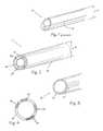
- FIG. 1is a perspective view of the distal end of a conventional endoscope.
- FIG. 2is a perspective view of the distal end of an endoscope with an optical waveguide sheath according to the present disclosure.
- FIG. 3is a perspective view of the distal end of an optical waveguide sheath according to the present disclosure.
- FIG. 4is an end view of the distal end of an optical waveguide sheath according to the present disclosure.
- FIG. 5is a side view of an optical waveguide sheath coupling to fiber optic elements.
- FIG. 6is an end view of the fiber optic coupling lens array of FIG. 5 .
- FIG. 7is a side view of an optical waveguide sheath with a light-coupling adapter according to the present disclosure.
- FIG. 8is a side view of an optical waveguide illumination system with a high-resolution arthroscope disposed therein.
- FIG. 9is a side perspective view of an alternate optical waveguide light coupling technique.
- FIG. 10is an end view of the optical waveguide of FIG. 9 .
- FIG. 11Ais a cutaway view of the proximal end of an optical waveguide with another alternate light coupling.
- FIG. 11Bis an end view of an optical waveguide of FIG. 11A .
- FIG. 11Cis a cutaway view of the proximal end of the optical waveguide of FIG. 11B taken along B-B.
- FIG. 12is a perspective view of an optical waveguide with yet another input light coupling.
- FIG. 13is an enlarged perspective view of the distal end of an optical waveguide.
- FIG. 14is a cutaway view of an alternate optical waveguide.
- FIGS. 14 a -14 dare cutaway views of alternate distal ends of the optical waveguide of FIG. 14 .
- FIG. 15is a perspective view of an optical waveguide with an alternate light coupling.
- FIG. 16is a cutaway view of the proximal end of the optical waveguide of FIG. 15 .
- FIGS. 17 a -17 care front views alternate distal ends of the light coupling of FIG. 15 .
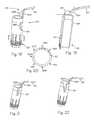
- FIG. 18is a perspective view of an optical waveguide with a split input coupling.
- FIG. 19is cutaway view of the optical waveguide of FIG. 18 .
- FIG. 20is and cross-section of the optical waveguide of FIG. 18 taken along B-B.
- FIG. 21is a perspective view of an alternate optical waveguide with a split input coupling.
- FIG. 22is a perspective view of another alternate optical waveguide with a split input coupling.
- FIG. 23is a cross section of the distal end of an optical waveguide.
- FIG. 24is a cross-section of the distal end of an alternate optical waveguide.
- FIG. 25is a perspective view of an alternate optical waveguide with a reinforced and shielded split input coupling.
- FIG. 26is a cutaway view of the optical waveguide of FIG. 25 .
- FIG. 27is a perspective view of the optical waveguide of FIG. 25 with the clamp assembly removed for clarity.
- FIG. 28is a side view of the optical waveguide of FIG. 27 .
- FIG. 29is a cutaway perspective view of an optical waveguide with the clamp assembly removed for clarity.
- FIG. 30is a close up front view of the input connector of FIG. 29 .
- FIG. 31is a cutaway view of the optical waveguide of FIG. 25 with a ventilation path added.
- FIG. 32is a perspective view of a ventilation controller.
- FIG. 33is a perspective view of an alternate ventilation controller.
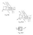
- FIG. 34is a cross-section of a light coupling for the optical waveguide of FIG. 25 .
- FIG. 35Ais a cross-section of an alternate light coupling for the optical waveguide of FIG. 25 .
- FIG. 35Bis a cross section of the alternate light coupling of FIG. 35A taken along C-C.
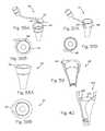
- FIG. 36Ais a perspective view of an ear speculum style optical waveguide.
- FIG. 36Bis a top view of the ear speculum style optical waveguide of FIG. 36A .
- FIG. 37Ais a perspective view of an ear speculum style optical waveguide with a side entry light coupling.
- FIG. 37Bis a top view of the ear speculum style optical waveguide of FIG. 37A .
- FIG. 38Ais a perspective view of another alternate ear speculum style optical waveguide.
- FIG. 38Bis a top view of the ear speculum style optical waveguide of FIG. 38A .
- FIG. 39is a cutaway view of the optical waveguide of FIG. 38A .
- FIG. 40is a cutaway view of the optical waveguide of FIG. 36A .
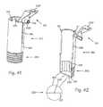
- FIG. 41is a perspective view of a separable waveguide.
- FIG. 42is a cutaway view of the optical waveguide of FIG. 41 .
- FIG. 43is a cutaway view of an optical waveguide with an extended reflecting surface.
- the following disclosuregenerally refers to an optical waveguide and associated elements for conduction of light. This discussion is for example and the following disclosure may also be suitable for any electromagnetic radiation.
- the cross-sections illustratedare generally circular and may also adopt any suitable geometry.
- optical waveguide system 14may accommodate any suitable surgical instrument such as for example, a drill, burr or endoscope 18 which is encased, enclosed or otherwise surrounded by optical waveguide sheath 16 .
- An optical waveguide sheath according to the present disclosureis a generally annular or cylindrical shaped structure and may be manufactured separately and may be a single use device. In the event of a failure of an optical waveguide such as optical waveguide sheath 16 , a replacement may be introduced immediately.
- One or more flow pathssuch as flow path 26 may be created between endoscope 18 and optical waveguide sheath 16 .
- Flow path 26may be used for any suitable service such as suction, irrigation, ventilation or the introduction of other tools or devices.
- a waveguide sheathmay be subjected to forces during use, such as a prying force, that may weaken or break it.
- Structural elementssuch as gussets or ribs may be added to waveguide sheath 16 in the bore between the sheath and endoscope 18 that serve to strengthen waveguide sheath 16 .
- a filmmay be added to the outside of waveguide sheath 16 to secure pieces that may become broken during use to prevent the broken pieces from dropping into the surgical work space. Said film may serve an optical function as well, e.g., enhancing total internal reflection within the wall of waveguide sheath 16 .
- Surgical devicessuch as endoscope 18 may be made without an illumination element and thus aperture 20 may be increased without increasing overall dimension 13 compared to dimension 11 of the device of FIG. 1 .
- Wall 18 A of endoscope 18may also be perform as optical waveguide to improve illumination and may provide an alternate light path to enable illumination of different characteristics.
- waveguide sheath 28may be a single generally uniform element, it may be composed of two or more distinct illumination pathways forming an apparently singular conduit, or it may be composed of one or more parallel light conducting elements such as light path element 24 or light path element 92 of FIG. 14 .
- Moving the illumination element from conventional endoscopes to a separate device such as a light conduit such as waveguide sheath 28permits illumination surface 22 to be larger than many conventional illumination elements.
- Surrounding an apparatus such as an endoscope with the optical waveguidemay provide generally uniform illumination for any orientation of the endoscope or other device.
- illumination surface 22may adopt any suitable configuration to provide illumination.
- facetssuch as facets 30 may direct light energy in any selected direction and may be coated or otherwise treated to introduce filtering for frequency and or polarization.
- Microstructuressuch as microstructures 32 may be used to achieve directed light energy, filtering or other.
- One or more lens structuresmay be coupled to illumination surface 22 , or they may be formed in or on illumination surface such as lenses 34 . Alternatively, these elements may also be combined.
- Each light path elementmay permit selective illumination through a waveguide sheath as well as provide multiple illumination paths for illumination having different characteristics such as polarization, wavelength or intensity.
- Each light path elementmay include microstructures, facets, lenses or other suitable treatment on distal face 24 A.
- coupling ring 38is provided to couple light from fibers 42 into optical waveguide 36 .
- Coupling ring 38permits rotation of optical waveguide 36 about bore centerline 37 without rotating fibers 42 .
- Coupling ring 38may be made reusable since it includes the expensive optical fibers whereas optical waveguide 36 may be made disposable, e.g., as an inexpensive plastic injection molded part using a suitable optical material such as acrylic or polycarbonate.
- Coupling ring 38may also include any suitable light coupling structure such as coupling lenses such as lenses 40 , each lens coupling light energy 39 from a fiber 42 into optical waveguide 36 .
- the lenses or suitable microstructuremay be spherical, cylindrical or aspherical or non-symmetrical depending on the light source.
- a spherical lensmay be used to match the numerical apertures (acceptance angle) of the fiber optic and the optical waveguide. Because a specific cone angle of light exits a fiber optic cable, a matching acceptance angle should be used for the coupling ring.
- light coupling adapter 44may be used to couple light energy in through face 46 and directs the light energy around access channel 48 and through adapter ring 50 into optical waveguide 36 .
- Access port 49 and access channel 48provide access to bore 35 for any suitable surgical tool, apparatus or device.
- Adapter ring 50engages waveguide 36 while permitting relative motion of waveguide 36 relative to light coupling adapter 44 .
- coupling adapter 44 , adapter ring 50 and optical waveguide 36may be contiguous with no relative motion permitted.
- Coupling ring 50may also be an element of waveguide 36 as well as an element of light coupling adapter 44 .
- FIG. 8illustrates arthroscopic illumination system 52 with a high-resolution arthroscope 54 disposed therein.
- the arthroscopic illumination systemcomprises a cannula sheath 55 adapted to provide structure-guided illumination, a hub 56 and an illumination source 58 .
- the hubmay contain one or more valves 60 and be placed in fluid communication with a vacuum and/or irrigation source 62 .
- the cannula sheath 55comprises a biocompatible sterilizable polymer that functions as a waveguide.
- the polymermay be transparent or semi-transparent and may incorporate facets, prisms, microstructures or other suitable characteristics.
- An illumination sourceis operably coupled to the hub 56 and placed in optical communication with the cannula sheath 55 .
- the illumination sourcecomprises one or more LEDs 64 (light emitting diodes), a power source 66 , a conductor 68 electrically connecting the power source and the LED, an LED control circuit 65 and switch 67 .
- the LEDis preferably a white-light LED, which provides a bright, white light.
- the power sourcemay be provided in any form such as a power outlet or a lithium ion polymer battery.
- the outer surfaces of the sleevemay be provided with metallic or other suitable coating to help prevent light leakage while assisting with total internal reflection.
- the distal end of the sleevemay be provided with a microstructure, optical component or a diffuse finish. Based on the desired optical output, a molded component or custom finish may be applied to filter or shape the light exiting the sheath.
- the illumination sourcemay comprise a conventional fiber light cable operably connected to the hub.
- the illumination sourcemay be placed in optical communication with the sheath through optical coupling lenses disposed on the proximal end of sleeve 61 within hub 56 .
- light energy from LED array 72may be coupled into optical waveguide 70 using reflective and or refractive optical assembly 74 in proximal end 70 p such that light energy is projected from illumination surface 71 on distal end 70 d.
- FIGS. 11A, 11B and 11Cillustrate an alternate light coupling into optical waveguide 76 .
- Light 75may be provided through any suitable conduit such as plastic rod 78 .
- Light conduit 78may be formed, cut or otherwise shaped at engagement end 79 to reflect light 75 at any suitable angle relative to light conduit 78 .
- Surface 80may include any suitable treatment, coating or microstructure to reflect a suitable amount of light 75 at a suitable angle relative to light conduit 78 .
- a notch, groove or other suitable indentationsuch as u-shaped notch 82 may be provided in proximal end 84 of an optical waveguide to engage a light conduit such as plastic rod 78 .
- the shape of notch 82may be selected to optimize light coupling between the light conduit and the optical waveguide.
- One or more structuressuch as reflectors 73 and or facet 86 may be included in any suitable location of an optical waveguide to spread the input light throughout the waveguide and or reflect light into bore 88 or out of the optical waveguide into areas surrounding the waveguide. Light generally exits optical waveguide through illumination surface 89 .
- One or more light splitting prismssuch as prisms 73 may be added to a waveguide or to a coupling such as coupling 81 of FIG. 12 to direct the light around the circumference of waveguide 76 . Two or more such prisms may be placed in spaced relation to each other to allow some light to spread straight down through the gap between prisms while light hitting the prisms is directed around the circum
- optical waveguide 76may include an alternate light coupling apparatus such as coupling 81 .
- Coupling 81may provide mechanical support and optical conduit between optical input 83 and waveguide 76 .
- Distal end 83 as shown in FIG. 13includes one of more vertical facets such as facet 83 F within the distal end to disrupt the light spiraling within the waveguide. Also shown are structures such as structure 85 on the end face of the cannula which serve to direct light as it exits the end face. Shown are convex lenses, but concave lenses or other optical structures (e.g., stamped foil diffuser) may be employed depending on the desired light control. Stepped facets such as facets 87 and 89 are shown on the outside tube wall. The “riser” section, risers 87 R and 89 R respectively, of the stepped facet is angled to cause the light to exit and as a result the waveguide slides against tissue without damaging the tissue.
- the angleis generally obtuse relative to the adjacent distal surface.
- Stepsmay be uniform or non-uniform as shown (second step from end is smaller than the first or third step) depending on the light directional control desired.
- the stepsmay be designed to direct light substantially inwards and or toward the bottom of the tube or some distance from the bottom of the tube, or they may be designed to direct light toward the outside of the tube, or any suitable combination.
- the facetssuch as facets 87 and 89 may be each designed to direct light at different angles away from the waveguide and or may be designed to provide different beam spreads from each facet, e.g., by using different micro-structure diffusers on each facet face.
- Facetsmay be used on the inside surface of the waveguide, but if waveguide material is removed to form the facets, the shape of the waveguide may be changed to maintain the internal diameter of the bore generally constant to prevent formation of a gap is between the waveguide and a dilator tube used to insert the waveguide into the body. Said gap may trap tissue, thereby damaging it during insertion into the body or causing the waveguide to be difficult to insert. Thus the outer wall of the waveguide may appear to narrow to close this gap and prevent the problems noted.
- optical waveguide 90 as illustrated in FIGS. 14 and 14 a - 14 dmay be formed using one or more solid light guides such as light path element or rod 92 and forming the one or more rods into a spring like spiral.
- Input 93may be formed at any suitable angle 94 with an optimal angle between 45.degree. and 90.degree.
- Distal end 95may be cut or formed to have any suitable configuration to reflect or emit light in any suitable direction or directions as illustrated in FIGS. 14 and 14 a - 14 d for example.
- a spiral waveguidemay be mechanically flexible, much as a spring is flexible.
- the spiral waveguidemay be part of an assembly that includes rigid or semi-rigid tubular waveguides interconnected by spiral waveguides. Either or both of the tubular and spiral waveguides may have light extraction structures.
- Surgical illumination system 100may include optical waveguide 96 and light adapter 98 .
- Distal end 99 of light adapter 98may have any suitable shape as illustrated in FIGS. 17 a -17 c .
- Lenses or other optical structuressuch as lenses 102 , 104 , 106 and 108 may have any suitable shape or orientation to optimize light coupling, extraction or output. Different lenses may also be combined on a light adapter as in FIG. 17 a .
- a complimentary surface 110may be produced in optical waveguide 96 to achieve selected light transfer or coupling.
- light adapter 98may extend through optical waveguide 96 such that lenses such as lenses 102 , 104 , 106 and or 108 directly illuminate bore 105 and or the surgical site.
- An optical waveguidemay also be used with any suitable end cap engaging the distal end of the optical waveguide.
- the end capmay or may not be used to modify or reflect the illumination energy.
- shimsmay be used within the optical waveguide to orient any tool or tools within the waveguide and the shims may or may not conduct or modify the illumination energy.
- applied light energymay be bifurcated to send light into wall 123 of tube 125 .
- Light input 120may be split in input coupling 122 .
- the input couplingmay be a solid plastic or may consist of a bundle of optical fibers.
- Optical fibersmay be preferred because it is then possible to combine the waveguide and the optical fiber bundle, typically a separate cable used to conduct light from a light source to the waveguide, as one single device thereby eliminating the need for the user to maintain separate fiber optic cables.
- the optical fiber input 120may also be provided as a short “pigtail” section, typically less than two feet long, to which a standard optical fiber cable attaches.
- the optical fibersmay be insert molded with the waveguide or may be glued into corresponding holes in the waveguide using a suitable index-matching adhesive.
- the holesmay include a collar section or other technique to provide strain relief.
- fiber bundlesare made round.
- the optical fibers at the end to be coupled into the waveguideare shaped to match the waveguide, which may not be circular.
- the section of the tube waveguide into which the optical fibers gomay be approximated as a rectangular profile. Shaping the optical fibers into a matching rectangular profile simplifies the resulting optical design because the light dispersion from the optical fibers already conforms to the shape of the waveguide.
- the bifurcated ends 122 A and 122 B of input 122preferably enter tube wall 123 at an angle 124 to start directing light around the tube wall.
- the bifurcated ends 122 A and 122 Bmay each enter tube wall 123 at different angles to further control light distribution.
- the bifurcated endsmay enter the tube wall orthogonally, but this may require a prism structure in the wall placed between the input and the output with the apex of the prism pointed at the input.
- the prism structuredirects the light around the tube wall.
- a vertical prism structure, prism 126is shown with apex 126 A of the prism pointed in toward the center of the tube.
- Prism structure 126may direct a portion of the input light back underneath the inputs and contributes to directing light all the way around the tube wall.
- the position, angle and size of this prism relative to the input bifurcated enddetermines how much light continues in the tube wall in its primary direction and how much light is reflected in the opposite direction in the tube wall.
- Additional vertical prism structures or light disruption structuresmay be placed toward the bottom of the tube on the outside tube wall as shown in FIGS. 18, 19 and 20 .
- One or more light extraction structures 128shown as circumferential grooves cut into the outside wall of the tube, may also be included to optimize the illumination provided below waveguide 125 .
- Light 127 traveling circumferentially in the tube wallwill not strike the light extraction structures 128 with sufficient angle to exit waveguide 125 .
- vertical prisms or light disruption structuressuch as disruption prisms 130 A, 130 B, 130 C and 130 D may be necessary to redirect the light so that the light rays will strike the light extraction structures and exit the tube wall to provide illumination.
- vertical prism structures such as 130 A and 130 Bhave different depths around the circumference in order to affect substantially all of the light rays traveling circumferentially in the tube wall. Vertical prisms of constant depth would not affect substantially all of the light rays.
- FIG. 19also illustrates how a half-tube may be formed to provide illumination.
- At least one half-tube illuminatormay be attached to the end of at least one arm of a frame, such as that used in Adson, Williams or McCulloch retractors. Such frames typically include two arms, but some frames have more than two arms. The arms of the frame are then moved apart to create a surgical workspace, with the at least one half-tube illuminator providing illumination of said space.
- One or more half-tube illuminatorsmay also be provided with an extension that preferably is in contact with the opposite half tube and that serves to prevent tissue from filling in the gap created when the half tubes are separated. Tissue may enter this gap and interfere with surgery, so the extension helps reduce that issue.
- the extensionis preferably thin and flexible, for example, a thin section of plastic molded or otherwise secured to the waveguide or a thin section of metal or other suitable material attached to the waveguide.
- FIGS. 21 and 22illustrate alternative configurations of an illumination waveguide.
- Proximal reflecting structuressuch as proximal structure 132 and proximal structure 134 may provide more complete control of the light within the waveguide with an associated weakening of the structure.
- cross-sections 135 and 137illustrate additional alternate light extraction structures of the distal end of an illumination waveguide.
- depth 136 of light extraction structuressuch as structures 138 and 141 increases relative to the distance from the light input in order to extract most of the light and send the light out the inner tube wall 139 toward the bottom of the tube or distal end 140 and for some distance beyond the distal end.
- the light that remains in the tube wall below the extraction structuresexits the bottom edge 140 B, which may be flat or may have additional optical structures, e.g., a curved lens or a pattern of light diffusing structures such as structures 85 of FIG. 13 .
- the distal 5-10 mm of the tube wall, window 142have no structures to enable this surface to operate as a window to the surrounding tissues to improve visualization of the surgical space.
- a clear waveguide cannulaprovides improved visualization of the entire surgical workspace because the surgeon can see the layers of tissue through the walls, thereby enhancing the surgeon's sense of depth and position, which are difficult to determine in an opaque cannula.
- extraction structures 138 or 141may extend all the way down to bottom edge 140 B.
- light input connector 152 Csurrounds light input cylinder 152 which may be divided into multiple input arms such as arms 151 and 153 that then direct light into illumination waveguide 150 .
- Input arms 151 and 153may assume any suitable shape and cross sections depending on the optical design goals, such as the multi-radius arms with rectangular cross-section shown or straight sections (no radius) or angle rotators, etc.
- a clamp flange holder 159that serves to support input connector 152 C and arms as well as providing a standard light connector 152 C over input cylinder 152 (e.g., an ACMI or WOLF connector) and a flange 159 F at the top for attaching a clamp used to hold the entire structure in place once it is positioned relative to a surgical site in a body.
- a shelf, glare shield 159 S or other similar light blocking structuresmay be added to the holder, extending over the input arms and or the upper tube edge as needed to help block any light that may escape these structures that might shine up into the user's eyes.
- Circumferential light extraction structures 154are shown at the bottom, distal end 156 , of the tube.
- vertical light disruption structures or facets 83 Fare shown on the inside wall of the tube.
- Illuminated cannula 150 of FIG. 25includes clamp adapter 159 F that also support light coupling 152 C for introducing light energy into cannula 150 .
- the relative orientation of the clamp adapter and the light coupling as shownenables the clamp adapter to operate as a shield to prevent any misdirected light shining into the eyes of anyone looking into bore 150 B of the cannula, but the clamp adapter and light coupling may adopt any suitable orientation.
- FIG. 26illustrates vertical facets 83 F within the distal end for disrupting the light spiraling within the waveguide.
- Circumferential light extraction structures 154may include stepped facets such as facets 154 F and risers such as riser 154 R on the outside tube wall 150 W.
- the “riser” section of the stepped facet section 154 Ris angled so that it may slide against tissue without damaging the tissue. Steps may be uniform or non-uniform depending on the light directional control desired.
- the stepsmay be designed to directly light substantially inwards and toward the bottom of the tube or some distance from the bottom of the tube, or they may be designed to direct light toward the outside of the tube, or both.
- Circumferential light extraction structuressuch as structures 154 may be facets or may be other geometries, such as parabolas.
- Circumferential light extraction structures coupled with light directing structures that provide circumferentially distributed light to the extraction structuresprovide circumferential illumination. Since tools entering the interior of the tube now have light shining on them from all sides, the tools do not cast any shadows within the cone of illumination emitted by the cannula.
- the circumferential illumination from a cylindrical waveguidecreates a generally uniform cone of light that minimizes shadows, e.g., from instruments, creating substantially shadowless illumination in the surgical field below the tubular waveguide.
- Cannula 150 of FIGS. 27-30is illustrated without clamp flange/holder 159 in place.
- Input arms 151 and 153are offset above proximal surface 161 by a distance 162 and end in angled reflector surface 158 that partially extends down distance 160 into the tube wall. The offset controls the light entering waveguide 150 and restricts light entering to input structure 165 .
- Reflector surface 158serves to direct light orthogonally from the horizontal input and down into the tube wall, also causing the light to spread around the circumference of the tube wall by the time the light reaches the distal or lower part of the tube.
- Reflector surfaces such as surface 158may be a flat surface, an arced surface, or a series of interconnected surfaces and may also end at the top of the tube wall.
- Reflector surface 158may be treated, e.g., a reflective or metalized coating or an applied reflective film, to enhance reflection.
- Waveguide 150 of FIG. 29includes male connector 148 C that has been integrated with waveguide tube wall 157 via bracket 147 . This allows connector 148 C to be molded with the waveguide and not attached as a separate part, such as standard light connector 152 C shown in FIG. 25 .
- a separate connectorintroduces tolerance concerns into the system that may result in reduced coupling efficiency between a fiber optic cable output and waveguide input 149 because the two parts may not be aligned correctly. Molding the connector and the waveguide input as one piece substantially reduces the chance of misalignment and thereby increases coupling efficiency.
- FIG. 30is a front view looking into the input of connector 148 C.
- Air gaps 146are maintained around waveguide input 149 to isolate the light-conducting pathway.
- One or more small zones of contactsuch as contact zone 146 C may be maintained, essentially bridging connector 148 C and input 149 with a small amount of material, to add strength and stability to the system while resulting in minimum light loss in the contact zone.
- structure 166 along the inside wallmay be used for suction for smoke evacuation and or ventilation.
- Smoke from an electrosurgical knifemay obscure the surgeons view until the smoke dissipates.
- a ventilation tubesuch as tube 167 may be attached to the top of structure 166 to engage the suction structure and provide a source of suction or vacuum.
- the bottom of suction structure 166may be as shown opening into working channel 170 B orthogonal to wall 170 W or it may open directly toward the bottom or distal end 170 D by removing lower lip 166 L. The former is preferred to reduce the chance that debris is sucked into the suction structure thereby blocking it.
- One or more additional tubesmay also be positioned to inject air into the cannula bore, angled along the walls to create a vortex-like air flow that draws smoke toward the side walls where it can then be evacuated, said air flow serving to clear the smoke sooner from the center of the tube where it may obscure vision.
- Small filterssuch as debris filter 172 may be included in or near suction input 168 to block debris.
- the lower suction opening, input 168is preferred to be as close to distal end 170 D of illuminated waveguide 170 as practical, while not interfering with the optical structures, in order to evacuate smoke from electrocautery as soon as possible.
- Multiple suction openingsmay be provided along the vertical channel of the suction section, but these ports should be sized differently, smallest at the top and largest at the bottom so that there is sufficient suction at the bottom port.
- the suction ports and channelshould be designed to minimize turbulence that contributes to noise.
- Multiple suction structuresmay be provided.
- a shelf in clamp flange/holdermay help secure suction tubing to suction source.
- Suction tubing 167 or suction structure 166 in tube 170may also include one or more air filters 173 , e.g., charcoal filters, to remove the smell of the smoke and or other airborne impurities.
- FIGS. 32 and 33illustrate details of suction tube controls 174 and 176 with sliders 174 S and 176 S over a tear drop shaped opening 177 to control the amount of vacuum or suction.
- the irregular shape of openings 177allows finer control over amount of vacuum over a constant shape opening like a rectangular or oblong opening. Any other suitable irregular may also be used.
- FIG. 30shows slider 174 S engaged to allow some suction. Slider 174 S is made to go all the way around tube 174 T with a friction fit. A slider such as sliders 174 S or 176 S may be moved completely off of opening 177 to stop suction.
- FIG. 31shows slider 176 S with a section removed allowing slider 176 S to be simply rotated to expose opening 177 completely to turn off suction.
- opening 177can be rotated 90.degree. relative to the orientation of opening 177 in control 174 .
- the orientation of opening 177 in control 176enables control of suction by simply rotating slider 176 S rather than sliding it up and down as in control 174 .
- input coupling 180may incorporate compound parabolic concentrator 181 or similarly functioning device, such as optical taper 187 in FIG. 35A , whose input 182 is sized to match the largest fiber bundle, which is typically 5 or 6 mm in diameter, but whose output 183 is coupled to a smaller waveguide thickness, e.g., 3 or 5 mm.
- compound parabolic concentrator 181 or similarly functioning devicesuch as optical taper 187 in FIG. 35A , whose input 182 is sized to match the largest fiber bundle, which is typically 5 or 6 mm in diameter, but whose output 183 is coupled to a smaller waveguide thickness, e.g., 3 or 5 mm.
- Such a devicecould be hidden in the connector of the waveguide device, e.g., inside of an ACMI connector or other suitable device.
- the area times the numerical aperture of the inputmust equal the area times the numerical aperture of the output. This means that in going from a larger area input such as input 182 to a smaller area output such as output 183 to inject light into the waveguide, the numerical aperture at the output will increase thereby increasing the angles of the light entering the waveguide. Larger light angles are more difficult to control inside of the waveguide, resulting in greater light loss in the waveguide and increasing design complexity and cost.
- the numerical aperture of an input couplingsuch as coupling 180 or 186 should match or be less than the numerical aperture of the waveguide. Any other suitable method may be employed for enhancing light coupling efficiency to a fiber bundle cable while preserving etendue.
- Input 188 of optical taper coupling 186 of FIGS. 35A and 35Bprovides a significant improvement in input coupling occurs by using a square input coupler on the waveguide that couples to a typical, round fiber bundle cable.
- the increase in coupling surface arearesults in improved light coupling for a variety of fiber sizes without the effect on numerical aperture. For example, going from a 4 mm round coupler to a 4 mm square coupler results in 27% more surface area for coupling to a fiber bundle. If these round and square coupling faces are coupled to a 5 mm diameter fiber bundle, the percent of the 5 mm bundle that remains uncoupled is 36% with the round coupler, but is only 18% with the square coupler.
- the input squareshould be sized as close as practical to the maximum fiber bundle diameter expected. For example, if a 3 mm input is used to couple to a 5 mm fiber bundle, then the square input provides only a 10% improvement in coupling efficiency over a round input. A further improvement is made by shaping the optical fibers in the fiber bundle cable to match the square input of the waveguide so that the capture and dispersion of light in the waveguide is optimized. Similarly, any suitable index matching material may also be used, such as an index matching gel, to improve input coupling.
- FIGS. 36A, 36B and 40illustrate an illumination waveguide configured as ear speculum 190 .
- Input 192is through proximal edge 193 with an angle 191 selected to control the angle of circulation of the light within the waveguide.
- Lightenters the larger diameter upper portion and exits from at least one light extraction structure at or near the smaller diameter lower portion.
- the walls of the waveguideare preferably curved, but may adopt any other suitable geometry.
- illumination waveguide 197 of FIGS. 38A, 38B and 39may include a bifurcated input 198 that may include a beam directing prism as described for FIG. 11C .
- one or more optical elementssuch as lens 200 may also be included in waveguide 202 .
- Optical elements such as lens 200may also include one or more ports such as port 201 to enable access for the insertion of tools, fluid, suction or any other suitable necessity.
- Waveguide 210 of FIGS. 41 and 42may be split open during surgery to permit greater access to the surgical field.
- Waveguide 210may be rigid optical material, e.g., acrylic or polycarbonate, or may be flexible optical material, e.g., silicone, or may incorporate both flexible and rigid elements, e.g. a silicone waveguide hinge over-molded to an upper and lower rigid acrylic waveguide.
- Light input channels 211 and 213may be split and fed through a fiber “Y” or may be comprised entirely of optical fibers. Fibers may be embedded into the wall of the wave-guide all the way to lower portion 210 L that may incorporate light extraction structures.
- Waveguide 210is fully split front and back from the top to about 1 ⁇ 2-2 ⁇ 3 of tube by slots 214 and 216 .
- a waveguidemay be split all the way to lower portion 210 L.
- Lower portion 210 Lis scored inside and out with scoring such as score 218 .
- the scoringoperates to redirect light stuck circling the tube.
- the bottom element 220is pre-split in half along edge 221 and may be glued or otherwise secured in a waveguide such as waveguide 210 .
- the planar shape of element 220permits viewing through bottom element 220 and allows light to shine through.
- element 220may also adopt any other suitable geometry such as rounded to form a lens. Because of the interface with the tube along edge 222 very little light is conducted into element 220 .
- Hole 223enables a surgical screw or other suitable connector to engage through the bottom of waveguide 210 to a surgical site.
- Splitting waveguide 210 and bottom 220frees the waveguide elements from the connector, and permits the waveguide elements to be removed from the surgical site. While at least one light extraction structure is preferably located in lower portion 210 L on each tube half, the at least one extraction structure may be located on only one half or may be located further up the tube, e.g., near the end of split 216 and or split 214 .
- Waveguide 230 in FIG. 43has reflector face 232 extending down to the opposite side of tube waveguide 234 , effectively removing material 236 .
- Extended reflector face 232serves to direct light circumferentially around the tube wall. This opens up the waveguide to provide improved access to the surgical space. In addition, it offers the opportunity to replace removed material 236 with more durable material to improve strength and or provide the clamp flange holder function and or to provide mounting for other devices, such as a CCD camera.
- Illuminated retractorssuch as cannula, waveguides, tubes and or sheaths may also benefit from extendable skirts or segments to prevent tissue encroaching on a surgical site.
- the extendable elementsmay also include interface surfaces to introduce light into the elements to enhance surgical site illumination and or provide off axis illumination to enhance shadows for better depth perception and tissue discrimination.
- the illuminated retractors as discussed abovemay also be made extendable or telescoping to enable a varying depths of surgery with a single thus device minimizing hospital inventory.
- the illuminating cannulas discussedmay also be formed as an illuminating drill guide, either as a tube or as two half tubes, that may be used to hold and guide drill or burr tip while also providing illumination of the area being worked on.
Landscapes
- Health & Medical Sciences (AREA)
- Life Sciences & Earth Sciences (AREA)
- Surgery (AREA)
- Physics & Mathematics (AREA)
- General Health & Medical Sciences (AREA)
- Molecular Biology (AREA)
- Pathology (AREA)
- Veterinary Medicine (AREA)
- Nuclear Medicine, Radiotherapy & Molecular Imaging (AREA)
- Engineering & Computer Science (AREA)
- Biomedical Technology (AREA)
- Heart & Thoracic Surgery (AREA)
- Medical Informatics (AREA)
- Public Health (AREA)
- Animal Behavior & Ethology (AREA)
- Optics & Photonics (AREA)
- Biophysics (AREA)
- Radiology & Medical Imaging (AREA)
- Astronomy & Astrophysics (AREA)
- General Physics & Mathematics (AREA)
- Oral & Maxillofacial Surgery (AREA)
- Endoscopes (AREA)
Abstract
Description
Claims (12)
Priority Applications (1)
| Application Number | Priority Date | Filing Date | Title |
|---|---|---|---|
| US14/229,528US9504373B2 (en) | 2005-04-04 | 2014-03-28 | Illuminated cannula |
Applications Claiming Priority (6)
| Application Number | Priority Date | Filing Date | Title |
|---|---|---|---|
| US66844205P | 2005-04-04 | 2005-04-04 | |
| US72471705P | 2005-10-07 | 2005-10-07 | |
| US11/397,446US7510524B2 (en) | 2005-04-04 | 2006-04-03 | Optical waveguide sheath |
| US11/715,247US7901353B2 (en) | 2005-04-04 | 2007-03-06 | Illuminated cannula |
| US13/019,198US8708896B2 (en) | 2005-04-04 | 2011-02-01 | Illuminated cannula |
| US14/229,528US9504373B2 (en) | 2005-04-04 | 2014-03-28 | Illuminated cannula |
Related Parent Applications (1)
| Application Number | Title | Priority Date | Filing Date |
|---|---|---|---|
| US13/019,198ContinuationUS8708896B2 (en) | 2005-04-04 | 2011-02-01 | Illuminated cannula |
Publications (2)
| Publication Number | Publication Date |
|---|---|
| US20140213851A1 US20140213851A1 (en) | 2014-07-31 |
| US9504373B2true US9504373B2 (en) | 2016-11-29 |
Family
ID=37074110
Family Applications (6)
| Application Number | Title | Priority Date | Filing Date |
|---|---|---|---|
| US11/397,446ActiveUS7510524B2 (en) | 2005-04-04 | 2006-04-03 | Optical waveguide sheath |
| US11/715,247Active2028-12-19US7901353B2 (en) | 2005-04-04 | 2007-03-06 | Illuminated cannula |
| US12/412,764Expired - Fee RelatedUS8162824B2 (en) | 2005-04-04 | 2009-03-27 | Optical waveguide sheath |
| US13/019,198Active2027-04-12US8708896B2 (en) | 2005-04-04 | 2011-02-01 | Illuminated cannula |
| US13/429,700Expired - Fee RelatedUS9072455B2 (en) | 2005-04-04 | 2012-03-26 | Optical waveguide sheath |
| US14/229,528Active2026-07-21US9504373B2 (en) | 2005-04-04 | 2014-03-28 | Illuminated cannula |
Family Applications Before (5)
| Application Number | Title | Priority Date | Filing Date |
|---|---|---|---|
| US11/397,446ActiveUS7510524B2 (en) | 2005-04-04 | 2006-04-03 | Optical waveguide sheath |
| US11/715,247Active2028-12-19US7901353B2 (en) | 2005-04-04 | 2007-03-06 | Illuminated cannula |
| US12/412,764Expired - Fee RelatedUS8162824B2 (en) | 2005-04-04 | 2009-03-27 | Optical waveguide sheath |
| US13/019,198Active2027-04-12US8708896B2 (en) | 2005-04-04 | 2011-02-01 | Illuminated cannula |
| US13/429,700Expired - Fee RelatedUS9072455B2 (en) | 2005-04-04 | 2012-03-26 | Optical waveguide sheath |
Country Status (5)
| Country | Link |
|---|---|
| US (6) | US7510524B2 (en) |
| EP (3) | EP1868488B1 (en) |
| JP (1) | JP5143723B2 (en) |
| CN (2) | CN101188966B (en) |
| WO (1) | WO2006108143A2 (en) |
Cited By (13)
| Publication number | Priority date | Publication date | Assignee | Title |
|---|---|---|---|---|
| US10512518B2 (en) | 2005-04-04 | 2019-12-24 | Invuity, Inc. | Illuminated telescoping cannula |
| US11439379B2 (en) | 2015-02-05 | 2022-09-13 | Obp Surgical Corporation | Illuminated surgical retractor |
| US11540817B2 (en) | 2017-07-18 | 2023-01-03 | Obp Surgical Corporation | Minimally invasive no touch (MINT) procedure for harvesting the great saphenous vein (GSV) and venous hydrodissector and retractor for use during the mint procedure |
| US11617822B2 (en) | 2020-01-31 | 2023-04-04 | Obp Surgical Corporation | Illuminated suction device |
| US11622756B2 (en) | 2015-06-03 | 2023-04-11 | Obp Surgical Corporation | End cap assembly for retractor and other medical devices |
| US11622758B2 (en) | 2020-02-25 | 2023-04-11 | Obp Surgical Corporation | Illuminated dual-blade retractor |
| US11717374B2 (en) | 2016-07-11 | 2023-08-08 | Obp Surgical Corporation | Illuminated suction device |
| US11744568B2 (en) | 2018-02-20 | 2023-09-05 | Obp Surgical Corporation | Illuminated medical devices |
| US11903557B2 (en) | 2019-04-30 | 2024-02-20 | Psip2 Llc | Endoscope for imaging in nonvisible light |
| US12201287B2 (en) | 2015-06-03 | 2025-01-21 | Coopersurgical, Inc. | Retractor |
| US12318080B2 (en) | 2023-07-21 | 2025-06-03 | Coopersurgical, Inc. | Illuminated surgical retractor capable of hand-held operation and of being mounted to a fixed frame |
| US12329370B2 (en) | 2015-02-05 | 2025-06-17 | Coopersurgical, Inc. | Illuminated surgical retractor |
| US12383129B2 (en) | 2017-10-19 | 2025-08-12 | Coopersurgical, Inc. | Medical devices with battery removal |
Families Citing this family (166)
| Publication number | Priority date | Publication date | Assignee | Title |
|---|---|---|---|---|
| US20070167681A1 (en) | 2001-10-19 | 2007-07-19 | Gill Thomas J | Portable imaging system employing a miniature endoscope |
| US10595710B2 (en) | 2001-10-19 | 2020-03-24 | Visionscope Technologies Llc | Portable imaging system employing a miniature endoscope |
| US9216015B2 (en) | 2004-10-28 | 2015-12-22 | Vycor Medical, Inc. | Apparatus and methods for performing brain surgery |
| US20080255441A1 (en)* | 2004-12-01 | 2008-10-16 | Ron Hadani | Add-On For Invasive Probe |
| US7510524B2 (en) | 2005-04-04 | 2009-03-31 | Invuity, Inc. | Optical waveguide sheath |
| US20060287583A1 (en)* | 2005-06-17 | 2006-12-21 | Pool Cover Corporation | Surgical access instruments for use with delicate tissues |
| US8360970B2 (en)* | 2005-06-22 | 2013-01-29 | Vycor Medical, Inc. | Surgical access instruments for use with spinal or orthopedic surgery |
| GB0519769D0 (en)* | 2005-09-28 | 2005-11-09 | Imp College Innovations Ltd | Imaging system |
| US8409088B2 (en) | 2006-01-18 | 2013-04-02 | Invuity, Inc. | Retractor illumination system |
| FR2899087B1 (en)* | 2006-04-03 | 2008-06-20 | V I M S Video Interventionnell | PROTECTION FOR ENDOSCOPE AND CORRESPONDING ENDOSCOPE |
| US20090286694A1 (en)* | 2006-08-21 | 2009-11-19 | Gafur Zainiev | Nucleic acid array with releaseable nucleic acid probes |
| US20080166677A1 (en)* | 2007-01-08 | 2008-07-10 | Neil John Graham | Light directing and amplifying device |
| US8273015B2 (en)* | 2007-01-09 | 2012-09-25 | Ethicon Endo-Surgery, Inc. | Methods for imaging the anatomy with an anatomically secured scanner assembly |
| US8801606B2 (en)* | 2007-01-09 | 2014-08-12 | Ethicon Endo-Surgery, Inc. | Method of in vivo monitoring using an imaging system including scanned beam imaging unit |
| DE102007015553B3 (en) | 2007-03-29 | 2008-11-06 | Pajunk Gmbh & Co. Kg Besitzverwaltung | Device for locating a cannula pierced into a body |
| DE102007026234A1 (en)* | 2007-05-31 | 2008-12-04 | Karl Storz Gmbh & Co. Kg | Videoscope |
| US9125552B2 (en)* | 2007-07-31 | 2015-09-08 | Ethicon Endo-Surgery, Inc. | Optical scanning module and means for attaching the module to medical instruments for introducing the module into the anatomy |
| US8088066B2 (en) | 2007-10-24 | 2012-01-03 | Invuity, Inc. | Blade insert illuminator |
| US9402643B2 (en) | 2008-01-15 | 2016-08-02 | Novartis Ag | Targeted illumination for surgical instrument |
| WO2009116969A1 (en)* | 2008-03-20 | 2009-09-24 | Invuity, Inc. | Illuminated cannula |
| US8636653B2 (en) | 2008-06-09 | 2014-01-28 | Capso Vision, Inc. | In vivo camera with multiple sources to illuminate tissue at different distances |
| DE102008033506A1 (en) | 2008-07-07 | 2010-01-14 | Karl Storz Gmbh & Co. Kg | Video endoscope with switchable semiconductor light sources |
| US9282878B2 (en)* | 2008-08-13 | 2016-03-15 | Invuity, Inc. | Cyclo olefin polymer and copolymer medical devices |
| US11382711B2 (en) | 2008-08-13 | 2022-07-12 | Invuity, Inc. | Cyclo olefin polymer and copolymer medical devices |
| US20100081873A1 (en)* | 2008-09-30 | 2010-04-01 | AiHeart Medical Technologies, Inc. | Systems and methods for optical viewing and therapeutic intervention in blood vessels |
| US8992558B2 (en)* | 2008-12-18 | 2015-03-31 | Osteomed, Llc | Lateral access system for the lumbar spine |
| US20130324803A1 (en)* | 2009-01-23 | 2013-12-05 | Reza S. Mohajer | Veress needle with illuminated guidance and suturing capability |
| US8523817B2 (en)* | 2009-01-23 | 2013-09-03 | Reza S. Mohajer | Veress needle with illuminated guidance and suturing capability |
| DE102009025659A1 (en)* | 2009-06-17 | 2010-12-23 | Karl Storz Gmbh & Co. Kg | endoscope tube |
| DE102009036211B4 (en)* | 2009-08-05 | 2013-01-31 | Trw Automotive Electronics & Components Gmbh | Optical display element of selectively illuminable concentric rings |
| US9877644B2 (en) | 2009-11-10 | 2018-01-30 | Illumigyn Ltd. | Optical speculum |
| US8795162B2 (en) | 2009-11-10 | 2014-08-05 | Invuity, Inc. | Illuminated suction apparatus |
| US8292805B2 (en)* | 2009-11-10 | 2012-10-23 | Invuity, Inc. | Illuminated suction apparatus |
| US9271640B2 (en)* | 2009-11-10 | 2016-03-01 | Illumigyn Ltd. | Optical speculum |
| JP2011120627A (en)* | 2009-12-08 | 2011-06-23 | Fujifilm Corp | Illumination optical system of endoscope |
| US8728162B2 (en) | 2010-04-15 | 2014-05-20 | Osteomed, Llc | Direct lateral spine system instruments, implants and associated methods |
| US8840546B2 (en) | 2010-06-01 | 2014-09-23 | The Board Of Trustees Of The Leland Stanford Junior University | System for accessing a body orifice |
| US8838206B2 (en)* | 2010-06-30 | 2014-09-16 | Reza S. Mohajer | Veress needle with illuminated tip and cavity penetration indicator |
| CN102834045B (en) | 2010-07-09 | 2015-03-11 | 奥林巴斯医疗株式会社 | Endoscope-holding device and endoscopic system |
| EP2599427A4 (en) | 2010-07-28 | 2017-07-05 | Olympus Corporation | Rigid scope |
| US9289114B2 (en)* | 2010-07-30 | 2016-03-22 | Nilesh R. Vasan | Disposable, self-contained laryngoscope and method of using same |
| WO2012021451A1 (en)* | 2010-08-09 | 2012-02-16 | Alcon Research, Ltd. | Illuminated surgical instrument |
| MX350734B (en) | 2010-09-08 | 2017-09-15 | Covidien Lp | Catheter with imaging assembly. |
| JP6317583B2 (en) | 2010-12-16 | 2018-04-25 | インブイティ・インコーポレイテッド | Illuminated suction device |
| DE102011011086A1 (en)* | 2011-02-11 | 2012-08-16 | Olympus Winter & Ibe Gmbh | Endoscope with a shaft tube and head piece for it |
| EP2649923A4 (en) | 2011-04-07 | 2014-05-28 | Olympus Medical Systems Corp | ENDOSCOPE AND ILLUMINATION DEVICE FOR ENDOSCOPE |
| CN102798928A (en)* | 2011-05-27 | 2012-11-28 | 吕路可 | Light-transmissible composite plastic tube body |
| WO2012170480A1 (en) | 2011-06-07 | 2012-12-13 | Boston Scientific Scimed, Inc. | Disposable sheath |
| US20120321259A1 (en)* | 2011-06-14 | 2012-12-20 | Luke Lu | Light-transmittable composite tube |
| GB2493165A (en)* | 2011-07-26 | 2013-01-30 | Nusurgix Ltd | A light emitting head having an LED ring, used with a disposable speculum |
| DE102011079958A1 (en)* | 2011-07-28 | 2013-01-31 | Karl Storz Gmbh & Co. Kg | Endoscope with adjustable viewing direction |
| WO2013032881A1 (en) | 2011-08-31 | 2013-03-07 | Boston Scientific Scimed, Inc. | Extendible flexible sheath |
| US20130052618A1 (en)* | 2011-08-31 | 2013-02-28 | Modern Bar Review Course, Inc. | Computerized focused, individualized bar exam preparation |
| IL215106A0 (en)* | 2011-09-12 | 2012-02-29 | Daniel Sherwin | Laparoscopic device |
| EP2757931B1 (en)* | 2011-09-20 | 2015-11-25 | Boston Scientific Scimed, Inc. | Access devices and related methods of use |
| US8942530B2 (en) | 2011-09-20 | 2015-01-27 | San Marino Capital, Inc. | Endoscope connector method and apparatus |
| US8585235B2 (en) | 2011-10-27 | 2013-11-19 | Covidien Lp | Access assembly with landing light |
| US8944596B2 (en) | 2011-11-09 | 2015-02-03 | Welch Allyn, Inc. | Digital-based medical devices |
| US9308051B2 (en) | 2011-11-15 | 2016-04-12 | Smiths Medical Asd, Inc. | Illuminated tubing set |
| US9308323B2 (en) | 2011-11-15 | 2016-04-12 | Smiths Medical Asd, Inc. | Systems and methods for illuminated medical tubing detection and management indicating a characteristic of at least one infusion pump |
| GB201121963D0 (en)* | 2011-12-20 | 2012-02-01 | Smiths Medical Int Ltd | Imaging and illumination apparatus |
| KR101327110B1 (en)* | 2012-04-24 | 2013-11-08 | 서오남 | Slide exhaust type surgery instrument Guider |
| WO2013177324A2 (en)* | 2012-05-25 | 2013-11-28 | Invuity, Inc. | Actuatable retractor |
| CN103445754A (en)* | 2012-05-31 | 2013-12-18 | 广州宝胆医疗器械科技有限公司 | Rocket-like multichannel hard cystoscope |
| CN103445745A (en)* | 2012-05-31 | 2013-12-18 | 广州宝胆医疗器械科技有限公司 | Rocket-like multichannel hard uteroscope |
| CN103445752A (en)* | 2012-05-31 | 2013-12-18 | 广州宝胆医疗器械科技有限公司 | Rocket-like multichannel hard colposcope |
| CN103445755A (en)* | 2012-05-31 | 2013-12-18 | 广州宝胆医疗器械科技有限公司 | Rocket-like multichannel hard anorectal endoscope |
| CN103445756A (en)* | 2012-05-31 | 2013-12-18 | 广州宝胆医疗器械科技有限公司 | Rocket-like multichannel hard gallbladder endoscope |
| JP2014012043A (en)* | 2012-07-03 | 2014-01-23 | Coden Co Ltd | Pipe endoscope |
| USD735343S1 (en) | 2012-09-07 | 2015-07-28 | Covidien Lp | Console |
| US9517184B2 (en) | 2012-09-07 | 2016-12-13 | Covidien Lp | Feeding tube with insufflation device and related methods therefor |
| US9198835B2 (en) | 2012-09-07 | 2015-12-01 | Covidien Lp | Catheter with imaging assembly with placement aid and related methods therefor |
| USD717340S1 (en) | 2012-09-07 | 2014-11-11 | Covidien Lp | Display screen with enteral feeding icon |
| USD716841S1 (en) | 2012-09-07 | 2014-11-04 | Covidien Lp | Display screen with annotate file icon |
| US9375137B2 (en) | 2012-09-11 | 2016-06-28 | Brainchild Surgical Devices Llc | Gastric bougie/dilator with integral lighted tip |
| US9413896B2 (en) | 2012-09-14 | 2016-08-09 | The Spectranetics Corporation | Tissue slitting methods and systems |
| KR102232361B1 (en) | 2012-09-24 | 2021-03-25 | 인뷰이티 인코퍼레이티드 | Methods and apparatus for controlling optical properties of light |
| US9480855B2 (en) | 2012-09-26 | 2016-11-01 | DePuy Synthes Products, Inc. | NIR/red light for lateral neuroprotection |
| AU2013338201C1 (en)* | 2012-11-01 | 2018-08-30 | Alcon Inc. | Illuminated vitrectomy cutter with adjustable illumination aperture |
| EP3473160B1 (en)* | 2012-12-12 | 2023-12-27 | Invuity, Inc. | Illuminated suction apparatus |
| JP6375309B2 (en) | 2013-02-01 | 2018-08-15 | デカ・プロダクツ・リミテッド・パートナーシップ | Endoscope with camera capable of panning |
| US10616491B2 (en) | 2013-02-01 | 2020-04-07 | Deka Products Limited Partnership | Endoscope with pannable camera and related method |
| WO2014133500A1 (en)* | 2013-02-27 | 2014-09-04 | Empire Technology Development Llc | Diagnostic needle probe |
| US10835279B2 (en) | 2013-03-14 | 2020-11-17 | Spectranetics Llc | Distal end supported tissue slitting apparatus |
| MX371031B (en)* | 2013-03-26 | 2020-01-13 | Steris Instrument Man Services Inc | Endoscope and method of assembly therefore. |
| CN103284769B (en)* | 2013-07-02 | 2014-11-26 | 赵令军 | Surgical cannula |
| TW201503867A (en)* | 2013-07-17 | 2015-02-01 | Genesis Photonics Inc | Opening device for surgical operation |
| US20150087911A1 (en)* | 2013-09-26 | 2015-03-26 | Gyrus Acmi, Inc. D.B.A Olympus Surgical Technologies America | Endoscope sheath deflection devices |
| US10078226B2 (en) | 2013-10-14 | 2018-09-18 | Welch Allyn, Inc. | Portable eye viewing device enabled for enhanced field of view |
| US11033182B2 (en) | 2014-02-21 | 2021-06-15 | 3Dintegrated Aps | Set comprising a surgical instrument |
| EP4218629B1 (en)* | 2014-04-23 | 2024-11-20 | Applied Medical Resources Corporation | System for tissue removal |
| CN106413503B (en)* | 2014-04-29 | 2019-07-09 | B-K医疗公司 | Ultrasonic imaging probe |
| EP3142541A4 (en) | 2014-05-13 | 2017-04-26 | Vycor Medical, Inc. | Guidance system mounts for surgical introducers |
| EP3145385A4 (en)* | 2014-05-22 | 2018-02-14 | Invuity, Inc. | Medical device featuring cladded waveguide |
| JP5975504B2 (en)* | 2014-07-24 | 2016-08-23 | アドバンストヘルスケア株式会社 | Trocar, port, surgery support system |
| US10405838B2 (en)* | 2014-08-28 | 2019-09-10 | Koninklijke Philips N.V. | Side-looking lung biopsy device |
| CA2967766C (en)* | 2014-11-13 | 2023-10-17 | Applied Medical Resources Corporation | Systems and methods for tissue removal |
| US20160147002A1 (en)* | 2014-11-26 | 2016-05-26 | Lightmed Dental Technology Corp. | Light Field-Modulable Optical Needle Assembly |
| KR102475203B1 (en)* | 2014-12-02 | 2022-12-07 | 인뷰이티 인코퍼레이티드 | Methods and apparatus for coupling an optical input to an illumination device |
| US10245071B2 (en) | 2014-12-23 | 2019-04-02 | Michael Frank Gunter WOOD | System for illumination during a corridor based procedure |
| WO2016148751A1 (en)* | 2015-03-18 | 2016-09-22 | A.M. Surgical, Inc. | Video assisted surgery device |
| US20160354176A1 (en)* | 2015-06-08 | 2016-12-08 | Covidien Lp | Surgical instrument with integrated illumination |
| US10244931B2 (en) | 2015-07-13 | 2019-04-02 | Novartis Ag | Illuminated ophthalmic infusion line and associated devices, systems, and methods |
| CN108024806B (en)* | 2015-07-21 | 2022-07-01 | 3D集成公司 | Cannula assembly kit, trocar assembly kit, sleeve assembly, minimally invasive surgical system and method thereof |
| EP3184025A4 (en)* | 2015-08-20 | 2018-08-29 | Olympus Corporation | Medical sheath and medical device |
| US11173008B2 (en) | 2015-11-01 | 2021-11-16 | Alcon Inc. | Illuminated ophthalmic cannula |
| CA3008028A1 (en)* | 2016-01-07 | 2017-07-13 | Glenn P. Gardner | Endotracheal tube insertion device |
| US20170215707A1 (en)* | 2016-01-29 | 2017-08-03 | Boston Scientific Scimed, Inc. | Sheath for an imaging device |
| WO2017132149A1 (en)* | 2016-01-29 | 2017-08-03 | Boston Scientific Scimed, Inc. | Medical retrieval devices and related methods of use |
| US20170231706A1 (en)* | 2016-02-17 | 2017-08-17 | Invuity, Inc. | Illuminated surgical barrier |
| US9956053B2 (en) | 2016-03-04 | 2018-05-01 | Novartis Ag | Cannula with an integrated illumination feature |
| US11096557B2 (en) | 2016-03-14 | 2021-08-24 | Eyelum Ltd. | Endoscopy system having a miniature closed head |
| US10481386B2 (en)* | 2016-03-30 | 2019-11-19 | Arizona Board Of Regents On Behalf Of The University Of Arizona | Optical article and illumination system for endoscope |
| WO2018039228A1 (en) | 2016-08-23 | 2018-03-01 | Stryker European Holdings I, Llc | Instrumentation for the implantation of spinal implants |
| US10376258B2 (en) | 2016-11-07 | 2019-08-13 | Vycor Medical, Inc. | Surgical introducer with guidance system receptacle |
| US10543016B2 (en) | 2016-11-07 | 2020-01-28 | Vycor Medical, Inc. | Surgical introducer with guidance system receptacle |
| US12178469B2 (en) | 2016-11-07 | 2024-12-31 | Vycor Medical Inc. | Surgical introducer with guidance system receptacle |
| US10869735B2 (en)* | 2016-11-17 | 2020-12-22 | Alcon Inc. | Medical instrument with an integrated optical fiber |
| TWI623774B (en)* | 2016-12-02 | 2018-05-11 | Nat Chung Shan Inst Science & Tech | Lighting device |
| US20180280046A1 (en)* | 2017-03-30 | 2018-10-04 | Acclarent, Inc. | Guidewire with optics tube containing core wire |
| CN111295126B (en) | 2017-09-11 | 2023-11-17 | 艾拉姆有限公司 | Disposable miniature endoscopy system |
| EP3494862A1 (en)* | 2017-12-08 | 2019-06-12 | Ambu A/S | Illumination system for an endoscope |
| US10401883B2 (en)* | 2018-01-11 | 2019-09-03 | Eric Swanson | Optical probe using multimode optical waveguide and proximal processing |
| US11147441B2 (en) | 2018-01-16 | 2021-10-19 | Welch Allyn, Inc. | Physical assessment device |
| EP3545857B1 (en) | 2018-03-30 | 2024-01-03 | Stryker European Operations Holdings LLC | Lateral access retractor and core insertion |
| WO2019210227A1 (en) | 2018-04-26 | 2019-10-31 | Deka Products Limited Partnership | Endoscope with rotatable camera and related methods |
| CN112292093B (en)* | 2018-06-19 | 2024-09-17 | 美敦力先进能量有限公司 | Illuminated electrosurgical devices, systems, and methods |
| US11571205B2 (en) | 2018-07-16 | 2023-02-07 | Cilag Gmbh International | Surgical visualization feedback system |
| US11395713B2 (en)* | 2018-07-19 | 2022-07-26 | Alcon Inc. | Illuminated cannula |
| CN108938102A (en)* | 2018-07-19 | 2018-12-07 | 上海博进凯利泰医疗科技有限公司 | A kind of arthroscope casing |
| USD876625S1 (en) | 2018-08-07 | 2020-02-25 | Adroit Surgical, Llc | Laryngoscope |
| US10736659B2 (en)* | 2018-10-23 | 2020-08-11 | Covidien Lp | Optical trocar assembly |
| CA3127963A1 (en)* | 2019-02-08 | 2020-08-13 | Rebound Therapeutics Corporation | Lighted cannula system |
| CN113795187A (en)* | 2019-03-06 | 2021-12-14 | 诺亚医疗集团公司 | Single use endoscope, cannula and obturator with integrated vision and illumination |
| US12257013B2 (en) | 2019-03-15 | 2025-03-25 | Cilag Gmbh International | Robotic surgical systems with mechanisms for scaling camera magnification according to proximity of surgical tool to tissue |
| KR20210133304A (en) | 2019-03-27 | 2021-11-05 | 패시 메디컬, 엘엘씨 | Lighting devices for portable surgical instruments, surgical instruments and lighting devices with lighting devices and holsters for surgical instruments with kits |
| CN111366909B (en)* | 2019-04-12 | 2022-12-02 | 上海禾赛科技有限公司 | Laser radar |
| US11426203B2 (en) | 2019-05-23 | 2022-08-30 | Covidien Lp | Tissue guards and systems incorporating the same for tissue specimen removal procedures and other surgical procedures |
| US12342991B2 (en) | 2019-07-31 | 2025-07-01 | Nico Corporation | Surgical access device with integrated illumination |
| US11278317B2 (en) | 2019-08-28 | 2022-03-22 | Covidien Lp | Surgical access devices and systems including smoke evacuation |
| CN110558922B (en)* | 2019-09-02 | 2021-11-23 | 西安交通大学医学院第一附属医院 | Neuroendoscopy with suction device and use method thereof |
| US20210113072A1 (en)* | 2019-10-21 | 2021-04-22 | John L. Bala | Bala 2/3 dimension endoscope |
| US11564674B2 (en) | 2019-11-27 | 2023-01-31 | K2M, Inc. | Lateral access system and method of use |
| US11058459B2 (en) | 2019-12-12 | 2021-07-13 | Covidien Lp | Two-piece cutting guard with evacuation ports |
| US11116488B2 (en)* | 2019-12-20 | 2021-09-14 | Covidien Lp | Tissue guard for tissue removal and other surgical procedures |
| US11744667B2 (en) | 2019-12-30 | 2023-09-05 | Cilag Gmbh International | Adaptive visualization by a surgical system |
| US12207881B2 (en) | 2019-12-30 | 2025-01-28 | Cilag Gmbh International | Surgical systems correlating visualization data and powered surgical instrument data |
| US11832996B2 (en) | 2019-12-30 | 2023-12-05 | Cilag Gmbh International | Analyzing surgical trends by a surgical system |
| US11284963B2 (en) | 2019-12-30 | 2022-03-29 | Cilag Gmbh International | Method of using imaging devices in surgery |
| US11648060B2 (en) | 2019-12-30 | 2023-05-16 | Cilag Gmbh International | Surgical system for overlaying surgical instrument data onto a virtual three dimensional construct of an organ |
| US11896442B2 (en) | 2019-12-30 | 2024-02-13 | Cilag Gmbh International | Surgical systems for proposing and corroborating organ portion removals |
| US11759283B2 (en) | 2019-12-30 | 2023-09-19 | Cilag Gmbh International | Surgical systems for generating three dimensional constructs of anatomical organs and coupling identified anatomical structures thereto |
| US12002571B2 (en) | 2019-12-30 | 2024-06-04 | Cilag Gmbh International | Dynamic surgical visualization systems |
| US11776144B2 (en) | 2019-12-30 | 2023-10-03 | Cilag Gmbh International | System and method for determining, adjusting, and managing resection margin about a subject tissue |
| US12053223B2 (en) | 2019-12-30 | 2024-08-06 | Cilag Gmbh International | Adaptive surgical system control according to surgical smoke particulate characteristics |
| US11219501B2 (en) | 2019-12-30 | 2022-01-11 | Cilag Gmbh International | Visualization systems using structured light |
| EP4087511A4 (en)* | 2020-01-08 | 2024-02-14 | 460Medical, Inc. | Systems and methods for optical interrogation of ablation lesions |
| US11583314B2 (en) | 2020-03-03 | 2023-02-21 | Covidien Lp | Surgical access device and method for using the same |
| US11690648B2 (en) | 2020-03-03 | 2023-07-04 | Covidien Lp | Surgical access device and method for using the same |
| US11529191B2 (en) | 2020-05-26 | 2022-12-20 | Covidien Lp | Auxiliary electrosurgical return via cutting guard |
| US11627988B2 (en) | 2020-07-14 | 2023-04-18 | Covidien Lp | Snap-fit cutting guard |
| US11931067B2 (en) | 2020-08-15 | 2024-03-19 | Covidien Lp | Insertable cutting guards |
| US11534258B2 (en) | 2020-08-26 | 2022-12-27 | Covidien Lp | Cutting guard |
| EP4210612A2 (en)* | 2020-09-09 | 2023-07-19 | Stryker European Operations Limited | Electrosurgical devices, methods of use, and methods of manufacture |
| US20250072723A1 (en)* | 2023-08-30 | 2025-03-06 | Karl Storz Imaging, Inc. | Endoscopic Illumination Sleeve |
| WO2025122772A1 (en)* | 2023-12-05 | 2025-06-12 | Bemis Manufacturing Company | Medical suction device |
Citations (84)
| Publication number | Priority date | Publication date | Assignee | Title |
|---|---|---|---|---|
| US1246340A (en) | 1916-08-21 | 1917-11-13 | Isaac J Smit | Self-illuminated surgical illuminating-speculum. |
| US2482971A (en) | 1947-07-11 | 1949-09-27 | Golson Kelly Kendall | Self-illuminated transparent proctoscope |
| US2843112A (en) | 1954-06-30 | 1958-07-15 | Bernard J Miller | Light transmitting means for endoscopes |
| US3075516A (en) | 1960-05-23 | 1963-01-29 | Clauss B Strauch | Apparatus for auto-vaginoscopy |
| US3261349A (en) | 1963-08-29 | 1966-07-19 | American Cystoscope Makers Inc | Endoscope |
| US3413067A (en) | 1964-03-25 | 1968-11-26 | Froio Corp | Light conducting rod endoscopic instrument which makes use of the principle of total internal reflection to sight perpendicularly to the rod axis |
| US3498286A (en) | 1966-09-21 | 1970-03-03 | American Optical Corp | Catheters |
| US3638644A (en) | 1969-03-05 | 1972-02-01 | Michael Elbert | Illuminated surgical speculum |
| GB1262214A (en) | 1969-12-23 | 1972-02-02 | Genito Urinary Mfg Company Ltd | Improvements in surgical endoscopic instruments |
| US3641332A (en) | 1969-10-30 | 1972-02-08 | Ebert Michael | Fiber optics illumination system |
| US3770342A (en) | 1971-05-07 | 1973-11-06 | R Dudragne | Device for lighting and examining a cavity |
| US3890960A (en) | 1973-01-19 | 1975-06-24 | Efrudec Vertriebsgesellschaft | Medical diagnostic inspection spatula |
| US4215678A (en) | 1976-08-13 | 1980-08-05 | Propper Manufacturing Co., Inc. | Endoscope |
| US4226228A (en) | 1978-11-02 | 1980-10-07 | Shin Hee J | Multiple joint retractor with light |
| US4300541A (en) | 1979-02-09 | 1981-11-17 | Kermit Burgin | Speculum lens structure |
| US4306546A (en) | 1980-03-26 | 1981-12-22 | Propper Manufacturing Co., Inc. | Endoscope |
| GB2078526A (en) | 1980-06-21 | 1982-01-13 | Original Hanau Heraeus Gmbh | Improvements in or relating to surgical retractors |
| EP0101781A1 (en) | 1982-07-30 | 1984-03-07 | W.C. Heraeus GmbH | Retractor for surgical purposes |
| US4519385A (en)* | 1982-12-01 | 1985-05-28 | Snyder Laboratories, Inc. | Lavage handpiece |
| US4526573A (en)* | 1982-03-29 | 1985-07-02 | Smiths Industries Public Limited Company | Suction-irrigation equipment with control valve |
| EP0148034A2 (en) | 1984-01-03 | 1985-07-10 | Medical Dynamics, Inc. | Laser endoscope apparatus |
| US4562832A (en) | 1984-01-21 | 1986-01-07 | Wilder Joseph R | Medical instrument and light pipe illumination assembly |
| US4592344A (en) | 1980-07-25 | 1986-06-03 | Scheer Peter M | Combination illuminator and lip and cheek expander |
| US4597030A (en) | 1985-01-31 | 1986-06-24 | American Hospital Supply Corporation | Surgical illuminator |
| US4605990A (en) | 1984-01-21 | 1986-08-12 | Wilder Joseph R | Surgical clip-on light pipe illumination assembly |
| US4617013A (en)* | 1983-03-14 | 1986-10-14 | Timron Instruments, Incorporated | Method and apparatus for surgical irrigation, aspiration and illumination |
| US4643172A (en) | 1985-10-21 | 1987-02-17 | Taff Barry E | Luminescent tongue depressor |
| US4697578A (en) | 1981-07-17 | 1987-10-06 | Burgin Kermit H | Acrylooptic tongue depressor and handle therefor incorporating adjustable viewing optics |
| US4736733A (en) | 1987-02-25 | 1988-04-12 | Medical Dynamics, Inc. | Endoscope with removable eyepiece |
| US4807599A (en) | 1987-05-08 | 1989-02-28 | Med-Struments, Inc. | Illuminating tongue depressor |
| US4819620A (en) | 1986-08-16 | 1989-04-11 | Ichiro Okutsu | Endoscope guide pipe |
| US4842356A (en) | 1987-04-15 | 1989-06-27 | Kei Mori | Light ray radiation device for use in medical treatment of the nose and throat passages |
| US4906070A (en) | 1985-11-21 | 1990-03-06 | Minnesota Mining And Manufacturing Company | Totally internally reflecting thin, flexible film |
| US4961617A (en) | 1989-07-19 | 1990-10-09 | Ferrydon Shahidi | Fibre optic waveguide illuminating elements |
| US5035232A (en) | 1987-10-24 | 1991-07-30 | Aesculap Ag | Retractor |
| US5136480A (en) | 1989-02-10 | 1992-08-04 | Lumitex, Inc. | Thin panel illuminator |
| US5250045A (en) | 1991-06-11 | 1993-10-05 | The Spectranetics Corporation | Optical fiber catheter with spaced optical fiber |
| DE4238977A1 (en) | 1992-11-19 | 1994-05-26 | Schoelly Fiberoptic Gmbh | Illumination and visual inspection device for cavities and interstices - comprises reusable optical system holder and disposable tubular lighting unit into which it is snap-fitted |
| US5353786A (en) | 1992-01-24 | 1994-10-11 | Wilk Peter J | Surgical lighting method |
| US5354302A (en) | 1992-11-06 | 1994-10-11 | Ko Sung Tao | Medical device and method for facilitating intra-tissue visual observation and manipulation of distensible tissues |
| US5406938A (en)* | 1992-08-24 | 1995-04-18 | Ethicon, Inc. | Glare elimination device |
| US5419309A (en) | 1992-02-18 | 1995-05-30 | Biehl; Albert G. | Tip cleaning accessory for rigid endoscopic instrument |
| US5419313A (en) | 1988-10-27 | 1995-05-30 | Rosemarie Lemke | Microwave sterilizable and reusable endoscope |
| US5423312A (en) | 1992-12-18 | 1995-06-13 | Schott Fiber Optics, Inc. | Rigid endoscope having modified high refractive index tunnel rod for image transmission and method of manufacture thereof |
| US5538497A (en) | 1992-10-28 | 1996-07-23 | Oktas | Endoscope having parasitic light elements |
| WO1997009937A1 (en) | 1995-09-14 | 1997-03-20 | Conceptus, Inc. | Radiation-transmitting sheath and methods for its use |
| US5617498A (en) | 1994-12-05 | 1997-04-01 | Cawood; Charles D. | Light-transmitting outer casings for endoscopes and methods of making |
| US5709459A (en)* | 1993-10-08 | 1998-01-20 | Cogent Light Technologies, Inc. | Surgical luminaire |
| US5745632A (en) | 1995-10-18 | 1998-04-28 | Minnesota Mining And Manufacturing Co. | Totally internally reflecting light conduit |
| US5785648A (en) | 1996-10-09 | 1998-07-28 | David Min, M.D., Inc. | Speculum |
| US5931576A (en) | 1996-02-26 | 1999-08-03 | North American Lighting, Inc. | Optical coupler for distributive lighting system |
| WO2000013568A1 (en) | 1998-09-09 | 2000-03-16 | Visionscope, Inc. | Zoom laparoscope |
| US6185356B1 (en) | 1995-06-27 | 2001-02-06 | Lumitex, Inc. | Protective cover for a lighting device |
| WO2001049164A1 (en) | 1999-12-29 | 2001-07-12 | Keymed (Medical & Industrial Equipment) Ltd | Light source for borescopes and endoscopes |
| US6293910B1 (en) | 1997-02-13 | 2001-09-25 | Matsushita Electric Industrial Co., Ltd. | Endoscope, method of manufacturing the same, and insertion member |
| US6306083B1 (en) | 1996-07-11 | 2001-10-23 | Micro Medical Devices, Inc. | Integrated illumination and imaging system |
| US20020007111A1 (en) | 1998-07-08 | 2002-01-17 | Deckert Curtis K. | Optical probe having and methods for difuse and uniform light irradiation |
| US6350233B1 (en) | 1998-07-30 | 2002-02-26 | David Z. Lubowski | Sigmoidoscope |
| US6449006B1 (en) | 1992-06-26 | 2002-09-10 | Apollo Camera, Llc | LED illumination system for endoscopic cameras |
| US6551346B2 (en) | 2000-05-17 | 2003-04-22 | Kent Crossley | Method and apparatus to prevent infections |
| US20030095417A1 (en) | 2001-10-25 | 2003-05-22 | Koninklijke Philips Electronics N.V. | Illumination system |
| WO2003051184A1 (en) | 2001-12-18 | 2003-06-26 | Advanced Cardiovascular Systems, Inc. | Optical guidewire having windows or apertures |
| US20030163030A1 (en) | 2002-02-25 | 2003-08-28 | Arriaga Moises A. | Hollow endoscopy |
| US6621973B1 (en) | 2000-03-16 | 2003-09-16 | 3M Innovative Properties Company | Light guide with protective outer sleeve |
| US6679838B2 (en) | 2000-07-25 | 2004-01-20 | Micro-Invasive Technology, Inc. | Micro-endoscopic system |
| US20040032750A1 (en)* | 2002-08-02 | 2004-02-19 | R & H Industries Inc. | Finger-mounted light for variable light output |
| US20040143169A1 (en) | 2002-08-02 | 2004-07-22 | Branch Charles L. | Systems and techniques for illuminating a surgical space |
| US20040143167A1 (en) | 2002-08-02 | 2004-07-22 | Branch Charles L. | Systems and techniques for illuminating a surgical space |
| US6863651B2 (en) | 2001-10-19 | 2005-03-08 | Visionscope, Llc | Miniature endoscope with imaging fiber system |
| US6871000B1 (en) | 1999-09-09 | 2005-03-22 | Mitsubishi Rayon Co., Ltd. | Plastic optical fiber, optical fiber cable, plugged optical fiber cable, and production methods thereof |
| US6945933B2 (en) | 2002-06-26 | 2005-09-20 | Sdgi Holdings, Inc. | Instruments and methods for minimally invasive tissue retraction and surgery |
| US6966685B2 (en) | 2004-02-26 | 2005-11-22 | World Hint Limited | Distributed light illumination system |
| US20060069314A1 (en) | 2004-09-24 | 2006-03-30 | Mina Farr | Solid state illumination for endoscopy |
| US20060206007A1 (en) | 2005-03-14 | 2006-09-14 | Bala John L | Disposable illuminator endoscope |
| US20060211918A1 (en) | 2005-03-21 | 2006-09-21 | Lieponis Jonas V | Surgical instrument with integral optical system |
| US20060217597A1 (en)* | 2005-02-18 | 2006-09-28 | Spotlight Surgical, Inc. | Surgical illumination system |
| US20060224045A1 (en) | 2005-03-31 | 2006-10-05 | Depuy Spine, Inc. | Integrated access device and light source for surgical procedures |
| US20060268570A1 (en) | 2005-04-04 | 2006-11-30 | Spotlight Surgical, Inc. | Optical waveguide sheath |
| US20070078500A1 (en) | 2005-09-30 | 2007-04-05 | Cornova, Inc. | Systems and methods for analysis and treatment of a body lumen |
| US20070276191A1 (en) | 2006-05-26 | 2007-11-29 | Sean Selover | Illuminated surgical access system including a surgical access device and integrated light emitter |
| US7306559B2 (en) | 1997-07-02 | 2007-12-11 | Lumitex, Inc. | Illuminated surgical retractor |
| US20080144330A1 (en) | 2004-03-09 | 2008-06-19 | Buelow Roger F | Light Pipe with Directional Side-Light Extraction |
| US20090036744A1 (en) | 2005-04-04 | 2009-02-05 | Invuity, Inc. | Illuminated Telescoping Cannula |
| US20110021882A1 (en) | 2005-11-02 | 2011-01-27 | Sean Selover | Illuminated surgical access system including a surgical access device and coupled light emitter |
Family Cites Families (5)
| Publication number | Priority date | Publication date | Assignee | Title |
|---|---|---|---|---|
| JPS57185305U (en)* | 1981-05-18 | 1982-11-25 | ||
| JPH0898799A (en)* | 1994-09-30 | 1996-04-16 | Shimadzu Corp | Lighting equipment |
| JPH11336A (en)* | 1997-06-11 | 1999-01-06 | Olympus Optical Co Ltd | In vivo inserting tool |
| MY138864A (en) | 1999-07-05 | 2009-08-28 | Nihon Nohyaku Co Ltd | Ant controllers and method for application thereof |
| US6551316B1 (en)* | 2001-03-02 | 2003-04-22 | Beere Precision Medical Instruments, Inc. | Selective compression and distraction instrument |
- 2006
- 2006-04-03USUS11/397,446patent/US7510524B2/enactiveActive
- 2006-04-04CNCN2006800195380Apatent/CN101188966B/ennot_activeExpired - Fee Related
- 2006-04-04CNCN2010105641795Apatent/CN102038480B/ennot_activeExpired - Fee Related
- 2006-04-04WOPCT/US2006/013029patent/WO2006108143A2/enactiveApplication Filing
- 2006-04-04EPEP06749513Apatent/EP1868488B1/ennot_activeNot-in-force
- 2006-04-04EPEP14166681.8Apatent/EP2767217B1/enactiveActive
- 2006-04-04EPEP12171467.9Apatent/EP2499959B1/ennot_activeNot-in-force
- 2006-04-04JPJP2008505572Apatent/JP5143723B2/ennot_activeExpired - Fee Related
- 2007
- 2007-03-06USUS11/715,247patent/US7901353B2/enactiveActive
- 2009
- 2009-03-27USUS12/412,764patent/US8162824B2/ennot_activeExpired - Fee Related
- 2011
- 2011-02-01USUS13/019,198patent/US8708896B2/enactiveActive
- 2012
- 2012-03-26USUS13/429,700patent/US9072455B2/ennot_activeExpired - Fee Related
- 2014
- 2014-03-28USUS14/229,528patent/US9504373B2/enactiveActive
Patent Citations (101)
| Publication number | Priority date | Publication date | Assignee | Title |
|---|---|---|---|---|
| US1246340A (en) | 1916-08-21 | 1917-11-13 | Isaac J Smit | Self-illuminated surgical illuminating-speculum. |
| US2482971A (en) | 1947-07-11 | 1949-09-27 | Golson Kelly Kendall | Self-illuminated transparent proctoscope |
| US2843112A (en) | 1954-06-30 | 1958-07-15 | Bernard J Miller | Light transmitting means for endoscopes |
| US3075516A (en) | 1960-05-23 | 1963-01-29 | Clauss B Strauch | Apparatus for auto-vaginoscopy |
| US3261349A (en) | 1963-08-29 | 1966-07-19 | American Cystoscope Makers Inc | Endoscope |
| US3413067A (en) | 1964-03-25 | 1968-11-26 | Froio Corp | Light conducting rod endoscopic instrument which makes use of the principle of total internal reflection to sight perpendicularly to the rod axis |
| US3498286A (en) | 1966-09-21 | 1970-03-03 | American Optical Corp | Catheters |
| US3638644A (en) | 1969-03-05 | 1972-02-01 | Michael Elbert | Illuminated surgical speculum |
| US3641332A (en) | 1969-10-30 | 1972-02-08 | Ebert Michael | Fiber optics illumination system |
| GB1262214A (en) | 1969-12-23 | 1972-02-02 | Genito Urinary Mfg Company Ltd | Improvements in surgical endoscopic instruments |
| US3770342A (en) | 1971-05-07 | 1973-11-06 | R Dudragne | Device for lighting and examining a cavity |
| US3890960A (en) | 1973-01-19 | 1975-06-24 | Efrudec Vertriebsgesellschaft | Medical diagnostic inspection spatula |
| US4215678A (en) | 1976-08-13 | 1980-08-05 | Propper Manufacturing Co., Inc. | Endoscope |
| US4226228A (en) | 1978-11-02 | 1980-10-07 | Shin Hee J | Multiple joint retractor with light |
| US4300541A (en) | 1979-02-09 | 1981-11-17 | Kermit Burgin | Speculum lens structure |
| US4306546A (en) | 1980-03-26 | 1981-12-22 | Propper Manufacturing Co., Inc. | Endoscope |
| GB2078526A (en) | 1980-06-21 | 1982-01-13 | Original Hanau Heraeus Gmbh | Improvements in or relating to surgical retractors |
| US4592344A (en) | 1980-07-25 | 1986-06-03 | Scheer Peter M | Combination illuminator and lip and cheek expander |
| US4697578A (en) | 1981-07-17 | 1987-10-06 | Burgin Kermit H | Acrylooptic tongue depressor and handle therefor incorporating adjustable viewing optics |
| US4526573A (en)* | 1982-03-29 | 1985-07-02 | Smiths Industries Public Limited Company | Suction-irrigation equipment with control valve |
| EP0101781A1 (en) | 1982-07-30 | 1984-03-07 | W.C. Heraeus GmbH | Retractor for surgical purposes |
| US4519385A (en)* | 1982-12-01 | 1985-05-28 | Snyder Laboratories, Inc. | Lavage handpiece |
| US4617013A (en)* | 1983-03-14 | 1986-10-14 | Timron Instruments, Incorporated | Method and apparatus for surgical irrigation, aspiration and illumination |
| EP0148034A3 (en) | 1984-01-03 | 1986-11-20 | Medical Dynamics, Inc. | Laser endoscope apparatus |
| US4589404A (en) | 1984-01-03 | 1986-05-20 | Medical Dynamics, Inc. | Laser endoscope |
| EP0148034A2 (en) | 1984-01-03 | 1985-07-10 | Medical Dynamics, Inc. | Laser endoscope apparatus |
| US4605990A (en) | 1984-01-21 | 1986-08-12 | Wilder Joseph R | Surgical clip-on light pipe illumination assembly |
| US4562832A (en) | 1984-01-21 | 1986-01-07 | Wilder Joseph R | Medical instrument and light pipe illumination assembly |
| US4597030A (en) | 1985-01-31 | 1986-06-24 | American Hospital Supply Corporation | Surgical illuminator |
| US4643172A (en) | 1985-10-21 | 1987-02-17 | Taff Barry E | Luminescent tongue depressor |
| US4906070A (en) | 1985-11-21 | 1990-03-06 | Minnesota Mining And Manufacturing Company | Totally internally reflecting thin, flexible film |
| US4819620A (en) | 1986-08-16 | 1989-04-11 | Ichiro Okutsu | Endoscope guide pipe |
| US4736733A (en) | 1987-02-25 | 1988-04-12 | Medical Dynamics, Inc. | Endoscope with removable eyepiece |
| US4842356A (en) | 1987-04-15 | 1989-06-27 | Kei Mori | Light ray radiation device for use in medical treatment of the nose and throat passages |
| US4807599A (en) | 1987-05-08 | 1989-02-28 | Med-Struments, Inc. | Illuminating tongue depressor |
| US5035232A (en) | 1987-10-24 | 1991-07-30 | Aesculap Ag | Retractor |
| US5419313A (en) | 1988-10-27 | 1995-05-30 | Rosemarie Lemke | Microwave sterilizable and reusable endoscope |
| US5136480A (en) | 1989-02-10 | 1992-08-04 | Lumitex, Inc. | Thin panel illuminator |
| US4961617A (en) | 1989-07-19 | 1990-10-09 | Ferrydon Shahidi | Fibre optic waveguide illuminating elements |
| US5250045A (en) | 1991-06-11 | 1993-10-05 | The Spectranetics Corporation | Optical fiber catheter with spaced optical fiber |
| US5353786A (en) | 1992-01-24 | 1994-10-11 | Wilk Peter J | Surgical lighting method |
| US5419309A (en) | 1992-02-18 | 1995-05-30 | Biehl; Albert G. | Tip cleaning accessory for rigid endoscopic instrument |
| US6449006B1 (en) | 1992-06-26 | 2002-09-10 | Apollo Camera, Llc | LED illumination system for endoscopic cameras |
| US5406938A (en)* | 1992-08-24 | 1995-04-18 | Ethicon, Inc. | Glare elimination device |
| US5538497A (en) | 1992-10-28 | 1996-07-23 | Oktas | Endoscope having parasitic light elements |
| US5354302A (en) | 1992-11-06 | 1994-10-11 | Ko Sung Tao | Medical device and method for facilitating intra-tissue visual observation and manipulation of distensible tissues |
| DE4238977A1 (en) | 1992-11-19 | 1994-05-26 | Schoelly Fiberoptic Gmbh | Illumination and visual inspection device for cavities and interstices - comprises reusable optical system holder and disposable tubular lighting unit into which it is snap-fitted |
| US5423312A (en) | 1992-12-18 | 1995-06-13 | Schott Fiber Optics, Inc. | Rigid endoscope having modified high refractive index tunnel rod for image transmission and method of manufacture thereof |
| US5709459A (en)* | 1993-10-08 | 1998-01-20 | Cogent Light Technologies, Inc. | Surgical luminaire |
| US5617498A (en) | 1994-12-05 | 1997-04-01 | Cawood; Charles D. | Light-transmitting outer casings for endoscopes and methods of making |
| US6185356B1 (en) | 1995-06-27 | 2001-02-06 | Lumitex, Inc. | Protective cover for a lighting device |
| US6504985B2 (en) | 1995-06-27 | 2003-01-07 | Lumitex, Inc. | Illuminated surgical retractor |
| WO1997009937A1 (en) | 1995-09-14 | 1997-03-20 | Conceptus, Inc. | Radiation-transmitting sheath and methods for its use |
| US5947958A (en) | 1995-09-14 | 1999-09-07 | Conceptus, Inc. | Radiation-transmitting sheath and methods for its use |
| US5745632A (en) | 1995-10-18 | 1998-04-28 | Minnesota Mining And Manufacturing Co. | Totally internally reflecting light conduit |
| US5931576A (en) | 1996-02-26 | 1999-08-03 | North American Lighting, Inc. | Optical coupler for distributive lighting system |
| US6306083B1 (en) | 1996-07-11 | 2001-10-23 | Micro Medical Devices, Inc. | Integrated illumination and imaging system |
| US5785648A (en) | 1996-10-09 | 1998-07-28 | David Min, M.D., Inc. | Speculum |
| US6293910B1 (en) | 1997-02-13 | 2001-09-25 | Matsushita Electric Industrial Co., Ltd. | Endoscope, method of manufacturing the same, and insertion member |
| US7306559B2 (en) | 1997-07-02 | 2007-12-11 | Lumitex, Inc. | Illuminated surgical retractor |
| US20020007111A1 (en) | 1998-07-08 | 2002-01-17 | Deckert Curtis K. | Optical probe having and methods for difuse and uniform light irradiation |
| US6350233B1 (en) | 1998-07-30 | 2002-02-26 | David Z. Lubowski | Sigmoidoscope |
| US6478730B1 (en) | 1998-09-09 | 2002-11-12 | Visionscope, Inc. | Zoom laparoscope |
| WO2000013568A1 (en) | 1998-09-09 | 2000-03-16 | Visionscope, Inc. | Zoom laparoscope |
| US6871000B1 (en) | 1999-09-09 | 2005-03-22 | Mitsubishi Rayon Co., Ltd. | Plastic optical fiber, optical fiber cable, plugged optical fiber cable, and production methods thereof |
| WO2001049164A1 (en) | 1999-12-29 | 2001-07-12 | Keymed (Medical & Industrial Equipment) Ltd | Light source for borescopes and endoscopes |
| US20020193664A1 (en) | 1999-12-29 | 2002-12-19 | Ross Ian Michael | Light source for borescopes and endoscopes |
| US6814699B2 (en) | 1999-12-29 | 2004-11-09 | Keymed (Medical & Industrial Equipment) Ltd. | Light source for borescopes and endoscopes |
| US6621973B1 (en) | 2000-03-16 | 2003-09-16 | 3M Innovative Properties Company | Light guide with protective outer sleeve |
| US6551346B2 (en) | 2000-05-17 | 2003-04-22 | Kent Crossley | Method and apparatus to prevent infections |
| US6679838B2 (en) | 2000-07-25 | 2004-01-20 | Micro-Invasive Technology, Inc. | Micro-endoscopic system |
| US6863651B2 (en) | 2001-10-19 | 2005-03-08 | Visionscope, Llc | Miniature endoscope with imaging fiber system |
| US20030095417A1 (en) | 2001-10-25 | 2003-05-22 | Koninklijke Philips Electronics N.V. | Illumination system |
| WO2003051184A1 (en) | 2001-12-18 | 2003-06-26 | Advanced Cardiovascular Systems, Inc. | Optical guidewire having windows or apertures |
| US20030163030A1 (en) | 2002-02-25 | 2003-08-28 | Arriaga Moises A. | Hollow endoscopy |
| US6945933B2 (en) | 2002-06-26 | 2005-09-20 | Sdgi Holdings, Inc. | Instruments and methods for minimally invasive tissue retraction and surgery |
| US20040032750A1 (en)* | 2002-08-02 | 2004-02-19 | R & H Industries Inc. | Finger-mounted light for variable light output |
| US20040143169A1 (en) | 2002-08-02 | 2004-07-22 | Branch Charles L. | Systems and techniques for illuminating a surgical space |
| US7223233B2 (en) | 2002-08-02 | 2007-05-29 | Warsaw Orthopedic, Inc. | Systems and techniques for illuminating a surgical space |
| US20040143167A1 (en) | 2002-08-02 | 2004-07-22 | Branch Charles L. | Systems and techniques for illuminating a surgical space |
| US6966685B2 (en) | 2004-02-26 | 2005-11-22 | World Hint Limited | Distributed light illumination system |
| US20080144330A1 (en) | 2004-03-09 | 2008-06-19 | Buelow Roger F | Light Pipe with Directional Side-Light Extraction |
| US20060069314A1 (en) | 2004-09-24 | 2006-03-30 | Mina Farr | Solid state illumination for endoscopy |
| US20060217597A1 (en)* | 2005-02-18 | 2006-09-28 | Spotlight Surgical, Inc. | Surgical illumination system |
| US20060206007A1 (en) | 2005-03-14 | 2006-09-14 | Bala John L | Disposable illuminator endoscope |
| US20060211918A1 (en) | 2005-03-21 | 2006-09-21 | Lieponis Jonas V | Surgical instrument with integral optical system |
| US20060224045A1 (en) | 2005-03-31 | 2006-10-05 | Depuy Spine, Inc. | Integrated access device and light source for surgical procedures |
| US7510524B2 (en) | 2005-04-04 | 2009-03-31 | Invuity, Inc. | Optical waveguide sheath |
| US20150173596A1 (en) | 2005-04-04 | 2015-06-25 | Invuity, Inc. | Illuminated telescoping cannula |
| US8708896B2 (en) | 2005-04-04 | 2014-04-29 | Invuity, Inc. | Illuminated cannula |
| US20060268570A1 (en) | 2005-04-04 | 2006-11-30 | Spotlight Surgical, Inc. | Optical waveguide sheath |
| US20070270653A1 (en) | 2005-04-04 | 2007-11-22 | Spotlight Surgical, Inc. | Illuminated cannula |
| US20090182202A1 (en) | 2005-04-04 | 2009-07-16 | Invuity, Inc. | Optical Waveguide Sheath |
| US20090036744A1 (en) | 2005-04-04 | 2009-02-05 | Invuity, Inc. | Illuminated Telescoping Cannula |
| US7901353B2 (en) | 2005-04-04 | 2011-03-08 | Invuity, Inc. | Illuminated cannula |
| US20110201889A1 (en) | 2005-04-04 | 2011-08-18 | Invuity, Inc. | Illuminated cannula |
| US8162824B2 (en) | 2005-04-04 | 2012-04-24 | Invuity, Inc. | Optical waveguide sheath |
| US20120245413A1 (en) | 2005-04-04 | 2012-09-27 | Invuity, Inc. | Optical waveguide sheath |
| US20070078500A1 (en) | 2005-09-30 | 2007-04-05 | Cornova, Inc. | Systems and methods for analysis and treatment of a body lumen |
| US20110021882A1 (en) | 2005-11-02 | 2011-01-27 | Sean Selover | Illuminated surgical access system including a surgical access device and coupled light emitter |
| US20070276191A1 (en) | 2006-05-26 | 2007-11-29 | Sean Selover | Illuminated surgical access system including a surgical access device and integrated light emitter |
Non-Patent Citations (17)
| Title |
|---|
| "Notice of allowance dated Mar. 16, 2015 for U.S. Appl. No. 13/429,700." |
| Co-pending U.S. Appl. No. 14/635,996, filed Mar. 2, 2015. |
| European search report dated Aug. 9, 2012 for EP 12171467.9. |
| European search report dated Dec. 8, 2010 for EP 06749513.5. |
| International search report and written opinion dated May 4, 2007 for PCT/US2006/013029. |
| International search report and written opinion dated Sep. 22, 2008 for PCT/US2008/003779. |
| Notice of allowance dated Dec. 2, 2014 for U.S. Appl. No. 12/188,055. |
| Office action dated Apr. 10, 2013 for U.S. Appl. No. 13/019,198. |
| Office action dated Apr. 19, 2007 for U.S. Appl. No. 11/397,446. |
| Office action dated Apr. 30, 2014 for U.S. Appl. No. 13/429,700. |
| Office action dated Aug. 1, 2014 for U.S. Appl. No. 12/188,055. |
| Office action dated Jul. 25, 2012 for U.S. Appl. No. 12/188,055. |
| Office action dated Jul. 7, 2011 for U.S. Appl. No. 12/412,764. |
| Office action dated Mar. 9, 2012 for U.S. Appl. No. 12/188,055. |
| Office action dated Nov. 6, 2014 for U.S. Appl. No. 13/429,700. |
| Office action dated Oct. 9, 2007 for U.S. Appl. No. 11/397,446. |
| Office action dated Sep. 4, 2013 for U.S. Appl. No. 13/019,198. |
Cited By (20)
| Publication number | Priority date | Publication date | Assignee | Title |
|---|---|---|---|---|
| US10531933B2 (en) | 2005-04-04 | 2020-01-14 | Invuity, Inc. | Illuminated telescoping cannula |
| US10548682B2 (en) | 2005-04-04 | 2020-02-04 | Invuity, Inc. | Illuminated telescoping cannula |
| US10568712B2 (en) | 2005-04-04 | 2020-02-25 | Invuity, Inc. | Illuminated telescoping cannula |
| US10675115B2 (en) | 2005-04-04 | 2020-06-09 | Invuity, Inc. | Illuminated telescoping cannula |
| US10729511B2 (en) | 2005-04-04 | 2020-08-04 | Invuity, Inc. | Illuminated telescoping cannula |
| US10512518B2 (en) | 2005-04-04 | 2019-12-24 | Invuity, Inc. | Illuminated telescoping cannula |
| US12089829B2 (en) | 2015-02-05 | 2024-09-17 | Obp Surgical Corporation | Illuminated surgical retractor |
| US11439379B2 (en) | 2015-02-05 | 2022-09-13 | Obp Surgical Corporation | Illuminated surgical retractor |
| US12329370B2 (en) | 2015-02-05 | 2025-06-17 | Coopersurgical, Inc. | Illuminated surgical retractor |
| US12201287B2 (en) | 2015-06-03 | 2025-01-21 | Coopersurgical, Inc. | Retractor |
| US11622756B2 (en) | 2015-06-03 | 2023-04-11 | Obp Surgical Corporation | End cap assembly for retractor and other medical devices |
| US11717374B2 (en) | 2016-07-11 | 2023-08-08 | Obp Surgical Corporation | Illuminated suction device |
| US11540817B2 (en) | 2017-07-18 | 2023-01-03 | Obp Surgical Corporation | Minimally invasive no touch (MINT) procedure for harvesting the great saphenous vein (GSV) and venous hydrodissector and retractor for use during the mint procedure |
| US12383129B2 (en) | 2017-10-19 | 2025-08-12 | Coopersurgical, Inc. | Medical devices with battery removal |
| US11744568B2 (en) | 2018-02-20 | 2023-09-05 | Obp Surgical Corporation | Illuminated medical devices |
| US11903557B2 (en) | 2019-04-30 | 2024-02-20 | Psip2 Llc | Endoscope for imaging in nonvisible light |
| US11617822B2 (en) | 2020-01-31 | 2023-04-04 | Obp Surgical Corporation | Illuminated suction device |
| US12246124B2 (en) | 2020-01-31 | 2025-03-11 | Coopersurgical, Inc. | Illuminated suction device |
| US11622758B2 (en) | 2020-02-25 | 2023-04-11 | Obp Surgical Corporation | Illuminated dual-blade retractor |
| US12318080B2 (en) | 2023-07-21 | 2025-06-03 | Coopersurgical, Inc. | Illuminated surgical retractor capable of hand-held operation and of being mounted to a fixed frame |
Also Published As
| Publication number | Publication date |
|---|---|
| US7510524B2 (en) | 2009-03-31 |
| EP2767217B1 (en) | 2020-07-08 |
| US8162824B2 (en) | 2012-04-24 |
| WO2006108143A2 (en) | 2006-10-12 |
| CN102038480A (en) | 2011-05-04 |
| US20060268570A1 (en) | 2006-11-30 |
| EP1868488B1 (en) | 2012-06-27 |
| US20110201889A1 (en) | 2011-08-18 |
| EP2499959B1 (en) | 2014-06-25 |
| JP2008534237A (en) | 2008-08-28 |
| WO2006108143A3 (en) | 2007-06-28 |
| US20140213851A1 (en) | 2014-07-31 |
| EP2499959A1 (en) | 2012-09-19 |
| US20070270653A1 (en) | 2007-11-22 |
| US7901353B2 (en) | 2011-03-08 |
| US20090182202A1 (en) | 2009-07-16 |
| EP2767217A1 (en) | 2014-08-20 |
| US9072455B2 (en) | 2015-07-07 |
| JP5143723B2 (en) | 2013-02-13 |
| CN101188966B (en) | 2011-01-19 |
| CN101188966A (en) | 2008-05-28 |
| EP1868488A4 (en) | 2011-01-05 |
| US8708896B2 (en) | 2014-04-29 |
| EP1868488A2 (en) | 2007-12-26 |
| US20120245413A1 (en) | 2012-09-27 |
| CN102038480B (en) | 2013-11-27 |
Similar Documents
| Publication | Publication Date | Title |
|---|---|---|
| US10729511B2 (en) | Illuminated telescoping cannula | |
| US9504373B2 (en) | Illuminated cannula | |
| WO2009116969A1 (en) | Illuminated cannula | |
| EP3524133B1 (en) | Illuminated suction apparatus | |
| US8864662B2 (en) | Cyclo olefin polymer and copolymer medical devices | |
| US9282878B2 (en) | Cyclo olefin polymer and copolymer medical devices | |
| US11382711B2 (en) | Cyclo olefin polymer and copolymer medical devices | |
| US11369452B2 (en) | Wide-angle endoilluminator |
Legal Events
| Date | Code | Title | Description |
|---|---|---|---|
| AS | Assignment | Owner name:SPOTLIGHT SURGICAL, INC., CALIFORNIA Free format text:ASSIGNMENT OF ASSIGNORS INTEREST;ASSIGNORS:VAYSER, ALEX;TRAUNER, KENNETH B.;GASSON, JONATHAN G.;AND OTHERS;SIGNING DATES FROM 20070503 TO 20070615;REEL/FRAME:032555/0462 Owner name:INVUITY, INC., CALIFORNIA Free format text:CHANGE OF NAME;ASSIGNOR:SPOTLIGHT SURGICAL, INC.;REEL/FRAME:032559/0923 Effective date:20071108 | |
| AS | Assignment | Owner name:INVUITY, INC., CALIFORNIA Free format text:MERGER;ASSIGNOR:INVUITY, INC.;REEL/FRAME:035819/0943 Effective date:20150528 | |
| AS | Assignment | Owner name:HEALTHCARE ROYALTY PARTNERS II, L.P., CONNECTICUT Free format text:SECURITY INTEREST;ASSIGNOR:INVUITY, INC.;REEL/FRAME:036229/0990 Effective date:20150730 | |
| STCF | Information on status: patent grant | Free format text:PATENTED CASE | |
| AS | Assignment | Owner name:INVUITY, INC., CALIFORNIA Free format text:RELEASE BY SECURED PARTY;ASSIGNOR:HEALTHCARE ROYALTY PARTNERS II, L.P.;REEL/FRAME:042035/0801 Effective date:20170310 | |
| AS | Assignment | Owner name:MIDCAP FINANCIAL TRUST, AS AGENT, MARYLAND Free format text:SECURITY INTEREST (REVOLVING LOAN);ASSIGNOR:INVUITY, INC.;REEL/FRAME:042052/0834 Effective date:20170310 Owner name:MIDCAP FINANCIAL TRUST, AS AGENT, MARYLAND Free format text:SECURITY INTEREST (TERM LOAN);ASSIGNOR:INVUITY, INC.;REEL/FRAME:042053/0284 Effective date:20170310 | |
| AS | Assignment | Owner name:INVUITY, INC., CALIFORNIA Free format text:RELEASE BY SECURED PARTY;ASSIGNOR:MIDCAP FINANCIAL TRUST, AS AGENT;REEL/FRAME:047292/0435 Effective date:20181023 Owner name:INVUITY, INC., CALIFORNIA Free format text:RELEASE BY SECURED PARTY;ASSIGNOR:MIDCAP FINANCIAL TRUST, AS AGENT;REEL/FRAME:047719/0034 Effective date:20181023 | |
| FEPP | Fee payment procedure | Free format text:ENTITY STATUS SET TO UNDISCOUNTED (ORIGINAL EVENT CODE: BIG.); ENTITY STATUS OF PATENT OWNER: LARGE ENTITY | |
| MAFP | Maintenance fee payment | Free format text:PAYMENT OF MAINTENANCE FEE, 4TH YEAR, LARGE ENTITY (ORIGINAL EVENT CODE: M1551); ENTITY STATUS OF PATENT OWNER: LARGE ENTITY Year of fee payment:4 | |
| MAFP | Maintenance fee payment | Free format text:PAYMENT OF MAINTENANCE FEE, 8TH YEAR, LARGE ENTITY (ORIGINAL EVENT CODE: M1552); ENTITY STATUS OF PATENT OWNER: LARGE ENTITY Year of fee payment:8 |