US9504133B2 - System and method for controlling lighting - Google Patents
System and method for controlling lightingDownload PDFInfo
- Publication number
- US9504133B2 US9504133B2US13/648,933US201213648933AUS9504133B2US 9504133 B2US9504133 B2US 9504133B2US 201213648933 AUS201213648933 AUS 201213648933AUS 9504133 B2US9504133 B2US 9504133B2
- Authority
- US
- United States
- Prior art keywords
- lighting fixtures
- lighting
- algorithm
- facility
- user interface
- Prior art date
- Legal status (The legal status is an assumption and is not a legal conclusion. Google has not performed a legal analysis and makes no representation as to the accuracy of the status listed.)
- Active
Links
Images


Classifications
- H05B37/0272—
- H—ELECTRICITY
- H05—ELECTRIC TECHNIQUES NOT OTHERWISE PROVIDED FOR
- H05B—ELECTRIC HEATING; ELECTRIC LIGHT SOURCES NOT OTHERWISE PROVIDED FOR; CIRCUIT ARRANGEMENTS FOR ELECTRIC LIGHT SOURCES, IN GENERAL
- H05B47/00—Circuit arrangements for operating light sources in general, i.e. where the type of light source is not relevant
- H05B47/10—Controlling the light source
- H05B47/16—Controlling the light source by timing means
- H05B37/0281—
- H—ELECTRICITY
- H05—ELECTRIC TECHNIQUES NOT OTHERWISE PROVIDED FOR
- H05B—ELECTRIC HEATING; ELECTRIC LIGHT SOURCES NOT OTHERWISE PROVIDED FOR; CIRCUIT ARRANGEMENTS FOR ELECTRIC LIGHT SOURCES, IN GENERAL
- H05B47/00—Circuit arrangements for operating light sources in general, i.e. where the type of light source is not relevant
- H05B47/10—Controlling the light source
- H05B47/105—Controlling the light source in response to determined parameters
- H—ELECTRICITY
- H05—ELECTRIC TECHNIQUES NOT OTHERWISE PROVIDED FOR
- H05B—ELECTRIC HEATING; ELECTRIC LIGHT SOURCES NOT OTHERWISE PROVIDED FOR; CIRCUIT ARRANGEMENTS FOR ELECTRIC LIGHT SOURCES, IN GENERAL
- H05B47/00—Circuit arrangements for operating light sources in general, i.e. where the type of light source is not relevant
- H05B47/10—Controlling the light source
- H05B47/175—Controlling the light source by remote control
- H05B47/19—Controlling the light source by remote control via wireless transmission
- H—ELECTRICITY
- H05—ELECTRIC TECHNIQUES NOT OTHERWISE PROVIDED FOR
- H05B—ELECTRIC HEATING; ELECTRIC LIGHT SOURCES NOT OTHERWISE PROVIDED FOR; CIRCUIT ARRANGEMENTS FOR ELECTRIC LIGHT SOURCES, IN GENERAL
- H05B47/00—Circuit arrangements for operating light sources in general, i.e. where the type of light source is not relevant
- H05B47/10—Controlling the light source
- H05B47/175—Controlling the light source by remote control
- H05B47/196—Controlling the light source by remote control characterised by user interface arrangements
- H05B47/1965—Controlling the light source by remote control characterised by user interface arrangements using handheld communication devices
- H—ELECTRICITY
- H05—ELECTRIC TECHNIQUES NOT OTHERWISE PROVIDED FOR
- H05B—ELECTRIC HEATING; ELECTRIC LIGHT SOURCES NOT OTHERWISE PROVIDED FOR; CIRCUIT ARRANGEMENTS FOR ELECTRIC LIGHT SOURCES, IN GENERAL
- H05B47/00—Circuit arrangements for operating light sources in general, i.e. where the type of light source is not relevant
- H05B47/10—Controlling the light source
- H05B47/175—Controlling the light source by remote control
- H05B47/198—Grouping of control procedures or address assignation to light sources
- H05B47/1985—Creation of lighting zones or scenes
- H—ELECTRICITY
- H05—ELECTRIC TECHNIQUES NOT OTHERWISE PROVIDED FOR
- H05B—ELECTRIC HEATING; ELECTRIC LIGHT SOURCES NOT OTHERWISE PROVIDED FOR; CIRCUIT ARRANGEMENTS FOR ELECTRIC LIGHT SOURCES, IN GENERAL
- H05B41/00—Circuit arrangements or apparatus for igniting or operating discharge lamps
- H—ELECTRICITY
- H05—ELECTRIC TECHNIQUES NOT OTHERWISE PROVIDED FOR
- H05B—ELECTRIC HEATING; ELECTRIC LIGHT SOURCES NOT OTHERWISE PROVIDED FOR; CIRCUIT ARRANGEMENTS FOR ELECTRIC LIGHT SOURCES, IN GENERAL
- H05B47/00—Circuit arrangements for operating light sources in general, i.e. where the type of light source is not relevant
- H05B47/10—Controlling the light source
- H05B47/105—Controlling the light source in response to determined parameters
- H05B47/115—Controlling the light source in response to determined parameters by determining the presence or movement of objects or living beings
- Y—GENERAL TAGGING OF NEW TECHNOLOGICAL DEVELOPMENTS; GENERAL TAGGING OF CROSS-SECTIONAL TECHNOLOGIES SPANNING OVER SEVERAL SECTIONS OF THE IPC; TECHNICAL SUBJECTS COVERED BY FORMER USPC CROSS-REFERENCE ART COLLECTIONS [XRACs] AND DIGESTS
- Y02—TECHNOLOGIES OR APPLICATIONS FOR MITIGATION OR ADAPTATION AGAINST CLIMATE CHANGE
- Y02B—CLIMATE CHANGE MITIGATION TECHNOLOGIES RELATED TO BUILDINGS, e.g. HOUSING, HOUSE APPLIANCES OR RELATED END-USER APPLICATIONS
- Y02B20/00—Energy efficient lighting technologies, e.g. halogen lamps or gas discharge lamps
- Y02B20/40—Control techniques providing energy savings, e.g. smart controller or presence detection
- Y02B20/42—
- Y02B60/50—
Definitions
- the field of the disclosurerelates generally to reduction in energy usage. More specifically, the disclosure relates to systems and methods for intelligent monitoring, controlling and metering of lighting equipment in a facility.
- Base demandis the steady-state, or average, demand for electricity, while peak demand occurs when the demand for electricity is the greatest, for example, during a hot summer day when electricity use for air conditioning is very high. Reducing either type of demand is desirable, but a reduction in peak demand generally is more valuable because of the relatively high unit cost of the capacity required to provide the peak demand.
- HIF lighting devicessuch as high intensity fluorescent (“HIF”) lighting fixtures that reduce the amount of electricity consumed in comparison to other less efficient types of artificial lighting such as high intensity discharge (“HID”) lighting.
- HIF lighting equipmentreduces the consumption of electricity required for operation, it is desirable to further reduce the electricity consumed by HIF lighting equipment in a facility.
- Such lighting devicesare often configured for control using relatively simplistic control schemes, such as “on” or “idle” during periods where the facility is regularly occupied, and “off” or “standby” when the facility is regularly unoccupied (typically referred to as the facility's “usage pattern”).
- What is neededis a system and method for reducing peak and off-peak electricity usage in a facility by intelligently monitoring the need for operation of HIF lighting equipment in a facility, and turning-off the HIF lighting equipment during periods when operation of the HIF lighting equipment is determined to be unnecessary, or when peak demand electric capacity is limited and dictates a reduction in demand.
- What is also neededis a system and method to reduce electricity usage during peak demand periods by providing a signal from an electricity supplier to the HIF lighting equipment to turn-off certain equipment on an as-needed basis (e.g. during unplanned or unforeseen reductions in capacity, etc.) according to a pre-established plan with the facility to accomplish peak electric supply capacity objectives.
- What is further neededis a system and method to reduce electricity usage during peak demand periods by automatically providing a signal from an electricity supplier to the HIF lighting equipment to turn-off certain equipment, in accordance with a pre-established plan with the facility, in response to decreasing capacity margins during peak demand periods.
- suitable sensorsoperable to monitor the need for operation of the HIF lighting equipment during peak or off-peak demand periods at various locations within the facility.
- a control deviceoperable to receive an indication of the need for operation of the HIF lighting equipment and to provide a demand-based control signal to turn-off such equipment during periods when operation of the HIF lighting equipment is unnecessary, or override the usage of such equipment when peak demand capacity limitations dictate a reduction in usage.
- What is further neededis a control device that logs (e.g. records, tracks, trends) the time, duration and amount of electricity that is “saved” by reducing the operation of such equipment, and provides output data to determine the cost savings provided by the intelligent monitoring, relative to the facility's typical usage pattern.
- a systemthat communicates with a power provider to permit a user, such as a power provider, to “trim” or “shed” certain loads during peak demand periods by overriding the demand-based control signals.
- What is further neededis a system that provides a data log of energy reduction (i.e. total reduction and reduction for individual devices) achieved by use of the system, both on a cumulative basis for a designated period of time, and on an instantaneous basis for confirmation by a power provider.
- a controller for controlling a plurality of devices configured for wireless communications in a facilityincludes a data communications interface communicating with at least one of the devices.
- the controllerfurther includes a control module configured to provide a control signal to the data communications interface for communicating to a transceiver associated with the device and for turning off the device according to an algorithm wherein the control signal is provided based on a time of day and/or a sensed condition relating to use of the facility.
- the transceiverreports device data to the control module to quantify a reduction in power obtained by controlling the devices according to the algorithm.
- a controller for controlling lighting in a facility provided by a plurality of lighting fixtures configured for wireless communicationsincludes a data communications interface communicating with at least one of the plurality of lighting fixtures.
- the controlleralso includes a control module configured to provide a control signal to the data communications interface for communicating to the at least one of the plurality of lighting fixtures and for turning off the plurality of lighting fixtures according to an algorithm wherein the control signal is provided based on at least one of a time of day and a sensed condition relating to use of the facility, wherein the control module is further configured to quantify a reduction in power obtained by controlling the plurality of lighting fixtures according to the algorithm.
- a method for controlling lighting in a facility provided by a plurality of lighting fixtures configured for wireless communicationsincludes determining whether to provide a control signal to at least one of the plurality of lighting fixtures according to an algorithm wherein the control is provided based on at least one of a time of day and a sensed condition relating to use of the facility.
- the methodfurther includes providing the control signal to a data communications interface for communication to the at least one of the plurality of lighting fixtures.
- the methodyet further includes quantifying a reduction in power obtained by controlling the plurality of lighting fixtures according to the algorithm, and storing indicia of the reduction in power in a memory device, displaying indicia of the reduction in power on an electronic display, or storing indicia of the reduction in power in the memory device and displaying indicia of the reduction in power on the electronic display.
- a system for controlling lighting in a facilityincludes a plurality of lighting fixtures configured for wireless communications.
- the systemalso includes a data communications interface communicating with at least one of the plurality of lighting fixtures, wherein the at least one of the plurality of lighting fixtures communicates with at least a second of the plurality of lighting fixtures via wireless communications.
- the systemyet further includes a control module configured to provide a control signal to the data communications interface for communicating to the at least one of the plurality of lighting fixtures and for turning off the plurality of lighting fixtures according to an algorithm wherein the control signal is provided based on at least one of a time of day and a sensed condition relating to use of the facility.
- the control moduleis further configured to quantify a reduction in power obtained by controlling the plurality of lighting fixtures according to the algorithm.
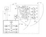
- FIG. 1depicts a schematic diagram of a system for monitoring, controlling and metering a plurality of HIF lighting fixtures in a facility in accordance with an exemplary embodiment.
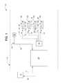
- FIG. 2depicts a schematic diagram of a system for monitoring, controlling and metering a plurality of HIF lighting fixtures in a facility in accordance with another exemplary embodiment.
- FIG. 3depicts a schematic diagram of a system for monitoring, controlling and metering a plurality of HIF lighting fixtures in a facility in accordance with a further exemplary embodiment.
- FIG. 4depicts a block diagram of a method for monitoring, controlling and metering a plurality of HIF lighting fixtures in a facility in accordance with an exemplary embodiment.
- FIG. 5depicts a block diagram of a method for reducing electricity usage during peak demand periods in accordance with an exemplary embodiment.
- FIG. 6depicts a block diagram of a system for controlling lighting in a facility in accordance with an exemplary embodiment.
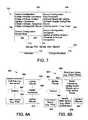
- FIG. 7depicts an exemplary graphical user interface that could be displayed on a display in accordance with an exemplary embodiment.
- FIG. 8Adepicts a block diagram of a system for controlling lighting in accordance with an exemplary embodiment.
- FIG. 8Bdepicts a block diagram of a system for controlling lighting in accordance with another exemplary embodiment.
- FIG. 9depicts a flow diagram of a process for controlling lighting devices in accordance with an exemplary embodiment.
- FIG. 1a block diagram of an intelligent system 10 for monitoring, controlling and metering electrically-operated (e.g. electricity consuming) equipment shown as HIF lighting fixtures in a facility 12 is shown in accordance with an exemplary embodiment.
- the system 10is shown to include a master controller 20 , a master transceiver 40 , a sensor 50 , a group of HIF lighting fixtures 60 , and a local transceiver unit 70 associated with the HIF lighting fixtures 60 .
- HIF lighting fixturesAlthough only one sensor is shown to be associated with the HIF lighting fixtures in one environment (or interior space), it is understood that any number of sensors (operable to monitor any of a wide variety of parameters in one or more interior spaces within the facility) may be provided for operating the HIF lighting fixtures in one or more designated spaces or environments within the facility.
- the master controller 20is programmable with a desired usage pattern (e.g. control schedule, operation schedule, time schedule, etc.) for the applicable electrically-operated equipment in the facility and automatically generates a time-based control signal 42 to be sent from the master transceiver 40 to the local transceiver unit(s) 70 associated with each of the applicable HIF lighting fixtures 60 to control operation of the fixtures according to the usage pattern (e.g. turn on at a specified time, turn off at a specified time, etc.).
- the master controller 20is also operable to automatically “learn” a new usage pattern based on an on-going pattern of demand-based control signals 44 from the master controller 20 , based on demand signals received from the sensor 50 .
- the master controllermay also be manually programmed with new (or modified) usage patterns, as may be determined by a manager of the facility (or other appropriate entity).
- the master controller 20is also operable to reduce power consumption during peak and off-peak power demand periods by monitoring the need for operation (e.g. “demand”) of the HIF lighting fixtures (as indicated by appropriate signal(s) received from the sensors) and generating a demand-based control signal 44 that is sent from the master transceiver 40 to the local transceiver units 70 for operation of the HIF lighting fixtures 60 in a manner intended to reduce power consumption during the peak and/or off-peak demand periods (e.g. turn-off, turn-on, etc.).
- demande.g. “demand”
- the master controller 20may also receive instructions from an external entity (e.g. shown for example as a power provider 14 , etc.) to shape or manage peak loading by “trimming” or “shedding” load (e.g. during peak demand periods, or during other periods when power supply capacity is limited, such as when a base load generating plant is taken off-line, etc.) by generating an override control signal 46 to be sent from the master transceiver 40 to the local transceiver units 70 for overriding the time-based control signals 42 and/or the demand-based control signals 44 and turning certain designated HIF lighting fixtures off.
- an external entitye.g. shown for example as a power provider 14 , etc.
- triminge.g. during peak demand periods, or during other periods when power supply capacity is limited, such as when a base load generating plant is taken off-line, etc.
- the override control signal 46may be selectively transmitted to the fixtures on an as-needed or case-by-case basis to permit selective/manual management of loading and capacity of a power grid during peak demand periods.
- the override control signal 46may be automatically transmitted to the fixtures upon the occurrence of certain predetermined criteria, such as a reduction in available capacity to a certain level or percentage, or a rate of reduction in available capacity that exceeds a certain setpoint, etc.
- the criteria for initiation of the override control signal 46are intended to be established in advance between the power provider and the facility manager and implemented according to a predetermined arrangement.
- certain designated HIF lighting fixturesmay be preprogrammed into the master controller 20 by the facility manager (or others) according to the criticality of operation of the HIF lighting fixtures, and may be provided in “stages” or the like according to an amount of demand reduction that is desired.
- the local transceiver unitsactuate the HIF lighting fixtures according to the control signal(s) (i.e. turn-on, turn-off, etc.) and then send a return signal corresponding to the particular HIF lighting fixture to respond to the master controller indicating that the action has been accomplished and to provide a status of each HIF lighting fixture (e.g. on, off, etc.).
- power provideras used herein is intended to include (as applicable) any supplier, distributor or aggregator of electrical power to a user, including but not limited to an electric power aggregator, a utility, a utility generator, an electric power generator, an electric power distributor, etc.
- the master controller 20receives the return signal 72 from the local transceiver unit(s) 70 and is intended to provide “intelligent metering” of each of the HIF lighting fixtures 60 in the facility 12 by logging (e.g. tracking, recording, trending, etc.) the power reduction achieved by reducing operation of the HIF lighting fixtures 60 (e.g. during peak demand periods relative to the facility's usage pattern as accomplished by monitoring within the facility 10 , or during any reduced capacity period as requested/instructed by the power provider, etc.) and provides data for each HIF lighting fixture to a user (e.g.
- the datais provided in a cumulative format to provide a total savings over a predetermined period of time.
- the datais also provided instantaneously for confirmation of the status of each of the HIF lighting fixtures (e.g. on, off, etc.) by the user.
- the master controller 20may be a custom device that is programmed with the desired algorithms and functionality to monitor and control operation of, and to provide intelligent metering of, the HIF lighting fixtures.
- the master controllermay be a commercially available product.
- the master controller 20is operable in a “normal” mode and an “override” mode for control of the HIF lighting fixtures 60 .
- the master controller 20operates according to both a time-based control scheme and a demand-based control scheme to reduce electricity usage during both peak and off-peak demand periods.
- the master controller 20controls operation of the HIF lighting fixtures 60 according to the usage pattern (i.e. on a time-based schedule, etc.) to operate (e.g. energize/de-energize, turn on/off, etc.) the HIF lighting fixtures 60 .
- the usage patternprovides a “baseline” operation control scheme for the HIF lighting fixtures 60 that is time or schedule based, and may be regularly updated (manually or automatically) to reflect changing usage patterns for the HIF lighting fixtures 60 .
- the time based control schememay reduce off-peak demand by reducing the scope/duration of the usage pattern and conserve energy during evening and nighttime hours.
- the master controller 20monitors and controls the designated HIF lighting fixtures 60 within the facility 12 based on signals received from various sensors 50 .
- Each sensoris operable to monitor any one or more of a wide variety of parameters associated within a predefined interior space 16 (e.g. designated environment, room, etc.) within the facility 12 , such as but not limited to, ambient light level, motion, temperature, sound, etc., and provide a sensor output signal 52 associated with the parameter to the master controller 20 .
- a switche.g. pushbutton, etc.
- the sensor output signal 52may be transmitted using a network that is wired, or may be wireless. According to one embodiment as shown for example in FIG.
- the sensor 50is operable to monitor ambient light level (e.g. through windows, light-pipes, skylights, etc.) and/or motion within the interior space 16 and to provide a sensor output signal 52 to the master controller 20 via a hardwire network 54 .
- the master controller 20processes the sensor output signal(s) 52 according to a preprogrammed algorithm having logic steps that determine the need (e.g. demand) for operation of the HIF lighting fixtures 60 , based on the facility usage pattern and the parameters monitored by the sensor(s) 50 , and defines or generates a demand-based control signal 44 to be transmitted from the master transceiver 40 to the appropriate local transceiver unit(s) 70 to control operation of the HIF lighting fixtures 60 .
- the demand based control schememay reduce peak demand or off-peak demand depending on when the HIF fixtures are turned-off (e.g. by turning-off the HIF fixtures due to ambient light level during daytime hours, or by turning-off the HIF fixtures due to absence of motion during evening/nighttime hours, etc.).
- a local transceiver unit 70is provided on each of the HIF lighting fixtures 60 and intended to be controlled by the master controller 20 , and each local transceiver unit 70 includes a unique address corresponding to a particular HIF lighting fixture 60 that is recognized by the master controller 20 .
- each local transceiver unit 70includes multiple switches (e.g. relays, etc.) for operation of the HIF lighting fixtures. For example, in HIF lighting fixtures having two ballasts, one local transceiver unit 70 has two switches and is associated with each fixture, and each ballast (with its associated lamps on the fixture) is independently controlled by one of the switches in the transceiver unit 70 .
- Each local transceiver unit 70may be coupled to its associated HIF lighting fixture 60 in any one of a variety of manners.
- the local transceiver unitmay be locally installed adjacent to the HIF lighting fixture and hard-wired (e.g. for retro-fit applications, etc.).
- the local transceiver unitmay be configured for plug-in connection to the HIF lighting fixtures (e.g. in a “plug-and-play” manner, etc.).
- the local transceiver unitmay be integrally formed with (or otherwise integrally provided as a part or component of) the HIF lighting fixtures.
- the HIF lighting fixtures 60form an artificial lighting system for interior space 16 in the facility 12 .
- the electrical equipmentmay be any of a wide variety of energy consuming devices or equipment, such as appliances, motors that operate building service loads or run manufacturing process equipment, etc.).
- the master controller 20receives the sensor output signal 52 representative of motion (e.g. by occupants within the facility, operation of manufacturing equipment, etc.) and/or ambient light level (e.g. artificial light from fixtures that are “on”, natural light such as sunlight through windows, skylights, light pipes, etc.) from the sensor(s) 50 .
- the sensor output signal 52representative of motion (e.g. by occupants within the facility, operation of manufacturing equipment, etc.) and/or ambient light level (e.g. artificial light from fixtures that are “on”, natural light such as sunlight through windows, skylights, light pipes, etc.) from the sensor(s) 50 .
- ambient light levele.g. artificial light from fixtures that are “on”, natural light such as sunlight through windows, skylights, light pipes, etc.
- the master controller 20also receives a response signal 72 from the local transceiver unit 70 associated with each HIF lighting fixtures 60 indicating whether the fixture 60 (or it's ballasts) is “on” or “off.”
- the master controller 20processes the sensor output signal 52 from the sensor 50 and the response signal 72 from local transceiver units 70 according to a preprogrammed method or algorithm and determines whether a demand for lighting exists within the interior space 16 , and then provides an appropriate demand-based control signal(s) 44 to the local transceiver unit(s) 70 for operation of the HIF lighting fixtures 60 .
- the method for determination of artificial lighting demand in the interior space 16may include the steps of (a) comparing the ambient light level to a predetermined setpoint, below which artificial lighting is desired and above which artificial lighting is not desired, (b) determining whether motion within the environment is present. If the light level is below the setpoint, and the HIF lighting fixtures 60 are “off,” and motion is detected, then the master controller 20 generates a demand-based control signal 44 that is transmitted from the master transceiver 40 to the appropriate local transceiver units 70 to turn HIF lighting fixtures 60 (e.g. one or both ballasts) “on”.
- HIF lighting fixtures 60e.g. one or both ballasts
- the local transceiver units 70receive the demand-based control signal 44 and operate to turn their respective HIF lighting fixtures 60 “on” and then send a respond signal 72 to the master controller 20 to provide the status of each HIF lighting fixture 60 (e.g. “on”). Similarly, if the ambient light level within the environment is above the setpoint and the HIF lighting fixtures 60 are “on”, regardless whether or not motion is detected, then the master controller 20 provides a demand-based control signal 44 to the local transceiver units 70 to turn fixtures 60 “off”. The master controller 20 may delay the control signal for a suitable time delay period (e.g. 5 minutes, 15 minutes, etc.) to provide increased assurance that no activity in the environment is present (e.g.
- a suitable time delay periode.g. 5 minutes, 15 minutes, etc.
- the master controller 20may also be programmed to provide a time delay before such fixtures may be turned back on again (e.g. to minimize power consumption associated with too-frequently cycling the equipment or fixtures between and on and off condition, and/or to minimize detrimental effects on the equipment such as reducing lamp life, overheating motors, etc.).
- the local transceiver units 70receive the demand-based control signal 44 and operate (e.g. by actuating one or more switches or relays) to turn their respective HIF lighting fixtures 60 “off” and provide a response signal 72 to the master controller 20 indicating the status (e.g. “on” or “off”) of the fixture 60 , thus providing “metering” of the HIF lighting at a “fixture level.”
- the master controller 20“meters” the amount of the power reduction achieved (during peak demand and off-peak demand periods) by logging the response signal 72 of the HIF lighting fixtures' status received from the local transceiver units 70 and providing cumulative data on the time, duration and status of the HIF lighting fixtures 60 .
- the datamay be provided on a predetermined frequency (e.g. monthly or keyed on some other criteria, such as a billing period, etc.).
- the sensor 50 for a particular environmentmay interface directly with one of the local transceiver units 70 for the HIF lighting fixtures 60 associated with the interior space 16 .
- the local transceiver unit 70then wirelessly transmits the sensor output signal 52 from the sensor(s) 50 to the master controller 20 .
- a sensormay include a modular quick-connect that plugs into a local transceiver unit, or may be hard-wired to the local transceiver unit, or may transmit the sensor signal wirelessly to the local transceiver unit. In either case, the local transceiver unit “relays” the sensor signal to the master controller.
- the master controlleralso operates to accomplish peak demand energy reduction by receiving override control signals (e.g. to turn-off certain fixtures according to a predetermined scheme) from the power provider (in response to peak demand management or shaping objectives/criteria) and transmitting a signal to appropriate local transceivers to “override” any existing or previous signal and turn-off the associated HIF fixture (or a ballast of the fixture).
- override control signalse.g. to turn-off certain fixtures according to a predetermined scheme
- the master controller 20provides a signal that overrides the “normal” mode of monitoring and controlling operation of the HIF lighting fixtures 60 , such as when override control instructions are received from a user (e.g.
- the master controller 20receives input signals or instructions 17 (manually or automatically) to control operation of the HIF lighting fixtures 60 .
- the power providermay manually send instructions 17 to the master controller 20 to reduce power consumption by a specified amount (e.g. percent load, specific number of kilowatts, etc.).
- the instructions 17may be provided automatically (e.g.
- the master controller 20processes the instructions 17 according to a preprogrammed algorithm that reflects the criteria established and agreed upon between the power provider and the facility manager for intervention (or interruption) by the power provider.
- the override control signal 46may be manually initiated by the facility manager (e.g. by actuating an input interface (touch screen, pushbutton, etc.) at, or operably associated with, the master controller) to permit the facility manager to initiate action (unilaterally or in coordination with a power provider) to reduce peak demand.
- the algorithmreads the desired load reduction instructed by the power provider 14 and identifies certain HIF lighting fixtures 60 to be turned-off according to a preprogrammed hierarchy of fixtures that are arranged generally from least-critical to most-critical for the operation or purpose of the facility 12 , corresponding to the amount of load reduction requested by the power provider 14 .
- the master controller 20defines or provides an override signal 46 to be transmitted by the master transceiver 40 to the appropriate local transceiver units 70 to turn off the corresponding HIF lighting fixtures 60 identified by the master controller 20 to comply with the instructions 17 .
- the local transceiver units 70operate to turn the HIF lighting fixtures 60 off and then send a response signal 72 to the master controller 20 with the status of the HIF lighting fixtures 60 (i.e.
- the master controller 20may process one or more iterations of load shedding control signals to local transceiver units 70 until the amount of load reduction requested by the power provider 14 has been achieved.
- the master controller 20logs the status of the HIF lighting fixtures 60 and sends data 18 (e.g. “instantaneously” or otherwise within a certain desired time period) to the power provider 14 confirming the instructions and identifying the equipment status and the corresponding amount of power reduction (i.e. “instantaneous metering” or the like), where the dynamics of regional grid stability and control dictate a rapid instruction and response.
- the power provider 14may then send instructions 17 to the master controller to resume a normal mode of operation for the HIF lighting fixtures 60 (as otherwise indicated by time-based or demand-based criteria).
- the facility managermay provide instructions to the master controller (e.g. via an input interface on the master controller, etc).
- the master controller 20then operates to restore such loads (if needed) according to the algorithm for the normal mode of operation, including such factors as the facility's usage pattern, the sensor signals, the existing status of the HIF lighting fixtures, etc., preferably by restoring the HIF lighting fixtures in order from most-critical to least-critical.
- the master controller 20monitors the status of the HIF lighting fixtures 60 and records the time (e.g. date and time) that the devices turn on and off, and determines the amount of time that the device was actually “off” during the normal “on” time of the facility's usage pattern and calculates the amount of peak demand electrical energy saved, based on pre-programmed data related to each fixture's electrical power consumption rating.
- the calculation of peak demand electrical energy savedmay be conducted on a daily basis, or may be done on a less frequent and cumulative basis (e.g., weekly, monthly, etc.).
- the master controller 20also sends the data 18 representing the peak demand power reduction to the facility's power provider 14 , so that an appropriate credit for reduction in peak demand power may be received by the facility owner (or its representative).
- the facility owneror its representative.
- the power providercould provide certain on-going credits (e.g. discounts, rebates, refunds, etc.) corresponding to the peak demand power reduction achieved by the user, in order to provide incentive.
- the master controlleris intended to allow demand-side users to intelligently manage their power usage and obtain corresponding credits, while permitting the supply-side power providers to obtain the benefits of a lower peak demand, by actively controlling operation of the electrically-operated equipment, and recording and storing the equipment's operating status data, and calculating the resulting reduction in peak power demand, and transmitting such data to the power provider.
- Master controller 20is described in further detail, according to an exemplary embodiment.
- Master controller 20is shown to include a display 22 , an input interface 24 , an output interface 26 , a memory 28 , a processor 30 , a normal mode equipment controller application 32 , an override mode equipment control application 34 , a power reduction metering application 36 and a usage pattern application 38 .
- Display 22presents information to a user of master controller 20 as known to those skilled in the art.
- display 22may be a thin film transistor display, a light emitting diode display, a liquid crystal display, or any of a variety of different displays known to those skilled in the art now or in the future.
- Input interface 24provides an interface for receiving information from the user for entry into master controller 20 as known to those skilled in the art.
- Input interface 24may use various input technologies including, but not limited to, a keypad, a keyboard, a pen and touch screen, a mouse, a track ball, a touch screen, one or more buttons, a rotary dial, etc. to allow the user to enter information into master controller 20 or to make selections presented in a user interface displayed on display 22 .
- Input interface 24is also configured to receive signals from a power provider 14 (e.g. override instructions to reduce load, etc.).
- Input interface 24is also configured to receive response signals 72 from the local transceiver units 70 representative of a status of their associated HIF lighting fixtures 60 .
- Output interface 26provides the control signals to the master transceiver 40 , and sends metering data 18 to a user (e.g. transmits instantaneous monitoring and metering data to a power provider 14 in response to override instructions, or transmits power reduction metering data for a predetermined period of time to the power provider 14 , etc.).
- the input interface 24may provide both an input and an output interface.
- a touch screenboth allows user input and presents output to the user.
- Master controller 20may have one or more input interfaces and/or output interfaces that use the same or a different technology.
- Memory 28is an electronic holding place or storage for information so that the information can be accessed by processor 30 as known to those skilled in the art.
- Master controller 20may have one or more memories that use the same or a different memory technology. Memory technologies include, but are not limited to, any type of RAM, any type of ROM, any type of flash memory, etc.
- Master controller 20also may have one or more drives that support the loading of a memory media such as a compact disk, digital video disk, or a flash stick.
- Master transceiver 40provides an interface for receiving and transmitting data between devices (e.g. master controller 50 , sensors 50 , local transceiver units 70 , etc.) using various protocols, transmission technologies, and media as known to those skilled in the art.
- the communication interfacemay support communication using various transmission media that may be wired or wireless.
- Master controller 20may include a plurality of communication interfaces that use the same or a different transmission and receiving technology.
- Processor 30executes instructions as known to those skilled in the art.
- the instructionsmay be carried out by a special purpose computer, logic circuits, or hardware circuits.
- processor 30may be implemented in hardware, firmware, software, or any combination of these methods.
- executionis the process of running an application or the carrying out of the operation called for by an instruction or algorithm.
- the instructions or algorithmmay be written using one or more programming language, scripting language, assembly language, etc.
- Processor 30executes an instruction, meaning that it performs the operations called for by that instruction.
- Processor 30operably couples with display 22 , with input interface 24 , with output interface 26 , and with memory 28 to receive, to send, and to process information.
- Processor 30may retrieve a set of instructions from a permanent memory device and copy the instructions in an executable form to a temporary memory device that is generally some form of RAM.
- Master controller 20may include a plurality of processors that use the same or a different processing technology.
- Normal mode equipment controller application 32performs operations associated with managing electricity usage during peak demand and off-peak demand periods by controlling the operation of HIF lighting fixtures 60 in the facility 12 (such as a light level within the interior space 16 ). Control of the HIF lighting fixtures 60 may be determined according to a time-based control algorithm (e.g. based on a usage pattern) and a demand-based control algorithm (e.g. based on input signals from sensor(s) that monitor applicable parameters or conditions such as light level and motion). The operations may be implemented using hardware, firmware, software, or any combination of these methods. With reference to the exemplary embodiment of FIG. 2 , normal mode equipment controller application 32 is implemented in software stored in memory 28 and accessible by processor 30 for execution of the instructions that embody the operations of normal mode equipment controller application 32 . Normal mode equipment controller application 32 may be written using one or more programming languages, assembly languages, scripting languages, etc.
- Override mode equipment controller application 34performs operations associated with reducing electricity usage during peak demand periods by overriding the normal operation of HIF lighting fixtures 60 in the facility 12 (such as reducing or shedding loads in the facility 12 in response to instructions 17 generated automatically or manually and received from a power provider 14 , or the facility manager, etc.). The operations may be implemented using hardware, firmware, software, or any combination of these methods. With reference to the exemplary embodiment of FIG. 2 , override mode equipment controller application 34 is implemented in software stored in memory 28 and accessible by processor 30 for execution of the instructions that embody the operations of override mode equipment controller application 34 . Override mode equipment controller application 34 may be written using one or more programming languages, assembly languages, scripting languages, etc.
- Power reduction metering application 36performs operations associated with calculating the amount of electric power saved during peak and off-peak demand periods by controlling the usage of the HIF lighting fixtures 60 within the facility 12 .
- the operationsmay be implemented using hardware, firmware, software, or any combination of these methods.
- power reduction metering application 36is implemented in software stored in memory 28 and accessible by processor 30 for execution of the instructions that embody the operations of power reduction metering application 36 .
- Power reduction metering application 36may be written using one or more programming languages, assembly languages, scripting languages, etc.
- Facility usage pattern application 38performs operations associated with establishing or providing the normal usage pattern (e.g. time schedule and status such as “on” or “off”) of the HIF lighting fixtures 60 in the facility 12 , for use in calculating the amount of electric power saved during peak and off-peak demand periods by controlling the usage of the HIF lighting fixtures 60 within the facility 12 .
- the facility usage pattern application 38also includes power consumption ratings for the HIF lighting fixtures 60 controlled by the master controller 20 .
- the operationsmay be implemented using hardware, firmware, software, or any combination of these methods.
- facility usage pattern application 38is implemented in software stored in memory 28 and accessible by processor 30 for execution of the instructions that embody the operations of peak demand power saved application 38 . Peak demand power saved application 38 may be written using one or more programming languages, assembly languages, scripting languages, etc.
- the HIF lighting fixtures 60may be the same or may include variations of HIF lighting devices.
- a local transceiver 70having a unique address recognized by the master controller 20 , and which receives and responds to a control signal ( 42 , 44 , 46 ) from master transceiver 40 .
- the control signal ( 42 , 44 , 46 )may include a lighting indicator specific to each of the plurality of HIF lighting fixtures 60 or may include the same lighting indicator for each of the plurality of HIF lighting fixtures 60 .
- the lighting indicatormay indicate on/off or may indicate a lighting level (e.g. turn one or both ballasts of a fluorescent lighting fixture on or off).
- the local transceiver units 70are capable of plugging into the lighting fixtures (or other electrically operated equipment provided by any of a wide variety of manufacturers) without additional wiring and can communicate (e.g. receive and respond) wirelessly with the master controller 20 using radio frequency (e.g. 915 MHz).
- Each local transceiver unitis assigned a unique address, so that each fixture is identifiable to (and controllable by) the master controller 20 .
- master transceiver 40transmits control signal 42 , 44 , 46 using a radio frequency (such as 915 MHz) to the local transceiver units 70 of the interior space 16 that are within an effective range R 1 defined based on the characteristics of the transmitter as known to those skilled in the art.
- a radio frequencysuch as 915 MHz
- any of a wide variety of operating frequencies, modulation schemes, and transmission power levelscan be used. For example, frequencies in the range of 27-930 MHz, and particularly within about 5% of 315, 434, 868, and/or 915 MHz may be used. Additionally, other frequencies such as 2.4 gigahertz may be used.
- Master transceiver 40 and local transceiver units 70may be designed to qualify as unlicensed radio frequency devices under the Federal Communications Commission rules found in 47 C.F.R. ⁇ 15.
- Master controller 20is configured to encode a particular transceiver address in the control signal 42 , 44 , 46 .
- Each local transceiver unit 70is configured to respond only to control signals 42 , 44 , 46 encoded with its unique address.
- the HIF lighting fixture 60 associated with each local transceiver unit 70can be turned on or off (or dimmed by de-energizing only one ballast) based on the control signal 42 , 44 , 46 received from the master transceiver 40 .
- the address informationmay be encoded in the control signal using a variety of methods as known to those skilled in the art.
- the master controller 20can control the HIF lighting fixtures 60 located throughout the facility 12 , by using one or more of the local transceiver units 70 as “repeaters” (shown as a repeater 74 ) to overcome range limitations due to the distance of the desired equipment from the master transceiver 40 .
- master transceiver 40transmits a control signal 42 , 44 , 46 within a first range R 1 for operation of fixtures 60 that are within range R 1 .
- a local transceiver unit 70 positioned within effective range R 1is designated (i.e.
- the group of equipment 60shown for example as light fixtures 62 ) positioned outside effective range R 1 (and within the effective range R 2 ) can be controlled.
- a repeatermay be provided to permit control of a wide variety of electrically operated equipment located in various interior spaces throughout the facility.
- the method of monitoring, controlling and metering the HIF lighting fixtures in the facilityis shown according to one embodiment to include the following steps (among possible other steps):
- any one or more of a variety of other stepsmay be included, in any particular order to accomplish the method of monitoring, controlling and metering operation of the HIF lighting fixtures in the facility.
- the method of reducing electricity usage during peak demand periods by monitoring, controlling and metering the HIF lighting fixtures in the facilityis shown according to one embodiment to include the following steps (among possible other steps):
- the criteriamay include a level or amount of load/demand on the grid, or a rate of increase in load/demand on the grid, or an actual or anticipated reduction in electricity supply to the grid, or a level or amount of capacity available on the grid, or a rate of decrease in the capacity available on the grid, where capacity is generally understood to be the difference between the available supply of electricity to the grid and the demand (i.e. load, etc.) on the grid (e.g. by users connected to the grid, etc.),
- the listing of equipmentmay include individual fixtures, or independent ballasts within a fixture, identified by a unique address recognized by the master controller;
- the fixturesmay be groups of fixtures based on location or criticality to operation of the facility;
- the groups of fixturesmay be specified in a cascading hierarchy of groups that are turned-off sequentially, or simultaneously, depending on an amount of electricity usage reduction, or the specific fixtures/ballasts, identified by the instructions;
- a system and methodare provided for reducing electricity usage during peak and off-peak demand periods through intelligent monitoring, control and metering of HIF lighting fixtures within a facility.
- the systemincludes a master controller, a master transceiver, one or more sensors, and a local transceiver unit uniquely identifiable to the master controller for each of the HIF lighting fixtures in the facility to be controlled.
- the sensor(s)monitor parameters within the facility and provide sensor signal(s) representative of the parameters to the master controller.
- the master controllerprocesses the sensor signals according to preprogrammed algorithms and define or generate signals that are transmitted from the master transceiver to the appropriate local transceiver unit(s) to control operation of the HIF lighting fixtures.
- the local transceiver unitsprovide a response signal to the master controller indicating the status of the associated HIF lighting fixtures for logging and tracking by the master controller.
- the master controllerprovides power reduction metering data to a user for quantifying the power saved and the economic benefit resulting from the power saved.
- an outside usere.g. power provider, facility manager, etc.
- the instructionsmay be generic (e.g. reduce power by a certain amount or percentage) or the instructions may be directed to certain identified equipment.
- the master controllerprocesses the instructions according to preprogrammed algorithms and defines or generates signals that override previous control signals and are transmitted from the master transceiver to the appropriate local transceiver unit(s) to provide override control operation of the HIF lighting fixtures.
- the local transceiver unitsprovide a response signal to the master controller indicating the status of the associated HIF lighting fixtures for logging and tracking by the master controller.
- the master controllerprovides instantaneous metering data to the power provider to confirm implementation of the instructions and identify a corresponding economic benefit resulting from the power saved.
- the system and method described hereinmay be adapted for use with other types of electrically operated equipment within the facility, such as equipment related to manufacturing processes, building support and services, and the like.
- the intelligent monitoring, controlling and metering of the HIF lighting equipment in a facilityis provided by the master controller and includes preprogrammed instructions, algorithms, data and other information that permits the HIF lighting equipment to be controlled (e.g. turned-off) in response to commands from an external source (e.g. a power provider), or an internal source (e.g. a facility manager), or in response to signals received from suitable sensors, to provide optimum operation of the HIF lighting equipment in coordination with peak-demand conditions, and to reduce overall energy usage and impact on the environment, and to optimize performance and life of the HIF lighting equipment and reduce maintenance and costs associated with the lighting equipment.
- an external sourcee.g. a power provider
- an internal sourcee.g. a facility manager
- System 600is shown to include master controller 602 , which may be configured to be the same as master controller 20 shown in FIGS. 1-3 or which may be configured differently.
- Master controller 602is shown in communication with a plurality of lighting fixture groups 604 , 606 ; each group having a plurality of lighting fixtures.
- Master controller 602is shown to include a data communications interface 608 for conducting the communications with the plurality of lighting fixtures.
- Master controller 602is further shown to include a control module 610 .
- Control module 610is configured to provide a control signal to data communications interface 608 (directly or indirectly).
- Control module 610includes a processor 612 and memory 614 (which may generally be configured similarly to the processor and memory described above with reference to FIGS. 2 and 3 ).
- memory 614is a non-volatile memory device storing at least computer code for operating master controller 602 and for the completion of one or more control algorithms relating to the lighting fixtures variously in communication with data communications interface 608 .
- processor 612is configured to execute the computer code stored in memory 614 and/or to otherwise facilitate the activities of master controller 602 .
- the control signal provided to data communications interface 608 from control module 610may be configured (e.g., formatted, modulated, etc.) to turn off (or on) one or more of the plurality of lighting fixtures.
- the control signalcan be generated and sent from the control module according to a control algorithm.
- the control algorithmcan be configured to generate the control signal based on at least one of a time of day and/or a sensed condition relating to the use of the facility.
- the control modulecan further be configured to quantify a reduction in power obtained by controlling the plurality of lighting fixtures according to the algorithm.
- This quantificationcan be conducted according to any of the activities described above including, but not limited to, aggregating power readings from the lighting fixtures, aggregating lighting fixture time on and/or off during the day (the times on and/or off maintained by the lighting fixtures and/or the control module), considering the rate of energy consumed, characteristics of installed equipment (e.g., information that twelve lighting fixtures will be on for one hour at one hundred watt hours), and aggregating power measurements (e.g., current, voltage, power factor, etc.).
- memory 614may store historical power usage information and/or power cost information for the lighting fixtures.
- Memory device 614may also store any number of other temporary, intermediate term, or long term data sets.
- memory device 614may store measurements of energy, schedule information, system/device configuration profiles, user profiles, light on/off records, and/or any other data.
- emissions profiles for individual devices or device types of the systemare stored in memory 614 and used to calculate emission costs/savings based on behavioral data experienced by the system (e.g., off/on data).
- Resource (e.g., power) cost informationmay also be stored, updated, and/or maintained in memory based on manually entered costs or costs obtained from a remote system. This cost information can be used by the control algorithms and/or viewed by the user to control costs actually incurred. For example, if the user (or the algorithm) sees that the cost of power has increased by five percent, the user (or the algorithm) can take configuration steps to offset some or all of the increased costs (e.g., by configuring the lighting fixtures to power-down earlier if occupancy is no longer detected in a space).
- master controller 602receives information regarding the sensed condition from data communications interface 608 and/or sensor interface 616 .
- data communications interface 608receives the sensor information
- any number of different sensing devicescan be used to transmit the sensor information to data communications interface 608 .
- one or more of the lighting fixturescan include or be electrically coupled to a sensor. As shown in FIG. 6 , first lighting fixture 618 is coupled to master transceiver 620 which is coupled to or includes sensor 622 ; second lighting fixture 624 is coupled to plug-in transceiver 626 which is coupled to or includes sensor 628 .
- Group B lighting fixtures 606can also include sensing devices.
- Sensors 630 not directly coupled to or in communication with the lighting fixturescan communicate directly with master controller 602 via sensor interface 616 .
- Sensor interface 616can be any type of wired or wireless interface (e.g., 915 Mhz, 315 Mhz, WiMesh, ZigBee, WiFi, WiMax, Ethernet, BACnet, wireless USB, Bluetooth, etc.).
- Data communications interface 608can be of the same or a different technology and configuration than sensor interface 616 .
- the sensor information or condition sensed by sensors 630 , 622 , 628can include motion, ambient light levels, absolute light levels, heat, carbon dioxide, capacitance, or any other information or condition that can be used to sense a condition relevant to lighting (e.g., occupancy information, lighting information, etc.).
- one or more of the lighting fixtures in communicationincludes a transceiver (e.g., transceiver 620 , 626 ).
- the transceivercan be supplied with the lighting fixture or retrofit to the lighting fixture.
- at least one of the plurality of lighting fixturesmay include a transceiver which has been retrofit to the lighting fixture by placement in series (e.g., via a female plug-in interface and a male plug) with the power input for the lighting fixture.
- each lighting fixturecan also include a logic circuit configured to report a condition of the lighting fixture or its individual ballasts back to control module 610 via wireless communications.
- the conditions reported back to control module 610can include, for example: (a) a state change from ‘on’ to ‘off’ or from ‘off’ to ‘on’, (b) a total of time in the ‘on’ state or the ‘off’ state, (c) a log of lighting state changes including a time the state change occurred, and the like.
- the logic circuit and/or a logic circuit of the transceivercan also gather measurements of actual energy used (e.g., current used, voltage used, power factor used) or another operational characteristics of the device by which energy usage can be derived and report the actual energy usage or the characteristics back to controller 602 via wireless communications.
- a transceiver associated with a pumping systemmight measure pressure and report pressure back to controller 602 .
- a pressure-to-energy model in controller 602 for the pumping systemcan be used to convert these received measurements to energy or emissions costs/savings.
- the conditions reported to control module 610 from the devicescan be communicated upon receipt of a query signal sent from control module 610 via data communications interface 608 .
- lighting fixtures 604 , 606only report conditions back to control module 610 when their state changes.
- lighting fixtures 604 , 606self-report back to control module 610 on a regular (or irregular) basis (e.g., after a predetermined period of time, at predetermined times, etc.).
- the signals sent between data communications interface 608 and the transceiverscan be modulated analog signals, digital signals, or any other appropriate wireless data communications signals.
- control module 610can also include circuitry and/or computer code for providing a diagnostics tool that determines maintenance actions to be completed. For example, if control module 610 sends a control signal to a lighting fixture and the lighting fixture does not appropriately respond (e.g., via a timeout, a communication failure, or by simply not responding properly (by not responding with the correct lighting state), etc.), the diagnostics tool might alert a system manager to this fact (e.g., via an alert provided to a graphical user interface, via an e-mail, text message, audible alert, and the like).
- a diagnostics toolmight alert a system manager to this fact (e.g., via an alert provided to a graphical user interface, via an e-mail, text message, audible alert, and the like).
- control module 610Any number of other lighting-related activities may be provided by control module 610 or another system coupled to master controller 602 due to master controller 602 's ability to serve as a data collection point for lighting-related information.
- a bulb replacement or ballast replacement alert signalmay be sent (e.g., to a graphical user interface, to an e-mail address, to a pager, to a text messaging device, etc.) after logging a predetermined cumulative “on” time or number of state changes.
- a diagnostics tool associated with control module 610e.g., working along with other software modules such as a web server
- a remote terminalmay be able to log-into the control module to view device failure information, device alert information, device energy usage information, device communication success/failure information, network health information, and the like.
- a user investigating failure information via the remote terminalcould then access configuration user interfaces provided at the remote location (e.g., web-based user interfaces served from controller 602 to the remote terminal) to repair or reconfigure the system, the network, the individual devices or otherwise address the problem.
- controller 602may include a self-diagnostics module so that the system could attempt repair or reconfiguration measures without user input.
- controller 602could command the transceivers of the system (e.g., lighting transceivers) to switch to a different RF channel.
- the transceivers of the systeme.g., lighting transceivers
- diagnostics and repair user interfacesare available via a user-friendly touch screen interface generated on a touch screen 632 .
- data communications interface 608may also be configured to communicate with at least one other type of building component in addition to lighting fixtures.
- data communications interface 608may be configured to communicate with fans, air handling units, heating systems, manufacturing systems, research processing systems, and any other energy using systems/components.
- Control module 610may selectively provide sensed condition based control and time of day based control to the other building component(s) via data communications interface 608 .
- User interfaces provided by master controller 602 for lighting fixturescan also be appropriately provided for the other building component(s).
- controller 602could be adapted to primarily serve the other types of building components rather than lighting (e.g. motors, machines, appliances, devices used in lean manufacturing processes, etc.).
- controller 602may be used to control motors used to operate conveyor devices and the like in logistics facilities, or ventilation equipment in livestock or agricultural facilities and the like.
- controller 602may use an optical sensor to count a number of units (e.g., processed units, input units, output units, etc.) of a manufacturing process and to quantify power expenditure based on known or estimated power costs associated with a unit.
- controller 602can be configured to provide user interfaces, execute control algorithms, and to control signals relating to any building system having devices that may be turned on/off and or varied to save power.
- controller 602may be configured to control a one or more variable speed pumps of an air compressor for maximum efficiency.
- a transceiver coupled to the pumpmay record data relating to the pump and send the data to controller 602 via the transceiver.
- the transmission of the data to controller 602may be conducted by a network of similar or different transceivers coupled to devices for control/energy monitoring.
- transceivers coupled to devicesmay use a bi-directional “information highway” formed by similar transceivers (e.g., transceivers coupled to lighting fixtures) to propagate data and/or control information to/from the transceivers and the controller (e.g., controller 602 ).
- Each lighting fixturemay be associated with a unique identifier so that high resolution sensing and control options are available to master controller 602 .
- control logic of master controller 602 or a circuit local to the lighting fixturescan advantageously cause lighting to “follow” a human walking through a building (e.g., turning only those lights on that the human needs to see, saving power by keeping the other lights off).
- a high resolution of lighting fixtures and individual controlcan provide varied power savings and/or brightness levels.
- a usercan select to have “every third light” turned on during a low-use period of the day or configure control module 610 or the local circuit of the lighting fixture to only turn those lights on in an area that are necessary to reach a threshold absolute brightness level (ambient light +lighting fixture light).
- a high resolution of lighting devicesmay also be configured to assist with access control/security features. For example, while lights may turn on for authorized users, the lights may not turn on for unauthorized users, making it difficult for unauthorized users to see and/or otherwise serving as an deterrent.
- some of sensors 630may be access card readers, biometrics devices, security keypads, or other security-related sensors or devices for evaluating whether access is permitted.
- controller 602include a security module configured to store access control profiles that affect the operation of the control algorithms.
- the security modulemay also allow varying levels of control to the control algorithms and user interfaces provided by controller 602 . For example, while all user might have “turn on/turn off” level access, only users with higher level access might be granted configuration level access, scheduling access, and the like.
- master controller 602is shown to include a touch screen 632 electrically coupled to control module 610 , according to an exemplary embodiment. While touch screen 632 is illustrated as being integrated with master controller 602 (e.g., touch screen 632 and control module 610 share the same housing), according to other exemplary embodiments touch screen 632 can be remote from master controller 602 /control module 610 and communicate with master controller 602 /control module 610 via a wired or wireless communications link. Further, while touch screen 632 is illustrated in FIG. 6 , it should be appreciated that any user interface having one or more user interface controls or elements could be configured to provide functionality similar to or the same as touch screen 632 . For example, in place of (or in addition to) touch screen 632 , a display screen with buttons separate from the display screen may be provided.
- Touch screen 632is displaying a Lighting Fixtures Group A configuration menu via a graphical user interface 634 .
- Graphical user interface 634is shown to include an indicator of the current algorithm mode for Lighting Fixtures Group A as well as a number of user interface elements (e.g., buttons, “hot zones,” hyperlinks, etc.) 636 - 648 for controlling Group A lighting fixtures 604 or for configuring control module 610 for control of Group A lighting fixtures 604 .
- User interface elements 636 - 648include user interface element 636 and user interface element 638 for manually controlling lighting fixtures. As indicated by user interface elements 636 , 638 , manual control of lighting fixtures may override a previously set algorithm mode.
- Another algorithm mode selectable via exemplary graphical user interface 634includes a “time of day” based lighting logic (available via user interface element 640 ). According to various exemplary embodiments, algorithm modes such as sensed condition-based logic, supply-based logic, or any other suitable lighting logic mode are available via graphical user interface 634 .
- Graphical user interface 634is further shown to include user interface element 642 for setting a schedule for mode switching.
- user interface element 642for example, a user can schedule an “ambient lighting” mode to be active during day-light hours (so that, for example, the lighting fixtures only turn on if there is not enough ambient light in the room), an occupancy-based mode to be active during dawn and dusk hours, and a manual mode (with a default to off) to be active during nighttime hours.
- graphical user interface 634allows a user to schedule/set any combination or permutation of algorithm conditions (e.g., motion, ambient lighting, timing) or states (e.g., override, timing, occupancy, sensed condition, etc.).
- control module 610could be configured to provide control signals to transceivers in system 600 based on internal demand-response type algorithms, external demand-response type algorithms, and/or any other type of algorithm.
- external demand-response type algorithmscan control devices to save power based on commands and/or data received from sources external the system (e.g., a power plant).
- Internal demand-response type algorithmscan monitor energy, device, and/or facility characteristics locally and make and execute control decisions relating to those characteristics.
- graphical user interface 634is shown to include a user interface element 644 titled “Change Group A Composition.”
- User interface element 644can be used to receive input for changing the lighting fixtures associated with “Group A.” For example, by utilizing user interface element 644 (and other user interface elements that appear once element 644 is selected (e.g., clicked, touched, pressed), a user could remove the second lighting fixture from “Group A” and add one or more additional lighting fixtures to “Group A.”
- graphical user interface 634is configured to provide a map (e.g., top-down floor plan view, bird's eye view, perspective view, etc.) of a facility area (e.g., zone, room, group of rooms, etc.) from which the user can select lighting fixtures or groups for control.
- a mape.g., top-down floor plan view, bird's eye view, perspective view, etc.
- the usercan click on a plurality of lighting fixtures shown dispersed around a floor plan, select a user interface element labeled “Group,” and then assign a name to the group of selected lighting fixtures (e.g. “Library Fixtures”, etc.).
- Control module 610can then store the user's selected grouping in memory, allow the user to select the grouping for configuration via the touch screen, and store algorithm settings for the grouping.
- user interface element 646labeled “View Lighting Fixtures Group B Configuration Menu”
- a usercan command the controller to change from providing user interface elements for Group A to providing user interface elements for Group B.
- a usercan command the controller to provide a map of all lighting fixtures or groups in a facility or facility area.
- the Group A fixturescan be associated with a first color (e.g., blue) while the Group B fixtures are associated with a second color (e.g., green) allowing for easy viewing of the map and/or actual labeling of the fixtures.
- FIG. 7an exemplary graphical user interface 700 that could be displayed on the touch screen of FIG. 6 or on another display communicably coupled to a master controller is illustrated, according to an exemplary embodiment.
- graphical user interface 700is shown to include four configuration zones for Groups A, B, C, and D (zones 702 - 708 ).
- zones 702 - 708correspond to areas or zones of a facility floor (e.g., zone 702 corresponds to lighting in a northwest area of the facility, zone 704 corresponds to lighting in a northeast area of the facility, zone 706 corresponds to a southwest area of the facility, and zone 708 corresponds to a southeast area of the facility, etc.).
- the graphical user interfaceshows a representation of a facility floor plan and the graphical user interface is configured to allow the user to divide the floor plan into one or more zones and to associate at least one of the lighting groups (e.g., A-D) with the one or more zones created by dividing the floor plan.
- graphical user interface 700many different graphics and/or ways for associating groups with physical facility locations could be implemented on graphical user interface 700 . If a user clicks on zones 702 - 708 , the system will generate a form or prompt for the user to change the configuration for the corresponding lighting fixture group. For example, if a user selects zone 702 , the system will prompt the user for changes to the configuration corresponding to Group A. It should be appreciated that any number of configuration zones, lighting groups, lighting fixtures, floors, floor plans, facilities, or any other aspect shown in FIG. 7 may be varied according to other exemplary embodiments.
- Each of zones 702 - 708not only allow user selection for configuration, but, as shown, also display the current configuration. By the display of such information, users can advantageously see how a plurality of groups are configured by viewing a single screen.
- the usermay only need to tap zone 702 , tap the time period of 6:00pm to 9:00pm and then select a different mode (e.g., to change from an occupancy-based sensed condition during the three hour time period to an “ON” setting during the time period).
- the exemplary graphical user interface for configuration of Group A shown in FIG. 6is displayed when a user clicks on zone 702 .
- Zone 704indicates that the Group B lights are in a fully automated algorithm mode whereby sensed conditions (e.g., motion, carbon dioxide, light sensors, etc.) plus logic determine when lighting is demanded in zone 704 .
- Zone 704further indicates that an override for the area is optional (e.g., users can flip a switch to turn the lights “off” or “on” and the fully automated mode will be overridden for one hour).
- Zone 706indicates that the algorithm is set for manual mode and provides two user interface elements 710 , 712 that can behave as traditional light switches for turning the lighting fixtures of Group C off and on.
- Zone 708indicates that the algorithm is set for sensed condition based lighting logic and that the algorithm will turn the lights on when occupancy is detected in the room.
- Zone 708is further illustrated to indicate a user-selected definition for “occupied”; when either sensed motion or sensed carbon dioxide levels (e.g., the carbon dioxide produced by breathing humans) in the facility area associated with Group D reach a threshold associated with human occupation, the lights will turn on. By selecting zone 708 , user will view a prompt, generated by the master controller, to edit this configuration. Changes made via graphical user interface 700 are communicated to a memory device associated with the control model and/or are communicated out to the various lighting fixtures. It should be appreciated that other occupancy conditions may be used by other zones or that zone 708 may be reconfigured to a different set of conditions before zone 708 is considered “occupied.”
- graphical user interface 700is shown to include indicia 714 of a quantified reduction in power obtained by controlling the plurality of lighting fixtures of the facility according to “smart lighting” algorithms (e.g., the configurations of zones 702 - 708 ). While indicia 714 includes an indication of the kilowatt hours saved per date and dollars saved per date for the facility, it should be noted that any units of measurement, time period, and/or monetary unit may be displayed for any zone(s) in the facility. Further, it should be noted that indicia 714 may be icon-based, graph-based, color-coded, or otherwise used to communicate power savings information.
- indicia 714can be a user interface element (e.g., a button) that allows a user to view further and/or more detailed information regarding the quantification of power saved. For example, when indicia 714 is selected (e.g., clicked) the system may generate a tool (e.g., graphical user interface window) for verifying emission credits that utilizes the quantifications of power saved from the control module for conducting the verification.
- Graphical user interface 700is further shown to include “view map” user interface element 716 and “change groupings” user interface element 718 .
- System 800is shown to provide a configuration whereby a client device 802 provides the user interface (e.g., the graphical user interface shown in FIG. 7 ) for system 800 .
- Client device 802e.g., a personal digital assistant (PDA), a mobile phone, a laptop, a workstation, a tablet, a remote control, a panel mounted on the wall, etc.
- PDApersonal digital assistant
- master controller 804connects to master controller 804 via a wired or wireless connection to network 806 (WiFi network, Ethernet network, IP network, LAN, WAN, ZigBee network, Bluetooth Piconet, etc.).
- network 806WiFi network, Ethernet network, IP network, LAN, WAN, ZigBee network, Bluetooth Piconet, etc.
- Master controller 804may include the server (e.g., web server, web services module, server module) with which client device 802 communicates and provide the logic/control module for executing the lighting control algorithm of the system.
- servere.g., web server, web services module, server module
- master transceiver 808(which may be incorporated with one or more lighting fixtures 810 , 812 or may be stand-alone) is also shown connected to network 806 via a wired or wireless connection.
- master controller 804can communicate to master transceiver 808 via the same protocol and/or network as that used to communicate to client device 802 .
- Lighting fixtures 810 , 812can be wired to master transceiver 808 or master transceiver 808 can wirelessly relay control signals from master controller 804 to the appropriate lighting fixtures.
- master controller 804 , master transceiver 808 , and lighting fixtures 810 , 812can be of any network topology.
- master transceiver 808can broadcast control signals to all lighting fixtures in its vicinity in one embodiment
- master transceiver 808can be a node (e.g., a head node) in a mesh network in another embodiment, a center node in a star topology, a first node in a ring topology, etc.
- FIG. 8Bshows another exemplary embodiment of a system 850 for controlling lighting, according to an exemplary embodiment.
- device 852includes the master transceiver, the lighting control module for the system (e.g., the functionality of master controller 804 shown in FIG. 8A ) and circuitry for a first lighting fixture.
- Lighting fixtures 854 , client devices 856 , 858 , and network 860are all shown as communicably connected to device 852 via wireless or wired connections.
- Additional client devices 864e.g., PDAs, mobile phones, control boxes
- Additional lighting fixtures 862can also connect to device 852 to receive control signals via network 860 .
- Process 900is shown to include the step of recording and storing information regarding previous lighting fixture and/or power usage (step 902 ).
- the recording and storing stepcan include a variety of sub-steps including, but not limited to, gathering utility bills, measuring daily power consumption of the previous lighting over a period of time, averaging the previous consumption, measuring power use by a single lighting fixture, and calculating to determine the power used by all lighting fixtures, etc.
- the output from step 902may be some record or value against which power use reductions can be quantified.
- Process 900is further shown to include the step of providing and installing a plurality of new (or retrofit) lighting fixtures (step 904 ).
- the lighting fixturescan be lighting fixtures as described above or otherwise.
- the lighting fixturesinclude or are retrofit with a transceiver configured to receive and respond to control signals for turning the lighting circuitry (but not the control electronics) off or on.
- the lighting fixturesthemselves include logic for responding to control signals that include more complex information than “off/on” (e.g., signals with scheduling information, signals with sensed condition attributes, etc.).
- process 900is shown to include providing a user interface for creating groups of lighting fixtures and/or for associating lighting fixture groups with facility zones (step 906 ).
- the user interfaceas previously described, can include a map or overhead view of a floor plan and icons for the various lighting fixtures serving the facility. Users can group the lighting fixtures via a point and click activity or otherwise. Input received by the user interface can be stored for use by the system and other user interfaces (e.g., scheduling user interfaces) of the system can be updated accordingly.
- a first and second group of lighting fixturescan be associated with different facility zones (step 908 ).
- Process 900is further shown to include the step of providing a user interface for configuring an algorithm for the first group of lighting fixtures (step 910 ) and the step of providing a user interface for configuring an algorithm for the second group of lighting fixtures (step 911 ).
- Steps 910 and 911can use graphical user interfaces such as those described with reference to FIGS. 6 and 7 or can use any other suitable user interface and collection of user interface elements (e.g., displays, LEDs, buttons, switches, etc.).
- an algorithm implemented by a control modulecan determine whether to provide a control signal based on a time of day schedule or a sensed facility condition (step 912 ).
- Step 912can include any number of sensor information gathering steps, condition checking activities, and/or scheduling activities.
- step 912can include the step of receiving motion sensor information, receiving carbon dioxide sensor information, and comparing the readings to a threshold to make a decision regarding whether the space is occupied. Based on the determination(s) of step 912 , the system can provide the control signal to a data communications interface for further communication to the lighting fixtures (step 914 ).
- the communicationmay be wired or wireless and can be sent to a master transceiver for broadcasting or relaying to other lighting fixtures.
- Process 900is further shown to include the step of quantifying a reduction in power obtained by providing (e.g., providing in step 904 ) and intelligently controlling (e.g., controlling in steps 910 , 914 ) the new (or retrofit) lighting fixtures (step 916 ).
- the quantificationcan compare current power usage for the new lighting fixtures to metrics recorded and stored in step 902 , compare recent power usage, average recent power usage, consider actual power usage on a minute-by-minute basis, gather usage information from a utility company, gather usage information from a utility billing system, prompt the user for utility billing information, multiply a new daily power usage by the number of days in a year, multiply the power usage by a power cost, and conduct any additional or alternative sub-steps for quantifying the difference in power consumption or cost between the old lighting system and the new lighting system with control algorithm(s).
- Indicia of the quantificationcan then be stored in a memory device and/or displayed on an electronic display (step 918 ). It should be appreciated that other output activities are also possible (e.g., generating a graph, generating a “real-time” counter, ticker or dial, generating a detailed report, e-mailing a report, etc.).
- electrically coupledor “coupled” can mean directly or indirectly coupled, according to various exemplary embodiments.
- the sensorscan be directly wired to the control module with no components that substantially change the signal located between the sensor and the control module; in other embodiments the signals sent to the sensors may be provided to one or many components between the sensors and the control module and the sensors and the control module can still be considered electrically coupled (indirectly).
- any data communications via a wireless connectioncan occur directly or indirectly via a network, relay node, booster node, or any other device.
Landscapes
- Engineering & Computer Science (AREA)
- Computer Networks & Wireless Communication (AREA)
- Circuit Arrangement For Electric Light Sources In General (AREA)
Abstract
Description
Claims (30)
Priority Applications (2)
| Application Number | Priority Date | Filing Date | Title |
|---|---|---|---|
| US13/648,933US9504133B2 (en) | 2008-03-27 | 2012-10-10 | System and method for controlling lighting |
| US15/357,922US20170071050A1 (en) | 2008-03-27 | 2016-11-21 | System and method for controlling lighting |
Applications Claiming Priority (3)
| Application Number | Priority Date | Filing Date | Title |
|---|---|---|---|
| US12/057,217US8406937B2 (en) | 2008-03-27 | 2008-03-27 | System and method for reducing peak and off-peak electricity demand by monitoring, controlling and metering high intensity fluorescent lighting in a facility |
| US12/240,805US8344665B2 (en) | 2008-03-27 | 2008-09-29 | System and method for controlling lighting |
| US13/648,933US9504133B2 (en) | 2008-03-27 | 2012-10-10 | System and method for controlling lighting |
Related Parent Applications (1)
| Application Number | Title | Priority Date | Filing Date |
|---|---|---|---|
| US12/240,805ContinuationUS8344665B2 (en) | 2007-05-03 | 2008-09-29 | System and method for controlling lighting |
Related Child Applications (1)
| Application Number | Title | Priority Date | Filing Date |
|---|---|---|---|
| US15/357,922ContinuationUS20170071050A1 (en) | 2008-03-27 | 2016-11-21 | System and method for controlling lighting |
Publications (2)
| Publication Number | Publication Date |
|---|---|
| US20130033183A1 US20130033183A1 (en) | 2013-02-07 |
| US9504133B2true US9504133B2 (en) | 2016-11-22 |
Family
ID=41116069
Family Applications (4)
| Application Number | Title | Priority Date | Filing Date |
|---|---|---|---|
| US12/240,805Expired - Fee RelatedUS8344665B2 (en) | 2007-05-03 | 2008-09-29 | System and method for controlling lighting |
| US13/648,933ActiveUS9504133B2 (en) | 2008-03-27 | 2012-10-10 | System and method for controlling lighting |
| US13/732,077Expired - Fee RelatedUS9351381B2 (en) | 2008-03-27 | 2012-12-31 | System and method for controlling lighting |
| US15/357,922AbandonedUS20170071050A1 (en) | 2008-03-27 | 2016-11-21 | System and method for controlling lighting |
Family Applications Before (1)
| Application Number | Title | Priority Date | Filing Date |
|---|---|---|---|
| US12/240,805Expired - Fee RelatedUS8344665B2 (en) | 2007-05-03 | 2008-09-29 | System and method for controlling lighting |
Family Applications After (2)
| Application Number | Title | Priority Date | Filing Date |
|---|---|---|---|
| US13/732,077Expired - Fee RelatedUS9351381B2 (en) | 2008-03-27 | 2012-12-31 | System and method for controlling lighting |
| US15/357,922AbandonedUS20170071050A1 (en) | 2008-03-27 | 2016-11-21 | System and method for controlling lighting |
Country Status (1)
| Country | Link |
|---|---|
| US (4) | US8344665B2 (en) |
Cited By (15)
| Publication number | Priority date | Publication date | Assignee | Title |
|---|---|---|---|---|
| US20160084487A1 (en)* | 2012-01-09 | 2016-03-24 | L&P Property Management Company | Standalone capacitance sensor for furniture |
| US20170150584A1 (en)* | 2012-07-01 | 2017-05-25 | Cree, Inc. | Master/slave arrangement for lighting fixture modules |
| US9717125B2 (en) | 2012-07-01 | 2017-07-25 | Cree, Inc. | Enhanced lighting fixture |
| US9872367B2 (en) | 2012-07-01 | 2018-01-16 | Cree, Inc. | Handheld device for grouping a plurality of lighting fixtures |
| US9913348B2 (en) | 2012-12-19 | 2018-03-06 | Cree, Inc. | Light fixtures, systems for controlling light fixtures, and methods of controlling fixtures and methods of controlling lighting control systems |
| US9967944B2 (en) | 2016-06-22 | 2018-05-08 | Cree, Inc. | Dimming control for LED-based luminaires |
| US9980350B2 (en) | 2012-07-01 | 2018-05-22 | Cree, Inc. | Removable module for a lighting fixture |
| US10154569B2 (en) | 2014-01-06 | 2018-12-11 | Cree, Inc. | Power over ethernet lighting fixture |
| US10197609B2 (en) | 2012-01-09 | 2019-02-05 | L&P Property Management Company | Capacitive sensing for automated furniture |
| US10219338B2 (en) | 2012-07-01 | 2019-02-26 | Cree, Inc. | Modular lighting control |
| US10278250B2 (en) | 2014-05-30 | 2019-04-30 | Cree, Inc. | Lighting fixture providing variable CCT |
| US10334960B2 (en) | 2012-01-09 | 2019-07-02 | L&P Property Management Company | Drop-in occupancy detection component for furniture |
| US10393691B2 (en) | 2012-01-09 | 2019-08-27 | L&P Property Management Company | Capacitive sensing for furniture |
| US10555615B2 (en) | 2012-01-09 | 2020-02-11 | L&P Property Management Company | Calibration of detection features for automated furniture |
| US10595380B2 (en) | 2016-09-27 | 2020-03-17 | Ideal Industries Lighting Llc | Lighting wall control with virtual assistant |
Families Citing this family (188)
| Publication number | Priority date | Publication date | Assignee | Title |
|---|---|---|---|---|
| US7623042B2 (en)* | 2005-03-14 | 2009-11-24 | Regents Of The University Of California | Wireless network control for building lighting system |
| US8406937B2 (en) | 2008-03-27 | 2013-03-26 | Orion Energy Systems, Inc. | System and method for reducing peak and off-peak electricity demand by monitoring, controlling and metering high intensity fluorescent lighting in a facility |
| US8344665B2 (en) | 2008-03-27 | 2013-01-01 | Orion Energy Systems, Inc. | System and method for controlling lighting |
| US8376600B2 (en) | 2007-06-29 | 2013-02-19 | Orion Energy Systems, Inc. | Lighting device |
| US8884203B2 (en) | 2007-05-03 | 2014-11-11 | Orion Energy Systems, Inc. | Lighting systems and methods for displacing energy consumption using natural lighting fixtures |
| US8450670B2 (en) | 2007-06-29 | 2013-05-28 | Orion Energy Systems, Inc. | Lighting fixture control systems and methods |
| US8866582B2 (en) | 2009-09-04 | 2014-10-21 | Orion Energy Systems, Inc. | Outdoor fluorescent lighting fixtures and related systems and methods |
| US8445826B2 (en) | 2007-06-29 | 2013-05-21 | Orion Energy Systems, Inc. | Outdoor lighting systems and methods for wireless network communications |
| US8586902B2 (en) | 2007-06-29 | 2013-11-19 | Orion Energy Systems, Inc. | Outdoor lighting fixture and camera systems |
| US8476565B2 (en) | 2007-06-29 | 2013-07-02 | Orion Energy Systems, Inc. | Outdoor lighting fixtures control systems and methods |
| US8729446B2 (en) | 2007-06-29 | 2014-05-20 | Orion Energy Systems, Inc. | Outdoor lighting fixtures for controlling traffic lights |
| US7915837B2 (en)* | 2008-04-08 | 2011-03-29 | Lumetric, Inc. | Modular programmable lighting ballast |
| US8823277B2 (en) | 2008-04-14 | 2014-09-02 | Digital Lumens Incorporated | Methods, systems, and apparatus for mapping a network of lighting fixtures with light module identification |
| US8866408B2 (en) | 2008-04-14 | 2014-10-21 | Digital Lumens Incorporated | Methods, apparatus, and systems for automatic power adjustment based on energy demand information |
| US8841859B2 (en) | 2008-04-14 | 2014-09-23 | Digital Lumens Incorporated | LED lighting methods, apparatus, and systems including rules-based sensor data logging |
| US8754589B2 (en) | 2008-04-14 | 2014-06-17 | Digtial Lumens Incorporated | Power management unit with temperature protection |
| US8805550B2 (en) | 2008-04-14 | 2014-08-12 | Digital Lumens Incorporated | Power management unit with power source arbitration |
| US10539311B2 (en) | 2008-04-14 | 2020-01-21 | Digital Lumens Incorporated | Sensor-based lighting methods, apparatus, and systems |
| US8275471B2 (en) | 2009-11-06 | 2012-09-25 | Adura Technologies, Inc. | Sensor interface for wireless control |
| US20100114340A1 (en) | 2008-06-02 | 2010-05-06 | Charles Huizenga | Automatic provisioning of wireless control systems |
| US8364325B2 (en) | 2008-06-02 | 2013-01-29 | Adura Technologies, Inc. | Intelligence in distributed lighting control devices |
| US7839017B2 (en)* | 2009-03-02 | 2010-11-23 | Adura Technologies, Inc. | Systems and methods for remotely controlling an electrical load |
| US20100262296A1 (en)* | 2008-06-25 | 2010-10-14 | HID Laboratories, Inc. | Lighting control system and method |
| US8143811B2 (en)* | 2008-06-25 | 2012-03-27 | Lumetric, Inc. | Lighting control system and method |
| US8390581B2 (en)* | 2008-06-30 | 2013-03-05 | Production Resource Group, Llc | Software based touchscreen |
| US9575478B2 (en) | 2009-09-05 | 2017-02-21 | Enlighted, Inc. | Configuring a set of devices of a structure |
| US8901823B2 (en) | 2008-10-24 | 2014-12-02 | Ilumisys, Inc. | Light and light sensor |
| US8692487B2 (en)* | 2008-10-30 | 2014-04-08 | B/E Aerospace, Inc. | Aircraft cabin lighting system and kit therefor |
| KR101781399B1 (en) | 2008-11-17 | 2017-09-25 | 익스프레스 이미징 시스템즈, 엘엘씨 | Electronic control to regulate power for solid-state lighting and methods thereof |
| US9178768B2 (en)* | 2009-01-07 | 2015-11-03 | Ixia | Methods, systems, and computer readable media for combining voice over internet protocol (VoIP) call data with geographical information |
| US8363557B2 (en)* | 2009-04-17 | 2013-01-29 | Ixia | Methods, systems, and computer readable media for remotely evaluating and controlling voice over IP (VoIP) subscriber terminal equipment |
| BRPI1007441A2 (en)* | 2009-01-27 | 2019-09-24 | Led Roadway Lighting Ltd | power supply for LED road lighting fixture. |
| US20100246168A1 (en)* | 2009-03-31 | 2010-09-30 | Orion Energy Systems, Inc. | Reflector with coating for a fluorescent light fixture |
| US8954170B2 (en) | 2009-04-14 | 2015-02-10 | Digital Lumens Incorporated | Power management unit with multi-input arbitration |
| US8872964B2 (en) | 2009-05-20 | 2014-10-28 | Express Imaging Systems, Llc | Long-range motion detection for illumination control |
| KR101801682B1 (en)* | 2009-07-24 | 2017-11-27 | 필립스 라이팅 홀딩 비.브이. | A lighting system and a method for determining the energy consumption of lighting scenes of the lighting system |
| US9618915B2 (en)* | 2009-09-05 | 2017-04-11 | Enlighted, Inc. | Configuring a plurality of sensor devices of a structure |
| EP2477308A4 (en)* | 2009-09-09 | 2013-12-04 | Panasonic Corp | POWER CONTROL SYSTEM |
| CA2715471A1 (en)* | 2009-09-25 | 2011-03-25 | Panasonic Electric Works Co., Ltd. | Monitoring and control system and monitoring and control device |
| US9433067B2 (en)* | 2009-10-03 | 2016-08-30 | Ixys Intl Limited | Dimming a multi-lamp fluorescent light fixture by turning off an individual lamp using a wireless fluorescent lamp starter |
| ES2540548T3 (en) | 2009-10-08 | 2015-07-10 | Delos Living, Llc | LED lighting system |
| JP2011087016A (en)* | 2009-10-13 | 2011-04-28 | Panasonic Electric Works Co Ltd | Location management system |
| EP2750448B1 (en)* | 2009-12-09 | 2018-07-04 | Philips Lighting Holding B.V. | Wireless communication method based on proxy redundancy |
| JP2011130597A (en)* | 2009-12-18 | 2011-06-30 | Sony Corp | Power control method, communication apparatus, and power control system |
| US20110153108A1 (en)* | 2009-12-18 | 2011-06-23 | Electronics And Telecommunications Research Institute | Method and device for remote power management |
| US20110185349A1 (en)* | 2010-01-28 | 2011-07-28 | Empower Electronics, Inc. | Lamp ballast configured to operate in a self-forming network |
| JP5881177B2 (en)* | 2010-02-11 | 2016-03-09 | コーニンクレッカ フィリップス エヌ ヴェKoninklijke Philips N.V. | Light level control for building lighting |
| US8437882B2 (en)* | 2010-02-17 | 2013-05-07 | Inscope Energy, Llc | Managing power utilized within a local power network |
| US8981913B2 (en) | 2010-02-18 | 2015-03-17 | Redwood Systems, Inc. | Commissioning lighting systems |
| US9572228B2 (en) | 2010-02-18 | 2017-02-14 | Redwood Systems, Inc. | Commissioning lighting systems |
| US8706271B2 (en)* | 2010-02-18 | 2014-04-22 | Redwood Systems, Inc. | Integration of computing device and lighting system |
| US20110235317A1 (en)* | 2010-03-26 | 2011-09-29 | Orion Energy Systems, Inc. | Lighting device with throw forward reflector |
| USD623340S1 (en) | 2010-03-26 | 2010-09-07 | Orion Energy Systems, Inc. | Reflector for a lighting fixture |
| TW201220952A (en)* | 2010-03-29 | 2012-05-16 | Koninkl Philips Electronics Nv | Network of heterogeneous devices including at least one outdoor lighting fixture node |
| US20110270420A1 (en)* | 2010-04-09 | 2011-11-03 | Kent Tabor | Motion control enhanced radio frequency control system and method |
| US8285419B2 (en)* | 2010-04-23 | 2012-10-09 | Emerson Electric Co. | Thermostat load reduction based on percentage change in energy price |
| US8738186B2 (en) | 2010-04-23 | 2014-05-27 | Emerson Electric Co. | Load reduction based on percentage change in energy price |
| US8588989B1 (en)* | 2010-04-29 | 2013-11-19 | Google Inc. | Power-consuming facilities as a source of reserve power |
| CN101861013B (en)* | 2010-04-30 | 2013-06-05 | 鸿富锦精密工业(深圳)有限公司 | Intelligent lamp and control method thereof |
| CA2798254A1 (en)* | 2010-05-04 | 2011-11-10 | Green Ballast Inc. | Energy efficient lighting system |
| TWI420967B (en)* | 2010-05-11 | 2013-12-21 | Compal Communications Inc | Wireless sensing-illumination system |
| US8376583B2 (en) | 2010-05-17 | 2013-02-19 | Orion Energy Systems, Inc. | Lighting system with customized intensity and profile |
| WO2012015437A1 (en)* | 2010-07-30 | 2012-02-02 | Leviton Manufacturing Co., Inc. | Distributed control system operation and configuration |
| US9872271B2 (en) | 2010-09-02 | 2018-01-16 | Enlighted, Inc. | Tracking locations of a computing device and recording locations of sensor units |
| US20120101646A1 (en)* | 2010-10-20 | 2012-04-26 | Nydegger Neil K | Interactive system for price-point control of power consumption |
| CA3084936A1 (en) | 2010-11-04 | 2012-05-10 | Digital Lumens Incorporated | Method, apparatus, and system for occupancy sensing |
| US20120166003A1 (en)* | 2010-12-23 | 2012-06-28 | James Eric Taylor | System for Evaluating, Measuring and Verifying Power Consumption Based on Price-Point Control |
| KR101817355B1 (en)* | 2011-01-31 | 2018-01-11 | 삼성전자주식회사 | Method and apparatus for controlling electric power of smart appliance |
| US8849472B2 (en) | 2011-02-02 | 2014-09-30 | Inscope Energy, Llc | Effectuating energization and deactivation of particular circuits through rules-based smart nodes |
| EP3734143A3 (en) | 2011-03-21 | 2020-12-02 | Digital Lumens Incorporated | Methods, apparatus and systems for providing occupancy-based variable lighting |
| US8604701B2 (en) | 2011-03-22 | 2013-12-10 | Neal R. Verfuerth | Systems and method for lighting aisles |
| WO2012137092A1 (en)* | 2011-04-04 | 2012-10-11 | Koninklijke Philips Electronics N.V. | Device and method for dynamic load control in lighting systems |
| US8901825B2 (en) | 2011-04-12 | 2014-12-02 | Express Imaging Systems, Llc | Apparatus and method of energy efficient illumination using received signals |
| US9084310B2 (en)* | 2011-06-10 | 2015-07-14 | Lutron Electronics Co., Inc. | Method and apparatus for adjusting an ambient light threshold |
| ES2400650B1 (en)* | 2011-06-29 | 2014-05-09 | Universitat Politècnica De Catalunya | DYNAMIC LIGHTING CONTROL DEVICE IN CLOSED SPACES TO OPTIMIZE AND REDUCE ENERGY CONSUMPTION |
| US9521725B2 (en) | 2011-07-26 | 2016-12-13 | Hunter Industries, Inc. | Systems and methods for providing power and data to lighting devices |
| US11917740B2 (en) | 2011-07-26 | 2024-02-27 | Hunter Industries, Inc. | Systems and methods for providing power and data to devices |
| US20150237700A1 (en) | 2011-07-26 | 2015-08-20 | Hunter Industries, Inc. | Systems and methods to control color and brightness of lighting devices |
| US9609720B2 (en) | 2011-07-26 | 2017-03-28 | Hunter Industries, Inc. | Systems and methods for providing power and data to lighting devices |
| US10874003B2 (en) | 2011-07-26 | 2020-12-22 | Hunter Industries, Inc. | Systems and methods for providing power and data to devices |
| US8710770B2 (en)* | 2011-07-26 | 2014-04-29 | Hunter Industries, Inc. | Systems and methods for providing power and data to lighting devices |
| TWM436801U (en)* | 2011-08-02 | 2012-09-01 | Jung-Tang Huang | Light-source-base internet of thing |
| US20130065642A1 (en)* | 2011-09-12 | 2013-03-14 | Lustrous Green Technology Of Lighting | Luminaire control system and method for wirelessly controlling the same |
| US9312451B2 (en) | 2011-09-14 | 2016-04-12 | Express Imaging Systems, Llc | Apparatus, method to enhance color contrast in phosphor-based solid state lights |
| CN103858520B (en)* | 2011-10-07 | 2016-03-23 | 皇家飞利浦有限公司 | The adaptive control systems that atmosphere is arranged and method |
| EP3723457B1 (en) | 2011-11-03 | 2022-09-07 | Digital Lumens Incorporated | Methods, systems, and apparatus for intelligent lighting |
| US9360198B2 (en) | 2011-12-06 | 2016-06-07 | Express Imaging Systems, Llc | Adjustable output solid-state lighting device |
| US9192019B2 (en) | 2011-12-07 | 2015-11-17 | Abl Ip Holding Llc | System for and method of commissioning lighting devices |
| EP3410642B1 (en)* | 2011-12-28 | 2021-05-19 | Lutron Technology Company LLC | Load control system having a broadcast controller with a diverse wireless communication system |
| US9304500B2 (en) | 2012-01-06 | 2016-04-05 | Cortland Research Llc | System for building management of electricity via network control of point-of-use devices |
| US9497393B2 (en) | 2012-03-02 | 2016-11-15 | Express Imaging Systems, Llc | Systems and methods that employ object recognition |
| WO2013142292A1 (en) | 2012-03-19 | 2013-09-26 | Digital Lumens Incorporated | Methods, systems, and apparatus for providing variable illumination |
| US9014828B2 (en)* | 2012-03-22 | 2015-04-21 | Abl Ip Holding Llc | Lighting controller |
| US9215779B2 (en)* | 2012-03-30 | 2015-12-15 | Cooper Technologies Company | Light switch and control device having a touch screen interface |
| US9507327B2 (en)* | 2012-04-20 | 2016-11-29 | Liaison Home Automation, Llc | Systems and methods for controlling home and commercial environments including one touch and intuitive functionality |
| US9210751B2 (en) | 2012-05-01 | 2015-12-08 | Express Imaging Systems, Llc | Solid state lighting, drive circuit and method of driving same |
| US9204523B2 (en) | 2012-05-02 | 2015-12-01 | Express Imaging Systems, Llc | Remotely adjustable solid-state lamp |
| JP2013247030A (en)* | 2012-05-28 | 2013-12-09 | Panasonic Corp | Illumination control system |
| EA201500002A1 (en)* | 2012-06-12 | 2015-10-30 | Сенсити Системс Инк. | LIGHTING INFRASTRUCTURE AND MODEL FOR DETERMINING THE VOLUME OF INCOME |
| US10721808B2 (en) | 2012-07-01 | 2020-07-21 | Ideal Industries Lighting Llc | Light fixture control |
| US9131552B2 (en) | 2012-07-25 | 2015-09-08 | Express Imaging Systems, Llc | Apparatus and method of operating a luminaire |
| GB2504326A (en)* | 2012-07-26 | 2014-01-29 | Wunelli Ltd | Driving behaviour monitoring system |
| EP3702685A1 (en) | 2012-08-28 | 2020-09-02 | Delos Living LLC | Environmental control system and method of operation such system |
| US8896215B2 (en) | 2012-09-05 | 2014-11-25 | Express Imaging Systems, Llc | Apparatus and method for schedule based operation of a luminaire |
| GB2502847B (en)* | 2012-11-02 | 2016-03-02 | Danlers Ltd | Intelligent lux switch |
| US9301365B2 (en) | 2012-11-07 | 2016-03-29 | Express Imaging Systems, Llc | Luminaire with switch-mode converter power monitoring |
| US9258685B2 (en)* | 2012-12-31 | 2016-02-09 | Dialight Corporation | Lighting controller with integrated wide area network interface |
| CN104885572B (en)* | 2013-01-08 | 2017-09-26 | 飞利浦灯具控股公司 | The method and control unit that are grouped to the lighting device in system, user mutual element |
| US9288873B2 (en) | 2013-02-13 | 2016-03-15 | Express Imaging Systems, Llc | Systems, methods, and apparatuses for using a high current switching device as a logic level sensor |
| US9766799B2 (en)* | 2013-02-20 | 2017-09-19 | Panasonic Intellectual Property Corporation Of America | Control method for information apparatus and computer-readable recording medium |
| EP2800459B1 (en) | 2013-02-20 | 2016-05-25 | Panasonic Intellectual Property Corporation of America | Program and method for controlling portable information terminal |
| US20140232272A1 (en)* | 2013-02-20 | 2014-08-21 | C2 Development, Inc. | Led lighting system |
| US9800428B2 (en)* | 2013-02-20 | 2017-10-24 | Panasonic Intellectual Property Corporation Of America | Control method for information apparatus and computer-readable recording medium |
| US9271375B2 (en)* | 2013-02-25 | 2016-02-23 | Leviton Manufacturing Company, Inc. | System and method for occupancy sensing with enhanced functionality |
| WO2014160096A1 (en)* | 2013-03-13 | 2014-10-02 | Federal Law Enforcement Development Services, Inc. | Led light control and management system |
| US20140265865A1 (en)* | 2013-03-15 | 2014-09-18 | Abl Ip Holding Llc | Systems and methods for providing a preview bar of a light show |
| EP2992395B1 (en) | 2013-04-30 | 2018-03-07 | Digital Lumens Incorporated | Operating light emitting diodes at low temperature |
| US9466443B2 (en) | 2013-07-24 | 2016-10-11 | Express Imaging Systems, Llc | Photocontrol for luminaire consumes very low power |
| EP3053414B1 (en) | 2013-10-03 | 2018-08-15 | Casambi Technologies OY | Intelligent lighting control |
| GB2518865B (en)* | 2013-10-03 | 2018-04-11 | Casambi Tech Oy | Intelligent lighting control |
| CA2926260C (en)* | 2013-10-10 | 2023-01-24 | Digital Lumens Incorporated | Methods, systems, and apparatus for intelligent lighting |
| US10571873B2 (en) | 2013-11-15 | 2020-02-25 | Apple Inc. | Aggregating automated-environment information across a neighborhood |
| US10719122B2 (en) | 2013-11-15 | 2020-07-21 | Apple Inc. | Automated environment providing feedback based on user routine |
| US10416625B2 (en) | 2013-11-15 | 2019-09-17 | Apple Inc. | Aggregating user routines in an automated environment |
| US10496050B2 (en)* | 2013-11-15 | 2019-12-03 | Apple Inc. | Modification of automated environment behavior based on user routine |
| US10416205B2 (en) | 2013-11-15 | 2019-09-17 | Apple Inc. | Monitoring of resource consumption patterns in an automated environment including detecting variance in resource consumption |
| US9414449B2 (en) | 2013-11-18 | 2016-08-09 | Express Imaging Systems, Llc | High efficiency power controller for luminaire |
| WO2015116812A1 (en) | 2014-01-30 | 2015-08-06 | Express Imaging Systems, Llc | Ambient light control in solid state lamps and luminaires |
| WO2015130786A1 (en) | 2014-02-28 | 2015-09-03 | Delos Living Llc | Systems, methods and articles for enhancing wellness associated with habitable environments |
| WO2015153992A1 (en)* | 2014-04-05 | 2015-10-08 | Enlighted, Inc. | Configuring a plurality of sensor devices of a structure |
| US9736051B2 (en) | 2014-04-30 | 2017-08-15 | Ixia | Smartap arrangement and methods thereof |
| TWI511616B (en)* | 2014-05-13 | 2015-12-01 | Yu Sheng So | Control system and control method based on synchronous AC power frequency |
| JP6238023B2 (en)* | 2014-05-21 | 2017-11-29 | パナソニックIpマネジメント株式会社 | Power control method, power control apparatus, and power control system |
| CN106664773B (en)* | 2014-06-05 | 2019-12-24 | 飞利浦灯具控股公司 | Lighting scene creation or modification with the help of lighting fixture usage data |
| US10531545B2 (en) | 2014-08-11 | 2020-01-07 | RAB Lighting Inc. | Commissioning a configurable user control device for a lighting control system |
| DE102014217692A1 (en)* | 2014-09-04 | 2016-03-10 | Tridonic Gmbh & Co Kg | Illuminant arrangement for the dynamic display of a machine-readable code |
| US10045427B2 (en)* | 2014-09-29 | 2018-08-07 | Philips Lighting Holding B.V. | System and method of autonomous restore point creation and restoration for luminaire controllers |
| EP3201773A1 (en) | 2014-09-30 | 2017-08-09 | Apple Inc. | Modification of automated environment behavior based on user routine |
| US10420191B2 (en)* | 2014-10-28 | 2019-09-17 | Signify Holding B.V. | Control system for controlling a lighting system |
| US9510419B2 (en) | 2014-11-20 | 2016-11-29 | Abl Ip Holding Llc | Temperature adjusted dimming controller |
| AU2016202287B2 (en) | 2015-01-13 | 2021-04-01 | Delos Living Llc | Systems, methods and articles for monitoring and enhancing human wellness |
| US10192435B2 (en) | 2015-02-23 | 2019-01-29 | GE Lighting Solutions, LLC | Remote control of traffic heads |
| US9462662B1 (en) | 2015-03-24 | 2016-10-04 | Express Imaging Systems, Llc | Low power photocontrol for luminaire |
| US10918030B2 (en) | 2015-05-26 | 2021-02-16 | Hunter Industries, Inc. | Decoder systems and methods for irrigation control |
| US10228711B2 (en) | 2015-05-26 | 2019-03-12 | Hunter Industries, Inc. | Decoder systems and methods for irrigation control |
| US9538612B1 (en) | 2015-09-03 | 2017-01-03 | Express Imaging Systems, Llc | Low power photocontrol for luminaire |
| US10248146B2 (en) | 2015-10-14 | 2019-04-02 | Honeywell International Inc. | System for dynamic control with interactive visualization to optimize energy consumption |
| US9961731B2 (en) | 2015-12-08 | 2018-05-01 | Express Imaging Systems, Llc | Luminaire with transmissive filter and adjustable illumination pattern |
| JP6575871B2 (en)* | 2016-01-15 | 2019-09-18 | パナソニックIpマネジメント株式会社 | Lighting equipment and lighting system |
| US20190021155A1 (en)* | 2016-03-02 | 2019-01-17 | Philips Lighting Holding B.V. | Lighting scene selection based on operation of one or more individual light sources |
| WO2017167675A1 (en)* | 2016-03-31 | 2017-10-05 | Philips Lighting Holding B.V. | A controller for controlling a group of lighting devices and a method thereof |
| US9924582B2 (en) | 2016-04-26 | 2018-03-20 | Express Imaging Systems, Llc | Luminaire dimming module uses 3 contact NEMA photocontrol socket |
| US10588202B1 (en)* | 2016-05-02 | 2020-03-10 | Technology For Humankind Llc | Communicative lighting systems |
| JP6719078B2 (en)* | 2016-05-26 | 2020-07-08 | パナソニックIpマネジメント株式会社 | Lighting control device, lighting system, and control method |
| US11102866B2 (en)* | 2016-05-30 | 2021-08-24 | Signify Holding B.V. | Illumination control |
| US20190157866A1 (en)* | 2016-07-27 | 2019-05-23 | Kyocera Corporation | Power management apparatus, power management method, and power management system |
| US10348974B2 (en)* | 2016-08-02 | 2019-07-09 | Cree, Inc. | Solid state lighting fixtures and image capture systems |
| US11338107B2 (en) | 2016-08-24 | 2022-05-24 | Delos Living Llc | Systems, methods and articles for enhancing wellness associated with habitable environments |
| US10544917B2 (en) | 2016-08-24 | 2020-01-28 | Express Imaging Systems, Llc | Shade and wavelength converter for solid state luminaires |
| WO2018048894A1 (en) | 2016-09-06 | 2018-03-15 | Charlton Erik Allen | Intelligent lighting control system automated adjustment apparatuses, systems, and methods |
| US10230296B2 (en) | 2016-09-21 | 2019-03-12 | Express Imaging Systems, Llc | Output ripple reduction for power converters |
| US9985429B2 (en) | 2016-09-21 | 2018-05-29 | Express Imaging Systems, Llc | Inrush current limiter circuit |
| CN108075465A (en)* | 2016-11-18 | 2018-05-25 | 松下电器产业株式会社 | Power-saving control method and electricity-saving control system |
| US11083070B2 (en)* | 2016-11-25 | 2021-08-03 | Signify Holding B.V. | Lighting control |
| JP6846665B2 (en)* | 2017-02-15 | 2021-03-24 | パナソニックIpマネジメント株式会社 | lighting equipment |
| US10904992B2 (en) | 2017-04-03 | 2021-01-26 | Express Imaging Systems, Llc | Systems and methods for outdoor luminaire wireless control |
| US11375599B2 (en) | 2017-04-03 | 2022-06-28 | Express Imaging Systems, Llc | Systems and methods for outdoor luminaire wireless control |
| US10731831B2 (en) | 2017-05-08 | 2020-08-04 | Gemmy Industries Corp. | Clip lights and related systems |
| US10436470B2 (en)* | 2017-07-18 | 2019-10-08 | Abb Schweiz Ag | Rule-based load shedding algorithm for building energy management |
| WO2019046580A1 (en) | 2017-08-30 | 2019-03-07 | Delos Living Llc | Systems, methods and articles for assessing and/or improving health and well-being |
| US11842194B2 (en)* | 2017-10-25 | 2023-12-12 | Nicor, Inc. | Methods and systems for a user interface for illumination power, management, and control |
| US20200052917A1 (en) | 2018-08-10 | 2020-02-13 | Peertracks Inc. | Systems and methods for an online media marketplace |
| US11539581B2 (en)* | 2018-08-27 | 2022-12-27 | At&T Intellectual Property I, L.P. | Autonomous cloud design and control |
| US11649977B2 (en) | 2018-09-14 | 2023-05-16 | Delos Living Llc | Systems and methods for air remediation |
| CN109871174B (en)* | 2019-01-28 | 2021-01-08 | 维沃移动通信有限公司 | Virtual key display method and mobile terminal |
| WO2020176503A1 (en) | 2019-02-26 | 2020-09-03 | Delos Living Llc | Method and apparatus for lighting in an office environment |
| US11898898B2 (en) | 2019-03-25 | 2024-02-13 | Delos Living Llc | Systems and methods for acoustic monitoring |
| US11234304B2 (en) | 2019-05-24 | 2022-01-25 | Express Imaging Systems, Llc | Photocontroller to control operation of a luminaire having a dimming line |
| US11317497B2 (en) | 2019-06-20 | 2022-04-26 | Express Imaging Systems, Llc | Photocontroller and/or lamp with photocontrols to control operation of lamp |
| US11212887B2 (en) | 2019-11-04 | 2021-12-28 | Express Imaging Systems, Llc | Light having selectively adjustable sets of solid state light sources, circuit and method of operation thereof, to provide variable output characteristics |
| US10869371B1 (en)* | 2019-12-23 | 2020-12-15 | Eaton Intelligent Power Limited | Configuring color of indicator LED using single wire two-way communication |
| US10915230B1 (en)* | 2020-01-15 | 2021-02-09 | Citelum Sa | Layer superimposition in a user interface for a lighting plan |
| US20220117062A1 (en)* | 2020-10-13 | 2022-04-14 | G&G Led, Llc | Method and System for Changing a Function of a Lighting Device |
| CN112351559B (en)* | 2021-01-04 | 2021-04-02 | 宏景科技股份有限公司 | Self-adaptive lighting system capable of meeting requirements of single person or multiple persons |
| CN116746282A (en)* | 2021-01-08 | 2023-09-12 | 昕诺飞控股有限公司 | Adjusting routines based on differences between current and expected states |
| CN114390742A (en)* | 2021-12-30 | 2022-04-22 | 深圳市星颖达实业有限公司 | Lighting control method, system, device and computer readable medium |
| US12439488B2 (en) | 2022-12-09 | 2025-10-07 | Express Imaging Systems, Llc | Field adjustable output for dimmable luminaires |
| CN117521179B (en)* | 2024-01-04 | 2024-04-19 | 深圳市智岩科技有限公司 | Atmosphere lamp equipment, luminous partition layout construction method, device and computer equipment |
Citations (190)
| Publication number | Priority date | Publication date | Assignee | Title |
|---|---|---|---|---|
| US1254520A (en) | 1916-10-14 | 1918-01-22 | Daniel M Macduff | Combined light and air transmitting apparatus. |
| US2403240A (en) | 1943-12-02 | 1946-07-02 | Wheeler Refiector Company | Retaining guard for fluorescent lamps |
| US2636977A (en) | 1953-04-28 | Safety guard for fluorescent lamps | ||
| US3337035A (en) | 1964-12-21 | 1967-08-22 | James A Schoke | Handling protector for u-tubes |
| US3511559A (en) | 1967-07-20 | 1970-05-12 | John T Foster | Light transmitting and distributing device |
| US3757290A (en) | 1971-03-12 | 1973-09-04 | Sperry Rand Corp | Automatic vehicle monitoring system |
| US4013922A (en) | 1974-08-01 | 1977-03-22 | U.S. Philips Corporation | Sunlamp device |
| US4023043A (en) | 1974-08-16 | 1977-05-10 | Megatherm Corporation | Computerized peak-shaving system for alleviating electric utility peak loads |
| US4114186A (en) | 1977-05-26 | 1978-09-12 | Richard Lee Dominguez | Lighting fixture |
| US4135181A (en) | 1976-01-30 | 1979-01-16 | General Electric Company | Automatic remote meter reading and control system |
| US4144462A (en) | 1977-04-28 | 1979-03-13 | Dual-Lite, Inc. | Emergency lighting fluorescent pack |
| US4190800A (en) | 1976-11-22 | 1980-02-26 | Scientific-Atlanta, Inc. | Electrical load management system |
| US4204195A (en) | 1977-05-23 | 1980-05-20 | General Electric Company | Meter terminal unit for use in automatic remote meter reading and control system |
| US4204194A (en) | 1977-05-23 | 1980-05-20 | General Electric Company | Meter terminal unit for use in automatic remote meter reading and control system |
| US4306769A (en) | 1980-04-09 | 1981-12-22 | Martinet Michael E | Interior illumination apparatus using sunlight |
| US4360881A (en) | 1980-07-07 | 1982-11-23 | Martinson John R | Energy consumption control system and method |
| US4387417A (en) | 1981-12-30 | 1983-06-07 | General Electric Company | Lamp retaining means within luminaire |
| US4489386A (en) | 1982-02-03 | 1984-12-18 | At&T Bell Laboratories | Device control system |
| US4727593A (en) | 1981-03-25 | 1988-02-23 | Pinchas Goldstein | Passive line-of-sight optical switching apparatus |
| US4733505A (en) | 1985-10-22 | 1988-03-29 | James Van Dame | Energy-efficient skylight structure |
| US4809468A (en) | 1987-04-24 | 1989-03-07 | Bareiss Raymond E | Light transmitter interconnecting a skylight and a ceiling opening |
| US4883340A (en) | 1988-08-02 | 1989-11-28 | Solar Lighting Research, Inc. | Solar lighting reflector apparatus having slatted mirrors and improved tracker |
| US4998095A (en) | 1989-10-19 | 1991-03-05 | Specific Cruise Systems, Inc. | Emergency transmitter system |
| US5099622A (en) | 1986-10-20 | 1992-03-31 | Continuum Developments Pty Limited | Skylight |
| US5165465A (en) | 1988-05-03 | 1992-11-24 | Electronic Environmental Controls Inc. | Room control system |
| US5371661A (en) | 1992-07-21 | 1994-12-06 | Simpson; Alexander L. | Retro-fit lighting fixture and method of retro-fitting |
| US5426620A (en) | 1987-03-23 | 1995-06-20 | Budney; Stanley M. | Method for controlling and managing load demand |
| US5546712A (en) | 1994-11-03 | 1996-08-20 | Bixby; Joseph A. | System and method of constructing a skylight |
| US5572438A (en) | 1995-01-05 | 1996-11-05 | Teco Energy Management Services | Engery management and building automation system |
| US5598042A (en) | 1993-09-22 | 1997-01-28 | The Watt Stopper | Moveable desktop load controller |
| US5644173A (en) | 1994-10-25 | 1997-07-01 | Elliason; Kurt L. | Real time and/shed load based on received tier pricing and direct load control with processors for each load |
| US5655339A (en) | 1996-08-09 | 1997-08-12 | Odl, Incorporated | Tubular skylight with improved dome |
| US5717609A (en) | 1996-08-22 | 1998-02-10 | Emv Technologies, Inc. | System and method for energy measurement and verification with constant baseline reference |
| US5729387A (en) | 1899-02-17 | 1998-03-17 | Sanyo Electric Co., Ltd. | Solar lighting apparatus and controller for controlling the solar lighting apparatus |
| US5758331A (en) | 1994-08-15 | 1998-05-26 | Clear With Computers, Inc. | Computer-assisted sales system for utilities |
| US5956462A (en) | 1996-09-26 | 1999-09-21 | Aquabeat Pty Ltd. | Domestic electric energy control |
| US5962989A (en) | 1995-01-17 | 1999-10-05 | Negawatt Technologies Inc. | Energy management control system |
| US6122603A (en) | 1998-05-29 | 2000-09-19 | Powerweb, Inc. | Multi-utility energy control system with dashboard |
| US6257735B1 (en) | 2000-02-19 | 2001-07-10 | Smartlite, Inc. | Fluorescent light reflector |
| USD447266S1 (en) | 2001-02-13 | 2001-08-28 | Neal R. Verfuerth | Overhead downlight fluorescent light fixture |
| US20010055965A1 (en) | 1998-03-06 | 2001-12-27 | Don Delp | Integrated building control and information system with wireless networking |
| US6363667B2 (en) | 1999-03-18 | 2002-04-02 | O'neill Mark | Passive collimating tubular skylight |
| US20020060283A1 (en) | 1998-11-24 | 2002-05-23 | Jordan Geoffrey A. | Natural light metering and augmentation device |
| US20020065583A1 (en) | 2000-11-30 | 2002-05-30 | Matsushita Electric Works, Ltd. | Setting apparatus and setting method each for setting setting information in electric power line carrier communication terminal apparatus |
| US20020082748A1 (en) | 2000-06-15 | 2002-06-27 | Internet Energy Systems, Inc. | Utility monitoring and control systems |
| US20020103655A1 (en) | 2001-01-30 | 2002-08-01 | International Business Machines Corporation | Method for a utility providing electricity via class of service |
| USD463059S1 (en) | 2002-01-25 | 2002-09-17 | Neal R. Verfuerth | Overhead down-light fluorescent light fixture |
| US20020162032A1 (en) | 2001-02-27 | 2002-10-31 | Gundersen Lars S. | Method, system and computer program for load management |
| US20020172049A1 (en) | 2001-05-15 | 2002-11-21 | Test-Rite International Company, Ltd. | Protective grill for use of working light |
| US20020173321A1 (en) | 2001-05-17 | 2002-11-21 | Koninklijke Philips Electronics N.V. | Wireless master-slave distributed communications network |
| US20030011486A1 (en) | 2001-07-10 | 2003-01-16 | Yingco Electronic Inc. | Remotely controllable wireless energy control unit |
| US20030016143A1 (en) | 2001-07-23 | 2003-01-23 | Ohanes Ghazarian | Intersection vehicle collision avoidance system |
| US20030036820A1 (en) | 2001-08-16 | 2003-02-20 | International Business Machines Corporation | Method for optimizing energy consumption and cost |
| US6524175B2 (en) | 1997-06-16 | 2003-02-25 | Donald W. Beaudry | Sanding sponge |
| US20030041038A1 (en) | 2001-05-10 | 2003-02-27 | Spool Peter R. | Business management system and method for a deregulated electric power market in a shortage situation |
| US20030041017A1 (en) | 2001-05-10 | 2003-02-27 | Spool Peter R. | Business management system and method for a deregulated electric power market using consumer selected special offers |
| US6528782B1 (en) | 1996-08-20 | 2003-03-04 | Schott Donnelly Llc | Chromogenic light filter and controls |
| US6528957B1 (en) | 1999-09-08 | 2003-03-04 | Lutron Electronics, Co., Inc. | Power/energy management control system |
| US20030046252A1 (en) | 2001-05-10 | 2003-03-06 | Spool Peter R. | Business management system and method for a deregulated electric power market using suppliers' special offers |
| US6535859B1 (en) | 1999-12-03 | 2003-03-18 | Ultrawatt Energy System, Inc | System and method for monitoring lighting systems |
| US20030084359A1 (en) | 2001-10-31 | 2003-05-01 | Bresniker Kirk M. | System and method for intelligent control of power consumption of distributed services during periods when power consumption must be reduced |
| US20030084358A1 (en) | 2001-10-31 | 2003-05-01 | Bresniker Kirk M. | System and method for intelligent control of power consumption of distributed services during periods of reduced load |
| US20030093332A1 (en) | 2001-05-10 | 2003-05-15 | Spool Peter R. | Business management system and method for a deregulated electric power market |
| US6585396B1 (en) | 2001-06-01 | 2003-07-01 | Neal R. Verfuerth | Fluorescent hanging light fixture |
| US20030171851A1 (en) | 2002-03-08 | 2003-09-11 | Peter J. Brickfield | Automatic energy management and energy consumption reduction, especially in commercial and multi-building systems |
| US6622097B2 (en) | 2001-06-28 | 2003-09-16 | Robert R. Hunter | Method and apparatus for reading and controlling electric power consumption |
| USD479826S1 (en) | 2002-11-12 | 2003-09-23 | Neal R. Verfuerth | Electric connector cord having male plug ends |
| US20030179577A1 (en) | 1996-04-10 | 2003-09-25 | Brent Marsh | CCFL illuminated device and method of use |
| US6633823B2 (en) | 2000-07-13 | 2003-10-14 | Nxegen, Inc. | System and method for monitoring and controlling energy usage |
| US6644836B1 (en) | 2002-04-23 | 2003-11-11 | Adams Mfg. Corp. | Apparatus for hanging rope lights from a gutter |
| USD483332S1 (en) | 2003-03-05 | 2003-12-09 | Neal R. Verfuerth | Electric connector cord |
| US20030229572A1 (en) | 2001-12-28 | 2003-12-11 | Icf Consulting | Measurement and verification protocol for tradable residential emissions reductions |
| US6671586B2 (en) | 2001-08-15 | 2003-12-30 | Statsignal Systems, Inc. | System and method for controlling power demand over an integrated wireless network |
| US20040024483A1 (en) | 1999-12-23 | 2004-02-05 | Holcombe Bradford L. | Controlling utility consumption |
| WO2004023849A1 (en) | 2002-09-04 | 2004-03-18 | Koninklijke Philips Electronics N.V. | Master-slave oriented two-way rf wireless lighting control system |
| US6717660B1 (en) | 2000-08-01 | 2004-04-06 | Safe Passage Systems Corporation | System for monitoring and testing of light sources |
| US20040076001A1 (en) | 2002-10-17 | 2004-04-22 | Lutes Arthur L. | Leadless ballast |
| US20040078154A1 (en) | 2001-06-28 | 2004-04-22 | Hunter Robert R. | Method and apparatus for reading and controlling utility consumption |
| US20040083163A1 (en) | 2002-10-24 | 2004-04-29 | Michael Cooper | System and method for purchasing increased efficiency items |
| US6731080B2 (en) | 2002-06-28 | 2004-05-04 | Hubbell Incorporated | Multiple ballast and lamp control system for selectively varying operation of ballasts to distribute burn times among lamps |
| US20040095237A1 (en) | 1999-01-09 | 2004-05-20 | Chen Kimball C. | Electronic message delivery system utilizable in the monitoring and control of remote equipment and method of same |
| US6774790B1 (en) | 2000-09-21 | 2004-08-10 | Robert B. Houston | Solar powered perimeter beam |
| USD494700S1 (en) | 2003-04-23 | 2004-08-17 | Smartlite, Inc. | Overhead fluorescent light fixture |
| US6785592B1 (en) | 1999-07-16 | 2004-08-31 | Perot Systems Corporation | System and method for energy management |
| US20040193329A1 (en) | 1994-12-30 | 2004-09-30 | Ransom Douglas S. | System and method for securing energy management systems |
| US20040201448A1 (en) | 2002-03-13 | 2004-10-14 | Ling Wang | Initialization of wireless-controlled lighting systems |
| US20040243377A1 (en) | 2002-12-18 | 2004-12-02 | Ilya Roytelman | Real time power flow method for distribution system |
| US6828695B1 (en) | 2001-04-09 | 2004-12-07 | Rick L. Hansen | System, apparatus and method for energy distribution monitoring and control and information transmission |
| US6832135B2 (en) | 2001-07-10 | 2004-12-14 | Yingco Electronic Inc. | System for remotely controlling energy distribution at local sites |
| US20050027636A1 (en) | 2003-07-29 | 2005-02-03 | Joel Gilbert | Method and apparatus for trading energy commitments |
| US20050034023A1 (en) | 2002-12-16 | 2005-02-10 | Maturana Francisco P. | Energy management system |
| US20050035717A1 (en) | 2003-07-30 | 2005-02-17 | Adamson Hugh P. | Lighting control systems and methods |
| US20050043860A1 (en) | 2001-08-15 | 2005-02-24 | Petite Thomas D. | System and method for controlling generation over an integrated wireless network |
| US6894609B2 (en) | 2001-07-17 | 2005-05-17 | Royal Thoughts, Llc | Electrical power control and sensor module for a wireless system |
| US20050124346A1 (en) | 2003-12-05 | 2005-06-09 | Microsoft Corporation | Hooker mode technique for growing mesh networking footprint and recapturing lost nodes |
| US6938210B1 (en) | 2000-04-11 | 2005-08-30 | Liztech Co., Ltd. | Computer-Based lecture recording and reproducing method |
| US20050232289A1 (en) | 2003-06-10 | 2005-10-20 | Lutron Electronics Co., Inc. | System bridge and timeclock for RF controlled lighting systems |
| US20050265050A1 (en) | 2004-05-30 | 2005-12-01 | Miller Robert G | Lighting fixture with night light |
| US6979097B2 (en) | 2003-03-18 | 2005-12-27 | Elam Thomas E | Modular ambient lighting system |
| US6983210B2 (en) | 2003-06-20 | 2006-01-03 | Matsushita Electric Industrial Co., Ltd. | Energy management system, energy management method, and unit for providing information on energy-saving recommended equipment |
| US20060002110A1 (en) | 2004-03-15 | 2006-01-05 | Color Kinetics Incorporated | Methods and systems for providing lighting systems |
| US6990394B2 (en) | 2002-12-24 | 2006-01-24 | Pasternak Barton A | Lighting control system and method |
| US20060044789A1 (en) | 2004-08-26 | 2006-03-02 | The Southern Company, A Delaware Corporation | Post top receptacle adapter |
| US20060065750A1 (en) | 2004-05-21 | 2006-03-30 | Fairless Keith W | Measurement, scheduling and reporting system for energy consuming equipment |
| US7027736B1 (en) | 2001-11-02 | 2006-04-11 | Genlyte Thomas Group, Llc | Addressable system for light fixture modules |
| US20060085301A1 (en) | 2004-09-03 | 2006-04-20 | James Leahy | System and method of cost distribution and invoice management for products having time-based benefits |
| US20060125426A1 (en) | 2004-12-14 | 2006-06-15 | Dragan Veskovic | Distributed intelligence ballast system and extended lighting control protocol |
| US7130719B2 (en) | 2002-03-28 | 2006-10-31 | Robertshaw Controls Company | System and method of controlling an HVAC system |
| US7130832B2 (en) | 2000-07-14 | 2006-10-31 | Hitachi, Ltd. | Energy service business method and system |
| US20060253885A1 (en) | 2005-03-28 | 2006-11-09 | Greg Murphy | Wireless surveillance system |
| US7167777B2 (en) | 2003-11-04 | 2007-01-23 | Powerweb Technologies | Wireless internet lighting control system |
| US20070027645A1 (en) | 2005-07-29 | 2007-02-01 | Guenther Robert A | System and method for monitoring power in a front end rectifier power system |
| US20070043478A1 (en) | 2003-07-28 | 2007-02-22 | Ehlers Gregory A | System and method of controlling an HVAC system |
| US20070085701A1 (en) | 2005-09-12 | 2007-04-19 | Acuity Brands, Inc. | Light management system having networked intelligent luminaire managers that support third-party applications |
| US20070100571A1 (en)* | 2003-12-24 | 2007-05-03 | The Doshisha | Control system and lighting control system |
| US20070097993A1 (en) | 2005-11-02 | 2007-05-03 | Bojahra Richard D | System and method for remote control of local devices over a wide area network |
| US20070145915A1 (en) | 2003-05-05 | 2007-06-28 | Color Kinetics Incorporated | Lighting methods and systems |
| US7259527B2 (en) | 2005-05-20 | 2007-08-21 | Mass Technology (H.K.) Limited | Stepped dimming ballast for fluorescent lamps |
| US7264177B2 (en) | 2004-08-03 | 2007-09-04 | Intelligent Lawn Systems, L.P. | Methods, systems and apparatuses for automated irrigation and chemical treatment |
| US20070222581A1 (en) | 2005-10-05 | 2007-09-27 | Guardian Networks, Inc. | Method and System for Remotely Monitoring and Controlling Field Devices with a Street Lamp Elevated Mesh Network |
| US20070247859A1 (en) | 2002-10-09 | 2007-10-25 | Genlyte Thomas Group Llc | Modular Pole System for a Light Fixture |
| US20070252528A1 (en) | 2004-07-10 | 2007-11-01 | Koninklijke Philips Electronics, N.V. | Lighting Fixtures Incorporating Rf Antennae |
| US7307542B1 (en) | 2003-09-03 | 2007-12-11 | Vantage Controls, Inc. | System and method for commissioning addressable lighting systems |
| USD557817S1 (en) | 2006-08-29 | 2007-12-18 | Orion Energy Systems, Ltd. | Skylight |
| USD560469S1 (en) | 2006-08-29 | 2008-01-29 | Orion Energy Systems, Ltd | Flange for a skylight |
| US7369056B2 (en) | 2005-11-16 | 2008-05-06 | Hendrix Wire & Cable, Inc. | Photoelectric controller for electric street lighting |
| US20080143273A1 (en) | 2006-12-13 | 2008-06-19 | Davidson David L | System and method for maintaining and controlling a plurality of wireless light fixtures |
| US7401942B1 (en) | 2003-02-11 | 2008-07-22 | Orion Energy Systems, Inc. | Female electric connector plug apparatus for and method of attachment to flourescent tube luminaire fixture assembly |
| US20080183337A1 (en) | 2007-01-31 | 2008-07-31 | Fifth Light Technology Ltd. | Methods and systems for controlling addressable lighting units |
| US20080218317A1 (en) | 2007-02-16 | 2008-09-11 | Joong-Kwen Choi | Ballast control system for hid lamp using zigbee |
| US20080266664A1 (en) | 2007-04-24 | 2008-10-30 | Roland Winston | Liquid light pipe with an aplanatic imaging system and coupled non-imaging light concentrator |
| US7446671B2 (en) | 2002-12-19 | 2008-11-04 | Koninklijke Philips Electronics N.V. | Method of configuration a wireless-controlled lighting system |
| US20080275802A1 (en) | 2007-05-03 | 2008-11-06 | Verfuerth Neal R | System and method for a utility financial model |
| US20080291054A1 (en) | 2007-05-21 | 2008-11-27 | Eric Groft | Parking system employing rem techniques |
| US20080315772A1 (en) | 2005-12-19 | 2008-12-25 | Engel Johannes Knibbe | Method and Apparatus for Lighting Control |
| US20080316743A1 (en) | 2007-06-19 | 2008-12-25 | Qualite Lighting, Inc. | Remote controlled athletic field lighting system |
| US20090000217A1 (en) | 2007-06-29 | 2009-01-01 | Orion Energy Systems, Inc. | Lighting device with anti bird-perch system |
| US20090059603A1 (en) | 2007-08-30 | 2009-03-05 | Wireless Environment, Llc | Wireless light bulb |
| US20090090895A1 (en) | 2007-10-08 | 2009-04-09 | Hogan Jr James | Variably controlled adjustable height carriages for raising, lowering, holding, locking and releasing objects on elevated structures |
| US7518531B2 (en) | 2004-03-02 | 2009-04-14 | Butzer George L | Traffic control device transmitter, receiver, relay and display system |
| US20090147507A1 (en) | 2005-10-03 | 2009-06-11 | Orion Energy Systems, Inc. | Modular light fixture with power pack |
| US20090150004A1 (en) | 2005-09-30 | 2009-06-11 | Koninklijke Philips Electronics, N.V. | Wireless building automation and control network |
| USD595894S1 (en) | 2008-06-19 | 2009-07-07 | Orion Energy Systems, Inc. | Reflector for a lighting apparatus |
| US7563006B1 (en) | 2004-08-02 | 2009-07-21 | Orion Energy Systems, Inc. | Fluorescent lamp catcher |
| US7575338B1 (en) | 2005-10-03 | 2009-08-18 | Orion Energy Systems, Inc. | Modular light fixture with power pack |
| US20090222142A1 (en) | 2008-02-29 | 2009-09-03 | Bsafe Electrix, Inc. | Electrical monitoring and control system |
| US20090248217A1 (en) | 2008-03-27 | 2009-10-01 | Orion Energy Systems, Inc. | System and method for reducing peak and off-peak electricity demand by monitoring, controlling and metering high intensity fluorescent lighting in a facility |
| US20090243517A1 (en) | 2008-03-27 | 2009-10-01 | Orion Energy Systems, Inc. | System and method for controlling lighting |
| US20090251066A1 (en) | 2005-03-31 | 2009-10-08 | Koninklijke Philips Electronics, N.V. | Lighting unit |
| US20090299811A1 (en) | 2008-05-28 | 2009-12-03 | Orion Energy Systems, Inc. | System and method for task management |
| US7628506B2 (en) | 2005-10-03 | 2009-12-08 | Orion Energy Systems, Inc. | Modular light fixture with power pack and radiative, conductive, and convective cooling |
| USD606697S1 (en) | 2009-09-04 | 2009-12-22 | Orion Energy Systems, Inc. | Lighting fixture |
| US20090315485A1 (en) | 2007-06-29 | 2009-12-24 | Orion Energy Systems, Inc. | Lighting fixture control systems and methods |
| US7638743B2 (en) | 2007-06-29 | 2009-12-29 | Orion Energy Systems, Inc. | Method and system for controlling a lighting system |
| US7660652B2 (en) | 2006-02-02 | 2010-02-09 | Signature Control Systems, Inc. | Method, system and device for monitoring vehicle usage |
| US20100061088A1 (en) | 2007-06-29 | 2010-03-11 | Orion Energy Systems, Inc. | Lighting device |
| USD617029S1 (en) | 2009-09-04 | 2010-06-01 | Orion Energy Systems, Inc. | Lighting fixture |
| US7746003B2 (en) | 2008-01-29 | 2010-06-29 | Orion Energy Systems, Inc. | Transformer wiring method and apparatus for fluorescent lighting |
| US7762861B2 (en) | 2008-02-20 | 2010-07-27 | Orion Energy Systems, Inc. | Method and apparatus for mounting a light sleeve |
| USD621410S1 (en) | 2009-08-28 | 2010-08-10 | Orion Energy Systems, Inc. | Graphical user interface for a display screen |
| USD621411S1 (en) | 2009-08-28 | 2010-08-10 | Orion Energy Systems, Inc. | Graphical user interface for a display screen |
| US7780310B2 (en) | 2005-10-03 | 2010-08-24 | Orion Energy Systems, Inc. | Modular light fixture with power pack and deployable sensor |
| US7784966B2 (en) | 2005-10-03 | 2010-08-31 | Orion Energy Systems, Inc. | Modular light fixture with power pack with latching ends |
| USD623340S1 (en) | 2010-03-26 | 2010-09-07 | Orion Energy Systems, Inc. | Reflector for a lighting fixture |
| US20100246168A1 (en) | 2009-03-31 | 2010-09-30 | Orion Energy Systems, Inc. | Reflector with coating for a fluorescent light fixture |
| US7812543B2 (en) | 2006-11-15 | 2010-10-12 | Budike Jr Lothar E S | Modular wireless lighting control system using a common ballast control interface |
| US7847706B1 (en) | 2004-06-23 | 2010-12-07 | Wireless Telematics Llc | Wireless electrical apparatus controller device and method of use |
| US20110060701A1 (en) | 2009-09-04 | 2011-03-10 | Orion Energy Systems, Inc. | Outdoor fluorescent lighting fixtures and related systems and methods |
| US20110146669A1 (en) | 2009-12-23 | 2011-06-23 | Orion Energy Systems, Inc. | Solar thermal panel |
| US20110235317A1 (en) | 2010-03-26 | 2011-09-29 | Orion Energy Systems, Inc. | Lighting device with throw forward reflector |
| US8033686B2 (en) | 2006-03-28 | 2011-10-11 | Wireless Environment, Llc | Wireless lighting devices and applications |
| US8035320B2 (en) | 2007-04-20 | 2011-10-11 | Sibert W Olin | Illumination control network |
| US20110279063A1 (en) | 2010-05-17 | 2011-11-17 | Orion Energy Systems, Inc. | Lighting and energy conservation system for low temperature applications |
| US8070312B2 (en) | 2004-08-02 | 2011-12-06 | Orion Energy Systems, Inc. | Fluorescent light fixture with lamp catcher |
| USD650225S1 (en) | 2009-09-14 | 2011-12-13 | Orion Energy Systems, Inc. | Guard for a lighting apparatus |
| US20120038281A1 (en) | 2007-06-29 | 2012-02-16 | Orion Energy Systems, Inc. | Outdoor lighting fixtures control systems and methods |
| US20120037725A1 (en) | 2008-03-27 | 2012-02-16 | Orion Energy Systems, Inc. | Sprinkler control systems and methods |
| US20120038490A1 (en) | 2007-06-29 | 2012-02-16 | Orion Energy Systems, Inc. | Outdoor lighting fixtures for controlling traffic lights |
| US20120040606A1 (en) | 2007-06-29 | 2012-02-16 | Orion Energy Systems, Inc. | Outdoor lighting systems and methods for wireless network communications |
| US20120044350A1 (en) | 2007-06-29 | 2012-02-23 | Orion Energy Systems, Inc. | Outdoor lighting fixture and camera systems |
| US8138690B2 (en) | 2008-04-14 | 2012-03-20 | Digital Lumens Incorporated | LED-based lighting methods, apparatus, and systems employing LED light bars, occupancy sensing, local state machine, and meter circuit |
| US20120081906A1 (en) | 2010-10-01 | 2012-04-05 | Orion Energy Systems, Inc. | Retrofit kit for a lighting fixture |
| US20120167957A1 (en) | 2011-01-03 | 2012-07-05 | Orion Energy Systems, Inc. | Solar panel installation systems and methods |
| US8255090B2 (en) | 2008-02-01 | 2012-08-28 | Energyhub | System and method for home energy monitor and control |
| US20120274222A1 (en) | 2011-03-22 | 2012-11-01 | Orion Energy Systems, Inc. | Systems and method for lighting aisles |
| US8373362B2 (en) | 2008-04-14 | 2013-02-12 | Digital Lumens Incorporated | Methods, systems, and apparatus for commissioning an LED lighting fixture with remote reporting |
| US8531134B2 (en) | 2008-04-14 | 2013-09-10 | Digital Lumens Incorporated | LED-based lighting methods, apparatus, and systems employing LED light bars, occupancy sensing, local state machine, and time-based tracking of operational modes |
| US8543249B2 (en) | 2008-04-14 | 2013-09-24 | Digital Lumens Incorporated | Power management unit with modular sensor bus |
| US8610377B2 (en) | 2008-04-14 | 2013-12-17 | Digital Lumens, Incorporated | Methods, apparatus, and systems for prediction of lighting module performance |
| US8884203B2 (en) | 2007-05-03 | 2014-11-11 | Orion Energy Systems, Inc. | Lighting systems and methods for displacing energy consumption using natural lighting fixtures |
Family Cites Families (19)
| Publication number | Priority date | Publication date | Assignee | Title |
|---|---|---|---|---|
| US2485148A (en) | 1946-08-16 | 1949-10-18 | Albert L Fralin | Antiroosting device |
| US3292319A (en) | 1964-06-22 | 1966-12-20 | Henry J Mccarthy | Sea gull guard |
| US3416266A (en) | 1964-09-08 | 1968-12-17 | Robert E. Eron | Poly-sonic mechanical pest deterrent |
| US4860511A (en)* | 1985-02-11 | 1989-08-29 | Kenergy Enterprises Limited Partnership | Standing seam roof skylight systems |
| US4841914A (en)* | 1987-07-23 | 1989-06-27 | Victor Chattan | Method and apparatus for deterring birds |
| GB2237826B (en) | 1989-11-10 | 1993-10-06 | Phs Pest Control Ltd | Anti-roosting device |
| GB9025863D0 (en) | 1990-11-28 | 1991-01-09 | James Michael J | Bird deterrent device |
| US5253444A (en) | 1992-08-31 | 1993-10-19 | Donoho Bruce A | Bird repellent apparatus for window sills and the like |
| US5261179A (en) | 1993-01-26 | 1993-11-16 | Schwinler Richard D | Bird repelling device |
| US5353543A (en) | 1993-02-10 | 1994-10-11 | Katsumi Teraoka | Deterring bird intrusion of spaces |
| US5649394A (en)* | 1993-11-05 | 1997-07-22 | Ohba Building Maintenance Co., Ltd | Apparatus for inhibitively preventing birds from crowding |
| US5836114A (en) | 1994-06-21 | 1998-11-17 | Ohba Building Maintenance Co., Ltd. | Apparatus for inhibitively preventing birds from crowding |
| JP3029485U (en)* | 1995-12-31 | 1996-10-01 | 大庭ビルメインテナンス株式会社 | Bird repellent |
| US5713160A (en)* | 1996-07-08 | 1998-02-03 | Heron; Harold G. | Retractable bird deterring device |
| US6003471A (en) | 1997-12-31 | 1999-12-21 | Ohba Building Maintenance Co., Ltd. | Apparatus for inhibitively preventing birds from gathering |
| US6418674B1 (en)* | 1999-12-01 | 2002-07-16 | Robert Deraedt | Bird repellant method and system |
| US6367419B1 (en)* | 2000-03-15 | 2002-04-09 | John Peter Gosselin | Bird anti-perching device |
| US6813864B2 (en) | 2002-07-01 | 2004-11-09 | Epic Metals Corporation | Decking for receipt of skylights |
| JP5042295B2 (en) | 2009-11-17 | 2012-10-03 | 株式会社フジナガ | Bird protection equipment |
- 2008
- 2008-09-29USUS12/240,805patent/US8344665B2/ennot_activeExpired - Fee Related
- 2012
- 2012-10-10USUS13/648,933patent/US9504133B2/enactiveActive
- 2012-12-31USUS13/732,077patent/US9351381B2/ennot_activeExpired - Fee Related
- 2016
- 2016-11-21USUS15/357,922patent/US20170071050A1/ennot_activeAbandoned
Patent Citations (205)
| Publication number | Priority date | Publication date | Assignee | Title |
|---|---|---|---|---|
| US2636977A (en) | 1953-04-28 | Safety guard for fluorescent lamps | ||
| US5729387A (en) | 1899-02-17 | 1998-03-17 | Sanyo Electric Co., Ltd. | Solar lighting apparatus and controller for controlling the solar lighting apparatus |
| US1254520A (en) | 1916-10-14 | 1918-01-22 | Daniel M Macduff | Combined light and air transmitting apparatus. |
| US2403240A (en) | 1943-12-02 | 1946-07-02 | Wheeler Refiector Company | Retaining guard for fluorescent lamps |
| US3337035A (en) | 1964-12-21 | 1967-08-22 | James A Schoke | Handling protector for u-tubes |
| US3511559A (en) | 1967-07-20 | 1970-05-12 | John T Foster | Light transmitting and distributing device |
| US3757290A (en) | 1971-03-12 | 1973-09-04 | Sperry Rand Corp | Automatic vehicle monitoring system |
| US4013922A (en) | 1974-08-01 | 1977-03-22 | U.S. Philips Corporation | Sunlamp device |
| US4023043A (en) | 1974-08-16 | 1977-05-10 | Megatherm Corporation | Computerized peak-shaving system for alleviating electric utility peak loads |
| US4135181A (en) | 1976-01-30 | 1979-01-16 | General Electric Company | Automatic remote meter reading and control system |
| US4190800A (en) | 1976-11-22 | 1980-02-26 | Scientific-Atlanta, Inc. | Electrical load management system |
| US4144462A (en) | 1977-04-28 | 1979-03-13 | Dual-Lite, Inc. | Emergency lighting fluorescent pack |
| US4204194A (en) | 1977-05-23 | 1980-05-20 | General Electric Company | Meter terminal unit for use in automatic remote meter reading and control system |
| US4204195A (en) | 1977-05-23 | 1980-05-20 | General Electric Company | Meter terminal unit for use in automatic remote meter reading and control system |
| US4114186A (en) | 1977-05-26 | 1978-09-12 | Richard Lee Dominguez | Lighting fixture |
| US4306769A (en) | 1980-04-09 | 1981-12-22 | Martinet Michael E | Interior illumination apparatus using sunlight |
| US4360881A (en) | 1980-07-07 | 1982-11-23 | Martinson John R | Energy consumption control system and method |
| US4727593A (en) | 1981-03-25 | 1988-02-23 | Pinchas Goldstein | Passive line-of-sight optical switching apparatus |
| US4387417A (en) | 1981-12-30 | 1983-06-07 | General Electric Company | Lamp retaining means within luminaire |
| US4489386A (en) | 1982-02-03 | 1984-12-18 | At&T Bell Laboratories | Device control system |
| US4733505A (en) | 1985-10-22 | 1988-03-29 | James Van Dame | Energy-efficient skylight structure |
| US5099622A (en) | 1986-10-20 | 1992-03-31 | Continuum Developments Pty Limited | Skylight |
| US5426620A (en) | 1987-03-23 | 1995-06-20 | Budney; Stanley M. | Method for controlling and managing load demand |
| US4809468A (en) | 1987-04-24 | 1989-03-07 | Bareiss Raymond E | Light transmitter interconnecting a skylight and a ceiling opening |
| US5165465A (en) | 1988-05-03 | 1992-11-24 | Electronic Environmental Controls Inc. | Room control system |
| US4883340A (en) | 1988-08-02 | 1989-11-28 | Solar Lighting Research, Inc. | Solar lighting reflector apparatus having slatted mirrors and improved tracker |
| US4998095A (en) | 1989-10-19 | 1991-03-05 | Specific Cruise Systems, Inc. | Emergency transmitter system |
| US5371661A (en) | 1992-07-21 | 1994-12-06 | Simpson; Alexander L. | Retro-fit lighting fixture and method of retro-fitting |
| US5598042A (en) | 1993-09-22 | 1997-01-28 | The Watt Stopper | Moveable desktop load controller |
| US5758331A (en) | 1994-08-15 | 1998-05-26 | Clear With Computers, Inc. | Computer-assisted sales system for utilities |
| US6169979B1 (en) | 1994-08-15 | 2001-01-02 | Clear With Computers, Inc. | Computer-assisted sales system for utilities |
| US5644173A (en) | 1994-10-25 | 1997-07-01 | Elliason; Kurt L. | Real time and/shed load based on received tier pricing and direct load control with processors for each load |
| US5546712A (en) | 1994-11-03 | 1996-08-20 | Bixby; Joseph A. | System and method of constructing a skylight |
| US20040193329A1 (en) | 1994-12-30 | 2004-09-30 | Ransom Douglas S. | System and method for securing energy management systems |
| US5572438A (en) | 1995-01-05 | 1996-11-05 | Teco Energy Management Services | Engery management and building automation system |
| US5962989A (en) | 1995-01-17 | 1999-10-05 | Negawatt Technologies Inc. | Energy management control system |
| US20030179577A1 (en) | 1996-04-10 | 2003-09-25 | Brent Marsh | CCFL illuminated device and method of use |
| US5655339A (en) | 1996-08-09 | 1997-08-12 | Odl, Incorporated | Tubular skylight with improved dome |
| US6528782B1 (en) | 1996-08-20 | 2003-03-04 | Schott Donnelly Llc | Chromogenic light filter and controls |
| US5717609A (en) | 1996-08-22 | 1998-02-10 | Emv Technologies, Inc. | System and method for energy measurement and verification with constant baseline reference |
| US5956462A (en) | 1996-09-26 | 1999-09-21 | Aquabeat Pty Ltd. | Domestic electric energy control |
| US6524175B2 (en) | 1997-06-16 | 2003-02-25 | Donald W. Beaudry | Sanding sponge |
| US20010055965A1 (en) | 1998-03-06 | 2001-12-27 | Don Delp | Integrated building control and information system with wireless networking |
| US6122603A (en) | 1998-05-29 | 2000-09-19 | Powerweb, Inc. | Multi-utility energy control system with dashboard |
| US20020060283A1 (en) | 1998-11-24 | 2002-05-23 | Jordan Geoffrey A. | Natural light metering and augmentation device |
| US20040095237A1 (en) | 1999-01-09 | 2004-05-20 | Chen Kimball C. | Electronic message delivery system utilizable in the monitoring and control of remote equipment and method of same |
| US6363667B2 (en) | 1999-03-18 | 2002-04-02 | O'neill Mark | Passive collimating tubular skylight |
| US6785592B1 (en) | 1999-07-16 | 2004-08-31 | Perot Systems Corporation | System and method for energy management |
| US6528957B1 (en) | 1999-09-08 | 2003-03-04 | Lutron Electronics, Co., Inc. | Power/energy management control system |
| US6535859B1 (en) | 1999-12-03 | 2003-03-18 | Ultrawatt Energy System, Inc | System and method for monitoring lighting systems |
| US20040024483A1 (en) | 1999-12-23 | 2004-02-05 | Holcombe Bradford L. | Controlling utility consumption |
| US6257735B1 (en) | 2000-02-19 | 2001-07-10 | Smartlite, Inc. | Fluorescent light reflector |
| US6467933B2 (en) | 2000-02-19 | 2002-10-22 | Raymond P. Baar | Means and method of increasing lifetime of fluorescent lamps |
| US6938210B1 (en) | 2000-04-11 | 2005-08-30 | Liztech Co., Ltd. | Computer-Based lecture recording and reproducing method |
| US20020082748A1 (en) | 2000-06-15 | 2002-06-27 | Internet Energy Systems, Inc. | Utility monitoring and control systems |
| US6633823B2 (en) | 2000-07-13 | 2003-10-14 | Nxegen, Inc. | System and method for monitoring and controlling energy usage |
| US20040078153A1 (en) | 2000-07-13 | 2004-04-22 | Bartone Erik J. | System and method for monitoring and controlling energy usage |
| US7130832B2 (en) | 2000-07-14 | 2006-10-31 | Hitachi, Ltd. | Energy service business method and system |
| US6717660B1 (en) | 2000-08-01 | 2004-04-06 | Safe Passage Systems Corporation | System for monitoring and testing of light sources |
| US6774790B1 (en) | 2000-09-21 | 2004-08-10 | Robert B. Houston | Solar powered perimeter beam |
| US20020065583A1 (en) | 2000-11-30 | 2002-05-30 | Matsushita Electric Works, Ltd. | Setting apparatus and setting method each for setting setting information in electric power line carrier communication terminal apparatus |
| US20020103655A1 (en) | 2001-01-30 | 2002-08-01 | International Business Machines Corporation | Method for a utility providing electricity via class of service |
| USD447266S1 (en) | 2001-02-13 | 2001-08-28 | Neal R. Verfuerth | Overhead downlight fluorescent light fixture |
| US20020162032A1 (en) | 2001-02-27 | 2002-10-31 | Gundersen Lars S. | Method, system and computer program for load management |
| US6828695B1 (en) | 2001-04-09 | 2004-12-07 | Rick L. Hansen | System, apparatus and method for energy distribution monitoring and control and information transmission |
| US20030093332A1 (en) | 2001-05-10 | 2003-05-15 | Spool Peter R. | Business management system and method for a deregulated electric power market |
| US20030046252A1 (en) | 2001-05-10 | 2003-03-06 | Spool Peter R. | Business management system and method for a deregulated electric power market using suppliers' special offers |
| US20030041038A1 (en) | 2001-05-10 | 2003-02-27 | Spool Peter R. | Business management system and method for a deregulated electric power market in a shortage situation |
| US20030041017A1 (en) | 2001-05-10 | 2003-02-27 | Spool Peter R. | Business management system and method for a deregulated electric power market using consumer selected special offers |
| US20020172049A1 (en) | 2001-05-15 | 2002-11-21 | Test-Rite International Company, Ltd. | Protective grill for use of working light |
| US20020173321A1 (en) | 2001-05-17 | 2002-11-21 | Koninklijke Philips Electronics N.V. | Wireless master-slave distributed communications network |
| US6585396B1 (en) | 2001-06-01 | 2003-07-01 | Neal R. Verfuerth | Fluorescent hanging light fixture |
| US20040078154A1 (en) | 2001-06-28 | 2004-04-22 | Hunter Robert R. | Method and apparatus for reading and controlling utility consumption |
| US6622097B2 (en) | 2001-06-28 | 2003-09-16 | Robert R. Hunter | Method and apparatus for reading and controlling electric power consumption |
| US20040006439A1 (en) | 2001-06-28 | 2004-01-08 | Hunter Robert R. | Method and apparatus for reading and controlling utility consumption |
| US6832135B2 (en) | 2001-07-10 | 2004-12-14 | Yingco Electronic Inc. | System for remotely controlling energy distribution at local sites |
| US20030011486A1 (en) | 2001-07-10 | 2003-01-16 | Yingco Electronic Inc. | Remotely controllable wireless energy control unit |
| US6894609B2 (en) | 2001-07-17 | 2005-05-17 | Royal Thoughts, Llc | Electrical power control and sensor module for a wireless system |
| US20030016143A1 (en) | 2001-07-23 | 2003-01-23 | Ohanes Ghazarian | Intersection vehicle collision avoidance system |
| US20050043860A1 (en) | 2001-08-15 | 2005-02-24 | Petite Thomas D. | System and method for controlling generation over an integrated wireless network |
| US7738999B2 (en) | 2001-08-15 | 2010-06-15 | Hunt Technologies, Inc. | System for controlling electrically-powered devices in an integrated wireless network |
| US6671586B2 (en) | 2001-08-15 | 2003-12-30 | Statsignal Systems, Inc. | System and method for controlling power demand over an integrated wireless network |
| US20030036820A1 (en) | 2001-08-16 | 2003-02-20 | International Business Machines Corporation | Method for optimizing energy consumption and cost |
| US20040128266A1 (en) | 2001-08-16 | 2004-07-01 | International Business Machines Corporation | Method for optimizing energy consumption and cost |
| US20030084358A1 (en) | 2001-10-31 | 2003-05-01 | Bresniker Kirk M. | System and method for intelligent control of power consumption of distributed services during periods of reduced load |
| US20030084359A1 (en) | 2001-10-31 | 2003-05-01 | Bresniker Kirk M. | System and method for intelligent control of power consumption of distributed services during periods when power consumption must be reduced |
| US7027736B1 (en) | 2001-11-02 | 2006-04-11 | Genlyte Thomas Group, Llc | Addressable system for light fixture modules |
| US20080147465A1 (en) | 2001-12-28 | 2008-06-19 | Fannie Mae | Measurement and verification protocol for tradable residential emissions reductions |
| US20030229572A1 (en) | 2001-12-28 | 2003-12-11 | Icf Consulting | Measurement and verification protocol for tradable residential emissions reductions |
| USD463059S1 (en) | 2002-01-25 | 2002-09-17 | Neal R. Verfuerth | Overhead down-light fluorescent light fixture |
| US20030171851A1 (en) | 2002-03-08 | 2003-09-11 | Peter J. Brickfield | Automatic energy management and energy consumption reduction, especially in commercial and multi-building systems |
| US20050038571A1 (en) | 2002-03-08 | 2005-02-17 | Brickfield Peter J. | Automatic energy management and energy consumption reduction, especially in commercial and multi-building systems |
| US20040201448A1 (en) | 2002-03-13 | 2004-10-14 | Ling Wang | Initialization of wireless-controlled lighting systems |
| US7130719B2 (en) | 2002-03-28 | 2006-10-31 | Robertshaw Controls Company | System and method of controlling an HVAC system |
| US6644836B1 (en) | 2002-04-23 | 2003-11-11 | Adams Mfg. Corp. | Apparatus for hanging rope lights from a gutter |
| US6731080B2 (en) | 2002-06-28 | 2004-05-04 | Hubbell Incorporated | Multiple ballast and lamp control system for selectively varying operation of ballasts to distribute burn times among lamps |
| US20060044152A1 (en) | 2002-09-04 | 2006-03-02 | Ling Wang | Master-slave oriented two-way rf wireless lighting control system |
| WO2004023849A1 (en) | 2002-09-04 | 2004-03-18 | Koninklijke Philips Electronics N.V. | Master-slave oriented two-way rf wireless lighting control system |
| US20070247859A1 (en) | 2002-10-09 | 2007-10-25 | Genlyte Thomas Group Llc | Modular Pole System for a Light Fixture |
| US20040076001A1 (en) | 2002-10-17 | 2004-04-22 | Lutes Arthur L. | Leadless ballast |
| US20040083163A1 (en) | 2002-10-24 | 2004-04-29 | Michael Cooper | System and method for purchasing increased efficiency items |
| USD479826S1 (en) | 2002-11-12 | 2003-09-23 | Neal R. Verfuerth | Electric connector cord having male plug ends |
| US20050034023A1 (en) | 2002-12-16 | 2005-02-10 | Maturana Francisco P. | Energy management system |
| US20040243377A1 (en) | 2002-12-18 | 2004-12-02 | Ilya Roytelman | Real time power flow method for distribution system |
| US7446671B2 (en) | 2002-12-19 | 2008-11-04 | Koninklijke Philips Electronics N.V. | Method of configuration a wireless-controlled lighting system |
| US6990394B2 (en) | 2002-12-24 | 2006-01-24 | Pasternak Barton A | Lighting control system and method |
| US7401942B1 (en) | 2003-02-11 | 2008-07-22 | Orion Energy Systems, Inc. | Female electric connector plug apparatus for and method of attachment to flourescent tube luminaire fixture assembly |
| USD483332S1 (en) | 2003-03-05 | 2003-12-09 | Neal R. Verfuerth | Electric connector cord |
| US6979097B2 (en) | 2003-03-18 | 2005-12-27 | Elam Thomas E | Modular ambient lighting system |
| USD494700S1 (en) | 2003-04-23 | 2004-08-17 | Smartlite, Inc. | Overhead fluorescent light fixture |
| US20070145915A1 (en) | 2003-05-05 | 2007-06-28 | Color Kinetics Incorporated | Lighting methods and systems |
| US20050232289A1 (en) | 2003-06-10 | 2005-10-20 | Lutron Electronics Co., Inc. | System bridge and timeclock for RF controlled lighting systems |
| US6983210B2 (en) | 2003-06-20 | 2006-01-03 | Matsushita Electric Industrial Co., Ltd. | Energy management system, energy management method, and unit for providing information on energy-saving recommended equipment |
| US20070043478A1 (en) | 2003-07-28 | 2007-02-22 | Ehlers Gregory A | System and method of controlling an HVAC system |
| US20050027636A1 (en) | 2003-07-29 | 2005-02-03 | Joel Gilbert | Method and apparatus for trading energy commitments |
| US20050035717A1 (en) | 2003-07-30 | 2005-02-17 | Adamson Hugh P. | Lighting control systems and methods |
| US7307542B1 (en) | 2003-09-03 | 2007-12-11 | Vantage Controls, Inc. | System and method for commissioning addressable lighting systems |
| US7167777B2 (en) | 2003-11-04 | 2007-01-23 | Powerweb Technologies | Wireless internet lighting control system |
| US20050124346A1 (en) | 2003-12-05 | 2005-06-09 | Microsoft Corporation | Hooker mode technique for growing mesh networking footprint and recapturing lost nodes |
| US20070100571A1 (en)* | 2003-12-24 | 2007-05-03 | The Doshisha | Control system and lighting control system |
| US7518531B2 (en) | 2004-03-02 | 2009-04-14 | Butzer George L | Traffic control device transmitter, receiver, relay and display system |
| US20060002110A1 (en) | 2004-03-15 | 2006-01-05 | Color Kinetics Incorporated | Methods and systems for providing lighting systems |
| US20060065750A1 (en) | 2004-05-21 | 2006-03-30 | Fairless Keith W | Measurement, scheduling and reporting system for energy consuming equipment |
| US20050265050A1 (en) | 2004-05-30 | 2005-12-01 | Miller Robert G | Lighting fixture with night light |
| US7847706B1 (en) | 2004-06-23 | 2010-12-07 | Wireless Telematics Llc | Wireless electrical apparatus controller device and method of use |
| US20070252528A1 (en) | 2004-07-10 | 2007-11-01 | Koninklijke Philips Electronics, N.V. | Lighting Fixtures Incorporating Rf Antennae |
| US7563006B1 (en) | 2004-08-02 | 2009-07-21 | Orion Energy Systems, Inc. | Fluorescent lamp catcher |
| US8070312B2 (en) | 2004-08-02 | 2011-12-06 | Orion Energy Systems, Inc. | Fluorescent light fixture with lamp catcher |
| US7264177B2 (en) | 2004-08-03 | 2007-09-04 | Intelligent Lawn Systems, L.P. | Methods, systems and apparatuses for automated irrigation and chemical treatment |
| US20060044789A1 (en) | 2004-08-26 | 2006-03-02 | The Southern Company, A Delaware Corporation | Post top receptacle adapter |
| US20060085301A1 (en) | 2004-09-03 | 2006-04-20 | James Leahy | System and method of cost distribution and invoice management for products having time-based benefits |
| US20060125426A1 (en) | 2004-12-14 | 2006-06-15 | Dragan Veskovic | Distributed intelligence ballast system and extended lighting control protocol |
| US20060253885A1 (en) | 2005-03-28 | 2006-11-09 | Greg Murphy | Wireless surveillance system |
| US20090251066A1 (en) | 2005-03-31 | 2009-10-08 | Koninklijke Philips Electronics, N.V. | Lighting unit |
| US7259527B2 (en) | 2005-05-20 | 2007-08-21 | Mass Technology (H.K.) Limited | Stepped dimming ballast for fluorescent lamps |
| US20070027645A1 (en) | 2005-07-29 | 2007-02-01 | Guenther Robert A | System and method for monitoring power in a front end rectifier power system |
| US20070085701A1 (en) | 2005-09-12 | 2007-04-19 | Acuity Brands, Inc. | Light management system having networked intelligent luminaire managers that support third-party applications |
| US20090150004A1 (en) | 2005-09-30 | 2009-06-11 | Koninklijke Philips Electronics, N.V. | Wireless building automation and control network |
| US7780310B2 (en) | 2005-10-03 | 2010-08-24 | Orion Energy Systems, Inc. | Modular light fixture with power pack and deployable sensor |
| US20090147507A1 (en) | 2005-10-03 | 2009-06-11 | Orion Energy Systems, Inc. | Modular light fixture with power pack |
| US7628506B2 (en) | 2005-10-03 | 2009-12-08 | Orion Energy Systems, Inc. | Modular light fixture with power pack and radiative, conductive, and convective cooling |
| US7784966B2 (en) | 2005-10-03 | 2010-08-31 | Orion Energy Systems, Inc. | Modular light fixture with power pack with latching ends |
| US7575338B1 (en) | 2005-10-03 | 2009-08-18 | Orion Energy Systems, Inc. | Modular light fixture with power pack |
| US20070222581A1 (en) | 2005-10-05 | 2007-09-27 | Guardian Networks, Inc. | Method and System for Remotely Monitoring and Controlling Field Devices with a Street Lamp Elevated Mesh Network |
| US20070097993A1 (en) | 2005-11-02 | 2007-05-03 | Bojahra Richard D | System and method for remote control of local devices over a wide area network |
| US7369056B2 (en) | 2005-11-16 | 2008-05-06 | Hendrix Wire & Cable, Inc. | Photoelectric controller for electric street lighting |
| US20080315772A1 (en) | 2005-12-19 | 2008-12-25 | Engel Johannes Knibbe | Method and Apparatus for Lighting Control |
| US7660652B2 (en) | 2006-02-02 | 2010-02-09 | Signature Control Systems, Inc. | Method, system and device for monitoring vehicle usage |
| US8033686B2 (en) | 2006-03-28 | 2011-10-11 | Wireless Environment, Llc | Wireless lighting devices and applications |
| USD557817S1 (en) | 2006-08-29 | 2007-12-18 | Orion Energy Systems, Ltd. | Skylight |
| USD560469S1 (en) | 2006-08-29 | 2008-01-29 | Orion Energy Systems, Ltd | Flange for a skylight |
| US7812543B2 (en) | 2006-11-15 | 2010-10-12 | Budike Jr Lothar E S | Modular wireless lighting control system using a common ballast control interface |
| US7859398B2 (en) | 2006-12-13 | 2010-12-28 | Eaton Corporation | System and method for maintaining and controlling a plurality of wireless light fixtures |
| US20080143273A1 (en) | 2006-12-13 | 2008-06-19 | Davidson David L | System and method for maintaining and controlling a plurality of wireless light fixtures |
| US20080183337A1 (en) | 2007-01-31 | 2008-07-31 | Fifth Light Technology Ltd. | Methods and systems for controlling addressable lighting units |
| US20080218317A1 (en) | 2007-02-16 | 2008-09-11 | Joong-Kwen Choi | Ballast control system for hid lamp using zigbee |
| US8035320B2 (en) | 2007-04-20 | 2011-10-11 | Sibert W Olin | Illumination control network |
| US20080266664A1 (en) | 2007-04-24 | 2008-10-30 | Roland Winston | Liquid light pipe with an aplanatic imaging system and coupled non-imaging light concentrator |
| US8626643B2 (en) | 2007-05-03 | 2014-01-07 | Orion Energy Systems, Inc. | System and method for a utility financial model |
| US8884203B2 (en) | 2007-05-03 | 2014-11-11 | Orion Energy Systems, Inc. | Lighting systems and methods for displacing energy consumption using natural lighting fixtures |
| US20080275802A1 (en) | 2007-05-03 | 2008-11-06 | Verfuerth Neal R | System and method for a utility financial model |
| US20080291054A1 (en) | 2007-05-21 | 2008-11-27 | Eric Groft | Parking system employing rem techniques |
| US20080316743A1 (en) | 2007-06-19 | 2008-12-25 | Qualite Lighting, Inc. | Remote controlled athletic field lighting system |
| US20120044350A1 (en) | 2007-06-29 | 2012-02-23 | Orion Energy Systems, Inc. | Outdoor lighting fixture and camera systems |
| US20120040606A1 (en) | 2007-06-29 | 2012-02-16 | Orion Energy Systems, Inc. | Outdoor lighting systems and methods for wireless network communications |
| US20100061088A1 (en) | 2007-06-29 | 2010-03-11 | Orion Energy Systems, Inc. | Lighting device |
| US20120038281A1 (en) | 2007-06-29 | 2012-02-16 | Orion Energy Systems, Inc. | Outdoor lighting fixtures control systems and methods |
| US8450670B2 (en) | 2007-06-29 | 2013-05-28 | Orion Energy Systems, Inc. | Lighting fixture control systems and methods |
| US7638743B2 (en) | 2007-06-29 | 2009-12-29 | Orion Energy Systems, Inc. | Method and system for controlling a lighting system |
| US20090000217A1 (en) | 2007-06-29 | 2009-01-01 | Orion Energy Systems, Inc. | Lighting device with anti bird-perch system |
| US20120038490A1 (en) | 2007-06-29 | 2012-02-16 | Orion Energy Systems, Inc. | Outdoor lighting fixtures for controlling traffic lights |
| US20090315485A1 (en) | 2007-06-29 | 2009-12-24 | Orion Energy Systems, Inc. | Lighting fixture control systems and methods |
| US20090059603A1 (en) | 2007-08-30 | 2009-03-05 | Wireless Environment, Llc | Wireless light bulb |
| US20090090895A1 (en) | 2007-10-08 | 2009-04-09 | Hogan Jr James | Variably controlled adjustable height carriages for raising, lowering, holding, locking and releasing objects on elevated structures |
| US7746003B2 (en) | 2008-01-29 | 2010-06-29 | Orion Energy Systems, Inc. | Transformer wiring method and apparatus for fluorescent lighting |
| US8255090B2 (en) | 2008-02-01 | 2012-08-28 | Energyhub | System and method for home energy monitor and control |
| US7762861B2 (en) | 2008-02-20 | 2010-07-27 | Orion Energy Systems, Inc. | Method and apparatus for mounting a light sleeve |
| US20090222142A1 (en) | 2008-02-29 | 2009-09-03 | Bsafe Electrix, Inc. | Electrical monitoring and control system |
| US20090248217A1 (en) | 2008-03-27 | 2009-10-01 | Orion Energy Systems, Inc. | System and method for reducing peak and off-peak electricity demand by monitoring, controlling and metering high intensity fluorescent lighting in a facility |
| US20090243517A1 (en) | 2008-03-27 | 2009-10-01 | Orion Energy Systems, Inc. | System and method for controlling lighting |
| US20130006437A1 (en) | 2008-03-27 | 2013-01-03 | Orion Energy Systems, Inc. | System and method for reducing peak and off-peak electricity demand by monitoring, controlling and metering high intensity fluorescent lighting in a facility |
| US20120037725A1 (en) | 2008-03-27 | 2012-02-16 | Orion Energy Systems, Inc. | Sprinkler control systems and methods |
| US8531134B2 (en) | 2008-04-14 | 2013-09-10 | Digital Lumens Incorporated | LED-based lighting methods, apparatus, and systems employing LED light bars, occupancy sensing, local state machine, and time-based tracking of operational modes |
| US8138690B2 (en) | 2008-04-14 | 2012-03-20 | Digital Lumens Incorporated | LED-based lighting methods, apparatus, and systems employing LED light bars, occupancy sensing, local state machine, and meter circuit |
| US8373362B2 (en) | 2008-04-14 | 2013-02-12 | Digital Lumens Incorporated | Methods, systems, and apparatus for commissioning an LED lighting fixture with remote reporting |
| US8610377B2 (en) | 2008-04-14 | 2013-12-17 | Digital Lumens, Incorporated | Methods, apparatus, and systems for prediction of lighting module performance |
| US8543249B2 (en) | 2008-04-14 | 2013-09-24 | Digital Lumens Incorporated | Power management unit with modular sensor bus |
| US20090299811A1 (en) | 2008-05-28 | 2009-12-03 | Orion Energy Systems, Inc. | System and method for task management |
| USD595894S1 (en) | 2008-06-19 | 2009-07-07 | Orion Energy Systems, Inc. | Reflector for a lighting apparatus |
| US20100246168A1 (en) | 2009-03-31 | 2010-09-30 | Orion Energy Systems, Inc. | Reflector with coating for a fluorescent light fixture |
| USD621410S1 (en) | 2009-08-28 | 2010-08-10 | Orion Energy Systems, Inc. | Graphical user interface for a display screen |
| USD621411S1 (en) | 2009-08-28 | 2010-08-10 | Orion Energy Systems, Inc. | Graphical user interface for a display screen |
| US20110060701A1 (en) | 2009-09-04 | 2011-03-10 | Orion Energy Systems, Inc. | Outdoor fluorescent lighting fixtures and related systems and methods |
| USD617029S1 (en) | 2009-09-04 | 2010-06-01 | Orion Energy Systems, Inc. | Lighting fixture |
| USD617028S1 (en) | 2009-09-04 | 2010-06-01 | Orion Energy Systems, Inc. | Lighting fixture |
| USD606697S1 (en) | 2009-09-04 | 2009-12-22 | Orion Energy Systems, Inc. | Lighting fixture |
| USD650225S1 (en) | 2009-09-14 | 2011-12-13 | Orion Energy Systems, Inc. | Guard for a lighting apparatus |
| US20110146669A1 (en) | 2009-12-23 | 2011-06-23 | Orion Energy Systems, Inc. | Solar thermal panel |
| USD632006S1 (en) | 2010-03-26 | 2011-02-01 | Orion Energy Systems, Inc. | Reflector for a lighting fixture |
| USD623340S1 (en) | 2010-03-26 | 2010-09-07 | Orion Energy Systems, Inc. | Reflector for a lighting fixture |
| US20110235317A1 (en) | 2010-03-26 | 2011-09-29 | Orion Energy Systems, Inc. | Lighting device with throw forward reflector |
| US20110279063A1 (en) | 2010-05-17 | 2011-11-17 | Orion Energy Systems, Inc. | Lighting and energy conservation system for low temperature applications |
| US20120081906A1 (en) | 2010-10-01 | 2012-04-05 | Orion Energy Systems, Inc. | Retrofit kit for a lighting fixture |
| US20120167957A1 (en) | 2011-01-03 | 2012-07-05 | Orion Energy Systems, Inc. | Solar panel installation systems and methods |
| US20120274222A1 (en) | 2011-03-22 | 2012-11-01 | Orion Energy Systems, Inc. | Systems and method for lighting aisles |
Non-Patent Citations (10)
| Title |
|---|
| "About Sun Dome Tubular Skylights," having a date indication of © 2009, 8 pages. |
| Deru et al.; BigHorn Home Improvement Center Energy Performance; ASHRAE Transactions, Atlanta: 2006 vol. 112, 26 pages. |
| Galasiu et al. "Energy saving lighting control systems for open-plan offices: a filed study"; Jul. 2007, National Research Council Canada; vol. 4; No. 1, pp. 1-28, 56 pages. |
| Halliday, D., et al., Physics Part I and II; John Wiley& Sons, Inc. 1967 (9 pgs.). |
| Harris, L. R., et al., "Pacific Northwest Laboratory's Lighting Technology Screening Matrix," PNL-SA-23871, Apr. 1994, U.S. Department of Energy, Pacific Northwest Laboratory, Richland, Washington 99352, pp. 1-14. |
| Notice of Acceptance (NOA) from Miami-Dade County, Building Code Compliance Office, Product Control Division, Approval Date Dec. 13, 2007, 2 pages. |
| Sun-Dome /Tubular Skylight, Daylighting Technologies, Riviera Beach, FL, revision Oct. 22, 2007, 1 page. |
| U.S. Appl. No. 13/275,536, filed Oct. 18, 2011, Verfuerth et al. |
| U.S. Appl. No. 13/296,058, filed Nov. 14, 2011, Verfuerth et al. |
| U.S. Appl. No. 61/466,411, filed Mar. 22, 2011, Verfuerth et al. |
Cited By (25)
| Publication number | Priority date | Publication date | Assignee | Title |
|---|---|---|---|---|
| US20160084487A1 (en)* | 2012-01-09 | 2016-03-24 | L&P Property Management Company | Standalone capacitance sensor for furniture |
| US10555615B2 (en) | 2012-01-09 | 2020-02-11 | L&P Property Management Company | Calibration of detection features for automated furniture |
| US10393691B2 (en) | 2012-01-09 | 2019-08-27 | L&P Property Management Company | Capacitive sensing for furniture |
| US10334960B2 (en) | 2012-01-09 | 2019-07-02 | L&P Property Management Company | Drop-in occupancy detection component for furniture |
| US10197259B2 (en)* | 2012-01-09 | 2019-02-05 | L&P Property Management Company | Standalone capacitance sensor for furniture |
| US10197609B2 (en) | 2012-01-09 | 2019-02-05 | L&P Property Management Company | Capacitive sensing for automated furniture |
| US9872367B2 (en) | 2012-07-01 | 2018-01-16 | Cree, Inc. | Handheld device for grouping a plurality of lighting fixtures |
| US10219338B2 (en) | 2012-07-01 | 2019-02-26 | Cree, Inc. | Modular lighting control |
| US11849512B2 (en) | 2012-07-01 | 2023-12-19 | Ideal Industries Lighting Llc | Lighting fixture that transmits switch module information to form lighting networks |
| US9980350B2 (en) | 2012-07-01 | 2018-05-22 | Cree, Inc. | Removable module for a lighting fixture |
| US10624182B2 (en) | 2012-07-01 | 2020-04-14 | Ideal Industries Lighting Llc | Master/slave arrangement for lighting fixture modules |
| US10172218B2 (en) | 2012-07-01 | 2019-01-01 | Cree, Inc. | Master/slave arrangement for lighting fixture modules |
| US9795016B2 (en)* | 2012-07-01 | 2017-10-17 | Cree, Inc. | Master/slave arrangement for lighting fixture modules |
| US9723696B2 (en) | 2012-07-01 | 2017-08-01 | Cree, Inc. | Handheld device for controlling settings of a lighting fixture |
| US10206270B2 (en) | 2012-07-01 | 2019-02-12 | Cree, Inc. | Switch module for controlling lighting fixtures in a lighting network |
| US20170150584A1 (en)* | 2012-07-01 | 2017-05-25 | Cree, Inc. | Master/slave arrangement for lighting fixture modules |
| US10506678B2 (en) | 2012-07-01 | 2019-12-10 | Ideal Industries Lighting Llc | Modular lighting control |
| US9723673B2 (en) | 2012-07-01 | 2017-08-01 | Cree, Inc. | Handheld device for merging groups of lighting fixtures |
| US10342105B2 (en) | 2012-07-01 | 2019-07-02 | Cree, Inc. | Relay device with automatic grouping function |
| US9717125B2 (en) | 2012-07-01 | 2017-07-25 | Cree, Inc. | Enhanced lighting fixture |
| US9913348B2 (en) | 2012-12-19 | 2018-03-06 | Cree, Inc. | Light fixtures, systems for controlling light fixtures, and methods of controlling fixtures and methods of controlling lighting control systems |
| US10154569B2 (en) | 2014-01-06 | 2018-12-11 | Cree, Inc. | Power over ethernet lighting fixture |
| US10278250B2 (en) | 2014-05-30 | 2019-04-30 | Cree, Inc. | Lighting fixture providing variable CCT |
| US9967944B2 (en) | 2016-06-22 | 2018-05-08 | Cree, Inc. | Dimming control for LED-based luminaires |
| US10595380B2 (en) | 2016-09-27 | 2020-03-17 | Ideal Industries Lighting Llc | Lighting wall control with virtual assistant |
Also Published As
| Publication number | Publication date |
|---|---|
| US8344665B2 (en) | 2013-01-01 |
| US20130131882A1 (en) | 2013-05-23 |
| US20170071050A1 (en) | 2017-03-09 |
| US20130033183A1 (en) | 2013-02-07 |
| US20090243517A1 (en) | 2009-10-01 |
| US9351381B2 (en) | 2016-05-24 |
Similar Documents
| Publication | Publication Date | Title |
|---|---|---|
| US9504133B2 (en) | System and method for controlling lighting | |
| US10334704B2 (en) | System and method for reducing peak and off-peak electricity demand by monitoring, controlling and metering lighting in a facility | |
| US20220364695A1 (en) | Intelligent illumination system | |
| US11026302B2 (en) | Outdoor lighting fixtures control systems and methods | |
| US10557876B2 (en) | System and method for home energy monitor and control | |
| EP2467766B1 (en) | Systems and methods for estimating the effects of a request to change power usage | |
| EP2544333B1 (en) | Appliance control system | |
| Katipamula et al. | Small-and medium-sized commercial building monitoring and controls needs: A scoping study | |
| US20110043035A1 (en) | Apparatus and methods for controlling light fixtures and electrical appliances | |
| US20140148923A1 (en) | Apparatus and methods for controlling light fixtures and electrical apparatus | |
| CN102418988A (en) | Energy-saving monitoring and management system for air conditioner | |
| WO2013170895A1 (en) | Energy management gateway |
Legal Events
| Date | Code | Title | Description |
|---|---|---|---|
| AS | Assignment | Owner name:ORION ENERGY SYSTEMS, INC., WISCONSIN Free format text:ASSIGNMENT OF ASSIGNORS INTEREST;ASSIGNOR:VERFUERTH, NEAL R.;REEL/FRAME:029110/0863 Effective date:20081015 Owner name:ORION ENERGY SYSTEMS, INC., WISCONSIN Free format text:ASSIGNMENT OF ASSIGNORS INTEREST;ASSIGNORS:POTTS, MICHAEL J.;WANG, JUN;BARTOL, ANTHONY J.;REEL/FRAME:029111/0906 Effective date:20081015 | |
| AS | Assignment | Owner name:WELLS FARGO BANK, NATIONAL ASSOCIATION, MINNESOTA Free format text:SECURITY INTEREST;ASSIGNOR:ORION ENERGY SYSTEMS, INC.;REEL/FRAME:034912/0772 Effective date:20150206 | |
| STCF | Information on status: patent grant | Free format text:PATENTED CASE | |
| AS | Assignment | Owner name:ORION ENERGY SYSTEMS, INC., WISCONSIN Free format text:RELEASE BY SECURED PARTY;ASSIGNOR:WELLS FARGO BANK, NATIONAL ASSOCIATION;REEL/FRAME:047493/0113 Effective date:20181026 | |
| AS | Assignment | Owner name:WESTERN ALLIANCE BANK, CALIFORNIA Free format text:SECURITY INTEREST;ASSIGNOR:ORION ENERGY SYSTEMS, INC.;REEL/FRAME:048066/0508 Effective date:20181026 | |
| MAFP | Maintenance fee payment | Free format text:PAYMENT OF MAINTENANCE FEE, 4TH YR, SMALL ENTITY (ORIGINAL EVENT CODE: M2551); ENTITY STATUS OF PATENT OWNER: SMALL ENTITY Year of fee payment:4 | |
| AS | Assignment | Owner name:BANK OF AMERICA, N.A., WISCONSIN Free format text:SECURITY INTEREST;ASSIGNOR:ORION ENERGY SYSTEMS, INC.;REEL/FRAME:054869/0709 Effective date:20201229 | |
| MAFP | Maintenance fee payment | Free format text:PAYMENT OF MAINTENANCE FEE, 8TH YR, SMALL ENTITY (ORIGINAL EVENT CODE: M2552); ENTITY STATUS OF PATENT OWNER: SMALL ENTITY Year of fee payment:8 |