US9504049B2 - Channel optimization in half duplex communications systems - Google Patents
Channel optimization in half duplex communications systemsDownload PDFInfo
- Publication number
- US9504049B2 US9504049B2US14/325,307US201414325307AUS9504049B2US 9504049 B2US9504049 B2US 9504049B2US 201414325307 AUS201414325307 AUS 201414325307AUS 9504049 B2US9504049 B2US 9504049B2
- Authority
- US
- United States
- Prior art keywords
- terminal
- spectral information
- frequency band
- devices
- terminal devices
- Prior art date
- Legal status (The legal status is an assumption and is not a legal conclusion. Google has not performed a legal analysis and makes no representation as to the accuracy of the status listed.)
- Active, expires
Links
Images


Classifications
- H04W72/085—
- H—ELECTRICITY
- H04—ELECTRIC COMMUNICATION TECHNIQUE
- H04L—TRANSMISSION OF DIGITAL INFORMATION, e.g. TELEGRAPHIC COMMUNICATION
- H04L27/00—Modulated-carrier systems
- H04L27/0006—Assessment of spectral gaps suitable for allocating digitally modulated signals, e.g. for carrier allocation in cognitive radio
- H—ELECTRICITY
- H04—ELECTRIC COMMUNICATION TECHNIQUE
- H04L—TRANSMISSION OF DIGITAL INFORMATION, e.g. TELEGRAPHIC COMMUNICATION
- H04L5/00—Arrangements affording multiple use of the transmission path
- H04L5/003—Arrangements for allocating sub-channels of the transmission path
- H04L5/0032—Distributed allocation, i.e. involving a plurality of allocating devices, each making partial allocation
- H04L5/0033—Distributed allocation, i.e. involving a plurality of allocating devices, each making partial allocation each allocating device acting autonomously, i.e. without negotiation with other allocating devices
- H—ELECTRICITY
- H04—ELECTRIC COMMUNICATION TECHNIQUE
- H04L—TRANSMISSION OF DIGITAL INFORMATION, e.g. TELEGRAPHIC COMMUNICATION
- H04L5/00—Arrangements affording multiple use of the transmission path
- H04L5/14—Two-way operation using the same type of signal, i.e. duplex
- H04L5/16—Half-duplex systems; Simplex/duplex switching; Transmission of break signals non-automatically inverting the direction of transmission
- H—ELECTRICITY
- H04—ELECTRIC COMMUNICATION TECHNIQUE
- H04W—WIRELESS COMMUNICATION NETWORKS
- H04W24/00—Supervisory, monitoring or testing arrangements
- H04W24/02—Arrangements for optimising operational condition
- H—ELECTRICITY
- H04—ELECTRIC COMMUNICATION TECHNIQUE
- H04W—WIRELESS COMMUNICATION NETWORKS
- H04W72/00—Local resource management
- H04W72/50—Allocation or scheduling criteria for wireless resources
- H04W72/54—Allocation or scheduling criteria for wireless resources based on quality criteria
- H04W72/542—Allocation or scheduling criteria for wireless resources based on quality criteria using measured or perceived quality
Definitions
- Embodiments of the disclosurerelate to the wireless radio systems. More specifically, but not by way of limitation, the present technology includes dynamic channel selection in a half-duplex (HDX) mode with explicit radio frequency (RF) spectrum feedback from a remote device, which allows a local device to select a Modulation and Coding Scheme (MCS) that maximizes the throughput and improves link reliability.
- HDXhalf-duplex
- RFradio frequency
- Carrier sensingwhich is a fundamental medium access protocol for IEEE 802.11 Distributed Coordination Function (DCF) devices, may function poorly when the RF environment at the transmitter and receiver are vastly different.
- a terminalsuch as a transmitter begins sending a frame after determining a medium is free, but high interference and noise levels at the receiver may cause the frame to be received erroneously at the intended receiving terminal. Retransmission of the same data may degrade link throughput even further.
- the exchange of Request-To-Send (RTS) and Clear-To-Send (CTS) frames before sending of the data framesis intended to mitigate this problem.
- RTSRequest-To-Send
- CTSClear-To-Send
- the sending of RTS and CTS frames for every data frameis inefficient particularly for wireless links, and even further over large distances, leading to long transmission latency.
- Another problem with an IEEE 802.11 DCF based medium access protocolis that it requires terminal devices on both sides of a wireless link to operate on the same channel for transmissions and receptions since a Clear Channel Assessment (CCA) needs to be performed before any frame exchange sequences can be initiated.
- CCAClear Channel Assessment
- the transmitter and receiverare separated by a long distance their respective local radio environments are likely to be significantly different, further reducing the likelihood of a single frequency band being optimal for both the forward and reverse wireless links.
- the present technologymay be directed to a method for transmitting data between network devices using channel optimization in half duplex communications.
- the methodmay include: (a) obtaining at a first terminal, radio frequency (RF) spectral information local to the first terminal; (b) analyzing at the first terminal, RF spectral information for a second terminal that is not co-located with the first terminal; (c) transmitting data to the second terminal on a second terminal optimal frequency band; and (d) receiving data from the second terminal on the first terminal optimal frequency band, the first terminal optimal frequency being based upon the RF spectral information local to the first terminal.
- RFradio frequency
- the present technologymay be directed to a network coordinator for a network using time division duplexing or time division multiple access.
- the network coordinatormay include: (a) a processor; and (b) a memory for storing executable instructions, the processor executing the instructions to perform operations comprising: (i) establishing a wireless link with a plurality of terminal devices; (ii) receiving from the plurality of terminal devices, radio frequency (RF) spectral information; (iii) exchanging RF spectral information between the plurality of terminal devices; and (iv) negotiating a frequency band for each of the plurality of terminal devices such that a product or a sum of a forward link and a reverse link throughput for each plurality of terminal devices is jointly maximized on the wireless link, the forward and reverse link throughput being determined from an analysis of the radio frequency (RF) spectral information for the plurality of terminal devices.
- RFradio frequency
- the present technologymay be directed to a dual channel network device, comprising: (a) a time division duplexing interface for transmitting or receiving data on a first channel; (b) a time division duplexing and frequency division duplexing interface for transmitting or receiving data on a second channel; (c) a processor; and (d) a memory for storing executable instructions, the processor executing the instructions to perform operations comprising: (i) determining radio frequency (RF) spectral information local to the device; (ii) selecting at the device an optimal frequency band for the first channel based upon the RF spectral information; (iii) selecting at the device an optimal frequency band for the second channel based upon the RF spectral information; (iv) transmitting management frames that include the optimal frequency band for the first channel and the optimal frequency band for the second channel to one or more additional devices on a network; and (v) receiving data from the one or more devices on either of the first and second channels.
- RFradio frequency
- the present technologymay be directed to a terminal device having (a) a processor; and (b) a memory for storing executable instructions, wherein execution of the instructions causes the processor to: (i) determine radio frequency (RF) spectral information local to the terminal device; (ii) analyze spectral information for one or more additional terminals in a network that are not co-located with the first terminal; (iii) determine an optimal frequency band for each of the one or more additional terminals; (iv) transmit data to the one or more additional terminals using the optimal frequency bands; and (v) receive data from the one or more additional terminals on a device optimal frequency band that is based upon the RF spectral information local to the terminal device.
- RFradio frequency
- the present technologymay be directed to a non-transitory computer readable storage media that includes instructions for transmitting data between network devices using channel optimization in half duplex communications.
- the methodmay include: (a) obtaining at a first terminal, radio frequency (RF) spectral information local to the first terminal; (b) analyzing at the first terminal, RF spectral information for a second terminal that is not co-located with the first terminal; (c) transmitting data to the second terminal on a second terminal optimal frequency band; and (d) receiving data from the second terminal on the first terminal optimal frequency band, the first terminal optimal frequency being based upon the RF spectral information local to the first terminal.
- RFradio frequency
- FIG. 1Ais an exemplary wireless network, constructed in accordance with the present disclosure
- FIG. 1Bis another exemplary wireless network, constructed in accordance with the present technology
- FIG. 2illustrates two terminal devices communicating together using a pure Time Division Duplexing (TDD) mode of operation
- FIG. 3illustrates three terminal devices communicating with one another using Time Division Multiple Access (TDMA) and Frequency Division Duplexing (FDD) mode of operation;
- TDMATime Division Multiple Access
- FDDFrequency Division Duplexing
- FIG. 4is a graphical representation of local terminal and remote terminal RF spectrum profiles
- FIG. 5Aillustrates an exemplary wireless system comprising a point-to-multipoint arrangement of network terminals, having a hybrid TDMA/FDD network topology
- FIG. 5Billustrates an exemplary wireless system comprising co-located arrangement of network terminals, having a hybrid TDMA/FDD network topology
- FIG. 6is a signal flow diagram illustrating a channel optimization method executed between two terminals of a wireless network
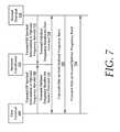
- FIG. 7is a signal flow diagram illustrating a channel optimization method executed by a network coordinator, mediating communications between two terminals of a wireless network;
- FIG. 8is an exemplary method for transmitting data between network devices using channel optimization in half duplex communications
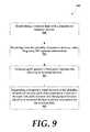
- FIG. 9is an exemplary method for transmitting data between network devices using channel optimization in half duplex communications
- FIG. 10is a schematic diagram of a method of channel optimization executed by dual channel network devices (e.g., terminals);
- FIG. 11is a graphical plot of time-averaged interference plus noise versus frequency band at two locations, each associated with a terminal device
- FIG. 12is a graphical plot of received signal to noise ration versus frequency bands at the two locations
- FIG. 13is a graphical representation of available 80 MHz with number of spatial streams (NSS) of 2 and an effective rate for different frequency bands at the two locations; and
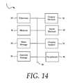
- FIG. 14illustrates an exemplary computing system that may be used to implement embodiments according to the present technology.
- a hyphenated term(e.g., “on-demand”) may be occasionally interchangeably used with its non-hyphenated version (e.g., “on demand”)
- a capitalized entrye.g., “Software”
- a non-capitalized versione.g., “software”
- a plural termmay be indicated with or without an apostrophe (e.g., PE's or PEs)
- an italicized terme.g., “N+1” may be interchangeably used with its non-italicized version (e.g., “N+1”).
- Such occasional interchangeable usesshall not be considered inconsistent with each other.
- the present disclosurerelates to optimal, dynamic channel selection in a wireless network, where devices operate in a HDX mode with explicit RF spectrum feedback for terminal devices.
- RF spectrum feedbackallows the terminal devices to select a Modulation and Coding Scheme (MCS) that maximizes the throughput and improves wireless link reliability.
- MCSModulation and Coding Scheme
- These featuresreduce or eliminate the possibility of hidden terminals and the inadequacy with carrier sensing for wireless links with longer distance. These methodologies are particularly advantages in wireless links of long distance.
- dynamic channel selectionallows for adaptation within wireless links in response to local changes in the wireless medium and the physical surroundings, allowing continued optimal communications in light of these changes.
- the decoupling and use of different frequency bands for transmission and receptionallows the overall throughput to be further optimized, since the RF spectrum can be vastly different and/or congested on both sides of a wireless link(s). In such situations, a reasonably good frequency band may not be available for pure TDD or TDMA mode of operation.
- terminal devicescan select a different frequency band for both transmit and receive communications, the selection of frequency band(s) may maximize throughput in both directions. Furthermore, this also increases reliability of the wireless link, since it is less probable that a potential interferer may overlap both frequency bands for transmit and receive at the same time.
- the present technologycontemplates various systems that dynamically select the operating frequency band(s) for transmission or reception of radio signals for half-duplex (HDX) communications.
- the choice of frequency band(s) used for transmission or reception of radio signalscan be identical or different.
- RFRadio Frequency
- devices in a HDX (half duplex) wireless systemare provisioned with non-overlapping periods of time for transmission of radio signals. These can be based on Time Division Duplex (TDD) for point-to-point systems or Time Division Multiple Access (TDMA) for point-to-multipoint systems.
- TDDTime Division Duplex
- TDMATime Division Multiple Access
- the start and duration of each transmission periodcan be signaled to the device in three different ways, such as carrier sensing, token passing between devices, or coordinated by an external entity (e.g., GPS clock, master device, etc.).
- Each terminal devicemeasures its local RF spectra, either on a periodic time interval, or when triggered by a loss of signal quality, or upon the request of a remote device, such as another terminal device or a network coordinator.
- a terminal devicethen either sends local raw RF spectra information, or the preferred frequency band(s) for reception of radio signals information to the opposing terminal device.
- a terminal devicemay select an optimal frequency band for transmissions either based on the raw RF spectra information received, or adopt the preferred frequency band(s) indicated.
- the choice of frequency band(s) for transmission or reception of radio signalsis selected separately based on the frequency band(s) that maximizes link throughput; as a result, different frequency band(s) can be selected for transmission and reception.
- a frequency bandis selected such the product of the forward and reverse link throughput is maximized. See FIG. 4 for selected frequency bands for both remote and local (e.g., first and second) terminal device, which illustrate a pure TDD mode of operation.
- a first optimal frequency band 405is illustrated for a first terminal 105 as well as a second optimal frequency band 410 is illustrated for a second terminal 110 .
- the optimal frequency bands for both the first and second terminals 105 and 110change over time, as indicated by the trend lines. In time periods where the first and second optimal frequency bands coincide, such as during interval 415 , the terminal devices may operate in a pure TDD mode.
- both the first and second terminals 105 and 110are utilizing a TDD/FDD mode of operation, where both terminals are configured to utilize both time division and frequency division.
- both terminalsare configured to utilize both time division and frequency division.
- Another problem with an IEEE 802.11 DCF based medium access protocolis that it requires terminal devices on both sides of a wireless link to operate on the same channel for transmissions and receptions since a clear channel assessment (CCA) needs to be performed before any frame exchange sequences can be initiated.
- CCAclear channel assessment
- a Time Division Duplex (TDD) wireless systemis a point-to-point system comprising of a pair of terminal devices that can send radio signals and communicate with each other in both directions. Only one terminal device can transmit a radio signal at any one time.
- TDDTime Division Duplex
- a Time Division Multiple Access (TDMA) wireless systemis a point-to-multipoint system comprising a group of terminal devices that can send radio signals and communicate with one another. Only one terminal device can transmit a radio signal at any one time.
- TDMATime Division Multiple Access
- a transmission periodis defined as duration of time where a terminal device in a TDD or TDMA systems transmits a radio signal.
- the start and duration of each transmission periodcan be indicated to the terminal device by carrier sensing, token passing between devices, or coordinated by an external entity (e.g., GPS, master device, etc.).
- a network coordinatorcoordinates and schedules transmission periods and frequency bands for all transmission and reception of radio signals in a wireless network. This function can be physically located in a single device or distributed across several devices, such as the terminal devices of a wireless network.
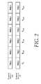
- a pure TDD or TDMA mode of operationis when terminal devices communicate wirelessly with one another in transmission periods indicated, and the operating frequency bands for transmission and reception of radio signals are identical. Exemplary pure TDD or TDMA operations are illustrated in FIG. 2 .
- a terminal device 105transmits and receives during opposing transmission periods from a second terminal device 110 , using the same frequency f 1 .
- a TDD/FDD (Frequency Division Duplex) or TDMA/FDD mode of operationis when terminal devices communicate wirelessly with one another in the indicated transmission periods, and the operating frequency bands for transmission and reception of radio signals can be different.
- An example of pure TDD/FDD or TDMA/FDD operationsis illustrated in FIG. 3 .
- Terminal devices 105 , 110 , and 111each transmit and receive signals according to the arrangement provided. It is noteworthy that for each transmit and receive transmission period, two of the three terminal devices may communicate with one another on a particular frequency band.
- a RF spectrum scanis a system process where a first terminal periodically measures the local RF spectrum over the all available frequency bands, and generates a measurement report that is then sent to a second (or more) terminal. Alternatively, the first terminal may use the measurement report to select a preferred frequency band(s), and send this preference to the second terminal.
- terminal or terminal devicemay be used interchangeably herein, and may include, for example, an RF radio, such as a wireless transceiver, a User Equipment or communications device, such as cellular telephone, or any other device that is capable of transmitting or receiving RF signals that would be known to one of ordinary skill in the art with the present disclosure before them.
- an RF radiosuch as a wireless transceiver
- a User Equipment or communications devicesuch as cellular telephone
- FIG. 1Aillustrates an exemplary network 100 A that includes network devices.
- the network devicesinclude a first terminal 105 and a second terminal 110 .
- the first and second terminal devices 105 and 110may be constructed similarly to one another.
- the first and second terminal devicesmay be dissimilar to one another, although both the first and second terminal devices 105 and 110 may both include a processor 115 and a memory 120 for storing executable instructions.
- the executable instructions that are stored in memory 120may be executed by the processor 115 to perform one or more of the various methods of channel optimization as described herein.
- each of the devicesincludes a communications interface 125 that interfaces with a wireless link 130 that communicatively couples the first and second terminal devices 105 and 110 .
- FIG. 1Aillustrates a first and second terminal devices 105 and 110
- the network 100 Amay include any number of terminal devices.
- the networkmay include a point-to-multipoint arrangement of terminal devices or an arrangement of terminal devices where a portion of the terminal devices are co-located with one another (see FIGS. 5A and 5B ).
- Each of the terminal devices 105 and 110performs a RF spectrum scan of their local RF spectrum periodically for any of: (a) received Signal to Noise Ratio (SINR), (b) Error Vector Magnitude (EVM), (c) interference plus noise power spectrum, and (d) overlapping Basic Service Set (OBSS) traffic activity.
- SINRSignal to Noise Ratio
- EVMError Vector Magnitude
- OBSSBasic Service Set
- the measurement for these parameterscan be performed in any frequency bands permitted by local regulatory rules.
- measurementmay occur by monitoring a count of beacons or any IEEE 802.11 frames in each of the IEEE 802.11 channels.
- a terminal devicemay process the RF spectra information locally, select a preferred frequency band(s) for reception of radio signals, and communicate that information to one or more terminal devices or a network coordinator 135 (see FIG. 1B ).
- This feedback reportcan include either the raw RF spectra information, or the preferred frequency band(s) for reception of radio signals.
- the feedback informationmay be encapsulated in proprietary management frame(s) and sent over an established wireless link to remote peer terminal devices at a periodic time interval, or when triggered by degradation in link quality, or upon the request by a remote peer terminal device.
- the RF spectracan be vastly different and/or congested on both sides of a wireless link.
- empirical data illustrating the widely varying nature of RF spectral data for terminal devices, taken from actual measurements at two locationswill be provided in graphical format in FIGS. 11-13 .
- a frequency bandis selected such the product of the forward and reverse link throughput is maximized. See FIG. 4 for selected frequency bands for both remote and local (e.g., first and second) terminal device, which illustrate a pure TDD mode of operation.
- a first optimal frequency band 405is illustrated for a first terminal 105 as well as a second optimal frequency band 410 is illustrated for a second terminal 110 .
- the optimal frequency bands for both the first and second terminals 105 and 110change over time, as indicated by the trend lines. In time periods where the first and second optimal frequency bands coincide, such as during interval 415 , the terminal devices may operate in a pure TDD mode.
- both the first and second terminals 105 and 110are utilizing a TDD/FDD mode of operation, where both terminals are configured to utilize both time division and frequency division.
- both terminalsare configured to utilize both time division and frequency division.
- a frequency bandmay be selected such that the sum of the forward and reverse link throughput is maximized.
- a local (first) terminal deviceselects a frequency band for transmission such that the interference plus SNIR at the remote (second) terminal device is minimized or equivalently to maximizing the received SINR.
- the selection of frequency band used for transmission at both sides of the wireless linkcan be performed independently from one another.
- the frequency bands for both the terminal devicesare not required to be identical to one another.
- a terminal device in this mode of operationwill be transmitting a frame at one frequency band, and receiving a frame at a different frequency band.
- a mode of operation where TDD is overlaid with FDD capabilitiesprovides unique modes of operation for devices that are inherently limited.
- most wireless radiosare not designed to perform FDD modes of operation.
- Most of these devicesare inherently half duplex devices and are not configured for full duplex operations.
- Full duplex radio creationis significantly more expensive than that of half-duplex radios. Endowing half-duplex radio with the ability to layer an FDD mode of operation onto its inherent TDD mode will provide interference mitigation due to use of FDD modes, while the radio may operate in TDD modes, when appropriate, to reduce operating cost.
- the network 100 Bincludes a network coordinator 135 that can establish wireless links, such as wireless link 130 with one or more remote terminal devices.
- the network 100 Bmay operate in a TDMA/FDD mode. More specifically, the network coordinator 135 exchanges local RF spectrum information with each remote terminal device. This feedback information can include either the raw RF spectra information, or the preferred frequency band(s) for reception of radio signals. Using this feedback information, the network coordinator 135 negotiates with each group of remote terminal devices the frequency band(s) for transmission and reception of radio signals that maximizes throughput and link reliability.
- the network coordinator 135may include a processor 150 and a memory 155 for storing executable instructions.
- the processor 150executes the instructions stored in the memory 155 to perform various methods for establishing wireless links between terminal devices, where the wireless links are configured for optimal/maximum throughput using the channel optimization techniques described herein.
- the network coordinator 135may also include a communications interface 160 , such as an RF interface (i.e., an RF antenna and associated hardware) that communicatively couples the network coordinator 135 with the first and second terminal devices 105 and 110 .
- the network coordinator 135may be individually coupled to the terminal devices with separate wireless links 165 A and 165 B, respectively.
- a network coordinator 135may include a terminal device that establishes an ad-hoc wireless network with one or more remote terminal devices.
- the network coordinator 135may include a centralized network device, such as a Call Session Control Function (CSCF) or service within a communications system that acts as a communications intermediary between remote terminal devices.
- CSCFCall Session Control Function
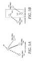
- FIG. 5Aillustrates a first terminal device 505 , which is coupled with a plurality of remote terminal devices 510 A-C.
- the first terminal device 505is configured to receive signals from each of the plurality of remote terminal devices 510 A-C on a first optimal frequency band TX(f 1 ), while transmitting signals to each of the remote terminal devices using a unique optimal frequency band.
- the first terminal device 505transmits to the remote terminal device 510 A on a frequency RX(f 3 ), while transmitting to another remote terminal device 510 B on a frequency RX(f 1 ), and yet another remote terminal device 510 C on a frequency RX(f 2 ).
- two terminal devices 515 A and 515 Bare co-located with one another, meaning that the two terminal devices 515 A and 515 B share similar RF spectral information.
- remote terminal devices 520 A and 520 Bcan transmit to the two terminal devices 515 A and 515 B using the same frequency TX(f 1 ).
- the two terminal devices 515 A and 515 Bmay include co-located radios in a Multiple Input Multiple Output (MIMO) radio system.
- MIMOMultiple Input Multiple Output
- Channel selectioncan be triggered dynamically by a terminal device (either local or remote) with the availability of a new measurement report, or degradation in throughput performance beyond a threshold in the current frequency band. For example, if a sum of local interference plus SINR indicates a reduction in throughput that is greater than 60%, a request for an updated RF spectral scan may be requested. When a more optimal frequency band is found, channel switch is achieved by a repeated exchange of management frames between terminal devices to coordinate and schedule a channel switch at an indicated time in the future. RF spectrum monitoring and dynamic channel selection continues to run throughout the existence of the wireless link.
- a system of networked terminal devicesoperate in HDX mode either by carrier sensing, token passing or coordinated by an external entity to explicitly indicate transmission periods.
- Terminal devicescommunicate wirelessly with one another using these transmission periods.
- the systemcan be a point-to-point wireless link between two devices, or a point-to-multipoint wireless network with a group of devices (see FIGS. 5A and 5B ).
- the negotiation to establish pure TDD or TDD/FDD modes of operationis achieved by an exchange of proprietary management frames between participating devices.
- participating terminal devicesAfter establishing the mode of operation, participating terminal devices start the transfer of data frames in a HDX manner. In each transmission period, only the terminal device assigned to that transmission period is permitted to transmit a radio signal on an assigned, optimal frequency band. The intended receiving terminal device (or devices) of this radio signal switches to the frequency band at the start of the assigned transmission period in anticipation of this radio signals.
- terminal devices on both sides of the wireless linkuse the same frequency band for transmission of radio signals, as described above.
- terminal devices on both sides of a wireless linkmay use a different frequency band for transmission of radio signals.
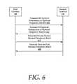
- FIG. 6is a signal flow diagram of an exemplary optimal frequency band exchange process and subsequent data transfer using the established optimal frequency bands for a first terminal 105 and a second terminal 110 .
- the first terminal 105may transmit 605 either local RF spectral information to or desired optimal frequency band(s) to the second terminal 110 . If the RF spectral information is transmitted, the second terminal 110 advantageously determines a first optimal frequency band(s) for the first terminal 105 .
- the same process 610is conducted for the second terminal 110 to determine a second optimal frequency band.
- the first terminal 105transmits 615 signals to the second terminal 110 on one or more of the second optimal frequency bands, while the second terminal 110 transmits 620 signals to the first terminal 105 on one or more of the first optimal frequency bands.
- FIG. 7is a signal flow diagram for a network arrangement having a first terminal 105 , a second terminal 110 , and a network coordinator 135 .
- the network arrangementmay include any number of terminals.
- the network coordinator 135 and the first and second terminalsmay be similarly configured devices, such as cellular telephones, RF radios, or other devices configured to transmit and receive data on a wireless link.
- the network coordinator 135is tasked with establishing the wireless link between the first terminal and the second terminal 110 (see FIG. 1B ).
- both the first and second terminals 105 and 110transmit ( 705 and 710 ) their respective RF spectral information or desired operating frequency band(s) to the network coordinator 135 .
- the network coordinator 135negotiates a frequency band for each of the terminals such that a product or a sum of a forward link and a reverse link throughput for each plurality of terminal devices is jointly maximized on the wireless link.
- the forward and reverse link throughputis determined from an analysis of the radio frequency (RF) spectral information for the plurality of terminal devices.
- the network coordinator 135then transmits ( 715 and 720 ) to each terminal device, an optimal frequency band(s) for the other terminal devices in the network.
- the first terminal 105receives an optimal frequency band for the second terminal 110 and the second terminal 110 receives an optimal frequency band for the first terminal 105 .
- the second terminal 110transmits 725 signals to the first terminal 105 on one or more of the optimal frequency bands, while the first terminal 105 transmits 730 signals to the second terminal 110 on one or more of the optimal frequency bands.
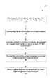
- FIG. 8is a flowchart of an exemplary method 800 for transmitting data between network devices using channel optimization in half duplex communications.
- a first and second terminalare network devices, and more specifically, the first and second terminals are not co-located with one another. Again, when the terminals are not co-located, the RF spectral information for these terminals may be different from one another due to interference, SINR, or any of the other throughput mitigating factors described herein.
- the method 800includes obtaining 805 at a first terminal, radio frequency (RF) spectral information local to the first terminal. This may include scanning the local area for RF spectral information.
- RFradio frequency
- the method 800also includes an optional step of transmitting 810 the RF information to a second terminal.
- the second terminalmay process this RF spectral information for the first terminal to determine a first optimal frequency band for the first terminal.
- This step 810is optional because the first terminal may analyze its own RF spectral information and select one or more preferred frequency bands. These bands may be placed in a ranked ordered list according to interference plus noise information for each band, and transmitted to the second terminal.
- the method 800also includes analyzing 815 at the first terminal, RF spectral information for a second terminal that is not co-located with the first terminal.
- the first terminalmay select a second terminal optimal frequency band for the second terminal.
- the method 800includes transmitting 820 data to the second terminal on a second terminal optimal frequency band, as well as receiving 825 data from the second terminal on a first terminal optimal frequency band.
- the first terminal optimal frequencymay be based upon the RF spectral information local to the first terminal.
- FIG. 9is a flowchart of an exemplary method 900 for transmitting data between network devices using channel optimization in half duplex communications.
- the methodis preferably executed by a network coordinator, which may include an intermediary network device that communicates with a plurality of terminal devices. Also, the network coordinator may include one of a plurality of terminal devices that form a network.
- the method 900includes establishing 905 a wireless link with a plurality of terminal devices. After establishing the wireless link, the method includes receiving 910 from the plurality of terminal devices, radio frequency (RF) spectral information. Also, the method 900 includes exchanging 915 RF spectral information between the plurality of terminal devices.
- RFradio frequency
- the method 900includes negotiating 920 a frequency band for each of the plurality of terminal devices such that a product or a sum of a forward link and a reverse link throughput for each plurality of terminal devices is jointly maximized on the wireless link.
- the forward and reverse link throughputis determined from an analysis of the radio frequency (RF) spectral information for the plurality of terminal devices.
- RFradio frequency
- the network coordinatornegotiates an optimal frequency band for each terminal by analyzing all of the RF spectral data for the terminals. The network coordinator would then transmit to each terminal, the optimal frequency for the other terminals in the network. Further, this information would include the optimal receiving frequency for the terminal.
- the terminalsmay process their own RF spectral information and provide suggested optimal frequency bands to the network coordinator.
- the network coordinatorwould then resolve any conflicts between the terminals and transmit back to the terminals their respective optimal frequency band(s), both for transmitting and receiving of signals with other terminals in the network.
- each terminalhas an optimal receiving frequency band, but may utilize a plurality of optimal transmitting frequency bands for the other remote terminals in the network.
- FIG. 10illustrates an exemplary network 1000 having two dual channel terminals that are communicating with one another using the TDD/FDD methods provided herein.
- each of the terminals 1005 and 1010include a processor 1015 and a memory 1020 for storing executable instructions.
- the processor 1015executes the instructions to perform methods of dual channel optimization as provided below.
- terminals 1005 and 1010are constructed similarly to one another. Furthermore, these terminals are similar to the terminals of FIGS. 1A and 1B with the exception that they are configured with dual communication interfaces.
- both of the terminals 1005 and 1010each include a time division duplexing interface 1025 for transmitting or receiving data on a first channel 1030 and a frequency division duplexing interface 1035 for transmitting or receiving data on a second channel 1040 .
- the terminals 1005 and 1010transmit data over a wireless link 130 , which comprises both the first and second channels 1030 and 1040 .
- Each of the terminalsmay be configured to determine radio frequency (RF) spectral information local to the terminal. Furthermore, each terminal may select an optimal frequency band for the first channel 1030 based upon the RF spectral information.
- RFradio frequency
- Each of the terminalsis also configured to select an optimal frequency band for the second channel 1040 based upon the RF spectral information.
- this functionalitymay be performed by other terminals in the network or by a network coordinator.
- each of the terminalsmay transmit management frames that include the optimal frequency band for the first channel and the optimal frequency band for the second channel to one or more additional devices on the network.
- the terminal 1005may also be configured to receive data from another terminal 1010 on either of the first and second channels 1030 and 1040 , using the desired frequency for each channel.
- a combination of pure TDD and TDD/FDD modes of operationcan be used on each channel. See FIG. 5 for an example of pure TDD mode of operation one channel, and TDD/FDD mode of operation on the second channel. Dynamic channel selection and RF spectrum monitoring can be performed separately for each channel.
- a point-to-point link of 26.4 miles between two sites in Northern Californiais established between a first terminal and a second terminal. At the site for each end of the link, the RF spectrum is measured.
- FIG. 11plots the time-averaged RF power due to interference plus noise at each of the two sites, and overlaid on top of each other. This shows that the RF spectra at two sites can be quite different.
- FIG. 12plots the similar data from the RF spectrum measurements in terms of received SINR at each of the two sites. This is correlates to the achievable MCS and rate in the presence of interference and noise at each frequency band.
- FIG. 13shows as an example for each of the 80 MHz channels (based on IEEE 802.11ac channels) the effective rate that can be achieved.
- the 80 MHz channelsbased on IEEE 802.11ac channels
- FIG. 14illustrates an exemplary computing device 1 that may be used to implement an embodiment of the present systems and methods.
- the system 1 of FIG. 14may be implemented in the contexts of the likes of computing devices, radios, terminals, networks, servers, or combinations thereof.
- the computing device 1 of FIG. 14includes a processor 10 and main memory 20 .
- Main memory 20stores, in part, instructions and data for execution by processor 10 .
- Main memory 20may store the executable code when in operation.
- the system 1 of FIG. 14further includes a mass storage device 30 , portable storage device 40 , output devices 50 , user input devices 60 , a display system 70 , and peripherals 80 .
- FIG. 14The components shown in FIG. 14 are depicted as being connected via a single bus 90 .
- the componentsmay be connected through one or more data transport means.
- Processor 10 and main memory 20may be connected via a local microprocessor bus, and the mass storage device 30 , peripherals 80 , portable storage device 40 , and display system 70 may be connected via one or more input/output (I/O) buses.
- I/Oinput/output
- Mass storage device 30which may be implemented with a magnetic disk drive or an optical disk drive, is a non-volatile storage device for storing data and instructions for use by processor 10 . Mass storage device 30 can store the system software for implementing embodiments of the present technology for purposes of loading that software into main memory 20 .
- Portable storage device 40operates in conjunction with a portable non-volatile storage medium, such as a floppy disk, compact disk or digital video disc, to input and output data and code to and from the computing system 1 of FIG. 14 .
- the system software for implementing embodiments of the present technologymay be stored on such a portable medium and input to the computing system 1 via the portable storage device 40 .
- Input devices 60provide a portion of a user interface.
- Input devices 60may include an alphanumeric keypad, such as a keyboard, for inputting alphanumeric and other information, or a pointing device, such as a mouse, a trackball, stylus, or cursor direction keys.
- the system 1 as shown in FIG. 14includes output devices 50 . Suitable output devices include speakers, printers, network interfaces, and monitors.
- Display system 70may include a liquid crystal display (LCD) or other suitable display device.
- Display system 70receives textual and graphical information, and processes the information for output to the display device.
- LCDliquid crystal display
- Peripherals 80may include any type of computer support device to add additional functionality to the computing system. Peripherals 80 may include a modem or a router.
- the components contained in the computing system 1 of FIG. 14are those typically found in computing systems that may be suitable for use with embodiments of the present technology and are intended to represent a broad category of such computer components that are well known in the art.
- the computing system 1can be a personal computer, hand held computing system, telephone, mobile computing system, workstation, server, minicomputer, mainframe computer, or any other computing system.
- the computercan also include different bus configurations, networked platforms, multi-processor platforms, etc.
- Various operating systemscan be used including UNIX, Linux, Windows, Macintosh OS, Palm OS, and other suitable operating systems.
- Some of the above-described functionsmay be composed of instructions that are stored on storage media (e.g., computer-readable medium).
- the instructionsmay be retrieved and executed by the processor.
- Some examples of storage mediaare memory devices, tapes, disks, and the like.
- the instructionsare operational when executed by the processor to direct the processor to operate in accord with the technology. Those skilled in the art are familiar with instructions, processor(s), and storage media.
- Non-volatile mediainclude, for example, optical or magnetic disks, such as a fixed disk.
- Volatile mediainclude dynamic memory, such as system RAM.
- Transmission mediainclude coaxial cables, copper wire and fiber optics, among others, including the wires that comprise one embodiment of a bus.
- Transmission mediacan also take the form of acoustic or light waves, such as those generated during radio frequency (RF) and infrared (IR) data communications.
- RFradio frequency
- IRinfrared
- Common forms of computer-readable mediainclude, for example, a floppy disk, a flexible disk, a hard disk, magnetic tape, any other magnetic medium, a CD-ROM disk, digital video disk (DVD), any other optical medium, any other physical medium with patterns of marks or holes, a RAM, a PROM, an EPROM, an EEPROM, a FLASHEPROM, any other memory chip or data exchange adapter, a carrier wave, or any other medium from which a computer can read.
- a buscarries the data to system RAM, from which a CPU retrieves and executes the instructions.
- the instructions received by system RAMcan optionally be stored on a fixed disk either before or after execution by a CPU.
- Computer program code for carrying out operations for aspects of the present technologymay be written in any combination of one or more programming languages, including an object oriented programming language such as Java, Smalltalk, C++ or the like and conventional procedural programming languages, such as the “C” programming language or similar programming languages.
- the program codemay execute entirely on the user's computer, partly on the user's computer, as a stand-alone software package, partly on the user's computer and partly on a remote computer or entirely on the remote computer or server.
- the remote computermay be connected to the user's computer through any type of network, including a local area network (LAN) or a wide area network (WAN), or the connection may be made to an external computer (for example, through the Internet using an Internet Service Provider).
- LANlocal area network
- WANwide area network
- Internet Service Providerfor example, AT&T, MCI, Sprint, EarthLink, MSN, GTE, etc.
- These computer program instructionsmay also be stored in a computer readable medium that can direct a computer, other programmable data processing apparatus, or other devices to function in a particular manner, such that the instructions stored in the computer readable medium produce an article of manufacture including instructions which implement the function/act specified in the flowchart and/or block diagram block or blocks.
- the computer program instructionsmay also be loaded onto a computer, other programmable data processing apparatus, or other devices to cause a series of operational steps to be performed on the computer, other programmable apparatus or other devices to produce a computer implemented process such that the instructions which execute on the computer or other programmable apparatus provide processes for implementing the functions/acts specified in the flowchart and/or block diagram block or blocks.
- each block in the flowchart or block diagramsmay represent a module, segment, or portion of code, which comprises one or more executable instructions for implementing the specified logical function(s).
- the functions noted in the blockmay occur out of the order noted in the figures. For example, two blocks shown in succession may, in fact, be executed substantially concurrently, or the blocks may sometimes be executed in the reverse order, depending upon the functionality involved.
Landscapes
- Engineering & Computer Science (AREA)
- Signal Processing (AREA)
- Computer Networks & Wireless Communication (AREA)
- Quality & Reliability (AREA)
- Physics & Mathematics (AREA)
- Health & Medical Sciences (AREA)
- General Health & Medical Sciences (AREA)
- Spectroscopy & Molecular Physics (AREA)
- Mobile Radio Communication Systems (AREA)
Abstract
Description
Claims (26)
Priority Applications (3)
| Application Number | Priority Date | Filing Date | Title |
|---|---|---|---|
| US14/325,307US9504049B2 (en) | 2014-01-24 | 2014-07-07 | Channel optimization in half duplex communications systems |
| US15/224,412US9888485B2 (en) | 2014-01-24 | 2016-07-29 | Channel optimization in half duplex communications systems |
| US15/809,968US10616903B2 (en) | 2014-01-24 | 2017-11-10 | Channel optimization in half duplex communications systems |
Applications Claiming Priority (2)
| Application Number | Priority Date | Filing Date | Title |
|---|---|---|---|
| US14/164,081US9001689B1 (en) | 2014-01-24 | 2014-01-24 | Channel optimization in half duplex communications systems |
| US14/325,307US9504049B2 (en) | 2014-01-24 | 2014-07-07 | Channel optimization in half duplex communications systems |
Related Parent Applications (1)
| Application Number | Title | Priority Date | Filing Date |
|---|---|---|---|
| US14/164,081ContinuationUS9001689B1 (en) | 2014-01-24 | 2014-01-24 | Channel optimization in half duplex communications systems |
Related Child Applications (1)
| Application Number | Title | Priority Date | Filing Date |
|---|---|---|---|
| US15/224,412ContinuationUS9888485B2 (en) | 2014-01-24 | 2016-07-29 | Channel optimization in half duplex communications systems |
Publications (2)
| Publication Number | Publication Date |
|---|---|
| US20150215952A1 US20150215952A1 (en) | 2015-07-30 |
| US9504049B2true US9504049B2 (en) | 2016-11-22 |
Family
ID=52745180
Family Applications (4)
| Application Number | Title | Priority Date | Filing Date |
|---|---|---|---|
| US14/164,081ActiveUS9001689B1 (en) | 2014-01-24 | 2014-01-24 | Channel optimization in half duplex communications systems |
| US14/325,307Active2034-06-02US9504049B2 (en) | 2014-01-24 | 2014-07-07 | Channel optimization in half duplex communications systems |
| US15/224,412ActiveUS9888485B2 (en) | 2014-01-24 | 2016-07-29 | Channel optimization in half duplex communications systems |
| US15/809,968ActiveUS10616903B2 (en) | 2014-01-24 | 2017-11-10 | Channel optimization in half duplex communications systems |
Family Applications Before (1)
| Application Number | Title | Priority Date | Filing Date |
|---|---|---|---|
| US14/164,081ActiveUS9001689B1 (en) | 2014-01-24 | 2014-01-24 | Channel optimization in half duplex communications systems |
Family Applications After (2)
| Application Number | Title | Priority Date | Filing Date |
|---|---|---|---|
| US15/224,412ActiveUS9888485B2 (en) | 2014-01-24 | 2016-07-29 | Channel optimization in half duplex communications systems |
| US15/809,968ActiveUS10616903B2 (en) | 2014-01-24 | 2017-11-10 | Channel optimization in half duplex communications systems |
Country Status (3)
| Country | Link |
|---|---|
| US (4) | US9001689B1 (en) |
| CN (1) | CN105191204B (en) |
| WO (1) | WO2015112627A2 (en) |
Cited By (17)
| Publication number | Priority date | Publication date | Assignee | Title |
|---|---|---|---|---|
| US9693388B2 (en) | 2013-05-30 | 2017-06-27 | Mimosa Networks, Inc. | Wireless access points providing hybrid 802.11 and scheduled priority access communications |
| US9780892B2 (en) | 2014-03-05 | 2017-10-03 | Mimosa Networks, Inc. | System and method for aligning a radio using an automated audio guide |
| US9843940B2 (en) | 2013-03-08 | 2017-12-12 | Mimosa Networks, Inc. | System and method for dual-band backhaul radio |
| US9871302B2 (en) | 2013-03-06 | 2018-01-16 | Mimosa Networks, Inc. | Enclosure for radio, parabolic dish antenna, and side lobe shields |
| US9888485B2 (en) | 2014-01-24 | 2018-02-06 | Mimosa Networks, Inc. | Channel optimization in half duplex communications systems |
| US9930592B2 (en) | 2013-02-19 | 2018-03-27 | Mimosa Networks, Inc. | Systems and methods for directing mobile device connectivity |
| US9986565B2 (en) | 2013-02-19 | 2018-05-29 | Mimosa Networks, Inc. | WiFi management interface for microwave radio and reset to factory defaults |
| US9998246B2 (en) | 2014-03-13 | 2018-06-12 | Mimosa Networks, Inc. | Simultaneous transmission on shared channel |
| US10096933B2 (en) | 2013-03-06 | 2018-10-09 | Mimosa Networks, Inc. | Waterproof apparatus for cables and cable interfaces |
| US10511074B2 (en) | 2018-01-05 | 2019-12-17 | Mimosa Networks, Inc. | Higher signal isolation solutions for printed circuit board mounted antenna and waveguide interface |
| US10742275B2 (en) | 2013-03-07 | 2020-08-11 | Mimosa Networks, Inc. | Quad-sector antenna using circular polarization |
| US10749263B2 (en) | 2016-01-11 | 2020-08-18 | Mimosa Networks, Inc. | Printed circuit board mounted antenna and waveguide interface |
| US10938110B2 (en) | 2013-06-28 | 2021-03-02 | Mimosa Networks, Inc. | Ellipticity reduction in circularly polarized array antennas |
| US10958332B2 (en) | 2014-09-08 | 2021-03-23 | Mimosa Networks, Inc. | Wi-Fi hotspot repeater |
| US11069986B2 (en) | 2018-03-02 | 2021-07-20 | Airspan Ip Holdco Llc | Omni-directional orthogonally-polarized antenna system for MIMO applications |
| US11251539B2 (en) | 2016-07-29 | 2022-02-15 | Airspan Ip Holdco Llc | Multi-band access point antenna array |
| US11289821B2 (en) | 2018-09-11 | 2022-03-29 | Air Span Ip Holdco Llc | Sector antenna systems and methods for providing high gain and high side-lobe rejection |
Families Citing this family (168)
| Publication number | Priority date | Publication date | Assignee | Title |
|---|---|---|---|---|
| US9113347B2 (en) | 2012-12-05 | 2015-08-18 | At&T Intellectual Property I, Lp | Backhaul link for distributed antenna system |
| US10009065B2 (en) | 2012-12-05 | 2018-06-26 | At&T Intellectual Property I, L.P. | Backhaul link for distributed antenna system |
| US9999038B2 (en) | 2013-05-31 | 2018-06-12 | At&T Intellectual Property I, L.P. | Remote distributed antenna system |
| US9525524B2 (en) | 2013-05-31 | 2016-12-20 | At&T Intellectual Property I, L.P. | Remote distributed antenna system |
| US8897697B1 (en) | 2013-11-06 | 2014-11-25 | At&T Intellectual Property I, Lp | Millimeter-wave surface-wave communications |
| US9209902B2 (en) | 2013-12-10 | 2015-12-08 | At&T Intellectual Property I, L.P. | Quasi-optical coupler |
| US9692101B2 (en) | 2014-08-26 | 2017-06-27 | At&T Intellectual Property I, L.P. | Guided wave couplers for coupling electromagnetic waves between a waveguide surface and a surface of a wire |
| KR102247085B1 (en)* | 2014-09-01 | 2021-04-30 | 삼성전자주식회사 | Scheme for communcation in mobile communication system using unlicensed frequency band |
| USD752566S1 (en) | 2014-09-12 | 2016-03-29 | Mimosa Networks, Inc. | Wireless repeater |
| US9768833B2 (en) | 2014-09-15 | 2017-09-19 | At&T Intellectual Property I, L.P. | Method and apparatus for sensing a condition in a transmission medium of electromagnetic waves |
| US10063280B2 (en) | 2014-09-17 | 2018-08-28 | At&T Intellectual Property I, L.P. | Monitoring and mitigating conditions in a communication network |
| US9628854B2 (en) | 2014-09-29 | 2017-04-18 | At&T Intellectual Property I, L.P. | Method and apparatus for distributing content in a communication network |
| US9615269B2 (en) | 2014-10-02 | 2017-04-04 | At&T Intellectual Property I, L.P. | Method and apparatus that provides fault tolerance in a communication network |
| US9685992B2 (en) | 2014-10-03 | 2017-06-20 | At&T Intellectual Property I, L.P. | Circuit panel network and methods thereof |
| US9503189B2 (en) | 2014-10-10 | 2016-11-22 | At&T Intellectual Property I, L.P. | Method and apparatus for arranging communication sessions in a communication system |
| US9762289B2 (en) | 2014-10-14 | 2017-09-12 | At&T Intellectual Property I, L.P. | Method and apparatus for transmitting or receiving signals in a transportation system |
| US9973299B2 (en) | 2014-10-14 | 2018-05-15 | At&T Intellectual Property I, L.P. | Method and apparatus for adjusting a mode of communication in a communication network |
| US9627768B2 (en) | 2014-10-21 | 2017-04-18 | At&T Intellectual Property I, L.P. | Guided-wave transmission device with non-fundamental mode propagation and methods for use therewith |
| US9577306B2 (en) | 2014-10-21 | 2017-02-21 | At&T Intellectual Property I, L.P. | Guided-wave transmission device and methods for use therewith |
| US9653770B2 (en) | 2014-10-21 | 2017-05-16 | At&T Intellectual Property I, L.P. | Guided wave coupler, coupling module and methods for use therewith |
| US9520945B2 (en) | 2014-10-21 | 2016-12-13 | At&T Intellectual Property I, L.P. | Apparatus for providing communication services and methods thereof |
| US9769020B2 (en) | 2014-10-21 | 2017-09-19 | At&T Intellectual Property I, L.P. | Method and apparatus for responding to events affecting communications in a communication network |
| US9780834B2 (en) | 2014-10-21 | 2017-10-03 | At&T Intellectual Property I, L.P. | Method and apparatus for transmitting electromagnetic waves |
| US9312919B1 (en) | 2014-10-21 | 2016-04-12 | At&T Intellectual Property I, Lp | Transmission device with impairment compensation and methods for use therewith |
| US9564947B2 (en) | 2014-10-21 | 2017-02-07 | At&T Intellectual Property I, L.P. | Guided-wave transmission device with diversity and methods for use therewith |
| US10340573B2 (en) | 2016-10-26 | 2019-07-02 | At&T Intellectual Property I, L.P. | Launcher with cylindrical coupling device and methods for use therewith |
| US10243784B2 (en) | 2014-11-20 | 2019-03-26 | At&T Intellectual Property I, L.P. | System for generating topology information and methods thereof |
| US9742462B2 (en) | 2014-12-04 | 2017-08-22 | At&T Intellectual Property I, L.P. | Transmission medium and communication interfaces and methods for use therewith |
| US9997819B2 (en) | 2015-06-09 | 2018-06-12 | At&T Intellectual Property I, L.P. | Transmission medium and method for facilitating propagation of electromagnetic waves via a core |
| US9954287B2 (en) | 2014-11-20 | 2018-04-24 | At&T Intellectual Property I, L.P. | Apparatus for converting wireless signals and electromagnetic waves and methods thereof |
| US9544006B2 (en) | 2014-11-20 | 2017-01-10 | At&T Intellectual Property I, L.P. | Transmission device with mode division multiplexing and methods for use therewith |
| US9461706B1 (en) | 2015-07-31 | 2016-10-04 | At&T Intellectual Property I, Lp | Method and apparatus for exchanging communication signals |
| US9800327B2 (en) | 2014-11-20 | 2017-10-24 | At&T Intellectual Property I, L.P. | Apparatus for controlling operations of a communication device and methods thereof |
| US9654173B2 (en) | 2014-11-20 | 2017-05-16 | At&T Intellectual Property I, L.P. | Apparatus for powering a communication device and methods thereof |
| US9680670B2 (en) | 2014-11-20 | 2017-06-13 | At&T Intellectual Property I, L.P. | Transmission device with channel equalization and control and methods for use therewith |
| US10009067B2 (en) | 2014-12-04 | 2018-06-26 | At&T Intellectual Property I, L.P. | Method and apparatus for configuring a communication interface |
| US10144036B2 (en) | 2015-01-30 | 2018-12-04 | At&T Intellectual Property I, L.P. | Method and apparatus for mitigating interference affecting a propagation of electromagnetic waves guided by a transmission medium |
| US9876570B2 (en) | 2015-02-20 | 2018-01-23 | At&T Intellectual Property I, Lp | Guided-wave transmission device with non-fundamental mode propagation and methods for use therewith |
| US9749013B2 (en) | 2015-03-17 | 2017-08-29 | At&T Intellectual Property I, L.P. | Method and apparatus for reducing attenuation of electromagnetic waves guided by a transmission medium |
| US9705561B2 (en) | 2015-04-24 | 2017-07-11 | At&T Intellectual Property I, L.P. | Directional coupling device and methods for use therewith |
| US10224981B2 (en) | 2015-04-24 | 2019-03-05 | At&T Intellectual Property I, Lp | Passive electrical coupling device and methods for use therewith |
| US9948354B2 (en) | 2015-04-28 | 2018-04-17 | At&T Intellectual Property I, L.P. | Magnetic coupling device with reflective plate and methods for use therewith |
| US9793954B2 (en) | 2015-04-28 | 2017-10-17 | At&T Intellectual Property I, L.P. | Magnetic coupling device and methods for use therewith |
| US9490869B1 (en) | 2015-05-14 | 2016-11-08 | At&T Intellectual Property I, L.P. | Transmission medium having multiple cores and methods for use therewith |
| US9748626B2 (en) | 2015-05-14 | 2017-08-29 | At&T Intellectual Property I, L.P. | Plurality of cables having different cross-sectional shapes which are bundled together to form a transmission medium |
| US9871282B2 (en) | 2015-05-14 | 2018-01-16 | At&T Intellectual Property I, L.P. | At least one transmission medium having a dielectric surface that is covered at least in part by a second dielectric |
| US10650940B2 (en) | 2015-05-15 | 2020-05-12 | At&T Intellectual Property I, L.P. | Transmission medium having a conductive material and methods for use therewith |
| US10679767B2 (en) | 2015-05-15 | 2020-06-09 | At&T Intellectual Property I, L.P. | Transmission medium having a conductive material and methods for use therewith |
| US9917341B2 (en) | 2015-05-27 | 2018-03-13 | At&T Intellectual Property I, L.P. | Apparatus and method for launching electromagnetic waves and for modifying radial dimensions of the propagating electromagnetic waves |
| US10103801B2 (en) | 2015-06-03 | 2018-10-16 | At&T Intellectual Property I, L.P. | Host node device and methods for use therewith |
| US10348391B2 (en) | 2015-06-03 | 2019-07-09 | At&T Intellectual Property I, L.P. | Client node device with frequency conversion and methods for use therewith |
| US9912381B2 (en) | 2015-06-03 | 2018-03-06 | At&T Intellectual Property I, Lp | Network termination and methods for use therewith |
| US10154493B2 (en) | 2015-06-03 | 2018-12-11 | At&T Intellectual Property I, L.P. | Network termination and methods for use therewith |
| US10812174B2 (en) | 2015-06-03 | 2020-10-20 | At&T Intellectual Property I, L.P. | Client node device and methods for use therewith |
| US9866309B2 (en) | 2015-06-03 | 2018-01-09 | At&T Intellectual Property I, Lp | Host node device and methods for use therewith |
| US9913139B2 (en) | 2015-06-09 | 2018-03-06 | At&T Intellectual Property I, L.P. | Signal fingerprinting for authentication of communicating devices |
| US9608692B2 (en) | 2015-06-11 | 2017-03-28 | At&T Intellectual Property I, L.P. | Repeater and methods for use therewith |
| US10142086B2 (en) | 2015-06-11 | 2018-11-27 | At&T Intellectual Property I, L.P. | Repeater and methods for use therewith |
| US9820146B2 (en) | 2015-06-12 | 2017-11-14 | At&T Intellectual Property I, L.P. | Method and apparatus for authentication and identity management of communicating devices |
| US9667317B2 (en) | 2015-06-15 | 2017-05-30 | At&T Intellectual Property I, L.P. | Method and apparatus for providing security using network traffic adjustments |
| US9640850B2 (en) | 2015-06-25 | 2017-05-02 | At&T Intellectual Property I, L.P. | Methods and apparatus for inducing a non-fundamental wave mode on a transmission medium |
| US9509415B1 (en) | 2015-06-25 | 2016-11-29 | At&T Intellectual Property I, L.P. | Methods and apparatus for inducing a fundamental wave mode on a transmission medium |
| US9865911B2 (en) | 2015-06-25 | 2018-01-09 | At&T Intellectual Property I, L.P. | Waveguide system for slot radiating first electromagnetic waves that are combined into a non-fundamental wave mode second electromagnetic wave on a transmission medium |
| US9628116B2 (en) | 2015-07-14 | 2017-04-18 | At&T Intellectual Property I, L.P. | Apparatus and methods for transmitting wireless signals |
| US9882257B2 (en) | 2015-07-14 | 2018-01-30 | At&T Intellectual Property I, L.P. | Method and apparatus for launching a wave mode that mitigates interference |
| US10044409B2 (en) | 2015-07-14 | 2018-08-07 | At&T Intellectual Property I, L.P. | Transmission medium and methods for use therewith |
| US10148016B2 (en) | 2015-07-14 | 2018-12-04 | At&T Intellectual Property I, L.P. | Apparatus and methods for communicating utilizing an antenna array |
| US10033108B2 (en) | 2015-07-14 | 2018-07-24 | At&T Intellectual Property I, L.P. | Apparatus and methods for generating an electromagnetic wave having a wave mode that mitigates interference |
| US9836957B2 (en) | 2015-07-14 | 2017-12-05 | At&T Intellectual Property I, L.P. | Method and apparatus for communicating with premises equipment |
| US10320586B2 (en) | 2015-07-14 | 2019-06-11 | At&T Intellectual Property I, L.P. | Apparatus and methods for generating non-interfering electromagnetic waves on an insulated transmission medium |
| US9847566B2 (en) | 2015-07-14 | 2017-12-19 | At&T Intellectual Property I, L.P. | Method and apparatus for adjusting a field of a signal to mitigate interference |
| US10033107B2 (en) | 2015-07-14 | 2018-07-24 | At&T Intellectual Property I, L.P. | Method and apparatus for coupling an antenna to a device |
| US10341142B2 (en) | 2015-07-14 | 2019-07-02 | At&T Intellectual Property I, L.P. | Apparatus and methods for generating non-interfering electromagnetic waves on an uninsulated conductor |
| US9722318B2 (en) | 2015-07-14 | 2017-08-01 | At&T Intellectual Property I, L.P. | Method and apparatus for coupling an antenna to a device |
| US9853342B2 (en) | 2015-07-14 | 2017-12-26 | At&T Intellectual Property I, L.P. | Dielectric transmission medium connector and methods for use therewith |
| US10205655B2 (en) | 2015-07-14 | 2019-02-12 | At&T Intellectual Property I, L.P. | Apparatus and methods for communicating utilizing an antenna array and multiple communication paths |
| US10170840B2 (en) | 2015-07-14 | 2019-01-01 | At&T Intellectual Property I, L.P. | Apparatus and methods for sending or receiving electromagnetic signals |
| US9793951B2 (en) | 2015-07-15 | 2017-10-17 | At&T Intellectual Property I, L.P. | Method and apparatus for launching a wave mode that mitigates interference |
| US9608740B2 (en) | 2015-07-15 | 2017-03-28 | At&T Intellectual Property I, L.P. | Method and apparatus for launching a wave mode that mitigates interference |
| US10090606B2 (en) | 2015-07-15 | 2018-10-02 | At&T Intellectual Property I, L.P. | Antenna system with dielectric array and methods for use therewith |
| US9948333B2 (en) | 2015-07-23 | 2018-04-17 | At&T Intellectual Property I, L.P. | Method and apparatus for wireless communications to mitigate interference |
| US10784670B2 (en) | 2015-07-23 | 2020-09-22 | At&T Intellectual Property I, L.P. | Antenna support for aligning an antenna |
| US9871283B2 (en) | 2015-07-23 | 2018-01-16 | At&T Intellectual Property I, Lp | Transmission medium having a dielectric core comprised of plural members connected by a ball and socket configuration |
| US9912027B2 (en) | 2015-07-23 | 2018-03-06 | At&T Intellectual Property I, L.P. | Method and apparatus for exchanging communication signals |
| US9749053B2 (en) | 2015-07-23 | 2017-08-29 | At&T Intellectual Property I, L.P. | Node device, repeater and methods for use therewith |
| US10020587B2 (en) | 2015-07-31 | 2018-07-10 | At&T Intellectual Property I, L.P. | Radial antenna and methods for use therewith |
| US9967173B2 (en) | 2015-07-31 | 2018-05-08 | At&T Intellectual Property I, L.P. | Method and apparatus for authentication and identity management of communicating devices |
| US9735833B2 (en) | 2015-07-31 | 2017-08-15 | At&T Intellectual Property I, L.P. | Method and apparatus for communications management in a neighborhood network |
| US9904535B2 (en) | 2015-09-14 | 2018-02-27 | At&T Intellectual Property I, L.P. | Method and apparatus for distributing software |
| US9705571B2 (en) | 2015-09-16 | 2017-07-11 | At&T Intellectual Property I, L.P. | Method and apparatus for use with a radio distributed antenna system |
| US10079661B2 (en) | 2015-09-16 | 2018-09-18 | At&T Intellectual Property I, L.P. | Method and apparatus for use with a radio distributed antenna system having a clock reference |
| US10136434B2 (en) | 2015-09-16 | 2018-11-20 | At&T Intellectual Property I, L.P. | Method and apparatus for use with a radio distributed antenna system having an ultra-wideband control channel |
| US10051629B2 (en) | 2015-09-16 | 2018-08-14 | At&T Intellectual Property I, L.P. | Method and apparatus for use with a radio distributed antenna system having an in-band reference signal |
| US10009901B2 (en) | 2015-09-16 | 2018-06-26 | At&T Intellectual Property I, L.P. | Method, apparatus, and computer-readable storage medium for managing utilization of wireless resources between base stations |
| US10009063B2 (en) | 2015-09-16 | 2018-06-26 | At&T Intellectual Property I, L.P. | Method and apparatus for use with a radio distributed antenna system having an out-of-band reference signal |
| US9769128B2 (en) | 2015-09-28 | 2017-09-19 | At&T Intellectual Property I, L.P. | Method and apparatus for encryption of communications over a network |
| US9729197B2 (en) | 2015-10-01 | 2017-08-08 | At&T Intellectual Property I, L.P. | Method and apparatus for communicating network management traffic over a network |
| US10074890B2 (en) | 2015-10-02 | 2018-09-11 | At&T Intellectual Property I, L.P. | Communication device and antenna with integrated light assembly |
| US9876264B2 (en) | 2015-10-02 | 2018-01-23 | At&T Intellectual Property I, Lp | Communication system, guided wave switch and methods for use therewith |
| US9882277B2 (en) | 2015-10-02 | 2018-01-30 | At&T Intellectual Property I, Lp | Communication device and antenna assembly with actuated gimbal mount |
| US10051483B2 (en) | 2015-10-16 | 2018-08-14 | At&T Intellectual Property I, L.P. | Method and apparatus for directing wireless signals |
| US10355367B2 (en) | 2015-10-16 | 2019-07-16 | At&T Intellectual Property I, L.P. | Antenna structure for exchanging wireless signals |
| US10665942B2 (en) | 2015-10-16 | 2020-05-26 | At&T Intellectual Property I, L.P. | Method and apparatus for adjusting wireless communications |
| NL2016189B1 (en)* | 2016-02-01 | 2017-08-10 | Head Tech Int | A data link device. |
| US9912419B1 (en) | 2016-08-24 | 2018-03-06 | At&T Intellectual Property I, L.P. | Method and apparatus for managing a fault in a distributed antenna system |
| US9860075B1 (en) | 2016-08-26 | 2018-01-02 | At&T Intellectual Property I, L.P. | Method and communication node for broadband distribution |
| US10291311B2 (en) | 2016-09-09 | 2019-05-14 | At&T Intellectual Property I, L.P. | Method and apparatus for mitigating a fault in a distributed antenna system |
| US11032819B2 (en) | 2016-09-15 | 2021-06-08 | At&T Intellectual Property I, L.P. | Method and apparatus for use with a radio distributed antenna system having a control channel reference signal |
| US10135147B2 (en) | 2016-10-18 | 2018-11-20 | At&T Intellectual Property I, L.P. | Apparatus and methods for launching guided waves via an antenna |
| US10135146B2 (en) | 2016-10-18 | 2018-11-20 | At&T Intellectual Property I, L.P. | Apparatus and methods for launching guided waves via circuits |
| US10340600B2 (en) | 2016-10-18 | 2019-07-02 | At&T Intellectual Property I, L.P. | Apparatus and methods for launching guided waves via plural waveguide systems |
| US10811767B2 (en) | 2016-10-21 | 2020-10-20 | At&T Intellectual Property I, L.P. | System and dielectric antenna with convex dielectric radome |
| US10374316B2 (en) | 2016-10-21 | 2019-08-06 | At&T Intellectual Property I, L.P. | System and dielectric antenna with non-uniform dielectric |
| US9876605B1 (en) | 2016-10-21 | 2018-01-23 | At&T Intellectual Property I, L.P. | Launcher and coupling system to support desired guided wave mode |
| US9991580B2 (en) | 2016-10-21 | 2018-06-05 | At&T Intellectual Property I, L.P. | Launcher and coupling system for guided wave mode cancellation |
| US10312567B2 (en) | 2016-10-26 | 2019-06-04 | At&T Intellectual Property I, L.P. | Launcher with planar strip antenna and methods for use therewith |
| US10498044B2 (en) | 2016-11-03 | 2019-12-03 | At&T Intellectual Property I, L.P. | Apparatus for configuring a surface of an antenna |
| US10291334B2 (en) | 2016-11-03 | 2019-05-14 | At&T Intellectual Property I, L.P. | System for detecting a fault in a communication system |
| US10225025B2 (en) | 2016-11-03 | 2019-03-05 | At&T Intellectual Property I, L.P. | Method and apparatus for detecting a fault in a communication system |
| US10224634B2 (en) | 2016-11-03 | 2019-03-05 | At&T Intellectual Property I, L.P. | Methods and apparatus for adjusting an operational characteristic of an antenna |
| US10535928B2 (en) | 2016-11-23 | 2020-01-14 | At&T Intellectual Property I, L.P. | Antenna system and methods for use therewith |
| US10090594B2 (en) | 2016-11-23 | 2018-10-02 | At&T Intellectual Property I, L.P. | Antenna system having structural configurations for assembly |
| US10178445B2 (en) | 2016-11-23 | 2019-01-08 | At&T Intellectual Property I, L.P. | Methods, devices, and systems for load balancing between a plurality of waveguides |
| US10340601B2 (en) | 2016-11-23 | 2019-07-02 | At&T Intellectual Property I, L.P. | Multi-antenna system and methods for use therewith |
| US10340603B2 (en) | 2016-11-23 | 2019-07-02 | At&T Intellectual Property I, L.P. | Antenna system having shielded structural configurations for assembly |
| US10305190B2 (en) | 2016-12-01 | 2019-05-28 | At&T Intellectual Property I, L.P. | Reflecting dielectric antenna system and methods for use therewith |
| US10361489B2 (en) | 2016-12-01 | 2019-07-23 | At&T Intellectual Property I, L.P. | Dielectric dish antenna system and methods for use therewith |
| US10135145B2 (en) | 2016-12-06 | 2018-11-20 | At&T Intellectual Property I, L.P. | Apparatus and methods for generating an electromagnetic wave along a transmission medium |
| US10694379B2 (en) | 2016-12-06 | 2020-06-23 | At&T Intellectual Property I, L.P. | Waveguide system with device-based authentication and methods for use therewith |
| US10439675B2 (en) | 2016-12-06 | 2019-10-08 | At&T Intellectual Property I, L.P. | Method and apparatus for repeating guided wave communication signals |
| US10637149B2 (en) | 2016-12-06 | 2020-04-28 | At&T Intellectual Property I, L.P. | Injection molded dielectric antenna and methods for use therewith |
| US10727599B2 (en) | 2016-12-06 | 2020-07-28 | At&T Intellectual Property I, L.P. | Launcher with slot antenna and methods for use therewith |
| US9927517B1 (en) | 2016-12-06 | 2018-03-27 | At&T Intellectual Property I, L.P. | Apparatus and methods for sensing rainfall |
| US10382976B2 (en) | 2016-12-06 | 2019-08-13 | At&T Intellectual Property I, L.P. | Method and apparatus for managing wireless communications based on communication paths and network device positions |
| US10819035B2 (en) | 2016-12-06 | 2020-10-27 | At&T Intellectual Property I, L.P. | Launcher with helical antenna and methods for use therewith |
| US10326494B2 (en) | 2016-12-06 | 2019-06-18 | At&T Intellectual Property I, L.P. | Apparatus for measurement de-embedding and methods for use therewith |
| US10020844B2 (en) | 2016-12-06 | 2018-07-10 | T&T Intellectual Property I, L.P. | Method and apparatus for broadcast communication via guided waves |
| US10755542B2 (en) | 2016-12-06 | 2020-08-25 | At&T Intellectual Property I, L.P. | Method and apparatus for surveillance via guided wave communication |
| US10139820B2 (en) | 2016-12-07 | 2018-11-27 | At&T Intellectual Property I, L.P. | Method and apparatus for deploying equipment of a communication system |
| US10389029B2 (en) | 2016-12-07 | 2019-08-20 | At&T Intellectual Property I, L.P. | Multi-feed dielectric antenna system with core selection and methods for use therewith |
| US10446936B2 (en) | 2016-12-07 | 2019-10-15 | At&T Intellectual Property I, L.P. | Multi-feed dielectric antenna system and methods for use therewith |
| US9893795B1 (en) | 2016-12-07 | 2018-02-13 | At&T Intellectual Property I, Lp | Method and repeater for broadband distribution |
| US10359749B2 (en) | 2016-12-07 | 2019-07-23 | At&T Intellectual Property I, L.P. | Method and apparatus for utilities management via guided wave communication |
| US10027397B2 (en) | 2016-12-07 | 2018-07-17 | At&T Intellectual Property I, L.P. | Distributed antenna system and methods for use therewith |
| US10243270B2 (en) | 2016-12-07 | 2019-03-26 | At&T Intellectual Property I, L.P. | Beam adaptive multi-feed dielectric antenna system and methods for use therewith |
| US10547348B2 (en) | 2016-12-07 | 2020-01-28 | At&T Intellectual Property I, L.P. | Method and apparatus for switching transmission mediums in a communication system |
| US10168695B2 (en) | 2016-12-07 | 2019-01-01 | At&T Intellectual Property I, L.P. | Method and apparatus for controlling an unmanned aircraft |
| US10069535B2 (en) | 2016-12-08 | 2018-09-04 | At&T Intellectual Property I, L.P. | Apparatus and methods for launching electromagnetic waves having a certain electric field structure |
| US9998870B1 (en) | 2016-12-08 | 2018-06-12 | At&T Intellectual Property I, L.P. | Method and apparatus for proximity sensing |
| US10601494B2 (en) | 2016-12-08 | 2020-03-24 | At&T Intellectual Property I, L.P. | Dual-band communication device and method for use therewith |
| US10530505B2 (en) | 2016-12-08 | 2020-01-07 | At&T Intellectual Property I, L.P. | Apparatus and methods for launching electromagnetic waves along a transmission medium |
| US10777873B2 (en) | 2016-12-08 | 2020-09-15 | At&T Intellectual Property I, L.P. | Method and apparatus for mounting network devices |
| US10938108B2 (en) | 2016-12-08 | 2021-03-02 | At&T Intellectual Property I, L.P. | Frequency selective multi-feed dielectric antenna system and methods for use therewith |
| US10916969B2 (en) | 2016-12-08 | 2021-02-09 | At&T Intellectual Property I, L.P. | Method and apparatus for providing power using an inductive coupling |
| US10389037B2 (en) | 2016-12-08 | 2019-08-20 | At&T Intellectual Property I, L.P. | Apparatus and methods for selecting sections of an antenna array and use therewith |
| US10411356B2 (en) | 2016-12-08 | 2019-09-10 | At&T Intellectual Property I, L.P. | Apparatus and methods for selectively targeting communication devices with an antenna array |
| US10326689B2 (en) | 2016-12-08 | 2019-06-18 | At&T Intellectual Property I, L.P. | Method and system for providing alternative communication paths |
| US9911020B1 (en) | 2016-12-08 | 2018-03-06 | At&T Intellectual Property I, L.P. | Method and apparatus for tracking via a radio frequency identification device |
| US10103422B2 (en) | 2016-12-08 | 2018-10-16 | At&T Intellectual Property I, L.P. | Method and apparatus for mounting network devices |
| US10340983B2 (en) | 2016-12-09 | 2019-07-02 | At&T Intellectual Property I, L.P. | Method and apparatus for surveying remote sites via guided wave communications |
| US10264586B2 (en) | 2016-12-09 | 2019-04-16 | At&T Mobility Ii Llc | Cloud-based packet controller and methods for use therewith |
| US9838896B1 (en) | 2016-12-09 | 2017-12-05 | At&T Intellectual Property I, L.P. | Method and apparatus for assessing network coverage |
| US9973940B1 (en) | 2017-02-27 | 2018-05-15 | At&T Intellectual Property I, L.P. | Apparatus and methods for dynamic impedance matching of a guided wave launcher |
| US10298293B2 (en) | 2017-03-13 | 2019-05-21 | At&T Intellectual Property I, L.P. | Apparatus of communication utilizing wireless network devices |
| US10405314B2 (en) | 2017-11-20 | 2019-09-03 | Hewlett Packard Enterprise Development Lp | Channel plans for wireless local area networks |
| CN108880753A (en)* | 2018-06-20 | 2018-11-23 | 深圳无线电检测技术研究院 | A kind of acquisition methods and system of grid equipment operation data |
| US11722544B2 (en)* | 2021-08-24 | 2023-08-08 | Motorola Mobility Llc | Electronic device that mitigates audio/video communication degradation of an image stream of a remote participant in a video communication session |
| US11765215B2 (en) | 2021-08-24 | 2023-09-19 | Motorola Mobility Llc | Electronic device that supports individualized dynamic playback of a live video communication session |
Citations (153)
| Publication number | Priority date | Publication date | Assignee | Title |
|---|---|---|---|---|
| US2735993A (en) | 1956-02-21 | humphrey | ||
| US3182129A (en) | 1965-05-04 | Clark etalelectronic stethoscope | ||
| US4402566A (en) | 1981-10-13 | 1983-09-06 | International Telephone & Telegraph Corporation | Field repairable electrical connector |
| USD273111S (en) | 1981-02-09 | 1984-03-20 | Canon Kabushiki Kaisha | Combined data input terminal and acoustic coupler |
| US4626863A (en) | 1983-09-12 | 1986-12-02 | Andrew Corporation | Low side lobe Gregorian antenna |
| US4893288A (en) | 1986-12-03 | 1990-01-09 | Deutsche Thomson-Brandt Gmbh | Audible antenna alignment apparatus |
| US4986764A (en) | 1989-10-31 | 1991-01-22 | Amp Incorporated | High voltage lead assembly and connector |
| US5015195A (en) | 1990-03-13 | 1991-05-14 | Thomas & Betts Corporation | Plug and socket electrical connection assembly |
| US5226837A (en) | 1990-11-16 | 1993-07-13 | Raychem Corporation | Environmentally protected connection |
| USD346598S (en) | 1992-04-28 | 1994-05-03 | Coherent Communications Systems Corporation | Transceiver module for a table-top teleconferencing system |
| USD355416S (en) | 1994-02-14 | 1995-02-14 | Coherent Communications Systems Corporation | Transceiver module for a table-top teleconferencing system |
| US5513380A (en) | 1992-09-23 | 1996-04-30 | Siemens Aktiengesellschaft | Mobile speed dependent handover techniques in hierarchical mobile radio networks |
| USD375501S (en) | 1994-01-28 | 1996-11-12 | American Phone Products, Inc. | Cup receptacle for telephone hand set |
| US5580264A (en) | 1994-08-09 | 1996-12-03 | Sumitomo Wiring Systems, Ltd. | Waterproofed connector |
| USD389575S (en) | 1996-10-22 | 1998-01-20 | Grasfield James A | Chestpiece of a stethoscope |
| US5746611A (en) | 1996-07-15 | 1998-05-05 | The Whitaker Corporation | Electrical connector seal cap assembly |
| US6014372A (en) | 1997-12-08 | 2000-01-11 | Lockheed Martin Corp. | Antenna beam congruency system for spacecraft cellular communications system |
| US6176739B1 (en) | 1997-02-20 | 2001-01-23 | The Whitaker Corporation | Sealed electrical conductor assembly |
| US6216266B1 (en) | 1999-10-28 | 2001-04-10 | Hughes Electronics Corporation | Remote control signal level meter |
| USD455735S1 (en) | 1999-12-30 | 2002-04-16 | Telaxis Communications Corporation | Subscriber premises transceiver for a local multi-point distribution service |
| US6421538B1 (en) | 1993-12-22 | 2002-07-16 | Nokia Mobile Phones, Limited | Multi-mode radio telephone with velocity sensing mode selection |
| US20020102948A1 (en) | 2000-09-14 | 2002-08-01 | Stanwood Kenneth L. | System and method for wireless communication in a frequency division duplexing region |
| US20020159434A1 (en) | 2001-02-12 | 2002-10-31 | Eleven Engineering Inc. | Multipoint short range radio frequency system |
| US20030013452A1 (en) | 2001-07-13 | 2003-01-16 | Koninklijke Philips Electronics N.V. | Hierarchical cellular radio communication system |
| US20030027577A1 (en) | 2001-08-06 | 2003-02-06 | Metric Systems, Inc. | Wireless communication system control apparatus and method |
| US20030169763A1 (en) | 2002-03-07 | 2003-09-11 | Sunghyun Choi | Coexistence of stations capable of different modulation schemes in a wireless local area network |
| US20030224741A1 (en) | 2002-04-22 | 2003-12-04 | Sugar Gary L. | System and method for classifying signals occuring in a frequency band |
| US20040029549A1 (en) | 2002-08-09 | 2004-02-12 | Fikart Josef Ludvik | Downconverter for the combined reception of linear and circular polarization signals from collocated satellites |
| US6716063B1 (en) | 2000-02-28 | 2004-04-06 | Pgs Exploration (Us), Inc. | Electrical cable insert |
| US6754511B1 (en) | 2000-02-04 | 2004-06-22 | Harris Corporation | Linear signal separation using polarization diversity |
| US20040120277A1 (en) | 2002-11-18 | 2004-06-24 | Holur Balaji S. | Method and system for service portability across disjoint wireless networks |
| US20040240376A1 (en) | 2003-05-30 | 2004-12-02 | Agency For Science, Technology And Research | Method for reducing channel estimation error in an OFDM system |
| US6847653B1 (en) | 1999-11-09 | 2005-01-25 | Interwave Communications International, Ltd. | Protocol for voice and data priority virtual channels in a wireless local area networking system |
| US20050032479A1 (en) | 2003-07-28 | 2005-02-10 | Miller Karl A. | Signal classification methods for scanning receiver and other applications |
| USD501848S1 (en) | 2003-07-14 | 2005-02-15 | Sony Corporation | Transmitter |
| US6877277B2 (en) | 2000-12-10 | 2005-04-12 | Tiefenbach Bergbautechnik Gmbh | Coupling for explosion-proof connection of two electric line ends |
| US20050195758A1 (en) | 2004-03-05 | 2005-09-08 | Interdigital Technology Corporation | Full duplex communication system using disjoint spectral blocks |
| US20050227625A1 (en) | 2004-03-25 | 2005-10-13 | Diener Neil R | User interface and time-shifted presentation of data in a system that monitors activity in a shared radio frequency band |
| US6962445B2 (en) | 2003-09-08 | 2005-11-08 | Adc Telecommunications, Inc. | Ruggedized fiber optic connection |
| US20050271056A1 (en) | 2004-05-17 | 2005-12-08 | Matsushita Electronic Industrial Co., Ltd | Packet generation method, communication method, packet processing method and data structure |
| US20060072518A1 (en) | 2000-07-10 | 2006-04-06 | Interdigital Technology Corporation | Code power measurement for dynamic channel allocation |
| US20060132602A1 (en) | 2003-06-12 | 2006-06-22 | Denso Corporation | Image server, image acquisition device, and image display terminal |
| US20060172578A1 (en) | 2005-02-03 | 2006-08-03 | Pacific Wireless Manufacturing, Inc. | Low-cost weatherproof cable feedthrough |
| US20060187952A1 (en) | 2005-02-18 | 2006-08-24 | Avaya Technology Corp. | Methods and systems for providing priority access to 802.11 endpoints using DCF protocol |
| USD533899S1 (en) | 2003-09-18 | 2006-12-19 | Riso Kagaku Corporation | Hub for a printing paper roll |
| US20070001910A1 (en) | 2003-12-18 | 2007-01-04 | Fujitsu Limited | Antenna device, radio-wave receiver and radio-wave transmitter |
| US20070019664A1 (en) | 2000-11-03 | 2007-01-25 | At&T Corp. | Tiered contention multiple access (TCMA): a method for priority-based shared channel access |
| US20070060158A1 (en) | 2005-02-04 | 2007-03-15 | Toshiba American Research, Inc. | Channel partitioning forwireless local area networks |
| US20070173260A1 (en) | 2006-01-23 | 2007-07-26 | Love Robert T | Wireless communication network scheduling |
| US20070173199A1 (en) | 2006-01-13 | 2007-07-26 | Amit Sinha | Systems and methods for wireless intrusion detection using spectral analysis |
| US7264494B2 (en) | 2004-12-06 | 2007-09-04 | Weatherford/Lamb, Inc. | Electrical connector and socket assemblies |
| US20070223701A1 (en) | 2006-01-30 | 2007-09-27 | Motorola, Inc. | Method and apparatus for utilizing multiple group keys for secure communications |
| US20070238482A1 (en) | 2006-03-30 | 2007-10-11 | Giora Rayzman | Device, system and method of coordination among multiple transceivers |
| US7281856B2 (en) | 2005-08-15 | 2007-10-16 | Molex Incorporated | Industrial optical fiber connector assembly |
| US20070268848A1 (en) | 2006-05-18 | 2007-11-22 | Qualcomm Incorporated | Half-duplex communication in a frequency division duplex system |
| US7306485B2 (en) | 2006-03-01 | 2007-12-11 | Hirose Electric Co., Ltd. | Waterproof device |
| US7324057B2 (en) | 2005-09-26 | 2008-01-29 | Gideon Argaman | Low wind load parabolic dish antenna fed by crosspolarized printed dipoles |
| USD566698S1 (en) | 2006-03-03 | 2008-04-15 | Lite-On Technology Corp. | Wireless network device |
| US7362236B2 (en) | 2004-12-06 | 2008-04-22 | Itron, Inc. | Mobile utility data collection system with voice technology, such as for data collection relating to an electric, gas, or water utility |
| US20080109051A1 (en) | 2006-11-06 | 2008-05-08 | Tim John Splinter | System and method for operating a wireless medical device interrogation network |
| US20080112380A1 (en) | 2006-11-10 | 2008-05-15 | Fischer Matthew J | Serial clear to send (cts) to self (cts2self) messaging procedure |
| US7380984B2 (en) | 2005-03-28 | 2008-06-03 | Tokyo Electron Limited | Process flow thermocouple |
| US20080242342A1 (en) | 2007-03-26 | 2008-10-02 | Broadcom Corporation | Rf filtering at very high frequencies for substrate communications |
| US7431602B2 (en) | 2005-04-21 | 2008-10-07 | Dsm & T Co., Inc. | Electrical connector |
| US20090052362A1 (en) | 2004-05-12 | 2009-02-26 | Meier Robert C | Power-save apparatus for 802.11 multicast paging applications |
| US7507105B1 (en) | 2007-07-17 | 2009-03-24 | Ventek, Llc | Hazardous area coupler device |
| US7542717B2 (en) | 1995-02-22 | 2009-06-02 | Global Communications, Inc. | Satellite broadcast receiving and distribution system |
| US7581976B2 (en) | 2004-06-02 | 2009-09-01 | Gl Tool & Manufacturing Company Inc. | Bulkhead connector |
| US7586891B1 (en) | 2005-12-08 | 2009-09-08 | The United States Of America As Represented By The Secretary Of The Army | Communication network optimization tool |
| US20090233475A1 (en) | 2008-03-11 | 2009-09-17 | Ametek Scp, Inc. | Waterproof gigabit ethernet connector |
| US20090232026A1 (en) | 2007-05-21 | 2009-09-17 | Arrowspan, Inc. | Multi-radio wireless mesh network solutions |
| US7616959B2 (en) | 2004-07-19 | 2009-11-10 | Rotani, Inc. | Method and apparatus for shaped antenna radiation patterns |
| US20090291690A1 (en) | 2008-05-22 | 2009-11-26 | Ntt Docomo, Inc. | Femtocell Channel Assignment and Power Control for Improved Femtocell Coverage and Efficient Cell Search |
| US20100029282A1 (en) | 2008-07-31 | 2010-02-04 | Qualcomm Incorporated | Resource partitioning in heterogeneous access point networks |
| US20100046650A1 (en) | 2007-01-12 | 2010-02-25 | Joengren George | Method for Precoding Using a Block Diagonal Matrix |
| US20100085950A1 (en) | 2008-10-07 | 2010-04-08 | Masahiro Sekiya | Wireless communication device and wireless communication method |
| US20100091818A1 (en)* | 2008-10-14 | 2010-04-15 | Sen Indranil S | Dynamic channel evaluation in wireless communication device |
| US20100103066A1 (en) | 2004-08-18 | 2010-04-29 | Victor Shtrom | Dual Band Dual Polarization Antenna Array |
| US20100103065A1 (en) | 2004-08-18 | 2010-04-29 | Victor Shtrom | Dual Polarization Antenna with Increased Wireless Coverage |
| US20100151877A1 (en) | 2008-12-16 | 2010-06-17 | Seung-Hwan Lee | Smart radio communication system and method of operating the same |
| US20100167719A1 (en) | 2005-06-29 | 2010-07-01 | Koninklijke Philips Electronics N.V. | Method and apparatus for delegating signal quality handover measuring of a user equipment in wireless communication to a neighbouring user equipment |
| US20100171675A1 (en) | 2007-06-06 | 2010-07-08 | Carmen Borja | Dual-polarized radiating element, dual-band dual-polarized antenna assembly and dual-polarized antenna array |
| US20100189005A1 (en) | 2009-01-27 | 2010-07-29 | Bertani Torquato | Method for automatic selection of a mac protocol for a communication system and related system |
| US20100202613A1 (en)* | 2009-01-07 | 2010-08-12 | Qualcomm Incorporated | Packet bundling at the pdcp layer with ciphering on the pdcp sdu |
| US20100210147A1 (en) | 2009-02-13 | 2010-08-19 | Itt Manufacturing Enterprises, Inc. | Connectors to connect electronic devices |
| US20100238083A1 (en) | 2009-03-20 | 2010-09-23 | Rammohan Malasani | Long-distance wireless-lan directional antenna alignment |
| US20100315307A1 (en) | 2009-06-12 | 2010-12-16 | Andrew Llc | Radome and Shroud Enclosure for Reflector Antenna |
| US20100322219A1 (en)* | 2009-06-05 | 2010-12-23 | Broadcom Corporation | Management frame directed cluster assignment within multiple user, multiple access, and/or MIMO wireless communications |
| US7857523B2 (en) | 2008-06-04 | 2010-12-28 | Hirose Electric Co., Ltd. | Waterproof connector having movable connector member and waterproof apparatus using the same |
| US20110006956A1 (en) | 2006-06-27 | 2011-01-13 | Mccown James Charles | Passive parabolic antenna, wireless communication system and method of boosting signal strength of a subscriber module antenna |
| US20110028097A1 (en) | 2009-07-29 | 2011-02-03 | Gokhan Memik | Hierarchical spectrum sensing for cognitive radios |
| US20110044186A1 (en) | 2009-08-19 | 2011-02-24 | Samsung Electronics Co. Ltd. | Apparatus and method for adaptively generating channel quality indicator in wireless communication system |
| US7929914B2 (en) | 2004-03-31 | 2011-04-19 | The Invention Science Fund I, Llc | Mote networks using directional antenna techniques |
| US20110103309A1 (en) | 2009-10-30 | 2011-05-05 | Interdigital Patent Holdings, Inc. | Method and apparatus for concurrently processing multiple radio carriers |
| US20110111715A1 (en) | 2009-11-06 | 2011-05-12 | Viasat, Inc. | Outdoor unit installation aid feature |
| US20110170424A1 (en) | 2010-01-08 | 2011-07-14 | Saeid Safavi | Apparatus and methods for interference mitigation and coordination in a wireless network |
| US20110172916A1 (en) | 2010-01-14 | 2011-07-14 | Qualcomm Incorporated | Mobile Device Positioning In A Constrained Environment |
| US20110194644A1 (en) | 2010-02-10 | 2011-08-11 | Yong Liu | Transmission Protection For Wireless Communications |
| US20110243291A1 (en) | 2010-03-31 | 2011-10-06 | Andrew Llc | Synchronous transfer of streaming data in a distributed antenna system |
| US8069465B1 (en) | 2011-01-05 | 2011-11-29 | Domanicom Corp. | Devices, systems, and methods for managing multimedia traffic across a common wireless communication network |
| US20120008542A1 (en) | 2009-03-20 | 2012-01-12 | Luke Koleszar | Distributed Ad Hoc Mesh Network Protocol for Underground Mine and Hazardous Area Communications |
| US20120040700A1 (en) | 2010-02-12 | 2012-02-16 | Interdigital Patent Holdings, Inc. | Group paging for machine-type communications |
| US20120057533A1 (en) | 2010-09-03 | 2012-03-08 | Nokia Corporation | Resource sharing between secondary networks |
| US20120134280A1 (en) | 2010-11-29 | 2012-05-31 | Rosemount, Inc. | Wireless sensor network access point and device rf spectrum analysis system and method |
| US20120238201A1 (en) | 2009-04-17 | 2012-09-20 | Lingna Holdings Pte., Llc | Exploiting multiple antennas for spectrum sensing in cognitive radio networks |
| US20120314634A1 (en) | 2011-06-09 | 2012-12-13 | Symbol Technologies, Inc. | Client bridge between wired and wireless communication networks |
| US20130005350A1 (en) | 2011-06-30 | 2013-01-03 | Cable Television Laboratories, Inc. | Optimizing network access |
| USD674787S1 (en) | 2011-10-18 | 2013-01-22 | Yokogawa Electric Corporation | Field wireless access point |
| US20130023216A1 (en) | 2011-07-21 | 2013-01-24 | Microsoft Corporation | Cloud service for optimizing white-space networks coexistence |
| US20130128858A1 (en)* | 2010-08-04 | 2013-05-23 | Nokia Corporation | Resolution method and apparatus for simultaneous transmission and receiving contention in a device-to-device cellular reuse system |
| US20130176902A1 (en) | 2012-01-09 | 2013-07-11 | Qualcomm Incorporated | System and method of communication using distributed channel access parameters |
| US20130182652A1 (en) | 2012-01-13 | 2013-07-18 | Fei Tong | Methods and apparatus in a wireless network |
| US20130195081A1 (en) | 2011-09-29 | 2013-08-01 | Qualcomm Incorporated | Collision reduction mechanisms for wireless communication networks |
| US20130210457A1 (en) | 2010-03-01 | 2013-08-15 | Andrew Llc | System and method for location of mobile devices in confined environments |
| US8515434B1 (en) | 2010-04-08 | 2013-08-20 | Sprint Spectrum L.P. | Methods and devices for limiting access to femtocell radio access networks |
| US20130223398A1 (en)* | 2010-11-25 | 2013-08-29 | Nokia Corporation | Network assisted sensing on a shared band for local communications |
| EP2640177A1 (en) | 2010-11-10 | 2013-09-18 | Korea Institute of Machinery and Materials | Electromagnetic wave absorber using a dielectric loss sheet, method for forming the electromagnetic wave absorber, and rotary blade for a wind turbine having an electromagnetic wave function using same |
| US20130271319A1 (en) | 2012-04-12 | 2013-10-17 | Alan Trerise | Method and system for aiming and aligning self-installed broadcast signal receivers |
| US20130288735A1 (en) | 2011-01-07 | 2013-10-31 | Sony Corporation | System and method for wireless network management |
| US20130301438A1 (en) | 2012-05-11 | 2013-11-14 | Qinghua Li | Apparatus and method to establish a device-to-device (d2d) connection in a 3gpp-lte network using a distributed channel scan |
| USD694740S1 (en) | 2011-10-25 | 2013-12-03 | Costa Apostolakis | Wireless communications gateway |
| US20130322276A1 (en)* | 2012-05-31 | 2013-12-05 | Interdigital Patent Holdings, Inc. | Device-to-device (d2d) link adaptation |
| US20130322413A1 (en)* | 2012-05-31 | 2013-12-05 | Interdigital Patent Holdings, Inc. | Methods to enable scheduling and control of direct link communication in cellular communication systems |
| US20140024328A1 (en) | 2012-07-19 | 2014-01-23 | Tensorcom, Inc. | Method and Apparatus for the Alignment of a 60 GHz Endfire Antenna |
| US20140051357A1 (en)* | 2011-02-25 | 2014-02-20 | Research In Motion Limited | Determining device in-range proximity |
| US20140098748A1 (en) | 2012-10-09 | 2014-04-10 | Cisco Technology, Inc. | Dynamic Bandwidth Selection for Wide Bandwidth Wireless Local Area Networks |
| US20140145890A1 (en) | 2012-11-27 | 2014-05-29 | Laird Technologies, Inc. | Antenna Assemblies Including Dipole Elements and Vivaldi Elements |
| US8777660B2 (en) | 2011-07-26 | 2014-07-15 | Tyco Electronics Amp Italia Srl | Electric connector with a cable clamping portion |
| US20140198867A1 (en) | 2013-01-16 | 2014-07-17 | Broadcom Corporation | Communication System Having Cross Polarization Interference Cancellation (XPIC) |
| US20140206322A1 (en)* | 2013-01-18 | 2014-07-24 | Telefonaktiebolaget L M Ericsson (Publ) | Network-assisted ue detection in direct mode ue-to-ue communication |
| US8792759B2 (en) | 2011-04-11 | 2014-07-29 | Advanced Fiber Products, LLC | Gigabit wet mate active cable |
| US20140225788A1 (en) | 2013-02-08 | 2014-08-14 | Ubiquiti Networks, Inc. | Radio system for long-range high speed wireless communication |
| US20140235244A1 (en) | 2013-02-19 | 2014-08-21 | Brian L. Hinman | Systems and Methods for Directing Mobile Device Connectivity |
| US20140233613A1 (en) | 2013-02-19 | 2014-08-21 | Jaime Fink | WiFi Management Interface for Microwave Radio and Reset to Factory Defaults |
| US8827729B2 (en) | 2010-04-09 | 2014-09-09 | Delphi International Operations Luxembourg S.A.R.L. | Electrical connector system |
| US20140256166A1 (en) | 2013-03-06 | 2014-09-11 | Mimosa Networks, Inc. | Waterproof Apparatus for Cables and Cable Interfaces |
| US20140253378A1 (en) | 2013-03-07 | 2014-09-11 | Brian L. Hinman | Quad-Sector Antenna Using Circular Polarization |
| US20140253402A1 (en) | 2013-03-06 | 2014-09-11 | Brian L. Hinman | Enclosure for Radio, Parabolic Dish Antenna, and Side Lobe Shields |
| US20140254700A1 (en) | 2013-03-08 | 2014-09-11 | Brian L. Hinman | System and Method for Dual-Band Backhaul Radio |
| US8836601B2 (en) | 2013-02-04 | 2014-09-16 | Ubiquiti Networks, Inc. | Dual receiver/transmitter radio devices with choke |
| US20140320306A1 (en) | 2011-11-24 | 2014-10-30 | Nisko Telematics 2012 Limited Partnership | Methods and systems of reading utility meters and methods and systems of transmitting utility meter data |
| US20140320377A1 (en) | 2013-04-27 | 2014-10-30 | Commsky Technologies, Inc. | Multi-channel multi-sector smart antenna system |
| US20140355578A1 (en) | 2013-05-30 | 2014-12-04 | Mimosa Networks, Inc. | Wireless Access Points Providing Hybrid 802.11 and Scheduled Priority Access Communications |
| WO2014193394A1 (en) | 2013-05-30 | 2014-12-04 | Mimosa Networks, Inc. | Wireless access points providing hybrid 802.11 and scheduled priority access communications |
| US20150002335A1 (en) | 2013-06-28 | 2015-01-01 | Mimosa Networks, Inc. | Ellipticity reduction in circularly polarized array antennas |
| US8935122B2 (en) | 2010-12-03 | 2015-01-13 | US Tower Corp. | Alignment detection device |
| US20150015435A1 (en) | 2012-03-14 | 2015-01-15 | Zte (Usa) Inc. | Receiver signal strength indicator meter for automatic antenna alignment in indoor and outdoor mount applications |
| US9001689B1 (en) | 2014-01-24 | 2015-04-07 | Mimosa Networks, Inc. | Channel optimization in half duplex communications systems |
| US20150256275A1 (en) | 2014-03-05 | 2015-09-10 | Mimosa Networks, Inc. | System and method for aligning a radio using an automated audio guide |
| US20150263816A1 (en) | 2014-03-13 | 2015-09-17 | Mimosa Networks, Inc. | Simultaneous transmission on shared channel |
| CN303453662S (en) | 2015-11-18 | |||
| USD752566S1 (en) | 2014-09-12 | 2016-03-29 | Mimosa Networks, Inc. | Wireless repeater |
| US20160149635A1 (en) | 2014-09-08 | 2016-05-26 | Mimosa Networks, Inc. | Wi-Fi Hotspot Repeater |
Family Cites Families (136)
| Publication number | Priority date | Publication date | Assignee | Title |
|---|---|---|---|---|
| US3069465A (en) | 1959-09-09 | 1962-12-18 | Du Pont | Recovery of adipic acid and hexamethylene diamine from nylon |
| US4188633A (en) | 1978-01-26 | 1980-02-12 | Hazeltine Corporation | Phased array antenna with reduced phase quantization errors |
| JPS59178002A (en) | 1983-03-29 | 1984-10-09 | Radio Res Lab | Circularly polarized wave antenna |
| US4562416A (en) | 1984-05-31 | 1985-12-31 | Sanders Associates, Inc. | Transition from stripline to waveguide |
| US4866451A (en) | 1984-06-25 | 1989-09-12 | Communications Satellite Corporation | Broadband circular polarization arrangement for microstrip array antenna |
| US4835538A (en) | 1987-01-15 | 1989-05-30 | Ball Corporation | Three resonator parasitically coupled microstrip antenna array element |
| US4903033A (en) | 1988-04-01 | 1990-02-20 | Ford Aerospace Corporation | Planar dual polarization antenna |
| US5231406A (en) | 1991-04-05 | 1993-07-27 | Ball Corporation | Broadband circular polarization satellite antenna |
| US5389941A (en) | 1992-02-28 | 1995-02-14 | Hughes Aircraft Company | Data link antenna system |
| GB2271246B (en) | 1992-10-03 | 1997-02-12 | Motorola Ltd | Sectorized cellular radio base station antenna |
| JP2513405B2 (en) | 1993-06-11 | 1996-07-03 | 日本電気株式会社 | Dual frequency array antenna |
| JP2636718B2 (en) | 1993-12-27 | 1997-07-30 | 日本電気株式会社 | Mobile communication system |
| US5724666A (en) | 1994-03-24 | 1998-03-03 | Ericsson Inc. | Polarization diversity phased array cellular base station and associated methods |
| US5495258A (en) | 1994-09-01 | 1996-02-27 | Nicholas L. Muhlhauser | Multiple beam antenna system for simultaneously receiving multiple satellite signals |
| US5539361A (en) | 1995-05-31 | 1996-07-23 | The United States Of America As Represented By The Secretary Of The Air Force | Electromagnetic wave transfer |
| US5764696A (en) | 1995-06-02 | 1998-06-09 | Time Domain Corporation | Chiral and dual polarization techniques for an ultra-wide band communication system |
| US5684495A (en) | 1995-08-30 | 1997-11-04 | Andrew Corporation | Microwave transition using dielectric waveguides |
| US5966102A (en) | 1995-12-14 | 1999-10-12 | Ems Technologies, Inc. | Dual polarized array antenna with central polarization control |
| US5797083A (en) | 1995-12-22 | 1998-08-18 | Hughes Electronics Corporation | Self-aligning satellite receiver antenna |
| US6137449A (en) | 1996-09-26 | 2000-10-24 | Kildal; Per-Simon | Reflector antenna with a self-supported feed |
| US6304762B1 (en) | 1996-12-23 | 2001-10-16 | Texas Instruments Incorporated | Point to multipoint communication system with subsectored upstream antennas |
| US6271802B1 (en) | 1997-04-14 | 2001-08-07 | Mems Optical, Inc. | Three dimensional micromachined electromagnetic device and associated methods |
| NL1009033C2 (en) | 1998-04-29 | 1999-11-01 | Hollandse Signaalapparaten Bv | Antenna system. |
| US5995063A (en) | 1998-08-13 | 1999-11-30 | Nortel Networks Corporation | Antenna structure |
| CA2397430A1 (en) | 2000-01-14 | 2001-07-19 | Breck W. Lovinggood | Repeaters for wireless communication systems |
| US20010033600A1 (en) | 2000-02-28 | 2001-10-25 | Golden Bridge Technology Inc. | Sectorized smart antenna system and method |
| FR2810163A1 (en) | 2000-06-09 | 2001-12-14 | Thomson Multimedia Sa | IMPROVEMENT TO ELECTROMAGNETIC WAVE EMISSION / RECEPTION SOURCE ANTENNAS |
| US6853336B2 (en) | 2000-06-21 | 2005-02-08 | International Business Machines Corporation | Display device, computer terminal, and antenna |
| WO2002084310A1 (en) | 2001-04-11 | 2002-10-24 | Kyocera Wireless Corporation | Low-loss tunable ferro-electric device and method of characterization |
| US20030222831A1 (en) | 2002-05-31 | 2003-12-04 | Brian Dunlap | Three-dimensional spatial division multiplexing access (3D-SDMA) antenna system |
| US20040002357A1 (en) | 2002-06-25 | 2004-01-01 | Mathilde Benveniste | Directional antennas and wireless channel access |
| JP2005539458A (en) | 2002-09-17 | 2005-12-22 | アイピーアール ライセンシング インコーポレイテッド | Multi-pattern antenna |
| US7696943B2 (en) | 2002-09-17 | 2010-04-13 | Ipr Licensing, Inc. | Low cost multiple pattern antenna for use with multiple receiver systems |
| CN100490248C (en) | 2002-10-25 | 2009-05-20 | 独立行政法人情报通信研究机构 | Antenna device |
| GB2411797B (en) | 2002-12-16 | 2006-03-01 | Widefi Inc | Improved wireless network repeater |
| US7345632B2 (en) | 2003-02-12 | 2008-03-18 | Nortel Networks Limited | Multibeam planar antenna structure and method of fabrication |
| US20040196812A1 (en) | 2003-04-07 | 2004-10-07 | Instant802 Networks Inc. | Multi-band access point with shared processor |
| US7643794B2 (en) | 2003-04-07 | 2010-01-05 | Yoram Ofek | Multi-sector antenna apparatus |
| US7130586B2 (en) | 2003-05-30 | 2006-10-31 | Microsoft Corporation | Using directional antennas to mitigate the effects of interference in wireless networks |
| US20050058111A1 (en) | 2003-09-15 | 2005-03-17 | Pai-Fu Hung | WLAN device having smart antenna system |
| EP1530316A1 (en) | 2003-11-10 | 2005-05-11 | Go Networks | Improving the performance of a wireless packet data communication system |
| US20050124294A1 (en) | 2003-11-17 | 2005-06-09 | Conextant Systems, Inc. | Wireless access point simultaneously supporting basic service sets on multiple channels |
| KR100626666B1 (en) | 2003-11-22 | 2006-09-22 | 한국전자통신연구원 | Circularly Polarized Horn Antenna Using Flat Radiating Element |
| US7206550B2 (en) | 2003-12-29 | 2007-04-17 | Intel Corporation | Antenna subsystem calibration apparatus and methods in spatial-division multiple-access systems |
| EP2015396A3 (en) | 2004-02-11 | 2009-07-29 | Sony Deutschland GmbH | Circular polarised array antenna |
| WO2005115022A2 (en) | 2004-05-13 | 2005-12-01 | Widefi, Inc. | Non-frequency translating repeater with detection and media access control |
| US7042352B2 (en) | 2004-05-27 | 2006-05-09 | Lawrence Kates | Wireless repeater for sensor system |
| US7173570B1 (en) | 2004-07-12 | 2007-02-06 | Wensink Jan B | Cell phone tower antenna tilt and heading control |
| DE102004035083A1 (en) | 2004-07-20 | 2006-02-16 | Vega Grieshaber Kg | Level gauge parabolic antenna and level gauge with a parabolic antenna |
| US7406300B2 (en) | 2004-07-29 | 2008-07-29 | Lucent Technologies Inc. | Extending wireless communication RF coverage inside building |
| US7880683B2 (en) | 2004-08-18 | 2011-02-01 | Ruckus Wireless, Inc. | Antennas with polarization diversity |
| US7498996B2 (en) | 2004-08-18 | 2009-03-03 | Ruckus Wireless, Inc. | Antennas with polarization diversity |
| US7193562B2 (en) | 2004-11-22 | 2007-03-20 | Ruckus Wireless, Inc. | Circuit board having a peripheral antenna apparatus with selectable antenna elements |
| US7292198B2 (en) | 2004-08-18 | 2007-11-06 | Ruckus Wireless, Inc. | System and method for an omnidirectional planar antenna apparatus with selectable elements |
| US20060099940A1 (en) | 2004-11-10 | 2006-05-11 | Pfleging Gerald W | Method for changing the status of a mobile apparatus |
| US7639183B2 (en) | 2004-11-15 | 2009-12-29 | Anritsu Corporation | Circularly polarized antenna and radar device using the same |
| TWI239681B (en) | 2004-12-22 | 2005-09-11 | Tatung Co Ltd | Circularly polarized array antenna |
| US7646343B2 (en) | 2005-06-24 | 2010-01-12 | Ruckus Wireless, Inc. | Multiple-input multiple-output wireless antennas |
| US7702370B2 (en) | 2005-03-17 | 2010-04-20 | Qualcomm Incorporated | GPS position tracking method with variable updating rate for power conservation |
| US20060276073A1 (en) | 2005-04-07 | 2006-12-07 | Mcmurray William J | Accelerator |
| US7075492B1 (en) | 2005-04-18 | 2006-07-11 | Victory Microwave Corporation | High performance reflector antenna system and feed structure |
| US7952525B2 (en) | 2005-06-03 | 2011-05-31 | Sony Corporation | Antenna device associated wireless communication apparatus and associated control methodology for multi-input and multi-output communication systems |
| US7522095B1 (en) | 2005-07-15 | 2009-04-21 | Lockheed Martin Corporation | Polygonal cylinder array antenna |
| DE102005049243B4 (en) | 2005-10-14 | 2012-09-27 | Vega Grieshaber Kg | Parabolic antenna with flushing connection |
| US7221322B1 (en) | 2005-12-14 | 2007-05-22 | Harris Corporation | Dual polarization antenna array with inter-element coupling and associated methods |
| US20070153760A1 (en) | 2005-12-29 | 2007-07-05 | Nir Shapira | Method, apparatus and system of spatial division multiple access communication in a wireless local area network |
| EP2461491A1 (en) | 2006-02-28 | 2012-06-06 | Rotani Inc. | Methods and apparatus for overlapping MIMO antenna physical sectors |
| US20070255797A1 (en) | 2006-04-28 | 2007-11-01 | Dunn Douglas L | Method for selecting an air interface using an access list on a multi-mode wireless device |
| US7782822B2 (en) | 2006-06-13 | 2010-08-24 | Texas Instruments Incorporated | Reducing collisions in beamforming wireless systems |
| CN101501928B (en) | 2006-08-03 | 2012-08-29 | 松下电器产业株式会社 | Antenna devices and antenna systems |
| US7316583B1 (en) | 2006-08-22 | 2008-01-08 | Mencom Corporation | Field wireable network plug |
| US7541982B2 (en) | 2007-03-05 | 2009-06-02 | Lockheed Martin Corporation | Probe fed patch antenna |
| JP4835499B2 (en) | 2007-04-18 | 2011-12-14 | 株式会社日立製作所 | Intersystem handoff method and wireless communication terminal |
| US7498896B2 (en) | 2007-04-27 | 2009-03-03 | Delphi Technologies, Inc. | Waveguide to microstrip line coupling apparatus |
| WO2008142900A1 (en) | 2007-05-17 | 2008-11-27 | Omron Corporation | Array antenna |
| US7885220B2 (en) | 2007-08-17 | 2011-02-08 | Intel Corporation | Method and apparatus for improved dual channel operation and access point discovery in wireless communication networks |
| WO2009032131A1 (en) | 2007-08-29 | 2009-03-12 | Skypilot Networks, Inc. | Method and apparatus for wifi long range radio coordination |
| US7710343B2 (en) | 2007-10-16 | 2010-05-04 | Hong Kong Technologies Group Limited | Compact 3-port orthogonally polarized MIMO antennas |
| US7865152B2 (en) | 2007-10-19 | 2011-01-04 | Raytheon Company | RF waveform modulation apparatus and method |
| US8830133B2 (en) | 2008-02-04 | 2014-09-09 | Commonwealth Scientific And Industrial Research Organisation | Circularly polarised array antenna |
| JP5526659B2 (en) | 2008-09-25 | 2014-06-18 | ソニー株式会社 | Millimeter-wave dielectric transmission device |
| US8482478B2 (en) | 2008-11-12 | 2013-07-09 | Xirrus, Inc. | MIMO antenna system |
| US8270981B2 (en) | 2008-12-03 | 2012-09-18 | Electronics And Telecommunications Research Institute | Method for handoff of portable terminal between heterogeneous wireless networks |
| KR101543648B1 (en) | 2008-12-12 | 2015-08-11 | 난양 테크놀러지컬 유니버시티 | Grid array antennas and an integration structure |
| US8233846B2 (en) | 2009-02-26 | 2012-07-31 | Broadcom Corporation | Configurable transceiver and methods for use therewith |
| WO2010097650A1 (en) | 2009-02-27 | 2010-09-02 | Nokia Siemens Networks Oy | Improved mimo communication system |
| US7821446B2 (en) | 2009-03-05 | 2010-10-26 | Southwest Research Institute | Unswitched, ultra low power, long range radar system |
| US8254844B2 (en) | 2009-05-29 | 2012-08-28 | Motorola Solutions, Inc. | Method and apparatus for utilizing a transmission polarization to reduce interference with a primary incumbent signal |
| BRPI1010879A2 (en) | 2009-06-09 | 2016-03-15 | Directv Group Inc | omnidirectional switchable broadband antenna system. |
| FR2947137B1 (en) | 2009-06-18 | 2012-04-13 | St Ericsson Sa | QUALITY CONTROL FOR INTERCELLULAR TRANSFER |
| US20110032159A1 (en) | 2009-08-04 | 2011-02-10 | Min-Chung Wu | Antenna Apparatus with Adaptive Polarization Switching Function |
| US8509987B2 (en) | 2009-11-11 | 2013-08-13 | Benjamin Resner | Methods and apparatus for automatic internet logging and social comparison of vehicular driving behavior |
| US20110133996A1 (en) | 2009-12-08 | 2011-06-09 | Motorola, Inc. | Antenna feeding mechanism |
| US8976742B2 (en) | 2010-01-26 | 2015-03-10 | Georgia Tech Research Corporation | Systems and methods for achieving high data-rate wireless communication |
| EP2849278B1 (en) | 2010-01-29 | 2017-03-01 | Orban Microwave Products (OMP) N.V. | 180° coupler |
| US8275265B2 (en) | 2010-02-15 | 2012-09-25 | Corning Cable Systems Llc | Dynamic cell bonding (DCB) for radio-over-fiber (RoF)-based networks and communication systems and related methods |
| KR101103941B1 (en) | 2010-02-22 | 2012-01-12 | 성균관대학교산학협력단 | Handover Method and Control Device for Mobile IPTV Services in Heterogeneous Wireless Communication Networks |
| US8425260B2 (en) | 2010-05-06 | 2013-04-23 | Leviton Manufacturing Co., Inc. | High speed data communications cable having reduced susceptibility to modal alien crosstalk |
| US8405570B2 (en) | 2010-05-27 | 2013-03-26 | Andrew Llc | Segmented antenna reflector with shield |
| US9407012B2 (en) | 2010-09-21 | 2016-08-02 | Ruckus Wireless, Inc. | Antenna with dual polarization and mountable antenna elements |
| US20120093091A1 (en) | 2010-10-17 | 2012-04-19 | Industrial Technology Research Institute | Method and system for extended service channel access on demand in an alternating wireless channel access environment |
| US8750188B2 (en) | 2010-12-01 | 2014-06-10 | Deutsche Telekom Ag | System support for accessing and switching among multiple wireless interfaces on mobile devices |
| CN102025627B (en) | 2010-12-06 | 2012-07-04 | 意法·爱立信半导体(北京)有限公司 | Method for processing PS (Packet Switched) domain business and realizing PS domain business request and mobile terminal |
| US9107134B1 (en) | 2011-01-12 | 2015-08-11 | Sprint Communications Company L.P. | Edge sector handoff determination |
| JP2014512145A (en) | 2011-04-13 | 2014-05-19 | インターデイジタル パテント ホールディングス インコーポレイテッド | Method and apparatus for small cell discovery in heterogeneous networks |
| US20120282868A1 (en) | 2011-05-05 | 2012-11-08 | OMNI-WiFi, LLC | Pyramidal Antenna Apparatus |
| US9301154B2 (en) | 2011-05-06 | 2016-03-29 | Nokia Solutions And Networks Oy | Arrangements for controlling antennas |
| US9431702B2 (en) | 2011-05-24 | 2016-08-30 | Xirrus, Inc. | MIMO antenna system having beamforming networks |
| US9337913B2 (en) | 2011-06-15 | 2016-05-10 | Celeno Communications Ltd. | Repeater for enhancing performance of a wireless LAN network |
| US8385305B1 (en) | 2012-04-16 | 2013-02-26 | CBF Networks, Inc | Hybrid band intelligent backhaul radio |
| US8467363B2 (en) | 2011-08-17 | 2013-06-18 | CBF Networks, Inc. | Intelligent backhaul radio and antenna system |
| US8599735B2 (en) | 2011-09-14 | 2013-12-03 | Cisco Technology, Inc. | Group addressing for multicast transmissions for power savings at physical layer |
| JP5431433B2 (en) | 2011-09-30 | 2014-03-05 | 株式会社東芝 | High frequency line-waveguide converter |
| US9037094B2 (en) | 2011-10-17 | 2015-05-19 | Golba Llc | Method and system for high-throughput and low-power communication links in a distributed transceiver network |
| US9503976B2 (en) | 2011-11-24 | 2016-11-22 | Lg Electronics Inc. | Grouping-based data transceiving method in wireless LAN system and apparatus for supporting same |
| CN104012169B (en) | 2011-12-27 | 2019-03-05 | 英特尔公司 | The method and system coexisted for multiple wireless devices set altogether |
| GB2498546B (en) | 2012-01-18 | 2015-07-22 | Thales Holdings Uk Plc | Horn antenna |
| US9123995B2 (en) | 2012-03-06 | 2015-09-01 | City University Of Hong Kong | Dielectric antenna and method of discretely emitting radiation pattern using same |
| EP4418616A3 (en) | 2012-04-30 | 2024-11-06 | InterDigital Patent Holdings, Inc. | Method and apparatus for supporting coordinated orthogonal block-based resource allocation (cobra) operations |
| US9019874B2 (en) | 2012-06-27 | 2015-04-28 | Nokia Corporation | Method, apparatus, and computer program product for resolving hidden node in synchronized DCF based channel access |
| US9147977B2 (en) | 2012-07-05 | 2015-09-29 | Leviton Manufacturing Co., Inc. | High density high speed data communications connector |
| US8870069B2 (en) | 2012-08-22 | 2014-10-28 | Symbol Technologies, Inc. | Co-located antenna arrangement |
| TWI548145B (en) | 2013-01-07 | 2016-09-01 | 智易科技股份有限公司 | Omnidirectional antenna |
| BR112015031407A2 (en) | 2013-06-18 | 2017-07-25 | Ericsson Telefon Ab L M | transceiver arrangement, radio link, and method for transmitting and receiving radio signals through a transceiver arrangement |
| US9391375B1 (en) | 2013-09-27 | 2016-07-12 | The United States Of America As Represented By The Secretary Of The Navy | Wideband planar reconfigurable polarization antenna array |
| US11387574B2 (en) | 2013-10-29 | 2022-07-12 | Nokia Shanghai Bell Co., Ltd | Vertically and horizontally polarized omnidirectional antennas and related methods |
| US9577340B2 (en) | 2014-03-18 | 2017-02-21 | Peraso Technologies Inc. | Waveguide adapter plate to facilitate accurate alignment of sectioned waveguide channel in microwave antenna assembly |
| CN106465369B (en)* | 2014-05-06 | 2019-11-12 | Lg电子株式会社 | Method for device-to-device (D2D) operation performed by terminal in wireless communication system and terminal using the same |
| CN110665114B (en) | 2014-05-12 | 2022-12-06 | 斯蒂维科技公司 | Remote RF power system with small size transmit antenna |
| US20160149634A1 (en) | 2014-11-24 | 2016-05-26 | Vivint, Inc. | Quad-polarized sector and dimensional antenna for high throughput |
| KR101688628B1 (en) | 2015-01-20 | 2016-12-21 | 한국전자통신연구원 | Controlled reception pattern antenna |
| GB2539724A (en) | 2015-06-25 | 2016-12-28 | Airspan Networks Inc | A rotable antenna apparatus |
| WO2017123558A1 (en) | 2016-01-11 | 2017-07-20 | Mimosa Networks, Inc. | Printed circuit board mounted antenna and waveguide interface |
| US11251539B2 (en) | 2016-07-29 | 2022-02-15 | Airspan Ip Holdco Llc | Multi-band access point antenna array |
| US10511074B2 (en) | 2018-01-05 | 2019-12-17 | Mimosa Networks, Inc. | Higher signal isolation solutions for printed circuit board mounted antenna and waveguide interface |
| US11069986B2 (en) | 2018-03-02 | 2021-07-20 | Airspan Ip Holdco Llc | Omni-directional orthogonally-polarized antenna system for MIMO applications |
- 2014
- 2014-01-24USUS14/164,081patent/US9001689B1/enactiveActive
- 2014-07-07USUS14/325,307patent/US9504049B2/enactiveActive
- 2015
- 2015-01-21CNCN201580000078.6Apatent/CN105191204B/enactiveActive
- 2015-01-21WOPCT/US2015/012285patent/WO2015112627A2/enactiveApplication Filing
- 2016
- 2016-07-29USUS15/224,412patent/US9888485B2/enactiveActive
- 2017
- 2017-11-10USUS15/809,968patent/US10616903B2/enactiveActive
Patent Citations (171)
| Publication number | Priority date | Publication date | Assignee | Title |
|---|---|---|---|---|
| US2735993A (en) | 1956-02-21 | humphrey | ||
| US3182129A (en) | 1965-05-04 | Clark etalelectronic stethoscope | ||
| CN303453662S (en) | 2015-11-18 | |||
| USD273111S (en) | 1981-02-09 | 1984-03-20 | Canon Kabushiki Kaisha | Combined data input terminal and acoustic coupler |
| US4402566A (en) | 1981-10-13 | 1983-09-06 | International Telephone & Telegraph Corporation | Field repairable electrical connector |
| US4626863A (en) | 1983-09-12 | 1986-12-02 | Andrew Corporation | Low side lobe Gregorian antenna |
| US4893288A (en) | 1986-12-03 | 1990-01-09 | Deutsche Thomson-Brandt Gmbh | Audible antenna alignment apparatus |
| US4986764A (en) | 1989-10-31 | 1991-01-22 | Amp Incorporated | High voltage lead assembly and connector |
| US5015195A (en) | 1990-03-13 | 1991-05-14 | Thomas & Betts Corporation | Plug and socket electrical connection assembly |
| US5226837A (en) | 1990-11-16 | 1993-07-13 | Raychem Corporation | Environmentally protected connection |
| USD346598S (en) | 1992-04-28 | 1994-05-03 | Coherent Communications Systems Corporation | Transceiver module for a table-top teleconferencing system |
| US5513380A (en) | 1992-09-23 | 1996-04-30 | Siemens Aktiengesellschaft | Mobile speed dependent handover techniques in hierarchical mobile radio networks |
| US6421538B1 (en) | 1993-12-22 | 2002-07-16 | Nokia Mobile Phones, Limited | Multi-mode radio telephone with velocity sensing mode selection |
| USD375501S (en) | 1994-01-28 | 1996-11-12 | American Phone Products, Inc. | Cup receptacle for telephone hand set |
| USD355416S (en) | 1994-02-14 | 1995-02-14 | Coherent Communications Systems Corporation | Transceiver module for a table-top teleconferencing system |
| US5580264A (en) | 1994-08-09 | 1996-12-03 | Sumitomo Wiring Systems, Ltd. | Waterproofed connector |
| US7542717B2 (en) | 1995-02-22 | 2009-06-02 | Global Communications, Inc. | Satellite broadcast receiving and distribution system |
| US5746611A (en) | 1996-07-15 | 1998-05-05 | The Whitaker Corporation | Electrical connector seal cap assembly |
| USD389575S (en) | 1996-10-22 | 1998-01-20 | Grasfield James A | Chestpiece of a stethoscope |
| US6176739B1 (en) | 1997-02-20 | 2001-01-23 | The Whitaker Corporation | Sealed electrical conductor assembly |
| US6014372A (en) | 1997-12-08 | 2000-01-11 | Lockheed Martin Corp. | Antenna beam congruency system for spacecraft cellular communications system |
| US6216266B1 (en) | 1999-10-28 | 2001-04-10 | Hughes Electronics Corporation | Remote control signal level meter |
| US6847653B1 (en) | 1999-11-09 | 2005-01-25 | Interwave Communications International, Ltd. | Protocol for voice and data priority virtual channels in a wireless local area networking system |
| USD455735S1 (en) | 1999-12-30 | 2002-04-16 | Telaxis Communications Corporation | Subscriber premises transceiver for a local multi-point distribution service |
| US6754511B1 (en) | 2000-02-04 | 2004-06-22 | Harris Corporation | Linear signal separation using polarization diversity |
| US6716063B1 (en) | 2000-02-28 | 2004-04-06 | Pgs Exploration (Us), Inc. | Electrical cable insert |
| US20060072518A1 (en) | 2000-07-10 | 2006-04-06 | Interdigital Technology Corporation | Code power measurement for dynamic channel allocation |
| US20020102948A1 (en) | 2000-09-14 | 2002-08-01 | Stanwood Kenneth L. | System and method for wireless communication in a frequency division duplexing region |
| US20070019664A1 (en) | 2000-11-03 | 2007-01-25 | At&T Corp. | Tiered contention multiple access (TCMA): a method for priority-based shared channel access |
| US6877277B2 (en) | 2000-12-10 | 2005-04-12 | Tiefenbach Bergbautechnik Gmbh | Coupling for explosion-proof connection of two electric line ends |
| US20020159434A1 (en) | 2001-02-12 | 2002-10-31 | Eleven Engineering Inc. | Multipoint short range radio frequency system |
| US20030013452A1 (en) | 2001-07-13 | 2003-01-16 | Koninklijke Philips Electronics N.V. | Hierarchical cellular radio communication system |
| US20030027577A1 (en) | 2001-08-06 | 2003-02-06 | Metric Systems, Inc. | Wireless communication system control apparatus and method |
| US20030169763A1 (en) | 2002-03-07 | 2003-09-11 | Sunghyun Choi | Coexistence of stations capable of different modulation schemes in a wireless local area network |
| US20030224741A1 (en) | 2002-04-22 | 2003-12-04 | Sugar Gary L. | System and method for classifying signals occuring in a frequency band |
| US20040029549A1 (en) | 2002-08-09 | 2004-02-12 | Fikart Josef Ludvik | Downconverter for the combined reception of linear and circular polarization signals from collocated satellites |
| US20040120277A1 (en) | 2002-11-18 | 2004-06-24 | Holur Balaji S. | Method and system for service portability across disjoint wireless networks |
| US20040240376A1 (en) | 2003-05-30 | 2004-12-02 | Agency For Science, Technology And Research | Method for reducing channel estimation error in an OFDM system |
| US20060132602A1 (en) | 2003-06-12 | 2006-06-22 | Denso Corporation | Image server, image acquisition device, and image display terminal |
| USD501848S1 (en) | 2003-07-14 | 2005-02-15 | Sony Corporation | Transmitter |
| US20050032479A1 (en) | 2003-07-28 | 2005-02-10 | Miller Karl A. | Signal classification methods for scanning receiver and other applications |
| USRE42522E1 (en) | 2003-09-08 | 2011-07-05 | Adc Telecommunications, Inc. | Ruggedized fiber optic connection |
| US6962445B2 (en) | 2003-09-08 | 2005-11-08 | Adc Telecommunications, Inc. | Ruggedized fiber optic connection |
| USD533899S1 (en) | 2003-09-18 | 2006-12-19 | Riso Kagaku Corporation | Hub for a printing paper roll |
| US20070001910A1 (en) | 2003-12-18 | 2007-01-04 | Fujitsu Limited | Antenna device, radio-wave receiver and radio-wave transmitter |
| US20050195758A1 (en) | 2004-03-05 | 2005-09-08 | Interdigital Technology Corporation | Full duplex communication system using disjoint spectral blocks |
| US20050227625A1 (en) | 2004-03-25 | 2005-10-13 | Diener Neil R | User interface and time-shifted presentation of data in a system that monitors activity in a shared radio frequency band |
| US7929914B2 (en) | 2004-03-31 | 2011-04-19 | The Invention Science Fund I, Llc | Mote networks using directional antenna techniques |
| US20090052362A1 (en) | 2004-05-12 | 2009-02-26 | Meier Robert C | Power-save apparatus for 802.11 multicast paging applications |
| US20050271056A1 (en) | 2004-05-17 | 2005-12-08 | Matsushita Electronic Industrial Co., Ltd | Packet generation method, communication method, packet processing method and data structure |
| US7581976B2 (en) | 2004-06-02 | 2009-09-01 | Gl Tool & Manufacturing Company Inc. | Bulkhead connector |
| US7616959B2 (en) | 2004-07-19 | 2009-11-10 | Rotani, Inc. | Method and apparatus for shaped antenna radiation patterns |
| US20100103065A1 (en) | 2004-08-18 | 2010-04-29 | Victor Shtrom | Dual Polarization Antenna with Increased Wireless Coverage |
| US20100103066A1 (en) | 2004-08-18 | 2010-04-29 | Victor Shtrom | Dual Band Dual Polarization Antenna Array |
| US7264494B2 (en) | 2004-12-06 | 2007-09-04 | Weatherford/Lamb, Inc. | Electrical connector and socket assemblies |
| US7362236B2 (en) | 2004-12-06 | 2008-04-22 | Itron, Inc. | Mobile utility data collection system with voice technology, such as for data collection relating to an electric, gas, or water utility |
| US7726997B2 (en) | 2004-12-06 | 2010-06-01 | Oilfield Equpiment Development Center Limited | Electrical connector and socket assemblies |
| US20060172578A1 (en) | 2005-02-03 | 2006-08-03 | Pacific Wireless Manufacturing, Inc. | Low-cost weatherproof cable feedthrough |
| US20070060158A1 (en) | 2005-02-04 | 2007-03-15 | Toshiba American Research, Inc. | Channel partitioning forwireless local area networks |
| US20060187952A1 (en) | 2005-02-18 | 2006-08-24 | Avaya Technology Corp. | Methods and systems for providing priority access to 802.11 endpoints using DCF protocol |
| US7380984B2 (en) | 2005-03-28 | 2008-06-03 | Tokyo Electron Limited | Process flow thermocouple |
| US7431602B2 (en) | 2005-04-21 | 2008-10-07 | Dsm & T Co., Inc. | Electrical connector |
| US20100167719A1 (en) | 2005-06-29 | 2010-07-01 | Koninklijke Philips Electronics N.V. | Method and apparatus for delegating signal quality handover measuring of a user equipment in wireless communication to a neighbouring user equipment |
| US7281856B2 (en) | 2005-08-15 | 2007-10-16 | Molex Incorporated | Industrial optical fiber connector assembly |
| US7324057B2 (en) | 2005-09-26 | 2008-01-29 | Gideon Argaman | Low wind load parabolic dish antenna fed by crosspolarized printed dipoles |
| US7586891B1 (en) | 2005-12-08 | 2009-09-08 | The United States Of America As Represented By The Secretary Of The Army | Communication network optimization tool |
| US20070173199A1 (en) | 2006-01-13 | 2007-07-26 | Amit Sinha | Systems and methods for wireless intrusion detection using spectral analysis |
| US20070173260A1 (en) | 2006-01-23 | 2007-07-26 | Love Robert T | Wireless communication network scheduling |
| US20070223701A1 (en) | 2006-01-30 | 2007-09-27 | Motorola, Inc. | Method and apparatus for utilizing multiple group keys for secure communications |
| US7306485B2 (en) | 2006-03-01 | 2007-12-11 | Hirose Electric Co., Ltd. | Waterproof device |
| USD566698S1 (en) | 2006-03-03 | 2008-04-15 | Lite-On Technology Corp. | Wireless network device |
| US20070238482A1 (en) | 2006-03-30 | 2007-10-11 | Giora Rayzman | Device, system and method of coordination among multiple transceivers |
| US7778226B2 (en) | 2006-03-30 | 2010-08-17 | Intel Corporation | Device, system and method of coordination among multiple transceivers |
| US20070268848A1 (en) | 2006-05-18 | 2007-11-22 | Qualcomm Incorporated | Half-duplex communication in a frequency division duplex system |
| US20110006956A1 (en) | 2006-06-27 | 2011-01-13 | Mccown James Charles | Passive parabolic antenna, wireless communication system and method of boosting signal strength of a subscriber module antenna |
| US20080109051A1 (en) | 2006-11-06 | 2008-05-08 | Tim John Splinter | System and method for operating a wireless medical device interrogation network |
| US20080112380A1 (en) | 2006-11-10 | 2008-05-15 | Fischer Matthew J | Serial clear to send (cts) to self (cts2self) messaging procedure |
| US20100046650A1 (en) | 2007-01-12 | 2010-02-25 | Joengren George | Method for Precoding Using a Block Diagonal Matrix |
| US20080242342A1 (en) | 2007-03-26 | 2008-10-02 | Broadcom Corporation | Rf filtering at very high frequencies for substrate communications |
| US20090232026A1 (en) | 2007-05-21 | 2009-09-17 | Arrowspan, Inc. | Multi-radio wireless mesh network solutions |
| US20100171675A1 (en) | 2007-06-06 | 2010-07-08 | Carmen Borja | Dual-polarized radiating element, dual-band dual-polarized antenna assembly and dual-polarized antenna array |
| US7507105B1 (en) | 2007-07-17 | 2009-03-24 | Ventek, Llc | Hazardous area coupler device |
| US20090233475A1 (en) | 2008-03-11 | 2009-09-17 | Ametek Scp, Inc. | Waterproof gigabit ethernet connector |
| US20090291690A1 (en) | 2008-05-22 | 2009-11-26 | Ntt Docomo, Inc. | Femtocell Channel Assignment and Power Control for Improved Femtocell Coverage and Efficient Cell Search |
| US7857523B2 (en) | 2008-06-04 | 2010-12-28 | Hirose Electric Co., Ltd. | Waterproof connector having movable connector member and waterproof apparatus using the same |
| US20100029282A1 (en) | 2008-07-31 | 2010-02-04 | Qualcomm Incorporated | Resource partitioning in heterogeneous access point networks |
| US20100085950A1 (en) | 2008-10-07 | 2010-04-08 | Masahiro Sekiya | Wireless communication device and wireless communication method |
| US20100091818A1 (en)* | 2008-10-14 | 2010-04-15 | Sen Indranil S | Dynamic channel evaluation in wireless communication device |
| US20100151877A1 (en) | 2008-12-16 | 2010-06-17 | Seung-Hwan Lee | Smart radio communication system and method of operating the same |
| US20100202613A1 (en)* | 2009-01-07 | 2010-08-12 | Qualcomm Incorporated | Packet bundling at the pdcp layer with ciphering on the pdcp sdu |
| US20100189005A1 (en) | 2009-01-27 | 2010-07-29 | Bertani Torquato | Method for automatic selection of a mac protocol for a communication system and related system |
| US20100210147A1 (en) | 2009-02-13 | 2010-08-19 | Itt Manufacturing Enterprises, Inc. | Connectors to connect electronic devices |
| US20100238083A1 (en) | 2009-03-20 | 2010-09-23 | Rammohan Malasani | Long-distance wireless-lan directional antenna alignment |
| US20120008542A1 (en) | 2009-03-20 | 2012-01-12 | Luke Koleszar | Distributed Ad Hoc Mesh Network Protocol for Underground Mine and Hazardous Area Communications |
| US20120238201A1 (en) | 2009-04-17 | 2012-09-20 | Lingna Holdings Pte., Llc | Exploiting multiple antennas for spectrum sensing in cognitive radio networks |
| US20100322219A1 (en)* | 2009-06-05 | 2010-12-23 | Broadcom Corporation | Management frame directed cluster assignment within multiple user, multiple access, and/or MIMO wireless communications |
| US20100315307A1 (en) | 2009-06-12 | 2010-12-16 | Andrew Llc | Radome and Shroud Enclosure for Reflector Antenna |
| US20110028097A1 (en) | 2009-07-29 | 2011-02-03 | Gokhan Memik | Hierarchical spectrum sensing for cognitive radios |
| US20110044186A1 (en) | 2009-08-19 | 2011-02-24 | Samsung Electronics Co. Ltd. | Apparatus and method for adaptively generating channel quality indicator in wireless communication system |
| US20110103309A1 (en) | 2009-10-30 | 2011-05-05 | Interdigital Patent Holdings, Inc. | Method and apparatus for concurrently processing multiple radio carriers |
| US20110111715A1 (en) | 2009-11-06 | 2011-05-12 | Viasat, Inc. | Outdoor unit installation aid feature |
| US20110170424A1 (en) | 2010-01-08 | 2011-07-14 | Saeid Safavi | Apparatus and methods for interference mitigation and coordination in a wireless network |
| US20110172916A1 (en) | 2010-01-14 | 2011-07-14 | Qualcomm Incorporated | Mobile Device Positioning In A Constrained Environment |
| US20110194644A1 (en) | 2010-02-10 | 2011-08-11 | Yong Liu | Transmission Protection For Wireless Communications |
| US20120040700A1 (en) | 2010-02-12 | 2012-02-16 | Interdigital Patent Holdings, Inc. | Group paging for machine-type communications |
| US20130210457A1 (en) | 2010-03-01 | 2013-08-15 | Andrew Llc | System and method for location of mobile devices in confined environments |
| US20110243291A1 (en) | 2010-03-31 | 2011-10-06 | Andrew Llc | Synchronous transfer of streaming data in a distributed antenna system |
| US8515434B1 (en) | 2010-04-08 | 2013-08-20 | Sprint Spectrum L.P. | Methods and devices for limiting access to femtocell radio access networks |
| US8827729B2 (en) | 2010-04-09 | 2014-09-09 | Delphi International Operations Luxembourg S.A.R.L. | Electrical connector system |
| US20130128858A1 (en)* | 2010-08-04 | 2013-05-23 | Nokia Corporation | Resolution method and apparatus for simultaneous transmission and receiving contention in a device-to-device cellular reuse system |
| US20120057533A1 (en) | 2010-09-03 | 2012-03-08 | Nokia Corporation | Resource sharing between secondary networks |
| EP2640177A1 (en) | 2010-11-10 | 2013-09-18 | Korea Institute of Machinery and Materials | Electromagnetic wave absorber using a dielectric loss sheet, method for forming the electromagnetic wave absorber, and rotary blade for a wind turbine having an electromagnetic wave function using same |
| US20130223398A1 (en)* | 2010-11-25 | 2013-08-29 | Nokia Corporation | Network assisted sensing on a shared band for local communications |
| US20120134280A1 (en) | 2010-11-29 | 2012-05-31 | Rosemount, Inc. | Wireless sensor network access point and device rf spectrum analysis system and method |
| US8935122B2 (en) | 2010-12-03 | 2015-01-13 | US Tower Corp. | Alignment detection device |
| US8069465B1 (en) | 2011-01-05 | 2011-11-29 | Domanicom Corp. | Devices, systems, and methods for managing multimedia traffic across a common wireless communication network |
| US20130288735A1 (en) | 2011-01-07 | 2013-10-31 | Sony Corporation | System and method for wireless network management |
| US20140051357A1 (en)* | 2011-02-25 | 2014-02-20 | Research In Motion Limited | Determining device in-range proximity |
| US8792759B2 (en) | 2011-04-11 | 2014-07-29 | Advanced Fiber Products, LLC | Gigabit wet mate active cable |
| US20120314634A1 (en) | 2011-06-09 | 2012-12-13 | Symbol Technologies, Inc. | Client bridge between wired and wireless communication networks |
| US20130005350A1 (en) | 2011-06-30 | 2013-01-03 | Cable Television Laboratories, Inc. | Optimizing network access |
| US20130023216A1 (en) | 2011-07-21 | 2013-01-24 | Microsoft Corporation | Cloud service for optimizing white-space networks coexistence |
| US8777660B2 (en) | 2011-07-26 | 2014-07-15 | Tyco Electronics Amp Italia Srl | Electric connector with a cable clamping portion |
| US20130195081A1 (en) | 2011-09-29 | 2013-08-01 | Qualcomm Incorporated | Collision reduction mechanisms for wireless communication networks |
| USD674787S1 (en) | 2011-10-18 | 2013-01-22 | Yokogawa Electric Corporation | Field wireless access point |
| USD694740S1 (en) | 2011-10-25 | 2013-12-03 | Costa Apostolakis | Wireless communications gateway |
| US20140320306A1 (en) | 2011-11-24 | 2014-10-30 | Nisko Telematics 2012 Limited Partnership | Methods and systems of reading utility meters and methods and systems of transmitting utility meter data |
| US20130176902A1 (en) | 2012-01-09 | 2013-07-11 | Qualcomm Incorporated | System and method of communication using distributed channel access parameters |
| US20130182652A1 (en) | 2012-01-13 | 2013-07-18 | Fei Tong | Methods and apparatus in a wireless network |
| US20150015435A1 (en) | 2012-03-14 | 2015-01-15 | Zte (Usa) Inc. | Receiver signal strength indicator meter for automatic antenna alignment in indoor and outdoor mount applications |
| US20130271319A1 (en) | 2012-04-12 | 2013-10-17 | Alan Trerise | Method and system for aiming and aligning self-installed broadcast signal receivers |
| US20130301438A1 (en) | 2012-05-11 | 2013-11-14 | Qinghua Li | Apparatus and method to establish a device-to-device (d2d) connection in a 3gpp-lte network using a distributed channel scan |
| US20130322413A1 (en)* | 2012-05-31 | 2013-12-05 | Interdigital Patent Holdings, Inc. | Methods to enable scheduling and control of direct link communication in cellular communication systems |
| US20130322276A1 (en)* | 2012-05-31 | 2013-12-05 | Interdigital Patent Holdings, Inc. | Device-to-device (d2d) link adaptation |
| US20140024328A1 (en) | 2012-07-19 | 2014-01-23 | Tensorcom, Inc. | Method and Apparatus for the Alignment of a 60 GHz Endfire Antenna |
| US20140098748A1 (en) | 2012-10-09 | 2014-04-10 | Cisco Technology, Inc. | Dynamic Bandwidth Selection for Wide Bandwidth Wireless Local Area Networks |
| US20140145890A1 (en) | 2012-11-27 | 2014-05-29 | Laird Technologies, Inc. | Antenna Assemblies Including Dipole Elements and Vivaldi Elements |
| US20140198867A1 (en) | 2013-01-16 | 2014-07-17 | Broadcom Corporation | Communication System Having Cross Polarization Interference Cancellation (XPIC) |
| US20140206322A1 (en)* | 2013-01-18 | 2014-07-24 | Telefonaktiebolaget L M Ericsson (Publ) | Network-assisted ue detection in direct mode ue-to-ue communication |
| US8836601B2 (en) | 2013-02-04 | 2014-09-16 | Ubiquiti Networks, Inc. | Dual receiver/transmitter radio devices with choke |
| US20140225788A1 (en) | 2013-02-08 | 2014-08-14 | Ubiquiti Networks, Inc. | Radio system for long-range high speed wireless communication |
| US20150327272A1 (en) | 2013-02-19 | 2015-11-12 | Mimosa Networks, Inc. | WiFi Management Interface for Microwave Radio and Reset to Factory Defaults |
| US20140235244A1 (en) | 2013-02-19 | 2014-08-21 | Brian L. Hinman | Systems and Methods for Directing Mobile Device Connectivity |
| US20140233613A1 (en) | 2013-02-19 | 2014-08-21 | Jaime Fink | WiFi Management Interface for Microwave Radio and Reset to Factory Defaults |
| US9179336B2 (en) | 2013-02-19 | 2015-11-03 | Mimosa Networks, Inc. | WiFi management interface for microwave radio and reset to factory defaults |
| US20140253402A1 (en) | 2013-03-06 | 2014-09-11 | Brian L. Hinman | Enclosure for Radio, Parabolic Dish Antenna, and Side Lobe Shields |
| US9362629B2 (en) | 2013-03-06 | 2016-06-07 | Mimosa Networks, Inc. | Enclosure for radio, parabolic dish antenna, and side lobe shields |
| WO2014138292A1 (en) | 2013-03-06 | 2014-09-12 | Mimosa Networks, Inc. | Enclosure for radio, parabolic dish antenna, and side lobe shields |
| US20140256166A1 (en) | 2013-03-06 | 2014-09-11 | Mimosa Networks, Inc. | Waterproof Apparatus for Cables and Cable Interfaces |
| US20150325945A1 (en) | 2013-03-06 | 2015-11-12 | Mimosa Networks, Inc. | Waterproof Apparatus for Cables and Cable Interfaces |
| US9130305B2 (en) | 2013-03-06 | 2015-09-08 | Mimosa Networks, Inc. | Waterproof apparatus for cables and cable interfaces |
| WO2014137370A1 (en) | 2013-03-06 | 2014-09-12 | Mimosa Networks, Inc. | Waterproof apparatus for cables and cable interfaces |
| US20140253378A1 (en) | 2013-03-07 | 2014-09-11 | Brian L. Hinman | Quad-Sector Antenna Using Circular Polarization |
| US20150365866A1 (en) | 2013-03-08 | 2015-12-17 | Mimosa Networks, Inc. | System and Method for Dual-Band Backhaul Radio |
| US20140254700A1 (en) | 2013-03-08 | 2014-09-11 | Brian L. Hinman | System and Method for Dual-Band Backhaul Radio |
| US9191081B2 (en) | 2013-03-08 | 2015-11-17 | Mimosa Networks, Inc. | System and method for dual-band backhaul radio |
| US20140320377A1 (en) | 2013-04-27 | 2014-10-30 | Commsky Technologies, Inc. | Multi-channel multi-sector smart antenna system |
| WO2014193394A1 (en) | 2013-05-30 | 2014-12-04 | Mimosa Networks, Inc. | Wireless access points providing hybrid 802.11 and scheduled priority access communications |
| US9161387B2 (en) | 2013-05-30 | 2015-10-13 | Mimosa Networks, Inc. | Wireless access points providing hybrid 802.11 and scheduled priority access communications |
| US20140355578A1 (en) | 2013-05-30 | 2014-12-04 | Mimosa Networks, Inc. | Wireless Access Points Providing Hybrid 802.11 and Scheduled Priority Access Communications |
| US20150319584A1 (en) | 2013-05-30 | 2015-11-05 | Mimosa Networks, Inc. | Wireless Access Points Providing Hybrid 802.11 and Scheduled Fixed Access Communications |
| US9295103B2 (en) | 2013-05-30 | 2016-03-22 | Mimosa Networks, Inc. | Wireless access points providing hybrid 802.11 and scheduled priority access communications |
| US20140355584A1 (en) | 2013-05-30 | 2014-12-04 | Mimosa Networks, Inc. | Wireless Access Points Providing Hybrid 802.11 and Scheduled Priority Access Communications |
| US20150002335A1 (en) | 2013-06-28 | 2015-01-01 | Mimosa Networks, Inc. | Ellipticity reduction in circularly polarized array antennas |
| US9001689B1 (en) | 2014-01-24 | 2015-04-07 | Mimosa Networks, Inc. | Channel optimization in half duplex communications systems |
| WO2015112627A2 (en) | 2014-01-24 | 2015-07-30 | Mimosa Networks, Inc. | Channel optimization in half duplex communications systems |
| CN105191204A (en) | 2014-01-24 | 2015-12-23 | 米莫萨网络公司 | Channel optimization in half duplex communications systems |
| US20150256275A1 (en) | 2014-03-05 | 2015-09-10 | Mimosa Networks, Inc. | System and method for aligning a radio using an automated audio guide |
| US20150263816A1 (en) | 2014-03-13 | 2015-09-17 | Mimosa Networks, Inc. | Simultaneous transmission on shared channel |
| US20160149635A1 (en) | 2014-09-08 | 2016-05-26 | Mimosa Networks, Inc. | Wi-Fi Hotspot Repeater |
| USD752566S1 (en) | 2014-09-12 | 2016-03-29 | Mimosa Networks, Inc. | Wireless repeater |
Non-Patent Citations (34)
| Title |
|---|
| Advisory Action, Jul. 31, 2014, U.S. Appl. No. 13/906,128, filed May 30, 2013. |
| Advisory Action, Mar. 2, 2016, U.S. Appl. No. 14/183,375, filed Feb. 18, 2014. |
| Final Office Action, Apr. 15, 2014, U.S. Appl. No. 13/906,128, filed May 30, 2013. |
| Final Office Action, Apr. 16, 2014, U.S. Appl. No. 14/045,741, filed Oct. 3, 2013. |
| Final Office Action, Mar. 23, 2015, U.S. Appl. No. 13/906,128, filed May 30, 2013. |
| Final Office Action, Nov. 24, 2015, U.S. Appl. No. 14/183,375, filed Feb. 18, 2014. |
| First Official Notification mailed Jun. 15, 2015 in Chinese Design Patent Application 201530058063.8, filed Mar. 11, 2015. |
| Hinman et al., U.S. Appl. No. 61/774,632, filed Mar. 7, 2013. |
| International Search Report and Written Opinion of the International Search Authority mailed Aug. 9, 2013 in Patent Cooperation Treaty Application No. PCT/US2013/043436, filed May 30, 2013. |
| International Search Report and Written Opinion of the International Search Authority mailed Jul. 1, 2014 in Patent Cooperation Treaty Application No. PCT/US2014/020880, filed Mar. 5, 2014. |
| International Search Report and Written Opinion of the International Search Authority mailed Jun. 29, 2015 in Patent Cooperation Treaty Application No. PCT/US2015/012285, filed Jan. 21, 2015. |
| International Search Report and Written Opinion of the International Search Authority mailed Nov. 26, 2013 in Patent Cooperation Treaty Application No. PCT/US2013/047406, filed Jun. 24, 2013. |
| Non-Final Office Action, Apr. 26, 2016, U.S. Appl. No. 14/802,829, filed Jul. 17, 2015. |
| Non-Final Office Action, Apr. 7, 2016, U.S. Appl. No. 14/639,976, filed Mar. 5, 2015. |
| Non-Final Office Action, Aug. 25, 2014, U.S. Appl. No. 13/906,128, filed May 30, 2013. |
| Non-Final Office Action, Dec. 11, 2013, U.S. Appl. No. 13/906,128, filed May 30, 2013. |
| Non-Final Office Action, Dec. 24, 2013, U.S. Appl. No. 14/045,741, filed Oct. 3, 2013. |
| Non-Final Office Action, Jan. 15, 2015, U.S. Appl. No. 14/183,329, filed Feb. 18, 2014. |
| Non-Final Office Action, Jan. 2, 2015, U.S. Appl. No. 13/925,566, filed Jun. 24, 2013. |
| Non-Final Office Action, Jan. 5, 2015, U.S. Appl. No. 14/183,445, filed Feb. 18, 2014. |
| Non-Final Office Action, Jun. 16, 2014, U.S. Appl. No. 14/164,081, filed Jan. 24, 2014. |
| Non-Final Office Action, Mar. 18, 2015, U.S. Appl. No. 14/183,375, filed Feb. 18, 2014. |
| Non-Final Office Action, Sep. 10, 2015, U.S. Appl. No. 14/198,378, filed Mar. 5, 2014. |
| Non-Final Office Action, Sep. 15, 2016, U.S. Appl. No. 14/183,375, filed Feb. 18, 2014. |
| Non-Final Office Action, Sep. 17, 2015, U.S. Appl. No. 14/741,423, filed Jun. 16, 2015. |
| Non-Final Office Action, Sep. 22, 2014, U.S. Appl. No. 14/045,741, filed Oct. 3, 2013. |
| Notice of Allowance mailed Sep. 8, 2015 in Chinese Design Patent Application 201530058063.8, filed Mar. 11, 2015. |
| Notice of Allowance, Apr. 6, 2016, U.S. Appl. No. 14/198,378, filed Mar. 5, 2014. |
| Notice of Allowance, Aug. 16, 2016, U.S. Appl. No. 14/802,829, filed Jul. 17, 2015. |
| Notice of Allowance, Aug. 19, 2015, U.S. Appl. No. 14/183,329, filed Feb. 18, 2014. |
| Notice of Allowance, Dec. 30, 2014, U.S. Appl. No. 14/164,081, filed Jan. 24, 2014. |
| Notice of Allowance, Jan. 11, 2016, U.S. Appl. No. 29/502,253, filed Sep. 12, 2014. |
| Notice of Allowance, Jun. 3, 2015, U.S. Appl. No. 14/045,741, filed Oct. 3, 2013. |
| Notice of Allowance, Oct. 26, 2015, U.S. Appl. No. 13/906,128, filed May 30, 2013. |
Cited By (38)
| Publication number | Priority date | Publication date | Assignee | Title |
|---|---|---|---|---|
| US9986565B2 (en) | 2013-02-19 | 2018-05-29 | Mimosa Networks, Inc. | WiFi management interface for microwave radio and reset to factory defaults |
| US10425944B2 (en) | 2013-02-19 | 2019-09-24 | Mimosa Networks, Inc. | WiFi management interface for microwave radio and reset to factory defaults |
| US10200925B2 (en) | 2013-02-19 | 2019-02-05 | Mimosa Networks, Inc. | Systems and methods for directing mobile device connectivity |
| US10595253B2 (en) | 2013-02-19 | 2020-03-17 | Mimosa Networks, Inc. | Systems and methods for directing mobile device connectivity |
| US10863507B2 (en) | 2013-02-19 | 2020-12-08 | Mimosa Networks, Inc. | WiFi management interface for microwave radio and reset to factory defaults |
| US9930592B2 (en) | 2013-02-19 | 2018-03-27 | Mimosa Networks, Inc. | Systems and methods for directing mobile device connectivity |
| US10186786B2 (en) | 2013-03-06 | 2019-01-22 | Mimosa Networks, Inc. | Enclosure for radio, parabolic dish antenna, and side lobe shields |
| US10790613B2 (en) | 2013-03-06 | 2020-09-29 | Mimosa Networks, Inc. | Waterproof apparatus for pre-terminated cables |
| US10096933B2 (en) | 2013-03-06 | 2018-10-09 | Mimosa Networks, Inc. | Waterproof apparatus for cables and cable interfaces |
| US9871302B2 (en) | 2013-03-06 | 2018-01-16 | Mimosa Networks, Inc. | Enclosure for radio, parabolic dish antenna, and side lobe shields |
| US10742275B2 (en) | 2013-03-07 | 2020-08-11 | Mimosa Networks, Inc. | Quad-sector antenna using circular polarization |
| US9949147B2 (en) | 2013-03-08 | 2018-04-17 | Mimosa Networks, Inc. | System and method for dual-band backhaul radio |
| US10812994B2 (en) | 2013-03-08 | 2020-10-20 | Mimosa Networks, Inc. | System and method for dual-band backhaul radio |
| US10117114B2 (en) | 2013-03-08 | 2018-10-30 | Mimosa Networks, Inc. | System and method for dual-band backhaul radio |
| US9843940B2 (en) | 2013-03-08 | 2017-12-12 | Mimosa Networks, Inc. | System and method for dual-band backhaul radio |
| US10257722B2 (en) | 2013-03-08 | 2019-04-09 | Mimosa Networks, Inc. | System and method for dual-band backhaul radio |
| US9693388B2 (en) | 2013-05-30 | 2017-06-27 | Mimosa Networks, Inc. | Wireless access points providing hybrid 802.11 and scheduled priority access communications |
| US10785608B2 (en) | 2013-05-30 | 2020-09-22 | Mimosa Networks, Inc. | Wireless access points providing hybrid 802.11 and scheduled priority access communications |
| US10938110B2 (en) | 2013-06-28 | 2021-03-02 | Mimosa Networks, Inc. | Ellipticity reduction in circularly polarized array antennas |
| US11482789B2 (en) | 2013-06-28 | 2022-10-25 | Airspan Ip Holdco Llc | Ellipticity reduction in circularly polarized array antennas |
| US9888485B2 (en) | 2014-01-24 | 2018-02-06 | Mimosa Networks, Inc. | Channel optimization in half duplex communications systems |
| US10616903B2 (en) | 2014-01-24 | 2020-04-07 | Mimosa Networks, Inc. | Channel optimization in half duplex communications systems |
| US10090943B2 (en) | 2014-03-05 | 2018-10-02 | Mimosa Networks, Inc. | System and method for aligning a radio using an automated audio guide |
| US9780892B2 (en) | 2014-03-05 | 2017-10-03 | Mimosa Networks, Inc. | System and method for aligning a radio using an automated audio guide |
| US10447417B2 (en) | 2014-03-13 | 2019-10-15 | Mimosa Networks, Inc. | Synchronized transmission on shared channel |
| US9998246B2 (en) | 2014-03-13 | 2018-06-12 | Mimosa Networks, Inc. | Simultaneous transmission on shared channel |
| US11888589B2 (en) | 2014-03-13 | 2024-01-30 | Mimosa Networks, Inc. | Synchronized transmission on shared channel |
| US11626921B2 (en) | 2014-09-08 | 2023-04-11 | Airspan Ip Holdco Llc | Systems and methods of a Wi-Fi repeater device |
| US10958332B2 (en) | 2014-09-08 | 2021-03-23 | Mimosa Networks, Inc. | Wi-Fi hotspot repeater |
| US10749263B2 (en) | 2016-01-11 | 2020-08-18 | Mimosa Networks, Inc. | Printed circuit board mounted antenna and waveguide interface |
| US11251539B2 (en) | 2016-07-29 | 2022-02-15 | Airspan Ip Holdco Llc | Multi-band access point antenna array |
| US12316014B2 (en) | 2016-07-29 | 2025-05-27 | Mimosa Networks, Inc. | Multi-band antenna array devices having a tubular configuration |
| US10714805B2 (en) | 2018-01-05 | 2020-07-14 | Milmosa Networks, Inc. | Higher signal isolation solutions for printed circuit board mounted antenna and waveguide interface |
| US10511074B2 (en) | 2018-01-05 | 2019-12-17 | Mimosa Networks, Inc. | Higher signal isolation solutions for printed circuit board mounted antenna and waveguide interface |
| US11069986B2 (en) | 2018-03-02 | 2021-07-20 | Airspan Ip Holdco Llc | Omni-directional orthogonally-polarized antenna system for MIMO applications |
| US11404796B2 (en) | 2018-03-02 | 2022-08-02 | Airspan Ip Holdco Llc | Omni-directional orthogonally-polarized antenna system for MIMO applications |
| US11637384B2 (en) | 2018-03-02 | 2023-04-25 | Airspan Ip Holdco Llc | Omni-directional antenna system and device for MIMO applications |
| US11289821B2 (en) | 2018-09-11 | 2022-03-29 | Air Span Ip Holdco Llc | Sector antenna systems and methods for providing high gain and high side-lobe rejection |
Also Published As
| Publication number | Publication date |
|---|---|
| US20180084563A1 (en) | 2018-03-22 |
| WO2015112627A3 (en) | 2015-11-12 |
| CN105191204B (en) | 2019-05-14 |
| US20150215952A1 (en) | 2015-07-30 |
| US20160338076A1 (en) | 2016-11-17 |
| CN105191204A (en) | 2015-12-23 |
| US10616903B2 (en) | 2020-04-07 |
| WO2015112627A2 (en) | 2015-07-30 |
| WO2015112627A9 (en) | 2016-01-07 |
| US9001689B1 (en) | 2015-04-07 |
| US9888485B2 (en) | 2018-02-06 |
Similar Documents
| Publication | Publication Date | Title |
|---|---|---|
| US10616903B2 (en) | Channel optimization in half duplex communications systems | |
| US20200187216A1 (en) | Improving wireless communication in an environment with electromagnetic interference | |
| US7515609B2 (en) | Wireless communication system, wireless communication apparatus, wireless communication method, and computer program | |
| US8311498B2 (en) | Multiband communication device for use with a mesh network and methods for use therewith | |
| KR101113352B1 (en) | Techniques for spatial reuse in wireless personal area networks based on virtual time divisional multiple access | |
| US7831738B2 (en) | Multiband communication device with graphical connection interface and methods for use therewith | |
| EP3751936B1 (en) | Carrier set determination method and device, storage medium and electronic device | |
| CN107211425B (en) | Multi-frequency directional access point communication | |
| US20100080177A1 (en) | Multiband communication device for communication control of remote devices and methods for use therewith | |
| US9661646B2 (en) | Techniques to train a personal area network component | |
| CA3173855C (en) | Systems and methods for wi-fi sensing using uplink orthogonal frequency division multiple access (ul-ofdma) | |
| US9137673B2 (en) | Interference control system for simultaneously supporting low power communication and high spectral efficient communication | |
| US20100081422A1 (en) | Multiband communication device with communication control and methods for use therewith | |
| CN119836773A (en) | Inter-user equipment coordination for resource management | |
| US20200314872A1 (en) | Coexistence management in wireless communications | |
| EP3029850B1 (en) | Multi-frequency directional access point communication | |
| US12314494B2 (en) | System and method for software application performance-specific data packet communication and polling system for wireless input/output (IO) devices | |
| US20250324406A1 (en) | Frequency-domain resource determination method and apparatus, and communication device and storage medium | |
| KR101492127B1 (en) | Ap controller, ap and method for allocating bandwidth in wlan system | |
| US20100081429A1 (en) | Multiband communication device for use with a local area network and methods for use therewith | |
| WO2024256389A1 (en) | Load based bandwidth selection | |
| WO2025113649A1 (en) | Communication method and apparatus, terminal device, and network device |
Legal Events
| Date | Code | Title | Description |
|---|---|---|---|
| AS | Assignment | Owner name:MIMOSA NETWORKS, INC., CALIFORNIA Free format text:ASSIGNMENT OF ASSIGNORS INTEREST;ASSIGNORS:HINMAN, BRIAN;GUREVICH, DAVID;KESKINEN, MIIKA;AND OTHERS;SIGNING DATES FROM 20131031 TO 20140124;REEL/FRAME:033317/0700 | |
| AS | Assignment | Owner name:MIMOSA NETWORKS, INC., CALIFORNIA Free format text:CHANGE OF ADDRESS;ASSIGNOR:MIMOSA NETWORKS, INC.;REEL/FRAME:039844/0555 Effective date:20160825 | |
| STCF | Information on status: patent grant | Free format text:PATENTED CASE | |
| AS | Assignment | Owner name:ALLY BANK, NEW YORK Free format text:SECURITY INTEREST;ASSIGNOR:MIMOSA NETWORKS, INC.;REEL/FRAME:044102/0979 Effective date:20171026 | |
| AS | Assignment | Owner name:PACIFIC WESTERN BANK, AS AGENT, NORTH CAROLINA Free format text:ASSIGNMENT OF ASSIGNORS INTEREST;ASSIGNOR:ALLY BANK;REEL/FRAME:047564/0630 Effective date:20181120 Owner name:PACIFIC WESTERN BANK, AS AGENT, NORTH CAROLINA Free format text:SECURITY INTEREST;ASSIGNOR:MIMOSA NETWORKS, INC.;REEL/FRAME:047564/0485 Effective date:20181120 | |
| FEPP | Fee payment procedure | Free format text:ENTITY STATUS SET TO UNDISCOUNTED (ORIGINAL EVENT CODE: BIG.); ENTITY STATUS OF PATENT OWNER: LARGE ENTITY | |
| MAFP | Maintenance fee payment | Free format text:PAYMENT OF MAINTENANCE FEE, 4TH YR, SMALL ENTITY (ORIGINAL EVENT CODE: M2551); ENTITY STATUS OF PATENT OWNER: LARGE ENTITY Year of fee payment:4 | |
| MAFP | Maintenance fee payment | Free format text:PAYMENT OF MAINTENANCE FEE UNDER 1.28(C) (ORIGINAL EVENT CODE: M1559); ENTITY STATUS OF PATENT OWNER: LARGE ENTITY | |
| FEPP | Fee payment procedure | Free format text:PETITION RELATED TO MAINTENANCE FEES GRANTED (ORIGINAL EVENT CODE: PTGR); ENTITY STATUS OF PATENT OWNER: LARGE ENTITY | |
| AS | Assignment | Owner name:AIRSPAN IP HOLDCO LLC, FLORIDA Free format text:ASSIGNMENT OF ASSIGNORS INTEREST;ASSIGNORS:AIRSPAN NETWORKS INC.;MIMOSA NETWORKS, INC.;REEL/FRAME:054884/0251 Effective date:20201230 | |
| AS | Assignment | Owner name:DBFIP ANI LLC, NEW YORK Free format text:SECURITY INTEREST;ASSIGNOR:AIRSPAN IP HOLDCO LLC;REEL/FRAME:055472/0384 Effective date:20201230 | |
| AS | Assignment | Owner name:MIMOSA NETWORKS, INC., CALIFORNIA Free format text:RELEASE BY SECURED PARTY;ASSIGNOR:ALLY BANK;REEL/FRAME:055326/0137 Effective date:20210218 Owner name:MIMOSA NETWORKS, INC., CALIFORNIA Free format text:RELEASE BY SECURED PARTY;ASSIGNOR:PACIFIC WESTERN BANK, AS AGENT;REEL/FRAME:055326/0285 Effective date:20210218 | |
| AS | Assignment | Owner name:DBFIP ANI LLC, NEW YORK Free format text:SECURITY INTEREST;ASSIGNOR:AIRSPAN IP HOLDCO LLC;REEL/FRAME:057183/0733 Effective date:20210813 | |
| AS | Assignment | Owner name:MIMOSA NETWORKS, INC., CALIFORNIA Free format text:ASSIGNMENT OF ASSIGNORS INTEREST;ASSIGNOR:AIRSPAN IP HOLDCO LLC;REEL/FRAME:064673/0601 Effective date:20230811 Owner name:MIMOSA NETWORKS, INC., CALIFORNIA Free format text:RELEASE BY SECURED PARTY;ASSIGNOR:DBFIP ANI LLC;REEL/FRAME:064571/0900 Effective date:20230811 | |
| MAFP | Maintenance fee payment | Free format text:PAYMENT OF MAINTENANCE FEE, 8TH YEAR, LARGE ENTITY (ORIGINAL EVENT CODE: M1552); ENTITY STATUS OF PATENT OWNER: LARGE ENTITY Year of fee payment:8 |