US9503526B2 - Therapy management system - Google Patents
Therapy management systemDownload PDFInfo
- Publication number
- US9503526B2 US9503526B2US13/564,188US201213564188AUS9503526B2US 9503526 B2US9503526 B2US 9503526B2US 201213564188 AUS201213564188 AUS 201213564188AUS 9503526 B2US9503526 B2US 9503526B2
- Authority
- US
- United States
- Prior art keywords
- data
- medical provider
- network
- access
- party medical
- Prior art date
- Legal status (The legal status is an assumption and is not a legal conclusion. Google has not performed a legal analysis and makes no representation as to the accuracy of the status listed.)
- Active, expires
Links
- 238000002560therapeutic procedureMethods0.000titledescription4
- 238000013500data storageMethods0.000claimsabstractdescription18
- 238000000034methodMethods0.000claimsdescription82
- 238000001802infusionMethods0.000claimsdescription75
- NOESYZHRGYRDHS-UHFFFAOYSA-NinsulinChemical compoundN1C(=O)C(NC(=O)C(CCC(N)=O)NC(=O)C(CCC(O)=O)NC(=O)C(C(C)C)NC(=O)C(NC(=O)CN)C(C)CC)CSSCC(C(NC(CO)C(=O)NC(CC(C)C)C(=O)NC(CC=2C=CC(O)=CC=2)C(=O)NC(CCC(N)=O)C(=O)NC(CC(C)C)C(=O)NC(CCC(O)=O)C(=O)NC(CC(N)=O)C(=O)NC(CC=2C=CC(O)=CC=2)C(=O)NC(CSSCC(NC(=O)C(C(C)C)NC(=O)C(CC(C)C)NC(=O)C(CC=2C=CC(O)=CC=2)NC(=O)C(CC(C)C)NC(=O)C(C)NC(=O)C(CCC(O)=O)NC(=O)C(C(C)C)NC(=O)C(CC(C)C)NC(=O)C(CC=2NC=NC=2)NC(=O)C(CO)NC(=O)CNC2=O)C(=O)NCC(=O)NC(CCC(O)=O)C(=O)NC(CCCNC(N)=N)C(=O)NCC(=O)NC(CC=3C=CC=CC=3)C(=O)NC(CC=3C=CC=CC=3)C(=O)NC(CC=3C=CC(O)=CC=3)C(=O)NC(C(C)O)C(=O)N3C(CCC3)C(=O)NC(CCCCN)C(=O)NC(C)C(O)=O)C(=O)NC(CC(N)=O)C(O)=O)=O)NC(=O)C(C(C)CC)NC(=O)C(CO)NC(=O)C(C(C)O)NC(=O)C1CSSCC2NC(=O)C(CC(C)C)NC(=O)C(NC(=O)C(CCC(N)=O)NC(=O)C(CC(N)=O)NC(=O)C(NC(=O)C(N)CC=1C=CC=CC=1)C(C)C)CC1=CN=CN1NOESYZHRGYRDHS-UHFFFAOYSA-N0.000claimsdescription40
- 238000004891communicationMethods0.000claimsdescription36
- 230000004044responseEffects0.000claimsdescription26
- 102000004877InsulinHuman genes0.000claimsdescription20
- 108090001061InsulinProteins0.000claimsdescription20
- 229940125396insulinDrugs0.000claimsdescription20
- 230000008569processEffects0.000claimsdescription16
- 238000013475authorizationMethods0.000claimsdescription4
- 230000007423decreaseEffects0.000claimsdescription3
- 238000012545processingMethods0.000description35
- 238000010586diagramMethods0.000description22
- 239000000284extractSubstances0.000description12
- 238000012546transferMethods0.000description12
- 238000012384transportation and deliveryMethods0.000description11
- 239000003814drugSubstances0.000description10
- 230000006870functionEffects0.000description10
- 230000007246mechanismEffects0.000description9
- 238000012790confirmationMethods0.000description8
- 238000000605extractionMethods0.000description8
- 230000008859changeEffects0.000description7
- 239000012530fluidSubstances0.000description7
- 238000013022ventingMethods0.000description6
- WQZGKKKJIJFFOK-GASJEMHNSA-NGlucoseNatural productsOC[C@H]1OC(O)[C@H](O)[C@@H](O)[C@@H]1OWQZGKKKJIJFFOK-GASJEMHNSA-N0.000description5
- 238000001514detection methodMethods0.000description5
- 239000008103glucoseSubstances0.000description5
- 238000005259measurementMethods0.000description5
- 230000001186cumulative effectEffects0.000description4
- 238000013479data entryMethods0.000description4
- 230000036541healthEffects0.000description4
- 238000007639printingMethods0.000description4
- 230000001105regulatory effectEffects0.000description4
- 239000000126substanceSubstances0.000description4
- 230000005540biological transmissionEffects0.000description3
- 230000000977initiatory effectEffects0.000description3
- 230000003287optical effectEffects0.000description3
- 238000012549trainingMethods0.000description3
- 230000009471actionEffects0.000description2
- 230000008901benefitEffects0.000description2
- 230000033228biological regulationEffects0.000description2
- 238000006243chemical reactionMethods0.000description2
- 238000013523data managementMethods0.000description2
- 206010012601diabetes mellitusDiseases0.000description2
- 230000006698inductionEffects0.000description2
- 238000007726management methodMethods0.000description2
- 238000004519manufacturing processMethods0.000description2
- 239000000463materialSubstances0.000description2
- 239000000203mixtureSubstances0.000description2
- 230000000153supplemental effectEffects0.000description2
- 229910005813NiMHInorganic materials0.000description1
- 239000012491analyteSubstances0.000description1
- 238000004458analytical methodMethods0.000description1
- 239000008280bloodSubstances0.000description1
- 210000004369bloodAnatomy0.000description1
- 238000004590computer programMethods0.000description1
- 238000010276constructionMethods0.000description1
- 230000001276controlling effectEffects0.000description1
- 125000004122cyclic groupChemical group0.000description1
- 238000013498data listingMethods0.000description1
- 230000009977dual effectEffects0.000description1
- -1e.g.Substances0.000description1
- 230000000694effectsEffects0.000description1
- 238000005516engineering processMethods0.000description1
- 230000006872improvementEffects0.000description1
- 230000002452interceptive effectEffects0.000description1
- 230000003278mimic effectEffects0.000description1
- 238000010295mobile communicationMethods0.000description1
- 238000012986modificationMethods0.000description1
- 230000004048modificationEffects0.000description1
- 238000012544monitoring processMethods0.000description1
- 230000002265preventionEffects0.000description1
- 239000004065semiconductorSubstances0.000description1
- 239000007787solidSubstances0.000description1
- 210000000352storage cellAnatomy0.000description1
- 230000000007visual effectEffects0.000description1
- 230000004584weight gainEffects0.000description1
- 235000019786weight gainNutrition0.000description1
- 230000004580weight lossEffects0.000description1
Images


Classifications
- G—PHYSICS
- G16—INFORMATION AND COMMUNICATION TECHNOLOGY [ICT] SPECIALLY ADAPTED FOR SPECIFIC APPLICATION FIELDS
- G16H—HEALTHCARE INFORMATICS, i.e. INFORMATION AND COMMUNICATION TECHNOLOGY [ICT] SPECIALLY ADAPTED FOR THE HANDLING OR PROCESSING OF MEDICAL OR HEALTHCARE DATA
- G16H10/00—ICT specially adapted for the handling or processing of patient-related medical or healthcare data
- G16H10/60—ICT specially adapted for the handling or processing of patient-related medical or healthcare data for patient-specific data, e.g. for electronic patient records
- H—ELECTRICITY
- H04—ELECTRIC COMMUNICATION TECHNIQUE
- H04L—TRANSMISSION OF DIGITAL INFORMATION, e.g. TELEGRAPHIC COMMUNICATION
- H04L67/00—Network arrangements or protocols for supporting network services or applications
- H04L67/01—Protocols
- H04L67/12—Protocols specially adapted for proprietary or special-purpose networking environments, e.g. medical networks, sensor networks, networks in vehicles or remote metering networks
- G06F19/322—
- G06F19/3406—
- G06F19/3418—
- G06F19/3468—
- G—PHYSICS
- G16—INFORMATION AND COMMUNICATION TECHNOLOGY [ICT] SPECIALLY ADAPTED FOR SPECIFIC APPLICATION FIELDS
- G16H—HEALTHCARE INFORMATICS, i.e. INFORMATION AND COMMUNICATION TECHNOLOGY [ICT] SPECIALLY ADAPTED FOR THE HANDLING OR PROCESSING OF MEDICAL OR HEALTHCARE DATA
- G16H20/00—ICT specially adapted for therapies or health-improving plans, e.g. for handling prescriptions, for steering therapy or for monitoring patient compliance
- G16H20/10—ICT specially adapted for therapies or health-improving plans, e.g. for handling prescriptions, for steering therapy or for monitoring patient compliance relating to drugs or medications, e.g. for ensuring correct administration to patients
- G16H20/17—ICT specially adapted for therapies or health-improving plans, e.g. for handling prescriptions, for steering therapy or for monitoring patient compliance relating to drugs or medications, e.g. for ensuring correct administration to patients delivered via infusion or injection
- G—PHYSICS
- G16—INFORMATION AND COMMUNICATION TECHNOLOGY [ICT] SPECIALLY ADAPTED FOR SPECIFIC APPLICATION FIELDS
- G16H—HEALTHCARE INFORMATICS, i.e. INFORMATION AND COMMUNICATION TECHNOLOGY [ICT] SPECIALLY ADAPTED FOR THE HANDLING OR PROCESSING OF MEDICAL OR HEALTHCARE DATA
- G16H40/00—ICT specially adapted for the management or administration of healthcare resources or facilities; ICT specially adapted for the management or operation of medical equipment or devices
- G16H40/40—ICT specially adapted for the management or administration of healthcare resources or facilities; ICT specially adapted for the management or operation of medical equipment or devices for the management of medical equipment or devices, e.g. scheduling maintenance or upgrades
- G—PHYSICS
- G16—INFORMATION AND COMMUNICATION TECHNOLOGY [ICT] SPECIALLY ADAPTED FOR SPECIFIC APPLICATION FIELDS
- G16H—HEALTHCARE INFORMATICS, i.e. INFORMATION AND COMMUNICATION TECHNOLOGY [ICT] SPECIALLY ADAPTED FOR THE HANDLING OR PROCESSING OF MEDICAL OR HEALTHCARE DATA
- G16H40/00—ICT specially adapted for the management or administration of healthcare resources or facilities; ICT specially adapted for the management or operation of medical equipment or devices
- G16H40/60—ICT specially adapted for the management or administration of healthcare resources or facilities; ICT specially adapted for the management or operation of medical equipment or devices for the operation of medical equipment or devices
- G16H40/63—ICT specially adapted for the management or administration of healthcare resources or facilities; ICT specially adapted for the management or operation of medical equipment or devices for the operation of medical equipment or devices for local operation
- G—PHYSICS
- G16—INFORMATION AND COMMUNICATION TECHNOLOGY [ICT] SPECIALLY ADAPTED FOR SPECIFIC APPLICATION FIELDS
- G16H—HEALTHCARE INFORMATICS, i.e. INFORMATION AND COMMUNICATION TECHNOLOGY [ICT] SPECIALLY ADAPTED FOR THE HANDLING OR PROCESSING OF MEDICAL OR HEALTHCARE DATA
- G16H40/00—ICT specially adapted for the management or administration of healthcare resources or facilities; ICT specially adapted for the management or operation of medical equipment or devices
- G16H40/60—ICT specially adapted for the management or administration of healthcare resources or facilities; ICT specially adapted for the management or operation of medical equipment or devices for the operation of medical equipment or devices
- G16H40/67—ICT specially adapted for the management or administration of healthcare resources or facilities; ICT specially adapted for the management or operation of medical equipment or devices for the operation of medical equipment or devices for remote operation
- H—ELECTRICITY
- H04—ELECTRIC COMMUNICATION TECHNIQUE
- H04L—TRANSMISSION OF DIGITAL INFORMATION, e.g. TELEGRAPHIC COMMUNICATION
- H04L63/00—Network architectures or network communication protocols for network security
- H04L63/10—Network architectures or network communication protocols for network security for controlling access to devices or network resources
Definitions
- Electronic devicesmaintain a data log of information to keep a record of their operational status, use history, and other parameters. Such electronic devices can be used for controlling a variety of operations, such as transmitting data.
- electronic medical devicessuch as infusion pumps and the like, they may be used for dispensing or releasing medicaments, including fluids and other materials such as insulin and related medicaments.
- the data logmay provide, for example, a history of transmitted or received data, data associated with substances or fluids such as on-board and dispensed volume, composition, lot number, and other characteristics, as well as operational parameters relating to transmitting, dispensing or releasing such substances or fluids.
- These electronic devicesmay not include sufficient memory to maintain a running, cumulative record of these data over an extended time period, or there may be a need for such cumulative data or other non-cumulative data to be backed-up, mirrored, or simply stored elsewhere for archival or other purposes. Therefore, these data may be maintained at one or more locations that are remote from the device, such as, e.g., a remote computing device or a network data storage facility that may have more extensive data storage capacity than that on the electronic device.
- datasuch as those comprising a data log and/or other operational information (which such operational information may or may not be in a data log) may need to be sent to, transferred to, or otherwise maintained at a remote location such as a network data storage site to meet various needs of the users of and manufacturers of such devices.
- portable medicament infusion devicessuch as infusion pumps, are used to regulate the dispensing of fluids such as insulin and other medicaments to a patient.
- These electronic devicesmay be in constant or frequent operation and may store data relating to, e.g., the dispensing of medicaments such as insulin to the patient, data relating to various operational parameters of the pump, and the like.
- dataparticularly if it is cumulative in nature, may be more than can be accurately and safely stored in the memory of the infusion device itself. It may also be desired to store all or selected portions of such data at one or more alternative sites such as, e.g., a remote computing device or a network data storage facility.
- Such remote locationsmay be used to archive such data, enable analysis thereof for the patient, the health care provider, the manufacturer, and even government regulatory authorities, and for other purposes. It is therefore desirable to maintain some or all of such data in a format that is available to meet such needs.
- a request message containing an access requestor identifieris received at the network data manager from a client device for access to a data storage facility.
- the network data managerdetermines if the access requestor identifier is associated with a data record that identifies a product device having a registration record, and if it does, the network data manager transmits a data link to the client device, wherein the data link provides access to the data record by the client device over the computer network for a predetermined time period such that access to the data record is halted upon expiration of the predetermined time period.
- the client devicemay comprise, for example, a desktop or laptop computer.
- the product devicefor example, may comprise a portable insulin pump that can be connected to the computer for data transfer to and from the network data manager.
- data transfer over a computer network from a product deviceis accomplished with an uploader application executing at a host device, such that the uploader application authenticates the product device, extracts a data log from the authenticated product device, and uploads the extracted data log to a data record at a data storage facility over the computer network.
- the uploader applicationcan receive a data link at the host device from the network data manager in response to uploading of the extracted data log, and generates a display of the received data link, wherein the data link provides access to the data record by the host device over the computer network for a predetermined time period such that access to the data record is halted upon expiration of the predetermined time period.
- access to datais controlled such that access is automatically terminated such that an unattended but previously authorized device cannot be used to gain access.
- the network data managermay send an access grant message to the client device for access to the stored data and receives a data request back from the client device. The network data manager will then provide the requested data record to the client device over the computer network only if the predetermined time period for the data link has not expired. In this way, access to the stored data is securely controlled and unauthorized access is less likely.
- the product identifier associated with the registration record at the network data managermay relate to a product device, and the product device and client device may be integrated together into a single device.
- the product device (and client device)may comprise an insulin pump device that directly communicates with the network data manager.
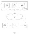
- FIG. 1is a block diagram of a system in accordance with the invention.
- FIG. 2is a flow diagram that illustrates operation of the data manager of FIG. 1 in authenticating.
- FIG. 3is a flow diagram that illustrates operation of the uploader of FIG. 1 in processing a product device.
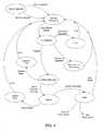
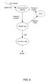
- FIG. 4is a state diagram that illustrates operation of the uploader of FIG. 1 .
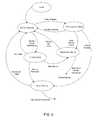
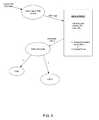
- FIG. 5is a state diagram that illustrates the device detection operation shown in FIG. 4 .
- FIG. 6is a state diagram that illustrates operation of the standby operation shown in FIG. 4 .
- FIG. 7is a state diagram that illustrates the authentication operation shown in FIG. 4 .
- FIG. 8is a state diagram that illustrates the extract logs operation shown in FIG. 4 .
- FIG. 9is a state diagram that illustrates the upload operation shown in FIG. 4 .
- FIG. 10is a state diagram that illustrates the Done operation shown in FIG. 4 .
- FIG. 11is a screen shot for a computer accessing the network data manager illustrated in FIG. 1 .
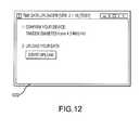
- FIG. 12is a screen shot for a computer with a single device connected while accessing the network data manager illustrated in FIG. 1 .
- FIG. 13is a screen shot for a computer with multiple devices connected while accessing the network data manager illustrated in FIG. 1 .
- FIG. 14is a screen shot for a computer at the start of data log uploading while accessing the network data manager illustrated in FIG. 1 .
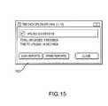
- FIG. 15is a screen shot for a computer after successful uploading to the network data manager illustrated in FIG. 1 .
- FIG. 16is a screen shot for a computer accessing the network data manager that shows automatic cancellation of the data link.
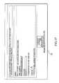
- FIG. 17is a screen shot for a computer accessing the network data manager that shows automatic logout of an inactive user.
- FIG. 18is a flow diagram that illustrates operation of the system illustrated in FIG. 1 for data sharing with third parties.
- FIG. 19is a screen shot for a computer accessing the network data manager that shows data sharing with third parties.
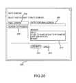
- FIG. 20is a screen shot for a computer accessing the network data manager that shows data entry of an email address for data sharing.
- FIG. 21is a screen shot for a computer accessing the network data manager that shows selection of a data sharing invitee from a list.
- FIG. 22is an illustration of an exemplary infusion pump device in which the features described herein are incorporated.
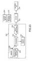
- FIG. 23is a block diagram of the device illustrated in FIG. 22 .
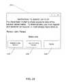
- FIG. 24is a screenshot of an invitation message sent in response to a user request to share data with a third party.
- FIG. 1is a block diagram of a system in accordance with the invention that shows a product device 102 that communicates over a computer network 104 with a data system 106 .
- the product devicecommunicates with a network data manager 108 through an uploader application 110 .
- the uploaderis a computer software application that performs operations of authentication and data transfer between the product device 102 and the network data manager 108 .
- the uploadertypically is installed at a host computer 112 .
- the uploader application 110manages, e.g., product device authentication, transfer of product device data from the product device to the network data manager, and receipt of stored product device data from the data manager. That is, the uploader application is a network client of the network data manager.
- Product device datamay include, for example, operational details of the device, information regarding a history of transmitted or received data, data associated with substances or fluids such as on-board and dispensed volume, composition, lot number, and other characteristics, as well as operational parameters relating to transmitting, dispensing or releasing such substances or fluids.
- the uploader application 110 of the system of FIG. 1communicates with the data manager 108 while executing on a device having a processor, memory, display, and network communication interfaces sufficient for communication with the network data manager. Other computer resources for more convenient operation may be provided as well.
- the uploader applicationis hosted on the host computer 112 and the host computer is a client device to the network data manager.
- the host computercommunicates with the product device 102 for product data including data logs, which the host computer transfers to the network data manager 108 .
- the host computer 112 and product device 102 and uploader application 110comprise a system for transferring data over the computer network 104 .
- the uploader application 110can reside on, e.g., the product device, and in that situation the product device can communicate directly with the network data manager 108 over the network 104 .
- the host computer 112 and the product device 102are integrated together into a single device that hosts the uploader application 110 and is a client device to the network data manager. That is, the integrated host computer and product device comprise a system having sufficient resources, such as a processor, memory, input/output components, and network communication interfaces, to carry out the functions described herein.
- the network data manager 108 of the data system 106may receive a request message for access to data stored at a data storage facility 114 .
- the data storage facilityis adapted to store large amounts of data for access by computers and may comprise, for example, multiple disk drives, solid state disk drives, semiconductor memory, and/or other suitable storage devices.
- the data stored at the data storage facility 114may comprise all or portions of data transferred from the product device 102 , including the product device data noted above.
- the request messageincludes an access requestor identifier, to identify an owner of a product device or to identify a third party who is neither the owner of the product device nor the network data manager.
- the third partymay comprise, for example, a physician and/or an authorized member of the physician's staff, a representative from a partner device producer, a clinician, a certified diabetes educator (CDE), and the like.
- CDEcertified diabetes educator
- the network data managerdetermines that the access requestor identifier is associated with a data record that identifies a product device that has a registration record or that otherwise identifies an authorized party, such association may be used to confirm that the access requestor has been authorized.
- the data record to identify authorized partiesmay be generated through a process such as a prior registration process with the data storage facility 114 through the network data manager 108 . That is, a registration record for a product device 102 includes identifiers of any product device owners or third parties who have registered with the network data manager or have otherwise been previously authorized to gain access to data of the product device.
- third partiesmay register with the network data manager in response to an invitation initiated by a product device owner and sent to the third party.
- the network data managergenerates an invitation request pop-up window to a user who has logged in to their account and who requests inviting someone with whom the user will share data.
- the third partyresponds to the invitation by providing registration information to the network data manager, which stores the registration information in a data record that is associated with the product device 102 .
- the registration data recordis stored in the data storage 114 along with other information relating to the product device, such as product model number, serial number, name and address of purchaser (owner and/or user) of the product device, and the like. Additional data that may be maintained in the registration data record will depend on the product device.
- additional data in the registration data recordmay relate to therapy settings for the pump, such as insulin delivery settings, daytime settings, night settings, dosage size and frequency, and the like, as described, for example, in U.S. patent application Ser. No. 12/846,688 to DiPerna et al. filed Jul. 29, 2010.
- Other data that may be acquired and stored in the registration recordincludes the email address used as the user name to login to the network data manager, the password used to authenticate the user, a secret question (e.g. selected by the registrant from a list) and the answer to the secret question, date of birth.
- the systemalso maintains registration information from the caregiver or the parent, such as first name, last name, email address, and date of birth for the caregiver or parent. Some or all of the information described above may be maintained in the registration information, depending on whether the registrant is a user of the product (patient) or a third party.
- the network data manager 108After the network data manager 108 determines that the access requestor is authorized, the network data manager transmits a data link to the requesting client device, wherein the data link provides access to the data record by the client device over the computer network 104 but automatically expires, canceling access.
- the data linkmay be active only for a predetermined time period, such that access to the data record is halted upon expiration of the predetermined time period.
- the data linktypically comprises an Internet link that is accessed via an Internet browser application executing on the client device. Accessing the Internet link takes the browser application to a Web site 116 in accordance with the authorization of the data manager 108 .
- FIG. 16shows a pop-up window 1602 that appears in a browser if a user is accessing the network data manager through an Internet browser application and has attempted to access the data link after it has been canceled.
- Other means of providing automatic canceling of the data linkmay be provided, such as requiring a supplemental authentication step to remain active, where the supplemental authentication step may require entering a password, providing biometric input, or the like.
- the automatic canceling of the data linkhelps limit the chance of unauthorized access or viewing, such as where a legitimate user gains access through a desktop computer and then leaves the computer unattended.
- FIG. 17shows a logout window 1702 such as would be displayed after a user has been inactive, after first logging into the network data manager facility. The logout action of FIG. 17 helps to make more efficient use of system resources, so that users who are idle can be logged out to make room for other users who are attempting to gain access to the network data manager.
- FIG. 2illustrates the operation of the network data manager 108 illustrated in FIG. 1 .
- the illustrated operationbegins at the flow diagram box numbered 202 , where the network data manager receives a data request from a client device.
- the data requestincludes an access requestor identifier.
- the network data managerdetermines if the data request comes from a registered user (such as an owner of a product device who is associated with a registration record for the product device) or if the data request comes from an authorized partner (such as, in the context of a medical device such as an infusion pump or the like, a physician, physician's authorized representative, personnel at an authorized medical clinic, etc., who has replied to an access invitation message associated with the product device and who has registered with the network data manager). If either of these conditions is true, then access can be granted. Thus, if the data request is from an authorized user, then at box 206 the network data manager can receive upload data from the client device, and normal operation then continues.
- a registered usersuch as an owner of a product device who is associated with a registration record for the product device
- an authorized partnersuch as, in the context of a medical device such as an infusion pump or the like, a physician, physician's authorized representative, personnel at an authorized medical clinic, etc.
- the received upload datamay comprise any data capable of being transferred from the device, including the product device data described above. If the data request is from an authorized partner, then the network data manager will grant access in response to the data request and normal operation then continues. If neither authorized situation applies, then the data manager will not grant access in response to the data request.
- the data request from an authorized usermay be automatically initiated by the device upon becoming activated or achieving network access. For example, when the device gains network data access, it may automatically send a message to the network data manager that requests access or login to the account associated with the device.
- the messagemay take the form of an email message or a mobile telephone text message or message forwarded from a social network facility, or the like.
- the data request from an authorized partnermay comprise a message to the network data manager that initiates a login process by the authorized partner to log in to their own account. Again, the message may take the form of an email message or a mobile telephone text message or social network message or the like.
- the authorized partnertypically must accept an invitation from an authorized user to establish an account and share the user's data.
- the authorized partnercan view a list of patients from whom they have received data sharing invitations and may choose a patient's name from the list, upon which they are granted access to view the data.
- the data requestwill typically be received through the Web site 116 ( FIG. 1 ), which can initiate error processing or otherwise provide the data requestor with options to provide additional information to become registered and gain access, where appropriate.
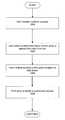
- FIG. 3illustrates the operation of the uploader application 110 illustrated in FIG. 1 .
- the uploader applicationis installed in a host device, such as a desktop or laptop computer, mobile computing device such as a mobile phone, tablet computer or the like, or the uploader application 110 may be installed in the product device itself.
- the first operation illustrated in FIG. 3is represented by the flow diagram box numbered 302 , which shows the uploader operation to authenticate the product device.
- the operation to authenticate the product deviceis initiated by launching the uploader application, which may be manually launched by a user of the uploader application, or may be automatically launched.
- Automatic launch of the uploader applicationmay occur in response to connecting the product device to the host device, in the case of a separate product device and a host device that executes the uploader application, or automatic launch may occur in response to a suitable network connection that becomes available to the uploader application.
- Automatic launch in response to a suitable network connectionmay comprise, for example, a network interface of the host device or product device that detects a broadband connection such that relatively high speed data communications with the network data manager will be supported. For example, upon coming within range of a broadband “WiFi” network, the device may attempt to establish a communication session with the network and, upon logging on, the uploader application 110 may be launched.
- the automatic uploader launchmay be in place of, or in addition to, the automatic data request message described above.
- the uploadersends a data request message to the network data manager, providing an access requestor identifier.
- the access requestor identifiermay comprise, for example, the product device serial number and/or product number or other indicator of the device's authenticity, registration, and ownership data, an email address and/or password combination, user name and/or password combination, or other login identifier information by which registered users may be identified, including combinations thereof. Any combination of one or more of such information may be used as the access requestor identifier to uniquely identify a person who is requesting access to the data of the device that has been transferred to the network data manager.
- the network data managerdetermines that the access requestor identifier is associated with a data record that identifies a product device having a registration record
- the data requestoris authenticated. That is, the network data manager identifies product user registration data that is associated with the login information and that is associated with the product device.
- the network data managerthen sends an access grant message to the client device to confirm that access to the stored data has been granted.
- data logsare extracted from the product device, as indicated by the flow diagram box numbered 304 .
- the product devicestores a log of operational information and records an index of upload events to keep track of the last uploaded data log with changed data. For example, in the case of a product device that is a portable medicament infusion device such as a portable insulin pump, after an upload occurs, an index number is increased by one incremental value when a change is made to the data log.
- the uploader applicationwill not transfer data logs if the index number is not greater than the index number of the last upload event. In this way, duplicate data log records will not be extracted and will not be transferred to the network data manager.
- a portable medicament infusion devicesuch as a portable insulin pump
- the pumprecognizes that the delivery is a change in its operational history, and records that event in the data log as a change.
- the time and dosage amountis recorded in the data log and the data log index number is incremented.
- another changesuch as a dose delivery, or a change to device parameters such as dosage times or the like, then the data log index number is again incremented.
- the devicediscriminates between events that should initiate a log index increment and those events that should not. For example, uploading data from the device, and applying electrical power to the device, are examples of detected events that initiate a log index increment by the device.
- Entering values on the device keypad but not entering or submitting the values that would otherwise proceed with processingis an example of an event that would not initiate a log index increment.
- the deviceis adapted to increment the log index in response to events that have been determined to be worthy of recording at the network data manager.
- the current index numberwill be different from the index number at the time of the last successful upload, and therefore an upload event will occur. That is, after device authentication, the network data manager sends the last index number that the network data manager received in an upload, so that the uploader application only extracts data based on the index number it received from the network data manager.
- the data log beginning from after the previously uploaded data log at the old index number, through the data log at the current index number,will be transferred to the network data manager. If the current index number is the same as the index number of the last upload, then the uploader application recognizes that no data change has occurred since the last upload, and the uploader application will not perform an upload.
- the network data managerkeeps track of the index numbers on the device and sends the index number of the last uploaded data to the device so that the uploader application extracts data from the data log for sending to the network data manager based on the difference between in index number received from the network data manager and the current index number in the data log of the device.
- the changed datais extracted for transfer to the network data manager. This operation is represented by box 306 in FIG. 3 .
- the extracted data log and corresponding change itemsare then transferred to the network data manager.
- the network data managerAfter a successful upload is received at the network data manager, the network data manager provides a confirmation that produces a window display at the client device (i.e. host device or product device) that permits the user to request access to a data record for viewing of a report, or printing of a report, or both.
- the window displaytypically comprises a data link that is sent from the network data manager to the client device, such that the data link can be viewed with an Internet browser application.
- Viewing the data linkprovides access to the data record by the client device over the computer network until the data link is automatically canceled, as noted above. That is, the browser is unable to view the data record through the data link after the data link has been canceled, such as after a predetermined time period has expired.
- Thisprovides data security so that only authorized users may gain access to the data records associated with a product device. If the data link is canceled after a predetermined time period, then the predetermined time period may be set in accordance with privacy or other security needs. A time period of ten minutes should suffice under most circumstances, to provide a user with time to access and view or print the reports.
- the network data managerreceives any requested data record viewing or printing request from the client device via the data link, and processes the request to deliver the requested information, either a window view or a print file. Normal operation then continues.
- FIG. 4shows that operation of the uploader application begins in the Device Detection state and remains there until a device detected or device removed event.
- the device detected eventoccurs when a product device 102 is connected to the host computer 112 or the product device 102 , or otherwise gains access to the network 104 (see FIG. 1 ).
- the uploader applicationmay remain in the Device Detection state until the product device integrated with the uploader application gains network communication, or until the product device is connected to a host device, which may or may not have an existing network communication.
- a device removed eventoccurs when the product device 102 is disconnected from the host computer 112 or the product device otherwise loses access to the network 104 .
- the state of the uploader applicationchanges to the Standby Processing state, in which the uploader application remains until the user initiates an “upload” operation.
- the deviceincludes an optional GUI (graphical user interface) display that is produced by the uploader application for product devices containing GUI displays, then the user may select an upload operation from the GUI display window.
- the upload operation selectionmay be accomplished via a linked icon or button of the GUI display.
- the GUI display with selectable upload operationmay be produced on a display of the host device or on a display of the product device, or both.
- the state of the uploader applicationchanges to Authenticate, at which time the uploader application initiates authentication processing.
- the authentication processingmay result in one of three outcomes: (1) the product device is not registered with the network data manager, (2) the product device is not a recognized device that is maintained in the network data manager database, or (3) the product device is recognized and is registered (a “passed” outcome).
- the processing to determine the authentication outcomeinvolves determining if the product device is associated with a registration record that identifies a registered user of the product device, in which case the authentication passes, and otherwise indicating that a registration process must be completed for the product device in response to determining that the product device is not associated with a registration record that identifies a registered user of the product device, or indicating that the product device is not recognized as a valid device for the uploader application.
- the state of the uploader applicationchanges from the Authenticate state to the Error state, and uploader application processing subsequently returns to the Standby Processing state with an appropriate error message (e.g. “Product not recognized”) that is generated in the Error state.
- the state of the uploader applicationchanges from the Authenticate state to the New Account/New Device state, in which the uploader application provides an appropriate message such as a request to the user to register the product device.
- the usermay be required to establish a user account after verifying data relating to user patient status, payment, and the like.
- the uploader application processingsubsequently returns to the Standby Processing state, once registration is complete. The user may then request the upload operation.
- the state of the uploader applicationchanges from Authenticate to Extract Data Logs. If the data logs are successfully extracted as described above in connection with FIG. 3 , then the uploader application sends the extracted data logs to the network data manager and the state of the uploader application changes to Upload. If the extraction of data logs fails, such as if communication with the product device is lost, then the state of the uploader application changes from Extract Data Logs to Extraction Error, in which case an appropriate data message error message (e.g. “Extraction Error”) is generated and the state of the uploader application changes to the Standby Processing state to await the next user operation.
- Extraction Erroran appropriate data message error message
- the state of the uploader applicationis in the Upload state, where the outcome of the state is either a successful upload or a failed upload. If the upload is successful, then the state of the uploader application changes to Done, and the user is presented with a display that offers choices between obtaining reports and completing operations. For example, FIG. 3 shows three choices comprising (1) view reports, (2) print reports, or (3) selecting Done. Selecting “view reports” permits the user to view a report online through the display of the device or through a Web browser, selecting “print reports” permits the user to print a report at a connected printer, and selecting “done” results in the state of the uploader application changing to the Standby Processing state, to await the next user operation.
- the display of post-upload selectable operationsmay be produced on a display of the host device or on a display of the product device, or both. If the upload operation failed, then the state of the uploader application changes to indicate an upload error, an error message is displayed, and the state of the uploader application changes to the Standy Processing state.
- a successful device authentication and a successful data log extractionresults in a state of “successful upload” and the user is presented with a “successful upload” display that offers choices between obtaining reports and completing operations.
- an embodiment of the systemguards against a “spoofed” device or other attempt at establishing communication by an unauthorized person with an unauthorized device.
- the “device”may actually be a computer being used to mimic a device, for the purpose of surreptitious or nefarious data access.
- the operation in FIG. 4 of the “Upload” state with output of “Upload successful”may be configured so that the device is confirmed before the “successful upload” display is provided to the device.
- Confirming the devicemay comprise sending a request for confirmation information to the device and then validating the received response.
- the network data managermay request the device to provide a randomly selected data record from a randomly selected time in the history of the device operation.
- the network data managercan check the response to ensure that it contains correct information.
- the network data managercan check for correctness because the network data manager has a record of the device history, via prior data uploads from the device, and therefore the data records received from the device in response to the confirmation request should be identical to the corresponding data record previously received at the data manager from the device for the selected data record and selected time. If they are identical, then the response to the confirmation request is validated.
- the data managermight request that the device provide its bolus setting at 12:30 pm on Aug. 1, 2012. The data manager will have previously received exactly that data via a previous upload from the device. If the device seeking to establish communication is a legitimate device and is the same device from which the prior upload was received, then the device seeking to establish communication should be able to provide the requested information. If the device does not provide the correct information, the data manager will conclude that the device is an imposter and will not confirm the device, and therefore the user of the device will not be presented with a “successful upload” display and will not be offered a choice between obtaining reports and completing operations.
- the uploaded data received at the network data manager from the devicewill comprise a relatively large body of data from which the network data manager may choose for confirmation requests.
- the network data manageris free to request confirmation data from the device according to any and all data available to the network data manager and to a legitimate device.
- the body of data from which the network data manager may selectcan comprise all the operating history data stored at the device, which will be determined by the storage capacity of the device itself.
- the initial communication with the devicemay take place upon manufacturing, with an initial set of upload data from which the network data manager can select for confirming requests. The network data manager can then select from the body of data with which the device has been initiated. Alternatively, the initial communication may not include storing an initial set of data into the device.
- the initial confirmation request from the network data managermay involve administrative information known only to a legitimate device, such as device serial number, production date and time, power-on date and time, and the like.
- the window displaytypically comprises a data link that is sent from the network data manager to the client device, such that the data link can be viewed with an Internet browser application. Viewing the data link provides access to the data record by the client device over the computer network for a predetermined time period, such that access to the data record is halted upon expiration of the predetermined time period.
- FIG. 5illustrates the operation of the uploader application in the Device Detection state shown in FIG. 4 .
- the uploader applicationbegins in an Initial state, waiting for notifications regarding device registration. After a brief wait in the Initial state, involving any system activities for launch of the uploader application, the uploader application changes state to the Wait for Devices state.
- a default configuration for the uploader application to communicate with product devicesis to communicate with such devices via a cable connection. Therefore, the uploader application remains in the Wait for Devices state until it receives a notification of a “device connected” event, at which time the state changes to Check Event, or the uploader application automatically changes to a Poll Attached Cables state after a one second time interval of waiting.
- An alternative to a cable (electronic, optical or otherwise) connectionis for the product device to be connected to the host device via wireless connection, such as by infrared (IR) transmission, or by radio frequency (RF) transmission.
- the RF connectionmay be through, for example, particular protocols such as “Bluetooth” or “WiFi” or the like.
- the connection from the product device to the network, or from the host device to the network, or bothmay be either wired or wireless.
- the uploader applicationreturns to the Wait for Devices state if no new connected product devices are found. That is, the uploader application is capable of communicating with multiple product devices that are simultaneously connected to the client device, and therefore the cable polling is with reference to checking for any new devices that were not previously detected since the time of last upload. If the Poll Attached Cables state finds a new device, then the state changes to the Check New Device state. If the Poll Attached Cables state determines that a previously connected device is now missing, then the state changes to the Check Device state.
- a notification to initiate the statemust have related to either a newly connected device, or a removed device. If the event related to a newly connected device, then the uploader application state is changed to the Check New Device state. If the event related to a removed device, then the uploader application state is changed to the Check Device state. If the event notification was not recognized, or if the product device was not recognized, then the uploader application returns to the Wait for Devices state.
- the Check New Device statehandles uploader application processing in the case of a newly connected device. If the newly connected device is recognized as a valid device for operation with the uploader application, then the state changes to the Standby Processing state (see FIG. 4 ). If the newly connected device is not recognized as a valid device, then the state of the uploader application returns to the Wait for Devices state.
- the Check Device statehandles uploader application processing in the case of a missing or removed product device. If the missing or removed device is recognized as a valid device for operation with the uploader application, then the state changes to the Standby Processing state (see FIG. 4 ). If the missing or removed device is not recognized as a valid device, then the state of the uploader application returns to the Wait for Devices state.
- any drivers, program logic, communication protocols, and the like necessary for communication between the product device and the uploader applicationmay be included in the cable itself.
- Such drivers, program logic, communication protocols, and the like necessary for communicationmay otherwise be provided with the product device itself, such as in the case where the client device (host device) and product device are provided in a single integrated device.
- FIG. 6illustrates the operation of the uploader application in the Standby Processing state shown in FIG. 4 .
- the Standby Processing statehandles processing of the uploader application while it waits for a device to be connected.
- FIG. 11shows a window 1102 with a message that indicates the user of the uploader application should connect a product device to begin operation.
- the “Start Upload” button in the FIG. 11 displayis grayed out to indicate that the upload operation is not available, prior to detecting a supported device.
- the display window for the uploader applicationis changed so that the new device is added to a drop-down menu in the display window, as indicated by the Add Device state in FIG. 6 .
- a displaysuch as illustrated in FIG. 12 is produced.
- FIG. 12shows a window 1202 in which the “Start Upload” button is highlighted, to show that it can be selected by the user.
- the newly connected deviceis a second or subsequent device to be detected, then the newly connected device is added to a drop-down menu is produced.
- FIG. 13shows a window 1302 in which the device is listed, and other previously-connected devices can be viewed in a drop-down list of the window.
- the “Start Upload” buttonis available for selection by the user, to initiate upload processing. If a device is detected as removed, then the display window for the uploader application is changed so that the removed device is deleted from the drop-down menu in the display window, as indicated by the Remove Device state indicating that the GUI display is updated.
- FIG. 7illustrates the operation of the uploader application in the Authenticate state shown in FIG. 4 .
- the Authenticate statehandles processing of the uploader application after the user of the uploader application has selected “Start Upload” from the GUI display.
- the uploader application statechanges to the Extract Serial & Model Number state.
- the state of the uploader applicationis changed to Authenticate Device, at which time the extracted data is provided to the network data manager, such as via a Web service communication.
- the network data managerperforms the Web service and validates the extracted product device serial number and model number, as indicated by the Web Service state.
- the response from the network data managerin the form of a return Web service outcome, will be one of four conditions: (1) the extracted model number was not recognized, (2) the model number and serial number were recognized, but there is no corresponding registration record, (3) the model number and serial number were recognized, but correspond to an inactive (i.e., not released or sold) product device, or (4) the model number and serial number were recognized as being associated with a valid registration, and for that registration a corresponding last uploaded index number is being returned.
- the response from the network data manageris checked.
- authentication outcomes (1) and (3)extracted device data not recognized, an error display message is generated as the output of the Authenticate state, and the state of the uploader application changes to the Standby Processing state for display of the error message (see FIG. 4 ).
- authentication outcome (2)extracted data recognized but no registration located, the state of the uploader application is changed to the New Account/New Device state (see FIG. 4 ).
- authentication outcome (4)device data and registration passed, the uploader application is ready to extract the data logs from the product device, and therefore the state of the uploader application is changed to the Extract Logs state (see FIG. 4 ).
- FIG. 8illustrates the operation of the uploader application in the Extract Logs state shown in FIG. 4 .
- the Extract Logs statehandles processing of the uploader application when the most recent data logs are to be extracted from the product device and provided to the network data manager.
- the uploader applicationreceives a “passed” indication from the network data manager while in the Authenticate state, it receives a network address for a data link to be used in connection with the upload operation.
- the network addressmay comprise a Uniform Resource Locater (URL) for a network location on the Internet, to which an Internet browser application of the client device may be pointed for communications. That is, the URL comprises a data link that provides access to a data storage facility.
- the access via the data linkis available over the computer network for a predetermined time period such that access is halted upon expiration of the predetermined time period.
- URLUniform Resource Locater
- the uploader applicationchanges to the Extract Device Settings state and attempts to determine device settings for the product device.
- Such settingsmay comprise, as noted previously for the case of a portable insulin pump device, dosage and duration settings for the pump during daytime, such settings for the pump during night time, and the like. If such information cannot be successfully retrieved from the product device, then an error condition results, initiating an “extraction failed” data message, and the state of the uploader application is changed to an Error state before proceeding to the Standby Processing state (see FIG. 4 ).
- the uploader applicationchanges to the Extract Logs state and attempts to retrieve data logs from the product device.
- data logsinclude operational history of the device and provide a record of dosage and any difficulties in operation since the last upload event.
- the Convert stateinvolves processing the extracted data, which is typically a text string alphanumeric flat data file, to convert the extracted data into a form that is more readily usable by the network data manager and more usable by other applications and users.
- conversion of the extracted datais from a text format (e.g. ASCII) to a format such as XML (extensible markup language).
- ASCIItext format
- XMLextensible markup language
- FIG. 9illustrates the operation of the uploader application in the Upload state shown in FIG. 4 .
- the Upload statehandles processing of the uploader application for transmitting the extracted data logs to the network data manager.
- the initial operation in the Upload stateis for the uploader application to receive an indication that the extracted data logs have been successfully retrieved from the product device, at which time the state of the uploader application changes to the Send Logs state.
- the uploader applicationsends the extracted data logs, in their converted XML format, to the Web service at the network data manager.
- the extracted data logsare received, and any errors in the data transfer may be detected, such as through cyclic redundancy code (CRC) processing and the like, and a data link is determined for the uploader application.
- CRCcyclic redundancy code
- the network data managerWhen the network data manager completes its processing, it sends an upload response back to the uploader application, and the uploader application changes state to the Check Response state, as indicated in FIG. 9 .
- the uploader applicationcan display a progress indication in the upload display window.
- An exemplary progress indication windowis shown in FIG. 14 , which shows the upload window 1402 with a horizontal window with a bar display for progress, and also provides a “Cancel Upload” button for the case in which the user wishes to halt the upload operation.
- the response from the network data managerindicates either (1) a successful upload, or (2) a failed upload. If the upload was (1), successful, then the uploader application receives the data link and changes state to the Done state (see FIG. 4 ). If the upload was (2), a failure, then the uploader application receives an “upload failed” indication and the state of the uploader application changes to the Error state to produce a suitable error message and then changes to the Standby Processing state for display of the error message (see FIG. 4 ).
- FIG. 9illustrates the operation of the uploader application in the Done state shown in FIG. 4 .
- the Done statehandles processing in the uploader application for a successful operation from the Check Response state and generates an appropriate display.
- the displayshows an “upload successful” message and waits for further user selection input. That is, the operation in the Done state provides the user with a display having options for (1) viewing a report of a data record, or (2) printing a report of a data record, or for (3) terminating operation of the uploader application.
- three display buttons for selecting each of the three optionsare provided.
- An exemplary display of the buttonsis illustrated in FIG. 15 in an Upload Successful window 1502 .
- the uploader applicationconnects to a data link at a first URL for viewing of a data record report corresponding to the authenticated product device for which an upload was just completed. If the user selects the “Print Reports” button, then the uploader application connects to a data link at a second URL for printing of a data record report corresponding to the authenticated product device for which an upload was just completed. If the user selects the “Close” button, then the uploader application closes the network data connection and halts operation.
- FIG. 18is a flow diagram that illustrates computer operations that implement the feature.
- FIG. 18shows operations of the exemplary embodiment in which a user initiates the invitation process by selecting an invitation process.
- a useraccesses the network data manager through a Web browser application.
- FIG. 19shows a Settings window 1902 after a Sharing tab 1904 has been selected by the user to provide the user with a display button 1906 from which the user may initiate the invitation process.
- Third parties with whom the user has already achieved data sharingare shown in the Sharing display of FIG. 19 .
- the window 1902shows details of the respective third party invitation status and sharing information.
- FIG. 20shows an invitation pop-up window 2002 that is displayed in the user's browser after the user has selected “Invite Someone” from the display of FIG. 19 .
- FIG. 20shows that the user is presented with two options, to provide contact information for an invitee via a tab 2004 , or to select an invitee from a data listing via a tab 2006 .
- FIG. 20shows details for the user to provide contact information, which is the default action in the illustrated embodiment.
- FIG. 20shows a data entry box 2008 in which the user may enter contact information, such as an email address, for a third party to whom the user wishes to send an invitation for sharing data from the user's device.
- a message box 2010is also provided, with text for a default message to the invitee, with the option for the user to modify the message text as desired.
- the usermay select the Send Invite button 2012 to send the invitation or may use the cancel link 2014 to cancel the invitation operation.
- FIG. 21shows an invitation pop-up window 2102 that is displayed in response to the user selecting “Search for Provider” tab 2006 in the default invitation pop-up window 2002 ( FIG. 20 ).
- FIG. 21shows that a list of third party providers is generated in response to selecting the search tab 2006 .
- the listmay be populated by, for example, search information inserted into a search box 2104 followed by initiating a search of available third parties by selecting a search button 2106 .
- the available third party data over which the search is conductedmay be pulled from a directory of third parties, or data from a contact list of the user or of another person or entity, or may comprise a list of registered third parties, or the like.
- FIG. 21shows that the user has selected one third party by selecting a tick box 2108 corresponding to the third party.
- the usermay select the Send Invite button 2110 to send the invitation or may use the cancel link 2112 to cancel the invitation operation.
- An example of the invitation message sent by the network data manager and received by the inviteeis illustrated in FIG. 24 , which is a screenshot of the invitation message 2402 .
- the third party who receives the invitation to share datamay reply to the message and become authorized to share data.
- the third party inviteemay comprise, for example, a physician and/or an authorized member of the physician's staff, a representative from a partner device producer, a clinician, a certified diabetes educator (CDE), and the like.
- the inviteemay be requested to provide contact information and any other data for sharing data.
- the invitee's datamay be used to generate a data record with which the third party will be associated such that the data record includes information about the user and the user's device, thereby generating a registration record that identifies the third party as an authorized party for data sharing.
- the exemplary invitation message of FIG. 24shows that a recipient may be provided with selectable display buttons that give the recipient the option to enter their data and establish a new account 2404 , or may login to their account if they are already registered 2406 , or may decline to proceed further 2408 .
- FIGS. 22 and 23illustrate an infusion pump device 2200 in which the features described above are incorporated. Details of constructions will be described for the infusion pump device.
- FIG. 22is an illustration of an embodiment comprising an infusion pump device 2200 that can perform the functions described herein.
- FIG. 23illustrates a block diagram of the infusion pump device 2200 .
- the infusion pump device 2200can include an infusion cartridge 2216 having an infusion set connector 2218 , and optionally a glucose meter 2220 . Either the infusion cartridge 2216 or the glucose meter 2220 can be functionally and interchangeably inserted in a receiving slot 2219 of the infusion pump device.
- the infusion pump device 2200can include memory 2256 , transmitter/receiver 2258 , processor 2260 , output/display 2262 , and drive mechanism 2264 .
- the housing 2228 of the pump device 2200can be functionally associated with an interchangeable and removable glucose meter 2220 or an infusion cartridge 2216 .
- the infusion cartridge 2216can have an outlet 2252 that can be connected to an infusion set connector 2218 and an infusion set 2254 .
- the pump devicemay include a spool 2234 of a delivery mechanism for delivering medicaments such as insulin.
- the housing 2228 of the infusion pump device 2200can each be of any suitable shape and size.
- the housing 2228may be extended and tubular, or in the shape of a square, rectangle, circle, cylinder or the like.
- the housing 2228may be dimensioned so as to be comfortably associated with a user and/or hidden from view, for instance, within the clothes of a user.
- the housing 2228 of the pump device 2200may have a width of about 2.5 inches to about 3.5 inches, a height of about 1 inch to about 2 inches and a thickness of about 0.2 inches to about 0.6 inches.
- the materials of the housing 2228may vary as well.
- housing 2228 of the pump device 2200may be a very water-tight, plastic housing that is glued together permanently.
- the infusion pump device 2200may include an output/display 2262 .
- the type of output/display 2262may vary as may be useful for particular application.
- the type of visual output/displaymay include LCD displays, LED displays, plasma displays, OLEO displays and the like.
- the output/display 2262may also be an interactive or touch sensitive screen having an input device such as a touch screen, a capacitance screen, a resistive screen or the like.
- the output/display 2244 of the pump device 2200may be an OLEO screen or an LCD screen or a capacitance touch screen.
- the pump device 2200may additionally include a keyboard or other input device known in the art for data entry, which may be separate from the display.
- the output/display 2262may also include a capability to operatively couple to a secondary display device such as a laptop computer, mobile communication device such as a smartphone or personal digital assistant (PDA), or the like.
- PDApersonal digital assistant
- the pump devicemay have wired or wireless communication capability such as for the sending and receiving of data as is known in the art.
- the wireless capabilitymay be used for a variety purposes, including updating of any software or firmware for the processor of the device.
- the wireless communication capabilitymay vary including, e.g., a transmitter and/or receiver, radiofrequency (RF) transceiver, WIFI connection, infrared or Bluetooth® communication device.
- the wired communication capabilitymay also vary including, e.g., USB or SO port, flash drive port, or the like.
- the pump device 2200has a network communications block such as a transmitter/receiver 2258 having a radiofrequency (RF) transceiver, that allows the pump device to communicate with other electronic devices and to be used interchangeably without loss of data or information during an infusion protocol with a single infusion cartridge 2216 .
- Datamay be transferred between the processor of the pump device and a second electronic device by radio signal, optical transmission, or any other suitable means.
- the pump device 2200may be used as stand-alone device as well.
- the infusion pump device 2200may also include GPS functionality, phone functionality, warning and/or alarm programming; music storage and replay functionality, e.g., an MP3 player; a camera or video mechanism; auto scaling capabilities, and/or one or more video type games or other applications developed by third parties for use thereon.
- the pump device 2200may also include an accelerometer, for instance, which may be used for changing presented estimates, wherein instead of scrolling through a menu of options or using a numerical keypad, values can be input or changed via the accelerometer, such as by gesturing with or otherwise shaking the device.
- the pump device 2200has a processor 2260 that functions to control the overall functions of the device.
- the processor 2260may include programming that functions to control the respective device and its components.
- the processor 2260may communicate with and/or otherwise control the drive mechanism, output/display, memory, transmitter/receiver and the like.
- the processor of the pump devicemay communicate with the processor of other electronic devices, for example, through the transmitter/receiver.
- the processormay include programming that can be executed to control the infusion of insulin or other medicament from the cartridge, the data to be displayed by the display, the data to be transmitted via the transmitter, etc.
- the processormay also include programming that allows the processor to receive signals and/or other data from an input device, such as a sensor that senses pressure, temperature, and the like, that may be included as a part of the device or used in conjunction therewith.
- the processor 2260may receive signals, for instance, from a transmitter/receiver on a blood glucose monitor and store the signals in the memory.
- the processor 2260may also include additional programming to allow the processor to learn user preferences and/or user characteristics and/or user history data, for instance, to implement changes in use suggestions based on detected trends, such as weight gain or loss; and may include programming that allows the device to generate reports, such as reports based upon user history, compliance, trending, and/or other such data.
- pump device embodiments of the disclosuremay include a “power off” or “suspend” function for suspending one or more functions of the device, such as suspending a delivery protocol, and/or for powering off the device or the delivery mechanism thereof.
- two or more processorsmay be used for controller function of the pumps, including a high power controller and a low power controller used to maintain programming and pump functions in low power mode in order to save battery life.
- the pump device 2200may include a memory device 2256 .
- the memory device 2256may be any type of memory capable of storing data and communicating that data to one or more other components of the device, such as the processor.
- the memorymay be one or more of a Flash memory, SRAM, ROM, DRAM, RAM, EPROM, dynamic storage, and the like.
- the memorymay be coupled to the processor and configured to receive and store input data and/or store one or more template or generated delivery patterns.
- the memorycan be configured to store one or more personalized (e.g., user defined) delivery profiles, such as a profile based on a user's selection and/or grouping of various input factors (as described below); past generated delivery profiles; recommended delivery profiles; one or more traditional delivery profiles, e.g., square wave, dual square wave, basal and bolus rate profiles; and/or the like.
- the memorycan also store user information, history of use, glucose measurements, compliance, an accessible calendar of events, and the like.
- the memory 2230 of the pump devicemay be about 200 kB up to about 3 GB.
- the pump device 2200may include a power charging mechanism in some cases, such as a USB port, induction charger, or the like.
- the power charging systemmay be used to charge a power storage cell such as a rechargable battery of the pump device. Some embodiments may use a rechargable battery such as a NiCad battery, LiPo battery, NiMH battery or the like.
- the power charging mechanism 2268may be a USB port. As such, all data may be kept in the pump device for quick and easy downloading of data to a computer, other pump device, network, etc. using the USB port.
- the USB portmay also provide the pump device 2200 with power charging.
- the power charging mechanism 2268may be an induction charging device 2270 .
- the uploader application described herein, as well as the network data manager and other components whose operation is described herein,may be provided as a computer program product embodied in a non-transitory computer readable storage medium containing computer implementable instructions that may be executed by a computer device.
- the storage mediummay comprise, for example, flash memory, an optical disc such as data CD or DVD, or other computer-readable data storage device.
- the computer implementable instructions stored on the storage mediumcomprise instructions that when executed by a computer processor will provide the operation and functions described herein.
- the computer device for executing the enhanced media workmay comprise a wide variety of computer devices that operate under control of a processor and include memory and input/output facilities, such as, for example, a mobile device or a tablet computer or a desktop or laptop computer.
- the mobile devicemay comprise, for example, a portable insulin pump device or other readily transported device that operates under control of a processor and includes memory and interfaces for input and output of data.
- kitsmay include a device and/or a system for the transfer of device data over a computer network as described herein.
- the kitmay include one or more of a portable electronic device, such as an infusion device having a drive mechanism and receiving an infusion cartridge, as well as instructions for using the same, and may include an aliquot of the medicament, e.g., insulin to be delivered, as well as infusion set tubing.
- the instructionsmay be in written, audio, or pictorial form and may be included in a written manual and/or on an instruction CD or DVD, MP3 file, or accessible via a network.
- a training videomay be included, for instance, on a separate DVD or other medium, may be accessible via a network, or may be included as programming on the portable infusion device.
- the portable infusion devicemay include a training module.
- the training modulemay be included as programming accessible by the processor of the device, wherein the software is configured to instruct a user in the proper use of the device.
Landscapes
- Engineering & Computer Science (AREA)
- Health & Medical Sciences (AREA)
- Biomedical Technology (AREA)
- Medical Informatics (AREA)
- General Health & Medical Sciences (AREA)
- Primary Health Care (AREA)
- Public Health (AREA)
- Epidemiology (AREA)
- General Business, Economics & Management (AREA)
- Business, Economics & Management (AREA)
- Medicinal Chemistry (AREA)
- Bioinformatics & Cheminformatics (AREA)
- Chemical & Material Sciences (AREA)
- Computing Systems (AREA)
- Computer Networks & Wireless Communication (AREA)
- Signal Processing (AREA)
- Infusion, Injection, And Reservoir Apparatuses (AREA)
- External Artificial Organs (AREA)
- Medical Treatment And Welfare Office Work (AREA)
Abstract
Description
Claims (30)
Priority Applications (5)
| Application Number | Priority Date | Filing Date | Title |
|---|---|---|---|
| US13/564,188US9503526B2 (en) | 2008-05-19 | 2012-08-01 | Therapy management system |
| US14/797,589US20150317437A1 (en) | 2008-05-19 | 2015-07-13 | Therapy management system |
| US15/411,406US20170132377A1 (en) | 2008-05-19 | 2017-01-20 | Therapy management system |
| US17/830,586US20220310222A1 (en) | 2011-08-01 | 2022-06-02 | Therapy management system |
| US18/960,093US20250087322A1 (en) | 2011-08-01 | 2024-11-26 | Therapy management system |
Applications Claiming Priority (5)
| Application Number | Priority Date | Filing Date | Title |
|---|---|---|---|
| US5442008P | 2008-05-19 | 2008-05-19 | |
| US201161511220P | 2011-07-25 | 2011-07-25 | |
| US201161513998P | 2011-08-01 | 2011-08-01 | |
| US201261656731P | 2012-06-07 | 2012-06-07 | |
| US13/564,188US9503526B2 (en) | 2008-05-19 | 2012-08-01 | Therapy management system |
Related Child Applications (1)
| Application Number | Title | Priority Date | Filing Date |
|---|---|---|---|
| US14/797,589ContinuationUS20150317437A1 (en) | 2008-05-19 | 2015-07-13 | Therapy management system |
Publications (2)
| Publication Number | Publication Date |
|---|---|
| US20130159456A1 US20130159456A1 (en) | 2013-06-20 |
| US9503526B2true US9503526B2 (en) | 2016-11-22 |
Family
ID=47629897
Family Applications (5)
| Application Number | Title | Priority Date | Filing Date |
|---|---|---|---|
| US13/564,188Active2034-02-17US9503526B2 (en) | 2008-05-19 | 2012-08-01 | Therapy management system |
| US14/797,589AbandonedUS20150317437A1 (en) | 2008-05-19 | 2015-07-13 | Therapy management system |
| US15/411,406AbandonedUS20170132377A1 (en) | 2008-05-19 | 2017-01-20 | Therapy management system |
| US17/830,586AbandonedUS20220310222A1 (en) | 2011-08-01 | 2022-06-02 | Therapy management system |
| US18/960,093PendingUS20250087322A1 (en) | 2011-08-01 | 2024-11-26 | Therapy management system |
Family Applications After (4)
| Application Number | Title | Priority Date | Filing Date |
|---|---|---|---|
| US14/797,589AbandonedUS20150317437A1 (en) | 2008-05-19 | 2015-07-13 | Therapy management system |
| US15/411,406AbandonedUS20170132377A1 (en) | 2008-05-19 | 2017-01-20 | Therapy management system |
| US17/830,586AbandonedUS20220310222A1 (en) | 2011-08-01 | 2022-06-02 | Therapy management system |
| US18/960,093PendingUS20250087322A1 (en) | 2011-08-01 | 2024-11-26 | Therapy management system |
Country Status (2)
| Country | Link |
|---|---|
| US (5) | US9503526B2 (en) |
| WO (1) | WO2013019852A2 (en) |
Cited By (15)
| Publication number | Priority date | Publication date | Assignee | Title |
|---|---|---|---|---|
| US9962081B2 (en) | 2012-12-31 | 2018-05-08 | Dexcom, Inc. | Remote monitoring of analyte measurements |
| US10456524B2 (en) | 2013-03-15 | 2019-10-29 | Tandem Diabetes Care, Inc. | Field update of an ambulatory infusion pump system |
| US10541987B2 (en) | 2016-02-26 | 2020-01-21 | Tandem Diabetes Care, Inc. | Web browser-based device communication workflow |
| EP3742449A1 (en) | 2019-05-21 | 2020-11-25 | Tandem Diabetes Care, Inc. | System and method for incorporating exercise into closed-loop diabetes therapy |
| US10860687B2 (en) | 2012-12-31 | 2020-12-08 | Dexcom, Inc. | Remote monitoring of analyte measurements |
| US10932672B2 (en) | 2015-12-28 | 2021-03-02 | Dexcom, Inc. | Systems and methods for remote and host monitoring communications |
| US10960137B2 (en) | 2019-07-16 | 2021-03-30 | Beta Bionics, Inc. | Blood glucose control system with automated backup therapy protocol generation |
| US11045602B2 (en) | 2019-07-16 | 2021-06-29 | Beta Bionics, Inc. | Ambulatory medical device with therapy data sharing via wireless wide area network |
| US20220310222A1 (en)* | 2011-08-01 | 2022-09-29 | Tandem Diabetes Care, Inc. | Therapy management system |
| US11587664B2 (en) | 2020-12-07 | 2023-02-21 | Beta Bionics, Inc. | Glucose level control system with therapy customization |
| US20230298094A1 (en)* | 2013-10-10 | 2023-09-21 | Wells Fargo Bank, N.A. | Mobile enabled activation of a bank account |
| US11957876B2 (en) | 2019-07-16 | 2024-04-16 | Beta Bionics, Inc. | Glucose control system with automated backup therapy protocol generation |
| US12069050B1 (en) | 2020-12-29 | 2024-08-20 | Strat ID GIC, Inc. | Reciprocal authentication of digital transmissions and method |
| US12169866B1 (en) | 2016-04-01 | 2024-12-17 | Wells Fargo Bank, N.A. | Systems and methods for onboarding customers through a short-range communication channel |
| EP4531051A1 (en) | 2023-09-29 | 2025-04-02 | Tandem Diabetes Care, Inc. | Infusion pump with multi-cgm compatibility |
Families Citing this family (35)
| Publication number | Priority date | Publication date | Assignee | Title |
|---|---|---|---|---|
| US20080172026A1 (en) | 2006-10-17 | 2008-07-17 | Blomquist Michael L | Insulin pump having a suspension bolus |
| US8149131B2 (en) | 2006-08-03 | 2012-04-03 | Smiths Medical Asd, Inc. | Interface for medical infusion pump |
| US7875022B2 (en)* | 2007-12-12 | 2011-01-25 | Asante Solutions, Inc. | Portable infusion pump and media player |
| US7959598B2 (en) | 2008-08-20 | 2011-06-14 | Asante Solutions, Inc. | Infusion pump systems and methods |
| US9526920B2 (en) | 2010-10-12 | 2016-12-27 | Smith & Nephew, Inc. | Medical device |
| EP2852333B1 (en) | 2012-05-22 | 2021-12-15 | Smith & Nephew plc | Apparatuses for wound therapy |
| US9787568B2 (en)* | 2012-11-05 | 2017-10-10 | Cercacor Laboratories, Inc. | Physiological test credit method |
| US9737649B2 (en) | 2013-03-14 | 2017-08-22 | Smith & Nephew, Inc. | Systems and methods for applying reduced pressure therapy |
| JP2016517318A (en) | 2013-03-14 | 2016-06-16 | スミス アンド ネフュー インコーポレーテッド | System and method for administering decompression therapy |
| US9561324B2 (en) | 2013-07-19 | 2017-02-07 | Bigfoot Biomedical, Inc. | Infusion pump system and method |
| WO2015023515A1 (en) | 2013-08-13 | 2015-02-19 | Smith & Nephew, Inc. | Systems and methods for applying reduced pressure therapy |
| US10569015B2 (en) | 2013-12-02 | 2020-02-25 | Bigfoot Biomedical, Inc. | Infusion pump system and method |
| WO2015100340A1 (en) | 2013-12-26 | 2015-07-02 | Tandem Diabetes Care, Inc. | Safety processor for wireless control of a drug delivery device |
| EP4250313A3 (en) | 2013-12-26 | 2023-11-22 | Tandem Diabetes Care, Inc. | Integration of infusion pump with remote electronic device |
| US10279106B1 (en) | 2014-05-08 | 2019-05-07 | Tandem Diabetes Care, Inc. | Insulin patch pump |
| US12133789B2 (en) | 2014-07-31 | 2024-11-05 | Smith & Nephew, Inc. | Reduced pressure therapy apparatus construction and control |
| US9878097B2 (en) | 2015-04-29 | 2018-01-30 | Bigfoot Biomedical, Inc. | Operating an infusion pump system |
| US9993595B2 (en) | 2015-05-18 | 2018-06-12 | Tandem Diabetes Care, Inc. | Patch pump cartridge attachment |
| US10279107B2 (en) | 2015-08-20 | 2019-05-07 | Tandem Diabetes Care, Inc. | Drive mechanism for infusion pump |
| US11315681B2 (en) | 2015-10-07 | 2022-04-26 | Smith & Nephew, Inc. | Reduced pressure therapy device operation and authorization monitoring |
| US10492141B2 (en)* | 2015-11-17 | 2019-11-26 | Tandem Diabetes Care, Inc. | Methods for reduction of battery usage in ambulatory infusion pumps |
| US9923930B2 (en) | 2015-11-19 | 2018-03-20 | Bank Of America Corporation | Selectively enabling and disabling biometric authentication based on mobile device state information |
| AU2016385454B2 (en) | 2016-01-05 | 2021-12-16 | Bigfoot Biomedical, Inc. | Operating multi-modal medicine delivery systems |
| HK1256995A1 (en) | 2016-01-14 | 2019-10-11 | Bigfoot Biomedical, Inc. | Occlusion resolution in medication delivery devices, systems, and methods |
| CN109069713A (en) | 2016-05-13 | 2018-12-21 | 史密夫和内修有限公司 | Automatic wound in negative pressure wound treating system couples detection |
| JP6733434B2 (en)* | 2016-09-02 | 2020-07-29 | 富士ゼロックス株式会社 | Information display system and image forming apparatus |
| US12263294B2 (en) | 2016-09-28 | 2025-04-01 | T.J.Smith And Nephew, Limited | Systems and methods for operating negative pressure wound therapy devices |
| WO2018064077A2 (en) | 2016-09-29 | 2018-04-05 | Smith & Nephew, Inc. | Construction and protection of components in negative pressure wound therapy systems |
| WO2018165049A1 (en) | 2017-03-07 | 2018-09-13 | Smith & Nephew, Inc. | Reduced pressure therapy systems and methods including an antenna |
| WO2018201078A1 (en) | 2017-04-28 | 2018-11-01 | Masimo Corporation | Spot check measurement system |
| WO2019014141A1 (en) | 2017-07-10 | 2019-01-17 | Smith & Nephew, Inc. | Systems and methods for directly interacting with communications module of wound therapy apparatus |
| GB201820668D0 (en) | 2018-12-19 | 2019-01-30 | Smith & Nephew Inc | Systems and methods for delivering prescribed wound therapy |
| CN110290526B (en)* | 2019-06-26 | 2023-10-24 | 北京小米移动软件有限公司 | Data access method, device and medium |
| GB201911693D0 (en) | 2019-08-15 | 2019-10-02 | Smith & Nephew | Systems and methods for monitoring essential performance of wound therapy |
| CN117032527A (en)* | 2019-11-04 | 2023-11-10 | 华为终端有限公司 | Picture selection method and electronic equipment |
Citations (89)
| Publication number | Priority date | Publication date | Assignee | Title |
|---|---|---|---|---|
| US5429602A (en)* | 1992-04-29 | 1995-07-04 | Hauser; Jean-Luc | Programmable portable infusion pump system |
| US5497772A (en) | 1993-11-19 | 1996-03-12 | Alfred E. Mann Foundation For Scientific Research | Glucose monitoring system |
| US5822715A (en) | 1997-01-10 | 1998-10-13 | Health Hero Network | Diabetes management system and method for controlling blood glucose |
| US6024699A (en) | 1998-03-13 | 2000-02-15 | Healthware Corporation | Systems, methods and computer program products for monitoring, diagnosing and treating medical conditions of remotely located patients |
| US6068615A (en) | 1994-07-22 | 2000-05-30 | Health Hero Network, Inc. | Inductance-based dose measurement in syringes |
| US6110148A (en) | 1994-07-22 | 2000-08-29 | Health Hero Network, Inc. | Capacitance-based dose measurements in syringes |
| US6113578A (en) | 1994-07-22 | 2000-09-05 | Health Hero Network, Inc. | Optical dose measurements in syringes |
| US6270455B1 (en) | 1997-03-28 | 2001-08-07 | Health Hero Network, Inc. | Networked system for interactive communications and remote monitoring of drug delivery |
| US6272468B1 (en) | 1997-12-01 | 2001-08-07 | John Peter Melrose | Clinical, heoristic, adminstrative, research & teaching (CHART) java-web-object information system for medical record management predicated on human body anatomy and physiology multi-media modeling |
| US20020029776A1 (en) | 2000-08-02 | 2002-03-14 | Blomquist Michael L. | Processing program data for medical pumps |
| US6442433B1 (en) | 1999-10-26 | 2002-08-27 | Medtronic, Inc. | Apparatus and method for remote troubleshooting, maintenance and upgrade of implantable device systems |
| US20020178126A1 (en) | 2001-05-25 | 2002-11-28 | Beck Timothy L. | Remote medical device access |
| US6564104B2 (en) | 1999-12-24 | 2003-05-13 | Medtronic, Inc. | Dynamic bandwidth monitor and adjuster for remote communications with a medical device |
| US20030208490A1 (en) | 2001-06-15 | 2003-11-06 | Jean-Jacques Larrea | System and method for data storage, control and access |
| US6649403B1 (en) | 2000-01-31 | 2003-11-18 | Board Of Regents, The University Of Texas Systems | Method of preparing a sensor array |
| US6740075B2 (en) | 2000-01-21 | 2004-05-25 | Medtronic Minimed, Inc. | Ambulatory medical apparatus with hand held communication device |
| US6768425B2 (en) | 2000-12-21 | 2004-07-27 | Insulet Corporation | Medical apparatus remote control and method |
| US20050091316A1 (en)* | 2003-10-03 | 2005-04-28 | Oscar Ponce | System and method for creating and selectively sharing data elements in a peer-to-peer network |
| US20050177395A1 (en) | 2003-12-04 | 2005-08-11 | Blomquist Michael L. | Programming medical pumps with electronic standing order template |
| US6958691B1 (en) | 1999-10-01 | 2005-10-25 | Smithkline Beecham Corporation | Medicament delivery system |
| US20050246416A1 (en) | 2004-02-23 | 2005-11-03 | Blomquist Michael L | Server for medical device |
| US6970742B2 (en) | 2000-01-11 | 2005-11-29 | Savacor, Inc. | Method for detecting, diagnosing, and treating cardiovascular disease |
| US20060031094A1 (en) | 2004-08-06 | 2006-02-09 | Medtronic Minimed, Inc. | Medical data management system and process |
| US20060064143A1 (en)* | 2004-09-17 | 2006-03-23 | Cardiac Pacemakers, Inc. | Systems and methods for deriving relative physiologic measurements using a backend computing system |
| US7025743B2 (en) | 1998-08-18 | 2006-04-11 | Medtronic Minimed, Inc. | External infusion device with remote programming, bolus estimator and/or vibration alarm capabilities |
| US7181505B2 (en) | 1999-07-07 | 2007-02-20 | Medtronic, Inc. | System and method for remote programming of an implantable medical device |
| US20070060869A1 (en) | 2005-08-16 | 2007-03-15 | Tolle Mike C V | Controller device for an infusion pump |
| US20070060870A1 (en) | 2005-08-16 | 2007-03-15 | Tolle Mike Charles V | Controller device for an infusion pump |
| US20070093786A1 (en) | 2005-08-16 | 2007-04-26 | Medtronic Minimed, Inc. | Watch controller for a medical device |
| US20070100222A1 (en) | 2004-06-14 | 2007-05-03 | Metronic Minimed, Inc. | Analyte sensing apparatus for hospital use |
| US20070219597A1 (en) | 2006-02-09 | 2007-09-20 | Dean Kamen | Adhesive and peripheral systems and methods for medical devices |
| US20070253380A1 (en) | 2006-04-28 | 2007-11-01 | James Jollota | Data translation device with nonvolatile memory for a networked medical device system |
| US20070255348A1 (en) | 2006-04-28 | 2007-11-01 | Medtronic Minimed, Inc. | Router device for centralized management of medical device data |
| US20070255125A1 (en) | 2006-04-28 | 2007-11-01 | Moberg Sheldon B | Monitor devices for networked fluid infusion systems |
| US20070254593A1 (en) | 2006-04-28 | 2007-11-01 | Medtronic Minimed, Inc. | Wireless data communication for a medical device network that supports a plurality of data communication modes |
| US20070253021A1 (en) | 2006-04-28 | 2007-11-01 | Medtronic Minimed, Inc. | Identification of devices in a medical device network and wireless data communication techniques utilizing device identifiers |
| US20070251835A1 (en) | 2006-04-28 | 2007-11-01 | Medtronic Minimed, Inc. | Subnetwork synchronization and variable transmit synchronization techniques for a wireless medical device network |
| US20070258395A1 (en) | 2006-04-28 | 2007-11-08 | Medtronic Minimed, Inc. | Wireless data communication protocols for a medical device network |
| US7369919B2 (en) | 2001-11-30 | 2008-05-06 | Vonk Glenn P | Medication adherence system |
| US20080139910A1 (en) | 2006-12-06 | 2008-06-12 | Metronic Minimed, Inc. | Analyte sensor and method of using the same |
| US20080249470A1 (en) | 1998-04-29 | 2008-10-09 | Minimed Inc. | Communication Station and Software for Interfacing with an Infusion Pump, Analyte Monitor, Analyte Meter, or the Like |
| US20080300572A1 (en) | 2007-06-01 | 2008-12-04 | Medtronic Minimed, Inc. | Wireless monitor for a personal medical device system |
| US20090058598A1 (en)* | 2004-11-12 | 2009-03-05 | Koninklijke Philips Electronics N.V. | Distinctive user identification and authentication for multiple user access to display devices |
| US20090077179A1 (en)* | 2007-09-14 | 2009-03-19 | At&T Knowledge Ventures, L.P. | System and method for personalized messaging |
| US20090177154A1 (en) | 2008-01-08 | 2009-07-09 | Michael Blomquist | Insulin pump with convenience features |
| US20090177147A1 (en) | 2008-01-07 | 2009-07-09 | Michael Blomquist | Insulin pump with insulin therapy coaching |
| US20090227855A1 (en) | 2005-08-16 | 2009-09-10 | Medtronic Minimed, Inc. | Controller device for an infusion pump |
| US20100063844A1 (en) | 2008-09-10 | 2010-03-11 | Roche Diagnostics Operations, Inc. | Extensible therapy delivery system and method thereof |
| US7737581B2 (en) | 2005-08-16 | 2010-06-15 | Medtronic Minimed, Inc. | Method and apparatus for predicting end of battery life |
| US20100153832A1 (en)* | 2005-06-29 | 2010-06-17 | S.M.A.R.T. Link Medical., Inc. | Collections of Linked Databases |
| US20100198142A1 (en) | 2009-02-04 | 2010-08-05 | Abbott Diabetes Care Inc. | Multi-Function Analyte Test Device and Methods Therefor |
| US7779183B2 (en) | 2005-08-27 | 2010-08-17 | Roche Diagnostics Operations, Inc. | Communication adapter for ambulant medical or therapeutic devices |
| US20100299517A1 (en) | 2009-05-22 | 2010-11-25 | Nuvon, Inc. | Network System with a Plurality of Networked Devices with Various Connection Protocols |
| US20100305421A1 (en) | 2009-05-29 | 2010-12-02 | Abbott Diabetes Care Inc. | Glucose monitoring system with wireless communications |
| US7877489B2 (en) | 1996-03-26 | 2011-01-25 | Pixion, Inc. | Negotiation and validation of a client in a video conference |
| US20110040247A1 (en) | 2009-03-25 | 2011-02-17 | Deka Products Limited Partnership | Infusion pump methods and systems |
| US20110058485A1 (en) | 2009-09-09 | 2011-03-10 | Abbott Diabetes Care Inc. | Analyzing wireless communication degradation through comparison of communication links |
| US20110092907A1 (en) | 2009-04-14 | 2011-04-21 | Baxter International Inc. | Therapy management development platform |
| US20110119087A1 (en) | 2001-04-02 | 2011-05-19 | Abbott Diabetes Care Inc. | System for managing treatment of a particular health condition that includes graphing accumulated data |
| US20110133946A1 (en) | 2009-12-04 | 2011-06-09 | Kevin Sean Kopp | Guided user help system for an ambulatory infusion system |
| US7963946B2 (en) | 2006-09-18 | 2011-06-21 | Baxter International Inc. | Method and system for controlled infusion of therapeutic substances |
| US20110151571A1 (en) | 2009-12-23 | 2011-06-23 | Roche Diagnostics Operations, Inc. | Memory apparatus for multiuse analyte test element systems, and kits, systems, combinations and methods relating to same |
| US7970620B2 (en) | 1992-11-17 | 2011-06-28 | Health Hero Network, Inc. | Multi-user remote health monitoring system with biometrics support |
| US20110166875A1 (en) | 2010-01-05 | 2011-07-07 | Abbott Diabetes Care Inc. | System and method for managing medical data and facilitating reimbursement for health care |
| US20110178462A1 (en) | 2006-04-28 | 2011-07-21 | Medtronic Minimed, Inc. | Remote monitoring for networked fluid infusion systems |
| US20110184264A1 (en) | 2010-01-28 | 2011-07-28 | Abbott Diabetes Care Inc. | Universal Test Strip Port |
| US7991625B2 (en) | 1999-06-23 | 2011-08-02 | Koninklijke Philips Electronics N.V. | System for providing expert care to a basic care medical facility from a remote location |
| US7996245B2 (en) | 2007-12-07 | 2011-08-09 | Roche Diagnostics Operations, Inc. | Patient-centric healthcare information maintenance |
| US8019721B2 (en) | 2007-12-07 | 2011-09-13 | Roche Diagnostics Operations, Inc. | Method and system for enhanced data transfer |
| US20110256024A1 (en) | 2010-04-16 | 2011-10-20 | Abbott Diabetes Care Inc. | Modular Analyte Monitoring Device |
| US20110313784A1 (en)* | 2010-06-21 | 2011-12-22 | Harvey David D | Healthcare information communication system |
| US8126728B2 (en) | 2006-10-24 | 2012-02-28 | Medapps, Inc. | Systems and methods for processing and transmittal of medical data through an intermediary device |
| US8126733B2 (en) | 2006-10-24 | 2012-02-28 | Medapps, Inc. | Systems and methods for medical data interchange using mobile computing devices |
| US8126730B2 (en) | 2006-10-24 | 2012-02-28 | Medapps, Inc. | Systems and methods for storage and forwarding of medical data |
| US8126729B2 (en) | 2006-10-24 | 2012-02-28 | Medapps, Inc. | Systems and methods for processing and transmittal of data from a plurality of medical devices |
| US8126734B2 (en) | 2006-10-24 | 2012-02-28 | Medapps, Inc. | Systems and methods for adapter-based communication with a medical device |
| US8126732B2 (en) | 2006-10-24 | 2012-02-28 | Medapps, Inc. | Systems and methods for processing and transmittal of medical data through multiple interfaces |
| US8249894B2 (en) | 1992-11-17 | 2012-08-21 | Robert Bosch Healthcare, Inc. | Networked remote patient monitoring with handheld devices |
| US20120232520A1 (en) | 2011-03-10 | 2012-09-13 | Abbott Diabetes Care Inc. | Multi-Function Analyte Monitor Device and Methods of Use |
| US8398592B2 (en) | 2004-09-07 | 2013-03-19 | Thomas Leibner-Druska | Medication data transfer system and method for patient infusions |
| US8402151B2 (en) | 2007-12-07 | 2013-03-19 | Roche Diagnostics Operations, Inc. | Dynamic communication stack |
| US8452953B2 (en) | 2008-09-05 | 2013-05-28 | Roche Diagnostics Operations, Inc. | Insulin pump programming software for selectively modifying configuration data |
| US8475409B2 (en) | 2009-07-08 | 2013-07-02 | Micrel Medical Devices S.A. | Infusion pump |
| US8512276B2 (en) | 2002-07-24 | 2013-08-20 | Medtronic Minimed, Inc. | System for providing blood glucose measurements to an infusion device |
| US8579853B2 (en) | 2006-10-31 | 2013-11-12 | Abbott Diabetes Care Inc. | Infusion devices and methods |
| US20130331778A1 (en) | 2012-06-07 | 2013-12-12 | Tandem Diabetes Care, Inc. | Device and method for training users of ambulatory medical devices |
| US8635085B2 (en) | 1992-11-17 | 2014-01-21 | Robert Bosch Gmbh | Multi-user remote health monitoring system with biometrics support |
| US8952794B2 (en) | 2006-08-03 | 2015-02-10 | Smiths Medical Asd, Inc. | Interface for medical infusion pump |
| US8971958B2 (en) | 2005-04-11 | 2015-03-03 | Roche Diagnostics International Ag | Web-enabled portable medical device |
Family Cites Families (13)
| Publication number | Priority date | Publication date | Assignee | Title |
|---|---|---|---|---|
| US20020023134A1 (en)* | 2000-04-03 | 2002-02-21 | Roskowski Steven G. | Method and computer program product for establishing real-time communications between networked computers |
| US20050165627A1 (en)* | 2003-03-10 | 2005-07-28 | Medem, Inc. | Electronic personal health record system |
| US20050228680A1 (en)* | 2004-04-08 | 2005-10-13 | Malik Dale W | Guest account architecture |
| EP1810185A4 (en)* | 2004-06-04 | 2010-01-06 | Therasense Inc | Diabetes care host-client architecture and data management system |
| US20060184524A1 (en)* | 2004-09-14 | 2006-08-17 | Gunter Pollanz | Method and system for automated data analysis, performance estimation and data model creation |
| US7292956B1 (en)* | 2006-11-20 | 2007-11-06 | Microsoft Corporation | Federated sensing, analysis, summarization, and sharing of data for healthcare |
| US9503526B2 (en)* | 2008-05-19 | 2016-11-22 | Tandem Diabetes Care, Inc. | Therapy management system |
| US20100205005A1 (en)* | 2009-02-12 | 2010-08-12 | Patient Assist, LLC | Patient oriented electronic medical record system |
| US20100269157A1 (en)* | 2009-04-20 | 2010-10-21 | Bettina Experton | System and Method for User Control of Authorizing and Tracking Access to Electronic Records |
| US10558949B2 (en)* | 2009-05-20 | 2020-02-11 | International Business Machines Corporation | User-configured alternate email rendering |
| US8463620B2 (en)* | 2009-07-08 | 2013-06-11 | American Well Corporation | Connecting consumers with service providers |
| AU2010324517A1 (en)* | 2009-11-27 | 2012-06-14 | New Ideas Company Pty Ltd | Method and system for consumer centred care management |
| US8990393B2 (en)* | 2010-04-19 | 2015-03-24 | Henri Rizk | System and method for managing relationships with independent multi-dimensional grouping, individualized privileges, and interactive feedback in a social network |
- 2012
- 2012-08-01USUS13/564,188patent/US9503526B2/enactiveActive
- 2012-08-01WOPCT/US2012/049145patent/WO2013019852A2/enactiveApplication Filing
- 2015
- 2015-07-13USUS14/797,589patent/US20150317437A1/ennot_activeAbandoned
- 2017
- 2017-01-20USUS15/411,406patent/US20170132377A1/ennot_activeAbandoned
- 2022
- 2022-06-02USUS17/830,586patent/US20220310222A1/ennot_activeAbandoned
- 2024
- 2024-11-26USUS18/960,093patent/US20250087322A1/enactivePending
Patent Citations (116)
| Publication number | Priority date | Publication date | Assignee | Title |
|---|---|---|---|---|
| US5429602A (en)* | 1992-04-29 | 1995-07-04 | Hauser; Jean-Luc | Programmable portable infusion pump system |
| US8249894B2 (en) | 1992-11-17 | 2012-08-21 | Robert Bosch Healthcare, Inc. | Networked remote patient monitoring with handheld devices |
| US8635085B2 (en) | 1992-11-17 | 2014-01-21 | Robert Bosch Gmbh | Multi-user remote health monitoring system with biometrics support |
| US7970620B2 (en) | 1992-11-17 | 2011-06-28 | Health Hero Network, Inc. | Multi-user remote health monitoring system with biometrics support |
| US5497772A (en) | 1993-11-19 | 1996-03-12 | Alfred E. Mann Foundation For Scientific Research | Glucose monitoring system |
| US5660163A (en) | 1993-11-19 | 1997-08-26 | Alfred E. Mann Foundation For Scientific Research | Glucose sensor assembly |
| US6352523B1 (en) | 1994-07-22 | 2002-03-05 | Health Hero Network, Inc. | Capacitance-based dose measurements in syringes |
| US6110148A (en) | 1994-07-22 | 2000-08-29 | Health Hero Network, Inc. | Capacitance-based dose measurements in syringes |
| US6068615A (en) | 1994-07-22 | 2000-05-30 | Health Hero Network, Inc. | Inductance-based dose measurement in syringes |
| US6113578A (en) | 1994-07-22 | 2000-09-05 | Health Hero Network, Inc. | Optical dose measurements in syringes |
| US7877489B2 (en) | 1996-03-26 | 2011-01-25 | Pixion, Inc. | Negotiation and validation of a client in a video conference |
| US5822715A (en) | 1997-01-10 | 1998-10-13 | Health Hero Network | Diabetes management system and method for controlling blood glucose |
| US6270455B1 (en) | 1997-03-28 | 2001-08-07 | Health Hero Network, Inc. | Networked system for interactive communications and remote monitoring of drug delivery |
| US6272468B1 (en) | 1997-12-01 | 2001-08-07 | John Peter Melrose | Clinical, heoristic, adminstrative, research & teaching (CHART) java-web-object information system for medical record management predicated on human body anatomy and physiology multi-media modeling |
| US6024699A (en) | 1998-03-13 | 2000-02-15 | Healthware Corporation | Systems, methods and computer program products for monitoring, diagnosing and treating medical conditions of remotely located patients |
| US20080249470A1 (en) | 1998-04-29 | 2008-10-09 | Minimed Inc. | Communication Station and Software for Interfacing with an Infusion Pump, Analyte Monitor, Analyte Meter, or the Like |
| US20120029941A1 (en) | 1998-04-29 | 2012-02-02 | Medtronic Minimed, Inc. | Communication Station and Software for Interfacing with an Infusion Pump, Analyte Monitor, Analyte Meter, or the Like |
| US7647237B2 (en) | 1998-04-29 | 2010-01-12 | Minimed, Inc. | Communication station and software for interfacing with an infusion pump, analyte monitor, analyte meter, or the like |
| US7025743B2 (en) | 1998-08-18 | 2006-04-11 | Medtronic Minimed, Inc. | External infusion device with remote programming, bolus estimator and/or vibration alarm capabilities |
| US7991625B2 (en) | 1999-06-23 | 2011-08-02 | Koninklijke Philips Electronics N.V. | System for providing expert care to a basic care medical facility from a remote location |
| US7181505B2 (en) | 1999-07-07 | 2007-02-20 | Medtronic, Inc. | System and method for remote programming of an implantable medical device |
| US6958691B1 (en) | 1999-10-01 | 2005-10-25 | Smithkline Beecham Corporation | Medicament delivery system |
| US6442433B1 (en) | 1999-10-26 | 2002-08-27 | Medtronic, Inc. | Apparatus and method for remote troubleshooting, maintenance and upgrade of implantable device systems |
| US6564104B2 (en) | 1999-12-24 | 2003-05-13 | Medtronic, Inc. | Dynamic bandwidth monitor and adjuster for remote communications with a medical device |
| US6970742B2 (en) | 2000-01-11 | 2005-11-29 | Savacor, Inc. | Method for detecting, diagnosing, and treating cardiovascular disease |
| US7483743B2 (en) | 2000-01-11 | 2009-01-27 | Cedars-Sinai Medical Center | System for detecting, diagnosing, and treating cardiovascular disease |
| US6740075B2 (en) | 2000-01-21 | 2004-05-25 | Medtronic Minimed, Inc. | Ambulatory medical apparatus with hand held communication device |
| US7316899B2 (en) | 2000-01-31 | 2008-01-08 | The Board Of Regents Of The University Of Texas System | Portable sensor array system |
| US6649403B1 (en) | 2000-01-31 | 2003-11-18 | Board Of Regents, The University Of Texas Systems | Method of preparing a sensor array |
| US20020029776A1 (en) | 2000-08-02 | 2002-03-14 | Blomquist Michael L. | Processing program data for medical pumps |
| US20040235446A1 (en) | 2000-12-21 | 2004-11-25 | Flaherty J. Christopher | Medical apparatus remote control and method |
| US6768425B2 (en) | 2000-12-21 | 2004-07-27 | Insulet Corporation | Medical apparatus remote control and method |
| US8257652B2 (en) | 2001-04-02 | 2012-09-04 | Abbott Diabetes Care Inc. | System for managing treatment of a particular health condition that includes graphing accumulated data |
| US8211364B2 (en) | 2001-04-02 | 2012-07-03 | Abbott Diabetes Care Inc. | PDA based system for managing treatment of a patient health condition |
| US20110125530A1 (en) | 2001-04-02 | 2011-05-26 | Abbott Diabetes Care Inc. | Central server system for collecting patient health condition management data |
| US8257653B2 (en) | 2001-04-02 | 2012-09-04 | Abbott Diabetes Care Inc. | Central server system for collecting patient health condition management data |
| US20110119087A1 (en) | 2001-04-02 | 2011-05-19 | Abbott Diabetes Care Inc. | System for managing treatment of a particular health condition that includes graphing accumulated data |
| US20020178126A1 (en) | 2001-05-25 | 2002-11-28 | Beck Timothy L. | Remote medical device access |
| US20030208490A1 (en) | 2001-06-15 | 2003-11-06 | Jean-Jacques Larrea | System and method for data storage, control and access |
| US7369919B2 (en) | 2001-11-30 | 2008-05-06 | Vonk Glenn P | Medication adherence system |
| US8512276B2 (en) | 2002-07-24 | 2013-08-20 | Medtronic Minimed, Inc. | System for providing blood glucose measurements to an infusion device |
| US20050091316A1 (en)* | 2003-10-03 | 2005-04-28 | Oscar Ponce | System and method for creating and selectively sharing data elements in a peer-to-peer network |
| US20050177395A1 (en) | 2003-12-04 | 2005-08-11 | Blomquist Michael L. | Programming medical pumps with electronic standing order template |
| US20130012878A1 (en) | 2003-12-04 | 2013-01-10 | Blomquist Michael L | Programming medical pumps with electronic standing order template |
| US20130018315A1 (en) | 2003-12-04 | 2013-01-17 | Blomquist Michael L | Programming medical pumps with electronic standing order template |
| US20050246416A1 (en) | 2004-02-23 | 2005-11-03 | Blomquist Michael L | Server for medical device |
| US20070100222A1 (en) | 2004-06-14 | 2007-05-03 | Metronic Minimed, Inc. | Analyte sensing apparatus for hospital use |
| US20060031094A1 (en) | 2004-08-06 | 2006-02-09 | Medtronic Minimed, Inc. | Medical data management system and process |
| US8313433B2 (en) | 2004-08-06 | 2012-11-20 | Medtronic Minimed, Inc. | Medical data management system and process |
| US8398592B2 (en) | 2004-09-07 | 2013-03-19 | Thomas Leibner-Druska | Medication data transfer system and method for patient infusions |
| US20060064143A1 (en)* | 2004-09-17 | 2006-03-23 | Cardiac Pacemakers, Inc. | Systems and methods for deriving relative physiologic measurements using a backend computing system |
| US20090058598A1 (en)* | 2004-11-12 | 2009-03-05 | Koninklijke Philips Electronics N.V. | Distinctive user identification and authentication for multiple user access to display devices |
| US8971958B2 (en) | 2005-04-11 | 2015-03-03 | Roche Diagnostics International Ag | Web-enabled portable medical device |
| US20100153832A1 (en)* | 2005-06-29 | 2010-06-17 | S.M.A.R.T. Link Medical., Inc. | Collections of Linked Databases |
| US7737581B2 (en) | 2005-08-16 | 2010-06-15 | Medtronic Minimed, Inc. | Method and apparatus for predicting end of battery life |
| US8106534B2 (en) | 2005-08-16 | 2012-01-31 | Medtronic Minimed, Inc. | Method and apparatus for predicting end of battery life |
| US20070060869A1 (en) | 2005-08-16 | 2007-03-15 | Tolle Mike C V | Controller device for an infusion pump |
| US20090227855A1 (en) | 2005-08-16 | 2009-09-10 | Medtronic Minimed, Inc. | Controller device for an infusion pump |
| US8663201B2 (en) | 2005-08-16 | 2014-03-04 | Medtronic Minimed, Inc. | Infusion device |
| US20070060870A1 (en) | 2005-08-16 | 2007-03-15 | Tolle Mike Charles V | Controller device for an infusion pump |
| US20070093786A1 (en) | 2005-08-16 | 2007-04-26 | Medtronic Minimed, Inc. | Watch controller for a medical device |
| US7779183B2 (en) | 2005-08-27 | 2010-08-17 | Roche Diagnostics Operations, Inc. | Communication adapter for ambulant medical or therapeutic devices |
| US20070219597A1 (en) | 2006-02-09 | 2007-09-20 | Dean Kamen | Adhesive and peripheral systems and methods for medical devices |
| US20070255125A1 (en) | 2006-04-28 | 2007-11-01 | Moberg Sheldon B | Monitor devices for networked fluid infusion systems |
| US20070254593A1 (en) | 2006-04-28 | 2007-11-01 | Medtronic Minimed, Inc. | Wireless data communication for a medical device network that supports a plurality of data communication modes |
| US20110178462A1 (en) | 2006-04-28 | 2011-07-21 | Medtronic Minimed, Inc. | Remote monitoring for networked fluid infusion systems |
| US20070253380A1 (en) | 2006-04-28 | 2007-11-01 | James Jollota | Data translation device with nonvolatile memory for a networked medical device system |
| US20070255348A1 (en) | 2006-04-28 | 2007-11-01 | Medtronic Minimed, Inc. | Router device for centralized management of medical device data |
| US8348885B2 (en) | 2006-04-28 | 2013-01-08 | Medtronic Minimed, Inc. | Remote monitoring for networked fluid infusion systems |
| US7942844B2 (en) | 2006-04-28 | 2011-05-17 | Medtronic Minimed, Inc. | Remote monitoring for networked fluid infusion systems |
| US20070258395A1 (en) | 2006-04-28 | 2007-11-08 | Medtronic Minimed, Inc. | Wireless data communication protocols for a medical device network |
| US20070255126A1 (en) | 2006-04-28 | 2007-11-01 | Moberg Sheldon B | Data communication in networked fluid infusion systems |
| US20070253021A1 (en) | 2006-04-28 | 2007-11-01 | Medtronic Minimed, Inc. | Identification of devices in a medical device network and wireless data communication techniques utilizing device identifiers |
| US20070251835A1 (en) | 2006-04-28 | 2007-11-01 | Medtronic Minimed, Inc. | Subnetwork synchronization and variable transmit synchronization techniques for a wireless medical device network |
| US20070255116A1 (en) | 2006-04-28 | 2007-11-01 | Medtronic Minimed, Inc. | Broadcast data transmission and data packet repeating techniques for a wireless medical device network |
| US8952794B2 (en) | 2006-08-03 | 2015-02-10 | Smiths Medical Asd, Inc. | Interface for medical infusion pump |
| US8182445B2 (en) | 2006-09-18 | 2012-05-22 | Baxter International Inc. | Method and system for controlled infusion of therapeutic substances |
| US7963946B2 (en) | 2006-09-18 | 2011-06-21 | Baxter International Inc. | Method and system for controlled infusion of therapeutic substances |
| US8025634B1 (en) | 2006-09-18 | 2011-09-27 | Baxter International Inc. | Method and system for controlled infusion of therapeutic substances |
| US8126729B2 (en) | 2006-10-24 | 2012-02-28 | Medapps, Inc. | Systems and methods for processing and transmittal of data from a plurality of medical devices |
| US8126730B2 (en) | 2006-10-24 | 2012-02-28 | Medapps, Inc. | Systems and methods for storage and forwarding of medical data |
| US8155982B2 (en) | 2006-10-24 | 2012-04-10 | Medapps, Inc. | Methods for sampling and relaying patient medical data |
| US8140356B2 (en) | 2006-10-24 | 2012-03-20 | Medapps, Inc. | System for sampling and relaying patient medical data |
| US8126732B2 (en) | 2006-10-24 | 2012-02-28 | Medapps, Inc. | Systems and methods for processing and transmittal of medical data through multiple interfaces |
| US8126734B2 (en) | 2006-10-24 | 2012-02-28 | Medapps, Inc. | Systems and methods for adapter-based communication with a medical device |
| US8126728B2 (en) | 2006-10-24 | 2012-02-28 | Medapps, Inc. | Systems and methods for processing and transmittal of medical data through an intermediary device |
| US8126733B2 (en) | 2006-10-24 | 2012-02-28 | Medapps, Inc. | Systems and methods for medical data interchange using mobile computing devices |
| US8579853B2 (en) | 2006-10-31 | 2013-11-12 | Abbott Diabetes Care Inc. | Infusion devices and methods |
| US20080139910A1 (en) | 2006-12-06 | 2008-06-12 | Metronic Minimed, Inc. | Analyte sensor and method of using the same |
| US20080300572A1 (en) | 2007-06-01 | 2008-12-04 | Medtronic Minimed, Inc. | Wireless monitor for a personal medical device system |
| US20100010330A1 (en) | 2007-06-01 | 2010-01-14 | Medtronic Minimed, Inc. | Wireless monitor for a personal medical device system |
| US20090077179A1 (en)* | 2007-09-14 | 2009-03-19 | At&T Knowledge Ventures, L.P. | System and method for personalized messaging |
| US8019721B2 (en) | 2007-12-07 | 2011-09-13 | Roche Diagnostics Operations, Inc. | Method and system for enhanced data transfer |
| US7996245B2 (en) | 2007-12-07 | 2011-08-09 | Roche Diagnostics Operations, Inc. | Patient-centric healthcare information maintenance |
| US8402151B2 (en) | 2007-12-07 | 2013-03-19 | Roche Diagnostics Operations, Inc. | Dynamic communication stack |
| US20090177147A1 (en) | 2008-01-07 | 2009-07-09 | Michael Blomquist | Insulin pump with insulin therapy coaching |
| US20110033833A1 (en) | 2008-01-07 | 2011-02-10 | Michael Blomquist | Pump with therapy coaching |
| US20090177154A1 (en) | 2008-01-08 | 2009-07-09 | Michael Blomquist | Insulin pump with convenience features |
| US20110047499A1 (en) | 2008-04-01 | 2011-02-24 | Deka Products Limited Partnership | Infusion pump methods and systems |
| US8452953B2 (en) | 2008-09-05 | 2013-05-28 | Roche Diagnostics Operations, Inc. | Insulin pump programming software for selectively modifying configuration data |
| US20100063844A1 (en) | 2008-09-10 | 2010-03-11 | Roche Diagnostics Operations, Inc. | Extensible therapy delivery system and method thereof |
| US20100198142A1 (en) | 2009-02-04 | 2010-08-05 | Abbott Diabetes Care Inc. | Multi-Function Analyte Test Device and Methods Therefor |
| US20110040247A1 (en) | 2009-03-25 | 2011-02-17 | Deka Products Limited Partnership | Infusion pump methods and systems |
| US20110092907A1 (en) | 2009-04-14 | 2011-04-21 | Baxter International Inc. | Therapy management development platform |
| US20100299517A1 (en) | 2009-05-22 | 2010-11-25 | Nuvon, Inc. | Network System with a Plurality of Networked Devices with Various Connection Protocols |
| US20100305421A1 (en) | 2009-05-29 | 2010-12-02 | Abbott Diabetes Care Inc. | Glucose monitoring system with wireless communications |
| US8475409B2 (en) | 2009-07-08 | 2013-07-02 | Micrel Medical Devices S.A. | Infusion pump |
| US20110058485A1 (en) | 2009-09-09 | 2011-03-10 | Abbott Diabetes Care Inc. | Analyzing wireless communication degradation through comparison of communication links |
| US20110133946A1 (en) | 2009-12-04 | 2011-06-09 | Kevin Sean Kopp | Guided user help system for an ambulatory infusion system |
| US20110151571A1 (en) | 2009-12-23 | 2011-06-23 | Roche Diagnostics Operations, Inc. | Memory apparatus for multiuse analyte test element systems, and kits, systems, combinations and methods relating to same |
| US20110166875A1 (en) | 2010-01-05 | 2011-07-07 | Abbott Diabetes Care Inc. | System and method for managing medical data and facilitating reimbursement for health care |
| US20110184264A1 (en) | 2010-01-28 | 2011-07-28 | Abbott Diabetes Care Inc. | Universal Test Strip Port |
| US20110256024A1 (en) | 2010-04-16 | 2011-10-20 | Abbott Diabetes Care Inc. | Modular Analyte Monitoring Device |
| US20110313784A1 (en)* | 2010-06-21 | 2011-12-22 | Harvey David D | Healthcare information communication system |
| US20120232520A1 (en) | 2011-03-10 | 2012-09-13 | Abbott Diabetes Care Inc. | Multi-Function Analyte Monitor Device and Methods of Use |
| US20130331778A1 (en) | 2012-06-07 | 2013-12-12 | Tandem Diabetes Care, Inc. | Device and method for training users of ambulatory medical devices |
Non-Patent Citations (2)
| Title |
|---|
| Application No. PCT/US2012/049145, International Preliminary Report on Patentability, mailed Feb. 4, 2014, 12 pages. |
| Application No. PCT/US2012/049145, International Search Report, mailed Feb. 27, 2013, 5 pages. |
Cited By (38)
| Publication number | Priority date | Publication date | Assignee | Title |
|---|---|---|---|---|
| US20220310222A1 (en)* | 2011-08-01 | 2022-09-29 | Tandem Diabetes Care, Inc. | Therapy management system |
| US11850020B2 (en) | 2012-12-31 | 2023-12-26 | Dexcom, Inc. | Remote monitoring of analyte measurements |
| US10860687B2 (en) | 2012-12-31 | 2020-12-08 | Dexcom, Inc. | Remote monitoring of analyte measurements |
| US10667686B2 (en) | 2012-12-31 | 2020-06-02 | Dexcom, Inc. | Remote monitoring of analyte measurements |
| US12396687B2 (en) | 2012-12-31 | 2025-08-26 | Dexcom, Inc. | Remote monitoring of analyte measurements |
| US10856736B2 (en) | 2012-12-31 | 2020-12-08 | Dexcom, Inc. | Remote monitoring of analyte measurements |
| US11744463B2 (en) | 2012-12-31 | 2023-09-05 | Dexcom, Inc. | Remote monitoring of analyte measurements |
| US10869599B2 (en) | 2012-12-31 | 2020-12-22 | Dexcom, Inc. | Remote monitoring of analyte measurements |
| US11382508B2 (en) | 2012-12-31 | 2022-07-12 | Dexcom, Inc. | Remote monitoring of analyte measurements |
| US9962081B2 (en) | 2012-12-31 | 2018-05-08 | Dexcom, Inc. | Remote monitoring of analyte measurements |
| US10993617B2 (en) | 2012-12-31 | 2021-05-04 | Dexcom, Inc. | Remote monitoring of analyte measurements |
| US11213204B2 (en) | 2012-12-31 | 2022-01-04 | Dexcom, Inc. | Remote monitoring of analyte measurements |
| US11160452B2 (en) | 2012-12-31 | 2021-11-02 | Dexcom, Inc. | Remote monitoring of analyte measurements |
| US11109757B2 (en) | 2012-12-31 | 2021-09-07 | Dexcom, Inc. | Remote monitoring of analyte measurements |
| US11152115B2 (en) | 2013-03-15 | 2021-10-19 | Tandem Diabetes Care, Inc. | Field update of an ambulatory infusion pump system |
| US11049614B2 (en) | 2013-03-15 | 2021-06-29 | Tandem Diabetes Care, Inc. | Field update of an ambulatory infusion pump system |
| US11776689B2 (en) | 2013-03-15 | 2023-10-03 | Tandem Diabetes Care, Inc. | Field update of an ambulatory infusion pump system |
| US10456524B2 (en) | 2013-03-15 | 2019-10-29 | Tandem Diabetes Care, Inc. | Field update of an ambulatory infusion pump system |
| US20230298094A1 (en)* | 2013-10-10 | 2023-09-21 | Wells Fargo Bank, N.A. | Mobile enabled activation of a bank account |
| US10932672B2 (en) | 2015-12-28 | 2021-03-02 | Dexcom, Inc. | Systems and methods for remote and host monitoring communications |
| US11399721B2 (en) | 2015-12-28 | 2022-08-02 | Dexcom, Inc. | Systems and methods for remote and host monitoring communications |
| US11956225B2 (en) | 2016-02-26 | 2024-04-09 | Tandem Diabetes Care, Inc. | Web browser-based device communication workflow |
| US11470069B2 (en) | 2016-02-26 | 2022-10-11 | Tandem Diabetes Care, Inc. | Web browser-based device communication workflow |
| US10541987B2 (en) | 2016-02-26 | 2020-01-21 | Tandem Diabetes Care, Inc. | Web browser-based device communication workflow |
| US12169866B1 (en) | 2016-04-01 | 2024-12-17 | Wells Fargo Bank, N.A. | Systems and methods for onboarding customers through a short-range communication channel |
| EP3742449A1 (en) | 2019-05-21 | 2020-11-25 | Tandem Diabetes Care, Inc. | System and method for incorporating exercise into closed-loop diabetes therapy |
| EP4372753A2 (en) | 2019-05-21 | 2024-05-22 | Tandem Diabetes Care, Inc. | System and method for incorporating exercise into closed-loop diabetes therapy |
| US11045602B2 (en) | 2019-07-16 | 2021-06-29 | Beta Bionics, Inc. | Ambulatory medical device with therapy data sharing via wireless wide area network |
| US11941392B2 (en) | 2019-07-16 | 2024-03-26 | Beta Bionics, Inc. | Ambulatory medical device with malfunction alert prioritization |
| US10960137B2 (en) | 2019-07-16 | 2021-03-30 | Beta Bionics, Inc. | Blood glucose control system with automated backup therapy protocol generation |
| US11957876B2 (en) | 2019-07-16 | 2024-04-16 | Beta Bionics, Inc. | Glucose control system with automated backup therapy protocol generation |
| US12093681B2 (en) | 2019-07-16 | 2024-09-17 | Beta Bionics, Inc. | Ambulatory medicament device with security override passcode |
| US11260174B2 (en) | 2019-07-16 | 2022-03-01 | Beta Bionics, Inc. | Ambulatory medical device data access management via wireless wide area network |
| US12204889B2 (en) | 2019-07-16 | 2025-01-21 | Beta Bionics, Inc. | Ambulatory medicament device alarm system |
| US11587664B2 (en) | 2020-12-07 | 2023-02-21 | Beta Bionics, Inc. | Glucose level control system with therapy customization |
| US11610662B2 (en) | 2020-12-07 | 2023-03-21 | Beta Bionics, Inc | Medicament pumps and control systems for managing glucose control therapy data of a subject |
| US12069050B1 (en) | 2020-12-29 | 2024-08-20 | Strat ID GIC, Inc. | Reciprocal authentication of digital transmissions and method |
| EP4531051A1 (en) | 2023-09-29 | 2025-04-02 | Tandem Diabetes Care, Inc. | Infusion pump with multi-cgm compatibility |
Also Published As
| Publication number | Publication date |
|---|---|
| US20220310222A1 (en) | 2022-09-29 |
| US20130159456A1 (en) | 2013-06-20 |
| WO2013019852A2 (en) | 2013-02-07 |
| US20250087322A1 (en) | 2025-03-13 |
| WO2013019852A3 (en) | 2013-05-16 |
| US20150317437A1 (en) | 2015-11-05 |
| US20170132377A1 (en) | 2017-05-11 |
Similar Documents
| Publication | Publication Date | Title |
|---|---|---|
| US20250087322A1 (en) | Therapy management system | |
| US11383027B2 (en) | Integration of infusion pump with remote electronic device | |
| US11887726B2 (en) | Application licensing for a centralized system of medical devices | |
| US11776689B2 (en) | Field update of an ambulatory infusion pump system | |
| CN110494919B (en) | Method for managing healthcare services by using a therapy management system | |
| US11836242B2 (en) | Controlled identity credential release | |
| US10173008B2 (en) | System and method for communicating with a dialysis machine through a network | |
| US20150230760A1 (en) | Methods, circuits, devices, systems and computer executable code for operating a medical device using a hybrid communication path | |
| US20220072322A1 (en) | Self-contained, connected automated external defibrillator systems and methods of use | |
| CN112639993A (en) | Mobile system for dispensing medication | |
| US20110202368A1 (en) | Emailing/texting biometric data for automatic emr incorporation | |
| EP4055503B1 (en) | Methods and devices for granting temporary remote access via biometric data | |
| EP2989570B1 (en) | Medical data transfer component | |
| US12125590B2 (en) | Controlling physical property access using health parameters | |
| WO2020129008A1 (en) | Secure medical device | |
| CN118510445A (en) | Systems, devices, and methods for health monitoring using physiological sensors | |
| CN118575228A (en) | Automatic registration of medical devices to services |
Legal Events
| Date | Code | Title | Description |
|---|---|---|---|
| AS | Assignment | Owner name:CAPITAL ROYALTY PARTNERS II L.P., TEXAS Free format text:SHORT-FORM PATENT SECURITY AGREEMENT;ASSIGNOR:TANDEM DIABETES CARE, INC.;REEL/FRAME:029529/0886 Effective date:20121224 Owner name:CAPITAL ROYALTY PARTNERS II - PARALLEL FUND "A" L. Free format text:SHORT-FORM PATENT SECURITY AGREEMENT;ASSIGNOR:TANDEM DIABETES CARE, INC.;REEL/FRAME:029529/0886 Effective date:20121224 | |
| AS | Assignment | Owner name:TANDEM DIABETES CARE, INC., CALIFORNIA Free format text:ASSIGNMENT OF ASSIGNORS INTEREST;ASSIGNORS:DAOUD, SALEEM;JUNG, CHRISTOPHER;HAINES, GREGORY GRANT;SIGNING DATES FROM 20121120 TO 20121212;REEL/FRAME:029644/0157 | |
| FEPP | Fee payment procedure | Free format text:PETITION RELATED TO MAINTENANCE FEES GRANTED (ORIGINAL EVENT CODE: PTGR); ENTITY STATUS OF PATENT OWNER: LARGE ENTITY | |
| AS | Assignment | Owner name:CAPITAL ROYALTY PARTNERS II L.P., TEXAS Free format text:SHORT-FORM PATENT SECURITY AGREEMENT;ASSIGNOR:TANDEM DIABETES CARE, INC.;REEL/FRAME:032608/0780 Effective date:20140404 Owner name:CAPITAL ROYALTY PARTNERS II (CAYMAN) L.P., TEXAS Free format text:SHORT-FORM PATENT SECURITY AGREEMENT;ASSIGNOR:TANDEM DIABETES CARE, INC.;REEL/FRAME:032608/0780 Effective date:20140404 Owner name:CAPITAL ROYALTY PARTNERS II - PARALLEL FUND "A" L. Free format text:SHORT-FORM PATENT SECURITY AGREEMENT;ASSIGNOR:TANDEM DIABETES CARE, INC.;REEL/FRAME:032608/0780 Effective date:20140404 Owner name:PARALLEL INVESTMENT OPPORTUNITIES PARTNERS II L.P. Free format text:SHORT-FORM PATENT SECURITY AGREEMENT;ASSIGNOR:TANDEM DIABETES CARE, INC.;REEL/FRAME:032608/0780 Effective date:20140404 | |
| STCF | Information on status: patent grant | Free format text:PATENTED CASE | |
| CC | Certificate of correction | ||
| AS | Assignment | Owner name:TANDEM DIABETES CARE, INC., CALIFORNIA Free format text:RELEASE BY SECURED PARTY;ASSIGNORS:CAPITAL ROYALTY PARTNERS II L.P.;CAPITAL ROYALTY PARTNERS II L.P. - PARALLEL FUND "A" L.P.;PARALLEL INVESTMENT OPPORTUNITIES PARTNERS II L.P.;AND OTHERS;REEL/FRAME:046761/0843 Effective date:20180808 Owner name:TANDEM DIABETES CARE, INC., CALIFORNIA Free format text:RELEASE BY SECURED PARTY;ASSIGNORS:CAPITAL ROYALTY PARTNERS II L.P.;CAPITAL ROYALTY PARTNERS II L.P. - PARALLEL FUND "A" L.P.;REEL/FRAME:046763/0268 Effective date:20180808 | |
| MAFP | Maintenance fee payment | Free format text:PAYMENT OF MAINTENANCE FEE, 4TH YEAR, LARGE ENTITY (ORIGINAL EVENT CODE: M1551); ENTITY STATUS OF PATENT OWNER: LARGE ENTITY Year of fee payment:4 | |
| AS | Assignment | Owner name:BANK OF AMERICA, N.A., AS ADMINISTRATIVE AGENT, CALIFORNIA Free format text:SECURITY INTEREST;ASSIGNOR:TANDEM DIABETES CARE, INC.;REEL/FRAME:060179/0100 Effective date:20220518 | |
| AS | Assignment | Owner name:TANDEM DIABETES CARE, INC., CALIFORNIA Free format text:RELEASE BY SECURED PARTY;ASSIGNOR:BANK OF AMERICA, N.A., AS ADMINISTRATIVE AGENT;REEL/FRAME:066880/0918 Effective date:20240319 | |
| MAFP | Maintenance fee payment | Free format text:PAYMENT OF MAINTENANCE FEE, 8TH YEAR, LARGE ENTITY (ORIGINAL EVENT CODE: M1552); ENTITY STATUS OF PATENT OWNER: LARGE ENTITY Year of fee payment:8 |