US9501202B2 - Computer graphical user interface with genomic workflow - Google Patents
Computer graphical user interface with genomic workflowDownload PDFInfo
- Publication number
- US9501202B2 US9501202B2US13/831,791US201313831791AUS9501202B2US 9501202 B2US9501202 B2US 9501202B2US 201313831791 AUS201313831791 AUS 201313831791AUS 9501202 B2US9501202 B2US 9501202B2
- Authority
- US
- United States
- Prior art keywords
- data
- module
- workflow
- node
- output
- Prior art date
- Legal status (The legal status is an assumption and is not a legal conclusion. Google has not performed a legal analysis and makes no representation as to the accuracy of the status listed.)
- Active, expires
Links
Images


Classifications
- G—PHYSICS
- G16—INFORMATION AND COMMUNICATION TECHNOLOGY [ICT] SPECIALLY ADAPTED FOR SPECIFIC APPLICATION FIELDS
- G16B—BIOINFORMATICS, i.e. INFORMATION AND COMMUNICATION TECHNOLOGY [ICT] SPECIALLY ADAPTED FOR GENETIC OR PROTEIN-RELATED DATA PROCESSING IN COMPUTATIONAL MOLECULAR BIOLOGY
- G16B45/00—ICT specially adapted for bioinformatics-related data visualisation, e.g. displaying of maps or networks
- G—PHYSICS
- G16—INFORMATION AND COMMUNICATION TECHNOLOGY [ICT] SPECIALLY ADAPTED FOR SPECIFIC APPLICATION FIELDS
- G16B—BIOINFORMATICS, i.e. INFORMATION AND COMMUNICATION TECHNOLOGY [ICT] SPECIALLY ADAPTED FOR GENETIC OR PROTEIN-RELATED DATA PROCESSING IN COMPUTATIONAL MOLECULAR BIOLOGY
- G16B20/00—ICT specially adapted for functional genomics or proteomics, e.g. genotype-phenotype associations
- G—PHYSICS
- G06—COMPUTING OR CALCULATING; COUNTING
- G06F—ELECTRIC DIGITAL DATA PROCESSING
- G06F16/00—Information retrieval; Database structures therefor; File system structures therefor
- G06F16/90—Details of database functions independent of the retrieved data types
- G06F16/95—Retrieval from the web
- G06F16/951—Indexing; Web crawling techniques
- G06F19/26—
- G06F19/28—
- G—PHYSICS
- G06—COMPUTING OR CALCULATING; COUNTING
- G06F—ELECTRIC DIGITAL DATA PROCESSING
- G06F3/00—Input arrangements for transferring data to be processed into a form capable of being handled by the computer; Output arrangements for transferring data from processing unit to output unit, e.g. interface arrangements
- G06F3/01—Input arrangements or combined input and output arrangements for interaction between user and computer
- G06F3/048—Interaction techniques based on graphical user interfaces [GUI]
- G06F3/0481—Interaction techniques based on graphical user interfaces [GUI] based on specific properties of the displayed interaction object or a metaphor-based environment, e.g. interaction with desktop elements like windows or icons, or assisted by a cursor's changing behaviour or appearance
- G06F3/0482—Interaction with lists of selectable items, e.g. menus
- G—PHYSICS
- G06—COMPUTING OR CALCULATING; COUNTING
- G06F—ELECTRIC DIGITAL DATA PROCESSING
- G06F3/00—Input arrangements for transferring data to be processed into a form capable of being handled by the computer; Output arrangements for transferring data from processing unit to output unit, e.g. interface arrangements
- G06F3/01—Input arrangements or combined input and output arrangements for interaction between user and computer
- G06F3/048—Interaction techniques based on graphical user interfaces [GUI]
- G06F3/0484—Interaction techniques based on graphical user interfaces [GUI] for the control of specific functions or operations, e.g. selecting or manipulating an object, an image or a displayed text element, setting a parameter value or selecting a range
- G06F3/04847—Interaction techniques to control parameter settings, e.g. interaction with sliders or dials
- G—PHYSICS
- G06—COMPUTING OR CALCULATING; COUNTING
- G06Q—INFORMATION AND COMMUNICATION TECHNOLOGY [ICT] SPECIALLY ADAPTED FOR ADMINISTRATIVE, COMMERCIAL, FINANCIAL, MANAGERIAL OR SUPERVISORY PURPOSES; SYSTEMS OR METHODS SPECIALLY ADAPTED FOR ADMINISTRATIVE, COMMERCIAL, FINANCIAL, MANAGERIAL OR SUPERVISORY PURPOSES, NOT OTHERWISE PROVIDED FOR
- G06Q10/00—Administration; Management
- G06Q10/10—Office automation; Time management
- G—PHYSICS
- G16—INFORMATION AND COMMUNICATION TECHNOLOGY [ICT] SPECIALLY ADAPTED FOR SPECIFIC APPLICATION FIELDS
- G16B—BIOINFORMATICS, i.e. INFORMATION AND COMMUNICATION TECHNOLOGY [ICT] SPECIALLY ADAPTED FOR GENETIC OR PROTEIN-RELATED DATA PROCESSING IN COMPUTATIONAL MOLECULAR BIOLOGY
- G16B50/00—ICT programming tools or database systems specially adapted for bioinformatics
- G16B50/10—Ontologies; Annotations
Definitions
- the present inventionrelates to data processing techniques for genomic data, such as data describing nucleic acid sequences.
- Genomic dataexists in a wide variety of sources.
- sequence datais one type of genomic data.
- Common sources of sequence datainclude web-based databases such as GenBank, provided by the United States National Institute of Health, the European Nucleotide Archive (“ENA”), and the Protein Data Bank, operated by the Research Collaboratory for Structural Bioinformatics. These sources allow users to access sequence data in a number of formats, such as flat-text files or FASTA-formatted files.
- the sequence datacomprises a header with a sequence identifier and other metadata, and a body comprising a sequence.
- the sequence datamay be accessed in a variety of manners, including in pages on a website, in files downloadable via HTTP and/or FTP protocols, or using a REST-based application programming interface.
- Annotationsmay include, for example, research findings that are related to specific sites of a sequence, such as an observation that a site is a binding site for a certain protein or a variation of a certain disease.
- the UC Santa Cruz (UCSC) Genome Browseris a popular web-based interface with which to access various sources of annotation data.
- Each sequence identifiermay be associated with one or more annotation records, and each record may be associated with one or more specific sites in a sequence.
- BLASTa web-based tool for identifying similarities between an unknown protein and known proteins.
- genomic dataA number of example algorithms for processing genomic data are described in “Biological Sequence Analysis: Probabilistic Models of Proteins and Nucleic Acids” by Richard Durbin, Cambridge University Press 1998, the entire contents of which are hereby incorporated by reference for all purposes as if set forth in their entirety herein.
- These and other toolsgenerally identify genomic data to process based on input, such as input specifying sequences or input based upon which sequences may be mined or derived.
- the toolsthen perform one or more various processing algorithms with respect to the genomic data, such as statistical analyses, comparisons, search operations, filtering operations, manipulations, and so forth.
- the toolsthen generate a report of any result(s) of the processing.
- genomic datahas become an increasingly important task.
- analysesare often complex, relying on large quantities of disparate data sources and disconnected tools.
- a researchermay be interested in determining how variations in a certain genomic sequence affect a certain disease.
- the researchermay begin the analysis by retrieving a sequence from a databank.
- the researchermay then code the sequence as a protein using a first tool, compute variations of the protein using a second tool, and run a large-scale similarity search across yet a different databank to find species that have similar proteins.
- the researchermay then access yet other tools and databanks to search for sequences in these species that code for the protein, and finally execute a motif-finding algorithm to identify other proteins that bind to the protein.
- the researcher's workmay be disorganized and difficult to reproduce or extend to other sequences.
- FIG. 1illustrates an example flow for utilizing a workflow
- FIG. 2is a block diagram of an example system in which the techniques described herein may be practiced
- FIG. 3is a screenshot that illustrates an example interface for practicing techniques described herein;
- FIG. 4is a screenshot that illustrates the representation of data nodes in the example interface
- FIG. 5is a screenshot that illustrates the controls for importing data in the example interface
- FIG. 6is a screenshot that illustrates adding a data node to the workspace of the example interface
- FIG. 7is a screenshot that illustrates adding an action node to the workspace of the example interface
- FIG. 8is a screenshot that illustrates controls for linking nodes in the workspace of the example interface
- FIG. 9is a screenshot that illustrates linked nodes in the workspace of the example interface.
- FIG. 10is a screenshot that illustrates running a portion of the workflow using the example interface
- FIG. 11is a screenshot that illustrates interacting with output from an action node in workflow using the example interface
- FIG. 12is a screenshot that illustrates the workspace with various types of nodes from workflow
- FIG. 13is a screenshot that illustrates an automated chain of nodes for retrieving publications from a database using the user interface
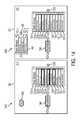
- FIG. 14is a pair of screenshots that illustrate the splitting of data from a data node to create a new data node in the workspace of the user interface.
- FIG. 15is a block diagram that illustrates a computer system upon which an embodiment of the invention may be implemented.
- a methodcomprises: receiving first input specifying a source from which one or more nucleic acid sequences are to be obtained.
- the methodfurther comprises receiving one or more second inputs selecting one or more modules for processing data, including at least one module for processing the one or more nucleic acid sequences.
- the methodfurther comprises presenting, in a graphical user interface, graphical components representing the source and the one or more modules as nodes within a workspace.
- the methodfurther comprises receiving, via the graphical user interface, one or more third inputs arranging the source and the one or more modules as a workflow comprising a series of nodes.
- the seriesindicates, for each particular module of the selected modules, that output from one of the source or another particular module is to be input into the particular module.
- the methodfurther comprises generating an output for the workflow based upon the one or more nucleic acid sequences by processing each module of the one or more modules in an order indicated by the series.
- the methodis performed by one or more computing devices.
- each module of the one or more modulesgenerates output that conforms to an ontology defining data structures that represent genomic data.
- the data structuresinclude at least sequences, protein objects, alignment objects, annotations, and publications.
- the methodfurther comprises generating a data node from the output.
- the data nodecomprises items of genomic data.
- the data nodeis linked to a last module in the series.
- the methodfurther comprises receiving, via the graphical user interface, fourth input that adds or removes an item of genomic data from the data node.
- the methodfurther comprises receiving, via the graphical user interface, fifth input selecting a particular module to process the data node.
- the methodfurther comprises adding the particular module to the end of the series.
- the methodfurther comprises generating second output for the workflow based upon the one or more nucleic acid sequences by processing each module in the series, including the particular module, in the order indicated by the series.
- the one or more modulesinclude a plurality of modules, wherein generating the output for the workflow comprises using output from the source as input to a first module, and using output from the first module as input to a second module.
- the at least one moduleis configured to process the one or more nucleic acid sequences by communicating with at least one of an external web server or an external database server.
- the methodfurther comprises saving workflow data describing the series.
- the methodfurther comprises causing the workflow data to be shared with multiple users.
- the methodfurther comprises subsequently reconstructing the series in a second graphical user interface based on the workflow data.
- the methodfurther comprises receiving fourth input, via the second graphical user interface, modifying the series to include one or more additional modules.
- the methodfurther comprises generating second output based upon the one or more nucleic acid sequences by processing each module in the series, including the one or more additional modules, in an order indicated by the series.
- the one or more modulesinclude a first module that generates first output based upon the source, and a second module that merges the first output with second output from a third module that is not in the series, wherein the source, first module, second module, and third module are all nodes within a workflow.
- the methodfurther comprises presenting controls for selecting the one or more modules, wherein the controls include at least: a first control for selecting a first module that searches for publications in an online database based on genomic data, a second control for selecting a second module that outputs a sequence alignment for multiple sequences, and a third control for selecting a third module that identifies protein families for a nucleic acid sequence.
- receiving the one or more third inputscomprises presenting visual feedback while a first node is selected that indicates that genomic data output from the first node can be linked as input to a second node.
- the one or more modulesinclude at least two modules, and processing each module of the one or more modules in an order indicated by the series comprises automatically processing each module, without human intervention between beginning processing of a first module in the series and generating the output by concluding processing of a last module in the series.
- the inventionencompasses a computer apparatus and a computer-readable medium configured to carry out the foregoing steps.
- the processing and study of genomic datais greatly simplified using a construct herein described as a “workflow.”
- a workflowmay be utilized to generate a re-usable and easily modifiable workflow that chains these disparate steps together in an interconnected construct, and performs some or all of the steps of a task in an automated fashion, with minimal or no user intervention.
- a workflowis a set of linked nodes that represent sets of data, and actions that are to be performed on those sets of data.
- the linked nodesform one or more ordered series of nodes. Certain nodes in a series represents an action, while other nodes represent data that has been output from an action represented by a previous node in the series and/or input to an action represented by a next node in the series.
- the first node of a workflowmay represent a mining operation that pulls data from a source
- the second node of the workflowmay represent the data output by that source
- the third node of the workflowmay represent an action to be performed on that data
- the fourth nodemay represent a data set that results from that action, and so forth.
- a workflowmay comprise any arbitrary number of nodes. However, the utility of the workflow model is generally best realized in a series of nodes that comprises two or more action nodes. Furthermore, a workflow may feature branches. Some of these branches may merge. For example, multiple actions may produce a single data set, or multiple data sets may be input into a single action. Other branches split. For example, a data set may be input into two separate actions, or an action may produce multiple similar or dissimilar data sets.
- Data nodesmay include data sets imported from a data source, such as a sequence database or publications library, search results, manually inputted data from a user, and/or output data from an action node.
- the data sets represented by a data nodeare one or more similarly-typed items.
- Itemsmay include any type of data structure.
- example itemsinclude, without limitation, sequences, publications, annotations, gene data structures, protein data structures, motif data structures, disease data structures, patient data structures, and so forth.
- a data nodemay directly comprise the data set it represents, or a data node may indirectly comprise the data set by referencing location(s) where the data set is found.
- a data nodemay further comprise metadata describing the data set, such as a data type to which the items in the data set conform, summary data, research notes, and/or a reference to the original source of the data set, such as database record(s) and/or action node(s).
- a workflow interfacemay allow a user to interact with any data node in a workflow for observational purposes.
- a usermay create data nodes in certain positions of a workflow where the user wishes to observe data being processed by the workflow.
- the workflow interfacemay represent the data node as a group of named items, with an interactive control corresponding to each item.
- a usermay select the control for an item to access various interfaces for viewing sequences, metadata, analyses, and other information corresponding to the selected item.
- Data nodesmay further facilitate other interactions, as described in other sections.
- Action nodesare nodes that represent actions to be performed on a data set.
- An action nodemay represent any type of action supported by a workflow application. Examples of actions that could be represented by action nodes that pertain to genomic data are described in subsequent sections.
- each action nodecomprises a reference to a specific module that is responsible for performing the node's action, and optionally one or more configuration parameters for that module.
- a moduleis a reusable execution unit that performs an action.
- the modulemay comprise actual instructions for performing an action based on a specified set of data.
- the modulemay comprise instructions for submitting the specified set of data to an external tool, such as an external run-time library or web server, and then retrieving any result.
- a workflow applicationsupports an extensible application programming interface, whereby users may define a variety of different types of modules, each performing different actions.
- An action nodemay comprise metadata that links the node to one or more input nodes.
- the term input noderefers to any data node or other action node that generates data upon which a particular action node performs an action.
- Certain action nodesare not necessarily linked to any input node. These action nodes may nonetheless have an implied or user-configurable data set upon which actions are performed.
- an action nodemay perform a query operation on a database, in which case the database constitutes an implied data set upon which the query operation is performed.
- An action nodemay also comprise metadata that links the node to one or more output nodes.
- the term output noderefers to any other node, including both data nodes and action nodes, to which data generated by an action performed at a particular node is directed. Some action nodes are not necessarily linked to any output nodes. Such may be the case for action nodes that perform a terminal action such as saving results, or for action nodes that have not yet been executed.
- workflowsare described in terms of their action nodes. However, these workflows may also have intervening data nodes that represent data with which a user may interact.
- workflowssimplify this obstacle by converting the outputs of various tools into defined data types.
- workflowsmay utilize a set of data types defined by a certain schema or ontology.
- the schema or ontologymay define universal structures to represent common units of genomic data, such as sequences, proteins, annotations, publications, and so forth.
- each workflow nodeRather than working with ambiguously formatted flat text files, the inputs and outputs of each workflow node conform to standardized, predictable data types. This is because action modules are required to accept input that conforms to a specified data type, and to generate output that conforms to a specified data type.
- particular action modulescomprise or are associated with metadata that specifies one or more input or output data types that the action module can handle.
- a workflow applicationonly allows a user to link a particular action node to other action nodes whose action module handles input or output that conform to these one or more specified input or output data types, or data nodes that comprise data of these one or more specified input or output data types.
- a workflow applicationmay provide various data conversion components.
- a modulemay feed output from an external tool to an appropriate conversion component along with information that assists the conversion component in understanding the data, such as the identity of the tool from which the data was retrieved.
- the conversion componentparses the data and generates converted data structures based thereon.
- the workflow applicationmay provide conversion components that convert the converted data into common input formats expected by various tools. Yet other modules may perform such conversions using their own customized code.
- FIG. 1illustrates an example flow 100 for utilizing a workflow, according to an embodiment.
- Flow 100is but an example flow for utilizing a workflow.
- Other flowsmay comprise fewer or additional elements in potentially different arrangements.
- Block 110comprises receiving first input specifying a source from which one or more nucleic acid sequences are to be obtained.
- the first inputdefines, in essence, a data node of a workflow.
- a data noderepresents a data set, which in this case is the one or more nucleic acids obtained from the source.
- Example sourcesinclude, without limitation, one or more files in a local file system, a web page, a web-based search, one or more database records, an existing workflow, clipboard contents, a library of previously saved sequences, or an action node.
- Input specifying a sourcemay be received via any suitable user interface technique. An example interface for specifying sources is described in other sections. Input specifying a source may instead be received via textual input, such as in an XML file for a previously saved workflow or via command-line input.
- the data node defined by the first inputis not necessarily the only data node in the workflow or even the only data node defined in block 110 .
- block 110may further comprise receiving other input(s) specifying source(s) for other nucleic acid sequences or other types of genomic data.
- Block 120comprises receiving one or more second inputs selecting one or more modules for processing data.
- the one or more second inputsmay select, for example, one or more action modules such as described herein.
- each second inputdefines an action node for the workflow.
- the one or more second inputsmay further specify one or more configuration parameters for the one or more modules, if needed.
- the action nodes defined by the one or more second inputsare not necessarily all of the action nodes within a workflow, and block 120 may further comprise receiving other input(s) defining other action node(s).
- each second inputmay be received via any suitable user interface technique, including those described in other sections, or via textual input.
- the modulesare selected from a set of pre-defined modules.
- the pre-defined modulesmay include both modules provided by a provider of a workflow application, and user-created modules.
- a second inputselects a module that is not pre-defined, but rather created by the second input. For example, a user may provide code or other instructions for a non-reusable module while defining the workflow.
- Block 130comprises presenting, in a graphical user interface, graphical components representing the source and the selected modules.
- the presentationmay comprise, for example, separate icons or other graphical representations for the source and for each module.
- the complexity of the graphical componentsmay vary from embodiment to embodiment. For example, some embodiments may represent a source using a simple icon, while other embodiments may represent a source by listing, within the graphical component corresponding to the source, identifiers for some or all of the data items that belong to the source. Examples of suitable graphical components are described herein.
- a workflow applicationmay perform block 130 .
- the workflow applicationidentifies the source and module(s) specified by the first and second inputs.
- the workflow applicationthen generates a visual presentation of the source and module(s) within an application workspace.
- the application workspacerepresents a workflow, to which the source and the selected module(s) are deemed to belong.
- blocks 110 - 130occur concurrently.
- a usermay provide the first input, and the workflow application may immediately respond by displaying a graphical component for the source.
- the usermay subsequently provide each second input, and the workflow application creates a new graphical component in response to each second input.
- Block 140comprises receiving one or more third inputs arranging the source and the one or more modules in a series.
- the one or more third inputsmay comprise a fourth input that establishes the source as a first node in a series, and additional inputs that link the one or more modules in a succession following the source.
- each third inputmay be received via any suitable user interface technique, including those described in other sections, or via textual input.
- the one or more third inputsare received via the graphical user interface.
- a third inputmay comprise dragging a cursor from an output connector associated with a graphical representation of the source to an input connector associated with a graphical representation of a module.
- the seriesindicates that for each particular module of the selected modules, output from one of the source or another particular module is to be input into the particular module.
- the seriesmay in fact comprise more nodes than just the source and the one or more modules.
- the source and module(s)may have been arranged to follow an existing series of nodes, and/or other nodes may be arranged to follow the source and the module(s).
- the workflowmay in fact comprise multiple series of nodes.
- a workflowmay comprise two series that are entirely detached from each other, or the workflow may comprise a series that branches into or off of a node in another series.
- the one or more third inputsare received via an interface that enforces constraints upon the types of nodes that can be linked. For example, if any input attempts to arrange a module after a source or another module that outputs a data type not supported by the module, the interface will refuse to arrange the module in the manner indicated by the input.
- Block 150comprises updating the graphical user interface to depict the series arranged by the one or more third inputs.
- the source and module(s)may be re-ordered within the graphical user interface in accordance to the series.
- the source and module(s)may be connected to each other by lines or other suitable connectors, in an order indicated by the series.
- the graphical user interfacein response to each third input, the graphical user interface updates to depict a new arrangement, rather than waiting for receipt of all of the one or more third inputs.
- blocks 140 and 150may be performed concurrently with blocks 110 - 130 .
- the usermay add a source and a first module to a workspace, and then link the source to the first module.
- the usermay then add a second module to the workspace, and then link the second module to the original module.
- the graphical user interfacemay continually update as the user provides these inputs.
- Block 160comprises processing each module of the selected modules in an order indicated by the series. The processing of modules within a workflow is described in subsequent sections.
- Block 170comprises generating an output based upon this processing. Since the one or more nucleic acid sequences were used as input to at least one module, the output is based at least upon the one or more nucleic acid sequences. Of course, the output may be further based on other data inputs, if so defined, in the workflow. The output is generated by the processing of the last, or second to last, module in the series. Thus, block 160 in essence comprises block 170 .
- Block 180comprises optionally storing the output.
- the outputmay be saved in a local database or file system.
- the outputmay be uploaded to a web-based database.
- the outputmay be sent to another user.
- Block 180may or may not be performed as part of processing the last module in a series.
- the last node in a workflowmay be an action node that performs the storage operation.
- the last node in the workflowmay be a data node with the output from block 170 .
- block 180may be performed outside of the processing of the workflow.
- the usermay manually import the data set represented by the last node of the workflow to a database.
- the usermay copy and paste the data set into a report, that is then stored to a file.
- processing a workflowcomprises processing a series of nodes.
- a first action node in the series of nodescorresponds to a first module.
- Processing the workflowcomprises executing the first module based on data input from a data node that represents a source. An output is generated based on the execution of the first module.
- the processingfurther comprises executing a second module represented by a second action node in the series. Based on the output from the first module, a second output is generated based on the execution of the second module.
- the processingfurther comprises iteratively executing each module represented by each subsequent action node in the series, using output from an immediately previous action node as input, until all action nodes in the series have been processed.
- processing a workflowcomprises “processing” a data node.
- the processing of a data nodecomprises populating the data node with a data set output from a previous action node.
- the processing of a data nodemay or may not further comprise receiving interactive user manipulations of the data set, as described below.
- the data setis passed as input to any subsequent action node.
- processing a workflowcomprises processing multiple series of nodes. Any given series or node may be dependent upon output from any other given series or node in the workflow. However, once a node or series upon which another node or series depends has been processed, the other node or series may be executed without regard to the timing of any other node or series. For example, multiple independent series may be executed in parallel with respect to each other, or at any other time relative to each other.
- executing (“processing”) a modulecomprises executing instructions defined for the module.
- the instructionsare optionally executed based upon one or more configuration parameters defined in a second input.
- the instructionssend a request to an external component, such as a web-based server or external application.
- the requestcomprises or references the data input into the module during the processing, which may or may not have been reformatted in accordance to the module's instructions.
- the modulereceives data from the external component.
- the modulemay optionally reformat or otherwise process the returned data before returning it as output.
- workflowsare processed automatically, in a non-interactive fashion. Once such a workflow has been defined, processing of the workflow requires no additional user input between the time that the first node is processed and the time that a last module is processed.
- workflows described hereinare designed to produce output without human intervention
- other workflowsare designed to assist a user in identification processes and determinations, rather than simply produce an output.
- the usermay provide various inputs to interact with and/or manipulate the flow of data.
- a usermay, for example, execute a portion of the workflow. Based on output from execution of that portion, the user may decide to execute other portions of the workflow, and/or redefine the workflow to include additional nodes or series of nodes.
- a usermay manipulate the data within any data node.
- a data nodemay represent a position in the workflow at which a user may wish to make an informed decision with respect to how the workflow is to proceed.
- the workflowdoes not require a data node.
- multiple action nodesmay follow each other without intervening data nodes, thereby indicating that the processing of data at those positions is entirely automated.
- data nodesmay also serve observational purposes, the existence of a data node does not necessitate that the user must manipulate data within the data node.
- a usermay edit a data node by adding or removing items, thereby allowing the user to interactively filter the data set for any subsequent workflow actions for which the data node provides input.
- the usermay “execute” a first portion of a workflow to generate the data node.
- the usermay then edit the data node before proceeding with, or even creating, the second portion of the workflow.
- the usermay create new data nodes by moving or copying items from another data node. These new data nodes may then be linked to action nodes within the workflow.
- a usermay save a workflow for subsequent re-use.
- a workflow data structuresuch as an XML file or other data object, may describe a workflow.
- a usermay save the workflow data structure to a file system or database.
- the usermay subsequently access the workflow data structure in order to execute the workflow again.
- the usermay load the workflow data structure in a workflow application.
- the workflow applicationmay present graphical representations of the workflow described by the workflow data structure.
- the usermay then execute the workflow as it was constituted at the time the workflow was saved, or the user may modify the workflow to process potentially different data sources in different manners.
- certain saved workflowsmay be utilized as templates, from which the user may rapidly create new workflows.
- a workflowmay be shared with other users. For example, a user may email a workflow, or a link to a workflow, to another user. If the other user has access to the same data sources and same modules—for instance, by means of a centralized resource server—the other user may run and/or tweak the workflow. If the other user does not have access to the same data sources and same modules, various techniques for finding substitute sources and modules may apply. Or, to prevent resource dependency problems, a shared workflow may embed modules and data sources to which another user is not likely to have access.
- a usermay configure a saved, non-interactive workflow to run in response to triggers or on a periodic basis.
- a data sourcemay change periodically or in response to certain events.
- a usermay create and save an automated workflow to, for instance, generate updated report data whenever the data source is changed or reimport data into a database based on the changes.
- a processmay monitor the output of a automated workflow and provide an update notification to a user whenever the output changes.
- a usermay configure a workflow to run every morning. The workflow may typically pull the same results. The user may request to receive an automated email whenever the workflow output changes. The user may then investigate the new data.
- FIG. 2is a block diagram of an example system 200 in which the techniques described herein may be practiced, according to an embodiment.
- the various components of system 200may implement flow 100 as described above.
- System 200comprises a workflow system 210 .
- Workflow system 210comprises one or more computing devices that implement a series of components 220 - 260 that provide various functionalities with respect to workflows.
- workflow system 210may comprise a client computing device and server computing device.
- workflow system 210may comprise a single computing device.
- Components 220 - 260may be any combination of hardware at the one or more computing devices and software executed by that hardware.
- components 220 - 260are collectively referred to herein as a “workflow application.”
- Workflow creation component 230provides workflow interface component 240 to a user 205 .
- Workflow creation component 230creates workflows in response to various user input to workflow interface component 240 .
- the various user inputsmay, for example, instruct workflow creation component 230 to add data nodes and action nodes to a workflow, manipulate those nodes, and create links between certain nodes.
- Workflow creation component 230updates the workflow interface component 240 to depict representations of the nodes and/or links in a workflow as the user input is received.
- Workflow creation component 230creates action nodes that represent action modules 250 for processing workflow data.
- Action modules 250are execution units that input and/or output data, as described in other sections.
- Workflow creation component 230learns of the availability of these action modules 250 , as well as configuration options for and constraints upon the modules 250 , by accessing module metadata 255 . For example, when a workflow application is first invoked, the workflow application may scan a folder or other metadata 255 for modules 250 , and then make any found modules 250 available for use in the action nodes of a workflow. Workflow creation component 230 then generates interface controls in workflow interface component 240 that allow user 205 to create a new action node and associate that action node with one of the modules 250 .
- Workflow creation component 230may create a data node based on input from user 205 specifying a data set. Workflow creation component 230 may further create data nodes based on output from processing an action node, such as from an immediately preceding action node in the current flow, or from an action node at the end of a different workflow.
- Workflow creation component 230further creates data nodes based on data selected by a user from one or both of a converted data repository 290 , and data sources 280 .
- Workflow creation component 230retrieves data sets from converted data repository 290 and/or data sources 280 .
- data sources 280are converted by data conversion component 260 , thereby yielding uniform, typed data structures.
- Data sets from converted data repository 290are already organized as uniform, typed data structures.
- Workflow creation component 230presents these data sets to user 205 in workflow interface component 240 , and in response receives input that selects specific data items from the data sets that should belong in the data nodes.
- workflow creation component 230stores a workflow data structure representing the workflow in workflow storage 235 .
- workflow storage 235may be, for example, a temporary location in memory, directory in a local file system, or database.
- Workflow interface component 240further includes controls by which user 205 may instruct workflow processing component 220 to process at least a portion of a currently loaded workflow or a workflow in workflow storage 235 .
- workflow interface component 240may present a “run workflow” and/or “run node” button that causes the workflow processing component 220 to process at least a portion of the workflow currently displayed in workflow interface component 240 .
- Workflow processing component 220may also or instead run workflows specified by other input, such as command line input or input from a task scheduler.
- Workflow processing component 220executes workflows described by workflow data structures in workflow storage 235 , using workflow processing techniques such as described in other sections.
- workflow processing component 220invokes action modules 250 referenced by action nodes within the workflow.
- Workflow processing component 220may pass a typed data set output by a previous node, if one exists, to an invoked action module 250 .
- Most action modules 250will process one or more instructions with respect to the input data set, and then return an output comprised of typed data to workflow processor 220 .
- workflow processing component 220may create and/or update data nodes in the currently processed workflow to include the data sets output by action modules 250 .
- workflow processing component 220when workflow processing component 220 is running in an interactive mode, workflow processing component 220 may further update the workflow interface component 240 to display representations of added or updated data nodes. In an embodiment, workflow processing component 220 may be configured to store, print, or display the final output from a workflow to a variety of locations other than workflow interface component 240 .
- one or more action modules 250comprise self-contained instructions for processing a data set. For example, code for relatively common and/or simple operations, such as merging or filtering a data set, may be included directly within a module 250 .
- an action module 250processes a data set using only self-contained instructions, without calling any external tools 270 .
- a module 250interacts with one or more external tools 270 for processing a data set.
- the one or more external tools 270may implement various algorithms for processing genomic data.
- Action modules 250send some or all of the input data set, or processed data based thereon, to external tools 270 for processing.
- Action modules 250then receive an output in return.
- Action modules 250may optionally process an output before returning the output as typed data to workflow processing component 220 .
- usersmay supply their own action modules 250 via an API, which the workflows system 210 may also use.
- the external tools 270may include, for example, local runtime libraries 270 a , such as redistributable libraries of Java or Python code, that can be invoked directly through procedure calls in an action module 250 .
- the external tools 270may also include client-side libraries that run within the workflow interface component 240 at the user's computing device.
- a module 250may be implemented using client-side JavaScript tools. Such tools may or may not prompt a user for input that will affect the outcome of the module 250 .
- the external tools 270may also include local application servers 270 c and web-based application servers 270 d with which an action module 250 may communicate over one or more networks via any suitable protocol, including HTTP, FTP, REST-based protocols, JSON, and so forth.
- all action modules 250are coded objects that extend a common class.
- the common classimplements logic for communicating with each of these four types of external tools 270 .
- external tools 270may include other tools not depicted.
- some external tools 270may furthermore communicate with other external tools 270 to produce an output.
- some external tools 270may generate outputs based on requesting data from data sources 280 .
- Data sources 280may include any source of data accessible to system 201 , including local files 280 a , in any of a variety of formats, and queryable local databases 280 b .
- Data sources 280may further include web-based repositories 280 c that are accessible by various web-based interfaces, including SOAP or REST-based interfaces.
- web-based repositories 280 care cached locally as local files 280 a and/or local databases 280 b .
- workflow system 210may periodically download database dumps from web-based repository 280 c .
- Data sources 280may further include web pages 280 d .
- action modules 250 and/or data conversion component 260may feature “screen-scraping” elements for extracting publications or other data from the web pages 280 d of certain web sites.
- data output from external tools 270 and data sources 280must be converted to converted data 290 prior to being processed by workflow system 210 .
- Workflow system 210may provide a data conversion component 260 to reformat data from external tools 270 and data sources 280 into typed data structures defined by an ontology 291 .
- the ontology 291may be for any type of data.
- an ontology 291 for genomic datacomprises the following core data types: sequences, DNA sequences, mRNA sequences, RNA sequences, protein sequences, protein objects, paper objects, alignment objects, and gene objects.
- Converted data 290is then stored at least temporarily, for processing of the workflow, and/or permanently, for subsequent access by users 205 in other workflows and projects.
- data conversion component 260may further convert data back into a form expected by external tools 270 and data sources 280 , for use as input to external tools 270 , or for storage in data sources 280 .
- action modules 250may also or instead be responsible for directly converting some of the data sets sent to or received from a corresponding tool 270 .
- some action modules 250may rely directly upon converted data 290 , stored permanently in a database, as opposed to data from data sources 280 .
- System 200is but one example of a system in which the techniques described herein may be practiced. Other systems may comprise additional or fewer elements, in potentially varying arrangements. For example, one system omits any number of external tool 270 types or data source 280 types. Another system omits converted data 290 and data conversion component 260 . Yet another system omits a graphical workflow interface component 240 . Many other variations are also possible.
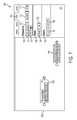
- FIG. 3is a screenshot 300 that illustrates an example interface 305 for practicing techniques described herein, according to an embodiment.
- interface 305may facilitate the receipt of input from a user to define a workflow and/or interact with the processing of a workflow.
- Interface 305is an example of a workflow interface component 240 .
- Interface 305may comprise various graphical representations of items such as nodes, data items, modules, files, and so forth. To simplify the disclosure, this application sometimes describes graphical interface features in terms of represented items themselves as opposed to the graphical representations of those items. The skilled person will understand that, as is common when describing graphical interfaces, literal descriptions of a graphical interface comprising non-graphical interface components should be interpreted as descriptions of the graphical interface comprising graphical representations of those components. For example, the description may describe a step of “selecting a node from a workspace” when in fact the skilled person will understand that what is being selected is a representation of a node in the workspace.
- Interface 305comprises a workspace area 310 in which is depicted a workflow 320 .
- the various components of workflow 320are described with respect to subsequent figures.
- Workspace 310further comprises zoom controls 312 for enlarging or shrinking the visible area of workspace 310 .
- the viewable area of workspace 310is movable through various combinations of cursor inputs and/or selections of scrolling controls.
- Interface 305further comprises a header area 390 .
- Header area 390includes controls 391 - 397 for general workflow operations.
- Save control 391facilitates input for saving workflow 320 .
- Load control 392facilitates input for loading a previously stored workflow into workspace 310 .
- Run control 393facilitates input for processing the entire workflow 320 . Or, if a particular one or more nodes of a workflow 320 are currently selected, run control 393 facilitates input for processing a portion of the workflow 320 corresponding to the particular one or more nodes.
- Controls 394 - 396facilitate input for generating different types of presentations based on output from workflow 320 .
- Control 397facilitates input for importing selected output from workflow 320 , including data sets stored in intermediate data nodes, into a data repository.
- Interface 305further comprises a sidebar area 370 , which is generally reserved for controls that facilitate the creation of new nodes in workflow 320 .
- Sidebar area 370comprises four panes 371 - 374 .
- the currently depicted pane, search pane 371depicts a database search control 375 .
- Database search control 375allows a user to perform a term-based search on various databases of genomic data. The user may drag search results, in part or as a whole, to workspace 320 to create new data node(s).
- Sidebar 370further includes an import pane 372 , an action pane 373 , and a library pane 374 .
- Interface 305further comprises a summary view area 380 .
- Summary view area 380generally presents a context-sensitive detail view of information about a currently selected object in workspace 310 .
- summary view area 380presents a “publication view” of a particular publication item that is selected in a data node of workflow 320 .
- summary view area 380may present differently organized views of different fields of information. Some views may contain a single field of information, while other views may contain many fields of information.
- the information presented in summary view area 380is user-defineable. Summary view area 380 may be scrollable, depending on which view is presented.
- FIG. 4is a screenshot 400 that illustrates the representation of data nodes in the example interface 305 , according to an embodiment.
- Screenshot 400shows a portion of workspace 310 , including graphical representations of three different data nodes 430 - 450 , and summary view area 380 .
- Each data node 430 - 450comprises a set of data items, which are depicted in the respective graphical representations.
- data node 430includes at least data items 431 a - g , each of which is a different protein object. A user may bring additional data items into view using scroll control 435 .
- summary view area 380may be updated with a view 485 of information that is associated with the selected item 431 a .
- the information in view 485may change in response to a user clicking on panes 481 - 484 .
- Each of panes 481 - 484brings into view 485 a different set of information about protein 431 a , including summary information (per pane 481 ), references (per pane 482 ), sequence data (per pane 483 ), and PDB data (per pane 484 ).
- a usermay also select an entire data node 430 - 450 by clicking on it, or using any other suitable selection technique. Clicking on a data node may cause summary view area 380 to show a different view of different information than the information depicted in FIG. 4 .
- the view for node 430may comprise summary information for an entire data set, such as a statistical analysis or histogram showing how similar protein items 431 are to each other.
- the summary view area 380may comprise metadata describing the module corresponding to the action node, information about the last execution of the module, and/or fields for entering values for configurable parameters of the module.
- FIG. 5is a screenshot 500 that illustrates controls for importing data in the example interface 305 , according to an embodiment.
- Screenshot 500shows workspace 310 , sidebar 370 , and header 390 .
- the import pane 372has been selected in sidebar 370 . Consequently, sidebar 370 displays an import control 575 for receiving input selecting a file.
- Screenshot 500further shows a file system explorer window 560 from which a user may select a representation of a file 561 . The user may then use cursor 565 to “grab” and “drag” the representation of file 561 over the import control 575 .
- a feedback graphic 562may be displayed to indicate to the user that the user is in fact dragging file 561 using cursor 565 .
- cursor 565Once cursor 565 is over import control 575 , the user may then “drop” the representation of file 561 in interface area 575 to instruct the user interface 305 to attempt to recognize the file format of file 561 , automatically convert the file 561 to one or more data items that may be used in a workflow, and import those data items into the interface 305 .
- FIG. 6is a screenshot 600 that illustrates adding a data node 630 to the workspace 310 of the example interface 305 , according to an embodiment.
- Screenshot 600shows portions of workspace 310 and sidebar 370 .
- Sidebar 370still depicts the import pane 372 with import control 575 .
- sidebar 370includes representations of data items 661 and 662 .
- Data items 661 and 662are sequences that have been imported from file 561 .
- Adjacent to the representations of data items 661 and 662are controls 665 and 666 for adding data items 661 and 662 , respectively, to a data node that is currently selected within workspace 310 . If there is no currently selected data node in workspace 310 , a new data node is created when one of controls 665 or 666 is selected.
- workspace 310comprises a representation of the data node 630 , which has been created in response to a user clicking on control 665 .
- node 630comprises the imported data item 661 .
- the representation of node 630further comprises a remove control 639 that causes the removal of node 630 from workspace 310 , and a node title 632 , which by default refers to the technique by which node 630 came into existence (i.e. the fact that it was “Imported”).
- FIG. 7is a screenshot 700 that illustrates adding an action node 740 to workspace 310 of example interface 305 , according to an embodiment.
- Screenshot 700shows portions of workspace 310 and sidebar 370 .
- the action pane 373has been selected in sidebar 370 , thus causing sidebar 370 to include control groups 770 , 780 and 790 .
- Control groups 770 , 780 , and 790include, respectively, controls 771 - 775 , 781 - 782 , and 791 - 792 for adding action nodes to workspace 310 .
- Workspace 310includes a representation of the newly added action node 740 .
- Action node 740may have been created, and its corresponding representation added to workspace 310 , in response to selection of control 775 from workspace 370 . As depicted, action node 740 is shaded differently from data node 630 . In an embodiment, all data nodes are shaded or colored differently from action nodes.
- Controls 771 - 775 , 781 - 782 , and 791 - 792may have been generated, for example, by scanning one or more plugin directories in which the workflow application expects to find modules.
- Control groups 770 , 780 , and 790may have been generated based on module metadata categorizing each of the module plug-ins.
- Control group 770corresponds to a “Sequence” category of modules. Selecting one of its controls 771 - 775 creates an action node that executes an action implemented by, respectively, an “MSA” module, a “BLAST” module, a “Transcription” module, a “Translation” module, or a “ScanProsite” module.
- Control group 780corresponds to a “Basic” category of modules, and includes a merge control 781 and filter control 782 . Selecting one of controls 781 - 782 creates an action node that executes an action implemented by, respectively, a “Merge” module or a “Filer” module. Control group 790 corresponds to a “Query” category of modules. Selecting one of its controls 791 - 792 creates an action node that executes an action implemented by, respectively, a “PubMed” module or a “UniProtKB” module.
- control groups 770 , 780 , and 790are controls 771 - 775 , 781 - 782 , and 791 - 792 and are but a small sample of the control groups and controls that may appear in sidebar 370 .
- FIG. 8is a screenshot 800 that illustrates controls for linking nodes in the workspace 310 of the example interface 305 , according to an embodiment.
- Screenshot 800shows a portion of workspace 310 , including representations of nodes 630 and 740 .
- the representation of node 740has been moved closer to the representation of node 630 in response to user input, such as user input that drags and drops node 740 in the currently indicated position.
- Node 630includes an input connector 634 and output connector 635 .
- node 740includes an input connector 744 and an output connector 745 .
- a usermay link any node to any other node by dragging its output connector to the input connector of the other node, or by dragging its input connector to the output connector of the other node.
- the node whose output connector was connected to the input connector of the other nodeprovides input to the other node, and is thus considered to have been ordered before the other node in the series.
- a connectorcan only be linked to another connector if the two connectors are associated with a same data type.
- user interface 305may furthermore change the appearance of any connector that is compatible with the connector that is currently selected.
- Two connectorsare compatible if they are of opposite connection types (input versus output), support at least one common data type, are not in the same node, and are not both in data nodes.
- input connector 744since input connector 744 is compatible with output connector 635 , input connector 744 has been shaded a solid color with no border, in contrast to input node 634 which is transparent and has a border.
- Connector 745likewise has a border, indicating that it cannot receive connector 635 . However, node 745 is currently shaded because it represents output that is currently not being provided to another node.
- a variety of other techniques for changing appearances of compatible nodesmay also or instead be utilized.
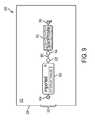
- FIG. 9is a screenshot 900 that illustrates linked nodes in the workspace 310 of the example interface 305 , according to an embodiment.
- Screenshot 900shows a portion of workspace 310 , in which nodes 630 and 740 have been linked per the drag and drop operation described above.
- Workspace 310includes a representation of the link 961 between nodes 630 and 740 .
- Nodes 630 and 740now form a series, and as such constitute a functional workflow 320 .
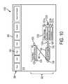
- FIG. 10is a screenshot 1000 that illustrates running a portion of the workflow 320 using the example interface 305 , according to an embodiment.
- Screenshot 1000shows header area 390 and a portion of workspace 310 , including nodes 630 and 740 .
- a usermay decide to run workflow 320 .
- the usermay click on the run control 393 .
- the workflow applicationmay run workflow 320 by inputting the sequence represented by node 630 into the ScanProsite module represented by node 740 , and executing the ScanProsite module.
- the ScanProsite moduleinteracts with a web server that implements an algorithm for identifying motifs in the sequence.
- the ScanProsite modulereceives a response from the web server, interprets this response as a data set of motifs, and provides this data set to the workflow application.
- the workflow applicationcreates data node 1030 , adds the identified motifs to the data node 1030 as data items 1031 a - 1031 c , adds data node 1030 to the workflow 320 by linking data node 1030 to node 740 with a new link 1061 , and then adds corresponding representations of the new data to workspace 310 . These representations are depicted within workspace 310 of FIG. 10 .
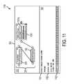
- FIG. 11is a screenshot 1100 that illustrates interacting with output from an action node in workflow 320 using the example interface 305 , according to an embodiment.
- Screenshot 1100shows portions of summary view area 380 and workspace 310 , including workflow 320 as constituted in FIG. 10 .
- a particular data item 1031 ahas been selected from node 1030 .
- summary view area 380is updated with information associated with item 1031 a , including a label 1181 , metadata 1182 , and a sequence 1183 .
- FIG. 12is a screenshot 1200 that illustrates the workspace 310 with various types of nodes from workflow 320 , according to an embodiment.
- Screenshot 1200shows portions of sidebar 370 and workspace 310 . While node 630 has been scrolled out of view in workspace 310 , workspace 310 now includes a number of additional nodes that have been added to workflow 320 . Specifically, node 1030 is now linked as input to an action node 1240 , which is in turn linked as input to action node 1250 . Another data node 1230 has also been added to workspace 310 . Data node 1230 is also connected as input to action node 1250 .
- the library pane 374is selected in sidebar 370 . Consequently, sidebar 370 includes three controls 1281 - 1283 for adding items from a library.
- a libraryis a local storage repository where users may save data items of interest to the user.
- sidebar 370may include many more controls depending on which items have been added by a user.
- library itemsare shared with groups of users.
- Each control 1281 - 1283corresponds to a different library item. Selection of one of controls 1281 - 1283 results in the addition of the corresponding library item to the currently selected data node, or in the creation of a new data node if no compatible data node is selected. For example, data node 1230 was created when the user clicked on control 1282 .
- Action node 1240corresponds to a filter module.
- action node 1240may have been added to workspace 310 in response to a user clicking on control 782 .
- the filter moduleis configured to filter data node 1030 to include only the first item 1031 a , but the user may reconfigure the filtering behavior associated with action node 1240 by selecting node 1240 and changing parameter values that are shown in summary view area 380 in response to the selection.
- Action node 1250corresponds to a merge module.
- action node 1250may have been added to workspace 310 in response to a user clicking on control 781 .
- Action node 1250includes multiple input connectors 1253 and 1254 , to allow node 1250 to receive multiple inputs.
- the merge moduleis configured to create one data set out of the multiple inputs. For example, as depicted, node 1250 will merge the output of node 1240 with the data in node 1230 .
- FIG. 13is a screenshot 1300 that illustrates an automated chain of nodes for retrieving publications from a database using user interface 305 , according to an embodiment.
- Screenshot 1300shows a portion of workspace 310 , including most of workflow 320 .
- Workflow 320now includes an action node 1340 and a data node 1330 .
- Action node 1340receives the output of merge node 1250 and sends the output to a module for searching a PubMed database for articles.
- Action node 1340was generated in response to a user selecting control 791 .
- This outputcomprising a group of publications, was saved in data node 1330 as at least data items 1331 a - 1331 j . A user may see other data items that are in node 1330 using scroll control 1235 .
- FIG. 14is a pair of screenshots 1400 and 1450 that illustrate the splitting of data from data node 1330 to create a new data node 1430 in workspace 310 of user interface 305 , according to an embodiment.
- Screenshots 1400 and 1450show respectively a portion of workspace 310 while the user is performing the splitting, and the same portion of workspace 310 after the user has performed the splitting.
- the userhas selected three items from data node 1330 : items 1331 c , 1331 e , and 1331 g .
- the useris dragging those items from node 1330 to an empty space in workspace 310 .
- Cursor icon 1465indicates the current position of the cursor within the workspace, as well as the number of items that the cursor is dragging.
- screenshot 1450the user has “dropped” the selected items at the location of data node 1430 . Accordingly, node 1430 was created and a representation of the node, including data items 1331 c , 1331 e , and 1331 g was added to the workspace 310 . Meanwhile, data items 1331 c , 1331 e , and 1331 g are removed from data node 1330 as a result of the operation, rendering items 1331 k - m visible in node 1330 . In some embodiments, however, splitting items from a node does not necessarily remove items from the original node, but rather clones the items in a new node.
- Node 1430can now be added to workflow 320 . For example, it may be connected back to node 1340 , effectively requesting that node 1340 split its input into two separate data nodes. Or node 1430 may be used as a first node within another independent series of nodes within workflow 320 .
- Interface 305is but one example of an interface for practicing techniques described herein. Other interfaces may comprise fewer or additional elements in potentially varying arrangements.
- action nodesthat may be useful for processing genomic data are described below. There may in fact be many more types of modules than those listed here. Workflows for other types of data may include some of these action nodes, but may also or instead include other action nodes that reflect algorithms for processing the other types of data.
- standard modulesinclude a merge module for merging data sets from multiple nodes and a filter module for filtering a data set based on configurable criteria.
- one type of action nodecorresponds to a “Translate DNA to Protein” module.
- the moduleaccepts input in the form of a sequence.
- the moduleuses a locally-implemented algorithm to translate the DNA sequence.
- the modulegenerates output in the form of a protein data structure.
- Example configurable parameters for the modulemay include, without limitation, a frame parameter and a complement parameter.
- another type of action nodecorresponds to a “multiple sequence alignment” module.
- the moduleaccepts input in the form of a multiple sequence data set in, for example, a multi-FASTA formatted file.
- the modulegenerates output in the form of alignment data, such as in an MSA alignment file.
- a summary area of a workflowmight present the alignment data in a detailed view area using techniques such as described in the previously referenced application, “Computer Graphical User Interface Supporting Aligning Genomic Sequences.”
- another type of action nodecorresponds to a “Protein family (Pfam) Scan” module.
- the moduleaccesses a web-based application server that runs a Hidden Markov Module over a protein sequence and computes the most likely protein famil(ies) based on motifs in the protein sequence.
- the moduleaccepts input in the form of a protein data structure.
- the modulegenerates output in the form of protein family data structure(s).
- another type of action nodecorresponds to a “Glimmer” module.
- the moduleaccesses a web-based application server to locate genes using an interpolated Markov model.
- Configurable parameters for the moduleinclude, without limitation, a genetic code type, topology type, a number of input sequences, and an output data type, which may be an annotation or a sequence.
- another type of action nodecorresponds to a “BLAST” module.
- the moduleaccesses a web-based application server that searches for genes in a sequence query using various libraries of genomic data. The module returns information about matching results.
- another type of action nodecorresponds to a “FASTA sequence reader” module, which converts FASTA file structure into a protein or DNA sequence using a local application.
- another type of action nodecorresponds to a “UniProt” module.
- the modulequeries an online UniProt database to retrieve information about inputted protein sequences or objects.
- Configurable parameters for the moduleinclude, without limitation, an organism parameter, a Gene Ontology (GO) parameter, a reviewed parameter, and a pro site parameter.
- GOGene Ontology
- another type of action nodecorresponds to a “PubMed” module.
- the modulequeries the online PubMed database for all publications that match input data.
- Configurable parameters for the moduleinclude, without limitation, an id parameter and a reviewed parameter.
- various workflow node types supported by the systems described hereinmay include, without limitation, nodes that represent one or more of the following: sourcing functions that retrieve data from one or more sources using various querying and/or scraping techniques; aggregation functions, such as cumulative and average results of data; filtering functions that choose subsets from sets of biological objects based on various matching criteria and/or thresholds; sequence partitioning functions that select a section from a sequence or alignment and use that section as a new data object; comparison functions that compare two or more biological objects or sets of objects based on specified metric(s) and determine whether the differences are statistically significant; comparison functions that compare patient cohorts; conversion and modification functions; sequence alignment generation functions; sequence alignment analysis functions; prediction functions that predict sites of a sequence of potential interest for annotations or other features; annotation functions for automatically creating annotations; annotation lookup functions; Natural Language Processing functions for publications; lookup functions to identify diseases associated with certain genomic objects; and storage functions that save various annotations or other outputs to various storage locations and make the outputs available to other users.
- modules to which various workflow node types may linkinclude, without limitation, modules that implement the following types of analyses: allele tests, genotypes frequencies tests, Hardy-Weinberg equilibrium tests, missing genotype rates, inbreeding tests, identity-by-state and identity-by-descent statistics for individuals and pairs of individuals, non-Mendelian transmission in family data, complete linkage hierarchical clustering, multidimensional scaling analysis to visualise substructures, significance tests for whether two individuals belong to the same population, constrain cluster solutions by phenotype, cluster size, and/or external matching criteria, subsequent association analyses that are conditional on cluster solutions, standard allelic tests, Fisher's exact tests, Cochran-Armitage trend tests, Mantel-Haenszel and Breslow-Day tests for stratified samples, dominant/recessive and general model tests, model comparison tests (e.g.
- association testssuch as transmission disequilibrium tests or sibship tests, quantitative traits, associations, and interactions, association tests that are conditional on one or more single-nucleotide polymorphisms (“SNPs”), asymptotic and empirical p-values, flexible clustered permutation schemes, analysis of genotype probability data and fractional allele counts (post-imputation), conditional haplotype tests, case/control and transmission disequilibrium test association on the probabilistic haplotype phase, proxy association methods to study single SNP associations in their local haplotypic context, imputation heuristics to test untyped SNPs given a reference panel, joint SNP and copy-number variation (“CNV”) tests for common copy number variants, filtering and summary procedures for segmental (rare) CNV data, case/control comparison tests for global CNV properties, permutation-based association procedure for identifying specific loci, gene-based tests of association, screen for epistasis, gene-environment interaction with continuous
- SNPssingle-nu
- Lactobacillus acidophilus strainswhich are typically of interest in probiotics and potential vaccine vectors, sometimes have a surface layer protein for adhesion to cells.
- a researchermay sequence a new strain of L. acidophilus . When the researcher aligns the new strain to the reference sequences, the researcher discovers that the new strain lacks the SlpA gene, but has an unknown insertion. The researcher decides that the new strain may be interesting, and wants to know whether the new strain is a gene, the likely function of the protein that the new strain encodes, the biological context of the new strain, and how the strain compares to proteins that are already known.
- An example workflow to assist in accomplishing these objectivesmay be as follows.
- a first set of one or more action nodesloads the appropriate DNA sequence and metadata, including the source, sequencing method, date, and quality.
- a second set of one or more action nodesruns a GLIMMER tool to predict gene(s) based on the loaded data.
- a third set of one or more action nodesruns a multi-sequence alignment and comparison to compare the sequence to a corresponding region of the L. acidophilus reference sequence, thereby producing a genome object with annotated genes.
- a fourth set of one or more action nodestranslates the genome object into a protein sequence.
- a fifth set of one or more action nodespredicts pfams and GO terms.
- a sixth set of one or more action nodesruns BLAST on the protein sequence to answer the questions of what pfams and GO terms are most common among the top hits, how do these terms intersect with those from the predicted protein, and how closely related are the bacteria of the top hits to L. acidophilus ?
- a seventh set of one or more action nodessearches for known pathways that the top hits are involved in using Metacyc and E.C. numbers.
- An eighth set of one or more action nodespulls PubMed data for the top BLAST hits.
- a ninth set of one or more action nodesfind genes and features upstream and downstream of the insertion and determines what the functions of these sites are.
- a tenth set of one or more action nodesruns a feature/annotation module to compare the gene to the PubMed annotations of the BLAST hits to identify unique features of the gene.
- An eleventh set of one or more action nodesadds appropriate annotations concerning the unique feature as annotations to the gene, and links the annotations back to the genome.
- various actionsmay require human intervention to identify important data points before proceeding to the next node.
- the workflowis entirely automated, without human intervention.
- such a workflowmay be saved for reuse. The next time the researcher discovers a new strain, the researcher may perform the same workflow with respect to the new strain simply by modifying the original workflow input.
- workflows described hereinAnother use for the workflows described herein is to address sequence-structure-function-disease problems with respect to a gene. For example, a researcher may put together a workflow that answers questions such as what are the implications of the polymorphisms in a gene for how and when the gene is expressed, what are the implications of the polymorphisms in the protein it encodes for interaction with its co-factor, and how do these implications relate to the gene's role in disease.
- An example workflow to assist in accomplishing these objectivesmay be as follows.
- a first set of one or more action nodesperforms a multi-sequence alignment of the gene's variants.
- a second set of one or more action nodesuses tracked viewing of microarray expression data under various experimental conditions to identify patterns of altered activity. The identification process may involve multiple-hypothesis controlled t-tests and/or other algorithms to statistically identify mutations that are correlated with expression changes under one or more conditions.
- a third set of one or more action nodesadds a track of annotated features, such as regulatory sequences, to compare with the experimental expression data.
- a fourth set of one or more action nodesperforms a multi-sequence alignment of the protein's variants.
- a fifth set of one or more action nodesperforms a tracked viewing of activity levels, such as binding affinity.
- a sixth set of one or more action nodesexamines individual assays in a table view module to determine the ranking of the variants by binding affinity.
- a seventh set of one or more action nodesuses a structure viewer module to assess how binding affinity might be affected by amino acid mutations, including predicting important interactions (H-bonds, pi-pi interactions, steric interactions).
- An eighth set of one or more action nodessearches PubChem for additional relevant assays.
- a ninth set of one or more action nodeslooks up the pathways that the protein is in.
- a tenth set of one or more action nodessearches PubMed for items associated with both the gene and a disease.
- An eleventh set of one or more action nodesimports the other components of the biological pathway hypothesized to link gene and disease from Uniprot and/or other databases and draws the biological pathway.
- Another use for the workflows described hereinis to address protein design problems. For example, a researcher may intend to design a set of candidate proteins to perform a specific chemical function, such as tyrosine decarboxylase. The researcher will have these proteins made, and then try them out in a bacterium that lacks this activity.
- a specific chemical functionsuch as tyrosine decarboxylase
- An example workflow to assist in accomplishing these objectivesmay be as follows.
- a first set of one or more action nodessearches Uniprot for proteins with pfam PF00282 (Pyridoxal-dependent decarboxylase).
- a second set of one or more action nodessearches Pfam for PF00282 and unions the results with the Uniprot results.
- a third set of one or more action nodesruns BLAST on this set of protein sequences against itself to generate all possible pairwise BLAST comparisons.
- a fourth set of one or more action nodesclusters the results based on the BLAST scores.
- a fifth set of one or more action nodeslooks at the annotations from each cluster and determines if there is more than one cluster annotated with tyrosine decarboxylase activity.
- a sixth set of one or more action nodesaligns the sequences from each cluster, annotated with Y-decarb activity.
- the alignmentaccomplishes two objectives. First, the alignment allows for a comparison of the conserved regions within and between alignments. Second, the alignment groups subsets of aligned sequences, visually or algorithmically, based on similarity.
- a seventh set of one or more action nodescreates a set of candidate proteins that is representative of the alignments, in that the candidate proteins have a consensus sequence in the conserved regions.
- An eighth set of one or more action nodeslooks at the bacteria that produce the BLAST hit proteins and determines which bacteria is most similar to the researcher's test bacterium, based on phylogenetic information.
- a ninth set of one or more action nodessearches PubMed or other databases for comparisons of the niche and metabolism of the two species.
- a tenth set of one or more action nodessearches PubMed or other databases to find what more is known about candidate1 in the other bacterium.
- An eleventh set of one or more action nodesanalyzes the annotated features from candidate1 to hypothesize whether any regions will be disrupted in the other candidates.
- a twelfth set of one or more action nodesanalyzes the structure of candidate1 and alignment of each other candidate to candidate1, to determine where the sequence changes might impact structure. This may involve threading the candidate sequences into the structure of candidate1, or threading both into the most similar existing PDB structure, and finding differences.
- a thirteenth set of one or more action nodesexports the sequences of the candidate proteins to a database for future reference.
- a first set of one or more action nodesuses Plink, Eigenstrat, and/or R modules to compute summary statistics, including allele frequencies and SNP frequencies.
- a second set of one or more action nodesuses these same modules to adjust the statistics to control for population stratification (i.e. bias due to ancestry/relatedness within the case or control group), using identity-by-state (IBS) or multidimensional scaling.
- IBSidentity-by-state
- a third set of one or more action nodesuses these modules to run a variety of association tests, in order to determine how the genotype is linked to disease. The tests include Fisher's exact test, Chi square, correlation, and regression.
- a fourth set of one or more action nodesuses a Manhattan plot module, potentially with a ggplot2 R package, to generate a plot of the p-values of all the SNPs along the genomic axis.
- a sixth set of one or more action nodesgenerates multiple sequence alignments of each SNP's region. The multiple sequence alignments are organized by case/control.
- a seventh set of one or more action nodessearches dbSNP or other databases for the SNPs to determine if they have they been associated with anything else.
- An eighth set of one or more action nodessearches for other annotations in these regions, in order to form functional hypotheses.
- the techniques described hereinare implemented by one or more special-purpose computing devices.
- the special-purpose computing devicesmay be hard-wired to perform the techniques, or may include digital electronic devices such as one or more application-specific integrated circuits (ASICs) or field programmable gate arrays (FPGAs) that are persistently programmed to perform the techniques, or may include one or more general purpose hardware processors programmed to perform the techniques pursuant to program instructions in firmware, memory, other storage, or a combination.
- ASICsapplication-specific integrated circuits
- FPGAsfield programmable gate arrays
- Such special-purpose computing devicesmay also combine custom hard-wired logic, ASICs, or FPGAs with custom programming to accomplish the techniques.
- the special-purpose computing devicesmay be desktop computer systems, portable computer systems, handheld devices, networking devices or any other device that incorporates hard-wired and/or program logic to implement the techniques.
- FIG. 15is a block diagram that illustrates a computer system 1500 upon which an embodiment of the invention may be implemented.
- Computer system 1500includes a bus 1502 or other communication mechanism for communicating information, and a hardware processor 1504 coupled with bus 1502 for processing information.
- Hardware processor 1504may be, for example, a general purpose microprocessor.
- Computer system 1500also includes a main memory 1506 , such as a random access memory (RAM) or other dynamic storage device, coupled to bus 1502 for storing information and instructions to be executed by processor 1504 .
- Main memory 1506also may be used for storing temporary variables or other intermediate information during execution of instructions to be executed by processor 1504 .
- Such instructionswhen stored in non-transitory storage media accessible to processor 1504 , render computer system 1500 into a special-purpose machine that is customized to perform the operations specified in the instructions.
- Computer system 1500further includes a read only memory (ROM) 1508 or other static storage device coupled to bus 1502 for storing static information and instructions for processor 1504 .
- ROMread only memory
- a storage device 1510such as a magnetic disk or optical disk, is provided and coupled to bus 1502 for storing information and instructions.
- Computer system 1500may be coupled via bus 1502 to a display 1512 , such as a cathode ray tube (CRT), for displaying information to a computer user.
- a display 1512such as a cathode ray tube (CRT)
- An input device 1514is coupled to bus 1502 for communicating information and command selections to processor 1504 .
- cursor control 1516is Another type of user input device
- cursor control 1516such as a mouse, a trackball, or cursor direction keys for communicating direction information and command selections to processor 1504 and for controlling cursor movement on display 1512 .
- This input devicetypically has two degrees of freedom in two axes, a first axis (e.g., x) and a second axis (e.g., y), that allows the device to specify positions in a plane.
- Computer system 1500may implement the techniques described herein using customized hard-wired logic, one or more ASICs or FPGAs, firmware and/or program logic which in combination with the computer system causes or programs computer system 1500 to be a special-purpose machine. According to one embodiment, the techniques herein are performed by computer system 1500 in response to processor 1504 executing one or more sequences of one or more instructions contained in main memory 1506 . Such instructions may be read into main memory 1506 from another storage medium, such as storage device 1510 . Execution of the sequences of instructions contained in main memory 1506 causes processor 1504 to perform the process steps described herein. In alternative embodiments, hard-wired circuitry may be used in place of or in combination with software instructions.
- Non-volatile mediaincludes, for example, optical or magnetic disks, such as storage device 1510 .
- Volatile mediaincludes dynamic memory, such as main memory 1506 .
- Common forms of storage mediainclude, for example, a floppy disk, a flexible disk, hard disk, solid state drive, magnetic tape, or any other magnetic data storage medium, a CD-ROM, any other optical data storage medium, any physical medium with patterns of holes, a RAM, a PROM, and EPROM, a FLASH-EPROM, NVRAM, any other memory chip or cartridge.
- Storage mediais distinct from but may be used in conjunction with transmission media.
- Transmission mediaparticipates in transferring information between storage media.
- transmission mediaincludes coaxial cables, copper wire and fiber optics, including the wires that comprise bus 1502 .
- transmission mediacan also take the form of acoustic or light waves, such as those generated during radio-wave and infra-red data communications.
- Various forms of mediamay be involved in carrying one or more sequences of one or more instructions to processor 1504 for execution.
- the instructionsmay initially be carried on a magnetic disk or solid state drive of a remote computer.
- the remote computercan load the instructions into its dynamic memory and send the instructions over a telephone line using a modem.
- a modem local to computer system 1500can receive the data on the telephone line and use an infra-red transmitter to convert the data to an infra-red signal.
- An infra-red detectorcan receive the data carried in the infra-red signal and appropriate circuitry can place the data on bus 1502 .
- Bus 1502carries the data to main memory 1506 , from which processor 1504 retrieves and executes the instructions.
- the instructions received by main memory 1506may optionally be stored on storage device 1510 either before or after execution by processor 1504 .
- Computer system 1500also includes a communication interface 1518 coupled to bus 1502 .
- Communication interface 1518provides a two-way data communication coupling to a network link 1520 that is connected to a local network 1522 .
- communication interface 1518may be an integrated services digital network (ISDN) card, cable modem, satellite modem, or a modem to provide a data communication connection to a corresponding type of telephone line.
- ISDNintegrated services digital network
- communication interface 1518may be a local area network (LAN) card to provide a data communication connection to a compatible LAN.
- LANlocal area network
- Wireless linksmay also be implemented.
- communication interface 1518sends and receives electrical, electromagnetic or optical signals that carry digital data streams representing various types of information.
- Network link 1520typically provides data communication through one or more networks to other data devices.
- network link 1520may provide a connection through local network 1522 to a host computer 1524 or to data equipment operated by an Internet Service Provider (ISP) 1526 .
- ISP 1526in turn provides data communication services through the world wide packet data communication network now commonly referred to as the “Internet” 1528 .
- Internet 1528uses electrical, electromagnetic or optical signals that carry digital data streams.
- the signals through the various networks and the signals on network link 1520 and through communication interface 1518which carry the digital data to and from computer system 1500 , are example forms of transmission media.
- Computer system 1500can send messages and receive data, including program code, through the network(s), network link 1520 and communication interface 1518 .
- a server 1530might transmit a requested code for an application program through Internet 1528 , ISP 1526 , local network 1522 and communication interface 1518 .
- the received codemay be executed by processor 1504 as it is received, and/or stored in storage device 1510 , or other non-volatile storage for later execution.
Landscapes
- Engineering & Computer Science (AREA)
- Physics & Mathematics (AREA)
- Theoretical Computer Science (AREA)
- Life Sciences & Earth Sciences (AREA)
- Health & Medical Sciences (AREA)
- General Engineering & Computer Science (AREA)
- Databases & Information Systems (AREA)
- Bioinformatics & Cheminformatics (AREA)
- General Physics & Mathematics (AREA)
- Medical Informatics (AREA)
- Spectroscopy & Molecular Physics (AREA)
- Bioinformatics & Computational Biology (AREA)
- Biotechnology (AREA)
- Evolutionary Biology (AREA)
- General Health & Medical Sciences (AREA)
- Biophysics (AREA)
- Business, Economics & Management (AREA)
- Data Mining & Analysis (AREA)
- Bioethics (AREA)
- Entrepreneurship & Innovation (AREA)
- Human Resources & Organizations (AREA)
- Strategic Management (AREA)
- Human Computer Interaction (AREA)
- Economics (AREA)
- Marketing (AREA)
- Operations Research (AREA)
- Quality & Reliability (AREA)
- Tourism & Hospitality (AREA)
- General Business, Economics & Management (AREA)
- Proteomics, Peptides & Aminoacids (AREA)
- Molecular Biology (AREA)
- Genetics & Genomics (AREA)
- Analytical Chemistry (AREA)
- Chemical & Material Sciences (AREA)
- Management, Administration, Business Operations System, And Electronic Commerce (AREA)
- User Interface Of Digital Computer (AREA)
Abstract
Description
Claims (20)
Priority Applications (9)
| Application Number | Priority Date | Filing Date | Title |
|---|---|---|---|
| US13/831,791US9501202B2 (en) | 2013-03-15 | 2013-03-15 | Computer graphical user interface with genomic workflow |
| AU2014200965AAU2014200965B2 (en) | 2013-03-15 | 2014-02-25 | Computer Graphical User Interface with Genomic Workflow |
| CA2845606ACA2845606C (en) | 2013-03-15 | 2014-03-11 | Computer graphical user interface with genomic workflow |
| DE102014103482.1ADE102014103482A1 (en) | 2013-03-15 | 2014-03-14 | Graphical user interface of a computer with genomic workflow |
| GB1404574.4AGB2517529A (en) | 2013-03-15 | 2014-03-14 | Computer graphical user interface with genomic workflow |
| NL2012437ANL2012437B1 (en) | 2013-03-15 | 2014-03-14 | Computer graphical user interface with genomic workflow. |
| US15/339,666US10431327B2 (en) | 2013-03-15 | 2016-10-31 | Computer graphical user interface with genomic workflow |
| US16/543,002US11074993B2 (en) | 2013-03-15 | 2019-08-16 | Computer graphical user interface with genomic workflow |
| US17/355,711US11676686B2 (en) | 2013-03-15 | 2021-06-23 | Computer graphical user interface with genomic workflow |
Applications Claiming Priority (1)
| Application Number | Priority Date | Filing Date | Title |
|---|---|---|---|
| US13/831,791US9501202B2 (en) | 2013-03-15 | 2013-03-15 | Computer graphical user interface with genomic workflow |
Related Child Applications (1)
| Application Number | Title | Priority Date | Filing Date |
|---|---|---|---|
| US15/339,666ContinuationUS10431327B2 (en) | 2013-03-15 | 2016-10-31 | Computer graphical user interface with genomic workflow |
Publications (2)
| Publication Number | Publication Date |
|---|---|
| US20140282177A1 US20140282177A1 (en) | 2014-09-18 |
| US9501202B2true US9501202B2 (en) | 2016-11-22 |
Family
ID=50555220
Family Applications (4)
| Application Number | Title | Priority Date | Filing Date |
|---|---|---|---|
| US13/831,791Active2033-11-14US9501202B2 (en) | 2013-03-15 | 2013-03-15 | Computer graphical user interface with genomic workflow |
| US15/339,666Expired - Fee RelatedUS10431327B2 (en) | 2013-03-15 | 2016-10-31 | Computer graphical user interface with genomic workflow |
| US16/543,002ActiveUS11074993B2 (en) | 2013-03-15 | 2019-08-16 | Computer graphical user interface with genomic workflow |
| US17/355,711ActiveUS11676686B2 (en) | 2013-03-15 | 2021-06-23 | Computer graphical user interface with genomic workflow |
Family Applications After (3)
| Application Number | Title | Priority Date | Filing Date |
|---|---|---|---|
| US15/339,666Expired - Fee RelatedUS10431327B2 (en) | 2013-03-15 | 2016-10-31 | Computer graphical user interface with genomic workflow |
| US16/543,002ActiveUS11074993B2 (en) | 2013-03-15 | 2019-08-16 | Computer graphical user interface with genomic workflow |
| US17/355,711ActiveUS11676686B2 (en) | 2013-03-15 | 2021-06-23 | Computer graphical user interface with genomic workflow |
Country Status (6)
| Country | Link |
|---|---|
| US (4) | US9501202B2 (en) |
| AU (1) | AU2014200965B2 (en) |
| CA (1) | CA2845606C (en) |
| DE (1) | DE102014103482A1 (en) |
| GB (1) | GB2517529A (en) |
| NL (1) | NL2012437B1 (en) |
Cited By (9)
| Publication number | Priority date | Publication date | Assignee | Title |
|---|---|---|---|---|
| USD789390S1 (en)* | 2014-12-31 | 2017-06-13 | Linkedin Corporation | Portion of a display with a graphical user interface |
| USD798322S1 (en)* | 2015-10-20 | 2017-09-26 | 23Andme, Inc. | Display screen or portion thereof with graphical user interface |
| USD831051S1 (en)* | 2016-11-07 | 2018-10-16 | Illumina, Inc. | Display screen or portion thereof with zygosity icons |
| US10431327B2 (en) | 2013-03-15 | 2019-10-01 | Palantir Technologies Inc. | Computer graphical user interface with genomic workflow |
| US11282118B2 (en)* | 2019-09-17 | 2022-03-22 | Salesforce.Com, Inc. | Order management user interface |
| USD959448S1 (en)* | 2020-04-09 | 2022-08-02 | Palantir Technologies Inc. | Display screen or portion thereof with graphical user interface |
| USD1036458S1 (en)* | 2021-05-11 | 2024-07-23 | Roche Molecular Systems, Inc. | Display screen or portion thereof with graphical user interface for patient pathway reconstruction and aggregation |
| USD1050168S1 (en)* | 2024-07-23 | 2024-11-05 | Datadog, Inc. | Display screen or portion thereof with graphical user interface |
| USD1062781S1 (en)* | 2021-12-02 | 2025-02-18 | Passivelogic, Inc | Display screen or portion thereof with an animated graphical user interface |
Families Citing this family (171)
| Publication number | Priority date | Publication date | Assignee | Title |
|---|---|---|---|---|
| US8930331B2 (en) | 2007-02-21 | 2015-01-06 | Palantir Technologies | Providing unique views of data based on changes or rules |
| US8984390B2 (en) | 2008-09-15 | 2015-03-17 | Palantir Technologies, Inc. | One-click sharing for screenshots and related documents |
| US9092482B2 (en) | 2013-03-14 | 2015-07-28 | Palantir Technologies, Inc. | Fair scheduling for mixed-query loads |
| US8799240B2 (en) | 2011-06-23 | 2014-08-05 | Palantir Technologies, Inc. | System and method for investigating large amounts of data |
| US9547693B1 (en) | 2011-06-23 | 2017-01-17 | Palantir Technologies Inc. | Periodic database search manager for multiple data sources |
| US8732574B2 (en) | 2011-08-25 | 2014-05-20 | Palantir Technologies, Inc. | System and method for parameterizing documents for automatic workflow generation |
| US8504542B2 (en) | 2011-09-02 | 2013-08-06 | Palantir Technologies, Inc. | Multi-row transactions |
| US8560494B1 (en) | 2011-09-30 | 2013-10-15 | Palantir Technologies, Inc. | Visual data importer |
| US9378526B2 (en) | 2012-03-02 | 2016-06-28 | Palantir Technologies, Inc. | System and method for accessing data objects via remote references |
| US9798768B2 (en) | 2012-09-10 | 2017-10-24 | Palantir Technologies, Inc. | Search around visual queries |
| US9471370B2 (en) | 2012-10-22 | 2016-10-18 | Palantir Technologies, Inc. | System and method for stack-based batch evaluation of program instructions |
| US9348677B2 (en) | 2012-10-22 | 2016-05-24 | Palantir Technologies Inc. | System and method for batch evaluation programs |
| US9123086B1 (en) | 2013-01-31 | 2015-09-01 | Palantir Technologies, Inc. | Automatically generating event objects from images |
| US9367463B2 (en) | 2013-03-14 | 2016-06-14 | Palantir Technologies, Inc. | System and method utilizing a shared cache to provide zero copy memory mapped database |
| US10037314B2 (en) | 2013-03-14 | 2018-07-31 | Palantir Technologies, Inc. | Mobile reports |
| US10275778B1 (en) | 2013-03-15 | 2019-04-30 | Palantir Technologies Inc. | Systems and user interfaces for dynamic and interactive investigation based on automatic malfeasance clustering of related data in various data structures |
| US8909656B2 (en) | 2013-03-15 | 2014-12-09 | Palantir Technologies Inc. | Filter chains with associated multipath views for exploring large data sets |
| US8937619B2 (en) | 2013-03-15 | 2015-01-20 | Palantir Technologies Inc. | Generating an object time series from data objects |
| US8868486B2 (en) | 2013-03-15 | 2014-10-21 | Palantir Technologies Inc. | Time-sensitive cube |
| US9965937B2 (en) | 2013-03-15 | 2018-05-08 | Palantir Technologies Inc. | External malware data item clustering and analysis |
| US8917274B2 (en) | 2013-03-15 | 2014-12-23 | Palantir Technologies Inc. | Event matrix based on integrated data |
| US8818892B1 (en) | 2013-03-15 | 2014-08-26 | Palantir Technologies, Inc. | Prioritizing data clusters with customizable scoring strategies |
| US9740369B2 (en) | 2013-03-15 | 2017-08-22 | Palantir Technologies Inc. | Systems and methods for providing a tagging interface for external content |
| US9898167B2 (en) | 2013-03-15 | 2018-02-20 | Palantir Technologies Inc. | Systems and methods for providing a tagging interface for external content |
| US8799799B1 (en) | 2013-05-07 | 2014-08-05 | Palantir Technologies Inc. | Interactive geospatial map |
| US9335897B2 (en) | 2013-08-08 | 2016-05-10 | Palantir Technologies Inc. | Long click display of a context menu |
| US9223773B2 (en) | 2013-08-08 | 2015-12-29 | Palatir Technologies Inc. | Template system for custom document generation |
| US8713467B1 (en) | 2013-08-09 | 2014-04-29 | Palantir Technologies, Inc. | Context-sensitive views |
| US9785317B2 (en) | 2013-09-24 | 2017-10-10 | Palantir Technologies Inc. | Presentation and analysis of user interaction data |
| US8938686B1 (en) | 2013-10-03 | 2015-01-20 | Palantir Technologies Inc. | Systems and methods for analyzing performance of an entity |
| US8812960B1 (en) | 2013-10-07 | 2014-08-19 | Palantir Technologies Inc. | Cohort-based presentation of user interaction data |
| US9116975B2 (en) | 2013-10-18 | 2015-08-25 | Palantir Technologies Inc. | Systems and user interfaces for dynamic and interactive simultaneous querying of multiple data stores |
| US8924872B1 (en) | 2013-10-18 | 2014-12-30 | Palantir Technologies Inc. | Overview user interface of emergency call data of a law enforcement agency |
| US9021384B1 (en) | 2013-11-04 | 2015-04-28 | Palantir Technologies Inc. | Interactive vehicle information map |
| US8868537B1 (en) | 2013-11-11 | 2014-10-21 | Palantir Technologies, Inc. | Simple web search |
| US9105000B1 (en) | 2013-12-10 | 2015-08-11 | Palantir Technologies Inc. | Aggregating data from a plurality of data sources |
| US10025834B2 (en) | 2013-12-16 | 2018-07-17 | Palantir Technologies Inc. | Methods and systems for analyzing entity performance |
| US9552615B2 (en) | 2013-12-20 | 2017-01-24 | Palantir Technologies Inc. | Automated database analysis to detect malfeasance |
| US10356032B2 (en) | 2013-12-26 | 2019-07-16 | Palantir Technologies Inc. | System and method for detecting confidential information emails |
| US8832832B1 (en) | 2014-01-03 | 2014-09-09 | Palantir Technologies Inc. | IP reputation |
| US9043696B1 (en) | 2014-01-03 | 2015-05-26 | Palantir Technologies Inc. | Systems and methods for visual definition of data associations |
| US9483162B2 (en) | 2014-02-20 | 2016-11-01 | Palantir Technologies Inc. | Relationship visualizations |
| US9009827B1 (en) | 2014-02-20 | 2015-04-14 | Palantir Technologies Inc. | Security sharing system |
| US9727376B1 (en) | 2014-03-04 | 2017-08-08 | Palantir Technologies, Inc. | Mobile tasks |
| US8924429B1 (en) | 2014-03-18 | 2014-12-30 | Palantir Technologies Inc. | Determining and extracting changed data from a data source |
| US9836580B2 (en) | 2014-03-21 | 2017-12-05 | Palantir Technologies Inc. | Provider portal |
| US9354922B2 (en)* | 2014-04-02 | 2016-05-31 | International Business Machines Corporation | Metadata-driven workflows and integration with genomic data processing systems and techniques |
| US9857958B2 (en) | 2014-04-28 | 2018-01-02 | Palantir Technologies Inc. | Systems and user interfaces for dynamic and interactive access of, investigation of, and analysis of data objects stored in one or more databases |
| US9009171B1 (en) | 2014-05-02 | 2015-04-14 | Palantir Technologies Inc. | Systems and methods for active column filtering |
| US10192022B2 (en)* | 2014-06-04 | 2019-01-29 | IronCAD, LLC | Geometric modeling system with intelligent behaviors of design components |
| US9619557B2 (en) | 2014-06-30 | 2017-04-11 | Palantir Technologies, Inc. | Systems and methods for key phrase characterization of documents |
| US9535974B1 (en) | 2014-06-30 | 2017-01-03 | Palantir Technologies Inc. | Systems and methods for identifying key phrase clusters within documents |
| US9202249B1 (en) | 2014-07-03 | 2015-12-01 | Palantir Technologies Inc. | Data item clustering and analysis |
| US10572496B1 (en) | 2014-07-03 | 2020-02-25 | Palantir Technologies Inc. | Distributed workflow system and database with access controls for city resiliency |
| US9256664B2 (en) | 2014-07-03 | 2016-02-09 | Palantir Technologies Inc. | System and method for news events detection and visualization |
| US9785773B2 (en) | 2014-07-03 | 2017-10-10 | Palantir Technologies Inc. | Malware data item analysis |
| US20160026923A1 (en) | 2014-07-22 | 2016-01-28 | Palantir Technologies Inc. | System and method for determining a propensity of entity to take a specified action |
| US9454281B2 (en) | 2014-09-03 | 2016-09-27 | Palantir Technologies Inc. | System for providing dynamic linked panels in user interface |
| US9501851B2 (en) | 2014-10-03 | 2016-11-22 | Palantir Technologies Inc. | Time-series analysis system |
| US9767172B2 (en) | 2014-10-03 | 2017-09-19 | Palantir Technologies Inc. | Data aggregation and analysis system |
| US9984133B2 (en) | 2014-10-16 | 2018-05-29 | Palantir Technologies Inc. | Schematic and database linking system |
| CN104331640B (en)* | 2014-10-17 | 2018-04-17 | 北京百迈客生物科技有限公司 | Project concluding report analysis system and method based on biological cloud platform |
| US9229952B1 (en) | 2014-11-05 | 2016-01-05 | Palantir Technologies, Inc. | History preserving data pipeline system and method |
| US9043894B1 (en) | 2014-11-06 | 2015-05-26 | Palantir Technologies Inc. | Malicious software detection in a computing system |
| US10552994B2 (en) | 2014-12-22 | 2020-02-04 | Palantir Technologies Inc. | Systems and interactive user interfaces for dynamic retrieval, analysis, and triage of data items |
| US10362133B1 (en) | 2014-12-22 | 2019-07-23 | Palantir Technologies Inc. | Communication data processing architecture |
| US9367872B1 (en) | 2014-12-22 | 2016-06-14 | Palantir Technologies Inc. | Systems and user interfaces for dynamic and interactive investigation of bad actor behavior based on automatic clustering of related data in various data structures |
| US9348920B1 (en) | 2014-12-22 | 2016-05-24 | Palantir Technologies Inc. | Concept indexing among database of documents using machine learning techniques |
| US9335911B1 (en) | 2014-12-29 | 2016-05-10 | Palantir Technologies Inc. | Interactive user interface for dynamic data analysis exploration and query processing |
| US9870205B1 (en) | 2014-12-29 | 2018-01-16 | Palantir Technologies Inc. | Storing logical units of program code generated using a dynamic programming notebook user interface |
| US9817563B1 (en) | 2014-12-29 | 2017-11-14 | Palantir Technologies Inc. | System and method of generating data points from one or more data stores of data items for chart creation and manipulation |
| US10372879B2 (en) | 2014-12-31 | 2019-08-06 | Palantir Technologies Inc. | Medical claims lead summary report generation |
| US11302426B1 (en) | 2015-01-02 | 2022-04-12 | Palantir Technologies Inc. | Unified data interface and system |
| US10482992B2 (en) | 2015-01-09 | 2019-11-19 | Ceres, Inc. | Genome browser |
| US10387834B2 (en) | 2015-01-21 | 2019-08-20 | Palantir Technologies Inc. | Systems and methods for accessing and storing snapshots of a remote application in a document |
| US9727560B2 (en) | 2015-02-25 | 2017-08-08 | Palantir Technologies Inc. | Systems and methods for organizing and identifying documents via hierarchies and dimensions of tags |
| EP3611632A1 (en) | 2015-03-16 | 2020-02-19 | Palantir Technologies Inc. | Displaying attribute and event data along paths |
| US9886467B2 (en) | 2015-03-19 | 2018-02-06 | Plantir Technologies Inc. | System and method for comparing and visualizing data entities and data entity series |
| US9348880B1 (en) | 2015-04-01 | 2016-05-24 | Palantir Technologies, Inc. | Federated search of multiple sources with conflict resolution |
| US10628834B1 (en) | 2015-06-16 | 2020-04-21 | Palantir Technologies Inc. | Fraud lead detection system for efficiently processing database-stored data and automatically generating natural language explanatory information of system results for display in interactive user interfaces |
| US9418337B1 (en) | 2015-07-21 | 2016-08-16 | Palantir Technologies Inc. | Systems and models for data analytics |
| US9454785B1 (en) | 2015-07-30 | 2016-09-27 | Palantir Technologies Inc. | Systems and user interfaces for holistic, data-driven investigation of bad actor behavior based on clustering and scoring of related data |
| US9996595B2 (en) | 2015-08-03 | 2018-06-12 | Palantir Technologies, Inc. | Providing full data provenance visualization for versioned datasets |
| US9456000B1 (en) | 2015-08-06 | 2016-09-27 | Palantir Technologies Inc. | Systems, methods, user interfaces, and computer-readable media for investigating potential malicious communications |
| US9600146B2 (en) | 2015-08-17 | 2017-03-21 | Palantir Technologies Inc. | Interactive geospatial map |
| US10489391B1 (en) | 2015-08-17 | 2019-11-26 | Palantir Technologies Inc. | Systems and methods for grouping and enriching data items accessed from one or more databases for presentation in a user interface |
| US10102369B2 (en) | 2015-08-19 | 2018-10-16 | Palantir Technologies Inc. | Checkout system executable code monitoring, and user account compromise determination system |
| US10853378B1 (en) | 2015-08-25 | 2020-12-01 | Palantir Technologies Inc. | Electronic note management via a connected entity graph |
| US11150917B2 (en) | 2015-08-26 | 2021-10-19 | Palantir Technologies Inc. | System for data aggregation and analysis of data from a plurality of data sources |
| US9485265B1 (en) | 2015-08-28 | 2016-11-01 | Palantir Technologies Inc. | Malicious activity detection system capable of efficiently processing data accessed from databases and generating alerts for display in interactive user interfaces |
| US10496528B2 (en)* | 2015-08-31 | 2019-12-03 | Microsoft Technology Licensing, Llc | User directed partial graph execution |
| US10706434B1 (en) | 2015-09-01 | 2020-07-07 | Palantir Technologies Inc. | Methods and systems for determining location information |
| US9514205B1 (en) | 2015-09-04 | 2016-12-06 | Palantir Technologies Inc. | Systems and methods for importing data from electronic data files |
| US9576015B1 (en) | 2015-09-09 | 2017-02-21 | Palantir Technologies, Inc. | Domain-specific language for dataset transformations |
| US10558339B1 (en) | 2015-09-11 | 2020-02-11 | Palantir Technologies Inc. | System and method for analyzing electronic communications and a collaborative electronic communications user interface |
| US9772934B2 (en) | 2015-09-14 | 2017-09-26 | Palantir Technologies Inc. | Pluggable fault detection tests for data pipelines |
| US10296617B1 (en) | 2015-10-05 | 2019-05-21 | Palantir Technologies Inc. | Searches of highly structured data |
| WO2017082813A1 (en)* | 2015-11-12 | 2017-05-18 | Cloudseq Pte Ltd | Methods and systems for generating workflows for analysing large data sets |
| US9542446B1 (en) | 2015-12-17 | 2017-01-10 | Palantir Technologies, Inc. | Automatic generation of composite datasets based on hierarchical fields |
| US9652510B1 (en) | 2015-12-29 | 2017-05-16 | Palantir Technologies Inc. | Systems and user interfaces for data analysis including artificial intelligence algorithms for generating optimized packages of data items |
| US10089289B2 (en) | 2015-12-29 | 2018-10-02 | Palantir Technologies Inc. | Real-time document annotation |
| US9823818B1 (en) | 2015-12-29 | 2017-11-21 | Palantir Technologies Inc. | Systems and interactive user interfaces for automatic generation of temporal representation of data objects |
| US9612723B1 (en) | 2015-12-30 | 2017-04-04 | Palantir Technologies Inc. | Composite graphical interface with shareable data-objects |
| US10698938B2 (en) | 2016-03-18 | 2020-06-30 | Palantir Technologies Inc. | Systems and methods for organizing and identifying documents via hierarchies and dimensions of tags |
| US10554516B1 (en) | 2016-06-09 | 2020-02-04 | Palantir Technologies Inc. | System to collect and visualize software usage metrics |
| US9678850B1 (en) | 2016-06-10 | 2017-06-13 | Palantir Technologies Inc. | Data pipeline monitoring |
| EP3475863B1 (en)* | 2016-06-22 | 2023-12-06 | Sophia Genetics S.A. | Methods for processing next-generation sequencing genomic data |
| US10719188B2 (en) | 2016-07-21 | 2020-07-21 | Palantir Technologies Inc. | Cached database and synchronization system for providing dynamic linked panels in user interface |
| US10324609B2 (en) | 2016-07-21 | 2019-06-18 | Palantir Technologies Inc. | System for providing dynamic linked panels in user interface |
| US12204845B2 (en) | 2016-07-21 | 2025-01-21 | Palantir Technologies Inc. | Cached database and synchronization system for providing dynamic linked panels in user interface |
| US10133782B2 (en) | 2016-08-01 | 2018-11-20 | Palantir Technologies Inc. | Techniques for data extraction |
| US10621314B2 (en) | 2016-08-01 | 2020-04-14 | Palantir Technologies Inc. | Secure deployment of a software package |
| US11256762B1 (en) | 2016-08-04 | 2022-02-22 | Palantir Technologies Inc. | System and method for efficiently determining and displaying optimal packages of data items |
| US10373078B1 (en) | 2016-08-15 | 2019-08-06 | Palantir Technologies Inc. | Vector generation for distributed data sets |
| EP3282374A1 (en) | 2016-08-17 | 2018-02-14 | Palantir Technologies Inc. | User interface data sample transformer |
| US10437840B1 (en) | 2016-08-19 | 2019-10-08 | Palantir Technologies Inc. | Focused probabilistic entity resolution from multiple data sources |
| USD841687S1 (en)* | 2016-09-22 | 2019-02-26 | Brainlab Ag | Display screen with an animated graphical user interface for medical software |
| US10650086B1 (en) | 2016-09-27 | 2020-05-12 | Palantir Technologies Inc. | Systems, methods, and framework for associating supporting data in word processing |
| US10152306B2 (en) | 2016-11-07 | 2018-12-11 | Palantir Technologies Inc. | Framework for developing and deploying applications |
| US10318630B1 (en) | 2016-11-21 | 2019-06-11 | Palantir Technologies Inc. | Analysis of large bodies of textual data |
| US10261763B2 (en) | 2016-12-13 | 2019-04-16 | Palantir Technologies Inc. | Extensible data transformation authoring and validation system |
| US11157951B1 (en) | 2016-12-16 | 2021-10-26 | Palantir Technologies Inc. | System and method for determining and displaying an optimal assignment of data items |
| US10460602B1 (en) | 2016-12-28 | 2019-10-29 | Palantir Technologies Inc. | Interactive vehicle information mapping system |
| US10509844B1 (en) | 2017-01-19 | 2019-12-17 | Palantir Technologies Inc. | Network graph parser |
| EP3571582A4 (en) | 2017-01-20 | 2020-12-16 | Lifefoundry, Inc. | SYSTEMS AND PROCEDURES TO SUPPORT SEVERAL AUTOMATED WORK FLOWS |
| US10180934B2 (en) | 2017-03-02 | 2019-01-15 | Palantir Technologies Inc. | Automatic translation of spreadsheets into scripts |
| US10572576B1 (en) | 2017-04-06 | 2020-02-25 | Palantir Technologies Inc. | Systems and methods for facilitating data object extraction from unstructured documents |
| US10824604B1 (en) | 2017-05-17 | 2020-11-03 | Palantir Technologies Inc. | Systems and methods for data entry |
| US10956406B2 (en) | 2017-06-12 | 2021-03-23 | Palantir Technologies Inc. | Propagated deletion of database records and derived data |
| US10534595B1 (en) | 2017-06-30 | 2020-01-14 | Palantir Technologies Inc. | Techniques for configuring and validating a data pipeline deployment |
| US10403011B1 (en) | 2017-07-18 | 2019-09-03 | Palantir Technologies Inc. | Passing system with an interactive user interface |
| US10204119B1 (en) | 2017-07-20 | 2019-02-12 | Palantir Technologies, Inc. | Inferring a dataset schema from input files |
| US10839022B1 (en) | 2017-07-24 | 2020-11-17 | Palantir Technologies Inc. | System to manage document workflows |
| US10754820B2 (en) | 2017-08-14 | 2020-08-25 | Palantir Technologies Inc. | Customizable pipeline for integrating data |
| US11016936B1 (en) | 2017-09-05 | 2021-05-25 | Palantir Technologies Inc. | Validating data for integration |
| CN110019207B (en)* | 2017-11-02 | 2023-07-21 | 阿里巴巴集团控股有限公司 | Data processing method and device and script display method and device |
| US11379525B1 (en) | 2017-11-22 | 2022-07-05 | Palantir Technologies Inc. | Continuous builds of derived datasets in response to other dataset updates |
| US10552524B1 (en) | 2017-12-07 | 2020-02-04 | Palantir Technolgies Inc. | Systems and methods for in-line document tagging and object based data synchronization |
| US10783162B1 (en) | 2017-12-07 | 2020-09-22 | Palantir Technologies Inc. | Workflow assistant |
| US10360252B1 (en) | 2017-12-08 | 2019-07-23 | Palantir Technologies Inc. | Detection and enrichment of missing data or metadata for large data sets |
| US11176116B2 (en) | 2017-12-13 | 2021-11-16 | Palantir Technologies Inc. | Systems and methods for annotating datasets |
| US10853352B1 (en) | 2017-12-21 | 2020-12-01 | Palantir Technologies Inc. | Structured data collection, presentation, validation and workflow management |
| GB201800595D0 (en) | 2018-01-15 | 2018-02-28 | Palantir Technologies Inc | Management of software bugs in a data processing system |
| US10599762B1 (en) | 2018-01-16 | 2020-03-24 | Palantir Technologies Inc. | Systems and methods for creating a dynamic electronic form |
| US10262271B1 (en)* | 2018-02-14 | 2019-04-16 | DataTron Technologies Inc. | Systems and methods for modeling machine learning and data analytics |
| USD881912S1 (en)* | 2018-02-16 | 2020-04-21 | Sony Corporation | Display panel or screen or portion thereof with graphical user interface |
| US11599369B1 (en) | 2018-03-08 | 2023-03-07 | Palantir Technologies Inc. | Graphical user interface configuration system |
| US10754822B1 (en) | 2018-04-18 | 2020-08-25 | Palantir Technologies Inc. | Systems and methods for ontology migration |
| US10885021B1 (en) | 2018-05-02 | 2021-01-05 | Palantir Technologies Inc. | Interactive interpreter and graphical user interface |
| US11263263B2 (en) | 2018-05-30 | 2022-03-01 | Palantir Technologies Inc. | Data propagation and mapping system |
| US11061542B1 (en) | 2018-06-01 | 2021-07-13 | Palantir Technologies Inc. | Systems and methods for determining and displaying optimal associations of data items |
| US10795909B1 (en) | 2018-06-14 | 2020-10-06 | Palantir Technologies Inc. | Minimized and collapsed resource dependency path |
| US11119630B1 (en) | 2018-06-19 | 2021-09-14 | Palantir Technologies Inc. | Artificial intelligence assisted evaluations and user interface for same |
| USD923042S1 (en)* | 2018-07-04 | 2021-06-22 | The Fourth Paradigm (Beijing) Tech Co Ltd | Display screen with transitional graphical user interface |
| US12117800B2 (en) | 2018-07-25 | 2024-10-15 | LifeFoundry Inc. | Systems and methods for supporting multiple automated workflows |
| US11526322B2 (en)* | 2018-08-25 | 2022-12-13 | Microsoft Technology Licensing, Llc | Enhanced techniques for merging content from separate computing devices |
| USD942984S1 (en)* | 2018-11-23 | 2022-02-08 | Siemens Aktiengesellschaft | Display screen or portion thereof with graphical user interface |
| US11182697B1 (en)* | 2019-05-03 | 2021-11-23 | State Farm Mutual Automobile Insurance Company | GUI for interacting with analytics provided by machine-learning services |
| US11392855B1 (en) | 2019-05-03 | 2022-07-19 | State Farm Mutual Automobile Insurance Company | GUI for configuring machine-learning services |
| USD940172S1 (en)* | 2019-10-14 | 2022-01-04 | Roche Molecular Systems, Inc. | Display screen or portion thereof with graphical user interface for interactive guidelines for multidisciplinary cancer treatment planning |
| USD930022S1 (en) | 2019-10-14 | 2021-09-07 | Roche Molecular Systems, Inc. | Display screen or portion thereof with graphical user interface for interactive guidelines for multidisciplinary cancer treatment planning |
| USD931314S1 (en) | 2019-10-14 | 2021-09-21 | Roche Molecular Systems, Inc. | Display screen or portion thereof with graphical user interface for interactive guidelines for multidisciplinary cancer treatment planning |
| US12353678B2 (en) | 2019-10-17 | 2025-07-08 | Palantir Technologies Inc. | Object-centric data analysis system and associated graphical user interfaces |
| US11086602B2 (en)* | 2019-11-13 | 2021-08-10 | Palantir Technologies Inc. | Workflow application and user interface builder integrating objects, relationships, and actions |
| US20220180258A1 (en)* | 2020-11-16 | 2022-06-09 | K2View Ltd | Method and system for efficiently creating and assessing work and data flows |
| US11461297B1 (en) | 2021-06-09 | 2022-10-04 | T-Mobile Usa, Inc. | Ensuring database integrity using a data flow in a graph, such as for use by a wireless telecommunications service provider |
| US12050762B2 (en) | 2021-09-13 | 2024-07-30 | DataRobot, Inc. | Methods and systems for integrated design and execution of machine learning models |
| USD1021928S1 (en)* | 2021-09-26 | 2024-04-09 | Siemens Ltd., China | Display screen with graphical user interface |
| USD998629S1 (en)* | 2021-10-19 | 2023-09-12 | Splunk Inc. | Display screen or portion thereof having a graphical user interface |
| USD998628S1 (en)* | 2021-10-19 | 2023-09-12 | Splunk Inc. | Display screen or portion thereof having a graphical user interface |
| CN117610500A (en)* | 2023-06-01 | 2024-02-27 | 上海同星智能科技有限公司 | Text code and graphic code conversion positioning method and conversion system for automobile development |
Citations (31)
| Publication number | Priority date | Publication date | Assignee | Title |
|---|---|---|---|---|
| US6505196B2 (en) | 1999-02-23 | 2003-01-07 | Clinical Focus, Inc. | Method and apparatus for improving access to literature |
| US6523019B1 (en) | 1999-09-21 | 2003-02-18 | Choicemaker Technologies, Inc. | Probabilistic record linkage model derived from training data |
| US20030163352A1 (en) | 2002-01-17 | 2003-08-28 | Jo Surpin | Method and system for gainsharing of physician services |
| US20040126840A1 (en)* | 2002-12-23 | 2004-07-01 | Affymetrix, Inc. | Method, system and computer software for providing genomic ontological data |
| US20050108063A1 (en) | 2003-11-05 | 2005-05-19 | Madill Robert P.Jr. | Systems and methods for assessing the potential for fraud in business transactions |
| US20060142949A1 (en)* | 2002-04-26 | 2006-06-29 | Affymetrix, Inc. | System, method, and computer program product for dynamic display, and analysis of biological sequence data |
| US20060149596A1 (en) | 2002-01-17 | 2006-07-06 | Jo Surpin | Method and system for evaluating a physician's economic performance and gainsharing of physician services |
| US20060241974A1 (en) | 2005-04-26 | 2006-10-26 | Chao David Y | System and method for peer-profiling individual performance |
| US20070192143A1 (en) | 2006-02-09 | 2007-08-16 | Siemens Medical Solutions Usa, Inc. | Quality Metric Extraction and Editing for Medical Data |
| US20070299697A1 (en) | 2004-10-12 | 2007-12-27 | Friedlander Robert R | Methods for Associating Records in Healthcare Databases with Individuals |
| US20080155440A1 (en)* | 2006-12-20 | 2008-06-26 | Yahoo! Inc. | Graphical user interface to manipulate syndication data feeds |
| US20080172257A1 (en) | 2007-01-12 | 2008-07-17 | Bisker James H | Health Insurance Fraud Detection Using Social Network Analytics |
| US7418431B1 (en) | 1999-09-30 | 2008-08-26 | Fair Isaac Corporation | Webstation: configurable web-based workstation for reason driven data analysis |
| WO2008113059A1 (en) | 2007-03-14 | 2008-09-18 | Microsoft Corporation | Enterprise security assessment sharing |
| US20080281819A1 (en)* | 2007-05-10 | 2008-11-13 | The Research Foundation Of State University Of New York | Non-random control data set generation for facilitating genomic data processing |
| US20090070162A1 (en)* | 2007-09-11 | 2009-03-12 | Jean-Baptiste Leonelli | System, Method And Graphical User Interface For Workflow Generation, Deployment And/Or Execution |
| US7813937B1 (en) | 2002-02-15 | 2010-10-12 | Fair Isaac Corporation | Consistency modeling of healthcare claims to detect fraud and abuse |
| US20110246229A1 (en) | 2007-11-12 | 2011-10-06 | Debra Pacha | System and Method for Detecting Healthcare Insurance Fraud |
| US8214232B2 (en) | 2010-04-22 | 2012-07-03 | Fair Isaac Corporation | Healthcare insurance claim fraud detection using datasets derived from multiple insurers |
| US8301464B1 (en) | 2008-07-18 | 2012-10-30 | Cave Consulting Group, Inc. | Method and system for producing statistical analysis of medical care information |
| US20130006655A1 (en) | 2011-06-30 | 2013-01-03 | Verizon Patent And Licensing Inc. | Near real-time healthcare fraud detection |
| US8578500B2 (en) | 2005-05-31 | 2013-11-05 | Kurt James Long | System and method of fraud and misuse detection |
| US20130338934A1 (en)* | 2012-04-23 | 2013-12-19 | Bina Technologies, Inc. | Systems and methods for processing nucleic acid sequence data |
| US20140052466A1 (en) | 2012-08-20 | 2014-02-20 | Rearden Analytics | System and method for enabling compliance with rules to reduce fraudulent reimbursement associated with durable medical equipment prescriptions |
| US20140058754A1 (en) | 2012-08-22 | 2014-02-27 | David Wild | Professional networking platform with ranked patient information delivery |
| US20140136237A1 (en) | 2012-11-13 | 2014-05-15 | Nicholas G. Anderson | Healthcare data management system |
| US20140214579A1 (en)* | 2013-01-25 | 2014-07-31 | Illumina, Inc. | Methods and systems for using a cloud computing environment to share biological related data |
| DE102014103476A1 (en) | 2013-03-15 | 2014-09-18 | Palantir Technologies, Inc. | Data processing techniques |
| US20140372953A1 (en)* | 2011-08-03 | 2014-12-18 | Ingenuity Systems, Inc. | Methods and Systems for Biological Data Analysis |
| US20150187036A1 (en) | 2014-01-02 | 2015-07-02 | Palantir Technologies Inc. | Computer-implemented methods and systems for analyzing healthcare data |
| US20150235334A1 (en) | 2014-02-20 | 2015-08-20 | Palantir Technologies Inc. | Healthcare fraud sharing system |
Family Cites Families (41)
| Publication number | Priority date | Publication date | Assignee | Title |
|---|---|---|---|---|
| US5893072A (en) | 1996-06-20 | 1999-04-06 | Aetna Life & Casualty Company | Insurance classification plan loss control system |
| US6232971B1 (en) | 1998-09-23 | 2001-05-15 | International Business Machines Corporation | Variable modality child windows |
| US7373592B2 (en) | 1999-07-30 | 2008-05-13 | Microsoft Corporation | Modeless child windows for application programs |
| US8145507B2 (en) | 2000-10-23 | 2012-03-27 | Deloitte Development Llc | Commercial insurance scoring system and method |
| US9053222B2 (en) | 2002-05-17 | 2015-06-09 | Lawrence A. Lynn | Patient safety processor |
| US7921123B2 (en) | 2001-02-20 | 2011-04-05 | Hartford Fire Insurance Company | Method and system for processing physician claims over a network |
| US20030036927A1 (en) | 2001-08-20 | 2003-02-20 | Bowen Susan W. | Healthcare information search system and user interface |
| US8799023B2 (en) | 2002-10-18 | 2014-08-05 | Medimpact Healthcare Systems, Inc. | Mass customization for management of healthcare |
| US7383239B2 (en) | 2003-04-30 | 2008-06-03 | Genworth Financial, Inc. | System and process for a fusion classification for insurance underwriting suitable for use by an automated system |
| US20050125715A1 (en) | 2003-12-04 | 2005-06-09 | Fabrizio Di Franco | Method of saving data in a graphical user interface |
| US20050149527A1 (en) | 2003-12-31 | 2005-07-07 | Intellipoint International, Llc | System and method for uniquely identifying persons |
| US20060080139A1 (en) | 2004-10-08 | 2006-04-13 | Woodhaven Health Services | Preadmission health care cost and reimbursement estimation tool |
| US20060129746A1 (en) | 2004-12-14 | 2006-06-15 | Ithink, Inc. | Method and graphic interface for storing, moving, sending or printing electronic data to two or more locations, in two or more formats with a single save function |
| US20060190295A1 (en) | 2005-02-22 | 2006-08-24 | Richard Merkin | Systems and methods for assessing and optimizing healthcare administration |
| US20070136095A1 (en) | 2005-12-09 | 2007-06-14 | Arizona Board Of Regents On Behalf Of The University Of Arizona | Icon Queues for Workflow Management |
| US20070208518A1 (en)* | 2006-03-01 | 2007-09-06 | Gordon David B | User interface for presentation of genomic data |
| US7962495B2 (en) | 2006-11-20 | 2011-06-14 | Palantir Technologies, Inc. | Creating data in a data store using a dynamic ontology |
| US8515912B2 (en) | 2010-07-15 | 2013-08-20 | Palantir Technologies, Inc. | Sharing and deconflicting data changes in a multimaster database system |
| US20080195421A1 (en) | 2007-02-13 | 2008-08-14 | Sunrise Medical Management, Llc | Electronic medical records exchange system |
| US7966199B1 (en) | 2007-07-19 | 2011-06-21 | Intuit Inc. | Method and system for identification of geographic condition zones using aggregated claim data |
| US8156166B2 (en) | 2007-08-06 | 2012-04-10 | Intuit Inc. | Method and apparatus for selecting a doctor based on an observed experience level |
| WO2009039391A1 (en) | 2007-09-21 | 2009-03-26 | The Methodist Hospital System | Systems, methods and apparatuses for generating and using representations of individual or aggregate human medical data |
| US20110047189A1 (en)* | 2007-10-01 | 2011-02-24 | Microsoft Corporation | Integrated Genomic System |
| US8682696B1 (en) | 2007-11-30 | 2014-03-25 | Intuit Inc. | Healthcare claims navigator |
| US7765489B1 (en) | 2008-03-03 | 2010-07-27 | Shah Shalin N | Presenting notifications related to a medical study on a toolbar |
| WO2009149063A1 (en) | 2008-06-02 | 2009-12-10 | Azuki Systems, Inc. | Media mashup system |
| US8924469B2 (en) | 2008-06-05 | 2014-12-30 | Headwater Partners I Llc | Enterprise access control and accounting allocation for access networks |
| US8984390B2 (en) | 2008-09-15 | 2015-03-17 | Palantir Technologies, Inc. | One-click sharing for screenshots and related documents |
| US20100324929A1 (en) | 2009-04-23 | 2010-12-23 | Jason Petrasich | Apparatus and method for predicting healthcare revenue cycle outcomes and controlling work flow |
| WO2011159842A2 (en) | 2010-06-15 | 2011-12-22 | Nimbula, Inc. | Virtual computing infrastructure |
| US8829248B2 (en) | 2010-08-18 | 2014-09-09 | Eastman Chemical Company | Method for recovery and recycle of ruthenium homogeneous catalysts |
| US20120136764A1 (en)* | 2010-11-29 | 2012-05-31 | Intuit Inc. | On-line tax preparation application screen navigation using url bookmarks |
| IL298116A (en) | 2010-12-22 | 2023-01-01 | Syqe Medical Ltd | Method and system for drug delivery |
| US20120197657A1 (en) | 2011-01-31 | 2012-08-02 | Ez Derm, Llc | Systems and methods to facilitate medical services |
| US20120197660A1 (en) | 2011-01-31 | 2012-08-02 | Ez Derm, Llc | Systems and methods to faciliate medical services |
| US8782004B2 (en) | 2012-01-23 | 2014-07-15 | Palantir Technologies, Inc. | Cross-ACL multi-master replication |
| US20140081652A1 (en) | 2012-09-14 | 2014-03-20 | Risk Management Solutions Llc | Automated Healthcare Risk Management System Utilizing Real-time Predictive Models, Risk Adjusted Provider Cost Index, Edit Analytics, Strategy Management, Managed Learning Environment, Contact Management, Forensic GUI, Case Management And Reporting System For Preventing And Detecting Healthcare Fraud, Abuse, Waste And Errors |
| US20140149130A1 (en) | 2012-11-29 | 2014-05-29 | Verizon Patent And Licensing Inc. | Healthcare fraud detection based on statistics, learning, and parameters |
| US20140244284A1 (en) | 2013-02-25 | 2014-08-28 | Complete Consent, Llc | Communication of medical claims |
| US9501202B2 (en) | 2013-03-15 | 2016-11-22 | Palantir Technologies, Inc. | Computer graphical user interface with genomic workflow |
| US20160034578A1 (en) | 2014-07-31 | 2016-02-04 | Palantir Technologies, Inc. | Querying medical claims data |
- 2013
- 2013-03-15USUS13/831,791patent/US9501202B2/enactiveActive
- 2014
- 2014-02-25AUAU2014200965Apatent/AU2014200965B2/ennot_activeCeased
- 2014-03-11CACA2845606Apatent/CA2845606C/ennot_activeExpired - Fee Related
- 2014-03-14DEDE102014103482.1Apatent/DE102014103482A1/enactivePending
- 2014-03-14NLNL2012437Apatent/NL2012437B1/ennot_activeIP Right Cessation
- 2014-03-14GBGB1404574.4Apatent/GB2517529A/ennot_activeWithdrawn
- 2016
- 2016-10-31USUS15/339,666patent/US10431327B2/ennot_activeExpired - Fee Related
- 2019
- 2019-08-16USUS16/543,002patent/US11074993B2/enactiveActive
- 2021
- 2021-06-23USUS17/355,711patent/US11676686B2/enactiveActive
Patent Citations (37)
| Publication number | Priority date | Publication date | Assignee | Title |
|---|---|---|---|---|
| US6505196B2 (en) | 1999-02-23 | 2003-01-07 | Clinical Focus, Inc. | Method and apparatus for improving access to literature |
| US6523019B1 (en) | 1999-09-21 | 2003-02-18 | Choicemaker Technologies, Inc. | Probabilistic record linkage model derived from training data |
| US7418431B1 (en) | 1999-09-30 | 2008-08-26 | Fair Isaac Corporation | Webstation: configurable web-based workstation for reason driven data analysis |
| US20080195417A1 (en) | 2002-01-17 | 2008-08-14 | Jo Surpin | Method and system for evaluating a physician's economic performance and gainsharing of physician services |
| US20030163352A1 (en) | 2002-01-17 | 2003-08-28 | Jo Surpin | Method and system for gainsharing of physician services |
| US20060149596A1 (en) | 2002-01-17 | 2006-07-06 | Jo Surpin | Method and system for evaluating a physician's economic performance and gainsharing of physician services |
| US8639522B2 (en) | 2002-02-15 | 2014-01-28 | Fair Isaac Corporation | Consistency modeling of healthcare claims to detect fraud and abuse |
| US7813937B1 (en) | 2002-02-15 | 2010-10-12 | Fair Isaac Corporation | Consistency modeling of healthcare claims to detect fraud and abuse |
| US20060142949A1 (en)* | 2002-04-26 | 2006-06-29 | Affymetrix, Inc. | System, method, and computer program product for dynamic display, and analysis of biological sequence data |
| US20040126840A1 (en)* | 2002-12-23 | 2004-07-01 | Affymetrix, Inc. | Method, system and computer software for providing genomic ontological data |
| US20050108063A1 (en) | 2003-11-05 | 2005-05-19 | Madill Robert P.Jr. | Systems and methods for assessing the potential for fraud in business transactions |
| US7827045B2 (en) | 2003-11-05 | 2010-11-02 | Computer Sciences Corporation | Systems and methods for assessing the potential for fraud in business transactions |
| US20070299697A1 (en) | 2004-10-12 | 2007-12-27 | Friedlander Robert R | Methods for Associating Records in Healthcare Databases with Individuals |
| US20060241974A1 (en) | 2005-04-26 | 2006-10-26 | Chao David Y | System and method for peer-profiling individual performance |
| US8578500B2 (en) | 2005-05-31 | 2013-11-05 | Kurt James Long | System and method of fraud and misuse detection |
| US20070192143A1 (en) | 2006-02-09 | 2007-08-16 | Siemens Medical Solutions Usa, Inc. | Quality Metric Extraction and Editing for Medical Data |
| US20080155440A1 (en)* | 2006-12-20 | 2008-06-26 | Yahoo! Inc. | Graphical user interface to manipulate syndication data feeds |
| US20080172257A1 (en) | 2007-01-12 | 2008-07-17 | Bisker James H | Health Insurance Fraud Detection Using Social Network Analytics |
| WO2008113059A1 (en) | 2007-03-14 | 2008-09-18 | Microsoft Corporation | Enterprise security assessment sharing |
| US20080281819A1 (en)* | 2007-05-10 | 2008-11-13 | The Research Foundation Of State University Of New York | Non-random control data set generation for facilitating genomic data processing |
| US20090070162A1 (en)* | 2007-09-11 | 2009-03-12 | Jean-Baptiste Leonelli | System, Method And Graphical User Interface For Workflow Generation, Deployment And/Or Execution |
| US20110246229A1 (en) | 2007-11-12 | 2011-10-06 | Debra Pacha | System and Method for Detecting Healthcare Insurance Fraud |
| US8301464B1 (en) | 2008-07-18 | 2012-10-30 | Cave Consulting Group, Inc. | Method and system for producing statistical analysis of medical care information |
| US8214232B2 (en) | 2010-04-22 | 2012-07-03 | Fair Isaac Corporation | Healthcare insurance claim fraud detection using datasets derived from multiple insurers |
| US20130006655A1 (en) | 2011-06-30 | 2013-01-03 | Verizon Patent And Licensing Inc. | Near real-time healthcare fraud detection |
| US20130006668A1 (en) | 2011-06-30 | 2013-01-03 | Verizon Patent And Licensing Inc. | Predictive modeling processes for healthcare fraud detection |
| US20140372953A1 (en)* | 2011-08-03 | 2014-12-18 | Ingenuity Systems, Inc. | Methods and Systems for Biological Data Analysis |
| US20130338934A1 (en)* | 2012-04-23 | 2013-12-19 | Bina Technologies, Inc. | Systems and methods for processing nucleic acid sequence data |
| US20140052466A1 (en) | 2012-08-20 | 2014-02-20 | Rearden Analytics | System and method for enabling compliance with rules to reduce fraudulent reimbursement associated with durable medical equipment prescriptions |
| US20140058754A1 (en) | 2012-08-22 | 2014-02-27 | David Wild | Professional networking platform with ranked patient information delivery |
| US20140136237A1 (en) | 2012-11-13 | 2014-05-15 | Nicholas G. Anderson | Healthcare data management system |
| US20140214579A1 (en)* | 2013-01-25 | 2014-07-31 | Illumina, Inc. | Methods and systems for using a cloud computing environment to share biological related data |
| DE102014103476A1 (en) | 2013-03-15 | 2014-09-18 | Palantir Technologies, Inc. | Data processing techniques |
| GB2514239A (en) | 2013-03-15 | 2014-11-19 | Palantir Technologies Inc | Data processing techniques |
| US20150187036A1 (en) | 2014-01-02 | 2015-07-02 | Palantir Technologies Inc. | Computer-implemented methods and systems for analyzing healthcare data |
| US20150186821A1 (en) | 2014-01-02 | 2015-07-02 | Palantir Technologies Inc. | Computer-implemented methods and systems for analyzing healthcare data |
| US20150235334A1 (en) | 2014-02-20 | 2015-08-20 | Palantir Technologies Inc. | Healthcare fraud sharing system |
Non-Patent Citations (31)
| Title |
|---|
| "A Quick Guide to UniProtKB Swiss-Prot & TrEMBL" dated Sep. 2011, 2 pages. |
| "The FASTA program package", fasta-36.3.4 dated Mar. 25, 2011, 29 pages. |
| Alur, Nagraj et al., "Chapter 2: IBM InfoSphere DataStage Stages", IBM InfoSphere DataStage Data Flow and Job Design, dated Jul. 1, 2008, 106 pages, published in United States by IBM Corporation. |
| Anonymous, European Patent Office, Munich, Germany, Official communication for European Patent Application 15156004.2, dated Aug. 24, 2015. |
| Anonymous, European Patent Office, Munich, Germany, Official Communication for European Patent Application No. 15179122.5, dated Sep. 11, 2015. |
| Anonymous, Netherlands Patent Office, Search Report in application NL 2012437, dated Sep. 18, 2015, pp. 5-7 only of the search report, in English. Non-substantive portions in Dutch omitted. |
| Anonymous, The current claims in Netherlands application NL 2012437, from public file as of Sep. 2015, 5 pages. |
| Anonymous, UK IP Office (UKIPO), Official communication for Great Britain Patent Application 1404573.6, dated Sep. 10, 2014. |
| Canese, K. et al., "Chapter 2: PubMed: The Bibliographic Database", the NCBI Handbook dated Oct. 2002, 10 pages. |
| Delcher, A. et al., "Identifying bacterial genes and endosymbiont DNA with Glimmer", doi: 10.1093/bioinformatics/btm009, Jan. 19, 2007, 7 pages. |
| Kitts, P., "Chapter 14: Genome Assembly and Annotation Process" the NCBI Handbook dated Oct. 2002, 21 pages. |
| Madden, T., "Chapter 16: The BLAST Sequence Analysis Tool", the NCBI Handbook dated Oct. 2002, 15 pages. |
| Mizrachi, I., "Chapter 1: GenBank: The Nucleotide Sequence Database", the NCBI Handbook dated Oct. 2002, 14 pages. |
| Sigrist, C. et al., "PROSITE, a protein domain database for functional characterization and annotation", Nucleic Acids Research, 2010, 6 pages. |
| Sirotkin, K., "Chapter 13: The Processing of Biological Sequence Data at NCBI" the NCBI Handbook dated Oct. 2002, 11 pages. |
| U.S. Appl. No. 13/835,688, filed Mar. 15, 2013, Final Office Action, Sep. 30, 2015. |
| U.S. Appl. No. 13/949,043, filed Jul. 23, 2013, Office Action, May 7, 2015. |
| U.S. Appl. No. 14/170,562, filed Jan. 31, 2014, Final Office Action, Sep. 25, 2014. |
| U.S. Appl. No. 14/170,562, filed Jan. 31, 2014, Interview Summary, Oct. 2, 2015. |
| U.S. Appl. No. 14/170,562, filed Jan. 31, 2014, Office Action, Jul. 17, 2015. |
| U.S. Appl. No. 14/289,596, filed May 28, 2014, Advisory Action, Apr. 30, 2015. |
| U.S. Appl. No. 14/289,596, filed May 28, 2014, First Office Action Interview, Jul. 18, 2014. |
| U.S. Appl. No. 14/289,596, U.S. Appl. No. 14/289,596, Final Office Action, May 28, 2014. |
| U.S. Appl. No. 14/289,599, filed May 28, 2014, Advisory Action, Sep. 4, 2015. |
| U.S. Appl. No. 14/289,599, filed May 28, 2014, Final Office Action, May 29, 2015. |
| U.S. Appl. No. 14/289,599, filed May 28, 2014, First Office Action Interview, Jul. 22, 2014. |
| U.S. Appl. No. 14/449,083, filed Jul. 31, 2014, Final Office Action, Aug. 26, 2015. |
| U.S. Appl. No. 14/449,083, filed Jul. 31, 2014, First Office Interview, Oct. 2, 2014. |
| U.S. Appl. No. 14/449,083, filed Jul. 31, 2014, Office Action, Mar. 12, 2015. |
| U.S. Appl. No. 14/518,757, filed Oct. 20, 2014, First Office Action Interview, Apr. 2, 2014. |
| U.S. Appl. No. 14/518,757, filed Oct. 20, 2014, First Office Action Interview, Jul. 20, 2015. |
Cited By (13)
| Publication number | Priority date | Publication date | Assignee | Title |
|---|---|---|---|---|
| US11676686B2 (en) | 2013-03-15 | 2023-06-13 | Palantir Technologies Inc. | Computer graphical user interface with genomic workflow |
| US10431327B2 (en) | 2013-03-15 | 2019-10-01 | Palantir Technologies Inc. | Computer graphical user interface with genomic workflow |
| USD789972S1 (en)* | 2014-12-31 | 2017-06-20 | Linkedin Corporation | Portion of a display with a graphical user interface |
| USD789390S1 (en)* | 2014-12-31 | 2017-06-13 | Linkedin Corporation | Portion of a display with a graphical user interface |
| USD798322S1 (en)* | 2015-10-20 | 2017-09-26 | 23Andme, Inc. | Display screen or portion thereof with graphical user interface |
| USD831051S1 (en)* | 2016-11-07 | 2018-10-16 | Illumina, Inc. | Display screen or portion thereof with zygosity icons |
| USD867389S1 (en) | 2016-11-07 | 2019-11-19 | Illumina, Inc. | Display screen or portion thereof with zygosity icon |
| US11282118B2 (en)* | 2019-09-17 | 2022-03-22 | Salesforce.Com, Inc. | Order management user interface |
| USD959448S1 (en)* | 2020-04-09 | 2022-08-02 | Palantir Technologies Inc. | Display screen or portion thereof with graphical user interface |
| USD1068791S1 (en) | 2020-04-09 | 2025-04-01 | Palantir Technologies Inc. | Display screen or portion thereof with graphical user interface |
| USD1036458S1 (en)* | 2021-05-11 | 2024-07-23 | Roche Molecular Systems, Inc. | Display screen or portion thereof with graphical user interface for patient pathway reconstruction and aggregation |
| USD1062781S1 (en)* | 2021-12-02 | 2025-02-18 | Passivelogic, Inc | Display screen or portion thereof with an animated graphical user interface |
| USD1050168S1 (en)* | 2024-07-23 | 2024-11-05 | Datadog, Inc. | Display screen or portion thereof with graphical user interface |
Also Published As
| Publication number | Publication date |
|---|---|
| AU2014200965B2 (en) | 2018-03-15 |
| US20190371435A1 (en) | 2019-12-05 |
| US20210383896A1 (en) | 2021-12-09 |
| US11676686B2 (en) | 2023-06-13 |
| NL2012437B1 (en) | 2016-07-04 |
| DE102014103482A1 (en) | 2014-09-18 |
| GB201404574D0 (en) | 2014-04-30 |
| US11074993B2 (en) | 2021-07-27 |
| NL2012437A (en) | 2014-09-16 |
| GB2517529A (en) | 2015-02-25 |
| US10431327B2 (en) | 2019-10-01 |
| US20170046481A1 (en) | 2017-02-16 |
| US20140282177A1 (en) | 2014-09-18 |
| CA2845606A1 (en) | 2014-09-15 |
| CA2845606C (en) | 2020-09-01 |
| AU2014200965A1 (en) | 2014-10-02 |
Similar Documents
| Publication | Publication Date | Title |
|---|---|---|
| US11676686B2 (en) | Computer graphical user interface with genomic workflow | |
| Wattam et al. | Assembly, annotation, and comparative genomics in PATRIC, the all bacterial bioinformatics resource center | |
| Kasprzyk et al. | EnsMart: a generic system for fast and flexible access to biological data | |
| Finn et al. | HMMER web server: interactive sequence similarity searching | |
| Bombarely et al. | The Sol Genomics Network (solgenomics. net): growing tomatoes using Perl | |
| Dubchak et al. | VISTA family of computational tools for comparative analysis of DNA sequences and whole genomes | |
| Reiser et al. | Using the Arabidopsis Information Resource (TAIR) to find information about Arabidopsis genes | |
| US20170177792A1 (en) | Methods and systems for knowledge discovery using biological data | |
| Nuhamunada et al. | BGCFlow: systematic pangenome workflow for the analysis of biosynthetic gene clusters across large genomic datasets | |
| Zhou et al. | Gene ontology, enrichment analysis, and pathway analysis | |
| Lundström et al. | WebSTR: a population-wide database of short tandem repeat variation in humans | |
| Mangan et al. | The UCSC genome browser: what every molecular biologist should know | |
| CN1390332A (en) | Graphical user interface for displaying and analyzing biological sequence data | |
| US20120110013A1 (en) | Flexibly Filterable Visual Overlay Of Individual Genome Sequence Data Onto Biological Relational Networks | |
| Chakrabarti et al. | Visualization of multiple genome annotations and alignments with the K-BROWSER | |
| Skrzypek et al. | How to use the Candida genome database | |
| US20200388353A1 (en) | Automatic annotation of significant intervals of genome | |
| Joyce et al. | Leveraging CyVerse resources for de novo comparative transcriptomics of underserved (non-model) organisms | |
| Miao et al. | VRPG: an interactive web viewer for reference pangenome graph | |
| Smith | Manipulating hapmap data using haploview | |
| Smith | Browsing HapMap Data using the genome browser | |
| Ratnere et al. | Obtaining comparative genomic data with the VISTA family of computational tools | |
| Singh et al. | Bioinformatics tools and databases for genomics research | |
| Joyce et al. | Leveraging CyVerse Resources for | |
| Kim et al. | Array2GO: a simple web-based tool to search gene ontology for analysis of multi genes expression |
Legal Events
| Date | Code | Title | Description |
|---|---|---|---|
| AS | Assignment | Owner name:PALANTIR TECHNOLOGIES, INC., CALIFORNIA Free format text:ASSIGNMENT OF ASSIGNORS INTEREST;ASSIGNORS:WANG, LEKAN;CHO, HYUNGHOON;RAJA, ABIMANYU;AND OTHERS;SIGNING DATES FROM 20130313 TO 20130415;REEL/FRAME:030233/0026 | |
| STCF | Information on status: patent grant | Free format text:PATENTED CASE | |
| AS | Assignment | Owner name:MORGAN STANLEY SENIOR FUNDING, INC., AS ADMINISTRATIVE AGENT, NEW YORK Free format text:SECURITY INTEREST;ASSIGNOR:PALANTIR TECHNOLOGIES INC.;REEL/FRAME:051713/0149 Effective date:20200127 Owner name:ROYAL BANK OF CANADA, AS ADMINISTRATIVE AGENT, CANADA Free format text:SECURITY INTEREST;ASSIGNOR:PALANTIR TECHNOLOGIES INC.;REEL/FRAME:051709/0471 Effective date:20200127 | |
| MAFP | Maintenance fee payment | Free format text:PAYMENT OF MAINTENANCE FEE, 4TH YEAR, LARGE ENTITY (ORIGINAL EVENT CODE: M1551); ENTITY STATUS OF PATENT OWNER: LARGE ENTITY Year of fee payment:4 | |
| AS | Assignment | Owner name:PALANTIR TECHNOLOGIES INC., CALIFORNIA Free format text:RELEASE BY SECURED PARTY;ASSIGNOR:ROYAL BANK OF CANADA;REEL/FRAME:052856/0382 Effective date:20200604 Owner name:MORGAN STANLEY SENIOR FUNDING, INC., NEW YORK Free format text:SECURITY INTEREST;ASSIGNOR:PALANTIR TECHNOLOGIES INC.;REEL/FRAME:052856/0817 Effective date:20200604 | |
| AS | Assignment | Owner name:PALANTIR TECHNOLOGIES INC., CALIFORNIA Free format text:CORRECTIVE ASSIGNMENT TO CORRECT THE ERRONEOUSLY LISTED PATENT BY REMOVING APPLICATION NO. 16/832267 FROM THE RELEASE OF SECURITY INTEREST PREVIOUSLY RECORDED ON REEL 052856 FRAME 0382. ASSIGNOR(S) HEREBY CONFIRMS THE RELEASE OF SECURITY INTEREST;ASSIGNOR:ROYAL BANK OF CANADA;REEL/FRAME:057335/0753 Effective date:20200604 | |
| AS | Assignment | Owner name:WELLS FARGO BANK, N.A., NORTH CAROLINA Free format text:ASSIGNMENT OF INTELLECTUAL PROPERTY SECURITY AGREEMENTS;ASSIGNOR:MORGAN STANLEY SENIOR FUNDING, INC.;REEL/FRAME:060572/0640 Effective date:20220701 Owner name:WELLS FARGO BANK, N.A., NORTH CAROLINA Free format text:SECURITY INTEREST;ASSIGNOR:PALANTIR TECHNOLOGIES INC.;REEL/FRAME:060572/0506 Effective date:20220701 | |
| MAFP | Maintenance fee payment | Free format text:PAYMENT OF MAINTENANCE FEE, 8TH YEAR, LARGE ENTITY (ORIGINAL EVENT CODE: M1552); ENTITY STATUS OF PATENT OWNER: LARGE ENTITY Year of fee payment:8 |