US9501163B2 - Apparatus and method for activating a trigger mechanism - Google Patents
Apparatus and method for activating a trigger mechanismDownload PDFInfo
- Publication number
- US9501163B2 US9501163B2US14/270,400US201414270400AUS9501163B2US 9501163 B2US9501163 B2US 9501163B2US 201414270400 AUS201414270400 AUS 201414270400AUS 9501163 B2US9501163 B2US 9501163B2
- Authority
- US
- United States
- Prior art keywords
- input
- data capture
- pattern
- touch
- data
- Prior art date
- Legal status (The legal status is an assumption and is not a legal conclusion. Google has not performed a legal analysis and makes no representation as to the accuracy of the status listed.)
- Active, expires
Links
Images


Classifications
- G—PHYSICS
- G06—COMPUTING OR CALCULATING; COUNTING
- G06F—ELECTRIC DIGITAL DATA PROCESSING
- G06F3/00—Input arrangements for transferring data to be processed into a form capable of being handled by the computer; Output arrangements for transferring data from processing unit to output unit, e.g. interface arrangements
- G06F3/01—Input arrangements or combined input and output arrangements for interaction between user and computer
- G06F3/03—Arrangements for converting the position or the displacement of a member into a coded form
- G06F3/041—Digitisers, e.g. for touch screens or touch pads, characterised by the transducing means
- G06F3/0412—Digitisers structurally integrated in a display
- G—PHYSICS
- G06—COMPUTING OR CALCULATING; COUNTING
- G06K—GRAPHICAL DATA READING; PRESENTATION OF DATA; RECORD CARRIERS; HANDLING RECORD CARRIERS
- G06K7/00—Methods or arrangements for sensing record carriers, e.g. for reading patterns
- G06K7/10—Methods or arrangements for sensing record carriers, e.g. for reading patterns by electromagnetic radiation, e.g. optical sensing; by corpuscular radiation
- G06K7/10009—Methods or arrangements for sensing record carriers, e.g. for reading patterns by electromagnetic radiation, e.g. optical sensing; by corpuscular radiation sensing by radiation using wavelengths larger than 0.1 mm, e.g. radio-waves or microwaves
- G06K7/10366—Methods or arrangements for sensing record carriers, e.g. for reading patterns by electromagnetic radiation, e.g. optical sensing; by corpuscular radiation sensing by radiation using wavelengths larger than 0.1 mm, e.g. radio-waves or microwaves the interrogation device being adapted for miscellaneous applications
- G06K7/10376—Methods or arrangements for sensing record carriers, e.g. for reading patterns by electromagnetic radiation, e.g. optical sensing; by corpuscular radiation sensing by radiation using wavelengths larger than 0.1 mm, e.g. radio-waves or microwaves the interrogation device being adapted for miscellaneous applications the interrogation device being adapted for being moveable
- G06K7/10386—Methods or arrangements for sensing record carriers, e.g. for reading patterns by electromagnetic radiation, e.g. optical sensing; by corpuscular radiation sensing by radiation using wavelengths larger than 0.1 mm, e.g. radio-waves or microwaves the interrogation device being adapted for miscellaneous applications the interrogation device being adapted for being moveable the interrogation device being of the portable or hand-handheld type, e.g. incorporated in ubiquitous hand-held devices such as PDA or mobile phone, or in the form of a portable dedicated RFID reader
- G—PHYSICS
- G06—COMPUTING OR CALCULATING; COUNTING
- G06F—ELECTRIC DIGITAL DATA PROCESSING
- G06F3/00—Input arrangements for transferring data to be processed into a form capable of being handled by the computer; Output arrangements for transferring data from processing unit to output unit, e.g. interface arrangements
- G06F3/01—Input arrangements or combined input and output arrangements for interaction between user and computer
- G06F3/03—Arrangements for converting the position or the displacement of a member into a coded form
- G06F3/041—Digitisers, e.g. for touch screens or touch pads, characterised by the transducing means
- G—PHYSICS
- G06—COMPUTING OR CALCULATING; COUNTING
- G06F—ELECTRIC DIGITAL DATA PROCESSING
- G06F3/00—Input arrangements for transferring data to be processed into a form capable of being handled by the computer; Output arrangements for transferring data from processing unit to output unit, e.g. interface arrangements
- G06F3/01—Input arrangements or combined input and output arrangements for interaction between user and computer
- G06F3/048—Interaction techniques based on graphical user interfaces [GUI]
- G06F3/0487—Interaction techniques based on graphical user interfaces [GUI] using specific features provided by the input device, e.g. functions controlled by the rotation of a mouse with dual sensing arrangements, or of the nature of the input device, e.g. tap gestures based on pressure sensed by a digitiser
- G06F3/0488—Interaction techniques based on graphical user interfaces [GUI] using specific features provided by the input device, e.g. functions controlled by the rotation of a mouse with dual sensing arrangements, or of the nature of the input device, e.g. tap gestures based on pressure sensed by a digitiser using a touch-screen or digitiser, e.g. input of commands through traced gestures
- G06F3/04883—Interaction techniques based on graphical user interfaces [GUI] using specific features provided by the input device, e.g. functions controlled by the rotation of a mouse with dual sensing arrangements, or of the nature of the input device, e.g. tap gestures based on pressure sensed by a digitiser using a touch-screen or digitiser, e.g. input of commands through traced gestures for inputting data by handwriting, e.g. gesture or text
- G—PHYSICS
- G06—COMPUTING OR CALCULATING; COUNTING
- G06K—GRAPHICAL DATA READING; PRESENTATION OF DATA; RECORD CARRIERS; HANDLING RECORD CARRIERS
- G06K7/00—Methods or arrangements for sensing record carriers, e.g. for reading patterns
- G06K7/10—Methods or arrangements for sensing record carriers, e.g. for reading patterns by electromagnetic radiation, e.g. optical sensing; by corpuscular radiation
- G06K7/10544—Methods or arrangements for sensing record carriers, e.g. for reading patterns by electromagnetic radiation, e.g. optical sensing; by corpuscular radiation by scanning of the records by radiation in the optical part of the electromagnetic spectrum
- G06K7/10821—Methods or arrangements for sensing record carriers, e.g. for reading patterns by electromagnetic radiation, e.g. optical sensing; by corpuscular radiation by scanning of the records by radiation in the optical part of the electromagnetic spectrum further details of bar or optical code scanning devices
- G06K7/10881—Methods or arrangements for sensing record carriers, e.g. for reading patterns by electromagnetic radiation, e.g. optical sensing; by corpuscular radiation by scanning of the records by radiation in the optical part of the electromagnetic spectrum further details of bar or optical code scanning devices constructional details of hand-held scanners
- G06K7/1091—Methods or arrangements for sensing record carriers, e.g. for reading patterns by electromagnetic radiation, e.g. optical sensing; by corpuscular radiation by scanning of the records by radiation in the optical part of the electromagnetic spectrum further details of bar or optical code scanning devices constructional details of hand-held scanners means to wake up the scanner from a sleep mode, e.g. using an acceleration sensor indicating that the scanner is being picked up by a user
- G—PHYSICS
- G06—COMPUTING OR CALCULATING; COUNTING
- G06Q—INFORMATION AND COMMUNICATION TECHNOLOGY [ICT] SPECIALLY ADAPTED FOR ADMINISTRATIVE, COMMERCIAL, FINANCIAL, MANAGERIAL OR SUPERVISORY PURPOSES; SYSTEMS OR METHODS SPECIALLY ADAPTED FOR ADMINISTRATIVE, COMMERCIAL, FINANCIAL, MANAGERIAL OR SUPERVISORY PURPOSES, NOT OTHERWISE PROVIDED FOR
- G06Q30/00—Commerce
- G06Q30/06—Buying, selling or leasing transactions
- G06Q30/0601—Electronic shopping [e-shopping]
- G06Q30/0633—Managing shopping lists, e.g. compiling or processing purchase lists
- G—PHYSICS
- G06—COMPUTING OR CALCULATING; COUNTING
- G06F—ELECTRIC DIGITAL DATA PROCESSING
- G06F2203/00—Indexing scheme relating to G06F3/00 - G06F3/048
- G06F2203/041—Indexing scheme relating to G06F3/041 - G06F3/045
- G06F2203/04104—Multi-touch detection in digitiser, i.e. details about the simultaneous detection of a plurality of touching locations, e.g. multiple fingers or pen and finger
Definitions
- Data capture devicessuch as bar code scanners facilitate information retrieval from objects and locations in a convenient manner.
- a bar code scannermay be used to read bar codes on prepackaged items at a point of sale. Accordingly, a checkout clerk may identify a product being purchased and its associated price by scanning a bar code and eliminating the need to type the information manually, speeding up the checkout process significantly.
- Data captureis typically performed in a routine and rigid manner, repeating data scans in quick succession. For example, at a checkout, a purchased item is scanned within a matter of seconds to capture its identification and price, and this scan process is repeated for each item purchased. Accordingly, being able to quickly identify and activate a trigger mechanism for initiating data capture is important to continue the data gathering process efficiently. This can be done readily when the trigger mechanism is an easily identifiable dedicated physical trigger.
- data capture devicesare rapidly being transformed to touch screen devices without physical buttons. With a touch screen device, identifying the virtual trigger mechanism, typically in the form of a virtual button on a touch screen display, may be a time consuming process since it requires deflecting attention away from the items to be scanned and visually inspecting the screen to locate the touch button.
- data capture devicesare also becoming more versatile, and may accommodate performance of different operational modes besides a data capture mode. Accordingly, data capture may occur while the device is in a mode other than a data capture mode. In such cases, locating and activating a trigger mechanism for capturing data on a touch screen device may require several menu operations. Accordingly, there is a need for an improved mechanism for activating a trigger mechanism on a touch device.
- FIG. 1is a block diagram of a data capture device in accordance with some embodiments.
- FIG. 2is a flowchart of a method of activating a trigger mechanism in accordance with some embodiments.
- FIG. 3illustrates a device user interface in accordance with some embodiments.
- FIG. 4illustrates a device user interface in accordance with some embodiments.
- FIG. 5illustrates a device user interface in accordance with some embodiments.
- a method and apparatus for activating a trigger mechanism at a data capture device having a touch display, and a data capture moduleis provided.
- a first region associated with a first application and an input regionis provided on the touch display.
- An inputis received at the device, including at least a touch sensor input from the touch display.
- an obtained input patternmay be identified.
- the identified input patternmay include at least one of a spatial pattern, a temporal pattern, a touch size and a hard-tap.
- an operation associated with the first applicationmay be performed or a mode of operation of the data capture device may be changed to a second mode.
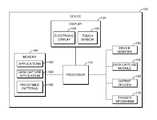
- FIG. 1is a block diagram of a data capture device 100 in which methods and components required for performing a variable data capture process is implemented in accordance with the embodiments.
- the data capture device 100may take form of, but is not limited to, wearable devices such as finger or head mounted devices, vehicle mounted devices, handheld devices such as a smartphone, a tablet, a bar code scanner, optical code reader and the like, a data capture terminal connected to a handheld device, a desktop, a vehicle mounted device, a laptop or notebook computer, an automated teller machine, a kiosk, a vending machine, a payment machine, facsimile machine, a point of sale device, a vehicle mounted device and the like.
- wearable devicessuch as finger or head mounted devices, vehicle mounted devices, handheld devices such as a smartphone, a tablet, a bar code scanner, optical code reader and the like
- a data capture terminalconnected to a handheld device, a desktop, a vehicle mounted device, a laptop or notebook computer, an automated teller machine, a kiosk, a vend
- connectionmay be wired or wireless.
- the connectionmay utilize a wireless communication system, a wired communication system, a broadcast communication system, or any other equivalent communication system.
- the communication systemmay function utilizing any wireless radio frequency channel, for example, a one or two-way messaging channel, a mobile cellular telephone channel, or a mobile radio channel.
- the communication systemmay function utilizing other types of communication channels such as Institute of Electrical and Electronics Engineers (IEEE) 802.11, IEEE 802.16 and/or Bluetooth channels.
- IEEEInstitute of Electrical and Electronics Engineers
- the communication systemmay function utilizing a wireline communication channel such as a local area network (LAN) or a wide area network (WAN) or a combination of both.
- LANlocal area network
- WANwide area network
- the LANmay employ any one of a number of networking protocols, such as TCP/IP (Transmission Control Protocol/Internet Protocol), AppleTalkTM, IPX/SPX (Inter-Packet Exchange/Sequential Packet Exchange), Net BIOS (Network Basic Input Output System) or any other packet structures to enable the communication among the devices and/or chargers.
- the WANmay use a physical network media such as X.25, Frame Relay, ISDN, Modem dial-up or other media to connect devices or other local area networks.
- the term “communication system” or “connection”refers to any of the systems mentioned above or an equivalent.
- Embodimentsmay be advantageously implemented to perform variable data capture processes on the data capture device 100 .
- Embodimentsmay be implemented in any electronic device performing data capture.
- the data capture device 100comprises a processor 110 , a touch display 120 , one or more output devices 135 , a memory 140 , a data capture module 150 , one or more device sensors 160 and a trigger mechanism 170 .
- the processor 110runs or executes operating instructions or applications that are stored in the memory 140 to perform various functions for the data capture device 100 and to process data.
- the processor 110includes one or more microprocessors, microcontrollers, digital signal processors (DSP), state machines, logic circuitry, or any device or devices that process information based on operational or programming instructions stored in the memory 140 .
- the processor 110processes various functions and data associated with carrying out the variable data capture process.
- the touch display 120may be realized as an electronic display 125 configured to graphically display information and/or content under the control of the processor 110 .
- the electronic display 125may be realized as a liquid crystal display (LCD), a touch-sensitive display, a cathode ray tube (CRT), a light emitting diode (LED) display, an organic light emitting diode (OLED) display, a plasma display, a projection display, or another suitable electronic display.
- the touch display 120may provide a user interface between the data capture device 100 and a user.
- the touch display 120includes a touch sensor 130 .
- the touch sensor 130can provide an input interface that can complement an output interface, as provided by the electronic display 125 .
- the touch sensor 130may have a touch-sensitive surface, sensor, or set of sensors that accepts input from the user based on haptic and/or tactile contact.
- the touch sensor 130may be operated on by an input device (such as a finger of a user or other input device such as a stylus, including passive and active) to provide touch sensitive inputs to the data capture device 100 .
- the touch display 120has a virtual keypad or keyboard that comprises a plurality of graphical keys or buttons arranged in a predetermined layout (for example, QWERTY keyboard or numeric/alpha numeric keypads) to allow the user to tap or touch the keys in a sequence to provide inputs to the data capture device 100 .
- a virtual keypad or keyboardthat comprises a plurality of graphical keys or buttons arranged in a predetermined layout (for example, QWERTY keyboard or numeric/alpha numeric keypads) to allow the user to tap or touch the keys in a sequence to provide inputs to the data capture device 100 .
- the block diagram of FIG. 1shows the touch sensor 130 to be an integral part of the display 120
- the data capture device 100may include a touch display 120 that is separated from and communicatively coupled to the touch sensor 130 .
- the term “touch sensor”will be used throughout the description to represent any touch sensitive surface or panel that may be used in conjunction with the touch display 120 , to receive input. In some embodiments, more
- the data capture module 150includes one or more data sensors for capturing data from various data sources.
- a data sensormay be an optical sensor such as a charge-coupled device (CCD) sensor, a laser scanner and the like, that may capture data from optical data sources such as bar codes, quick response (QR) codes and video response (VR) codes and other similar optical data sources.
- Data sensorsmay also include electromagnetic sensors such as near field communication (NFC) sensors and radio frequency identification (RFID) readers that may capture data from electromagnetic data sources such as from RFID tags and NFC tags, acoustic sensors such as ultrasonic devices, or voice sensors and the like.
- NFCnear field communication
- RFIDradio frequency identification
- the data capture module 150may also include additional components to aid with its operation such as lasers for scanning optical data, optics for directing light to image sensors and antennae for aiding data reception by electromagnetic readers.
- the optics of the data capture module 150may be pointed at the data source, such as a bar code, at an appropriate distance.
- antennae associated with the RFID reader or NFC sensorare brought within a prescribed range of the item containing the RFID or NFC tag.
- the data capture device 100may include multiple data capture modules 150 , each module including one or more data sensors.
- the device sensors 160may detect various physical forces applied to the data capture device 100 .
- motion sensorssuch as accelerometers and gyroscopes may detect acceleration and changes in orientation respectively.
- Other device sensors 160such as pressure sensors may detect pressure applied to the housing of the data capture device 100 .
- a force sensormay be fabricated using any suitable force sensing technology.
- Device sensors 160may include further sensors such as magnetometers, and the like.
- the device sensors 160may be placed on or in a portion of the data capture device 100 in predetermined numbers and arrangements.
- a pressure sensormay be incorporated as part of the grip, allowing the sensor to detect the amount of pressure (or strength of “squeeze”) applied to the grip.
- a plurality of accelerometersmay be placed on or in the data capture device 100 so as to enable measuring motion along an associated plurality of axes. In accordance with such an arrangement, motion of the data capture device 100 may be detected.
- the plurality of accelerometersfor example, may comprise three accelerometers placed along perpendicular axes to provide for three dimensional motion detection of the data capture device 100 .
- Each of the device sensors 160provides indicators of forces detected to the processor 110 , which may process the indicators as appropriate to determine motion and/or pressure.
- the trigger mechanism 170may be a virtual mechanism and/or a physical mechanism, the activation of which enables the performance of various operations and processes by data capture device 100 .
- a physical trigger mechanismmay include a physical switch, a capacitive or optical sensor, a pressure sensor, a microphone or other physical mechanisms which may be activated through the provision of an input such as pressure and/or touch applied to the mechanism.
- a virtual trigger mechanismmay be implemented through software applications.
- the touch display 120may provide virtual trigger mechanisms such as one or more virtual keys, buttons or regions on the touch display 120 which may be activated by providing an input to the touch sensor 130 .
- the virtual trigger mechanismmay not be displayed and when the trigger mechanism is not displayed, an indication indicating that it is available for activating may be provided.
- the trigger mechanism 170may be activated through provision of specific audio inputs such as voice commands and the like.
- the trigger mechanism 170may be dedicated to triggering one single function or the function triggered through its activation may depend on the operational context of the data capture device 100 .
- activation of the trigger mechanism 170may initiate a data capture by the data capture module 150 .
- the memory 140may be an IC (integrated circuit) memory chip containing any form of RAM (random-access memory) or ROM (read-only memory), a CD-RW (compact disk with read write), a hard disk drive, a DVD-RW (digital versatile disc with read write), a flash memory card, external subscriber identity module (SIM) card or any other non-transitory medium for storing digital information.
- the memory 140comprises one or more applications 180 , a data gathering application 185 and one or more patterns 190 corresponding to one or more known gestures.
- the applications 180include various software and/or firmware programs necessary for the operation of the data capture device 100 as well as software and/or firmware programs (e.g. banking, email applications etc.) that address specific requirements of the user.
- the data gathering application 185includes instructions that may be executed by the processor 110 to gather data from various data sources through the use of the data capture module 150 in accordance with a data capture process.
- Data sourcesmay be located in or on items such as inventory, packed individually or in groups, machine parts, and the like and locations such as walls, shelves, items stored in a warehouse, items transported in a truck, and the like.
- the data gathering application 185may provide an indication that it is ready to receive captured data.
- the trigger mechanism 170is activated to initiate data capture through the data capture module 150 .
- the captured datais then provided, by the processor 110 , to the data gathering application 185 .
- the data gathering application 185may subsequently cause the processor 110 to process the captured data in accordance with instructions contained by the data gathering application 185 .
- the captured datamay be processed prior to its provision to the data gathering application 185 or may be processed by the data gathering application 185 .
- the processed datamay be provided as an input to an input field of the data gathering application 185 and displayed on the touch display 120 accordingly.
- the virtual trigger mechanism 170may be provided on the touch display 120 simultaneously with the applications 180 and/or the data gathering application 185 .
- the region of the touch display 120 associated with providing the virtual trigger mechanism 170may overlap with the region of the touch display 120 for providing the applications 180 and/or the data gathering application 185 .
- the virtual mechanism 170 and/or the applications 180 and/or the data gathering application 185may be translucent. Translucency allows the applications 180 or the data gathering application 185 to be visible through the virtual trigger mechanism 170 and vice versa.
- activation of the trigger mechanism 170may be based on obtaining and identifying an input.
- the inputmay be received at a location on the touch display 120 that corresponds to a region where the virtual mechanism 170 is displayed.
- the inputmay be received anywhere on the touch display 120 .
- the inputmay be received at any area of the touch display 120 .
- at least a portion of the inputmay be received at the region of the touch display 120 where the trigger mechanism 170 is provided.
- the reception of the gesturemay originate at a location on the touch display 120 where the trigger mechanism 170 is provided.
- the processor 110monitors the touch display 120 and the device sensors 160 for at least a predetermined period of time following the initiation of a detection process. In some embodiments, obtaining an input is initiated in response to some received input. In some embodiments, monitoring for an input may be initiated based on the operational state of device 100 in addition to or as an alternative to an input, such as when data capture through data capture module 150 is needed. For example, in some embodiments, data capture may be needed when the data gathering application 185 enters a state of readiness and awaits captured data as an input.
- the monitoringmay continue until a further input is received indicating that the monitoring should cease, and/or when the operational context of the data capture device 100 changes to one where data capture through the data capture module 150 is no longer required.
- the data gathering application 185may exit a readiness state indicating that it no longer expects captured data as an input.
- the detection processmay always be active, regardless of inputs or the operational state of the data capture device 100 .
- an inputis obtained from the touch sensor 130 .
- the inputcomprises a sequence, in time, of touch sensor 130 values corresponding to a gesture sequence representing a gesture pattern.
- the inputmay also include sensor values obtained from the device sensors 160 , corresponding to the touch sensor 130 input.
- the obtained inputincludes input patterns in the form of gesture sequences representing gesture patterns.
- Gesture patternsmay be in the form of device gesture patterns and touch gesture patterns.
- Device gesture patternsmay be obtained when the data capture device 100 obtains a gesture though one or more of the device sensors 160
- touch gesture patternsmay be obtained when the data capture device 100 obtains a gesture through the touch sensor 130 .
- device gesture patternsmay include any gesture patterns obtained through one or more device sensors 160 , including accelerometers, gyroscopes, pressure sensors, magnetometers and the like.
- device gesturesmay include shaking, tilting, rotating, and the like.
- a side to side translational movement of the data capture device 100may result in the data capture device 100 obtaining a device gesture pattern represented by a sequence of sensor values received from an accelerometer corresponding to the movement.
- the data capture device 100may obtain sensor values corresponding to a side to side or forward and backward tilt.
- the data capture devicebeing raised in an arc from a horizontal position to a vertical position with the touch screen facing a user may result in the data capture device 100 obtaining a device gesture pattern represented by a sequence of sensor values obtained from an accelerometer and a gyroscope corresponding to the movement.
- the data capture device 100may obtain a device gesture pattern represented by a sequence of sensor values from a gyroscope corresponding to the data capture device being rotated ninety degrees.
- Touch gesture patternsmay include any gesture patterns obtained through one or more touch sensors 130 .
- touch gesturesmay include, swipe or slide and flick.
- the data capture device 100may obtain a touch gesture pattern from the touch sensor 130 corresponding to a particular pattern of a touch input, for example a swipe from an edge of the touch display 120 towards the middle of the touch display 120 .
- Gesture patternsmay include patterns in space (spatial gestures) and/or time (temporal gestures).
- Spatial gesture patternsare patterns that are formed from inputs from the touch sensor 130 (touch gesture pattern) or from the device sensors 160 (device gesture pattern), the received gesture patterns, in each case, being based on a spatial pattern.
- spatial patternsmay be classified in accordance with a type of spatial pattern.
- a spatial gesture patternmay be shape based, corresponding to a particular shape, such as a circle, a “z” (for example, as a pattern of points and/or lines), or the like.
- Shape based patternsmay include size, such as, a touch size pattern that includes the size of a touch on the touch display 120 .
- Touch sizecan be varied by pressing the touch input on the touch display 120 such that greater area of the touch display 120 is covered by the touch input.
- the sizecan vary in time by varying the press, or by rolling the input, such as when rolling fingers to provide fingerprints.
- a spatial patternmay be location based, corresponding, for example, to a movement related to specific regions of the touch display 120 , such as a swipe, with a touch input, from an edge to the center of the touch display 120 and the like.
- the gesture patternmay be orientation based, corresponding to a change in orientation, or translation of a capture device 100 .
- the capture device 100may be raised in an arc form, form a horizontal position to a vertical position.
- a spatial gesture patternmay comprise discrete movements, corresponding to a series of discrete inputs, such as touches at specific locations of the touch display 120 in a sequence and the like.
- a spatial gesture patternmay comprise continuous movements, corresponding to continuous movements, such as a continuous side-to side movement or the like.
- gesturesmay comprise a combination of two or more of the spatial pattern types.
- Temporal gesture patternsare gesture patterns that are formed from inputs from the touch sensor 130 (touch gesture patterns) or the device sensors 160 (device gesture patterns), the received gesture patterns in each case being based on patterns in time.
- the data capture device 100may obtain a temporal device gesture pattern from the device sensors 160 in accordance with a temporal pattern such that detected movements are separated in time in accordance with a pattern in time.
- the device 100may obtain, from one of the device sensors 160 that is a pressure sensor, a temporal gesture pattern corresponding to pressure changes, each pressure variation separated in accordance with a pattern in time.
- temporal patternsmay be classified in accordance with a type of temporal pattern.
- a temporal gesture patternmay be rhythm based, corresponding to a particular rhythm, such as providing touch to the touch display 120 in accordance with a tempo, or shaking the data capture device 100 , up or down, in accordance with a rhythm.
- a temporal gesture patternmay be speed based, correspond to a speed of movement, such as a flick, with a touch input, on the touch display 120 or a hard tap on the touch display 120 .
- a temporal gesturemay comprise discrete movements, corresponding to a series of discrete inputs, such as detected touches at specific locations of the touch display 120 in a timed pattern and the like.
- a temporal gesturemay comprise continuous movements, corresponding to continuous movements such as a timed pattern of continuous side-to side movement or the like.
- gesturesmay comprise a combination of two or more of the temporal pattern types.
- a gesture pattern obtainedcan correspond to a combination of spatial and temporal patterns.
- a gesture pattern obtainedmay correspond to a rhythmic back and forth linear movement of an input on the touch display 120 .
- the linear movement, and its sizemay represent a spatial pattern and the rhythmic nature of it may represent a temporal pattern.
- sensor values from different device sensors 160 as well as the touch sensor 130may be included in an input defining more complex gesture patterns.
- sensor values from an accelerometer and a gyroscopemay be combined to represent a complex gesture pattern including both translational and rotational movements.
- the obtained inputmay include other input patterns.
- the input patternsmay include sensor values from the touch sensor 130 as well as the device sensors 160 .
- an input pattern “hard-tap”may be represented by both a touch sensor value and a device sensor value.
- a hard-tap input patternmay comprise a touch on the touch display 120 , with sufficient force to register a certain amount of acceleration in the direction of the tap.
- the processor 110may obtain the touch sensor 130 values representing a touch on the touch display 120 .
- the processor 110may also receive values from one of the device sensors 160 that is an accelerometer representing data capture device 100 movements corresponding to the detected touch. The combination of the touch sensor 130 values and the values of device sensors 160 may accordingly be deemed to represent a hard-tap input pattern when the acceleration values corresponding to the touch, as measured by the accelerometer, is greater than a predetermined acceleration threshold.
- the input patternmay be a touch size input pattern.
- the inputmay include an indication of a touch size, in addition to a touch location, both obtained from the touch sensor 130 .
- the combination of the touch location and size indicatorsmay accordingly be deemed to represent a touch size input pattern when the touch size indicators corresponding to the touch, as provided by the touch sensor 130 , is greater than a predefined touch-size threshold.
- sensor values comprising the inputmay be processed.
- an obtained sequences of sensor valuesmay be processed to convert them into a pattern that facilitates the identifiability of gesture patterns.
- a sequence of acceleration values obtained from an accelerometer representing a gesturemay be converted into a sequence of relative locations for the data capture device 100 , indicating a relative path that the data capture device 100 has traversed in performing the gesture.
- a sequence of location values obtained from a touch sensor 130 representing a gesturemay be converted into a sequence of relative locations for the display screen, indicating a path that a touch input has traversed relative to the touch display 120 , such as a movement from an edge to the center or from the center to the edge of the touch display 120 .
- the processingmay occur at the data capture device 100 , or may occur at a computing device external to the data capture device 100 .
- the obtained input patternin either raw or processed form, is compared to the predefined patterns 190 .
- the comparisonallows determining whether the obtained input pattern can be matched to a predefined one.
- Predefined patternsmay represent any input pattern defined by an operator of the data capture device 100 .
- Predefined patternsmay be obtained, for example, using a data capture device 100 , by providing an input and storing the corresponding input pattern received on the device.
- predefined patternsmay be obtained from sources external to the data capture device 100 such as other computing devices, servers and the like.
- the comparisonmay be performed at a computing device external to the data capture device 100 .
- the obtained input patternmay be transmitted to an external computing device for performing the comparison to the predefined gesture patterns. Accordingly, in these embodiments, the predefined gesture patterns may be maintained externally to the data capture device 100 .
- the virtual trigger mechanism 170when a match between the obtained input pattern and a predefined pattern is identified, on the basis of the comparison, the virtual trigger mechanism 170 can be deemed to be activated. Accordingly, data capture by the data capture module 150 is initiated. In some embodiments, where an input pattern is not obtained (or alternatively, an input pattern is obtained but not identified based on predefined patterns) the input may be provided to the data gathering application 185 or the applications 180 . Alternatively, in some embodiments, identification of an obtained input pattern based on a predefined pattern 190 may cause an input to be provided to the data gathering application 185 or the applications 180 . In these embodiments, virtual trigger mechanism 170 is activated when the identification of the input pattern fails.
- the input provided to the data gathering application 185 or the applications 180may be indicated as occurring at the location where the obtained input originates. In yet other embodiments, the input provided to the data gathering application 185 or the applications 180 may be a portion of the input. In further embodiments, the input provided to the data gathering application 185 or the applications 180 may be different from the input obtained. For example, the input provided may be a simple indication of a touch at the touch display 120 and the touch may be indicated as occurring at the location where the obtained input originates.
- FIG. 2represents a flowchart of a method 200 for activating a trigger mechanism at the data capture device 100 of FIG. 1 in accordance with some embodiments.
- the method 200begins by entering a first mode of operation at block 205 .
- the virtual trigger mechanism 170is monitored for activation in this mode of operation.
- the monitoringoccurs in response to the data capture device 100 entering a ready state for capturing data.
- the monitoringoccurs based on receiving an input, such as a touch.
- other types of inputsmay be received to initiate the monitoring of the virtual trigger mechanism 170 for activation.
- the monitoringmay be always on. In other embodiments, the monitoring may last for a predetermined period.
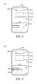
- the touch display 120 of the data capture device 100is shown in a mode of operation in accordance with one embodiment where the virtual trigger mechanism 170 is being monitored.
- the touch display 120includes user interface elements for the data gathering application 185 .
- the data gathering applicationis shown as occupying the whole of the touch display 120
- the display region occupied by the data gathering application 185may be a portion of the display area of the touch display 120 .
- Input boxes 310 - 1 through 310 - 3are indicated, with the input box 310 - 1 including an asterisk 320 , indicating that the data gathering application 185 is in a ready state to accept captured data to be processed and provided to the input box 310 - 1 .
- the touch display 120also includes a virtual button 325 , which, when selected allows for the modification of various application options.
- the touch display 120further includes a virtual trigger mechanism 170 .
- the virtual trigger mechanism 170is shown as an input region 330 .
- the input region 330overlaps with the display region of the data gathering application 185 and is translucent to allow the user interface of the data gathering application 185 to be visible in areas of the touch display 120 where the user interface of the data gathering application 185 overlaps with the input region 330 .
- the change in display characteristics resulting from the translucenceserves as an indicator of the presence of the input region 330 .
- input regionmay occupy a larger or smaller portion of the touch display 120 .
- the input region 330may be invisible, and its presence may be indicated through a visual indicator such as a text, graphic or image indicator, displayed at some portion of the touch display 120 .
- the activation of the virtual trigger mechanism 170may be detected based on obtaining, at the data capture device 100 , an input containing an input pattern that can be identified based on matching a predefined pattern.
- an inputis obtained at block 210 .
- the processor 110monitors one or more device sensors 160 and the touch sensor 130 to obtain the input.
- An inputmay comprise spatial or temporal gesture patterns obtained as a result of performing a gesture on the touch display device 120 , for example.
- a “swipe-in” gestureis indicated at 410 .
- the data capture device 100obtains an input pattern based on a horizontal movement of a touch input at the touch display 120 from an edge of the touch display 120 , as indicated by the circle 420 , towards the middle of the touch display 120 , as indicated by the arrow 410 .
- the swipe-in gesturemay be a diagonal or a vertical movement.
- the movementmay be from an area near the middle of the touch display 120 to an edge of the touch display 120 .
- Obtaining the inputis based on the processor 110 receiving a sequence of sensor values from the touch sensor 130 as a result of the gesture.
- the sequence of sensor valuescontain information representing the spatial and temporal gesture patterns defining the gesture.
- the inputmay be further processed to better represent the input patterns.
- an input pattern obtained by the data capture device 100may additionally include input data representing rotational movements, discrete movements as well as a sequence of sensor values obtained from the device sensors 160 representing device gestures.
- the movementsmay also involve temporal patterns, adding a rhythm and the like to the obtained movements and pressure changes, for example. Accordingly, the obtained input pattern may include both spatial and temporal patterns.
- an input patternmay comprise a touch size pattern and corresponding input obtained may include, sensor values corresponding to the size of the touch input being received at the touch display 120 .
- an input patternmay comprise a hard-tap. Accordingly, the input received may include sensor values from both the touch sensor 130 , indicating a touch and from the device sensors 160 indicating movement corresponding to the touch.
- patternsmay be combined. For example, the swipe-in gesture may be initiated with a hard-tap pattern.
- the obtained input patternis compared to the predefined patterns 190 to identify the input pattern at block 215 .
- the data capture device 100may maintain one or more predefined patterns 190 which are defined to correspond to specific gestures. These predefined patterns may be received by the device 100 , prior to performing method 200 .
- the predefined patterns 190may be supplied to the data capture device 100 during the operation of method 200 .
- the obtained input patternis compared to one or more of the predefined patterns 190 .
- the comparisonresults in a match, the obtained input pattern is deemed to be an identified input pattern.
- Matching an input patternmay be performed using various methods of pattern comparison. In some embodiments, the comparison occurs once the input applied to the data capture device 100 is completed. For example, when a detected input ceases, sensor values received will indicate no further detection. Accordingly, gesture identification may begin. In other embodiments, the identification may be performed on the fly, as the input is being obtained.
- At least a portion of the inputis provided to the data gathering application 185 as indicated at 220 in FIG. 2 .
- an indicationmay be provided that no input pattern is detected, or that the obtained input pattern cannot be identified.
- monitoring for an input patternmay be repeated for a predetermined period. After one or more repetitions, at least a portion of the input may be provided to the data gathering application 185 as indicated at 220 .
- an input other than the obtained inputmay be provided to the data gathering application 185 at block 220 .
- the inputmay be provided as a simple touch input, as opposed to a sequence of input values obtained from the touch sensor 130 or the device sensors 160 .
- the touch inputmay comprise the location of the touch input on the touch display 120 .
- the locationmay be indicated as the originating position of the obtained input on the touch display 120 .
- itmay be the ending position of the obtained input on the touch display 120 .
- an inputmay be provided to the data gathering application 185 indicating a touch at location 420 indicated in FIG. 4 .
- the virtual button 325may be activated, allowing modification of application options.
- the data capture processinvolves acquiring a representation of data contained at a data source through one or more of the data sensors included in the data capture module 150 . For example, an image of a barcode may be acquired.
- the captured datamay be passed back to the data gathering application 185 at block 230 , to be provided, for example, as input for the input box 310 - 1 .
- a capture complete indicatormay also be generated.
- the captured datamay be processed, and the processed data may be provided to the input box 310 - 1 .
- the input box 310 - 1now includes a checkmark 510 , which indicates that the captured data was received and processed successfully.
- the indicator 510may be presented in formats other than graphics, such as in a text or image format.
- the indicator 510may include information obtained from the captured data and the information may be obtained from pre or post-processing of the data. In some embodiments, the indicator 510 may also serve as a capture complete indicator. In some embodiments, once input is provided to input box 310 - 1 , the input focus may move to input box 310 - 2 , and the data capture device 100 may once again enter a ready state, causing method 200 to be performed once again.
- successful identification of an input pattern at block 215may cause an operation other than data capture operation to be performed at block 225 .
- the data gathering application 185may be caused to change the active input box, from, for example, input box 310 - 1 to input box 310 - 2 .
- the data gathering application 185may be caused to change the active input box, from, for example, input box 310 - 1 to input box 310 - 2 .
- the input boxeswhen all the input boxes are occupied, they may be caused to be submitted to, for example, one of the applications 180 .
- identifying the obtained input pattern successfully at 215causes the data capture device 100 to enter a different mode of operation.
- the data capture device 100may enter a second mode of operation, such as a rapid data capture mode. Once the mode of operation is changed, method 200 may be performed again.
- the action performed at block 220based on an unsuccessful identification of an input pattern at block 215 may change.
- a data capturemay be performed at 220 .
- method 200may be repeated in the second mode of operation.
- the data capture device 100may perform data capture rapidly and repeatedly through, for example, repeated touches on the touch display 120 .
- the captured datacan be provided to application 185 , for example, as described herein.
- the second mode of operationcan be ended, and another mode of operation, such as the first mode of operation, entered, when for example, an obtained input pattern is successfully identified at block 215 . Accordingly, performing block 225 , while in the second mode may cause the mode of operation to be changed, for example to the first mode of operation.
- aincludes . . . a”, “contains . . . a” does not, without more constraints, preclude the existence of additional identical elements in the process, method, article, or apparatus that comprises, has, includes, contains the element.
- the terms “a” and “an”are defined as one or more unless explicitly stated otherwise herein.
- the terms “substantially”, “essentially”, “approximately”, “about” or any other version thereof,are defined as being close to as understood by one of ordinary skill in the art, and in one non-limiting embodiment the term is defined to be within 10%, in another embodiment within 5%, in another embodiment within 1% and in another embodiment within 0.5%.
- the term “coupled” as used hereinis defined as connected, although not necessarily directly and not necessarily mechanically.
- a device or structure that is “configured” in a certain wayis configured in at least that way, but may also be configured in ways that are not listed.
- processorssuch as microprocessors, digital processors, customized processors and field programmable gate arrays (FPGAs) and unique stored program instructions (including both software and firmware) that control the one or more processors to implement, in conjunction with certain non-processor circuits, some, most, or all of the functions of the method and/or apparatus described herein.
- processorsor “processing devices” such as microprocessors, digital processors, customized processors and field programmable gate arrays (FPGAs) and unique stored program instructions (including both software and firmware) that control the one or more processors to implement, in conjunction with certain non-processor circuits, some, most, or all of the functions of the method and/or apparatus described herein.
- FPGAsfield programmable gate arrays
- unique stored program instructionsincluding both software and firmware
- an embodimentmay be implemented as a computer-readable storage medium having computer readable code stored thereon for programming a computer (e.g., comprising a processor) to perform a method as described and claimed herein.
- Examples of such computer-readable storage mediumsinclude, but are not limited to, a hard disk, a CD-ROM, an optical storage device, a magnetic storage device, a ROM (Read Only Memory), a PROM (Programmable Read Only Memory), an EPROM (Erasable Programmable Read Only Memory), an EEPROM (Electrically Erasable Programmable Read Only Memory) and a Flash memory.
Landscapes
- Engineering & Computer Science (AREA)
- Physics & Mathematics (AREA)
- Theoretical Computer Science (AREA)
- General Engineering & Computer Science (AREA)
- General Physics & Mathematics (AREA)
- Electromagnetism (AREA)
- Toxicology (AREA)
- Health & Medical Sciences (AREA)
- Human Computer Interaction (AREA)
- General Health & Medical Sciences (AREA)
- Artificial Intelligence (AREA)
- Computer Vision & Pattern Recognition (AREA)
- User Interface Of Digital Computer (AREA)
- Business, Economics & Management (AREA)
- Accounting & Taxation (AREA)
- Finance (AREA)
- Development Economics (AREA)
- Economics (AREA)
- Marketing (AREA)
- Strategic Management (AREA)
- General Business, Economics & Management (AREA)
Abstract
Description
Claims (18)
Priority Applications (2)
| Application Number | Priority Date | Filing Date | Title |
|---|---|---|---|
| US14/270,400US9501163B2 (en) | 2014-05-06 | 2014-05-06 | Apparatus and method for activating a trigger mechanism |
| PCT/US2015/028406WO2015171407A1 (en) | 2014-05-06 | 2015-04-30 | Apparatus and method for activating a trigger mechanism |
Applications Claiming Priority (1)
| Application Number | Priority Date | Filing Date | Title |
|---|---|---|---|
| US14/270,400US9501163B2 (en) | 2014-05-06 | 2014-05-06 | Apparatus and method for activating a trigger mechanism |
Publications (2)
| Publication Number | Publication Date |
|---|---|
| US20150324041A1 US20150324041A1 (en) | 2015-11-12 |
| US9501163B2true US9501163B2 (en) | 2016-11-22 |
Family
ID=53267579
Family Applications (1)
| Application Number | Title | Priority Date | Filing Date |
|---|---|---|---|
| US14/270,400Active2034-08-30US9501163B2 (en) | 2014-05-06 | 2014-05-06 | Apparatus and method for activating a trigger mechanism |
Country Status (2)
| Country | Link |
|---|---|
| US (1) | US9501163B2 (en) |
| WO (1) | WO2015171407A1 (en) |
Cited By (1)
| Publication number | Priority date | Publication date | Assignee | Title |
|---|---|---|---|---|
| EP4166558A1 (en) | 2010-02-12 | 2023-04-19 | Pfizer Inc. | Salts and polymorphs of 8-fluoro-2-{4- [(methylamino)methyl]phenyl}-1 ,3,4,5-tetrahydro-6h-azepino[5,4,3- cd]indol-6-one |
Families Citing this family (151)
| Publication number | Priority date | Publication date | Assignee | Title |
|---|---|---|---|---|
| US8677377B2 (en) | 2005-09-08 | 2014-03-18 | Apple Inc. | Method and apparatus for building an intelligent automated assistant |
| US9318108B2 (en) | 2010-01-18 | 2016-04-19 | Apple Inc. | Intelligent automated assistant |
| US8977255B2 (en) | 2007-04-03 | 2015-03-10 | Apple Inc. | Method and system for operating a multi-function portable electronic device using voice-activation |
| US10002189B2 (en) | 2007-12-20 | 2018-06-19 | Apple Inc. | Method and apparatus for searching using an active ontology |
| US9330720B2 (en) | 2008-01-03 | 2016-05-03 | Apple Inc. | Methods and apparatus for altering audio output signals |
| US8996376B2 (en) | 2008-04-05 | 2015-03-31 | Apple Inc. | Intelligent text-to-speech conversion |
| US20100030549A1 (en) | 2008-07-31 | 2010-02-04 | Lee Michael M | Mobile device having human language translation capability with positional feedback |
| US8676904B2 (en) | 2008-10-02 | 2014-03-18 | Apple Inc. | Electronic devices with voice command and contextual data processing capabilities |
| US20120309363A1 (en) | 2011-06-03 | 2012-12-06 | Apple Inc. | Triggering notifications associated with tasks items that represent tasks to perform |
| US10241644B2 (en) | 2011-06-03 | 2019-03-26 | Apple Inc. | Actionable reminder entries |
| US10241752B2 (en) | 2011-09-30 | 2019-03-26 | Apple Inc. | Interface for a virtual digital assistant |
| US9431006B2 (en) | 2009-07-02 | 2016-08-30 | Apple Inc. | Methods and apparatuses for automatic speech recognition |
| US10276170B2 (en) | 2010-01-18 | 2019-04-30 | Apple Inc. | Intelligent automated assistant |
| US8682667B2 (en) | 2010-02-25 | 2014-03-25 | Apple Inc. | User profiling for selecting user specific voice input processing information |
| US9262612B2 (en) | 2011-03-21 | 2016-02-16 | Apple Inc. | Device access using voice authentication |
| US10057736B2 (en) | 2011-06-03 | 2018-08-21 | Apple Inc. | Active transport based notifications |
| US10134385B2 (en) | 2012-03-02 | 2018-11-20 | Apple Inc. | Systems and methods for name pronunciation |
| US10417037B2 (en) | 2012-05-15 | 2019-09-17 | Apple Inc. | Systems and methods for integrating third party services with a digital assistant |
| US9721563B2 (en) | 2012-06-08 | 2017-08-01 | Apple Inc. | Name recognition system |
| US9547647B2 (en) | 2012-09-19 | 2017-01-17 | Apple Inc. | Voice-based media searching |
| DE212014000045U1 (en) | 2013-02-07 | 2015-09-24 | Apple Inc. | Voice trigger for a digital assistant |
| US10652394B2 (en) | 2013-03-14 | 2020-05-12 | Apple Inc. | System and method for processing voicemail |
| US10748529B1 (en) | 2013-03-15 | 2020-08-18 | Apple Inc. | Voice activated device for use with a voice-based digital assistant |
| WO2014197334A2 (en) | 2013-06-07 | 2014-12-11 | Apple Inc. | System and method for user-specified pronunciation of words for speech synthesis and recognition |
| WO2014197335A1 (en) | 2013-06-08 | 2014-12-11 | Apple Inc. | Interpreting and acting upon commands that involve sharing information with remote devices |
| DE112014002747T5 (en) | 2013-06-09 | 2016-03-03 | Apple Inc. | Apparatus, method and graphical user interface for enabling conversation persistence over two or more instances of a digital assistant |
| US10176167B2 (en) | 2013-06-09 | 2019-01-08 | Apple Inc. | System and method for inferring user intent from speech inputs |
| DE112014003653B4 (en) | 2013-08-06 | 2024-04-18 | Apple Inc. | Automatically activate intelligent responses based on activities from remote devices |
| US10296160B2 (en) | 2013-12-06 | 2019-05-21 | Apple Inc. | Method for extracting salient dialog usage from live data |
| US10365721B2 (en)* | 2014-05-06 | 2019-07-30 | Symbol Technologies, Llc | Apparatus and method for performing a variable data capture process |
| US9633004B2 (en) | 2014-05-30 | 2017-04-25 | Apple Inc. | Better resolution when referencing to concepts |
| US9430463B2 (en) | 2014-05-30 | 2016-08-30 | Apple Inc. | Exemplar-based natural language processing |
| CN110797019B (en) | 2014-05-30 | 2023-08-29 | 苹果公司 | Multi-command single speech input method |
| US9715875B2 (en) | 2014-05-30 | 2017-07-25 | Apple Inc. | Reducing the need for manual start/end-pointing and trigger phrases |
| US10170123B2 (en) | 2014-05-30 | 2019-01-01 | Apple Inc. | Intelligent assistant for home automation |
| US9338493B2 (en) | 2014-06-30 | 2016-05-10 | Apple Inc. | Intelligent automated assistant for TV user interactions |
| US9818400B2 (en) | 2014-09-11 | 2017-11-14 | Apple Inc. | Method and apparatus for discovering trending terms in speech requests |
| US10127911B2 (en) | 2014-09-30 | 2018-11-13 | Apple Inc. | Speaker identification and unsupervised speaker adaptation techniques |
| US9668121B2 (en) | 2014-09-30 | 2017-05-30 | Apple Inc. | Social reminders |
| US10074360B2 (en) | 2014-09-30 | 2018-09-11 | Apple Inc. | Providing an indication of the suitability of speech recognition |
| US10133412B2 (en)* | 2014-10-07 | 2018-11-20 | General Electric Company | Intuitive touch screen calibration device and method |
| US10152299B2 (en) | 2015-03-06 | 2018-12-11 | Apple Inc. | Reducing response latency of intelligent automated assistants |
| US10567477B2 (en) | 2015-03-08 | 2020-02-18 | Apple Inc. | Virtual assistant continuity |
| US9886953B2 (en) | 2015-03-08 | 2018-02-06 | Apple Inc. | Virtual assistant activation |
| US9721566B2 (en) | 2015-03-08 | 2017-08-01 | Apple Inc. | Competing devices responding to voice triggers |
| US10460227B2 (en) | 2015-05-15 | 2019-10-29 | Apple Inc. | Virtual assistant in a communication session |
| US10083688B2 (en) | 2015-05-27 | 2018-09-25 | Apple Inc. | Device voice control for selecting a displayed affordance |
| US10200824B2 (en) | 2015-05-27 | 2019-02-05 | Apple Inc. | Systems and methods for proactively identifying and surfacing relevant content on a touch-sensitive device |
| US9578173B2 (en) | 2015-06-05 | 2017-02-21 | Apple Inc. | Virtual assistant aided communication with 3rd party service in a communication session |
| US11025565B2 (en) | 2015-06-07 | 2021-06-01 | Apple Inc. | Personalized prediction of responses for instant messaging |
| US20160378747A1 (en) | 2015-06-29 | 2016-12-29 | Apple Inc. | Virtual assistant for media playback |
| KR20170014407A (en)* | 2015-07-30 | 2017-02-08 | 삼성전자주식회사 | Apparatus and method for controlling a security of electronic device |
| US10740384B2 (en) | 2015-09-08 | 2020-08-11 | Apple Inc. | Intelligent automated assistant for media search and playback |
| US10747498B2 (en) | 2015-09-08 | 2020-08-18 | Apple Inc. | Zero latency digital assistant |
| US10331312B2 (en) | 2015-09-08 | 2019-06-25 | Apple Inc. | Intelligent automated assistant in a media environment |
| US10671428B2 (en) | 2015-09-08 | 2020-06-02 | Apple Inc. | Distributed personal assistant |
| US11010550B2 (en) | 2015-09-29 | 2021-05-18 | Apple Inc. | Unified language modeling framework for word prediction, auto-completion and auto-correction |
| US10366158B2 (en) | 2015-09-29 | 2019-07-30 | Apple Inc. | Efficient word encoding for recurrent neural network language models |
| US11587559B2 (en) | 2015-09-30 | 2023-02-21 | Apple Inc. | Intelligent device identification |
| US10691473B2 (en) | 2015-11-06 | 2020-06-23 | Apple Inc. | Intelligent automated assistant in a messaging environment |
| US10956666B2 (en) | 2015-11-09 | 2021-03-23 | Apple Inc. | Unconventional virtual assistant interactions |
| US10049668B2 (en) | 2015-12-02 | 2018-08-14 | Apple Inc. | Applying neural network language models to weighted finite state transducers for automatic speech recognition |
| US10223066B2 (en) | 2015-12-23 | 2019-03-05 | Apple Inc. | Proactive assistance based on dialog communication between devices |
| US10446143B2 (en) | 2016-03-14 | 2019-10-15 | Apple Inc. | Identification of voice inputs providing credentials |
| US9934775B2 (en) | 2016-05-26 | 2018-04-03 | Apple Inc. | Unit-selection text-to-speech synthesis based on predicted concatenation parameters |
| US9972304B2 (en) | 2016-06-03 | 2018-05-15 | Apple Inc. | Privacy preserving distributed evaluation framework for embedded personalized systems |
| US11227589B2 (en) | 2016-06-06 | 2022-01-18 | Apple Inc. | Intelligent list reading |
| US10249300B2 (en) | 2016-06-06 | 2019-04-02 | Apple Inc. | Intelligent list reading |
| US10049663B2 (en) | 2016-06-08 | 2018-08-14 | Apple, Inc. | Intelligent automated assistant for media exploration |
| DK179309B1 (en) | 2016-06-09 | 2018-04-23 | Apple Inc | Intelligent automated assistant in a home environment |
| US12223282B2 (en) | 2016-06-09 | 2025-02-11 | Apple Inc. | Intelligent automated assistant in a home environment |
| US10067938B2 (en) | 2016-06-10 | 2018-09-04 | Apple Inc. | Multilingual word prediction |
| US10586535B2 (en) | 2016-06-10 | 2020-03-10 | Apple Inc. | Intelligent digital assistant in a multi-tasking environment |
| US10509862B2 (en) | 2016-06-10 | 2019-12-17 | Apple Inc. | Dynamic phrase expansion of language input |
| US10490187B2 (en) | 2016-06-10 | 2019-11-26 | Apple Inc. | Digital assistant providing automated status report |
| US10192552B2 (en) | 2016-06-10 | 2019-01-29 | Apple Inc. | Digital assistant providing whispered speech |
| DK179343B1 (en) | 2016-06-11 | 2018-05-14 | Apple Inc | Intelligent task discovery |
| US12197817B2 (en) | 2016-06-11 | 2025-01-14 | Apple Inc. | Intelligent device arbitration and control |
| DK179049B1 (en) | 2016-06-11 | 2017-09-18 | Apple Inc | Data driven natural language event detection and classification |
| DK179415B1 (en) | 2016-06-11 | 2018-06-14 | Apple Inc | Intelligent device arbitration and control |
| DK201670540A1 (en) | 2016-06-11 | 2018-01-08 | Apple Inc | Application integration with a digital assistant |
| US10474753B2 (en) | 2016-09-07 | 2019-11-12 | Apple Inc. | Language identification using recurrent neural networks |
| US10043516B2 (en) | 2016-09-23 | 2018-08-07 | Apple Inc. | Intelligent automated assistant |
| US10372412B2 (en)* | 2016-10-25 | 2019-08-06 | Microsoft Technology Licensing, Llc | Force-based interactions with digital agents |
| US20180121000A1 (en)* | 2016-10-27 | 2018-05-03 | Microsoft Technology Licensing, Llc | Using pressure to direct user input |
| US11281993B2 (en) | 2016-12-05 | 2022-03-22 | Apple Inc. | Model and ensemble compression for metric learning |
| US10593346B2 (en) | 2016-12-22 | 2020-03-17 | Apple Inc. | Rank-reduced token representation for automatic speech recognition |
| US11204787B2 (en) | 2017-01-09 | 2021-12-21 | Apple Inc. | Application integration with a digital assistant |
| US10417266B2 (en) | 2017-05-09 | 2019-09-17 | Apple Inc. | Context-aware ranking of intelligent response suggestions |
| DK201770383A1 (en) | 2017-05-09 | 2018-12-14 | Apple Inc. | User interface for correcting recognition errors |
| DK180048B1 (en) | 2017-05-11 | 2020-02-04 | Apple Inc. | MAINTAINING THE DATA PROTECTION OF PERSONAL INFORMATION |
| US10726832B2 (en) | 2017-05-11 | 2020-07-28 | Apple Inc. | Maintaining privacy of personal information |
| DK201770439A1 (en) | 2017-05-11 | 2018-12-13 | Apple Inc. | Offline personal assistant |
| US10395654B2 (en) | 2017-05-11 | 2019-08-27 | Apple Inc. | Text normalization based on a data-driven learning network |
| US11301477B2 (en) | 2017-05-12 | 2022-04-12 | Apple Inc. | Feedback analysis of a digital assistant |
| DK179745B1 (en) | 2017-05-12 | 2019-05-01 | Apple Inc. | SYNCHRONIZATION AND TASK DELEGATION OF A DIGITAL ASSISTANT |
| DK201770427A1 (en) | 2017-05-12 | 2018-12-20 | Apple Inc. | Low-latency intelligent automated assistant |
| DK179496B1 (en) | 2017-05-12 | 2019-01-15 | Apple Inc. | USER-SPECIFIC Acoustic Models |
| DK201770411A1 (en) | 2017-05-15 | 2018-12-20 | Apple Inc. | MULTI-MODAL INTERFACES |
| DK201770432A1 (en) | 2017-05-15 | 2018-12-21 | Apple Inc. | Hierarchical belief states for digital assistants |
| DK201770431A1 (en) | 2017-05-15 | 2018-12-20 | Apple Inc. | Optimizing dialogue policy decisions for digital assistants using implicit feedback |
| US10311144B2 (en) | 2017-05-16 | 2019-06-04 | Apple Inc. | Emoji word sense disambiguation |
| US10303715B2 (en) | 2017-05-16 | 2019-05-28 | Apple Inc. | Intelligent automated assistant for media exploration |
| US10403278B2 (en) | 2017-05-16 | 2019-09-03 | Apple Inc. | Methods and systems for phonetic matching in digital assistant services |
| US20180336892A1 (en) | 2017-05-16 | 2018-11-22 | Apple Inc. | Detecting a trigger of a digital assistant |
| DK179549B1 (en) | 2017-05-16 | 2019-02-12 | Apple Inc. | Far-field extension for digital assistant services |
| US10657328B2 (en) | 2017-06-02 | 2020-05-19 | Apple Inc. | Multi-task recurrent neural network architecture for efficient morphology handling in neural language modeling |
| US10445429B2 (en) | 2017-09-21 | 2019-10-15 | Apple Inc. | Natural language understanding using vocabularies with compressed serialized tries |
| US10755051B2 (en) | 2017-09-29 | 2020-08-25 | Apple Inc. | Rule-based natural language processing |
| US10636424B2 (en) | 2017-11-30 | 2020-04-28 | Apple Inc. | Multi-turn canned dialog |
| US10733982B2 (en) | 2018-01-08 | 2020-08-04 | Apple Inc. | Multi-directional dialog |
| US10733375B2 (en) | 2018-01-31 | 2020-08-04 | Apple Inc. | Knowledge-based framework for improving natural language understanding |
| US10747358B2 (en)* | 2018-02-22 | 2020-08-18 | Wacom Co., Ltd. | Position detection circuit and position detection method |
| US10789959B2 (en) | 2018-03-02 | 2020-09-29 | Apple Inc. | Training speaker recognition models for digital assistants |
| US10592604B2 (en) | 2018-03-12 | 2020-03-17 | Apple Inc. | Inverse text normalization for automatic speech recognition |
| US10818288B2 (en) | 2018-03-26 | 2020-10-27 | Apple Inc. | Natural assistant interaction |
| US10909331B2 (en) | 2018-03-30 | 2021-02-02 | Apple Inc. | Implicit identification of translation payload with neural machine translation |
| US11145294B2 (en) | 2018-05-07 | 2021-10-12 | Apple Inc. | Intelligent automated assistant for delivering content from user experiences |
| US10928918B2 (en) | 2018-05-07 | 2021-02-23 | Apple Inc. | Raise to speak |
| US10984780B2 (en) | 2018-05-21 | 2021-04-20 | Apple Inc. | Global semantic word embeddings using bi-directional recurrent neural networks |
| DK179822B1 (en) | 2018-06-01 | 2019-07-12 | Apple Inc. | Voice interaction at a primary device to access call functionality of a companion device |
| DK180639B1 (en) | 2018-06-01 | 2021-11-04 | Apple Inc | DISABILITY OF ATTENTION-ATTENTIVE VIRTUAL ASSISTANT |
| US11386266B2 (en) | 2018-06-01 | 2022-07-12 | Apple Inc. | Text correction |
| DK201870355A1 (en) | 2018-06-01 | 2019-12-16 | Apple Inc. | Virtual assistant operation in multi-device environments |
| US10892996B2 (en) | 2018-06-01 | 2021-01-12 | Apple Inc. | Variable latency device coordination |
| US10504518B1 (en) | 2018-06-03 | 2019-12-10 | Apple Inc. | Accelerated task performance |
| US11010561B2 (en) | 2018-09-27 | 2021-05-18 | Apple Inc. | Sentiment prediction from textual data |
| US11462215B2 (en) | 2018-09-28 | 2022-10-04 | Apple Inc. | Multi-modal inputs for voice commands |
| US10839159B2 (en) | 2018-09-28 | 2020-11-17 | Apple Inc. | Named entity normalization in a spoken dialog system |
| US11170166B2 (en) | 2018-09-28 | 2021-11-09 | Apple Inc. | Neural typographical error modeling via generative adversarial networks |
| US11475898B2 (en) | 2018-10-26 | 2022-10-18 | Apple Inc. | Low-latency multi-speaker speech recognition |
| US11638059B2 (en) | 2019-01-04 | 2023-04-25 | Apple Inc. | Content playback on multiple devices |
| US11348573B2 (en) | 2019-03-18 | 2022-05-31 | Apple Inc. | Multimodality in digital assistant systems |
| DK201970509A1 (en) | 2019-05-06 | 2021-01-15 | Apple Inc | Spoken notifications |
| US11475884B2 (en) | 2019-05-06 | 2022-10-18 | Apple Inc. | Reducing digital assistant latency when a language is incorrectly determined |
| US11423908B2 (en) | 2019-05-06 | 2022-08-23 | Apple Inc. | Interpreting spoken requests |
| US11307752B2 (en) | 2019-05-06 | 2022-04-19 | Apple Inc. | User configurable task triggers |
| US11140099B2 (en) | 2019-05-21 | 2021-10-05 | Apple Inc. | Providing message response suggestions |
| US11496600B2 (en) | 2019-05-31 | 2022-11-08 | Apple Inc. | Remote execution of machine-learned models |
| US11289073B2 (en) | 2019-05-31 | 2022-03-29 | Apple Inc. | Device text to speech |
| DK180129B1 (en) | 2019-05-31 | 2020-06-02 | Apple Inc. | USER ACTIVITY SHORTCUT SUGGESTIONS |
| DK201970511A1 (en) | 2019-05-31 | 2021-02-15 | Apple Inc | Voice identification in digital assistant systems |
| US11360641B2 (en) | 2019-06-01 | 2022-06-14 | Apple Inc. | Increasing the relevance of new available information |
| US11227599B2 (en) | 2019-06-01 | 2022-01-18 | Apple Inc. | Methods and user interfaces for voice-based control of electronic devices |
| US11488406B2 (en) | 2019-09-25 | 2022-11-01 | Apple Inc. | Text detection using global geometry estimators |
| US12301635B2 (en) | 2020-05-11 | 2025-05-13 | Apple Inc. | Digital assistant hardware abstraction |
| US11183193B1 (en) | 2020-05-11 | 2021-11-23 | Apple Inc. | Digital assistant hardware abstraction |
| US11061543B1 (en) | 2020-05-11 | 2021-07-13 | Apple Inc. | Providing relevant data items based on context |
| US11755276B2 (en) | 2020-05-12 | 2023-09-12 | Apple Inc. | Reducing description length based on confidence |
| US11490204B2 (en) | 2020-07-20 | 2022-11-01 | Apple Inc. | Multi-device audio adjustment coordination |
| US11438683B2 (en) | 2020-07-21 | 2022-09-06 | Apple Inc. | User identification using headphones |
Citations (17)
| Publication number | Priority date | Publication date | Assignee | Title |
|---|---|---|---|---|
| US5536930A (en) | 1992-06-03 | 1996-07-16 | Symbol Technologies, Inc. | Apparatus and method for sensing positional orientations of a portable terminal |
| EP0635780B1 (en) | 1993-07-21 | 2001-01-10 | Xerox Corporation | User interface having clickthrough tools that can be composed with other tools |
| US6501464B1 (en)* | 2000-10-31 | 2002-12-31 | Intel Corporation | On-screen transparent keyboard interface |
| US20030034392A1 (en) | 2001-08-17 | 2003-02-20 | Grimm Roger L. | Inventory system |
| US20040248621A1 (en) | 2001-09-06 | 2004-12-09 | Lennart Schon | Electronic device comprising a touch screen with special input functionality |
| CA2673587A1 (en) | 2006-12-29 | 2008-07-10 | Nokia Corporation | Transparent layer application |
| US20130147850A1 (en) | 2011-12-08 | 2013-06-13 | Motorola Solutions, Inc. | Method and device for force sensing gesture recognition |
| US20130169540A1 (en) | 2012-01-04 | 2013-07-04 | Huy Hai Dinh | Moving virtual keyboard |
| US20130181050A1 (en) | 2012-01-13 | 2013-07-18 | John M. McConnell | Gesture and motion operation control for multi-mode reading devices |
| US8581844B2 (en) | 2010-06-23 | 2013-11-12 | Google Inc. | Switching between a first operational mode and a second operational mode using a natural motion gesture |
| GB2502669A (en) | 2012-05-22 | 2013-12-04 | Lenovo Singapore Pte Ltd | Pressure-sensitive touch-screen with inputs of different pressures being applied to different applications |
| US20130321340A1 (en)* | 2011-02-10 | 2013-12-05 | Samsung Electronics Co., Ltd. | Portable device comprising a touch-screen display, and method for controlling same |
| US20130339872A1 (en) | 2012-06-18 | 2013-12-19 | Gary Stephen Shuster | Translating user interfaces of applications |
| WO2014008670A1 (en) | 2012-07-13 | 2014-01-16 | 华为技术有限公司 | Method and terminal for determining operation object |
| US20140055400A1 (en)* | 2011-05-23 | 2014-02-27 | Haworth, Inc. | Digital workspace ergonomics apparatuses, methods and systems |
| US8704783B2 (en)* | 2010-03-24 | 2014-04-22 | Microsoft Corporation | Easy word selection and selection ahead of finger |
| US20140123069A1 (en)* | 2011-02-28 | 2014-05-01 | Sony Corporation | Electronic apparatus, display method, and program |
- 2014
- 2014-05-06USUS14/270,400patent/US9501163B2/enactiveActive
- 2015
- 2015-04-30WOPCT/US2015/028406patent/WO2015171407A1/enactiveApplication Filing
Patent Citations (17)
| Publication number | Priority date | Publication date | Assignee | Title |
|---|---|---|---|---|
| US5536930A (en) | 1992-06-03 | 1996-07-16 | Symbol Technologies, Inc. | Apparatus and method for sensing positional orientations of a portable terminal |
| EP0635780B1 (en) | 1993-07-21 | 2001-01-10 | Xerox Corporation | User interface having clickthrough tools that can be composed with other tools |
| US6501464B1 (en)* | 2000-10-31 | 2002-12-31 | Intel Corporation | On-screen transparent keyboard interface |
| US20030034392A1 (en) | 2001-08-17 | 2003-02-20 | Grimm Roger L. | Inventory system |
| US20040248621A1 (en) | 2001-09-06 | 2004-12-09 | Lennart Schon | Electronic device comprising a touch screen with special input functionality |
| CA2673587A1 (en) | 2006-12-29 | 2008-07-10 | Nokia Corporation | Transparent layer application |
| US8704783B2 (en)* | 2010-03-24 | 2014-04-22 | Microsoft Corporation | Easy word selection and selection ahead of finger |
| US8581844B2 (en) | 2010-06-23 | 2013-11-12 | Google Inc. | Switching between a first operational mode and a second operational mode using a natural motion gesture |
| US20130321340A1 (en)* | 2011-02-10 | 2013-12-05 | Samsung Electronics Co., Ltd. | Portable device comprising a touch-screen display, and method for controlling same |
| US20140123069A1 (en)* | 2011-02-28 | 2014-05-01 | Sony Corporation | Electronic apparatus, display method, and program |
| US20140055400A1 (en)* | 2011-05-23 | 2014-02-27 | Haworth, Inc. | Digital workspace ergonomics apparatuses, methods and systems |
| US20130147850A1 (en) | 2011-12-08 | 2013-06-13 | Motorola Solutions, Inc. | Method and device for force sensing gesture recognition |
| US20130169540A1 (en) | 2012-01-04 | 2013-07-04 | Huy Hai Dinh | Moving virtual keyboard |
| US20130181050A1 (en) | 2012-01-13 | 2013-07-18 | John M. McConnell | Gesture and motion operation control for multi-mode reading devices |
| GB2502669A (en) | 2012-05-22 | 2013-12-04 | Lenovo Singapore Pte Ltd | Pressure-sensitive touch-screen with inputs of different pressures being applied to different applications |
| US20130339872A1 (en) | 2012-06-18 | 2013-12-19 | Gary Stephen Shuster | Translating user interfaces of applications |
| WO2014008670A1 (en) | 2012-07-13 | 2014-01-16 | 华为技术有限公司 | Method and terminal for determining operation object |
Non-Patent Citations (1)
| Title |
|---|
| International Search Report and Written Opinion mailed Jul. 13, 2015 in counterpart PCT application PCT/US2015/028406. |
Cited By (1)
| Publication number | Priority date | Publication date | Assignee | Title |
|---|---|---|---|---|
| EP4166558A1 (en) | 2010-02-12 | 2023-04-19 | Pfizer Inc. | Salts and polymorphs of 8-fluoro-2-{4- [(methylamino)methyl]phenyl}-1 ,3,4,5-tetrahydro-6h-azepino[5,4,3- cd]indol-6-one |
Also Published As
| Publication number | Publication date |
|---|---|
| WO2015171407A1 (en) | 2015-11-12 |
| US20150324041A1 (en) | 2015-11-12 |
Similar Documents
| Publication | Publication Date | Title |
|---|---|---|
| US9501163B2 (en) | Apparatus and method for activating a trigger mechanism | |
| US11704085B2 (en) | Augmented reality quick-start and user guide | |
| CN107209625B (en) | Floating Soft Triggers for Touch Displays on Electronic Devices | |
| US10365721B2 (en) | Apparatus and method for performing a variable data capture process | |
| JP7460728B2 (en) | Method for handling large numbers of decodable indicia | |
| US20170123598A1 (en) | System and method for focus on touch with a touch sensitive screen display | |
| US20160202951A1 (en) | Portable dialogue engine | |
| US20160179368A1 (en) | Intelligent small screen layout and pop-up keypads for screen-only devices | |
| US9396363B2 (en) | Gesture and motion operation control for multi-mode reading devices | |
| US20160042241A1 (en) | Interactive indicia reader | |
| US20170010780A1 (en) | Programmable touchscreen zone for mobile devices | |
| JP2016091567A (en) | Barcode scanning system using wearable device with embedded camera | |
| US10671277B2 (en) | Floating soft trigger for touch displays on an electronic device with a scanning module | |
| US20170278057A1 (en) | Information processing apparatus, shelf label management system, control method, and program | |
| US20160180658A1 (en) | Apparatus and method for adaptive notifications | |
| US10078828B2 (en) | Commodity registration apparatus and commodity registration method | |
| CN108463798A (en) | The dimension adjustable icon of touch screen on electronic equipment | |
| US10867141B2 (en) | System and method for augmented reality configuration of indicia readers | |
| US20140145927A1 (en) | Method for Providing Identification Information and Related Electronic Device | |
| US20160125815A1 (en) | System and method for controlling display brightness | |
| EP3866051A1 (en) | Mobile computer configured to read multiple decodable indicia |
Legal Events
| Date | Code | Title | Description |
|---|---|---|---|
| AS | Assignment | Owner name:SYMBOL TECHNOLOGIES, INC., NEW YORK Free format text:ASSIGNMENT OF ASSIGNORS INTEREST;ASSIGNORS:VARLEY, JORDAN K.;NEWMAN, NADER A.;SCOTT, BRADLEY M.;REEL/FRAME:032826/0065 Effective date:20140429 | |
| AS | Assignment | Owner name:MORGAN STANLEY SENIOR FUNDING, INC. AS THE COLLATERAL AGENT, MARYLAND Free format text:SECURITY AGREEMENT;ASSIGNORS:ZIH CORP.;LASER BAND, LLC;ZEBRA ENTERPRISE SOLUTIONS CORP.;AND OTHERS;REEL/FRAME:034114/0270 Effective date:20141027 Owner name:MORGAN STANLEY SENIOR FUNDING, INC. AS THE COLLATE Free format text:SECURITY AGREEMENT;ASSIGNORS:ZIH CORP.;LASER BAND, LLC;ZEBRA ENTERPRISE SOLUTIONS CORP.;AND OTHERS;REEL/FRAME:034114/0270 Effective date:20141027 | |
| AS | Assignment | Owner name:SYMBOL TECHNOLOGIES, LLC, NEW YORK Free format text:CHANGE OF NAME;ASSIGNOR:SYMBOL TECHNOLOGIES, INC.;REEL/FRAME:036083/0640 Effective date:20150410 | |
| AS | Assignment | Owner name:SYMBOL TECHNOLOGIES, INC., NEW YORK Free format text:RELEASE BY SECURED PARTY;ASSIGNOR:MORGAN STANLEY SENIOR FUNDING, INC.;REEL/FRAME:036371/0738 Effective date:20150721 | |
| STCF | Information on status: patent grant | Free format text:PATENTED CASE | |
| MAFP | Maintenance fee payment | Free format text:PAYMENT OF MAINTENANCE FEE, 4TH YEAR, LARGE ENTITY (ORIGINAL EVENT CODE: M1551); ENTITY STATUS OF PATENT OWNER: LARGE ENTITY Year of fee payment:4 | |
| MAFP | Maintenance fee payment | Free format text:PAYMENT OF MAINTENANCE FEE, 8TH YEAR, LARGE ENTITY (ORIGINAL EVENT CODE: M1552); ENTITY STATUS OF PATENT OWNER: LARGE ENTITY Year of fee payment:8 |