US9501152B2 - Free-space user interface and control using virtual constructs - Google Patents
Free-space user interface and control using virtual constructsDownload PDFInfo
- Publication number
- US9501152B2 US9501152B2US14/154,730US201414154730AUS9501152B2US 9501152 B2US9501152 B2US 9501152B2US 201414154730 AUS201414154730 AUS 201414154730AUS 9501152 B2US9501152 B2US 9501152B2
- Authority
- US
- United States
- Prior art keywords
- control
- control object
- virtual
- construct
- mode
- Prior art date
- Legal status (The legal status is an assumption and is not a legal conclusion. Google has not performed a legal analysis and makes no representation as to the accuracy of the status listed.)
- Active, expires
Links
Images


Classifications
- G—PHYSICS
- G06—COMPUTING OR CALCULATING; COUNTING
- G06F—ELECTRIC DIGITAL DATA PROCESSING
- G06F3/00—Input arrangements for transferring data to be processed into a form capable of being handled by the computer; Output arrangements for transferring data from processing unit to output unit, e.g. interface arrangements
- G06F3/01—Input arrangements or combined input and output arrangements for interaction between user and computer
- G06F3/017—Gesture based interaction, e.g. based on a set of recognized hand gestures
- G—PHYSICS
- G06—COMPUTING OR CALCULATING; COUNTING
- G06F—ELECTRIC DIGITAL DATA PROCESSING
- G06F3/00—Input arrangements for transferring data to be processed into a form capable of being handled by the computer; Output arrangements for transferring data from processing unit to output unit, e.g. interface arrangements
- G06F3/01—Input arrangements or combined input and output arrangements for interaction between user and computer
- G06F3/011—Arrangements for interaction with the human body, e.g. for user immersion in virtual reality
- G—PHYSICS
- G06—COMPUTING OR CALCULATING; COUNTING
- G06F—ELECTRIC DIGITAL DATA PROCESSING
- G06F3/00—Input arrangements for transferring data to be processed into a form capable of being handled by the computer; Output arrangements for transferring data from processing unit to output unit, e.g. interface arrangements
- G06F3/01—Input arrangements or combined input and output arrangements for interaction between user and computer
- G06F3/03—Arrangements for converting the position or the displacement of a member into a coded form
- G06F3/0304—Detection arrangements using opto-electronic means
- G—PHYSICS
- G06—COMPUTING OR CALCULATING; COUNTING
- G06F—ELECTRIC DIGITAL DATA PROCESSING
- G06F3/00—Input arrangements for transferring data to be processed into a form capable of being handled by the computer; Output arrangements for transferring data from processing unit to output unit, e.g. interface arrangements
- G06F3/01—Input arrangements or combined input and output arrangements for interaction between user and computer
- G06F3/048—Interaction techniques based on graphical user interfaces [GUI]
- G06F3/0484—Interaction techniques based on graphical user interfaces [GUI] for the control of specific functions or operations, e.g. selecting or manipulating an object, an image or a displayed text element, setting a parameter value or selecting a range
- G06F3/04845—Interaction techniques based on graphical user interfaces [GUI] for the control of specific functions or operations, e.g. selecting or manipulating an object, an image or a displayed text element, setting a parameter value or selecting a range for image manipulation, e.g. dragging, rotation, expansion or change of colour
- G06K9/00335—
- G—PHYSICS
- G06—COMPUTING OR CALCULATING; COUNTING
- G06V—IMAGE OR VIDEO RECOGNITION OR UNDERSTANDING
- G06V40/00—Recognition of biometric, human-related or animal-related patterns in image or video data
- G06V40/20—Movements or behaviour, e.g. gesture recognition
Definitions
- Embodimentsrelate generally to machine-user interfaces, and more specifically to the interpretation of free-space user movements as control inputs.
- a graphic user interfacethat can be navigated by a cursor, i.e., a graphic element displayed on the screen and movable relative to other screen content, and which serves to indicate a position on the screen.
- the cursoris usually controlled by the user via a computer mouse or touch pad.
- the screenitself doubles as an input device, allowing the user to select and manipulate graphic user interface components by touching the screen where they are located. While touch may be convenient and relatively intuitive for many users, touch is not that accurate. Fingers are fat. The user's fingers can easily cover multiple links on a crowded display leading to erroneous selection. Touch is also unforgiving—it requires the user's motions to be confined to specific areas of space. For example, move one's hand merely one key-width to the right or left and type. Nonsense appears on the screen.
- Mice, touch pads, and touch screenscan be cumbersome and inconvenient to use. Touch pads and touch screens require the user to be in close physical proximity to the pad (which is often integrated into a keyboard) or screen so as to be able to reach them, which significantly restricts users' range of motion while providing input to the system. Touch is, moreover, not always reliably detected, sometimes necessitating repeated motions across the pad or screen to effect the input.
- Micefacilitate user input at some distance from the computer and screen (determined by the length of the connection cable or the range of the wireless connection between computer and mouse), but require a flat surface with suitable surface properties, or even a special mouse pad, to function properly. Furthermore, prolonged use of a mouse, in particular if it is positioned sub-optimally relative to the user, can result in discomfort or even pain.
- aspects of the system and methods, described hereinprovide for improved machine interface and/or control by interpreting the motions (and/or position, configuration) of one or more control objects or portions thereof relative to one or more virtual control constructs defined (e.g., programmatically) in free space disposed at least partially within a field of view of an image-capture device.
- the position, orientation, and/or motion of control object(s)e.g., a user's finger(s), thumb, etc.; a suitable hand-held pointing device such as a stylus, wand, or some other control object; portions and/or combinations thereof
- control object(s)e.g., a user's finger(s), thumb, etc.; a suitable hand-held pointing device such as a stylus, wand, or some other control object; portions and/or combinations thereof
- portions and/or combinations thereofare tracked relative to virtual control surface(s) to facilitate determining whether an engagement gesture has occurred.
- Engagement gesturescan include engaging with a control (e.g., selecting a button or switch), disengaging with a control (e.g., releasing a button or switch), motions that do not involve engagement with any control (e.g., motion that is tracked by the system, possibly followed by a cursor, and/or a single object in an application or the like), environmental interactions (i.e., gestures to direct an environment rather than a specific control, such as scroll up/down), special-purpose gestures (e.g., brighten/darken screen, volume control, etc.), as well as others or combinations thereof.
- a controle.g., selecting a button or switch
- disengaging with a controle.g., releasing a button or switch
- motions that do not involve engagement with any controle.g., motion that is tracked by the system, possibly followed by a cursor, and/or a single object in an application or the like
- environmental interactionsi.e., gestures to direct an environment rather than
- Engagement gesturescan be mapped to one or more controls, or a control-less screen location, of a display device associated with the machine under control.
- Embodimentsprovide for mapping of movements in three-dimensional (3D) space conveying control and/or other information to zero, one, or more controls.
- Controlscan include imbedded controls (e.g., sliders, buttons, and other control objects in an application), or environmental-level controls (e.g., windowing controls, scrolls within a window, and other controls affecting the control environment).
- controlsmay be displayable using two-dimensional (2D) presentations (e.g., a traditional cursor symbol, cross-hairs, icon, graphical representation of the control object, or other displayable object) on, e.g., one or more display screens, and/or 3D presentations using holography, projectors, or other mechanisms for creating 3D presentations. Presentations may also be audible (e.g., mapped to sounds, or other mechanisms for conveying audible information) and/or haptic.
- 2Dtwo-dimensional
- presentationsmay also be audible (e.g., mapped to sounds, or other mechanisms for conveying audible information) and/or haptic.
- determining whether motion information defines an engagement gesturecan include finding an intersection (also referred to as a contact, pierce, or a “virtual touch”) of motion of a control object with a virtual control surface, whether actually detected or determined to be imminent; dis-intersection (also referred to as a “pull back” or “withdrawal”) of the control object with a virtual control surface; a non-intersection—i.e., motion relative to a virtual control surface (e.g., wave of a hand approximately parallel to the virtual surface to “erase” a virtual chalk board); or other types of identified motions relative to the virtual control surface suited to defining gestures conveying information to the machine.
- intersectionalso referred to as a contact, pierce, or a “virtual touch”
- dis-intersectionalso referred to as a “pull back” or “withdrawal” of the control object with a virtual control surface
- a non-intersectioni.e., motion relative to a virtual control surface (e.g
- one or more virtual control constructscan be defined computationally (e.g., programmatically using a computer or other intelligent machinery) based upon one or more geometric constructs to facilitate determining occurrence of engagement gestures from information about one or more control objects (e.g., hand, tool, combinations thereof) captured using imaging systems, scanning systems, or combinations thereof.
- Virtual control constructs in an embodimentcan include virtual surface constructs, virtual linear or curvilinear constructs, virtual point constructs, virtual solid constructs, and complex virtual constructs comprising combinations thereof.
- Virtual surface constructscan comprise one or more surfaces, e.g., a plane, curved open surface, closed surface, bounded open surface, or generally any multi-dimensional virtual surface definable in two or three dimensions.
- Virtual linear or curvilinear constructscan comprise any one-dimensional virtual line, curve, line segment or curve segment definable in one, two, or three dimensions.
- Virtual point constructscan comprise any zero-dimensional virtual point definable in one, two, or three dimensions.
- Virtual solidscan comprise one or more solids, e.g., spheres, cylinders, cubes, or generally any three-dimensional virtual solid definable in three dimensions.
- an engagement targetcan be defined using one or more virtual construct(s) coupled with a virtual control (e.g., slider, button, rotatable knob, or any graphical user interface component) for presentation to user(s) by a presentation system (e.g., displays, 3D projections, holographic presentation devices, non-visual presentation systems such as haptics, audio, and the like, any other devices for presenting information to users, or combinations thereof).
- a virtual controle.g., slider, button, rotatable knob, or any graphical user interface component
- a presentation systeme.g., displays, 3D projections, holographic presentation devices, non-visual presentation systems such as haptics, audio, and the like, any other devices for presenting information to users, or combinations thereof.
- Engagement targets in an embodimentcan include engagement volumes, engagement surfaces, engagement lines, engagement points, or the like, as well as complex engagement targets comprising combinations thereof.
- An engagement targetcan be associated with an application or non-application (e.g., OS, systems software, etc.) so that virtual control managers (i.e., program routines, classes, objects, etc. that manage the virtual control) can trigger differences in interpretation of engagement gestures including presence, position and/or shape of control objects, control object motions, or combinations thereof to conduct machine control.
- virtual control managersi.e., program routines, classes, objects, etc. that manage the virtual control
- engagement targetscan be used to determine engagement gestures by providing the capability to discriminate between engagement and non-engagement (e.g., virtual touches, moves in relation to, and/or virtual pierces) of the engagement target by the control object.
- determining whether motion information defines an engagement gesturecan include determining one or more engagement attributes from the motion information about the control object.
- engagement attributesinclude motion attributes (e.g., speed, acceleration, duration, distance, etc.), gesture attributes (e.g., hand, two hands, tools, type, precision, etc.), other attributes and/or combinations thereof.
- determining whether motion information defines an engagement gesturecan include filtering motion information to determine whether motion comprises an engagement gesture. Filtering may be applied based upon engagement attributes, characteristics of motion, position in space, other criteria, and/or combinations thereof. Filtering can enable identification of engagement gestures, discrimination of engagement gestures from extraneous motions, discrimination of engagement gestures of differing types or meanings, and so forth.
- sensing an engagement gestureprovides an indication for selecting a mode to control a user interface of the machine (e.g., an “engaged mode” simulating a touch, or a “disengaged mode” simulating no contact and/or a hover in which a control is selected but not actuated).
- a mode to control a user interface of the machinee.g., an “engaged mode” simulating a touch, or a “disengaged mode” simulating no contact and/or a hover in which a control is selected but not actuated.
- Other modes useful in various embodimentsinclude an “idle,” in which no control is selected nor virtually touched, and a “lock,” in which the last control to be engaged with remains engaged until disengaged.
- hybrid modescan be created from the definitions of the foregoing modes in embodiments.
- an engaged modecorresponding to, e.g., touching an object or a virtual object displayed on a screen
- the control object's motion toward an engagement targetsuch as a virtual surface construct (i.e., a plane, plane portion, or other (non-planar or curved) surface computationally or programmatically defined in space, but not necessarily corresponding to any physical surface)
- an engagement targetsuch as a virtual surface construct (i.e., a plane, plane portion, or other (non-planar or curved) surface computationally or programmatically defined in space, but not necessarily corresponding to any physical surface)
- the motionmay be, e.g., a forward motion starting from a disengaged mode, or a backward retreating motion.
- the control objectWhen the control object reaches a spatial location corresponding to this virtual surface construct—i.e., when the control object intersects “touches” or “pierces” the virtual surface construct—the user interface (or a component thereof, such as a cursor, user-interface control, or user-interface environment) is operated in the engaged mode; as the control object retracts from the virtual surface construct, user-interface operation switches back to the disengaged mode.
- the user interfaceor a component thereof, such as a cursor, user-interface control, or user-interface environment
- the virtual surface constructmay be fixed in space, e.g., relative to the screen; for example, it may be defined as a plane (or portion of a plane) parallel to and located several inches in front of the screen in one application, or as a curved surface defined in free space convenient to one or more users and optionally proximately to display(s) associated with one or more machines under control.
- the usercan engage this plane while remaining at a comfortable distance from the screen (e.g., without needing to lean forward to reach the screen).
- the position of the planemay be adjusted by the user from time to time.
- a virtual planemay be computationally defined as perpendicular to the orientation of the control object and located a certain distance, e.g., 3-4 millimeters, in front of its tip when the control object is at rest or moving with constant velocity. As the control object moves, the plane follows it, but with a certain time lag (e.g., 0.2 second).
- updates to the position of the virtual planemay be computed based on a virtual energy potential defined to accelerate the plane towards (or away from) the control object tip depending on the plane-to-tip distance, likewise allowing the control object to touch or pierce the plane. Either way, such virtual touching or piercing can be interpreted as engagement events.
- the degree of piercingi.e., the distance beyond the plane that the control object reaches
- the degree of piercingis interpreted as an intensity level.
- the cursor symbolmay encode the distance from the virtual surface visually, e.g., by changing in size with varying distance.
- control objectmay serve to move graphical components across the screen (e.g., drag an icon, shift a scroll bar, etc.), change perceived “depth” of the object to the viewer (e.g., resize and/or change shape of objects displayed on the screen in connection, alone, or coupled with other visual effects) to create perception of “pulling” objects into the foreground of the display or “pushing” objects into the background of the display, create new screen content (e.g., draw a line), or otherwise manipulate screen content until the control object disengages (e.g., by pulling away from the virtual surface, indicating disengagement with some other gesture of the control object (e.g., curling the forefinger backward); and/or with some other movement of a second control object (e.g., waving the other hand, etc.)).
- graphical components across the screene.g., drag an icon, shift a scroll bar, etc.
- change perceived “depth” of the object to the viewere.g., resize and/or change
- tying the virtual surface construct to the control objecte.g., the user's finger
- the control objecte.g., the user's finger
- the control object's movementsmay be filtered and the cursor position thereby stabilized. Since faster movements will generally result in more jitter, the strength of the filter may depend on the speed of motion.
- a computer-implemented method of controlling a machine user interfaceinvolves receiving information including motion information for a control object; determining from the motion information whether a motion of the control object is an engagement gesture according to an occurrence of an engagement gesture applied to at least one virtual control construct defined within a field of view of an image capturing device; determining a control to which the engagement gesture is applicable; and manipulating the control according to at least the motion information.
- the methodmay further include updating at least a spatial position of the virtual control construct(s) based at least in part on a spatial position of the control object determined from the motion information, thereby enabling the spatial position of the virtual control construct(s) to follow tracked motions of the control object.
- determining whether a motion of the control object is an engagement gestureincludes determining whether an intersection between the control object and the virtual control construct(s), a dis-intersection of the control object from the virtual control construct(s), or a motion of the control object relative to the virtual control construct(s) occurred.
- the methodmay further include determining from the motion information whether the engagement includes continued motion after intersection.
- determining from the motion information whether a motion of the control object is an engagement gestureincludes determining from the motion information one or more engagement attributes (e.g., a potential energy) defining an engagement gesture.
- determining whether a motion of the control object is an engagement gestureincludes identifying an engagement gesture by correlating motion information to at least one engagement gesture based at least upon one or more of motion of the control object, occurrence of any of an intersection, a dis-intersection or a non-intersection of the control object with the virtual control construct, and the set of engagement attributes.
- Determining a control to which the engagement gesture is applicablemay include selecting a control associated with an application, a control associated with an operating environment, and/or a special control.
- Manipulating a control according to at least the motion informationmay include controlling a user interface in a first mode, and otherwise controlling the user interface in a second mode different from the first mode.
- a computer-implemented method of controlling a machine user interfaceincludes receiving information including motion information for a control object. Further, it includes determining from the motion information whether a motion of the control object is an engagement gesture according to an occurrence of an engagement gesture applied to at least one virtual control construct defined within a field of view of an image capturing device by (i) determining whether an intersection occurred between control object and at least one virtual control construct, and when an intersection has occurred determining from the motion information whether the engagement includes continued motion after intersection; otherwise (ii) determining whether a dis-intersection of the control object from the at least one virtual control construct occurred; otherwise (iii) determining whether motion of the control object occurred relative to at least one virtual control construct; (iv) determining from the motion information a set of engagement attributes defining an engagement gesture; and (v) identifying an engagement gesture by correlating motion information to at least one engagement gesture based at least upon one or more of motion of the control object, occurrence of any of an intersection, a dis-intersection or
- a computer-implemented method for facilitating control of a user interface via free-space motions of a control objectincludes receiving data indicative of tracked motions of the control object, and computationally (i.e., using a processor) defining a virtual control construct and updating a spatial position (and, in some embodiments, also a spatial orientation) of the virtual control construct based at least in part on the data such that the position of the virtual control construct follows the tracked motions of the control object.
- embodiments of the methodinvolve computationally determining whether the control object intersects the virtual control construct, and, if so, controlling the user interface in a first mode (e.g., an engaged mode), and otherwise controlling the user interface in a second mode different from the first mode (e.g., a disengaged mode).
- a first modee.g., an engaged mode
- a second modee.g., a disengaged mode
- the virtual control constructfollows the tracked motions of the control object with a time lag, which may be fixed or, e.g., depend on a motion parameter of the control object.
- the spatial position of the virtual control constructis updated based on a current distance between the control object and the virtual control construct, e.g., in accordance with a virtual energy potential defined as a function of that distance.
- the virtual energy potentialmay have minima at steady-state distances between the control object and the virtual control construct in the engaged mode and the disengaged mode.
- the steady-state distance in the engaged modeis equal to the steady-state distance in the disengaged mode; in other embodiments, the steady-state distance in the engaged mode is larger (or smaller) than the steady-state distance in the disengaged mode.
- Determining whether the control object intersects the virtual control constructmay involve computing an intersection of a straight line through the axis of the control object with a screen displaying the user interface or, alternatively, computationally projecting a tip of the control object perpendicularly onto the screen.
- Controlling the user interfacemay involve updating the screen content based, at least in part, on the tracked control object motions and the operational mode (e.g., the engaged or disengaged mode). For example, in some embodiments, it involves operating a cursor variably associated with a screen position; a cursor symbol may be displayed on the screen at that position. The cursor may also be indicative of a distance between the control object and the virtual control construct.
- the methodfurther includes computationally determining, for a transition from the disengaged mode to the engaged mode, a degree of penetration of the virtual control construct by the control object, and controlling the user interface based at least in part thereon.
- the methodmay also include acquiring a temporal sequence of images of the control object (e.g., with a camera system having depth-sensing capability) and/or computationally tracking the motions of the control object based on the sequence of images.
- the control object motionsare computationally filtered based, at least in part, on the control object's velocity.
- embodimentspertain to a computer-implemented method for controlling a user interface via free-space motions of a control object.
- the methodinvolves receiving motion information indicating positions of a control object being tracked in free space, and, using a processor, (i) defining a virtual control construct, at least a portion thereof having a spatial position determined based at least in part on the motion information such that the virtual control construct portion is positioned proximate to the control object, (ii) determining from the motion information whether the tracked motions of the control object indicate that the control object has intersected the virtual control construct, and (iii) switching from conducting control of a user interface in a first mode to conducting control of the user interface in a second mode based at least in part upon an occurrence of the control object intersecting the virtual control construct.
- the methodmay further involve updating at least the spatial position of the virtual control construct portion based at least in part on the motion information such that the virtual control construct portion is enabled to follow the control object.
- embodimentsprovide a system for controlling a machine user interface via free-space motions of a control object tracked with an image capturing device, the system including a processor and memory.
- the memorystores (i) motion information for the control object; and (ii) processor-executable instructions for causing the processor to determine from the motion information whether a motion of the control object is an engagement gesture according to an occurrence of an engagement gesture applied to at least one virtual control construct defined within a field of view of the image capturing device, to determine a control to which the engagement gesture is applicable, and to manipulate the control according to at least the motion information.
- the mediumstores one or more instructions which, when executed by one or more processors, cause the one or more processors to determine from motion information received for a control object whether a motion of the control object is an engagement gesture according to an occurrence of an engagement gesture applied to at least one virtual control construct defined within a field of view of an image capturing device; determine a control to which the engagement gesture is applicable; and manipulate the control according to at least the motion information.
- a system for controlling a user interface via free-space motions of a control object tracked by a motion-capture systemincludes a processor and associated memory, the memory storing processor-executable instructions for causing the processor to (i) computationally define a virtual control construct relative to the control object and update at least a spatial position thereof, based at least in part on the tracked motions of the control object, such that the spatial position of the virtual control construct follows the tracked motions of the control object, (ii) computationally determine whether the control object, in the current spatial position, intersects the virtual control construct, and (iii) if so, control the user interface in a first mode, and otherwise control the user interface in a second mode different from the first mode.
- the first and second modesare engaged and disengaged modes, respectively.
- Execution of the instructions by the processormay cause the processor to compute a position of the virtual control construct relative to the current position of the control object such that the virtual control construct follows the tracked motions of the control object with a time lag, and/or to update the spatial position of the virtual control construct in accordance with a virtual energy potential defined as a function of a distance between the control object and the virtual control construct.
- the systemmay further include the motion-capture system for tracking the motions of the control object in three dimensions based on a temporal sequence of images of the control object.
- the motion-capture systemincludes one or more camera(s) acquiring the images and a plurality of image buffers for storing a most recent set of the images.
- the systemmay also have a filter for computationally filtering the motions of the control object based, at least in part, on a velocity of these motions.
- the systemmay include a screen for displaying the user interface; execution of the instructions by the processor may cause the processor to update screen content based, at least in part, on the mode and the tracked motions of the control object.
- execution of the instructions by the processorcauses the processor to operate a cursor associated with a position on a screen based, at least in part, on the mode and the tracked motions of the control object.
- the screenmay display a cursor symbol at the associated position; the cursor symbol may be indicative of a distance between the control object and the virtual control construct.
- a non-transitory machine-readable mediumstoring one or more instructions in which, when executed by one or more processors, cause the one or more processors to (i) computationally define a virtual control construct and update at least a spatial position thereof based at least in part on data indicative of tracked motions of a control object such that the position of the virtual control construct follows the tracked motions of the control object, (ii) computationally determine whether the control object intersects the virtual control construct, and (iii) if so, control the user interface in a first mode, and otherwise control the user interface in a second mode different from the first mode.
- a computer-implemented method for facilitating control of a user interface via free-space motions of a control objectinvolves receiving data indicative of tracked motions of the control object, and, using a processor, (i) computationally defining a virtual control construct and updating at least a spatial position thereof based at least in part on the data such that the position of the virtual control construct follows the tracked motions of the control object, (ii) computationally detecting when a tip of the control object transitions from one side of the virtual control construct to another side, and (iii) whenever it does, switching between two modes of controlling the user interface.
- yet another computer-implemented method for facilitating control of a user interface via free-space motions of a control objectincludes tracking motions of a control object and a gesturer; using a processor to continuously determine computationally whether the control object intersects a virtual control construct located at a temporarily fixed location in space and, if so, controlling the user interface in a first mode and otherwise controlling the user interface in a second mode different from the first mode; and, each time upon recognition of a specified gesture performed by the gesturer, using the processor to relocate the virtual control construct to a specified distance from an instantaneous position of the control object.
- embodimentscan enable quicker, crisper gesture based or “free space” (i.e., not requiring physical contact) interfacing with a variety of machines (e.g., a computing systems, including desktop, laptop, tablet computing devices, special purpose computing machinery, including graphics processors, embedded microcontrollers, gaming consoles, audio mixers, or the like; wired or wirelessly coupled networks of one or more of the foregoing, and/or combinations thereof), obviating or reducing the need for contact-based input devices such as a mouse, joystick, touch pad, or touch screen.
- machinese.g., a computing systems, including desktop, laptop, tablet computing devices, special purpose computing machinery, including graphics processors, embedded microcontrollers, gaming consoles, audio mixers, or the like; wired or wirelessly coupled networks of one or more of the foregoing, and/or combinations thereof
- contact-based input devicessuch as a mouse, joystick, touch pad, or touch screen.
- FIGS. 1A and 1Bare perspective views of a planar virtual surface construct and a control object in the disengaged and engaged modes, respectively, illustrating free-space gesture control of a desktop computer in accordance with various embodiments;
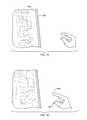
- FIG. 1C-1is a perspective view of a tablet connected to a motion-capture device, illustrating free-space gesture control of the tablet in accordance with various embodiments;
- FIG. 1C-2is a perspective view of a tablet incorporating a motion-capture device, illustrating free-space gesture control of the tablet in accordance with various embodiments;
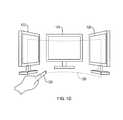
- FIG. 1Dis a perspective view of a curved virtual surface construct accommodating free-space gesture control of a multi-screen computer system in accordance with various embodiments;
- FIG. 2illustrates motion of a virtual surface construct relative to a user's finger in accordance with various embodiments
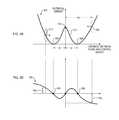
- FIGS. 3A and 3Bare plots of a virtual energy potential and its derivative, respectively, in accordance with various embodiments for updating the position of a virtual surface construct
- FIGS. 3C-3Eare plots of alternative virtual energy potentials in accordance with various embodiments for updating the position of a virtual surface construct
- FIGS. 4A, 4B, and 4B-1are flow charts illustrating methods for machine and/or user interface control in accordance with various embodiments
- FIG. 5Ais a schematic diagram of a system for tracking control object movements in accordance with various embodiments.
- FIG. 5Bis a block diagram of a computer system for machine control based on tracked control object movements in accordance with various embodiments
- FIGS. 6A-6Dillustrate a free-space compound gesture in accordance with various embodiments
- FIGS. 7A and 7Billustrate, in two snap shots, a zooming action performed by a user via a free-space gesture in accordance with various embodiments
- FIGS. 8A and 8Billustrate, in two snap shots, a swiping action performed by a user via a free-space gesture in accordance with various embodiments.
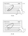
- FIGS. 9A and 9Billustrate, in two snap shots, a drawing action performed by a user via free-space hand motions in accordance with various embodiments.
- System and methods in accordance herewithgenerally utilize information about the motion of a control object, such as a user's finger or a stylus, in three-dimensional space to operate a user interface and/or components thereof based on the motion information.
- a control objectsuch as a user's finger or a stylus
- Various embodimentstake advantage of motion-capture technology to track the motions of the control object in real time (or near real time, i.e., sufficiently fast that any residual lag between the control object and the system's response is unnoticeable or practically insignificant).
- Other embodimentsmay use synthetic motion data (e.g., generated by a computer game) or stored motion data (e.g., previously captured or generated).
- references to motions in “free space” or “touchless” motionsare used herein with reference to an embodiment to distinguish motions tied to and/or requiring physical contact of the moving object with a physical surface to effect input; however, in some applications, the control object may contact a physical surface ancillary to providing input, in such case the motion is still considered a “free-space” motion.
- the virtual surfacemay be defined to co-reside at or very near a physical surface (e.g., a virtual touch screen may be created by defining a (substantially planar) virtual surface at or very near the screen of a display (e.g., television, monitor, or the like); or a virtual active table top may be created by defining a (substantially planar) virtual surface at or very near a table top convenient to the machine receiving the input).
- a virtual touch screenmay be created by defining a (substantially planar) virtual surface at or very near the screen of a display (e.g., television, monitor, or the like); or a virtual active table top may be created by defining a (substantially planar) virtual surface at or very near a table top convenient to the machine receiving the input).
- a “control object” as used herein with reference to an embodimentis generally any three-dimensionally movable object or appendage with an associated position and/or orientation (e.g., the orientation of its longest axis) suitable for pointing at a certain location and/or in a certain direction.
- Control objectsinclude, e.g., hands, fingers, feet, or other anatomical parts, as well as inanimate objects such as pens, styluses, handheld controls, portions thereof, and/or combinations thereof. Where a specific type of control object, such as the user's finger, is used hereinafter for ease of illustration, it is to be understood that, unless otherwise indicated or clear from context, any other type of control object may be used as well.
- a “virtual control construct” as used herein with reference to an embodimentdenotes a geometric locus defined (e.g., programmatically) in space and useful in conjunction with a control object, but not corresponding to a physical object; its purpose is to discriminate between different operational modes of the control object (and/or a user-interface element controlled therewith, such as a cursor) based on whether the control object intersects the virtual control construct.
- the virtual control constructmay be, e.g., a virtual surface construct (a plane oriented relative to a tracked orientation of the control object or an orientation of a screen displaying the user interface) or a point along a line or line segment extending from the tip of the control object.
- control objectwhich is an extended object
- various embodimentsfacilitate user input via gestures and motions performed by the user's hand or a (typically handheld) pointing device.
- the usercan control the position of a cursor and/or other object on the screen by pointing at the desired screen location, e.g., with his index finger, without the need to touch the screen.
- the position and orientation of the finger relative to the screen, as determined by the motion-capture systemmay be used to compute the intersection of a straight line through the axis of the finger with the screen, and a cursor symbol (e.g., an arrow, circle, cross hair, or hand symbol) may be displayed at the point of intersection.
- a cursor symbole.g., an arrow, circle, cross hair, or hand symbol
- the intersection with a (virtual) plane through the screenmay be used, and the cursor motions may be re-scaled, relative to the finger motions, to remain within the screen boundaries.
- the position of the finger (or control object) tipmay be projected perpendicularly onto the screen; in this embodiment, the control object orientation may be disregarded.
- mapping the control object position and/or orientation onto a screen locationmay, in principle, be used; a particular mapping may be selected based on considerations such as, without limitation, the requisite amount of information about the control object, the intuitiveness of the mapping to the user, and the complexity of the computation.
- the mappingis based on intersections with or projections onto a (virtual) plane defined relative to the camera, under the assumption that the screen is located within that plane (which is correct, at least approximately, if the camera is correctly aligned relative to the screen), whereas, in other embodiments, the screen location relative to the camera is established via explicit calibration (e.g., based on camera images including the screen).
- the cursorcan be operated in at least two modes: a disengaged mode in which it merely indicates a position on the screen, typically without otherwise affecting the screen content; and one or more engaged modes, which allow the user to manipulate the screen content.
- the engaged modethe user may, for example, drag graphical user-interface elements (such as icons representing files or applications, controls such as scroll bars, or displayed objects) across the screen, or draw or write on a virtual canvas.
- transient operation in the engaged modemay be interpreted as a click event.
- operation in the engaged modegenerally corresponds to, or emulates, touching a touch screen or touch pad, or controlling a mouse with a mouse button held down.
- cursorrefers generally to the cursor functionality rather than the visual element; in other words, the cursor is a control element operable to select a screen position—whether or not the control element is actually displayed and manipulate screen content via movement across the screen, i.e., changes in the selected position.
- the cursorneed not always be visible in the engaged mode. In some instances, a cursor symbol still appears, e.g., overlaid onto another graphical element that is moved across the screen, whereas in other instances, cursor motion is implicit in the motion of other screen elements or in newly created screen content (such as a line that appears on the screen as the control object moves), obviating the need for a special symbol.
- a cursor symbolis typically used to visualize the current cursor location.
- a screen element or portion presently co-located with the cursormay change brightness, color, or some other property to indicate that it is being pointed at.
- the symbol or other visual indication of the cursor locationmay be omitted so that the user has to rely on his own observation of the control object relative to the screen to estimate the screen location pointed at. (For example, in a shooter game, the player may have the option to shoot with or without a “virtual sight” indicating a pointed-to screen location.)
- Discrimination between the engaged and disengaged modesmay be achieved by tracking the control object relative to a virtual control construct such as a virtual plane (or, more generally, a virtual surface construct).
- a virtual control construct implemented by a virtual plane 100may be defined in front of and substantially parallel to the screen 102 .
- the control object 104“touches” or “pierces” the virtual plane (i.e., when its spatial location coincides with, intersects, or moves beyond the virtual plane's computationally defined spatial location)
- the cursor 106 and/or machine interfaceoperates in the engaged mode ( FIG. 1B ); otherwise, the cursor and/or machine interface operates in the disengaged mode ( FIG. 1A ).
- a drawing applicationmay define two substantially parallel virtual planes at different distances from the screen.
- the usermoving his finger towards the screen, pierces the first virtual plane, the user may be able to operate menus and controls within the application; when his finger pierces the second virtual plane, the finger's further (e.g., lateral) motions may be converted to line drawings on the screen.
- Two parallel virtual planesmay also be used to, effectively, define a virtual control construct with a certain associated thickness (i.e., a “virtual slab”). Control object movements within that virtual slab may operate the cursor in the engaged mode, while movements on either side of the virtual slab correspond to the disengaged mode.
- a planar virtual control construct with a non-zero thicknessmay serve to avoid unintended engagement and disengagement resulting from inevitable small motions in and out of the virtual plane (e.g., due to the inherent instability of the user's hand and/or the user's perception of depth).
- the thicknessmay vary depending on one or more sensed parameters (e.g., the overall speed of the control object's motion; the faster the movements, the thicker the slice may be chosen to be).
- Transitions between the different operational modesmay, but need not, be visually indicated by a change in the shape, color (as in FIGS. 1A and 1B ), or other visual property of the cursor or other displayable object and/or audio feedback.
- the cursor symbolindicates not only the operational mode, but also the control object's distance from the virtual control construct.
- the cursor symbolmay take the form of a circle, centered at the cursor location, whose radius is proportional to (or otherwise monotonically increasing with) the distance between control object and virtual control construct, and which, optionally, changes color when switching from the disengaged mode into the engaged mode.
- FIG. 1C-1illustrates an embodiment in which free-space gestures are used to operate a handheld tablet 110 .
- the tablet 110may be connected, e.g., via a USB cable 112 (or any other wired or wireless connection), to a motion-capture device 114 (such as for example, a dual-camera motion controller as provided by Leap Motion, Inc., San Francisco, Calif. or other interfacing mechanisms and/or combinations thereof) that is positioned and oriented so as to monitor a region where hand motions normally take place.
- the motion-capture device 114may be placed onto a desk or other working surface, and the tablet 110 may be held at an angle to that working surface to facilitate easy viewing of the displayed content.
- the tablet 110may be propped up on a tablet stand or against a wall or other suitable vertical surface to free up the second hand, facilitating two-hand gestures.
- FIG. 1C-2illustrates a modified tablet embodiment, in which the motion-capture device 114 is integrated into the frame of the tablet 110 .
- the virtual surface constructneed not be planar, but may be curved in space, e.g., to conform to the user's range of movements.
- FIG. 1Dillustrates, for example, a cylindrical virtual surface construct 120 in front of an arrangement of three monitors 122 , 124 , 126 , which may all be connected to the same computer.
- the user's finger motionsmay control screen content on any one of the screens, depending on the direction in which the finger 128 points and/or the portion of the virtual surface construct 120 that it pierces.
- other types of curved virtual surfaces constructs of regular (e.g., spherical) or irregular shape, or virtual surface constructs composed of multiple (planar or curved) segmentsmay also be used in combination with one or more screens.
- the virtual control constructis a virtual solid construct or a virtual closed surface (such as, e.g., a sphere, box, oriented ellipsoid, etc.) or portion thereof, having an interior (or, alternatively, exterior) that defines a three-dimensional engagement target.
- the virtual control constructmay be a virtual sphere located at some distance in front of the screen. The user may be able to rotate the on-screen globe by moving his fingertips while they are touching or piercing the spherical virtual surface construct (from outside).
- the spherical virtual surface constructmay be defined as surrounding the user (or at least his hand), with its exterior serving as the engagement target. Engagement and disengagement of the control object need not necessarily be defined relative to a two-dimensional surface. Rather, in some embodiments, the virtual control construct may be a virtual point construct along a virtual line (or line segment) extending from the control object, or a line within a plane extending from the control object.
- the location and/or orientation of the virtual surface constructmay be defined relative to the room and/or stationary objects (e.g., a screen) therein, relative to the user, relative to the device 114 or relative to some combination.
- a planar virtual surface constructmay be oriented parallel to the screen, perpendicular to the direction of the control object, or at some angle in between.
- the location of the virtual surface constructcan, in some embodiments, be set by the user, e.g., by means of a particular gesture recognized by the motion-capture system.
- the usermay, with her index finger stretched out, have her thumb and middle finger touch so as to pin the virtual surface construct at a certain location relative to the current position of the index-finger-tip. Once set in this manner, the virtual surface construct may be stationary until reset by the user via performance of the same gesture in a different location.
- the virtual surface constructis tied to and moves along with the control object, i.e., the position and/or orientation of the virtual surface construct are updated based on the tracked control object motion. This affords the user maximum freedom of motion by allowing the user to control the user interface from anywhere (or almost anywhere) within the space monitored by the motion-capture system.
- the virtual surface constructfollows the control object's movements with some delay. Thus, starting from a steady-state distance between the virtual surface construct and the control object tip in the disengaged mode, the distance generally decreases as the control object accelerates towards the virtual surface construct, and increases as the control object accelerates away from the virtual surface construct.
- control object's forward accelerationi.e., towards the virtual surface construct
- the control objecteventually pierces the virtual surface construct.
- the virtual surface constructagain follows the control object's movements.
- the virtual surface constructis “pushed” ahead of the control object (i.e., is located in front of the control object tip), it is “pulled” behind the control object in the engaged mode (i.e., is located behind the control object tip).
- the control objectgenerally needs to be pulled back through the virtual surface construct with sufficient acceleration to exceed the surface's responsive movement.
- an engagement targetcan be defined as merely the point where the user touches or pierces a virtual control construct.
- a virtual point constructmay be defined along a line extending from or through the control object tip, or any other point or points on the control object, located a certain distance from the control object tip in the steady state, and moving along the line to follow the control object.
- the linemay, e.g., be oriented in the direction of the control object's motion, perpendicularly project the control object tip onto the screen, extend in the direction of the control object's axis, or connect the control object tip to a fixed location, e.g., a point on the display screen.
- a virtual line construct(straight or curved) may be defined as a line within a surface intersecting the control object at its tip, e.g., as a line lying in the same plane as the control object and oriented perpendicular (or at some other non-zero angle) to the control object. Defining the virtual line construct within a surface tied to and intersecting the control object tip ensures that the control object can eventually intersect the virtual line construct.
- engagement targets defined by one or more virtual point constructs or virtual line (i.e., linear or curvilinear) constructscan be mapped onto engagement targets defined as virtual surface constructs, in the sense that the different mathematical descriptions are functionally equivalent.
- a virtual point constructmay correspond to the point of a virtual surface construct that is pierced by the control object (and a virtual line construct may correspond to a line in the virtual surface construct going through the virtual point construct).
- control object motions perpendicular to that linemove the virtual point construct in a plane parallel to the screen
- control object motions perpendicular to that linemove the virtual point construct in a plane perpendicular to that axis; in either case, control object motions along the line move the control object tip towards or away from the virtual point construct and, thus, the respective plane.
- the user's experience interacting with a virtual point constructmay be little (or no) different from interacting with a virtual surface construct.
- the descriptionwill, for ease of illustration, focus on virtual surface constructs.
- a person of skill in the artwill appreciate, however, that the approaches, methods, and systems described can be straightforwardly modified and applied to other virtual control constructs (e.g., virtual point constructs or virtual linear/curvilinear constructs).
- the position and/or orientation of the virtual surface constructare typically updated continuously or quasi-continuously, i.e., as often as the motion-capture system determines the control object location and/or direction (which, in visual systems, corresponds to the frame rate of image acquisition and/or image processing).
- the virtual surface constructis updated less frequently (e.g., only every other frame, to save computational resources) or more frequently (e.g., based on interpolations between the measured control object positions) can be provided for in embodiments.
- the virtual surface constructfollows the control object with a fixed time lag, e.g., between 0.1 and 1.0 second.
- the location of the virtual surface constructis updated, for each frame, based on where the control object tip was a certain amount of time (e.g., 0.2 second) in the past.
- FIG. 2shows the control object and the virtual surface construct (represented as a plane) at locations within a consistent coordinate system across the figures for various points in time according to various embodiments.
- the planemay be computationally defined as substantially perpendicular to the orientation of the control object (meaning that its normal is angled relative to the control object orientation by less than a certain small amount, e.g., less than 5°, and preferably smaller than 1°).
- the virtual planeneed not necessarily be perpendicular to the orientation of the control object. In some embodiments, it is, instead, substantially parallel to the screen, but still dynamically positioned relative to the control object (e.g., so as to remain at a certain distance from the control object tip, where distance may be measured, e.g., in a direction perpendicular to the screen or, alternatively, in the direction of the control object).
- a second point tt 1 in time—after the control object has started moving towards the virtual plane, but before the lag period has passed—the virtual plane is still in the same location, but its distance from the control object tip has decreased due to the control object's movement.
- the steady-state distances in the disengaged mode and the engaged modemay, but need not be the same.
- the steady-state distance in the engaged modeis larger, such that disengaging from the virtual plane (i.e., “unclicking”) appears harder to the user than engaging (i.e., “clicking”) because it requires a larger motion.
- the lag timesmay differ between the engaged and disengaged modes.
- the steady-state distanceis not fixed, but adjustable based on the control object's speed of motion, generally being greater for higher control object speeds.
- the position of the virtual planeis updated not based on a time lag, but based on its current distance from the control object tip. That is, for any image frame, the distance between the current control object tip position and the virtual plane is computed (e.g., with the virtual-plane position being taken from the previous frame), and, based thereon, a displacement or shift to be applied to the virtual plane is determined.
- the update rate as a function of distancemay be defined in terms of a virtual “potential-energy surface” or “potential-energy curve.” In FIG. 3A , an exemplary such potential-energy curve 300 is plotted as a function of the distance of the virtual plane from the control object tip according to various embodiments.
- the negative derivative 302 (or slope) of this curvewhich specifies the update rate, i.e., the shift in the virtual plane's position per frame (in arbitrary units), is shown in FIG. 3B .
- the minima of the potential-energy curve 300determine the steady-state distances 304 , 306 to both sides of the control object; at these distances, the virtual plane is not updated at all. At larger distances, the virtual plane is attracted towards the control object tip, at a rate that generally increases with distance. For example, at point 308 , where the virtual plane is a positive distance d 1 away from the control object, a negative displacement or shift ⁇ s 1 is applied to bring the virtual plane closer.
- a positive shift ⁇ s 2is applied to move the virtual plane closer to the control object.
- the virtual planeis repelled by the control object and driven back towards the steady state.
- the magnitude of the local maximum 314 between the two steady statesdetermines the level of force or acceleration needed to cross from the disengaged to the engaged mode or back.
- the potential-energy curve 300is given an even more physical interpretation, and its negative slope is associated with an acceleration, i.e., a change in the velocity of the virtual plane, rather than a change in its position.
- the virtual planedoes not immediately stop as it reaches a steady state, but oscillates around the steady state.
- a friction termmay be introduced into the physical model.
- the potential-energy curveneed not be symmetric, or course.
- FIG. 3Cshows an asymmetric curve in which the steady-state distance in the engaged mode is larger than that in the disengaged mode, rendering disengagement harder.
- the curvemay have more than two (e.g., four) steady states 320 , which may correspond to one disengaged and three engaged modes. The requisite force to transition between modes depends, again, on the heights of the local maxima 322 between the steady states.
- the curveabruptly jumps at the steady-state points and assumes a constant, higher value therebetween. In this case, which is illustrated in FIG.
- the position of the virtual planeis not updated whenever the control object tip is within the steady-state distance from the virtual plane on either side, allowing fast transitions between the modes.
- the potential-energy curvemay take many other forms, which may be tailored to a desired engagement-disengagement force profile experienced by the user.
- the virtual planemay be updated in accordance with a two-dimensional potential-energy surface that defines the update rate depending on, e.g., the distances between the virtual plane and control object tip along various directions (as opposed to only one, e.g., the perpendicular and shortest, distance of the control object tip from the virtual plane).
- the virtual planemay follow the control object differently for different relative orientations between the control object and the virtual plane, and each such relative orientation may correspond to a cross-section through the potential-energy surface.
- Two-dimensional potential-energy surfacesmay also be useful to control position updates applied to a curved virtual surface construct.
- the potential piercing energyneed not, or not only, be a function of the distance from the control object tip to the virtual surface construct, but may depend on other factors.
- a stylus with a pressure-sensitive gripis used as the control object.
- the pressure with which the user squeezes the stylusmay be mapped to the piercing energy.
- jitter in the control object's motionsmay result in unintentional transitions between the engaged and disengaged modes. While such modal instability may be combated by increasing the steady-state distance (i.e., the “buffer zone” between control object and virtual surface construct), this comes at the cost of requiring the user, when she intends to switch modes, to perform larger movements that may feel unnatural.
- the trade-off between modal stability and user conveniencemay be improved by filtering the tracked control object movements. Specifically, jitter may be filtered out, based on the generally more frequent changes in direction associated with it, with some form of time averaging.
- a moving-average filterspanning, e.g., a few frames, is applied to the tracked movements, such that only a net movement within each time window is used as input for cursor control.
- the time-averaging windowmay be chosen to likewise increase as a function of control object velocity (such as a function of overall control object speed or of a velocity component, e.g., perpendicular to the virtual plane).
- the control object's previous and newly measured positionare averaged with weighting factors that depend, e.g., on velocity, frame rate, and/or other factors.
- FIG. 4Asummarizes representative methods for control-object-controlled cursor operation that utilize a virtual surface construct moving with the control object in accordance with various embodiments.
- a control objectis tracked ( 400 ), based on computer vision or otherwise, to determine its position and/or orientation in space (typically within a detection zone proximate to the computer screen).
- the tracked control object motionis computationally filtered to reduce jitter ( 402 ).
- the position and/or orientation of the virtual surface constructare then computed ( 404 ).
- the virtual surface constructis updated based on a control object position in the past, it may initially take a few control object tracking cycles (e.g., frames in image-based tracking) before the first position of the virtual surface construct is established; thereafter, the virtual surface construct can be updated every cycle.
- the position of the virtual surface constructmay be initiated arbitrarily, e.g., such that the virtual surface construct starts a steady-state distance away from the control object.
- the current operational mode(engaged or disengaged) is identified based on a determination whether the control object touches or pierces the virtual surface construct or not ( 406 ).
- the current cursor positionis calculated, typically from the control object's position and orientation relative to the screen ( 408 ). (This step may be performed prior to, or in parallel with, the computations of the virtual surface construct.)
- the screen contentis then updated ( 410 ), e.g., to move the cursor symbol or re-arrange other screen content. Steps 400 - 410 are executed in a loop as long as the user interacts with the system via free-space control object motions.
- temporary piercing of the virtual surface constructi.e., a clicking motion including penetration of the virtual surface construct immediately followed by withdrawal from the virtual surface construct—switches between modes and locks in the new mode. For example, starting in the disengaged mode, a first click event may switch the control object into the engaged mode, where it may then remain until the virtual surface construct is clicked at again.
- the degree of piercingi.e., the distance beyond the virtual surface construct that the control object initially reaches, before the virtual surface construct catches up
- the intensity (of engagement) in a swiping gesture for scrolling through screen contentmay determine the speed of scrolling.
- different intensity levels when touching a virtual objectmay correspond to merely touching the object versus pushing the object over.
- the intensity levelmay translate into the volume of the sound created.
- FIGS. 4B and 4B-1illustrate at a higher conceptual level various methods for controlling a machine-user interface using free-space gestures or motions performed by a control object.
- the methodinvolves receiving information including motion information for a control object ( 420 ). Further, it includes determining from the motion information whether the motion corresponds to an engagement gesture ( 422 ). This determination may be made by determining whether an intersection occurred between the control object and a virtual control construct ( 424 ); whether a dis-intersection of the control object from the at least one virtual control construct occurred ( 426 ); and/or whether motion of the control object occurred relative to at least one virtual control construct ( 428 ).
- the determinationmay involve determining, from the motion information, one or more engagement attributes (e.g., a potential energy) defining an engagement gesture ( 430 ), and/or identifying an engagement gesture by correlating the motion information to one of a plurality of engagement gestures based in part upon one or more of motion of the control object, occurrence of any of an intersection, a dis-intersection or a non-intersection of the control object with the virtual control construct, and the set of engagement attributes ( 432 ).
- the user-interface control to which the gesture appliese.g., a control associated with an application or an operating environment, or a special control
- the controlmay then be manipulated according to the gesture ( 436 ).
- both left and right index fingers of a usermay be tracked, each relative to its own associated virtual touch surface, to operate to cursors simultaneously and independently.
- the user's handmay be tracked to determine the positions and orientations of all fingers; each finger may have its own associated virtual surface construct (or other virtual control construct) or, alternatively, all fingers may share the same virtual surface construct, which may follow the overall hand motions.
- a joint virtual planemay serve, e.g., as a virtual drawing canvas on which multiple lines can be drawn by the fingers at once.
- one or more control parameter(s) and the control objectare applied to some control mechanism to determine the distance of the virtual control construct to a portion of the control object (e.g., tool tip(s), point(s) of interest on a user's hand or other points of interest).
- a lage.g., filter or filtering function
- embodimentscan provide enhanced verisimilitude to the human-machine interaction, and/or increased fidelity of tracking control object(s) and/or control object portion(s).
- control object portionis a user's finger-tip.
- a control parameteris also the user's finger-tip.
- a control mechanismincludes equating a plane-distance between virtual control construct and finger-tip to a distance between finger-tip and an arbitrary coordinate (e.g., center (or origin) of an interaction zone of the controller). Accordingly, the closer the finger-tip approaches to the arbitrary coordinate, the closer the virtual control construct approaches the finger-tip.
- control objectis a hand, which includes a control object portion, e.g., a palm, determined by a “palm-point” or center of mass of the entire hand.
- a control parameterincludes a velocity of the hand, as measured at the control object portion, i.e., the center of mass of the hand.
- a control mechanismincludes filtering forward velocity over the last one (1) second. Accordingly, the faster the palm has recently been travelling forward, the closer the virtual control construct approaches to the control object (i.e., the hand).
- a control objectincludes a control object portion (e.g., a finger-tip).
- a control mechanismincludes determining a distance between a thumb-tip (e.g., a first control object portion) and an index finger (e.g., a second control object portion). This distance can be used as a control parameter. Accordingly, the closer the thumb-tip and index-finger, the closer the virtual control construct is determined to be to the index finger. When the thumb-tip and index finger touch one another, the virtual control construct is determined to be partially pierced by the index finger.
- a lage.g., filter or filtering function
- horizontal jitteri.e., the random motion of the control object in a substantially horizontal dimension
- images acquired from two (or more) vantage pointsare used to define tangent lines to the surface of the object and approximate the location and shape of the object based thereon, as explained in more detail below.
- Other vision-based approachesthat can be used in embodiments include, without limitation, stereo imaging, detection of patterned light projected onto the object, or the use of sensors and markers attached to or worn by the object (such as, e.g., markers integrated into a glove) and/or combinations thereof.
- the control objectmay be tracked acoustically or ultrasonically, or using inertial sensors such as accelerometers, gyroscopes, and/or magnetometers (e.g., MEMS sensors) attached to or embedded within the control object.
- Embodimentscan be built employing one or more of particular motion-tracking approaches that provide control object position and/or orientation (and/or derivatives thereof) tracking with sufficient accuracy, precision, and responsiveness for the particular application.
- FIGS. 5A and 5Billustrate an exemplary system for capturing images and controlling a machine based on motions relative to a virtual control construct according to various embodiments.
- the systemincludes motion-capture hardware including two video cameras 500 , 502 that acquire a stream of images of a region of interest 504 from two different vantage points.
- the cameras 500 , 502are connected to a computer 506 that processes these images to infer three-dimensional information about the position and orientation of a control object 508 , or a larger object of interest including the control object (e.g., a user's hand), in the region of interest 504 , and computes suitable control signals to the user interface based thereon.
- the camerasmay be, e.g., CCD or CMOS cameras, and may operate, e.g., in the visible, infrared (IR), or ultraviolet wavelength regime, either by virtue of the intrinsic sensitivity of their sensors primarily to these wavelengths, or due to appropriate filters 510 placed in front of the cameras.
- the motion-capture hardwareincludes, co-located with the cameras 500 , 502 , one or more light sources 512 that illuminate the region of interest 504 at wavelengths matching the wavelength regime of the cameras 500 , 502 .
- the light sources 512may be LEDs that emit IR light
- the cameras 500 , 502may capture IR light that is reflected off the control object and/or objects in the background.
- the cameras 500 , 502 and light sources 512are disposed below the control object to be tracked and point upward. For example, they may be placed on a desk to capture hand motions taking place in a spatial region above the desk, e.g., in front of the screen.
- This locationmay be optimal both for foreground/background discrimination (because the background is in this case typically the ceiling and, thus, far away) and for discerning the control object's direction and tip position (because the usual pointing direction will lie, more or less, in the image plane).
- the computer 506 processing the images acquired by the cameras 500 , 502may be a suitably programmed general-purpose computer. As shown in FIG. 5B , it may include a processor (or CPU) 520 , associated system memory 522 (typically volatile memory, e.g., RAM), one or more permanent storage devices 524 (such as hard disks, CDs, DVDs, memory keys, etc.), a display screen 526 (e.g., an LCD screen or CRT monitor), input devices (such as a keyboard and, optionally, a mouse) 528 , and a system bus 530 that facilitates communication between these components and, optionally via a dedicated interface, with the cameras 500 , 502 and/or other motion-capture hardware.
- processoror CPU
- associated system memory 522typically volatile memory, e.g., RAM
- permanent storage devices 524such as hard disks, CDs, DVDs, memory keys, etc.
- a display screen 526e.g., an LCD screen or CRT monitor
- input devicessuch
- the memory 522may store computer-executable instructions, conceptually illustrated as a group of modules and programmed in any of various suitable programming languages (such as, e.g., C, C++, Java, Basic, Python, Pascal, Fortran, assembler languages, etc.), that control the operation of the CPU and provide the requisite computational functionality for implementing methods in accordance herewith.
- suitable programming languagessuch as, e.g., C, C++, Java, Basic, Python, Pascal, Fortran, assembler languages, etc.
- the memorymay store modules for image processing and control object tracking, computation of the virtual control construct and determination of the operational mode, and cursor operation and user-interface control.
- the image-processing and tracking module 536may analyze pairs of image frames acquired by the two cameras 500 , 502 (and stored, e.g., in image buffers in memory 522 ) to identify the control object (or an object including the control object or multiple control objects, such as a user's hand) therein (e.g., as a non-stationary foreground object) and detect its edges. Next, the module 536 may, for each pair of corresponding rows in the two images, find an approximate cross-section of the control object by defining tangent lines on the control object that extend from the vantage points (i.e., the cameras) to the respective edge points of the control object, and inscribe an ellipse (or other geometric shape defined by only a few parameters) therein.
- the cross-sectionsmay then be computationally connected in a manner that is consistent with certain heuristics and known properties of the control object (e.g., the requirement of a smooth surface) and resolves any ambiguities in the fitted ellipse parameters.
- the control objectis reconstructed or modeled in three dimensions.
- This method, and systems for its implementationare described in more detail in U.S. patent application Ser. No. 13/414,485, filed on Mar. 7, 2012, the entire enclosure of which is incorporated herein by reference.
- a larger object including multiple control objectscan similarly be reconstructed with respective tangent lines and fitted ellipses, typically exploiting information of internal constraints of the object (such as a maximum physical separation between the fingertips of one hand).
- the image-processing and tracking module 534may, further, extract relevant control object parameters, such as tip positions and orientations as well as velocities, from the three-dimensional model. In some embodiments, this information can be inferred from the images at a lower level, prior to or without the need for fully reconstructing the control object. These operations are readily implemented by those skilled in the art without undue experimentation.
- a filter module 538receives input from the image-processing and tracking module 564 , and smoothens or averages the tracked control object motions; the degree of smoothing or averaging may depend on a control object velocity as determined by the tracking module 536 .
- An engagement-target module 540may receive tracking data about the control object from the image-processing and tracking module 536 and/or the filter module 538 , and use that data to compute a representation of the virtual control construct, i.e., to define and/or update the position and orientation of the virtual control construct relative to the control object (and/or the screen); the representation may be stored in memory in any suitable mathematical form.
- a touch-detection module 542 in communication with the engagement-target module 540may determine, for each frame, whether the control object touches or pierces the virtual control construct.
- a cursor module 544may, based on tracking data from the image-processing and tracking module 536 , determine a cursor location on the screen (e.g., as the projection of the control object tip onto the screen).
- the cursor module 544may also include a visualization component that depicts a cursor at the computed location, preferably in a way that discriminates, based on output from the touch-detection module 542 , between the engaged and disengaged mode (e.g., by using different colors).
- the visualization component of the cursor module 544may also modify the cursor appearance based on the control object distance from the virtual control construct; for instance, the cursor may take the form of a circle having a radius proportional to the distance between the control object tip and the virtual control construct.
- a user-interface control module 546may map detected motions in the engaged mode into control input for the applications 534 running on the computer 506 .
- the end-user application 534 , user-interface control module 546 , and cursor module 544may compute the screen content, i.e., an image for display on the screen 526 , which may be stored in a display buffer (e.g., in memory 522 or in the buffer of a GPU included in the system).
- a display buffere.g., in memory 522 or in the buffer of a GPU included in the system.
- module 536may be provided by a separate computer in communication with the computer on which the end-user applications controlled via free-space control object motions are executed.
- the cameras 500 , 502 , light sources 512 , and computational facility for image-processing and trackingare integrated into a single motion-capture device (which, typically, utilizes an application-specific integrated circuit (ASIC) or other special-purpose computer for image-processing).
- ASICapplication-specific integrated circuit
- the camera imagesare sent from a client terminal over a network to a remote server computer for processing, and the tracked control object positions and orientations are sent back to the client terminal as input into the user interface.
- Embodimentscan be realized using any number and arrangement of computers (broadly understood to include any kind of general-purpose or special-purpose processing device, including, e.g., microcontrollers, ASICs, programmable gate arrays (PGAs), or digital signal processors (DSPs) and associated peripherals) executing the methods described herein, an any implementation of the various functional modules in hardware, software, or a combination thereof.
- Computer programs incorporating various features or functionality described hereinmay be encoded on various computer readable storage media; suitable media include magnetic disk or tape, optical storage media such as compact disk (CD) or DVD (digital versatile disk), flash memory, and any other non-transitory medium capable of holding data in a computer-readable form.
- Computer-readable storage media encoded with the program codemay be packaged with a compatible device or provided separately from other devices.
- program codemay be encoded and transmitted via wired, optical, and/or wireless networks conforming to a variety of protocols, including the Internet, thereby allowing distribution, e.g., via Internet download and/or provided on-demand as web-services.
- Free-space control object motions and virtual-touch recognitionmay be used, for example, to provide input to commercial and industrial legacy applications (such as, e.g., business applications, including Microsoft OutlookTM; office software, including Microsoft OfficeTM, WindowsTM, Excel, etc.; graphic design programs; including Microsoft VisioTM etc.), operating systems such as Microsoft WindowsTM; web applications (e.g., browsers, such as Internet ExplorerTM); other applications (such as e.g., audio, video, graphics programs, etc.), to navigate virtual worlds (e.g., in video games) or computer representations of the real world (e.g., Google street ViewTM), or to interact with three-dimensional virtual objects (e.g., Google EarthTM).
- FIGS. 6A-9Billustrate various exemplary control inputs achievable with free-space hand motions and gestures when using systems and methods in accord
- FIG. 6Aillustrates a system 100 a comprising wired and/or wirelessly communicatively coupled components of a tower 602 a , a display device 604 a , a keyboard 606 a and optionally a tactile pointing device (e.g., mouse, or track ball) 608 a .
- computing machinery of tower 602 acan be integrated into display device 604 a in an “all in one” configuration.
- a position and motion sensing device(e.g., 600 a - 1 , 600 a - 2 and/or 600 a - 3 ) comprises all or a portion of the non-tactile interface system of FIG. 1A , that provides for receiving non-tactile input based upon detected position(s), shape(s) and/or motion(s) made by a hand 104 and/or any other detectable object serving as a control object.
- the position and motion sensing devicecan be embodied as a stand-alone entity or integrated into another device, e.g., a computer, workstation, laptop, notebook, smartphone, tablet, smart watch or other type of wearable intelligent device(s) and/or combinations thereof.
- Position and motion sensing devicecan be communicatively coupled with, and/or integrated within, one or more of the other elements of the system, and can interoperate cooperatively with component(s) of the system 100 a , to provide a non-tactile interface capabilities, such as illustrated by the non-tactile interface system 100 of FIG. 1A .
- the motion sensing device(e.g., 600 a - 1 , 600 a - 2 and/or 600 a - 3 ) is capable of detecting position as well as motion of hands and/or portions of hands and/or other detectable objects (e.g., a pen, a pencil, a stylus, a paintbrush, an eraser, a virtualized tool, and/or a combination thereof), within a region of space 110 a from which it is convenient for a user to interact with system 100 a .
- Region 110 acan be situated in front of, nearby, and/or surrounding system 100 a .
- the position and motion sensing devicecan be integrated directly into display device 604 a as integrated device 600 a - 2 and/or keyboard 106 a as integrated device 600 a - 3 .
- FIG. 6Aillustrates devices 600 a - 1 , 600 a - 2 and 600 a - 3 , it will be appreciated that these are alternative embodiments shown in FIG. 6A for clarity sake.
- Keyboard 606 a and position and motion sensing deviceare representative types of “user input devices.”
- Other examples of user input devicescan be used in conjunction with computing environment 100 a , such as for example, a touch screen, light pen, mouse, track ball, touch pad, data glove and so forth.
- FIG. 6Ais representative of but one type of system embodiment. It will be readily apparent to one of ordinary skill in the art that many system types and configurations are suitable for use in conjunction with various embodiments.
- Tower 102 a and/or position and motion sensing device and/or other elements of system 100 acan implement functionality to provide virtual control surface 600 a within region 110 a with which engagement gestures are sensed and interpreted to facilitate user interactions with system 602 a . Accordingly, objects and/or motions occurring relative to virtual control surface 600 a within region 110 a can be afforded differing interpretations than like (and/or similar) objects and/or motions otherwise occurring.
- control object 104(happens to be a pointing finger in this example) is moving toward an “Erase” button being displayed on display 604 a by a user desiring to select the “Erase” button.
- control object 104has moved triggered an engagement gesture by means of “virtually contacting”, i.e., intersecting virtual control surface 600 a .
- the userhas suffered misgivings about executing an “Erase.” Since the “Erase” button has been engaged, however, mere withdrawal of control object 104 (i.e., a “dis-intersection”) will not undo the erase operation selected. Accordingly, with reference to FIG.
- the usermakes a wiping motion with a second control object (i.e., the user's other hand in this example) indicating that the user would like to cancel an operation that is underway.
- Motion by a second control objectillustrates a “compound gesture” that includes two or more gestures, sequentially or simultaneously.
- Compound gesturescan be performed using a single control object, or two or more control objects (e.g., one hand, two hands, one stylus and one hand, etc.).
- the point/select and the wipeare two gestures made by two different control objects (two hands) occurring contemporaneously.
- FIG. 6Dwhen the second part of the compound gesture is recognized, the Erase button is no longer highlighted, indicating that the button is now “unselected”. The user is free to withdraw the first control object from engagement with the virtual control surface without triggering an “Erase” operation.
- FIGS. 7A and 7Billustrate a zooming action performed by two fingers (thumb and index finger) according to various embodiments. These diagrams are merely an example; one of ordinary skill in the art would recognize many other variations, alternatives, and modifications.
- an image 706(happens to be a web page feed) is being displayed by display 704 , by a browser or other application.
- the usercommences a motion including engaging a virtual control construct (not shown) interposed between the user and display 704 at an engagement target approximately over the right most column being displayed.
- the finger tips 104 a , 104 b of the userare moved away from each other.
- This motionis recognized by device 700 from differences in images captured of the control object portion 104 a , 104 b and determined to be an engagement gesture including a spreading motion of the thumb and index finger-tip in front of the screen using the techniques described hereinabove.
- the result of interpreting the engagement gestureis passed to an application (and/or to the OS) owning the display 704 .
- the application owning display 704responds by zooming-in the image of display 704 .
- FIGS. 8A and 8Bshow how a swiping gesture by a finger in engaged mode may serve to scroll through screen content according to various embodiments. These diagrams are merely an example; one of ordinary skill in the art would recognize many other variations, alternatives, and modifications.
- an image 806(happens to be of dogs in this example) is being displayed by display 804 .
- the user's gesturemay be interpreted as a control input for the application displaying the images. For example, in FIG.
- the userhas swiped a finger-tip 104 a from left to right.
- This motionis recognized by device 800 from differences in images captured of the control object portion 104 a and determined to be an engagement gesture including a swiping motion from left to right that pierces the virtual control construct using the techniques described hereinabove.
- the result of interpreting the engagement gestureis passed to the image application, which responds by scrolling the image on the display 804 .
- the same gesture performed without engaging the virtual control constructmay be passed to the operating system and, for example, used to switch the display 804 between multiple desktops or trigger some other higher-level function.
- This is just one example of how engagement gesturesi.e., gestures performed relative to a virtual control construct (whether in the engaged or the disengaged mode, or changing between the modes), can be used to provide different types of control input.
- FIGS. 9A and 9Bshow how the motion of a control object in free space in conjunction with a virtual plane (or a slice of a certain thickness) can provide writing with a virtual pen onto a virtual paper defined in space according to various embodiments. These diagrams are merely an example; one of ordinary skill in the art would recognize many other variations, alternatives, and modifications.
- a usermoves a tool 104 b (happens to be a stylus) in free space in front of a writing area being displayed on the screen of display 904 so as to pierce a virtual control construct (not shown) (happens to be a plane) interposed between the user and display 904 .
- This motionis recognized by device 900 from differences in images captured of the control object portion 104 b and determined to be an engagement gesture including placing a virtual pen onto a virtual paper of space, and is reflected by the contents of display 904 .
- Continuing motion of the stylus 104 b in space by the user after engaging the virtual control planeis interpreted as writing with the stylus 104 b on the virtual paper of space and is reflected by the contents of display 904 .
- FIG. 9Bwhen the user dis-engages with the virtual control construct, the virtual pen is lifted from the virtual paper, completing the letter “D” in script matching the handwriting of the user in free space.
- embodimentscan enable, e.g., signature capture, free-hand drawings, etc.
Landscapes
- Engineering & Computer Science (AREA)
- Theoretical Computer Science (AREA)
- General Engineering & Computer Science (AREA)
- Human Computer Interaction (AREA)
- General Physics & Mathematics (AREA)
- Physics & Mathematics (AREA)
- General Health & Medical Sciences (AREA)
- Social Psychology (AREA)
- Psychiatry (AREA)
- Multimedia (AREA)
- Health & Medical Sciences (AREA)
- Computer Vision & Pattern Recognition (AREA)
- User Interface Of Digital Computer (AREA)
- Position Input By Displaying (AREA)
Abstract
Description
Claims (37)
Priority Applications (20)
| Application Number | Priority Date | Filing Date | Title |
|---|---|---|---|
| US14/154,730US9501152B2 (en) | 2013-01-15 | 2014-01-14 | Free-space user interface and control using virtual constructs |
| PCT/US2014/011649WO2014113454A1 (en) | 2013-01-15 | 2014-01-15 | Dynamic, free-space user interactions for machine control |
| US14/155,722US9459697B2 (en) | 2013-01-15 | 2014-01-15 | Dynamic, free-space user interactions for machine control |
| US14/280,018US9679215B2 (en) | 2012-01-17 | 2014-05-16 | Systems and methods for machine control |
| US15/279,363US10139918B2 (en) | 2013-01-15 | 2016-09-28 | Dynamic, free-space user interactions for machine control |
| US15/358,104US10042430B2 (en) | 2013-01-15 | 2016-11-21 | Free-space user interface and control using virtual constructs |
| US15/392,920US9778752B2 (en) | 2012-01-17 | 2016-12-28 | Systems and methods for machine control |
| US15/696,086US10691219B2 (en) | 2012-01-17 | 2017-09-05 | Systems and methods for machine control |
| US16/054,891US10739862B2 (en) | 2013-01-15 | 2018-08-03 | Free-space user interface and control using virtual constructs |
| US16/195,755US11243612B2 (en) | 2013-01-15 | 2018-11-19 | Dynamic, free-space user interactions for machine control |
| US16/908,643US11493998B2 (en) | 2012-01-17 | 2020-06-22 | Systems and methods for machine control |
| US16/987,289US11353962B2 (en) | 2013-01-15 | 2020-08-06 | Free-space user interface and control using virtual constructs |
| US17/666,534US11740705B2 (en) | 2013-01-15 | 2022-02-07 | Method and system for controlling a machine according to a characteristic of a control object |
| US17/833,556US11874970B2 (en) | 2013-01-15 | 2022-06-06 | Free-space user interface and control using virtual constructs |
| US17/862,212US11720180B2 (en) | 2012-01-17 | 2022-07-11 | Systems and methods for machine control |
| US18/209,259US12260023B2 (en) | 2012-01-17 | 2023-06-13 | Systems and methods for machine control |
| US18/219,517US12204695B2 (en) | 2013-01-15 | 2023-07-07 | Dynamic, free-space user interactions for machine control |
| US18/506,009US12405673B2 (en) | 2013-01-15 | 2023-11-09 | Free-space user interface and control using virtual constructs |
| US18/988,746US20250130648A1 (en) | 2013-01-15 | 2024-12-19 | Dynamic, free-space user interactions for machine control |
| US19/026,259US20250165079A1 (en) | 2012-01-17 | 2025-01-16 | Systems and methods for machine control |
Applications Claiming Priority (14)
| Application Number | Priority Date | Filing Date | Title |
|---|---|---|---|
| US201361752725P | 2013-01-15 | 2013-01-15 | |
| US201361752731P | 2013-01-15 | 2013-01-15 | |
| US201361752733P | 2013-01-15 | 2013-01-15 | |
| US201361791204P | 2013-03-15 | 2013-03-15 | |
| US201361808984P | 2013-04-05 | 2013-04-05 | |
| US201361808959P | 2013-04-05 | 2013-04-05 | |
| US201361816487P | 2013-04-26 | 2013-04-26 | |
| US201361824691P | 2013-05-17 | 2013-05-17 | |
| US201361825480P | 2013-05-20 | 2013-05-20 | |
| US201361825515P | 2013-05-20 | 2013-05-20 | |
| US201361872538P | 2013-08-30 | 2013-08-30 | |
| US201361873351P | 2013-09-03 | 2013-09-03 | |
| US201361877641P | 2013-09-13 | 2013-09-13 | |
| US14/154,730US9501152B2 (en) | 2013-01-15 | 2014-01-14 | Free-space user interface and control using virtual constructs |
Related Parent Applications (3)
| Application Number | Title | Priority Date | Filing Date |
|---|---|---|---|
| US14/106,140Continuation-In-PartUS9153028B2 (en) | 2012-01-17 | 2013-12-13 | Systems and methods for capturing motion in three-dimensional space |
| US14/250,758Continuation-In-PartUS20140307920A1 (en) | 2012-01-17 | 2014-04-11 | Systems and methods for tracking occluded objects in three-dimensional space |
| US14/250,758ContinuationUS20140307920A1 (en) | 2012-01-17 | 2014-04-11 | Systems and methods for tracking occluded objects in three-dimensional space |
Related Child Applications (4)
| Application Number | Title | Priority Date | Filing Date |
|---|---|---|---|
| US14/155,722Continuation-In-PartUS9459697B2 (en) | 2013-01-15 | 2014-01-15 | Dynamic, free-space user interactions for machine control |
| US14/212,485Continuation-In-PartUS20150253428A1 (en) | 2012-01-17 | 2014-03-14 | Determining positional information for an object in space |
| US14/280,018Continuation-In-PartUS9679215B2 (en) | 2012-01-17 | 2014-05-16 | Systems and methods for machine control |
| US15/358,104ContinuationUS10042430B2 (en) | 2013-01-15 | 2016-11-21 | Free-space user interface and control using virtual constructs |
Publications (2)
| Publication Number | Publication Date |
|---|---|
| US20140201689A1 US20140201689A1 (en) | 2014-07-17 |
| US9501152B2true US9501152B2 (en) | 2016-11-22 |
Family
ID=51166277
Family Applications (6)
| Application Number | Title | Priority Date | Filing Date |
|---|---|---|---|
| US14/154,730Active2034-07-25US9501152B2 (en) | 2012-01-17 | 2014-01-14 | Free-space user interface and control using virtual constructs |
| US15/358,104ActiveUS10042430B2 (en) | 2013-01-15 | 2016-11-21 | Free-space user interface and control using virtual constructs |
| US16/054,891ActiveUS10739862B2 (en) | 2013-01-15 | 2018-08-03 | Free-space user interface and control using virtual constructs |
| US16/987,289Active2034-01-22US11353962B2 (en) | 2013-01-15 | 2020-08-06 | Free-space user interface and control using virtual constructs |
| US17/833,556ActiveUS11874970B2 (en) | 2013-01-15 | 2022-06-06 | Free-space user interface and control using virtual constructs |
| US18/506,009ActiveUS12405673B2 (en) | 2013-01-15 | 2023-11-09 | Free-space user interface and control using virtual constructs |
Family Applications After (5)
| Application Number | Title | Priority Date | Filing Date |
|---|---|---|---|
| US15/358,104ActiveUS10042430B2 (en) | 2013-01-15 | 2016-11-21 | Free-space user interface and control using virtual constructs |
| US16/054,891ActiveUS10739862B2 (en) | 2013-01-15 | 2018-08-03 | Free-space user interface and control using virtual constructs |
| US16/987,289Active2034-01-22US11353962B2 (en) | 2013-01-15 | 2020-08-06 | Free-space user interface and control using virtual constructs |
| US17/833,556ActiveUS11874970B2 (en) | 2013-01-15 | 2022-06-06 | Free-space user interface and control using virtual constructs |
| US18/506,009ActiveUS12405673B2 (en) | 2013-01-15 | 2023-11-09 | Free-space user interface and control using virtual constructs |
Country Status (2)
| Country | Link |
|---|---|
| US (6) | US9501152B2 (en) |
| WO (1) | WO2014113454A1 (en) |
Cited By (11)
| Publication number | Priority date | Publication date | Assignee | Title |
|---|---|---|---|---|
| US20170061205A1 (en)* | 2012-01-17 | 2017-03-02 | Leap Motion, Inc. | Enhanced Contrast for Object Detection and Characterization By Optical Imaging Based on Differences Between Images |
| US20170185166A1 (en)* | 2015-12-24 | 2017-06-29 | Intel Corporation | Tracker for cursor navigation |
| US9916009B2 (en) | 2013-04-26 | 2018-03-13 | Leap Motion, Inc. | Non-tactile interface systems and methods |
| US10042430B2 (en) | 2013-01-15 | 2018-08-07 | Leap Motion, Inc. | Free-space user interface and control using virtual constructs |
| US10139918B2 (en) | 2013-01-15 | 2018-11-27 | Leap Motion, Inc. | Dynamic, free-space user interactions for machine control |
| US10281987B1 (en) | 2013-08-09 | 2019-05-07 | Leap Motion, Inc. | Systems and methods of free-space gestural interaction |
| US11150800B1 (en)* | 2019-09-16 | 2021-10-19 | Facebook Technologies, Llc | Pinch-based input systems and methods |
| US11531392B2 (en)* | 2019-12-02 | 2022-12-20 | Finchxr Ltd. | Tracking upper arm movements using sensor modules attached to the hand and forearm |
| US11720180B2 (en) | 2012-01-17 | 2023-08-08 | Ultrahaptics IP Two Limited | Systems and methods for machine control |
| US12260023B2 (en) | 2012-01-17 | 2025-03-25 | Ultrahaptics IP Two Limited | Systems and methods for machine control |
| US12306301B2 (en) | 2013-03-15 | 2025-05-20 | Ultrahaptics IP Two Limited | Determining positional information of an object in space |
Families Citing this family (71)
| Publication number | Priority date | Publication date | Assignee | Title |
|---|---|---|---|---|
| US9679215B2 (en) | 2012-01-17 | 2017-06-13 | Leap Motion, Inc. | Systems and methods for machine control |
| US9070019B2 (en) | 2012-01-17 | 2015-06-30 | Leap Motion, Inc. | Systems and methods for capturing motion in three-dimensional space |
| US8638989B2 (en) | 2012-01-17 | 2014-01-28 | Leap Motion, Inc. | Systems and methods for capturing motion in three-dimensional space |
| US10691219B2 (en) | 2012-01-17 | 2020-06-23 | Ultrahaptics IP Two Limited | Systems and methods for machine control |
| EP2817693B1 (en) | 2012-02-24 | 2023-04-05 | Moscarillo, Thomas, J. | Gesture recognition device |
| TWI456486B (en)* | 2012-03-06 | 2014-10-11 | Acer Inc | Electronic device and method of controlling electronic device |
| US9632683B2 (en)* | 2012-11-08 | 2017-04-25 | Nokia Technologies Oy | Methods, apparatuses and computer program products for manipulating characteristics of audio objects by using directional gestures |
| JP6070211B2 (en)* | 2013-01-22 | 2017-02-01 | 株式会社リコー | Information processing apparatus, system, image projection apparatus, information processing method, and program |
| CN103197889B (en)* | 2013-04-03 | 2017-02-08 | 锤子科技(北京)有限公司 | Brightness adjusting method and device and electronic device |
| US10846942B1 (en) | 2013-08-29 | 2020-11-24 | Ultrahaptics IP Two Limited | Predictive information for free space gesture control and communication |
| US20160239002A1 (en)* | 2013-09-25 | 2016-08-18 | Schneider Electric Buildings Llc | Method and device for adjusting a set point |
| US9632572B2 (en) | 2013-10-03 | 2017-04-25 | Leap Motion, Inc. | Enhanced field of view to augment three-dimensional (3D) sensory space for free-space gesture interpretation |
| WO2015051461A1 (en)* | 2013-10-09 | 2015-04-16 | Magna Closures Inc. | Control of display for vehicle window |
| US9996638B1 (en) | 2013-10-31 | 2018-06-12 | Leap Motion, Inc. | Predictive information for free space gesture control and communication |
| US9875019B2 (en)* | 2013-12-26 | 2018-01-23 | Visteon Global Technologies, Inc. | Indicating a transition from gesture based inputs to touch surfaces |
| US9317129B2 (en) | 2014-03-25 | 2016-04-19 | Dell Products, Lp | System and method for using a side camera for a free space gesture inputs |
| US9785247B1 (en) | 2014-05-14 | 2017-10-10 | Leap Motion, Inc. | Systems and methods of tracking moving hands and recognizing gestural interactions |
| US9741169B1 (en) | 2014-05-20 | 2017-08-22 | Leap Motion, Inc. | Wearable augmented reality devices with object detection and tracking |
| CN204480228U (en) | 2014-08-08 | 2015-07-15 | 厉动公司 | motion sensing and imaging device |
| US10452195B2 (en) | 2014-12-30 | 2019-10-22 | Samsung Electronics Co., Ltd. | Electronic system with gesture calibration mechanism and method of operation thereof |
| US10656720B1 (en) | 2015-01-16 | 2020-05-19 | Ultrahaptics IP Two Limited | Mode switching for integrated gestural interaction and multi-user collaboration in immersive virtual reality environments |
| CN104820493B (en)* | 2015-04-23 | 2018-09-14 | 北京小小牛创意科技有限公司 | A kind of implementation method and realization system of movement driving effect |
| US9442575B1 (en) | 2015-05-15 | 2016-09-13 | Atheer, Inc. | Method and apparatus for applying free space input for surface constrained control |
| US10401966B2 (en) | 2015-05-15 | 2019-09-03 | Atheer, Inc. | Method and apparatus for applying free space input for surface constrained control |
| CN107836020B (en)* | 2015-06-05 | 2020-09-25 | 麦克赛尔株式会社 | Image display device and control method |
| US10372268B2 (en)* | 2015-07-21 | 2019-08-06 | Sony Corporation | Spatial image display apparatus and spatial image display method |
| US10310618B2 (en) | 2015-12-31 | 2019-06-04 | Microsoft Technology Licensing, Llc | Gestures visual builder tool |
| US9898256B2 (en)* | 2015-12-31 | 2018-02-20 | Microsoft Technology Licensing, Llc | Translation of gesture to gesture code description using depth camera |
| US10429935B2 (en) | 2016-02-08 | 2019-10-01 | Comcast Cable Communications, Llc | Tremor correction for gesture recognition |
| US11841920B1 (en) | 2016-02-17 | 2023-12-12 | Ultrahaptics IP Two Limited | Machine learning based gesture recognition |
| US11714880B1 (en) | 2016-02-17 | 2023-08-01 | Ultrahaptics IP Two Limited | Hand pose estimation for machine learning based gesture recognition |
| US11854308B1 (en) | 2016-02-17 | 2023-12-26 | Ultrahaptics IP Two Limited | Hand initialization for machine learning based gesture recognition |
| US10509469B2 (en) | 2016-04-21 | 2019-12-17 | Finch Technologies Ltd. | Devices for controlling computers based on motions and positions of hands |
| US10140776B2 (en)* | 2016-06-13 | 2018-11-27 | Microsoft Technology Licensing, Llc | Altering properties of rendered objects via control points |
| US11435888B1 (en)* | 2016-09-21 | 2022-09-06 | Apple Inc. | System with position-sensitive electronic device interface |
| KR101821522B1 (en)* | 2017-02-08 | 2018-03-08 | 윤일식 | Apparatus and Method for controlling the Motion of an Elevator using a Monitor |
| US10705113B2 (en) | 2017-04-28 | 2020-07-07 | Finch Technologies Ltd. | Calibration of inertial measurement units attached to arms of a user to generate inputs for computer systems |
| US10824293B2 (en)* | 2017-05-08 | 2020-11-03 | International Business Machines Corporation | Finger direction based holographic object interaction from a distance |
| US10540006B2 (en) | 2017-05-16 | 2020-01-21 | Finch Technologies Ltd. | Tracking torso orientation to generate inputs for computer systems |
| US10379613B2 (en) | 2017-05-16 | 2019-08-13 | Finch Technologies Ltd. | Tracking arm movements to generate inputs for computer systems |
| SE541650C2 (en)* | 2017-05-30 | 2019-11-19 | Crunchfish Ab | Improved activation of a virtual object |
| US11048329B1 (en) | 2017-07-27 | 2021-06-29 | Emerge Now Inc. | Mid-air ultrasonic haptic interface for immersive computing environments |
| EP3710913A1 (en)* | 2017-11-13 | 2020-09-23 | Telefonaktiebolaget LM Ericsson (PUBL) | Input device for a computing device |
| US10521011B2 (en) | 2017-12-19 | 2019-12-31 | Finch Technologies Ltd. | Calibration of inertial measurement units attached to arms of a user and to a head mounted device |
| US10509464B2 (en) | 2018-01-08 | 2019-12-17 | Finch Technologies Ltd. | Tracking torso leaning to generate inputs for computer systems |
| US11016116B2 (en) | 2018-01-11 | 2021-05-25 | Finch Technologies Ltd. | Correction of accumulated errors in inertial measurement units attached to a user |
| US11474593B2 (en) | 2018-05-07 | 2022-10-18 | Finch Technologies Ltd. | Tracking user movements to control a skeleton model in a computer system |
| US10416755B1 (en) | 2018-06-01 | 2019-09-17 | Finch Technologies Ltd. | Motion predictions of overlapping kinematic chains of a skeleton model used to control a computer system |
| US11009941B2 (en) | 2018-07-25 | 2021-05-18 | Finch Technologies Ltd. | Calibration of measurement units in alignment with a skeleton model to control a computer system |
| EP3680858A1 (en)* | 2019-01-11 | 2020-07-15 | Tata Consultancy Services Limited | Dynamic multi-camera tracking of moving objects in motion streams |
| US10884487B2 (en)* | 2019-03-21 | 2021-01-05 | Microsoft Technology Licensing, Llc | Position based energy minimizing function |
| US10890983B2 (en) | 2019-06-07 | 2021-01-12 | Facebook Technologies, Llc | Artificial reality system having a sliding menu |
| US11334212B2 (en) | 2019-06-07 | 2022-05-17 | Facebook Technologies, Llc | Detecting input in artificial reality systems based on a pinch and pull gesture |
| US11029845B2 (en)* | 2019-07-11 | 2021-06-08 | Microsoft Technology Licensing, Llc | Virtual keyboard engagement |
| WO2021073733A1 (en)* | 2019-10-16 | 2021-04-22 | Supsi | Method for controlling a device by a human |
| JP7057393B2 (en)* | 2020-06-24 | 2022-04-19 | 株式会社電通 | Programs, head-mounted displays and information processing equipment |
| US20220050432A1 (en)* | 2020-08-14 | 2022-02-17 | VTouch Co., Ltd. | Method, system and non-transitory computer-readable recording medium for supporting object control |
| US11474690B2 (en)* | 2020-08-14 | 2022-10-18 | VTouch Co., Ltd. | Method, system and non-transitory computer-readable recording medium for non-contact control |
| EP3985491A1 (en)* | 2020-10-19 | 2022-04-20 | ameria AG | Control method for touchless gesture control |
| JP7534206B2 (en)* | 2020-12-17 | 2024-08-14 | シャープ株式会社 | Display device, display method, and display program |
| WO2022170105A1 (en)* | 2021-02-05 | 2022-08-11 | Pepsico, Inc. | Devices, systems, and methods for contactless interfacing |
| CN113052148B (en)* | 2021-05-10 | 2023-09-29 | 读书郎教育科技有限公司 | Method for improving positioning shake of flat fingertip |
| US11366529B1 (en) | 2021-07-14 | 2022-06-21 | Steven Reynolds | Gesture based data capture and analysis device and system with states, confirmatory feedback and timeline |
| DE102022128074A1 (en)* | 2022-10-24 | 2024-04-25 | Sensor-Technik Wiedemann Gmbh | METHOD FOR CONTROLLING A MACHINE ELEMENT AND CONTROL ARRANGEMENT |
| EP4400944A1 (en)* | 2023-01-12 | 2024-07-17 | ameria AG | Touchless user interface control method, system, computer program and computer-readable medium, based on a mobile device |
| US12400414B2 (en) | 2023-02-08 | 2025-08-26 | Meta Platforms Technologies, Llc | Facilitating system user interface (UI) interactions in an artificial reality (XR) environment |
| US12387449B1 (en) | 2023-02-08 | 2025-08-12 | Meta Platforms Technologies, Llc | Facilitating system user interface (UI) interactions in an artificial reality (XR) environment |
| WO2024200685A1 (en) | 2023-03-30 | 2024-10-03 | Ameria Ag | Improved touchless user interface for computer devices |
| EP4439241A1 (en) | 2023-03-30 | 2024-10-02 | ameria AG | Improved touchless pointer operation during typing activities using a computer device |
| US11991222B1 (en) | 2023-05-02 | 2024-05-21 | Meta Platforms Technologies, Llc | Persistent call control user interface element in an artificial reality environment |
| EP4513305A1 (en) | 2023-08-21 | 2025-02-26 | ameria AG | Improvements in touchless user interface pointer movement for computer devices |
Citations (106)
| Publication number | Priority date | Publication date | Assignee | Title |
|---|---|---|---|---|
| US4175862A (en) | 1975-08-27 | 1979-11-27 | Solid Photography Inc. | Arrangement for sensing the geometric characteristics of an object |
| US5454043A (en) | 1993-07-30 | 1995-09-26 | Mitsubishi Electric Research Laboratories, Inc. | Dynamic and static hand gesture recognition through low-level image analysis |
| US5581276A (en) | 1992-09-08 | 1996-12-03 | Kabushiki Kaisha Toshiba | 3D human interface apparatus using motion recognition based on dynamic image processing |
| US5594469A (en) | 1995-02-21 | 1997-01-14 | Mitsubishi Electric Information Technology Center America Inc. | Hand gesture machine control system |
| US5742263A (en) | 1995-12-18 | 1998-04-21 | Telxon Corporation | Head tracking system for a head mounted display system |
| US6002808A (en) | 1996-07-26 | 1999-12-14 | Mitsubishi Electric Information Technology Center America, Inc. | Hand gesture control system |
| US6072494A (en) | 1997-10-15 | 2000-06-06 | Electric Planet, Inc. | Method and apparatus for real-time gesture recognition |
| US6154558A (en) | 1998-04-22 | 2000-11-28 | Hsieh; Kuan-Hong | Intention identification method |
| US6263091B1 (en) | 1997-08-22 | 2001-07-17 | International Business Machines Corporation | System and method for identifying foreground and background portions of digitized images |
| US20020105484A1 (en) | 2000-09-25 | 2002-08-08 | Nassir Navab | System and method for calibrating a monocular optical see-through head-mounted display system for augmented reality |
| US20030053658A1 (en) | 2001-06-29 | 2003-03-20 | Honeywell International Inc. | Surveillance system and methods regarding same |
| US20030053659A1 (en) | 2001-06-29 | 2003-03-20 | Honeywell International Inc. | Moving object assessment system and method |
| US20030081141A1 (en) | 2001-09-17 | 2003-05-01 | Douglas Mazzapica | Brightness adjustment method |
| US20030123703A1 (en) | 2001-06-29 | 2003-07-03 | Honeywell International Inc. | Method for monitoring a moving object and system regarding same |
| US6661918B1 (en) | 1998-12-04 | 2003-12-09 | Interval Research Corporation | Background estimation and segmentation based on range and color |
| US6901170B1 (en) | 2000-09-05 | 2005-05-31 | Fuji Xerox Co., Ltd. | Image processing device and recording medium |
| US20050131607A1 (en) | 1995-06-07 | 2005-06-16 | Automotive Technologies International Inc. | Method and arrangement for obtaining information about vehicle occupants |
| US6950534B2 (en) | 1998-08-10 | 2005-09-27 | Cybernet Systems Corporation | Gesture-controlled interfaces for self-service machines and other applications |
| US20050236558A1 (en) | 2004-04-22 | 2005-10-27 | Nobuo Nabeshima | Displacement detection apparatus |
| US20060017807A1 (en) | 2004-07-26 | 2006-01-26 | Silicon Optix, Inc. | Panoramic vision system and method |
| US20060210112A1 (en) | 1998-08-10 | 2006-09-21 | Cohen Charles J | Behavior recognition system |
| US20070130547A1 (en) | 2005-12-01 | 2007-06-07 | Navisense, Llc | Method and system for touchless user interface control |
| US20070206719A1 (en) | 2006-03-02 | 2007-09-06 | General Electric Company | Systems and methods for improving a resolution of an image |
| DE102007015495A1 (en) | 2006-03-31 | 2007-10-04 | Denso Corp., Kariya | Control object e.g. driver`s finger, detection device for e.g. vehicle navigation system, has illumination section to illuminate one surface of object, and controller to control illumination of illumination and image recording sections |
| WO2007137093A2 (en) | 2006-05-16 | 2007-11-29 | Madentec | Systems and methods for a hands free mouse |
| US7308112B2 (en) | 2004-05-14 | 2007-12-11 | Honda Motor Co., Ltd. | Sign based human-machine interaction |
| US20080106746A1 (en) | 2005-10-11 | 2008-05-08 | Alexander Shpunt | Depth-varying light fields for three dimensional sensing |
| US20080273764A1 (en) | 2004-06-29 | 2008-11-06 | Koninklijke Philips Electronics, N.V. | Personal Gesture Signature |
| US20080278589A1 (en) | 2007-05-11 | 2008-11-13 | Karl Ola Thorn | Methods for identifying a target subject to automatically focus a digital camera and related systems, and computer program products |
| US20080319356A1 (en) | 2005-09-22 | 2008-12-25 | Cain Charles A | Pulsed cavitational ultrasound therapy |
| US7519223B2 (en) | 2004-06-28 | 2009-04-14 | Microsoft Corporation | Recognizing gestures and using gestures for interacting with software applications |
| US7536032B2 (en) | 2003-10-24 | 2009-05-19 | Reactrix Systems, Inc. | Method and system for processing captured image information in an interactive video display system |
| US20090217211A1 (en)* | 2008-02-27 | 2009-08-27 | Gesturetek, Inc. | Enhanced input using recognized gestures |
| US7598942B2 (en) | 2005-02-08 | 2009-10-06 | Oblong Industries, Inc. | System and method for gesture based control system |
| US7606417B2 (en) | 2004-08-16 | 2009-10-20 | Fotonation Vision Limited | Foreground/background segmentation in digital images with differential exposure calculations |
| CN201332447Y (en) | 2008-10-22 | 2009-10-21 | 康佳集团股份有限公司 | Television for controlling or operating game through gesture change |
| US20090309710A1 (en) | 2005-04-28 | 2009-12-17 | Aisin Seiki Kabushiki Kaisha | Vehicle Vicinity Monitoring System |
| US7665041B2 (en) | 2003-03-25 | 2010-02-16 | Microsoft Corporation | Architecture for controlling a computer using hand gestures |
| US20100058252A1 (en) | 2008-08-28 | 2010-03-04 | Acer Incorporated | Gesture guide system and a method for controlling a computer system by a gesture |
| WO2010032268A2 (en) | 2008-09-19 | 2010-03-25 | Avinash Saxena | System and method for controlling graphical objects |
| US20100125815A1 (en) | 2008-11-19 | 2010-05-20 | Ming-Jen Wang | Gesture-based control method for interactive screen control |
| CN101729808A (en) | 2008-10-14 | 2010-06-09 | Tcl集团股份有限公司 | Remote control method for television and system for remotely controlling television by same |
| US20100158372A1 (en) | 2008-12-22 | 2010-06-24 | Electronics And Telecommunications Research Institute | Apparatus and method for separating foreground and background |
| US20100222102A1 (en) | 2009-02-05 | 2010-09-02 | Rodriguez Tony F | Second Screens and Widgets |
| US20100219934A1 (en) | 2009-02-27 | 2010-09-02 | Seiko Epson Corporation | System of controlling device in response to gesture |
| US20100277411A1 (en) | 2009-05-01 | 2010-11-04 | Microsoft Corporation | User tracking feedback |
| US20100296698A1 (en) | 2009-05-25 | 2010-11-25 | Visionatics Inc. | Motion object detection method using adaptive background model and computer-readable storage medium |
| US20100306712A1 (en) | 2009-05-29 | 2010-12-02 | Microsoft Corporation | Gesture Coach |
| US20100302357A1 (en) | 2009-05-26 | 2010-12-02 | Che-Hao Hsu | Gesture-based remote control system |
| US20100309097A1 (en) | 2009-06-04 | 2010-12-09 | Roni Raviv | Head mounted 3d display |
| CN101951474A (en) | 2010-10-12 | 2011-01-19 | 冠捷显示科技(厦门)有限公司 | Television technology based on gesture control |
| US20110026765A1 (en) | 2009-07-31 | 2011-02-03 | Echostar Technologies L.L.C. | Systems and methods for hand gesture control of an electronic device |
| US20110057875A1 (en) | 2009-09-04 | 2011-03-10 | Sony Corporation | Display control apparatus, display control method, and display control program |
| US20110066984A1 (en) | 2009-09-16 | 2011-03-17 | Google Inc. | Gesture Recognition on Computing Device |
| WO2011036618A2 (en) | 2009-09-22 | 2011-03-31 | Pebblestech Ltd. | Remote control of computer devices |
| US20110080470A1 (en) | 2009-10-02 | 2011-04-07 | Kabushiki Kaisha Toshiba | Video reproduction apparatus and video reproduction method |
| WO2011045789A1 (en) | 2009-10-13 | 2011-04-21 | Pointgrab Ltd. | Computer vision gesture based control of a device |
| WO2011044680A1 (en) | 2009-10-13 | 2011-04-21 | Recon Instruments Inc. | Control systems and methods for head-mounted information systems |
| US20110093820A1 (en) | 2009-10-19 | 2011-04-21 | Microsoft Corporation | Gesture personalization and profile roaming |
| US20110107216A1 (en) | 2009-11-03 | 2011-05-05 | Qualcomm Incorporated | Gesture-based user interface |
| US20110115486A1 (en) | 2008-04-18 | 2011-05-19 | Universitat Zurich | Travelling-wave nuclear magnetic resonance method |
| US20110119640A1 (en) | 2009-11-19 | 2011-05-19 | Microsoft Corporation | Distance scalable no touch computing |
| US20110134112A1 (en) | 2009-12-08 | 2011-06-09 | Electronics And Telecommunications Research Institute | Mobile terminal having gesture recognition function and interface system using the same |
| US20110173574A1 (en) | 2010-01-08 | 2011-07-14 | Microsoft Corporation | In application gesture interpretation |
| US20110169726A1 (en) | 2010-01-08 | 2011-07-14 | Microsoft Corporation | Evolving universal gesture sets |
| US20110181509A1 (en) | 2010-01-26 | 2011-07-28 | Nokia Corporation | Gesture Control |
| US20110205151A1 (en) | 2009-12-04 | 2011-08-25 | John David Newton | Methods and Systems for Position Detection |
| US20110213664A1 (en) | 2010-02-28 | 2011-09-01 | Osterhout Group, Inc. | Local advertising content on an interactive head-mounted eyepiece |
| US20110228978A1 (en) | 2010-03-18 | 2011-09-22 | Hon Hai Precision Industry Co., Ltd. | Foreground object detection system and method |
| US20110234840A1 (en) | 2008-10-23 | 2011-09-29 | Fraunhofer-Gesellschaft Zur Foerderung Der Angewandten Forschung E.V. | Apparatus, method and computer program for recognizing a gesture in a picture, and apparatus, method and computer program for controlling a device |
| US20110251896A1 (en) | 2010-04-09 | 2011-10-13 | Affine Systems, Inc. | Systems and methods for matching an advertisement to a video |
| US20110267259A1 (en) | 2010-04-30 | 2011-11-03 | Microsoft Corporation | Reshapable connector with variable rigidity |
| US20110286676A1 (en) | 2010-05-20 | 2011-11-24 | Edge3 Technologies Llc | Systems and related methods for three dimensional gesture recognition in vehicles |
| US20110289456A1 (en) | 2010-05-18 | 2011-11-24 | Microsoft Corporation | Gestures And Gesture Modifiers For Manipulating A User-Interface |
| US20110289455A1 (en) | 2010-05-18 | 2011-11-24 | Microsoft Corporation | Gestures And Gesture Recognition For Manipulating A User-Interface |
| US20110296353A1 (en) | 2009-05-29 | 2011-12-01 | Canesta, Inc. | Method and system implementing user-centric gesture control |
| US20110291925A1 (en) | 2009-02-02 | 2011-12-01 | Eyesight Mobile Technologies Ltd. | System and method for object recognition and tracking in a video stream |
| US20110291988A1 (en) | 2009-09-22 | 2011-12-01 | Canesta, Inc. | Method and system for recognition of user gesture interaction with passive surface video displays |
| US20110299737A1 (en) | 2010-06-04 | 2011-12-08 | Acer Incorporated | Vision-based hand movement recognition system and method thereof |
| US20110304650A1 (en) | 2010-06-09 | 2011-12-15 | The Boeing Company | Gesture-Based Human Machine Interface |
| US20110310007A1 (en) | 2010-06-22 | 2011-12-22 | Microsoft Corporation | Item navigation using motion-capture data |
| US8086971B2 (en) | 2006-06-28 | 2011-12-27 | Nokia Corporation | Apparatus, methods and computer program products providing finger-based and hand-based gesture commands for portable electronic device applications |
| US8112719B2 (en) | 2009-05-26 | 2012-02-07 | Topseed Technology Corp. | Method for controlling gesture-based remote control system |
| US20120038637A1 (en) | 2003-05-29 | 2012-02-16 | Sony Computer Entertainment Inc. | User-driven three-dimensional interactive gaming environment |
| US20120050157A1 (en) | 2009-01-30 | 2012-03-01 | Microsoft Corporation | Gesture recognizer system architecture |
| US20120068914A1 (en) | 2010-09-20 | 2012-03-22 | Kopin Corporation | Miniature communications gateway for head mounted display |
| US8235529B1 (en) | 2011-11-30 | 2012-08-07 | Google Inc. | Unlocking a screen using eye tracking information |
| US20120204133A1 (en)* | 2009-01-13 | 2012-08-09 | Primesense Ltd. | Gesture-Based User Interface |
| US20120250936A1 (en) | 2011-03-31 | 2012-10-04 | Smart Technologies Ulc | Interactive input system and method |
| US20120320080A1 (en) | 2011-06-14 | 2012-12-20 | Microsoft Corporation | Motion based virtual object navigation |
| US20130191911A1 (en) | 2012-01-20 | 2013-07-25 | Apple Inc. | Device, Method, and Graphical User Interface for Accessing an Application in a Locked Device |
| US8514221B2 (en) | 2010-01-05 | 2013-08-20 | Apple Inc. | Working with 3D objects |
| US20130222640A1 (en) | 2012-02-27 | 2013-08-29 | Samsung Electronics Co., Ltd. | Moving image shooting apparatus and method of using a camera device |
| US20130239059A1 (en) | 2012-03-06 | 2013-09-12 | Acer Incorporated | Touch screen folder control |
| US20130307935A1 (en) | 2011-02-01 | 2013-11-21 | National University Of Singapore | Imaging system and method |
| US20130321265A1 (en) | 2011-02-09 | 2013-12-05 | Primesense Ltd. | Gaze-Based Display Control |
| US20140125813A1 (en) | 2012-11-08 | 2014-05-08 | David Holz | Object detection and tracking with variable-field illumination devices |
| US20140134733A1 (en)* | 2012-11-13 | 2014-05-15 | The Board Of Trustees Of The Leland Stanford Junior University | Chemically defined production of cardiomyocytes from pluripotent stem cells |
| US20140157135A1 (en)* | 2012-12-03 | 2014-06-05 | Samsung Electronics Co., Ltd. | Method and mobile terminal for controlling bluetooth low energy device |
| US20140223385A1 (en) | 2013-02-05 | 2014-08-07 | Qualcomm Incorporated | Methods for system engagement via 3d object detection |
| US20140240215A1 (en) | 2013-02-26 | 2014-08-28 | Corel Corporation | System and method for controlling a user interface utility using a vision system |
| US20140344762A1 (en) | 2013-05-14 | 2014-11-20 | Qualcomm Incorporated | Augmented reality (ar) capture & play |
| US20150003673A1 (en) | 2013-07-01 | 2015-01-01 | Hand Held Products, Inc. | Dimensioning system |
| US20150084864A1 (en) | 2012-01-09 | 2015-03-26 | Google Inc. | Input Method |
| US9056396B1 (en) | 2013-03-05 | 2015-06-16 | Autofuss | Programming of a robotic arm using a motion capture system |
| US20150227795A1 (en) | 2012-01-06 | 2015-08-13 | Google Inc. | Object Outlining to Initiate a Visual Search |
Family Cites Families (382)
| Publication number | Priority date | Publication date | Assignee | Title |
|---|---|---|---|---|
| US2665041A (en) | 1952-01-09 | 1954-01-05 | Daniel J Maffucci | Combination form for washing woolen socks |
| NL122446C (en) | 1961-01-26 | Hutchinson Cie Ets | ||
| US4879659A (en) | 1987-11-24 | 1989-11-07 | Bowlin William P | Log processing systems |
| US4876455A (en) | 1988-02-25 | 1989-10-24 | Westinghouse Electric Corp. | Fiber optic solder joint inspection system |
| US4893223A (en) | 1989-01-10 | 1990-01-09 | Northern Telecom Limited | Illumination devices for inspection systems |
| DE8915535U1 (en) | 1989-03-02 | 1990-10-25 | Carl Zeiss, 89518 Heidenheim | Incident light object lighting device |
| JPH076782B2 (en) | 1989-03-10 | 1995-01-30 | 工業技術院長 | Object shape measuring method and apparatus |
| US5134661A (en) | 1991-03-04 | 1992-07-28 | Reinsch Roger A | Method of capture and analysis of digitized image data |
| US5282067A (en) | 1991-10-07 | 1994-01-25 | California Institute Of Technology | Self-amplified optical pattern recognition system |
| DE4201934A1 (en) | 1992-01-24 | 1993-07-29 | Siemens Ag | GESTIC COMPUTER |
| US6184326B1 (en) | 1992-03-20 | 2001-02-06 | Fina Technology, Inc. | Syndiotactic polypropylene |
| WO1994017636A1 (en) | 1993-01-29 | 1994-08-04 | Bell Communications Research, Inc. | Automatic tracking camera control system |
| AU6577194A (en) | 1993-04-29 | 1994-11-21 | Scientific Generics Limited | Background separation for still and moving images |
| JPH0795561A (en) | 1993-09-21 | 1995-04-07 | Sony Corp | Displayed object explanation system |
| US5659475A (en) | 1994-03-17 | 1997-08-19 | Brown; Daniel M. | Electronic air traffic control system for use in airport towers |
| US5900863A (en) | 1995-03-16 | 1999-05-04 | Kabushiki Kaisha Toshiba | Method and apparatus for controlling computer without touching input device |
| JP3737537B2 (en) | 1995-03-22 | 2006-01-18 | 帝人ファイバー株式会社 | Deterioration detection method for illumination means for image processing |
| IL114838A0 (en) | 1995-08-04 | 1996-11-14 | Spiegel Ehud | Apparatus and method for object tracking |
| US5574511A (en) | 1995-10-18 | 1996-11-12 | Polaroid Corporation | Background replacement for an image |
| JPH09259278A (en) | 1996-03-25 | 1997-10-03 | Matsushita Electric Ind Co Ltd | Image processing device |
| US6184926B1 (en) | 1996-11-26 | 2001-02-06 | Ncr Corporation | System and method for detecting a human face in uncontrolled environments |
| JP3438855B2 (en) | 1997-01-23 | 2003-08-18 | 横河電機株式会社 | Confocal device |
| US6492986B1 (en) | 1997-06-02 | 2002-12-10 | The Trustees Of The University Of Pennsylvania | Method for human face shape and motion estimation based on integrating optical flow and deformable models |
| US6075895A (en)* | 1997-06-20 | 2000-06-13 | Holoplex | Methods and apparatus for gesture recognition based on templates |
| US6252598B1 (en) | 1997-07-03 | 2001-06-26 | Lucent Technologies Inc. | Video hand image computer interface |
| US6720949B1 (en) | 1997-08-22 | 2004-04-13 | Timothy R. Pryor | Man machine interfaces and applications |
| US6181343B1 (en) | 1997-12-23 | 2001-01-30 | Philips Electronics North America Corp. | System and method for permitting three-dimensional navigation through a virtual reality environment using camera-based gesture inputs |
| US6195104B1 (en) | 1997-12-23 | 2001-02-27 | Philips Electronics North America Corp. | System and method for permitting three-dimensional navigation through a virtual reality environment using camera-based gesture inputs |
| US6031161A (en) | 1998-02-04 | 2000-02-29 | Dekalb Genetics Corporation | Inbred corn plant GM9215 and seeds thereof |
| US6493041B1 (en) | 1998-06-30 | 2002-12-10 | Sun Microsystems, Inc. | Method and apparatus for the detection of motion in video |
| JP2000023038A (en) | 1998-06-30 | 2000-01-21 | Toshiba Corp | Image extraction device |
| JP4016526B2 (en) | 1998-09-08 | 2007-12-05 | 富士ゼロックス株式会社 | 3D object identification device |
| US6629065B1 (en) | 1998-09-30 | 2003-09-30 | Wisconsin Alumni Research Foundation | Methods and apparata for rapid computer-aided design of objects in virtual reality and other environments |
| US6501515B1 (en) | 1998-10-13 | 2002-12-31 | Sony Corporation | Remote control system |
| US6594632B1 (en) | 1998-11-02 | 2003-07-15 | Ncr Corporation | Methods and apparatus for hands-free operation of a voice recognition system |
| US7483049B2 (en) | 1998-11-20 | 2009-01-27 | Aman James A | Optimizations for live event, real-time, 3D object tracking |
| US6204852B1 (en) | 1998-12-09 | 2001-03-20 | Lucent Technologies Inc. | Video hand image three-dimensional computer interface |
| US6147678A (en) | 1998-12-09 | 2000-11-14 | Lucent Technologies Inc. | Video hand image-three-dimensional computer interface with multiple degrees of freedom |
| US6578203B1 (en) | 1999-03-08 | 2003-06-10 | Tazwell L. Anderson, Jr. | Audio/video signal distribution system for head mounted displays |
| EP1139286A1 (en) | 1999-05-18 | 2001-10-04 | Sanyo Electric Co., Ltd. | Dynamic image processing method and device and medium |
| US6804656B1 (en) | 1999-06-23 | 2004-10-12 | Visicu, Inc. | System and method for providing continuous, expert network critical care services from a remote location(s) |
| US6346933B1 (en) | 1999-09-21 | 2002-02-12 | Seiko Epson Corporation | Interactive display presentation system |
| US6734911B1 (en) | 1999-09-30 | 2004-05-11 | Koninklijke Philips Electronics N.V. | Tracking camera using a lens that generates both wide-angle and narrow-angle views |
| US6710770B2 (en) | 2000-02-11 | 2004-03-23 | Canesta, Inc. | Quasi-three-dimensional method and apparatus to detect and localize interaction of user-object and virtual transfer device |
| JP4332964B2 (en) | 1999-12-21 | 2009-09-16 | ソニー株式会社 | Information input / output system and information input / output method |
| US6738424B1 (en) | 1999-12-27 | 2004-05-18 | Objectvideo, Inc. | Scene model generation from video for use in video processing |
| US6771294B1 (en) | 1999-12-29 | 2004-08-03 | Petri Pulli | User interface |
| GB2358098A (en) | 2000-01-06 | 2001-07-11 | Sharp Kk | Method of segmenting a pixelled image |
| US6674877B1 (en) | 2000-02-03 | 2004-01-06 | Microsoft Corporation | System and method for visually tracking occluded objects in real time |
| US6965113B2 (en) | 2000-02-10 | 2005-11-15 | Evotec Ag | Fluorescence intensity multiple distributions analysis: concurrent determination of diffusion times and molecular brightness |
| US6798628B1 (en) | 2000-11-17 | 2004-09-28 | Pass & Seymour, Inc. | Arc fault circuit detector having two arc fault detection levels |
| US6463402B1 (en) | 2000-03-06 | 2002-10-08 | Ralph W. Bennett | Infeed log scanning for lumber optimization |
| US6980249B2 (en) | 2000-04-21 | 2005-12-27 | Lockheed Martin, Corporation | Wide-field extended-depth doubly telecentric catadioptric optical system for digital imaging |
| US6417970B1 (en) | 2000-06-08 | 2002-07-09 | Interactive Imaging Systems | Two stage optical system for head mounted display |
| JP4040825B2 (en) | 2000-06-12 | 2008-01-30 | 富士フイルム株式会社 | Image capturing apparatus and distance measuring method |
| US7692625B2 (en) | 2000-07-05 | 2010-04-06 | Smart Technologies Ulc | Camera-based touch system |
| US7227526B2 (en) | 2000-07-24 | 2007-06-05 | Gesturetek, Inc. | Video-based image control system |
| US6850872B1 (en) | 2000-08-30 | 2005-02-01 | Microsoft Corporation | Facial image processing methods and systems |
| JP4483067B2 (en) | 2000-10-24 | 2010-06-16 | 沖電気工業株式会社 | Target object extraction image processing device |
| US8042740B2 (en) | 2000-11-24 | 2011-10-25 | Metrologic Instruments, Inc. | Method of reading bar code symbols on objects at a point-of-sale station by passing said objects through a complex of stationary coplanar illumination and imaging planes projected into a 3D imaging volume |
| US6774869B2 (en) | 2000-12-22 | 2004-08-10 | Board Of Trustees Operating Michigan State University | Teleportal face-to-face system |
| AU2002235939A1 (en) | 2001-03-08 | 2002-09-19 | Universite Joseph Fourier | Quantitative analysis, visualization and movement correction in dynamic processes |
| US7542586B2 (en) | 2001-03-13 | 2009-06-02 | Johnson Raymond C | Touchless identification system for monitoring hand washing or application of a disinfectant |
| WO2002086592A1 (en) | 2001-03-20 | 2002-10-31 | Thomson Licensing S.A. | Element for the combined symmetrization and homogenization of a bundle of beams |
| US6814656B2 (en) | 2001-03-20 | 2004-11-09 | Luis J. Rodriguez | Surface treatment disks for rotary tools |
| US7009773B2 (en) | 2001-05-23 | 2006-03-07 | Research Foundation Of The University Of Central Florida, Inc. | Compact microlenslet arrays imager |
| US6919880B2 (en) | 2001-06-01 | 2005-07-19 | Smart Technologies Inc. | Calibrating camera offsets to facilitate object position determination using triangulation |
| US8035612B2 (en) | 2002-05-28 | 2011-10-11 | Intellectual Ventures Holding 67 Llc | Self-contained interactive video display system |
| US20040125228A1 (en) | 2001-07-25 | 2004-07-01 | Robert Dougherty | Apparatus and method for determining the range of remote objects |
| US7213707B2 (en) | 2001-12-11 | 2007-05-08 | Walgreen Co. | Product shipping and display carton |
| US6804654B2 (en) | 2002-02-11 | 2004-10-12 | Telemanager Technologies, Inc. | System and method for providing prescription services using voice recognition |
| US7215828B2 (en) | 2002-02-13 | 2007-05-08 | Eastman Kodak Company | Method and system for determining image orientation |
| AU2003217587A1 (en)* | 2002-02-15 | 2003-09-09 | Canesta, Inc. | Gesture recognition system using depth perceptive sensors |
| JP2003256814A (en) | 2002-02-27 | 2003-09-12 | Olympus Optical Co Ltd | Substrate checking device |
| EP2749991A1 (en) | 2002-03-08 | 2014-07-02 | Quantum Interface, Llc | Electric device control apparatus |
| DE10213643A1 (en) | 2002-03-27 | 2003-10-09 | Geka Brush Gmbh | cosmetics unit |
| US7120297B2 (en) | 2002-04-25 | 2006-10-10 | Microsoft Corporation | Segmented layered image system |
| US7646372B2 (en) | 2003-09-15 | 2010-01-12 | Sony Computer Entertainment Inc. | Methods and systems for enabling direction detection when interfacing with a computer program |
| US7760248B2 (en) | 2002-07-27 | 2010-07-20 | Sony Computer Entertainment Inc. | Selective sound source listening in conjunction with computer interactive processing |
| US8570378B2 (en) | 2002-07-27 | 2013-10-29 | Sony Computer Entertainment Inc. | Method and apparatus for tracking three-dimensional movements of an object using a depth sensing camera |
| US7046924B2 (en) | 2002-11-25 | 2006-05-16 | Eastman Kodak Company | Method and computer program product for determining an area of importance in an image using eye monitoring information |
| US7400344B2 (en) | 2002-12-19 | 2008-07-15 | Hitachi Kokusai Electric Inc. | Object tracking method and object tracking apparatus |
| GB2398469B (en) | 2003-02-12 | 2005-10-26 | Canon Europa Nv | Image processing apparatus |
| JP2004246252A (en) | 2003-02-17 | 2004-09-02 | Takenaka Komuten Co Ltd | Apparatus and method for collecting image information |
| US7257237B1 (en) | 2003-03-07 | 2007-08-14 | Sandia Corporation | Real time markerless motion tracking using linked kinematic chains |
| US7532206B2 (en) | 2003-03-11 | 2009-05-12 | Smart Technologies Ulc | System and method for differentiating between pointers used to contact touch surface |
| US7738725B2 (en) | 2003-03-19 | 2010-06-15 | Mitsubishi Electric Research Laboratories, Inc. | Stylized rendering using a multi-flash camera |
| EP1477924B1 (en) | 2003-03-31 | 2007-05-02 | HONDA MOTOR CO., Ltd. | Gesture recognition apparatus, method and program |
| JP2007501942A (en) | 2003-05-19 | 2007-02-01 | マイクロ−エプシロン・メステヒニク・ゲーエムベーハー・ウント・コンパニー・カー・ゲー | Optical test method and optical test apparatus for optically controlling the quality of an object preferably having a circular edge |
| DE10326035B4 (en) | 2003-06-10 | 2005-12-22 | Hema Electronic Gmbh | Method for adaptive error detection on a structured surface |
| US7492934B2 (en) | 2003-06-17 | 2009-02-17 | Brown University | Methods and apparatus for model-based detection of structure in view data |
| US7244233B2 (en) | 2003-07-29 | 2007-07-17 | Ntd Laboratories, Inc. | System and method for utilizing shape analysis to assess fetal abnormality |
| US7633633B2 (en) | 2003-08-29 | 2009-12-15 | Avago Technologies Ecbu Ip (Singapore) Pte. Ltd. | Position determination that is responsive to a retro-reflective object |
| GB2407635B (en) | 2003-10-31 | 2006-07-12 | Hewlett Packard Development Co | Improvements in and relating to camera control |
| WO2005060629A2 (en) | 2003-12-11 | 2005-07-07 | Strider Labs, Inc. | Probable reconstruction of surfaces in occluded regions by computed symmetry |
| US7217913B2 (en) | 2003-12-18 | 2007-05-15 | Micron Technology, Inc. | Method and system for wavelength-dependent imaging and detection using a hybrid filter |
| US7184022B2 (en) | 2004-01-16 | 2007-02-27 | Avago Technologies Ecbu Ip (Singapore) Pte. Ltd. | Position determination and motion tracking |
| US7663689B2 (en) | 2004-01-16 | 2010-02-16 | Sony Computer Entertainment Inc. | Method and apparatus for optimizing capture device settings through depth information |
| US7707039B2 (en) | 2004-02-15 | 2010-04-27 | Exbiblio B.V. | Automatic modification of web pages |
| US7826641B2 (en) | 2004-01-30 | 2010-11-02 | Electronic Scripting Products, Inc. | Apparatus and method for determining an absolute pose of a manipulated object in a real three-dimensional environment with invariant features |
| US8872914B2 (en) | 2004-02-04 | 2014-10-28 | Acushnet Company | One camera stereo system |
| US7812860B2 (en) | 2004-04-01 | 2010-10-12 | Exbiblio B.V. | Handheld device for capturing text from both a document printed on paper and a document displayed on a dynamic display device |
| WO2005079059A1 (en) | 2004-02-18 | 2005-08-25 | Matsushita Electric Industrial Co., Ltd. | Image correction method and image correction apparatus |
| JP4419603B2 (en) | 2004-02-25 | 2010-02-24 | 日本電気株式会社 | Driving method of liquid crystal display device |
| DE102004015785B4 (en) | 2004-03-25 | 2012-06-06 | Sikora Ag | Method for determining the dimension of a cross-section of a flat cable or a sector conductor |
| US7379563B2 (en) | 2004-04-15 | 2008-05-27 | Gesturetek, Inc. | Tracking bimanual movements |
| JP4916096B2 (en) | 2004-07-01 | 2012-04-11 | イビデン株式会社 | Optical communication device |
| US20060017720A1 (en) | 2004-07-15 | 2006-01-26 | Li You F | System and method for 3D measurement and surface reconstruction |
| WO2006020846A2 (en) | 2004-08-11 | 2006-02-23 | THE GOVERNMENT OF THE UNITED STATES OF AMERICA as represented by THE SECRETARY OF THE NAVY Naval Research Laboratory | Simulated locomotion method and apparatus |
| EP1645944B1 (en) | 2004-10-05 | 2012-08-15 | Sony France S.A. | A content-management interface |
| US7706571B2 (en) | 2004-10-13 | 2010-04-27 | Sarnoff Corporation | Flexible layer tracking with weak online appearance model |
| GB2419433A (en)* | 2004-10-20 | 2006-04-26 | Glasgow School Of Art | Automated Gesture Recognition |
| EP2278383A1 (en) | 2004-11-24 | 2011-01-26 | Battelle Memorial Institute | A test tube handling apparatus |
| JP2008537190A (en) | 2005-01-07 | 2008-09-11 | ジェスチャー テック,インコーポレイテッド | Generation of three-dimensional image of object by irradiating with infrared pattern |
| WO2006089417A1 (en) | 2005-02-23 | 2006-08-31 | Craig Summers | Automatic scene modeling for the 3d camera and 3d video |
| US7715589B2 (en) | 2005-03-07 | 2010-05-11 | Massachusetts Institute Of Technology | Occluding contour detection and storage for digital photography |
| JP4678487B2 (en) | 2005-03-15 | 2011-04-27 | オムロン株式会社 | Image processing system, image processing apparatus and method, recording medium, and program |
| US8185176B2 (en) | 2005-04-26 | 2012-05-22 | Novadaq Technologies, Inc. | Method and apparatus for vasculature visualization with applications in neurosurgery and neurology |
| US20060239921A1 (en) | 2005-04-26 | 2006-10-26 | Novadaq Technologies Inc. | Real time vascular imaging during solid organ transplant |
| JP2006323212A (en) | 2005-05-19 | 2006-11-30 | Konica Minolta Photo Imaging Inc | Lens unit and imaging apparatus having the same |
| US7613363B2 (en) | 2005-06-23 | 2009-11-03 | Microsoft Corp. | Image superresolution through edge extraction and contrast enhancement |
| KR101186868B1 (en) | 2005-06-30 | 2012-10-02 | 엘지디스플레이 주식회사 | Backlight and liquid crystal display device having same |
| KR101334081B1 (en) | 2005-07-08 | 2013-11-29 | 일렉트로 싸이언티픽 인더스트리이즈 인코포레이티드 | Achieving convergent light rays emitted by planar array of light sources |
| JP2009515375A (en) | 2005-09-16 | 2009-04-09 | フリクサー,インコーポレーテッド | Operation to personalize video |
| DE102005047160B4 (en) | 2005-09-30 | 2007-06-06 | Fraunhofer-Gesellschaft zur Förderung der angewandten Forschung e.V. | Apparatus, methods and computer program for determining information about a shape and / or a position of an ellipse in a graphic image |
| US9046962B2 (en) | 2005-10-31 | 2015-06-02 | Extreme Reality Ltd. | Methods, systems, apparatuses, circuits and associated computer executable code for detecting motion, position and/or orientation of objects within a defined spatial region |
| US7570732B2 (en) | 2005-11-09 | 2009-08-04 | Dexela Limited | Methods and apparatus for obtaining low-dose imaging |
| CN100502463C (en) | 2005-12-14 | 2009-06-17 | 浙江工业大学 | A Feature Acquisition Method in Video Detection of Traffic Flow Information |
| DE102005061557B3 (en) | 2005-12-22 | 2007-11-22 | Siemens Ag | Imaging apparatus and method for operating an imaging device |
| US9910497B2 (en) | 2006-02-08 | 2018-03-06 | Oblong Industries, Inc. | Gestural control of autonomous and semi-autonomous systems |
| US8334841B2 (en) | 2006-03-13 | 2012-12-18 | Navisense | Virtual user interface method and system thereof |
| US7834780B2 (en) | 2006-03-20 | 2010-11-16 | Tektronix, Inc. | Waveform compression and display |
| JP2007271876A (en) | 2006-03-31 | 2007-10-18 | Denso Corp | Speech recognizer and program for speech recognition |
| EP2030171A1 (en) | 2006-04-10 | 2009-03-04 | Avaworks Incorporated | Do-it-yourself photo realistic talking head creation system and method |
| US7676169B2 (en) | 2006-05-22 | 2010-03-09 | Lexmark International, Inc. | Multipath toner patch sensor for use in an image forming device |
| EP1879149B1 (en) | 2006-07-10 | 2016-03-16 | Fondazione Bruno Kessler | method and apparatus for tracking a number of objects or object parts in image sequences |
| US8180114B2 (en) | 2006-07-13 | 2012-05-15 | Northrop Grumman Systems Corporation | Gesture recognition interface system with vertical display |
| US8589824B2 (en) | 2006-07-13 | 2013-11-19 | Northrop Grumman Systems Corporation | Gesture recognition interface system |
| US9696808B2 (en) | 2006-07-13 | 2017-07-04 | Northrop Grumman Systems Corporation | Hand-gesture recognition method |
| US20080030429A1 (en) | 2006-08-07 | 2008-02-07 | International Business Machines Corporation | System and method of enhanced virtual reality |
| US20080064954A1 (en) | 2006-08-24 | 2008-03-13 | Baylor College Of Medicine | Method of measuring propulsion in lymphatic structures |
| KR100783552B1 (en) | 2006-10-11 | 2007-12-07 | 삼성전자주식회사 | Method and device for input control of a mobile terminal |
| US8102465B2 (en) | 2006-11-07 | 2012-01-24 | Fujifilm Corporation | Photographing apparatus and photographing method for photographing an image by controlling light irradiation on a subject |
| US20110025818A1 (en) | 2006-11-07 | 2011-02-03 | Jonathan Gallmeier | System and Method for Controlling Presentations and Videoconferences Using Hand Motions |
| US8793621B2 (en) | 2006-11-09 | 2014-07-29 | Navisense | Method and device to control touchless recognition |
| EP2081494B1 (en) | 2006-11-16 | 2018-07-11 | Vanderbilt University | System and method of compensating for organ deformation |
| US7605686B2 (en) | 2006-11-16 | 2009-10-20 | Motorola, Inc. | Alerting system for a communication device |
| US8050206B2 (en) | 2006-11-20 | 2011-11-01 | Micropower Technologies, Inc. | Wireless network camera systems |
| SE0602545L (en) | 2006-11-29 | 2008-05-30 | Tobii Technology Ab | Eye tracking illumination |
| US7840031B2 (en) | 2007-01-12 | 2010-11-23 | International Business Machines Corporation | Tracking a range of body movement based on 3D captured image streams of a user |
| US7971156B2 (en) | 2007-01-12 | 2011-06-28 | International Business Machines Corporation | Controlling resource access based on user gesturing in a 3D captured image stream of the user |
| US8350847B2 (en) | 2007-01-21 | 2013-01-08 | Primesense Ltd | Depth mapping using multi-beam illumination |
| KR20080073933A (en) | 2007-02-07 | 2008-08-12 | 삼성전자주식회사 | Object tracking method and apparatus, and object pose information calculation method and apparatus |
| JP2010520565A (en) | 2007-03-02 | 2010-06-10 | オーガニック・モーション | System and method for tracking and recording a three-dimensional object |
| JP2008227569A (en) | 2007-03-08 | 2008-09-25 | Seiko Epson Corp | Imaging apparatus, electronic device, imaging control method, and imaging control program |
| JP4605170B2 (en) | 2007-03-23 | 2011-01-05 | 株式会社デンソー | Operation input device |
| JP2008250774A (en) | 2007-03-30 | 2008-10-16 | Denso Corp | Information equipment operation device |
| US8493496B2 (en) | 2007-04-02 | 2013-07-23 | Primesense Ltd. | Depth mapping using projected patterns |
| US20100201880A1 (en) | 2007-04-13 | 2010-08-12 | Pioneer Corporation | Shot size identifying apparatus and method, electronic apparatus, and computer program |
| JP4854582B2 (en) | 2007-04-25 | 2012-01-18 | キヤノン株式会社 | Image processing apparatus and image processing method |
| US20080291160A1 (en) | 2007-05-09 | 2008-11-27 | Nintendo Co., Ltd. | System and method for recognizing multi-axis gestures based on handheld controller accelerometer outputs |
| US8229134B2 (en) | 2007-05-24 | 2012-07-24 | University Of Maryland | Audio camera using microphone arrays for real time capture of audio images and method for jointly processing the audio images with video images |
| US7940985B2 (en) | 2007-06-06 | 2011-05-10 | Microsoft Corporation | Salient object detection |
| US20090002489A1 (en) | 2007-06-29 | 2009-01-01 | Fuji Xerox Co., Ltd. | Efficient tracking multiple objects through occlusion |
| JP2009031939A (en) | 2007-07-25 | 2009-02-12 | Advanced Telecommunication Research Institute International | Image processing apparatus, image processing method, and image processing program |
| WO2009029767A1 (en) | 2007-08-30 | 2009-03-05 | Next Holdings, Inc. | Optical touchscreen with improved illumination |
| JP4929109B2 (en) | 2007-09-25 | 2012-05-09 | 株式会社東芝 | Gesture recognition apparatus and method |
| US8144233B2 (en) | 2007-10-03 | 2012-03-27 | Sony Corporation | Display control device, display control method, and display control program for superimposing images to create a composite image |
| US20090093307A1 (en) | 2007-10-08 | 2009-04-09 | Sony Computer Entertainment America Inc. | Enhanced game controller |
| US8139110B2 (en) | 2007-11-01 | 2012-03-20 | Northrop Grumman Systems Corporation | Calibration of a gesture recognition interface system |
| CN101878591B (en) | 2007-11-08 | 2012-06-20 | 建兴电子科技股份有限公司 | Lighting system |
| JP4933406B2 (en) | 2007-11-15 | 2012-05-16 | キヤノン株式会社 | Image processing apparatus and image processing method |
| US8777875B2 (en) | 2008-07-23 | 2014-07-15 | Otismed Corporation | System and method for manufacturing arthroplasty jigs having improved mating accuracy |
| US8611591B2 (en) | 2007-12-21 | 2013-12-17 | 21 Ct, Inc. | System and method for visually tracking with occlusions |
| US8319832B2 (en) | 2008-01-31 | 2012-11-27 | Denso Corporation | Input apparatus and imaging apparatus |
| US8270669B2 (en) | 2008-02-06 | 2012-09-18 | Denso Corporation | Apparatus for extracting operating object and apparatus for projecting operating hand |
| DE102008000479A1 (en) | 2008-03-03 | 2009-09-10 | Amad - Mennekes Holding Gmbh & Co. Kg | Plug-in device with strain relief |
| US8073203B2 (en) | 2008-04-15 | 2011-12-06 | Cyberlink Corp. | Generating effects in a webcam application |
| SG189800A1 (en) | 2008-04-17 | 2013-05-31 | Shilat Optronics Ltd | Intrusion warning system |
| US8249345B2 (en) | 2008-06-27 | 2012-08-21 | Mako Surgical Corp. | Automatic image segmentation using contour propagation |
| WO2010007662A1 (en) | 2008-07-15 | 2010-01-21 | イチカワ株式会社 | Heat-resistant cushion material for forming press |
| US8131063B2 (en) | 2008-07-16 | 2012-03-06 | Seiko Epson Corporation | Model-based object image processing |
| US20100013662A1 (en) | 2008-07-17 | 2010-01-21 | Michael Stude | Product locating system |
| JP2010033367A (en) | 2008-07-29 | 2010-02-12 | Canon Inc | Information processor and information processing method |
| US20100027845A1 (en) | 2008-07-31 | 2010-02-04 | Samsung Electronics Co., Ltd. | System and method for motion detection based on object trajectory |
| DE102008040949B4 (en) | 2008-08-01 | 2012-03-08 | Sirona Dental Systems Gmbh | Optical projection grating, measuring camera with optical projection grating and method for producing an optical projection grating |
| US8520979B2 (en) | 2008-08-19 | 2013-08-27 | Digimarc Corporation | Methods and systems for content processing |
| US20100053209A1 (en) | 2008-08-29 | 2010-03-04 | Siemens Medical Solutions Usa, Inc. | System for Processing Medical Image data to Provide Vascular Function Information |
| DE102008045387B4 (en) | 2008-09-02 | 2017-02-09 | Carl Zeiss Ag | Apparatus and method for measuring a surface |
| US20100053151A1 (en) | 2008-09-02 | 2010-03-04 | Samsung Electronics Co., Ltd | In-line mediation for manipulating three-dimensional content on a display device |
| TWI425203B (en) | 2008-09-03 | 2014-02-01 | Univ Nat Central | Apparatus for scanning hyper-spectral image and method thereof |
| JP4613994B2 (en) | 2008-09-16 | 2011-01-19 | ソニー株式会社 | Dynamic estimation device, dynamic estimation method, program |
| WO2010042953A1 (en) | 2008-10-10 | 2010-04-15 | Gesturetek, Inc. | Single camera tracker |
| KR20100041006A (en) | 2008-10-13 | 2010-04-22 | 엘지전자 주식회사 | A user interface controlling method using three dimension multi-touch |
| US8860793B2 (en) | 2008-10-15 | 2014-10-14 | The Regents Of The University Of California | Camera system with autonomous miniature camera and light source assembly and method for image enhancement |
| US8744122B2 (en) | 2008-10-22 | 2014-06-03 | Sri International | System and method for object detection from a moving platform |
| US20100121189A1 (en) | 2008-11-12 | 2010-05-13 | Sonosite, Inc. | Systems and methods for image presentation for medical examination and interventional procedures |
| US8502787B2 (en) | 2008-11-26 | 2013-08-06 | Panasonic Corporation | System and method for differentiating between intended and unintended user input on a touchpad |
| EP2193825B1 (en) | 2008-12-03 | 2017-03-22 | Alcatel Lucent | Mobile device for augmented reality applications |
| US20100162165A1 (en) | 2008-12-22 | 2010-06-24 | Apple Inc. | User Interface Tools |
| US8289162B2 (en) | 2008-12-22 | 2012-10-16 | Wimm Labs, Inc. | Gesture-based user interface for a wearable portable device |
| US8379987B2 (en) | 2008-12-30 | 2013-02-19 | Nokia Corporation | Method, apparatus and computer program product for providing hand segmentation for gesture analysis |
| US8290208B2 (en) | 2009-01-12 | 2012-10-16 | Eastman Kodak Company | Enhanced safety during laser projection |
| EP2389622A1 (en) | 2009-01-26 | 2011-11-30 | Zrro Technologies (2009) Ltd. | Device and method for monitoring an object's behavior |
| JP4771183B2 (en) | 2009-01-30 | 2011-09-14 | 株式会社デンソー | Operating device |
| US9652030B2 (en) | 2009-01-30 | 2017-05-16 | Microsoft Technology Licensing, Llc | Navigation of a virtual plane using a zone of restriction for canceling noise |
| US8624962B2 (en) | 2009-02-02 | 2014-01-07 | Ydreams—Informatica, S.A. Ydreams | Systems and methods for simulating three-dimensional virtual interactions from two-dimensional camera images |
| US9569001B2 (en) | 2009-02-03 | 2017-02-14 | Massachusetts Institute Of Technology | Wearable gestural interface |
| KR100992411B1 (en) | 2009-02-06 | 2010-11-05 | (주)실리콘화일 | Image sensor to determine whether subject is close |
| US8775023B2 (en) | 2009-02-15 | 2014-07-08 | Neanode Inc. | Light-based touch controls on a steering wheel and dashboard |
| GB2467932A (en) | 2009-02-19 | 2010-08-25 | Sony Corp | Image processing device and method |
| US20100216508A1 (en) | 2009-02-23 | 2010-08-26 | Augusta Technology, Inc. | Systems and Methods for Driving an External Display Device Using a Mobile Phone Device |
| US9427657B2 (en) | 2009-03-30 | 2016-08-30 | Nintendo Co., Ltd. | Computer readable storage medium having game program stored thereon and game apparatus |
| US9317128B2 (en) | 2009-04-02 | 2016-04-19 | Oblong Industries, Inc. | Remote devices used in a markerless installation of a spatial operating environment incorporating gestural control |
| JP5256109B2 (en) | 2009-04-23 | 2013-08-07 | 株式会社日立製作所 | Display device |
| JP4840620B2 (en) | 2009-04-30 | 2011-12-21 | 株式会社デンソー | In-vehicle electronic device operation device |
| JP5522757B2 (en) | 2009-05-12 | 2014-06-18 | コーニンクレッカ フィリップス エヌ ヴェ | Camera, system having camera, method of operating camera, and method of deconvolving recorded image |
| EP2433567A4 (en) | 2009-05-20 | 2013-10-16 | Hitachi Medical Corp | DEVICE FOR DIAGNOSING MEDICAL IMAGES AND ASSOCIATED METHOD OF DETERMINING A ZONE INVESTIGATED |
| CN102460563B (en) | 2009-05-27 | 2016-01-06 | 美国亚德诺半导体公司 | The position measuring system of use location sensitive detectors |
| JP2011010258A (en) | 2009-05-27 | 2011-01-13 | Seiko Epson Corp | Image processing apparatus, image display system, and image extraction device |
| US8009022B2 (en) | 2009-05-29 | 2011-08-30 | Microsoft Corporation | Systems and methods for immersive interaction with virtual objects |
| US20100315413A1 (en) | 2009-06-16 | 2010-12-16 | Microsoft Corporation | Surface Computer User Interaction |
| US8907941B2 (en) | 2009-06-23 | 2014-12-09 | Disney Enterprises, Inc. | System and method for integrating multiple virtual rendering systems to provide an augmented reality |
| CN101930610B (en) | 2009-06-26 | 2012-05-02 | 思创影像科技股份有限公司 | Moving Object Detection Method Using Adaptive Background Model |
| US20110007072A1 (en) | 2009-07-09 | 2011-01-13 | University Of Central Florida Research Foundation, Inc. | Systems and methods for three-dimensionally modeling moving objects |
| JP5771913B2 (en) | 2009-07-17 | 2015-09-02 | 株式会社ニコン | Focus adjustment device and camera |
| US9131142B2 (en) | 2009-07-17 | 2015-09-08 | Nikon Corporation | Focusing device and camera |
| WO2011024193A2 (en) | 2009-08-20 | 2011-03-03 | Natarajan Kannan | Electronically variable field of view (fov) infrared illuminator |
| JP5412227B2 (en) | 2009-10-05 | 2014-02-12 | 日立コンシューマエレクトロニクス株式会社 | Video display device and display control method thereof |
| US8547327B2 (en) | 2009-10-07 | 2013-10-01 | Qualcomm Incorporated | Proximity object tracker |
| DE102009049073A1 (en) | 2009-10-12 | 2011-04-21 | Metaio Gmbh | Method for presenting virtual information in a view of a real environment |
| KR101092909B1 (en) | 2009-11-27 | 2011-12-12 | (주)디스트릭트홀딩스 | Gesture Interactive Hologram Display Appatus and Method |
| GB0921461D0 (en) | 2009-12-08 | 2010-01-20 | Qinetiq Ltd | Range based sensing |
| EP2337323A1 (en) | 2009-12-17 | 2011-06-22 | NTT DoCoMo, Inc. | Method and an apparatus for performing interaction between a mobile device and a screen |
| KR101307341B1 (en) | 2009-12-18 | 2013-09-11 | 한국전자통신연구원 | Method and apparatus for motion capture of dynamic object |
| US8631355B2 (en) | 2010-01-08 | 2014-01-14 | Microsoft Corporation | Assigning gesture dictionaries |
| US8933884B2 (en) | 2010-01-15 | 2015-01-13 | Microsoft Corporation | Tracking groups of users in motion capture system |
| RU2422878C1 (en) | 2010-02-04 | 2011-06-27 | Владимир Валентинович Девятков | Method of controlling television using multimodal interface |
| KR101184460B1 (en) | 2010-02-05 | 2012-09-19 | 연세대학교 산학협력단 | Device and method for controlling a mouse pointer |
| US8659658B2 (en) | 2010-02-09 | 2014-02-25 | Microsoft Corporation | Physical interaction zone for gesture-based user interfaces |
| US20140063055A1 (en) | 2010-02-28 | 2014-03-06 | Osterhout Group, Inc. | Ar glasses specific user interface and control interface based on a connected external device type |
| CN102201121A (en) | 2010-03-23 | 2011-09-28 | 鸿富锦精密工业(深圳)有限公司 | System and method for detecting article in video scene |
| EP2550579A4 (en) | 2010-03-24 | 2015-04-22 | Hewlett Packard Development Co | Gesture mapping for display device |
| US9218119B2 (en)* | 2010-03-25 | 2015-12-22 | Blackberry Limited | System and method for gesture detection and feedback |
| EP2372512A1 (en) | 2010-03-30 | 2011-10-05 | Harman Becker Automotive Systems GmbH | Vehicle user interface unit for a vehicle electronic device |
| JP2011210139A (en) | 2010-03-30 | 2011-10-20 | Sony Corp | Image processing apparatus and method, and program |
| CN201859393U (en) | 2010-04-13 | 2011-06-08 | 任峰 | Three-dimensional gesture recognition box |
| US8405680B1 (en) | 2010-04-19 | 2013-03-26 | YDreams S.A., A Public Limited Liability Company | Various methods and apparatuses for achieving augmented reality |
| US20130038694A1 (en) | 2010-04-27 | 2013-02-14 | Sanjay Nichani | Method for moving object detection using an image sensor and structured light |
| CA2797302C (en) | 2010-04-28 | 2019-01-15 | Ryerson University | System and methods for intraoperative guidance feedback |
| CN102236412A (en) | 2010-04-30 | 2011-11-09 | 宏碁股份有限公司 | Three-dimensional gesture recognition system and vision-based gesture recognition method |
| US8593402B2 (en) | 2010-04-30 | 2013-11-26 | Verizon Patent And Licensing Inc. | Spatial-input-based cursor projection systems and methods |
| US9110557B2 (en) | 2010-05-04 | 2015-08-18 | Timocco Ltd. | System and method for tracking and mapping an object to a target |
| US9069386B2 (en) | 2010-05-11 | 2015-06-30 | Nippon Systemware Co., Ltd. | Gesture recognition device, method, program, and computer-readable medium upon which program is stored |
| JP2011257337A (en) | 2010-06-11 | 2011-12-22 | Seiko Epson Corp | Optical position detection device and display device with position detection function |
| US8670029B2 (en) | 2010-06-16 | 2014-03-11 | Microsoft Corporation | Depth camera illuminator with superluminescent light-emitting diode |
| US20110314427A1 (en) | 2010-06-18 | 2011-12-22 | Samsung Electronics Co., Ltd. | Personalization using custom gestures |
| DE102010030616A1 (en) | 2010-06-28 | 2011-12-29 | Robert Bosch Gmbh | Method and device for detecting a disturbing object in a camera image |
| US20110317871A1 (en)* | 2010-06-29 | 2011-12-29 | Microsoft Corporation | Skeletal joint recognition and tracking system |
| US20120050007A1 (en) | 2010-08-24 | 2012-03-01 | Babak Forutanpour | Methods and apparatus for interacting with an electronic device application by moving an object in the air over an electronic device display |
| WO2012032515A1 (en) | 2010-09-07 | 2012-03-15 | Zrro Technologies (2009) Ltd. | Device and method for controlling the behavior of virtual objects on a display |
| US8842084B2 (en) | 2010-09-08 | 2014-09-23 | Telefonaktiebolaget L M Ericsson (Publ) | Gesture-based object manipulation methods and devices |
| KR101522991B1 (en) | 2010-09-22 | 2015-05-26 | 시마네켄 | Operation Input Apparatus, Operation Input Method, and Program |
| IL208600A (en) | 2010-10-10 | 2016-07-31 | Rafael Advanced Defense Systems Ltd | Network-based real time registered augmented reality for mobile devices |
| US8957856B2 (en) | 2010-10-21 | 2015-02-17 | Verizon Patent And Licensing Inc. | Systems, methods, and apparatuses for spatial input associated with a display |
| IL208910A0 (en) | 2010-10-24 | 2011-02-28 | Rafael Advanced Defense Sys | Tracking and identification of a moving object from a moving sensor using a 3d model |
| CN102053702A (en) | 2010-10-26 | 2011-05-11 | 南京航空航天大学 | Dynamic gesture control system and method |
| US8817087B2 (en) | 2010-11-01 | 2014-08-26 | Robert Bosch Gmbh | Robust video-based handwriting and gesture recognition for in-car applications |
| US20120113223A1 (en) | 2010-11-05 | 2012-05-10 | Microsoft Corporation | User Interaction in Augmented Reality |
| US9244606B2 (en) | 2010-12-20 | 2016-01-26 | Apple Inc. | Device, method, and graphical user interface for navigation of concurrently open software applications |
| KR101587962B1 (en) | 2010-12-22 | 2016-01-28 | 한국전자통신연구원 | Motion capture apparatus and method |
| US8929609B2 (en) | 2011-01-05 | 2015-01-06 | Qualcomm Incorporated | Method and apparatus for scaling gesture recognition to physical dimensions of a user |
| US8570320B2 (en) | 2011-01-31 | 2013-10-29 | Microsoft Corporation | Using a three-dimensional environment model in gameplay |
| US10216866B2 (en) | 2011-02-25 | 2019-02-26 | Smiths Heimann Gmbh | Image reconstruction based on parametric models |
| US20120223959A1 (en) | 2011-03-01 | 2012-09-06 | Apple Inc. | System and method for a touchscreen slider with toggle control |
| US9152306B2 (en) | 2011-03-29 | 2015-10-06 | Intel Corporation | Techniques for touch and non-touch user interaction input |
| US9182838B2 (en)* | 2011-04-19 | 2015-11-10 | Microsoft Technology Licensing, Llc | Depth camera-based relative gesture detection |
| US9117147B2 (en) | 2011-04-29 | 2015-08-25 | Siemens Aktiengesellschaft | Marginal space learning for multi-person tracking over mega pixel imagery |
| US8457355B2 (en) | 2011-05-05 | 2013-06-04 | International Business Machines Corporation | Incorporating video meta-data in 3D models |
| US8810640B2 (en) | 2011-05-16 | 2014-08-19 | Ut-Battelle, Llc | Intrinsic feature-based pose measurement for imaging motion compensation |
| US8842163B2 (en) | 2011-06-07 | 2014-09-23 | International Business Machines Corporation | Estimation of object properties in 3D world |
| KR101255950B1 (en) | 2011-06-13 | 2013-05-02 | 연세대학교 산학협력단 | Location-based construction project management method and system |
| US8539055B2 (en)* | 2011-06-30 | 2013-09-17 | Aruba Networks, Inc. | Device abstraction in autonomous wireless local area networks |
| US9086794B2 (en) | 2011-07-14 | 2015-07-21 | Microsoft Technology Licensing, Llc | Determining gestures on context based menus |
| US9030487B2 (en) | 2011-08-01 | 2015-05-12 | Lg Electronics Inc. | Electronic device for displaying three-dimensional image and method of using the same |
| US8891868B1 (en) | 2011-08-04 | 2014-11-18 | Amazon Technologies, Inc. | Recognizing gestures captured by video |
| CN103858074B (en) | 2011-08-04 | 2018-10-19 | 视力移动技术有限公司 | Systems and methods for interacting with devices via 3D displays |
| TW201310389A (en) | 2011-08-19 | 2013-03-01 | Vatics Inc | Motion object detection method using image contrast enhancement |
| JP5789793B2 (en) | 2011-08-23 | 2015-10-07 | パナソニックIpマネジメント株式会社 | Three-dimensional imaging device, lens control device, and program |
| US8830302B2 (en) | 2011-08-24 | 2014-09-09 | Lg Electronics Inc. | Gesture-based user interface method and apparatus |
| US8803885B1 (en) | 2011-09-07 | 2014-08-12 | Infragistics, Inc. | Method for evaluating spline parameters for smooth curve sampling |
| KR20140060297A (en) | 2011-09-07 | 2014-05-19 | 닛토덴코 가부시키가이샤 | Method for detecting motion of input body and input device using same |
| EP2575007A1 (en) | 2011-09-27 | 2013-04-03 | Elo Touch Solutions, Inc. | Scaling of gesture based input |
| JP5624530B2 (en) | 2011-09-29 | 2014-11-12 | 株式会社東芝 | Command issuing device, method and program |
| US20130097566A1 (en) | 2011-10-17 | 2013-04-18 | Carl Fredrik Alexander BERGLUND | System and method for displaying items on electronic devices |
| US9195900B2 (en) | 2011-11-21 | 2015-11-24 | Pixart Imaging Inc. | System and method based on hybrid biometric detection |
| AU2011253910B2 (en) | 2011-12-08 | 2015-02-26 | Canon Kabushiki Kaisha | Method, apparatus and system for tracking an object in a sequence of images |
| WO2013103410A1 (en) | 2012-01-05 | 2013-07-11 | California Institute Of Technology | Imaging surround systems for touch-free display control |
| US8942419B1 (en) | 2012-01-06 | 2015-01-27 | Google Inc. | Position estimation using predetermined patterns of light sources |
| US20150097772A1 (en) | 2012-01-06 | 2015-04-09 | Thad Eugene Starner | Gaze Signal Based on Physical Characteristics of the Eye |
| US9501152B2 (en) | 2013-01-15 | 2016-11-22 | Leap Motion, Inc. | Free-space user interface and control using virtual constructs |
| US20130182079A1 (en) | 2012-01-17 | 2013-07-18 | Ocuspec | Motion capture using cross-sections of an object |
| DE112013000590B4 (en) | 2012-01-17 | 2016-05-04 | Leap Motion, Inc. | Improved contrast for object detection and characterization by optical imaging |
| US8693731B2 (en) | 2012-01-17 | 2014-04-08 | Leap Motion, Inc. | Enhanced contrast for object detection and characterization by optical imaging |
| US8638989B2 (en) | 2012-01-17 | 2014-01-28 | Leap Motion, Inc. | Systems and methods for capturing motion in three-dimensional space |
| US9070019B2 (en) | 2012-01-17 | 2015-06-30 | Leap Motion, Inc. | Systems and methods for capturing motion in three-dimensional space |
| US20150253428A1 (en) | 2013-03-15 | 2015-09-10 | Leap Motion, Inc. | Determining positional information for an object in space |
| US20140307920A1 (en) | 2013-04-12 | 2014-10-16 | David Holz | Systems and methods for tracking occluded objects in three-dimensional space |
| US9679215B2 (en) | 2012-01-17 | 2017-06-13 | Leap Motion, Inc. | Systems and methods for machine control |
| US20130194173A1 (en) | 2012-02-01 | 2013-08-01 | Ingeonix Corporation | Touch free control of electronic systems and associated methods |
| US8854433B1 (en) | 2012-02-03 | 2014-10-07 | Aquifi, Inc. | Method and system enabling natural user interface gestures with an electronic system |
| KR101318244B1 (en) | 2012-02-29 | 2013-10-15 | 한국과학기술연구원 | System and Method for Implemeting 3-Dimensional User Interface |
| WO2013136053A1 (en) | 2012-03-10 | 2013-09-19 | Digitaloptics Corporation | Miniature camera module with mems-actuated autofocus |
| CN108469899B (en) | 2012-03-13 | 2021-08-10 | 视力移动技术有限公司 | Method of identifying an aiming point or area in a viewing space of a wearable display device |
| US9122354B2 (en) | 2012-03-14 | 2015-09-01 | Texas Instruments Incorporated | Detecting wave gestures near an illuminated surface |
| US9218723B2 (en) | 2012-03-20 | 2015-12-22 | Intralot S.A.—Integrated Lottery Systems and Services | Methods and systems for a gesture-controlled lottery terminal |
| AU2013239179B2 (en) | 2012-03-26 | 2015-08-20 | Apple Inc. | Enhanced virtual touchpad and touchscreen |
| US8942881B2 (en) | 2012-04-02 | 2015-01-27 | Google Inc. | Gesture-based automotive controls |
| TWI464640B (en) | 2012-04-03 | 2014-12-11 | Wistron Corp | Gesture sensing apparatus and electronic system having gesture input function |
| US9448635B2 (en) | 2012-04-16 | 2016-09-20 | Qualcomm Incorporated | Rapid gesture re-engagement |
| US20130300831A1 (en) | 2012-05-11 | 2013-11-14 | Loren Mavromatis | Camera scene fitting of real world scenes |
| US9671566B2 (en) | 2012-06-11 | 2017-06-06 | Magic Leap, Inc. | Planar waveguide apparatus with diffraction element(s) and system employing same |
| US9245492B2 (en) | 2012-06-28 | 2016-01-26 | Intermec Ip Corp. | Dual screen display for mobile computing device |
| US9697418B2 (en) | 2012-07-09 | 2017-07-04 | Qualcomm Incorporated | Unsupervised movement detection and gesture recognition |
| CN105378593B (en) | 2012-07-13 | 2019-03-01 | 索尼深度传感解决方案股份有限公司 | The method and system of man-machine synchronous interaction is carried out based on gesture using unusual point of interest on hand |
| KR20140010616A (en) | 2012-07-16 | 2014-01-27 | 한국전자통신연구원 | Apparatus and method for processing manipulation of 3d virtual object |
| WO2014017317A1 (en) | 2012-07-27 | 2014-01-30 | 日産自動車株式会社 | Three-dimensional object detection device and foreign object detection device |
| US20140037135A1 (en) | 2012-07-31 | 2014-02-06 | Omek Interactive, Ltd. | Context-driven adjustment of camera parameters |
| US9552068B2 (en) | 2012-08-27 | 2017-01-24 | Microchip Technology Germany Gmbh | Input device with hand posture control |
| US10839227B2 (en) | 2012-08-29 | 2020-11-17 | Conduent Business Services, Llc | Queue group leader identification |
| US9124778B1 (en) | 2012-08-29 | 2015-09-01 | Nomi Corporation | Apparatuses and methods for disparity-based tracking and analysis of objects in a region of interest |
| US9530232B2 (en) | 2012-09-04 | 2016-12-27 | Qualcomm Incorporated | Augmented reality surface segmentation |
| JP6186689B2 (en) | 2012-09-26 | 2017-08-30 | セイコーエプソン株式会社 | Video display system |
| US10234941B2 (en) | 2012-10-04 | 2019-03-19 | Microsoft Technology Licensing, Llc | Wearable sensor for tracking articulated body-parts |
| US10146316B2 (en) | 2012-10-31 | 2018-12-04 | Nokia Technologies Oy | Method and apparatus for disambiguating a plurality of targets |
| US9386298B2 (en) | 2012-11-08 | 2016-07-05 | Leap Motion, Inc. | Three-dimensional image sensors |
| JP6058978B2 (en) | 2012-11-19 | 2017-01-11 | サターン ライセンシング エルエルシーSaturn Licensing LLC | Image processing apparatus, image processing method, photographing apparatus, and computer program |
| WO2014083953A1 (en) | 2012-11-27 | 2014-06-05 | ソニー株式会社 | Display device, display method, and computer program |
| KR101448749B1 (en) | 2012-12-10 | 2014-10-08 | 현대자동차 주식회사 | System and method for object image detecting |
| US9274608B2 (en) | 2012-12-13 | 2016-03-01 | Eyesight Mobile Technologies Ltd. | Systems and methods for triggering actions based on touch-free gesture detection |
| US9733713B2 (en) | 2012-12-26 | 2017-08-15 | Futurewei Technologies, Inc. | Laser beam based gesture control interface for mobile devices |
| US20140189579A1 (en) | 2013-01-02 | 2014-07-03 | Zrro Technologies (2009) Ltd. | System and method for controlling zooming and/or scrolling |
| US9182812B2 (en) | 2013-01-08 | 2015-11-10 | Ayotle | Virtual sensor systems and methods |
| US9465461B2 (en) | 2013-01-08 | 2016-10-11 | Leap Motion, Inc. | Object detection and tracking with audio and optical signals |
| US9459697B2 (en) | 2013-01-15 | 2016-10-04 | Leap Motion, Inc. | Dynamic, free-space user interactions for machine control |
| US9632658B2 (en) | 2013-01-15 | 2017-04-25 | Leap Motion, Inc. | Dynamic user interactions for display control and scaling responsiveness of display objects |
| US10133342B2 (en) | 2013-02-14 | 2018-11-20 | Qualcomm Incorporated | Human-body-gesture-based region and volume selection for HMD |
| US20140236529A1 (en) | 2013-02-18 | 2014-08-21 | Motorola Mobility Llc | Method and Apparatus for Determining Displacement from Acceleration Data |
| US20140240225A1 (en) | 2013-02-26 | 2014-08-28 | Pointgrab Ltd. | Method for touchless control of a device |
| GB201303707D0 (en) | 2013-03-01 | 2013-04-17 | Tosas Bautista Martin | System and method of interaction for mobile devices |
| DE102013203667B4 (en) | 2013-03-04 | 2024-02-22 | Adidas Ag | Cabin for trying out one or more items of clothing |
| US20140253785A1 (en) | 2013-03-07 | 2014-09-11 | Mediatek Inc. | Auto Focus Based on Analysis of State or State Change of Image Content |
| JP6037901B2 (en) | 2013-03-11 | 2016-12-07 | 日立マクセル株式会社 | Operation detection device, operation detection method, and display control data generation method |
| CN104969148B (en) | 2013-03-14 | 2018-05-29 | 英特尔公司 | Depth-based user interface gesture control |
| US9766709B2 (en) | 2013-03-15 | 2017-09-19 | Leap Motion, Inc. | Dynamic user interactions for display control |
| US8738523B1 (en) | 2013-03-15 | 2014-05-27 | State Farm Mutual Automobile Insurance Company | Systems and methods to identify and profile a vehicle operator |
| KR102037930B1 (en) | 2013-03-15 | 2019-10-30 | 엘지전자 주식회사 | Mobile terminal and control method for the mobile terminal |
| US9916009B2 (en) | 2013-04-26 | 2018-03-13 | Leap Motion, Inc. | Non-tactile interface systems and methods |
| US10137361B2 (en) | 2013-06-07 | 2018-11-27 | Sony Interactive Entertainment America Llc | Systems and methods for using reduced hops to generate an augmented virtual reality scene within a head mounted system |
| US9908048B2 (en) | 2013-06-08 | 2018-03-06 | Sony Interactive Entertainment Inc. | Systems and methods for transitioning between transparent mode and non-transparent mode in a head mounted display |
| JP6270808B2 (en) | 2013-06-27 | 2018-01-31 | パナソニック インテレクチュアル プロパティ コーポレーション オブ アメリカPanasonic Intellectual Property Corporation of America | Motion sensor device having a plurality of light sources |
| US9857876B2 (en) | 2013-07-22 | 2018-01-02 | Leap Motion, Inc. | Non-linear motion capture using Frenet-Serret frames |
| JP2015027015A (en) | 2013-07-29 | 2015-02-05 | ソニー株式会社 | Information presentation device and information processing system |
| US9063578B2 (en)* | 2013-07-31 | 2015-06-23 | Microsoft Technology Licensing, Llc | Ergonomic physical interaction zone cursor mapping |
| US9529513B2 (en) | 2013-08-05 | 2016-12-27 | Microsoft Technology Licensing, Llc | Two-hand interaction with natural user interface |
| US10281987B1 (en) | 2013-08-09 | 2019-05-07 | Leap Motion, Inc. | Systems and methods of free-space gestural interaction |
| GB201314984D0 (en) | 2013-08-21 | 2013-10-02 | Sony Comp Entertainment Europe | Head-mountable apparatus and systems |
| US9261966B2 (en) | 2013-08-22 | 2016-02-16 | Sony Corporation | Close range natural user interface system and method of operation thereof |
| US8943569B1 (en) | 2013-10-01 | 2015-01-27 | Myth Innovations, Inc. | Wireless server access control system and method |
| US10152136B2 (en) | 2013-10-16 | 2018-12-11 | Leap Motion, Inc. | Velocity field interaction for free space gesture interface and control |
| CN105579929B (en) | 2013-10-29 | 2019-11-05 | 英特尔公司 | Human-computer interaction based on gesture |
| US9546776B2 (en) | 2013-10-31 | 2017-01-17 | General Electric Company | Customizable modular luminaire |
| US9402018B2 (en) | 2013-12-17 | 2016-07-26 | Amazon Technologies, Inc. | Distributing processing for imaging processing |
| US20150205358A1 (en) | 2014-01-20 | 2015-07-23 | Philip Scott Lyren | Electronic Device with Touchless User Interface |
| US20150205400A1 (en) | 2014-01-21 | 2015-07-23 | Microsoft Corporation | Grip Detection |
| US9311718B2 (en) | 2014-01-23 | 2016-04-12 | Microsoft Technology Licensing, Llc | Automated content scrolling |
| JP6377759B2 (en) | 2014-03-14 | 2018-08-22 | 株式会社ソニー・インタラクティブエンタテインメント | Calibration method and system for head mounted display (HMD) tracking and HMD headband adjustment |
| JP6307627B2 (en) | 2014-03-14 | 2018-04-04 | 株式会社ソニー・インタラクティブエンタテインメント | Game console with space sensing |
| US10013083B2 (en) | 2014-04-28 | 2018-07-03 | Qualcomm Incorporated | Utilizing real world objects for user input |
| US20160062571A1 (en) | 2014-09-02 | 2016-03-03 | Apple Inc. | Reduced size user interface |
| US9984505B2 (en) | 2014-09-30 | 2018-05-29 | Sony Interactive Entertainment Inc. | Display of text information on a head-mounted display |
| US9703400B2 (en) | 2015-10-09 | 2017-07-11 | Zspace, Inc. | Virtual plane in a stylus based stereoscopic display system |
- 2014
- 2014-01-14USUS14/154,730patent/US9501152B2/enactiveActive
- 2014-01-15WOPCT/US2014/011649patent/WO2014113454A1/enactiveApplication Filing
- 2016
- 2016-11-21USUS15/358,104patent/US10042430B2/enactiveActive
- 2018
- 2018-08-03USUS16/054,891patent/US10739862B2/enactiveActive
- 2020
- 2020-08-06USUS16/987,289patent/US11353962B2/enactiveActive
- 2022
- 2022-06-06USUS17/833,556patent/US11874970B2/enactiveActive
- 2023
- 2023-11-09USUS18/506,009patent/US12405673B2/enactiveActive
Patent Citations (108)
| Publication number | Priority date | Publication date | Assignee | Title |
|---|---|---|---|---|
| US4175862A (en) | 1975-08-27 | 1979-11-27 | Solid Photography Inc. | Arrangement for sensing the geometric characteristics of an object |
| US5581276A (en) | 1992-09-08 | 1996-12-03 | Kabushiki Kaisha Toshiba | 3D human interface apparatus using motion recognition based on dynamic image processing |
| US5454043A (en) | 1993-07-30 | 1995-09-26 | Mitsubishi Electric Research Laboratories, Inc. | Dynamic and static hand gesture recognition through low-level image analysis |
| US5594469A (en) | 1995-02-21 | 1997-01-14 | Mitsubishi Electric Information Technology Center America Inc. | Hand gesture machine control system |
| US20050131607A1 (en) | 1995-06-07 | 2005-06-16 | Automotive Technologies International Inc. | Method and arrangement for obtaining information about vehicle occupants |
| US5742263A (en) | 1995-12-18 | 1998-04-21 | Telxon Corporation | Head tracking system for a head mounted display system |
| US6002808A (en) | 1996-07-26 | 1999-12-14 | Mitsubishi Electric Information Technology Center America, Inc. | Hand gesture control system |
| US6263091B1 (en) | 1997-08-22 | 2001-07-17 | International Business Machines Corporation | System and method for identifying foreground and background portions of digitized images |
| US6072494A (en) | 1997-10-15 | 2000-06-06 | Electric Planet, Inc. | Method and apparatus for real-time gesture recognition |
| US6154558A (en) | 1998-04-22 | 2000-11-28 | Hsieh; Kuan-Hong | Intention identification method |
| US20060210112A1 (en) | 1998-08-10 | 2006-09-21 | Cohen Charles J | Behavior recognition system |
| US20090274339A9 (en) | 1998-08-10 | 2009-11-05 | Cohen Charles J | Behavior recognition system |
| US6950534B2 (en) | 1998-08-10 | 2005-09-27 | Cybernet Systems Corporation | Gesture-controlled interfaces for self-service machines and other applications |
| US6661918B1 (en) | 1998-12-04 | 2003-12-09 | Interval Research Corporation | Background estimation and segmentation based on range and color |
| US6901170B1 (en) | 2000-09-05 | 2005-05-31 | Fuji Xerox Co., Ltd. | Image processing device and recording medium |
| US20020105484A1 (en) | 2000-09-25 | 2002-08-08 | Nassir Navab | System and method for calibrating a monocular optical see-through head-mounted display system for augmented reality |
| US20030053658A1 (en) | 2001-06-29 | 2003-03-20 | Honeywell International Inc. | Surveillance system and methods regarding same |
| US20030053659A1 (en) | 2001-06-29 | 2003-03-20 | Honeywell International Inc. | Moving object assessment system and method |
| US20030123703A1 (en) | 2001-06-29 | 2003-07-03 | Honeywell International Inc. | Method for monitoring a moving object and system regarding same |
| US20030081141A1 (en) | 2001-09-17 | 2003-05-01 | Douglas Mazzapica | Brightness adjustment method |
| US7665041B2 (en) | 2003-03-25 | 2010-02-16 | Microsoft Corporation | Architecture for controlling a computer using hand gestures |
| US20120038637A1 (en) | 2003-05-29 | 2012-02-16 | Sony Computer Entertainment Inc. | User-driven three-dimensional interactive gaming environment |
| US7536032B2 (en) | 2003-10-24 | 2009-05-19 | Reactrix Systems, Inc. | Method and system for processing captured image information in an interactive video display system |
| US20050236558A1 (en) | 2004-04-22 | 2005-10-27 | Nobuo Nabeshima | Displacement detection apparatus |
| US7308112B2 (en) | 2004-05-14 | 2007-12-11 | Honda Motor Co., Ltd. | Sign based human-machine interaction |
| US7519223B2 (en) | 2004-06-28 | 2009-04-14 | Microsoft Corporation | Recognizing gestures and using gestures for interacting with software applications |
| US20080273764A1 (en) | 2004-06-29 | 2008-11-06 | Koninklijke Philips Electronics, N.V. | Personal Gesture Signature |
| US20060017807A1 (en) | 2004-07-26 | 2006-01-26 | Silicon Optix, Inc. | Panoramic vision system and method |
| US7606417B2 (en) | 2004-08-16 | 2009-10-20 | Fotonation Vision Limited | Foreground/background segmentation in digital images with differential exposure calculations |
| US7598942B2 (en) | 2005-02-08 | 2009-10-06 | Oblong Industries, Inc. | System and method for gesture based control system |
| US20090309710A1 (en) | 2005-04-28 | 2009-12-17 | Aisin Seiki Kabushiki Kaisha | Vehicle Vicinity Monitoring System |
| US20080319356A1 (en) | 2005-09-22 | 2008-12-25 | Cain Charles A | Pulsed cavitational ultrasound therapy |
| US20080106746A1 (en) | 2005-10-11 | 2008-05-08 | Alexander Shpunt | Depth-varying light fields for three dimensional sensing |
| US20070130547A1 (en) | 2005-12-01 | 2007-06-07 | Navisense, Llc | Method and system for touchless user interface control |
| US20070206719A1 (en) | 2006-03-02 | 2007-09-06 | General Electric Company | Systems and methods for improving a resolution of an image |
| DE102007015495A1 (en) | 2006-03-31 | 2007-10-04 | Denso Corp., Kariya | Control object e.g. driver`s finger, detection device for e.g. vehicle navigation system, has illumination section to illuminate one surface of object, and controller to control illumination of illumination and image recording sections |
| WO2007137093A2 (en) | 2006-05-16 | 2007-11-29 | Madentec | Systems and methods for a hands free mouse |
| US8086971B2 (en) | 2006-06-28 | 2011-12-27 | Nokia Corporation | Apparatus, methods and computer program products providing finger-based and hand-based gesture commands for portable electronic device applications |
| US20080278589A1 (en) | 2007-05-11 | 2008-11-13 | Karl Ola Thorn | Methods for identifying a target subject to automatically focus a digital camera and related systems, and computer program products |
| US20090217211A1 (en)* | 2008-02-27 | 2009-08-27 | Gesturetek, Inc. | Enhanced input using recognized gestures |
| US20110115486A1 (en) | 2008-04-18 | 2011-05-19 | Universitat Zurich | Travelling-wave nuclear magnetic resonance method |
| US20100058252A1 (en) | 2008-08-28 | 2010-03-04 | Acer Incorporated | Gesture guide system and a method for controlling a computer system by a gesture |
| WO2010032268A2 (en) | 2008-09-19 | 2010-03-25 | Avinash Saxena | System and method for controlling graphical objects |
| CN101729808A (en) | 2008-10-14 | 2010-06-09 | Tcl集团股份有限公司 | Remote control method for television and system for remotely controlling television by same |
| CN201332447Y (en) | 2008-10-22 | 2009-10-21 | 康佳集团股份有限公司 | Television for controlling or operating game through gesture change |
| US20110234840A1 (en) | 2008-10-23 | 2011-09-29 | Fraunhofer-Gesellschaft Zur Foerderung Der Angewandten Forschung E.V. | Apparatus, method and computer program for recognizing a gesture in a picture, and apparatus, method and computer program for controlling a device |
| US20100125815A1 (en) | 2008-11-19 | 2010-05-20 | Ming-Jen Wang | Gesture-based control method for interactive screen control |
| US20100158372A1 (en) | 2008-12-22 | 2010-06-24 | Electronics And Telecommunications Research Institute | Apparatus and method for separating foreground and background |
| US20120204133A1 (en)* | 2009-01-13 | 2012-08-09 | Primesense Ltd. | Gesture-Based User Interface |
| US20120050157A1 (en) | 2009-01-30 | 2012-03-01 | Microsoft Corporation | Gesture recognizer system architecture |
| US20110291925A1 (en) | 2009-02-02 | 2011-12-01 | Eyesight Mobile Technologies Ltd. | System and method for object recognition and tracking in a video stream |
| US20100222102A1 (en) | 2009-02-05 | 2010-09-02 | Rodriguez Tony F | Second Screens and Widgets |
| US20100219934A1 (en) | 2009-02-27 | 2010-09-02 | Seiko Epson Corporation | System of controlling device in response to gesture |
| US20100277411A1 (en) | 2009-05-01 | 2010-11-04 | Microsoft Corporation | User tracking feedback |
| US20100296698A1 (en) | 2009-05-25 | 2010-11-25 | Visionatics Inc. | Motion object detection method using adaptive background model and computer-readable storage medium |
| US20100302357A1 (en) | 2009-05-26 | 2010-12-02 | Che-Hao Hsu | Gesture-based remote control system |
| US8112719B2 (en) | 2009-05-26 | 2012-02-07 | Topseed Technology Corp. | Method for controlling gesture-based remote control system |
| US20100306712A1 (en) | 2009-05-29 | 2010-12-02 | Microsoft Corporation | Gesture Coach |
| US20110296353A1 (en) | 2009-05-29 | 2011-12-01 | Canesta, Inc. | Method and system implementing user-centric gesture control |
| US20100309097A1 (en) | 2009-06-04 | 2010-12-09 | Roni Raviv | Head mounted 3d display |
| US20110026765A1 (en) | 2009-07-31 | 2011-02-03 | Echostar Technologies L.L.C. | Systems and methods for hand gesture control of an electronic device |
| US20110057875A1 (en) | 2009-09-04 | 2011-03-10 | Sony Corporation | Display control apparatus, display control method, and display control program |
| US20110066984A1 (en) | 2009-09-16 | 2011-03-17 | Google Inc. | Gesture Recognition on Computing Device |
| WO2011036618A2 (en) | 2009-09-22 | 2011-03-31 | Pebblestech Ltd. | Remote control of computer devices |
| US20110291988A1 (en) | 2009-09-22 | 2011-12-01 | Canesta, Inc. | Method and system for recognition of user gesture interaction with passive surface video displays |
| US20110080470A1 (en) | 2009-10-02 | 2011-04-07 | Kabushiki Kaisha Toshiba | Video reproduction apparatus and video reproduction method |
| WO2011045789A1 (en) | 2009-10-13 | 2011-04-21 | Pointgrab Ltd. | Computer vision gesture based control of a device |
| WO2011044680A1 (en) | 2009-10-13 | 2011-04-21 | Recon Instruments Inc. | Control systems and methods for head-mounted information systems |
| US20110093820A1 (en) | 2009-10-19 | 2011-04-21 | Microsoft Corporation | Gesture personalization and profile roaming |
| US20110107216A1 (en) | 2009-11-03 | 2011-05-05 | Qualcomm Incorporated | Gesture-based user interface |
| US20110119640A1 (en) | 2009-11-19 | 2011-05-19 | Microsoft Corporation | Distance scalable no touch computing |
| US20110205151A1 (en) | 2009-12-04 | 2011-08-25 | John David Newton | Methods and Systems for Position Detection |
| US20110134112A1 (en) | 2009-12-08 | 2011-06-09 | Electronics And Telecommunications Research Institute | Mobile terminal having gesture recognition function and interface system using the same |
| US8514221B2 (en) | 2010-01-05 | 2013-08-20 | Apple Inc. | Working with 3D objects |
| US20110169726A1 (en) | 2010-01-08 | 2011-07-14 | Microsoft Corporation | Evolving universal gesture sets |
| US20110173574A1 (en) | 2010-01-08 | 2011-07-14 | Microsoft Corporation | In application gesture interpretation |
| US20110181509A1 (en) | 2010-01-26 | 2011-07-28 | Nokia Corporation | Gesture Control |
| US20110213664A1 (en) | 2010-02-28 | 2011-09-01 | Osterhout Group, Inc. | Local advertising content on an interactive head-mounted eyepiece |
| US20110228978A1 (en) | 2010-03-18 | 2011-09-22 | Hon Hai Precision Industry Co., Ltd. | Foreground object detection system and method |
| US20110251896A1 (en) | 2010-04-09 | 2011-10-13 | Affine Systems, Inc. | Systems and methods for matching an advertisement to a video |
| US20110267259A1 (en) | 2010-04-30 | 2011-11-03 | Microsoft Corporation | Reshapable connector with variable rigidity |
| US20110289456A1 (en) | 2010-05-18 | 2011-11-24 | Microsoft Corporation | Gestures And Gesture Modifiers For Manipulating A User-Interface |
| US20110289455A1 (en) | 2010-05-18 | 2011-11-24 | Microsoft Corporation | Gestures And Gesture Recognition For Manipulating A User-Interface |
| US20110286676A1 (en) | 2010-05-20 | 2011-11-24 | Edge3 Technologies Llc | Systems and related methods for three dimensional gesture recognition in vehicles |
| US20110299737A1 (en) | 2010-06-04 | 2011-12-08 | Acer Incorporated | Vision-based hand movement recognition system and method thereof |
| US20110304650A1 (en) | 2010-06-09 | 2011-12-15 | The Boeing Company | Gesture-Based Human Machine Interface |
| US20110310007A1 (en) | 2010-06-22 | 2011-12-22 | Microsoft Corporation | Item navigation using motion-capture data |
| US20120068914A1 (en) | 2010-09-20 | 2012-03-22 | Kopin Corporation | Miniature communications gateway for head mounted display |
| CN101951474A (en) | 2010-10-12 | 2011-01-19 | 冠捷显示科技(厦门)有限公司 | Television technology based on gesture control |
| US20130307935A1 (en) | 2011-02-01 | 2013-11-21 | National University Of Singapore | Imaging system and method |
| US20130321265A1 (en) | 2011-02-09 | 2013-12-05 | Primesense Ltd. | Gaze-Based Display Control |
| US20120250936A1 (en) | 2011-03-31 | 2012-10-04 | Smart Technologies Ulc | Interactive input system and method |
| US20120320080A1 (en) | 2011-06-14 | 2012-12-20 | Microsoft Corporation | Motion based virtual object navigation |
| US8235529B1 (en) | 2011-11-30 | 2012-08-07 | Google Inc. | Unlocking a screen using eye tracking information |
| US20150227795A1 (en) | 2012-01-06 | 2015-08-13 | Google Inc. | Object Outlining to Initiate a Visual Search |
| US20150084864A1 (en) | 2012-01-09 | 2015-03-26 | Google Inc. | Input Method |
| US20130191911A1 (en) | 2012-01-20 | 2013-07-25 | Apple Inc. | Device, Method, and Graphical User Interface for Accessing an Application in a Locked Device |
| US20130222640A1 (en) | 2012-02-27 | 2013-08-29 | Samsung Electronics Co., Ltd. | Moving image shooting apparatus and method of using a camera device |
| US20130239059A1 (en) | 2012-03-06 | 2013-09-12 | Acer Incorporated | Touch screen folder control |
| US8930852B2 (en) | 2012-03-06 | 2015-01-06 | Acer Incorporated | Touch screen folder control |
| US20140125813A1 (en) | 2012-11-08 | 2014-05-08 | David Holz | Object detection and tracking with variable-field illumination devices |
| US20140134733A1 (en)* | 2012-11-13 | 2014-05-15 | The Board Of Trustees Of The Leland Stanford Junior University | Chemically defined production of cardiomyocytes from pluripotent stem cells |
| US20140157135A1 (en)* | 2012-12-03 | 2014-06-05 | Samsung Electronics Co., Ltd. | Method and mobile terminal for controlling bluetooth low energy device |
| US20140223385A1 (en) | 2013-02-05 | 2014-08-07 | Qualcomm Incorporated | Methods for system engagement via 3d object detection |
| US20140240215A1 (en) | 2013-02-26 | 2014-08-28 | Corel Corporation | System and method for controlling a user interface utility using a vision system |
| US9056396B1 (en) | 2013-03-05 | 2015-06-16 | Autofuss | Programming of a robotic arm using a motion capture system |
| US20140344762A1 (en) | 2013-05-14 | 2014-11-20 | Qualcomm Incorporated | Augmented reality (ar) capture & play |
| US20150003673A1 (en) | 2013-07-01 | 2015-01-01 | Hand Held Products, Inc. | Dimensioning system |
Non-Patent Citations (3)
| Title |
|---|
| Non-Final Office Action for U.S. Appl. No. 14/155,722 mailed Nov. 20, 2015. |
| U.S. Appl. No. 14/262,691-Office Action, Dec. 11, 2015, 31 pages. |
| U.S. Appl. No. 14/281,817-Office Action, Sep. 28, 2015, 5 pages. |
Cited By (32)
| Publication number | Priority date | Publication date | Assignee | Title |
|---|---|---|---|---|
| US11308711B2 (en) | 2012-01-17 | 2022-04-19 | Ultrahaptics IP Two Limited | Enhanced contrast for object detection and characterization by optical imaging based on differences between images |
| US10366308B2 (en) | 2012-01-17 | 2019-07-30 | Leap Motion, Inc. | Enhanced contrast for object detection and characterization by optical imaging based on differences between images |
| US12086327B2 (en) | 2012-01-17 | 2024-09-10 | Ultrahaptics IP Two Limited | Differentiating a detected object from a background using a gaussian brightness falloff pattern |
| US11720180B2 (en) | 2012-01-17 | 2023-08-08 | Ultrahaptics IP Two Limited | Systems and methods for machine control |
| US9934580B2 (en)* | 2012-01-17 | 2018-04-03 | Leap Motion, Inc. | Enhanced contrast for object detection and characterization by optical imaging based on differences between images |
| US12260023B2 (en) | 2012-01-17 | 2025-03-25 | Ultrahaptics IP Two Limited | Systems and methods for machine control |
| US11782516B2 (en) | 2012-01-17 | 2023-10-10 | Ultrahaptics IP Two Limited | Differentiating a detected object from a background using a gaussian brightness falloff pattern |
| US10699155B2 (en) | 2012-01-17 | 2020-06-30 | Ultrahaptics IP Two Limited | Enhanced contrast for object detection and characterization by optical imaging based on differences between images |
| US20170061205A1 (en)* | 2012-01-17 | 2017-03-02 | Leap Motion, Inc. | Enhanced Contrast for Object Detection and Characterization By Optical Imaging Based on Differences Between Images |
| US9652668B2 (en)* | 2012-01-17 | 2017-05-16 | Leap Motion, Inc. | Enhanced contrast for object detection and characterization by optical imaging based on differences between images |
| US10139918B2 (en) | 2013-01-15 | 2018-11-27 | Leap Motion, Inc. | Dynamic, free-space user interactions for machine control |
| US11740705B2 (en) | 2013-01-15 | 2023-08-29 | Ultrahaptics IP Two Limited | Method and system for controlling a machine according to a characteristic of a control object |
| US12405673B2 (en) | 2013-01-15 | 2025-09-02 | Ultrahaptics IP Two Limited | Free-space user interface and control using virtual constructs |
| US10042430B2 (en) | 2013-01-15 | 2018-08-07 | Leap Motion, Inc. | Free-space user interface and control using virtual constructs |
| US11874970B2 (en) | 2013-01-15 | 2024-01-16 | Ultrahaptics IP Two Limited | Free-space user interface and control using virtual constructs |
| US10739862B2 (en) | 2013-01-15 | 2020-08-11 | Ultrahaptics IP Two Limited | Free-space user interface and control using virtual constructs |
| US11353962B2 (en) | 2013-01-15 | 2022-06-07 | Ultrahaptics IP Two Limited | Free-space user interface and control using virtual constructs |
| US11243612B2 (en) | 2013-01-15 | 2022-02-08 | Ultrahaptics IP Two Limited | Dynamic, free-space user interactions for machine control |
| US12204695B2 (en) | 2013-01-15 | 2025-01-21 | Ultrahaptics IP Two Limited | Dynamic, free-space user interactions for machine control |
| US12306301B2 (en) | 2013-03-15 | 2025-05-20 | Ultrahaptics IP Two Limited | Determining positional information of an object in space |
| US12333081B2 (en) | 2013-04-26 | 2025-06-17 | Ultrahaptics IP Two Limited | Interacting with a machine using gestures in first and second user-specific virtual planes |
| US9916009B2 (en) | 2013-04-26 | 2018-03-13 | Leap Motion, Inc. | Non-tactile interface systems and methods |
| US11099653B2 (en) | 2013-04-26 | 2021-08-24 | Ultrahaptics IP Two Limited | Machine responsiveness to dynamic user movements and gestures |
| US10452151B2 (en) | 2013-04-26 | 2019-10-22 | Ultrahaptics IP Two Limited | Non-tactile interface systems and methods |
| US11567578B2 (en) | 2013-08-09 | 2023-01-31 | Ultrahaptics IP Two Limited | Systems and methods of free-space gestural interaction |
| US10831281B2 (en) | 2013-08-09 | 2020-11-10 | Ultrahaptics IP Two Limited | Systems and methods of free-space gestural interaction |
| US10281987B1 (en) | 2013-08-09 | 2019-05-07 | Leap Motion, Inc. | Systems and methods of free-space gestural interaction |
| US10254854B2 (en) | 2015-12-24 | 2019-04-09 | Intel Corporation | Tracker for cursor navigation |
| US9971418B2 (en)* | 2015-12-24 | 2018-05-15 | Intel Corporation | Tracker for cursor navigation |
| US20170185166A1 (en)* | 2015-12-24 | 2017-06-29 | Intel Corporation | Tracker for cursor navigation |
| US11150800B1 (en)* | 2019-09-16 | 2021-10-19 | Facebook Technologies, Llc | Pinch-based input systems and methods |
| US11531392B2 (en)* | 2019-12-02 | 2022-12-20 | Finchxr Ltd. | Tracking upper arm movements using sensor modules attached to the hand and forearm |
Also Published As
| Publication number | Publication date |
|---|---|
| US20240077950A1 (en) | 2024-03-07 |
| US20190033979A1 (en) | 2019-01-31 |
| US12405673B2 (en) | 2025-09-02 |
| US20220300085A1 (en) | 2022-09-22 |
| WO2014113454A1 (en) | 2014-07-24 |
| US20140201689A1 (en) | 2014-07-17 |
| US11874970B2 (en) | 2024-01-16 |
| US11353962B2 (en) | 2022-06-07 |
| US10739862B2 (en) | 2020-08-11 |
| US20200363874A1 (en) | 2020-11-19 |
| US10042430B2 (en) | 2018-08-07 |
| US20170075428A1 (en) | 2017-03-16 |
Similar Documents
| Publication | Publication Date | Title |
|---|---|---|
| US12405673B2 (en) | Free-space user interface and control using virtual constructs | |
| US12204695B2 (en) | Dynamic, free-space user interactions for machine control | |
| US11567578B2 (en) | Systems and methods of free-space gestural interaction | |
| US11048333B2 (en) | System and method for close-range movement tracking | |
| US9910498B2 (en) | System and method for close-range movement tracking | |
| US8793620B2 (en) | Gaze-assisted computer interface | |
| JP2013037675A5 (en) | ||
| EP2550579A1 (en) | Gesture mapping for display device | |
| US9940900B2 (en) | Peripheral electronic device and method for using same | |
| WO2024200685A1 (en) | Improved touchless user interface for computer devices | |
| Pyryeskin et al. | Investigating Selection above a Multitouch Surface | |
| Carey | The Implementation of a Glove-Based User Interface |
Legal Events
| Date | Code | Title | Description |
|---|---|---|---|
| AS | Assignment | Owner name:LEAP MOTION, INC., CALIFORNIA Free format text:ASSIGNMENT OF ASSIGNORS INTEREST;ASSIGNORS:BEDIKIAN, RAFFI;MARSDEN, JONATHAN;MERTENS, KEITH;AND OTHERS;REEL/FRAME:032009/0145 Effective date:20140110 | |
| AS | Assignment | Owner name:TRIPLEPOINT CAPITAL LLC, CALIFORNIA Free format text:SECURITY INTEREST;ASSIGNOR:LEAP MOTION, INC.;REEL/FRAME:036644/0314 Effective date:20150918 | |
| AS | Assignment | Owner name:THE FOUNDERS FUND IV, LP, CALIFORNIA Free format text:SECURITY INTEREST;ASSIGNOR:LEAP MOTION, INC.;REEL/FRAME:036796/0151 Effective date:20150918 | |
| STCF | Information on status: patent grant | Free format text:PATENTED CASE | |
| AS | Assignment | Owner name:LEAP MOTION, INC., CALIFORNIA Free format text:TERMINATION OF SECURITY AGREEMENT;ASSIGNOR:THE FOUNDERS FUND IV, LP, AS COLLATERAL AGENT;REEL/FRAME:047444/0567 Effective date:20181101 | |
| AS | Assignment | Owner name:HAYNES BEFFEL WOLFELD LLP, CALIFORNIA Free format text:SECURITY INTEREST;ASSIGNOR:LEAP MOTION, INC.;REEL/FRAME:048919/0109 Effective date:20190411 | |
| AS | Assignment | Owner name:LEAP MOTION, INC., CALIFORNIA Free format text:RELEASE BY SECURED PARTY;ASSIGNOR:HAYNES BEFFEL WOLFELD LLP;REEL/FRAME:049926/0631 Effective date:20190731 | |
| AS | Assignment | Owner name:ULTRAHAPTICS IP TWO LIMITED, UNITED KINGDOM Free format text:ASSIGNMENT OF ASSIGNORS INTEREST;ASSIGNOR:LMI LIQUIDATING CO., LLC.;REEL/FRAME:051580/0165 Effective date:20190930 Owner name:LMI LIQUIDATING CO., LLC., CALIFORNIA Free format text:ASSIGNMENT OF ASSIGNORS INTEREST;ASSIGNOR:LEAP MOTION, INC.;REEL/FRAME:052914/0871 Effective date:20190930 | |
| MAFP | Maintenance fee payment | Free format text:PAYMENT OF MAINTENANCE FEE, 4TH YR, SMALL ENTITY (ORIGINAL EVENT CODE: M2551); ENTITY STATUS OF PATENT OWNER: SMALL ENTITY Year of fee payment:4 | |
| AS | Assignment | Owner name:LMI LIQUIDATING CO., LLC, CALIFORNIA Free format text:SECURITY INTEREST;ASSIGNOR:ULTRAHAPTICS IP TWO LIMITED;REEL/FRAME:052848/0240 Effective date:20190524 | |
| AS | Assignment | Owner name:TRIPLEPOINT CAPITAL LLC, CALIFORNIA Free format text:SECURITY INTEREST;ASSIGNOR:LMI LIQUIDATING CO., LLC;REEL/FRAME:052902/0571 Effective date:20191228 | |
| FEPP | Fee payment procedure | Free format text:ENTITY STATUS SET TO UNDISCOUNTED (ORIGINAL EVENT CODE: BIG.); ENTITY STATUS OF PATENT OWNER: LARGE ENTITY | |
| MAFP | Maintenance fee payment | Free format text:PAYMENT OF MAINTENANCE FEE, 8TH YEAR, LARGE ENTITY (ORIGINAL EVENT CODE: M1552); ENTITY STATUS OF PATENT OWNER: LARGE ENTITY Year of fee payment:8 |