US9500831B2 - Cable payout cassette with single layer cable storage area - Google Patents
Cable payout cassette with single layer cable storage areaDownload PDFInfo
- Publication number
- US9500831B2 US9500831B2US13/872,592US201313872592AUS9500831B2US 9500831 B2US9500831 B2US 9500831B2US 201313872592 AUS201313872592 AUS 201313872592AUS 9500831 B2US9500831 B2US 9500831B2
- Authority
- US
- United States
- Prior art keywords
- cable
- cassette
- telecommunications
- storage area
- telecommunications cable
- Prior art date
- Legal status (The legal status is an assumption and is not a legal conclusion. Google has not performed a legal analysis and makes no representation as to the accuracy of the status listed.)
- Expired - Fee Related, expires
Links
Images


Classifications
- G—PHYSICS
- G02—OPTICS
- G02B—OPTICAL ELEMENTS, SYSTEMS OR APPARATUS
- G02B6/00—Light guides; Structural details of arrangements comprising light guides and other optical elements, e.g. couplings
- G02B6/44—Mechanical structures for providing tensile strength and external protection for fibres, e.g. optical transmission cables
- G02B6/4439—Auxiliary devices
- G02B6/444—Systems or boxes with surplus lengths
- G02B6/4453—Cassettes
- G—PHYSICS
- G02—OPTICS
- G02B—OPTICAL ELEMENTS, SYSTEMS OR APPARATUS
- G02B6/00—Light guides; Structural details of arrangements comprising light guides and other optical elements, e.g. couplings
- G02B6/44—Mechanical structures for providing tensile strength and external protection for fibres, e.g. optical transmission cables
- G02B6/4439—Auxiliary devices
- G02B6/4457—Bobbins; Reels
Definitions
- Spools, reels, cassettes, and cartridgescan be used to store telecommunications cable (e.g., electrical cable and/or fiber optic cable).
- the spoolsinclude a hub or a drum about which the cable is wound.
- the hub of the spoolsis often cylindrical, and the cable is often wrapped around the cylindrical hub in a predominantly circumferential manner. By winding up the cable on the spool, the cable can be compactly stored and transported, protected from tangling and kinking, and kept ready for easy deployment.
- An aspect of the present disclosurerelates to a payout cassette (i.e. a cartridge, a dispenser, etc.) for a telecommunications cable.
- the telecommunications cableextends between a first end and a second end.
- the payout cassettepays-out the telecommunications cable when the first end of the telecommunications cable is pulled away from the payout cassette.
- the cassettealso stores the telecommunications cable.
- the telecommunications cablehas a cross-dimension.
- the cassetteincludes a storage area and a transitioning area.
- the storage areais adapted to store a stored portion of the telecommunications cable.
- the storage areaincludes a first cable constraining surface that is spaced a distance from a second cable constraining surface.
- the storage areaextends between the first and the second cable constraining surfaces.
- the first and the second cable constraining surfacesare positioned generally parallel to each other.
- the distanceis sufficiently large to allow the cross-dimension of the telecommunications cable to slide between the first and the second cable constraining surfaces and is sufficiently small to prevent a first portion of the stored portion of the telecommunications cable from crossing over a second portion of the stored portion of the telecommunications cable within the storage area.
- the storage areaincludes a single layer of the telecommunications cable and thereby keeps the telecommunications cable from becoming tangled.
- the transitioning areais adapted to transition the telecommunications cable from the stored portion within the storage area to a paid-out portion of the telecommunications cable that is external to the storage area.
- the transitioning areais at least partially positioned within an interior of the storage area.
- first cable guidethat may be spaced from a rotatable ring and may extend circumferentially around the rotatable ring along a first arc segment.
- the first arc segmentmay be concentric with the rotatable ring.
- the first cable guidemay be spaced from the rotatable ring by a passage distance that provides sufficient space to route a single strand of the telecommunications cable between the first cable guide and the rotatable ring.
- a second cable guidemay be positioned immediately adjacent the rotatable ring and may extend circumferentially around the rotatable ring along a second arc segment. The second cable guide may have a clearance with the rotatable ring.
- the clearancemight not be sufficient in size to position a strand of the telecommunications cable within.
- the first and/or the second cable guidesmay be attached to a base of the payout cassette.
- the payout cassettemay further include a third cable guide that may be in the form of a slot (i.e., a slit) or a channel.
- the third cable guidemay include a straight segment and/or a curved segment that may be tangent to the straight segment.
- the curved segmentmay generally follow and continue along a path of the passage distance between the first cable guide and the rotatable ring.
- the telecommunications cablemay be elevated above the storage area.
- the third cable guidemay continue until it reaches an exterior of the payout cassette at an exit.
- a payout cassettethat includes a telecommunications cable and a housing for storing and deploying the telecommunications cable.
- the housingmay include a base portion and a cover.
- the base portionmay include a cavity with a perimeter and a wrapping area within the perimeter of the cavity.
- the telecommunications cablemay be initially loaded in the cavity adjacent the perimeter in a series of loops that may be positioned within the cavity one layer deep.
- An initial loopmay begin at a cable passage adjacent the perimeter that may extend to an exterior of the payout cassette.
- the initial loopmay be positioned within the cable passage (i.e., an entrance passage) and wrapped adjacent the perimeter until the initial loop has extended around the perimeter.
- Cable wrappingmay continue with a second loop that may be positioned adjacent the initial loop and may follow the initial loop as it extends around the perimeter. Likewise, the cable wrapping may continue with a third loop that follows the second loop, a fourth loop that follows the third loop, etc.
- the initial loopis initially wrapped in contact with the perimeter, thereby maximizing a length of the initial loop.
- the second loopmay be in contact with the initial loop and thereby include a maximum length of the telecommunications cable.
- the third loopmay be in contact with the second loop, and the fourth loop may be in contact with the third loop, etc.
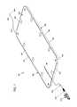
- FIG. 1is a perspective view of a payout cassette according to the principles of the present disclosure, the payout cassette storing a stored portion of a telecommunications cable and paying out a paid-out portion of the telecommunications cable;
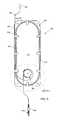
- FIG. 2is the perspective view of FIG. 1 , but without the telecommunications cable;
- FIG. 3is the perspective view of FIG. 2 , but with a cover and an anti-friction device of the payout cassette exploded away from a main housing of the payout cassette;
- FIG. 4is an enlarged portion of FIG. 3 ;
- FIG. 5is a top plan view of the payout cassette of FIG. 1 with the cover of FIG. 3 removed and a currently stored portion of the telecommunications cable substantially equal to an initially stored portion of the telecommunications cable;
- FIG. 6is an enlarged portion of FIG. 5 ;
- FIG. 7is the top plan view of FIG. 5 , but with some of the initially stored portion of the telecommunications cable having been transferred to the paid-out portion of the telecommunications cable;
- FIG. 8is an enlarged portion of FIG. 7 ;
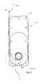
- FIG. 9is similar to the view of FIG. 8 , but with the cover of FIG. 3 installed and the telecommunications cable of FIG. 1 removed.
- an example cassette assembly 100is adapted to pay-out an example telecommunications cable 500 .
- the cassette assembly 100can pay-out an extended length of the telecommunications cable 500 without disconnecting the telecommunications cable 500 from a first end 502 (i.e. a paid-out end).
- the cassette assembly 100can pay-out the extended length of the telecommunications cable 500 without disconnecting the telecommunications cable 500 from a second end 504 (i.e. a base end).
- the paid-out end 502can be pulled from the cassette assembly 100 at various lengths including the extended length to bring the paid-out end 502 of the telecommunications cable 500 to a desired location.
- the cassette assembly 100does not require a rotary union or substantial accumulated twist in the telecommunications cable 500 , but rather loops 510 of a stored portion 520 of the telecommunications cable 500 within a storage area 110 of the cassette assembly 100 are reduced in length (i.e., circumference) while the cassette assembly 100 is paying-out a paid-out portion 530 of the telecommunications cable 500 , as illustrated by changes in routing of the telecommunications cable 500 between FIGS. 5 and 6 and FIGS. 7 and 8 .
- the loops 510 of the stored portion 520 of the telecommunications cable 500tighten around a wrapping surface 122 of a wrapping area 120 within the storage area 110 when the cassette assembly 100 pays-out the telecommunications cable 500 (see FIG. 6 ).
- the telecommunications cable 500is thereby transferred from the stored portion 520 to a transitional portion 525 and then to the paid-out portion 530 .
- the transitional portion 525is adjacent an inner-most loop 510 i and the base end 504 is adjacent an outer-most loop 510 o .
- the paid-out end 502is continuously connected to the base end 504 while the telecommunications cable 500 is being paid-out.
- a first deviceconnected to the first end 502 , may be continuously connected to a second device, connected to the second end 504 , while the telecommunications cable 500 is being paid-out and/or stored.
- the first deviceconnected to the first end 502 , may be continuously connected to the telecommunications cable 500 while the telecommunications cable 500 is being paid-out and/or stored
- the second deviceconnected to the second end 504 , may be continuously connected to the telecommunications cable 500 while the telecommunications cable 500 is being paid-out and/or stored.
- the cassette assembly 100includes a terminal 150 .
- the terminal 150is not substantially extendable from the cassette assembly 100 .
- the terminal 150is generally stationary with the cassette assembly 100 .
- the terminal 150may be fixed with a main housing 200 of the cassette assembly 100 .
- the terminal 150is attached to the housing 200 by a terminal portion 540 (e.g., a base cable portion) of the telecommunications cable 500 .
- the terminal 150can be connectorized by a fiber optic connector and/or a fiber optic adaptor.
- the terminal 150can be permanently or semi-permanently connected to a fiber optic component, a fiber optic network, the second device, etc. If it is desired to change the position of the first end 502 , the terminal 150 can remain connected to the fiber optic component, the fiber optic network, the second device, etc.
- individual loops 510 1-4 of the loops 510 of the stored portion 520 of the telecommunications cable 500may become smaller and thereby transfer cable length to the paid-out portion 530 of the telecommunications cable 500 .
- a number N of loops 510 1-Ndoes not change as the telecommunications cable 500 is paid-out over a pay-out range (i.e., starting from a fully retracted configuration to a fully deployed configuration).
- the telecommunications cable 500extends continuously between the first end 502 and the second end 504 .
- pulling the first end 502actuates the cassette assembly 100 .
- the housing 200typically remains stationary.
- the cassette assembly 100includes a housing 180 that further includes the housing 200 and a cover 300 .
- the housing 180extends between a first side 182 and a second side 184 , a first end 186 and a second end 188 , and a first edge 190 and a second edge 192 .
- Two or more of the cassette assemblies 100may be stacked.
- the first side 182 of a first of the cassette assemblies 100may be placed adjacent to the second side 184 of a second of the cassette assemblies 100 .
- the second ends 504 of the first and the second of the cassette assemblies 100may be merged (e.g., continuous with each other) thereby creating a cassette assembly that can pay-out the telecommunications cable 500 from either of two ends (i.e., the first ends 502 of the first and the second of the cassette assemblies 100 ).
- the housing 200(e.g., a base portion) includes a cavity 210 with a perimeter 212 and a first wrapping area 214 in the cavity 210 within and adjacent to the perimeter 212 .
- the cavity 210also includes a second wrapping area 234 that may serve as the wrapping area 120 .
- a substantial majority of the telecommunications cable 500may be initially loaded in the first wrapping area 214 of the cavity 210 adjacent the perimeter 212 in a series of the loops 510 that are positioned within the cavity 210 one layer deep (see FIG. 5 ).
- An initial loop 510 1(i.e., the outermost loop 510 o ) may begin at a cable passage 202 .
- the cable passage 202may be adjacent the perimeter 212 and may extend between the cavity 210 and an exterior 102 of the cassette 100 (see FIGS. 1, 5, and 6 ).
- the telecommunications cable 500may continue from the initial loop 510 1 , 510 o to the cable passage 202 and may be positioned within the cable passage 202 (i.e., an entrance passage).
- the initial loop 510 1 , 510 omay be wrapped adjacent the perimeter 212 until the initial loop 510 1 , 510 o has extended around the perimeter 212 .
- the cable wrappingmay continue with a second loop 510 2 that is positioned adjacent the initial loop 510 1 , 510 o and follows the initial loop 510 1 , 510 o as it extends around the perimeter 212 .
- the cable wrappingmay continue with a third loop 510 3 that follows the second loop 510 2 , a fourth loop 510 4 that follows the third loop 510 3 , etc.
- the initial loop 510 1 , 510 ois initially wrapped in contact or near contact with the perimeter 212 , thereby maximizing or substantially maximizing a length (i.e., a circumference) of the initial loop 510 1 , 510 o .
- the second loop 510 2may be in contact or near contact with the initial loop 510 1 , 510 o and thereby include a maximum length of the telecommunications cable 500 .
- the third loop 510 3may be in contact or near contact with the second loop 510 2
- the fourth loop 510 4may be in contact or near contact with the third loop 510 3 , etc.
- the telecommunications cable 500may be wrapped in the first wrapping area 214 of the cavity 210 inside of (i.e., within an interior of) the perimeter 212 .
- the terminal portion 540 of the telecommunications cable 500 of the cassette 100may extend from the cable passage 202 to the second end 504 of the telecommunications cable 500 .
- the terminal portion 540is not substantially extendable or retractable and is of a substantially fixed length.
- the telecommunications cable 500tightens around the wrapping surface 122 of the wrapping area 120 within the storage area 110 when the cassette assembly 100 pays-out the telecommunications cable 500 .
- the second wrapping area 234 of the cavity 210serves as the wrapping area 120 (see FIG. 4 ), and a wrapping surface 402 of an annular ring 400 includes the wrapping surface 122 .
- the annular ring 400may be made of a low-friction material (e.g., Teflon®) and thereby be an anti-friction device.
- the annular ring 400may be rotatably mounted to a mount 260 that is attached to or part of the housing 180 (e.g., the main housing 200 ). In certain embodiments, the mount 260 may be attached to or part of the cover 300 .
- the cassette 100further includes a transitioning area 160 for transitioning the telecommunications cable 500 from the storage area 110 to the exterior 102 of the cassette 100 .
- a transitioning area 160for transitioning the telecommunications cable 500 from the storage area 110 to the exterior 102 of the cassette 100 .
- the telecommunications cable 500 within the storage area 110generally transfers through the transitioning area 160 and on to the exterior 102 of the cassette 100 where it continues on toward a deployed area.
- the transitioning area 160includes a first cable guide 162 that is spaced away from the annular ring 400 and extends circumferentially around the annular ring 400 along an arc segment.
- the arc segmentis concentric with the annular ring 400 .
- the first cable guide 162is spaced from the annular ring 400 by a space 410 (e.g., a distance) sufficient to route a single strand of the telecommunications cable 500 between the first cable guide 162 and the annular ring 400 .
- a second cable guide 164is positioned immediately adjacent the annular ring 400 .
- the second cable guide 164may have a small clearance with the annular ring 400 .
- the small clearanceis not sufficient in size to receive a strand of the telecommunications cable 500 .
- the first and the second cable guides 162 , 164are formed on the housing 200 of the cassette 100 .
- the cassette 100further includes a third cable guide 360 .
- the third cable guide 360is in the form of a slot (i.e., a slit).
- the slotextends through the cover 300 of the housing 180 .
- the third cable guide 360may be formed as a channel and thereby may not necessarily extend through the cover 300 .
- the third cable guide 360includes a straight segment 362 and a curved segment 364 that is tangent to the straight segment 362 .
- the curved segment 364generally follows and continues along a path of the space 410 between the first cable guide 162 and the annular ring 400 .
- the outermost loop 510 1 , 510 o , the second loop 510 2 , the third loop 510 3 , etc.follow the perimeter 212 of the storage cavity 210 , as mentioned above.
- the telecommunications cable 500departs from following the perimeter 212 and veers toward the annular ring 400 .
- the telecommunications cable 500is routed between the first cable guide 162 and the annular ring 400 and then through the curved portion 364 of the third cable guide 360 .
- the telecommunications cable 500is elevated above the previous loops 510 1-4 and progressively is positioned at an elevation of the cover 300 within the third cable guide 360 .
- the third cable guide 360continues until it reaches an edge of the cover 300 .
- the telecommunications cable 500follows the third cable guide 360 and continues past the edge of the cover 300 toward the exterior 102 of the cassette 100 .
- the third cable guide 360thereby forms at least a portion of an exit 104 for the telecommunications cable 500 as it leaves (i.e., exits) the cassette 100 .
- the second cable guide 164may assist in preventing the telecommunications cable 500 from following the annular ring 400 and may peel the telecommunications cable 500 from the annular ring 400 and direct the telecommunications cable 500 toward the third cable guide 360 .
- a spacemay be created between the second cable guide 164 and the first cable guide 162 adjacent a portion of the circumference of the annular ring 400 so that as the telecommunications cable 500 winds around the annular ring 400 and exits, the telecommunications cable 500 does not get pinched and thereby prevented from being pulled out.
- the transitioning area 160may include the space between the second cable guide 164 and the first cable guide 162 .
- the main housing 200 of the housing 180includes a series of fingers 270 that project inwardly.
- the series of the fingers 270are spaced at the elevation of the cover 300 and form a space 272 with a bottom surface 216 of the cavity 210 that is substantially equal to a space 218 between an interior 302 of the cover 300 and the bottom surface 216 of the cavity 210 .
- the space 218keeps the series of the loops 510 positioned within the cavity 210 at the one layer deep.
- the fingers 270may provide a convenient holding arrangement for initially wrapping the loops 510 of the telecommunications cable 500 about the perimeter 212 .
- the cover 300may include a series of notches 370 or recesses that match the fingers 270 of the housing 200 .
- the housing 200may include a flange 280 that extends around an outer perimeter of the housing 200 .
- the cover 300may fit inside the flange 280 .
- the flange 280may include an opening aligned with the third cable guide 360 that allows the telecommunications cable 500 to exit through the flange 280 at the exit 104 .
- the loops 510transition from being positioned adjacent the perimeter 212 to being positioned adjacent or partially adjacent to the annular ring 400 .
- the innermost loop 510 idraws the telecommunications cable 500 from the second to the most innermost loop ( 510 3 as depicted at FIG. 8 ) as the telecommunications cable 500 is deployed from the cassette 100 .
- the second to the most innermost loopis drawn toward the rotating ring 400 , it is positioned on an opposite side of the first cable guide 162 from the innermost loop 510 i .
- portions of the telecommunications cable that were in the innermost loop 510 iexit through the transition area 160 and toward the exterior 102 of the cassette 100 .
- the telecommunications cable 500 that has left the innermost loop 510 iis replaced by the telecommunications cable 500 that is drawn from the second to the most innermost loop. This results in the second to the most innermost loop becoming smaller and drawing material from the third to the most innermost loop. This process continues until all of the telecommunications cable 500 that was positioned at the perimeter 212 of the cavity 210 is now positioned adjacent the rotating ring 400 and/or has exited the cassette 100 .
- the number of loops N of the telecommunications cable 500 within the storage area 110may remain constant during the cable deployment process.
- the length of each loop 510is decreased in magnitude (i.e., circumference) thereby supplying the length of the telecommunications cable 500 that is deployed.
- the cavity 210is an obround shape that includes semicircular ends spaced from each other. In other embodiments, the cavity 210 may have other shapes (e.g., circular, oval, etc.). In the depicted embodiment, the rotating ring 400 is positioned concentric to the semicircular end positioned opposite the cable entrance 202 .
- features within the cassette 100are shaped to provide bend radius protection to a fiber optic cable.
- the first end 502 and/or the second end 504 of the telecommunications cable 500may be connectorized by a connector 600 (e.g., a fiber optic connector).
- a connector 600e.g., a fiber optic connector
Landscapes
- Physics & Mathematics (AREA)
- General Physics & Mathematics (AREA)
- Optics & Photonics (AREA)
- Light Guides In General And Applications Therefor (AREA)
Abstract
Description
Claims (20)
Priority Applications (1)
| Application Number | Priority Date | Filing Date | Title |
|---|---|---|---|
| US13/872,592US9500831B2 (en) | 2012-04-30 | 2013-04-29 | Cable payout cassette with single layer cable storage area |
Applications Claiming Priority (2)
| Application Number | Priority Date | Filing Date | Title |
|---|---|---|---|
| US201261640422P | 2012-04-30 | 2012-04-30 | |
| US13/872,592US9500831B2 (en) | 2012-04-30 | 2013-04-29 | Cable payout cassette with single layer cable storage area |
Publications (2)
| Publication Number | Publication Date |
|---|---|
| US20130287359A1 US20130287359A1 (en) | 2013-10-31 |
| US9500831B2true US9500831B2 (en) | 2016-11-22 |
Family
ID=49477358
Family Applications (1)
| Application Number | Title | Priority Date | Filing Date |
|---|---|---|---|
| US13/872,592Expired - Fee RelatedUS9500831B2 (en) | 2012-04-30 | 2013-04-29 | Cable payout cassette with single layer cable storage area |
Country Status (2)
| Country | Link |
|---|---|
| US (1) | US9500831B2 (en) |
| WO (1) | WO2013165899A1 (en) |
Cited By (2)
| Publication number | Priority date | Publication date | Assignee | Title |
|---|---|---|---|---|
| US11648922B2 (en)* | 2015-09-02 | 2023-05-16 | Evolution Technologies Inc. | Manually-operated, height-adjustable wheeled vehicle, and a brake assembly and wheel fork assembly thereof |
| US12383255B2 (en) | 2019-01-31 | 2025-08-12 | Mvrx, Inc. | Suture management device and methods |
Families Citing this family (8)
| Publication number | Priority date | Publication date | Assignee | Title |
|---|---|---|---|---|
| CN104412475B (en) | 2012-04-30 | 2019-01-15 | Adc电信公司 | Cable storage spool with center feed |
| US9722407B2 (en) | 2012-04-30 | 2017-08-01 | Commscope Technologies Llc | Guided cable storage assembly with switchbacks |
| US9126802B2 (en) | 2012-04-30 | 2015-09-08 | Adc Telecommunications, Inc. | Payout spool with automatic cable disconnect/reconnect |
| US10276990B2 (en) | 2013-03-13 | 2019-04-30 | Commscope Technologies Llc | Telecommunications assembly with patch cord storage |
| US20160157006A1 (en)* | 2013-11-04 | 2016-06-02 | Sca Hygiene Products Ab | Wire coil retainer |
| WO2016094331A1 (en) | 2014-12-10 | 2016-06-16 | Commscope Technologies Llc | Fiber optic cable slack management module |
| CA2970167A1 (en)* | 2014-12-19 | 2016-06-23 | Commscope Technologies Llc | Coreless wound coil dispenser with optional cable storage for an optical terminal network |
| US20230278826A1 (en)* | 2022-03-03 | 2023-09-07 | Crestron Electronics, Inc. | Motorized cable retractor |
Citations (188)
| Publication number | Priority date | Publication date | Assignee | Title |
|---|---|---|---|---|
| US342354A (en) | 1886-05-25 | Ticket-case | ||
| US415423A (en) | 1889-11-19 | Ribbon-holder | ||
| US1137133A (en) | 1914-11-02 | 1915-04-27 | Joseph W Horner | Twine-holder. |
| US1276825A (en) | 1916-07-21 | 1918-08-27 | David Swope | Automatic take-up attachment for portable-telephone conductors. |
| US1588577A (en) | 1925-06-22 | 1926-06-15 | Heifler Isidore | Container and dispensing device for tape-like bodies |
| US1592030A (en) | 1925-06-04 | 1926-07-13 | Dietzgen Co Eugene | Tape reel |
| US1858371A (en) | 1931-09-30 | 1932-05-17 | William S Lutz | Gold leaf laying device |
| US2206352A (en) | 1939-01-20 | 1940-07-02 | Jay T Hellmann | Cord take-up |
| US2260109A (en) | 1940-02-19 | 1941-10-21 | Amdal Hans | Apparatus for operating lifesaving buoys |
| US2440974A (en) | 1945-08-24 | 1948-05-04 | Stewart H Resch | Combined humidifier and toilet paper dispenser |
| US2605060A (en) | 1949-09-29 | 1952-07-29 | Northwestern Steel & Wire Co | Wire magazine and feed mechanism |
| US2752106A (en) | 1952-09-02 | 1956-06-26 | Reuben A Thompson | Gauze holder |
| US2874918A (en) | 1954-07-24 | 1959-02-24 | Steiber Sven Ingemar | Wire reeling mechanism |
| US2905409A (en) | 1955-02-02 | 1959-09-22 | Rea Magnet Wire Company Inc | Wire dispensing device |
| US3015384A (en) | 1958-12-09 | 1962-01-02 | Clemson Bros Inc | Container and dispenser for coiled strip stock, bandsaw blade stock, and the like |
| US3120355A (en) | 1962-01-25 | 1964-02-04 | I T E Circuit Breaker Corp | Transfer mechanism |
| US3208121A (en) | 1963-10-03 | 1965-09-28 | James C Price | Storage reel |
| US3632061A (en) | 1968-05-23 | 1972-01-04 | Philips Corp | Wire-unwinding device |
| US3822834A (en) | 1972-06-05 | 1974-07-09 | Fathom Oceanology Ltd | Cable transfer apparatus |
| US3831879A (en) | 1970-03-11 | 1974-08-27 | Us Navy | Wire dispenser |
| US3843071A (en) | 1973-01-02 | 1974-10-22 | T Graham | Strip material container and dispenser |
| US4008791A (en) | 1975-09-08 | 1977-02-22 | Cascade Corporation | Takeup reel for combined hose and cable |
| US4055314A (en) | 1976-09-17 | 1977-10-25 | Wyrepak Industries, Inc. | Wire pay-off cap assembly for wire spools |
| US4108390A (en) | 1977-02-15 | 1978-08-22 | The United States Of America As Represented By The Secretary Of The Army | Paper tape canister |
| US4111380A (en) | 1977-06-14 | 1978-09-05 | Heuckroth Carl C | Welding wire spool shroud |
| US4186897A (en) | 1978-07-31 | 1980-02-05 | Brown Maurice H | Wire control mechanism |
| US4222535A (en) | 1979-07-16 | 1980-09-16 | Mossberg Hubbard, Division Of Wanskuck Company | Wire dereeling apparatus |
| US4273392A (en) | 1979-05-04 | 1981-06-16 | Stinson Constance E | Tissue roll holder |
| US4282954A (en) | 1980-02-11 | 1981-08-11 | Hill John O | Rewinder device |
| US4301611A (en) | 1978-06-23 | 1981-11-24 | Catuma Pty, Limited | Fishing line caster |
| US4436224A (en) | 1982-02-22 | 1984-03-13 | Mcinerny John | Dispenser for fluids and paper towels |
| US4565333A (en) | 1984-07-11 | 1986-01-21 | Fleet Industries | Cable winder system |
| US4664260A (en) | 1986-04-14 | 1987-05-12 | Seneca Wire And Manufacturing Company | Container/pallet for annular packages of strand material |
| US4936452A (en) | 1989-06-05 | 1990-06-26 | Pauley Helena R | Bathroom tissue container |
| JPH02296201A (en) | 1989-05-11 | 1990-12-06 | Topcon Corp | Cassette type optical fiber cable for surgical operation |
| US4978191A (en) | 1989-02-14 | 1990-12-18 | The Furukawa Electric Co., Ltd. | Connector device |
| US5022600A (en) | 1988-05-16 | 1991-06-11 | Commissariat A L'energie Atomique | Winder-unwinder for optical fibre cables |
| US5058259A (en) | 1988-03-25 | 1991-10-22 | Nippon Steel Welding Products & Engineering Co., Ltd. | Method and apparatus for passing threadlike pieces through tubular products |
| US5069523A (en) | 1988-12-08 | 1991-12-03 | Siemens Aktiengesellschaft | Cassette for spare lengths of light waveguides to be used at the site to be spliced |
| US5078466A (en) | 1991-04-19 | 1992-01-07 | Allied-Signal Inc. | Fiber optic rotary joint |
| US5098028A (en) | 1989-06-05 | 1992-03-24 | Alps Electric Co., Ltd. | Clock spring connector including cable stowage grooves |
| US5165543A (en) | 1991-09-25 | 1992-11-24 | At&T Bell Laboratories | Protected optical fiber package |
| EP0531628A1 (en) | 1991-06-15 | 1993-03-17 | Walter Rose GmbH & Co. KG | Device for dividing optical fibre cables and wires |
| JPH05303018A (en) | 1991-09-09 | 1993-11-16 | Sumitomo Electric Ind Ltd | Surplus length processing mechanism for optical fiber in optical cable terminal |
| US5265822A (en) | 1992-07-13 | 1993-11-30 | Shober Jr Robert C | IV tube support assembly |
| US5268986A (en) | 1991-09-09 | 1993-12-07 | Sumitomo Electric Industries, Ltd. | Redundant length treatment mechanism for optical fiber at terminal of optical cable |
| US5277314A (en) | 1991-06-18 | 1994-01-11 | The Lincoln Electric Company | Retainer ring for welding wire container disclosure |
| US5294068A (en) | 1991-09-26 | 1994-03-15 | Sensormatic Electronics Corporation | Dispenser for different width label rolls and method of using |
| US5305937A (en) | 1992-08-12 | 1994-04-26 | Barnett Sharon R | Dispenser for supplies |
| US5332171A (en) | 1991-03-15 | 1994-07-26 | Josef Steff | Winding device for winding up and unwinding a tube, cable or hose |
| US5335874A (en) | 1992-11-20 | 1994-08-09 | Siecor Corporation | Connectorized optical fiber cable reel |
| US5367827A (en) | 1992-11-05 | 1994-11-29 | Koito Manufacturing Co., Ltd. | Wire guide structure for power window |
| US5388781A (en) | 1991-01-30 | 1995-02-14 | Sauber; Charles J. | Cable pulling and reeling apparatus having anti-spill device and method |
| US5450509A (en) | 1994-07-26 | 1995-09-12 | Alliedsignal Inc. | Fiber optic rotary joint |
| US5481607A (en) | 1994-09-30 | 1996-01-02 | Hsiao; Tien J. | Automatic rewinding device for the conductor of a telephone transmitter |
| US5494446A (en) | 1994-01-05 | 1996-02-27 | Delucia; Eugene | Receptacle mounted, retractable, extension cord |
| US5544836A (en) | 1994-06-03 | 1996-08-13 | Lloyds International Trust | Extensible and self-retractable cable device |
| US5598987A (en) | 1995-09-20 | 1997-02-04 | Wachowicz; Walter J. | Dispenser for rolled paper products |
| US5607316A (en) | 1995-01-05 | 1997-03-04 | Yazaki Corporation | Structure for fixing a flat cable to a cylindrical rotator |
| US5630456A (en) | 1996-05-08 | 1997-05-20 | Hugo; Marie J. R. | Window blind cord winding apparatus |
| US5641067A (en) | 1995-08-30 | 1997-06-24 | Ellis; David A. | Retractable speaker wire |
| US5669571A (en) | 1995-12-04 | 1997-09-23 | Graybill; Larry Dean | Electrical cord storage and dispensing organizer |
| US5679015A (en) | 1994-10-15 | 1997-10-21 | Alcatel Kabel Ag & Co. | Device for the transmission of signals between two terminals |
| US5689605A (en)* | 1995-02-09 | 1997-11-18 | Lucent Technologies Inc. | Splice holder assembly for an optical fiber cable splice closure |
| US5758834A (en) | 1996-08-20 | 1998-06-02 | Illinois Tool Works Inc. | Welding wire storage and shipping container |
| US5772146A (en) | 1993-12-22 | 1998-06-30 | Nihon Plast Co., Ltd. | Reel device for cable |
| US5797558A (en) | 1996-02-12 | 1998-08-25 | Preco New Products Corp. | Uni-directional cord take-up device |
| US5802237A (en) | 1997-04-18 | 1998-09-01 | Minnesota Mining And Manufacturing Company | Optical fiber organizer |
| US5857285A (en) | 1997-01-22 | 1999-01-12 | Little; Joe | Storage device for hooks and leaders |
| US5913487A (en) | 1998-04-17 | 1999-06-22 | Leatherman; Michael | Retractable cable system |
| US5915062A (en) | 1997-07-01 | 1999-06-22 | Lucent Technologies Inc. | Low loss optical fiber reel |
| US5915641A (en) | 1993-04-19 | 1999-06-29 | Reel-A-Pail, Inc. | Reel inside bucket |
| US5921497A (en) | 1997-12-19 | 1999-07-13 | Lucent Technologies Inc. | Cable rotary joint |
| USD412439S (en) | 1997-06-27 | 1999-08-03 | Johnson & Johnson Limited | Container for impregnated wipes |
| WO1999041183A1 (en) | 1998-02-17 | 1999-08-19 | Gibbs James Matthews Irvine | Cable storage device |
| US5993229A (en) | 1996-09-13 | 1999-11-30 | Yazaki Corporation | Relaying apparatus between relative rotary members |
| US5996930A (en) | 1996-03-13 | 1999-12-07 | Sumitomo Electric Industries, Ltd. | Line dispenser and dispensing method |
| US6015110A (en) | 1996-12-17 | 2000-01-18 | Lai; Cheng-Ting | Wire receiving device |
| US6019308A (en) | 1998-09-28 | 2000-02-01 | Huang; Harrison | Device for dispensing plastic film roll |
| USD422170S (en) | 1999-07-08 | 2000-04-04 | Harris Jr Bennie | Paper towel dispenser |
| US6077108A (en) | 1997-12-31 | 2000-06-20 | Krone Gmbh | Patch panel with retractable patch cord |
| JP2000284129A (en) | 1999-04-01 | 2000-10-13 | Furukawa Electric Co Ltd:The | Optical fiber cord storage device |
| JP2001091753A (en) | 1999-09-13 | 2001-04-06 | Lucent Technol Inc | Optical fiber cassette |
| US6215938B1 (en) | 1998-09-21 | 2001-04-10 | Adc Telecommunications, Inc. | Fiber optic cabinet and tray |
| US6220413B1 (en) | 1999-10-19 | 2001-04-24 | Siecor Operations, Llc | Retractable cable reel |
| JP2001169452A (en) | 1999-12-02 | 2001-06-22 | Yazaki Corp | Wire harness winding device |
| US6250578B1 (en) | 1999-05-20 | 2001-06-26 | Lucent Technologies Inc. | Cable winding housing |
| US6260781B1 (en) | 1998-12-16 | 2001-07-17 | Lincoln Global, Inc. | Method and apparatus for packing wire in a storage drum |
| US6305958B1 (en) | 1998-07-23 | 2001-10-23 | Sumitomo Wiring Systems, Ltd. | Cable reel and assembling method thereof |
| US6311007B1 (en)* | 1999-09-07 | 2001-10-30 | Lucent Technologies Inc. | Fiber-optic cable tray having adjustable components |
| US6325665B1 (en) | 2000-04-25 | 2001-12-04 | Yu-Lin Chung | Power adapter with cable storage device |
| JP2001339837A (en) | 2000-05-25 | 2001-12-07 | Yazaki Corp | Assembly method and assembly jig for wire harness winding device |
| US6328243B1 (en) | 1999-06-18 | 2001-12-11 | Yazaki Corporation | Reel device for wire harness |
| US6349893B1 (en) | 2000-02-01 | 2002-02-26 | Avaya Technology Corp. | Retractable fiber slack storage device |
| US6361237B1 (en) | 1999-11-19 | 2002-03-26 | Raytheon Company | Coupling device |
| US6375109B1 (en) | 2000-02-29 | 2002-04-23 | Sheng-Hsin Liao | Wire winding box for short distance use |
| US6405961B1 (en) | 2000-07-05 | 2002-06-18 | At&T Corp | Storage assembly |
| US6422503B1 (en) | 2001-05-29 | 2002-07-23 | Michele Renee Hoo Kong | Toilet paper roll dispenser |
| US6434313B1 (en) | 2000-10-31 | 2002-08-13 | Corning Cable Systems Llc | Fiber optic closure with couplers and splice tray |
| US6433274B1 (en) | 2000-01-06 | 2002-08-13 | Mobility Electronic, Inc. | Power converter device |
| US20020122643A1 (en) | 2000-07-11 | 2002-09-05 | Bueschelberger Hanns J | Fiber optic coil for a fiber optic measuring system and method for producing the same |
| US6484958B1 (en) | 2001-11-20 | 2002-11-26 | Dowslake Microsystems Corporation | Patch cord caddy |
| US6501898B1 (en) | 1999-05-27 | 2002-12-31 | Telefonaktiebolaget Lm Ericsson (Publ) | Handling of optical fibres in confined or limited spaces |
| JP2003029059A (en) | 2001-07-11 | 2003-01-29 | Mitsubishi Cable Ind Ltd | Optical module |
| US6522826B2 (en) | 2001-05-11 | 2003-02-18 | Fibersense Technology Corporation | System and method of winding a fog coil |
| US20030059192A1 (en) | 2001-09-21 | 2003-03-27 | Johnson Christopher P. | Apparatus and method for holding coilable elongated product |
| US20030089818A1 (en) | 1999-12-21 | 2003-05-15 | Anne-Cecile Reau | A reel for paying out elongate elements for interior cabling of buildings |
| US20030095773A1 (en) | 2001-11-20 | 2003-05-22 | Toyokuni Electric Cable Co., Ltd. | Device for winding optical fiber cable |
| US6572393B2 (en) | 2001-02-15 | 2003-06-03 | Sumitomo Wiring Systems, Ltd. | Cable reel |
| USRE38211E1 (en) | 1996-02-12 | 2003-08-12 | Peterson Edwin R | Uni-directional cord take-up device |
| US6612515B1 (en) | 2000-08-28 | 2003-09-02 | Adc Telecommunications, Inc. | Telecommunications cable storage spool |
| US6616080B1 (en) | 1999-04-28 | 2003-09-09 | Speculative Product Design, Inc. | Retractable cord device |
| US6643443B2 (en) | 2000-09-21 | 2003-11-04 | Adc Telecommunications, Inc. | Cable storage cartridge |
| US6643445B2 (en) | 2000-12-22 | 2003-11-04 | Corning Incorporated | Fiber optic spools and methods of making the same |
| US6643444B1 (en) | 2002-03-14 | 2003-11-04 | Digital Lightwave, Inc. | Optical fiber spool assembly |
| JP2003329851A (en) | 2002-05-10 | 2003-11-19 | Sumitomo Electric Ind Ltd | Optical fiber storage device and optical fiber storage method |
| JP2003329850A (en) | 2002-05-09 | 2003-11-19 | Sumitomo Electric Ind Ltd | Optical fiber storage device and optical fiber storage method |
| US6733328B2 (en) | 2002-05-02 | 2004-05-11 | Chen Che Lin | USB cable adapter with cable winding mechanism |
| US6744954B1 (en) | 1998-11-20 | 2004-06-01 | Sumitomo Electric Industries, Ltd. | Submarine optical cable, optical fiber unit employed in the submarine optical cable, and method of making optical fiber unit |
| US6795633B2 (en) | 2002-03-28 | 2004-09-21 | Corning Incorporated | Method and apparatus for handling optical components |
| US20040211851A1 (en) | 2003-04-24 | 2004-10-28 | Lincoln Global , Inc. | Welding wire payout drum |
| US6819848B2 (en) | 2001-06-13 | 2004-11-16 | The Furukawa Electric Co., Ltd. | Method of winding optical fiber on reel |
| US6856748B1 (en) | 2003-09-30 | 2005-02-15 | Corning Cable Systems Llc | Interconnection enclosure having a connector port and preterminated optical connector |
| USD501722S1 (en) | 2003-12-19 | 2005-02-15 | Sterilite Corporation | Container |
| US6871812B1 (en) | 2004-01-20 | 2005-03-29 | Wen-Han Chang | Multi-stages retractable coiling cord device |
| US6915058B2 (en) | 2003-02-28 | 2005-07-05 | Corning Cable Systems Llc | Retractable optical fiber assembly |
| US20050167544A1 (en) | 2004-01-30 | 2005-08-04 | Bay West Paper Corporation | Three roll tissue dispenser |
| US20050247813A1 (en) | 2004-05-07 | 2005-11-10 | Kovacevich Ian D | Bi-directional device |
| US20050263640A1 (en) | 2004-06-01 | 2005-12-01 | David Vanderslice | Storage spool |
| WO2006015343A2 (en) | 2004-07-30 | 2006-02-09 | Viseon, Inc. | System for providing ip video telephony |
| US6997410B1 (en) | 2004-09-08 | 2006-02-14 | Kui-Hsien Huang | Positioning device for a reel |
| US20060045458A1 (en) | 2004-08-26 | 2006-03-02 | Koji Sasaki | Holder and structure for organizing excess length |
| US7017846B2 (en) | 2004-02-20 | 2006-03-28 | Comstar Communications Ltd. | Retractable cable winder |
| US7032854B2 (en) | 2003-10-31 | 2006-04-25 | Cosco Management, Inc. | Cord shortener |
| US7036761B2 (en) | 2003-03-04 | 2006-05-02 | Prfc, Inc. | Dual reel unwinder/rewinder with a slack take-up mechanism |
| US20060151654A1 (en) | 2001-12-31 | 2006-07-13 | David Pitcher | Hanging cable shortener arrangement |
| WO2006078007A1 (en) | 2005-01-24 | 2006-07-27 | Sumitomo Electric Industries, Ltd. | Optcal fiber module |
| US7086512B2 (en) | 2003-10-06 | 2006-08-08 | Cahp, Llc | Headset cable retraction system |
| US20060196989A1 (en) | 2005-03-04 | 2006-09-07 | Harold Bartley | Stackable dispenser for coiled materials |
| US7104491B2 (en) | 2002-02-07 | 2006-09-12 | Vinding Donald R | Retractable reel for flexible tubing |
| US7116883B2 (en) | 2004-11-19 | 2006-10-03 | Fiber Optic Protection Systems, Inc. | Fiber optic protective carrier |
| US7120349B2 (en) | 2002-10-29 | 2006-10-10 | Hewlett-Packard Development Company, L.P. | Fiber optic cable device with retractable operation |
| US20060264921A1 (en) | 2004-12-29 | 2006-11-23 | Imflux Llc | Retractable Surgical Instruments |
| US7182286B2 (en) | 2004-12-28 | 2007-02-27 | Chin Huang | Cable winder apparatus |
| US7229042B2 (en) | 2002-12-13 | 2007-06-12 | France Telecom | Packaging reel with an optical fiber unwinding device |
| US20070189829A1 (en) | 2004-05-06 | 2007-08-16 | Kokuyo Co., Ltd. | Transfer tool |
| US20070196053A1 (en) | 2006-02-17 | 2007-08-23 | Anthony Kewitsch | Isolated Fiber Optic Union Adapters |
| US7266283B2 (en) | 2005-03-16 | 2007-09-04 | Fiber Optic Cable Storage, Inc. | Fiber optic storing and dispensing apparatus |
| USD551477S1 (en) | 2005-06-27 | 2007-09-25 | Kiku Kikuchi | Case for housing a paper towel |
| US20070278227A1 (en) | 2006-05-16 | 2007-12-06 | Robin Damaghi | Dispenser lid and container including the same |
| US7315681B2 (en) | 2004-08-09 | 2008-01-01 | Anthony Kewitsch | Fiber optic rotary coupling and devices |
| US20080019642A1 (en) | 2006-02-17 | 2008-01-24 | Anthony Kewitsch | Protective Fiber Optic Union Adapters |
| US7357666B2 (en) | 2006-07-20 | 2008-04-15 | Sung Chiang Wu | Cable winder |
| US7369739B2 (en) | 2005-08-08 | 2008-05-06 | Fiber Optic Protection Systems, Inc. | Fiber optic cable protective apparatus |
| JP2008197530A (en) | 2007-02-15 | 2008-08-28 | Nippon Telegr & Teleph Corp <Ntt> | Optical fiber winding device |
| US20080273844A1 (en) | 2007-05-04 | 2008-11-06 | Dr. Anthony Stephen Kewitsch | Electrically Traceable and Identifiable Fiber Optic Cables and Connectors |
| US20080292261A1 (en) | 2007-05-07 | 2008-11-27 | Kowalczyk Scott C | Fiber optic enclosure with external cable spool |
| US7460753B2 (en) | 2006-07-06 | 2008-12-02 | Anthony Stephen Kewitsch | Shape-retaining fiber optic cables having limited bend radius |
| US7497351B2 (en) | 2006-05-30 | 2009-03-03 | Kimberly-Clark Worldwide, Inc. | Wet wipe dispensing system |
| US20090060441A1 (en) | 2007-09-05 | 2009-03-05 | Kowalczyk Scott C | Fiber optic enclosure with tear-away spool |
| US20090065629A1 (en) | 2007-09-06 | 2009-03-12 | Veit Kenneth C | Personal portable tissue roll holder |
| US20090074370A1 (en) | 2007-08-06 | 2009-03-19 | Adc Telecommunications, Inc. | Fiber optic enclosure with internal cable spool |
| US20090097797A1 (en) | 2007-10-15 | 2009-04-16 | Anthony Stephen Kewitsch | Methods to reconfigure all-fiber optical cross-connects |
| US20090140093A1 (en) | 2007-12-04 | 2009-06-04 | Delta Electronics, Inc. | Cable winding mechanism with reduced friction |
| US7548679B2 (en) | 2006-10-26 | 2009-06-16 | Sumitomo Electric Industries, Ltd. | Container for accommodating optical fiber coil and optical fiber module having the container |
| US7599598B2 (en) | 2006-08-09 | 2009-10-06 | Adc Telecommunications, Inc. | Cable payout systems and methods |
| US7627218B2 (en) | 2007-08-08 | 2009-12-01 | Corning Cable Systems Llc | Retractable optical fiber tether assembly and associated fiber optic cable |
| US20090324189A1 (en) | 2007-10-01 | 2009-12-31 | Clearfield, Inc. | Modular optical fiber cassette |
| US20100054680A1 (en) | 2008-08-27 | 2010-03-04 | Lochkovic Gregory A | Optical fiber assemblies for fiber to the subscriber applications |
| US7680386B2 (en) | 2008-07-23 | 2010-03-16 | Corning Cable Systems Llc | Retractable module for patch cords |
| US20100329621A1 (en) | 2009-06-26 | 2010-12-30 | Elli Makrides-Saravanos | Fiber Optic Cable Slack Storage Module |
| US20110024543A1 (en) | 2009-07-30 | 2011-02-03 | Mark Smrha | Spool for telecommunications cable and method |
| US20110024544A1 (en) | 2009-07-30 | 2011-02-03 | Mark Smrha | Locking spool for telecommunications cable and method |
| US20110073700A1 (en) | 2009-09-28 | 2011-03-31 | Jeanne Godett | Optical laser fiber reel |
| US20110085775A1 (en) | 2009-10-14 | 2011-04-14 | Accutech Medical Technologies Inc. | Packaging system and method for packaging fibers |
| US20110154867A1 (en) | 2004-12-28 | 2011-06-30 | Checkpoint Systems, Inc. | Cable wrap security device |
| US20110297781A1 (en) | 2010-06-06 | 2011-12-08 | Martin Jay Peters | Shielding Device |
| US20120168554A1 (en) | 2011-01-04 | 2012-07-05 | Randy Blunt | System for storing a bulk supply of cable for controlled payout and method of using the system |
| US20120205477A1 (en) | 2011-02-11 | 2012-08-16 | Adc Telecommunications, Inc. | Spool for telecommunications cable and method |
| US20130161430A1 (en) | 2011-12-27 | 2013-06-27 | Lincoln Global, Inc. | Hook slot to retain a wire within a spool |
| US20130233962A1 (en) | 2012-03-07 | 2013-09-12 | Garth Wells | Tape dispenser |
| US20130284843A1 (en) | 2012-04-30 | 2013-10-31 | Adc Telecommunications, Inc. | Cable storage spool with center feed |
| US20130284844A1 (en) | 2012-04-30 | 2013-10-31 | Adc Telecommunications, Inc. | Payout spool with automatic cable disconnect/reconnect |
| US20130306780A1 (en) | 2012-04-30 | 2013-11-21 | Adc Telecommunications, Inc. | Guided cable storage assembly with switchbacks |
| US20140027560A1 (en) | 2012-07-26 | 2014-01-30 | Rosemary Flood | Free standing dispenser apparatus for rolled sheet material |
| US20140131505A1 (en) | 2012-11-12 | 2014-05-15 | Southwire Company | Wire and Cable Package |
| US20140161411A1 (en) | 2011-07-27 | 2014-06-12 | Tyco Electronics Services Gmbh | Surface-mountable enclosure |
| US8800910B2 (en) | 2011-04-28 | 2014-08-12 | Ian Andrew Shepherd | Roll-form toilet wipes and dispenser |
- 2013
- 2013-04-29WOPCT/US2013/038651patent/WO2013165899A1/enactiveApplication Filing
- 2013-04-29USUS13/872,592patent/US9500831B2/ennot_activeExpired - Fee Related
Patent Citations (195)
| Publication number | Priority date | Publication date | Assignee | Title |
|---|---|---|---|---|
| US342354A (en) | 1886-05-25 | Ticket-case | ||
| US415423A (en) | 1889-11-19 | Ribbon-holder | ||
| US1137133A (en) | 1914-11-02 | 1915-04-27 | Joseph W Horner | Twine-holder. |
| US1276825A (en) | 1916-07-21 | 1918-08-27 | David Swope | Automatic take-up attachment for portable-telephone conductors. |
| US1592030A (en) | 1925-06-04 | 1926-07-13 | Dietzgen Co Eugene | Tape reel |
| US1588577A (en) | 1925-06-22 | 1926-06-15 | Heifler Isidore | Container and dispensing device for tape-like bodies |
| US1858371A (en) | 1931-09-30 | 1932-05-17 | William S Lutz | Gold leaf laying device |
| US2206352A (en) | 1939-01-20 | 1940-07-02 | Jay T Hellmann | Cord take-up |
| US2260109A (en) | 1940-02-19 | 1941-10-21 | Amdal Hans | Apparatus for operating lifesaving buoys |
| US2440974A (en) | 1945-08-24 | 1948-05-04 | Stewart H Resch | Combined humidifier and toilet paper dispenser |
| US2605060A (en) | 1949-09-29 | 1952-07-29 | Northwestern Steel & Wire Co | Wire magazine and feed mechanism |
| US2752106A (en) | 1952-09-02 | 1956-06-26 | Reuben A Thompson | Gauze holder |
| US2874918A (en) | 1954-07-24 | 1959-02-24 | Steiber Sven Ingemar | Wire reeling mechanism |
| US2905409A (en) | 1955-02-02 | 1959-09-22 | Rea Magnet Wire Company Inc | Wire dispensing device |
| US3015384A (en) | 1958-12-09 | 1962-01-02 | Clemson Bros Inc | Container and dispenser for coiled strip stock, bandsaw blade stock, and the like |
| US3120355A (en) | 1962-01-25 | 1964-02-04 | I T E Circuit Breaker Corp | Transfer mechanism |
| US3208121A (en) | 1963-10-03 | 1965-09-28 | James C Price | Storage reel |
| US3632061A (en) | 1968-05-23 | 1972-01-04 | Philips Corp | Wire-unwinding device |
| US3831879A (en) | 1970-03-11 | 1974-08-27 | Us Navy | Wire dispenser |
| US3822834A (en) | 1972-06-05 | 1974-07-09 | Fathom Oceanology Ltd | Cable transfer apparatus |
| US3843071A (en) | 1973-01-02 | 1974-10-22 | T Graham | Strip material container and dispenser |
| US4008791A (en) | 1975-09-08 | 1977-02-22 | Cascade Corporation | Takeup reel for combined hose and cable |
| US4055314A (en) | 1976-09-17 | 1977-10-25 | Wyrepak Industries, Inc. | Wire pay-off cap assembly for wire spools |
| US4108390A (en) | 1977-02-15 | 1978-08-22 | The United States Of America As Represented By The Secretary Of The Army | Paper tape canister |
| US4111380A (en) | 1977-06-14 | 1978-09-05 | Heuckroth Carl C | Welding wire spool shroud |
| US4301611A (en) | 1978-06-23 | 1981-11-24 | Catuma Pty, Limited | Fishing line caster |
| US4186897A (en) | 1978-07-31 | 1980-02-05 | Brown Maurice H | Wire control mechanism |
| US4273392A (en) | 1979-05-04 | 1981-06-16 | Stinson Constance E | Tissue roll holder |
| US4222535A (en) | 1979-07-16 | 1980-09-16 | Mossberg Hubbard, Division Of Wanskuck Company | Wire dereeling apparatus |
| US4282954A (en) | 1980-02-11 | 1981-08-11 | Hill John O | Rewinder device |
| US4436224A (en) | 1982-02-22 | 1984-03-13 | Mcinerny John | Dispenser for fluids and paper towels |
| US4565333A (en) | 1984-07-11 | 1986-01-21 | Fleet Industries | Cable winder system |
| US4664260A (en) | 1986-04-14 | 1987-05-12 | Seneca Wire And Manufacturing Company | Container/pallet for annular packages of strand material |
| US5058259A (en) | 1988-03-25 | 1991-10-22 | Nippon Steel Welding Products & Engineering Co., Ltd. | Method and apparatus for passing threadlike pieces through tubular products |
| US5022600A (en) | 1988-05-16 | 1991-06-11 | Commissariat A L'energie Atomique | Winder-unwinder for optical fibre cables |
| US5069523A (en) | 1988-12-08 | 1991-12-03 | Siemens Aktiengesellschaft | Cassette for spare lengths of light waveguides to be used at the site to be spliced |
| US4978191A (en) | 1989-02-14 | 1990-12-18 | The Furukawa Electric Co., Ltd. | Connector device |
| JPH02296201A (en) | 1989-05-11 | 1990-12-06 | Topcon Corp | Cassette type optical fiber cable for surgical operation |
| US4936452A (en) | 1989-06-05 | 1990-06-26 | Pauley Helena R | Bathroom tissue container |
| US5098028A (en) | 1989-06-05 | 1992-03-24 | Alps Electric Co., Ltd. | Clock spring connector including cable stowage grooves |
| US5388781A (en) | 1991-01-30 | 1995-02-14 | Sauber; Charles J. | Cable pulling and reeling apparatus having anti-spill device and method |
| US5332171A (en) | 1991-03-15 | 1994-07-26 | Josef Steff | Winding device for winding up and unwinding a tube, cable or hose |
| US5078466A (en) | 1991-04-19 | 1992-01-07 | Allied-Signal Inc. | Fiber optic rotary joint |
| EP0531628A1 (en) | 1991-06-15 | 1993-03-17 | Walter Rose GmbH & Co. KG | Device for dividing optical fibre cables and wires |
| US5277314A (en) | 1991-06-18 | 1994-01-11 | The Lincoln Electric Company | Retainer ring for welding wire container disclosure |
| US5268986A (en) | 1991-09-09 | 1993-12-07 | Sumitomo Electric Industries, Ltd. | Redundant length treatment mechanism for optical fiber at terminal of optical cable |
| JPH05303018A (en) | 1991-09-09 | 1993-11-16 | Sumitomo Electric Ind Ltd | Surplus length processing mechanism for optical fiber in optical cable terminal |
| US5165543A (en) | 1991-09-25 | 1992-11-24 | At&T Bell Laboratories | Protected optical fiber package |
| US5294068A (en) | 1991-09-26 | 1994-03-15 | Sensormatic Electronics Corporation | Dispenser for different width label rolls and method of using |
| US5265822A (en) | 1992-07-13 | 1993-11-30 | Shober Jr Robert C | IV tube support assembly |
| US5305937A (en) | 1992-08-12 | 1994-04-26 | Barnett Sharon R | Dispenser for supplies |
| US5367827A (en) | 1992-11-05 | 1994-11-29 | Koito Manufacturing Co., Ltd. | Wire guide structure for power window |
| US5335874A (en) | 1992-11-20 | 1994-08-09 | Siecor Corporation | Connectorized optical fiber cable reel |
| US5915641A (en) | 1993-04-19 | 1999-06-29 | Reel-A-Pail, Inc. | Reel inside bucket |
| US5772146A (en) | 1993-12-22 | 1998-06-30 | Nihon Plast Co., Ltd. | Reel device for cable |
| US5494446A (en) | 1994-01-05 | 1996-02-27 | Delucia; Eugene | Receptacle mounted, retractable, extension cord |
| US5544836A (en) | 1994-06-03 | 1996-08-13 | Lloyds International Trust | Extensible and self-retractable cable device |
| US5450509A (en) | 1994-07-26 | 1995-09-12 | Alliedsignal Inc. | Fiber optic rotary joint |
| US5481607A (en) | 1994-09-30 | 1996-01-02 | Hsiao; Tien J. | Automatic rewinding device for the conductor of a telephone transmitter |
| US5679015A (en) | 1994-10-15 | 1997-10-21 | Alcatel Kabel Ag & Co. | Device for the transmission of signals between two terminals |
| US5607316A (en) | 1995-01-05 | 1997-03-04 | Yazaki Corporation | Structure for fixing a flat cable to a cylindrical rotator |
| US5689605A (en)* | 1995-02-09 | 1997-11-18 | Lucent Technologies Inc. | Splice holder assembly for an optical fiber cable splice closure |
| US5641067A (en) | 1995-08-30 | 1997-06-24 | Ellis; David A. | Retractable speaker wire |
| US5598987A (en) | 1995-09-20 | 1997-02-04 | Wachowicz; Walter J. | Dispenser for rolled paper products |
| US5669571A (en) | 1995-12-04 | 1997-09-23 | Graybill; Larry Dean | Electrical cord storage and dispensing organizer |
| US5797558A (en) | 1996-02-12 | 1998-08-25 | Preco New Products Corp. | Uni-directional cord take-up device |
| USRE38211E1 (en) | 1996-02-12 | 2003-08-12 | Peterson Edwin R | Uni-directional cord take-up device |
| US5996930A (en) | 1996-03-13 | 1999-12-07 | Sumitomo Electric Industries, Ltd. | Line dispenser and dispensing method |
| US5630456A (en) | 1996-05-08 | 1997-05-20 | Hugo; Marie J. R. | Window blind cord winding apparatus |
| US5758834A (en) | 1996-08-20 | 1998-06-02 | Illinois Tool Works Inc. | Welding wire storage and shipping container |
| US5993229A (en) | 1996-09-13 | 1999-11-30 | Yazaki Corporation | Relaying apparatus between relative rotary members |
| US6015110A (en) | 1996-12-17 | 2000-01-18 | Lai; Cheng-Ting | Wire receiving device |
| US5857285A (en) | 1997-01-22 | 1999-01-12 | Little; Joe | Storage device for hooks and leaders |
| US5802237A (en) | 1997-04-18 | 1998-09-01 | Minnesota Mining And Manufacturing Company | Optical fiber organizer |
| USD412439S (en) | 1997-06-27 | 1999-08-03 | Johnson & Johnson Limited | Container for impregnated wipes |
| US5915062A (en) | 1997-07-01 | 1999-06-22 | Lucent Technologies Inc. | Low loss optical fiber reel |
| US5921497A (en) | 1997-12-19 | 1999-07-13 | Lucent Technologies Inc. | Cable rotary joint |
| US6077108A (en) | 1997-12-31 | 2000-06-20 | Krone Gmbh | Patch panel with retractable patch cord |
| WO1999041183A1 (en) | 1998-02-17 | 1999-08-19 | Gibbs James Matthews Irvine | Cable storage device |
| US5913487A (en) | 1998-04-17 | 1999-06-22 | Leatherman; Michael | Retractable cable system |
| US6305958B1 (en) | 1998-07-23 | 2001-10-23 | Sumitomo Wiring Systems, Ltd. | Cable reel and assembling method thereof |
| US6215938B1 (en) | 1998-09-21 | 2001-04-10 | Adc Telecommunications, Inc. | Fiber optic cabinet and tray |
| US6019308A (en) | 1998-09-28 | 2000-02-01 | Huang; Harrison | Device for dispensing plastic film roll |
| US6744954B1 (en) | 1998-11-20 | 2004-06-01 | Sumitomo Electric Industries, Ltd. | Submarine optical cable, optical fiber unit employed in the submarine optical cable, and method of making optical fiber unit |
| US6260781B1 (en) | 1998-12-16 | 2001-07-17 | Lincoln Global, Inc. | Method and apparatus for packing wire in a storage drum |
| JP2000284129A (en) | 1999-04-01 | 2000-10-13 | Furukawa Electric Co Ltd:The | Optical fiber cord storage device |
| US6616080B1 (en) | 1999-04-28 | 2003-09-09 | Speculative Product Design, Inc. | Retractable cord device |
| US6250578B1 (en) | 1999-05-20 | 2001-06-26 | Lucent Technologies Inc. | Cable winding housing |
| US6501898B1 (en) | 1999-05-27 | 2002-12-31 | Telefonaktiebolaget Lm Ericsson (Publ) | Handling of optical fibres in confined or limited spaces |
| US6328243B1 (en) | 1999-06-18 | 2001-12-11 | Yazaki Corporation | Reel device for wire harness |
| USD422170S (en) | 1999-07-08 | 2000-04-04 | Harris Jr Bennie | Paper towel dispenser |
| US6311007B1 (en)* | 1999-09-07 | 2001-10-30 | Lucent Technologies Inc. | Fiber-optic cable tray having adjustable components |
| JP2001091753A (en) | 1999-09-13 | 2001-04-06 | Lucent Technol Inc | Optical fiber cassette |
| US6220413B1 (en) | 1999-10-19 | 2001-04-24 | Siecor Operations, Llc | Retractable cable reel |
| US6361237B1 (en) | 1999-11-19 | 2002-03-26 | Raytheon Company | Coupling device |
| JP2001169452A (en) | 1999-12-02 | 2001-06-22 | Yazaki Corp | Wire harness winding device |
| US20030089818A1 (en) | 1999-12-21 | 2003-05-15 | Anne-Cecile Reau | A reel for paying out elongate elements for interior cabling of buildings |
| US6433274B1 (en) | 2000-01-06 | 2002-08-13 | Mobility Electronic, Inc. | Power converter device |
| US6349893B1 (en) | 2000-02-01 | 2002-02-26 | Avaya Technology Corp. | Retractable fiber slack storage device |
| US6375109B1 (en) | 2000-02-29 | 2002-04-23 | Sheng-Hsin Liao | Wire winding box for short distance use |
| US6325665B1 (en) | 2000-04-25 | 2001-12-04 | Yu-Lin Chung | Power adapter with cable storage device |
| JP2001339837A (en) | 2000-05-25 | 2001-12-07 | Yazaki Corp | Assembly method and assembly jig for wire harness winding device |
| US6405961B1 (en) | 2000-07-05 | 2002-06-18 | At&T Corp | Storage assembly |
| US20020122643A1 (en) | 2000-07-11 | 2002-09-05 | Bueschelberger Hanns J | Fiber optic coil for a fiber optic measuring system and method for producing the same |
| US6612515B1 (en) | 2000-08-28 | 2003-09-02 | Adc Telecommunications, Inc. | Telecommunications cable storage spool |
| US6643443B2 (en) | 2000-09-21 | 2003-11-04 | Adc Telecommunications, Inc. | Cable storage cartridge |
| US6434313B1 (en) | 2000-10-31 | 2002-08-13 | Corning Cable Systems Llc | Fiber optic closure with couplers and splice tray |
| US6643445B2 (en) | 2000-12-22 | 2003-11-04 | Corning Incorporated | Fiber optic spools and methods of making the same |
| US6572393B2 (en) | 2001-02-15 | 2003-06-03 | Sumitomo Wiring Systems, Ltd. | Cable reel |
| US6522826B2 (en) | 2001-05-11 | 2003-02-18 | Fibersense Technology Corporation | System and method of winding a fog coil |
| US6422503B1 (en) | 2001-05-29 | 2002-07-23 | Michele Renee Hoo Kong | Toilet paper roll dispenser |
| US6819848B2 (en) | 2001-06-13 | 2004-11-16 | The Furukawa Electric Co., Ltd. | Method of winding optical fiber on reel |
| JP2003029059A (en) | 2001-07-11 | 2003-01-29 | Mitsubishi Cable Ind Ltd | Optical module |
| US20030059192A1 (en) | 2001-09-21 | 2003-03-27 | Johnson Christopher P. | Apparatus and method for holding coilable elongated product |
| US20030095773A1 (en) | 2001-11-20 | 2003-05-22 | Toyokuni Electric Cable Co., Ltd. | Device for winding optical fiber cable |
| US6484958B1 (en) | 2001-11-20 | 2002-11-26 | Dowslake Microsystems Corporation | Patch cord caddy |
| US20060151654A1 (en) | 2001-12-31 | 2006-07-13 | David Pitcher | Hanging cable shortener arrangement |
| US7104491B2 (en) | 2002-02-07 | 2006-09-12 | Vinding Donald R | Retractable reel for flexible tubing |
| US6643444B1 (en) | 2002-03-14 | 2003-11-04 | Digital Lightwave, Inc. | Optical fiber spool assembly |
| US6795633B2 (en) | 2002-03-28 | 2004-09-21 | Corning Incorporated | Method and apparatus for handling optical components |
| US6733328B2 (en) | 2002-05-02 | 2004-05-11 | Chen Che Lin | USB cable adapter with cable winding mechanism |
| JP2003329850A (en) | 2002-05-09 | 2003-11-19 | Sumitomo Electric Ind Ltd | Optical fiber storage device and optical fiber storage method |
| JP2003329851A (en) | 2002-05-10 | 2003-11-19 | Sumitomo Electric Ind Ltd | Optical fiber storage device and optical fiber storage method |
| US7120349B2 (en) | 2002-10-29 | 2006-10-10 | Hewlett-Packard Development Company, L.P. | Fiber optic cable device with retractable operation |
| US7229042B2 (en) | 2002-12-13 | 2007-06-12 | France Telecom | Packaging reel with an optical fiber unwinding device |
| US6915058B2 (en) | 2003-02-28 | 2005-07-05 | Corning Cable Systems Llc | Retractable optical fiber assembly |
| US7036761B2 (en) | 2003-03-04 | 2006-05-02 | Prfc, Inc. | Dual reel unwinder/rewinder with a slack take-up mechanism |
| US20040211851A1 (en) | 2003-04-24 | 2004-10-28 | Lincoln Global , Inc. | Welding wire payout drum |
| US6856748B1 (en) | 2003-09-30 | 2005-02-15 | Corning Cable Systems Llc | Interconnection enclosure having a connector port and preterminated optical connector |
| US7086512B2 (en) | 2003-10-06 | 2006-08-08 | Cahp, Llc | Headset cable retraction system |
| US7032854B2 (en) | 2003-10-31 | 2006-04-25 | Cosco Management, Inc. | Cord shortener |
| USD501722S1 (en) | 2003-12-19 | 2005-02-15 | Sterilite Corporation | Container |
| US6871812B1 (en) | 2004-01-20 | 2005-03-29 | Wen-Han Chang | Multi-stages retractable coiling cord device |
| US20050167544A1 (en) | 2004-01-30 | 2005-08-04 | Bay West Paper Corporation | Three roll tissue dispenser |
| US7017846B2 (en) | 2004-02-20 | 2006-03-28 | Comstar Communications Ltd. | Retractable cable winder |
| US20070189829A1 (en) | 2004-05-06 | 2007-08-16 | Kokuyo Co., Ltd. | Transfer tool |
| US20050247813A1 (en) | 2004-05-07 | 2005-11-10 | Kovacevich Ian D | Bi-directional device |
| US20050263640A1 (en) | 2004-06-01 | 2005-12-01 | David Vanderslice | Storage spool |
| WO2006015343A2 (en) | 2004-07-30 | 2006-02-09 | Viseon, Inc. | System for providing ip video telephony |
| US7315681B2 (en) | 2004-08-09 | 2008-01-01 | Anthony Kewitsch | Fiber optic rotary coupling and devices |
| US20060045458A1 (en) | 2004-08-26 | 2006-03-02 | Koji Sasaki | Holder and structure for organizing excess length |
| US6997410B1 (en) | 2004-09-08 | 2006-02-14 | Kui-Hsien Huang | Positioning device for a reel |
| US7116883B2 (en) | 2004-11-19 | 2006-10-03 | Fiber Optic Protection Systems, Inc. | Fiber optic protective carrier |
| US7182286B2 (en) | 2004-12-28 | 2007-02-27 | Chin Huang | Cable winder apparatus |
| US20110154867A1 (en) | 2004-12-28 | 2011-06-30 | Checkpoint Systems, Inc. | Cable wrap security device |
| US20060264921A1 (en) | 2004-12-29 | 2006-11-23 | Imflux Llc | Retractable Surgical Instruments |
| WO2006078007A1 (en) | 2005-01-24 | 2006-07-27 | Sumitomo Electric Industries, Ltd. | Optcal fiber module |
| US20060196989A1 (en) | 2005-03-04 | 2006-09-07 | Harold Bartley | Stackable dispenser for coiled materials |
| US7266283B2 (en) | 2005-03-16 | 2007-09-04 | Fiber Optic Cable Storage, Inc. | Fiber optic storing and dispensing apparatus |
| USD551477S1 (en) | 2005-06-27 | 2007-09-25 | Kiku Kikuchi | Case for housing a paper towel |
| US7369739B2 (en) | 2005-08-08 | 2008-05-06 | Fiber Optic Protection Systems, Inc. | Fiber optic cable protective apparatus |
| US20070196053A1 (en) | 2006-02-17 | 2007-08-23 | Anthony Kewitsch | Isolated Fiber Optic Union Adapters |
| US20080019642A1 (en) | 2006-02-17 | 2008-01-24 | Anthony Kewitsch | Protective Fiber Optic Union Adapters |
| US7665901B2 (en) | 2006-02-17 | 2010-02-23 | Telescent Inc. | Protective fiber optic union adapters |
| US20070278227A1 (en) | 2006-05-16 | 2007-12-06 | Robin Damaghi | Dispenser lid and container including the same |
| US7497351B2 (en) | 2006-05-30 | 2009-03-03 | Kimberly-Clark Worldwide, Inc. | Wet wipe dispensing system |
| US7460753B2 (en) | 2006-07-06 | 2008-12-02 | Anthony Stephen Kewitsch | Shape-retaining fiber optic cables having limited bend radius |
| US7357666B2 (en) | 2006-07-20 | 2008-04-15 | Sung Chiang Wu | Cable winder |
| US7599598B2 (en) | 2006-08-09 | 2009-10-06 | Adc Telecommunications, Inc. | Cable payout systems and methods |
| US7548679B2 (en) | 2006-10-26 | 2009-06-16 | Sumitomo Electric Industries, Ltd. | Container for accommodating optical fiber coil and optical fiber module having the container |
| JP2008197530A (en) | 2007-02-15 | 2008-08-28 | Nippon Telegr & Teleph Corp <Ntt> | Optical fiber winding device |
| US20080273844A1 (en) | 2007-05-04 | 2008-11-06 | Dr. Anthony Stephen Kewitsch | Electrically Traceable and Identifiable Fiber Optic Cables and Connectors |
| US20080292261A1 (en) | 2007-05-07 | 2008-11-27 | Kowalczyk Scott C | Fiber optic enclosure with external cable spool |
| US7715679B2 (en) | 2007-05-07 | 2010-05-11 | Adc Telecommunications, Inc. | Fiber optic enclosure with external cable spool |
| US7756379B2 (en) | 2007-08-06 | 2010-07-13 | Adc Telecommunications, Inc. | Fiber optic enclosure with internal cable spool |
| US20090074370A1 (en) | 2007-08-06 | 2009-03-19 | Adc Telecommunications, Inc. | Fiber optic enclosure with internal cable spool |
| US7627218B2 (en) | 2007-08-08 | 2009-12-01 | Corning Cable Systems Llc | Retractable optical fiber tether assembly and associated fiber optic cable |
| US20090060441A1 (en) | 2007-09-05 | 2009-03-05 | Kowalczyk Scott C | Fiber optic enclosure with tear-away spool |
| US7869682B2 (en) | 2007-09-05 | 2011-01-11 | Adc Telecommunications, Inc. | Fiber optic enclosure with tear-away spool |
| US20090065629A1 (en) | 2007-09-06 | 2009-03-12 | Veit Kenneth C | Personal portable tissue roll holder |
| US20090324189A1 (en) | 2007-10-01 | 2009-12-31 | Clearfield, Inc. | Modular optical fiber cassette |
| US20090097797A1 (en) | 2007-10-15 | 2009-04-16 | Anthony Stephen Kewitsch | Methods to reconfigure all-fiber optical cross-connects |
| US20090140093A1 (en) | 2007-12-04 | 2009-06-04 | Delta Electronics, Inc. | Cable winding mechanism with reduced friction |
| US7680386B2 (en) | 2008-07-23 | 2010-03-16 | Corning Cable Systems Llc | Retractable module for patch cords |
| US20100054680A1 (en) | 2008-08-27 | 2010-03-04 | Lochkovic Gregory A | Optical fiber assemblies for fiber to the subscriber applications |
| US20100329621A1 (en) | 2009-06-26 | 2010-12-30 | Elli Makrides-Saravanos | Fiber Optic Cable Slack Storage Module |
| US8238707B2 (en) | 2009-07-30 | 2012-08-07 | Adc Telecommunications, Inc. | Locking spool for telecommunications cable and method |
| US8474742B2 (en) | 2009-07-30 | 2013-07-02 | Adc Telecommunications, Inc. | Spool for telecommunications cable and method |
| US20110024544A1 (en) | 2009-07-30 | 2011-02-03 | Mark Smrha | Locking spool for telecommunications cable and method |
| US20110024543A1 (en) | 2009-07-30 | 2011-02-03 | Mark Smrha | Spool for telecommunications cable and method |
| US20110073700A1 (en) | 2009-09-28 | 2011-03-31 | Jeanne Godett | Optical laser fiber reel |
| US20110085775A1 (en) | 2009-10-14 | 2011-04-14 | Accutech Medical Technologies Inc. | Packaging system and method for packaging fibers |
| US20110297781A1 (en) | 2010-06-06 | 2011-12-08 | Martin Jay Peters | Shielding Device |
| US20120168554A1 (en) | 2011-01-04 | 2012-07-05 | Randy Blunt | System for storing a bulk supply of cable for controlled payout and method of using the system |
| US20120205477A1 (en) | 2011-02-11 | 2012-08-16 | Adc Telecommunications, Inc. | Spool for telecommunications cable and method |
| US8720810B2 (en) | 2011-02-11 | 2014-05-13 | Adc Telecommunications, Inc. | Spool for telecommunications cable and method |
| US8800910B2 (en) | 2011-04-28 | 2014-08-12 | Ian Andrew Shepherd | Roll-form toilet wipes and dispenser |
| US20140161411A1 (en) | 2011-07-27 | 2014-06-12 | Tyco Electronics Services Gmbh | Surface-mountable enclosure |
| US20130161430A1 (en) | 2011-12-27 | 2013-06-27 | Lincoln Global, Inc. | Hook slot to retain a wire within a spool |
| US20130233962A1 (en) | 2012-03-07 | 2013-09-12 | Garth Wells | Tape dispenser |
| US20130284843A1 (en) | 2012-04-30 | 2013-10-31 | Adc Telecommunications, Inc. | Cable storage spool with center feed |
| US20130284844A1 (en) | 2012-04-30 | 2013-10-31 | Adc Telecommunications, Inc. | Payout spool with automatic cable disconnect/reconnect |
| US20130306780A1 (en) | 2012-04-30 | 2013-11-21 | Adc Telecommunications, Inc. | Guided cable storage assembly with switchbacks |
| US20140027560A1 (en) | 2012-07-26 | 2014-01-30 | Rosemary Flood | Free standing dispenser apparatus for rolled sheet material |
| US20140131505A1 (en) | 2012-11-12 | 2014-05-15 | Southwire Company | Wire and Cable Package |
Non-Patent Citations (11)
| Title |
|---|
| Catalogue-Fastening Solutions-RICHCO-(Version JPG)-p. 227, 3 pages (Date Unknown). |
| Decoiler Devices/Traverse Arms/Accessories, http://replay.web.archive.org/20060518044402/https://weldingsupply.securesites.com/, 4 pages (May 18, 2006). |
| Decoiler Devices/Traverse Arms/Accessories, https://weldingsupply.securesites.com/yeoweld-fax.html, 5 pages (Date Printed May 2, 2011). |
| Fiber Management, Richco, p. 211 (Date Unknown). |
| Fiberlaunch, 4 pages (Copyright 2010). |
| Fibre Fastening and Routing Components, Richco, pp. 54-72 (Date Unknown). |
| Fibre Winding Reel, Europlus Technologies plc, 2 pages (Date Unknown). |
| International Search Report and Written Opinion for PCT/US2013/038651 mailed Aug. 27, 2013. |
| Still images from video located at http://www.igus.com Dec. 8, 2009-igus-12HMInews, 3 pages (Downloaded Dec. 2009). |
| Still images from video located at http://www.igus.com/ApplicationCorner/igus%20Videos/E-Chain/Excellent%20quality/EChainSystems-for-machinetools.wmv, 6 pages (Downloaded Dec. 2009). |
| Telescent Catalog Fiber Optic Connectivity, pp. 1-39 (Copyright 2007). |
Cited By (2)
| Publication number | Priority date | Publication date | Assignee | Title |
|---|---|---|---|---|
| US11648922B2 (en)* | 2015-09-02 | 2023-05-16 | Evolution Technologies Inc. | Manually-operated, height-adjustable wheeled vehicle, and a brake assembly and wheel fork assembly thereof |
| US12383255B2 (en) | 2019-01-31 | 2025-08-12 | Mvrx, Inc. | Suture management device and methods |
Also Published As
| Publication number | Publication date |
|---|---|
| WO2013165899A1 (en) | 2013-11-07 |
| US20130287359A1 (en) | 2013-10-31 |
Similar Documents
| Publication | Publication Date | Title |
|---|---|---|
| US9500831B2 (en) | Cable payout cassette with single layer cable storage area | |
| US10625978B2 (en) | Cable storage spool with center feed | |
| US8474742B2 (en) | Spool for telecommunications cable and method | |
| US9555999B2 (en) | Cable spool assembly | |
| US10566747B2 (en) | Telecommunications assembly with patch cord storage | |
| US8720657B2 (en) | Rewindable electrical cable extension device | |
| US8720810B2 (en) | Spool for telecommunications cable and method | |
| US9722407B2 (en) | Guided cable storage assembly with switchbacks | |
| US20220212892A1 (en) | Spool with multi-position loop keeper | |
| US9290358B2 (en) | Retractable in-wall cable system | |
| US20080296426A1 (en) | Apparatus and method for managing flexible lines | |
| US10330880B2 (en) | Cable spool re-orientation device for a wall box | |
| CA3021203C (en) | Retractable fiber optic reel assembly | |
| US20200158978A1 (en) | Telecommunications cabling system | |
| US8235322B1 (en) | Handling excess optical fiber | |
| GB2460880A (en) | Mounting for a reel, spool or the like | |
| US9884738B1 (en) | Wire caddy | |
| EP4592723A1 (en) | Floating cable spool containment cover and method of operation thereof |
Legal Events
| Date | Code | Title | Description |
|---|---|---|---|
| AS | Assignment | Owner name:TYCO ELECTRONICS SERVICES GMBH, SWITZERLAND Free format text:ASSIGNMENT OF ASSIGNORS INTEREST;ASSIGNORS:ADC TELECOMMUNICATIONS, INC.;TE CONNECTIVITY SOLUTIONS GMBH;REEL/FRAME:036908/0443 Effective date:20150825 | |
| AS | Assignment | Owner name:COMMSCOPE EMEA LIMITED, IRELAND Free format text:ASSIGNMENT OF ASSIGNORS INTEREST;ASSIGNOR:TYCO ELECTRONICS SERVICES GMBH;REEL/FRAME:036956/0001 Effective date:20150828 | |
| AS | Assignment | Owner name:COMMSCOPE TECHNOLOGIES LLC, NORTH CAROLINA Free format text:ASSIGNMENT OF ASSIGNORS INTEREST;ASSIGNOR:COMMSCOPE EMEA LIMITED;REEL/FRAME:037012/0001 Effective date:20150828 | |
| AS | Assignment | Owner name:JPMORGAN CHASE BANK, N.A., AS COLLATERAL AGENT, ILLINOIS Free format text:PATENT SECURITY AGREEMENT (TERM);ASSIGNOR:COMMSCOPE TECHNOLOGIES LLC;REEL/FRAME:037513/0709 Effective date:20151220 Owner name:JPMORGAN CHASE BANK, N.A., AS COLLATERAL AGENT, ILLINOIS Free format text:PATENT SECURITY AGREEMENT (ABL);ASSIGNOR:COMMSCOPE TECHNOLOGIES LLC;REEL/FRAME:037514/0196 Effective date:20151220 Owner name:JPMORGAN CHASE BANK, N.A., AS COLLATERAL AGENT, IL Free format text:PATENT SECURITY AGREEMENT (ABL);ASSIGNOR:COMMSCOPE TECHNOLOGIES LLC;REEL/FRAME:037514/0196 Effective date:20151220 Owner name:JPMORGAN CHASE BANK, N.A., AS COLLATERAL AGENT, IL Free format text:PATENT SECURITY AGREEMENT (TERM);ASSIGNOR:COMMSCOPE TECHNOLOGIES LLC;REEL/FRAME:037513/0709 Effective date:20151220 | |
| AS | Assignment | Owner name:ADC TELECOMMUNICATIONS, INC., PENNSYLVANIA Free format text:ASSIGNMENT OF ASSIGNORS INTEREST;ASSIGNOR:HAATAJA, TIMOTHY;REEL/FRAME:038278/0457 Effective date:20130226 | |
| STCF | Information on status: patent grant | Free format text:PATENTED CASE | |
| AS | Assignment | Owner name:COMMSCOPE, INC. OF NORTH CAROLINA, NORTH CAROLINA Free format text:RELEASE BY SECURED PARTY;ASSIGNOR:JPMORGAN CHASE BANK, N.A.;REEL/FRAME:048840/0001 Effective date:20190404 Owner name:COMMSCOPE TECHNOLOGIES LLC, NORTH CAROLINA Free format text:RELEASE BY SECURED PARTY;ASSIGNOR:JPMORGAN CHASE BANK, N.A.;REEL/FRAME:048840/0001 Effective date:20190404 Owner name:REDWOOD SYSTEMS, INC., NORTH CAROLINA Free format text:RELEASE BY SECURED PARTY;ASSIGNOR:JPMORGAN CHASE BANK, N.A.;REEL/FRAME:048840/0001 Effective date:20190404 Owner name:ANDREW LLC, NORTH CAROLINA Free format text:RELEASE BY SECURED PARTY;ASSIGNOR:JPMORGAN CHASE BANK, N.A.;REEL/FRAME:048840/0001 Effective date:20190404 Owner name:ALLEN TELECOM LLC, ILLINOIS Free format text:RELEASE BY SECURED PARTY;ASSIGNOR:JPMORGAN CHASE BANK, N.A.;REEL/FRAME:048840/0001 Effective date:20190404 Owner name:COMMSCOPE, INC. OF NORTH CAROLINA, NORTH CAROLINA Free format text:RELEASE BY SECURED PARTY;ASSIGNOR:JPMORGAN CHASE BANK, N.A.;REEL/FRAME:049260/0001 Effective date:20190404 Owner name:ALLEN TELECOM LLC, ILLINOIS Free format text:RELEASE BY SECURED PARTY;ASSIGNOR:JPMORGAN CHASE BANK, N.A.;REEL/FRAME:049260/0001 Effective date:20190404 Owner name:COMMSCOPE TECHNOLOGIES LLC, NORTH CAROLINA Free format text:RELEASE BY SECURED PARTY;ASSIGNOR:JPMORGAN CHASE BANK, N.A.;REEL/FRAME:049260/0001 Effective date:20190404 Owner name:REDWOOD SYSTEMS, INC., NORTH CAROLINA Free format text:RELEASE BY SECURED PARTY;ASSIGNOR:JPMORGAN CHASE BANK, N.A.;REEL/FRAME:049260/0001 Effective date:20190404 Owner name:ANDREW LLC, NORTH CAROLINA Free format text:RELEASE BY SECURED PARTY;ASSIGNOR:JPMORGAN CHASE BANK, N.A.;REEL/FRAME:049260/0001 Effective date:20190404 | |
| AS | Assignment | Owner name:JPMORGAN CHASE BANK, N.A., NEW YORK Free format text:ABL SECURITY AGREEMENT;ASSIGNORS:COMMSCOPE, INC. OF NORTH CAROLINA;COMMSCOPE TECHNOLOGIES LLC;ARRIS ENTERPRISES LLC;AND OTHERS;REEL/FRAME:049892/0396 Effective date:20190404 Owner name:JPMORGAN CHASE BANK, N.A., NEW YORK Free format text:TERM LOAN SECURITY AGREEMENT;ASSIGNORS:COMMSCOPE, INC. OF NORTH CAROLINA;COMMSCOPE TECHNOLOGIES LLC;ARRIS ENTERPRISES LLC;AND OTHERS;REEL/FRAME:049905/0504 Effective date:20190404 Owner name:WILMINGTON TRUST, NATIONAL ASSOCIATION, AS COLLATE Free format text:PATENT SECURITY AGREEMENT;ASSIGNOR:COMMSCOPE TECHNOLOGIES LLC;REEL/FRAME:049892/0051 Effective date:20190404 Owner name:WILMINGTON TRUST, NATIONAL ASSOCIATION, AS COLLATERAL AGENT, CONNECTICUT Free format text:PATENT SECURITY AGREEMENT;ASSIGNOR:COMMSCOPE TECHNOLOGIES LLC;REEL/FRAME:049892/0051 Effective date:20190404 | |
| FEPP | Fee payment procedure | Free format text:MAINTENANCE FEE REMINDER MAILED (ORIGINAL EVENT CODE: REM.); ENTITY STATUS OF PATENT OWNER: LARGE ENTITY | |
| LAPS | Lapse for failure to pay maintenance fees | Free format text:PATENT EXPIRED FOR FAILURE TO PAY MAINTENANCE FEES (ORIGINAL EVENT CODE: EXP.); ENTITY STATUS OF PATENT OWNER: LARGE ENTITY | |
| STCH | Information on status: patent discontinuation | Free format text:PATENT EXPIRED DUE TO NONPAYMENT OF MAINTENANCE FEES UNDER 37 CFR 1.362 | |
| FP | Lapsed due to failure to pay maintenance fee | Effective date:20201122 | |
| AS | Assignment | Owner name:RUCKUS WIRELESS, LLC (F/K/A RUCKUS WIRELESS, INC.), NORTH CAROLINA Free format text:RELEASE OF SECURITY INTEREST AT REEL/FRAME 049905/0504;ASSIGNOR:JPMORGAN CHASE BANK, N.A., AS COLLATERAL AGENT;REEL/FRAME:071477/0255 Effective date:20241217 Owner name:COMMSCOPE TECHNOLOGIES LLC, NORTH CAROLINA Free format text:RELEASE OF SECURITY INTEREST AT REEL/FRAME 049905/0504;ASSIGNOR:JPMORGAN CHASE BANK, N.A., AS COLLATERAL AGENT;REEL/FRAME:071477/0255 Effective date:20241217 Owner name:COMMSCOPE, INC. OF NORTH CAROLINA, NORTH CAROLINA Free format text:RELEASE OF SECURITY INTEREST AT REEL/FRAME 049905/0504;ASSIGNOR:JPMORGAN CHASE BANK, N.A., AS COLLATERAL AGENT;REEL/FRAME:071477/0255 Effective date:20241217 Owner name:ARRIS SOLUTIONS, INC., NORTH CAROLINA Free format text:RELEASE OF SECURITY INTEREST AT REEL/FRAME 049905/0504;ASSIGNOR:JPMORGAN CHASE BANK, N.A., AS COLLATERAL AGENT;REEL/FRAME:071477/0255 Effective date:20241217 Owner name:ARRIS TECHNOLOGY, INC., NORTH CAROLINA Free format text:RELEASE OF SECURITY INTEREST AT REEL/FRAME 049905/0504;ASSIGNOR:JPMORGAN CHASE BANK, N.A., AS COLLATERAL AGENT;REEL/FRAME:071477/0255 Effective date:20241217 Owner name:ARRIS ENTERPRISES LLC (F/K/A ARRIS ENTERPRISES, INC.), NORTH CAROLINA Free format text:RELEASE OF SECURITY INTEREST AT REEL/FRAME 049905/0504;ASSIGNOR:JPMORGAN CHASE BANK, N.A., AS COLLATERAL AGENT;REEL/FRAME:071477/0255 Effective date:20241217 |