US9498602B2 - Guided intravascular catheter sheath having bi-directional steering assembly - Google Patents
Guided intravascular catheter sheath having bi-directional steering assemblyDownload PDFInfo
- Publication number
- US9498602B2 US9498602B2US14/715,728US201514715728AUS9498602B2US 9498602 B2US9498602 B2US 9498602B2US 201514715728 AUS201514715728 AUS 201514715728AUS 9498602 B2US9498602 B2US 9498602B2
- Authority
- US
- United States
- Prior art keywords
- proximal
- handle assembly
- distal
- sheath
- end portion
- Prior art date
- Legal status (The legal status is an assumption and is not a legal conclusion. Google has not performed a legal analysis and makes no representation as to the accuracy of the status listed.)
- Active, expires
Links
- 230000000295complement effectEffects0.000claimsdescription4
- 230000001225therapeutic effectEffects0.000description14
- 238000000034methodMethods0.000description5
- 239000000463materialSubstances0.000description2
- 230000007935neutral effectEffects0.000description2
- 210000005166vasculatureAnatomy0.000description2
- 206010001526Air embolismDiseases0.000description1
- 210000001367arteryAnatomy0.000description1
- 230000002457bidirectional effectEffects0.000description1
- 239000008280bloodSubstances0.000description1
- 210000004369bloodAnatomy0.000description1
- UQMRAFJOBWOFNS-UHFFFAOYSA-Nbutyl 2-(2,4-dichlorophenoxy)acetateChemical compoundCCCCOC(=O)COC1=CC=C(Cl)C=C1ClUQMRAFJOBWOFNS-UHFFFAOYSA-N0.000description1
- 230000000747cardiac effectEffects0.000description1
- 239000011248coating agentSubstances0.000description1
- 238000000576coating methodMethods0.000description1
- 238000002405diagnostic procedureMethods0.000description1
- 230000002439hemostatic effectEffects0.000description1
- 230000002209hydrophobic effectEffects0.000description1
- 238000002347injectionMethods0.000description1
- 239000007924injectionSubstances0.000description1
- 238000004519manufacturing processMethods0.000description1
- 238000012986modificationMethods0.000description1
- 230000004048modificationEffects0.000description1
- 239000002991molded plasticSubstances0.000description1
- 230000002093peripheral effectEffects0.000description1
- 239000004810polytetrafluoroethyleneSubstances0.000description1
- 229920001343polytetrafluoroethylenePolymers0.000description1
- 238000001356surgical procedureMethods0.000description1
- 238000002560therapeutic procedureMethods0.000description1
- 238000002604ultrasonographyMethods0.000description1
- 210000003462veinAnatomy0.000description1
Images


Classifications
- A—HUMAN NECESSITIES
- A61—MEDICAL OR VETERINARY SCIENCE; HYGIENE
- A61M—DEVICES FOR INTRODUCING MEDIA INTO, OR ONTO, THE BODY; DEVICES FOR TRANSDUCING BODY MEDIA OR FOR TAKING MEDIA FROM THE BODY; DEVICES FOR PRODUCING OR ENDING SLEEP OR STUPOR
- A61M25/00—Catheters; Hollow probes
- A61M25/01—Introducing, guiding, advancing, emplacing or holding catheters
- A61M25/0105—Steering means as part of the catheter or advancing means; Markers for positioning
- A61M25/0133—Tip steering devices
- A61M25/0147—Tip steering devices with movable mechanical means, e.g. pull wires
- A—HUMAN NECESSITIES
- A61—MEDICAL OR VETERINARY SCIENCE; HYGIENE
- A61M—DEVICES FOR INTRODUCING MEDIA INTO, OR ONTO, THE BODY; DEVICES FOR TRANSDUCING BODY MEDIA OR FOR TAKING MEDIA FROM THE BODY; DEVICES FOR PRODUCING OR ENDING SLEEP OR STUPOR
- A61M25/00—Catheters; Hollow probes
- A61M25/01—Introducing, guiding, advancing, emplacing or holding catheters
- A61M25/0105—Steering means as part of the catheter or advancing means; Markers for positioning
- A61M25/0133—Tip steering devices
- A61M25/0136—Handles therefor
Definitions
- the subject inventionrelates to intravascular catheters, and more particularly, to a guided intravascular catheter sheath having a bi-directional steering assembly for accurately placing the distal end of the sheath at a targeted location in a patient's body, to facilitate the introduction of a diagnostic and/or therapeutic device to the targeted location.
- diagnostic and therapeutic devicessuch as diagnostic and therapeutic electrodes, ultrasound transducers and other surgical tools.
- the diagnostic and therapeutic devicesare often carried by catheters, which allow physicians to gain access to the body in a minimally invasive manner by way of bodily lumens.
- a catheterIn cardiac treatment, for example, a catheter is advanced through a main vein or artery into the region of the heart that is to be treated.
- One method of introducing diagnostic and therapeutic devices into the bodyis to introduce a tubular member (typically a “sheath”) into the vicinity of the targeted region.
- a diagnostic or therapeutic deviceis then passed through the sheath to the targeted region. If necessary, the diagnostic or therapeutic apparatus may be removed after its function is performed, but the sheath can be left in place, so that other devices can be advanced to the targeted region to complete the diagnostic and/or therapeutic procedure.
- sheathsinclude a steering mechanism that allows the physician to guide the distal portion of the sheath to the targeted region.
- An example of a highly maneuverable bidirectional steerable sheathis disclosed in commonly assigned U.S. Patent Application Publication 2015/0057610 to Osypka et al. While this device is well suited for the precise placement of diagnostic or therapeutic devices within a patient's body, the bi-directional steering mechanism associated therewith is relatively complex, having several cooperating structural components that are relatively difficult to manufacture and assemble at a low cost. Accordingly, there remains a need in the art for a steerable sheath with a bi-directional steering mechanism that is less complex, easy to use and more easily manufactured and assembled.
- the subject inventionis directed to a new and useful guided intravascular catheter that includes a bi-directional steering mechanism that is easy to use and more easily manufactured and assembled than other devices known in the art.
- the catheteris adapted and configured to facilitate the introduction of diagnostic and therapeutic devices into the vasculature of a patient.
- the steerable catheter of the subject inventionincludes an elongated sheath having a tubular body wall defining a central lumen and a deflectable distal end portion.
- a pair of laterally opposed elongated pull wiresextend through the tubular body wall of the sheath and terminate within the distal end portion thereof.
- the catheterfurther includes a handle assembly having a longitudinal axis and operatively associated with a proximal end portion of the sheath. The proximal end portion of the sheath extends entirely through the handle assembly and terminates at a sealed access port communicating with the central lumen defined by the tubular body wall.
- the handle assemblyincludes a rotatable control knob for controlling bi-directional deflection of the distal end portion of the sheath. Moreover, bi-directional angular rotation of the control knob about the longitudinal axis of the handle assembly effectuates corresponding reciprocal axial movement of the laterally opposed pull wires in opposed axial directions and corresponding bi-directional angular deflection of the distal end portion of the sheath.
- the handle assemblyincludes a drive mechanism for actuating the laterally opposed elongated pull wires in response to the bi-directional angular rotation of the control knob.
- the drive mechanismincludes a distal drive gear mounted for angular rotation about the longitudinal axis of the handle assembly, having a threaded bore and a cooperating threaded distal drive sleeve positioned within the threaded bore and supported for reciprocal axial movement therein.
- the drive mechanismalso includes a proximal drive gear mounted for angular rotation about the longitudinal axis of the handle assembly, having a threaded bore and a cooperating threaded proximal drive sleeve positioned within the threaded bore and supported for reciprocal axial movement therein.
- the proximal and distal drive gearshave fixed axial positions relative to the longitudinal axis of the handle assembly, and they are interlocked end to end with one another.
- the distal drive gearhas a polygonal belt extending about the circumference thereof for engaging a complementary shaped recess formed in an interior wall of the control knob.
- the proximal and distal drive sleeveshave fixed angular positions relative to the longitudinal axis of the handle assembly.
- the threaded bore of the proximal drive gearhas a first thread pitch and the threaded bore of the distal drive gear has a second thread pitch that runs in a direction opposite the first thread pitch.
- proximal and distal drive sleevesare supported for reciprocal axial movement on a pair of laterally opposed guide rods that are extend parallel to the longitudinal axis of the handle assembly.
- a proximal end of one of the pull wiresis anchored to the proximal drive sleeve and a proximal end of the other pull wire is anchored to the distal drive sleeve.
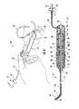
- FIG. 1is a perspective view of a steerable intravascular catheter device constructed in accordance with a preferred embodiment of the subject invention
- FIG. 2is an exploded perspective view of the handle assembly of the steerable intravascular catheter device shown in FIG. 1 , with the component parts of the steering mechanism separated for ease of illustration;
- FIG. 3is a perspective view, in partial cross-section, of the steering mechanism housed within the handle assembly of the intravascular catheter of FIG. 1 , as viewed from above;
- FIG. 4is a perspective view, in partial cross-section, of the steering mechanism housed within the handle assembly of the intravascular catheter of FIG. 1 , as viewed from below;
- FIG. 5is a cross-sectional view of the steerable intravascular catheter of the subject invention, taken along line 4 - 4 of FIG. 1 , with bi-directional steering mechanism disposed in a neutral position, wherein the distal end portion of the sheath is aligned with the longitudinal axis of the sheath;
- FIG. 6is an illustration showing the way in which the control knob of the handle assembly is rotated in a clockwise direction to cause the distal end portion of the sheath to deflect in a first direction;
- FIG. 7is a cross-sectional view of the steerable intravascular catheter of the subject invention, taken along line 7 - 7 of FIG. 6 , showing the relative positions of the components of the bi-directional steering mechanism when the control knob is rotated as shown in FIG. 6 ;
- FIG. 8is an illustration showing the way in which the control knob of the handle assembly is rotated in a counter-clockwise direction to cause the distal end portion of the sheath to deflect in a second direction;
- FIG. 9is a cross-sectional view of the steerable intravascular catheter of the subject invention, taken along line 9 - 9 of FIG. 8 , showing the relative positions of the components of the bi-directional steering mechanism when the control knob is rotated as shown in FIG. 8 ;
- FIG. 1a new and useful steerable intravascular catheter constructed in accordance with a preferred embodiment of the subject invention and designated generally by reference numeral 10 .
- Steerable intravascular catheter 10is adapted and configured to facilitate the intracardiac, renal and/or peripheral placement of diagnostic and therapeutic devices during a surgical procedure.
- the steerable intravascular catheter 10 of the subject inventionis intended for interventional use and/or transseptal use. It includes an elongated sheath 12 having a tubular body wall 14 defining a central lumen 16 to accommodate the introduction of diagnostic and/or therapeutic devices to the targeted procedure site.
- the sheath 12is designed to be flexible and can have an inner lumen diameter ranging from about 6.5 F to about 8.5 F, and a usable length ranging from about 45 cm up to about 90 cm.
- the sheath 12is provided with a hydrophobic coating that enables smooth access to the vasculature of a patient.
- the tubular body wall 14is preferably reinforced with a braided or woven material to provide enhanced control and resist kinking during use.
- the sheath 12has a deflectable distal end portion 18 that promotes precise and reliable tip adjustment for fast access to difficult to reach sites.
- the tip 15 of the deflectable distal end portion 18 of sheath 12is radiopaque to provide a surgeon with enhanced visibility, enabling accurate positioning during a procedure.
- two pull wires 20 and 22extend through the tubular body wall 14 of sheath 12 on opposite sides of the central lumen 16 .
- the pull wires 20 and 22terminate within the deflectable distal end portion 18 of sheath 12 .
- pull wires 20 and 22facilitate the remotely controlled bi-directional deflection of the distal end portion 18 of sheath 12 during an intravascular procedure.
- the total amount of tip deflectionas measured across the inside of the deflected curve, will vary depending upon the intended use of the catheter. For example, in a catheter designed for interventional use, the total amount of tip deflection can range from 9 mm up to about 17 mm. Whereas, in a catheter designed for transseptal use, the total amount of tip deflection can range from 17 mm up to about 50 mm.
- the steerable intravascular catheter 10 of the subject inventionfurther includes an ergonomically shaped elongated handle assembly 24 , which has a longitudinal axis extending therethrough and is operatively associated with a proximal end portion 25 of the sheath 12 . More particularly, the proximal end portion 25 of sheath 12 extends entirely through the handle assembly 24 and it terminates at a sealed access port 26 .
- the access port 26communicates with the central lumen 16 defined by the tubular body wall 14 , and it includes a hemostatic valve 28 designed to minimize blood loss and prevent air embolisms.
- a flush port 30 with standard leur fittings 32communicates with access port 26 by way of a flexible tube 34 .
- the handle assembly 24is made of an injection molded plastic material and constructed in a bifurcated manner. It includes a main body portion 36 and a rotatable deflection control knob 38 with a conical nose piece 42 .
- the main body portion 36has a rubberized outer shell 37 and deflection control knob 36 has a ribbed outer shell 40 to enhance tactile control of the catheter.
- the control knob 38is adapted and configured to effectuate bi-directional deflection of the distal end portion 18 of the sheath 12 .
- bi-directional angular rotation of the control knob 38 about the longitudinal axis of the handle assembly 24i.e., clockwise and counter-clockwise rotation
- Thiscauses the corresponding bi-directional angular deflection of the distal end portion 18 of sheath 12 , as discussed in more detail below, with reference to FIGS. 6 through 8 .
- handle assembly 24includes an internal drive mechanism designated generally by reference numeral 50 for actuating the elongated pull wires 20 and 22 in response to the bi-directional angular rotation of the control knob 38 .
- the drive mechanism 50includes a generally cylindrical distal drive gear 52 mounted for angular rotation about the longitudinal axis of the handle assembly 24 .
- the distal drive gear 52has a threaded internal bore 54 .
- a cooperating threaded distal drive sleeve 56is positioned within the threaded internal bore 54 and is supported for reciprocal axial movement therein.
- the drive mechanism 50also includes a generally cylindrical proximal drive gear 62 that is also mounted for angular rotation about the longitudinal axis of the handle assembly 24 .
- the proximal drive gear 62has a threaded internal bore 64 and a cooperating threaded proximal drive sleeve 66 positioned therein and supported for reciprocal axial movement.
- the distal and proximal drive gears 52 and 62have fixed axial positions relative to the longitudinal axis of the handle assembly 24 .
- the two drive gears 52 and 62are interlocked end to end with one another by way of cooperating structural features 53 and 63 .
- the distal drive gear 52has a polygonal belt 55 extending about the circumference thereof for engaging a complementary shaped recess 65 formed in an interior wall of the control knob 38 . Consequently, when deflection control knob 38 is rotated about the axis of the handle assembly 24 , the interlocked drive gears 52 and 62 will rotate therewith to steer the deflectable distal end portion 18 of sheath 12 .
- the pitch of the threaded bore 54 of the distal drive gear 52runs in a direction that is opposite the direction of the pitch of the threaded bore 64 of proximal drive gear 62 .
- the pitch angles of both threaded boresare the same. Consequently, when the interlocked drive gears 52 and 62 rotate together about the longitudinal axis of handle assembly 24 , the drive two sleeves 56 and 66 will move simultaneously toward and away from one another along the longitudinal axis of the handle assembly 24 , as illustrated for example in FIGS. 7 and 9 .
- the proximal and distal drive sleeves 56 and 66have fixed angular positions relative to the longitudinal axis of the handle assembly 24 . More particularly, the distal and proximal drive sleeves 56 and 66 are supported for reciprocal axial movement on a pair of laterally opposed PTFE coated guide rods 70 and 72 that extend parallel to the longitudinal axis of the handle assembly 24 .
- the guide rods 70 and 72are supported within handle assembly 24 by and between a circular distal support member 74 and a square proximal support member 76 .
- the distal and proximal support members 74 and 76both have a central aperture for accommodating the passage of the proximal end portion 25 of sheath 12 .
- the proximal end of pull wire 20is anchored to the distal drive sleeve 56 by a distal anchor 78 , so that when the distal sleeve 56 translates in a proximal direction, the pull wire 22 will be drawn with it, causing the distal end portion 18 of sheath 12 to deflect in a first direction.
- proximal end of pull wire 22is anchored to the proximal drive sleeve 66 by a proximal anchor 80 , so that when the proximal sleeve 66 translates in a proximal direction pull wire 22 will be drawn with it, causing the distal end portion 18 of sheath 12 to deflect in a second opposite direction.
- the two drive sleeves 56 and 66are located in a neutral position relative to the two respective drive gears 52 and 62 . That is, distal drive sleeve 56 is positioned generally in the middle of the internal bore 54 of the distal drive gear 52 and proximal drive sleeve 66 is positioned generally in the middle of the internal bore 64 of the proximal drive gear 62 , as shown in FIG. 5 .
Landscapes
- Health & Medical Sciences (AREA)
- Life Sciences & Earth Sciences (AREA)
- Engineering & Computer Science (AREA)
- Hematology (AREA)
- Pulmonology (AREA)
- Anesthesiology (AREA)
- Biomedical Technology (AREA)
- Heart & Thoracic Surgery (AREA)
- Biophysics (AREA)
- Animal Behavior & Ethology (AREA)
- General Health & Medical Sciences (AREA)
- Public Health (AREA)
- Veterinary Medicine (AREA)
- Mechanical Engineering (AREA)
- Surgical Instruments (AREA)
- Media Introduction/Drainage Providing Device (AREA)
Abstract
Description
Claims (11)
Priority Applications (1)
| Application Number | Priority Date | Filing Date | Title |
|---|---|---|---|
| US14/715,728US9498602B2 (en) | 2014-05-20 | 2015-05-19 | Guided intravascular catheter sheath having bi-directional steering assembly |
Applications Claiming Priority (2)
| Application Number | Priority Date | Filing Date | Title |
|---|---|---|---|
| US201462000720P | 2014-05-20 | 2014-05-20 | |
| US14/715,728US9498602B2 (en) | 2014-05-20 | 2015-05-19 | Guided intravascular catheter sheath having bi-directional steering assembly |
Publications (2)
| Publication Number | Publication Date |
|---|---|
| US20150335861A1 US20150335861A1 (en) | 2015-11-26 |
| US9498602B2true US9498602B2 (en) | 2016-11-22 |
Family
ID=54555296
Family Applications (1)
| Application Number | Title | Priority Date | Filing Date |
|---|---|---|---|
| US14/715,728Active2035-06-16US9498602B2 (en) | 2014-05-20 | 2015-05-19 | Guided intravascular catheter sheath having bi-directional steering assembly |
Country Status (1)
| Country | Link |
|---|---|
| US (1) | US9498602B2 (en) |
Cited By (12)
| Publication number | Priority date | Publication date | Assignee | Title |
|---|---|---|---|---|
| CN109223064A (en)* | 2018-11-13 | 2019-01-18 | 北京华脉泰科医疗器械有限公司 | A kind of operation handle and adjustable bending sheath tube of adjustable bending sheath tube |
| US11147635B1 (en) | 2020-06-19 | 2021-10-19 | Remedy Robotics, Inc. | Systems and methods for guidance of intraluminal devices within the vasculature |
| US20210402147A1 (en)* | 2020-06-25 | 2021-12-30 | Oscor Inc. | Braid and pull wire containment ring for deflectable guiding catheter |
| USD940306S1 (en)* | 2020-06-11 | 2022-01-04 | Oscor Inc. | Steerable catheter handle |
| USD940307S1 (en)* | 2020-06-11 | 2022-01-04 | Oscor Inc. | Steerable catheter handle |
| US11690683B2 (en) | 2021-07-01 | 2023-07-04 | Remedy Robotics, Inc | Vision-based position and orientation determination for endovascular tools |
| US11707332B2 (en) | 2021-07-01 | 2023-07-25 | Remedy Robotics, Inc. | Image space control for endovascular tools |
| US11890431B2 (en) | 2017-03-07 | 2024-02-06 | Circa Scientific, Inc. | Steerable guide catheter |
| US11890432B2 (en) | 2020-06-08 | 2024-02-06 | Oscor Inc. | Shaped pull wire for deflectable vascular catheter sheath |
| US11938278B2 (en) | 2020-04-07 | 2024-03-26 | Oscor Inc. | Vascular introducer system with interlocking deflectable guiding catheter sheaths |
| US12121307B2 (en) | 2021-07-01 | 2024-10-22 | Remedy Robotics, Inc. | Vision-based position and orientation determination for endovascular tools |
| US12171957B2 (en) | 2016-12-07 | 2024-12-24 | Biosense Webster (Israel) Ltd. | Steerable guiding sheath with rack and pinion deflection mechanism |
Families Citing this family (21)
| Publication number | Priority date | Publication date | Assignee | Title |
|---|---|---|---|---|
| US9821097B2 (en) | 2014-06-27 | 2017-11-21 | Merit Medical Systems, Inc. | Body cavity drainage devices including drainage tubes having inline portions and related methods |
| USD782037S1 (en)* | 2014-08-08 | 2017-03-21 | Oscor Inc. | Steerable guiding catheter handle |
| USD784523S1 (en)* | 2014-12-10 | 2017-04-18 | Hollister Incorporated | Catheter gripper aid |
| CN108366715A (en)* | 2015-11-09 | 2018-08-03 | 施菲姆德控股有限责任公司 | Steering assembly and application method for medical treatment device |
| JP7074666B2 (en)* | 2015-11-25 | 2022-05-24 | メリット・メディカル・システムズ・インコーポレイテッド | Maneuverable sheath catheter and how to use |
| CN107233656B (en)* | 2017-07-18 | 2022-12-02 | 依奈德医疗技术(上海)有限公司 | Paranasal sinus sacculus pipe system |
| USD903111S1 (en)* | 2018-01-15 | 2020-11-24 | Hollister Incorporated | Catheter gripping aid |
| EP3510914A1 (en) | 2018-01-15 | 2019-07-17 | Koninklijke Philips N.V. | Device with bendable distal portion and system actuating the distal portion of the device |
| US20190255292A1 (en)* | 2018-02-16 | 2019-08-22 | Oscor Inc. | Deflectable sheath with inflatable balloon |
| US11559662B2 (en) | 2018-04-13 | 2023-01-24 | Merit Medical Systems, Inc. | Steerable drainage devices |
| USD935016S1 (en) | 2018-06-15 | 2021-11-02 | Hollister Incorporated | Catheter gripping aid |
| CN110037760A (en)* | 2019-05-30 | 2019-07-23 | 北京华脉泰科医疗器械有限公司 | Operation handle and medical adjustable bending sheath tube |
| USD897186S1 (en)* | 2019-06-05 | 2020-09-29 | Welch Allyn, Inc. | Handle |
| USD897185S1 (en)* | 2019-06-05 | 2020-09-29 | Welch Allyn, Inc. | Handle |
| USD897184S1 (en)* | 2019-06-05 | 2020-09-29 | Welch Allyn, Inc. | Handle |
| CN112220504B (en)* | 2020-09-23 | 2025-05-13 | 山前(珠海)医疗科技有限公司 | A steerable sheath |
| CN112245767A (en)* | 2020-10-30 | 2021-01-22 | 广东脉搏医疗科技有限公司 | Controllable bent catheter |
| EP4262954A1 (en)* | 2020-12-18 | 2023-10-25 | Boston Scientific Scimed Inc. | Bi-directional steerable catheter |
| CN112704465A (en)* | 2021-01-15 | 2021-04-27 | 宁波胜杰康生物科技有限公司 | Rotatable endoscope outer channel |
| KR20240087691A (en)* | 2021-10-06 | 2024-06-19 | 엔도론 메디컬 엘티디. | Steerable Catheter System |
| CN114748159B (en)* | 2022-06-15 | 2023-06-09 | 杭州德诺电生理医疗科技有限公司 | Bending handle, bending-adjustable catheter and ablation device |
Citations (9)
| Publication number | Priority date | Publication date | Assignee | Title |
|---|---|---|---|---|
| US4730616A (en)* | 1983-08-12 | 1988-03-15 | Advanced Cardiovascular Systems, Inc. | Multiple probe angioplasty apparatus and method |
| US5395329A (en)* | 1994-01-19 | 1995-03-07 | Daig Corporation | Control handle for steerable catheter |
| US20060142694A1 (en)* | 2004-12-28 | 2006-06-29 | Bednarek Michael C | Bi-directional steerable catheter control handle |
| US20120203169A1 (en)* | 2008-12-31 | 2012-08-09 | Tegg Troy T | Shaft and handle for a catheter with independently-deflectable segments |
| US20150045696A1 (en) | 2013-08-09 | 2015-02-12 | Oscor Inc. | Steerable dilator |
| US20150057655A1 (en) | 2013-08-23 | 2015-02-26 | Oscor Inc. | Steerable ablation catheter for renal denervation |
| US20150057610A1 (en) | 2013-08-23 | 2015-02-26 | Oscor Inc. | Steerable medical devices |
| US20150105721A1 (en) | 2013-10-10 | 2015-04-16 | Oscor Inc. | Steerable medical devices |
| US9308349B2 (en)* | 2013-02-08 | 2016-04-12 | Vention Medical Advanced Components, Inc. | Universal catheter handle |
- 2015
- 2015-05-19USUS14/715,728patent/US9498602B2/enactiveActive
Patent Citations (9)
| Publication number | Priority date | Publication date | Assignee | Title |
|---|---|---|---|---|
| US4730616A (en)* | 1983-08-12 | 1988-03-15 | Advanced Cardiovascular Systems, Inc. | Multiple probe angioplasty apparatus and method |
| US5395329A (en)* | 1994-01-19 | 1995-03-07 | Daig Corporation | Control handle for steerable catheter |
| US20060142694A1 (en)* | 2004-12-28 | 2006-06-29 | Bednarek Michael C | Bi-directional steerable catheter control handle |
| US20120203169A1 (en)* | 2008-12-31 | 2012-08-09 | Tegg Troy T | Shaft and handle for a catheter with independently-deflectable segments |
| US9308349B2 (en)* | 2013-02-08 | 2016-04-12 | Vention Medical Advanced Components, Inc. | Universal catheter handle |
| US20150045696A1 (en) | 2013-08-09 | 2015-02-12 | Oscor Inc. | Steerable dilator |
| US20150057655A1 (en) | 2013-08-23 | 2015-02-26 | Oscor Inc. | Steerable ablation catheter for renal denervation |
| US20150057610A1 (en) | 2013-08-23 | 2015-02-26 | Oscor Inc. | Steerable medical devices |
| US20150105721A1 (en) | 2013-10-10 | 2015-04-16 | Oscor Inc. | Steerable medical devices |
Cited By (20)
| Publication number | Priority date | Publication date | Assignee | Title |
|---|---|---|---|---|
| US12171957B2 (en) | 2016-12-07 | 2024-12-24 | Biosense Webster (Israel) Ltd. | Steerable guiding sheath with rack and pinion deflection mechanism |
| US11890431B2 (en) | 2017-03-07 | 2024-02-06 | Circa Scientific, Inc. | Steerable guide catheter |
| CN109223064B (en)* | 2018-11-13 | 2023-02-28 | 北京华脉泰科医疗器械股份有限公司 | Operating handle of adjustable curved sheath pipe and adjustable curved sheath pipe |
| CN109223064A (en)* | 2018-11-13 | 2019-01-18 | 北京华脉泰科医疗器械有限公司 | A kind of operation handle and adjustable bending sheath tube of adjustable bending sheath tube |
| US11938278B2 (en) | 2020-04-07 | 2024-03-26 | Oscor Inc. | Vascular introducer system with interlocking deflectable guiding catheter sheaths |
| US11890432B2 (en) | 2020-06-08 | 2024-02-06 | Oscor Inc. | Shaped pull wire for deflectable vascular catheter sheath |
| USD940306S1 (en)* | 2020-06-11 | 2022-01-04 | Oscor Inc. | Steerable catheter handle |
| USD940307S1 (en)* | 2020-06-11 | 2022-01-04 | Oscor Inc. | Steerable catheter handle |
| US12290646B2 (en) | 2020-06-11 | 2025-05-06 | Oscor Inc. | Deflection indicator for deflectable vascular catheter |
| US11147635B1 (en) | 2020-06-19 | 2021-10-19 | Remedy Robotics, Inc. | Systems and methods for guidance of intraluminal devices within the vasculature |
| US11246667B2 (en) | 2020-06-19 | 2022-02-15 | Remedy Robotics, Inc. | Systems and methods for guidance of intraluminal devices within the vasculature |
| US11229488B2 (en) | 2020-06-19 | 2022-01-25 | Remedy Robotics, Inc. | Systems and methods for guidance of intraluminal devices within the vasculature |
| US11779406B2 (en) | 2020-06-19 | 2023-10-10 | Remedy Robotics, Inc. | Systems and methods for guidance of intraluminal devices within the vasculature |
| US11197725B1 (en) | 2020-06-19 | 2021-12-14 | Remedy Robotics, Inc. | Systems and methods for guidance of intraluminal devices within the vasculature |
| US11154366B1 (en) | 2020-06-19 | 2021-10-26 | Remedy Robotics, Inc. | Systems and methods for guidance of intraluminal devices within the vasculature |
| US12193764B2 (en) | 2020-06-19 | 2025-01-14 | Remedy Robotics, Inc. | Systems and methods for guidance of intraluminal devices within the vasculature |
| US20210402147A1 (en)* | 2020-06-25 | 2021-12-30 | Oscor Inc. | Braid and pull wire containment ring for deflectable guiding catheter |
| US11690683B2 (en) | 2021-07-01 | 2023-07-04 | Remedy Robotics, Inc | Vision-based position and orientation determination for endovascular tools |
| US12121307B2 (en) | 2021-07-01 | 2024-10-22 | Remedy Robotics, Inc. | Vision-based position and orientation determination for endovascular tools |
| US11707332B2 (en) | 2021-07-01 | 2023-07-25 | Remedy Robotics, Inc. | Image space control for endovascular tools |
Also Published As
| Publication number | Publication date |
|---|---|
| US20150335861A1 (en) | 2015-11-26 |
Similar Documents
| Publication | Publication Date | Title |
|---|---|---|
| US9498602B2 (en) | Guided intravascular catheter sheath having bi-directional steering assembly | |
| US9907570B2 (en) | Steerable medical devices | |
| US9572957B2 (en) | Steerable medical devices and steering assemblies | |
| US20220111176A1 (en) | Introducer with steerable distal tip section | |
| US20240416082A1 (en) | Coaxial bi-directional catheter | |
| US9913684B2 (en) | Steerable ablation catheter for renal denervation | |
| US20240285900A1 (en) | Sheath Visualization | |
| CN110913763B (en) | Steerable guide catheter | |
| US8911397B2 (en) | Steerable sheath handle pulley mechanism | |
| CA2894763C (en) | Mri compatible handle and steerable sheath | |
| US20150105721A1 (en) | Steerable medical devices | |
| US20150045696A1 (en) | Steerable dilator | |
| US20200222667A1 (en) | Steerable sheath with variable curve span | |
| US20140188108A1 (en) | Energy Assisted Tissue Piercing Device and Method of Use Thereof | |
| US20210322726A1 (en) | Catheter system with linear actuation control mechanism | |
| CN108158571A (en) | Controllable formula guide sheath and relevant building method with annular electrode | |
| US20210128230A1 (en) | Catheter including deflectable shaft and methods of assembling same | |
| US11938278B2 (en) | Vascular introducer system with interlocking deflectable guiding catheter sheaths |
Legal Events
| Date | Code | Title | Description |
|---|---|---|---|
| AS | Assignment | Owner name:OSCOR INC., FLORIDA Free format text:ASSIGNMENT OF ASSIGNORS INTEREST;ASSIGNORS:OSYPKA, THOMAS P.;GELINEAU, MICHAEL J.;GARLOCK, BRETT;REEL/FRAME:035666/0798 Effective date:20150518 | |
| AS | Assignment | Owner name:OSCOR INC., FLORIDA Free format text:ASSIGNMENT OF ASSIGNORS INTEREST;ASSIGNOR:ENERSON, ANDREW J.;REEL/FRAME:039982/0173 Effective date:20160328 | |
| STCF | Information on status: patent grant | Free format text:PATENTED CASE | |
| MAFP | Maintenance fee payment | Free format text:PAYMENT OF MAINTENANCE FEE, 4TH YR, SMALL ENTITY (ORIGINAL EVENT CODE: M2551); ENTITY STATUS OF PATENT OWNER: SMALL ENTITY Year of fee payment:4 | |
| AS | Assignment | Owner name:WELLS FARGO BANK, NATIONAL ASSOCIATION, AS ADMINISTRATIVE AGENT, VIRGINIA Free format text:SECURITY INTEREST;ASSIGNOR:OSCOR INC.;REEL/FRAME:058838/0203 Effective date:20220124 | |
| FEPP | Fee payment procedure | Free format text:ENTITY STATUS SET TO UNDISCOUNTED (ORIGINAL EVENT CODE: BIG.); ENTITY STATUS OF PATENT OWNER: LARGE ENTITY | |
| MAFP | Maintenance fee payment | Free format text:PAYMENT OF MAINTENANCE FEE, 8TH YEAR, LARGE ENTITY (ORIGINAL EVENT CODE: M1552); ENTITY STATUS OF PATENT OWNER: LARGE ENTITY Year of fee payment:8 |