US9498397B2 - Dual column surgical support system - Google Patents
Dual column surgical support systemDownload PDFInfo
- Publication number
- US9498397B2 US9498397B2US13/789,037US201313789037AUS9498397B2US 9498397 B2US9498397 B2US 9498397B2US 201313789037 AUS201313789037 AUS 201313789037AUS 9498397 B2US9498397 B2US 9498397B2
- Authority
- US
- United States
- Prior art keywords
- coupled
- shaft
- linear actuator
- column
- plate
- Prior art date
- Legal status (The legal status is an assumption and is not a legal conclusion. Google has not performed a legal analysis and makes no representation as to the accuracy of the status listed.)
- Active, expires
Links
Images


Classifications
- A—HUMAN NECESSITIES
- A61—MEDICAL OR VETERINARY SCIENCE; HYGIENE
- A61G—TRANSPORT, PERSONAL CONVEYANCES, OR ACCOMMODATION SPECIALLY ADAPTED FOR PATIENTS OR DISABLED PERSONS; OPERATING TABLES OR CHAIRS; CHAIRS FOR DENTISTRY; FUNERAL DEVICES
- A61G13/00—Operating tables; Auxiliary appliances therefor
- A61G13/02—Adjustable operating tables; Controls therefor
- A61G13/04—Adjustable operating tables; Controls therefor tiltable around transverse or longitudinal axis
- A—HUMAN NECESSITIES
- A61—MEDICAL OR VETERINARY SCIENCE; HYGIENE
- A61G—TRANSPORT, PERSONAL CONVEYANCES, OR ACCOMMODATION SPECIALLY ADAPTED FOR PATIENTS OR DISABLED PERSONS; OPERATING TABLES OR CHAIRS; CHAIRS FOR DENTISTRY; FUNERAL DEVICES
- A61G13/00—Operating tables; Auxiliary appliances therefor
- A61G13/02—Adjustable operating tables; Controls therefor
- A61G13/06—Adjustable operating tables; Controls therefor raising or lowering of the whole table surface
- A—HUMAN NECESSITIES
- A61—MEDICAL OR VETERINARY SCIENCE; HYGIENE
- A61G—TRANSPORT, PERSONAL CONVEYANCES, OR ACCOMMODATION SPECIALLY ADAPTED FOR PATIENTS OR DISABLED PERSONS; OPERATING TABLES OR CHAIRS; CHAIRS FOR DENTISTRY; FUNERAL DEVICES
- A61G13/00—Operating tables; Auxiliary appliances therefor
- A61G13/10—Parts, details or accessories
- A61G13/104—Adaptations for table mobility, e.g. arrangement of wheels
- A—HUMAN NECESSITIES
- A61—MEDICAL OR VETERINARY SCIENCE; HYGIENE
- A61G—TRANSPORT, PERSONAL CONVEYANCES, OR ACCOMMODATION SPECIALLY ADAPTED FOR PATIENTS OR DISABLED PERSONS; OPERATING TABLES OR CHAIRS; CHAIRS FOR DENTISTRY; FUNERAL DEVICES
- A61G13/00—Operating tables; Auxiliary appliances therefor
- A61G13/10—Parts, details or accessories
- A61G13/12—Rests specially adapted therefor; Arrangements of patient-supporting surfaces
- A61G13/128—Rests specially adapted therefor; Arrangements of patient-supporting surfaces with mechanical surface adaptations
- A61G13/1295—Rests specially adapted therefor; Arrangements of patient-supporting surfaces with mechanical surface adaptations having alignment devices for the patient's body
- A—HUMAN NECESSITIES
- A61—MEDICAL OR VETERINARY SCIENCE; HYGIENE
- A61G—TRANSPORT, PERSONAL CONVEYANCES, OR ACCOMMODATION SPECIALLY ADAPTED FOR PATIENTS OR DISABLED PERSONS; OPERATING TABLES OR CHAIRS; CHAIRS FOR DENTISTRY; FUNERAL DEVICES
- A61G7/00—Beds specially adapted for nursing; Devices for lifting patients or disabled persons
- A61G7/05—Parts, details or accessories of beds
- A61G7/0528—Steering or braking devices for castor wheels
- F—MECHANICAL ENGINEERING; LIGHTING; HEATING; WEAPONS; BLASTING
- F16—ENGINEERING ELEMENTS AND UNITS; GENERAL MEASURES FOR PRODUCING AND MAINTAINING EFFECTIVE FUNCTIONING OF MACHINES OR INSTALLATIONS; THERMAL INSULATION IN GENERAL
- F16H—GEARING
- F16H21/00—Gearings comprising primarily only links or levers, with or without slides
- F16H21/06—Gearings comprising primarily only links or levers, with or without slides which can be made ineffective when desired
- A—HUMAN NECESSITIES
- A61—MEDICAL OR VETERINARY SCIENCE; HYGIENE
- A61G—TRANSPORT, PERSONAL CONVEYANCES, OR ACCOMMODATION SPECIALLY ADAPTED FOR PATIENTS OR DISABLED PERSONS; OPERATING TABLES OR CHAIRS; CHAIRS FOR DENTISTRY; FUNERAL DEVICES
- A61G2203/00—General characteristics of devices
- A61G2203/30—General characteristics of devices characterised by sensor means
- A61G2203/42—General characteristics of devices characterised by sensor means for inclination
- A—HUMAN NECESSITIES
- A61—MEDICAL OR VETERINARY SCIENCE; HYGIENE
- A61G—TRANSPORT, PERSONAL CONVEYANCES, OR ACCOMMODATION SPECIALLY ADAPTED FOR PATIENTS OR DISABLED PERSONS; OPERATING TABLES OR CHAIRS; CHAIRS FOR DENTISTRY; FUNERAL DEVICES
- A61G2210/00—Devices for specific treatment or diagnosis
- A61G2210/10—Devices for specific treatment or diagnosis for orthopedics
Definitions
- the present disclosurerelates to patient support apparatuses such as are used to support a patient in different positions. More particularly, the present disclosure relates to surgical tables used during surgery to support a patient in a predetermined position or number of positions. However, the present disclosure may also be applicable to other types of patient support apparatuses such as hospital beds, home care beds, x-ray tables, therapy supports, wheel chairs, and the like.
- surgical tablesallow adjustment of the table prior to surgery so that patients can be properly supported or held in place for a particular surgical operation. Also, some surgical tables allow adjustment during surgery so that a patient is moved to different positions during an operation. Many such surgical tables are difficult to adjust prior to and/or during surgery.
- a patient support apparatusmay include a caster, a brake drive, and a linkage.
- the castermay include a stem, a wheel coupled to the stem to rotate about an wheel axis relative to the stem, and a braking element movable from a disengaged position allowing rotation of the wheel relative to the stem to an engaged position blocking the wheel from rotation relative to the stem.
- the brake drivemay include a mount and a linear actuator coupled to the mount. The linear actuator may move from a retracted position to an extended position relative to the mount.
- the linkagemay be coupled to the braking element of the caster and to the linear actuator of the brake drive.
- the linkagemay be configured to transfer motion of the linear actuator from the retracted position to the extended position to the braking element to move the braking element from the disengaged position to the engaged position.
- the linkagemay further be configured to selectively move the braking element from the engaged position to the disengaged position while the linear actuator is in the extended position so that a user can free the wheel of the caster to rotate even if the actuator is stuck in the extended position.
- the linkagemay include a shaft coupled to the mount to slide relative to the mount and a release assembly coupled to the linear actuator.
- the release assemblymay be configured to couple the shaft to the linear actuator so that the shaft slides relative to the mount during movement of the linear actuator from the retracted position to the extended position and to selectively release the shaft from the linear actuator when the linear actuator is in the extended position.
- the linkagemay include a spring coupled to the shaft and the mount.
- the springmay be configured to move the shaft when the shaft is released from the linear actuator by the release assembly.
- the linkagemay include a pivot connector coupled to the shaft for movement about a connector axis.
- the pivot connectormay be coupled to the braking element of the caster to convert linear motion from the linear actuator into rotating motion applied to the braking element.
- the release assemblymay include a plate and a handle coupled to the plate.
- the platemay be movable from a first position in which the plate couples the shaft to the linear actuator for movement therewith to a second position in which the plate releases the shaft from the linear actuator for motion independent of the shaft.
- the platemay move from the first position to the second position in response to a user moving the handle.
- the platemay be biased toward the first position.
- the platemay be coupled to the linear actuator to pivot about a plate axis relative to the linear actuator.
- the platemay be formed to include a slot that receives a pin coupled to the shaft.
- the platemay be formed to include a hole through which the shaft extends, the hole having a first section sized to engage the shaft and a second section sized to allow the shaft to slide through the plate.
- a patient support apparatusmay include a pair of casters, a brake drive, and a linkage.
- the pair of castersmay each include a stem, a wheel coupled to the stem to rotate about an wheel axis relative to the stem, and a braking element movable from a disengaged position allowing the wheel to rotate relative to the stem to an engaged position blocking the wheel from rotation relative to the stem.
- the brake drivemay include a mount and an actuator coupled to the mount. The actuator may move from a first position to a second position relative to the mount.
- the linkagemay be coupled to the braking element of each of the casters and to the actuator of the brake drive.
- the linkagemay be configured to transfer motion of the actuator during motion from the first position to the second position to the braking elements.
- the linkagemay further be configured to selectively move the braking elements from the engaged position to the disengaged position while the linear actuator is in the second position.
- the linkagemay include an actuation member coupled to the actuator for movement therewith, a rod assembly coupled to the braking elements of the casters, and a plate coupled to the actuation member and to the rod assembly.
- the platemay be coupled to the actuation member to pivot relative to the actuation member about a plate axis.
- the rod assemblymay include a shaft slidable along a shaft axis, a first pivot connector coupled to the shaft and to one of the braking elements included in one of the casters, and a second pivot connector coupled to the shaft and to the other of the braking elements included in the other of the casters.
- the rod assemblymay further include a pin extending outwardly from the shaft and received in a slot formed in the plate.
- the shaftmay extend through a hole formed in the plate.
- the actuation membermay be a slider coupled to the shaft to slide along the shaft axis relative to the shaft.
- a patient support apparatusmay include a foundation frame, a patient support top, and a brake system.
- the foundation framemay include a first column and a second column spaced apart from the first column.
- the patient support topmay be suspended from the first column and the second column for rotation about a support-top axis extending from the first column to the second column.
- the brake systemmay include a caster with a braking element coupled to the first column, a brake drive coupled to the first column, and a linkage coupled to the caster and to the brake drive.
- the linkagemay be configured to transfer motion from the brake drive to the braking element of the caster to brake the caster.
- the linkagemay also be configured to selectively move the braking element of the caster to unbrake the caster while the brake drive remains stationary.
- the brake drivemay include a mount coupled to the first column and a linear actuator coupled to the mount.
- the linkagemay include an actuation member coupled to the linear actuator for movement therewith, a rod assembly coupled to the braking element of the caster, and a plate coupled to the actuation member and to the rod assembly.
- the platemay be coupled to the actuation member to pivot relative to the actuation member about a plate axis.
- a surgical patient supportmay include a foundation frame and a support top.
- the foundation framemay include a rotation driver, a drive shaft, and a drive coupler.
- the support topmay be coupled to the drive shaft of the foundation frame and may rotate with the drive shaft.
- the support topmay be configured to rotate relative to the foundation frame about a top axis extending along the length of the support top.
- the drive coupler of the foundation framemay be configured to move between an engaged position, coupling the drive shaft to the rotation driver so that the support top is rotated about the top axis, and a disengaged position, de-coupling the drive shaft from the rotation drive so that the support top is free to be manually rotated about the top axis.
- the drive couplermay include a first engagement member that extends through the rotation driver and into the drive shaft when the drive coupler is in the engaged position.
- the first engagement membermay be withdrawn from the drive shaft when the drive coupler is in the disengaged position.
- the drive couplermay include a second engagement member that extends through the rotation driver and into the drive shaft when the drive coupler is in the engaged position.
- the second engagement membermay be withdrawn from the drive shaft when the drive coupler is in the disengaged position.
- the drive couplermay include an engagement slider, a handle, and a biasing spring.
- the engagement slidermay slide between a first position and a second position, the first position corresponding to the engaged position of the drive coupler and the second position corresponding to the disengaged position of the drive coupler.
- the engagement slidermay slide along the top axis to move between the first position and the second position.
- the biasing springmay bias the engagement slider toward the first position.
- the drive couplermay include a cover plate formed to include a guide track.
- the handlemay be coupled to the engagement slider and may extend away from the engagement slider through the guide track of the cover plate.
- a brake system for a patient support apparatusmay include at least two casters, a powered actuator, and a releasable linkage.
- the at least two castersmay be movable between a braked configuration and an unbraked configuration.
- the powered actuatormay be configured to move the at least two casters between the braked configuration and the unbraked configuration.
- the releasable linkagemay be coupled between the at least two casters and the brake drive.
- the releasable linkagemay be configured to disconnect the at least two casters from the brake drive when the at least two casters are in the braked configuration and to move the at least two casters from the braked configuration to the unbraked configuration.
- each of the castersmay include a stem, a hub coupled to the stem and configured to pivot about a vertical axis relative to the stem, a wheel coupled to the hub and configured to rotate about a horizontal axis relative to the hub, and a braking element.
- the braking elements of the at least two castersmay be movable between a disengaged position, allowing the hubs to pivot about the vertical axes and allowing the wheels to rotate about the horizontal axes, and an engaged position, blocking the hubs from pivoting about the vertical axes and blocking the wheels from rotating about the horizontal axes.
- the braking elementsmay be in the disengaged position when the casters are in the unbraked configuration and the braking elements may be in the engaged position when the casters are in the braked configuration.
- the at least two castersmay include at least four casters.
- Each of the castersmay include a stem, a hub coupled to the stem and configured to pivot about a vertical axis relative to the stem, a wheel coupled to the hub and configured to rotate about a horizontal axis relative to the hub, and a braking element.
- the braking elementmay be movable between a disengaged position, allowing the hubs to pivot about the vertical axes and allowing the wheels to rotate about the horizontal axes, and an engaged position, blocking the hubs from pivoting about the vertical axes and blocking the wheels from rotating about the horizontal axes.
- the releasable linkagemay include a plunger configured to be pulled by a user to disconnect the at least two casters from the brake drive. It is contemplated that the releasable linkage may include a biasing spring configured to move the at least two casters from the braked configuration to the unbraked configuration when the at least two casters are disconnected from the brake drive.
- the releasable linkagemay include a spring biasing the plunger away from being pulled out by a user. It is contemplated that, the powered actuator may be a linear actuator.
- a surgical patient support topfor use with a foundation frame.
- the surgical patient support topmay include a support frame and a motion coupler.
- the support framemay include a first rail, a second rail spaced apart from and parallel to the first rail, and a cross beam.
- the motion couplermay include a connector configured to be coupled to the foundation frame and a joint coupled to the cross beam and to the connector. The joint may be configured to allow the connector to slide and shift relative to the crossbeam.
- the jointmay include an arm extending from the connector and into a beam slot formed in the cross beam.
- the jointmay include a first resilient bumper situated along a first side of the slot formed in the cross beam and a second resilient bumper situated along a second side, opposite the first side, of the slot formed in the cross beam.
- the first resilient bumper and the second resilient bumpermay be formed from rubber.
- the jointmay include a retainer configured to resist removal of the arm from the slot formed in the cross beam.
- the retainermay include a retainer pin extending through an arm slot formed in the arm and a spring extending from the retainer pin to the arm.
- the first railmay include a number of indicators spaced at predetermined intervals along the length of the first rail. It is contemplated that the second rail may include a number of indicators spaced at predetermined intervals along the length of the second rail. Each indicator on the first rail may correspond to an indicator on the second rail.
- the indicators of the first rail and the indicators of the second railmay be lines extending perpendicular to the length of the first rail and the second rail.
- a yoke bracketfor coupling a patient support top to a foundation frame.
- the yoke bracketmay include a base member, a left coupling member, a right coupling member, a left ledge and a right ledge.
- the left coupling membermay be coupled to the base member and may extend substantially perpendicular to the base member.
- the left coupling membermay be formed to include a number of attachment holes situated between a front surface and a back surface of the left coupling member, the attachment holes extending through the left coupling member parallel to the base member.
- the right coupling membermay be coupled to base member and may extend substantially perpendicular to the base member.
- the right coupling membermay be formed to include a number of attachment holes situated between a front surface and a back surface of the right coupling member. The attachment holes may extend through the right coupling member parallel to the base member.
- the left ledgemay extend from the left coupling member toward the right coupling member and may be arranged along the back surface of the left coupling member.
- the right ledgemay extend from the right coupling member toward the left coupling member and may be arranged along the back surface of the right coupling member.
- the left ledgemay be formed to include a number of notches, each notch corresponding to and aligned with an attachment hole of the left coupling member and extending into the ledge away from the corresponding hole.
- the right ledgemay be formed to include a number of notches, each notch corresponding to and aligned with an attachment hole of the right coupling member and extending into the ledge away from the corresponding hole.
- the number of attachment holes formed in the left coupling membermay be arranged along a line spaced apart from and extending perpendicular to the base member.
- the left coupling membermay be formed to include a coupling hole extending through the right coupling member parallel to the base member and arranged out of alignment with the number of attachment holes.
- the number of attachment holes formed in the right coupling membermay be arranged along the line spaced apart from and extending perpendicular to the base member.
- the right coupling membermay be formed to include a coupling hole extending through the right coupling member parallel to the base member and arranged out of alignment with the number of attachment holes.
- each of the attachment holes of the left coupling membermay be aligned with a corresponding attachment hole of the right coupling member.
- Each of the left and the right coupling membersmay include a series of markings associating each pair of corresponding attachment holes.
- a rail couplerfor coupling an accessory to a rail.
- the accessory rail couplermay include a bracket and a flap.
- the bracketmay include a first jaw and a second jaw cooperating with the top wall to define a rail opening sized to receive the rail.
- the flapmay be coupled to the first jaw for pivotable movement relative to the first jaw about an axis.
- One of the second jaw and the flapmay include a first headed post and the other of the second jaw and the flap may be formed to include an first post opening.
- the flapmay be configured to pivot between an open position, wherein the first headed post is withdrawn from the first post opening, and a closed position wherein the first headed post is received in the first post opening.
- the first post openingmay be formed to include a first section sized to allow the head of the first post to be received in the first post opening and a second section sized to block the headed first post from withdrawing from the first post opening.
- the flapmay be slidable relative to the bracket along the axis between the closed position, wherein the first headed post is received in the first section of the first opening and the flap is free to pivot relative to the bracket, and a clamped position, wherein the headed bracket is received in the second section of the first post opening and the flap is blocked from pivoting relative to the bracket.
- the first headed postmay be coupled to the second jaw and the first post opening is formed in the flap.
- the second jawmay include a second headed post and the first opening may be formed to include a second post opening.
- the second headed postmay be configured to be received in the second post opening when the flap is in the closed position. The second post may be blocked from being withdrawn from the second post opening when the flap is in the clamped position.
- the flapmay pivot relative to the bracket between the open position and the closed position about a pivot pin extending along the pivot axis. It is contemplated that the center line of the first headed post may be spaced a first distance from the pivot pin. The center line of the second section of the first post opening may be spaced a second distance from the pivot pin. The second distance may be smaller than the first distance.
- the rail couplermay include an unlocked indicator configured to be displayed when the flap is slid away from the clamped position and a locked indicator configured to be displayed with the flap is slid to the clamped position.
- the pivot pinmay include a first portion marked with the unlocked indicator and a second portion marked with the locked indicator.
- the locked indicatormay be blocked from view when the flap is slid away from the clamped position and the locked indicator may be blocked from view when the flap is slid to the clamped position
- a surgical patient supportmay include a foundation frame, a support top, and a rotation system.
- the foundation framemay include a first column and a second column spaced from the first column.
- the support topmay be supported between the first column and the second column of the foundation frame and may rotate about a top axis.
- the rotation systemmay include a rotation driver configured to drive rotation of the support top about the top axis and a rotation brake configured to resist rotation of the support top about the top axis.
- the rotation drivermay be coupled to the first column and the rotation brake may be coupled to the second column.
- the rotation brakemay include a shaft, a friction member, and an actuation linkage.
- the shaftmay be configured to be coupled to the support top.
- the friction membermay be configured to move between a first position allowing rotation of the shaft and a second position resisting rotation of the shaft.
- the actuation linkagemay be configured to move the friction member from the first position to the second position.
- the actuation linkagemay include a linear actuator.
- the actuation linkagemay include a pivot arm configured to convert linear motion of the linear actuator into rotational movement.
- the actuation linkagemay include a cam coupled to the pivot arm and configured to move the friction member from the first position to the second position.
- the friction membermay be a clamp including an upper jaw and a lower jaw.
- the lower jawmay be moved toward the upper jaw when the friction member moves from the first position to the second position.
- the friction membermay be U-shaped.
- the lower jawmay follow a cam included in the actuation linkage when the friction member moves from the first position to the second position.
- the rotation brakemay be coupled to the second column. In some such embodiments, the rotation brake may be slidable relative to the second column.
- a surgical patient supportmay include a foundation frame, a support top, and a surgical traction device.
- the foundation framemay include a first column and a hollow shaft supported by the first column for rotation relative thereto.
- the support topmay be coupled to the shaft of the foundation frame to rotate with the shaft relative to the first column.
- the surgical traction devicemay include a traction attachment configured to be coupled to a patient during surgery, a force provider, and a link that may extend through the shaft from the patient coupler to the force provider.
- the force providermay be a weight coupled to the link.
- the traction attachmentmay be configured to be coupled to a patient's head to provide cervical traction.
- the linkmay include a cable.
- the cablemay be guided by a horizontal pulley coupled to the first column and a vertical pulley coupled to the first column.
- a surgical patient supportincludes a foundation frame, a support top, and a brake system.
- the foundation frameincludes a first column having a first base, a left caster coupled to the first base, a right caster coupled to the first base, and an upright extending up from the first base.
- the support topis coupled to the upright of the first column for rotation about a rotation axis extending along a longitudinal axis of the support top.
- the brake systemincludes a first plunger mounted to the first base for movement from a retracted position to an extended position and an actuator for moving the first plunger from the retracted position to the extended position.
- the first plunger in the retracted positionis disengaged from the floor to allow the left caster and the right caster of the first column to roll along the floor.
- the first plunger in the extended positionis engaged with the floor to lift the left caster and the right caster of the first column away from the floor to prevent the left caster and the right caster of the first column from rolling along the floor.
- the left caster and the right caster of the first columnmay contact the floor when the first plunger is in the retracted position.
- the left caster and the right caster of the first columnmay be spaced apart from the floor when the first plunger is in the extended position.
- the foundation framemay include a second column having a second base, a left caster coupled to the second base, a right caster coupled to the second base, and an upright extending up from the second base.
- the braking systemmay include a second plunger mounted to the second base for movement from a retracted position to an extended position.
- the second plunger in the retracted positionmay be disengaged from the floor to allow the left caster and the right caster of the second column to roll along the floor.
- the first plunger in the extended positionmay be engaged with the floor to lift the left caster and the right caster of the second column away from the floor to prevent the left caster and the right caster of the second column from rolling along the floor.
- the first plungermay be spaced apart from and located between the left caster and the right caster of the first column.
- the second plungermay also be spaced apart from and located between the left caster and the right caster of the second column.
- the braking systemmay include a third plunger spaced apart from and located between the left caster and the right caster of the first column.
- the third plungermay be mounted to the first base for movement from a retracted position to an extended position.
- the braking systemmay also include a fourth plunger spaced apart from and located between the left caster and the right caster of the second column.
- the fourth castermay be mounted to the second base for movement from a retracted position to an extended position.
- the braking systemmay include a third plunger mounted to the first base for movement from a retracted position to an extended position.
- the braking systemmay also include a fourth plunger mounted to the second base for movement from a retracted position to an extended position.
- the first plungermay be located between a pair of wheels included in the left caster of the first column.
- the second plungermay be located between a pair of wheels included in the left caster of the second column.
- the third plungermay be located between a pair of wheels included in the right caster of the first column.
- the fourth plungermay be located between a pair of wheels included in the right caster of the second column.
- the brake systemmay include a user input coupled to the upright of the first column.
- the actuatormay be configured to move the first plunger between the retracted position and the extended position in response to a signal from the user input.
- the brake systemmay include a releasable linkage coupled between the first plunger and the actuator.
- the releasable linkagemay be configured to disconnect the first plunger from the actuator when the first plunger is in the extended position.
- the first plungermay be biased toward the retracted position when the first plunger is disconnected from the actuator.
- a surgical patient supportincludes a foundation frame, a support top, and a brake system.
- the foundation frameincludes a first column having a first base, a left caster coupled to the first base, a right caster coupled to the first base, and an upright extending up from the first base.
- the support topis coupled to the upright of the first column for rotation about a rotation axis extending along a longitudinal axis of the support top.
- the brake systemincludes a first ring mounted to the first base for movement from a raised position to a lowered position and an actuator for moving the first ring from the raised position to the lowered position.
- the first ring in the raised positionis disengaged from the left caster of the first column to allow the left caster to roll along the floor.
- the first ring in the lowered positionis engaged with the left caster of the first column to block the left caster of the first column from rolling along the floor.
- the foundation frameincludes a second column spaced apart from the first column.
- the second columnmay include a second base, a left caster coupled to the second base, a right caster coupled to the second base, and an upright extending up from the second base.
- the brake systemmay include a second ring mounted to the second base for movement from a raised position to a lowered position.
- the second ring in the raised positionmay be disengaged from the left caster of the second column to allow the left caster to roll along the floor.
- the second ring in the lowered positionmay be engaged with the left caster of the second column to block the left caster of the second column from rolling along the floor.
- the brake systemmay include a third ring mounted to the first base for movement from a raised position to a lowered position and a fourth ring mounted to the second base for movement from a raised position to a lowered position.
- the third ring in the raised positionmay be disengaged from the right caster of the first column to allow the right caster to roll along the floor.
- the third ring in the lowered positionmay be engaged with the right caster of the first column to block the right caster of the first column from rolling along the floor.
- the fourth ring in the raised positionmay be disengaged from the right caster of the second column to allow the right caster to roll along the floor.
- the fourth ring in the lowered positionmay be engaged with the right caster of the second column to block the right caster of the second column from rolling along the floor.
- the brake systemmay include a user input coupled to the upright of the first column.
- the actuatormay be configured to move the first ring between the raised position and the lowered position in response to a signal from the user input.
- a yoke bracketfor coupling a patient support top to a foundation frame including a connection block with retainer pegs.
- the yoke bracketincludes a base member, a left coupling member, a right coupling member, and secondary retainer means.
- the left coupling memberis coupled to base member and extends substantially perpendicular to the base member.
- the left coupling memberis formed to include a retainer slot adapted to receive the retainer pegs of the connector block when the yoke bracket is coupled to the coupler block.
- the right coupling memberis coupled to base member and extends substantially perpendicular to the base member with an interior side facing an interior side of the left coupling member.
- the right coupling memberis formed to include a retainer slot adapted to receive the retainer pegs of the connector block when the yoke bracket is coupled to the coupler block.
- the secondary retainer meansis configured to resist movement of the yoke bracket away from engagement with the connection block when the yoke bracket is coupled to the connection block.
- the secondary retainer meansmay include a spring-loaded ball coupled to the bracket.
- the spring-loaded ballmay be sized to be received in a divot formed in the connector block.
- the spring-loaded ballmay extend from the interior side of the right coupling member toward the left coupling member.
- the spring-loaded ballmay be located in the retainer slot.
- the secondary retainer meansmay include a pair of spring-loaded balls. The pair of spring-loaded balls may each extending in to the retainer slot.
- the secondary retainer meansmay include a latch coupled to the left coupling member for pivotable movement about a pivot axis extending parallel to the base member.
- the latchmay move from an open position that allows the retainer peg of the connector block to enter the retainer slot of the left coupling member to a closed position that blocks the retainer peg of the connector block from moving out of the retainer slot of the left coupling member.
- the secondary retainer meansmay include a friction pad formed on a surface of the yoke bracket and arranged to contact the connector block.
- the retainer slotmay be defined by a sidewall and a floor, and the friction pad may be formed on the sidewall.
- the friction padmay be formed on the interior surface of the left coupling member.
- the friction padmay be formed on the surface of the yoke bracket is arranged to contact a friction pad formed on a surface of the connector block.
- the left retention slotmay extend through the left coupling member.
- the right retention slotmay also extend through the right coupling member.
- the retainer slotis defined by a sidewall and a floor.
- the secondary retention meansmay include a peg-recess pocket extending into the floor of the retainer slot.
- the peg-recess pocketmay be sized to receive a retainer peg of the connector block.
- the peg-recess pocketmay be cylindrical.
- a surgical patient support topfor use with a foundation frame.
- the surgical patient support topincludes a support top frame and a motion coupler.
- the support frameincludes a first rail, a second rail spaced apart from and parallel to the first rail, and a cross beam extending from the first rail to the second rail.
- the motion couplerincludes a connector configured to be coupled to the foundation frame for movement about a horizontal axis so that the support frame is free to pivot relative to the foundation frame about the horizontal axis.
- the motion coupleralso includes a joint coupled to the connector and coupled to the cross beam of the support frame for slidable movement relative to the cross beam so that the support frame is free to slide relative to the foundation frame.
- the jointmay include an arm extending from the connector and into a beam slot formed in the cross beam.
- the beam slotmay be angled relative to the longitudinal axis of the cross beam so that the support frame shifts and slides relative to the cross beam in a plane that intersects the horizontal axis at only one point.
- the jointmay include a first resilient bumper situated along a first side of the slot formed in the cross beam and a second resilient bumper situated along a second side, opposite the first side, of the beam slot.
- the jointmay include a retainer configured to resist removal of the arm from the slot formed in the cross beam.
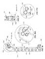
- FIG. 1is a perspective view of a patient support apparatus including a foundation frame and a patient support top supported on the foundation frame to rotate about an axis;
- FIG. 2is a diagrammatic view of the patient support apparatus of FIG. 1 showing that the foundation frame includes a pair of columns housing a rotation system, a lift system, and a braking system;
- FIG. 3is a front elevation view of an input pad for operating the rotation system, the lift system, and the braking system;
- FIG. 4is a front elevation view of a display included in the user interface of the patient support apparatus of FIG. 1 ;
- FIG. 5is a perspective view of the patient support of FIG. 1 showing a patient supported in the prone position facing straight down;
- FIG. 6is a perspective view of the patient support of FIG. 5 showing the patient rotated about the longitudinal axis of the support top;
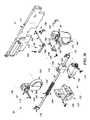
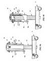
- FIG. 7is a partial perspective view of the first (head end) column included in the foundation frame of FIG. 1 showing the rotation system in a powered mode of operation for rotating a patient;
- FIG. 8is a view similar to FIG. 7 showing the rotation system disengaged to a manual mode of operation allowing a patient to be rotated by hand;
- FIG. 9is an exploded assembly view of the rotation system
- FIG. 10is a top plan view of the rotation system in the powered mode of operation
- FIG. 11is a view similar to FIG. 10 showing the rotation system in the manual mode of operation
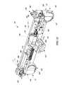
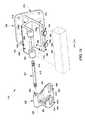
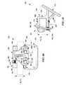
- FIG. 12is a partial perspective view of the second (foot end) column included in the foundation frame of FIG. 1 ;
- FIG. 13is a view similar to FIG. 12 showing a cover of the second column removed to expose a braking system
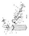
- FIG. 14is a view similar to FIG. 13 showing the braking system exploded away from the second column;
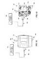
- FIG. 15is an inboard elevation view of the second column of FIG. 13 showing the braking system in an unbraked configuration allowing a shaft included in the brake system to rotate;
- FIG. 16is a view similar to FIG. 15 showing the braking system moved to a braked configuration resisting rotation of the shaft when a cam is rotated to push a lower jaw toward an upper jaw thereby squeezing the shaft;
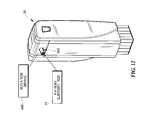
- FIG. 17is a perspective view of the patient support apparatus of FIG. 1 showing the patient supported in a flat prone position;
- FIG. 18is a perspective view similar to FIG. 17 showing the second column lowered so that the patient is supported in an inclined prone position;
- FIG. 19is a side elevation view of the second column corresponding to the second column in FIG. 17 with the cover removed to show that the braking system coupled to the patient support top is slid-back relative to the second column when the patient-support top is in a flat arrangement;
- FIG. 20is a side elevation view of the second column corresponding to the second column in FIG. 18 showing that the braking system coupled to the patient support top is slid-forward relative to the second column when the patient support top is in an inclined arrangement;
- FIG. 21is an outboard view of the first column included in the patient support apparatus of FIG. 1 showing a rotary switch coupled to the first column in a “BRAKE” position so that braking elements included in the casters of the first column are in an engaged position blocking the casters from turning or rolling;
- FIG. 22is a view similar to FIG. 21 showing the rotary switch moved to a “ROLL” position so that braking elements included in the casters of the first column are moved to a disengaged position allowing the casters to turn and roll;
- FIG. 23is a perspective view of the braking system included in the patient support apparatus of FIGS. 1 and 2 showing that the braking system includes a manual release for disengaging brake elements of the brake system in response to a user manually pulling a plunger;
- FIG. 24is an exploded view of the braking system of FIG. 23 ;
- FIGS. 25A-Care a set of views of the braking system of FIGS. 23 and 24 diagrammatically showing braking elements in a disengaged (unbraked) condition;
- FIGS. 26A-Care a set of views similar to FIGS. 25A-C diagrammatically showing the braking element moved to an engaged (braked) condition;
- FIGS. 27A-Care a set of views similar to FIGS. 26A-C diagrammatically showing the braking element in the engaged (braked) condition as a user pulls the plunger to release and disengage the braking element;
- FIGS. 28A-Care a set of view similar to FIGS. 27A-C diagrammatically showing the braking element in the disengaged (unbraked) condition after a user has pulled the plunger;
- FIG. 29is a perspective view of an alternative braking system configured to be used in the patient support apparatus of FIGS. 1 and 2 showing that the alternative braking system includes a manual release for disengaging brake elements of the brake system in response to a user manually pulling a plunger;
- FIG. 30is an exploded view of the alternative braking system of FIG. 29 ;
- FIG. 31is a perspective view of braking system of FIGS. 29-30 showing the braking system in an unbraked configuration
- FIG. 32is a perspective view similar to FIG. 31 showing the braking system moved to the braked configuration
- FIG. 33is a perspective view similar to FIG. 32 showing the braking system in the braked configuration as a user pulls a release handle included in the braking system;
- FIG. 34is a perspective view similar to FIG. 33 showing the braking system returning to the unbraked configuration in response to the release handle being pulled;
- FIG. 35is an outboard view of a first column included in an alternative patient support apparatus with another alternative braking system showing a rotary switch coupled to the first column in a “BRAKE” position so that plungers included in legs located between casters of the column are in an extended, engaged position contacting the floor so that the column is unable to turn or roll;
- FIG. 36is a view similar to FIG. 35 showing the rotary switch moved to a “ROLL” position so that the plungers are in a retracted, disengaged position spaced apart from the floor so that the column is free to turn and roll on the casters;
- FIG. 37is an outboard view of a first column included in another alternative patient support apparatus with another alternative braking system showing a rotary switch coupled to the first column in a “BRAKE” position so that plungers included in stems of the casters of the column are in an extended, engaged position contacting the floor so that the column is unable to turn or roll;
- FIG. 38is a view similar to FIG. 43 showing the rotary switch moved to a “ROLL” position so that the plungers are in a retracted, disengaged position spaced apart from the floor so that the column is free to turn and roll on the casters;
- FIG. 39is an outboard view of a first column included in yet another alternative patient support apparatus with another alternative braking system showing a rotary switch coupled to the first column in a “BRAKE” position so that brake rings included in the braking system are in a lowered, engaged position contacting wheels included in the casters to block the wheels from turning or rolling;
- FIG. 40is a view similar to FIG. 39 showing the rotary switch moved to a “ROLL” position so that brake rings included in the braking system are in a raised, disengaged position freeing wheels included in the casters to turn and roll;
- FIG. 41is partial perspective view of the patient support of FIG. 1 showing that the patient support top includes a support frame and a motion joint that is coupled to the foundation frame by a yoke bracket;
- FIG. 42is an exploded view of one end of the patient support top of FIG. 41 showing that the motion joint includes a connector configured to couple to the yoke bracket and a joint extending from the cross beam to the connector;
- FIG. 43is a top plan view of the motion joint of FIG. 41 showing the rails of the patient support top extending at a first angle from a column of the foundation frame, and showing the patient support top cutaway to show that the joint of the motion joint includes an arm extending through the cross beam, a pair of resilient bumpers situated on either side of the arm inside the cross beam, and a retainer configured to keep the arm from being pulled out from the cross beam;
- FIG. 44is a view similar to FIG. 43 showing rails of the rails of the patient support top shifted relative to the foundation frame;
- FIG. 45is a perspective view of the yoke bracket included in the patient support of FIG. 1 ;
- FIG. 46is a cross-sectional view of FIG. 45 taken at line 46 - 46 and showing that the yoke bracket includes a ledge with a number of notches formed therein so that a pin connector is guided into one of a number of attachment holes formed in the yoke bracket;
- FIGS. 47-52are a series of views showing the yoke bracket of FIG. 39 being mounted on a connector block included in the foundation frame;
- FIG. 47is a perspective view of the yoke bracket being lowered on to the connector block of the foundation frame
- FIG. 47Ais a partial cross-section view of FIG. 47 showing that a slot formed in the yoke bracket is facing the connector block;
- FIG. 48is a perspective view similar to FIG. 47 showing the yoke bracket contacting the connector block of the foundation frame;
- FIG. 48Ais a partial cross-sectional view of FIG. 48 showing the slot formed in the yoke bracket aligned with a retainer peg included in the connector block;
- FIG. 49is a perspective view similar to FIGS. 47 and 48 showing the slot formed in the yoke bracket receiving the retaining peg included in the connector block;
- FIG. 49Ais a partial cross-sectional view of FIG. 49 showing that the yoke bracket slides along the connector block so that the slot formed in the yoke bracket receives the retainer peg included in the connector block;
- FIG. 50is a perspective view similar to FIGS. 47-49 showing the yoke bracket rotated about the retainer peg;
- FIG. 50Ais a partial cross-sectional view of FIG. 50 showing that when the yoke bracket pivots about the retainer peg, a hole extending through the yoke bracket aligns with a hole extending through the connector block;
- FIG. 51is a perspective view similar to FIGS. 47-50 showing a pin being inserted through the aligned holes of the yoke bracket;
- FIG. 51Ais a partial cross-sectional view of FIG. 51 showing the pin extending through the yoke bracket and the connector block;
- FIG. 52is a perspective view similar to FIGS. 47-51 showing the yoke bracket and the connector block rotated about a pivot axis so that the yoke bracket is mounted to the connector block for supporting a patient;
- FIG. 52Ais a partial cross-sectional view of FIG. 52 showing that the connector pin and the retainer peg both connect the yoke bracket to the connector block of the foundation frame when the yoke bracket is mounted to the connector block;
- FIG. 53is a perspective view similar to FIGS. 47-52 showing the pin connecting the yoke bracket to the connector block removed and the yoke bracket pivoted about the retainer peg;
- FIG. 53Ais a partial cross-sectional view of FIG. 53 showing that the retainer peg can independently connect the yoke bracket to the connector block of the foundation frame even if the pin extending through the yoke bracket and the connector block is removed;
- FIG. 54is a perspective view of an alternative yoke bracket configured for use with an alternative connector block shown in FIG. 55 , the alternative yoke bracket including a spring-loaded ball sized to be received in a detent formed in the connector block;
- FIG. 55is a perspective view of an alternative connector block configured for use with the alternative yoke bracket of FIG. 54 , the alternative connector block is formed to include a detent sized to receive the spring-loaded ball of the alternative yoke bracket;
- FIG. 56is a cross-sectional view of the alternative yoke bracket of FIG. 54 showing the location of the spring-loaded ball and suggesting an alternative location for the spring-loaded ball;
- FIG. 56Ais a detail view of a portion of the cross-sectional view of FIG. 56 ;
- FIG. 57is a side-elevation view of the connector block of FIG. 55 showing the location of the detent and suggesting an alternative location for the detent;
- FIG. 57Ais a detail view of a portion of the side-elevation view of FIG. 57 ;
- FIG. 58is cross-sectional view similar to FIG. 56 of another alternative yoke bracket including a pair of spring-loaded balls configured to resist removal of the yoke bracket from a connector block;
- FIG. 58Ais a detail view of a portion of the cross-sectional view of FIG. 58 showing the location of the spring-loaded balls;
- FIG. 59is cross-sectional view similar to FIGS. 56 and 58 of yet another alternative yoke bracket including a pivoting latch configured to block unwanted removal of the yoke bracket from a connector block;
- FIG. 59Ais a detail view of a portion of the cross-sectional view of FIG. 59 showing the location of the pivoting latch;
- FIG. 60is a perspective view of another alternative yoke bracket along with another alternative connector block showing that the friction pad of the yoke bracket is located in a slot formed in the yoke bracket and the friction pad of the connector block is formed on a connector peg of the connector block;
- FIG. 61is a perspective view of another alternative yoke bracket along with another alternative connector block similar to those shown in FIG. 60 showing that a top surface of the yoke bracket is formed to include a friction pad arranged to contact a friction pad formed on the connector block when the yoke bracket is coupled to the connector block to resist removal of the yoke bracket from the connector block;
- FIG. 62Ais a first perspective view of another alternative yoke bracket along with another alternative connector block similar to those shown in FIGS. 60 and 61 showing that the friction pad of the yoke bracket is located on an internal side of a left coupling member of the yoke bracket;
- FIG. 62Bis a second perspective view of the alternative yoke bracket and connector block shown in FIG. 62A showing that the friction pad of the connector block is located on an external side of the connector block and is arranged to contact the friction pad of the alternative yoke bracket;
- FIG. 63is a perspective view of another alternative yoke bracket and an alternative connector block including a downwardly-jutting retainer that contacts a ledge included in the yoke bracket;
- FIG. 63Ais a front elevation view of the connection of the alternative yoke bracket and connector block of FIG. 63 showing that the downwardly-jutting retainer supports a spring-loaded ball that is received by the ledge included in the yoke bracket;
- FIG. 64is a perspective view of another alternative yoke bracket and an alternative connector block including a downwardly-jutting retainer that contacts a ledge included in the yoke bracket similar to the alternative connector block of FIG. 63 ;
- FIG. 64Ais a front elevation view of the connection of the alternative yoke bracket and connector block of FIG. 64 showing that the downwardly-jutting retainer supports a latch that pivots about an axis to move from a closed position blocking the ledge from moving away from the connector block to an open position allowing the ledge to move away from the connector block;
- FIG. 65is a perspective view of another alternative yoke bracket coupled to a connector block
- FIG. 65Ais a front elevation view of the alternative yoke bracket of FIG. 65 coupled to the connector block;
- FIG. 65Bis a detail view of a portion of the alternative yoke bracket and connector block of FIG. 65A ;
- FIG. 66is a perspective view of yet another alternative yoke bracket showing that the yoke bracket includes a base, a left connection member coupled to the base and formed to include a slot extending through the left connection member, and a right connection member coupled to the base and formed to include a slot extending through the right connection member;
- FIG. 67is a perspective view of the alternative yoke bracket of FIG. 66 showing that the slots in the left and the right connection members are sized to receive retaining pegs included in the connection block;
- FIG. 68is a perspective view of another alternative yoke bracket and another alternative connector block showing that a left and a right connection member of the yoke bracket each include a peg-receiving pocket formed in a slot and suggesting that a retainer peg included in the connector block is movable from an extended position to an retracted position;
- FIG. 68Ais a detail perspective view of a portion of FIG. 68 showing the peg-receiving pocket formed in the slot of the left connection member;
- FIG. 69is a perspective view of an alternative patient support top for use with the foundation frame of FIG. 1 , the alternative patient support top including a plate forming a panel and a pair of rails;
- FIG. 70is a cross-sectional view of FIG. 48 taken at line 49 - 49 showing that the plate of the alternative patient support top is integrally formed with the rails;
- FIG. 71is a perspective view of another alternative patient support top for use with the foundation frame of FIG. 1 , the alternative patient support top including a support frame and a motion joint;
- FIG. 72is a front elevation view of the alternative patient support of FIG. 71 showing that the motion joint includes an arm received in a slot formed in a cross beam of the support frame and a connector extending parallel to the cross beam;
- FIG. 73is a cross-sectional view of the alternative patient support of FIGS. 71 and 72 showing that the slot formed in the cross beam is not parallel with the connector of the motion joint;
- FIG. 74is a perspective view of a rail coupler included in the patient support apparatus of FIG. 1 ;
- FIG. 75is an exploded assembly view of the rail coupler of FIG. 74 showing that the rail coupler includes a bracket, a flap, and a pivot pin;
- FIG. 76is a front view of the rail coupler of FIGS. 74 and 75 showing the flap of the rail coupler in an open position;
- FIG. 77is a side elevation view of the rail coupler of FIG. 76 ;
- FIG. 78is a front view of the rail coupler of FIGS. 74 and 75 showing the flap pivoted to a closed position;
- FIG. 79is a side elevation view of the rail coupler of FIG. 78 ;
- FIG. 80is a front view of the rail coupler of FIGS. 74 and 75 showing the flap slid to a clamped position wherein the flap is blocked from moving to an open position by the flap lock;
- FIG. 81is a side elevation view of the rail coupler of FIG. 80 ;
- FIG. 82is a partial front elevation view of an alternative flap lock for use with the rail coupler of FIG. 74 ;
- FIG. 83is a partial front elevation view of another alternative flap lock for use with the rail coupler of FIG. 74 ;
- FIG. 84is a side elevation view of an alternative rail coupler for use with a triangular rail
- FIG. 85is a side elevation view of an alternative rail coupler wherein the bracket is configured to be coupled with a slide-on accessory;
- FIG. 86is a diagrammatic view of the patient support apparatus in communication with a communication infrastructure and with a remote computer;
- FIG. 87is a perspective view of an alternative patient support apparatus similar to the patient support apparatus of FIG. 1 showing that the alternative patient support apparatus includes a pedal control input for operating the brake system and a foundation frame with a foldable extension coupled between a first column and a second column of the foundation frame;
- FIG. 88is a side elevation view of the patient support apparatus of FIG. 63 showing the foldable extension moving from an extended-use configuration toward a folded-storage configuration;
- FIG. 89is a side elevation view of the patient support apparatus of FIG. 1 showing that the patient support apparatus includes a traction device;
- FIG. 90is a side elevation view of the first (head end) column of the patient support apparatus of FIG. 89 showing the traction device coupled to the first column;
- FIG. 91is a view similar to FIG. 90 with the cover of the first column broken away to show the arrangement of the traction device;
- FIG. 92is a top plan view of the first column of the patient support apparatus of FIG. 89 showing the traction device coupled to the first column;
- FIG. 93is a view similar to FIG. 92 with the cover of the first column broken away to show a horizontal pulley included in the traction device coupled to the first column;
- FIG. 94is a rear elevation view of the first column of the patient support apparatus of FIG. 89 showing the traction device coupled to the first column;
- FIG. 95is a view similar to FIG. 94 with the cover of the first column broken away to show a vertical pulley included in the traction device coupled to the first column.
- FIG. 1A patient support apparatus 10 for supporting a patient during surgery is shown in FIG. 1 .
- the patient support apparatus 10illustratively includes a foundation frame 12 and a patient support top 14 .
- the foundation frame 12rests on a floor 16 and is configured to suspend the support top 14 in a number of different positions above the floor 16 .
- a patient undergoing surgerycan be moved with the support top 14 to a number of different positions and orientations depending on the particular surgical operation to be performed on the patient.
- the foundation frame 12includes a first column 24 , a second column 26 , an extension 28 , and a control system 30 as shown in FIG. 1 .
- the first column 24is a head-end column and the second column 26 is a foot-end column.
- the support top 14is coupled to the foundation frame 12 between the columns 24 , 26 via yoke brackets 20 .
- the support top 14 and the yoke brackets 20are configured to rotate relative to the foundation frame 12 about a pivot axis 22 as suggested by arrow 23 in FIG. 1 .
- the pivot axis 22extends parallel to, and is spaced apart from, the length of the support top 14 . Thus, a patient can be rotated prior to or during a surgical operation.
- Each column 24 , 26includes a base 31 and an upright 32 extending up from the base 31 as shown in FIG. 1 .
- Each base 31includes a horizontal top plate 51 , a vertical lower plate 53 extending down from the horizontal plate 51 , and a cover 55 coupled the top plate 51 to house the lower plate 53 .
- Each upright 32includes a lower section 34 and an upper section 36 that is movable vertically up and down along the lower section 34 as suggested by arrow 38 to raise and lower each end of the support top 14 .
- a patientcan be raised, lowered, or inclined prior to or during a surgical operation at the discretion of a surgeon.
- each column 24 , 26 of the patient support apparatus 10includes a pair of casters 33 , 35 that engage the floor 16 as shown in FIG. 1 . All of the casters 33 , 35 are selectively freed to allow the patient support apparatus 10 to roll along the floor 16 to different surgery or storage rooms within a healthcare facility. However, during surgical operations, the patient support apparatus 10 may be held in place relative to the floor 16 to minimize unwanted movement of the patient during the operation.
- the extension 28extends between the columns 24 , 26 and includes a first tube 41 and a second tube 42 configured to telescope as suggested by arrow 43 in FIG. 1 . Telescoping of the tubes 41 , 42 allow the columns 24 , 26 to be moved between a deployed position, spaced to support the support top 14 , and a storage position, collapsed together reducing the footprint of the foundation frame 12 .
- the control system 30is configured to control the motions of the patient support apparatus 10 . Specifically, the control system 30 directs rotation of the support top 14 about the pivot axis 22 , movement of the upper section 36 along the lower section 34 of each upright 32 to raise and lower the ends of the support top 14 , and freedom of the casters 33 , 35 to roll along the floor 16 .
- the control system 30includes a controller 40 , a user interface 44 , a rotation system 46 , a lift system 48 , and a brake system 50 as shown diagrammatically in FIG. 2 .
- the controller 40is electrically coupled to the user interface 44 , the rotation system 46 , the lift system 48 , and the brake system 50 .
- the user interface 44includes a display 52 and a user input 54 configured to allow a surgeon to direct operation of and receive information about the foundation frame systems 46 , 48 , 50 .
- the rotation system 46is configured to provide powered and manual rotation of the support top 14 about the pivot axis 22 .
- the lift system 48is configured to provide powered movement of the upper section 36 relative to the lower section 34 to raise and lower the ends of the support top 14 .
- the brake system 50is configured to provide powered braking and unbraking of the casters 33 , 35 and to allow manual unbraking of the casters 33 , 35 in case of a power failure.
- the controller 40shown diagrammatically in FIG. 2 , illustratively includes a memory 56 containing instructions, a clock 57 , and a processor 58 coupled to the clock 57 and to the memory 56 to execute the instructions stored therein.
- the memory 56may be embodied as or otherwise include one or more memory devices or data storage locations including, for example, dynamic random access memory devices (DRAM), synchronous dynamic random access memory devices (SDRAM), double-data rate synchronous dynamic random access memory device (DDR SDRAM), mask read-only memory (ROM) devices, erasable programmable ROM (EPROM), electrically erasable programmable ROM (EEPROM) devices, flash memory devices, and/or other volatile and/or non-volatile memory devices.
- the processor 58may be embodied as any type of processor capable of executing the instructions stored in the memory 56 .
- the illustrative processor 58is a single core processor, but processors having multiple cores may be used in other embodiments.
- the user interface 44 of the illustrative embodimentincludes a remote pendant 60 , a panel 61 , and a switch box 62 as shown in FIG. 1 .
- the remote pendant 60is illustratively coupled to the first column 24 by an extendable cord 64 and is received in a dock 66 situated along a right side 63 of the upper section 36 included in the first column 24 .
- the remote pendant 60may be wireless.
- the panel 61is illustratively mounted to a top side 64 of the upper section 36 included in the first column 24 .
- the switch box 62is mounted along a back side 65 of the upper section 36 included in the first column 24 .
- the remote pendant 60includes buttons 67 - 74 .
- Buttons 67 , 68are configured to activate rotation system 46 to rotate support top 14 about the pivot axis 22 .
- Buttons 69 , 70are configured to activate the lift system 48 to raise or lower the upper section 36 of the first column 24 relative to the lower section 34 of the first column 24 .
- Buttons 71 , 72are configured to activate a lift drive 93 included in the lift system 48 to raise or lower the upper section 36 of the second column 26 relative to the lower section 34 of the second column 26 .
- Buttons 73 , 74are configured to simultaneously raise or lower the upper sections 36 of the first and second columns 24 , 26 relative to the lower sections 34 of the first and second columns 24 , 26 .
- buttons 67 - 74are electro-mechanical push-button switches arranged adjacent icons suggesting the associated movement type and each button is marked with an indicator to suggest the direction of movement to be activated by pressing the respective button.
- the remote pendant 60may include GUI interfaces such as LCD screens with menus and/or touch sensitive areas to achieve the functions described.
- the panel 61includes indicator lights 77 - 80 and status displays 81 - 82 showing status information related to the foundation frame 12 and support top 14 .
- a power indicator light 77is lit when the control system 30 has power received from an external power source (not shown) or a battery power source (not shown), thereby showing power status.
- a brake indicator light 78is unlit when the brake system 50 is unbraked so that casters 33 , 35 are free to roll along the floor 16 , thereby showing brake status.
- a maintenance indicator light 79is lit when the controller 40 determines that the foundation frame 12 needs service, thereby showing service status. When the maintenance indicator light 79 is lit, all powered functions of the foundation frame 12 may be disabled.
- a flip indicator light 80is lit when the rotation system 46 is configured to allow manual rotation of the support top 14 about the pivot axis 22 , thereby showing rotation status.
- a rotation display 81indicates the rotation angle of the rotation system 46 , thereby showing rotation angle status of the support top 14 relative to the foundation frame 12 .
- a lift display 82indicates the location of each upper section 36 of the columns 24 , 26 , thereby showing height and lift angle statuses of the support top 14 .
- the rotation and lift displays 81 , 82may be used by a surgeon to determine the orientation and position of a patient supported on the patient support 10 even when the patient is covered in surgical drapes or covers.
- panel 61may be a GUI with an LCD for displaying information and/or a touch-screen for displaying information and for receiving user inputs.
- the switch box 62includes a housing 84 and a rotary switch 86 received in the housing 84 .
- Rotary switch 86is configured to move between a first position, wherein the brake system 50 is braked, and a second position, wherein the brake system 50 is unbraked.
- the casters 33 , 35are free to roll along the floor 16 in different directions.
- the rotary switchis movable to a third position to initiate a brake reset sequence to reset the brake system 50 after the brake system 50 has been manually released as further described below.
- one or more membrane switches, pivot switches, or other suitable user inputsmay be used to control the brake system 50 .
- the rotation system 46 for rotating the patient support top 14 relative to the foundation frame 12is housed in the columns 24 , 26 of the foundation frame 12 and is coupled to the support top 14 as shown diagrammatically in FIG. 2 .
- the rotation system 46is operable in a powered mode to rotate the support top 14 about the pivot axis 22 in response to a user pressing one of the buttons 67 , 68 on the remote pendant 60 .
- a usercan rotate a patient without adjusting mechanical locks or manually controlling turning of the patient.
- the rotation system 46allows manual rotation of the support top 14 about the pivot axis 22 relative to foundation frame 12 .
- the rotation system 46includes a rotation drive 88 , a drive shaft 90 configured to be coupled to the support top 14 , and a drive coupler 92 as shown in FIG. 2 .
- the drive coupler 92connects the rotation drive 88 to the drive shaft 90 when the rotation system 46 is in the powered mode and disconnects the rotation drive 88 from the drive shaft 90 when the rotation system is in the manual mode.
- the rotation drive 88 , drive shaft 90 , and drive coupler 92are coupled to the first column 24 .
- the powered mode of the rotation system 46is established when a knob 94 included in the drive coupler 92 is located in a forward-and-down position in a guide plate 96 as shown in FIG. 7 .
- the manual mode of the rotation system 46is established when the knob 94 is located in a back-and-down position in the guide plate 96 as shown in FIG. 8 .
- a userlifts the knob 94 , slides the knob 94 back or forward, and pushes the knob 94 down along an inverted U-shaped slot 98 formed in the guide plate 96 .
- the rotation drive 88includes a linear actuator 100 and a rotation arm 102 coupled to the linear actuator 100 by a pin 104 as shown in FIG. 7 .
- the linear actuator 100extends and retracts in response to a user operating buttons 67 , 68 of remote pendant 60 .
- the rotation arm 102includes a body 106 and a finger 108 configured to be coupled to the linear actuator 100 .
- the body 106 of the rotation arm 102is formed to include a central opening 110 and a number of engagement holes 111 (illustratively four) arranged around the central opening 110 .
- the drive shaft 90includes a shaft 112 , a collar 113 , and a key 114 .
- the collar 113is configured to be coupled to the shaft 112 by a set screw 116 to locate the collar 113 axially along the shaft.
- the shaft 112is illustratively hollow and forms a central opening 118 .
- the collar 113is formed to include a central opening 120 sized to receive the shaft 112 and a number of engagement holes 121 (illustratively four) arranged around the central opening 120 .
- the engagement holes 121 of the collar 113are spaced to correspond with the engagement holes 111 of the rotation arm 102 .
- the key 114extends along the shaft 112 and engages notches 125 , 127 formed in the shaft 112 and the collar 123 to block the collar 123 from rotating about the shaft 112 .
- the drive coupler 92includes an engagement member 122 , a user control 124 , and a biasing spring 126 as shown in FIG. 9 .
- the engagement member 122is configured to engage the rotation arm 102 of the rotation drive 88 and the collar 113 of the drive shaft 90 when the rotation system 46 is in the powered mode and to disengage from the collar 113 of the drive shaft 90 when the rotation system 46 is in the manual mode.
- the user control 124is configured move and hold the engagement member 122 out of engagement with the collar 113 of the drive shaft 90 in response to a mechanical user input.
- the biasing spring 126biases engagement member 122 toward engagement with the collar 113 of the drive shaft 90 .
- the engagement member 122includes a ring 128 formed to includes a central opening 130 and a number (illustratively four) of pegs 131 .
- the central opening 130 of the engagement member 122 , the central opening 120 of the collar 113 , the central opening 110 of the rotation arm 102 , and the hollow shaft 112cooperate to form a passage 132 extending through the rotation system 46 along the pivot axis 22 through which cervical traction cables, intravenous tubes, patient monitoring sensor wires, and other lines can be run so that the lines are not twisted during rotation of a patient about the pivot axis 22 during surgery.
- the pegs 131are spaced to correspond with the engagement holes 111 of the rotation arm 102 and the engagement holes 121 of the collar 113 .
- the drive coupler 92also includes a pair of screws 134 , 135 coupling the engagement member 122 to the user interface 124 .
- the user control 124includes a sleeve 136 , the knob 94 , and the guide plate 96 as shown in FIG. 9 .
- the sleeve 136is coupled to the first column 24 for pivotable movement relative to the column 24 about an axis 133 .
- the knob 94is coupled to the sleeve 136 by a screw 137 for pivotable movement relative to the sleeve 136 about a pivot axis 95 .
- the guide plate 96is formed to include the inverted U-shaped slot 98 and the knob 94 extends through the slot 98 .
- the sleeve 136includes a band 138 sized to receive the ring 128 of the engagement member 122 and is formed to include a top slot 139 and a bottom slot 140 .
- the top and bottom slots 139 , 140extend partially around the pivot axis 22 .
- the slots 139 , 140receive the screws 134 , 135 for movement along the slots 139 , 140 so that the engagement member 122 is movable relative to the sleeve 136 as the sleeve 136 pivots about the axis 133 .
- the pegs 131 of the engagement member 122are received in the engagement holes 111 of the rotation arm 102 and the engagement holes 121 of the collar 113 , as shown in FIG. 10 .
- rotation of the rotation arm 102is transmitted to the drive shaft 90 and the support top 14 is rotated under power from the linear actuator 100 about the pivot axis 22 .
- the linear actuator 100is extended and retracted in response to a user input from the remote pendant 60 .
- the knob 94 of the user control 124is in the forward-and-down position and the engagement member 122 is blocked from disengagement by the guide plate 96 until a user lifts up on the knob 94 .
- the pegs 131 of the engagement member 122are received in the engagement holes 111 of the rotation arm 102 but are withdrawing from the engagement holes 121 of the collar 113 as shown in FIG. 11 .
- the drive shaft 90 and the support top 14are free to rotate about the pivot axis 22 in response to a user manipulating the support top 14 .
- the knob 94 of the user control 124is in the back-and-down position and the engagement member 122 is blocked from engaging the engagement holes 121 of the collar 113 by the guide plate 96 until a user lifts up on the knob 94 .
- the rotation system 46also includes a rotation brake 600 configured to resist rotation of the support top 14 when the rotation system 46 is in the powered mode of operation and a user is not pressing one of the buttons 67 , 68 on the remote pendant 60 .
- a rotation brake 600configured to resist rotation of the support top 14 when the rotation system 46 is in the powered mode of operation and a user is not pressing one of the buttons 67 , 68 on the remote pendant 60 .
- Rotation brake 600is coupled to second column 26 as shown in FIGS. 12-16 .
- the rotation brake 600includes a shaft 602 , a shaft brake 604 , and an actuation linkage 606 , as shown, for example, in FIG. 14 .
- the shaft 602is configured to be coupled to the support top 14 and to rotate therewith.
- the shaft brake 604is configured to move between an unbraked position allowing rotation of the shaft 602 and a braked position resisting rotation of the shaft 602 .
- the actuation linkage 604is configured to move the shaft brake 604 between the unbraked and braked position.
- the shaft 602is supported for rotation on second column 26 by a pair of plates 610 , 611 fitted with bushings 612 , 613 as shown in FIG. 14 .
- Shaft 602illustratively includes a hollow shaft 616 supported on bushings 612 , 613 and a collar 618 coupled to the hollow shaft 616 .
- Hollow shaft 616is configured to be coupled to support top 14 and may guide a cable for a traction device used during surgery.
- Collar 618is configured to be engaged and disengaged by shaft brake 602 .
- Shaft brake 604is illustratively a U-shaped clamp configured to receive collar 618 of shaft 602 as shown in FIG. 14 .
- Shaft brake 604includes an upper jaw 620 and a lower jaw 622 .
- the upper jaw 620is mounted to a bracket 630 between plates 610 , 611 .
- the lower jaw 622is biased a first distance from the upper jaw 620 so that the shaft 602 is allowed to rotate relative to second column 26 as suggested in FIG. 15 .
- the lower jaw 622is moved by the actuation linkage 604 toward the upper jaw 620 so that the shaft 602 is engaged by the shaft brake 604 and so that shaft brake 604 resists rotation of the shaft 602 as suggested in FIG. 16 .
- Actuation linkage 606is configured to move the lower jaw 622 of the shaft brake 604 toward the upper jaw 620 of the shaft brake 604 .
- Actuation linkage 606includes a linear actuator 624 , a pivot arm 626 , and a cam 628 supported by a bracket 630 located between the plates 610 , 611 .
- the linear actuator 624is configured to extend and retract to pivot the cam 628 .
- the pivot arm 626is coupled to the linear actuator 624 and is configured to convert linear motion of the linear actuator 624 into rotational movement of the cam 628 as suggested by arrow 629 in FIG. 16 .
- the cam 628is coupled to the pivot arm 626 and contacts the lower jaw 622 of shaft brake 604 so that the lower jaw 622 follows the cam 628 and moves toward the upper jaw 620 as suggested by arrow 623 in FIG. 16 thereby causing the shaft brake 604 to resist rotation of the shaft 602 .
- connection of the support top 14 to the second column 26is slidable toward the first column 24 to accommodate increased distance between the top of the second column 26 and the top of the first column 24 .
- the distance between the top of the second column 26 and the top of the first column 24is increased when the lift system 48 is operated to incline a patient as shown in FIG. 18 .
- the rotation brake 600 that couples to the support top 14is mounted on a sled plate 650 as shown in FIGS. 19 and 20 .
- Sled plate 650is configured to slide along a sled base 652 mounted on the second column 26 so that when the upper section 36 of second column 26 is lowered as suggested by arrow 37 the sled plate 650 slides toward the first column 24 as suggested by arrow 651 in FIG. 20 .
- the sled base 652includes a plate 656 , a number of rollers 658 , and a retainer bracket 660 as shown in FIG. 14 .
- the plate 656is mounted to upper section 36 of second column 26 by bolts 654 .
- the rollers 658are coupled to the plate 656 and are configured to support the sliding motion of the sled plate 650 .
- the retainer bracket 660is coupled to the plate 656 of the sled base 652 .
- the retainer bracket 660is also connected to the sled plate 650 by a chain 662 to retain the sled plate 650 on the sled base 652 when the sled moves relative to the sled base 652 .
- the sled plate 650is formed to include channels 664 along right and left sides of the sled plate 650 . Each channel 664 is sized to receive the rollers 658 included in the sled base 652 as shown in FIG. 13 .
- the brake system 50 for holding the patient support apparatus in place on the floor 16includes a pair of brake drives 150 , a pair of caster sets 33 , 35 , and a pair of releasable linkages 152 as shown diagrammatically in FIG. 2 .
- the brake drive 150is coupled to the controller 40 and is configured to drive the braking system 50 between a braked configuration and an unbraked configuration in response to a user turning rotary switch 86 as suggested by arrow 87 from a BRAKE position, shown in FIG. 21 , to a ROLL position as shown in FIG. 22 .
- the releasable linkage 152is coupled between the brake drive 150 and the casters 33 , 35 .
- the releasable linkageis configured to allow a user to manually free the braking system 50 to move to a released-and-unbraked configuration.
- the manually achieved released-and-unbraked configurationallows a user to move the patient support apparatus 10 in case of a power failure, an emergency, or an equipment failure.
- the brake drive 150includes a mount block 154 , a linear actuator 156 , and a slider 158 as shown in FIG. 24 .
- the mount block 154is coupled to the lower plate 53 included in one of the columns 24 , 26 and supports the linear actuator 156 and the releasable linkage 152 .
- the linear actuator 156is coupled to the mount block 154 by a bolt 159 and extends and retracts in response to a user input to the remote pendant 60 .
- the slider 158is coupled to the releasable linkage 152 and to the linear actuator 156 .
- the casters 33 , 35each include a stem 160 , a hub 162 , and a wheel 164 as shown in FIG. 24 .
- the stem 160is coupled to the lower plate 53 of one of the columns 24 , 26 .
- the hub 162 and the wheel 164are coupled to the stem 160 for pivotable movement about a vertical axis 166 so that the caster can change direction relative to the base 31 .
- the wheel 64is coupled to the hub 162 for rotation about a horizontal axis 168 so that the casters 33 , 35 can roll along the floor 16 .
- the casters 33 , 35are each of a type described in U.S. Pat. No. 7,506,404, herein incorporated by reference, and are available from TENTE USA.
- Each of the four casters 33 , 35also include a braking element 170 shown diagrammatically in FIGS. 25A, 26A, 27A, and 28A .
- the braking element 170is movable between a disengaged and an engaged configuration. In the disengaged configuration, the braking element 170 allows pivoting of the hub 162 and the wheel 164 about the vertical axis 166 and allows rotation of the wheel 164 about the horizontal axis 168 . In the engaged configuration, the braking element 170 blocks pivoting of the hub 162 and the wheel 164 about the vertical axis 166 and blocks rotation of the wheel 164 about the horizontal axis 168 , thereby completely immobilizing the casters 33 , 35 .
- a dowel 173 extending into the stem 160is rotated.
- the dowel 173has at least one flat side and is hexagonal in the illustrative embodiment.
- the releasable linkage 152is configured to convert linear motion from the brake drive 150 into rotation of the dowels 173 so that the braking system 50 is driven between the unbraked and the braked configuration as suggested in FIGS. 25 and 26 .
- the releasable linkage 152is also configured to manually release the casters 33 , 35 from the brake drive 150 and to move the braking elements 170 of the casters 33 , 35 from the engaged configuration to the disengaged configuration so that the braking system is in the released-and-unbraked configuration when a user manually releases the linkage 152 as suggested in FIGS. 27 and 28 .
- the releasable linkage 152includes a release assembly 172 , a rod assembly 174 , and a pair of pivot connectors 176 connected at opposing ends of the rod assembly 174 as shown in FIG. 23 .
- the release assembly 172is coupled to the slider 158 of the brake drive 150 and transfers motion of the brake drive 150 to the rod assembly 174 as shown in FIG. 23 .
- the rod assembly 174extends through the mount block 154 and along the base 31 .
- the pivot connectors 176couple the rod assembly 174 to the dowels 173 and are configured to convert linear motion from the linear actuator 156 to rotating motion so that the dowels 173 are turned and the braking elements 170 of the casters 33 , 35 are moved between the disengaged and the engaged configurations.
- the release assembly 172includes a handle 178 and a plate 180 as shown in FIG. 24 .
- the handle 178includes a support block 182 , a plunger 184 , and a biasing spring 186 .
- the support block 182is coupled to the mount block 154 and supports the plunger 184 for sliding movement perpendicular to the rod assembly 174 .
- the plunger 184is configured to be pulled out by a user to release the casters 33 , 35 from the braked configuration.
- the biasing spring 186is configured to bias the plunger 184 away from being pulled out.
- the plate 180is coupled to the slider 158 of the brake drive 150 for pivotable movement relative thereto about an axis 181 as shown in FIG. 23 .
- the plate 180is formed to include a plunger slot 188 and a rod slot 190 .
- the plunger slot 188receives the plunger 184 and allows the plunger to slide along the plunger slot 188 .
- the rod slot 190is illustratively L-shaped and receives a pin 192 included in the rod assembly 174 .
- the rod assembly 174includes a shaft 194 , the pin 192 , a flange 196 , and a biasing spring 198 as shown in FIG. 24 .
- the shaft 194extends through the mount block 154 along the length of the base 31 .
- the pin 192extends perpendicularly up from the shaft 194 .
- the flange 196extends outwardly from the shaft 194 and is spaced apart from the mount block 154 .
- the biasing spring 198is configured to bias the releasable linkage 152 so that the braking system 50 is moved from the braked configuration to the unbraked configuration when the plunger 184 is pulled out and the linear actuator 156 of the brake drive 150 is extended.
- Each of the pair of pivot connectors 176includes an end cap 202 and a pivot fork 204 as shown in FIG. 24 .
- the end cap 202is coupled to an end of the shaft 194 .
- the pivot fork 204is coupled to the end cap 202 for pivotable movement relative to the end cap 202 about an axis 205 .
- Each pivot fork 204is also configured to receive the one of the dowels 173 to turn the dowels 173 about an axis 175 in response to linear motion of the shaft 194 and the end caps 202 as shown in FIGS. 25A and 26A .
- the braking system 50In powered operation, the braking system 50 is in the unbraked configuration when the linear actuator 156 is in the retracted position as shown in FIG. 25A .
- the linear actuator 156In response to a user input to remote pendant 60 , the linear actuator 156 is extended as suggested by arrow 206 shown in FIG. 26A-C .
- the releasable linkage 152converts the linear motion of the actuator 156 to rotation of the dowels 173 about 30 degrees as suggested by angle ⁇ so that the braking elements 170 are engaged and the casters 33 , 35 are moved to the braked configuration.
- the braking system 50may be returned to the unbraked configuration by a user operating the remote pendant 60 to retract the linear actuator 156 .
- a userpulls the plunger 184 out as suggested by arrow 208 in FIG. 27A .
- the plate 180pivots about the axis 181 so that the pin 192 is moved to the long section of the slot 190 and the shaft 194 of the releasable linkage 152 is free to move relative to the brake drive 150 .
- the biasing spring 198moves the shaft 194 of the linkage 152 as suggested by arrow 210 in FIG.
- the releasable linkage 152remains free to move relative to the brake drive 150 until the linear actuator 156 is retracted so that spring 186 pulls the plunger 184 back in, thereby linking the brake drive 150 and the releasable linkage 152 so that the braking system 50 is in the unbraked configuration as shown in FIG. 25A .
- FIGS. 29-34An alternative brake system 50 ′ for holding the patient support apparatus in place on the floor 16 is shown in FIGS. 29-34 and includes a pair of brake drives 150 ′, a pair of caster sets 33 ′, 35 ′, and a pair of releasable linkages 152 ′.
- the brake drive 150 ′is configured to be coupled to the controller 40 and is configured to drive the braking system 50 ′ between a braked configuration and an unbraked configuration in response to a user turning rotary switch 86 as suggested by arrow 87 in FIG. 22 .
- the releasable linkage 152 ′is coupled between the brake drive 150 ′ and the casters 33 ′, 35 ′.
- the releasable linkageis configured to allow a user to manually free the braking system 50 ′ to move to a released-and-unbraked configuration.
- the manually achieved released-and-unbraked configurationallows a user to move the patient support apparatus 10 in case of a power failure, an emergency, or an equipment failure.
- the brake drive 150 ′includes a mount block 154 ′, a linear actuator 156 ′, and a slider 158 ′ as shown in FIG. 30 .
- the mount block 154 ′is coupled to a lower plate 53 ′, (similar to the lower plate 53 included in one of the columns 24 , 26 described above).
- Mount block 154 ′supports the linear actuator 156 ′ and the releasable linkage 152 ′.
- the linear actuator 156 ′is coupled to the mount block 154 ′ by a bolt 159 ′ and is configured to extend and retract in response to a user input to the remote pendant 60 .
- the slider 158 ′is coupled to the releasable linkage 152 ′ and to the linear actuator 156 ′ by a bolt 155 ′.
- the casters 33 ′, 35 ′each include a stem 160 ′, a hub 162 ′, and a wheel 164 ′ as shown in FIG. 30 .
- the stem 160 ′is coupled to the lower plate 53 ′.
- the hub 162 ′ and the wheel 164 ′are coupled to the stem 160 ′ for pivotable movement about a vertical axis 166 ′ so that the caster can change direction relative to the base 31 ′.
- the wheel 64 ′is coupled to the hub 162 ′ for rotation about a horizontal axis 168 ′ so that the casters 33 ′, 35 ′ can roll.
- the casters 33 ′, 35 ′are substantially similar to casters 33 , 35 and are each of a type described in U.S. Pat. No. 7,506,404 available from TENTE USA.
- Each of the four casters 33 ′, 35 ′also include a braking element 170 ′ housed inside stem 160 ′ as shown in FIG. 29 .
- the braking element 170 ′is movable between a disengaged and an engaged configuration. In the disengaged configuration, the braking element 170 ′ allows pivoting of the hub 162 ′ and the wheel 164 ′ about the vertical axis 166 ′ and allows rotation of the wheel 164 ′ about the horizontal axis 168 ′.
- the braking element 170 ′blocks pivoting of the hub 162 ′ and the wheel 164 ′ about the vertical axis 166 ′ and blocks rotation of the wheel 164 ′ about the horizontal axis 168 ′, thereby completely immobilizing the casters 33 ′, 35 ′.
- the braking elements 170 ′ of all four casters 33 ′, 35 ′are engaged to immobilize the casters 33 ′, 35 ′.
- the immobilization of the casters 33 ′, 35 ′prevents movement of the patient support apparatus 10 during surgery.
- a dowel 173 ′ extending into the stem 160 ′is rotated.
- the dowel 173 ′has at least one flat side and is hexagonal in the illustrative embodiment.
- the releasable linkage 152 ′is configured to convert linear motion from the brake drive 150 ′ into rotation of the dowels 173 ′ so that the braking system 50 ′ is driven between the unbraked and the braked configuration as suggested in FIGS. 31 and 32 .
- the releasable linkage 152 ′is also configured to manually release the casters 33 ′, 35 ′ from the brake drive 150 ′ and to move the braking elements 170 ′ of the casters 33 ′, 35 ′ from the engaged configuration to the disengaged configuration so that the braking system is in the released-and-unbraked configuration when a user manually releases the linkage 152 ′ as suggested in FIGS. 33 and 34 .
- the releasable linkage 152 ′includes a release assembly 172 ′, a rod assembly 174 ′, and a pair of pivot connectors 176 ′ connected at opposing ends of the rod assembly 174 ′ as shown in FIG. 30 .
- the release assembly 172 ′is coupled to the slider 158 ′ of the brake drive 150 ′ and transfers motion of the brake drive 150 ′ to the rod assembly 174 ′ as shown in FIG. 32 .
- the rod assembly 174 ′extends through the mount block 154 ′ and along the base 31 ′.
- the pivot connectors 176 ′couple the rod assembly 174 ′ to the dowels 173 ′ and are configured to convert linear motion from the linear actuator 156 ′ to rotating motion so that the dowels 173 ′ are turned and the braking elements 170 ′ of the casters 33 ′, 35 ′ are moved between the disengaged and the engaged configurations.
- the release assembly 172 ′is configured to selectively transfer motion of the brake drive 150 ′ to the rod assembly 174 ′.
- the release assembly 172 ′includes a handle 178 ′, a link member 179 ′, and a plate 180 ′.
- the handle 178 ′is configured to be pulled by a user to disconnect the brake drive 150 ′ and the rod assembly 174 ′ so that the brake system 50 ′ is moved to the unbraked configuration.
- the link member 179 ′extends between the handle 178 ′ and the plate 180 ′.
- the plate 180 ′is coupled to the slider 158 ′ and moves between a first position transferring motion of the brake drive 150 ′ to the rod assembly 174 ′ and a second position releasing the brake drive 150 ′ from the rod assembly 174 ′.
- the rod assembly 174 ′includes a shaft 194 ′, a flange 196 ′, and a biasing spring 198 ′ as shown in FIG. 30 .
- the shaft 194 ′extends through the mount block 154 ′ along the length of the base 31 ′.
- the flange 196 ′extends outwardly from the shaft 194 ′ and is spaced apart from the mount block 154 ′.
- the biasing spring 198 ′is configured to bias the releasable linkage 152 ′ so that the braking system 50 ′ is moved from the braked configuration to the unbraked configuration when the handle 178 ′ is pulled out and the linear actuator 156 ′ of the brake drive 150 ′ is extended.
- the handle 178 ′includes a grip 182 ′ and a rod 184 ′ as shown in FIG. 29 .
- the grip 182is a T-shape grip configured to be pulled by a user.
- the rod 184 ′extends from the grip 182 ′ to the link member 179 ′.
- the link member 179 ′is coupled to the block 158 ′ for pivotable movement about a link axis 181 ′ as shown in FIG. 29 .
- the link member 179 ′is also coupled to the plate 180 ′ so that the plate 180 ′ moves between the first and second positions when the link member 179 ′ pivots.
- the link member 179is formed to include a rod slot 188 ′ sized to receive the rod 184 ′ of the handle 178 ′ so that the rod 184 ′ can slide along the plate 180 ′ when a user pulls on the grip 182 ′.
- the plate 180 ′is received in a slot 195 ′ formed in the slider 158 ′ and is blocked from being removed by a bolt 199 ′.
- the plate 190 ′configured to slide between the first position and the second position when the link member 179 ′ pivots.
- the plate 180 ′is formed to include a hole 192 ′ with a first section 191 ′ sized to engage the shaft 194 ′ of the rod assembly 174 ′ and a second section 193 ′ sized to allow the shaft 914 of the rod assembly 174 ′ to slide past the plate 180 ′.
- the plate 180 ′is biased to the first position by a spring 185 ′.
- the braking system 50 ′In powered operation, the braking system 50 ′ is in the unbraked configuration when the linear actuator 156 ′ is in the retracted position as shown in FIG. 31 .
- the linear actuator 156 ′In response to a user input to rotary switch 86 , the linear actuator 156 ′ is extended as shown in FIG. 32 .
- the releasable linkage 152 ′converts the linear motion of the actuator 156 ′ to rotation of the dowels 173 ′ about 30 degrees so that the braking elements 170 ′ are engaged and the casters 33 ′, 35 ′ are moved to the braked configuration.
- the braking system 50 ′may be returned to the unbraked configuration by a user operating the remote pendant 60 to retract the linear actuator 156 ′.
- a userpulls the grip 182 ′ out as suggested in FIG. 33 .
- the plate 180 ′pivots about the axis 183 ′ so that the plate 180 ′ is moved to the second position and the shaft 194 ′ of the releasable linkage 152 ′ is free to move relative to the plate 180 ′ and the brake drive 150 ′.
- the biasing spring 198 ′moves the shaft 194 ′ of the linkage 152 ′ as shown in FIG.
- the releasable linkage 152 ′remains free to move relative to the brake drive 150 ′ until the linear actuator 156 ′ is retracted so that the grip 182 ′ is pulled back in, thereby linking the brake drive 150 ′ and the releasable linkage 152 ′ so that the braking system 50 ′ is in the unbraked configuration as shown in FIG. 31 .
- FIGS. 35 and 36Another alternative brake system 50 ′′ is shown in FIGS. 35 and 36 for use with the foundation frame 12 .
- the brake system 50 ′′includes a left brake leg 154 ′′, a right brake leg 155 ′′, and an actuator 156 ′′ all coupled to the base 31 of the first column 24 .
- the brake system 50 ′′also includes a left brake leg (not shown), a right brake leg (not shown), and an actuator (not shown) coupled to the base 31 of the second column 26 that are substantially similar to brake legs 154 ′′, 155 ′′ and actuator 156 ′′.
- the left brake leg 154 ′′ and the right brake leg 155 ′′are spaced apart from and located between the left caster 33 ′′ and the right caster 35 ′′ of the first column 24 as shown in FIGS. 35 and 36 .
- Each brake leg 154 ′′, 155 ′′includes a sleeve 158 ′′ and a plunger 160 ′′ received in the sleeve 158 ′′.
- the plungers 160 ′′are configured to move between an extended position shown in FIG. 35 and a retracted position shown in FIG. 36 .
- the braking system 50 ′′is braked and the plungers 160 ′′ engage the floor 16 underlying the patient support 10 to lift the casters 33 ′′, 35 ′′ away from the floor 16 .
- the casters 33 ′′, 35 ′′are out of contact with the floor 16 , the left caster 33 ′′ and the right caster 35 ′′ are prevented from rolling along the floor 16 .
- the braking system 50 ′′is unbraked and the plungers 60 ′′ disengage the floor 16 so that the casters 33 ′′, 35 ′′ contact the floor 16 and are free to roll along the floor 16 .
- the actuator 156 ′′extends or retracts the plungers 160 ′′ in response to a user input to rotary switch 86 .
- the brake system 50 ′′includes a releasable linkage (not shown) coupled between the plungers 160 ′′ and the actuator 156 ′′.
- the linkage(not shown) is configured to disconnect the plungers 160 ′′ from the actuator 156 ′′ when the plungers 160 ′′ are in the extended position in response to a user pulling a handle 178 ′′.
- the plungers 160 ′′are biased toward the retracted position when the plungers 160 ′′ are disconnected from the actuator 156 ′′.
- FIGS. 37 and 38Another alternative braking system 50 ′′′ is shown in FIGS. 37 and 38 for use with foundation frame 12 .
- the braking system 50 ′′′is substantially similar to the braking system 50 ′′ described herein and similar reference numbers reflect similar components. However, the location of the left leg 154 ′′′ and the right leg 155 ′′′ included in the braking system 50 ′′′ is different from the location of the left leg 154 ′′ and the right leg 155 ′′ in the braking system 50 ′′.
- the left leg 154 ′′′ integrated with a left caster 333 ′′′ and the right plunger 156 ′′′is integrated with a right caster 335 ′′′ as shown in FIGS. 37 and 38 .
- the sleeve 158 ′′′ of left and right legs 154 ′′′form a stem of the casters 333 ′′′, 335 ′′′.
- Each caster 333 ′′′ and 335 ′′′include wheels 164 L and 164 R coupled to the sleeves 158 ′′′ of the legs 154 ′′′, 156 ′′′ for rotation about the legs 154 ′′′, 156 ′′′.
- legs 154 ′′′ and 156 ′′′, including plungers 160 ′′′are located between the wheels 164 L, 164 R as shown in FIGS. 37 and 38 .
- FIGS. 39 and 40Yet another alternative brake system 50 ′′′′ is shown in FIGS. 39 and 40 for use with the foundation frame 12 .
- the brake system 50 ′′′′includes a left ring 154 ′′′′, a right ring 155 ′′′′, and an actuator 156 ′′′′ all coupled to the base 31 of the first column 24 .
- the brake system 50 ′′′′also includes a left ring (not shown), a right ring (not shown), and an actuator (not shown) coupled to the base 31 of the second column 26 that are substantially similar to rings 154 ′′′′, 155 ′′′′ and actuator 156 ′′′′.
- the left ring 154 ′′′′ and the right ring 155 ′′′′are coupled to the base 31 for movement between lowered position shown in FIG. 39 and a raised position shown in FIG. 40 .
- the braking system 50 ′′′′is braked and the rings 154 ′′′′, 155 ′′′′ engage the wheels of the casters 33 ′′′′, 35 ′′′′ to block the casters from rotating or rolling along the floor 16 .
- the braking system 50 ′′′′is unbraked and the rings 154 ′′′′, 155 ′′′′ disengage the wheels of the casters 33 ′′′′, 35 ′′′′ to allow the casters to rotate or roll along the floor 16 .
- the actuator 156 ′′raises or lowers the rings 154 ′′′′, 155 ′′′′ in response to a user input to rotary switch 86 .
- the brake system 50 ′′′′includes a releasable linkage (not shown) coupled between the rings 154 ′′′′, 155 ′′′′ and the actuator 156 ′′′′.
- the linkage (not shown)is configured to disconnect the rings 154 ′′′′, 155 ′′′′ from the actuator 156 ′′′′ when the rings 154 ′′′′, 155 ′′′′ are in the lowered position in response to a user pulling a handle 178 ′′′′.
- the rings 154 ′′′′, 155 ′′′′are biased toward the raised position when the rings 154 ′′′′, 155 ′′′′ are disconnected from the actuator 156 ′′.
- the patient support top 14is dynamically coupled to the foundation frame 12 so that the patient support top 14 can move in response to reconfiguration of the foundation frame 12 .
- the patient support top 14includes a first rail 214 , a second rail 216 , a pair of cross beams 219 located at either end of the first rail 214 and the second rail 216 , and two motion couplers 218 each coupled to a cross beam 219 as shown in FIG. 16 .
- the first rail 214 and the second rail 216are spaced apart and extend parallel to one another.
- the cross beams 219extend from the first rail 214 to the second rail 216 to establish a support frame 225 upon which a surgical patient is supported.
- the motion couplers 218are coupled to the support frame 225 and to the foundation frame 12 (by the yoke bracket 20 ) to allow movement of the support frame 225 about a horizontal axis 215 relative to the foundation frame 12 , for instance, in response to reconfiguration of the rotation system 46 and/or the lift system 48 of the foundation frame 12 .
- the motion couplers 218allow sliding and shifting of the support frame 225 relative to the foundation frame 12 as suggested in FIGS. 43 and 44 .
- the first and second rails 214 , 216are illustratively square tubes formed from carbon fiber but in other embodiments may be other shapes or materials.
- the first rail 214includes a number of indicator lines 222 marked perpendicular to the length of the rail 214 .
- the second rail 216also includes a number of indicator lines 224 marked perpendicular to the length of the rail 216 .
- the indicator lines 224 of the second rail 216correspond to the indicator lines 222 of the first rail 214 so that a user can gage relative position along the rails 214 , 216 of accessories attached to the rails 214 , 216 .
- each indicator line 222 , 224are evenly spaced about one inch apart but in other embodiments may be unevenly distributed to indicate likely positions for different types of accessories. In other embodiments, other indicators such as numbers, letters, dots, or another suitable indicator may be marked along the rails 214 , 216 .
- the cross beam 219extends from the first rail 214 to the second rail 216 and is coupled to the first rail 214 and to the second rail 216 by a number of pins 211 and screws 213 .
- Each motion coupler 218includes a connector 220 and a joint 221 as shown in FIG. 42 .
- the connector 220is configured to be coupled to the yoke bracket 20 and foundation frame 12 for rotation about the horizontal pivot axis 215 .
- the connector 220is coupled to the yoke bracket 20 by a small-knob pin 217 .
- the joint 221is coupled to the connector 220 and to the cross beam 219 .
- the joint 221includes an arm 230 , a first resilient bumper 232 , a second resilient bumper 234 , and an arm retainer 236 as shown in FIG. 42 .
- the arm 230extends from the connector and into a beam slot 238 formed in the cross beam 219 .
- the slot 238extends substantially parallel to the longitudinal axis of the cross beam 219 .
- the bumpers 232 , 234locate the arm 230 in the beam slot 238 and allow the arm 230 to slide and shift in the beam slot 238 as the bumpers 232 , 234 are resiliently deformed and expanded.
- the arm retainer 236is configured to resist the arm 230 from being pulled out of the beam slot 238 .
- the first resilient bumper 232is situated along a first side 238 L of the beam slot 238 .
- the second resilient bumper 234is situated along a second side 238 R, opposite the first side 238 L, of the beam slot 238 .
- the first resilient bumper 232 and the second resilient bumper 234are formed from rubber. In other embodiments, the bumpers 232 , 234 are formed from another resilient material.
- the arm retainer 236includes a retainer pin 240 extending through an arm slot 242 formed in the arm and a pair of springs 244 extending from the retainer pin 240 to the arm 230 .
- the retainer pin 240extends horizontally along the slot 238 and is secured in the slot 238 by a pair of screws 250 .
- the arm retainer 236also includes a cover plate 246 that is coupled to the cross beam 219 by screws 248 to cover a side 249 of the slot 238 facing the rails 214 , 216 as shown in FIG. 42 .
- the joint 221 of the illustrative embodimentalso includes a low-friction pad or bushing 239 coupled to the arm 230 as shown in FIG. 42 .
- the low-friction pad 239to reduce abrasion of the arm 230 during sliding and shifting of the motion couplers 218 relative to the cross beams 219 of the support frame 225 .
- the low-friction padis illustratively made from brass but may be made from other low-friction materials.
- the motion coupler 218 of the support top 14cooperates with the yoke bracket 20 to form an offset connector 252 for coupling the support top 14 at a distance from the axis 22 of support top rotation as shown in FIG. 42 .
- the offset connector 252includes the small-knob pin 217 and a large-knob pin 255 .
- the small knob pin 217has a handle 256 colored green with a round shape and is configured to couple the motion coupler 218 to the yoke bracket.
- the large-knob pin 255has a handle 258 colored red with an oblong cross-section and is configured to couple the yoke bracket 20 to the foundation frame 12 .
- the yoke brackets 20are coupled between the foundation frame 12 and the patient support top 14 as shown in FIG. 1 .
- Each yoke bracket 20includes a base member 260 , a left coupling member 262 , and a right coupling member 264 spaced apart from the left coupling member 262 as shown in FIG. 45 .
- the left coupling member 262is coupled to the base member 260 and extends substantially perpendicular to the base member 260 .
- the right coupling member 264is coupled to the base member 260 and extends substantially perpendicularly to the base member 260 .
- Both the left and the right coupling members 262 , 264 of the yoke bracket 20are formed to include a number of attachment holes 266 , a coupling hole 267 , a retainer slot 275 , and a resistance divot 277 .
- the attachment holes 266are used to attach the support top 14 to the yoke bracket 20 .
- the coupling hole 267is used to secure the yoke bracket 20 to a connection block 283 included in the foundation frame 12 .
- the retainer slot 275is used to retain attachment of the yoke bracket 20 to the foundation frame 12 when the large knob pin 255 is pulled out of the yoke brackets 20 so that a patient is not accidentally dropped during a surgery.
- the resistance divot 277provides secondary retention means that resists movement of the yoke bracket 20 away from engagement with the connection block 283 when the yoke bracket 20 is coupled to the connection block 283 so that a patient is not accidentally dropped during a surgery.
- the attachment holes 266 and the coupling hole 267extend through between inner surfaces 268 and outer surfaces 270 of the coupling members 262 , 264 .
- the attachment holes 266extend parallel to the base member 260 through the left and the right coupling members 262 , 264 and are arranged in a line perpendicular to the base member 260 .
- Each of the left and the right coupling members 262 , 264includes numerical markings 271 associating each pair of corresponding attachment holes. In other embodiments, the numerical markings may be alphabetical characters or other indicators allowing a user to identify corresponding holes 266 in the left and the right coupling members 262 , 264 .
- the coupling holes 267are spaced apart from the base member 260 and are arranged out of alignment with the attachment holes 266 .
- the retainer slots 275are configured to receive retainer pegs 281 included in connection block 283 .
- the retainer slot 275extends in from the inner surface 268 toward the outer surface 270 of the coupling members 262 , 264 .
- the retainer slots 275are situated near the coupling hole 267 .
- the resistance divots 277extend down from a top surface 279 of each coupling member 262 , 264 . Each resistance divot 277 receives a spring-loaded ball 287 coupled to coupler block 283 when the yoke bracket 20 is mounted on the connector block 283 . When the resistance divot 277 receives the spring-loaded ball 287 , light resistance to the removal of yoke bracket 20 from connector block 283 is applied by spring-loaded ball 287 .
- Each yoke bracket 20also includes a left ledge 272 and a right ledge 274 as shown in FIG. 45 .
- the ledges 272 , 274are configured to ensure that the patient support top 14 is properly coupled to the yoke bracket 20 before a patient is placed on the patient support apparatus 10 .
- the left ledge 272extends from the left coupling member 262 toward the right coupling member 264 and is arranged along the inner surface 268 of the left coupling member 262 .
- the right ledge 274extends from the right coupling member 264 toward the left coupling member 262 and is arranged along the inner surface 268 of the right coupling member 264 .
- the left and the right ledges 272 , 274are formed to include a number of notches 273 , each notch 273 corresponding to and align with an attachment hole 266 and each notch 273 extends into the ledge 272 , 274 away from the corresponding hole 266 .
- the shape and location of the ledges 272 , 274block a user from placing the connector 220 of the patient support top 14 fully between the left and the right coupling members 262 , 264 when the connector 220 is not aligned with a pair of corresponding coupler holes 266 .
- the yoke bracket 20is mounted to the foundation frame 12 and couples to the support top 14 to suspend the patient support top 14 from the foundation frame 12 .
- a userTo mount the yoke bracket 20 to the connection block 283 of the foundation frame 12 , a user lowers the yoke bracket 20 toward the connector block 283 with the retainer slots 275 facing downwardly as suggested by arrows 289 in FIG. 47 .
- the useraligns retainer slots 275 with retainer pegs 281 as shown in FIG. 48 .
- the yoke bracket 20is slid relative to connector block 283 as suggested by arrow 291 in FIG. 48A so that the retainer pegs 281 are received in retainer slots 285 .
- the yoke bracket 20is pivoted about retainer pegs 281 as suggested by arrow 293 in FIG. 48A so that the coupling hole 267 of the yoke bracket 20 aligns with a securing hole 285 formed through connector block 283 as shown in FIG. 50A .
- the pin 258is slid through the aligned coupling hole 267 and securing hole 285 as suggested by arrow 295 to secure the yoke bracket 20 to the connector block 283 as shown in FIG. 51 .
- the yoke bracket 20 and the connector block 283are then pivoted about the support top axis 22 as suggested by arrow 297 so that the yoke bracket 20 is mounted to the foundation frame 12 for use in supporting a patient suspended from the foundation frame 12 .
- the yoke bracket 20When the yoke bracket 20 is mounted to the connector block 283 of the foundation frame 12 , the yoke bracket 20 is retained in connection with the connector block 283 of the foundation frame 12 by the retainer pegs 281 as shown in FIG. 52 . Specifically, the retainer pegs 281 received in retainer slots 275 maintain a double connection between the yoke bracket 20 and the connector block 283 so that a patient supported by the yoke bracket 20 may be safely supported by the yoke bracket 20 . Even if a user were to accidentally pull the pin 258 out of the coupling hole 267 and pivot the yoke bracket 20 about the retainer pegs 281 , as suggested by arrow 299 in FIG.
- the yoke bracket 20 the connection between the yoke bracket 20 and the connector block 283is maintained by retainer pegs 281 as shown in FIG. 53A .
- the configuration of the yoke bracket 20 and the connector block 283provide a safe support coupling between the foundation frame 12 and the patient support top 14 .
- FIGS. 54-68A number of alternative yoke bracket and connector blocks are shown in FIGS. 54-68 .
- a first alternative yoke bracket 1020 and a first alternative connector block 1283is shown in FIGS. 54-56 .
- the yoke bracket 1020 and the connector block 1283are substantially similar to the yoke bracket 20 and the connector block 283 described herein and similar reference numbers in the 1000 series indicate similar features.
- the yoke bracket 1020includes a secondary retaining feature 1005 for maintaining the connection of the yoke bracket 1020 to the connector block 1283 once the yoke bracket 1020 is coupled to the connector block 1283 .
- the secondary retaining feature 1005includes a left spring-loaded ball 1006 and a right spring-loaded ball 1007 as shown in FIG. 54 .
- the left spring-loaded ball 1006is mounted in the left coupling member 1262 and extends outwardly from an interior surface of the left coupling member 1262 .
- the right spring-loaded ball 1007is mounted in the right coupling member 1264 and extends outwardly from an interior surface of the right coupling member 1264 .
- the left spring-loaded ball 1006is sized to be received in a divot 1008 formed in the connector block 1283 as suggested in FIGS. 56 and 57 .
- the right spring-loaded ball 1007is sized to be received in a divot 1009 formed in the connector block 1283 .
- the second retaining feature 1005can be alternatively placed as suggested in phantom in FIGS. 54-56 .
- a left spring-loaded ball 1006 ′may be located in the retainer slot 1275 of the left coupling member 1262 to be received in a divot 1008 ′ formed in the connector block 1283 as suggested in FIGS. 56 and 57 .
- a right spring-loaded ball 1007 ′may be located in the retainer slot 1275 of the right coupling member 1264 to be received in a divot 1009 ′ formed in the connector block.
- the divots 1008 ′ and 1009 ′are formed in retainer pins 1281 of the connector block 1283 .
- the location of the spring loaded balls 1006 , 1006 ′ and the location of the divots 1009 , 1009 ′may be reversed in other alternative embodiments.
- a second alternative yoke bracket 2020is shown in FIGS. 58 and 58A .
- the yoke bracket 2020is substantially similar to the yoke bracket 20 described herein and similar reference numbers in the 2000 series indicate similar features.
- the yoke bracket 2020includes a secondary retaining feature 1005 for maintaining the connection of the yoke bracket 2020 to the connector block 283 once the yoke bracket 2020 is coupled to the connector block 283 .
- the secondary retaining feature 2005includes a pair of spring-loaded balls 2006 , 2007 extending into the retainer slots 2275 of the left coupling member 2262 and the right coupling member (not shown) as suggested in FIG. 58A .
- the spring-loaded balls 2006 , 2007are arranged to contact the retaining pins 281 of the connector block 283 when the retaining pins 281 are slid into and out of the retainer slots 2275 of the yoke bracket 2020 .
- the spring-loaded balls 2006 , 2007resist both coupling and decoupling of the yoke bracket 2020 from the connector block 283 .
- a third alternative yoke bracket 3020is shown in FIGS. 59 and 59A .
- the yoke bracket 3020is substantially similar to the yoke bracket 20 described herein and similar reference numbers in the 3000 series indicate similar features.
- the yoke bracket 3020includes a secondary retaining feature 3005 for maintaining the connection of the yoke bracket 3020 to the connector block 283 once the yoke bracket 3020 is coupled to the connector block 283 .
- the secondary retaining feature 3005includes latch 3006 coupled to the left coupling member 3262 and to the right coupling member (not shown).
- the latchesmove between a closed position, shown in FIGS. 59 and 59A , and an open position, shown in phantom in FIGS. 59 and 59A .
- the latches 3006block the retaining pins 281 from sliding out of the retainer slots 3275 of the yoke bracket 3020 .
- the latches 3006block the retaining pins 281 from sliding out of the retainer slots 3275 of the yoke bracket 3020 .
- a fourth alternative yoke bracket 4020 and an alternative connector block 4283are shown in FIG. 60 .
- the yoke bracket 4020 and connector block 4283are substantially similar to the yoke bracket 20 and connector block 283 described herein and similar reference numbers in the 4000 series indicate similar features.
- the yoke bracket 4020includes a secondary retaining feature 4005 for maintaining the connection of the yoke bracket 4020 to the connector block 4283 once the yoke bracket 4020 is coupled to the connector block 283 .
- the secondary retaining feature 4005includes friction pads 4006 formed on the left coupling member 4262 and similarly on the right coupling member (not shown). Specifically, the friction pads 4006 are formed on a sidewall 4277 and a floor 4279 of the pin receiving slot 4275 included in each coupling member 4262 , 4264 . The friction pads 4006 are arranged to contact complementary friction pads 4008 formed on the retainer pins 4281 of the connector block 4283 . Each friction pad 4006 , 4008 can be formed by knurling the yoke bracket 4020 and the connector block 4283 or by coupling high friction sheets to the yoke bracket 4020 and the connector block 4283 .
- the secondary retaining feature 4005can be alternatively placed as shown in FIG. 61 and in FIGS. 62A and 62B .
- friction pads 4006 ′can be coupled to a yoke bracket 4020 ′ along a top surface of each of the coupling members 4262 ′, 4264 ′ as shown in FIG. 61 .
- a friction pad 4008 ′can be formed on surfaces of the connector block 4283 ′ arranged to contact the top surface of the coupling members 4262 ′, 4264 ′ when the yoke bracket 4020 ′ is coupled to the connector block 4283 ′.
- friction pads 4006 ′′can be coupled to a yoke bracket 4020 ′′ along an interior surface 4268 ′′ of each of the coupling members 4262 ′′, 4264 ′′ as shown in FIG. 62A .
- a friction pad 4008 ′′can be formed on surfaces of the connector block 4283 ′′ arranged to contact the interior surface of the coupling members 4262 ′′, 4264 ′′ when the yoke bracket 4020 ′′ is coupled to the connector block 4283 ′′.
- FIGS. 63 and 63AA fifth alternative yoke bracket 5020 and an alternative connector block 5283 are shown in FIGS. 63 and 63A .
- the yoke bracket 5020 and connector block 5283are substantially similar to the yoke bracket 20 and connector block 283 described herein and similar reference numbers in the 5000 series indicate similar features.
- the yoke bracket 5020includes a secondary retaining feature 5005 for maintaining the connection of the yoke bracket 5020 to the connector block 5283 once the yoke bracket 5020 is coupled to the connector block 5283 .
- the secondary retaining feature 5005includes a divot 5006 formed in the ledge 5272 .
- the divot 5006is sized and arranged to receive a spring-loaded ball 5007 included in the connector block 5283 as shown in FIG. 63A .
- FIGS. 64 and 64AA sixth alternative yoke bracket 6020 and an alternative connector block 6283 are shown in FIGS. 64 and 64A .
- the yoke bracket 6020 and connector block 6283are substantially similar to the yoke bracket 20 and connector block 283 described herein and similar reference numbers in the 6000 series indicate similar features.
- a secondary retaining feature 6005is included in the connector block 6283 for maintaining the connection of the yoke bracket 6020 to the connector block 6283 once the yoke bracket 6020 is coupled to the connector block 6283 .
- the secondary retaining feature 6005includes a latch 6006 coupled to the connector block 6283 to pivot about an axis 6006 A as shown in FIG. 64A .
- the latch 6006moves from an open position to a closed position by pivoting about axis 6006 A as suggested by arrow 6007 in FIG. 64A . In the closed position, the latch 6006 blocks the ledge 6272 from moving away from the connector block 6283 .
- FIGS. 65, 65A, and 65BA seventh alternative yoke bracket 7020 and an alternative connector block 7283 are shown in FIGS. 65, 65A, and 65B .
- the yoke bracket 7020 and connector block 7283are substantially similar to the yoke bracket 20 and connector block 283 described herein and similar reference numbers in the 7000 series indicate similar features.
- yoke bracket 7020includes coupling members 7262 , 7264 each formed to include recesses 7265 opposite of base member 7260 .
- Recesses 7265are configured to receive T-shaped extensions 7269 included in the connector block 7283 when the yoke bracket 7020 is coupled to the connector block 7283 .
- Recesses 7265are sized to cooperate with the T-shaped extensions 7269 so that an outer surface 7911 of each coupling member 7262 , 7264 is flush with an outer surface 72912 of the T-shaped extensions 7269 as shown in FIGS. 65A and 65B .
- FIGS. 66 and 67An eighth alternative yoke bracket 8020 and is shown in FIGS. 66 and 67 .
- the yoke bracket 8020is substantially similar to the yoke bracket 20 described herein and similar reference numbers in the 8000 series indicate similar features.
- yoke bracket 8020is formed to include a pair of peg receiving slots 8275 that extends through the left and the right coupling members 8262 , 8264 .
- FIGS. 68 and 68AA ninth alternative yoke bracket 9020 and an alternative connector block 9283 are shown in FIGS. 68 and 68A .
- the yoke bracket 9020 and connector block 9283are substantially similar to the yoke bracket 20 and connector block 283 described herein and similar reference numbers in the 9000 series indicate similar features.
- a secondary retaining feature 9005is included in the connector block 9283 for maintaining the connection of the yoke bracket 9020 to the connector block 9283 once the yoke bracket 9020 is coupled to the connector block 9283 .
- the secondary retaining feature 9005includes a peg-recess pocket 9006 formed in each of the peg-receiving slots 9275 included in the coupling members 9262 , 9264 .
- the peg-recess pockets 9006extend into a floor 9298 of the retainer slots 9275 .
- the peg-recess pocket 9006is configured to receive a spring-loaded retainer peg 9281 included in the connector block 9283 .
- the peg-recess pockets 9006cooperate with the floors 9298 to form a cam surface that guides the retainer pegs 9281 to slide into a connector-block body 9299 during coupling of the yoke bracket 9020 and the connector block 9283 .
- FIGS. 69 and 70An alternative patient support top 312 for supporting a patient in a supine position (face up) is shown in FIGS. 69 and 70 .
- the support top 314includes a support plank 325 and a motion coupler 318 at both ends of the support plank 325 .
- the support plank 325includes a first rail 314 , a second rail 316 , a panel 317 , and cross beams 319 .
- the first rail 314 and the second rail 316are spaced apart and extend parallel to one another.
- Each rail 314 , 316is square in shape.
- the panel 317interconnects the first rail and the second rail 314 , 316 so that the rails 314 , 316 and the panel 317 align to form a flat top surface 320 of the support top 314 for supporting a patient in a supine position.
- the rails 314 , 316extend down below the panel 317 as shown in FIGS. 69 and 70 .
- the motion coupler 318allows for movement of the support plank 325 relative to the foundation frame 12 .
- the cross beam 319includes a pair of handles 330 for transporting the support top 314 .
- the first rail 314 , the second rail 316 , and the panel 317cooperate to form a monolithic table top 232 as shown wherein layers of carbon fiber composite are arranged to form the table top 232 as shown, for example, in FIG. 70 .
- the panel 317is formed around a core 235 illustratively formed from foam as shown in FIG. 70 .
- the core 235may be formed from wood, plastics, or another material.
- the motion coupler 318is substantially similar to the motion coupler 218 described above.
- FIGS. 71-73Another alternative patient support top 14 ′ is shown in FIGS. 71-73 .
- the support top 14 ′is substantially similar to the support top 14 described herein and similar reference numbers indicate similar features.
- the support top 14 ′includes a support frame 225 ′ and two motion couplers 218 ′ as shown in FIG. 71 .
- the support frame 225 ′includes a first rail 214 ′, a second rail 216 ′, a pair of cross beams 219 ′ located at either end of the first rail 214 ′ and the second rail 216 ′.
- the motion couplers 218 ′are coupled to the support frame 225 ′ to allow movement of the support frame 225 ′ about a horizontal axis 215 ′ relative to the foundation frame 12 , for instance, in response to reconfiguration of the rotation system 46 and/or the lift system 48 of the foundation frame 12 .
- the motion couplers 218 ′allow sliding and shifting of the support frame 225 ′ relative to the foundation frame 12 .
- Each motion coupler 218 ′includes a connector 220 ′ and a joint 221 ′ as shown in FIG. 71 .
- the connector 220 ′is configured to be coupled to the yoke bracket 20 and foundation frame 12 for rotation about the horizontal pivot axis 215 ′.
- the joint 221 ′is coupled to the connector 220 ′ and to the cross beam 219 ′ of the support frame 225 ′.
- the joint 221 ′includes an arm 230 ′, a first resilient bumper 232 ′, a second resilient bumper 234 ′, and an arm retainer 236 ′ as shown in FIGS. 71-73 .
- the arm 230 ′is illustratively twisted and extends from the connector and into a beam slot 238 ′ formed in the cross beam 219 ′.
- the beam slot 238 ′extends at an angle ⁇ (illustratively about 5 degrees) to the longitudinal axis of the cross beam 219 ′ so that the support frame 225 ′ slides and shifts relative to the foundation frame 12 in a plane that is angled relative to the axis 215 ′ as suggested in FIG. 71 .
- any axis perpendicular to the axis 215 ′is not substantially perpendicular to plane in which the arm 230 ′ slides and shifts.
- the bumpers 232 ′, 234 ′locate the arm 230 ′ in the beam slot 238 ′ and allow the arm 230 ′ to slide and shift in the beam slot 238 ′ as the bumpers 232 ′, 234 ′ are resiliently deformed and expanded.
- the arm retainer 236 ′extends parallel to the beam slot 238 ′ and is configured to resist the arm 230 ′ from being pulled out of the beam slot 238 ′.
- the patient support apparatus 10further includes a number of accessory cushions 350 coupled to the patient support top 14 as shown in FIG. 1 .
- the accessory cushions 350are configured to support a patient in a prone position (face down) lying on the patient support apparatus 10 .
- Each accessory cushion 350includes a pad 352 and a rail coupler 354 for coupling the pad 352 to the rails 214 , 216 of the support top 14 .
- the rail coupler 354is configured to clamp on to the rails 214 , 216 of the support top 14 , as shown in FIG. 74 , in order to hold the pads 352 in place along the rails 214 , 216 .
- supports and devices other than prone padsmay be coupled to a rail by the rail coupler 354 .
- Examples of other supports or devicesinclude other pads, linkages, IV poles, monitors, instrument trays, lights, traction devices, or any other item or part useful around the time of surgery or for supporting a patient.
- the rail coupler 354includes a bracket 360 , a flap 362 , and pivot pin 364 as shown in FIG. 75 .
- the bracket 360is configured to receive a rail 214 , 216 and to be coupled to the pad 352 .
- the flap 362is coupled to the bracket 360 for pivotable movement about an axis 366 and for slidable movement along the axis 366 .
- the pivot pin 364couples the flap 362 to the bracket 360 and defines the axis 366 .
- the bracket 360includes an upper jaw 370 , a lower jaw 372 , and a coupling plate 374 as shown in FIG. 75 .
- the upper jaw 370 and the lower jaw 372are interconnected by a rear wall 378 and cooperate with the rear wall 378 to define a rail opening 376 such that the rear wall 378 extends behind the rail opening 376 .
- the coupling plate 374is configured to be coupled to the pad 352 . In other embodiments, the coupling plate 374 may be coupled to a number of different patient support pads or other surgical rail accessories.
- the upper jaw 370is formed to include a top wall 380 , a left eyelet 382 , and a right eyelet 384 as shown in FIG. 75 .
- the top wall 380extends away from the rear wall 378 over the rail opening 376 .
- the left eyelet 382is situated at a left side 380 L of the top wall 380 and is configured to receive the pivot pin 364 .
- the right eyelet 384is situated at a right side 380 R of the top wall 380 and is configured to receive the pivot pin 364 .
- the lower jaw 372is formed to include a bottom wall 388 , a lip 390 , a left headed post 392 , and a right headed post 394 as shown in FIG. 75 .
- the bottom wall 388is coupled to the coupling plate 374 and extends under the rail opening 376 .
- the lip 390is coupled to the bottom wall 388 and extends over a portion of the front of the rail opening 376 .
- the left headed post 392 and the right headed post 394are coupled to the lip 390 .
- Each headed post 392 , 394includes a shaft 396 and a head 398 extending out from the shaft 396 .
- Each head 398is chamfered around the edges.
- a center 393 of each headed post 392 , 394is spaced a distance d 1 from the axis 366 as shown in FIG. 74 .
- the flap 362is configured to clamp the rail 214 , 216 to the bracket 360 and is formed to include an eyelet 400 , a left post opening 402 , a right post opening 404 , and a handle 406 as shown in FIG. 75 .
- the eyelet 400is sized to receive the pivot pin 364 .
- the left and the right post openings 402 , 404are configured to receive the headed posts 392 , 394 of the bracket 360 when the rail 214 , 216 is clamped to the bracket 360 .
- the left and the right post openings 402 , 404are each formed to include a first section 408 and a second section 410 .
- the first section 408is sized to allow the head 398 of each headed post 392 , 394 to be received in the post openings 402 , 404 .
- the second section 410is sized to block the head 398 of each headed post 392 , 394 from being withdrawn from the post openings 402 , 404 .
- the second section 410 of the post openings 402 , 404has a center line 411 spaced a distance d 2 from the axis 366 as shown in FIG. 74 .
- the pivot pin 364includes a shaft 412 , an unlocked indicator 414 marked on the shaft 412 , and a locked indicator 416 marked on the shaft 412 as shown in FIG. 75 .
- the unlocked indictor 414is illustratively a red marking indicating that the bracket 260 is not clamped to the rail 214 , 216 .
- the locked indicator 416is illustratively a green marking indicating that the bracket 260 is clamped to the rail 214 , 216 .
- the indicators 414 , 416may be other colors, words, symbols, knurled patterns, or other suitable indicators.
- the flap 262is configured to pivot between an open position (shown in FIGS. 76-77 ) and a closed position (shown in FIGS. 78-79 ). Following movement to the closed position, the flap 262 is configured to slide from the closed position to a clamped position (shown in FIGS. 80-81 ). When the flap 262 is in the open position, the flap 262 is pivoted away from the opening 276 so that the rails 214 , 216 can be inserted into the opening 276 and the headed posts 392 , 394 are withdrawn from the post openings 402 , 404 .
- the flap 262In the closed position, the flap 262 is pivoted toward the opening 276 so that the rails 214 , 216 are blocked from moving out of the opening 276 and the headed posts 392 , 394 are received in the first sections 408 of the post openings 402 , 404 . In the clamped position, the flap 262 is slid relative to the bracket 360 so that the headed posts 392 , 394 are received in the second sections 410 of the post openings 402 , 404 .
- the distance d 1between the a center 393 of each headed post 392 , 394 and the axis 366 , is greater than the distance d 2 , between the center line 411 of the second section 410 of the post openings 402 , 404 and the axis 366 , when the flap is in the closed position as shown in FIGS. 78 and 79 .
- the distance d 1is reduced to be about equal to the distance d 2 when the flap 262 is moved to the clamped position as shown in FIGS. 80 and 81 since the headed posts 392 , 394 are encouraged toward the centerline 403 of the second section 410 of the post openings 402 , 404 .
- the lower jaw 372is moved toward the upper jaw 370 in response to the reduction of distance d 2 as suggested by arrow 420 in FIG. 81 .
- the rail 214 , 216 in the opening 376is clamped in the rail coupler 354 when the flap is moved to the clamped position.
- the unlocked indicator 414is displayed (exposed) when the flap is in either the open or closed position and is covered (hidden) when the flap is slid to the clamped position as shown in FIG. 78 .
- the locked indicator 416is displayed (exposed) when the flap is in the clamped position and is covered (hidden) when the flap is slid to either the open or closed position as shown in FIG. 80 .
- FIG. 82One alternative flap 362 ′ is shown in FIG. 82 and is formed to include alternative post openings 402 ′, 404 ′.
- the post openings 402 ′, 404 ′are substantially rectangular and include a triangular protrusion 401 ′ locating the center line of the second section 410 ′ of the openings 402 ′, 404 ′.
- Another alternative flap 362 ′′is shown in FIG. 83 and is formed to include alternative post openings 402 ′, 404 ′.
- FIG. 84An alternative rail coupler 354 ′′′ for use with a triangular rail is shown in FIG. 84 .
- the alternative rail coupler 354 ′′′is substantially similar to rail coupler 354 and similar reference numbers indicate similar structure.
- alternative rail coupler 354 ′′′does not include a rear wall 378 so that rail opening 376 ′′′ is triangular in shape to receive a triangular rail.
- FIG. 85Another alternative rail coupler 354 ′′′′ is shown in FIG. 85 .
- the alternative rail coupler 354 ′′′′is substantially similar to rail coupler 354 and similar reference numbers indicate similar structure.
- the coupling plate 374 ′′′′ of rail coupler 354 ′′′′is slidably removable from the rest of the bracket 360 ′′′′ as suggested by arrow 421 so that different pads or accessories may be coupled to the rest of the bracket 360 ′′′′.
- the headed posts 392 ′′′′, 394 ′′′′are coupled to the flap 362 ′′′′ and the post openings (not shown) are formed in the bracket 360 ′′′′.
- the control system 30 of the patient support apparatus 10also includes an angle sensor 446 , a pair of height sensors 448 , a pair of brake sensors 450 , and a communications interface 452 each in communication with the controller 40 as shown in FIG. 2 .
- the angle sensor 446is included in the rotation system 46 and is configured to detect the angle of the support top 14 relative to the ground.
- the height sensors 448are included in the lift system 48 and are configured to detect the height of either end of the support top 14 as a function of the amount of lift applied to the columns 24 , 26 .
- the brake sensors 450are included in the brake system 50 and are configured to detect the position of the releasable linkages 152 to determine the braking status of the casters 33 , 35 .
- the communications interface 452 of the patient support apparatus 10communicates with a remote computer device 460 via communication infrastructure 462 such as an Ethernet of a healthcare facility in which the patient support 10 is located and via communication links 464 , 466 as shown diagrammatically in FIG. 86 .
- the computer device 460is sometimes simply referred to as a “computer” herein.
- Computer 460may be part of a surgical computer system, a maintenance computer system, or an electronic medical records (EMR) system, for example.
- EMRelectronic medical records
- the communication interface 452(or port) provides bi-directional communication with the communication infrastructure 462 via a link 464 .
- the communication infrastructure 462is, in turn, in bi-directional communication with computer 460 via a link 466 .
- Communication interface 452is illustratively a wireless transceiver for communicating with a wireless interface unit of the type shown and described in U.S. Patent Application Publication No. 2007/0210917 A1 which is hereby expressly incorporated by reference herein.
- the communication interface 452is a wired transceiver and the link 464 includes a cable that connects the patient support 10 to a wall mounted jack that is included as part of an apparatus interface unit or a network interface unit of the type shown and described in U.S. Pat. Nos. 7,538,659 and 7,319,386 and in U.S. Patent Application Publication Nos. 2009/0217080 A1, 2009/0212925 A1, and 2009/0212926 A1, each of which are hereby expressly incorporated by reference herein.
- the communication interface 452may communicate information from the sensors 446 , 446 , 450 and from the user interface 44 to the remote computer 460 .
- the remote computer 460may display and/or store the information from the sensors 446 , 448 , 450 . Additionally, the remote computer 460 may communicate user inputs to the communication interface 452 of the patient support apparatus 10 to control the rotation, lift, and brake systems 46 , 48 , 50 of the patient support apparatus 10 .
- a usercan remotely operate the patient support apparatus 10 during a typical or a robotically assisted surgery such that the user controls the position of a patient supported on the patient support 10 during the surgery.
- the remote computer 460may compare received information from the sensors 446 , 448 , 450 and received information from the user interface 44 to determine if the rotation, lift, and brake systems 46 , 48 , 50 of the patient support apparatus 10 are operating as expected. If one of the systems 46 , 48 , 50 is not operating as expected, the remote computer 460 may communicate with the patient support apparatus 10 to activate the maintenance indicator light 79 on the panel 61 and/or may activate an alert within the remote computer 460 requesting service for the patient support apparatus 10 . The alert may then be communicated to other maintenance systems or personnel within a healthcare facility. If the systems 46 , 48 , 50 are operating as expected, the remote computer 460 may record the information from the sensors 446 , 448 , 450 and from the user interface 44 .
- a patient identifiermay be associated with the patient support apparatus 10 in the remote computer 460 when a patient is supported on the patient support apparatus 10 .
- the remote computer 460may also record the user inputs received by the patient support apparatus 10 from the user input 54 and the information from the sensors 446 , 448 , 450 while the patient is supported on the patient support apparatus.
- the remote computermay then associate the patient identifier with the user inputs received and the information from the sensors 446 , 448 , 450 and store the associated data in the patient's electronic medical records.
- FIGS. 87 and 88An alternative patient support apparatus 510 is shown in FIGS. 87 and 88 .
- the alternative patient support apparatus 510is substantially similar to patient support apparatus 10 and similar reference numbers indicate similar structure.
- the alternative patient support apparatus 510includes a pair of input pedals 512 not present in the patient support apparatus 10 .
- the alternative patient support apparatus 510includes an extension 528 rather than the extension 28 included in patient support apparatus 10 .
- the pair of input pedals 512is coupled to the base 31 of the first column 24 as shown in FIG. 87 .
- the input pedals 512are included in the user input 54 of the user interface 44 and are electrically coupled to the controller 40 .
- the pair of input pedalsis configured to brake and unbrake the casters 33 , 35 of the brake system 50 .
- the pair of input pedalsinclude a brake pedal 522 , configured to provide an electronic input directing the brake system 50 to move the braked configuration, and an unbrake pedal 524 configured to provide an electronic input directing the brake system to move the unbraked configuration.
- the extension 528is configured to move between a deployed position, wherein the columns 24 , 26 are spaced to support the support top 14 , and a storage position, wherein the columns 24 , 26 are collapsed together reducing the footprint of the foundation frame.
- the extension 528includes a first member 541 and a second member 542 coupled to the first member 541 for pivotable movement about an axis 543 .
- the first member 545is coupled to the first column 24 for pivotable movement about an axis 540 .
- the second member 542is coupled to the second column 26 for pivotable movement about an axis 547 .
- the patient support apparatus 10may include a traction device 700 .
- Tractionmay be applied to a patient before, during, or after a surgery so that a surgeon or caregiver can arrange the patient for evaluation and/or particular surgical procedures.
- the traction device 700is coupled to the first column 24 and includes a traction attachment 702 , a set of selectively removable weights 704 , and a cable 706 extending from the traction attachment to the selectively removable weights 704 .
- the traction device 700may be coupled to the second column 26 .
- the traction attachment 702is illustratively a head wrap for applying cervical traction to a patient as shown in FIG. 89 .
- the traction attachment 702may be a crown-type attachment screwed directly in to a patient's skull or another type of attachment device for attachment to a patient's head or other body part.
- the weights 704are situated along a side of the first column 24 and are configured to be removed or added to the traction device 700 to increase or decrease traction force applied to a patient as shown in FIG. 89 .
- a reel or other force providermay be used to apply traction through the traction attachment 702 to the patient.
- the cable 706illustratively extends through the first column 24 and transmits traction force from the weights 704 to the traction attachment 702 .
- the cable 706illustratively extends through the passage 132 of rotation system 46 and generally along the axis of rotation 22 so that the cable 706 is not twisted during rotation of a patient about the pivot axis 22 during surgery as shown in FIG. 89 .
- the cable 706extends through the central opening 130 of the engagement member 122 , the central opening 120 of the collar 113 , the central opening 110 of the rotation arm 102 , and the hollow shaft 112 of the rotation system 46 as suggested in FIG. 91 .
- the cable 706is guided from the traction attachment 702 to the weights 704 by a number of guides ash shown in FIGS. 93 and 95 .
- the guidesinclude a horizontal pulley 710 , a guide block 712 , and a vertical pulley 714 .
- the horizontal pulley 710is coupled to the first column 24 and guides the cable 706 from along the passage 132 toward the side of the column 24 as shown in FIG. 93 .
- the guide block 712is coupled to the first column 24 and blocks the cable from disengaging the horizontal pulley 710 .
- the vertical pulley 714is coupled to the first column 24 and guides the cable 706 from down along the side of the column 24 to the weights 704 as shown in FIG. 95 .
Landscapes
- Health & Medical Sciences (AREA)
- Engineering & Computer Science (AREA)
- Life Sciences & Earth Sciences (AREA)
- Animal Behavior & Ethology (AREA)
- General Health & Medical Sciences (AREA)
- Public Health (AREA)
- Veterinary Medicine (AREA)
- Biomedical Technology (AREA)
- General Engineering & Computer Science (AREA)
- Nursing (AREA)
- Mechanical Engineering (AREA)
- Accommodation For Nursing Or Treatment Tables (AREA)
Abstract
Description
Claims (13)
Priority Applications (14)
| Application Number | Priority Date | Filing Date | Title |
|---|---|---|---|
| US13/789,037US9498397B2 (en) | 2012-04-16 | 2013-03-07 | Dual column surgical support system |
| EP22200968.0AEP4151191A3 (en) | 2012-04-16 | 2013-04-15 | Dual column surgical table having a single-handle unlock for table rotation |
| EP13163692.0AEP2653145B1 (en) | 2012-04-16 | 2013-04-15 | Dual column surgical support system |
| JP2013085461AJP6219589B2 (en) | 2012-04-16 | 2013-04-16 | Double column surgical retention system |
| US14/673,183US9757299B2 (en) | 2012-04-16 | 2015-03-30 | Dual column surgical support system |
| US14/699,004US9968503B2 (en) | 2012-04-16 | 2015-04-29 | Dual column surgical table having a single-handle unlock for table rotation |
| JP2017188468AJP7032897B2 (en) | 2012-04-16 | 2017-09-28 | Double column surgical table with a single release handle for rotating the table |
| US15/962,025US10993864B2 (en) | 2012-04-16 | 2018-04-25 | Bracket attachment apparatus for dual column surgical table |
| JP2020157299AJP7051963B2 (en) | 2012-04-16 | 2020-09-18 | Surgical patient retention device |
| US17/223,081US11938065B2 (en) | 2012-04-16 | 2021-04-06 | Table top to bracket coupling apparatus for spine surgery table |
| US17/495,068US11452657B2 (en) | 2012-04-16 | 2021-10-06 | Dual column surgical table having a single-handle unlock for table rotation |
| JP2022056580AJP7557497B2 (en) | 2012-04-16 | 2022-03-30 | Dual column surgical retention system |
| US18/584,299US12186242B2 (en) | 2012-04-16 | 2024-02-22 | Dual column surgical table having a single-handle unlock for table rotation |
| US18/956,589US20250073106A1 (en) | 2012-04-16 | 2024-11-22 | Surgical table rail clamp apparatus |
Applications Claiming Priority (4)
| Application Number | Priority Date | Filing Date | Title |
|---|---|---|---|
| US201261624626P | 2012-04-16 | 2012-04-16 | |
| US201261647950P | 2012-05-16 | 2012-05-16 | |
| US201261703561P | 2012-09-20 | 2012-09-20 | |
| US13/789,037US9498397B2 (en) | 2012-04-16 | 2013-03-07 | Dual column surgical support system |
Related Child Applications (1)
| Application Number | Title | Priority Date | Filing Date |
|---|---|---|---|
| US14/673,183ContinuationUS9757299B2 (en) | 2012-04-16 | 2015-03-30 | Dual column surgical support system |
Publications (2)
| Publication Number | Publication Date |
|---|---|
| US20130269710A1 US20130269710A1 (en) | 2013-10-17 |
| US9498397B2true US9498397B2 (en) | 2016-11-22 |
Family
ID=48139751
Family Applications (8)
| Application Number | Title | Priority Date | Filing Date |
|---|---|---|---|
| US13/789,037Active2034-07-04US9498397B2 (en) | 2012-04-16 | 2013-03-07 | Dual column surgical support system |
| US14/673,183ActiveUS9757299B2 (en) | 2012-04-16 | 2015-03-30 | Dual column surgical support system |
| US14/699,004Active2034-03-27US9968503B2 (en) | 2012-04-16 | 2015-04-29 | Dual column surgical table having a single-handle unlock for table rotation |
| US15/962,025Active2034-04-28US10993864B2 (en) | 2012-04-16 | 2018-04-25 | Bracket attachment apparatus for dual column surgical table |
| US17/223,081Active2033-12-25US11938065B2 (en) | 2012-04-16 | 2021-04-06 | Table top to bracket coupling apparatus for spine surgery table |
| US17/495,068ActiveUS11452657B2 (en) | 2012-04-16 | 2021-10-06 | Dual column surgical table having a single-handle unlock for table rotation |
| US18/584,299ActiveUS12186242B2 (en) | 2012-04-16 | 2024-02-22 | Dual column surgical table having a single-handle unlock for table rotation |
| US18/956,589PendingUS20250073106A1 (en) | 2012-04-16 | 2024-11-22 | Surgical table rail clamp apparatus |
Family Applications After (7)
| Application Number | Title | Priority Date | Filing Date |
|---|---|---|---|
| US14/673,183ActiveUS9757299B2 (en) | 2012-04-16 | 2015-03-30 | Dual column surgical support system |
| US14/699,004Active2034-03-27US9968503B2 (en) | 2012-04-16 | 2015-04-29 | Dual column surgical table having a single-handle unlock for table rotation |
| US15/962,025Active2034-04-28US10993864B2 (en) | 2012-04-16 | 2018-04-25 | Bracket attachment apparatus for dual column surgical table |
| US17/223,081Active2033-12-25US11938065B2 (en) | 2012-04-16 | 2021-04-06 | Table top to bracket coupling apparatus for spine surgery table |
| US17/495,068ActiveUS11452657B2 (en) | 2012-04-16 | 2021-10-06 | Dual column surgical table having a single-handle unlock for table rotation |
| US18/584,299ActiveUS12186242B2 (en) | 2012-04-16 | 2024-02-22 | Dual column surgical table having a single-handle unlock for table rotation |
| US18/956,589PendingUS20250073106A1 (en) | 2012-04-16 | 2024-11-22 | Surgical table rail clamp apparatus |
Country Status (3)
| Country | Link |
|---|---|
| US (8) | US9498397B2 (en) |
| EP (2) | EP4151191A3 (en) |
| JP (4) | JP6219589B2 (en) |
Cited By (36)
| Publication number | Priority date | Publication date | Assignee | Title |
|---|---|---|---|---|
| US20180319007A1 (en)* | 2017-05-04 | 2018-11-08 | Travis Wilkinson | Automated Mechanic Creeper |
| US20190046383A1 (en)* | 2017-08-08 | 2019-02-14 | Warsaw Orthopedic, Inc. | Surgical frame including main beam for facilitating patient access |
| US10363189B2 (en) | 2015-10-23 | 2019-07-30 | Allen Medical Systems, Inc. | Surgical patient support for accommodating lateral-to-prone patient positioning |
| US10492973B2 (en)* | 2015-01-05 | 2019-12-03 | Allen Medical Systems, Inc. | Dual modality prone spine patient support apparatuses |
| US10548796B2 (en) | 2015-08-17 | 2020-02-04 | Warsaw Orthopedic, Inc. | Surgical frame and method for use thereof facilitating articulatable support for a patient during surgery |
| US10561559B2 (en)* | 2015-10-23 | 2020-02-18 | Allen Medical Systems, Inc. | Surgical patient support system and method for lateral-to-prone support of a patient during spine surgery |
| US20200060914A1 (en)* | 2018-08-22 | 2020-02-27 | Warsaw Orthopedic, Inc. | Surgical frame having translating lower beam and moveable linkage or surgical equipment attached thereto and method for use thereof |
| US10576006B2 (en) | 2017-06-30 | 2020-03-03 | Warsaw Orthopedic, Inc. | Surgical frame having translating lower beam and method for use thereof |
| US10729507B2 (en) | 2017-01-12 | 2020-08-04 | Warsaw Orthopedic, Inc. | Surgical draping system and method for using same |
| US10806653B2 (en) | 2017-12-21 | 2020-10-20 | Stryker Corporation | Patient transport apparatus with electro-mechanical braking system |
| US10835439B2 (en) | 2018-08-21 | 2020-11-17 | Warsaw Orthopedic, Inc. | Surgical frame having translating lower beam and moveable linkage or surgical equipment attached thereto and method for use thereof |
| US10874570B2 (en) | 2017-06-30 | 2020-12-29 | Warsaw Orthopedic, Inc. | Surgical frame and method for use thereof facilitating patient transfer |
| US10881570B2 (en) | 2019-04-26 | 2021-01-05 | Warsaw Orthopedic, Inc | Reconfigurable pelvic support for a surgical frame and method for use thereof |
| US10888484B2 (en) | 2019-04-26 | 2021-01-12 | Warsaw Orthopedic, Inc | Reconfigurable pelvic support for surgical frame and method for use thereof |
| US10898401B2 (en) | 2018-08-22 | 2021-01-26 | Warsaw Orthopedic, Inc. | Reconfigurable surgical frame and method for use |
| US10900448B2 (en) | 2017-03-10 | 2021-01-26 | Warsaw Orthopedic, Inc. | Reconfigurable surgical frame and method for use thereof |
| US10940072B2 (en) | 2016-10-28 | 2021-03-09 | Warsaw Orthopedic, Inc. | Surgical table and method for use thereof |
| US10966892B2 (en) | 2015-08-17 | 2021-04-06 | Warsaw Orthopedic, Inc. | Surgical frame facilitating articulatable support for a patient during surgery |
| US10993864B2 (en) | 2012-04-16 | 2021-05-04 | Allen Medical Systems, Inc. | Bracket attachment apparatus for dual column surgical table |
| US11202731B2 (en) | 2018-02-28 | 2021-12-21 | Allen Medical Systems, Inc. | Surgical patient support and methods thereof |
| US11213448B2 (en) | 2017-07-31 | 2022-01-04 | Allen Medical Systems, Inc. | Rotation lockout for surgical support |
| US11234886B2 (en) | 2019-09-25 | 2022-02-01 | Warsaw Orthopedic, Inc. | Reconfigurable upper leg support for a surgical frame |
| US11241350B2 (en) | 2018-08-31 | 2022-02-08 | Hill-Rom Services, Inc. | Patient turning system |
| US11304867B2 (en) | 2020-04-22 | 2022-04-19 | Warsaw Orthopedic, Inc. | Lift and method for use of a lift for positioning a patient relative to a surgical frame |
| EP4052690A1 (en) | 2021-03-05 | 2022-09-07 | Allen Medical Systems, Inc. | Patient positioning device for lateral and prone single-position spine surgery |
| US11439557B2 (en) | 2018-06-06 | 2022-09-13 | Allen Medical Systems, Inc. | Modular surgical system |
| US11471354B2 (en) | 2018-08-30 | 2022-10-18 | Allen Medical Systems, Inc. | Patient support with selectable pivot |
| US11744758B2 (en) | 2020-02-03 | 2023-09-05 | Alphatec Spine, Inc. | Patient positioning system |
| US11813217B2 (en) | 2020-04-22 | 2023-11-14 | Warsaw Orthopedic, Inc | Lift and method for use of a lift for positioning a patient relative to a surgical frame |
| US11925586B2 (en) | 2022-03-25 | 2024-03-12 | Mazor Robotics Ltd. | Surgical platform and trolley assembly |
| US12053423B2 (en) | 2019-12-30 | 2024-08-06 | Stryker Corporation | Patient transport apparatus with electro-mechanical braking system |
| US12150902B2 (en) | 2022-05-10 | 2024-11-26 | Warsaw Orthopedic, Inc. | Surgical table |
| US12207946B2 (en) | 2022-05-10 | 2025-01-28 | Warsaw Orthopedic, Inc. | Surgical platform system |
| US12213905B2 (en) | 2022-05-10 | 2025-02-04 | Warsaw Orthopedic, Inc. | Surgical platform system |
| US12239584B2 (en) | 2022-06-22 | 2025-03-04 | Warsaw Orthopedic, Inc. | Interface moveably interconnecting surgical table and gantry |
| US12396909B2 (en) | 2022-08-29 | 2025-08-26 | Warsaw Orthopedic, Inc. | Surgical platform system |
Families Citing this family (64)
| Publication number | Priority date | Publication date | Assignee | Title |
|---|---|---|---|---|
| US9744087B2 (en) | 2005-02-22 | 2017-08-29 | Roger P. Jackson | Patient support apparatus with body slide position digitally coordinated with hinge angle |
| US7565708B2 (en) | 2005-02-22 | 2009-07-28 | Jackson Roger P | Patient positioning support structure |
| US8707484B2 (en) | 2005-02-22 | 2014-04-29 | Roger P. Jackson | Patient positioning support structure |
| US9468576B2 (en) | 2005-02-22 | 2016-10-18 | Roger P. Jackson | Patient support apparatus with body slide position digitally coordinated with hinge angle |
| US9265679B2 (en) | 2005-02-22 | 2016-02-23 | Roger P Jackson | Cantilevered patient positioning support structure |
| US20150059094A1 (en) | 2005-02-22 | 2015-03-05 | Roger P. Jackson | Patient positioning support structure |
| US9295433B2 (en) | 2005-02-22 | 2016-03-29 | Roger P. Jackson | Synchronized patient elevation and positioning apparatus for use with patient positioning support systems |
| US9186291B2 (en) | 2005-02-22 | 2015-11-17 | Roger P. Jackson | Patient positioning support structure with trunk translator |
| US9301897B2 (en) | 2005-02-22 | 2016-04-05 | Roger P. Jackson | Patient positioning support structure |
| US7739762B2 (en) | 2007-10-22 | 2010-06-22 | Mizuho Orthopedic Systems, Inc. | Surgery table apparatus |
| US9308145B2 (en) | 2005-02-22 | 2016-04-12 | Roger P. Jackson | Patient positioning support structure |
| US9642760B2 (en)* | 2006-05-05 | 2017-05-09 | Roger P. Jackson | Patient positioning support apparatus with virtual pivot-shift pelvic pads, upper body stabilization and fail-safe table attachment mechanism |
| US9339430B2 (en)* | 2006-05-05 | 2016-05-17 | Roger P. Jackson | Patient positioning support apparatus with virtual pivot-shift pelvic pads, upper body stabilization and fail-safe table attachment mechanism |
| US10869798B2 (en) | 2006-05-05 | 2020-12-22 | Warsaw Orthopedic, Inc. | Patient positioning support apparatus with virtual pivot-shift pelvic pads, upper body stabilization and fail-safe table attachment mechanism |
| US9072646B2 (en)* | 2010-12-14 | 2015-07-07 | Allen Medical Systems, Inc. | Lateral surgical platform with rotation |
| WO2013058806A1 (en) | 2011-10-17 | 2013-04-25 | Jackson Roger P | Patient positioning support structure |
| US9561145B2 (en) | 2012-02-07 | 2017-02-07 | Roger P. Jackson | Fail-safe release mechanism for use with patient positioning support apparati |
| DE202012003941U1 (en)* | 2012-04-20 | 2012-07-23 | Igus Gmbh | Caddy for cable drag chains |
| US9930969B2 (en)* | 2013-05-13 | 2018-04-03 | Paramount Bed Co., Ltd. | Bed apparatus |
| US12011399B2 (en) | 2013-08-28 | 2024-06-18 | Warsaw Orthopedic, Inc. | Patient positioning support apparatus with fail-safe connector attachment mechanism |
| DE102013111523B4 (en) | 2013-10-18 | 2017-04-06 | MAQUET GmbH | X-ray optimized device for storing a patient |
| DE102013111519B4 (en)* | 2013-10-18 | 2016-11-10 | MAQUET GmbH | A patient support unit for a device for storing a patient to be X-rayed during surgery |
| WO2015087999A1 (en)* | 2013-12-13 | 2015-06-18 | 雅文 山▲崎▼ | Treatment table |
| JP6244011B2 (en)* | 2014-03-10 | 2017-12-06 | フジデノロ株式会社 | Surgical table |
| US9402775B2 (en) | 2014-07-07 | 2016-08-02 | Roger P. Jackson | Single and dual column patient positioning and support structure |
| US9549863B2 (en) | 2014-07-07 | 2017-01-24 | Roger P. Jackson | Surgical table with pivoting and translating hinge |
| WO2016054633A1 (en)* | 2014-10-03 | 2016-04-07 | Ilift2Assist, Llc | Patient transfer device |
| US10149793B2 (en)* | 2015-02-04 | 2018-12-11 | Stephen Hoel | Adjustable support apparatus for a surgery table |
| US9655793B2 (en)* | 2015-04-09 | 2017-05-23 | Allen Medical Systems, Inc. | Brake release mechanism for surgical table |
| EP3302894B1 (en)* | 2015-06-05 | 2023-04-26 | Thomas Buck | Robot-assisted transport of a mobile object |
| US11382816B2 (en) | 2015-06-05 | 2022-07-12 | Stryker Corporation | Surgical table and accessories to facilitate hip arthroscopy |
| US10112004B2 (en)* | 2015-10-05 | 2018-10-30 | International Business Machines Corporation | Integrated intravenous (IV) clamp and power supply |
| ES2572633B1 (en)* | 2016-01-16 | 2017-03-17 | Gerinet, S.L.U. | Bed with mobile frame |
| CN105520754B (en)* | 2016-03-08 | 2018-04-06 | 上海市第一人民医院 | Multifunction supersonic examination couch |
| EP3216438B1 (en)* | 2016-03-08 | 2019-10-23 | Mizuho Orthopedic Systems, Inc. | Patient platform connection device |
| US10603234B2 (en)* | 2016-03-30 | 2020-03-31 | Stryker Corporation | Patient support apparatuses with drive systems |
| CN105769345A (en)* | 2016-05-27 | 2016-07-20 | 张道英 | Portable medical safe transfer trolley for intensive care |
| CN105997424A (en)* | 2016-06-13 | 2016-10-12 | 黄山金富医疗器械有限公司 | Physiotherapy bed |
| US11160709B2 (en)* | 2016-06-14 | 2021-11-02 | Warsaw Orthopedic, Inc. | Surgical table with movement capabilities of lower body support structures |
| US10548793B2 (en) | 2016-06-14 | 2020-02-04 | Allen Medical Systems, Inc. | Pinless loading for spine table |
| DE102016219162B4 (en)* | 2016-10-04 | 2019-01-17 | Siemens Healthcare Gmbh | Six degree of freedom patient support and method of inclining such a patient support device |
| US10849808B2 (en) | 2017-01-05 | 2020-12-01 | Allen Medical Systems, Inc. | Reconfigurable patient support device and patient support system |
| US11510805B2 (en) | 2017-02-06 | 2022-11-29 | Stryker Corp. | Anatomical gripping system for gripping the leg and foot of a patient when effecting hip distraction and/or when effecting leg positioning |
| EP3576687B1 (en) | 2017-02-06 | 2025-07-02 | Stryker Corporation | Method and apparatus for supporting and stabilizing a patient during hip distraction |
| CA3052793A1 (en) | 2017-02-06 | 2018-08-09 | Stryker Corp. | Distraction frame for effecting hip distraction |
| USD878836S1 (en) | 2017-08-17 | 2020-03-24 | Stryker Corp. | Table extender |
| DK179748B1 (en)* | 2017-09-15 | 2019-05-01 | Bergmann Jean-Paul | Hospital bed with an enclosed housing, easy to clean and maintain |
| US11387390B2 (en) | 2017-11-27 | 2022-07-12 | Nichia Corporation | Method for producing wavelength converting member, and wavelength converting member |
| CN108542670B (en)* | 2018-05-11 | 2024-02-02 | 北京国械堂科技发展有限责任公司 | Operating bed |
| CN109865208B (en)* | 2019-01-31 | 2020-09-08 | 华中科技大学 | Rotary frame supporting eccentric adjusting device for radiotherapy equipment |
| DE102019203882B3 (en)* | 2019-03-21 | 2020-07-02 | Siemens Healthcare Gmbh | Patient positioning device and medical imaging device |
| US11083663B1 (en)* | 2020-02-11 | 2021-08-10 | Stephen MULLINS | Cervical traction device |
| US12186260B2 (en)* | 2020-03-12 | 2025-01-07 | Physio-Control, Inc. | Adjustable mechanical CPR device for a range of patient sizes |
| KR200496417Y1 (en)* | 2020-07-24 | 2023-01-20 | 송유찬 | Chest support for vertebra surgical patient |
| US11564855B2 (en) | 2020-09-28 | 2023-01-31 | Stryker Corporation | Systems and methods for supporting and stabilizing a patient during hip distraction |
| CN112932873B (en)* | 2021-03-10 | 2022-06-07 | 李中正 | Auxiliary device for medical operation |
| CN113069303B (en)* | 2021-03-18 | 2023-07-25 | 南京鼎瑞电子科技有限公司 | Auxiliary medical bed for thoracic surgery |
| USD1009274S1 (en)* | 2021-10-01 | 2023-12-26 | Metal Industries Research & Development Centre | Medical cart |
| KR20230084728A (en)* | 2021-12-06 | 2023-06-13 | (주)씨비에이치 | Operating Table comprising Floating Function |
| CN115177519B (en)* | 2022-06-29 | 2024-08-20 | 田清清 | Moxibustion rehabilitation therapeutic instrument and use method thereof |
| US12011397B2 (en) | 2022-08-26 | 2024-06-18 | EMPLASE Medical Technologies, LLC | Patient-positioning system, computer-control and data-integration system, surgical componentry, and surgical methods of using same |
| WO2024252234A1 (en)* | 2023-06-05 | 2024-12-12 | Warsaw Orthopedic, Inc. | Surgical cart supporting one or more surgical robotic arms and interface moveably interconnecting surgical cart with surgical table |
| US20250000733A1 (en)* | 2023-06-30 | 2025-01-02 | Allen Medical Systems, Inc. | Surgical support system with support top height adjustment |
| GB2635674A (en)* | 2023-11-18 | 2025-05-28 | Kbx Tech Ltd | Foldable treatment table |
Citations (270)
| Publication number | Priority date | Publication date | Assignee | Title |
|---|---|---|---|---|
| US1021335A (en) | 1911-05-11 | 1912-03-26 | Thomas C Robinson | Invalid-bedstead. |
| US1160451A (en) | 1914-04-06 | 1915-11-16 | Charles H Sanford | Combined fracture and orthopedic operating-table. |
| US1372565A (en) | 1920-11-10 | 1921-03-22 | Bernard H Skelly | Lubricating system |
| US1662464A (en) | 1927-02-15 | 1928-03-13 | Mccutchen Lex Glin | Fracture device |
| US1938006A (en) | 1932-05-11 | 1933-12-05 | Edward P Blanchard | Manipulative table for spinal correction |
| US2103693A (en) | 1934-02-12 | 1937-12-28 | Pohl Ernst | Radiographic couch |
| US2188592A (en) | 1936-12-21 | 1940-01-30 | Damon R Hosken | Invalid bed |
| US2261297A (en) | 1941-03-03 | 1941-11-04 | Seib Frederick Anthony | Hospital bed crane |
| US2337505A (en) | 1941-03-22 | 1943-12-21 | Stanley H Swift | Convertible passenger car and ambulance |
| US2452816A (en) | 1945-05-21 | 1948-11-02 | Venus M Wagner | Jaw-supporting appliance |
| US2509086A (en) | 1948-08-10 | 1950-05-23 | Eaton Appliance Corp | Headrest for operating tables |
| US2613371A (en) | 1950-06-16 | 1952-10-14 | Jr Kenneth S Keyes | Turnover bed |
| US2636793A (en) | 1950-07-21 | 1953-04-28 | Meyer Walter | Operating table with adjustable top sections |
| US2667169A (en) | 1952-08-21 | 1954-01-26 | Nicholas M Kambourakis | Sun bathing apparatus |
| US2691979A (en) | 1951-06-13 | 1954-10-19 | William S Watson | Anchor for unilateral traction |
| US2764150A (en) | 1954-06-11 | 1956-09-25 | Zimmer Mfg Company | Convex spinal frame |
| US2803022A (en) | 1954-12-17 | 1957-08-20 | Francis Y Wynkoop | Head and upper body support |
| US2880720A (en) | 1956-05-04 | 1959-04-07 | Amer L Houghtaling | Therapeutic device |
| US2935286A (en) | 1956-01-27 | 1960-05-03 | Parsons Jim Skelt | Infusion standard |
| US3046072A (en) | 1960-01-21 | 1962-07-24 | Shampaine Ind Inc | Accessory supports for surgical operating tables and the like |
| US3049726A (en) | 1960-03-15 | 1962-08-21 | Clarence A Getz | Mobile body lift |
| US3090381A (en) | 1960-12-30 | 1963-05-21 | Pelvic Anchor Corp | Surgical components for operating tables |
| US3099441A (en) | 1959-12-29 | 1963-07-30 | Ries Mfg Company | Surgical device |
| DE1162508B (en) | 1958-11-20 | 1964-02-06 | Orthopedic Frame Company | Hospital swivel bed |
| US3188079A (en) | 1962-04-05 | 1965-06-08 | American Sterilizer Co | Surgical headrest |
| US3238539A (en) | 1962-09-05 | 1966-03-08 | Koch Albert | Rotatable beds for invalids |
| US3281141A (en) | 1963-01-15 | 1966-10-25 | American Sterilizer Co | Surgical table |
| US3286707A (en) | 1963-10-28 | 1966-11-22 | Forest M Shafer | Rotating device with inflatable means for securing a human therein |
| US3302218A (en) | 1965-05-28 | 1967-02-07 | Stryker Corp | Turning frame |
| US3388700A (en) | 1964-08-27 | 1968-06-18 | Mountz Forrest Kindle | Means and process for effecting periodic body inversion |
| US3428307A (en) | 1964-11-06 | 1969-02-18 | Philips Corp | Adjustable couches |
| US3434165A (en) | 1967-07-03 | 1969-03-25 | Vickers Ltd | Hospital bed |
| US3584321A (en) | 1969-09-12 | 1971-06-15 | Donald L Buchanan | Hydraulic positioning bed for radioisotope scanning |
| US3599964A (en) | 1968-07-17 | 1971-08-17 | Jaernhs Elektriska Ab | Operating table |
| US3652851A (en) | 1968-07-18 | 1972-03-28 | Philips Corp | Patient{40 s couch for radiological radiation |
| US3739406A (en) | 1970-09-16 | 1973-06-19 | Stiegelmeyer & Co Gmbh | Adjustable bed |
| US3745996A (en) | 1971-02-19 | 1973-07-17 | Berivon Co | Apparatus for the reduction of bone fractures |
| US3751028A (en) | 1971-07-22 | 1973-08-07 | Siemens Ag | Supporting table for patients |
| US3766384A (en) | 1971-04-28 | 1973-10-16 | Tower Co Inc | Surgical table |
| US3795018A (en) | 1973-05-29 | 1974-03-05 | C Broaded | Adjustable bed |
| US3814414A (en) | 1972-07-24 | 1974-06-04 | H Chapa | Medical examination table |
| US3827089A (en) | 1971-09-16 | 1974-08-06 | W Grow | Turnover bed assembly |
| US3828377A (en) | 1973-02-02 | 1974-08-13 | G Fary | Adjustable body rest |
| US3832742A (en) | 1972-06-07 | 1974-09-03 | Stryker Corp | End support for anterior bed frame |
| US3859982A (en) | 1973-02-24 | 1975-01-14 | Picker Corp | Apparatus for supporting patient during rotation with provision for fluid administration and discharge |
| US3873081A (en) | 1974-01-07 | 1975-03-25 | Robert H Smith | Surgical support |
| US3890668A (en) | 1971-01-20 | 1975-06-24 | Tente Rollen Gmbh & Co | Lockable castor, in particular swivel castor |
| US3895403A (en) | 1974-04-05 | 1975-07-22 | Sanford Davis | Patient orienting device |
| US3930548A (en) | 1975-02-03 | 1976-01-06 | Wallraff Richard J | Motorized scaffold attachment |
| US3946452A (en) | 1975-03-17 | 1976-03-30 | Eary Sr George D | Adjustable head and shoulder rest |
| US3947686A (en) | 1974-04-25 | 1976-03-30 | The Babcock & Wilcox Co. | Graphite composite X-ray transparent patient support |
| US3949983A (en) | 1975-03-10 | 1976-04-13 | The Raymond Lee Organization, Inc. | Prone board for pediatric physical therapy |
| US3986582A (en)* | 1975-06-09 | 1976-10-19 | Universal Oil Products Company | Braking system for a rollable service cart |
| US4018412A (en) | 1975-10-14 | 1977-04-19 | Kees Surgical Specialty Company | Bracket for an operating table |
| US4054282A (en) | 1976-11-19 | 1977-10-18 | Louis O. Scheu, Jr. | Auxiliary operating table for hand surgery and the like |
| FR2247194B1 (en) | 1973-10-13 | 1977-10-21 | Siemens Ag | |
| US4071916A (en) | 1977-03-17 | 1978-02-07 | Nelson Yvette E | Apparatus for rocking a bed |
| US4101120A (en) | 1976-08-10 | 1978-07-18 | Mizuho Ika Kogyo Kabushiki Kaisha | Electrically driven, separate type, surgical operation table |
| US4108426A (en) | 1978-01-26 | 1978-08-22 | Siemens Aktiengesellschaft | Device for holding the head of a patient |
| US4131802A (en) | 1976-06-28 | 1978-12-26 | Ohio-Nuclear, Inc. | Automatic patient table having means for transporting patient along a table |
| US4139917A (en) | 1977-10-17 | 1979-02-20 | Loel Fenwick | Labor, delivery and patient care bed |
| US4143652A (en) | 1976-01-29 | 1979-03-13 | Hans Meier | Surgical retaining device |
| US4144880A (en) | 1977-03-11 | 1979-03-20 | Daniels E Robert | Orthopedic table |
| US4148472A (en) | 1977-05-27 | 1979-04-10 | M. Schaerer A.G. | Operating table for medical purposes |
| US4175550A (en) | 1978-03-27 | 1979-11-27 | Leininger James R | Therapeutic bed |
| US4186917A (en) | 1977-05-27 | 1980-02-05 | M. Schaerer A.G. | Operating table for medical purposes |
| US4205413A (en) | 1979-01-10 | 1980-06-03 | Bliss & Laughlin Industries, Inc. | Swivel lock and brake mechanism for casters |
| US4225125A (en) | 1977-04-28 | 1980-09-30 | Matburn (Holdings) Limited | Operation table |
| US4239039A (en) | 1979-02-28 | 1980-12-16 | Thompson Harris A | Dual control valve for positive pressure artificial respiration apparatus |
| US4244358A (en) | 1979-09-10 | 1981-01-13 | Noel Pyers | Rollover bed having pallet with flex points and constant traction maintaining apparatus |
| US4248445A (en) | 1979-06-18 | 1981-02-03 | Vassar Hervey P | Caster brake and swivel lock |
| US4257407A (en) | 1977-10-21 | 1981-03-24 | Macchi Pier G | Negative pressure respirator shells |
| US4355631A (en) | 1981-03-19 | 1982-10-26 | Minnesota Scientific, Inc. | Surgical retractor apparatus with improved clamping device |
| US4356577A (en) | 1980-03-31 | 1982-11-02 | Taylor Gene E | Multipositional medical bed |
| US4383351A (en) | 1981-10-23 | 1983-05-17 | Loel Fenwick | Universal clamp |
| US4384378A (en) | 1980-10-17 | 1983-05-24 | Tri W-G, Inc. | Mobile body lift |
| US4398707A (en) | 1981-09-16 | 1983-08-16 | Cloward Ralph B | Surgical saddle |
| US4459712A (en) | 1981-06-11 | 1984-07-17 | Pathan Rajendra K | Hospital bed |
| US4474364A (en) | 1982-11-29 | 1984-10-02 | American Sterilizer Company | Surgical table |
| US4484911A (en) | 1982-09-29 | 1984-11-27 | Berlin Richard B | Cannula and clamp device |
| US4487523A (en) | 1981-12-31 | 1984-12-11 | American Sterilizer Company | Accessory clamp for abductor bar |
| US4503844A (en) | 1983-01-13 | 1985-03-12 | Fischer Imaging Corporation | Surgical table |
| WO1985000967A1 (en) | 1983-08-24 | 1985-03-14 | Rwm Kinetic Enterprises, Inc. | Therapeutic table |
| US4506872A (en) | 1982-09-29 | 1985-03-26 | Siemens Aktiengesellschaft | Device for mounting accessories on a patient support apparatus |
| DE3438956A1 (en) | 1983-10-24 | 1985-05-02 | Kiyoshi Kitahama | DEVICE FOR ROTATING A HUMAN BODY |
| US4526355A (en) | 1982-09-29 | 1985-07-02 | Moore Robert R | Arthroscopic leg holder |
| US4545571A (en) | 1982-06-11 | 1985-10-08 | Thomson-Csf | Linearly displaceable examination table |
| US4552346A (en) | 1982-05-14 | 1985-11-12 | Stierlen-Maquet Ag | Operating table |
| WO1986000221A1 (en) | 1984-06-20 | 1986-01-16 | Christian Buus Pedersen | Device for beds for turning of patients |
| US4579111A (en) | 1984-02-02 | 1986-04-01 | Ledesma Joe C | Lumbar lamenectomy pad |
| US4583725A (en) | 1985-03-05 | 1986-04-22 | Arnold Roger D | Patient support frame for posterior lumbar laminectomy |
| US4658450A (en) | 1984-11-20 | 1987-04-21 | Egerton Hospital Equipment Limited | Multi-position bed |
| US4667365A (en) | 1986-02-24 | 1987-05-26 | M-B Company, Inc. Of Wisconsin | Anti-shimmy caster wheel assembly using a speed sensor and braking action about the verticle axis |
| US4671728A (en) | 1985-07-11 | 1987-06-09 | Applied Power, Inc. | Hydraulic system for a mobile transport vehicle that supports and positions a load relative to a docking structure |
| US4712781A (en) | 1986-05-12 | 1987-12-15 | Watanabe Orthopedic Systems, Inc. | Operating table for microscopic lumbar laminectomy surgery |
| US4729535A (en) | 1986-12-09 | 1988-03-08 | Frazier Stanley J | Apparatus for supporting a cooking device |
| US4730606A (en) | 1986-01-22 | 1988-03-15 | Kinetic Concepts, Inc. | Apparatus for applying traction during oscillatory therapy |
| US4763643A (en) | 1981-01-19 | 1988-08-16 | Kinetic Concepts, Inc. | Arc changing apparatus for a therapeutic oscillating bed |
| US4769584A (en) | 1985-06-18 | 1988-09-06 | Thomas J. Ring | Electronic controller for therapeutic table |
| US4772880A (en) | 1986-01-21 | 1988-09-20 | Goldstein Larry W | Shopping cart anti-theft system |
| US4796846A (en) | 1987-06-01 | 1989-01-10 | Automated Medical Products, Corporation | Retaining device for a surgical instrument |
| US4827541A (en) | 1987-12-15 | 1989-05-09 | Vollman Kathleen M | Prone patient positioner |
| US4840362A (en) | 1988-02-04 | 1989-06-20 | Ross L. Bremer | Apparatus for positioning and supporting a patient for spinal surgery |
| US4840363A (en) | 1981-05-27 | 1989-06-20 | Mcconnell Bernard E | Telescoping, sterile upright support assembly |
| US4852840A (en) | 1988-09-06 | 1989-08-01 | Marks Dale H | Clamp for mounting a device to a tubular |
| US4856128A (en) | 1985-04-17 | 1989-08-15 | Thomas J. Ring | Therapeutic table |
| GB2210554B (en) | 1985-01-23 | 1989-09-13 | Hasson Harith Abdul H | A bed for a disabled patient |
| US4866796A (en) | 1985-04-17 | 1989-09-19 | Thomas J. Ring | Therapeutic table |
| US4868937A (en) | 1986-05-02 | 1989-09-26 | Ethos Medical Research Limited | Therapeutic bed |
| US4901963A (en) | 1985-06-20 | 1990-02-20 | Universal Consolidated Methods, Inc. | Adjustable clamp |
| US4901964A (en) | 1985-01-22 | 1990-02-20 | Mcconnell Bernard E | Rail clamp |
| US4923187A (en) | 1989-03-10 | 1990-05-08 | Avec Scientific Utility Corporation | Radiolucent iliac crest support frame |
| US4924537A (en) | 1985-04-17 | 1990-05-15 | Thomas J. Ring | Therapeutic table |
| US4937901A (en) | 1988-11-04 | 1990-07-03 | Brennan Louis G | Apparatus for turning a patient from a supine to a prone position and vice-versa |
| US4939801A (en) | 1988-12-22 | 1990-07-10 | Schaal Gary A | Patient transporting and turning gurney |
| US4944054A (en) | 1988-01-29 | 1990-07-31 | Thomas J. Ring | Therapeutic table |
| US4947496A (en) | 1987-11-02 | 1990-08-14 | Ethos Medical Research Limited | Therapeutic bed |
| US4971037A (en) | 1988-09-19 | 1990-11-20 | Pilling Co. | Surgical retractor support |
| US4989848A (en) | 1981-12-21 | 1991-02-05 | American Sterilizer Company | Apparatus for adjusting the position of the upper body support of an orthopedic table |
| US4998320A (en) | 1988-11-03 | 1991-03-12 | Albert Schulte Sohne Gmbh. & Co. | Apparatus for movably supporting beds and the like |
| US5020170A (en) | 1988-07-05 | 1991-06-04 | Hermann Ruf | Bed for immobile patients |
| DE4039907A1 (en) | 1990-12-14 | 1991-07-04 | Peter Dr Kuemmel | Bed with rotating frame - turns immobile patient about horizontal axis |
| US5036958A (en)* | 1989-08-28 | 1991-08-06 | Krestbuch Engineering, Inc. | Automatic slack adjuster for vehicle brakes |
| US5088706A (en) | 1990-08-30 | 1992-02-18 | Jackson Roger P | Spinal surgery table |
| US5108213A (en) | 1991-03-22 | 1992-04-28 | Edgewater Medical Equipment Systems, Inc. | Clamping assembly |
| US5121892A (en) | 1991-02-15 | 1992-06-16 | Herzog Kenneth J | Pivoting rail clamp |
| US5131106A (en) | 1990-08-30 | 1992-07-21 | Jackson Roger P | Spinal surgery table |
| US5135210A (en) | 1989-05-01 | 1992-08-04 | Michelson Gary K | Surgical armboard attachment device |
| US5152024A (en) | 1985-04-17 | 1992-10-06 | Thomas J. Ring | Therapeutic table-with time based tilt motor controller |
| US5210888A (en) | 1992-06-25 | 1993-05-18 | Canfield Michael A | Portable tent--cot |
| US5239716A (en) | 1992-04-03 | 1993-08-31 | Fisk Albert W | Surgical spinal positioning frame |
| US5276927A (en) | 1992-09-21 | 1994-01-11 | Ohio Medical Instrument Co. | Radiolucent head support |
| US5287575A (en) | 1992-11-09 | 1994-02-22 | Allen Medical Systems | Hand table |
| US5320444A (en) | 1993-01-22 | 1994-06-14 | Bookwalter John R | Enclosed surgical apparatus clamp |
| EP0617947B1 (en) | 1993-03-16 | 1995-01-25 | Schmidt & Lenhardt GmbH & Co. oHG | Turning plate for disabled persons |
| US5393018A (en) | 1992-11-10 | 1995-02-28 | Deutsche Aerospace Ag | Unfolding and locking joint for space elements |
| US5400772A (en) | 1991-05-24 | 1995-03-28 | Minnesota Scientific, Inc. | Surgical retractor apparatus with improved clamping device |
| US5404603A (en) | 1992-11-09 | 1995-04-11 | Nishikawa Sangyo Co., Ltd. | Oscillating bed |
| US5444882A (en) | 1990-09-17 | 1995-08-29 | Orthopedic Systems, Inc. | Spinal surgery table |
| US5461740A (en) | 1991-07-23 | 1995-10-31 | Theraposture Limited | Multi-positional bed |
| US5483323A (en) | 1993-05-31 | 1996-01-09 | Mita Industrial Co., Ltd. | Electrophotographic apparatus utilizing a hollow roller changing mechanism |
| US5502853A (en) | 1994-02-14 | 1996-04-02 | Sequin Hospital Bed Corp. | Bed frame with independently oscillating cradle |
| US5503416A (en) | 1994-03-10 | 1996-04-02 | Oec Medical Systems, Inc. | Undercarriage for X-ray diagnostic equipment |
| US5538215A (en) | 1994-11-15 | 1996-07-23 | Midmark Corporation | Siderail socket |
| US5588705A (en) | 1993-10-06 | 1996-12-31 | Chang; Chung L. | Seatback recliner mechanism |
| US5613254A (en) | 1994-12-02 | 1997-03-25 | Clayman; Ralph V. | Radiolucent table for supporting patients during medical procedures |
| US5626362A (en) | 1994-06-07 | 1997-05-06 | Interactive Driving Systems, Inc. | Simulator for teaching vehicle speed control and skid recovery techniques |
| US5658315A (en) | 1994-02-23 | 1997-08-19 | Orthopedic Systems, Inc. | Apparatus and method for lower limb traction |
| US5701991A (en) | 1996-02-06 | 1997-12-30 | Hi-Speed Checkweigher Co., Inc. | Clamping mechanism |
| US5741210A (en) | 1995-10-10 | 1998-04-21 | Minnesota Scientific, Inc. | Clamping device for a surgical retractor |
| US5758374A (en) | 1996-05-20 | 1998-06-02 | Ronci; Samuel | Portable table assembly |
| US5778467A (en) | 1995-09-13 | 1998-07-14 | Standex International | Patient treatment apparatus |
| US5794286A (en) | 1995-09-13 | 1998-08-18 | Standex International | Patient treatment apparatus |
| US5836026A (en) | 1997-05-22 | 1998-11-17 | Reed; Michael C. | Orthopedic trapeze with self-locking rotatable mechanism |
| US5836559A (en) | 1997-05-23 | 1998-11-17 | Ronci; Samuel | Clamp for securing a pole to a stationary object |
| US5836569A (en) | 1995-04-11 | 1998-11-17 | Flowserve Management Company | Guided gate valve |
| US5926871A (en) | 1998-09-15 | 1999-07-27 | Howard; Troy D. | Tanning cot construction |
| US5926876A (en) | 1996-11-19 | 1999-07-27 | Compacta International, Ltd. | Surgical operating table accessory for shoulder procedures |
| US5950259A (en) | 1997-10-09 | 1999-09-14 | Boggs Monte C | Lounge chair having integrated aperture cover |
| WO1999053997A1 (en) | 1998-04-21 | 1999-10-28 | Boris Vladimirovich Astrakhan | Method for radiating a subject using a horizontal beam of charged heavy particles such as protons and devices for realising the same |
| US6003174A (en) | 1997-09-03 | 1999-12-21 | Kantrowitz; Allen | Radiolucent table extension and method |
| US6076525A (en) | 1999-01-28 | 2000-06-20 | Hoffman; Michael D. | Frame for prone surgical positioning |
| US6094760A (en) | 1997-08-04 | 2000-08-01 | Sumitomo Heavy Industries, Ltd. | Bed system for radiation therapy |
| DE4429062C2 (en) | 1994-08-17 | 2000-08-24 | Manfred Wienaeber | Sick bed |
| US6108838A (en) | 1995-03-08 | 2000-08-29 | Alliance Investments Limited | Therapeutic bed |
| US6112349A (en) | 1995-12-18 | 2000-09-05 | Alliance Investments Limited | Therapeutic device |
| US6120397A (en) | 1998-01-21 | 2000-09-19 | Indian Industries, Inc. | Table tennis table top with pivotal legs |
| WO2000062731A1 (en) | 1999-04-21 | 2000-10-26 | Hill-Rom, Inc. | Proning bed |
| US6154901A (en) | 1997-09-26 | 2000-12-05 | New York Society For The Relief Of The Ruptured And Crippled Maintaining The Hospital For Special Surgery | Spinal-surgery table |
| US6161849A (en) | 1998-09-29 | 2000-12-19 | Schweninger; Q. David | Turn wheel locking device |
| JP2001112582A (en) | 1999-10-19 | 2001-04-24 | Satomi Kubokawa | Bed |
| US6230342B1 (en) | 1996-02-26 | 2001-05-15 | Audun Haugs | Method and apparatus for handling of a person in a rocking movement in relation to a bed |
| US6260220B1 (en) | 1997-02-13 | 2001-07-17 | Orthopedic Systems, Inc. | Surgical table for lateral procedures |
| US20010011393A1 (en)* | 1996-12-03 | 2001-08-09 | Hill-Rom, Inc. | Brake assembly for a bed |
| US6282736B1 (en) | 1997-08-08 | 2001-09-04 | Hill-Rom Services, Inc. | Proning bed |
| US6286183B1 (en) | 1996-07-19 | 2001-09-11 | Tente-Rollen Gmbh & Co. | Caster with securing device |
| US6286164B1 (en) | 1998-03-19 | 2001-09-11 | Orthopedic Systems, Inc. | Medical table having controlled movement and method of use |
| US6295671B1 (en) | 1998-03-06 | 2001-10-02 | Ohio Medical Instrument Company, Inc. | Medical surgical table including interchangeable orthopedic attachment and scanning table |
| US20010032362A1 (en)* | 1997-09-23 | 2001-10-25 | Welling Jeffrey R. | Mattress having a retractable foot section |
| US6311349B1 (en) | 1999-05-26 | 2001-11-06 | New York Society For The Relief Of The Ruptured And Crippled Maintaining The Hospital For Special Surgery | Pelvic positioner |
| US6320510B2 (en) | 1999-03-05 | 2001-11-20 | Douglas J. Menkedick | Bed control apparatus |
| US6324710B1 (en) | 2000-04-14 | 2001-12-04 | Arthur S. Hernandez | Prone support apparatus for spinal procedures |
| US6330926B1 (en)* | 1999-09-15 | 2001-12-18 | Hill-Rom Services, Inc. | Stretcher having a motorized wheel |
| US6382576B1 (en) | 1999-06-08 | 2002-05-07 | Hill-Rom Services, Inc. | Clamping apparatus |
| US6385801B1 (en) | 2000-03-13 | 2002-05-14 | Kabushikikaisha Nihon M.D.M. | Rocking bed |
| EP1210049A1 (en) | 1999-09-07 | 2002-06-05 | BBG Bergbau-Berufs Genossenschaft | Hospital bed |
| US6421854B1 (en) | 2000-02-18 | 2002-07-23 | Hill-Rom Services, Inc. | Imaging stretcher |
| WO2002005740A8 (en) | 2000-07-14 | 2002-07-25 | Hill Rom Services Inc | Pulmonary therapy apparatus |
| US6438777B1 (en) | 2000-01-27 | 2002-08-27 | Tri-Medics, Inc. | Surgical supporting device |
| US6490737B1 (en) | 1998-05-19 | 2002-12-10 | Dupaco, Inc | Protective cushion and cooperatively engageable helmet casing for anesthetized patient |
| US6499158B1 (en) | 2000-10-30 | 2002-12-31 | Steris, Inc. | Surgical table top and accessory clamp used thereon |
| US6502669B1 (en) | 2001-02-15 | 2003-01-07 | Charles D. Harris | Security device and method for transport devices |
| US6505365B1 (en) | 1998-12-11 | 2003-01-14 | Hill-Rom Services, Inc. | Hospital bed mechanisms |
| US6523197B2 (en) | 2000-09-18 | 2003-02-25 | Siemens Aktiengesellschaft | Operating table for surgical and angiographic applications |
| US6526610B1 (en) | 1998-06-26 | 2003-03-04 | Hill-Rom Services, Inc. | Proning bed |
| DE19723927C2 (en) | 1997-06-06 | 2003-05-22 | Eickhoff Claus | Hospital bed or nursing bed |
| DE10158470A1 (en) | 2001-11-28 | 2003-06-12 | Klaus Seeliger | Bed for mechanically changing the position of a patient, unable to move himself, has a flexible mattress with a system of levers and rollers that can be program controlled to automatically vary the position |
| US6584630B1 (en) | 2000-04-06 | 2003-07-01 | Ohio Medical Instrument Company, Inc. | Radiolucent surgical table extension assembly and method |
| US6609260B2 (en) | 2000-03-17 | 2003-08-26 | Hill-Rom Services, Inc. | Proning bed and method of operating the same |
| US6622980B2 (en) | 2000-03-28 | 2003-09-23 | Hill-Rom Services, Inc. | Socket and rail clamp apparatus |
| US6622324B2 (en) | 2000-03-28 | 2003-09-23 | Hill-Rom Services, Inc. | Hip brace apparatus |
| US6638299B2 (en) | 2001-09-14 | 2003-10-28 | James M. Cox | Chiropractic treatment table and method for spinal distraction |
| WO2003096958A1 (en) | 2002-05-17 | 2003-11-27 | H.C. Equipment Aps | Device and bed for turning horizontally lying persons |
| US6663055B2 (en) | 2000-03-15 | 2003-12-16 | The Or Group, Inc. | Armboard assembly |
| US6662391B2 (en) | 2000-02-23 | 2003-12-16 | Hi-Rom Services, Inc. | Bed latch position detector and method |
| US6668965B2 (en) | 2001-05-25 | 2003-12-30 | Russell W. Strong | Dolly wheel steering system for a vehicle |
| US6681423B2 (en) | 2000-03-29 | 2004-01-27 | Stille Surgical Ab | Surgical table with displacement arrangement |
| US6691350B2 (en) | 1999-12-13 | 2004-02-17 | Hill-Rom Services, Inc. | Accessories for a patient support apparatus |
| WO2004026212A1 (en) | 2002-09-20 | 2004-04-01 | H.C. Equipment Aps | Aid for turning bedridden persons |
| US6721976B2 (en) | 2002-02-05 | 2004-04-20 | Reliance Medical Products, Inc. | Surgical table |
| US6735794B1 (en) | 2000-03-17 | 2004-05-18 | Stryker Corporation | Stretcher with castor wheels |
| US6754923B2 (en) | 1997-11-07 | 2004-06-29 | Hill-Rom Services, Inc. | Leg section support for a surgical table |
| US20040133983A1 (en) | 2003-01-13 | 2004-07-15 | Newkirk David C. | Surgical table |
| US6813788B2 (en) | 2000-04-06 | 2004-11-09 | Schaerer Mayfield Usa, Inc. | Variable length radiolucent surgical table extension |
| US6859967B2 (en) | 2002-02-22 | 2005-03-01 | Samuel W. Harrison | Overlay mattress |
| US6865775B2 (en) | 2001-09-05 | 2005-03-15 | Hill-Rom Services, Inc. | Hospital bed caster apparatus |
| US6874181B1 (en) | 1995-12-18 | 2005-04-05 | Kci Licensing, Inc. | Therapeutic bed |
| US6898811B2 (en) | 2002-09-10 | 2005-05-31 | Pediatric Medical Devices, Inc. | Device for emergency transport of pediatric patients |
| US6912959B2 (en) | 2001-03-12 | 2005-07-05 | Steris Inc. | Surgical table and clamp system |
| US6941951B2 (en) | 2003-10-17 | 2005-09-13 | Labelle Hubert | Dynamic frame for prone surgical positioning |
| US6951034B2 (en) | 2002-02-26 | 2005-10-04 | Stryker Corporation | Brake control for a patient supporting wheeled carriage |
| US6966081B1 (en) | 2004-06-14 | 2005-11-22 | Lewis Sharps | Transport and positioning system for use in hospital operating rooms |
| WO2006006106A1 (en) | 2004-07-07 | 2006-01-19 | Koninklijke Philips Electronics N. V. | Apparatus for receiving a differential signal using a differential amplifier |
| US20060010643A1 (en) | 2004-07-15 | 2006-01-19 | Hornbach David W | Caster with powered brake |
| US7017228B2 (en) | 2002-10-02 | 2006-03-28 | Harlan Silverstein | Pneumatic locking swivel caster |
| US7020917B1 (en) | 2001-03-12 | 2006-04-04 | Steris Corporation | Radiolucent surgical table with low shadow accessory interface profile |
| US7080422B2 (en) | 2002-06-08 | 2006-07-25 | Michael Ben-Levi | Automatic patient turner |
| US7086103B2 (en) | 2002-01-08 | 2006-08-08 | Hans-Peter Barthelt | Rotating bed with improved stability |
| EP1686944A1 (en) | 2003-09-25 | 2006-08-09 | Mark Kevin Ricks | A bed for patient care |
| US7089884B2 (en) | 2004-08-31 | 2006-08-15 | Wang Jin-Shan | Pet's dressing cart |
| US20060185091A1 (en)* | 2005-02-22 | 2006-08-24 | Jackson Roger P | Modular multi-articulated patient support system |
| US7103932B1 (en) | 2004-12-15 | 2006-09-12 | Biodex Medical Systems, Inc. | Echocardiography table swing out patient support cushion |
| EP1159947B1 (en) | 2000-05-31 | 2006-09-20 | Paul Chuang | Sickbed |
| US7159695B2 (en) | 2001-05-25 | 2007-01-09 | Russell W. Strong | Dampening for a dolly wheel within a steering system |
| US7200894B2 (en) | 2001-01-12 | 2007-04-10 | Tente-Rollen Gmbh & Co.Kg | Roller |
| US7216385B2 (en) | 2004-07-14 | 2007-05-15 | Hill Benjamin P | Inflatable cushion apparatus for use in surgical procedures and surgical method utilizing the same |
| US7234180B2 (en) | 2004-12-10 | 2007-06-26 | Warsaw Orthopedic, Inc. | Dynamic surgical table system |
| US20070157385A1 (en)* | 2005-12-19 | 2007-07-12 | Stryker Corporation | Hospital bed |
| WO2006061606A9 (en) | 2004-12-08 | 2007-08-02 | Allan Richard James | System for turning a patient |
| US20070174965A1 (en) | 2005-12-19 | 2007-08-02 | Stryker Corporation | Hospital bed |
| US7290302B2 (en) | 2005-11-19 | 2007-11-06 | Patient Safety Transport Systems Gp, Llc | Back surgery platform |
| US20080000028A1 (en) | 2006-06-28 | 2008-01-03 | Stryker Corporation | Patient support |
| DE202008001952U1 (en) | 2008-02-12 | 2008-05-21 | Rohde, Kerstin | Anti-shear rotating plate |
| US20080172789A1 (en)* | 2005-12-19 | 2008-07-24 | Stryker Corporation | Patient support with improved control |
| US7520008B2 (en) | 2004-11-10 | 2009-04-21 | Allen Medical Systems | Surgical table extension |
| US7520007B2 (en) | 2004-11-10 | 2009-04-21 | Allen Medical Systems, Inc. | Accessory rail clamp with latch and lock mechanisms |
| US7565708B2 (en) | 2005-02-22 | 2009-07-28 | Jackson Roger P | Patient positioning support structure |
| WO2009071787A3 (en) | 2007-11-30 | 2009-08-06 | Medical Techni Confort | Motorised device for changing the decubitus of a patient confined to bed |
| US20090205139A1 (en) | 2005-02-08 | 2009-08-20 | Dynamic Sleeping Systems International Holding B.V | Bed with Lying Support and Method for Dynamically Supporting a Lying Position |
| US7600281B2 (en) | 2004-11-10 | 2009-10-13 | Allen Medical Systems, Inc. | Body support apparatus for spinal surgery |
| US7603731B2 (en) | 2003-05-01 | 2009-10-20 | Dunholt Medical, Llc | Attachment mechanism for medical patient platform |
| USD603967S1 (en) | 2007-12-21 | 2009-11-10 | Wake Forest University Health Sciences | Surgical head support adapter |
| US7669262B2 (en) | 2004-11-10 | 2010-03-02 | Allen Medical Systems, Inc. | Accessory frame for spinal surgery |
| US7681269B2 (en) | 2005-06-01 | 2010-03-23 | Anodyne Medical Device, Inc. | Support surface with integral patient turning mechanism |
| US7694369B2 (en) | 2005-06-13 | 2010-04-13 | Sharon Hinders | Configurable bolster for operative and therapeutic procedures |
| US20100187379A1 (en)* | 2007-09-13 | 2010-07-29 | Tom Toft Kragh | Lifting column for treatment tables, hospital-and care beds |
| US20100192300A1 (en) | 2008-10-28 | 2010-08-05 | Tannoury Tony Y | Prone and laterally angled surgical device and method |
| US7882583B2 (en) | 2004-11-10 | 2011-02-08 | Allen Medical Systems, Inc. | Head support apparatus for spinal surgery |
| US20110099716A1 (en) | 2005-02-22 | 2011-05-05 | Jackson Roger P | Patient positioning support structure |
| US20110107516A1 (en) | 2005-02-22 | 2011-05-12 | Jackson Roger P | Patient positioning support structure with trunk translator |
| US20110120815A1 (en)* | 2005-11-10 | 2011-05-26 | Zbynek Frolik | Braking System for Patient Support |
| US20110119829A1 (en) | 2007-08-24 | 2011-05-26 | ALLEN MEDICAL SYSTEMS ,INC. a corporation | Surgical table accessory platform |
| US20110247903A1 (en) | 2010-04-07 | 2011-10-13 | Mikhail Boukhny | Systems and Methods for Console Braking |
| US8118029B2 (en) | 2007-04-18 | 2012-02-21 | Brainlab Ag | Patient lateral positioning device for pelvic treatments comprising a vacuum mattress |
| US20120085595A1 (en)* | 2010-10-09 | 2012-04-12 | Shenzhen Mindray Bio-Medical Electronics Co., Ltd. | Central control braking system |
| US8196237B2 (en) | 2008-05-23 | 2012-06-12 | Stryker Corporation | Patient support brake system |
| US20130282234A1 (en)* | 2012-04-23 | 2013-10-24 | Timothy J. Roberts | High centering bases for hospital gurneys |
| US20130312188A1 (en)* | 2005-02-22 | 2013-11-28 | Roger P. Jackson | Patient support apparatus with body slide position digitally coordinated with hinge angle |
| US20140130259A1 (en)* | 2012-11-09 | 2014-05-15 | MAQUET GmbH | Transport carriage for transport of a patient support and/or an operating table column of an operating table |
| US20140259413A1 (en)* | 2013-03-15 | 2014-09-18 | Kap Medical, Inc. | Bed systems and method |
Family Cites Families (193)
| Publication number | Priority date | Publication date | Assignee | Title |
|---|---|---|---|---|
| US678417A (en) | 1901-05-18 | 1901-07-16 | William G Eric Muller | Surgical jaw-splint and support. |
| US1098477A (en) | 1913-04-11 | 1914-06-02 | Patrick Cashman | Apparatus for elevating and conveying invalids. |
| US1171713A (en) | 1914-02-16 | 1916-02-15 | John K Gilkerson | Chiropractic table. |
| US1453013A (en)* | 1919-06-23 | 1923-04-24 | John V Mcmanis | Treatment table |
| US1528835A (en) | 1922-09-23 | 1925-03-10 | William A Mccollough | Invalid's bed |
| US1799692A (en) | 1925-08-08 | 1931-04-07 | St Louis Union Trust C Incorpo | Operating stand |
| DE558320C (en)* | 1930-10-15 | 1932-09-05 | Schnellpressenfabrik Akt Ges H | Device for quick adjustment of the bed surface or parts of it on operating tables |
| US2494792A (en) | 1947-03-03 | 1950-01-17 | Frederick A Bloom | Skull clamp |
| US2688410A (en) | 1949-08-27 | 1954-09-07 | George B Nelson | Device for transporting bedridden patients |
| US2792945A (en) | 1952-10-13 | 1957-05-21 | Stanley J Brenny | Corpse handling device |
| US2831482A (en)* | 1955-11-25 | 1958-04-22 | Cobb George | Bedstead attached cervical traction means |
| US3033198A (en)* | 1957-10-08 | 1962-05-08 | Jensen Lee | Cervical traction device |
| US3046071A (en) | 1958-07-24 | 1962-07-24 | Shampaine | Head-end control surgical operating table |
| US2949110A (en)* | 1959-04-08 | 1960-08-16 | T T Peck Jr | Traction weight shield |
| US3298364A (en)* | 1963-03-20 | 1967-01-17 | Jack C Radford | Therapeutic traction device |
| US3226734A (en) | 1963-09-30 | 1966-01-04 | Orange M Welborn M D | Device for supporting hospital patients and for the support of articles for transportation |
| US3372921A (en)* | 1966-01-03 | 1968-03-12 | Anderson Roger | Adjustably positioned support board for a surgical table |
| US3391693A (en) | 1966-02-11 | 1968-07-09 | Georgiade | Cranial fixation apparatus |
| US3620210A (en)* | 1969-03-21 | 1971-11-16 | Paramount Health Equip Corp | Sacroiliac rotator |
| US3599632A (en)* | 1969-04-03 | 1971-08-17 | Frank M Childers | Portable traction stand |
| US3640416A (en) | 1970-10-16 | 1972-02-08 | John J Temple | Reverse angle thread system for containers |
| US3695256A (en)* | 1970-11-16 | 1972-10-03 | Richards Mfg Co | Over-a-door support for cervical traction apparatus |
| FR2205815A5 (en)* | 1972-11-08 | 1974-05-31 | Cotrel Yves | |
| SE373506B (en) | 1973-05-29 | 1975-02-10 | Alfa Laval Ab | DEVICE FOR TRANSFERTING A FLUID BETWEEN A STOPPING AND A ROTATING MACHINE PART BY PRESSURE DROP |
| JPS5063400U (en)* | 1973-10-05 | 1975-06-09 | ||
| US3988790A (en) | 1973-11-29 | 1976-11-02 | Mracek Milo F | Portable support for a bed patient |
| US3888243A (en)* | 1974-07-18 | 1975-06-10 | Roy Y Powlan | Adjustable traction device |
| DE2626638A1 (en)* | 1976-06-14 | 1977-12-22 | Stierlen Maquet Ag | TRANSPORT DEVICE FOR RELOCATING LY PATIENTS, ESPECIALLY IN HOSPITALS |
| US4181125A (en)* | 1977-10-05 | 1980-01-01 | Carlson Richard C | Portable traction device |
| US4227269A (en) | 1978-09-01 | 1980-10-14 | Burke, Inc. | Adjustable bed |
| FR2444458A1 (en)* | 1978-12-22 | 1980-07-18 | Deschamps Olivier | Table headrest attachment for medical use - has adjustable arms pivoting upwards to lock onto adjustable slides fixed under table |
| JPS5663353A (en) | 1979-10-31 | 1981-05-29 | Kinetic Concepts Inc | Bed for treatment |
| US4407274A (en) | 1980-03-31 | 1983-10-04 | Goodley Paul H | Cervical traction device |
| US4466427A (en) | 1980-08-29 | 1984-08-21 | Granberg Pump & Meter Ltd. | Traction device |
| US4425673A (en) | 1980-12-01 | 1984-01-17 | B-W Health Products, Inc. | Lifting system for adjustable hospital bed |
| SE448059B (en)* | 1981-07-27 | 1987-01-19 | Torsten Persson | DEVICE FOR SIDING OF SINGLE PERSONS |
| US4489715A (en)* | 1982-08-16 | 1984-12-25 | Hall Donald C | Portable cervical traction apparatus |
| US4539979A (en) | 1983-04-27 | 1985-09-10 | Bremer Orthopedics, Inc. | Temporary cervical traction maintenance |
| FR2548016B1 (en)* | 1983-06-30 | 1985-11-29 | Alm | MULTIPLE DEGREE OF INSTALLATION SUCH AS SURGICAL OPERATING TABLE |
| US4580554A (en) | 1983-11-28 | 1986-04-08 | Paul Goodley | Traction device |
| US4606333A (en)* | 1984-03-01 | 1986-08-19 | Graham Erwin W | Portable cervical spine traction device |
| US4546766A (en) | 1984-03-02 | 1985-10-15 | Hill Laboratories, Inc. | Therapeutic traction appliance having self-calibrating mechanism |
| US4582050A (en) | 1984-12-04 | 1986-04-15 | Willis William J | Therapeutic bed with traction assembly |
| US4662619A (en)* | 1985-02-26 | 1987-05-05 | Charles D. Ray, Ltd. | Kneeling attachment for operations in the prone sitting position |
| US4664101A (en) | 1986-02-03 | 1987-05-12 | Elof Granberg | Open frame traction system |
| US4771785A (en) | 1986-07-25 | 1988-09-20 | Resonex, Inc. | Magnetic resonance imaging apparatus and three-axis patient positioning assembly for use therewith |
| US4872657A (en) | 1986-10-17 | 1989-10-10 | M. Schaerer Ag | Operating table with a patient support surface tiltable around the longitudinal and transverse axes |
| US4807605A (en) | 1986-12-16 | 1989-02-28 | Mattingly Leslie G | Halo traction brace |
| US4944500A (en) | 1987-04-07 | 1990-07-31 | American Sterilizer Company | Translation lock for surgical table with displaceable tabletop |
| US4971043A (en) | 1988-02-12 | 1990-11-20 | Jones J Paul | Self actuated cervical traction machine |
| US4850775A (en) | 1988-04-26 | 1989-07-25 | Lee Jae B | Screw-type fastening device |
| US4954815A (en) | 1988-06-17 | 1990-09-04 | Delmonte Jeffrey C | Head positioning system |
| US5181904A (en) | 1988-10-24 | 1993-01-26 | Gerry Cook | Pneumatic traction device with electrically controlled compressor and relief valve |
| EP0366878A1 (en)* | 1988-11-04 | 1990-05-09 | Firma Carl Zeiss | Operating table |
| DE3902027C1 (en) | 1989-01-25 | 1990-03-29 | Hans 7052 Schwaikheim De Jung | |
| DE3903874C2 (en) | 1989-02-10 | 1994-10-06 | Vauth Sagel Gmbh & Co | Adjustable hospital and nursing bed |
| US5010880A (en)* | 1989-05-11 | 1991-04-30 | Lamb Mark A | Home traction device |
| US4887325A (en) | 1989-07-13 | 1989-12-19 | Tesch Charles V | Patient positioning apparatus |
| US5052378A (en) | 1989-11-03 | 1991-10-01 | Glacier Cross, Inc. | Portable traction apparatus |
| JP2737354B2 (en) | 1990-04-17 | 1998-04-08 | 株式会社デンソー | Output control device for internal combustion engine |
| JPH0414455A (en) | 1990-05-08 | 1992-01-20 | Seiko Epson Corp | nozzleless print head |
| JPH0414455U (en) | 1990-05-21 | 1992-02-05 | ||
| US5042462A (en) | 1990-10-30 | 1991-08-27 | Bremer Paul W | Cervical traction tongs |
| JP2719986B2 (en) | 1991-03-15 | 1998-02-25 | 健造 ▲葛▼西 | Bed apparatus and method of using the same |
| US5147287A (en)* | 1991-03-18 | 1992-09-15 | Ohio Medical Instrument Company | Neck support means for cervical surgery |
| US5068931A (en) | 1991-06-21 | 1991-12-03 | Smith Gene A | Apparatus for lifting and turning a patient confined to a bed |
| US5308359A (en) | 1991-06-24 | 1994-05-03 | Lossing Orthopedic, Inc. | Apparatus and method for producing spinal distraction |
| US5155874A (en) | 1991-08-26 | 1992-10-20 | Juanita Kershaw | Turn sheet for invalid |
| US5231741A (en) | 1991-11-12 | 1993-08-03 | Batesville Casket Company, Inc. | Articulated bed for positioning human bodies in caskets |
| US5299334A (en) | 1992-01-21 | 1994-04-05 | Kinetic Concepts, Inc. | Hydraulic oscillating treatment table and method |
| US5274862A (en) | 1992-05-18 | 1994-01-04 | Palmer Jr John M | Patient turning device and method for lateral traveling transfer system |
| AU659788B2 (en) | 1992-06-15 | 1995-05-25 | Aprica Kassai Kabushiki Kaisha | Human body moving apparatus |
| US5594963A (en) | 1992-08-20 | 1997-01-21 | Kinetic Concepts, Inc. | Pressure relief air mattress and related system |
| US5487195A (en) | 1993-02-22 | 1996-01-30 | Ray; Donald A. | Patient lifting and transporting apparatus |
| US5544371A (en) | 1993-04-13 | 1996-08-13 | Fuller; Carmel U. | Bed patient turning, lifting and transporting apparatus with mobile, folding and knockdown frame |
| US6897780B2 (en) | 1993-07-12 | 2005-05-24 | Hill-Rom Services, Inc. | Bed status information system for hospital beds |
| US5451202A (en) | 1993-09-22 | 1995-09-19 | Pacific Research Laboratories, Inc. | Cervical traction device |
| US5456266A (en) | 1993-12-01 | 1995-10-10 | Brown; Cameron C. | Cranial traction tong convertible to a halo and a method of applying a halo to a patient |
| US5588215A (en) | 1994-05-25 | 1996-12-31 | Hart; Penny F. | Transportable measurement device for children's clothes |
| US5499408A (en) | 1994-09-09 | 1996-03-19 | Nix; John W. | Apparatus for lifting invalids |
| US5579550A (en) | 1994-09-19 | 1996-12-03 | C.E.B. Enterprises, Inc. | Articulated bed with collapsible frame |
| US5524304A (en) | 1994-10-19 | 1996-06-11 | Shutes; Robert S. | Bed rail mounted drive unit for patient positioner |
| WO1996014810A2 (en) | 1994-11-03 | 1996-05-23 | The Saunders Group, Inc. | Portable traction device |
| IL111636A0 (en) | 1994-11-14 | 1995-01-24 | Rogozinski Joseph | Patient lifting and support systems |
| US5667529A (en) | 1995-02-28 | 1997-09-16 | Butner; Tarry Adair | Patient controlled therapy table |
| US5928101A (en) | 1995-04-04 | 1999-07-27 | Hancock; Frank John Thompson | Differential gear mechanism |
| US6113563A (en)* | 1995-04-21 | 2000-09-05 | D'amico; Anthony | Traction device for physical therapy |
| US5737781A (en) | 1995-09-13 | 1998-04-14 | Ergodyne Corporation | Patient transfer system |
| DE69634574T2 (en) | 1995-09-13 | 2006-03-30 | Hill-Rom Services, Inc., Batesville | TRANSFER SYSTEM FOR ONE PATIENT |
| US6496991B1 (en) | 1995-09-13 | 2002-12-24 | Ergodyne Corporation | Device for patient pullup, rollover, and transfer and methods therefor |
| US5865780A (en) | 1995-10-13 | 1999-02-02 | Sdgi Holdings, Inc. | Transportable cervical immobilization device |
| US5722420A (en) | 1995-11-28 | 1998-03-03 | National Science Council | EMG biofeedback traction modality for rehabilitation |
| US5722941A (en) | 1996-02-20 | 1998-03-03 | Hart; Brian K. | Pneumatic ambulatory traction device |
| US5673443A (en) | 1996-08-30 | 1997-10-07 | Marmor; Maxine S. | Apparatus for turning a patient in bed |
| US5895367A (en) | 1997-04-28 | 1999-04-20 | Mautoni; Milton | Medical therapeutic device for placing a patient into either traction or compression |
| US5889469A (en) | 1997-08-14 | 1999-03-30 | Jmr Electronics, Inc. | Fan pulse alarm using two stage comparator for speed detection |
| US5937456A (en) | 1997-08-29 | 1999-08-17 | Norris; John F. | Device for transferring a patient to and from a hospital bed |
| JP3380872B2 (en) | 1997-10-03 | 2003-02-24 | 重美 落合 | Descending brake device of hoisting elevator |
| US5901388A (en) | 1998-03-26 | 1999-05-11 | Cowan; William Thomas | Mono-pull drawsheet |
| US6123680A (en) | 1998-04-16 | 2000-09-26 | Brummer; Eric | Centrifugal force device and method for treatment of orthopedic spinal disorders |
| DE19821962C1 (en) | 1998-05-17 | 1999-09-02 | Bauermeister | Apparatus for spinal traction |
| JP2000205429A (en) | 1999-01-11 | 2000-07-25 | Mizota Corp | Water gate opening/closing machine with power-assist |
| US6258050B1 (en)* | 1999-10-12 | 2001-07-10 | Joseph E. Henderson | Cervical vertebral traction device and method |
| AR019513A1 (en) | 2000-03-21 | 2002-02-27 | Levisman Ricardo | IMPLANT OF FIXATION. |
| US6905508B2 (en)* | 2000-09-13 | 2005-06-14 | David F. Cuccia | Lumbar support and adjustment assembly |
| FR2819173B1 (en) | 2001-01-09 | 2003-04-11 | Alm | MULTI-SECTIONS MOTORIZED OPERATING TABLE |
| US6671905B2 (en)* | 2001-03-29 | 2004-01-06 | Kci Licensing, Inc. | Prone positioning therapeutic bed |
| US6629982B2 (en) | 2001-04-17 | 2003-10-07 | Ohio Medical Instrument Company, Inc. | Three-pin skull clamp with load distribution indicators on the rocker arm |
| US6718581B2 (en)* | 2001-06-06 | 2004-04-13 | Oakworks, Inc. | Support device |
| US7144380B2 (en) | 2001-07-23 | 2006-12-05 | Gilliam Larry A | Traction method and device |
| US6599257B2 (en) | 2001-12-14 | 2003-07-29 | Al-Obaidi Saud M | Cervical therapy device |
| US6662388B2 (en) | 2001-12-18 | 2003-12-16 | Evelyn M. Friel | Patient adjustment device |
| US6668396B2 (en) | 2001-12-28 | 2003-12-30 | Ching-Hua Wei | Turning mechanism for a patient confined to a bed |
| US6692451B2 (en) | 2002-01-11 | 2004-02-17 | Suncepts, Inc. | Passive motion apparatus providing a controlled range of motion |
| US7189214B1 (en)* | 2002-01-22 | 2007-03-13 | The Saunders Group, Inc. | Multi-axis cervical and lumbar traction table |
| EP1480591A4 (en) | 2002-02-18 | 2007-12-05 | Dane Ind | Patient transfer and transport device |
| US7060013B2 (en) | 2002-06-28 | 2006-06-13 | Bedside Rehabilitation Technology, Inc. | Versatile health care apparatus |
| US6986179B2 (en) | 2002-11-26 | 2006-01-17 | Ge Medical Systems Global Technology Company, Llc | Grouted tilting patient positioning table for vascular applications |
| US6984217B2 (en) | 2003-07-10 | 2006-01-10 | North American Medical Corporation | Cervical distraction device |
| US20070027422A1 (en) | 2003-07-10 | 2007-02-01 | Carlos Becerra | Cervical distraction device |
| KR100507928B1 (en) | 2003-07-24 | 2005-08-17 | 삼성광주전자 주식회사 | Robot cleaner |
| US6857144B1 (en) | 2003-08-12 | 2005-02-22 | Chi-Tzung Huang | Foldable lift and transfer apparatus for patient |
| WO2005037167A2 (en) | 2003-10-16 | 2005-04-28 | Calypso Medical Technologies, Inc. | Patient support systems for use with radiation therapy systems and other applications |
| US6875189B1 (en) | 2004-02-03 | 2005-04-05 | David Eugene Nelson | Cervical traction device |
| MXPA04001513A (en) | 2004-02-17 | 2005-08-19 | Ciateq A C | Rotating therapeutic bed. |
| US7341565B2 (en) | 2004-04-02 | 2008-03-11 | Suncepts, Inc. | Passive motion machine providing controlled body motions for exercise and therapeutic purposes |
| CN1984628B (en) | 2004-05-12 | 2013-04-03 | 瑟治帕得私人有限公司 | Lateral support for an operating table |
| GB2416153A (en)* | 2004-07-16 | 2006-01-18 | Andrew Ramon Brown | A drive system for a human powered vehicle |
| DE102004035220A1 (en) | 2004-07-21 | 2006-02-16 | Tente Gmbh & Co. Kg | Swivel castor with an impeller |
| US7852208B2 (en) | 2004-08-02 | 2010-12-14 | Hill-Rom Services, Inc. | Wireless bed connectivity |
| US7319386B2 (en) | 2004-08-02 | 2008-01-15 | Hill-Rom Services, Inc. | Configurable system for alerting caregivers |
| US7255666B2 (en) | 2004-09-03 | 2007-08-14 | Cardenas Anthony J | Multi-function swing apparatus for total-body exercise, stretching, yoga, spinal traction, gymnastics, inversion therapy, spinal manipulation and weightless coupling and sky chair |
| DE102004054332A1 (en)* | 2004-11-10 | 2006-05-11 | Memminger, Michael, Dr. | Leg guide, in particular for use in hip surgery |
| US7357777B1 (en) | 2005-01-19 | 2008-04-15 | Ryan Meyers | Spinal traction device and method |
| US9468576B2 (en) | 2005-02-22 | 2016-10-18 | Roger P. Jackson | Patient support apparatus with body slide position digitally coordinated with hinge angle |
| US7739762B2 (en) | 2007-10-22 | 2010-06-22 | Mizuho Orthopedic Systems, Inc. | Surgery table apparatus |
| US9308145B2 (en) | 2005-02-22 | 2016-04-12 | Roger P. Jackson | Patient positioning support structure |
| US9295433B2 (en) | 2005-02-22 | 2016-03-29 | Roger P. Jackson | Synchronized patient elevation and positioning apparatus for use with patient positioning support systems |
| US8844077B2 (en) | 2005-02-22 | 2014-09-30 | Roger P. Jackson | Syncronized patient elevation and positioning apparatus positioning support systems |
| US9265679B2 (en) | 2005-02-22 | 2016-02-23 | Roger P Jackson | Cantilevered patient positioning support structure |
| US20150059094A1 (en) | 2005-02-22 | 2015-03-05 | Roger P. Jackson | Patient positioning support structure |
| US9301897B2 (en) | 2005-02-22 | 2016-04-05 | Roger P. Jackson | Patient positioning support structure |
| US7654974B2 (en) | 2005-04-01 | 2010-02-02 | David B. Bass | Recliner spinal traction device |
| US20070106192A1 (en) | 2005-09-23 | 2007-05-10 | Axiom Worldwide, Inc. | System and method for treating the spine with light therapy |
| DE102005054223A1 (en) | 2005-11-14 | 2007-05-16 | Maquet Gmbh & Co Kg | Device for adjusting an operating table |
| US8042208B2 (en) | 2006-01-05 | 2011-10-25 | Jan Gilbert | Rotational operating table |
| US20070208289A1 (en) | 2006-03-03 | 2007-09-06 | Jay Walther | Systems and methods for providing light therapy traction |
| USD665912S1 (en) | 2006-04-11 | 2012-08-21 | Allen Medical Systems, Inc. | Head support pad for surgery |
| US8676293B2 (en) | 2006-04-13 | 2014-03-18 | Aecc Enterprises Ltd. | Devices, systems and methods for measuring and evaluating the motion and function of joint structures and associated muscles, determining suitability for orthopedic intervention, and evaluating efficacy of orthopedic intervention |
| US9339430B2 (en) | 2006-05-05 | 2016-05-17 | Roger P. Jackson | Patient positioning support apparatus with virtual pivot-shift pelvic pads, upper body stabilization and fail-safe table attachment mechanism |
| US9642760B2 (en) | 2006-05-05 | 2017-05-09 | Roger P. Jackson | Patient positioning support apparatus with virtual pivot-shift pelvic pads, upper body stabilization and fail-safe table attachment mechanism |
| US8864205B2 (en) | 2006-06-28 | 2014-10-21 | Stryker Corporation | Patient support with wireless data and/or energy transfer |
| US8215311B2 (en)* | 2006-08-10 | 2012-07-10 | The Invention Science Fund I, Llc | Medical displaceable contouring mechanism |
| US8486068B2 (en) | 2006-09-15 | 2013-07-16 | Board Of Regents, The University Of Texas System | System, kit and apparatus for attachment of external fixators for bone realignment |
| US8037884B2 (en) | 2006-10-02 | 2011-10-18 | Allen Medical Systems, Inc. | Modular system for patient positioning during medical procedures |
| US8858470B2 (en) | 2007-01-29 | 2014-10-14 | Fraser Cummins Henderson | Method for treating a neurological disorder |
| US8845264B2 (en) | 2007-04-02 | 2014-09-30 | NOA Medical Industries, Inc. | Bed transport and utility dolly |
| JP5152960B2 (en)* | 2007-04-26 | 2013-02-27 | 株式会社いうら | Lift device |
| US20090099481A1 (en) | 2007-10-10 | 2009-04-16 | Adam Deitz | Devices, Systems and Methods for Measuring and Evaluating the Motion and Function of Joints and Associated Muscles |
| US8146189B2 (en)* | 2007-11-30 | 2012-04-03 | Jun Yang | Patient alignment device |
| US8905958B2 (en) | 2008-02-06 | 2014-12-09 | Dynotrax, Llc | Traction apparatus and methods |
| US8384526B2 (en) | 2008-02-22 | 2013-02-26 | Hill-Rom Services, Inc. | Indicator apparatus for healthcare communication system |
| US20090212926A1 (en) | 2008-02-23 | 2009-08-27 | Ruoping Du | Baby Monitor |
| DE102008001952A1 (en) | 2008-05-23 | 2009-11-26 | Robert Bosch Gmbh | Method for producing isolated micromechanical components arranged on a silicon substrate and components produced therefrom |
| EP2133056A3 (en) | 2008-06-13 | 2011-05-04 | Hill-Rom Services, Inc. | Transport apparatus |
| US7954996B2 (en) | 2008-07-08 | 2011-06-07 | General Electric Company | Positioning system with tilting arm support for imaging devices |
| WO2010039105A1 (en)* | 2008-09-30 | 2010-04-08 | Dyer Allen E | Dynamic logarithmic spinal decompression table and method |
| US8308616B1 (en) | 2009-03-17 | 2012-11-13 | Flavell Scott H | Halo posture headband neck training device |
| US8707476B2 (en) | 2009-04-01 | 2014-04-29 | Operating Room Safety Enterprises, LLC | Apparatuses for posterior surgery |
| US8381331B2 (en) | 2009-04-01 | 2013-02-26 | Operating Room Safety Enterprises, LLC | Patient-rotation system with center-of-gravity assembly |
| US8763178B1 (en) | 2009-08-19 | 2014-07-01 | Martin Manufacturing Co., Llc | Low profile patient examination table |
| DE102009047869B4 (en) | 2009-09-30 | 2014-06-05 | Maquet Gmbh & Co. Kg | Adapter for connecting at least one accessory to an operating table and system comprising an operating table, at least one accessory and an adapter |
| US8782832B2 (en) | 2009-11-06 | 2014-07-22 | New York Society For The Ruptured And Crippled Maintaining The Hospital For Special Surgery | System, method, and apparatus for patient positioning table |
| US8496605B1 (en) | 2010-01-09 | 2013-07-30 | Bryan Chavers | Spinal traction device |
| US8833707B2 (en) | 2010-07-15 | 2014-09-16 | Allen Medical Systems, Inc. | Disposable urology drainage bag |
| US8732876B2 (en) | 2010-09-29 | 2014-05-27 | Hill-Rom Services, Inc. | Upper body support mechanism |
| USD645967S1 (en) | 2010-10-14 | 2011-09-27 | Patient Safety Transport Systems, Llc | Patient-support frame |
| USD663427S1 (en) | 2010-10-14 | 2012-07-10 | Operating Room Safety Enterprises, LLC | Torso-support apparatus |
| US8555439B2 (en) | 2010-11-18 | 2013-10-15 | Allen Medical Systems, Inc. | Padded head support |
| US8806679B2 (en) | 2010-11-18 | 2014-08-19 | Allen Medical Systems, Inc. | Operating room table adapter |
| US8893333B2 (en) | 2010-11-18 | 2014-11-25 | Allen Medical Systems, Inc. | Surgical head support apparatus |
| US9072646B2 (en)* | 2010-12-14 | 2015-07-07 | Allen Medical Systems, Inc. | Lateral surgical platform with rotation |
| US20130289464A1 (en) | 2011-01-18 | 2013-10-31 | Kinetic Medicus Ltd | Apparatus and method for therapeutic spinal treatment |
| USD683032S1 (en) | 2011-02-24 | 2013-05-21 | Operating Room Safety Enterprises, LLC | Torso-support apparatus |
| USD676971S1 (en) | 2011-02-24 | 2013-02-26 | Operating Room Safety Enterprises, LLC | Torso-support apparatus |
| US8584281B2 (en) | 2011-04-07 | 2013-11-19 | Mizuho Orthopedic Systems, Inc | Surgery table having coordinated motion |
| US20150113733A1 (en) | 2011-04-07 | 2015-04-30 | Mark Diel | Surgery table having coordinated motion |
| WO2013058806A1 (en) | 2011-10-17 | 2013-04-25 | Jackson Roger P | Patient positioning support structure |
| US9561145B2 (en) | 2012-02-07 | 2017-02-07 | Roger P. Jackson | Fail-safe release mechanism for use with patient positioning support apparati |
| US9498397B2 (en) | 2012-04-16 | 2016-11-22 | Allen Medical Systems, Inc. | Dual column surgical support system |
| USD720076S1 (en) | 2013-03-06 | 2014-12-23 | Operating Room Safety Enterprises, LLC | Surgical table |
| US9402775B2 (en)* | 2014-07-07 | 2016-08-02 | Roger P. Jackson | Single and dual column patient positioning and support structure |
| WO2016118696A1 (en) | 2015-01-21 | 2016-07-28 | Mayo Foundation For Medical Education And Research | Traction apparatuses and spinal traction systems |
- 2013
- 2013-03-07USUS13/789,037patent/US9498397B2/enactiveActive
- 2013-04-15EPEP22200968.0Apatent/EP4151191A3/enactivePending
- 2013-04-15EPEP13163692.0Apatent/EP2653145B1/enactiveActive
- 2013-04-16JPJP2013085461Apatent/JP6219589B2/enactiveActive
- 2015
- 2015-03-30USUS14/673,183patent/US9757299B2/enactiveActive
- 2015-04-29USUS14/699,004patent/US9968503B2/enactiveActive
- 2017
- 2017-09-28JPJP2017188468Apatent/JP7032897B2/enactiveActive
- 2018
- 2018-04-25USUS15/962,025patent/US10993864B2/enactiveActive
- 2020
- 2020-09-18JPJP2020157299Apatent/JP7051963B2/enactiveActive
- 2021
- 2021-04-06USUS17/223,081patent/US11938065B2/enactiveActive
- 2021-10-06USUS17/495,068patent/US11452657B2/enactiveActive
- 2022
- 2022-03-30JPJP2022056580Apatent/JP7557497B2/enactiveActive
- 2024
- 2024-02-22USUS18/584,299patent/US12186242B2/enactiveActive
- 2024-11-22USUS18/956,589patent/US20250073106A1/enactivePending
Patent Citations (298)
| Publication number | Priority date | Publication date | Assignee | Title |
|---|---|---|---|---|
| US1021335A (en) | 1911-05-11 | 1912-03-26 | Thomas C Robinson | Invalid-bedstead. |
| US1160451A (en) | 1914-04-06 | 1915-11-16 | Charles H Sanford | Combined fracture and orthopedic operating-table. |
| US1372565A (en) | 1920-11-10 | 1921-03-22 | Bernard H Skelly | Lubricating system |
| US1662464A (en) | 1927-02-15 | 1928-03-13 | Mccutchen Lex Glin | Fracture device |
| US1938006A (en) | 1932-05-11 | 1933-12-05 | Edward P Blanchard | Manipulative table for spinal correction |
| US2103693A (en) | 1934-02-12 | 1937-12-28 | Pohl Ernst | Radiographic couch |
| US2188592A (en) | 1936-12-21 | 1940-01-30 | Damon R Hosken | Invalid bed |
| US2261297A (en) | 1941-03-03 | 1941-11-04 | Seib Frederick Anthony | Hospital bed crane |
| US2337505A (en) | 1941-03-22 | 1943-12-21 | Stanley H Swift | Convertible passenger car and ambulance |
| US2452816A (en) | 1945-05-21 | 1948-11-02 | Venus M Wagner | Jaw-supporting appliance |
| US2509086A (en) | 1948-08-10 | 1950-05-23 | Eaton Appliance Corp | Headrest for operating tables |
| US2613371A (en) | 1950-06-16 | 1952-10-14 | Jr Kenneth S Keyes | Turnover bed |
| US2636793A (en) | 1950-07-21 | 1953-04-28 | Meyer Walter | Operating table with adjustable top sections |
| US2691979A (en) | 1951-06-13 | 1954-10-19 | William S Watson | Anchor for unilateral traction |
| US2667169A (en) | 1952-08-21 | 1954-01-26 | Nicholas M Kambourakis | Sun bathing apparatus |
| US2764150A (en) | 1954-06-11 | 1956-09-25 | Zimmer Mfg Company | Convex spinal frame |
| US2803022A (en) | 1954-12-17 | 1957-08-20 | Francis Y Wynkoop | Head and upper body support |
| US2935286A (en) | 1956-01-27 | 1960-05-03 | Parsons Jim Skelt | Infusion standard |
| US2880720A (en) | 1956-05-04 | 1959-04-07 | Amer L Houghtaling | Therapeutic device |
| DE1162508B (en) | 1958-11-20 | 1964-02-06 | Orthopedic Frame Company | Hospital swivel bed |
| US3099441A (en) | 1959-12-29 | 1963-07-30 | Ries Mfg Company | Surgical device |
| US3046072A (en) | 1960-01-21 | 1962-07-24 | Shampaine Ind Inc | Accessory supports for surgical operating tables and the like |
| US3049726A (en) | 1960-03-15 | 1962-08-21 | Clarence A Getz | Mobile body lift |
| US3090381A (en) | 1960-12-30 | 1963-05-21 | Pelvic Anchor Corp | Surgical components for operating tables |
| US3188079A (en) | 1962-04-05 | 1965-06-08 | American Sterilizer Co | Surgical headrest |
| US3238539A (en) | 1962-09-05 | 1966-03-08 | Koch Albert | Rotatable beds for invalids |
| US3281141A (en) | 1963-01-15 | 1966-10-25 | American Sterilizer Co | Surgical table |
| US3286707A (en) | 1963-10-28 | 1966-11-22 | Forest M Shafer | Rotating device with inflatable means for securing a human therein |
| US3388700A (en) | 1964-08-27 | 1968-06-18 | Mountz Forrest Kindle | Means and process for effecting periodic body inversion |
| US3428307A (en) | 1964-11-06 | 1969-02-18 | Philips Corp | Adjustable couches |
| US3302218A (en) | 1965-05-28 | 1967-02-07 | Stryker Corp | Turning frame |
| US3434165A (en) | 1967-07-03 | 1969-03-25 | Vickers Ltd | Hospital bed |
| US3434165B1 (en) | 1967-07-03 | 1983-12-06 | ||
| US3599964A (en) | 1968-07-17 | 1971-08-17 | Jaernhs Elektriska Ab | Operating table |
| US3652851A (en) | 1968-07-18 | 1972-03-28 | Philips Corp | Patient{40 s couch for radiological radiation |
| US3584321A (en) | 1969-09-12 | 1971-06-15 | Donald L Buchanan | Hydraulic positioning bed for radioisotope scanning |
| US3739406A (en) | 1970-09-16 | 1973-06-19 | Stiegelmeyer & Co Gmbh | Adjustable bed |
| US3890668A (en) | 1971-01-20 | 1975-06-24 | Tente Rollen Gmbh & Co | Lockable castor, in particular swivel castor |
| US3745996A (en) | 1971-02-19 | 1973-07-17 | Berivon Co | Apparatus for the reduction of bone fractures |
| US3766384A (en) | 1971-04-28 | 1973-10-16 | Tower Co Inc | Surgical table |
| US3751028A (en) | 1971-07-22 | 1973-08-07 | Siemens Ag | Supporting table for patients |
| US3827089A (en) | 1971-09-16 | 1974-08-06 | W Grow | Turnover bed assembly |
| US3832742A (en) | 1972-06-07 | 1974-09-03 | Stryker Corp | End support for anterior bed frame |
| US3814414A (en) | 1972-07-24 | 1974-06-04 | H Chapa | Medical examination table |
| US3828377A (en) | 1973-02-02 | 1974-08-13 | G Fary | Adjustable body rest |
| US3859982A (en) | 1973-02-24 | 1975-01-14 | Picker Corp | Apparatus for supporting patient during rotation with provision for fluid administration and discharge |
| US3795018A (en) | 1973-05-29 | 1974-03-05 | C Broaded | Adjustable bed |
| FR2247194B1 (en) | 1973-10-13 | 1977-10-21 | Siemens Ag | |
| US3873081A (en) | 1974-01-07 | 1975-03-25 | Robert H Smith | Surgical support |
| US3895403A (en) | 1974-04-05 | 1975-07-22 | Sanford Davis | Patient orienting device |
| US3947686A (en) | 1974-04-25 | 1976-03-30 | The Babcock & Wilcox Co. | Graphite composite X-ray transparent patient support |
| US3930548A (en) | 1975-02-03 | 1976-01-06 | Wallraff Richard J | Motorized scaffold attachment |
| US3949983A (en) | 1975-03-10 | 1976-04-13 | The Raymond Lee Organization, Inc. | Prone board for pediatric physical therapy |
| US3946452A (en) | 1975-03-17 | 1976-03-30 | Eary Sr George D | Adjustable head and shoulder rest |
| US3986582A (en)* | 1975-06-09 | 1976-10-19 | Universal Oil Products Company | Braking system for a rollable service cart |
| US4018412A (en) | 1975-10-14 | 1977-04-19 | Kees Surgical Specialty Company | Bracket for an operating table |
| US4143652A (en) | 1976-01-29 | 1979-03-13 | Hans Meier | Surgical retaining device |
| US4131802A (en) | 1976-06-28 | 1978-12-26 | Ohio-Nuclear, Inc. | Automatic patient table having means for transporting patient along a table |
| US4101120A (en) | 1976-08-10 | 1978-07-18 | Mizuho Ika Kogyo Kabushiki Kaisha | Electrically driven, separate type, surgical operation table |
| US4054282A (en) | 1976-11-19 | 1977-10-18 | Louis O. Scheu, Jr. | Auxiliary operating table for hand surgery and the like |
| US4144880A (en) | 1977-03-11 | 1979-03-20 | Daniels E Robert | Orthopedic table |
| US4071916A (en) | 1977-03-17 | 1978-02-07 | Nelson Yvette E | Apparatus for rocking a bed |
| US4225125A (en) | 1977-04-28 | 1980-09-30 | Matburn (Holdings) Limited | Operation table |
| US4186917A (en) | 1977-05-27 | 1980-02-05 | M. Schaerer A.G. | Operating table for medical purposes |
| US4148472A (en) | 1977-05-27 | 1979-04-10 | M. Schaerer A.G. | Operating table for medical purposes |
| US4139917A (en) | 1977-10-17 | 1979-02-20 | Loel Fenwick | Labor, delivery and patient care bed |
| US4257407A (en) | 1977-10-21 | 1981-03-24 | Macchi Pier G | Negative pressure respirator shells |
| US4108426A (en) | 1978-01-26 | 1978-08-22 | Siemens Aktiengesellschaft | Device for holding the head of a patient |
| US4175550A (en) | 1978-03-27 | 1979-11-27 | Leininger James R | Therapeutic bed |
| US4205413A (en) | 1979-01-10 | 1980-06-03 | Bliss & Laughlin Industries, Inc. | Swivel lock and brake mechanism for casters |
| US4239039A (en) | 1979-02-28 | 1980-12-16 | Thompson Harris A | Dual control valve for positive pressure artificial respiration apparatus |
| US4248445A (en) | 1979-06-18 | 1981-02-03 | Vassar Hervey P | Caster brake and swivel lock |
| US4244358A (en) | 1979-09-10 | 1981-01-13 | Noel Pyers | Rollover bed having pallet with flex points and constant traction maintaining apparatus |
| US4356577A (en) | 1980-03-31 | 1982-11-02 | Taylor Gene E | Multipositional medical bed |
| US4384378A (en) | 1980-10-17 | 1983-05-24 | Tri W-G, Inc. | Mobile body lift |
| US4763643A (en) | 1981-01-19 | 1988-08-16 | Kinetic Concepts, Inc. | Arc changing apparatus for a therapeutic oscillating bed |
| US4355631A (en) | 1981-03-19 | 1982-10-26 | Minnesota Scientific, Inc. | Surgical retractor apparatus with improved clamping device |
| US4840363A (en) | 1981-05-27 | 1989-06-20 | Mcconnell Bernard E | Telescoping, sterile upright support assembly |
| US4459712A (en) | 1981-06-11 | 1984-07-17 | Pathan Rajendra K | Hospital bed |
| US4398707A (en) | 1981-09-16 | 1983-08-16 | Cloward Ralph B | Surgical saddle |
| US4383351A (en) | 1981-10-23 | 1983-05-17 | Loel Fenwick | Universal clamp |
| US4989848A (en) | 1981-12-21 | 1991-02-05 | American Sterilizer Company | Apparatus for adjusting the position of the upper body support of an orthopedic table |
| US4487523A (en) | 1981-12-31 | 1984-12-11 | American Sterilizer Company | Accessory clamp for abductor bar |
| US4552346A (en) | 1982-05-14 | 1985-11-12 | Stierlen-Maquet Ag | Operating table |
| US4545571A (en) | 1982-06-11 | 1985-10-08 | Thomson-Csf | Linearly displaceable examination table |
| US4526355A (en) | 1982-09-29 | 1985-07-02 | Moore Robert R | Arthroscopic leg holder |
| US4506872A (en) | 1982-09-29 | 1985-03-26 | Siemens Aktiengesellschaft | Device for mounting accessories on a patient support apparatus |
| US4484911A (en) | 1982-09-29 | 1984-11-27 | Berlin Richard B | Cannula and clamp device |
| US4474364A (en) | 1982-11-29 | 1984-10-02 | American Sterilizer Company | Surgical table |
| US4503844A (en) | 1983-01-13 | 1985-03-12 | Fischer Imaging Corporation | Surgical table |
| WO1985000967A1 (en) | 1983-08-24 | 1985-03-14 | Rwm Kinetic Enterprises, Inc. | Therapeutic table |
| DE3438956A1 (en) | 1983-10-24 | 1985-05-02 | Kiyoshi Kitahama | DEVICE FOR ROTATING A HUMAN BODY |
| US4579111A (en) | 1984-02-02 | 1986-04-01 | Ledesma Joe C | Lumbar lamenectomy pad |
| WO1986000221A1 (en) | 1984-06-20 | 1986-01-16 | Christian Buus Pedersen | Device for beds for turning of patients |
| US4658450A (en) | 1984-11-20 | 1987-04-21 | Egerton Hospital Equipment Limited | Multi-position bed |
| US4901964A (en) | 1985-01-22 | 1990-02-20 | Mcconnell Bernard E | Rail clamp |
| GB2210554B (en) | 1985-01-23 | 1989-09-13 | Hasson Harith Abdul H | A bed for a disabled patient |
| US4583725A (en) | 1985-03-05 | 1986-04-22 | Arnold Roger D | Patient support frame for posterior lumbar laminectomy |
| US4924537A (en) | 1985-04-17 | 1990-05-15 | Thomas J. Ring | Therapeutic table |
| US5152024A (en) | 1985-04-17 | 1992-10-06 | Thomas J. Ring | Therapeutic table-with time based tilt motor controller |
| US4866796A (en) | 1985-04-17 | 1989-09-19 | Thomas J. Ring | Therapeutic table |
| US4856128A (en) | 1985-04-17 | 1989-08-15 | Thomas J. Ring | Therapeutic table |
| US4769584A (en) | 1985-06-18 | 1988-09-06 | Thomas J. Ring | Electronic controller for therapeutic table |
| US4901963A (en) | 1985-06-20 | 1990-02-20 | Universal Consolidated Methods, Inc. | Adjustable clamp |
| US4671728A (en) | 1985-07-11 | 1987-06-09 | Applied Power, Inc. | Hydraulic system for a mobile transport vehicle that supports and positions a load relative to a docking structure |
| US4772880A (en) | 1986-01-21 | 1988-09-20 | Goldstein Larry W | Shopping cart anti-theft system |
| US4730606A (en) | 1986-01-22 | 1988-03-15 | Kinetic Concepts, Inc. | Apparatus for applying traction during oscillatory therapy |
| US4667365A (en) | 1986-02-24 | 1987-05-26 | M-B Company, Inc. Of Wisconsin | Anti-shimmy caster wheel assembly using a speed sensor and braking action about the verticle axis |
| US4868937A (en) | 1986-05-02 | 1989-09-26 | Ethos Medical Research Limited | Therapeutic bed |
| US4712781A (en) | 1986-05-12 | 1987-12-15 | Watanabe Orthopedic Systems, Inc. | Operating table for microscopic lumbar laminectomy surgery |
| US4729535A (en) | 1986-12-09 | 1988-03-08 | Frazier Stanley J | Apparatus for supporting a cooking device |
| US4796846A (en) | 1987-06-01 | 1989-01-10 | Automated Medical Products, Corporation | Retaining device for a surgical instrument |
| US4947496A (en) | 1987-11-02 | 1990-08-14 | Ethos Medical Research Limited | Therapeutic bed |
| US4827541A (en) | 1987-12-15 | 1989-05-09 | Vollman Kathleen M | Prone patient positioner |
| US4944054A (en) | 1988-01-29 | 1990-07-31 | Thomas J. Ring | Therapeutic table |
| US4840362A (en) | 1988-02-04 | 1989-06-20 | Ross L. Bremer | Apparatus for positioning and supporting a patient for spinal surgery |
| US5020170A (en) | 1988-07-05 | 1991-06-04 | Hermann Ruf | Bed for immobile patients |
| US4852840A (en) | 1988-09-06 | 1989-08-01 | Marks Dale H | Clamp for mounting a device to a tubular |
| US4971037A (en) | 1988-09-19 | 1990-11-20 | Pilling Co. | Surgical retractor support |
| US4998320A (en) | 1988-11-03 | 1991-03-12 | Albert Schulte Sohne Gmbh. & Co. | Apparatus for movably supporting beds and the like |
| US4937901A (en) | 1988-11-04 | 1990-07-03 | Brennan Louis G | Apparatus for turning a patient from a supine to a prone position and vice-versa |
| US4939801A (en) | 1988-12-22 | 1990-07-10 | Schaal Gary A | Patient transporting and turning gurney |
| US4923187A (en) | 1989-03-10 | 1990-05-08 | Avec Scientific Utility Corporation | Radiolucent iliac crest support frame |
| US5135210A (en) | 1989-05-01 | 1992-08-04 | Michelson Gary K | Surgical armboard attachment device |
| US5036958A (en)* | 1989-08-28 | 1991-08-06 | Krestbuch Engineering, Inc. | Automatic slack adjuster for vehicle brakes |
| US5088706A (en) | 1990-08-30 | 1992-02-18 | Jackson Roger P | Spinal surgery table |
| US5131106A (en) | 1990-08-30 | 1992-07-21 | Jackson Roger P | Spinal surgery table |
| US5444882A (en) | 1990-09-17 | 1995-08-29 | Orthopedic Systems, Inc. | Spinal surgery table |
| DE4039907A1 (en) | 1990-12-14 | 1991-07-04 | Peter Dr Kuemmel | Bed with rotating frame - turns immobile patient about horizontal axis |
| US5121892A (en) | 1991-02-15 | 1992-06-16 | Herzog Kenneth J | Pivoting rail clamp |
| US5108213A (en) | 1991-03-22 | 1992-04-28 | Edgewater Medical Equipment Systems, Inc. | Clamping assembly |
| US5400772A (en) | 1991-05-24 | 1995-03-28 | Minnesota Scientific, Inc. | Surgical retractor apparatus with improved clamping device |
| US5461740A (en) | 1991-07-23 | 1995-10-31 | Theraposture Limited | Multi-positional bed |
| US5239716A (en) | 1992-04-03 | 1993-08-31 | Fisk Albert W | Surgical spinal positioning frame |
| US5210888A (en) | 1992-06-25 | 1993-05-18 | Canfield Michael A | Portable tent--cot |
| US5276927A (en) | 1992-09-21 | 1994-01-11 | Ohio Medical Instrument Co. | Radiolucent head support |
| US5404603A (en) | 1992-11-09 | 1995-04-11 | Nishikawa Sangyo Co., Ltd. | Oscillating bed |
| US5287575A (en) | 1992-11-09 | 1994-02-22 | Allen Medical Systems | Hand table |
| US5393018A (en) | 1992-11-10 | 1995-02-28 | Deutsche Aerospace Ag | Unfolding and locking joint for space elements |
| US5320444A (en) | 1993-01-22 | 1994-06-14 | Bookwalter John R | Enclosed surgical apparatus clamp |
| EP0617947B1 (en) | 1993-03-16 | 1995-01-25 | Schmidt & Lenhardt GmbH & Co. oHG | Turning plate for disabled persons |
| US5483323A (en) | 1993-05-31 | 1996-01-09 | Mita Industrial Co., Ltd. | Electrophotographic apparatus utilizing a hollow roller changing mechanism |
| US5588705A (en) | 1993-10-06 | 1996-12-31 | Chang; Chung L. | Seatback recliner mechanism |
| US5502853A (en) | 1994-02-14 | 1996-04-02 | Sequin Hospital Bed Corp. | Bed frame with independently oscillating cradle |
| US5658315A (en) | 1994-02-23 | 1997-08-19 | Orthopedic Systems, Inc. | Apparatus and method for lower limb traction |
| US5503416A (en) | 1994-03-10 | 1996-04-02 | Oec Medical Systems, Inc. | Undercarriage for X-ray diagnostic equipment |
| US5626362A (en) | 1994-06-07 | 1997-05-06 | Interactive Driving Systems, Inc. | Simulator for teaching vehicle speed control and skid recovery techniques |
| DE4429062C2 (en) | 1994-08-17 | 2000-08-24 | Manfred Wienaeber | Sick bed |
| US5538215A (en) | 1994-11-15 | 1996-07-23 | Midmark Corporation | Siderail socket |
| US5613254A (en) | 1994-12-02 | 1997-03-25 | Clayman; Ralph V. | Radiolucent table for supporting patients during medical procedures |
| US6108838A (en) | 1995-03-08 | 2000-08-29 | Alliance Investments Limited | Therapeutic bed |
| US5836569A (en) | 1995-04-11 | 1998-11-17 | Flowserve Management Company | Guided gate valve |
| US5778467A (en) | 1995-09-13 | 1998-07-14 | Standex International | Patient treatment apparatus |
| US5794286A (en) | 1995-09-13 | 1998-08-18 | Standex International | Patient treatment apparatus |
| US5741210A (en) | 1995-10-10 | 1998-04-21 | Minnesota Scientific, Inc. | Clamping device for a surgical retractor |
| US6112349A (en) | 1995-12-18 | 2000-09-05 | Alliance Investments Limited | Therapeutic device |
| US6874181B1 (en) | 1995-12-18 | 2005-04-05 | Kci Licensing, Inc. | Therapeutic bed |
| US5701991A (en) | 1996-02-06 | 1997-12-30 | Hi-Speed Checkweigher Co., Inc. | Clamping mechanism |
| US6230342B1 (en) | 1996-02-26 | 2001-05-15 | Audun Haugs | Method and apparatus for handling of a person in a rocking movement in relation to a bed |
| US5758374A (en) | 1996-05-20 | 1998-06-02 | Ronci; Samuel | Portable table assembly |
| US6286183B1 (en) | 1996-07-19 | 2001-09-11 | Tente-Rollen Gmbh & Co. | Caster with securing device |
| US5926876A (en) | 1996-11-19 | 1999-07-27 | Compacta International, Ltd. | Surgical operating table accessory for shoulder procedures |
| US20010011393A1 (en)* | 1996-12-03 | 2001-08-09 | Hill-Rom, Inc. | Brake assembly for a bed |
| US6260220B1 (en) | 1997-02-13 | 2001-07-17 | Orthopedic Systems, Inc. | Surgical table for lateral procedures |
| US5836026A (en) | 1997-05-22 | 1998-11-17 | Reed; Michael C. | Orthopedic trapeze with self-locking rotatable mechanism |
| US5836559A (en) | 1997-05-23 | 1998-11-17 | Ronci; Samuel | Clamp for securing a pole to a stationary object |
| DE19723927C2 (en) | 1997-06-06 | 2003-05-22 | Eickhoff Claus | Hospital bed or nursing bed |
| US6094760A (en) | 1997-08-04 | 2000-08-01 | Sumitomo Heavy Industries, Ltd. | Bed system for radiation therapy |
| US6499160B2 (en) | 1997-08-08 | 2002-12-31 | Hill-Rom Services, Inc. | Hospital bed |
| US6282736B1 (en) | 1997-08-08 | 2001-09-04 | Hill-Rom Services, Inc. | Proning bed |
| US6691347B2 (en) | 1997-08-08 | 2004-02-17 | Hill-Rom Services, Inc. | Hospital bed |
| US6003174A (en) | 1997-09-03 | 1999-12-21 | Kantrowitz; Allen | Radiolucent table extension and method |
| US20010032362A1 (en)* | 1997-09-23 | 2001-10-25 | Welling Jeffrey R. | Mattress having a retractable foot section |
| US6154901A (en) | 1997-09-26 | 2000-12-05 | New York Society For The Relief Of The Ruptured And Crippled Maintaining The Hospital For Special Surgery | Spinal-surgery table |
| US5950259A (en) | 1997-10-09 | 1999-09-14 | Boggs Monte C | Lounge chair having integrated aperture cover |
| US6754923B2 (en) | 1997-11-07 | 2004-06-29 | Hill-Rom Services, Inc. | Leg section support for a surgical table |
| US6120397A (en) | 1998-01-21 | 2000-09-19 | Indian Industries, Inc. | Table tennis table top with pivotal legs |
| US6295671B1 (en) | 1998-03-06 | 2001-10-02 | Ohio Medical Instrument Company, Inc. | Medical surgical table including interchangeable orthopedic attachment and scanning table |
| US6634043B2 (en) | 1998-03-19 | 2003-10-21 | Orthopedic Systems, Inc. | Medical table having controlled movement and method of use |
| US6286164B1 (en) | 1998-03-19 | 2001-09-11 | Orthopedic Systems, Inc. | Medical table having controlled movement and method of use |
| WO1999053997A1 (en) | 1998-04-21 | 1999-10-28 | Boris Vladimirovich Astrakhan | Method for radiating a subject using a horizontal beam of charged heavy particles such as protons and devices for realising the same |
| US6490737B1 (en) | 1998-05-19 | 2002-12-10 | Dupaco, Inc | Protective cushion and cooperatively engageable helmet casing for anesthetized patient |
| US6526610B1 (en) | 1998-06-26 | 2003-03-04 | Hill-Rom Services, Inc. | Proning bed |
| US6862759B2 (en) | 1998-06-26 | 2005-03-08 | Hill-Rom Services, Inc. | Hospital bed |
| US5926871A (en) | 1998-09-15 | 1999-07-27 | Howard; Troy D. | Tanning cot construction |
| US6161849A (en) | 1998-09-29 | 2000-12-19 | Schweninger; Q. David | Turn wheel locking device |
| US6505365B1 (en) | 1998-12-11 | 2003-01-14 | Hill-Rom Services, Inc. | Hospital bed mechanisms |
| US6076525A (en) | 1999-01-28 | 2000-06-20 | Hoffman; Michael D. | Frame for prone surgical positioning |
| US6320510B2 (en) | 1999-03-05 | 2001-11-20 | Douglas J. Menkedick | Bed control apparatus |
| US6701553B1 (en) | 1999-04-21 | 2004-03-09 | Hill-Rom Services, Inc. | Proning bed |
| US7137160B2 (en) | 1999-04-21 | 2006-11-21 | Hill-Rom Services, Inc. | Proning bed |
| WO2000062731A1 (en) | 1999-04-21 | 2000-10-26 | Hill-Rom, Inc. | Proning bed |
| US6311349B1 (en) | 1999-05-26 | 2001-11-06 | New York Society For The Relief Of The Ruptured And Crippled Maintaining The Hospital For Special Surgery | Pelvic positioner |
| US6382576B1 (en) | 1999-06-08 | 2002-05-07 | Hill-Rom Services, Inc. | Clamping apparatus |
| EP1210049A1 (en) | 1999-09-07 | 2002-06-05 | BBG Bergbau-Berufs Genossenschaft | Hospital bed |
| US6330926B1 (en)* | 1999-09-15 | 2001-12-18 | Hill-Rom Services, Inc. | Stretcher having a motorized wheel |
| JP2001112582A (en) | 1999-10-19 | 2001-04-24 | Satomi Kubokawa | Bed |
| US6691350B2 (en) | 1999-12-13 | 2004-02-17 | Hill-Rom Services, Inc. | Accessories for a patient support apparatus |
| USRE43193E1 (en)* | 1999-12-29 | 2012-02-21 | Hill-Rom Services, Inc. | Hospital bed |
| US6438777B1 (en) | 2000-01-27 | 2002-08-27 | Tri-Medics, Inc. | Surgical supporting device |
| US6421854B1 (en) | 2000-02-18 | 2002-07-23 | Hill-Rom Services, Inc. | Imaging stretcher |
| US6615430B2 (en) | 2000-02-18 | 2003-09-09 | Hill-Rom Services, Inc. | Imaging stretcher |
| US6701554B2 (en) | 2000-02-18 | 2004-03-09 | Hill-Rom Services, Inc. | Imaging stretcher with pivotable armboards, and handles, positioned over wheel assemblies |
| US6662391B2 (en) | 2000-02-23 | 2003-12-16 | Hi-Rom Services, Inc. | Bed latch position detector and method |
| US6385801B1 (en) | 2000-03-13 | 2002-05-14 | Kabushikikaisha Nihon M.D.M. | Rocking bed |
| US6663055B2 (en) | 2000-03-15 | 2003-12-16 | The Or Group, Inc. | Armboard assembly |
| US20040123389A1 (en) | 2000-03-15 | 2004-07-01 | Michael Boucher | Armboard assembly |
| US6735794B1 (en) | 2000-03-17 | 2004-05-18 | Stryker Corporation | Stretcher with castor wheels |
| US6862761B2 (en) | 2000-03-17 | 2005-03-08 | Hill-Rom Services, Inc. | Hospital proning bed |
| US6609260B2 (en) | 2000-03-17 | 2003-08-26 | Hill-Rom Services, Inc. | Proning bed and method of operating the same |
| US6622324B2 (en) | 2000-03-28 | 2003-09-23 | Hill-Rom Services, Inc. | Hip brace apparatus |
| US6622980B2 (en) | 2000-03-28 | 2003-09-23 | Hill-Rom Services, Inc. | Socket and rail clamp apparatus |
| US6681423B2 (en) | 2000-03-29 | 2004-01-27 | Stille Surgical Ab | Surgical table with displacement arrangement |
| US6813788B2 (en) | 2000-04-06 | 2004-11-09 | Schaerer Mayfield Usa, Inc. | Variable length radiolucent surgical table extension |
| US6584630B1 (en) | 2000-04-06 | 2003-07-01 | Ohio Medical Instrument Company, Inc. | Radiolucent surgical table extension assembly and method |
| US6324710B1 (en) | 2000-04-14 | 2001-12-04 | Arthur S. Hernandez | Prone support apparatus for spinal procedures |
| EP1159947B1 (en) | 2000-05-31 | 2006-09-20 | Paul Chuang | Sickbed |
| US7343916B2 (en) | 2000-07-14 | 2008-03-18 | Hill-Rom Services, Inc. | Pulmonary therapy apparatus |
| WO2002005740A8 (en) | 2000-07-14 | 2002-07-25 | Hill Rom Services Inc | Pulmonary therapy apparatus |
| US6817363B2 (en) | 2000-07-14 | 2004-11-16 | Hill-Rom Services, Inc. | Pulmonary therapy apparatus |
| US6523197B2 (en) | 2000-09-18 | 2003-02-25 | Siemens Aktiengesellschaft | Operating table for surgical and angiographic applications |
| US6671904B2 (en) | 2000-10-30 | 2004-01-06 | Steris, Inc. | Surgical table top and accessory clamp used thereon |
| US6499158B1 (en) | 2000-10-30 | 2002-12-31 | Steris, Inc. | Surgical table top and accessory clamp used thereon |
| US7200894B2 (en) | 2001-01-12 | 2007-04-10 | Tente-Rollen Gmbh & Co.Kg | Roller |
| US6502669B1 (en) | 2001-02-15 | 2003-01-07 | Charles D. Harris | Security device and method for transport devices |
| US7020917B1 (en) | 2001-03-12 | 2006-04-04 | Steris Corporation | Radiolucent surgical table with low shadow accessory interface profile |
| US6912959B2 (en) | 2001-03-12 | 2005-07-05 | Steris Inc. | Surgical table and clamp system |
| US7159695B2 (en) | 2001-05-25 | 2007-01-09 | Russell W. Strong | Dampening for a dolly wheel within a steering system |
| US6668965B2 (en) | 2001-05-25 | 2003-12-30 | Russell W. Strong | Dolly wheel steering system for a vehicle |
| US6865775B2 (en) | 2001-09-05 | 2005-03-15 | Hill-Rom Services, Inc. | Hospital bed caster apparatus |
| US6638299B2 (en) | 2001-09-14 | 2003-10-28 | James M. Cox | Chiropractic treatment table and method for spinal distraction |
| DE10158470A1 (en) | 2001-11-28 | 2003-06-12 | Klaus Seeliger | Bed for mechanically changing the position of a patient, unable to move himself, has a flexible mattress with a system of levers and rollers that can be program controlled to automatically vary the position |
| US7086103B2 (en) | 2002-01-08 | 2006-08-08 | Hans-Peter Barthelt | Rotating bed with improved stability |
| US6886199B1 (en) | 2002-02-05 | 2005-05-03 | Reliance Medical Products, Inc. | Surgical table |
| US6721976B2 (en) | 2002-02-05 | 2004-04-20 | Reliance Medical Products, Inc. | Surgical table |
| US6928676B1 (en) | 2002-02-05 | 2005-08-16 | Reliance Medical Products, Inc. | Surgical table |
| US6859967B2 (en) | 2002-02-22 | 2005-03-01 | Samuel W. Harrison | Overlay mattress |
| US6951034B2 (en) | 2002-02-26 | 2005-10-04 | Stryker Corporation | Brake control for a patient supporting wheeled carriage |
| WO2003096958A1 (en) | 2002-05-17 | 2003-11-27 | H.C. Equipment Aps | Device and bed for turning horizontally lying persons |
| US7080422B2 (en) | 2002-06-08 | 2006-07-25 | Michael Ben-Levi | Automatic patient turner |
| US6898811B2 (en) | 2002-09-10 | 2005-05-31 | Pediatric Medical Devices, Inc. | Device for emergency transport of pediatric patients |
| WO2004026212A1 (en) | 2002-09-20 | 2004-04-01 | H.C. Equipment Aps | Aid for turning bedridden persons |
| US7017228B2 (en) | 2002-10-02 | 2006-03-28 | Harlan Silverstein | Pneumatic locking swivel caster |
| US20040133983A1 (en) | 2003-01-13 | 2004-07-15 | Newkirk David C. | Surgical table |
| US7603731B2 (en) | 2003-05-01 | 2009-10-20 | Dunholt Medical, Llc | Attachment mechanism for medical patient platform |
| EP1686944A1 (en) | 2003-09-25 | 2006-08-09 | Mark Kevin Ricks | A bed for patient care |
| US6941951B2 (en) | 2003-10-17 | 2005-09-13 | Labelle Hubert | Dynamic frame for prone surgical positioning |
| US7197778B2 (en) | 2004-06-14 | 2007-04-03 | Patient Safety Transport Systems Gp, Llc | Patient transfer system |
| US6966081B1 (en) | 2004-06-14 | 2005-11-22 | Lewis Sharps | Transport and positioning system for use in hospital operating rooms |
| WO2006006106A1 (en) | 2004-07-07 | 2006-01-19 | Koninklijke Philips Electronics N. V. | Apparatus for receiving a differential signal using a differential amplifier |
| US7216385B2 (en) | 2004-07-14 | 2007-05-15 | Hill Benjamin P | Inflatable cushion apparatus for use in surgical procedures and surgical method utilizing the same |
| US20060010643A1 (en) | 2004-07-15 | 2006-01-19 | Hornbach David W | Caster with powered brake |
| US7089884B2 (en) | 2004-08-31 | 2006-08-15 | Wang Jin-Shan | Pet's dressing cart |
| US8234730B2 (en) | 2004-11-10 | 2012-08-07 | Allen Medical Systems, Inc. | Body support apparatus for spinal surgery |
| US7600281B2 (en) | 2004-11-10 | 2009-10-13 | Allen Medical Systems, Inc. | Body support apparatus for spinal surgery |
| US7669262B2 (en) | 2004-11-10 | 2010-03-02 | Allen Medical Systems, Inc. | Accessory frame for spinal surgery |
| US8256050B2 (en) | 2004-11-10 | 2012-09-04 | Allen Medical Systems | Surgical table extension |
| US7520007B2 (en) | 2004-11-10 | 2009-04-21 | Allen Medical Systems, Inc. | Accessory rail clamp with latch and lock mechanisms |
| US7882583B2 (en) | 2004-11-10 | 2011-02-08 | Allen Medical Systems, Inc. | Head support apparatus for spinal surgery |
| US7520008B2 (en) | 2004-11-10 | 2009-04-21 | Allen Medical Systems | Surgical table extension |
| WO2006061606A9 (en) | 2004-12-08 | 2007-08-02 | Allan Richard James | System for turning a patient |
| US7234180B2 (en) | 2004-12-10 | 2007-06-26 | Warsaw Orthopedic, Inc. | Dynamic surgical table system |
| US7103932B1 (en) | 2004-12-15 | 2006-09-12 | Biodex Medical Systems, Inc. | Echocardiography table swing out patient support cushion |
| US20090205139A1 (en) | 2005-02-08 | 2009-08-20 | Dynamic Sleeping Systems International Holding B.V | Bed with Lying Support and Method for Dynamically Supporting a Lying Position |
| US7343635B2 (en) | 2005-02-22 | 2008-03-18 | Jackson Roger P | Modular multi-articulated patient support system |
| US8060960B2 (en) | 2005-02-22 | 2011-11-22 | Jackson Roger P | Patient positioning support structure |
| US7565708B2 (en) | 2005-02-22 | 2009-07-28 | Jackson Roger P | Patient positioning support structure |
| US7152261B2 (en) | 2005-02-22 | 2006-12-26 | Jackson Roger P | Modular multi-articulated patient support system |
| US20130312188A1 (en)* | 2005-02-22 | 2013-11-28 | Roger P. Jackson | Patient support apparatus with body slide position digitally coordinated with hinge angle |
| US20060185091A1 (en)* | 2005-02-22 | 2006-08-24 | Jackson Roger P | Modular multi-articulated patient support system |
| US20110107516A1 (en) | 2005-02-22 | 2011-05-12 | Jackson Roger P | Patient positioning support structure with trunk translator |
| US20120023672A1 (en) | 2005-02-22 | 2012-02-02 | Jackson Roger P | Patient positioning support structure |
| US20110099716A1 (en) | 2005-02-22 | 2011-05-05 | Jackson Roger P | Patient positioning support structure |
| US7681269B2 (en) | 2005-06-01 | 2010-03-23 | Anodyne Medical Device, Inc. | Support surface with integral patient turning mechanism |
| US7694369B2 (en) | 2005-06-13 | 2010-04-13 | Sharon Hinders | Configurable bolster for operative and therapeutic procedures |
| US20110120815A1 (en)* | 2005-11-10 | 2011-05-26 | Zbynek Frolik | Braking System for Patient Support |
| US7290302B2 (en) | 2005-11-19 | 2007-11-06 | Patient Safety Transport Systems Gp, Llc | Back surgery platform |
| US7496980B2 (en) | 2005-11-19 | 2009-03-03 | Patient Safety Transport Systems, Llc | Operating table conversion platform |
| US20070157385A1 (en)* | 2005-12-19 | 2007-07-12 | Stryker Corporation | Hospital bed |
| US7690059B2 (en) | 2005-12-19 | 2010-04-06 | Stryker Corporation | Hospital bed |
| US20070174965A1 (en) | 2005-12-19 | 2007-08-02 | Stryker Corporation | Hospital bed |
| US20080172789A1 (en)* | 2005-12-19 | 2008-07-24 | Stryker Corporation | Patient support with improved control |
| US8006332B2 (en) | 2005-12-19 | 2011-08-30 | Stryker Corporation | Hospital bed |
| US20080000028A1 (en) | 2006-06-28 | 2008-01-03 | Stryker Corporation | Patient support |
| US8118029B2 (en) | 2007-04-18 | 2012-02-21 | Brainlab Ag | Patient lateral positioning device for pelvic treatments comprising a vacuum mattress |
| US20110119829A1 (en) | 2007-08-24 | 2011-05-26 | ALLEN MEDICAL SYSTEMS ,INC. a corporation | Surgical table accessory platform |
| US8397323B2 (en) | 2007-08-24 | 2013-03-19 | Allen Medical Systems, Inc. | Surgical table accessory platform |
| US20100187379A1 (en)* | 2007-09-13 | 2010-07-29 | Tom Toft Kragh | Lifting column for treatment tables, hospital-and care beds |
| WO2009071787A3 (en) | 2007-11-30 | 2009-08-06 | Medical Techni Confort | Motorised device for changing the decubitus of a patient confined to bed |
| USD603967S1 (en) | 2007-12-21 | 2009-11-10 | Wake Forest University Health Sciences | Surgical head support adapter |
| DE202008001952U1 (en) | 2008-02-12 | 2008-05-21 | Rohde, Kerstin | Anti-shear rotating plate |
| US8196237B2 (en) | 2008-05-23 | 2012-06-12 | Stryker Corporation | Patient support brake system |
| US20100192300A1 (en) | 2008-10-28 | 2010-08-05 | Tannoury Tony Y | Prone and laterally angled surgical device and method |
| US20110247903A1 (en) | 2010-04-07 | 2011-10-13 | Mikhail Boukhny | Systems and Methods for Console Braking |
| US20120085595A1 (en)* | 2010-10-09 | 2012-04-12 | Shenzhen Mindray Bio-Medical Electronics Co., Ltd. | Central control braking system |
| US20130282234A1 (en)* | 2012-04-23 | 2013-10-24 | Timothy J. Roberts | High centering bases for hospital gurneys |
| US20140130259A1 (en)* | 2012-11-09 | 2014-05-15 | MAQUET GmbH | Transport carriage for transport of a patient support and/or an operating table column of an operating table |
| US20140259413A1 (en)* | 2013-03-15 | 2014-09-18 | Kap Medical, Inc. | Bed systems and method |
Non-Patent Citations (2)
| Title |
|---|
| EP Search Report for Application No. 13163692.0, dated Feb. 26, 2016 (9 pages). |
| Partial EP Search Report in Application/Patent No. 13163692.0, dated Sep. 30, 2015 (5 pages). |
Cited By (71)
| Publication number | Priority date | Publication date | Assignee | Title |
|---|---|---|---|---|
| US12186242B2 (en) | 2012-04-16 | 2025-01-07 | Allen Medical Systems, Inc. | Dual column surgical table having a single-handle unlock for table rotation |
| US11452657B2 (en) | 2012-04-16 | 2022-09-27 | Allen Medical Systems, Inc. | Dual column surgical table having a single-handle unlock for table rotation |
| US11938065B2 (en) | 2012-04-16 | 2024-03-26 | Allen Medical Systems, Inc. | Table top to bracket coupling apparatus for spine surgery table |
| US10993864B2 (en) | 2012-04-16 | 2021-05-04 | Allen Medical Systems, Inc. | Bracket attachment apparatus for dual column surgical table |
| US10492973B2 (en)* | 2015-01-05 | 2019-12-03 | Allen Medical Systems, Inc. | Dual modality prone spine patient support apparatuses |
| US11957626B2 (en) | 2015-08-17 | 2024-04-16 | Warsaw Orthopedic, Inc. | Surgical frame and method for use thereof facilitating articulatable support for a patient during surgery |
| US11612533B2 (en) | 2015-08-17 | 2023-03-28 | Warsaw Orthopedic, Inc. | Surgical frame facilitating articulatable support for a patient during surgery |
| US10751240B2 (en) | 2015-08-17 | 2020-08-25 | Warsaw Orthopedic, Inc. | Surgical frame and method for use thereof facilitating articulatable support for a patient during surgery |
| US10548796B2 (en) | 2015-08-17 | 2020-02-04 | Warsaw Orthopedic, Inc. | Surgical frame and method for use thereof facilitating articulatable support for a patient during surgery |
| US10966892B2 (en) | 2015-08-17 | 2021-04-06 | Warsaw Orthopedic, Inc. | Surgical frame facilitating articulatable support for a patient during surgery |
| US20200146915A1 (en)* | 2015-10-23 | 2020-05-14 | Allen Medical Systems, Inc. | Lateral-to-prone spine surgery table |
| US10363189B2 (en) | 2015-10-23 | 2019-07-30 | Allen Medical Systems, Inc. | Surgical patient support for accommodating lateral-to-prone patient positioning |
| US10792207B2 (en)* | 2015-10-23 | 2020-10-06 | Allen Medical Systems, Inc. | Lateral-to-prone spine surgery table |
| US12403055B2 (en) | 2015-10-23 | 2025-09-02 | Allen Medical Systems, Inc. | Surgical patient support for lateral-to-prone patient positioning |
| US11096853B2 (en) | 2015-10-23 | 2021-08-24 | Allen Medical Systems, Inc. | Surgical patient support for accommodating lateral-to-prone patient positioning |
| US10561559B2 (en)* | 2015-10-23 | 2020-02-18 | Allen Medical Systems, Inc. | Surgical patient support system and method for lateral-to-prone support of a patient during spine surgery |
| US10940072B2 (en) | 2016-10-28 | 2021-03-09 | Warsaw Orthopedic, Inc. | Surgical table and method for use thereof |
| US11857467B2 (en) | 2016-10-28 | 2024-01-02 | Warsaw Orthopedic, Inc. | Surgical table and method for use thereof |
| US11826118B2 (en) | 2017-01-12 | 2023-11-28 | Warsaw Orthopedic, Inc. | Surgical draping system and method for using same |
| US12127812B2 (en) | 2017-01-12 | 2024-10-29 | Warsaw Orthopedic, Inc. | Surgical draping system and method for using same |
| US11497573B2 (en) | 2017-01-12 | 2022-11-15 | Warsaw Orthopedic, Inc. | Surgical draping system and method for using same |
| US10729507B2 (en) | 2017-01-12 | 2020-08-04 | Warsaw Orthopedic, Inc. | Surgical draping system and method for using same |
| US10900448B2 (en) | 2017-03-10 | 2021-01-26 | Warsaw Orthopedic, Inc. | Reconfigurable surgical frame and method for use thereof |
| US20180319007A1 (en)* | 2017-05-04 | 2018-11-08 | Travis Wilkinson | Automated Mechanic Creeper |
| US10874570B2 (en) | 2017-06-30 | 2020-12-29 | Warsaw Orthopedic, Inc. | Surgical frame and method for use thereof facilitating patient transfer |
| US11052008B2 (en) | 2017-06-30 | 2021-07-06 | Warsaw Orthopedic, Inc. | Surgical frame and method for use thereof facilitating patient transfer |
| US10576006B2 (en) | 2017-06-30 | 2020-03-03 | Warsaw Orthopedic, Inc. | Surgical frame having translating lower beam and method for use thereof |
| US12186243B2 (en) | 2017-06-30 | 2025-01-07 | Warsaw Orthopedic, Inc. | Surgical frame having translating lower beam and method for use thereof |
| US11389362B2 (en) | 2017-06-30 | 2022-07-19 | Warsaw Orthopedic, Inc. | Surgical frame having translating lower beam and method for use thereof |
| US12029689B2 (en) | 2017-07-31 | 2024-07-09 | Allen Medical Systems, Inc. | Controls for surgical support apparatus |
| US11752055B2 (en) | 2017-07-31 | 2023-09-12 | Allen Medical Systems, Inc. | Rotation lockout for surgical support |
| US11213448B2 (en) | 2017-07-31 | 2022-01-04 | Allen Medical Systems, Inc. | Rotation lockout for surgical support |
| US11554068B2 (en) | 2017-07-31 | 2023-01-17 | Allen Medical Systems, Inc. | Rotation lockout for surgical support |
| US11020304B2 (en)* | 2017-08-08 | 2021-06-01 | Warsaw Orthopedic, Inc. | Surgical frame including main beam for facilitating patient access |
| US20190046383A1 (en)* | 2017-08-08 | 2019-02-14 | Warsaw Orthopedic, Inc. | Surgical frame including main beam for facilitating patient access |
| US12427075B2 (en) | 2017-08-08 | 2025-09-30 | Warsaw Orthopedic, Inc. | Surgical frame including main beam for facilitating patient access |
| US11819461B2 (en) | 2017-08-08 | 2023-11-21 | Warsaw Orthopedic, Inc. | Surgical frame including main beam for facilitating patient access |
| US12048661B2 (en) | 2017-12-21 | 2024-07-30 | Stryker Corporation | Patient transport apparatus with electro-mechanical braking system |
| US10806653B2 (en) | 2017-12-21 | 2020-10-20 | Stryker Corporation | Patient transport apparatus with electro-mechanical braking system |
| US12220359B2 (en) | 2018-02-28 | 2025-02-11 | Allen Medical Systems, Inc. | Surgical patient support and methods thereof |
| US11202731B2 (en) | 2018-02-28 | 2021-12-21 | Allen Medical Systems, Inc. | Surgical patient support and methods thereof |
| US11439557B2 (en) | 2018-06-06 | 2022-09-13 | Allen Medical Systems, Inc. | Modular surgical system |
| US10835439B2 (en) | 2018-08-21 | 2020-11-17 | Warsaw Orthopedic, Inc. | Surgical frame having translating lower beam and moveable linkage or surgical equipment attached thereto and method for use thereof |
| US11696863B2 (en) | 2018-08-21 | 2023-07-11 | Warsaw Orthopedic, Inc. | Surgical frame having translating lower beam and moveable linkage or surgical equipment attached thereto and method for use thereof |
| US20200060914A1 (en)* | 2018-08-22 | 2020-02-27 | Warsaw Orthopedic, Inc. | Surgical frame having translating lower beam and moveable linkage or surgical equipment attached thereto and method for use thereof |
| US11624342B2 (en) | 2018-08-22 | 2023-04-11 | Warsaw Orthopedic, Inc. | Reconfigurable surgical frame and method for use thereof |
| US10893996B2 (en)* | 2018-08-22 | 2021-01-19 | Warsaw Orthopedic, Inc. | Surgical frame having translating lower beam and moveable linkage or surgical equipment attached thereto and method for use thereof |
| US10898401B2 (en) | 2018-08-22 | 2021-01-26 | Warsaw Orthopedic, Inc. | Reconfigurable surgical frame and method for use |
| US12123381B2 (en) | 2018-08-22 | 2024-10-22 | Warsaw Orthopedic, Inc. | Reconfigurable surgical frame and method for use thereof |
| US11471354B2 (en) | 2018-08-30 | 2022-10-18 | Allen Medical Systems, Inc. | Patient support with selectable pivot |
| US11241350B2 (en) | 2018-08-31 | 2022-02-08 | Hill-Rom Services, Inc. | Patient turning system |
| US10881570B2 (en) | 2019-04-26 | 2021-01-05 | Warsaw Orthopedic, Inc | Reconfigurable pelvic support for a surgical frame and method for use thereof |
| US11369538B2 (en) | 2019-04-26 | 2022-06-28 | Warsaw Orthopedic, Inc. | Reconfigurable pelvic support for a surgical frame and method for use thereof |
| US10888484B2 (en) | 2019-04-26 | 2021-01-12 | Warsaw Orthopedic, Inc | Reconfigurable pelvic support for surgical frame and method for use thereof |
| US12403058B2 (en) | 2019-09-25 | 2025-09-02 | Warsaw Orthopedic, Inc. | Reconfigurable upper leg support for a surgical frame |
| US11234886B2 (en) | 2019-09-25 | 2022-02-01 | Warsaw Orthopedic, Inc. | Reconfigurable upper leg support for a surgical frame |
| US11672718B2 (en) | 2019-09-25 | 2023-06-13 | Warsaw Orthopedic, Inc. | Reconfigurable upper leg support for a surgical frame |
| US12053423B2 (en) | 2019-12-30 | 2024-08-06 | Stryker Corporation | Patient transport apparatus with electro-mechanical braking system |
| US12318337B2 (en) | 2019-12-30 | 2025-06-03 | Stryker Corporation | Patient transport apparatus with electro-mechanical braking system |
| US11744758B2 (en) | 2020-02-03 | 2023-09-05 | Alphatec Spine, Inc. | Patient positioning system |
| US12370113B2 (en) | 2020-02-03 | 2025-07-29 | Alphatec Spine, Inc. | Patient positioning system |
| US11304867B2 (en) | 2020-04-22 | 2022-04-19 | Warsaw Orthopedic, Inc. | Lift and method for use of a lift for positioning a patient relative to a surgical frame |
| US12208046B2 (en) | 2020-04-22 | 2025-01-28 | Warsaw Orthopedic, Inc. | Lift and method for use of a lift for positioning a patient relative to a surgical frame |
| US11813217B2 (en) | 2020-04-22 | 2023-11-14 | Warsaw Orthopedic, Inc | Lift and method for use of a lift for positioning a patient relative to a surgical frame |
| EP4052690A1 (en) | 2021-03-05 | 2022-09-07 | Allen Medical Systems, Inc. | Patient positioning device for lateral and prone single-position spine surgery |
| US11925586B2 (en) | 2022-03-25 | 2024-03-12 | Mazor Robotics Ltd. | Surgical platform and trolley assembly |
| US12213905B2 (en) | 2022-05-10 | 2025-02-04 | Warsaw Orthopedic, Inc. | Surgical platform system |
| US12207946B2 (en) | 2022-05-10 | 2025-01-28 | Warsaw Orthopedic, Inc. | Surgical platform system |
| US12150902B2 (en) | 2022-05-10 | 2024-11-26 | Warsaw Orthopedic, Inc. | Surgical table |
| US12239584B2 (en) | 2022-06-22 | 2025-03-04 | Warsaw Orthopedic, Inc. | Interface moveably interconnecting surgical table and gantry |
| US12396909B2 (en) | 2022-08-29 | 2025-08-26 | Warsaw Orthopedic, Inc. | Surgical platform system |
Also Published As
| Publication number | Publication date |
|---|---|
| JP2022084904A (en) | 2022-06-07 |
| EP2653145A2 (en) | 2013-10-23 |
| US11452657B2 (en) | 2022-09-27 |
| US20130269710A1 (en) | 2013-10-17 |
| US20150202106A1 (en) | 2015-07-23 |
| EP4151191A2 (en) | 2023-03-22 |
| US9968503B2 (en) | 2018-05-15 |
| EP2653145B1 (en) | 2022-10-12 |
| EP4151191A3 (en) | 2023-07-19 |
| US12186242B2 (en) | 2025-01-07 |
| US10993864B2 (en) | 2021-05-04 |
| EP2653145A3 (en) | 2016-03-30 |
| JP7051963B2 (en) | 2022-04-11 |
| JP2013223722A (en) | 2013-10-31 |
| US9757299B2 (en) | 2017-09-12 |
| US11938065B2 (en) | 2024-03-26 |
| JP7557497B2 (en) | 2024-09-27 |
| JP2018020159A (en) | 2018-02-08 |
| JP7032897B2 (en) | 2022-03-09 |
| US20240189169A1 (en) | 2024-06-13 |
| US20180235823A1 (en) | 2018-08-23 |
| US20210220202A1 (en) | 2021-07-22 |
| US20250073106A1 (en) | 2025-03-06 |
| JP6219589B2 (en) | 2017-10-25 |
| US20150245969A1 (en) | 2015-09-03 |
| JP2021007758A (en) | 2021-01-28 |
| US20220023130A1 (en) | 2022-01-27 |
Similar Documents
| Publication | Publication Date | Title |
|---|---|---|
| US11452657B2 (en) | Dual column surgical table having a single-handle unlock for table rotation | |
| US9815439B2 (en) | Patient support apparatus with lift system | |
| WO2007075701A2 (en) | Hospital bed | |
| EP2194949A1 (en) | Modular patient support system |
Legal Events
| Date | Code | Title | Description |
|---|---|---|---|
| AS | Assignment | Owner name:ALLEN MEDICAL SYSTEMS, INC., INDIANA Free format text:ASSIGNMENT OF ASSIGNORS INTEREST;ASSIGNORS:HIGHT, JOSHUA C.;SCOTT, DAVID P.;SOTO, ORLANDO;AND OTHERS;SIGNING DATES FROM 20130423 TO 20140529;REEL/FRAME:033016/0124 | |
| AS | Assignment | Owner name:JPMORGAN CHASE BANK, N.A., AS COLLATERAL AGENT, ILLINOIS Free format text:SECURITY INTEREST;ASSIGNORS:ALLEN MEDICAL SYSTEMS, INC.;HILL-ROM SERVICES, INC.;ASPEN SURGICAL PRODUCTS, INC.;AND OTHERS;REEL/FRAME:036582/0123 Effective date:20150908 Owner name:JPMORGAN CHASE BANK, N.A., AS COLLATERAL AGENT, IL Free format text:SECURITY INTEREST;ASSIGNORS:ALLEN MEDICAL SYSTEMS, INC.;HILL-ROM SERVICES, INC.;ASPEN SURGICAL PRODUCTS, INC.;AND OTHERS;REEL/FRAME:036582/0123 Effective date:20150908 | |
| AS | Assignment | Owner name:JPMORGAN CHASE BANK, N.A., AS COLLATERAL AGENT, ILLINOIS Free format text:SECURITY AGREEMENT;ASSIGNORS:HILL-ROM SERVICES, INC.;ASPEN SURGICAL PRODUCTS, INC.;ALLEN MEDICAL SYSTEMS, INC.;AND OTHERS;REEL/FRAME:040145/0445 Effective date:20160921 Owner name:JPMORGAN CHASE BANK, N.A., AS COLLATERAL AGENT, IL Free format text:SECURITY AGREEMENT;ASSIGNORS:HILL-ROM SERVICES, INC.;ASPEN SURGICAL PRODUCTS, INC.;ALLEN MEDICAL SYSTEMS, INC.;AND OTHERS;REEL/FRAME:040145/0445 Effective date:20160921 | |
| STCF | Information on status: patent grant | Free format text:PATENTED CASE | |
| AS | Assignment | Owner name:VOALTE, INC., FLORIDA Free format text:RELEASE BY SECURED PARTY;ASSIGNOR:JPMORGAN CHASE BANK, N.A.;REEL/FRAME:050254/0513 Effective date:20190830 Owner name:ANODYNE MEDICAL DEVICE, INC., FLORIDA Free format text:RELEASE BY SECURED PARTY;ASSIGNOR:JPMORGAN CHASE BANK, N.A.;REEL/FRAME:050254/0513 Effective date:20190830 Owner name:HILL-ROM, INC., ILLINOIS Free format text:RELEASE BY SECURED PARTY;ASSIGNOR:JPMORGAN CHASE BANK, N.A.;REEL/FRAME:050254/0513 Effective date:20190830 Owner name:HILL-ROM COMPANY, INC., ILLINOIS Free format text:RELEASE BY SECURED PARTY;ASSIGNOR:JPMORGAN CHASE BANK, N.A.;REEL/FRAME:050254/0513 Effective date:20190830 Owner name:WELCH ALLYN, INC., NEW YORK Free format text:RELEASE BY SECURED PARTY;ASSIGNOR:JPMORGAN CHASE BANK, N.A.;REEL/FRAME:050254/0513 Effective date:20190830 Owner name:ALLEN MEDICAL SYSTEMS, INC., ILLINOIS Free format text:RELEASE BY SECURED PARTY;ASSIGNOR:JPMORGAN CHASE BANK, N.A.;REEL/FRAME:050254/0513 Effective date:20190830 Owner name:MORTARA INSTRUMENT SERVICES, INC., WISCONSIN Free format text:RELEASE BY SECURED PARTY;ASSIGNOR:JPMORGAN CHASE BANK, N.A.;REEL/FRAME:050254/0513 Effective date:20190830 Owner name:HILL-ROM SERVICES, INC., ILLINOIS Free format text:RELEASE BY SECURED PARTY;ASSIGNOR:JPMORGAN CHASE BANK, N.A.;REEL/FRAME:050254/0513 Effective date:20190830 Owner name:MORTARA INSTRUMENT, INC., WISCONSIN Free format text:RELEASE BY SECURED PARTY;ASSIGNOR:JPMORGAN CHASE BANK, N.A.;REEL/FRAME:050254/0513 Effective date:20190830 | |
| AS | Assignment | Owner name:JPMORGAN CHASE BANK, N.A., ILLINOIS Free format text:SECURITY AGREEMENT;ASSIGNORS:HILL-ROM HOLDINGS, INC.;HILL-ROM, INC.;HILL-ROM SERVICES, INC.;AND OTHERS;REEL/FRAME:050260/0644 Effective date:20190830 | |
| MAFP | Maintenance fee payment | Free format text:PAYMENT OF MAINTENANCE FEE, 4TH YEAR, LARGE ENTITY (ORIGINAL EVENT CODE: M1551); ENTITY STATUS OF PATENT OWNER: LARGE ENTITY Year of fee payment:4 | |
| AS | Assignment | Owner name:HILL-ROM HOLDINGS, INC., ILLINOIS Free format text:RELEASE OF SECURITY INTEREST AT REEL/FRAME 050260/0644;ASSIGNOR:JPMORGAN CHASE BANK, N.A.;REEL/FRAME:058517/0001 Effective date:20211213 Owner name:BARDY DIAGNOSTICS, INC., ILLINOIS Free format text:RELEASE OF SECURITY INTEREST AT REEL/FRAME 050260/0644;ASSIGNOR:JPMORGAN CHASE BANK, N.A.;REEL/FRAME:058517/0001 Effective date:20211213 Owner name:VOALTE, INC., FLORIDA Free format text:RELEASE OF SECURITY INTEREST AT REEL/FRAME 050260/0644;ASSIGNOR:JPMORGAN CHASE BANK, N.A.;REEL/FRAME:058517/0001 Effective date:20211213 Owner name:HILL-ROM, INC., ILLINOIS Free format text:RELEASE OF SECURITY INTEREST AT REEL/FRAME 050260/0644;ASSIGNOR:JPMORGAN CHASE BANK, N.A.;REEL/FRAME:058517/0001 Effective date:20211213 Owner name:WELCH ALLYN, INC., NEW YORK Free format text:RELEASE OF SECURITY INTEREST AT REEL/FRAME 050260/0644;ASSIGNOR:JPMORGAN CHASE BANK, N.A.;REEL/FRAME:058517/0001 Effective date:20211213 Owner name:ALLEN MEDICAL SYSTEMS, INC., ILLINOIS Free format text:RELEASE OF SECURITY INTEREST AT REEL/FRAME 050260/0644;ASSIGNOR:JPMORGAN CHASE BANK, N.A.;REEL/FRAME:058517/0001 Effective date:20211213 Owner name:HILL-ROM SERVICES, INC., ILLINOIS Free format text:RELEASE OF SECURITY INTEREST AT REEL/FRAME 050260/0644;ASSIGNOR:JPMORGAN CHASE BANK, N.A.;REEL/FRAME:058517/0001 Effective date:20211213 Owner name:BREATHE TECHNOLOGIES, INC., CALIFORNIA Free format text:RELEASE OF SECURITY INTEREST AT REEL/FRAME 050260/0644;ASSIGNOR:JPMORGAN CHASE BANK, N.A.;REEL/FRAME:058517/0001 Effective date:20211213 | |
| MAFP | Maintenance fee payment | Free format text:PAYMENT OF MAINTENANCE FEE, 8TH YEAR, LARGE ENTITY (ORIGINAL EVENT CODE: M1552); ENTITY STATUS OF PATENT OWNER: LARGE ENTITY Year of fee payment:8 |