US9498365B2 - Intragastric implants with multiple fluid chambers - Google Patents
Intragastric implants with multiple fluid chambersDownload PDFInfo
- Publication number
- US9498365B2 US9498365B2US13/275,224US201113275224AUS9498365B2US 9498365 B2US9498365 B2US 9498365B2US 201113275224 AUS201113275224 AUS 201113275224AUS 9498365 B2US9498365 B2US 9498365B2
- Authority
- US
- United States
- Prior art keywords
- implant
- balloon
- fluid
- stomach
- inflatable balloon
- Prior art date
- Legal status (The legal status is an assumption and is not a legal conclusion. Google has not performed a legal analysis and makes no representation as to the accuracy of the status listed.)
- Active, expires
Links
- IMPMASZKXHYBPB-VURMDHGXSA-NCC(/C(/C)=C\C(C)=C)N=[NH+][N-]CChemical compoundCC(/C(/C)=C\C(C)=C)N=[NH+][N-]CIMPMASZKXHYBPB-VURMDHGXSA-N0.000description1
Images


Classifications
- A—HUMAN NECESSITIES
- A61—MEDICAL OR VETERINARY SCIENCE; HYGIENE
- A61F—FILTERS IMPLANTABLE INTO BLOOD VESSELS; PROSTHESES; DEVICES PROVIDING PATENCY TO, OR PREVENTING COLLAPSING OF, TUBULAR STRUCTURES OF THE BODY, e.g. STENTS; ORTHOPAEDIC, NURSING OR CONTRACEPTIVE DEVICES; FOMENTATION; TREATMENT OR PROTECTION OF EYES OR EARS; BANDAGES, DRESSINGS OR ABSORBENT PADS; FIRST-AID KITS
- A61F5/00—Orthopaedic methods or devices for non-surgical treatment of bones or joints; Nursing devices ; Anti-rape devices
- A61F5/0003—Apparatus for the treatment of obesity; Anti-eating devices
- A61F5/0013—Implantable devices or invasive measures
- A61F5/003—Implantable devices or invasive measures inflatable
- A61F5/0033—Implantable devices or invasive measures inflatable with more than one chamber
- A—HUMAN NECESSITIES
- A61—MEDICAL OR VETERINARY SCIENCE; HYGIENE
- A61F—FILTERS IMPLANTABLE INTO BLOOD VESSELS; PROSTHESES; DEVICES PROVIDING PATENCY TO, OR PREVENTING COLLAPSING OF, TUBULAR STRUCTURES OF THE BODY, e.g. STENTS; ORTHOPAEDIC, NURSING OR CONTRACEPTIVE DEVICES; FOMENTATION; TREATMENT OR PROTECTION OF EYES OR EARS; BANDAGES, DRESSINGS OR ABSORBENT PADS; FIRST-AID KITS
- A61F5/00—Orthopaedic methods or devices for non-surgical treatment of bones or joints; Nursing devices ; Anti-rape devices
- A61F5/0003—Apparatus for the treatment of obesity; Anti-eating devices
- A61F5/0013—Implantable devices or invasive measures
- A61F5/0036—Intragastrical devices
Definitions
- the present inventiongenerally relates to intragastric implants used for the treatment of obesity, and in particular to inflatable implants and systems for placement in the stomach cavity that provide flow between multiple chambers.
- Obesityis caused by a wide range of factors including genetics, metabolic disorders, physical and psychological issues, lifestyle, and poor nutrition. Millions of obese and overweight individuals first turn to diet, fitness and medication to lose weight; however, these efforts alone are often not enough to keep weight at a level that is optimal for good health. Surgery is another increasingly viable alternative for those with a body mass index (BMI) of greater than 40. In fact, the number of bariatric surgeries in the United States was estimated to be about 400,000 in 2010.
- Examples of surgical methods and devices used to treat obesityinclude the LAP-BAND® (Allergan, Inc., Irvine, Calif.) gastric band and the LAP-BAND AP® (Allergan, Inc., Irvine, Calif.) gastric band.
- LAP-BAND®Allergan, Inc., Irvine, Calif.
- LAP-BAND AP®Allergan, Inc., Irvine, Calif.
- surgerymight not be an option for every obese individual; for certain patients, non-surgical therapies or minimal-surgery options are more effective or appropriate.
- Intragastric balloonsare also well known in the art as a means for treating obesity.
- One such inflatable intragastric balloonis described in U.S. Pat. No. 5,084,061 and is commercially available as the Orbera® System from Allergan Medical of Irvine, Calif. These devices are designed to provide therapy for moderately obese individuals who need to shed pounds in preparation for surgery, or as part of a dietary or behavioral modification program.
- the Orbera® Systemfor example, consists of a silicone elastomer intragastric balloon that is inserted into the stomach in an empty or deflated state and thereafter filled (fully or partially) with a suitable fluid.
- the balloonoccupies space in the stomach, thereby leaving less room for food and creating a feeling of satiety for the patient.
- Placement of the intragastric balloonis non-surgical, trans-oral, usually requiring no more than 20-30 minutes.
- the procedureis performed gastroscopically in an outpatient setting, typically using local anesthesia and sedation.
- Intragastric balloonstypically are implanted for a finite period of time, up to six months.
- Removing the balloonrequires deflation by puncturing with a gastroscopic instrument, and either aspirating the contents of the balloon and removing it, or allowing the fluid to pass into the patient's stomach.
- Clinical results with these devicesshow that for many obese patients, the intragastric balloons significantly help to control appetite and accomplish weight loss.
- Some attempted solutions for weight loss by placing devices in the stomachresult in unintended consequences. For instance, some devices tend to cause food and liquid to back up in the stomach, leading to symptoms of gastroesophageal reflux disease (GERD), a condition in which the stomach contents (food or liquid) leak backwards from the stomach into the esophagus. Also, the stomach acclimates to some gastric implant devices, leading to an expansion of stomach volume and consequent reduction in the efficacy of the device.
- GFDgastroesophageal reflux disease
- the present inventionaddresses the above-described problems by providing intragastric apparatuses and methods for inducing satiety and therefore treating obesity.
- the devicesmay take up volume within the stomach, thus reducing the intake capacity. Additionally, the devices may contact areas within the stomach, such as the cardia surrounding the esophageal sphincter, to stimulate satiety-inducing nerves. Also, a number of devices slow gastric emptying by blocking or otherwise impeding flow through the pyloric sphincter. A number of devices combine two or more of these satiety-inducing features.
- Methods of implantare disclosed including compressing the devices within a delivery tube and transorally advancing the devices through the esophagus to be deployed within the stomach. Removal of the devices occurs in the reverse.
- One intragastric obesity treatment implant disclosed hereincomprises a first inflatable balloon configured to be disposed in a patient's stomach, wherein the first inflatable balloon is configured to be inflated with a fluid after implantation in the patient's stomach.
- a second inflatable balloonfluidly couples to the first inflatable balloon such that the inflatable balloons have a longitudinal length that substantially spans the stomach and the second inflatable balloon is positioned adjacent the cardia, wherein the second inflatable balloon is configured to be inflated with a fluid after implantation in the patient's stomach.
- a flow restrictor interposed between the first and second inflatable balloonsregulates flow therebetween.
- a portion of the fluidmoves from the first inflatable balloon through the flow restrictor into the second inflatable balloon and causes the second inflatable balloon to expand to exert pressure on the cardia and induce a feeling of satiety in the patient.
- the first inflatable balloon and the second inflatable balloonmay comprise a plurality of external grooves oriented along an axis connecting the two balloons and configured to allow ingested food to pass by so that the ingested food may be digested by the patient.
- the first and second inflatable balloonsmay have eight grooves each.
- the flow restrictorcomprises a narrow portion connecting the first inflatable balloon and the second inflatable balloon, and further including an elastic band wrapped around the narrow portion.
- the flow restrictorcomprises a narrow portion connecting the first inflatable balloon and the second inflatable balloon, and the narrow portion includes fluted wings configured to provide structural support to the narrow portion.
- the implantmay further include a single evacuation valve that may be accessed with an aspirator to simultaneously evacuate both the first and second inflatable balloons.
- the implanthas a dog-bone shape, with identical first and second inflatable balloons defining enlarged outer ends joined by a smaller middle portion.
- the first and second inflatable balloonsmay each include an inner end wall diametrically-oriented with respect to the longitudinal axis, the end walls being joined in abutting relationship to form a partition in the implant, and wherein the flow restrictor comprises fluid passageways across the partition.
- a valvemay be positioned in the partition that permits flow from the first inflatable balloon to the second inflatable balloon but prevents reverse flow therebetween, the valve having a flow rate capacity greater than the fluid passageways of the flow restrictor.
- the first and second inflatable balloonsmay have a generally uniform longitudinal exterior shape.
- the second inflatable balloonis at least three times the volume of the first inflatable balloon. Desirably, the combined volumes of the first and second inflatable balloons is at least about 400 ml of saline.
- the implantmay further including a tether having a first fluid passage fluidly connecting the first and second inflatable balloons and having the flow restrictor therein.
- the tethermay include two passages, the first fluid passage being open between the first and second inflatable balloons and a second passage having one-way flow valves therein at each end adjacent each of the first and second inflatable balloons that prevent fluid from traveling from the second passage into the respective first or second inflatable balloon but permit flow from the respective first or second inflatable balloon into the second passage upon a predetermined pressure differential thereacross.
- the first fluid passagepreferably has a size that permits a maximum flow rate of about 1-20 ml/s.
- the implantmay also include a third inflatable balloon positioned between the first and second inflatable balloons, the third inflatable balloon having a fixed volume and not being freely fluidly connected to the first and second inflatable balloons.
- the third inflatable balloonpreferably comprises a larger balloon than either of the first and second inflatable balloons, wherein the first and second inflatable balloons fluidly communicate with each other via a communication tube extending through the third inflatable balloon.
- a relief valvemay be provided on the communication tube and within the third inflatable balloon that opens from a threshold pressure from the connected first and second inflatable balloons to vent fluid into the third inflatable balloon.
- an intragastric obesity treatment implanthaving an outer inflatable balloon configured to be disposed in a patient's stomach, wherein the outer inflatable balloon is configured to be inflated with saline after implantation in the patient's stomach and having a length oriented along a longitudinal axis that substantially spans the stomach such that a first end of the implant is positioned adjacent the antrum and a second end of the implant is positioned adjacent the cardia.
- a core balloon located within the outer inflatable ballooncontains air without leaking so as to occupy volume within the outer inflatable balloon.
- the core balloonincludes an upper portion residing within the second end of the outer balloon, and a lower portion residing within the first end of the outer balloon having a smaller internal volume than the upper portion such that the greater buoyancy of the upper portion tends to orient the second end of the outer balloon at the top of the stomach cavity adjacent the cardia.
- the upper portionmay be formed as a monolithic bladder and the lower portion of the core balloon comprises a series of elongated longitudinally-oriented bladders fluidly connected to the single monolithic bladder.
- the outer inflatable balloonpreferably includes first and second inflatable balloons respectively defining the first and second ends of the implant and separated from each other by a one-way valve and a series of fluid passageways.
- the one-way valvepermits fluid flow of a predetermined maximum rate from the first inflatable balloon to the second inflatable balloon and the fluid passageways permitting fluid flow in the opposite direction from the second inflatable balloon to the first inflatable balloon at a rate less than the predetermined maximum rate.
- each of the first and second inflatable balloonsincludes an inner end wall diametrically-oriented with respect to the longitudinal axis, the end walls being joined in abutting relationship to form a partition in the implant, and wherein the one-way valve and fluid passageways cross the partition.
- the core balloonmay span the partition.
- the implantmay further have an outer fill valve in the outer inflatable balloon at the first end of the implant with an outlet aperture projecting within the outer inflatable balloon and toward an inner fill valve in the core balloon such that a single fill tube may be used to inflate both the inner core balloon with air and the outer inflatable balloon with saline.
- An alternative embodiment of an intragastric obesity treatment implantcomprises a pumping chamber configured to pump a fluid within a patient's stomach, wherein the fluid enters the pumping chamber via a hole disposed in the pumping chamber.
- a first reservoircouples to the pumping chamber via first tubing, and a first fill valve disposed in the first reservoir couples to the first tubing to regulate the flow of the fluid from the pumping chamber to the first reservoir. Consequently, a peristaltic motion of the patient's stomach compresses the pumping chamber causing the fluid to exit the pumping chamber through the first tubing and the first fill valve into the first reservoir.
- the implantalso has a first release valve disposed in the first reservoir, wherein the first release valve is configured to release a portion of the fluid from the first reservoir when a first predetermined condition is reached in the first reservoir.
- a still further intragastric obesity treatment implant disclosed hereinhas a flexible pumping chamber with a fill valve and configured to be inserted transorally into a patient's stomach in a deflated state and inflated with a fluid through the fill valve.
- First and second flexible reservoirseach separately fluidly couple to the pumping chamber via an open fluid transfer lumen.
- a fill valvefluidly disposed in a fluid lumen between each of the first and second reservoirs and the pumping chamber permits the flow of the fluid from the pumping chamber to the respective reservoir but prevents flow in the opposite direction.
- a second reservoirmay be provided comprising a second fill valve, wherein the second reservoir is coupled to the pumping chamber via second tubing.
- the pumping chamber, the first reservoir, and the second reservoirmay be coupled in series or in parallel.
- the first fill valve and the second fill valvemay individually comprise at least one of a one-way valve, a duckbill valve, or a ball check valve.
- at least one of the first reservoir or the second reservoircomprises a compliant reservoir that expands in response to the fluid entering the compliant reservoir, wherein the expanding compliant reservoir generates an increased pressure in the compliant reservoir.
- the implantmay have a second release valve disposed in the second reservoir to release a second portion of the fluid from the second reservoir when a second predetermined condition is reached in the second reservoir.
- the first release valve and the second release valvemay individually comprise at least one of a flow restrictor, a burp valve, or a burst valve.
- the first predetermined condition and the second predetermined conditionindividually comprise at least one of a predetermined pressure, a predetermined shape, or a predetermined size.
- a wall of the patient's stomachcovers the hole during the peristaltic motion to cause the fluid to exit the pumping chamber via the first tubing.
- a wall of the patient's stomachcovers the hole during the peristaltic motion to prevent the fluid from exiting the hole.
- the pumping chamberdesirably comprises a plurality of holes.
- the pumping chamberis preferably configured to return to an expanded state after the peristaltic motion ceases, and wherein the pumping chamber draws the fluid into the pumping chamber through the hole when the pumping chamber returns to the expanded state.
- the pumping chamberincludes an open celled foam structure to cause the pumping chamber to return to the expanded state.
- the pumping chambermay also comprise thick walls that cause the pumping chamber to return to the expanded state.
- the pumping chambermay further comprise a chamber tube disposed through the pumping chamber to cause the pumping chamber to return to the expanded state.
- the chamber tubeis coupled to the first tubing and comprises a chamber tube hole to allow the fluid to pass from the pumping chamber into the chamber tube and through the first tubing into the first reservoir.
- the fluidmay be saline, and the volume of the pumping chamber is between about 400-600 ml.
- Each of the fluid transfer lumenspreferably has a size that permits a maximum flow rate of about 1-20 ml/s.
- the implantmay further include a connector between each of the first and second reservoirs and the pumping chamber, including a threaded coupling through which the fluid transfer lumen and the fluid lumen pass.
- the fluid transfer lumenmay be substantially smaller in size than the fluid lumen such that fluid flows faster from the pumping chamber to the reservoirs than in the reverse for a given pressure differential.
- an intragastric obesity treatment implantcomprises a first inflatable balloon configured to be disposed in a patient's stomach, wherein the first inflatable balloon is configured to be inflated with a fluid after implantation in the patient's stomach.
- a second inflatable ballooncouples to the first inflatable balloon such that the inflatable balloons have a longitudinal length that substantially spans the stomach and the second inflatable balloon is positioned adjacent the cardia, wherein the second inflatable balloon is configured to be inflated with a fluid after implantation in the patient's stomach.
- a flow restrictor interposed between the first and second inflatable balloonsis adapted to regulate flow therebetween.
- a portion of the fluidmoves from the first inflatable balloon through the flow restrictor into the second inflatable balloon and causes the second inflatable balloon to expand to exert pressure on the cardia and induce a feeling of satiety in the patient.
- an intragastric obesity treatment implantcomprises a pumping chamber configured to pump a fluid within a patient's stomach.
- the fluidenters the pumping chamber via a hole disposed in the pumping chamber.
- a reservoiris coupled to the pumping chamber via tubing, and a fill valve is disposed in the reservoir and coupled to the tubing to regulate the flow of the fluid from the pumping chamber to the reservoir.
- the peristaltic motion of the patient's stomachcompresses the pumping chamber causing the fluid to exit the pumping chamber through the tubing and the fill valve into the reservoir.
- a release valveis disposed in the reservoir, and the release valve is configured to release a portion of the fluid from the reservoir into the patient's stomach when a predetermined condition is reached in the reservoir.
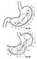
- FIG. 1illustrates a side view of an intragastric obesity treatment implant with two grooved balloons in a patient's stomach in accordance with an embodiment of the present application.
- FIG. 2illustrates a perspective view of an intragastric obesity treatment implant with two grooved balloons similar to FIG. 1 .
- FIG. 3illustrates a perspective view of an intragastric obesity treatment implant with two grooved balloons and a flow restrictor similar to FIG. 1 .
- FIG. 4illustrates an end view of the grooved intragastric obesity treatment implant balloon of FIG. 3 .
- FIG. 5illustrates a sectional side view of the intragastric obesity treatment implant with a flow restrictor of FIG. 3 .
- FIG. 6Aillustrates a perspective view of an intragastric obesity treatment implant with center flanges and an end plug in accordance with an embodiment of the present application.
- FIG. 6Billustrates a perspective view of an intragastric obesity treatment implant with center flanges and a fill valve as in FIG. 6A .
- FIG. 7Aillustrates a perspective view of an intragastric obesity treatment implant with eight center wings and an end plug in accordance with an embodiment of the present application.
- FIG. 7Billustrates a perspective view of an intragastric obesity treatment implant with eight center wings and a fill valve as in FIG. 7A .
- FIG. 8Aillustrates a side view of an intragastric obesity treatment implant with a pumping chamber and two reservoirs in a patient's stomach in accordance with an embodiment of the present application.
- FIG. 8Billustrates a side view of an intragastric obesity treatment implant with a pumping chamber as in FIG. 8A being compressed by a patient's stomach.
- FIG. 9illustrates a perspective view of tri-balloon intragastric obesity treatment implant with a pumping chamber, two reservoirs, one-way valves, and flow restrictors in accordance with an embodiment of the present application.
- FIG. 10Aillustrates a sectional view of a reservoir with an open one-way valve for use in an implant such as FIG. 9 .
- FIG. 10Billustrates a sectional view of a reservoir with a closed one-way valve as in FIG. 10A .
- FIGS. 11A-11Cillustrate sectional views of a reservoir with a burp valve in accordance with an embodiment of the present application.
- FIGS. 12A-12Billustrate sectional views of a pumping chamber with a chamber tube in accordance with an embodiment of the present application.
- FIGS. 13A-13Billustrate sectional views of a pumping chamber with open-celled foam in accordance with an embodiment of the present application.
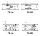
- FIGS. 14A-14Billustrate sectional views of a one-way duckbill valve for use in implants of the present application.
- FIGS. 15A-15Billustrate sectional views of a one-way ball check valve for use in implants of the present application.
- FIG. 16illustrates an alternative tri-balloon intragastric obesity treatment implant of the present application implanted in a stomach.
- FIGS. 17A-17Billustrate details of the tri-balloon intragastric obesity treatment implant of FIG. 16
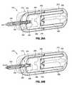
- FIG. 18illustrates a side view of an intragastric obesity treatment implant with two inflated and fluidly-connected balloons in a patient's stomach in accordance with an embodiment of the present application.
- FIG. 19Aillustrates a sectional side view of an intragastric obesity treatment implant as in FIG. 18 showing a flow restrictor within a connecting tether.
- FIG. 19Bis a detail of the connecting channel from FIG. 19A showing the flow restrictor and a deflation assembly.
- FIG. 20shows an alternative dual-balloon intragastric obesity treatment implant with two inflated and fluidly-connected balloons in a patient's stomach.
- FIGS. 21A-21Billustrate details of the dual-balloon intragastric obesity treatment implant as in FIG. 20 .
- FIG. 22Aillustrates a side view of an intragastric obesity treatment implant with an inflated pumping chamber fluidly-connected to two reservoirs on opposite ends in a patient's stomach in accordance with an embodiment of the present application.
- FIG. 22Billustrates a side view of the intragastric obesity treatment implant in FIG. 22A with the pumping chamber being compressed by a patient's stomach to fill the two reservoirs.
- FIG. 23is a sectional view of the intragastric obesity treatment implant in FIG. 22A showing one-way valves and flow restrictors between the pumping chamber and two reservoirs.
- FIG. 24is a detailed sectional view of a one-way valve and flow restrictor between the pumping chamber and one of the two reservoirs in the intragastric obesity treatment implant of FIG. 22A .
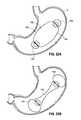
- FIGS. 25A-25Billustrate an alternative intragastric obesity treatment implant positioned within a patient's stomach and in sectional view, the intragastric obesity treatment implant having dual connected balloons in a dog bone configuration with a partition and fluid transfer therebetween.
- FIG. 26Ashow an alternative dual-balloon intragastric obesity treatment implant similar to that in FIGS. 25A-25B with a more uniform longitudinal shape and positioned within the stomach, while FIG. 26B illustrates contraction of the stomach walls to squeeze fluid from a lower balloon to an upper balloon.
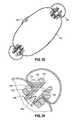
- FIGS. 27-29are various views of a concentric chamber inflatable intragastric obesity treatment implant of the present application having an outer saline-filled chamber and an inner air-filled chamber.
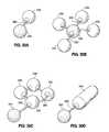
- FIGS. 30A-30Dillustrate perspective views of intragastric obesity treatment implants with various configurations of pumping chambers, tubing, and reservoirs in accordance with various embodiments of the present application.
- FIGS. 31-33illustrate intragastric implant surface features that provide additional stomach cavity stimulation.
- intragastric obesity treatment implantsgenerally comprise an implant that occupies space in a patient's stomach.
- the space occupied by the intragastric obesity treatment implantreduces the available volume in the stomach that may be occupied by ingested food. Accordingly, a patient with the intragastric obesity treatment implant in the stomach may experience a feeling of satiety while consuming less food than before the device was implanted. This reduced food intake may allow the patient to lose weight.
- some embodiments disclosed hereinmay exert pressure on the upper portion of the stomach, or the cardia. This pressure may induce early feelings of satiety by triggering the patient's brain to release satiety-inducing hormones. These hormones may cause the patient to stop eating sooner, also resulting in weight loss.
- the intragastric obesity treatment implantsmay be implanted in the patient's stomach transorally—through the patient's mouth and down the patient's esophagus.
- the intragastric obesity treatment implantsmay be referred to as transoral implants and/or transoral intragastric obesity treatment implants.
- Transoral implantationadvantageously allows implantation of the intragastric obesity treatment implant without associated patient risks of invasive surgery and without substantial patient discomfort.
- Recovery time after implantation of the transoral intragastric obesity treatment implantmay be minimal as no extensive tissue healing is generally required.
- the life span of these implantsmay be material-dependent upon long-term survivability within an acidic stomach, but various embodiments are advantageously configured to last one year or longer.
- FIG. 1illustrates a first space-occupying implant 8 , but also illustrates the anatomy of the human stomach, which will be described first.
- the major function of the stomachis to temporarily store food and release it slowly into the duodenum.
- the esophagus extending downward from the mouthconnects to the stomach via esophageal sphincter, which regulates flow food into the stomach cavity.
- the cardiasurrounds the superior opening of the stomach.
- the rounded portion superior to the body and adjacent the cardiais the fundus.
- Inferior to the fundusis the large central portion of the stomach, called the body, that is lined with muscles that contract and relax repetitively to churn the food therein.
- the stomachprocesses the food to a semi-solid “chyme,” which enables better contact with the mucous membrane of the intestines, thereby facilitating absorption of nutrients.
- the stomachis an important site of enzyme production.
- the antrumconnects the body to the pylorus, which leads into the duodenum.
- the duodenumleads into the upper part of the small intestine (not shown); the jejunum makes up about one-third of the small intestine.
- the region of the stomach that connects to the duodenumis the pylorus.
- the pyloruscommunicates with the duodenum of the small intestine via the pyloric sphincter (valve). This valve regulates the passage of chyme from stomach to duodenum and it prevents backflow of chyme from duodenum to stomach.
- an intragastric obesity treatment implant 8such as an active balloon adipose trimming element, comprises a gastrointestinal implant with two lobes and/or balloons 10 , 12 , that may be filled with saline, air, or other fluids.
- the balloons 10 , 12have a nominal capacity (e.g., in a post-filled, pre-expanded state) of at least approximately 400 g, or about 400 ml, of saline.
- the intragastric obesity treatment implant 8may be configured to be implanted in the patient's stomach S, transorally, without invasive surgery, and without associated patient risks of invasive surgery. Recovery time may be minimal because of reduced tissue healing post implantation.
- the intragastric obesity treatment implant 8may have a product life span in the stomach S of up to one year or longer. As will be discussed, the intragastric obesity treatment implant 8 facilitates weight loss and obesity treatment through adipose trimming and/or fat reduction due to the patient consuming less food.
- the intragastric obesity treatment implant 8comprises an active system where the balloons 10 , 12 are joined to each other and are configured to occupy space inside the stomach S, thereby decreasing the amount of food that is ingestible by the patient, which may result in weight loss.
- the intragastric obesity treatment implant 8is configured to span the upper and lower stomach regions, ranging from the antrum to the cardia.
- the intragastric obesity treatment implant 8may be configured to actively facilitate obesity treatment through early inducement of feelings of satiety and resulting reduced food consumption.
- a fluidis disposed in the balloons 10 , 12 , and the fluid may move between the balloons 10 , 12 via a center portion 17 that couples the balloon 10 to the balloon 12 .
- the center portion 17comprises a passageway that allows the fluid to pass between the balloons 10 , 12 .
- peristaltic digestive “churning” of the stomach Sbegins. These peristaltic motions cause various portions of the stomach S to repeatedly contract and relax to move food through the stomach S.
- the peristaltic motions near the lower balloon 12may cause the stomach S to squeeze the balloon 12 .
- the upper balloon 10may comprise a compliant material, such that the increased amount of fluid in the balloon 10 causes the balloon 10 to expand and exert increased pressure on the cardia. This increased pressure on the cardia may induce early feelings of satiety by triggering the brain to release satiety-inducing hormones, so eating will likely cease and weight loss may ensue.
- the peristaltic motions in the stomachcease, resulting in reduced pressure exerted on the balloon 12 .
- This reduced pressure exerted on the balloon 12in conjunction with the increased pressure in the balloon 10 from the increased amount of fluid in the balloon 10 (and due to forces induced in the expanded compliant material in the balloon 10 from expansion), causes the fluid in the balloon 10 to return to the balloon 12 via the center portion 17 until the pressure is substantially equalized between the two balloons 10 , 12 .
- the return flow from the balloon 10 to the balloon 12may be slowed down to maintain an expanded size of the balloon 10 for a longer period of time.
- the passageway in the center portion 17may be advantageously configured to have a sufficient size to allow for a desired flow rate.
- the passagewaymay be a through hole having a diameter of approximately one millimeter.
- a center band 19e.g., an elastic band
- Other flow restrictor devicessuch as valves, pressure reducers and the like and combinations thereof may be utilized to allow for a desired flow rate between the balloons 10 , 12 .
- the intragastric obesity treatment implant 8may comprise a plurality of flutes, ridges, and/or grooves 15 that are configured to prevent obstruction of food as it moves through the pylorus and into the duodenum of the patient.
- the grooves 15direct the food to pass by the implant 8 along the stomach S walls.
- each balloon 10 , 12comprises eight grooves 15 to direct the food flow.
- the ends of the grooves 15 near the center portion 17may be flush with the surrounding surface of the balloons 10 , 12 to prevent undesired expansion from increased pressure due to movement of the fluid between the balloons 10 , 12 .
- the intragastric obesity treatment implant 8may be formed in a “dog bone” shape with enlarged ends and strengthening structure, such as a flange or wing 20 disposed along the narrower center portion 17 .
- the wing or wings 20may prevent kinking of the center portion 17 in order to maintain the passageway in the center portion 17 open.
- four wings 20may be configured in an “X” shape along the center portion 17 in accordance with an embodiment.
- FIGS. 6A-6Bfour wings 20 may be configured in an “X” shape along the center portion 17 in accordance with an embodiment.
- eight wings 20may be disposed along the center portion 17 to provide structure to the center portion 17 and/or to prevent kinking. It should be understood that various other configurations of the wings 20 and/or other structures may be utilized to provide support to the center portion 17 and/or to prevent kinking, without departing from the scope of the present invention.
- the balloon 10may comprise a fill valve 24 to allow the intragastric obesity treatment implant 8 to be filled with saline after implantation of the implant in the stomach S.
- the balloon 12may similarly have an end plug 22 to prevent saline from exiting the balloon 12 .
- the intragastric obesity treatment implant 8may be disposed in the stomach S via the esophagus in a substantially non-inflated state.
- a lubricated, thin-walled tubesuch as a tube made with Teflon or a similar material may be inserted through the patient's mouth, down the esophagus, and partially into the stomach S.
- the implant 8 in a compressed statemay be preloaded into the tube prior to insertion, and may then be deployed into the stomach S after the tube is inserted.
- a filling tubemay be removably coupled to the intragastric obesity treatment implant 8 prior to insertion through the lubricated tube to facilitate filling the implant 8 after implantation in the stomach S.
- the fill valve 24may comprise a slit valve that couples the balloon 10 to the filling tube.
- the fill valve 24may be a one way valve such that saline or another fluid may enter the balloon 10 via the filling tube, but the filling tube may then be removed after inflation of the intragastric obesity treatment implant 8 without a substantial amount of fluid being lost from the implant 8 .
- the thin-walled tube and the filling tubemay be removed from the patient, leaving the inflated implant 8 in the stomach S.
- an aspiratormay be fed down the patient's esophagus to puncture the implant 8 , releasing the saline or other fluid into the stomach S.
- the deflated implant 8may then be removed from the stomach S via the esophagus using a grasper or other tool.
- the intragastric obesity treatment implant 8may be configured to be removed in other ways, for example, by passing out of the patient through digestion.
- the implant 28is contained substantially within the patient's stomach S, and may be referred to as a stomach fluid transfer implant because it is configured to transfer stomach fluids between chambers or reservoirs to facilitate obesity control.
- a pumping chamber 40may move stomach fluids or juices between one or more stimulation reservoirs, such a reservoir 30 .
- the intragastric obesity treatment implant 28may be implanted in a similar manner as discussed above for other intragastric obesity treatment implants, for example, transorally, through the esophagus, and into the stomach, during a minimally invasive gastroendoscopic surgical procedure.
- the intragastric obesity treatment implant 28may induce weight loss through a variety of methods.
- the volume of the implant 28 in the stomach Smay reduce the total quantity of food ingested during a meal and reduce the sensation of pre-prandial hunger while implanted.
- the implant 28may be configured to change shape or size when acted upon by the stomach S, for example, when acted upon by peristaltic motions 45 of the stomach S during digestion. Such changes may induce a changing sensation on the stomach S, and the changing sensation may be mechanotransduced by the stomach S to trigger the efferent nerves in the stomach S so as to encourage feelings of satiety.
- the pumping chamber 40is coupled to an upper reservoir 30 via an upper tube 47 and to a lower reservoir 32 via a lower tube 48 .
- the tubing 47 , 48may comprise rigid or flexible tubing, and may connect the various reservoirs 30 , 32 in series or parallel.
- reservoirs 330may be connected by tubing 350 in series or in parallel with an alternate pumping chamber 320 .
- the pumping chamber 40moves fluid (e.g., gas, liquid, and combinations thereof) into the reservoirs 30 , 32 .
- the pumping chamber 40moves any fluid (liquid or gas) that is inside of the stomach.
- a hole 42 or plurality of holes 42is disposed in the walls of the pumping chamber 40 to allow the stomach fluids to enter the pumping chamber 40 .
- the reservoirs 30 , 32are compliant chambers that may expand to accommodate the volume of fluid being pumped from the pumping chamber 40 .
- the reservoirs 30 , 32may be spherical or cylindrical (see, e.g., the reservoirs 330 illustrated in FIGS. 30A-30D in accordance with various embodiments), or any other shape configured to allow fluid to enter and to exert appropriate pressure on the stomach S.
- the holes 42 in the pumping chamber 40are open, which allows the stomach juices to enter the pumping chamber 40 . Then, as the peristaltic motions 45 begin during digestion, the holes 42 are configured to be covered by the stomach S walls to prevent the stomach juices from exiting the pumping chamber 40 . In this manner, the peristaltic motions 45 compress the pumping chamber 40 and move the stomach juices from the pumping chamber 40 , through the tubes 47 , 48 and into the reservoirs 30 , 32 to facilitate inducing a sensation of satiety in the patient. It should be noted that FIG.
- FIG. 8Bis illustrative of the peristaltic motions 45 and the resulting compression of the pumping chamber 40 . While FIG. 8B may appear to not show coverage of the holes 42 during the peristaltic motions 45 , it should be understood that the holes 42 are covered by the stomach S walls during the compression process. After the peristaltic motions 45 stop, the stomach S relaxes, the holes 42 are uncovered, and more stomach juices enter the pumping chamber 40 .
- valves 31 , 33may be coupled to the reservoirs 30 , 32 and/or to the tubing 47 , 48 .
- These valves 31 , 33are one-way valves to allow the fluid to flow into the reservoirs 30 , 32 from the pumping chamber 40 , but not from the reservoirs 30 , 32 into the pumping chamber 40 .
- the valves 31 , 33may comprise one-way “duckbill” valves.
- a ball check valve 60may be utilized as a one-way valve.
- valvesmay be utilized to appropriately control the flow of fluid without departing from the scope of the present invention.
- various embodimentsinclude one-way valves 31 , 33 that are disposed in the reservoirs 30 , 32 .
- the valvesmay be disposed in the pumping chamber 40 and/or in the tubing 47 , 48 .
- the reservoirs 30 , 32are made of a compliant material to allow the reservoirs 30 , 32 to advantageously expand to induce a feeling of satiety in the patient.
- a release mechanism and/or valve 34 , 35may be disposed in the reservoirs 30 , 32 to allow the reservoirs 30 , 32 to expand to a certain size and/or pressure. But, once the desired size/pressure is reached, fluid is released from the reservoirs 30 , 32 through the release mechanisms/valves 34 , 35 to prevent over-inflation. The fluid is released from the release valves 34 , 35 back to the stomach where the fluid may then be drawn in by the pumping chamber 40 or otherwise utilized by the patient's body.
- a flow restrictor 34 , 35may be used as a release mechanism, such that fluid will start to exit the reservoirs 30 , 32 at a desired rate once the reservoirs 30 , 32 have reached a predetermined size/pressure. Thus, once pumping from the pumping chamber 40 ceases, the size/pressure of the reservoirs 30 , 32 will gradually reduce to a nominal size/pressure.
- a burst or burp valve 36may be utilized as a release mechanism.
- the burp valve 36may be configured to open when the reservoir 30 has been stretched to a certain degree, or when a specific strain has been induced in the reservoir 30 . In this manner, once the burp valve 36 opens, it may remain open until the reservoir 30 returns to a nominal size/pressure.
- Other release mechanismssuch as pressure relief valves which crack or open at a certain pressure may similarly be used to regulate the size of the reservoir 30 or the amount of fluid in the reservoir 30 .
- the pumping chamber 40may be advantageously configured to be biased toward an open/expanded state.
- the pumping chamber 40may want to return to its largest state after the peristaltic motions 45 cease and the stomach S relaxes.
- a supporting structuresuch as a chamber tube 50 may be disposed within the pumping chamber 40 to cause the pumping chamber 40 to return to its expanded state after the peristaltic motions 45 cease.
- a plurality of chamber tube holes 52may be disposed in the chamber tube 50 to allow the stomach fluids to enter the chamber tube 50 and then pass through the tubes 47 , 48 coupled to the reservoirs 30 , 32 (see, e.g., FIGS. 8-10 ) during the pumping process.
- an open-celled foam 56may be disposed within the pumping chamber 40 to facilitate returning the pumping chamber 40 to its expanded state after pumping (e.g., after the peristaltic motions 45 cease).
- the tube 47may be directly coupled to the pumping chamber 40 , and the chamber tube 50 may not be utilized.
- a chamber tube 50may be employed in conjunction with the open-celled foam 56 .
- the walls of the pumping chamber 40may be sufficiently thick that they will cause the pumping chamber 40 to be biased toward its expanded state without the use of the open-celled foam 56 or the chamber tube 50 . It should be understood that various combinations of these and other components may be utilized to cause the pumping chamber 40 to return to its expanded state after the peristaltic motions 45 cease.
- FIG. 16illustrates an alternative tri-balloon intragastric obesity treatment implant 70 implanted in a stomach
- FIGS. 17A-17Billustrate details of the implant.
- the implant 70comprises a system of three balloons; a larger central balloon 72 , a smaller upper end balloon 74 , and a smaller lower end balloon 76 .
- the three balloons 72 , 74 , 76are coupled together via a tubular communication channel 78 .
- the larger central balloon 72preferably has a fixed volume, while the two end balloons 74 , 76 transfer fluid through the communication channel 78 .
- the upper end balloon 74further includes a fill valve 80 which is used to inflate the two end balloons. Although not shown, a fill valve is also provided for the central fixed volume balloon 72 .
- the larger central balloon 72occupies space in the stomach and presses against the stomach walls to properly position the end balloons 74 , 76 . Desirably, the smaller upper end balloon 74 maintains contact with the cardia region for stimulation. Fluid transfer between the two end balloon 74 , 76 occurs at a rate driven by the size of the communication channel 78 .
- a relief valve 82 on the communication channel 78 and within the chamber of the central balloon 72ensures that the end balloon 74 , 76 do not break under excessive pressure.
- the three balloons 72 , 74 , 76are shown as generally spherical, although modifications to spheres are contemplated. Indeed, the central balloon 72 shown as slightly offset with a prolate spheroid shape. The central balloon 72 is desirably wider about its equatorial diameter than the dimension along the axis defined by the communication channel 78 .
- an intragastric obesity treatment implant 100 with fluidly-connected active balloon reservoirscomprises a gastrointestinal implant with two lobes and/or balloon reservoirs 110 , 112 that may be filled with saline, air, or other fluids.
- the balloon reservoirs 110 , 112have a nominal capacity (e.g., in a post-filled, pre-expanded state) of at least approximately 400 ml of saline, preferably between about 400-600 ml of saline.
- the intragastric obesity treatment implant 100is similar to the implant 400 discussed above with reference to FIGS. 1-5 .
- the intragastric obesity treatment implant 100may be configured to be implanted in the patient's stomach S, transorally, without invasive surgery, and without associated patient risks of invasive surgery. Recovery time is minimal because of reduced tissue healing post implantation.
- the implant 100has a product life span in the stomach S of up to one year or longer. As will be discussed, the implant 100 facilitates weight loss and obesity treatment through adipose trimming and/or fat reduction due to the patient consuming less food.
- the intragastric obesity treatment implant 100comprises the balloon reservoirs 110 , 112 which are configured to occupy space inside the stomach S, thereby decreasing the amount of food that is ingestible by the patient, which may result in weight loss.
- the implant 100is configured to span the upper and lower stomach regions, ranging from the antrum to the cardia.
- the intragastric obesity treatment implant 100actively facilitates obesity treatment through early inducement of feelings of satiety and resulting reduced food consumption.
- a fluid disposed in the balloon reservoirs 110 , 112may move between the reservoirs via a dual-lumen connecting tether 114 that couples the upper reservoir 110 to the lower reservoir 112 .
- the connecting tether 114comprises a small fluid transfer passageway 116 that allows the fluid to pass between the reservoirs 110 , 112 .
- peristaltic digestive “churning” of the stomach Sbegins. These peristaltic motions cause various portions of the stomach S to repeatedly contract and relax to move food through the stomach S.
- the peristaltic motions near the lower reservoir 112may cause the stomach S to squeeze the reservoir.
- the upper reservoir 110preferably comprises a compliant material, such that the increased amount of fluid in the reservoir 110 causes it to expand and exert increased pressure on the cardia. This increased pressure on the cardia may induce early feelings of satiety by triggering the brain to release satiety-inducing hormones, so eating will likely cease, thus promoting weight loss over time.
- the peristaltic motions in the stomachcease, resulting in reduced pressure exerted on the lower reservoir 112 .
- This reduced pressure exerted on the lower reservoir 112in conjunction with the increased pressure in the upper reservoir 110 from the increased amount of fluid therein (and due to forces induced in the expanded compliant material in the reservoir 110 from expansion), causes the fluid in the upper reservoir 110 to return to the lower reservoir 112 via the fluid transfer passageway 116 until the pressure is substantially equalized between the two reservoirs.
- the overall geometry of the implant 100alters to encourage a varied stimulus on the stomach. Changing the character of the stimulus on the stomach walls is believed not only to encourage feelings of satiety, but also to help prevent the stomach muscles from “learning” a particular stimulus and adapting to it.
- the systemdesirably delays return flow from the upper reservoir 110 to the lower reservoir 112 to maintain an expanded size of the upper reservoir 110 for a longer period of time.
- the fluid transfer passageway 116 in the connecting tether 114may be advantageously configured to have a small diameter to allow for a desired low flow rate.
- the passageway 116has a diameter of approximately one millimeter.
- a center band(not shown) (e.g., a rubber band) disposed around the connecting tether 114 appropriately reduces the size of the passageway 116 to allow for a desired low flow rate.
- Other devicessuch as valves, flow restrictors, pressure reducers and the like and combinations thereof may be utilized to allow for a desired flow rate between the reservoirs 110 , 112 .
- One desired low flow rateis between about 1-20 ml/s.
- the dual-lumen tether 114also includes a deflation lumen 118 extending between the reservoirs 110 , 112 , parallel to the passageway 116 .
- the deflation lumen 118is larger than the passageway 116 , and is only accessed to evacuate fluid from the reservoirs 110 , 112 during explanation.
- the larger deflation lumen 118is fitted on both sides with one-way valves 120 (e.g., duck-bill valves as shown) which are oriented in opposite directions.
- the valves 120prevent fluid flow from the deflation lumen 118 into each reservoir, and therefore prevent flow from one reservoir to another through the deflation lumen 118 .
- the orientation of the valves 120is such that they will open if a vacuum (predetermined pressure differential across the valves) is introduced through a vacuum port 122 .
- a vacuumpredetermined pressure differential across the valves
- an instrument introduced trans-orally through the esophagusmay be used to access the vacuum port 122 and pull fluid therefrom.
- the relatively large size of the deflation lumen 118 and uninhibited flow through the valves 120encourages rapid deflation of the balloon reservoirs 110 , 112 during explanation.
- the tether 114is rigid enough so that the dual lumens do not collapse or kink under various operating conditions. However, the tether 114 remains flexible enough such that the device as a whole can roughly orient itself inside a variety of stomach geometries. Indeed, the intragastric obesity treatment implant 100 in one embodiment is symmetric across the balloon reservoirs 110 , 112 and may completely invert so that the reservoir 112 is now the upper reservoir.
- One solutionis to provide a reinforcing coil embedded within a more flexible tether 114 .
- the tether 114 and all of its integral componentsmay be manufactured from materials including, but not limited to, rubbers, fluorosilicones, fluoroelastomers, thermoplastic elastomers, or any combinations thereof, while a reinforcing coil may be formed of those materials as well as flexible metals such as Nitinol.
- FIG. 20shows another dual-balloon intragastric obesity treatment implant 130 with a larger upper cardia-stimulating balloon 132 fluidly-connected via relatively stiff tube 134 to a smaller positioning balloon 136 .
- the tube 134includes a plurality of apertures (not shown) along its length within each of the balloons 132 , 136 .
- Each of the balloons 132 , 136has a one-way fill valve 138 , 140 , respectively, so that both balloons may be filled from either valve. Alternatively, only one of the balloons 132 , 136 has a fill valve.
- Fluidmay transfer between the balloons 132 , 136 from stomach churning, though the rate of return to equilibrium will be slower and depend on the size of the interconnecting flow apertures.
- the rate of return flowis about half the maximum rate of forward flow, which is induced by the stomach squeezing on one or the other balloon.
- the larger balloon 132has an inflated volume at least twice as big, and preferably at least three times as big, as the smaller balloon 136 and is shaped to conform to the relatively larger cardia region within the stomach.
- the smaller balloon 136has an inflated size large enough to prevent passing through the pylorus, but large enough to provide an atraumatic surface in contact with the antrum region in the lower region of the stomach.
- the stiff tube 134ensures that the larger balloon 132 maintains contact with the cardia, stimulating upper baroreceptors.
- FIGS. 22A and 22Bshow an intragastric obesity treatment implant 150 in a patient's stomach S in two different configurations.
- the implant 150comprises a large central pumping chamber 152 fluidly connected between two smaller reservoirs 154 on either end.
- the central pumping chamber 152is expanded to fill a substantial portion of the interior of the stomach S, while in FIG. 22B the pumping chamber has been compressed such that an outside fluid is transferred to the end reservoirs 154 .
- the pumping chamber 152has a capacity of at least about 400 ml of saline, preferably between about 400-600 ml of saline, while the combined capacity of the smaller reservoirs 154 is also at least about 400 ml.
- the intragastric obesity treatment implant 150is similar in many respects to the implant 28 discussed above with reference to FIGS. 8-10 , where, however, in contrast, a pumping chamber 40 moves stomach fluids or juices between stimulation reservoirs 30 .
- FIGS. 23 and 24illustrate internal components of the intragastric obesity treatment implant 150 , specifically between the pumping chamber 152 and the reservoirs 154 on either end.
- a connector 156 between the chamber 152 and each reservoir 154includes a large flow lumen 158 housing a one-way valve 160 , and a smaller lumen 162 acting as a fluid transfer channel and providing flow restriction between the pumping chamber and each reservoir.
- the connector 156comprises a substantially tubular male member 170 within which is formed the lumens 158 , 162 , and which has a radially outward-directed flange 172 that contacts an interior wall of the respective end reservoir 154 .
- a portion of the tubular male member 170 extending within the interior of the pumping chamber 152includes external threading for mating with internal threading on a nut 176 .
- the nut 176tightens along the male member 170 and forces a washer 178 against an interior wall of the pumping chamber 152 .
- Both the washer 178 and the flange 172 of the male member 170include concentric circular ribs that engage across the walls of the pumping chamber 152 and reservoir 154 and help prevent slipping of the assembly.
- the portion of the male member 170 within the end reservoirs 154is shaped to allow for easy handling, and in particular for applying torque, through a deflated end reservoir 154 .
- the male member 170 within the end reservoirs 154has a hexagonal, square or winged shape.
- An aperture in the side wall of the pumping chamber 152 that receives a fill valve 180permits introduction of the nuts 176 and washers 178 , and also provides access for a tool for either holding or turning the nut during assembly.
- the physicianinflates the implant 150 through the valve 180 located along one side of the central pumping chamber 152 .
- the stomach's peristaltic forcesact on the larger pumping chamber 152 and squeeze fluid through the fluid transfer lumens 162 of the connectors 156 , and into the end reservoirs 154 , as depicted in FIG. 22B .
- the end reservoirs 154thus inflate and stimulate the stomach walls.
- the increased pressure within the inflated end reservoirs 154creates a pressure differential across the connector 156 , thus initiating a return flow from each reservoir back to the central pumping chamber 152 .
- an open-celled foam(such as that shown in FIGS.
- the walls of the pumping chamber 152may be sufficiently thick that they will cause it to be biased toward its expanded state without the use of the open-celled foam. It should be understood that various combinations of these and other components may be utilized to cause the pumping chamber 152 to return to its expanded state after the peristaltic motions cease.
- reverse flow of fluid from the end reservoirs 154 to the central pumping chamber 152takes an extended period of time, preferably greater than two minutes and potentially up to several (e.g., two) hours.
- One desired low flow rateis about 1-20 ml/s.
- a single set of stomach contractionsare sufficient to create the geometry shown in FIG. 22B , which is believed to stimulate the inner walls of the stomach and induce satiety more than the relaxed geometry of FIG. 22A .
- an intragastric obesity treatment implant 200such as a dual balloon gastrointestinal implant includes two lobes and/or balloons 210 , 212 , that may be filled with saline, air, or other fluids.
- the balloons 210 , 212have a nominal capacity (e.g., in a post-filled, pre-expanded state) of at least approximately 400 g, or about 400 ml, of saline.
- the combined fluid capacity of the balloons 210 , 212may be between about 400-700 ml of saline, with a more preferred capacity of about 500 or 600 ml.
- the inflated intragastric obesity treatment implant 200describes a somewhat dog-bone shape, with identical lower and upper balloons 210 , 212 having enlarged, fluted outer ends joined by a smaller, generally cylindrical middle portion.
- the middle portion of the implant 200is strengthened to prevent kinking by virtue of its relative size and a central partition, as will be explained.
- the implant 200is configured to span the upper and lower stomach regions, as shown in FIG. 25A , with the lower balloon 210 adjacent the antrum and the upper balloon 212 adjacent the cardia.
- the balloons 210 , 212are desirably separately formed and joined to each other. More particularly, the intragastric obesity treatment implant 200 comprises two identical balloons 210 , 212 generally aligned along a longitudinal axis and bonded together along a centrally located diametrically-oriented partition 214 . As seen in FIG. 25B , the partition 214 desirably comprises the juxtaposed flat inner end walls of the two balloons 210 , 212 . From the inner end wall outward, each balloon 210 , 212 has a tubular portion 216 , 218 that extends along the longitudinal axis and widens at bulbous end portions 220 , 222 . Desirably, the end portions 220 , 222 feature a series of longitudinal flutes or ridges 224 around their circumference between which are grooves, best seen in FIG. 25A .
- the intragastric obesity treatment implant 200facilitates weight loss and obesity treatment by taking up space within the stomach as well as by stimulating satiety-inducing nerves.
- the implant 200occupies space inside the stomach S, thereby decreasing the amount of food that is ingestible by the patient, which may result in weight loss.
- the flutes or ridges 224 and accompanying groovesprevent obstruction of food as it moves through the pylorus and into the duodenum of the patient. Namely, food passes by the implant 200 through the grooves between the flutes 224 and along the stomach S walls.
- the intragastric obesity treatment implant 200further actively treats obesity through early inducement of feelings of satiety and resulting reduced food consumption.
- fluidsuch as saline may move between the balloons 210 , 212 across the center partition 214 ( FIG. 25B ) that separates the inner chambers of the balloons 210 , 212 .
- the center partition 214includes a duckbill valve 226 and parallel fluid passageways (not shown) that allow fluid to pass between the balloons 210 , 212 .
- the duckbill valve 226permits fluid to flow from the lower balloon 210 to the upper balloon 212 but prevents a reverse flow.
- One or more fluid passageways near or surrounding the valve 226permit fluid flow back from the upper balloon 212 to the lower balloon 210 .
- the flow orifice through the duckbill valve 226is larger than the combined area of the return passageway(s), and thus fluid may flow at a greater rate from the lower balloon 210 to the upper balloon 212 .
- peristaltic motions near the lower balloon 212may cause the stomach S to squeeze the balloon 212 .
- the upper balloon 210desirably comprises a compliant material, such that the increased amount of fluid in the balloon 210 causes the balloon 210 to expand and exert increased pressure on the cardia.
- This increased pressure on the cardiamay induce early feelings of satiety by triggering the brain to release satiety-inducing hormones, so eating will likely cease, thus contributing to eventual weight loss.
- the peristaltic motions in the stomachcease, resulting in reduced pressure exerted on the lower balloon 212 .
- This reduced pressurein conjunction with the increased pressure in the upper balloon 210 from the increased amount of fluid therein (and due to forces induced in the expanded compliant material in the balloon 210 from expansion), causes the fluid to return to the lower balloon 212 via the fluid passageway(s) in the center partition 214 until the pressure is substantially equalized between the two balloons 210 , 212 .
- the return flow to the lower balloon 212may be inhibited to maintain an expanded size of the upper balloon 210 for a longer period of time.
- the passageway(s) in the center partition 214preferably has a maximum size to allow for a desired low flow rate.
- the passagewaymay be a through hole having a diameter of approximately 1 mm.
- the maximum flow rate from the lower balloon 212 to the upper balloon 210is desirably substantially greater than in the reverse direction.
- the duckbill valve 226enables twice the flow rate from the lower balloon 212 to the upper balloon 210 than the reverse flow through the return passageway(s).
- the entire intragastric obesity treatment implant 200has a fluid capacity of about 500 ml which is typically split evenly (250-250) between the two balloon chambers when the pressures in both are equal.
- Up to 200 ml of the fluid in the lower balloon 212 chamberrapidly flows through the valve 226 to the upper balloon 210 chamber from peristaltic contractions. This may take just a few seconds. Swelling of the upper balloon 210 applies pressure to the surrounding cardia and its subcutaneous nerves, thereby stimulating the brain's release of satiety-inducing hormones. Subsequently, the return fluid passageway(s) permit a trickle flow back to the lower balloon 212 chamber that takes at least 10 seconds, potentially minutes.
- the intragastric obesity treatment implant 200is preferably implanted in the patient's stomach S transorally, without invasive surgery and its associated patient risks. Recovery time is minimized because of reduced tissue healing post implantation.
- the implant 200may have a product life span in the stomach S of up to one year or longer.
- the upper balloon 212conveniently has a fill valve 230 along the longitudinal axis at the bulbous end 222 to allow the implant 210 to be filled with saline after implantation in the stomach S.
- the lower balloon 210is also filled by transfer through the fluid passageway(s) across the partition 214 .
- the implant 200may be disposed in the stomach S via the esophagus in a substantially non-inflated state.
- a lubricated (e.g., Teflon), thin-walled tube(not shown) may be inserted through the patient's mouth, down the esophagus, and partially into the stomach S.
- the implant 200is preloaded in a non-inflated and compressed state into the tube prior to insertion, and then expelled into the stomach S from the distal end of the tube.
- a fluid filling tube coupled to the fill valve 230is removably coupled to the intragastric obesity treatment implant 200 prior to insertion through the lubricated tube to facilitate filling the implant after implantation.
- the fill valve 230is a one way valve such that the filling tube can be removed after inflation of the implant 200 without a substantial amount of fluid being lost.
- the intragastric obesity treatment implant 200features a rapid deflation valve 232 located approximately at the center of the implant which can deflate both chambers of the balloons 210 , 212 simultaneously.
- the valve 232has a T-shaped configuration with a nipple 234 opening to the exterior of the implant and in fluid communication with a pair of one-way valves 236 extending in opposite directions into each of the dual fluid chambers of the implant.
- the one-way valves 236permit flow from the dual chambers and out of the nipple 234 , but prevent flow in the opposite direction.
- a “lasso” device(not shown) with a slip-knotted cord is used to capture the intragastric obesity treatment implant 200 about its midsection.
- the sideways-oriented nipple 234may then be accessed using a wire-stiffened fluid removal line or aspirator having an end specially configured to engage the nipple (e.g., with a single-barbed end).
- the fluid removal lineexerts a vacuum pressure on the two one-way valves 236 to evacuate the inside of both balloon chambers simultaneously.
- the vacuummay be created using an empty syringe connected to the fluid line.
- a standard endoluminal cuttermaybe deployed down an overtube through the esophagus to cut each balloon chamber in one or more places so the saline therein can drain into the stomach cavity. Once the balloons 210 , 212 collapse, the entire implant can be refracted into the overtube using a standard grabber after withdrawal of the cutter.
- the intragastric obesity treatment implant 200may be configured to be removed in other ways, for example, by passing out of the patient through digestion.
- FIG. 26Ashows an alternative dual-balloon intragastric obesity treatment implant 250 similar to that in FIGS. 25A-25B but with a more uniform longitudinal shape.
- the implant 250includes a lower balloon 252 connected to an upper balloon 254 at a central diametric partition 256 .
- the two balloons 252 , 254are connected at their inner ends and each feature longitudinal flutes 260 which match up to provide uniform longitudinal flutes and intermediate grooves along the entire length of the implant 250 .
- the implant 250desirably features a fill valve on one end, a one-way fluid transfer valve as well as return fluid passageways in the partition 256 , and a rapid deflation valve, like the embodiment of FIGS. 25A-25B .
- peristaltic contractionsmay squeeze the lower balloon 252 as shown in FIG. 26B .
- Thiscauses fluid transfer through the one-way valve in the partition 256 , which rapidly fills the upper balloon 254 .
- the asymmetric shape createdcontacts the inner walls of the cardia in the upper end of the stomach and stimulates satiety-inducing nerves.
- the presence of the filled intragastric obesity treatment implant 250takes up space within the stomach S, though the deep grooves between the flutes 260 help food bypass the implant.
- FIGS. 27-29illustrate a still further inflatable intragastric obesity treatment implant 270 having an outer saline-filled chamber and an inner air-filled chamber.
- the exterior shape of the implant 270is similar to the embodiment shown in FIGS. 26A-26B , with a first exterior balloon 272 connected at one end in series to a second identical exterior balloon 274 at a partition wall 276 .
- the two balloons 272 , 274are oriented along a longitudinal axis and the partition wall 276 extends diametrically perpendicular to the axis.
- Each of the balloons 272 , 274has a rounded outer end shape with a plurality (6 shown) of longitudinal flutes 278 creating longitudinal grooves 280 therebetween.
- the intragastric obesity treatment implant 270features a convenient outer fill valve 282 centrally located on the outer end of the second balloon 274 .
- the intragastric obesity treatment implant 270has a configuration much like that shown in FIGS. 26A-26B , and indeed functions much like that earlier embodiment.
- the implant 270may be deflated for transoral insertion into the stomach through the esophagus using a lubricated overtube, and then filled. Once in the stomach, the implant 270 takes up space and also actively changes shape in reaction to peristaltic contractions. Specifically, fluid may be transferred between the two balloons 272 , 274 to enlarge one or the other.
- the outer flutes 278contact the stomach wall and channels defined by the grooves 280 therebetween permit food to flow past the implant.
- the intragastric obesity treatment implant 270features a concentric balloon structure with dual saline-filled outer balloons surrounding an air-filled core balloon that occupies volume within the outer balloons.
- the connected outer balloons 272 , 274 having the diametric partition 276 therebetweenare shown surrounding an inner air-filled core balloon 284 .
- the core balloon 284includes an upper portion formed as a monolithic bladder 286 residing entirely within the chamber of the first outer balloon 272 , and a lower portion comprising a series of elongated longitudinally-oriented bladders 288 .
- the elongated bladders 288are each fluidly connected to the single monolithic bladder 286 and extend across the partition 276 into the chamber of the second outer balloon 274 . It should be noted that the air-filled core balloon 284 may be located within a single outer saline-filled outer balloon in a manner that orients the outer balloon, though the partitioned dual outer balloon provide additional advantages
- the partition 276provides sealed apertures for passage of each of the elongated bladders 288 without compromising the fluid separation between the chambers of the first and second outer balloons 272 , 274 .
- the partition 276includes a duckbill valve 290 and parallel fluid passageways (not shown) that allow fluid to pass back and forth between the balloons 272 , 274 .
- the duckbill valve 290permits fluid to flow from the first or lower balloon 272 to the second or upper balloon 274 but prevents reverse flow.
- One or more fluid passageways near or surrounding the valve 290permit fluid flow back from the second balloon 274 to the first balloon 272 .
- the flow orifice through the duckbill valve 290is larger than the combined area of the return passageway(s), and thus fluid may flow at a greater rate from the first balloon 272 to the second balloon 274 .
- the first outer balloon 272desirably resides below the second outer balloon 274 in the stomach such that the outer fill valve 282 is located on the proximal end (or toward the esophagus) of the intragastric obesity treatment implant 270 .
- the outer fill valve 282has an outlet aperture 294 projecting into the second outer balloon 274 and toward an inner fill valve in the corresponding end of the core balloon 284 .
- a single fill tubemay be used to inflate both the inner core balloon 284 with air, and the outer dual balloons 272 , 274 with saline.
- the core balloon 284has a single fluidly-connected chamber and remains filled with air throughout use of the implant.
- the two outer balloons 272 , 274transfer fluid across the partition 276 over the implant duration, as was described above. More particularly, fluid rapidly passes through the one-way valve 290 from the chamber of the first outer balloon 272 to the chamber of the second outer balloon 274 , and then returns more slowly through the surrounding fluid passageway(s). Since the monolithic bladder 286 of the upper portion has a larger volume than the combined volumes of the elongated bladders 288 of the lower portion of the air-filled balloon 284 , the intragastric obesity treatment implant 270 has greater buoyancy toward the end of the second outer balloon 274 having the fill valve 282 .
- the end with the fill valve 282remains oriented upwards toward the cardia by virtue of its greater buoyancy.
- some of the air residing in the elongated bladders 288may be forced across the partition 276 into the chamber of the second outer balloon 274 , further contributing to the buoyancy differential across the partition. All this results in the end having the second outer balloon 274 floating and remaining in the top of the stomach adjacent the cardia. Because the fill valve 282 permits more rapid fluid transfer to the chamber of the second outer balloon 274 , this end tends to swell to a greater extent and contact the surrounding cardia, thus stimulating the subcutaneous nerves and contributing to a sensation of being full.
- FIGS. 29A and 29Billustrate two stages in filling the intragastric obesity treatment implant 270 .
- an obturator 1600advances through an overtube 1602 that passes through the esophagus.
- the distal end of the obturator 1600has a tapered shape which easily engages and penetrates a central outer opening of the fill valve 282 .
- FIG. 29Aillustrates the first, air-filling position, with the tip of the obturator 1600 engaged in the inner valve that is sealed to only the air balloon.
- FIG. 29Bshows the obturator tube still in place, but the lumen tip is now pulled back slightly, so it “pops” into the second, (outer) valve.
- the operatoradvances the obturator 1600 until a distal enlarged tip 1604 pops into a similarly-shaped cavity (not numbered) within the fill valve 282 , as seen in FIG. 29A .
- the open end of the obturator 1600 lumenfluidly communicates with an outlet 292 of the inner fill valve that opens to the interior of the core balloon 284 .
- the technicianthen inflates the core balloon 284 with air. Subsequently, the technician retracts the obturator 1600 a short distance into the position shown in FIG. 29B , wherein the distal enlarged tip 1604 pops into another mating cavity within the outer fill valve 282 .
- the open end of the obturator 1600fluidly communicates with the fill valve outlet 294 that opens to the interior of the second outer balloon 274 .
- the techniciancan then fill the second outer balloon 274 with saline, which gradually migrates to the chamber of the first outer balloon 272 through the fluid passageway(s) in the partition 276 .
- the concentric air/saline balloonsmay be filled using one fill tube in a sequential procedure.
- FIGS. 30A-30Dschematically illustrate various configurations of reservoirs 330 in the shape of simple spheres connected by tubing 350 , in series or in parallel, and with a pumping chamber 320 .
- Various numbers and/or configurations of reservoirs 330 and tubing 350are contemplated within the scope of the present invention.
- one pumping chamber 320 in series with a single reservoir 330is shown in FIGS. 30A and 30D .
- One pumping chamber 320 in the middle of multiple reservoirs 330is shown in FIG. 30B
- a pumping chamber 320 connected to one of a loop of reservoirs 330is seen in FIG. 30C .
- the outer surface of the intragastric implants disclosed hereinmay further include additional uneven surface features such as small rounded bumps or protrusions, quill-like extensions, dimples or recesses, and the like. These features, upon contact with the inner stomach wall of the patient may further trigger hormone release or otherwise aid the patient in feeling full. Such features may be particularly effective for those embodiments which stimulate the cardia.
- the examples in FIGS. 31-33may be applied to any of the various implants and surfaces disclosed herein.
- FIG. 31illustrates a spherical intragastric implant 510 having numerous external protrusions or bumps 512 projecting outward therefrom. These bumps 512 separately contact the inner walls of the stomach, potentially increasing the stimulation to the surrounding satiety-sensing nerves.
- a plurality of bumps 512may be equally spaced apart on the outer surface and interspersed with flat portions.
- the bumps 512may be of equal heights and diameters, or they may be configured to have different heights and/or diameters. For example, having bumps 512 with different heights and/or diameters may be advantageous for preventing the stomach from adjusting to the bumps.
- the bumps 512separately contact the inner walls of the stomach, potentially increasing the stimulation to the surrounding satiety-sensing nerves.
- an intragastric implant 520 formed as a spherefeatures a multitude of small flagella or quill-like extensions 522 extending outward therefrom.
- a plurality of extensions 522may be equally spaced apart.
- the extensions 522may be of equal heights and diameters, or they may be configured to have different heights and/or diameters.
- the extensions 522may be extremely flexible and may bend when a pressure is exerted on them from the inner stomach wall of the patient.
- the extensions 522may be stiffer and might not bend as much when a pressure is exerted on them from the inner stomach wall of the patient.
- some of the extensions 522may have a first flexibility while some of the extensions may have a second flexibility.
- FIG. 33illustrates another example of uneven surface features on an intragastric implant 550 .
- the intragastric implant 550is a substantially spherical object with recesses or dimples 555 extending inward from the surface of the intragastric implant 550 .
- the intragastric implant 550may be considered to have a surface comprised of recesses 555 and flat portions 560 .
- a plurality of recesses 555may be equally spaced apart on the outer surface.
- recesses 555do not contact each other, and may be of equal heights and diameters.
- the recesses 555may employ a thinner wall.
- the recesses 555may have a wall thickness of 10 millimeters. With a thinner wall, the recesses 555 may be more susceptible to larger strains.
- the intragastric implant 550is effectively triggered in the patient's stomach by stomach contractions. These stomach contractions increase the pressure in the intragastric implant 550 . If one recess 555 is not in contact with the stomach wall, it will deform outward until it comes into contact with the stomach wall.
- the embodiments shown in FIGS. 31-33rotate freely within the stomach, and that the bumps 512 , quill-like extensions 522 , or recesses 555 may be provided in a non-uniform distribution so as to take advantage of the benefits of the rotational variation described above. That is, a regular array of such exterior features may stimulate the stomach wall more than a smooth surface, but also providing a non-uniform distribution will create different sensations on a constantly changing basis.
- the intragastric obesity treatment implants disclosed hereinmay be advantageously configured to utilize naturally occurring and/or transient stomach contractions to trigger a sustained change in the implant, which results in a physiological response that may in turn result in weight loss.
- the feeling of satiety induced by the stimulation mechanisms disclosed hereinis often aligned with feeding, such that the patient may begin to associate the two events—eating a meal and feeling sated.
- the implantable devices described hereinwill be subjected to clinical testing in humans.
- the devicesare intended to treat obesity, which is variously defined by different medical authorities.
- overweightand “obese” are labels for ranges of weight that are greater than what is generally considered healthy for a given height.
- the termsalso identify ranges of weight that have been shown to increase the likelihood of certain diseases and other health problems.
- Applicantspropose implanting the devices as described herein into a clinical survey group of obese patients in order to monitor weight loss.
- Silicone materials usedinclude 3206 silicone for any shells, inflatable structures, or otherwise flexible hollow structures. Any fill valves will be made from 4850 silicone with 6% BaSo 4 . Tubular structures or other flexible conduits will be made from silicone rubber as defined by the Food and Drug Administration (FDA) in the Code of Federal Regulations (CFR) Title 21 Section 177.2600.
- FDAFood and Drug Administration
- Total length of implant 100between 10-26 cm (4-10 inch), preferably 12 cm (4.75 inch)
- Diameters of upper and lower reservoirs reservoir 110 , 112—5-13 cm (2-5 inch), preferably 5 cm (2 inch)
- the devicesare for human implant
- the devicesare intended to occupy gastric space while also applying intermittent pressure to various and continually changing areas of the stomach;
- the devicesare intended to stimulate feelings of satiety, thereby functioning as a treatment for obesity.
- the deviceis intended to be implanted transorally via endoscope into the corpus of the stomach.
- Implantation of the medical deviceswill occur via endoscopy.
- Nasal/Respiratory administration of oxygen and isofluraneto be used during surgical procedures to maintain anesthesia as necessary.
- this deviceWhen deployed this device will occupy space in the caudal aspect of the corpus and in portions of the rostral corpus or antrum.
- the deviceis non-fixating and will be inflated using isotonic saline.
- the image belowis an appropriately scaled rendering of the device in its deployed state.
- OPTIONALPlace the insufflation cap on the over-tubes inlet, insert the gastroscope, and navigate back to the stomach cavity.
- OPTIONALInsufflate the stomach with air/inert gas to provide greater endoscopic visual working volume.
Landscapes
- Health & Medical Sciences (AREA)
- Child & Adolescent Psychology (AREA)
- Obesity (AREA)
- Nursing (AREA)
- Orthopedic Medicine & Surgery (AREA)
- Engineering & Computer Science (AREA)
- Biomedical Technology (AREA)
- Heart & Thoracic Surgery (AREA)
- Vascular Medicine (AREA)
- Life Sciences & Earth Sciences (AREA)
- Animal Behavior & Ethology (AREA)
- General Health & Medical Sciences (AREA)
- Public Health (AREA)
- Veterinary Medicine (AREA)
- Surgical Instruments (AREA)
- Prostheses (AREA)
Abstract
Description
| TABLE 2 |
| Dual-Balloon Device Selection, Scaling, and exemplary Fill Volumes |
| Fill volume range of 400-700 mL (this is the fill range of a standard |
| BioEnterics Intragastric Balloon System (“BIB System”) per the directions |
| for use), with a nominal fill of 550 mL. |
| Scaling − (% | ||
| Device | Relative to clinical BIB) | Max. Fill (cc) |
| A | 50 | 275 |
| 60 | 330 | |
| 70 | 385 | |
Claims (16)
Priority Applications (1)
| Application Number | Priority Date | Filing Date | Title |
|---|---|---|---|
| US13/275,224US9498365B2 (en) | 2010-10-19 | 2011-10-17 | Intragastric implants with multiple fluid chambers |
Applications Claiming Priority (4)
| Application Number | Priority Date | Filing Date | Title |
|---|---|---|---|
| US39459210P | 2010-10-19 | 2010-10-19 | |
| US39468510P | 2010-10-19 | 2010-10-19 | |
| US201161478013P | 2011-04-21 | 2011-04-21 | |
| US13/275,224US9498365B2 (en) | 2010-10-19 | 2011-10-17 | Intragastric implants with multiple fluid chambers |
Publications (2)
| Publication Number | Publication Date |
|---|---|
| US20120191125A1 US20120191125A1 (en) | 2012-07-26 |
| US9498365B2true US9498365B2 (en) | 2016-11-22 |
Family
ID=44863273
Family Applications (1)
| Application Number | Title | Priority Date | Filing Date |
|---|---|---|---|
| US13/275,224Active2032-07-16US9498365B2 (en) | 2010-10-19 | 2011-10-17 | Intragastric implants with multiple fluid chambers |
Country Status (4)
| Country | Link |
|---|---|
| US (1) | US9498365B2 (en) |
| EP (2) | EP2629711B1 (en) |
| ES (1) | ES2562035T3 (en) |
| WO (1) | WO2012054410A2 (en) |
Cited By (1)
| Publication number | Priority date | Publication date | Assignee | Title |
|---|---|---|---|---|
| USRE47902E1 (en)* | 2009-03-31 | 2020-03-17 | Reshape Lifesciences, Inc. | Method and apparatus for treating obesity and controlling weight gain using self-expanding intragastric devices |
Families Citing this family (26)
| Publication number | Priority date | Publication date | Assignee | Title |
|---|---|---|---|---|
| CA2462509A1 (en)* | 2001-10-04 | 2003-04-10 | Neovasc Medical Ltd. | Flow reducing implant |
| WO2014055766A1 (en)* | 2012-10-04 | 2014-04-10 | Apollo Endosurgery, Inc. | Intragastric balloon for treating obesity |
| EP2775933B1 (en) | 2011-11-09 | 2016-12-28 | Easynotes Ltd. | Obstruction device |
| US9456916B2 (en) | 2013-03-12 | 2016-10-04 | Medibotics Llc | Device for selectively reducing absorption of unhealthy food |
| WO2014040064A1 (en)* | 2012-09-10 | 2014-03-13 | Boston Scientific Scimed, Inc. | Catheter with releasable balloon and related methods |
| US10137023B2 (en) | 2012-09-14 | 2018-11-27 | Medibotics Llc | Colonnade (TM) expandable intragastric food flow lumen device |
| US9125660B2 (en) | 2013-04-14 | 2015-09-08 | Easynotes Ltd. | Inflation and deflation of obstruction device |
| US9067070B2 (en) | 2013-03-12 | 2015-06-30 | Medibotics Llc | Dysgeusia-inducing neurostimulation for modifying consumption of a selected nutrient type |
| US9011365B2 (en) | 2013-03-12 | 2015-04-21 | Medibotics Llc | Adjustable gastrointestinal bifurcation (AGB) for reduced absorption of unhealthy food |
| US9358120B2 (en) | 2013-03-14 | 2016-06-07 | DePuy Synthes Products, Inc. | Expandable coil spinal implant |
| US9585761B2 (en) | 2013-03-14 | 2017-03-07 | DePuy Synthes Products, Inc. | Angulated rings and bonded foils for use with balloons for fusion and dynamic stabilization |
| US9572676B2 (en)* | 2013-03-14 | 2017-02-21 | DePuy Synthes Products, Inc. | Adjustable multi-volume balloon for spinal interventions |
| CN103330608A (en)* | 2013-06-26 | 2013-10-02 | 汉斯·葛根森 | A balloon device for weight loss and symptom relief |
| AU2015249283B2 (en)* | 2014-04-25 | 2019-07-18 | Flow Medtech, Llc | Left atrial appendage occlusion device |
| CA2999169A1 (en) | 2014-09-19 | 2016-03-24 | Flow Medtech, Inc. | Left atrial appendage occlusion device delivery system |
| US20170333049A1 (en)* | 2016-05-23 | 2017-11-23 | Easynotes Ltd. | Pyloric obstruction device with space-occupying device |
| WO2019136227A1 (en)* | 2018-01-06 | 2019-07-11 | Barix Medical Corp., a Delaware Corporation | Simplified implantable gastric balloon system with self deflating timer |
| WO2020076927A1 (en)* | 2018-10-09 | 2020-04-16 | Arizona Board Of Regents On Behalf Of The University Of Arizona | Bariatric balloon systems |
| CN109223272A (en)* | 2018-11-21 | 2019-01-18 | 郑州大学第附属医院 | Double balloon-systems and its application method in a kind of stomach |
| KR102163651B1 (en)* | 2018-12-24 | 2020-10-08 | 박용희 | using buoy system for dirt |
| CN113891686B (en) | 2019-01-23 | 2024-12-27 | 冲击波医疗公司 | Flow changing device with cover |
| WO2021051182A1 (en)* | 2019-09-20 | 2021-03-25 | Salles De Almeida Leonardo | Devices and method for bi-directional adjustment of intragastric balloons, and shut-off valve |
| CN113332014A (en)* | 2020-02-18 | 2021-09-03 | 上海微创医疗器械(集团)有限公司 | Gastric balloon, gastric balloon structure and use method of gastric balloon structure |
| EP4304527A1 (en)* | 2021-03-08 | 2024-01-17 | Poriferous, LLC | Sinus implant |
| ES2933224B2 (en)* | 2021-07-09 | 2023-12-12 | Servicio Cantabro De Salud | INTRAGASTRIC DEVICE |
| CN114652490B (en)* | 2022-05-20 | 2022-09-02 | 茂名市人民医院 | A foldable artificial meniscus |
Citations (259)
| Publication number | Priority date | Publication date | Assignee | Title |
|---|---|---|---|---|
| US1702974A (en) | 1928-05-12 | 1929-02-19 | Spalding & Bros Ag | Collapsible valve and method of making same |
| US2087604A (en) | 1935-02-25 | 1937-07-20 | Ira S Mosher | Hair clamp for permanent wave apparatus |
| US2163048A (en) | 1937-02-13 | 1939-06-20 | Mckee Brothers Corp | Band clamp |
| US2619138A (en) | 1949-10-07 | 1952-11-25 | Lee Marler Herod | Straight beam adjustable jaw cam clamp |
| US3667081A (en) | 1969-11-03 | 1972-06-06 | Bosch Gmbh Robert | Window-cleaning arrangement |
| US3719973A (en) | 1972-03-03 | 1973-03-13 | Might Mac Inc | T-bar zipper tab handle |
| US3840018A (en) | 1973-01-31 | 1974-10-08 | M Heifetz | Clamp for occluding tubular conduits in the human body |
| US3919724A (en) | 1974-06-07 | 1975-11-18 | Medical Eng Corp | Implantable prosthesis having a self-sealing valve |
| US4118805A (en) | 1977-02-28 | 1978-10-10 | Codman & Shurtleff, Inc. | Artificial sphincter |
| GB2086792A (en) | 1980-11-07 | 1982-05-19 | Microsurgical Administrative S | Gripping devices |
| US4364379A (en)* | 1980-05-15 | 1982-12-21 | Finney Roy P | Penile erectile system |
| US4416267A (en) | 1981-12-10 | 1983-11-22 | Garren Lloyd R | Method and apparatus for treating obesity |
| US4430392A (en) | 1983-02-11 | 1984-02-07 | Honeywell Inc. | Heat activated vent |
| US4485805A (en) | 1982-08-24 | 1984-12-04 | Gunther Pacific Limited Of Hong Kong | Weight loss device and method |
| US4545367A (en) | 1982-07-16 | 1985-10-08 | Cordis Corporation | Detachable balloon catheter and method of use |
| US4586501A (en) | 1982-10-21 | 1986-05-06 | Michel Claracq | Device for partly occluding a vessel in particular the inferior vena cava and inherent component of this device |
| US4592355A (en) | 1983-01-28 | 1986-06-03 | Eliahu Antebi | Process for tying live tissue and an instrument for performing the tying operation |
| US4598699A (en) | 1985-06-10 | 1986-07-08 | Garren Lloyd R | Endoscopic instrument for removing stomach insert |
| US4607618A (en) | 1983-02-23 | 1986-08-26 | Angelchik Jean P | Method for treatment of morbid obesity |
| US4636213A (en) | 1985-01-24 | 1987-01-13 | Pakiam Anthony I | Implantable prosthesis |
| US4648383A (en) | 1985-01-11 | 1987-03-10 | Angelchik Jean P | Peroral apparatus for morbid obesity treatment |
| US4694827A (en) | 1986-01-14 | 1987-09-22 | Weiner Brian C | Inflatable gastric device for treating obesity and method of using the same |
| WO1988000027A1 (en) | 1986-07-09 | 1988-01-14 | Angelchik Jean P | Method for treatment of morbid obesity |
| US4723547A (en) | 1985-05-07 | 1988-02-09 | C. R. Bard, Inc. | Anti-obesity balloon placement system |
| US4739758A (en) | 1986-05-19 | 1988-04-26 | Criticare Systems, Inc. | Apparatus for stomach cavity reduction |
| US4773432A (en) | 1987-02-09 | 1988-09-27 | Schneider-Shiley (Usa) Inc. | Bail-out catheter |
| US4774956A (en) | 1985-05-02 | 1988-10-04 | Mic Medical Instrument Corporation | Portable apparatus for the determination of upper gastrointestinal function in terms of pH values and clinical uses thereof |
| JPS63264078A (en) | 1987-04-22 | 1988-10-31 | オリンパス光学工業株式会社 | Balloon for diet |
| JPS63279854A (en) | 1987-05-12 | 1988-11-16 | Olympus Optical Co Ltd | Diet balloon extracting apparatus |
| DE8804765U1 (en) | 1988-04-12 | 1989-05-11 | Witzel, Lothar, Prof. Dr., 1000 Berlin | Gastric balloon for weight loss |
| US4844068A (en) | 1987-06-05 | 1989-07-04 | Ethicon, Inc. | Bariatric surgical instrument |
| US4881939A (en) | 1985-02-19 | 1989-11-21 | The Johns Hopkins University | Implantable helical cuff |
| US4899747A (en) | 1981-12-10 | 1990-02-13 | Garren Lloyd R | Method and appartus for treating obesity |
| US4925446A (en) | 1988-07-06 | 1990-05-15 | Transpharm Group Inc. | Removable inflatable intragastrointestinal device for delivering beneficial agents |
| US4930535A (en) | 1987-05-14 | 1990-06-05 | Mcghan Medical Corporation | Folding leaf valve and method of making |
| US4950258A (en) | 1988-01-28 | 1990-08-21 | Japan Medical Supply Co., Ltd. | Plastic molded articles with shape memory property |
| US4969899A (en) | 1989-03-08 | 1990-11-13 | Cox-Uphoff International | Inflatable implant |
| US5074868A (en) | 1990-08-03 | 1991-12-24 | Inamed Development Company | Reversible stoma-adjustable gastric band |
| US5084061A (en) | 1987-09-25 | 1992-01-28 | Gau Fred C | Intragastric balloon with improved valve locating means |
| US5211371A (en) | 1991-07-22 | 1993-05-18 | Advanced Control Technologies, Inc. | Linearly actuated valve |
| US5226429A (en) | 1991-06-20 | 1993-07-13 | Inamed Development Co. | Laparoscopic gastric band and method |
| US5242398A (en)* | 1992-03-12 | 1993-09-07 | Knoll Charles L | Catheter assembly and related method |
| US5255690A (en) | 1992-07-16 | 1993-10-26 | Scimed Life Systems, Inc. | Method and apparatus for proximal support of a guide wire during catheter exchange |
| US5259399A (en) | 1992-03-02 | 1993-11-09 | Alan Brown | Device and method of causing weight loss using removable variable volume intragastric bladder |
| US5289817A (en) | 1991-08-20 | 1994-03-01 | Linvatec Corporation | Endoscopic surgical retractor |
| US5308324A (en) | 1989-01-09 | 1994-05-03 | Pilot Cardiovascular Systems, Inc. | Steerable medical device |
| US5312343A (en) | 1989-11-24 | 1994-05-17 | Michael Krog | Device for segmental perfusion and aspiration of colon and rectum |
| US5449368A (en) | 1993-02-18 | 1995-09-12 | Kuzmak; Lubomyr I. | Laparoscopic adjustable gastric banding device and method for implantation and removal thereof |
| US5514176A (en) | 1995-01-20 | 1996-05-07 | Vance Products Inc. | Pull apart coil stent |
| US5527340A (en) | 1990-04-20 | 1996-06-18 | S & T Marketing Ag | Surgical instrument with gripping portion |
| US5540701A (en) | 1994-05-20 | 1996-07-30 | Hugh Sharkey | Passive fixation anastomosis method and device |
| US5547458A (en) | 1994-07-11 | 1996-08-20 | Ethicon, Inc. | T-shaped abdominal wall lift with telescoping member |
| US5601604A (en) | 1993-05-27 | 1997-02-11 | Inamed Development Co. | Universal gastric band |
| US5658298A (en) | 1993-11-09 | 1997-08-19 | Inamed Development Company | Laparoscopic tool |
| US5693014A (en) | 1993-08-23 | 1997-12-02 | Boston Scientific Corporation | Balloon catheter |
| US5725507A (en) | 1994-03-04 | 1998-03-10 | Mentor Corporation | Self-sealing injection sites and plugs |
| US5748200A (en) | 1995-03-23 | 1998-05-05 | Fuji Photo Film Co., Ltd. | Image displaying apparatus |
| US5776160A (en) | 1994-02-02 | 1998-07-07 | Pankaj Pasricha | Winged biliary stent |
| US5820584A (en) | 1997-08-28 | 1998-10-13 | Crabb; Jerry A. | Duodenal insert and method of use |
| US5819749A (en) | 1995-09-25 | 1998-10-13 | Regents Of The University Of California | Microvalve |
| US5938669A (en) | 1997-05-07 | 1999-08-17 | Klasamed S.A. | Adjustable gastric banding device for contracting a patient's stomach |
| WO2000015158A1 (en) | 1998-09-14 | 2000-03-23 | Sofradim Production | Gastric constriction device |
| CN1250382A (en) | 1997-01-27 | 2000-04-12 | 斯蒂斯生物聚合物公司 | Bonding layer for surface coating of medical devices |
| WO2000032092A1 (en) | 1998-11-25 | 2000-06-08 | Ball Semiconductor, Inc. | Intraluminal monitoring system |
| US6074341A (en) | 1998-06-09 | 2000-06-13 | Timm Medical Technologies, Inc. | Vessel occlusive apparatus and method |
| US6102678A (en) | 1997-04-04 | 2000-08-15 | Medtronic, Inc. | Peristaltic pump |
| US6102922A (en) | 1995-09-22 | 2000-08-15 | Kirk Promotions Limited | Surgical method and device for reducing the food intake of patient |
| US6102897A (en) | 1996-11-19 | 2000-08-15 | Lang; Volker | Microvalve |
| US6152922A (en) | 1998-07-27 | 2000-11-28 | Asahi Kogaku Kogyo Kabushiki Kaisha | High-frequency snare for endoscope |
| US6183492B1 (en) | 1997-08-28 | 2001-02-06 | Charles C. Hart | Perfusion-isolation catheter apparatus and method |
| FR2797181A1 (en) | 1999-08-05 | 2001-02-09 | Richard Cancel | GASTRIC BAND REMOTE CONTROL DEVICE FOR RESTRICTED OPENING OF STOMA IN STOMACH |
| WO2001049245A2 (en) | 2000-02-10 | 2001-07-12 | Obtech Medical Ag | Mechanical heartburn and reflux disease treatment apparatus |
| US6264700B1 (en) | 1998-08-27 | 2001-07-24 | Endonetics, Inc. | Prosthetic gastroesophageal valve |
| WO2001066166A2 (en) | 2000-03-03 | 2001-09-13 | Bioenterics Corporation | Endoscopic device for removing an intragastric balloon |
| US6290575B1 (en) | 1999-03-01 | 2001-09-18 | John I. Shipp | Surgical ligation clip with increased ligating force |
| US6322538B1 (en) | 1999-02-18 | 2001-11-27 | Scimed Life Systems, Inc. | Gastro-intestinal tube placement device |
| US20020019577A1 (en) | 2000-04-28 | 2002-02-14 | Maurizio Arabia | Ventricular assist device, accessory therefore and method of use |
| US20020055757A1 (en) | 2000-11-03 | 2002-05-09 | Torre Roger De La | Method and device for use in minimally invasive placement of intragastric devices |
| US20020095181A1 (en) | 1992-11-13 | 2002-07-18 | Mordechay Beyar | Medical sling procedures and anchor insertion methods and devices |
| US6450946B1 (en) | 2000-02-11 | 2002-09-17 | Obtech Medical Ag | Food intake restriction with wireless energy transfer |
| US6454699B1 (en) | 2000-02-11 | 2002-09-24 | Obtech Medical Ag | Food intake restriction with controlled wireless energy supply |
| US6454785B2 (en) | 2000-02-24 | 2002-09-24 | DE HOYOS GARZA ANDRéS | Percutaneous intragastric balloon catheter for the treatment of obesity |
| US20020139208A1 (en) | 2001-04-03 | 2002-10-03 | Yatskov Alexander I. | Flexible drive rod for access to enclosed locations |
| US6464628B1 (en) | 1999-08-12 | 2002-10-15 | Obtech Medical Ag | Mechanical anal incontinence |
| FR2823663A1 (en) | 2001-04-18 | 2002-10-25 | Cousin Biotech | Surgical implant for treating obesity comprises inflatable band with male and female couplings to make ring round oesophagus or stomach |
| US20020183782A1 (en) | 1999-11-15 | 2002-12-05 | Scimed Life Systems, Inc. | Guidewire filter and methods of use |
| US6511490B2 (en) | 2001-06-22 | 2003-01-28 | Antoine Jean Henri Robert | Gastric banding device and method |
| US20030045896A1 (en) | 2001-02-28 | 2003-03-06 | Chase Medical, Lp | Method of using a ventricular restoration shaping apparatus |
| US6540789B1 (en) | 2000-06-15 | 2003-04-01 | Scimed Life Systems, Inc. | Method for treating morbid obesity |
| US20030073880A1 (en) | 2001-10-11 | 2003-04-17 | Polsky M. Sheldon | Continent bladder access device |
| US20030074054A1 (en) | 1998-01-09 | 2003-04-17 | Thomas Duerig | Intravascular device with improved radiopacity |
| US20030100822A1 (en) | 2001-09-01 | 2003-05-29 | Seok Lew | Analyte measuring biosensor chip using image scanning system |
| US20030106761A1 (en) | 2001-12-07 | 2003-06-12 | Taylor William Morris | Shape memory alloy wrap spring clutch |
| US20030109935A1 (en) | 2001-11-09 | 2003-06-12 | Boston Scientific Corporation | Intragastric prosthesis for the treatment of morbid obesity |
| US6579301B1 (en) | 2000-11-17 | 2003-06-17 | Syntheon, Llc | Intragastric balloon device adapted to be repeatedly varied in volume without external assistance |
| WO2003055419A1 (en) | 2001-12-28 | 2003-07-10 | Compagnie Europeenne D'etude Et De Recherche De Dispositifs Pour L'implantation Par Laparoscopie | Medical device for explantation |
| US20030144575A1 (en) | 2000-02-11 | 2003-07-31 | Peter Forsell | Urinary incontinence treatment apparatus |
| US20030153905A1 (en) | 2002-01-25 | 2003-08-14 | Edwards Stuart Denzil | Selective ablation system |
| US20030158570A1 (en) | 2000-04-13 | 2003-08-21 | Paolo Ferrazzi | Endoventicular device for the treatment and correction of cardiomyopathies |
| US6629776B2 (en) | 2000-12-12 | 2003-10-07 | Mini-Mitter Company, Inc. | Digital sensor for miniature medical thermometer, and body temperature monitor |
| WO2003105732A1 (en) | 2002-06-13 | 2003-12-24 | Richard Cancel | System for treating obesity and implant therefor |
| US6675809B2 (en) | 2001-08-27 | 2004-01-13 | Richard S. Stack | Satiation devices and methods |
| US6682473B1 (en) | 2000-04-14 | 2004-01-27 | Solace Therapeutics, Inc. | Devices and methods for attenuation of pressure waves in the body |
| US20040044357A1 (en) | 2002-08-30 | 2004-03-04 | James Gannoe | Stented anchoring of gastric space-occupying devices |
| EP1396243A1 (en) | 2002-09-04 | 2004-03-10 | Endoart S.A. | Surgical ring with remote control system for reversible variation of diameter |
| EP1396242A1 (en) | 2002-09-04 | 2004-03-10 | Endoart S.A. | Closure system for surgical ring |
| WO2004019671A2 (en) | 2002-08-28 | 2004-03-11 | Inamed Medical Products Corporation | Fatigue-resistant gastric banding device |
| US6733513B2 (en) | 1999-11-04 | 2004-05-11 | Advanced Bioprosthetic Surfaces, Ltd. | Balloon catheter having metal balloon and method of making same |
| US6733512B2 (en) | 2002-03-07 | 2004-05-11 | Mcghan Jim J. | Self-deflating intragastric balloon |
| US20040092892A1 (en) | 2002-11-01 | 2004-05-13 | Jonathan Kagan | Apparatus and methods for treatment of morbid obesity |
| US6746460B2 (en) | 2002-08-07 | 2004-06-08 | Satiety, Inc. | Intra-gastric fastening devices |
| US20040117031A1 (en) | 2001-08-27 | 2004-06-17 | Stack Richard S. | Satiation devices and methods |
| US20040122452A1 (en) | 2001-05-30 | 2004-06-24 | Satiety, Inc. | Obesity treatment tools and methods |
| US20040143342A1 (en) | 2003-01-16 | 2004-07-22 | Stack Richard S. | Satiation pouches and methods of use |
| US20040148034A1 (en) | 2002-11-01 | 2004-07-29 | Jonathan Kagan | Apparatus and methods for treatment of morbid obesity |
| US6776783B1 (en) | 1999-01-08 | 2004-08-17 | Cardiothoracic Systems, Inc. | Surgical clips and apparatus and method for clip placement |
| US20040186503A1 (en) | 2003-03-17 | 2004-09-23 | Delegge Rebecca | Intragastric catheter |
| FR2852821A1 (en) | 2003-03-31 | 2004-10-01 | Cie Euro Etude Rech Paroscopie | INTRA-GASTRIC BALLOON COATED WITH PARYLENE, METHOD OF MANUFACTURING SUCH A BALLOON AND USE OF PARYLENE FOR COATING AN INTRA-GASTRIC BALLOON |
| FR2855744A1 (en) | 2003-06-04 | 2004-12-10 | Cie Euro Etude Rech Paroscopie | SURGICAL RING WITH IMPROVED CLOSURE SYSTEM |
| US6840257B2 (en) | 2001-05-08 | 2005-01-11 | Alberto Arena | Proportional valve with shape memory alloy actuator |
| US6845776B2 (en) | 2001-08-27 | 2005-01-25 | Richard S. Stack | Satiation devices and methods |
| WO2005007231A1 (en) | 2003-06-20 | 2005-01-27 | Inamed Medical Products Corporation | Two-way slit valve |
| US20050033332A1 (en) | 2003-07-28 | 2005-02-10 | Burnett Daniel R. | Pyloric valve corking device and method |
| US20050049718A1 (en) | 2002-11-01 | 2005-03-03 | Valentx, Inc. | Gastrointestinal sleeve device and methods for treatment of morbid obesity |
| US20050055039A1 (en) | 2003-07-28 | 2005-03-10 | Polymorfix, Inc. | Devices and methods for pyloric anchoring |
| US20050085923A1 (en) | 2002-12-02 | 2005-04-21 | Gi Dynamics, Inc. | Anti-obesity devices |
| US20050096692A1 (en) | 2003-09-12 | 2005-05-05 | Linder Richard J. | Methods, systems, and devices for providing embolic protection and removing embolic material |
| US6905471B2 (en) | 1999-11-24 | 2005-06-14 | Innovative Development & Marketing | Method and device for training pelvic floor muscles |
| US20050131485A1 (en) | 2003-02-03 | 2005-06-16 | Enteromedics, Inc. | High frequency vagal blockage therapy |
| US20050190070A1 (en) | 2001-03-07 | 2005-09-01 | Telezygology Inc. | Closure with concertina element and processing means |
| US20050192614A1 (en) | 2004-02-26 | 2005-09-01 | Binmoeller Kenneth F. | Method and apparatus for reducing obesity |
| US20050197714A1 (en) | 2004-03-02 | 2005-09-08 | Sayet Peter H. | System, system devices, and methods for regulating nutrient absorption and caloric intake |
| US20050228504A1 (en) | 2004-03-26 | 2005-10-13 | Demarais Denise M | Systems and methods for treating obesity |
| US6960233B1 (en) | 2002-12-10 | 2005-11-01 | Torax Medical, Inc. | Methods and apparatus for improving the function of biological passages |
| US20050250979A1 (en) | 2002-08-13 | 2005-11-10 | Coe Frederick L | Remotely adjustable gastric banding device and method |
| US20050256533A1 (en) | 2003-10-14 | 2005-11-17 | Roth Alex T | Single fold device for tissue fixation |
| US20050261711A1 (en) | 2004-05-24 | 2005-11-24 | Olympus Corporation | Treatment method and endoscope apparatus |
| US20050267596A1 (en) | 2004-05-03 | 2005-12-01 | Fulfillium, Inc. A Delaware Corporation | Devices and systems for gastric volume control |
| US20050273060A1 (en)* | 2004-06-03 | 2005-12-08 | Mayo Foundation For Medical Education And Research | Obesity treatment and device |
| US20050277975A1 (en) | 2004-06-09 | 2005-12-15 | Usgi Medical Corp. | Methods and apparatus for creating a working space within a body lumen or cavity |
| US6981980B2 (en) | 2003-03-19 | 2006-01-03 | Phagia Technology | Self-inflating intragastric volume-occupying device |
| US6981978B2 (en) | 2002-08-30 | 2006-01-03 | Satiety, Inc. | Methods and devices for maintaining a space occupying device in a relatively fixed location within a stomach |
| WO2005110280A3 (en) | 2004-05-07 | 2006-01-05 | Valentx Inc | Devices and methods for attaching an endolumenal gastrointestinal implant |
| US20060020278A1 (en) | 2003-07-28 | 2006-01-26 | Polymorfix, Inc. | Gastric retaining devices and methods |
| WO2005094257A3 (en) | 2004-03-18 | 2006-01-26 | Inamed Medical Products Corp | Apparatus and method for volume adjustment of intragastric balloons |
| US20060025799A1 (en) | 2004-07-27 | 2006-02-02 | Patrick Basu | Endoscopically placed gastric balloon (EPGB) device and method for treating obesity involving the same |
| US7008419B2 (en) | 1998-05-20 | 2006-03-07 | Shadduck John H | Surgical instruments and techniques for treating gastro-esophageal reflux disease |
| US7020531B1 (en) | 2001-05-01 | 2006-03-28 | Intrapace, Inc. | Gastric device and suction assisted method for implanting a device on a stomach wall |
| US20060069403A1 (en) | 2004-09-21 | 2006-03-30 | Shalon Ventures, Inc. | Tissue expansion devices |
| WO2006044640A1 (en) | 2004-10-15 | 2006-04-27 | Bfkw, Llc | Bariatric device and method |
| US20060106288A1 (en) | 2004-11-17 | 2006-05-18 | Roth Alex T | Remote tissue retraction device |
| US7056305B2 (en) | 2001-03-09 | 2006-06-06 | Garza Alvarez Jose Rafael | Intragastric balloon assembly |
| WO2006063593A2 (en) | 2004-12-14 | 2006-06-22 | Rune Wessel Weltlesen | A system and a method for treating of obesity by use of an intragastric balloon |
| US20060178691A1 (en) | 2004-02-26 | 2006-08-10 | Binmoeller Kenneth F | Methods and devices to curb appetite and/or reduce food intake |
| WO2006090018A1 (en) | 2005-02-24 | 2006-08-31 | Compagnie Europeene D'etude Et De Recherche De Dispositifs Pour L'implantation Par Laparoscopie | Intragastric balloon with extraction reinforcement |
| US20060217762A1 (en) | 2004-06-09 | 2006-09-28 | Usgi Medical, Inc. | Compressible tissue anchor assemblies |
| US20060229702A1 (en) | 2005-03-24 | 2006-10-12 | Agnew Charles W | Exchangeable delivery system with distal protection |
| US20060252983A1 (en) | 2005-02-11 | 2006-11-09 | Lembo Nicholas J | Dynamically adjustable gastric implants and methods of treating obesity using dynamically adjustable gastric implants |
| WO2006118744A8 (en) | 2005-05-02 | 2006-12-28 | Almuhannad Alfrhan | Percutaneous intragastric balloon device and method |
| US20070010864A1 (en) | 2002-11-01 | 2007-01-11 | Mitchell Dann | Gastrointestinal implant system |
| US20070016262A1 (en) | 2005-07-13 | 2007-01-18 | Betastim, Ltd. | Gi and pancreatic device for treating obesity and diabetes |
| US20070021761A1 (en) | 2005-07-22 | 2007-01-25 | Phillips Edward H | Clamp device to plicate the stomach |
| WO2006111961A3 (en) | 2005-04-18 | 2007-02-15 | Eli Bar | Methods and devices for limiting gastric expansion |
| US20070078476A1 (en) | 2004-10-12 | 2007-04-05 | Hull Wendell C Sr | Overweight control apparatuses for insertion into the stomach |
| US20070083224A1 (en)* | 2005-06-16 | 2007-04-12 | Hively Robert L | Gastric bariatric apparatus with selective inflation and safety features |
| US20070100368A1 (en) | 2005-10-31 | 2007-05-03 | Quijano Rodolfo C | Intragastric space filler |
| US7214233B2 (en) | 2002-08-30 | 2007-05-08 | Satiety, Inc. | Methods and devices for maintaining a space occupying device in a relatively fixed location within a stomach |
| WO2007053556A1 (en) | 2005-10-31 | 2007-05-10 | Abdominus, Inc. | Intragastric space filler |
| US7220237B2 (en) | 2002-10-23 | 2007-05-22 | Satiety, Inc. | Method and device for use in endoscopic organ procedures |
| US20070118168A1 (en) | 2001-12-28 | 2007-05-24 | Lointier Patrice H | Multiple-pouch intragastric balloons, surgical device for expanding said balloon and method for making same |
| US20070135803A1 (en) | 2005-09-14 | 2007-06-14 | Amir Belson | Methods and apparatus for performing transluminal and other procedures |
| US20070149994A1 (en) | 2005-12-22 | 2007-06-28 | Sosnowski Stephen A | Intragastric space filler and methods of manufacture |
| US20070147170A1 (en) | 2005-11-09 | 2007-06-28 | Hood Leroy E | Acoustically controlled reaction device |
| US20070156013A1 (en) | 2006-01-04 | 2007-07-05 | Allergan, Inc. | Self-regulating gastric band with pressure data processing |
| US20070156248A1 (en) | 2005-03-01 | 2007-07-05 | Doron Marco | Bioerodible self-deployable intragastric implants |
| US20070185374A1 (en) | 2006-01-17 | 2007-08-09 | Ellipse Technologies, Inc. | Two-way adjustable implant |
| US20070185375A1 (en) | 2006-02-06 | 2007-08-09 | Depuy Spine, Inc. | Medical device installation tool |
| WO2007110866A2 (en) | 2006-03-28 | 2007-10-04 | Spatz-Fgia Inc | Floating gastrointestinal anchor |
| US20070239284A1 (en) | 2005-12-22 | 2007-10-11 | Skerven Gregory J | Coiled intragastric member for treating obesity |
| US20070250020A1 (en) | 2006-04-19 | 2007-10-25 | Steven Kim | Devices and methods for treatment of obesity |
| US20070265598A1 (en) | 2004-09-30 | 2007-11-15 | Duocure, Inc. | Device and Method for Treating Weight Disorders |
| US20070276428A1 (en) | 2005-12-22 | 2007-11-29 | Haller Frederick B | Intragastric bag for treating obesity |
| US20070288033A1 (en) | 2006-06-09 | 2007-12-13 | Allergan, Inc. | Intragastric balloon retrieval mechanisms |
| US20080015618A1 (en) | 2006-07-16 | 2008-01-17 | Elazar Sonnenschein | Devices and methods for treating morbid obesity |
| US7320696B2 (en) | 2003-06-24 | 2008-01-22 | Bashir Mussa Gazi | Semi-stationary balloon in the gastric antrum provided with connecting an anchoring rod for inducing weight reduction in human beings |
| WO2007092390A3 (en) | 2006-02-03 | 2008-02-21 | Baronova Inc | Devices and methods for gastrointestinal stimulation |
| US20080058887A1 (en) | 2006-04-25 | 2008-03-06 | Bobby Griffin | Methods and devices for gastrointestinal stimulation |
| US20080058840A1 (en) | 2006-09-01 | 2008-03-06 | Albrecht Thomas E | Implantable coil for insertion into a hollow body organ |
| US20080065122A1 (en) | 2003-10-10 | 2008-03-13 | Stack Richard S | Restrictive and/or obstructive implant system for inducing weight loss |
| US7347875B2 (en) | 2002-12-02 | 2008-03-25 | Gi Dynamics, Inc. | Methods of treatment using a bariatric sleeve |
| US20080097513A1 (en) | 2005-08-11 | 2008-04-24 | Olympus Medical Systems Corp. | Intragastric balloon |
| US20080167606A1 (en) | 2006-09-25 | 2008-07-10 | Valentx, Inc. | Toposcopic access and delivery devices |
| US20080172079A1 (en) | 2006-09-29 | 2008-07-17 | Allergan, Inc. | Apparatus and method for intragastric balloon with in situ adjustment means |
| US20080208241A1 (en) | 2007-02-13 | 2008-08-28 | Brian Charles Weiner | Multi-method and multi-apparatus for treating obesity |
| US20080208240A1 (en) | 2005-08-11 | 2008-08-28 | Stimplant Ltd. | Implantable Device For Obesity Prevention |
| US20080221595A1 (en) | 2007-03-02 | 2008-09-11 | Wilson-Cook Medical Inc. | Apparatus and methods for delaying gastric emptying to treat obesity |
| US20080228205A1 (en) | 2004-01-09 | 2008-09-18 | Cardiokinetix, Inc. | Ventricular partitioning device |
| WO2008112894A1 (en) | 2007-03-15 | 2008-09-18 | Jiayi Li | Devices, systems, kits and methods for treatment of obesity |
| US20080234834A1 (en) | 2003-12-09 | 2008-09-25 | Gi Dynamics, Inc. | Gastrointestinal implant with drawstring |
| US20080234718A1 (en) | 2003-10-23 | 2008-09-25 | Pascal Paganon | Ballasted Intragastric Balloon, Use Of An Absorbing Body And/Or Heavy Solid Bodies To Form A Ballast Inside Such A Balloon |
| US20080243166A1 (en) | 2004-02-20 | 2008-10-02 | Compagnie Europeenne D'etude Et De Recherche De Dispositifs Pour I'implantation Par Laparoscopie | Pouch-Equipped Intragastric Balloon |
| US20080243071A1 (en) | 2007-03-30 | 2008-10-02 | Quijano Rodolfo C | Intragastric balloon system and therapeutic processes and products |
| US20080249635A1 (en) | 2007-04-05 | 2008-10-09 | Barry Weitzner | Gastric filler devices for obesity therapy |
| US20080255678A1 (en) | 2007-04-13 | 2008-10-16 | Cully Edward H | Medical apparatus and method of making the same |
| US20080255601A1 (en) | 2007-04-13 | 2008-10-16 | Allergan, Inc. | Apparatus and method for remote deflation of intragastric balloon |
| US20080262529A1 (en) | 2004-05-14 | 2008-10-23 | C.R. Bard, Inc. | Gastric Balloon Devices and Methods of Use |
| WO2008132745A2 (en) | 2007-04-30 | 2008-11-06 | Spatz Fgia, Inc. | Non-endoscopic insertion and removal of a device |
| DE102007025312A1 (en) | 2007-05-25 | 2008-11-27 | Q Medical International Ag | Intragastric stomach use for the treatment of obesity |
| EP1397998B1 (en) | 2001-02-12 | 2008-12-03 | Luis Miguel Molina Trigueros | Gastric clamp for performing vertical band gastroplasty and a gastric bypass with lesser curvature |
| US20080306506A1 (en) | 2007-06-11 | 2008-12-11 | Leatherman Dennis A | Self-inflating and deflating intragastric balloon implant device |
| WO2008101048A3 (en) | 2007-02-14 | 2008-12-11 | Bfkw Llc | Bariatric device and method |
| US20090012553A1 (en) | 2007-06-08 | 2009-01-08 | Valentx, Inc. | Methods and devices for intragastric support of functional or prosthetic gastrointestinal devices |
| US7476256B2 (en) | 2003-12-09 | 2009-01-13 | Gi Dynamics, Inc. | Intestinal sleeve |
| US20090093837A1 (en)* | 2007-10-09 | 2009-04-09 | Wilson-Cook Medical Inc. | Anastomosis plug for bariatric surgery |
| US20090093767A1 (en) | 2007-10-04 | 2009-04-09 | Brian Kelleher | Devices and methods for endolumenal therapy |
| US20090132031A1 (en) | 2007-11-16 | 2009-05-21 | Medtronic Vascular, Inc. | Stent Having Spiral Channel for Drug Delivery |
| US20090131968A1 (en) | 2007-10-23 | 2009-05-21 | Allergan, Inc. | Pressure sensing intragastric balloon |
| US20090149879A1 (en)* | 2007-12-10 | 2009-06-11 | Dillon Travis E | Dynamic volume displacement weight loss device |
| US20090198210A1 (en) | 2007-09-07 | 2009-08-06 | Baronova, Inc. | Device for intermittently obstructing a gastric opening and method of use |
| US20090216337A1 (en) | 2005-03-18 | 2009-08-27 | Gastrix Medical, Llc | Gastric bypass prosthesis fixation system and method for treatment of obesity |
| EP2095798A1 (en) | 2008-02-28 | 2009-09-02 | Ethicon Endo-Surgery, Inc. | Physiological parameter analysis for an implantable restriction device and a data logger |
| US20090259246A1 (en) | 2008-04-14 | 2009-10-15 | Sherif Eskaros | Intragastric Volume-Occupying Device |
| US7608114B2 (en) | 2002-12-02 | 2009-10-27 | Gi Dynamics, Inc. | Bariatric sleeve |
| US20090299327A1 (en)* | 2008-06-02 | 2009-12-03 | Lorna Vista Medical, Inc. | Inflatable medical devices |
| US20090299486A1 (en) | 2006-06-29 | 2009-12-03 | Slimedics Ltd. | Gastrointestinal Prostheses |
| US7628442B1 (en) | 2006-10-25 | 2009-12-08 | Truxedo, Inc. | Quick release clamp for tonneau cover |
| US20100030017A1 (en) | 2007-02-14 | 2010-02-04 | Bkfw,Llc | Bariatric device and method |
| US20100049224A1 (en)* | 2007-03-29 | 2010-02-25 | Jaime Vargas | Intragastric Implant Devices |
| FR2892297B1 (en) | 2005-10-21 | 2010-03-12 | Christophe Bastid | INTRA-GASTRIC DEVICE FOR ARTIFICIALLY REDUCING AVAILABLE STOMACH VOLUMES |
| US20100082047A1 (en) | 2004-05-26 | 2010-04-01 | Idx Medical, Ltd. | Apparatus and methods for occluding a hollow anatomical structure |
| US20100081991A1 (en)* | 2008-09-30 | 2010-04-01 | Tyco Healthcare Group Lp | Skin level device for use with gastrostomy tube |
| US20100087843A1 (en) | 2008-10-06 | 2010-04-08 | Allergan, Inc. | Mechanical Gastric Band With Cushions |
| US7695446B2 (en) | 2002-12-02 | 2010-04-13 | Gi Dynamics, Inc. | Methods of treatment using a bariatric sleeve |
| WO2010042062A1 (en) | 2008-10-10 | 2010-04-15 | Milux Holding S.A. | An apparatus for treating gerd |
| US20100100079A1 (en) | 2008-10-21 | 2010-04-22 | General Electric Company | Implantable device system |
| US20100100115A1 (en) | 2008-10-20 | 2010-04-22 | Wilson-Cook Medical Inc. | Foam filled intragastric balloon for treating obesity |
| WO2010074712A2 (en) | 2008-12-27 | 2010-07-01 | Duggirala Chandra S | Devices for treating obesity and methods of using those devices |
| US20100168782A1 (en) | 2008-12-27 | 2010-07-01 | John Hancock | High specific gravity intragastric device |
| US20100198249A1 (en)* | 2007-10-16 | 2010-08-05 | European Company of Study and Research for Devices for the Implantaion by Laparoscopy | Device for inflating a surgical implant |
| WO2010087757A1 (en) | 2009-01-29 | 2010-08-05 | Milux Holding S.A. | Obesity treatment |
| US7771382B2 (en) | 2005-01-19 | 2010-08-10 | Gi Dynamics, Inc. | Resistive anti-obesity devices |
| US20100234937A1 (en) | 2007-11-28 | 2010-09-16 | Beijing Puyishengji Medical Technology Co., Ltd. | Recoverable Valve Stent |
| US20100249822A1 (en) | 2009-03-31 | 2010-09-30 | Raj Nihalani | Method and apparatus for treating obesity and controlling weight gain using adjustable intragastric devices |
| US20100249825A1 (en) | 2009-03-31 | 2010-09-30 | Raj Nihalani | Method and apparatus for treating obesity and controlling weight gain using self-expanding intragastric devices |
| US20100256776A1 (en) | 2005-01-19 | 2010-10-07 | Gi Dynamics, Inc. | Eversion Resistant Sleeves |
| US20100256775A1 (en) | 2009-04-03 | 2010-10-07 | Metamodix, Inc. | Modular gastrointestinal prostheses |
| US20100261390A1 (en) | 2009-04-14 | 2010-10-14 | Gardner Michael J | Ground clamp |
| WO2010117641A2 (en) | 2009-03-31 | 2010-10-14 | Anteromed, Inc. | Method and apparatus for treating obesity and controlling weight gain using self-expanding intragastric devices |
| US20100286628A1 (en) | 2009-05-07 | 2010-11-11 | Rainbow Medical Ltd | Gastric anchor |
| US7837643B2 (en) | 2004-07-09 | 2010-11-23 | Gi Dynamics, Inc. | Methods and devices for placing a gastrointestinal sleeve |
| US20100305590A1 (en) | 2009-05-29 | 2010-12-02 | Gi Dynamics, Inc. | Transpyloric Anchoring |
| US20110106113A1 (en) | 2007-07-13 | 2011-05-05 | The Brigham And Women's Hospital, Inc. | System and method for hernia mesh fixation |
| US8032223B2 (en) | 2005-09-01 | 2011-10-04 | Intrapace, Inc. | Randomized stimulation of a gastrointestinal organ |
| US20110307075A1 (en) | 2010-06-13 | 2011-12-15 | Sharma Virender K | Intragastric Device for Treating Obesity |
| US20120095483A1 (en) | 2010-10-19 | 2012-04-19 | Allergan, Inc. | Anchored non-piercing duodenal sleeve and delivery systems |
| US8162969B2 (en) | 2008-10-16 | 2012-04-24 | Obalon Therapeutics, Inc. | Intragastric device |
| US8187297B2 (en) | 2006-04-19 | 2012-05-29 | Vibsynt, Inc. | Devices and methods for treatment of obesity |
| FR2941617B1 (en) | 2009-02-04 | 2012-06-29 | Endalis | INTRA-GASTRIC BALLOON. |
| US20120221037A1 (en) | 2009-10-21 | 2012-08-30 | Allergan, Inc. | Bariatric device and method for weight loss |
- 2011
- 2011-10-17USUS13/275,224patent/US9498365B2/enactiveActive
- 2011-10-18ESES11773972.2Tpatent/ES2562035T3/enactiveActive
- 2011-10-18WOPCT/US2011/056605patent/WO2012054410A2/enactiveApplication Filing
- 2011-10-18EPEP11773972.2Apatent/EP2629711B1/ennot_activeNot-in-force
- 2011-10-18EPEP15202671.2Apatent/EP3023081A1/ennot_activeWithdrawn
Patent Citations (315)
| Publication number | Priority date | Publication date | Assignee | Title |
|---|---|---|---|---|
| US1702974A (en) | 1928-05-12 | 1929-02-19 | Spalding & Bros Ag | Collapsible valve and method of making same |
| US2087604A (en) | 1935-02-25 | 1937-07-20 | Ira S Mosher | Hair clamp for permanent wave apparatus |
| US2163048A (en) | 1937-02-13 | 1939-06-20 | Mckee Brothers Corp | Band clamp |
| US2619138A (en) | 1949-10-07 | 1952-11-25 | Lee Marler Herod | Straight beam adjustable jaw cam clamp |
| US3667081A (en) | 1969-11-03 | 1972-06-06 | Bosch Gmbh Robert | Window-cleaning arrangement |
| US3719973A (en) | 1972-03-03 | 1973-03-13 | Might Mac Inc | T-bar zipper tab handle |
| US3840018A (en) | 1973-01-31 | 1974-10-08 | M Heifetz | Clamp for occluding tubular conduits in the human body |
| US3919724A (en) | 1974-06-07 | 1975-11-18 | Medical Eng Corp | Implantable prosthesis having a self-sealing valve |
| US4118805A (en) | 1977-02-28 | 1978-10-10 | Codman & Shurtleff, Inc. | Artificial sphincter |
| US4364379A (en)* | 1980-05-15 | 1982-12-21 | Finney Roy P | Penile erectile system |
| GB2086792A (en) | 1980-11-07 | 1982-05-19 | Microsurgical Administrative S | Gripping devices |
| US4416267A (en) | 1981-12-10 | 1983-11-22 | Garren Lloyd R | Method and apparatus for treating obesity |
| US4899747A (en) | 1981-12-10 | 1990-02-13 | Garren Lloyd R | Method and appartus for treating obesity |
| US4545367A (en) | 1982-07-16 | 1985-10-08 | Cordis Corporation | Detachable balloon catheter and method of use |
| US4485805A (en) | 1982-08-24 | 1984-12-04 | Gunther Pacific Limited Of Hong Kong | Weight loss device and method |
| US4586501A (en) | 1982-10-21 | 1986-05-06 | Michel Claracq | Device for partly occluding a vessel in particular the inferior vena cava and inherent component of this device |
| US4592355A (en) | 1983-01-28 | 1986-06-03 | Eliahu Antebi | Process for tying live tissue and an instrument for performing the tying operation |
| US4430392A (en) | 1983-02-11 | 1984-02-07 | Honeywell Inc. | Heat activated vent |
| US4607618A (en) | 1983-02-23 | 1986-08-26 | Angelchik Jean P | Method for treatment of morbid obesity |
| US4648383A (en) | 1985-01-11 | 1987-03-10 | Angelchik Jean P | Peroral apparatus for morbid obesity treatment |
| US4636213A (en) | 1985-01-24 | 1987-01-13 | Pakiam Anthony I | Implantable prosthesis |
| US4881939A (en) | 1985-02-19 | 1989-11-21 | The Johns Hopkins University | Implantable helical cuff |
| US4774956A (en) | 1985-05-02 | 1988-10-04 | Mic Medical Instrument Corporation | Portable apparatus for the determination of upper gastrointestinal function in terms of pH values and clinical uses thereof |
| US4723547A (en) | 1985-05-07 | 1988-02-09 | C. R. Bard, Inc. | Anti-obesity balloon placement system |
| US4598699A (en) | 1985-06-10 | 1986-07-08 | Garren Lloyd R | Endoscopic instrument for removing stomach insert |
| US4694827A (en) | 1986-01-14 | 1987-09-22 | Weiner Brian C | Inflatable gastric device for treating obesity and method of using the same |
| US4739758A (en) | 1986-05-19 | 1988-04-26 | Criticare Systems, Inc. | Apparatus for stomach cavity reduction |
| WO1988000027A1 (en) | 1986-07-09 | 1988-01-14 | Angelchik Jean P | Method for treatment of morbid obesity |
| US4773432A (en) | 1987-02-09 | 1988-09-27 | Schneider-Shiley (Usa) Inc. | Bail-out catheter |
| JPS63264078A (en) | 1987-04-22 | 1988-10-31 | オリンパス光学工業株式会社 | Balloon for diet |
| JPS63279854A (en) | 1987-05-12 | 1988-11-16 | Olympus Optical Co Ltd | Diet balloon extracting apparatus |
| US4930535A (en) | 1987-05-14 | 1990-06-05 | Mcghan Medical Corporation | Folding leaf valve and method of making |
| US4844068A (en) | 1987-06-05 | 1989-07-04 | Ethicon, Inc. | Bariatric surgical instrument |
| US5084061A (en) | 1987-09-25 | 1992-01-28 | Gau Fred C | Intragastric balloon with improved valve locating means |
| US4950258A (en) | 1988-01-28 | 1990-08-21 | Japan Medical Supply Co., Ltd. | Plastic molded articles with shape memory property |
| DE8804765U1 (en) | 1988-04-12 | 1989-05-11 | Witzel, Lothar, Prof. Dr., 1000 Berlin | Gastric balloon for weight loss |
| US4925446A (en) | 1988-07-06 | 1990-05-15 | Transpharm Group Inc. | Removable inflatable intragastrointestinal device for delivering beneficial agents |
| US5308324A (en) | 1989-01-09 | 1994-05-03 | Pilot Cardiovascular Systems, Inc. | Steerable medical device |
| US4969899A (en) | 1989-03-08 | 1990-11-13 | Cox-Uphoff International | Inflatable implant |
| US5312343A (en) | 1989-11-24 | 1994-05-17 | Michael Krog | Device for segmental perfusion and aspiration of colon and rectum |
| US5527340A (en) | 1990-04-20 | 1996-06-18 | S & T Marketing Ag | Surgical instrument with gripping portion |
| US5074868A (en) | 1990-08-03 | 1991-12-24 | Inamed Development Company | Reversible stoma-adjustable gastric band |
| US5226429A (en) | 1991-06-20 | 1993-07-13 | Inamed Development Co. | Laparoscopic gastric band and method |
| US5211371A (en) | 1991-07-22 | 1993-05-18 | Advanced Control Technologies, Inc. | Linearly actuated valve |
| US5289817A (en) | 1991-08-20 | 1994-03-01 | Linvatec Corporation | Endoscopic surgical retractor |
| US5259399A (en) | 1992-03-02 | 1993-11-09 | Alan Brown | Device and method of causing weight loss using removable variable volume intragastric bladder |
| US5242398A (en)* | 1992-03-12 | 1993-09-07 | Knoll Charles L | Catheter assembly and related method |
| US5255690A (en) | 1992-07-16 | 1993-10-26 | Scimed Life Systems, Inc. | Method and apparatus for proximal support of a guide wire during catheter exchange |
| US20020095181A1 (en) | 1992-11-13 | 2002-07-18 | Mordechay Beyar | Medical sling procedures and anchor insertion methods and devices |
| US5449368A (en) | 1993-02-18 | 1995-09-12 | Kuzmak; Lubomyr I. | Laparoscopic adjustable gastric banding device and method for implantation and removal thereof |
| USRE36176E (en) | 1993-02-18 | 1999-03-30 | Kuzmak; Lubomyr I. | Laparoscopic adjustable gastric banding device and method for implantation and removal thereof |
| US5601604A (en) | 1993-05-27 | 1997-02-11 | Inamed Development Co. | Universal gastric band |
| US5693014A (en) | 1993-08-23 | 1997-12-02 | Boston Scientific Corporation | Balloon catheter |
| US5658298A (en) | 1993-11-09 | 1997-08-19 | Inamed Development Company | Laparoscopic tool |
| US5776160A (en) | 1994-02-02 | 1998-07-07 | Pankaj Pasricha | Winged biliary stent |
| US5725507A (en) | 1994-03-04 | 1998-03-10 | Mentor Corporation | Self-sealing injection sites and plugs |
| US5540701A (en) | 1994-05-20 | 1996-07-30 | Hugh Sharkey | Passive fixation anastomosis method and device |
| US5547458A (en) | 1994-07-11 | 1996-08-20 | Ethicon, Inc. | T-shaped abdominal wall lift with telescoping member |
| US5514176A (en) | 1995-01-20 | 1996-05-07 | Vance Products Inc. | Pull apart coil stent |
| US5748200A (en) | 1995-03-23 | 1998-05-05 | Fuji Photo Film Co., Ltd. | Image displaying apparatus |
| US6102922A (en) | 1995-09-22 | 2000-08-15 | Kirk Promotions Limited | Surgical method and device for reducing the food intake of patient |
| US5819749A (en) | 1995-09-25 | 1998-10-13 | Regents Of The University Of California | Microvalve |
| US6102897A (en) | 1996-11-19 | 2000-08-15 | Lang; Volker | Microvalve |
| CN1250382A (en) | 1997-01-27 | 2000-04-12 | 斯蒂斯生物聚合物公司 | Bonding layer for surface coating of medical devices |
| US6102678A (en) | 1997-04-04 | 2000-08-15 | Medtronic, Inc. | Peristaltic pump |
| US5938669A (en) | 1997-05-07 | 1999-08-17 | Klasamed S.A. | Adjustable gastric banding device for contracting a patient's stomach |
| US5820584A (en) | 1997-08-28 | 1998-10-13 | Crabb; Jerry A. | Duodenal insert and method of use |
| US6183492B1 (en) | 1997-08-28 | 2001-02-06 | Charles C. Hart | Perfusion-isolation catheter apparatus and method |
| US20030074054A1 (en) | 1998-01-09 | 2003-04-17 | Thomas Duerig | Intravascular device with improved radiopacity |
| US7008419B2 (en) | 1998-05-20 | 2006-03-07 | Shadduck John H | Surgical instruments and techniques for treating gastro-esophageal reflux disease |
| US6074341A (en) | 1998-06-09 | 2000-06-13 | Timm Medical Technologies, Inc. | Vessel occlusive apparatus and method |
| US6152922A (en) | 1998-07-27 | 2000-11-28 | Asahi Kogaku Kogyo Kabushiki Kaisha | High-frequency snare for endoscope |
| US6264700B1 (en) | 1998-08-27 | 2001-07-24 | Endonetics, Inc. | Prosthetic gastroesophageal valve |
| US6547801B1 (en) | 1998-09-14 | 2003-04-15 | Sofradim Production | Gastric constriction device |
| WO2000015158A1 (en) | 1998-09-14 | 2000-03-23 | Sofradim Production | Gastric constriction device |
| WO2000032092A1 (en) | 1998-11-25 | 2000-06-08 | Ball Semiconductor, Inc. | Intraluminal monitoring system |
| US6776783B1 (en) | 1999-01-08 | 2004-08-17 | Cardiothoracic Systems, Inc. | Surgical clips and apparatus and method for clip placement |
| US6322538B1 (en) | 1999-02-18 | 2001-11-27 | Scimed Life Systems, Inc. | Gastro-intestinal tube placement device |
| US6290575B1 (en) | 1999-03-01 | 2001-09-18 | John I. Shipp | Surgical ligation clip with increased ligating force |
| WO2001010359A1 (en) | 1999-08-05 | 2001-02-15 | Richard Cancel | Gastric band remote control device |
| FR2797181A1 (en) | 1999-08-05 | 2001-02-09 | Richard Cancel | GASTRIC BAND REMOTE CONTROL DEVICE FOR RESTRICTED OPENING OF STOMA IN STOMACH |
| CN1367670A (en) | 1999-08-05 | 2002-09-04 | 里夏尔·康塞尔 | Gastric band remote control device |
| US6464628B1 (en) | 1999-08-12 | 2002-10-15 | Obtech Medical Ag | Mechanical anal incontinence |
| US6733513B2 (en) | 1999-11-04 | 2004-05-11 | Advanced Bioprosthetic Surfaces, Ltd. | Balloon catheter having metal balloon and method of making same |
| US20020183782A1 (en) | 1999-11-15 | 2002-12-05 | Scimed Life Systems, Inc. | Guidewire filter and methods of use |
| US6905471B2 (en) | 1999-11-24 | 2005-06-14 | Innovative Development & Marketing | Method and device for training pelvic floor muscles |
| WO2001049245A2 (en) | 2000-02-10 | 2001-07-12 | Obtech Medical Ag | Mechanical heartburn and reflux disease treatment apparatus |
| US6470892B1 (en) | 2000-02-10 | 2002-10-29 | Obtech Medical Ag | Mechanical heartburn and reflux treatment |
| US6454699B1 (en) | 2000-02-11 | 2002-09-24 | Obtech Medical Ag | Food intake restriction with controlled wireless energy supply |
| US6450946B1 (en) | 2000-02-11 | 2002-09-17 | Obtech Medical Ag | Food intake restriction with wireless energy transfer |
| US20030144575A1 (en) | 2000-02-11 | 2003-07-31 | Peter Forsell | Urinary incontinence treatment apparatus |
| US6454785B2 (en) | 2000-02-24 | 2002-09-24 | DE HOYOS GARZA ANDRéS | Percutaneous intragastric balloon catheter for the treatment of obesity |
| US6503264B1 (en) | 2000-03-03 | 2003-01-07 | Bioenterics Corporation | Endoscopic device for removing an intragastric balloon |
| WO2001066166A2 (en) | 2000-03-03 | 2001-09-13 | Bioenterics Corporation | Endoscopic device for removing an intragastric balloon |
| US20030158570A1 (en) | 2000-04-13 | 2003-08-21 | Paolo Ferrazzi | Endoventicular device for the treatment and correction of cardiomyopathies |
| US6682473B1 (en) | 2000-04-14 | 2004-01-27 | Solace Therapeutics, Inc. | Devices and methods for attenuation of pressure waves in the body |
| US20020019577A1 (en) | 2000-04-28 | 2002-02-14 | Maurizio Arabia | Ventricular assist device, accessory therefore and method of use |
| US6540789B1 (en) | 2000-06-15 | 2003-04-01 | Scimed Life Systems, Inc. | Method for treating morbid obesity |
| US20050192615A1 (en) | 2000-11-03 | 2005-09-01 | Torre Roger D.L. | Method and device for use in minimally invasive placement of intragastric devices |
| WO2002035980A2 (en) | 2000-11-03 | 2002-05-10 | Satiety, Inc. | Method and device for use in minimally invasive placement of intragastric devices |
| US20020055757A1 (en) | 2000-11-03 | 2002-05-09 | Torre Roger De La | Method and device for use in minimally invasive placement of intragastric devices |
| US6579301B1 (en) | 2000-11-17 | 2003-06-17 | Syntheon, Llc | Intragastric balloon device adapted to be repeatedly varied in volume without external assistance |
| US6629776B2 (en) | 2000-12-12 | 2003-10-07 | Mini-Mitter Company, Inc. | Digital sensor for miniature medical thermometer, and body temperature monitor |
| EP1397998B1 (en) | 2001-02-12 | 2008-12-03 | Luis Miguel Molina Trigueros | Gastric clamp for performing vertical band gastroplasty and a gastric bypass with lesser curvature |
| US20030045896A1 (en) | 2001-02-28 | 2003-03-06 | Chase Medical, Lp | Method of using a ventricular restoration shaping apparatus |
| US20050190070A1 (en) | 2001-03-07 | 2005-09-01 | Telezygology Inc. | Closure with concertina element and processing means |
| US7056305B2 (en) | 2001-03-09 | 2006-06-06 | Garza Alvarez Jose Rafael | Intragastric balloon assembly |
| US20020139208A1 (en) | 2001-04-03 | 2002-10-03 | Yatskov Alexander I. | Flexible drive rod for access to enclosed locations |
| FR2823663A1 (en) | 2001-04-18 | 2002-10-25 | Cousin Biotech | Surgical implant for treating obesity comprises inflatable band with male and female couplings to make ring round oesophagus or stomach |
| US7020531B1 (en) | 2001-05-01 | 2006-03-28 | Intrapace, Inc. | Gastric device and suction assisted method for implanting a device on a stomach wall |
| US6840257B2 (en) | 2001-05-08 | 2005-01-11 | Alberto Arena | Proportional valve with shape memory alloy actuator |
| US20040122452A1 (en) | 2001-05-30 | 2004-06-24 | Satiety, Inc. | Obesity treatment tools and methods |
| US7510559B2 (en) | 2001-05-30 | 2009-03-31 | Satiety, Inc. | Obesity treatment tools and methods |
| US20040122453A1 (en) | 2001-05-30 | 2004-06-24 | Satiety, Inc. | Obesity treatment tools and methods |
| US6511490B2 (en) | 2001-06-22 | 2003-01-28 | Antoine Jean Henri Robert | Gastric banding device and method |
| US6845776B2 (en) | 2001-08-27 | 2005-01-25 | Richard S. Stack | Satiation devices and methods |
| US20040117031A1 (en) | 2001-08-27 | 2004-06-17 | Stack Richard S. | Satiation devices and methods |
| US7354454B2 (en) | 2001-08-27 | 2008-04-08 | Synecor, Llc | Satiation devices and methods |
| US7981162B2 (en) | 2001-08-27 | 2011-07-19 | Barosense, Inc. | Satiation devices and methods |
| US20040172142A1 (en) | 2001-08-27 | 2004-09-02 | Stack Richard S. | Satiation devices and methods |
| US6675809B2 (en) | 2001-08-27 | 2004-01-13 | Richard S. Stack | Satiation devices and methods |
| US20030100822A1 (en) | 2001-09-01 | 2003-05-29 | Seok Lew | Analyte measuring biosensor chip using image scanning system |
| US20030073880A1 (en) | 2001-10-11 | 2003-04-17 | Polsky M. Sheldon | Continent bladder access device |
| US7090699B2 (en) | 2001-11-09 | 2006-08-15 | Boston Scientific Corporation | Intragastric prosthesis for the treatment of morbid obesity |
| US20030109935A1 (en) | 2001-11-09 | 2003-06-12 | Boston Scientific Corporation | Intragastric prosthesis for the treatment of morbid obesity |
| US20030106761A1 (en) | 2001-12-07 | 2003-06-12 | Taylor William Morris | Shape memory alloy wrap spring clutch |
| US20070118168A1 (en) | 2001-12-28 | 2007-05-24 | Lointier Patrice H | Multiple-pouch intragastric balloons, surgical device for expanding said balloon and method for making same |
| US8075582B2 (en) | 2001-12-28 | 2011-12-13 | Compagnie Europeenne D'etude Et De Recherche De Dispositifs Pour L'implantation Par Laparoscopie | Multiple-pouch intragastric balloons, surgical device for expanding said balloon and method for making same |
| WO2003055419A1 (en) | 2001-12-28 | 2003-07-10 | Compagnie Europeenne D'etude Et De Recherche De Dispositifs Pour L'implantation Par Laparoscopie | Medical device for explantation |
| US20030153905A1 (en) | 2002-01-25 | 2003-08-14 | Edwards Stuart Denzil | Selective ablation system |
| US6733512B2 (en) | 2002-03-07 | 2004-05-11 | Mcghan Jim J. | Self-deflating intragastric balloon |
| WO2003105732A1 (en) | 2002-06-13 | 2003-12-24 | Richard Cancel | System for treating obesity and implant therefor |
| US6746460B2 (en) | 2002-08-07 | 2004-06-08 | Satiety, Inc. | Intra-gastric fastening devices |
| US20050250979A1 (en) | 2002-08-13 | 2005-11-10 | Coe Frederick L | Remotely adjustable gastric banding device and method |
| WO2004019671A2 (en) | 2002-08-28 | 2004-03-11 | Inamed Medical Products Corporation | Fatigue-resistant gastric banding device |
| US7033384B2 (en) | 2002-08-30 | 2006-04-25 | Satiety, Inc. | Stented anchoring of gastric space-occupying devices |
| US20060190019A1 (en) | 2002-08-30 | 2006-08-24 | James Gannoe | Stented anchoring of gastric space-occupying devices |
| US6981978B2 (en) | 2002-08-30 | 2006-01-03 | Satiety, Inc. | Methods and devices for maintaining a space occupying device in a relatively fixed location within a stomach |
| US20040044357A1 (en) | 2002-08-30 | 2004-03-04 | James Gannoe | Stented anchoring of gastric space-occupying devices |
| US7214233B2 (en) | 2002-08-30 | 2007-05-08 | Satiety, Inc. | Methods and devices for maintaining a space occupying device in a relatively fixed location within a stomach |
| EP1396242A1 (en) | 2002-09-04 | 2004-03-10 | Endoart S.A. | Closure system for surgical ring |
| EP1396243A1 (en) | 2002-09-04 | 2004-03-10 | Endoart S.A. | Surgical ring with remote control system for reversible variation of diameter |
| US7220237B2 (en) | 2002-10-23 | 2007-05-22 | Satiety, Inc. | Method and device for use in endoscopic organ procedures |
| US20050240279A1 (en) | 2002-11-01 | 2005-10-27 | Jonathan Kagan | Gastrointestinal sleeve device and methods for treatment of morbid obesity |
| US20070010864A1 (en) | 2002-11-01 | 2007-01-11 | Mitchell Dann | Gastrointestinal implant system |
| US7220284B2 (en) | 2002-11-01 | 2007-05-22 | Valentx, Inc. | Gastrointestinal sleeve device and methods for treatment of morbid obesity |
| US20040148034A1 (en) | 2002-11-01 | 2004-07-29 | Jonathan Kagan | Apparatus and methods for treatment of morbid obesity |
| US7794447B2 (en) | 2002-11-01 | 2010-09-14 | Valentx, Inc. | Gastrointestinal sleeve device and methods for treatment of morbid obesity |
| US20040092892A1 (en) | 2002-11-01 | 2004-05-13 | Jonathan Kagan | Apparatus and methods for treatment of morbid obesity |
| US20050049718A1 (en) | 2002-11-01 | 2005-03-03 | Valentx, Inc. | Gastrointestinal sleeve device and methods for treatment of morbid obesity |
| US7037344B2 (en) | 2002-11-01 | 2006-05-02 | Valentx, Inc. | Apparatus and methods for treatment of morbid obesity |
| US7695446B2 (en) | 2002-12-02 | 2010-04-13 | Gi Dynamics, Inc. | Methods of treatment using a bariatric sleeve |
| US7608114B2 (en) | 2002-12-02 | 2009-10-27 | Gi Dynamics, Inc. | Bariatric sleeve |
| US7347875B2 (en) | 2002-12-02 | 2008-03-25 | Gi Dynamics, Inc. | Methods of treatment using a bariatric sleeve |
| US20050085923A1 (en) | 2002-12-02 | 2005-04-21 | Gi Dynamics, Inc. | Anti-obesity devices |
| US6960233B1 (en) | 2002-12-10 | 2005-11-01 | Torax Medical, Inc. | Methods and apparatus for improving the function of biological passages |
| US20090177215A1 (en) | 2003-01-16 | 2009-07-09 | Stack Richard S | Satiation pouches and methods of use |
| US20040143342A1 (en) | 2003-01-16 | 2004-07-22 | Stack Richard S. | Satiation pouches and methods of use |
| US8029455B2 (en) | 2003-01-16 | 2011-10-04 | Barosense, Inc. | Satiation pouches and methods of use |
| US20050131485A1 (en) | 2003-02-03 | 2005-06-16 | Enteromedics, Inc. | High frequency vagal blockage therapy |
| US7883525B2 (en) | 2003-03-17 | 2011-02-08 | Delegge Rebecca | Intragastric catheter |
| US20040186503A1 (en) | 2003-03-17 | 2004-09-23 | Delegge Rebecca | Intragastric catheter |
| US20080071305A1 (en) | 2003-03-17 | 2008-03-20 | Delegge Rebecca | Intragastric catheter |
| US7223277B2 (en) | 2003-03-17 | 2007-05-29 | Delegge Rebecca | Method of inducing satiety |
| US6981980B2 (en) | 2003-03-19 | 2006-01-03 | Phagia Technology | Self-inflating intragastric volume-occupying device |
| FR2852821A1 (en) | 2003-03-31 | 2004-10-01 | Cie Euro Etude Rech Paroscopie | INTRA-GASTRIC BALLOON COATED WITH PARYLENE, METHOD OF MANUFACTURING SUCH A BALLOON AND USE OF PARYLENE FOR COATING AN INTRA-GASTRIC BALLOON |
| US20070135829A1 (en) | 2003-03-31 | 2007-06-14 | Pascal Paganon | Intra-gastric balloon coated in parylene, a method of fabricating such a balloon and of using parylene to coat an intra-gastric balloon |
| FR2855744A1 (en) | 2003-06-04 | 2004-12-10 | Cie Euro Etude Rech Paroscopie | SURGICAL RING WITH IMPROVED CLOSURE SYSTEM |
| US20100274194A1 (en) | 2003-06-20 | 2010-10-28 | Allergan, Inc. | Two-way slit valve |
| WO2005007231A1 (en) | 2003-06-20 | 2005-01-27 | Inamed Medical Products Corporation | Two-way slit valve |
| US20060142700A1 (en) | 2003-06-20 | 2006-06-29 | Sobelman Owen S | Two-way slit valve |
| US7320696B2 (en) | 2003-06-24 | 2008-01-22 | Bashir Mussa Gazi | Semi-stationary balloon in the gastric antrum provided with connecting an anchoring rod for inducing weight reduction in human beings |
| US20050033332A1 (en) | 2003-07-28 | 2005-02-10 | Burnett Daniel R. | Pyloric valve corking device and method |
| US20050055039A1 (en) | 2003-07-28 | 2005-03-10 | Polymorfix, Inc. | Devices and methods for pyloric anchoring |
| US6994095B2 (en) | 2003-07-28 | 2006-02-07 | Medventure Associates Iv | Pyloric valve corking device and method |
| US20060020278A1 (en) | 2003-07-28 | 2006-01-26 | Polymorfix, Inc. | Gastric retaining devices and methods |
| US20050096692A1 (en) | 2003-09-12 | 2005-05-05 | Linder Richard J. | Methods, systems, and devices for providing embolic protection and removing embolic material |
| US20080065122A1 (en) | 2003-10-10 | 2008-03-13 | Stack Richard S | Restrictive and/or obstructive implant system for inducing weight loss |
| US20050256533A1 (en) | 2003-10-14 | 2005-11-17 | Roth Alex T | Single fold device for tissue fixation |
| US20080234718A1 (en) | 2003-10-23 | 2008-09-25 | Pascal Paganon | Ballasted Intragastric Balloon, Use Of An Absorbing Body And/Or Heavy Solid Bodies To Form A Ballast Inside Such A Balloon |
| US20080234834A1 (en) | 2003-12-09 | 2008-09-25 | Gi Dynamics, Inc. | Gastrointestinal implant with drawstring |
| US7476256B2 (en) | 2003-12-09 | 2009-01-13 | Gi Dynamics, Inc. | Intestinal sleeve |
| US7682330B2 (en) | 2003-12-09 | 2010-03-23 | Gi Dynamics, Inc. | Intestinal sleeve |
| US7815589B2 (en) | 2003-12-09 | 2010-10-19 | Gi Dynamics, Inc. | Methods and apparatus for anchoring within the gastrointestinal tract |
| US20100331756A1 (en) | 2003-12-09 | 2010-12-30 | Gi Dynamics, Inc. | Methods and Apparatus for Anchoring within the Gastrointestinal Tract |
| US20080228205A1 (en) | 2004-01-09 | 2008-09-18 | Cardiokinetix, Inc. | Ventricular partitioning device |
| US20080243166A1 (en) | 2004-02-20 | 2008-10-02 | Compagnie Europeenne D'etude Et De Recherche De Dispositifs Pour I'implantation Par Laparoscopie | Pouch-Equipped Intragastric Balloon |
| US20060178691A1 (en) | 2004-02-26 | 2006-08-10 | Binmoeller Kenneth F | Methods and devices to curb appetite and/or reduce food intake |
| US7931693B2 (en) | 2004-02-26 | 2011-04-26 | Endosphere, Inc. | Method and apparatus for reducing obesity |
| US20050192614A1 (en) | 2004-02-26 | 2005-09-01 | Binmoeller Kenneth F. | Method and apparatus for reducing obesity |
| US20050197714A1 (en) | 2004-03-02 | 2005-09-08 | Sayet Peter H. | System, system devices, and methods for regulating nutrient absorption and caloric intake |
| WO2005094257A3 (en) | 2004-03-18 | 2006-01-26 | Inamed Medical Products Corp | Apparatus and method for volume adjustment of intragastric balloons |
| US20070173881A1 (en) | 2004-03-18 | 2007-07-26 | Allergan, Inc. | Apparatus and method for volume adjustment of intragastric balloons |
| US20050228504A1 (en) | 2004-03-26 | 2005-10-13 | Demarais Denise M | Systems and methods for treating obesity |
| WO2005097012A8 (en) | 2004-03-26 | 2005-12-01 | Satiety Inc | Systems and methods for treating obesity |
| US7753870B2 (en) | 2004-03-26 | 2010-07-13 | Satiety, Inc. | Systems and methods for treating obesity |
| US20090275973A1 (en) | 2004-05-03 | 2009-11-05 | Fulfillium, Inc. | Devices and systems for gastric volume control |
| US20050267596A1 (en) | 2004-05-03 | 2005-12-01 | Fulfillium, Inc. A Delaware Corporation | Devices and systems for gastric volume control |
| US20050267595A1 (en) | 2004-05-03 | 2005-12-01 | Fulfillium, Inc., A Delaware Corporation | Methods for gastric volume control |
| WO2005110280A3 (en) | 2004-05-07 | 2006-01-05 | Valentx Inc | Devices and methods for attaching an endolumenal gastrointestinal implant |
| US20080262529A1 (en) | 2004-05-14 | 2008-10-23 | C.R. Bard, Inc. | Gastric Balloon Devices and Methods of Use |
| US20050261711A1 (en) | 2004-05-24 | 2005-11-24 | Olympus Corporation | Treatment method and endoscope apparatus |
| US20100082047A1 (en) | 2004-05-26 | 2010-04-01 | Idx Medical, Ltd. | Apparatus and methods for occluding a hollow anatomical structure |
| US20050273060A1 (en)* | 2004-06-03 | 2005-12-08 | Mayo Foundation For Medical Education And Research | Obesity treatment and device |
| US20050277975A1 (en) | 2004-06-09 | 2005-12-15 | Usgi Medical Corp. | Methods and apparatus for creating a working space within a body lumen or cavity |
| US20060217762A1 (en) | 2004-06-09 | 2006-09-28 | Usgi Medical, Inc. | Compressible tissue anchor assemblies |
| US7837643B2 (en) | 2004-07-09 | 2010-11-23 | Gi Dynamics, Inc. | Methods and devices for placing a gastrointestinal sleeve |
| US20060025799A1 (en) | 2004-07-27 | 2006-02-02 | Patrick Basu | Endoscopically placed gastric balloon (EPGB) device and method for treating obesity involving the same |
| WO2006020370A2 (en) | 2004-08-09 | 2006-02-23 | Baronova, Inc. | Devices and methods for pyloric anchoring |
| US20060069403A1 (en) | 2004-09-21 | 2006-03-30 | Shalon Ventures, Inc. | Tissue expansion devices |
| US20070265598A1 (en) | 2004-09-30 | 2007-11-15 | Duocure, Inc. | Device and Method for Treating Weight Disorders |
| US20070078476A1 (en) | 2004-10-12 | 2007-04-05 | Hull Wendell C Sr | Overweight control apparatuses for insertion into the stomach |
| US20070293716A1 (en) | 2004-10-15 | 2007-12-20 | Bfkw, Llc | Bariatric device and method |
| WO2006044640A1 (en) | 2004-10-15 | 2006-04-27 | Bfkw, Llc | Bariatric device and method |
| US20060106288A1 (en) | 2004-11-17 | 2006-05-18 | Roth Alex T | Remote tissue retraction device |
| WO2006063593A2 (en) | 2004-12-14 | 2006-06-22 | Rune Wessel Weltlesen | A system and a method for treating of obesity by use of an intragastric balloon |
| US7771382B2 (en) | 2005-01-19 | 2010-08-10 | Gi Dynamics, Inc. | Resistive anti-obesity devices |
| US20100256776A1 (en) | 2005-01-19 | 2010-10-07 | Gi Dynamics, Inc. | Eversion Resistant Sleeves |
| US20060252983A1 (en) | 2005-02-11 | 2006-11-09 | Lembo Nicholas J | Dynamically adjustable gastric implants and methods of treating obesity using dynamically adjustable gastric implants |
| WO2006090018A1 (en) | 2005-02-24 | 2006-08-31 | Compagnie Europeene D'etude Et De Recherche De Dispositifs Pour L'implantation Par Laparoscopie | Intragastric balloon with extraction reinforcement |
| US20070156248A1 (en) | 2005-03-01 | 2007-07-05 | Doron Marco | Bioerodible self-deployable intragastric implants |
| US7699863B2 (en) | 2005-03-01 | 2010-04-20 | Tulip Medical Ltd. | Bioerodible self-deployable intragastric implants |
| US20090216337A1 (en) | 2005-03-18 | 2009-08-27 | Gastrix Medical, Llc | Gastric bypass prosthesis fixation system and method for treatment of obesity |
| US20060229702A1 (en) | 2005-03-24 | 2006-10-12 | Agnew Charles W | Exchangeable delivery system with distal protection |
| WO2006111961A3 (en) | 2005-04-18 | 2007-02-15 | Eli Bar | Methods and devices for limiting gastric expansion |
| US20090312597A1 (en) | 2005-04-18 | 2009-12-17 | Eli Bar | Methods and devices for limiting gastric expansion |
| WO2006118744A8 (en) | 2005-05-02 | 2006-12-28 | Almuhannad Alfrhan | Percutaneous intragastric balloon device and method |
| US20070083224A1 (en)* | 2005-06-16 | 2007-04-12 | Hively Robert L | Gastric bariatric apparatus with selective inflation and safety features |
| US8216266B2 (en) | 2005-06-16 | 2012-07-10 | Hively Robert L | Gastric bariatric apparatus with selective inflation and safety features |
| US20070016262A1 (en) | 2005-07-13 | 2007-01-18 | Betastim, Ltd. | Gi and pancreatic device for treating obesity and diabetes |
| US20070021761A1 (en) | 2005-07-22 | 2007-01-25 | Phillips Edward H | Clamp device to plicate the stomach |
| US20080208240A1 (en) | 2005-08-11 | 2008-08-28 | Stimplant Ltd. | Implantable Device For Obesity Prevention |
| US20080097513A1 (en) | 2005-08-11 | 2008-04-24 | Olympus Medical Systems Corp. | Intragastric balloon |
| WO2007027812A2 (en) | 2005-08-29 | 2007-03-08 | Baronova, Inc. | Gastric retaining devices and methods |
| US8032223B2 (en) | 2005-09-01 | 2011-10-04 | Intrapace, Inc. | Randomized stimulation of a gastrointestinal organ |
| US20070135803A1 (en) | 2005-09-14 | 2007-06-14 | Amir Belson | Methods and apparatus for performing transluminal and other procedures |
| EP1774929A2 (en) | 2005-10-12 | 2007-04-18 | Sr. Wendell C. Hull | Overweight control apparatuses for insertion into the stomach |
| FR2892297B1 (en) | 2005-10-21 | 2010-03-12 | Christophe Bastid | INTRA-GASTRIC DEVICE FOR ARTIFICIALLY REDUCING AVAILABLE STOMACH VOLUMES |
| US20070100368A1 (en) | 2005-10-31 | 2007-05-03 | Quijano Rodolfo C | Intragastric space filler |
| WO2007053556A1 (en) | 2005-10-31 | 2007-05-10 | Abdominus, Inc. | Intragastric space filler |
| US20070147170A1 (en) | 2005-11-09 | 2007-06-28 | Hood Leroy E | Acoustically controlled reaction device |
| US20070239284A1 (en) | 2005-12-22 | 2007-10-11 | Skerven Gregory J | Coiled intragastric member for treating obesity |
| US20070149994A1 (en) | 2005-12-22 | 2007-06-28 | Sosnowski Stephen A | Intragastric space filler and methods of manufacture |
| WO2007076021A9 (en) | 2005-12-22 | 2008-01-17 | Wilson Cook Medical Inc | Intragastric bag for treating obesity |
| US20070276428A1 (en) | 2005-12-22 | 2007-11-29 | Haller Frederick B | Intragastric bag for treating obesity |
| US20070156013A1 (en) | 2006-01-04 | 2007-07-05 | Allergan, Inc. | Self-regulating gastric band with pressure data processing |
| US20070185374A1 (en) | 2006-01-17 | 2007-08-09 | Ellipse Technologies, Inc. | Two-way adjustable implant |
| WO2007092390A3 (en) | 2006-02-03 | 2008-02-21 | Baronova Inc | Devices and methods for gastrointestinal stimulation |
| US20070185375A1 (en) | 2006-02-06 | 2007-08-09 | Depuy Spine, Inc. | Medical device installation tool |
| US20090287231A1 (en) | 2006-03-28 | 2009-11-19 | Spatz-Fgia, Inc. | Floating gastrointestinal anchor |
| WO2007110866A2 (en) | 2006-03-28 | 2007-10-04 | Spatz-Fgia Inc | Floating gastrointestinal anchor |
| US8187297B2 (en) | 2006-04-19 | 2012-05-29 | Vibsynt, Inc. | Devices and methods for treatment of obesity |
| US20070250020A1 (en) | 2006-04-19 | 2007-10-25 | Steven Kim | Devices and methods for treatment of obesity |
| US20080058887A1 (en) | 2006-04-25 | 2008-03-06 | Bobby Griffin | Methods and devices for gastrointestinal stimulation |
| US20100168783A1 (en) | 2006-06-09 | 2010-07-01 | Allergan, Inc. | Intragastric balloon retrieval mechanisms |
| US20070288033A1 (en) | 2006-06-09 | 2007-12-13 | Allergan, Inc. | Intragastric balloon retrieval mechanisms |
| US20090299486A1 (en) | 2006-06-29 | 2009-12-03 | Slimedics Ltd. | Gastrointestinal Prostheses |
| US20080015618A1 (en) | 2006-07-16 | 2008-01-17 | Elazar Sonnenschein | Devices and methods for treating morbid obesity |
| US7841503B2 (en) | 2006-07-16 | 2010-11-30 | Medigus Ltd. | Endoscopic device comprising linear staplers and a video camera on its distal end |
| US20080058840A1 (en) | 2006-09-01 | 2008-03-06 | Albrecht Thomas E | Implantable coil for insertion into a hollow body organ |
| US20080167606A1 (en) | 2006-09-25 | 2008-07-10 | Valentx, Inc. | Toposcopic access and delivery devices |
| US20080172079A1 (en) | 2006-09-29 | 2008-07-17 | Allergan, Inc. | Apparatus and method for intragastric balloon with in situ adjustment means |
| US7628442B1 (en) | 2006-10-25 | 2009-12-08 | Truxedo, Inc. | Quick release clamp for tonneau cover |
| US20080208241A1 (en) | 2007-02-13 | 2008-08-28 | Brian Charles Weiner | Multi-method and multi-apparatus for treating obesity |
| WO2008101048A3 (en) | 2007-02-14 | 2008-12-11 | Bfkw Llc | Bariatric device and method |
| US20100030017A1 (en) | 2007-02-14 | 2010-02-04 | Bkfw,Llc | Bariatric device and method |
| US20080221595A1 (en) | 2007-03-02 | 2008-09-11 | Wilson-Cook Medical Inc. | Apparatus and methods for delaying gastric emptying to treat obesity |
| WO2008112894A1 (en) | 2007-03-15 | 2008-09-18 | Jiayi Li | Devices, systems, kits and methods for treatment of obesity |
| US20090082644A1 (en) | 2007-03-15 | 2009-03-26 | Jiayi Li | Devices, Systems, Kits and Methods for Treatment of Obesity |
| US20100049224A1 (en)* | 2007-03-29 | 2010-02-25 | Jaime Vargas | Intragastric Implant Devices |
| US20080243071A1 (en) | 2007-03-30 | 2008-10-02 | Quijano Rodolfo C | Intragastric balloon system and therapeutic processes and products |
| US20080249635A1 (en) | 2007-04-05 | 2008-10-09 | Barry Weitzner | Gastric filler devices for obesity therapy |
| US20080255678A1 (en) | 2007-04-13 | 2008-10-16 | Cully Edward H | Medical apparatus and method of making the same |
| US20100174307A1 (en) | 2007-04-13 | 2010-07-08 | Allergan, Inc. | Remote deflation of intragastric balloon |
| US20080255601A1 (en) | 2007-04-13 | 2008-10-16 | Allergan, Inc. | Apparatus and method for remote deflation of intragastric balloon |
| US20100121371A1 (en) | 2007-04-30 | 2010-05-13 | Spatz Fgia, Inc. | Non-endoscopic insertion and removal of a device |
| WO2008132745A2 (en) | 2007-04-30 | 2008-11-06 | Spatz Fgia, Inc. | Non-endoscopic insertion and removal of a device |
| DE102007025312A1 (en) | 2007-05-25 | 2008-11-27 | Q Medical International Ag | Intragastric stomach use for the treatment of obesity |
| US20090012553A1 (en) | 2007-06-08 | 2009-01-08 | Valentx, Inc. | Methods and devices for intragastric support of functional or prosthetic gastrointestinal devices |
| US20080306506A1 (en) | 2007-06-11 | 2008-12-11 | Leatherman Dennis A | Self-inflating and deflating intragastric balloon implant device |
| US20110106113A1 (en) | 2007-07-13 | 2011-05-05 | The Brigham And Women's Hospital, Inc. | System and method for hernia mesh fixation |
| US20090198210A1 (en) | 2007-09-07 | 2009-08-06 | Baronova, Inc. | Device for intermittently obstructing a gastric opening and method of use |
| US20090093767A1 (en) | 2007-10-04 | 2009-04-09 | Brian Kelleher | Devices and methods for endolumenal therapy |
| US20090093837A1 (en)* | 2007-10-09 | 2009-04-09 | Wilson-Cook Medical Inc. | Anastomosis plug for bariatric surgery |
| US20100198249A1 (en)* | 2007-10-16 | 2010-08-05 | European Company of Study and Research for Devices for the Implantaion by Laparoscopy | Device for inflating a surgical implant |
| US20090131968A1 (en) | 2007-10-23 | 2009-05-21 | Allergan, Inc. | Pressure sensing intragastric balloon |
| US20090132031A1 (en) | 2007-11-16 | 2009-05-21 | Medtronic Vascular, Inc. | Stent Having Spiral Channel for Drug Delivery |
| US20100234937A1 (en) | 2007-11-28 | 2010-09-16 | Beijing Puyishengji Medical Technology Co., Ltd. | Recoverable Valve Stent |
| US20090149879A1 (en)* | 2007-12-10 | 2009-06-11 | Dillon Travis E | Dynamic volume displacement weight loss device |
| US20110009897A1 (en) | 2008-01-29 | 2011-01-13 | Peter Forsell | Apparatus for treating obesity and reflux disease |
| US20120022561A1 (en) | 2008-01-29 | 2012-01-26 | Milux Holding S.A. | apparatus for treating gerd |
| US20100332000A1 (en) | 2008-01-29 | 2010-12-30 | Peter Forsell | Device for treating obesity |
| EP2095798A1 (en) | 2008-02-28 | 2009-09-02 | Ethicon Endo-Surgery, Inc. | Physiological parameter analysis for an implantable restriction device and a data logger |
| US20090259246A1 (en) | 2008-04-14 | 2009-10-15 | Sherif Eskaros | Intragastric Volume-Occupying Device |
| US20090299327A1 (en)* | 2008-06-02 | 2009-12-03 | Lorna Vista Medical, Inc. | Inflatable medical devices |
| US20100081991A1 (en)* | 2008-09-30 | 2010-04-01 | Tyco Healthcare Group Lp | Skin level device for use with gastrostomy tube |
| US20100087843A1 (en) | 2008-10-06 | 2010-04-08 | Allergan, Inc. | Mechanical Gastric Band With Cushions |
| WO2010042062A1 (en) | 2008-10-10 | 2010-04-15 | Milux Holding S.A. | An apparatus for treating gerd |
| US8162969B2 (en) | 2008-10-16 | 2012-04-24 | Obalon Therapeutics, Inc. | Intragastric device |
| US20100100115A1 (en) | 2008-10-20 | 2010-04-22 | Wilson-Cook Medical Inc. | Foam filled intragastric balloon for treating obesity |
| US20100100079A1 (en) | 2008-10-21 | 2010-04-22 | General Electric Company | Implantable device system |
| US20100168782A1 (en) | 2008-12-27 | 2010-07-01 | John Hancock | High specific gravity intragastric device |
| WO2010074712A2 (en) | 2008-12-27 | 2010-07-01 | Duggirala Chandra S | Devices for treating obesity and methods of using those devices |
| WO2010087757A1 (en) | 2009-01-29 | 2010-08-05 | Milux Holding S.A. | Obesity treatment |
| FR2941617B1 (en) | 2009-02-04 | 2012-06-29 | Endalis | INTRA-GASTRIC BALLOON. |
| US20100249822A1 (en) | 2009-03-31 | 2010-09-30 | Raj Nihalani | Method and apparatus for treating obesity and controlling weight gain using adjustable intragastric devices |
| US20100249825A1 (en) | 2009-03-31 | 2010-09-30 | Raj Nihalani | Method and apparatus for treating obesity and controlling weight gain using self-expanding intragastric devices |
| WO2010117641A2 (en) | 2009-03-31 | 2010-10-14 | Anteromed, Inc. | Method and apparatus for treating obesity and controlling weight gain using self-expanding intragastric devices |
| US20100256775A1 (en) | 2009-04-03 | 2010-10-07 | Metamodix, Inc. | Modular gastrointestinal prostheses |
| US20100261390A1 (en) | 2009-04-14 | 2010-10-14 | Gardner Michael J | Ground clamp |
| US20100286628A1 (en) | 2009-05-07 | 2010-11-11 | Rainbow Medical Ltd | Gastric anchor |
| US20100305590A1 (en) | 2009-05-29 | 2010-12-02 | Gi Dynamics, Inc. | Transpyloric Anchoring |
| US20120221037A1 (en) | 2009-10-21 | 2012-08-30 | Allergan, Inc. | Bariatric device and method for weight loss |
| US20110307075A1 (en) | 2010-06-13 | 2011-12-15 | Sharma Virender K | Intragastric Device for Treating Obesity |
| US20120095483A1 (en) | 2010-10-19 | 2012-04-19 | Allergan, Inc. | Anchored non-piercing duodenal sleeve and delivery systems |
Non-Patent Citations (23)
Cited By (1)
| Publication number | Priority date | Publication date | Assignee | Title |
|---|---|---|---|---|
| USRE47902E1 (en)* | 2009-03-31 | 2020-03-17 | Reshape Lifesciences, Inc. | Method and apparatus for treating obesity and controlling weight gain using self-expanding intragastric devices |
Also Published As
| Publication number | Publication date |
|---|---|
| EP2629711B1 (en) | 2015-12-30 |
| WO2012054410A2 (en) | 2012-04-26 |
| WO2012054410A3 (en) | 2012-08-02 |
| US20120191125A1 (en) | 2012-07-26 |
| EP2629711A2 (en) | 2013-08-28 |
| ES2562035T3 (en) | 2016-03-02 |
| EP3023081A1 (en) | 2016-05-25 |
Similar Documents
| Publication | Publication Date | Title |
|---|---|---|
| US9498365B2 (en) | Intragastric implants with multiple fluid chambers | |
| US9895247B2 (en) | Space-filling intragastric implants with fluid flow | |
| US9668901B2 (en) | Intragastric implants with duodenal anchors | |
| US9095405B2 (en) | Space-filling intragastric implants with fluid flow | |
| EP2629713B1 (en) | Stomach-spanning gastric implants | |
| US20120095497A1 (en) | Non-inflatable gastric implants and systems | |
| US9198790B2 (en) | Upper stomach gastric implants | |
| US9398969B2 (en) | Upper stomach gastric implants | |
| US9895246B2 (en) | Reactive intragastric implant devices | |
| US9463107B2 (en) | Variable size intragastric implant devices | |
| US20160113798A1 (en) | Elevating Stomach Stimulation Device |
Legal Events
| Date | Code | Title | Description |
|---|---|---|---|
| AS | Assignment | Owner name:ALLERGAN, INC., CALIFORNIA Free format text:ASSIGNMENT OF ASSIGNORS INTEREST;ASSIGNORS:BABKES, MITCHELL H.;DOMINGUEZ, ZACHARY;MUDD, CHRISTOPHER S.;AND OTHERS;SIGNING DATES FROM 20111110 TO 20120404;REEL/FRAME:028026/0500 | |
| AS | Assignment | Owner name:APOLLO ENDOSURGERY, INC., TEXAS Free format text:ASSIGNMENT OF ASSIGNORS INTEREST;ASSIGNOR:ALLERGAN, INC.;REEL/FRAME:031747/0761 Effective date:20131202 | |
| AS | Assignment | Owner name:OXFORD FINANCE LLC, AS AGENT, VIRGINIA Free format text:SECURITY AGREEMENT;ASSIGNOR:APOLLO ENDOSURGERY, INC.;REEL/FRAME:031756/0729 Effective date:20131202 | |
| AS | Assignment | Owner name:ATHYRIUM OPPORTUNITIES II ACQUISITION LP, AS ADMINISTRATIVE AGENT, NEW YORK Free format text:NOTICE OF GRANT OF SECURITY INTEREST IN PATENTS;ASSIGNOR:APOLLO ENDOSURGERY, INC.;REEL/FRAME:035120/0843 Effective date:20150227 Owner name:ATHYRIUM OPPORTUNITIES II ACQUISITION LP, AS ADMIN Free format text:NOTICE OF GRANT OF SECURITY INTEREST IN PATENTS;ASSIGNOR:APOLLO ENDOSURGERY, INC.;REEL/FRAME:035120/0843 Effective date:20150227 Owner name:APOLLO ENDOSURGERY, INC., TEXAS Free format text:TERMINATION OF PATENT SECURITY INTEREST (RECORDED ON 12/3/13 AT REEL/FRAME 031756/0729 AND ON 1/2/14 AT REEL/FRAME 031910/0460);ASSIGNOR:OXFORD FINANCE LLC, AS AGENT;REEL/FRAME:035120/0740 Effective date:20150227 | |
| STCF | Information on status: patent grant | Free format text:PATENTED CASE | |
| AS | Assignment | Owner name:ATHYRIUM OPPORTUNITIES II ACQUISITION LP, AS ADMINISTRATIVE AGENT, NEW YORK Free format text:NOTICE OF GRANT OF SECURITY INTEREST IN PATENTS;ASSIGNOR:APOLLO ENDOSURGERY US, INC.;REEL/FRAME:041224/0821 Effective date:20150227 Owner name:ATHYRIUM OPPORTUNITIES II ACQUISITION LP, AS ADMIN Free format text:NOTICE OF GRANT OF SECURITY INTEREST IN PATENTS;ASSIGNOR:APOLLO ENDOSURGERY US, INC.;REEL/FRAME:041224/0821 Effective date:20150227 | |
| AS | Assignment | Owner name:APOLLO ENDOSURGERY US, INC., TEXAS Free format text:CHANGE OF NAME;ASSIGNOR:APOLLO ENDOSURGERY, INC.;REEL/FRAME:042106/0912 Effective date:20161229 | |
| AS | Assignment | Owner name:APOLLO ENDOSURGERY US, INC. (F/K/A APOLLO ENDOSURG Free format text:TERMINATION AND RELEASE OF SECURITY INTEREST IN PATENTS;ASSIGNOR:ATHYRIUM OPPORTUNITIES II ACQUISITION LP, AS ADMINISTRATIVE AGENT;REEL/FRAME:048622/0328 Effective date:20190315 Owner name:APOLLO ENDOSURGERY US, INC. (F/K/A APOLLO ENDOSURG Free format text:TERMINATION AND RELEASE OF SECURITY INTEREST IN PATENTS;ASSIGNOR:ATHYRIUM OPPORTUNITIES II ACQUISITION LP, AS ADMINISTRATIVE AGENT;REEL/FRAME:048622/0343 Effective date:20190315 Owner name:APOLLO ENDOSURGERY US, INC. (F/K/A APOLLO ENDOSURGERY, INC.), TEXAS Free format text:TERMINATION AND RELEASE OF SECURITY INTEREST IN PATENTS;ASSIGNOR:ATHYRIUM OPPORTUNITIES II ACQUISITION LP, AS ADMINISTRATIVE AGENT;REEL/FRAME:048622/0343 Effective date:20190315 Owner name:APOLLO ENDOSURGERY US, INC. (F/K/A APOLLO ENDOSURGERY, INC.), TEXAS Free format text:TERMINATION AND RELEASE OF SECURITY INTEREST IN PATENTS;ASSIGNOR:ATHYRIUM OPPORTUNITIES II ACQUISITION LP, AS ADMINISTRATIVE AGENT;REEL/FRAME:048622/0328 Effective date:20190315 | |
| AS | Assignment | Owner name:SOLAR CAPITAL LTD., AS COLLATERAL AGENT, NEW YORK Free format text:INTELLECTUAL PROPERTY SECURITY AGREEMENT;ASSIGNOR:APOLLO ENDOSURGERY US, INC.;REEL/FRAME:048885/0687 Effective date:20190315 | |
| MAFP | Maintenance fee payment | Free format text:PAYMENT OF MAINTENANCE FEE, 4TH YR, SMALL ENTITY (ORIGINAL EVENT CODE: M2551); ENTITY STATUS OF PATENT OWNER: SMALL ENTITY Year of fee payment:4 | |
| AS | Assignment | Owner name:INNOVATUS LIFE SCIENCES LENDING FUND I, LP, NEW YORK Free format text:SECURITY INTEREST;ASSIGNORS:APOLLO ENDOSURGERY, INC.;APOLLO ENDOSURGERY US, INC. (F/K/A LPATH, INC.);REEL/FRAME:058980/0199 Effective date:20211221 | |
| AS | Assignment | Owner name:LPATH THERAPEUTICS INC., TEXAS Free format text:RELEASE BY SECURED PARTY;ASSIGNOR:SLR INVESTMENT CORP. (F/K/A SOLAR CAPITAL LTD.);REEL/FRAME:058599/0297 Effective date:20211221 Owner name:APOLLO ENDOSURGERY, INC., TEXAS Free format text:RELEASE BY SECURED PARTY;ASSIGNOR:SLR INVESTMENT CORP. (F/K/A SOLAR CAPITAL LTD.);REEL/FRAME:058599/0297 Effective date:20211221 Owner name:APOLLO ENDOSURGERY INTERNATIONAL, LLC, TEXAS Free format text:RELEASE BY SECURED PARTY;ASSIGNOR:SLR INVESTMENT CORP. (F/K/A SOLAR CAPITAL LTD.);REEL/FRAME:058599/0297 Effective date:20211221 Owner name:APOLLO ENDOSURGERY US, INC., TEXAS Free format text:RELEASE BY SECURED PARTY;ASSIGNOR:SLR INVESTMENT CORP. (F/K/A SOLAR CAPITAL LTD.);REEL/FRAME:058599/0297 Effective date:20211221 | |
| AS | Assignment | Owner name:INNOVATUS LIFE SCIENCES LENDING FUND I, LP, NEW YORK Free format text:TERMINATION AND RELEASE OF INTELLECTUAL PROPERTY SECURITY AGREEMENT;ASSIGNORS:APOLLO ENDOSURGERY, INC.;APOLLO ENDOSURGERY US, INC.;APOLLO ENDOSURGERY INTERNATIONAL, LLC;AND OTHERS;REEL/FRAME:063264/0046 Effective date:20230404 | |
| FEPP | Fee payment procedure | Free format text:ENTITY STATUS SET TO UNDISCOUNTED (ORIGINAL EVENT CODE: BIG.); ENTITY STATUS OF PATENT OWNER: LARGE ENTITY | |
| AS | Assignment | Owner name:BOSTON SCIENTIFIC SCIMED, INC., MINNESOTA Free format text:ASSIGNMENT OF ASSIGNORS INTEREST;ASSIGNOR:APOLLO ENDOSURGERY, INC.;REEL/FRAME:066128/0812 Effective date:20230404 Owner name:APOLLO ENDOSURGERY, INC., TEXAS Free format text:ASSIGNMENT OF ASSIGNORS INTEREST;ASSIGNOR:APOLLO ENDOSURGERY US, INC.;REEL/FRAME:066128/0655 Effective date:20230404 | |
| MAFP | Maintenance fee payment | Free format text:PAYMENT OF MAINTENANCE FEE, 8TH YEAR, LARGE ENTITY (ORIGINAL EVENT CODE: M1552); ENTITY STATUS OF PATENT OWNER: LARGE ENTITY Year of fee payment:8 |