US9498356B2 - Flexible stent and delivery system - Google Patents
Flexible stent and delivery systemDownload PDFInfo
- Publication number
- US9498356B2 US9498356B2US14/106,157US201314106157AUS9498356B2US 9498356 B2US9498356 B2US 9498356B2US 201314106157 AUS201314106157 AUS 201314106157AUS 9498356 B2US9498356 B2US 9498356B2
- Authority
- US
- United States
- Prior art keywords
- stent
- proximal
- wire
- distal end
- coiled wire
- Prior art date
- Legal status (The legal status is an assumption and is not a legal conclusion. Google has not performed a legal analysis and makes no representation as to the accuracy of the status listed.)
- Active
Links
Images


Classifications
- A—HUMAN NECESSITIES
- A61—MEDICAL OR VETERINARY SCIENCE; HYGIENE
- A61F—FILTERS IMPLANTABLE INTO BLOOD VESSELS; PROSTHESES; DEVICES PROVIDING PATENCY TO, OR PREVENTING COLLAPSING OF, TUBULAR STRUCTURES OF THE BODY, e.g. STENTS; ORTHOPAEDIC, NURSING OR CONTRACEPTIVE DEVICES; FOMENTATION; TREATMENT OR PROTECTION OF EYES OR EARS; BANDAGES, DRESSINGS OR ABSORBENT PADS; FIRST-AID KITS
- A61F2/00—Filters implantable into blood vessels; Prostheses, i.e. artificial substitutes or replacements for parts of the body; Appliances for connecting them with the body; Devices providing patency to, or preventing collapsing of, tubular structures of the body, e.g. stents
- A61F2/82—Devices providing patency to, or preventing collapsing of, tubular structures of the body, e.g. stents
- A61F2/86—Stents in a form characterised by the wire-like elements; Stents in the form characterised by a net-like or mesh-like structure
- A61F2/88—Stents in a form characterised by the wire-like elements; Stents in the form characterised by a net-like or mesh-like structure the wire-like elements formed as helical or spiral coils
- A—HUMAN NECESSITIES
- A61—MEDICAL OR VETERINARY SCIENCE; HYGIENE
- A61M—DEVICES FOR INTRODUCING MEDIA INTO, OR ONTO, THE BODY; DEVICES FOR TRANSDUCING BODY MEDIA OR FOR TAKING MEDIA FROM THE BODY; DEVICES FOR PRODUCING OR ENDING SLEEP OR STUPOR
- A61M27/00—Drainage appliance for wounds or the like, i.e. wound drains, implanted drains
- A61M27/002—Implant devices for drainage of body fluids from one part of the body to another
- A61M27/008—Implant devices for drainage of body fluids from one part of the body to another pre-shaped, for use in the urethral or ureteral tract
- A—HUMAN NECESSITIES
- A61—MEDICAL OR VETERINARY SCIENCE; HYGIENE
- A61F—FILTERS IMPLANTABLE INTO BLOOD VESSELS; PROSTHESES; DEVICES PROVIDING PATENCY TO, OR PREVENTING COLLAPSING OF, TUBULAR STRUCTURES OF THE BODY, e.g. STENTS; ORTHOPAEDIC, NURSING OR CONTRACEPTIVE DEVICES; FOMENTATION; TREATMENT OR PROTECTION OF EYES OR EARS; BANDAGES, DRESSINGS OR ABSORBENT PADS; FIRST-AID KITS
- A61F2/00—Filters implantable into blood vessels; Prostheses, i.e. artificial substitutes or replacements for parts of the body; Appliances for connecting them with the body; Devices providing patency to, or preventing collapsing of, tubular structures of the body, e.g. stents
- A61F2/02—Prostheses implantable into the body
- A61F2/04—Hollow or tubular parts of organs, e.g. bladders, tracheae, bronchi or bile ducts
- A61F2002/041—Bile ducts
- A—HUMAN NECESSITIES
- A61—MEDICAL OR VETERINARY SCIENCE; HYGIENE
- A61F—FILTERS IMPLANTABLE INTO BLOOD VESSELS; PROSTHESES; DEVICES PROVIDING PATENCY TO, OR PREVENTING COLLAPSING OF, TUBULAR STRUCTURES OF THE BODY, e.g. STENTS; ORTHOPAEDIC, NURSING OR CONTRACEPTIVE DEVICES; FOMENTATION; TREATMENT OR PROTECTION OF EYES OR EARS; BANDAGES, DRESSINGS OR ABSORBENT PADS; FIRST-AID KITS
- A61F2/00—Filters implantable into blood vessels; Prostheses, i.e. artificial substitutes or replacements for parts of the body; Appliances for connecting them with the body; Devices providing patency to, or preventing collapsing of, tubular structures of the body, e.g. stents
- A61F2/02—Prostheses implantable into the body
- A61F2/04—Hollow or tubular parts of organs, e.g. bladders, tracheae, bronchi or bile ducts
- A61F2002/048—Ureters
- A—HUMAN NECESSITIES
- A61—MEDICAL OR VETERINARY SCIENCE; HYGIENE
- A61F—FILTERS IMPLANTABLE INTO BLOOD VESSELS; PROSTHESES; DEVICES PROVIDING PATENCY TO, OR PREVENTING COLLAPSING OF, TUBULAR STRUCTURES OF THE BODY, e.g. STENTS; ORTHOPAEDIC, NURSING OR CONTRACEPTIVE DEVICES; FOMENTATION; TREATMENT OR PROTECTION OF EYES OR EARS; BANDAGES, DRESSINGS OR ABSORBENT PADS; FIRST-AID KITS
- A61F2/00—Filters implantable into blood vessels; Prostheses, i.e. artificial substitutes or replacements for parts of the body; Appliances for connecting them with the body; Devices providing patency to, or preventing collapsing of, tubular structures of the body, e.g. stents
- A61F2/95—Instruments specially adapted for placement or removal of stents or stent-grafts
- A61F2002/9505—Instruments specially adapted for placement or removal of stents or stent-grafts having retaining means other than an outer sleeve, e.g. male-female connector between stent and instrument
Definitions
- This subject disclosureis related to medical stents for opening and maintaining patency within a lumen within a patient, such as a ureter, a bile duct, or similar elongate and relatively narrow lumen within a patient's anatomy.
- a first representative embodiment of the disclosureincludes a stent.
- the stentincludes an elongate body comprising a tightly coiled wire disposed therealong, the coiled wire spanning between a first end portion and a second end portion, and defining a lumen therethrough.
- a safety wireis disposed through the lumen and fixed with respect to each of the first and second end portions of the coiled wire.
- a proximal end capis fixed to the proximal end of the safety wire and a distal end cap fixed to the distal end of the safety wire, each of the proximal and distal end caps are fixed with respect to the respective proximal and distal ends of the coiled wire.
- At least one of the proximal and distal end capscomprises a window configured to receive the safety wire therethrough, and configured to allow access to the safety wire to join the safety wire and the respective end cap.
- the stentincludes an elongate body and first and second end portions.
- the elongate bodyincludes a central portion comprising a plurality of neighboring rings disposed along the length thereof, with neighboring rings connected with a bar along voids established between neighboring rings.
- a single barconnects each neighboring ring and establishes a uniform distance between each neighboring ring along the length of the central portion.
- One or both of the ends of the stentare formed from a coiled wire, with an end that is attached to the central portion and an opposite end extending therefrom. The end may be formed into a pigtail or another arcuate orientation to provide fixation of the stent within the anatomy.
- the stentincludes an elongate central portion comprising a coiled wire disposed to define a plurality of coils disposed proximate to each other along a length of a stent between proximal and distal end portions with a lumen disposed therethrough, the plurality of coils each coiled to form a first outer diameter.
- a safety wireis disposed through the lumen of the stent and is fixed with respect to each of the proximal end portion of the coiled wire and the distal end portion of the coiled wire, wherein the safety is fixed to one or both of the proximal and distal end portions.
- the proximal end portion of the coiled wirefurther comprises one or more end coils, wherein an outer diameter of the one or more end coils is less than the first outer diameter.
- the embodimentis a system for deploying a stent.
- the systemincludes an elongate stent defined from an elongate coiled wire defining proximal and distal end portions and a lumen therein and a sheath receiving the stent in a proximal portion of a sheath lumen extending therethrough.
- the sheathdefines a side aperture that allows communication between the sheath lumen, and a ramp surface disposed within the lumen and proximate to the side aperture.
- FIG. 1is a side view of a stent.
- FIG. 2is a partial view of both proximal and distal ends of the stent of FIG. 1 .
- FIG. 3is detail perspective view of an end portion of the stent of FIG. 1 .
- FIG. 4is another detail perspective view of an end portion of the stent of FIG. 1 .
- FIG. 5is a sectional view of the end portion of FIG. 3 .
- FIG. 6is a side view of another stent.
- FIG. 7is a side view of the central portion of the stent of FIG. 6 .
- FIG. 8is a perspective view of the central portion of the stent of FIG. 6 .
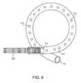
- FIG. 9is a side view of an end portion of another stent.
- FIG. 10is a side view of a stent deployment system.
- FIG. 11is a detail view of detail A of the stent deployment system of FIG. 10 .
- FIG. 12is a detail view of detail A of the stent deployment system of FIG. 10 .
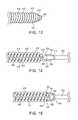
- FIG. 13is a side view of a proximal end portion of a stent.
- FIG. 14is a sectional view of the stent of FIG. 13 with a grasper approaching the proximal end portion of the stent.
- FIG. 15is the view of FIG. 14 with the grasper engaging the proximal end portion of the stent.
- FIG. 16is a perspective view of coaxial first and second sheaths for use in an indwelling stent exchange system.
- FIG. 17is the system of FIG. 16 , with the first sheath disposed partially over an indwelling stent and into the ureter.
- FIG. 18is the system of FIG. 16 with the first sheath threaded over the indwelling stent partially through the ureter.
- FIG. 19is the system of FIG. 16 with the first sheath threaded over the indwelling stent into the kidney.
- FIG. 20is the system of FIG. 16 with the indwelling stent removed from the first sheath and a second sheath threaded over the first sheath and into the kidney.
- FIG. 21is the system of FIG. 16 with a new stent threaded through the second sheath and positioned within the kidney and ureter.
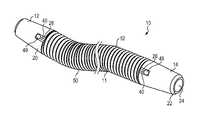
- the stent 10(as well as the other stent embodiments disclosed and depicted below) is configured to be inserted into a narrow and elongate lumen of a patient, in order to establish and maintain patency through the lumen of clinical interest.
- the stent 10may be especially applicable for a ureter, urethra, a bile duct, or other application.
- the stent 10may be applicable for vascular applications.
- the stent 10includes a central portion 11 that extends between opposite first and second end portions 12 , 14 .
- the central portion 11includes a lumen 11 a ( FIG. 5 ) disposed therethrough that allows for fluid communication therethrough, and through apertures 24 (aperture formed on the first end portion 12 is similar to aperture 14 depicted in FIG. 2 ) that are disposed through ends of the respective first and second end portions 12 , 14 .
- Fluid communication through with and through the lumen 11 ais also possible through gaps provided between neighboring portions 52 of a tightly coiled wire 50 that defines the central portion 11 , especially when the central portion 11 of the stent 10 is curved when placed within a patient's anatomy, such as through their ureter.
- the central portion 11 of the stent 10may be formed from a tightly coiled wire 50 , with a plurality of coils 52 forming the coiled wire 50 disposed to define the lumen 11 a extending therethrough as well as the structural outer flexible cylindrical surface of the stent 10 .
- the coiled wire 50may be formed such that neighboring coils 52 contact each other to provide for a lumen 11 a that can maintain a flow of fluid therethrough, and to minimize and preferably eliminate the space between neighboring coils 52 to prevent tissue ingrowth, while the coiled wire 50 is sufficiently flexible (due to the size of the wire, the geometry of the coils, among other factors) to allow the central portion 11 , and portions of the opposite first and second ends 12 , 14 of the stent 10 that are defined by the coiled wire 50 , to extend through a patient's urethra, and through a patient's ureter as the stent is inserted into the patient (by way of a delivery system) to be guided into place within the ureter.
- the coiled wire 50is configured to also be capable of forming pigtails 12 a , 14 a ( FIG. 1 ) on one or both of the first and second ends 12 , 14 of the stent 10 .
- one or two pigtails 12 a , 14 amay be provided on opposite ends of the stent 10 to provide a retention structure within the bladder for a proximal end of the stent 10 and an opposite retention structure within the kidney for the opposite distal end of the stent 10 .
- the stent 10may be provided with or without pigtails as clinically and geometrically appropriate to retain the stent 10 in position as necessary.
- One or both of the first and second ends 12 , 14 of the stent 10may include a cap 20 , which may be disposed adjacent to or in contact with an end of the coiled wire 50 .
- the cap 20may include an aperture 24 disposed upon the outer end thereof with a lumen 25 disposed therethrough that is in communication with the lumen 11 a through the central portion 11 of the stent 10 .
- the presence of the lumen that extends through the length of the stent 10 and through both end caps 20allows for the stent 10 to be delivered to the desired clinical location in an “over the wire” procedure, which is known to those of skill in the art.
- the cap 20may be fixed directly to the coiled wire 50 (with adhesive, one or more weld joints, a press fit connection, or the like) or alternatively the cap 20 not be directly fixed to the end of the coiled wire 50 .
- the cap 20may include a window 26 ( FIG. 4 ) that extends along a portion of the length of the cap 20 , and may provide for communication with the lumen 20 a of the cap 20 .
- the window 26 in the cap 20may provide a pocket for an end of the safety wire 40 to be disposed therein, which allows for a convenient fixation or connection between the safety wire 40 and the cap 20 .
- the cap 20may additionally include a proximal cuff that is next to the proximal end of the cap and receives an end of the coiled wire 50 therein.
- the cuffis provided to support the end of the coiled wire 50 within the cap 20 , to prevent the coiled wire 50 from unwinding and to prevent the end of the coiled wire 50 from extending radially outside of the diameter of the stent 10 .
- the cap 20may include a tapered profile as the cap 20 approaches its tip 22 , such as a conical profile that is formed like a geometric truncated cone or with another type of tapered profile.
- the design of a conical profile within the cap 20may assist with deployment and positioning of the stent 10 , such as the placement of a stent through a tortious path, or when the stent 10 is urged through a track that initially has a path with a smaller diameter than the diameter of the stent 10 .
- the gradual expansion of the anatomical lumen through when the stent 10 is placedis urged by the conical shape of the stent 10 .
- the top 22 of the cap 20may have a chamfered edge 23 or with another similar geometry to further provide a gradual transition for expanding the anatomical lumen through which the stent 10 is deployed.
- the cap 20includes a window 26 that extends for a portion of a length of the cap 20 , and provides an aperture for communication with the lumen 25 within the cap 20 from outside of the cap 20 .
- the window 26is configured to receive an end 42 of a safety wire 40 that extends through the lumen 11 a of the central portion 11 .
- the safety wire 40is provided to prevent the coiled wire 50 from significantly stretching due to a fixation between opposite ends 42 of the safety wire 40 with opposite end portions of the coiled wire 50 , either direct fixation, or indirect fixation between the two.
- the safety wire 40prevents the coiled wire 50 from stretching, which may be clinically important in various situations, such as in situations where the proximal end of the stent 10 is retracted for removal after the stent 10 has been indwelling within the patient for a significant length of time.
- the window 26may be disposed from a proximal edge 27 of the cap 20 and blindly extend along the cap 20 .
- the window 26may be simply an elongate aperture (such as a rectangular aperture) that extends through the cap 20 , while in other embodiments, the window 26 may further include a ledge 28 disposed at a distal end portion of the window 26 to support the end 42 of the safety wire 40 .
- the window 26 (and ledge 28 when provided)is configured to receive an end 42 of the safety wire 40 therein and allow convenient fixation between the safety wire 40 and the cap 20 .
- the tip 42 of the safety wire 40may be welded, crimped, or otherwise affixed directly to the cap 20 . This direct connection between the safety wire 40 and the cap 20 additionally causes the safety wire 40 to be fixably mounted with respect to the coiled wire 50 in view of the fixation between the respective end of the coiled wire 50 and the cap 20 .
- the stent 200may include a central portion 250 and one or two end portions 212 that extend from the central portion 250 .
- the central portion 250may be formed from a metallic cannula, such as one formed from a superelastic material, such as nitinol, or formed from other materials, such as stainless steel, or a cobalt chromium alloy.
- the central portionmight be formed from a single cannula and laser cut, chemically etched, or formed with another process known in the art, such that portions of the material are removed to develop a portions with material remaining, and portions with material removed.
- the central portion 250may be processed or formed to include a plurality of spaced apart rings 252 that are disposed in parallel but spaced apart from each other between voids 253 .
- the neighboring rings 252may be connected with preferably one, but potentially more than one, bars 254 to maintain the horizontal alignment between neighboring rings 252 .
- consecutive bars 254may be aligned at different positions along the outer circumference of the central portion 250 .
- consecutive bars 254may be aligned at rotational intervals along the length of the central portion 250 , such that a line 256 (broken line, FIG.
- the helical arrangement of bars 254 along the length of the central portion 250provides for increased flexibility of the central portion 250 than other embodiments, such as embodiments where the neighboring bars 254 are disposed along the same circumferential position along the length of the central portion 250 , or embodiments where two or more bars connect neighboring rings 252 .
- the bars 254are significantly more narrow than the width of the rings 252 that are separated by the bars, such as one half, one tenth, or one twentieth of the width of the rings 252 .
- the bars 252may be about the same as the width of the rings 252 .
- the stentmay be designed to minimize the space between neighboring rings (for such purposes as minimizing tissue ingrowth or maintain a lumen through the stent, among others).
- the end portions 212are fixed to the central portion 250 .
- the end portions 212may be made from a single coiled wire, such as a stainless steel, cobalt chromium (CoCr) wire, with a tight coil to provide substantially the same outer diameter as the central portion 250 .
- the end portions 212 and the central portion 250may be manufactured to be about 3 Fr (1 mm), while in other embodiments the central and end portions 250 , 212 may be about 6 Fr (2 mm) or other dimensions therebetween, or larger depending upon the desired clinical use. It is known that a 6 Fr diameter is clinically appropriate for many ureteral stent applications, while embodiments with smaller embodiments, such as 3 Fr, may be clinically appropriate (i.e. to provide the necessary lumen for sufficient urine flow therethrough) to provide patency through severely blocked ureteral passageways, which may not be clinically appropriate for a 6 Fr stent.
- the end portions 212are formed from a coiled wire, which is tightly wound to the outer diameter of the central portion 250 of the stent.
- the end portions 212may be trained to retain a pigtail shape ( FIG. 6 ) to provide one or both of the proximal and distal ends of the stent with retention structures, such as to aid in retaining the distal end of the stent within the kidney and the proximal end the stent within the bladder.
- the end portions 212are formed without a safety wire therethrough (and connected to the outer tip 212 b ), because stretching is not a concern in the pigtail or otherwise arcuate end portions 212 .
- one or both end portions 212may be formed with an internal safety wire which extends through the lumen of 212 a of the end portion, with opposite ends of the safety wire fixed proximal to the outer tip 212 b of the end portion 212 and the inner tip 212 c of the end portion 212 .
- the safety wiremay be formed from the same material or a different material than the coiled wire forming the end portion 212 , and may be substantially thin to not block a significant percentage of the lumen 212 a therewithin.
- the safety wiremay be trained to maintain the pigtail or other retention configuration along with remainder of the end portion 212 , such as bending the end portion 212 into the desired orientation, and/or using conventional nitinol “shape training” techniques as known in the art.
- the end portions 212may be formed from a laser cut cannula, similar to the construction of the central portion 250 .
- the one or two end portions 212are fixed directly to the central portion 250 , such as by various joining methods, such as soldering or welding (laser welding or other conventional techniques) the inner tip 212 c to an end of the central portion 250 , or otherwise fixing them together.
- the two componentsmay be fixed together with a shrink fit sleeve 260 , as shown in FIG. 6 , which may be in addition or instead of the welding between the two.
- alternate end portions 312may be provided upon one or both ends of the central portion 250 .
- the end portions 312may comprise plastic pigtail sections, such as sections found in conventional plastic ureteral stents. Each end portion 312 may be thermally bonded to the respective end of the central portion 250 .
- the end portions 312may include a closed end, or as shown in FIG. 9 , an open end 315 allowing fluid communication within the lumen 314 through the end.
- the end portions 312may additionally include a plurality of apertures 313 that allow fluid communication into the lumen 314 .
- the stent 350may be like one or more of the stents described above, or may be another type of elongate flexible stent known in the art.
- the stent 350may be formed from a tightly coiled wire, such as a nitinol, stainless steel, cobalt chrome alloy or other types of wire, and extend from a distal end portion 351 to a proximal end portion 352 with a lumen disposed therethrough.
- the stent 350may be formed with a coiled wire that is sufficient flexible to traverse the tight curves of a patient's urethra and ureter to be implanted into a desired position within the anatomy, such as through a patient's ureter.
- the stent 350is configured such that neighboring coils contact each other at one or more locations along each neighboring coil, but provide small spaces between neighboring coils, especially when the stent 350 is along a curved anatomy, to allow fluid from outside of the stent 350 to pass into the lumen of the stent 350 and flow therethrough.
- the stent 350may have an outer diameter of about 3 Fr (1 mm) and be configured to be retained within a ureter, and in some embodiments with one or both of the distal and proximal end portions 351 , 352 biased toward an arcuate, or “pigtail” orientation to be retained within the kidney (distal end portion 351 ) and the bladder (proximal end portion 352 ) to retain the stent 350 within the ureter.
- the stent 350is about 3 Fr (1 mm) the stent 350 is configured to achieve patency through the ureter, especially in situations where ureter is blocked such that patency is difficult therethrough with conventional ureteral stents, such as 6 Fr (2 mm) stents.
- the sheath 310is a flexible elongate member that extends between distal and proximal ends 310 a , 310 b with a lumen therethrough.
- the lumenis configured to receive the stent 350 slidably therein, as best shown in FIGS. 10 and 11 .
- the sheath 310additionally slidably receives the distal portion of a pusher 370 which is disposed proximal to the proximal end portion 352 of the stent 350 , such that distal movement of the pusher 370 (as urged by the medical professional) causes similar distal motion of the stent 350 .
- the sheath 310further comprises a block 312 disposed proximate to the distal end portion 310 of the sheath 310 .
- the distal block 312forms the distal end of the lumen and may include a ramp surface 314 disposed within the lumen and facing proximally within the lumen.
- the ramp surface 314is configured to receive the stent 350 as the stent 350 is urged distally within the sheath 310 , and urges the stent 350 from movement through the lumen through an aperture 316 defined upon a sidewall of the sheath 310 .
- the aperture 316is defined upon the sheath 310 such that the stent 350 extends through the aperture 316 , and therefore out of the sheath 310 , as the stent 350 slides along the ramp surface 314 .
- the sheath 310may include a flexible member 330 , such as a filiform tip that is connected to the distal end portion 310 a thereof, which is provided to direct the sheath 310 toward the selected clinical area for stent deployment, such as through the ureter U.
- the sheath 310may be advanced through the urethra, the bladder, and into the ureter using known positioning techniques.
- the filiform 330aides in directing the sheath 310 toward the kidney, and or two a blockage or stricture B within the ureter U.
- the stent 350is urged from the sheath 310 by pushing the pusher 370 distally.
- the pusher 370As the pusher 370 is pushed distally, the distal end of the pusher 370 engages the proximal end 352 of the stent 350 , which pushes the stent 350 distally within the lumen of the sheath 310 .
- the stent 350engages the ramp surface 314 within the sheath 310 which urges the stent 350 out of the sheath 310 through the aperture 316 defined upon the side wall of the sheath 310 .
- the stent 350With continued distal motion, the stent 350 translates along the outer surface of the sheath 310 and filiform until the stent 350 is properly positioned within the ureter U, such as through the stricture B, or into the kidney (where the distal end portion 350 of the stent 350 may be biased toward an arcuate or pigtail configuration to retain the stent 350 properly positioned within the ureter U) to allow for patency through the blockage/stricture B through the lumen of the stent 350 .
- the sheath 310is retracted proximally with respect to the stent 350 and removed from the ureter U and ultimately the patient, with the stent 350 remaining in position.
- the proximal end portion 352 of the stent 350may extend into the bladder and may form an arcuate portion or a pigtail to further retain the stent 350 properly positioned within the ureter U.
- the stent 410may extend between a proximal end portion 412 and a distal end portion (not shown, but similar to the proximal end portion 412 ).
- the stent 410may be formed from a coiled wire to define a plurality of neighboring coils 414 that are tightly wound to provide patency to an anatomical lumen through which the stent 410 extends (such as a ureter, bile duct, or other similar lumen) as well as provide a flow path for fluid, such as urine therethrough, such as from the kidney to the bladder.
- the stent 410may be formed with a safety wire 450 that extends through the lumen 416 of the stent 410 and may be fixed to (or with respect to) the distal and proximal end portions 412 of the stent 410 .
- the safety wire 450is normally not stretchable, and therefore prevents the coiled wire forming the stent from uncoiling during deployment, indwelling use, or particularly upon removal, when the proximal end portion 412 of the stent 410 is pulled proximally.
- one or both of the distal and proximal end portions 412 of the stent 410includes a weld bead 430 , which fixes an end of the safety wire 450 with respect to the respective end portion of the stent 410 .
- the weld bead 430may be approximately the same diameter as the body of the stent 410 , such as 3 Fr (1 mm), 6 Fr (2 mm) or other diameters that are configured for various desired clinical uses.
- the final coil(such as the proximal-most coil 418 , or the distal-most coil, like the proximal-most coil 418 depicted in the figures) is formed with an outer diameter less than the reminder of the coils 414 that define the body of the stent 410 .
- the proximal-most coil 418 and/or the distal-most coilmay be formed at about 3 Fr, and preferably with a diameter smaller than the diameter of the weld bead 430 that fixes the end of the safety wire 450 to the end of the body of the stent 410 .
- a grasper 510 with a pair (or set) of arms 520 , 521may be provided that is configured to engage the final coil 418 and weld bead 430 to allow for withdrawing a deployed stent 410 proximally.
- Each of the pair (set) of arms 520 , 521may include a respective tooth 522 , 523 that is configured to engage the final coil 418 , with the arms 520 , 521 sized and configured to engage the outer surface of the weld bead 430 .
- the grasper 510may be connected to a control portion 500 , such as a sheath or a control wire, which is manipulable by a user remotely from the proximal end portion 412 of the stent 410 .
- the pair (set) of arms 520 , 521 of the grasper 510are configured to be sufficiently resilient to bend around the weld bead 430 and engage the final coil 418 as the grasper 510 is urged toward and over the weld bead 430 .
- the teeth 522 , 523are configured to engage one or both of the final coil 418 and the weld bead 430 to pull the stent 410 proximally with the grasper 510 as the grasper 510 is pulled proximally (as urged by the control portion 500 ).
- the size of the final coil 418 and the weld bead 430are configured, in combination with the arms 520 , 521 , to engage the proximal end 412 of the stent 410 with a total outer diameter that is substantially the same, or slightly smaller than the outer diameter of the body of the stent 410 .
- This designwill be appreciated to be especially configured to allow for grasping of a proximal end portion 412 of a stent 410 deployed tightly within a lumen, such as a ureter, especially in situations where the proximal end portion 412 of the stent 410 is disposed within the lumen.
- the stent 410is configured to be surrounded by a sheath (not shown) that is disposed over the stent through the entire length of the ureter and into the kidney (or potentially over a portion of the ureter, as clinically appropriate) with the stent 410 remaining within the ureter.
- the proximal end portion 412is sized such that the grasper 500 engages the proximal end 412 of the stent 410 , as discussed above, with the stent 410 disposed within the sheath.
- the graspermay be withdrawn proximally, which simultaneously moves the stent 410 proximally, while the sheath is maintained within the ureter, and in some embodiments, with a portion of the sheath extending through the bladder, urethra, and out of the patient.
- a new stent 410(or other stent design, configured for maintaining ureteral patency and/or drainage described elsewhere herein, or otherwise known in the art) may be threaded through the sheath and into position within the ureter (and kidney as appropriate) for convenient stent exchange.
- smaller end coil 418(or a plurality of smaller end coils 418 ), preferably in combination with a weld bead that 430 that is also smaller than the outer diameter of the body of the stent 410 allows for a grasper no larger than the diameter of the stent 410 to engage an pull proximally a deployed stent 410 for stent exchange through the sheath.
- the stent exchange system 600may include first and second sheaths 610 , 620 which are configured for coaxial deployment, or may include only a first sheath 610 .
- the first sheath 610is an elongate, flexible sheath that extends from a distal end portion 611 to a proximal end portion (not shown), with a central portion 613 therebetween.
- the first sheath 610may be sized to extend from within a patient's bladder, through the length of a typical patient's ureter, and into a patient's kidney.
- the sizes and profiles of the first and second sheaths 610 , 620may be varied, in such a manner that will be easily appreciated by one of ordinary skill in the art would be appropriate after a thorough review and understanding of the subject specification and figures.
- the first sheath 610may include a substantially C-shaped profile along its length, and specifically along a central portion 613 thereof, such that material forming the side wall of the first sheath 610 extends along a significant portion (and greater than 180 degrees) of the arc length of a circle, and defines a cavity 618 therewithin, but defines a side opening 619 that extends along the length of the first sheath 610 and allows access into the cavity 618 through the side opening 619 .
- the side opening 619 along the central portion 613may be formed with an arc length (defining the arc length where the side wall of the first sheath 610 does not exist) of between about 45 degrees to about 150 degrees, and inclusive of all potential arc lengths therein.
- the side opening 619 along the central portion 613may be very thin, such as between about 10 degrees to about 30 degrees arc length (inclusive of all potential arc lengths therein).
- the arc length of the opening 619is consistent along the central portion 613 of the first sheath 610 , while in other embodiments, the arc length of the central portion 613 may vary along the length of the first sheath 610 .
- the first sheath 610may include a scooped portion 614 , or a bevel at the distal end thereof, which provides for a gradual increase in the arc length of the wall forming the first sheath 610 from the distal tip 614 a (which has a relatively small arc length, such as about 30 to about 50 degrees) to the arc length of the side opening 619 about the central portion 613 .
- the increase in arc length of the side wall (and therefore a related decrease in arc length of the side opening 619 ) along the scooped portion 614may be linear (as shown in FIG.
- the increase in arc length of the side wall of the first sheath 610 along the scooped portion 614is at a non-constant rate (either an increasing rate as the arc length of the side wall along the scooped portion 614 increases, or a decreasing rate as the arc length of the side wall increases) to give the edges of the scooped portion 614 a non-planar profile.
- the proximal end of the first sheath 610may be formed with a scooped portion 614 that is like that depicted in FIG. 16 (or with the variations to the scooped portion 614 described above), or may be formed with a material edge (at the proximal end) that is perpendicular to the longitudinal axis of the first sheath 610 .
- a scooped portion on the proximal end portion of the first sheath 610may be desired for ease of threading the second sheath 620 over the proximal end portion of the first sheath 610 and ultimately along the entire length of the first sheath 610 and into the kidney (or in embodiments were only the first sheath 610 is used, for threading a replacement stent 700 through the scooped portion on the proximal end portion and into the cavity 618 for placement as clinically necessary.
- the first sheath 610may be formed from a relatively flexible material that allows for expansion of the side opening 619 as needed for interacting with a previously placed stent 700 , while maintaining sufficient column or tube strength to maintain the ureter (or other clinical lumen for desired interaction by a stent) patent after the indwelling stent 700 is removed (discussed below).
- Suitable materials for the first sheath 610may be FEP, PTFE, or other materials that are known to be significantly low in friction in a clinical setting. Further, sheaths with hydrophilic coatings may be used.
- a distal end portion 614 of the first sheathmay be echogenic or metal, and/or potentially with one or more coatings known in the art that allow for remote observation of the distal tip 614 of the first sheath 610 when deployed within the patient, such as via ultrasound, fluoroscopy, or other remote clinical observation tools.
- a distal end portion of the second sheath 620discussed below, may also be formed from, coated with, or processed such that it may be visible through ultrasound, fluoroscopy, or other clinical remote observation tools when deployed within the patient.
- the second sheath 620is an elongate sheath that extends between a distal end portion 620 and a proximal end portion (not shown) with a lumen therethrough.
- the second sheath 620may be formed with an inner diameter just larger than a diameter of the first sheath 610 (measured across the first sheath 610 between two portions of the side wall that form the first sheath 610 (and not measured with respect to the side opening 619 of the first sheath 610 ).
- the second sheath 620is configured to be slid over the first sheath 610 , normally after the previously indwelling stent has been removed, such that the first sheath 610 (and in some embodiments an indwelling stent 700 ) is disposed within the lumen of the second sheath 620 .
- the second sheath 620may be sized such that a proximal end portion extends outside the patient (e.g. through the urethral meatus) when the distal end portion 621 extends into the kidney K.
- the second sheath 620may be formed from a clear material, such that the first sheath 610 or the stent 700 disposed therethrough may be observed through the side wall of the second sheath 620 .
- the first and second sheaths 610 , 620may be used in tandem (or in some embodiments, only the first sheath 610 may be used) to allow for replacement of an indwelling ureteral stent 700 (or alternatively another type of indwelling stent within a different portion of a patient's anatomy, such as an indwelling stent that is formed without apertures on opposite sides of a stent and a lumen therethrough, such as one or the stents described in this specification and depicted in these drawings, or stents described in U.S. Pat. No.
- the first sheath 610is guided toward the stent 700 , such that the scooped portion 614 engages the stent 700 causing the stent 700 to be aligned with respect to the cavity 618 within the first sheath 610 , and through the side opening 619 (which is relatively large at the scooped portion 614 ), as shown in FIG. 17 , with the scooped portion 614 just entering the proximal end of the ureter.
- the stent 700is urged into the cavity 618 , and specifically portions of the cavity 618 defined along the central portion 613 of the first sheath 610 , as best shown in FIGS. 17 and 18 .
- FIGS. 17 and 18As can be appreciated with reference to FIGS.
- the formation of the first sheath 610 with the side opening 619allows the first sheath 610 to be extended over the stent 700 with a point of initial contact just proximate to the ureter U, and without requiring the straightening of an arcuate portion or pigtail portion 714 of the stent 700 within the bladder B, which minimizes the chance of moving the stent 700 proximally and out of the kidney K until the first sheath 610 is fully threaded over the stent 700 and also extends into the kidney K, as shown in FIG. 19 .
- the first sheath 610may be threaded along the stent 700 (through the ureter U) with the stent 700 maintained in a stationary orientation until the first sheath 610 extends into the kidney K. Once the first sheath 610 enters the kidney K, the stent 700 may be withdrawn proximally (with the first sheath 610 maintained stationary) to remove the stent 700 from the kidney, ureter, and ultimately the patient.
- the second sheath 620may be pushed into the bladder B and threaded over the first sheath 610 , which may be aided by a scooped portion formed at the proximal end portion of the first sheath 610 (similar to scooped portion 614 upon the distal end portion depicted and described herein).
- the second sheath 620may be threaded over the first sheath 610 until the second sheath 620 enters the kidney K.
- the first sheath 610is pulled proximally as, may be observed through a scope threaded through the second sheath 620 and removed from the kidney K, ureter U, bladder B and ultimately from the patient.
- a new stent 700(which may be like the stent 700 removed during the procedure, or may be another type of stent configured for indwelling within the ureter U (or other desired clinical location within the patient) may be threaded through the lumen of the second sheath 620 , potentially with a pusher (not shown) that engages the proximal tip of the new stent 700 ) and into position within the ureter U, and extending into the kidney K and bladder B as desired, as shown in FIG. 21 .
- the second stent 620may be withdrawn.
- the new stent 700may be threaded directly through the cavity 618 of the first sheath 610 , which may enter the cavity 618 (of the portion of the first sheath 610 that extends into the bladder B) through a scooped portion on the proximal end portion (like scooped portion 614 ), when provided and/or may enter the cavity through the side opening 619 , by locally stretching the side opening 619 .
- the stent 700may then be threaded into position through the ureter U and into the kidney K, as urged by a pusher (not shown) that also extends enters the cavity proximally of the stent 700 (either through the scooped portion or the side opening 619 of the first sheath 610 ). After the stent 700 is properly positioned, the first sheath 610 is pulled proximally (with the stent 700 maintained in position) and the first sheath is removed from the patient.
Landscapes
- Health & Medical Sciences (AREA)
- Engineering & Computer Science (AREA)
- Biomedical Technology (AREA)
- Animal Behavior & Ethology (AREA)
- Veterinary Medicine (AREA)
- Public Health (AREA)
- Heart & Thoracic Surgery (AREA)
- General Health & Medical Sciences (AREA)
- Life Sciences & Earth Sciences (AREA)
- Transplantation (AREA)
- Vascular Medicine (AREA)
- Oral & Maxillofacial Surgery (AREA)
- Cardiology (AREA)
- Urology & Nephrology (AREA)
- Ophthalmology & Optometry (AREA)
- Otolaryngology (AREA)
- Anesthesiology (AREA)
- Hematology (AREA)
- Prostheses (AREA)
- Media Introduction/Drainage Providing Device (AREA)
Abstract
Description
Claims (16)
Priority Applications (1)
| Application Number | Priority Date | Filing Date | Title |
|---|---|---|---|
| US14/106,157US9498356B2 (en) | 2012-12-19 | 2013-12-13 | Flexible stent and delivery system |
Applications Claiming Priority (2)
| Application Number | Priority Date | Filing Date | Title |
|---|---|---|---|
| US201261739356P | 2012-12-19 | 2012-12-19 | |
| US14/106,157US9498356B2 (en) | 2012-12-19 | 2013-12-13 | Flexible stent and delivery system |
Publications (2)
| Publication Number | Publication Date |
|---|---|
| US20140172065A1 US20140172065A1 (en) | 2014-06-19 |
| US9498356B2true US9498356B2 (en) | 2016-11-22 |
Family
ID=49841511
Family Applications (1)
| Application Number | Title | Priority Date | Filing Date |
|---|---|---|---|
| US14/106,157ActiveUS9498356B2 (en) | 2012-12-19 | 2013-12-13 | Flexible stent and delivery system |
Country Status (2)
| Country | Link |
|---|---|
| US (1) | US9498356B2 (en) |
| EP (1) | EP2745804B1 (en) |
Families Citing this family (11)
| Publication number | Priority date | Publication date | Assignee | Title |
|---|---|---|---|---|
| US9387312B2 (en) | 2008-09-15 | 2016-07-12 | Brightwater Medical, Inc. | Convertible nephroureteral catheter |
| US9956100B2 (en)* | 2009-09-15 | 2018-05-01 | Brightwater Medical, Inc. | Systems and methods for coupling and decoupling a catheter |
| WO2014058043A1 (en)* | 2012-10-12 | 2014-04-17 | 日本発條株式会社 | Member for implanting in living organism, stent, embolization member, blood vessel expansion kit, and aneurysm embolization kit |
| US20180126129A1 (en)* | 2014-07-21 | 2018-05-10 | Stentorium Ltd | Implantable Stent |
| EP3936088A1 (en) | 2014-08-12 | 2022-01-12 | Merit Medical Systems, Inc. | Systems and methods for coupling and decoupling a catheter |
| US9763814B2 (en)* | 2014-10-24 | 2017-09-19 | Cook Medical Technologies Llc | Elongate medical device |
| AU2017371223B2 (en) | 2016-12-09 | 2023-04-27 | Zenflow, Inc. | Systems, devices, and methods for the accurate deployment of an implant in the prostatic urethra |
| AU2020337330B2 (en)* | 2019-08-23 | 2023-02-02 | Boston Scientific Scimed, Inc. | Devices, systems, and methods for delivering a stent |
| US11890213B2 (en) | 2019-11-19 | 2024-02-06 | Zenflow, Inc. | Systems, devices, and methods for the accurate deployment and imaging of an implant in the prostatic urethra |
| US12226327B2 (en) | 2020-04-15 | 2025-02-18 | Merit Medical Systems, Inc. | Systems and methods for coupling and decoupling a catheter |
| US20240197510A1 (en)* | 2021-04-26 | 2024-06-20 | Mdha Investment Pty Ltd | Techniques and instrumentation for the removal of retained ureteral stents |
Citations (116)
| Publication number | Priority date | Publication date | Assignee | Title |
|---|---|---|---|---|
| US2264988A (en) | 1940-07-31 | 1941-12-02 | Westinghouse Electric & Mfg Co | Mounting of bimetallic elements |
| US3514791A (en) | 1967-07-25 | 1970-06-02 | Charles H Sparks | Tissue grafts |
| US4003369A (en) | 1975-04-22 | 1977-01-18 | Medrad, Inc. | Angiographic guidewire with safety core wire |
| US4295464A (en) | 1980-03-21 | 1981-10-20 | Shihata Alfred A | Ureteric stone extractor with two ballooned catheters |
| US4299226A (en) | 1979-08-08 | 1981-11-10 | Banka Vidya S | Coronary dilation method |
| GB2127294A (en) | 1982-09-22 | 1984-04-11 | Bard Inc C R | Steerable guide wire for balloon dilatation catheter |
| DE3314755A1 (en) | 1983-04-23 | 1984-11-08 | Medizin-Technische Werkstätte Arzt- und Krankenhausbedarf Wolfgang Haag, 4230 Wesel | Endoprosthesis to be implanted with a duodenoscope, especially as transpapillary bile duct drain, in the form of a drainage tube provided with drainage holes in the wall |
| EP0054357B1 (en) | 1980-11-17 | 1985-10-02 | Advanced Cardiovascular Systems, Inc. | Inflating and deflating device |
| US4581019A (en) | 1981-04-23 | 1986-04-08 | Curelaru Johan | Device for introducing a catheter-cannula into a blood vessel |
| FR2512678B1 (en) | 1981-09-16 | 1986-08-22 | Medinvent Sa | DEVICE IMPLANTABLE IN BLOOD VESSELS OR OTHER DIFFICULT ACCESS LOCATIONS AND METHOD OF USE |
| EP0213748A1 (en) | 1985-07-30 | 1987-03-11 | Advanced Cardiovascular Systems, Inc. | Dual dilatation catheter assembly and miniature balloon dilatation catheter for use therewith |
| US4666442A (en) | 1984-03-03 | 1987-05-19 | Sorin Biomedica S.P.A. | Cardiac valve prosthesis with valve flaps of biological tissue |
| US4693242A (en) | 1982-04-02 | 1987-09-15 | Fenzy S.A. | Coupling connectors for respirator masks |
| US4713049A (en) | 1986-08-05 | 1987-12-15 | Medical Engineering Corporation | Ureteral stent kit |
| US4738666A (en) | 1985-06-11 | 1988-04-19 | Genus Catheter Technologies, Inc. | Variable diameter catheter |
| EP0266091A2 (en) | 1986-10-20 | 1988-05-04 | City Of Hope National Medical Center | Anchoring mechanism for an adjustable length percutaneous drainage catheter |
| US4787884A (en) | 1987-09-01 | 1988-11-29 | Medical Engineering Corporation | Ureteral stent guidewire system |
| US4813925A (en) | 1987-04-21 | 1989-03-21 | Medical Engineering Corporation | Spiral ureteral stent |
| US4820262A (en) | 1985-12-12 | 1989-04-11 | Medical Engineering Corporation | Ureteral stent |
| US4913683A (en) | 1988-07-05 | 1990-04-03 | Medical Engineering Corporation | Infusion stent system |
| EP0365269A1 (en) | 1988-10-17 | 1990-04-25 | VANCE PRODUCTS INCORPORATED d/b/a COOK UROLOGICAL INCORPORATED | Indwelling ureteral stent placement apparatus |
| US4930496A (en) | 1988-07-22 | 1990-06-05 | Vance Products, Inc. | Method and device for removing a stone from a ureter using extracorporeal shock wave lithotripsy |
| US4931037A (en) | 1988-10-13 | 1990-06-05 | International Medical, Inc. | In-dwelling ureteral stent and injection stent assembly, and method of using same |
| WO1990014804A1 (en) | 1989-05-31 | 1990-12-13 | Baxter International Inc. | Biological valvular prosthesis |
| US4994033A (en) | 1989-05-25 | 1991-02-19 | Schneider (Usa) Inc. | Intravascular drug delivery dilatation catheter |
| EP0418381A1 (en) | 1987-09-21 | 1991-03-27 | Terumo Kabushiki Kaisha | Ureter redressing device |
| US5044369A (en) | 1989-01-23 | 1991-09-03 | Harvinder Sahota | Bent topless catheters |
| US5160341A (en) | 1990-11-08 | 1992-11-03 | Advanced Surgical Intervention, Inc. | Resorbable urethral stent and apparatus for its insertion |
| US5234456A (en) | 1990-02-08 | 1993-08-10 | Pfizer Hospital Products Group, Inc. | Hydrophilic stent |
| US5254104A (en) | 1991-10-22 | 1993-10-19 | Center For Urological Treatment & Research | Device for pericatheter retrograde |
| WO1993025265A1 (en) | 1992-06-12 | 1993-12-23 | Mallinckrodt Medical, Inc. | Dual dilatation balloon and infusion balloon catheter |
| US5323768A (en) | 1991-04-22 | 1994-06-28 | Olympus Optical Co., Ltd. | Diathermic dissector with a bifurcation having substantially the same cross-sectional area as a lumen for guiding a wire |
| US5334185A (en) | 1991-06-28 | 1994-08-02 | Giesy Consultants, Inc. | End-to-end instrument placement apparatus |
| US5359991A (en) | 1991-04-24 | 1994-11-01 | Asahi Kogaku Kogyo Kabushiki Kaisha | Cover device for endoscope |
| US5405334A (en) | 1994-02-18 | 1995-04-11 | Merit Medical Systems, Inc. | Catheter apparatus with means for subcutaneous delivery of anesthetic agent or other fluid medicament |
| US5441516A (en) | 1994-03-03 | 1995-08-15 | Scimed Lifesystems Inc. | Temporary stent |
| EP0672394A1 (en) | 1994-02-25 | 1995-09-20 | Izquierdo de la Torre, Fernando | Long duration ureteral prosthesis |
| US5558643A (en) | 1985-07-30 | 1996-09-24 | Advanced Cardiovascular Systems, Inc. | Catheter with NiTi tubular shaft |
| US5582619A (en) | 1995-06-30 | 1996-12-10 | Target Therapeutics, Inc. | Stretch resistant vaso-occlusive coils |
| US5601591A (en) | 1994-09-23 | 1997-02-11 | Vidamed, Inc. | Stent for use in prostatic urethra, apparatus and placement device for same and method |
| US5643254A (en) | 1994-03-03 | 1997-07-01 | Target Therapeutics, Inc. | Endovascular embolic device detachment detection method |
| WO1997024081A1 (en) | 1995-12-29 | 1997-07-10 | Ramus Medical Technologies | Method and apparatus for forming vascular prostheses |
| US5681274A (en) | 1995-03-31 | 1997-10-28 | Boston Scientific Corporation | Variable length uretheral stent |
| EP0806189A1 (en) | 1996-05-10 | 1997-11-12 | Variomed AG | Device for draining with drainage tube |
| WO1997036536A9 (en) | 1997-04-02 | 1997-12-31 | Optical female urethroscope | |
| US5766192A (en) | 1995-10-20 | 1998-06-16 | Zacca; Nadim M. | Atherectomy, angioplasty and stent method and apparatus |
| CA2264988A1 (en) | 1998-03-10 | 1999-09-10 | Cordis Corporation | Embolic coil deployment system with improved embolic coil |
| US5964744A (en) | 1993-01-04 | 1999-10-12 | Menlo Care, Inc. | Polymeric medical device systems having shape memory |
| US6033413A (en) | 1998-04-20 | 2000-03-07 | Endocare, Inc. | Stent delivery system |
| US6096034A (en) | 1996-07-26 | 2000-08-01 | Target Therapeutics, Inc. | Aneurysm closure device assembly |
| US6120522A (en) | 1998-08-27 | 2000-09-19 | Scimed Life Systems, Inc. | Self-expanding stent delivery catheter |
| WO2000066032A1 (en) | 1999-04-30 | 2000-11-09 | Applied Medical Resources Corporation | Improved ureteral stent system apparatus and method |
| US6162231A (en) | 1998-09-14 | 2000-12-19 | Endocare, Inc. | Stent insertion device |
| US6254592B1 (en)* | 1995-06-06 | 2001-07-03 | Target Therapeutics, Inc. | Variable stiffness coils |
| US6264611B1 (en) | 1998-11-25 | 2001-07-24 | Ball Semiconductor, Inc. | Monitor for interventional procedures |
| US6280457B1 (en)* | 1999-06-04 | 2001-08-28 | Scimed Life Systems, Inc. | Polymer covered vaso-occlusive devices and methods of producing such devices |
| US20010018574A1 (en) | 1997-08-14 | 2001-08-30 | Scimed Life Systems, Inc. | Drainage catheter delivery system |
| WO2001091668A1 (en) | 2000-05-26 | 2001-12-06 | Scimed Life Systems, Inc. | Ureteral stent |
| US6332892B1 (en) | 1999-03-02 | 2001-12-25 | Scimed Life Systems, Inc. | Medical device with one or more helical coils |
| US6371979B1 (en) | 1993-01-27 | 2002-04-16 | Intratherapeutics, Inc. | Stent delivery system |
| US6383146B1 (en) | 1999-03-29 | 2002-05-07 | Cook Incorporated | Guidewire |
| US6458119B1 (en) | 1992-11-18 | 2002-10-01 | Target Therapeutics, Inc. | Ultrasoft embolism devices and process for using them |
| US20020183852A1 (en) | 2001-06-01 | 2002-12-05 | Mcweeney John O. | Compressible ureteral stent for comfort |
| US20030018306A1 (en) | 2001-07-23 | 2003-01-23 | Weenna Bucay-Couto | Long-term indwelling medical devices containing slow-releasing antimicrobial agents and having a surfactant surface |
| US6517569B2 (en) | 1998-09-14 | 2003-02-11 | Endocare, Inc. | Insertion device for stents and methods for use |
| US6589262B1 (en) | 2000-03-31 | 2003-07-08 | Medamicus, Inc. | Locking catheter introducing system |
| WO2003079930A1 (en) | 2002-03-18 | 2003-10-02 | Scimed Life Systems, Inc. | Expandable ureteral stent |
| US6652536B2 (en)* | 2000-09-29 | 2003-11-25 | Primus Medical, Inc. | Snare with anti-skewing |
| US6654536B2 (en) | 2001-04-12 | 2003-11-25 | Corning Cable Systems Llc | Fiber management frame having connector platform |
| US6702846B2 (en) | 1996-04-09 | 2004-03-09 | Endocare, Inc. | Urological stent therapy system and method |
| US20040078088A1 (en) | 2002-10-22 | 2004-04-22 | Scimed Life Systems | Male urethral stent device |
| US20040087886A1 (en) | 2002-10-30 | 2004-05-06 | Scimed Life Systems, Inc. | Linearly expandable ureteral stent |
| US20040093075A1 (en) | 2000-12-15 | 2004-05-13 | Titus Kuehne | Stent with valve and method of use thereof |
| US6736839B2 (en) | 2001-02-01 | 2004-05-18 | Charles Cummings | Medical device delivery system |
| US6746489B2 (en) | 1998-08-31 | 2004-06-08 | Wilson-Cook Medical Incorporated | Prosthesis having a sleeve valve |
| US20040127918A1 (en) | 1995-06-07 | 2004-07-01 | Conceptus, Inc. | Contraceptive transcervical fallopian tube occlusion devices and methods |
| US6770101B2 (en) | 2001-10-09 | 2004-08-03 | Scimed Life Systems, Inc. | Prostatic stent and delivery system |
| JP2004248886A (en) | 2003-02-20 | 2004-09-09 | Kaneka Medix Corp | Stent |
| US20040181186A1 (en) | 2003-03-13 | 2004-09-16 | Scimed Life Systems, Inc. | Medical device |
| US20040193141A1 (en)* | 2003-02-14 | 2004-09-30 | Leopold Eric W. | Intravascular flow modifier and reinforcement device and deployment system for same |
| US20040267213A1 (en) | 2003-04-08 | 2004-12-30 | Knapp Tracey E | Ureteral access sheath |
| US20050033403A1 (en) | 2003-08-01 | 2005-02-10 | Vance Products, Inc. D/B/A Cook Urological Incorporated | Implant delivery device |
| DE202005001416U1 (en) | 2005-01-28 | 2005-03-31 | Urovision Ges Fuer Medizinisch | stent |
| US20050075538A1 (en) | 2003-04-01 | 2005-04-07 | Banik Michael S. | Single use endoscopic imaging system |
| US20050222581A1 (en) | 2004-03-30 | 2005-10-06 | Vance Products Incorporated, D/B/A | Multiple lumen access sheath |
| US20050234388A1 (en) | 2004-03-23 | 2005-10-20 | Ray Amos | Agent eluting stent and catheter |
| US20050240278A1 (en) | 2004-04-26 | 2005-10-27 | Peter Aliski | Stent improvements |
| US20060079926A1 (en) | 2004-10-07 | 2006-04-13 | Rupesh Desai | Vasoocclusive coil with biplex windings to improve mechanical properties |
| US20060095050A1 (en) | 2004-09-14 | 2006-05-04 | William A. Cook Australia Pty. Ltd. | Large diameter sheath |
| US7044981B2 (en) | 2003-01-22 | 2006-05-16 | Boston Scientific Scimed, Inc. | Ureteral stent configured for improved patient comfort and aftercare |
| US20060149359A1 (en) | 1993-03-11 | 2006-07-06 | Jacob Richter | Stent |
| US7108655B2 (en) | 2001-01-23 | 2006-09-19 | Abbeymoor Medical, Inc. | Endourethral device and method |
| US20070021840A1 (en) | 2005-07-20 | 2007-01-25 | Jorge Lopera | Temporal stricture expander |
| US20070050006A1 (en) | 2005-08-31 | 2007-03-01 | Cook Ireland Limited | Coaxial dilatation method for stent implantation |
| WO2007027830A1 (en) | 2005-08-31 | 2007-03-08 | Vance Products Incorporated | Coaxial dilatation method for stent implantation |
| US20070078446A1 (en) | 2005-08-31 | 2007-04-05 | Cook Ireland Limited And Cook Incorporated | Stent for implantation |
| US20070078511A1 (en) | 2005-09-30 | 2007-04-05 | Boston Scientific Scimed, Inc. | Hybrid bifurcated stent |
| US20070191767A1 (en) | 2005-12-16 | 2007-08-16 | Medtronic Vascular, Inc. | Bifurcated Catheter Joints |
| US20070276466A1 (en)* | 2005-08-31 | 2007-11-29 | Vance Products Inc., D/B/A/ Cook Urological Inc. | Stent for implantation |
| US20080086215A1 (en) | 2001-04-02 | 2008-04-10 | St Pierre Ernest J | Medical Stent and Related Methods |
| US20080133025A1 (en) | 2003-03-10 | 2008-06-05 | Daignault Kenneth J | Medical stent |
| US20080183299A1 (en) | 2005-06-21 | 2008-07-31 | Vance Products Inc., D/B/A/ Cook Urological Inc. | Ureteral stent with axial and radial variability |
| US7412993B2 (en) | 2004-03-09 | 2008-08-19 | George Tzong-Chyi Tzeng | Expandable stent |
| US20080208083A1 (en) | 2006-04-28 | 2008-08-28 | Bryant Lin | System and method to counter material deposition on devices in the urinary tract |
| WO2009023720A1 (en) | 2007-08-15 | 2009-02-19 | Wilson-Cook Medical Inc. | Deployment system for soft stents |
| US7637863B2 (en) | 2003-07-31 | 2009-12-29 | Wilson-Cook Medical Inc. | Wire guide holder |
| US20100130815A1 (en) | 2007-05-18 | 2010-05-27 | Prostaplant Ltd. | Intraurethral and extraurethral apparatus |
| US7731693B2 (en) | 2005-10-27 | 2010-06-08 | Cook Incorporated | Coupling wire guide |
| US7811238B2 (en) | 2006-01-13 | 2010-10-12 | Cook Incorporated | Wire guide having distal coupling tip |
| US20100305715A1 (en)* | 2009-05-18 | 2010-12-02 | Pneumrx, Inc. | Cross-Sectional Modification During Deployment of an Elongate Lung Volume Reduction Device |
| US7959554B2 (en) | 2004-03-29 | 2011-06-14 | Cook Biotech Incorporated | Medical graft products with differing regions and methods and systems for producing the same |
| US8022331B2 (en) | 2003-02-26 | 2011-09-20 | Boston Scientific Scimed, Inc. | Method of making elongated medical devices |
| US20110276121A1 (en)* | 2002-11-01 | 2011-11-10 | Marc-Alan Levine | Method And Apparatus For Caged Stent Delivery |
| US8137291B2 (en) | 2005-10-27 | 2012-03-20 | Cook Medical Technologies Llc | Wire guide having distal coupling tip |
| US8211118B2 (en) | 2005-05-20 | 2012-07-03 | Neotract, Inc. | Apparatus and method for manipulating or retracting tissue and anatomical structure |
| US20130197623A1 (en)* | 2011-08-04 | 2013-08-01 | Cook Medical Technologies Llc | Non-woven helical wire stent |
Family Cites Families (1)
| Publication number | Priority date | Publication date | Assignee | Title |
|---|---|---|---|---|
| US5855549A (en) | 1993-08-18 | 1999-01-05 | Vista Medical Technologies, Inc. | Method of using an optical female urethroscope |
- 2013
- 2013-12-13USUS14/106,157patent/US9498356B2/enactiveActive
- 2013-12-16EPEP13197500.5Apatent/EP2745804B1/enactiveActive
Patent Citations (129)
| Publication number | Priority date | Publication date | Assignee | Title |
|---|---|---|---|---|
| US2264988A (en) | 1940-07-31 | 1941-12-02 | Westinghouse Electric & Mfg Co | Mounting of bimetallic elements |
| US3514791A (en) | 1967-07-25 | 1970-06-02 | Charles H Sparks | Tissue grafts |
| US4003369A (en) | 1975-04-22 | 1977-01-18 | Medrad, Inc. | Angiographic guidewire with safety core wire |
| US4080706A (en) | 1975-04-22 | 1978-03-28 | Medrad, Inc. | Method of manufacturing catheter guidewire |
| US4299226A (en) | 1979-08-08 | 1981-11-10 | Banka Vidya S | Coronary dilation method |
| US4295464A (en) | 1980-03-21 | 1981-10-20 | Shihata Alfred A | Ureteric stone extractor with two ballooned catheters |
| EP0054357B1 (en) | 1980-11-17 | 1985-10-02 | Advanced Cardiovascular Systems, Inc. | Inflating and deflating device |
| US4581019A (en) | 1981-04-23 | 1986-04-08 | Curelaru Johan | Device for introducing a catheter-cannula into a blood vessel |
| FR2512678B1 (en) | 1981-09-16 | 1986-08-22 | Medinvent Sa | DEVICE IMPLANTABLE IN BLOOD VESSELS OR OTHER DIFFICULT ACCESS LOCATIONS AND METHOD OF USE |
| US4693242A (en) | 1982-04-02 | 1987-09-15 | Fenzy S.A. | Coupling connectors for respirator masks |
| GB2127294A (en) | 1982-09-22 | 1984-04-11 | Bard Inc C R | Steerable guide wire for balloon dilatation catheter |
| DE3314755A1 (en) | 1983-04-23 | 1984-11-08 | Medizin-Technische Werkstätte Arzt- und Krankenhausbedarf Wolfgang Haag, 4230 Wesel | Endoprosthesis to be implanted with a duodenoscope, especially as transpapillary bile duct drain, in the form of a drainage tube provided with drainage holes in the wall |
| US4666442A (en) | 1984-03-03 | 1987-05-19 | Sorin Biomedica S.P.A. | Cardiac valve prosthesis with valve flaps of biological tissue |
| US4738666A (en) | 1985-06-11 | 1988-04-19 | Genus Catheter Technologies, Inc. | Variable diameter catheter |
| EP0213748A1 (en) | 1985-07-30 | 1987-03-11 | Advanced Cardiovascular Systems, Inc. | Dual dilatation catheter assembly and miniature balloon dilatation catheter for use therewith |
| US5558643A (en) | 1985-07-30 | 1996-09-24 | Advanced Cardiovascular Systems, Inc. | Catheter with NiTi tubular shaft |
| US4820262A (en) | 1985-12-12 | 1989-04-11 | Medical Engineering Corporation | Ureteral stent |
| US4713049A (en) | 1986-08-05 | 1987-12-15 | Medical Engineering Corporation | Ureteral stent kit |
| EP0266091A2 (en) | 1986-10-20 | 1988-05-04 | City Of Hope National Medical Center | Anchoring mechanism for an adjustable length percutaneous drainage catheter |
| EP0266091A3 (en) | 1986-10-20 | 1988-07-13 | City Of Hope National Medical Center | Anchoring mechanism for an adjustable length percutaneous drainage catheter |
| US4813925A (en) | 1987-04-21 | 1989-03-21 | Medical Engineering Corporation | Spiral ureteral stent |
| US4787884A (en) | 1987-09-01 | 1988-11-29 | Medical Engineering Corporation | Ureteral stent guidewire system |
| EP0418381A1 (en) | 1987-09-21 | 1991-03-27 | Terumo Kabushiki Kaisha | Ureter redressing device |
| US4913683A (en) | 1988-07-05 | 1990-04-03 | Medical Engineering Corporation | Infusion stent system |
| US4930496A (en) | 1988-07-22 | 1990-06-05 | Vance Products, Inc. | Method and device for removing a stone from a ureter using extracorporeal shock wave lithotripsy |
| US4931037A (en) | 1988-10-13 | 1990-06-05 | International Medical, Inc. | In-dwelling ureteral stent and injection stent assembly, and method of using same |
| US4957479A (en) | 1988-10-17 | 1990-09-18 | Vance Products Incorporated | Indwelling ureteral stent placement apparatus |
| EP0516189A1 (en) | 1988-10-17 | 1992-12-02 | Vance Products Incorporated Trading As Cook Urological Incorporated | Indwelling ureteral stent placement apparatus |
| EP0365269A1 (en) | 1988-10-17 | 1990-04-25 | VANCE PRODUCTS INCORPORATED d/b/a COOK UROLOGICAL INCORPORATED | Indwelling ureteral stent placement apparatus |
| EP0516189B1 (en) | 1988-10-17 | 1994-09-14 | Vance Products Incorporated Trading As Cook Urological Incorporated | Indwelling ureteral stent placement apparatus |
| EP0365269B1 (en) | 1988-10-17 | 1994-03-16 | VANCE PRODUCTS INCORPORATED d/b/a COOK UROLOGICAL INCORPORATED | Indwelling ureteral stent placement apparatus |
| US5044369A (en) | 1989-01-23 | 1991-09-03 | Harvinder Sahota | Bent topless catheters |
| US4994033A (en) | 1989-05-25 | 1991-02-19 | Schneider (Usa) Inc. | Intravascular drug delivery dilatation catheter |
| WO1990014804A1 (en) | 1989-05-31 | 1990-12-13 | Baxter International Inc. | Biological valvular prosthesis |
| US5234456A (en) | 1990-02-08 | 1993-08-10 | Pfizer Hospital Products Group, Inc. | Hydrophilic stent |
| US5160341A (en) | 1990-11-08 | 1992-11-03 | Advanced Surgical Intervention, Inc. | Resorbable urethral stent and apparatus for its insertion |
| US5323768A (en) | 1991-04-22 | 1994-06-28 | Olympus Optical Co., Ltd. | Diathermic dissector with a bifurcation having substantially the same cross-sectional area as a lumen for guiding a wire |
| US5359991A (en) | 1991-04-24 | 1994-11-01 | Asahi Kogaku Kogyo Kabushiki Kaisha | Cover device for endoscope |
| US5334185A (en) | 1991-06-28 | 1994-08-02 | Giesy Consultants, Inc. | End-to-end instrument placement apparatus |
| US5254104A (en) | 1991-10-22 | 1993-10-19 | Center For Urological Treatment & Research | Device for pericatheter retrograde |
| WO1993025265A1 (en) | 1992-06-12 | 1993-12-23 | Mallinckrodt Medical, Inc. | Dual dilatation balloon and infusion balloon catheter |
| US6458119B1 (en) | 1992-11-18 | 2002-10-01 | Target Therapeutics, Inc. | Ultrasoft embolism devices and process for using them |
| US5964744A (en) | 1993-01-04 | 1999-10-12 | Menlo Care, Inc. | Polymeric medical device systems having shape memory |
| US6371979B1 (en) | 1993-01-27 | 2002-04-16 | Intratherapeutics, Inc. | Stent delivery system |
| US20060149359A1 (en) | 1993-03-11 | 2006-07-06 | Jacob Richter | Stent |
| US5405334A (en) | 1994-02-18 | 1995-04-11 | Merit Medical Systems, Inc. | Catheter apparatus with means for subcutaneous delivery of anesthetic agent or other fluid medicament |
| US5554189A (en) | 1994-02-25 | 1996-09-10 | De La Torre; Fernando I. | Ureteral prosthesis |
| EP0672394A1 (en) | 1994-02-25 | 1995-09-20 | Izquierdo de la Torre, Fernando | Long duration ureteral prosthesis |
| US5643254A (en) | 1994-03-03 | 1997-07-01 | Target Therapeutics, Inc. | Endovascular embolic device detachment detection method |
| US5441516A (en) | 1994-03-03 | 1995-08-15 | Scimed Lifesystems Inc. | Temporary stent |
| US5601591A (en) | 1994-09-23 | 1997-02-11 | Vidamed, Inc. | Stent for use in prostatic urethra, apparatus and placement device for same and method |
| US5681274A (en) | 1995-03-31 | 1997-10-28 | Boston Scientific Corporation | Variable length uretheral stent |
| US6254592B1 (en)* | 1995-06-06 | 2001-07-03 | Target Therapeutics, Inc. | Variable stiffness coils |
| US20040127918A1 (en) | 1995-06-07 | 2004-07-01 | Conceptus, Inc. | Contraceptive transcervical fallopian tube occlusion devices and methods |
| US5582619A (en) | 1995-06-30 | 1996-12-10 | Target Therapeutics, Inc. | Stretch resistant vaso-occlusive coils |
| US5766192A (en) | 1995-10-20 | 1998-06-16 | Zacca; Nadim M. | Atherectomy, angioplasty and stent method and apparatus |
| US5865723A (en) | 1995-12-29 | 1999-02-02 | Ramus Medical Technologies | Method and apparatus for forming vascular prostheses |
| WO1997024081A1 (en) | 1995-12-29 | 1997-07-10 | Ramus Medical Technologies | Method and apparatus for forming vascular prostheses |
| US6702846B2 (en) | 1996-04-09 | 2004-03-09 | Endocare, Inc. | Urological stent therapy system and method |
| EP0806189A1 (en) | 1996-05-10 | 1997-11-12 | Variomed AG | Device for draining with drainage tube |
| US6096034A (en) | 1996-07-26 | 2000-08-01 | Target Therapeutics, Inc. | Aneurysm closure device assembly |
| US6395021B1 (en) | 1997-02-26 | 2002-05-28 | Applied Medical Resources Corporation | Ureteral stent system apparatus and method |
| WO1997036536A9 (en) | 1997-04-02 | 1997-12-31 | Optical female urethroscope | |
| US20010018574A1 (en) | 1997-08-14 | 2001-08-30 | Scimed Life Systems, Inc. | Drainage catheter delivery system |
| CA2264988A1 (en) | 1998-03-10 | 1999-09-10 | Cordis Corporation | Embolic coil deployment system with improved embolic coil |
| US6033413A (en) | 1998-04-20 | 2000-03-07 | Endocare, Inc. | Stent delivery system |
| US6120522A (en) | 1998-08-27 | 2000-09-19 | Scimed Life Systems, Inc. | Self-expanding stent delivery catheter |
| US6746489B2 (en) | 1998-08-31 | 2004-06-08 | Wilson-Cook Medical Incorporated | Prosthesis having a sleeve valve |
| US6162231A (en) | 1998-09-14 | 2000-12-19 | Endocare, Inc. | Stent insertion device |
| US6517569B2 (en) | 1998-09-14 | 2003-02-11 | Endocare, Inc. | Insertion device for stents and methods for use |
| US6264611B1 (en) | 1998-11-25 | 2001-07-24 | Ball Semiconductor, Inc. | Monitor for interventional procedures |
| US6332892B1 (en) | 1999-03-02 | 2001-12-25 | Scimed Life Systems, Inc. | Medical device with one or more helical coils |
| US6383146B1 (en) | 1999-03-29 | 2002-05-07 | Cook Incorporated | Guidewire |
| WO2000066032A1 (en) | 1999-04-30 | 2000-11-09 | Applied Medical Resources Corporation | Improved ureteral stent system apparatus and method |
| US6280457B1 (en)* | 1999-06-04 | 2001-08-28 | Scimed Life Systems, Inc. | Polymer covered vaso-occlusive devices and methods of producing such devices |
| US6589262B1 (en) | 2000-03-31 | 2003-07-08 | Medamicus, Inc. | Locking catheter introducing system |
| WO2001091668A1 (en) | 2000-05-26 | 2001-12-06 | Scimed Life Systems, Inc. | Ureteral stent |
| US6652536B2 (en)* | 2000-09-29 | 2003-11-25 | Primus Medical, Inc. | Snare with anti-skewing |
| US20040093075A1 (en) | 2000-12-15 | 2004-05-13 | Titus Kuehne | Stent with valve and method of use thereof |
| US7108655B2 (en) | 2001-01-23 | 2006-09-19 | Abbeymoor Medical, Inc. | Endourethral device and method |
| US6736839B2 (en) | 2001-02-01 | 2004-05-18 | Charles Cummings | Medical device delivery system |
| US20080086215A1 (en) | 2001-04-02 | 2008-04-10 | St Pierre Ernest J | Medical Stent and Related Methods |
| US6654536B2 (en) | 2001-04-12 | 2003-11-25 | Corning Cable Systems Llc | Fiber management frame having connector platform |
| US6887215B2 (en) | 2001-06-01 | 2005-05-03 | Boston Scientific Scimed, Inc. | Compressible ureteral stent for comfort |
| US20020183852A1 (en) | 2001-06-01 | 2002-12-05 | Mcweeney John O. | Compressible ureteral stent for comfort |
| US20030018306A1 (en) | 2001-07-23 | 2003-01-23 | Weenna Bucay-Couto | Long-term indwelling medical devices containing slow-releasing antimicrobial agents and having a surfactant surface |
| US6770101B2 (en) | 2001-10-09 | 2004-08-03 | Scimed Life Systems, Inc. | Prostatic stent and delivery system |
| WO2003079930A1 (en) | 2002-03-18 | 2003-10-02 | Scimed Life Systems, Inc. | Expandable ureteral stent |
| US6685744B2 (en) | 2002-03-18 | 2004-02-03 | Scimed Life Systems, Inc. | Expandable ureteral stent |
| US20040078088A1 (en) | 2002-10-22 | 2004-04-22 | Scimed Life Systems | Male urethral stent device |
| US6733536B1 (en) | 2002-10-22 | 2004-05-11 | Scimed Life Systems | Male urethral stent device |
| US20040087886A1 (en) | 2002-10-30 | 2004-05-06 | Scimed Life Systems, Inc. | Linearly expandable ureteral stent |
| US20110276121A1 (en)* | 2002-11-01 | 2011-11-10 | Marc-Alan Levine | Method And Apparatus For Caged Stent Delivery |
| US7044981B2 (en) | 2003-01-22 | 2006-05-16 | Boston Scientific Scimed, Inc. | Ureteral stent configured for improved patient comfort and aftercare |
| US20040193141A1 (en)* | 2003-02-14 | 2004-09-30 | Leopold Eric W. | Intravascular flow modifier and reinforcement device and deployment system for same |
| JP2004248886A (en) | 2003-02-20 | 2004-09-09 | Kaneka Medix Corp | Stent |
| US8022331B2 (en) | 2003-02-26 | 2011-09-20 | Boston Scientific Scimed, Inc. | Method of making elongated medical devices |
| US20080133025A1 (en) | 2003-03-10 | 2008-06-05 | Daignault Kenneth J | Medical stent |
| US20040181186A1 (en) | 2003-03-13 | 2004-09-16 | Scimed Life Systems, Inc. | Medical device |
| US20050075538A1 (en) | 2003-04-01 | 2005-04-07 | Banik Michael S. | Single use endoscopic imaging system |
| US20040267213A1 (en) | 2003-04-08 | 2004-12-30 | Knapp Tracey E | Ureteral access sheath |
| US7637863B2 (en) | 2003-07-31 | 2009-12-29 | Wilson-Cook Medical Inc. | Wire guide holder |
| US20050033403A1 (en) | 2003-08-01 | 2005-02-10 | Vance Products, Inc. D/B/A Cook Urological Incorporated | Implant delivery device |
| US7412993B2 (en) | 2004-03-09 | 2008-08-19 | George Tzong-Chyi Tzeng | Expandable stent |
| US20050234388A1 (en) | 2004-03-23 | 2005-10-20 | Ray Amos | Agent eluting stent and catheter |
| US7959554B2 (en) | 2004-03-29 | 2011-06-14 | Cook Biotech Incorporated | Medical graft products with differing regions and methods and systems for producing the same |
| US20050222581A1 (en) | 2004-03-30 | 2005-10-06 | Vance Products Incorporated, D/B/A | Multiple lumen access sheath |
| WO2005096915A1 (en) | 2004-03-30 | 2005-10-20 | Cook Urological Incorporated | Multiple lumen access sheath |
| US20050240278A1 (en) | 2004-04-26 | 2005-10-27 | Peter Aliski | Stent improvements |
| US20060095050A1 (en) | 2004-09-14 | 2006-05-04 | William A. Cook Australia Pty. Ltd. | Large diameter sheath |
| US20060079926A1 (en) | 2004-10-07 | 2006-04-13 | Rupesh Desai | Vasoocclusive coil with biplex windings to improve mechanical properties |
| DE202005001416U1 (en) | 2005-01-28 | 2005-03-31 | Urovision Ges Fuer Medizinisch | stent |
| US8211118B2 (en) | 2005-05-20 | 2012-07-03 | Neotract, Inc. | Apparatus and method for manipulating or retracting tissue and anatomical structure |
| US20080183299A1 (en) | 2005-06-21 | 2008-07-31 | Vance Products Inc., D/B/A/ Cook Urological Inc. | Ureteral stent with axial and radial variability |
| US20070021840A1 (en) | 2005-07-20 | 2007-01-25 | Jorge Lopera | Temporal stricture expander |
| US20070078446A1 (en) | 2005-08-31 | 2007-04-05 | Cook Ireland Limited And Cook Incorporated | Stent for implantation |
| WO2007027830A1 (en) | 2005-08-31 | 2007-03-08 | Vance Products Incorporated | Coaxial dilatation method for stent implantation |
| US20070276466A1 (en)* | 2005-08-31 | 2007-11-29 | Vance Products Inc., D/B/A/ Cook Urological Inc. | Stent for implantation |
| US20070050006A1 (en) | 2005-08-31 | 2007-03-01 | Cook Ireland Limited | Coaxial dilatation method for stent implantation |
| US20070078511A1 (en) | 2005-09-30 | 2007-04-05 | Boston Scientific Scimed, Inc. | Hybrid bifurcated stent |
| US7731693B2 (en) | 2005-10-27 | 2010-06-08 | Cook Incorporated | Coupling wire guide |
| US8137291B2 (en) | 2005-10-27 | 2012-03-20 | Cook Medical Technologies Llc | Wire guide having distal coupling tip |
| US20070191767A1 (en) | 2005-12-16 | 2007-08-16 | Medtronic Vascular, Inc. | Bifurcated Catheter Joints |
| US7811238B2 (en) | 2006-01-13 | 2010-10-12 | Cook Incorporated | Wire guide having distal coupling tip |
| US20080208083A1 (en) | 2006-04-28 | 2008-08-28 | Bryant Lin | System and method to counter material deposition on devices in the urinary tract |
| US20100130815A1 (en) | 2007-05-18 | 2010-05-27 | Prostaplant Ltd. | Intraurethral and extraurethral apparatus |
| WO2009023720A1 (en) | 2007-08-15 | 2009-02-19 | Wilson-Cook Medical Inc. | Deployment system for soft stents |
| US20100305715A1 (en)* | 2009-05-18 | 2010-12-02 | Pneumrx, Inc. | Cross-Sectional Modification During Deployment of an Elongate Lung Volume Reduction Device |
| US20130197623A1 (en)* | 2011-08-04 | 2013-08-01 | Cook Medical Technologies Llc | Non-woven helical wire stent |
Non-Patent Citations (8)
| Title |
|---|
| Cook® 810 Set, https://www.cookmedical.com/product/-/catalog/display?ds=uro-cook810-webds; Sep. 30, 2013, 1 pg. |
| Cook® 810 Set, https://www.cookmedical.com/product/−/catalog/display?ds=uro-cook810-webds; Sep. 30, 2013, 1 pg. |
| Extended European Search Report for Application No. 13197500.5, date of issuance Nov. 4, 2014. |
| Flexor DL® Dual Lumen Ureteral Access Sheath, https://www.cookmedical.com/product/-/catalog/display?ds=uro-fusdl-webds, Sep. 30, 2013, 2 pgs. |
| Flexor DL® Dual Lumen Ureteral Access Sheath, https://www.cookmedical.com/product/−/catalog/display?ds=uro-fusdl-webds, Sep. 30, 2013, 2 pgs. |
| Flexor® Ureteral Access Sheath, https://www.cookmedical.com/product/-/catalog/display?ds=uro-fus-webds, Sep. 30, 2013, 2 pgs. |
| Flexor® Ureteral Access Sheath, https://www.cookmedical.com/product/−/catalog/display?ds=uro-fus-webds, Sep. 30, 2013, 2 pgs. |
| Wah, Tze M. and Irving, Henry C.; "A New Design for a Metallic Stent for the Management of Malignant Ureteral Obstruction"; European Renal & Genito-Urinary Disease 2006; pp. 93, 94, 96. |
Also Published As
| Publication number | Publication date |
|---|---|
| US20140172065A1 (en) | 2014-06-19 |
| EP2745804B1 (en) | 2020-02-12 |
| EP2745804A1 (en) | 2014-06-25 |
Similar Documents
| Publication | Publication Date | Title |
|---|---|---|
| US9498356B2 (en) | Flexible stent and delivery system | |
| EP1890656B1 (en) | Delivery device with viewing window and associated method | |
| JP5619703B2 (en) | Endoprosthesis deployment system for treating vascular bifurcations | |
| US10271978B2 (en) | Releasable vascular device connection | |
| EP3157465B1 (en) | Biliary stent | |
| US8986360B2 (en) | Delivery device with shortened inner tube and associated method | |
| US8864789B2 (en) | Interventional medical device system having a spiral section and radiopaque marker and method of making the same | |
| US20150164666A1 (en) | Vascular intervention system | |
| AU2018220002B2 (en) | Distal capture device for a self-expanding stent | |
| EP1985244A2 (en) | Interventional medical device system having a slotted section and radiopaque marker and method of making the same | |
| CN107405160B (en) | Vascular intervention system | |
| JP2011041833A (en) | Endoprosthesis deployment system which treats vessel branch part | |
| EP3011937B1 (en) | Elongate medical device | |
| US11304837B2 (en) | Implantable device delivery system | |
| US11564820B2 (en) | Ureteral stent and related methods |
Legal Events
| Date | Code | Title | Description |
|---|---|---|---|
| AS | Assignment | Owner name:COOK IRELAND LIMITED, IRELAND Free format text:ASSIGNMENT OF ASSIGNORS INTEREST;ASSIGNORS:LAVELLE, SHAY JOSEPH;DEVEREUX, PAUL D.;SIGNING DATES FROM 20131007 TO 20131203;REEL/FRAME:031938/0945 Owner name:COOK MEDICAL TECHNOLOGIES LLC, INDIANA Free format text:ASSIGNMENT OF ASSIGNORS INTEREST;ASSIGNOR:COOK IRELAND LIMITED;REEL/FRAME:031942/0964 Effective date:20131211 | |
| STCF | Information on status: patent grant | Free format text:PATENTED CASE | |
| MAFP | Maintenance fee payment | Free format text:PAYMENT OF MAINTENANCE FEE, 4TH YEAR, LARGE ENTITY (ORIGINAL EVENT CODE: M1551); ENTITY STATUS OF PATENT OWNER: LARGE ENTITY Year of fee payment:4 | |
| AS | Assignment | Owner name:WILMINGTON TRUST, NATIONAL ASSOCIATION, AS COLLATERAL AGENT, DELAWARE Free format text:SECURITY INTEREST;ASSIGNOR:COOK MEDICAL TECHNOLOGIES LLC;REEL/FRAME:066700/0277 Effective date:20240227 | |
| MAFP | Maintenance fee payment | Free format text:PAYMENT OF MAINTENANCE FEE, 8TH YEAR, LARGE ENTITY (ORIGINAL EVENT CODE: M1552); ENTITY STATUS OF PATENT OWNER: LARGE ENTITY Year of fee payment:8 |