US9498349B2 - Expandable spinal implant with expansion wedge and anchor - Google Patents
Expandable spinal implant with expansion wedge and anchorDownload PDFInfo
- Publication number
- US9498349B2 US9498349B2US14/043,171US201314043171AUS9498349B2US 9498349 B2US9498349 B2US 9498349B2US 201314043171 AUS201314043171 AUS 201314043171AUS 9498349 B2US9498349 B2US 9498349B2
- Authority
- US
- United States
- Prior art keywords
- implant
- micrometers
- anchor pin
- interbody spinal
- wedge
- Prior art date
- Legal status (The legal status is an assumption and is not a legal conclusion. Google has not performed a legal analysis and makes no representation as to the accuracy of the status listed.)
- Active, expires
Links
- 239000007943implantSubstances0.000titleclaimsabstractdescription315
- 210000000988bone and boneAnatomy0.000claimsdescription70
- 238000000034methodMethods0.000claimsdescription46
- 239000000463materialSubstances0.000claimsdescription39
- 238000012876topographyMethods0.000claimsdescription29
- 238000002513implantationMethods0.000claimsdescription13
- 229910052751metalInorganic materials0.000claimsdescription9
- 239000002184metalSubstances0.000claimsdescription9
- 238000004891communicationMethods0.000claimsdescription8
- 230000001045lordotic effectEffects0.000claimsdescription6
- 239000004696Poly ether ether ketoneSubstances0.000claimsdescription4
- 229920002530polyetherether ketonePolymers0.000claimsdescription4
- 229920000642polymerPolymers0.000claimsdescription4
- 239000004699Ultra-high molecular weight polyethyleneSubstances0.000claimsdescription2
- 210000002805bone matrixAnatomy0.000claimsdescription2
- 230000007547defectEffects0.000claimsdescription2
- 230000000921morphogenic effectEffects0.000claimsdescription2
- 102000004169proteins and genesHuman genes0.000claimsdescription2
- 108090000623proteins and genesProteins0.000claimsdescription2
- 229920000785ultra high molecular weight polyethylenePolymers0.000claimsdescription2
- 229910052755nonmetalInorganic materials0.000claims2
- 230000003247decreasing effectEffects0.000claims1
- 238000003780insertionMethods0.000description22
- 230000037431insertionEffects0.000description22
- 230000008569processEffects0.000description19
- RTAQQCXQSZGOHL-UHFFFAOYSA-NTitaniumChemical compound[Ti]RTAQQCXQSZGOHL-UHFFFAOYSA-N0.000description11
- 230000004927fusionEffects0.000description11
- 239000010936titaniumSubstances0.000description11
- 229910052719titaniumInorganic materials0.000description11
- 238000005530etchingMethods0.000description9
- 239000002131composite materialSubstances0.000description8
- 230000010354integrationEffects0.000description8
- 239000002253acidSubstances0.000description7
- 239000004033plasticSubstances0.000description6
- 229920003023plasticPolymers0.000description6
- 210000001519tissueAnatomy0.000description6
- 208000007623LordosisDiseases0.000description5
- 230000009977dual effectEffects0.000description5
- 230000003746surface roughnessEffects0.000description5
- 238000001356surgical procedureMethods0.000description5
- VEXZGXHMUGYJMC-UHFFFAOYSA-NHydrochloric acidChemical compoundClVEXZGXHMUGYJMC-UHFFFAOYSA-N0.000description4
- QAOWNCQODCNURD-UHFFFAOYSA-NSulfuric acidChemical compoundOS(O)(=O)=OQAOWNCQODCNURD-UHFFFAOYSA-N0.000description4
- 230000000975bioactive effectEffects0.000description4
- 238000013461designMethods0.000description4
- 230000000694effectsEffects0.000description4
- 238000002360preparation methodMethods0.000description4
- 229910001069Ti alloyInorganic materials0.000description3
- 238000005422blastingMethods0.000description3
- 238000005520cutting processMethods0.000description3
- 238000002224dissectionMethods0.000description3
- 239000000945fillerSubstances0.000description3
- 230000033001locomotionEffects0.000description3
- 238000004519manufacturing processMethods0.000description3
- 238000005259measurementMethods0.000description3
- 238000013508migrationMethods0.000description3
- 239000002245particleSubstances0.000description3
- 238000012545processingMethods0.000description3
- 238000005070samplingMethods0.000description3
- 210000005065subchondral bone plateAnatomy0.000description3
- 239000000126substanceSubstances0.000description3
- 230000003319supportive effectEffects0.000description3
- 238000012546transferMethods0.000description3
- GRYLNZFGIOXLOG-UHFFFAOYSA-NNitric acidChemical compoundO[N+]([O-])=OGRYLNZFGIOXLOG-UHFFFAOYSA-N0.000description2
- 239000000654additiveSubstances0.000description2
- 230000000996additive effectEffects0.000description2
- 239000000853adhesiveSubstances0.000description2
- 230000001070adhesive effectEffects0.000description2
- JUPQTSLXMOCDHR-UHFFFAOYSA-Nbenzene-1,4-diol;bis(4-fluorophenyl)methanoneChemical compoundOC1=CC=C(O)C=C1.C1=CC(F)=CC=C1C(=O)C1=CC=C(F)C=C1JUPQTSLXMOCDHR-UHFFFAOYSA-N0.000description2
- 210000004027cellAnatomy0.000description2
- 238000003486chemical etchingMethods0.000description2
- 238000000576coating methodMethods0.000description2
- 239000000835fiberSubstances0.000description2
- 208000014674injuryDiseases0.000description2
- 238000010329laser etchingMethods0.000description2
- 150000002739metalsChemical class0.000description2
- 230000005012migrationEffects0.000description2
- 239000000203mixtureSubstances0.000description2
- 229910017604nitric acidInorganic materials0.000description2
- 238000001020plasma etchingMethods0.000description2
- 238000004321preservationMethods0.000description2
- 239000004576sandSubstances0.000description2
- 238000005480shot peeningMethods0.000description2
- 230000008733traumaEffects0.000description2
- 238000012800visualizationMethods0.000description2
- 239000011800void materialSubstances0.000description2
- HWSSEYVMGDIFMH-UHFFFAOYSA-N2-[2-[2-(2-methylprop-2-enoyloxy)ethoxy]ethoxy]ethyl 2-methylprop-2-enoateChemical compoundCC(=C)C(=O)OCCOCCOCCOC(=O)C(C)=CHWSSEYVMGDIFMH-UHFFFAOYSA-N0.000description1
- 208000008035Back PainDiseases0.000description1
- 229910001111Fine metalInorganic materials0.000description1
- 206010061246Intervertebral disc degenerationDiseases0.000description1
- 206010033372Pain and discomfortDiseases0.000description1
- 238000005270abrasive blastingMethods0.000description1
- 230000009471actionEffects0.000description1
- 229910045601alloyInorganic materials0.000description1
- 239000000956alloySubstances0.000description1
- 238000005452bendingMethods0.000description1
- 230000009286beneficial effectEffects0.000description1
- 230000008901benefitEffects0.000description1
- 230000008512biological responseEffects0.000description1
- 230000015572biosynthetic processEffects0.000description1
- 239000002639bone cementSubstances0.000description1
- 238000005266castingMethods0.000description1
- 230000001413cellular effectEffects0.000description1
- 239000004568cementSubstances0.000description1
- 239000000919ceramicSubstances0.000description1
- 238000007385chemical modificationMethods0.000description1
- 239000011248coating agentSubstances0.000description1
- 239000000356contaminantSubstances0.000description1
- 230000001054cortical effectEffects0.000description1
- 230000001186cumulative effectEffects0.000description1
- 230000002950deficientEffects0.000description1
- 238000009826distributionMethods0.000description1
- 238000005553drillingMethods0.000description1
- MKVYSRNJLWTVIK-UHFFFAOYSA-Nethyl carbamate;2-methylprop-2-enoic acidChemical compoundCCOC(N)=O.CC(=C)C(O)=O.CC(=C)C(O)=OMKVYSRNJLWTVIK-UHFFFAOYSA-N0.000description1
- 238000011049fillingMethods0.000description1
- 238000005242forgingMethods0.000description1
- 239000003365glass fiberSubstances0.000description1
- 238000000227grindingMethods0.000description1
- 230000035876healingEffects0.000description1
- -1hedrocelPolymers0.000description1
- 229910052588hydroxylapatiteInorganic materials0.000description1
- 238000002347injectionMethods0.000description1
- 239000007924injectionSubstances0.000description1
- 238000011900installation processMethods0.000description1
- 230000003993interactionEffects0.000description1
- 238000011068loading methodMethods0.000description1
- 238000003754machiningMethods0.000description1
- 230000000873masking effectEffects0.000description1
- 239000011159matrix materialSubstances0.000description1
- 230000010534mechanism of actionEffects0.000description1
- 238000002844meltingMethods0.000description1
- 230000008018meltingEffects0.000description1
- 229910001092metal group alloyInorganic materials0.000description1
- 239000007769metal materialSubstances0.000description1
- 239000002923metal particleSubstances0.000description1
- 238000003801millingMethods0.000description1
- 230000000116mitigating effectEffects0.000description1
- 230000004048modificationEffects0.000description1
- 238000012986modificationMethods0.000description1
- 230000000414obstructive effectEffects0.000description1
- 230000003287optical effectEffects0.000description1
- 210000000963osteoblastAnatomy0.000description1
- 239000013618particulate matterSubstances0.000description1
- 230000037361pathwayEffects0.000description1
- XYJRXVWERLGGKC-UHFFFAOYSA-Dpentacalcium;hydroxide;triphosphateChemical compound[OH-].[Ca+2].[Ca+2].[Ca+2].[Ca+2].[Ca+2].[O-]P([O-])([O-])=O.[O-]P([O-])([O-])=O.[O-]P([O-])([O-])=OXYJRXVWERLGGKC-UHFFFAOYSA-D0.000description1
- 239000000843powderSubstances0.000description1
- 230000035755proliferationEffects0.000description1
- 238000011084recoveryMethods0.000description1
- 230000009467reductionEffects0.000description1
- 238000007634remodelingMethods0.000description1
- 230000008439repair processEffects0.000description1
- 230000003252repetitive effectEffects0.000description1
- 239000011347resinSubstances0.000description1
- 229920005989resinPolymers0.000description1
- 238000007493shaping processMethods0.000description1
- 239000007921spraySubstances0.000description1
- 238000004544sputter depositionMethods0.000description1
- 229910001220stainless steelInorganic materials0.000description1
- 239000010935stainless steelSubstances0.000description1
- 229910001256stainless steel alloyInorganic materials0.000description1
- 239000000758substrateSubstances0.000description1
- 230000000153supplemental effectEffects0.000description1
- 210000000115thoracic cavityAnatomy0.000description1
- 238000003466weldingMethods0.000description1
Images


Classifications
- A—HUMAN NECESSITIES
- A61—MEDICAL OR VETERINARY SCIENCE; HYGIENE
- A61F—FILTERS IMPLANTABLE INTO BLOOD VESSELS; PROSTHESES; DEVICES PROVIDING PATENCY TO, OR PREVENTING COLLAPSING OF, TUBULAR STRUCTURES OF THE BODY, e.g. STENTS; ORTHOPAEDIC, NURSING OR CONTRACEPTIVE DEVICES; FOMENTATION; TREATMENT OR PROTECTION OF EYES OR EARS; BANDAGES, DRESSINGS OR ABSORBENT PADS; FIRST-AID KITS
- A61F2/00—Filters implantable into blood vessels; Prostheses, i.e. artificial substitutes or replacements for parts of the body; Appliances for connecting them with the body; Devices providing patency to, or preventing collapsing of, tubular structures of the body, e.g. stents
- A61F2/02—Prostheses implantable into the body
- A61F2/30—Joints
- A61F2/44—Joints for the spine, e.g. vertebrae, spinal discs
- A61F2/4455—Joints for the spine, e.g. vertebrae, spinal discs for the fusion of spinal bodies, e.g. intervertebral fusion of adjacent spinal bodies, e.g. fusion cages
- A61F2/447—Joints for the spine, e.g. vertebrae, spinal discs for the fusion of spinal bodies, e.g. intervertebral fusion of adjacent spinal bodies, e.g. fusion cages substantially parallelepipedal, e.g. having a rectangular or trapezoidal cross-section
- A—HUMAN NECESSITIES
- A61—MEDICAL OR VETERINARY SCIENCE; HYGIENE
- A61F—FILTERS IMPLANTABLE INTO BLOOD VESSELS; PROSTHESES; DEVICES PROVIDING PATENCY TO, OR PREVENTING COLLAPSING OF, TUBULAR STRUCTURES OF THE BODY, e.g. STENTS; ORTHOPAEDIC, NURSING OR CONTRACEPTIVE DEVICES; FOMENTATION; TREATMENT OR PROTECTION OF EYES OR EARS; BANDAGES, DRESSINGS OR ABSORBENT PADS; FIRST-AID KITS
- A61F2/00—Filters implantable into blood vessels; Prostheses, i.e. artificial substitutes or replacements for parts of the body; Appliances for connecting them with the body; Devices providing patency to, or preventing collapsing of, tubular structures of the body, e.g. stents
- A61F2/02—Prostheses implantable into the body
- A61F2/30—Joints
- A61F2/44—Joints for the spine, e.g. vertebrae, spinal discs
- A61F2/4455—Joints for the spine, e.g. vertebrae, spinal discs for the fusion of spinal bodies, e.g. intervertebral fusion of adjacent spinal bodies, e.g. fusion cages
- A61F2/4465—Joints for the spine, e.g. vertebrae, spinal discs for the fusion of spinal bodies, e.g. intervertebral fusion of adjacent spinal bodies, e.g. fusion cages having a circular or kidney shaped cross-section substantially perpendicular to the axis of the spine
- A—HUMAN NECESSITIES
- A61—MEDICAL OR VETERINARY SCIENCE; HYGIENE
- A61F—FILTERS IMPLANTABLE INTO BLOOD VESSELS; PROSTHESES; DEVICES PROVIDING PATENCY TO, OR PREVENTING COLLAPSING OF, TUBULAR STRUCTURES OF THE BODY, e.g. STENTS; ORTHOPAEDIC, NURSING OR CONTRACEPTIVE DEVICES; FOMENTATION; TREATMENT OR PROTECTION OF EYES OR EARS; BANDAGES, DRESSINGS OR ABSORBENT PADS; FIRST-AID KITS
- A61F2/00—Filters implantable into blood vessels; Prostheses, i.e. artificial substitutes or replacements for parts of the body; Appliances for connecting them with the body; Devices providing patency to, or preventing collapsing of, tubular structures of the body, e.g. stents
- A61F2/02—Prostheses implantable into the body
- A61F2/30—Joints
- A61F2/46—Special tools for implanting artificial joints
- A61F2/4603—Special tools for implanting artificial joints for insertion or extraction of endoprosthetic joints or of accessories thereof
- A61F2/4611—Special tools for implanting artificial joints for insertion or extraction of endoprosthetic joints or of accessories thereof of spinal prostheses
- A—HUMAN NECESSITIES
- A61—MEDICAL OR VETERINARY SCIENCE; HYGIENE
- A61F—FILTERS IMPLANTABLE INTO BLOOD VESSELS; PROSTHESES; DEVICES PROVIDING PATENCY TO, OR PREVENTING COLLAPSING OF, TUBULAR STRUCTURES OF THE BODY, e.g. STENTS; ORTHOPAEDIC, NURSING OR CONTRACEPTIVE DEVICES; FOMENTATION; TREATMENT OR PROTECTION OF EYES OR EARS; BANDAGES, DRESSINGS OR ABSORBENT PADS; FIRST-AID KITS
- A61F2/00—Filters implantable into blood vessels; Prostheses, i.e. artificial substitutes or replacements for parts of the body; Appliances for connecting them with the body; Devices providing patency to, or preventing collapsing of, tubular structures of the body, e.g. stents
- A61F2/02—Prostheses implantable into the body
- A61F2/30—Joints
- A61F2002/30001—Additional features of subject-matter classified in A61F2/28, A61F2/30 and subgroups thereof
- A61F2002/30108—Shapes
- A61F2002/30199—Three-dimensional shapes
- A61F2002/30261—Three-dimensional shapes parallelepipedal
- A61F2002/30266—Three-dimensional shapes parallelepipedal wedge-shaped parallelepipeds
- A—HUMAN NECESSITIES
- A61—MEDICAL OR VETERINARY SCIENCE; HYGIENE
- A61F—FILTERS IMPLANTABLE INTO BLOOD VESSELS; PROSTHESES; DEVICES PROVIDING PATENCY TO, OR PREVENTING COLLAPSING OF, TUBULAR STRUCTURES OF THE BODY, e.g. STENTS; ORTHOPAEDIC, NURSING OR CONTRACEPTIVE DEVICES; FOMENTATION; TREATMENT OR PROTECTION OF EYES OR EARS; BANDAGES, DRESSINGS OR ABSORBENT PADS; FIRST-AID KITS
- A61F2/00—Filters implantable into blood vessels; Prostheses, i.e. artificial substitutes or replacements for parts of the body; Appliances for connecting them with the body; Devices providing patency to, or preventing collapsing of, tubular structures of the body, e.g. stents
- A61F2/02—Prostheses implantable into the body
- A61F2/30—Joints
- A61F2002/30001—Additional features of subject-matter classified in A61F2/28, A61F2/30 and subgroups thereof
- A61F2002/30108—Shapes
- A61F2002/30199—Three-dimensional shapes
- A61F2002/3028—Three-dimensional shapes polyhedral different from parallelepipedal and pyramidal
- A61F2002/30281—Three-dimensional shapes polyhedral different from parallelepipedal and pyramidal wedge-shaped
- A—HUMAN NECESSITIES
- A61—MEDICAL OR VETERINARY SCIENCE; HYGIENE
- A61F—FILTERS IMPLANTABLE INTO BLOOD VESSELS; PROSTHESES; DEVICES PROVIDING PATENCY TO, OR PREVENTING COLLAPSING OF, TUBULAR STRUCTURES OF THE BODY, e.g. STENTS; ORTHOPAEDIC, NURSING OR CONTRACEPTIVE DEVICES; FOMENTATION; TREATMENT OR PROTECTION OF EYES OR EARS; BANDAGES, DRESSINGS OR ABSORBENT PADS; FIRST-AID KITS
- A61F2/00—Filters implantable into blood vessels; Prostheses, i.e. artificial substitutes or replacements for parts of the body; Appliances for connecting them with the body; Devices providing patency to, or preventing collapsing of, tubular structures of the body, e.g. stents
- A61F2/02—Prostheses implantable into the body
- A61F2/30—Joints
- A61F2002/30001—Additional features of subject-matter classified in A61F2/28, A61F2/30 and subgroups thereof
- A61F2002/30316—The prosthesis having different structural features at different locations within the same prosthesis; Connections between prosthetic parts; Special structural features of bone or joint prostheses not otherwise provided for
- A61F2002/30329—Connections or couplings between prosthetic parts, e.g. between modular parts; Connecting elements
- A61F2002/30383—Connections or couplings between prosthetic parts, e.g. between modular parts; Connecting elements made by laterally inserting a protrusion, e.g. a rib into a complementarily-shaped groove
- A61F2002/3039—Connections or couplings between prosthetic parts, e.g. between modular parts; Connecting elements made by laterally inserting a protrusion, e.g. a rib into a complementarily-shaped groove with possibility of relative movement of the rib within the groove
- A61F2002/30398—Sliding
- A61F2002/30401—Sliding with additional means for preventing or locking said sliding
- A—HUMAN NECESSITIES
- A61—MEDICAL OR VETERINARY SCIENCE; HYGIENE
- A61F—FILTERS IMPLANTABLE INTO BLOOD VESSELS; PROSTHESES; DEVICES PROVIDING PATENCY TO, OR PREVENTING COLLAPSING OF, TUBULAR STRUCTURES OF THE BODY, e.g. STENTS; ORTHOPAEDIC, NURSING OR CONTRACEPTIVE DEVICES; FOMENTATION; TREATMENT OR PROTECTION OF EYES OR EARS; BANDAGES, DRESSINGS OR ABSORBENT PADS; FIRST-AID KITS
- A61F2/00—Filters implantable into blood vessels; Prostheses, i.e. artificial substitutes or replacements for parts of the body; Appliances for connecting them with the body; Devices providing patency to, or preventing collapsing of, tubular structures of the body, e.g. stents
- A61F2/02—Prostheses implantable into the body
- A61F2/30—Joints
- A61F2002/30001—Additional features of subject-matter classified in A61F2/28, A61F2/30 and subgroups thereof
- A61F2002/30316—The prosthesis having different structural features at different locations within the same prosthesis; Connections between prosthetic parts; Special structural features of bone or joint prostheses not otherwise provided for
- A61F2002/30329—Connections or couplings between prosthetic parts, e.g. between modular parts; Connecting elements
- A61F2002/30476—Connections or couplings between prosthetic parts, e.g. between modular parts; Connecting elements locked by an additional locking mechanism
- A61F2002/30481—Connections or couplings between prosthetic parts, e.g. between modular parts; Connecting elements locked by an additional locking mechanism using a locking clip
- A—HUMAN NECESSITIES
- A61—MEDICAL OR VETERINARY SCIENCE; HYGIENE
- A61F—FILTERS IMPLANTABLE INTO BLOOD VESSELS; PROSTHESES; DEVICES PROVIDING PATENCY TO, OR PREVENTING COLLAPSING OF, TUBULAR STRUCTURES OF THE BODY, e.g. STENTS; ORTHOPAEDIC, NURSING OR CONTRACEPTIVE DEVICES; FOMENTATION; TREATMENT OR PROTECTION OF EYES OR EARS; BANDAGES, DRESSINGS OR ABSORBENT PADS; FIRST-AID KITS
- A61F2/00—Filters implantable into blood vessels; Prostheses, i.e. artificial substitutes or replacements for parts of the body; Appliances for connecting them with the body; Devices providing patency to, or preventing collapsing of, tubular structures of the body, e.g. stents
- A61F2/02—Prostheses implantable into the body
- A61F2/30—Joints
- A61F2002/30001—Additional features of subject-matter classified in A61F2/28, A61F2/30 and subgroups thereof
- A61F2002/30316—The prosthesis having different structural features at different locations within the same prosthesis; Connections between prosthetic parts; Special structural features of bone or joint prostheses not otherwise provided for
- A61F2002/30329—Connections or couplings between prosthetic parts, e.g. between modular parts; Connecting elements
- A61F2002/30476—Connections or couplings between prosthetic parts, e.g. between modular parts; Connecting elements locked by an additional locking mechanism
- A61F2002/30492—Connections or couplings between prosthetic parts, e.g. between modular parts; Connecting elements locked by an additional locking mechanism using a locking pin
- A—HUMAN NECESSITIES
- A61—MEDICAL OR VETERINARY SCIENCE; HYGIENE
- A61F—FILTERS IMPLANTABLE INTO BLOOD VESSELS; PROSTHESES; DEVICES PROVIDING PATENCY TO, OR PREVENTING COLLAPSING OF, TUBULAR STRUCTURES OF THE BODY, e.g. STENTS; ORTHOPAEDIC, NURSING OR CONTRACEPTIVE DEVICES; FOMENTATION; TREATMENT OR PROTECTION OF EYES OR EARS; BANDAGES, DRESSINGS OR ABSORBENT PADS; FIRST-AID KITS
- A61F2/00—Filters implantable into blood vessels; Prostheses, i.e. artificial substitutes or replacements for parts of the body; Appliances for connecting them with the body; Devices providing patency to, or preventing collapsing of, tubular structures of the body, e.g. stents
- A61F2/02—Prostheses implantable into the body
- A61F2/30—Joints
- A61F2002/30001—Additional features of subject-matter classified in A61F2/28, A61F2/30 and subgroups thereof
- A61F2002/30316—The prosthesis having different structural features at different locations within the same prosthesis; Connections between prosthetic parts; Special structural features of bone or joint prostheses not otherwise provided for
- A61F2002/30535—Special structural features of bone or joint prostheses not otherwise provided for
- A61F2002/30537—Special structural features of bone or joint prostheses not otherwise provided for adjustable
- A61F2002/30556—Special structural features of bone or joint prostheses not otherwise provided for adjustable for adjusting thickness
- A—HUMAN NECESSITIES
- A61—MEDICAL OR VETERINARY SCIENCE; HYGIENE
- A61F—FILTERS IMPLANTABLE INTO BLOOD VESSELS; PROSTHESES; DEVICES PROVIDING PATENCY TO, OR PREVENTING COLLAPSING OF, TUBULAR STRUCTURES OF THE BODY, e.g. STENTS; ORTHOPAEDIC, NURSING OR CONTRACEPTIVE DEVICES; FOMENTATION; TREATMENT OR PROTECTION OF EYES OR EARS; BANDAGES, DRESSINGS OR ABSORBENT PADS; FIRST-AID KITS
- A61F2/00—Filters implantable into blood vessels; Prostheses, i.e. artificial substitutes or replacements for parts of the body; Appliances for connecting them with the body; Devices providing patency to, or preventing collapsing of, tubular structures of the body, e.g. stents
- A61F2/02—Prostheses implantable into the body
- A61F2/30—Joints
- A61F2002/30001—Additional features of subject-matter classified in A61F2/28, A61F2/30 and subgroups thereof
- A61F2002/30316—The prosthesis having different structural features at different locations within the same prosthesis; Connections between prosthetic parts; Special structural features of bone or joint prostheses not otherwise provided for
- A61F2002/30535—Special structural features of bone or joint prostheses not otherwise provided for
- A61F2002/30579—Special structural features of bone or joint prostheses not otherwise provided for with mechanically expandable devices, e.g. fixation devices
- A—HUMAN NECESSITIES
- A61—MEDICAL OR VETERINARY SCIENCE; HYGIENE
- A61F—FILTERS IMPLANTABLE INTO BLOOD VESSELS; PROSTHESES; DEVICES PROVIDING PATENCY TO, OR PREVENTING COLLAPSING OF, TUBULAR STRUCTURES OF THE BODY, e.g. STENTS; ORTHOPAEDIC, NURSING OR CONTRACEPTIVE DEVICES; FOMENTATION; TREATMENT OR PROTECTION OF EYES OR EARS; BANDAGES, DRESSINGS OR ABSORBENT PADS; FIRST-AID KITS
- A61F2/00—Filters implantable into blood vessels; Prostheses, i.e. artificial substitutes or replacements for parts of the body; Appliances for connecting them with the body; Devices providing patency to, or preventing collapsing of, tubular structures of the body, e.g. stents
- A61F2/02—Prostheses implantable into the body
- A61F2/30—Joints
- A61F2002/30001—Additional features of subject-matter classified in A61F2/28, A61F2/30 and subgroups thereof
- A61F2002/30316—The prosthesis having different structural features at different locations within the same prosthesis; Connections between prosthetic parts; Special structural features of bone or joint prostheses not otherwise provided for
- A61F2002/30535—Special structural features of bone or joint prostheses not otherwise provided for
- A61F2002/30593—Special structural features of bone or joint prostheses not otherwise provided for hollow
- A—HUMAN NECESSITIES
- A61—MEDICAL OR VETERINARY SCIENCE; HYGIENE
- A61F—FILTERS IMPLANTABLE INTO BLOOD VESSELS; PROSTHESES; DEVICES PROVIDING PATENCY TO, OR PREVENTING COLLAPSING OF, TUBULAR STRUCTURES OF THE BODY, e.g. STENTS; ORTHOPAEDIC, NURSING OR CONTRACEPTIVE DEVICES; FOMENTATION; TREATMENT OR PROTECTION OF EYES OR EARS; BANDAGES, DRESSINGS OR ABSORBENT PADS; FIRST-AID KITS
- A61F2/00—Filters implantable into blood vessels; Prostheses, i.e. artificial substitutes or replacements for parts of the body; Appliances for connecting them with the body; Devices providing patency to, or preventing collapsing of, tubular structures of the body, e.g. stents
- A61F2/02—Prostheses implantable into the body
- A61F2/30—Joints
- A61F2/30767—Special external or bone-contacting surface, e.g. coating for improving bone ingrowth
- A61F2/30771—Special external or bone-contacting surface, e.g. coating for improving bone ingrowth applied in original prostheses, e.g. holes or grooves
- A61F2002/30772—Apertures or holes, e.g. of circular cross section
- A61F2002/30777—Oblong apertures
- A61F2002/30779—Oblong apertures arcuate
- A—HUMAN NECESSITIES
- A61—MEDICAL OR VETERINARY SCIENCE; HYGIENE
- A61F—FILTERS IMPLANTABLE INTO BLOOD VESSELS; PROSTHESES; DEVICES PROVIDING PATENCY TO, OR PREVENTING COLLAPSING OF, TUBULAR STRUCTURES OF THE BODY, e.g. STENTS; ORTHOPAEDIC, NURSING OR CONTRACEPTIVE DEVICES; FOMENTATION; TREATMENT OR PROTECTION OF EYES OR EARS; BANDAGES, DRESSINGS OR ABSORBENT PADS; FIRST-AID KITS
- A61F2/00—Filters implantable into blood vessels; Prostheses, i.e. artificial substitutes or replacements for parts of the body; Appliances for connecting them with the body; Devices providing patency to, or preventing collapsing of, tubular structures of the body, e.g. stents
- A61F2/02—Prostheses implantable into the body
- A61F2/30—Joints
- A61F2/30767—Special external or bone-contacting surface, e.g. coating for improving bone ingrowth
- A61F2/30771—Special external or bone-contacting surface, e.g. coating for improving bone ingrowth applied in original prostheses, e.g. holes or grooves
- A61F2002/30772—Apertures or holes, e.g. of circular cross section
- A61F2002/30784—Plurality of holes
- A61F2002/30787—Plurality of holes inclined obliquely with respect to each other
- A—HUMAN NECESSITIES
- A61—MEDICAL OR VETERINARY SCIENCE; HYGIENE
- A61F—FILTERS IMPLANTABLE INTO BLOOD VESSELS; PROSTHESES; DEVICES PROVIDING PATENCY TO, OR PREVENTING COLLAPSING OF, TUBULAR STRUCTURES OF THE BODY, e.g. STENTS; ORTHOPAEDIC, NURSING OR CONTRACEPTIVE DEVICES; FOMENTATION; TREATMENT OR PROTECTION OF EYES OR EARS; BANDAGES, DRESSINGS OR ABSORBENT PADS; FIRST-AID KITS
- A61F2/00—Filters implantable into blood vessels; Prostheses, i.e. artificial substitutes or replacements for parts of the body; Appliances for connecting them with the body; Devices providing patency to, or preventing collapsing of, tubular structures of the body, e.g. stents
- A61F2/02—Prostheses implantable into the body
- A61F2/30—Joints
- A61F2/30767—Special external or bone-contacting surface, e.g. coating for improving bone ingrowth
- A61F2/30771—Special external or bone-contacting surface, e.g. coating for improving bone ingrowth applied in original prostheses, e.g. holes or grooves
- A61F2002/30838—Microstructures
- A—HUMAN NECESSITIES
- A61—MEDICAL OR VETERINARY SCIENCE; HYGIENE
- A61F—FILTERS IMPLANTABLE INTO BLOOD VESSELS; PROSTHESES; DEVICES PROVIDING PATENCY TO, OR PREVENTING COLLAPSING OF, TUBULAR STRUCTURES OF THE BODY, e.g. STENTS; ORTHOPAEDIC, NURSING OR CONTRACEPTIVE DEVICES; FOMENTATION; TREATMENT OR PROTECTION OF EYES OR EARS; BANDAGES, DRESSINGS OR ABSORBENT PADS; FIRST-AID KITS
- A61F2/00—Filters implantable into blood vessels; Prostheses, i.e. artificial substitutes or replacements for parts of the body; Appliances for connecting them with the body; Devices providing patency to, or preventing collapsing of, tubular structures of the body, e.g. stents
- A61F2/02—Prostheses implantable into the body
- A61F2/30—Joints
- A61F2/30767—Special external or bone-contacting surface, e.g. coating for improving bone ingrowth
- A61F2/30771—Special external or bone-contacting surface, e.g. coating for improving bone ingrowth applied in original prostheses, e.g. holes or grooves
- A61F2002/3084—Nanostructures
- A—HUMAN NECESSITIES
- A61—MEDICAL OR VETERINARY SCIENCE; HYGIENE
- A61F—FILTERS IMPLANTABLE INTO BLOOD VESSELS; PROSTHESES; DEVICES PROVIDING PATENCY TO, OR PREVENTING COLLAPSING OF, TUBULAR STRUCTURES OF THE BODY, e.g. STENTS; ORTHOPAEDIC, NURSING OR CONTRACEPTIVE DEVICES; FOMENTATION; TREATMENT OR PROTECTION OF EYES OR EARS; BANDAGES, DRESSINGS OR ABSORBENT PADS; FIRST-AID KITS
- A61F2/00—Filters implantable into blood vessels; Prostheses, i.e. artificial substitutes or replacements for parts of the body; Appliances for connecting them with the body; Devices providing patency to, or preventing collapsing of, tubular structures of the body, e.g. stents
- A61F2/02—Prostheses implantable into the body
- A61F2/30—Joints
- A61F2/30767—Special external or bone-contacting surface, e.g. coating for improving bone ingrowth
- A61F2002/30906—Special external or bone-contacting surface, e.g. coating for improving bone ingrowth shot- sand- or grit-blasted
- A—HUMAN NECESSITIES
- A61—MEDICAL OR VETERINARY SCIENCE; HYGIENE
- A61F—FILTERS IMPLANTABLE INTO BLOOD VESSELS; PROSTHESES; DEVICES PROVIDING PATENCY TO, OR PREVENTING COLLAPSING OF, TUBULAR STRUCTURES OF THE BODY, e.g. STENTS; ORTHOPAEDIC, NURSING OR CONTRACEPTIVE DEVICES; FOMENTATION; TREATMENT OR PROTECTION OF EYES OR EARS; BANDAGES, DRESSINGS OR ABSORBENT PADS; FIRST-AID KITS
- A61F2/00—Filters implantable into blood vessels; Prostheses, i.e. artificial substitutes or replacements for parts of the body; Appliances for connecting them with the body; Devices providing patency to, or preventing collapsing of, tubular structures of the body, e.g. stents
- A61F2/02—Prostheses implantable into the body
- A61F2/30—Joints
- A61F2/30767—Special external or bone-contacting surface, e.g. coating for improving bone ingrowth
- A61F2002/30925—Special external or bone-contacting surface, e.g. coating for improving bone ingrowth etched
- A61F2002/4475—
- A—HUMAN NECESSITIES
- A61—MEDICAL OR VETERINARY SCIENCE; HYGIENE
- A61F—FILTERS IMPLANTABLE INTO BLOOD VESSELS; PROSTHESES; DEVICES PROVIDING PATENCY TO, OR PREVENTING COLLAPSING OF, TUBULAR STRUCTURES OF THE BODY, e.g. STENTS; ORTHOPAEDIC, NURSING OR CONTRACEPTIVE DEVICES; FOMENTATION; TREATMENT OR PROTECTION OF EYES OR EARS; BANDAGES, DRESSINGS OR ABSORBENT PADS; FIRST-AID KITS
- A61F2310/00—Prostheses classified in A61F2/28 or A61F2/30 - A61F2/44 being constructed from or coated with a particular material
- A61F2310/00005—The prosthesis being constructed from a particular material
- A61F2310/00011—Metals or alloys
- A61F2310/00023—Titanium or titanium-based alloys, e.g. Ti-Ni alloys
Definitions
- the inventionrelates generally to expandable interbody spinal implants, into which an expansion wedge may be inserted to increase the implant height, and methods of using such implants in spinal fusion applications.
- Spinal fusionhas become a recognized surgical procedure for mitigating back pain by restoring biomechanical and anatomical integrity to the spine.
- Spinal fusion techniquesinvolve the removal, or partial removal, of at least one intervertebral disc and preparation of the disc space for receiving an implant by shaping the exposed vertebral endplates. An implant is then inserted between the opposing endplates.
- the surgical procedure corresponding to an implant systemshould preserve as much vertebral endplate bone surface as possible by minimizing the amount of bone removed.
- This vertebral endplate bone surface, or subchondral boneis generally much stronger than the underlying cancellous bone.
- Preservation of the endplate bone stockensures biomechanical integrity of the endplates and minimizes the risk of implant subsidence.
- proper interbody implant designshould provide for optimal seating of the implant while utilizing the maximum amount of available supporting vertebral bone stock.
- tissue traumatend to increase pain and discomfort, and prolong recovery time in the patient, and also may increase the chances of a complication to the patient resulting from the implantation procedure. Accordingly, there is a standing need to reduce tissue trauma in implantation patients. It is a general desire to reduce the size of the implant such that the incision and tissue dissection can be minimized, yet any reduction in size must be balanced with the need for the implant to adequately stand in the place of the tissue it replaces. In other words, an implant that is smaller must still be able to adequately bear the load in the body.
- the implantcomprises a top portion comprising an anterior face, a posterior face, opposing lateral sides, and a top surface comprising a roughened surface topography adapted to grip bone and inhibit migration of the implant, and a slot for receiving a prong of an anchor pin extending through the top portion, and a bottom portion separate from the top portion, the bottom portion comprising an anterior face, a posterior face, opposing lateral sides, and a bottom surface comprising a roughened surface topography adapted to grip bone and inhibit migration of the implant, and a slot for receiving a prong of an anchor pin extending through the bottom portion.
- a moveable jointpreferably connects the top portion and bottom portion together, and allows the top and bottom portions to move vertically relative to each other.
- the implantcomprises a socket for receiving an expansion wedge, with an opening to access the socket on either the anterior or posterior face of the top and bottom portions. Since the implant comprises top and bottom portions, each such portion comprises a portion of the socket, and this portion of the socket may be equal in each of the top and bottom portions, or may be unequal with more or less of the socket in either the top or bottom portions.
- the implantmay be used, for example, to repair defective or damaged intervertebral disks in the spinal column, including cervical, thoracic, or lumbar disks.
- a systemmay comprise the implant.
- the systemalso comprises an expansion wedge comprising a top surface, a bottom surface, an anterior face, a posterior face, opposing lateral sides, and an opening on either the anterior face or posterior face for receiving an anchor pin, the opening in communication with a first channel extending through the top surface of the wedge and a second channel extending through the bottom surface of the wedge.
- the systemalso comprises an anchor pin comprising at least two prongs comprising a plurality of ridges or teeth.
- the systemmay further comprise a bone graft material disposed in the vertical aperture of the implant, including cancellous autograft bone, allograft bone, demineralized bone matrix (DBM), porous synthetic bone graft substitute, bone morphogenic protein (BMP), or a combination thereof.
- BBMdemineralized bone matrix
- BMPbone morphogenic protein
- the top portion and the bottom portion of the implantmay further comprise a vertical aperture extending from the top surface through the bottom surface of the implant.
- the expansion wedgemay further comprise a vertical aperture extending from the top surface of the wedge to the bottom surface of the wedge.
- the implantmay be generally oval-shaped in transverse cross-section.
- the implantmay be generally rectangular-shaped in transverse cross-section.
- the implantmay have a curved rectangular cross-section.
- the expansion wedgemay comprise substantially the same shape in cross-section as the implant into which it will be inserted.
- FIG. 1Ashows an anterior perspective of an expandable implant
- FIG. 1Bshows a posterior perspective of an expandable implant
- FIG. 2Ashows an anterior perspective of an expandable implant and an expansion wedge positioned for insertion into the implant
- FIG. 2Bshows an anterior perspective of an expandable implant with the expansion wedge inserted into the socket, and with the top and bottom halves of the implant body separated;
- FIG. 2Cshows a perspective of the top and bottom halves of the implant body pushed apart due to the presence of the inserted expansion wedge
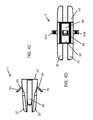
- FIG. 3Ashows an anterior perspective of an expandable implant with the expansion wedge inserted into the socket, and an anchor pin positioned for insertion into the expansion wedge;
- FIG. 3Bshows a lateral view of the expandable implant and anchor pin
- FIG. 4Ashows an anterior perspective of an expandable implant with the expansion wedge inserted into the socket, and the anchor pin inserted into the expansion wedge, with the prongs of the anchor pin extending out from the top surface of the implant;
- FIG. 4Bshows a posterior perspective of an expandable implant with the expansion wedge inserted into the socket, and the anchor pin inserted into the expansion wedge, with the prongs of the anchor pin extending out from the top surface of the implant;
- FIG. 4Cshows a lateral view of the expandable implant and extended anchor pin prongs
- FIG. 4Dshows an anterior view of the expandable implant and extended anchor pin prongs
- FIG. 5Ashows a posterior perspective of an expandable implant having a vertical aperture and an anchor pin slot through the top and bottom sections
- FIG. 5Bshows an anterior perspective of an expandable implant having a vertical aperture and an anchor pin slot through the top and bottom sections
- FIG. 5Cshows a top perspective of the vertical aperture and anchor pin slot
- FIG. 6Ashows an anterior perspective of an expandable implant and an expansion wedge, each having a vertical aperture and anchor pin slot
- FIG. 6Bshows an anterior perspective of an expandable implant with an inserted expansion wedge, each having a vertical aperture and anchor pin slot;
- FIG. 6Cshows a top perspective of the implant and expansion wedge vertical apertures when aligned
- FIG. 7Ashows an anterior perspective of an expandable implant and expansion wedge, each having a vertical aperture and anchor pin slot, with an anchor pin positioned for insertion;
- FIG. 7Bshows a posterior perspective of an expandable implant and expansion wedge, with aligned vertical apertures, and with an anchor pin extending out from the anchor pin slot;
- FIG. 7Cshows an anterior perspective of an expandable implant and expansion wedge, with aligned vertical apertures, and with an anchor pin extending out from the anchor pin slot;
- FIG. 7Dshows a top perspective of the implant and expansion wedge vertical apertures when aligned, with an anchor pin extending out from the anchor pin slot;
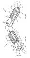
- FIG. 8Ashows a posterior perspective of an embodiment of a PLIF expandable implant and expansion wedge positioned for insertion
- FIG. 8Bshows an anterior perspective of an embodiment of a PLIF expandable implant and expansion wedge positioned for insertion
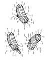
- FIG. 8Cshows an anterior perspective of a curved embodiment of a PLIF expandable implant, with a curved embodiment of an expansion wedge positioned for insertion;
- FIG. 8Dshows a posterior perspective of a curved embodiment of a PLIF expandable implant, with a curved embodiment of an expansion wedge positioned for insertion;
- FIG. 9Ashows an embodiment of a PLIF expandable implant with the expansion wedge inserted and the anchor pin secured, and with the top and bottom portions of the implant spaced apart;
- FIG. 9Bshows a cut-away view of an embodiment of a PLIF expandable implant, illustrating the deflection spur and channels for each prong of the anchor pin;
- FIG. 9Cshows a cut-away view of an embodiment of a PLIF expandable implant with an anchor pin extending through each channel, with the ends of the anchor pin prongs extending out from the top and bottom surface of the implant;
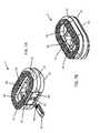
- FIG. 10Ashows a posterior perspective an embodiment of a curved PLIF expandable implant with an expansion wedge inserted and with the anchor pin aligned for insertion into the expansion wedge;
- FIG. 10Bshows a posterior perspective of an embodiment of a curved PLIF expandable implant with an expansion wedge inserted, and an anchor pin secured in place;
- FIG. 10Cshows an anterior perspective of an embodiment of a curved PLIF expandable implant with an expansion wedge inserted, and an anchor pin secured in place;
- FIG. 11Ashows a posterior perspective of an embodiment of a PLIF expandable implant having a vertical aperture extending from the top portion through the bottom portion, with an expansion wedge having a vertical aperture extending from its top surface through its bottom surface and aligned for insertion into the implant;
- FIG. 11Bshows an anterior perspective of an embodiment of a PLIF expandable implant having a vertical aperture extending from the top portion through the bottom portion, with an expansion wedge having a vertical aperture extending from its top surface through its bottom surface and aligned for insertion into the implant;
- FIG. 11Cshows a perspective of an embodiment of a PLIF expandable implant having a vertical aperture, with the expansion wedge having a vertical aperture inserted into the implant;
- FIG. 11Dshows a perspective of an embodiment of a PLIF expandable implant having a vertical aperture, with the expansion wedge having a vertical aperture inserted into the implant, with an anchor pin secured in place;
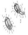
- FIG. 12Ashows a posterior perspective of an embodiment of a curved PLIF expandable implant having a vertical aperture extending from the top portion through the bottom portion;
- FIG. 12Bshows a posterior perspective of an embodiment of a curved PLIF expandable implant having a vertical aperture extending from the top portion through the bottom portion, with an expansion wedge having a vertical aperture extending from its top surface through its bottom surface and aligned for insertion into the implant;
- FIG. 12Cshows a posterior perspective of an embodiment of a curved PLIF expandable implant having a vertical aperture, with the expansion wedge having a vertical aperture inserted into the implant and an anchor pin aligned for insertion;
- FIG. 12Dshows a posterior perspective of an embodiment of a curved PLIF expandable implant having a vertical aperture, with the expansion wedge having a vertical aperture inserted into the implant and an anchor pin secured in place.
- the inventionfeatures interbody spinal implants comprising self-deploying anchors.
- the implantis adaptable to different conditions between vertebrae, and helps to stabilize the implant, while preserving vertebral endplate bone.
- Certain embodiments of the inventionmay be especially suited for placement between adjacent human vertebral bodies.
- the implants of the inventionmay be used in procedures such as Anterior Lumbar Interbody Fusion (ALIF), Posterior Lumbar Interbody Fusion (PLIF), Transforaminal Lumbar Interbody Fusion (TLIF), and cervical fusion. Certain embodiments do not extend beyond the outer dimensions of the vertebral bodies.
- Interbody spinal implants, expansion wedges, and anchor pinsthat are described below and in accordance with the invention are preferably made of a durable material such as stainless steel, stainless steel alloy, titanium, or titanium alloy, but can also be made of other durable materials such as, but not limited to, polymeric, ceramic, and composite materials.
- a durable materialsuch as stainless steel, stainless steel alloy, titanium, or titanium alloy
- other durable materialssuch as, but not limited to, polymeric, ceramic, and composite materials.
- certain embodiments of the interbody spinal implants, expansion wedges, and anchor pinsmay be comprised of a biocompatible, polymeric matrix reinforced with bioactive fillers, fibers, or both.
- interbody spinal implants, expansion wedges, and anchor pinsmay be comprised of urethane dimethacrylate (DUDMA)/tri-ethylene glycol dimethacrylate (TEDGMA) blended resin and a plurality of fillers and fibers including bioactive fillers and E-glass fibers.
- Durable materialsalso include any number of pure metals, metal alloys, or both. Titanium and its alloys are generally preferred for certain embodiments due to their acceptable, and desirable, strength and biocompatibility.
- Suitable polymeric materialsinclude polyetherether-ketone, hedrocel, and ultra-high molecular weight polyethylene.
- Compositesmay include a combination of metals and polymeric materials.
- FIG. 1A and FIG. 1Bshow a first embodiment of an interbody spinal implant 1 especially well-adapted for use in an ALIF procedure.
- the implant 1is comprised of two primary sections, a top portion 10 and a bottom portion 20 .
- the top portion 10comprises a top surface 12
- the bottom portion 20comprises a bottom surface 22 .
- the top portion 10 and bottom portion 20preferably are not directly connected to each other such that they may be separated when the implant 1 expands, as detailed below.
- the top portion 10 and bottom portion 20may be indirectly connected to each other through at least one movable joint (not shown) that holds these portions together to form the implant 1 .
- the at least one movable jointWhen the implant 1 is not expanded, the at least one movable joint is/are substantially closed such that the top portion 10 and bottom portion 20 may contact each other or at least be in close proximity to each other, as shown in FIGS. 1A and 1B .
- the at least one movable jointopens such that the top portion 10 and bottom portion 20 separate, but do not become detached from the implant 1 .
- the movable jointis operably connected to each of the top portion 10 and bottom portion 20 .
- One or more of the top surface 12 and the bottom surface 22comprises a roughened topography 18 .
- the top portion 10comprises an anterior side 14 , a posterior side 15 , and opposing lateral sides 13 .
- the bottom portion 20comprises an anterior side 24 , a posterior side 25 , and opposing lateral sides 23 .
- the anterior sides 14 and 24together comprise an anterior face 40 of the implant 1 .
- the posterior sides 15 and 25together comprise a posterior face 50 of the implant 1 .
- the opposing lateral sides 13 and 23together comprise opposing lateral faces 30 of the implant 1 .
- the interbody spinal implant 1has a generally oval-shaped transverse cross-section, with smooth, blunted, or rounded opposing lateral faces 30 and a smooth, blunted, or rounded posterior face 50 .
- the implant 1comprises a socket 70 , with an opening 74 to the socket 70 on the anterior face 40 ( FIG. 1A ).
- the socket 70receives an expansion wedge 80 ( FIG. 2A ).
- the opening 74is comprised of a section of each of the anterior sides 14 and 24 .
- the socket 70is configured or includes one or more engagement structures 72 to facilitate insertion and placement of the implant 1 by the practitioner during an implant procedure.
- such configurations or engagement structures 72may receive and engage a surgical tool, and the surgical tool may be used to move the implant 1 about the intervertebral space.
- the engagement structures 72may comprise screw threads 72 , ribs 72 , one or more notches 72 , one or more lips 72 , ridges 72 , flanges 72 , barbs 72 , grooves 72 , or any combination thereof, to enhance engagement with a surgical tool to reduce the possibility of the surgical tool slipping out of the engagement structures 72 .
- the top portion 10 and the bottom portion 20 of the implant 1each preferably comprise a slot 16 (top portion), 26 (bottom portion) near the anterior side 14 or 24 , and extending from the top surface 12 and through the top portion 10 , and extending from the bottom surface 22 and through the bottom portion 20 , and into the socket 70 ( FIG. 1A and FIG. 1B ).
- the expansion wedge 80is inserted into the opening 74 and advanced into the socket 70 ( FIG. 2A and FIG. 2B ).
- the expansion wedge 80comprises a top surface 81 , a bottom surface 82 , opposing lateral sides 83 , an anterior face 84 , and a posterior face 85 .
- the posterior face 85is the section that is first inserted into the opening 74 .
- the expansion wedge 80comprises at least one channel 86 on each of the top 81 and bottom surfaces 82 .
- the expansion wedge 80also comprises at least one opening 87 on the anterior face 84 .
- the opening 87is preferably in communication with each channel 86 .
- the opening 87preferably receives the prongs 92 of an anchor pin 90 ( FIG. 3A and FIG. 3B ).
- the opening 87may comprise one or more engagement structures 88 to facilitate insertion and placement of the expansion wedge 80 into the socket 70 of the implant, and/or insertion and placement of the implant 1 by the practitioner during an implant procedure.
- the engagement structures 88may comprise screw threads 88 , ribs 88 , one or more notches 88 , one or more lips 88 , ridges 88 , flanges 88 , barbs 88 , grooves 88 , or any combination thereof.
- the engagement structures 88may receive and engage a surgical tool, and the surgical tool may be used to move the implant 1 about the intervertebral space. For example, once the expansion wedge 80 is fully inserted into the socket 70 ( FIG. 2B - FIG. 2D ), the engagement structures 72 on the socket 70 may no longer be fully accessible such that the engagement structures 88 of the wedge 80 stand in the place of the engagement structures 72 of the socket 70 to allow further manipulation of the implant 1 by surgical tools within the intervertebral space.
- the expansion wedge 80may also comprise a spur 89 that may separate and force the prongs 92 of the anchor pin 90 outward and through each channel 86 .
- the spur 89is preferably substantially wedge-shaped. As the prongs 92 of the anchor pin 90 are advanced into the wedge 80 , they contact the spur 89 , and are separated and directed toward and into each channel 86 .
- the anterior face 84 of the expansion wedge 80comprises a first height h
- the posterior face 85 of the expansion wedge 80comprises a second height h′ that is preferably less than the first height h.
- the second height h′allows the posterior face 85 to fit within the opening 74 of the implant 1 .
- the first height hmay be about 0.5 mm to about 20 mm, about 1 mm to about 3 mm, about 1 mm to about 5 mm, about 1 mm to about 7 mm, about 1 mm to about 10 mm, about 1 mm to about 12 mm, about 1 mm to about 15 mm, about 1 mm to about 18 mm, about 2 mm to about 4 mm, about 2 mm to about 5 mm, about 2 mm to about 6 mm, about 2 mm to about 8 mm, about 2 mm to about 10 mm, about 2 mm to about 12 mm, about 2 mm to about 14 mm, about 2 mm to about 16 mm, about 2 mm to about 20 mm, about 3 mm to about 5 mm, about 3 mm to about 7 mm, about 3 mm to about 10 mm, about 3 mm to about 14 mm, about 3 mm to about 16 mm, about 4 mm to about 6 mm, about 4 mm to about 8 mm, about 4 mm to about
- the second height h′may be about 0.5 mm to about 15 mm, about 1 mm to about 3 mm, about 1 mm to about 5 mm, about 1 mm to about 7 mm, about 1 mm to about 10 mm, about 1 mm to about 12 mm, about 1 mm to about 15 mm, about 2 mm to about 4 mm, about 2 mm to about 5 mm, about 2 mm to about 6 mm, about 2 mm to about 8 mm, about 2 mm to about 10 mm, about 2 mm to about 12 mm, about 3 mm to about 5 mm, about 3 mm to about 7 mm, about 3 mm to about 10 mm, about 4 mm to about 6 mm, about 4 mm to about 8 mm, about 4 mm to about 12 mm, about 5 mm to about 10 mm, about 6 mm to about 8 mm, or about 6 mm to about 10 mm.
- the first height h and second height h′may independently be about 0.5 mm, about 1 mm, about 1.5 mm, about 2 mm, about 2.5 mm, about 3 mm, about 3.5 mm, about 4 mm, about 4.5 mm, about 5 mm, about 5.5 mm, about 6 mm, about 6.5 mm, about 7 mm, about 7.5 mm, about 8 mm, about 8.5 mm, about 9 mm, about 9.5 mm, about 10 mm, about 11 mm, about 12 mm, about 13 mm, about 14 mm, about 15 mm, about 16 mm, about 17 mm, about 18 mm, about 19 mm, or about 20 mm.
- the socket 70preferably comprises a wedge shape that accommodates the shape of the expansion wedge 80 .
- the internal surfaces of the socket 70contact the top surface 81 and bottom surface 82 of the expansion wedge 80 (e.g., FIG. 9B and FIG. 9C ).
- the posterior face 85which has a smaller height (h′) than the anterior face 84 , maintains contact with a socket surface 70 and does not “float” freely within the center of the implant 1 . This helps to ensure that the load is distributed on all surfaces of the expansion wedge 80 , without the load being exerted primarily on the highest point of the anterior face 84 .
- the implant 1expands, thereby increasing in height H ( FIG. 2B and FIG. 2C ).
- the expansion wedge 80advances inward, it forces each of the top portion 10 and bottom portion 20 of the implant 1 apart, thereby increasing the distance between them ( FIG. 2C ) and increasing the height H.
- the height Hincreases proportionally with the first height h of the expansion wedge 80 .
- the implant 1is preferably compatible with expansion wedges 80 having different first heights h and/or second heights h′, thereby allowing the implant 1 to be expanded to a desired height H, for example, to accommodate different intervertebral space heights or other conditions of the subject into which the implant 1 is implanted.
- the expansion wedge 80may comprise one or more structures to resist expulsion of the wedge 80 from the socket 70 once fully inserted.
- the structuresmay comprise a ratchet or tabs (not shown).
- the expansion wedge 80may be freely inserted and removed from the socket, and in some aspects does not include any structures to resist expulsion from the socket 70 .
- the wedge 80may be fabricated from any suitable materials.
- the wedge 80is preferably sufficiently rigid to hold the top 10 and bottom 20 portions of the implant 1 apart and not break under load stress once the implant 1 is implanted.
- the wedge 80may be fabricated from a metal, a plastic, a polymer, or a composite, (including any metal, plastic, polymer, or composite described or exemplified herein) and the material is preferably biocompatible.
- the anchor pin 90comprises at least two flexible prongs 92 a , 92 b preferably spaced apart. Each prong 92 a , 92 b comprises a plurality of ridges or teeth 94 extending toward the proximal edge of the pin 90 ( FIG. 3B ).
- the anchor pin 90may be inserted prongs-first (e.g., distal edge) into the opening 87 of the expansion wedge 80 ( FIG. 3B ).
- the leading edge of each prong 92 a , 92 bcontacts the spur 89 , and the shape of the spur 89 directs each prong 92 a , 92 b outward and into each channel 86 .
- one prong 92 awill extend into the top channel 86
- the other prong 92 bwill extend into the bottom channel 86 .
- each channel 86preferably aligns with each slot 16 , 26 on the main body of the implant 1 .
- each prong 92 a , 92 bpasses through each channel 86 , and extends into and ultimately out from each slot 16 , 26 ( FIGS. 4A-4D ).
- the ridges or teeth 94preferably engage a notch, catch or pawl 17 (top portion 10 ), 27 (bottom portion 20 ) on each slot 16 , 26 , effectively locking the anchor pin 90 in place, and preventing expulsion of the anchor pin 90 from each slot 16 , 26 and each channel 86 .
- each prong 92 a , 92 bextend out from top surface 12 and bottom surface 22 of the implant 1 .
- Each distal edgepreferably engages vertebral endplate bone, and helps resist expulsion of the implant 1 from the intervertebral space, and preferably also facilitates integration of the implant 1 .
- the distal edges of each prong 92 a , 92 bmay comprise a roughened surface topography 18 , including a roughened surface topography 18 as described or exemplified herein, and including macro features, micro features, and nano features. Roughened surface topography on the prongs 92 a , 92 b may enhance integration of the implant 1 with the vertebral end plate bone.
- the anchor pin 90may be fabricated from any suitable material.
- the anchor pin 90is preferably sufficiently rigid to engage vertebral endplate bone and not break under load stress once the implant 1 is implanted, yet the pin 90 is also sufficiently flexible to extend as directed through each channel 86 and slot 16 , 26 .
- the implant 1comprises at least one vertical aperture 60 that extends the entire height H of the implant 1 .
- the vertical aperture 60has a size and shape for maximizing the surface area of the top surface 12 and the bottom surface 22 available for contacting vertebral endplate bone and maximizing the contact of a bone graft material with vertebral endplate bone, when a bone graft material is disposed in the aperture 60 such that it may make contact with the vertebral endplate bone.
- the vertical aperture 60may further define a transverse rim 62 having a greater posterior portion width P than an anterior portion width A, or an equal posterior portion width P and anterior portion width A.
- the posterior portion width Pmay comprise the distance between the posterior edge of the implant 1 and the posterior edge of the vertical aperture 60 .
- the transverse rim 62effectively surrounds the vertical aperture 60 .
- the vertical aperture 60may extend through the implant 1 , from the top surface 12 through the bottom surface 22 , and may contain a bone graft material as described herein.
- the posterior portion width Pmay be about 1 mm to about 15 mm, including about 1 mm, about 2 mm, about 3 mm, about 4 mm, about 5 mm, about 6 mm, about 7 mm, about 8 mm, about 9 mm, about 10 mm, about 11 mm, about 12 mm, about 13 mm, about 14 mm, or about 15 mm.
- the anterior portion width Amay be about 1 mm to about 15 mm, including about 1 mm, about 2 mm, about 3 mm, about 4 mm, about 5 mm, about 6 mm, about 7 mm, about 8 mm, about 9 mm, about 10 mm, about 11 mm, about 12 mm, about 13 mm, about 14 mm, or about 15 mm.
- the transverse rim 62has a generally large surface area and contacts the vertebral endplate.
- the transverse rim 62may act to better distribute contact stresses upon the implant 1 , and hence minimize the risk of subsidence while maximizing contact with the apophyseal supportive bone.
- the posterior portion width P and/or anterior portion width Acomprise dimensions of the implant top surface 12 or bottom surface 22 .
- the top surface 12 and bottom surface 22may be about 5 mm to about 50 mm in width, and in some aspects may be about 7 mm to about 15 mm, about 8 mm to about 12 mm, about 9 mm to about 12 mm, about 9 mm to about 11 mm, about 10 mm to about 20 mm, about 10 mm to about 18 mm, about 10 mm to about 17 mm, about 11 mm to about 19 mm, about 11 mm to about 17 mm, about 12 mm to about 17 mm, about 12 mm to about 16 mm, about 15 mm to about 25 mm, about 15 mm to about 23 mm, about 16 mm to about 24 mm, about 16 mm to about 23 mm, about 17 mm to about 24 mm, about 17 mm to about 23 mm, about 18 mm to about 22
- the top surface 12 and bottom surface 22may be about 9 mm, about 10 mm, about 11 mm, about 12 mm, about 13 mm, about 14 mm, about 15 mm, about 16 mm, about 17 mm, about 18 mm, about 19 mm, about 20 mm, about 21 mm, about 22 mm, about 25 mm, about 30 mm, about 31 mm, about 32 mm, about 33 mm, about 34 mm, about 35 mm, about 36 mm, about 37 mm, about 38 mm, about 39 mm, or about 40 mm in width.
- the top surface 12 and bottom surface 22may be about 10 mm to about 70 mm in length, and in some aspects may be about 10 mm to about 20 mm, about 10 mm to about 18 mm, about 11 mm to about 19 mm, about 11 mm to about 18 mm, about 11 mm to about 17 mm, about 12 mm to about 16 mm, about 18 mm to about 34 mm, about 18 mm to about 32 mm, about 20 mm to about 34 mm, about 20 mm to about 32 mm, about 20 mm to about 31 mm, about 20 mm to about 30 mm, about 20 mm to about 28 mm, about 20 mm to about 27 mm, about 21 mm to about 32 mm, about 21 mm to about 30 mm, about 21 mm to about 28 mm, about 21 mm to about 27 mm, about 22 mm to about 32 mm, about 22 mm to about 31 mm, about 30 mm to
- the top surface 12 and bottom surface 22may be about 9 mm, about 10 mm, about 11 mm, about 12 mm, about 13 mm, about 14 mm, about 15 mm, about 16 mm, about 17 mm, about 18 mm, about 19 mm, about 20 mm, about 21 mm, about 22 mm, about 23 mm, about 24 mm, about 25 mm, about 26 mm, about 27 mm, about 28 mm, about 29 mm, about 30 mm, about 31 mm, about 35 mm, about 40 mm, about 45 mm, about 55 mm, or about 60 mm in length.
- the size and shape of the vertical aperture 60is carefully chosen to achieve a preferable design tradeoff for the particular application envisioned for the implant 1 .
- the vertical aperture 60preferably maximizes the surface area of the top surface 12 and/or bottom surface 22 , while at the same time maximizing both the capacity for radiographic visualization and access to the bone graft material. It is highly preferred that the bone graft material bear at least some of the load forces of the spine once the implant 1 is implanted.
- the vertical aperture 60comprises a maximum width at its center, the size of this width ranges from about 40% to about 80% of the distance (e.g., width) between the edges of the opposing lateral sides.
- the widthmay range from about 40% to about 60%, about 45% to about 75%, about 50% to about 70%, about 50% to about 80%, about 55% to about 65%, about 55% to about 70%, about 55% to about 75%, about 60% to about 75%, or about 60% to about 80% of the distance between the edges of the opposing lateral sides
- the vertical aperture 60may be in communication with the slot 16 on the top portion and with the slot 26 on the bottom portion 26 , as shown in FIG. 5A , FIG. 5B , and FIG. 5C .
- the vertical aperture 60preferably aligns with a vertical aperture 96 that extends through the expansion wedge 80 ( FIG. 6A ).
- a voidextends through the top surface 12 , the vertical aperture 60 on the implant 1 body, the vertical aperture 96 on the expansion wedge 80 , and the bottom surface 22 ( FIG. 6B ).
- the bone graft materialmay thus be contained by the expansion wedge vertical aperture 96 .
- the expansion wedge vertical aperture 96preferably is not in communication with the opening 87 or the channels 86 .
- each prong 92 a , 92 bpasses through each channel 86 , and extends into and ultimately out from each slot 16 , 26 ( FIGS. 7B-7D ).
- Each prong 92 a , 92 bmay project above the vertical aperture 60 .
- the ridges or teeth 94preferably engage a notch, catch, or pawl 17 (top portion 10 ), 27 (bottom portion 20 ) on each slot 16 , 26 , effectively locking the anchor pin 90 in place, and preventing expulsion of the anchor pin 90 from each slot 16 , 26 and each channel 86 .
- FIG. 1A - FIG. 7Dshow examples of embodiments of the interbody spinal implant 1 suitable for use in an ALIF procedure.
- Other embodiments of the implantare better suited for PLIF, TLIF, or cervical fusion procedures.
- the inventionalso features embodiments an interbody spinal implant 101 especially well adapted for use in a PLIF procedure.
- the implant 101may comprise a substantially rectangular shape, or in a variation, may comprise a curved shape.
- An implant comprising a curved shapeis designated as implant 101 a ; because the features of the implant 101 a illustrated in the drawings are the same as those of the implant 101 , these features are given the same reference numbers, with the addition of the letter “a,” (e.g., 101 and 101 a ) and are not described further.
- the curved implant 101 ais suitable for a PLIF or TLIF procedure.
- the interbody spinal implant 101 , 101 ais comprised of two primary sections, a top portion 110 , 110 a , and a bottom portion 120 , 120 a .
- the top portion 110 , 110 acomprises a top surface 112 , 112 a and the bottom portion 120 , 120 a comprises a bottom surface 122 , 122 a .
- the top portion 110 , 110 a and bottom portion 120 , 120 apreferably are not directly connected to each other such that they may be separated when the implant 101 , 101 a expands, as detailed below.
- the top portion 110 , 110 a and bottom portion 120 , 120 amay be indirectly connected to each other through at least one movable joint (not shown) that holds these portions together to form the implant 101 , 101 a .
- the at least one movable jointis/are substantially closed such that the top portion 110 , 110 a and bottom portion 120 , 120 a may nevertheless contact each other, or at least be proximal to each other, as shown in FIGS. 8A-8D .
- the at least one movable jointopens such that the top portion 110 , 110 a and bottom portion 120 , 120 a separate, but do not become detached from the implant 101 , 101 a .
- the movable jointis operably connected to each of the top portion 110 , 110 a and bottom portion 120 , 120 a .
- One or more of the top surface 112 , 112 a and the bottom surface 122 , 122 acomprises a roughened surface topography 118 , 118 a.
- the top portion 110 , 110 acomprises an anterior side 114 , 114 a , a posterior side 115 , 115 a and opposing lateral sides 113 , 113 a .
- the bottom portion 120 , 120 acomprises an anterior side 124 , 124 a , a posterior side 125 , 125 a , and opposing lateral sides 123 , 123 a .
- the anterior sides 114 , 114 a and 124 , 124 atogether comprise an anterior face 140 , 140 a of the implant 101 , 101 a .
- the posterior sides 115 , 115 a and 125 , 125 atogether comprise a posterior face 150 , 150 a of the implant 101 , 101 a .
- the opposing lateral sides 113 , 113 a and 123 , 123 atogether comprise opposing lateral faces 130 , 130 a of the implant 101 , 101 a .
- the interbody spinal implant 101has a generally rectangular-shaped transverse cross-section, with smooth, blunted, or rounded opposing lateral faces 130 and anterior-lateral corners.
- the interbody spinal implant 101 ahas a generally parabolic- or curved-shaped transverse cross-section, with smooth, blunted, or rounded opposing lateral faces 130 a and anterior-lateral corners.
- the anterior portion 140 , 140 amay be tapered to facilitate insertion of the implant 101 , 101 a .
- the implant 101 , 101 amay comprise chamfers at the corners of each posterior side 115 , 115 a (not shown). The chamfers may prevent the implant 101 , 101 a from catching upon insertion.
- the implant 101 , 101 acomprises a socket 170 , 170 a with an opening 174 , 174 a to the socket 170 , 170 a on the posterior face 150 , 150 a ( FIG. 8A and FIG. 8D ).
- the socket 170 , 170 areceives an expansion wedge 180 , 180 a ( FIG. 8A and FIG. 8E ).
- the opening 174 , 174 ais comprised of a section of each of the posterior sides 115 , 115 a and 125 , 125 a .
- the socket 170 , 170 ais configured or includes engagement structures 172 , 172 a to facilitate insertion and placement of the implant 101 , 101 a by the practitioner during an implant procedure.
- engagement structures 172 , 172 amay receive and engage a surgical tool, and the surgical tool may be used to move the implant 1 about the intervertebral space.
- the structures 172 , 172 amay comprise screw threads 172 , 172 a , ribs 172 , 172 a , one or more notches 172 , 172 a , one or more lips 172 , 172 a , ridges 172 , 172 a , flanges 172 , 172 a , barbs 172 , 172 a , grooves 172 , 172 a or any combination thereof, to enhance engagement with a surgical tool to reduce the possibility of the surgical tool slipping out of the engagement structures 172 , 172 a .
- the top portion 110 , 110 a and the bottom portion 120 , 120 a of the implant 101 , 101 aeach preferably comprise a slot 116 , 116 a (top portion 110 , 110 a ), 126 , 126 a (bottom portion 120 , 120 a ) near the posterior side 115 , 115 a or 125 , 125 a and extending from the top surface 112 , 112 a and through the top portion 110 , 110 a , and extending from the bottom surface 122 , 122 a and through the bottom portion 120 , 120 a , and into the socket 170 170 a ( FIGS. 8A-8D ).
- the expansion wedge 180 , 180 ais inserted into the opening 174 , 174 a and advanced into the socket 170 , 170 a ( FIG. 9A - FIG. 9C ).
- the expansion wedge 180 , 180 acomprises a top surface 181 , 181 a , a bottom surface 182 , 182 a , opposing lateral sides 183 , 183 a , an anterior face 184 , 184 a , and a posterior face 185 .
- 185 aGenerally, the anterior face 184 , 184 a is the section that is first inserted into the opening 174 , 174 a.
- the expansion wedge 180 , 180 acomprises at least one channel 186 , 186 a on each of the top 181 , 181 a and bottom surfaces 182 , 182 a .
- the expansion wedge 180 , 180 aalso comprises at least one opening 187 , 187 a on the posterior face 185 , 185 a ( FIG. 8A - FIG. 8D , and FIG. 9B and FIG. 9C ).
- the opening 187 , 187 ais preferably in communication with each channel 186 , 186 a .
- the opening 187 , 187 apreferably receives the prongs 192 , 192 a of an anchor pin 190 , 190 a ( FIG. 9B and FIG. 9C ).
- the opening 187 , 187 amay comprise one or more engagement structures 188 , 188 a to facilitate insertion and placement of the expansion wedge 180 , 180 a into the socket 170 , 170 a of the implant 101 , 101 a , and/or insertion and placement of the implant 101 , 101 a by the practitioner during an implant procedure.
- the engagement structures 188 , 188 amay comprise screw threads 188 , 188 a , ribs 188 , 188 a , one or more notches 188 , 188 a , one or more lips 188 , 188 a , ridges 188 , 188 a , flanges 188 , 188 a , barbs 188 , 188 a , grooves 188 , 188 a or any combination thereof.
- the engagement structures 188 , 188 amay receive and engage a surgical tool, and the surgical tool may be used to move the implant 101 , 101 a about the intervertebral space.
- the structures 172 , 172 a on the socket 170 , 170 amay no longer be fully accessible such that the structures 188 , 188 a of the wedge 180 , 180 a stand in the place of the structures 172 , 172 a of the socket to allow further manipulation of the implant 101 , 101 a by surgical tools within the intervertebral space.
- the expansion wedge 180 , 180 amay also comprise a wedge-shaped spur 189 , 189 a ( FIG. 9B and FIG. 9C ) that may separate and force the prongs 192 , 192 a of the anchor pin 190 , 190 a outward and through each channel 186 , 186 a.
- the expansion wedge 180 , 180 amay also comprise a spur 189 , 189 a that may separate and force the prongs 192 , 192 a of the anchor pin 190 , 190 a outward and through each channel 186 , 186 a .
- the spur 189 , 189 ais preferably substantially wedge-shaped. As the prongs 192 , 192 a of the anchor pin 190 , 190 a are advanced into the wedge 180 , 180 a they contact the spur 189 , 189 a and are separated and directed toward and into each channel 186 , 186 a.
- the anterior face 184 , 184 a of the expansion wedge 180 , 180 acomprises a first height h
- the posterior face 185 , 185 a of the expansion wedge 180 , 180 acomprises a second height h′ that is preferably greater than the first height h.
- the first height hallows the anterior face 184 , 184 a to fit within the opening 174 , 174 a of the implant 101 , 101 a.
- the first height hmay be about 0.5 mm to about 20 mm, about 1 mm to about 3 mm, about 1 mm to about 5 mm, about 1 mm to about 7 mm, about 1 mm to about 10 mm, about 1 mm to about 12 mm, about 1 mm to about 15 mm, about 1 mm to about 18 mm, about 2 mm to about 4 mm, about 2 mm to about 5 mm, about 2 mm to about 6 mm, about 2 mm to about 8 mm, about 2 mm to about 10 mm, about 2 mm to about 12 mm, about 2 mm to about 14 mm, about 2 mm to about 16 mm, about 2 mm to about 20 mm, about 3 mm to about 5 mm, about 3 mm to about 7 mm, about 3 mm to about 10 mm, about 3 mm to about 14 mm, about 3 mm to about 16 mm, about 4 mm to about 6 mm, about 4 mm to about 8 mm, about 4 mm to about
- the second height h′may be about 0.5 mm to about 15 mm, about 1 mm to about 3 mm, about 1 mm to about 5 mm, about 1 mm to about 7 mm, about 1 mm to about 10 mm, about 1 mm to about 12 mm, about 1 mm to about 15 mm, about 2 mm to about 4 mm, about 2 mm to about 5 mm, about 2 mm to about 6 mm, about 2 mm to about 8 mm, about 2 mm to about 10 mm, about 2 mm to about 12 mm, about 3 mm to about 5 mm, about 3 mm to about 7 mm, about 3 mm to about 10 mm, about 4 mm to about 6 mm, about 4 mm to about 8 mm, about 4 mm to about 12 mm, about 5 mm to about 10 mm, about 6 mm to about 8 mm, or about 6 mm to about 10 mm.
- the first height h and second height h′may independently be about 0.5 mm, about 1 mm, about 1.5 mm, about 2 mm, about 2.5 mm, about 3 mm, about 3.5 mm, about 4 mm, about 4.5 mm, about 5 mm, about 5.5 mm, about 6 mm, about 6.5 mm, about 7 mm, about 7.5 mm, about 8 mm, about 8.5 mm, about 9 mm, about 9.5 mm, about 10 mm, about 11 mm, about 12 mm, about 13 mm, about 14 mm, about 15 mm, about 16 mm, about 17 mm, about 18 mm, about 19 mm, or about 20 mm.
- the socket 170 , 170 apreferably comprises a wedge shape that accommodates the shape of the expansion wedge 180 , 180 a . In this manner, the internal surfaces of the socket 170 , 170 a contact the top surface 181 , 181 a and bottom surface 182 , 182 a of the expansion wedge 180 , 180 a (e.g., FIG. 9B and FIG. 9C ).
- the posterior face 185 , 185 awhich has a smaller height (h′) than the anterior face 184 , 184 a maintains contact with a socket surface 170 , 170 a and does not “float” freely within the center of the implant 101 , 101 a .
- Thishelps to ensure that the load is distributed on all surfaces of the expansion wedge 180 , 180 a without the load being exerted primarily on the highest point of the anterior face 184 , 184 a.
- the implant 101 , 101 aexpands, thereby increasing in height H.
- the expansion wedge 180 , 180 aadvances inward, it forces each of the top portion 110 , 110 a and bottom portion 120 , 120 a of the implant 101 , 101 a apart, thereby increasing the distance between them and increasing the height H.
- the height Hincreases proportionally with the second height h′ of the expansion wedge 180 , 180 a .
- the implant 101 , 101 ais preferably compatible with expansion wedges 180 , 180 a having different first heights h and/or second heights h′, thereby allowing the implant 101 , 101 a to be expanded to a desired height H, for example, to accommodate different intervertebral space heights or other conditions of the subject into which the implant 101 , 101 a is implanted.
- the expansion wedge 180 , 180 amay comprise one or more structures to resist expulsion of the wedge 180 , 180 a from the socket 170 , 170 a , once fully inserted.
- the structuresmay comprise a ratchet or tabs (not shown).
- the expansion wedge 180 , 180 amay be freely inserted and removed from the socket, and in some aspects does not include any structures to resist expulsion from the socket 170 , 170 a.
- the wedge 180 , 180 amay be fabricated from any suitable materials.
- the wedge 180 , 180 ais preferably sufficiently rigid to hold the top 110 , 110 a and bottom 120 , 120 a portions of the implant 101 , 101 a apart and not break under load stress once the implant 101 , 101 a is implanted.
- the wedge 180 , 180 amay be fabricated from a metal, a plastic, or a composite, and the material is preferably biocompatible.
- the anchor pin 190 , 190 acomprises at least two flexible prongs 192 a , 192 b , 192 a - a , 192 a - b preferably spaced apart.
- Each prong 192 a , 192 b , 192 a - a , 192 a - bcomprises a plurality of ridges or teeth 194 , 194 a extending toward the exterior of the pin 190 , 190 a ( FIG. 9A - FIG. 10C ).
- the anchor pin 190 , 190 amay be inserted prongs-first (e.g., distal edge) into the opening 187 , 187 a of the expansion wedge 180 , 180 a ( FIG.
- each prong 192 a , 192 b , 192 a - a , 192 a - bcontacts the spur 189 , 189 a
- the shape of the spur 189 , 189 adirects each prong 192 a , 192 b , 192 a - a , 192 a - b outward and into each channel 186 , 186 a ( FIG. 9B and FIG. 9C ).
- one prong 192 a , 192 a - awill extend into the top channel 186 , 186 a
- the other prong 192 b , 192 a - bwill extend into the bottom channel 186 , 186 a.
- each channel 186 , 186 apreferably aligns with each slot 116 , 116 a , 126 , 126 a on the main body of the implant 101 , 101 a .
- each prong 192 a , 192 b , 192 a - a , 192 a - bpasses through each channel 186 , 186 a , and extends into and ultimately out from each slot 116 , 116 a , 126 , 126 a ( FIG. 9A , FIG.
- the ridges or teeth 194 , 194 apreferably engage a catch or pawl 117 , 117 a (top portion 110 , 110 a ), 127 , 127 a (bottom portion 120 , 120 a ) on each slot 116 , 116 a , 126 , 126 a effectively locking the anchor pin 190 , 190 a in place, and preventing expulsion of the anchor pin 190 , 190 a from each slot 116 , 116 a , 126 , 126 a and each channel 186 , 186 a.
- each prong 192 a , 192 b , 192 a - a , 192 a - bextend out from top surface 112 , 112 a and bottom surface 122 , 122 a of the implant 101 , 101 a .
- Each distal edgepreferably engages vertebral endplate bone, and helps resist expulsion of the implant 101 , 101 a from the intervertebral space, and preferably also facilitates integration of the implant 101 , 101 a .
- each prong 192 a , 192 b , 192 a - a , 192 a - bmay comprise a roughened surface topography 118 , 118 a , including a roughened surface topography 118 , 118 a as described or exemplified herein, and including macro features, micro features, and nano features.
- Roughened surface topography on the prongs 192 a , 192 b , 192 a - a , 192 a - bmay enhance integration of the implant 1 with the vertebral end plate bone.
- the anchor pin 190 , 190 amay be fabricated from any suitable material.
- the anchor pin 190 , 190 ais preferably sufficiently rigid to engage vertebral endplate bone and not break under load stress once the implant 101 , 101 a is implanted, yet the pin 190 , 190 a is also sufficiently flexible to extend as directed through each channel 186 , 186 a and slot 116 , 116 a , 126 , 126 a .
- the anchor pin 190 , 190 amay be fabricated from a metal, a plastic, or a composite, and the material is preferably biocompatible.
- the implant 101 , 101 acomprises at least one vertical aperture 160 , 160 a that extends the entire height H of the implant 101 , 101 a .
- the vertical aperture 160 , 160 ahas a size and shape for maximizing the surface area of the top surface 112 , 112 a and the bottom surface 122 , 122 a available for contacting vertebral endplate bone and maximizing the contact of a bone graft material with vertebral endplate bone, when a bone graft material is disposed in the aperture 160 , 160 a such that it may make contact with the vertebral endplate bone.
- the vertical aperture 160 , 160 amay further define a transverse rim 162 , 162 a having a greater posterior portion width P than an anterior portion width A, or an equal posterior portion width P and anterior portion width A.
- the posterior portion width Pmay comprise the distance between the posterior edge of the implant 101 , 101 a and the posterior edge of the vertical aperture 160 , 160 a .
- the transverse rim 162 , 162 aeffectively surrounds the vertical aperture 160 , 160 a .
- the vertical aperture 160 , 160 amay extend through the implant 101 , 101 a , from the top surface 112 , 112 a through the bottom surface 122 , 122 a , and may contain a bone graft material as described herein.
- the posterior portion width Pmay be about 1 mm to about 15 mm, including about 1 mm, about 2 mm, about 3 mm, about 4 mm, about 5 mm, about 6 mm, about 7 mm, about 8 mm, about 9 mm, about 10 mm, about 11 mm, about 12 mm, about 13 mm, about 14 mm, or about 15 mm.
- the anterior portion width Amay be about 1 mm to about 15 mm, including about 1 mm, about 2 mm, about 3 mm, about 4 mm, about 5 mm, about 6 mm, about 7 mm, about 8 mm, about 9 mm, about 10 mm, about 11 mm, about 12 mm, about 13 mm, about 14 mm, or about 15 mm.
- the transverse rim 162 , 162 ahas a generally large surface area and contacts the vertebral endplate.
- the transverse rim 162 , 162 amay act to better distribute contact stresses upon the implant 101 , 101 a , and hence minimize the risk of subsidence while maximizing contact with the apophyseal supportive bone.
- the posterior portion width P and/or anterior portion width Acomprise dimensions of the implant top surface 112 , 112 a or bottom surface 122 , 122 a .
- the top surface 112 , 112 a and bottom surface 122 , 122 amay be about 5 mm to about 50 mm in width, and in some aspects may be about 7 mm to about 15 mm, about 8 mm to about 12 mm, about 9 mm to about 12 mm, about 9 mm to about 11 mm, about 10 mm to about 20 mm, about 10 mm to about 18 mm, about 10 mm to about 17 mm, about 11 mm to about 19 mm, about 11 mm to about 17 mm, about 12 mm to about 17 mm, about 12 mm to about 16 mm, about 15 mm to about 25 mm, about 15 mm to about 23 mm, about 16 mm to about 24 mm,
- the top surface 112 , 112 a and bottom surface 122 , 122 amay be about 9 mm, about 10 mm, about 11 mm, about 12 mm, about 13 mm, about 14 mm, about 15 mm, about 16 mm, about 17 mm, about 18 mm, about 19 mm, about 20 mm, about 21 mm, about 22 mm, about 25 mm, about 30 mm, about 31 mm, about 32 mm, about 33 mm, about 34 mm, about 35 mm, about 36 mm, about 37 mm, about 38 mm, about 39 mm, or about 40 mm in width.
- the top surface 112 , 112 a and bottom surface 122 , 122 amay be about 10 mm to about 70 mm in length, and in some aspects may be about 10 mm to about 20 mm, about 10 mm to about 18 mm, about 11 mm to about 19 mm, about 11 mm to about 18 mm, about 11 mm to about 17 mm, about 12 mm to about 16 mm, about 18 mm to about 34 mm, about 18 mm to about 32 mm, about 20 mm to about 34 mm, about 20 mm to about 32 mm, about 20 mm to about 34 mm, about 20 mm to about 32 mm, about 20 mm to about 31 mm, about 20 mm to about 30 mm, about 20 mm to about 28 mm, about 20 mm to about 27 mm, about 21 mm to about 32 mm, about 21 mm to about 30 mm, about 21 mm to about 28 mm, about 21 mm to about 27 mm, about
- the top surface 112 , 112 a and bottom surface 122 , 122 amay be about 9 mm, about 10 mm, about 11 mm, about 12 mm, about 13 mm, about 14 mm, about 15 mm, about 16 mm, about 17 mm, about 18 mm, about 19 mm, about 20 mm, about 21 mm, about 22 mm, about 23 mm, about 24 mm, about 25 mm, about 26 mm, about 27 mm, about 28 mm, about 29 mm, about 30 mm, about 31 mm, about 35 mm, about 40 mm, about 45 mm, about 55 mm, or about 60 mm in length.
- the size and shape of the vertical aperture 160 , 160 ais carefully chosen to achieve a preferable design tradeoff for the particular application envisioned for the implant 101 , 101 a .
- the vertical aperture 160 , 160 apreferably maximizes the surface area of the top surface 112 , 112 a and/or bottom surface 122 , 122 a while at the same time maximizing both the capacity for radiographic visualization and access to the bone graft material. It is highly preferred that the bone graft material bear at least some of the load forces of the spine once the implant 101 , 101 a is implanted.
- the vertical aperture 160 , 160 acomprises a maximum width at its center, the size of this width ranges from about 40% to about 80% of the distance (e.g., width) between the edges of the opposing lateral sides.
- the widthmay range from about 40% to about 60%, about 45% to about 75%, about 50% to about 70%, about 50% to about 80%, about 55% to about 65%, about 55% to about 70%, about 55% to about 75%, about 60% to about 75%, or about 60% to about 80% of the distance between the edges of the opposing lateral sides.
- the vertical aperture 160 , 160 amay be in communication with the slot 116 , 116 a on the top portion and with the slot 126 , 126 a on the bottom portion 126 , 126 a , as shown in FIGS. 11A-12D .
- the vertical aperture 160 , 160 apreferably aligns with a vertical aperture 196 , 196 a that extends through the expansion wedge 180 , 180 a ( FIG. 11A , FIG. 11B , FIG. 12B ).
- a voidextends through the top surface 112 , 112 a , the vertical aperture 160 , 160 a on the implant 101 , 101 a body, the vertical aperture 196 , 196 a on the expansion wedge 180 , 180 a and the bottom surface 122 , 122 a ( FIG. 11B , FIG. 12C ).
- the bone graft materialmay thus be contained by the expansion wedge vertical aperture 196 , 196 a .
- the expansion wedge vertical aperture 196 , 196 apreferably is not in communication with the opening 187 , 187 a or the channels 186 , 186 a.
- the expansion wedge vertical aperture 196 , 196 apreferably aligns with the implant vertical aperture 160 , 160 a
- each channel 186 , 186 apreferably aligns with each slot 116 , 116 a , 126 , 126 a on the main body of the implant 101 , 101 a .
- Each prong 192 a , 192 b , 192 a - a , 192 a - bmay project above the vertical aperture 160 , 160 a .
- the ridges or teeth 194 , 194 apreferably engage a catch or pawl 117 , 117 a (top portion 110 , 110 a ), 127 , 127 a (bottom portion 120 , 120 a ) on each slot 116 , 116 a , 126 , 126 a effectively locking the anchor pin 190 , 190 a in place, and preventing expulsion of the anchor pin 190 , 190 a from each slot 116 , 116 a , 126 , 126 a and each channel 186 , 186 a.
- implant fixationmay depend, at least in part, on the attachment and proliferation of osteoblasts and like-functioning cells upon the implant surface. Still further, it appears that these cells attach more readily to relatively rough surfaces rather than smooth surfaces. In this manner, a surface may be bioactive due to its ability to facilitate cellular attachment and osteointegration.
- the roughened topography 18 , 118 , 118 amay better promote the ultimate osteointegration of the implant 1 , 101 , 101 a , and complements the anti-expulsion and anti-migration activity of the anchor pin 90 , 190 , 190 a by gripping the vertebral endplate surfaces.
- the implant 1 , 101 , 101 adoes not include the roughened topography 18 , 118 , 118 a.
- the roughened surface topography 18 , 118 , 118 amay be comprised of macro-scale features, micro-scale features, and nano-scale features.
- the roughened surface topography 18 , 118 , 118 amay be obtained by combining separate macro processing, micro processing, and nano processing steps.
- Macro featuresinclude relatively large dimensions, for example, dimensions measured in millimeters (mm) or microns ( ⁇ m).
- Micro featuresinclude dimensions that are measured in microns ( ⁇ m).
- Nano featuresinclude dimensions that are measured in nanometers (nm).
- the shapes of the frictional surface protrusions of the roughened surface topography 18 , 118 , 118 amay be formed using processes and methods commonly applied to remove metal during fabrication of implantable devices such as chemical, electrical, electrochemical, plasma, or laser etching; cutting and removal processes; casting; forging; machining; drilling; grinding; shot peening; abrasive media blasting (such as sand or grit blasting); and combinations of these subtractive processes.
- Additive processessuch as welding, thermal, coatings, sputtering, and optical melt additive processes are also suitable.
- the resulting surfaceseither can be random in the shape and location of the features or can have repeating patterns.
- This flexibilityallows for the design and production of surfaces that resist motion induced by loading in specific directions that are beneficial to the installation process and resist the opposing forces that can be the result of biologic or patient activities such as standing, bending, or turning or as a result of other activities.
- the shapes of the surface features when overlappingincrease the surface contact area but do not result in undercuts that generate a cutting or aggressively abrasive action on the contacting bone surfaces.
- These designed surfacesare composed of various sizes of features that, at the microscopic level, interact with the tissues and stimulate their natural remodeling and growth. At a larger scale these features perform the function of generating non-stressful friction that, when combined with a surgical technique that retains the most rigid cortical bone structures in the disc space, allow for a friction fit that does not abrade, chip, perforate, or compromise the critical endplate structures.
- the featuresmay be divided into three size scales: nano, micro, and macro. The overlapping of the three feature sizes can be achieved using manufacturing processes that are completed sequentially and, therefore, do not remove or degrade the previous method.
- Raaverage amplitude
- Rzaverage peak-to-valley roughness
- Rmaxmaximum peak-to-valley height
- Wttotal peak-to-valley of waviness profile
- Smmean spacing
- Rais the most commonly used roughness parameter. It is the arithmetic average height.
- Rais computed as the average distance between each roughness profile point and the mean line. In mathematical terms, this process can be represented as Equation 1:
- the average peak-to-valley roughness, Rzis defined by the ISO and ASME 1995 and later. Rz is based on one peak and one valley per sampling length. The RzDIN value is based on the determination of the peak-to-valley distance in each sampling length. These individual peak-to-valley distances are averaged, resulting in the RzDIN value.
- the maximum peak-to-valley height, Rmaxis the maximum peak-to-valley distance in a single sampling length.
- the mean spacing, Smis the average spacing between positive mean line crossings. The distance between each positive (upward) mean line crossing is determined and the average value is calculated.
- the parameters Sm, Rmax, and Racan be used define the surface roughness following formation of each of the three types of features macro, micro, and nano.
- the macro features for each of the three parametersmay comprise the following preferred ranges (all measurements in microns).
- the macro mean spacing, Smis about 400 to about 2000 micrometers. More preferably, the macro mean spacing is about 750 to about 1750 micrometers, and more preferably, the macro mean spacing is about 1000 to about 1500 micrometers.
- the macro mean spacingis about 500 to about 1000 micrometers, about 600 to about 900 micrometers, about 700 to about 1000 micrometers, about 750 to about 1200 micrometers, about 800 to about 1300 micrometers, about 900 to about 1300 micrometers, about 1000 to about 1300 micrometers, about 1100 to about 1300 micrometers, about 1100 to about 1400 micrometers, about 1150 to about 1250 micrometers, about 1150 to about 1350 micrometers, about 1200 to about 1500 micrometers, or about 1200 to about 1400 micrometers.
- the macro peak-to-valley height, Rmaxis about 40 to about 500 micrometers.
- the macro peak-to-valley heightis about 150 to about 400 micrometers, and more preferably, about 250 to about 300 micrometers.
- the macro mean peak-to valley heightis about 100 to about 450 micrometers, about 200 to about 400 micrometers, about 200 to about 300 micrometers, about 260 to about 280 micrometers, about 250 to about 350 micrometers, about 260 to about 320 micrometers, or about 270 to about 300 micrometers.
- the macro average amplitude, Rais about 20 to about 200 micrometers. More preferably, the macro average amplitude is about 50 to about 150 micrometers, and more preferably about 100 to about 120 micrometers.
- the macro average amplitudeis about 80 to about 180 micrometers, about 90 to about 160 micrometers, about 90 to about 140 micrometers, about 100 to about 150 micrometers, about 100 to about 130 micrometers, about 105 to about 125 micrometers, or about 105 to about 115 micrometers.
- the micro mean spacing, Smis about 20 to about 400 micrometers. More preferably, the micro mean spacing is about 100 to about 300 micrometers, and more preferably, the macro mean spacing is about 200 to about 220 micrometers. In some aspects, the micro mean spacing is about 50 to about 350 micrometers, about 75 to about 350 micrometers, about 75 to about 300 micrometers, about 100 to about 325 micrometers, about 100 to about 250 micrometers, about 120 to about 220 micrometers, about 150 to about 250 micrometers, about 180 to about 240 micrometers, about 190 to about 230 micrometers, or about 205 to about 215 micrometers.
- the micro peak-to-valley height, Rmaxis about 2 to about 40 micrometers. More preferably, the micro peak-to-valley height is about 5 to about 25 micrometers, and more preferably, about 6 to about 16 micrometers.
- the micro mean peak-to valley heightis about 0.5 to about 50 micrometers, about 1 to about 45 micrometers, about 1 to about 40 micrometers, about 1 to about 30 micrometers, about 1 to about 20 micrometers, about 1 to about 15 micrometers, about 2 to about 50 micrometers, about 2 to about 30 micrometers, about 2 to about 25 micrometers, about 3 to about 40 micrometers, about 3 to about 30 micrometers, about 4 to about 40 micrometers, about 4 to about 30 micrometers, about 5 to about 40 micrometers, about 5 to about 30 micrometers, about 7 to about 20 micrometers, about 7 to about 15 micrometers, about 8 to about 14 micrometers, or about 9 to about 13 micrometers.
- the micro average amplitude, Rais about 1 to about 20 micrometers. More preferably, the micro average amplitude is about 1 to about 10 micrometers, and more preferably about 3 to about 7 micrometers. In some aspects, the micro average amplitude is about 0.5 to about 30 micrometers, about 0.5 to about 25 micrometers, about 1 to about 15 micrometers, about 1 to about 10 micrometers, about 1 to about 9 micrometers, about 1 to about 7 micrometers, about 2 to about 9 micrometers, or about 4 to about 7 micrometers.
- the nano features for each of the three parametersmay comprise the following preferred ranges (all measurements in microns).
- the nano mean spacing, Smis about 0.5 to about 20 micrometers. More preferably, the nano mean spacing is about 5 to about 15 micrometers, and more preferably, the macro mean spacing is about 8 to about 12 micrometers.
- the nano mean spacingis about 0.1 to about 30 micrometers, about 0.25 to about 25 micrometers, about 0.5 to about 15 micrometers, about 0.5 to about 13 micrometers, about 1 to about 250 micrometers, about 1 to about 20 micrometers, about 1 to about 150 micrometers, about 2 to about 18 micrometers, about 2 to about 12 micrometers, about 7 to about 14 micrometers, or about 9 to about 11.5 micrometers.
- the nano peak-to-valley height, Rmaxis about 0.2 to about 2 micrometers. More preferably, the nano peak-to-valley height is about 0.5 to about 1.5 micrometers, and more preferably, about 0.8 to about 1.4 micrometers.
- the nano mean peak-to valley heightis about 0.05 to about 5 micrometers, about 0.1 to about 3 micrometers, about 0.1 to about 2 micrometers, about 0.1 to about 1.5 micrometers, about 0.1 to about 0.4 micrometers, about 0.2 to about 3 micrometers, about 0.2 to about 2.5 micrometers, about 0.2 to about 1.8 micrometers, about 0.6 to about 1.6 micrometers, about 0.7 to about 1.5 micrometers, or about 0.9 to about 1.3 micrometers.
- the nano average amplitude, Rais about 0.01 to about 1 micrometers. More preferably, the nano average amplitude is about 0.05 to about 0.75 micrometers, and more preferably about 0.3 to about 0.7 micrometers.
- the nano average amplitudeis about 0.005 to about 2 micrometers, about 0.005 to about 1.5 micrometers, about 0.01 to about 0.75 micrometers, about 0.01 to about 1.1 micrometers, about 0.01 to about 0.9 micrometers, about 0.01 to about 0.07 micrometers, about 0.025 to about 0.75 micrometers, or about 0.04 to about 0.6 micrometers.
- the roughened topography 18 , 118 , 118 amay be obtained through a variety of techniques including, without limitation, chemical etching, shot peening, plasma etching, laser etching, or abrasive blasting (such as sand or grit blasting).
- the interbody spinal implant 1 , 101 , 101 amay be comprised of titanium, or a titanium alloy, having the surface roughened topography 18 , 118 , 118 a .
- the surfaces of the implant 1 , 101 , 101 aare preferably bioactive (e.g., facilitate integration of the implant 1 , 101 , 101 a ).
- the roughened topography 18 , 118 , 118 amay be obtained via the repetitive masking and chemical or electrochemical milling processes described in U.S. Pat. No. 5,258,098; U.S. Pat. No. 5,507,815; U.S. Pat. No. 5,922,029; and U.S. Pat. No. 6,193,762.
- the surfaceis prepared through an etching process which utilizes the random application of a maskant and subsequent etching of the metallic substrate in areas unprotected by the maskant. This etching process is repeated a number of times as necessitated by the amount and nature of the irregularities required for any particular application.
- Control of the strength of the etchant material, the temperature at which the etching process takes place, and the time allotted for the etching processallow fine control over the resulting surface produced by the process.
- the number of repetitions of the etching processcan also be used to control the surface features.
- an etchant mixture of nitric acid (HNO 3 ) and hydrofluoric (HF) acidmay be repeatedly applied to a titanium surface to produce an average etch depth of about 0.5 mm.
- Interbody spinal implants 1 , 101 , 101 a in accordance with some preferred embodimentsmay be comprised of titanium, or a titanium alloy, having an average surface roughness of about 100 ⁇ m. Surface roughness may be measured using a laser profilometer or other standard instrumentation.
- chemical modification of the titanium implant surfacescan be achieved using HF and a combination of hydrochloric acid and sulfuric acid (HCl/H 2 SO 4 ).
- HFhydrochloric acid and sulfuric acid
- the first exposureis to HF and the second is to HCl/H 2 SO 4 .
- Chemical acid etching alone of the titanium implant surfacehas the potential to greatly enhance osteointegration without adding particulate matter (e.g., hydroxyapatite) or embedding surface contaminants (e.g., grit particles).
- the roughened surface topography 18 , 118 , 118 amay also be provided by coating the implant 1 , 101 , 101 a or anchor pin prongs 92 a , 92 b , 192 a , 192 b , 192 a - a , 192 b - a with a roughened topography material.
- a materialsuch as metal filings, shavings, or fine metal particles or powder, or fine plastic or polymeric particles may be laid onto the top surface 12 , 112 , 112 a , or bottom surface 22 , 122 , 122 a of the implant 1 , 101 , 101 a , or vertebral bone-contacting surfaces of anchor pin prongs 92 a , 92 b , 192 a , 192 b , 192 a - a , 192 b - a according to any suitable method.
- an adhesivemay be used to affix the material to the implant 1 , 101 , 101 a or anchor pin prongs 92 a , 92 b , 192 a , 192 b , 192 a - a , 192 b - a .
- Plastic or polymeric materialsmay be spray-coated, airlaid, or melt-blown onto the implant 1 , 101 , 101 a or anchor pin prongs 92 a , 92 b , 192 a , 192 b , 192 a - a , 192 b - a .
- the materialsmay be adhered directly, for example, by at least partially melting the particles such that they fuse to the desired surface when they cool.
- Metal materialsmay be cold sprayed or thermal sprayed onto the implant 1 , 101 , 101 a , or anchor pin prongs 92 a , 92 b , 192 a , 192 b , 192 a - a , 192 b - a according to any suitable technique.
- the implant 1 , 101 , 101 amay be shaped to reduce the risk of subsidence, and improve stability, by maximizing contact with the apophyseal rim of vertebral endplates. Embodiments may be provided in a variety of anatomical footprints having a medial-lateral width ranging from about 32 mm to about 44 mm.
- An interbody spinal implant 1 , 101 , 101 agenerally does not require extensive supplemental or obstructive implant instrumentation to maintain the prepared disc space during implantation.
- the interbody spinal implant 1 , 101 , 101 a and associated implantation methodsallow for larger-sized implants as compared with other size-limited interbody spinal implants known in the art. This advantage allows for greater medial-lateral width and correspondingly greater contact with the apophyseal rim.
- the implant 1 , 101 , 101 amay comprise a lordotic angle L, e.g., may be wedge-shaped to facilitate sagittal alignment.
- the anterior portion 40 , 140 , 140 amay comprise a height that is larger than the height of the posterior portion 50 , 150 , 150 a .
- one of the lateral sides 30 , 130 , 130 amay comprise a height that is larger than the height of the opposing lateral side 30 , 130 , 130 a.
- the lordotic angle L of the implant 1 , 101 , 101 apreferably closely approximates, or otherwise is substantially the same as, the angle of lordosis of the spine of the patient where the implant 1 , 101 , 101 a will be implanted.
- the implant 1 , 101 , 101 acomprises a lordotic angle L that is about 3% to about 5% greater than the angle of lordosis of the spine into which the implant 1 , 101 , 101 a is inserted.
- the implant 1 , 101 , 101 amay comprise a lordotic angle L about 3%, about 3.3%, about 3.5%, about 3.7%, about 4%, about 4.3%, about 4.5%, about 4.7%, or about 5% greater than the patient's angle of lordosis, though percentages greater than 5% or lesser 3% are possible.
- the implant 1 , 101 , 101 amay also comprise one or more sharp or anti-expulsion edges 8 , 108 , 108 a to help resist movement and expulsion of the implant 1 , 101 , 101 a after implantation.
- the roughened topography 18 , 118 , 118 apromotes integration with the vertebral end plates over time, and the anchor pin 90 , 190 , 190 a engages the vertebral end plates.
- the one or more sharp or anti-expulsion edges 8 , 108 , 108 amay “dig” into the end-plates slightly and help to resist expulsion.
- the sharp or anti-expulsion edge 8 , 108 , 108 amay be present on the top surface 10 , 110 , 110 a , the bottom surface 20 , 120 , 120 a , 220 , or both surfaces of the implant 1 , 101 , 101 a .
- the anti-expulsion edge 8 , 108 , 108 amay comprise a blade.
- the sharp or anti-expulsion edge 8 , 108 , 108 amay be oriented toward the anterior portion 40 , 140 , 140 a , the posterior portion 50 , 150 , 150 a , or either of the opposing lateral sides 30 , 130 , 130 a .
- the orientation of the anti-expulsion edge 8 , 108 , 108 amay depend on the intended orientation of the implant 1 , 101 , 101 a when it has been implanted between vertebrae in the patient.
- the sharp or anti-expulsion-edge 8 , 108 , 108 amay comprise an anti-expulsion edge angle E.
- the anti-expulsion edge angle Emay be from about 80 degrees to about 100 degrees.
- the anti-expulsion edge angle Emay be measured by taking into account the lordosis angle O of the implant 1 , 101 , 101 a .
- the anti-expulsion edge angle Eis measured by subtracting half of the lordotic angle O from 90 degrees. For example, where the lordosis angle O of the implant 1 , 101 , 101 a is 12 degrees, the anti-expulsion edge angle E is 84 degrees (90 ⁇ (12 ⁇ 0.5)).
- the anti-expulsion edge angle Emay be about 80 degrees, about 81 degrees, about 82 degrees, about 83 degrees, about 84 degrees, about 85 degrees, about 86 degrees, about 86.5 degrees, about 87 degrees, about 88 degrees, or about 89 degrees.
- Certain embodiments of the inventionare particularly suited for use during interbody spinal implant procedures. But the process according to the invention at least substantially reduces, and at least in some cases substantially eliminates the cutting of bone.
- the processseeks to preserve as much of a vertebral endplate as possible.
- the processsubstantially minimizes or eliminates impact to the natural anatomical arch, or concavity, of the vertebral endplate while preserving much of the apophyseal rim.
- Preservation of the anatomical concavityis particularly advantageous in maintaining biomechanical integrity of the spine. For example, in a healthy spine, the transfer of compressive loads from the vertebrae to the spinal disc is achieved via hoop stresses acting upon the natural arch of the endplate.
- the distribution of forces, and resultant hoop stress, along the natural archallows the relatively thin shell of subchondral bone to transfer large amounts of load.
- the vertebral endplate natural archmay be significantly removed due to excessive surface preparation for implant placement and seating.
- the vertebraemay be distracted and the intervertebral space prepared according to any suitable process, while preserving as much vertebral endplate bone as possible.
- a determinatively sized interbody implant 1 , 101 , 101 amay inserted into the prepared disc space, and its location may be adjusted by the practitioner until the implant 1 , 101 , 101 a is at or substantially near to its intended integration location.
- the practitionermay insert an expansion wedge 80 , 180 , 180 a into the implant socket 70 , 170 , 170 a , thereby separating each of the top 10 , 110 , 110 a and bottom 20 , 120 , 120 a portions of the implant 1 , 101 , 101 a apart, and increasing the distance between them and the height H of the implant 1 , 101 , 101 a .
- the expansion wedge 80 , 180 , 180 apreferably comprises a height h suitable to increase the implant height H appropriate for the patient.
- the practitionermay insert an anchor pin 90 , 190 , 190 a into the opening 87 , 187 , 187 a of the expansion wedge 80 , 180 , 180 a , through each channel 86 , 186 , 186 a , and out from each slot 16 , 116 , 116 a , 26 , 126 , 126 a .
- the anchor pin 90 , 190 , 190 ais preferably of sufficient size, and is inserted sufficiently to engage vertebral endplate bone, and helps resist expulsion of the implant 1 . 101 , 101 a from the intervertebral space.
- the anchor pin 90 , 190 , 190 amay be further secured in place (in addition to the locking interaction with the teeth/ridges and notch/catch/pawl) within the wedge 80 , 180 , 180 a with an adhesive or a cement such as bone cement.
- the implant 1 , 101 , 101 amay be filled, at least partially, with bone fusion-enabling materials such as, without limitation, cancellous autograft bone, allograft bone, DBM, porous synthetic bone graft substitute, BMP, or combinations of those materials.
- bone fusion-enabling materialmay be pre-loaded into the implant 1 , 101 , 101 a , for example, by filling the vertical aperture 60 , 160 , 160 a before inserting the implant 1 , 101 , 101 a into the intervertebral space.
- the bone graft materialmay fill the full volume, or less than the full volume, of the implant interior and surrounding disc space appropriately.
- interbody spinal implant 1 , 101 , 101 ainclude smooth, rounded, and highly radiused posterior portions and lateral sides which may minimize extraneous bone removal for endplate preparation and reduce localized stress concentrations.
- interbody surgical implant 1 , 101 , 101 a and methods of using itare particularly useful in preserving the natural arch of the vertebral endplate and minimizing the chance of implant subsidence.
- endplatesare spared during the process of inserting the spinal implant 1 , 101 , 101 a hoop stress of the inferior and superior endplates is maintained. Spared endplates allow the transfer of axial stress to the apophasis. Endplate flexion allows the bone graft placed in the interior of the spinal implant 1 , 101 , 101 to accept and share stress transmitted from the endplates. In addition, spared endplates minimize the concern that BMP might erode the cancellous bone.
- the interbody spinal implant 1 , 101 , 101 ais durable and can be impacted between the endplates with standard instrumentation. Therefore, certain embodiments of the invention may be used as the final distractor during implantation. In this manner, the disc space may be under-distracted (e.g., distracted to some height less than the height of the interbody spinal implant 1 , 101 , 101 a ) to facilitate press-fit implantation. Further, certain embodiments of the current invention having a smooth and rounded posterior portion (and lateral sides) may facilitate easier insertion into the disc space.
- those embodiments having a roughened surface topography 18 , 118 , 118 amay lessen the risk of excessive bone removal during distraction as compared to implants having teeth, ridges, or threads currently known in the art even in view of a press-fit surgical distraction method. Nonetheless, once implanted, the interbody surgical implant 1 , 101 , 101 a may provide secure seating and prove difficult to remove, particularly with supporting contributions from the anchor pin 90 , 190 , 190 a.
- the inventionencompasses a number of different configurations, including a one-piece, titanium-only implant and a composite implant formed of top and bottom plates (components) made out of titanium.
- the surfaces exposed to the vertebral bodyare dual acid etched to allow for bony in-growth over time, and to provide resistance against expulsion.
- the top and bottom titanium platesare assembled together with the implant body that is injection molded with PEEK.
- the net resultis a composite implant that has engineered stiffness for its clinical application.
- the axial loadis borne by the PEEK component of the construct.
- the top and bottom surfaces of the implantmay be made out of titanium and are dual acid etched.
- the dual acid etching processcreates a highly roughened texture on these surfaces, which generates tremendous resistance to expulsion.
- the width of these dual acid etched surfacesis very broad and creates a large area of contact with the vertebral end-plates, further increasing the resistance to expulsion.
- the implant surfacesincluding for example, portions of the top surface 12 , 112 , 112 a and bottom surface 22 , 122 , 122 a may have rounded edges, including blunt and radiused edges.
- the transverse rim 62 , 162 , 162 acomprises roughened surface topography 18 , 118 , 118 a
- a portion of the transverse rim 62 , 162 , 162 amay comprise a blunt, radiused, and/or round surface that does not comprise roughened surface topography 18 , 118 , 118 a .
- the posterior face 50 , 150 , 150 amay comprise a generally blunt nosed profile, including a generally rounded profile, and in some aspects, the anterior face 40 , 140 , 140 a may comprise a generally blunt nosed profile.
- the blunt nosepreferably does not comprise roughened surface topography 18 , 118 , 118 a.
- an intact vertebral end-platedeflects like a diaphragm under axial compressive loads generated due to physiologic activities. If a spinal fusion implant is inserted in the prepared disc space via a procedure which does not destroy the end-plate, and if the implant contacts the end-plates only peripherally, the central dome of the end-plates can still deflect under physiologic loads. This deflection of the dome can pressurize the bone graft material packed inside the spinal implant, hence allowing it to heal naturally.
- the implant 1according to certain embodiments of the invention allows the vertebral end-plate to deflect and facilitates healing of the bone graft into fusion.
Landscapes
- Health & Medical Sciences (AREA)
- Engineering & Computer Science (AREA)
- Biomedical Technology (AREA)
- Neurology (AREA)
- Orthopedic Medicine & Surgery (AREA)
- Cardiology (AREA)
- Oral & Maxillofacial Surgery (AREA)
- Transplantation (AREA)
- Heart & Thoracic Surgery (AREA)
- Vascular Medicine (AREA)
- Life Sciences & Earth Sciences (AREA)
- Animal Behavior & Ethology (AREA)
- General Health & Medical Sciences (AREA)
- Public Health (AREA)
- Veterinary Medicine (AREA)
- Prostheses (AREA)
Abstract
Description
Claims (17)
Priority Applications (1)
| Application Number | Priority Date | Filing Date | Title |
|---|---|---|---|
| US14/043,171US9498349B2 (en) | 2012-10-09 | 2013-10-01 | Expandable spinal implant with expansion wedge and anchor |
Applications Claiming Priority (2)
| Application Number | Priority Date | Filing Date | Title |
|---|---|---|---|
| US201261711403P | 2012-10-09 | 2012-10-09 | |
| US14/043,171US9498349B2 (en) | 2012-10-09 | 2013-10-01 | Expandable spinal implant with expansion wedge and anchor |
Publications (2)
| Publication Number | Publication Date |
|---|---|
| US20140100662A1 US20140100662A1 (en) | 2014-04-10 |
| US9498349B2true US9498349B2 (en) | 2016-11-22 |
Family
ID=49378048
Family Applications (1)
| Application Number | Title | Priority Date | Filing Date |
|---|---|---|---|
| US14/043,171Active2034-09-29US9498349B2 (en) | 2012-10-09 | 2013-10-01 | Expandable spinal implant with expansion wedge and anchor |
Country Status (2)
| Country | Link |
|---|---|
| US (1) | US9498349B2 (en) |
| EP (1) | EP2719360B1 (en) |
Cited By (28)
| Publication number | Priority date | Publication date | Assignee | Title |
|---|---|---|---|---|
| US10736752B1 (en) | 2017-10-24 | 2020-08-11 | Omnia Medical, LLC | Multi-material multi-component spinal implant |
| US11051953B2 (en) | 2019-07-31 | 2021-07-06 | Zavation Medical Products, Llc | Porous spinal implant |
| US11058550B2 (en) | 2019-10-04 | 2021-07-13 | Pain TEQ, LLC | Allograft implant for fusing a sacroiliac joint |
| US11083511B2 (en) | 2013-03-15 | 2021-08-10 | Orthocision Inc. | Method and implant system for sacroiliac joint fixation and fusion |
| US11285014B1 (en) | 2020-11-05 | 2022-03-29 | Warsaw Orthopedic, Inc. | Expandable inter-body device, system, and method |
| US11291554B1 (en) | 2021-05-03 | 2022-04-05 | Medtronic, Inc. | Unibody dual expanding interbody implant |
| US11376134B1 (en) | 2020-11-05 | 2022-07-05 | Warsaw Orthopedic, Inc. | Dual expanding spinal implant, system, and method of use |
| US11395743B1 (en) | 2021-05-04 | 2022-07-26 | Warsaw Orthopedic, Inc. | Externally driven expandable interbody and related methods |
| US11517443B2 (en) | 2020-11-05 | 2022-12-06 | Warsaw Orthopedic, Inc. | Dual wedge expandable implant, system and method of use |
| US11564724B2 (en) | 2020-11-05 | 2023-01-31 | Warsaw Orthopedic, Inc. | Expandable inter-body device, system and method |
| US11612499B2 (en) | 2021-06-24 | 2023-03-28 | Warsaw Orthopedic, Inc. | Expandable interbody implant |
| US11638653B2 (en) | 2020-11-05 | 2023-05-02 | Warsaw Orthopedic, Inc. | Surgery instruments with a movable handle |
| US11730608B2 (en) | 2021-07-13 | 2023-08-22 | Warsaw Orthopedic, Inc. | Monoblock expandable interbody implant |
| US11766339B1 (en) | 2017-10-24 | 2023-09-26 | Omnia Medical, LLC | Multi-material multi-component spinal implant |
| US11806250B2 (en) | 2018-02-22 | 2023-11-07 | Warsaw Orthopedic, Inc. | Expandable spinal implant system and method of using same |
| US11833059B2 (en) | 2020-11-05 | 2023-12-05 | Warsaw Orthopedic, Inc. | Expandable inter-body device, expandable plate system, and associated methods |
| US11850163B2 (en) | 2022-02-01 | 2023-12-26 | Warsaw Orthopedic, Inc. | Interbody implant with adjusting shims |
| US11857436B1 (en) | 2019-07-31 | 2024-01-02 | Zavation Medical Products, Llc | Porous spinal implant |
| US11963881B2 (en) | 2020-11-05 | 2024-04-23 | Warsaw Orthopedic, Inc. | Expandable inter-body device, system, and method |
| US12121453B2 (en) | 2020-11-05 | 2024-10-22 | Warsaw Orthopedic, Inc. | Dual wedge expandable implant with eyelets, system, and method of use |
| US12171439B2 (en) | 2020-11-05 | 2024-12-24 | Warsaw Orthopedic, Inc. | Protected drill |
| US12239544B2 (en) | 2020-11-05 | 2025-03-04 | Warsaw Orthopedic, Inc. | Rhomboid shaped implants |
| US12268614B2 (en) | 2021-06-24 | 2025-04-08 | Warsaw Orthopedic, Inc. | Interbody implant with adjusting shims |
| US12295865B2 (en) | 2021-06-24 | 2025-05-13 | Warsaw Orthopedic, Inc. | Expandable interbody implant and corresponding inserter |
| US12318307B2 (en) | 2021-07-16 | 2025-06-03 | Blue Ocean Spine Gmbh | Adjustable spinal implants, associated instruments and methods |
| US12318308B2 (en) | 2020-11-05 | 2025-06-03 | Warsaw Orthopedic, Inc. | Dual expandable inter-body device |
| US12414863B2 (en) | 2021-06-24 | 2025-09-16 | Warsaw Orthopedic, Inc. | Expandable interbody implant and corresponding surgical tool |
| US12440349B2 (en) | 2022-02-04 | 2025-10-14 | Warsaw Orthopedic, Inc. | Expandable interbody implant and breakoff screw |
Families Citing this family (67)
| Publication number | Priority date | Publication date | Assignee | Title |
|---|---|---|---|---|
| WO2008070863A2 (en) | 2006-12-07 | 2008-06-12 | Interventional Spine, Inc. | Intervertebral implant |
| US8900307B2 (en) | 2007-06-26 | 2014-12-02 | DePuy Synthes Products, LLC | Highly lordosed fusion cage |
| EP2237748B1 (en) | 2008-01-17 | 2012-09-05 | Synthes GmbH | An expandable intervertebral implant |
| US8936641B2 (en) | 2008-04-05 | 2015-01-20 | DePuy Synthes Products, LLC | Expandable intervertebral implant |
| US9526620B2 (en) | 2009-03-30 | 2016-12-27 | DePuy Synthes Products, Inc. | Zero profile spinal fusion cage |
| US9381045B2 (en) | 2010-01-13 | 2016-07-05 | Jcbd, Llc | Sacroiliac joint implant and sacroiliac joint instrument for fusing a sacroiliac joint |
| US9333090B2 (en) | 2010-01-13 | 2016-05-10 | Jcbd, Llc | Systems for and methods of fusing a sacroiliac joint |
| US9421109B2 (en) | 2010-01-13 | 2016-08-23 | Jcbd, Llc | Systems and methods of fusing a sacroiliac joint |
| WO2014015309A1 (en) | 2012-07-20 | 2014-01-23 | Jcbd, Llc | Orthopedic anchoring system and methods |
| US8979860B2 (en) | 2010-06-24 | 2015-03-17 | DePuy Synthes Products. LLC | Enhanced cage insertion device |
| US9693876B1 (en)* | 2012-03-30 | 2017-07-04 | Ali H. MESIWALA | Spinal fusion implant and related methods |
| WO2013149134A2 (en)* | 2012-03-30 | 2013-10-03 | Olympus Biotech Corporation | Alif spinal implant |
| EP2877127B1 (en) | 2012-07-26 | 2019-08-21 | Synthes GmbH | Expandable implant |
| US9717601B2 (en) | 2013-02-28 | 2017-08-01 | DePuy Synthes Products, Inc. | Expandable intervertebral implant, system, kit and method |
| US9522070B2 (en) | 2013-03-07 | 2016-12-20 | Interventional Spine, Inc. | Intervertebral implant |
| US9700356B2 (en) | 2013-07-30 | 2017-07-11 | Jcbd, Llc | Systems for and methods of fusing a sacroiliac joint |
| US9826986B2 (en) | 2013-07-30 | 2017-11-28 | Jcbd, Llc | Systems for and methods of preparing a sacroiliac joint for fusion |
| US10245087B2 (en) | 2013-03-15 | 2019-04-02 | Jcbd, Llc | Systems and methods for fusing a sacroiliac joint and anchoring an orthopedic appliance |
| US9717539B2 (en) | 2013-07-30 | 2017-08-01 | Jcbd, Llc | Implants, systems, and methods for fusing a sacroiliac joint |
| WO2014146018A1 (en) | 2013-03-15 | 2014-09-18 | Jcbd, Llc | Systems and methods for fusing a sacroiliac joint and anchoring an orthopedic appliance |
| US9730802B1 (en) | 2014-01-14 | 2017-08-15 | Nuvasive, Inc. | Spinal fusion implant and related methods |
| FR3016793B1 (en)* | 2014-01-30 | 2021-05-07 | Ldr Medical | ANCHORING DEVICE FOR SPINAL IMPLANT, SPINAL IMPLANT AND IMPLANTATION INSTRUMENTATION |
| US9801546B2 (en) | 2014-05-27 | 2017-10-31 | Jcbd, Llc | Systems for and methods of diagnosing and treating a sacroiliac joint disorder |
| US9498347B2 (en) | 2014-06-25 | 2016-11-22 | Spine Wave, Inc. | Expandable interbody fusion device with nested correction surface |
| US20160235455A1 (en)* | 2015-02-14 | 2016-08-18 | Nuvista, Llc | Expandable open wedge implant |
| US11426290B2 (en) | 2015-03-06 | 2022-08-30 | DePuy Synthes Products, Inc. | Expandable intervertebral implant, system, kit and method |
| US10433980B2 (en)* | 2015-05-21 | 2019-10-08 | Globus Medical, Inc. | Device and method for deployment of an anchoring device for intervertebral spinal fusion |
| US10631997B2 (en) | 2015-05-21 | 2020-04-28 | Globus Medical, Inc. | Device and method for deployment of an anchoring device for intervertebral spinal fusion |
| US10433975B2 (en) | 2015-05-21 | 2019-10-08 | Globus Medical, Inc. | Device and method for deployment of an anchoring device for intervertebral spinal fusion |
| US10137005B2 (en)* | 2015-05-21 | 2018-11-27 | Globus Medical, Inc. | Device and method for deployment of an anchoring device for intervertebral spinal fusion |
| US10610376B2 (en) | 2015-10-16 | 2020-04-07 | Warsaw Orthopedic, Inc. | Expandable spinal implant system and method |
| US10137006B2 (en) | 2016-01-28 | 2018-11-27 | Warsaw Orthopedic, Inc. | Geared cam expandable interbody implant and method of implanting same |
| US11510788B2 (en) | 2016-06-28 | 2022-11-29 | Eit Emerging Implant Technologies Gmbh | Expandable, angularly adjustable intervertebral cages |
| EP3474784A2 (en) | 2016-06-28 | 2019-05-01 | Eit Emerging Implant Technologies GmbH | Expandable and angularly adjustable intervertebral cages with articulating joint |
| WO2018053403A1 (en) | 2016-09-16 | 2018-03-22 | Mirus Llc | Interbody fusion devices and related methods of manufacture |
| FR3058043B1 (en)* | 2016-10-27 | 2020-11-13 | Ldr Medical | EXPANDABLE INTERSOMATIC CAGE |
| FR3058044A1 (en)* | 2016-10-27 | 2018-05-04 | Ldr Medical | EXPANDABLE INTERSOMATIC CAGE |
| US10537436B2 (en)* | 2016-11-01 | 2020-01-21 | DePuy Synthes Products, Inc. | Curved expandable cage |
| US10238503B2 (en) | 2016-11-01 | 2019-03-26 | Warsaw Orthopedic, Inc. | Expandable spinal implant system with a biased tip and method of using same |
| US10888433B2 (en) | 2016-12-14 | 2021-01-12 | DePuy Synthes Products, Inc. | Intervertebral implant inserter and related methods |
| US10398563B2 (en) | 2017-05-08 | 2019-09-03 | Medos International Sarl | Expandable cage |
| US11344424B2 (en) | 2017-06-14 | 2022-05-31 | Medos International Sarl | Expandable intervertebral implant and related methods |
| US10940016B2 (en) | 2017-07-05 | 2021-03-09 | Medos International Sarl | Expandable intervertebral fusion cage |
| US10603055B2 (en) | 2017-09-15 | 2020-03-31 | Jcbd, Llc | Systems for and methods of preparing and fusing a sacroiliac joint |
| US11944552B2 (en)* | 2018-03-08 | 2024-04-02 | Nexus Spine, LLC | Stand-alone interbody fusion |
| AU2019342137A1 (en) | 2018-09-20 | 2021-03-25 | Spinal Elements, Inc. | Spinal implant device |
| US11446156B2 (en) | 2018-10-25 | 2022-09-20 | Medos International Sarl | Expandable intervertebral implant, inserter instrument, and related methods |
| GB201818847D0 (en) | 2018-11-19 | 2019-01-02 | Axis Spine Tech Ltd | Intervertebral devices |
| GB201818850D0 (en) | 2018-11-19 | 2019-01-02 | Axis Spine Tech Ltd | Intervertebral devices |
| GB201818849D0 (en) | 2018-11-19 | 2019-01-02 | Axis Spine Tech Ltd | Intervertebral devices |
| GB201902002D0 (en) | 2019-02-13 | 2019-04-03 | Axis Spine Tech Ltd | Intervertebral devices |
| GB201910640D0 (en) | 2019-07-25 | 2019-09-11 | Axis Spine Tech Ltd | Insertions instruments |
| GB201910668D0 (en) | 2019-07-25 | 2019-09-11 | Axis Spine Tech Ltd | Assemblies for and methods of determing height and angle of an intervertebral device |
| GB201913777D0 (en) | 2019-09-24 | 2019-11-06 | Axis Spine Tech Ltd | Intervertebral devices |
| GB201913778D0 (en)* | 2019-09-24 | 2019-11-06 | Axis Spine Tech Ltd | Intervertebral devices |
| US11957600B2 (en) | 2020-02-18 | 2024-04-16 | Mirus Llc | Anterior lumbar interbody fusion device with bidirectional screws |
| US11426286B2 (en) | 2020-03-06 | 2022-08-30 | Eit Emerging Implant Technologies Gmbh | Expandable intervertebral implant |
| US11883300B2 (en) | 2020-06-15 | 2024-01-30 | Nofusco Corporation | Orthopedic implant system and methods of use |
| US11723778B1 (en) | 2021-09-23 | 2023-08-15 | Nofusco Corporation | Vertebral implant system and methods of use |
| US11259936B2 (en) | 2020-06-15 | 2022-03-01 | Nofusco Corporation | Intravertebral implant system and methods of use |
| US12144742B2 (en) | 2020-06-15 | 2024-11-19 | Foundation Surgical Group, Inc. | Implant system and methods of use |
| US11166825B1 (en) | 2020-07-01 | 2021-11-09 | Warsaw Orthopedic, Inc. | Spinal implant |
| US11911284B2 (en) | 2020-11-19 | 2024-02-27 | Spinal Elements, Inc. | Curved expandable interbody devices and deployment tools |
| WO2022133456A1 (en) | 2020-12-17 | 2022-06-23 | Spinal Elements, Inc. | Spinal implant device |
| US11850160B2 (en) | 2021-03-26 | 2023-12-26 | Medos International Sarl | Expandable lordotic intervertebral fusion cage |
| US11752009B2 (en) | 2021-04-06 | 2023-09-12 | Medos International Sarl | Expandable intervertebral fusion cage |
| US12090064B2 (en) | 2022-03-01 | 2024-09-17 | Medos International Sarl | Stabilization members for expandable intervertebral implants, and related systems and methods |
Citations (268)
| Publication number | Priority date | Publication date | Assignee | Title |
|---|---|---|---|---|
| US4314876A (en) | 1980-03-17 | 1982-02-09 | The Diversey Corporation | Titanium etching solution |
| US4834757A (en) | 1987-01-22 | 1989-05-30 | Brantigan John W | Prosthetic implant |
| US4904261A (en) | 1987-08-06 | 1990-02-27 | A. W. Showell (Surgicraft) Limited | Spinal implants |
| US5015247A (en) | 1988-06-13 | 1991-05-14 | Michelson Gary K | Threaded spinal implant |
| US5071437A (en) | 1989-02-15 | 1991-12-10 | Acromed Corporation | Artificial disc |
| US5258098A (en) | 1991-06-17 | 1993-11-02 | Cycam, Inc. | Method of production of a surface adapted to promote adhesion |
| US5306308A (en) | 1989-10-23 | 1994-04-26 | Ulrich Gross | Intervertebral implant |
| US5306309A (en) | 1992-05-04 | 1994-04-26 | Calcitek, Inc. | Spinal disk implant and implantation kit |
| EP0599419A2 (en) | 1992-11-26 | 1994-06-01 | ESKA Implants GmbH & Co. | Disk-shaped implant for reinforcing adjacent vertebrae |
| US5425772A (en) | 1993-09-20 | 1995-06-20 | Brantigan; John W. | Prosthetic implant for intervertebral spinal fusion |
| US5443514A (en) | 1993-10-01 | 1995-08-22 | Acromed Corporation | Method for using spinal implants |
| US5456723A (en) | 1989-03-23 | 1995-10-10 | Institut Straumann Ag | Metallic implant anchorable to bone tissue for replacing a broken or diseased bone |
| JPH0810276Y2 (en) | 1990-02-23 | 1996-03-29 | ダイワ精工株式会社 | Fishing rod |
| US5571188A (en) | 1992-12-04 | 1996-11-05 | Astra Aktiebolag | Process for treating a metallic surgical implant |
| US5603338A (en) | 1994-11-30 | 1997-02-18 | Innovative Implants, Inc. | Implant surface preparation utilizing acid treatment |
| US5609635A (en) | 1988-06-28 | 1997-03-11 | Michelson; Gary K. | Lordotic interbody spinal fusion implants |
| WO1997006753A3 (en) | 1995-08-11 | 1997-04-24 | Bernhard Zientek | Intervertebral implant, process for widening and instruments for implanting an intervertebral implant |
| US5702449A (en) | 1995-06-07 | 1997-12-30 | Danek Medical, Inc. | Reinforced porous spinal implants |
| WO1998001091A1 (en) | 1995-10-16 | 1998-01-15 | Sdgi Holdings, Inc. | Implant insertion device |
| US5755798A (en) | 1995-10-26 | 1998-05-26 | Artos Medizinische Produkte Gmbh | Intervertebral implant |
| US5766252A (en) | 1995-01-24 | 1998-06-16 | Osteonics Corp. | Interbody spinal prosthetic implant and method |
| US5776199A (en) | 1988-06-28 | 1998-07-07 | Sofamor Danek Properties | Artificial spinal fusion implants |
| US5849004A (en)* | 1996-07-17 | 1998-12-15 | Bramlet; Dale G. | Surgical anchor |
| US5860973A (en) | 1995-02-27 | 1999-01-19 | Michelson; Gary Karlin | Translateral spinal implant |
| US5863201A (en) | 1994-11-30 | 1999-01-26 | Implant Innovations, Inc. | Infection-blocking dental implant |
| US5865845A (en) | 1996-03-05 | 1999-02-02 | Thalgott; John S. | Prosthetic intervertebral disc |
| US5885079A (en) | 1998-06-22 | 1999-03-23 | Core-Vent Corporation | Selective surface, endosseous dental implants |
| US5888224A (en) | 1993-09-21 | 1999-03-30 | Synthesis (U.S.A.) | Implant for intervertebral space |
| US5968098A (en) | 1996-10-22 | 1999-10-19 | Surgical Dynamics, Inc. | Apparatus for fusing adjacent bone structures |
| US5984922A (en) | 1993-07-09 | 1999-11-16 | Mckay; Douglas William | Spinal fixation device and method |
| US6033582A (en) | 1996-01-22 | 2000-03-07 | Etex Corporation | Surface modification of medical implants |
| US6039762A (en) | 1995-06-07 | 2000-03-21 | Sdgi Holdings, Inc. | Reinforced bone graft substitutes |
| US6059829A (en) | 1995-03-08 | 2000-05-09 | Synthese | Intervertebral implant |
| US6080158A (en) | 1999-08-23 | 2000-06-27 | Lin; Chih-I | Intervertebral fusion device |
| US6086613A (en) | 1997-12-23 | 2000-07-11 | Depuy Acromed, Inc. | Spacer assembly for use in spinal surgeries |
| US6096107A (en) | 2000-01-03 | 2000-08-01 | Norton Company | Superabrasive products |
| US6102950A (en)* | 1999-01-19 | 2000-08-15 | Vaccaro; Alex | Intervertebral body fusion device |
| US6113638A (en)* | 1999-02-26 | 2000-09-05 | Williams; Lytton A. | Method and apparatus for intervertebral implant anchorage |
| US6123705A (en) | 1988-06-13 | 2000-09-26 | Sdgi Holdings, Inc. | Interbody spinal fusion implants |
| US6143032A (en) | 1997-11-12 | 2000-11-07 | Schafer Micomed Gmbh | Intervertebral implant |
| US6176882B1 (en) | 1998-02-20 | 2001-01-23 | Biedermann Motech Gmbh | Intervertebral implant |
| US6183255B1 (en) | 2000-03-27 | 2001-02-06 | Yoshiki Oshida | Titanium material implants |
| US6193757B1 (en) | 1998-10-29 | 2001-02-27 | Sdgi Holdings, Inc. | Expandable intervertebral spacers |
| US6241771B1 (en) | 1997-08-13 | 2001-06-05 | Cambridge Scientific, Inc. | Resorbable interbody spinal fusion devices |
| US6241770B1 (en) | 1999-03-05 | 2001-06-05 | Gary K. Michelson | Interbody spinal fusion implant having an anatomically conformed trailing end |
| US6245108B1 (en) | 1999-02-25 | 2001-06-12 | Spineco | Spinal fusion implant |
| JP2001170092A (en) | 1999-12-21 | 2001-06-26 | Nippon Electric Glass Co Ltd | Vertebral arch spacer for enlarging operation of vertebral canal |
| US20010014826A1 (en) | 1995-02-14 | 2001-08-16 | Lutz Biedermann | Space holder, in particular for a vertebra or an intervertebral disk |
| WO2001070144A1 (en) | 2000-03-22 | 2001-09-27 | Scolio Gmbh | Cage-type intervertebral implant |
| US6296664B1 (en) | 1998-06-17 | 2001-10-02 | Surgical Dynamics, Inc. | Artificial intervertebral disc |
| US20010039454A1 (en) | 1993-11-02 | 2001-11-08 | John Ricci | Orthopedic implants having ordered microgeometric surface patterns |
| US20010047208A1 (en) | 1999-12-08 | 2001-11-29 | Michelson Gary K. | Spinal implant surface configuration |
| WO2001095838A1 (en) | 2000-06-12 | 2001-12-20 | Ortho Development Corporation | Intervertebral spacer |
| US6342074B1 (en) | 1999-04-30 | 2002-01-29 | Nathan S. Simpson | Anterior lumbar interbody fusion implant and method for fusing adjacent vertebrae |
| WO2001028469B1 (en) | 1999-10-21 | 2002-01-31 | Sdgi Holdings Inc | Devices and techniques for a posterior lateral disc space approach |
| US6344057B1 (en) | 1994-11-22 | 2002-02-05 | Sdgi Holdings, Inc. | Adjustable vertebral body replacement |
| US6350283B1 (en) | 2000-04-19 | 2002-02-26 | Gary K. Michelson | Bone hemi-lumbar interbody spinal implant having an asymmetrical leading end and method of installation thereof |
| US6375681B1 (en) | 1998-06-23 | 2002-04-23 | Ebi, L.P. | Vertebral body replacement |
| US20020049497A1 (en) | 2000-10-11 | 2002-04-25 | Mason Michael D. | Graftless spinal fusion device |
| US6387130B1 (en) | 1999-04-16 | 2002-05-14 | Nuvasive, Inc. | Segmented linked intervertebral implant systems |
| US20020087212A1 (en) | 2000-12-29 | 2002-07-04 | James Stephen B. | Spinal implant |
| US6423095B1 (en) | 1995-10-16 | 2002-07-23 | Sdgi Holdings, Inc. | Intervertebral spacers |
| US20020099443A1 (en) | 1999-02-04 | 2002-07-25 | Synthes (Usa) | End member for a bone fusion implant |
| US6425920B1 (en) | 1999-10-13 | 2002-07-30 | James S. Hamada | Spinal fusion implant |
| US6432140B1 (en) | 1999-12-10 | 2002-08-13 | Chih-I Lin | Intervertebral retrieval device |
| US6436102B1 (en) | 2001-07-16 | 2002-08-20 | Third Millennium Engineering, Llc | Method of distracting vertebral bones |
| US6447546B1 (en)* | 2000-08-11 | 2002-09-10 | Dale G. Bramlet | Apparatus and method for fusing opposing spinal vertebrae |
| US20020128716A1 (en) | 1999-07-26 | 2002-09-12 | Howard Cohen | Spinal surgical prosthesis |
| US20020138142A1 (en) | 2001-03-23 | 2002-09-26 | Michael Castro | Modular implant for fusing adjacent bone structure |
| US6458159B1 (en) | 2000-08-15 | 2002-10-01 | John S. Thalgott | Disc prosthesis |
| US20020156529A1 (en) | 1998-03-11 | 2002-10-24 | Panjian Li | Surface-mineralized spinal implants |
| US20020161443A1 (en) | 2001-04-02 | 2002-10-31 | Michelson Gary K. | Artificial contoured spinal fusion implants made of a material other than bone |
| US6482233B1 (en) | 1998-01-29 | 2002-11-19 | Synthes(U.S.A.) | Prosthetic interbody spacer |
| US20020173854A1 (en) | 2001-01-25 | 2002-11-21 | Tecomet, Inc. | Method for making a mesh-and-plate surgical implant |
| US6485517B1 (en) | 1999-05-05 | 2002-11-26 | Gary K. Michelson | Nested interbody spinal fusion implants |
| US6491723B1 (en) | 1996-02-27 | 2002-12-10 | Implant Innovations, Inc. | Implant surface preparation method |
| US20020188294A1 (en) | 2001-04-06 | 2002-12-12 | Couture Gary M. | Vessel sealer and divider |
| US20030014116A1 (en) | 2001-07-16 | 2003-01-16 | Ralph James D. | Intervertebral spacer having a flexible wire mesh vertebral body contact element |
| US20030083668A1 (en) | 2001-10-30 | 2003-05-01 | Christopher Rogers | Slaphammer tool |
| US6558424B2 (en) | 2001-06-28 | 2003-05-06 | Depuy Acromed | Modular anatomic fusion device |
| US6569201B2 (en) | 2001-09-28 | 2003-05-27 | Depuy Acromed, Inc. | Hybrid composite interbody fusion device |
| US20030105527A1 (en) | 2001-12-03 | 2003-06-05 | Surgical Dynamics, Inc. | Apparatus for fusing adjacent bone structures |
| US20030109928A1 (en) | 2000-07-12 | 2003-06-12 | Denis Pasquet | Intersomatic implant |
| US6592624B1 (en) | 1999-11-24 | 2003-07-15 | Depuy Acromed, Inc. | Prosthetic implant element |
| US6599322B1 (en) | 2001-01-25 | 2003-07-29 | Tecomet, Inc. | Method for producing undercut micro recesses in a surface, a surgical implant made thereby, and method for fixing an implant to bone |
| US20030153975A1 (en) | 2002-02-12 | 2003-08-14 | Byrd John Abbott | Vertebral Interbody cage with translatable locking screw |
| US6610089B1 (en) | 1997-08-26 | 2003-08-26 | Sdgi Holdings, Inc. | Spinal implant and cutting tool preparation accessory for mounting the implant |
| US20030176925A1 (en) | 2002-03-15 | 2003-09-18 | Francois Paponneau | Vertebral body spacer having variable wedged endplates |
| US20030181981A1 (en) | 2000-05-11 | 2003-09-25 | Jean-Philippe Lemaire | Anterior lumbar interbody implant |
| US20030181980A1 (en) | 2002-03-21 | 2003-09-25 | Berry Bret M. | Vertebral body and disc space replacement devices |
| US20030187506A1 (en) | 2002-03-27 | 2003-10-02 | Raymond Ross | Modular disc prosthesis |
| US20030191531A1 (en) | 2002-03-21 | 2003-10-09 | Berry Bret M. | Vertebral body and disc space replacement devices |
| US6635086B2 (en) | 2000-05-30 | 2003-10-21 | Blacksheep Technologies Incorporated | Implant for placement between cervical vertebrae |
| US6652765B1 (en) | 1994-11-30 | 2003-11-25 | Implant Innovations, Inc. | Implant surface preparation |
| WO2004008983A1 (en) | 2002-07-19 | 2004-01-29 | Astra Tech Ab | An implant and a method for treating an implant surface |
| US6702855B1 (en) | 1999-01-29 | 2004-03-09 | Institut Straumann Ag | Osteophilic implants |
| US6719794B2 (en) | 2001-05-03 | 2004-04-13 | Synthes (U.S.A.) | Intervertebral implant for transforaminal posterior lumbar interbody fusion procedure |
| US20040073314A1 (en) | 2002-03-21 | 2004-04-15 | White John L. | Vertebral body and disc space replacement devices |
| US6730127B2 (en) | 2000-07-10 | 2004-05-04 | Gary K. Michelson | Flanged interbody spinal fusion implants |
| US6740118B2 (en) | 2002-01-09 | 2004-05-25 | Sdgi Holdings, Inc. | Intervertebral prosthetic joint |
| US6743231B1 (en) | 2000-10-02 | 2004-06-01 | Sulzer Spine-Tech Inc. | Temporary spinal fixation apparatuses and methods |
| US20040117020A1 (en) | 1999-10-21 | 2004-06-17 | George Frey | Devices and techniques for a posterior lateral disc space approach |
| US20040117019A1 (en) | 2000-08-30 | 2004-06-17 | Trieu Hai H. | Method and apparatus for delivering an intervertebral disc implant |
| US20040122518A1 (en) | 2002-12-19 | 2004-06-24 | Rhoda William S. | Intervertebral implant |
| US20040127993A1 (en) | 2002-10-16 | 2004-07-01 | Erich Kast | Spreader implant for placement between vertebrae |
| US6758849B1 (en) | 1995-02-17 | 2004-07-06 | Sdgi Holdings, Inc. | Interbody spinal fusion implants |
| US20040153154A1 (en) | 2003-01-23 | 2004-08-05 | Wolfgang Dinkelacker | Bone implant and method for manufacturing same |
| US20040153160A1 (en) | 2002-10-30 | 2004-08-05 | Carrasco Mauricio Rodolfo | Implant for vertebral replacement and restoration of the normal spinal curvature |
| US20040162616A1 (en) | 2002-10-21 | 2004-08-19 | Simonton T. Andrew | Systems and techniques for restoring and maintaining intervertebral anatomy |
| US20040167632A1 (en) | 2003-02-24 | 2004-08-26 | Depuy Products, Inc. | Metallic implants having roughened surfaces and methods for producing the same |
| WO2004041131A3 (en) | 2002-10-31 | 2004-09-02 | Spinal Concepts Inc | Movable disc implant |
| US20040186570A1 (en)* | 2001-04-04 | 2004-09-23 | Rapp Lawrence G | Interbody spinal fusion device |
| US20040210309A1 (en) | 2001-10-11 | 2004-10-21 | Denzer Alain J | Osteophilic implants |
| US20040254644A1 (en)* | 2002-10-21 | 2004-12-16 | Taylor Brett Allison | Intervertebral disk prosthesis |
| US20040267367A1 (en) | 2003-06-30 | 2004-12-30 | Depuy Acromed, Inc | Intervertebral implant with conformable endplate |
| US20040265780A1 (en) | 2003-05-16 | 2004-12-30 | Robb T. Tait | Surface treatment process for implants made of titanium alloy |
| US20050021150A1 (en) | 1999-12-08 | 2005-01-27 | Michelson Gary K. | Orthopedic implant surface configuration with a projection having a back cut |
| US20050027360A1 (en) | 2003-08-01 | 2005-02-03 | Webb Scott A. | Spinal implant |
| US20050060034A1 (en) | 2003-09-15 | 2005-03-17 | Sdgi Holdings, Inc. | Revisable prosthetic device |
| US20050075734A1 (en) | 2003-10-07 | 2005-04-07 | Michael Fulton | Spinal implant |
| US20050085913A1 (en) | 2003-03-31 | 2005-04-21 | Robert Fraser | Spinal fixation plate |
| US20050119758A1 (en) | 2003-07-30 | 2005-06-02 | Bio-Lok International Inc. | Surgical implant for promotion of osseo-integration |
| US6902581B2 (en) | 2000-10-24 | 2005-06-07 | Kowmedica Osteonics Corp. | Apparatus for fusing adjacent bone structure |
| US20050131416A1 (en) | 2002-11-12 | 2005-06-16 | Jansen Keith E. | SERRATOME vertebral cortical endplate cutter |
| US20050147942A1 (en) | 2001-12-21 | 2005-07-07 | Jan Hall | Method for producing a surface structure on an implant, and such an implant |
| US20050159814A1 (en) | 2004-01-15 | 2005-07-21 | Sdgi Holdings, Inc. | Universal interference cleat |
| US20050165483A1 (en) | 2004-01-27 | 2005-07-28 | Ray Eddie F.Iii | Bone grafts |
| US20050161120A1 (en) | 2003-06-13 | 2005-07-28 | Yukiharu Hasegawa | Orthopedic and dental endosseous implants and their preparation method |
| US6923810B1 (en) | 1988-06-13 | 2005-08-02 | Gary Karlin Michelson | Frusto-conical interbody spinal fusion implants |
| US20050203630A1 (en) | 2000-01-30 | 2005-09-15 | Pope Bill J. | Prosthetic knee joint having at least one diamond articulation surface |
| US20050251257A1 (en) | 2004-05-04 | 2005-11-10 | Mitchell Margaret E | Spinal implants with body and insert |
| US6964687B1 (en) | 1999-07-09 | 2005-11-15 | Scient'x | Anatomical interbody implant and gripper for same |
| US6974480B2 (en) | 2001-05-03 | 2005-12-13 | Synthes (Usa) | Intervertebral implant for transforaminal posterior lumbar interbody fusion procedure |
| US6981975B2 (en) | 2002-02-02 | 2006-01-03 | Sdgi Holdings, Inc. | Method for inserting a spinal fusion implant having deployable bone engaging projections |
| US20060041313A1 (en) | 2004-08-19 | 2006-02-23 | Sdgi Holdings, Inc. | Intervertebral disc system |
| US7018418B2 (en) | 2001-01-25 | 2006-03-28 | Tecomet, Inc. | Textured surface having undercut micro recesses in a surface |
| US7018412B2 (en) | 2001-08-20 | 2006-03-28 | Ebi, L.P. | Allograft spinal implant |
| US20060093646A1 (en) | 2004-10-28 | 2006-05-04 | Cima Michael J | Orthopedic and dental implant devices providing controlled drug delivery |
| US20060100705A1 (en) | 2004-11-10 | 2006-05-11 | Rolando Puno | Intervertebral spacer |
| US7044972B2 (en) | 2001-01-30 | 2006-05-16 | Synthes Ag Chur | Bone implant, in particular, an inter-vertebral implant |
| US7048870B1 (en) | 1993-12-20 | 2006-05-23 | Astrazeneca Ab | Metallic implant and process for treating a metallic implant |
| US20060122701A1 (en)* | 2004-11-23 | 2006-06-08 | Kiester P D | Posterior lumbar interbody fusion expandable cage with lordosis and method of deploying the same |
| US20060149372A1 (en) | 2004-12-17 | 2006-07-06 | Paxson Robert D | Artificial spinal disc |
| US20060149376A1 (en) | 2003-06-03 | 2006-07-06 | Shimp Lawrence A | Bioimplant with nonuniformly configured protrusions on the load bearing surfaces thereof |
| US7087085B2 (en) | 2000-07-26 | 2006-08-08 | Straumann Holding Ag | Surface-modified implants |
| WO2006081843A1 (en) | 2005-02-01 | 2006-08-10 | Advanced Medical Technologies Ag | Expandable implant placeable between two vertebral bodies |
| US20060190079A1 (en) | 2005-01-21 | 2006-08-24 | Naim Istephanous | Articulating spinal disc implants with amorphous metal elements |
| US20060219661A1 (en) | 2005-02-24 | 2006-10-05 | Towse Ross W | Surface treatment methods for implants made of titanium or titanium alloy |
| US20060235534A1 (en) | 2005-04-15 | 2006-10-19 | Gertzman Arthur A | Vertebral disc repair |
| US7128760B2 (en) | 2001-03-27 | 2006-10-31 | Warsaw Orthopedic, Inc. | Radially expanding interbody spinal fusion implants, instrumentation, and methods of insertion |
| US7137997B2 (en) | 2003-12-29 | 2006-11-21 | Globus Medical, Inc. | Spinal fusion implant |
| US20060265065A1 (en) | 2005-05-06 | 2006-11-23 | Bagga Charanpreet S | Anterior interbody spinal implant |
| US7141068B2 (en) | 2003-07-01 | 2006-11-28 | Thomas Ross | Spinal spacer assembly |
| US7144428B2 (en) | 2000-09-19 | 2006-12-05 | Eduardo Aldecoa Anitua | Method for surface treatment of implants or prosthesis made of titanium or other materials |
| US20060293748A1 (en) | 2005-06-24 | 2006-12-28 | Spineworks, Llc | Prosthetic implant, and a method and tool for the insertion of same |
| US7169183B2 (en) | 2000-03-14 | 2007-01-30 | Warsaw Orthopedic, Inc. | Vertebral implant for promoting arthrodesis of the spine |
| WO2006119088A3 (en) | 2005-05-02 | 2007-02-22 | Seaspine Inc | Prosthesis for restoring motion |
| USD539934S1 (en) | 2005-11-04 | 2007-04-03 | Spinal Elements, Inc. | Interbody fusion device |
| US7201775B2 (en) | 2002-09-24 | 2007-04-10 | Bogomir Gorensek | Stabilizing device for intervertebral disc, and methods thereof |
| WO2006116306A3 (en) | 2005-04-26 | 2007-04-12 | Hfsc Co | Spinal implant |
| US20070093898A1 (en) | 2005-09-26 | 2007-04-26 | Schwab Frank J | Transforaminal hybrid implant |
| USD541940S1 (en) | 2005-11-04 | 2007-05-01 | Spinal Elements, Inc. | Interbody fusion device |
| US7220280B2 (en) | 2002-10-16 | 2007-05-22 | Advanced Medical Technologies Ag | Spreader implant for placement between vertebrae |
| US20070118223A1 (en) | 2005-11-23 | 2007-05-24 | Warsaw Orthopedic Inc. | Posterior Articular Disc and Method for Implantation |
| US7223289B2 (en) | 2002-04-16 | 2007-05-29 | Warsaw Orthopedic, Inc. | Annulus repair systems and techniques |
| US7226480B2 (en) | 2000-08-15 | 2007-06-05 | Depuy Spine, Inc. | Disc prosthesis |
| US7238186B2 (en) | 1995-03-27 | 2007-07-03 | Warsaw Orthopedic, Inc. | Interbody fusion device and method for restoration of normal spinal anatomy |
| US7238203B2 (en) | 2001-12-12 | 2007-07-03 | Vita Special Purpose Corporation | Bioactive spinal implants and method of manufacture thereof |
| US7250060B2 (en) | 2004-01-27 | 2007-07-31 | Sdgi Holdings, Inc. | Hybrid intervertebral disc system |
| US7255698B2 (en) | 1994-03-28 | 2007-08-14 | Warsaw Orthopedic, Inc. | Apparatus and method for anterior spinal stabilization |
| US20070233248A1 (en) | 2005-09-26 | 2007-10-04 | Schwab Frank J | Anterior hybrid implant |
| US20070233247A1 (en) | 2005-09-26 | 2007-10-04 | Schwab Frank J | Hybrid intervertebral spinal fusion implant |
| WO2007089905A3 (en) | 2006-02-01 | 2007-10-04 | Synthes Usa | Interspinous process spacer |
| US7288093B2 (en) | 1988-06-13 | 2007-10-30 | Warsaw Orthopedic, Inc. | Spinal fusion implant having a curved end |
| US20070260320A1 (en) | 2005-03-28 | 2007-11-08 | Peterman Marc M | Spinal system and method including lateral approach |
| US20070269475A1 (en) | 2006-03-31 | 2007-11-22 | Gil Carlos E | Osteochondral plug graft trimming device and method |
| US20070270961A1 (en)* | 2006-04-25 | 2007-11-22 | Sdgi Holdings, Inc. | Spinal implant with deployable and retractable barbs |
| US20070270956A1 (en) | 2006-04-13 | 2007-11-22 | Sdgi Holdings, Inc. | Vertebral fusion implants and methods of use |
| US20070270951A1 (en) | 2006-02-15 | 2007-11-22 | Reginald James Davis | Transforaminal intersomatic cage for an intervertebral fusion graft and an instrument for implanting the cage |
| US20070270968A1 (en)* | 2004-02-10 | 2007-11-22 | Baynham Bret O | Plif opposing wedge ramp |
| US20070282441A1 (en) | 2006-05-19 | 2007-12-06 | Katie Stream | Spinal Stabilization Device and Methods |
| US20070293949A1 (en) | 2004-10-08 | 2007-12-20 | Salerni Anthony A | Interior connecting interbody cage insertional tools, methods and devices |
| US20080071380A1 (en) | 2006-09-19 | 2008-03-20 | Thomas Sweeney | Systems and Methods for Percutaneous Placement of Interspinous Process Spacers |
| US7347873B2 (en) | 1998-01-30 | 2008-03-25 | Synthes (U.S.A.) | Intervertebral allograft spacer |
| US20080077171A1 (en) | 2006-09-25 | 2008-03-27 | Spinal Elements, Inc. | Retractor |
| US20080097610A1 (en) | 2006-09-02 | 2008-04-24 | Guyer Richard D | Implantable intervertebral fusion device |
| US7368065B2 (en) | 2005-06-23 | 2008-05-06 | Depuy Products, Inc. | Implants with textured surface and methods for producing the same |
| US20080154378A1 (en) | 2006-12-22 | 2008-06-26 | Warsaw Orthopedic, Inc. | Bone implant having engineered surfaces |
| US20080195209A1 (en) | 2001-11-09 | 2008-08-14 | Javier Garcia | Spinal implant |
| WO2008103843A1 (en) | 2007-02-22 | 2008-08-28 | Spinal Elements, Inc. | Vertebral facet joint drill and method of use |
| US20080221689A1 (en) | 2007-03-10 | 2008-09-11 | Christopher Chaput | Artificial disc with unique articulating geometry and associated methods |
| US20080249622A1 (en) | 2007-04-05 | 2008-10-09 | Gray Wayne P | Interbody implant |
| US20080269764A1 (en) | 2007-04-25 | 2008-10-30 | Spinal Elements, Inc. | Spinal implant distractor/inserter |
| US20080269806A1 (en) | 2007-04-24 | 2008-10-30 | Jeffrey Zhang | Prostheses for locking an artificial disc in an intervertebral disc space |
| US20080288076A1 (en) | 2006-09-27 | 2008-11-20 | Teck Soo | Spinal interbody spacer |
| US20090005871A1 (en) | 2007-04-10 | 2009-01-01 | David White | Suture-based orthopedic joint devices |
| US20090005784A1 (en) | 2007-04-25 | 2009-01-01 | Spinal Elements, Inc. | Spinal implant distractor/inserter |
| WO2009006225A2 (en) | 2007-06-28 | 2009-01-08 | Spinal Elements, Inc. | Spinal stabilization device |
| US20090014243A1 (en) | 2007-07-13 | 2009-01-15 | Petrolink Usa, Llc | Breather-sampling-filler assembly for liquid reservoirs/systems |
| US20090024132A1 (en) | 2007-07-19 | 2009-01-22 | Spinal Elements, Inc. | Attachable instrument guide with detachable handle |
| WO2009029458A1 (en) | 2007-08-24 | 2009-03-05 | Spinal Elements, Inc. | Loop rod spinal stabilization device |
| US20090088853A1 (en) | 2007-09-27 | 2009-04-02 | Nexgen Spine, Inc. | Orthopedic device assembly with elements coupled by a retaining structure |
| US7517363B2 (en) | 2002-06-27 | 2009-04-14 | Depuy Acromed, Inc. | Intervertebral disc having translation |
| US20090132048A1 (en) | 2006-04-13 | 2009-05-21 | Camlog Biotechnologies Ag | Biodegrading Coatings of Salt for Protecting Implants Against Organic Contaminants |
| US20090182432A1 (en) | 1999-06-04 | 2009-07-16 | Warsaw Orthopedic, Inc. | Artificial disc implant |
| US20090187247A1 (en) | 2008-01-23 | 2009-07-23 | Metcalf Jr Newton H | Spinal implant having a resorbable anchor device for temporarily securing an interbody device to adjacent upper and lower vertebrae |
| US7569074B2 (en) | 2003-12-11 | 2009-08-04 | Warsaw Orthopedic, Inc. | Expandable intervertebral implant |
| US20090204152A1 (en) | 2004-02-06 | 2009-08-13 | Spinal Elements, Inc. | Vertebral facet joint prosthesis and method of fixation |
| USD599019S1 (en) | 2008-03-07 | 2009-08-25 | Nuvasive, Inc. | Spinal fusion implant |
| US20090234362A1 (en) | 2008-03-12 | 2009-09-17 | Spinal Elements, Inc. | Offset opposing arm spinal implant distractor/inserter |
| WO2009129262A1 (en) | 2008-04-18 | 2009-10-22 | Spinal Elements, Inc | Implant and method for facet immobilization |
| US7608107B2 (en) | 2000-07-07 | 2009-10-27 | Warsaw Orthopedic, Inc. | Expandable implant with interlocking walls and method for use thereof |
| US20090276049A1 (en) | 2005-01-28 | 2009-11-05 | Peter Weiland | Implant for Transforaminal Intracorporeal Fusion |
| WO2009140544A1 (en) | 2008-05-15 | 2009-11-19 | Spinal Elements, Inc. | Method for accessing a spinal facet joint |
| US20100023057A1 (en) | 2006-09-20 | 2010-01-28 | Woodwelding Ag | Device to be implanted in human or animal tissue and method for implanting and assembling the device |
| US20100036496A1 (en)* | 2008-08-06 | 2010-02-11 | Warsaw Orthopedic, Inc. | V-Shaped Staple for Spinal Prosthesis |
| US20100076559A1 (en) | 2007-05-04 | 2010-03-25 | Titan Spine, Llc | Composite telescoping anterior interbody spinal implant |
| EP1449544B1 (en) | 2003-02-24 | 2010-04-14 | DePuy Products, Inc. | Metallic implants having roughened surfaces and methods for producing the same |
| US20100094426A1 (en) | 2008-10-14 | 2010-04-15 | Grohowski Jr Joseph A | Hybrid intervertebral spinal implant |
| US20100121385A1 (en) | 2008-11-10 | 2010-05-13 | Spinal Elements, Inc. | Rod reducer instrument for spinal surgery |
| US20100137989A1 (en)* | 2008-12-02 | 2010-06-03 | Warsaw Orthopedic, Inc. | Intervertebral implant with fixation mechanism |
| US7744612B2 (en) | 2004-02-10 | 2010-06-29 | Spinal Elements, Inc. | System and method for protecting neurovascular structures |
| US20100173264A1 (en) | 2007-07-09 | 2010-07-08 | Astra Tech Ab | Nanosurface |
| US20100204798A1 (en) | 2005-10-21 | 2010-08-12 | Stryker Spine | System and method for fusion cage implantation |
| US20100218854A1 (en) | 2007-09-10 | 2010-09-02 | Garcia Saban Francisco J | Method for obtaining a surface of titanium-based metal implant to be inserted into bone tissue |
| US20100234958A1 (en) | 2007-11-19 | 2010-09-16 | Linares Medical Devices, Llc | Combination spacer insert and support for providing inter-cervical vertebral support |
| US20100249937A1 (en) | 2009-03-27 | 2010-09-30 | Spinal Elements, Inc. | Flanged interbody fusion device |
| US20100274286A1 (en) | 2009-04-23 | 2010-10-28 | Spinal Elements, Inc. | Transverse connectors |
| US20100274358A1 (en) | 2009-02-25 | 2010-10-28 | Spinewelding Ag | Spine stabilization device, and method and kit for its implantation |
| US20100303722A1 (en) | 2006-06-23 | 2010-12-02 | Sungho Jin | Articles comprising large-surface-area bio-compatible materials and methods for making and using them |
| US20110009965A1 (en) | 2009-04-03 | 2011-01-13 | Ankem Sreeramamurthy | Biomedical implantable material and methods of producing the same |
| US20110040301A1 (en) | 2007-02-22 | 2011-02-17 | Spinal Elements, Inc. | Vertebral facet joint drill and method of use |
| US7901462B2 (en) | 2005-06-23 | 2011-03-08 | Depuy Products, Inc. | Implants with textured surface and methods for producing the same |
| US20110190902A1 (en) | 2010-01-29 | 2011-08-04 | Depuy Products, Inc. | Methods and devices for implants with improved cement adhesion |
| WO2011094748A1 (en) | 2010-02-01 | 2011-08-04 | Sb Technologies, Llc | Composite interbody device and method of manufacture |
| US20110224796A1 (en) | 2008-11-07 | 2011-09-15 | Advanced Medical Technologies Ag | Implant for fusing spinal column segments |
| US20110230971A1 (en)* | 2009-04-15 | 2011-09-22 | Synthes Usa, Llc | Arcuate fixation member |
| US20110230970A1 (en) | 2010-03-16 | 2011-09-22 | Pinnacle Spine Group, Llc | Intervertebral implants and graft delivery systems and methods |
| US20110233169A1 (en) | 2010-03-29 | 2011-09-29 | Biomet 3I, Llc | Titanium nano-scale etching on an implant surface |
| EP2386274A1 (en) | 2010-05-14 | 2011-11-16 | Titan Spine, LLC | Interbody spinal implant having internally textured surfaces |
| US8062374B2 (en)* | 2008-12-01 | 2011-11-22 | Custom Spine, Inc. | Compliant interbody fusion device with deployable bone anchors |
| US20120009341A1 (en) | 2009-02-12 | 2012-01-12 | Snu R&Db Foundation | Method for modifying the surface of a bioinert material |
| US8100955B2 (en) | 2005-03-17 | 2012-01-24 | Spinal Elements, Inc. | Orthopedic expansion fastener |
| US20120078371A1 (en)* | 2010-09-23 | 2012-03-29 | Thomas Gamache | Fusion cage with in-line single piece fixation |
| US20120136443A1 (en) | 2009-03-04 | 2012-05-31 | Advanced Medical Technologies Ag | Implant system having at least three support elements |
| US20120158144A1 (en) | 2005-05-06 | 2012-06-21 | Ullrich Jr Peter F | Implant with critical ratio of load bearing surface area to central opening area |
| US20120226357A1 (en) | 2010-01-11 | 2012-09-06 | Innova Spinal Technologies, Llc | Expandable intervertebral implant and associated surgical method |
| US8262737B2 (en) | 2005-05-06 | 2012-09-11 | Titan Spine, Llc | Composite interbody spinal implant having openings of predetermined size and shape |
| US20120232664A1 (en) | 2005-05-06 | 2012-09-13 | Titan Spine, Llc | Instruments and interbody spinal implants enhancing disc space distraction |
| US20120239150A1 (en) | 2005-05-06 | 2012-09-20 | Titan Spine, Llc | Friction Fit and Vertebral Endplate-Preserving Spinal Implant |
| US20120239153A1 (en) | 2005-05-06 | 2012-09-20 | Titan Spine, Llc. | Endplate-preserving spinal implant having a raised expulsion-resistant edge |
| US20120239152A1 (en) | 2005-05-06 | 2012-09-20 | Titan Spine, Llc | Endplate-preserving spinal implant with an integration plate having a roughened surface topography |
| US20120239154A1 (en) | 2005-05-06 | 2012-09-20 | Titan Spine, Llc | Endplate-preserving spinal implant with an integration plate having durable connectors |
| US20120239151A1 (en) | 2005-05-06 | 2012-09-20 | Titan Spine, Llc | Method of using instruments and interbody spinal implants to enhance distraction |
| US20120245694A1 (en) | 2005-05-06 | 2012-09-27 | Titan Spine, Llc | Endplate-preserving spinal implant with an integration plate having durable connectors |
| US20120277876A1 (en) | 2005-05-06 | 2012-11-01 | Titan Spine, Llc | Spinal implant having a passage for enhancing contact between bone graft material and cortical endplate bone |
| US20120303128A1 (en) | 2005-05-06 | 2012-11-29 | Titan Spine, Llc | Spinal implant and integration plate for optimizing vertebral endplate contact load-bearing edges |
| US20120303127A1 (en) | 2005-05-06 | 2012-11-29 | Titan Spine, Llc | Implants having internal features for graft retention and load transfer between implant and vertebrae |
| US20120310354A1 (en) | 2005-05-06 | 2012-12-06 | Titan Spine, Llc | Spinal implant having variable ratios of the integration surface area to the axial passage area |
| US20120312778A1 (en) | 2005-05-06 | 2012-12-13 | Titan Spine, Llc | Processes for producing regular repeating patterns on surfaces of interbody devices |
| US20120316651A1 (en) | 2005-05-06 | 2012-12-13 | Titan Spine, Llc | Composite implants having integration surfaces composed of a regular repeating pattern |
| US20120316650A1 (en) | 2005-05-06 | 2012-12-13 | Titan Spine, Llc | Implants having three distinct surfaces |
| US20120312779A1 (en) | 2005-05-06 | 2012-12-13 | Titian Spine, LLC | Methods for manufacturing implants having integration surfaces |
| US20120316653A1 (en) | 2005-05-06 | 2012-12-13 | Titan Spine, Llc | Spinal implant having a transverse aperture |
| US20130006363A1 (en) | 2005-05-06 | 2013-01-03 | Titan Spine, Llc | Implants with integration surfaces having regular repeating surface patterns |
| US8523946B1 (en)* | 2010-02-06 | 2013-09-03 | Karl W. Swann | Stand-alone spinal cage |
| US8628578B2 (en)* | 2011-12-19 | 2014-01-14 | Warsaw Orthopedic, Inc. | Expandable interbody implant and methods of use |
| US8894652B2 (en)* | 2008-08-29 | 2014-11-25 | Globus Medical, Inc. | Devices and methods for treating bone |
- 2013
- 2013-10-01USUS14/043,171patent/US9498349B2/enactiveActive
- 2013-10-02EPEP13187041.2Apatent/EP2719360B1/enactiveActive
Patent Citations (331)
| Publication number | Priority date | Publication date | Assignee | Title |
|---|---|---|---|---|
| US4314876A (en) | 1980-03-17 | 1982-02-09 | The Diversey Corporation | Titanium etching solution |
| US4834757A (en) | 1987-01-22 | 1989-05-30 | Brantigan John W | Prosthetic implant |
| US4904261A (en) | 1987-08-06 | 1990-02-27 | A. W. Showell (Surgicraft) Limited | Spinal implants |
| US6123705A (en) | 1988-06-13 | 2000-09-26 | Sdgi Holdings, Inc. | Interbody spinal fusion implants |
| US5015247A (en) | 1988-06-13 | 1991-05-14 | Michelson Gary K | Threaded spinal implant |
| US7288093B2 (en) | 1988-06-13 | 2007-10-30 | Warsaw Orthopedic, Inc. | Spinal fusion implant having a curved end |
| US6923810B1 (en) | 1988-06-13 | 2005-08-02 | Gary Karlin Michelson | Frusto-conical interbody spinal fusion implants |
| US7066961B2 (en) | 1988-06-28 | 2006-06-27 | Gary Karlin Michelson | Spinal implant |
| US6478823B1 (en) | 1988-06-28 | 2002-11-12 | Sofamor Danek Holdings, Inc. | Artificial spinal fusion implants |
| US5609635A (en) | 1988-06-28 | 1997-03-11 | Michelson; Gary K. | Lordotic interbody spinal fusion implants |
| US5776199A (en) | 1988-06-28 | 1998-07-07 | Sofamor Danek Properties | Artificial spinal fusion implants |
| US5071437A (en) | 1989-02-15 | 1991-12-10 | Acromed Corporation | Artificial disc |
| US5456723A (en) | 1989-03-23 | 1995-10-10 | Institut Straumann Ag | Metallic implant anchorable to bone tissue for replacing a broken or diseased bone |
| US5306308A (en) | 1989-10-23 | 1994-04-26 | Ulrich Gross | Intervertebral implant |
| JPH0810276Y2 (en) | 1990-02-23 | 1996-03-29 | ダイワ精工株式会社 | Fishing rod |
| US5258098A (en) | 1991-06-17 | 1993-11-02 | Cycam, Inc. | Method of production of a surface adapted to promote adhesion |
| US6193762B1 (en) | 1991-06-17 | 2001-02-27 | Cycam, Inc. | Surface for use on an implantable device |
| US5507815A (en) | 1991-06-17 | 1996-04-16 | Cycam, Inc. | Random surface protrusions on an implantable device |
| US6911249B2 (en) | 1991-06-17 | 2005-06-28 | Medsource Technologies Pittsburgh, Inc. | Surface for use on implantable device |
| US20040134886A1 (en) | 1991-06-17 | 2004-07-15 | Wagner Donald J. | Surface for use on implantable device |
| US5922029A (en) | 1991-06-17 | 1999-07-13 | Cycam, Inc. | Surface for use on an implantable device and method of production therefor |
| US5306309A (en) | 1992-05-04 | 1994-04-26 | Calcitek, Inc. | Spinal disk implant and implantation kit |
| EP0599419A2 (en) | 1992-11-26 | 1994-06-01 | ESKA Implants GmbH & Co. | Disk-shaped implant for reinforcing adjacent vertebrae |
| US5571188A (en) | 1992-12-04 | 1996-11-05 | Astra Aktiebolag | Process for treating a metallic surgical implant |
| US5984922A (en) | 1993-07-09 | 1999-11-16 | Mckay; Douglas William | Spinal fixation device and method |
| US5425772A (en) | 1993-09-20 | 1995-06-20 | Brantigan; John W. | Prosthetic implant for intervertebral spinal fusion |
| US5888224A (en) | 1993-09-21 | 1999-03-30 | Synthesis (U.S.A.) | Implant for intervertebral space |
| US5443514A (en) | 1993-10-01 | 1995-08-22 | Acromed Corporation | Method for using spinal implants |
| US20010039454A1 (en) | 1993-11-02 | 2001-11-08 | John Ricci | Orthopedic implants having ordered microgeometric surface patterns |
| US20080014243A1 (en) | 1993-12-20 | 2008-01-17 | Astrazeneca, A Sweden Corporation | Metallic implant and process for treating a metallic implant |
| US7048870B1 (en) | 1993-12-20 | 2006-05-23 | Astrazeneca Ab | Metallic implant and process for treating a metallic implant |
| US7255698B2 (en) | 1994-03-28 | 2007-08-14 | Warsaw Orthopedic, Inc. | Apparatus and method for anterior spinal stabilization |
| US6344057B1 (en) | 1994-11-22 | 2002-02-05 | Sdgi Holdings, Inc. | Adjustable vertebral body replacement |
| US6652765B1 (en) | 1994-11-30 | 2003-11-25 | Implant Innovations, Inc. | Implant surface preparation |
| US5876453A (en) | 1994-11-30 | 1999-03-02 | Implant Innovations, Inc. | Implant surface preparation |
| US5863201A (en) | 1994-11-30 | 1999-01-26 | Implant Innovations, Inc. | Infection-blocking dental implant |
| US5603338A (en) | 1994-11-30 | 1997-02-18 | Innovative Implants, Inc. | Implant surface preparation utilizing acid treatment |
| US5766252A (en) | 1995-01-24 | 1998-06-16 | Osteonics Corp. | Interbody spinal prosthetic implant and method |
| US20010014826A1 (en) | 1995-02-14 | 2001-08-16 | Lutz Biedermann | Space holder, in particular for a vertebra or an intervertebral disk |
| US6758849B1 (en) | 1995-02-17 | 2004-07-06 | Sdgi Holdings, Inc. | Interbody spinal fusion implants |
| US5860973A (en) | 1995-02-27 | 1999-01-19 | Michelson; Gary Karlin | Translateral spinal implant |
| US6059829A (en) | 1995-03-08 | 2000-05-09 | Synthese | Intervertebral implant |
| US7238186B2 (en) | 1995-03-27 | 2007-07-03 | Warsaw Orthopedic, Inc. | Interbody fusion device and method for restoration of normal spinal anatomy |
| US20050038512A1 (en) | 1995-06-07 | 2005-02-17 | Michelson Gary Karlin | Implant having arcuate upper and lower bearing surfaces along a longitudinal axis |
| US5702449A (en) | 1995-06-07 | 1997-12-30 | Danek Medical, Inc. | Reinforced porous spinal implants |
| US7503933B2 (en) | 1995-06-07 | 2009-03-17 | Warsaw Orthopedic, Inc. | Lordotic interbody spinal fusion implants |
| US6447544B1 (en) | 1995-06-07 | 2002-09-10 | Gary Karlin Michelson | Lordotic interbody spinal fusion implants |
| US6039762A (en) | 1995-06-07 | 2000-03-21 | Sdgi Holdings, Inc. | Reinforced bone graft substitutes |
| US6302914B1 (en) | 1995-06-07 | 2001-10-16 | Gary Karlin Michelson | Lordotic interbody spinal fusion implants |
| WO1997006753A3 (en) | 1995-08-11 | 1997-04-24 | Bernhard Zientek | Intervertebral implant, process for widening and instruments for implanting an intervertebral implant |
| WO1998001091A1 (en) | 1995-10-16 | 1998-01-15 | Sdgi Holdings, Inc. | Implant insertion device |
| US6423095B1 (en) | 1995-10-16 | 2002-07-23 | Sdgi Holdings, Inc. | Intervertebral spacers |
| US20040230306A1 (en) | 1995-10-16 | 2004-11-18 | Hoeck James E. Van | Intervertebral spacers |
| US7311734B2 (en) | 1995-10-16 | 2007-12-25 | Warsaw Orthopedic, Inc. | Intervertebral spacers |
| US5755798A (en) | 1995-10-26 | 1998-05-26 | Artos Medizinische Produkte Gmbh | Intervertebral implant |
| US6033582A (en) | 1996-01-22 | 2000-03-07 | Etex Corporation | Surface modification of medical implants |
| US6491723B1 (en) | 1996-02-27 | 2002-12-10 | Implant Innovations, Inc. | Implant surface preparation method |
| US5865845A (en) | 1996-03-05 | 1999-02-02 | Thalgott; John S. | Prosthetic intervertebral disc |
| US5849004A (en)* | 1996-07-17 | 1998-12-15 | Bramlet; Dale G. | Surgical anchor |
| US5968098A (en) | 1996-10-22 | 1999-10-19 | Surgical Dynamics, Inc. | Apparatus for fusing adjacent bone structures |
| US6241771B1 (en) | 1997-08-13 | 2001-06-05 | Cambridge Scientific, Inc. | Resorbable interbody spinal fusion devices |
| US20070010885A1 (en) | 1997-08-26 | 2007-01-11 | Mingyan Liu | Spinal implant and cutting tool preparation accessory for mounting the implant |
| US6610089B1 (en) | 1997-08-26 | 2003-08-26 | Sdgi Holdings, Inc. | Spinal implant and cutting tool preparation accessory for mounting the implant |
| US7112224B2 (en) | 1997-08-26 | 2006-09-26 | Sdgi Holdings, Inc. | Spinal implant and cutting tool preparation accessory for mounting the implant |
| US6143032A (en) | 1997-11-12 | 2000-11-07 | Schafer Micomed Gmbh | Intervertebral implant |
| EP0916323B1 (en) | 1997-11-12 | 2003-01-02 | Bernd Schäfer | Intervertebral implant |
| US6086613A (en) | 1997-12-23 | 2000-07-11 | Depuy Acromed, Inc. | Spacer assembly for use in spinal surgeries |
| US6482233B1 (en) | 1998-01-29 | 2002-11-19 | Synthes(U.S.A.) | Prosthetic interbody spacer |
| US7347873B2 (en) | 1998-01-30 | 2008-03-25 | Synthes (U.S.A.) | Intervertebral allograft spacer |
| US6176882B1 (en) | 1998-02-20 | 2001-01-23 | Biedermann Motech Gmbh | Intervertebral implant |
| US20020156529A1 (en) | 1998-03-11 | 2002-10-24 | Panjian Li | Surface-mineralized spinal implants |
| US6296664B1 (en) | 1998-06-17 | 2001-10-02 | Surgical Dynamics, Inc. | Artificial intervertebral disc |
| US5885079A (en) | 1998-06-22 | 1999-03-23 | Core-Vent Corporation | Selective surface, endosseous dental implants |
| US6375681B1 (en) | 1998-06-23 | 2002-04-23 | Ebi, L.P. | Vertebral body replacement |
| US7655042B2 (en) | 1998-10-29 | 2010-02-02 | Warsaw Orthopedic, Inc. | Expandable intervertebral spacers |
| US6193757B1 (en) | 1998-10-29 | 2001-02-27 | Sdgi Holdings, Inc. | Expandable intervertebral spacers |
| US6833006B2 (en) | 1998-10-29 | 2004-12-21 | Sdgi Holdings, Inc. | Expandable intervertebral spacers |
| US6395031B1 (en) | 1998-10-29 | 2002-05-28 | Sdgi Holdings, Inc. | Expandable intervertebral spacers |
| US6102950A (en)* | 1999-01-19 | 2000-08-15 | Vaccaro; Alex | Intervertebral body fusion device |
| US6702855B1 (en) | 1999-01-29 | 2004-03-09 | Institut Straumann Ag | Osteophilic implants |
| US20020099443A1 (en) | 1999-02-04 | 2002-07-25 | Synthes (Usa) | End member for a bone fusion implant |
| US6245108B1 (en) | 1999-02-25 | 2001-06-12 | Spineco | Spinal fusion implant |
| US6676703B2 (en) | 1999-02-25 | 2004-01-13 | Depuy Acromed, Inc. | Spinal fusion implant |
| US20010016777A1 (en) | 1999-02-25 | 2001-08-23 | Spineco | Spinal fusion implant |
| US6113638A (en)* | 1999-02-26 | 2000-09-05 | Williams; Lytton A. | Method and apparatus for intervertebral implant anchorage |
| US6241770B1 (en) | 1999-03-05 | 2001-06-05 | Gary K. Michelson | Interbody spinal fusion implant having an anatomically conformed trailing end |
| US6387130B1 (en) | 1999-04-16 | 2002-05-14 | Nuvasive, Inc. | Segmented linked intervertebral implant systems |
| US6342074B1 (en) | 1999-04-30 | 2002-01-29 | Nathan S. Simpson | Anterior lumbar interbody fusion implant and method for fusing adjacent vertebrae |
| US6485517B1 (en) | 1999-05-05 | 2002-11-26 | Gary K. Michelson | Nested interbody spinal fusion implants |
| US20090182432A1 (en) | 1999-06-04 | 2009-07-16 | Warsaw Orthopedic, Inc. | Artificial disc implant |
| US6964687B1 (en) | 1999-07-09 | 2005-11-15 | Scient'x | Anatomical interbody implant and gripper for same |
| US20020128716A1 (en) | 1999-07-26 | 2002-09-12 | Howard Cohen | Spinal surgical prosthesis |
| US6080158A (en) | 1999-08-23 | 2000-06-27 | Lin; Chih-I | Intervertebral fusion device |
| US6425920B1 (en) | 1999-10-13 | 2002-07-30 | James S. Hamada | Spinal fusion implant |
| US7060073B2 (en) | 1999-10-21 | 2006-06-13 | Sdgi Holdings, Inc. | Devices and techniques for a posterior lateral disc space approach |
| US20040117020A1 (en) | 1999-10-21 | 2004-06-17 | George Frey | Devices and techniques for a posterior lateral disc space approach |
| WO2001028469B1 (en) | 1999-10-21 | 2002-01-31 | Sdgi Holdings Inc | Devices and techniques for a posterior lateral disc space approach |
| US6592624B1 (en) | 1999-11-24 | 2003-07-15 | Depuy Acromed, Inc. | Prosthetic implant element |
| US7244275B2 (en) | 1999-12-08 | 2007-07-17 | Warsaw Orthopedic, Inc. | Orthopedic implant surface configuration with a projection having a back cut |
| US20010047208A1 (en) | 1999-12-08 | 2001-11-29 | Michelson Gary K. | Spinal implant surface configuration |
| US20050021150A1 (en) | 1999-12-08 | 2005-01-27 | Michelson Gary K. | Orthopedic implant surface configuration with a projection having a back cut |
| US7166129B2 (en) | 1999-12-08 | 2007-01-23 | Warsaw Orthopedic, Inc. | Method for forming a spinal implant surface configuration |
| US6432140B1 (en) | 1999-12-10 | 2002-08-13 | Chih-I Lin | Intervertebral retrieval device |
| JP2001170092A (en) | 1999-12-21 | 2001-06-26 | Nippon Electric Glass Co Ltd | Vertebral arch spacer for enlarging operation of vertebral canal |
| US6096107A (en) | 2000-01-03 | 2000-08-01 | Norton Company | Superabrasive products |
| US20050203630A1 (en) | 2000-01-30 | 2005-09-15 | Pope Bill J. | Prosthetic knee joint having at least one diamond articulation surface |
| US20070118220A1 (en) | 2000-03-14 | 2007-05-24 | Mingyan Liu | Vertebral implant for promoting arthrodesis of the spine |
| US7169183B2 (en) | 2000-03-14 | 2007-01-30 | Warsaw Orthopedic, Inc. | Vertebral implant for promoting arthrodesis of the spine |
| WO2001070144A1 (en) | 2000-03-22 | 2001-09-27 | Scolio Gmbh | Cage-type intervertebral implant |
| US6183255B1 (en) | 2000-03-27 | 2001-02-06 | Yoshiki Oshida | Titanium material implants |
| US6350283B1 (en) | 2000-04-19 | 2002-02-26 | Gary K. Michelson | Bone hemi-lumbar interbody spinal implant having an asymmetrical leading end and method of installation thereof |
| US20030181981A1 (en) | 2000-05-11 | 2003-09-25 | Jean-Philippe Lemaire | Anterior lumbar interbody implant |
| US6635086B2 (en) | 2000-05-30 | 2003-10-21 | Blacksheep Technologies Incorporated | Implant for placement between cervical vertebrae |
| WO2001095838A1 (en) | 2000-06-12 | 2001-12-20 | Ortho Development Corporation | Intervertebral spacer |
| US6579318B2 (en) | 2000-06-12 | 2003-06-17 | Ortho Development Corporation | Intervertebral spacer |
| US7608107B2 (en) | 2000-07-07 | 2009-10-27 | Warsaw Orthopedic, Inc. | Expandable implant with interlocking walls and method for use thereof |
| US6730127B2 (en) | 2000-07-10 | 2004-05-04 | Gary K. Michelson | Flanged interbody spinal fusion implants |
| US20030109928A1 (en) | 2000-07-12 | 2003-06-12 | Denis Pasquet | Intersomatic implant |
| US7662190B2 (en) | 2000-07-26 | 2010-02-16 | Straumann Holding Ag | Surface-modified implants |
| US7087085B2 (en) | 2000-07-26 | 2006-08-08 | Straumann Holding Ag | Surface-modified implants |
| US6447546B1 (en)* | 2000-08-11 | 2002-09-10 | Dale G. Bramlet | Apparatus and method for fusing opposing spinal vertebrae |
| US7226480B2 (en) | 2000-08-15 | 2007-06-05 | Depuy Spine, Inc. | Disc prosthesis |
| US6458159B1 (en) | 2000-08-15 | 2002-10-01 | John S. Thalgott | Disc prosthesis |
| US20040117019A1 (en) | 2000-08-30 | 2004-06-17 | Trieu Hai H. | Method and apparatus for delivering an intervertebral disc implant |
| US7144428B2 (en) | 2000-09-19 | 2006-12-05 | Eduardo Aldecoa Anitua | Method for surface treatment of implants or prosthesis made of titanium or other materials |
| US6743231B1 (en) | 2000-10-02 | 2004-06-01 | Sulzer Spine-Tech Inc. | Temporary spinal fixation apparatuses and methods |
| US20020049497A1 (en) | 2000-10-11 | 2002-04-25 | Mason Michael D. | Graftless spinal fusion device |
| US6902581B2 (en) | 2000-10-24 | 2005-06-07 | Kowmedica Osteonics Corp. | Apparatus for fusing adjacent bone structure |
| US6520993B2 (en) | 2000-12-29 | 2003-02-18 | Depuy Acromed, Inc. | Spinal implant |
| US20020087212A1 (en) | 2000-12-29 | 2002-07-04 | James Stephen B. | Spinal implant |
| US20020173854A1 (en) | 2001-01-25 | 2002-11-21 | Tecomet, Inc. | Method for making a mesh-and-plate surgical implant |
| US6620332B2 (en) | 2001-01-25 | 2003-09-16 | Tecomet, Inc. | Method for making a mesh-and-plate surgical implant |
| US7018418B2 (en) | 2001-01-25 | 2006-03-28 | Tecomet, Inc. | Textured surface having undercut micro recesses in a surface |
| US6599322B1 (en) | 2001-01-25 | 2003-07-29 | Tecomet, Inc. | Method for producing undercut micro recesses in a surface, a surgical implant made thereby, and method for fixing an implant to bone |
| US7044972B2 (en) | 2001-01-30 | 2006-05-16 | Synthes Ag Chur | Bone implant, in particular, an inter-vertebral implant |
| US20060167549A1 (en) | 2001-01-30 | 2006-07-27 | Synthes Ag Chur And Synthes (Usa) | Bone implant, in particular, an inter-vertebral implant |
| US20020138142A1 (en) | 2001-03-23 | 2002-09-26 | Michael Castro | Modular implant for fusing adjacent bone structure |
| US7410501B2 (en) | 2001-03-27 | 2008-08-12 | Warsaw Orthopedic, Inc. | Radially expanding interbody spinal fusion implants, instrumentation, and method of insertion |
| US7128760B2 (en) | 2001-03-27 | 2006-10-31 | Warsaw Orthopedic, Inc. | Radially expanding interbody spinal fusion implants, instrumentation, and methods of insertion |
| US20020161443A1 (en) | 2001-04-02 | 2002-10-31 | Michelson Gary K. | Artificial contoured spinal fusion implants made of a material other than bone |
| US6890355B2 (en) | 2001-04-02 | 2005-05-10 | Gary K. Michelson | Artificial contoured spinal fusion implants made of a material other than bone |
| US20040186570A1 (en)* | 2001-04-04 | 2004-09-23 | Rapp Lawrence G | Interbody spinal fusion device |
| US20020188294A1 (en) | 2001-04-06 | 2002-12-12 | Couture Gary M. | Vessel sealer and divider |
| US6974480B2 (en) | 2001-05-03 | 2005-12-13 | Synthes (Usa) | Intervertebral implant for transforaminal posterior lumbar interbody fusion procedure |
| US6719794B2 (en) | 2001-05-03 | 2004-04-13 | Synthes (U.S.A.) | Intervertebral implant for transforaminal posterior lumbar interbody fusion procedure |
| US6558424B2 (en) | 2001-06-28 | 2003-05-06 | Depuy Acromed | Modular anatomic fusion device |
| US20030014116A1 (en) | 2001-07-16 | 2003-01-16 | Ralph James D. | Intervertebral spacer having a flexible wire mesh vertebral body contact element |
| US6436102B1 (en) | 2001-07-16 | 2002-08-20 | Third Millennium Engineering, Llc | Method of distracting vertebral bones |
| US7018412B2 (en) | 2001-08-20 | 2006-03-28 | Ebi, L.P. | Allograft spinal implant |
| US6569201B2 (en) | 2001-09-28 | 2003-05-27 | Depuy Acromed, Inc. | Hybrid composite interbody fusion device |
| US20040210309A1 (en) | 2001-10-11 | 2004-10-21 | Denzer Alain J | Osteophilic implants |
| US20030083668A1 (en) | 2001-10-30 | 2003-05-01 | Christopher Rogers | Slaphammer tool |
| US20080195209A1 (en) | 2001-11-09 | 2008-08-14 | Javier Garcia | Spinal implant |
| US20030105527A1 (en) | 2001-12-03 | 2003-06-05 | Surgical Dynamics, Inc. | Apparatus for fusing adjacent bone structures |
| US7238203B2 (en) | 2001-12-12 | 2007-07-03 | Vita Special Purpose Corporation | Bioactive spinal implants and method of manufacture thereof |
| US20050147942A1 (en) | 2001-12-21 | 2005-07-07 | Jan Hall | Method for producing a surface structure on an implant, and such an implant |
| US6740118B2 (en) | 2002-01-09 | 2004-05-25 | Sdgi Holdings, Inc. | Intervertebral prosthetic joint |
| US6981975B2 (en) | 2002-02-02 | 2006-01-03 | Sdgi Holdings, Inc. | Method for inserting a spinal fusion implant having deployable bone engaging projections |
| US20030153975A1 (en) | 2002-02-12 | 2003-08-14 | Byrd John Abbott | Vertebral Interbody cage with translatable locking screw |
| US7077864B2 (en) | 2002-02-12 | 2006-07-18 | Cross Medical Products, Inc. | Vertebral interbody cage with translatable locking screw |
| US20030176925A1 (en) | 2002-03-15 | 2003-09-18 | Francois Paponneau | Vertebral body spacer having variable wedged endplates |
| US20030181980A1 (en) | 2002-03-21 | 2003-09-25 | Berry Bret M. | Vertebral body and disc space replacement devices |
| US20030191531A1 (en) | 2002-03-21 | 2003-10-09 | Berry Bret M. | Vertebral body and disc space replacement devices |
| US20040073314A1 (en) | 2002-03-21 | 2004-04-15 | White John L. | Vertebral body and disc space replacement devices |
| US7615078B2 (en) | 2002-03-21 | 2009-11-10 | Warsaw Orthopedic, Inc. | Vertebral body and disc space replacement devices |
| US20030187506A1 (en) | 2002-03-27 | 2003-10-02 | Raymond Ross | Modular disc prosthesis |
| US6726720B2 (en) | 2002-03-27 | 2004-04-27 | Depuy Spine, Inc. | Modular disc prosthesis |
| US7223289B2 (en) | 2002-04-16 | 2007-05-29 | Warsaw Orthopedic, Inc. | Annulus repair systems and techniques |
| US7517363B2 (en) | 2002-06-27 | 2009-04-14 | Depuy Acromed, Inc. | Intervertebral disc having translation |
| WO2004008983A1 (en) | 2002-07-19 | 2004-01-29 | Astra Tech Ab | An implant and a method for treating an implant surface |
| US20070288028A1 (en) | 2002-09-24 | 2007-12-13 | Bogomir Gorensek | Implantable intervertebral disc shearing device |
| US7201775B2 (en) | 2002-09-24 | 2007-04-10 | Bogomir Gorensek | Stabilizing device for intervertebral disc, and methods thereof |
| US7220280B2 (en) | 2002-10-16 | 2007-05-22 | Advanced Medical Technologies Ag | Spreader implant for placement between vertebrae |
| US20040127993A1 (en) | 2002-10-16 | 2004-07-01 | Erich Kast | Spreader implant for placement between vertebrae |
| US20040162616A1 (en) | 2002-10-21 | 2004-08-19 | Simonton T. Andrew | Systems and techniques for restoring and maintaining intervertebral anatomy |
| US20040254644A1 (en)* | 2002-10-21 | 2004-12-16 | Taylor Brett Allison | Intervertebral disk prosthesis |
| US20040153160A1 (en) | 2002-10-30 | 2004-08-05 | Carrasco Mauricio Rodolfo | Implant for vertebral replacement and restoration of the normal spinal curvature |
| WO2004041131A3 (en) | 2002-10-31 | 2004-09-02 | Spinal Concepts Inc | Movable disc implant |
| US20050131416A1 (en) | 2002-11-12 | 2005-06-16 | Jansen Keith E. | SERRATOME vertebral cortical endplate cutter |
| US20040122518A1 (en) | 2002-12-19 | 2004-06-24 | Rhoda William S. | Intervertebral implant |
| US20040153154A1 (en) | 2003-01-23 | 2004-08-05 | Wolfgang Dinkelacker | Bone implant and method for manufacturing same |
| US20040167632A1 (en) | 2003-02-24 | 2004-08-26 | Depuy Products, Inc. | Metallic implants having roughened surfaces and methods for producing the same |
| EP1449544B1 (en) | 2003-02-24 | 2010-04-14 | DePuy Products, Inc. | Metallic implants having roughened surfaces and methods for producing the same |
| US7501073B2 (en) | 2003-02-24 | 2009-03-10 | Depuy Products, Inc. | Methods for producing metallic implants having roughened surfaces |
| US20050085913A1 (en) | 2003-03-31 | 2005-04-21 | Robert Fraser | Spinal fixation plate |
| US20040265780A1 (en) | 2003-05-16 | 2004-12-30 | Robb T. Tait | Surface treatment process for implants made of titanium alloy |
| US20060149376A1 (en) | 2003-06-03 | 2006-07-06 | Shimp Lawrence A | Bioimplant with nonuniformly configured protrusions on the load bearing surfaces thereof |
| US20050161120A1 (en) | 2003-06-13 | 2005-07-28 | Yukiharu Hasegawa | Orthopedic and dental endosseous implants and their preparation method |
| US20040267367A1 (en) | 2003-06-30 | 2004-12-30 | Depuy Acromed, Inc | Intervertebral implant with conformable endplate |
| US7141068B2 (en) | 2003-07-01 | 2006-11-28 | Thomas Ross | Spinal spacer assembly |
| US20050119758A1 (en) | 2003-07-30 | 2005-06-02 | Bio-Lok International Inc. | Surgical implant for promotion of osseo-integration |
| US20050027360A1 (en) | 2003-08-01 | 2005-02-03 | Webb Scott A. | Spinal implant |
| US20050060034A1 (en) | 2003-09-15 | 2005-03-17 | Sdgi Holdings, Inc. | Revisable prosthetic device |
| US20050075734A1 (en) | 2003-10-07 | 2005-04-07 | Michael Fulton | Spinal implant |
| US7041137B2 (en) | 2003-10-07 | 2006-05-09 | Lanx, Llc | Spinal implant |
| US20090312837A1 (en) | 2003-12-11 | 2009-12-17 | Warsaw Orthopedic Inc. | Expandable intervertebral implant |
| US7569074B2 (en) | 2003-12-11 | 2009-08-04 | Warsaw Orthopedic, Inc. | Expandable intervertebral implant |
| US7137997B2 (en) | 2003-12-29 | 2006-11-21 | Globus Medical, Inc. | Spinal fusion implant |
| US20050159814A1 (en) | 2004-01-15 | 2005-07-21 | Sdgi Holdings, Inc. | Universal interference cleat |
| US20050165483A1 (en) | 2004-01-27 | 2005-07-28 | Ray Eddie F.Iii | Bone grafts |
| US7250060B2 (en) | 2004-01-27 | 2007-07-31 | Sdgi Holdings, Inc. | Hybrid intervertebral disc system |
| US7998172B2 (en) | 2004-02-06 | 2011-08-16 | Spinal Elements, Inc. | Vertebral facet joint prosthesis and method of fixation |
| US20110082503A1 (en) | 2004-02-06 | 2011-04-07 | Spinal Elements, Inc. | Vertebral facet joint prosthesis and method of fixation |
| US7846183B2 (en) | 2004-02-06 | 2010-12-07 | Spinal Elements, Inc. | Vertebral facet joint prosthesis and method of fixation |
| US20090204152A1 (en) | 2004-02-06 | 2009-08-13 | Spinal Elements, Inc. | Vertebral facet joint prosthesis and method of fixation |
| US7744612B2 (en) | 2004-02-10 | 2010-06-29 | Spinal Elements, Inc. | System and method for protecting neurovascular structures |
| US20070270968A1 (en)* | 2004-02-10 | 2007-11-22 | Baynham Bret O | Plif opposing wedge ramp |
| US20100228288A1 (en) | 2004-02-10 | 2010-09-09 | Spinal Elements, Inc. | System and method for protecting neurovascular structures |
| US20050251257A1 (en) | 2004-05-04 | 2005-11-10 | Mitchell Margaret E | Spinal implants with body and insert |
| US20090264928A1 (en) | 2004-06-10 | 2009-10-22 | Spinal Elements, Inc. | Implant and method for facet immobilization |
| US20120046695A9 (en) | 2004-06-10 | 2012-02-23 | Spinal Elements, Inc. | Implant and method for facet immobilization |
| US20060041313A1 (en) | 2004-08-19 | 2006-02-23 | Sdgi Holdings, Inc. | Intervertebral disc system |
| US20070293949A1 (en) | 2004-10-08 | 2007-12-20 | Salerni Anthony A | Interior connecting interbody cage insertional tools, methods and devices |
| US20060093646A1 (en) | 2004-10-28 | 2006-05-04 | Cima Michael J | Orthopedic and dental implant devices providing controlled drug delivery |
| US20060100705A1 (en) | 2004-11-10 | 2006-05-11 | Rolando Puno | Intervertebral spacer |
| US20060122701A1 (en)* | 2004-11-23 | 2006-06-08 | Kiester P D | Posterior lumbar interbody fusion expandable cage with lordosis and method of deploying the same |
| US20060149372A1 (en) | 2004-12-17 | 2006-07-06 | Paxson Robert D | Artificial spinal disc |
| US20060190079A1 (en) | 2005-01-21 | 2006-08-24 | Naim Istephanous | Articulating spinal disc implants with amorphous metal elements |
| US20090276049A1 (en) | 2005-01-28 | 2009-11-05 | Peter Weiland | Implant for Transforaminal Intracorporeal Fusion |
| WO2006081843A1 (en) | 2005-02-01 | 2006-08-10 | Advanced Medical Technologies Ag | Expandable implant placeable between two vertebral bodies |
| US20060219661A1 (en) | 2005-02-24 | 2006-10-05 | Towse Ross W | Surface treatment methods for implants made of titanium or titanium alloy |
| US8100955B2 (en) | 2005-03-17 | 2012-01-24 | Spinal Elements, Inc. | Orthopedic expansion fastener |
| US20120158056A1 (en) | 2005-03-17 | 2012-06-21 | Spinal Elements, Inc. | Orthopedic expansion fastener |
| US20070260320A1 (en) | 2005-03-28 | 2007-11-08 | Peterman Marc M | Spinal system and method including lateral approach |
| US20060235534A1 (en) | 2005-04-15 | 2006-10-19 | Gertzman Arthur A | Vertebral disc repair |
| WO2006116306A3 (en) | 2005-04-26 | 2007-04-12 | Hfsc Co | Spinal implant |
| WO2006119088A3 (en) | 2005-05-02 | 2007-02-22 | Seaspine Inc | Prosthesis for restoring motion |
| US20120245694A1 (en) | 2005-05-06 | 2012-09-27 | Titan Spine, Llc | Endplate-preserving spinal implant with an integration plate having durable connectors |
| US20120277876A1 (en) | 2005-05-06 | 2012-11-01 | Titan Spine, Llc | Spinal implant having a passage for enhancing contact between bone graft material and cortical endplate bone |
| US20120310354A1 (en) | 2005-05-06 | 2012-12-06 | Titan Spine, Llc | Spinal implant having variable ratios of the integration surface area to the axial passage area |
| US20120303128A1 (en) | 2005-05-06 | 2012-11-29 | Titan Spine, Llc | Spinal implant and integration plate for optimizing vertebral endplate contact load-bearing edges |
| US20120158144A1 (en) | 2005-05-06 | 2012-06-21 | Ullrich Jr Peter F | Implant with critical ratio of load bearing surface area to central opening area |
| US20120312778A1 (en) | 2005-05-06 | 2012-12-13 | Titan Spine, Llc | Processes for producing regular repeating patterns on surfaces of interbody devices |
| US20120316651A1 (en) | 2005-05-06 | 2012-12-13 | Titan Spine, Llc | Composite implants having integration surfaces composed of a regular repeating pattern |
| US20120316650A1 (en) | 2005-05-06 | 2012-12-13 | Titan Spine, Llc | Implants having three distinct surfaces |
| US20130006363A1 (en) | 2005-05-06 | 2013-01-03 | Titan Spine, Llc | Implants with integration surfaces having regular repeating surface patterns |
| US20120303129A1 (en) | 2005-05-06 | 2012-11-29 | Titan Spine, Llc | Composite interbody spinal implant having openings of predetermined size and shape |
| US7662186B2 (en) | 2005-05-06 | 2010-02-16 | Titan Spine, Llc | Anterior interbody spinal implant |
| US20120312779A1 (en) | 2005-05-06 | 2012-12-13 | Titian Spine, LLC | Methods for manufacturing implants having integration surfaces |
| US20120239152A1 (en) | 2005-05-06 | 2012-09-20 | Titan Spine, Llc | Endplate-preserving spinal implant with an integration plate having a roughened surface topography |
| US20120303127A1 (en) | 2005-05-06 | 2012-11-29 | Titan Spine, Llc | Implants having internal features for graft retention and load transfer between implant and vertebrae |
| US20120239153A1 (en) | 2005-05-06 | 2012-09-20 | Titan Spine, Llc. | Endplate-preserving spinal implant having a raised expulsion-resistant edge |
| US20120239154A1 (en) | 2005-05-06 | 2012-09-20 | Titan Spine, Llc | Endplate-preserving spinal implant with an integration plate having durable connectors |
| US20120316653A1 (en) | 2005-05-06 | 2012-12-13 | Titan Spine, Llc | Spinal implant having a transverse aperture |
| WO2006121795B1 (en) | 2005-05-06 | 2008-03-06 | Titan Spine Llc | Anterior interbody spinal implant |
| US20060265065A1 (en) | 2005-05-06 | 2006-11-23 | Bagga Charanpreet S | Anterior interbody spinal implant |
| US8262737B2 (en) | 2005-05-06 | 2012-09-11 | Titan Spine, Llc | Composite interbody spinal implant having openings of predetermined size and shape |
| US20120232664A1 (en) | 2005-05-06 | 2012-09-13 | Titan Spine, Llc | Instruments and interbody spinal implants enhancing disc space distraction |
| US20120239150A1 (en) | 2005-05-06 | 2012-09-20 | Titan Spine, Llc | Friction Fit and Vertebral Endplate-Preserving Spinal Implant |
| US20120239151A1 (en) | 2005-05-06 | 2012-09-20 | Titan Spine, Llc | Method of using instruments and interbody spinal implants to enhance distraction |
| US7901462B2 (en) | 2005-06-23 | 2011-03-08 | Depuy Products, Inc. | Implants with textured surface and methods for producing the same |
| US7368065B2 (en) | 2005-06-23 | 2008-05-06 | Depuy Products, Inc. | Implants with textured surface and methods for producing the same |
| US20060293748A1 (en) | 2005-06-24 | 2006-12-28 | Spineworks, Llc | Prosthetic implant, and a method and tool for the insertion of same |
| US20070233247A1 (en) | 2005-09-26 | 2007-10-04 | Schwab Frank J | Hybrid intervertebral spinal fusion implant |
| US20070233248A1 (en) | 2005-09-26 | 2007-10-04 | Schwab Frank J | Anterior hybrid implant |
| US20070093898A1 (en) | 2005-09-26 | 2007-04-26 | Schwab Frank J | Transforaminal hybrid implant |
| US20100204798A1 (en) | 2005-10-21 | 2010-08-12 | Stryker Spine | System and method for fusion cage implantation |
| USD564095S1 (en) | 2005-11-04 | 2008-03-11 | Spinal Elements, Inc. | Interbody fusion device |
| USD539934S1 (en) | 2005-11-04 | 2007-04-03 | Spinal Elements, Inc. | Interbody fusion device |
| USD541940S1 (en) | 2005-11-04 | 2007-05-01 | Spinal Elements, Inc. | Interbody fusion device |
| USD566276S1 (en) | 2005-11-04 | 2008-04-08 | Spinal Elements, Inc. | Interbody fusion device |
| US20070118223A1 (en) | 2005-11-23 | 2007-05-24 | Warsaw Orthopedic Inc. | Posterior Articular Disc and Method for Implantation |
| WO2007089905A3 (en) | 2006-02-01 | 2007-10-04 | Synthes Usa | Interspinous process spacer |
| US20070270951A1 (en) | 2006-02-15 | 2007-11-22 | Reginald James Davis | Transforaminal intersomatic cage for an intervertebral fusion graft and an instrument for implanting the cage |
| US20070269475A1 (en) | 2006-03-31 | 2007-11-22 | Gil Carlos E | Osteochondral plug graft trimming device and method |
| US20070270956A1 (en) | 2006-04-13 | 2007-11-22 | Sdgi Holdings, Inc. | Vertebral fusion implants and methods of use |
| US20090132048A1 (en) | 2006-04-13 | 2009-05-21 | Camlog Biotechnologies Ag | Biodegrading Coatings of Salt for Protecting Implants Against Organic Contaminants |
| US20070270961A1 (en)* | 2006-04-25 | 2007-11-22 | Sdgi Holdings, Inc. | Spinal implant with deployable and retractable barbs |
| US20070282441A1 (en) | 2006-05-19 | 2007-12-06 | Katie Stream | Spinal Stabilization Device and Methods |
| US20100303722A1 (en) | 2006-06-23 | 2010-12-02 | Sungho Jin | Articles comprising large-surface-area bio-compatible materials and methods for making and using them |
| US20080097610A1 (en) | 2006-09-02 | 2008-04-24 | Guyer Richard D | Implantable intervertebral fusion device |
| US20080071380A1 (en) | 2006-09-19 | 2008-03-20 | Thomas Sweeney | Systems and Methods for Percutaneous Placement of Interspinous Process Spacers |
| US20100023057A1 (en) | 2006-09-20 | 2010-01-28 | Woodwelding Ag | Device to be implanted in human or animal tissue and method for implanting and assembling the device |
| US8142355B2 (en) | 2006-09-25 | 2012-03-27 | Spinal Elements, Inc. | Surgical tissue retractor |
| US20080077171A1 (en) | 2006-09-25 | 2008-03-27 | Spinal Elements, Inc. | Retractor |
| US20120149991A1 (en) | 2006-09-25 | 2012-06-14 | Spinal Elements, Inc. | Method of using a surgical tissue retractor |
| US20080288076A1 (en) | 2006-09-27 | 2008-11-20 | Teck Soo | Spinal interbody spacer |
| US20080154378A1 (en) | 2006-12-22 | 2008-06-26 | Warsaw Orthopedic, Inc. | Bone implant having engineered surfaces |
| WO2008103843A1 (en) | 2007-02-22 | 2008-08-28 | Spinal Elements, Inc. | Vertebral facet joint drill and method of use |
| US20110040301A1 (en) | 2007-02-22 | 2011-02-17 | Spinal Elements, Inc. | Vertebral facet joint drill and method of use |
| US20080221689A1 (en) | 2007-03-10 | 2008-09-11 | Christopher Chaput | Artificial disc with unique articulating geometry and associated methods |
| US20080249622A1 (en) | 2007-04-05 | 2008-10-09 | Gray Wayne P | Interbody implant |
| US20090005871A1 (en) | 2007-04-10 | 2009-01-01 | David White | Suture-based orthopedic joint devices |
| US20080269806A1 (en) | 2007-04-24 | 2008-10-30 | Jeffrey Zhang | Prostheses for locking an artificial disc in an intervertebral disc space |
| US20080269764A1 (en) | 2007-04-25 | 2008-10-30 | Spinal Elements, Inc. | Spinal implant distractor/inserter |
| US20120123424A1 (en) | 2007-04-25 | 2012-05-17 | Spinal Elements, Inc. | Spinal implant distractor/inserter |
| US20090005784A1 (en) | 2007-04-25 | 2009-01-01 | Spinal Elements, Inc. | Spinal implant distractor/inserter |
| US8062304B2 (en) | 2007-04-25 | 2011-11-22 | Spinal Elements, Inc. | Spinal implant distractor/inserter |
| US20100076559A1 (en) | 2007-05-04 | 2010-03-25 | Titan Spine, Llc | Composite telescoping anterior interbody spinal implant |
| US20090082819A1 (en) | 2007-06-28 | 2009-03-26 | Spinal Elements, Inc. | Spinal stabilization device |
| WO2009006225A2 (en) | 2007-06-28 | 2009-01-08 | Spinal Elements, Inc. | Spinal stabilization device |
| US20100173264A1 (en) | 2007-07-09 | 2010-07-08 | Astra Tech Ab | Nanosurface |
| US20090014243A1 (en) | 2007-07-13 | 2009-01-15 | Petrolink Usa, Llc | Breather-sampling-filler assembly for liquid reservoirs/systems |
| US20090024132A1 (en) | 2007-07-19 | 2009-01-22 | Spinal Elements, Inc. | Attachable instrument guide with detachable handle |
| US8172854B2 (en) | 2007-07-19 | 2012-05-08 | Spinal Elements, Inc. | Attachable instrument guide with detachable handle |
| WO2009029458A1 (en) | 2007-08-24 | 2009-03-05 | Spinal Elements, Inc. | Loop rod spinal stabilization device |
| US20090088800A1 (en) | 2007-08-24 | 2009-04-02 | Spinal Elements, Inc. | Loop rod spinal stablization device |
| US20100218854A1 (en) | 2007-09-10 | 2010-09-02 | Garcia Saban Francisco J | Method for obtaining a surface of titanium-based metal implant to be inserted into bone tissue |
| US20090088853A1 (en) | 2007-09-27 | 2009-04-02 | Nexgen Spine, Inc. | Orthopedic device assembly with elements coupled by a retaining structure |
| US20100234958A1 (en) | 2007-11-19 | 2010-09-16 | Linares Medical Devices, Llc | Combination spacer insert and support for providing inter-cervical vertebral support |
| US20090187247A1 (en) | 2008-01-23 | 2009-07-23 | Metcalf Jr Newton H | Spinal implant having a resorbable anchor device for temporarily securing an interbody device to adjacent upper and lower vertebrae |
| USD599019S1 (en) | 2008-03-07 | 2009-08-25 | Nuvasive, Inc. | Spinal fusion implant |
| US20090234362A1 (en) | 2008-03-12 | 2009-09-17 | Spinal Elements, Inc. | Offset opposing arm spinal implant distractor/inserter |
| WO2009129262A1 (en) | 2008-04-18 | 2009-10-22 | Spinal Elements, Inc | Implant and method for facet immobilization |
| WO2009140544A1 (en) | 2008-05-15 | 2009-11-19 | Spinal Elements, Inc. | Method for accessing a spinal facet joint |
| US20100036496A1 (en)* | 2008-08-06 | 2010-02-11 | Warsaw Orthopedic, Inc. | V-Shaped Staple for Spinal Prosthesis |
| US8894652B2 (en)* | 2008-08-29 | 2014-11-25 | Globus Medical, Inc. | Devices and methods for treating bone |
| US20100094426A1 (en) | 2008-10-14 | 2010-04-15 | Grohowski Jr Joseph A | Hybrid intervertebral spinal implant |
| US20110224796A1 (en) | 2008-11-07 | 2011-09-15 | Advanced Medical Technologies Ag | Implant for fusing spinal column segments |
| US20100121385A1 (en) | 2008-11-10 | 2010-05-13 | Spinal Elements, Inc. | Rod reducer instrument for spinal surgery |
| US8062374B2 (en)* | 2008-12-01 | 2011-11-22 | Custom Spine, Inc. | Compliant interbody fusion device with deployable bone anchors |
| US20100137989A1 (en)* | 2008-12-02 | 2010-06-03 | Warsaw Orthopedic, Inc. | Intervertebral implant with fixation mechanism |
| US20120009341A1 (en) | 2009-02-12 | 2012-01-12 | Snu R&Db Foundation | Method for modifying the surface of a bioinert material |
| US20100274358A1 (en) | 2009-02-25 | 2010-10-28 | Spinewelding Ag | Spine stabilization device, and method and kit for its implantation |
| US20120136443A1 (en) | 2009-03-04 | 2012-05-31 | Advanced Medical Technologies Ag | Implant system having at least three support elements |
| US20100249937A1 (en) | 2009-03-27 | 2010-09-30 | Spinal Elements, Inc. | Flanged interbody fusion device |
| US20110009965A1 (en) | 2009-04-03 | 2011-01-13 | Ankem Sreeramamurthy | Biomedical implantable material and methods of producing the same |
| US20110230971A1 (en)* | 2009-04-15 | 2011-09-22 | Synthes Usa, Llc | Arcuate fixation member |
| US20100274286A1 (en) | 2009-04-23 | 2010-10-28 | Spinal Elements, Inc. | Transverse connectors |
| US20120226357A1 (en) | 2010-01-11 | 2012-09-06 | Innova Spinal Technologies, Llc | Expandable intervertebral implant and associated surgical method |
| US20110190902A1 (en) | 2010-01-29 | 2011-08-04 | Depuy Products, Inc. | Methods and devices for implants with improved cement adhesion |
| WO2011094748A1 (en) | 2010-02-01 | 2011-08-04 | Sb Technologies, Llc | Composite interbody device and method of manufacture |
| US20120172991A1 (en) | 2010-02-01 | 2012-07-05 | Bertele Theodore P | Composite Interbody Device |
| US8523946B1 (en)* | 2010-02-06 | 2013-09-03 | Karl W. Swann | Stand-alone spinal cage |
| US20110230970A1 (en) | 2010-03-16 | 2011-09-22 | Pinnacle Spine Group, Llc | Intervertebral implants and graft delivery systems and methods |
| US20120123548A1 (en) | 2010-03-16 | 2012-05-17 | Pinnacle Spine Group, Llc | Methods of delivering an implant to an intervertebral space |
| US20110233169A1 (en) | 2010-03-29 | 2011-09-29 | Biomet 3I, Llc | Titanium nano-scale etching on an implant surface |
| EP2386274A1 (en) | 2010-05-14 | 2011-11-16 | Titan Spine, LLC | Interbody spinal implant having internally textured surfaces |
| US20110282454A1 (en) | 2010-05-14 | 2011-11-17 | Titan Spine, Llc | Interbody Spinal Implant Having Internally Textured Surfaces |
| US20120078371A1 (en)* | 2010-09-23 | 2012-03-29 | Thomas Gamache | Fusion cage with in-line single piece fixation |
| US8628578B2 (en)* | 2011-12-19 | 2014-01-14 | Warsaw Orthopedic, Inc. | Expandable interbody implant and methods of use |
Non-Patent Citations (16)
| Title |
|---|
| Astra Tech Dental, "Nanolevel topographic modifications on the OsseoSpeed surface", http://shop.dentsplyimplants.us, Mar. 8, 2001. |
| Astra Tech Dental, "OsseoSpeed-more bone more rapidly", http://shop.dentsplyimplants.us, May 2011. |
| Guo, et al., "The effect of hydrofluoric acid treatment of TiO2 grit blasted titanium implants on adherent osteoblast gene expression in vitro and in vivo", Biomaterials 28 (Sep. 14, 2007) 5418-5425. |
| He, et al., "Mechanical and Histomorphometric Evaluations of Rough Titanium Implants Treated with Hydrofluoric Acid/Nitric Acid Solution in Rabbit Tibia", Int. J. Oral Maxillofac. Implants, Nov. 1, 2011; 26:115-122. |
| Isa, et al., "Effects of Fluoride-Modified Titanium Surfaces on Osteoblast Proliferation and Gene Expression", Int. J. Oral Maxillofac. Implants 2006; 21:203-211. |
| Lamolle, et al., "The effect of hydrofluoric acid treatment of titanium surface on nanostructural and chemical changes and the growith of MC3T3-E1 cells", Biomaterials 30 (Nov. 20, 2008) 736-742. |
| Meirelles, et al., "The Effect of Chemical and Nanotopographical Modifications on the Early Stages of Osseointegration", Int. J. Oral Maxillofac. Implants 2008; 23:641-647. |
| Pending U.S. Appl. No. 13/286,813 of Chad J. Patterson, et al. filed Nov. 1, 2011. |
| Pending U.S. Appl. No. 13/713,417 of Chad J. Patterson, et al. filed Dec. 13, 2012. |
| Pending U.S. Appl. No. 13/784,144 of Peter F. Ullrich, Jr., et al. filed Mar. 4, 2013. |
| Pending U.S. Appl. No. 13/826,304 of Peter F. Ullrich, Jr., et al. filed Mar. 14, 2013. |
| Supplementary Partial European Search Report issued Aug. 19, 2011, for EP 06 75 9086. |
| Supplementary Partial European Search Report issued Sep. 27, 2011, for EP 06 75 9086. |
| Variola, et al., "Nanoscale surface modifications of medically relevant metals: state-of-the art and prespectives", Nanoscale, 2011, 3, 335-353. |
| Wennerberg, A., et al., "Effects of titanium surface topography on bone integration: a systematic review", Clin. Oral Impl. Res., 20 (Suppl. 4), 2009, pp. 172-184. |
| Wennerberg, et al., "Spontaneously formed nanostructures on titanium surfaces", Clin. Oral Impl. Res., 2012, 1-7. |
Cited By (37)
| Publication number | Priority date | Publication date | Assignee | Title |
|---|---|---|---|---|
| US11083511B2 (en) | 2013-03-15 | 2021-08-10 | Orthocision Inc. | Method and implant system for sacroiliac joint fixation and fusion |
| US11766339B1 (en) | 2017-10-24 | 2023-09-26 | Omnia Medical, LLC | Multi-material multi-component spinal implant |
| US10751196B1 (en) | 2017-10-24 | 2020-08-25 | Omnia Medical, LLC | Multi-material multi-component spinal implant |
| US10918497B1 (en) | 2017-10-24 | 2021-02-16 | Omnia Medical, LLC | Multi-material multi-component spinal implant |
| US10736752B1 (en) | 2017-10-24 | 2020-08-11 | Omnia Medical, LLC | Multi-material multi-component spinal implant |
| US11819418B1 (en) | 2017-10-24 | 2023-11-21 | Omnia Medical, LLC | Multi-material multi-component spinal implant |
| US12036132B2 (en) | 2018-02-22 | 2024-07-16 | Warsaw Orthopedic, Inc. | Expandable spinal implant system and method of using same |
| US11806250B2 (en) | 2018-02-22 | 2023-11-07 | Warsaw Orthopedic, Inc. | Expandable spinal implant system and method of using same |
| US11051953B2 (en) | 2019-07-31 | 2021-07-06 | Zavation Medical Products, Llc | Porous spinal implant |
| US11857436B1 (en) | 2019-07-31 | 2024-01-02 | Zavation Medical Products, Llc | Porous spinal implant |
| US11771566B2 (en) | 2019-07-31 | 2023-10-03 | Zavation Medical Products, Llc | Porous spinal implant |
| US11058550B2 (en) | 2019-10-04 | 2021-07-13 | Pain TEQ, LLC | Allograft implant for fusing a sacroiliac joint |
| US12121453B2 (en) | 2020-11-05 | 2024-10-22 | Warsaw Orthopedic, Inc. | Dual wedge expandable implant with eyelets, system, and method of use |
| US11617658B2 (en) | 2020-11-05 | 2023-04-04 | Warsaw Orthopedic, Inc. | Expandable inter-body device, system and method |
| US11638653B2 (en) | 2020-11-05 | 2023-05-02 | Warsaw Orthopedic, Inc. | Surgery instruments with a movable handle |
| US12364529B2 (en) | 2020-11-05 | 2025-07-22 | Warsaw Orthopedic, Inc. | Expandable inter-body device, system, and method |
| US12318308B2 (en) | 2020-11-05 | 2025-06-03 | Warsaw Orthopedic, Inc. | Dual expandable inter-body device |
| US11564724B2 (en) | 2020-11-05 | 2023-01-31 | Warsaw Orthopedic, Inc. | Expandable inter-body device, system and method |
| US11517443B2 (en) | 2020-11-05 | 2022-12-06 | Warsaw Orthopedic, Inc. | Dual wedge expandable implant, system and method of use |
| US12171439B2 (en) | 2020-11-05 | 2024-12-24 | Warsaw Orthopedic, Inc. | Protected drill |
| US11833059B2 (en) | 2020-11-05 | 2023-12-05 | Warsaw Orthopedic, Inc. | Expandable inter-body device, expandable plate system, and associated methods |
| US12239544B2 (en) | 2020-11-05 | 2025-03-04 | Warsaw Orthopedic, Inc. | Rhomboid shaped implants |
| US11376134B1 (en) | 2020-11-05 | 2022-07-05 | Warsaw Orthopedic, Inc. | Dual expanding spinal implant, system, and method of use |
| US11963881B2 (en) | 2020-11-05 | 2024-04-23 | Warsaw Orthopedic, Inc. | Expandable inter-body device, system, and method |
| US11969196B2 (en) | 2020-11-05 | 2024-04-30 | Warsaw Orthopedic, Inc. | Expandable inter-body device, system, and method |
| US11285014B1 (en) | 2020-11-05 | 2022-03-29 | Warsaw Orthopedic, Inc. | Expandable inter-body device, system, and method |
| US12053392B2 (en) | 2020-11-05 | 2024-08-06 | Warsaw Orthopedic, Inc. | Expandable inter-body device, expandable plate system, and associated methods |
| US11291554B1 (en) | 2021-05-03 | 2022-04-05 | Medtronic, Inc. | Unibody dual expanding interbody implant |
| US11395743B1 (en) | 2021-05-04 | 2022-07-26 | Warsaw Orthopedic, Inc. | Externally driven expandable interbody and related methods |
| US12268614B2 (en) | 2021-06-24 | 2025-04-08 | Warsaw Orthopedic, Inc. | Interbody implant with adjusting shims |
| US12295865B2 (en) | 2021-06-24 | 2025-05-13 | Warsaw Orthopedic, Inc. | Expandable interbody implant and corresponding inserter |
| US11612499B2 (en) | 2021-06-24 | 2023-03-28 | Warsaw Orthopedic, Inc. | Expandable interbody implant |
| US12414863B2 (en) | 2021-06-24 | 2025-09-16 | Warsaw Orthopedic, Inc. | Expandable interbody implant and corresponding surgical tool |
| US11730608B2 (en) | 2021-07-13 | 2023-08-22 | Warsaw Orthopedic, Inc. | Monoblock expandable interbody implant |
| US12318307B2 (en) | 2021-07-16 | 2025-06-03 | Blue Ocean Spine Gmbh | Adjustable spinal implants, associated instruments and methods |
| US11850163B2 (en) | 2022-02-01 | 2023-12-26 | Warsaw Orthopedic, Inc. | Interbody implant with adjusting shims |
| US12440349B2 (en) | 2022-02-04 | 2025-10-14 | Warsaw Orthopedic, Inc. | Expandable interbody implant and breakoff screw |
Also Published As
| Publication number | Publication date |
|---|---|
| EP2719360A1 (en) | 2014-04-16 |
| EP2719360B1 (en) | 2016-05-25 |
| US20140100662A1 (en) | 2014-04-10 |
Similar Documents
| Publication | Publication Date | Title |
|---|---|---|
| US9498349B2 (en) | Expandable spinal implant with expansion wedge and anchor | |
| US9327051B2 (en) | Implants with integration surfaces having regular repeating surface patterns | |
| US9011546B2 (en) | Composite implants having integration surfaces composed of a regular repeating pattern | |
| US8814939B2 (en) | Implants having three distinct surfaces | |
| US9655745B2 (en) | Methods for manufacturing implants having integration surfaces | |
| US8585765B2 (en) | Endplate-preserving spinal implant having a raised expulsion-resistant edge | |
| US8480749B2 (en) | Friction fit and vertebral endplate-preserving spinal implant | |
| US8562684B2 (en) | Endplate-preserving spinal implant with an integration plate having a roughened surface topography | |
| US8585766B2 (en) | Endplate-preserving spinal implant with an integration plate having durable connectors | |
| US8585767B2 (en) | Endplate-preserving spinal implant with an integration plate having durable connectors | |
| US9125756B2 (en) | Processes for producing regular repeating patterns on surfaces of interbody devices | |
| US20120303127A1 (en) | Implants having internal features for graft retention and load transfer between implant and vertebrae | |
| EP2877128B1 (en) | Implants having three distinct surfaces | |
| US11510786B2 (en) | Corpectomy implants with roughened bioactive lateral surfaces | |
| US9642721B2 (en) | Implants with self-deploying anchors | |
| AU2013280952B2 (en) | Spinal implant having a passage of enhancing contact between bone graft material and cortical endplate bone | |
| WO2013181234A1 (en) | Endplate-preserving spinal implant with an integration plate having a roughened surface topography |
Legal Events
| Date | Code | Title | Description |
|---|---|---|---|
| AS | Assignment | Owner name:TITAN SPINE, LLC, WISCONSIN Free format text:ASSIGNMENT OF ASSIGNORS INTEREST;ASSIGNORS:PATTERSON, CHAD J.;ULLRICH, PETER F.;SIGNING DATES FROM 20131008 TO 20131017;REEL/FRAME:031430/0175 | |
| AS | Assignment | Owner name:MB FINANCIAL BANK, N.A., WISCONSIN Free format text:SECURITY INTEREST;ASSIGNOR:TITAN SPINE, LLC;REEL/FRAME:036799/0001 Effective date:20151014 | |
| STCF | Information on status: patent grant | Free format text:PATENTED CASE | |
| AS | Assignment | Owner name:TITAN SPINE, INC., WISCONSIN Free format text:CERTIFICATE OF CONVERSION;ASSIGNOR:TITAN SPINE, LLC;REEL/FRAME:046100/0953 Effective date:20180430 | |
| AS | Assignment | Owner name:TITAN SPINE, LLC, WISCONSIN Free format text:SECURITY INTEREST;ASSIGNOR:FIFTH THIRD BANK SBM MB FINANCIAL BANK, N.A.;REEL/FRAME:050188/0722 Effective date:20190627 | |
| FEPP | Fee payment procedure | Free format text:ENTITY STATUS SET TO UNDISCOUNTED (ORIGINAL EVENT CODE: BIG.); ENTITY STATUS OF PATENT OWNER: LARGE ENTITY | |
| MAFP | Maintenance fee payment | Free format text:PAYMENT OF MAINTENANCE FEE, 4TH YEAR, LARGE ENTITY (ORIGINAL EVENT CODE: M1551); ENTITY STATUS OF PATENT OWNER: LARGE ENTITY Year of fee payment:4 | |
| MAFP | Maintenance fee payment | Free format text:PAYMENT OF MAINTENANCE FEE, 8TH YEAR, LARGE ENTITY (ORIGINAL EVENT CODE: M1552); ENTITY STATUS OF PATENT OWNER: LARGE ENTITY Year of fee payment:8 |