US9498292B2 - Single site robotic device and related systems and methods - Google Patents
Single site robotic device and related systems and methodsDownload PDFInfo
- Publication number
- US9498292B2 US9498292B2US13/839,422US201313839422AUS9498292B2US 9498292 B2US9498292 B2US 9498292B2US 201313839422 AUS201313839422 AUS 201313839422AUS 9498292 B2US9498292 B2US 9498292B2
- Authority
- US
- United States
- Prior art keywords
- component
- robotic
- arm
- housing
- shoulder
- Prior art date
- Legal status (The legal status is an assumption and is not a legal conclusion. Google has not performed a legal analysis and makes no representation as to the accuracy of the status listed.)
- Expired - Fee Related, expires
Links
Images


Classifications
- A61B19/2203—
- A—HUMAN NECESSITIES
- A61—MEDICAL OR VETERINARY SCIENCE; HYGIENE
- A61B—DIAGNOSIS; SURGERY; IDENTIFICATION
- A61B17/00—Surgical instruments, devices or methods
- A61B17/00234—Surgical instruments, devices or methods for minimally invasive surgery
- A—HUMAN NECESSITIES
- A61—MEDICAL OR VETERINARY SCIENCE; HYGIENE
- A61B—DIAGNOSIS; SURGERY; IDENTIFICATION
- A61B34/00—Computer-aided surgery; Manipulators or robots specially adapted for use in surgery
- A61B34/20—Surgical navigation systems; Devices for tracking or guiding surgical instruments, e.g. for frameless stereotaxis
- A—HUMAN NECESSITIES
- A61—MEDICAL OR VETERINARY SCIENCE; HYGIENE
- A61B—DIAGNOSIS; SURGERY; IDENTIFICATION
- A61B34/00—Computer-aided surgery; Manipulators or robots specially adapted for use in surgery
- A61B34/30—Surgical robots
- B—PERFORMING OPERATIONS; TRANSPORTING
- B25—HAND TOOLS; PORTABLE POWER-DRIVEN TOOLS; MANIPULATORS
- B25J—MANIPULATORS; CHAMBERS PROVIDED WITH MANIPULATION DEVICES
- B25J9/00—Programme-controlled manipulators
- B25J9/0084—Programme-controlled manipulators comprising a plurality of manipulators
- B—PERFORMING OPERATIONS; TRANSPORTING
- B25—HAND TOOLS; PORTABLE POWER-DRIVEN TOOLS; MANIPULATORS
- B25J—MANIPULATORS; CHAMBERS PROVIDED WITH MANIPULATION DEVICES
- B25J9/00—Programme-controlled manipulators
- B25J9/0084—Programme-controlled manipulators comprising a plurality of manipulators
- B25J9/0087—Dual arms
- A—HUMAN NECESSITIES
- A61—MEDICAL OR VETERINARY SCIENCE; HYGIENE
- A61B—DIAGNOSIS; SURGERY; IDENTIFICATION
- A61B17/00—Surgical instruments, devices or methods
- A61B17/28—Surgical forceps
- A61B17/29—Forceps for use in minimally invasive surgery
- A61B2017/2901—Details of shaft
- A61B2017/2906—Multiple forceps
- A—HUMAN NECESSITIES
- A61—MEDICAL OR VETERINARY SCIENCE; HYGIENE
- A61B—DIAGNOSIS; SURGERY; IDENTIFICATION
- A61B34/00—Computer-aided surgery; Manipulators or robots specially adapted for use in surgery
- A61B34/20—Surgical navigation systems; Devices for tracking or guiding surgical instruments, e.g. for frameless stereotaxis
- A61B2034/2046—Tracking techniques
- A61B2034/2048—Tracking techniques using an accelerometer or inertia sensor
- A—HUMAN NECESSITIES
- A61—MEDICAL OR VETERINARY SCIENCE; HYGIENE
- A61B—DIAGNOSIS; SURGERY; IDENTIFICATION
- A61B34/00—Computer-aided surgery; Manipulators or robots specially adapted for use in surgery
- A61B34/20—Surgical navigation systems; Devices for tracking or guiding surgical instruments, e.g. for frameless stereotaxis
- A61B2034/2046—Tracking techniques
- A61B2034/2051—Electromagnetic tracking systems
- A—HUMAN NECESSITIES
- A61—MEDICAL OR VETERINARY SCIENCE; HYGIENE
- A61B—DIAGNOSIS; SURGERY; IDENTIFICATION
- A61B34/00—Computer-aided surgery; Manipulators or robots specially adapted for use in surgery
- A61B34/30—Surgical robots
- A61B2034/302—Surgical robots specifically adapted for manipulations within body cavities, e.g. within abdominal or thoracic cavities
- A—HUMAN NECESSITIES
- A61—MEDICAL OR VETERINARY SCIENCE; HYGIENE
- A61B—DIAGNOSIS; SURGERY; IDENTIFICATION
- A61B90/00—Instruments, implements or accessories specially adapted for surgery or diagnosis and not covered by any of the groups A61B1/00 - A61B50/00, e.g. for luxation treatment or for protecting wound edges
- A61B90/36—Image-producing devices or illumination devices not otherwise provided for
- A61B90/361—Image-producing devices, e.g. surgical cameras
Definitions
- inventions disclosed hereinrelate to various medical devices and related components, including robotic and/or in vivo medical devices and related components.
- Certain embodimentsinclude various robotic medical devices, including robotic devices that are disposed within a body cavity and positioned using a support component disposed through an orifice or opening in the body cavity. Further embodiment relate to methods of operating the above devices.
- Invasive surgical proceduresare essential for addressing various medical conditions. When possible, minimally invasive procedures such as laparoscopy are preferred.
- FIG. 1is a top perspective view of a robotic surgical system according to one embodiment.
- FIG. 2is the same perspective view of the device of FIG. 1 .
- FIG. 3is the same perspective view of the device of FIG. 1 .
- FIG. 4Ais a schematic view of the robotic medical device body from the top, according to one embodiment.
- FIG. 4Bis a schematic view of the robotic medical device body from the side, according to the embodiment of FIG. 4A .
- FIG. 4Cis a cutaway perspective schematic view of a robotic medical device body, according to the embodiment of FIG. 4A .
- FIG. 4Dis a perspective exploded schematic view of a robotic medical device body, according to the embodiment of FIG. 4A .
- FIG. 4Eis another exploded schematic view of a robotic medical device body, according to the embodiment of FIG. 4A .
- FIG. 4Eis an end-long see-through schematic view of a robotic medical device body, according to the embodiment of FIG. 4A .
- FIG. 4Fis another cutaway perpective schematic view of a robotic medical device body, according to the embodiment of FIG. 4A .
- FIG. 4Gis a top-down see-through schematic view of a robotic medical device body, according to the embodiment of FIG. 4A .
- FIG. 4His a see-through schematic side view of a robotic medical device body, according to the embodiment of FIG. 4A .
- FIG. 5Ais a top perspective exploded schematic of the body of a robotic device, according to one embodiment.
- FIG. 5Bis a bottom perspective exploded schematic of the body of a robotic device, according to the embodiment of FIG. 5A .
- FIG. 6Ais a top perspective exploded schematic of the internal components of body of a robotic device, according to one embodiment.
- FIG. 6Bis a top perspective separated schematic of the internal components of a robotic device, according to the embodiment of FIG. 6A .
- FIG. 6Cis an endlong schematic of the internal components of a robotic device, along the section line of FIG. 6B according to the embodiment of FIG. 6B .
- FIG. 7Ais a top perspective separated schematic of the internal components and body of a robotic device, according to one embodiment.
- FIG. 7Bis an exploded top perspective view of the body of a robotic device, according to the embodiment of FIG. 7A .
- FIG. 8Ais a bottom perspective view of the internal components and body of a robotic device, according to one embodiment.
- FIG. 8Bis a sectional view of the body of a robotic device showing internal wiring, according to the embodiment of FIG. 8A .
- FIG. 9Ais another exploded perspective view of internal components of a robotic device, according to one embodiment.
- FIG. 9Bis a sectional view of the body of a robotic device, according to the embodiment of FIG. 9A .
- FIG. 9Cis a close exploded view of bevel gear and spur shaft of a robotic device, according to the embodiment of FIG. 9A .
- FIG. 10Ais an perspective exploded view of the body segments of a robotic device, according to another embodiment.
- FIG. 10Bis an perspective exploded view of the body segments of a robotic device, according to the embodiment of FIG. 10A .
- FIG. 11Ais an perspective exploded view of a body segment of a robotic device, according to another embodiment.
- FIG. 11Bis an endlong sectional view of a body segment of a robotic device, according to the embodiment of FIG. 11A .
- FIG. 12Ais an perspective exploded view of the body segments of a robotic device, according to another embodiment.
- FIG. 12Bis an opposite perspective exploded view of the body segments of a robotic device, according to the embodiment of FIG. 12A .
- FIG. 13Ais an perspective exploded view of the shoulder joint of a robotic device, according to another embodiment.
- FIG. 13Bis a side view of the shoulder joint of a robotic device, according to the embodiment of FIG. 13A .
- FIG. 13Cis a cross sectional view of a shoulder joint of a robotic device, according to the embodiment of FIG. 13A .
- FIG. 13Dis an exploded perspective view of a shoulder joint of a robotic device, according to the embodiment of FIG. 13A .
- FIG. 14Ais a bottom perspective view of the shoulder joint of a robotic device, according to another embodiment.
- FIG. 14Bis a side perspective view of the shoulder joint of a robotic device, according to the embodiment of FIG. 14A .
- FIG. 14Cis a bottom view of the shoulder joints of a robotic device, according to the embodiment of FIG. 14A .
- FIG. 15Ais a perspective view of the upper arm of a robotic device, according to another embodiment.
- FIG. 15Bis a side view of the upper arm of a robotic device, according to the embodiment of FIG. 15A .
- FIG. 16Ais an exploded perspective view of the motor and drive train of a robotic device, according to another embodiment.
- FIG. 16Bis a side view of the motor and drive train of a robotic device, according to the embodiment of FIG. 16A .
- FIG. 17Ais an exploded side view of the housing segments of a robotic device, according to another embodiment.
- FIG. 17Bis an exploded perspective view of the housing segments of a robotic device, according to the embodiment of FIG. 17A .
- FIG. 18Ais an exploded side view of the housing and spur shaft of a robotic device, according to another embodiment.
- FIG. 18Bis an assembled side cross-sectional view of the housing and spur shaft of a robotic device, according to the embodiment of FIG. 18A .
- FIG. 19Ais an exploded side perspective view of the shaft housing and housing of a robotic device, according to another embodiment.
- FIG. 19Bis an opposite exploded side perspective view of the shaft housing and housing a robotic device, according to the embodiment of FIG. 19A .
- FIG. 19Cis a cross-sectional view of the shaft housing and housing a robotic device, according to the embodiment of FIG. 19A .
- FIG. 20Ais a side view of the shaft of a robotic device, according to another embodiment.
- FIG. 20Bis a perspective view of the shaft of a robotic device, according to the embodiment of FIG. 20A .
- FIG. 20Cis another perspective view of the shaft of a robotic device, according to the embodiment of FIG. 20A .
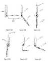
- FIG. 21Ais a perspective view of the forearm of a robotic device, according to another embodiment.
- FIG. 21Bis a side view of the forearm of a robotic device, according to the embodiment of FIG. 21A .
- FIG. 21Cis another side view of the forearm of a robotic device, according to the embodiment of FIG. 21A .
- FIG. 21Dis an end view of the forearm of a robotic device, according to the embodiment of FIG. 21A .
- FIG. 21Eis a cross sectional side view of the forearm of a robotic device, according to the embodiment of FIG. 21A .
- FIG. 21Fis a side view of the forearm of a robotic device, according to the embodiment of FIG. 21A .
- FIG. 21Gis an exploded perspective view of the forearm and internal components of a robotic device, according to the embodiment of FIG. 21A .
- FIG. 21His a side view of the forearm and internal components of a robotic device, according to the embodiment of FIG. 21A .
- FIG. 22Ais an exploded close-up view of the proximal end of the forearm and internal components of a robotic device, according to another embodiment.
- FIG. 22Bis a cutaway close-up view of the proximal end of the forearm and internal components of a robotic device, according to the embodiment of FIG. 22A .
- FIG. 23Ais a cutaway close-up view of the grasper end of the forearm and internal components of a robotic device, according to another embodiment.
- FIG. 23Bis an exploded close-up view of the grasper end of the forearm and internal components of a robotic device, according to the embodiment of FIG. 23A .
- FIG. 24is a perspective close-up view of the grasper of a robotic device, according to another yet implementation.
- FIG. 25Ais a see-through side view of the forearm having a camera and internal components of a robotic device, according to another embodiment of the system.
- FIG. 25Bis an exploded and see-through view of the forearm having a camera of a robotic device, according to the embodiment of FIG. 25A .
- FIG. 25Cis a close up perspective view of the forearm having a camera of a robotic device, according to the embodiment of FIG. 25A .
- FIG. 25Dis another close up perspective view of the forearm having a camera of a robotic device, according to the embodiment of FIG. 25A .
- FIG. 25Eis a perspective view of the forearm having a camera detailing the camera's field of vision for a robotic device, according to the embodiment of FIG. 25A .
- FIG. 26Ais a side view of the forearm and body of a robotic device in one position, according to another embodiment.
- FIG. 26Bis a side view of the forearm and body of a robotic device in one position, according to the embodiment of FIG. 26A .
- FIG. 26Cis a side view of the forearm and body of a robotic device in one position, according to the embodiment of FIG. 26A .
- FIG. 26Dis a side view of the forearm and body of a robotic device in one position, according to the embodiment of FIG. 26A .
- FIG. 26Eis a side view of the forearm and body of a robotic device in one position, according to the embodiment of FIG. 26A .
- FIG. 26Fis a side view of the forearm and body of a robotic device in one position, according to the embodiment of FIG. 26A .
- FIG. 27Ais a side view of the forearm and body of a robotic device in one position inside the body, according to another embodiment.
- FIG. 27Bis a side view of the forearm and body of a robotic device in one position inside the body according to the embodiment of FIG. 27A .
- FIG. 27Cis a side view of the forearm and body of a robotic device in one position inside the body, according to the embodiment of FIG. 27A .
- FIG. 28is front view of a robotic device, according to one embodiment.
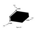
- FIG. 29is a perspective view of an accelerometer according to one embodiment, showing the axis of detection.
- the various embodiments disclosed or contemplated hereinrelate to surgical robotic devices, systems, and methods. More specifically, various embodiments relate to various medical devices, including robotic devices and related methods and systems. Certain implementations relate to such devices for use in laparo-endoscopic single-site (LESS) surgical procedures.
- LESSlaparo-endoscopic single-site
- an “in vivo device” as used hereinmeans any device that can be positioned, operated, or controlled at least in part by a user while being positioned within a body cavity of a patient, including any device that is coupled to a support component such as a rod or other such component that is disposed through an opening or orifice of the body cavity, also including any device positioned substantially against or adjacent to a wall of a body cavity of a patient, further including any such device that is internally actuated (having no external source of motive force), and additionally including any device that may be used laparoscopically or endoscopically during a surgical procedure.
- the terms “robot,” and “robotic device”shall refer to any device that can perform a task either automatically or in response to a command.
- Certain embodimentsprovide for insertion of the present invention into the cavity while maintaining sufficient insufflation of the cavity. Further embodiments minimize the physical contact of the surgeon or surgical users with the present invention during the insertion process. Other implementations enhance the safety of the insertion process for the patient and the present invention. For example, some embodiments provide visualization of the present invention as it is being inserted into the patient's cavity to ensure that no damaging contact occurs between the system/device and the patient. In addition, certain embodiments allow for minimization of the incision size/length. Further implementations reduce the complexity of the access/insertion procedure and/or the steps required for the procedure. Other embodiments relate to devices that have minimal profiles, minimal size, or are generally minimal in function and appearance to enhance ease of handling and use.
- both “combination device” and “modular device”shall mean any medical device having modular or interchangeable components that can be arranged in a variety of different configurations.
- the modular components and combination devices disclosed hereinalso include segmented triangular or quadrangular-shaped combination devices. These devices, which are made up of modular components (also referred to herein as “segments”) that are connected to create the triangular or quadrangular configuration, can provide leverage and/or stability during use while also providing for substantial payload space within the device that can be used for larger components or more operational components.
- these triangular or quadrangular devicescan be positioned inside the body cavity of a patient in the same fashion as those devices discussed and disclosed above.
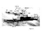
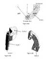
- FIGS. 1, 2, and 3An exemplary embodiment of a robotic device is depicted in FIGS. 1, 2, and 3 .
- the devicehas a main body, 100 , a right arm A, and a left arm B.
- each of the left B and right A armsis comprised of 2 segments: an upper arm (or first link) 300 A, 300 B and a forearm (or second link) 200 A, 200 B, thereby resulting in each arm A, B having a shoulder joint (or first joint) 300 . 1 A, 300 . 1 B and an elbow joint (or second joint) 200 . 1 A, 200 . 1 B.
- each of the left arm B and right arm Ais capable of four degrees of freedom.
- the left shoulder joint 300 . 1 B and right shoulder joint 300 . 1 Ahave intersecting axes of rotation: shoulder yaw ( ⁇ 1 ) and shoulder pitch ( ⁇ 2 ).
- the elbow joints 200 . 1 A, 200 . 1 Bcontribute a degree of freedom—elbow yaw ( ⁇ 3 )—and the end effectors do as well: end effector roll ( ⁇ 4 ).
- FIGS. 4A, 4B, 4C, 4D, 4E, 4F, 4G, and 4Hdepict the device body 100 according to an exemplary embodiment. More specifically, FIG. 4A depicts a front view of the body 100 , while FIG. 4B depicts a side view. In addition, FIGS. 4C, 4D, 4E, 4F, 4G, and 4H depict various perspectives of the device body 100 in which various internal components of the body 100 are visible.
- the body 100contains four motors which control shoulder yaw ( ⁇ 1 ) and shoulder pitch ( ⁇ 2 ) for the right and left arms A, B. More specifically, as best shown in FIGS. 4C, 4G, and 13D , the proximal right motor 109 A and distal right motor 122 A control shoulder yaw ( ⁇ 1 ) and shoulder pitch ( ⁇ 2 ) for the right shoulder 300 . 1 A, while the proximal left motor 109 B and distal left motor 122 B control shoulder yaw ( ⁇ 1 ) and shoulder pitch ( ⁇ 2 ) for the left shoulder 300 . 1 B.
- This discussionwill focus on the right shoulder 300 . 1 A and arm A, but it is understood that a similar set of components are coupled in a similar fashion to control the yaw and pitch of the left shoulder 300 . 1 B and left arm B.
- the proximal right motor 109 Ais operably coupled to the right shoulder subassembly 127 A of the right shoulder 300 . 1 A via gear 108 A, which is operably coupled to gear 115 . 1 A on the end of the right spur shaft 115 A, and the right bevel gear first right bevel gear at the opposite end of the right spur shaft 115 A is operably coupled to the bevel gear 130 A of the right shoulder subassembly 127 A.
- distal right motor 122 Ais operably coupled to the right shoulder subassembly 127 A via a right distal spur gear 121 A, which is operably coupled to a gear 119 A, which is operably coupled to bevel gear second right bevel gear 117 A, which is operably coupled to the bevel gear 130 A of the right shoulder subassembly 127 A.
- the proximal right motor 109 A and distal right motor 122 Aoperate together to control both the shoulder yaw ( ⁇ 1 ) and shoulder pitch ( ⁇ 2 ) for the right shoulder 300 . 1 A by rotating the first right bevel gear and second right bevel gear at predetermined directions and speeds as will be described in further detail below.
- the four motors 109 A, 109 B, 122 A, 122 B, along with the motors in the arms as described elsewhere herein,are brushed direct current (DC) motors with integrated magnetic encoders and planetary gearheads.
- DCdirect current
- the motors used in the devicecan vary in size depending on the particular device embodiment and the location and/or use of the motor, with the size ranging in diameter from about 6 mm to about 10 mm Alternatively, any known motors or other devices for converting electrical energy into rotational motion can be used.
- the body 100has a plurality of segments that result in separate housings or subassemblies that are coupled together.
- these segments 101 , 102 , 103 , 104 , 105 , and 106create housings that provide protection for internal electronics and support for internal components, including motors and drivetrain components.
- first segment 101is configured to be coupled with second segment 102 such that second segment 102 is positioned at least partially within segment first 101 , thereby creating first housing 100 . 1 as shown in FIGS.
- first housing 100 . 1 and second housing 100 . 2are coupled together as best shown in FIG. 5A .
- the segments, housings, and their assembly into the body 100are discussed in further detail below.
- the distal end (or bottom) of the body 100can also have a camera 99 .
- the camera 99is a single fixed camera 99 positioned in direct line of sight of the surgical workspace.
- the body 100could have multiple cameras operating together to provide stereoscopic (3D) vision.
- any known camera or set of cameras for use in medical devicescould be used.
- the body 100can also have a lighting system such as LEDs and/or fiber optic lights to illuminate the body cavity and/or the surgical workspace.
- the plurality of segments 101 , 102 , 103 , 104 , 105 , 106are made of a combination of machined aluminum and rapid prototyped plastic.
- a process using such materialsis described in “Rapid Prototyping Primer” by William Palm, May 1998 (revised Jul. 30, 2002), which is hereby incorporated herein by reference in its entirety.
- many other known materials for medical devicescan be used, including, but not limited to, stainless steel and/or injection molded plastics.
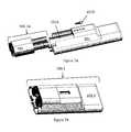
- FIGS. 5A and 5Bdepict the first and second housings 100 . 1 , 100 . 2 .
- FIG. 5Adepicts the front of the first and second housings 100 . 1 , 100 . 2
- FIG. 5Bdepicts the back.
- the proximal right motor 109 A and proximal left motor 109 Bare positioned in the first housing 100 . 1
- the distal right motor 122 A and distal left motor 122 Bare positioned in the second housing 100 . 2
- the first and second housings 100 . 1 , 100 . 2are coupled together using a plurality of threaded members 107 A, 107 B, 107 C as shown.
- any coupling mechanismcan be used to retain the first 100 . 1 and second housings 100 . 2 together.
- FIGS. 6A, 6B, and 6Cdepict the second segment 102 and the positioning of the right 109 A and left proximal motors 109 B within.
- each of the proximal motors 109 A, 109 Bhas a diameter of 10 mm and is made up of three components: the right planetary gearhead 109 A. 1 and left planetary gearhead 109 B. 1 , the proximal right motor drive component 109 A. 2 , proximal left motor drive component 109 B. 2 , and the right 109 A. 3 and left encoders 109 B. 3 . It is understood that the right 109 A. 1 and left 109 B. 1 planetary gearheads reduce the speed of the proximal motor drive components, 109 A.
- the right 109 A. 3 and left 109 B. 3 encoderscontrol the position of the right proximal motor output shaft 108 . 1 A and left proximal motor output shaft 108 . 1 B using electric pulses which can be generated by magnetic, optic, or resistance means.
- the right and left encoders 109 A. 3 , 109 B. 3provide accurate positioning of the right proximal motor output shaft 108 . 1 A and left proximal motor output shaft 108 . 1 B.
- each of the proximal right 108 A, and proximal left spur gears 108 Bis used to transmit the rotational motion from the corresponding proximal motor 109 A, 109 B which further comprises a proximal motor drive component 109 A. 2 , 109 B. 2 which acts through a planetary gearhead 109 A. 1 , 109 B. 1 ).
- Each proximal spur gear 108 A, 108 Bis rotationally constrained with a “D” shaped geometric feature 108 . 1 A, 108 . 1 B and, in some embodiments, a bonding material such as JB-Weld.
- the second segment 102has a plurality of partial lumens, in this implementation a right partial lumen 102 A and left partial lumen 102 B defined within the second segment 102 that have inner walls that do not extend a full 360 degrees.
- the right and left partial lumens 102 A, 102 Bare configured to receive the right and left proximal motors 109 A, 109 B.
- the right and left proximal motors 109 A, 109 Bcan be positioned in the right and left partial lumens 102 A, 102 B as shown in FIGS. 6B, and 6C .
- the second segment 102is configured to allow for the diameter of the walls of the right and left partial lumens 102 A, 102 B to be reduced after the right and left proximal motors 109 A, 109 B have been positioned therein, thereby providing frictional resistance to rotationally and translationally secure the right and left proximal motors 109 A, 109 B within the right and left partial lumens 102 A, 102 B, thereby creating first subassembly 100 . 1 A. More specifically, the second segment 102 allows for a clamping force to be applied to the right and left proximal motors 109 A, 109 B by the tightening of the thread members 110 . It is understood that the right and left proximal motors 109 A, 109 B can also be constrained or secured by any other known method or mechanism.
- FIGS. 7A and 7Bshow the attachment or coupling of the first subassembly 100 . 1 A with the first segment 101 , thereby resulting in the first housing 100 . 1 .
- First segment 101has a first segment mating feature 101 A defined within the first segment 101 that is configured to receive the first subassembly 100 . 1 A. More specifically, in the embodiment depicted in FIG. 7A , the first segment mating feature 101 A is an opening defined in the first segment 101 that mates with the first subassembly 100 . 1 A such that the first subassembly 100 . 1 A fits within the opening and couples with the first segment 101 . In one embodiment, the first subassembly 100 .
- first segment mating feature 101 Afits within the first segment mating feature 101 A such that the first subassembly 100 . 1 A and the first segment 101 are rotationally constrained with respect to each other. Further, a first threaded member 107 D is used to translationally constrain the components.
- the first segment top portion 101 . 1 of the first segment 101is configured or shaped to receive an external clamp (such as, for example, a commercially available external clamp available from Automated Medical Products Corp.
- the clampcan be attached to the first segment top portion 101 . 1 to easily and securely attach the clamp to the body 100 .
- the first housing 100 . 1can have additional features, according to one embodiment. More specifically, the first segment 101 can have a notch or opening 101 . 2 defined at a bottom back portion of the first segment 101 that provides an exit site for cabling/wiring 101 . 4 coupled to at least one of the right and left proximal motors 109 A, 109 B disposed within the first housing 100 . 1 .
- the opening 101 . 2can provide strain relief for the cabling/wiring 101 . 4 to maintain the integrity of the electrical/electronic connections. That is, the opening 101 . 2 can provide a clamping feature that clamps or otherwise secures all of the cabling/wiring 101 .
- the clamping featureresults from the coupling of first 100 . 1 and second housings 100 . 2 as best shown in FIG. 5B .
- the urging of all the cabling/wiring 101 . 4 into the opening 101 . 2 for purposes of allowing for coupling of the housings 100 . 1 and 100 . 2results in a “clamping” of the cabling/wiring 101 . 4 resulting from the frictional restriction of the cabling/wiring 101 . 4 in the opening 101 .
- the opening 101 . 2can also be filled prior to use with silicon or some other means of sealing against liquid contaminants, body fluids, etc., which can also provide additional strain relief similar to the clamping feature described above.
- the first housing 100 . 1can also have a cavity 101 . 3 defined within the first housing 100 . 1 that allows sufficient clearance for the cabling/wiring 101 . 4 to extend from at least one of the right and left proximal motors 109 A, 109 B and exit through opening 101 . 2 .
- FIGS. 9A, 9B, and 9Cdepict the fourth segment 104 , which is a component of the second housing 100 . 2 discussed above and depicted in FIGS. 5A and 5B .
- the fourth segment 104has right 115 . 1 A, and left fourth segment lumens 115 . 1 B defined in the fourth segment 104 that are configured to receive the right proximal spur shaft 115 A and left proximal spur shaft 115 B, both of which are part of the drive trains that operably couple the right and left proximal motors 109 A, 109 B to the right and left shoulder subassemblies 127 A, 127 B that constitute the right 300 . 1 A and left 300 . 1 B shoulders of the device.
- the fourth segment 104also has right and left holes 122 . 1 A, 122 . 1 B defined in the fourth segment 104 . These holes 122 . 1 A, 122 . 1 B are discussed in further detail in relation to FIGS. 11A and 11B below. While the drive train that includes the right proximal spur shaft 115 A will be discussed in detail in this paragraph, it is understood that the drive train that includes the left proximal spur shaft 115 B has the same components that are coupled and function in the same manner. As discussed above with respect to FIGS. 4C and 4G , the right proximal spur shaft 115 A is configured to be disposed through the right lumen 115 . 1 A of the fourth segment 104 . It has a first right driven gear 115 .
- a first right ball bearing 111 Ais positioned within an opening or recess in the first right bevel gear 112 A and is contacted only on its outer race by the inner wall of the opening in the first right bevel gear 112 A. In the finished assembly, this contact will provide appropriate preload to this bearing. It is understood by those of ordinary skill in the art that “bearing preload” is a term and concept that is well known in the art as a mechanism or method by which to improve manufacturing tolerances from the ball bearing by applying a constant axial stress.
- first right bevel gear 112 Ais coupled to the spur shaft 115 A via a threaded coupling (not shown). That is, the first right bevel gear 112 A has a bevel gear lumen 112 . 1 A as best shown in FIG.
- a thread lockeris used to permanently affix the first right bevel gear 112 A to the right proximal spur shaft 115 A.
- the thread lockercan be Loctite, which is commercially available from Henkel Corp. in Dusseldorf, Germany.
- the second and third ball bearings 113 . 1 A, 113 . 2 Acontact the inner walls of the lumen 115 .
- FIGS. 10A and 10Bdepict the fifth 105 and sixth 106 segments, both of which are also components of the second housing 100 . 2 discussed above and depicted in FIGS. 5A and 5B . It should be noted that FIGS. 10A and 10B depict the back side of these segments, while the other figures discussed herein relating to the other segments generally depict the front side.
- the sixth segment 106is an end cap segment that couples to the fifth segment 105 .
- the fifth segment, 105like the fourth 104 , has right and left lumens 119 . 1 A, 119 . 1 B defined in the fifth segment 105 that are configured to receive the right 119 . 3 A and left distal spur shafts 119 .
- segment 105also has right and left fifth segment lumens 122 . 4 A, 122 . 4 B configured to receive the right 122 A and left 122 B distal motors as best shown in FIGS. 12A and 12B and discussed below.
- the first left distal spur shaft 119 . 3 Bis configured to be disposed through the left fifth segment lumen 119 . 1 B. It has a left distal driven gear 119 . 2 B at one end and is coupled to a left distal bevel gear 117 B at the other.
- a fourth ball bearing 116 Bis positioned within an opening or recess in the left distal bevel gear 117 B and is contacted only on its outer race by the inner wall of the opening in the left distal bevel gear 117 B.
- the fifth ball bearing 118 . 1 Bis positioned over/on the bore of left distal bevel gear 117 B and within the left fifth segment lumen 119 . 1 B
- the fifth ball bearing 118 . 2 Bis positioned on/over spur the left distal gear shaft 119 B and within the left fifth segment lumen 119 . 1 B at the opposite end of the fifth segment lumen 119 . 1 B from fifth ball bearing 118 . 1 B.
- the left distal bevel gear 117 Bis coupled to the first left distal spur shaft 119 . 3 B via a threaded coupling (not shown). That is, the left distal bevel gear 117 B has a left distal bevel gear lumen 117 . 1 B as best shown in FIG. 10B that contains internal threads (not shown) while the first left distal spur shaft 119 . 3 B has external threads (not shown) defined on an outer surface at the end of the first left distal spur shaft 119 . 3 B that comes into contact with left distal bevel gear 117 B.
- a thread lockeris used to permanently affix the left distal bevel gear 117 B to the first left distal spur shaft 119 . 3 B.
- the thread lockercan be Loctite, as described above.
- the act of coupling the internal threads in the left distal bevel gear lumen 117 . 1 B with the external threads on the outer surface of the first left distal spur shaft 119 . 3 Bpreloads the fifth and sixth ball bearings 118 . 1 B, 118 . 2 B.
- FIGS. 11A and 11Bdepict the fourth segment 104 and, more specifically, the positioning of the right distal motor 122 A and left distal motor 122 B in the fourth segment holes 122 . 1 A, 122 . 1 B.
- the right distal motor 122 A and left distal motor 122 Bare 10 mm motors that are similar or identical to the right and left proximal motors 109 A, 109 B discussed above. Alternatively, any known motors can be used.
- Each of the right distal motor 122 A and left distal motor 122 Bhave a second right distal spur gear 121 A and second left distal spur gear 121 B, respectively.
- each second distal spur gear 121 A, 121 Bis coupled to the distal motor 122 A, 122 B with “D” geometry as described above and, in some embodiments, adhesive such as JB-Weld.
- the right distal motor 122 A and left distal motor 122 Bare positioned in the right and left fourth segment holes 122 . 1 A, 122 . 1 B.
- the right distal motor 122 A and left distal motor 122 Bare positioned correctly when the right and left distal motor ends 122 . 2 A, 122 . 2 B contact or are substantially adjacent to the right and left distal stop tabs 122 . 3 A, 122 . 3 B.
- the threaded members 123are inserted in the right and left threaded member holes 123 . 1 A, 123 . 1 B and tightened, thereby urging the fourth segment crossbar 123 . 2 downward and thereby constraining the right distal motor 122 A and left distal motor 122 B rotationally and translationally within the fourth segment holes 122 . 1 A, 122 . 1 B.
- FIGS. 12A and 12Bdepict the fourth, fifth and sixth segments 104 , 105 , 106 of the second housing 100 . 2 and how they are coupled together to form the second housing 100 . 2 .
- the fourth, fifth and sixth segments 104 , 105 , 106couple together into a second housing 100 . 2 that forms the right 300 . 1 A and left shoulders 300 . 1 B of the device.
- the right distal motor 122 A and left distal motor 122 Bare positioned through the fifth segment lumens 122 . 4 A, 122 .
- the second distal spur gears 121 A, 121 Btransmit the rotational motion from the right distal motor 122 A and left distal motor 122 B, respectively to the distal spur shafts 119 . 3 A, 119 . 3 B, which are positioned such that they are coupled to the second distal spur gears 121 A, 121 B.
- the first distal spur shafts 119 . 3 A, 119 . 3 Bare coupled to the second right bevel gear, 117 B so that the motion is also transferred through the second right bevel gear, 117 B.
- a fifth segment projection 105 A on the back of the fifth segment 105is positioned in and mates with a fourth segment notch 104 A in the back of the fourth segment 104 , as best shown in FIG. 12B . Further threaded members are then threaded through holes in the fourth segment (not shown) and into the projection 105 A, thereby further securing the fourth and fifth segments 104 , 105 .
- This mated coupling of the fifth segment projection 105 A and fourth segment notch 104 Acan, in one implementation, secure the fourth and fifth segments 104 , 105 to each other such that neither component is rotational in relation to the other, while the threaded members secure the segments translationally.
- the third segment 103can serve as a protective cover that can be coupled or mated with the front portion of the fourth segment 104 and retained with a threaded member 126 .
- the third segment 103can help to protect the motors and electronics in the second housing 100 . 2 .
- a gearcap cover segment 106can be coupled or mated with the bottom portion of the fourth segment 104 and retained with threaded members 120 .
- the cover segment 106can help to cover and protects the various gears 119 A, 119 B, 121 A, 121 B contained within the fourth segment 104 .
- the coupling of the fourth 104 and fifth 105 segmentsalso results in the positioning of the second right bevel gear 117 A in relation to the first right bevel gear, 112 B such that the second right bevel gear 117 A and the first right bevel gear 112 A are positioned to couple with the right shoulder subassembly 127 A to form the right shoulder 300 .
- 1 A and the corresponding left bevel gears 117 B, 112 Bare positioned to couple with the subassembly left shoulder subassembly 127 B to form the left shoulder 300 . 1 B. This is depicted and explained in further detail in FIGS. 13A-14C .
- FIGS. 13A-13D and 14A-14Cdepict the shoulder subassembly design, according to one embodiment.
- the components in these figuresare numbered and will be described without reference to whether they are components of the right shoulder (designated with an “A” at the end of the number) or the left shoulder (designated with a “B” at the end of the number). Instead, it is understood that these components are substantially similar on both sides of the device and will be described as such.
- the shoulder subassemblies 127 A, 127 B of the right shoulder 300 . 1 A and left shoulder 300 . 1 B respectively,have output bevel gears 130 A, 130 B (which couples with the right bevel gears 112 A, 117 A and left bevel gears 112 B, 117 B) having a right lumen 130 A and left lumen (not pictured) configured to receive the right output shaft 128 A and left output shaft.
- the right output shaft 128 Ais positioned in the lumen 130 A and also has two projections (a first 128 A. 1 , and second 128 A. 2 ) that are configured to be positioned in the lumens of the first and second right bevel gears 112 A, 117 A.
- a plurality of ball bearings 111 , 116are positioned over the projections 128 A. 1 , 128 A. 2 such that the inner race of the bearings 111 , 116 contact the projections 128 A. 1 , 128 A. 2 .
- a further ball bearing 129 Ais positioned on/over the right output shaft 128 A such that the ball bearing 129 is positioned within the lumen 130 A of the right output bevel gear 130 A.
- a further ball bearing 131is positioned in the opposing side of the right output bevel gear lumen 130 A and on/over a threaded member 132 .
- the threaded member 132is configured to be threaded into the end of the right output shaft 128 A after the shaft 128 A has been positioned through the lumen 130 A of the right output bevel gear 130 A, thereby helping to retain the right output bevel gear 130 A in position over the right output shaft 128 A and coupled with the first and second right bevels gears 112 A, 117 A.
- the full right shoulder subassembly 127 Ais fully secured such that the right output bevel gear 130 A is securely coupled to the first and second right bevel gears 112 A, 117 A.
- rotation of the first and second right bevel gears 112 A, 117 Arotates the right output bevel gear 130 , which can cause rotation of the right shoulder subassembly 127 A along at least one of two axes—axis A 1 or axis A 2 —depending on the specific rotation and speed of each of the first and second right bevel gears 112 A, 117 A.
- first and second right bevel gears 112 A, 117 Aare rotated in the same direction at the same speed, the first and second right bevel gears 112 A, 117 A are essentially operating as if first and second right bevel gears 112 A, 117 A are a fixed, single unit that cause rotation of the shoulder subassembly 127 A around axis Al.
- the first and second right bevel gears 112 A, 117 Aare rotated in opposite directions, the right output bevel gear 130 A is rotated around axis A 2 . It is understood that the first and second right bevel gears 112 A, 117 A can also work together to achieve any combination of rotation along both axes A 1 , A 2 .
- first and second right bevel gears 112 A, 117 Aare driven independently by the distal and proximal motors 122 A, 109 A, any combination of ⁇ 1 and ⁇ 2 are achievable around axes A 1 and A 2 .
- both gears 112 A, 117 Aare rotated in the same direction but at different speeds, this will result in a combined rotation of the subassembly around both the A 1 axis and the A 2 axis, as would be clear to one of skill in the art
- FIGS. 15A and 15Bdepict a right upper arm (or first link) 300 A that is coupled to the device body 100 at right shoulder 300 . 1 A (as also shown in FIGS. 1 and 2 ). While the following figures and discussion focus on the right upper arm 300 A, it is understood that the left upper arm 300 B can have the same or similar components and thus that the discussion is relevant for the left upper arm 300 B as well.
- the upper arm 300 Ais coupled to the output bevel gear 130 A with two threaded screws 301 A. 1 .
- the upper arm 300 Ahas a notch 301 . 1 A defined in the proximal end of the arm 300 A into which the output bevel gear 130 A is positioned, thereby providing additional mating geometry that further secures the upper arm 300 A and the output bevel gear 130 A.
- the upper arm 300 Ahas an upper arm motor 317 A that actuates the movement of the forearm 200 A at the elbow joint 200 . 1 A of the arm A. That is, the motor 317 is coupled to an upper arm spur gear 318 A, which is coupled to an upper arm driven gear 302 A.
- the driven gear 302 Ais coupled to a first right upper arm bevel gear 306 A, which is coupled to a second right upper arm bevel gear 313 A.
- the second right upper arm bevel gear 313 Ais coupled to an upper arm output upper arm shaft 312 AA, which is coupled to the right forearm 200 A.
- FIGS. 16A and 16Bdepict the right upper arm motor 317 A and the drive train coupled to the motor 317 A in the upper arm 300 A.
- the motor 317 Ais an 8 mm motor that is positioned in the upper arm 300 A.
- the upper arm spur gear 318 Ais coupled to the upper arm motor output shaft 317 A and rotationally secured via a “D” geometry 317 . 1 A.
- the upper arm spur gear 318 Ais further secured with JB-Weld.
- the upper arm 300 Aalso has a housing 304 A positioned in the arm 300 A that is configured to house or support the drive train that is coupled to the upper arm motor 317 A.
- the housing 304has a hole 304 . 3 A defined by two arms 304 .
- a screw 319 Acan be positioned through holes in both arms 304 . 1 A, 304 . 2 A and tightened, thereby urging the arms 304 . 1 A, 304 . 2 A together and securing the upper arm motor 317 A both rotationally and translationally within the hole 304 . 3 A.
- an adhesivesuch as epoxy can be added help to further restrict unwanted movement of the upper arm motor 317 A in relation to the upper arm housing 304 A. This securing of the motor 317 A in the upper arm housing 304 A ensures proper coupling of upper arm spur gear 318 A with the upper arm spur shaft gear 302 A.
- FIGS. 17A and 17Bdepict the first 320 A and second 232 A segments (or “shells”) that couple together to create the housing around the upper arm motor 317 A.
- the first shell 320 Ais positioned above the upper arm motor 317 A and the second shell 323 A is positioned beneath the motor 317 A.
- the two shells 320 A, 323 Aare coupled together with screws 322 A that are positioned through the second shell 323 A and into the first shell 320 A.
- the two shells 320 A, 323 Aare also coupled to the upper arm housing 304 A, with the first shell 320 A being coupled to the upper arm housing 304 A with screws 321 A and the second shell 323 A being coupled to the upper arm housing 304 A with further screws 324 A.
- FIGS. 18A and 18Bdepict the right upper arm housing 304 A and further depict the right upper arm spur shaft 302 A. 1 positioned in the housing 304 A.
- the right upper arm spur shaft 302 Ahas a right upper arm spur gear 302 A. 2 at one end of the spur shaft 302 A. 1 as best shown in FIG. 18A .
- the spur shaft 302 A. 1is positioned in an upper arm housing lumen 304 A. 1 defined in the housing 304 A.
- There are two ball bearings 303 , 305positioned on/over the spur shaft 302 A. 1 and further positioned at the openings of the upper arm housing lumen 304 A. 1 .
- a first upper arm bearing 303is positioned on/over the spur shaft 302 A.
- a second upper arm bearing 305 Ais positioned on/over spur shaft 302 A. 1 in the same manner
- the first right upper arm bevel gear 306 Ais coupled to the upper arm spur shaft 302 A. 1 at the end opposite the spur shaft gear 302 A. 2 .
- the upper arm bevel gear 306 Ais secured to the spur shaft 302 A. 1 with “D” geometry 302 A. 3 .
- the first right upper arm bevel gear 306 Acan also be further secured using adhesive such as JB-Weld.
- a screw 307 Ais positioned through the first right upper arm bevel gear 306 A and into the spur shaft 302 A. 1 such that when the screw 307 A is fully threaded into the spur shaft 302 A. 1 , the screw 307 A translationally secures first right upper arm bevel gear 306 A and also preloads the first 303 and second 305 upper arm bearings.
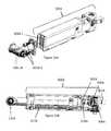
- FIGS. 19A, 19B, and 19Cdepict the upper arm shaft housing 311 A coupled to the upper arm housing 304 .
- the upper arm shaft housing 311 Ais made up of an upper shaft housing arm 311 A. 1 and a lower shaft housing arm 311 A. 2 , both of which are coupled to the upper arm housing 304 A.
- the upper shaft housing arm 311 A. 1is coupled to the housing 304 A via a first pair of screws 307 A. 1
- the lower shaft housing arm 311 A. 2is coupled via a second pair of screws 308 A. 1 .
- each of the shaft housing arms 311 A. 1 , 311 A. 2has a hole 311 A. 1 A, 311 A. 2 A.
- the upper arm shaft 312 AAhas a vertical shaft component 312 A. 1 and an appendage 312 A. 2 coupled to the vertical shaft component 312 A. 1 .
- the upper arm shaft 312 AAis oriented in the assembled shaft housing 311 A such that an upper portion of the vertical shaft component 312 A. 1 is positioned in the hole 311 A. 1 A and a lower portion of the vertical shaft component 312 A. 1 is positioned in the hole 311 A. 2 A.
- a vertical shaft bevel gear 313 Ais positioned over the vertical shaft component 312 A. 1 and above the lower shaft housing arm 311 A.
- the vertical shaft bevel gear 313 Ais coupled to the first right upper arm bevel gear 306 A when all components are properly positioned as best shown in FIG. 19C .
- the vertical shaft bevel gear 313 Ais coupled to the vertical shaft component 312 A. 1 rotationally by a “D” geometry 312 A. 4 as best shown in FIG. 20B .
- the vertical shaft bevel gear 313 Acan be further secured using JB-Weld.
- the vertical shaft component 312 A. 1also has two ball bearings: a first vertical shaft ball bearing 315 A is positioned over the vertical shaft component 312 A. 1 and through hole 311 A.
- a screw 316is positioned through the first ball bearing 315 A and hole 311 A. 2 A and threaded into the bottom of the vertical shaft component 312 A. 1 , thereby helping to secure the upper arm shaft 312 AA in the assemble shaft housing 311 A and the first ball bearing 315 A in the hole 311 A. 2 A.
- a second screw 309 Ais threaded into the top of the vertical shaft component 312 A to secure and preload the second ball bearing 310 .
- FIGS. 20A, 20B, and 20Cdepict upper arm shaft 312 A, according to one embodiment.
- the upper arm shaft 312 Ahas an appendage 312 A. 2 that is configured to be coupled to the forearm 300 A.
- the upper arm shaft 312 Ais rotatable in relation to the upper arm 300 A as a result of the plurality of vertical shaft ball bearings, 310 A and 315 A, as best depicted and described above in relation to FIGS. 19A-C .
- the upper arm shaft 312 Ais rotatable by the right upper arm motor 317 AA in the upper arm 300 A as described above via the drive train that couples the right upper arm motor 317 A to the vertical shaft bevel gear 313 A, which in turn is coupled to the upper arm shaft 312 A.
- the appendage 312 A. 2can be rotated around vertical upper arm shaft 312 AA with a rotational radius or angle of ⁇ 3 as shown in FIG. 20A . In one specific implementation, the angle is 50 degrees.
- the appendage 312 A. 2is configured to be coupleable to a forearm 300 A via the configuration or geometry of the appendage 312 A. 2 and the hole 312 A. 5 formed underneath the appendage 312 A. 2 .
- any known forearm componentcan be coupled to either upper arm 300 A, 300 B.
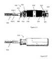
- the forearm coupled to the upper arm 300 A, 300 Bis the exemplary right forearm 410 , which could apply equally to a right 410 A or left 410 B forearm, depicted in FIGS. 21A-21D .
- the forearmhas a cylindrical body or housing 412 and an end effector 414 .
- the housing 412is made up of two separate forearm housing components 412 . 1 , 412 . 2 that are coupled together with three bolts (or threaded members) 472 .
- the three bolts 472pass through housing component 412 . 1 and into threaded holes in the housing component 412 . 2 .
- the two forearm housing components 412 . 1 , 412 . 2can be coupled together by any known coupling mechanism or method.
- the end effector 414is a grasper, but it is understood that any known end effector can be coupled to and used with this forearm 410 .
- the depicted embodimentcan also have a circular valley 474 defined in the distal end of the forearm housing 412 . This valley 474 can be used to retain an elastic band or other similar attachment mechanism for use in attaching a protective plastic bag or other protective container intended to be positioned around the forearm 410 and/or the entire device arm and/or the entire device to maintain a cleaner robot.
- the forearm 410has two motors—a rotation motor 416 and an end effector motor 418 .
- the rotation motor 416is coupled via a forearm rotation motor gear 420 and a forearm rotation motor attachment gear 422 to the forearm attachment component 424 , which is configured to be coupleable to an elbow joint, such as either elbow joint 200 . 1 A, 200 . 1 B.
- the forearm rotation motor attachment gear 422transmits the rotational drive of the motor from the forearm rotation motor gear 420 to the forearm rotation motor attachment component 424 .
- the attachment component 424as best shown in FIGS.
- the 22A and 22Bhas a forearm rotation motor shaft 426 that defines a forearm rotation motor lumen 428 having a threaded interior wall. Further, the attachment gear 422 and first and second forearm bearings 430 , 432 are positioned on/over this shaft 426 , thereby operably coupling the attachment gear 422 to the attachment component 424 .
- the shaft 426has a D-shaped configuration 436 that mates with the D configuration of the hole 438 defined in the gear 422 , thereby rotationally coupling the shaft 426 and gear 422 .
- any configuration that can rotationally couple the two componentscan be incorporated.
- the bearing 430is positioned on the shaft 426 between the attachment component 424 and the attachment gear 422 , while the bearing 432 is positioned between the attachment gear 422 and the motor 416 .
- the bearing 430is a ball bearing.
- these bearings or bushingscan be any roller bearings or bushings that can be used to support and couple any rotatable component to a non-rotatable component or housing.
- the bearings 430 , 432 , attachment gear 422 , and attachment component 424are secured to each other via a bolt or other type of threaded member 434 that is threaded into the threaded lumen 428 of the shaft 426 .
- the two housing components 212 A, 212 Bhave structures defined on their interior walls that are configured to mate with the various components contained within the housing 212 , including the gears 420 , 422 and bearings 430 , 432 .
- the bearings 430 , 432are configured to be positioned within the appropriate mating features in the housing components 212 A, 212 B. These features secure the bearings 430 , 432 in their intended positions in the housing 212 when the two housing components 212 A, 212 B are coupled.
- the rotation motor 416is secured in its position within the housing 412 through a combination of the coupling or mating of the motor 416 with the features defined on the interior walls of the housing components 212 A, 212 B and two bolts or other type of threaded members 440 A, 440 B (one bolt— 440 A—is depicted) that are threaded through the holes 442 A, 442 B and into holes 444 A, 444 B defined in the motor 416 .
- the attachment component 424is an attachment nut 424 .
- the specific geometry or configuration of the attachment component 424can vary depending on the specific robotic device and the specific elbow joint configuration.
- the actuation of the rotation motor 416actuates rotation of the attachment component 424 , which results in rotation of the forearm 410 , thereby rotating the end effector 414 .
- the rotation of the end effector 414is accomplished by rotating the entire forearm 410 , rather than just the end effector 414 .
- the forearm 410rotates around the same axis as the axis of the end effector 414 , such that rotation of the forearm 410 results in the end effector 414 rotating around its axis.
- the two axescan be offset.
- any known end effectorcan be coupled to the forearm 410 .
- the end effectoris a grasper 414 having a yoke 414 . 2 that is positioned around the proximal ends of the grasper components 414 . 1 .
- the grasper 414has a configuration and method of operation substantially similar to the grasper disclosed in U.S. application Ser. No. 13/493,725, filed on Jun. 11, 2012, which is hereby incorporated herein by reference in its entirety.
- any known grasper configurationcan be used.
- the end effector motor 418is configured to actuate the grasper 414 arms to open and close via the motor gear 450 , which is coupled to the coupling gear 452 , which is coupled to center drive rod 454 , which is coupled to the grasper components 414 . 1 .
- the grasper yoke 414 . 2is substantially fixed to the housing 412 so that it does not move relative to the housing 412 . More specifically, the grasper yoke 414 .
- the yoke gear 460is fixedly coupled to the yoke gear 460 , which is positioned in the housing 412 such that it is mated with the ridged notch 462 defined in the inner wall of the housing 412 , as best shown in FIG. 23B .
- the teeth of the yoke gear 460mate with the ridges of the ridge notch 462 to thereby couple the gear 460 and the housing 412 .
- gluecan be placed between the yoke gear 460 and the housing as well, to further enhance the fixation of the grasper yoke 414 . 2 to the housing 412 .
- the coupler gear 452has a center hole (not shown) that is internally threaded (not shown) such that the proximal end of the center drive rod 454 is positioned in the center hole. Because the center drive rod 454 has external threads (not shown) that mate with the internal threads of the center hole defined in the coupler gear 452 , the rotation of the coupler gear 452 causes the internal threads of the center hole to engage the external threads of the drive rod 454 such that the drive rod 454 is moved translationally. This translational movement of the drive rod 454 actuates the grasper arms to move between the closed and open positions.
- the coupler gear 452is supported by two bearings 464 , 466 , which are secured within the housing 412 by appropriate features defined in the inner walls of the housing 412 .
- the end effector motor 418is secured in a fashion similar to the motor 416 .
- the grasper or other end effectorcan be actuated by any known configuration of actuation and/or drive train components.
- the forearm 410when the forearm 410 and the end effector 414 are assembled, the forearm 410 can have a gap 470 between the two motors 416 , 418 .
- the gap 470can be a wiring gap 470 configured to provide space for the necessary wires and/or cables and any other connection components needed or desired to be positioned in the forearm 410 .
- any end effectorcan be used with the robotic device embodiments disclosed and contemplated herein.
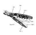
- the grasper 500has two jaws (also referred to as arms) 502 . 1 , 502 . 2 that both pivot around a single pivot point 504 .
- the grasper 500is a “combination” or “hybrid” grasper 500 having structures configured to perform at least two tasks, thereby reducing the need to use one tool for one task and then replace it with another tool for another task. More specifically, each jaw 502 . 1 , 502 .
- teeth 506 . 1 , 506 . 2has two sizes of ridges or toothlike formations (“teeth”): larger teeth 506 . 1 , 506 . 2 and smaller teeth 508 . 1 , 508 . 2 .
- the larger teeth 506 . 1 , 506 . 2are intended for gross manipulations (dealing with larger amounts of tissue or larger bodies in the patient) while the smaller teeth 508 . 1 , 508 . 2 are intended for finer work (such as manipulating thin tissue).
- fine workwhen fine work is to be performed, only the distal ends or tips of the jaws 502 . 1 , 502 . 2 are used such that only the smaller teeth 508 . 1 , 508 . 2 are used.
- the portion of the jaws 502 , 502 . 2 having the smaller teeth 508 . 1 , 508 . 2is narrower in comparison to the portion having the larger teeth 506 . 1 , 506 . 2 , thereby providing a thinner point that can provide more precise control of the grasper 500 .
- a robotic devicecan also have at least one forearm 550 with a camera 552 as shown in FIGS. 25A-25E .
- one embodiment of the forearm 550 with a camera 552has a lumen 560 A defined through a camera housing 556 positioned at the distal end of the forearm 550 .
- the forearm 550also has an end cap 554 that defines a portion of the lumen 560 B as well, as best shown in FIG. 25C .
- the lumens 560 A, 560 Bare coupled to produce a single lumen 560 .
- the end cap 554is coupled to the distal end of the forearm 550 by sliding the cap 554 over the end effector 562 (which, in this particular embodiment, is a cautery component 562 ) and secured to the distal end of the forearm 550 using at least one screw 558 .
- the camera 552can be positioned within the lumen 560 as best shown in FIGS. 25A and 25D .
- the camera 552provides a secondary viewpoint of the surgical site (in addition to the main camera on the robotic device (such as, for example, the camera 99 described above) and could potentially prevent trauma by showing a close-up view of the site.
- the camera 552is positioned such that the field of view contains the tip of the cautery (or any other end effector) 562 and as much of the surgical site as possible.
- One embodiment of the field of view 564 provided by the camera 552is depicted in FIG. 25E , in which the field of view cone is 60 degrees.
- the field of viewcan be any known size for a camera that can be incorporated into a medical device.
- multiple camerascould be incorporated into the distal end of the forearm 550 .
- multiple camerascould be configured to provide stereoscopic (“3D”) visualization.
- the distal end of the forearm 550could also have lights such as, for example, LED or fiber optic lights for illumination. While this particular embodiment depicts the camera 552 being used on a cautery forearm 550 , the camera 552 or any similar variation of the camera 552 as contemplated herein can be incorporated into any robotic end effector in which an alternate view would be beneficial.
- the camera unitcould be positioned in a location on a robotic device other than the forearm.
- the one or more additional viewpoints provided by one or more additional camerascan be shown as a Picture In Picture (PIP) on the surgical user interface or on separate monitors.
- PIPPicture In Picture
- the various embodiments of the robotic device disclosed and contemplated hereincan be positioned in or inserted into a cavity of a patient.
- the insertion methodis the method depicted in FIGS. 26A-26F .
- the entire device 602can be inserted into the cavity as a single device, in contrast to those prior art devices that must be inserted in some unassembled state and then assembled after insertion. That is, many known surgical robotic devices prior to the embodiments disclosed herein require a relatively extensive process for insertion into the abdominal cavity. For such prior art devices, each arm must be inserted individually, aligned with a central connecting rod that is also inserted, and then coupled to the connecting rod to secure the arms in place.
- FIGS. 26A-26Fdepict the various positions of the device arms 604 during the insertion procedure, according to one embodiment.
- FIG. 26Adepicts the base or homing position required by the control kinematics. That is, as is understood by those of ordinary skill in the art, robotic devices typically have encoders that track the current position of the moving parts of the device (such as, for example, the arms 604 on this device), but the encoders track the relative position, not the actual position.
- FIG. 26Bdepicts the arms 604 in a transition position in which the arms 604 are moving from the homing position toward the fully extended vertical position of FIG. 26C .
- the shouldersare then re-positioned to the configuration shown in FIG. 26D (and in further detail in FIG. 27A in which the insertion tube 600 is depicted) in which the arms 604 are rotated to a position in which they are no longer positioned along the same vertical axis (X 1 ) as the device body 602 , but instead are positioned such that the axis (X 2 ) of the arms 604 is parallel to and behind the device body 602 .
- the rotation of the arms 604 to the position of 26 D (and 27 A)also results in the cross-sectional profile of the device 602 along its width being reduced by the size of the arms 604 . That is, while the arms 604 in 26 C are positioned alongside the device body 602 such that the width of the body 602 is enlarged by the width of the arms 604 on each side of the body 602 , the rotation of the arms 604 to a position behind the body 602 also results in the arms 604 being positioned such that they are positioned within the width of the body 602 (that is, they do not extend beyond the width of the body 602 ). It is the configuration of the shoulders as described above that allows for this particular repositioning. The end result is a device configuration in 26 D that has a smaller width than the configuration in 26 C, thereby reducing the profile of the device along its width and allowing for insertion of the device without having to remove the arms.
- the devicecan begin to be inserted into the cavity. Due to the length of the arms, the device cannot be fully inserted into the cavity in this vertical position, so once the forearms are positioned inside the cavity, they are rotated to the position shown in FIG. 26E (and in further detail in FIG. 27B ). Once in this configuration, the rest of the robot is fully inserted and then the device is configured into a typical operating arrangement such as that shown in FIG. 26F (and in further detail in FIG. 27C ).
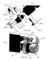
- FIGS. 27A-27Cdepict an insertion tube (also called an “overtube”) 600 in which the robotic device can be stored prior to use. Further, prior to insertion, the tube 600 will be sealed to the abdominal wall after an incision has been made in the wall. Once sealed, the abdomen can be insufflated between the skin 1000 and organ floor 1002 and the blue overtube and abdomen will be at equal pressures. The robot can then be inserted following the previously outlined steps discussed above.
- an insertion tube 600also called an “overtube” 600 in which the robotic device can be stored prior to use. Further, prior to insertion, the tube 600 will be sealed to the abdominal wall after an incision has been made in the wall. Once sealed, the abdomen can be insufflated between the skin 1000 and organ floor 1002 and the blue overtube and abdomen will be at equal pressures. The robot can then be inserted following the previously outlined steps discussed above.
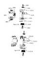
- any of the robotic devices disclosed or contemplated abovecan also incorporate sensors to assist in determining the absolute position of the device components.
- the robotic device 650has a body 652 , a right arm 654 , and a left arm 656 .
- the right arm 654has an upper arm 654 A and a forearm 654 B
- the left arm 656also has an upper arm 656 A and a forearm 656 B.
- each of the upper arms and forearmsare also referred to as “links.”
- the right arm 654has a shoulder joint 654 C and an elbow joint 654 D
- the left arm 656also has a shoulder joint 656 C and an elbow joint 656 D.
- various position sensors 658 , 660 A, 660 B, 662 A, 662 Bare positioned on the device 650 as shown in FIG. 28 . More specifically, a first position sensor 658 is positioned on the device body 652 , while a second position sensor 660 A is positioned on the right upper arm 654 A, a third position sensor 660 B is positioned on the right forearm 654 B, a fourth position sensor 662 A is positioned on the left upper arm 656 A, and a fifth position sensor 662 B is positioned on the left forearm 656 B.
- the sensorsare 3-axis sensors, as described in FIG. 29 .
- the position sensor 658 positioned on the device body 652senses the orientation of the device body 652 and then the orientation of each of the sensors 660 A, 660 B, 662 A, 662 B on the links 654 A, 654 B, 656 A, 656 B can be used to determine the current position of each link of each arm 654 , 656 and the joint angles at joints 654 C, 654 D, 656 C, 656 D.
- each of the other sensors 660 A, 660 B, 662 A, 662 Bcan be used in conjunction with the sensor 658 to determine the position and orientation of both arms relative to the reference point.
- each 3-axis sensormeasures the spatial effect of the at least one environmental characteristic being measured and also determine the orientation of that sensor in all three spatial dimensions.
- Each sensor 660 A, 660 B, 662 A, 662 B on a link 654 A, 654 B, 656 A, 656 Bmeasures the environmental characteristic at that position on the link.
- the measured value and orientation of the sensor 660 A, 660 B, 662 A, 662 B on that linkcan then be used to determine the spatial orientation of each link 654 A, 654 B, 656 A, 656 B.
- the kinematic configuration of both robotic arms 654 , 656can be used with the link orientations determined from the sensors to directly calculate the position of the arms 654 , 656 from the known reference point: sensor 658 . This known orientation can then be used to determine the position and orientation of both arms 654 , 656 relative to the reference point 658 .
- each linkcan be mounted on the link in any known or measureable position and orientation.
- each of the sensorscan be mounted in an interior location inside the particular component that the sensor is intended to be coupled to.
- each sensorcan be positioned on an exterior portion of the appropriate component as long as it is firmly attached to the component.
- FIG. 28depicts a robotic device 650 with two joints and two links per arm
- the position sensorscan be applied to and used with a robotic device with any number of joints and links per arm in any configuration.
- the 3-axis sensors 658 , 660 A, 660 B, 662 A, 662 Bare 3-axis accelerometers that measure the acceleration due to gravity. It is understood that a 3-axis accelerometer operates in the following fashion: the acceleration due to gravity is measured and depending on the orientation of the arm link (or other device component), magnitudes of acceleration in proportion to the orientation angles of the accelerometer are sensed on the different axes 702 , 704 , 706 of the 3-axis accelerometer as best shown in FIG. 29 . Given the acceleration measurements on each axis of the accelerometer, the orientation of the link that the accelerometer is mounted on can be determined with respect to gravity.
- accelerometer sensorscan also measure the acceleration of the link(s) they are attached to on the robotic device.
- this acceleration datacan be integrated over time to provide a position for the links of the robot. The positions determined from this integration can be more accurate if the system model of the robot is known to help account for the effects of inertia and other internal forces.
- sensors other than accelerometerscan be used.
- Possible sensorsinclude, but are not limited to, magnetometers (measuring magnetic field from earth's magnetic field, induced magnetic field, or other magnetic field), tilt sensors, radio frequency signal strength meters, capacitance meter, or any combination or extensions of these.
- magnetometersmeasuring magnetic field from earth's magnetic field, induced magnetic field, or other magnetic field
- tilt sensorstilt sensors
- radio frequency signal strength meterscapacitance meter, or any combination or extensions of these.
- 3-axis sensorsare used in the embodiment discussed above, single or dual or other multi-axis sensors could be used.
- a gyroscopemeasures the rate of rotation in space.
- the gyroscopecan be combined with an accelerometer and magnetometer to form an inertial measurement unit, or IMU, that can be used to measure the static position of the robotic device or to calculate the position of the device while it is moving through integration of the measured data over time.
- IMUinertial measurement unit
- the sensors described abovehelp to determine or provide information about the absolute position of a device component, such as an arm.
- a device componentsuch as an arm.
- the sensor system embodiments described hereinhelp to determine the absolute position of one or more links on a robotic device.
- the position tracking systems disclosed hereinallow a robotic device or a user to autonomously determine what position the device and device arms are in at any time.
- Such a system according to the embodiments disclosed hereincan be used alone (as a primary position tracking system) or in combination with the embedded encoders (as a redundant position tracking system).
- a primary position tracking systema primary position tracking system
- the embedded encodersa redundant position tracking system
- only one position sensoris used per link
- other embodimentshave multiple sensors per link.
- the additional position sensorsprovide additional positional redundancy, and in some implementations the data collected from the multiple position sensors can be used with various filtering techniques, such as Kalman Filtering, to provide a more robust calculation of the position of the robot.
Landscapes
- Health & Medical Sciences (AREA)
- Engineering & Computer Science (AREA)
- Life Sciences & Earth Sciences (AREA)
- Surgery (AREA)
- Nuclear Medicine, Radiotherapy & Molecular Imaging (AREA)
- Medical Informatics (AREA)
- Veterinary Medicine (AREA)
- Public Health (AREA)
- Robotics (AREA)
- Biomedical Technology (AREA)
- Heart & Thoracic Surgery (AREA)
- General Health & Medical Sciences (AREA)
- Molecular Biology (AREA)
- Animal Behavior & Ethology (AREA)
- Mechanical Engineering (AREA)
- Oral & Maxillofacial Surgery (AREA)
- Pathology (AREA)
- Manipulator (AREA)
- Surgical Instruments (AREA)
Abstract
Description
Claims (20)
Priority Applications (6)
| Application Number | Priority Date | Filing Date | Title |
|---|---|---|---|
| US13/839,422US9498292B2 (en) | 2012-05-01 | 2013-03-15 | Single site robotic device and related systems and methods |
| US15/357,663US10219870B2 (en) | 2012-05-01 | 2016-11-21 | Single site robotic device and related systems and methods |
| US16/293,135US11529201B2 (en) | 2012-05-01 | 2019-03-05 | Single site robotic device and related systems and methods |
| US18/058,904US11819299B2 (en) | 2012-05-01 | 2022-11-28 | Single site robotic device and related systems and methods |
| US18/485,601US12171512B2 (en) | 2012-05-01 | 2023-10-12 | Single site robotic device and related systems and methods |
| US18/928,293US20250049521A1 (en) | 2012-05-01 | 2024-10-28 | Single site robotic device and related systems and methods |
Applications Claiming Priority (2)
| Application Number | Priority Date | Filing Date | Title |
|---|---|---|---|
| US201261640879P | 2012-05-01 | 2012-05-01 | |
| US13/839,422US9498292B2 (en) | 2012-05-01 | 2013-03-15 | Single site robotic device and related systems and methods |
Related Child Applications (1)
| Application Number | Title | Priority Date | Filing Date |
|---|---|---|---|
| US15/357,663ContinuationUS10219870B2 (en) | 2012-05-01 | 2016-11-21 | Single site robotic device and related systems and methods |
Publications (2)
| Publication Number | Publication Date |
|---|---|
| US20140039515A1 US20140039515A1 (en) | 2014-02-06 |
| US9498292B2true US9498292B2 (en) | 2016-11-22 |
Family
ID=49916634
Family Applications (6)
| Application Number | Title | Priority Date | Filing Date |
|---|---|---|---|
| US13/839,422Expired - Fee RelatedUS9498292B2 (en) | 2012-05-01 | 2013-03-15 | Single site robotic device and related systems and methods |
| US15/357,663Active2033-05-05US10219870B2 (en) | 2012-05-01 | 2016-11-21 | Single site robotic device and related systems and methods |
| US16/293,135Active2033-07-07US11529201B2 (en) | 2012-05-01 | 2019-03-05 | Single site robotic device and related systems and methods |
| US18/058,904ActiveUS11819299B2 (en) | 2012-05-01 | 2022-11-28 | Single site robotic device and related systems and methods |
| US18/485,601ActiveUS12171512B2 (en) | 2012-05-01 | 2023-10-12 | Single site robotic device and related systems and methods |
| US18/928,293PendingUS20250049521A1 (en) | 2012-05-01 | 2024-10-28 | Single site robotic device and related systems and methods |
Family Applications After (5)
| Application Number | Title | Priority Date | Filing Date |
|---|---|---|---|
| US15/357,663Active2033-05-05US10219870B2 (en) | 2012-05-01 | 2016-11-21 | Single site robotic device and related systems and methods |
| US16/293,135Active2033-07-07US11529201B2 (en) | 2012-05-01 | 2019-03-05 | Single site robotic device and related systems and methods |
| US18/058,904ActiveUS11819299B2 (en) | 2012-05-01 | 2022-11-28 | Single site robotic device and related systems and methods |
| US18/485,601ActiveUS12171512B2 (en) | 2012-05-01 | 2023-10-12 | Single site robotic device and related systems and methods |
| US18/928,293PendingUS20250049521A1 (en) | 2012-05-01 | 2024-10-28 | Single site robotic device and related systems and methods |
Country Status (5)
| Country | Link |
|---|---|
| US (6) | US9498292B2 (en) |
| EP (3) | EP2844181B1 (en) |
| JP (2) | JP2015531608A (en) |
| CA (1) | CA2871149C (en) |
| WO (1) | WO2014011238A2 (en) |
Cited By (9)
| Publication number | Priority date | Publication date | Assignee | Title |
|---|---|---|---|---|
| WO2018039606A1 (en) | 2016-08-25 | 2018-03-01 | Virtual Incision Corporation | Quick-release tool coupler and related systems and methods |
| WO2019067763A1 (en) | 2017-09-27 | 2019-04-04 | Virtual Incision Corporation | Robotic Surgical Devices with Tracking Camera Technology and Related Systems and Methods |
| WO2020146348A1 (en) | 2019-01-07 | 2020-07-16 | Virtual Incision Corporation | Robotically assisted surgical system and related devices and methods |
| US11284958B2 (en) | 2016-11-29 | 2022-03-29 | Virtual Incision Corporation | User controller with user presence detection and related systems and methods |
| US11832871B2 (en) | 2011-06-10 | 2023-12-05 | Board Of Regents Of The University Of Nebraska | Methods, systems, and devices relating to surgical end effectors |
| US11918313B2 (en) | 2019-03-15 | 2024-03-05 | Globus Medical Inc. | Active end effectors for surgical robots |
| EP4461479A2 (en) | 2018-01-05 | 2024-11-13 | Board of Regents of the University of Nebraska | Single-arm robotic device with compact joint design and related systems |
| EP4523648A2 (en) | 2016-08-30 | 2025-03-19 | Board of Regents of the University of Nebraska | Robotic device with compact joint design and an additional degree of freedom and related systems and methods |
| US12390240B2 (en) | 2014-09-12 | 2025-08-19 | Virtual Incision Corporation | Quick-release end effectors and related systems and methods |
Families Citing this family (31)
| Publication number | Priority date | Publication date | Assignee | Title |
|---|---|---|---|---|
| US8679096B2 (en) | 2007-06-21 | 2014-03-25 | Board Of Regents Of The University Of Nebraska | Multifunctional operational component for robotic devices |
| WO2007149559A2 (en) | 2006-06-22 | 2007-12-27 | Board Of Regents Of The University Of Nebraska | Magnetically coupleable robotic devices and related methods |
| US9579088B2 (en) | 2007-02-20 | 2017-02-28 | Board Of Regents Of The University Of Nebraska | Methods, systems, and devices for surgical visualization and device manipulation |
| US8343171B2 (en) | 2007-07-12 | 2013-01-01 | Board Of Regents Of The University Of Nebraska | Methods and systems of actuation in robotic devices |
| JP2010536435A (en) | 2007-08-15 | 2010-12-02 | ボード オブ リージェンツ オブ ザ ユニバーシティ オブ ネブラスカ | Medical inflation, attachment and delivery devices and associated methods |
| WO2013009887A1 (en) | 2011-07-11 | 2013-01-17 | Board Of Regents Of The University Of Nebraska | Robotic surgical devices, systems and related methods |
| WO2013052137A2 (en) | 2011-10-03 | 2013-04-11 | Board Of Regents Of The University Of Nebraska | Robotic surgical devices, systems and related methods |
| WO2013106569A2 (en) | 2012-01-10 | 2013-07-18 | Board Of Regents Of The University Of Nebraska | Methods, systems, and devices for surgical access and insertion |
| EP2844181B1 (en) | 2012-05-01 | 2021-03-10 | Board of Regents of the University of Nebraska | Single site robotic device and related systems |
| EP3189948B1 (en) | 2012-06-22 | 2018-10-17 | Board of Regents of the University of Nebraska | Local control robotic surgical devices |
| US12295680B2 (en) | 2012-08-08 | 2025-05-13 | Board Of Regents Of The University Of Nebraska | Robotic surgical devices, systems and related methods |
| US9770305B2 (en) | 2012-08-08 | 2017-09-26 | Board Of Regents Of The University Of Nebraska | Robotic surgical devices, systems, and related methods |
| EP2882331A4 (en) | 2012-08-08 | 2016-03-23 | Univ Nebraska | ROBOTIC SURGICAL SYSTEMS AND DEVICES, AND ASSOCIATED METHODS |
| CA2906672C (en) | 2013-03-14 | 2022-03-15 | Board Of Regents Of The University Of Nebraska | Methods, systems, and devices relating to force control surgical systems |
| CA2905948C (en) | 2013-03-14 | 2022-01-11 | Board Of Regents Of The University Of Nebraska | Methods, systems, and devices relating to robotic surgical devices, end effectors, and controllers |
| CA2906772C (en) | 2013-03-15 | 2021-09-21 | Board Of Regents Of The University Of Nebraska | Robotic surgical devices, systems and related methods |
| US10966700B2 (en) | 2013-07-17 | 2021-04-06 | Virtual Incision Corporation | Robotic surgical devices, systems and related methods |
| JP2017514608A (en) | 2014-05-05 | 2017-06-08 | バイカリアス サージカル インク. | Virtual reality surgical device |
| EP3217890B1 (en)* | 2014-11-11 | 2020-04-08 | Board of Regents of the University of Nebraska | Robotic device with compact joint design |
| JP2016151499A (en)* | 2015-02-18 | 2016-08-22 | ソニー株式会社 | Information processing device, information processing method, and support arm device |
| GB201512966D0 (en) | 2015-07-22 | 2015-09-02 | Cambridge Medical Robotics Ltd | Drive arrangements for robot arms |
| WO2017024081A1 (en) | 2015-08-03 | 2017-02-09 | Board Of Regents Of The University Of Nebraska | Robotic surgical devices systems and related methods |
| ITUB20155057A1 (en) | 2015-10-16 | 2017-04-16 | Medical Microinstruments S R L | Robotic surgery set |
| CA3024623A1 (en) | 2016-05-18 | 2017-11-23 | Virtual Incision Corporation | Robotic surgical devices, systems and related methods |
| TWI614103B (en)* | 2016-10-21 | 2018-02-11 | 和碩聯合科技股份有限公司 | Mechanical arm positioning method and system adopting the same |
| CN115337111B (en) | 2016-11-22 | 2025-04-25 | 内布拉斯加大学董事会 | Improved coarse positioning device and related system and method |
| WO2018112199A1 (en) | 2016-12-14 | 2018-06-21 | Virtual Incision Corporation | Releasable attachment device for coupling to medical devices and related systems and methods |
| CN110522517A (en)* | 2019-09-16 | 2019-12-03 | 西安交通大学医学院第一附属医院 | A robotic arm for minimally invasive surgery in a single-port laparoscopic environment |
| JP2023532977A (en) | 2020-07-06 | 2023-08-01 | バーチャル インシジョン コーポレイション | Surgical robotic positioning system and related apparatus and methods |
| CN112091924B (en)* | 2020-08-07 | 2022-02-01 | 西南石油大学 | Wheel-arm hybrid reconfigurable robot |
| US20250160978A1 (en)* | 2022-11-21 | 2025-05-22 | Virtual Incision Corporation | Reduced profile robotic surgical device and related systems and methods |
Citations (362)
| Publication number | Priority date | Publication date | Assignee | Title |
|---|---|---|---|---|
| US3870264A (en) | 1973-03-26 | 1975-03-11 | William I Robinson | Stand |
| US3989952A (en) | 1973-08-06 | 1976-11-02 | Siemens Aktiengesellschaft | Dental apparatus |
| US4246661A (en) | 1979-03-15 | 1981-01-27 | The Boeing Company | Digitally-controlled artificial hand |
| US4258716A (en) | 1978-02-06 | 1981-03-31 | The University Of Melbourne | Microsurgical instruments |
| US4278077A (en) | 1978-07-27 | 1981-07-14 | Olympus Optical Co., Ltd. | Medical camera system |
| US4538594A (en) | 1982-11-26 | 1985-09-03 | Richard Wolf Gmbh | Rectoscope |
| US4568311A (en) | 1982-01-29 | 1986-02-04 | Hitachi, Ltd. | Flexible wrist mechanism |
| US4623183A (en) | 1983-09-30 | 1986-11-18 | Kabushiki Kaisha Toshiba | Robot hand |
| US4736645A (en) | 1985-07-19 | 1988-04-12 | Kuka-Schweissanlagen+Roboter Gmbh | Gear unit for a manipulator |
| US4771652A (en) | 1985-12-19 | 1988-09-20 | Kuka Schweissanlagen+Roboter Gmbh | Manipulator-head drive assembly |
| US4852391A (en) | 1986-04-14 | 1989-08-01 | Den Norske Stats Oljeselskap A.S. | Pipeline vehicle |
| US4896015A (en) | 1988-07-29 | 1990-01-23 | Refractive Laser Research & Development Program, Ltd. | Laser delivery system |
| US4897014A (en) | 1988-09-06 | 1990-01-30 | Harbor Branch Oceanographic Institution, Inc. | Device for interchange of tools |
| US4922755A (en) | 1987-12-28 | 1990-05-08 | Hitachi, Ltd. | Wrist mechanism of industrial robot |
| US4990050A (en) | 1984-10-15 | 1991-02-05 | Tokico Ltd. | Wrist mechanism |
| US5019968A (en) | 1988-03-29 | 1991-05-28 | Yulan Wang | Three-dimensional vector processor |
| US5108140A (en) | 1988-04-18 | 1992-04-28 | Odetics, Inc. | Reconfigurable end effector |
| US5172639A (en) | 1991-03-26 | 1992-12-22 | Gas Research Institute | Cornering pipe traveler |
| US5176649A (en) | 1991-01-28 | 1993-01-05 | Akio Wakabayashi | Insertion device for use with curved, rigid endoscopic instruments and the like |
| US5178032A (en) | 1990-10-04 | 1993-01-12 | Comau Spa | Robot wrist |
| WO1992021291A3 (en) | 1991-05-29 | 1993-01-21 | Origin Medsystems Inc | Apparatus and method for peritoneal retraction |
| US5187032A (en) | 1990-04-17 | 1993-02-16 | Yuasa Battery Co., Ltd. | Solid polymer electrolytes |
| US5187796A (en) | 1988-03-29 | 1993-02-16 | Computer Motion, Inc. | Three-dimensional vector co-processor having I, J, and K register files and I, J, and K execution units |
| US5195388A (en) | 1990-10-04 | 1993-03-23 | Comau Spa | Articulated robot |
| US5201325A (en) | 1989-09-01 | 1993-04-13 | Andronic Devices Ltd. | Advanced surgical retractor |
| US5217003A (en) | 1991-03-18 | 1993-06-08 | Wilk Peter J | Automated surgical system and apparatus |
| US5263382A (en) | 1992-04-13 | 1993-11-23 | Hughes Aircraft Company | Six Degrees of freedom motion device |
| US5271384A (en) | 1989-09-01 | 1993-12-21 | Mcewen James A | Powered surgical retractor |
| US5284096A (en) | 1991-08-06 | 1994-02-08 | Osaka Gas Company, Limited | Vehicle for use in pipes |
| US5297536A (en) | 1992-08-25 | 1994-03-29 | Wilk Peter J | Method for use in intra-abdominal surgery |
| US5297443A (en) | 1992-07-07 | 1994-03-29 | Wentz John D | Flexible positioning appendage |
| US5304899A (en) | 1991-08-30 | 1994-04-19 | Nippondenso Co., Ltd. | Energy supply system to robot within pipe |
| US5307447A (en) | 1982-10-29 | 1994-04-26 | Kabushiki Kaisha Toshiba | Control system of multi-joint arm robot apparatus |
| US5353807A (en) | 1992-12-07 | 1994-10-11 | Demarco Thomas J | Magnetically guidable intubation device |
| US5363935A (en) | 1993-05-14 | 1994-11-15 | Carnegie Mellon University | Reconfigurable mobile vehicle with magnetic tracks |
| US5382885A (en) | 1993-08-09 | 1995-01-17 | The University Of British Columbia | Motion scaling tele-operating system with force feedback suitable for microsurgery |
| JPH07136173A (en) | 1993-11-15 | 1995-05-30 | Olympus Optical Co Ltd | Manipulator for operation |
| US5436542A (en) | 1994-01-28 | 1995-07-25 | Surgix, Inc. | Telescopic camera mount with remotely controlled positioning |
| US5441494A (en) | 1993-07-29 | 1995-08-15 | Ethicon, Inc. | Manipulable hand for laparoscopy |
| US5458131A (en) | 1992-08-25 | 1995-10-17 | Wilk; Peter J. | Method for use in intra-abdominal surgery |
| US5458583A (en) | 1993-01-07 | 1995-10-17 | Medical Innovations Corporation | Gastrostomy catheter system |
| US5458598A (en) | 1993-12-02 | 1995-10-17 | Cabot Technology Corporation | Cutting and coagulating forceps |
| US5471515A (en) | 1994-01-28 | 1995-11-28 | California Institute Of Technology | Active pixel sensor with intra-pixel charge transfer |
| US5515478A (en) | 1992-08-10 | 1996-05-07 | Computer Motion, Inc. | Automated endoscope system for optimal positioning |
| US5524180A (en) | 1992-08-10 | 1996-06-04 | Computer Motion, Inc. | Automated endoscope system for optimal positioning |
| US5553198A (en) | 1993-12-15 | 1996-09-03 | Computer Motion, Inc. | Automated endoscope system for optimal positioning |
| JPH08224248A (en) | 1995-02-23 | 1996-09-03 | Olympus Optical Co Ltd | Mdical manipulator |
| US5562448A (en) | 1990-04-10 | 1996-10-08 | Mushabac; David R. | Method for facilitating dental diagnosis and treatment |
| US5588442A (en) | 1992-08-12 | 1996-12-31 | Scimed Life Systems, Inc. | Shaft movement control apparatus and method |
| US5620417A (en) | 1994-07-07 | 1997-04-15 | Cardiovascular Imaging Systems Incorporated | Rapid exchange delivery catheter |
| US5623582A (en) | 1994-07-14 | 1997-04-22 | Immersion Human Interface Corporation | Computer interface or control input device for laparoscopic surgical instrument and other elongated mechanical objects |
| US5624398A (en) | 1996-02-08 | 1997-04-29 | Symbiosis Corporation | Endoscopic robotic surgical tools and methods |
| US5632761A (en) | 1991-05-29 | 1997-05-27 | Origin Medsystems, Inc. | Inflatable devices for separating layers of tissue, and methods of using |
| US5645520A (en) | 1994-10-12 | 1997-07-08 | Computer Motion, Inc. | Shape memory alloy actuated rod for endoscopic instruments |
| US5657429A (en) | 1992-08-10 | 1997-08-12 | Computer Motion, Inc. | Automated endoscope system optimal positioning |
| US5657584A (en) | 1995-07-24 | 1997-08-19 | Rensselaer Polytechnic Institute | Concentric joint mechanism |
| US5672168A (en) | 1994-10-07 | 1997-09-30 | De La Torre; Roger A. | Laparoscopic access port for surgical instruments or the hand |
| US5674030A (en) | 1991-08-27 | 1997-10-07 | Sika Equipment Ag. | Device and method for repairing building branch lines in inacessible sewer mains |
| US5728599A (en) | 1993-10-28 | 1998-03-17 | Lsi Logic Corporation | Printable superconductive leadframes for semiconductor device assembly |
| US5736821A (en) | 1992-12-28 | 1998-04-07 | Tokyo Gas Co., Ltd. | Intrapipe work robot apparatus and method of measuring position of intrapipe work robot |
| US5754741A (en) | 1992-08-10 | 1998-05-19 | Computer Motion, Inc. | Automated endoscope for optimal positioning |
| US5762458A (en) | 1996-02-20 | 1998-06-09 | Computer Motion, Inc. | Method and apparatus for performing minimally invasive cardiac procedures |
| US5769640A (en) | 1992-12-02 | 1998-06-23 | Cybernet Systems Corporation | Method and system for simulating medical procedures including virtual reality and control method and system for use therein |
| US5791231A (en) | 1993-05-17 | 1998-08-11 | Endorobotics Corporation | Surgical robotic system and hydraulic actuator therefor |
| US5792135A (en) | 1996-05-20 | 1998-08-11 | Intuitive Surgical, Inc. | Articulated surgical instrument for performing minimally invasive surgery with enhanced dexterity and sensitivity |
| US5797538A (en) | 1994-10-05 | 1998-08-25 | United States Surgical Corporation | Articulating apparatus for applying surgical fasteners to body tissue |
| US5797900A (en) | 1996-05-20 | 1998-08-25 | Intuitive Surgical, Inc. | Wrist mechanism for surgical instrument for performing minimally invasive surgery with enhanced dexterity and sensitivity |
| US5808665A (en) | 1992-01-21 | 1998-09-15 | Sri International | Endoscopic surgical instrument and method for use |
| US5807377A (en) | 1996-05-20 | 1998-09-15 | Intuitive Surgical, Inc. | Force-reflecting surgical instrument and positioning mechanism for performing minimally invasive surgery with enhanced dexterity and sensitivity |
| US5825982A (en) | 1995-09-15 | 1998-10-20 | Wright; James | Head cursor control interface for an automated endoscope system for optimal positioning |
| US5845646A (en) | 1996-11-05 | 1998-12-08 | Lemelson; Jerome | System and method for treating select tissue in a living being |
| US5855583A (en) | 1996-02-20 | 1999-01-05 | Computer Motion, Inc. | Method and apparatus for performing minimally invasive cardiac procedures |
| US5876325A (en) | 1993-11-02 | 1999-03-02 | Olympus Optical Co., Ltd. | Surgical manipulation system |
| US5878783A (en) | 1995-05-22 | 1999-03-09 | British Gas Plc | Pipeline vehicle |
| US5895417A (en) | 1996-03-06 | 1999-04-20 | Cardiac Pathways Corporation | Deflectable loop design for a linear lesion ablation apparatus |
| US5906591A (en) | 1996-10-22 | 1999-05-25 | Scuola Superiore Di Studi Universitari E Di Perfezionamento S. Anna | Endoscopic robot |
| US5910129A (en) | 1996-12-19 | 1999-06-08 | Ep Technologies, Inc. | Catheter distal assembly with pull wires |
| US5971976A (en) | 1996-02-20 | 1999-10-26 | Computer Motion, Inc. | Motion minimization and compensation system for use in surgical procedures |
| US5993467A (en) | 1996-11-27 | 1999-11-30 | Yoon; Inbae | Suturing instrument with rotatably mounted spreadable needle holder |
| US6030365A (en) | 1998-06-10 | 2000-02-29 | Laufer; Michael D. | Minimally invasive sterile surgical access device and method |
| US6058323A (en) | 1996-11-05 | 2000-05-02 | Lemelson; Jerome | System and method for treating select tissue in a living being |
| US6063095A (en) | 1996-02-20 | 2000-05-16 | Computer Motion, Inc. | Method and apparatus for performing minimally invasive surgical procedures |
| US6066090A (en) | 1997-06-19 | 2000-05-23 | Yoon; Inbae | Branched endoscope system |
| US6132368A (en) | 1996-12-12 | 2000-10-17 | Intuitive Surgical, Inc. | Multi-component telepresence system and method |
| US6132441A (en) | 1996-11-22 | 2000-10-17 | Computer Motion, Inc. | Rigidly-linked articulating wrist with decoupled motion transmission |
| US6156006A (en) | 1997-10-17 | 2000-12-05 | Circon Corporation | Medical instrument system for piercing through tissue |
| US6159146A (en) | 1999-03-12 | 2000-12-12 | El Gazayerli; Mohamed Mounir | Method and apparatus for minimally-invasive fundoplication |
| US6162171A (en) | 1998-12-07 | 2000-12-19 | Wan Sing Ng | Robotic endoscope and an autonomous pipe robot for performing endoscopic procedures |
| USD438617S1 (en) | 1998-12-08 | 2001-03-06 | Intuitive Surgical, Inc. | Portion of an adaptor for a medical instrument |
| US6206903B1 (en) | 1999-10-08 | 2001-03-27 | Intuitive Surgical, Inc. | Surgical tool with mechanical advantage |
| USD441076S1 (en) | 1998-12-08 | 2001-04-24 | Intuitive Surgical, Inc. | Adaptor for a medical instrument |
| JP2001505810A (en) | 1997-09-25 | 2001-05-08 | アレジアンス、コーポレイション | Surgical tool with flexible shaft |
| USD441862S1 (en) | 1998-12-08 | 2001-05-08 | Intuitive Surgical, Inc. | Portion of an interface for a medical instrument |
| US6238415B1 (en) | 1994-12-22 | 2001-05-29 | Target Therapeutics, Inc | Implant delivery assembly with expandable coupling/decoupling mechanism |
| US6240312B1 (en) | 1997-10-23 | 2001-05-29 | Robert R. Alfano | Remote-controllable, micro-scale device for use in in vivo medical diagnosis and/or treatment |
| US6241730B1 (en) | 1997-11-26 | 2001-06-05 | Scient'x (Societe A Responsabilite Limitee) | Intervertebral link device capable of axial and angular displacement |
| US6246200B1 (en) | 1998-08-04 | 2001-06-12 | Intuitive Surgical, Inc. | Manipulator positioning linkage for robotic surgery |
| USD444555S1 (en) | 1998-12-08 | 2001-07-03 | Intuitive Surgical, Inc. | Interface for a medical instrument |
| US20010018591A1 (en) | 1998-02-24 | 2001-08-30 | Brock David L. | Articulated apparatus for telemanipulator system |
| US6286514B1 (en) | 1996-11-05 | 2001-09-11 | Jerome Lemelson | System and method for treating select tissue in a living being |
| US6292678B1 (en) | 1999-05-13 | 2001-09-18 | Stereotaxis, Inc. | Method of magnetically navigating medical devices with magnetic fields and gradients, and medical devices adapted therefor |
| US6293282B1 (en) | 1996-11-05 | 2001-09-25 | Jerome Lemelson | System and method for treating select tissue in living being |
| US6309403B1 (en) | 1998-06-01 | 2001-10-30 | Board Of Trustees Operating Michigan State University | Dexterous articulated linkage for surgical applications |
| US6309397B1 (en) | 1999-12-02 | 2001-10-30 | Sri International | Accessories for minimally invasive robotic surgery and methods |
| US6312435B1 (en) | 1999-10-08 | 2001-11-06 | Intuitive Surgical, Inc. | Surgical instrument with extended reach for use in minimally invasive surgery |
| US20010049497A1 (en) | 2000-03-24 | 2001-12-06 | Kalloo Anthony Nicolas | Methods and devices for diagnostic and therapeutic interventions in the peritoneal cavity |
| US6331181B1 (en) | 1998-12-08 | 2001-12-18 | Intuitive Surgical, Inc. | Surgical robotic tools, data architecture, and use |
| US20020003173A1 (en) | 2000-04-06 | 2002-01-10 | Siemens Westinghouse Power Corporation | Remote spray coating of nuclear cross-under piping |
| US20020026186A1 (en) | 1995-06-07 | 2002-02-28 | Arthrocare Corporation | Electrosurgical systems and methods for treating tissue |
| US6352503B1 (en) | 1998-07-17 | 2002-03-05 | Olympus Optical Co., Ltd. | Endoscopic surgery apparatus |
| US20020038077A1 (en) | 1994-10-07 | 2002-03-28 | General Surgical Innovations, Inc., California Corporation | Laparoscopic access port for surgical instruments or the hand |
| US6364888B1 (en) | 1996-09-09 | 2002-04-02 | Intuitive Surgical, Inc. | Alignment of master and slave in a minimally invasive surgical apparatus |
| US6394998B1 (en) | 1999-01-22 | 2002-05-28 | Intuitive Surgical, Inc. | Surgical tools for use in minimally invasive telesurgical applications |
| US20020065507A1 (en) | 1996-05-20 | 2002-05-30 | Gholam-Reza Zadno-Azizi | Exchange method for emboli containment |
| US6398726B1 (en) | 1998-11-20 | 2002-06-04 | Intuitive Surgical, Inc. | Stabilizer for robotic beating-heart surgery |
| US6408224B1 (en) | 1999-11-10 | 2002-06-18 | National Aerospace Laboratory Of Science Technology Agency | Rotary articulated robot and method of control thereof |
| US6424885B1 (en) | 1999-04-07 | 2002-07-23 | Intuitive Surgical, Inc. | Camera referenced control in a minimally invasive surgical apparatus |
| US20020103417A1 (en) | 1999-03-01 | 2002-08-01 | Gazdzinski Robert F. | Endoscopic smart probe and method |
| US20020111535A1 (en) | 2001-02-10 | 2002-08-15 | Byungkyu Kim | Self-propelled endoscopic micro-robot and system for intestinal endoscopy using the same |
| US6436107B1 (en) | 1996-02-20 | 2002-08-20 | Computer Motion, Inc. | Method and apparatus for performing minimally invasive surgical procedures |
| US20020120254A1 (en) | 1998-12-08 | 2002-08-29 | Intuitive Surgical, Inc. | Vivo accessories for minimally invasive robotic surgery |
| US20020128552A1 (en) | 1998-11-20 | 2002-09-12 | Intuitive Surgical, Inc. | Repositioning and reorientation of master/slave relationship in minimally invasive telesurgery |
| US6451027B1 (en) | 1998-12-16 | 2002-09-17 | Intuitive Surgical, Inc. | Devices and methods for moving an image capture device in telesurgical systems |
| US6450104B1 (en) | 2000-04-28 | 2002-09-17 | North Carolina State University | Modular observation crawler and sensing instrument and method for operating same |
| US6454758B1 (en) | 1996-12-19 | 2002-09-24 | Ep Technologies, Inc. | Loop structures for supporting multiple electrode elements |
| US20020140392A1 (en) | 2001-03-30 | 2002-10-03 | Johann Borenstein | Apparatus for obstacle traversion |
| US6463361B1 (en) | 1994-09-22 | 2002-10-08 | Computer Motion, Inc. | Speech interface for an automated endoscopic system |
| US20020147487A1 (en) | 2000-12-29 | 2002-10-10 | Medtronic, Inc. | System and method for placing endocardial leads |
| US20020151906A1 (en) | 1999-12-06 | 2002-10-17 | Bacchus Vascular, Inc. | Systems and methods for clot disruption and retrieval |
| US6468265B1 (en) | 1998-11-20 | 2002-10-22 | Intuitive Surgical, Inc. | Performing cardiac surgery without cardioplegia |
| US6470236B2 (en) | 2000-12-19 | 2002-10-22 | Sony Corporation | System and method for controlling master and slave manipulator |
| US6468203B2 (en) | 2000-04-03 | 2002-10-22 | Neoguide Systems, Inc. | Steerable endoscope and improved method of insertion |
| US20020156347A1 (en) | 2001-04-24 | 2002-10-24 | Byungkyu Kim | Micro-robot for colonoscope with motor locomotion and system for colonoscope using the same |
| US20020173700A1 (en) | 2001-05-19 | 2002-11-21 | Korea Institute Of Science And Technology | Micro robot |
| US20020171385A1 (en) | 2001-05-19 | 2002-11-21 | Korea Institute Of Science And Technology | Micro robot |
| US6491691B1 (en) | 1999-10-08 | 2002-12-10 | Intuitive Surgical, Inc. | Minimally invasive surgical hook apparatus and method for using same |
| US6493608B1 (en) | 1999-04-07 | 2002-12-10 | Intuitive Surgical, Inc. | Aspects of a control system of a minimally invasive surgical apparatus |
| US6496099B2 (en) | 1996-06-24 | 2002-12-17 | Computer Motion, Inc. | General purpose distributed operating room control system |
| US20020190682A1 (en) | 2001-03-07 | 2002-12-19 | Hagen Schempf | Gas main robotic inspection system |
| US20030020810A1 (en) | 2001-07-30 | 2003-01-30 | Olympus Optical Co., Ltd. | Capsule-type medical apparatus |
| WO2002082979A3 (en) | 2001-04-18 | 2003-02-06 | Bbms Ltd | Navigating and maneuvering of an in vivo vechicle by extracorporeal devices |
| US6522906B1 (en) | 1998-12-08 | 2003-02-18 | Intuitive Surgical, Inc. | Devices and methods for presenting and regulating auxiliary information on an image display of a telesurgical system to assist an operator in performing a surgical procedure |
| US20030065250A1 (en) | 2001-09-17 | 2003-04-03 | Case Western Reserve University | Peristaltically Self-propelled endoscopic device |
| US6548982B1 (en) | 1999-11-19 | 2003-04-15 | Regents Of The University Of Minnesota | Miniature robotic vehicles and methods of controlling same |
| US6554790B1 (en) | 1998-11-20 | 2003-04-29 | Intuitive Surgical, Inc. | Cardiopulmonary bypass device and method |
| US20030089267A1 (en) | 2001-10-17 | 2003-05-15 | William Marsh Rice University | Autonomous robotic crawler for in-pipe inspection |
| US20030092964A1 (en) | 2001-11-12 | 2003-05-15 | Korea Institute Of Science And Technology | Micro capsule type robot |
| US6565554B1 (en) | 1999-04-07 | 2003-05-20 | Intuitive Surgical, Inc. | Friction compensation in a minimally invasive surgical apparatus |
| US20030097129A1 (en) | 1998-01-21 | 2003-05-22 | Arthrocare Corporation | Apparatus and methods for electrosurgical removal and digestion of tissue |
| US6574355B2 (en) | 1992-01-21 | 2003-06-03 | Intuitive Surigical, Inc. | Method and apparatus for transforming coordinate systems in a telemanipulation system |
| US20030114731A1 (en) | 2001-12-14 | 2003-06-19 | Cadeddu Jeffrey A. | Magnetic positioning system for trocarless laparoscopic instruments |
| US6587750B2 (en) | 2001-09-25 | 2003-07-01 | Intuitive Surgical, Inc. | Removable infinite roll master grip handle and touch sensor for robotic surgery |
| US6591239B1 (en) | 1999-12-09 | 2003-07-08 | Steris Inc. | Voice controlled surgical suite |
| US6594552B1 (en) | 1999-04-07 | 2003-07-15 | Intuitive Surgical, Inc. | Grip strength with tactile feedback for robotic surgery |
| US20030135203A1 (en) | 2002-01-16 | 2003-07-17 | Yulun Wang | Minimally invasive surgical training using robotics and tele-collaboration |
| US20030139742A1 (en) | 2002-01-23 | 2003-07-24 | Wampler Scott D. | Feedback light apparatus and method for use with an electrosurgical instrument |
| US20030144656A1 (en) | 2002-01-25 | 2003-07-31 | Medtronic, Inc | Fluid-assisted electrosurgical instrument with shapeable electrode |
| US6610007B2 (en) | 2000-04-03 | 2003-08-26 | Neoguide Systems, Inc. | Steerable segmented endoscope and method of insertion |
| US20030167000A1 (en) | 2000-02-08 | 2003-09-04 | Tarun Mullick | Miniature ingestible capsule |
| US6620173B2 (en) | 1998-12-08 | 2003-09-16 | Intuitive Surgical, Inc. | Method for introducing an end effector to a surgical site in minimally invasive surgery |
| US20030172871A1 (en) | 2002-03-05 | 2003-09-18 | Oswald Scherer | Device and method for internal coating of a pipe |
| US20030181788A1 (en) | 2002-03-25 | 2003-09-25 | Olympus Optical Co., Ltd. | Capsule-type medical device |
| US20030179308A1 (en) | 2002-03-19 | 2003-09-25 | Lucia Zamorano | Augmented tracking using video, computed data and/or sensing technologies |
| US6642836B1 (en) | 1996-08-06 | 2003-11-04 | Computer Motion, Inc. | General purpose distributed operating room control system |
| US6645196B1 (en) | 2000-06-16 | 2003-11-11 | Intuitive Surgical, Inc. | Guided tool change |
| US6646541B1 (en) | 1996-06-24 | 2003-11-11 | Computer Motion, Inc. | General purpose distributed operating room control system |
| US6659939B2 (en) | 1998-11-20 | 2003-12-09 | Intuitive Surgical, Inc. | Cooperative minimally invasive telesurgical system |
| US6661571B1 (en) | 1999-09-21 | 2003-12-09 | Olympus Optical Co., Ltd. | Surgical microscopic system |
| US20030229268A1 (en) | 2002-04-08 | 2003-12-11 | Olympus Optical Co., Ltd. | Encapsulated endoscope system in which endoscope moves in lumen by itself and rotation of image of region to be observed is ceased |
| US20030230372A1 (en) | 2002-06-13 | 2003-12-18 | Kurt Schmidt | Method for placing objects on the inner wall of a placed sewer pipe and device for carrying out said method |
| US6676684B1 (en) | 2001-09-04 | 2004-01-13 | Intuitive Surgical, Inc. | Roll-pitch-roll-yaw surgical tool |
| US6684129B2 (en) | 1997-09-19 | 2004-01-27 | Intuitive Surgical, Inc. | Master having redundant degrees of freedom |
| US6685698B2 (en) | 2000-07-27 | 2004-02-03 | Intuitive Surgical, Inc. | Roll-pitch-roll surgical tool |
| US6687571B1 (en) | 2001-04-24 | 2004-02-03 | Sandia Corporation | Cooperating mobile robots |
| US6685648B2 (en) | 1996-10-11 | 2004-02-03 | Transvascular, Inc. | Systems and methods for delivering drugs to selected locations within the body |
| US20040024311A1 (en) | 2002-03-06 | 2004-02-05 | Quaid Arthur E. | System and method for haptic sculpting of physical objects |
| US6699177B1 (en) | 1996-02-20 | 2004-03-02 | Computer Motion, Inc. | Method and apparatus for performing minimally invasive surgical procedures |
| US6699235B2 (en) | 2001-06-29 | 2004-03-02 | Intuitive Surgical, Inc. | Platform link wrist mechanism |
| US6702805B1 (en) | 1999-11-12 | 2004-03-09 | Microdexterity Systems, Inc. | Manipulator |
| US20040050394A1 (en) | 2002-09-12 | 2004-03-18 | Sungho Jin | Magnetic navigation system for diagnosis, biopsy and drug delivery vehicles |
| US6714841B1 (en) | 1995-09-15 | 2004-03-30 | Computer Motion, Inc. | Head cursor control interface for an automated endoscope system for optimal positioning |
| US6720988B1 (en) | 1998-12-08 | 2004-04-13 | Intuitive Surgical, Inc. | Stereo imaging system and method for use in telerobotic systems |
| US6728599B2 (en) | 2001-09-07 | 2004-04-27 | Computer Motion, Inc. | Modularity system for computer assisted surgery |
| US6726699B1 (en) | 2000-08-15 | 2004-04-27 | Computer Motion, Inc. | Instrument guide |
| US6730021B2 (en) | 2001-11-07 | 2004-05-04 | Computer Motion, Inc. | Tissue spreader with force measurement, force indication or force limitation |
| US6731988B1 (en) | 1992-01-21 | 2004-05-04 | Sri International | System and method for remote endoscopic surgery |
| JP2004144533A (en) | 2002-10-23 | 2004-05-20 | Noozeru Engineering Kk | Minute light source locating system |
| US20040099175A1 (en) | 2000-07-18 | 2004-05-27 | Yann Perrot | Robot vehicle adapted to operate in pipelines and other narrow passages |
| US20040102772A1 (en) | 2000-03-09 | 2004-05-27 | Baxter Jeffrey W. | Apparatus and method for minimally invasive surgery using rotational cutting tool |
| US20040106916A1 (en) | 2002-03-06 | 2004-06-03 | Z-Kat, Inc. | Guidance system and method for surgical procedures with improved feedback |
| US20040111113A1 (en) | 2002-12-09 | 2004-06-10 | The University Of Tokyo | High-rigidity forceps tip assembly for active forceps and active forceps equipped with the same |
| JP2004180781A (en) | 2002-11-29 | 2004-07-02 | Jikei Univ School Of Medicine | Endoscopic surgery robot |
| US20040140786A1 (en) | 2001-03-30 | 2004-07-22 | Johann Borenstein | Apparatus for obstacle traversion |
| US6770081B1 (en) | 2000-01-07 | 2004-08-03 | Intuitive Surgical, Inc. | In vivo accessories for minimally invasive robotic surgery and methods |
| US6780184B2 (en) | 2000-10-12 | 2004-08-24 | Tanrisever Naim Ertuerk | Quantum energy surgical device and method |
| US6783524B2 (en) | 2001-04-19 | 2004-08-31 | Intuitive Surgical, Inc. | Robotic surgical tool with ultrasound cauterizing and cutting instrument |
| US6788018B1 (en) | 1999-08-03 | 2004-09-07 | Intuitive Surgical, Inc. | Ceiling and floor mounted surgical robot set-up arms |
| US20040173116A1 (en) | 2001-10-17 | 2004-09-09 | William Marsh Rice University | Autonomous robotic crawler for in-pipe inspection |
| US20040176664A1 (en) | 2002-10-29 | 2004-09-09 | Iddan Gavriel J. | In-vivo extendable element device and system, and method of use |
| US6793653B2 (en) | 2001-12-08 | 2004-09-21 | Computer Motion, Inc. | Multifunctional handle for a medical robotic system |
| US6799065B1 (en) | 1998-12-08 | 2004-09-28 | Intuitive Surgical, Inc. | Image shifting apparatus and method for a telerobotic system |
| US6801325B2 (en) | 2002-06-25 | 2004-10-05 | Intuitive Surgical, Inc. | Method and devices for inspecting and calibrating of stereoscopic endoscopes |
| US6810281B2 (en) | 2000-12-21 | 2004-10-26 | Endovia Medical, Inc. | Medical mapping system |
| US20040215331A1 (en) | 2001-12-03 | 2004-10-28 | Xtent, Inc. | Apparatus and methods for delivery of variable length stents |
| US20040225229A1 (en) | 2000-11-27 | 2004-11-11 | Viola Frank J. | Tissue sampling and removal apparatus and method |
| US6817975B1 (en) | 2000-01-14 | 2004-11-16 | Intuitive Surgical, Inc. | Endoscope |
| US6817974B2 (en) | 2001-06-29 | 2004-11-16 | Intuitive Surgical, Inc. | Surgical tool having positively positionable tendon-actuated multi-disk wrist joint |
| US6817972B2 (en) | 1999-10-01 | 2004-11-16 | Computer Motion, Inc. | Heart stabilizer |
| US6820653B1 (en) | 1999-04-12 | 2004-11-23 | Carnegie Mellon University | Pipe inspection and repair system |
| JP2004329292A (en) | 2003-04-30 | 2004-11-25 | Shimadzu Corp | Small shooting device |
| US20040254680A1 (en) | 2003-03-31 | 2004-12-16 | Kabushiki Kaisha Toshiba | Manipulator and its control apparatus and method |
| US6832988B2 (en) | 2002-07-05 | 2004-12-21 | Yacmur, Ltd. | Ultrasonic cannula system |
| US6837846B2 (en) | 2000-04-03 | 2005-01-04 | Neo Guide Systems, Inc. | Endoscope having a guide tube |
| US6839612B2 (en) | 2001-12-07 | 2005-01-04 | Institute Surgical, Inc. | Microwrist system for surgical procedures |
| US6840938B1 (en) | 2000-12-29 | 2005-01-11 | Intuitive Surgical, Inc. | Bipolar cauterizing instrument |
| US20050014994A1 (en) | 2003-07-15 | 2005-01-20 | Fowler Dennis L. | Insertable device and system for minimal access procedure |
| US20050029978A1 (en) | 2003-07-08 | 2005-02-10 | Dmitry Oleynikov | Microrobot for surgical applications |
| US20050043583A1 (en) | 2003-05-22 | 2005-02-24 | Reinmar Killmann | Endoscopy apparatus |
| US6860877B1 (en) | 2000-09-29 | 2005-03-01 | Computer Motion, Inc. | Heart stabilizer support arm |
| US6860346B2 (en) | 2002-04-19 | 2005-03-01 | Regents Of The University Of Minnesota | Adjustable diameter wheel assembly, and methods and vehicles using same |
| US20050049462A1 (en) | 2003-09-01 | 2005-03-03 | Pentax Corporation | Capsule endoscope |
| US20050054902A1 (en) | 2003-09-05 | 2005-03-10 | Mitsujiro Konno | Capsule endoscope |
| US20050054901A1 (en) | 2003-09-05 | 2005-03-10 | Koichiro Yoshino | Capsule endoscope |
| US6870343B2 (en) | 2001-03-30 | 2005-03-22 | The University Of Michigan | Integrated, proportionally controlled, and naturally compliant universal joint actuator with controllable stiffness |
| US20050064378A1 (en) | 2003-09-24 | 2005-03-24 | Toly Christopher C. | Laparoscopic and endoscopic trainer including a digital camera |
| US20050065400A1 (en) | 2001-10-05 | 2005-03-24 | Banik Michael S. | Robotic endoscope with wireless interface |
| US6871563B2 (en) | 2001-02-26 | 2005-03-29 | Howie Choset | Orientation preserving angular swivel joint |
| US20050083460A1 (en) | 2001-07-16 | 2005-04-21 | Nippon Sheet Glass Co., Ltd. | Semi-transmitting mirror-possessing substrate, and semi-transmitting type liquid crystal display apparatus |
| US20050096502A1 (en) | 2003-10-29 | 2005-05-05 | Khalili Theodore M. | Robotic surgical device |
| US6902560B1 (en) | 2000-07-27 | 2005-06-07 | Intuitive Surgical, Inc. | Roll-pitch-roll surgical tool |
| US6911916B1 (en) | 1996-06-24 | 2005-06-28 | The Cleveland Clinic Foundation | Method and apparatus for accessing medical data over a network |
| US20050143644A1 (en) | 2003-12-31 | 2005-06-30 | Given Imaging Ltd. | In-vivo sensing device with alterable fields of view |
| US20050154376A1 (en) | 2003-11-07 | 2005-07-14 | Riviere Cameron N. | Robot for minimally invasive interventions |
| US20050165449A1 (en) | 2003-12-02 | 2005-07-28 | Board Of Regents, The University Of Texas System | Surgical anchor and system |
| US6936001B1 (en) | 1999-10-01 | 2005-08-30 | Computer Motion, Inc. | Heart stabilizer |
| US6951535B2 (en) | 2002-01-16 | 2005-10-04 | Intuitive Surgical, Inc. | Tele-medicine system that transmits an entire state of a subsystem |
| US6974411B2 (en) | 2000-04-03 | 2005-12-13 | Neoguide Systems, Inc. | Endoscope with single step guiding apparatus |
| US20050283137A1 (en) | 2004-06-16 | 2005-12-22 | Doyle Mark C | Surgical tool kit |
| US20050288555A1 (en) | 2004-06-28 | 2005-12-29 | Binmoeller Kenneth E | Methods and devices for illuminating, vievwing and monitoring a body cavity |
| US20050288665A1 (en) | 2004-06-24 | 2005-12-29 | Arthrocare Corporation | Electrosurgical device having planar vertical electrode and related methods |
| US6984203B2 (en) | 2000-04-03 | 2006-01-10 | Neoguide Systems, Inc. | Endoscope with adjacently positioned guiding apparatus |
| US20060020272A1 (en) | 2004-06-24 | 2006-01-26 | Gildenberg Philip L | Semi-robotic suturing device |
| US6994708B2 (en) | 2001-04-19 | 2006-02-07 | Intuitive Surgical | Robotic tool with monopolar electro-surgical scissors |
| US6997908B2 (en) | 1996-09-13 | 2006-02-14 | Scimed Life Systems, Inc. | Rapid exchange catheter with detachable hood |
| US20060046226A1 (en) | 2004-08-27 | 2006-03-02 | Bergler Hans J | Dental imaging system and method of use |
| US7033344B2 (en) | 1997-03-06 | 2006-04-25 | Medtronic Vascular, Inc. | Methods for reducing distal embolization |
| US7053752B2 (en) | 1996-08-06 | 2006-05-30 | Intuitive Surgical | General purpose distributed operating room control system |
| US20060119304A1 (en) | 2003-07-08 | 2006-06-08 | Shane Farritor | Robot for surgical applications |
| WO2006005075A3 (en) | 2004-06-30 | 2006-06-15 | Amir Belson | Apparatus and methods for capsule endoscopy of the esophagus |
| US7063682B1 (en) | 1996-12-19 | 2006-06-20 | Ep Technologies, Inc. | Catheter distal assembly with pull wires |
| US20060149135A1 (en) | 2003-07-02 | 2006-07-06 | Adrian Paz | Virtual ports devices and method |
| US7074179B2 (en) | 1992-08-10 | 2006-07-11 | Intuitive Surgical Inc | Method and apparatus for performing minimally invasive cardiac procedures |
| US20060155263A1 (en) | 2002-12-17 | 2006-07-13 | Lipow Kenneth I | Augmented surgical interface |
| US20060152591A1 (en) | 2005-01-13 | 2006-07-13 | Sheng-Feng Lin | Automatic focus mechanism of an image capturing device |
| US7077446B2 (en) | 2002-10-07 | 2006-07-18 | Harmonic Drive Systems Inc. | Finger unit for robot hand |
| WO2006079108A1 (en) | 2005-01-24 | 2006-07-27 | Intuitive Surgical, Inc | Modular manipulator support for robotic surgery |
| US7083615B2 (en) | 2003-02-24 | 2006-08-01 | Intuitive Surgical Inc | Surgical tool having electrocautery energy supply conductor with inhibited current leakage |
| US7090683B2 (en) | 1998-02-24 | 2006-08-15 | Hansen Medical, Inc. | Flexible instrument |
| US7105000B2 (en) | 2003-03-25 | 2006-09-12 | Ethicon Endo-Surgery, Inc. | Surgical jaw assembly with increased mechanical advantage |
| US7109678B2 (en) | 2003-06-30 | 2006-09-19 | Carl-Zeiss-Stiftung | Holding arrangement having an apparatus for balancing a load torque |
| US7121781B2 (en) | 2003-06-11 | 2006-10-17 | Intuitive Surgical | Surgical instrument with a universal wrist |
| US20060241570A1 (en) | 2005-04-22 | 2006-10-26 | Wilk Patent, Llc | Intra-abdominal medical method |
| US20060241732A1 (en) | 2005-04-22 | 2006-10-26 | Kenergy, Inc. | Catheter system for implanting an intravascular medical device |
| US20060253109A1 (en) | 2006-02-08 | 2006-11-09 | David Chu | Surgical robotic helping hand system |
| US20060258954A1 (en) | 2005-05-13 | 2006-11-16 | Tyler Timberlake | Biopsy forceps assemblies |
| US7147650B2 (en) | 2003-10-30 | 2006-12-12 | Woojin Lee | Surgical instrument |
| US7169141B2 (en) | 1998-02-24 | 2007-01-30 | Hansen Medical, Inc. | Surgical instrument |
| US7182089B2 (en) | 2003-09-19 | 2007-02-27 | Siemens Aktiengesellschaft | Magnetically navigable device with associated magnetic element |
| US20070055342A1 (en) | 2003-09-12 | 2007-03-08 | Wu Patrick P | Delivery system for medical devices |
| US7214230B2 (en) | 1998-02-24 | 2007-05-08 | Hansen Medical, Inc. | Flexible instrument |
| US20070106113A1 (en) | 2005-11-07 | 2007-05-10 | Biagio Ravo | Combination endoscopic operative delivery system |
| US7217240B2 (en) | 1999-10-01 | 2007-05-15 | Intuitive Surgical, Inc. | Heart stabilizer |
| US20070123748A1 (en) | 2005-07-14 | 2007-05-31 | Dwight Meglan | Robot for minimally invasive interventions |
| US20070142725A1 (en) | 2005-12-16 | 2007-06-21 | Hardin Terry D | Biopsy site marker deployment device |
| US20070156019A1 (en) | 2005-12-30 | 2007-07-05 | Larkin David Q | Robotic surgery system including position sensors using fiber bragg gratings |
| US20070156211A1 (en) | 2004-04-19 | 2007-07-05 | Searete Llc, A Limited Liability Corporation Of The State Of Delaware | Lumen-traveling device |
| WO2006052927A3 (en) | 2004-11-08 | 2007-07-12 | Univ Johns Hopkins | Bioptome |
| US20070167955A1 (en) | 2005-01-10 | 2007-07-19 | Duke Fiduciary, Llc | Apparatus and method for deploying an implantable device within the body |
| US7250028B2 (en) | 1999-11-09 | 2007-07-31 | Intuitive Surgical Inc | Endoscopic beating-heart stabilizer and vessel occlusion fastener |
| US20070225634A1 (en) | 2004-04-19 | 2007-09-27 | Searete Llc, A Limited Liability Corporation Of The State Of Delaware | Lumen-traveling delivery device |
| WO2007111571A1 (en) | 2006-03-27 | 2007-10-04 | Nanyang Technological University | Surgical robotic system for flexible endoscopy |
| US20070244520A1 (en) | 2004-04-19 | 2007-10-18 | Searete Llc | Lumen-traveling biological interface device and method of use |
| US20070250064A1 (en) | 2006-04-21 | 2007-10-25 | Davol, Inc. | Method and apparatus for surgical fastening |
| US20070255273A1 (en) | 2006-04-29 | 2007-11-01 | Board Of Regents, The University Of Texas System | Devices for use in Transluminal and Endoluminal Surgery |
| WO2007149559A2 (en) | 2006-06-22 | 2007-12-27 | Board Of Regents Of The University Of Nebraska | Magnetically coupleable robotic devices and related methods |
| US20080015566A1 (en) | 2006-07-13 | 2008-01-17 | Steve Livneh | Surgical sealing and cutting apparatus |
| US20080033569A1 (en) | 2004-04-19 | 2008-02-07 | Searete Llc, A Limited Liability Corporation Of The State Of Delaware | Bioelectromagnetic interface system |
| US20080058989A1 (en) | 2006-04-13 | 2008-03-06 | Board Of Regents Of The University Of Nebraska | Surgical camera robot |
| US20080119870A1 (en) | 2006-11-16 | 2008-05-22 | Williams Matthew R | Two-piece end-effectors for robotic surgical tools |
| US20080132890A1 (en) | 1992-01-07 | 2008-06-05 | Arthrocare Corporation | Electrosurgical apparatus and methods for laparoscopy |
| US20080161804A1 (en) | 2006-12-27 | 2008-07-03 | Boston Scientific Scimed, Inc. | Rf ablation probe array advancing device |
| US20080164079A1 (en) | 2006-11-13 | 2008-07-10 | Jacobsen Stephen C | Serpentine robotic crawler |
| US20080183033A1 (en) | 2005-05-27 | 2008-07-31 | Bern M Jonathan | Endoscope Propulsion System and Method |
| US20080221591A1 (en) | 2007-02-20 | 2008-09-11 | Board Of Regents Of The University Of Nebraska | Methods, systems, and devices for surgical visualization and device manipulation |
| US20080269562A1 (en) | 2007-04-25 | 2008-10-30 | Karl Storz Endovision, Inc. | Endoscope system with pivotable arms |
| US20080269557A1 (en) | 2007-04-25 | 2008-10-30 | Jacques Francois Bernard Marescaux | Surgical Method Utilizing Transluminal Endoscope and Instruments |
| US7447537B1 (en) | 1992-05-27 | 2008-11-04 | International Business Machines Corporation | System and method for augmentation of endoscopic surgery |
| US20090020724A1 (en) | 2007-07-10 | 2009-01-22 | Pierburg Gmbh | Combined check and control valve |
| US20090024142A1 (en) | 2006-02-03 | 2009-01-22 | The European Atomic Energy Community (Euratom) | Robotic surgical system for performing minimally invasive medical procedures |
| US20090048612A1 (en) | 2007-08-15 | 2009-02-19 | Board Of Regents Of The University Of Nebraska | Modular and cooperative medical devices and related systems and methods |
| US20090054909A1 (en)* | 2007-07-12 | 2009-02-26 | Board Of Regents Of The University Of Nebraska | Methods and systems of actuation in robotic devices |
| US20090076536A1 (en) | 2007-08-15 | 2009-03-19 | Board Of Regents Of The University Of Nebraska | Medical inflation, attachment, and delivery devices and related methods |
| US20090137952A1 (en) | 2007-08-14 | 2009-05-28 | Ramamurthy Bhaskar S | Robotic instrument systems and methods utilizing optical fiber sensor |
| US20090143787A9 (en) | 2006-11-06 | 2009-06-04 | De La Pena Alejandro Ramos | Robotic surgical device |
| US20090163929A1 (en) | 2007-06-14 | 2009-06-25 | Benny Hon Bun Yeung | Surgical manipulator |
| US20090171373A1 (en)* | 2007-06-21 | 2009-07-02 | Farritor Shane M | Multifunctional operational component for robotic devices |
| US7566300B2 (en) | 2004-04-15 | 2009-07-28 | Wilson-Cook Medical, Inc. | Endoscopic surgical access devices and methods of articulating an external accessory channel |
| US20090234369A1 (en) | 2006-06-19 | 2009-09-17 | Robarts Research Institute | Apparatus for guiding a medical tool |
| US20090240246A1 (en) | 2008-03-19 | 2009-09-24 | Derek Dee Deville | Cordless Medical Cauterization and Cutting Device |
| US20090236400A1 (en) | 2008-03-18 | 2009-09-24 | David Cole | Endoscopic stapling devices and methods |
| US20090247821A1 (en) | 2008-03-31 | 2009-10-01 | Intuitive Surgical, Inc. | Endoscope with rotationally deployed arms |
| US20090248038A1 (en) | 2008-03-31 | 2009-10-01 | Intuitive Surgical Inc., A Delaware Corporation | Force and torque sensing in a surgical robot setup arm |
| US20090281377A1 (en) | 2006-04-19 | 2009-11-12 | Newell Matthew B | Devices, tools and methods for performing minimally invasive abdominal surgical procedures |
| WO2009144729A1 (en) | 2008-05-28 | 2009-12-03 | Technion Research & Development Foundation Ltd. | Laparoscopic camera array |
| US20090305210A1 (en) | 2008-03-11 | 2009-12-10 | Khurshid Guru | System For Robotic Surgery Training |
| US7637905B2 (en) | 2003-01-15 | 2009-12-29 | Usgi Medical, Inc. | Endoluminal tool deployment system |
| US7645230B2 (en) | 2003-02-11 | 2010-01-12 | Olympus Corporation | Over-tube, method of manufacturing over-tube, method of disposing over-tube, and method of treatment in abdominal cavity |
| US20100010294A1 (en) | 2008-07-10 | 2010-01-14 | Ethicon Endo-Surgery, Inc. | Temporarily positionable medical devices |
| US20100016853A1 (en) | 2008-07-16 | 2010-01-21 | Intuitive Surgical, Inc. | Bipolar cautery instrument |
| US20100016659A1 (en) | 2008-07-18 | 2010-01-21 | Barry Weitzner | Endoscope With Guide |
| US7655004B2 (en) | 2007-02-15 | 2010-02-02 | Ethicon Endo-Surgery, Inc. | Electroporation ablation apparatus, system, and method |
| US20100042097A1 (en) | 2008-08-18 | 2010-02-18 | Encision, Inc. | Enhanced control systems including flexible shielding and support systems for electrosurgical applications |
| US20100056863A1 (en) | 2008-09-02 | 2010-03-04 | Takumi Dejima | Medical manipulator, medical treatment system, and method for medical treatment |
| US7678043B2 (en) | 2005-12-29 | 2010-03-16 | Given Imaging, Ltd. | Device, system and method for in-vivo sensing of a body lumen |
| US20100069710A1 (en) | 2008-09-02 | 2010-03-18 | Ken Yamatani | treatment method |
| US20100069940A1 (en) | 2008-09-12 | 2010-03-18 | Miller Matthew C | Ultrasonic Device for Fingertip Control |
| US20100081875A1 (en) | 2003-07-15 | 2010-04-01 | EndoRobotics Inc. | Surgical Device For Minimal Access Surgery |
| WO2010042611A1 (en) | 2008-10-07 | 2010-04-15 | The Trustees Of Columbia University In The City Of New York | Systems, devices, and method for providing insertable robotic sensory and manipulation platforms for single port surgery |
| WO2010046823A1 (en) | 2008-10-20 | 2010-04-29 | Scuola Superiore Di Studi Universitari E Di Perfezionamento Sant'anna | Endoluminal robotic system |
| WO2010050771A2 (en)* | 2008-10-31 | 2010-05-06 | Chang Wook Jeong | Surgical robot system having tool for minimally invasive surgery |
| US7731727B2 (en) | 2006-04-26 | 2010-06-08 | Lsi Solutions, Inc. | Medical instrument to place a pursestring suture, open a hole and pass a guidewire |
| US20100139436A1 (en) | 2007-03-01 | 2010-06-10 | Tokyo Institute Of Technology | Maneuvering system having inner force sense presenting function |
| US7762825B2 (en) | 2005-12-20 | 2010-07-27 | Intuitive Surgical Operations, Inc. | Electro-mechanical interfaces to mount robotic surgical arms |
| US20100204713A1 (en) | 2006-02-03 | 2010-08-12 | The European Atomic Energy Community (Euratom) | Medical robotic system |
| US7785333B2 (en) | 2006-02-21 | 2010-08-31 | Olympus Medical Systems Corp. | Overtube and operative procedure via bodily orifice |
| US7785251B2 (en) | 2005-04-22 | 2010-08-31 | Wilk Patent, Llc | Port extraction method for trans-organ surgery |
| US7789825B2 (en) | 2003-09-29 | 2010-09-07 | Ethicon Endo-Surgery, Inc. | Handle for endoscopic device |
| US7794494B2 (en) | 2002-10-11 | 2010-09-14 | Boston Scientific Scimed, Inc. | Implantable medical devices |
| US20100245549A1 (en) | 2007-11-02 | 2010-09-30 | The Trustees Of Columbia University In The City Of New York | Insertable surgical imaging device |
| US20100262162A1 (en) | 2007-12-28 | 2010-10-14 | Terumo Kabushiki Kaisha | Medical manipulator and medical robot system |
| US20100292691A1 (en) | 2009-03-05 | 2010-11-18 | Intuitive Surgical Operations, Inc. | Cut and seal instrument |
| US20100318059A1 (en) | 2003-07-08 | 2010-12-16 | Board Of Regents Of The University Of Nebraska | Robotic devices with agent delivery components and related methods |
| US20110015569A1 (en) | 2008-03-27 | 2011-01-20 | Kirschenman Mark B | Robotic catheter system input device |
| US20110020779A1 (en)* | 2005-04-25 | 2011-01-27 | University Of Washington | Skill evaluation using spherical motion mechanism |
| EP2286756A1 (en) | 2009-08-21 | 2011-02-23 | Novineon Healthcare Technology Partners Gmbh | Surgical manipulator means |
| US20110071544A1 (en) | 2009-09-23 | 2011-03-24 | Intuitive Surgical, Inc. | Curved cannula instrument |
| US20110071347A1 (en) | 2009-09-23 | 2011-03-24 | Intuitive Surgical, Inc. | Cannula mounting fixture |
| US20110077478A1 (en) | 2002-04-19 | 2011-03-31 | Dominique Freeman | Body fluid sampling module with a continuous compression tissue interface surface |
| US20110082365A1 (en) | 2009-10-01 | 2011-04-07 | Intuitive Surgical, Inc. | Laterally fenestrated cannula |
| WO2011118646A1 (en) | 2010-03-24 | 2011-09-29 | 株式会社安川電機 | Robot hand and robot device |
| US20110237890A1 (en) | 2009-12-17 | 2011-09-29 | Board Of Regents Of The University Of Nebraska | Modular and cooperative medical devices and related systems and methods |
| US20110238080A1 (en)* | 2010-03-25 | 2011-09-29 | Date Ranjit | Robotic Surgical Instrument System |
| US20110270443A1 (en)* | 2010-04-28 | 2011-11-03 | Kabushiki Kaisha Yaskawa Denki | Apparatus and method for detecting contact position of robot |
| WO2011135503A1 (en) | 2010-04-26 | 2011-11-03 | Scuola Superiore Di Studi Universitari E Di Perfezionamento Sant'anna | Robotic apparatus for minimally invasive surgery |
| US20120035582A1 (en) | 2010-08-06 | 2012-02-09 | Board Of Regents Of The University Of Nebraska | Methods and systems for handling or delivering materials for natural orifice surgery |
| US20120109150A1 (en)* | 2002-03-06 | 2012-05-03 | Mako Surgical Corp. | Haptic guidance system and method |
| US20120253515A1 (en)* | 2001-06-07 | 2012-10-04 | Inria Roquencourt | Methods and apparatus for surgical planning |
| JP5115425B2 (en) | 2008-09-24 | 2013-01-09 | 豊田合成株式会社 | Group III nitride semiconductor light emitting device |
| US8353897B2 (en) | 2004-06-16 | 2013-01-15 | Carefusion 2200, Inc. | Surgical tool kit |
| WO2013009887A1 (en) | 2011-07-11 | 2013-01-17 | Board Of Regents Of The University Of Nebraska | Robotic surgical devices, systems and related methods |
| US20130041360A1 (en) | 2011-06-10 | 2013-02-14 | Board Of Regents Of The University Of Nebraska | Methods, Systems, and Devices Relating to Surgical End Effectors |
| EP2329787B1 (en) | 2009-12-04 | 2016-04-13 | Covidien LP | Suspension system for minimally invasive surgery |
Family Cites Families (184)
| Publication number | Priority date | Publication date | Assignee | Title |
|---|---|---|---|---|
| US2858947A (en) | 1953-11-16 | 1958-11-04 | Garrett Corp | Remote control manipulating apparatus |
| FR2183584B1 (en) | 1972-05-10 | 1974-09-27 | Commissariat Energie Atomique | |
| US3971266A (en) | 1973-07-17 | 1976-07-27 | Nippondenso Co., Ltd. | Power transmission device |
| US3922930A (en) | 1974-12-23 | 1975-12-02 | Nasa | Remotely operable articulated manipulator |
| US4353677A (en) | 1980-03-05 | 1982-10-12 | Thermwood Corporation | Wrist construction for industrial robots |
| JPH0659635B2 (en) | 1981-10-07 | 1994-08-10 | 株式会社日立製作所 | Robot wrist |
| US4645409A (en) | 1982-02-05 | 1987-02-24 | American Cimflex Corporation | Outer arm assembly for industrial robot |
| US4636138A (en) | 1982-02-05 | 1987-01-13 | American Robot Corporation | Industrial robot |
| JPS5959371A (en) | 1982-09-30 | 1984-04-05 | フアナツク株式会社 | Industrial robot |
| JPS601456A (en) | 1983-06-17 | 1985-01-07 | Agency Of Ind Science & Technol | One point-centered three-degree of freedom drive mechanism |
| GB2162814B (en) | 1984-01-13 | 1988-02-24 | Mitsubishi Electric Corp | Wrist apparatus for industrial robot |
| DE3441332A1 (en) | 1984-11-12 | 1986-05-22 | Forschungsinstitut für Steuerungstechnik der Werkzeugmaschinen und Fertigungseinrichtungen in der Institutsgemeinschaft Stuttgart e.V., 7000 Stuttgart | JOINT DRIVE, ESPECIALLY FOR INDUSTRIAL ROBOTS |
| JPS6268293A (en) | 1985-09-20 | 1987-03-28 | 株式会社明電舎 | Manipulator shoulder mechanism |
| US4787270A (en) | 1987-02-11 | 1988-11-29 | Cincinnati Milacron Inc. | Robotic manipulator |
| US4762455A (en)* | 1987-06-01 | 1988-08-09 | Remote Technology Corporation | Remote manipulator |
| IT1211195B (en) | 1987-07-10 | 1989-10-12 | Bruno Bisiach | INDUSTRIAL ROBOT WITH MULTIPLE ARTICULATIONS WITH MULTI-DEGREE FREEDOM OF MOVEMENT |
| JPH01109094A (en) | 1987-10-20 | 1989-04-26 | Fanuc Ltd | End-section rotary drive mechanism of industrial robot and end-section unit-change structure |
| DE3751227D1 (en) | 1987-11-30 | 1995-05-11 | Mark E Rosheim | WRIST ROBOT. |
| JPH0224075A (en) | 1988-07-13 | 1990-01-26 | Mitsubishi Electric Corp | Industrial robot |
| JPH04144533A (en) | 1990-10-05 | 1992-05-19 | Olympus Optical Co Ltd | Endoscope |
| JP3307392B2 (en) | 1991-05-29 | 2002-07-24 | オリジン・メドシステムズ・インク | Endoscope retraction device for surgery |
| US5305653A (en) | 1991-09-30 | 1994-04-26 | Tokico Ltd. | Robot wrist mechanism |
| JPH05115425A (en) | 1991-10-25 | 1993-05-14 | Olympus Optical Co Ltd | Endoscope |
| US6963792B1 (en) | 1992-01-21 | 2005-11-08 | Sri International | Surgical method |
| US5624380A (en) | 1992-03-12 | 1997-04-29 | Olympus Optical Co., Ltd. | Multi-degree of freedom manipulator |
| US5372147A (en) | 1992-06-16 | 1994-12-13 | Origin Medsystems, Inc. | Peritoneal distension robotic arm |
| US5397323A (en) | 1992-10-30 | 1995-03-14 | International Business Machines Corporation | Remote center-of-motion robot for surgery |
| US6346074B1 (en) | 1993-02-22 | 2002-02-12 | Heartport, Inc. | Devices for less invasive intracardiac interventions |
| JP3349197B2 (en) | 1993-06-30 | 2002-11-20 | テルモ株式会社 | Trocar tube |
| JPH07223180A (en) | 1994-02-10 | 1995-08-22 | Tescon:Kk | Horizontal articulated robot |
| JP3226710B2 (en) | 1994-05-10 | 2001-11-05 | 株式会社東芝 | Inspection image processing device and method |
| US5603702A (en) | 1994-08-08 | 1997-02-18 | United States Surgical Corporation | Valve system for cannula assembly |
| US6106521A (en) | 1996-08-16 | 2000-08-22 | United States Surgical Corporation | Apparatus for thermal treatment of tissue |
| CA2266016C (en) | 1996-09-13 | 2004-06-01 | Schering Corporation | Tricyclic inhibitors of farnesyl protein transferase |
| US6086529A (en) | 1997-05-13 | 2000-07-11 | Wisconsin Medical, Inc. | Bronchoscopic manifold with compressible diaphragmatic valve for simultaneous airway instrumentation |
| ATE253111T1 (en) | 1997-08-20 | 2003-11-15 | Univ California | NUCLEIC ACID SEQUENCES ENCODING THE CAPSAICIN RECEPTOR AND POLYPEPTIDES SIMILAR TO THE CAPSAICIN RECEPTOR AND USE THEREOF |
| US7789875B2 (en) | 1998-02-24 | 2010-09-07 | Hansen Medical, Inc. | Surgical instruments |
| US20020128661A1 (en) | 1998-02-24 | 2002-09-12 | Brock David L. | Surgical instrument |
| JP3596340B2 (en) | 1999-03-18 | 2004-12-02 | 株式会社日立製作所 | Surgical insertion device |
| US6450992B1 (en) | 1999-07-02 | 2002-09-17 | Smith & Nephew, Inc. | Cannula interface |
| AU2001233098A1 (en) | 2000-01-27 | 2001-08-07 | Sterilis, Inc. | Cavity enlarger method and apparatus |
| DE10025285A1 (en) | 2000-05-22 | 2001-12-06 | Siemens Ag | Fully automatic, robot-assisted camera guidance using position sensors for laparoscopic interventions |
| JP2002000524A (en) | 2000-06-20 | 2002-01-08 | Hitachi Ltd | Electric vacuum cleaner |
| US6601468B2 (en) | 2000-10-24 | 2003-08-05 | Innovative Robotic Solutions | Drive system for multiple axis robot arm |
| DE10055293A1 (en) | 2000-11-03 | 2002-05-29 | Storz Karl Gmbh & Co Kg | Device for holding and positioning an endoscopic instrument |
| AU2002218518A1 (en) | 2000-12-06 | 2002-06-18 | Honda Giken Kogyo Kabushiki Kaisha | Multi-finger hand device |
| US6440085B1 (en) | 2001-06-12 | 2002-08-27 | Jacek Krzyzanowski | Method of assembling a non-metallic biopsy forceps jaw and a non-metallic biopsy forceps jaw |
| JP3926119B2 (en) | 2001-08-10 | 2007-06-06 | 株式会社東芝 | Medical manipulator |
| WO2003043683A1 (en) | 2001-11-13 | 2003-05-30 | Applied Medical Resources Corporation | Multi-seal trocar system |
| US7637919B2 (en) | 2002-01-30 | 2009-12-29 | Olympus Corporation | Anastomosis system for performing anastomosis in body |
| US7674270B2 (en) | 2002-05-02 | 2010-03-09 | Laparocision, Inc | Apparatus for positioning a medical instrument |
| FR2839440B1 (en) | 2002-05-13 | 2005-03-25 | Perception Raisonnement Action | POSITIONING SYSTEM ON A PATIENT OF AN OBSERVATION AND / OR INTERVENTION DEVICE |
| US6678582B2 (en) | 2002-05-30 | 2004-01-13 | Kuka Roboter Gmbh | Method and control device for avoiding collisions between cooperating robots |
| AU2003257309A1 (en) | 2002-08-13 | 2004-02-25 | Microbotics Corporation | Microsurgical robot system |
| BR0313429A (en) | 2002-08-13 | 2007-07-31 | Wyeth Corp | peptides as solubilizing excipients for transforming growth factor beta proteins |
| EP1556509A2 (en) | 2002-08-19 | 2005-07-27 | Pharmacia Corporation | Antisense modulation of vegf co-regulated chemokine-1 expression |
| US7645510B2 (en) | 2002-09-13 | 2010-01-12 | Jds Uniphase Corporation | Provision of frames or borders around opaque flakes for covert security applications |
| JP4612280B2 (en) | 2003-02-25 | 2011-01-12 | 本田技研工業株式会社 | Automatic working device and automatic working device control program |
| JP2004283940A (en) | 2003-03-20 | 2004-10-14 | Harada Denshi Kogyo Kk | Coordinate driving mechanism, and joint mechanism for robot using it |
| US20050021069A1 (en) | 2003-07-24 | 2005-01-27 | Gerald Feuer | Inflatable apparatus for accessing body cavity and methods of making |
| US7785294B2 (en) | 2003-09-30 | 2010-08-31 | Ethicon Endo-Surgery, Inc. | Woven protector for trocar seal assembly |
| US7344494B2 (en) | 2004-02-09 | 2008-03-18 | Karl Storz Development Corp. | Endoscope with variable direction of view module |
| US8277373B2 (en) | 2004-04-14 | 2012-10-02 | Usgi Medical, Inc. | Methods and apparaus for off-axis visualization |
| US8562516B2 (en) | 2004-04-14 | 2013-10-22 | Usgi Medical Inc. | Methods and apparatus for obtaining endoluminal access |
| US20050272977A1 (en) | 2004-04-14 | 2005-12-08 | Usgi Medical Inc. | Methods and apparatus for performing endoluminal procedures |
| US7734375B2 (en) | 2004-06-09 | 2010-06-08 | Boston Dynamics | Robot and robot leg mechanism |
| CA2513202C (en) | 2004-07-23 | 2015-03-31 | Mehran Anvari | Multi-purpose robotic operating system and method |
| US10646292B2 (en) | 2004-09-30 | 2020-05-12 | Intuitive Surgical Operations, Inc. | Electro-mechanical strap stack in robotic arms |
| JP4541091B2 (en) | 2004-10-04 | 2010-09-08 | 本田技研工業株式会社 | Processing transfer device |
| US7163525B2 (en) | 2004-12-17 | 2007-01-16 | Ethicon Endo-Surgery, Inc. | Duckbill seal protector |
| US8463439B2 (en) | 2009-03-31 | 2013-06-11 | Intuitive Surgical Operations, Inc. | Optic fiber connection for a force sensing instrument |
| US10555775B2 (en) | 2005-05-16 | 2020-02-11 | Intuitive Surgical Operations, Inc. | Methods and system for performing 3-D tool tracking by fusion of sensor and/or camera derived data during minimally invasive robotic surgery |
| US9789608B2 (en) | 2006-06-29 | 2017-10-17 | Intuitive Surgical Operations, Inc. | Synthetic representation of a surgical robot |
| JP2006321027A (en) | 2005-05-20 | 2006-11-30 | Hitachi Ltd | Master / slave manipulator system and its operation input device |
| JP2009507617A (en) | 2005-09-14 | 2009-02-26 | ネオガイド システムズ, インコーポレイテッド | Method and apparatus for performing transluminal and other operations |
| US9198728B2 (en) | 2005-09-30 | 2015-12-01 | Intouch Technologies, Inc. | Multi-camera mobile teleconferencing platform |
| US20070106317A1 (en) | 2005-11-09 | 2007-05-10 | Shelton Frederick E Iv | Hydraulically and electrically actuated articulation joints for surgical instruments |
| US7789861B2 (en) | 2006-04-18 | 2010-09-07 | Ethicon Endo-Surgery, Inc. | Pleated trocar seal |
| CA2650474A1 (en) | 2006-04-24 | 2007-11-08 | Synecor, Llc | Natural orifice surgical system |
| KR101477133B1 (en) | 2006-06-13 | 2014-12-29 | 인튜어티브 서지컬 인코포레이티드 | Minimally invasive surgical system |
| US8377045B2 (en) | 2006-06-13 | 2013-02-19 | Intuitive Surgical Operations, Inc. | Extendable suction surface for bracing medial devices during robotically assisted medical procedures |
| US10008017B2 (en) | 2006-06-29 | 2018-06-26 | Intuitive Surgical Operations, Inc. | Rendering tool information as graphic overlays on displayed images of tools |
| US10258425B2 (en) | 2008-06-27 | 2019-04-16 | Intuitive Surgical Operations, Inc. | Medical robotic system providing an auxiliary view of articulatable instruments extending out of a distal end of an entry guide |
| JP4755047B2 (en) | 2006-08-08 | 2011-08-24 | テルモ株式会社 | Working mechanism and manipulator |
| US8231610B2 (en) | 2006-09-06 | 2012-07-31 | National Cancer Center | Robotic surgical system for laparoscopic surgery |
| US8632535B2 (en) | 2007-01-10 | 2014-01-21 | Ethicon Endo-Surgery, Inc. | Interlock and surgical instrument including same |
| US9138129B2 (en)* | 2007-06-13 | 2015-09-22 | Intuitive Surgical Operations, Inc. | Method and system for moving a plurality of articulated instruments in tandem back towards an entry guide |
| US9089256B2 (en) | 2008-06-27 | 2015-07-28 | Intuitive Surgical Operations, Inc. | Medical robotic system providing an auxiliary view including range of motion limitations for articulatable instruments extending out of a distal end of an entry guide |
| JP5483834B2 (en) | 2007-06-28 | 2014-05-07 | キヤノン株式会社 | Image processing apparatus and image processing method |
| WO2009004616A2 (en) | 2007-07-02 | 2009-01-08 | M.S.T. Medical Surgery Technologies Ltd | System for positioning endoscope and surgical instruments |
| US8920300B2 (en)* | 2007-09-19 | 2014-12-30 | Walter A. Roberts | Direct visualization robotic intra-operative radiation therapy device with radiation ablation capsule |
| GB2454017A (en) | 2007-10-26 | 2009-04-29 | Prosurgics Ltd | A control assembly |
| JP5364255B2 (en) | 2007-10-31 | 2013-12-11 | テルモ株式会社 | Medical manipulator |
| US8758342B2 (en) | 2007-11-28 | 2014-06-24 | Covidien Ag | Cordless power-assisted medical cauterization and cutting device |
| US8636686B2 (en) | 2008-04-28 | 2014-01-28 | Ethicon Endo-Surgery, Inc. | Surgical access device |
| US8562513B2 (en) | 2008-05-20 | 2013-10-22 | Olympus Medical Systems Corp. | Endoscope device |
| US8771260B2 (en) | 2008-05-30 | 2014-07-08 | Ethicon Endo-Surgery, Inc. | Actuating and articulating surgical device |
| JP5195054B2 (en) | 2008-06-11 | 2013-05-08 | パナソニック株式会社 | Arm joint and robot having the same |
| US9179832B2 (en) | 2008-06-27 | 2015-11-10 | Intuitive Surgical Operations, Inc. | Medical robotic system with image referenced camera control using partitionable orientational and translational modes |
| US8864652B2 (en) | 2008-06-27 | 2014-10-21 | Intuitive Surgical Operations, Inc. | Medical robotic system providing computer generated auxiliary views of a camera instrument for controlling the positioning and orienting of its tip |
| JP2010041156A (en) | 2008-08-01 | 2010-02-18 | Toshiba Corp | Semiconductor integrated circuit |
| US8333129B2 (en) | 2008-10-29 | 2012-12-18 | S.A. Robotics | Robotic manipulator arm |
| US9033958B2 (en) | 2008-11-11 | 2015-05-19 | Perception Raisonnement Action En Medecine | Surgical robotic system |
| US20100331856A1 (en) | 2008-12-12 | 2010-12-30 | Hansen Medical Inc. | Multiple flexible and steerable elongate instruments for minimally invasive operations |
| EP2381873A2 (en) | 2009-01-16 | 2011-11-02 | The Board Of Regents Of The University Of Texas System | Medical devices and methods |
| US8120301B2 (en) | 2009-03-09 | 2012-02-21 | Intuitive Surgical Operations, Inc. | Ergonomic surgeon control console in robotic surgical systems |
| DE102009017581B4 (en) | 2009-04-18 | 2021-06-24 | Igus Gmbh | Multi-axis joint especially for robotics |
| KR101030427B1 (en) | 2009-04-28 | 2011-04-20 | 국립암센터 | Endoscopic adjustment device for minimally invasive surgery |
| SG176213A1 (en) | 2009-05-29 | 2011-12-29 | Univ Nanyang Tech | Robotic system for flexible endoscopy |
| JP2011045500A (en) | 2009-08-26 | 2011-03-10 | Terumo Corp | Medical manipulator |
| JP2011077339A (en) | 2009-09-30 | 2011-04-14 | Sony Corp | Semiconductor laser |
| US8888687B2 (en) | 2009-10-28 | 2014-11-18 | Boston Scientific Scimed, Inc. | Method and apparatus related to a flexible assembly at a distal end portion of a medical device |
| JP5499647B2 (en) | 2009-11-10 | 2014-05-21 | 株式会社安川電機 | Robot and robot system |
| KR102152042B1 (en) | 2009-11-13 | 2020-09-04 | 인튜어티브 서지컬 오퍼레이션즈 인코포레이티드 | Surgical tool with a compact wrist |
| US9877744B2 (en) | 2010-02-12 | 2018-01-30 | Intuitive Surgical Operations, Inc. | Entry guide for multiple instruments in a single port surgical system |
| WO2011116332A2 (en) | 2010-03-18 | 2011-09-22 | SPI Surgical, Inc. | Surgical cockpit comprising multisensory and multimodal interfaces for robotic surgery and methods related thereto |
| US9498298B2 (en) | 2010-04-23 | 2016-11-22 | Kenneth I. Lipow | Ring form surgical effector |
| US9918787B2 (en) | 2010-05-05 | 2018-03-20 | St. Jude Medical, Atrial Fibrillation Division, Inc. | Monitoring, managing and/or protecting system and method for non-targeted tissue |
| JP5653073B2 (en) | 2010-05-19 | 2015-01-14 | キヤノン株式会社 | Robot cell device and production system |
| JP5851499B2 (en) | 2010-06-25 | 2016-02-03 | マツィエイ ジェイ. チェトゥラキス, | Single-port laparoscopic access with laterally spaced virtual insertion points |
| US8437884B2 (en) | 2010-07-28 | 2013-05-07 | GM Global Technology Operations LLC | System and method for detecting vehicle motion |
| DE102010040405B4 (en) | 2010-09-08 | 2017-07-27 | Siemens Healthcare Gmbh | Instrument system for an endoscopic robot |
| EP2627278B1 (en) | 2010-10-11 | 2015-03-25 | Ecole Polytechnique Fédérale de Lausanne (EPFL) | Mechanical manipulator for surgical instruments |
| IT1404527B1 (en) | 2011-02-24 | 2013-11-22 | Comau Spa | ARTICULATED ROBOT WRIST. |
| JP5582313B2 (en) | 2011-06-28 | 2014-09-03 | 株式会社安川電機 | Robot system |
| WO2013052137A2 (en) | 2011-10-03 | 2013-04-11 | Board Of Regents Of The University Of Nebraska | Robotic surgical devices, systems and related methods |
| CN102499759B (en) | 2011-10-31 | 2013-11-20 | 上海交通大学 | Multi-degree-of-freedom single-wound-hole robot flexible hand for celiac minimally invasive surgery |
| CN103121215A (en) | 2011-11-18 | 2013-05-29 | 鸿富锦精密工业(深圳)有限公司 | Robot arm part |
| US9622825B2 (en) | 2011-11-28 | 2017-04-18 | National University Of Singapore | Robotic system for flexible endoscopy |
| WO2013106569A2 (en) | 2012-01-10 | 2013-07-18 | Board Of Regents Of The University Of Nebraska | Methods, systems, and devices for surgical access and insertion |
| EP2844181B1 (en)* | 2012-05-01 | 2021-03-10 | Board of Regents of the University of Nebraska | Single site robotic device and related systems |
| EP2854687B1 (en) | 2012-06-01 | 2022-08-24 | Intuitive Surgical Operations, Inc. | Systems for avoiding collisions between manipulator arms using a null-space |
| EP2863827B1 (en) | 2012-06-21 | 2022-11-16 | Globus Medical, Inc. | Surgical robot platform |
| EP3189948B1 (en) | 2012-06-22 | 2018-10-17 | Board of Regents of the University of Nebraska | Local control robotic surgical devices |
| US20140005718A1 (en) | 2012-06-28 | 2014-01-02 | Ethicon Endo-Surgery, Inc. | Multi-functional powered surgical device with external dissection features |
| US9839480B2 (en) | 2012-07-09 | 2017-12-12 | Covidien Lp | Surgical adapter assemblies for use between surgical handle assembly and surgical end effectors |
| US9770305B2 (en) | 2012-08-08 | 2017-09-26 | Board Of Regents Of The University Of Nebraska | Robotic surgical devices, systems, and related methods |
| EP2882331A4 (en) | 2012-08-08 | 2016-03-23 | Univ Nebraska | ROBOTIC SURGICAL SYSTEMS AND DEVICES, AND ASSOCIATED METHODS |
| JP5959371B2 (en) | 2012-08-28 | 2016-08-02 | 三菱鉛筆株式会社 | Shaft cylinder forming method |
| JP5549950B2 (en) | 2012-11-19 | 2014-07-16 | 株式会社安川電機 | robot |
| JP5418704B1 (en) | 2013-01-17 | 2014-02-19 | 株式会社安川電機 | robot |
| US10616491B2 (en) | 2013-02-01 | 2020-04-07 | Deka Products Limited Partnership | Endoscope with pannable camera and related method |
| JP6375309B2 (en) | 2013-02-01 | 2018-08-15 | デカ・プロダクツ・リミテッド・パートナーシップ | Endoscope with camera capable of panning |
| US10507066B2 (en) | 2013-02-15 | 2019-12-17 | Intuitive Surgical Operations, Inc. | Providing information of tools by filtering image areas adjacent to or on displayed images of the tools |
| US9468438B2 (en) | 2013-03-01 | 2016-10-18 | Eticon Endo-Surgery, LLC | Sensor straightened end effector during removal through trocar |
| US9234606B2 (en) | 2013-03-11 | 2016-01-12 | Kohler Co. | Transverse handle assembly for a valve |
| CA2905948C (en) | 2013-03-14 | 2022-01-11 | Board Of Regents Of The University Of Nebraska | Methods, systems, and devices relating to robotic surgical devices, end effectors, and controllers |
| CA2906672C (en) | 2013-03-14 | 2022-03-15 | Board Of Regents Of The University Of Nebraska | Methods, systems, and devices relating to force control surgical systems |
| EP2969409B1 (en) | 2013-03-15 | 2024-05-01 | Intuitive Surgical Operations, Inc. | Inter-operative switching of tools in a robotic surgical system |
| CA2906772C (en) | 2013-03-15 | 2021-09-21 | Board Of Regents Of The University Of Nebraska | Robotic surgical devices, systems and related methods |
| ITMI20130666A1 (en) | 2013-04-23 | 2014-10-24 | Valuebiotech S R L | ROBOT STRUCTURE, PARTICULARLY FOR MINI-INVASIVE SURGERY THROUGH SINGLE PARIETAL ENGRAVING OR NATURAL ORIFICE. |
| US9797486B2 (en) | 2013-06-20 | 2017-10-24 | Covidien Lp | Adapter direct drive with manual retraction, lockout and connection mechanisms |
| US10966700B2 (en) | 2013-07-17 | 2021-04-06 | Virtual Incision Corporation | Robotic surgical devices, systems and related methods |
| WO2015031777A1 (en) | 2013-08-29 | 2015-03-05 | Wayne State University | Camera control system and method |
| US9295522B2 (en) | 2013-11-08 | 2016-03-29 | Covidien Lp | Medical device adapter with wrist mechanism |
| US9918713B2 (en) | 2013-12-09 | 2018-03-20 | Covidien Lp | Adapter assembly for interconnecting electromechanical surgical devices and surgical loading units, and surgical systems thereof |
| CN110448377A (en) | 2013-12-12 | 2019-11-15 | 柯惠Lp公司 | Gear train for robotic surgical system |
| KR101483081B1 (en) | 2014-01-16 | 2015-01-21 | 주식회사 로보스타 | Parallel robot wrist using differential gear |
| EP3125785B1 (en) | 2014-03-31 | 2020-03-04 | Covidien LP | Wrist and jaw assemblies for robotic surgical systems |
| US10080552B2 (en) | 2014-04-21 | 2018-09-25 | Covidien Lp | Adapter assembly with gimbal for interconnecting electromechanical surgical devices and surgical loading units, and surgical systems thereof |
| CN105358072B (en) | 2014-04-22 | 2018-11-09 | 香港生物医学工程有限公司 | Single access channel surgical robotic devices and systems and methods of configuring single access channel surgical robotic devices and systems |
| US10159533B2 (en) | 2014-07-01 | 2018-12-25 | Auris Health, Inc. | Surgical system with configurable rail-mounted mechanical arms |
| CA2961213A1 (en) | 2014-09-12 | 2016-03-17 | Board Of Regents Of The University Of Nebraska | Quick-release end effectors and related systems and methods |
| US9849586B2 (en) | 2014-10-27 | 2017-12-26 | Ross-Hime Designs, Incorporated | Robotic manipulator |
| US9814640B1 (en) | 2014-10-31 | 2017-11-14 | Space Technology Research LLC | Robotic arm bed assist |
| EP3217890B1 (en) | 2014-11-11 | 2020-04-08 | Board of Regents of the University of Nebraska | Robotic device with compact joint design |
| CN204337044U (en) | 2014-12-17 | 2015-05-20 | 上海交通大学 | A kind of operating theater instruments end structure of micro-wound operation robot |
| CN104523309B (en) | 2015-01-23 | 2017-01-18 | 哈尔滨工业大学 | Intraperitoneal traction surgical robot for minimally invasive surgery |
| US9857786B2 (en) | 2015-03-31 | 2018-01-02 | Recognition Robotics, Inc. | System and method for aligning a coordinated movement machine reference frame with a measurement system reference frame |
| JP6494404B2 (en) | 2015-05-01 | 2019-04-03 | キヤノン株式会社 | Vibration type driving device, image forming apparatus, positioning stage, and medical system |
| EP3288720A4 (en) | 2015-05-01 | 2018-04-25 | Titan Medical Inc. | Instrument collision detection and feedback |
| GB2541369B (en) | 2015-07-22 | 2021-03-31 | Cmr Surgical Ltd | Drive mechanisms for robot arms |
| WO2017024081A1 (en) | 2015-08-03 | 2017-02-09 | Board Of Regents Of The University Of Nebraska | Robotic surgical devices systems and related methods |
| US11202653B2 (en) | 2015-08-28 | 2021-12-21 | Atropos Limited | Access port device |
| ITUB20155057A1 (en) | 2015-10-16 | 2017-04-16 | Medical Microinstruments S R L | Robotic surgery set |
| JP6416746B2 (en) | 2015-12-24 | 2018-10-31 | ファナック株式会社 | Industrial articulated robot with miniaturized joints |
| EP3426176B1 (en) | 2016-03-07 | 2020-10-07 | Ethicon LLC | Robotic bi-polar instruments |
| CA3024623A1 (en) | 2016-05-18 | 2017-11-23 | Virtual Incision Corporation | Robotic surgical devices, systems and related methods |
| WO2018045036A1 (en) | 2016-08-30 | 2018-03-08 | Board Of Regents Of The University Of Nebraska | Robotic device with compact joint design and an additional degree of freedom and related systems and methods |
| US10917543B2 (en) | 2017-04-24 | 2021-02-09 | Alcon Inc. | Stereoscopic visualization camera and integrated robotics platform |
| CN117017492A (en) | 2017-09-27 | 2023-11-10 | 虚拟切割有限公司 | Robotic surgical device with tracking camera technology and related systems and methods |
| US10751883B2 (en) | 2018-08-16 | 2020-08-25 | Mitutoyo Corporation | Robot system with supplementary metrology position coordinates determination system |
| WO2020146348A1 (en) | 2019-01-07 | 2020-07-16 | Virtual Incision Corporation | Robotically assisted surgical system and related devices and methods |
| EP4084721B1 (en) | 2019-12-31 | 2025-10-01 | Auris Health, Inc. | Anatomical feature identification and targeting |
- 2013
- 2013-03-15EPEP13816521.2Apatent/EP2844181B1/enactiveActive
- 2013-03-15CACA2871149Apatent/CA2871149C/enactiveActive
- 2013-03-15JPJP2015510277Apatent/JP2015531608A/enactivePending
- 2013-03-15EPEP21156999.1Apatent/EP3845190B1/enactiveActive
- 2013-03-15EPEP23179494.2Apatent/EP4357083A3/enactivePending
- 2013-03-15USUS13/839,422patent/US9498292B2/ennot_activeExpired - Fee Related
- 2013-03-15WOPCT/US2013/032397patent/WO2014011238A2/enactiveApplication Filing
- 2016
- 2016-11-21USUS15/357,663patent/US10219870B2/enactiveActive
- 2019
- 2019-03-05USUS16/293,135patent/US11529201B2/enactiveActive
- 2019-03-20JPJP2019052065Apatent/JP6949894B2/enactiveActive
- 2022
- 2022-11-28USUS18/058,904patent/US11819299B2/enactiveActive
- 2023
- 2023-10-12USUS18/485,601patent/US12171512B2/enactiveActive
- 2024
- 2024-10-28USUS18/928,293patent/US20250049521A1/enactivePending
Patent Citations (499)
| Publication number | Priority date | Publication date | Assignee | Title |
|---|---|---|---|---|
| US3870264A (en) | 1973-03-26 | 1975-03-11 | William I Robinson | Stand |
| US3989952A (en) | 1973-08-06 | 1976-11-02 | Siemens Aktiengesellschaft | Dental apparatus |
| US4258716A (en) | 1978-02-06 | 1981-03-31 | The University Of Melbourne | Microsurgical instruments |
| US4278077A (en) | 1978-07-27 | 1981-07-14 | Olympus Optical Co., Ltd. | Medical camera system |
| US4246661A (en) | 1979-03-15 | 1981-01-27 | The Boeing Company | Digitally-controlled artificial hand |
| US4568311A (en) | 1982-01-29 | 1986-02-04 | Hitachi, Ltd. | Flexible wrist mechanism |
| US5307447A (en) | 1982-10-29 | 1994-04-26 | Kabushiki Kaisha Toshiba | Control system of multi-joint arm robot apparatus |
| US4538594A (en) | 1982-11-26 | 1985-09-03 | Richard Wolf Gmbh | Rectoscope |
| US4623183A (en) | 1983-09-30 | 1986-11-18 | Kabushiki Kaisha Toshiba | Robot hand |
| US4990050A (en) | 1984-10-15 | 1991-02-05 | Tokico Ltd. | Wrist mechanism |
| US4736645A (en) | 1985-07-19 | 1988-04-12 | Kuka-Schweissanlagen+Roboter Gmbh | Gear unit for a manipulator |
| US4771652A (en) | 1985-12-19 | 1988-09-20 | Kuka Schweissanlagen+Roboter Gmbh | Manipulator-head drive assembly |
| US4852391A (en) | 1986-04-14 | 1989-08-01 | Den Norske Stats Oljeselskap A.S. | Pipeline vehicle |
| US4922755A (en) | 1987-12-28 | 1990-05-08 | Hitachi, Ltd. | Wrist mechanism of industrial robot |
| US5187796A (en) | 1988-03-29 | 1993-02-16 | Computer Motion, Inc. | Three-dimensional vector co-processor having I, J, and K register files and I, J, and K execution units |
| US5019968A (en) | 1988-03-29 | 1991-05-28 | Yulan Wang | Three-dimensional vector processor |
| US5108140A (en) | 1988-04-18 | 1992-04-28 | Odetics, Inc. | Reconfigurable end effector |
| US4896015A (en) | 1988-07-29 | 1990-01-23 | Refractive Laser Research & Development Program, Ltd. | Laser delivery system |
| US4897014A (en) | 1988-09-06 | 1990-01-30 | Harbor Branch Oceanographic Institution, Inc. | Device for interchange of tools |
| US5271384A (en) | 1989-09-01 | 1993-12-21 | Mcewen James A | Powered surgical retractor |
| US5201325A (en) | 1989-09-01 | 1993-04-13 | Andronic Devices Ltd. | Advanced surgical retractor |
| US5562448A (en) | 1990-04-10 | 1996-10-08 | Mushabac; David R. | Method for facilitating dental diagnosis and treatment |
| US5187032A (en) | 1990-04-17 | 1993-02-16 | Yuasa Battery Co., Ltd. | Solid polymer electrolytes |
| US5195388A (en) | 1990-10-04 | 1993-03-23 | Comau Spa | Articulated robot |
| US5178032A (en) | 1990-10-04 | 1993-01-12 | Comau Spa | Robot wrist |
| US5176649A (en) | 1991-01-28 | 1993-01-05 | Akio Wakabayashi | Insertion device for use with curved, rigid endoscopic instruments and the like |
| US5217003A (en) | 1991-03-18 | 1993-06-08 | Wilk Peter J | Automated surgical system and apparatus |
| US5172639A (en) | 1991-03-26 | 1992-12-22 | Gas Research Institute | Cornering pipe traveler |
| WO1992021291A3 (en) | 1991-05-29 | 1993-01-21 | Origin Medsystems Inc | Apparatus and method for peritoneal retraction |
| US5632761A (en) | 1991-05-29 | 1997-05-27 | Origin Medsystems, Inc. | Inflatable devices for separating layers of tissue, and methods of using |
| US5284096A (en) | 1991-08-06 | 1994-02-08 | Osaka Gas Company, Limited | Vehicle for use in pipes |
| US5388528A (en) | 1991-08-06 | 1995-02-14 | Osaka Gas Company, Limited | Vehicle for use in pipes |
| US5674030A (en) | 1991-08-27 | 1997-10-07 | Sika Equipment Ag. | Device and method for repairing building branch lines in inacessible sewer mains |
| US5304899A (en) | 1991-08-30 | 1994-04-19 | Nippondenso Co., Ltd. | Energy supply system to robot within pipe |
| US20080132890A1 (en) | 1992-01-07 | 2008-06-05 | Arthrocare Corporation | Electrosurgical apparatus and methods for laparoscopy |
| JP2004322310A (en) | 1992-01-21 | 2004-11-18 | Sri Internatl | Teleoperator system and telepresence method |
| US6223100B1 (en) | 1992-01-21 | 2001-04-24 | Sri, International | Apparatus and method for performing computer enhanced surgery with articulated instrument |
| US6731988B1 (en) | 1992-01-21 | 2004-05-04 | Sri International | System and method for remote endoscopic surgery |
| US5808665A (en) | 1992-01-21 | 1998-09-15 | Sri International | Endoscopic surgical instrument and method for use |
| US6574355B2 (en) | 1992-01-21 | 2003-06-03 | Intuitive Surigical, Inc. | Method and apparatus for transforming coordinate systems in a telemanipulation system |
| US5263382A (en) | 1992-04-13 | 1993-11-23 | Hughes Aircraft Company | Six Degrees of freedom motion device |
| US7447537B1 (en) | 1992-05-27 | 2008-11-04 | International Business Machines Corporation | System and method for augmentation of endoscopic surgery |
| US5297443A (en) | 1992-07-07 | 1994-03-29 | Wentz John D | Flexible positioning appendage |
| US5878193A (en) | 1992-08-10 | 1999-03-02 | Computer Motion, Inc. | Automated endoscope system for optimal positioning |
| US6804581B2 (en) | 1992-08-10 | 2004-10-12 | Computer Motion, Inc. | Automated endoscope system for optimal positioning |
| US5524180A (en) | 1992-08-10 | 1996-06-04 | Computer Motion, Inc. | Automated endoscope system for optimal positioning |
| US6994703B2 (en) | 1992-08-10 | 2006-02-07 | Intuitive Surgical | Method and apparatus for performing minimally invasive cardiac procedures |
| US7027892B2 (en) | 1992-08-10 | 2006-04-11 | Intuitive Surgical | Method and apparatus for performing minimally invasive cardiac procedures |
| US7074179B2 (en) | 1992-08-10 | 2006-07-11 | Intuitive Surgical Inc | Method and apparatus for performing minimally invasive cardiac procedures |
| US5907664A (en) | 1992-08-10 | 1999-05-25 | Computer Motion, Inc. | Automated endoscope system for optimal positioning |
| US5754741A (en) | 1992-08-10 | 1998-05-19 | Computer Motion, Inc. | Automated endoscope for optimal positioning |
| US5515478A (en) | 1992-08-10 | 1996-05-07 | Computer Motion, Inc. | Automated endoscope system for optimal positioning |
| US5657429A (en) | 1992-08-10 | 1997-08-12 | Computer Motion, Inc. | Automated endoscope system optimal positioning |
| US5841950A (en) | 1992-08-10 | 1998-11-24 | Computer Motion, Inc. | Automated endoscope system for optimal positioning |
| US5815640A (en) | 1992-08-10 | 1998-09-29 | Computer Motion, Inc. | Automated endoscope system for optimal positioning |
| US5588442A (en) | 1992-08-12 | 1996-12-31 | Scimed Life Systems, Inc. | Shaft movement control apparatus and method |
| US5458131A (en) | 1992-08-25 | 1995-10-17 | Wilk; Peter J. | Method for use in intra-abdominal surgery |
| US5297536A (en) | 1992-08-25 | 1994-03-29 | Wilk Peter J | Method for use in intra-abdominal surgery |
| US5769640A (en) | 1992-12-02 | 1998-06-23 | Cybernet Systems Corporation | Method and system for simulating medical procedures including virtual reality and control method and system for use therein |
| US5353807A (en) | 1992-12-07 | 1994-10-11 | Demarco Thomas J | Magnetically guidable intubation device |
| US5736821A (en) | 1992-12-28 | 1998-04-07 | Tokyo Gas Co., Ltd. | Intrapipe work robot apparatus and method of measuring position of intrapipe work robot |
| US5458583A (en) | 1993-01-07 | 1995-10-17 | Medical Innovations Corporation | Gastrostomy catheter system |
| US5363935A (en) | 1993-05-14 | 1994-11-15 | Carnegie Mellon University | Reconfigurable mobile vehicle with magnetic tracks |
| US5791231A (en) | 1993-05-17 | 1998-08-11 | Endorobotics Corporation | Surgical robotic system and hydraulic actuator therefor |
| US5441494A (en) | 1993-07-29 | 1995-08-15 | Ethicon, Inc. | Manipulable hand for laparoscopy |
| US5382885A (en) | 1993-08-09 | 1995-01-17 | The University Of British Columbia | Motion scaling tele-operating system with force feedback suitable for microsurgery |
| US5728599A (en) | 1993-10-28 | 1998-03-17 | Lsi Logic Corporation | Printable superconductive leadframes for semiconductor device assembly |
| US5876325A (en) | 1993-11-02 | 1999-03-02 | Olympus Optical Co., Ltd. | Surgical manipulation system |
| JPH07136173A (en) | 1993-11-15 | 1995-05-30 | Olympus Optical Co Ltd | Manipulator for operation |
| US5458598A (en) | 1993-12-02 | 1995-10-17 | Cabot Technology Corporation | Cutting and coagulating forceps |
| US5553198A (en) | 1993-12-15 | 1996-09-03 | Computer Motion, Inc. | Automated endoscope system for optimal positioning |
| US5436542A (en) | 1994-01-28 | 1995-07-25 | Surgix, Inc. | Telescopic camera mount with remotely controlled positioning |
| US5471515A (en) | 1994-01-28 | 1995-11-28 | California Institute Of Technology | Active pixel sensor with intra-pixel charge transfer |
| US5620417A (en) | 1994-07-07 | 1997-04-15 | Cardiovascular Imaging Systems Incorporated | Rapid exchange delivery catheter |
| US5623582A (en) | 1994-07-14 | 1997-04-22 | Immersion Human Interface Corporation | Computer interface or control input device for laparoscopic surgical instrument and other elongated mechanical objects |
| US6463361B1 (en) | 1994-09-22 | 2002-10-08 | Computer Motion, Inc. | Speech interface for an automated endoscopic system |
| US6965812B2 (en) | 1994-09-22 | 2005-11-15 | Computer Motion, Inc. | Speech interface for an automated endoscopic system |
| US5797538A (en) | 1994-10-05 | 1998-08-25 | United States Surgical Corporation | Articulating apparatus for applying surgical fasteners to body tissue |
| US5672168A (en) | 1994-10-07 | 1997-09-30 | De La Torre; Roger A. | Laparoscopic access port for surgical instruments or the hand |
| US20020038077A1 (en) | 1994-10-07 | 2002-03-28 | General Surgical Innovations, Inc., California Corporation | Laparoscopic access port for surgical instruments or the hand |
| US5645520A (en) | 1994-10-12 | 1997-07-08 | Computer Motion, Inc. | Shape memory alloy actuated rod for endoscopic instruments |
| US6238415B1 (en) | 1994-12-22 | 2001-05-29 | Target Therapeutics, Inc | Implant delivery assembly with expandable coupling/decoupling mechanism |
| JPH08224248A (en) | 1995-02-23 | 1996-09-03 | Olympus Optical Co Ltd | Mdical manipulator |
| US5878783A (en) | 1995-05-22 | 1999-03-09 | British Gas Plc | Pipeline vehicle |
| US6107795A (en) | 1995-05-22 | 2000-08-22 | British Gas Plc | Pipeline vehicle with linked modules and carriages |
| US6031371A (en) | 1995-05-22 | 2000-02-29 | Bg Plc | Self-powered pipeline vehicle for carrying out an operation on a pipeline and method |
| US20020026186A1 (en) | 1995-06-07 | 2002-02-28 | Arthrocare Corporation | Electrosurgical systems and methods for treating tissue |
| US6832996B2 (en) | 1995-06-07 | 2004-12-21 | Arthrocare Corporation | Electrosurgical systems and methods for treating tissue |
| US5657584A (en) | 1995-07-24 | 1997-08-19 | Rensselaer Polytechnic Institute | Concentric joint mechanism |
| US6714841B1 (en) | 1995-09-15 | 2004-03-30 | Computer Motion, Inc. | Head cursor control interface for an automated endoscope system for optimal positioning |
| US5825982A (en) | 1995-09-15 | 1998-10-20 | Wright; James | Head cursor control interface for an automated endoscope system for optimal positioning |
| US5911036A (en) | 1995-09-15 | 1999-06-08 | Computer Motion, Inc. | Head cursor control interface for an automated endoscope system for optimal positioning |
| US7670329B2 (en) | 1995-10-13 | 2010-03-02 | Medtronic Vascular, Inc. | Systems and methods for delivering drugs to selected locations within the body |
| US5624398A (en) | 1996-02-08 | 1997-04-29 | Symbiosis Corporation | Endoscopic robotic surgical tools and methods |
| US6296635B1 (en) | 1996-02-08 | 2001-10-02 | Symbiosis Corporation | Endoscopic robotic surgical tools and methods |
| US5855583A (en) | 1996-02-20 | 1999-01-05 | Computer Motion, Inc. | Method and apparatus for performing minimally invasive cardiac procedures |
| US6007550A (en) | 1996-02-20 | 1999-12-28 | Computer Motion, Inc. | Method and apparatus for performing minimally invasive cardiac procedures |
| US5762458A (en) | 1996-02-20 | 1998-06-09 | Computer Motion, Inc. | Method and apparatus for performing minimally invasive cardiac procedures |
| US6699177B1 (en) | 1996-02-20 | 2004-03-02 | Computer Motion, Inc. | Method and apparatus for performing minimally invasive surgical procedures |
| US20030100817A1 (en) | 1996-02-20 | 2003-05-29 | Yulun Wang | Method and apparatus for performing minimally invasive surgical procedures |
| US6905491B1 (en) | 1996-02-20 | 2005-06-14 | Intuitive Surgical, Inc. | Apparatus for performing minimally invasive cardiac procedures with a robotic arm that has a passive joint and system which can decouple the robotic arm from the input device |
| US6102850A (en) | 1996-02-20 | 2000-08-15 | Computer Motion, Inc. | Medical robotic system |
| US7083571B2 (en) | 1996-02-20 | 2006-08-01 | Intuitive Surgical | Medical robotic arm that is attached to an operating table |
| US6436107B1 (en) | 1996-02-20 | 2002-08-20 | Computer Motion, Inc. | Method and apparatus for performing minimally invasive surgical procedures |
| US6063095A (en) | 1996-02-20 | 2000-05-16 | Computer Motion, Inc. | Method and apparatus for performing minimally invasive surgical procedures |
| US6001108A (en) | 1996-02-20 | 1999-12-14 | Computer Motion, Inc. | Method and apparatus for performing minimally invasive cardiac procedures |
| US5971976A (en) | 1996-02-20 | 1999-10-26 | Computer Motion, Inc. | Motion minimization and compensation system for use in surgical procedures |
| US6905460B2 (en) | 1996-02-20 | 2005-06-14 | Intuitive Surgical, Inc. | Method and apparatus for performing minimally invasive surgical procedures |
| US6244809B1 (en) | 1996-02-20 | 2001-06-12 | Computer Motion, Inc. | Method and apparatus for performing minimally invasive cardiac procedures |
| US7118582B1 (en) | 1996-02-20 | 2006-10-10 | Computer Motion, Inc. | Method and apparatus for performing minimally invasive cardiac procedures |
| US7025064B2 (en) | 1996-02-20 | 2006-04-11 | Intuitive Surgical Inc | Method and apparatus for performing minimally invasive cardiac procedures |
| US5895417A (en) | 1996-03-06 | 1999-04-20 | Cardiac Pathways Corporation | Deflectable loop design for a linear lesion ablation apparatus |
| US20020065507A1 (en) | 1996-05-20 | 2002-05-30 | Gholam-Reza Zadno-Azizi | Exchange method for emboli containment |
| US6371952B1 (en) | 1996-05-20 | 2002-04-16 | Intuitive Surgical, Inc. | Articulated surgical instrument for performing minimally invasive surgery with enhanced dexterity and sensitivity |
| US6991627B2 (en) | 1996-05-20 | 2006-01-31 | Intuitive Surgical Inc. | Articulated surgical instrument for performing minimally invasive surgery with enhanced dexterity and sensitivity |
| US5807377A (en) | 1996-05-20 | 1998-09-15 | Intuitive Surgical, Inc. | Force-reflecting surgical instrument and positioning mechanism for performing minimally invasive surgery with enhanced dexterity and sensitivity |
| US5797900A (en) | 1996-05-20 | 1998-08-25 | Intuitive Surgical, Inc. | Wrist mechanism for surgical instrument for performing minimally invasive surgery with enhanced dexterity and sensitivity |
| US5792135A (en) | 1996-05-20 | 1998-08-11 | Intuitive Surgical, Inc. | Articulated surgical instrument for performing minimally invasive surgery with enhanced dexterity and sensitivity |
| US6544276B1 (en) | 1996-05-20 | 2003-04-08 | Medtronic Ave. Inc. | Exchange method for emboli containment |
| US6911916B1 (en) | 1996-06-24 | 2005-06-28 | The Cleveland Clinic Foundation | Method and apparatus for accessing medical data over a network |
| US7097640B2 (en) | 1996-06-24 | 2006-08-29 | Intuitive Surgical, Inc. | Multi-functional surgical control system and switching interface |
| US6496099B2 (en) | 1996-06-24 | 2002-12-17 | Computer Motion, Inc. | General purpose distributed operating room control system |
| US6646541B1 (en) | 1996-06-24 | 2003-11-11 | Computer Motion, Inc. | General purpose distributed operating room control system |
| US7259652B2 (en) | 1996-08-06 | 2007-08-21 | Intuitive Surgical, Inc. | General purpose distributed operating room control system |
| US6943663B2 (en) | 1996-08-06 | 2005-09-13 | Intuitive Surgical, Inc. | General purpose distributed operating room control system |
| US7053752B2 (en) | 1996-08-06 | 2006-05-30 | Intuitive Surgical | General purpose distributed operating room control system |
| US6642836B1 (en) | 1996-08-06 | 2003-11-04 | Computer Motion, Inc. | General purpose distributed operating room control system |
| US6364888B1 (en) | 1996-09-09 | 2002-04-02 | Intuitive Surgical, Inc. | Alignment of master and slave in a minimally invasive surgical apparatus |
| US6997908B2 (en) | 1996-09-13 | 2006-02-14 | Scimed Life Systems, Inc. | Rapid exchange catheter with detachable hood |
| US6685648B2 (en) | 1996-10-11 | 2004-02-03 | Transvascular, Inc. | Systems and methods for delivering drugs to selected locations within the body |
| US5906591A (en) | 1996-10-22 | 1999-05-25 | Scuola Superiore Di Studi Universitari E Di Perfezionamento S. Anna | Endoscopic robot |
| US5845646A (en) | 1996-11-05 | 1998-12-08 | Lemelson; Jerome | System and method for treating select tissue in a living being |
| US6400980B1 (en) | 1996-11-05 | 2002-06-04 | Jerome Lemelson | System and method for treating select tissue in a living being |
| US6327492B1 (en) | 1996-11-05 | 2001-12-04 | Jerome Lemelson | System and method for treating select tissue in a living being |
| US6286514B1 (en) | 1996-11-05 | 2001-09-11 | Jerome Lemelson | System and method for treating select tissue in a living being |
| US6293282B1 (en) | 1996-11-05 | 2001-09-25 | Jerome Lemelson | System and method for treating select tissue in living being |
| US6058323A (en) | 1996-11-05 | 2000-05-02 | Lemelson; Jerome | System and method for treating select tissue in a living being |
| US6321106B1 (en) | 1996-11-05 | 2001-11-20 | Jerome Lemelson | System and method for treating select tissue in a living being |
| US6132441A (en) | 1996-11-22 | 2000-10-17 | Computer Motion, Inc. | Rigidly-linked articulating wrist with decoupled motion transmission |
| US5993467A (en) | 1996-11-27 | 1999-11-30 | Yoon; Inbae | Suturing instrument with rotatably mounted spreadable needle holder |
| US6866671B2 (en) | 1996-12-12 | 2005-03-15 | Intuitive Surgical, Inc. | Surgical robotic tools, data architecture, and use |
| US20020091374A1 (en) | 1996-12-12 | 2002-07-11 | Intuitive Surgical, Inc. | Multi-component telepresence system and method |
| US6346072B1 (en) | 1996-12-12 | 2002-02-12 | Intuitive Surgical, Inc. | Multi-component telepresence system and method |
| US6132368A (en) | 1996-12-12 | 2000-10-17 | Intuitive Surgical, Inc. | Multi-component telepresence system and method |
| US7063682B1 (en) | 1996-12-19 | 2006-06-20 | Ep Technologies, Inc. | Catheter distal assembly with pull wires |
| US6454758B1 (en) | 1996-12-19 | 2002-09-24 | Ep Technologies, Inc. | Loop structures for supporting multiple electrode elements |
| US5910129A (en) | 1996-12-19 | 1999-06-08 | Ep Technologies, Inc. | Catheter distal assembly with pull wires |
| US7033344B2 (en) | 1997-03-06 | 2006-04-25 | Medtronic Vascular, Inc. | Methods for reducing distal embolization |
| US6066090A (en) | 1997-06-19 | 2000-05-23 | Yoon; Inbae | Branched endoscope system |
| US6684129B2 (en) | 1997-09-19 | 2004-01-27 | Intuitive Surgical, Inc. | Master having redundant degrees of freedom |
| JP2001505810A (en) | 1997-09-25 | 2001-05-08 | アレジアンス、コーポレイション | Surgical tool with flexible shaft |
| US6156006A (en) | 1997-10-17 | 2000-12-05 | Circon Corporation | Medical instrument system for piercing through tissue |
| US6240312B1 (en) | 1997-10-23 | 2001-05-29 | Robert R. Alfano | Remote-controllable, micro-scale device for use in in vivo medical diagnosis and/or treatment |
| US6241730B1 (en) | 1997-11-26 | 2001-06-05 | Scient'x (Societe A Responsabilite Limitee) | Intervertebral link device capable of axial and angular displacement |
| US6949096B2 (en) | 1998-01-21 | 2005-09-27 | Arthrocare Corporation | Electrosurgical ablation and aspiration apparatus having flow directing feature and methods related thereto |
| US20030097129A1 (en) | 1998-01-21 | 2003-05-22 | Arthrocare Corporation | Apparatus and methods for electrosurgical removal and digestion of tissue |
| US7169141B2 (en) | 1998-02-24 | 2007-01-30 | Hansen Medical, Inc. | Surgical instrument |
| US20030045888A1 (en) | 1998-02-24 | 2003-03-06 | Endo Via Medical, Inc. | Articulated apparatus for telemanipulator system |
| US6692485B1 (en) | 1998-02-24 | 2004-02-17 | Endovia Medical, Inc. | Articulated apparatus for telemanipulator system |
| US7090683B2 (en) | 1998-02-24 | 2006-08-15 | Hansen Medical, Inc. | Flexible instrument |
| US6432112B2 (en) | 1998-02-24 | 2002-08-13 | Brock Rogers Surgical, Inc. | Articulated apparatus for telemanipulator system |
| US7214230B2 (en) | 1998-02-24 | 2007-05-08 | Hansen Medical, Inc. | Flexible instrument |
| US20010018591A1 (en) | 1998-02-24 | 2001-08-30 | Brock David L. | Articulated apparatus for telemanipulator system |
| US6309403B1 (en) | 1998-06-01 | 2001-10-30 | Board Of Trustees Operating Michigan State University | Dexterous articulated linkage for surgical applications |
| US6030365A (en) | 1998-06-10 | 2000-02-29 | Laufer; Michael D. | Minimally invasive sterile surgical access device and method |
| US6352503B1 (en) | 1998-07-17 | 2002-03-05 | Olympus Optical Co., Ltd. | Endoscopic surgery apparatus |
| US6441577B2 (en) | 1998-08-04 | 2002-08-27 | Intuitive Surgical, Inc. | Manipulator positioning linkage for robotic surgery |
| US6246200B1 (en) | 1998-08-04 | 2001-06-12 | Intuitive Surgical, Inc. | Manipulator positioning linkage for robotic surgery |
| US6659939B2 (en) | 1998-11-20 | 2003-12-09 | Intuitive Surgical, Inc. | Cooperative minimally invasive telesurgical system |
| US6459926B1 (en) | 1998-11-20 | 2002-10-01 | Intuitive Surgical, Inc. | Repositioning and reorientation of master/slave relationship in minimally invasive telesurgery |
| US6764445B2 (en) | 1998-11-20 | 2004-07-20 | Intuitive Surgical, Inc. | Stabilizer for robotic beating-heart surgery |
| US20040153057A1 (en) | 1998-11-20 | 2004-08-05 | Arthrocare Corporation | Electrosurgical apparatus and methods for ablating tissue |
| US6554790B1 (en) | 1998-11-20 | 2003-04-29 | Intuitive Surgical, Inc. | Cardiopulmonary bypass device and method |
| US6979423B2 (en) | 1998-11-20 | 2005-12-27 | Intuitive Surgical | Cardiopulmonary bypass device and method |
| US20080015565A1 (en) | 1998-11-20 | 2008-01-17 | Arthrocare Corporation | Electrosurgical apparatus and methods for ablating tissue |
| US7865266B2 (en) | 1998-11-20 | 2011-01-04 | Intuitive Surgical Operations, Inc. | Cooperative minimally invasive telesurgical system |
| US6858003B2 (en) | 1998-11-20 | 2005-02-22 | Intuitive Surgical, Inc. | Performing cardiac surgery without cardioplegia |
| US20020128552A1 (en) | 1998-11-20 | 2002-09-12 | Intuitive Surgical, Inc. | Repositioning and reorientation of master/slave relationship in minimally invasive telesurgery |
| US6398726B1 (en) | 1998-11-20 | 2002-06-04 | Intuitive Surgical, Inc. | Stabilizer for robotic beating-heart surgery |
| US6468265B1 (en) | 1998-11-20 | 2002-10-22 | Intuitive Surgical, Inc. | Performing cardiac surgery without cardioplegia |
| US6837883B2 (en) | 1998-11-20 | 2005-01-04 | Intuitive Surgical, Inc. | Arm cart for telerobotic surgical system |
| US7087049B2 (en) | 1998-11-20 | 2006-08-08 | Intuitive Surgical | Repositioning and reorientation of master/slave relationship in minimally invasive telesurgery |
| US6162171A (en) | 1998-12-07 | 2000-12-19 | Wan Sing Ng | Robotic endoscope and an autonomous pipe robot for performing endoscopic procedures |
| USD441862S1 (en) | 1998-12-08 | 2001-05-08 | Intuitive Surgical, Inc. | Portion of an interface for a medical instrument |
| US6491701B2 (en) | 1998-12-08 | 2002-12-10 | Intuitive Surgical, Inc. | Mechanical actuator interface system for robotic surgical tools |
| US7574250B2 (en) | 1998-12-08 | 2009-08-11 | Intuitive Surgical, Inc. | Image shifting apparatus and method for a telerobotic system |
| US7107090B2 (en) | 1998-12-08 | 2006-09-12 | Intuitive Surgical | Devices and methods for presenting and regulating auxiliary information on an image display of a telesurgical system to assist an operator in performing a surgical procedure |
| US6714839B2 (en) | 1998-12-08 | 2004-03-30 | Intuitive Surgical, Inc. | Master having redundant degrees of freedom |
| US6620173B2 (en) | 1998-12-08 | 2003-09-16 | Intuitive Surgical, Inc. | Method for introducing an end effector to a surgical site in minimally invasive surgery |
| US20020120254A1 (en) | 1998-12-08 | 2002-08-29 | Intuitive Surgical, Inc. | Vivo accessories for minimally invasive robotic surgery |
| US6720988B1 (en) | 1998-12-08 | 2004-04-13 | Intuitive Surgical, Inc. | Stereo imaging system and method for use in telerobotic systems |
| US6799065B1 (en) | 1998-12-08 | 2004-09-28 | Intuitive Surgical, Inc. | Image shifting apparatus and method for a telerobotic system |
| USD438617S1 (en) | 1998-12-08 | 2001-03-06 | Intuitive Surgical, Inc. | Portion of an adaptor for a medical instrument |
| US7125403B2 (en) | 1998-12-08 | 2006-10-24 | Intuitive Surgical | In vivo accessories for minimally invasive robotic surgery |
| US6331181B1 (en) | 1998-12-08 | 2001-12-18 | Intuitive Surgical, Inc. | Surgical robotic tools, data architecture, and use |
| USD441076S1 (en) | 1998-12-08 | 2001-04-24 | Intuitive Surgical, Inc. | Adaptor for a medical instrument |
| US6522906B1 (en) | 1998-12-08 | 2003-02-18 | Intuitive Surgical, Inc. | Devices and methods for presenting and regulating auxiliary information on an image display of a telesurgical system to assist an operator in performing a surgical procedure |
| US7048745B2 (en) | 1998-12-08 | 2006-05-23 | Intuitive Surgical | Surgical robotic tools, data architecture, and use |
| US6766204B2 (en) | 1998-12-08 | 2004-07-20 | Intuitive Surgical, Inc. | Alignment of master and slave in a minimally invasive surgical apparatus |
| USD444555S1 (en) | 1998-12-08 | 2001-07-03 | Intuitive Surgical, Inc. | Interface for a medical instrument |
| US6451027B1 (en) | 1998-12-16 | 2002-09-17 | Intuitive Surgical, Inc. | Devices and methods for moving an image capture device in telesurgical systems |
| US6936042B2 (en) | 1999-01-22 | 2005-08-30 | Intuitive Surgical | Surgical tools for use in minimally invasive telesurgical applications |
| US6394998B1 (en) | 1999-01-22 | 2002-05-28 | Intuitive Surgical, Inc. | Surgical tools for use in minimally invasive telesurgical applications |
| US20020103417A1 (en) | 1999-03-01 | 2002-08-01 | Gazdzinski Robert F. | Endoscopic smart probe and method |
| US6984205B2 (en) | 1999-03-01 | 2006-01-10 | Gazdzinski Robert F | Endoscopic smart probe and method |
| US6159146A (en) | 1999-03-12 | 2000-12-12 | El Gazayerli; Mohamed Mounir | Method and apparatus for minimally-invasive fundoplication |
| US7155315B2 (en) | 1999-04-07 | 2006-12-26 | Intuitive Surgical, Inc. | Camera referenced control in a minimally invasive surgical apparatus |
| US6493608B1 (en) | 1999-04-07 | 2002-12-10 | Intuitive Surgical, Inc. | Aspects of a control system of a minimally invasive surgical apparatus |
| US6594552B1 (en) | 1999-04-07 | 2003-07-15 | Intuitive Surgical, Inc. | Grip strength with tactile feedback for robotic surgery |
| US6424885B1 (en) | 1999-04-07 | 2002-07-23 | Intuitive Surgical, Inc. | Camera referenced control in a minimally invasive surgical apparatus |
| US6974449B2 (en) | 1999-04-07 | 2005-12-13 | Intuitive Surgical, Inc | Friction compensation in a minimally invasive surgical apparatus |
| US6879880B2 (en) | 1999-04-07 | 2005-04-12 | Intuitive Surgical, Inc. | Grip strength with tactile feedback for robotic surgery |
| US6899705B2 (en) | 1999-04-07 | 2005-05-31 | Intuitive Surgical | Friction compensation in a minimally invasive surgical apparatus |
| US6565554B1 (en) | 1999-04-07 | 2003-05-20 | Intuitive Surgical, Inc. | Friction compensation in a minimally invasive surgical apparatus |
| US6671581B2 (en) | 1999-04-07 | 2003-12-30 | Intuitive Surgical, Inc. | Camera referenced control in a minimally invasive surgical apparatus |
| US6820653B1 (en) | 1999-04-12 | 2004-11-23 | Carnegie Mellon University | Pipe inspection and repair system |
| US6292678B1 (en) | 1999-05-13 | 2001-09-18 | Stereotaxis, Inc. | Method of magnetically navigating medical devices with magnetic fields and gradients, and medical devices adapted therefor |
| US6933695B2 (en) | 1999-08-03 | 2005-08-23 | Intuitive Surgical | Ceiling and floor mounted surgical robot set-up arms |
| US6788018B1 (en) | 1999-08-03 | 2004-09-07 | Intuitive Surgical, Inc. | Ceiling and floor mounted surgical robot set-up arms |
| US20040070822A1 (en) | 1999-09-21 | 2004-04-15 | Olympus Optical Co., Ltd. | Surgical microscopic system |
| US6661571B1 (en) | 1999-09-21 | 2003-12-09 | Olympus Optical Co., Ltd. | Surgical microscopic system |
| US6936001B1 (en) | 1999-10-01 | 2005-08-30 | Computer Motion, Inc. | Heart stabilizer |
| US6817972B2 (en) | 1999-10-01 | 2004-11-16 | Computer Motion, Inc. | Heart stabilizer |
| US7217240B2 (en) | 1999-10-01 | 2007-05-15 | Intuitive Surgical, Inc. | Heart stabilizer |
| US6491691B1 (en) | 1999-10-08 | 2002-12-10 | Intuitive Surgical, Inc. | Minimally invasive surgical hook apparatus and method for using same |
| US6312435B1 (en) | 1999-10-08 | 2001-11-06 | Intuitive Surgical, Inc. | Surgical instrument with extended reach for use in minimally invasive surgery |
| US6206903B1 (en) | 1999-10-08 | 2001-03-27 | Intuitive Surgical, Inc. | Surgical tool with mechanical advantage |
| US7250028B2 (en) | 1999-11-09 | 2007-07-31 | Intuitive Surgical Inc | Endoscopic beating-heart stabilizer and vessel occlusion fastener |
| US6408224B1 (en) | 1999-11-10 | 2002-06-18 | National Aerospace Laboratory Of Science Technology Agency | Rotary articulated robot and method of control thereof |
| US6702805B1 (en) | 1999-11-12 | 2004-03-09 | Microdexterity Systems, Inc. | Manipulator |
| US6548982B1 (en) | 1999-11-19 | 2003-04-15 | Regents Of The University Of Minnesota | Miniature robotic vehicles and methods of controlling same |
| US6309397B1 (en) | 1999-12-02 | 2001-10-30 | Sri International | Accessories for minimally invasive robotic surgery and methods |
| US20020151906A1 (en) | 1999-12-06 | 2002-10-17 | Bacchus Vascular, Inc. | Systems and methods for clot disruption and retrieval |
| US6591239B1 (en) | 1999-12-09 | 2003-07-08 | Steris Inc. | Voice controlled surgical suite |
| US6770081B1 (en) | 2000-01-07 | 2004-08-03 | Intuitive Surgical, Inc. | In vivo accessories for minimally invasive robotic surgery and methods |
| US6817975B1 (en) | 2000-01-14 | 2004-11-16 | Intuitive Surgical, Inc. | Endoscope |
| US20060195015A1 (en) | 2000-02-08 | 2006-08-31 | Tarun Mullick | Miniature ingestible capsule |
| US7039453B2 (en) | 2000-02-08 | 2006-05-02 | Tarun Mullick | Miniature ingestible capsule |
| US20030167000A1 (en) | 2000-02-08 | 2003-09-04 | Tarun Mullick | Miniature ingestible capsule |
| US20040102772A1 (en) | 2000-03-09 | 2004-05-27 | Baxter Jeffrey W. | Apparatus and method for minimally invasive surgery using rotational cutting tool |
| US20010049497A1 (en) | 2000-03-24 | 2001-12-06 | Kalloo Anthony Nicolas | Methods and devices for diagnostic and therapeutic interventions in the peritoneal cavity |
| US6837846B2 (en) | 2000-04-03 | 2005-01-04 | Neo Guide Systems, Inc. | Endoscope having a guide tube |
| US6468203B2 (en) | 2000-04-03 | 2002-10-22 | Neoguide Systems, Inc. | Steerable endoscope and improved method of insertion |
| US6984203B2 (en) | 2000-04-03 | 2006-01-10 | Neoguide Systems, Inc. | Endoscope with adjacently positioned guiding apparatus |
| US6974411B2 (en) | 2000-04-03 | 2005-12-13 | Neoguide Systems, Inc. | Endoscope with single step guiding apparatus |
| US6610007B2 (en) | 2000-04-03 | 2003-08-26 | Neoguide Systems, Inc. | Steerable segmented endoscope and method of insertion |
| US20020003173A1 (en) | 2000-04-06 | 2002-01-10 | Siemens Westinghouse Power Corporation | Remote spray coating of nuclear cross-under piping |
| US6508413B2 (en) | 2000-04-06 | 2003-01-21 | Siemens Westinghouse Power Corporation | Remote spray coating of nuclear cross-under piping |
| US6450104B1 (en) | 2000-04-28 | 2002-09-17 | North Carolina State University | Modular observation crawler and sensing instrument and method for operating same |
| US6645196B1 (en) | 2000-06-16 | 2003-11-11 | Intuitive Surgical, Inc. | Guided tool change |
| US20040099175A1 (en) | 2000-07-18 | 2004-05-27 | Yann Perrot | Robot vehicle adapted to operate in pipelines and other narrow passages |
| US6746443B1 (en) | 2000-07-27 | 2004-06-08 | Intuitive Surgical Inc. | Roll-pitch-roll surgical tool |
| US6685698B2 (en) | 2000-07-27 | 2004-02-03 | Intuitive Surgical, Inc. | Roll-pitch-roll surgical tool |
| US6902560B1 (en) | 2000-07-27 | 2005-06-07 | Intuitive Surgical, Inc. | Roll-pitch-roll surgical tool |
| US6726699B1 (en) | 2000-08-15 | 2004-04-27 | Computer Motion, Inc. | Instrument guide |
| US6860877B1 (en) | 2000-09-29 | 2005-03-01 | Computer Motion, Inc. | Heart stabilizer support arm |
| US6780184B2 (en) | 2000-10-12 | 2004-08-24 | Tanrisever Naim Ertuerk | Quantum energy surgical device and method |
| US20040225229A1 (en) | 2000-11-27 | 2004-11-11 | Viola Frank J. | Tissue sampling and removal apparatus and method |
| US6470236B2 (en) | 2000-12-19 | 2002-10-22 | Sony Corporation | System and method for controlling master and slave manipulator |
| US6810281B2 (en) | 2000-12-21 | 2004-10-26 | Endovia Medical, Inc. | Medical mapping system |
| US20020147487A1 (en) | 2000-12-29 | 2002-10-10 | Medtronic, Inc. | System and method for placing endocardial leads |
| US6840938B1 (en) | 2000-12-29 | 2005-01-11 | Intuitive Surgical, Inc. | Bipolar cauterizing instrument |
| WO2002100256A3 (en) | 2001-01-12 | 2003-11-27 | Tarun Mullick | Miniature ingestible capsule |
| US20020111535A1 (en) | 2001-02-10 | 2002-08-15 | Byungkyu Kim | Self-propelled endoscopic micro-robot and system for intestinal endoscopy using the same |
| US6702734B2 (en) | 2001-02-10 | 2004-03-09 | Korea Institute Of Science And Technology | Self-propelled endoscopic micro-robot and system for intestinal endoscopy using the same |
| US6871563B2 (en) | 2001-02-26 | 2005-03-29 | Howie Choset | Orientation preserving angular swivel joint |
| US20020190682A1 (en) | 2001-03-07 | 2002-12-19 | Hagen Schempf | Gas main robotic inspection system |
| US6917176B2 (en) | 2001-03-07 | 2005-07-12 | Carnegie Mellon University | Gas main robotic inspection system |
| US6774597B1 (en) | 2001-03-30 | 2004-08-10 | The Regents Of The University Of Michigan | Apparatus for obstacle traversion |
| US20020140392A1 (en) | 2001-03-30 | 2002-10-03 | Johann Borenstein | Apparatus for obstacle traversion |
| US6870343B2 (en) | 2001-03-30 | 2005-03-22 | The University Of Michigan | Integrated, proportionally controlled, and naturally compliant universal joint actuator with controllable stiffness |
| US20040140786A1 (en) | 2001-03-30 | 2004-07-22 | Johann Borenstein | Apparatus for obstacle traversion |
| US6512345B2 (en) | 2001-03-30 | 2003-01-28 | The Regents Of The University Of Michigan | Apparatus for obstacle traversion |
| US20040138552A1 (en) | 2001-04-18 | 2004-07-15 | Alex Harel | Navigating and maneuvering of an in vivo vehicle by extracorporeal devices |
| WO2002082979A3 (en) | 2001-04-18 | 2003-02-06 | Bbms Ltd | Navigating and maneuvering of an in vivo vechicle by extracorporeal devices |
| US7311107B2 (en) | 2001-04-18 | 2007-12-25 | Bbms Ltd. | Navigating and maneuvering of an in vivo vehicle by extracorporeal devices |
| US6783524B2 (en) | 2001-04-19 | 2004-08-31 | Intuitive Surgical, Inc. | Robotic surgical tool with ultrasound cauterizing and cutting instrument |
| US6994708B2 (en) | 2001-04-19 | 2006-02-07 | Intuitive Surgical | Robotic tool with monopolar electro-surgical scissors |
| US6648814B2 (en) | 2001-04-24 | 2003-11-18 | Korean Institute Of Science And Technology | Micro-robot for colonoscope with motor locomotion and system for colonoscope using the same |
| US6687571B1 (en) | 2001-04-24 | 2004-02-03 | Sandia Corporation | Cooperating mobile robots |
| US20020156347A1 (en) | 2001-04-24 | 2002-10-24 | Byungkyu Kim | Micro-robot for colonoscope with motor locomotion and system for colonoscope using the same |
| US20020173700A1 (en) | 2001-05-19 | 2002-11-21 | Korea Institute Of Science And Technology | Micro robot |
| US20020171385A1 (en) | 2001-05-19 | 2002-11-21 | Korea Institute Of Science And Technology | Micro robot |
| US6824508B2 (en) | 2001-05-19 | 2004-11-30 | Korea Institute Of Science And Technology | Micro robot |
| US6824510B2 (en) | 2001-05-19 | 2004-11-30 | Korea Institute Of Science And Technology | Micro robot |
| US20120253515A1 (en)* | 2001-06-07 | 2012-10-04 | Inria Roquencourt | Methods and apparatus for surgical planning |
| US6699235B2 (en) | 2001-06-29 | 2004-03-02 | Intuitive Surgical, Inc. | Platform link wrist mechanism |
| US6817974B2 (en) | 2001-06-29 | 2004-11-16 | Intuitive Surgical, Inc. | Surgical tool having positively positionable tendon-actuated multi-disk wrist joint |
| US7066926B2 (en) | 2001-06-29 | 2006-06-27 | Intuitive Surgical Inc | Platform link wrist mechanism |
| US20050083460A1 (en) | 2001-07-16 | 2005-04-21 | Nippon Sheet Glass Co., Ltd. | Semi-transmitting mirror-possessing substrate, and semi-transmitting type liquid crystal display apparatus |
| US20030020810A1 (en) | 2001-07-30 | 2003-01-30 | Olympus Optical Co., Ltd. | Capsule-type medical apparatus |
| US6676684B1 (en) | 2001-09-04 | 2004-01-13 | Intuitive Surgical, Inc. | Roll-pitch-roll-yaw surgical tool |
| US6728599B2 (en) | 2001-09-07 | 2004-04-27 | Computer Motion, Inc. | Modularity system for computer assisted surgery |
| US6892112B2 (en) | 2001-09-07 | 2005-05-10 | Computer Motion, Inc. | Modularity system for computer assisted surgery |
| US7239940B2 (en) | 2001-09-07 | 2007-07-03 | Intuitive Surgical, Inc | Modularity system for computer assisted surgery |
| US6871117B2 (en) | 2001-09-07 | 2005-03-22 | Intuitive Surgical, Inc. | Modularity system for computer assisted surgery |
| US6785593B2 (en) | 2001-09-07 | 2004-08-31 | Computer Motion, Inc. | Modularity system for computer assisted surgery |
| US6836703B2 (en) | 2001-09-07 | 2004-12-28 | Computer Motion, Inc. | Modularity system for computer assisted surgery |
| US6799088B2 (en) | 2001-09-07 | 2004-09-28 | Computer Motion, Inc. | Modularity system for computer assisted surgery |
| US20030065250A1 (en) | 2001-09-17 | 2003-04-03 | Case Western Reserve University | Peristaltically Self-propelled endoscopic device |
| US6764441B2 (en) | 2001-09-17 | 2004-07-20 | Case Western Reserve University | Peristaltically self-propelled endoscopic device |
| US6587750B2 (en) | 2001-09-25 | 2003-07-01 | Intuitive Surgical, Inc. | Removable infinite roll master grip handle and touch sensor for robotic surgery |
| US20050065400A1 (en) | 2001-10-05 | 2005-03-24 | Banik Michael S. | Robotic endoscope with wireless interface |
| US20030089267A1 (en) | 2001-10-17 | 2003-05-15 | William Marsh Rice University | Autonomous robotic crawler for in-pipe inspection |
| US7210364B2 (en) | 2001-10-17 | 2007-05-01 | Fathi Hassan Ghorbel | Autonomous robotic crawler for in-pipe inspection |
| US20040173116A1 (en) | 2001-10-17 | 2004-09-09 | William Marsh Rice University | Autonomous robotic crawler for in-pipe inspection |
| US7182025B2 (en) | 2001-10-17 | 2007-02-27 | William Marsh Rice University | Autonomous robotic crawler for in-pipe inspection |
| US6730021B2 (en) | 2001-11-07 | 2004-05-04 | Computer Motion, Inc. | Tissue spreader with force measurement, force indication or force limitation |
| US20030092964A1 (en) | 2001-11-12 | 2003-05-15 | Korea Institute Of Science And Technology | Micro capsule type robot |
| US6719684B2 (en) | 2001-11-12 | 2004-04-13 | Korea Institute Of Science And Technology | Micro capsule type robot |
| US20040215331A1 (en) | 2001-12-03 | 2004-10-28 | Xtent, Inc. | Apparatus and methods for delivery of variable length stents |
| US6839612B2 (en) | 2001-12-07 | 2005-01-04 | Institute Surgical, Inc. | Microwrist system for surgical procedures |
| US6793653B2 (en) | 2001-12-08 | 2004-09-21 | Computer Motion, Inc. | Multifunctional handle for a medical robotic system |
| US20030114731A1 (en) | 2001-12-14 | 2003-06-19 | Cadeddu Jeffrey A. | Magnetic positioning system for trocarless laparoscopic instruments |
| US6852107B2 (en) | 2002-01-16 | 2005-02-08 | Computer Motion, Inc. | Minimally invasive surgical training using robotics and tele-collaboration |
| US20030135203A1 (en) | 2002-01-16 | 2003-07-17 | Yulun Wang | Minimally invasive surgical training using robotics and tele-collaboration |
| US6951535B2 (en) | 2002-01-16 | 2005-10-04 | Intuitive Surgical, Inc. | Tele-medicine system that transmits an entire state of a subsystem |
| US20030139742A1 (en) | 2002-01-23 | 2003-07-24 | Wampler Scott D. | Feedback light apparatus and method for use with an electrosurgical instrument |
| US20070043397A1 (en) | 2002-01-25 | 2007-02-22 | Ocel Jon M | Cardiac mapping instrument with shapeable electrode |
| US20040267326A1 (en) | 2002-01-25 | 2004-12-30 | Ocel Jon M | Cardiac mapping instrument with shapeable electrode |
| US20030144656A1 (en) | 2002-01-25 | 2003-07-31 | Medtronic, Inc | Fluid-assisted electrosurgical instrument with shapeable electrode |
| US20030172871A1 (en) | 2002-03-05 | 2003-09-18 | Oswald Scherer | Device and method for internal coating of a pipe |
| US7206626B2 (en) | 2002-03-06 | 2007-04-17 | Z-Kat, Inc. | System and method for haptic sculpting of physical objects |
| US20040034302A1 (en) | 2002-03-06 | 2004-02-19 | Abovitz Rony A. | System and method for intra-operative haptic planning of a medical procedure |
| US7206627B2 (en) | 2002-03-06 | 2007-04-17 | Z-Kat, Inc. | System and method for intra-operative haptic planning of a medical procedure |
| US20040024311A1 (en) | 2002-03-06 | 2004-02-05 | Quaid Arthur E. | System and method for haptic sculpting of physical objects |
| US20040034282A1 (en) | 2002-03-06 | 2004-02-19 | Quaid Arthur E. | System and method for using a haptic device as an input device |
| US20040106916A1 (en) | 2002-03-06 | 2004-06-03 | Z-Kat, Inc. | Guidance system and method for surgical procedures with improved feedback |
| US20120109150A1 (en)* | 2002-03-06 | 2012-05-03 | Mako Surgical Corp. | Haptic guidance system and method |
| US20040034283A1 (en) | 2002-03-06 | 2004-02-19 | Quaid Arthur E. | System and method for interactive haptic positioning of a medical device |
| US20030179308A1 (en) | 2002-03-19 | 2003-09-25 | Lucia Zamorano | Augmented tracking using video, computed data and/or sensing technologies |
| US20030181788A1 (en) | 2002-03-25 | 2003-09-25 | Olympus Optical Co., Ltd. | Capsule-type medical device |
| US20030229268A1 (en) | 2002-04-08 | 2003-12-11 | Olympus Optical Co., Ltd. | Encapsulated endoscope system in which endoscope moves in lumen by itself and rotation of image of region to be observed is ceased |
| US20100198231A1 (en) | 2002-04-18 | 2010-08-05 | Intuitive Surgical Operations, Inc. | Methods for replaceable end-effector cartridges |
| US6860346B2 (en) | 2002-04-19 | 2005-03-01 | Regents Of The University Of Minnesota | Adjustable diameter wheel assembly, and methods and vehicles using same |
| US20110077478A1 (en) | 2002-04-19 | 2011-03-31 | Dominique Freeman | Body fluid sampling module with a continuous compression tissue interface surface |
| US20030230372A1 (en) | 2002-06-13 | 2003-12-18 | Kurt Schmidt | Method for placing objects on the inner wall of a placed sewer pipe and device for carrying out said method |
| US6801325B2 (en) | 2002-06-25 | 2004-10-05 | Intuitive Surgical, Inc. | Method and devices for inspecting and calibrating of stereoscopic endoscopes |
| US6832988B2 (en) | 2002-07-05 | 2004-12-21 | Yacmur, Ltd. | Ultrasonic cannula system |
| US6776165B2 (en) | 2002-09-12 | 2004-08-17 | The Regents Of The University Of California | Magnetic navigation system for diagnosis, biopsy and drug delivery vehicles |
| US20040050394A1 (en) | 2002-09-12 | 2004-03-18 | Sungho Jin | Magnetic navigation system for diagnosis, biopsy and drug delivery vehicles |
| US7077446B2 (en) | 2002-10-07 | 2006-07-18 | Harmonic Drive Systems Inc. | Finger unit for robot hand |
| US7794494B2 (en) | 2002-10-11 | 2010-09-14 | Boston Scientific Scimed, Inc. | Implantable medical devices |
| JP2004144533A (en) | 2002-10-23 | 2004-05-20 | Noozeru Engineering Kk | Minute light source locating system |
| US20040176664A1 (en) | 2002-10-29 | 2004-09-09 | Iddan Gavriel J. | In-vivo extendable element device and system, and method of use |
| US6936003B2 (en) | 2002-10-29 | 2005-08-30 | Given Imaging Ltd | In-vivo extendable element device and system, and method of use |
| JP2004180781A (en) | 2002-11-29 | 2004-07-02 | Jikei Univ School Of Medicine | Endoscopic surgery robot |
| US7273488B2 (en) | 2002-12-09 | 2007-09-25 | The University Of Tokyo | High-rigidity forceps tip assembly for active forceps and active forceps equipped with the same |
| US20040111113A1 (en) | 2002-12-09 | 2004-06-10 | The University Of Tokyo | High-rigidity forceps tip assembly for active forceps and active forceps equipped with the same |
| US20060155263A1 (en) | 2002-12-17 | 2006-07-13 | Lipow Kenneth I | Augmented surgical interface |
| US7637905B2 (en) | 2003-01-15 | 2009-12-29 | Usgi Medical, Inc. | Endoluminal tool deployment system |
| US7645230B2 (en) | 2003-02-11 | 2010-01-12 | Olympus Corporation | Over-tube, method of manufacturing over-tube, method of disposing over-tube, and method of treatment in abdominal cavity |
| US7083615B2 (en) | 2003-02-24 | 2006-08-01 | Intuitive Surgical Inc | Surgical tool having electrocautery energy supply conductor with inhibited current leakage |
| US7105000B2 (en) | 2003-03-25 | 2006-09-12 | Ethicon Endo-Surgery, Inc. | Surgical jaw assembly with increased mechanical advantage |
| US20040254680A1 (en) | 2003-03-31 | 2004-12-16 | Kabushiki Kaisha Toshiba | Manipulator and its control apparatus and method |
| US6993413B2 (en) | 2003-03-31 | 2006-01-31 | Kabushiki Kaisha Toshiba | Manipulator and its control apparatus and method |
| JP2004329292A (en) | 2003-04-30 | 2004-11-25 | Shimadzu Corp | Small shooting device |
| US20050043583A1 (en) | 2003-05-22 | 2005-02-24 | Reinmar Killmann | Endoscopy apparatus |
| US7121781B2 (en) | 2003-06-11 | 2006-10-17 | Intuitive Surgical | Surgical instrument with a universal wrist |
| US7109678B2 (en) | 2003-06-30 | 2006-09-19 | Carl-Zeiss-Stiftung | Holding arrangement having an apparatus for balancing a load torque |
| US20060149135A1 (en) | 2003-07-02 | 2006-07-06 | Adrian Paz | Virtual ports devices and method |
| US20110224605A1 (en) | 2003-07-08 | 2011-09-15 | The Board of Regents of the University of Nebraska (UNeMed) | Robotic devices with agent delivery components and related methods |
| US8604742B2 (en) | 2003-07-08 | 2013-12-10 | Board Of Regents Of The University Of Nebraska | Robotic devices with arms and related methods |
| US20090069821A1 (en) | 2003-07-08 | 2009-03-12 | Board Of Regents Of The University Of Nebraska | Robotic devices with agent delivery components and related methods |
| US20080111513A1 (en) | 2003-07-08 | 2008-05-15 | Board Of Regents Of The University Of Nebraska | Robot for surgical applications |
| US7126303B2 (en) | 2003-07-08 | 2006-10-24 | Board Of Regents Of The University Of Nebraska | Robot for surgical applications |
| US7372229B2 (en) | 2003-07-08 | 2008-05-13 | Board Of Regents For The University Of Nebraska | Robot for surgical applications |
| US20060198619A1 (en) | 2003-07-08 | 2006-09-07 | Dmitry Oleynikov | Surgical camera robot |
| US20060196301A1 (en) | 2003-07-08 | 2006-09-07 | Dmitry Oleynikov | Robot for surgical applications |
| US7772796B2 (en) | 2003-07-08 | 2010-08-10 | Board Of Regents Of The University Of Nebraska | Robotic devices with agent delivery components and related methods |
| US7339341B2 (en) | 2003-07-08 | 2008-03-04 | Board Of Regents Of The University Of Nebraska | Surgical camera robot |
| US7199545B2 (en) | 2003-07-08 | 2007-04-03 | Board Of Regents Of The University Of Nebraska | Robot for surgical applications |
| US20070080658A1 (en) | 2003-07-08 | 2007-04-12 | Shane Farritor | Robot for Surgical Applications |
| US20100318059A1 (en) | 2003-07-08 | 2010-12-16 | Board Of Regents Of The University Of Nebraska | Robotic devices with agent delivery components and related methods |
| US20070241714A1 (en) | 2003-07-08 | 2007-10-18 | Board Or Regents Of The University Of Nebraska | Robot for surgical applications |
| US7960935B2 (en) | 2003-07-08 | 2011-06-14 | The Board Of Regents Of The University Of Nebraska | Robotic devices with agent delivery components and related methods |
| US7492116B2 (en) | 2003-07-08 | 2009-02-17 | Board Of Regents Of The University Of Nebraska | Robot for surgical applications |
| US8179073B2 (en) | 2003-07-08 | 2012-05-15 | The Board Of Regents Of The University Of Nebraska | Robotic devices with agent delivery components and related methods |
| US7042184B2 (en) | 2003-07-08 | 2006-05-09 | Board Of Regents Of The University Of Nebraska | Microrobot for surgical applications |
| US20050029978A1 (en) | 2003-07-08 | 2005-02-10 | Dmitry Oleynikov | Microrobot for surgical applications |
| US20060119304A1 (en) | 2003-07-08 | 2006-06-08 | Shane Farritor | Robot for surgical applications |
| US20050014994A1 (en) | 2003-07-15 | 2005-01-20 | Fowler Dennis L. | Insertable device and system for minimal access procedure |
| US7066879B2 (en) | 2003-07-15 | 2006-06-27 | The Trustees Of Columbia University In The City Of New York | Insertable device and system for minimal access procedure |
| WO2005009211A3 (en) | 2003-07-15 | 2005-12-15 | Univ Columbia | Insertable device and system for minimal access procedure |
| US20070032701A1 (en) | 2003-07-15 | 2007-02-08 | Fowler Dennis L | Insertable device and system for minimal access procedure |
| US20100081875A1 (en) | 2003-07-15 | 2010-04-01 | EndoRobotics Inc. | Surgical Device For Minimal Access Surgery |
| US20050049462A1 (en) | 2003-09-01 | 2005-03-03 | Pentax Corporation | Capsule endoscope |
| US20050054902A1 (en) | 2003-09-05 | 2005-03-10 | Mitsujiro Konno | Capsule endoscope |
| US20050054901A1 (en) | 2003-09-05 | 2005-03-10 | Koichiro Yoshino | Capsule endoscope |
| US20070055342A1 (en) | 2003-09-12 | 2007-03-08 | Wu Patrick P | Delivery system for medical devices |
| US7182089B2 (en) | 2003-09-19 | 2007-02-27 | Siemens Aktiengesellschaft | Magnetically navigable device with associated magnetic element |
| US20050064378A1 (en) | 2003-09-24 | 2005-03-24 | Toly Christopher C. | Laparoscopic and endoscopic trainer including a digital camera |
| US7789825B2 (en) | 2003-09-29 | 2010-09-07 | Ethicon Endo-Surgery, Inc. | Handle for endoscopic device |
| US20050096502A1 (en) | 2003-10-29 | 2005-05-05 | Khalili Theodore M. | Robotic surgical device |
| US7147650B2 (en) | 2003-10-30 | 2006-12-12 | Woojin Lee | Surgical instrument |
| US20050154376A1 (en) | 2003-11-07 | 2005-07-14 | Riviere Cameron N. | Robot for minimally invasive interventions |
| US20050165449A1 (en) | 2003-12-02 | 2005-07-28 | Board Of Regents, The University Of Texas System | Surgical anchor and system |
| US20050143644A1 (en) | 2003-12-31 | 2005-06-30 | Given Imaging Ltd. | In-vivo sensing device with alterable fields of view |
| US7566300B2 (en) | 2004-04-15 | 2009-07-28 | Wilson-Cook Medical, Inc. | Endoscopic surgical access devices and methods of articulating an external accessory channel |
| US20070225633A1 (en) | 2004-04-19 | 2007-09-27 | Searete Llc, A Limited Liability Corporation Of The State Of Delaware | Lumen-traveling device |
| US20070225634A1 (en) | 2004-04-19 | 2007-09-27 | Searete Llc, A Limited Liability Corporation Of The State Of Delaware | Lumen-traveling delivery device |
| US20080033569A1 (en) | 2004-04-19 | 2008-02-07 | Searete Llc, A Limited Liability Corporation Of The State Of Delaware | Bioelectromagnetic interface system |
| US20070156211A1 (en) | 2004-04-19 | 2007-07-05 | Searete Llc, A Limited Liability Corporation Of The State Of Delaware | Lumen-traveling device |
| US20070244520A1 (en) | 2004-04-19 | 2007-10-18 | Searete Llc | Lumen-traveling biological interface device and method of use |
| US20080103440A1 (en) | 2004-04-19 | 2008-05-01 | Searete Llc, A Limited Liability Corporation Of The State Of Delaware | Lumen-traveling biological interface device |
| US8021358B2 (en) | 2004-06-16 | 2011-09-20 | Carefusion 2200, Inc. | Surgical tool kit |
| US8353897B2 (en) | 2004-06-16 | 2013-01-15 | Carefusion 2200, Inc. | Surgical tool kit |
| US20050283137A1 (en) | 2004-06-16 | 2005-12-22 | Doyle Mark C | Surgical tool kit |
| US20050288665A1 (en) | 2004-06-24 | 2005-12-29 | Arthrocare Corporation | Electrosurgical device having planar vertical electrode and related methods |
| US20060020272A1 (en) | 2004-06-24 | 2006-01-26 | Gildenberg Philip L | Semi-robotic suturing device |
| US20050288555A1 (en) | 2004-06-28 | 2005-12-29 | Binmoeller Kenneth E | Methods and devices for illuminating, vievwing and monitoring a body cavity |
| WO2006005075A3 (en) | 2004-06-30 | 2006-06-15 | Amir Belson | Apparatus and methods for capsule endoscopy of the esophagus |
| US20060046226A1 (en) | 2004-08-27 | 2006-03-02 | Bergler Hans J | Dental imaging system and method of use |
| WO2006052927A3 (en) | 2004-11-08 | 2007-07-12 | Univ Johns Hopkins | Bioptome |
| US20070167955A1 (en) | 2005-01-10 | 2007-07-19 | Duke Fiduciary, Llc | Apparatus and method for deploying an implantable device within the body |
| US20060152591A1 (en) | 2005-01-13 | 2006-07-13 | Sheng-Feng Lin | Automatic focus mechanism of an image capturing device |
| WO2006079108A1 (en) | 2005-01-24 | 2006-07-27 | Intuitive Surgical, Inc | Modular manipulator support for robotic surgery |
| US20060241570A1 (en) | 2005-04-22 | 2006-10-26 | Wilk Patent, Llc | Intra-abdominal medical method |
| US20060241732A1 (en) | 2005-04-22 | 2006-10-26 | Kenergy, Inc. | Catheter system for implanting an intravascular medical device |
| US7785251B2 (en) | 2005-04-22 | 2010-08-31 | Wilk Patent, Llc | Port extraction method for trans-organ surgery |
| US20110020779A1 (en)* | 2005-04-25 | 2011-01-27 | University Of Washington | Skill evaluation using spherical motion mechanism |
| US20060258954A1 (en) | 2005-05-13 | 2006-11-16 | Tyler Timberlake | Biopsy forceps assemblies |
| US20080183033A1 (en) | 2005-05-27 | 2008-07-31 | Bern M Jonathan | Endoscope Propulsion System and Method |
| US20070123748A1 (en) | 2005-07-14 | 2007-05-31 | Dwight Meglan | Robot for minimally invasive interventions |
| US20070106113A1 (en) | 2005-11-07 | 2007-05-10 | Biagio Ravo | Combination endoscopic operative delivery system |
| US20070142725A1 (en) | 2005-12-16 | 2007-06-21 | Hardin Terry D | Biopsy site marker deployment device |
| US7762825B2 (en) | 2005-12-20 | 2010-07-27 | Intuitive Surgical Operations, Inc. | Electro-mechanical interfaces to mount robotic surgical arms |
| US7678043B2 (en) | 2005-12-29 | 2010-03-16 | Given Imaging, Ltd. | Device, system and method for in-vivo sensing of a body lumen |
| US20070156019A1 (en) | 2005-12-30 | 2007-07-05 | Larkin David Q | Robotic surgery system including position sensors using fiber bragg gratings |
| US20100204713A1 (en) | 2006-02-03 | 2010-08-12 | The European Atomic Energy Community (Euratom) | Medical robotic system |
| US20090024142A1 (en) | 2006-02-03 | 2009-01-22 | The European Atomic Energy Community (Euratom) | Robotic surgical system for performing minimally invasive medical procedures |
| US20060253109A1 (en) | 2006-02-08 | 2006-11-09 | David Chu | Surgical robotic helping hand system |
| US7785333B2 (en) | 2006-02-21 | 2010-08-31 | Olympus Medical Systems Corp. | Overtube and operative procedure via bodily orifice |
| WO2007111571A1 (en) | 2006-03-27 | 2007-10-04 | Nanyang Technological University | Surgical robotic system for flexible endoscopy |
| US20080058989A1 (en) | 2006-04-13 | 2008-03-06 | Board Of Regents Of The University Of Nebraska | Surgical camera robot |
| US20090281377A1 (en) | 2006-04-19 | 2009-11-12 | Newell Matthew B | Devices, tools and methods for performing minimally invasive abdominal surgical procedures |
| US20070250064A1 (en) | 2006-04-21 | 2007-10-25 | Davol, Inc. | Method and apparatus for surgical fastening |
| US7731727B2 (en) | 2006-04-26 | 2010-06-08 | Lsi Solutions, Inc. | Medical instrument to place a pursestring suture, open a hole and pass a guidewire |
| US20070255273A1 (en) | 2006-04-29 | 2007-11-01 | Board Of Regents, The University Of Texas System | Devices for use in Transluminal and Endoluminal Surgery |
| US20090234369A1 (en) | 2006-06-19 | 2009-09-17 | Robarts Research Institute | Apparatus for guiding a medical tool |
| US20080058835A1 (en) | 2006-06-22 | 2008-03-06 | Board Of Regents Of The University Of Nebraska | Magnetically coupleable robotic surgical devices and related methods |
| US20080004634A1 (en) | 2006-06-22 | 2008-01-03 | Board Of Regents Of The University Of Nebraska | Magnetically coupleable robotic surgical devices and related methods |
| WO2007149559A2 (en) | 2006-06-22 | 2007-12-27 | Board Of Regents Of The University Of Nebraska | Magnetically coupleable robotic devices and related methods |
| US20080015566A1 (en) | 2006-07-13 | 2008-01-17 | Steve Livneh | Surgical sealing and cutting apparatus |
| US20090143787A9 (en) | 2006-11-06 | 2009-06-04 | De La Pena Alejandro Ramos | Robotic surgical device |
| US20080164079A1 (en) | 2006-11-13 | 2008-07-10 | Jacobsen Stephen C | Serpentine robotic crawler |
| US20080119870A1 (en) | 2006-11-16 | 2008-05-22 | Williams Matthew R | Two-piece end-effectors for robotic surgical tools |
| US20080161804A1 (en) | 2006-12-27 | 2008-07-03 | Boston Scientific Scimed, Inc. | Rf ablation probe array advancing device |
| US7655004B2 (en) | 2007-02-15 | 2010-02-02 | Ethicon Endo-Surgery, Inc. | Electroporation ablation apparatus, system, and method |
| US20080221591A1 (en) | 2007-02-20 | 2008-09-11 | Board Of Regents Of The University Of Nebraska | Methods, systems, and devices for surgical visualization and device manipulation |
| US20100139436A1 (en) | 2007-03-01 | 2010-06-10 | Tokyo Institute Of Technology | Maneuvering system having inner force sense presenting function |
| US20080269562A1 (en) | 2007-04-25 | 2008-10-30 | Karl Storz Endovision, Inc. | Endoscope system with pivotable arms |
| US20080269557A1 (en) | 2007-04-25 | 2008-10-30 | Jacques Francois Bernard Marescaux | Surgical Method Utilizing Transluminal Endoscope and Instruments |
| US20090163929A1 (en) | 2007-06-14 | 2009-06-25 | Benny Hon Bun Yeung | Surgical manipulator |
| US20090171373A1 (en)* | 2007-06-21 | 2009-07-02 | Farritor Shane M | Multifunctional operational component for robotic devices |
| US20090020724A1 (en) | 2007-07-10 | 2009-01-22 | Pierburg Gmbh | Combined check and control valve |
| US20090054909A1 (en)* | 2007-07-12 | 2009-02-26 | Board Of Regents Of The University Of Nebraska | Methods and systems of actuation in robotic devices |
| US20090137952A1 (en) | 2007-08-14 | 2009-05-28 | Ramamurthy Bhaskar S | Robotic instrument systems and methods utilizing optical fiber sensor |
| WO2009023851A1 (en) | 2007-08-15 | 2009-02-19 | Board Of Regents Of The University Of Nebraska | Modular and cooperative medical devices and related systems and methods |
| US20090048612A1 (en) | 2007-08-15 | 2009-02-19 | Board Of Regents Of The University Of Nebraska | Modular and cooperative medical devices and related systems and methods |
| US20090076536A1 (en) | 2007-08-15 | 2009-03-19 | Board Of Regents Of The University Of Nebraska | Medical inflation, attachment, and delivery devices and related methods |
| US20100245549A1 (en) | 2007-11-02 | 2010-09-30 | The Trustees Of Columbia University In The City Of New York | Insertable surgical imaging device |
| US20100262162A1 (en) | 2007-12-28 | 2010-10-14 | Terumo Kabushiki Kaisha | Medical manipulator and medical robot system |
| US20090305210A1 (en) | 2008-03-11 | 2009-12-10 | Khurshid Guru | System For Robotic Surgery Training |
| US20090236400A1 (en) | 2008-03-18 | 2009-09-24 | David Cole | Endoscopic stapling devices and methods |
| US20090240246A1 (en) | 2008-03-19 | 2009-09-24 | Derek Dee Deville | Cordless Medical Cauterization and Cutting Device |
| US20110015569A1 (en) | 2008-03-27 | 2011-01-20 | Kirschenman Mark B | Robotic catheter system input device |
| US20090248038A1 (en) | 2008-03-31 | 2009-10-01 | Intuitive Surgical Inc., A Delaware Corporation | Force and torque sensing in a surgical robot setup arm |
| US20090247821A1 (en) | 2008-03-31 | 2009-10-01 | Intuitive Surgical, Inc. | Endoscope with rotationally deployed arms |
| WO2009144729A1 (en) | 2008-05-28 | 2009-12-03 | Technion Research & Development Foundation Ltd. | Laparoscopic camera array |
| US20100010294A1 (en) | 2008-07-10 | 2010-01-14 | Ethicon Endo-Surgery, Inc. | Temporarily positionable medical devices |
| US20100016853A1 (en) | 2008-07-16 | 2010-01-21 | Intuitive Surgical, Inc. | Bipolar cautery instrument |
| US20100016659A1 (en) | 2008-07-18 | 2010-01-21 | Barry Weitzner | Endoscope With Guide |
| US20100042097A1 (en) | 2008-08-18 | 2010-02-18 | Encision, Inc. | Enhanced control systems including flexible shielding and support systems for electrosurgical applications |
| US20100056863A1 (en) | 2008-09-02 | 2010-03-04 | Takumi Dejima | Medical manipulator, medical treatment system, and method for medical treatment |
| US20100069710A1 (en) | 2008-09-02 | 2010-03-18 | Ken Yamatani | treatment method |
| US20100069940A1 (en) | 2008-09-12 | 2010-03-18 | Miller Matthew C | Ultrasonic Device for Fingertip Control |
| JP5115425B2 (en) | 2008-09-24 | 2013-01-09 | 豊田合成株式会社 | Group III nitride semiconductor light emitting device |
| US20110230894A1 (en)* | 2008-10-07 | 2011-09-22 | The Trustees Of Columbia University In The City Of New York | Systems, devices, and methods for providing insertable robotic sensory and manipulation platforms for single port surgery |
| WO2010042611A1 (en) | 2008-10-07 | 2010-04-15 | The Trustees Of Columbia University In The City Of New York | Systems, devices, and method for providing insertable robotic sensory and manipulation platforms for single port surgery |
| WO2010046823A1 (en) | 2008-10-20 | 2010-04-29 | Scuola Superiore Di Studi Universitari E Di Perfezionamento Sant'anna | Endoluminal robotic system |
| WO2010050771A2 (en)* | 2008-10-31 | 2010-05-06 | Chang Wook Jeong | Surgical robot system having tool for minimally invasive surgery |
| US20100292691A1 (en) | 2009-03-05 | 2010-11-18 | Intuitive Surgical Operations, Inc. | Cut and seal instrument |
| EP2286756B1 (en) | 2009-08-21 | 2013-04-03 | Novineon Healthcare Technology Partners Gmbh | Surgical manipulator means |
| US20110152615A1 (en)* | 2009-08-21 | 2011-06-23 | Novineon Healthcare Technology Partners, Gmbh | Surgical manipulator |
| EP2286756A1 (en) | 2009-08-21 | 2011-02-23 | Novineon Healthcare Technology Partners Gmbh | Surgical manipulator means |
| US20110071544A1 (en) | 2009-09-23 | 2011-03-24 | Intuitive Surgical, Inc. | Curved cannula instrument |
| US20110071347A1 (en) | 2009-09-23 | 2011-03-24 | Intuitive Surgical, Inc. | Cannula mounting fixture |
| US20110082365A1 (en) | 2009-10-01 | 2011-04-07 | Intuitive Surgical, Inc. | Laterally fenestrated cannula |
| EP2329787B1 (en) | 2009-12-04 | 2016-04-13 | Covidien LP | Suspension system for minimally invasive surgery |
| US20110237890A1 (en) | 2009-12-17 | 2011-09-29 | Board Of Regents Of The University Of Nebraska | Modular and cooperative medical devices and related systems and methods |
| WO2011118646A1 (en) | 2010-03-24 | 2011-09-29 | 株式会社安川電機 | Robot hand and robot device |
| US20110238080A1 (en)* | 2010-03-25 | 2011-09-29 | Date Ranjit | Robotic Surgical Instrument System |
| WO2011135503A1 (en) | 2010-04-26 | 2011-11-03 | Scuola Superiore Di Studi Universitari E Di Perfezionamento Sant'anna | Robotic apparatus for minimally invasive surgery |
| US20130131695A1 (en)* | 2010-04-26 | 2013-05-23 | Scuola Superiore De Studi Universitari E Di Per- Fezionamento Sant'anna | Robotic apparatus for minimally invasive surgery |
| US20110270443A1 (en)* | 2010-04-28 | 2011-11-03 | Kabushiki Kaisha Yaskawa Denki | Apparatus and method for detecting contact position of robot |
| US20120035582A1 (en) | 2010-08-06 | 2012-02-09 | Board Of Regents Of The University Of Nebraska | Methods and systems for handling or delivering materials for natural orifice surgery |
| US20130041360A1 (en) | 2011-06-10 | 2013-02-14 | Board Of Regents Of The University Of Nebraska | Methods, Systems, and Devices Relating to Surgical End Effectors |
| WO2013009887A1 (en) | 2011-07-11 | 2013-01-17 | Board Of Regents Of The University Of Nebraska | Robotic surgical devices, systems and related methods |
Non-Patent Citations (146)
| Title |
|---|
| "International Search Report and Written Opinion from international application No. PCT/US07/14567, mailed Apr. 28, 2008, 19 pp." |
| Abbott et al., "Design of an Endoluminal NOTES Robotic System," from the Proceedings of the 2007 IEEE/RSJ Int'l Conf. on Intelligent Robot Systems, San Diego, CA, Oct. 29-Nov. 2, 2007, pp. 410-416. |
| Abbou et al., "Laparoscopic Radical Prostatectomy with a Remote Controlled Robot," The Journal of Urology, Jun. 2001, 165: 1964-1966. |
| Allendorf et al., "Postoperative Immune Function Varies Inversely with the Degree of Surgical Trauma in a Murine Model," Surgical Endoscopy 1997; 11:427-430. |
| Ang, "Active Tremor Compensation in Handheld Instrument for Microsurgery," Doctoral Dissertation, tech report CMU-RI-TR-04-28, Robotics Institute, Carnegie Mellon Unviersity, May 2004, 167pp. |
| Applicant Amendment after Notice of Allowance under Rule 312, filed Aug. 25, 2008, in related case U.S. Appl. No. 11/695,944, 6pp. |
| Applicant Response to Office Action dated Apr. 17, 2007, in related case U.S. Appl. No. 11/552,379, filed Aug. 8, 2007, 7 pp. |
| Applicant Response to Office Action dated Aug. 18, 2006, in related case U.S. Appl. No. 11/398,174, filed Nov. 7, 2006, 8pp. |
| Applicant Response to Office Action dated Aug. 21, 2006, in related case U.S. Appl. No. 11/403,756, filed Nov. 21, 2006, 52pp. |
| Applicant Response to Office Action dated Oct. 29, 2007, in related case U.S. Appl. No. 11/695,944, filed Jan. 22, 2008, 6pp. |
| Atmel 80C5X2 Core, http://www.atmel.com, 2006, 186pp. |
| Bailey et al., "Complications of Laparoscopic Surgery," Quality Medical Publishers, Inc., 1995, 25pp. |
| Ballantyne, "Robotic Surgery, Telerobotic Surgery, Telepresence, and Telementoring," Surgical Endoscopy, 2002; 16: 1389-1402. |
| Bauer et al., "Case Report: Remote Percutaneous Renal Percutaneous Renal Access Using a New Automated Telesurgical Robotic System," Telemedicine Journal and e-Health 2001; (4): 341-347. |
| Begos et al., "Laparoscopic Cholecystectomy: From Gimmick to Gold Standard," J Clin Gastroenterol, 1994; 19(4): 325-330. |
| Berg et al., "Surgery with Cooperative Robots," Medicine Meets Virtual Reality, Feb. 2007, 1 pg. |
| Breda et al., "Future developments and perspectives in laparoscopy," Eur. Urology 2001; 40(1): 84-91. |
| Breedveld et al., "Design of Steerable Endoscopes to Improve the Visual Perception of Depth During Laparoscopic Surgery," ASME, Jan. 2004; vol. 126, pp. 2-5. |
| Breedveld et al., "Locomotion through the Intestine by means of Rolling Stents," Proceedings of the ASME Design Engineering Technical Conferences, 2004, pp. 1-7. |
| Calafiore et al., Multiple Arterial Conduits Without Cardiopulmonary Bypass: Early Angiographic Results,: Ann Thorac Surg, 1999; 67: 450-456. |
| Camarillo et al., "Robotic Technology in Surgery: Past, Present and Future," The American Journal of Surgery, 2004; 188: 2S-15. |
| Cavusoglu et al., "Robotics for Telesurgery: Second Generation Berkeley/UCSF Laparoscopic Telesurgical Workstation and Looking Towards the Future Applications," Industrial Robot: An International Journal, 2003; 30(1): 22-29. |
| Cavusoglu et al., "Telesurgery and Surgical Simulation: Haptic Interfaces to Real and Virtual Surgical Environments," In McLaughliin, M.L., Hespanha, J.P., and Sukhatme, G., editors. Touch in virtual environments, IMSC Series in Multimedia 2001, 28pp. |
| Chanthasopeephan et al., (2003), "Measuring Forces in Liver Cutting: New Equipment and Experimenal Results," Annals of Biomedical Engineering 31: 1372-1382. |
| Choi et al., "Flexure-based Manipulator for Active Handheld Microsurgical Instrument," Proceedings of the 27th Annual International Conference of the IEEE Engineering in Medicine and Biology Society (EMBS), Sep. 2005, 4pp. |
| Cuschieri, "Technology for Minimal Access Surgery," BMJ, 1999, 319: 1-6. |
| Dakin et al., "Comparison of laparoscopic skills performance between standard instruments and two surgical robotic systems," Surg Endosc., 2003; 17: 574-579. |
| Dumpert et al., "Improving in Vivo Robot Visioin Quality," from the Proceedings of Medicine Meets Virtual Realtiy, Long Beach, CA, Jan. 26-29, 2005. 1 pg. |
| Dumpert et al., "Stereoscopic In Vivo Surgical Robots," IEEE Sensors Special Issue on In Vivo Sensors for Medicine, Jan. 2007, 10 pp. |
| Examiner Interview Summary dated Aug. 6 and Aug. 12, 2008, in related case U.S. Appl. No. 11/695,944, 1 pg. |
| Examiner Interview Summary dated May 9, 2008, in related case U.S. Appl. No. 11/695,944, 1 pg. |
| Examiner Interview Summary dated Nov. 30, 2006, in related case U.S. Appl. No. 11/398,174, 2pp. |
| Fearing et al., "Wing Transmission for a Micromechanical Flying Insect," Proceedings of the 2000 IEEE International Conference to Robotics & Automation, Apr. 2000; 1509-1516. |
| Fireman et al., "Diagnosing small bowel Crohn's desease with wireless capsule endoscopy," Gut 2003; 52: 390-392. |
| Flynn et al., "Tomorrow's Surgery: micromotors and microbots for minimally invasive procedures," Minimally Invasive Surgery & Allied Technologies. |
| Franklin et al., "Prospective Comparison of Open vs. Laparoscopic Colon Surgery for Carcinoma: Five-Year Results," Dis Colon Rectum, 1996; 39: S35-S46. |
| Franzino, "The Laprotek Surgical System and the Next Generation of Robotics," Surg Clin North Am, 2003 83(6). |
| Fraulob et al., "Miniature assistance module for robot-assisted heart surgery," Biomed. Tech. 2002, 47 Suppl. 1, Pt. 1: 12-15. |
| Fukuda et al., "Mechanism and Swimming Experiment of Micro Mobile Robot in Water," Proceedings of the 1994 IEEE International Conference on Robotics and Automation, 1994: 814-819. |
| Fukuda et al., "Micro Active Catheter System with Multi Degrees of Freedom," Proceedings of the IEEE International Conference on Robotics and Automation, May 1994, pp. 2290-2295. |
| Fuller et al., "Laparoscopic Trocar Injuries: A Report from a U.S. Food and Drug Administration (FDA) Center for Devices and Radiological Health (CDRH) Systematic Technology Assessment of Medical Products (STAMP) Committe," U.S. Food and Drug Adminstration, available at http://www.fdaJ:?;ov, Finalized: Nov. 7, 2003; Updated: Jun. 24, 2005, 11 pp. |
| Glukhovsky et al.., "The development and application of wireless capsule endoscopy," Int. J. Med. Robot. Comput. Assist. Surgery, 2004; I (1): 114-123. |
| Gong et al., Wireless endoscopy, Gastrointestinal Endoscopy 2000; 51(6): 725-729. |
| Grady, "Doctors Try New Surgery for Gallbladder Removal," The New York Times, Apr. 20, 2007, 3 pp. |
| Guber et al., "Miniaturized Instrumetn Systems for Minimally Invasive Diagnosis and Therapy," Biomedizinishe Technic. 2002, Band 47, Erganmngsband 1. |
| Hanly et al., "Value of the SAGES Learning Center in introducing new technology," Surgical Endoscopy, 2004; 19 (4): 477-483. |
| International Search Report and Written Opinion from international application No. PCT/US12/46274, mailed Sep. 25, 2012. |
| International Search Report and Written Opinion from international application No. PCT/US2007/089191, mailed Nov. 10, 2008, 20 pp. |
| International Search report and Written Opinion from international application No. PCT/US2012/41911, mailed Mar. 13, 2013. |
| International Search Report and Written Opinion issued in PCT/US11/46809, mailed Dec. 8, 2011. |
| International Search Report and Written Opinion of international application No. PCT/US2008/069822, mailed Aug. 5, 2009, 12 pp. |
| International Search Report and Written Opinion of international application No. PCT/US2008/073334, mailed Jan. 12, 2009, 11 pp. |
| International Search Report and Written Opinion of international application No. PCT/US2008/073369, mailed Nov. 12, 2008, 12 pp. |
| International Search Report and Written Opinion of international application No. PCT/US2010/061137, mailed Feb. 11, 2011, 10 pp. |
| Ishiyama et al., "Spiral-type Micro-machine for Medical Applications," 2000 International Symposium on Micromechatronics and Human Science, 2000: 65-69. |
| Jagannath et al., "Peroral transgastric endoscopic ligation of fallopian tubes with long-term survival in a porcine model," Gastrointestinal Endoscopy, 2005; 61(3): 449-453. |
| Kalloo et al., "Flexible transgastric peritoneoscopy: a novel approach to diagnostic and therapeutic interventions in the peritoneal cavity," Gastrointestinal Endoscopy, 2004; 60(1): 114-117. |
| Kang et al., "Robotic Assistants Aid Surgeons During Minimally Invasive Procedures," IEEE Engineering in Medicine and Biology, Jan.-Feb. 2001; pp. 94-104. |
| Kantsevoy et al., "Endoscopic gastrojejunostomy with survival in a porcine model," Gastrointestinal Endoscopy, 2005; 62(2): 287-292. |
| Kantsevoy et al., "Transgastric endoscopic splenectomy," Surgical Endoscopy, 2006; 20: 522-525. |
| Kazemier et al. (1998), "Vascular Injuries During Laparoscopy," J. Am. Coli. Surg. 186(5): 604-5. |
| Kim, "Early Experience with Telemanipulative Robot-Assisted Laparoscopic Cholecystectomy Using da Vinci," Surgical Laparoscopy, Endoscopy & Percutaneous Techniques, 2002; 12(1):33-40. |
| Ko et al., "Per-Oral transgastric abdominal surgery," Chinese Journal of Digestive Diseases, 2006; 7: 67-70. |
| Lafullarde et al., "Laparoscopic Nissen Fundoplication: Five-year Results and Beyond," Arch/Surg, Feb. 2001; 136:180-184. |
| Leggett et al. (2002), "Aortic injury during laparoscopic fundoplication," Surg. Endoscopy 16(2): 362. |
| Li et al. (2000), "Microvascular Anastomoses Performed in Rats Using a Microsurgical Telemanipulator," Comp. Aid. Surg. 5: 326-332. |
| Liem et al., "Comparison of Conventional Anterior Surgery and Laparoscopic Surgery for Inguinal-hernia Repair," New England Journal of Medicine, 1997; 336 (22): 1541-1547. |
| MacFarlane et al., "Force-Feedback Grasper Helps Restore the Sense of Touch in Minimally Invasive Surgery," Journal of Gastrointestinal Surgery, 1999; 3: 278-285. |
| Mack et al., "Present Role of Thoracoscopy in the Diagnosis and Treatment of Diseases of the Chest," Ann Thorac Surgery, 1992; 54: 403-409. |
| Mack, "Minimally Invasive and Robotic Surgery," JAMA, Feb. 2001; 285(5): 568-572. |
| Mei et al., "Wireless Drive and Control of a Swimming Microrobot," Proceedings of the 2002 IEEE International Conference on Robotics & Automation, May 2002: 1131-1136. |
| Melvin et al., "Computer-Enhanced vs. Standard Laparoscopic Antireflux Surgery," J Gastrointest Surg 2002; 6: 11-16. |
| Menciassi et al., "Locomotion of a Leffed Capsule in the Gastrointestinal Tract: Theoretical Study and Preliminary Technological Results," IEEE Int. Conf. on Engineering in Medicine and Biology, San Francisco, CA, pp. 2767-2770, Sep. 2004. |
| Menciassi et al., "Robotic Solutions and Mechanisms for a Semi-Autonomous Endoscope," Proceedings of the 2002 IEEE/RSJ Intl. Conference on Intelligent Robots and Systems, Oct. 2002; 1379-1384. |
| Menciassi et al., "Shape memory alloy clamping devices of a capsule for monitoring tasks in the gastrointestinal tract," J. Micromech. Microeng, 2005, 15: 2045-2055. |
| Meron, "The development of the swallowable video capsule (M2A)," Gastrointestinal Endoscopy 2000; 52 6: 817-819. |
| Micron, http://www.micron.com, 2006, I/4-inch VGA NTSC/PAL CMOS Digital Image Sensor, 98 pp. |
| Midday Jeff et al., "Material Handling System for Robotic natural Orifice Surgery", Proceedings of the 2011 Design of medical Devices Conference, Apr. 12-14, 2011, Minneapolis, MN, 4 pages. |
| Miller, Ph.D., et al., "In-Vivo Stereoscopic Imaging System with 5 Degrees-of-Freedom for Minimal Access Surgery," Dept. of Computer Science and Dept. of Surgery, Columbia University, New York, NY, 7 pp. |
| Munro (2002), "Laparoscopic access: complications, technologies, and techniques," Curro Opin. Obstet. Gynecol., 14(4): 365-74. |
| Nio et al., "Efficiency of manual vs robotical (Zeus) assisted laparoscopic surgery in the performance of standardized tasks," Surg Endosc, 2002; 16: 412-415. |
| Office Action dated Apr. 17, 2007, received in related case U.S. Appl. No. 11/552,379, 5 pp. |
| Office Action dated Oct. 29, 2007, received in related case U.S. Appl. No. 11/695,944, 5pp. |
| Oleynikov et al., "In Vivo Camera Robots Provide Improved Vision for Laparoscopic Surgery," Computer Assisted Radiology and Surgery (CARS), Chicago, IL, Jun. 23-26, 2004b. |
| Oleynikov et al., "In Vivo Robotic Laparoscopy," Surgical Innovation, Jun. 2005, 12(2): 177-181. |
| Oleynikov et al., "Miniature Robots Can Assist in Laparoscopic Cholecystectomy," Journal of Surgical Endoscopy, 19-4: 473-476, 2005. |
| O'Neill, "Surgeon takes new route to gallbladder," The Oregonian, Jun. 2007, 2 pp. |
| Orlando et al., (2003), "Needle and Trocar Injuries in Diagnostic Laparoscopy under Local Anesthesia: What Is the True Incidence of These Complications?" Journal of Laparoendoscopic & Advanced Surgical Techniques 13(3): 181-184. |
| Palm, William, "Rapid Prototyping Primer" May 1998 (revised Jul. 30, 2002) (http://www.me.psu.edu/lamancusa/rapidpro/primer/chapter2.htm). |
| Park et al., "Experimental studies of transgastric gallbladder surgery: cholecystectomy and cholecystogastric anastomosis (videos)," Gastrointestinal Endoscopy, 2005; 61(4): 601-606. |
| Park et al., "Trocar-less Instrumentation for Laparoscopy: Magnetic Positioning of Intra-abdominal Camera and Retractor," Ann Surg, Mar. 2007; 245(3): 379-384. |
| Patronik et al., "Crawling on the Heart: A Mobile Robotic Device for Minimally Invasive Cardiac Interventions," MICCAI, 2004, pp. 9-16. |
| Patronik et al., "Development of a Tethered Epicardial Crawler for Minimally Invasive Cardiac Therapies," IEEE, pp. 239-240. |
| Patronik et al., "Preliminary evaluation of a mobile robotic device for navigation and intervention on the beating heart," Computer Aided Surgery, 10(4): 225-232, Jul. 2005. |
| Peirs et al., "A miniature manipulator for integration in a self-propelling endoscope," Sensors and Actuators A, 2001, 92: 343-349. |
| Peters, "Minimally Invasive Colectomy: Are the Potential Benefits Realized?" Dis Colon Rectum 1993; 36: 751-756. |
| Phee et al., "Analysis and Development of Locomotion Devices for the Gastrointestinal Tract," IEEE Transaction on Biomedical Engineering, vol. 49, No. 6, Jun. 2002, pp. 613-616. |
| Phee et al., "Development of Microrobotic Devices for Locomotion in the Human Gastrointestinal Tract," International Conference on Computational Intelligence, Robotics and Autonomous Systems (CIRAS 2001), Nov. 28-30, 2001, Singapore. |
| Platt et al., "In Vivo Robotic Cameras can Enhance Imaging Capability During Laparoscopic Surgery," in the Proceedings of the Society of American Gastrointestinal Endoscopic Surgeons (SAGES) Scientific Conference, Ft. Lauderdale, FL, Apr. 13-16, 2005, I pg. |
| Rentschler et al., "An In Vivo Mobile Robot for Surgical Vision and Task Assistance," Journal of Medical Devices, Mar. 2007, vol. 1: 23-29. |
| Rentschler et al., "In vivo Mobile Surgical Robotic Task Assistance," 1 pg. |
| Rentschler et al., "In vivo Robotics during the NEEMO 9 Mission," Medicine Meets Virtual Reality, Feb. 2007, I pg. |
| Rentschler et al., "Mechanical Design of Robotic In Vivo Wheeled Mobility," ASME Journal of Mechanical Design, 2006a, pp. I-II. |
| Rentschler et al., "Miniature in vivo Robots for Remote and Harsh Environments," IEEE Transactions on Information Technology in Biomedicine, Jan. 2006; 12(1): 66-75. |
| Rentschler et al., "Mobile In Vivo Biopsy and Camera Robot," Studies in Health and Infonnatics Medicine Meets Virtual Reality, vol. 119., pp. 449-454, IOS Press, Long Beach, CA, 2006e. |
| Rentschler et al., "Mobile In Vivo Camera Robots Provide Sole Visual Feedback for Abdominal Exploration and Cholecystectomy," Journal of Surgical Endoscopy, 20-I: 135-138, 2006b. |
| Rentschler et al., "Mobile In Vivo Robots Can Assist in Abdominal Exploration," from the Proceedings of the Society of American Gastrointestinal Endoscopic Surgeons (SAGES) Scientific Conference, Ft. Lauderdale, FL, Apr. 13-16, 2005b. |
| Rentschler et al., "Modeling, Analysis, and Experimental Study of In Vivo Wheeled Robotic Mobility," IEEE Transactions on Robotics, 22 (2): 308-321, 2005c. |
| Rentschler et al., "Natural Orifice Surgery with an Endoluminal Mobile Robot," The Society of American Gastrointestinal Endoscopic Surgeons, Dallas, TX, Apr. 2006d, 14 pp. |
| Rentschler et al., "Theoretical and Experimental Analysis of In Vivo Wheeled Mobility," ASME Design Engineering Technical Conferences: 28th Biennial Mechanisms and Robotics Conference, Salt Lake City, Utah, Sep. 28-Oct. 2, 2004, pp. 1-9. |
| Rentschler et al., "Toward In Vivo Mobility," Studies in Health Technology and Infonnatics-Medicine Meets Virtual Reality, ISO Press, Long Beach, CA, 2005a, III: 397-403. |
| Rentschler et al., Mobile In Vivo Biopsy Robot, IEEE International Conference on Robotics and Automation, Orlando, Florida, May 2006, pp. 4155-4160. |
| Rentschler et al.., "In Vivo Robots for Laparoscopic Surgery," Studies in Health Technology and Infonnatics-Medicine Meets Virtual Reality, ISO Press, Newport Beach, CA, 2004a, 98: 316-322. |
| Response to Rule 312 Amendment in related case U.S. Appl. No. 11/695,944, dated Jan. 12, 2009, 2 pp. |
| Riviere et al., "Toward Active Tremor Canceling in Handheld Microsurgical Instruments," IEEE Transactions on Robotics and Automation, Oct. 2003, 19(5): 793-800. |
| Rosen et al., "Force Controlled and Teleoperated Endoscopic, Grasper for Minimally Invasive Surgery-Experimental Performance Evaluation," IEEE Transactions of Biomedical Engineering, Oct. 1999; 46(10): 1212-1221. |
| Rosen et al., "Objective Laparoscopic Skills Assessments of Surgical Residents Using Hidden Markov Models Based on Haptic Information and Tool/Tissue Interactions," Studies in Health Technology and Infonnatics-Medicine Meets Virtual Reality, Jan. 2001, 7 pp. |
| Rosen et al., "Spherical Mechanism Analysis of a Surgical Robot for Minimally Invasive Surgery-Analytical and Experimental Approaches," Studies in Health Technology and Infonnatics-Medicine Meets Virtual Reality, pp. 442-448, Jan. 2005. |
| Rosen et al., "Task Decomposition of Laparoscopic Surgery for Objective Evaluation of Surgical Residents' Learning Curve Using Hidden Markov Model," Computer Aided Surgery, vol. 7, pp. 49-61, 2002. |
| Rosen et al., "The Blue Dragon-A System of Measuring the Kinematics and the Dynamics of Minimally Invasive Surgical Tools In-Vivo," Proc. of the 2002 IEEE International Conference on Robotics and Automation, Washington, DC, pp. 1876-1881, May 2002. |
| Ruurda et al., "Feasibility of Robot-Assisted Laparoscopic Surgery," Surgical Laparoscopy, Endoscopy & Percutaneous Techniques, 2002; 12(1):41-45. |
| Ruurda et al., "Robot-Assisted surgical systems: a new era in laparoscopic surgery," Ann R. Coll Surg Engl., 2002; 84: 223-226. |
| Sackier et al., "Robotically assisted laparoscopic surgery," Surgical Endoscopy, 1994; 8: 63-66. |
| Salky, "What is the Penetration of Endoscopic Techniques into Surgical Practice?" Digestive Surgery, 2000; 17:422-426. |
| Satava, "Surgical Robotics: The Early Chronicles," Surgical Laparoscopy, Endoscopy & Percutaneous Techniques, 2002; 12(1): 6-16. |
| Schippers et al., (1996) "Requirements and Possibilities of Computer-Assisted Endoscopic Surgery," In: Computer Integrated Surgery: Technology and Clinical Applications, pp. 561-565. |
| Schurr et al., "Robotics and Telemanipulation Technologies for Endoscopic Surgery," Surgical Endoscopy, 2000; 14: 375-381. |
| Schwartz, "In the Lab: Robots that Slink and Squirm," The New York Times, Mar. 27, 2007, 4 pp. |
| Sharp LL-151-3D, http://www.sharp3d.com, 2006, 2 pp. |
| Slatkin et al., "The Development of a Robotic Endoscope," Proceedings of the 1995 IEEE International Conference on Robotics and Automation, pp. 162-171, 1995. |
| Smart Pill "Fantastic Voyage: Smart Pill to Expand Testing," http://www.smartpilldiagnostics.com, Apr. 13, 2005, 1 pg. |
| Southern Surgeons Club (1991), "A prospective analysis of 1518 laparoscopic cholecystectomies," N. Eng. 1 Med. 324 (16): 1073-1078. |
| Stefanini et al., "Modeling and Experiments on a Legged Microrobot Locomoting in a Tubular Compliant and Slippery Environment," Int. Journal of Robotics Research, vol. 25, No. 5-6, pp. 551-560, May-Jun. 2006. |
| Stiff et al.., "Long-term Pain: Less Common After Laparoscopic than Open Cholecystectomy," British Journal of Surgery, 1994; 81: 1368-1370. |
| Strong, et al., "Efficacy of Novel Robotic Camera vs. a Standard Laproscopic Camera," Surgical Innovation vol. 12, No. 4, Dec. 2005, Westminster Publications, Inc., pp. 315-318. |
| Suzumori et al., "Development of Flexible Microactuator and its Applications to Robotics Mechanisms," Proceedings of the IEEE International Conference on Robotics and Automation, 1991: 1622-1627. |
| Taylor et al., "A Telerobotic Assistant for Laparoscopic Surgery," IEEE Eng Med Biol, 1995; 279-287. |
| Tendick et al., "Applications of Micromechatronics in Minimally Invasive Surgery," IEEE/ASME Transactions on Mechatronics, 1998; 3(1): 34-42. |
| Tendick et al.. (1993), "Sensing and Manipulation Problems in Endoscopic Surgery: Experiment, Analysis, and Observation," Presence 2( 1): 66-81. |
| Thomann et al., "The Design of a new type of Micro Robot for the Intestinal Inspection," Proceedings of the 2002 IEEE Intl. Conference on Intelligent Robots and Systems, Oct. 2002: 1385-1390. |
| Way et al., (editors), "Fundamentals of Laparoscopic Surgery," Churchill Livingstone Inc., 1995, 14 pp. |
| Wolfe et al., "Endoscopic Cholecystectomy: An analysis of Complications," Arch. Surg. Oct. 1991; 126: 1192-1196. |
| Worn et al., "Espirit Project No. 33915: Miniaturised Robot for Micro Manipulation (MINIMAN)", Nov. 1998; http://www.ipr.ira.ujka.de/-microbot/miniman. |
| Xu et al., "System Design of an Insertable Robotic Effector Platform for Single Access (SPA) Surgery", The 2009 IEEE/RSJ International Conference on Intelligent Robots and Systems, Oct. 11-15, 2009, St Louis MO USA pp. 5546-5552.* |
| Yu et al., "Microrobotic Cell Injection," Proceedings of the 2001 IEEE International Conference on Robotics and Automation, May 2001; 620-625. |
| Yu, BSN, RN, "M2ATM Capsule Endoscopy a Breakthrough Diagnostic Tool for Small Intestine Imagining," vol. 25, No. 1, Gastroenterology Nursing, pp. 24-27. |
Cited By (12)
| Publication number | Priority date | Publication date | Assignee | Title |
|---|---|---|---|---|
| US11832871B2 (en) | 2011-06-10 | 2023-12-05 | Board Of Regents Of The University Of Nebraska | Methods, systems, and devices relating to surgical end effectors |
| US12390240B2 (en) | 2014-09-12 | 2025-08-19 | Virtual Incision Corporation | Quick-release end effectors and related systems and methods |
| WO2018039606A1 (en) | 2016-08-25 | 2018-03-01 | Virtual Incision Corporation | Quick-release tool coupler and related systems and methods |
| EP4523648A2 (en) | 2016-08-30 | 2025-03-19 | Board of Regents of the University of Nebraska | Robotic device with compact joint design and an additional degree of freedom and related systems and methods |
| US11284958B2 (en) | 2016-11-29 | 2022-03-29 | Virtual Incision Corporation | User controller with user presence detection and related systems and methods |
| US11701193B2 (en) | 2016-11-29 | 2023-07-18 | Virtual Incision Corporation | User controller with user presence detection and related systems and methods |
| US12114953B2 (en) | 2016-11-29 | 2024-10-15 | Virtual Incision Corporation | User controller with user presence detection and related systems and methods |
| WO2019067763A1 (en) | 2017-09-27 | 2019-04-04 | Virtual Incision Corporation | Robotic Surgical Devices with Tracking Camera Technology and Related Systems and Methods |
| EP4473932A2 (en) | 2017-09-27 | 2024-12-11 | Virtual Incision Corporation | Robotic surgical devices with tracking camera technology and related systems |
| EP4461479A2 (en) | 2018-01-05 | 2024-11-13 | Board of Regents of the University of Nebraska | Single-arm robotic device with compact joint design and related systems |
| WO2020146348A1 (en) | 2019-01-07 | 2020-07-16 | Virtual Incision Corporation | Robotically assisted surgical system and related devices and methods |
| US11918313B2 (en) | 2019-03-15 | 2024-03-05 | Globus Medical Inc. | Active end effectors for surgical robots |
Also Published As
| Publication number | Publication date |
|---|---|
| EP2844181A4 (en) | 2016-06-15 |
| JP6949894B2 (en) | 2021-10-13 |
| US12171512B2 (en) | 2024-12-24 |
| US20190201133A1 (en) | 2019-07-04 |
| WO2014011238A2 (en) | 2014-01-16 |
| JP2015531608A (en) | 2015-11-05 |
| US20250049521A1 (en) | 2025-02-13 |
| EP4357083A2 (en) | 2024-04-24 |
| US20140039515A1 (en) | 2014-02-06 |
| JP2019107524A (en) | 2019-07-04 |
| CA2871149A1 (en) | 2014-01-16 |
| EP3845190A1 (en) | 2021-07-07 |
| US20170119482A1 (en) | 2017-05-04 |
| EP4357083A3 (en) | 2024-08-21 |
| US20240041546A1 (en) | 2024-02-08 |
| US11529201B2 (en) | 2022-12-20 |
| EP2844181B1 (en) | 2021-03-10 |
| US10219870B2 (en) | 2019-03-05 |
| US11819299B2 (en) | 2023-11-21 |
| WO2014011238A3 (en) | 2015-05-21 |
| EP2844181A2 (en) | 2015-03-11 |
| CA2871149C (en) | 2020-08-25 |
| EP3845190B1 (en) | 2023-07-12 |
| US20230092901A1 (en) | 2023-03-23 |
Similar Documents
| Publication | Publication Date | Title |
|---|---|---|
| US11819299B2 (en) | Single site robotic device and related systems and methods | |
| US20210378770A1 (en) | Methods and devices for tele-surgical table registration | |
| US20210344554A1 (en) | Robotic Surgical Devices, Systems and Related Methods | |
| KR102849844B1 (en) | Multiport surgical robotic system architecture | |
| Zemiti et al. | Mechatronic design of a new robot for force control in minimally invasive surgery | |
| US9655680B2 (en) | Master devices for surgical robots and control methods thereof | |
| CN115768371A (en) | System and method for reversing the orientation and view of selected components of a small surgical robotic unit in vivo | |
| Aksungur | Remote center of motion (RCM) mechanisms for surgical operations | |
| US20130282022A1 (en) | Manipulator For Surgical Tools | |
| US20090240259A1 (en) | System and methods for controlling surgical tool elements | |
| US20110202070A1 (en) | Endoluminal robotic system | |
| Rosen et al. | Roboscope: A flexible and bendable surgical robot for single portal minimally invasive surgery | |
| EP4084723A1 (en) | Manual actuator for a robotic medical system | |
| WO2018044306A1 (en) | Length conservative surgical instrument | |
| Direkwatana et al. | Development of wire-driven laparoscopic surgical robotic system,“MU-LapaRobot” | |
| WO2022140614A1 (en) | System and method for implementing a multi-turn rotary concept in an actuator mechanism of a surgical robotic arm | |
| Feng et al. | Development of master-slave magnetic anchoring vision robotic system for single-port laparoscopy (SPL) surgery | |
| Farritor et al. | Miniature in vivo robots for NOTES | |
| Platt et al. | Modular wireless wheeled in vivo surgical robots |
Legal Events
| Date | Code | Title | Description |
|---|---|---|---|
| AS | Assignment | Owner name:US ARMY, SECRETARY OF THE ARMY, MARYLAND Free format text:CONFIRMATORY LICENSE;ASSIGNOR:UNIVERSITY OF NEBRASKA MEDICAL CENTER;REEL/FRAME:030665/0090 Effective date:20130319 | |
| AS | Assignment | Owner name:BOARD OF REGENTS OF THE UNIVERSITY OF NEBRASKA, NE Free format text:ASSIGNMENT OF ASSIGNORS INTEREST;ASSIGNORS:MONDRY, JACK;FREDERICK, TOM;BARTELS, JOE;AND OTHERS;SIGNING DATES FROM 20130613 TO 20130619;REEL/FRAME:030903/0234 | |
| AS | Assignment | Owner name:UNITED STATES OF AMERICA AS REPRESENTED BY THE ADM Free format text:LICENSE;ASSIGNOR:BOARD OF REGENTS OF THE UNIVERSITY OF NEBRASKA;REEL/FRAME:033694/0103 Effective date:20140815 | |
| ZAAA | Notice of allowance and fees due | Free format text:ORIGINAL CODE: NOA | |
| ZAAB | Notice of allowance mailed | Free format text:ORIGINAL CODE: MN/=. | |
| ZAAA | Notice of allowance and fees due | Free format text:ORIGINAL CODE: NOA | |
| STCF | Information on status: patent grant | Free format text:PATENTED CASE | |
| MAFP | Maintenance fee payment | Free format text:PAYMENT OF MAINTENANCE FEE, 4TH YR, SMALL ENTITY (ORIGINAL EVENT CODE: M2551); ENTITY STATUS OF PATENT OWNER: SMALL ENTITY Year of fee payment:4 | |
| FEPP | Fee payment procedure | Free format text:MAINTENANCE FEE REMINDER MAILED (ORIGINAL EVENT CODE: REM.); ENTITY STATUS OF PATENT OWNER: SMALL ENTITY | |
| LAPS | Lapse for failure to pay maintenance fees | Free format text:PATENT EXPIRED FOR FAILURE TO PAY MAINTENANCE FEES (ORIGINAL EVENT CODE: EXP.); ENTITY STATUS OF PATENT OWNER: SMALL ENTITY | |
| STCH | Information on status: patent discontinuation | Free format text:PATENT EXPIRED DUE TO NONPAYMENT OF MAINTENANCE FEES UNDER 37 CFR 1.362 | |
| FP | Lapsed due to failure to pay maintenance fee | Effective date:20241122 |