US9498266B2 - Intramedullary implant, system, and method for inserting an implant into a bone - Google Patents
Intramedullary implant, system, and method for inserting an implant into a boneDownload PDFInfo
- Publication number
- US9498266B2 US9498266B2US14/460,808US201414460808AUS9498266B2US 9498266 B2US9498266 B2US 9498266B2US 201414460808 AUS201414460808 AUS 201414460808AUS 9498266 B2US9498266 B2US 9498266B2
- Authority
- US
- United States
- Prior art keywords
- beams
- pair
- implant
- wire
- bone
- Prior art date
- Legal status (The legal status is an assumption and is not a legal conclusion. Google has not performed a legal analysis and makes no representation as to the accuracy of the status listed.)
- Expired - Fee Related
Links
- 239000007943implantSubstances0.000titleclaimsabstractdescription152
- 210000000988bone and boneAnatomy0.000titleclaimsabstractdescription73
- 238000000034methodMethods0.000titleclaimsabstractdescription12
- 238000003780insertionMethods0.000claimsabstractdescription5
- 230000037431insertionEffects0.000claimsabstractdescription5
- 230000008878couplingEffects0.000claimsdescription31
- 238000010168coupling processMethods0.000claimsdescription31
- 238000005859coupling reactionMethods0.000claimsdescription31
- 229910052751metalInorganic materials0.000claimsdescription7
- 239000002184metalSubstances0.000claimsdescription7
- 229920000642polymerPolymers0.000claimsdescription3
- 150000002739metalsChemical class0.000claimsdescription2
- 238000004904shorteningMethods0.000description9
- 238000001356surgical procedureMethods0.000description9
- 206010061159Foot deformityDiseases0.000description6
- 208000000013Hammer Toe SyndromeDiseases0.000description6
- 229910001000nickel titaniumInorganic materials0.000description6
- RTAQQCXQSZGOHL-UHFFFAOYSA-NTitaniumChemical compound[Ti]RTAQQCXQSZGOHL-UHFFFAOYSA-N0.000description5
- HLXZNVUGXRDIFK-UHFFFAOYSA-Nnickel titaniumChemical compound[Ti].[Ti].[Ti].[Ti].[Ti].[Ti].[Ti].[Ti].[Ti].[Ti].[Ti].[Ni].[Ni].[Ni].[Ni].[Ni].[Ni].[Ni].[Ni].[Ni].[Ni].[Ni].[Ni].[Ni].[Ni]HLXZNVUGXRDIFK-UHFFFAOYSA-N0.000description5
- 230000001225therapeutic effectEffects0.000description5
- 229910052719titaniumInorganic materials0.000description5
- 239000010936titaniumSubstances0.000description5
- PXHVJJICTQNCMI-UHFFFAOYSA-NNickelChemical compound[Ni]PXHVJJICTQNCMI-UHFFFAOYSA-N0.000description4
- 230000007704transitionEffects0.000description4
- 229910045601alloyInorganic materials0.000description3
- 239000000956alloySubstances0.000description3
- 230000006835compressionEffects0.000description3
- 238000007906compressionMethods0.000description3
- 230000001054cortical effectEffects0.000description3
- 230000002093peripheral effectEffects0.000description3
- 239000012781shape memory materialSubstances0.000description3
- 210000004872soft tissueAnatomy0.000description3
- 241001465754MetazoaSpecies0.000description2
- 229910001566austeniteInorganic materials0.000description2
- 230000000694effectsEffects0.000description2
- 230000002708enhancing effectEffects0.000description2
- 238000002513implantationMethods0.000description2
- 238000009434installationMethods0.000description2
- 230000014759maintenance of locationEffects0.000description2
- 239000000463materialSubstances0.000description2
- 210000001519tissueAnatomy0.000description2
- 230000009466transformationEffects0.000description2
- 206010017577Gait disturbanceDiseases0.000description1
- 229910000990Ni alloyInorganic materials0.000description1
- HZEWFHLRYVTOIW-UHFFFAOYSA-N[Ti].[Ni]Chemical compound[Ti].[Ni]HZEWFHLRYVTOIW-UHFFFAOYSA-N0.000description1
- 238000005452bendingMethods0.000description1
- 239000000560biocompatible materialSubstances0.000description1
- 230000033228biological regulationEffects0.000description1
- 230000008859changeEffects0.000description1
- 230000007797corrosionEffects0.000description1
- 238000005260corrosionMethods0.000description1
- 230000004927fusionEffects0.000description1
- 238000011065in-situ storageMethods0.000description1
- 238000005304joiningMethods0.000description1
- 238000004519manufacturing processMethods0.000description1
- 229910000734martensiteInorganic materials0.000description1
- 230000013011matingEffects0.000description1
- 230000007246mechanismEffects0.000description1
- 229910001092metal group alloyInorganic materials0.000description1
- 239000000203mixtureSubstances0.000description1
- 229910052759nickelInorganic materials0.000description1
- 230000000399orthopedic effectEffects0.000description1
- 230000000630rising effectEffects0.000description1
- 230000006641stabilisationEffects0.000description1
- 238000011105stabilizationMethods0.000description1
- 239000010935stainless steelSubstances0.000description1
- 229910001220stainless steelInorganic materials0.000description1
- 238000002560therapeutic procedureMethods0.000description1
Images


Classifications
- A—HUMAN NECESSITIES
- A61—MEDICAL OR VETERINARY SCIENCE; HYGIENE
- A61B—DIAGNOSIS; SURGERY; IDENTIFICATION
- A61B17/00—Surgical instruments, devices or methods
- A61B17/56—Surgical instruments or methods for treatment of bones or joints; Devices specially adapted therefor
- A61B17/58—Surgical instruments or methods for treatment of bones or joints; Devices specially adapted therefor for osteosynthesis, e.g. bone plates, screws or setting implements
- A61B17/68—Internal fixation devices, including fasteners and spinal fixators, even if a part thereof projects from the skin
- A61B17/72—Intramedullary devices, e.g. pins or nails
- A61B17/7291—Intramedullary devices, e.g. pins or nails for small bones, e.g. in the foot, ankle, hand or wrist
- A—HUMAN NECESSITIES
- A61—MEDICAL OR VETERINARY SCIENCE; HYGIENE
- A61B—DIAGNOSIS; SURGERY; IDENTIFICATION
- A61B17/00—Surgical instruments, devices or methods
- A61B17/56—Surgical instruments or methods for treatment of bones or joints; Devices specially adapted therefor
- A61B17/58—Surgical instruments or methods for treatment of bones or joints; Devices specially adapted therefor for osteosynthesis, e.g. bone plates, screws or setting implements
- A61B17/68—Internal fixation devices, including fasteners and spinal fixators, even if a part thereof projects from the skin
- A61B17/72—Intramedullary devices, e.g. pins or nails
- A61B17/7216—Intramedullary devices, e.g. pins or nails for bone lengthening or compression
- A61B17/7225—Intramedullary devices, e.g. pins or nails for bone lengthening or compression for bone compression
- A—HUMAN NECESSITIES
- A61—MEDICAL OR VETERINARY SCIENCE; HYGIENE
- A61B—DIAGNOSIS; SURGERY; IDENTIFICATION
- A61B17/00—Surgical instruments, devices or methods
- A61B17/56—Surgical instruments or methods for treatment of bones or joints; Devices specially adapted therefor
- A61B17/58—Surgical instruments or methods for treatment of bones or joints; Devices specially adapted therefor for osteosynthesis, e.g. bone plates, screws or setting implements
- A61B17/68—Internal fixation devices, including fasteners and spinal fixators, even if a part thereof projects from the skin
- A61B17/72—Intramedullary devices, e.g. pins or nails
- A61B17/7233—Intramedullary devices, e.g. pins or nails with special means of locking the nail to the bone
- A61B17/7258—Intramedullary devices, e.g. pins or nails with special means of locking the nail to the bone with laterally expanding parts, e.g. for gripping the bone
- A61B17/7266—Intramedullary devices, e.g. pins or nails with special means of locking the nail to the bone with laterally expanding parts, e.g. for gripping the bone with fingers moving radially outwardly
- A—HUMAN NECESSITIES
- A61—MEDICAL OR VETERINARY SCIENCE; HYGIENE
- A61B—DIAGNOSIS; SURGERY; IDENTIFICATION
- A61B17/00—Surgical instruments, devices or methods
- A61B17/56—Surgical instruments or methods for treatment of bones or joints; Devices specially adapted therefor
- A61B17/58—Surgical instruments or methods for treatment of bones or joints; Devices specially adapted therefor for osteosynthesis, e.g. bone plates, screws or setting implements
- A61B17/68—Internal fixation devices, including fasteners and spinal fixators, even if a part thereof projects from the skin
- A61B17/84—Fasteners therefor or fasteners being internal fixation devices
- A61B17/846—Nails or pins, i.e. anchors without movable parts, holding by friction only, with or without structured surface
- A61B17/848—Kirschner wires, i.e. thin, long nails
- A—HUMAN NECESSITIES
- A61—MEDICAL OR VETERINARY SCIENCE; HYGIENE
- A61B—DIAGNOSIS; SURGERY; IDENTIFICATION
- A61B17/00—Surgical instruments, devices or methods
- A61B17/56—Surgical instruments or methods for treatment of bones or joints; Devices specially adapted therefor
- A61B17/58—Surgical instruments or methods for treatment of bones or joints; Devices specially adapted therefor for osteosynthesis, e.g. bone plates, screws or setting implements
- A61B17/68—Internal fixation devices, including fasteners and spinal fixators, even if a part thereof projects from the skin
- A61B17/84—Fasteners therefor or fasteners being internal fixation devices
- A61B17/86—Pins or screws or threaded wires; nuts therefor
- A—HUMAN NECESSITIES
- A61—MEDICAL OR VETERINARY SCIENCE; HYGIENE
- A61B—DIAGNOSIS; SURGERY; IDENTIFICATION
- A61B17/00—Surgical instruments, devices or methods
- A61B17/56—Surgical instruments or methods for treatment of bones or joints; Devices specially adapted therefor
- A61B17/58—Surgical instruments or methods for treatment of bones or joints; Devices specially adapted therefor for osteosynthesis, e.g. bone plates, screws or setting implements
- A61B17/88—Osteosynthesis instruments; Methods or means for implanting or extracting internal or external fixation devices
- A61B17/8872—Instruments for putting said fixation devices against or away from the bone
Definitions
- the disclosed device, system, and methodrelate to implants and, more particularly to implants for installation in an appendage for treating a variety of skeletal maladies including hammer toe.
- Hammer toeis a deformity of the toe that affects the alignment of the bones adjacent to the proximal interphalangeal (PIP) joint.
- Hammer toecan cause pain and can lead to difficulty in walking or wearing shoes.
- a hammer toecan often result in an open sore or wound on the foot.
- surgerymay be required to correct the deformity by fusing one or both of the PIP and distal interphalangeal (DIP) joints.
- the most common corrective surgeryincludes the placement of a pin or rod in the distal, middle, and proximal phalanxes of the foot to fuse the PIP and DIP joints.
- the pin or rodis cut at the tip of the toe, externally of the body.
- a plastic or polymeric ballis placed over the exposed end of the rod, which remains in the foot of the patient until the PIP and/or DIP joints are fused in approximately 6 to 12 weeks.
- This conventional treatmenthas several drawbacks such as preventing the patient from wearing closed toe shoes while the rod or pin is in place, and the plastic or polymeric ball may snag a bed sheet or other object due to it extending from the tip of the toe resulting in substantial pain for the patient.
- Another conventional implantincludes a pair of threaded members that are disposed within adjacent bones of a patient's foot. The implants are then coupled to one another through male-female connection mechanism, which is difficult to install in situ and has a tendency to separate.
- Yet another conventional implanthas a body including an oval head and a pair of feet, which are initially compressed.
- the implantis formed from nitinol and is refrigerated until it is ready to be installed.
- the head and feet of the implantexpand due to the rising temperature of the implant to provide an outward force on the surrounding bone when installed.
- the temperature sensitive materialmay result in the implant deploying or expanding prior to being installed, which requires a new implant to be used.
- an improved intramedullary implant for treating hammer toe and other maladies of the skeletal systemis desirable that provides active compression across a joint and maintains compression thereafter so as to greatly increase the fusion rate.
- the implantshould be insertable with minimal disruption to the DIP joint while optimizing compression and fixation at the PIP joint.
- Such an improved implantcould find efficacy in Hammertoe surgery.
- An intramedullary implant systemincludes a body from each opposite end of which project a pair of beams arranged about a longitudinal axis of the body.
- the beamsare each fixed to the body and each has a coupling latch with a bore so that the coupling latch of each of the beams of a pair may be releasably coupled to the other beam of the pair of beams by a removable coupling rod.
- a flexible tailprojects from one end of the removable coupling rod projects outwardly.
- Each of the pair of beamsis movable between (i) a coupled and biased position wherein the coupling rod is located in each bore of each latch so that the implant may be inserted into a respective bone with at least a portion of the flexible tail protruding from the implant, and (ii) an uncoupled position for internally gripping the respective bone.
- the beams of each pair in the uncoupled positiondiverge away from the longitudinal axis of the body wherein an outer surface of each beam is adapted to form a compressive engagement with the respective bone when disposed in the uncoupled position.
- a bodyhas an end from which project a pair of beams arranged about a longitudinal axis of the body.
- the beamsare each fixed to the body with the end of one of the beams being releasably coupled to the other beam of the pair by a removable coupling rod.
- a flexible tailprojects from one end of the coupling rod.
- the beamsare each deflectable between (i) a coupled and biased position for insertion of the beams into a respective bone and with at least a portion of the flexible tail positioned within a bone, and (ii) an uncoupled position for gripping the respective bone, the pair of beams in the uncoupled position being arranged so as to form a compressive engagement with the respective bone.
- a first k-wireis provided from one end of which extends a flexible tail.
- a bodyis provided from opposite ends of which project at least one pair of beams arranged about a longitudinal axis of the body.
- the beamsare each fixed to the body and each have a coupling latch with a bore so that the coupling latch of each of the beams of a pair may be releasably coupled to the other beam of the pair of beams by the k-wire such that each of the pair of beams is movable between (i) a coupled and biased position wherein the k-wire is located in each bore of each latch so that the implant may be inserted into a respective bone and (ii) an uncoupled position wherein the k-wire is removed from each bore of each latch so that the beams of each pair diverge away from the longitudinal axis of the body wherein an outer surface of each beam is adapted to form a compressive engagement with the respective bone when disposed in the uncoupled position.
- a method for implanting a device within a boneincludes opening and debriding a target bone system.
- a canalis formed through the target bone system, and a k-wire is provided that has a flexible tail extending from one end.
- An implantis also provided that includes a body from opposite ends of which project at least one pair of beams arranged about a longitudinal axis of the body wherein the body defines a passageway along the longitudinal axis.
- the beamsare each fixed to the body and each has a coupling latch with a bore.
- the latch of each beamis releasably coupled to one another by inserting the k-wire into the latch bores thereby biasing the beams.
- the implant and k-wireare inserted into the canal along with the flexible tail, often protruding from the patient's body.
- the flexible tailBy pulling upon the flexible tail so as to decouple and remove the k-wire from the latches, the beams are thereby decoupled and released from their biased state so that a portion of each beam engages the surface of the surrounding bone that defines the canal.
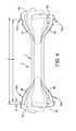
- FIG. 1is a perspective view of an intramedullary implant formed in accordance with one embodiment of the invention
- FIG. 2is a top plan view of the implant shown in FIG. 1 ;
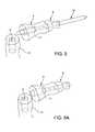
- FIG. 3is a top plan view of the implant shown in FIGS. 1 and 2 , and with a K-wire coupled to the implant;
- FIG. 4is a top plan view, partially in phantom, illustrating the change in length of the beams as a result of decoupled bending;
- FIG. 5is a perspective view of the distal, middle, and proximal phalanxes with a K-wire installed, and with the soft tissues removed for clarity of illustration;
- FIG. 5Ais a further perspective view of the distal, middle, and proximal phalanxes without a K-wire installed, and with the soft tissues removed for clarity of illustration;
- FIG. 6is a side view of the distal, middle, and proximal phalanxes shown in FIGS. 5 and 5A ;
- FIG. 7is a side view of the distal, middle, and proximal phalanxes with an implant formed in accordance with one embodiment of the invention installed in the proximal end of a middle phalanx, and with the soft tissues removed for clarity of illustration;
- FIG. 8is a top plan view showing an implant fully installed between the proximal and middle phalanxes, just prior to removal of the k-wire;
- FIG. 9is a top plan view showing an implant fully installed between the proximal and middle phalanxes, with the K-wire removed and decoupled from the proximal and distal pair of beams, and illustrating an implant fully installed within the bones;
- FIG. 6Ais a top plan view of a distal and middle phalanx showing initial insertion of an implant device and system in accordance with an alternative method of installation;
- FIG. 7Ais a top plan view, similar to FIG. 6A , showing further progress of the implant system through a canal broached within the bones;
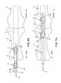
- FIG. 7Bis a side view, partially in phantom showing progress of the implant system, including a k-wire with a flexible tail, through a canal broached within the bones;
- FIG. 8Ais a top plan view, similar to FIGS. 6A and 7A , showing a K-wire partially removed and decoupled from a distal pair of beams, and illustrating the compressive engagement of the beams against the internal surfaces of the bone;
- FIG. 8Bis a top plan view, similar to FIG. 7B , showing an implant coupled by a K-wire with a flexible tail prior to removal and decoupling from a distal pair of beams;
- FIG. 9Ais a top plan view, similar to FIGS. 6A, 7A, and 8A , showing the implant fully installed with the K-wire removed and decoupled from a proximal pair of beams, and illustrating an implant fully installed within the bones;
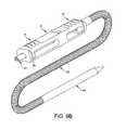
- FIG. 9Bis a perspective view of an implant formed in accordance with the invention, showing an alternative K-wire having a flexible tail installed and coupling the beams of the implant;
- FIG. 9Cis a side elevational view of the implant and k-wire shown in FIG. 9B , with the implant shown in cross-section for clarity of illustration perspective view of an implant formed in accordance with the invention, showing an alternative K-wire having a flexible tail installed and coupling the beams of the implant;
- FIG. 9Dis a top plan view, similar to FIGS. 7B and 8B , showing a K-wire with a flexible tail partially removed and decoupled from a distal pair of beams, and illustrating the compressive engagement of the beams against the internal surfaces of the bone;
- FIG. 9Eis a perspective view, partially in phantom, of a human foot located within a shoe and illustrating one possible arrangement of a flexible tail and second k-wire after implantation of an implant formed in accordance with on embodiment of the invention
- FIG. 10is a perspective view of the implant shown in FIGS. 11 and 12 with the K-wire reinstalled through central canal to stabilize neighboring joints (MTP);
- FIG. 11is a further perspective view of the implant shown in FIG. 12 , with a K-wire removed;
- FIG. 12is a perspective view of an alternative embodiment of implant formed in accordance with the invention.
- FIG. 13is a top plan view of a further alternative embodiment of the invention, showing a K-wire partially in phantom, installed and coupled to a single pair of beams;
- FIG. 14is a top plan view of the implant shown in FIG. 13 , but with the K-wire removed and decoupled from the beams;
- FIG. 15is a top plan view, similar to FIG. 14 , showing a K-wire prior to coupling with the implant;
- FIG. 16is a bottom plan view of the implant shown in FIG. 15 , but from the reverse side so as to reveal grooves or channels formed in the implant for receiving a coupling K-wire;
- FIG. 17is a top plan view, partially in phantom, showing a K-wire coupled with the implant of FIGS. 15-16 ;
- FIG. 18is a further embodiment of implant formed in accordance with the invention.
- FIG. 19is a cross-sectional view, similar to FIG. 18 , but showing a K-wire coupled to the beams of the implant;
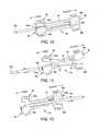
- FIG. 20is an end view of a further embodiment of implant formed in accordance with the invention.
- FIG. 21is a side elevational view of the further embodiment shown in FIG. 20 ;
- FIG. 22is a cross-sectional view, taken along lines 22 - 22 in FIG. 21 ;
- FIG. 23is a perspective view of a further embodiment of the invention showing an implant having a curved cross-sectional profile
- FIG. 24is a side elevational view of an angled implant embodiment of the invention.
- FIG. 25is a top plan view of the angled embodiment of the invention shown in FIG. 24 ;
- FIG. 26is an end on, perspective view of the embodiment of implant shown in FIGS. 24 and 25 ;
- FIG. 27is a cross-sectional view taken along lines 27 - 27 of the angled embodiment shown in FIGS. 24-26 ;
- FIG. 28is a top plan view of yet a further embodiment of implant showing a pair of beams disposed diagonally on the body of the implant;
- FIG. 29is top view similar to FIG. 28 , showing the implant coupled to a K-wire in accordance with invention.
- FIG. 30is a top view of yet a further embodiment of implant showing a pair of beams disposed on the same side of the body of the implant;
- FIG. 31is a top view similar to FIG. 30 , showing the implant coupled to a K-wire in accordance with invention
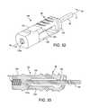
- FIG. 32is a perspective view of an embodiment formed in accordance with the invention showing a single pair of beams coupled to a K-wire;
- FIG. 33is a cross-sectional view, taken along line 33 - 33 in FIG. 32 ;
- FIG. 34is a perspective exploded view of the alternative embodiment implant of FIGS. 32 and 33 , showing a therapeutic device prior to interconnection with the implant;
- FIG. 35is a perspective view of the implant and therapeutic device shown in FIG. 34 , after interconnection;
- FIG. 36is a cross-sectional view of the implant and therapeutic device interconnected in FIG. 35 ;
- FIG. 37is a perspective view, similar to FIG. 34 , showing a therapeutic device in the form of a bone anchor just prior to interconnection with the implant;
- FIG. 38is a perspective view, similar to FIG. 35 , showing bone anchor of FIG. 37 interconnected with the implant;
- FIG. 39is a cross-section view, similar to FIG. 36 , but showing a bone anchor of FIGS. 37 and 38 interconnected with an implant formed in accordance with the invention
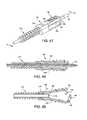
- FIG. 40is an exploded perspective view of an implant similar to that shown in FIGS. 34 and 37 , showing a suture anchor just prior to interconnection with the implant;
- FIG. 41is a perspective view similar to FIG. 40 but showing the suture anchor installed on the implant;
- FIG. 42is a cross-sectional view, taken along line 42 - 42 in FIG. 41 , showing the suture anchor installed on the implant with suture threaded through a conduit defined to the middle of the body of the implant and also showing a K-wire coupled to the single pair of beams;
- FIG. 43is a cross-sectional view similar to FIG. 42 , with the K-wire decoupled from the single pair of beams;
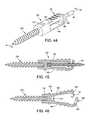
- FIG. 44is a perspective view of a further alternative embodiment of the invention showing a bone screw interconnected with the implant of the invention
- FIG. 45is a cross-sectional view, taken along line 45 - 45 in FIG. 44 , and also showing a K-wire coupled to a single pair of beams;
- FIG. 46is a cross-sectional view similar to FIG. 45 , but showing the single pair of beams after decoupling from the K-wire;
- FIG. 47is another embodiment of implant similar to that shown in FIGS. 34, 37, 40, and 44 , showing a cannulated bone screw installed in the implant with a K-wire located within the cannulated bone screw and coupled to the single pair of beams;
- FIG. 48is a cross-sectional view, taken along line 48 - 48 in FIG. 47 ;
- FIG. 49is a cross-sectional view similar to FIG. 48 but with the K-wire removed from the cannulated bone screw and decoupled from the single pair of beams.
- an implant 2that includes a cannulated body 4 , a distal pair of cantilevered beams 6 , and a proximal pair of cantilevered beams 8 .
- cannulated body 4often comprises an elongate bar having a distal end 14 and a proximal end 15 .
- a through-bore 18is often defined centrally through the bar along longitudinal axis 17 so as to define openings at distal end 14 and proximal end 15 .
- Distal pair of beams 6comprise a superior beam 24 and an inferior beam 26 arranged in spaced confronting relation to one another at distal end 14 of cannulated body 4 .
- pairs of beamswill be arranged symmetrically about longitudinal axis 17 of body 4 , often so as to be bisected by the axis.
- Superior beam 24is fixed to distal end 14 of cannulated body 4 , and in some embodiments, is formed integral with cannulated body 4 .
- One or more barbs 30 aare located on an outer surface 31 of superior beam 24 , often oriented transversely across outer surface 31 .
- a latch-plate 34extends inwardly, toward inferior beam 26 , from a free end of superior beam 24 .
- a bore 36 ais defined through latch-plate 34 .
- Inferior beam 26is fixed to distal end 14 of cannulated body 4 , and in some embodiments, is formed integral with cannulated body 4 .
- One or more barbs 30 bare located on a distal outer surface 32 of inferior beam 26 , often oriented transversely across outer surface 32 .
- a latch-plate 38extends inwardly, toward superior beam 24 and latch-plate 34 , from a free end of inferior beam 26 .
- a bore 36 bis defined through latch-plate 38 .
- Distal pair of beams 6are cantilevered to cannulated body 4 at distal end 14 , i.e., supported or clamped at one end and capable of storing elastic energy when loaded or pre-loaded at the other end or along their length.
- distal pair of beams 6When distal pair of beams 6 are loaded during normal use, they each deflect inwardly, toward one another.
- superior beam 24is greater in length than inferior beam 26 so that, when deflected to a optimally biased state, i.e., the beams are deflected so that a desirable amount of elastic energy is stored, with latch-plate 34 is located in overlapping adjacent relation to latch-plate 38 with bore 36 a and bore 36 b overlapping and communicating relation to one another ( FIGS. 3-4 ).
- distal pair of beams 6are loaded bores 36 a and 36 b will often be arranged in substantially coaxial relation to the open end of through-bore 18 at distal end 14 of cannulated body 4 .
- Proximal pair of beams 8comprise a superior beam 44 and an inferior beam 46 arranged in spaced confronting relation to one another at proximal end 15 of cannulated body 4 .
- Superior beam 44is fixed to proximal end 15 of cannulated body 4 , and in some embodiments, is formed integral with cannulated body 4 .
- One or more barbs 50 aare located on an outer surface 51 of superior beam 44 , often oriented transversely across outer surface 51 .
- a latch-plate 54extends inwardly, toward inferior beam 46 , from a free end of superior beam 44 .
- a bore 56 bis defined through latch-plate 54 .
- Inferior beam 46is fixed to proximal end 15 of cannulated body 4 , and in some embodiments, is formed integral with cannulated body 4 .
- One or more barbs 50 bare located on a distal outer surface 52 of inferior beam 46 , often oriented transversely across outer surface 52 .
- a latch-plate 58extends inwardly, toward superior beam 44 and latch-plate 54 , from a free end of inferior beam 46 .
- a bore 56 ais defined through latch-plate 58 .
- proximal pair of beams 8are also cantilevered to cannulated body 4 , but at proximal end 15 , i.e., supported or clamped at one end and capable of storing elastic energy when loaded or pre-loaded at the other end or along their length.
- proximal pair of beams 8When proximal pair of beams 8 are loaded during normal use, they each deflect inwardly, toward one another.
- superior beam 44is greater in length than inferior beam 46 so that, when deflected to a optimally biased state, latch-plate 58 is located adjacent to latch-plate 54 with bore 56 a and bore 56 b overlapping one another.
- bores 56 a and 56 boften will be arranged in substantially coaxial relation to the open end of through-bore 18 at proximal end 15 of cannulated body 4 .
- Implant 2may be manufactured from conventional implant metal, such as stainless steel or titanium.
- the implantsare manufactured out of shape memory materials (SMA) or alloys such as nickel titanium to enhance fixation.
- SMAshape memory materials
- Nitinolsold by Memry Corporation of Menlo Park, Calif.
- the implantsare preferably made of nitinol, a biocompatible, shape memory metal alloy of titanium and nickel.
- the metal's properties at the higher temperature (austenite phase)are similar to those of titanium.
- the temperature at which the implants will undergo the shape transformationcan be controlled by the manufacturing process and the selection of the appropriate alloy composition.
- Nitinolhas a very low corrosion rate and has been used in a variety of medical implants, e.g., orthodontic appliances, stents, suture anchors, etc. Implant studies in animals have shown minimal elevations of nickel in the tissues in contact with the metal; the levels of titanium are comparable to the lowest levels found in tissues near titanium hip prostheses.
- the SMAis selected to have a temperature transformation range such that the implant undergoes a transition from austenite to stress-induced martensite under the influence of deformation forces.
- the distal and proximal beams of implant 2are deflected inwardly, toward one another and then released, they are already at a temperature such that they automatically attempt to reform to their original shape.
- implant 2is prepared for use in corrective surgery at the distal B, middle A, and proximal C phalanxes of the foot, as follows.
- Distal pair of beams 6are loaded so that they each deflect inwardly, toward one another until latch-plate 38 is located adjacent to latch-plate 34 with bore 36 a and bore 36 b overlapping one another.
- proximal pair of beams 8are also loaded so that they each deflect inwardly, toward one another until latch-plate 58 is located adjacent to latch-plate 54 with bore 56 a and bore 56 b overlapping one another.
- a coupling rodsuch as k-wire 60
- k-wire 60is inserted through bores 56 a , 56 b , through-bore 18 , and bores 36 a bore 36 b , thereby coupling distal pair of beams 6 and proximal pair of beams 8 in their respective optimally biased state.
- k-wire 60includes a proximal portion 63 that has a smaller diameter than the distal portion of the k-wire thereby defining a shoulder 67 at the transition 69 between diameters. Shoulder 67 is often sized so as to engage the outer surface of latch-plate 54 and thereby prevent k-wire 60 from further travel into implant 2 beyond transition 69 .
- a k-wire 61comprises a flexible tail 62 that is terminated by a second k-wire 64 .
- Flexible tail 62may be fashioned from woven, non-woven, knitted, braided or crocheted materials, any of which can included but not be limited to standard surgical sutures, polymer or fiberous cords, metal wire or tape, or the like, and may be formed from a single multiple strands of metals, polymers, or other bio compatible materials. Often, flexible tail 62 comprises a metal braid or cable.
- K-wire 61may have a circular, oval or flattened cross-sectional profile similar to that of K-wire 60 b ( FIGS. 20-23 ).
- Implant 2is used in systems and methods for corrective surgery at the distal B, middle A, and proximal C phalanxes of the foot or elsewhere in bones of the human or animal body, as follows.
- the PIP jointis first opened and debrided and an initial k-wire 75 ( FIG. 5 ) is inserted through the axis of the middle phalanx A and out the distal end of the toe.
- Initial k-wire 75is then removed distally from the distal tip of the toe ( FIGS. 5A and 6 ).
- a canal Dis defined through distal and proximal portions of the PIP joint.
- Canal Dextends for a distance into middle phalanx A along the path defined previously by k-wire 75 such that a counter-bore shoulder 71 is defined at the transition between the diameters of canal D and the passageway formed by the prior insertion of k-wire 75 .
- Shoulder 71is often sized so as to engage the outer surface of a latch-plate 54 or 34 and thereby prevent implant 2 from further distal travel into middle phalanx A.
- an implant 2 that has been coupled to a k-wire 60 or 61is inserted through broached canal D ( FIGS. 7 and 7B ) such that k-wire 60 travels through middle phalanx A and distal phalanx B with distal end portion 63 projecting outwardly from the end of distal phalanx B.
- flexible tail 62travels through middle phalanx A and distal phalanx B with distal end portion 63 projecting outwardly from the end of distal phalanx B.
- Flexible tail 62may often be employed to ease implantation.
- a cord 62provides the flexibility that is often needed by the surgeon to position the implant within the patient's bone, while maintaining tensile strength for removing k-wire 61 from the implant during deployment.
- flexible tail 62 and k-wireare left protruding from the patient's foot F by the surgeon so as to allow the patient to slip on a shoe G or other foot wear ( FIG. 9E ).
- a rigid k-wirewas left protruding from the patient's toe by the surgeon, when the surgery was completed. This arrangement prevented the patient from wearing shoes which often precluded the patient from returning to work based upon work place safety regulations.
- implant 2travels down the longitudinal axis of middle phalanx A until the constrained distal beams 6 are adjacent shoulder 71 within broached canal D ( FIG. 7 ). Once in position, end portions of distal pair of beams 6 are located adjacent to shoulder 71 within middle phalanx A and proximal pair of beams 8 project outwardly from the open end of canal D at the proximal end of middle phalanx A.
- the jointis re-aligned and closed by moving the distal and middle phalanxes so that proximal pair of beams 8 is caused to enter the open end of canal D in proximal phalanx C ( FIG. 8 ). In this position, proximal pair of beams 8 are located within canal D in proximal phalanx C and the joint is closed around implant 2 .
- k-wire 60is moved distally ( FIG. 9 ) so as to disengage from latch-plates 54 and 58 of proximal beams 8 thereby decoupling and releasing beams 44 and 46 from their optimally biased state.
- k-wire 64is moved distally ( FIGS. 8B and 9C )) thereby pulling flexible tail 62 and k-wire 61 so as to disengage from latch-plates 54 and 58 of proximal beams 8 thereby decoupling and releasing beams 44 and 46 from their optimally biased state.
- superior beam 44 and inferior beam 46spring outwardly, away from one another, until their respective barbs 50 a and 50 b engage the surface of the surrounding bone that defines broached canal D. Since superior beam 44 and inferior beam 46 are still biased, i.e., continue to store some elastic energy, but are geometrically shortened by an amount ⁇ . Barbs 50 a and 50 b compressively engage the surface of the surrounding bone so as to “bite” into the bone, thus enhancing the retention of implant 2 . It should be noted that the respective shortening of the moment arm of proximal pair of beams 8 applies an active compressive force to articulating surfaces of the PIP joint.
- K-wire 60continues to be decoupled and withdrawn from implant 2 , through through-bore 18 of cannulated body 4 until distal end 70 slips past through-bores 36 a , 36 b in latch-plates 34 and 38 of distal pair of beams 6 so as to entirely decouple k-wire 60 from implant 2 ( FIG. 9 ).
- superior beam 24 and inferior beam 26spring outwardly, away from one another and away from their optimally biased state into a partially biased state in which distal pair of beams 6 engage the surface of the bone that defines broached canal D.
- cantilevered distal pair of beams 6move into their second partially biased state, they will also shorten.
- This geometric effectapplies an active compressive force to the articulating surfaces of the PIP joint while proximal pair of beams 8 maintain cortical fixation on either side of the joint.
- barbs 30 a and barbs 30 bare caused to bite into the bone that defines broached canal D by the outward force of superior beam 24 and inferior beam 26 moving into their partially biased state. The biting of barbs 30 a and 30 b into the bone greatly enhances the compressive load exerted by proximal pair of beams 8 .
- an implant 2 that has been coupled to a k-wire 60is inserted through broached canal D ( FIG. 6A ).
- implant 2travels along the longitudinal axis of middle phalanx A until the constrained proximal beams 8 are adjacent the end of broached canal D within proximal phalanx C ( FIG. 7A ).
- k-wire 60is moved distally ( FIG. 8A ) so as to disengage distal portion 63 from latch-plates 34 and 38 of proximal beams 8 thereby decoupling and releasing beams 24 and 26 from their optimally biased state.
- superior beam 24 and inferior beam 26spring outwardly, away from one another, until their respective barbs 30 a and 30 b engage the surface of the surrounding bone that defines broached canal D. Since superior beam 24 and inferior beam 26 are still biased, i.e., continue to store some elastic energy, but are geometrically shortened by an amount ⁇ , barbs 30 a and 30 b compressively engage the surface of the surrounding bone so as to “bite” into the bone, thus enhancing the retention of implant 2 . It should be noted that the respective shortening of the moment arm of proximal pair of beams 8 applies an active compressive force to articulating surfaces of the PIP joint while distal pair of beams 6 maintain cortical fixation via barbs 30 a and 30 b.
- proximal pair of beams 8With proximal pair of beams 8 fully seated within the proximal phalanx C, the joint is compressed axially so as to fully seat proximal pair of beams 8 within broached canal D ( FIG. 8A ).
- K-wire 60continues to be decoupled and withdrawn from implant 2 , through through-bore 18 of cannulated body 4 until proximal end 70 slips past through-bores 56 a , 56 b in latch-plates 54 and 58 of distal pair of beams 6 so as to entirely decouple k-wire 60 from distal pair of beams 6 ( FIG. 9A ).
- distal pair of beams 6spring outwardly, away from one another and away from their optimally biased state into a partially biased state in which distal pair of beams 6 engage surface of the bone that defines broached canal D.
- cantilevered distal pair of beams 6move into their second partially biased state, they will also shorten their length. This geometric effect applies an active compressive force to the articulating surfaces of the PIP joint while distal pair of beams 6 maintain cortical fixation.
- barbs 50 a located on an outer surface 51 of superior beam 44 and barbs 50 b located on outer surface 52 of inferior beam 46are caused to bite into the bone that defines broached canal D by the outward force of superior beam 44 and inferior beam 46 moving into their partially biased state.
- the biting of barbs 30 a , 30 b , 50 a and 50 b into the internal bone surfaces at both sides of the joint, coupled with the geometric shortening of both proximal beams 8 and distal beams 6greatly enhances the compressive load exerted across the PIP joint.
- implant 82is provided that includes a body 84 , a distal pair of cantilevered beams 86 , and a proximal pair of cantilevered beams 88 .
- body 84defines an elongate, channel or groove 90 having a distal end 94 and a proximal end 95 .
- Distal pair of beams 86 a , 86 bare arranged in spaced confronting relation to one another at distal end 94 of body 84 .
- Each beam 86 a , 86 bis fixed to distal end 94 and in some embodiments, is formed integral with body 84 .
- One or more barbs 96are located on an outer surface of each distal beam 86 a , 86 b .
- Open-ended groove 90extends through an inner portion of body 84 .
- An open-ended groove 100 ais defined as a channel through an inner distal portion of distal beam 86 b ( FIG. 10 ) that is sized so as to slidingly receive a sharpened portion of a k-wire 60 a .
- Distal pair of beams 86 a , 86 bare cantilevered to body 84 , i.e., supported or clamped at one end and capable of storing elastic energy when loaded or pre-loaded at the other end or along their length.
- distal pair of beams 86 a , 86 bare coupled and loaded during normal use, they each deflect inwardly, toward one another.
- Proximal pair of beams 88 a , 88 bare arranged in spaced confronting relation to one another at proximal end 95 of body 84 .
- One or more barbs 96are located on an outer surface of each proximal beam 88 a , 88 b .
- a groove 100 bis defined as a channel through an inner distal portion of proximal beam 88 a ( FIGS. 10 and 11 ) that is sized so as to slidingly receive a rounded portion of k-wire 60 b .
- proximal pair of beams 88 a , 88 bare also cantilevered to cannulated body 84 but at proximal end 95 , i.e., supported or clamped at one end and capable of storing elastic energy when loaded or pre-loaded at the other end or along their length.
- proximal pair of beams 88 a , 88 bare and coupled loaded during normal use, they each deflect inwardly, toward one another.
- Implant 82is prepared for use in corrective surgery at the distal B, middle A, and proximal C phalanxes of the foot in much the same way as implant 2 . More particularly, distal pair of beams 86 a , 86 b are loaded so that they each deflect inwardly, toward one another such that open-ended groove 90 of body 84 and groove 100 a are arranged in substantially coaxial relation to one another. Likewise, proximal pair of beams 88 a , 88 b are also loaded so that they each deflect inwardly, toward one another such that open-ended groove 90 of body 84 and groove 100 b are arranged in substantially coaxial relation to one another.
- k-wire 60 ais inserted through groove 100 a , open-ended groove 90 , and groove 100 b , thereby coupling distal pair of beams 86 a , 86 b and proximal pair of beams 88 a , 88 b in their respective optimally biased state.
- distal pair of beams 86 a , 86 b and proximal pair of beams 88 a , 88 bcauses distal pair of beams 86 a , 86 b and proximal pair of beams 88 a , 88 b to spring outwardly and away from one another thereby shortening their lengths so as to apply an active compressive force to the articulating surfaces of the PIP joint.
- barbs 96are caused to bite compressively into the bone that defines the broached canal by the force of distal pair of beams 86 a , 86 b and proximal pair of beams 88 a , 88 b moving into their partially biased state as a result of the elastic energy that continues to be stored in in each beam.
- the sharpened portion 60 a of k-wire 60is, e.g., driven proximally through the tip of the patient's toe and through distal end 94 and proximal end 95 of groove 90 of implant 82 to achieve temporary stabilization of outlying joints (e.g., the MTP joint).
- Implants in accordance with the general principles of the inventionmay be take a variety of configurations.
- a proximal beam 86 a and distal beam 88 bmay be arranged on their respective ends of body 84 with somewhat thinner or variable cross-sections so as to allow for adjustments in spring force to a predetermined level as may be needed for a particular therapy.
- implant 2may incorporate an inferior latch-plate 38 a or 58 a located anywhere along the length of its corresponding beam 26 , 46 . As shown in FIGS. 20-23 , implant 2 may have any peripheral shape.
- implant 2will have a circular or elliptical peripheral shape so as to be better suited for disposition through drilled canal D.
- bores 36 a , 36 b or 56 a , 56 bmay be defined with one or more partially flattened walls 110 so as to allow for sufficient wall thickness in latch plate and for engagement with a correspondingly shaped k-wire 60 b .
- This arrangementallows the surgeon to rotationally orient implant 2 relative to the bone surface that defines broached canal D.
- an implant 112may be formed so as to bend at or adjacent to the central portion of body 4 a .
- distal pair of beams 6 or proximal pair of beams 8may be arranged and oriented at an angle relative to body 4 a .
- a similarly shaped k-wire also comprised of Nitinol to insert through bend 60 cis coupled and decoupled during use of implant 112 in a manner previously disclosed herein.
- an implant 122that includes a body 124 , a distal cantilevered beam 126 , and a proximal cantilevered beam 128 .
- Body 124defines an through bore 130 and has a distal end 134 and a proximal end 135 .
- Proximal beam 126projects longitudinally outwardly from distal end of body 124
- distal cantilevered beam 128projects longitudinally outwardly from the proximal end of body 124 .
- One or more barbs 136are located on an outer surface of each of distal end 134 and a proximal end 135 .
- a latch-plate 140extends inwardly from a free end of proximal cantilevered beam 126 and a second latch-plate 142 extends inwardly from a free end of distal cantilevered beam 128 .
- a bore 146 ais defined through latch-plate 140 and a bore 146 b is defined through latch-plate 142 .
- Cantilevered beams 124 , 126are cantilevered to body 124 , i.e., supported or clamped at one end and capable of storing elastic energy when loaded or pre-loaded at the other end or along their length. When cantilevered beams 124 , 126 are loaded during normal use, they each deflect inwardly.
- cantilevered beams 124 , 126are arranged so as to be located diagonally from one another relative to body 124 .
- Implant 122is prepared for use in corrective surgery at the distal B, middle A, and proximal C phalanxes of the foot in much the same way as implant 2 . More particularly, proximal cantilevered beam 126 and distal cantilevered beam 128 are loaded so that they each deflect inwardly, toward the longitudinal axis of through bore 130 of body 124 so that bore 146 a of latch-plate 140 and bore 146 b of latch-plate 142 are arranged in substantially coaxial relation to one another.
- k-wire 60is inserted through bore 130 , bore 146 a , and bore 146 b , thereby coupling distal cantilevered beam 126 , and proximal cantilevered beam 128 in their respective optimally biased state.
- decoupling of k-wire 60causes proximal cantilevered beam 126 and distal cantilevered beam 128 to spring outwardly and away from one another and away from the longitudinal axis of through bore 130 of body 124 thereby shortening their lengths so as to apply an active compressive force to the articulating surfaces of the PIP joint.
- barbs 96are caused to bite into the bone compressively by the outward force of proximal cantilevered beam 126 and distal cantilevered beam 128 shortening as they move into their respective partially biased state.
- an implant 122 amay be formed having distal cantilevered beam 126 a and proximal cantilevered beam 128 a that are arranged on the same side of body 124 rather than diagonally as in implant 122 .
- implant 150includes a body 154 and a single pair of cantilevered beams 156 and a mating structure suitable for joining implant 150 to a therapeutic device 157 via interconnection with blind bores 151 a and 151 b defined in body 154 .
- single pair of cantilevered beams 156comprise a superior beam 160 and an inferior beam 162 arranged in spaced confronting relation to one another at an end of body 154 .
- Superior beam 160is fixed to an end of body 154 , and in some embodiments, is formed integral therewith.
- One or more barbs 96are located on an outer surface of superior beam 160 , often oriented transversely across the outer surface.
- a latch-plate 164extends inwardly, toward inferior beam 162 , from a free end of superior beam 160 .
- a bore 166is defined through latch-plate 164 .
- Inferior beam 162is fixed to an end of body 154 , and in some embodiments, is formed integral therewith.
- One or more barbs 96are located on an outer surface of inferior beam 162 , often oriented transversely across the outer surface.
- a latch-plate 168extends inwardly, toward superior beam 160 and latch-plate 164 , from a free end of inferior beam 162 .
- a bore 170is defined through latch-plate 168 .
- Cantilevered beams 160 , 162are cantilevered to body 154 , i.e., supported or clamped at one end and capable of storing elastic energy when loaded or pre-loaded at the other end or along their length. When cantilevered beams 160 , 162 are coupled and preloaded during normal use, they each deflect inwardly.
- Implant 150is prepared for use in surgery at a variety of orthopedic locations throughout a patient in much the same way as implant 2 . More particularly, single pair of beams 160 , 162 are loaded so that they each deflect inwardly, toward one another such that bore 166 , bore 170 , and blind bore 151 b are arranged in substantially coaxial relation to one another. Once in this arrangement, k-wire 60 is inserted through bore 166 , bore 170 , and blind bore 151 b , thereby coupling single pair of beams 160 , 162 in their respective optimally biased state.
- decoupling of k-wire 60causes single pair of beams 160 , 162 to spring outwardly and away from one another thereby shortening their lengths so as to apply an active compressive force to the articulating surfaces of the PIP joint.
- barbs 96are caused to bite into the bone compressively by the outward force of pair of beams 160 , 162 shortening as they move into their respective partially biased state. The biting of barbs 96 into the bone greatly enhances the compressive load exerted by implant 150 .
- Implants in accordance with the general principles of the foregoing embodiment of the inventionmay be take a variety of configurations.
- a tapered and ribbed anchor 173may be coupled to body 154 via a threaded engagement between a post 175 and threaded bore 151 a .
- a suture anchor 178may be assembled to body 154 in a similar manner to that of tapered and ribbed anchor 173 .
- Bores 151 a and 151 bmay be modified so as to communicate, via conduit 181 ( FIGS. 40-43 ) thereby allowing suture 180 to exit implant 150 near to single pair of beams 160 , 162 .
- implant 150will have a circular or elliptical peripheral shape so as to be better suited for disposition through broached canal D. As shown in FIGS. 44 and 49 , implant 150 may be formed so as receive a threaded screw 200 or cannulated screw 210 .
Landscapes
- Health & Medical Sciences (AREA)
- Orthopedic Medicine & Surgery (AREA)
- Surgery (AREA)
- Life Sciences & Earth Sciences (AREA)
- Heart & Thoracic Surgery (AREA)
- Nuclear Medicine, Radiotherapy & Molecular Imaging (AREA)
- Engineering & Computer Science (AREA)
- Biomedical Technology (AREA)
- Neurology (AREA)
- Medical Informatics (AREA)
- Molecular Biology (AREA)
- Animal Behavior & Ethology (AREA)
- General Health & Medical Sciences (AREA)
- Public Health (AREA)
- Veterinary Medicine (AREA)
- Prostheses (AREA)
Abstract
Description
Claims (13)
Priority Applications (2)
| Application Number | Priority Date | Filing Date | Title |
|---|---|---|---|
| US14/460,808US9498266B2 (en) | 2014-02-12 | 2014-08-15 | Intramedullary implant, system, and method for inserting an implant into a bone |
| US15/297,522US20170035474A1 (en) | 2014-02-12 | 2016-10-19 | Intramedullary implant, system, and method for inserting an implant into a bone |
Applications Claiming Priority (2)
| Application Number | Priority Date | Filing Date | Title |
|---|---|---|---|
| US14/179,172US9545274B2 (en) | 2014-02-12 | 2014-02-12 | Intramedullary implant, system, and method for inserting an implant into a bone |
| US14/460,808US9498266B2 (en) | 2014-02-12 | 2014-08-15 | Intramedullary implant, system, and method for inserting an implant into a bone |
Related Parent Applications (1)
| Application Number | Title | Priority Date | Filing Date |
|---|---|---|---|
| US14/179,172Continuation-In-PartUS9545274B2 (en) | 2014-02-12 | 2014-02-12 | Intramedullary implant, system, and method for inserting an implant into a bone |
Related Child Applications (1)
| Application Number | Title | Priority Date | Filing Date |
|---|---|---|---|
| US15/297,522ContinuationUS20170035474A1 (en) | 2014-02-12 | 2016-10-19 | Intramedullary implant, system, and method for inserting an implant into a bone |
Publications (2)
| Publication Number | Publication Date |
|---|---|
| US20150223849A1 US20150223849A1 (en) | 2015-08-13 |
| US9498266B2true US9498266B2 (en) | 2016-11-22 |
Family
ID=53773920
Family Applications (2)
| Application Number | Title | Priority Date | Filing Date |
|---|---|---|---|
| US14/460,808Expired - Fee RelatedUS9498266B2 (en) | 2014-02-12 | 2014-08-15 | Intramedullary implant, system, and method for inserting an implant into a bone |
| US15/297,522AbandonedUS20170035474A1 (en) | 2014-02-12 | 2016-10-19 | Intramedullary implant, system, and method for inserting an implant into a bone |
Family Applications After (1)
| Application Number | Title | Priority Date | Filing Date |
|---|---|---|---|
| US15/297,522AbandonedUS20170035474A1 (en) | 2014-02-12 | 2016-10-19 | Intramedullary implant, system, and method for inserting an implant into a bone |
Country Status (1)
| Country | Link |
|---|---|
| US (2) | US9498266B2 (en) |
Cited By (6)
| Publication number | Priority date | Publication date | Assignee | Title |
|---|---|---|---|---|
| US9757168B2 (en) | 2015-03-03 | 2017-09-12 | Howmedica Osteonics Corp. | Orthopedic implant and methods of implanting and removing same |
| US20180078293A1 (en)* | 2016-09-08 | 2018-03-22 | Meduloc, Llc | Implant and method for long bone fixation |
| US10383671B2 (en) | 2008-09-09 | 2019-08-20 | Stryker European Holdings I, Llc | Resorptive intramedullary implant between two bones or two bone fragments |
| US10470807B2 (en) | 2016-06-03 | 2019-11-12 | Stryker European Holdings I, Llc | Intramedullary implant and method of use |
| US10537369B1 (en)* | 2016-05-19 | 2020-01-21 | Medshape, Inc. | Bone anchor device |
| US11478285B2 (en) | 2005-04-14 | 2022-10-25 | Stryker European Operations Holdings Llc | Device for osteosyntheses or arthrodesis of two-bone parts, in particular of the hand and/or foot |
Families Citing this family (18)
| Publication number | Priority date | Publication date | Assignee | Title |
|---|---|---|---|---|
| FR2913876B1 (en) | 2007-03-20 | 2009-06-05 | Memometal Technologies Soc Par | OSTEOSYNTHESIS DEVICE |
| US8608785B2 (en) | 2010-06-02 | 2013-12-17 | Wright Medical Technology, Inc. | Hammer toe implant with expansion portion for retrograde approach |
| US9724140B2 (en) | 2010-06-02 | 2017-08-08 | Wright Medical Technology, Inc. | Tapered, cylindrical cruciform hammer toe implant and method |
| US9498273B2 (en) | 2010-06-02 | 2016-11-22 | Wright Medical Technology, Inc. | Orthopedic implant kit |
| HK1201138A1 (en)* | 2011-10-10 | 2015-08-28 | William Casey Fox | Shape changing bone implant for enhanced healing |
| US8945232B2 (en) | 2012-12-31 | 2015-02-03 | Wright Medical Technology, Inc. | Ball and socket implants for correction of hammer toes and claw toes |
| US9724139B2 (en) | 2013-10-01 | 2017-08-08 | Wright Medical Technology, Inc. | Hammer toe implant and method |
| US9474561B2 (en)* | 2013-11-19 | 2016-10-25 | Wright Medical Technology, Inc. | Two-wire technique for installing hammertoe implant |
| US9545274B2 (en) | 2014-02-12 | 2017-01-17 | Wright Medical Technology, Inc. | Intramedullary implant, system, and method for inserting an implant into a bone |
| AU2014331633B2 (en) | 2014-09-18 | 2017-06-22 | Wright Medical Technology, Inc | Hammertoe implant and instrument |
| CN105960211B (en) | 2014-12-19 | 2019-01-11 | 瑞特医疗技术公司 | Intramedullary Anchors for Interphalangeal Arthrodesis |
| ITUB20159242A1 (en)* | 2015-12-15 | 2017-06-15 | Giuseppe Lodola | DEVICE FOR FIXING TWO BONE FRAMES AND KITS FOR THE CONNECTION OF TWO BONE FRAGMENTS |
| FR3051350B1 (en)* | 2016-05-19 | 2021-12-10 | Fournitures Hospitalieres Ind | INTERPHALANGIAL ARTHRODESIS IMPLANT |
| RU176946U1 (en)* | 2017-03-27 | 2018-02-02 | Федеральное государственное бюджетное образовательное учреждение высшего образования "Курский государственный медицинский университет" Министерства здравоохранения Российской Федерации | SPEED LOCK FOR MINIMASIBLE ELASTIC-STRENGTHEN OSTEOSYNTHESIS OF DIAPHYSIS FRACTURES OF LARGE TUBULAR BONES |
| WO2020076383A1 (en)* | 2018-10-09 | 2020-04-16 | Frank Castro | Long bone fracture reduction system |
| WO2021183647A1 (en)* | 2020-03-11 | 2021-09-16 | ExsoMed Corporation | Orthopedic implants and instruments for delivering the same |
| WO2021231329A1 (en) | 2020-05-11 | 2021-11-18 | Gensano Llc | Cannulated bone implant |
| US12390252B2 (en) | 2021-04-18 | 2025-08-19 | Medical Patents Llc | Fracture reduction device |
Citations (501)
| Publication number | Priority date | Publication date | Assignee | Title |
|---|---|---|---|---|
| US321389A (en) | 1885-06-30 | Combined nail and screw | ||
| US346148A (en) | 1886-07-27 | Daniel p | ||
| US348589A (en) | 1886-09-07 | sloan | ||
| US373074A (en) | 1887-11-15 | Wood-screw | ||
| US430236A (en) | 1890-06-17 | Island | ||
| US561968A (en) | 1896-06-16 | Georges cotjlon | ||
| US736121A (en) | 1902-04-21 | 1903-08-11 | Abraham B Lipscomb | Boot-calk. |
| US821025A (en) | 1903-01-27 | 1906-05-22 | Joseph Bartlett Davies | Nail or screw for securing corrugated iron. |
| US882937A (en) | 1908-03-24 | North Bros M F G Co | Screw-eye driver. | |
| GB140983A (en) | 1919-10-27 | 1920-04-08 | Charles Louis Basham | Improvements in wood screws |
| FR736058A (en) | 1932-04-28 | 1932-11-18 | Improvements made to bolts to ensure the safety of assemblies | |
| US1966835A (en) | 1932-01-28 | 1934-07-17 | Dardelet Threadlock Corp | Fastening means |
| US2140749A (en) | 1936-08-05 | 1938-12-20 | Filshie Lead Head Nail Company | Capped nail |
| US2361107A (en) | 1944-03-08 | 1944-10-24 | Charles E Johnson | Self-locking valve tappet screw |
| US2451747A (en) | 1945-03-23 | 1948-10-19 | Ernest T Kindt | Doweled structure |
| US2490364A (en) | 1948-02-27 | 1949-12-06 | Herman H Livingston | Bone pin |
| US2600517A (en) | 1948-09-29 | 1952-06-17 | Herschel L Rushing | Tell-tale screw spike |
| FR1036978A (en) | 1951-05-11 | 1953-09-14 | Karcher Schraubenwerke G M B H | Bolt |
| US2697370A (en) | 1951-09-04 | 1954-12-21 | Linzy W Brooks | Ratchet type socket wrench |
| US2832245A (en) | 1956-02-15 | 1958-04-29 | Burrows Allen | Sponge-rubber liner for socket wrench |
| US2895368A (en) | 1955-01-21 | 1959-07-21 | Jr Paul R Trigg | Bolt having rolled grooves and recessed head to enhance uniform elongation |
| US3462765A (en) | 1967-01-06 | 1969-08-26 | Dow Corning | Surgically implantable prosthetic joint |
| US3466669A (en) | 1966-09-20 | 1969-09-16 | Univ Iowa | Intramedullary finger joint prosthesis |
| US3593342A (en) | 1969-01-27 | 1971-07-20 | Cutter Lab | Prosthetic joint |
| US3681786A (en) | 1970-07-13 | 1972-08-08 | Medical Eng Corp | Solid human prosthesis of varying consistency |
| US3739403A (en) | 1970-10-09 | 1973-06-19 | F Nicolle | Prosthetic joint having a tissue ingrowth preventive capsule |
| US3759257A (en) | 1971-03-13 | 1973-09-18 | Fischer Artur | Connector for fractured tubular bones |
| US3760802A (en) | 1971-02-26 | 1973-09-25 | Fischer Artur | Supporting device for fractured tubular bones |
| US3779239A (en) | 1971-03-13 | 1973-12-18 | Fischer Artur | Connector for fractured bones |
| US3824631A (en) | 1973-05-11 | 1974-07-23 | Sampson Corp | Bone joint fusion prosthesis |
| USD243716S (en) | 1975-07-24 | 1977-03-15 | Richards Manufacturing Company, Inc. | Great toe prosthesis |
| US4047524A (en) | 1975-04-28 | 1977-09-13 | Downs Surgical Limited | Surgical implant spinal staple |
| US4096896A (en) | 1977-04-29 | 1978-06-27 | Upson Tools, Inc. | Composite tool structure |
| JPS53128181A (en) | 1977-02-24 | 1978-11-08 | Herbert Timothy James | Screw for bonding bones |
| US4156296A (en) | 1977-04-08 | 1979-05-29 | Bio-Dynamics, Inc. | Great (large) toe prosthesis and method of implanting |
| US4170990A (en) | 1977-01-28 | 1979-10-16 | Fried. Krupp Gesellschaft Mit Beschrankter Haftung | Method for implanting and subsequently removing mechanical connecting elements from living tissue |
| US4198713A (en) | 1976-10-12 | 1980-04-22 | Swanson Alfred B | Protective member for implantable prosthesis and method of protecting the prosthesis |
| US4204284A (en) | 1977-11-16 | 1980-05-27 | Lord Corporation | Joint prosthesis with contoured pin |
| US4213208A (en) | 1977-12-05 | 1980-07-22 | Sheldon Marne | Metatarso-phalangeal joint implant |
| US4237875A (en) | 1979-02-23 | 1980-12-09 | Towmotor Corporation | Dynamic intramedullary compression nailing |
| US4262665A (en) | 1979-06-27 | 1981-04-21 | Roalstad W L | Intramedullary compression device |
| US4263903A (en) | 1979-01-08 | 1981-04-28 | Richards Manufacturing Co., Inc. | Medical staple means |
| US4275717A (en) | 1979-07-27 | 1981-06-30 | Zimmer Usa, Inc. | Intramedullary fixation device for fractured tubular bones |
| US4276660A (en) | 1979-05-25 | 1981-07-07 | Laure Prosthetics, Inc. | Carpometacarpal thumb joint |
| US4278091A (en) | 1980-02-01 | 1981-07-14 | Howmedica, Inc. | Soft tissue retainer for use with bone implants, especially bone staples |
| US4304011A (en) | 1980-08-25 | 1981-12-08 | Whelan Iii Edward J | Semi-constrained metacarpophalangeal prosthesis |
| US4321002A (en) | 1978-03-27 | 1982-03-23 | Minnesota Mining And Manufacturing Company | Medical stapling device |
| US4364382A (en) | 1979-08-23 | 1982-12-21 | Ulrich Mennen | Internal fixation device for bone fractures |
| US4367562A (en) | 1980-06-19 | 1983-01-11 | Georges Gauthier | Joint prosthesis |
| US4404874A (en) | 1980-05-02 | 1983-09-20 | Firma Hermann Werner Gmbh & Co. | Screwdriver with replaceable blade |
| US4434796A (en) | 1981-04-07 | 1984-03-06 | Vsesojuzny Nauchno-Issledovatelsky I Ispytatelny Institut Meditsinskoi Tekhniki | Surgical staple, a method of and forceps for its removal |
| US4454875A (en) | 1982-04-15 | 1984-06-19 | Techmedica, Inc. | Osteal medical staple |
| US4485816A (en) | 1981-06-25 | 1984-12-04 | Alchemia | Shape-memory surgical staple apparatus and method for use in surgical suturing |
| USD277509S (en) | 1982-07-01 | 1985-02-05 | Sutter Biomedical Inc. | Great toe metatarsal phalangeal implant |
| USD277784S (en) | 1982-06-25 | 1985-02-26 | Sutter Biomedical, Inc. | Lesser toe metatarsal phalangeal implant |
| SU1152582A1 (en) | 1982-09-24 | 1985-04-30 | Новокузнецкий институт усовершенствования врачей | Clip for osteosynthesis |
| US4516569A (en) | 1982-05-06 | 1985-05-14 | National Research Development Corporation | Intramedullary orthopaedic devices |
| GB2119655B (en) | 1982-05-06 | 1985-05-15 | Nat Res Dev | Endoprosthesis] |
| JPS60145133U (en) | 1984-03-08 | 1985-09-26 | 三洋電機株式会社 | Paper feeding device |
| US4570623A (en) | 1983-06-02 | 1986-02-18 | Pfizer Hospital Products Group Inc. | Arched bridge staple |
| US4590928A (en) | 1980-09-25 | 1986-05-27 | South African Invention Development Corporation | Surgical implant |
| USD284099S (en) | 1983-03-14 | 1986-06-03 | Sutter Bio-Medical, Inc. | Great toe metatarsal phalangeal implant |
| US4634382A (en) | 1984-06-07 | 1987-01-06 | Molten Corp. | Attachment for dental prosthesis |
| US4642122A (en) | 1986-04-02 | 1987-02-10 | Laure Prosthetics, Inc. | Toe implant |
| US4655661A (en) | 1983-12-23 | 1987-04-07 | Richter-System Gmbh & Co. Kg | Self-cutting fast construction screw |
| USD291731S (en) | 1985-05-08 | 1987-09-01 | Zimmer, Inc. | Prosthetic joint implant for a finger or toe or the like |
| US4723541A (en) | 1986-05-19 | 1988-02-09 | Reese Hewitt W | Bone screw and method |
| US4723540A (en) | 1986-07-15 | 1988-02-09 | Gilmer Jr Raymond E | Apparatus and method for exerting and maintaining a force between two bone members |
| US4731087A (en) | 1987-01-06 | 1988-03-15 | New York Society For The Relief Of The Ruptured And Crippled | Metatarsal-phalangeal prosthesis |
| FR2605878A1 (en) | 1986-10-30 | 1988-05-06 | Landos Applic Orthopediques Fs | Prosthesis for small joints, in particular metacarpophalangial and interphalangial joints |
| US4756711A (en) | 1985-12-24 | 1988-07-12 | Christian Mai | Self-locking prosthesis, and methods for producing and for fitting in same |
| US4759768A (en) | 1987-02-11 | 1988-07-26 | Thierry Hermann | Joint prosthesis, in particular finger joint prosthesis |
| FR2603794B1 (en) | 1986-09-12 | 1988-12-09 | Labourrau Jacques Philippe | SURGICAL STAPLE AND STAPLE HOLDER FOR ITS IMPLEMENTATION |
| US4790304A (en) | 1984-01-20 | 1988-12-13 | Lior Rosenberg | Self-locking pin device particularly useful for internally fixing bone fractures |
| US4865606A (en) | 1987-08-13 | 1989-09-12 | Friedrichsfeld Gmbh Keramik Und Kunststoffwerke | Endoprosthesis for a knee-joint |
| EP0340159A1 (en) | 1988-04-27 | 1989-11-02 | GebràDer Sulzer Aktiengesellschaft | Dowel pin for cementless bone implants |
| US4908031A (en) | 1989-07-27 | 1990-03-13 | Dow Corning Wright | Toe implant |
| US4915092A (en) | 1985-11-05 | 1990-04-10 | Interprinderea Industria Technico-Medicala | Flexible implants for stable flexible osteosynthesis of femoral tibia fractures and working instrumentation |
| US4932974A (en) | 1989-07-06 | 1990-06-12 | Pappas Michael J | Prosthetic device with predetermined crystal orientation |
| US4940467A (en) | 1988-02-03 | 1990-07-10 | Tronzo Raymond G | Variable length fixation device |
| GB2227540A (en) | 1989-01-27 | 1990-08-01 | David Ian Quarmby | Self-countersinking screws |
| US4955916A (en) | 1989-05-01 | 1990-09-11 | Techmedica, Inc. | Thumb joint prosthesis |
| US4963144A (en) | 1989-03-17 | 1990-10-16 | Huene Donald R | Bone screw fixation assembly, bone screw therefor and method of fixation |
| FR2645735A1 (en) | 1989-04-14 | 1990-10-19 | Diebold Patrice | Metatarsophalangeal joint prosthesis for the first shaft of the foot |
| US4969909A (en) | 1987-10-27 | 1990-11-13 | Barouk Louis S | Articular prosthetic implant with temporary fixing means |
| EP0409364A2 (en) | 1989-07-13 | 1991-01-23 | ARTOS Medizinische Produkte GmbH | Junction element for osteosynthesis |
| FR2651119A1 (en) | 1989-08-23 | 1991-03-01 | Felman Daniel | Phalangeal articular prosthesis |
| US5002563A (en) | 1990-02-22 | 1991-03-26 | Raychem Corporation | Sutures utilizing shape memory alloys |
| US5007932A (en) | 1985-01-08 | 1991-04-16 | Ngk Spark Plug Co., Ltd. | Artificial bone joint |
| US5011497A (en) | 1987-10-29 | 1991-04-30 | Atos Medical Ab | Joint prosthesis |
| US5019079A (en) | 1989-11-20 | 1991-05-28 | Zimmer, Inc. | Bone screw |
| US5029753A (en) | 1989-12-08 | 1991-07-09 | Francisco Hipon | Garage door mail drop box |
| US5037440A (en) | 1989-06-06 | 1991-08-06 | Koenig Implant, Inc. | Orthopedic toe implant |
| US5046513A (en) | 1987-05-18 | 1991-09-10 | Mitek Surgical Products, Inc. | Method for anchoring suture to bone |
| US5047059A (en) | 1987-09-28 | 1991-09-10 | Philippe Saffar | Prosthesis for metacarpopealangeal or interphalangeal articulation of the fingers |
| US5053038A (en) | 1989-08-17 | 1991-10-01 | Tenstaple, Inc. | Compression bone staple |
| US5059193A (en) | 1989-11-20 | 1991-10-22 | Spine-Tech, Inc. | Expandable spinal implant and surgical method |
| US5062851A (en) | 1989-04-25 | 1991-11-05 | Medevelop Ab | Anchoring element for supporting a joint mechanism of a finger or other reconstructed joint |
| FR2663838A1 (en) | 1990-06-29 | 1992-01-03 | Michel Jean Pierre | Implant for an arthroplasty, in particular of a glenoid cavity |
| US5089009A (en) | 1989-06-27 | 1992-02-18 | United States Surgical Corporation | Inwardly biased skin fastener |
| US5092896A (en) | 1989-09-28 | 1992-03-03 | Protek Ag | Finger joint prosthesis |
| US5108395A (en) | 1989-09-18 | 1992-04-28 | Societe De Fabrication De Materiel Orthopedique - Sofamor | Implant for anterior dorsolumbar spinal osteosynthesis, intended for the correction of kyphoses |
| US5133761A (en) | 1991-06-12 | 1992-07-28 | Research Development Foundation | Finger joint prosthesis |
| US5147363A (en) | 1989-12-21 | 1992-09-15 | Haerle Anton | Screw for use in osteosynthesis |
| WO1992017122A3 (en) | 1991-03-27 | 1992-11-12 | Rainer Baumgart | Elastic clamp |
| US5171252A (en) | 1991-02-05 | 1992-12-15 | Friedland Thomas W | Surgical fastening clip formed of a shape memory alloy, a method of making such a clip and a method of using such a clip |
| US5179915A (en) | 1992-01-06 | 1993-01-19 | Osteonics Corporation | Anatomically matching intramedullary alignment rod |
| US5190546A (en) | 1983-10-14 | 1993-03-02 | Raychem Corporation | Medical devices incorporating SIM alloy elements |
| US5199839A (en) | 1991-10-09 | 1993-04-06 | Abbott-Interfast Corporation | Fastener screw having improved installation and self-locking characteristics |
| US5207712A (en) | 1992-05-07 | 1993-05-04 | Michael Cohen | Absorbable joint implants for the lesser digits and metatarsal phalangeal joints in the surgical correction of the foot |
| US5209756A (en) | 1989-11-03 | 1993-05-11 | Bahaa Botros Seedhom | Ligament fixation staple |
| US5213347A (en) | 1991-04-29 | 1993-05-25 | Lisle Corporation | Socket driveable tap apparatus |
| EP0545830A1 (en) | 1991-12-03 | 1993-06-09 | Christian Mai | Intracortical implant, especially for ligament fixation |
| US5222975A (en) | 1992-07-13 | 1993-06-29 | Lawrence Crainich | Surgical staples |
| EP0551846A1 (en) | 1992-01-14 | 1993-07-21 | Andrea Zoli | Intramedullary pin for dynamic osteosynthesis in the femoral trochanteric region |
| US5246443A (en) | 1990-10-30 | 1993-09-21 | Christian Mai | Clip and osteosynthesis plate with dynamic compression and self-retention |
| US5281225A (en)* | 1989-06-07 | 1994-01-25 | Guglielmo Vicenzi | Intramedullary pin with self-locking end for metadiaphyseal fractures of long bones |
| FR2628312B1 (en) | 1988-03-10 | 1994-01-28 | Lebeguec Pierre | SURGICAL STAPLE, AND IMPACTOR TOOL FOR ITS IMPLANTATION |
| US5304204A (en) | 1993-02-09 | 1994-04-19 | Ethicon, Inc. | Receiverless surgical fasteners |
| US5324307A (en) | 1990-07-06 | 1994-06-28 | American Cyanamid Company | Polymeric surgical staple |
| US5326366A (en) | 1993-02-16 | 1994-07-05 | Wright Medical Technology, Inc. | Biomechanical great toe implant |
| US5326364A (en) | 1992-12-16 | 1994-07-05 | Wright Medical Technology, Inc. | Trapezial implant |
| US5330476A (en) | 1991-11-18 | 1994-07-19 | Christophe Obry | Protective cap for an osteosynthesis pin and assembly including this cap as well as an instrument for fixing it on the pin |
| US5342396A (en) | 1993-03-02 | 1994-08-30 | Cook Melvin S | Staples |
| US5352229A (en) | 1993-05-12 | 1994-10-04 | Marlowe Goble E | Arbor press staple and washer and method for its use |
| US5354301A (en) | 1993-03-19 | 1994-10-11 | Castellano Bradley D | Hammer toe operation tool system and method |
| US5358405A (en) | 1991-06-05 | 1994-10-25 | Daigen Sangyo Inc. | Tooth fixing member and method of fixing teeth with the member |
| US5360450A (en) | 1992-03-09 | 1994-11-01 | Howmedica International Div.Ne Pfizer Italiana S.P.A. | Prosthesis for the correction of flatfoot |
| FR2694696B1 (en) | 1992-08-14 | 1994-11-04 | Memometal Ind | Contentive piece for osteosynthesis, in particular a clip, made of an alloy with an austenite / martensite transition close to room temperature. |
| US5366479A (en) | 1991-10-18 | 1994-11-22 | United States Surgical Corporation | Surgical staple for attaching an object to body tissue |
| US5380334A (en) | 1993-02-17 | 1995-01-10 | Smith & Nephew Dyonics, Inc. | Soft tissue anchors and systems for implantation |
| JPH07500520A (en) | 1992-08-25 | 1995-01-19 | ウオルセル,アレクサンドル | osteosynthesis device |
| US5395372A (en) | 1993-09-07 | 1995-03-07 | Danek Medical, Inc. | Spinal strut graft holding staple |
| US5405401A (en) | 1993-10-05 | 1995-04-11 | Orthomet, Inc. | Prosthesis for replacement of joints between long bones in the hand |
| US5405400A (en) | 1993-10-05 | 1995-04-11 | Orthomet, Inc. | Joint prosthesis enabling rotary circumduction |
| US5417692A (en) | 1994-01-04 | 1995-05-23 | Goble; E. Marlowe | Bone fixation and fusion system |
| US5425776A (en) | 1992-05-07 | 1995-06-20 | Cohen; Michael | Method of using absorbable joint implants for the lesser digits and metatarsal phalangeal joints in the surgical correction of the foot |
| US5425777A (en) | 1992-12-23 | 1995-06-20 | Sarkisian; James S. | Artificial finger joint |
| US5449359A (en) | 1991-09-05 | 1995-09-12 | Groiso; Jorge A. | Elastic clip for osteosynthesis |
| US5454814A (en) | 1992-09-02 | 1995-10-03 | Orthomed Sarl | Surgical clamp and clamp driving device |
| US5458648A (en) | 1994-02-24 | 1995-10-17 | Kinetikos Medical, Inc. | Great toe joint implant and method of implantation |
| JPH07303662A (en) | 1994-05-12 | 1995-11-21 | Hiroo Fukuyo | Connecting device for medical treatment |
| US5470230A (en) | 1994-09-30 | 1995-11-28 | Daftary; Fereidoun | Anatomical dental implant with expandable root |
| US5474557A (en) | 1993-09-21 | 1995-12-12 | Mai; Christian | Multibranch osteosynthesis clip with dynamic compression and self-retention |
| US5480447A (en) | 1992-12-15 | 1996-01-02 | International Polymer Engineering, Inc. | Joint implant |
| US5484443A (en) | 1992-01-03 | 1996-01-16 | Wright Medical Technology, Inc. | Instrument for inserting a protective sleeve into the medullary canal of a bone |
| US5498265A (en) | 1991-03-05 | 1996-03-12 | Howmedica Inc. | Screw and driver |
| US5507822A (en) | 1993-04-23 | 1996-04-16 | Societe Dite Jbs Societe Anonyme | Ball-and-socket jointed two-part thumb prosthesis |
| US5516248A (en) | 1994-09-07 | 1996-05-14 | Abbott-Interfast Corporation | Low torque wood screw |
| US5522903A (en) | 1993-11-10 | 1996-06-04 | Jbs S.A. | Finger prosthesis |
| US5529075A (en) | 1994-09-12 | 1996-06-25 | Clark; David | Fixation device and method for repair of pronounced hallux valgus |
| FR2728779A1 (en) | 1995-01-02 | 1996-07-05 | Caffiniere Jean Yves De | Surgical wire anchor for impacting into spongy bone tissue |
| US5536127A (en) | 1994-10-13 | 1996-07-16 | Pennig; Dietmar | Headed screw construction for use in fixing the position of an intramedullary nail |
| US5549681A (en) | 1994-04-26 | 1996-08-27 | Zsuzsa Cserhati | Articulated prosthesis |
| US5551871A (en) | 1993-03-05 | 1996-09-03 | Besselink; Petrus A. | Temperature-sensitive medical/dental apparatus |
| US5554157A (en) | 1995-07-13 | 1996-09-10 | Fastenetix, L.L.C. | Rod securing polyaxial locking screw and coupling element assembly |
| EP0738502A2 (en) | 1995-04-20 | 1996-10-23 | Halifax Orthopaedic Research Limited | Bone support to be inserted in the interior of a bone |
| US5578034A (en) | 1995-06-07 | 1996-11-26 | Danek Medical, Inc. | Apparatus for preventing screw backout in a bone plate fixation system |
| WO1996041596A1 (en) | 1995-06-13 | 1996-12-27 | Biocon Oy | Joint prosthesis |
| US5591165A (en) | 1992-11-09 | 1997-01-07 | Sofamor, S.N.C. | Apparatus and method for spinal fixation and correction of spinal deformities |
| US5595563A (en) | 1995-09-05 | 1997-01-21 | Moisdon; Roger G. F. | Method and apparatus for maintaining the position of body parts |
| USD378409S (en) | 1995-10-30 | 1997-03-11 | Michelson Gary K | Spinal fixation staple |
| FR2725126B1 (en) | 1994-10-04 | 1997-04-25 | Mai Christian | LIGAMENT IMPLANT WITH SHAPE MEMORY |
| US5634925A (en) | 1993-02-19 | 1997-06-03 | Alphatec Manufacturing, Inc. | Apparatus and method for spinal fixation system |
| US5643264A (en) | 1995-09-13 | 1997-07-01 | Danek Medical, Inc. | Iliac screw |
| US5645599A (en) | 1994-07-26 | 1997-07-08 | Fixano | Interspinal vertebral implant |
| US5669913A (en) | 1995-12-22 | 1997-09-23 | Zobel; Robert A. | Method and apparatus for smoothing an anatomical joint bearing surface during hemi-joint replacement |
| US5674297A (en) | 1995-12-08 | 1997-10-07 | Lane; Lewis B. | Metacarpophalangeal prosthesis |
| US5683466A (en) | 1996-03-26 | 1997-11-04 | Vitale; Glenn C. | Joint surface replacement system |
| US5690629A (en) | 1996-04-24 | 1997-11-25 | Acromed Corporation | Apparatus for maintaining vertebrae of a spinal column in a desired spatial relationship |
| US5702472A (en) | 1996-12-26 | 1997-12-30 | Huebner; Randall J. | Phalangeal finger joint prosthesis and method |
| US5707395A (en) | 1997-01-16 | 1998-01-13 | Li Medical Technologies, Inc. | Surgical fastener and method and apparatus for ligament repair |
| US5713904A (en) | 1997-02-12 | 1998-02-03 | Third Millennium Engineering, Llc | Selectively expandable sacral fixation screw-sleeve device |
| US5713903A (en) | 1991-03-22 | 1998-02-03 | United States Surgical Corporation | Orthopedic fastener |
| US5720753A (en) | 1991-03-22 | 1998-02-24 | United States Surgical Corporation | Orthopedic fastener |
| US5725585A (en) | 1997-02-27 | 1998-03-10 | Zobel; Robert A. | Anatomically correct great toe implant and surgical procedure for implanting the same |
| US5728127A (en) | 1995-06-27 | 1998-03-17 | Acro Med Corporation | Apparatus for maintaining vertebrae of a spinal column in a desired spatial relationship |
| US5733307A (en) | 1996-09-17 | 1998-03-31 | Amei Technologies, Inc. | Bone anchor having a suture trough |
| FR2743490B1 (en) | 1996-01-16 | 1998-04-03 | Medinov Amp | ARTHRODESIS CLIP AND ANCILLARY INSTRUMENTS FOR LAYING SUCH A CLIP |
| US5741256A (en) | 1997-01-13 | 1998-04-21 | Synthes (U.S.A.) | Helical osteosynthetic implant |
| WO1998017189A1 (en) | 1996-10-18 | 1998-04-30 | Depuy France | Device for securing at least two vertebrae |
| US5749916A (en)* | 1997-01-21 | 1998-05-12 | Spinal Innovations | Fusion implant |
| US5769852A (en) | 1993-04-27 | 1998-06-23 | Medevelop Ab | Implantable anchoring element and anchoring assembly for prostheses |
| US5776202A (en) | 1993-09-07 | 1998-07-07 | Copf; Franz | Joint prosthesis |
| US5779707A (en) | 1992-11-13 | 1998-07-14 | Bertholet; Maurice | Link piece for bony elements |
| US5782927A (en) | 1996-11-06 | 1998-07-21 | Ascension Orthopedics, Inc. | Metacarpal-phalangeal joint replacement |
| US5785713A (en) | 1995-04-25 | 1998-07-28 | Jobe; Richard P. | Surgical fixation apparatus |
| WO1998047449A1 (en) | 1997-04-18 | 1998-10-29 | W.L. Gore & Associates, Inc. | Resorbable interposition arthroplasty implant |
| US5840078A (en) | 1995-03-01 | 1998-11-24 | Yerys; Paul | Method and apparatus for mechanical attachment of soft tissue to bone tissue |
| EP0880950A1 (en) | 1997-05-30 | 1998-12-02 | Biomat | Intervertebral cervical cage |
| US5876434A (en) | 1997-07-13 | 1999-03-02 | Litana Ltd. | Implantable medical devices of shape memory alloy |
| US5882444A (en) | 1995-05-02 | 1999-03-16 | Litana Ltd. | Manufacture of two-way shape memory devices |
| US5893850A (en) | 1996-11-12 | 1999-04-13 | Cachia; Victor V. | Bone fixation device |
| WO1999021515A1 (en) | 1997-10-27 | 1999-05-06 | University Of Florida Tissue Bank, Inc. | Segmentally demineralized bone implant |
| US5919193A (en) | 1996-03-14 | 1999-07-06 | Slavitt; Jerome A. | Method and kit for surgically correcting malformations in digits of a finger or toe |
| US5928236A (en) | 1994-07-04 | 1999-07-27 | Depuy France | Locking pin or screw device for an osteosynthesis plate or for the coaptation of bone fragments |
| US5941890A (en) | 1998-06-26 | 1999-08-24 | Ethicon Endo-Surgery, Inc. | Implantable surgical marker |
| US5951288A (en) | 1998-07-03 | 1999-09-14 | Sawa; Shlaimon T. | Self expanding dental implant and method for using the same |
| US5958159A (en) | 1997-01-16 | 1999-09-28 | Memometal Industries | Process for the production of a superelastic material out of a nickel and titanium alloy |
| GB2336415A (en) | 1998-04-14 | 1999-10-20 | Kenneth Williams | Self countersinking screw |
| US5980524A (en) | 1997-06-02 | 1999-11-09 | Innovasive Devices, Inc. | Device for repairing a meniscal tear in a knee and method |
| US5984970A (en) | 1996-03-13 | 1999-11-16 | Bramlet; Dale G. | Arthroplasty joint assembly |
| US5984971A (en) | 1995-02-17 | 1999-11-16 | Tecres S.P.A. | Prosthesis for metacarpal-phalangeal and interphalangeal joints in hands or feet |
| US6011497A (en) | 1997-04-01 | 2000-01-04 | Seagate Technology, Inc. | Location dependent maximum transition run length code with alternating code word length and efficient K constraint |
| US6030162A (en) | 1998-12-18 | 2000-02-29 | Acumed, Inc. | Axial tension screw |
| FR2783702A1 (en) | 1998-09-29 | 2000-03-31 | Maurice Bertholet | Self-locking prosthesis for bone insert has heat activated anchor flanges formed on central core |
| US6045573A (en) | 1999-01-21 | 2000-04-04 | Ethicon, Inc. | Suture anchor having multiple sutures |
| US6048343A (en) | 1999-06-02 | 2000-04-11 | Mathis; John M. | Bone screw system |
| US6048151A (en) | 1999-04-16 | 2000-04-11 | Kwee; Kim | Threaded fastener |
| US6083242A (en) | 1999-02-17 | 2000-07-04 | Holobeam, Inc. | Surgical staples with deformation zones of non-uniform cross section |
| US6099571A (en) | 1997-07-16 | 2000-08-08 | Knapp; John G. | Joint prosthesis |
| US6102642A (en) | 1997-02-20 | 2000-08-15 | Yamahiro Co., Ltd. | Screw head |
| US6146387A (en) | 1998-08-26 | 2000-11-14 | Linvatec Corporation | Cannulated tissue anchor system |
| US6187009B1 (en) | 1997-02-28 | 2001-02-13 | Synthes (U.S.A.) | Osteosynthesis implant |
| US6193757B1 (en) | 1998-10-29 | 2001-02-27 | Sdgi Holdings, Inc. | Expandable intervertebral spacers |
| US6197037B1 (en) | 1999-07-29 | 2001-03-06 | John Hunter Hair | Surgical fastener for joining adjacent bone portions |
| US6200330B1 (en) | 1998-11-23 | 2001-03-13 | Theodore V. Benderev | Systems for securing sutures, grafts and soft tissue to bone and periosteum |
| US6200345B1 (en) | 1997-01-18 | 2001-03-13 | Diro, Inc. | Locking taper attachment system having improved bacterial seal |
| US6200321B1 (en) | 1998-09-10 | 2001-03-13 | Hand Innovations, Inc. | Fracture fixation system |
| US6224600B1 (en) | 1996-07-10 | 2001-05-01 | G. Constantine Protogirou | Intramedullary, flexible fracture fixation device, using bi-axial prestressing |
| FR2787313B1 (en) | 1998-12-17 | 2001-05-04 | Orsco Internat | OSTEOSYNTHESIS IMPLANT |
| FR2801189A1 (en) | 1999-11-24 | 2001-05-25 | Newdeal | Bone shortening implant, especially for metatarsal bones, has anterior portion with anchoring head and posterior portion sliding into bone canal |
| US6248109B1 (en) | 1998-07-30 | 2001-06-19 | Waldemar Link (Gmbh & Co.) | Implant for interconnecting two bone fragments |
| FR2794019B1 (en) | 1999-05-26 | 2001-08-24 | Orsco Internat | OSTEOSYNTHESIS IMPLANT |
| US20010025199A1 (en) | 2000-03-21 | 2001-09-27 | Markus Rauscher | Artificial finger joint |
| US6299613B1 (en) | 1999-04-23 | 2001-10-09 | Sdgi Holdings, Inc. | Method for the correction of spinal deformities through vertebral body tethering without fusion |
| US20010028836A1 (en) | 2000-04-11 | 2001-10-11 | Jk Kabushiki Kaisha | Pull stud bolt |
| US6306140B1 (en) | 2001-01-17 | 2001-10-23 | Synthes (Usa) | Bone screw |
| US6305053B1 (en) | 2000-02-01 | 2001-10-23 | John A. Galbreath | Cord lock |
| WO2001080751A1 (en) | 2000-04-26 | 2001-11-01 | Anchor Medical Technologies, Inc. | Bone fixation system |
| US6319284B1 (en) | 2000-05-31 | 2001-11-20 | Futura Biomedical Llc | Toe implant |
| US20010049529A1 (en) | 1996-11-12 | 2001-12-06 | Cachia Victor V. | Bone fixation system |
| US6332885B1 (en) | 1998-05-07 | 2001-12-25 | Pasquale Martella | Synthesis device for orthopaedia and traumatology |
| US20020019636A1 (en) | 1999-04-23 | 2002-02-14 | James Ogilvie | Shape memory alloy sample |
| US20020022887A1 (en) | 1999-05-11 | 2002-02-21 | Huene Donald R. | Expandable implant for inter-vertebral stabilization, and a method of stabilizing vertebrae |
| US20020026194A1 (en) | 1999-04-16 | 2002-02-28 | Morrison Matthew M. | Multi-axial bone anchor system |
| US6352560B1 (en) | 1998-07-03 | 2002-03-05 | Van Straten Beheer B.V. | Joint prosthesis |
| WO2002034107A2 (en) | 2000-10-26 | 2002-05-02 | Safedrip Ltd. | Self locking intramedullary nail |
| US6383223B1 (en) | 1997-06-18 | 2002-05-07 | BAEHLER ANDRé | Endoprosthesis for a joint, especially a finger, toe or wrist joint |
| US20020055785A1 (en) | 2000-11-03 | 2002-05-09 | Finsbury (Development) Limited | Prosthesis |
| US6386877B1 (en) | 1998-07-30 | 2002-05-14 | Franz Sutter | Implant for holding and/or forming a dental prosthesis or artificial finger joint |
| US20020065561A1 (en) | 2000-11-28 | 2002-05-30 | Ogilvie William F. | Interphalangeal joint replacement |
| US20020068939A1 (en) | 1998-10-26 | 2002-06-06 | Expanding Orthopedics Inc. | Expandable orthopedic device |
| US20020072803A1 (en) | 2000-11-29 | 2002-06-13 | Saunders Gerald Anthony Briden | Metatarsophalangeal resurfacing joint |
| US6406234B2 (en) | 1998-06-04 | 2002-06-18 | Synthes (Usa) | Blind rivet with fastener |
| US20020082705A1 (en) | 2000-09-22 | 2002-06-27 | Hans-Werner Bouman | Basal finger joint implant |
| US6413260B1 (en) | 1999-08-17 | 2002-07-02 | Pioneer Laboratories, Inc. | Bone connector system |
| US6419706B1 (en)* | 1997-12-19 | 2002-07-16 | Sofamor S.N.C. | Partial disc prosthesis |
| US6428634B1 (en) | 1994-03-31 | 2002-08-06 | Ormco Corporation | Ni-Ti-Nb alloy processing method and articles formed from the alloy |
| US20020111690A1 (en) | 2001-01-16 | 2002-08-15 | Hyde Edward R. | Joint prosthesis and method of implantation |
| US6436099B1 (en) | 1999-04-23 | 2002-08-20 | Sdgi Holdings, Inc. | Adjustable spinal tether |
| US20020128713A1 (en) | 1999-08-13 | 2002-09-12 | Bret Ferree | Spinal fusion cage with lordosis correction |
| US6451057B1 (en) | 2001-10-29 | 2002-09-17 | Chen Po-Quang | Spinal plate element adjusting device having a threaded engagement |
| US6454808B1 (en) | 1998-01-28 | 2002-09-24 | M-E-System Inc. | Finger joint prosthesis |
| US6458134B1 (en) | 1999-08-17 | 2002-10-01 | Pioneer Laboratories, Inc. | Bone connector system with anti-rotational feature |
| US20020165544A1 (en) | 1999-11-11 | 2002-11-07 | Stephan Perren | Radially expandable intramedullary nail |
| US20020183846A1 (en) | 1989-07-06 | 2002-12-05 | Sulzer Spine-Tech Inc. | Spinal implant |
| US6508841B2 (en) | 1993-11-01 | 2003-01-21 | Biomet, Inc. | Method and apparatus for segmental bone replacement |
| US6517543B1 (en) | 1999-08-17 | 2003-02-11 | Pioneer Laboratories, Inc. | Bone connector system with anti-rotational feature |
| US20030032961A1 (en) | 2001-07-16 | 2003-02-13 | Pelo Mark Joseph | Devices from naturally occurring biologically derived materials |
| US20030040805A1 (en) | 2001-08-27 | 2003-02-27 | Yoshitaka Minamikawa | Artificial joint |
| US6533788B1 (en) | 2001-11-01 | 2003-03-18 | Hand Innovations, Inc. | Locking device for intramedullary pin fixation |
| US20030069645A1 (en) | 2001-10-05 | 2003-04-10 | Ball Robert J. | Prosthetic joint component having multiple arcuate bending portions |
| US6551343B1 (en) | 1998-04-01 | 2003-04-22 | Bionx Implants, Oy | Bioabsorbable surgical fastener for tissue treatment |
| US6551321B1 (en)* | 2000-06-23 | 2003-04-22 | Centerpulse Orthopedics Inc. | Flexible intramedullary nail |
| US6575976B2 (en) | 2000-06-12 | 2003-06-10 | Arthrex, Inc. | Expandable tissue anchor |
| US6582453B1 (en) | 2000-07-14 | 2003-06-24 | Opus Medical, Inc. | Method and apparatus for attaching connective tissues to bone using a suture anchoring device |
| US20030130660A1 (en)* | 1998-10-26 | 2003-07-10 | Expanding Orthopedics, Inc. | Expandable orthopedic device |
| US20030191422A1 (en) | 2002-04-03 | 2003-10-09 | Sossong Charles E. | Claw toe straightening clamp |
| US6648890B2 (en) | 1996-11-12 | 2003-11-18 | Triage Medical, Inc. | Bone fixation system with radially extendable anchor |
| US20030233095A1 (en) | 2002-06-12 | 2003-12-18 | Urbanski Mark G. | Device and method for attaching soft tissue to bone |
| US20040010315A1 (en)* | 2002-03-29 | 2004-01-15 | Song John K. | Self-expanding intervertebral device |
| US6679668B2 (en) | 2000-12-07 | 2004-01-20 | Bell South Intellectual Property Corporation | Double-ended fastener |
| US6682565B1 (en) | 1999-09-14 | 2004-01-27 | Flinders University | Joint prosthesis |
| US6685706B2 (en) | 2001-11-19 | 2004-02-03 | Triage Medical, Inc. | Proximal anchors for bone fixation system |
| US6699247B2 (en) | 1997-01-02 | 2004-03-02 | St. Francis Medical Technologies, Inc. | Spine distraction implant |
| US6706045B2 (en) | 1997-05-15 | 2004-03-16 | Howmedica Osteonics Corp. | Clamping connector for spinal fixation systems |
| US20040093081A1 (en) | 2001-01-15 | 2004-05-13 | Anders Nilsson | Implant for reconstruction of joints |
| US20040097941A1 (en) | 2002-11-20 | 2004-05-20 | Millennium Medical Technologies Inc. | Compression bone fragment wire |
| US20040111117A1 (en) | 2001-11-08 | 2004-06-10 | Smith & Nephew, Inc., A Delaware Corporation | Tissue repair system |
| US20040133204A1 (en) | 2001-01-27 | 2004-07-08 | Davies John Bruce Clayfield | Expandable bone nails |
| US20040138756A1 (en) | 2003-01-09 | 2004-07-15 | Nathan Reeder | Method for preparing radial and carpal bones for a wrist prosthesis |
| US6767350B1 (en) | 1998-07-25 | 2004-07-27 | Helke Lob | Fixing element for bone fragments |
| US20040220678A1 (en) | 2003-04-29 | 2004-11-04 | Chow Shew Ping | Prosthetic device and method for total joint replacement in small joint arthroplasty |
| US20040230194A1 (en) | 2002-06-12 | 2004-11-18 | Urbanski Mark G. | Device and method for attaching soft tissue to bone |
| US20040230313A1 (en) | 2001-11-29 | 2004-11-18 | Saunders Gerald A.B. | Metatarsophalangeal resurfacing joint |
| US20040230193A1 (en) | 2003-04-18 | 2004-11-18 | Cheung Kenneth M.C. | Fixation device |
| US20040249461A1 (en) | 1999-08-13 | 2004-12-09 | Ferree Bret A. | Coupled artificial disc replacements methods and apparatus |
| US6875235B2 (en) | 1999-10-08 | 2005-04-05 | Bret A. Ferree | Prosthetic joints with contained compressible resilient members |
| US20050113836A1 (en) | 2003-11-25 | 2005-05-26 | Lozier Antony J. | Expandable reamer |
| US20050119757A1 (en) | 2001-12-12 | 2005-06-02 | Michel Hassler | Trapezium or trapezometacarpal implant |
| US20050123672A1 (en) | 2003-12-03 | 2005-06-09 | Justin Daniel F. | Laser based metal deposition of implant structures |
| US20050124443A1 (en) | 2003-10-21 | 2005-06-09 | Summers John C. | T-lock broadhead and tight point matched balance point archery point system |
| US20050149031A1 (en) | 2003-11-26 | 2005-07-07 | Paul Ciccone | Cannulated fastener system |
| WO2005063149A1 (en) | 2003-12-22 | 2005-07-14 | Memometal Technologies | Interphalangeal and/or metacarpophalangeal prosthesis |
| US20050177158A1 (en) | 2004-02-09 | 2005-08-11 | Doubler Robert L. | Intramedullary screw and tang for orthopedic surgery |
| US20050187636A1 (en) | 2004-02-19 | 2005-08-25 | Graham Michael E. | Sinus tarsi implant |
| FR2846545B1 (en) | 2002-10-30 | 2005-09-09 | Bouali Amara | INTRAMEDULAR OSTEOSYNTHESIS IMPLANT |
| WO2005094706A1 (en) | 2004-03-31 | 2005-10-13 | Orthofix S.R.L. | Intramedullary nail comprising elements of shape-memory material |
| WO2005104961A1 (en) | 2004-04-16 | 2005-11-10 | Memometal Technologies | Clamp for positioning a superelastic osteosynthesis clip |
| US20050251265A1 (en) | 2004-05-07 | 2005-11-10 | Calandruccio James H | Trapezium implant for thumb and method |
| US20050261768A1 (en) | 2004-05-21 | 2005-11-24 | Trieu Hai H | Interspinous spacer |
| US20050283159A1 (en) | 2004-06-17 | 2005-12-22 | Bouali Amara | Intramedullary osteosynthesis implant |
| US20060052725A1 (en) | 2004-09-03 | 2006-03-09 | Santilli Albert N | Small joint orthopedic implants and their manufacture |
| US20060052878A1 (en) | 2004-08-18 | 2006-03-09 | Reinhold Schmieding | Modular joint replacement implant with hydrogel surface |
| US20060074492A1 (en) | 2004-09-09 | 2006-04-06 | Theo Frey | Endoprosthesis for a metatarsophalangeal joint |
| US20060074488A1 (en) | 2004-08-23 | 2006-04-06 | Abdou M S | Bone fixation and fusion device |
| US20060074421A1 (en) | 2003-05-08 | 2006-04-06 | Bickley Barry T | Fixation augmentation device and related techniques |
| US7037324B2 (en) | 2000-09-15 | 2006-05-02 | United States Surgical Corporation | Knotless tissue anchor |
| US7037309B2 (en) | 2001-07-05 | 2006-05-02 | Depuy (Ireland) Limted | Self-tapping screw for small-bone surgery |
| US7041106B1 (en) | 2001-06-15 | 2006-05-09 | Biomet, Inc. | Interphalangeal fusion pin |
| US20060100715A1 (en) | 2002-09-19 | 2006-05-11 | De Villiers Malan | Arthroplasty implant |
| US7044953B2 (en) | 2003-02-27 | 2006-05-16 | Stryker Leibinger Gmbh & Co. Kg | Compression bone screw |
| US20060129153A1 (en) | 2003-04-10 | 2006-06-15 | Kaj Klaue | Device for temporarily splinting toes |
| US20060149258A1 (en) | 2004-12-14 | 2006-07-06 | Sousa Joaquim P G | Surgical tool and method for fixation of ligaments |
| US20060173462A1 (en) | 2005-01-28 | 2006-08-03 | Kay David B | Orthopedic screw for use in repairing small bones |
| US20060200151A1 (en) | 2005-01-28 | 2006-09-07 | Dustin Ducharme | Orthopedic screw for use in repairing small bones |
| US7112214B2 (en) | 2002-06-25 | 2006-09-26 | Incisive Surgical, Inc. | Dynamic bioabsorbable fastener for use in wound closure |
| WO2006103598A1 (en) | 2005-03-31 | 2006-10-05 | Bächler Feintech Ag | Device for fixing a ligament |
| US20060229617A1 (en) | 2005-02-25 | 2006-10-12 | Orthomechanics Ltd. | Intramedullary devices and methods of deploying the same |
| WO2006109004A1 (en) | 2005-04-14 | 2006-10-19 | Memometal Technologies | Intramedullar osteosynthetic device of two bone parts, in particular of the hand and/or foot |
| US20060247787A1 (en) | 2003-06-27 | 2006-11-02 | Rydell Mark A | Method and system for toe arthroplasty |
| US20070038303A1 (en) | 2006-08-15 | 2007-02-15 | Ebi, L.P. | Foot/ankle implant and associated method |
| US7192445B2 (en) | 2000-12-06 | 2007-03-20 | Astra Tech Ab | Medical prosthetic devices and implants having improved biocompatibility |
| GB2430625A (en) | 2005-09-30 | 2007-04-04 | Andrew Malcolm Jackson | Joint fusion peg |
| US20070078518A1 (en) | 2005-08-22 | 2007-04-05 | Vilex, Inc. | Cannulated hemi-implant and methods of use thereof |
| US7207994B2 (en) | 2002-02-12 | 2007-04-24 | Pioneer Laboratories, Inc. | Cannulated bone screw |
| US20070106283A1 (en) | 2005-11-07 | 2007-05-10 | Garcia Saddy R | Driver assembly and fastener apparatus |
| US20070123873A1 (en) | 2005-10-31 | 2007-05-31 | Czartoski Timothy J | Intramedullary nail with oblique openings |
| US20070142920A1 (en) | 2005-12-20 | 2007-06-21 | Niemi Willard J | Metatarsal implant |
| US7240677B2 (en) | 2003-02-03 | 2007-07-10 | Biomedical Enterprises, Inc. | System and method for force, displacement, and rate control of shaped memory material implants |
| US20070177959A1 (en) | 2006-01-27 | 2007-08-02 | Panduit Corp. | Data center cabinet bonding stud |
| US20070185584A1 (en) | 2006-02-02 | 2007-08-09 | Kaufmann Robert A | Small joint hemiarthroplasty |
| US20070185583A1 (en) | 2004-06-01 | 2007-08-09 | Per-Ingvar Branemark | Joint prosthesis, use of such and a method for the application of a joint prosthesis |
| US20070198018A1 (en) | 2006-02-23 | 2007-08-23 | Lutz Biedermann | Bone anchoring device |
| US7261716B2 (en) | 1999-12-23 | 2007-08-28 | Karl Storz Gmbh & Co. Kg | Biodegradable interference screw and tool for attaching a transplant to a bone |
| US20070213831A1 (en) | 2004-07-09 | 2007-09-13 | De Cubber Jan | Finger or toe prosthesis |
| US20070239158A1 (en) | 2006-04-10 | 2007-10-11 | Sdgi Holdings, Inc. | Elastic plates for spinal fixation or stabilization |
| US7291175B1 (en) | 2005-01-06 | 2007-11-06 | David J Gordon | Metatarsal phalangeal implant with locking screw |
| WO2007135322A1 (en) | 2006-05-19 | 2007-11-29 | Memometal Technologies | Support device for a surgical implant with shape memory |
| US20070293866A1 (en) | 2006-05-12 | 2007-12-20 | Dieter Stoeckel | Bone anchor system and method of use |
| EP1870050A2 (en) | 2006-06-22 | 2007-12-26 | Textile Hi-Tec (T.H.T.) | Surgical assembly for bone repair comprising a cylindrical screw such as a Herbert screw |
| US20080039949A1 (en) | 2004-12-03 | 2008-02-14 | Larissa Meesenburg | Artificial Joint Element And Gripping Tool Equipped With The Same |
| US20080051912A1 (en) | 2004-11-08 | 2008-02-28 | Small Bone Innovations, Inc. | Metatarsal implant |
| US20080086139A1 (en) | 2006-10-04 | 2008-04-10 | Gerard Bourke | Toe deformity repair using bioabsorbable pin |
| US20080132894A1 (en) | 2006-11-16 | 2008-06-05 | Newdeal | Phalangeal arthrodesis implant, surgical kit and method for manufacturing same |
| US20080132958A1 (en) | 2006-11-30 | 2008-06-05 | Normed Medizin-Technik Vertriebs Gmbh | Orthopedic compression screw |
| US20080154385A1 (en) | 2006-06-20 | 2008-06-26 | Finsbury (Development) Limited | Prosthesis |
| US20080161919A1 (en) | 2006-10-03 | 2008-07-03 | Warsaw Orthopedic, Inc. | Dynamic Devices and Methods for Stabilizing Vertebral Members |
| CN201085677Y (en) | 2007-10-18 | 2008-07-16 | 王存平 | Hollow pressurization locking nail for femoral neck stem |
| US20080177291A1 (en) | 2006-11-01 | 2008-07-24 | Jensen David G | Orthopedic connector system |
| US20080177334A1 (en) | 2007-01-19 | 2008-07-24 | Alexa Medical, Llc | Screw and method of use |
| US20080195219A1 (en) | 2007-02-08 | 2008-08-14 | Zimmer, Inc. | Hydrogel proximal interphalangeal implant |
| US20080195215A1 (en) | 2007-02-09 | 2008-08-14 | Morton Troy N | Artificial toe joint |
| US20080221574A1 (en) | 2007-03-05 | 2008-09-11 | Cesare Cavallazzi | Method of Treating a Clavicle Fracture |
| US20080221698A1 (en) | 2005-08-18 | 2008-09-11 | Mayo Foundation For Medical Education And Research | Semi-Constrained 1st Carpometacarpal Implant Arthroplasty |
| US20080221697A1 (en) | 2007-03-06 | 2008-09-11 | Robert Graser | Hemi-implant for first metatarsophalangeal joint |
| US20080255618A1 (en) | 2007-04-13 | 2008-10-16 | Depuy Spine, Inc. | Articulating facet fusion screw |
| US20080269908A1 (en) | 2007-04-27 | 2008-10-30 | Piper Medical, Inc. | Carpometacarpal (cmc) joint arthoplasty implants and related jigs, medical kits and methods |
| US20080294204A1 (en) | 2007-03-07 | 2008-11-27 | Spineworks Medical, Inc. | Systems, methods, and devices for soft tissue attachment to bone |
| US20090005782A1 (en) | 2007-03-02 | 2009-01-01 | Chirico Paul E | Fracture Fixation System and Method |
| US20090012564A1 (en) | 2007-03-07 | 2009-01-08 | Spineworks Medical, Inc. | Transdiscal interbody fusion device and method |
| US20090036893A1 (en) | 2007-08-02 | 2009-02-05 | Proactive Orthopedic, Llc | Fixation and alignment device and method used in orthopaedic surgery |
| US20090149891A1 (en) | 2005-07-21 | 2009-06-11 | Harry Lee | Pin site wound protection system |
| US20090163918A1 (en) | 2004-04-05 | 2009-06-25 | Mark M Levy | Expandable bone device |
| JP2009160399A (en) | 2007-12-28 | 2009-07-23 | Biedermann Motech Gmbh | Implant used to stabilize vertebrae or bone |
| US20090187219A1 (en) | 2007-08-03 | 2009-07-23 | Neal Pachtman | Spinal Facet Joint Immobilization Systems and Methods |
| US7569061B2 (en) | 2004-11-16 | 2009-08-04 | Innovative Spinal Technologies, Inc. | Off-axis anchor guidance system |
| US20090204158A1 (en) | 2003-07-15 | 2009-08-13 | Spinal Generations, Llc | Method and device for delivering medicine to bone |
| US20090210016A1 (en) | 2008-02-14 | 2009-08-20 | Champagne Lloyd P | Joint fusion device |
| FR2927529A1 (en) | 2008-02-14 | 2009-08-21 | Pfaifer Patrick | Joint e.g. inter-phalangeal joint, prosthesis, for patient, has blade forming central part projecting in transverse direction, where central part is directed from side of treated joint whose flexion movement is realized on central part |
| US20090216282A1 (en) | 2007-05-18 | 2009-08-27 | Blake Doris M | Systems and methods for retaining a plate to a substrate with an asynchronous thread form |
| US7588603B2 (en) | 2003-11-05 | 2009-09-15 | Teknimed | Implantable orthesis and surgical kit for knee arthrodesis |
| US20090254190A1 (en) | 2008-01-07 | 2009-10-08 | Jamy Gannoe | System and method for trapezium bone replacement |
| US20090254189A1 (en) | 2005-10-13 | 2009-10-08 | Aptis Medical, Llc | Wrist prosthesis |
| US20090259316A1 (en) | 2008-04-15 | 2009-10-15 | Ginn Richard S | Spacer Devices and Systems for the Treatment of Spinal Stenosis and Methods for Using the Same |
| WO2009155577A2 (en) | 2008-06-19 | 2009-12-23 | Synthes Usa, Llc | Bone screw purchase augmentation implants, systems and techniques |
| US20100010637A1 (en) | 2007-02-07 | 2010-01-14 | Jean-Pierre Pequignot | Trapezo-metacarpal implant |
| US20100016982A1 (en) | 2006-12-07 | 2010-01-21 | Michael Wayne Solomons | Trapezium prosthesis |
| US20100023012A1 (en) | 2008-07-23 | 2010-01-28 | University Of Louisville Research Foundation, Inc. | Device and method to prevent hip fractures |
| US20100030221A1 (en) | 2008-08-04 | 2010-02-04 | Georg Christian | Clamping sleeve for clamping a cannulated drill and a guide wire |
| US20100049244A1 (en) | 2008-08-20 | 2010-02-25 | Tyco Healthcare Group Lp | Double threaded tissue tack |
| US20100057214A1 (en) | 2008-09-03 | 2010-03-04 | Mimedx, Inc., Corporation of the State of Florida | Arthrodesis implant for finger joints and related methods |
| US20100061825A1 (en) | 2008-09-05 | 2010-03-11 | Lisong Liu | Two-way nails, two-way screws and their mounting tools |
| FR2935601A1 (en) | 2008-09-09 | 2010-03-12 | Memometal Technologies | INTRAMEDULLARY IMPLANT RESORBABLE BETWEEN TWO BONE OR TWO BONE FRAGMENTS |
| US20100069970A1 (en) | 2008-09-16 | 2010-03-18 | Lewis Derek S | Orthopedic compression screw |
| US20100069913A1 (en) | 2005-08-31 | 2010-03-18 | Chirico Paul E | Threaded bone filling material plunger |
| US7708759B2 (en) | 1996-09-13 | 2010-05-04 | Tendon Technology, Ltd. | Apparatus and methods for securing tendons or ligaments to bone |
| US20100121390A1 (en) | 2008-11-10 | 2010-05-13 | Acumed Llc | Partial or complete prosthetic replacement arthroplasty of the distal radioulnar joint |
| US20100125274A1 (en) | 2005-12-19 | 2010-05-20 | Stout Medical Group, L.P. | Expandable delivery device |
| US20100131014A1 (en) | 2007-03-20 | 2010-05-27 | Memometal Technologies | Osteosynthesis device |
| US20100131072A1 (en) | 2008-11-25 | 2010-05-27 | Schulte Robert C | Intra-osseus fusion system |
| US7727235B2 (en) | 2005-06-29 | 2010-06-01 | Ethicon, Inc. | Medical fixation devices with improved torsional drive head |
| US20100161068A1 (en) | 2007-07-09 | 2010-06-24 | Zrinski Ag | Prosthesis for part of a joint, with an expandable shaft |
| US20100185295A1 (en) | 2006-06-23 | 2010-07-22 | Implants International Limited | Articulation prosthesis for small bones, in particular for phalangeal, metacarpo-phalangeal or metatarso-phalangeal articulations |
| US7780701B1 (en) | 2003-08-13 | 2010-08-24 | Biomet Sports Medicine, Llc | Suture anchor |
| US7780737B2 (en) | 2004-08-09 | 2010-08-24 | Ortho Id | Ball-type triple-joint implant system for upper or lower limbs |
| US20100217325A1 (en) | 2008-11-03 | 2010-08-26 | Hochschuler Stephen H | Expandable spinal support device with attachable members and methods of use |
| US7785357B2 (en) | 2005-12-14 | 2010-08-31 | Arthrex, Inc. | Expanding plug for tendon fixation |
| US20100249942A1 (en) | 2009-03-27 | 2010-09-30 | Wright State University | Toe joint replacement models |
| US20100256639A1 (en) | 2008-06-24 | 2010-10-07 | Jeff Tyber | Fixation system, an intramedullary fixation assembly and method of use |
| US20100256770A1 (en) | 2007-11-07 | 2010-10-07 | Gs Development Ab | Artificial joint |
| US20100262254A1 (en) | 2009-04-09 | 2010-10-14 | Solana Surgical LLC | Metatarsal bone implant |
| US20100274293A1 (en) | 2009-04-28 | 2010-10-28 | Osteomed L.P. | Bone Plate with a Transfixation Screw Hole |
| US20100286692A1 (en) | 2008-01-22 | 2010-11-11 | Stout Medical Group, L.P. | Expandable orthopedic device and method |
| US20100292799A1 (en) | 2009-05-15 | 2010-11-18 | Noah Hansell | Method for Inserting and Positioning an Artificial Disc |
| US7837738B2 (en) | 2005-02-16 | 2010-11-23 | Swemac Orthopaedics Ab | Joint prosthesis and use of screw tool for positioning members thereof |
| US7842091B2 (en) | 2002-08-24 | 2010-11-30 | Grampian University Hospitals Nhs Trust | Implantable replacement joint |
| US20100324556A1 (en) | 2008-06-24 | 2010-12-23 | Jeff Tyber | Fixation system, an intramedullary fixation assembly and method of use |
| US20100331893A1 (en) | 2009-06-26 | 2010-12-30 | Wyatt Drake Geist | K-Wire And Method For Surgical Procedures |
| US20110004255A1 (en) | 2009-02-19 | 2011-01-06 | Nextremity Solutions, Llc | Bone joining apparatus and method |
| US20110004317A1 (en) | 2007-12-18 | 2011-01-06 | Hacking Adam S | Orthopaedic implants |
| JP2011502584A (en) | 2007-11-02 | 2011-01-27 | スタウト メディカル グループ,エル.ピー. | Expandable mounting device and method |
| US7887589B2 (en) | 2004-11-23 | 2011-02-15 | Glenn Bradley J | Minimally invasive spinal disc stabilizer and insertion tool |
| US20110066190A1 (en) | 2009-09-14 | 2011-03-17 | Konrad Schaller | Humeral Head Fixation Device for Osteoporotic Bone |
| US7909880B1 (en) | 2007-06-04 | 2011-03-22 | Grant William P | Toe cap implant |
| US7918879B2 (en) | 2002-02-25 | 2011-04-05 | Jeffrey Eric Yeung | Expandable fastener with compressive grips |
| US20110082507A1 (en) | 2005-05-13 | 2011-04-07 | Kaj Klaue | Osteosynthesis Device |
| US20110082508A1 (en) | 2009-10-02 | 2011-04-07 | Jason M. Hiatt | Apparatus and Method for Use in the Treatment of Hammertoe |
| US20110093075A1 (en) | 2008-04-22 | 2011-04-21 | Kinetic Spine Technologies Inc. | Artificial intervertebral spacer |
| US20110093085A1 (en) | 2007-02-09 | 2011-04-21 | Morton Troy N | Artificial joint and insert |
| US20110093017A1 (en) | 2009-10-15 | 2011-04-21 | Priya Prasad | Method and plate for fusing the medial column bones of the foot |
| US20110118739A1 (en) | 2008-06-24 | 2011-05-19 | Jeff Tyber | Intramedullary fixation assembly and method of use |
| US7963995B2 (en)* | 2004-10-05 | 2011-06-21 | Aesculap, Inc. | Minimally invasive spine implant for restoration of motion |
| US7976565B1 (en) | 2004-12-07 | 2011-07-12 | Biomet Sports Medicine, Llc | Expanding suture anchor having an actuator pin |
| US7985246B2 (en)* | 2006-03-31 | 2011-07-26 | Warsaw Orthopedic, Inc. | Methods and instruments for delivering interspinous process spacers |
| US8002811B2 (en) | 2003-06-13 | 2011-08-23 | Tyco Healthcare Group Lp | Surgical fastener with predetermined resorption rate |
| US20110208252A1 (en) | 2008-08-20 | 2011-08-25 | Medizinische Universitaet Wien | Bone screw set |
| US20110257652A1 (en) | 2010-04-14 | 2011-10-20 | Arrowhead Medical Device Technologies, LLC. | Intramedullary fixation device and methods for bone fixation and stabilization |
| US8057524B2 (en) | 2004-12-07 | 2011-11-15 | Biomet Sports Medicine, Llc | Soft tissue rivet and method of use |
| US20110301653A1 (en) | 2010-06-02 | 2011-12-08 | Wright Medical Technology, Inc. | Hammer toe implant with expansion portion for retrograde approach |
| US20110301652A1 (en) | 2010-06-02 | 2011-12-08 | Wright Medical Technology, Inc. | Hammer toe implant and method |
| US20110306975A1 (en) | 2009-08-31 | 2011-12-15 | Ozics Oy | Arrangement for internal bone support |
| US20110319946A1 (en) | 2009-03-12 | 2011-12-29 | Levy Mark M | Bone implantation and stabilization assembly including deployment device |
| US20120016428A1 (en) | 2010-06-28 | 2012-01-19 | Mtp Solutions, Llc | Bunion correction method and device |
| US8118839B2 (en) | 2006-11-08 | 2012-02-21 | Kyphon Sarl | Interspinous implant |
| US8118849B2 (en) | 2006-03-17 | 2012-02-21 | Tornier, Inc. | Bone screw with selectively securable washer |
| US20120065692A1 (en) | 2010-09-10 | 2012-03-15 | Lloyd Champagne | Proximal interphalangeal fusion device |
| US20120065738A1 (en) | 2010-09-15 | 2012-03-15 | Daniel Schulman | Cortical Bone Spacers for Arthrodesis |
| US20120089197A1 (en) | 2010-10-10 | 2012-04-12 | Anderson Gregory S | Arthrodesis implant apparatus and method |
| US20120136448A1 (en) | 2008-08-29 | 2012-05-31 | Jody L Seifert | Devices and Methods for Treating Bone |
| US8197509B2 (en) | 2005-06-29 | 2012-06-12 | Depuy Mitek, Inc. | Suture anchor with improved torsional drive head |
| US20120209337A1 (en) | 2011-02-10 | 2012-08-16 | Weinstein Robert B | Method And Apparatus For Preparing And Fusion Of Small Joints |
| US8267939B2 (en) | 2008-02-28 | 2012-09-18 | Stryker Spine | Tool for implanting expandable intervertebral implant |
| US20120259419A1 (en) | 2011-04-05 | 2012-10-11 | Michael Glyn Brown | Method and apparatus for the treatment of metatarsophalangeal joint degenerative arthritis |
| US20120271362A1 (en) | 2009-10-13 | 2012-10-25 | The Royal Institution for the Advancement of Learn McGill University | Porous bone screw |
| US20120323241A1 (en) | 2011-06-17 | 2012-12-20 | Figure 8 Surgical, Inc. | Sternum band tensioner device, system and method |
| US20130030475A1 (en) | 2009-02-19 | 2013-01-31 | Nextremity Solutions, Llc | Reversible bone coupling device and method |
| EP2564799A1 (en) | 2011-08-31 | 2013-03-06 | NORMED Medizin-Technik GmbH | Surgical metatarsal compression nail |
| US20130066383A1 (en) | 2010-10-10 | 2013-03-14 | Gregory S. Anderson | Arthrodesis implant and buttressing apparatus and method |
| US20130066435A1 (en) | 2010-03-09 | 2013-03-14 | Synchro Medical | Arthrodesis implant |
| US20130079776A1 (en) | 2009-08-25 | 2013-03-28 | Paul Zwirkoski | Bone compression system |
| US20130090655A1 (en) | 2011-04-12 | 2013-04-11 | William L. Tontz | Device for Establishing Supportive Forces in the Bony Structure of a Skeleton |
| US20130096634A1 (en) | 2011-10-12 | 2013-04-18 | Sean Suh | Screw With Anchor Features |
| US20130123862A1 (en) | 2010-10-10 | 2013-05-16 | Gregory Anderson | Arthrodesis implant and buttressing apparatus and method |
| US20130131822A1 (en) | 2011-11-17 | 2013-05-23 | Orthohelix Surgical Designs, Inc. | Hammertoe implant |
| US20130150965A1 (en) | 2011-12-12 | 2013-06-13 | Alan G. Taylor | Fusion implant |
| US8465525B2 (en) | 2004-03-09 | 2013-06-18 | DePuy Synthes Products, LLC | Posterior process dynamic spacer |
| WO2013096746A1 (en) | 2011-12-22 | 2013-06-27 | Arthrosurface Incorporated | System and method for bone fixation |
| US20130211451A1 (en) | 2012-02-09 | 2013-08-15 | Anulex Technologies, Inc. | Bone anchor and related instrumentation and methods |
| US20130226191A1 (en) | 2010-06-02 | 2013-08-29 | Wright Medical Technology, Inc. | Orthopedic implant kit |
| US8523944B2 (en) | 2008-12-31 | 2013-09-03 | Spinex Tec, Llc | Methods and apparatus for vertebral body distraction and fusion employing flexure members |
| WO2013131974A1 (en) | 2012-03-08 | 2013-09-12 | Normed Medizin-Technik Gmbh | Intramedullary locking bone screw for fixing the metatarsophalangeal joint of the big toe in foot surgery |
| US20130274814A1 (en) | 2009-02-19 | 2013-10-17 | Nextremity Solutions, Llc | Bone joining apparatus and method |
| US8591545B2 (en) | 2011-03-25 | 2013-11-26 | Smith & Nephew, Inc. | Flat suture anchor |
| US20130317559A1 (en) | 2012-05-24 | 2013-11-28 | Orthopro Llc | Systems and methods for implanting surgical implants |
| US20130325138A1 (en) | 2012-05-31 | 2013-12-05 | GraMedica | Interphalangeal Joint Implant Methods and Apparatus |
| US8616091B2 (en) | 2008-02-06 | 2013-12-31 | Process Displays | Peg board display fastener and connector |
| US20140018930A1 (en) | 2011-03-04 | 2014-01-16 | Swemac Innovation Ab | Prosthesis for arthrodhesis |
| US20140025125A1 (en) | 2012-07-18 | 2014-01-23 | Jmea Corporation | Expandable Prosthesis for a Tissue Repair System |
| US8636457B2 (en) | 2009-06-25 | 2014-01-28 | Robert W. Connors | Two-way fastener |
| US8641769B2 (en) | 2010-07-15 | 2014-02-04 | Spine Wave, Inc. | Plastically deformable inter-osseous device |
| US8647390B2 (en) | 2009-01-08 | 2014-02-11 | Memometal Technologies | Intramedullary anchoring stem for an orthopaedic implant head |
| US20140052196A1 (en) | 2011-04-13 | 2014-02-20 | Wright Medical Technology, Inc. | Hammer toe implant with living hinge and method |
| US20140107713A1 (en) | 2012-10-11 | 2014-04-17 | Normed Medizin-Technik Gmbh | Subtalar Implant |
| US20140142715A1 (en) | 2010-06-02 | 2014-05-22 | Wright Medical Technology, Inc. | Tapered, cylindrical cruciform hammer toe implant and method |
| US20140180428A1 (en) | 2012-12-21 | 2014-06-26 | Wright Medical Technology, Inc. | Percutaneous expanding hammertoe implant |
| US20140188237A1 (en) | 2012-12-27 | 2014-07-03 | Wright Medical Technology, Inc. | Device and method for fixation for bone or soft tissue deformity of digits |
| US20140188179A1 (en) | 2012-12-27 | 2014-07-03 | Wright Medical Technology, Inc. | Percutaneous flaring hammertoe fixation implant and instrument |
| US20140188239A1 (en) | 2012-12-27 | 2014-07-03 | Wright Medical Technology, Inc. | Double thread hammertoe compression device |
| EP2774556A1 (en) | 2013-03-08 | 2014-09-10 | Arthrex, Inc. | Expandable reamer |
| US20140257289A1 (en) | 2007-09-21 | 2014-09-11 | Depuy International Limited | Intramedullary rod instrument |
| US20140277186A1 (en) | 2013-03-13 | 2014-09-18 | Arthrex, Inc. | Drill/driver hybrid instrument for interphalangeal fusion |
| US20140277185A1 (en) | 2013-03-15 | 2014-09-18 | Smith & Nephew, Inc. | Surgical fastening |
| US20140276825A1 (en) | 2013-03-13 | 2014-09-18 | Arrowhead Medical Device Technologies Llc | Methods and Implants for Treating Hammertoe and Other Deformities |
| WO2014165123A1 (en) | 2013-03-13 | 2014-10-09 | Arrowhead Medical Device Technologies Llc | Hammertoe implant with enhanced gripping surfaces |
| US8888779B2 (en) | 2003-03-07 | 2014-11-18 | DePuy Synthes Products, LLC | Locking screw for an intramedullary nail |
| US8906060B2 (en) | 2009-06-24 | 2014-12-09 | Karl Storz Gmbh & Co. Kg | Method and apparatus for soft tissue fixation to bone |
| USD720072S1 (en) | 2013-02-06 | 2014-12-23 | Biomedical Enterprises, Inc. | Orthopedic implant |
| US20150012098A1 (en) | 2013-07-03 | 2015-01-08 | Spine Innovation, Inc. | Methods and apparatus for implanting an interbody device |
| US20150018954A1 (en) | 2013-07-09 | 2015-01-15 | Nlt Spine Ltd. | Orthopedic Implant with Adjustable Angle between Tissue Contact Surfaces |
| US20150073413A1 (en)* | 2011-09-22 | 2015-03-12 | Mx Orthopedics, Corp. | Intermedullary devices for generating and applying compression within a body |
| US8986386B2 (en) | 2009-03-12 | 2015-03-24 | Vexim Sas | Apparatus for bone restoration of the spine and methods of use |
| US20150088266A1 (en) | 2012-12-31 | 2015-03-26 | Wright Medical Technology, Inc. | Ball and socket implants for correction of hammer toes and claw toes |
| US20150094778A1 (en) | 2013-10-01 | 2015-04-02 | Wright Medical Technology, Inc. | Hammer toe implant and method |
| US20150112342A1 (en) | 2013-10-23 | 2015-04-23 | Extremity Medical Llc | Methods for bone fixation using an intramedullary fixation implant |
| US20150142066A1 (en) | 2013-11-19 | 2015-05-21 | Wright Medical Technology, Inc. | Two-wire technique for installing hammertoe implant |
| US20150141994A1 (en)* | 2013-11-18 | 2015-05-21 | Biomedical Enterprises, Inc. | Method and appparatus for an intramedullary implant and method of implantation therefor |
| US20150223848A1 (en) | 2014-02-12 | 2015-08-13 | Wright Medical Technology, Inc. | Intramedullary implant, system, and method for inserting an implant into a bone |
| US9138274B1 (en) | 2012-05-04 | 2015-09-22 | Xtraverse, LLC | Fasteners with shape changing bellows and methods using same |
| US9149268B2 (en) | 2009-07-17 | 2015-10-06 | Pivot Medical, Inc. | Method and apparatus for attaching tissue to bone, including the provision and use of a novel knotless suture anchor system |
Family Cites Families (27)
| Publication number | Priority date | Publication date | Assignee | Title |
|---|---|---|---|---|
| US4522200A (en)* | 1983-06-10 | 1985-06-11 | Ace Orthopedic Company | Adjustable intramedullar rod |
| JPH10507386A (en)* | 1994-10-17 | 1998-07-21 | レイメディカ, インコーポレイテッド | Artificial spinal disc nucleus |
| US5964770A (en)* | 1997-09-30 | 1999-10-12 | Litana Ltd. | High strength medical devices of shape memory alloy |
| EP1000958B1 (en)* | 1998-11-12 | 2004-03-17 | Takiron Co. Ltd. | Shape-memory, biodegradable and absorbable material |
| AU5701200A (en)* | 1999-07-02 | 2001-01-22 | Petrus Besselink | Reinforced expandable cage |
| US20030078579A1 (en)* | 2001-04-19 | 2003-04-24 | Ferree Bret A. | Annular repair devices and methods |
| WO2003051212A2 (en)* | 2001-12-13 | 2003-06-26 | Sdgi Holdings, Inc. | Instrumentation and method for delivering an implant into a vertebral space |
| US7033393B2 (en)* | 2002-06-27 | 2006-04-25 | Raymedica, Inc. | Self-transitioning spinal disc anulus occulsion device and method of use |
| WO2004047689A1 (en)* | 2002-11-21 | 2004-06-10 | Sdgi Holdings, Inc. | Systems and techniques for intravertebral spinal stablization with expandable devices |
| US20040138707A1 (en)* | 2003-01-14 | 2004-07-15 | Greenhalgh E. Skott | Anchor removable from a substrate |
| US20040260300A1 (en)* | 2003-06-20 | 2004-12-23 | Bogomir Gorensek | Method of delivering an implant through an annular defect in an intervertebral disc |
| US7819880B2 (en)* | 2003-06-30 | 2010-10-26 | Depuy Products, Inc. | Implant delivery instrument |
| US8425559B2 (en)* | 2004-10-20 | 2013-04-23 | Vertiflex, Inc. | Systems and methods for posterior dynamic stabilization of the spine |
| US7799078B2 (en)* | 2004-11-12 | 2010-09-21 | Warsaw Orthopedic, Inc. | Implantable vertebral lift |
| WO2006116761A2 (en)* | 2005-04-27 | 2006-11-02 | Stout Medical Group, L.P. | Expandable support device and methods of use |
| US20090276048A1 (en)* | 2007-05-08 | 2009-11-05 | Chirico Paul E | Devices and method for bilateral support of a compression-fractured vertebral body |
| US8070754B2 (en)* | 2007-05-31 | 2011-12-06 | Fabian Henry F | Spine surgery method and instrumentation |
| WO2009114523A1 (en)* | 2008-03-14 | 2009-09-17 | Synthes Usa, Llc | Nested expandable sleeve implant |
| US20090264924A1 (en)* | 2008-04-19 | 2009-10-22 | James Ushiba | Surgical device and method |
| US20090270873A1 (en)* | 2008-04-24 | 2009-10-29 | Fabian Henry F | Spine surgery method and inserter |
| US8267857B2 (en)* | 2009-01-30 | 2012-09-18 | Cook Medical Technologies Llc | Expandable port for accessing a bodily opening |
| US8834483B2 (en)* | 2010-10-04 | 2014-09-16 | Biomedical Enterprises, Inc. | Method and system for storing and inserting an implant |
| US9283019B2 (en)* | 2011-06-08 | 2016-03-15 | Warsaw Orthopedic, Inc. | Flexible guide wire |
| WO2015168311A1 (en)* | 2011-09-22 | 2015-11-05 | Mx Orthopedics, Corp | Controlling the unloading stress of nitinol devices and/or other shape memory material devices |
| EP2606860B1 (en)* | 2011-12-22 | 2016-07-20 | Biedermann Technologies GmbH & Co. KG | Expandable intervertebral implant |
| US9615935B2 (en)* | 2014-01-30 | 2017-04-11 | Titan Spine, Llc | Thermally activated shape memory spring assemblies for implant expansion |
| KR101922321B1 (en)* | 2014-04-08 | 2018-11-26 | 보스톤 싸이엔티픽 싸이메드 인코포레이티드 | Medical devices and related methods of use thereof |
- 2014
- 2014-08-15USUS14/460,808patent/US9498266B2/ennot_activeExpired - Fee Related
- 2016
- 2016-10-19USUS15/297,522patent/US20170035474A1/ennot_activeAbandoned
Patent Citations (567)
| Publication number | Priority date | Publication date | Assignee | Title |
|---|---|---|---|---|
| US321389A (en) | 1885-06-30 | Combined nail and screw | ||
| US346148A (en) | 1886-07-27 | Daniel p | ||
| US348589A (en) | 1886-09-07 | sloan | ||
| US373074A (en) | 1887-11-15 | Wood-screw | ||
| US430236A (en) | 1890-06-17 | Island | ||
| US561968A (en) | 1896-06-16 | Georges cotjlon | ||
| US882937A (en) | 1908-03-24 | North Bros M F G Co | Screw-eye driver. | |
| US736121A (en) | 1902-04-21 | 1903-08-11 | Abraham B Lipscomb | Boot-calk. |
| US821025A (en) | 1903-01-27 | 1906-05-22 | Joseph Bartlett Davies | Nail or screw for securing corrugated iron. |
| GB140983A (en) | 1919-10-27 | 1920-04-08 | Charles Louis Basham | Improvements in wood screws |
| US1966835A (en) | 1932-01-28 | 1934-07-17 | Dardelet Threadlock Corp | Fastening means |
| FR736058A (en) | 1932-04-28 | 1932-11-18 | Improvements made to bolts to ensure the safety of assemblies | |
| US2140749A (en) | 1936-08-05 | 1938-12-20 | Filshie Lead Head Nail Company | Capped nail |
| US2361107A (en) | 1944-03-08 | 1944-10-24 | Charles E Johnson | Self-locking valve tappet screw |
| US2451747A (en) | 1945-03-23 | 1948-10-19 | Ernest T Kindt | Doweled structure |
| US2490364A (en) | 1948-02-27 | 1949-12-06 | Herman H Livingston | Bone pin |
| US2600517A (en) | 1948-09-29 | 1952-06-17 | Herschel L Rushing | Tell-tale screw spike |
| FR1036978A (en) | 1951-05-11 | 1953-09-14 | Karcher Schraubenwerke G M B H | Bolt |
| US2697370A (en) | 1951-09-04 | 1954-12-21 | Linzy W Brooks | Ratchet type socket wrench |
| US2895368A (en) | 1955-01-21 | 1959-07-21 | Jr Paul R Trigg | Bolt having rolled grooves and recessed head to enhance uniform elongation |
| US2832245A (en) | 1956-02-15 | 1958-04-29 | Burrows Allen | Sponge-rubber liner for socket wrench |
| US3466669A (en) | 1966-09-20 | 1969-09-16 | Univ Iowa | Intramedullary finger joint prosthesis |
| US3462765A (en) | 1967-01-06 | 1969-08-26 | Dow Corning | Surgically implantable prosthetic joint |
| US3593342A (en) | 1969-01-27 | 1971-07-20 | Cutter Lab | Prosthetic joint |
| US3681786A (en) | 1970-07-13 | 1972-08-08 | Medical Eng Corp | Solid human prosthesis of varying consistency |
| US3739403A (en) | 1970-10-09 | 1973-06-19 | F Nicolle | Prosthetic joint having a tissue ingrowth preventive capsule |
| US3760802A (en) | 1971-02-26 | 1973-09-25 | Fischer Artur | Supporting device for fractured tubular bones |
| US3779239A (en) | 1971-03-13 | 1973-12-18 | Fischer Artur | Connector for fractured bones |
| US3759257A (en) | 1971-03-13 | 1973-09-18 | Fischer Artur | Connector for fractured tubular bones |
| US3824631A (en) | 1973-05-11 | 1974-07-23 | Sampson Corp | Bone joint fusion prosthesis |
| US4047524A (en) | 1975-04-28 | 1977-09-13 | Downs Surgical Limited | Surgical implant spinal staple |
| USD243716S (en) | 1975-07-24 | 1977-03-15 | Richards Manufacturing Company, Inc. | Great toe prosthesis |
| US4198713A (en) | 1976-10-12 | 1980-04-22 | Swanson Alfred B | Protective member for implantable prosthesis and method of protecting the prosthesis |
| US4170990A (en) | 1977-01-28 | 1979-10-16 | Fried. Krupp Gesellschaft Mit Beschrankter Haftung | Method for implanting and subsequently removing mechanical connecting elements from living tissue |
| JPS53128181A (en) | 1977-02-24 | 1978-11-08 | Herbert Timothy James | Screw for bonding bones |
| US4175555A (en) | 1977-02-24 | 1979-11-27 | Interfix Limited | Bone screw |
| US4156296A (en) | 1977-04-08 | 1979-05-29 | Bio-Dynamics, Inc. | Great (large) toe prosthesis and method of implanting |
| US4096896A (en) | 1977-04-29 | 1978-06-27 | Upson Tools, Inc. | Composite tool structure |
| US4204284A (en) | 1977-11-16 | 1980-05-27 | Lord Corporation | Joint prosthesis with contoured pin |
| US4213208A (en) | 1977-12-05 | 1980-07-22 | Sheldon Marne | Metatarso-phalangeal joint implant |
| US4321002A (en) | 1978-03-27 | 1982-03-23 | Minnesota Mining And Manufacturing Company | Medical stapling device |
| US4263903A (en) | 1979-01-08 | 1981-04-28 | Richards Manufacturing Co., Inc. | Medical staple means |
| US4237875A (en) | 1979-02-23 | 1980-12-09 | Towmotor Corporation | Dynamic intramedullary compression nailing |
| US4276660A (en) | 1979-05-25 | 1981-07-07 | Laure Prosthetics, Inc. | Carpometacarpal thumb joint |
| US4262665A (en) | 1979-06-27 | 1981-04-21 | Roalstad W L | Intramedullary compression device |
| US4275717A (en) | 1979-07-27 | 1981-06-30 | Zimmer Usa, Inc. | Intramedullary fixation device for fractured tubular bones |
| US4364382A (en) | 1979-08-23 | 1982-12-21 | Ulrich Mennen | Internal fixation device for bone fractures |
| US4278091A (en) | 1980-02-01 | 1981-07-14 | Howmedica, Inc. | Soft tissue retainer for use with bone implants, especially bone staples |
| US4404874A (en) | 1980-05-02 | 1983-09-20 | Firma Hermann Werner Gmbh & Co. | Screwdriver with replaceable blade |
| US4367562A (en) | 1980-06-19 | 1983-01-11 | Georges Gauthier | Joint prosthesis |
| US4304011A (en) | 1980-08-25 | 1981-12-08 | Whelan Iii Edward J | Semi-constrained metacarpophalangeal prosthesis |
| US4590928A (en) | 1980-09-25 | 1986-05-27 | South African Invention Development Corporation | Surgical implant |
| US4434796A (en) | 1981-04-07 | 1984-03-06 | Vsesojuzny Nauchno-Issledovatelsky I Ispytatelny Institut Meditsinskoi Tekhniki | Surgical staple, a method of and forceps for its removal |
| US4485816A (en) | 1981-06-25 | 1984-12-04 | Alchemia | Shape-memory surgical staple apparatus and method for use in surgical suturing |
| US4454875A (en) | 1982-04-15 | 1984-06-19 | Techmedica, Inc. | Osteal medical staple |
| US4516569A (en) | 1982-05-06 | 1985-05-14 | National Research Development Corporation | Intramedullary orthopaedic devices |
| GB2119655B (en) | 1982-05-06 | 1985-05-15 | Nat Res Dev | Endoprosthesis] |
| USD277784S (en) | 1982-06-25 | 1985-02-26 | Sutter Biomedical, Inc. | Lesser toe metatarsal phalangeal implant |
| USD277509S (en) | 1982-07-01 | 1985-02-05 | Sutter Biomedical Inc. | Great toe metatarsal phalangeal implant |
| SU1152582A1 (en) | 1982-09-24 | 1985-04-30 | Новокузнецкий институт усовершенствования врачей | Clip for osteosynthesis |
| USD284099S (en) | 1983-03-14 | 1986-06-03 | Sutter Bio-Medical, Inc. | Great toe metatarsal phalangeal implant |
| US4570623A (en) | 1983-06-02 | 1986-02-18 | Pfizer Hospital Products Group Inc. | Arched bridge staple |
| EP0127994B1 (en) | 1983-06-02 | 1987-05-06 | Pfizer Hospital Products Group, Inc. | Arched bridge staple |
| US5190546A (en) | 1983-10-14 | 1993-03-02 | Raychem Corporation | Medical devices incorporating SIM alloy elements |
| US4655661A (en) | 1983-12-23 | 1987-04-07 | Richter-System Gmbh & Co. Kg | Self-cutting fast construction screw |
| US4790304A (en) | 1984-01-20 | 1988-12-13 | Lior Rosenberg | Self-locking pin device particularly useful for internally fixing bone fractures |
| JPS60145133U (en) | 1984-03-08 | 1985-09-26 | 三洋電機株式会社 | Paper feeding device |
| US4634382A (en) | 1984-06-07 | 1987-01-06 | Molten Corp. | Attachment for dental prosthesis |
| US5007932A (en) | 1985-01-08 | 1991-04-16 | Ngk Spark Plug Co., Ltd. | Artificial bone joint |
| USD291731S (en) | 1985-05-08 | 1987-09-01 | Zimmer, Inc. | Prosthetic joint implant for a finger or toe or the like |
| US4915092A (en) | 1985-11-05 | 1990-04-10 | Interprinderea Industria Technico-Medicala | Flexible implants for stable flexible osteosynthesis of femoral tibia fractures and working instrumentation |
| US4756711A (en) | 1985-12-24 | 1988-07-12 | Christian Mai | Self-locking prosthesis, and methods for producing and for fitting in same |
| US4642122A (en) | 1986-04-02 | 1987-02-10 | Laure Prosthetics, Inc. | Toe implant |
| US4723541A (en) | 1986-05-19 | 1988-02-09 | Reese Hewitt W | Bone screw and method |
| US4723540A (en) | 1986-07-15 | 1988-02-09 | Gilmer Jr Raymond E | Apparatus and method for exerting and maintaining a force between two bone members |
| FR2603794B1 (en) | 1986-09-12 | 1988-12-09 | Labourrau Jacques Philippe | SURGICAL STAPLE AND STAPLE HOLDER FOR ITS IMPLEMENTATION |
| FR2605878A1 (en) | 1986-10-30 | 1988-05-06 | Landos Applic Orthopediques Fs | Prosthesis for small joints, in particular metacarpophalangial and interphalangial joints |
| US4731087A (en) | 1987-01-06 | 1988-03-15 | New York Society For The Relief Of The Ruptured And Crippled | Metatarsal-phalangeal prosthesis |
| US4759768A (en) | 1987-02-11 | 1988-07-26 | Thierry Hermann | Joint prosthesis, in particular finger joint prosthesis |
| US5046513A (en) | 1987-05-18 | 1991-09-10 | Mitek Surgical Products, Inc. | Method for anchoring suture to bone |
| US4865606A (en) | 1987-08-13 | 1989-09-12 | Friedrichsfeld Gmbh Keramik Und Kunststoffwerke | Endoprosthesis for a knee-joint |
| US5047059A (en) | 1987-09-28 | 1991-09-10 | Philippe Saffar | Prosthesis for metacarpopealangeal or interphalangeal articulation of the fingers |
| US4969909A (en) | 1987-10-27 | 1990-11-13 | Barouk Louis S | Articular prosthetic implant with temporary fixing means |
| US5011497A (en) | 1987-10-29 | 1991-04-30 | Atos Medical Ab | Joint prosthesis |
| US4940467A (en) | 1988-02-03 | 1990-07-10 | Tronzo Raymond G | Variable length fixation device |
| FR2628312B1 (en) | 1988-03-10 | 1994-01-28 | Lebeguec Pierre | SURGICAL STAPLE, AND IMPACTOR TOOL FOR ITS IMPLANTATION |
| EP0340159A1 (en) | 1988-04-27 | 1989-11-02 | GebràDer Sulzer Aktiengesellschaft | Dowel pin for cementless bone implants |
| GB2227540A (en) | 1989-01-27 | 1990-08-01 | David Ian Quarmby | Self-countersinking screws |
| US4963144A (en) | 1989-03-17 | 1990-10-16 | Huene Donald R | Bone screw fixation assembly, bone screw therefor and method of fixation |
| FR2645735A1 (en) | 1989-04-14 | 1990-10-19 | Diebold Patrice | Metatarsophalangeal joint prosthesis for the first shaft of the foot |
| US5062851A (en) | 1989-04-25 | 1991-11-05 | Medevelop Ab | Anchoring element for supporting a joint mechanism of a finger or other reconstructed joint |
| US4955916A (en) | 1989-05-01 | 1990-09-11 | Techmedica, Inc. | Thumb joint prosthesis |
| US5037440A (en) | 1989-06-06 | 1991-08-06 | Koenig Implant, Inc. | Orthopedic toe implant |
| US5281225A (en)* | 1989-06-07 | 1994-01-25 | Guglielmo Vicenzi | Intramedullary pin with self-locking end for metadiaphyseal fractures of long bones |
| US5089009A (en) | 1989-06-27 | 1992-02-18 | United States Surgical Corporation | Inwardly biased skin fastener |
| US4932974A (en) | 1989-07-06 | 1990-06-12 | Pappas Michael J | Prosthetic device with predetermined crystal orientation |
| US20020183846A1 (en) | 1989-07-06 | 2002-12-05 | Sulzer Spine-Tech Inc. | Spinal implant |
| EP0409364A2 (en) | 1989-07-13 | 1991-01-23 | ARTOS Medizinische Produkte GmbH | Junction element for osteosynthesis |
| US4908031A (en) | 1989-07-27 | 1990-03-13 | Dow Corning Wright | Toe implant |
| US5053038A (en) | 1989-08-17 | 1991-10-01 | Tenstaple, Inc. | Compression bone staple |
| FR2651119A1 (en) | 1989-08-23 | 1991-03-01 | Felman Daniel | Phalangeal articular prosthesis |
| US5108395A (en) | 1989-09-18 | 1992-04-28 | Societe De Fabrication De Materiel Orthopedique - Sofamor | Implant for anterior dorsolumbar spinal osteosynthesis, intended for the correction of kyphoses |
| US5092896A (en) | 1989-09-28 | 1992-03-03 | Protek Ag | Finger joint prosthesis |
| US5209756A (en) | 1989-11-03 | 1993-05-11 | Bahaa Botros Seedhom | Ligament fixation staple |
| US5059193A (en) | 1989-11-20 | 1991-10-22 | Spine-Tech, Inc. | Expandable spinal implant and surgical method |
| US5019079A (en) | 1989-11-20 | 1991-05-28 | Zimmer, Inc. | Bone screw |
| US5029753A (en) | 1989-12-08 | 1991-07-09 | Francisco Hipon | Garage door mail drop box |
| US5147363A (en) | 1989-12-21 | 1992-09-15 | Haerle Anton | Screw for use in osteosynthesis |
| US5002563A (en) | 1990-02-22 | 1991-03-26 | Raychem Corporation | Sutures utilizing shape memory alloys |
| FR2663838A1 (en) | 1990-06-29 | 1992-01-03 | Michel Jean Pierre | Implant for an arthroplasty, in particular of a glenoid cavity |
| US5324307A (en) | 1990-07-06 | 1994-06-28 | American Cyanamid Company | Polymeric surgical staple |
| US5246443A (en) | 1990-10-30 | 1993-09-21 | Christian Mai | Clip and osteosynthesis plate with dynamic compression and self-retention |
| US5171252A (en) | 1991-02-05 | 1992-12-15 | Friedland Thomas W | Surgical fastening clip formed of a shape memory alloy, a method of making such a clip and a method of using such a clip |
| US5498265A (en) | 1991-03-05 | 1996-03-12 | Howmedica Inc. | Screw and driver |
| US5713903A (en) | 1991-03-22 | 1998-02-03 | United States Surgical Corporation | Orthopedic fastener |
| US5720753A (en) | 1991-03-22 | 1998-02-24 | United States Surgical Corporation | Orthopedic fastener |
| WO1992017122A3 (en) | 1991-03-27 | 1992-11-12 | Rainer Baumgart | Elastic clamp |
| US5213347A (en) | 1991-04-29 | 1993-05-25 | Lisle Corporation | Socket driveable tap apparatus |
| US5660188A (en) | 1991-05-09 | 1997-08-26 | Groiso; Jorge A. | Procedure for applying an elastic clip |
| US5853414A (en) | 1991-05-09 | 1998-12-29 | Groiso; Jorge A. | Elastic clip for osteosynthesis |
| US5358405A (en) | 1991-06-05 | 1994-10-25 | Daigen Sangyo Inc. | Tooth fixing member and method of fixing teeth with the member |
| US5133761A (en) | 1991-06-12 | 1992-07-28 | Research Development Foundation | Finger joint prosthesis |
| US5449359A (en) | 1991-09-05 | 1995-09-12 | Groiso; Jorge A. | Elastic clip for osteosynthesis |
| US5199839A (en) | 1991-10-09 | 1993-04-06 | Abbott-Interfast Corporation | Fastener screw having improved installation and self-locking characteristics |
| US5366479A (en) | 1991-10-18 | 1994-11-22 | United States Surgical Corporation | Surgical staple for attaching an object to body tissue |
| US5330476A (en) | 1991-11-18 | 1994-07-19 | Christophe Obry | Protective cap for an osteosynthesis pin and assembly including this cap as well as an instrument for fixing it on the pin |
| EP0545830A1 (en) | 1991-12-03 | 1993-06-09 | Christian Mai | Intracortical implant, especially for ligament fixation |
| US5484443A (en) | 1992-01-03 | 1996-01-16 | Wright Medical Technology, Inc. | Instrument for inserting a protective sleeve into the medullary canal of a bone |
| US5179915A (en) | 1992-01-06 | 1993-01-19 | Osteonics Corporation | Anatomically matching intramedullary alignment rod |
| EP0551846A1 (en) | 1992-01-14 | 1993-07-21 | Andrea Zoli | Intramedullary pin for dynamic osteosynthesis in the femoral trochanteric region |
| US5360450A (en) | 1992-03-09 | 1994-11-01 | Howmedica International Div.Ne Pfizer Italiana S.P.A. | Prosthesis for the correction of flatfoot |
| US5207712A (en) | 1992-05-07 | 1993-05-04 | Michael Cohen | Absorbable joint implants for the lesser digits and metatarsal phalangeal joints in the surgical correction of the foot |
| US5425776A (en) | 1992-05-07 | 1995-06-20 | Cohen; Michael | Method of using absorbable joint implants for the lesser digits and metatarsal phalangeal joints in the surgical correction of the foot |
| US5222975A (en) | 1992-07-13 | 1993-06-29 | Lawrence Crainich | Surgical staples |
| FR2694696B1 (en) | 1992-08-14 | 1994-11-04 | Memometal Ind | Contentive piece for osteosynthesis, in particular a clip, made of an alloy with an austenite / martensite transition close to room temperature. |
| JPH07500520A (en) | 1992-08-25 | 1995-01-19 | ウオルセル,アレクサンドル | osteosynthesis device |
| US5437674A (en) | 1992-08-25 | 1995-08-01 | Alexandre Worcel | Osteosynthesis device |
| US5454814A (en) | 1992-09-02 | 1995-10-03 | Orthomed Sarl | Surgical clamp and clamp driving device |
| US5591165A (en) | 1992-11-09 | 1997-01-07 | Sofamor, S.N.C. | Apparatus and method for spinal fixation and correction of spinal deformities |
| US5779707A (en) | 1992-11-13 | 1998-07-14 | Bertholet; Maurice | Link piece for bony elements |
| US5480447A (en) | 1992-12-15 | 1996-01-02 | International Polymer Engineering, Inc. | Joint implant |
| US5326364A (en) | 1992-12-16 | 1994-07-05 | Wright Medical Technology, Inc. | Trapezial implant |
| US5425777A (en) | 1992-12-23 | 1995-06-20 | Sarkisian; James S. | Artificial finger joint |
| US5304204A (en) | 1993-02-09 | 1994-04-19 | Ethicon, Inc. | Receiverless surgical fasteners |
| US5326366A (en) | 1993-02-16 | 1994-07-05 | Wright Medical Technology, Inc. | Biomechanical great toe implant |
| US5380334A (en) | 1993-02-17 | 1995-01-10 | Smith & Nephew Dyonics, Inc. | Soft tissue anchors and systems for implantation |
| US5601558A (en) | 1993-02-17 | 1997-02-11 | Smith & Nephew Endoscopy, Inc. | Soft tissue anchors and systems for implantation |
| EP0611557A3 (en) | 1993-02-17 | 1995-07-05 | Smith & Nephew Dyonics | Surgical implant & surgical kit. |
| US5634925A (en) | 1993-02-19 | 1997-06-03 | Alphatec Manufacturing, Inc. | Apparatus and method for spinal fixation system |
| US5342396A (en) | 1993-03-02 | 1994-08-30 | Cook Melvin S | Staples |
| US5551871A (en) | 1993-03-05 | 1996-09-03 | Besselink; Petrus A. | Temperature-sensitive medical/dental apparatus |
| US5354301A (en) | 1993-03-19 | 1994-10-11 | Castellano Bradley D | Hammer toe operation tool system and method |
| US5507822A (en) | 1993-04-23 | 1996-04-16 | Societe Dite Jbs Societe Anonyme | Ball-and-socket jointed two-part thumb prosthesis |
| US5769852A (en) | 1993-04-27 | 1998-06-23 | Medevelop Ab | Implantable anchoring element and anchoring assembly for prostheses |
| US5352229A (en) | 1993-05-12 | 1994-10-04 | Marlowe Goble E | Arbor press staple and washer and method for its use |
| US5395372A (en) | 1993-09-07 | 1995-03-07 | Danek Medical, Inc. | Spinal strut graft holding staple |
| US5776202A (en) | 1993-09-07 | 1998-07-07 | Copf; Franz | Joint prosthesis |
| US5474557A (en) | 1993-09-21 | 1995-12-12 | Mai; Christian | Multibranch osteosynthesis clip with dynamic compression and self-retention |
| US5405400A (en) | 1993-10-05 | 1995-04-11 | Orthomet, Inc. | Joint prosthesis enabling rotary circumduction |
| US5405401A (en) | 1993-10-05 | 1995-04-11 | Orthomet, Inc. | Prosthesis for replacement of joints between long bones in the hand |
| US6508841B2 (en) | 1993-11-01 | 2003-01-21 | Biomet, Inc. | Method and apparatus for segmental bone replacement |
| US5522903A (en) | 1993-11-10 | 1996-06-04 | Jbs S.A. | Finger prosthesis |
| US5417692A (en) | 1994-01-04 | 1995-05-23 | Goble; E. Marlowe | Bone fixation and fusion system |
| US5458648A (en) | 1994-02-24 | 1995-10-17 | Kinetikos Medical, Inc. | Great toe joint implant and method of implantation |
| US6428634B1 (en) | 1994-03-31 | 2002-08-06 | Ormco Corporation | Ni-Ti-Nb alloy processing method and articles formed from the alloy |
| US5549681A (en) | 1994-04-26 | 1996-08-27 | Zsuzsa Cserhati | Articulated prosthesis |
| JPH07303662A (en) | 1994-05-12 | 1995-11-21 | Hiroo Fukuyo | Connecting device for medical treatment |
| US5928236A (en) | 1994-07-04 | 1999-07-27 | Depuy France | Locking pin or screw device for an osteosynthesis plate or for the coaptation of bone fragments |
| US5645599A (en) | 1994-07-26 | 1997-07-08 | Fixano | Interspinal vertebral implant |
| US5516248A (en) | 1994-09-07 | 1996-05-14 | Abbott-Interfast Corporation | Low torque wood screw |
| US5529075A (en) | 1994-09-12 | 1996-06-25 | Clark; David | Fixation device and method for repair of pronounced hallux valgus |
| US5470230A (en) | 1994-09-30 | 1995-11-28 | Daftary; Fereidoun | Anatomical dental implant with expandable root |
| FR2725126B1 (en) | 1994-10-04 | 1997-04-25 | Mai Christian | LIGAMENT IMPLANT WITH SHAPE MEMORY |
| US5536127A (en) | 1994-10-13 | 1996-07-16 | Pennig; Dietmar | Headed screw construction for use in fixing the position of an intramedullary nail |
| FR2728779A1 (en) | 1995-01-02 | 1996-07-05 | Caffiniere Jean Yves De | Surgical wire anchor for impacting into spongy bone tissue |
| US5984971A (en) | 1995-02-17 | 1999-11-16 | Tecres S.P.A. | Prosthesis for metacarpal-phalangeal and interphalangeal joints in hands or feet |
| US5840078A (en) | 1995-03-01 | 1998-11-24 | Yerys; Paul | Method and apparatus for mechanical attachment of soft tissue to bone tissue |
| EP0738502A2 (en) | 1995-04-20 | 1996-10-23 | Halifax Orthopaedic Research Limited | Bone support to be inserted in the interior of a bone |
| US5785713A (en) | 1995-04-25 | 1998-07-28 | Jobe; Richard P. | Surgical fixation apparatus |
| US5882444A (en) | 1995-05-02 | 1999-03-16 | Litana Ltd. | Manufacture of two-way shape memory devices |
| US5578034A (en) | 1995-06-07 | 1996-11-26 | Danek Medical, Inc. | Apparatus for preventing screw backout in a bone plate fixation system |
| WO1996041596A1 (en) | 1995-06-13 | 1996-12-27 | Biocon Oy | Joint prosthesis |
| US5728127A (en) | 1995-06-27 | 1998-03-17 | Acro Med Corporation | Apparatus for maintaining vertebrae of a spinal column in a desired spatial relationship |
| US5554157A (en) | 1995-07-13 | 1996-09-10 | Fastenetix, L.L.C. | Rod securing polyaxial locking screw and coupling element assembly |
| US5595563A (en) | 1995-09-05 | 1997-01-21 | Moisdon; Roger G. F. | Method and apparatus for maintaining the position of body parts |
| US5643264A (en) | 1995-09-13 | 1997-07-01 | Danek Medical, Inc. | Iliac screw |
| USD378409S (en) | 1995-10-30 | 1997-03-11 | Michelson Gary K | Spinal fixation staple |
| US5674297A (en) | 1995-12-08 | 1997-10-07 | Lane; Lewis B. | Metacarpophalangeal prosthesis |
| US5669913A (en) | 1995-12-22 | 1997-09-23 | Zobel; Robert A. | Method and apparatus for smoothing an anatomical joint bearing surface during hemi-joint replacement |
| FR2743490B1 (en) | 1996-01-16 | 1998-04-03 | Medinov Amp | ARTHRODESIS CLIP AND ANCILLARY INSTRUMENTS FOR LAYING SUCH A CLIP |
| US5984970A (en) | 1996-03-13 | 1999-11-16 | Bramlet; Dale G. | Arthroplasty joint assembly |
| US6475242B1 (en) | 1996-03-13 | 2002-11-05 | Dale G. Bramlet | Arthroplasty joint assembly |
| US5919193A (en) | 1996-03-14 | 1999-07-06 | Slavitt; Jerome A. | Method and kit for surgically correcting malformations in digits of a finger or toe |
| US5683466A (en) | 1996-03-26 | 1997-11-04 | Vitale; Glenn C. | Joint surface replacement system |
| US5690629A (en) | 1996-04-24 | 1997-11-25 | Acromed Corporation | Apparatus for maintaining vertebrae of a spinal column in a desired spatial relationship |
| US6224600B1 (en) | 1996-07-10 | 2001-05-01 | G. Constantine Protogirou | Intramedullary, flexible fracture fixation device, using bi-axial prestressing |
| US7708759B2 (en) | 1996-09-13 | 2010-05-04 | Tendon Technology, Ltd. | Apparatus and methods for securing tendons or ligaments to bone |
| US5733307A (en) | 1996-09-17 | 1998-03-31 | Amei Technologies, Inc. | Bone anchor having a suture trough |
| FR2754702B1 (en) | 1996-10-18 | 1999-01-08 | Medinov Amp | DEVICE FOR SOLIDARIZING AT LEAST TWO VERTEBRAL BODIES |
| US6336928B1 (en) | 1996-10-18 | 2002-01-08 | Depuy France | Device for securing at least two vertebrae |
| WO1998017189A1 (en) | 1996-10-18 | 1998-04-30 | Depuy France | Device for securing at least two vertebrae |
| US5782927A (en) | 1996-11-06 | 1998-07-21 | Ascension Orthopedics, Inc. | Metacarpal-phalangeal joint replacement |
| US6648890B2 (en) | 1996-11-12 | 2003-11-18 | Triage Medical, Inc. | Bone fixation system with radially extendable anchor |
| US5893850A (en) | 1996-11-12 | 1999-04-13 | Cachia; Victor V. | Bone fixation device |
| US20010049529A1 (en) | 1996-11-12 | 2001-12-06 | Cachia Victor V. | Bone fixation system |
| US5702472A (en) | 1996-12-26 | 1997-12-30 | Huebner; Randall J. | Phalangeal finger joint prosthesis and method |
| US6699247B2 (en) | 1997-01-02 | 2004-03-02 | St. Francis Medical Technologies, Inc. | Spine distraction implant |
| US5741256A (en) | 1997-01-13 | 1998-04-21 | Synthes (U.S.A.) | Helical osteosynthetic implant |
| US5958159A (en) | 1997-01-16 | 1999-09-28 | Memometal Industries | Process for the production of a superelastic material out of a nickel and titanium alloy |
| US5707395A (en) | 1997-01-16 | 1998-01-13 | Li Medical Technologies, Inc. | Surgical fastener and method and apparatus for ligament repair |
| US6200345B1 (en) | 1997-01-18 | 2001-03-13 | Diro, Inc. | Locking taper attachment system having improved bacterial seal |
| US5749916A (en)* | 1997-01-21 | 1998-05-12 | Spinal Innovations | Fusion implant |
| US5713904A (en) | 1997-02-12 | 1998-02-03 | Third Millennium Engineering, Llc | Selectively expandable sacral fixation screw-sleeve device |
| US6102642A (en) | 1997-02-20 | 2000-08-15 | Yamahiro Co., Ltd. | Screw head |
| US5725585A (en) | 1997-02-27 | 1998-03-10 | Zobel; Robert A. | Anatomically correct great toe implant and surgical procedure for implanting the same |
| US6187009B1 (en) | 1997-02-28 | 2001-02-13 | Synthes (U.S.A.) | Osteosynthesis implant |
| US6011497A (en) | 1997-04-01 | 2000-01-04 | Seagate Technology, Inc. | Location dependent maximum transition run length code with alternating code word length and efficient K constraint |
| US6017366A (en) | 1997-04-18 | 2000-01-25 | W. L. Gore & Associates, Inc. | Resorbable interposition arthroplasty implant |
| WO1998047449A1 (en) | 1997-04-18 | 1998-10-29 | W.L. Gore & Associates, Inc. | Resorbable interposition arthroplasty implant |
| US6706045B2 (en) | 1997-05-15 | 2004-03-16 | Howmedica Osteonics Corp. | Clamping connector for spinal fixation systems |
| EP0880950A1 (en) | 1997-05-30 | 1998-12-02 | Biomat | Intervertebral cervical cage |
| US5980524A (en) | 1997-06-02 | 1999-11-09 | Innovasive Devices, Inc. | Device for repairing a meniscal tear in a knee and method |
| US6383223B1 (en) | 1997-06-18 | 2002-05-07 | BAEHLER ANDRé | Endoprosthesis for a joint, especially a finger, toe or wrist joint |
| US5876434A (en) | 1997-07-13 | 1999-03-02 | Litana Ltd. | Implantable medical devices of shape memory alloy |
| US6099571A (en) | 1997-07-16 | 2000-08-08 | Knapp; John G. | Joint prosthesis |
| WO1999021515A1 (en) | 1997-10-27 | 1999-05-06 | University Of Florida Tissue Bank, Inc. | Segmentally demineralized bone implant |
| US6419706B1 (en)* | 1997-12-19 | 2002-07-16 | Sofamor S.N.C. | Partial disc prosthesis |
| US6454808B1 (en) | 1998-01-28 | 2002-09-24 | M-E-System Inc. | Finger joint prosthesis |
| US6551343B1 (en) | 1998-04-01 | 2003-04-22 | Bionx Implants, Oy | Bioabsorbable surgical fastener for tissue treatment |
| GB2336415A (en) | 1998-04-14 | 1999-10-20 | Kenneth Williams | Self countersinking screw |
| US6332885B1 (en) | 1998-05-07 | 2001-12-25 | Pasquale Martella | Synthesis device for orthopaedia and traumatology |
| US6406234B2 (en) | 1998-06-04 | 2002-06-18 | Synthes (Usa) | Blind rivet with fastener |
| US5941890A (en) | 1998-06-26 | 1999-08-24 | Ethicon Endo-Surgery, Inc. | Implantable surgical marker |
| US5951288A (en) | 1998-07-03 | 1999-09-14 | Sawa; Shlaimon T. | Self expanding dental implant and method for using the same |
| US6352560B1 (en) | 1998-07-03 | 2002-03-05 | Van Straten Beheer B.V. | Joint prosthesis |
| US6767350B1 (en) | 1998-07-25 | 2004-07-27 | Helke Lob | Fixing element for bone fragments |
| US6248109B1 (en) | 1998-07-30 | 2001-06-19 | Waldemar Link (Gmbh & Co.) | Implant for interconnecting two bone fragments |
| US6386877B1 (en) | 1998-07-30 | 2002-05-14 | Franz Sutter | Implant for holding and/or forming a dental prosthesis or artificial finger joint |
| US6146387A (en) | 1998-08-26 | 2000-11-14 | Linvatec Corporation | Cannulated tissue anchor system |
| US6200321B1 (en) | 1998-09-10 | 2001-03-13 | Hand Innovations, Inc. | Fracture fixation system |
| FR2783702A1 (en) | 1998-09-29 | 2000-03-31 | Maurice Bertholet | Self-locking prosthesis for bone insert has heat activated anchor flanges formed on central core |
| FR2783702B1 (en) | 1998-09-29 | 2001-01-19 | Maurice Bertholet | SELF-LOCKING DEVICE FOR PROSTHESES |
| US20030130660A1 (en)* | 1998-10-26 | 2003-07-10 | Expanding Orthopedics, Inc. | Expandable orthopedic device |
| US20020068939A1 (en) | 1998-10-26 | 2002-06-06 | Expanding Orthopedics Inc. | Expandable orthopedic device |
| JP2004535249A (en) | 1998-10-26 | 2004-11-25 | エクスパンディング オーソペディクス インコーポレーテッド | Expandable orthopedic device |
| US20060084998A1 (en) | 1998-10-26 | 2006-04-20 | Expanding Orthopedics, Inc. | Expandable orthopedic device |
| US6193757B1 (en) | 1998-10-29 | 2001-02-27 | Sdgi Holdings, Inc. | Expandable intervertebral spacers |
| US6200330B1 (en) | 1998-11-23 | 2001-03-13 | Theodore V. Benderev | Systems for securing sutures, grafts and soft tissue to bone and periosteum |
| FR2787313B1 (en) | 1998-12-17 | 2001-05-04 | Orsco Internat | OSTEOSYNTHESIS IMPLANT |
| US6030162A (en) | 1998-12-18 | 2000-02-29 | Acumed, Inc. | Axial tension screw |
| US6045573A (en) | 1999-01-21 | 2000-04-04 | Ethicon, Inc. | Suture anchor having multiple sutures |
| US6083242A (en) | 1999-02-17 | 2000-07-04 | Holobeam, Inc. | Surgical staples with deformation zones of non-uniform cross section |
| US20020026194A1 (en) | 1999-04-16 | 2002-02-28 | Morrison Matthew M. | Multi-axial bone anchor system |
| US6048151A (en) | 1999-04-16 | 2000-04-11 | Kwee; Kim | Threaded fastener |
| US6773437B2 (en) | 1999-04-23 | 2004-08-10 | Sdgi Holdings, Inc. | Shape memory alloy staple |
| US20020019636A1 (en) | 1999-04-23 | 2002-02-14 | James Ogilvie | Shape memory alloy sample |
| US6436099B1 (en) | 1999-04-23 | 2002-08-20 | Sdgi Holdings, Inc. | Adjustable spinal tether |
| US6299613B1 (en) | 1999-04-23 | 2001-10-09 | Sdgi Holdings, Inc. | Method for the correction of spinal deformities through vertebral body tethering without fusion |
| US20020022887A1 (en) | 1999-05-11 | 2002-02-21 | Huene Donald R. | Expandable implant for inter-vertebral stabilization, and a method of stabilizing vertebrae |
| FR2794019B1 (en) | 1999-05-26 | 2001-08-24 | Orsco Internat | OSTEOSYNTHESIS IMPLANT |
| US6048343A (en) | 1999-06-02 | 2000-04-11 | Mathis; John M. | Bone screw system |
| US6197037B1 (en) | 1999-07-29 | 2001-03-06 | John Hunter Hair | Surgical fastener for joining adjacent bone portions |
| US20020128713A1 (en) | 1999-08-13 | 2002-09-12 | Bret Ferree | Spinal fusion cage with lordosis correction |
| US20040249461A1 (en) | 1999-08-13 | 2004-12-09 | Ferree Bret A. | Coupled artificial disc replacements methods and apparatus |
| US6413260B1 (en) | 1999-08-17 | 2002-07-02 | Pioneer Laboratories, Inc. | Bone connector system |
| US6517543B1 (en) | 1999-08-17 | 2003-02-11 | Pioneer Laboratories, Inc. | Bone connector system with anti-rotational feature |
| US6458134B1 (en) | 1999-08-17 | 2002-10-01 | Pioneer Laboratories, Inc. | Bone connector system with anti-rotational feature |
| US6682565B1 (en) | 1999-09-14 | 2004-01-27 | Flinders University | Joint prosthesis |
| US6875235B2 (en) | 1999-10-08 | 2005-04-05 | Bret A. Ferree | Prosthetic joints with contained compressible resilient members |
| US20020165544A1 (en) | 1999-11-11 | 2002-11-07 | Stephan Perren | Radially expandable intramedullary nail |
| FR2801189A1 (en) | 1999-11-24 | 2001-05-25 | Newdeal | Bone shortening implant, especially for metatarsal bones, has anterior portion with anchoring head and posterior portion sliding into bone canal |
| US7261716B2 (en) | 1999-12-23 | 2007-08-28 | Karl Storz Gmbh & Co. Kg | Biodegradable interference screw and tool for attaching a transplant to a bone |
| US6305053B1 (en) | 2000-02-01 | 2001-10-23 | John A. Galbreath | Cord lock |
| US20010025199A1 (en) | 2000-03-21 | 2001-09-27 | Markus Rauscher | Artificial finger joint |
| US6423097B2 (en) | 2000-03-21 | 2002-07-23 | Sulzer Orthopedics Ltd. | Artificial finger joint |
| US20010028836A1 (en) | 2000-04-11 | 2001-10-11 | Jk Kabushiki Kaisha | Pull stud bolt |
| WO2001080751A1 (en) | 2000-04-26 | 2001-11-01 | Anchor Medical Technologies, Inc. | Bone fixation system |
| US6319284B1 (en) | 2000-05-31 | 2001-11-20 | Futura Biomedical Llc | Toe implant |
| US6575976B2 (en) | 2000-06-12 | 2003-06-10 | Arthrex, Inc. | Expandable tissue anchor |
| US6551321B1 (en)* | 2000-06-23 | 2003-04-22 | Centerpulse Orthopedics Inc. | Flexible intramedullary nail |
| US6582453B1 (en) | 2000-07-14 | 2003-06-24 | Opus Medical, Inc. | Method and apparatus for attaching connective tissues to bone using a suture anchoring device |
| US7037324B2 (en) | 2000-09-15 | 2006-05-02 | United States Surgical Corporation | Knotless tissue anchor |
| US20020082705A1 (en) | 2000-09-22 | 2002-06-27 | Hans-Werner Bouman | Basal finger joint implant |
| US20040102853A1 (en) | 2000-09-22 | 2004-05-27 | Hans-Werner Boumann | Basal finger joint implant |
| US6575973B1 (en) | 2000-10-26 | 2003-06-10 | Safedrip Ltd. | Self locking intramedullary nail |
| WO2002034107A2 (en) | 2000-10-26 | 2002-05-02 | Safedrip Ltd. | Self locking intramedullary nail |
| US20020055785A1 (en) | 2000-11-03 | 2002-05-09 | Finsbury (Development) Limited | Prosthesis |
| US6699292B2 (en) | 2000-11-28 | 2004-03-02 | Ascension Orthopedics, Inc. | Interphalangeal joint replacement |
| US20020065561A1 (en) | 2000-11-28 | 2002-05-30 | Ogilvie William F. | Interphalangeal joint replacement |
| US20020072803A1 (en) | 2000-11-29 | 2002-06-13 | Saunders Gerald Anthony Briden | Metatarsophalangeal resurfacing joint |
| US7192445B2 (en) | 2000-12-06 | 2007-03-20 | Astra Tech Ab | Medical prosthetic devices and implants having improved biocompatibility |
| US6679668B2 (en) | 2000-12-07 | 2004-01-20 | Bell South Intellectual Property Corporation | Double-ended fastener |
| US7037342B2 (en) | 2001-01-15 | 2006-05-02 | Artimplant Ab | Implant for reconstruction of joints |
| US20040093081A1 (en) | 2001-01-15 | 2004-05-13 | Anders Nilsson | Implant for reconstruction of joints |
| US20020111690A1 (en) | 2001-01-16 | 2002-08-15 | Hyde Edward R. | Joint prosthesis and method of implantation |
| US6306140B1 (en) | 2001-01-17 | 2001-10-23 | Synthes (Usa) | Bone screw |
| US20040133204A1 (en) | 2001-01-27 | 2004-07-08 | Davies John Bruce Clayfield | Expandable bone nails |
| US7041106B1 (en) | 2001-06-15 | 2006-05-09 | Biomet, Inc. | Interphalangeal fusion pin |
| US7037309B2 (en) | 2001-07-05 | 2006-05-02 | Depuy (Ireland) Limted | Self-tapping screw for small-bone surgery |
| US20040220574A1 (en) | 2001-07-16 | 2004-11-04 | Pelo Mark Joseph | Device from naturally occuring biologically derived materials |
| US8337537B2 (en) | 2001-07-16 | 2012-12-25 | Depuy Products, Inc. | Device from naturally occurring biologically derived materials |
| US20030032961A1 (en) | 2001-07-16 | 2003-02-13 | Pelo Mark Joseph | Devices from naturally occurring biologically derived materials |
| US6811568B2 (en) | 2001-08-27 | 2004-11-02 | Aidall International Ltd. | Artificial joint |
| US20030040805A1 (en) | 2001-08-27 | 2003-02-27 | Yoshitaka Minamikawa | Artificial joint |
| US20030069645A1 (en) | 2001-10-05 | 2003-04-10 | Ball Robert J. | Prosthetic joint component having multiple arcuate bending portions |
| US6869449B2 (en) | 2001-10-05 | 2005-03-22 | Depuy Orthopaedics, Inc. | Prosthetic joint component having multiple arcuate bending portions |
| EP1300122B1 (en) | 2001-10-05 | 2010-09-29 | Depuy Orthopaedics, Inc. | Prosthetic joint component having multiple arcuate bending portions |
| US6451057B1 (en) | 2001-10-29 | 2002-09-17 | Chen Po-Quang | Spinal plate element adjusting device having a threaded engagement |
| US6533788B1 (en) | 2001-11-01 | 2003-03-18 | Hand Innovations, Inc. | Locking device for intramedullary pin fixation |
| US20040111117A1 (en) | 2001-11-08 | 2004-06-10 | Smith & Nephew, Inc., A Delaware Corporation | Tissue repair system |
| US6685706B2 (en) | 2001-11-19 | 2004-02-03 | Triage Medical, Inc. | Proximal anchors for bone fixation system |
| US20040230313A1 (en) | 2001-11-29 | 2004-11-18 | Saunders Gerald A.B. | Metatarsophalangeal resurfacing joint |
| US20050119757A1 (en) | 2001-12-12 | 2005-06-02 | Michel Hassler | Trapezium or trapezometacarpal implant |
| US7182787B2 (en) | 2001-12-12 | 2007-02-27 | Bioprofile | Trapezium or trapezometacarpal implant |
| US20070123993A1 (en) | 2001-12-12 | 2007-05-31 | Bioprofile | Trapezal or trapezo-metacarpal implant |
| US7207994B2 (en) | 2002-02-12 | 2007-04-24 | Pioneer Laboratories, Inc. | Cannulated bone screw |
| US7918879B2 (en) | 2002-02-25 | 2011-04-05 | Jeffrey Eric Yeung | Expandable fastener with compressive grips |
| US20040010315A1 (en)* | 2002-03-29 | 2004-01-15 | Song John K. | Self-expanding intervertebral device |
| US20030191422A1 (en) | 2002-04-03 | 2003-10-09 | Sossong Charles E. | Claw toe straightening clamp |
| US20030233095A1 (en) | 2002-06-12 | 2003-12-18 | Urbanski Mark G. | Device and method for attaching soft tissue to bone |
| US20040230194A1 (en) | 2002-06-12 | 2004-11-18 | Urbanski Mark G. | Device and method for attaching soft tissue to bone |
| US7112214B2 (en) | 2002-06-25 | 2006-09-26 | Incisive Surgical, Inc. | Dynamic bioabsorbable fastener for use in wound closure |
| US7842091B2 (en) | 2002-08-24 | 2010-11-30 | Grampian University Hospitals Nhs Trust | Implantable replacement joint |
| US20060100715A1 (en) | 2002-09-19 | 2006-05-11 | De Villiers Malan | Arthroplasty implant |
| FR2846545B1 (en) | 2002-10-30 | 2005-09-09 | Bouali Amara | INTRAMEDULAR OSTEOSYNTHESIS IMPLANT |
| US20040097941A1 (en) | 2002-11-20 | 2004-05-20 | Millennium Medical Technologies Inc. | Compression bone fragment wire |
| US20040138756A1 (en) | 2003-01-09 | 2004-07-15 | Nathan Reeder | Method for preparing radial and carpal bones for a wrist prosthesis |
| US7240677B2 (en) | 2003-02-03 | 2007-07-10 | Biomedical Enterprises, Inc. | System and method for force, displacement, and rate control of shaped memory material implants |
| US7044953B2 (en) | 2003-02-27 | 2006-05-16 | Stryker Leibinger Gmbh & Co. Kg | Compression bone screw |
| US8888779B2 (en) | 2003-03-07 | 2014-11-18 | DePuy Synthes Products, LLC | Locking screw for an intramedullary nail |
| US20060129153A1 (en) | 2003-04-10 | 2006-06-15 | Kaj Klaue | Device for temporarily splinting toes |
| US20040230193A1 (en) | 2003-04-18 | 2004-11-18 | Cheung Kenneth M.C. | Fixation device |
| US7695471B2 (en)* | 2003-04-18 | 2010-04-13 | The University Of Hong Kong | Fixation device |
| US20040220678A1 (en) | 2003-04-29 | 2004-11-04 | Chow Shew Ping | Prosthetic device and method for total joint replacement in small joint arthroplasty |
| US20060074421A1 (en) | 2003-05-08 | 2006-04-06 | Bickley Barry T | Fixation augmentation device and related techniques |
| US8002811B2 (en) | 2003-06-13 | 2011-08-23 | Tyco Healthcare Group Lp | Surgical fastener with predetermined resorption rate |
| US20060247787A1 (en) | 2003-06-27 | 2006-11-02 | Rydell Mark A | Method and system for toe arthroplasty |
| US20090204158A1 (en) | 2003-07-15 | 2009-08-13 | Spinal Generations, Llc | Method and device for delivering medicine to bone |
| US7780701B1 (en) | 2003-08-13 | 2010-08-24 | Biomet Sports Medicine, Llc | Suture anchor |
| US20050124443A1 (en) | 2003-10-21 | 2005-06-09 | Summers John C. | T-lock broadhead and tight point matched balance point archery point system |
| US7588603B2 (en) | 2003-11-05 | 2009-09-15 | Teknimed | Implantable orthesis and surgical kit for knee arthrodesis |
| US20050113836A1 (en) | 2003-11-25 | 2005-05-26 | Lozier Antony J. | Expandable reamer |
| US20050149031A1 (en) | 2003-11-26 | 2005-07-07 | Paul Ciccone | Cannulated fastener system |
| US20050123672A1 (en) | 2003-12-03 | 2005-06-09 | Justin Daniel F. | Laser based metal deposition of implant structures |
| EP1708653B1 (en) | 2003-12-22 | 2009-09-30 | Memometal Technologies | Interphalangeal and/or metacarpophalangeal prosthesis |
| WO2005063149A1 (en) | 2003-12-22 | 2005-07-14 | Memometal Technologies | Interphalangeal and/or metacarpophalangeal prosthesis |
| US20050177158A1 (en) | 2004-02-09 | 2005-08-11 | Doubler Robert L. | Intramedullary screw and tang for orthopedic surgery |
| US20050187636A1 (en) | 2004-02-19 | 2005-08-25 | Graham Michael E. | Sinus tarsi implant |
| US8465525B2 (en) | 2004-03-09 | 2013-06-18 | DePuy Synthes Products, LLC | Posterior process dynamic spacer |
| WO2005094706A1 (en) | 2004-03-31 | 2005-10-13 | Orthofix S.R.L. | Intramedullary nail comprising elements of shape-memory material |
| JP2007530194A (en) | 2004-03-31 | 2007-11-01 | オルトフィックス ソシエタ ア レスポンサビリタ リミタータ | Bone marrow insertion spear with shape memory nail |
| US20090163918A1 (en) | 2004-04-05 | 2009-06-25 | Mark M Levy | Expandable bone device |
| WO2005104961A1 (en) | 2004-04-16 | 2005-11-10 | Memometal Technologies | Clamp for positioning a superelastic osteosynthesis clip |
| US20050251265A1 (en) | 2004-05-07 | 2005-11-10 | Calandruccio James H | Trapezium implant for thumb and method |
| US20050261768A1 (en) | 2004-05-21 | 2005-11-24 | Trieu Hai H | Interspinous spacer |
| US7585316B2 (en)* | 2004-05-21 | 2009-09-08 | Warsaw Orthopedic, Inc. | Interspinous spacer |
| US20070185583A1 (en) | 2004-06-01 | 2007-08-09 | Per-Ingvar Branemark | Joint prosthesis, use of such and a method for the application of a joint prosthesis |
| US20050283159A1 (en) | 2004-06-17 | 2005-12-22 | Bouali Amara | Intramedullary osteosynthesis implant |
| US20070213831A1 (en) | 2004-07-09 | 2007-09-13 | De Cubber Jan | Finger or toe prosthesis |
| US7780737B2 (en) | 2004-08-09 | 2010-08-24 | Ortho Id | Ball-type triple-joint implant system for upper or lower limbs |
| US20060052878A1 (en) | 2004-08-18 | 2006-03-09 | Reinhold Schmieding | Modular joint replacement implant with hydrogel surface |
| US20060074488A1 (en) | 2004-08-23 | 2006-04-06 | Abdou M S | Bone fixation and fusion device |
| US20060052725A1 (en) | 2004-09-03 | 2006-03-09 | Santilli Albert N | Small joint orthopedic implants and their manufacture |
| US20060074492A1 (en) | 2004-09-09 | 2006-04-06 | Theo Frey | Endoprosthesis for a metatarsophalangeal joint |
| US7963995B2 (en)* | 2004-10-05 | 2011-06-21 | Aesculap, Inc. | Minimally invasive spine implant for restoration of motion |
| US20080051912A1 (en) | 2004-11-08 | 2008-02-28 | Small Bone Innovations, Inc. | Metatarsal implant |
| US7569061B2 (en) | 2004-11-16 | 2009-08-04 | Innovative Spinal Technologies, Inc. | Off-axis anchor guidance system |
| US7887589B2 (en) | 2004-11-23 | 2011-02-15 | Glenn Bradley J | Minimally invasive spinal disc stabilizer and insertion tool |
| US20080039949A1 (en) | 2004-12-03 | 2008-02-14 | Larissa Meesenburg | Artificial Joint Element And Gripping Tool Equipped With The Same |
| US8057524B2 (en) | 2004-12-07 | 2011-11-15 | Biomet Sports Medicine, Llc | Soft tissue rivet and method of use |
| US7976565B1 (en) | 2004-12-07 | 2011-07-12 | Biomet Sports Medicine, Llc | Expanding suture anchor having an actuator pin |
| US20060149258A1 (en) | 2004-12-14 | 2006-07-06 | Sousa Joaquim P G | Surgical tool and method for fixation of ligaments |
| US7291175B1 (en) | 2005-01-06 | 2007-11-06 | David J Gordon | Metatarsal phalangeal implant with locking screw |
| US20060200151A1 (en) | 2005-01-28 | 2006-09-07 | Dustin Ducharme | Orthopedic screw for use in repairing small bones |
| US20060173462A1 (en) | 2005-01-28 | 2006-08-03 | Kay David B | Orthopedic screw for use in repairing small bones |
| US7837738B2 (en) | 2005-02-16 | 2010-11-23 | Swemac Orthopaedics Ab | Joint prosthesis and use of screw tool for positioning members thereof |
| US20060229617A1 (en) | 2005-02-25 | 2006-10-12 | Orthomechanics Ltd. | Intramedullary devices and methods of deploying the same |
| WO2006103598A1 (en) | 2005-03-31 | 2006-10-05 | Bächler Feintech Ag | Device for fixing a ligament |
| EP2221025B1 (en) | 2005-04-14 | 2012-12-12 | Memometal Technologies, société anonyme | Intramedullar osteosynthetic device of two bone parts, in particular of the hand and/or foot |
| EP1868536B1 (en) | 2005-04-14 | 2010-11-17 | Memometal Technologies | Intramedullar osteosynthetic device of two bone parts, in particular of the hand and/or foot |
| US20080177262A1 (en) | 2005-04-14 | 2008-07-24 | Marc Augoyard | Intramedullar Osteosynthetic Device of Two Bone Parts, In Particular of the Hand and/or Foot |
| EP2275055B1 (en) | 2005-04-14 | 2012-05-30 | Memometal Technologies | Device for intramedullary osteosynthesis of two parts of bone, in particular of the hand and/or foot |
| EP2221026B1 (en) | 2005-04-14 | 2013-03-20 | Memometal Technologies, société anonyme | Device for intramedullary osteosynthesis of two parts of bone, in particular of the hand and/or foot |
| WO2006109004A1 (en) | 2005-04-14 | 2006-10-19 | Memometal Technologies | Intramedullar osteosynthetic device of two bone parts, in particular of the hand and/or foot |
| US8475456B2 (en)* | 2005-04-14 | 2013-07-02 | Memometal Technologies | Intramedullar osteosynthetic device of two bone parts, in particular of the hand and/or foot |
| US20130253597A1 (en) | 2005-04-14 | 2013-09-26 | Memometal Technologies | Method of osteosyntheses or arthrodeses of two- bone parts, in particular of the hand and / or foot |
| FR2884406B1 (en) | 2005-04-14 | 2008-10-17 | Memometal Technologies Soc Par | INTRAMEDULAR OSTEOSYNTHESIS DEVICE OF TWO BONE PARTS, IN PARTICULAR HAND AND / OR FOOT |
| US20110082507A1 (en) | 2005-05-13 | 2011-04-07 | Kaj Klaue | Osteosynthesis Device |
| US7727235B2 (en) | 2005-06-29 | 2010-06-01 | Ethicon, Inc. | Medical fixation devices with improved torsional drive head |
| US8197509B2 (en) | 2005-06-29 | 2012-06-12 | Depuy Mitek, Inc. | Suture anchor with improved torsional drive head |
| US20090149891A1 (en) | 2005-07-21 | 2009-06-11 | Harry Lee | Pin site wound protection system |
| US20080221698A1 (en) | 2005-08-18 | 2008-09-11 | Mayo Foundation For Medical Education And Research | Semi-Constrained 1st Carpometacarpal Implant Arthroplasty |
| US20070078518A1 (en) | 2005-08-22 | 2007-04-05 | Vilex, Inc. | Cannulated hemi-implant and methods of use thereof |
| US7959681B2 (en) | 2005-08-22 | 2011-06-14 | Vilex In Tennessee, Inc. | Cannulated hemi-implant and methods of use thereof |
| US20100069913A1 (en) | 2005-08-31 | 2010-03-18 | Chirico Paul E | Threaded bone filling material plunger |
| GB2430625A (en) | 2005-09-30 | 2007-04-04 | Andrew Malcolm Jackson | Joint fusion peg |
| US20090254189A1 (en) | 2005-10-13 | 2009-10-08 | Aptis Medical, Llc | Wrist prosthesis |
| US20070123873A1 (en) | 2005-10-31 | 2007-05-31 | Czartoski Timothy J | Intramedullary nail with oblique openings |
| US20070106283A1 (en) | 2005-11-07 | 2007-05-10 | Garcia Saddy R | Driver assembly and fastener apparatus |
| US7785357B2 (en) | 2005-12-14 | 2010-08-31 | Arthrex, Inc. | Expanding plug for tendon fixation |
| US20100125274A1 (en) | 2005-12-19 | 2010-05-20 | Stout Medical Group, L.P. | Expandable delivery device |
| US20070142920A1 (en) | 2005-12-20 | 2007-06-21 | Niemi Willard J | Metatarsal implant |
| US20070177959A1 (en) | 2006-01-27 | 2007-08-02 | Panduit Corp. | Data center cabinet bonding stud |
| US20070185584A1 (en) | 2006-02-02 | 2007-08-09 | Kaufmann Robert A | Small joint hemiarthroplasty |
| US20070198018A1 (en) | 2006-02-23 | 2007-08-23 | Lutz Biedermann | Bone anchoring device |
| EP1825826A1 (en) | 2006-02-23 | 2007-08-29 | BIEDERMANN MOTECH GmbH | Bone anchoring device |
| US8118849B2 (en) | 2006-03-17 | 2012-02-21 | Tornier, Inc. | Bone screw with selectively securable washer |
| US7985246B2 (en)* | 2006-03-31 | 2011-07-26 | Warsaw Orthopedic, Inc. | Methods and instruments for delivering interspinous process spacers |
| US20070239158A1 (en) | 2006-04-10 | 2007-10-11 | Sdgi Holdings, Inc. | Elastic plates for spinal fixation or stabilization |
| US20070293866A1 (en) | 2006-05-12 | 2007-12-20 | Dieter Stoeckel | Bone anchor system and method of use |
| WO2007135322A1 (en) | 2006-05-19 | 2007-11-29 | Memometal Technologies | Support device for a surgical implant with shape memory |
| US20080154385A1 (en) | 2006-06-20 | 2008-06-26 | Finsbury (Development) Limited | Prosthesis |
| EP1870050A2 (en) | 2006-06-22 | 2007-12-26 | Textile Hi-Tec (T.H.T.) | Surgical assembly for bone repair comprising a cylindrical screw such as a Herbert screw |
| US20100185295A1 (en) | 2006-06-23 | 2010-07-22 | Implants International Limited | Articulation prosthesis for small bones, in particular for phalangeal, metacarpo-phalangeal or metatarso-phalangeal articulations |
| US20070038303A1 (en) | 2006-08-15 | 2007-02-15 | Ebi, L.P. | Foot/ankle implant and associated method |
| US20080161919A1 (en) | 2006-10-03 | 2008-07-03 | Warsaw Orthopedic, Inc. | Dynamic Devices and Methods for Stabilizing Vertebral Members |
| US20080086139A1 (en) | 2006-10-04 | 2008-04-10 | Gerard Bourke | Toe deformity repair using bioabsorbable pin |
| US20080177291A1 (en) | 2006-11-01 | 2008-07-24 | Jensen David G | Orthopedic connector system |
| US8118839B2 (en) | 2006-11-08 | 2012-02-21 | Kyphon Sarl | Interspinous implant |
| US20080132894A1 (en) | 2006-11-16 | 2008-06-05 | Newdeal | Phalangeal arthrodesis implant, surgical kit and method for manufacturing same |
| JP2008188411A (en) | 2006-11-16 | 2008-08-21 | Newdeal Sas | Inter-phalangeal arthrodesis implant, corresponding surgical kit and corresponding method of production |
| EP1923012B1 (en) | 2006-11-16 | 2010-06-16 | Newdeal | Interphalangeal arthrodesis implant, corresponding surgical kit and manufacturing method |
| US8262712B2 (en)* | 2006-11-16 | 2012-09-11 | New Deal | Phalangeal arthrodesis implant, surgical kit and method for manufacturing same |
| US20080132958A1 (en) | 2006-11-30 | 2008-06-05 | Normed Medizin-Technik Vertriebs Gmbh | Orthopedic compression screw |
| US20100016982A1 (en) | 2006-12-07 | 2010-01-21 | Michael Wayne Solomons | Trapezium prosthesis |
| US20080177334A1 (en) | 2007-01-19 | 2008-07-24 | Alexa Medical, Llc | Screw and method of use |
| US20100010637A1 (en) | 2007-02-07 | 2010-01-14 | Jean-Pierre Pequignot | Trapezo-metacarpal implant |
| US20080195219A1 (en) | 2007-02-08 | 2008-08-14 | Zimmer, Inc. | Hydrogel proximal interphalangeal implant |
| US20110093085A1 (en) | 2007-02-09 | 2011-04-21 | Morton Troy N | Artificial joint and insert |
| US20080195215A1 (en) | 2007-02-09 | 2008-08-14 | Morton Troy N | Artificial toe joint |
| US20090005782A1 (en) | 2007-03-02 | 2009-01-01 | Chirico Paul E | Fracture Fixation System and Method |
| US20080221574A1 (en) | 2007-03-05 | 2008-09-11 | Cesare Cavallazzi | Method of Treating a Clavicle Fracture |
| US20080221697A1 (en) | 2007-03-06 | 2008-09-11 | Robert Graser | Hemi-implant for first metatarsophalangeal joint |
| US20080294204A1 (en) | 2007-03-07 | 2008-11-27 | Spineworks Medical, Inc. | Systems, methods, and devices for soft tissue attachment to bone |
| US20090012564A1 (en) | 2007-03-07 | 2009-01-08 | Spineworks Medical, Inc. | Transdiscal interbody fusion device and method |
| US20100131014A1 (en) | 2007-03-20 | 2010-05-27 | Memometal Technologies | Osteosynthesis device |
| US8394097B2 (en)* | 2007-03-20 | 2013-03-12 | Memometal Technologies | Osteosynthesis device |
| US20080255618A1 (en) | 2007-04-13 | 2008-10-16 | Depuy Spine, Inc. | Articulating facet fusion screw |
| US20080269908A1 (en) | 2007-04-27 | 2008-10-30 | Piper Medical, Inc. | Carpometacarpal (cmc) joint arthoplasty implants and related jigs, medical kits and methods |
| US20090216282A1 (en) | 2007-05-18 | 2009-08-27 | Blake Doris M | Systems and methods for retaining a plate to a substrate with an asynchronous thread form |
| US7909880B1 (en) | 2007-06-04 | 2011-03-22 | Grant William P | Toe cap implant |
| US20100161068A1 (en) | 2007-07-09 | 2010-06-24 | Zrinski Ag | Prosthesis for part of a joint, with an expandable shaft |
| US20090036893A1 (en) | 2007-08-02 | 2009-02-05 | Proactive Orthopedic, Llc | Fixation and alignment device and method used in orthopaedic surgery |
| US20090187219A1 (en) | 2007-08-03 | 2009-07-23 | Neal Pachtman | Spinal Facet Joint Immobilization Systems and Methods |
| US20140257289A1 (en) | 2007-09-21 | 2014-09-11 | Depuy International Limited | Intramedullary rod instrument |
| CN201085677Y (en) | 2007-10-18 | 2008-07-16 | 王存平 | Hollow pressurization locking nail for femoral neck stem |
| JP2011502584A (en) | 2007-11-02 | 2011-01-27 | スタウト メディカル グループ,エル.ピー. | Expandable mounting device and method |
| US20100256770A1 (en) | 2007-11-07 | 2010-10-07 | Gs Development Ab | Artificial joint |
| US20110004317A1 (en) | 2007-12-18 | 2011-01-06 | Hacking Adam S | Orthopaedic implants |
| JP2009160399A (en) | 2007-12-28 | 2009-07-23 | Biedermann Motech Gmbh | Implant used to stabilize vertebrae or bone |
| US20090254190A1 (en) | 2008-01-07 | 2009-10-08 | Jamy Gannoe | System and method for trapezium bone replacement |
| US20100286692A1 (en) | 2008-01-22 | 2010-11-11 | Stout Medical Group, L.P. | Expandable orthopedic device and method |
| US8616091B2 (en) | 2008-02-06 | 2013-12-31 | Process Displays | Peg board display fastener and connector |
| FR2927529A1 (en) | 2008-02-14 | 2009-08-21 | Pfaifer Patrick | Joint e.g. inter-phalangeal joint, prosthesis, for patient, has blade forming central part projecting in transverse direction, where central part is directed from side of treated joint whose flexion movement is realized on central part |
| US20090210016A1 (en) | 2008-02-14 | 2009-08-20 | Champagne Lloyd P | Joint fusion device |
| US8267939B2 (en) | 2008-02-28 | 2012-09-18 | Stryker Spine | Tool for implanting expandable intervertebral implant |
| US20090259316A1 (en) | 2008-04-15 | 2009-10-15 | Ginn Richard S | Spacer Devices and Systems for the Treatment of Spinal Stenosis and Methods for Using the Same |
| US20110093075A1 (en) | 2008-04-22 | 2011-04-21 | Kinetic Spine Technologies Inc. | Artificial intervertebral spacer |
| JP2011525229A (en) | 2008-06-19 | 2011-09-15 | ジンテス ゲゼルシャフト ミット ベシュレンクテル ハフツング | Bone Screw Footrest Implants, Systems, and Technologies |
| US20110144766A1 (en) | 2008-06-19 | 2011-06-16 | Shreedhar Kale | Allograft Bone Plugs, Systems and Techniques |
| US8840677B2 (en) | 2008-06-19 | 2014-09-23 | DePuy Synthes Products, LLC | Allograft bone plugs, systems and techniques |
| WO2009155577A2 (en) | 2008-06-19 | 2009-12-23 | Synthes Usa, Llc | Bone screw purchase augmentation implants, systems and techniques |
| US20100256639A1 (en) | 2008-06-24 | 2010-10-07 | Jeff Tyber | Fixation system, an intramedullary fixation assembly and method of use |
| US20110118739A1 (en) | 2008-06-24 | 2011-05-19 | Jeff Tyber | Intramedullary fixation assembly and method of use |
| US20100324556A1 (en) | 2008-06-24 | 2010-12-23 | Jeff Tyber | Fixation system, an intramedullary fixation assembly and method of use |
| US20100023012A1 (en) | 2008-07-23 | 2010-01-28 | University Of Louisville Research Foundation, Inc. | Device and method to prevent hip fractures |
| US20100030221A1 (en) | 2008-08-04 | 2010-02-04 | Georg Christian | Clamping sleeve for clamping a cannulated drill and a guide wire |
| US20100049244A1 (en) | 2008-08-20 | 2010-02-25 | Tyco Healthcare Group Lp | Double threaded tissue tack |
| US20110208252A1 (en) | 2008-08-20 | 2011-08-25 | Medizinische Universitaet Wien | Bone screw set |
| JP2010046481A (en) | 2008-08-20 | 2010-03-04 | Tyco Healthcare Group Lp | Double threaded tissue tack |
| US20120136448A1 (en) | 2008-08-29 | 2012-05-31 | Jody L Seifert | Devices and Methods for Treating Bone |
| US20100057214A1 (en) | 2008-09-03 | 2010-03-04 | Mimedx, Inc., Corporation of the State of Florida | Arthrodesis implant for finger joints and related methods |
| US20100061825A1 (en) | 2008-09-05 | 2010-03-11 | Lisong Liu | Two-way nails, two-way screws and their mounting tools |
| US20130190761A1 (en) | 2008-09-09 | 2013-07-25 | Memometal Technologies | Resorptive intramedullary implant between two bones or two bone fragments |
| US8414583B2 (en)* | 2008-09-09 | 2013-04-09 | Memometal Technologies | Resorptive intramedullary implant between two bones or two bone fragments |
| FR2935601A1 (en) | 2008-09-09 | 2010-03-12 | Memometal Technologies | INTRAMEDULLARY IMPLANT RESORBABLE BETWEEN TWO BONE OR TWO BONE FRAGMENTS |
| US20110144644A1 (en) | 2008-09-09 | 2011-06-16 | Memometal Technologies | Resorptive intramedullary implant between two bones or two bone fragments |
| US8394132B2 (en) | 2008-09-16 | 2013-03-12 | Orthohelix Surgical Designs, Inc. | Orthopedic compression screw |
| US20100069970A1 (en) | 2008-09-16 | 2010-03-18 | Lewis Derek S | Orthopedic compression screw |
| US20100217325A1 (en) | 2008-11-03 | 2010-08-26 | Hochschuler Stephen H | Expandable spinal support device with attachable members and methods of use |
| US20100121390A1 (en) | 2008-11-10 | 2010-05-13 | Acumed Llc | Partial or complete prosthetic replacement arthroplasty of the distal radioulnar joint |
| US8100983B2 (en) | 2008-11-25 | 2012-01-24 | Schulte Robert C | Intra-osseus fusion system |
| US20100131072A1 (en) | 2008-11-25 | 2010-05-27 | Schulte Robert C | Intra-osseus fusion system |
| US8523944B2 (en) | 2008-12-31 | 2013-09-03 | Spinex Tec, Llc | Methods and apparatus for vertebral body distraction and fusion employing flexure members |
| US8647390B2 (en) | 2009-01-08 | 2014-02-11 | Memometal Technologies | Intramedullary anchoring stem for an orthopaedic implant head |
| US20130274814A1 (en) | 2009-02-19 | 2013-10-17 | Nextremity Solutions, Llc | Bone joining apparatus and method |
| US20110004255A1 (en) | 2009-02-19 | 2011-01-06 | Nextremity Solutions, Llc | Bone joining apparatus and method |
| US20130030475A1 (en) | 2009-02-19 | 2013-01-31 | Nextremity Solutions, Llc | Reversible bone coupling device and method |
| US20110319946A1 (en) | 2009-03-12 | 2011-12-29 | Levy Mark M | Bone implantation and stabilization assembly including deployment device |
| US8986386B2 (en) | 2009-03-12 | 2015-03-24 | Vexim Sas | Apparatus for bone restoration of the spine and methods of use |
| US20100249942A1 (en) | 2009-03-27 | 2010-09-30 | Wright State University | Toe joint replacement models |
| US20100262254A1 (en) | 2009-04-09 | 2010-10-14 | Solana Surgical LLC | Metatarsal bone implant |
| US20100274293A1 (en) | 2009-04-28 | 2010-10-28 | Osteomed L.P. | Bone Plate with a Transfixation Screw Hole |
| US20100292799A1 (en) | 2009-05-15 | 2010-11-18 | Noah Hansell | Method for Inserting and Positioning an Artificial Disc |
| US8906060B2 (en) | 2009-06-24 | 2014-12-09 | Karl Storz Gmbh & Co. Kg | Method and apparatus for soft tissue fixation to bone |
| US8636457B2 (en) | 2009-06-25 | 2014-01-28 | Robert W. Connors | Two-way fastener |
| US20100331893A1 (en) | 2009-06-26 | 2010-12-30 | Wyatt Drake Geist | K-Wire And Method For Surgical Procedures |
| US9149268B2 (en) | 2009-07-17 | 2015-10-06 | Pivot Medical, Inc. | Method and apparatus for attaching tissue to bone, including the provision and use of a novel knotless suture anchor system |
| US20130079776A1 (en) | 2009-08-25 | 2013-03-28 | Paul Zwirkoski | Bone compression system |
| US20110306975A1 (en) | 2009-08-31 | 2011-12-15 | Ozics Oy | Arrangement for internal bone support |
| US20110066190A1 (en) | 2009-09-14 | 2011-03-17 | Konrad Schaller | Humeral Head Fixation Device for Osteoporotic Bone |
| US20110082508A1 (en) | 2009-10-02 | 2011-04-07 | Jason M. Hiatt | Apparatus and Method for Use in the Treatment of Hammertoe |
| US20120271362A1 (en) | 2009-10-13 | 2012-10-25 | The Royal Institution for the Advancement of Learn McGill University | Porous bone screw |
| US20110093017A1 (en) | 2009-10-15 | 2011-04-21 | Priya Prasad | Method and plate for fusing the medial column bones of the foot |
| US20130066435A1 (en) | 2010-03-09 | 2013-03-14 | Synchro Medical | Arthrodesis implant |
| US20110257652A1 (en) | 2010-04-14 | 2011-10-20 | Arrowhead Medical Device Technologies, LLC. | Intramedullary fixation device and methods for bone fixation and stabilization |
| US20140135768A1 (en) | 2010-04-14 | 2014-05-15 | Arrowhead Medical Device Technologies, Llc | Intramedullary fixation device and methods for bone fixation and stabilization |
| US8608785B2 (en) | 2010-06-02 | 2013-12-17 | Wright Medical Technology, Inc. | Hammer toe implant with expansion portion for retrograde approach |
| US20130060295A1 (en) | 2010-06-02 | 2013-03-07 | Wright Medical Technology, Inc. | Hammer toe implant |
| US20150342655A1 (en) | 2010-06-02 | 2015-12-03 | Wright Medical Technology, Inc. | Hammer toe implant with expansion portion for retrograde approach |
| US20110301653A1 (en) | 2010-06-02 | 2011-12-08 | Wright Medical Technology, Inc. | Hammer toe implant with expansion portion for retrograde approach |
| US20130053975A1 (en) | 2010-06-02 | 2013-02-28 | Wright Medical Technology, Inc. | Hammer toe implant method |
| US9125704B2 (en) | 2010-06-02 | 2015-09-08 | Wright Medical Technology, Inc. | Hammer toe implant with expansion portion for retrograde approach |
| US9044287B2 (en) | 2010-06-02 | 2015-06-02 | Wright Medical Technology, Inc. | Hammer toe implant method |
| US20130226191A1 (en) | 2010-06-02 | 2013-08-29 | Wright Medical Technology, Inc. | Orthopedic implant kit |
| US20140142715A1 (en) | 2010-06-02 | 2014-05-22 | Wright Medical Technology, Inc. | Tapered, cylindrical cruciform hammer toe implant and method |
| US20110301652A1 (en) | 2010-06-02 | 2011-12-08 | Wright Medical Technology, Inc. | Hammer toe implant and method |
| US20120016428A1 (en) | 2010-06-28 | 2012-01-19 | Mtp Solutions, Llc | Bunion correction method and device |
| US8641769B2 (en) | 2010-07-15 | 2014-02-04 | Spine Wave, Inc. | Plastically deformable inter-osseous device |
| US20120065692A1 (en) | 2010-09-10 | 2012-03-15 | Lloyd Champagne | Proximal interphalangeal fusion device |
| US20120065738A1 (en) | 2010-09-15 | 2012-03-15 | Daniel Schulman | Cortical Bone Spacers for Arthrodesis |
| US20130066383A1 (en) | 2010-10-10 | 2013-03-14 | Gregory S. Anderson | Arthrodesis implant and buttressing apparatus and method |
| US20130123862A1 (en) | 2010-10-10 | 2013-05-16 | Gregory Anderson | Arthrodesis implant and buttressing apparatus and method |
| US20120089197A1 (en) | 2010-10-10 | 2012-04-12 | Anderson Gregory S | Arthrodesis implant apparatus and method |
| US20120209337A1 (en) | 2011-02-10 | 2012-08-16 | Weinstein Robert B | Method And Apparatus For Preparing And Fusion Of Small Joints |
| US20140018930A1 (en) | 2011-03-04 | 2014-01-16 | Swemac Innovation Ab | Prosthesis for arthrodhesis |
| US8591545B2 (en) | 2011-03-25 | 2013-11-26 | Smith & Nephew, Inc. | Flat suture anchor |
| US20120259419A1 (en) | 2011-04-05 | 2012-10-11 | Michael Glyn Brown | Method and apparatus for the treatment of metatarsophalangeal joint degenerative arthritis |
| US20130090655A1 (en) | 2011-04-12 | 2013-04-11 | William L. Tontz | Device for Establishing Supportive Forces in the Bony Structure of a Skeleton |
| US20140052196A1 (en) | 2011-04-13 | 2014-02-20 | Wright Medical Technology, Inc. | Hammer toe implant with living hinge and method |
| US20120323241A1 (en) | 2011-06-17 | 2012-12-20 | Figure 8 Surgical, Inc. | Sternum band tensioner device, system and method |
| EP2564799A1 (en) | 2011-08-31 | 2013-03-06 | NORMED Medizin-Technik GmbH | Surgical metatarsal compression nail |
| US20150073413A1 (en)* | 2011-09-22 | 2015-03-12 | Mx Orthopedics, Corp. | Intermedullary devices for generating and applying compression within a body |
| US20130096634A1 (en) | 2011-10-12 | 2013-04-18 | Sean Suh | Screw With Anchor Features |
| US20130131822A1 (en) | 2011-11-17 | 2013-05-23 | Orthohelix Surgical Designs, Inc. | Hammertoe implant |
| US8998999B2 (en) | 2011-11-17 | 2015-04-07 | Orthohelix Surgical Designs, Inc. | Hammertoe implant |
| US20150164563A1 (en) | 2011-11-17 | 2015-06-18 | Orthohelix Surgical Designs, Inc. | Hammertoe implant |
| US20130150965A1 (en) | 2011-12-12 | 2013-06-13 | Alan G. Taylor | Fusion implant |
| WO2013096746A1 (en) | 2011-12-22 | 2013-06-27 | Arthrosurface Incorporated | System and method for bone fixation |
| US20130211451A1 (en) | 2012-02-09 | 2013-08-15 | Anulex Technologies, Inc. | Bone anchor and related instrumentation and methods |
| WO2013131974A1 (en) | 2012-03-08 | 2013-09-12 | Normed Medizin-Technik Gmbh | Intramedullary locking bone screw for fixing the metatarsophalangeal joint of the big toe in foot surgery |
| US20150088136A1 (en) | 2012-03-08 | 2015-03-26 | Normed Medizen-Technik Gmbh | Intramedullary locking bone screw for fixing the metatarsophalangeal joint of the big toe in foot surgery |
| US9138274B1 (en) | 2012-05-04 | 2015-09-22 | Xtraverse, LLC | Fasteners with shape changing bellows and methods using same |
| US20130317559A1 (en) | 2012-05-24 | 2013-11-28 | Orthopro Llc | Systems and methods for implanting surgical implants |
| US8764842B2 (en) | 2012-05-31 | 2014-07-01 | Michael Graham | Interphalangeal joint implant methods and apparatus |
| US20130325138A1 (en) | 2012-05-31 | 2013-12-05 | GraMedica | Interphalangeal Joint Implant Methods and Apparatus |
| US20140025125A1 (en) | 2012-07-18 | 2014-01-23 | Jmea Corporation | Expandable Prosthesis for a Tissue Repair System |
| US20140107713A1 (en) | 2012-10-11 | 2014-04-17 | Normed Medizin-Technik Gmbh | Subtalar Implant |
| US20140180428A1 (en) | 2012-12-21 | 2014-06-26 | Wright Medical Technology, Inc. | Percutaneous expanding hammertoe implant |
| US9056014B2 (en) | 2012-12-27 | 2015-06-16 | Wright Medical Technology, Inc. | Device and method for fixation for bone or soft tissue deformity of digits |
| US20140188239A1 (en) | 2012-12-27 | 2014-07-03 | Wright Medical Technology, Inc. | Double thread hammertoe compression device |
| US20140188179A1 (en) | 2012-12-27 | 2014-07-03 | Wright Medical Technology, Inc. | Percutaneous flaring hammertoe fixation implant and instrument |
| US20140188237A1 (en) | 2012-12-27 | 2014-07-03 | Wright Medical Technology, Inc. | Device and method for fixation for bone or soft tissue deformity of digits |
| US20150088266A1 (en) | 2012-12-31 | 2015-03-26 | Wright Medical Technology, Inc. | Ball and socket implants for correction of hammer toes and claw toes |
| USD720072S1 (en) | 2013-02-06 | 2014-12-23 | Biomedical Enterprises, Inc. | Orthopedic implant |
| EP2774556A1 (en) | 2013-03-08 | 2014-09-10 | Arthrex, Inc. | Expandable reamer |
| WO2014165123A1 (en) | 2013-03-13 | 2014-10-09 | Arrowhead Medical Device Technologies Llc | Hammertoe implant with enhanced gripping surfaces |
| US20140276825A1 (en) | 2013-03-13 | 2014-09-18 | Arrowhead Medical Device Technologies Llc | Methods and Implants for Treating Hammertoe and Other Deformities |
| US20140277186A1 (en) | 2013-03-13 | 2014-09-18 | Arthrex, Inc. | Drill/driver hybrid instrument for interphalangeal fusion |
| US20140277185A1 (en) | 2013-03-15 | 2014-09-18 | Smith & Nephew, Inc. | Surgical fastening |
| US20150012098A1 (en) | 2013-07-03 | 2015-01-08 | Spine Innovation, Inc. | Methods and apparatus for implanting an interbody device |
| US20150018954A1 (en) | 2013-07-09 | 2015-01-15 | Nlt Spine Ltd. | Orthopedic Implant with Adjustable Angle between Tissue Contact Surfaces |
| US20150094778A1 (en) | 2013-10-01 | 2015-04-02 | Wright Medical Technology, Inc. | Hammer toe implant and method |
| US20150112342A1 (en) | 2013-10-23 | 2015-04-23 | Extremity Medical Llc | Methods for bone fixation using an intramedullary fixation implant |
| US20150141994A1 (en)* | 2013-11-18 | 2015-05-21 | Biomedical Enterprises, Inc. | Method and appparatus for an intramedullary implant and method of implantation therefor |
| US20150142066A1 (en) | 2013-11-19 | 2015-05-21 | Wright Medical Technology, Inc. | Two-wire technique for installing hammertoe implant |
| US20150223848A1 (en) | 2014-02-12 | 2015-08-13 | Wright Medical Technology, Inc. | Intramedullary implant, system, and method for inserting an implant into a bone |
Non-Patent Citations (16)
| Title |
|---|
| Bensmann, et al., "Nickel-titanium Osteosynthesis Clips," Reprint from Medical Focus, 1983. |
| Besselink, Sachdeva, "Applications of Shape Memory Effects," Memory Metal Holland, Memory Medical Systems, Publication Date Unknown. |
| Brochure 900-01-008 Rev C: Hammer Toe Implant System Instructions for Use, Trilliant Surgical Ltd, 2 pages, undated. |
| Brochure MKT 016 A: iFuse HT Hammertoe Correction Implant, OrthoPro LLC, 2 pages, undated. |
| Brochure p/n 030-1788 Rev A: ExtremiFuse Hammertoe Fixation System, OsteoMED Smalll Bone Orthopedics, 6 pages, undated. |
| Dai, K.R., et al., "Treatment of Intra-Articular Fractures with Shape Memory Compression Staples," Injury, (1993) 24, (IO), 651-655. |
| Haasters, Dr. J., et al., "The Use of Ni-Ti as an Implant Material in Orthopedics", pp. 426-444. |
| In the United States Patent and Trademark Office: Non-final Office Action issued for U.S. Appl. No. 14/179,172, Jul. 1, 2015, 25 pages. |
| International Search Report and Written Opinion issued for International patent application No. PCT/US2014/069337, Mar. 19, 2015, 10 pages. |
| International Search Report for PCT/FR2006/050345, dated Aug. 30, 2006. |
| International Search Report for PCT/FR2008/050453 dated Nov. 20, 2008. |
| Kuo, M.D., et al., "The Use of Nickel-Titanium Alloy in Orthopedic Surgery in China," Orthopedics, Jan. 1989, vol. 12/No. 1. |
| Lu, M.D., SHIBI,"Medical Applications of Ni-Ti Alloys in China," pp. 445-451. |
| Ricart, "The Use of a Memory Shape Staple in Cervical Anterior Fusion," Proceedings of the Second International Conference on Shape Memory and Superelastic Technologies, Asilomar Conference Center, Pacific Grove, CA, USA, Mar. 2-6, 1997. |
| Ricart, "The Use of a Memory-Shaple Staple in Cervical Anterior Fusion," in Shape Memory Implants, Springer-Verlag Berlin Heidelberg, 2000. |
| Tang, Dai, Chen ,"Application of a Ni-Ti Staple in the Metatarsal Osteotomy," Bio-Medical Materials and Engineering 6, (1996), 307-312, IOS Press. |
Cited By (16)
| Publication number | Priority date | Publication date | Assignee | Title |
|---|---|---|---|---|
| US11478285B2 (en) | 2005-04-14 | 2022-10-25 | Stryker European Operations Holdings Llc | Device for osteosyntheses or arthrodesis of two-bone parts, in particular of the hand and/or foot |
| US12059186B2 (en) | 2008-09-09 | 2024-08-13 | Stryker European Operations Holdings Llc | Resorptive intramedullary implant between two bones or two bone fragments |
| US12390255B2 (en) | 2008-09-09 | 2025-08-19 | Stryker European Operations Holdings Llc | Resorptive intramedullary implant between two bones or two bone fragments |
| US12383319B2 (en) | 2008-09-09 | 2025-08-12 | Stryker European Operations Holdings Llc | Resorptive intramedullary implant between two bones or two bone fragments |
| US10383671B2 (en) | 2008-09-09 | 2019-08-20 | Stryker European Holdings I, Llc | Resorptive intramedullary implant between two bones or two bone fragments |
| US11672576B2 (en) | 2015-03-03 | 2023-06-13 | Howmedica Osteonics Corp. | Orthopedic implant and methods of implanting and removing same |
| US10702318B2 (en) | 2015-03-03 | 2020-07-07 | Howmedica Osteonics Corp. | Orthopedic implant and methods of implanting and removing same |
| US12383318B2 (en) | 2015-03-03 | 2025-08-12 | Howmedica Osteonics Corp. | Orthopedic implant and methods of implanting and removing same |
| US9757168B2 (en) | 2015-03-03 | 2017-09-12 | Howmedica Osteonics Corp. | Orthopedic implant and methods of implanting and removing same |
| US10537369B1 (en)* | 2016-05-19 | 2020-01-21 | Medshape, Inc. | Bone anchor device |
| US11992248B2 (en) | 2016-06-03 | 2024-05-28 | Stryker European Operations Holdings Llc | Intramedullary implant and method of use |
| US11272966B2 (en) | 2016-06-03 | 2022-03-15 | Stryker European Operations Holdings Llc | Intramedullary implant and method of use |
| US10470807B2 (en) | 2016-06-03 | 2019-11-12 | Stryker European Holdings I, Llc | Intramedullary implant and method of use |
| US20180078293A1 (en)* | 2016-09-08 | 2018-03-22 | Meduloc, Llc | Implant and method for long bone fixation |
| US11622796B2 (en) | 2016-09-08 | 2023-04-11 | Meduloc, Llc | Implant and method for long bone fixation |
| US10813673B2 (en)* | 2016-09-08 | 2020-10-27 | Meduloc, Llc | Implant and method for long bone fixation |
Also Published As
| Publication number | Publication date |
|---|---|
| US20170035474A1 (en) | 2017-02-09 |
| US20150223849A1 (en) | 2015-08-13 |
Similar Documents
| Publication | Publication Date | Title |
|---|---|---|
| US9498266B2 (en) | Intramedullary implant, system, and method for inserting an implant into a bone | |
| US9545274B2 (en) | Intramedullary implant, system, and method for inserting an implant into a bone | |
| JP4852680B2 (en) | Intervertebral joint stabilization procedure | |
| US8277459B2 (en) | Methods and devices for treating a structural bone and joint deformity | |
| CN114423357A (en) | Flush Anchor Breakaway | |
| JP2020049326A (en) | Device and method for reinforcement of facet | |
| CN111050675B (en) | Connector for use in systems and methods for reducing proximal interfacing posterior relief | |
| US8951263B2 (en) | Orthopedic suture passer and method | |
| US20080255664A1 (en) | Percutaneously deliverable orthopedic joint device | |
| US20120271358A1 (en) | Bone alignment implant and method of use | |
| US9737294B2 (en) | Method and system for orthopedic repair | |
| JP2010518987A (en) | Spinal therapy device | |
| US10548588B2 (en) | Suture-anchoring implanted medical devices engineered from bioresorbable metal alloys | |
| US11433161B2 (en) | Autonomously growing implantable device | |
| EP3618740B1 (en) | Implants for bunion correction | |
| US10456267B2 (en) | Lateral cage stabilization | |
| US20220313239A1 (en) | Implantable repair devices | |
| US20160051245A1 (en) | Segmented Suture Anchor |
Legal Events
| Date | Code | Title | Description |
|---|---|---|---|
| AS | Assignment | Owner name:WRIGHT MEDICAL TECHNOLOGY, INC., TENNESSEE Free format text:ASSIGNMENT OF ASSIGNORS INTEREST;ASSIGNORS:MCCORMICK, DANIEL F.;O'KANE, TIMOTHY M.;REEL/FRAME:033701/0578 Effective date:20140909 | |
| STCF | Information on status: patent grant | Free format text:PATENTED CASE | |
| AS | Assignment | Owner name:MIDCAP FINANCIAL TRUST, AS AGENT, MARYLAND Free format text:SECURITY INTEREST;ASSIGNOR:WRIGHT MEDICAL TECHNOLOGY, INC.;REEL/FRAME:041257/0126 Effective date:20161223 | |
| FEPP | Fee payment procedure | Free format text:MAINTENANCE FEE REMINDER MAILED (ORIGINAL EVENT CODE: REM.); ENTITY STATUS OF PATENT OWNER: LARGE ENTITY | |
| AS | Assignment | Owner name:WRIGHT MEDICAL GROUP, INC., TENNESSEE Free format text:RELEASE BY SECURED PARTY;ASSIGNOR:MIDCAP FUNDING IV TRUST;REEL/FRAME:054480/0001 Effective date:20201112 Owner name:BIOMIMETIC THERAPEUTICS, LLC, TENNESSEE Free format text:RELEASE BY SECURED PARTY;ASSIGNOR:MIDCAP FUNDING IV TRUST;REEL/FRAME:054480/0001 Effective date:20201112 Owner name:WRIGHT MEDICAL GROUP N.V., NETHERLANDS Free format text:RELEASE BY SECURED PARTY;ASSIGNOR:MIDCAP FUNDING IV TRUST;REEL/FRAME:054480/0001 Effective date:20201112 Owner name:WHITE BOX ORTHOPEDICS, LLC, TENNESSEE Free format text:RELEASE BY SECURED PARTY;ASSIGNOR:MIDCAP FUNDING IV TRUST;REEL/FRAME:054480/0001 Effective date:20201112 Owner name:TORNIER US HOLDINGS, INC., MINNESOTA Free format text:RELEASE BY SECURED PARTY;ASSIGNOR:MIDCAP FUNDING IV TRUST;REEL/FRAME:054480/0001 Effective date:20201112 Owner name:WRIGHT MEDICAL TECHNOLOGY, INC., TENNESSEE Free format text:RELEASE BY SECURED PARTY;ASSIGNOR:MIDCAP FUNDING IV TRUST;REEL/FRAME:054480/0001 Effective date:20201112 Owner name:WRIGHT MEDICAL CAPITAL, INC., TENNESSEE Free format text:RELEASE BY SECURED PARTY;ASSIGNOR:MIDCAP FUNDING IV TRUST;REEL/FRAME:054480/0001 Effective date:20201112 Owner name:WRIGHT MEDICAL GROUP INTELLECTUAL PROPERTY, INC., TENNESSEE Free format text:RELEASE BY SECURED PARTY;ASSIGNOR:MIDCAP FUNDING IV TRUST;REEL/FRAME:054480/0001 Effective date:20201112 Owner name:ORTHOPRO, L.L.C., TENNESSEE Free format text:RELEASE BY SECURED PARTY;ASSIGNOR:MIDCAP FUNDING IV TRUST;REEL/FRAME:054480/0001 Effective date:20201112 Owner name:SOLANA SURGICAL, LLC, TENNESSEE Free format text:RELEASE BY SECURED PARTY;ASSIGNOR:MIDCAP FUNDING IV TRUST;REEL/FRAME:054480/0001 Effective date:20201112 Owner name:TORNIER, INC., MINNESOTA Free format text:RELEASE BY SECURED PARTY;ASSIGNOR:MIDCAP FUNDING IV TRUST;REEL/FRAME:054480/0001 Effective date:20201112 Owner name:ORTHOHELIX SURGICAL DESIGNS, INC., MINNESOTA Free format text:RELEASE BY SECURED PARTY;ASSIGNOR:MIDCAP FUNDING IV TRUST;REEL/FRAME:054480/0001 Effective date:20201112 Owner name:BIOMIMETIC THERAPEUTICS CANADA, INC., TENNESSEE Free format text:RELEASE BY SECURED PARTY;ASSIGNOR:MIDCAP FUNDING IV TRUST;REEL/FRAME:054480/0001 Effective date:20201112 Owner name:TROOPER HOLDINGS INC., MINNESOTA Free format text:RELEASE BY SECURED PARTY;ASSIGNOR:MIDCAP FUNDING IV TRUST;REEL/FRAME:054480/0001 Effective date:20201112 Owner name:INBONE TECHNOLOGIES, INC., TENNESSEE Free format text:RELEASE BY SECURED PARTY;ASSIGNOR:MIDCAP FUNDING IV TRUST;REEL/FRAME:054480/0001 Effective date:20201112 Owner name:BIOMIMETIC THERAPEUTICS USA, INC., TENNESSEE Free format text:RELEASE BY SECURED PARTY;ASSIGNOR:MIDCAP FUNDING IV TRUST;REEL/FRAME:054480/0001 Effective date:20201112 | |
| LAPS | Lapse for failure to pay maintenance fees | Free format text:PATENT EXPIRED FOR FAILURE TO PAY MAINTENANCE FEES (ORIGINAL EVENT CODE: EXP.); ENTITY STATUS OF PATENT OWNER: LARGE ENTITY | |
| STCH | Information on status: patent discontinuation | Free format text:PATENT EXPIRED DUE TO NONPAYMENT OF MAINTENANCE FEES UNDER 37 CFR 1.362 | |
| FP | Expired due to failure to pay maintenance fee | Effective date:20201122 |