US9498244B2 - Medical systems and methods - Google Patents
Medical systems and methodsDownload PDFInfo
- Publication number
- US9498244B2 US9498244B2US14/053,434US201314053434AUS9498244B2US 9498244 B2US9498244 B2US 9498244B2US 201314053434 AUS201314053434 AUS 201314053434AUS 9498244 B2US9498244 B2US 9498244B2
- Authority
- US
- United States
- Prior art keywords
- resecting
- tissue
- extending
- extending element
- fluid
- Prior art date
- Legal status (The legal status is an assumption and is not a legal conclusion. Google has not performed a legal analysis and makes no representation as to the accuracy of the status listed.)
- Active, expires
Links
Images


Classifications
- A—HUMAN NECESSITIES
- A61—MEDICAL OR VETERINARY SCIENCE; HYGIENE
- A61B—DIAGNOSIS; SURGERY; IDENTIFICATION
- A61B17/00—Surgical instruments, devices or methods
- A61B17/32—Surgical cutting instruments
- A61B17/320016—Endoscopic cutting instruments, e.g. arthroscopes, resectoscopes
- A61B17/32002—Endoscopic cutting instruments, e.g. arthroscopes, resectoscopes with continuously rotating, oscillating or reciprocating cutting instruments
- A—HUMAN NECESSITIES
- A61—MEDICAL OR VETERINARY SCIENCE; HYGIENE
- A61B—DIAGNOSIS; SURGERY; IDENTIFICATION
- A61B10/00—Instruments for taking body samples for diagnostic purposes; Other methods or instruments for diagnosis, e.g. for vaccination diagnosis, sex determination or ovulation-period determination; Throat striking implements
- A61B10/02—Instruments for taking cell samples or for biopsy
- A61B10/0233—Pointed or sharp biopsy instruments
- A61B10/0266—Pointed or sharp biopsy instruments means for severing sample
- A61B10/0275—Pointed or sharp biopsy instruments means for severing sample with sample notch, e.g. on the side of inner stylet
- A—HUMAN NECESSITIES
- A61—MEDICAL OR VETERINARY SCIENCE; HYGIENE
- A61B—DIAGNOSIS; SURGERY; IDENTIFICATION
- A61B17/00—Surgical instruments, devices or methods
- A61B17/32—Surgical cutting instruments
- A61B17/3205—Excision instruments
- A—HUMAN NECESSITIES
- A61—MEDICAL OR VETERINARY SCIENCE; HYGIENE
- A61B—DIAGNOSIS; SURGERY; IDENTIFICATION
- A61B18/00—Surgical instruments, devices or methods for transferring non-mechanical forms of energy to or from the body
- A61B18/04—Surgical instruments, devices or methods for transferring non-mechanical forms of energy to or from the body by heating
- A61B18/12—Surgical instruments, devices or methods for transferring non-mechanical forms of energy to or from the body by heating by passing a current through the tissue to be heated, e.g. high-frequency current
- A61B18/14—Probes or electrodes therefor
- A61B18/1485—Probes or electrodes therefor having a short rigid shaft for accessing the inner body through natural openings
- A—HUMAN NECESSITIES
- A61—MEDICAL OR VETERINARY SCIENCE; HYGIENE
- A61B—DIAGNOSIS; SURGERY; IDENTIFICATION
- A61B18/00—Surgical instruments, devices or methods for transferring non-mechanical forms of energy to or from the body
- A61B18/18—Surgical instruments, devices or methods for transferring non-mechanical forms of energy to or from the body by applying electromagnetic radiation, e.g. microwaves
- A—HUMAN NECESSITIES
- A61—MEDICAL OR VETERINARY SCIENCE; HYGIENE
- A61B—DIAGNOSIS; SURGERY; IDENTIFICATION
- A61B18/00—Surgical instruments, devices or methods for transferring non-mechanical forms of energy to or from the body
- A61B2018/00053—Mechanical features of the instrument of device
- A61B2018/00184—Moving parts
- A61B2018/00196—Moving parts reciprocating lengthwise
- A—HUMAN NECESSITIES
- A61—MEDICAL OR VETERINARY SCIENCE; HYGIENE
- A61B—DIAGNOSIS; SURGERY; IDENTIFICATION
- A61B18/00—Surgical instruments, devices or methods for transferring non-mechanical forms of energy to or from the body
- A61B2018/00315—Surgical instruments, devices or methods for transferring non-mechanical forms of energy to or from the body for treatment of particular body parts
- A61B2018/00559—Female reproductive organs
- A—HUMAN NECESSITIES
- A61—MEDICAL OR VETERINARY SCIENCE; HYGIENE
- A61B—DIAGNOSIS; SURGERY; IDENTIFICATION
- A61B18/00—Surgical instruments, devices or methods for transferring non-mechanical forms of energy to or from the body
- A61B2018/00571—Surgical instruments, devices or methods for transferring non-mechanical forms of energy to or from the body for achieving a particular surgical effect
- A61B2018/00601—Cutting
- A—HUMAN NECESSITIES
- A61—MEDICAL OR VETERINARY SCIENCE; HYGIENE
- A61B—DIAGNOSIS; SURGERY; IDENTIFICATION
- A61B18/00—Surgical instruments, devices or methods for transferring non-mechanical forms of energy to or from the body
- A61B2018/00982—Surgical instruments, devices or methods for transferring non-mechanical forms of energy to or from the body combined with or comprising means for visual or photographic inspections inside the body, e.g. endoscopes
- A—HUMAN NECESSITIES
- A61—MEDICAL OR VETERINARY SCIENCE; HYGIENE
- A61B—DIAGNOSIS; SURGERY; IDENTIFICATION
- A61B18/00—Surgical instruments, devices or methods for transferring non-mechanical forms of energy to or from the body
- A61B18/04—Surgical instruments, devices or methods for transferring non-mechanical forms of energy to or from the body by heating
- A61B18/12—Surgical instruments, devices or methods for transferring non-mechanical forms of energy to or from the body by heating by passing a current through the tissue to be heated, e.g. high-frequency current
- A61B18/1206—Generators therefor
- A61B2018/1246—Generators therefor characterised by the output polarity
- A61B2018/126—Generators therefor characterised by the output polarity bipolar
- A—HUMAN NECESSITIES
- A61—MEDICAL OR VETERINARY SCIENCE; HYGIENE
- A61B—DIAGNOSIS; SURGERY; IDENTIFICATION
- A61B18/00—Surgical instruments, devices or methods for transferring non-mechanical forms of energy to or from the body
- A61B18/04—Surgical instruments, devices or methods for transferring non-mechanical forms of energy to or from the body by heating
- A61B18/12—Surgical instruments, devices or methods for transferring non-mechanical forms of energy to or from the body by heating by passing a current through the tissue to be heated, e.g. high-frequency current
- A61B18/14—Probes or electrodes therefor
- A61B2018/1405—Electrodes having a specific shape
- A61B2018/1412—Blade
- A—HUMAN NECESSITIES
- A61—MEDICAL OR VETERINARY SCIENCE; HYGIENE
- A61B—DIAGNOSIS; SURGERY; IDENTIFICATION
- A61B2217/00—General characteristics of surgical instruments
- A61B2217/002—Auxiliary appliance
- A61B2217/005—Auxiliary appliance with suction drainage system
- A—HUMAN NECESSITIES
- A61—MEDICAL OR VETERINARY SCIENCE; HYGIENE
- A61B—DIAGNOSIS; SURGERY; IDENTIFICATION
- A61B2217/00—General characteristics of surgical instruments
- A61B2217/002—Auxiliary appliance
- A61B2217/007—Auxiliary appliance with irrigation system
Definitions
- the present inventionrelates to tissue resection devices and methods, for example, for use in resecting and extracting uterine fibroid tissue, polyps and other abnormal uterine tissue.
- Uterine fibroidsare non-cancerous tumors that develop in the wall of uterus. Such fibroids occur in a large percentage of the female population with some studies indicating up to 40 percent of all women have fibroids. Uterine fibroids can grow over time to be several centimeters in diameter and symptoms can include menorrhagia, reproductive dysfunction, pelvic pressure and pain.
- hysteroscopic resection or myomectomywhich involves transcervical access to the uterus with a hysteroscope together with insertion of a resecting instrument through a working channel in the hysteroscope.
- the resecting instrumentmay be a mechanical tissue cutter or an electrosurgical resection device such as an RF loop.
- Mechanical cutting devicesare disclosed in U.S. Pat. Nos. 7,226,459; 6,032,673 and 5,730,752 and U.S. Published Patent Appl. 2009/0270898.
- An electrosurgical resecting deviceis disclosed in U.S. Pat. No. 5,906,615.
- the initial step of the procedureincludes distention of the uterine cavity to create a working space for assisting viewing through the hysteroscope.
- the uterine cavitycollapses with the uterine walls in contact with one another.
- a fluid management systemis used to distend the uterus to provide a working space by means of a fluid being introduced through a passageway in the hysteroscope under sufficient pressure to expand or distend the uterine cavity.
- the fluids used to distend the uterusare typically liquid aqueous solutions such as a saline solution or a sugar-based aqueous solution.
- hysteroscopic resectioncan be effective in removing uterine fibroids
- many commercially available instrumentare too large in diameter and thus require anesthesia in an operating room environment.
- Conventional resectoscopesrequire cervical dilation to about 9 mm. What is needed is a system that can effectively resect and remove fibroid tissue through a small diameter hysteroscope.
- the present inventionprovides methods for resecting and removing target tissue from a patient's body, such as fibroids from a uterus.
- the tissueis resected, captured in a probe, catheter, or other tissue-removal device, and expelled from the resecting device by vaporizing a liquid adjacent to the captured tissue in order to propel the tissue from the device, typically through an extraction or other lumen present in a body or shaft of the device.
- Exemplary embodiments of the tissue resecting devicecomprise an RF electrode, wherein the electrode can be advanced past a tissue-receiving window on the device in order to sever a tissue strip and capture the strip within an interior volume or receptacle on the device.
- the liquid or other expandable fluidis also present in the device, and energy is applied to the fluid in order to cause rapid expansion, e.g., vaporization, in order to propel the resected tissue strip through the extraction lumen.
- energyis applied to the fluid in order to cause rapid expansion, e.g., vaporization, in order to propel the resected tissue strip through the extraction lumen.
- rapid expansione.g., vaporization
- the dimensions of the extraction lumencan be reduced, particularly in the distal regions of the device where size is of critical importance.
- a tubular resecting devicehas an inner resecting sleeve that reciprocates in a passageway in an outer sleeve or housing to resect tissue in a window of the outer sleeve.
- a projecting elementextends into a tissue extraction channel in the inner sleeve.
- the cross-section of the projecting elementfunctions in a scissor-like manner to push the tissue against an electrode edge of the inner sleeve to resect the tissue.
- the projecting elementcan have an axial length of at least 2 mm.
- the projecting elementalso can have a tapered region for insuring that the inner sleeve when moving distally is guided over the projecting element even if there is flex in the distal portion of the outer sleeve in the region of the tissue-receiving window.
- FIG. 1is a plan view of an assembly including a hysteroscope and a tissue resecting device corresponding to the invention that is inserted through the working channel of the hysteroscope.
- FIG. 2is a schematic perspective view of a fluid management system used for distending the uterus and for assisting in electrosurgical tissue resection and extraction.
- FIG. 3is a cross-sectional view of the shaft of the hysteroscope of FIG. 1 showing various channels therein.
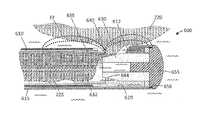
- FIG. 4is a schematic side view of the working end of the electrosurgical tissue resecting device of FIG. 1 showing an outer sleeve, a reciprocating inner sleeve and an electrode arrangement.
- FIG. 5is a schematic perspective view of the working end of the inner sleeve of FIG. 4 showing its electrode edge.
- FIG. 6Ais a schematic cut-away view of a portion of outer sleeve, inner RF resecting sleeve and a tissue-receiving window of the outer sleeve.
- FIG. 6Bis a schematic view of a distal end portion another embodiment of inner RF resecting sleeve.
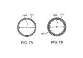
- FIG. 7Ais a cross sectional view of the inner RF resecting sleeve of FIG. 6B taken along line 7 A- 7 A of FIG. 6B .
- FIG. 7Bis another cross sectional view of the inner RF resecting sleeve of FIG. 6B taken along line 7 B- 7 B of FIG. 6B .
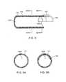
- FIG. 8is a schematic view of a distal end portion of another embodiment of inner RF resecting sleeve.
- FIG. 9Ais a cross sectional view of the RF resecting sleeve of FIG. 8 taken along line 9 A- 9 A of FIG. 8 .
- FIG. 9Bis a cross sectional view of the RF resecting sleeve of FIG. 8 taken along line 9 B- 9 B of FIG. 8 .
- FIG. 10Ais a perspective view of the working end of the tissue resecting device of FIG. 1 with the reciprocating RF resecting sleeve in a non-extended position.
- FIG. 10Bis a perspective view of the tissue resecting device of FIG. 1 with the reciprocating RF resecting sleeve in a partially extended position.
- FIG. 10Cis a perspective view of the tissue resecting device of FIG. 1 with the reciprocating RF resecting sleeve in a fully extended position across the tissue-receiving window.
- FIG. 11Ais a sectional view of the working end of the tissue resecting device of FIG. 10A with the reciprocating RF resecting sleeve in a non-extended position.
- FIG. 11Bis a sectional view of the working end of FIG. 10B with the reciprocating RF resecting sleeve in a partially extended position.
- FIG. 11Cis a sectional view of the working end of FIG. 10C with the reciprocating RF resecting sleeve in a fully extended position.
- FIG. 12Ais an enlarged sectional view of the working end of tissue resecting device of FIG. 11B with the reciprocating RF resecting sleeve in a partially extended position showing the RF field in a first RF mode and plasma resection of tissue.
- FIG. 12Bis an enlarged sectional view of the working end of FIG. 11C with the reciprocating RF resecting sleeve almost fully extended and showing the RF fields switching to a second RF mode from a first RF mode shown in FIG. 12A .
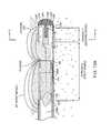
- FIG. 12Cis an enlarged sectional view of the working end of FIG. 11C with the reciprocating RF resecting sleeve again almost fully extended and showing the explosive vaporization of a captured liquid volume to expel resected tissue in the proximal direction.
- FIG. 13is an enlarged perspective view of a portion of the working end of FIG. 12C showing an interior chamber and a fluted projecting element.
- FIG. 14is a sectional view of the working end of FIG. 12C showing an interior chamber and a variation of a projecting element.
- FIG. 15is a sectional view of the working end of FIG. 12C showing an interior chamber and a variation of a projecting element configured to explosively vaporize the captured liquid volume.
- FIG. 16Ais sectional view of a working end of a resection probe similar to that of FIGS. 11A-12C showing a variation of a projecting element and resecting sleeve.
- FIG. 16Bis another view of the working end of FIG. 16A with the resecting sleeve moving distally over a tapered portion of the projecting element.
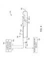
- FIG. 17is a schematic view of a system for fibroid removal including a fluid management system.
- FIG. 18is a schematic view of the fluid management system of FIG. 17 with an enlarged view of the working end of a tissue resecting probe as generally described in FIGS. 1-12C in a position to resect and remove a fibroid.
- FIG. 19is a cut-away schematic view of a filter module of the fluid management system of FIGS. 17-18 .
- FIG. 1illustrates an assembly that comprises an endoscope 50 used for hysteroscopy together with a tissue resecting and extracting device 100 extending through a working channel 102 of the endoscope.
- the endoscope or hysteroscope 50has a handle 104 coupled to an elongated shaft 105 having a diameter of 3 mm to 7 mm.
- the working channel 102 thereinmay be round, D-shaped or any other suitable shape.
- the endoscope shaft 105is further configured with an optics channel 106 and one or more fluid inflow/outflow channels 108 a , 108 b ( FIG.
- the fluid inflow source 120is a component of a fluid management system 126 as is known in the art ( FIG. 2 ) which comprises a fluid container 128 and pump mechanism 130 which pumps fluid through the hysteroscope 50 into the uterine cavity.
- the fluid management system 126further includes the negative pressure source 125 coupled to the tissue resecting device 100 .
- the handle 104 of the endoscopeincludes the angled extension portion 132 with optics to which a videoscopic camera 135 can be operatively coupled.
- a light source 136is coupled to light coupling 138 on the handle of the hysteroscope 50 .
- the working channel 102 of the hysteroscopeis configured for insertion and manipulation of the tissue resecting and extracting device 100 , for example to treat and remove fibroid tissue.
- the hysteroscope shaft 105has an axial length of 21 cm, and can comprise a 0° scope, or 15° to 30° scope.
- the tissue resecting device 100has a highly elongated shaft assembly 140 configured to extend through the working channel 102 in the hysteroscope.
- a handle 142 of the tissue resecting device 100is adapted for manipulating the electrosurgical working end 145 of the device. In use, the handle 142 can be manipulated both rotationally and axially, for example, to orient the working end 145 to resect targeted fibroid tissue.
- the tissue resecting device 100has subsystems coupled to its handle 142 to enable electrosurgical resection of targeted tissue.
- a radiofrequency generator or RF source 150 and controller 155are coupled to at least one RF electrode carried by the working end 145 as will be described in detail below. In one embodiment shown in FIG.
- an electrical cable 156 and negative pressure source 125are operatively coupled to a connector 158 in handle 142 .
- the electrical cablecouples the RF source 150 to the electrosurgical working end 145 .
- the negative pressure source 125communicates with a tissue-extraction channel 160 in the shaft assembly 140 of the tissue resecting device 100 ( FIG. 4 ).
- FIG. 1further illustrates a seal housing 162 that carries a flexible seal 164 within the hysteroscope handle 104 for sealing the shaft 140 of the tissue resecting device 100 in the working channel 102 to prevent distending fluid from escaping from a uterine cavity.
- the handle 142 of tissue resecting device 100includes a motor drive 165 for reciprocating or otherwise moving a resecting component of the electrosurgical working end 145 as will be described below.
- the handle 142optionally includes one or more actuator buttons 166 for actuating the device.
- a footswitchcan be used to operate the device.
- the systemincludes a switch or control mechanism to provide a plurality of reciprocation speeds, for example 1 Hz, 2 Hz, 3 Hz, 4 Hz and up to 8 Hz.
- the systemcan include a mechanism for moving and locking the reciprocating resecting sleeve in a non-extended position and in an extended position.
- the systemcan include a mechanism for actuating a single reciprocating stroke.
- an electrosurgical tissue resecting devicehas an elongate shaft assembly 140 extending about longitudinal axis 168 comprising an exterior or first outer sleeve 170 with passageway or lumen 172 therein that accommodates a second or inner sleeve 175 that can reciprocate (and optionally rotate or oscillate) in lumen 172 to resect tissue as is known in that art.
- the tissue-receiving window 176 in the outer sleeve 170has an axial length ranging between 10 mm and 30 mm and extends in a radial angle about outer sleeve 170 from about 45° to 210° relative to axis 168 of the sleeve.
- the outer and inner sleeves 170 and 175can comprise a thin-wall stainless steel material and function as opposing polarity electrodes as will be described in detail below.
- FIGS. 6A-8illustrate insulative layers carried by the outer and inner sleeves 170 and 175 to limit, control and/or prevent unwanted electrical current flows between certain portions of the sleeve.
- a stainless steel outer sleeve 170has an O.D. of 0.143′′ with an I.D. of 0.133′′ and with an inner insulative layer (described below) the sleeve has a nominal I.D. of 0.125′′.
- the stainless steel inner sleeve 175has an O.D. of 0.120′′ with an I.D. of 0.112′′.
- the inner sleeve 175 with an outer insulative layerhas a nominal O.D. of about 0.123′′ to 0.124′′ to reciprocate in lumen 172 .
- outer and or inner sleevescan be fabricated of metal, plastic, ceramic of a combination thereof.
- the cross-section of the sleevescan be round, oval or any other suitable shape.
- the distal end 177 of inner sleeve 175comprises a first polarity electrode with distal electrode edge 180 about which plasma can be generated.
- the electrode edge 180also can be described as an active electrode during tissue resection since the electrode edge 180 then has a substantially smaller surface area than the opposing polarity or return electrode.
- the exposed surfaces of outer sleeve 170comprises the second polarity electrode 185 , which thus can be described as the return electrode since during use such an electrode surface has a substantially larger surface area compared to the functionally exposed surface area of the active electrode edge 180 .
- the inner sleeve or resecting sleeve 175has an interior tissue extraction lumen 160 with first and second interior diameters that are adapted to electrosurgically resect tissue volumes rapidly—and thereafter consistently extract the resected tissue strips through the highly elongated lumen 160 without clogging.
- first and second interior diametersthat are adapted to electrosurgically resect tissue volumes rapidly—and thereafter consistently extract the resected tissue strips through the highly elongated lumen 160 without clogging.
- the tissue extraction lumentransitions to a smaller second diameter lumen 190 B with a reduced diameter indicated at B which is defined by the electrode sleeve element 195 that provides the resection electrode edge 180 .
- the axial length C of the reduced cross-section lumen 190 Bcan range from about 2 mm to 20 mm.
- the first diameter Ais 0.112′′ and the second reduced diameter B is 0.100′′.
- the inner sleeve 175can be an electrically conductive stainless steel and the reduced diameter electrode portion also can comprise a stainless steel electrode sleeve element 195 that is welded in place by weld 196 ( FIG. 6A ).
- the electrode and reduced diameter electrode sleeve element 195comprises a tungsten tube that can be press fit into the distal end 198 of inner sleeve 175 .
- FIGS. 5 and 6Afurther illustrate the interfacing insulation layers 202 and 204 carried by the first and second sleeves 170 , 175 , respectively.
- the outer sleeve 170is lined with a thin-wall insulative material 200 , such as PFA, or another material described below.
- the inner sleeve 175has an exterior insulative layer 202 . These coating materials can be lubricious as well as electrically insulative to reduce friction during reciprocation of the inner sleeve 175 .
- the insulative layers 200 and 202 described abovecan comprise a lubricious, hydrophobic or hydrophilic polymeric material.
- the materialcan comprise a bio-compatible material such as PFA, TEFLON®, polytetrafluroethylene (PTFE), FEP (Fluorinated ethylenepropylene), polyethylene, polyamide, ECTFE (Ethylenechlorotrifluoro-ethylene), ETFE, PVDF, polyvinyl chloride or silicone.
- FIG. 6Banother variation of inner sleeve 175 is illustrated in a schematic view together with a tissue volume being resected with the plasma electrode edge 180 .
- the RF sourceoperates at selected operational parameters to create plasma around the edge 180 of electrode sleeve 195 as is known in the art.
- the plasma generated at electrode edge 180can ablate a path P in the tissue 220 and is suited for resecting fibroid tissue and other abnormal uterine tissue.
- the distal portion of the resecting sleeve 175includes a ceramic collar 222 which is proximate to the distal edge 180 of the electrode sleeve 195 .
- the ceramic collar 222functions to confine plasma formation about the distal electrode edge 180 and functions further to prevent plasma from contacting and damaging the polymer insulative layer 202 on the resecting sleeve 175 during operation.
- the path P ablated in the tissue 220 with the plasma at electrode edge 180provides a path P having an ablated width indicated at W, wherein such path width W is substantially wide due to tissue vaporization.
- This vaporization of tissue in path P to provide the resectionis substantially different than the effect of resecting similar tissue with a sharp blade edge, as in various prior art devices.
- a sharp blade edgecan divide tissue (without cauterization) but applies mechanical force to the tissue and may prevent a large cross section slug of tissue from being resected.
- the plasma at the electrode edge 180can vaporize a path Pin tissue without applying any substantial force on the tissue to thus resect larger cross sections or strips of tissue.
- the plasma resecting effectreduces the cross section of tissue strip 225 received in the reduced cross-section region 190 B of the tissue extraction lumen 160 .
- FIG. 6Bdepicts a tissue strip 225 entering the reduced cross-section region 190 B, wherein the tissue strip has a smaller cross-section than the lumen due to the vaporization of tissue.
- the cross section of tissue strip 225 as it enters the larger cross-section lumen 190 Aresults in even greater free space 197 around the tissue strip 225 .
- the resection of tissue with the plasma electrode edge 180together with the lumen transition from the smaller cross-section ( 190 B) to the larger cross-section ( 190 A) of the tissue-extraction lumen 160 can significantly reduce or eliminate the potential for successive resected tissue strips 225 clogging the lumen.
- Prior art resection devices with such a small diameter tissue-extraction lumentypically have problems with tissue clogging.
- the negative pressure source 125 coupled to the proximal end of tissue-extraction lumen 160also assists in aspirating and moving tissue strips 225 in the proximal direction to a collection reservoir (not shown) outside the handle 142 of the resecting device.
- FIGS. 7A-7Billustrate the change in lumen diameter of resecting sleeve 175 of FIG. 6B .
- FIG. 8illustrates the distal end of a variation of resecting sleeve 175 ′ which is configured with an electrode resecting element 195 ′ that is partially tubular in contrast to the previously described tubular electrode element 195 ( FIGS. 5 and 6A ).
- FIGS. 9A-9Bagain illustrate the change in cross-section of the tissue-extraction lumen between reduced cross-section region 190 B′ and the increased cross-section region 190 A′ of the resecting sleeve 175 ′ of FIG. 8 .
- the functionalityremains the same whether the resecting electrode element 195 ′ is tubular or partly tubular.
- the ceramic collar 222 ′is shown, in one variation, as extending only partially around sleeve 175 ′ to cooperate with the radial angle of resecting electrode element 195 ′. Further, the variation of FIG. 8 illustrates that the ceramic collar 222 ′ has a larger outside diameter than insulative layer 202 . Thus, friction may be reduced since the short axial length of the ceramic collar 222 ′ interfaces and slides against the interfacing insulative layer 200 about the inner surface of lumen 172 of outer sleeve 170 .
- one aspect of the inventioncomprises a tissue resecting and extracting device ( FIGS. 10A-11C ) that includes first and second concentric sleeves having an axis and wherein the second (inner) sleeve 175 has an axially-extending tissue-extraction lumen therein, and wherein the second sleeve 175 is moveable between axially non-extended and extended positions relative to a tissue-receiving window 176 in first sleeve 170 to resect tissue, and wherein the tissue extraction lumen 160 has first and second cross-sections.
- the second sleeve 175has a distal end configured as a plasma electrode edge 180 to resect tissue disposed in tissue-receiving window 176 of the first sleeve 170 . Further, the distal end of the second sleeve, and more particularly, the electrode edge 180 is configured for plasma ablation of a substantially wide path in the tissue.
- the tissue resecting deviceis configured with a tissue extraction lumen 160 having a distal end portion with a reduced cross-section that is smaller than a cross-section of medial and proximal portions of the lumen 160 .
- the tissue-extraction lumen 160has a reduced cross-sectional area in lumen region 190 B proximate the plasma resecting tip or electrode edge 180 wherein said reduced cross section is less than 95%, 90%, 85% or 80% than the cross sectional area of medial and proximal portions 190 A of the tissue-extraction lumen, and wherein the axial length of the tissue-extraction lumen is at least 10 cm, 20 cm, 30 cm or 40 cm.
- the shaft assembly 140 of the tissue resecting deviceis 35 cm in length.
- FIGS. 10A-10Cillustrate the working end 145 of the tissue resecting device 100 with the reciprocating resecting sleeve or inner sleeve 175 in three different axial positions relative to the tissue receiving window 176 in outer sleeve 170 .
- the resecting sleeve 175is shown in a retracted or non-extended position in which the sleeve 175 is at it proximal limit of motion and is prepared to advance distally to an extended position to thereby electrosurgically resect tissue positioned in and/or suctioned into window 176 .
- FIG. 10Athe resecting sleeve 175 is shown in a retracted or non-extended position in which the sleeve 175 is at it proximal limit of motion and is prepared to advance distally to an extended position to thereby electrosurgically resect tissue positioned in and/or suctioned into window 176 .
- FIG. 10Bshows the resecting sleeve 175 moved and advanced distally to a partially advanced or medial position relative to tissue resection window 176 .
- FIG. 10Cillustrates the resecting sleeve 175 fully advanced and extended to the distal limit of its motion wherein the plasma resecting electrode 180 has extended past the distal end 226 of tissue-receiving window 176 at which moment the tissue strip 225 is resected from tissue volume 220 and captured in reduced cross-sectional lumen region 190 B.
- tissue displacement mechanismsprovided by multiple elements and processes to displace and move tissue strips 225 in the proximal direction in lumen 160 of resecting sleeve 175 to thus ensure that tissue does not clog the lumen of the inner sleeve 175 .
- one tissue displacement mechanismcomprises a projecting element 230 that extends proximally from distal tip 232 which is fixedly attached to outer sleeve 170 .
- the projecting element 230extends proximally along central axis 168 in a distal chamber 240 defined by outer sleeve 170 and distal tip 232 .
- the shaft-like projecting element 230in a first functional aspect, comprises a mechanical pusher that functions to push a captured tissue strip 225 proximally from the small cross-section lumen 190 B of resecting sleeve 175 as the sleeve 175 moves to its fully advanced or extended position.
- the chamber 240 in the distal end of sleeve 170is configured to capture a volume of saline distending fluid 244 from the working space, and wherein the existing RF electrodes of the working end 145 are further configured to explosively vaporize the captured fluid 244 to generate proximally-directed forces on tissue strips 225 resected and disposed in lumen 160 of the resecting sleeve 175 .
- tissue displacement mechanismscan apply substantial mechanical force to captured tissue strips 225 .
- the explosive vaporization of liquid in chamber 240can function to move tissue strips 225 in the proximal direction in the tissue-extraction lumen 160 . It has been found that using the combination of multiple functional elements and processes can virtually eliminate the potential for tissue clogging the tissue extraction lumen 160 .
- FIGS. 12A-12Cillustrate sequentially the functional aspects of the tissue displacement mechanisms and the explosive vaporization of fluid captured in chamber 240 .
- the reciprocating resecting sleeve 175is shown in a medial position advancing distally wherein plasma at the electrode edge 180 is resecting a tissue strip 225 that is disposed within lumen 160 of the resecting sleeve 175 .
- FIG. 12A-12Cit can be seen that the system operates in first and second electrosurgical modes corresponding to the reciprocation and axial range of motion of resecting sleeve 175 relative to the tissue-receiving window 176 .
- the term “electrosurgical mode”refers to which electrode of the two opposing polarity electrodes functions as an “active electrode” and which electrode functions as a “return electrode”.
- active electrodeand “return electrode” are used in accordance with convention in the art—wherein an active electrode has a smaller surface area than the return electrode which thus focuses RF energy density about such an active electrode.
- the resecting electrode element 195 and its electrode edge 180must comprise the active electrode to focus energy about the electrode to generate the plasma for tissue resection. Such a high-intensity, energetic plasma at the electrode edge 180 is needed throughout stroke X indicated in FIGS. 12A-12B to resect tissue.
- the first modeoccurs over an axial length of travel of inner sleeve 175 as it crosses the tissue receiving window 176 , at which time the entire exterior surface of outer sleeve 170 comprises the return electrode indicated at 185 .
- the electrical fields EF of the first RF modeare indicated schematically generally in FIG. 12A .
- FIG. 12Billustrates the moment in time at which the distal advancement or extension of inner resecting sleeve 175 entirely crosses the tissue-receiving window 176 .
- the electrode sleeve 195 and its electrode edge 180are confined within the mostly insulated-wall chamber 240 defined by the outer sleeve 170 and distal tip 232 .
- the systemis configured to switch to the second RF mode in which the electric fields EF switch from those described previously in the first RF mode. As can be seen in FIG.
- the limited interior surface area 250 of distal tip 232 that interfaces chamber 240functions as an active electrode and the distal end portion of resecting sleeve 175 exposed to chamber 240 acts as a return electrode.
- very high energy densitiesoccur about surface 250 and such a contained electric field EF can explosively and instantly vaporize the fluid 244 captured in chamber 240 .
- the expansion of water vaporcan be dramatic and can thus apply tremendous mechanical forces and fluid pressure on the tissue strip 225 to move the tissue strip in the proximal direction in the tissue extraction lumen 160 .
- FIG. 12Cillustrates such explosive or expansive vaporization of the distention fluid 244 captured in chamber 240 and further shows the tissue strip 225 being expelled in the proximal direction in the lumen 160 of inner resecting sleeve 175 .
- FIG. 14further shows the relative surface areas of the active and return electrodes at the extended range of motion of the resecting sleeve 175 , again illustrating that the surface area of the non-insulated distal end surface 250 is small compared to surface 255 of electrode sleeve which comprises the return electrode.
- a single power setting on the RF source 150 and controller 155can be configured both (i) to create plasma at the electrode edge 180 of electrode sleeve 195 to resect tissue in the first mode, and (ii) to explosively vaporize the captured distention fluid 244 in the second mode. Further, it has been found that the system can function with RF mode-switching automatically at suitable reciprocation rates ranging from 0.5 cycles per second to 8 or 10 cycles per second.
- tissue resecting devicedescribed above can resect and extract tissue at the rate of from 4 grams/min to 20 grams/min without any potential for tissue strips 225 clogging the tissue-extraction lumen 160 , depending on the diameter of the device.
- a negative pressure source 125can be coupled to the tissue-extraction lumen 160 to apply additional tissue-extracting forces to tissue strips 225 in the system.
- the fluid-capture chamber 240 defined by sleeve 170 and distal tip 232can be designed to have a selected volume, exposed electrode surface area, length and geometry to optimize the expelling forces applied to resected tissue strips 225 .
- the diameter of the chamberis 3.175 mm and the length is 5.0 mm which taking into account the projecting element 230 , provides a captured fluid volume of approximately 0.040 mL. In other variations, the captured fluid volume can range from 0.004 to 0.080 mL.
- a chamber 240 with a captured liquid volume of 0.040 mL together with 100% conversion efficiency in an instantaneous vaporizationwould require 103 Joules to heat the liquid from room temperature to water vapor.
- the power requiredwould be on the order of 311 W for full, instantaneous conversion of the captured liquid to water vapor.
- a corresponding theoretical expansion of 1700 ⁇would occur in the phase transition, which would results in up to 25,000 psi instantaneously (14.7 psi ⁇ 1700), although due to losses in efficiency and non-instantaneous expansion, the actual pressures would be less.
- the pressuresare substantial and can apply expelling forces sufficient to expel the captured tissue strips 225 along the length of the extraction channel 160 in the probe.
- the interior chamber 240can have an axial length from about 0.5 mm to 10 mm to capture a liquid volume ranging from about 0.004 mL 0.01 mL. It can be understood in FIG. 12A , that the interior wall of chamber 240 has an insulator layer 200 which thus limits the electrode surface area 250 exposed to chamber 240 .
- the distal tip 232is stainless steel and is welded to outer sleeve 170 .
- the post element 248is welded to tip 232 or machined as a feature thereof.
- the projecting element 230 in this embodimentis a non-conductive ceramic.
- FIG. 13shows the cross-section of the ceramic projecting element 230 which is fluted, which in one embodiment has three flute elements 260 in three corresponding axial grooves 262 in its surface. Any number of flutes, channels or the like is possible, for example from 2 to about 20.
- the purpose of this designis to provide a significant cross-sectional area at the proximal end of the projecting element 230 to push the tissue strip 225 , while at the same time the three grooves 262 permit the proximally-directed jetting of water vapor to impact the tissue exposed to the grooves 262 .
- the axial length D of the projecting element 230is configured to push tissue entirely out of the reduced cross-sectional region 190 B of the electrode sleeve element 195 .
- the volume of the chamber 240is configured to capture liquid that when explosively vaporized provides a gas (water vapor) volume sufficient to expand into and occupy at least the volume defined by a 10% of the total length of extraction channel 160 in the device, at least 20% of the extraction channel 160 , at least 40% of the extraction channel 160 , at least 60% of the extraction channel 160 , at least 80% of the extraction channel 160 or at least 100% of the extraction channel 160 .
- a gaswater vapor
- the distention fluid 244 in the working spacereplenishes the captured fluid in chamber 240 as the resecting sleeve 175 moves in the proximal direction or towards its non-extended position.
- the interior chamber 240is filled with fluid 244 which is then again contained and is then available for explosive vaporization as described above when the resecting sleeve 175 closes the tissue-receiving window 176 .
- a one-way valvecan be provided in the distal tip 232 to draw fluid directly into interior chamber 240 without the need for fluid to migrate through window 176 .
- FIG. 15illustrates another variation in which the active electrode surface area 250 ′ in the second mode comprises a projecting element 230 with conductive regions and nonconductive regions 261 which can have the effect of distributing the focused RF energy delivery over a plurality of discrete regions each in contact with the captured fluid 244 .
- This configurationcan more efficiently vaporize the captured fluid volume in chamber 240 .
- the conductive regions 250 ′can comprise metal discs or washers on post 248 .
- the conductive regions 250 ′can comprise holes, ports or pores in a ceramic material 261 fixed over an electrically conductive post 248 .
- the RF source 150 and controller 155can be programmed to modulate energy delivery parameters during stroke X and stroke Y in FIGS. 12A-12C to provide the optimal energy (i) for plasma resection with electrode edge 180 , and (ii) for explosively vaporizing the captured fluid in chamber 240 .
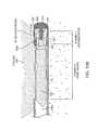
- FIGS. 16A-16Bare sectional views of a working end 600 of a tissue resecting probe that is similar to previous embodiments.
- the inner resecting member or sleeve 610is shown in a distal portion of its stroke after resecting a tissue strip 225 captured in the window 612 in the outer sleeve 615 or housing as generally depicted in the tissue resecting sequence of FIGS. 12A-12B .
- FIGS. 16A-16Billustrate another aspect of the invention wherein the inner resecting sleeve 610 moves in a passageway 620 in the outer sleeve 615 and in the distal portion of its stroke, a projecting or extending element 630 extends into the tissue extraction channel 632 in the inner sleeve 610 .
- the cross-section of the extending element 630is configured to extend into the distal reduced cross-section portion 635 of the tissue extraction channel 632 and function in a scissor-like manner to push the tissue against the electrode edge 640 of the inner sleeve 610 as depicted in FIG. 16A .
- the extending element 630can have an axial length of at least 2 mm.
- the extending element 630has a length can ranging from 4 mm to 10 mm.
- the extending element 630can have a length that equals at least 50% of the axial length of the distal reduced cross-section region 635 of the extraction channel 632 .
- a method of resecting tissuecomprises positioning a working end of a tissue resecting probe against tissue and moving a resecting sleeve or member 610 carried by the probe wherein the moveable resecting member 610 interfaces with an extending element 630 carried by the probe that extends into a channel 632 in the resecting sleeve to thereby resect tissue that is captured between the resecting member 610 and the extending element 630 .
- the step of resecting tissueis accomplished by plasma formed at the distal electrode edge 640 of the resecting member 610 , with electrical fields EF ( FIG. 16A ) as described above.
- the extending element 630has a tapered region 644 that tapers in the proximal direction.
- the tapered regionhelps insure that the distally moving inner sleeve 610 is guided over the projecting element 630 even if there is some flex in the distal portion of the outer sleeve 615 in the region of window 612 .
- a method of resecting and extracting tissuecomprises positioning a window of a tubular resecting device against tissue, and reciprocating a resecting sleeve in forward and backward strokes across the window wherein a projecting member separate from the resecting sleeve projects into a bore in the resecting sleeve during a portion of its forward stroke to prevent flexing of the sleeve proximate the window.
- the extending element 630has a recessed region 648 therein for receiving a fluid volume.
- the extending element 630is a dielectric material (e.g., a ceramic) with a central bore 660 for mounting the element 630 over the post element 652 of metal endcap 655 .
- the proximal surface 658 of post element 652functions as an electrode when vaporizing captured fluid as described previously and shown in FIG. 16B .
- the electrical fields EF′are shown in FIG. 16B which result in the explosive vaporization of the contained liquid. It can be seen in FIG.
- FIG. 16Bthat metal endcap 655 is fixed with annular weld 656 to outer sleeve 615 (electrode) so that endcap 655 and its post element 652 also function as an electrode.
- FIG. 16Bfurther illustrates that the working end has insulative layers on all surfaces of the distal annular space 660 that receives the inner resecting sleeve 610 to focus RF current paths in the central bore 650 of the projecting element 630 . More in particular, the outer sleeve 615 is lined with an insulative layer 662 and the endcap 655 has an annular inner insulator 664 bonded thereto.
- FIGS. 17-19illustrate a fluid management system 500 that can be used when treating tissue in a body cavity, space or potential space 502 ( FIG. 18 ).
- the fluid management system 500is depicted schematically in a hysteroscopic fibroid treatment system 510 that is adapted for resection and extraction of fibroids or other abnormal intra-uterine tissue using a hysteroscope 512 and tissue resection probe 515 that can be similar to those described above.
- FIG. 17depicts the probe 515 with handle 516 and extension member 518 with working end 520 ( FIG. 18 ) that can be introduced through working channel 522 extending through the body 523 and shaft 524 of the hysteroscope 512 .
- FIG. 17further shows a motor 525 in handle 516 of the probe that is coupled to a controller 545 and power supply by power cable 526 .
- FIG. 18illustrates the working end 520 of the resecting probe in a uterine cavity proximate a targeted fibroid 530 .
- the fluid management system 500comprises a fluid source or reservoir 535 of a distention fluid 244 , a controller and pump system to provide fluid inflows and outflows adapted to maintain distension of a body space and a filter system 540 for filtering distention fluid 244 that is removed from the body cavity and thereafter returned to the fluid source 535 .
- the use of a recovered and filtered fluid 244 and the replenishment of the fluid source 535is advantageous because (i) the closed-loop fluid management system can effectively measure fluid deficit to thereby monitor intravasation and insure patient safety, (ii) the system can be set up and operated in a very time-efficient manner, and (iii) the system can be compact and less expensive to thereby assist in enabling office-based procedures.
- the fluid management system 500( FIG. 17 ) includes a computer control system that is integrated with the RF control system in an integrated controller 545 .
- the controller 545is adapted to control first and second peristaltic pumps 546 A and 546 B for providing inflows and outflows of a distention fluid 244 , such as saline solution, from source 535 for the purpose of distending the body cavity and controlling the intra-cavity pressure during a tissue resecting and extracting procedure as depicted in FIG. 18 .
- a distention fluid 244such as saline solution
- the controller 545controls peristaltic pump 546 A to provide positive pressure at the outflow side 548 of the pump ( FIG.
- the controller 545further controls the second peristaltic pump 546 B to provide negative pressure at the inflow side 552 of the pump ( FIG. 18 ) to the second line 555 to assist in providing outflows of distention fluid 244 from the body cavity 502 .
- the explosive vaporization of fluid in the working end 525 of probe 515functions to expel tissue strips 225 proximally in the extraction channel 160 of resecting sleeve 175 , which can operate in conjunction with negative pressures in line 555 provided by pump 546 B.
- the second peristaltic pump 546 Balso operates to provide positive pressure on the outflow side 556 of pump 546 B in the second flow line portion 555 ′ to pump outflows of distention fluid 244 through the filter system 540 and back to the fluid source 535 .
- the controller 545operates to control pressure in cavity 502 by pressure signals from a disposable pressure sensor 560 that is coupled to a fitting 562 in hysterocope 512 which communicates with a flow channel 108 b (see FIG. 17 ) that extends through the hysteroscope.
- the pressure sensor 560is operatively coupled to controller 545 by cable 564 .
- the flow channel 108 bhas a diameter of at least 1.0 mm to allow highly accurate sensing of actual intra-cavity pressure.
- the intra-cavity pressureis typically estimated by various calculations using known flow rates through a pump or remote pressure sensors in the fluid inflow line that can measure back pressures.
- prior art fluid management systemsare stand-alone systems and are adapted for use with a wide variety of hysteroscopes and endoscopes, most of which do not have a dedicated flow channel for communicating with a pressure sensor. For this reason, prior art fluid management systems rely on algorithms and calculations to estimate intra-cavity pressure.
- the fluid channel or sensor channel 108 b used by the pressure sensor 560is independent of flow channel 108 a used for distention fluid inflows into the body cavity. In the absence of fluid flows in the sensor channel 108 b , the fluid in the channel 108 b then forms a static column of incompressible fluid that changes in pressure as the pressure in the body cavity changes. With a sensor channel cross-section of 1 mm or more, the pressure within the pressure channel column and the pressure in the body cavity are equivalent. Thus, the pressure sensor 560 is capable of a direct measurement of pressure within the body cavity.
- FIG. 18schematically illustrates the fluid management system 500 in operation.
- the uterine cavity 502is a potential space and needs to be distended to allow for hysteroscopic viewing.
- a selected pressurecan be set in the controller 545 , for example via a touch screen 565 , which the physician knows from experience is suited for distending the cavity 502 and/or for performing a procedure.
- the selected pressurecan be any pressure between 0 and 150 mm Hg.
- the first pump 546 Acan operate as a variable speed pump that is actuated to provide a flow rate of up to 850 ml/min through first line 550 .
- the second pump 546 Bcan operate at a fixed speed to move fluid in the second line 555 .
- the controller 545can operate the pumps 546 A and 546 B at selected matching or non-matching speeds to increase, decrease or maintain the volume of distention fluid 244 in the uterine cavity 502 .
- a selected set pressure in the body cavitycan be achieved and maintained in response to signals of actual intra-cavity pressure provided by sensor 560 .
- the fluid management system 500includes a filter module or system 540 that can include a first filter or tissue-capturing filter 570 that is adapted to catch tissue strips 225 that have been resected and extracted from the body cavity 502 .
- a second filter or molecular filter 575is provided beyond the first filter 570 , wherein the molecular filter 575 is adapted to remove blood and other body materials from the distention fluid 244 .
- the molecular filter 575is capable of removing red blood cells, hemoglobin, particulate matter, proteins, bacteria, viruses and the like from the distention fluid 244 so that endoscopic viewing of the body cavity is not obscured or clouded by any such blood components or other contaminants.
- the second peristaltic pump 546 B at its outflow side 556provides a positive pressure relative to fluid flows into the filter module 540 to move the distention fluid 244 and body media through the first and second filters, 570 and 575 , and in a circulatory flow back to the fluid source 535 .
- the first filter 570comprises a container portion or vial 576 with a removable cap 577 .
- the inflow of distention fluid 244 and body mediaflows though line portion 555 and through fitting 578 into a mesh sac or perforate structure 580 disposed in the interior chamber 582 of the vial 576 .
- the pore size of the perforate structure 580can range from about 200 microns to 10 microns.
- the lumen diameter of hollow fibers 585 in the second filter 575can be from about 400 microns to 20 microns. In general, the pore size of perforate structure 580 in the first filter 570 is less than the diameter of the lumens of hollow fibers 585 in the second filter 575 .
- the pore size of the perforate structure 580is 100 microns, and the lumen size of the hollow fibers 585 in the molecular filter 575 is 200 microns.
- the molecular filter 575is a Nephros DSU filter available from Nephros, Inc., 41 Grand Ave., River Edge, N.J. 07661.
- the filter 575is configured with hollow fibers having a nominal molecular weight limit (NMWL) of less than 50 kDa, 30 kDa or 20 kDa.
- NMWLnominal molecular weight limit
- the filter module 540includes detachable connections between the various fluid flow lines to allow for rapid coupling and de-coupling of the filters and flow lines. More in particular, flow line 555 extending from the tissue resecting probe 515 has a connector portion 592 that connects to inlet fitting 578 in the first filter 570 . Flow line portion 555 ′ that is intermediate the filters 570 and 575 has connector portion 596 a that connects to outlet fitting 596 b in first filter 570 . The outflow end of flow line 555 ′ has connector 598 a that connects to inlet fitting 598 b of the second filter 575 .
- the portion 590 of the second flow line 555 that is intermediate the second filter 575 and fluid source 535has connector portion 602 a that connects to outlet fitting 602 b in the second filter 575 .
- at least one check valve 605is provided in the flow path intermediate the filters 570 , 575 which for example can be in line 555 ′, connectors 596 a , 598 a or fittings 596 b , 598 b .
- a check valve 605is integrated with the inlet end 608 of the second filter 575 .
- the operation of the systemwill result in substantial fluid pressures in the interior of the second filter, and the check valve 605 allows for de-coupling the first filter without escape of pressure and release of fluid media into the environment, for example, when the tissue resection procedure is completed and the physician or nurse wishes to transport the vial 576 and tissue strips 225 therein to a different site for biopsy purposes.
- a fluid management systemcomprising a first fluid line 550 configured to carry distention fluid 224 or influent from a fluid source 535 to a body space, a second fluid line 555 , 555 ′ and 560 configured to carry fluid from the body space to a first filter 570 and then to a second filter 575 and then back to the fluid source 535 , a pump operatively coupled to the second fluid line to move the fluid and at least one check valve 605 in the second fluid line intermediate the first and second filters 570 and 575 .
- the controller 545 of the fluid management system 500is configured for calculation of a fluid deficit that is measured as a difference between a fluid volume delivered to the body space 502 and a fluid volume recovered from the body space during a medical procedure such as fibroid removal (see FIGS. 17-18 ).
- a method of fluid management in a hysteroscopic procedurecomprises providing a distention fluid source 535 ( FIG.
- fluide.g., saline
- introducing fluide.g., saline
- fluide.g., saline
- the interior volume of the first and second flow lines and the filter module when subtracted from the predetermined volume of the source 535equals 2.5 liters or less to thereby insure that saline intravasion is less than 2.5 liters.
- the predetermined volume of the source 535can be 3.0 liters, as in a standard 3 liter saline bag, and the interior system volume can be at least 0.5 liters.
- the fluid management system 500can include a sensor system for determining the volume of fluid remaining in the source 535 , and the sensor can provide a signal to the controller 545 which in turn can provide a visual or aural signal relating to remaining fluid volume in fluid source 535 .
- the fluid source 535can be a bag that hangs from a member including a load cell 625 ( FIGS. 17, 19 ) which is configured to send load signals to the controller 545 .
- the controllercan have a screen 565 which continuously displays a fluid parameter such as calculated fluid deficit or fluid remaining in the source 535 .
- the sensor adapted for sensing the weight or volume of fluid in the fluid sourcecan be a float or level sensor in a fluid container, an impedance or capacitance sensor coupled to the fluid source container, an optical sensor operatively coupled to the fluid container or any other suitable type of weight or volume sensing mechanism. Any such sensor system can send signals to the controller for providing fluid deficit calculations or fluid intravasation warnings.
Landscapes
- Health & Medical Sciences (AREA)
- Life Sciences & Earth Sciences (AREA)
- Surgery (AREA)
- Engineering & Computer Science (AREA)
- Animal Behavior & Ethology (AREA)
- General Health & Medical Sciences (AREA)
- Biomedical Technology (AREA)
- Heart & Thoracic Surgery (AREA)
- Medical Informatics (AREA)
- Molecular Biology (AREA)
- Veterinary Medicine (AREA)
- Public Health (AREA)
- Nuclear Medicine, Radiotherapy & Molecular Imaging (AREA)
- Physics & Mathematics (AREA)
- Otolaryngology (AREA)
- Orthopedic Medicine & Surgery (AREA)
- Plasma & Fusion (AREA)
- Pathology (AREA)
- Electromagnetism (AREA)
- Surgical Instruments (AREA)
Abstract
Description
Claims (24)
Priority Applications (6)
| Application Number | Priority Date | Filing Date | Title |
|---|---|---|---|
| US14/053,434US9498244B2 (en) | 2012-10-19 | 2013-10-14 | Medical systems and methods |
| US15/292,711US10806510B2 (en) | 2012-10-19 | 2016-10-13 | Medical systems and methods |
| US17/010,193US11653972B2 (en) | 2012-10-19 | 2020-09-02 | Medical systems and methods |
| US17/075,844US11660138B2 (en) | 2012-10-19 | 2020-10-21 | Medical systems and methods |
| US18/302,755US12042214B2 (en) | 2012-10-19 | 2023-04-18 | Medical systems and methods |
| US18/754,649US20240341837A1 (en) | 2012-10-19 | 2024-06-26 | Medical systems and methods |
Applications Claiming Priority (2)
| Application Number | Priority Date | Filing Date | Title |
|---|---|---|---|
| US201261716049P | 2012-10-19 | 2012-10-19 | |
| US14/053,434US9498244B2 (en) | 2012-10-19 | 2013-10-14 | Medical systems and methods |
Related Child Applications (1)
| Application Number | Title | Priority Date | Filing Date |
|---|---|---|---|
| US15/292,711ContinuationUS10806510B2 (en) | 2012-10-19 | 2016-10-13 | Medical systems and methods |
Publications (2)
| Publication Number | Publication Date |
|---|---|
| US20140114300A1 US20140114300A1 (en) | 2014-04-24 |
| US9498244B2true US9498244B2 (en) | 2016-11-22 |
Family
ID=50485991
Family Applications (6)
| Application Number | Title | Priority Date | Filing Date |
|---|---|---|---|
| US14/053,434Active2034-08-28US9498244B2 (en) | 2012-10-19 | 2013-10-14 | Medical systems and methods |
| US15/292,711Active2036-01-08US10806510B2 (en) | 2012-10-19 | 2016-10-13 | Medical systems and methods |
| US17/010,193Active2034-12-31US11653972B2 (en) | 2012-10-19 | 2020-09-02 | Medical systems and methods |
| US17/075,844Active2034-11-13US11660138B2 (en) | 2012-10-19 | 2020-10-21 | Medical systems and methods |
| US18/302,755ActiveUS12042214B2 (en) | 2012-10-19 | 2023-04-18 | Medical systems and methods |
| US18/754,649PendingUS20240341837A1 (en) | 2012-10-19 | 2024-06-26 | Medical systems and methods |
Family Applications After (5)
| Application Number | Title | Priority Date | Filing Date |
|---|---|---|---|
| US15/292,711Active2036-01-08US10806510B2 (en) | 2012-10-19 | 2016-10-13 | Medical systems and methods |
| US17/010,193Active2034-12-31US11653972B2 (en) | 2012-10-19 | 2020-09-02 | Medical systems and methods |
| US17/075,844Active2034-11-13US11660138B2 (en) | 2012-10-19 | 2020-10-21 | Medical systems and methods |
| US18/302,755ActiveUS12042214B2 (en) | 2012-10-19 | 2023-04-18 | Medical systems and methods |
| US18/754,649PendingUS20240341837A1 (en) | 2012-10-19 | 2024-06-26 | Medical systems and methods |
Country Status (1)
| Country | Link |
|---|---|
| US (6) | US9498244B2 (en) |
Cited By (5)
| Publication number | Priority date | Publication date | Assignee | Title |
|---|---|---|---|---|
| US10178942B2 (en) | 2015-08-27 | 2019-01-15 | Boston Scientific Scimed, Inc. | Fluid management systems and methods |
| US10507278B2 (en)* | 2016-05-23 | 2019-12-17 | Boston Scientific Scimed, Inc. | Fluidic devices, methods, and systems |
| US10537227B2 (en) | 2015-08-27 | 2020-01-21 | Boston Scientific Scimed, Inc. | Medical devices and methods |
| US11957406B2 (en) | 2015-08-27 | 2024-04-16 | Minerva Surgical, Inc. | Tissue resecting device and methods |
| US12357755B2 (en) | 2020-01-30 | 2025-07-15 | Boston Scientific Scimed, Inc. | Fluid management system and method for controlling intracavity pressure |
Families Citing this family (18)
| Publication number | Priority date | Publication date | Assignee | Title |
|---|---|---|---|---|
| US9233193B2 (en) | 2011-06-29 | 2016-01-12 | Iogyn, Inc. | Surgical fluid management systems and methods |
| WO2014168985A1 (en)* | 2013-04-08 | 2014-10-16 | Iogyn, Inc | Medical systems and methods |
| WO2015161061A1 (en) | 2014-04-17 | 2015-10-22 | Stryker Corporation | Surgical tool with selectively bendable shaft that resists buckling |
| US10052149B2 (en)* | 2016-01-20 | 2018-08-21 | RELIGN Corporation | Arthroscopic devices and methods |
| US20170258519A1 (en)* | 2016-03-10 | 2017-09-14 | RELIGN Corporation | Arthroscopic devices and methods |
| US11207119B2 (en) | 2016-03-11 | 2021-12-28 | RELIGN Corporation | Arthroscopic devices and methods |
| US10595889B2 (en) | 2016-04-11 | 2020-03-24 | RELIGN Corporation | Arthroscopic devices and methods |
| US11172953B2 (en) | 2016-04-11 | 2021-11-16 | RELIGN Corporation | Arthroscopic devices and methods |
| CN109561899A (en) | 2016-04-22 | 2019-04-02 | 锐凌公司 | Arthroscope device and method |
| CN109661209A (en) | 2016-07-01 | 2019-04-19 | 锐凌公司 | Arthroscope device and method |
| EP3721820B1 (en)* | 2016-07-14 | 2022-01-19 | Stryker European Operations Holdings LLC | Cutting assembly for a surgical instrument having a drive assembly |
| KR102307399B1 (en)* | 2016-11-30 | 2021-10-01 | 충칭 시산 사이언스 앤드 테크놀로지 컴퍼니 리미티드 | Rotary Cutting Tools and Rotary Cutting Actuation Assemblies |
| US10772654B2 (en) | 2017-03-02 | 2020-09-15 | Covidien Lp | Fluid-driven tissue resecting instruments, systems, and methods |
| US20190262006A1 (en)* | 2018-02-28 | 2019-08-29 | Medtronic Xomed, Inc. | Surgical bur and related surgical instruments |
| US10576248B2 (en)* | 2018-07-23 | 2020-03-03 | Crossbay Medical, Inc. | Apparatus and method for everting catheter for uterine access for biopsy and cytology |
| EP3989795A1 (en) | 2019-06-27 | 2022-05-04 | Boston Scientific Scimed, Inc. | Detection of an endoscope to a fluid management system |
| KR20250047829A (en) | 2019-10-30 | 2025-04-04 | 보스톤 싸이언티픽 리미티드 | fluid management and medical device system |
| US20220031390A1 (en)* | 2020-07-31 | 2022-02-03 | Medtronic, Inc. | Bipolar tool for separating tissue adhesions or tunneling |
Citations (101)
| Publication number | Priority date | Publication date | Assignee | Title |
|---|---|---|---|---|
| EP0153190A1 (en) | 1984-02-20 | 1985-08-28 | Olympus Optical Co., Ltd. | Endoscopic ovum picker instruments |
| US4650462A (en) | 1985-07-29 | 1987-03-17 | Minnesota Mining And Manufacturing Company | Irrigation system |
| US4678459A (en)* | 1984-07-23 | 1987-07-07 | E-Z-Em, Inc. | Irrigating, cutting and aspirating system for percutaneous surgery |
| US4735603A (en) | 1986-09-10 | 1988-04-05 | James H. Goodson | Laser smoke evacuation system and method |
| JPS6487708A (en) | 1987-09-30 | 1989-03-31 | Sumitomo Metal Ind | Manufacture of high manganese steel by refining |
| JPH0187708U (en) | 1987-12-04 | 1989-06-09 | ||
| USRE33258E (en)* | 1984-07-23 | 1990-07-10 | Surgical Dynamics Inc. | Irrigating, cutting and aspirating system for percutaneous surgery |
| US4971034A (en) | 1985-01-16 | 1990-11-20 | Asahi Kogaku Kogyo Kabushiki Kaisha | Body cavity pressure adjusting device for endoscope and laser medical treatment apparatus including body cavity pressure adjusting device |
| US4998527A (en) | 1989-07-27 | 1991-03-12 | Percutaneous Technologies Inc. | Endoscopic abdominal, urological, and gynecological tissue removing device |
| US5098375A (en) | 1989-07-11 | 1992-03-24 | Richard Wolf Gmbh | Unit for insufflating and cleaning gas |
| US5106364A (en)* | 1989-07-07 | 1992-04-21 | Kabushiki Kaisha Topcon | Surgical cutter |
| US5169397A (en) | 1990-02-08 | 1992-12-08 | Olympus Optical Co., Ltd. | Medical instrument |
| US5277696A (en) | 1991-11-19 | 1994-01-11 | Delma Elektro- Und Medizinische Apparatebau Gesellschaft Mbh | Medical high frequency coagulation instrument |
| US5312399A (en) | 1992-09-29 | 1994-05-17 | Hakky Said I | Laser resectoscope with mechanical cutting means and laser coagulating means |
| US5320091A (en) | 1992-04-27 | 1994-06-14 | Circon Corporation | Continuous flow hysteroscope |
| US5382229A (en) | 1993-09-21 | 1995-01-17 | Abbott Laboratories | Irrigation solution re-circulating system |
| US5437629A (en) | 1994-04-14 | 1995-08-01 | Bei Medical Systems | Fluid delivery system for hysteroscopic endometrial ablation |
| US5456689A (en) | 1993-10-13 | 1995-10-10 | Arnold J. Kresch | Method and device for tissue resection |
| US5476447A (en) | 1983-06-28 | 1995-12-19 | Olympus Optical Co., Ltd. | Intraperitoneal therapy apparatus |
| US5643203A (en) | 1991-08-21 | 1997-07-01 | Smith & Nephew Dyonics Inc. | Fluid management system |
| US5669921A (en) | 1994-07-19 | 1997-09-23 | Linvatec Corporation | Endoscopic shaver blade window positioning system |
| US5730752A (en) | 1996-10-29 | 1998-03-24 | Femrx, Inc. | Tubular surgical cutters having aspiration flow control ports |
| US5779662A (en) | 1996-05-20 | 1998-07-14 | Linvatec Corporation | Laparoscopic tissue resection system |
| US5823990A (en) | 1997-01-16 | 1998-10-20 | Henley; Julian L. | Ultrasonic liposuction handpiece |
| US5830180A (en) | 1996-07-17 | 1998-11-03 | Aquarius Medical Corporation | Fluid management system for arthroscopic surgery |
| US5853392A (en) | 1997-04-03 | 1998-12-29 | Dennis; William G. | Sleeve trocar with penetration indicator |
| GB2327351A (en) | 1997-07-18 | 1999-01-27 | Gyrus Medical Ltd | Electrosurgical instrument |
| US5906615A (en) | 1997-03-31 | 1999-05-25 | Femrx, Inc. | Serpentine ablation/coagulation electrode |
| US5925050A (en) | 1997-08-15 | 1999-07-20 | The University Of Iowa Research Foundation | Self-clearing bone biting instrument |
| US5947983A (en)* | 1998-03-16 | 1999-09-07 | Boston Scientific Corporation | Tissue cutting and stitching device and method |
| US6032673A (en)* | 1994-10-13 | 2000-03-07 | Femrx, Inc. | Methods and devices for tissue removal |
| US6109268A (en) | 1995-06-07 | 2000-08-29 | Arthrocare Corporation | Systems and methods for electrosurgical endoscopic sinus surgery |
| USRE36914E (en) | 1992-10-07 | 2000-10-17 | Minntech Corp | Dialysate filter including an asymmetric microporous, hollow fiber membrane incorporating a polyimide |
| US6206014B1 (en) | 1999-03-26 | 2001-03-27 | American Optisurgical Incorporated | Automated system for rinsing a fluid line of a medical system |
| US6245084B1 (en) | 1998-10-20 | 2001-06-12 | Promex, Inc. | System for controlling a motor driven surgical cutting instrument |
| US20020010463A1 (en) | 1995-02-22 | 2002-01-24 | Medtronic, Inc. | Fluid-assisted electrosurgical device |
| US20020072745A1 (en) | 1998-07-13 | 2002-06-13 | Novacept | Apparatuses and methods for interstitial tissue removal |
| US6478805B1 (en)* | 1999-04-16 | 2002-11-12 | Nuvasive, Inc. | System for removing cut tissue from the inner bore of a surgical instrument |
| US20030060862A1 (en) | 2001-09-21 | 2003-03-27 | Gyrus Medical Limited | Surgical system and method |
| US6629986B1 (en) | 1996-06-07 | 2003-10-07 | Scieran Technologies, Inc. | Apparatus and method for performing opthalmic procedures |
| US20040092980A1 (en) | 2001-10-26 | 2004-05-13 | Cesarini Peter M. | Reciprocating rotary arthroscopic surgical instrument |
| US20040102770A1 (en) | 1997-07-18 | 2004-05-27 | Gyrus Medical Limited | Electrosurgical instrument |
| US20040167427A1 (en) | 2003-02-24 | 2004-08-26 | Senorx, Inc. | Biopsy device with inner cutter |
| US20040267255A1 (en) | 2001-08-15 | 2004-12-30 | Auge Ii Wayne K | Methods and devices for electrosurgery |
| WO2005037088A2 (en) | 2003-10-16 | 2005-04-28 | Smith & Nephew, Inc. | Endoscopic device |
| US20050096649A1 (en) | 2003-11-04 | 2005-05-05 | Medtronic, Inc. | Surgical micro-resecting instrument with electrocautery and continuous aspiration features |
| US20050236329A1 (en) | 2004-04-27 | 2005-10-27 | Brotherton John D | Metabolic detoxification and method |
| US20060047185A1 (en) | 2004-08-27 | 2006-03-02 | Cemal Shener | Tissue resecting system |
| US7029451B2 (en) | 2002-11-06 | 2006-04-18 | Rubicor Medical, Inc. | Excisional devices having selective cutting and atraumatic configurations and methods of using same |
| US20060135955A1 (en) | 2003-01-18 | 2006-06-22 | Shadduck John H | Medical instrument and method of use |
| US7070604B1 (en) | 2002-10-07 | 2006-07-04 | Garito Jon C | RF electrosurgically-activated cutter |
| US20060224154A1 (en) | 2001-12-07 | 2006-10-05 | Shadduck John H | Medical instrument and method of use |
| US20070016182A1 (en) | 2003-03-06 | 2007-01-18 | Tissuelink Medical, Inc | Fluid-assisted medical devices, systems and methods |
| US20070021713A1 (en) | 2004-01-19 | 2007-01-25 | Atul Kumar | System for distending body tissue cavities by continuous flow irrigation |
| US20070036768A1 (en) | 2001-12-07 | 2007-02-15 | Fraser John K | Systems and methods for treating patients with processed lipoaspirate cells |
| US7204821B1 (en) | 2000-01-31 | 2007-04-17 | Ethicon, Inc. | Surgical fluid management system with suction control |
| US20070088275A1 (en) | 2003-04-08 | 2007-04-19 | Ralph Stearns | Trocar assembly with pneumatic sealing |
| US7226459B2 (en) | 2001-10-26 | 2007-06-05 | Smith & Nephew, Inc. | Reciprocating rotary arthroscopic surgical instrument |
| US20070244353A1 (en) | 2006-04-13 | 2007-10-18 | Larsen Dane M | Resectoscopic Device And Method |
| US20080039832A1 (en) | 2002-05-03 | 2008-02-14 | Palanker Daniel V | Method and apparatus for plasma-mediated thermo-electrical ablation |
| US7334718B2 (en)* | 2000-11-30 | 2008-02-26 | Boston Scientific Scimed, Inc. | Stapling and cutting in resectioning for full thickness resection devices |
| US20080065060A1 (en) | 2006-09-07 | 2008-03-13 | Moshe Ein-Gal | Controlled monopolar and bipolar application of RF energy |
| US20080071269A1 (en) | 2006-09-18 | 2008-03-20 | Cytyc Corporation | Curved Endoscopic Medical Device |
| US20080091071A1 (en) | 2006-10-11 | 2008-04-17 | Alka Kumar | System for evacuating detached tissue in continuous flow irrigation endoscopic procedures |
| US20080091061A1 (en) | 2006-10-11 | 2008-04-17 | Alka Kumar | Efficient continuous flow irrigation system |
| US20080097471A1 (en) | 2006-10-18 | 2008-04-24 | Adams Ronald D | Systems for performing gynecological procedures with simultaneous tissue cutting and removal |
| US7384417B2 (en) | 1990-12-14 | 2008-06-10 | Cucin Robert L | Air-powered tissue-aspiration instrument system employing curved bipolar-type electro-cauterizing dual cannula assembly |
| US20080287893A1 (en) | 2005-12-15 | 2008-11-20 | Leonard Ineson | Air suctioning and filtering device having instantly available air suctioning and thermal sensing |
| US20090082715A1 (en) | 2007-09-21 | 2009-03-26 | Charles Steven T | System and Method For Actuation of A Vitreous Cutter |
| US20090137943A1 (en) | 2006-12-18 | 2009-05-28 | Ralph Stearns | System for surgical insufflation and gas recirculation |
| US7549987B2 (en) | 2000-12-09 | 2009-06-23 | Tsunami Medtech, Llc | Thermotherapy device |
| EP2100567A1 (en) | 2008-03-11 | 2009-09-16 | Tyco Healthcare Group, LP | Bipolar cutting end effector |
| US20090270897A1 (en) | 2007-04-06 | 2009-10-29 | Interlace Medical, Inc. | Methods of high rate, low profile tissue removal |
| US20090270896A1 (en) | 2007-04-06 | 2009-10-29 | Interlace Medical, Inc. | Tissue cutter with differential hardness |
| US7674259B2 (en) | 2000-12-09 | 2010-03-09 | Tsunami Medtech | Medical instruments and techniques for thermally-mediated therapies |
| US20100100091A1 (en) | 2008-10-21 | 2010-04-22 | Hermes Innovations Llc | Tissue ablation systems |
| US20100152533A1 (en) | 2008-12-16 | 2010-06-17 | Mark Joseph L | Tissue removal device for use with imaging devices in neurosurgical and spinal surgery applications |
| WO2010096139A2 (en) | 2009-02-20 | 2010-08-26 | Nico Corporation | Tissue removal device for neurosurgical and spinal surgery applications |
| US7892229B2 (en) | 2003-01-18 | 2011-02-22 | Tsunami Medtech, Llc | Medical instruments and techniques for treating pulmonary disorders |
| WO2011060189A1 (en) | 2009-11-13 | 2011-05-19 | Minerva Surgical, Inc. | Methods and systems for endometrial ablation utilizing radio frequency |
| US20110224486A1 (en) | 2005-06-24 | 2011-09-15 | Mimi Nguyen | Minimally Invasive Surgical Stabilization Devices and Methods |
| JP2011212450A (en) | 2011-06-09 | 2011-10-27 | Olympus Corp | Endoscopic treatment instrument |
| US8061359B2 (en) | 1997-09-04 | 2011-11-22 | Smith & Nephew, Inc. | Surgical endoscopic cutting device and method for its use |
| US20110306968A1 (en) | 2010-06-10 | 2011-12-15 | Beckman Andrew T | Heat management configurations for controlling heat dissipation from electrosurgical instruments |
| US20120010464A1 (en) | 2009-11-13 | 2012-01-12 | Hologic, Inc. | Access system with removable outflow channel |
| US20120172889A1 (en) | 2011-01-05 | 2012-07-05 | Hologic, Inc. | Tissue removal system |
| US20120172888A1 (en) | 2010-12-30 | 2012-07-05 | Hologic, Inc. | Hysteroscopic tissue removal system with improved fluid management and/or monitoring capabilities |
| US20120330292A1 (en)* | 2011-06-24 | 2012-12-27 | Arqos Surgical, Inc. | Tissue extraction devices and methods |
| US20130046304A1 (en)* | 2011-06-24 | 2013-02-21 | Arqos Surgical, Inc. | Tissue extraction devices and methods |
| US20130079702A1 (en)* | 2011-09-22 | 2013-03-28 | Arqos Surgical, Inc. | Surgical fluid management systems and methods |
| US20130090642A1 (en)* | 2011-07-06 | 2013-04-11 | Arqos Surgical, Inc. | Laparscopic tissue morcellator systems and methods |
| US20130103021A1 (en)* | 2011-04-11 | 2013-04-25 | Arqos Surgical, Inc. | Tissue extraction devices and methods |
| US20130172870A1 (en)* | 2011-07-06 | 2013-07-04 | Arqos Surgical, Inc. | Tissue cutting systems and methods |
| US20130172805A1 (en)* | 2011-06-29 | 2013-07-04 | Arqos Surgical, Inc. | Surgical fluid management systems and methods |
| US20130231652A1 (en)* | 2011-09-01 | 2013-09-05 | Arqos Surgical, Inc. | Tissue extraction devices and methods |
| US8574253B2 (en)* | 2007-04-06 | 2013-11-05 | Hologic, Inc. | Method, system and device for tissue removal |
| US20130296847A1 (en)* | 2011-11-04 | 2013-11-07 | Arqos Surgical, Inc. | Tissue extraction devices and methods |
| US20140031834A1 (en)* | 2012-01-20 | 2014-01-30 | Arqos Surgical, Inc. | Medical device and methods |
| US20140303551A1 (en) | 2013-04-08 | 2014-10-09 | Arqos Surgical, Inc. | Medical systems and methods |
| US20140324065A1 (en) | 2013-04-26 | 2014-10-30 | Arqos Surgical, Inc. | Tissue resecting systems and methods |
| US20150119795A1 (en) | 2013-10-28 | 2015-04-30 | Iogyn, Inc. | Fluid management system and methods |
Family Cites Families (3)
| Publication number | Priority date | Publication date | Assignee | Title |
|---|---|---|---|---|
| US3061359A (en) | 1961-01-30 | 1962-10-30 | Pearlman Albert | Vehicle with height-adjustable top for varying cargo space |
| US7343224B2 (en)* | 2001-12-31 | 2008-03-11 | B. Braun Medical Inc. | Pharmaceutical compounding systems and methods and information management system for same |
| US8597228B2 (en)* | 2009-03-09 | 2013-12-03 | Thermedx, Llc | Fluid deficit monitoring in a fluid management system |
- 2013
- 2013-10-14USUS14/053,434patent/US9498244B2/enactiveActive
- 2016
- 2016-10-13USUS15/292,711patent/US10806510B2/enactiveActive
- 2020
- 2020-09-02USUS17/010,193patent/US11653972B2/enactiveActive
- 2020-10-21USUS17/075,844patent/US11660138B2/enactiveActive
- 2023
- 2023-04-18USUS18/302,755patent/US12042214B2/enactiveActive
- 2024
- 2024-06-26USUS18/754,649patent/US20240341837A1/enactivePending
Patent Citations (123)
| Publication number | Priority date | Publication date | Assignee | Title |
|---|---|---|---|---|
| US5476447A (en) | 1983-06-28 | 1995-12-19 | Olympus Optical Co., Ltd. | Intraperitoneal therapy apparatus |
| EP0153190A1 (en) | 1984-02-20 | 1985-08-28 | Olympus Optical Co., Ltd. | Endoscopic ovum picker instruments |
| US4678459A (en)* | 1984-07-23 | 1987-07-07 | E-Z-Em, Inc. | Irrigating, cutting and aspirating system for percutaneous surgery |
| USRE33258E (en)* | 1984-07-23 | 1990-07-10 | Surgical Dynamics Inc. | Irrigating, cutting and aspirating system for percutaneous surgery |
| US4971034A (en) | 1985-01-16 | 1990-11-20 | Asahi Kogaku Kogyo Kabushiki Kaisha | Body cavity pressure adjusting device for endoscope and laser medical treatment apparatus including body cavity pressure adjusting device |
| US4650462A (en) | 1985-07-29 | 1987-03-17 | Minnesota Mining And Manufacturing Company | Irrigation system |
| US4735603A (en) | 1986-09-10 | 1988-04-05 | James H. Goodson | Laser smoke evacuation system and method |
| JPS6487708A (en) | 1987-09-30 | 1989-03-31 | Sumitomo Metal Ind | Manufacture of high manganese steel by refining |
| JPH0187708U (en) | 1987-12-04 | 1989-06-09 | ||
| US5106364A (en)* | 1989-07-07 | 1992-04-21 | Kabushiki Kaisha Topcon | Surgical cutter |
| US5098375A (en) | 1989-07-11 | 1992-03-24 | Richard Wolf Gmbh | Unit for insufflating and cleaning gas |
| US4998527A (en) | 1989-07-27 | 1991-03-12 | Percutaneous Technologies Inc. | Endoscopic abdominal, urological, and gynecological tissue removing device |
| US5169397A (en) | 1990-02-08 | 1992-12-08 | Olympus Optical Co., Ltd. | Medical instrument |
| US7384417B2 (en) | 1990-12-14 | 2008-06-10 | Cucin Robert L | Air-powered tissue-aspiration instrument system employing curved bipolar-type electro-cauterizing dual cannula assembly |
| US5643203A (en) | 1991-08-21 | 1997-07-01 | Smith & Nephew Dyonics Inc. | Fluid management system |
| US5277696A (en) | 1991-11-19 | 1994-01-11 | Delma Elektro- Und Medizinische Apparatebau Gesellschaft Mbh | Medical high frequency coagulation instrument |
| US5320091A (en) | 1992-04-27 | 1994-06-14 | Circon Corporation | Continuous flow hysteroscope |
| US5312399A (en) | 1992-09-29 | 1994-05-17 | Hakky Said I | Laser resectoscope with mechanical cutting means and laser coagulating means |
| USRE36914E (en) | 1992-10-07 | 2000-10-17 | Minntech Corp | Dialysate filter including an asymmetric microporous, hollow fiber membrane incorporating a polyimide |
| US5382229A (en) | 1993-09-21 | 1995-01-17 | Abbott Laboratories | Irrigation solution re-circulating system |
| US5456689A (en) | 1993-10-13 | 1995-10-10 | Arnold J. Kresch | Method and device for tissue resection |
| US5527331A (en) | 1993-10-13 | 1996-06-18 | Femrx | Method for prostatic tissue resection |
| US5437629A (en) | 1994-04-14 | 1995-08-01 | Bei Medical Systems | Fluid delivery system for hysteroscopic endometrial ablation |
| US5669921A (en) | 1994-07-19 | 1997-09-23 | Linvatec Corporation | Endoscopic shaver blade window positioning system |
| US5810858A (en) | 1994-07-19 | 1998-09-22 | Linvatec Corporation | Endoscopic shaver blade window positioning system |
| US6032673A (en)* | 1994-10-13 | 2000-03-07 | Femrx, Inc. | Methods and devices for tissue removal |
| US20020010463A1 (en) | 1995-02-22 | 2002-01-24 | Medtronic, Inc. | Fluid-assisted electrosurgical device |
| US6109268A (en) | 1995-06-07 | 2000-08-29 | Arthrocare Corporation | Systems and methods for electrosurgical endoscopic sinus surgery |
| US5779662A (en) | 1996-05-20 | 1998-07-14 | Linvatec Corporation | Laparoscopic tissue resection system |
| US20040049217A1 (en) | 1996-06-07 | 2004-03-11 | Rod Ross | Apparatus and method for performing ophthalmic procedures |
| US6629986B1 (en) | 1996-06-07 | 2003-10-07 | Scieran Technologies, Inc. | Apparatus and method for performing opthalmic procedures |
| US5830180A (en) | 1996-07-17 | 1998-11-03 | Aquarius Medical Corporation | Fluid management system for arthroscopic surgery |
| US5730752A (en) | 1996-10-29 | 1998-03-24 | Femrx, Inc. | Tubular surgical cutters having aspiration flow control ports |
| US5823990A (en) | 1997-01-16 | 1998-10-20 | Henley; Julian L. | Ultrasonic liposuction handpiece |
| US5906615A (en) | 1997-03-31 | 1999-05-25 | Femrx, Inc. | Serpentine ablation/coagulation electrode |
| US5853392A (en) | 1997-04-03 | 1998-12-29 | Dennis; William G. | Sleeve trocar with penetration indicator |
| US20040102770A1 (en) | 1997-07-18 | 2004-05-27 | Gyrus Medical Limited | Electrosurgical instrument |
| GB2327351A (en) | 1997-07-18 | 1999-01-27 | Gyrus Medical Ltd | Electrosurgical instrument |
| US5925050A (en) | 1997-08-15 | 1999-07-20 | The University Of Iowa Research Foundation | Self-clearing bone biting instrument |
| US8061359B2 (en) | 1997-09-04 | 2011-11-22 | Smith & Nephew, Inc. | Surgical endoscopic cutting device and method for its use |
| US5947983A (en)* | 1998-03-16 | 1999-09-07 | Boston Scientific Corporation | Tissue cutting and stitching device and method |
| US20110264090A1 (en) | 1998-03-27 | 2011-10-27 | Tsunami Medtech, Llc | Medical instruments and techniques for treating pulmonary disorders |
| US20020072745A1 (en) | 1998-07-13 | 2002-06-13 | Novacept | Apparatuses and methods for interstitial tissue removal |
| US6245084B1 (en) | 1998-10-20 | 2001-06-12 | Promex, Inc. | System for controlling a motor driven surgical cutting instrument |
| US6358263B2 (en) | 1998-10-20 | 2002-03-19 | Promex, Inc. | System for controlling a motor driven surgical cutting instrument |
| US6206014B1 (en) | 1999-03-26 | 2001-03-27 | American Optisurgical Incorporated | Automated system for rinsing a fluid line of a medical system |
| US6478805B1 (en)* | 1999-04-16 | 2002-11-12 | Nuvasive, Inc. | System for removing cut tissue from the inner bore of a surgical instrument |
| US7204821B1 (en) | 2000-01-31 | 2007-04-17 | Ethicon, Inc. | Surgical fluid management system with suction control |
| US7334718B2 (en)* | 2000-11-30 | 2008-02-26 | Boston Scientific Scimed, Inc. | Stapling and cutting in resectioning for full thickness resection devices |
| US7674259B2 (en) | 2000-12-09 | 2010-03-09 | Tsunami Medtech | Medical instruments and techniques for thermally-mediated therapies |
| US20090312753A1 (en) | 2000-12-09 | 2009-12-17 | Tsunami Medtech, Llc | Thermotherapy device |
| US7549987B2 (en) | 2000-12-09 | 2009-06-23 | Tsunami Medtech, Llc | Thermotherapy device |
| US20040267255A1 (en) | 2001-08-15 | 2004-12-30 | Auge Ii Wayne K | Methods and devices for electrosurgery |
| US20030060862A1 (en) | 2001-09-21 | 2003-03-27 | Gyrus Medical Limited | Surgical system and method |
| US20040092980A1 (en) | 2001-10-26 | 2004-05-13 | Cesarini Peter M. | Reciprocating rotary arthroscopic surgical instrument |
| US7226459B2 (en) | 2001-10-26 | 2007-06-05 | Smith & Nephew, Inc. | Reciprocating rotary arthroscopic surgical instrument |
| US20070036768A1 (en) | 2001-12-07 | 2007-02-15 | Fraser John K | Systems and methods for treating patients with processed lipoaspirate cells |
| US20060224154A1 (en) | 2001-12-07 | 2006-10-05 | Shadduck John H | Medical instrument and method of use |
| US20120271300A9 (en) | 2001-12-07 | 2012-10-25 | Shadduck John H | Medical instrument and method of use |
| US20080039832A1 (en) | 2002-05-03 | 2008-02-14 | Palanker Daniel V | Method and apparatus for plasma-mediated thermo-electrical ablation |
| US7070604B1 (en) | 2002-10-07 | 2006-07-04 | Garito Jon C | RF electrosurgically-activated cutter |
| US7029451B2 (en) | 2002-11-06 | 2006-04-18 | Rubicor Medical, Inc. | Excisional devices having selective cutting and atraumatic configurations and methods of using same |
| US7892229B2 (en) | 2003-01-18 | 2011-02-22 | Tsunami Medtech, Llc | Medical instruments and techniques for treating pulmonary disorders |
| US20060135955A1 (en) | 2003-01-18 | 2006-06-22 | Shadduck John H | Medical instrument and method of use |
| US8313485B2 (en) | 2003-01-18 | 2012-11-20 | Tsunami Medtech, Llc | Method for performing lung volume reduction |
| US20040167428A1 (en)* | 2003-02-24 | 2004-08-26 | Senorx, Inc. | Biopsy device with inner cutting member |
| US20040167427A1 (en) | 2003-02-24 | 2004-08-26 | Senorx, Inc. | Biopsy device with inner cutter |
| US20070016182A1 (en) | 2003-03-06 | 2007-01-18 | Tissuelink Medical, Inc | Fluid-assisted medical devices, systems and methods |
| US20070088275A1 (en) | 2003-04-08 | 2007-04-19 | Ralph Stearns | Trocar assembly with pneumatic sealing |
| WO2005037088A2 (en) | 2003-10-16 | 2005-04-28 | Smith & Nephew, Inc. | Endoscopic device |
| US20050096649A1 (en) | 2003-11-04 | 2005-05-05 | Medtronic, Inc. | Surgical micro-resecting instrument with electrocautery and continuous aspiration features |
| US20070021713A1 (en) | 2004-01-19 | 2007-01-25 | Atul Kumar | System for distending body tissue cavities by continuous flow irrigation |
| US20050236329A1 (en) | 2004-04-27 | 2005-10-27 | Brotherton John D | Metabolic detoxification and method |
| JP2008511397A (en) | 2004-08-27 | 2008-04-17 | スミス アンド ネフュー インコーポレーテッド | Tissue resection system |
| US20060047185A1 (en) | 2004-08-27 | 2006-03-02 | Cemal Shener | Tissue resecting system |
| US20110224486A1 (en) | 2005-06-24 | 2011-09-15 | Mimi Nguyen | Minimally Invasive Surgical Stabilization Devices and Methods |
| US20080287893A1 (en) | 2005-12-15 | 2008-11-20 | Leonard Ineson | Air suctioning and filtering device having instantly available air suctioning and thermal sensing |
| US20070244353A1 (en) | 2006-04-13 | 2007-10-18 | Larsen Dane M | Resectoscopic Device And Method |
| US20080065060A1 (en) | 2006-09-07 | 2008-03-13 | Moshe Ein-Gal | Controlled monopolar and bipolar application of RF energy |
| US20080071269A1 (en) | 2006-09-18 | 2008-03-20 | Cytyc Corporation | Curved Endoscopic Medical Device |
| US20080091071A1 (en) | 2006-10-11 | 2008-04-17 | Alka Kumar | System for evacuating detached tissue in continuous flow irrigation endoscopic procedures |
| US20080091061A1 (en) | 2006-10-11 | 2008-04-17 | Alka Kumar | Efficient continuous flow irrigation system |
| US20080097471A1 (en) | 2006-10-18 | 2008-04-24 | Adams Ronald D | Systems for performing gynecological procedures with simultaneous tissue cutting and removal |
| US8840625B2 (en) | 2006-10-18 | 2014-09-23 | Hologic, Inc. | Systems for performing gynecological procedures with closed visualization lumen |
| US8840626B2 (en) | 2006-10-18 | 2014-09-23 | Hologic, Inc. | Systems for performing gynecological procedures with simultaneous tissue cutting and removal |
| US20080097468A1 (en) | 2006-10-18 | 2008-04-24 | Adams Ronald D | Systems for performing gynecological procedures with closed visualization lumen |
| US20090137943A1 (en) | 2006-12-18 | 2009-05-28 | Ralph Stearns | System for surgical insufflation and gas recirculation |
| US9095366B2 (en) | 2007-04-06 | 2015-08-04 | Hologic, Inc. | Tissue cutter with differential hardness |
| US20090270896A1 (en) | 2007-04-06 | 2009-10-29 | Interlace Medical, Inc. | Tissue cutter with differential hardness |
| US20090270898A1 (en) | 2007-04-06 | 2009-10-29 | Interlace Medical, Inc. | Tissue removal device with high reciprocation rate |
| US20090270897A1 (en) | 2007-04-06 | 2009-10-29 | Interlace Medical, Inc. | Methods of high rate, low profile tissue removal |
| US8951274B2 (en) | 2007-04-06 | 2015-02-10 | Hologic, Inc. | Methods of high rate, low profile tissue removal |
| US20120053583A1 (en) | 2007-04-06 | 2012-03-01 | The Board Of Trustees Of The Leland Stanford Junior University | Method for plasma-mediated thermo-electrical ablation with low temperature electrode |
| US8574253B2 (en)* | 2007-04-06 | 2013-11-05 | Hologic, Inc. | Method, system and device for tissue removal |
| US20090082715A1 (en) | 2007-09-21 | 2009-03-26 | Charles Steven T | System and Method For Actuation of A Vitreous Cutter |
| EP2100567A1 (en) | 2008-03-11 | 2009-09-16 | Tyco Healthcare Group, LP | Bipolar cutting end effector |
| US20100100091A1 (en) | 2008-10-21 | 2010-04-22 | Hermes Innovations Llc | Tissue ablation systems |
| US20100152533A1 (en) | 2008-12-16 | 2010-06-17 | Mark Joseph L | Tissue removal device for use with imaging devices in neurosurgical and spinal surgery applications |
| WO2010096139A2 (en) | 2009-02-20 | 2010-08-26 | Nico Corporation | Tissue removal device for neurosurgical and spinal surgery applications |
| WO2010096139A3 (en) | 2009-02-20 | 2011-12-01 | Nico Corporation | Tissue removal device for neurosurgical and spinal surgery applications |
| WO2011060189A1 (en) | 2009-11-13 | 2011-05-19 | Minerva Surgical, Inc. | Methods and systems for endometrial ablation utilizing radio frequency |
| US20120010464A1 (en) | 2009-11-13 | 2012-01-12 | Hologic, Inc. | Access system with removable outflow channel |
| US9072431B2 (en) | 2009-11-13 | 2015-07-07 | Hologic, Inc. | Access system with removable outflow channel |
| US20110306968A1 (en) | 2010-06-10 | 2011-12-15 | Beckman Andrew T | Heat management configurations for controlling heat dissipation from electrosurgical instruments |
| US20120172888A1 (en) | 2010-12-30 | 2012-07-05 | Hologic, Inc. | Hysteroscopic tissue removal system with improved fluid management and/or monitoring capabilities |
| US8568424B2 (en) | 2010-12-30 | 2013-10-29 | Hologic, Inc. | Hysteroscopic tissue removal system with improved fluid management and/or monitoring capabilities |
| US20120172889A1 (en) | 2011-01-05 | 2012-07-05 | Hologic, Inc. | Tissue removal system |
| US20130103021A1 (en)* | 2011-04-11 | 2013-04-25 | Arqos Surgical, Inc. | Tissue extraction devices and methods |
| JP2011212450A (en) | 2011-06-09 | 2011-10-27 | Olympus Corp | Endoscopic treatment instrument |
| US20120330292A1 (en)* | 2011-06-24 | 2012-12-27 | Arqos Surgical, Inc. | Tissue extraction devices and methods |
| US8512326B2 (en) | 2011-06-24 | 2013-08-20 | Arqos Surgical, Inc. | Tissue extraction devices and methods |
| US8728066B2 (en) | 2011-06-24 | 2014-05-20 | Arqos Surgical, Inc. | Tissue extraction devices and methods |
| US20130046304A1 (en)* | 2011-06-24 | 2013-02-21 | Arqos Surgical, Inc. | Tissue extraction devices and methods |
| US20130172805A1 (en)* | 2011-06-29 | 2013-07-04 | Arqos Surgical, Inc. | Surgical fluid management systems and methods |
| US20130090642A1 (en)* | 2011-07-06 | 2013-04-11 | Arqos Surgical, Inc. | Laparscopic tissue morcellator systems and methods |
| US20130172870A1 (en)* | 2011-07-06 | 2013-07-04 | Arqos Surgical, Inc. | Tissue cutting systems and methods |
| US20130231652A1 (en)* | 2011-09-01 | 2013-09-05 | Arqos Surgical, Inc. | Tissue extraction devices and methods |
| US20130079702A1 (en)* | 2011-09-22 | 2013-03-28 | Arqos Surgical, Inc. | Surgical fluid management systems and methods |
| US20130296847A1 (en)* | 2011-11-04 | 2013-11-07 | Arqos Surgical, Inc. | Tissue extraction devices and methods |
| US20140031834A1 (en)* | 2012-01-20 | 2014-01-30 | Arqos Surgical, Inc. | Medical device and methods |
| US20140303551A1 (en) | 2013-04-08 | 2014-10-09 | Arqos Surgical, Inc. | Medical systems and methods |
| US20140324065A1 (en) | 2013-04-26 | 2014-10-30 | Arqos Surgical, Inc. | Tissue resecting systems and methods |
| US20150119795A1 (en) | 2013-10-28 | 2015-04-30 | Iogyn, Inc. | Fluid management system and methods |
Non-Patent Citations (3)
| Title |
|---|
| AAGL Practice Report: Practice Guidelines for the Management of Hysteroscopic Distending Media: (Replaces Hysteroscopic Fluid Monitoring Guidelines. J Am Assoc Gynecol Laparosc. 2000;7: 167-168) J Minim Invasive Gynecol. Mar.-Apr. 2013:137-48. doi: 10.1016/j.jmig.2012.12.002. |
| Liu, et al. Clinical application of hysteriscopic electroresection in 775 cases. Di YHi Jun Yi Da Xue Xue Bao. Apr. 2004;24(4):467-9. (in Chinese with English abstract). |
| Phillips, et al. The Effect of Dilute Vasopressin Solution on Blood Loss During Operative Hysteroscopy. J Am Assoc Gynecol Laparosc. Aug. 1996;3(4, Supplement):S38. |
Cited By (9)
| Publication number | Priority date | Publication date | Assignee | Title |
|---|---|---|---|---|
| US10178942B2 (en) | 2015-08-27 | 2019-01-15 | Boston Scientific Scimed, Inc. | Fluid management systems and methods |
| US10349815B2 (en) | 2015-08-27 | 2019-07-16 | Boston Scientific Scimed, Inc. | Fluid management systems and methods |
| US10531785B2 (en) | 2015-08-27 | 2020-01-14 | Boston Scientific Scimed, Inc. | Fluid management systems and methods |
| US10537227B2 (en) | 2015-08-27 | 2020-01-21 | Boston Scientific Scimed, Inc. | Medical devices and methods |
| US11957406B2 (en) | 2015-08-27 | 2024-04-16 | Minerva Surgical, Inc. | Tissue resecting device and methods |
| US12402939B2 (en) | 2015-08-27 | 2025-09-02 | Minerva Surgical, Inc. | Tissue resecting device and methods |
| US10507278B2 (en)* | 2016-05-23 | 2019-12-17 | Boston Scientific Scimed, Inc. | Fluidic devices, methods, and systems |
| US11433172B2 (en) | 2016-05-23 | 2022-09-06 | Boston Scientific Scimed, Inc. | Fluidic devices, methods, and systems |
| US12357755B2 (en) | 2020-01-30 | 2025-07-15 | Boston Scientific Scimed, Inc. | Fluid management system and method for controlling intracavity pressure |
Also Published As
| Publication number | Publication date |
|---|---|
| US20200397504A1 (en) | 2020-12-24 |
| US12042214B2 (en) | 2024-07-23 |
| US11660138B2 (en) | 2023-05-30 |
| US20170027637A1 (en) | 2017-02-02 |
| US10806510B2 (en) | 2020-10-20 |
| US20210038297A1 (en) | 2021-02-11 |
| US11653972B2 (en) | 2023-05-23 |
| US20140114300A1 (en) | 2014-04-24 |
| US20240341837A1 (en) | 2024-10-17 |
| US20230248423A1 (en) | 2023-08-10 |
Similar Documents
| Publication | Publication Date | Title |
|---|---|---|
| US12042214B2 (en) | Medical systems and methods | |
| US11986203B2 (en) | Surgical fluid management systems and methods | |
| US12076048B2 (en) | Surgical fluid management systems and methods | |
| US11350985B2 (en) | Medical device and methods | |
| US12402939B2 (en) | Tissue resecting device and methods |
Legal Events
| Date | Code | Title | Description |
|---|---|---|---|
| AS | Assignment | Owner name:ARQOS SURGICAL, INC., CALIFORNIA Free format text:ASSIGNMENT OF ASSIGNORS INTEREST;ASSIGNORS:ORCZY-TIMKO, BENEDEK;GERMAIN, AARON;WALKER, MICHAEL D.;REEL/FRAME:032586/0404 Effective date:20140402 | |
| AS | Assignment | Owner name:IOGYN, INC., CALIFORNIA Free format text:ASSIGNMENT OF ASSIGNORS INTEREST;ASSIGNOR:ARQOS SURGICAL, INC.;REEL/FRAME:033182/0220 Effective date:20140505 | |
| FEPP | Fee payment procedure | Free format text:PAYOR NUMBER ASSIGNED (ORIGINAL EVENT CODE: ASPN); ENTITY STATUS OF PATENT OWNER: LARGE ENTITY | |
| STCF | Information on status: patent grant | Free format text:PATENTED CASE | |
| AS | Assignment | Owner name:BOSTON SCIENTIFIC SCIMED, INC., MINNESOTA Free format text:ASSIGNMENT OF ASSIGNORS INTEREST;ASSIGNOR:IOGYN, INC.;REEL/FRAME:042294/0001 Effective date:20141201 | |
| MAFP | Maintenance fee payment | Free format text:PAYMENT OF MAINTENANCE FEE, 4TH YEAR, LARGE ENTITY (ORIGINAL EVENT CODE: M1551); ENTITY STATUS OF PATENT OWNER: LARGE ENTITY Year of fee payment:4 | |
| AS | Assignment | Owner name:MINERVA SURGICAL, INC., CALIFORNIA Free format text:ASSIGNMENT OF ASSIGNORS INTEREST;ASSIGNOR:BOSTON SCIENTIFIC SCIMED, INC.;REEL/FRAME:053265/0675 Effective date:20200429 | |
| AS | Assignment | Owner name:CANADIAN IMPERIAL BANK OF COMMERCE, CANADA Free format text:SECURITY INTEREST;ASSIGNOR:MINERVA SURGICAL, INC.;REEL/FRAME:057758/0137 Effective date:20211008 | |
| MAFP | Maintenance fee payment | Free format text:PAYMENT OF MAINTENANCE FEE, 8TH YEAR, LARGE ENTITY (ORIGINAL EVENT CODE: M1552); ENTITY STATUS OF PATENT OWNER: LARGE ENTITY Year of fee payment:8 |